Embed Size (px)
Citation preview

Service & Support
Answers for industry.
Cover
How can the Safety Functions of SINAMICS S120 be activated in an existing STEP 7 Project?
Technology CPU
FAQ March 2011

Question
2 Activating the Safety Functions
V1.0, Item-ID: 48205877
This entry is from the Service&Support portal of Siemens AG, Sector Industry, Industry Automation and Drive Technologies. The general terms of use (http://www.siemens.com/terms_of_use) apply.
Clicking the link below directly displays the download page of this document.
http://support.automation.siemens.com/WW/view/en/48205877
Question How can the safety functions of SINAMICS S120 be activated in an existing STEP 7 project?
Answer The instructions and notes listed in this document provide a detailed answer to this question.
Table of Contents
Activating the Safety Functions V1.0, Item-ID: 48205877 3
Table of Contents 1 Introduction........................................................................................................ 4
1.1 Requirement......................................................................................... 4 1.2 Standard procedure.............................................................................. 4 1.3 Example ............................................................................................... 5
2 Configuration ..................................................................................................... 6 2.1 SINAMICS: Extending the drive message frames ............................... 6 2.2 SINAMICS: Interconnecting the safety data block ............................... 8 2.3 SINAMICS: Setting the parameter ..................................................... 12 2.4 TF-CPU: Configuring failsafe communication.................................... 13 2.5 TF-CPU: Commissioning the safety function ..................................... 17 2.6 TF-CPU: Creating the safety program ............................................... 21 2.7 SINAMICS: Configuring the safety functions ..................................... 22 2.7.1 TF-CPU: Determining the address data............................................. 22 2.7.2 SINAMICS: Configuring...................................................................... 25 2.8 TF-CPU: Programming the safety program ....................................... 30
1 Introduction
4 Activating the Safety Functions
V1.0, Item-ID: 48205877
1 Introduction
Note This FAQ is based on the Getting Started “CPU 317TF-2 DP: Controlling a SINAMICS S120 with Safety Functions” for S7 Technology V4.2.
The safety functions can only be activated on real axes of a STEP 7 project. They cannot be activated on virtual axes.
The drive system used in this FAQ consists of SINAMICS S120 in interaction with the failsafe Technology CPU 317TF-2 DP.
1.1 Requirement
The use of this FAQ requires a functional STEP 7 project with the failsafe Technology CPU 317TF-2 DP and real axes.
The following configuration is assumed:
A failsafe Technology CPU 317TF-2 DP exists in HW Config – even without an active safety program. If necessary, the technology CPU that exists in HW Config has to be replaced by a failsafe Technology CPU 317TF-2 DP.
A SINAMICS S120 drive has already been configured on the failsafe Technology CPU 317TF-2 DP and the connected axes have been configured in the integrated technology and can be controlled via the failsafe technology CPU.
1.2 Standard procedure
The following steps are necessary to activate the safety functions on the axes that exist in the project:
Extend the drive message frames of the SINAMICS S120 drive system for each existing axis by PROFIsafe telegram and message frame extension.
Interconnect safety data blocks of message frame extensions with SINAMICS parameters of the individual axes.
Parameterize the settings for the deceleration ramp for each existing axis on SINAMICS S120.
Configure the safety-related communication between the safety part of the failsafe technology CPU and the existing axes.
Commission the safety function of the failsafe technology CPU.
Create the safety program in the failsafe technology CPU.
Configure the safety functions in the SINAMICS S120 drive.
Program the control of the safety functions of the drive for each axis in the safety program in the failsafe technology CPU.
1 Introduction
Activating the Safety Functions V1.0, Item-ID: 48205877 5
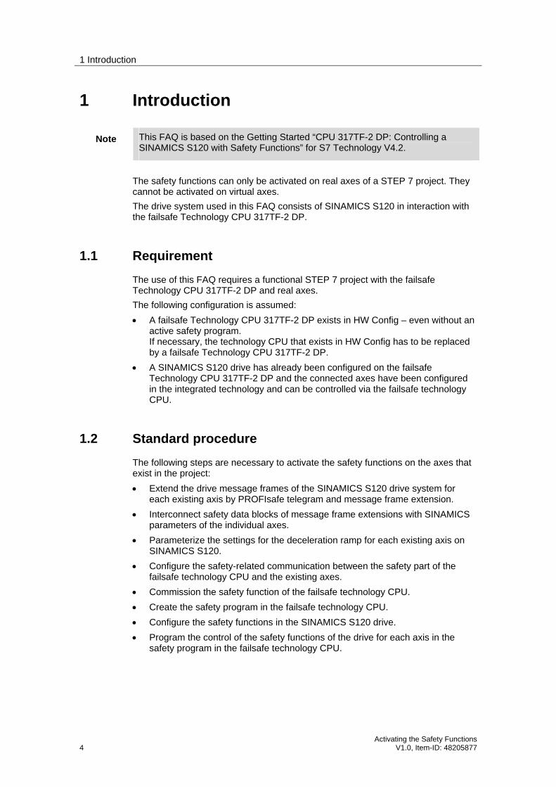
Figure 1-1 Control of the safety functions of SINAMICS S120
Failsafe technology CPU
PLC Integrated technology
SINAMICS S120
Motor
Technology objects
Standarduser
program
Safetyprogram
Status
Job
Motor
Failsafe I/O
StandardI/O
MPI/DP
DP(Drive)
DP
MPI/DP
MPI/DP
PROFIdrive + PROFIsafePROFIBUS + PROFIsafe
The following chapters of this FAQ provide a detailed explanation of the individual steps to activate the safety functions on the axes that already exist in a STEP 7 project.
1.3 Example
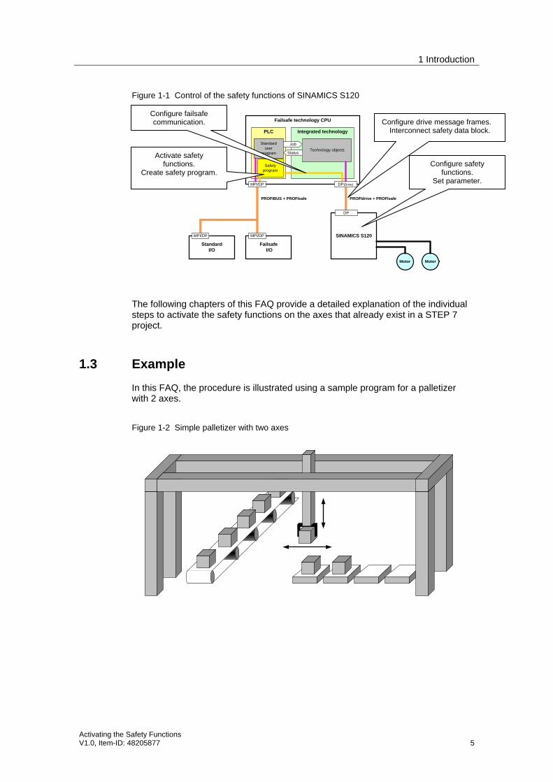
In this FAQ, the procedure is illustrated using a sample program for a palletizer with 2 axes.
Figure 1-2 Simple palletizer with two axes
Configure drive message frames. Interconnect safety data block.
Configure safety functions.
Set parameter.
Configure failsafe communication.
Activate safety functions.
Create safety program.
2 Configuration
6 Activating the Safety Functions
V1.0, Item-ID: 48205877
2 Configuration
2.1 SINAMICS: Extending the drive message frames
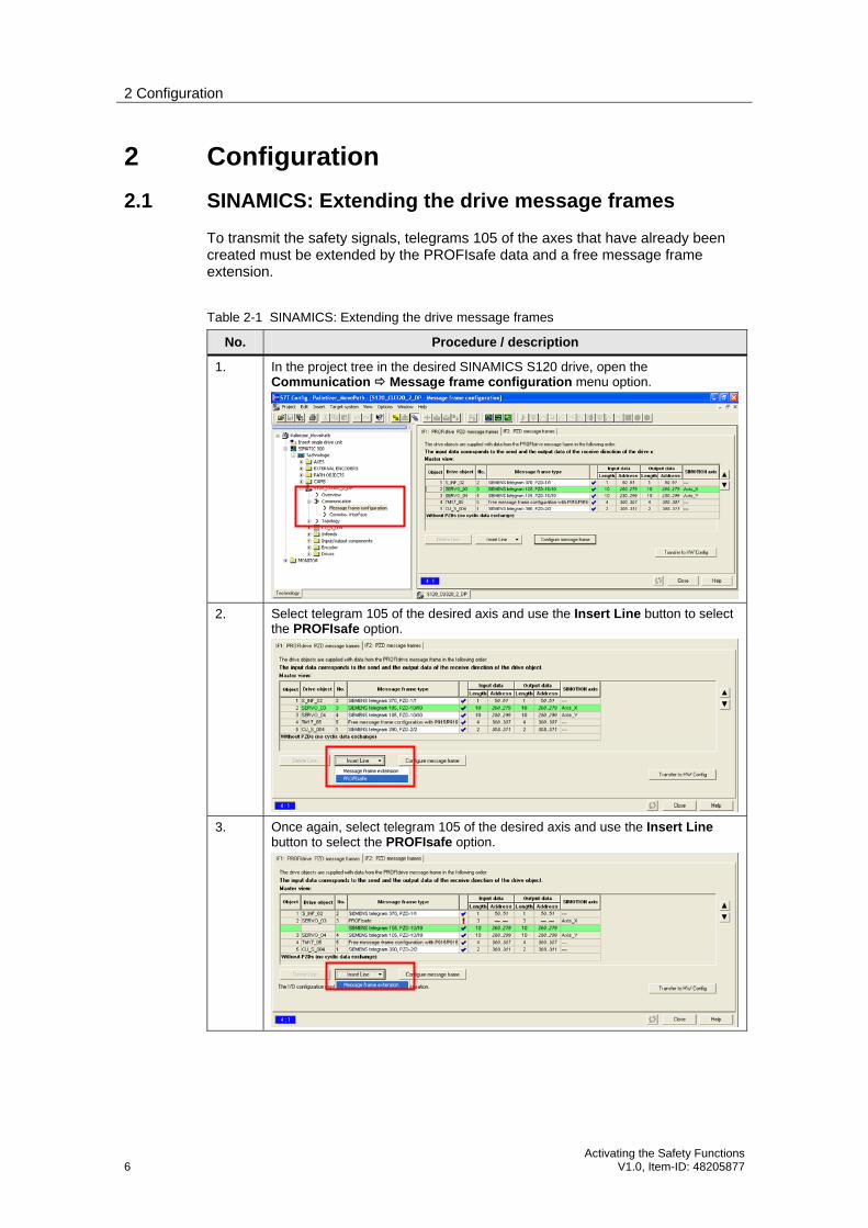
To transmit the safety signals, telegrams 105 of the axes that have already been created must be extended by the PROFIsafe data and a free message frame extension.
Table 2-1 SINAMICS: Extending the drive message frames
No. Procedure / description
1. In the project tree in the desired SINAMICS S120 drive, open the Communication Message frame configuration menu option.
2. Select telegram 105 of the desired axis and use the Insert Line button to select the PROFIsafe option.
3. Once again, select telegram 105 of the desired axis and use the Insert Line button to select the PROFIsafe option.

2 Configuration
Activating the Safety Functions V1.0, Item-ID: 48205877 7
No. Procedure / description
4. For Message frame extension, enter the desired message frame lengths from master view (Input data: 3 words, Output data: 0 words).
5. Repeat the extension of axis telegram 105 for all axes for which you want to activate the safety functions.
6. Use the Transfer to HW Config button and verify the correct address assignment.
7. Use the Save and Compile button of the changed configuration of the message frames for the drive.
If compiling fails due to inconsistency of the axis configuration, call the configuration of the axes in the technology and run the axis configuration wizard without making any changes. S7T Config then adapts the assignment of the message frame address in the axis configuration.

2 Configuration
8 Activating the Safety Functions
V1.0, Item-ID: 48205877
No. Procedure / description
If compiling is still not possible, save the changed configuration, close S7T Config and in HW Config check the values of the times Ti and To set on the equidistant Profibus.
Save the changed hardware configuration, close HW Config and reopen S7T Config. It should now be possible to save and compile the changes in S7T Config without further error messages.
2.2 SINAMICS: Interconnecting the safety data block
The current status of the drive safety functions is indicated with the safety data block of the technology. The signals are transmitted with the aid of the extension of the message frame by the safety data block. In the SINAMICS S120 drive, this message frame section must therefore be combined with the status signals of the drive safety functions as follows:
2 Configuration
Activating the Safety Functions V1.0, Item-ID: 48205877 9
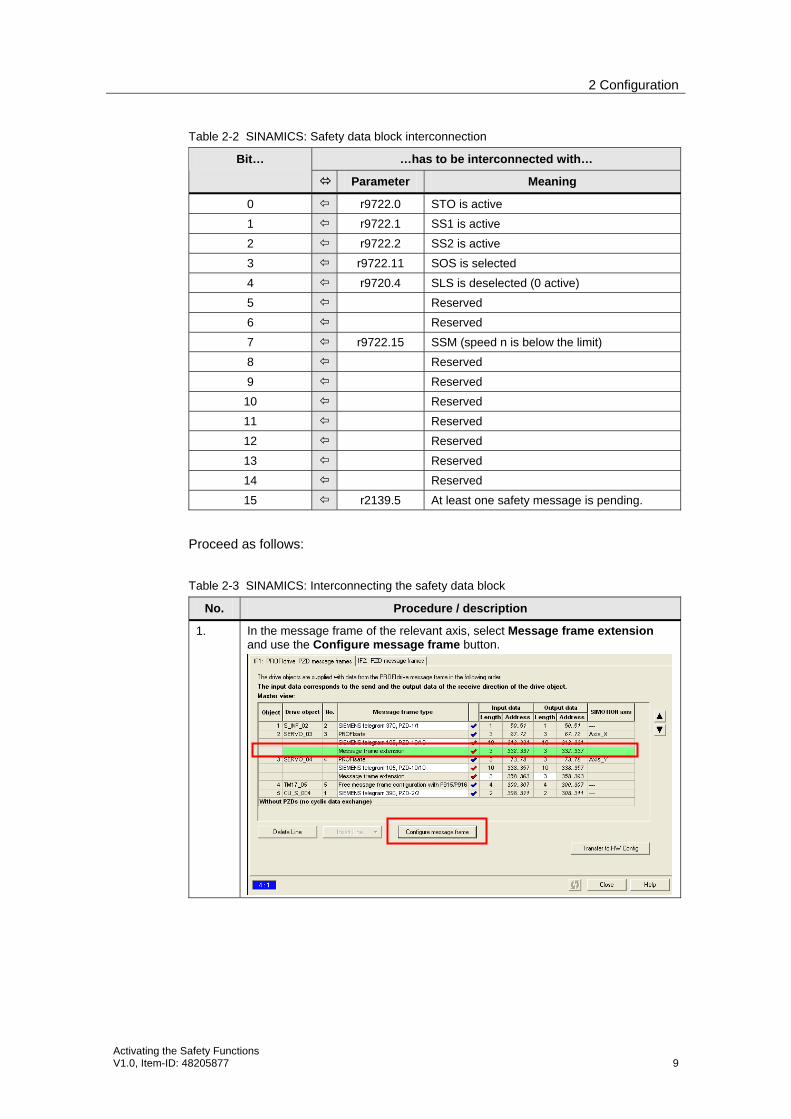
Table 2-2 SINAMICS: Safety data block interconnection
…has to be interconnected with… Bit…
Parameter Meaning
0 r9722.0 STO is active
1 r9722.1 SS1 is active
2 r9722.2 SS2 is active
3 r9722.11 SOS is selected
4 r9720.4 SLS is deselected (0 active)
5 Reserved
6 Reserved
7 r9722.15 SSM (speed n is below the limit)
8 Reserved
9 Reserved
10 Reserved
11 Reserved
12 Reserved
13 Reserved
14 Reserved
15 r2139.5 At least one safety message is pending.
Proceed as follows:
Table 2-3 SINAMICS: Interconnecting the safety data block
No. Procedure / description
1. In the message frame of the relevant axis, select Message frame extension and use the Configure message frame button.
2 Configuration
10 Activating the Safety Functions
V1.0, Item-ID: 48205877
No. Procedure / description
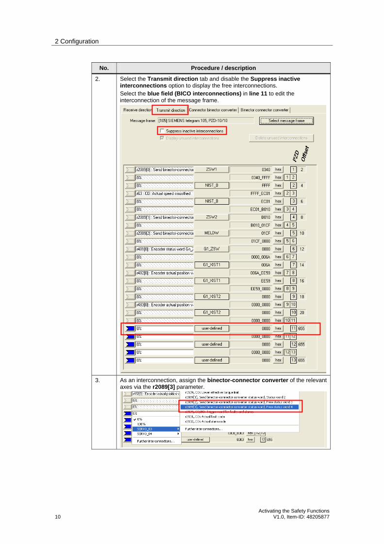
2. Select the Transmit direction tab and disable the Suppress inactive interconnections option to display the free interconnections. Select the blue field (BICO interconnections) in line 11 to edit the interconnection of the message frame.
3. As an interconnection, assign the binector-connector converter of the relevant axes via the r2089[3] parameter.

2 Configuration
Activating the Safety Functions V1.0, Item-ID: 48205877 11
No. Procedure / description
4. Select the blue field (BICO interconnections) in line 12/13 and use Further interconnections to assign the p9733[0] parameter as an interconnection.
5. Now call the binector-connector converter and interconnect the signals listed in the above table on the p2051[10] parameter.

2 Configuration
12 Activating the Safety Functions
V1.0, Item-ID: 48205877
No. Procedure / description
6. For the respective bits, select the relevant blue field (BICO interconnections) next to the parameter and use Further interconnections to assign the signals listed in the above table.
7. Repeat the interconnection of the safety data block for all axes for which you want to activate the safety functions.
8. Save and compile the changes you have made.
2.3 SINAMICS: Setting the parameter
On the SINAMICS S120 drive system, the setting of the OFF 3 deceleration ramp must be made or checked to use the safety functions.
Table 2-4 SINAMICS: Setting the parameter
No. Procedure / description
1. In the project tree for the relevant axis, select Open-loop/closed-loop control and click on Setpoint addition. Then click on Deceleration ramp.
2 Configuration
Activating the Safety Functions V1.0, Item-ID: 48205877 13
No. Procedure / description
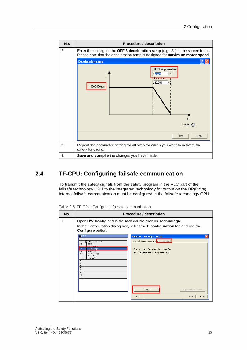
2. Enter the setting for the OFF 3 deceleration ramp (e.g., 3s) in the screen form. Please note that the deceleration ramp is designed for maximum motor speed.
3. Repeat the parameter setting for all axes for which you want to activate the safety functions.
4. Save and compile the changes you have made.
2.4 TF-CPU: Configuring failsafe communication
To transmit the safety signals from the safety program in the PLC part of the failsafe technology CPU to the integrated technology for output on the DP(Drive), internal failsafe communication must be configured in the failsafe technology CPU.
Table 2-5 TF-CPU: Configuring failsafe communication
No. Procedure / description
1. Open HW Config and in the rack double-click on Technologie. In the Configuration dialog box, select the F configuration tab and use the Configure button.

2 Configuration
14 Activating the Safety Functions
V1.0, Item-ID: 48205877
No. Procedure / description
2. In the Connection tab, select the Technologie line and click on the Connect button. The Technologie ID as an internal DP slave is then displayed in the Active Connection field at the bottom of the screen form.
Then close the screen form using the OK button.
3. In the Configuration dialog box, once again select the F configuration tab and use the Configure button.

2 Configuration
Activating the Safety Functions V1.0, Item-ID: 48205877 15
No. Procedure / description
4. Now select the newly added F Configuration tab and use the New button to create the safety-related communication link.
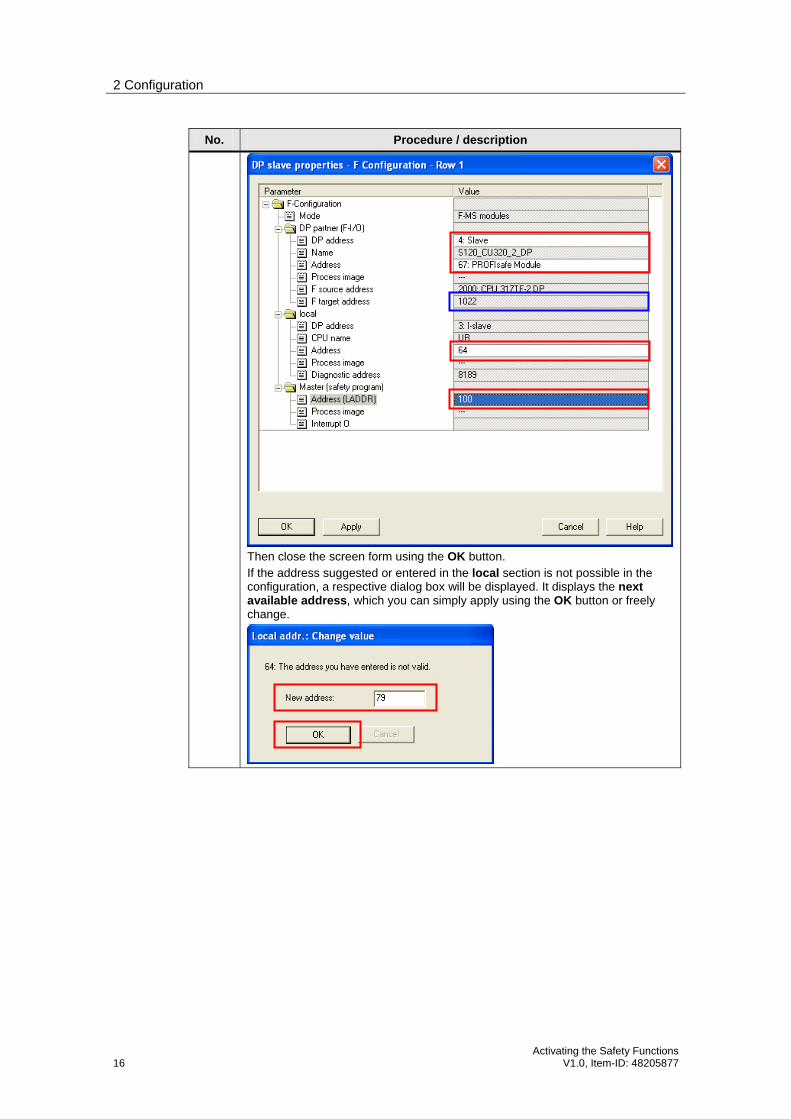
5. In the dialog box of the newly created safety-related communication link, set the following parameters:
DP partner Make sure that the correct axis of the drive is selected. Note down the displayed F target address. This address will later be needed for the configuration of the safety functions in the drive.
local Apply the suggested address or enter an available address >63.
Master Use Address (LADDR) to specify the start address via which the drive is to be accessed in the safety program. The address must be within the process image. This source address will later be used to set or reset the safety functions in SINAMICS S120 in the safety program. For program generation, additionally note down the address assigned for the axis.
2 Configuration
16 Activating the Safety Functions
V1.0, Item-ID: 48205877
No. Procedure / description
Then close the screen form using the OK button. If the address suggested or entered in the local section is not possible in the configuration, a respective dialog box will be displayed. It displays the next available address, which you can simply apply using the OK button or freely change.
2 Configuration
Activating the Safety Functions V1.0, Item-ID: 48205877 17
No. Procedure / description
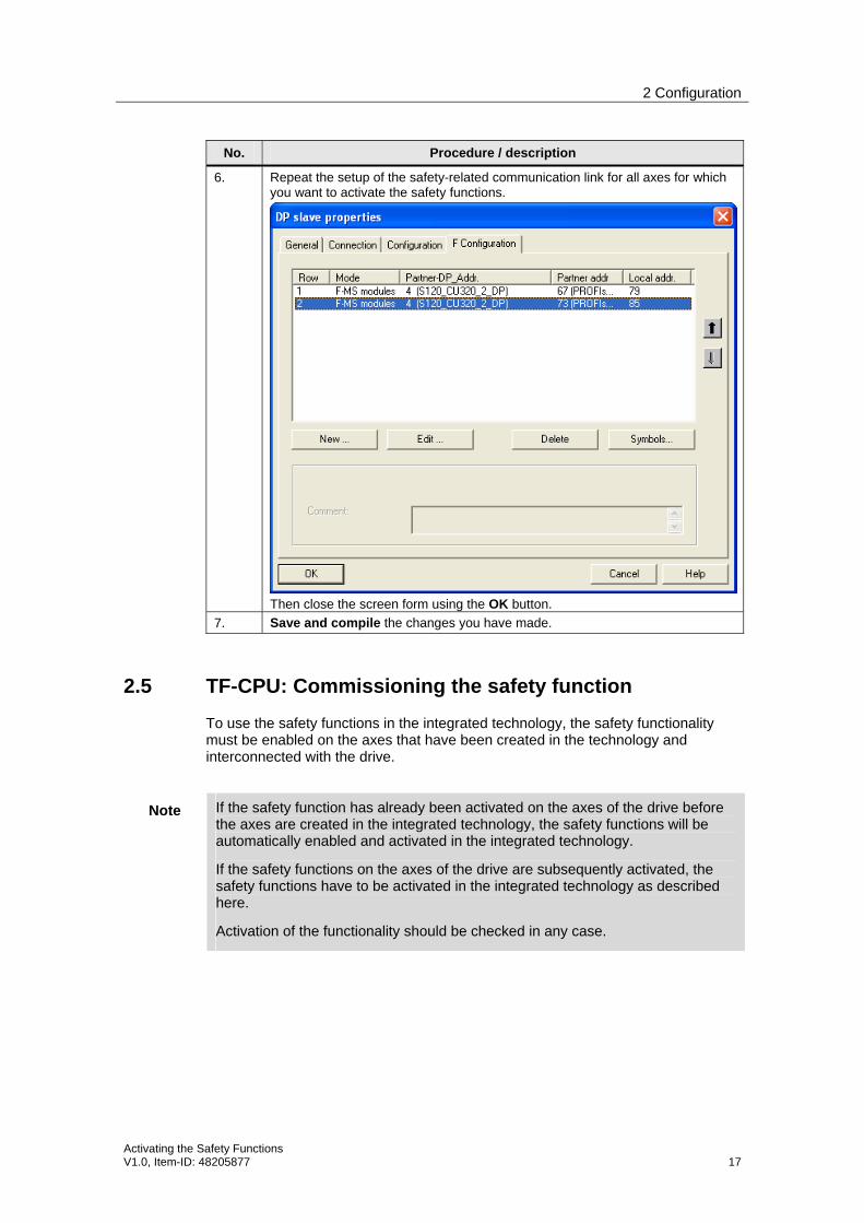
6. Repeat the setup of the safety-related communication link for all axes for which you want to activate the safety functions.
Then close the screen form using the OK button.
7. Save and compile the changes you have made.
2.5 TF-CPU: Commissioning the safety function
To use the safety functions in the integrated technology, the safety functionality must be enabled on the axes that have been created in the technology and interconnected with the drive.
Note If the safety function has already been activated on the axes of the drive before the axes are created in the integrated technology, the safety functions will be automatically enabled and activated in the integrated technology.
If the safety functions on the axes of the drive are subsequently activated, the safety functions have to be activated in the integrated technology as described here.
Activation of the functionality should be checked in any case.
2 Configuration
18 Activating the Safety Functions
V1.0, Item-ID: 48205877
Table 2-6 Commissioning the safety function
No. Procedure / description
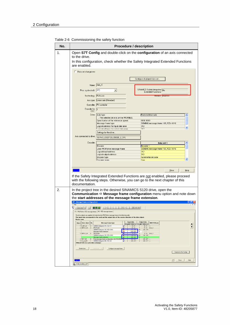
1. Open S7T Config and double-click on the configuration of an axis connected to the drive. In this configuration, check whether the Safety Integrated Extended Functions are enabled.
If the Safety Integrated Extended Functions are not enabled, please proceed with the following steps. Otherwise, you can go to the next chapter of this documentation.
2. In the project tree in the desired SINAMICS S120 drive, open the Communication Message frame configuration menu option and note down the start addresses of the message frame extension.
2 Configuration
Activating the Safety Functions V1.0, Item-ID: 48205877 19
No. Procedure / description
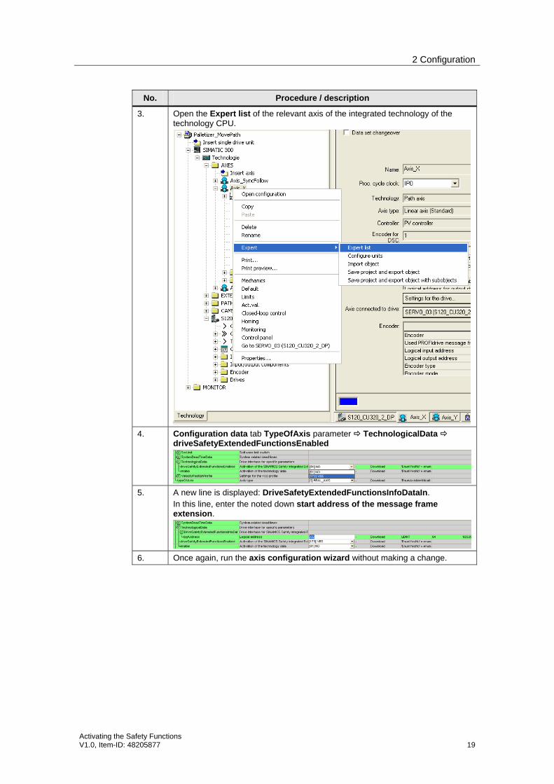
3. Open the Expert list of the relevant axis of the integrated technology of the technology CPU.
4. Configuration data tab TypeOfAxis parameter TechnologicalData driveSafetyExtendedFunctionsEnabled
5. A new line is displayed: DriveSafetyExtendedFunctionsInfoDataIn. In this line, enter the noted down start address of the message frame extension.
6. Once again, run the axis configuration wizard without making a change.
2 Configuration
20 Activating the Safety Functions
V1.0, Item-ID: 48205877
No. Procedure / description
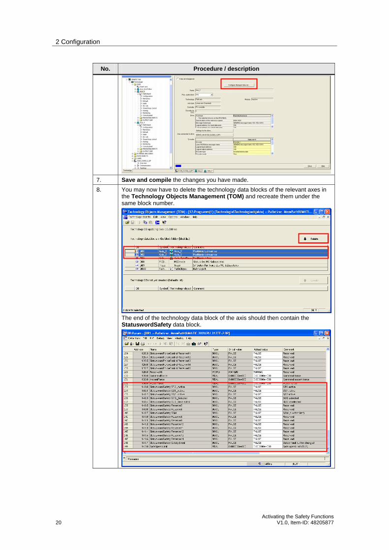
7. Save and compile the changes you have made.
8. You may now have to delete the technology data blocks of the relevant axes in the Technology Objects Management (TOM) and recreate them under the same block number.
The end of the technology data block of the axis should then contain the StatuswordSafety data block.
2 Configuration
Activating the Safety Functions V1.0, Item-ID: 48205877 21
2.6 TF-CPU: Creating the safety program
To be able to create the safety program and to use the safety functions of the technology CPU, the safety program must be activated in the PLC part of the failsafe technology CPU.
Table 2-7 Creating the safety program
No. Procedure / description
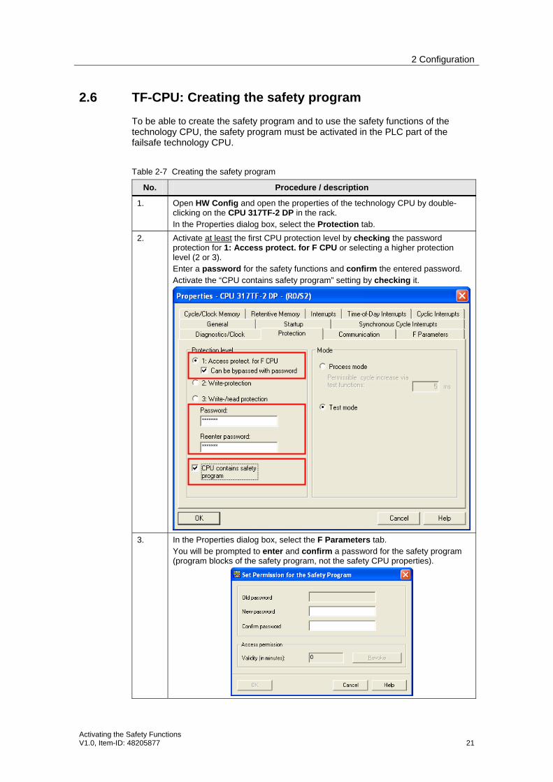
1. Open HW Config and open the properties of the technology CPU by double-clicking on the CPU 317TF-2 DP in the rack. In the Properties dialog box, select the Protection tab.
2. Activate at least the first CPU protection level by checking the password protection for 1: Access protect. for F CPU or selecting a higher protection level (2 or 3). Enter a password for the safety functions and confirm the entered password. Activate the “CPU contains safety program” setting by checking it.
3. In the Properties dialog box, select the F Parameters tab. You will be prompted to enter and confirm a password for the safety program (program blocks of the safety program, not the safety CPU properties).
2 Configuration
22 Activating the Safety Functions
V1.0, Item-ID: 48205877
No. Procedure / description
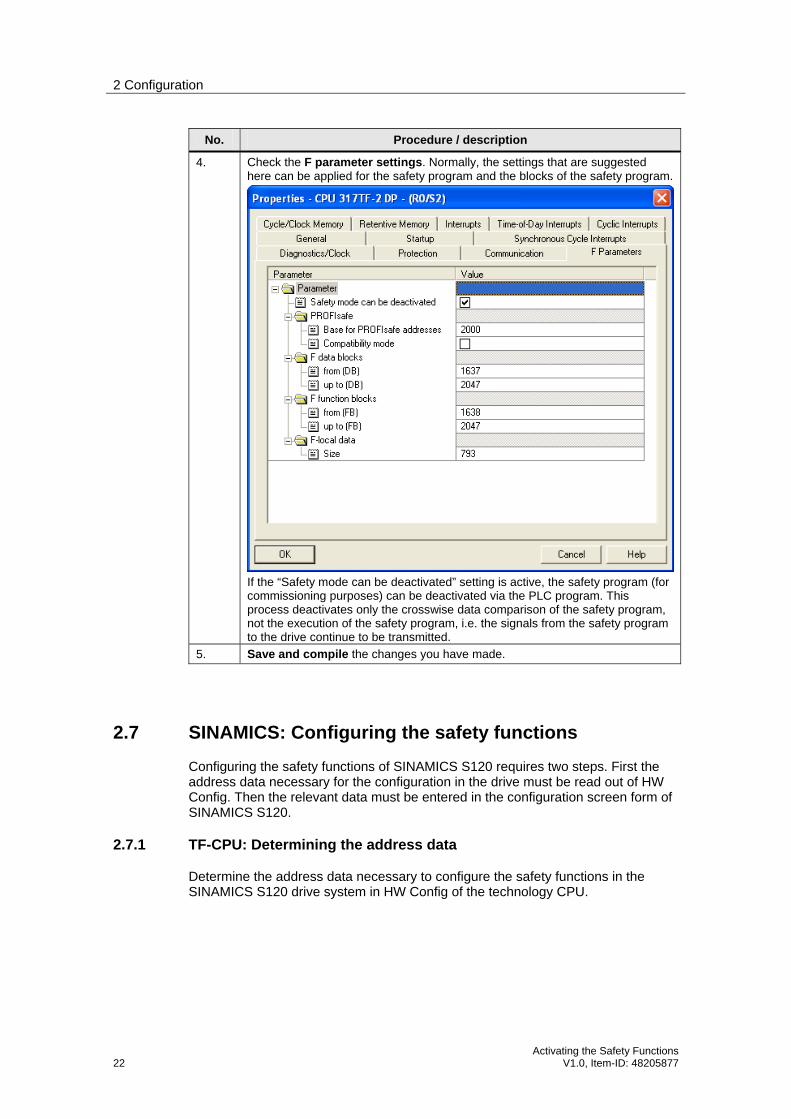
4. Check the F parameter settings. Normally, the settings that are suggested here can be applied for the safety program and the blocks of the safety program.
If the “Safety mode can be deactivated” setting is active, the safety program (for commissioning purposes) can be deactivated via the PLC program. This process deactivates only the crosswise data comparison of the safety program, not the execution of the safety program, i.e. the signals from the safety program to the drive continue to be transmitted.
5. Save and compile the changes you have made.
2.7 SINAMICS: Configuring the safety functions
Configuring the safety functions of SINAMICS S120 requires two steps. First the address data necessary for the configuration in the drive must be read out of HW Config. Then the relevant data must be entered in the configuration screen form of SINAMICS S120.
2.7.1 TF-CPU: Determining the address data
Determine the address data necessary to configure the safety functions in the SINAMICS S120 drive system in HW Config of the technology CPU.

2 Configuration
Activating the Safety Functions V1.0, Item-ID: 48205877 23
Table 2-8 Configuring the safety functions – determining the address data
No. Procedure / description
1. Open HW Config and in the rack double-click on Technologie. In the Configuration dialog box, select the F configuration tab and use the Configure button.
2. In the Properties dialog box, select the F Configuration tab.

2 Configuration
24 Activating the Safety Functions
V1.0, Item-ID: 48205877
No. Procedure / description
3. In the selection list, select the desired axis (recognizable by the partner address) and use the Edit button.
4. In the DP partner (F-I/O) section, note down the F target address of the relevant axis. For input to the configuration screen form of SINAMICS S120, convert the noted down decimal value to hexadecimal format. Example: (1022)DEC = (3FE)HEX or (1021)DEC = (3FD)HEX
5. Repeat the noting down of the F target address for all axes displayed in the selection list for which the safety functions are to be activated.

2 Configuration
Activating the Safety Functions V1.0, Item-ID: 48205877 25
2.7.2 SINAMICS: Configuring
Transfer the determined address data and make the additionally required parameterization of the safety functions of SINAMICS S120 in S7T Config (Starter).
Table 2-9 Configuring the safety functions – configuring
No. Procedure / description
1. Open S7T Config and select the relevant SINAMICS S120 drive. Then navigate to the desired Axis and in Functions Safety Integrated, call the screen form to configure the safety functions. Go to Online mode of S7T Config so that the safety functions of SINAMICS S120 can be parameterized directly in the drive. Select the Change settings button to be able to make changes in the drive.
2. Activate the Extended Safety Functions of SINAMICS S120 via PROFIsafe by selecting the relevant item in the list box. The following applies:
STO/SBC/SS1 via … = Basic Safety Functions
Motion Monitoring via … = Extended Safety Functions
2 Configuration
26 Activating the Safety Functions
V1.0, Item-ID: 48205877
No. Procedure / description
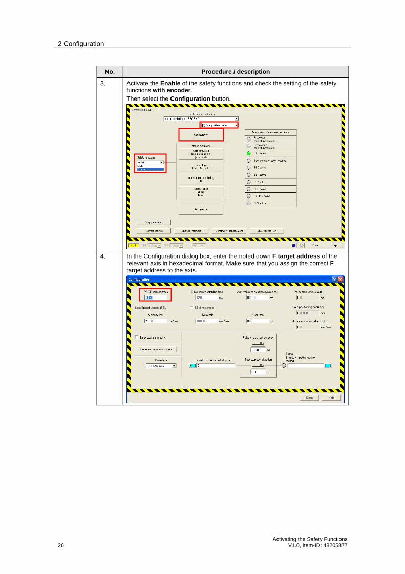
3. Activate the Enable of the safety functions and check the setting of the safety functions with encoder. Then select the Configuration button.
4. In the Configuration dialog box, enter the noted down F target address of the relevant axis in hexadecimal format. Make sure that you assign the correct F target address to the axis.

2 Configuration
Activating the Safety Functions V1.0, Item-ID: 48205877 27
No. Procedure / description
5. For axis velocity monitoring by the drive, also set the Drive type of the relevant axis. Select the same settings as in the axis configuration for the technology. Then click on the Encoder parameterization button.
Also in Encoder parameterization, set the same settings as in the axis configuration for the technology, for example the Leadscrew pitch setting of the axis.
2 Configuration
28 Activating the Safety Functions
V1.0, Item-ID: 48205877
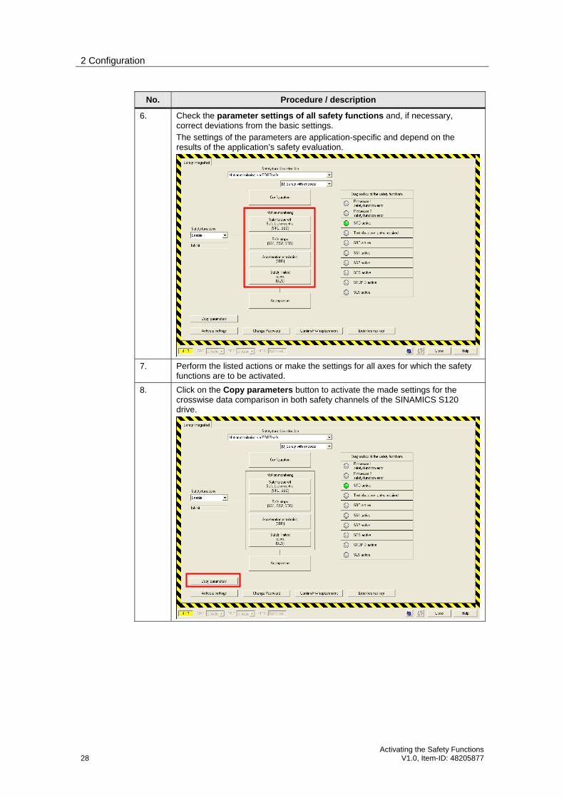
No. Procedure / description
6. Check the parameter settings of all safety functions and, if necessary, correct deviations from the basic settings. The settings of the parameters are application-specific and depend on the results of the application’s safety evaluation.
7. Perform the listed actions or make the settings for all axes for which the safety functions are to be activated.
8. Click on the Copy parameters button to activate the made settings for the crosswise data comparison in both safety channels of the SINAMICS S120 drive.

2 Configuration
Activating the Safety Functions V1.0, Item-ID: 48205877 29
No. Procedure / description
9. Select the Activate settings button to activate the made changes in the drive.
10. You may be prompted to change the safety password of the drive.
Enter the same password or a changed password.
11. Save the made changes to the drive by copying from RAM to ROM.
To do so, confirm the Copy dialog box with Yes.
2 Configuration
30 Activating the Safety Functions
V1.0, Item-ID: 48205877
No. Procedure / description
12. Then go to Offline mode of S7T Config and switch the SINAMICS S120 drive off and back on.
13. Go back to Online mode of S7T Config and load the made changes to the PG.
14. Then return to Offline mode of S7T Config.
2.8 TF-CPU: Programming the safety program
After successful configuration and commissioning of the safety functions, these functions must now be controlled via the safety program of the failsafe technology CPU.
Note Please note that the safety functions of the drive are activated at 0 signal (False) and deactivated at 1 signal (True).
To be able to move the axes of the drive with safety function, the safety functions of the axis have to be deactivated first, i.e. the relevant signals for the deselection of the safety functions of the axis via the PROFIsafe telegram must be transferred from the safety program to the drive.
The individual bits of the PROFIsafe telegram of the relevant axis are used to activate or deactivate the safety functions.
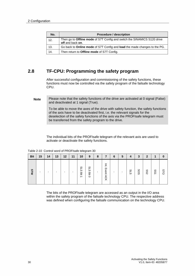
Table 2-10 Control word of PROFIsafe telegram 30
Bit 15 14 13 12 11 10 9 8 7 6 5 4 3 2 1 0
ST
W
- - - - -
SLS
Bit 1
SLS
Bit 0
-
Int. Event A
CK
- -
SLS
SO
S
SS
2
SS
1
ST
O
The bits of the PROFIsafe telegram are accessed as an output in the I/O area within the safety program of the failsafe technology CPU. The respective address was defined when configuring the failsafe communication on the technology CPU.
2 Configuration
Activating the Safety Functions V1.0, Item-ID: 48205877 31
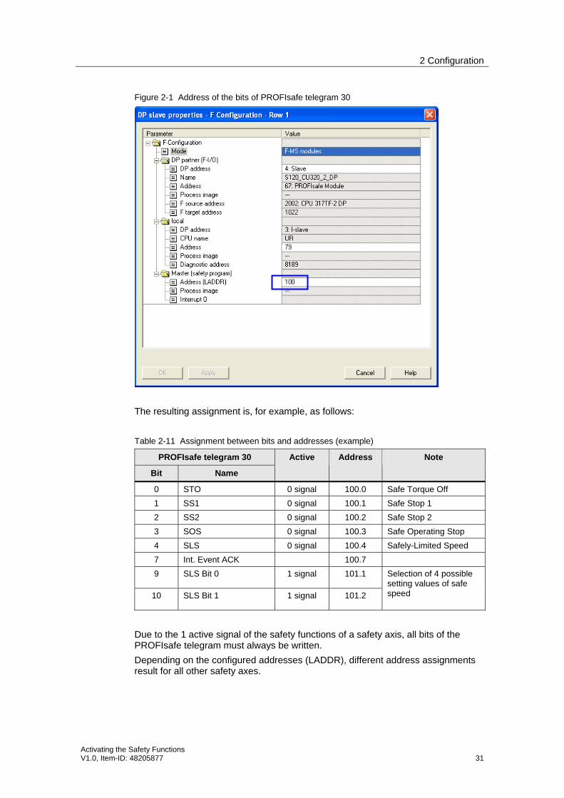
Figure 2-1 Address of the bits of PROFIsafe telegram 30
The resulting assignment is, for example, as follows:
Table 2-11 Assignment between bits and addresses (example)
PROFIsafe telegram 30
Bit Name
Active Address Note
0 STO 0 signal 100.0 Safe Torque Off
1 SS1 0 signal 100.1 Safe Stop 1
2 SS2 0 signal 100.2 Safe Stop 2
3 SOS 0 signal 100.3 Safe Operating Stop
4 SLS 0 signal 100.4 Safely-Limited Speed
7 Int. Event ACK 100.7
9 SLS Bit 0 1 signal 101.1
10 SLS Bit 1 1 signal 101.2
Selection of 4 possible setting values of safe speed
Due to the 1 active signal of the safety functions of a safety axis, all bits of the PROFIsafe telegram must always be written.
Depending on the configured addresses (LADDR), different address assignments result for all other safety axes.
2 Configuration
32 Activating the Safety Functions
V1.0, Item-ID: 48205877
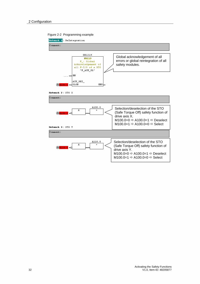
Figure 2-2 Programming example
Global acknowledgement of all errors or global reintegration of all safety modules.
Selection/deselection of the STO (Safe Torque Off) safety function of drive axis X. M100.0=0 A100.0=1 Deselect M100.0=1 A100.0=0 Select
Selection/deselection of the STO (Safe Torque Off) safety function of drive axis Y. M100.0=0 A100.0=1 Deselect M100.0=1 A100.0=0 Select