Embed Size (px)
Citation preview

Technology Development for Iron and Cobalt Fischer-Tropsch Catalysts
Quarterly Report
October 1, 2001 to December 31, 2001
Burtron H. Davis
Enrique Iglesia (UC/B Subcontract)
DE-FC26-98FT40308
University of Kentucky Research Foundation
201 Kinkead Hall
Lexington, KY 40506
University of California-Berkeley (Subcontract)
Laboratory for the Science and Application of Catalysis
Department of Chemical Engineering
University of California at Berkeley
Berkeley, CA 94720

1
Disclaimer
This report was prepared as an account of work sponsored by an agency of the United
States Government. Neither the United States Government nor any agency thereof, nor any of
their employees, makes any warranty, express or implied, or assumes any legal liability or
responsibility for the accuracy, completeness, or usefulness of any information, apparatus,
product, or process disclosed, or represents that its use would not infringe privately owned
rights. Reference herein to any specific commercial product, process, or service by trade name,
trademark, manufacturer, or otherwise does not necessarily constitute or imply its endorsement,
recommendation or favoring by the United States Government or any agency thereof. The views
and opinions of authors expressed herein do not necessarily state or reflect those of the United
States Government or any agency thereof.

2
Abstract
CAER
Tight control of catalyst distribution within SBCRs should be maintained in order to
quantify activity decline, especially for small pilot plant systems. Transient problems with
previous SBCR experiments were caused by a maldistribution of catalyst between the reactor
and slurry filtration system. The level indication/control system installed in an enhanced SBCR
was robust and effective in maintaining a steady inventory of catalyst slurry in contact with the
gas-phase. Measured deactivation rates in the enhanced SBCR system were comparable to that
of CSTR experiments under similar conditions.
Attrition tests in the SBCR system indicated that the most of the catalyst breakdown
occurred during catalyst activation and the initial synthesis stage; however, further research will
be required to investigate the possibility of particle size classification/segregation at the
sampling points. After activation, the catalyst particle mean diameter decreased in an
exponential decay fashion. Attrition effects must be considered in order to accurately estimate
the space velocity in pilot-scale SBCRs.
A cobalt catalyst (25%Co/γ-Al2O3, prepared by slurry phase impregnation) was used in a
fixed bed reactor under a pressure/density tuned supercritical fluid mixture of n-pentane/n-
hexane. By using an inert gas as a balancing gas to maintain a constant pressure, the density of
the supercritical fluid could be tuned near the supercritical point while maintaining constant
space velocity within the reactor. The benefits of the mixture allowed for optimization of
transport and solubility properties at an appropriate reaction temperature for Fischer Tropsch
synthesis with a cobalt catalyst. There was an important increase in conversion due to greater
accessibility to active sites after extraction of heavy wax from the catalyst, and additional

3
benefits included decreased methane and carbon dioxide selectivities. Decreased paraffin/(olefin
+ paraffin) selectivities with increasing carbon number were also observed, in line with
extraction of the hydrocarbons from the pore. Removal of the wax products resulted in lower
residence times in the catalyst pores and, therefore, decreased probability for readsorption and
reaction to the hydrogenated product. Even so, there was not an increase in the alpha value over
that obtained with just the inert gas.

4
Table of Contents
Page
Disclaimer . . . . . . . . . . . . . . . . . . . . . . . . . . . . . . . . . . . . . . . . . . . . . . . . . . . . . . . . . . . . . . 1
Abstract . . . . . . . . . . . . . . . . . . . . . . . . . . . . . . . . . . . . . . . . . . . . . . . . . . . . . . . . . . . . . . 2
Table of Contents . . . . . . . . . . . . . . . . . . . . . . . . . . . . . . . . . . . . . . . . . . . . . . . . . . . . . . . . . . . . 4
Executive Summary . . . . . . . . . . . . . . . . . . . . . . . . . . . . . . . . . . . . . . . . . . . . . . . . . . . . . . . . . . 5
Task 1. Iron Catalyst Preparation . . . . . . . . . . . . . . . . . . . . . . . . . . . . . . . . . . . . . . . . . . . . . . . 7
Task 2. Catalyst Testing . . . . . . . . . . . . . . . . . . . . . . . . . . . . . . . . . . . . . . . . . . . . . . . . . . . . . . 7
A. Slurry Bubble Activities . . . . . . . . . . . . . . . . . . . . . . . . . . . . . . . . . . . . . . . . . . 7
Task 3. Catalyst Characterization . . . . . . . . . . . . . . . . . . . . . . . . . . . . . . . . . . . . . . . . . . . . . . 20
Task 4. Wax/Catalyst Separation . . . . . . . . . . . . . . . . . . . . . . . . . . . . . . . . . . . . . . . . . . . . . . 20
Task 5. Oxygenates . . . . . . . . . . . . . . . . . . . . . . . . . . . . . . . . . . . . . . . . . . . . . . . . . . . . . . . . 20
Task 6. Literature Review of Prior Fischer-Tropsch Synthesis with Co Catalysts . . . . . . . 20
Task 7. Co Catalyst Preparation . . . . . . . . . . . . . . . . . . . . . . . . . . . . . . . . . . . . . . . . . . . . . . 20
Task 8. Co Catalyst Testing for Activity and Kinetic Rate Correlations . . . . . . . . . . . . . . . 21
A. Fischer-Tropsch Synthesis: Supercritical Conversion Using a Co/Al2O3
Catalyst in a Fixed Bed Reactor . . . . . . . . . . . . . . . . . . . . . . . . . . . . . . . . . . . 21
Task 9. Co Catalyst Life Testing . . . . . . . . . . . . . . . . . . . . . . . . . . . . . . . . . . . . . . . . . . . . . 77
Task 10. Co Catalyst Mechanism Study . . . . . . . . . . . . . . . . . . . . . . . . . . . . . . . . . . . . . . . . 77
Task 11. University of California, Berkeley (Subcontract) . . . . . . . . . . . . . . . . . . . . . . . . . . 77
Task 12. Reporting and Management . . . . . . . . . . . . . . . . . . . . . . . . . . . . . . . . . . . . . . . . . . . 77

5
Executive Summary
CAER
A Slurry Bubble Column Reactor (SBCR) is a gas-liquid-solid reactor in which the finely
divided solid catalyst is suspended in the liquid by rising gas bubbles. The synthesis gas flows
in a bubble phase through the catalyst/wax suspension. A gas distributor located in the bottom
of the reactor produces the bubbles that rise inside the reactor. The volatile products are removed
overhead together with unconverted gases, and the liquid products are separated from the
catalyst suspension through a filter.
A considerable interest has been expressed in using SBCRs to carry out Fischer-Tropsch
Synthesis (FTS), particularly for the conversion of stranded natural gas into liquids. Historically,
wall effects in small-scale SBCR reactors (diameters less than 30 cm) have presented many
challenges with regard to interpretation of kinetic/conversion data for process scale-up. In this
paper, we describe a novel 5-cm diameter SBCR system that incorporates a natural slurry
recirculation loop that minimizes wall effects and promotes plug-flow behavior in the liquid
phase. Conversion performance, catalyst activity decline, and attrition of a precipitated Fe/K
FTS catalyst in the improved SBCR is compared to that of a CSTR run using the same catalyst
and operating conditions.
Slurry back-mixing in the improved SBCR was significantly reduced by the addition of
the down-comer/dip-tube flow path; consequently, the gas and liquid phases likely exhibited
more plug-flow behavior. Thus, for a given space velocity, the enhanced SBCR yielded a higher
conversion than that of the CSTR. The activity decline measured in the revamped SBCR system
was shown to be similar to that of the CSTR experiments. Attrition tests in the SBCR system
indicated that the most of the catalyst breakdown occurred between the time period of loading
and activation; however, further research will be required to investigate the possibility of particle

6
size classification/segregation at the sampling points. After activation, the catalyst particle
mean diameter decreased in an exponential decay fashion.
The anticipated benefits of running FTS in a supercritical fixed bed reactor are clear. In
comparison with gas phase fixed bed processes, by using well pressure tuned supercritical
media, in this case a C5/C6 mixture, the condensation of high molecular weight hydrocarbons
leading to catalyst deactivation was avoided. In contrast to conventional slurry phase processes,
which suffer from catalyst attrition, whereby the catalyst fines eventually breakdown to the point
at which they can channel through the filter, running FTS under the supercritical media avoided
this problem altogether. With the increase in conversion due to greater accessibility to active
sites after wax extraction, additional benefits included decreased methane and carbon dioxide
selectivities. The decreased paraffin/(olefin + paraffin) selectivities with increasing carbon
number was in line with extraction of the hydrocarbon from the pore. Two possibilities are
considered. Faster diffusion rates of wax products may result in lower residence times in the
pores, and therefore, decreased probability for readsorption and reaction to the hydrogenated
product. A more probable explanation is that the residence times of intermediate olefins, which
are inversely related to their saturation vapor pressures, are decreased due to removal of the
liquid phase during extraction.

7
Task 1. Iron Catalyst Preparation
The objective of this task is to produce robust intermediate- and high-" catalysts.
No scheduled or further activity to report.
Task 2. Catalyst Testing
The objective of this task is to obtain catalyst performance on the catalysts prepared in
Task 1.
A. Slurry Bubble Activities
Executive Summary
A Slurry Bubble Column Reactor (SBCR) is a gas-liquid-solid reactor in which the finely
divided solid catalyst is suspended in the liquid by rising gas bubbles. The synthesis gas flows
in a bubble phase through the catalyst/wax suspension. A gas distributor located in the bottom
of the reactor produces the bubbles that rise inside the reactor. The volatile products are removed
over together with unconverted gases, and the liquid products are separated from the catalyst
suspension through a filter.
A considerable interest has been expressed in using SBCRs to carry out Fischer-Tropsch
Synthesis (FTS), particularly for the conversion of stranded natural gas into liquids. Historically,
wall effects in small-scale SBCR reactors (diameters less than 30 cm) have presented many
challenges with regard to interpretation of kinetic/conversion data for process scale-up. In this
paper, we describe a novel 5-cm diameter SBCR system that incorporates a natural slurry
recirculation loop that minimizes wall effects and promotes plug-flow behavior in the liquid
phase. Conversion performance, catalyst activity decline, and attrition of a precipitated Fe/K
FTS catalyst in the improved SBCR is compared to that of a CSTR run using the same catalyst
and operating conditions.

8
Slurry back-mixing in the improved SBCR was significantly reduced by the addition of
the down-comer/dip-tube flow path; consequently, the gas and liquid phases likely exhibited
more plug-flow behavior. Thus, for a given space velocity, the enhanced SBCR yielded a higher
conversion than that of the CSTR. The activity decline measured in the revamped SBCR system
was shown to be similar to that of the CSTR experiments. Attrition tests in the SBCR system
indicated that the most of the catalyst breakdown occurred between the time period of loading
and activation; however, further research will be required to investigate the possibility of particle
size classification/segregation at the sampling points. After activation, the catalyst particle
mean diameter decreased in an exponential decay fashion.
Introduction
The Prototype Integrated Process Unit (PIPU) is a pilot plant system built in the early
1980s at the University of Kentucky for studying a multitude of synthetic fuel/chemical
processes. Recently, a direct coal liquefaction reactor within the PIPU plant was reconfigured as
a SBCR for FTS studies (see Figure 1.). The reactor was originally designed to operate with
coarse catalyst pellets (>500 :m). Consequently, the reactor system did not contain a wax
separation system sufficient for smaller catalyst particles that are typically used in FTS.
Therefore, a slurry accumulator and a batch wax filtration system were installed.
Early attempts to operate the pilot-scale reactor in a F-T mode were successful in that a
clear wax product could be obtained. However, the initial activity observed in the bubble
column was about 10-15% less than that of comparable CSTR runs. Also, the rate of conversion
decline (and apparent catalyst deactivation) in the SBCR was much greater than that observed in
the CSTR. It was hypothesized that the apparent increased deactivation rate in the SBCR was
caused by the depletion of catalyst inventory due to the nature of the wax/catalyst separation
system.

9
The CAER SBCR plant was overhauled and redesigned to incorporate automatic slurry
level control and wax filtration systems. These design changes allowed for a more constant
inventory of the catalyst to be maintained in the reactor while reducing slurry hold-up in the
catalyst/wax separation system. In addition, the wax filtration system was rearranged to accept a
variety of filter elements. These additions were meant to enhance the stability of the reactor
operation so that long-term tests can be conducted to study catalyst deactivation and attrition
under real-world conditions.
In the following discussion, we will detail the results and operational experiences of a
catalyst attrition test with the enhanced SBCR system. Objectives of the study were to:
Compare the performance of a precipitated Fe/K Fischer Tropsch Synthesis (FTS) catalyst in the
enhanced SBCR and a continuous stirred tank reactor (CSTR); and Determine change of the
catalyst distribution within the reactor system due to particle attrition effects.
Experimental
All FTS runs were conducted in either CSTR or SBCR systems. Activation and synthesis
conditions for both reactor configurations are listed in Table 1. A precipitated iron catalyst
having atomic composition of 100 Fe/4.4 Si/1K was used for this series of experiments.
Table 1. Operating Conditions for SBCR and CSTR Comparison Experiments.
SBCR CSTRH2/CO Ratio 0.7 0.7Gas Space Velocity (SL/hr-g Fe) 5.0 5.15Temperature (oC) 270 270Pressure (Mpa) 1.21 1.21Gas Superficial Velocity (cm/s) 3 750 RPM
CSTR Apparatus. The one-liter CSTR used in this study has been described in detail in
the literature [1-2]. The following is a brief description of the reactor system.

10
The synthesis gas was delivered to the catalyst slurry via a sparger tube located below an
impeller blade turning at 750 rpm. The reactor effluent exited the reactor and passed
sequentially through two traps maintained at 333 and 273 K. Accumulated reactor wax was
removed daily through a tube fitted with a porous metal filter. A dry flow meter was used to
measure the exit gas flow rate.
SBCR Apparatus. A schematic of the SBCR apparatus is shown in Figure 1. In the
current configuration, the bubble column has a 5.08 cm diameter and a 2 m height with an
effective reactor volume of 3.7 liters. The synthesis gas was passed continuously through the
reactor and distributed by a sparger near the bottom of the reactor vessel. The product gas and
slurry exit the top of the reactor and pass through an overhead receiver vessel where the slurry
was disengaged from the gas-phase. Vapor products and unreacted syngas exit the overhead
vessel, enter a warm trap (333 K) followed by a cold trap (273 K). A dry flow meter down
stream of the cold trap was used to measure the exit gas flow rate.
A dip tube was added to the reactor vessel so that the F-T catalyst slurry could be
recycled internally via a natural convection loop. The unreacted syngas, F-T products, and
slurry exited into a side port near the top of the reactor vessel and entered a riser tube. The
driving force for the recirculation flow was essentially the difference in density between the fluid
column in the riser (slurry and gas) and that of the dip-tube (slurry only). The dip tube provided
a downward flow path for the slurry without interfering with the upward flow of the turbulent
syngas slurry mixture. Thus, to some degree, back mixing of the slurry phase and wall effects in
the narrow reactor [3] tube were minimized.
Based upon the analysis of the initial SBCR pilot plant runs, several more design changes
were carried out to the system to increase the conversion stability. An automatic level controller
was added to the overhead slurry/gas separation tank. This insured a constant inventory of
11
catalyst particles was being maintained in the reactor vessel if the superficial gas velocity within
the column was constant.
Originally, the overhead separator vessel was designed to enhance settling of the catalyst
particles. Thus, slurry to be filtered was extracted near the top of the vessel where the catalyst
concentration would be lower than that near the bottom. Unfortunately, this approach required a
large hold-up volume of slurry outside the reactor (greater than the reactor volume itself). Hold-
up of slurry outside the reactor was lowered by decreasing the volume of the overhead vessel
from 18 to 4 liters.
The sintered metal filter tube was moved to the liquid down comer below the overhead
separation vessel. Currently, the filter is a flow-through device having a sintered metal tube in a
shell. Filtered wax was extracted radially through the tube while slurry flows downward in the
axial direction. The shear force of the axial slurry flow prevented excessive caking of the
catalyst around the filter media. Filtered wax was metered into a storage tank through a let-
down valve operated by the overhead liquid level controller. Pressure drop across the filter
media can be varied manually by varying the wax storage tank pressure. The filter assembly was
configured such that the filter media could be replaced on-line, without aborting or interrupting
the reactor run.
The level or volume of the slurry within the receiver was continuously monitored by
measuring the differential pressure across the height of the vessel. Argon was purged through
each of the pressure legs to keep the lines free of slurry. Slurry volume within the receiver was
controlled to be no more than 1.3 liters by removing wax from the reactor system via the level
control valve. The unfiltered slurry flowed back to the reactor via a natural convection loop
through a dip-tube exiting near the bottom of a reactor.

12
Samples of the unfiltered slurry were taken from the bottom of the reactor vessel and the
overhead receiver tank on a daily basis. Wax products were Soxhlet extracted according to the
method of McCartney [4]. The particle size distributions of the extracted catalyst particles were
quantified using a light scattering technique by a Cilas 1064 liquid/particle analyzer.
Results and Discussion
SBCR Conversion Comparisons between CSTR and SBCR runs. One of the objectives of
the run was to compare the performance of the enhanced SBCR with that of a CSTR
configuration. It was anticipated that the modified SBCR system performance, in terms of
catalyst deactivation, would be comparable to that of the CSTR experiments. The run/activation
conditions for the enhanced SBCR system along with the comparison SBCR and CSTR
conditions are listed in Table 1.
The CO gas conversions versus time-on-stream for the SBCR and CSTR systems are
displayed in Figure 2. The CO conversion for the enhanced SBCR with level control reached a
maximum of 78% after 72 hours time-on-stream (TOS). After this catalyst initiation period, the
gas conversion started to steadily decline to about 72% after 192 hours TOS.
Slurry back-mixing in the SBCR is significantly reduced by the addition of the down-
comer/dip-tube flow path; consequently, the gas and liquid phases likely exhibited more Aplug-
flow@ behavior. Thus, for a given space velocity, the enhanced SBCR should yield a higher
conversion than that of a CSTR [5]. Differences in conversion between the enhanced SBCR and
CSTR reactor types may also be caused by the dissimilarity of heat and mass transfer
phenomena.
SBCR Catalyst Attrition. Heavy wax products must be separated from catalyst particles
before being removed from the reactor system. Achieving an efficient wax product separation
from the catalyst is one of the most challenging technical problems associated with slurry-phase
13
F-T. The breakdown of the catalyst particles and the production of heavy wax using high alpha
catalysts can further exasperate the filtration problem. Thus, designing a physically robust
catalyst without compromising activity is an important factor for a stable and economical F-T
process. However, small-scale catalyst attrition tests may not be adequate in simulating the
environment within a bubble column reactor. In previous studies [6,7] by Jothimurgean and
Zhao an air-jet attrition tester as outlined in the ASTM-D-5757-95 test method was used to
compare the relative breakdown resistance of catalysts. This method is useful in comparing the
relative strength between catalyst candidates; however, it does not yield information as to the
rate of attrition during synthesis. Attrition data in CSTR systems are compromised by the
extreme impact and shear forces from the impeller blade on catalyst particles. In contrast, the
SBCR unit does not utilize any mechanical pumping devices that could alter the size distribution
of the catalyst. Consequently, SBCR particle attrition will depend mainly on chemical changes
within particles and perhaps some particle/wall or particle/particle mechanical abrasion.
Figure 3 shows the changing distribution of catalyst concentration with TOS. During the
start of activation, only a small fraction of catalyst fines were detected in the reactor effluent
stream. However, near the bottom of the reactor the concentration of catalyst particles was
greater than 25 wt%. This indicated the liquid recirculation rate was not sufficient to fully
entrain the largest (>23 mm) catalyst particles. As the activation process was completed (TOS =
0), the slurry effluent contained about 5 wt% of catalyst fines. Thereafter, the solids
concentration of the reactor effluent increased linearly with TOS.
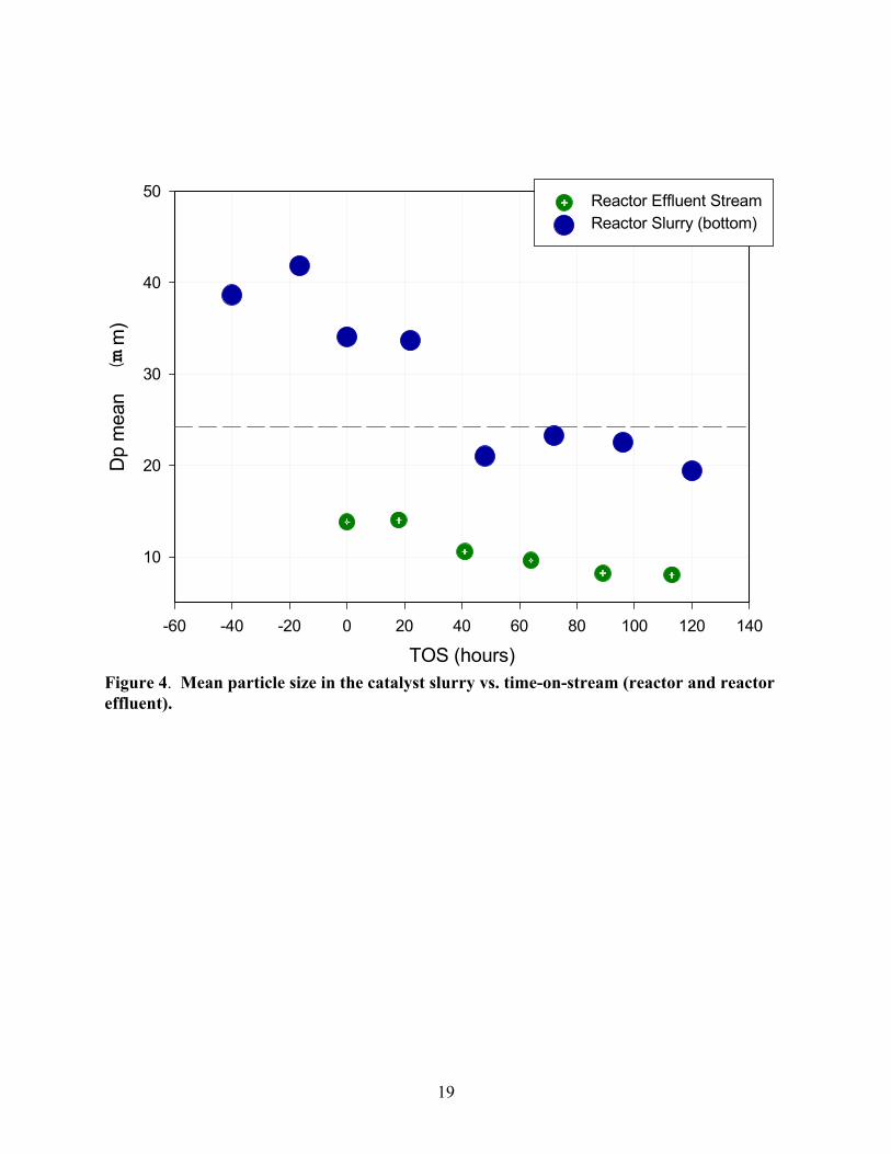
The mean particle size of the reactor bottom and effluent streams are shown in Figure 4.
The dotted horizontal line represents the initial mean particle size of the raw catalyst. Physical
classification of the catalyst particles was apparent as evidenced by the mean particle size of

14
slurry in the bottom being greater than that of the raw catalyst. As the synthesis progressed, the
mean particle size in the reactor dropped below the baseline (23 mm) after only 40 hours TOS.
In summary, the data shown in Figures 3 and 4 indicate that a significant portion of the catalyst
exited the reactor system due to particle attrition after 40 hours of TOS. Considering the slurry
hold-up outside the reactor was maintained at less than 1 liter, the percentage of catalyst lost
after 40 hours TOS was less than 20 wt%. Therefore, this lost catalyst must be considered when
calculating the space velocity.
Conclusions
Tight control of catalyst distribution within SBCRs should be maintained in order to
quantify activity decline, especially for small pilot plant systems. Transient problems with
previous SBCR experiments were caused by a maldistribution of catalyst between the reactor
and slurry filtration system. The level indication/control system installed in an enhanced SBCR
was robust and effective in maintaining a steady inventory of catalyst slurry in contact with the
gas-phase. Measured deactivation rates in the enhanced SBCR system were comparable to that
of CSTR experiments under similar conditions.
Attrition tests in the SBCR system indicated that the most of the catalyst breakdown
occurred during catalyst activation and the initial synthesis stage; however, further research will
be required to investigate the possibility of particle size classification/segregation at the
sampling points. After activation, the catalyst particle mean diameter decreased in an
exponential decay fashion. Attrition effects must be considered in order to accurately estimate
the space velocity in pilot-scale SBCRs.

15
References
1. R. J. O’Brien, R., L.Xu, D. Milburn, Y. Li, K. Klabunde, and B. Davis, Top. Catal.1995,
2, 1.
2. O’Brien, R., L. Xu, R. L. Spicer, and B. H. Davis, Energy & Fuels, 10 (1996) 921.
3. Marretto, C. and R. Krishna, AModeling of Bubble Column Slurry Reactor for Fischer-
Tropsch Synthesis@, Catalysis Today 52 (1999) 279-289.
4. McCartney, J.T., L. Hofer, B. Seligan, J. Lecky, W. Peebles, and W. Anderson, J. Phys.
Chem. 1953, 57, 730.
5. Fogler, H., Elements of Chemical Reaction Engineering, 1st Edition, pgs. 273-278,
Prentice-Hall, Englewood Cliffs, New Jersey 07632, 1986, ISBN 0-13-263476-7.
6. Jothimurugesan, K., J. Goodwin, Jr., S. Gangwal, and J. Spivey, “Development of Fe
Fischer-Tropsch Catalysts for Slurry Bubble Column Reactors”, Catalysis Today 58
(2000) 335-344.
7. Zhao, R., J. Goodwin, Jr., K. Jothimurugesan, S. Gangwal, J. Spivey, “Spray-Dried Iron
Fischer-Tropsch Catalysts. 1. Effect of Structure on the Attrition Resistance of the
Catalysts in the Calcined State”, Ind. Eng. Chem. Res. 2001, 1065-1075.

16
DP
PI
Hot Trap/Clear WaxStorage
WarmTrap
CoolTrap
OverheadReceiver
ArgonPurge
Slurry Bubble Column Reactor
FilterHousing
PI
0-20" w.c.
Total VesselVolume= 3.8 L
Nominal ControlledLiquid Vol. = 1.0 L
T
Chilled Water
Gas Samplesto Vent and/orGC Analysis
SlurryDowncomerto Dip-Tube
SamplePort
Slurry andGas Exit
PI
To Vent
Filtered Wax Letdown Control Valve
Syngas Inlet
Figure 1. Schematic of SBCR Pilot Plant System

17
Time on Stream, hrs0 50 100 150 200 250
%C
O C
onve
rsio
n
0
10
20
30
40
50
60
70
80
t'=0
t'=0
Time where -rF-T is at maximum for baseline activity.
SBCR
CSTR
Figure 2. CO conversion comparison between reactor types.

18
TOS (hrs)-60 -40 -20 0 20 40 60 80 100 120 140
Slur
ry W
t% C
atal
yst
0
5
10
15
20
25
30
Reactor Slurry (effluent) wt% CatalystReactor Bottom wt%
Figure 3. Catalyst solids distribution (reactor and reactor effluent) vs. time-on-stream.
19
TOS (hours)-60 -40 -20 0 20 40 60 80 100 120 140
Dp
mea
n (m
m)
10
20
30
40
50 Reactor Effluent StreamReactor Slurry (bottom)
Figure 4. Mean particle size in the catalyst slurry vs. time-on-stream (reactor and reactoreffluent).

20
Task 3. Catalyst Characterization
The objective of this task is to obtain characterization data of the prepared catalysts using
routine and selected techniques.
No scheduled or further activity to report.
Task 4. Wax/Catalyst Separation
The objective of this task is to develop techniques for the separation of catalysts from FT
reactor slurries.
No scheduled or further activity to report.
Task 5. Oxygenates
The objective of this task is to obtain a better understanding of the factors that affects
catalyst selectivity toward oxygenates for iron-based Fischer-Tropsch catalysts.
No scheduled activity to report.
Task 6. Literature Review of Prior Fischer-Tropsch Synthesis with Co Catalysts
The objective of this task is to prepare a critical review of prior work on cobalt Fischer-
Tropsch catalysts.
Task completed.
Task 7. Co Catalyst Preparation
The objective of this task is to prepare a limited number of cobalt-based Fischer-Tropsch
catalysts that can be used to obtain baseline data on cobalt-based Fischer-Tropsch synthesis.
No scheduled activity to report.

21
Task 8. Cobalt Catalyst Testing for Activity and Kinetic Rate Correlations
The objective of this task is to conduct initial screening of the cobalt catalysts prepared in
Task 7 to select three baseline catalysts that will then be used to generate a data base on the
performance of cobalt-based Fischer-Tropsch catalysts in slurry reactors.
A. Fischer-Tropsch Synthesis: Supercritical Conversion Using a Co/Al2O3 Catalyst in a
Fixed Bed Reactor
Abstract
A cobalt catalyst (25%Co/γ-Al2O3, prepared by slurry phase impregnation) was used in a
fixed bed reactor under a pressure/density tuned supercritical fluid mixture of n-pentane/n-
hexane. By using an inert gas as a balancing gas to maintain a constant pressure, the density of
the supercritical fluid could be tuned near the supercritical point while maintaining constant
space velocity within the reactor. The benefits of the mixture allowed for optimization of
transport and solubility properties at an appropriate reaction temperature for Fischer Tropsch
synthesis with a cobalt catalyst. There was an important increase in conversion due to greater
accessibility to active sites after extraction of heavy wax from the catalyst, and additional
benefits included decreased methane and carbon dioxide selectivities. Decreased paraffin/(olefin
+ paraffin) selectivities with increasing carbon number were also observed, in line with
extraction of the hydrocarbons from the pore. Removal of the wax products resulted in lower
residence times in the catalyst pores and, therefore, decreased probability for readsorption and
reaction to the hydrogenated product. Even so, there was not an increase in the alpha value over
that obtained with just the inert gas.

22
1. INTRODUCTION
In the near future, increasing dependence on stranded natural gas reserves for fuel
production is expected. This combined with increasing political pressure on oil companies to
limit flaring of gas has renewed focus on Gas-to-Liquids (GTL) technology. Most GTL plants
considered for commercialization consist of three process steps: (1) synthesis gas production
from natural gas; (2) Fischer-Tropsch synthesis (FTS) to convert syngas to a crude hydrocarbon
mixture (syncrude); and (3) hydroprocessing of syncrude to transportation fuels. Due to the
perception of high activity and stability, the catalyst of choice for FTS is typically a supported
cobalt catalyst.
There are positive features as well as drawbacks to conducting Fischer-Tropsch by the
traditional gas phase route or even by the more advanced liquid phase methods. For example,
gas phase FTS, which is typically carried out in a fixed or fluid bed reactor, produces higher
initial product yields, due to the superior catalyst concentration per reactor volume. However,
these higher initial rates, coupled with the potential for poor heat removal capacities of fixed-bed
gas phase processing, typically lead to localized overheating of the catalyst, due to the
exothermicity of the reaction, resulting in sintering of cobalt clusters, as well as the deposition of
heavy waxes within catalyst pores, both contributing adversely to catalyst deactivation.
Better heat control throughout the reactor can be gained by conducting FTS in the liquid
phase, due to the better heat removal capacities of the liquid. Liquid phase FTS is typically run
in the laboratory as a continuously stirred tank reactor (CSTR) or commercially in the more
slurry bubble column reactor (SBCR). In addition, deactivation rates are lower, because the
liquid media facilitates dissolving wax products, both internal and external to the catalyst pores.
However, the liquid itself provides a resistance to the diffusional transport of gas phase reactants
to active sites, resulting in a possible decrease of the reaction rate in comparison to gas phase

23
FTS. Also, separation of the attrited catalyst fines from the waxy product remains problematic
for liquid phase FTS in comparison to the typical fixed bed gas phase reactor, whereby the wax
products typically trickle down the catalyst bed.
By conducting FT in supercritical media [1], where the supercritical fluid is usually a
relatively low molecular weight solvent, one may take advantage of both the gas-like transport
properties as well as the liquid-like heat capacity and solubility characteristics of the
supercritical fluid, and utilize the fixed bed reactor. Implementing a fixed bed supercritical
reactor process may achieve two important goals of improving the economics of GTL
operations: (1) catalyst lifetimes can be extended by suppressing deactivation by pore plugging
via heavy molecular weight wax products and (2) the requirement of filtration to effect the
removal of the wax product, as is needed for CSTR and SBCR operations, is avoided.
A 25%Co/γ-Al2O3 catalyst, prepared using a slurry phase impregnation method, was
found to exhibit high activity and stability in a CSTR (H2/CO = 2, T = 220°C, P= 1.9 MPa).
Considerable effort was made to stabilize the catalyst against deactivation by reoxidation and
other instabilities, which occur when the cluster size of cobalt is below about 10 nm [2,3].
Choice of supercritical fluid, in our case a mixture, was based on, with some
modification, the following criteria set forth by Fujimoto et al. [4]:
1. The critical temperature and pressure should be slightly lower than the typical reaction
temperature and pressure. In this case, reaction temperature was similar to normal FTS,
but the reactor total pressure (8.24 MPa) was considerably higher than used for either a
gas-phase or liquid phase FTS reactor (approximately 2.00 MPa). Although much less
sensitive to total pressure than temperature, FTS is reported to shift to produce heavier

24
products with an increase in the total pressure of syngas [5]. This pressure dependence is
more pronounced for cobalt than for an iron catalyst [Sasol].
2. The solvent should be one which does not poison the catalyst and should be stable under
the reaction conditions. The low molecular weight paraffins chosen for this study are
unreactive and stable. Also, the paraffins are not coke precursors under the mild
temperatures of FTS.
3. The solvent should have a high affinity for aliphatic hydrocarbons to extract the wax
from the catalyst surface and reactor.
Because the upper optimum temperature for FTS for cobalt catalysts is approximately
220°C, the critical temperature of the solvent was selected to be below this temperature. In a
previous study [6] by our group, and reproduced here in Figures 1 and 2, it was determined using
the Hysys 2.1 process simulator that a 55% hexane/45% pentane mixture should give favorable
liquid-like densities, while still maintaining gas-like transport properties at a pressure of
approximately 8.24 MPa. Using these conditions with the 25%Co/Al2O3 catalyst, supercritical
studies were conducted by varying the partial pressure of the supercritical fluid, maintaining
constant space velocity by using argon as a balancing gas, to determine if the increased solubility
of the wax products in the supercritical fluid improved the activity and deactivation profile
during reaction testing.
2. EXPERIMENTAL
2.1 Catalyst Preparation
Condea Vista Catalox (high purity γ-alumina, 100-200 mesh, 175 m2/g) was used as the
support material for the cobalt FTS catalyst. The catalyst was prepared by a slurry impregnation
method, and cobalt nitrate was used as the precursor. In this method, which follows a Sasol

25
patent [7], the ratio of the volume of solution used to the weight of alumina was 1:1, such that
approximately 2.5 times the pore volume of solution was used to prepare the loading solution.
Two impregnation steps were used, each to load 12.5% of Co by weight. Between each step the
catalyst was dried under vacuum in a rotary evaporator at 333 K and the temperature was slowly
increased to 373 K. After the second impregnation/drying step, the catalyst was calcined under
air flow at 673K.
2.2 BET Measurements
The surface areas of the support and catalyst were measured by BET using a Micromeritics
Tri-Star system. Prior to the measurement, the sample was slowly ramped to 433K and evacuated
for 4hrs to approximately 6.7 Pa. Results of physisorption measurements are shown in Table 1.
2.3 Hydrogen Chemisorption with Pulse Reoxidation
Hydrogen chemisorption measurements were performed using a Zeton Altamira AMI-200
unit, which incorporates a thermal conductivity detector (TCD). The sample weight was 0.220 g.
The catalyst was activated at 623K for 10hrs using a flow of pure hydrogen at atmospheric pressure
and then cooled under flowing hydrogen to 373K. The sample was held at 373 K under flowing Ar
to prevent physisorption of weakly bound species prior to increasing the temperature slowly to
623K. At that temperature, the catalyst was held under flowing Ar to desorb the remaining
chemisorbed hydrogen so that the TCD signal returned to the baseline. The TPD spectrum was
integrated and the number of moles of desorbed hydrogen determined by comparing to the areas of
calibrated hydrogen pulses. Prior to experiments, the sample loop was calibrated with pulses of N2
in helium flow and compared against a calibration line produced from gas tight syringe injections
of N2 under helium flow.
After TPD of H2, the sample was reoxidized at 623K by injecting pulses of pure O2 in
helium referenced to helium gas. After oxidation of the cobalt metal clusters, the number of

26
moles of O2 consumed was determined, and the percent reducibility calculated assuming that the
Co0 reoxidized to Co3O4.
2.4 Temperature Programmed Reduction
The temperature programmed reduction (TPR) profile of the fresh catalyst was obtained
using a Zeton Altamira AMI-200 unit (Figure 3). The calcined fresh sample was first heated and
purged at 473K in flowing Ar to remove traces of water. TPR was performed using 30 cc/min
10%H2/Ar mixture referenced to Ar. The ramp was 5K/min from 303K to 623K, and the sample
was held at 623K for 30 min.
2.5 X-ray Diffraction
The powder diffractogram of the calcined catalyst was recorded using a Philips X’Pert
diffractometer. First, short-time scans were taken over the range from 2θ of 20° to 70° to verify
the formation of Co3O4 after calcination. Then, a long-time scan was made over the intense peak
at 36.8° corresponding to (311) so that estimates of Co3O4 cluster size could be assessed from
Scherrer line broadening analysis. The scanning step was 0.01, the scan speed was 0.0025 sec-1,
and the scan time was 4 sec.
2.6 Reaction Testing
The plug flow reactor configuration illustrated in Figure 4 was used and operated at a
total pressure of 8.24 MPa. The amount of catalyst was 3 g, diluted in 15 g of glass beads (80-
100 mesh). Temperature control was achieved using a three heating-zone furnace. Reactant
feed gases (H2 and CO; H2:CO of 2:1), as well as argon balancing gas and nitrogen calibration
gas, were introduced into the reactor by Brooks 5850 mass flow controllers, which were
calibrated over a wide range of pressure for the gases used. The solvent, a mixture of 55%
hexane and 45% pentane (by volume), was introduced to the reactor using an Altex Model 110A
liquid feed pump.

27
The configuration, with dual hot and cold traps, allowed for switching of the product
stream in order to maintain the reactor under normal operation and system total pressure during
sample collection. The traps were maintained at 423K and 273K, respectively. In addition, a
dry ice/acetone trap was brought online as necessary. Since sampling of the oil, liquid, and
supercritical fluid caused a substantial drop in the pressure of the traps, prior to restoring the
traps online, they were repressurized to system pressure using argon as the inert gas. This
complicated the gas analysis, since the gas stream from the traps was diluted by the argon used
to bring the traps back to operating pressure. To solve this problem and assess CO conversion,
inert N2 gas was used for calibration, as follows:
For the reactor:
XCO = (NCO, in -NCO, out)/(NCO, in)
XCO = [(Vin)(yCO, in) - (Vout)(yCO,out)]/[(Vin)(yCO, in)]
In the calculation, NCO, out refers to the moles of CO exiting the reactor, not the traps,
which are diluted. Nitrogen is unreactive and, therefore, the molar flow of nitrogen will be the
same entering and exiting the reactor. So, to correct for the argon dilution of the traps, nitrogen
is used to calibrate as follows.
For the traps:
calibration factor = CF = molar flow N2, in / molar flow N2, out
CF = [(Vin)(yN2, in)]/[(Vout)(yN2, out)]
XCO = [(Vin)(yCO, in) - (Vout)(yCO,out)(CF)]/[(Vin)(yCO, in)]
Note that the molar flow of nitrogen entering the trap is the same as the molar flow of
nitrogen exiting the reactor, which is the same as the molar flow of nitrogen entering the reactor.
Therefore, all quantities are easily measured. Trap outlet gas flows were measured using a wet

28
test meter. This procedure was implemented to address problems encountered in our earlier
work [6].
As another means to calculate the conversion, the CO:N2 ratio was analyzed both before
entering and after reaction, as follows.
XCO = 1 - (N2/CO)in/(N2/CO)out
Organic phase condensed liquid products of Fischer-Tropsch synthesis were analyzed by
gas chromatography. The analyses of C5 - C30 hydrocarbons were performed on a Hewlett
Packard (HP 5890) Gas Chromatograph equipped with a capillary column DB-5 (length: 60m,
i.d.: 0.32 mm and film thickness: 0.25 micrometer), He as a carrier gas and FID, and operated
with temperature programming from 308-598K at 4K/min. The analyses of reactor wax were
performed on a Hewlett Packard (HP 5890) Gas Chromatograph equipped with a capillary
column (length: 25m, i.d.: 0.53 mm and film thickness: 0.15 micrometer), He as a carrier gas and
FID with temperature programming from 323-663K at 10K/min. The product data were handled
using Hewlett-Packard Chemstation data analysis software.
3. RESULTS AND DISCUSSION
3.1 Characterization
To obtain an estimate of the Co0 cluster size by adsorption methods, it is necessary to
first determine the fraction of the cobalt that is reduced during activation of the catalyst. It is not
unusual to use the weight of the catalyst and the percentage of metal to determine the number of
metal atoms in the sample, and place this in the denominator for the dispersion calculation.
However, the TPR profile in Figure 3 indicates that not all of the cobalt is reduced during
activation at 623K; thus, a pulse reoxidation method was used to quantify the percentage
reduction, a method that has been used extensively in characterizing cobalt catalysts for Fischer-
29
Tropsch synthesis [8]. To estimate the cluster size, the following equations are used, and the
results for hydrogen TPD/pulse reoxidation are shown in Table 2.
%D = (#Co0 atoms on surface × 100%)/(total #Co0 atoms)
%D = (#Co0 atoms on surface × 100%)/[(total #Co atoms in sample)(fraction reduced)]
After calcination of the catalyst, the phase of cobalt detected by XRD was the spinel structure of
Co3O4. To provide another estimate of the cobalt cluster size, the calcined catalyst was scanned
by X-ray diffraction. Scherrer line broadening analysis by determination of the full width at half
the maximum (FWHM) of the peak at 36.8° was used to estimate the average size of the Co3O4
clusters. After reduction, the metal cluster size should be approximately 75% of this size.
Therefore, as displayed in Table 2, there is very good agreement between the results based on
calculations using chemisorption with reoxidation data and the results based on calculations
based on XRD data.
3.2 Reaction Testing
There has been great interest in utilizing the unique physical and transport properties of
fluids near their critical pressures and temperatures, as they can be made either more gas-like or
liquid-like by pressure tuning. With pressure tuning of the supercritical fluid, solubilities can be
enhanced to facilitate the dissolution and removal of wax products from the catalyst, while
maintaining gas-like diffusional properties of the reactants CO and H2 through the elimination of
interphase transport limitations on the reaction rate [9]. Figure 2 reveals that the density change
from gas-like to liquid-like occurs between 1 and 6 MPa. Most previous studies of Fischer-
Tropsch synthesis in the literature have focused on using pure solvents as supercritical fluids
[10-12]; therefore, the solvents in these studies were not at the optimum conditions for FTS. For
example, n-hexane has been used [10,11], with critical properties TC = 506.7 K and PC = 2.97
MPa, but the temperature of the reactor must be operated at approximately 513 K, a temperature

30
which is too high for cobalt-based FTS catalysts and favors production of light products. Also,
n-pentane, with critical properties TC = 196.6 and PC = 3.33 MPa, was also used in previous
work, but the density is not high enough to attain optimum solubility properties at the FTS
conditions. Propane was also used [12], with the same problem.
Among, if not the first, group to study the pressure tuning affect of the solvent pressure
on the transport and solubility properties was Subramanium [11]. In that work, the pressure of
the reactor was changed, while the CO/H2 ratio of the gas feed and supercritical liquid feeds
were kept constant. The partial pressures and the residence times were altered with each change
of condition and make it difficult to draw solid conclusions.
As an extension to this previous work, efforts were made to overcome the above
problems. In this work, a constant overall reactor pressure and constant partial pressures of the
feed CO and H2 gases were maintained. [We refer to nonsupercritical conditions although the
inert gases are present at supercritical but very low density conditions.] Only the partial pressure
of the supercritical fluid mixture is changed to tune the transport and solubility properties, while
a balancing inert gas (argon) is fed to maintain constant space velocity. Nitrogen is also fed, but
it is used as a calibration gas, so that CO conversion can be accurately assessed.
The data in Figure 5 show that when no or inadequate partial pressures of supercritical
fluid are present, the catalyst undergoes deactivation, probably by heavy wax buildup. However,
when the partial pressure of the supercritical fluid was 5.45 MPa, an increase in CO conversion
was observed due to the increased solubility of wax products in the supercritical media. It was
further noted that the amount of wax products sampled from the collection traps increased
dramatically, and then leveled off, consistent with wax extraction, as shown in Figure 6.

31
In practice, the chain growth probability α is used to define distribution of product
selectivity, based on Anderson-Schulz-Flory (ASF) polymerization kinetics, as follows:
α = Rp/(Rp + Rt)
where Rp and Rt are the rates of chain propagation and termination. Therefore, except for
deviations from this ideal model, with methane showing much higher termination probabilities
yielding higher than predicted values, and C2 products giving lower than predicted values [13],
these kinetics define the distribution of products based on carbon number, n. In contrast with Fe-
based FTS catalysts, the distribution of components for cobalt catalysts strongly favors paraffins,
although measurable quantities of olefins and traces of oxygenated products are also present,
primarily in lower carbon number components. In this study, the products were lumped into the
parameter mn, representing the sum of the components for each carbon number, where:
mn = (1 - α)α n - 1
Therefore, the slope of the natural log of the mole fraction versus the carbon number yields α as
follows:
α = exp[∆ln mn/∆n]
Table 3 and Figure 7 show that the resulting α value was very close to the value obtained during
CSTR testing, and remained constant during the course of reaction testing with or without
supercritical fluid, with values ranging between 0.87 and 0.90%.
Product selectivities were determined in two ways, as commonly reported in the
literature. Methane selectivity was defined on a carbon molar basis, not on a product molar
basis, and CO2 from the water-gas-shift reaction was not included. C5+ selectivity was defined in
a similar manner. In contrast, the CO2 selectivity was based on the rate of water-gas-shift

32
divided by the rate of water-gas-shift plus the FTS rate, again on a carbon molar basis, as
follows:
SCH4 = rCH4/rFTS = rCH4/(rCO - rCO2)
SC5+ = rC5+/rFTS = rC5+/(rCO - rCO2)
SCO2 = rCO2/(rCO2 + rFTS) = rCO2/rCO
The C2+ total olefin selectivity was defined on a carbon molar basis. First, the olefin
selectivity for each carbon number was calculated, as follows:
SO,n = O/(O+P)n
Then, the C2+ total olefin selectivity “C2=+” was determined by integrating over the distribution
up to C20.
C2=+ = 3SO,n α
n n / 3αn n
Initially, there are not important differences between the catalyst run with or without
supercritical fluid because early in the run, the catalyst is relatively free of wax products as it is
in the initial stage of deactivation. However, as shown in Table 3 and Figure 8, after the
deactivation period and especially under the condition of no supercritical hydrocarbon addition
during days 15 - 20, the CO2 selectivity is approximately 10% and the methane selectivity is
greater than 15%. This is the most important time to observe the differences between
supercritical and non-supercritical conditions, at the point where the catalyst has deactivated by
wax buildup. Clearly, after switching to the supercritical fluid partial pressure of 5.45 MPa,
important benefits in product selectivity occurred, with notable decreases in the selectivities of
both CO2 and methane.
CO2 is produced by the water-gas-shift reaction: H2O + CO W CO2 + H2. Yokota et al.
[14] attributed the decrease in CO2 production over an iron-based catalyst to the improved

33
extraction and transport of water by the supercritical fluid. This implies that the residence time
of the H2O relative to the reactants H2 and CO in the reactor was shortened yielding a lower
production rate of CO2. Our results are consistent with this explanation.
The methane selectivity is highly sensitive to changes in the process parameters.
Increasing temperature, decreasing the pressure, increasing the H2:CO, and changing the
conversion all may result in an increase in methane selectivity for cobalt catalysts [13, 15, 16]. In
this work, we attempted to maintain constant all parameters in our control in order to make
comparisons under supercritical and nonsupercritical conditions. After deactivation of the
catalyst by wax buildup, during days 15-20 under nonsupercritical conditions, the methane
selectivity is high (greater than 15%). However, when the 5.45 MPa of the SCF is added, the
methane selectivity decreases while the conversion increases. Therefore, one could assume that
the increased availability of active sites after extraction of long chain wax from the pores
resulting in increased conversion could decrease the methane selectivity. Another explanation is
that the observed decreased methane selectivity is the result of better heat distribution in the
reactor. That is, under supercritical conditions, localized hotspots in the reactor are avoided [17]
due to the better heat capacities of the SCF, resulting in lower methane selectivities. In that case,
one would also expect an increase of the chain growth parameter α. However, in Table 3, very
little, if any, change in α is observed with or without addition of supercritical fluid. Another
explanation is that mass transfer limitations are decreased with addition of the SCF due to the
improved extraction of the FTS products from the catalyst. The slow transport of heavy wax
products from the catalyst contribute to the deactivation of the catalyst and may increase the
mass-transfer limitations when no SCF is present. Therefore, this could also explain the increase
of methane selectivity with time onstream, since it is well known that mass transport limitations

34
can result in an increase of the thermodynamically favored product methane [18]. When a high
enough density of SCF is achieved (5.45 MPa) and solubilization of the wax occurs, resulting in
extraction, it is possible that the mass transfer barrier is decreased, resulting in the decreased
methane selectivity.
That wax extraction occurred is also evident when one considers the selectivity of olefins
to paraffins with increasing carbon number. These are reported in Table 4 for both conditions -
with or without SCF, and with changes in the SCF partial pressure. There is currently a debate
in the literature as to the cause of the decrease in olefin content with higher carbon number for
FTS. One is the higher solubility of higher carbon number product "-olefins in the liquid phase,
resulting in increased residence times which lead to their increased reactivity. Henry’s law
constants, which indicate the fugacity (in many cases, partial pressure) of a component in the gas
phase divided by the concentration of the solute gas in the liquid phase, have been observed for
paraffins to decrease exponentially with carbon number, indicating higher solubility with carbon
number [13]. Therefore, several authors [e.g., 13] have advanced the view that the greater
solubility of larger hydrocarbons result in increased residence times and therefore, higher rates of
readsorption.
However, a different explanation was offered [19-23]. The decrease in olefin content
with carbon number in this view is due to the decrease in the diffusivities of longer chain
hydrocarbons, which would lengthen their time in the catalyst pores. This has been coined
“diffusion enhanced α-olefin readsorption.”
The results presented here show that with the addition of SCF, the paraffin content is
much lower with increasing carbon number than without SCF. Therefore, the diffusivities of
hydrocarbons may be much higher in the presence of the supercritical fluid. This could result in

35
lower residence times in the pores, and therefore, decreased probability for readsorption.
Certainly, this is a possible explanation for the results. However, a more likely explanation is
based on a VLE study [24]. Based on a reaction scheme which took into account reversibility of
both olefin hydrogenation and adsorption and derived from material balances, it was
demonstrated that the residence time of each carbon number was inversely related to the
saturated vapor pressure. Moreover, the olefin to paraffin ratio was inversely related to the
residence time. Therefore, the results here may be explained in terms of this model. When no
SCF is present, O/(O+P) decreases with carbon number due to the higher residence times of the
higher carbon number intermediates resulting from their lower saturation vapor pressures. With
addition of SCF, extraction results in removal of the liquid layer, which results in a decrease of
the residence time of intermediates and an increase in O/(O+P) as a function of carbon number
relative to the nonsupercritical condition, as shown in Figures 8 and 9, and Table 4.
The research may also lead to other developments. For example, reaction intermediates
could potentially be added to the supercritical fluid in order to achieve incorporation into the
wax products. For example, Fujimoto’s group [25] has extended the idea to explore the addition
of middle α-olefins to promote wax selectivities. Also, our group has added 14C labeled α-olefin
compounds to the supercritical fluid in order to test the merits of α-olefin reincorporation [26].
4. CONCLUSIONS
The anticipated benefits of running FTS in a supercritical fixed bed reactor are clear. In
comparison with gas phase fixed bed processes, by using well pressure tuned supercritical
media, in this case a C5/C6 mixture, the condensation of high molecular weight hydrocarbons
leading to catalyst deactivation was avoided. In contrast to conventional slurry phase processes,
which suffer from catalyst attrition, whereby the catalyst fines eventually breakdown to the point
36
at which they can channel through the filter, running FTS under the supercritical media avoided
this problem altogether. With the increase in conversion due to greater accessibility to active
sites after wax extraction, additional benefits included decreased methane and carbon dioxide
selectivities. The decreased paraffin/(olefin + paraffin) selectivities with increasing carbon
number was in line with extraction of the hydrocarbon from the pore. Two possibilities are
considered. Faster diffusion rates of wax products may result in lower residence times in the
pores, and therefore, decreased probability for readsorption and reaction to the hydrogenated
product. A more probable explanation is that the residence times of intermediate olefins, which
are inversely related to their saturation vapor pressures, are decreased due to removal of the
liquid phase during extraction.

37
REFERENCES
1. Baiker, A., Chem. Rev. 99 (1999) 453.
2. Schanke, D., Hilmen, A.M., Bergene, E., Kinnari, K., Rytter, E., Adnanes, E., and
Holmen, A., Catal. Lett. 34 (1995) 269.
3. Hilmen, A.M., Schanke, D., Hanssen, K.F., and Holmen, A., Appl. Catal A: General 186
(1999) 169.
4. Fan, L., Fujimoto, K., Appl. Catal. A: General 186 (1999) 343.
5. Dry, M.E., Catalysis-Science and Technology (J.R. Anderson and M. Boudart, eds.),
Springer-Verlag, New York, 1981, Vol. 1, pp. 160-255.
6. Zhang, Y., Sparks, D.E., Spicer, R.L., and Davis, B.H., Symposium on Advances in
Fischer-Tropsch Chemistry, Div. of Petroleum Chemistry, 219th National ACS Meeting,
San Francisco, CA (March, 2000).
7. Espinoza, R.L., Visagie, J.L., van Berge, P.J., Bolder, F.H., U.S. Patent 5,733,839 (1998).
8. Vada, S., Hoff, A., Adnanes, E., Schanke, D., and Holmen, A., Topics in Catal. 2 (1995)
155.
9. Savage, P.E., Gopalan, S., Mizan, T.I., Martino, C.J., and Brock, E.E., AICHE Journal
41, No. 7 (1995) 1723.
10. Fan, L. and Fujimoto, K., Appl. Catal. A: General 186 (1999) 343.
11. Subramanium, B., Symp. on Advances in FTS Chemistry, 219th National Meeting, ACS,
San Francisco, (2000) 194.
12. Lang, X., Akgerman, A., and Bukur, D., Ind. Eng. Chem. Res., Vol. 34, No. 1 (1995) 72.
13. Van der Laan, G.P. and Beenackers, A.A.C.M., Catal. Rev.-Sci. Eng., Vol. 41 No. 3&4
(1999) 255.

38
14. Yokota, K., Hanakata, Y., and Fujimoto, K., Natural Gas Conversion, (A. Homen et al.
eds.) (1991) 289.
15. Iglesia, E., Reyes, S.C., and Madon, R.J., J. Catal. 129 (1991) 238.
16. Bukur, D.B., Patel, S.A., and Lang, X., Appl. Catal. A 61 (1990) 329.
17. Yokota, K., Hanakata, Y., and Fujimoto, K., Fuel 68 (1989) 255.
18. Dry, M.E., J. Mol. Catal., 17 (1982) 133.
19. Iglesia, E., Reyes, S.C., and Soled, S.L.,“Computer-Aided Design of Catalysts and
Reactors”, (E.R. Becker and C.J. Pereira, Eds.), Marcel Dekker, Inc., 1992.
20. Iglesia, E., Reyes, S.C., Madon, R.J., and Soled, S.L., Adv. Catal. 39 (1993) 221.
21. Madon, R., Iglesia, E., Reyes, S., Selectivity in Catalysis (1993) 181.
22. Iglesia, E., Stud. Surf. Sci. Catal., 107 (1997) 153.
23. Iglesia, E., Appl. Catal. A 161 (1997) 59.
24. Zhan, X. and Davis, B. H., AIChE Meeting, April 23, 2001.
25. Fan, L., Yoshii, K., Yan, S., Zhou, J., Fujimoto, K., Catal. Today 36 (1997) 295.
26. CAER, unpublished results.

39
Table 1
Results of BET Surface Area Measurements
Catalyst DescriptionCalcination
T (K)
MeasuredBET SA(m2/g)
MeasuredAve. PoreRad (nm)
Condea Vista (-Al2O3 Catalox SBa-150 623K 149 5.4
25%Co/(-al2O3 Catalox Sba-150 Slurry 623K 89 4.8

40
Tabl
e 2
Res
ults
of H
2 Che
mis
orpt
ion
by T
PD o
f H2 a
nd P
ulse
Reo
xida
tion
for C
o/A
l 2O3 C
atal
ysts
Com
pare
d w
ith R
esul
ts fr
om X
RD
by
Sche
rrer
Lin
e B
road
enin
g A
naly
sis
H2 T
PD/P
ulse
Reo
xida
tion
Cat
alys
tD
escr
iptio
nB
ET S
Am
2/gR
edT
(K)
:mol
H2
Des
orbe
dpe
r gU
ncor
r%
Dis
p
Unc
orr
Dia
m(n
m)
:mol
O2
Upt
ake
per g
% Red
Cor
r%
Dis
p
Cor
r Coo
Dia
m(n
m)
Co 3
O4
Dia
m (n
m)
XR
D
25%
Co/
Al 2O
389
623
77.7
3.7
28.2
1174
428.
711
.813
.7

41
Table 3
Product Selectivities at Different Conditions
Average Selectivities
TOS(days) Condition
FinalCO Conv CO2 CH4 C5+ Final "
0 - 3 No SCF 45.3% 2.1% 8.3% 89.7% 0.88%
3 - 5 2.34 MPa SCF 41.9% 4.1% 9.7% 89.3% 0.90%
5 - 7 3.90 MPa SCF 37.9% 5.5% 11.3% 87.4% 0.90%
7 - 9 5.45 MPa SCF 41.7% 4.7% 10.7% 88.4% 0.87%
9 - 11 3.90 MPa SCF 35.9% 5.7% 12.1% 87.1% 0.89%
11 - 12 5.45 MPa SCF 41.8% 5.8% 12.1% 86.8% 0.90%
12 - 15 2.34 MPa SCF 35.9% 7.2% 13.7% 85.0% 0.88%
15 - 20 No SCF 18.9% 10.3% 16.2% 78.9% 0.88%
20 - 29 5.45 MPa SCF 41.2% 4.3% 10.4% 89.0% 0.87%
42 - 26 No SCF 21.3% 4.8% 18.3% 76.0% ---
46 - 53 5.45 MPa SCF 27.9% 2.2% 11.9% 87.2% —

42
Table 4
Olefin Selectivities as a Function of Supercritical Fluid Partial Pressure
O/O + P
PSCF (MPa) No SCF 2.34 3.90 5.45 3.90 5.45 2.34 No SCF 5.45
TOS (days) 0-3 3-5 5-7 7-9 9-11 11-12 12-15 15-20 20-29
Carbon No.
2 0.20 0.20 0.16 0.14 0.18 0.13 0.20 0.20 0.11
3 0.70 0.72 0.73 0.71 0.71 0.70 0.73 0.70 0.71
4 --- 0.65 0.64 0.67 0.60 0.69 0.61 0.60 0.61
5 --- --- --- --- --- --- --- --- ---
6 0.54 --- --- --- --- --- --- --- ---
7 0.51 0.49 0.49 0.44 0.44 0.41 0.46 0.55 0.45
8 0.46 0.55 0.59 0.58 0.58 0.58 0.55 0.53 0.58
9 0.40 0.56 0.63 0.62 0.61 0.62 0.61 0.49 0.60
10 0.40 0.47 0.55 0.55 0.60 0.56 0.50 0.44 0.55
11 0.34 0.42 0.50 0.54 0.48 0.53 0.41 0.38 0.54
12 0.29 0.36 0.46 0.52 0.44 0.51 0.36 0.32 0.52
13 0.24 0.30 0.43 0.50 0.40 0.53 0.31 0.25 0.51
14 0.20 0.25 0.38 0.48 0.35 0.56 0.26 0.20 0.48
15 0.17 0.21 0.34 0.45 0.30 0.59 0.21 0.16 0.46
16 0.14 0.16 0.28 0.43 0.26 0.41 0.17 0.13 0.43
17 0.12 0.15 0.25 0.41 0.21 0.39 0.14 0.12 0.42
18 0.10 0.08 0.23 0.37 0.18 0.36 0.13 0.10 0.39
19 0.09 0.07 0.21 0.36 0.15 0.33 0.10 0.09 0.36
20 0.07 0.05 0.16 0.31 0.12 0.32 0.06 0.08 0.35

43
Percentage of Hexane
0 20 40 60 80 100
Crit
ical
Tem
pera
ture
of M
ixtu
re o
f Pen
tane
and
Hex
ane
(o C)
190
195
200
205
210
215
220
225
230
235
240
Figure 1. Critical temperature of pentane and hexane mixture with increasing hexane percentage.

44
P (MPa)0 2 4 6 8 10 12 14 16
Den
sity
(kg/
m3 )
0
100
200
300
400
500
600
Figure 2: Density versus pressure of the mixture of 55% hexane and 45% pentane.

45
T (K)400 500 600 700 800 900 1000 1100
TCD
Sig
nal (
a.u.
)
Figure 3: TPR profile of the 25%Co/Al2O3 catalyst prepared by the slurry phase impregnation method.

46
M FC
M FC
M FC
M FC
H2
CO
N2
Ar
������������������������������������������ Fixed Bed
Reactor
PressureRelief Vent
150 ccG asM ixer
150 ccHotTrap
1000 ccColdTrap
40 ccHotTrap
75 ccColdTrap
T/C
T/C T/C
P P
P
Vent/Analysis
Back PressureRegulator
P
1000 ccLiquidFeedBurets
P
Drain
Altex LiquidPum p
PressureRelief Vent
Figure 4: Flow diagram of the supercritical FT reactor system.

47
TOS (days)
0 5 10 15 20 25 30
CO
Con
vers
ion
0
10
20
30
40
50
DiamondsSquaresTrianglesCircles
No SCFp SCF = 340 psi = 565 psi = 790 psi
Reactor ConditionsP = 8.24 MPaT = 220oCSV = 300 scc CO/h-gcatH2:CO = 2:1
Legend
25%Co/γ-Al2O3 (slurry impreg.)
Figure 5: CO conversion vs time-on-stream on a 25%Co/γ-Al2O3 slurry phase impregnation catalyst in afixed-bed reactor with varying partial pressure of SCF.

48
Sampling Period
Wax
Col
lect
ion
(g/d
ay)
0
2
4
6
8
10
12
SupercriticalCondition
GasPhase
days17-20
days20-22
days23-24
days24-25 days
26-27α =
Figure 6: Wax collection during each sampling period.

49
0.001
0.01
0 - 3 daysNo SCF
log
(mol
e fra
ctio
n)
0.001
0.01
3 - 5 days2.34 MPa SCF
carbon number
10 15 20 25 300.001
0.01
5 - 7 days3.90 MPa SCF
7 - 9 days5.45 MPa SCF
9 - 11 days3.90 MPa SCF
10 15 20 25 30
11 - 12 days5.45 MPa SCF
12 - 15 days2.34 MPa SCF
15 - 20 daysNo SCF
10 15 20 25 30
20 - 29 days5.45 MPa SCF
Figure 7: Wax product distribution under nonsupercritical conditions.

50
TOS (days)
0 5 10 15 20 25 30
Prod
uct S
elec
tiviti
es
0
10
20
30
40
50
60Filled TrianglesFilled SquaresUnfilled
Circles
C1
C2+ OlefinsCO Conv
Figure 8: Product selectivities versus time-on-stream.

51
Carbon Number0 2 4 6 8 10 12 14 16 18 20
O/(O
+P)
0.0
0.2
0.4
0.6
0.8
Fixed BedPSCF = 5.45 MPaPTot = 8.24 MPa
CSTRPtot = 2.0 MPa
Fixed BedPSCF = 0Ptot = 8.24 MPa
Figure 9: Olefin selectivity as a function of carbon number for supercritical and gas phase FTS.

77
Task 9. Cobalt Catalyst Life Testing
The objective of this task is to obtain life data on baseline cobalt Fischer-Tropsch catalysts.
No scheduled for further activity to report.
Task 10. Cobalt Catalyst Mechanism Study
The objective of this task is to determine the impact of secondary reactions on the relationship of
cobalt Fischer-Tropsch catalysts under conditions appropriate to slurry bubble column reactors.
Task 11. University of California, Berkeley (Subcontract)
The objective of this task is the characterization of the structure and function of active sites
involved in the synthesis of high molecular weight hydrocarbons from CO and H2 on multi-component
catalysts based on Fe as the active component.
Our funding has been exhausted as of end of October 2001 and activities for the project have
focused on the preparation of the final technical report. The principal investigator is carrying out final
revisions and the final report should be finished by mid-February 2002.
Task 12. Reporting/Project Management
Three monthly and one quarterly reports have been completed.