Embed Size (px)
Citation preview
NUWC-NPT Reprint Report 11,7844 December 2006
Technology & Mechanics Overview ofAir-Inflated Fabric Structures
Paul V. CavallaroRanges, Engineering, and Analysis Department
NEWPORT
Naval Undersea Warfare Center DivisionNewport, Rhode Island
Approved for public release; distribution is unlimited.
Reprint of a chapter in 2007 Yearbook of Science & Technology,McGraw-Hill, New York, NY, 2006.
TABLE OF CONTENTS
Section Page
IN T R O D U C T IO N ................................................................................................................ I
D E SC R IPT IO N ..................................................................................................................... 2
Y A R N F IB E R S ..................................................................................................................... 3
CONTINUOUS MANUFACTURING AND SEAMLESS FABRICS ............................ 4
IMPROVED DAMAGE TOLERANCE .......................................................................... 4
R IG ID IFIC A TIO N ......................................................................................................... 5
DROP-STITCHED FABRICS ........................................................................................... 5
A IR B E A M S ......................................................................................................................... 6
EFFECTS OF AIR COMPRESSIBILITY ........................................................................ 8
B IB LIO G R A PH Y ......................................................................................................... 8
ADDITIONAL READINGS/WEBSITES ........................................................................ 9
TRA D EM A RK S ........................................................................................................... 9
LIST OF ILLUSTRATIONS
Figure Page
I Inflated fabric arches used in aircraft shelters (left); Demonstration ofarch load-carrying capability (right) ...................................................................... 1
2 Impact Attenuation System for Mars Pathfinder ........................................................ 13 Inflatable wings on a gun-launched observation vehicle ........................................... 24 Shelter constructed with a self-deploying woven fabric air beam system .................. 25 Textile architectures used in air-inflated fabric structures ........................................... 36 Continuous manufacturing methods .......................................................................... 47 Rip-stop fabric architecture ....................................................................................... 58 Section view of a drop-stitched fabric ........................................................................ 69 Partial section view of a woven air beam ................................................................... 610 4-Point bend test of a 6.0-inch (15.24 cm) diameter woven fabric air beam .............. 7
i (ii blank)
TECHNOLOGY & MECHANICS OVERVIEW OFAIR-INFLATED FABRIC STRUCTURES
INTRODUCTION:
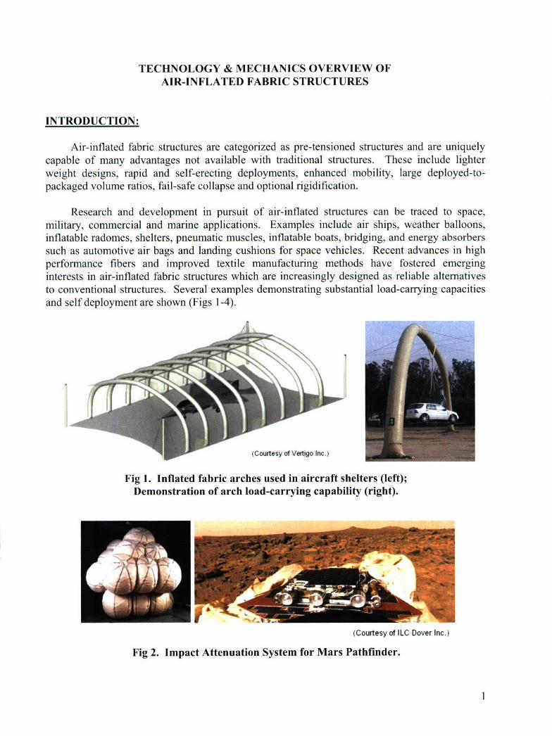
Air-inflated fabric structures are categorized as pre-tensioned structures and are uniquelycapable of many advantages not available with traditional structures. These include lighterweight designs, rapid and self-erecting deployments, enhanced mobility, large deployed-to-packaged volume ratios, fail-safe collapse and optional rigidification.
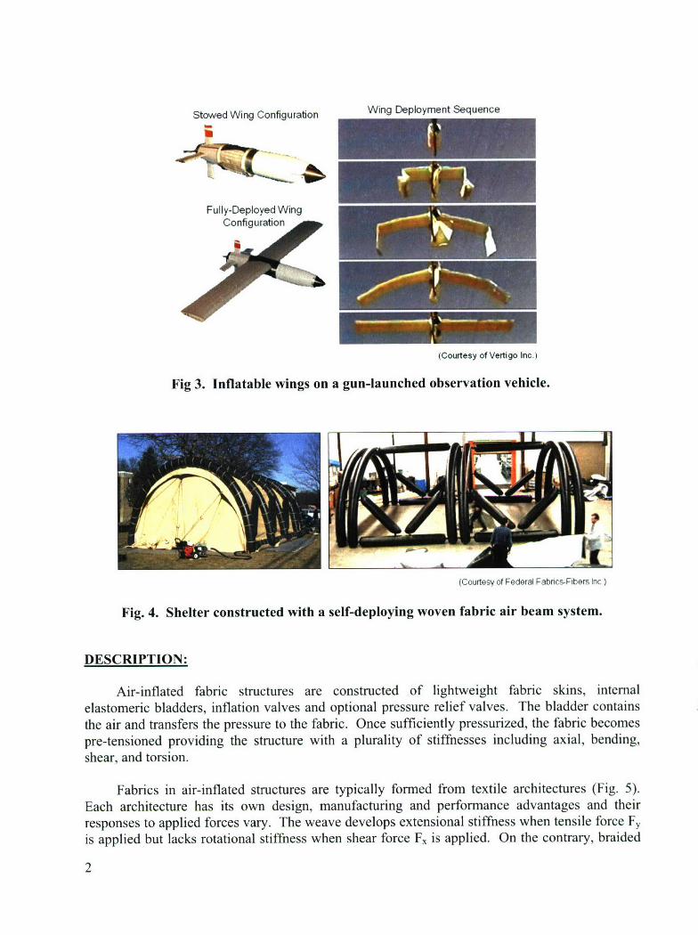
Research and development in pursuit of air-inflated structures can be traced to space,military, commercial and marine applications. Examples include air ships, weather balloons,inflatable radomes, shelters, pneumatic muscles, inflatable boats, bridging, and energy absorberssuch as automotive air bags and landing cushions for space vehicles. Recent advances in highperformance fibers and improved textile manufacturing methods have fostered emerginginterests in air-inflated fabric structures which are increasingly designed as reliable alternativesto conventional structures. Several examples demonstrating substantial load-carrying capacitiesand self deployment are shown (Figs 1-4).
(Courtesy of Vertigo Inc.)
Fig 1. Inflated fabric arches used in aircraft shelters (left);Demonstration of arch load-carrying capability (right).
(Courtesy of ILC Dover Inc.)
Fig 2. Impact Attenuation System for Mars Pathfinder.
Stowed Wing Configuration Wing Deployment Sequence
Fully-Deployed WingConfiguration
(Courtesy of Vertigo Inc.)
Fig 3. Inflatable wings on a gun-launched observation vehicle.
(Courtesy of Federal Fabrics-Fibers nc)
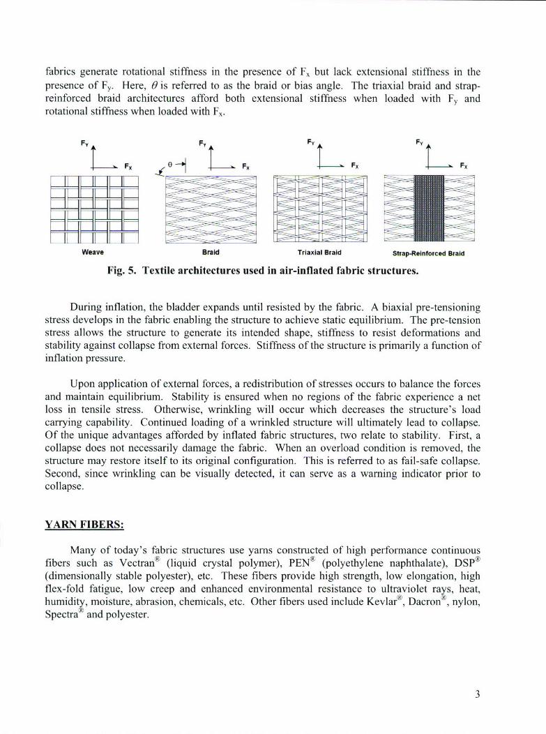
Fig. 4. Shelter constructed with a self-deploying woven fabric air beam system.
DESCRIPTION:
Air-inflated fabric structures are constructed of lightweight fabric skins, internalelastomeric bladders, inflation valves and optional pressure relief valves. The bladder containsthe air and transfers the pressure to the fabric. Once sufficiently pressurized, the fabric becomespre-tensioned providing the structure with a plurality of stiffnesses including axial, bending,shear, and torsion.
Fabrics in air-inflated structures are typically formed from textile architectures (Fig. 5).Each architecture has its own design, manufacturing and performance advantages and theirresponses to applied forces vary. The weave develops extensional stiffness when tensile force Fyis applied but lacks rotational stiffness when shear force F, is applied. On the contrary, braided
2
fabrics generate rotational stiffness in the presence of Fx but lack extensional stiffness in thepresence of Fy. Here, 0 is referred to as the braid or bias angle. The triaxial braid and strap-reinforced braid architectures afford both extensional stiffness when loaded with Fy androtational stiffness when loaded with F,.
F0 F
Fy FX FyFX
Weave Braid Triaxial Braid Strap-ReInforced Braid
Fig. 5. Textile architectures used in air-inflated fabric structures.
During inflation, the bladder expands until resisted by the fabric. A biaxial pre-tensioningstress develops in the fabric enabling the structure to achieve static equilibrium. The pre-tensionstress allows the structure to generate its intended shape, stiffness to resist deformations andstability against collapse from external forces. Stiffness of the structure is primarily a function ofinflation pressure.
Upon application of external forces, a redistribution of stresses occurs to balance the forcesand maintain equilibrium. Stability is ensured when no regions of the fabric experience a netloss in tensile stress. Otherwise, wrinkling will occur which decreases the structure's loadcarrying capability. Continued loading of a wrinkled structure will ultimately lead to collapse.Of the unique advantages afforded by inflated fabric structures, two relate to stability. First, acollapse does not necessarily damage the fabric. When an overload condition is removed, thestructure may restore itself to its original configuration. This is referred to as fail-safe collapse.Second, since wrinkling can be visually detected, it can serve as a warning indicator prior tocollapse.
YARN FIBERS:
Many of today's fabric structures use yarns constructed of high performance continuousfibers such as Vectran® (liquid crystal polymer), PEN® (polyethylene naphthalate), DSP®(dimensionally stable polyester), etc. These fibers provide high strength, low elongation, highflex-fold fatigue, low creep and enhanced environmental resistance to ultraviolet rays, heat,humidity, moisture, abrasion, chemicals, etc. Other fibers used include Kevlar®, Dacron"®, nylon,Spectra and polyester.
3
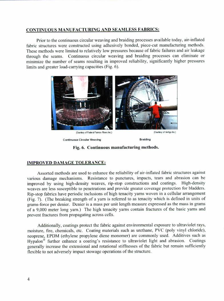
CONTINUOUS MANUFACTURING AND SEAMLESS FABRICS:
Prior to the continuous circular weaving and braiding processes available today, air-inflatedfabric structures were constructed using adhesively bonded, piece-cut manufacturing methods.These methods were limited to relatively low pressures because of fabric failures and air leakagethrough the seams. Continuous circular weaving and braiding processes can eliminate orminimize the number of seams resulting in improved reliability, significantly higher pressureslimits and greater load-carrying capacities (Fig. 6).
(Cowlsy of Federal Fabris-Fibers W.c) (Cox"s of Vertqo kvzc)
Continuous Circular Weaving Braiding
Fig. 6. Continuous manufacturing methods.
IMPROVED DAMAGE TOLERANCE:
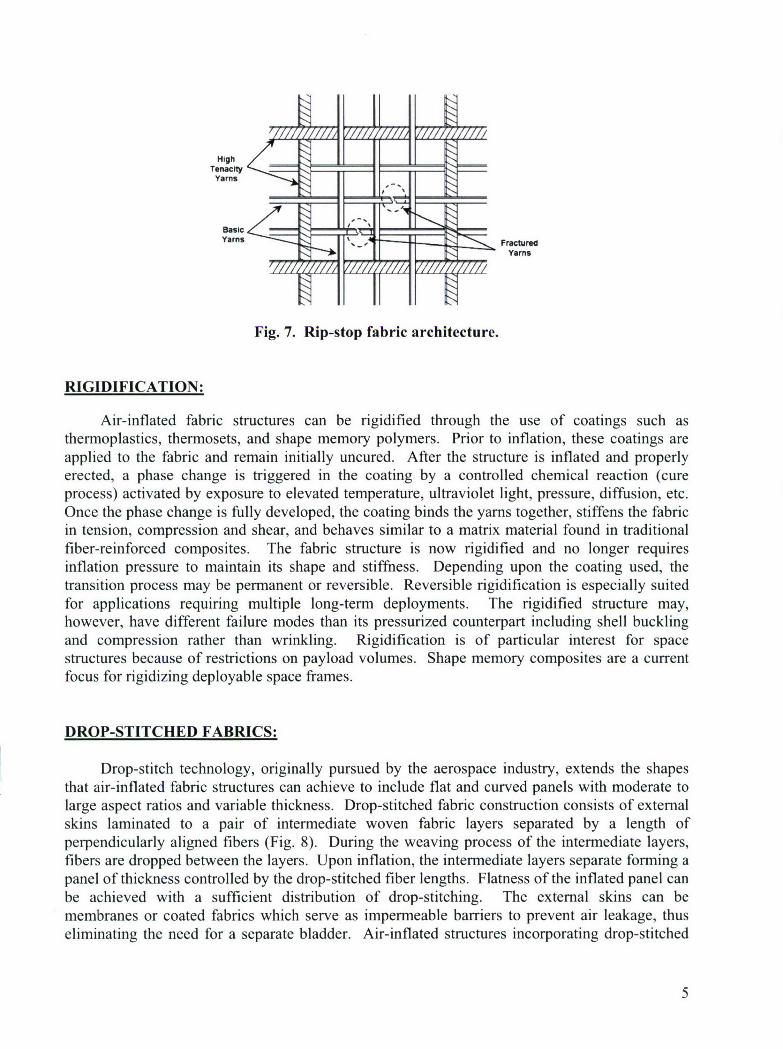
Assorted methods are used to enhance the reliability of air-inflated fabric structures againstvarious damage mechanisms. Resistance to punctures, impacts, tears and abrasion can beimproved by using high-density weaves, rip-stop constructions and coatings. High-densityweaves are less susceptible to penetrations and provide greater coverage protection for bladders.Rip-stop fabrics have periodic inclusions of high tenacity yams woven in a cellular arrangement(Fig. 7). (The breaking strength of a yam is referred to as tenacity which is defined in units ofgrams-force per denier. Denier is a mass per unit length measure expressed as the mass in gramsof a 9,000 meter long yam.) The high tenacity yams contain fractures of the basic yams andprevent fractures from propagating across cells.
Additionally, coatings protect the fabric against environmental exposure to ultraviolet rays,moisture, fire, chemicals, etc. Coating materials such as urethane, PVC (poly vinyl chloride),neoprene, EPDM (ethylene propylene diene monomer) are commonly used. Additives such asHypalon® further enhance a coating's resistance to ultraviolet light and abrasion. Coatingsgenerally increase the extensional and rotational stiffnesses of the fabric but remain sufficientlyflexible to not adversely impact stowage operations of the structure.
4
HighTenacity
Yarns
Yams -FracturedYams
Fig. 7. Rip-stop fabric architecture.
RIGIDIFICATION:
Air-inflated fabric structures can be rigidified through the use of coatings such asthermoplastics, thermosets, and shape memory polymers. Prior to inflation, these coatings areapplied to the fabric and remain initially uncured. After the structure is inflated and properlyerected, a phase change is triggered in the coating by a controlled chemical reaction (cureprocess) activated by exposure to elevated temperature, ultraviolet light, pressure, diffusion, etc.Once the phase change is fully developed, the coating binds the yams together, stiffens the fabricin tension, compression and shear, and behaves similar to a matrix material found in traditionalfiber-reinforced composites. The fabric structure is now rigidified and no longer requiresinflation pressure to maintain its shape and stiffness. Depending upon the coating used, thetransition process may be permanent or reversible. Reversible rigidification is especially suitedfor applications requiring multiple long-term deployments. The rigidified structure may,however, have different failure modes than its pressurized counterpart including shell bucklingand compression rather than wrinkling. Rigidification is of particular interest for spacestructures because of restrictions on payload volumes. Shape memory composites are a currentfocus for rigidizing deployable space frames.
DROP-STITCHED FABRICS:
Drop-stitch technology, originally pursued by the aerospace industry, extends the shapesthat air-inflated fabric structures can achieve to include flat and curved panels with moderate tolarge aspect ratios and variable thickness. Drop-stitched fabric construction consists of externalskins laminated to a pair of intermediate woven fabric layers separated by a length ofperpendicularly aligned fibers (Fig. 8). During the weaving process of the intermediate layers,fibers are dropped between the layers. Upon inflation, the intermediate layers separate forming apanel of thickness controlled by the drop-stitched fiber lengths. Flatness of the inflated panel canbe achieved with a sufficient distribution of drop-stitching. The external skins can bemembranes or coated fabrics which serve as impermeable barriers to prevent air leakage, thuseliminating the need for a separate bladder. Air-inflated structures incorporating drop-stitched
5
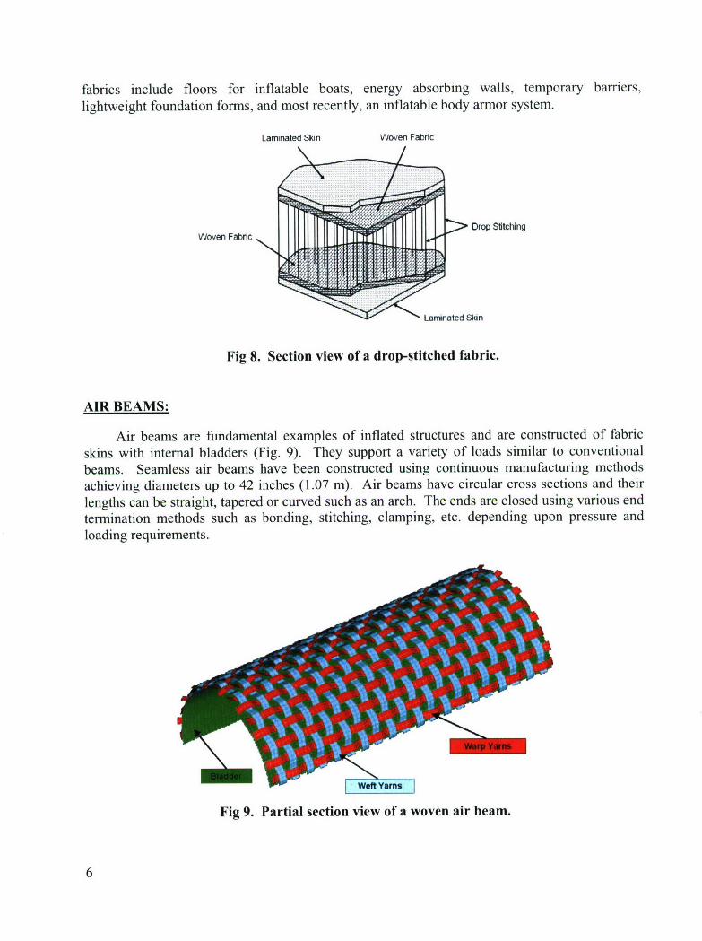
fabrics include floors for inflatable boats, energy absorbing walls, temporary barriers,lightweight foundation forms, and most recently, an inflatable body armor system.
Laminated Skin Woven Fabric
W Drop StitchngWoven Fabric
Larninated Skin
Fig 8. Section view of a drop-stitched fabric.
AIR BEAMS:
Air beams are fundamental examples of inflated structures and are constructed of fabricskins with internal bladders (Fig. 9). They support a variety of loads similar to conventionalbeams. Seamless air beams have been constructed using continuous manufacturing methodsachieving diameters up to 42 inches (1.07 m). Air beams have circular cross sections and theirlengths can be straight, tapered or curved such as an arch. The ends are closed using various endtermination methods such as bonding, stitching, clamping, etc. depending upon pressure andloading requirements.
Fig 9. Partial section view of a woven air beam.
6
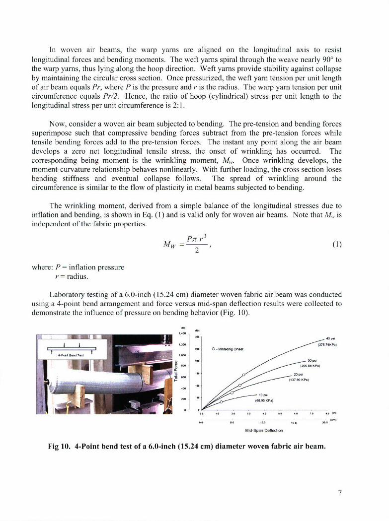
In woven air beams, the warp yams are aligned on the longitudinal axis to resistlongitudinal forces and bending moments. The weft yarns spiral through the weave nearly 900 tothe warp yams, thus lying along the hoop direction. Weft yarns provide stability against collapseby maintaining the circular cross section. Once pressurized, the weft yam tension per unit lengthof air beam equals Pr, where P is the pressure and r is the radius. The warp yam tension per unitcircumference equals Pr/2. Hence, the ratio of hoop (cylindrical) stress per unit length to thelongitudinal stress per unit circumference is 2:1.
Now, consider a woven air beam subjected to bending. The pre-tension and bending forcessuperimpose such that compressive bending forces subtract from the pre-tension forces whiletensile bending forces add to the pre-tension forces. The instant any point along the air beamdevelops a zero net longitudinal tensile stress, the onset of wrinkling has occurred. Thecorresponding being moment is the wrinkling moment, Mw. Once wrinkling develops, themoment-curvature relationship behaves nonlinearly. With further loading, the cross section losesbending stiffness and eventual collapse follows. The spread of wrinkling around thecircumference is similar to the flow of plasticity in metal beams subjected to bending.
The wrinkling moment, derived from a simple balance of the longitudinal stresses due toinflation and bending, is shown in Eq. (1) and is valid only for woven air beams. Note that M, isindependent of the fabric properties.
MW = P~r r3
2
where: P = inflation pressurer = radius.
Laboratory testing of a 6.0-inch (15.24 cm) diameter woven fabric air beam was conductedusing a 4-point bend arrangement and force versus mid-span deflection results were collected todemonstrate the influence of pressure on bending behavior (Fig. 10).
PN)
1 .Ano 40 p
No• 126.4 KPa)
:tM ~ ~ ~ 2 P WntMO•
0144
0 0O.* 10 2r 0 3 4 1 $0 $6 0 9* 80 0
0.0 to0 10.0 150 0.0
Mid-Span Deflection
Fig 10. 4-Point bend test of a 6.0-inch (15.24 cm) diameter woven fabric air beam.
7
EFFECTS OF AIR COMPRESSIBILITY:
The load-deflection response may depend upon stiffening sources other than initial
inflation pressure. If appreciable changes in pressure or volume occur, as for energy absorbers,
work is performed on the air through compressibility. Air compressibility can be modeled from
thermodynamic principles according to the Ideal Gas Law of Eq. (2).
P V = mRT, (2)
where: P = absolute pressureV = volumem = mass of airR = gas constant for airT = absolute temperature ('K).
For a quasi-static, isothermal process, the work done on the air is:
V2 V2 V2Wi = fPdV =fRTV= m R n .(3)wair trJA- 1If
I V Vl
The total energy, Eto,,i, is the work done by external forces, Wext, which is related to the
total strain energy of the fabric, Uf, and Wair as shown in the energy balance of Eq. (4).
EtotaI = Wext = U f + Wair. (4)
If volume changes are large, Uf may be negligible, Wair will dominate the energy balanceand deflections can be readily computed.
BIBLIOGRAPHY:
Bulson, P. S., "Design Principles of Pneumatic Structures," The Structural Engineer, Vol. 51,No. 6, June 1973.
Cavallaro, P., A. Sadegh, M. Johnson, "Mechanics of Plain-Woven Fabrics for InflatedStructures," Journal of Composite Structures, Vol. 61(4), 2003, pp 375-393.
Cavallaro, P., C. Quigley, A. Johnson, A. Sadegh, "Effects of Coupled Biaxial Tension andShear Stresses on Decrimping Behavior in Pressurized Woven Fabrics," 2004 ASMEInternational Mechanical Engineering Congress and Exposition, Anaheim, CA,
November 13, 2004, IMECE2004-59848, 2004.
Fichter, W. B., "A Theory for Inflated Thin-Wall Cylindrical Beams," NASA Technical Note D-3466, National Aeronautics and Space Administration, Washington, DC, 1966.
8
Freeston, W. D., M. M. Platt, M. M., Schoppee, "Mechanics of Elastic Performance of TextileMaterials, Part XVIII, Stress-Strain Response of Fabrics Under Two-DimensionalLoading," Textile Research Journal, Vol. 37, 1967, pp 948-975.
Fung, W., Coated and Laminated Textiles, Woodhead Publishing, 2002.
Hearle, J.W.S., et al., Structural Mechanics of Fibers, Yarns and Fabrics, John Wiley & Sons,Inc., New York, 1969.
Hearle, J.W.S., High Performance Fibres, Woodhead Publishing, 2001.
Steeves, E.C., "The Structural Behavior of Pressure Stabilized Arches," Technical Report 78/018(AD-A063263), United States Army, Soldier Biological Chemical Command, Natick,MA, 1978.
ADDITIONAL READINGS/WEBSITES:
Army Center of Excellence for Inflatable Composite Structures, Natick, MA,http://nsc.natick.army.mil/media/fact/facilities/ICS.htm.
Vertigo Inc., Lake Elsinore, CA, www.vertigo.aero.com.
ILC-Dover, Dover, DE, www.ilcdover.com.
Federal Fabrics-Fibers, Lowell, MA, www.federalfabrics.com.
Cadogan; D.P., S. E. Scarborough, J. K. H. Lin, G. H. Sapna III,G.H., "Shape MemoryComposite Development for Use in Gossamer Space Inflatable Structures," AmericanInstitute of Aeronautics and Astronautics, AIAA 2002-1372.
U.S. Patent No. 5,677,023, "Reinforced Fabric Inflatable Tube."
U.S. Patent No. 6,910,308 by D. P. Cadogan, S. E. Scarborough, J. K. H. Lin, G. H. Sapna III.
U.S. Patent No. 6,997,218, "Inflatable Body Armor System."
TRADEMARKS:
"* Kevlar®, Dacron® and Hypalon® are registered trademarks of DuPont Co."* Vectran® is a registered trademark of Celanese Acetate."* DSP® is a registered trademark of Performance Fibers Co."* PEN® and Spectra® are registered trademarks of Honeywell Inc.
See also: Inflatable Structure, Pressure Stabilized Structure, Tensioned Structure, Textile,Fabric Mechanics.
9 (10 blank)
REPORT DOCUMENTATION PAGE I Form ApprovedR OMB No. 0704-0188
Public reporting for this collection of Information Is estimated to average 1 hour per response, Including the time for reviewing instructions, searching existing data sources, gathering andmaintaining the data needed, and completing and reviewing the collection of information. Send comments regarding this burden estimate or any other aspect of this collection ofinformation, including suggestions for reducing this burden, to Washington Headquarters Services, Directorate for Information Operations and Reports, 1215 Jefferson Davis Highway,Suite 1204, Arlington, VA 22202-4302, and to the Office of Management and Budget, Paperwork Reduction Project (0704-0188), Washington, DC 20503.
1. AGENCY USE ONLY (Leave blank) 2. REPORT DATE 3. REPORT TYPE AND DATES COVERED4 December 2006
4. TITLE AND SUBTITLE 5. FUNDING NUMBERS
Technology & Mechanics Overview of Air-Inflated Fabric Structures P744007
6. AUTHOR(S)
Paul V. Cavallaro
7. PERFORMING ORGANIZATION NAME(S) AND ADDRESS(ES) 8. PERFORMING ORGANIZATION
Naval Undersea Warfare Center Division REPORT NUMBER
1176 Howell Street RR 11,784Newport, RI 02841-1708
9. SPONSORING/MONITORING AGENCY NAME(S) AND ADDRESS(ES) 10. SPONSORING/MONITORINGAGENCY REPORT NUMBER
11. SUPPLEMENTARY NOTES
Reprint of a chapter in 2007 Yearbook of Science & Technology, McGraw-Hill, New York, NY, 2006.
12a. DISTRIBUTION/AVAILABILITY STATEMENT 12b. DISTRIBUTION CODE
Approved for public release; distribution is unlimited.
13. ABSTRACT (Maximum 200 words)
Air-inflated fabric structures are categorized as pre-tensioned structures and are uniquely capable of many advantages not availablewith traditional structures. These include lighter weight designs, rapid and self-erecting deployments, enhanced mobility, largedeployed-to-packaged volume ratios, fail-safe collapse and optional rigidification.
Research and development in pursuit of air-inflated structures can be traced to space, military, commercial and marine applications.Examples include air ships, weather balloons, inflatable radomes, shelters, pneumatic muscles, inflatable boats, bridging, and energyabsorbers such as automotive air bags and landing cushions for space vehicles. Recent advances in high performance fibers andimproved textile manufacturing methods have fostered emerging interests in air-inflated fabric structures which are increasinglydesigned as reliable alternatives to conventional structures.
14. SUBJECT TERMS 15. NUMBER OF PAGESInflated fabric structures Air Beams Air Compressibility Drop-Stitched Fabric Inflatable WingsTextile Architectures Optional Rigidification High Performance Fibers 16. PRICE CODESeamless Fabrics Damage Tolerance Yarn Fibers
17. SECURITY 18. SECURITY 19. SECURITY 20. LIMITATION OFCLASSIFICATION CLASSIFICATION CLASSIFICATION ABSTRACT
OF REPORT OF THIS PAGE OF ABSTRACTUnclassified Unclassified Unclassified SAR
NSN 7540-01-280-5500 Standard Form 298 (Rev. 2-89)Pescribed by ANSI Std. Z39-18
298-102
INITIAL DISTRIBUTION LIST
Addressee No. of Copies
Defense Technical Center U2