Embed Size (px)
Citation preview
ISSN 0747�9239, Seismic Instruments, 2012, Vol. 48, No. 1, pp. 85–91. © Allerton Press, Inc., 2012.Original Russian Text © V.B. Dubovskoi, V.I. Leont’ev, A.V. Sbitnev, V.G. Pshenyanik, 2011, published in Seismicheskie Pribory, 2011, pp. 59–69.
85
The advancement of space research and inertialnavigation systems requires a considerable increase inthe accuracy and sensitivity of acceleration sensorsand the elaboration of methods for their approval. Theincrease in resolution of a microaccelerometer up to10–8–10–9 g (g is the acceleration of gravity) and theobtainment of its scaled coefficient with the absoluteaccuracy 10–3% pose a number of radically new scien�tific and engineering problems before the instrumentmaking industry.
Until very recently, accelerometers were generallydesigned in the context of expanding their dynamicrange and frequency band. The construction of instru�ments of a higher class is possible only with the use ofexperience, which has been gained by the geophysicalindustry during half a century. In the last 20–30 years,highly sensitive instruments were devised capable ofregistering both values and variations of gravity andinclinations of the Earth’s crust.
At the same time, the use of advancements in thefield of electronics and automatics together with theemployment of new materials and new methods forinformation processing, allow one to outline prospectsfor upgrading the metrological performance of low�frequency accelerometers and to expand their applica�tion field. The improvement of the accelerometerapparatus is inextricably entwined with the evolutionof theoretical and experimental foundations of themeasurement assurance and construction of accelera�tion sensors with regard to the progress of methods forstandardization and alignment.
The construction of low�frequency highly sensitiveacceleration sensors (accelerometers, gravimeters,tiltmeters, and inclinometers) operating with the reso�
lution upwards of 10–9 g and within the frequency band0.1–0.001 Hz requires an in�depth theoretical studyand the consideration of various troubling factors suchas the action of temperature on sensing elements,interactions between crossed (in the form of the cross�coupling effect) high�frequency accelerations, tem�perature dependences of metrological characteristics,hysteresis phenomena, and elastic aftereffects. Thesefactors call for extra thermal and antivibration protec�tion along with the optimization of electromechanicand electronic circuits.
A rather diverse assortment of instrumentations formeasuring constant and variable velocities and accel�erations based on various principles (locational,chemotronic, gyroscopic, etc.) (Ishlinskii, 1976,1985) is shown by the analysis of domestic and foreignstudies devoted to the problem of measuring trajectoryparameters of mobile objects to be developed andwidely applied by now. Among them, the inertialinstruments—low�frequency inertial accelerometerspossessing a higher accuracy, interference immunity,and relatively low dependence on external factors—seems to hold the lead, and with some good reasons(Braslavskii, 1970; Ishlinskii, 1976). However, despitethe fact that it was formulated as early as the 1920s–1930s, the idea of constructing inertial accelerometerswas not practically implemented until the 1950s (Ish�linskii, 1985).
It is from then on that the method underwent tre�mendous progress both in theoretical and technicalaspects for the measurement range of small andminute quantities. A wide assortment of various accel�erometers widely used in inertial control and naviga�tion systems was eventually created (Braslavskii, 1970;
Technology of the Construction of Microaccelerometersfor Automatic Spacecraft and the Sphere of Their Application
V. B. Dubovskoia, V. I. Leont’eva, A. V. Sbitneva, and V. G. Pshenyanikb
aSchmidt Institute of Physics of the Earth, Russian Academy of Sciences, ul. Bol'shaya Gruzinskaya 10, Moscow, 123995 Russiae�mail: [email protected]
bMaksimov Space Systems Research and Development Institute, Khrunichev State Research and Production Space Center,ul. Tikhonravova 36, Yubilyeinyi, Moscow Obl., 141091 Russia
e�mail: [email protected]
Abstract—Problems of constructing microaccelerometers with the maximally possible resolution are exam�ined, the principles of their construction and the state of modern developments are discussed, and the way ofsubstantially improving their principal characteristics is considered. The wide range of scientific and appliedproblems solved by the application of highly sensitive microaccelerometers is investigated.
Keywords: microaccelerometer, accuracy, construction.
DOI: 10.3103/S0747923912010045
86
SEISMIC INSTRUMENTS Vol. 48 No. 1 2012
DUBOVSKOI et al.
Orientatsiya …, 2006). At the same time, we have acompletely different situation in regard to the mea�surement range of small and minute quantities. Thereason is that a considerable enhancement (by five,six, or more orders) in sensitivity of inertial instru�ments requires extreme efforts and costs. In particular,special design and technological solutions for creatingand manufacturing spacecraft microaccelerometerstogether with a full�scale deployment of the metrolog�ical assurance for measuring accelerations over a rangeof small and minute quantities are essential (Pushkars�kii, Krivotsyuk, and Pshenyanik, 2007).
Analysis of the main technical and metrologicalcharacteristics of the best known spacecraft microac�celerometers is performed; these characteristics werecollected and systematized from rather different, evenconflicting, sources. The analysis results allow us tonote the following.
Works toward the creation and employment ofspacecraft microaccelerometers have been going onfor more than a decade, they have been especiallyactive in foreign countries such as the United States,France, and the Czech Republic. In this respect, pro�gressive “evolutional” development of these measur�ing instruments is taking place. Early in the develop�ment of the instruments at hand, two methods forenhancing the sensitivity were formed. The firstmethod provided the enhancement at the cost of anincrease in mass, while the second method, byimproving the suspension system of sensing elements.
For example, the spacecrafts San Marco and Can�nonball actually were microaccelerometers with a con�siderable proof mass. In the case of the San Marco, amassive interior in the form of a central barrel with therods attached played the role of a sensing element. Asfor the Cannonball, this spacecraft was sphere�like inshape and had the mass of 363 kg, with the mass of thebrass outer shell corresponding to 308 kg.
At a later time, the method involving an increase inmass of the sensing element was outdated, it havingbeen proved to be obviously uneconomical. This canbe explained by the fact that the increase in sensitivityof an inertial measurer by one order results in a tenfoldincrease in the mass of a sensing element. Thus, themass of sensing elements of subsequent microacceler�ometers is relatively small (within the range of 30–570 g), with the general trend of maximal decrease inmass. The best efforts of designers are also directed tothe optimization of the sensing elements’ shape(largely used are elements in the shape of a sphere or acylinder), the selection of materials (it was found thata sensing element must have a high density and a zeromagnetic inductivity), the development of techniquesfor treatment and deposition of coatings, etc.
In essence, the aim of these works is directly asso�ciated with the second method of increasing themicroaccelerometer’s sensitivity, which involves theimprovement of the suspension system of a sensingelement (Orientatsiya …, 2006). Whereas initiatory
stages of the microaccelerometers’ construction useddirect�conversion suspension systems (Nazarov,1987), further development was focused on engineer�ing solutions based on the compensation of the sensingelement’s inertia by the force which can be measuredaccurately enough (Orientatsiya …, 2006); of all thetypes of sensing element suspensions, compensatoryelectrostatic suspensions are the most used.
A distinctive feature of spacecraft microaccelerom�eters is an extremely wide measuring range, whichamounts up to 3–4 orders. This is responsible for apronounced nonlinearity of the microaccelerometers’static characteristics and forces one to break down themain measuring range into subranges and calibrateeach of them individually.
The sensitivity threshold of the best microacceler�ometer models reaches from 10–8 to 10–9 g but is cor�roborated indirectly by the periodic adjustment ofmeasurement results after an appropriate processing.The declared sensitivity threshold from 10–11 to 10–13 gof the most up�to�date microaccelerometers (theMacek microaccelerometers for the Mimosa micro�satellite and microaccelerometers for the Demetermicro�satellite) is, in all appearances, an advertisinggimmick and thus far lacks support from any properevidence, the appropriate technical means for moni�toring their main metrological characteristics beingunavailable (at least, there is no information on thesubject in open sources).
It is worth noting that the monitoring of metrolog�ical characteristics of first�generation microacceler�ometers (for the spacecrafts San Marco and Cannon�ball) was actually carried out during the orbital flightonly and, being characterized by a rather low accuracyand completeness of the estimate, was reduced to theperiodic calibration of an instrument scale accordingto results of the radiomonitoring of the spacecrafts’orbit. On occasion, wherever possible, the calibrationwas performed by rotating the spacecraft’s body with acertain angular velocity followed by a stepwise dou�bling of the latter.
In the case of subsequent microaccelerometers,metrological examinations were performed under ter�restrial conditions using drop towers. The primary rea�son for using drop towers is related to the desire ofeliminating the influence of seismic noises on resultsof metrological examinations; these noises are muchmore intensive than reproducible small and minuteaccelerations inputted to the instruments being veri�fied and graded. The examination of the main techni�cal characteristics of the best known drop towersallows us to note the following.
The history of creating and using drop towers,beginning with common towers and zero�gravityfarms, numbers more than a decade. All these towersvary in both main technical characteristics and avail�ability of special supporting systems (deceleration,catapulting, pumping, etc.). These technical charac�teristics and various supporting systems determine the
SEISMIC INSTRUMENTS Vol. 48 No. 1 2012
TECHNOLOGY OF THE CONSTRUCTION OF MICROACCELEROMETERS 87
capabilities of towers in performing required tests andexperiments including metrological examinations ofmicroaccelerometers under terrestrial conditions.Thus, the drop towers provide the performance check,the control of zero setting, and the operational test fol�lowing the action of impact accelerations. It might bewise to point out that in the case of the drop towerlocated at the Center of Applied Space Technologyand Microgravity (ZARM), University of Bremen(Germany) and equipped with special recordinginstruments implementing relative measurements oftrajectory parameters of a falling platform with respectto the fixed base, one can calibrate the instrumentscale with subsequent obligatory correction of the testresults during the orbital flight using the data of theorbit’s radiomonitoring.
The need for such refinement stems from the factthat the method of relative measurements is an indirectmethod with all the inherent drawbacks and is largelysubjected to errors due to an imperfect base (primarilydue to its weak seismic noise tolerance). Therefore, theaccuracy of such terrestrial metrological examinationsis obviously inadequate particularly in view of the depthof involvement of all the metrological characteristics tobe normalized. Such a situation largely arises from thelack of methods and equipment for measuring actualtest stimuli inputted to the microaccelerometer securedto the calibration platform, with the platform being in afree drop mode in the drop tube which is under a certainpressure or vacuum.
Among domestic drop towers, the tower of the vac�uum�dynamic complex of the Federal State UnitaryEnterprise, Makeyev Design Bureau, State RocketCenter (the city of Miass), is considered to hold thegreatest promise for metrological examinations ofmicroaccelerometers owing to both technical capabil�ities and a special system of vacuumization to a depthof 0.001 mm hg. According to preliminary estimates,the tower enables one to use a special calibration plat�form, which provides the instrumental measurementof actual test stimuli inputted to the microaccelerom�eters being verified.
It has not been until recent years that the solutionof paramount scientific and technical problems hasbecome feasible due to advances in designing the long�functioning manned space stations and ferry ships.Investigations in the field of space material processingarise from the attempt to use an exotic environment,stemming from the motion of spacecrafts in low earthorbits, in manufacturing processes; the environmentinvolves, above all, long�term weightlessness, ambientdeep vacuum, high and low temperatures, and spaceradiation.
Under zero gravity conditions, certain well�knownphysics progress differently than they do under usualterrestrial conditions (on exposure to gravity). In thecase of zero gravity, there is no buoyancy force respon�sible for the layering of liquid substances with variousdensities, and the natural convection, resulting in the
displacement of layers of gases and fluids having dif�ferent temperatures, is weak. This provides greatpotential for both the production of brand new mate�rials under zero gravity conditions and the improve�ment of properties of existing materials.
In such conditions, the spatial confinement of amolten metal is possible without using a container;this provides freedom from contamination due to theingress of impurities from the container walls andresults in ultrapure substances. The behavior of fluidsunder zero gravity conditions is determined by surfacetension forces; this should be taken into account inaccomplishing even such usual work processes aswelding, soldering, or fusion.
Intermolecular forces playing a lead role underconditions in question and revealing themselves in theform of surface tension and capillarity can be used forshaping materials. Shaping is performed at the bound�ary of liquid and gas phases by modifying the free sur�face using the energy controlled by, for example, anelectric field.
The state of full weightlessness is an ideal conditionactually non�existent during space flight. In fact, thisstate is violated because of various small accelerationsaffecting the spacecraft. According to Newton’s sec�ond law, the occurrence of such accelerations impliesthat all the objects aboard the spacecraft are exposed tosmall mass forces and, as a consequence, the gravity�free state is violated.
The solution of various complex scientific andengineering problems directly depends on the accu�racy of measuring gravitational fields and accelera�tions emerging aboard the spacecraft. Therefore,exhaustive data on microaccelerations affecting theequipment and samples during engineering experi�ments are necessary for processing and analyzingresults. Research into the field of celestial mechanicsshows that the spacecraft placed into a geodesic orbitproceeds along a trajectory substantially different froma geodesic one, i.e., the spacecraft undergoesmicroaccelerations during the flight.
Investigations of relativistic gravitation effects whensatellites are moving around the Sun are currently beingcarried out. Such investigations can allow one to ascer�tain which modern relativistic gravitation theories (in anon�wave zone) offer more accurate description of thegravitational field. The Helios drift�free satellite (theSorel program) is called upon to measure effects such asthe electromagnetic pulse delay in the gravitational fieldof the Sun with the relative accuracy ~10–4, which is bytwo orders better than we have at the moment. Anexperiment to measure the effect of the satellite gyro�scope’s relativistic precession is also to be conducted onthe platform with a certain compensation of non�gravi�tational accelerations.
Dirac made his classical proposal concerning thevariability of the gravitation constant G (Dirac, 1937).According to estimates, the value corresponds to
88
SEISMIC INSTRUMENTS Vol. 48 No. 1 2012
DUBOVSKOI et al.
ΔG/G ~ 3 × 10–11 year–1. This effect can be measuredwith respect to the wander of the orbiting period of ageocentric drift�free satellite provided that the com�pensation level of its non�gravitational acceleration isno less than 1 × 10⁻⁸ cm/s2. As it will be clear from thesubsequent discussion, this compensation level is nottoo high.
Drift�free satellites can be used as the proofmassesincorporated into gravitational antennas meant fordetection of low�frequency gravitational waves. More�over, these satellites can play the role of nearly ideal (interms of freedom from microseisms) laboratories forthe accommodation of high�frequency gravitationalantennas.
Low�flying drift�free satellites will provide thedetermination (considering their orbital changes) ofnonhomogeneity in the mass distribution of the Earthand other planets with an observable atmosphere inthe same way it has been done in the case of the Moon.The drift�free satellites can also be employed in aeron�omy to determine local (considering individual orbitsegments) densities of the upper atmosphere. In thiscase, the signal controlling a correcting engine pro�vides the data on the atmosphere deceleration force.Nowadays the upper�atmosphere density is evaluatedby measuring orbital changes within a few circuits, i.e.,the orbital density is considerably averaged. In order tocreate stable medium�altitude orbits for the purpose ofsatellite navigation, a drift compensation system isalso required.
The development of an elastic suspension systemfor the instrument’s proofmass is one of the most chal�lenging tasks in designing highly sensitive accelerome�ters of the type in question. In this regard, the follow�ing problems should be solved:
(1) The selection of materials for braces taking intoaccount their physical and mechanical properties (sol�
dering without loss in strength, a minor elastic afteref�fect, strength characteristics, and the value of theopposing torque);
(2) The selection of protection against the suspen�sion breakage either by means of precision limiterswith micronic clearances (the best option) or using thecaging system shown by the long experience of work�ing with other instruments to result in a zero drift afterthe decaging;
(3) The calculation of all the suspension system’sparameters, which enable such sensitive instrumentsto perform validation in the presence of intensivemicroseismic and technogenic vibration noises and,most importantly, to maintain the functionality underterrestrial conditions.
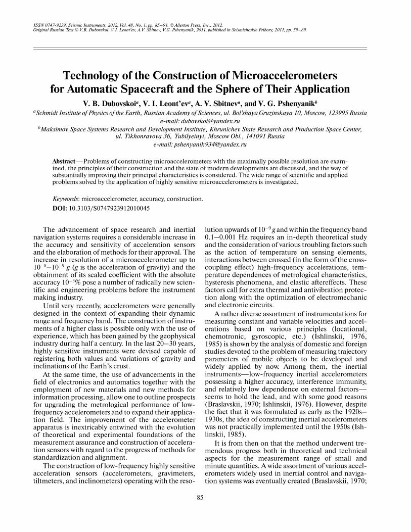
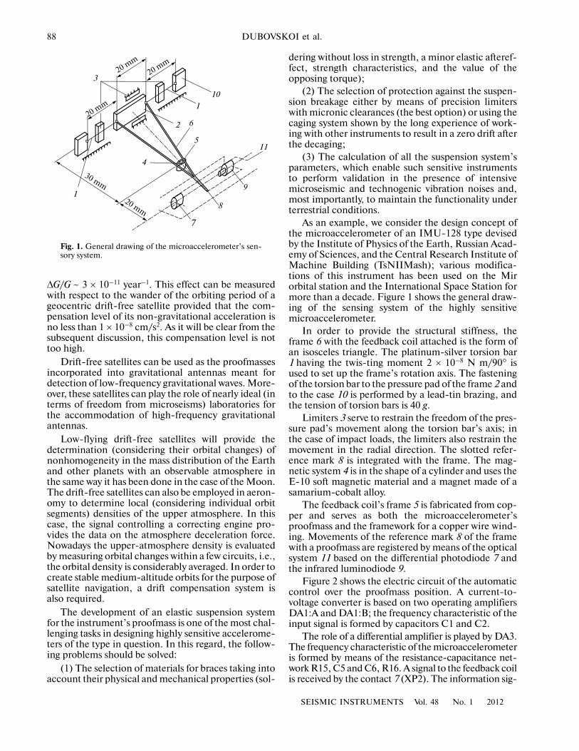
As an example, we consider the design concept ofthe microaccelerometer of an IMU�128 type devisedby the Institute of Physics of the Earth, Russian Acad�emy of Sciences, and the Central Research Institute ofMachine Building (TsNIIMash); various modifica�tions of this instrument has been used on the Mirorbital station and the International Space Station formore than a decade. Figure 1 shows the general draw�ing of the sensing system of the highly sensitivemicroaccelerometer.
In order to provide the structural stiffness, theframe 6 with the feedback coil attached is the form ofan isosceles triangle. The platinum�silver torsion bar1 having the twis�ting moment 2 × 10⁻⁸ N m/90° isused to set up the frame’s rotation axis. The fasteningof the torsion bar to the pressure pad of the frame 2 andto the case 10 is performed by a lead�tin brazing, andthe tension of torsion bars is 40 g.
Limiters 3 serve to restrain the freedom of the pres�sure pad’s movement along the torsion bar’s axis; inthe case of impact loads, the limiters also restrain themovement in the radial direction. The slotted refer�ence mark 8 is integrated with the frame. The mag�netic system 4 is in the shape of a cylinder and uses theE�10 soft magnetic material and a magnet made of asamarium�cobalt alloy.
The feedback coil’s frame 5 is fabricated from cop�per and serves as both the microaccelerometer’sproofmass and the framework for a copper wire wind�ing. Movements of the reference mark 8 of the framewith a proofmass are registered by means of the opticalsystem 11 based on the differential photodiode 7 andthe infrared luminodiode 9.
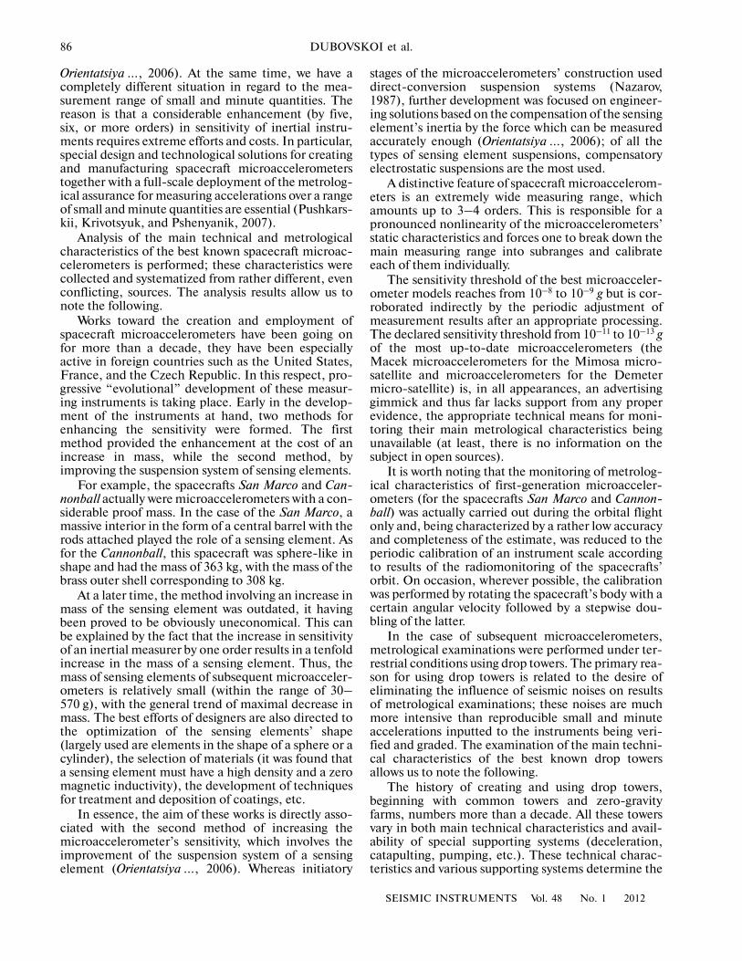
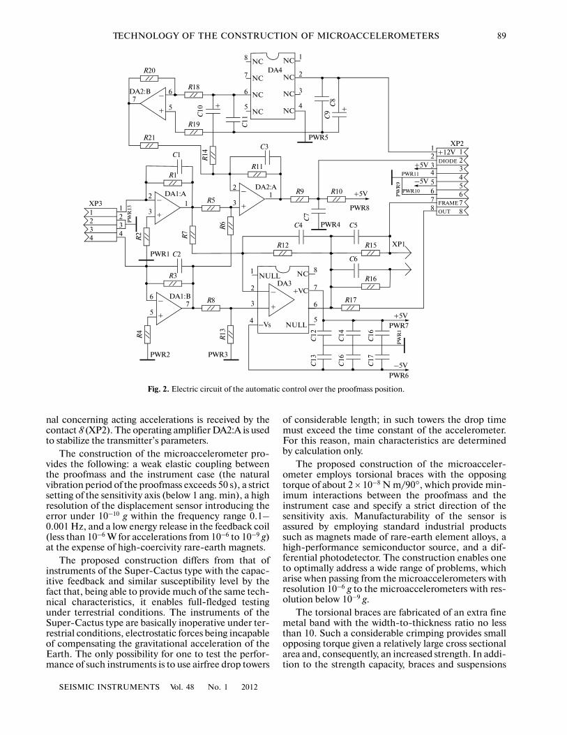
Figure 2 shows the electric circuit of the automaticcontrol over the proofmass position. A current�to�voltage converter is based on two operating amplifiersDA1:A and DA1:B; the frequency characteristic of theinput signal is formed by capacitors C1 and C2.
The role of a differential amplifier is played by DA3.The frequency characteristic of the microaccelerometeris formed by means of the resistance�capacitance net�work R15, C5 and C6, R16. A signal to the feedback coilis received by the contact 7 (XP2). The information sig�
1
30 mm
20 mm
4
7
8
9
115
6
1
2
10
320 m
m
20 mm
20 mm
Fig. 1. General drawing of the microaccelerometer’s sen�sory system.
SEISMIC INSTRUMENTS Vol. 48 No. 1 2012
TECHNOLOGY OF THE CONSTRUCTION OF MICROACCELEROMETERS 89
nal concerning acting accelerations is received by thecontact 8 (XP2). The operating amplifier DA2:A is usedto stabilize the transmitter’s parameters.
The construction of the microaccelerometer pro�vides the following: a weak elastic coupling betweenthe proofmass and the instrument case (the naturalvibration period of the proofmass exceeds 50 s), a strictsetting of the sensitivity axis (below 1 ang. min), a highresolution of the displacement sensor introducing theerror under 10–10 g within the frequency range 0.1–0.001 Hz, and a low energy release in the feedback coil(less than 10–6 W for accelerations from 10–6 to 10–9 g)at the expense of high�coercivity rare�earth magnets.
The proposed construction differs from that ofinstruments of the Super�Cactus type with the capac�itive feedback and similar susceptibility level by thefact that, being able to provide much of the same tech�nical characteristics, it enables full�fledged testingunder terrestrial conditions. The instruments of theSuper�Cactus type are basically inoperative under ter�restrial conditions, electrostatic forces being incapableof compensating the gravitational acceleration of theEarth. The only possibility for one to test the perfor�mance of such instruments is to use airfree drop towers
of considerable length; in such towers the drop timemust exceed the time constant of the accelerometer.For this reason, main characteristics are determinedby calculation only.
The proposed construction of the microacceler�ometer employs torsional braces with the opposingtorque of about 2 × 10⁻⁸ N m/90°, which provide min�imum interactions between the proofmass and theinstrument case and specify a strict direction of thesensitivity axis. Manufacturability of the sensor isassured by employing standard industrial productssuch as magnets made of rare�earth element alloys, ahigh�performance semiconductor source, and a dif�ferential photodetector. The construction enables oneto optimally address a wide range of problems, whicharise when passing from the microaccelerometers withresolution 10–6 g to the microaccelerometers with res�olution below 10–9 g.
The torsional braces are fabricated of an extra finemetal band with the width�to�thickness ratio no lessthan 10. Such a considerable crimping provides smallopposing torque given a relatively large cross sectionalarea and, consequently, an increased strength. In addi�tion to the strength capacity, braces and suspensions
R18
R20
–
+
6
57
++
R21
R19
C10
C1
C11
DA2:B
8
7
6
5
NC
NC
NC
NC
1
2
3
4
NC
NC
NC
NC
DA4
PWR5
C9
C8
C3
R11
R14
R1
–
+
2
31
DA2:AR9 R10
–
+
2
31
DA1:AR
7
R6
R2
R5
2
3
1
4
NULL
–Vs
8NC
7
6
5
+VC
NULL
–
+
DA3
–
+
6
57
DA1:BR8
R13
C2
R3
R12 R15
C4 C5
C6
R16
R17
C12
C14
C16
C7
PWR4
PWR8
+5V
+5VPWR11
–5VPWR10
PW
R9
78
654321
XP2
78
654321+12V
DIODE
FRAME
OUT
C13
C16
C17
PWR2 PWR3
–5V
+5V
PWR7
PWR6
PW
R1
R4
XP1
PWR1
PW
R13
XP3
4321
4321
Fig. 2. Electric circuit of the automatic control over the proofmass position.

90
SEISMIC INSTRUMENTS Vol. 48 No. 1 2012
DUBOVSKOI et al.
should possess a corrosion resistance and small elasticand residual aftereffects, i.e., they should provide thereturn of a moving element to the normal position fol�lowing the interruption of a controllable current.Braces are generally used to supply the current to themoving element’s frame. Solderability is a mandatoryrequirement imposed upon braces, suspensions, andcurrent leads of galvanometric instruments.
Instruments use braces of two types: one made of aplatinum�silver alloy (type G) and another made of aberyllium bronze (type B). In recent years, the moreeasily producible platinum–nickel braces made of aPlN23 alloy gradually replaced the platinum–silverbraces. In the case of the braces 100 mm in length,GOST 9444�74 standardizes the opposing torque Mwhen twisting through 90° and having the tensionforce Q0. The brace brings into existence the specificopposing torque
The ratio 57.3 : 90 results in the twist angle of 1 rad; l1
and l2 are the braces’ lengths expressed in millimeters.If l1 = l2 = l, then
Equations for WM0 are valid if the brace tension Qcorresponds to 20–30% of the breaking stress. At thesame time, the instrument’s tolerance for mechanicaldisturbances increases with increasing tension. There�fore, the B�type braces are used if tension forces Q cor�respond to 35–40% of the breaking stress Qbreak, andthe G�type braces are used if tension forces Q corre�spond to 40–50% of Pbreak. The specific opposingtorque is as follows:
where Q0 is the tension force whereby the braces char�acteristics are normalized. For Q > Q0, the moment isWM > WM0.
With brace lengths l1 and l2 being less than 100 mmand opposing torques generated by these braces beingadded up, the value of WM always exceeds values of M.
The elastic aftereffect manifests itself in the factthat after the deviation from equilibrium followed bythe removal of the force responsible for this deviationthe brace or suspension fall short of the starting posi�tion by only a slight angle. The elastic aftereffect typi�cally lasts for a few minutes during which the brace orsuspension returns to the starting position ever soslowly; then, the aftereffect fades away. In the case ofB�type braces, the elastic aftereffect determinedwithin 15 s after the removal of the steering effort iswithin 0.12–0.15%; in the case of G�type braces, theelastic aftereffect determined under the same condi�tions corresponds to 0.05–0.08%. Braces having a
WM0 M57.390
�������� 100l1
������� 100l2
�������+⎝ ⎠⎛ ⎞ 64M 1
l1
�� 1l2
��+⎝ ⎠⎛ ⎞ .= =
WM0 128Ml
����.=
WM WM0 1 0.75Q Q0–Qbreak
�������������+⎝ ⎠⎛ ⎞ ,=
small opposing torque possess a more limited elasticaftereffect as compared with relatively coarse braces.
The elastic aftereffect occurs only following theaction of efforts of twisting the brace or suspensionthrough the angle exceeding the proportional limit,i.e., de facto in the emergency situation. A particularbrace type is chosen from the given list of torsion barsdepending on the modification of an instrument andits specific purpose.
At this development phase, it is preferable to usethe platinum–silver ones, these braces being the moststable (possess a small elastic aftereffect), having amore limited opposing torque, being no different fromother types in terms of durability, and being solderedwithout loss of durability. In addition, a considerationmust be given to the fact that at the first approximationthe magnitude of the elastic aftereffect is proportionalto the torsion bar creeping which is responsible for thelong�term zero stability of an accelerometer.
The sag of the proofmass h under the action ofgravity must not exceed the level 0.5 relative to theamount of the coil clearance (corresponding to 1 mm)in the magnetic system. Having reasonable overalldimensions of an instrument, the length of either ofthe two braces should not exceed 20 mm. On this basis,the tension force FH of the braces is calculated consid�ering the adopted proofmass m = 2 g; the proofmass iscalculated from a thermodynamical noise whichshould be below 10–9 g
A particular brace, specifically, having the oppos�ing torque M = (1.8 – 2.0) × 10–8 N m/90° is furtherselected.
In designing an accelerometer with a specified res�olution, technical characteristics of the proofmass dis�placement sensor are determined by parameters of amechanical oscillating system and noises arising fromthe electronics of a mechanical�to�electrical energyconverter. Manufacturability of the system for settingand controlling the sensor’s mechanics and electron�ics also holds much significance.
In this regard, capacitive displacement sensors pos�sess high sensitivity; however, there are various tech�nological problems when manufacturing a sensorysystem, and more stringent requirements are placedupon parameters of the electric circuit. An opticalgrating displacement transducer based on the Michel�son interferometer is inapplicable in this case, suchsensors having considerable dimensions and weight.Use could be made of the optical sensor employing thelaser with a small diameter of light emission and theknife�edge method.
In the case of an experimental model of the accel�erometer, it is suggested to use a shuttle�type oscillat�ing system on torsional suspensions with a small elastictwisting moment. On exposure to statical and dynam�ical forces, a soft suspension ensures the proofmass to
FHmgl2h
�������> 40g.≈
SEISMIC INSTRUMENTS Vol. 48 No. 1 2012
TECHNOLOGY OF THE CONSTRUCTION OF MICROACCELEROMETERS 91
be nearly unaffected. Since the operational test of theaccelerometer’s breadboard model will be conductedunder terrestrial conditions, the movement of theproofmass in a nonmetering direction will take placeover a wide range (up to a millimeter) due to a soft sus�pension. The optical grating displacement transducer,based on an infrared luminodiode or an injection laserdiode, of the differential photodiode (together withthe employment of the slit method), is optimal for usein the experimental model as a sensor of minor powermovements of the proofmass.
In the case of the accelerometer with sensitivityfrom 10–8 to 10–9 g, calculations show that movementnoises of a displacement sensor should be less than25 nm within the frequency band 0.1 Hz, and 2500 nmwithin the frequency band 0.01 Hz. Electric noises interms of the proofmass displacement must not exceedcited values.
The overall noise level involves noises of the sensorysystem’s mechanics and noises of the device’s elec�tronics. Let us consider the contribution of thermalvibrations to the overall noise level. We equate thethermal energy of noises and the vibrational energy ofthe sensory system:
where k = 1.38 × 10⁻²³ J/K is the Boltzmann constant;f0 is the natural oscillation frequency of the pendulum;T is the Kelvin temperature; a is the mean�squareacceleration; and m is the weight of the proofmass.
The equation provides the mean�square value ofnoises over the entire spectral range. For the bread�board model of the accelerometer, f0 = 2 Hz, m = 5 g,and the resolution of a measurable acceleration is a =7 × 10⁻¹⁰ g for T = 300°K.
Proper allowance must be made for the fact thatmost of the noise is concentrated in the vicinity of theresonance where the spectral characteristic of the sen�sor’s oscillations shows the boost inversely propor�tional to the attenuation coefficient γ. Taking this intoaccount, the spectral mean�square noise density iswithin the frequency range well below the resonantand can be written as follows:
Thus, in the case of the experimental model, theresolution 7 × 10⁻¹⁰ g within the low�frequency mea�suring range (0.1–0.001 Hz) is not improbable in the�ory and can be achieved.
CONCLUSIONS
In summary, it is reasonably safe to suggest that thetechnological base for constructing microaccelerome�ters with resolution 10–9 g is actually created. Thesemicroaccelerometers outperform off�the�shelf devicesin terms of sensitivity by two or three orders within thelow�frequency measuring range (0.1–0.001 Hz) andallow one to address a wide range of scientific andapplied problems. The proposed design concept offersa means for further improvement of instruments at theexpense of increasing the proofmass and upgrading adisplacement sensor.
REFERENCES
Pushkarskii, S.V., Krivotsyuk, V.I., and Pshenyanik, V.G.,On the Problem of Microaccelerometers Utilization inNavigational Spacecrafts, Tr. Vseross. nauchn.�tekh. konf.“Navigatsionnye sputnikovye sistemy i ikh rol’ i znachenie vzhizni sovremennogo cheloveka” (Proc. All�Russian Sci.Tech. Conf. Navigational Satellite System and TheirImportance for People of Today), Zheleznogorsk, 2007,pp. 248–250.Braslavskii, D.A., Pribory i datchiki letatel’nykh apparatov(Flight Vehicle Devices and Sensors), Moscow: Mashinos�troenie, 1970.Ishlinskii, A.Yu., Orientatsiya, giroskopy i inertsial’nayanavigatsiya (Orientation, Gyroscopes, and Inertial Naviga�tion), Moscow: Nauka, 1976.Ishlinskii, A.Yu., Mekhanika: idei, zadachi, prilozheniya(Mechanics: Ideas, Problems, and Applications), Moscow:Nauka, 1985.Orientatsiya i navigatsiya podvizhnykh ob”ektov: sovremennyeinformatsionnye tekhnologii (Modern Information Technolo�gies for Problems of Orientation and Navigation of MobileObjects), Aleshin, B.S., Veremeenko, K.K., and Chernomor�skii, A.I., Eds., Moscow: Fizmatlit, 2006.Komandno�izmeritel’nye pribory (Automatic MeasuringInstruments), Nazarov, B.N., Ed., Moscow: MO, 1987.Dirac, P.A.M., The Cosmological Constants, Nature, 1937,vol. 139, p. 323.
a2 2π2f02kT
m�����������������,=
nf πγω02kT/m( )
1/2.=


![Spacecraft Simulation]](https://img.pdfslide.net/doc/110x75/544e0a73b1af9f33638b4bf0/spacecraft-simulation.jpg)