Embed Size (px)
Citation preview
AVM 215S-R: Valve actuator with SAUTER UniversalTechnology (SUT)
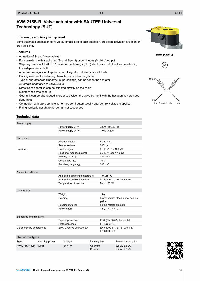
How energy efficiency is improvedSemi-automatic adaptation to valve, automatic stroke path detection, precision activation and high en-ergy efficiency
Features• Actuation of 2- and 3-way valves• For controllers with a switching (2- and 3-point) or continuous (0...10 V) output• Stepping motor with SAUTER Universal Technology (SUT) electronic control unit and electronic,
force-dependent cut-off• Automatic recognition of applied control signal (continuous or switched)• Coding switches for selecting characteristic and running time• Type of characteristic (linear/equal-percentage) can be set on the actuator• Automatic adaptation to valve stroke• Direction of operation can be selected directly on the cable• Maintenance-free gear unit• Gear unit can be disengaged in order to position the valve by hand with the hexagon key provided
(load-free)• Connection with valve spindle performed semi-automatically after control voltage is applied• Fitting vertically upright to horizontal, not suspended
Technical data
Power supplyPower supply 24 V~ ±20%, 50...60 HzPower supply 24 V= -10%...+20%
ParametersActuator stroke 8...20 mmResponse time 200 ms
Positioner Control signal 0...10 V, Ri > 100 kΩPositional feedback signal 0...10 V, load > 10 kΩStarting point U0 0 or 10 V
Control span ΔU 10 VSwitching range Xsh 200 mV
Ambient conditionsAdmissible ambient temperature -10...55 °CAdmissible ambient humidity 5...85% rh, no condensationTemperature of medium Max. 100 °C
ConstructionWeight 1 kgHousing Lower section black, upper section
yellowHousing material Flame-retardant plasticPower cable 1.2 m, 5 × 0.5 mm2
Standards and directivesType of protection IP54 (EN 60529) horizontalProtection class III (IEC 60730)
CE conformity according to EMC Directive 2014/30/EU EN 61000-6-1, EN 61000-6-3,EN 61000-6-4
Overview of typesType Actuating power Voltage Running time Power consumption
AVM215SF132R 500 N 24 V~/= 7.5 s/mm15 s/mm
3.5 W, 6.6 VA2.7 W, 5.3 VA
Product data sheet 4.1 51.383
Right of amendment reserved © 2018 Fr. Sauter AG 1/5
AVM215SF132

AccessoriesType Description
0510390030 Mounting kit for 8 mm stroke
0510390031 Mounting kit for 20 mm stroke
0510480003 Dual auxiliary switch for 8 mm stroke
0510480004 Dual auxiliary switch for 20 mm stroke
0372320001 Hexagon key as visualisation for position indicator
0510390032 Adapter set for V6R/B6R
0510390033 Adapter set for non-SAUTER valve IMI Hydronics TA-Fusion DN 32...50
0510390034 Adapter set for non-SAUTER valve IMI Hydronics TA-Fusion DN 65...80
0510390035 Adapter set for non-SAUTER valve IMI Hydronics CV DN 15...50
0510390036 Adapter set for non-SAUTER valve IMI Hydronics KTM512 DN 15...50
0510390037 Adapter set for non-SAUTER valve IMI Hydronics KTM512 DN 65...100
0510390039 Adapter set for non-SAUTER valve Danfoss VFS VEFS VL VF
0510390040 Adapter set for non-SAUTER valve Danfoss VRB VRG
0510390029 Adapter set for AVM215F***R, stroke 15 mm
0510390060 Adapter set for AVM 2*5 for Schneider V241/V341
A Auxiliary change-over contacts: infinitely variable 0...100%, admissible load 3(1.5) A, 24...230 V
A Accessory 0510390029 can also be used for SAUTER Valveco compact DN 40 and DN 50
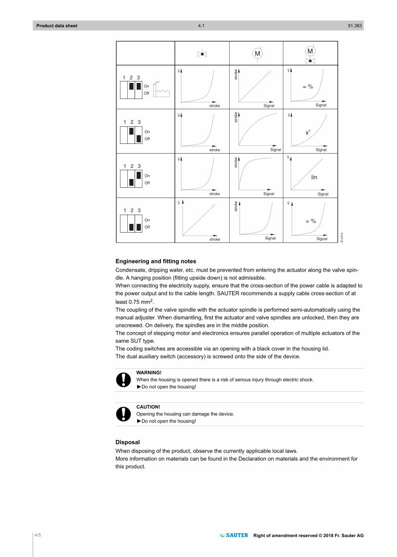
Description of operationThe SUT valve actuator is used to control valves and may only be used for this purpose.Depending on the type of connection (see connection diagram), the device can be used as a continu-ous 0...10 V actuator, a 2-point (OPEN/CLOSE) or 3-point actuator (OPEN/STOP/CLOSE) with an in-termediate position. Two running times are available for selection.Switch S3 can be used to select the linear or equal-percentage characteristic.The manual adjustment is performed in the load-free state by releasing the gear unit (slide switch be-side the connection cable) and simultaneously turning it with the hex key on the top part of the actua-tor. 20 mm stroke is achieved with four turns.
!CAUTION!Damage to device►After manual adjustment, move the slide switch back to its original position so that the gear unit engag-
es again.
Intended useThis product is only suitable for the purpose intended by the manufacturer, as described in the “De-scription of operation” section.All related product regulations must also be adhered to. Changing or converting the product is not ad-missible.
Connection as 2-point valve actuatorThe 2-point actuation is performed via two cables and it controls the valve actuator to both end posi-tions. The actuator is connected to the voltage via the blue cable [MM] and the brown cable [01]. The actuator spindle extends when the voltage is connected to the black cable [02]. When the voltage on the black cable is switched off, the actuator moves to the opposite end position.In the end positions (limit stop in valve or maximum stroke reached) or in the case of an overload, theelectronic motor cut-off is activated (no limit switches).The unused red and grey cables must not be connected or come into contact with other cables.SAUTER recommends that you insulate these.
Connection as 3-point valve actuatorThe 3-point actuation is performed via three cables and controls the valve actuator to any selectedposition. The actuator is connected to the voltage via the blue cable [MM] and the brown cable [01] orvia the black cable [02]. The actuator spindle retracts when the voltage is connected to the brown cable. When the voltage on the brown cable is switched off, the actuator spindle remains in the current posi-tion. The actuator spindle extends when the voltage is connected to the black cable.
Product data sheet 4.1 51.383
2/5 Right of amendment reserved © 2018 Fr. Sauter AG

When the voltage on the black cable is switched off, the actuator spindle remains in the current posi-tion.The direction of operation is changed by swapping the brown and black cables.In the end positions (limit stop in valve or maximum stroke reached) or in the case of an overload, theelectronic motor cut-off is activated (no limit switches).The unused red and grey cables must not be connected or come into contact with other cables.SAUTER recommends that you insulate these.
Connection as continuous 0...10 V valve actuatorThe built-in positioner controls the actuator depending on controller’s output signal y.Direction of operation 1 (mains power supply on brown cable [01]): When the positioning signal is in-creasing, the actuator spindle extends.Direction of operation 2 (mains power supply on black cable [02]): When the positioning signal is in-creasing, the actuator spindle retracts.The starting point and control span are fixed.After a manual adjustment or a power failure of more than at least five minutes, the actuator automati-cally readjusts itself.After the power supply is connected, the stepping motor moves to the lower limit stop, sets up theconnection with the valve spindle, moves to the upper limit stop and thus defines the closing position.After this, every stroke between 0 and 20 mm can be achieved, depending on the control voltage.Thanks to the electronics, no steps can be lost, and the actuator does not require periodic re-adjust-ment. It is possible to operate multiple actuators of the same type in parallel. The feedback signal y0= 0...10 V corresponds to the effective stroke.When control signal 0…10 V is interrupted and direction of operation 1 (brown cable [01]) is connec-ted, the actuator spindle is retracted.When control signal 0…10 V is interrupted and direction of operation 2 (black cable [02]) is connec-ted, the actuator spindle is extended.The coding switch can be used to select the characteristic of the valve. Characteristics can only begenerated when the actuator is used as a continuous actuator. The running times can be selectedwith additional switches. These can be used for 2-point, 3-point or continuous function.
Additional technical dataThe upper section of the housing with the cover, indicator knob and cover knob contains the steppingmotor and the SUT electronics. The lower section of the housing contains the maintenance-free gearunit.
Power consumptionType Running time [s/mm] State Active power P [W] Apparent power S [VA]AVM215SF132R 7.5 / 15 Operation 3.5 / 2.7 6.6 / 5.3
Standstill 0.35 0.75
Coding switch for selecting characteristic
Product data sheet 4.1 51.383
Right of amendment reserved © 2018 Fr. Sauter AG 3/5
B1241A
Engineering and fitting notesCondensate, dripping water, etc. must be prevented from entering the actuator along the valve spin-dle. A hanging position (fitting upside down) is not admissible.When connecting the electricity supply, ensure that the cross-section of the power cable is adapted tothe power output and to the cable length. SAUTER recommends a supply cable cross-section of atleast 0.75 mm2.The coupling of the valve spindle with the actuator spindle is performed semi-automatically using themanual adjuster. When dismantling, first the actuator and valve spindles are unlocked, then they areunscrewed. On delivery, the spindles are in the middle position.The concept of stepping motor and electronics ensures parallel operation of multiple actuators of thesame SUT type.The coding switches are accessible via an opening with a black cover in the housing lid.The dual auxiliary switch (accessory) is screwed onto the side of the device.
!WARNING!When the housing is opened there is a risk of serious injury through electric shock.►Do not open the housing!
!CAUTION!Opening the housing can damage the device.►Do not open the housing!
DisposalWhen disposing of the product, observe the currently applicable local laws.More information on materials can be found in the Declaration on materials and the environment forthis product.
Product data sheet 4.1 51.383
4/5 Right of amendment reserved © 2018 Fr. Sauter AG

Connection diagram
Accessories
Dual auxiliary switch0510480003, 0510480004
RD BN BK GN GY VT
RD = red/rotBN = brown/braunBK = black/schwarzGN = green/grünGY = grey/grauVT = violet/violett
Dimension drawing
70 145.5
79.179.1
62.7
Product data sheet 4.1 51.383
Right of amendment reserved © 2018 Fr. Sauter AG 5/5
Fr. Sauter AGIm Surinam 55
CH-4016 BaselTel. +41 61 - 695 55 55
www.sauter-controls.com