Embed Size (px)
Citation preview
Technology White Paper
Smart Planning for Smart Grid AMI Mesh Networks
Smart Planning for Smart Networks 2 ©2011 EDX Wireless www.edx.com
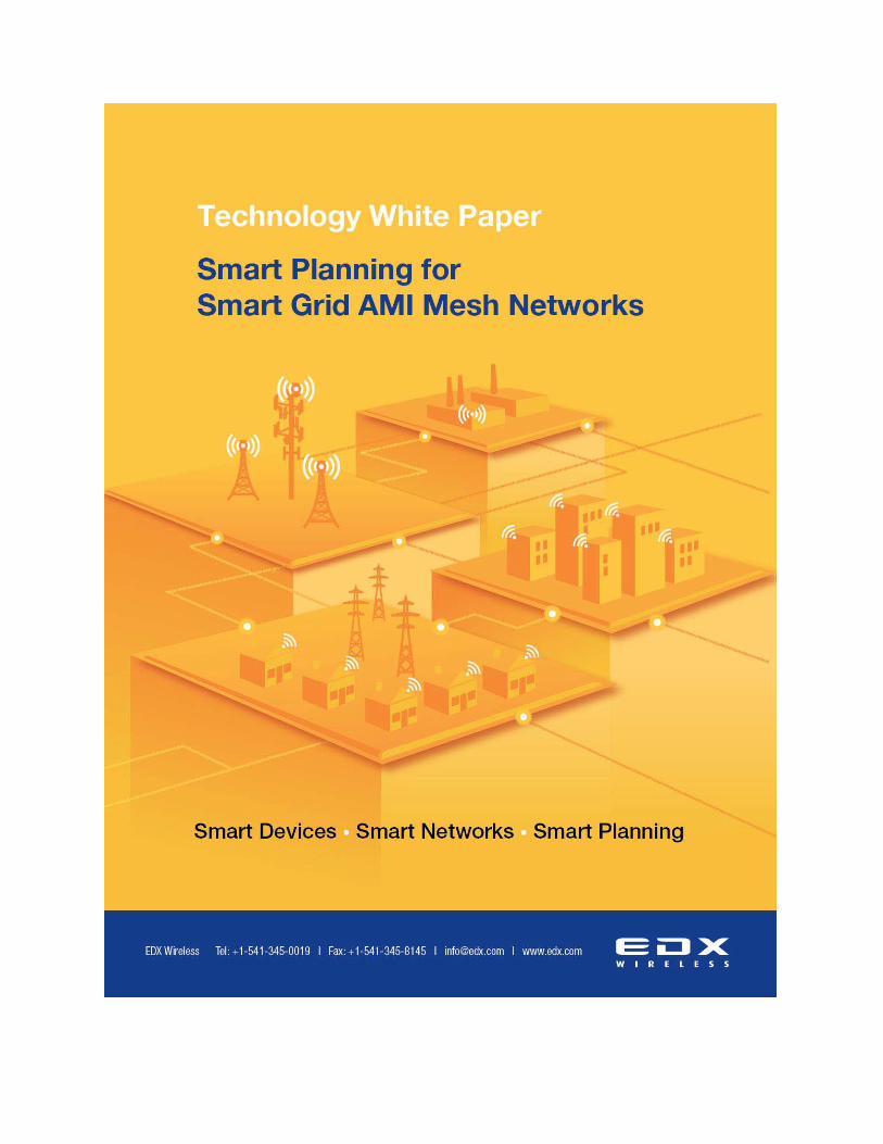
Smart Planning for Smart Grid AMI Mesh Networks
Greg Leon
EDX Wireless, LLC Eugene, Oregon USA
May, 2011
Figure 1 - Sample AMI Mesh Network

Technology White Paper
Smart Planning for Smart Grid AMI Mesh Networks
Smart Planning for Smart Networks 3 ©2011 EDX Wireless www.edx.com
Introduction
The evolution of the electrical grid, specifically electricity metering, has required the
development of two-way communication networks that are both reliable and cost-effective.
These two-way networks enable current and future smart grid applications such as smart
metering, demand response and remote disconnect/reconnect. In the future, new applications
will become prevalent such as the communication of time-of-use pricing signals sent from the
utility to a consumer’s home energy management system or electrical vehicle charging station.
These smart networks aid the utilities in improving grid reliability, improving energy efficiency,
reducing costs, and accomplishing load shifting.
Communication Network Options
There are a number of technologies that have been proposed, developed and deployed to
enable this communication, with both wired and wireless options available. Although wired
technologies such as power line communication (PLC) are attractive to utilities for obvious
reasons, the capital requirements have generally proved to be prohibitive which has limited
widespread adoption. Many utilities have chosen wireless technologies to accomplish their goals
of developing reliable two way communication for Advanced Metering Infrastructure (AMI)
networks.
Wireless systems provide a cost-effective option that can be both reliable and scalable.
Common AMI wireless network architectures currently being deployed include both point-to-
multipoint and mesh topologies. There are pros and cons for each architecture type, but
ultimately the architecture must be selected to best fit the deployment scenario and networking
Technology White Paper
Smart Planning for Smart Grid AMI Mesh Networks
Smart Planning for Smart Networks 4 ©2011 EDX Wireless www.edx.com
goals of the utility. Mesh networks are effective systems for the deployment of reliable large
scale AMI networks and are widely implemented [1]. However, the low power radio signals used
for AMI systems are deployed in unlicensed spectrum and are susceptible to interference and
link blockage that can affect their success and performance. Also, mesh networks have to be
properly dimensioned to operate within the constraints of the mesh routing protocol and system
capacity limits. Proper network planning and analysis techniques are valuable tools that can
mitigate these issues in advance. The purpose of this paper is to develop best practice guidelines
for the design of AMI mesh networks at 902-928 MHz. The reason this is important is due to the
fact that there are an estimated sixty-five million smart meters planned for deployment by 2020
[2]. Many of these smart meters will be mesh devices. Therefore, developing a set of best
design practices will enable successful network deployments that are optimized for performance
and cost.
AMI Design Best Practices
Although there is little literature defining how AMI mesh vendors are designing these
networks, it is apparent from personal experience and published reports concerning deployment
problems that a lack of design standards exists [3].
An outline for the best practice for designing AMI mesh networks is as follows:
1. Understanding the networking goals of the utility
2. Defining the design constraints of the AMI mesh vendor’s equipment
3. Pilot installation, field testing, and site infrastructure exploration
4. Model tuning within design software

Technology White Paper
Smart Planning for Smart Grid AMI Mesh Networks
Smart Planning for Smart Networks 5 ©2011 EDX Wireless www.edx.com
5. Design of AMI mesh network within design software including consideration for
collector backhaul
6. Deployment, Testing and Post-Design Optimization
Defining AMI Network Goals
Understanding the networking goals of the utility is the most important step in the design
process. Each utility will have different design and success criteria. They will have varying
constraints on performance requirements as well as budget. All of these goals and constraints
must be fully understood before any design work is initiated.
Key items to understand that will affect the design process are reliability, redundancy,
bandwidth and budget. For example, if a larger than normal bandwidth is required then the
hopping limits of the mesh network need to be reduced well below what a vendor recommends.
Also, if reliability and redundancy are high priorities then more collector and repeater devices
will have to be used in order to ensure multiple alternate routes for meters. These items need to
be defined so that the design approach can be appropriately matched to produce a network that
will meet the utility’s objectives.
Design Constraints of Vendor Equipment
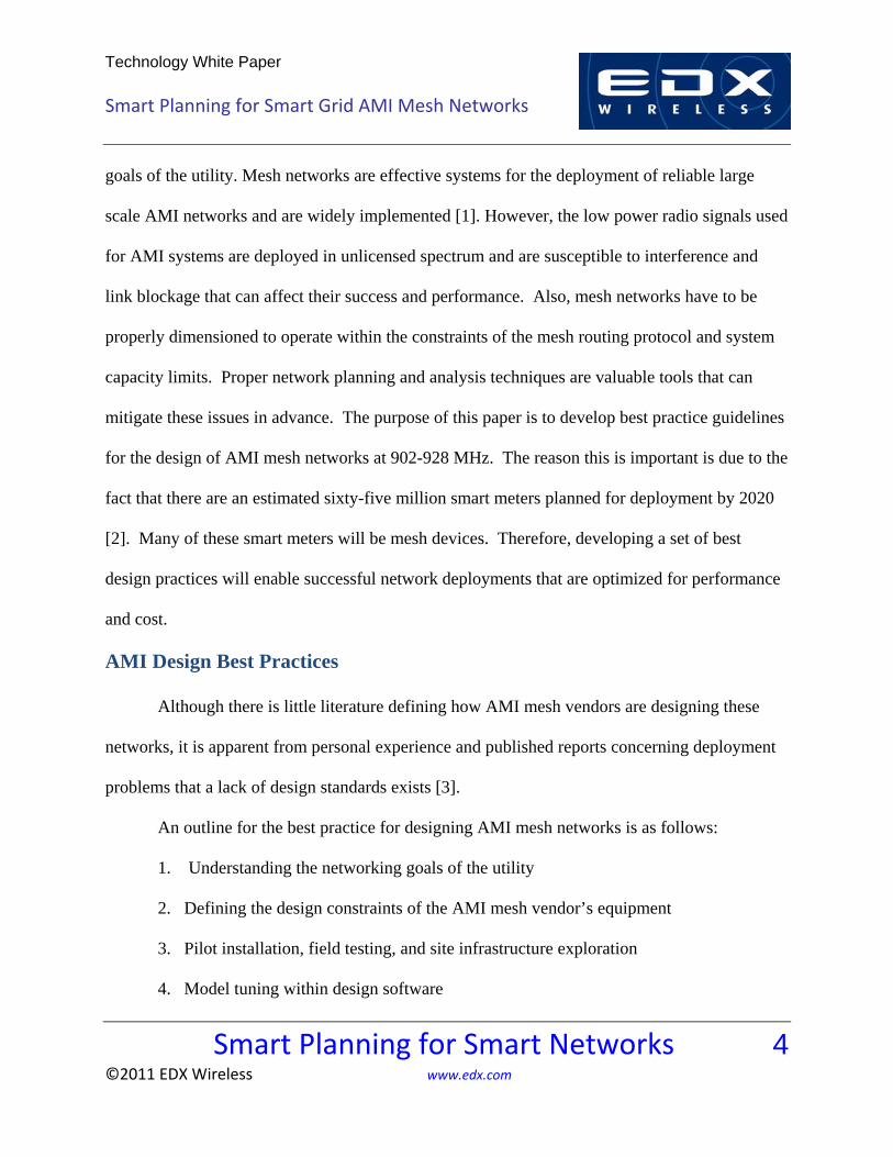
Although there are a number of vendors that supply a variety of AMI mesh equipment,
most offer three basic network components, which are the meter, the repeater and the collector
[4]. Typically the network architecture, as illustrated in Figure 2, allows many types of device
communication:
Technology White Paper
Smart Planning for Smart Grid AMI Mesh Networks
Smart Planning for Smart Networks 6 ©2011 EDX Wireless www.edx.com
Figure 2 - AMI Mesh Architecture
1. Collector to Meter
2. Collector to Repeater
3. Repeater to Repeater
4. Repeater to Meter
5. Meter to Meter
With the possible device communication configurations outlined above, it can be difficult
and overwhelming to create an optimal design. Compared with a cellular system, where the only

Technology White Paper
Smart Planning for Smart Grid AMI Mesh Networks
Smart Planning for Smart Networks 7 ©2011 EDX Wireless www.edx.com
type of device communication is from base station to handset, it is understandable that traditional
planning methods of coverage planning will not be enough [5]. Additionally, applying the
device constraints imposed by link capacity and mesh hopping limitations creates enough
variables to make the task daunting for even experienced RF engineers.
RF Network System Definition
The definition of the vendor’s equipment begins with creating the link budgets for the
various types of devices. This includes accounting for transmit power, receive sensitivity,
antenna gains, cable losses and meter location losses.
Figure 3 - AMI Device Link Budget Inputs
After a link budget is defined for each device type then hopping limits and collector
capacity can be considered. Typical systems have hopping limits from 5-15 hops and collector
capacity from 1,000 to 10,000 meters. Hopping limits and capacity limits also need to be scaled
based off the goals of the utility and what their specific applications and requirements dictate. In
addition, the role of the repeater device needs to be well understood. Some vendors rely heavily
on the repeater device to reduce the total cost of the system, whereas others only use repeaters as
a fill-in to connect up isolated meter clusters. Another major design hurdle comes up if any of
the radios are powered by a battery. This forces the consideration of the number of downstream
devices passing through a single device. The reason for this consideration is that with increasing

Technology White Paper
Smart Planning for Smart Grid AMI Mesh Networks
Smart Planning for Smart Networks 8 ©2011 EDX Wireless www.edx.com
transmission requirements of a radio comes decreasing battery life. This increases the
maintenance requirements and operating expenses of the AMI system.
Designing Large Scale AMI Networks
Due to the scale and complexity of AMI networks, some with over a million nodes, it is
essential to take advantage of computer-aided design tools, such as EDX SignalPro. EDX
SignalPro combines GIS mapping capabilities with propagation analysis and automated network
layout tools that provide for efficient dimensioning and placement of infrastructure equipment in
event the largest AMI networks. Such design software incorporates a three-dimensional model
of the geographical area of interest which is built up using a digital elevation model, land use
data and building/structure data. The 3D model is critical so the physical issues that affect the
performance of a complex AMI network can be accounted for in the design. Once this model is
created, then the planning of the complex mesh architecture can be accomplished in an
intelligent way that respects the unique physical issues of the service area.
Pilot System Field Tests
Valuable design tools are only as good as the input data provided to them. This includes
link budgets, device specifications, environmental data, and often overlooked, field measurement
data. An integral step in designing these large mesh networks is setting up a small pilot system
and measuring performance of the devices. At the very least, it is necessary to setup a test
transmitter in a representative location within the service area. Ideally, it is recommended to
setup test transmitters in multiple locations that provide an overall representation for the service
area. It is also worthwhile to perform testing on relevant link configurations such as collector-to-
Technology White Paper
Smart Planning for Smart Grid AMI Mesh Networks
Smart Planning for Smart Networks 9 ©2011 EDX Wireless www.edx.com
meter, collector-to-repeater, and meter-to-meter links. The measurement data collected during
these tests should provide a geo-referenced measurement point with a measurement value of
received power in dBm. The field measurements are taken to understand link range and clutter
effects of these link scenarios. This field data is then used in the design software in order to
develop tuned propagation models. The accuracy of the design software is greatly improved by
this tuning process, thus improving the confidence of the network design.
Also relevant in this pilot stage is data collection on the available site infrastructure for
equipment mounting. Typically utilities have a defined set of mounting assets which includes
substations, utility buildings, and distribution infrastructure. The substation locations are
typically given site locations for collectors as required by utilities. Visits to substations are
recommended to understand potential deployment issues because substation locations are used in
the network construction. Also, if devices are mounted on power poles and light poles, it is
important to understand how the radios will be mounted and if there any limitations that this
places on the equipment.
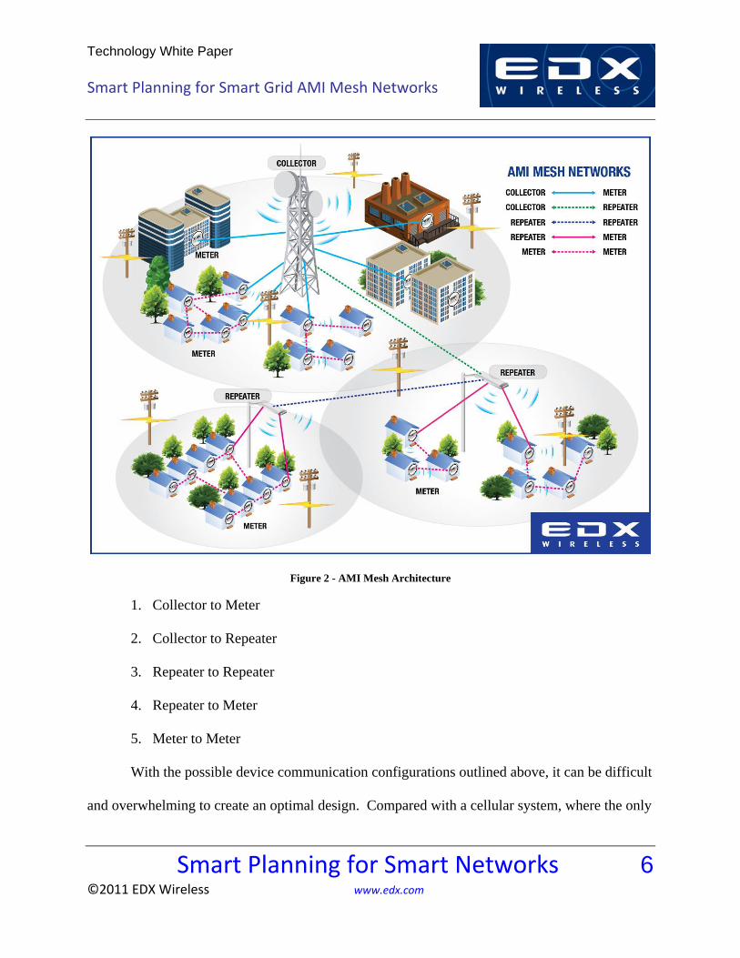
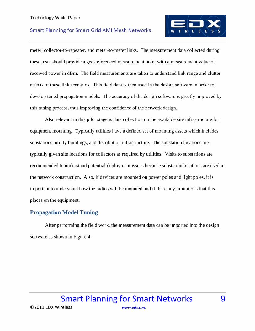
Propagation Model Tuning
After performing the field work, the measurement data can be imported into the design
software as shown in Figure 4.
Technology White Paper
Smart Planning for Smart Grid AMI Mesh Networks
Smart Planning for Smart Networks 10 ©2011 EDX Wireless www.edx.com
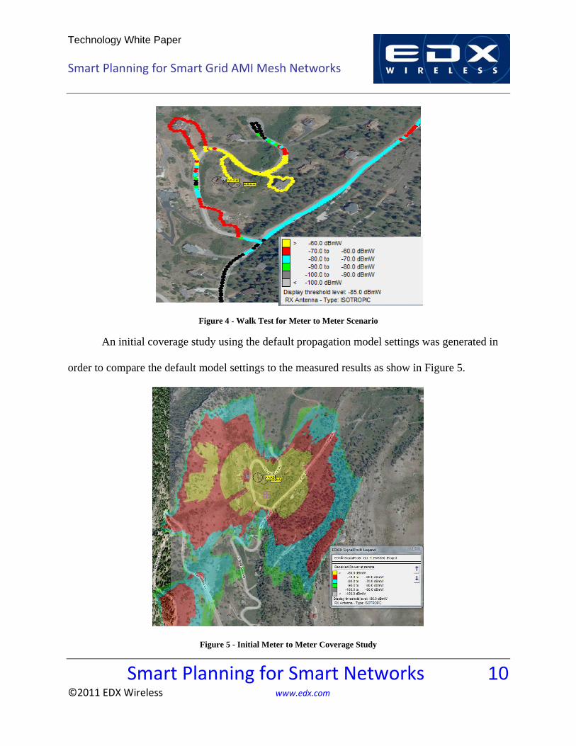
Figure 4 - Walk Test for Meter to Meter Scenario
An initial coverage study using the default propagation model settings was generated in
order to compare the default model settings to the measured results as show in Figure 5.
Figure 5 - Initial Meter to Meter Coverage Study

Technology White Paper
Smart Planning for Smart Grid AMI Mesh Networks
Smart Planning for Smart Networks 11 ©2011 EDX Wireless www.edx.com
A properly tuned propagation model will have less than 3 dB of mean error and less than
8 dB of standard deviation when comparing the prediction against the measurements. The
measurement data on top of the post-tuning coverage prediction as depicted in Figure 6 shows a
better match.
Figure 6 - Post Tuning Coverage Map
Although terrain and clutter effects account for the majority of propagation losses for
AMI radio links, it has been found by internal testing that there are additional losses due to the
placement of the meter. This means that local meter losses must be configured into the link
budget. EDX SignalPro provides the flexibility to include local meter losses based on placement
types.
Technology White Paper
Smart Planning for Smart Grid AMI Mesh Networks
Smart Planning for Smart Networks 12 ©2011 EDX Wireless www.edx.com
Design Procedures for an AMI Mesh Network
After model tuning exercises are completed, the full network design process can begin.
Before designing a single collector site it is important to begin the process by defining how the
system will be modeled within the design software. When examining this architecture in detail,
it becomes obvious that there are always a large collection of fixed point-to-point links. Instead
of using broad coverage studies to design the multiple levels of this architecture, a better
approach is to use discrete point-to-point link calculations that reflect the realities of the physical
environment and incorporate the proper link budgets for the various device communications
defined.
A good example of why this approach is very important and can greatly impact the
accuracy of the scaling and placement of equipment can be found with the repeater level of the
network. Repeaters are meant to extend range and capacity of the system by concentrating and
relaying meter data that falls out of the coverage area of the collector [4]. As previously noted,
repeaters can communicate to a meter, to one another, and to the collector, with both repeater
and collector device types usually sited on light poles or power poles. Repeaters play an
important role in reducing the total cost of the network and thus are used extensively in AMI
mesh networks [4]. However, they have a difficult job to perform from a radio perspective
because if they cannot close a link then all of the meters relying on the repeater will become
stranded. The best way to design for the repeaters is to run a mesh link study for all possible
known links. The mesh link study analyzes terrain, tree, and structure issues for each link as
well as hierarchy and capacity. Being able to do this in an efficient manner is a must, as there
Technology White Paper
Smart Planning for Smart Grid AMI Mesh Networks
Smart Planning for Smart Networks 13 ©2011 EDX Wireless www.edx.com
are so many possible repeater-to-meter, repeater-to-repeater and repeater-to-collector
combinations. It is impossible for the designer to examine each link manually. Therefore, using
a design tool that automates this is of enormous value. This automation allows for a full mesh
system link analysis of very large systems to be accomplished in a short period of time which
enables design optimization iterations to be carried out in short cycles. The result of an
optimally designed network leads to proper scaling, placement and investment in AMI
equipment. Reliability and performance of the network will also be improved allowing for the
future growth of the smart grid AMI network.
An optimal AMI mesh network design begins with importing the meter locations and
potential candidate locations for collectors and repeaters into EDX SignalPro. Candidate
locations can include substations, utility assets such as buildings and light poles, and distribution
assets such as electrical poles. For large systems it is useful to use intelligent layout tools that
will select candidates throughout a service area based on a reasonable geographical spacing.
Then EDX SignalPro can be used to find collector sites from the candidates that best serve
meters throughout the service area. The selection process must ensure proper coverage of meters
but also take into account the increased range of a collector due to repeaters and meter hopping.
The selection must also consider meter density as collector capacity is a selection constraint.
Using EDX SignalPro, which incorporates these constraints, will provide a faster path to
appropriate collector selections. A selection process was performed for a sample mid-sized city
and the resultant coverage of the collectors is shown in Figure 7.

Technology White Paper
Smart Planning for Smart Grid AMI Mesh Networks
Smart Planning for Smart Networks 14 ©2011 EDX Wireless www.edx.com
Figure 7 - Initial Collection Coverage
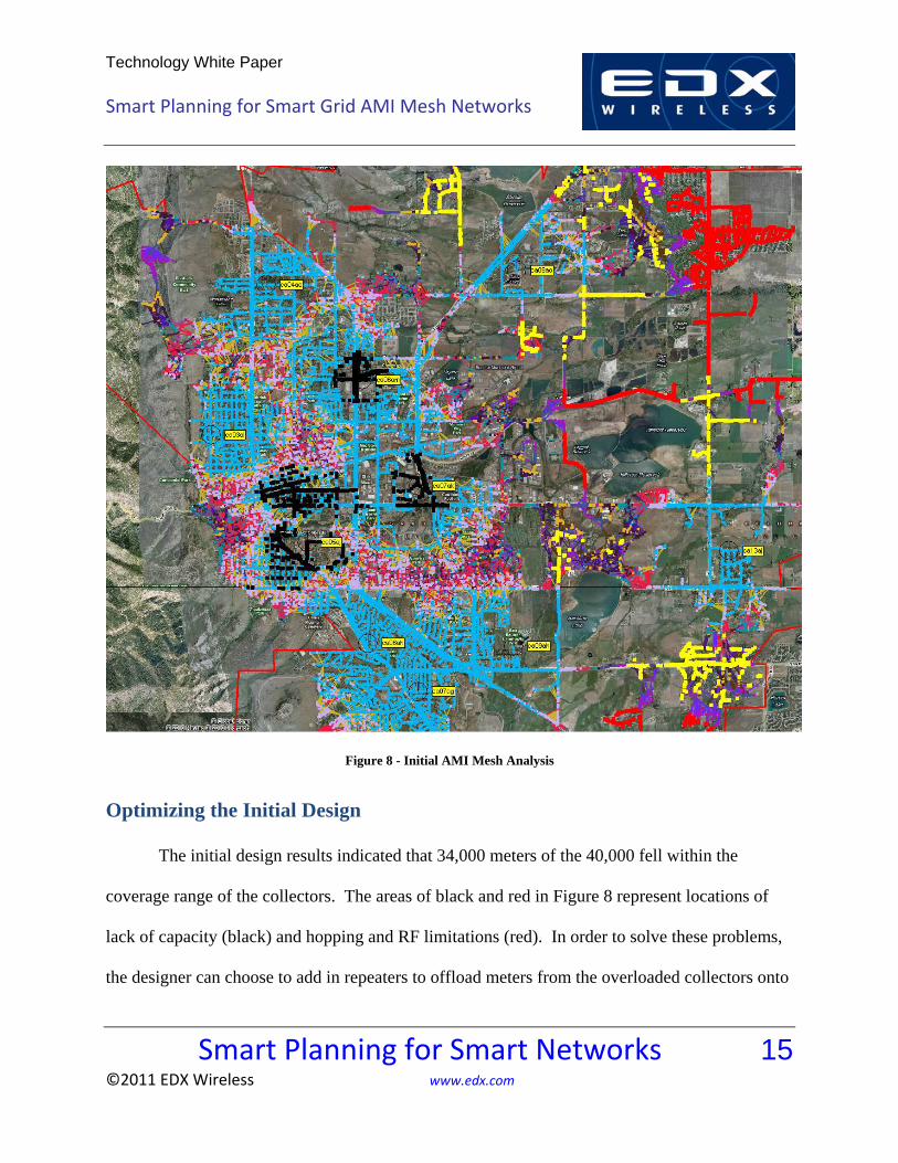
Now using the point-to-point mesh link study described before, the initial meter coverage
of the system not including repeaters can be determined. The inputs for this system analysis
were 10 collectors placed in the city to serve the approximate 40,000 meters, with the limitation
of 4,000 meters per collector and 4 hops. These inputs gave an initial view as shown in Figure 8:
Technology White Paper
Smart Planning for Smart Grid AMI Mesh Networks
Smart Planning for Smart Networks 15 ©2011 EDX Wireless www.edx.com
Figure 8 - Initial AMI Mesh Analysis
Optimizing the Initial Design
The initial design results indicated that 34,000 meters of the 40,000 fell within the
coverage range of the collectors. The areas of black and red in Figure 8 represent locations of
lack of capacity (black) and hopping and RF limitations (red). In order to solve these problems,
the designer can choose to add in repeaters to offload meters from the overloaded collectors onto
Technology White Paper
Smart Planning for Smart Grid AMI Mesh Networks
Smart Planning for Smart Networks 16 ©2011 EDX Wireless www.edx.com
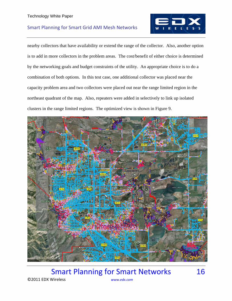
nearby collectors that have availability or extend the range of the collector. Also, another option
is to add in more collectors in the problem areas. The cost/benefit of either choice is determined
by the networking goals and budget constraints of the utility. An appropriate choice is to do a
combination of both options. In this test case, one additional collector was placed near the
capacity problem area and two collectors were placed out near the range limited region in the
northeast quadrant of the map. Also, repeaters were added in selectively to link up isolated
clusters in the range limited regions. The optimized view is shown in Figure 9.
Technology White Paper
Smart Planning for Smart Grid AMI Mesh Networks
Smart Planning for Smart Networks 17 ©2011 EDX Wireless www.edx.com
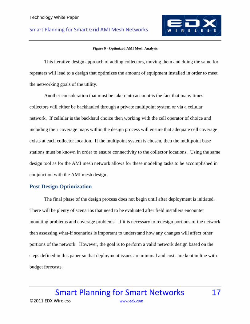
Figure 9 - Optimized AMI Mesh Analysis
This iterative design approach of adding collectors, moving them and doing the same for
repeaters will lead to a design that optimizes the amount of equipment installed in order to meet
the networking goals of the utility.
Another consideration that must be taken into account is the fact that many times
collectors will either be backhauled through a private multipoint system or via a cellular
network. If cellular is the backhaul choice then working with the cell operator of choice and
including their coverage maps within the design process will ensure that adequate cell coverage
exists at each collector location. If the multipoint system is chosen, then the multipoint base
stations must be known in order to ensure connectivity to the collector locations. Using the same
design tool as for the AMI mesh network allows for these modeling tasks to be accomplished in
conjunction with the AMI mesh design.
Post Design Optimization
The final phase of the design process does not begin until after deployment is initiated.
There will be plenty of scenarios that need to be evaluated after field installers encounter
mounting problems and coverage problems. If it is necessary to redesign portions of the network
then assessing what-if scenarios is important to understand how any changes will affect other
portions of the network. However, the goal is to perform a valid network design based on the
steps defined in this paper so that deployment issues are minimal and costs are kept in line with
budget forecasts.

Technology White Paper
Smart Planning for Smart Grid AMI Mesh Networks
Smart Planning for Smart Networks 18 ©2011 EDX Wireless www.edx.com
Summary and Conclusions
As you can see, there are formalized standard design steps for AMI mesh network
planning so that utilities can optimize their investment and accomplish their networking goals.
The process begins with defining the networking goals of the utility and then understanding the
limits of the mesh vendor’s equipment. Once this is understood, the field work is then completed
which includes site exploration and field testing. The design process then commences in EDX
SignalPro with propagation model tuning based off the field data. Complete network design is
then accomplished using EDX SignalPro that includes the ability to analyze mesh networks and
backhaul technologies effectively. The design process continues on with redesigning and
troubleshooting during the deployment phase. If all steps are performed successfully then the
AMI mesh network will exceed performance expectations and the potential of the smart grid can
be better realized through this reliable two-way communication network.
References
[1] Neichin, Greg. (2010). 2010 U.S. Smart Grid Vendor Ecosystem (1st ed.) [Online]. Available: http://www.energy.gov/media/Smart-Grid-Vendor.pdf [2] The Edison Foundation. (September, 2010). Utility-Scale Smart Meter Deployments, Plans and Proposals (1st ed.) [Online]. Available: http://www.edisonfoundation.net/iee/issuebriefs/SmartMeter_Rollouts_0910.pdf [3] Chen, Chun, “Topology Formation for Wireless Mesh Network Planning,” IEEE Infocomm 2009. [4] B. Lichtensteiger et al, “RF Mesh Systems for Smart Metering: System Architecture and Performance,” IEEE SmartGridComm 2010. [5] Aggelou, George, Wireless Mesh Networking, New York: McGraw-Hill, 2009.