Embed Size (px)
Citation preview

TITLE: TECHNICAL SPECIFICATION FOR CIVIL,
STRUCTURAL AND ARCHITECTURAL WORKS OF MAIN PLANT & BOP AREA
AT 3X660 MW NORTH KARANPURA STPP
SPECIFICATION NO. PE-TS-405-C005
VOLUME II
SECTION “C”
REV. 0 DATE: 11/19/2014
SHEET 1 OF 7
CIVIL WORKS
TITLE: TECHNICAL SPECIFICATION FOR CIVIL,
STRUCTURAL AND ARCHITECTURAL WORKS OF MAIN PLANT & BOP AREA
AT 3X660 MW NORTH KARANPURA STPP
SPECIFICATION NO. PE-TS-405-C005
VOLUME II
SECTION “C”
REV. 0 DATE: 11/19/2014
SHEET 2 OF 7
1. TECHNICAL SPECIFICATION:
The technical specification for civil, structural & architectural works consists of three parts.
1.Section-C : Section ‘C’ is special technical specification for design & construction.
2. Section-D : Section ‘D’ is General specification for design & construction.
Section-C is special technical specification for this project and NTPC specification included as “appendix-1” is a part of this document. In case there is any conflict between technical specification of Section D & Section C; requirements mentioned in Section-C shall prevail.

TITLE: TECHNICAL SPECIFICATION FOR CIVIL,
STRUCTURAL AND ARCHITECTURAL WORKS OF MAIN PLANT & BOP AREA
AT 3X660 MW NORTH KARANPURA STPP
SPECIFICATION NO. PE-TS-405-C005
VOLUME II
SECTION “C”
REV. 0 DATE: 11/19/2014
SHEET 3 OF 7
2. SCOPE OF WORK:
The scope of civil, structural and architectural works shall include construction of all civil, structural and architectural works including supply of all construction materials for all buildings, equipment and facilities for the project, except cement & reinforcement steel that shall be supplied free of cost by BHEL to the bidder at its store located inside plant area. Structural steel for fabrication works to be carried out at site shall be supplied by bidder from vendor(s) approved by BHEL/NTPC.
The nature of work generally involves earthwork in excavation, sheet piling wherever required, disposal of surplus earth, de-watering, backfilling around completed structures, plinth filling, piling, concreting including reinforcement and form work, masonry work, vibration isolation system consisting of springs & dampers for machine foundations if required, plastering, painting, uninsulated / sandwiched insulated metal wall cladding, roofing including permanent steel decking, flooring, false ceiling, under deck insulation, false flooring, acid and alkali resistant lining, fabrication of structures like coal bunker etc. at site, collection of pre-fabricated structural members from BHEL stores, assembly/erection of steel structures (with bolted field connections) and miscellaneous steel works (i.e. steel staircase, cable supports, pipe supports, ladders, walkways, railing, chequered plate/grating floors, inserts, anchor bolts etc.), painting of structures, paving, gravel filling, providing pre-cast covers, damp proofing, roof water proofing, anti-weed/ anti-termite treatment, roads, drainage, rain water harvesting, final grading and site clearance before handing over and any other items of work required for completion of all systems under the scope of work complete.
The scope of Bidder for civil, structural and architectural works as defined above shall include but not be limited to the following buildings/ areas/ systems along with their foundations, super structures and finishes complete. Major areas are listed below:
1. Infrastructure Works
a. Approach road to various buildings/facilities from main roads constructed by BHEL including drains and culverts wherever required.
b. Pipe culverts at road crossings, as directed by engineer in charge.
2. Foundations of various types for all buildings/ area/ systems including machine foundations as per requirements. 3. Civil, Structural, Architectural works for the following buildings/structures/facilities in Main plant Area: a. Main Power House building b. Mill Bunker building c. Mill Reject Silo & associated trenches d. Boiler structure e. ESP supporting Structure f. ESP control room building

TITLE: TECHNICAL SPECIFICATION FOR CIVIL,
STRUCTURAL AND ARCHITECTURAL WORKS OF MAIN PLANT & BOP AREA
AT 3X660 MW NORTH KARANPURA STPP
SPECIFICATION NO. PE-TS-405-C005
VOLUME II
SECTION “C”
REV. 0 DATE: 11/19/2014
SHEET 4 OF 7
g. Compressor House h. DELETED i. TG foundation j. TDBFP& MDBFP foundation k. CEP pit l. Fan foundations (PA/FD/ID Fans) m. Coal Mill foundation n. DG set foundation & Stack Foundation o. Seal air Fan foundation p. All other equipment foundations in Boiler-Turbine-Generator (BTG) area. q. Area paving and miscellaneous foundations in Main Plant Block, Transformer Yard, Boiler area, ESP Area & Chimney area including, Heavy duty passages, drains, culverts, fire water trench, rail/ road crossing of fire water trench, drains. r. Auxiliary Boiler Foundations & Switchgear cum Control Building s. Transformer yard area foundations including Rail Track and facilities including condensate storage tank foundation, condensate transfer pump shed and oil-water separation pit. 4. DELETED 5.Fire protection system works including Fire station building 6. Outdoor transformer foundations 7.DELETED 8. Pipe /Cable / duct supporting structures, trenches, culverts, duct banks, pedestals, hume pipe culverts and thrust blocks etc. for all systems covered under the scope. 9. DELETED. 10. Civil, Structural, Architectural works for the following buildings/ structures/ facilities: a. DELETED b. DELETED c. Gate Complex and Time Office cum CISF building including other gates along boundary wall d. DELETED e. Misc Switchgear building f. DELETED g. DELETED h. Field Laboratory Complex Building i. Weigh Bridge j. Hydrogen Generation Plant k. Fire Station Building. 11. Open Store Yard (20,000 Sq.M.) with RCC paving & chain link fence and gate 12. Landscaping 13. Earthing mats & riser for all buildings. 14. Facilities for rain water harvesting 15. Water supply & sanitation, plumbing works. 16. Boundary wall List of scope is not exhaustive and bidder has to carry out all works required for system completion as per instructions of engineer in charge, even though, not

TITLE: TECHNICAL SPECIFICATION FOR CIVIL,
STRUCTURAL AND ARCHITECTURAL WORKS OF MAIN PLANT & BOP AREA
AT 3X660 MW NORTH KARANPURA STPP
SPECIFICATION NO. PE-TS-405-C005
VOLUME II
SECTION “C”
REV. 0 DATE: 11/19/2014
SHEET 5 OF 7
explicitly mentioned in above list of scope of works. No claim/additional claim shall be entertained by BHEL on account of works carried out by bidder as per instructions of engineer in charge but not covered in above list. Most of the steel structures (excluding coal bunkers) shall be fabricated by BHEL in factory, and made available to bidder at site stores. The bidder shall collect the fabricated parts from BHEL office and shall assemble/erect the structures through bolted connections at site as per drawing/specification/instructions of engineer in charge. Special structures like coal bunkers etc. shall be fabricated at site. Bidder shall arrange structural steel/Stainless steel for fabrications to be carried out at site. Bidder shall fabricate structures as per drawing and instructions of engineer in charge at an area allocated by BHEL at site. All necessary consumables for fabrication at site are in bidder’s scope. Most of the structures shall have bolted field connections. Site welding will be adopted (for components other than main framing members) only at specific places as a special case as per approved drawings/ directions of engineer in charge. Welded splicing as per drawing has to be done with suitable arrangement at ground before erection. Civil, structural and architectural works though not explicitly mentioned in the above list but required for the completion of the various systems of the power plant shall also be in the scope of the bidder.
3. General Instructions:
The work to be performed under this specification consists of design, engineering, construction, erection and providing all labor, materials, consumables, equipment, temporary works, temporary storage sheds, temporary colony for labor and staff, temporary site offices, constructional plants, fuel supply, transportation and all incidental items not shown or specified but reasonably implied or necessary for the completion and proper functioning of the plant, all in strict accordance with the specifications including revisions and amendments thereto as may be required during the execution of work.
The scope shall also include setting up by the Bidder a complete testing laboratory in the field to carry out all relevant tests for structural steel, reinforcement steel & constituents of reinforced cement concrete (RCC) etc.
The work shall be carried out according to the design/drawings to be supplied by BHEL to the Bidder. In certain cases, however, detail construction drawings may have to be developed by bidder as required by BHEL.
The Bidder shall make the layout and levels of all structures from the general grid of the plot and the nearest GSI benchmark or other acceptable benchmark of Govt. deptt. as per the directions of the Engineer. The Bidder shall be solely responsible for the correctness of the layout and levels and shall also provide necessary instruments, materials, access to works, etc., to the Engineer for general checking of the correctness of the civil works.

TITLE: TECHNICAL SPECIFICATION FOR CIVIL,
STRUCTURAL AND ARCHITECTURAL WORKS OF MAIN PLANT & BOP AREA
AT 3X660 MW NORTH KARANPURA STPP
SPECIFICATION NO. PE-TS-405-C005
VOLUME II
SECTION “C”
REV. 0 DATE: 11/19/2014
SHEET 6 OF 7
All the quality standards, tolerances, welding standards and other technical requirements shall be strictly adhered to.
The Bidder shall fully apprise himself of the prevailing conditions at the proposed site, climatic conditions including monsoon pattern, soil conditions, local conditions and site specific parameters and shall include for all such conditions and contingent measures in the bid, including those which may not have been specifically brought out in the specifications.
In case of any conflict between stipulations in various portions of the specification, most stringent stipulation would be applicable for implementation by the Bidder without any extra cost to BHEL.
4. Exclusions:
a. Leveling and grading (Bidder shall be provided with levelled and graded land. However, micro-grading shall be in bidder’s scope of work).
b. Roads (Main roads of plant are not included in bidder’s scope. However, approach road to various buildings/facilities are in bidder’s scope).
c. Drains (Main drains of plant are not included in bidder’s scope. However, Diversion drains in plant area, drains along approach road to various buildings/facilities, culverts on these drains and peripheral drains around buildings/ any other drains as instructed by engineer in charge are in bidder’s scope).
d. Design & Engineering.
e. Owner’s Construction office.
f. Air cooled condenser.
g. Service Building
h. Administration Building
i. Auditorium
j. Canteen
k. water treatment system
l. Sewage treatment system (plumbing work in toilets and drinking water/sewage network is however included in scope of work)
m. Fuel oil pump house and dyke area
n. chimney
TITLE: TECHNICAL SPECIFICATION FOR CIVIL,
STRUCTURAL AND ARCHITECTURAL WORKS OF MAIN PLANT & BOP AREA
AT 3X660 MW NORTH KARANPURA STPP
SPECIFICATION NO. PE-TS-405-C005
VOLUME II
SECTION “C”
REV. 0 DATE: 11/19/2014
SHEET 7 OF 7
o. Township
5. Submissions: The documents listed below are to be submitted for approval of BHEL/NTPC unless specified otherwise. The list given below is not exhaustive but indicative only.
Write-up on various statutory requirements and their compliance for various buildings, facilities, structures and systems, etc.
Construction and erection procedure for all major structures such as Main Plant building including Control tower, Mill and Bunker building including coal bunkers, TG foundation and other machine foundations etc. covered under the Bidder’s scope.
Material test certificates.
Wherever applicable, scheme for dewatering, shoring, strutting/sheet piling.
6. NTPC Specifications: Included as Appendix:1.
Enclosure: Appendix:1-NTPC Specification

NTPC Limited
(A Government of India Enterprise)
NORTH KARANPURA SUPER THERMAL POWER PROJECT (3x660MW)
TECHNICAL SPECIFICATION
FOR
EPC PACKAGE
PART – B (CIVIL)
(BOOK 4 OF 5)
SECTION - VI
BIDDING DOCUMENT NO.: CS-4410-001-2

NTPC Limited
(A Government of India Enterprise)
NORTH KARANPURA SUPER THERMAL POWER PROJECT (3x660MW)
TECHNICAL SPECIFICATION
FOR
EPC PACKAGE
PART – B (CIVIL)
(BOOK 4 OF 5)
SECTION - VI
BIDDING DOCUMENT NO.: CS-4410-001-2
(This document is meant for the exclusive purpose of bidding against this Package and shall not be transferred, reproduced or otherwise used for purposes other than that for which it is specifically issued).

NORTH KARANPURA STPP (3 X 660 MW)
EPC PACKAGE
TECHNICAL SPECIFICATION SECTION-VI
BID DOC.NO.: CS-4410-001-2
PART – B
CIVIL

NORTH KARANPURA STPP (3 X 660 MW)
EPC PACKAGE
TECHNICAL SPECIFICATION SECTION-VI, PART-B
BID DOC. NO.: CS-4410-001-2
PART – B (CIVIL) (BOOK 4 OF 5)
D – 01 CIVIL WORKS
INDEX
1.00.00 GENERAL
2.00.00 SCOPE OF WORK
2.02.00 CONSTRUCTION FACILITIES
2.03.00 EXCLUSIONS
3.00.00 SUBMISSIONS
4.00.00 GENERAL LAYOUT PLAN
4.02.00 TECHNICAL SPECIFICATIONS FOR PLANT PRE-FAB. BOUNDARY WALL AND
WATCH TOWER
4.03.00 SITE LEVELLING AND SLOPE PROTECTION WORK
5.00.00 SALIENT FEATURES & DESIGN CONCEPT OF MAIN PLANT BUILDINGS, CHIMNEY, COOLING TOWERS, CW SYSTEM & MAKE-UP WATER SYSTEM, DM PLANT, PT PLANT & CW TREATMENT CIVIL WORKS, BALANCE OF PLANT BUILDINGS, COAL HANDLING & ASH HANLING SYSTEMS, SWITCHYARD STRUCTURES, FACILITIES FOR RAILWAY SIDING, FUEL OIL HANDLING SYSTEM, OFFICE BUILDINGS, ROADS AND DRAINAGE
5.00.01 ARCHITECTURAL CONCEPTS & DESIGN
5.01.00 MAIN PLANT BUILDINGS/ STRUCTURES / MACHINE FOUNDATIONS
5.02.00 CHIMNEY
5.03.00 COOLING TOWERS
5.03.01 INDUCED DRAUGHT COOLING TOWERS
5.03.02 SWITCH GEAR / CONTROL ROOM FOR COOLING TOWER
5.04.00 CW SYSTEM & MAKE-UP WATER SYSTEM
5.05.00 DM PLANT, PT PLANT, ETP & CW CHEMICAL TREATMENT CIVIL WORKS &
CPU CIVIL WORKS
5.06.0 SWITCHYARD CIVIL WORKS

NORTH KARANPURA STPP (3 X 660 MW)
EPC PACKAGE
TECHNICAL SPECIFICATION SECTION-VI, PART-B
BID DOC. NO.: CS-4410-001-2
5.07.0 COAL HANDLING PLANT (CHP) STRUCTURES
5.08.0 ASH HANDLING SYSTEM & ASH WATER RECIRCULATION SYSTEM
5.09.00 SEWERAGE SYSTEM
5.10.00 PLANT STORM WATER DRAINAGE SYSTEM
5.11.00 DIVERSION OF EXISTING DRAINAGE
5.12.00 ROADS
5.13.00 ADMINISTRATION BUILDING
5.14.00 PLANT AUDITORIUM
5.15.00 MAIN GATE COMPLEX & CISF BUILDING
5.16.00 PERMANENT STORE BUILDING
5.17.00 FACILITIES FOR RAILWAY SIDING AND CHP AREA
5.18.00 ASH DYKE
5.19.00 FIRE WATER PUMP HOUSE, FOAM PUMP HOUSE AND FIRE WATER BOOSTER PUMP HOUSE
5.20.00 RAW WATER RESERVOIR
5.21.00 FUEL OIL HANDLING SYSTEM
5.22.00 O&M WORKSHOP BUILDING
5.23.00 CANTEEN
5.24.00 FIRE STATION BUILDING
5.25.00 DOZER SHED
5.26.00 AREA PAVING IN MAIN PLANT BLOCK
5.33.00 OWNER’S CONSTRUCTION OFFICE
5.34.00 ASH DYKE MAINTENANCE BUIDING
5.35.00 SEWAGE TREATMENT PLANT
5.36.00 BALANCE BUILDINGS

NORTH KARANPURA STPP (3 X 660 MW)
EPC PACKAGE
TECHNICAL SPECIFICATION SECTION-VI, PART-B
BID DOC. NO.: CS-4410-001-2
6.00.00 DESIGN CRITERIA
6.01.00 GENERAL
6.02.00 LOADING
6.02.01 DEAD LOADS
6.02.02 IMPOSED LOADS
6.02.03 EQUIPMENT, PIPING AND ASSOCIATED LOADS
6.02.04 CRANE LOAD
6.02.05 SEISMIC LOAD
6.02.06 WIND LOAD
6.02.07 TEMPERATURE LOAD
6.02.08 DIFFERENTIAL SETTLEMENT LOADS
6.02.09 ADDITIONAL LOADS
6.03.00 CIVIL DESIGN CONCEPTS
6.03.11 DESIGN CRITERIA FOR ASH SILO
6.03.21 DESIGN OF FOUNDATION FOR TG, TDBFP, MDBFP & FAN FOUNDATIONS
6.03.30 BOILER/ ESP SUPPORT STRUCTURES
6.03.38 DESIGN CRITERIA OF RCC FLOORS
6.03.39 DESIGN CRITERIA OF RCC ROOFS:
6.03.40 DESIGN CRITERIA FOR FOUNDATION
6.03.41 COAL HANDLING PLANT STRUCTURES
6.04.00 CORROSION PROTECTION
7.00.0 FOUNDATION SYSTEM SOIL DATA AND GEOTECHNICAL INVESTIGATION
7.01.0 SOIL DATA
7.02.0 FOUNDATION SYSTEM
7.02.01 GENERAL REQUIREMENTS

NORTH KARANPURA STPP (3 X 660 MW)
EPC PACKAGE
TECHNICAL SPECIFICATION SECTION-VI, PART-B
BID DOC. NO.: CS-4410-001-2
7.02.02 OPEN FOUNDATIONS
7.02.03 PILE FOUNDATIONS
7.03.0 SPECIAL REQUIREMENTS
7.04.0 EXCAVATION FILLING AND DEWATERING
7.05.0 SHEETING & SHORING 7.06.0 SPECIAL REQUIREMENTS FOR RIVER SIDE/ SUBMERGENCE FACILITIES
7.07.0 GEOTECHNICAL INVESTIGATION - ANNEXURE-I
7.08.0 APPENDIX A –BOREHOLES
8.00.00 GENERAL SPECIFICATION
8.01.01 JOINTS IN CONCRETE STRUCTURES
8.01.52 ACID/ ALKALI RESISTANT LINING
8.01.53 BITUMINOUS COATING
8.02.00 CONCRETE
8.03.00 FORMWORK
8.04.00 FENCING AND GATE
8.05.00 GRATING
8.06.00 FABRICATION
8.07.00 STEEL HELICAL SPRING AND VISCOUS DAMPERS
9.00.00 ARCHITECTURAL CONCEPTS AND DESIGN
9.02.00 GENERAL ARCHITECTURAL SPECIFICATIONS
9.03.00 WATER SUPPLY AND SANITATION
9.04.00 FLOORING
9.04.19 PAVING
9.05.00 ACID/ ALKALI RESISTANT LINING
9.06.00 ROOF
NORTH KARANPURA STPP (3 X 660 MW)
EPC PACKAGE
TECHNICAL SPECIFICATION SECTION-VI, PART-B
BID DOC. NO.: CS-4410-001-2
9.06.06 ROOF WATER PROOFING
9.07.00 WALLS
9.08.00 COLOUR COATED AND OTHER SHEETING WORK
9.09.00 PLASTERING
9.10.00 PAINTING & ALUMINIUM COMPOSITE PANEL CLADDING
9.11.00 DOORS & WINDOWS
9.12.00 GLAZING
9.13.00 FALSE CEILING
9.14.00 INTERIOR DESIGN
9.15.00 FINISHING SCHEDULE
TABLE A -PROPOSED ACID /ALKALI RESISTANT TREATMENT
TABLE B - INTERIOR FINISHING SCHEDULE
TABLE C -EXTERIOR FINSIHES SCHEDULE
10.00.00 MATERIAL SPECIFICATION
10.01.00 CEMENT
10.02.00 AGGREGATES
10.03.00 REINFORCEMENT STEEL
10.04.00 STRUCTURAL STEEL
10.05.00 BRICKS
10.06.00 FOUNDATION BOLTS
10.07.00 STAINLESS STEEL
10.08.00 WATER
10.09.00 STATUTORY REQUIREMENTS
11.00.00 INSPECTION, TESTING AND QUALITY CONTROL
12.00.00 ANNEXURES

NORTH KARANPURA STPP (3 X 660 MW)
EPC PACKAGE
TECHNICAL SPECIFICATION SECTION-VI, PART-B
BID DOC. NO.: CS-4410-001-2
a) LIST OF CODES & STANDARDS
b) CONSTRUCTION METHODOLOGY
c) BORE HOLE DATA
d) WIND DESIGN CRITERIA
e) SEISMIC DESIGN CRITERIA
f) QA REQUIREMENT
h) HIGH PERFORMANCE MOISTURE COMPATIBLE CORROSION RESISTANT COATING SYSTEM (for concrete surfaces of IDCT)
(i) LIST OF TENDER DRAWINGS

CLAUSE NO.
TECHNICAL REQUIREMENTS
NORTH KARANPURA STPP
(3X660MW)
EPC PACKAGE
TECHNICAL SPECIFICATION
SECTION-VI, PART-B
BID DOC.NO.:CS-4410-001-2
SUB-SECTION-D-01
CIVIL WORKS
PAGE
9 OF 234
4.03.08 Bidder shall include in his offer any extra filling that may be required on account of
subsidence of the original ground due to overburden of filling above and/or compaction
works for site levelling.
4.03.09 After levelling, the bidder shall establish concrete pillars at the intersection points of the
grid lines for future reference. These pillars shall project at least 450 mm above the
formation level and shall be labeled permanently with their respective coordinates and
reduced levels.
4.03.10 Filling upto the specified formation level shall extend at least 2.0 m beyond the outside
face of boundary wall/fence. Thereafter, it shall be finished at a suitable slope (not
steeper than 1 Vertical: 2 Horizontal) and provided with good quality dry stone pitching
minimum 300mm thick.
5.00.00 SALIENT FEATURES & DESIGN CONCEPT OF MAIN PLANT BUILDINGS, CHIMNEY, COOLING TOWERS, ACW SYSTEM, DM PLANT, PT PLANT & CW TREATMENT CIVIL WORKS, BALANCE OF PLANT BUILDINGS, INTERNAL COAL HANDLING & ASH HANLING SYSTEMS, SWITCHYARD STRUCTURES, FUEL OIL HANDLING SYSTEM, OFFICE BUILDINGS, ROADS and DRAINAGE
5.00.01 Architectural concepts & design
a) Architectural Design and Detailing aspect of all the Building shall be rendered
through professional services of a registered Architect. The Architect consultant shall
be of National/ International repute, having experience in similar kind of works. The
consultant shall evolve the design based on employer's guidelines and shall present
it in the form of Presentation Drawings, Detail Drawings, Perspective View& 3D
Model/ Walk through. All drawing and document shall be duly stamped by the
Registered Architect
b) Power Plant Buildings shall be architecturally treated, based on functional
requirements, in such a way that they retain the desired scale, and present a
pleasing composition of mass and void. The overall impact of the buildings shall be
one of aesthetically unified architectural treatment having a comprehendible scale,
blending colour scheme with the surroundings.
c) All buildings and structures shall be architecturally treated in such a way so as to be
in complete harmony with the main plant building, surrounding structures and
environment. Due considerations shall be given to orientation, landscape design, and
interior design. All finishes for floors, walls, ceiling, structural elements, partitions for
offices and industrial areas shall be suitable for their aesthetics, durability and
functional requirements and shall include the latest building material & technology.
d) Overall colour scheme of the Main plant building and other buildings shall be
designed judiciously and in a comprehensive manner taking into a account the mass
and void of buildings, its facade, equipment, exposed structural elements, piping,
trestles, bus ducts, and other service elements.

CLAUSE NO.
TECHNICAL REQUIREMENTS
NORTH KARANPURA STPP
(3X660MW)
EPC PACKAGE
TECHNICAL SPECIFICATION
SECTION-VI, PART-B
BID DOC.NO.:CS-4410-001-2
SUB-SECTION-D-01
CIVIL WORKS
PAGE
10 OF 234
e) For adequate light and ventilation, National Building Code recommendations shall be
followed. Main Power House Building shall have skylights in polycarbonate sheet in
each bay on T.G Hall Roof, so as to provide adequate natural light inside. All
buildings having height more than 4.0 m shall have glazed ventilators.
f) Architectural design of Main Power House Building, Administration Building, Service
Building, & Canteen Building shall be suitable for installation of Solar Photovoltaic
Panels on roof tops for Renewable Energy Purpose.
g) All the buildings shall be architecturally designed to meet the National Building Code
requirement & Fire Safety Regulations.
h) During design stage, Technical specification as prepared shall govern the finishes.
i) Service building, Administration building, Auditorium building and Canteen building
shall be designed as GRIHA (Green Rating for Integrated Habitat Assessment)
compliant Green building, with a minimum four (4) star rating. Bidder shall perform all
services related to GRIHA certification including preliminary assessment, GRIHA
facilitation, simulation & analysis leading to obtaining the final certification by GRIHA.
For information about GRIHA, bidder is requested to visit the web site
www.grihaindia.org
j) All public buildings shall be designed incorporating the provision of barrier free
environment for physically disabled persons.
k) All the buildings and site development including landscaping shall be designed to
take care of Rain water harvesting & Ground water recharging.
l) For Control Rooms of MPH/ ESP Control Buildings, Dry Wall Construction
Technology shall be incorporated.
m) Due consideration shall be given to preserve and protect the existing Landscape
during the construction, reduce air pollution during construction and provide for
minimum level of sanitation and safety for construction workers.
n) Overall emphasis shall be on developing eco-friendly architecture, merging with the
nature with its own sustainable energy management systems
o) Landscape Development
There shall be comprehensive landscape development in entire Plant area to create a
pleasant and healthy environment. The scope of work for landscape and horticulture
work shall include supply and planting of trees, shrubs, hedges/edges/borders, grass
lawn around different areas, buffer and peripheral plantation etc. The scope shall also
include supply and installation of all landscape furniture i.e. Park-Benches, & Gazebos,
Landscape fountain & water bodies, Landscape Pavers/ Tiles etc & all associated
electrical works/ items, Mechanical works/items and civil works and all other work
required for completion of Landscape development. The landscape design and drawing
shall be developed by competent Landscape Architect. The landscape shall use the

CLAUSE NO.
TECHNICAL REQUIREMENTS
NORTH KARANPURA STPP
(3X660MW)
EPC PACKAGE
TECHNICAL SPECIFICATION
SECTION-VI, PART-B
BID DOC.NO.:CS-4410-001-2
SUB-SECTION-D-01
CIVIL WORKS
PAGE
11 OF 234
suitable plants and trees preferably local trees, plants, and shrubs. There shall be
provision of pathways in and around the landscaped area. Around the pathways and
roads, trees shall be planted. There shall be provision of drip/sprinkler irrigation system
for irrigation of landscaped area. There shall be intense landscape with four water body
development one near to Main gate complex, one near Administration building, one near
Service building and one near Canteen building. The landscape (including water body)
around Administration Building, Service Building, Auditorium Building, and Canteen
building shall meet the GRIHA requirement for 4 STAR rating.
5.01.00 Main plant Buildings/ Structures shall comprise of:
a) Main Power House
b) Mill Bunker Building
c) Machine Foundations in Main Plant
d) Boiler Structure
e) Compressor House
f) ESP Structure
g) ESP Control Building
h) Miscellaneous Equipment Foundations & Pipe Cable Trenches/ and Pedestals below finished ground level.
i) Pipe & Cable Gallery
j) Service Building
k) Transfer Points , Conveyor Galleries & Trestles
The Main Power house, Bunker building, transfer points, conveyor galleries and trestles, boiler supporting structure, ESP supporting structures including inlet and exhaust duct support structures, Pipe cable Galleries & trestles shall have structural steel framed super structure.
All other buildings may have either RCC or structural steel framework.
Brief description of the above mentioned Main Plant Buildings is furnished herein:-
a) Main Power House
• Salient Features:
Main Power House shall consist of the Turbine bay, adjacent Deaerator/ heaters Bay, electrical bay & Control room Building (as stipulated elsewhere in the specification). The Turbo – Generator (TG) foundation, MDBFP & TDBFP foundations shall be located inside the power house. The RCC floors shall comprise RCC slab over profiled metal deck sheets (to be used as permanent shuttering over structural steel beams and not to be considered for deign of RCC slab as composite slab). Shear anchor studs shall be provided with stud welding
CLAUSE NO.
TECHNICAL REQUIREMENTS
NORTH KARANPURA STPP
(3X660MW)
EPC PACKAGE
TECHNICAL SPECIFICATION
SECTION-VI, PART-B
BID DOC.NO.:CS-4410-001-2
SUB-SECTION-D-01
CIVIL WORKS
PAGE
12 OF 234
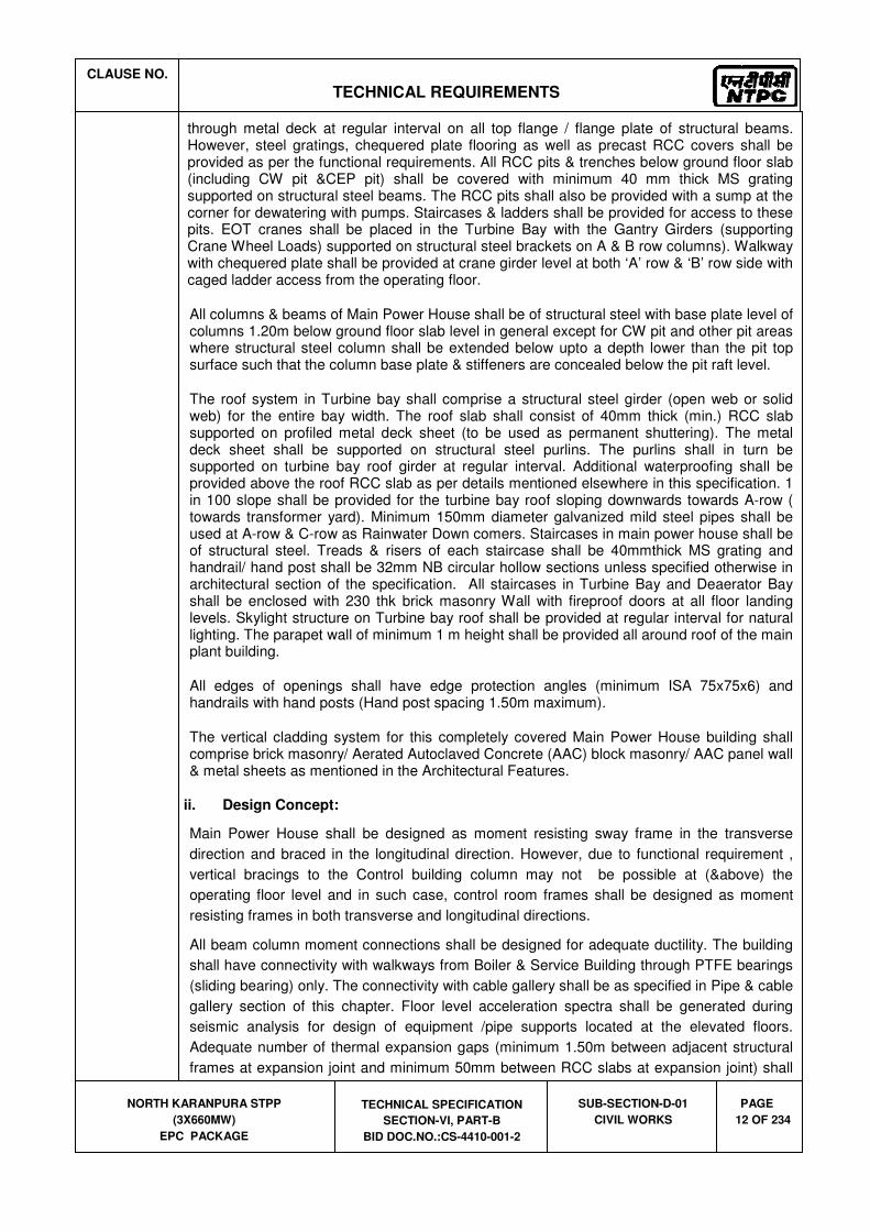
through metal deck at regular interval on all top flange / flange plate of structural beams. However, steel gratings, chequered plate flooring as well as precast RCC covers shall be provided as per the functional requirements. All RCC pits & trenches below ground floor slab (including CW pit &CEP pit) shall be covered with minimum 40 mm thick MS grating supported on structural steel beams. The RCC pits shall also be provided with a sump at the corner for dewatering with pumps. Staircases & ladders shall be provided for access to these pits. EOT cranes shall be placed in the Turbine Bay with the Gantry Girders (supporting Crane Wheel Loads) supported on structural steel brackets on A & B row columns). Walkway with chequered plate shall be provided at crane girder level at both ‘A’ row & ‘B’ row side with caged ladder access from the operating floor.
All columns & beams of Main Power House shall be of structural steel with base plate level of columns 1.20m below ground floor slab level in general except for CW pit and other pit areas where structural steel column shall be extended below upto a depth lower than the pit top surface such that the column base plate & stiffeners are concealed below the pit raft level.
The roof system in Turbine bay shall comprise a structural steel girder (open web or solid web) for the entire bay width. The roof slab shall consist of 40mm thick (min.) RCC slab supported on profiled metal deck sheet (to be used as permanent shuttering). The metal deck sheet shall be supported on structural steel purlins. The purlins shall in turn be supported on turbine bay roof girder at regular interval. Additional waterproofing shall be provided above the roof RCC slab as per details mentioned elsewhere in this specification. 1 in 100 slope shall be provided for the turbine bay roof sloping downwards towards A-row ( towards transformer yard). Minimum 150mm diameter galvanized mild steel pipes shall be used at A-row & C-row as Rainwater Down comers. Staircases in main power house shall be of structural steel. Treads & risers of each staircase shall be 40mmthick MS grating and handrail/ hand post shall be 32mm NB circular hollow sections unless specified otherwise in architectural section of the specification. All staircases in Turbine Bay and Deaerator Bay shall be enclosed with 230 thk brick masonry Wall with fireproof doors at all floor landing levels. Skylight structure on Turbine bay roof shall be provided at regular interval for natural lighting. The parapet wall of minimum 1 m height shall be provided all around roof of the main plant building.
All edges of openings shall have edge protection angles (minimum ISA 75x75x6) and handrails with hand posts (Hand post spacing 1.50m maximum).
The vertical cladding system for this completely covered Main Power House building shall comprise brick masonry/ Aerated Autoclaved Concrete (AAC) block masonry/ AAC panel wall & metal sheets as mentioned in the Architectural Features.
ii. Design Concept:
Main Power House shall be designed as moment resisting sway frame in the transverse
direction and braced in the longitudinal direction. However, due to functional requirement ,
vertical bracings to the Control building column may not be possible at (&above) the
operating floor level and in such case, control room frames shall be designed as moment
resisting frames in both transverse and longitudinal directions.
All beam column moment connections shall be designed for adequate ductility. The building
shall have connectivity with walkways from Boiler & Service Building through PTFE bearings
(sliding bearing) only. The connectivity with cable gallery shall be as specified in Pipe & cable
gallery section of this chapter. Floor level acceleration spectra shall be generated during
seismic analysis for design of equipment /pipe supports located at the elevated floors.
Adequate number of thermal expansion gaps (minimum 1.50m between adjacent structural
frames at expansion joint and minimum 50mm between RCC slabs at expansion joint) shall
CLAUSE NO.
TECHNICAL REQUIREMENTS
NORTH KARANPURA STPP
(3X660MW)
EPC PACKAGE
TECHNICAL SPECIFICATION
SECTION-VI, PART-B
BID DOC.NO.:CS-4410-001-2
SUB-SECTION-D-01
CIVIL WORKS
PAGE
13 OF 234
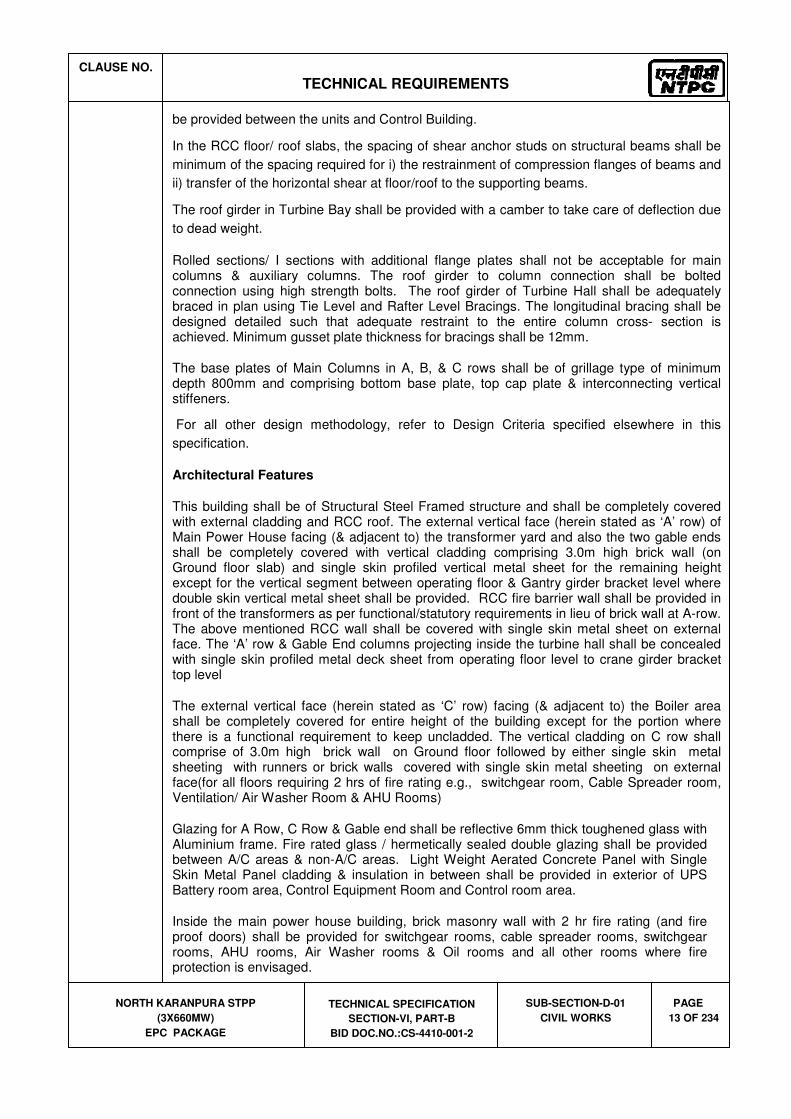
be provided between the units and Control Building.
In the RCC floor/ roof slabs, the spacing of shear anchor studs on structural beams shall be
minimum of the spacing required for i) the restrainment of compression flanges of beams and
ii) transfer of the horizontal shear at floor/roof to the supporting beams.
The roof girder in Turbine Bay shall be provided with a camber to take care of deflection due
to dead weight.
Rolled sections/ I sections with additional flange plates shall not be acceptable for main columns & auxiliary columns. The roof girder to column connection shall be bolted connection using high strength bolts. The roof girder of Turbine Hall shall be adequately braced in plan using Tie Level and Rafter Level Bracings. The longitudinal bracing shall be designed detailed such that adequate restraint to the entire column cross- section is achieved. Minimum gusset plate thickness for bracings shall be 12mm.
The base plates of Main Columns in A, B, & C rows shall be of grillage type of minimum depth 800mm and comprising bottom base plate, top cap plate & interconnecting vertical stiffeners.
For all other design methodology, refer to Design Criteria specified elsewhere in this
specification.
Architectural Features
This building shall be of Structural Steel Framed structure and shall be completely covered with external cladding and RCC roof. The external vertical face (herein stated as ‘A’ row) of Main Power House facing (& adjacent to) the transformer yard and also the two gable ends shall be completely covered with vertical cladding comprising 3.0m high brick wall (on Ground floor slab) and single skin profiled vertical metal sheet for the remaining height except for the vertical segment between operating floor & Gantry girder bracket level where double skin vertical metal sheet shall be provided. RCC fire barrier wall shall be provided in front of the transformers as per functional/statutory requirements in lieu of brick wall at A-row. The above mentioned RCC wall shall be covered with single skin metal sheet on external face. The ‘A’ row & Gable End columns projecting inside the turbine hall shall be concealed with single skin profiled metal deck sheet from operating floor level to crane girder bracket top level
The external vertical face (herein stated as ‘C’ row) facing (& adjacent to) the Boiler area shall be completely covered for entire height of the building except for the portion where there is a functional requirement to keep uncladded. The vertical cladding on C row shall comprise of 3.0m high brick wall on Ground floor followed by either single skin metal sheeting with runners or brick walls covered with single skin metal sheeting on external face(for all floors requiring 2 hrs of fire rating e.g., switchgear room, Cable Spreader room, Ventilation/ Air Washer Room & AHU Rooms)
Glazing for A Row, C Row & Gable end shall be reflective 6mm thick toughened glass with Aluminium frame. Fire rated glass / hermetically sealed double glazing shall be provided between A/C areas & non-A/C areas. Light Weight Aerated Concrete Panel with Single Skin Metal Panel cladding & insulation in between shall be provided in exterior of UPS Battery room area, Control Equipment Room and Control room area.
Inside the main power house building, brick masonry wall with 2 hr fire rating (and fire proof doors) shall be provided for switchgear rooms, cable spreader rooms, switchgear rooms, AHU rooms, Air Washer rooms & Oil rooms and all other rooms where fire protection is envisaged.

CLAUSE NO.
TECHNICAL REQUIREMENTS
NORTH KARANPURA STPP
(3X660MW)
EPC PACKAGE
TECHNICAL SPECIFICATION
SECTION-VI, PART-B
BID DOC.NO.:CS-4410-001-2
SUB-SECTION-D-01
CIVIL WORKS
PAGE
14 OF 234
Cut-outs and opening shall be provided in floors and walls as per functional requirement.
Sky light structure shall be provided in curved shape with 4mm embossed clear translucent polycarbonate IR sheet both side UV coated minimum 55% light transmission, solar control, approved make, texture and shade, fixed to powder coated Aluminium section with 60mm width top & bottom with EPDM gasket as per standard framing.
The Control Room / Control Equipment Room shall have 120 minutes Fire Rated Fully Glazed non load bearing fixed partition with valid fire test certificate from national or international lab. The Partition Frame shall be manufactured from minimum 2.0mm galvanized steel sheet pressed to form a profile of nominal size 60mm x 70 mm & fixed to the supporting construction by means of M 10 X 120 or bigger steel bolts at 300mm from the edges & every 500mm c/c.
False ceiling in Control Room / Control Equipment Room shall be of GI Metal Ceiling Clip in plain Bevelled edge global white colour tiles of size 600x600 and 0.5mm thick with 25mm height.
All door, windows in air conditioned area and all windows glazing shall be provided with Aluminium frame-work Steel door and Fire Proof doors shall be provided as per requirements. Area of windows shall be minimum 10 % of floor area.
Each unit shall have minimum 1 nos. of passenger lift of capacity 13 persons in BC way, Stairs in BC Bay and on A-Row shall be provided as per functional requirement and as per National Building Code and factories Act.
All stairs in BC Bay lift lobby Area shall be in RCC. Stainless steel railing shall be provided at TG Floor level for all cut-outs/ openings and stairs & M.S. railing shall be provided for all other locations.
For each unit, minimum one number Gent's toilet with adequate facilities including Drinking water space and Janitor's space shall be provided at each level of Power house Building, in addition one no Ladies toilet shall be provided in each unit at ground floor, mezzanine floor and operating floor level.
Main Control Room façade on B-Row shall have Fire rated glass partitions up to false ceiling level and brick masonry wall above false ceiling up to floor slab above Control Room, finished with Decorative murals in Tiles & Aluminium Composite Panels.
In Control room/ Control Equipment Room, Cat Walk Way above false ceiling shall be provided for service/ maintenance.
Adequate partitioning as per functional requirement above false ceiling in control Room &
CER shall be provided for Inert Gas zoning by brick wall /aerated concrete panel wall for inert
gas partitioning.
Internal steel columns in Air Conditioned Area of Main Power House Building shall be encased with Aluminium Composite Panelling up to false ceiling.
Functionally the very heart of Power House Building is its Control Room. Special attention shall be given for conceptualisation of interior design of the Control Room.
Metal Panel Cladding shall be composed of Different Colour shades to match with the surroundings. External finish of Masonry wall, shall be Resin Bounded Granular Texture finish.

CLAUSE NO.
TECHNICAL REQUIREMENTS
NORTH KARANPURA STPP
(3X660MW)
EPC PACKAGE
TECHNICAL SPECIFICATION
SECTION-VI, PART-B
BID DOC.NO.:CS-4410-001-2
SUB-SECTION-D-01
CIVIL WORKS
PAGE
15 OF 234
b) Mill and Bunker building
The mill bunker building shall house coal mills, feeders, Cylindrical Coal Bunker & Conical Hopper, Tripper Conveyor & its drive and monorails. All columns, main beams and secondary beams shall be made of structural steel. The RCC floor slabs (supporting the Feeder and Tripper Conveyors) shall comprise RCC slab supported on profiled metal deck sheet (to be used as permanent shuttering not to be considered for design of RCC slab as composite slab) and Shear anchor studs shall be provided with stud welding through metal deck at regular interval on all top flange / flange plate of structural beams which support the RCC slab.
Structural steel platform (with MS grating and hand rails and cage ladder) shall be provided above the feeder floor for access to the bunker coal level monitoring strain gauges.
The bottom level of base plates of columns shall be 1.20 M below the finished floor level of ground floor of Main Power House. The columns of Mill-Bunker building shall consist of built up structural steel I-sections. Rolled sections with additional cover plates on column flange shall not be acceptable for column sections. The base plate of main columns of the Mill bunker building shall be grillage type (minimum 800 depth) consisting of bottom base plate, top plate and vertical stiffeners.
The cylindrical coal bunker and conical hopper shall be made of structural steel. The inside surface of hopper shall be lined with stainless steel plates the details of which are mentioned hereafter in this specification.
Structural steel brackets with PTFE bearings shall be provided at the end columns to support the external gallery of the Tripper Conveyor.
All walkway bridges connecting the Boiler with Mill Bunker building shall have PTFE bearings, in case the Mill-Bunker building is designed as structurally independent of the Boiler structure.
The Mill-Bunker building shall be provided with insulated, sandwiched metal sheet roofing comprising of troughed profile permanently colour coated sheet on outside and plain permanently colour coated sheet on inside with 50mm thick mineral wool insulation in
between the two sheets. A slope of 1 in 5 shall be provided for quick drainage of rain water.
The RCC floor supporting the tripper conveyor shall be fully covered upto the roof level with single skin metal sheet fixed over structural steel runners.
Bidder has the option to provide the Mill Bunker Building structurally independent of the Boiler supporting structure or integrate this building with the Boiler structure.
i) Design Concept
The Mill Bunker Building shall be conceptualized as moment resisting frames in transverse direction and as braced framed in longitudinal direction. In the transverse direction the bracings may be provided, wherever feasible, in order to meet the deflection requirement specified in clause 6.03.07 of this section. The bracings in the longitudinal direction shall be in 2 planes through a pair of longitudinal members laced (or battened) together. Each bracing member shall be connected to column flange plate through gusset plate (minimum 12mm thick).

CLAUSE NO.
TECHNICAL REQUIREMENTS
NORTH KARANPURA STPP
(3X660MW)
EPC PACKAGE
TECHNICAL SPECIFICATION
SECTION-VI, PART-B
BID DOC.NO.:CS-4410-001-2
SUB-SECTION-D-01
CIVIL WORKS
PAGE
16 OF 234
Minimum thickness of structural steel Bunker plates shall be 12mm inclusive of 4mm corrosion allowance. Minimum wall thickness of Hopper shall be 8mm. Minimum thickness of stainless steel liners on the inner surface of hopper wall shall be 4mm conforming to grade SS304. To ensure smooth flow of coal, the hopper surface shall be provided with minimum angle of 73
o with the horizontal plane.
The top of the cylindrical bunker shall bear no load/ reaction from the tripper floor and accordingly neoprene bellow strap shall be provided at the interface between the two structures to allow free deflection of the tripper floor. Neoprene bellow strap shall be provided all-round the bunker to effectively seal the gap between top of bunker and sealing plate below bunker.
For all other design methodology, refer to Design Criteria specified hereafter in this specification.
Architectural Features:
The Mill & Bunker Building shall be a structural steel framed structure having RCC floors and prefabricated insulated metal sandwiched sheet sloped roof. The tripper floor side cladding shall be Single skin Metal cladding with steel louvered windows and fixed windows with poly carbonate sheet glazing. Area of windows shall be minimum 10 % of floor area. Rainwater down comer shall be of galvanised MS pipes and shall be located at every column location.
c) Transfer Points and Conveyor Galleries
Transfer Points
The transfer points shall be framed structure of structural steel work having RCC floors
(supported on structural steel beams) and prefabricated insulated metal sandwiched sheet
sloped roof. The RCC floor slabs shall comprise RCC slab supported on profiled metal deck
sheet (to be used as permanent shuttering not to be considered for deign of RCC slab as
composite slab) and Shear anchor studs shall be provided with stud welding through metal
deck at regular interval on all top flange / flange plate of structural beams which support the
RCC slab. The side cladding shall be Single skin Metal cladding (from lowest working floor
level till roof top) with steel louvered windows and fixed windows with poly carbonate sheet
glazing. Area of windows shall be minimum 10 % of floor area. However the lower portion of
side cladding for a minimum height of 0.9 m above the finished floor level shall be one brick
thick wall plastered on both sides. In some areas like MCC floors etc., one brick thick wall
cladding shall be provided. Brick wall cladding shall be supported on encased wall beams
and suitably anchored to adjoining columns and beams. Contractor shall have option to use
Tubular steel sections for vertical & horizontal bracings. Horizontal bracings at all platforms
levels shall be designed as beam carrying axial force and bending moment to take care of
loads from platforms for maintenance and Gravity Take-up.
Brackets and beams for supporting the Conveyor gallery portal shall be provided at required
elevation on columns of Transfer Point.
Grade slab shall be provided for all transfer point houses.
Steel doors and sliding steel doors of required sizes as per system requirement for personnel
access and handling of equipment respectively shall be provided.
Transfer points shall be provided with insulated, sandwiched metal sheet roofing comprising

CLAUSE NO.
TECHNICAL REQUIREMENTS
NORTH KARANPURA STPP
(3X660MW)
EPC PACKAGE
TECHNICAL SPECIFICATION
SECTION-VI, PART-B
BID DOC.NO.:CS-4410-001-2
SUB-SECTION-D-01
CIVIL WORKS
PAGE
17 OF 234
of troughed profile permanently colour coated sheet on outside and plain permanently colour
coated sheet on inside with 50mm thick mineral wool insulation in between the two sheets. A
slope of 1 in 5 shall be provided for quick drainage of rain water.
For TP’s in Main Plant Area, each down comer shall lead the water / coal slurry into the RCC
pit (of 2 Cu.M capacity) to allow settling of coal. The water from the pit shall overflow into
R.C.C drain(RCC drains with steel gratings provided around the TP), which will lead the
discharge finally into plant effluent drain routed alongside the nearby road.
Conveyor Galleries and Trestles
Troughed belt conveyors in Main Plant Area shall be housed in a suitably enclosed gallery of
structural steel. The overhead gallery shall consist of two vertical latticed girders having rigid
jointed portal frame at both ends. Cross beams at floor level supporting conveyor stringer
beams shall be made of single rolled steel beam or single channel section (ISMB or ISMC) or
plate girder. Horizontal bracings are to be provided at top & bottom plan of the gallery
(latticed girders shall be braced together in plan at the top and bottom). Common end portal
frame shall not be used for adjacent conveyor spans. Roof truss shall be provided at upper
node points of latticed girders to form an enclosure. Conveyor gallery shall have permanently
colour coated steel sheet covers on roof and both sides. However in roof, a panel of
minimum 1.5 m x 1.5 m area at about 6.0 m center shall be provided with translucent sheets
of polycarbonate material for natural lighting. A continuous slit opening of 500 mm shall be
provided on both sides just below the roof sheeting. Adequate provision of windows shall be
kept on both sides of conveyor gallery as appended in Mechanical Section (Belt conveyor
system). Windows shall be provided with wire mesh as specified elsewhere in this
specification.
The maximum span of conveyor gallery shall be limited to 25 meters unless higher span is
required due to site conditions, which shall be subject to approval of the Engineer. The
gallery should as far as possible be erected as a box section keeping all the vertical and
horizontal bracing tied in proper position. The gallery should be checked for all erection
stresses that are likely to develop during handling and erection and if required, temporary
strengthening of gallery members during erection shall be made. Contractor can also use
tubular steel sections for conveyor galleries and supporting trestles. The tubular steel section
shall be of circular/rectangular/square shape. The circular steel tube shall conform to IS:1161
and rectangular/square steel sections shall conform to IS:4923. The steel structures using
tubular sections shall be designed and fabricated as per IS:806 – “Code of Practice for use of
steel tubes in general building construction.” and EN 1993-1-8:2005.
For double stream conveyor gallery, two side and one central walkway of minimum width 800
mm and 1100 mm respectively shall be provided. The minimum width of two side walkways
for single stream conveyor gallery shall be 800 mm and 1100 mm respectively. Both sides of
central and side walkways shall be provided with pipe handrails all along the conveyor
gallery. Hand railing should not be supported on conveyor supporting stringers. The
walkways shall be of chequered plate construction with anti - skid arrangement. The anti -
skid arrangement will consist of welding of 10 mm square steel bars at a maximum spacing
of 500 mm along the length of the gallery. Where the slope of walkway is more than 10o,
chequered plate steps with nosing and toe guard shall be provided. Seal plates under the
conveyor galleries shall be provided in such a way that complete gallery bottom shall form a
leak proof floor. The floor of conveyor gallery all along the gallery length, shall be provided

CLAUSE NO.
TECHNICAL REQUIREMENTS
NORTH KARANPURA STPP
(3X660MW)
EPC PACKAGE
TECHNICAL SPECIFICATION
SECTION-VI, PART-B
BID DOC.NO.:CS-4410-001-2
SUB-SECTION-D-01
CIVIL WORKS
PAGE
18 OF 234
with minimum 12 gauge thick seal plates and other drainage arrangements as specified
elsewhere.
Conveyor gallery supporting trestles located between transfer points / buildings shall be four
legged type only. One end of each gallery span shall be hinged to the supporting trestle and
the other end shall be slide type. Slide type support shall be with P. T. F. E. bearings to allow
both rotation & longitudinal movements.
End of conveyor gallery which will be supported over transfer point, shall be so detailed that
only vertical reaction is transferred from conveyor gallery and no horizontal force in
longitudinal direction is transferred from conveyor gallery to transfer point structure and vice -
versa.
For trestles and trestle foundations for conveyor galleries located adjacent to existing
structures, over ground and under ground facilities, location and details of these trestles and
foundations shall have to be decided such that there is no interference both underground as
well as over ground with existing structures and facilities. Trestle columns base shall be kept
1.2m below the finished floor level of ground floor of Main Power House.
d) Machine Foundations in Main Plant Area
Turbo- Generator (TG) foundation:
Alternative-1
The TG foundation shall comprise of RCC top deck supported on steel helical springs & viscous dampers (herein after called as the Vibration Isolation System – VIS) and shall be located in the Turbine bay of Main Power House. The VIS shall be placed on a group of RCC/ Structural Steel columns. These TG columns can be interconnected to the Main Power House Building frame either rigidly or connected through PTFE bearings on corbels/ brackets of the TG Columns. The general arrangement & details of VIS and supporting group of columns and beams shall be based on TG Equipment detail of the Bidder.
Alternative-2
The TG foundation shall be conventional machine foundations comprising of RCC top deck directly supported on substructure comprising of columns and beams without any steel helical springs and viscous dampers. The columns shall be rigidly connected to the RCC deck at top and shall rest on open / pile supported foundation at bottom. The entire foundation system (including deck, columns and raft) shall be isolated from the main plant building structural system and no connection between the main plant structure and TG foundation is permitted.
Bidder has the option to choose either Alternative -1 or Alternative-2 based on his design philosophy and practice. However in case Alternative-2 is adopted by bidder, then the bidder has to furnish extended warranty of five years for satisfactory static and dynamic performance of the foundation system.
TDBFP & MDBFP foundations:

CLAUSE NO.
TECHNICAL REQUIREMENTS
NORTH KARANPURA STPP
(3X660MW)
EPC PACKAGE
TECHNICAL SPECIFICATION
SECTION-VI, PART-B
BID DOC.NO.:CS-4410-001-2
SUB-SECTION-D-01
CIVIL WORKS
PAGE
19 OF 234
Alternative-1
TDBFP&MDBFP foundations shall consist of RCC top deck supported on steel helical springs & viscous dampers inside Main Power House. In case the top deck is located at operating floor/mezzanine floor level, the springs/ viscous dampers shall be supported on a group of structural steel columns-beam grid which shall be rigidly integrated with the Main Power House Structural frame.
Alternative-2
TDBFP&MDBFP foundations shall consist of RCC top deck directly supported on structural beams and columns without any steel helical springs & viscous dampers inside Main Power House. The structural columns and beams supporting the TDBFP / MDBFP shall be independent of the Main Power House Structural frame and shall also have independent foundation without any connection to other nearby foundations. Further each TDBFP / MDBFP shall have independent supporting structural arrangement without any interconnection among themselves.
Bidder has the option to choose either Alternative-1 or Alternative-2 based on his design philosophy and practice. However in case Alternative-2 is adopted by bidder, then the bidder has to furnish extended warranty of five years for satisfactory static and dynamic performance of the foundation system.
BFPs in ground floor
In case the MDBFP/TDBFP foundation is envisaged to be located at ground floor of Main Power House, then these shall be designed as block foundations directly resting on soil / pile. Vertical facing of this block foundation shall be isolated from adjacent footings by providing minimum 100mm thick polystyrene board of type-1 conforming to IS:4671 with density 20 Kg/Cum sandwiched between the vertical face of block foundation and 230 thick brick wall all round.
PA/ FD/ID Fan foundations:
Alternative-1
These fan foundations shall consist of RCC top deck supported on steel helical springs & viscous dampers. The springs & viscous dampers shall be in turn supported on RCC sub-structure which shall be supported below Ground level.
Alternative-2
These fan foundations shall consist of RCC top deck supported on RCC sub-structure which shall be supported below Ground level either with open or pile foundation.
Bidder has the option to choose either Alternative -1 or Alternative-2 based on his design philosophy and practice. However in case Alternative-2 is adopted by bidder, then the bidder has to furnish extended warranty of five years for satisfactory static and dynamic performance of the foundation system.
Coal Mill foundation:
Coal Mill foundation shall be RCC block foundation directly resting on virgin soil below Ground level. The vertical faces of this block foundation shall be isolated from adjacent footings by providing minimum 100mm thick polystyrene board of type-1 conforming to

CLAUSE NO.
TECHNICAL REQUIREMENTS
NORTH KARANPURA STPP
(3X660MW)
EPC PACKAGE
TECHNICAL SPECIFICATION
SECTION-VI, PART-B
BID DOC.NO.:CS-4410-001-2
SUB-SECTION-D-01
CIVIL WORKS
PAGE
20 OF 234
IS: 4671 with density 20 Kg/cum sandwiched between the vertical face of block foundation and 230 thick brick wall all round.
General requirement for machine foundations:
• The vibration isolation system (where ever applicable) supplied shall be of proven make and shall be in successful operation supporting machines like steam turbo-generators, ID/PA/FD Fans, BFP, etc.,
• Springs and dampers of the vibration isolation system shall be located minimum 300 mm above the finished floor level for ID/PA/FD fans. Basements/pits/trenches shall not be provided for these machine foundations.
• Wherever alternative-2 is adopted by the bidder for TG or BFPs or FAN foundations, suitable provisions to be ensured by the bidder in their General Arrangement and design to prevent transmission of vibration from these machine foundations to other nearby structures / foundations.
• The bidder or his consultant should have adequate prior experience in design of machine foundations for the respective alternative to be adopted by the bidder and the machines should be in successful operation for al least one year prior to the date of submission of bid.
For detailed specification of steel helical springs and viscous dampers refer clause no 8.07.00.
Design Criterion:
Refer clause 6.03.21 for design criterion of machine foundations
e) Boiler Structure
The Boiler supporting structure shall be structural steel framed superstructure adequately braced in vertical planes in both the orthogonal directions. The general arrangement & details of structural steel columns, beams, bracings, ceiling girders etc shall be as per the Bidders Boiler Structure design and detailed engineering scheme.
The bottom level of base plates of columns shall be 1.20 M below the finished floor level of ground floor of Main Power House. The RCC pedestals supporting the column base plates shall be extended in order to provide RCC encasement to the structural steel columns up to at least 350mm above the top of the paving RCC slab.
The bidder shall have the option to design the Boiler structural steel superstructure as an isolated structure or structurally integrate it with the Mill-Bunker building superstructure based on Bidder’s design practice.
(i) Design Concept:
Boiler supporting super-structure shall be designed by the Bidder based on working stress method for structural steel as per IS 800 and as IS : 456 for RCC sub-structure (foundations).

CLAUSE NO.
TECHNICAL REQUIREMENTS
NORTH KARANPURA STPP
(3X660MW)
EPC PACKAGE
TECHNICAL SPECIFICATION
SECTION-VI, PART-B
BID DOC.NO.:CS-4410-001-2
SUB-SECTION-D-01
CIVIL WORKS
PAGE
21 OF 234
f) Compressor House
(i) Salient Features:
The compressor house shall be a framed superstructure of either RCC or structural steel construction with a overhead crane of required capacity. The gantry girder for the crane shall have walkway with chequered plate on both rows and cage ladder access.
The ground floor slab shall comprise of all RCC block foundations, cable trenches and pipe trenches.
(ii) Design Concept:
Framing arrangement shall be as specified in clause 6.01.03 iii) for steel structure and clause 6.01.03 iv) for concrete structure.
Design shall also be based on the Design Criteria specified elsewhere in this specification.
Architectural Features
This building shall be clad with brick wall up to window sill height & Single Skin Metal cladding above it. Roof of the building shall be insulated sandwiched double skin metal sheeting. However, in case of RCC construction bidder shall have option to provide brick masonry cladding for full height of the building and RCC slab roof.
Cut-outs and opening shall be provided in floors and walls as per requirements.
Metal cladding shall be composed of different colour shades to match with the surroundings. External finish shall be of Premium Acrylic Smooth Paint.
The size, height, door/window/rolling shutter details and building size shall be as per the approved equipment layout plan of the bidder.
g) ESP structure:
(i) Salient Features
The ESP structure shall be a structural steel superstructure with vertical bracings in the required vertical planes in both longitudinal and transverse directions, the details of which shall be as per the approved ESP equipment GA & details of the bidder. The bottom level of base plate of the structural columns shall be kept such that, the top of gusset plate / top of bolts shall be at least 200mm below the top of finished floor level. The gusset plate / base plate shall be encased in concrete upto the bottom of the floor slab. The RCC pedestals of the columns shall be extended upto at least 350mm above the ground floor slab for encasement of the columns.
(ii) Design Concept:
Design of ESP structure shall be based on Working stress method as per IS 800. It shall be an axially braced structure in both orthogonal directions. The ESP supporting columns shall be suitably strengthened about the minor axis for sliding movement of the base plate of ESP due to thermal movement.

CLAUSE NO.
TECHNICAL REQUIREMENTS
NORTH KARANPURA STPP
(3X660MW)
EPC PACKAGE
TECHNICAL SPECIFICATION
SECTION-VI, PART-B
BID DOC.NO.:CS-4410-001-2
SUB-SECTION-D-01
CIVIL WORKS
PAGE
22 OF 234
h) Air Cooled Condenser Supporting Structure
The Air Cooled Condenser (ACC) supporting structure shall be structural steel framed superstructure adequately braced in vertical planes in both the orthogonal directions. The general arrangement & details of structural steel columns, beams, bracings, etc shall be as per the Bidders ACC Structure design and detailed engineering scheme.
The bottom level of base plates of columns shall be 1.20 M below the finished floor level of ground floor of Main Power House. The RCC pedestals supporting the column base plates shall be extended in order to provide RCC encasement to the structural steel columns up to at least 350mm above the top of the paving RCC slab.
The bidder shall have the option to design the ACC structural steel superstructure as an isolated structure or structurally integrate it with the Main Plant building superstructure based on Bidder’s design practice.
(ii) Design Concept:
ACC supporting super-structure shall be designed by the Bidder based on working stress method for structural steel as per IS 800 and as IS : 456 for RCC sub-structure (foundations).
i) ESP Control Building
(i) Salient Features
ESP Control Building shall be a framed superstructure of either RCC or structural steel construction with RCC floors at ground floor level and upper levels. The RCC floors at upper levels shall be cast in situ RCC slabs supported on profiled metal deck incase of structural steel construction. Roof of the building shall be insulated sandwiched double skin metal sheeting. However, in case of RCC construction bidder shall have option to provide brick RCC slab roof. The rainwater down comers shall be as per specification and shall be suitably concealed.
The external Transformer Yard of the building shall comprise the transformer foundations and cable slit below ground level.
The building shall have Lift structure with lift pit below ground level and staircase at each gable end of the building.
(ii) Design Concept
Framing arrangement shall be as specified in clause 6.01.03 iii) for steel structure and clause 6.01.03 iv) for concrete structure. However, bracings in any internal axis may not be possible due to functional requirement and columns in that row shall be designed for biaxial bending.
Design shall also be based on the Design Criteria specified elsewhere in this specification.
Architectural Features:
This building shall be framed structure & shall be completely covered with Autoclaved aerated concrete panels on all four sides except for the portion in front of the external Transformer Yard. Provision for glazed/ fire proof doors & windows shall be included. Minimum 345mm thk brick wall shall be provided for the external brick

CLAUSE NO.
TECHNICAL REQUIREMENTS
NORTH KARANPURA STPP
(3X660MW)
EPC PACKAGE
TECHNICAL SPECIFICATION
SECTION-VI, PART-B
BID DOC.NO.:CS-4410-001-2
SUB-SECTION-D-01
CIVIL WORKS
PAGE
23 OF 234
wall facing the adjacent transformer yard and the brick wall height shall be 600mm above the highest point of the transformer. Inside the building, AHU rooms, UAF Room & Battery rooms shall have brick masonry of one brick thickness.
Entire transformer yard, which shall be adjacent to the building, shall be provided with metal fencing with gates.
The building shall accommodate cable vault, toilet, staircase, switchgear rooms, control rooms and AHU room. An auxiliary transformer yard with fencing and gate shall be provided adjoining to the building. Control room and VFD room shall be air-conditioned and shall have false ceiling. Windows& Ventilators all shall be provided with Aluminium sections. All doors, windows in air conditioned area shall be provided with hermetically sealed toughened glass glazing in Aluminium frame work Steel doors and Fire proof doors shall be provided as per requirements. Internal columns in Control Room shall be encased with Aluminium Composite Panel cladding/ Laminated Board Panelling
Minimum 2 Nos. of stairs and 2 Nos. of Toilets shall be provided as per requirement. Cut-outs and opening shall be provided in floors and walls as per requirements.
External finish shall be of Premium Acrylic Smooth Paint.
j) Miscellaneous Equipment Foundations & Pipe Cable Trenches/ and Pedestals below finished ground level.
Refer clause 7.02.01 for design criterion for Miscellaneous Equipment Foundations & Pipe Cable Trenches/ and Pedestals below finished ground level.
k) Pipe & Cable Galleries
(i) Salient Features:
The Pipe & Cable Galleries shall be Structural Steel Superstructure. The steel galleries shall be supported on 2 legged/ 4 legged trestles, the arrangement of which shall be developed by the Bidder. The width of the Galleries shall vary depending on the functional requirement. A walkway as per requirement shall be provided along the Cable Trays supporting tier of the gallery. The walkway shall comprise MS grating and 1.0m high handrail made of 32NB MS pipes.
Plan bracings shall be provided at all levels/tiers of the pipe & cable gallery girders. Minimum gusset plate thickness shall be 8mm for all connections.
The level of the bottom of steel of the gallery shall be at least 3.0m above the finished paving level in general. However, at all road crossings, the level of bottom of steel of the gallery shall be at least 8.0m from the top of road surface.
The Caged structural steel ladder shall be provided at an interval of 200m for access to the Pipe & Cable Gallery Walkway.
Suitable expansion gap shall be provided in the gallery structure by providing twin two-legged trestles at the expansion gap. The expansion gap shall be provided at an interval of 100 to 120m. Expansion gap shall also be provided at location where changes in plan dimensions (gallery width) take place abruptly.
At the inter-connection of Pipe/Cable gallery with Plant buildings, Pipe/Cable gallery shall be terminated at a maximum distance of 1.50m from the building. The

CLAUSE NO.
TECHNICAL REQUIREMENTS
NORTH KARANPURA STPP
(3X660MW)
EPC PACKAGE
TECHNICAL SPECIFICATION
SECTION-VI, PART-B
BID DOC.NO.:CS-4410-001-2
SUB-SECTION-D-01
CIVIL WORKS
PAGE
24 OF 234
foundation of the Pipe/Cable Trestle shall be constructed at a distance of 4.0M from center line of the plant building. Cantilever of 2.50m shall be taken from pipe-cable trestle structure.
(ii) Design Concept:
The pipe-cable structure shall be designed as a 3-dimensional space frame for all the relevant load cases mentioned in the design criteria chapter.
The gallery being an unclad structure, wind load shall be evaluated based on the projected frontal area of the structural members and cable tray depth.
The end portals shall be designed as rigid frames hinged (pinned support) at the base plate level (on top of the trestle column). Deflection of end portal due to wind shall be evaluated at the portal column-rafter joint. The gallery vertical girder shall be designed as simply supported girders on trestles and detailing of end portals shall be done accordingly.
The foundation for Pipe-Cable gallery trestles shall comprise RCC pedestals and foundations. The foundations shall rest on virgin soil. In case virgin soil depth is high, the gap shall be filled with PCC (M10 grade). The grade of concrete for RCC footing & pedestals shall be M25. The structural trestles shall not be supported on paving RCC slab.
l) Service Building
This building shall be an RCC structure having RCC frame with RCC floors and roof slab. For the building, floor-to-floor height shall be as per architectural features. A connecting corridor with MPH building shall be provided at operating floor level. The grade of concrete for RCC frame (including foundation) shall be M25.
Architectural Features
This building shall be designed as GRIHA (Green Rating for Integrated Habitat Assessment) compliant and shall be with floor area of 5500 sq.m in Ground + 4 Storeys. Autoclave Aerated Concrete Block masonry wall shall be provided for the full height of the building for both external and internal walls. Floor-to-floor height shall be minimum 4.25m.
This building shall provide offices for Operation staff, Conference room for 50 persons, C & I Laboratory, Exhibition Hall, VIP Lounge etc. This will be fully air-conditioned building with adequate provision of toilets, pantry, cabins for senior executives and separate rooms for executives, supervisors etc. Lift structure with RCC lift pits shall be located inside the service building. Separate toilet facilities shall be provided for ladies and gents in each floor. One toilet shall be provided for physically handicapped on each floor. The building shall have provision of attached toilet with the cabin for senior executives and conference rooms. 2 no's of staircases and 2 no's of lifts with adequate capacity shall be provided. One store room shall be provided.
Hermetically sealed double glazing with toughened glass shall be provided for external glazing.
A connecting corridor with Main Power House building shall be provided at operating floor level of Main Power House. The floor of the connecting corridor shall have vitrified ceramic tiles, stainless steel hand rail & fixed windows. The

CLAUSE NO.
TECHNICAL REQUIREMENTS
NORTH KARANPURA STPP
(3X660MW)
EPC PACKAGE
TECHNICAL SPECIFICATION
SECTION-VI, PART-B
BID DOC.NO.:CS-4410-001-2
SUB-SECTION-D-01
CIVIL WORKS
PAGE
54 OF 234
65 Kgs. At road crossings & entry locations, trench covers designed for 10 T wheel load at
centre shall be provided. Pre - cast covers shall be designed for central point load of 75 Kgs.
R. C. C. cable trenches shall be filled with sand after erection of cables, up to top level and
covered with pre - cast R. C. C. covers. For cable trenches outside buildings, top level shall
be 200 mm above G. L and sand filling shall be overlaid with 50 thk. PCC.
Minimum 50 x 50 x 6 mm size angles with lugs shall be provided as edge protection all
around cut outs / openings in floor slabs, edges of drains supporting grating/precast RCC
covers, edges of R. C. C. trenches supporting pre - cast covers, supported edges of pre -
cast cover.
5.07.12 Drainage & Water Supply Works
5.07.12.01 Drainage System
The drainage arrangements shall be so planned so as to ensure quick disposal of drainage water without stagnation and / or overflow. It is envisaged to clean the conveyor galleries, transfer points, crusher building, penthouse etc. with water periodically.
Minimum 4 nos. down comers shall be provided in each transfer house / crusher house. In case of conveyor galleries, the down comer shall be provided at every trestle location.
Drainage of the complete coal stock pile, area around stacker reclaimer rails etc. shall be discharged into the coal slurry settling pond.
For Conveyors in Main plant area each down comer shall lead the water / coal slurry to RCC pit (of 2 Cu.M capacity) to allow settling of coal. The water from the pit shall overflow into R.C.C drain, which will lead the discharge finally into trunk drain routed alongside the nearby road.
For Conveyors in stock pile area, each down comer shall lead the water / coal slurry to RCC pit (of 2 Cu.M capacity) to allow settling of coal. The water from the pit shall overflow into R.C.C drain, which will lead the discharge finally to the coal settling pond. For Crusher House, Pent Houses & TP’s in stock pile area, each down comer shall lead the water / coal slurry into the peripheral drains (Brick drains with steel gratings provided around the building) which will lead the water / coal slurry to water / coal slurry to RCC pit (of 2 Cu.M capacity) to allow settling of coal. The water from the pit shall overflow into R.C.C drain, which will lead the discharge finally to the coal settling pond. For TP’s in Main plant area, each down comer shall lead the water / coal slurry into the peripheral drains (Brick drains with steel gratings provided around the building) which will lead the water / coal slurry to RCC drain and finally into trunk drain routed alongside the nearby road. For reclaim hopper, peripheral drains (Brick drains with steel gratings provided around the building) shall lead the water / coal slurry to a local RCC pit (of 2 Cu. M. capacity) near each facility to allow settling of coal. The water from the pit shall overflow into R.C.C drain, which will lead the discharge finally to the coal settling pond. In case of Control rooms and M. C. C. buildings, Pump houses, etc, water / coal slurry coming from down comers shall discharge into peripheral drains (Brick drains with steel gratings provided around the building) which will lead the water / coal slurry into R.C.C drain,

CLAUSE NO.
TECHNICAL REQUIREMENTS
NORTH KARANPURA STPP
(3X660MW)
EPC PACKAGE
TECHNICAL SPECIFICATION
SECTION-VI, PART-B
BID DOC.NO.:CS-4410-001-2
SUB-SECTION-D-01
CIVIL WORKS
PAGE
55 OF 234
which will lead the discharge finally into trunk drain routed alongside the nearby road/ coal settling pond.
Suitable kick plates/Curb beams shall be provided around the floor openings, stair case landings, in the transfer points, crusher house and other buildings. Contractor’s scope shall also include construction of necessary culverts under the rail lines / roads as per railway / I. R. C. standards and approval of Railway culverts from concern Railway authorities.
5.07.12.02 Internal and external water supply, drainage etc.:-
The scope for potable water supply includes all distribution systems, tanks, pipes, fittings etc. as required and as described here or elsewhere in these specifications.
The scope for service water supply and dust control water supply shall be as described elsewhere in these specifications.
For water supply, medium class galvanized mild steel pipes conforming to IS: 1239 shall be used.
The scope for drainage of surface water shall include design, layout and construction of
drains for and from buildings and drains required for coal stockyard area, drainage up to
main coal slurry settling tank including connection with the tank. Drainage system shall be
designed for maximum intensity of rainfall as 75 mm/hr and 60 % runoff coefficient. All
buildings (including transfer houses and crusher house) shall be provided with open surface
brick drains of minimum size of 300 mm width and 300 mm depth all around the periphery.
All drains excepting the peripheral drains around the transfer points, crusher house, control /
M. C. C. buildings, pumps house etc., shall be of R. C. C. construction. All open drains shall
have removable steel grating designed for loads as specified under loading clause. Minimum
size of main bar of grating (Galvanised to 610 gm/m2) shall be 12 mm x 3mm and cross bars
6mm. At all entry or road/rail crossing point’s RCC box/pipe culvert shall be provided. The
opening size of grating shall not be more than 90 mm x 35 mm. All drains as well as pre -
cast covers shall be provided with edge protection angles and lifting hooks.
However, drains in coal stockyard area shall have pre cast R. C. C. covers. RCC pre - cast
cover weight shall not be more than 65 Kgs. RCC pre-cast covers near entry or at road
crossings shall be designed for 10 T wheel load at centre. RCC pre - cast covers shall be
designed for central point load of 75 Kgs.
The scope for foul water from toilets shall include layout and laying of sewers up to the
Employer’s main sewer line for sewerage system together with all fittings and fixtures and
inclusive of ancillary works such as connections, manholes and inspection chambers within
the building and from the building to the Employer’s sewer line.
For rain water down comer and those to be used for conveying water / coal slurry generated from cleaning of walkway/floors, Galvanised MS pipes conforming to IS: 1239 (for 150 mm NB Medium grade pipes) with welded joints shall be used for MCC buildings, penthouse, control rooms and Galvanised steel ERW pipes (273mm OD, 4mm thk) of steel grade Fe330 conforming to IS: 3589 with welded joints shall be used for all TP’s, Crusher house, and Conveyor galleries. Galvanising shall be as per IS: 4736. The minimum mass of zinc coating shall not be less than 360 gms/sq.m. as per IS:6745. The zinc coating shall be smooth and shall be subjected

CLAUSE NO.
TECHNICAL REQUIREMENTS
NORTH KARANPURA STPP
(3X660MW)
EPC PACKAGE
TECHNICAL SPECIFICATION
SECTION-VI, PART-B
BID DOC.NO.:CS-4410-001-2
SUB-SECTION-D-01
CIVIL WORKS
PAGE
56 OF 234
to testing as per IS: 2633, for uniformity of coating. The zinc coating shall be free from all defects as per IS: 2629. All rain water down comers shall be provided with roof drain heads and complete with shoes bends, junctions, sockets, adapters, brackets and finished with anti corrosive painting over a coat or primer. For design of building drainage system IS: 1742 shall be followed.
For sanitary / sewerage pipes above ground, sand cast iron pipes conforming to IS : 1729 with leak proof lead joints.
For underground drain pipes, minimum class NP - 2 pipes conforming to IS: 458. At road crossings, concrete pipes of class NP 3 conforming to IS: 458 and at rail crossing R.C.C. box culvert to be provided.
For sewerage below ground stoneware pipes conforming to IS: 651 with concrete bedding and haunch.
5.07.13 Roof Details
Roof slab shall be minimum 150 mm thick and shall have minimum 10 dia HYSD reinforcement bars placed at 200 mm center both ways at top and bottom.
900 mm high and minimum 100 mm thick R. C. C. parapet wall shall be provided over roofs. Parapet wall shall have suitable coping. External face of parapet wall of the buildings provided with metal cladding shall also be finished with metal cladding of design and colour as per approved architectural drawings.
Junction of roof and parapet shall be provided with 150 x 150 mm size concrete fillet.
Drain level shall be provided with 45 x 45 cm size khurras having minimum thickness of 30 mm of M-15 concrete over PVC sheet of 1 m x 1m x 400 micron and finished with 12 mm 1 : 3 cement : sand plaster.
Roofs of all M. C. C./control rooms, penthouse etc., shall have roof water proofing treatment. Roof water proofing treatment shall be as follows:
1) Application of polymerised mastic over the RCC roof to achieve smooth surface as primer coat.
2) Application of high solid content liquid applied urethane based elastomeric water proofing membrane, over the primer coat, to give uniform joint less dry film thickness of minimum 1.5 mm (as per ASTM C 836 and C 898).
3) For efficient disposal of rain water, the run off gradient for the roof shall not be less than 1: 100. This gradient shall be provided by screed concrete M-15 (using 12.5 mm coarse aggregate) and / or cement mortar (1: 4) over the elastomeric water proofing membrane with 25mm thick cement mortar (1:4) topping.
4) Wearing course at top, shall consist of 25 mm thick P. C. C. (M-15) cast in panels of maximum 1.2 x 1.2 m size and reinforced with 0.56 mm diameter galvanized chicken
CLAUSE NO.
TECHNICAL REQUIREMENTS
NORTH KARANPURA STPP
(3X660MW)
EPC PACKAGE
TECHNICAL SPECIFICATION
SECTION-VI, PART-B
BID DOC.NO.:CS-4410-001-2
SUB-SECTION-D-01
CIVIL WORKS
PAGE
57 OF 234
wire mesh and sealing of joints using sealing compound / elastomeric water proofing membrane. Pathways for handling of materials and movement of personnel shall be provided with 22 mm thick chequered cement concrete tiles as per IS : 13801 for a width of 1000 mm in place of P. C. C.
Roof of transfer points and crusher house shall be provided with troughed profile permanently colour coated sheet on outside and plain permanently colour coated sheet on inside with 50mm thick mineral wool insulation in between the two sheets. A slope of 1 in 5 shall be provided for quick drainage of rain water.
5.07.14 Floors and Grade level details
The floor slabs shall be minimum 150 mm thick and shall have minimum 10 dia HYSD reinforcement bars placed at 200 mm center both ways at top and bottom Floors of transfer points shall have cross slope of not flatter than 1: 80, towards the floor washing drainage outlets, for efficient drainage. For ground conveyor & crusher house slope shall be 1:100.
Chequered plates (used for platforms, walkways etc.) shall be minimum 6 mm thick o/p or as indicated on drawings. The chequered plate pattern shall be approved by Employer / Engineer. Mild steel flats/angles of suitable size shall be welded to the bottom portion of chequered plates at a designed spacing to stiffen chequered plates to restrict deflection within span/200. Chequered plates shall be fixed by staggered welding of suitable size.
Toe guard of size 100 x 6 mm shall be provided at various openings provided in floors e.g.
around stair case openings, chute openings and other similar cutouts. For conveyor
walkways, angle runner to act as toe guard shall be provided.
All along the periphery of R. C. C. floors (where no brick masonry walls are provided) shall be provided with one brick thick 300 mm high brick wall and 700 mm high steel hand rails all around over this brick work.
The grade slab shall consists of 230 mm thick rubble soling (63 mm downgraded hard stone aggregate as per IRC specification, watering and compaction to minimum of 90% Standard Proctor density, including filling the interstices of stone aggregates with sand), over well compacted earth, overlaid by 75 mm thick P. C. C. M-7.5 and 100 mm thick R. C. C. of grade M-20 with minimum 8 mm dia bars placed at 200 mm C / C in either direction respectively. There will be minimum 50 mm thick metallic hardener finish over the R. C. C. slab.
All buildings (including reclaim hopper, penthouse, MCC rooms, pump houses, transfer houses and crusher house) and ground conveyors shall be provided with 750 mm wide plinth protection all around. It consists of 50 mm thick P.C.C. M-20 grade with 12 mm maximum size aggregate over 200 mm thick stone soling using 40 mm nominal size rammed, consolidated and grouted with fine sand.
An area of 5 m width all round the reclaim hopper, around water tanks near pump house,
transfer houses and crusher house shall be paved. This paving will be in addition to plinth
protection. The paving construction shall be as per specifications for the grade slab at ground
level. However, 50 mm thick metallic hardener finish is not required to be provided in paved
area.

CLAUSE NO.
TECHNICAL REQUIREMENTS
NORTH KARANPURA STPP
(3X660MW)
EPC PACKAGE
TECHNICAL SPECIFICATION
SECTION-VI, PART-B
BID DOC.NO.:CS-4410-001-2
SUB-SECTION-D-01
CIVIL WORKS
PAGE
58 OF 234
Plinth level of all buildings shall be kept at least 500 mm above the finished grade / formation level.
5.07.15 Fencing
Fencing with toe wall and steel gates shall be provided around the transformers. Fencing shall comprise of PVC coated GI chain link fencing of minimum 8G (including PVC coating) of mesh size 75 mm and of height 2.4 m above the toe wall. The diameter of the steel wire for chain link fence (excluding PVC coating) shall not be less than 12G. Fence posts shall be of pre – cast R. C. C. of minimum M20 grade. All corner posts will have two stay posts and every tenth post will have transverse stay post. Suitable R. C. C. foundation for the post and stays shall be provided based on prevailing soil conditions. Gates shall be sturdy with locking provisions.
Toe walls of brick masonry shall be provided between fence posts all along the run of the
fence with suitable foundation. Toe wall shall be minimum 200 mm above the formation level
with 50 mm thick P. C. C. coping (1: 1. 5: 3) and shall extend minimum 300 mm below the
formation level. Toe wall shall be plastered on both sides and painted with two coats of
cement paint of approved colour and shade. Toe wall shall be provided with weep holes at
suitable spacing.
5.07.16 Loading
For consideration of loads on structures IS : 875 - ‘Code of practice for structural safety of buildings’ shall be followed. In addition to the dead load, live load, equipment load (including impact / vibration). Temperature loads etc. various loading conditions arising due to operation and maintenance of equipment shall be considered in the design. The structure and equipment shall also be designed for seismic loads as per the “Criteria for Earthquake Resistant Design of Structures and equipment" and the “Criteria for Wind Resistant Design of Structures and equipment". whichever is governing. Wind and seismic forces shall not be considered to act simultaneously. The following minimum live loads shall be adopted for the design of various structures. If actual expected load is more than the specified load, then actual load is to be considered.
Roofs 150 Kgs. / Sq. M. for accessible roofs and 75 Kgs. / Sq. M. for non - accessible roofs. In addition to this coal dust load (Dead load) of 150 Kgs. / sq. m. on flat roofs & 75 Kgs. / sq. m. on inclined roofs shall also be considered.
R. C. C. floors
500 Kgs. / Sq. M.
Stair and balconies
500 Kgs. / Sq. M.
Toilet rooms
200 Kgs. / Sq. M.
Chequered plate floors
400 Kgs. / Sq. M.
Walkways ( including walkways in conveyor/cable galleries )
300 Kgs. / Sq. M.

CLAUSE NO.
TECHNICAL REQUIREMENTS
NORTH KARANPURA STPP
(3X660MW)
EPC PACKAGE
TECHNICAL SPECIFICATION
SECTION-VI, PART-B
BID DOC.NO.:CS-4410-001-2
SUB-SECTION-D-01
CIVIL WORKS
PAGE
59 OF 234
Conveyor galleries In addition to the live loads, loads due to cable trays, fire fighting / service water pipes shall also be considered @ 125 Kgs. / m ( minimum ) on each of the longitudinal girder. Roof-truss members are to be checked for supporting fire fighting pipes/ Service water pipes. Tentative locations and diameter for pipes are shown in Tender Drawing.
Road Culverts and its allied structures including R. C. C. pipe crossing & road crossing of trenches.
For class 'AA' loading and checked for class A loading as per IRC standard.
Channels / trenches In addition to earth pressure and water pressure, etc. additional earth pressure due to surcharge of 2T / Sq. M. shall also be considered for design.
Covers for trenches / channels Covers for channels & trenches, shall be designed for a live load of 0.4T Sq. M. and loading as mentioned under clause in trenches, whichever is critical.
Sumps and tanks and other underground basement type structures
In addition to earth pressure with a surcharge of 2T / Sq. M. (or surcharge due to Railway loading whichever is critical for Railway load bearing structures etc.) and sub - soil water pressure etc. These are also to be designed for the following conditions : i ) Water / liquid inside and no earth outside (applicable only to such structures which are liable to be filled up with water or any liquid ). ii ) Earth with surcharge outside and no water / liquid inside iii ) For underground (basement) structures protection against buoyancy during execution and after execution shall be ensured without superimposed loadings with minimum factor of safety of 1.2 against buoyancy.
Unit weight of coal shall be taken as 1100 Kgs. / cum. for design purposes.
If the erection load is higher than the specified live loads on any floor or part thereof, then the
erection loads are to be considered for the design.
Permissible increase in stresses of materials and bearing pressure of soil due to wind load or seismic load shall be as per relevant I. R. S. and I. S. code.
CLAUSE NO.
TECHNICAL REQUIREMENTS
NORTH KARANPURA STPP
(3X660MW)
EPC PACKAGE
TECHNICAL SPECIFICATION
SECTION-VI, PART-B
BID DOC.NO.:CS-4410-001-2
SUB-SECTION-D-01
CIVIL WORKS
PAGE
60 OF 234
5.07.17 Design Criteria
The loads for all railway load bearing structures and the analysis and the design of these structures (if any) shall be made strictly in accordance with the provisions of Indian Railway Bridge rules (latest edition), and Indian Railway Codes of practice (latest edition) with all amendments up to the date of opening of bids. The axle load for analysis and design shall be considered as “DFC loading (32.5t axle load)” of Heavy mineral loading as per Indian railway standard. The analysis, design and detailed drawing for tunnel, under ground transfer houses, culverts etc. coming directly below the railway track shall be got approved by the contractor from the concerned railway authorities before taking up construction. All necessary payment for the above work shall be made by the bidder to the railway authority.
The design of all R. C. C. structures shall be carried out as per ‘code of practice for plain and reinforced concrete for general building construction’, IS: 456 ( latest ).
The steel structures shall be designed and fabricated as per ‘code of practice for use of structural steel in general building construction’, IS : 800 and other relevant IS Standards. Minimum size of the angle section to be used as structural members shall be 50 X 50 X 6. Minimum weld size shall be 6 mm. The steel structures using tubular sections shall be designed and fabricated as per IS:806-“code of practice for use of steel tubes in general building construction.” And EN 1993-1-8:2005. Minimum grade of steel & thickness of Tubular/Hollow sections shall be Yst 240 Mpa & 4.0mm respectively.
The building shall conform to local bye - laws, rules and regulations for industrial buildings and also B. I. S. publications, SP 32 and 41.
Slotted holes shall not be assumed to act as expansion joint for relieving of stresses and suitable bearings shall be provided at the supports.
All gallery supporting trestles shall be so proportioned that the transverse deflection of gallery due to wind / seismic load should not exceed trestle height / 1000 as stipulated in IS: 11592. This deflection condition shall be strictly followed. Peak wind speed method shall be considered for checking the transverse deflection.
The crusher and transfer house structures shall be so designed that transverse deflection at places where conveyor galleries meet, should be equal to the respective transverse deflection of conveyor supporting trestles.
Stresses for all CHP structures shall be checked for the higher of the forces obtained from gust factor method and the peak wind speed method.
The permissible vertical deflection for beams supporting drive machinery shall be restricted to span / 500 and for other beams it shall be within span / 325.
Horizontal bracing system shall be provided at floor levels around the openings.
Shear force in steel columns shall be transferred to the pedestals / foundations exclusively either through foundation bolts or the shear key arrangement.
For design of liquid retaining structures, IS : 3370 ( Part - I to IV ) ( latest ) shall be followed. Face of the structure in contact with liquid shall be designed as un - cracked section. For design of R. C. C. pipes for culverts, latest editions of IS: 458, IS: 783 should be followed.
For design of all underground structures / foundations, ground water table shall be assumed at the formation level ( i. e. the adjoining ground level ).

CLAUSE NO.
TECHNICAL REQUIREMENTS
NORTH KARANPURA STPP
(3X660MW)
EPC PACKAGE
TECHNICAL SPECIFICATION
SECTION-VI, PART-B
BID DOC.NO.:CS-4410-001-2
SUB-SECTION-D-01
CIVIL WORKS
PAGE
61 OF 234
Design of Hopper walls shall be done for both Static & Dynamic flow condition using Walker’s theory.
Design of masonry walls shall be made as per IS : 1905.
Civil task drawing indicating various equipment loading and supporting arrangement and floor loads to be submitted along with the design calculation.
For metal roofing and side cladding, the spacing of purlins/runners shall be such that the deflection of metal sheet used is limited to span/250 under adverse loading condition.
Minimum reinforcement shall be provided at the top face of the footing, even if, no reinforcements are required as per design.
5.07.18 CHEMICAL INJECTION GROUTING
Minimum, 12 mm dia ( NB ) threaded nozzle of suitable length, shall be provided over the surface and along the construction joint line in a grid pattern at a spacing not exceeding 1.5 m c / c before concreting operation. Adequate precaution shall be taken to keep the nozzles plugged at both ends to prevent them from getting closed by concrete.
For fixing of any nozzle in set concrete suitable size hole shall be drilled, preferably by using repercussive hammer drill electrically operated, in grid pattern and grouting nozzle shall be fixed in these holes.
After the nozzles are fully set, neat cement slurry admixed with water soluble non - shrink polymer / monomer based chemical shall be injected through the net - work of nozzles with low pressure grout pumps at a pressure of about 2.0 Kgs. / cm2. Cement slurry shall be prepared by mixing cement with non-shrink polymer/monomer @ 500 gm/50 kg bag of cement and water, ensuring that Water: Cement ratio does not exceed 2 (by weight). Wetter the structure, lesser should be the water cement ratio. The property of the polymer/monomer should be such that when it is mixed with water @0.5% by weight of water, the viscosity of the resultant solution (water and polymer/monomer) should not be more than 1.2 centipoises. Plasticizing agent shall be added wherever required. The grouting shall be started at very low pressure and increased gradually to a required pressure. The grouting shall continue, till the hole refuses to take any further grout, even at an increased pressure. Applied pressure shall not be more than the designed strength of the concrete. After completion of grouting operation, the nozzles shall be sealed properly to the satisfaction of the Engineer.
5.07.19 POLYMER MODIFIED CEMENTITIOUS COATING
5.07.19.01 Materials
Modified liquid polymer blend shall be a dispersion containing 100 % acrylic based polymer solids. Polymer shall be mixed in the ratio of 1 cement: 0.5 polymer (for minimum solid content of polymer 30%).
Portland cement based dry powder.
Clean, fine specially prepared quartz sand approximately 0.6 mm size.

CLAUSE NO.
TECHNICAL REQUIREMENTS
NORTH KARANPURA STPP
(3X660MW)
EPC PACKAGE
TECHNICAL SPECIFICATION
SECTION-VI, PART-B
BID DOC.NO.:CS-4410-001-2
SUB-SECTION-D-01
CIVIL WORKS
PAGE
62 OF 234
5.07.19.02 Mixing
The liquid polymer shall be stirred well and cement based powder shall then be added slowly to make a Slurry Mix. For preparation of Brush Topping Mix, quartz sand shall be added slowly and mixed well till a homogeneous mixture is obtained. The mix shall be used within half an hour of the preparation. Addition of quartz sand may not be necessary, in case dry power contains the same.
5.07.19.03 Properties of Coating
It must adhere to wet surface.
It should develop adequate bond strength, with the concrete surface, not less than 2 N / Sq. mm.
Co - efficient of permeability shall be about 5x10⁻¹⁰ Cm / Sec.
Water absorption after continuous soaking shall not be more than 1 %.
The materials shall be permeable under water vapour.
The material shall be resistant to acids and alkalies present in the soil and underground water with normal pH value between 4 and 14.
The co - efficient of thermal expansion of the material shall be close to that of concrete.
5.07.19.04 Application
The concrete surface shall be cleaned and made free from grease, oils or loosely adhered particles. The surface shall be damp without any free water. For exterior underground part, application (b) pertaining to Brush topping Mix shall be followed.
(a) For Slurry Mix
A minimum of 2 coats shall be applied on the surface. The first coat being applied, when the surface is still damp and left to harden for 4 to 6 hours. After 4 to 6 hours of the application of second coat, it shall be finished by rubbing down with a soft dry sponge. The coverage shall not be less than 1 : 1 Kgs. / m
2 in the 2 coats. A lap of
75 mm shall be provided at the joints.
The coating shall be air dried for 4 to 6 hours and, thereafter, cured for 7 days after the application of last coat.
(b) For Brush Topping Mix
This shall be applied in two coats. A primary coat of slurry mix can also be first applied on the surface as first coat. After the coating has dried up, a coat of Brush Topping Mix shall be applied over it with a push broom or any other similar brush. It

CLAUSE NO.
TECHNICAL REQUIREMENTS
NORTH KARANPURA STPP
(3X660MW)
EPC PACKAGE
TECHNICAL SPECIFICATION
SECTION-VI, PART-B
BID DOC.NO.:CS-4410-001-2
SUB-SECTION-D-01
CIVIL WORKS
PAGE
63 OF 234
shall be left in broom finished condition. The nominal thickness shall be 1.5 mm and minimum thickness shall be 1.0 mm. A lap of 75 mm shall be provided at the joints. It shall be ensured that no pinhole exists and rebrushing shall be done to cover the pinholes, if any.
The Coating shall be air dried for 4 to 6 hours and thereafter cured for 7 days after the application of last coat.
Rate of application of coating shall be established to achieve the required thickness.
5.07.20 SHOTCRETING
5.07.20.01 General Requirements
Generally, shotcreting shall be done in accordance with IS : 9012.
Reinforcement for shotcreting shall be as detailed below, unless specified otherwise.
Reinforcement in one direction consisting of 6 mm M. S. bars at 750 mm c / c shall be connected to the lugs for fastening of the wire fabric. This shall be used in case of 50 mm or above thick shotcreting.
Wire fabric conforming to IS : 1566 shall be used as reinforcement and shall consist of wire, 3 mm diameter, spaced 50 mm both ways and shall be electrically cross welded. Wire fabric shall be securely tied to 6 mm bars for 50 mm thickness. Adjacent sheet of wire fabric shall be lapped at least 100 mm and tied.
Clear cover to reinforcement mesh shall not be less than 15 mm.
Minimum thickness of shotcreting shall be 50 mm. for abrasion resistant work and 25 mm for ordinary surface protection work.
5.07.20.02 Material
Generally, the materials shall be in accordance with aggregates specification given
hereunder.
Fine aggregate shall consist of natural sand or crushed stone from a known source and shall be strong, hard, coarse, sharp, chemically inert, clean and free from any coating. It shall be

CLAUSE NO.
TECHNICAL REQUIREMENTS
NORTH KARANPURA STPP
(3X660MW)
EPC PACKAGE
TECHNICAL SPECIFICATION
SECTION-VI, PART-B
BID DOC.NO.:CS-4410-001-2
SUB-SECTION-D-01
CIVIL WORKS
PAGE
64 OF 234
free from clay, coal or coal residue, organic or any other impurities that may impair the strength or durability of the concrete and shall conform to IS : 383.
Fine aggregate (Sand) shall be well graded and particles shall range in size within the following limits. The Engineer, may approved the use of any other grading as per requirement or as per IS : 9012.
The fineness modulus shall be preferably between 2.5 and 3.3. Any other value can be used, with prior approval of the Engineer.
5.07.20.03 Application
After the placement of reinforcement and / or welded mesh and not more than six hours prior to the application of shotcrete, the surface shall be thoroughly cleaned of all loose materials and dirt. The Contractor shall properly prepare the surfaces, reinforcement and / or welded mesh to receive the shotcrete. Cleaned surfaces shall be wetted not more than hour prior to shotcreting.
The mix as placed on surface shall be one part cement to three parts approved sand by mass. Cement and sand shall be dry mixed; not water shall be added after mixing and before using in the gun. The quantity of water when added shall be only that which is sufficient to hydrate the cement. For average atmospheric conditions, the water cement ratio for shotcrete in place shall be between 0.35 and 0.5 by mass. Suitable admixture shall be used wherever required.
A uniform pressure of not less than 3 Kg/cm2 at the nozzle shall be maintained. Necessary adjustments shall be made to ensure this pressure, taking into account the length of hose and height of the place to be shotcreted, above location of the machine.
The application shall proceed in an upward direction. Beams, stiffeners and intermediate walls, if any, shall be wrapped with wire fabric and completely covered with shotcreting. All rebound shall be removed from the area of application as the work progresses and such rebound material shall not be reused.
As soon as the freshly shotcreted surface shows the first dry patches, a fine spray of water shall be applied to keep too moist. After the surface has hardened, it shall be kept continuously moist for minimum seven days. If there is extreme heat, especially when accompanied by hot winds, the shotcreted surface, immediately upon completion, shall be covered with burlap or similar covering, which must be kept continuously moist for 14 days after shotcreting. The temperature of the lining shall not be permitted to exceed 38oC during placing and curing.
5.07.21 VIBRATION ISOLATION SYSTEM
These specifications are meant for the design, supply and erection of vibration isolation system for supporting coal crushers ( ring granulators ).
5.07.21.01 Supporting Arrangement
The crushers shall be supported on vibration isolation system consisting of steel helical springs and viscous dampers. The supporting arrangement for each crusher shall consist of an R. C. C. deck supported on steel helical spring units and viscous damper units which in
CLAUSE NO.
TECHNICAL REQUIREMENTS
NORTH KARANPURA STPP
(3X660MW)
EPC PACKAGE
TECHNICAL SPECIFICATION
SECTION-VI, PART-B
BID DOC.NO.:CS-4410-001-2
SUB-SECTION-D-01
CIVIL WORKS
PAGE
65 OF 234
turn shall be supported on girders. The girders shall be an integral part of the crusher house building.
The part of the structure consisting of the R. C. C. deck, springs and viscous dampers shall hitherto be referred to as “spring supported foundation”. The part of the structure, which is below the spring shall hitherto be called “supporting structure”.
5.07.21.02 The Contractor should do the Engineering / design, supply and erection of vibration isolation system consisting of steel helical spring units and viscous dampers supporting the top deck which in turn would support the coal crushers. The vibrations isolation system supplied shall be of a proven make. The Contractor or his sub - contractor who designs and supplies the system should have designed, supplied and installed such systems for not less than five machines of speeds and unbalance forces comparable to the machine proposed by the vendor. The vibration isolation systems installed by the contractor or his sub - contractor in such machines should have been working satisfactorily for atleast five years.
5.07.21.03 Engineering
Design of the vibration isolation system using steel helical springs and viscous dampers to support an R. C. C. top deck supporting the coal crusher. This includes the static and dynamic analysis of the vibration isolation system with the R. C. C. top deck and the coal crusher.
Structural design of the R. C. C. top deck including preparation of General Arrangement drawings, detailed reinforcement drawings, bar - bending schedules etc.
Calculation of loads on the structure supporting the springs and viscous dampers, their points of application and the stiffness requirements of the supporting structure.
Drawings showing embedments and their locations and details on the R. C. C. top deck.
Drawings showing blockouts, recesses etc. on the top deck.
Design of the supporting structure, including preparation of detailed drawings and bill of materials.
5.07.21.04 Supply including packing and transportation to site
Steel helical spring units and viscous dampers, including associated auxiliaries for installation of the spring units and dampers like steel shims, adhesive pads etc.
Frame ( s ) for pre-stressing of spring elements.
Suitable hydraulic jacks system including electric pumps, high pressure tubes etc. required for the installation, alignment etc. of the spring units, two extra hydraulic jacks, one hand operated pump and spares for the hydraulic jack system as required.
5.07.21.05 Erection and Commissioning
Complete erection and commissioning of the vibration isolation system including :
Pre-stressing of spring elements, placing of spring elements in position, checking clearances on the shuttering of the R. C. C. top deck, construction of the supporting structure and the R. C. C. top deck, releasing to pre-stress in spring elements and making final adjustments and alignments after machine installation etc.

CLAUSE NO.
TECHNICAL REQUIREMENTS
NORTH KARANPURA STPP
(3X660MW)
EPC PACKAGE
TECHNICAL SPECIFICATION
SECTION-VI, PART-B
BID DOC.NO.:CS-4410-001-2
SUB-SECTION-D-01
CIVIL WORKS
PAGE
66 OF 234
The scope of work shall be deemed to include all activities which may not have been explicitly mentioned but are reasonably implied for the successful completion of the work for which these specifications are intended.
This part of the specifications is for vibration isolation system. For the construction of the supporting structure for the crusher and the top deck, the relevant parts of the specification should be referred to.
5.07.21.06 Documentation
Submission of detailed design calculation, analysis ( static and dynamic ) and drawings for Employer’s acceptance and approval.
Furnishing methodology of providing shuttering and its removal as well as concreting of deck slab, installation of springs and dampers and the sequence of operation.
Furnishing installation and maintenance manual indicating equipment, procedure etc., necessary for installation, maintenance of vibration isolation system.
Furnishing a check list for confirming the readiness of the civil fronts for the installation of vibration isolation system and equipment required at each stage installation.
Bill of materials of various elements such as springs, visco-dampers, with their rating, stiffness etc., included in supply.
Detailed specifications of the vibration isolation system and various items included in the supply and the standard (local or international) to which they conform.
Proposed erection strategy of the entire system.
5.07.21.07 Design Requirements for Crusher ( Ring Granulator ) Foundation
Dynamic Analysis
Detailed dynamic analysis shall be done for the top deck together with springs and dampers
and the natural frequencies and amplitudes of vibration shall be determined. A mathematical
model of the top deck shall be formulated with three - dimensional beam / plate finite
elements for the purpose of analysis with the spring idealised with vertical and horizontal
stiffnesses. The mass of the machine together with that of the top deck shall be considered
for the analysis.
Natural frequencies upto at least 10 % above the operating speed shall be determined and
these frequencies shall be checked against the design criteria.
Forced response dynamic analysis shall be carried out for the operating condition unbalance
forces using a sinusoidal forcing function. Unbalance forces as given by this specifications
shall be used for his purpose. The amplitudes shall be checked against the design criteria.
The dynamic forces from this analysis shall be used for structural design with a suitable
fatigue factor.
Isolation Efficiency
The vibration isolation system shall be designed for about 90 % isolation efficiency.

CLAUSE NO.
TECHNICAL REQUIREMENTS
NORTH KARANPURA STPP
(3X660MW)
EPC PACKAGE
TECHNICAL SPECIFICATION
SECTION-VI, PART-B
BID DOC.NO.:CS-4410-001-2
SUB-SECTION-D-01
CIVIL WORKS
PAGE
73 OF 234
5.10 Plant Storm Water Drainage System & Rain Water Harvesting
Plant storm water drain shall be designed taking into account the finished ground levels of the plant area, drainage pattern, intensity of rainfall, etc with a return period of 50 years. These values shall be based on the "Detailed Area Drainage Study" subject to minimum rainfall intensity of 75mm/hr. All RCC drains shall be either RCC Cast-in-Situ or RCC Pre-cast drains. The minimum grade of concrete shall be M25 for RCC Cast-In-Situ drains and M30 for RCC Pre-cast drains. The maximum velocity for RCC open drains shall be limited to 1.8 metre per second. However, minimum velocity of 0.6 metre per second for self - cleansing shall be ensured. Bed slope not milder than 1 in 1000 shall be provided.
Open RCC rectangular section, unless required otherwise due to functioned requirement,
shall be provided for all drains. The thickness of side walls and bottom slab of RCC drains shall be minimum 200 mm or as per design considerations whichever is higher. The drains shall be provided on both sides of the double lane roads and single lane roads. The drains shall be provided on one side of the patrol roads. These shall be designed to drain the road surface as well as all the free and covered areas, etc. Box culverts shall be provided at all rail, road and other crossings.
RCC drains located within and along both sides of peripheral roads of the main plant shall be
covered with perforated precast RCC slabs of minimum 50 mm thickness with provision of openable galvanized steel grating covers at about 4.0 metre intervals. Similarly all artillery drains and the drains along the periphery of all buildings shall also have perforated precast RCC cover of minimum 50 mm thickness with provision of openable galvanized steel grating covers at about 4.0 metre intervals. In areas where vehicular loads would be coming, precast RCC covers of suitable thickness without perforations and designed for the vehicular loading shall be provided. All drains in the main plant area shall be provided with heavy duty galvanized steel grating.
All drains inside the building shall have minimum 40 mm thick grating covers. In areas where
heavy equipment loads would be coming, precast RCC covers shall be provided in place of steel grating.
The invert levels of the in-plant and plant peripheral drains shall be kept such that water can
be discharged by gravity to the main / trunk drains under all conditions. The invert levels of the drains shall be decided in such a way that the water can easily be
discharged to the natural water bodies above the high flood level.
5.11 Diversion of Existing Drainage and Discharge Of Plant Drainage into Natural Drainage System
All existing drains crossing the project / site shall be diverted suitably and shall be discharged into a natural drainage outside plant boundary.
The controlled drainage from plant area and ash pond shall also be discharged at a single point. The final disposal point shall be same which is indicated for diverted drains. Bidder scope shall be upto an existing natural drain/ natural stream.
All external discharge / diversion drains shall be in trapezoidal section lined with 150mm thick RCC in M20 grade concrete.
CLAUSE NO.
TECHNICAL REQUIREMENTS
NORTH KARANPURA STPP
(3X660MW)
EPC PACKAGE
TECHNICAL SPECIFICATION
SECTION-VI, PART-B
BID DOC.NO.:CS-4410-001-2
SUB-SECTION-D-01
CIVIL WORKS
PAGE
74 OF 234
The controlled drainage from plant area and ash pond including the discharge of all existing drains crossing project/site shall be discharge in natural drain / natural stream.
5.12 Roads
All roads shall be of rigid pavements unless otherwise specified. The design of rigid
pavement shall be carried out as per IRC: 58. The effects of design wheel load, maximum tyre inflation pressures, tyre contact area for the vehicle, traffic loads, environmental factors such as temperature changes in the pavement, other factors, like impact, load repetitions, etc., are to be taken. Detailed plate load tests to determine the modulus of sub grade reaction “K” shall be carried out as per the procedure outlined in IS: 1888. The design traffic load shall be a minimum value of 4 million standard axles. The road shall be designed for 30 years of life and considering a minimum traffic growth rate of 1 per cent per annum. The concrete pavement for roads shall be minimum 250 mm thick slab.
The road construction including its shoulders, base, sub base and concrete pavement shall
be as per IRC standards. IRC: 58 shall be followed for the pavement design and IRC: 15 shall be followed for the construction of the concrete pavement.
The road base shall be with minimum 150 mm thick dry lean concrete over granular sub
base. Dry lean concrete shall be laid by a mechanical paver and compacted by vibratory rollers. Concrete pavement of the road shall be done with fully mechanized paver fitted with electronic sensors for construction techniques. Dry lean concrete shall be minimum M10 grade and concrete pavement slab shall be minimum M35 grade concrete.
The finished top (crest) of all roads shall be 350 mm above the surrounding finished ground
level. The sub grade under all roads and its shoulders shall be compacted to achieve 95 per cent
or more of Standard Proctor’s Density MDD using mechanical means. Cutting / extending / rerouting / remaking of existing roads including associated works to
maintain continuity of road system / network shall also be carried out. All culverts and RCC bridges at crossings of all roads / rail tracks / facilities with drains /
nallahs / channels / roads / rail tracks / pipes / other facilities, etc. are to be designed and constructed.
Unless otherwise specified, all roads (excluding access roads to all buildings / facilities /
structures, patrol road along boundary wall and road inside the switchyard) shall be double lane roads.
5.12.01 Double lane roads:
The double lane roads shall be (12 metres wide) with 7.5 metres wide concrete pavement and 2.25 metres wide raised shoulders on both sides of the roads.
The raised shoulders (on both sides of the road) shall comprise of 75mm thick inter locking
precast designer concrete blocks (M35 grade) at the top, over 20 mm thick sand layer. A 200mm diameter NP3 pipes shall carry the surface water from the road through a PCC drain trench (M20) on both sides of the roads to the drain. The pipes shall run over PCC (M 20) continuous cradle bedding. The pipes shall be laid at 10 metres centre to centre. A layer of 100 mm (average) thick PCC (M15) shall be laid over the pipes and below the sand layer. All roads shall be provided with edge protection on both sides of the road using pre - cast kerb
CLAUSE NO.
TECHNICAL REQUIREMENTS
NORTH KARANPURA STPP
(3X660MW)
EPC PACKAGE
TECHNICAL SPECIFICATION
SECTION-VI, PART-B
BID DOC.NO.:CS-4410-001-2
SUB-SECTION-D-01
CIVIL WORKS
PAGE
75 OF 234
blocks (450 mm long x 250 mm wide x 500 mm deep) (M25) laid in 1 (cement) : 6 (coarse sand) cement mortar.
5.12.02 Single lane roads:
All access roads to all buildings / facilities / structures, road approaches / connections, access roads to liquid fuel storage areas and other equipment areas where access is necessary from inspection, operation and maintenance point of view and all roads inside the switchyard shall be single lane roads. These shall be single lane roads (6.75 metres wide) with 3.75 metres wide concrete pavement and 1.5 metres wide shoulders on both sides of the roads. The shoulders shall also have 150 mm thick dry lean concrete and 75 mm thick inter locking blocks over compacted granular sub base of two layers of 75mm thick WBM grade III 53-22.4mm. All roads shall be provided with edge protection on both sides of the road using PCC blocks (300 mm long x 250 mm wide x 150 mm deep) (M25) laid in 1 (cement) : 6 (coarse sand) cement mortar.
5.12.03 Patrol roads:
All patrol roads along the boundary wall shall be single lane roads with 3.75 metres wide concrete pavement and 1.5 metres wide shoulders on one side of the road. The shoulders shall also have 150 mm thick dry lean concrete and 75 mm thick inter locking blocks over compacted granular sub base of two layers of 75mm thick WBM grade III 53-22.4mm. All roads shall be provided with edge protection on both sides of the road using PCC blocks (300 mm long x 250 mm wide x 150 mm deep) (M25) laid in 1 (cement) : 6 (coarse sand) cement mortar. The road shall slope towards the inner drain. The centre line of the black top of the road shall run at a distance not less than 2625 mm from the centre line of the boundary wall.
5.13 Administration Building
5.13.01 Salient Features
The Administration Building shall be a multi–storeyed RCC frame superstructure. The building shall have an RCC Lift structure accommodating the Lifts. The structural framing plan and elevations shall be based on the architectural concept to be developed by the bidder. The minimum thickness of Lift Superstructure RCC Wall shall be 230mm.
5.13.02 Design Concept
The building shall be designed as moment resisting RCC sway frame in both the orthogonal directions. For general design guidelines IS 456 shall be followed and for ductile detailing (against seismic load) IS: 13920 shall be followed.
5.13.03 Architectural Features
This building shall be designed as GRIHA (Green Rating for Integrated Habitat Assessment) compliant Green building seven storied (G+6 stories above) and area 5500 sq.m. with RCC Frame structure & Autoclave Aerated Concrete Block masonry. Floor-to-floor height shall be minimum 4.50m. The building shall have a central atrium covered with polycarbonate sheet dome.
. Hermetically sealed double glazing with toughened Glass to be provided for external glazing.

CLAUSE NO.
TECHNICAL REQUIREMENTS
NORTH KARANPURA STPP
(3X660MW)
EPC PACKAGE
TECHNICAL SPECIFICATION
SECTION-VI, PART-B
BID DOC.NO.:CS-4410-001-2
SUB-SECTION-D-01
CIVIL WORKS
PAGE
76 OF 234
There shall be provisions for Exhibition Hall, Conference Room for 50 persons, Canteen for 30 persons, Bank, Bank ATM space, AHU, MCC Room, First Aid Centre, Library, offices. In addition, adequate space shall be provided for IT & Communication Area. Separate toilet facilities shall be provided for ladies and gents in each floor. One toilet shall be provided for physically handicapped at each floor. The building shall have provision of attached toilet with the cabin for senior executives and conference rooms. The Administrative Building shall also have adequate floor area reserved for SATCOM facility. Dish antenna for SATCOM purpose shall be placed on the roof of the Admin Building.
2Nos Panoramic Lifts and minimum 2Nos stairs shall be provided. Atrium with dome shall be provided.
The provision for car and scooter parking shall be made. Covered Parking space for 28 Nos. cars and 28 Nos. scooters shall be provided. Minimum 23 Sq.m. area per car (including circulation area) and 2.5 Sq.m per scooter shall be considered for working out covered parking space. Covered parking shall be of RCC construction.
The rain water down comers shall be provided as per General architectural specification.The rain water down comers shall be suitably concealed by the external wall enclosure.
External finish shall be combination of solvent based exterior paint & aluminium composite panel.
5.14 Auditorium
5.14.01 Salient Features
Auditorium shall be an RCC framed superstructure. The building shall have large span Roof structure over the Auditorium Hall. The large span roof structure shall comprise either RCC beams (with camber at bottom surface) and roof slab or structural steel girders/ roof truss (with adequate lateral stability through tie & rafter level bracings / girders in orthogonal direction) and RCC slab over profiled metal deck sheets with purlins.
All the external wall shall be of Autoclaved aerated concrete block wall 250 thick for this fully covered Auditorium with additional internal & external plastering. Handrail for all balconies & staircases shall be made of stainless steel. Floor wall and false ceiling details shall be as per architectural specification.
5.14.02 Architectural Features:
This building shall be of RCC Frame structure & Autoclave Aerated Concrete Block masonry. The area of building shall be 1000 sq.m. and shall have seating capacity of 150 persons.
There shall be provisions for Main Entrance Foyer, Lounge, AHU, AC Plant room, MCC room, stage, Green rooms, pantry etc. Separate toilet facilities shall be provided for Ladies & Gents & physically handicapped people.
Provisions for air-conditioning for the building for all the areas except toilets, and other service areas shall be kept. External finishing shall be of Premium Acrylic Smooth Paint, and Coloured Aluminium Composite panel. False ceiling & wall panelling shall be provided as per Acoustical consideration.

CLAUSE NO.
TECHNICAL REQUIREMENTS
NORTH KARANPURA STPP
(3X660MW)
EPC PACKAGE
TECHNICAL SPECIFICATION
SECTION-VI, PART-B
BID DOC.NO.:CS-4410-001-2
SUB-SECTION-D-01
CIVIL WORKS
PAGE
77 OF 234
The rainwater down comers shall be provided as per General Arch. Specification and they shall be suitably concealed inside wall enclosure.
External finish shall be combination of solvent based exterior paint & aluminium composite panel.
5.15 Main Gate Complex & CISF Building
The Gate Complex shall comprise two (2) mild steel vehicle entry gates of minimum 8.0m width and height 3.0m and shall be electrically operated. Minimum one room for security personnel shall be located at each end of the gates.
Two (2) separate mild steel pedestrian gates minimum 3.0m high and 3.0m width shall be provided at the each end.
The Central Industrial Security Force (CISF) Building shall be a two (2) storied RCC super structure with office complex in ground floor & first floor. The building shall be constructed with 230mm thick brick wall with provisions for doors, windows & ventilators. The first floor shall also have a viewing gallery. The floor area and architectural details shall be as per the Arch spec. mentioned hereafter in this Specification.
5.15.01 Design Concept:
The CISF building shall be designed as moment resisting sway frame in both orthogonal directions and shall be designed as per IS: 456, IS: 1893 and IS: 13920 (for seismic ductility requirement) and as per design criteria mentioned hereafter in this specification.
5.15.02 Architectural Features
The CISF Building shall be 2-storied building. It shall be of RCC Frame structure & Brick masonry. The floor area of this building shall be minimum 700 sq m
The Gate Complex and CISF building shall have sufficient no: of guards rooms to regulate movement of men and material and overall security, using latest modern technology like turnstile type/ boom type access control with magnetic cards and close circuit TV sets, computerized time and security office, etc shall be made. For any other gate provided for entry or exit, provision for a suitable small security hut/shed shall be made.
Space provision for CISF personal staff, time office including time machine, reception, lounge, Arms store, Detention Room, Conference room, Toilets and pantry shall be provided as per functional requirement including toilets for Ladies, Gents, Physically handicapped.
In addition, provision for space for open parking (for trucks, cars, scooters, cycles) and covered parking for staff shall be provided.
External finishing shall be of solvent based exterior paint & Aluminium Composite Panel combination.

CLAUSE NO.
TECHNICAL REQUIREMENTS
NORTH KARANPURA STPP
(3X660MW)
EPC PACKAGE
TECHNICAL SPECIFICATION
SECTION-VI, PART-B
BID DOC.NO.:CS-4410-001-2
SUB-SECTION-D-01
CIVIL WORKS
PAGE
78 OF 234
5.15.03 Gates along Boundary Wall:
The gates shall be provided at the entry & exit points of ash bunker movement road, at the entry of railway line, at the entry of material access road to the plant, at the entry of plant from township. No. of gates in Bidder’s Scope are as identified in General Layout Plan Drawing No.: 4410-999-POC-F-001.
The gate shall comprise of two mild steel double panelled openable shutter of minimum 7.75 m clear width and minimum height of 3.0m from top of road.
The gate shall be complete with fabricated hinges, MS aldrops with locking arrangement, tempered steel pivot, guide track of MS tee, bronze aluminum ball bearing, castor wheel etc.
All gates shall be given anti-corrosive treatment in three coats.
The structural steel shall confirm to IS: 2062 (latest) and all other relevant IS codes.
Beside the each gate one room of size not less than 3m X 3m shall be provided for security guards. The room shall be made of brick/ RCC and with RCC roof. In addition to the room, one toilet block shall also be provided.
5.16 Permanent Store Building
5.16.01 Salient Features:
The Permanent Store Building shall comprise the following
a) Heavy Material Storage Hall
b) Light Material storage Hall (With 3 tier Racking System)
c) General Light Material Storage Hall
d) Office Complex.
a) The Heavy Material Storage Hall shall have a Single Bay framed superstructure with RCC / Structural steel construction. In case of Steel, construction, the roof of the Heavy Material Store shall be 40mm thick RCC slab (with additional water proofing) supported on permanent coloured metal deck. An EOT crane shall be provided with chequered plate walkways at both ends inside the bay of the Heavy Storage Hall. The capacity of the EOT crane shall be 30 T. The clear height up to the bottom of roof beam/girder of the Heavy material storage hall shall be finalized based on equipment/ spare to be handled.
b) The Light Material Storage Hall with 3 tier Rack system shall have a Single Bay framed superstructure with RCC/ structural steel construction. In case of Steel, the roof of light material Light Material Store shall be 40 mm thick RCC slab (with additional water proofing) supported on permanent coloured metal deck sheet.
c) The General Light Material Store shall be framed superstructure with RCC construction. The RCC building shall be two storied and all beam-column joints shall be designed and detailed for adequate ductility.
d) The office complex of this store shall be a single storied RCC building.

CLAUSE NO.
TECHNICAL REQUIREMENTS
NORTH KARANPURA STPP
(3X660MW)
EPC PACKAGE
TECHNICAL SPECIFICATION
SECTION-VI, PART-B
BID DOC.NO.:CS-4410-001-2
SUB-SECTION-D-01
CIVIL WORKS
PAGE
83 OF 234
5.21.02 Architectural Features
This building shall be of RCC Frame structure & Autoclave Aerated Concrete Block masonry. The area of building shall be 1000 sq.m.
The building shall have entrance lobby, dining hall for staff, dining room for executives, pantry, kitchen, office, stores, wash areas, rest room for kitchen staff, toilets, etc.
External finish shall be of Premium Acrylic Smooth Paint.
There shall be separate service road and entrance for supply of cooking materials and garbage disposal.
5.22 Fire Station Building
Salient Features: The Fire Station Building shall be a RCC framed superstructure. The building shall be designed as per the latest guidelines of IS:456, IS 1893 & IS 13920(for seismic ductility requirement)
5.22.01 Architectural Features
It shall be of RCC Frame structure& Brick masonry. The building shall be provided with area 650 sq m required to accommodate Fire tenders and fire personnel including Dy./Asst. Commandant's (Fire) office. The number of fire tenders shall be provided as per CISF norms. One drill tower per station shall be provided. Facilities for the staff including Kitchen, Dinning Hall, Rest Rooms, Stores, and First Aid Room shall be provided as applicable.
External finish shall be of Premium Acrylic Smooth Paint.
5.23 Dozer Shed
5.23.01 Architectural Feature
This building shall be prefabricated steel framed structure with brick wall up to window sill height & prefabricated insulated double skin metal sheeting cladding above it. Roof of the building shall be prefabricated insulated double skin metal sheeting on steel roof truss. The building shall provide for Dozer shed space, Workshop space, Office Rooms, Stores, Toilet & Pantry as per functional requirement. Minimum size of the dozer shed shall be 500 Sq.m.
Metal side cladding shall be composed of different colour shades to match with the other buildings. External finish for brick walls shall be of Premium Acrylic Smooth Paint.
5.24 Area Paving in Main Plant Block
RCC paving of minimum 150 mm thick with M25 grade concrete, over an underbed as specified herein shall be provided for areas mentioned below. RCC paving shall be designed as rigid reinforced concrete pavement for the crane/ vehicular/ equipment movement loads which the paving has to bear. The underbed for paving shall consist of

CLAUSE NO.
TECHNICAL REQUIREMENTS
NORTH KARANPURA STPP
(3X660MW)
EPC PACKAGE
TECHNICAL SPECIFICATION
SECTION-VI, PART-B
BID DOC.NO.:CS-4410-001-2
SUB-SECTION-D-01
CIVIL WORKS
PAGE
84 OF 234
preparation and consolidation of sub-grade to the required level, laying of stone soling of 200mm compacted thickness for normal duty paving and 400mm compacted thickness for heavy duty paving with 63 mm and down aggregate with interstices filled with selected moorum followed by 75 mm thick PCC of M7.5 grade with 40 mm nominal size aggregate. Paving areas shall be provided with the metallic hardener floor finish as specified elsewhere in the specification.
Entire main plant area from chimney to transformer yard as enclosed within the peripheral roads of the main plant area shall be provided with paving (on chimney side, paving shall be upto the edge of the storm water drain by Bidder.
Passages shall be provided inside the main plant block connecting to the outer periphery road to have access to the various facilities/buildings. The passage areas shall be provided with heavy duty paving for movement of heavy vehicles. The top surface of the passages shall be finished with 50 mm thick metallic hardener topping.
Heavy duty paving shall be provided for the areas in the Mill bunker building, equipment lay down area in the TG hall and handling areas for PA/FD fans with 50 mm thick metallic hardener topping.
The ground floor area in the boiler shall be provided with normal duty paving and shall be finished with 50 mm thick metallic hardener topping.
Lightly loaded areas such as corridors below trestle and other areas in the main plant block where no heavy traffic movement is envisaged shall be provided with interlocking concrete block paving with RCC concrete blocks of minimum M 35 grade and minimum 80 mm thickness underlain by 200mm thick with 63 mm and down aggregate with interstices filled with selected moorum.
All other area inside the main plant block shall be provided with normal duty paving. 2.5 m wide paving around periphery of all sumps and underground tanks without metallic hardener shall be provided.
Suitable drains shall be provided to dispose off storm water as well as floor wash of the main plant block. The paving shall be provided with slope of 1:500 to dispose the surface water/wash water to the nearest drain. Drains shall be provided to dispose the floor wash water of ESP to a sump of suitable size. Further, the overflow from the sump shall be drained to the nearest storm water drain.
Sewer lines (Cast Iron), interconnected by sewer manholes (RCC) at regular intervals (not exceeding 30 meter centre to centre) shall be provided to dispose off sewage from ESP area, Main Plant Building, Control Room, CD bay & transformer yard area to sewage treatment plant.
5.25 Hydrogen Generation Plant Building
5.25.01 Architectural Features:
This building shall be RCC Frame structure with brick masonry. The area of the building shall be as per functional requirement.
This building falls under hazardous building category. The entire building campus shall be properly fenced to prevent unauthorised access.

CLAUSE NO.
TECHNICAL REQUIREMENTS
NORTH KARANPURA STPP
(3X660MW)
EPC PACKAGE
TECHNICAL SPECIFICATION
SECTION-VI, PART-B
BID DOC.NO.:CS-4410-001-2
SUB-SECTION-D-01
CIVIL WORKS
PAGE
114 OF 234
xvi) From load considerations, single pile may be used under a column/tower. In that
case, pile shall be connected with tie beams at pile cut off level in both directions.
xvii) Contribution of frictional resistance of filled up soil if any, shall not be considered
for computation of frictional resistance of piles.
xviii) Reinforcement for job piles shall be designed for the allowable safe pile
capacities with combinations i.e. compression + bending case or tension +
bending case, irrespective of the actual load on each job pile.
7.03 Special Requirements
7.03.01 Details of treatment for foundations / underground structures required to counteract soil / water chemical environment, cement type, grade of concrete, type of reinforcement, cover to reinforcement and protective coating to foundations, etc. shall be as per detailed geotechnical investigation to be carried out by bidder.
Bidder shall carry out chemical analysis during detailed geotechnical investigation and required treatment shall be provided accordingly.
7.04 Excavation, Filling and Dewatering
7.04.01 For excavation works, comprehensive dewatering with well point or deep wells arrangement, if required, shall be adopted. Scheme for dewatering and design with all computations and back up data for dewatering shall be submitted for the owner’s information. The water table shall be maintained at 0.5m below the founding depth .
7.04.02 Excavation for shallow foundations shall be covered with PCC immediately after reaching the founding level. In case of any local loosening of soil or pockets are encountered at founding level during excavation the same shall be removed and compensated by PCC M 7.5. The final layer of about 300 mm thickness above the founding level shall be excavated by suitable means, so as to avoid disturbance to founding stratum.
7.04.03 Backfilling around foundations, pipes, trenches, sumps, pits, plinths, etc. shall be carried out with approved material in layers not exceeding 300 mm compacted thickness (higher thickness of layers upto 500mm with heavy mechanical compacting equipment) and each layer shall be compacted to 90% of standard proctor density for cohesive soils and to 75% of relative density for non cohesive soils. In any case, black cotton soil shall not be used in back filling without providing cushion of 1m of non expansive cohesive soil / moorum around the footings. In case of roads in the area of black cotton soil, minimum 0.4m moorum shall be provided.
7.04.04 The founding level for trenches/channels shall be decided as per functional requirement. The bottom of excavation shall be properly compacted prior to casting of bottom slab of trenches / channels.
7.04.05 CBR tests for pavement/road design shall be carried out by the Contractor after earth filling (if applicable) has been completed upto the formation level.
7.05 Sheeting & Shoring
The contractor shall ascertain for himself the nature of materials to be excavated and difficulties, if any, likely to be encountered in excavation, executing the work. Sheet piling, sheeting and shoring, bracing and maintaining suitable slopes, draining etc. shall be provided and installed by the Contractor, to the satisfaction of the Engineer.

CLAUSE NO.
TECHNICAL REQUIREMENTS
NORTH KARANPURA STPP
(2X660MW)
EPC PACKAGE
TECHNICAL SPECIFICATION
SECTION-VI, PART-B
BID DOC.NO.:CS-4410-001-2
SUB-SECTION-D-01
CIVIL WORKS
PAGE
120 OF 234
8.00.00 GENERAL SPECIFICATION
8.01.01 Joints in Concrete Structures
Construction Joints
All horizontal construction joints shall be provided with a groove (shear key) for transfer of shear force.
Expansions Joints
In case of expansion joints, preformed bitumen impregnated fibre board conforming to IS:1838 shall be used as joint filler. The joints shall be sealed with bitumen sealing compound conforming to IS: 1834, however in case of liquid retaining/carrying structures, two parts polysulphide sealant conforming to IS:12118 or silicon sealing compound shall be used.
IS:3414 shall be followed for details of joints in buildings. 3 mm thick stainless steel strip in matt or buff finish shall be provided over building expansion joints.
8.01.02 All steel sections and fabricated structures, which are required to be transported on sea, shall be provided with anti corrosive paint before shipment to take care of sea worthiness.
8.01.03 A screed or concrete layer not less than 100 mm thick and of grade not weaker than M 10 conforming to IS: 456 shall be provided below all water retaining structures.
8.01.04 Minimum 75mm thick lean concrete M-7.5 shall be provided below all other underground structures, foundations, trenches, etc., to provide a base for construction.
8.01.05 Monorails, monorail girders and fixtures shall be provided, wherever required to facilitate erection / maintenance of equipment.
8.01.06 Wherever possible all floor openings shall be provided with 100 mm thick 150 mm high RCC kerb all around.
8.01.07 Angles 75 x 75 x 6 mm (minimum) with 8mm dia and 150mm long MS lugs @ 150 c/c shall be provided for edge protection all around cut outs/openings in floor slabs. Angles 50 x 50 x 6mm with effective anchor lugs shall be provided for edges of concrete drains supporting grating/covers, edges of RCC cable / pipe trenches supporting covers/chequered plates/ grating, edges of manholes supporting covers, supporting edges of precast RCC covers and any other place where breakage of corners of concrete is expected.
8.01.08 Floor of switchgear room shall be provided with embedded M.S. channel suitable for easy movement of breaker panels.
8.01.09 Anti termite chemical treatment shall be given to all vulnerable areas susceptible to termite including column pits, wall trenches, foundations of buildings, filling below the floors, etc., as per IS: 6313 and other relevant Indian Standards.
8.01.10 Trenches located outside the buildings shall project at least 200mm above the finished formation level unless noted otherwise elsewhere in this specification so that no storm water shall enter the trench. The bottom of the trench shall be provided with a longitudinal slope of 1:500.The downstream end of cable trenches shall be connected through pipe drains to the nearby RCC manholes (to convey water from trenches) of storm water drainage system, but avoiding back flow of storm water. The precast covers shall not be more than 300 mm in width and shall not weigh more than 65 kg. Lifting hooks shall be provided in the precast covers. The trenches shall be given a slope of 1 in 250 in the direction perpendicular to the

CLAUSE NO.
TECHNICAL REQUIREMENTS
NORTH KARANPURA STPP
(2X660MW)
EPC PACKAGE
TECHNICAL SPECIFICATION
SECTION-VI, PART-B
BID DOC.NO.:CS-4410-001-2
SUB-SECTION-D-01
CIVIL WORKS
PAGE
121 OF 234
run of the trenches. PVC water stops shall be provided at all expansion joints of all trenches. Trench covers near entry or at road crossings shall be designed for 10 T wheel load at centre. Pre - cast covers shall be designed for central point load of 75 Kgs. R. C. C. cable slits shall be filled with sand after erection of cables, up to top level and covered with pre - cast R. C. C. covers.
8.01.11 All steel platforms above grade shall be provided with 100 x 6 thick kick plates at edge of platform.
8.01.12 Duct banks consisting of PVC conduits conforming to IS:4998 for cables shall be provided with proper sealing arrangement consisting of fire retardant sealing compound.
8.01.13 Independent network of lines for sewerage and drainage shall be provided.
8.01.14 The sub-grade for the roads and embankment filling shall be compacted to minimum 95% of the Standard Proctor density at Optimum moisture content (OMC.)
8.01.15 Detailed scheme for dewatering shall be prepared, wherever required, before starting of deep excavation work. IS: 9758 shall be followed as general guidance for dewatering.
8.01.16 Structural steel column base plates and bolts, gussets, etc., shall not project above the floor level. These shall be encased by concrete cover upto floor level with concrete grade M 30.
8.01.17 Non-shrink flowable grout shall be used for under-pinning work below base plate of columns. Nominal thickness of grout shall be 50 mm. Non-shrink cum plasticizer admixture shall be added in the grout. Crushing strength of the grout shall generally be one grade higher than that of the base concrete. Minimum grade of grout shall be M-30. However, for equipment
foundations, high strength (minimum characteristic compressive strength of 60 N/mm2 at 28 days) ready mixed non-shrink, chloride free, cement based, free flowing, non-metallic grout as recommended by equipment manufacturer shall be used.
8.01.18 Fencing for fuel oil area, switchyard, and transformer yard area shall be of the same type as specified, elsewhere in this specification.
8.01.19 Plant effluent shall not be mixed with either storm water or sewage.
8.01.20 Rail-track in transformer yard area shall be provided with rigid type RCC foundation. Rail weighing 52 kg/m shall be used.
8.01.21 All building shall be design to take care of Rain Water harvesting & ground water recharging.
8.01.22 Ground Floor Slab & Area / Pathway Paving:
For Ground floor / Area paving or path - way having earthen sub-grade, the paving work shall consist of following parts i.e. 150 mm thick RCC M - 25 Grade base slab, 75 mm thick PCC M7.5 Grade 275 mm thick (compacted thickness) stone / rubble soling sub base with 63 mm down aggregate compacted to 85% of original volume and interstices filled with well graded selected sand on compacted and dressed sub - grade. Reinforcement of the RCC slab shall consists of minimum 8mm dia bars @ 200 mm c / c at top in both directions.
8.01.23 As required suitable steel frames shall be provided around openings in the roof and external walls for mounting exhaust fans.
8.01.24 All foundation embedments, inserts, blockouts required for mounting of equipments and supporting any other facility like pipes etc. shall be provided.
CLAUSE NO.
TECHNICAL REQUIREMENTS
NORTH KARANPURA STPP
(2X660MW)
EPC PACKAGE
TECHNICAL SPECIFICATION
SECTION-VI, PART-B
BID DOC.NO.:CS-4410-001-2
SUB-SECTION-D-01
CIVIL WORKS
PAGE
122 OF 234
8.01.25 Grouting of all pockets, blockouts, sleeves and the openings around the embedment, inserts, bolts etc. and under pinning below the base / sole plate shall be with non - shrink flowable grout. Grade of grout shall be one grade higher than concrete. However minimum grade of grout shall be M - 30.
8.01.26 All cable trenches shall be provided with suitable insert plates for fixing support angles of cable trays.
8.01.27 All internal cable trenches shall have minimum 6mm thick (o / p) chequered plate covers while external cable trenches shall have pre - cast RCC covers. However, the portion of the cable trench behind and sides of control panel / MCC shall be provided with suitable chequered plate covers as directed by the Engineer.
8.01.28 All foundations and surfaces of substructures coming in contact with earth shall be applied with three coats of hot applied industrial bitumen conforming to IS : 702 ( latest ), of Grade 85 / 25, at the rate 1.7 Kg / Sq.m / coat.
8.01.29 All the liquid retaining structures shall be tested for water tightness with full water level in accordance with IS : 3370 (Part - I).
8.01.30 All structures receiving acid / alkali resistant lining shall be tested for water tightness and made leak proof before lining work.
8.01.31 Base slab of large tanks may be cast in number of panels viz. I, II, III etc. Starting with I, the slab panels shall be cast alternately in chess board fashion, with proper construction joints. Adjacent panels shall be cast with sufficient time interval, so that first cast concrete would have undergone most of its shrinking before the second cast concrete is poured against it. The construction joints shall be provided with chemical injection grouting treatment. The construction joints shall have continuity of reinforcement and shall be provided with suitably keys. The size of panels shall be as per IS : 3370 recommendations.
8.01.32 For construction joint in concrete wall, the maximum height of any lift should not exceed 2 meters. However, the time interval between the successive lifts should be as small possible and the wall should be built to its full height in the least possible time.
8.01.33 1000mm wide x 100 mm thick plinth protection in PCC (M-15) shall be provided around all buildings, pits / sumps, clarifiers, tanks, etc.
8.01.34 All masonry walls shall be provided with Damp Proof Course at plinth level.
8.01.35 Wherever required PVC coated chain - link fencing shall be provided as per specification.
8.01.36 Expansion joints for all underground structures shall be made water tight by using ribbed PVC water stops with central bulb or of kicker type. The thickness and width of PVC water stops shall be as per the requirement of design. However, the minimum thickness and width shall be 6mm and 225mm respectively.
Two - part polysulphide sealant conforming to IS: 12118 shall be used for sealing of joints.
Preformed bitumen impregnated fibre board conforming to IS: 1838 shall be used as joint filler.
8.01.37 All monorail openings in the walls shall be provided with double plate flush steel door shutters with suitable access platform and ladder as required.

CLAUSE NO.
TECHNICAL REQUIREMENTS
NORTH KARANPURA STPP
(2X660MW)
EPC PACKAGE
TECHNICAL SPECIFICATION
SECTION-VI, PART-B
BID DOC.NO.:CS-4410-001-2
SUB-SECTION-D-01
CIVIL WORKS
PAGE
123 OF 234
8.01.38 a) All drains inside the building shall have minimum 40mm thick grating covers. In areas where heavy equipment loads would be coming, precast RCC covers shall be provided in place of steel grating.
b) All drains outside building shall have perforated precast RCC covers of minimum 50mm thickness with provision of openable steel grating cover at about 4.0m interval. In areas where vehicular loads would be coming precast RCC covers of suitable thickness without perforations and designed for the vehicular loading shall be provided.
8.01.39 Hand rail height , size and material to be adopted shall be as per general architectural specification.
8.01.40 In all buildings, suitable arrangement for draining out water collected from equipment blowdowns, leakages, floor washings, fire fighting etc. shall be provided for each floor with suitable floor drains.
8.01.41 All cable & pipe routing in outlying area shall be clubbed and shall run over ground on steel trestles or other supporting structures at a height specified elsewhere in this specification except in some localised area (as approved by Employer) where the same can run in trenches. In case cable route is not envisaged in the area, pipe shall be routed on ground over RCC pedestals at a height of not less than 500 mm. All trenches shall be of RCC with removable RCC covers.
8.01.42 Water supply line & drainage of pump house shall be connected with the nearest Employer's water supply & drainage line.
8.01.43 Unless specified all sand filling shall be compacted to minimum 75% of the relative density and backfilled earth shall be compacted to minimum 90% of the Standard proctor density at OMC.
However, sub - grade for the roads shall be compacted to minimum 95% of the Standard Proctor density at Optimum moisture content (OMC).
8.01.44 All liquid retaining structures shall be leak-proof. Water proofing of all liquid retaining structures shall be done by addition of plastciser cum water proofing admixture conforming to IS : 9103, in the concrete at the time of mixing and through external treatment by chemical injection grouting at all construction joints as described in the specification. Addition of admixture should not reduce the strength of the concrete below the specified strength in any case. In addition, limit on permeability as given in IS : 2645 shall also be met with.
Further if required, chemical injection grouting treatment shall be applied to make the structure leak proof, if leakage is observed during hydro - test or otherwise, with no cost implication to the Employer.
8.01.45 Plywood formwork shall be used for all water retaining/ conveying structures (only on the face having contact with water) and for all overground concrete works. It shall also be used for the inner face of sump of pump (i.e. faces of piers back walls, breast walls and baffle walls having contact with water. For all other areas steel/ plywood formwork shall be used.
8.01.46 All buildings shall be provided with peripheral drains by the side of plinth protection for catering to the rain water from roofs and storm water from adjacent area.
8.01.47 Under drainage arrangement for under ground structures shall be provided as applicable in line with relevant codal provisions.

CLAUSE NO.
TECHNICAL REQUIREMENTS
NORTH KARANPURA STPP
(2X660MW)
EPC PACKAGE
TECHNICAL SPECIFICATION
SECTION-VI, PART-B
BID DOC.NO.:CS-4410-001-2
SUB-SECTION-D-01
CIVIL WORKS
PAGE
124 OF 234
8.01.48 2.0m wide walkway with concrete paving shall be provided connecting all buildings and facilities. The top of walkway shall be minimum 200mm above FGL.
8.01.49 For all buildings, finished floor level (FFL) shall be minimum 500mm above finished ground level (FGL).
8.01.50 Acid/ Alkali Resistant Lining
The acid / alkali resistant lining shall be provided broadly in the areas identified. The Bidder shall give a guarantee for satisfactory functioning of the lining for a period of 36 months from the date of completion of the work or date of handing over the site to the Engineer, whichever is later. The Bidder shall replace / rectify defects is any, observed in the lining to the satisfaction of the Engineer without any extra cost during this period.
8.01.51 Bituminous Coating
Bituminous coating shall be applied on the inside faces of the water retaining structures and also on that portion of water retaining structure which are in contact with ground water. Surface to be treated shall be absolutely dry, clean and dust free. The surface shall be sand papered, before applying the coating.
The external surfaces of concrete which are in contact with ground water shall be applied with hot industrial bitumen conforming to IS : 702, of grade 85 / 25. The rate of application shall not be less than 1.70 Kg / sq.m / coat, in three coats and it should be heated to about 120
oC before application. Anti stripping compound shall be added wherever necessary. After
application of third coat and before it is dried up, sand shall be spread on the surface to cover it completely. Sufficient time shall be allowed after spreading sand, before back filling is done in order to allow the final coat to dry up completely.
The internal surfaces of water retaining structure which are in contact with water shall be applied with one coat of suitable primer followed by minimum 3 coats of bitumen paint conforming to IS 9862 to achieve a DFT of 150 micron of bitument coat
8.01.52 40mm Dia. MS rods as earthing mat, placed at a distance of 1.0M away and at depths between 0.60M and 1.00M shall be supplied and laid all around the periphery of buildings, structures, and out door equipment, as per approved drawings. Riser of 40mm Dia. MS rods and connecting to the above Earthing mat shall also be supplied and laid in position by the Contractor, as per the approved drawings. Raiser shall be laid up to a height of 300 mm above the local Ground level, at each of the columns of the buildings on the outside of the buildings, and minimum 2 (two) numbers of structures and equipment. The contractor also supply and lay necessary number of 3.0 M deep 40 mm Dia. MS rods Earthing electrodes and connecting them to the Earthing mat, as per the approved drawings and supplying and laying of 40 mm Dia. MS rods for connecting the Contractor’s earthing mat with the Employer’s earthing mat separately of two locations.
8.02 Concrete
General
a) Concrete work shall be carried out as per IS:456. Mix design concrete shall be used for all areas other than lean concrete work and plain cement concrete where nominal/volume mix can be permitted. Design mix shall be carried out as per IS:10262. Specific approval of the Engineer shall be obtained regarding degree of quality control to be adopted for design mix.

CLAUSE NO.
TECHNICAL REQUIREMENTS
NORTH KARANPURA STPP
(2X660MW)
EPC PACKAGE
TECHNICAL SPECIFICATION
SECTION-VI, PART-B
BID DOC.NO.:CS-4410-001-2
SUB-SECTION-D-01
CIVIL WORKS
PAGE
125 OF 234
b) Minimum grade of reinforced cement concrete for all foundations including piling shall be M25 unless noted otherwise. Minimum grade of concrete for other structures/areas (other that machine foundations) shall be M25 for all superstructure and substructure unless noted otherwise elsewhere in this specification.
c) The minimum grades of concrete for different machine foundations and some of other important structural members shall be as follows:
Sl. No. Description Minimum grade of concrete i) TG Top Deck M-35 ii) ID, FD and PA fan Deck M-30 iii) Coal Mill foundation M-30 iv) Sub structure supporting top decks of TG, ID/FD/PA Fans, Mills including raft/ footings M-30 v) BFP foundations including deck M-30 d) Higher grade of concrete than specified above may be used at the discretion of the
Bidder.
e) Unless otherwise specified, 20mm and down aggregates shall be used for all structural concrete works.
f) For thin concrete sections such as roof slab over profiled metal deck sheets, 12mm and down coarse aggregates shall be used for coarse aggregates.
g) All underground concrete structures like trenches, substructures of pump houses, all water retaining / carrying structures , etc., shall have super-plasticizer cum water proofing cement additive conforming to IS:9103. In addition, limit on permeability as given in IS:2645 shall also be met with.
h) Minimum grade of concrete for Plain Cement Concrete (PCC) has been specified in the preceeding section
Special requirements for concreting of major equipment foundations shall be as given below.
a) Coarse Aggregates
Sound and durable crushed stone aggregates shall be used. All aggregates shall be tested for alkali aggregate reaction. Materials, which contain high percentage of reactive silica, shall not be used. In exceptional cases, high percentage of reactive silica content, aggregate may be allowed where low alkali content cement shall be used. Lime stone aggregate shall not generally be used for foundations which are subjected to high temperature and repeated temperature cycles (like in the case of all machine foundations). However, in case other types of suitable aggregate is not available, the Engineer may allow the use of lime stone aggregate provided the Bidder gets the sample tested from a reputed testing laboratory for satisfactory performance under high temperature and repeated temperature cycle.
Unless otherwise specifically approved by the engineer, the tests shall be carried out
for a temperature range from 10 °C to 65 °C and for 60 (sixty) temperature cycles.
CLAUSE NO.
TECHNICAL REQUIREMENTS
NORTH KARANPURA STPP
(2X660MW)
EPC PACKAGE
TECHNICAL SPECIFICATION
SECTION-VI, PART-B
BID DOC.NO.:CS-4410-001-2
SUB-SECTION-D-01
CIVIL WORKS
PAGE
126 OF 234
b) Temperature Control of Concrete
The temperature of fresh concrete shall not exceed 25 deg C when placed. For maintaining the temperature of 25 deg C in the top decks of machine foundations, crushed ice (if required) shall be used in mixing water.
c) Admixture
Plasticizer /super plasticizer admixture shall generally be added to the concrete for promoting workability. In addition, plasticizer/super plasticizer-cum-ratarder shall be added to retard the setting time for mass concreting work as required. In case of pumping, suitable pumping additive shall also be added to avoid segregation and increase flowability. The slump shall generally be in the range given below:
Top decks of TG, - 150 mm to 200 mm
BFP, ID/PA/FD Fans,
Mill deck - 100 mm to 150 mm
Block foundation - 100 mm to 150 mm
Column - 100 mm to 150 mm
Piling (bored cast-in-situ) - 150 mm to 180 mm
d) Form work
Plywood with film face form work shall be used for the top decks of all machine foundations and also for columns of TG foundation.
e) Placing of Concrete
Base Raft and top deck of machine foundations shall be cast in a single pour.
f) Ultrasonic Testing
Ultrasonic pulse velocity test shall be carried out for the top decks of all machine foundations and TG substructure to ascertain the homogeneity and integrity of concrete. In addition, additional cubes (at the rate of one cube per 150 cu.m. of concrete subject to a minimum of six cubes) shall be taken to carry out Ultrasonic Pulse velocity (UPV) testing on the cubes, to serve as reference UPV values. Testing shall be done as per IS:13311 (Part-1). In case of any defect, the Bidder shall rectify the defects suitably using cement/epoxy grout, etc.,
g) Scheme for Concreting
Weigh Batching Plants, transit mixer, concrete pump shall be mobilised. Arrangements for standby Plant and Equipment shall also be made.
h) Reinforcement Steel
Reinforcement Steel shall be of grade Fe500 TMT conforming to IS1786. However minimum elongation shall be 14.5%.

CLAUSE NO.
TECHNICAL REQUIREMENTS
NORTH KARANPURA STPP
(2X660MW)
EPC PACKAGE
TECHNICAL SPECIFICATION
SECTION-VI, PART-B
BID DOC.NO.:CS-4410-001-2
SUB-SECTION-D-01
CIVIL WORKS
PAGE
127 OF 234
8.03.0 Formwork
Formwork for building RCC Slabs/ Beams & Columns shall be of 2 different types.
Type 1 Formwork: (For RCC slab of Structural Steel Framed Buildings Only)
Troughed metal deck sheets shall be used as permanent shuttering. These profiled metal deck sheets shall be fixed to the structural steel secondary beams/ Purlins using Headed shear anchor studs. The metal deck sheet for turbine bay roof shall have permanent colour coating on bottom side of metal deck in addition to metallic coating as specified elsewhere in the specification. The detailed material property requirement of metal deck sheet is specified elsewhere in this specification.
The shear anchor studs for fixing metal deck sheet to floor structural beams shall conform to Type-B studs specified in AWS D1.1/D1.1M or equivalent as shear connector of 19mm diameter and 100mm length manufactured from cold drawn round steel bars conforming to the requirement of ASTM A 29, of grade designation 1010 through 1020, of standard quality with either semi-killed or killed, welded by Drawn Arc Stud Welding through metal deck sheet.
The shear anchor studs for fixing metal deck sheet to roof structural purlins shall conform to Type-B studs specified in AWS D1.1/D1.1M or equivalent as shear connector of 16mm diameter and 65mm length manufactured from cold drawn round steel bars conforming to the requirement of ASTM A 29, of grade designation 1010 through 1020, of standard quality with either semi-killed or killed, welded by Drawn Arc Stud Welding through metal deck sheet.
Type 2 Formwork: (For RCC Buildings)
Plywood with film face formwork shall be used for floor & roof slabs, Columns & Beams of all RCC buildings
8.04.0 Fencing and Gate
Fencing
Fencing with gate shall be provided around transformer yard, switchyard area, fuel oil area and other areas wherever necessary due to security, safety, and statutory requirements as per following specifications.
The fencing, with gate (unless specified otherwise) shall comprise of PVC coated G.I. welded wire mesh fencing of minimum 4 mm diameter (including PVC coating) of mesh size 75mmX75mm of height 2.4m above the toe wall with a 600mm high galvanised concertina at the top, such that total fence height of 3.0m above the toe wall is achieved. The diameter of the steel wire for chain link fence (excluding PVC coating) shall not be less than 2.5 mm.
The PVC coated chain link will be stretched by the clips at 0.5m intervals to three strands of galvanised high tensile spring steel wire (HTSSW) of 2.5 mm diameter interwoven with chain link wire mesh and kept under tension which in turn are attached to the fence post with security nuts and bolts. On every fourth post a clamping strip will be threaded through the links of chain link and bolted to the fence post with the help of security nuts and bolts.
Above the chain link a 600mm high tensile serrated galvanised wire (HTSW) concertina made with wire diameter of 2.5mm will be stretched to 6m and attached to two strands of galvanised HTSSW of 2.5 mm diameter by means of clips at 1m intervals. These two HTSSW strands will be attached to the fence posts with 12 mm security fasteners.

CLAUSE NO.
TECHNICAL REQUIREMENTS
NORTH KARANPURA STPP
(2X660MW)
EPC PACKAGE
TECHNICAL SPECIFICATION
SECTION-VI, PART-B
BID DOC.NO.:CS-4410-001-2
SUB-SECTION-D-01
CIVIL WORKS
PAGE
128 OF 234
All nuts, bolts, fasteners, clamping strips, clamps, clips, etc., shall be galvanised.
All fence posts shall be of 75 x 75 x 6 MS angles spaced at 2.5m c/c distance. All corner posts will have two stay posts and every tenth post will have transverse stay post. Suitable R.C.C. foundations for the post and stays shall be provided based on the prevailing soil conditions. All posts of fencing shall be painted with chlorinated rubber paint over a suitable primer.
Toe walls either of brick masonry with bricks of minimum 50 kg./sq.cm. crushing strength or of hollow concrete block masonry shall be provided between the fence posts all along the run of the fence with suitable foundation. Toe wall shall be minimum 200mm above the formation level with 50mm thick P.C.C. coping (1:2:4) and shall extend minimum 300mm below the formation level. Toe wall shall be plastered with cement sand mortar (1:6) on both sides and shall be painted with two coats of textured cement point (Sandtax Matt or equivalent) of approved colour and shade. Toe wall shall be provided with weep holes at appropriate spacings.
Gate along fencing
All gates shall be of structural steel of minimum 3.75 metres width for single lane access road and 8.00 m width for double lane access roads. The height of gate shall be same as that of the fence unless noted otherwise. Each gate shall have provision for wicket gate of size 1.0 m x 2.1 m.
The gate frame and post shall be fabricated from medium class MS pipe of nominal diameter not less than 75 mm. The panel plate shall be of minimum thickness 2.5 mm conforming to IS:513.
The gate shall be complete with fabricated hinges, MS aldrops with locking arrangement, tempered steel pivot, guide track of MS tee, bronze aluminum ball bearing arrangement, castor wheel, etc.
8.05.0 Grating
All gratings shall be electroformed types. Minimum thickness of the grating shall be 40 mm. The opening size shall not be more than 30mmx100mm. The minimum thickness of the main bearing bar shall be 5 mm or as per design requirement whichever is higher. All gratings shall be hot dip galvanised at the rate of 610 g. per sq.m. after surface preparation by means of shot blasting / chemical cleaning.
8.06.0 Fabrication
The fabrication shall be done as per fabrication drawing which would clearly indicate various details of joints to be welded, type of weld, length and size of weld.
Welding
a) Welding of Structural steel shall be done by an electric arc process and shall conform generally to relevant acceptable standards viz. IS:816, IS:9595, IS:814, IS:2014, IS:4354 and Indian Standard Hand Book for metal arc welding, and other standards, codes of practice internationally accepted. For welding of any particular type of joint, Bidder shall give appropriate tests as described in any of the Indian Standards - IS: 817, IS: 7307 and international standards as relevant.
b) Submerged arc-welding shall be used for welding longitudinal fillet welds (connecting flange with web) and longitudinal / transverse butt joints for fabrication of columns,

CLAUSE NO.
TECHNICAL REQUIREMENTS
NORTH KARANPURA STPP
(2X660MW)
EPC PACKAGE
TECHNICAL SPECIFICATION
SECTION-VI, PART-B
BID DOC.NO.:CS-4410-001-2
SUB-SECTION-D-01
CIVIL WORKS
PAGE
129 OF 234
framing beams and crane girders and all other built-up members, unless manual arc welding is specifically approved by the Engineer. Necessary jigs and fixtures and rotation of structures shall be so arranged that vertically down-hand position of welding becomes possible. ‘Open-Arc-Welding’ process employing coated electrodes shall be employed for fabrication of other welded connections and field welding.
c) Wherever welding is done for assembling the components of structures, the job shall so positioned that down hand welding is possible.
d) Any structural joint shall be welded only by those welders who are qualified for all welding procedures and positions in such type of joint that is welded.
e) All records for entire welding operations such as welders identification marks, the joints welded by the each welder, the welding procedures adopted, welding machine employed, pre and post heating done and any non destructive test done and stress relieving /heat treatment performed on such joints shall be accessible to the Engineer for scrutiny.
f) In a fabrication of plated columns/beams and built up members all shop splices in each component part shall be done before such component part is welded to other parts of the member. Wherever weld reinforcement interferes with proper fitting between components to be assembled by welding, these welds shall be ground flush prior to assembly.
g) The members to be jointed by fillet welding shall be brought and held as close together as possible and in no event shall be separated locally by more than 3mm. If the local separation is 1.5mm or greater, the fillet weld size shall be increased by the amount of separation.
Edge preparation for welding as per weld joint detail shall be prepared either by machines or by automatic gas cutting. All edges cut by flame shall be ground before they are welded.
Electrodes
a) The electrodes used for welding shall be of suitable type and size depending upon specification of the parent materials, the method of welding, the position of welding and quality of welds desired e.g. normal penetration welds or deep penetration welds. However, only low Hydrogen electrodes shall be used for plate thickness above 20 mm.
b) All low hydrogen electrodes shall be baked and stored before use as per
manufacturer recommendation. The electrodes shall be rebaked at 2500C - 3000 C
for one hour and later on cooled in the same oven to 1000C. It shall be transferred to
an holding oven maintained at 600C - 700C. The electrodes shall be drawn from this oven for use.
c) Where coated electrodes are used they shall meet the requirements of IS:814 and relevant ASME-Sec. Covering shall be heavy to withstand normal conditions of handling and storage.
d) Only those electrodes which give radiographic quality welds shall be used for welds which are subjected to radiographic testing
e) Where bare electrodes are used, these shall correspond to specification of the parent material. The type of flux-wire combination for submerged arc welding shall

CLAUSE NO.
TECHNICAL REQUIREMENTS
NORTH KARANPURA STPP
(2X660MW)
EPC PACKAGE
TECHNICAL SPECIFICATION
SECTION-VI, PART-B
BID DOC.NO.:CS-4410-001-2
SUB-SECTION-D-01
CIVIL WORKS
PAGE
130 OF 234
conform to the requirements of F-60 Class of AWSA-5-17-69 and IS:3613. The electrodes shall be stored properly and the flux shall be baked before use in an oven in accordance with the manufacturer’s requirements as stipulated.
f) 308L and 309L electrodes / fillers shall be used for welding of stainless steel to stainless steel and stainless steel to mild steel respectively.
g) Specific approval of the Engineer shall be taken by Bidder for the various electrodes proposed to be used on the work before any welding is started.
Preheating inter-pass temperature and post weld heat treatment.
a) Mild steel plates conforming to IS:2062 and thicker than 20mm, may require preheating of the parent plate prior to welding as mentioned in Table-I.
However, higher preheat and interpass temperatures required due to joint restraint etc. and will be followed as per approved welding procedure. In welding materials of unequal thickness, the thicker part shall be taken for this purpose.
c) Base metal shall be preheated, not withstanding provisions of IS:9595, to the temperature given in Table-1 prior to welding or tack welding. Preheating shall bring the surface of the base metal to the specified preheat temperature and this temperature shall be maintained as minimum temperature while welding is in progress.
TABLE – 1 MINIMUM PREHEAT and INTER PASS TEMPERATURE FOR WELDING
Thickness of thicker part Welding using Low hydrogen at point of Welding electrodes or Submerged arc welding Upto and including 20mm None
Over 20mm and upto and 20 0C including 40m
Over 40mm and upto and 66 0C including 63mm
Over 63mm 110 0C
c) Preheating may be applied by external flame which is non-carbonising like LPG, by electric resistance or electric induction process such that uniform heating of the surface extending upto a distance of four times the thickness of the plate on either side of the welding joint is obtained.
d) Thermo-chalk, thermo-couple or other approved methods, shall be used for measuring the plate temperature.
e) All butt welds with plates thicker than 50mm and all site butts weld of main framing beam shall require post weld heat treatment as per procedure given in AWS D-1.1. Post heating shall be done upto 600 deg.C and rate of application shall be 200 deg.C per hour. The post heat temperature shall be maintained for 60 minutes per 2.5cm. thickness. For maintaining slow and uniform cooling, asbestos pads shall be used for covering the heated areas.

CLAUSE NO.
TECHNICAL REQUIREMENTS
NORTH KARANPURA STPP
(2X660MW)
EPC PACKAGE
TECHNICAL SPECIFICATION
SECTION-VI, PART-B
BID DOC.NO.:CS-4410-001-2
SUB-SECTION-D-01
CIVIL WORKS
PAGE
131 OF 234
Sequence of Welding
a) The sequence of welding shall be carefully chosen to ensure that the components assembled by welding are free from distortion and large residual stresses are not developed. The distortion should be effectively controlled either by a counter effect or by a counter distortion. The direction of welding should be away from the point of restraint and towards the point of maximum freedom.
b) Each case shall be carefully studied before finally following a particular sequence of welding.
c) Butt weld in flange plates and/or web plates shall be completed before the flanges and webs are welded together.
d) The beam and column stiffeners shall preferably be welded to the webs before the web and flanges are assembled unless the web and flanges to the beam or column are assembled by automatic welding process.
e) All welds shall be finished full and made with correct number of runs, the weld being kept free from slag and other inclusions, all adhering slag being removed.
f) Current shall be appropriate for the type of electrode used. To ensure complete fusion, the weaving procedure should go proper and rate of arc advancement should not be so rapid as to leave the edges unmelted.
g) Pudding shall be sufficient to enable the gases to escape from the molten metal before it solidifies.
h) Non-uniform heating and cooling should be avoided to ensure that excessive stresses are not locked up resulting ultimately in cracks.
i) The ends of butt welds shall have full throat thickness. This shall be obtained on all main butt welds by the use of run off and run on pieces adequately secured on either side of main plates. The width of these pieces shall not be less than the thickness of the thicker part joined. Additional metal remaining after the removal of extension pieces shall be removed by grinding or by other approval means and the ends and surface of the welds shall be smoothly finished. Where the abutting parts are thinner than 20mm the extension pieces may be omitted but the end be welded to provide the ends with the required reinforcement.
j) The fusion faces shall be carefully aligned. Angle shrinkage shall be controlled by presetting. Correct gap and alignment shall be maintained during the welding operation.
k) All main butt welds shall have complete penetration and back surface of the weld being gouged out clean before first run of the weld is given from the back. However, partial penetration butt weld shall be permitted, when specifically shown in the design drawings.
l) Intermittent welds shall be permitted only when shown in the design drawings.
m) The welding shrinkage shall be minimised by adopting the correct welding procedure and method. In long and slender member extra length should be provided at the time of fabrication for shrinkage.
CLAUSE NO.
TECHNICAL REQUIREMENTS
NORTH KARANPURA STPP
(2X660MW)
EPC PACKAGE
TECHNICAL SPECIFICATION
SECTION-VI, PART-B
BID DOC.NO.:CS-4410-001-2
SUB-SECTION-D-01
CIVIL WORKS
PAGE
132 OF 234
Testing of Welders
All the welders to be employed for the job shall have to qualify the appropriate tests laid down in IS: 817 and IS: 1181 and ASME IX/AWS D1.1. All the necessary arrangements required for the testing of welders are to be provided by the Bidder.
Inspection of Welds
a) Visual Inspection
100 percent of the welds shall be inspected visually for external defects. Dimensions of welds shall be checked. The lengths and size of weld shall be as per fabrication drawings. It may be slightly oversized but should not be undersized. The profile of weld is affected by the position of the joint but it should be uniform. The welds should have regular height and width of beads. The height and spacing of ripples shall be uniform. The joints in the welds run shall as far as possible be smooth and should not show any humps or craters in the weld surface. Welds shall be free from unfilled craters on the surface, under-cuts, stages on the surface and visible cracks.
Such inspection shall be done after cleaning the weld surface with steel wire brushes and chisel to remove the spatter metal, scales, slag, etc., If external defects mentioned above are noticed, there is every possibility of internal defects and further radiographic/ultrasonic examination shall be undertaken.
b) Production Test Plate
Test plates shall be incorporated on either side of at least one main butt welds of each flange plate and web plate of every main frame columns and crane girder. The weld shall be continuous over the test plate. The test plate extensions of the main plates and shall be fixed so that metal lies in the same direction as that of the main plate. Test plates shall be prepared and tested in accordance with the accepted Standards, in the presence of the Engineer or his authorised representative. Should any of these tests fail, further radiographic examination of the welds shall be done. These tests for test plates and radiographic examination are additional to those contemplated under inspection and testing.
c) Non-destructive and special testing
Radiographic / ultrasonic or other non-destructive examination shall be carried out. All tests of welds shall be carried out by the Bidder at his own cost. The cordoning of radiation zone, while Radiography testing is going on, shall be done.
In case of failure of any of the tests, re-testing of the joints shall also be carried out after rectification is done.
d) Rectification of defective welding work
Wherever defects like improper penetration, extensive presence of blow holes, undercuts, cracking, slag inclusion, etc., are noticed by visual inspection/other tests, the welds, in such location shall be removed by gouging process. The joints shall be prepared again by cleaning the burrs and residual matters with wire brushes and grinding, if necessary, and rewelded. The gouging shall as far as possible be done using gouging electrodes.

CLAUSE NO.
TECHNICAL REQUIREMENTS
NORTH KARANPURA STPP
(2X660MW)
EPC PACKAGE
TECHNICAL SPECIFICATION
SECTION-VI, PART-B
BID DOC.NO.:CS-4410-001-2
SUB-SECTION-D-01
CIVIL WORKS
PAGE
133 OF 234
Inspection and Testing
a) Fillet Welds
i) All fillet welds shall be checked for size and visual defects.
ii) Macroetch examination on production test coupons for main fillet weld with minimum one joint per built up beam, column and crane girder, etc.
iii) 25% weld length of tension members of crane girder shall be subjected to dye-penetration test.
iv) On all other welds, dye-penetration test on 5% of weld length with minimum 300mm at each location shall be carried out.
b) Butt Welds
i) 100% visual examination.
ii) Dye penetration test on all butt welds after back gouging shall be carried out.
iii) Mechanical testing of production test coupons - minimum one joint/built up beam, column and crane girder. The engineer may reduce the frequency of the test, after getting consistently satisfactory results of initial 10 tests.
iv) 100% radiography test on butt welds of tension flange (bottom flange) of crane girder and bunker supporting girders. All other butt welds shall be subjected to radiography test on 10% of weld length of each welder.
c) Dimensional Tolerance and Acceptance Criteria of Welds
i) Every first and further every 10th set of identical structure shall be checked for control assembly at shop before erection.
ii) All structures, components/members shall be checked for dimensional tolerance during fabrication and erection as per IS:7215 and IS:12843 respectively.
iii) Dry film thickness after painting shall be checked by using elchometer.
iv) Acceptance criteria of NDTs on welds shall be as per AWS D-1.1 (Dynamically loaded structures - Tension welds).
Correction of Defective Welds
Correction of defective welds shall be carried out without damaging the parent metal. When a crack in the weld is removed magnetic particles inspection or any other equally positive means shall be used to ensure that the whole of the crack and material up to 25mm beyond each end of the crack has been removed.
Erection of Structures
All erection work shall be done with the help of cranes, use of derrick is not envisaged.

CLAUSE NO.
TECHNICAL REQUIREMENTS
NORTH KARANPURA STPP
(2X660MW)
EPC PACKAGE
TECHNICAL SPECIFICATION
SECTION-VI, PART-B
BID DOC.NO.:CS-4410-001-2
SUB-SECTION-D-01
CIVIL WORKS
PAGE
134 OF 234
Erection Marks
a) Erection marks in accordance with fabrication drawing shall be clearly painted on the fabricated steelwork. Each piece shall be marked in at least on two places. Each piece shall also have its weight marked thereon.
d) The centre lines of all columns, elevations and girder bearings shall be marked on the sections to ensure proper alignment and assembly of the pieces at site.
Erection Scheme
a) The Erection Scheme for the erection of all major structures shall be furnished. The erectability of the structure shall be checked by the Bidder before commencement of fabrication work to avoid future modification. The erection scheme shall indicate the approximate weight of the structural members, position of lifting hook, crane boom length, crane capacity at different boom length and at different boom inclination, etc., Bidder shall take up the erection work only after he has obtained the approval of the erection scheme from the Engineer.
b) The erection scheme shall also give details of the method of handling, transport, hoisting, including false work/staging, temporary, bracing, guying, temporary strengthening, etc., It will also give the complete details of the number and capacity of the various erection equipment that will be used such as cranes, winches, etc., along with disposition at the time of erection of columns, trusses, etc.
c) The erection of columns, trusses, trestles, portals, etc., shall be carried out in one single piece as far as practicable. No column shall be fabricated and erected in more than 3 pieces. Galleries shall generally be erected as box i.e. the bottom chord and bracings, top chord and bracings, side vertical posts and bracings, end portals and roof-trusses shall be completely welded prior to erection and if required temporary strengthening during erection shall be made. The inside sheeting runners and roof sheeting purlins may be erected individually. When erection joints are provided in columns, their location shall generally be just above a floor level.
8.07.0 Steel Helical Springs And Viscous Dampers
8.07.01 General Requirement
This part of the specification covers the requirement for the manufacturing, testing, supply, transport to site, pre-stressing erection, supervision of erection by the vendor, release of pre-stress, alignment, commissioning, etc. of Steel helical springs and viscous dampers.
The Steel helical springs and viscous dampers supplied should be of proven make.
8.07.02 Codes and Standards
Some of the relevant applicable Indian standards and codes, etc, applicable to this section of the specification are listed below:
DIN : 4024 Machine foundations; Flexible supporting structures for machine with rotating masses.
DIN : 2089 Helical compression springs out of round wire and rod : calculation & design.

CLAUSE NO.
TECHNICAL REQUIREMENTS
NORTH KARANPURA STPP
(2X660MW)
EPC PACKAGE
TECHNICAL SPECIFICATION
SECTION-VI, PART-B
BID DOC.NO.:CS-4410-001-2
SUB-SECTION-D-01
CIVIL WORKS
PAGE
135 OF 234
DIN : 2096 Helical compression springs out of round wire and rod; quality requirements for hot formed compression springs.
VDI : 2056 Criteria for assessing mechanical vibrations of machine.
VDI : 2060 Criteria for assessing the state of balance of rotating rigid bodies.
8.07.03 Design & Supply of Material
i) Supply
Steel helical springs and viscous dampers and associated auxiliaries shall consist of:
(a) Steel helical spring units and viscous dampers along with viscous liquid including associated auxiliaries for installation of the spring units and dampers like steel shims, adhesive pads, etc.
(b) Frames for pre-stressing of spring elements.
(c) Suitable hydraulic jack system including electric pumps, high pressure tubes etc. required for the erection, alignment etc., of the spring units. One set of extra hydraulic jacks, and hand operated pumps shall also be provided.
(d) Any other items which may be required for the pre-stressing, erection, release of pre-stress, alignment, and commissioning of the Steel helical springs and viscous dampers.
ii) Design
The spring units should have stiffness in both vertical and horizontal directions with the horizontal stiffness not less than 50% of vertical stiffness. The stiffness should be such that the vertical natural frequency of any spring unit at its rated load carrying capacity is not more than 3 Hz. The damper units or spring-cum-damper units should be of viscous type offering velocity proportional damping. The damper units should be suitable for temperatures ranging from 0 to 50°C. The damping resistance of individual damper units should be such that the designed damping can be provided using reasonable number of Units.
The Steel helical springs and viscous dampers shall be designed for a minimum operating life of 30 years.
8.07.04 Manufacturing & Testing
Complete manufacturing and testing of the Steel helical springs and viscous dampers shall be done at the manufacturing shop of the approved sub vendor / supplier. For this purpose the contractor / sub vendor shall submit the detailed quality plan for approval of engineer and take up the manufacturing / testing after approval of such quality plan. The quality plan shall include
(a) Manufacturing schedule and quality check exercised during manufacturing.
(b) Detail of test to be carried out at the manufacturing shop with their schedule.
(c) Special requirements, if any, regarding concreting of top deck.

CLAUSE NO.
TECHNICAL REQUIREMENTS
NORTH KARANPURA STPP
(2X660MW)
EPC PACKAGE
TECHNICAL SPECIFICATION
SECTION-VI, PART-B
BID DOC.NO.:CS-4410-001-2
SUB-SECTION-D-01
CIVIL WORKS
PAGE
136 OF 234
(d) Complete step-by-step procedure covering the installation and commissioning of the spring system.
(e) Manuals for erection, commissioning, testing and maintenance of the Steel helical springs and viscous dampers.
(f) A checklist for confirming the readiness of the civil fronts for erection of Steel helical springs and viscous dampers.
(g) Checklist for equipment required at each stage of erection.
(h) Bill of materials and data sheet of various elements such as spring units, viscous dampers, with their rating, stiffness etc. included in the supply.
(i) Bill of material and data sheet for frames for pre stressing, hydraulic jack including electric pump, high pressure tubes, hand operated pump etc., with their rating and umbers.
(j) Any other details which may be necessary to facilitate design and construction of the foundations / structures.
8.07.05 The Springs shall conform to codes DIN 2089 and DIN 2096. The quality assurance and inspection procedure shall be finalised on the basis of the above codes and the quality plans be drawn accordingly.
8.07.06 Transportation
Steel helical springs and viscous dampers shall be suitably protected, coated, covered, boxed and crated to prevent damage or deterioration during transit, handling and storage at site till the time of erection.
8.07.07 Erection and Commissioning
Complete erection and commissioning of the Steel helical springs and viscous dampers including pre-stressing of elements, placing of elements in position, checking clearances on the shuttering of the RCC top deck, releasing of pre-stress in spring elements, making final adjustments and alignments etc. shall be carried out by a specialist supervisor of vendor.
The contractor shall guarantee the performance of the Steel helical springs and viscous dampers for 24 months from the date of commissioning of each machine which shall be termed as Guarantee Period”.
8.07.07 Supervision
The supervision of installation of Steel helical springs and viscous dampers including pre-stressing, placing, releasing and alignment of spring units shall be done by a specialist supervisor of sub vendor / supplier, trained for this purpose.
8.07.08 Realignment of Spring System
If any realignment of the Steel helical springs and viscous dampers is required to be done for aligning the shaft or for any other reasons during the first one year of operation from the date of commissioning of the machine, the same shall be done by the contractor.

CLAUSE NO.
TECHNICAL REQUIREMENTS
NORTH KARANPURA STPP
(2X660MW)
EPC PACKAGE
TECHNICAL SPECIFICATION
SECTION-VI, PART-B
BID DOC.NO.:CS-4410-001-2
SUB-SECTION-D-01
CIVIL WORKS
PAGE
137 OF 234
8.07.10 Acceptance Criteria
Stiffness values shall be checked. The permissible deviations shall be as per DIN 2096.
Following acceptance criteria shall be followed:
General workmanship is being good as recommended by the manufacturer and approved by the Engineer.
Tolerances are within the specified limit.
Material test certificate ( MTC ) is in compliance with the applicable codes / standards.
Bought out material is from the approved manufacturer / vendor.
Bought out material is matching with the approved sample.
8.08.0 SHEETING WORKS
8.08.01 General Requirement
This part of the specification covers the technical requirements of colour-coated sheet and
allied works for roofing, decking and cladding, with or without thermal insulation. Supply and installation of the profiled sheeting shall be done by same agency. During handling / stacking, if any damage is done to sheets like distortion of edges, formation of dents, scratches on sheet etc., then such damaged sheet shall stand rejected and shall be immediately replaced by the contractor.
8.08.02 Material
8.08.03 Metal Decking
(a) Troughed permanently colour coated metal decking sheet of steel for floor/roof decking shall conform to the requirements of Table-1.
(b) Alternatively aluminium feed material of minimum 0.9 mm (bare metal thickness)
thick colour coated aluminium alloy of series 31,000 and above as per IS 737 and IS 1254 can also be used for metal decking.
(c) Steel/ aluminium alloy shall be colour coated with total coating thickness of 35
microns (nominal) dry film thickness (DFT) comprising of silicon modified polyester (SMP with silicon content 30% to 50%) paint or polyester paint, of 20 microns (nominal) SMP or polyester paint on one side (exposed side) on 5 micron (nominal) primer coat and 5 microns (nominal) SMP or polyester paint over 5 micron (nominal) primer coat on the other side. SMP and polyester paint systems shall conform to Product type 4 as per AS/ANZ 2728.
(d) Sheet shall be of approved profile, sectional properties, colour and shade. (e) Chemical composition of troughed permanently colour coated metal decking sheets
shall conform to the provisions of the same reference code to which the mechanical properties conform to.
(f) Mechanical properties shall be confirmed by relevant tests
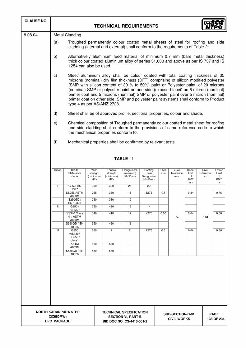
CLAUSE NO.
TECHNICAL REQUIREMENTS
NORTH KARANPURA STPP
(2X660MW)
EPC PACKAGE
TECHNICAL SPECIFICATION
SECTION-VI, PART-B
BID DOC.NO.:CS-4410-001-2
SUB-SECTION-D-01
CIVIL WORKS
PAGE
138 OF 234
8.08.04 Metal Cladding
(a) Troughed permanently colour coated metal sheets of steel for roofing and side cladding (internal and external) shall conform to the requirements of Table-2:
b) Alternatively aluminium feed material of minimum 0.7 mm (bare metal thickness)
thick colour coated aluminium alloy of series 31,000 and above as per IS 737 and IS 1254 can also be used.
c) Steel/ aluminium alloy shall be colour coated with total coating thickness of 35
microns (nominal) dry film thickness (DFT) comprising of silicon modified polyester (SMP with silicon content of 30 % to 50%) paint or Polyester paint, of 20 microns (nominal) SMP or polyester paint on one side (exposed face0 on 5 micron (nominal) primer coat and 5 microns (nominal) SMP or polyester paint over 5 micron (nominal) primer coat on other side. SMP and polyester paint systems shall conform to Product type 4 as per AS/ANZ 2728.
d) Sheet shall be of approved profile, sectional properties, colour and shade. e) Chemical composition of Troughed permanently colour coated metal sheet for roofing
and side cladding shall conform to the provisions of same reference code to which the mechanical properties conform to.
(f) Mechanical properties shall be confirmed by relevant tests.
TABLE - 1
Group Grade /Reference
Code
Yeild strength
(minimum) MPa
Tensile strength
(minimum) MPa
Elongation% (minimum) L0=50mm
Coating Class
Designation L0=80mm
BMT mm
(+)ve Tolerance
mm
Upper limit of
BMT mm
(-)ve Tolerance
mm
Lower Limit
of BMT mm
I G250/ AS 1397
250 320 25 22
.04
-0.04
SS255/ASTM A653M
255 360 18 Z275 0.8 0.84 0.76
S250GD / EN 10326
250 330 19
II G350 / AS1397
350 420 15 14
SS340 Class 4 / ASTM
A653M
340 410 12 Z275 0.60 0.64 0.56
S350GD / EN 10326
350 420 16
III G550 /AS1397 SS550 / class1
550 2 2 Z275 0.6 0.64 0.56
ASTM A653M
550 570 ---
S550GD / EN 10326
550 560 --

CLAUSE NO.
TECHNICAL REQUIREMENTS
NORTH KARANPURA STPP
(2X660MW)
EPC PACKAGE
TECHNICAL SPECIFICATION
SECTION-VI, PART-B
BID DOC.NO.:CS-4410-001-2
SUB-SECTION-D-01
CIVIL WORKS
PAGE
139 OF 234
Table - 2
Group Grade /Reference
Code
Yeild strength
(minimum) MPa
Tensile strength
(minimum) MPa
Elongation% (minimum) L0=50mm
Coating Class
Designation L0=80mm
BMT mm
(+)ve Tolerance
mm
Upper limit of
BMT mm
(-)ve Tolerance
mm
Lower Limit
of BMT mm
I G250/AS1397 250 320 25 22
0.04
-0.04
SS255/ASTM
A653M 255 360 18 Z275 0.6 0.64 0.56
S250GD / EN
10326 250 330 19
II G350/AS
1397 350 420 15 14
SS340 Class
4/ ASTM 340 410 12
A653M Z150 0.5 0.54 0.46
S350GD /EN
10326 350 420 16
III G550/AS
1397 550 550 2 2
SS340 Class 4/ ASTM A653M
550 570 -- Z150 0.4 0.44 0.36
S350GD /EN
10326 550 560 --
8.08.05 Plain permanently colour coated steel metal sheet for ridge and hips, flashings, trimmings, closure for vertical and horizontal joints, capping etc shall confirm to the same requirements as those of troughed permanently colour coated metal sheet for roofing and side cladding.
8.08.06 a) For metal decking the sectional modulus and moment of inertia of troughed profile per meter width shall be so as to limit the deflection of sheets to span/250 over a span of 1.7 m under total super imposed loading (DL +LL) of 450 kg per Sq.M. for two span condition. The sectional modulus and moment of inertia of troughed profile shall be computed as per the provisions of IS: 801 for satisfying the deflection and strength requirements. All structural calculations for checking the adequacy of the profiled sheet for strength & deflection criteria is to be done taking into consideration the maximum permissible negative tolerance over the specified BMT i.e. the lower limit of BMT is to be considered as per last column in Table -1.
b) For metal roofing and side cladding, the sectional modulus and moment of inertia of
troughed profile per metre width shall be such that the deflection of sheets is limited to span/250 over a span of 1.5 m under design wind pressure of 160 kg/sq.m. for two span condition. The sectional modulus and moment of inertia of troughed profile shall be computed as per the provisions of IS:801 for satisfying the deflection and strength requirements. No increase in allowable stress is permissible under wind load condition. All necessary structural calculations for checking the adequacy of the profiled sheet for strength & deflection criteria is to be done taking into consideration the maximum permissible negative tolerance over the BMT i.e. the lower limit of BMT is to be considered as per last column in Table - 2.
c) In case, during the inspection, if it is observed that the BMT of sheet / coil is having (-
)ve tolerance beyond 0.04mm i.e. if minimum BMT of sheet is found to be less than the "Lower Limit of BMT" as specified in last column of Table 1 or Table 2 as applicable, it will be rejected.

CLAUSE NO.
TECHNICAL REQUIREMENTS
NORTH KARANPURA STPP
(2X660MW)
EPC PACKAGE
TECHNICAL SPECIFICATION
SECTION-VI, PART-B
BID DOC.NO.:CS-4410-001-2
SUB-SECTION-D-01
CIVIL WORKS
PAGE
140 OF 234
8.08.07 The maximum spacing of the fasteners shall be 390 mm c/c along the length of purlins / runners. However exact spacing shall be as per the design done by the bidder for the fasteners considering the wind load, self load and other associated loads. Minimum diameter of the fastener shall be 5.5 mm and at least 3 nos. of fasteners shall be used per sheet.
Sealant used for cladding shall be butyl based, two parts poly sulphide or equivalent approved, non-staining material and be flexible enough not to interface with fit of the sheets.
Filler blocks as a trough filler shall be used to seal cavities formed between the profiled sheet
and the support or flashing. The filler blocks shall be manufactured from black synthetic rubber or any other material approved by the Engineer.
For insulation of cladding and other areas, mineral wool conforming to IS: 8183 shall be
used. The density shall be 32 or 48 kg. /Cu.M. for glass or rock wool respectively. The nominal thickness of insulation shall be 50mm.
Special coated fasteners shall be used conforming to class 3 as per AS3566 and shall be
tested to 1000 hours salt spray test. Data Sheet for Metal Decking and Metal Cladding shall be submitted as per the formats
given in the Annexure-1 & 2.
8.08.08 Installation and Fixing
8.08.08.1 Metal Decking
a) The sheeting shall be fixed as per the working drawings. Sheets shall be supplied in
required sizes (based on purlin spacing) according to the cutting schedule. Generally cutting of sheets to length shall not be permitted at site. Specific approval under exceptional circumstances shall be obtained before cutting of any sheet at site. Power tools shall be used for cutting. Cutting and trimming of small openings which were not finalised at the time of working drawings can be allowed at site. Wherever possible, site cut edges shall be concealed at laps or with flashings. Suitable steel members for stiffening shall be provided at the cut edges. No gas cutting shall be done on the sheet. If any sheet is found with gas cut mark, same shall stand rejected and shall be immediately replaced.
b) Distorted, blemished or water stained sheets shall not be used. c) Before installing decking sheet, it shall be ensured that the purlins are in true planes,
correctly placed and securely fixed.
d) Side and end laps of the sheets shall be made weather proof by securing them with the fasteners not less than 4.0mm diameter with 2.0 mm thick neoprene washer. Maximum spacing of the fasteners should not exceed 500 mm.
e) Precautions shall be taken during the erection of the sheets to ensure that partially
erected decking sheets are protected during inclement weather and damage at all times.
f) Side and end of decking sheet shall be located and positioned in such a manner as
to provide the maximum weather protection taking into account the direction of the prevailing wind.
g) Length of the sheet shall be such as to cover minimum 3 span purlin spacings.

CLAUSE NO.
TECHNICAL REQUIREMENTS
NORTH KARANPURA STPP
(2X660MW)
EPC PACKAGE
TECHNICAL SPECIFICATION
SECTION-VI, PART-B
BID DOC.NO.:CS-4410-001-2
SUB-SECTION-D-01
CIVIL WORKS
PAGE
141 OF 234
h) The roof decking sheets shall be fixed to the purlins with the help of self drilling and tapping type fasteners and neoprene washers
i) Sheets shall be laid over the supporting purlins with a minimum bearing of 50 mm
and end projection of 75 mm at lap joints.
j) End and side laps between the sheets shall be sufficiently large to ensure the weather tightness. In no case, the end laps shall be less than 150 mm and side laps less than one trough length with proper weather tight arrangement.
8.08.08.2 Roofing and cladding
a) The sheeting shall be fixed as per the working drawings. Sheets shall be supplied in
required sizes (based on purlin spacing) according to the cutting schedule. Generally cutting of sheets shall not be permitted at site. Specific approval under exceptional circumstances shall be obtained before cutting of any sheet at site. Power tools shall be used for cutting. Cutting and trimming of small openings which were not finalised at the time of working drawings can be allowed at site. Wherever possible, site cut edges shall be concealed at laps or with flashing. Suitable steel members for stiffening shall be provided at the cut edges. No gas cutting shall be done on the sheet. If any sheet is found with gas cut mark, same shall stand rejected and shall be immediately replaced.
b) Distorted, blemished or water stained sheets shall not be used. c) Before installing roofing/cladding, it shall be ensured that the supporting structure i.e.
purlins/runners are in true planes, correctly placed and securely fixed. d) Side and end laps of the sheets shall be made weather proof by securing them with
the fasteners not less than 4.0mm diameter with 2.0 mm thick neoprene washer and cap of matching colour. Maximum spacing of the fasteners should not to exceed 500 mm.
e) Precautions shall be taken during the erection of roofing/ cladding to ensure that
partially erected roofing/cladding and insulation (pending placing of external cladding sheet) are protected during inclement weather to prevent the ingress of water and damage at all times.
f) During erection of roofing/cladding, ladders shall not be leaned on any cladding
without precautions being taken against damage. g) The fasteners shall be installed by means of power tools and provided with neoprene
seal. h) Length of the sheet shall be such as to cover minimum 3 span purlin spacings. i) Expansion joints shall be provided to take care of movements due to temperature
variations. j) The sheets shall be laid on the steel purlins/runner or scantlings to a true plane with
the lines of profiles truly parallel to or normal to other sides of the area to be covered, unless otherwise required as in special shape.
k) Cladding erection for each elevation shall commence at the bottom and proceed
towards the top, in order to ensure tight fitting laps.

CLAUSE NO.
TECHNICAL REQUIREMENTS
NORTH KARANPURA STPP
(2X660MW)
EPC PACKAGE
TECHNICAL SPECIFICATION
SECTION-VI, PART-B
BID DOC.NO.:CS-4410-001-2
SUB-SECTION-D-01
CIVIL WORKS
PAGE
142 OF 234
l) The sheets shall be laid with a minimum overlap of 15 cm at the ends and side laps shall be of one trough length subject to a minimum of 50 mm, having a proper water tight arrangement. The minimum lap of sheets with ridges, hips and valleys shall be 15 cm measured at right angles to the line of the ridge, hip and valley respectively.
m) In case of insulated sheeting works, the insulation shall be provided. n) In case double skin cladding, inner sheet and outer sheet can be directly fixed to the
opposite faces of the sheeting runner totally concealing the supporting steel structure.
o) Crimping and curving wherever specified shall be provided over the profile sheet.
8.08.09 Flashing, trimming etc.
Flashings, cappings, trimming, closure for vertical/horizontal joints, ridge and hips etc. shall
be provided with a minimum lap of 15 cm. The lapping of sheets shall provide the dust free, airtight enclosure. If required this may be achieved by using 2-parts polysulphide sealing compound or butyl tape.
Aprons, closures, flashings and other similar fittings shall be formed at works before delivery
to site. Site forming or dressing of these items will be approved only in special locations. The black synthetic rubber external trough fillers are to be secured by the mechanical fixings
to the flashings or parapet capping.
8.09.0 Pre-Fabricated Insulated Metal Sandwich Panel For Roofing
8.09.01 Pre-Fabricated insulated metal sandwich panel for roofing shall consist of Troughed Permanently Coloured coated sheets of approved profile at top & bottom having minimum yield strength of 340 Mpa and 0.5 mm thickness (bare metal thickness i.e. metal thickness excluding thickness of coating & painting) and coated with Zinc Aluminium alloy (Zincalume) at the rate of 150gm per sq.m. conforming to AS: 1397/ class 4, ASTM A653M/ EN 10326. The outer exposed face of the sheets shall be permanently colour coated with total coating thickness of 25 micron (nominal) dry film thickness (DFT) comprising Silicon Modified Paint (SMP with silicon content of 30% to 50% paint ) or super polyester paint of 20 micron (nominal) over 5 micron (nominal) primer coat, and the inner face of the sheets shall be colour coated with total coating thickness of 10 micron (nominal) dry film thickness (DFT) comprising of SMP, with silicon content of 30% to 50% or super polyester paint of 5 microns (nominal) over 5 mm micron (nominal) primer coat (SMP & super polyester paint shall confirm to product type 4 of AS/NZS2728).
8.09.02 The insulation between the metal sheets shall be minimum 50mm thick Mineral Wool conforming to IS: 8183, of minimum density 32 kg / cu.m for glass wool or 48 kg / cu.m for rock wool.
8.09.03 Sheets shall be of approved profile, sectional properties (suitable for specified loading / deflection and purlins / runners spacing), color & shade and the item shall include all labour , materials , equipments, handling, transportation, special coated self drill fasteners for sheet fixing, special coated Z spacers for insulation fixing & clip fixing, and special coated clips for clip lock system (special coating conforming to corrosion resistant class 3 of AS 3566 and tested for 1000 hour salt spray test).
8.09.04 Roofing sheet panel shall be laid to specified slope.

CLAUSE NO.
TECHNICAL REQUIREMENTS
NORTH KARANPURA STPP
(2X660MW)
EPC PACKAGE
TECHNICAL SPECIFICATION
SECTION-VI, PART-B
BID DOC.NO.:CS-4410-001-2
SUB-SECTION-D-01
CIVIL WORKS
PAGE
143 OF 234
8.10.0 HEADED SHEAR STUDS
8.10.01 General
This part of specification covers the technical requirement of Headed shear studs. The studs shall be welded to steel beams either directly or through metal deck sheet whichever is applicable. In case metal deck sheet is used as permanent shuttering, it shall not be considered as structural element for slab design.
8.10.02 Material
(a) Studs shall be manufactured from cold drawn round bars conforming to the
requirement of ASTM A 29 of grade designation 1010 through 1020 or equivalent, inclusive either semi-killed or killed (aluminium or silicon deoxidation).
(b) Mechanical properties and other requirements of studs shall conform to requirement
of Type-B studs specified in AWS D1.1/D1.1M or equivalent. (c) The diameter of stud shall be 16mm (5/8 inch.) for roof slab and 19 mm (3/4 inch.)
for other slabs. (d) Before weld, length of 16mm (5/8 inch.) diameter stud shall be 65mm and that of
19mm (3/4 inch.) stud shall be 100mm.
8.10.03 Installation and fixing
(a) Headed shear studs shall be welded to top flange of floor beams either directly or
through metal deck by Drawn Arc Stud Welding by stud gun with arc shields/ferrules. After welding, arc shields/ferrules shall be broken free from studs.
(b) The distance between the edge of a stud and edge of steel beam flange shall not be
less than 25mm. (c) In no case studs shall be welded through more than two plies of metal decking. (d) Stud welding procedure specification, procedure qualification record,
operator/welder's qualification and acceptance norms shall conform to ASME IX.
8.10.04 Workman ship
(a) At the time of welding, the studs shall be free from rust, oil, moisture or other
deleterious matter that would adversely affect the welding operation. (b) The studs shall not be painted, galvanized or cadmium-plated prior to welding. (c) The areas to which the studs to be welded shall be made free of scales, rust,
moisture or other injurious material to the extent necessary to obtain satisfactory welds and prevent objectionable fumes.
(d) The arc shields/ferrules shall be dry. Any shields/ferrule which shows signs of
surface moisture from dew or rain shall be oven dried at 1200 C for two hours before use.

CLAUSE NO.
TECHNICAL REQUIREMENTS
NORTH KARANPURA STPP
(2X660MW)
EPC PACKAGE
TECHNICAL SPECIFICATION
SECTION-VI, PART-B
BID DOC.NO.:CS-4410-001-2
SUB-SECTION-D-01
CIVIL WORKS
PAGE
144 OF 234
(e) If there is any damage to the panting of steel members or metal deck sheet, same shall be repainted by the Bidder.
8.11.0 AUTOCLAVE AERATED CONCRETE BLOCKS (AAC BLOCKS)
8.11.01 General Requirements
Autoclave Aerated Concrete Blocks shall be used for external walls and internal partitions.
They shall be factory made in the form of blocks.
8.11.02 Codes and Standards
Some of the relevant Indian Standards are referred to here below: IS-2185(III) - 1984 : Aotuclaved Aerated Concrete Block. IS-6041 - 1985 : Construction of Autoclaved Aerated Concrete Block Masonary. IS-6441 - 1972 : Methods of Test for Autoclaved Cellular Concrete product.
8.11.03 Material
8.11.04 The blocks shall be made up of a mixture comprising of fine Fly Ash, quicklime, cement, gypsum as binding agents and water, aluminium powder as a foaming agent. The mixture shall be moulded into blocks of required shape and size and steam cured in high pressure Autoclaves.
8.11.05 The general size of finished blocks shall have dimensions of 625mm x 250 mm, with thickness ranging from 100mm to 300 mm and shall conform to IS:2185 (part III), for dimension and tolerance.
8.11.06 AAC blocks shall have the following physical properties :
- Density (over dry) - 550-650 kg/cum
- Compressive Strength - Min. 30 kg / sq.cm
- Thermal Conductivity - 0.162W/mk (avg)
- Resistant to fire - 2-6 hrs depending upon thickness
- Drying shrinkage - 0.02% (avg)
- Design gross density - 800 kg/cum (approx)

CLAUSE NO.
TECHNICAL REQUIREMENTS
NORTH KARANPURA STPP
(2X660MW)
EPC PACKAGE
TECHNICAL SPECIFICATION
SECTION-VI, PART-B
BID DOC.NO.:CS-4410-001-2
SUB-SECTION-D-01
CIVIL WORKS
PAGE
145 OF 234
8.11.07 Installation & Laying
Installation shall be done as per the working drawings. Laying of AAC Blocks masonary shall be in accordance with the recommendations of
IS:6041 of 1985 and IS:1905 of 1987. This shall hold valid for other structural requirements like stiffening of masonary, joint reinforcements, etc.
The jointing cement sand mortar in the composition of 1:6 (1 Cement : 6 sand) shall be used
with suitable plasticizer. Sand having modules of fineness 1:1 shall be used. The horizontal & vertical joint thickness shall be approximately 10mm thick. In case of partition walls (100 mm / 125 mm) the joint reinforcement i.e. 1 number of 6-8 mm diameter bars shall be placed at every alternate course to be anchored properly with the main structure.
Once the masonary erected, the curing shall be minimum, with more requirements at the
joints. 5-6 courses shall be erected maximum in a day. Before plastering, cement slurry shall be applied on the walls and only leaner mix shall be
applied. The thickness of the plaster shall be min. 12mm. The openings for doors, windows, ventilators, pipes, cables, ducts, fans, ACs etc. shall be
created as required. Blocks shall be cut with a saw. Wherever chasing to be done in AAC Blocks, rotary cutters shall be used. The chases shall be refilled with lean mortar and chicken mesh applied on that area.
While laying AAC blocks, safety precautions shall be taken for the safety of the requirement,
structure and personnel located / working in the area.
8.12.0 MODULAR AERATED CONCRETE PANELS
8.12.01 General
Modular aerated concrete panels shall be used for external walls and internal partitions. These shall be factory made in the form of modular panels.
8.12.02 Material
The panels shall be made up of two 4 mm thick cellulose fiber reinforced cement bonded plain sheets (as per IS:14862) on either side of a light weight concrete core composed of portland cement, fly ash, mica and sand aggregate. The compressive strength of concrete shall not be less than 35kg/sq.cm and the density shall be between 700-900 kg/cu.m.
The thickness of the panel shall be 50 mm and 75 mm. The minimum fire rating as per
BS:476 (Part-20 to 22) shall be 1 hour and 2 hours respectively for 50 mm and 75 mm panel thickness. The necessary certificate in this aspect shall be furnished by the contractor.
The panel shall generally be of 600mm width and of varying length as per requirement. The flexural strength of panel shall be sufficient for their installation on a span of upto 4.5 m.
and limiting the deflection to span / 250 under wind loading condition. The minimum thickness of U-channel shall be 1.25 mm and shall be galvanised to grade 180
as per IS: 277.

CLAUSE NO.
TECHNICAL REQUIREMENTS
NORTH KARANPURA STPP
(2X660MW)
EPC PACKAGE
TECHNICAL SPECIFICATION
SECTION-VI, PART-B
BID DOC.NO.:CS-4410-001-2
SUB-SECTION-D-01
CIVIL WORKS
PAGE
146 OF 234
All expansion fasteners / screws shall be of stainless steel from established and reputed manufacturers.
Silicone acrylic paste, glass fiber tape and all other material shall be of best quality from
established and reputed manufacturers.
8.12.03 Installation (fixing in position)
Installation shall be done as per the working drawings The contractor shall carry out the necessary design and get the third party testing done on
the panels in order to establish that the deflection of the panels are limited to span/325 over a span of 4.5 m. corresponding to designed wind loading.
The U-channels shall be fixed to the concrete and/or to primary steel members (provided by the owner), which are placed at a maximum vertical spacing of 4.5 m. with the help of expansion fasteners. The spacing of the fasteners shall be decided from the consideration of the load transfer from U-channel to concrete/steel members. However, the minimum size of the fastener shall be 8 X 35 mm long placed at a maximum spacing of 600 mm C/C.
The panels shall be fixed in the U-channel with the help of screws (8x35 mm) and placed at a
maximum spacing of 600 mm C/C or lesser, if required, as per design. The panels shall be placed preferably in tongue and groove jointing system. The joints shall
be subsequently finished on both faces with silicone acrylic paste. These shall be made water tight by application of glass fiber strip of minimum 50 mm wide and 0.5 mm thick and/or by any other suitable material.
The openings for doors, windows, ventilators, pipes, cables, ducts, fans, ACs etc. shall be
created as required. The face of the opening shall be finished with the same U-channel as that been used for fixing of panels.
The total construction shall be weather proof and the surfaces shall be flush for painting.
Undulations, if any, on the surface shall be finished with silicone acrylic paste. The complete installation of the panels shall be done in a mechanised way using power tools,
hoists etc. All openings shall be neatly cut with the power tools. While fixing the panels in position necessary safety precautions shall be taken for the safety
of the equipment, structure and personnel located/working in the area.
9.00.00 Architectural Concepts and Design
9.01.00 For Architectural Concepts and Design refer to 5.00.01 in this specification.
9.02.00 General Architectural Specifications
9.02.01 General
a) Minimum 1000 mm high (from floor/ roof level) hand railing shall be provided around all floor/roof openings, projections/balconies, walkways, platforms, steel stairs, etc., wherever the height of the building is more than 12m, railing ht to be 1.2m. All handrails and ladder pipes (except at operating floors) shall be 32 mm nominal bore MS pipes (medium class) conforming to IS:1161 and shall be galvanised as per IS : 4736 and finished with suitable paint. All rungs and ladders shall also be galvanised. Minimum weight of galvanising shall be 610 g/sqm. The spacing of vertical posts shall be maximum 1500mm. Two number of horizontal rails shall be provided including the top

CLAUSE NO.
TECHNICAL REQUIREMENTS
NORTH KARANPURA STPP
(2X660MW)
EPC PACKAGE
TECHNICAL SPECIFICATION
SECTION-VI, PART-B
BID DOC.NO.:CS-4410-001-2
SUB-SECTION-D-01
CIVIL WORKS
PAGE
147 OF 234
member. In addition, toe guard/ kick plate of min size 100x6th shall be provided above the floor level.
In Service Building, Administrative Building, Plant Auditorium and Canteen Building RCC stairs and passages/ corridors hand railing with posts shall be made of stainless steel and be 1200mm high. For Atrium areas, same shall be provided with 10mm thick laminated Glass infill panels.
For RCC stairs, passages & Atriums in buildings, around all floor openings at operating floors, 1000 mm /1200mm high hand railing with 32 NB (polished) stainless steel pipe shall be provided. The spacing of vertical posts shall be 1500mm. Two number of horizontal rails shall be provided including the top member. Toe guard and kick plate shall be provided above the floor level.
b) All stairs shall have a maximum riser height of 180mm and a minimum tread width of 275 mm. Minimum clear width of stair shall be 1200 mm unless specified otherwise. For Administration Building& Service Building, stairs width shall be minimum 1500 mm, with Riser 150mm and Tread 300 mm.
c) All buildings having metal cladding shall be provided with a 150 mm high RCC toe kerb at the edge of the floor along the metal cladding. 1000 mm high hand railing shall be provided on this RCC kerb, wherever required from the safety point of view.
d) In all buildings, structures, suitable arrangement for draining out water collected from equipment blowdowns, leakages, floor washings, fire fighting, etc., shall be provided for each floor. All the drains shall be suitably covered with grating or precast RCC panels.
e) RCC staircase shall be provided for main entrance of Turbine building; control tower area and all other RCC construction buildings.
f) Parapet, Chajjas 450mm over window and 600mm door heads,750mm over rolling shutters, architectural facias, projections, etc., shall be provided with drip course in cement sand mortar 1:3.
g) All fire exits shall be painted with fire resistant paint P.O red/signal red colour shade which shall not be used anywhere except to indicate emergency or safety measure. Fire safety norms shall be followed as per National Building Codes and fire safety requirements for providing fire exits, escape stairs and fire fighting equipment. In detailing of all buildings, fire safety requirements conforming to IS: 1641 and IS:1642 shall be followed.
h) Ramps & Lifts for physically challenged persons shall be provided for barrier free access to the buildings.
9.03.00 Water Supply and Sanitation
9.03.01 Two numbers of roof water tanks (one for storing service water and another for potable water) of adequate capacities depending on the number of users and 8 hours requirement shall be provided for each building and pump house. Polyethylene water storage tanks conforming to IS:12701 shall be used. The tanks shall be complete with all fittings including lid, float valve, stop cock, vent pipe, etc.
Galvanised MS pipe of medium class conforming to IS: 1239 shall be used for internal piping works for service water and potable water supply. The pipes shall be concealed, and painted with anti-corrosive bituminous paint (as per IS: 158) wherever required.

CLAUSE NO.
TECHNICAL REQUIREMENTS
NORTH KARANPURA STPP
(2X660MW)
EPC PACKAGE
TECHNICAL SPECIFICATION
SECTION-VI, PART-B
BID DOC.NO.:CS-4410-001-2
SUB-SECTION-D-01
CIVIL WORKS
PAGE
148 OF 234
Sand Cast Iron pipes with lead joints conforming to IS: 1729 shall be used for sanitary works above ground level. All Buildings shall be designed with Toilets as per NBC norms.
Minimum one number main toilet block for Gents & ladies separately, with required facilities shall be provided on each floor of Service building Administration building and Canteen building. Toilets for physically handicapped shall be provided as mentioned. Attached toilets shall be provided for all senior executive rooms and conference rooms. All other buildings shall have minimum one toilet block each. The facilities provided in the toilet block shall depend on the number of users. However, minimum facilities to be provided shall be as stipulated in subsequent clause. IS:1172 shall be followed for working out the basic requirements for water supply, drainage and sanitation. In addition, IS:2064 and IS:2065 shall also be followed.
9.03.02 Each Toilet block shall have the following minimum facilities. Unless specified all the fittings shall be of Chromium plated brass (fancy type). For GRIHA rated Buildings all fittings shall conform to GRIHA requirements, for water efficiency.
a) One number wall mounted coloured (excluding premium colours) glazed vitreous China European water closet and flushing valve system, water faucet, toilet paper holder as per IS:2556
b) One number white glazed vitreous China Orissa pan (580 x 440 mm) and flushing valve system, toilet paper holder as per IS:2256
c) One number colour (excluding premium colours) glazed ceramic oval shaped wash basin 450x 550 mm (approx.) mounted over 20mm thick granite beveled edge counter fitted with photo-voltaic control system for water controls, bottle trap as per IS:2556. For common toilets, number of washbasins shall be as per requirement. However for Pump Houses the same shall be provided without photo voltaic control system for water control.
d) For Male Toilets Urinal as per requirements, with all fittings with photovoltaic control flushing system as per IS: 2556.
e) One number looking mirror 600 x 900 x 6 mm, edge mounted with teak beading and minimum 12 mm thick plywood backing, one number stainless towel rail 600 x 20 mm, one number liquid soap dispenser
f) One toilet with required facilities shall be provided for physically challenged persons as per National Building Code requirements in GRIHA rated buildings.
g) In addition to the facilities stipulated elsewhere Bathroom with rotating type chromium plated shower including all fitting and fixtures shall also be provided in toilet at ground and operating floor of main plant and any other building as per functional requirement.
h) Janitor Space & space for drinking water cooler.
i) Electric operated hand dryer with photo voltaic control.
j) The pantry shall consist of one number stainless steel pantry sink, as per IS : 13983, of size 610 x 510 mm, bowl depth 200 mm with drain board of at least 450 mm length with trap, hot and cold water mixer, one number geyser of 25 liters capacity, with inlet and outlet connections, one number HDPE loft type / over head water storage tank, as per IS : 12701 and of 500 liters capacity, complete with float valve, overflow drainage pipe arrangement, GI concealed water supply pipe of minimum 12

CLAUSE NO.
TECHNICAL REQUIREMENTS
NORTH KARANPURA STPP
(2X660MW)
EPC PACKAGE
TECHNICAL SPECIFICATION
SECTION-VI, PART-B
BID DOC.NO.:CS-4410-001-2
SUB-SECTION-D-01
CIVIL WORKS
PAGE
149 OF 234
mm dia of medium class, cast iron sanitary pipe (with lead joints) of minimum 75 mm diameter, floor trap with Stainless
Steel grating, inlet and outlet connections for supply and drainage, with all bends, tees, junctions, sockets, etc., as are necessary for the commissioning and efficient functioning of the pantry (all sanitary fittings shall be heavy duty chrome plated brass, unless noted otherwise)
k) Laboratory sink shall be of white vitreous china of size 600x400x200 mm conforming to IS:2556 (Part-5).
l) In addition, adequate number of portable toilet units with adequate plumbing and sanitary arrangement, shall be provided during construction stage.
9.04.00 Flooring
Floor finishes of approved shade and colour (non - premium colours), over under bed of cement mortar / concrete, at all levels and for all kind of works, elevations, on horizontal and vertical surfaces for all types of work (like flooring, skirting, dado, wall lining & facing, tread and risers etc.), including topping, spreading white cement slurry at an average rate of 2.5 kg/Sq. M., (unless noted otherwise), jointing and joint filling with white cement (unless noted otherwise) slurry mixed with colour pigment, to match the shade of the finishing material, laying to plumb and water level in desired pattern, line and flush butt square jointing, curing, rubbing, grinding, polishing, edge moulding, finishing and cleaning, testing, providing opening of required size and shape, casting in panels wherever specified.
9.04.01 The nominal total thickness of floor finish shall be 50 mm i.e. underbed and topping. The floor shall be laid on an already laid and matured concrete base. The underbed for floors and similar horizontal surfaces shall consist of cement concrete M20 grade (1 part cement, 1.5 part sand and 3 part stone chips by volume). Stone chips shall be 12.5 mm down well graded( & proper filling shall be done with brick bats/cinders). Flooring like Tiles/ Stones shall be laid with 1:4 cement sand mortar and Tile/ Stone Cladding on wall shall be laid with 1:3 cement sand mortar.
9.04.02 Sunken slabs shall be made water tight by suitable water proofing treatment.
9.04.03 Metallic hardener topping -with ordinary grey cement shall be- 12 mm thick (insitu) or finishing the concrete / mortar surfaces topping shall be furnished with neat cement slurry (with ordinary grey cement)
9.04.04 Heavy duty cement concrete tiles 300 mm x 300 mm shall be in using white cement with pigment, with hard and abrasion resistant carborundum / quartz chips for wearing course as per IS:1237. Laying of tiles shall be as per IS: 1443.
9.04.05 Heavy duty (grade-5) dust pressed ceramic tiles (300mmx300mm shall be as per IS 15622. Designer ceramic wall tiles of size 300 mm x 200 mm / (300x600mm).
9.04.06 20mm / 38mm / 75 mm/ 115mm thick acid resistant tile on horizontal and vertical surfaces, at all levels for all type of works shall include one coat of bitumen primer followed by 12 mm thick bituminastic layer, 20mm / 38mm/ 75 mm / 115mm thick A.R. tiles, 6 mm thick under-bed by potassium silicate mortar, pointing of joints of tiles with acid/alkali resistant epoxy/furane mortar up to a depth of 20 mm and bituminastic end sealing.
9.04.07 Mirror polished/ Matt finish (80:20) Vitrified ceramic tiles (min 9.5mm thk) with 3mm groove joints as per approved pattern pointed neatly with 3X4mm stainless epoxy grout SP- 100 of

CLAUSE NO.
TECHNICAL REQUIREMENTS
NORTH KARANPURA STPP
(2X660MW)
EPC PACKAGE
TECHNICAL SPECIFICATION
SECTION-VI, PART-B
BID DOC.NO.:CS-4410-001-2
SUB-SECTION-D-01
CIVIL WORKS
PAGE
150 OF 234
Laticrete or approved equivalent in approved colour to match colour of tile. Sizes of the tiles shall be as under:
a) 600 mm x 600 mm
b) 800mm x 800mm
9.04.08 For pathway, chequered and designed concrete tiles minimum 22 mm thick, 200x200 mm size conforming to IS: 13801 of approved shade and colour shall be used. 1000 wide pathways shall be provided for maintenance on rooftops of all buildings.
9.04.09 PVC flooring, wherever used, shall be minimum 2 mm thick (virgin) as per IS: 3462. The laying of flooring shall be as per IS: 5318.
9.04.10 Epoxy Flooring
Epoxy Flooring shall be provided with surface preparation of concrete substrate with Captive Shot Blasting Machine OR Light Grinding to form the required anchor profile on the floor substrate followed by application of epoxy resin based moisture barrier underlay of 2 mm thickness including filling of saw cut joints with epoxy cementitious resin based moisture barrier underlay as per manufacturer specification. Application of self smoothing epoxy floor topping of epoxy based resin of 2 mm thickness over epoxy resin based moisture barrier underlay including application of solvent free epoxy resin based two component primer.
It shall include application of PU Sealant at Expansion and Isolation Joint respectively including surface preparation of the joint, fixing of backup strip and application of sealant.
9.04.11 Wherever required, carpet flooring shall be provided over cement concrete floor as in conference room of main control room complex. The carpet shall be of tile/roll form, machine/hand made tupled un-cut loop pile and lay with under lay of 10mm thick and shall be laid as per manufacturer’s recommendations, in matching grains. It shall be treated with anti fungus and anti-termite before laying.
9.04.12 Mirror polished (6 layers of polish) Granite stone (slab) - 20 mm Thk (minimum) shall be provided in areas as mentioned in finishing Schedule. Flame finish (making top surface rough by burning / shot blasting) granite stone (slab) - 20 mm Thk (minimum) shall be provided in ramps for Physically Challenged Persons in Administration building, Service Building, Auditorium Building and Canteen Building.
Mirror polished Marble stone (slab) - (Rajnagar) Plain white -20 mm thick shall be provided in main stairs & 18mm thick kota stone shall be provided in the fire escape stairs.
9.04.13 Decorative/designer prepolished, plain and pigmented, high wearing resistance concrete tiles of 20mm thickness (minimum) in various non-standard interlocking patterns.
9.04.15 Skirting in general shall be 150 mm high. Dado in toilets & pantries, shall be upto 2200 mm height from finished floor level. Dado shall match with the floor finish.
9.04.16 Wherever required, removable metallic false flooring system shall be provided. Nominal height of the false flooring shall be 600 mm. The same shall comprise of special grade steel panels (of size 600x600mm). without any dimensional tolerance 1.2mm thick die cast to shape having 1mm thick top MS sheet spot welded together to form a composite steel panel, sitting on aluminum diecasted heads & mounted on steel pedestals of 25mm dia rod of adjustable height and supporting 1.2mm thick channel frame work at-top and 2mm thick 150x150mm base plate. The top finish shall be 2mm thick antistatic PVC sheet or High

CLAUSE NO.
TECHNICAL REQUIREMENTS
NORTH KARANPURA STPP
(2X660MW)
EPC PACKAGE
TECHNICAL SPECIFICATION
SECTION-VI, PART-B
BID DOC.NO.:CS-4410-001-2
SUB-SECTION-D-01
CIVIL WORKS
PAGE
151 OF 234
pressures laminate. Cavity area below the false flooring shall be made dust proof by using Polyurethane paint.
9.04.17 Interlocking concrete blocks shall be of various sizes and thickness having M 35 grade of concrete and pigmented to specified colours, in different pattern (in different textures chequered or other patterns in indentation for guiding band/s for visually impaired persons) including the preparation of sub base with 20mm thick sand and filling of joints with sand.
9.04.18 Matt finish (with grooves) Porselin tiles (for guiding band/s for visually impaired persons) shall be with 3mm groove joints as per approved pattern pointed neatly with 3X4mm stainless epoxy grout SP- 100 of Laticrete or approved equivalent in approved colour to match colour of tile.
24 mm x 24 mm x 3.8 mm thick (minimum) glass mosaic tiles in decorative murals and pattern.
Laminated wooden flooring shall be provided in VIP area, conference rooms & auditoriums.
9.04.19 Paving
a) Ground floor of all buildings shall be provided with normal duty paving with 50mm thick metallic hardener floor finish. For details of normal duty paving refer to description elsewhere in this specification.
b) PCC paving of nominal mix 1:2:4 (1 part cement: 2 parts sand: 4 parts aggregate), 100 mm thick laid over 75 mm thick bed of dry brick aggregate shall be provided for following areas:
i) 750 mm wide plinth protection around all buildings other than those covered under paved area.
ii) 2.0 m wide pathway all along pipe/ cable corridor and all around each cooling tower. 2.0 mm wide ways inter connecting all cooling towers with each other.
9.05.00 Acid/ Alkali Resistant Lining
9.05.01 The material shall conform to the following:
i) Bitumen primer shall conform to IS: 158.
ii) Bitumastic compound shall conform to IS: 9510. Where the height of bitumastic layer on vertical surface is more than 2.0 m, the bitumastic layer shall be reinforced with diamond pattern expanded metal steel sheets conforming to IS: 412.
iii) A.R. Bricks/ Tiles shall conform to class II of IS: 4860 & IS: 4457 respectively.
iv) Mortar: Potassium silicate & resin type mortars shall conform to IS: 4832 Part-I&II respectively.
9.05.02 Requirements for acid/ alkali resistant flooring and lining for different areas shall be as given Table-A enclosed at the end of this specification. Battery Room in all buildings shall be provided with acid/ alkali resistant tiles on flooring & dado 1200mm high.

CLAUSE NO.
TECHNICAL REQUIREMENTS
NORTH KARANPURA STPP
(2X660MW)
EPC PACKAGE
TECHNICAL SPECIFICATION
SECTION-VI, PART-B
BID DOC.NO.:CS-4410-001-2
SUB-SECTION-D-01
CIVIL WORKS
PAGE
152 OF 234
9.06.00 Roof
9.06.01 Except for the roofs subjected to heavy loads, roof of all buildings having structural steel frame work shall consist of permanently colour coated (on exposed face) troughed metal sheet decking of approved profile having minimum base metal thickness of 0.8mm of galvanised (with minimum rate of galvanisation of 275 gm/sq.m.) M.S. sheet or minimum 0.8mm of high tensile steel (minimum yield strength 350 MPa) coated with zinc aluminium alloy (zincalume) (coating not less than 150 gm./sq.m). Silicon modified polyester paint having DFT of minimum 20 microns shall be used for permanent coating. The sheeting shall be fixed by means of concealed fixing system or any other compatible method approved by the Engineer. RCC slab of minimum 40 mm clear thickness in excess of trough depth shall be provided over the metal decking. Water proofing cum plasticiser compound shall be added to concrete over the metal decking. Bidder shall demonstrate that the roof is leak proof by carrying out the water-retaining test by maintaining the minimum water depth of 50mm over the roof surface for a period of 48 hours. Water Proofing Treatment as given below for RCC roof slabs shall be provided to ensure that the roof is watertight.
9.06.02 Roof of all buildings having RCC framework shall have cast-in-situ RCC slab. Such roof shall be provided with roof water proofing treatment using high solid content liquid applied elastomeric water proofing membrane with separate wearing course as per ASTM - C-836 & 898. Thickness of the membrane shall be 1.5mm (min.). This treatment shall include application of polymerised mastic over the roof to achieve smooth surface and primer coat. Wearing course on the top of membrane shall consist of 25mm thick PCC (1:2:4) cast in panels of maximum 1.2 x 1.2m size and reinforced with 0.56mm dia galvanised chicken wire mesh and sealing of joints using sealing compound/elastomeric water proofing membrane. However, chequered concrete tile flooring 22 mm (min.) thick of approved colour and shade conforming to IS: 13801 shall be provided for path way of 1 m. width for access of personnel and handling of equipment and for the entire area of the roof where equipment like AC / Ventilation plant, cooling towers, etc. are provided in place of PCC wearing course. Equipment shall be installed on raised pedestal of minimum 30 cm height from the finished roof to facilitate maintenance of roof treatment in future.
9.06.03 For efficient disposal of rainwater, the run off gradient for the roof shall not be less than 1:100 and the roof shall be provided with RCC water gutter, wherever required. Gutter shall be made water tight using suitable watertight treatment. This gradient can be provided either in structure or subsequently by screed concrete 1:2:4 (using 12.5 mm coarse aggregate) and/or cement mortar (1:4). However, minimum 25 mm thick cement mortar (1:4) shall be provided on top to achieve smooth surface.
9.06.04 For Building where metal cladding is envisaged medium class galvanised mild steel pipes conforming to IS: 1239/IS:3589 with welded joints shall be provided to drain off rain water from the roof. For rest of the buildings cast-iron pipes with lead caulked joints conforming to IS:1230 shall be used. These shall be suitably concealed with masonry work, cement concrete / or sheeting work to match with the exterior finish. The number and size of down comers shall be governed by IS:1742 and IS:2527. Roof drain level of all RCC framed buildings having cast-in-situ RCC roof shall be provided with Rain water gutter and/or 45 x 45 cm size Khurras having minimum thickness of 30 mm with 1:2:4 concrete over PVC sheet of 1 m x 1 m x 400 micron and finished with 12 mm thick cement sand plaster 1:3. All the pipes shall be provided with suitable fittings and fixtures. Gratings shall be of stainless steel.
9.06.05 Roof of the buildings shall conform to minimum 4 star GRIHA Rating shall have Overdeck insulation of minimum 40 mm thick impervious sprayed close cell free rigid Polyurethane foam confirming to IS: 12432 Part-III, with density of foam 40 TO 45 KG/ cum. Overdeck insulation shall be fixed over a coat of polyurethane primer applied @ 6 to 8 litre/ sqm, applied over cleaned surface of cement sand mortar (1:4) screed (laid for the part of Roof Water Proofing Treatment. 400 Gauge polythene sheet shall be laid over polyurethane

CLAUSE NO.
TECHNICAL REQUIREMENTS
NORTH KARANPURA STPP
(2X660MW)
EPC PACKAGE
TECHNICAL SPECIFICATION
SECTION-VI, PART-B
BID DOC.NO.:CS-4410-001-2
SUB-SECTION-D-01
CIVIL WORKS
PAGE
153 OF 234
spray. The top of the polyurethane foam shall be finished with 20 mm thick cement: sand (1:4) mortar with chicken wire mesh and broken white glazed tiles of 5 mm thickness laid over mortar at green stage.
9.06.06 Roof Water Proofing
Roof water proofing treatment shall be as follows:
a) For roofs having structural slope:
Top surface of sloped R.C.C. slab shall be finished with 15mm thick cement plaster (1:4). Over the finished surface elastomeric membrane shall be laid. The elastomeric shall comprise of high solid content liquid applied urethane laid over reinforcing layer of polyscrim cloth or non woven geo-textile. The top of the elastomeric membrane shall be finished with 20 mm thick cement: sand (1:4) mortar with chicken wire mesh and pressed precast concrete tiles of 20 mm thickness wherever applicable shall be laid over mortar at green stage. Provision for thermal expansion of roofing tiles shall be kept by providing an expansion gap in both directions filled up with polysulphide joint sealant. The expansion gap shall be provided in the cement sand mortar underbed layer also.
b) For roofs having no structural slope:
Screed concrete mix (M-15 grade) grading having minimum 25mm thickness at the lowest point of the slope shall be laid over R.C.C. slab and shall be laid as per the slope specified elsewhere in the specification. Top surface of grading underbed shall be finished with 15mm thick cement plaster (1:4). Over the finished surface elastomeric membrane shall be laid and top of the elastomeric membrane shall be finished with 20 mm thick cement: sand (1:4) mortar with chicken wire mesh and pressed precast concrete tiles of 20 mm thickness where applicable shall be laid over mortar at green stage. Provision for thermal expansion of roofing tiles shall be kept by providing an expansion gap in both directions filled up with polysulphide joint sealant. The expansion gap shall be provided in the cement sand mortar underbed layer also
9.06.07 Roof of all buildings shall be provided with access/approach through staircase or ladder. Roof where equipment are mounted shall be provided with access through staircase.
9.06.08 RCC parapet wall of minimum 1000 mm height (above top of slab) for all accessible roofs and 600 mm height for all non-accessible roofs shall be provided. Alternatively parapet wall comprising structural steel post, runner and sheeting may be provided for buildings with metal sheet cladding.
9.06.09 Fillets at junction of roof and vertical walls shall be provided with cast-in-situ cement concrete (1:1.5:3) nominal mix followed by 12mm thick 1:4 cement sand plaster.
9.06.10 Pathways for handling of materials and movement of personnel shall be provided with 22mm thick chequered cement concrete tiles as per IS:13801 for a width of 1000mm .
9.07.00 Walls
9.07.01 All walls shall be non-load bearing infill panel walls.
9.07.02 For initial height up to 3 metres from ground floor one brick thick masonry wall shall be provided wherever metal cladding is specified.

CLAUSE NO.
TECHNICAL REQUIREMENTS
NORTH KARANPURA STPP
(2X660MW)
EPC PACKAGE
TECHNICAL SPECIFICATION
SECTION-VI, PART-B
BID DOC.NO.:CS-4410-001-2
SUB-SECTION-D-01
CIVIL WORKS
PAGE
154 OF 234
9.07.03 All internal walls shall be with one brick thick in cement sand mortar (1:6). However, internal partition walls for toilets shall be with half brick masonry with cement sand mortar (1:4).
9.07.04 For Administration building, Service Building, Auditorium Building and Canteen Building Autoclaved Aerated Concrete blocks shall be used. Autoclaved Aerated Concrete (AAC ) block masonry shall be with blocks having dimensions of 625 mm x 250 mm thickness ranging from 100 mm to 300 mm conforming to I.S. :2185(part-III) .The jointing cement sand mortar in the composition of 1: 6 (Cement: sand) shall be used with suitable plasticizer(optional). Sand having modulus of fineness 1.1 shall be used. The horizontal and vertical joint thickness shall be approximately 10 mm. In case of partition walls (100 mm /125 mm thk.) the joint reinforcement i.e. 1 number of 6-8 mm diameter bars shall be placed at every alternate course to be anchored properly with the main structure. All other structural requirements like stiffening of masonry , joint reinforcement etc. in the AAC masonry work strictly be carried out as per instructions laid down in .I.S 6041 – 1985, I.S -1905.
9.07.05 For control room , control equipment room and ESP building wall shall be of factory made composite modular light weight aerated concrete panels,(minimum 4 hours of fire rating) consisting of 2 fiber reinforced cement sheets (minimum 4 mm thick) on either side of light weight concrete core, having minimum compressive strength of 35 Kg / Cm2 and the density in the range of 700-900 Kg. / cu.m. of the thickness and fire rating as specified below, to provide external wall and internal partition at all levels, capable of sustaining wind pressure of 4.50 M height (H) within limiting deflection of span/250, fixed in position in tongue and groove jointing system by screwing the panels to top and bottom U channels, (channels minimum 1.25 mm thick and galvanised to grade 180 (minimum) as per IS : 277), fixing U profiled top and bottom channels to concrete / primary steel members which are placed at the maximum vertical spacing of 4.5m with the help of galvanised steel expansion fasteners, filling the joints from both faces with silicon acrylic paste and making the same water tight by covering with fibre glass tape (minimum 50 mm wide and minimum 0.5 mm thick) or by any other suitable material, so as to ensure that the entire construction done with the light weight aerated concrete panels are weather proof and panel surfaces are flush for painting, creating opening for doors / windows /ventilators / ducts / pipes/fans/AC etc. and finishing the opening face with the same U profiled galvanized steel channel which is used at the top and bottom.
9.07.06 For Main plant building, Control tower and other buildings, the type, thickness and initial height of external cladding facing the transformer yard shall be according to the requirements.
External face of Toilets, Air-conditioned and pressurised areas shall be provided with masonry wall as per functional / aesthetic requirements. (Inside the metal cladding wherever provided).
9.07.07 50 mm thick DPC in Cement concrete (1:1.5:3) with water proofing compound followed by two layers of bitumen coating 85/25 grade as per IS:702 @ 1.7 kg./sq.m. shall be provided at plinth level before starting the masonry work.
9.08 Plastering
9.08.01 Outer face (i.e. rough side) of all brick walls shall have 18 mm thick and inner face (i.e. smooth side) of all walls shall have 12 mm thick cement sand plaster 1:6.
9.08.02 Preparation of all types of plastered and / or exposed concrete surface, in all kind of works,at all levels, by providing minimum 2mm of polymer based water resistant putty (wall putty) to give an even and smooth surface.
9.08.03 All R.C.C. walls shall have minimum 12mm thick cement sand plaster 1:6.

CLAUSE NO.
TECHNICAL REQUIREMENTS
NORTH KARANPURA STPP
(2X660MW)
EPC PACKAGE
TECHNICAL SPECIFICATION
SECTION-VI, PART-B
BID DOC.NO.:CS-4410-001-2
SUB-SECTION-D-01
CIVIL WORKS
PAGE
155 OF 234
9.08.04 All RCC ceilings (except areas provided with false ceiling, cable vault ceiling and metal decking) shall be provided with 6mm thick cement sand plaster 1:4.
9.08.05 Groove of uniform size 12 x 12 mm up to 20 x 15 mm in plastered surface as per approved pattern, shall be provided as per approved drawing.
9.08.06 All plastering work shall conform to IS:1661.
9.09 Painting & Aluminium Composite Panel Cladding
9.09.01 All painting on masonry or concrete surface shall preferably be applied by roller. If applied by brush then same shall be finished off with roller.
9.09.02 All paints shall be of approved make including chemical resistant paint.
9.09.03 Minimum 2 finishing coats of paint shall be applied over a coat of primer.
9.09.04 Premium Acrylic Smooth Exterior Paint: The paint should be applied in minimum 2 coats @1.43litre/10 sqm over and including priming coat of exterior primer applied @ 2.20 kg/10 sqm, on new plastered surfaces inclusive of all required tools, material, scaffolding and other painting accessories etc. The paint shall be applied as per the manufacturer's specifications and instructions and to the entire satisfaction of engineer-in-charge. The paint shall have excellent water resistant property.
9.09.05 Stone work for wall lining etc. (Veneer work) over 20 mm thick bed of cement mortar 1:3 (1 cement: 3 coarse sand) and jointed with grey cement slurry @3.3kg/sq.m, including rubbing and polishing in complete. (Black polished granite stone slab, 20 mm thk / polished Sadarhally grey granite slab 20 mm thk).
The final, finished coating shall be fungus resistant, UV resistant, water repellant, alkali resistant, and extremely durable with colour fastness.
9.09.06 Acrylic emulsion paint shall be as per IS:15489. Acrylic distemper shall be as per IS:428. Cement paint shall conform to IS:5410, white wash/colour wash shall conform to IS:627.
9.09.07 Fire resistant transparent paint as per IS:162 shall be provided on all wood work over French polish or flat oil paint. French polish shall conform to IS:348. Flat oil paint shall conform to IS:137.
9.09.08 All fire exits shall be painted in post office red/signal red colour shade, which shall not be used anywhere else except to indicate emergency or safety measure.
9.09.09 For painting on concrete, masonry and plastered surface IS: 2395 shall be followed. For painting on wood work IS: 2338 shall be followed.
9.09.10 For painting on steel work and ferrous metals, BS: 5493 and IS: 1477 shall be followed. The type of surface preparation, thickness and type of primer, intermediate and finishing paint shall be according to the painting system adopted.
9.09.11 Bitumen primer used in acid/alkali resistant treatment shall conform to IS:158.
9.09.12 All internal paints shall be of low VOC content conforming to GRIHA rating for reduction of VOC content.
9.09.13 Resin bonded granular textured finish, for external applications shall consist of crushed stone / quartz chips of 2.5 mm size and of approved colour/ shade and bonded with synthetic

CLAUSE NO.
TECHNICAL REQUIREMENTS
NORTH KARANPURA STPP
(2X660MW)
EPC PACKAGE
TECHNICAL SPECIFICATION
SECTION-VI, PART-B
BID DOC.NO.:CS-4410-001-2
SUB-SECTION-D-01
CIVIL WORKS
PAGE
156 OF 234
resins, Adhesives and additives, all together in a single pack mix. For internal finish 1.2mm of approved, colour & shade (pigmented granular or flake finish)
The final finish shall have UV-Resistant, fungus/bacterial resistant properties.
Grooves shall be provided as per drawing and the same shall be filled with polysulphide sealant of matching colour/shade.
9.09.14 Aluminium Composite Panel
Aluminum Composite Panels for external wall cladding at all heights and elevation shall be fixed on to the supporting steel members, masonry wall, fastening material and hardware complete with all labour, material, equipment, handling, transportation, workmanship, preparation of working drawings, staging, scaffolding, etc., all complete. The aluminum composite panel should consist of 3mm thick thermoplastic core of anti oxidant LDPE sandwiched between 2 skins of 0.5mm thick aluminum alloy sheet making a total panel thickness of 4mm. The surface shall be finished with PVDF based coating of minimum 30 micron on the topsides and services coating on the reverse side shall be with polymer paint. Coating shall conform to ECCA or AAMA.the surface shall be protected with self adhesive peel of masking foil. The system shall be designed to withstand a wind pressure of 200kg/Sqm and shall be fixed to he Masonry/RC walls with necessary clamps, brackets and anchor fasteners. All clamps and brackets shall be Hot dip galvanized minimum 80 microns thick and shall conform to IS: 4759-1996. The extruded aluminum section shall be anodized in approved colour with a anodic coating of minimum 20 microns. Extruded section shall be 6063 T5 or T6 alloy conforming to ASTM B221. Any other festering straps, nuts, bolts, rivets, washers, etc. shall be in stainless steel SS304 grade. EPDM gaskets, open cell polyethylene backer rods, weather sealant etc. shall be provided as per requirement.
Aluminium Composite Panel for internal encasement shall be with II B fire rated LDPE core mixed with mineral fibre.
9.10.00 Doors & Windows
9.10.01 Doors, windows and ventilators of air-conditioned areas, entrance lobby of all buildings (where ever provided), and all windows and ventilators of all buildings (unless otherwise mentioned) shall have, electro colour dyed (anodised with 15 micron coating thickness) aluminium framework with glazing. All doors of toilet areas shall be of steel framed solid core flush shutter. For Mill Bunker Building, transfer points, crusher house, conveyor gallery, steel louvered windows shall be provided.
9.10.02 Main entrance of the common control room and control equipment room shall be provided with air-locked lobby with provision of double doors of aluminium framework with glazing. Doors shall be of double action floor springs mounted.
9.10.03 For common control room building 120 minutes Fire Rated Fully Glazed non load bearing fixed partition with valid fire test certificate from national or international lab shall be provided. The Partition Frame shall be manufactured from minimum 2.0mm galvanized steel sheet pressed to form a profile of nominal size 60mm x 70 mm & fixed to the supporting construction by means of M 10 X 120 or bigger steel bolts at 300mm from the edges & every 500mm c/c. The frame shall be finished with etch primer for scratch resistance and shall be powder coated of approved shade and color. The glass panels shall be minimum 11mm thick, 120 minute fire rated, with 15 minute full insulation non wired toughened glass having a sound reduction of greater than 37dB, light transmission of 87% and compliant to class 1B1 category of impact resistance as per EN 12600. The glass shall be held in position with minimum 1.6mm G.I Beading, clamped or bolted to the frame profile by 4mm x 35mm steel screws at every 250 mm c/c and a ceramic tape of cross section of 5mm x 20mm on both

CLAUSE NO.
TECHNICAL REQUIREMENTS
NORTH KARANPURA STPP
(2X660MW)
EPC PACKAGE
TECHNICAL SPECIFICATION
SECTION-VI, PART-B
BID DOC.NO.:CS-4410-001-2
SUB-SECTION-D-01
CIVIL WORKS
PAGE
157 OF 234
sides of the glass. The item shall include in tumescent putty and fire resistant acrylic sealants and the total assembly shall satisfy the fire resistance criteria of stability, integrity & partial insulation. For Auto sliding doors, all necessary hardware with same fire rating shall also be provided. Shop drawings for the item with all construction and anchoring details along with fire rating test reports shall be got approved from Engineer-in-Charge before execution.
9.10.04 Single glazed panels with aluminium framework shall be provided as partition between two air-conditioned areas wherever clear view is necessary.
9.10.05 a) The doors frames shall be fabricated from 1.6 mm thick MS sheets and shall meet the general requirements of IS:4351.
b) All steel doors shall consist of double plate flush door shutters. The door shutter shall be 35 mm (min.) thick with two outer sheets of 1.2 mm rigidly connected with continuous vertical 1.0 mm stiffeners at the rate of 150 mm centre to centre. Side, top and bottom edges of shutters shall be reinforced by continuous pressed steel channel with minimum 1.2 mm. The door shall be sound deadened by filling the inside void with mineral wool. Doors shall be complete with all hardware and fixtures like door closer, tower bolts, handles, stoppers, aldrops, locks etc.
9.10.06 Steel windows and ventilators shall be as per IS:1361 and IS:1038.
9.10.07 Wherever functionally required Rolling shutter (fully closed/partly grilled) with suitable operating arrangement (manual/Electric) shall be provided to facilitate smooth operations. Rolling shutters shall conform to IS:6248. M.S sliding doors with suitable mechanical and electrical operations fixtures as per requirement for bigger openings shall be used.
9.10.08 All windows and ventilators on ground floor of all buildings shall be provided with suitable Aluminium grill.
9.10.09 Fire-Proof doors with panic devices shall be provided at all fire exit points as per requirements. These doors shall generally be as per IS:3614 Part-II. Fire rating of the doors shall be of minimum 2 hours. These doors shall be double cover plated type with mineral wool/wood insulation.
9.10.10 Hollow extruded section of minimum 2 mm wall thickness as per IS: 1285 shall be used for all aluminium doors, windows and ventilators.
9.10.11 Minimum size of door provided shall be 2.1 m high and 1.2 m wide. However for toilets minimum width shall be 0.75 m and office areas minimum width shall be 1.20m.
9.10.12 Electrically operated, self operable/closing, aluminium framed with tinted glass Automatic Sliding operating system for Glass doors comprising of Advanced DC brushless motor, Automatic Reversing Safety Device, Suitable for door weight 100 kg, Opening speed : 90-110cm /sec (adjustable), Closing Speed : 40-110cm/sec (adjustable), opening time : within 1-9 seconds after door stopped in opening, controller : 8 Bit micro computer, Motor ( Dortexor equivalent ) : DC12V, 35W brushlees motor, Power Voltage : AC 110V - 240V. 50Hz - 60Hz, Power Consumption : 45W including Infra Red Sensors 2No both sides, make of best and approved quality shall be provided.
9.11.00 Glazing
9.11.01 All accessible ventilators and windows of all buildings shall be provided with min. 4mm thick float glass, plain or tinted for preventing solar radiations, unless otherwise specified.
CLAUSE NO.
TECHNICAL REQUIREMENTS
NORTH KARANPURA STPP
(2X660MW)
EPC PACKAGE
TECHNICAL SPECIFICATION
SECTION-VI, PART-B
BID DOC.NO.:CS-4410-001-2
SUB-SECTION-D-01
CIVIL WORKS
PAGE
158 OF 234
9.11.02 All inaccessible (where regular maintenance is not feasible) ventilators and windows of all buildings shall be provided with 6mm thick clear toughened glass. 2 mm thick polycarbonate sheet with profile matching with metal sheeting shall be provided in TPs, conveyor galleries and Mill Bunker Building. The Polycarbonate sheets shall be fire and u/v resistant, and
suitable for continuous use up to a temperature of 1000C. Suitable aluminium beading shall be used. The open ends of the sheet shall be sealed as per manufacturer’s recommendations.
9.11.03 Sky light structure shall be provided as per design in curved shape 1m. wide and in 0.30M height, with 4mm embossed clear translucent polycarbonate IR sheet both side UV coated minimum 55% light transmission, solar control, approved make, texture and shade, fixed to powder coated Aluminium section with 60mm width top & bottom with EPDM rubber gasket as per standard framing including fabrication and erection of structural framing in square MS tubes to obtain the required shape, painting of structural members with adequate provision for expansion including all fittings, anchoring accessories, fixtures, joint sealing with EPDM gasket & weather sealants to make the complete structure water proof, fittings & fixing the complete skylight structure to RCC / Steel structural member, wastages etc. complete with all labour, scaffolding, material, equipments, handling, transportation, workmanship, preparation of working drawings including structural design, all complete, as per specifications, drawings and instructions of the Engineer-in-charge. The contractor shall submit the design and detailing of the structure much in advance (before casting of A-B Bay roof) to Engineer -in -charge to ensure the proper size and placement of insert plate for supporting structure. Supporting structure shall be painted as specified for other steel structures. The metal decking shall be cut smoothly in the area of sky light just before the placement of sky light.
9.11.04 All windows and ventilators located in fire prone areas shall be provided with minimum 6 mm thick toughened glass conforming to IS:5437.
9.11.05 For single glazed aluminium partitions and doors, 8mm or 10 mm thick clear toughened glass shall be used.
9.11.06 Toughened glass of 6mm thickness shall be used for all windows/ventilators in toilets.
9.11.07 All glazing work shall conform to IS:1083 and IS:3548.
9.11.08 For main plant glazings, 6mm thk. reflective toughened glass, with following technical characteristics: Solar factor 45% or less, U-value less than 5.7 W/m2.K, VLT min 40%: The glass to be used should be from the manufacturers of glass like Saint Gobain (India) or ASAHI (India) or equivalent. The glass should be free from distortion and thermal stress..
9.11.09 For glazings of Air Conditioned Buildings Composite double glazing shall be 24mm thick consisting of 6mm thick clear toughened glass on inner side and 6mm thick reflective toughened glass on outer side. The two glasses shall be separated by 12mm air-gap and hermetically sealed by beading of anodized aluminium with outer edge sealed with silicon sealant. Outer glass of 6mm thickness shall have following technical characteristics: Solar factor 25% or less, U-value less than 2.268 W/ SQMK,VLT min 30%: The glass to be used should be from the manufacturers of glass like Glavebel (Belgium), Saint Gobain (France) or Fort (USA) Or equivalent. The glass should be free from distortion and thermal stress. For CER & Control room, 24 mm thick hermitically sealed double glazing with toughened, fire resistant plane glass & tinted glass shall be provided. For glazing in non A/C areas of A/C Building single 6mm thick reflective glass shall be provided.
9.11.10 Glass block masonry work with glass blocks of size 190 x 190 x 90 ( min), jointed with suitable adhesive complete as per the best construction practices.
9.11.11 For internal glazed partition, 8mm thick & 10mm thick clear toughened glass shall be provided.
CLAUSE NO.
TECHNICAL REQUIREMENTS
NORTH KARANPURA STPP
(2X660MW)
EPC PACKAGE
TECHNICAL SPECIFICATION
SECTION-VI, PART-B
BID DOC.NO.:CS-4410-001-2
SUB-SECTION-D-01
CIVIL WORKS
PAGE
159 OF 234
9.12.00 False ceiling
9.12.01 False ceiling of 12.5 mm thick tapered/square edge glass fibre reinforced gypsum board conforming to IS : 2095 having fine texture finish, including providing and fixing of frame work at all levels, for all kind of work, consisting of light weight galvanised steel member (minimum 0.8 mm thick and galvanised as per IS : 277) having maximum grid size of 1200 mm x 600 mm for supporting panels of specified size, suspended from RCC structural steel or catwalkway grid above, with 4 mm (minimum) galvanised wires (rods), with special height adjustment clips, providing angle section of minimum 25 mm width along the perimeter of ceiling, supporting grid system (minimum 0.8 mm thick and galvanised as per IS : 277 ), expansion fasteners for suspension arrangement from RCC, providing openings for AC ducts, return air grills, light fixtures, etc., all complete. (concealed grid and finished flat seamless and curve shape (dome etc.), finished smooth(seamless) along with the galvanised light gauge steel supporting system laid in profile to suit the profile of dome)
9.12.02 False ceiling of 15 mm thick mineral fibre board, in tile form of size 600mm x 600mm, along with galvanised light gauge rolled form supporting system in double web construction pre painted with steel capping, of approved shade and colour, to give grid of maximum size of 1200x600. as per manufacturers details including supporting grid system, expansion fasteners for suspension arrangement from RCC, providing openings for AC ducts, return air grills, light fixtures, etc., all complete.
9.12.03 False ceiling of 12 mm thk calcium silicate board of 'HILUX' or equivalent with suspension system as per manufacturers details including supporting grid system, expansion fasteners for suspension arrangement from RCC, providing openings for AC ducts, return air grills, light fixtures, etc., all complete. (With concealed grid and finished flat seamless).
9.12.04 GI Clip in Metal Ceiling System of 600x600 mm module which includes providing and fixing ‘C’ wall angle of size 20x30x20mm made of 0.5mm thick pre painted steel along the perimeter of the room with help of nylon sleeves and wooden screws at 300mm center to centre, suspending the main C carrier of size 10x38x10mm made of G.I steel 0.7 mm thick from the soffit with help of soffit cleat 37x27x25x1.6 mm, rawl plugs of size 38x12 mm and C carrier suspension clip and main carrier bracket at 1000mm c/c. Inverted triangle shaped Spring Tee having height of 24 mm and width of 34mm made of GI steel 0.45 mm thick is then fixed to the main C carrier and in direction perpendicular to it at 600mm centers with help of suspension brackets. Wherever the main C carrier and spring T have to join, C carrier and spring T connectors have to be used. All sections to be galvanized @ 120 gms/sqm (both side inclusive) Fixing with clip in tiles into spring 'T' with GI Metal Ceiling Clip in plain Beveled edge global white color tiles of size 600x600 and 0.5mm thick with 25mm height, made of G I sheet having galvanizing of 100 gms/sqm (both sides inclusive) and 20% perforation area with 1.8mm dia holes and having NRC of 0.5, electro statically polyester powder coated of thickness 60 microns (minimum), including factory painted after bending and perforation and backed with a black Glass fiber acoustical fleece
9.12.05 Pre-Painted Coil coated Steel false ceiling system, at all level, for all kind of works, consisting of 0.5 mm thick galvanised as per IS : 277, along with galvanised supporting steel members exposed faces of galvanised member to be prepainted with regular modified polyester coating / super polyester coating minimum 20 DFT, to form panels of specified size for tile type panels and roll formed stove enamelled 0.6 mm thick steel carrier, for fixing of lineal type panels by clip on arrangement, suspended from RCC slab / structural steel or catwalk way steel channel grid above with 4 mm (minimum) galvanised wires (rods), with special height adjustment clips, providing angle section of minimum 25 mm leg width along the perimeter of ceiling, including all labour, material, supporting grid system (members minimum 0.8 mm thick and galvanised as per IS : 277) anchor fasteners for making suspension arrangement from RCC, providing openings for AC ducts, return air grills, insulation light fixtures, etc., all complete.

CLAUSE NO.
TECHNICAL REQUIREMENTS
NORTH KARANPURA STPP
(2X660MW)
EPC PACKAGE
TECHNICAL SPECIFICATION
SECTION-VI, PART-B
BID DOC.NO.:CS-4410-001-2
SUB-SECTION-D-01
CIVIL WORKS
PAGE
160 OF 234
9.12.06 Tile type steel false ceiling system in square pattern panels of 600 mm x 600 mm size along with galvanised light gauge rolled form. supporting system in double web ‘T’ construction with pre-painted steel, with Tee support.
9.12.07 Lineal pattern (closed type) of 100 mm nominal width, with carrier support. Metal ceiling as above in lineal/tile shape in stainless steel, bright finish instead of pre-painted coil coated finish.
9.12.08 Mineral wool insulation shall be laid on top of false ceiling panels. Additional hangers and height adjustment clips shall be provided for return air grills, light fixtures, A.C. ducts etc.
9.12.09 Suitable M.S. channel (Minimum MC75 with maximum spacing of 1.2 m C/C both ways) grid shall be provided above the false ceiling level for movement of personnel and to facilitate maintenance of lighting fixtures, AC ducts etc.
9.12.10 Underdeck insulation shall be provided on the ceiling (underside of roof slab) and underside of floor slab of air-conditioned area depending upon the functional requirements. This underdeck insulation shall consist of 50mm thk. mineral wool insulation with 0.05 mm thick aluminium foil & 0.6 mm x 25mm mesh wire netting and shall be fixed to the ceiling with 2 mm wire ties.
9.12.11 Suitable cut-outs shall be provided in false ceiling to facilitate fixing of lighting fixtures, AC grills, smoke detectors, etc.
9.13.00 Interior Design
A comprehensive interior design scheme shall be conceived with the intention of projecting a definite theme and aesthetic appearance to inside working environment. It shall take into account the multidisciplinary engineering activities involving power plant technology, and architectural & civil engineering for a smooth control hierarchy and man machine interface. All the design aspects such as flooring, false ceiling, furniture, colour scheme equipment design & layout, illumination, fire fighting, acoustics and ergonomics requirements shall be detailed out so as to present an overall unified aesthetic spatial appearance.
The areas to be undertaken for this interior design process shall be control room complex including common control room, computer room, conference rooms and office areas in the main plant building and the following aspects shall be reviewed and evaluated for design. Furniture to be supplied by Bidder for the control room complex shall be as specified under C&I specification.
a) Layout, keeping in view the man-machine interface and suitable ergonomic practices.
b) Integration of civil engineering with architecture and interior design.
c) Illumination levels, noise levels, electromagnetic interference levels, taking into account the equipment and furniture.
d) Comfort and safety requirements such as air conditioning, fire fighting, fire escapes, etc.
e) Microprocessors based control system to control the functional requirements.
The above design philosophy put into practice shall be detailed out through presentation drawings, perspective views, scale models, detail drawings, etc.

CLAUSE NO.
TECHNICAL REQUIREMENTS
NORTH KARANPURA STPP
(2X660MW)
EPC PACKAGE
TECHNICAL SPECIFICATION
SECTION-VI, PART-B
BID DOC.NO.:CS-4410-001-2
SUB-SECTION-D-01
CIVIL WORKS
PAGE
161 OF 234
9.14.00 Finishing Schedule
Interior and Exterior Finishes shall be as given in Tables-B & C respectively attached at the end of these specification.

CLAUSE NO.
TECHNICAL REQUIREMENTS
NORTH KARANPURA STPP
(3X660MW)
EPC PACKAGE
TECHNICAL SPECIFICATION
SECTION-VI, PART-B
BID DOC.NO.:CS-4410-001-2
SUB-SECTION-D-01
CIVIL WORKS
PAGE
162 OF 234
TABLE – A PROPOSED ACID /ALKALI RESISTANT TREATMENT
S.NO. AREA PRIMER
(ONE COAT)
TYPE OF LINING AND THICKNESS EPOXY COATING (TWO
COATS)
EFFLUENT TREATMENT PLANT
A.R. BRICKS
A.R. TILES
EPOXY MORTAR
BITUMASTIC
1 CPU:
a) Neutralization Pit
i) Floors
Bitumen
75 mm thick
18 mm thick
ii) Walls Bitumen 115 mm thick
18 mm thick
iii) Ceiling Epoxy 150 micron
iv) Pilasters 115 mm thick
b) Effluent Drains Bitumen 38 mm thick
c) Floor around equipment & dado
Bitumen 38 mm thick 12 mm thick
d) Regeneration area floor & dado
Bitumen 38 mm thick 12 mm thick

CLAUSE NO.
TECHNICAL REQUIREMENTS
NORTH KARANPURA STPP
(3X660MW)
EPC PACKAGE
TECHNICAL SPECIFICATION
SECTION-VI, PART-B
BID DOC.NO.:CS-4410-001-2
SUB-SECTION-D-01
CIVIL WORKS
PAGE
163 OF 234
e) Acid / Alkali storage area
Bitumen 38 mm thick 12 mm thick
f) Degasser area floor Bitumen 38 mm thick 12 mm thick
g) Pedestals for supporting equipment
Bitumen 38 mm thick 12 mm thick
h) M.S. Grating / Chequered plate
Epoxy 150 micron
Note : -
1. The above table is for general guidance only, however, actual areas/ facilities to be covered shall be as per Scope of work.
2. Suitable end sealing shall be provided.
3. Structures shall be tested for waterproofing before application of Acid / Alkali Resistant Treatment.
4. This treatment shall be applied on dry surface.
5. For laying of AR bricks / tiles, the bedding mortar shall be of potassium silicate 6 mm thickness and the pointing mortar shall be of Epoxy / furane 20 mm deep and 6 mm thickness.

CLAUSE NO.
TECHNICAL REQUIREMENTS
NORTH KARANPURA STPP
(3X660MW)
EPC PACKAGE
TECHNICAL SPECIFICATION
SECTION-VI, PART-B
BID DOC.NO.:CS-4410-001-2
SUB-SECTION-D-01
CIVIL WORKS
PAGE
164 OF 234
TABLE –B
INTERIOR FINISHING SCHEDULE
S.NO. DESCRIPTION OF AREA FLOORING WALLING CEILING
1. Main power house Building.
a) Unloading Bay
Cement concrete with Metallic hardener topping
Acrylic distemper
--
b) Cable vault Cement concrete with Metallic hardener topping
Acrylic distemper
Acrylic distemper
c) Balance area including passage
- do –
- do –
-do-
d) SWAS Room Vitrified ceramic tiles. Acrylic emulsion paint. Mineral fiber board false ceiling.
e) Equipment Area, ESP SWGR/ ACP Room/ UAF Room
Cement concrete with Metallic hardener topping
Acrylic distemper.
Acrylic distemper
f) UPS Battery charger room Vitrified ceramic tiles. Acrylic emulsion paint. G.I Metal panel false ceiling in approved pattern.
g) Deaerator floor
Cement concrete with Metallic hardener topping.
Metal deck roofing (bottom of sheeting with RAL 9002 finish)
h) Operating Floor
20 mm thick Granite stone (polished & shot blasted in ratio of 80:20).
Colour coated Metal cladding on A-Row& Gable end, up to crane girder level.
- do –

CLAUSE NO.
TECHNICAL REQUIREMENTS
NORTH KARANPURA STPP
(3X660MW)
EPC PACKAGE
TECHNICAL SPECIFICATION
SECTION-VI, PART-B
BID DOC.NO.:CS-4410-001-2
SUB-SECTION-D-01
CIVIL WORKS
PAGE
165 OF 234
TABLE –B
INTERIOR FINISHING SCHEDULE
S.NO. DESCRIPTION OF AREA FLOORING WALLING CEILING
General circulation and movement areas 20mm thk. Polished granite stone / marble stone/ Vitrified Ceramic tiles.
Acrylic distemper (except metal deck area).
i) Switchgear room
Cement concrete with Metallic hardener topping
Acrylic distemper
Acrylic distemper
j) MCC Room
- do - - do - - do -
k) Control room area including control room, computer room,
Vitrified ceramic tiles
Partition in Fire rated glass & Aluminium composite panel cladding for columns
G.I Metal panel false ceiling
l) control equipment room, Vitrified ceramic tiles
vitrified ceramic tiles for wall cladding& Aluminium composite panel cladding for columns
G.I Metal panel false ceiling
m) Conference room, senior executive room.
Laminated wooden flooring Glazed partition with anodized Aluminium frame/ Acrylic emulsion paint.
G.I Metal panel false ceiling
n) Record room
Heavy duty dust pressed ceramic tiles
Acrylic distemper.
- do –

CLAUSE NO.
TECHNICAL REQUIREMENTS
NORTH KARANPURA STPP
(3X660MW)
EPC PACKAGE
TECHNICAL SPECIFICATION
SECTION-VI, PART-B
BID DOC.NO.:CS-4410-001-2
SUB-SECTION-D-01
CIVIL WORKS
PAGE
166 OF 234
TABLE –B
INTERIOR FINISHING SCHEDULE
S.NO. DESCRIPTION OF AREA FLOORING WALLING CEILING
o) Locker room Heavy duty dust pressed Ceramic Tiles
Acrylic distemper.
Acrylic distemper
p) Toilet area Heavy Duty Dust pressed ceramic tiles and 18mm thick. Polished granite in one piece for wash basin platform.
Designer ceramic wall tiles upto 2.1m ht. and Acrylic distemper for balance height.
Calcium Silicate false ceiling.
q) Office Room, Staff Room/Library Vitrified ceramic tiles. Acrylic emulsion paint. Mineral fiber board false ceiling..
r) Laboratory area Heavy duty dust pressed ceramic tiles.
Designer ceramic wall tiles up to 1.2m ht.& rest Acrylic distemper/chemical resistant paint.
Gypsum board false ceiling as/profile or chemical resistant paint.
s) RCC Stair case 20mm thick Marble stone Vitrified Ceramic Tiles upto 1.2m. ht. & Resin bonded granular texture finish for balance height.
Acrylic Distemper
t) Lift areas. 20mm thick polished marble stone/ granite stone as/ pattern.
Acrylic emulsion paint or 18mm thick polished marble/ granite cladding.
Metal panel false ceiling
u) Passages and general circulation areas.
20mm thick polished Marble Stone/ granite stone.
Acrylic Distemper / acrylic emulsion paint.
- do- & Acrylic emulsion paint.

CLAUSE NO.
TECHNICAL REQUIREMENTS
NORTH KARANPURA STPP
(3X660MW)
EPC PACKAGE
TECHNICAL SPECIFICATION
SECTION-VI, PART-B
BID DOC.NO.:CS-4410-001-2
SUB-SECTION-D-01
CIVIL WORKS
PAGE
167 OF 234
TABLE –B
INTERIOR FINISHING SCHEDULE
S.NO. DESCRIPTION OF AREA FLOORING WALLING CEILING
v) Battery Room
Acid and alkali resistant tile.
Acid and alkali resistant epoxy coating up to 1.2m height and chemical resistant paint for balance height
Chemical Resistant paint.
w) Oil canal, oil room, oil purification Tank and other areas where oil spillage is likely to occur.
Oil resistant paint (epoxy based) 150 micron over primer.
As above except oil canal Oil resistant Paint
As above except oil canal.
x) Pathways including roof area. 22mm thick concrete chequered tiles.
- -
2. Service Building/ Admin Building/Auditorium Building
a) Entrance Lobbies and Lift areas/Foyer/Exhibition space/Canteen.
20mm thick polished marble stone/ granite stone as/ pattern.
Textured paint/ acrylic emulsion paint or 18mm thick polished marble/ granite cladding.
Mineral Fiber Board False Ceiling.
b) Conference room, senior executive room.
Laminated wooden fooring Glazed partition with Aluminium frame/ Acrylic emulsion paint.
Mineral fiber board false ceiling.
c) Office Room, Staff Room/Library.
Vitrified ceramic tiles. Acrylic emulsion paint. Gypsum Board False Ceiling as/profile
d) Passage Vitrified ceramic tiles. Textured paint/ acrylic emulsion paint.
Mineral fiber board false ceiling.
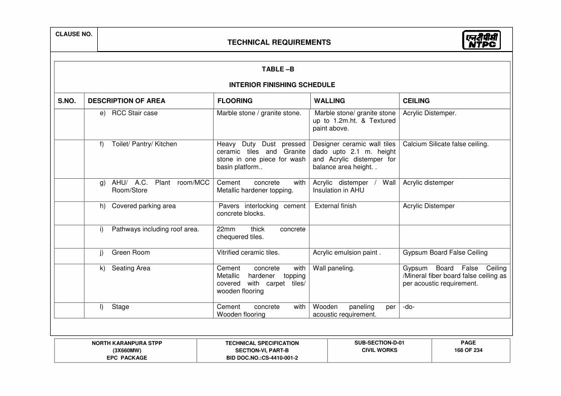
CLAUSE NO.
TECHNICAL REQUIREMENTS
NORTH KARANPURA STPP
(3X660MW)
EPC PACKAGE
TECHNICAL SPECIFICATION
SECTION-VI, PART-B
BID DOC.NO.:CS-4410-001-2
SUB-SECTION-D-01
CIVIL WORKS
PAGE
168 OF 234
TABLE –B
INTERIOR FINISHING SCHEDULE
S.NO. DESCRIPTION OF AREA FLOORING WALLING CEILING
e) RCC Stair case Marble stone / granite stone. Marble stone/ granite stone up to 1.2m.ht. & Textured paint above.
Acrylic Distemper.
f) Toilet/ Pantry/ Kitchen Heavy Duty Dust pressed ceramic tiles and Granite stone in one piece for wash basin platform..
Designer ceramic wall tiles dado upto 2.1 m. height and Acrylic distemper for balance area height. .
Calcium Silicate false ceiling.
g) AHU/ A.C. Plant room/MCC Room/Store
Cement concrete with Metallic hardener topping.
Acrylic distemper / Wall Insulation in AHU
Acrylic distemper
h) Covered parking area Pavers interlocking cement concrete blocks.
External finish
Acrylic Distemper
i) Pathways including roof area. 22mm thick concrete chequered tiles.
j) Green Room Vitrified ceramic tiles.
Acrylic emulsion paint . Gypsum Board False Ceiling
k) Seating Area Cement concrete with Metallic hardener topping covered with carpet tiles/ wooden flooring
Wall paneling. Gypsum Board False Ceiling /Mineral fiber board false ceiling as per acoustic requirement.
l) Stage Cement concrete with Wooden flooring
Wooden paneling per acoustic requirement.
-do-

CLAUSE NO.
TECHNICAL REQUIREMENTS
NORTH KARANPURA STPP
(3X660MW)
EPC PACKAGE
TECHNICAL SPECIFICATION
SECTION-VI, PART-B
BID DOC.NO.:CS-4410-001-2
SUB-SECTION-D-01
CIVIL WORKS
PAGE
169 OF 234
TABLE –B
INTERIOR FINISHING SCHEDULE
S.NO. DESCRIPTION OF AREA FLOORING WALLING CEILING
m) Projector room
Dust pressed ceramic tile Acrylic Distemper Acrylic Distemper
3 ESP control building/Air compressor house/ARCW. building
a) Operating/Maintenance areas Cement concrete with Metallic hardener topping
Pre color coated metal panel cladding.
Acrylic distemper (except metal deck area)
b) Office Room, Staff Room Vitrified ceramic tiles. Acrylic emulsion paint Acrylic emulsion paint
c) Control Room Vitrified ceramic tiles. Vitrified tile cladding on walls up to false ceiling& column encased with ACP.
False ceiling in lineal Metal panel
d) MCC Room Cement concrete with Metallic hardener topping
Acrylic distemper Acrylic distemper (except metal deck area)
e) RCC Stair case
Marble stone / granite stone. Vitrified tile up to 1.2m.ht. & Acrylic Distemper
Acrylic Distemper
f) Battery Room
Acid, Alkali resistant tile Acid, Alkali resistant tile Acrylic Distemper
g) AHU/ AC Plant room/ Cable vault
Cement concrete with Metallic hardener topping
Acrylic Distemper Acrylic Distemper

CLAUSE NO.
TECHNICAL REQUIREMENTS
NORTH KARANPURA STPP
(3X660MW)
EPC PACKAGE
TECHNICAL SPECIFICATION
SECTION-VI, PART-B
BID DOC.NO.:CS-4410-001-2
SUB-SECTION-D-01
CIVIL WORKS
PAGE
170 OF 234
TABLE –B
INTERIOR FINISHING SCHEDULE
S.NO. DESCRIPTION OF AREA FLOORING WALLING CEILING
h) Toilets Heavy Duty Dust pressed ceramic tiles and Granite stone in one piece for wash basin platform.
Designer ceramic wall tiles up to 2.1m / ceiling ht. and Acrylic distemper for balance height.
Acrylic distemper/ Calcium silicate false ceiling.
4. Canteen/ Gate Complex/Fire station/ Consruction Office
a) Reception/Waiting Marble stone / Granite stone Textured paint/ acrylic emulsion paint
Acrylic Distemper
b) Office/Guard Room/Conference/Viewing Gallery/ Staff room
Vitrified ceramic tiles. Acrylic distemper/ acrylic emulsion paint
Acrylic Distemper/Mineral fiber board false ceiling./ Metal False Ceiling
c) Detention Room/ Ammunition store
Cement concrete with Metallic hardener topping
Acrylic distemper Acrylic Distemper
d) Sitting and General Area
Granite stone/Vitrified ceramic tiles.
Designer ceramic wall tiles up to 1.2 m, and Textured Paint for balance height. Glass mosaic tiles for murals & Glass blocks for interior purpose.
Acrylic distemper/ Gypsum board false ceiling./ Aluminium False ceiling
e) Kitchen, Pantry and preparation area
Heavy duty dust pressed ceramic tiles and Granite stone for platform
Designer ceramic wall tiles dado upto 2.1 m. height and Acrylic distemper for balance area height. .
Acrylic distemper

CLAUSE NO.
TECHNICAL REQUIREMENTS
NORTH KARANPURA STPP
(3X660MW)
EPC PACKAGE
TECHNICAL SPECIFICATION
SECTION-VI, PART-B
BID DOC.NO.:CS-4410-001-2
SUB-SECTION-D-01
CIVIL WORKS
PAGE
171 OF 234
TABLE –B
INTERIOR FINISHING SCHEDULE
S.NO. DESCRIPTION OF AREA FLOORING WALLING CEILING
f) Toilets Heavy Duty Dust pressed ceramic tiles and Granite stone in one piece for wash basin platform.
Designer ceramic wall tiles. Calcium Silicate false ceiling.
g) Fire Tender area
Cement concrete with Metallic hardener topping.
Acrylic distemper. Acrylic distemper.
h) Stores Cement concrete with Metallic hardener topping.
Acrylic distemper. Acrylic distemper.
5. CHP Maintenance Building /Permanent store/Workshop building
a) Workshop/stores Cement concrete with Metallic hardener topping.
Acrylic distemper/ color coated Metal panel cladding
Acrylic distemper (except metal deck area)
b) Office Room, Staff Room Vitrified ceramic tiles. Acrylic emulsion paint. Mineral fiber board false ceiling/ Acrylic distemper
c) Passages
Vitrified Ceramic Tiles
Acrylic distemper Mineral fiber board false ceiling/ Acrylic distemper
d) RCC Stair case 18mm thick polished Marble stone / granite stone.
Vitrified Ceramic Tiles 1.2m.ht. & Distemper above.
Acrylic Distemper

CLAUSE NO.
TECHNICAL REQUIREMENTS
NORTH KARANPURA STPP
(3X660MW)
EPC PACKAGE
TECHNICAL SPECIFICATION
SECTION-VI, PART-B
BID DOC.NO.:CS-4410-001-2
SUB-SECTION-D-01
CIVIL WORKS
PAGE
172 OF 234
TABLE –B
INTERIOR FINISHING SCHEDULE
S.NO. DESCRIPTION OF AREA FLOORING WALLING CEILING
e) Toilets Heavy Duty Dust pressed ceramic tiles and Granite stone in one piece for wash basin platform.
Designer ceramic wall tiles dado upto 2.1 m. height and Acrylic distemper for balance area height. .
Acrylic distemper
6. Mill& Bunker building/Track Hooper/T.P./Conveyer's gallery/Crusher
a) Mill& Bunker area/Track Hooper area/ T.P. area/Conveyer's gallery area/Crusher area
Cement concrete with Metallic hardener topping
Acrylic distemper on masonry walls/ color coated Metal panel cladding
color coated Metal panel cladding
a) Toilets Heavy Duty Dust pressed ceramic tiles and Granite stone in one piece for wash basin platform.
Designer ceramic wall tiles up to 2.1m / ceiling ht. and Acrylic distemper for balance height.
Acrylic distemper
7. Fire water pump house
a) Maintenance /Pump floor/PLC Cement concrete with Metallic hardener topping
Acrylic distemper Acrylic distemper (except metal deck area)
b) Control room /PLC. Epoxy flooring
Acrylic emulsion paint . Mineral fiber board false ceiling.
c) Toilet area Heavy Duty Dust pressed ceramic tiles and Granite stone in one piece for wash basin platform.
Designer ceramic wall tiles up to 2.1m / ceiling ht. and Acrylic distemper for balance height.
Acrylic distemper

CLAUSE NO.
TECHNICAL REQUIREMENTS
NORTH KARANPURA STPP
(3X660MW)
EPC PACKAGE
TECHNICAL SPECIFICATION
SECTION-VI, PART-B
BID DOC.NO.:CS-4410-001-2
SUB-SECTION-D-01
CIVIL WORKS
PAGE
173 OF 234
TABLE –B
INTERIOR FINISHING SCHEDULE
S.NO. DESCRIPTION OF AREA FLOORING WALLING CEILING
8. Fire water booster water pump house /Foam pump house.
a) Maintenance /Pump floor/PLC Cement concrete with Metallic hardener topping
Acrylic distemper Acrylic distemper (except metal deck area)
b) Control room /PLC. Vitrified Ceramic Tiles Acrylic emulsion paint . Mineral fiber board false ceiling.
c) Toilet area Heavy Duty Dust pressed ceramic tiles and Granite stone in one piece for wash basin platform.
Designer ceramic wall tiles up to 2.1m / ceiling ht. and Acrylic distemper for balance height.
Acrylic distemper
9. Ash slurry pump house/ Ash water pump house / Silo Area Utility Building / Ash Water recirculation Pump House/ Transport air compressor house/ HCSD pump house/ Ash Dyke Maintenance building.
a) Operating/Maintenance areas/ MCC room
Cement concrete with Metallic hardener topping
Acrylic distemper Acrylic distemper (except metal deck area)
b) Office Room, Staff Room Vitrified ceramic tiles. Acrylic emulsion paint Acrylic distemper.
c) Control room Vitrified Ceramic Tiles Acrylic emulsion paint Mineral fiber board false ceiling.
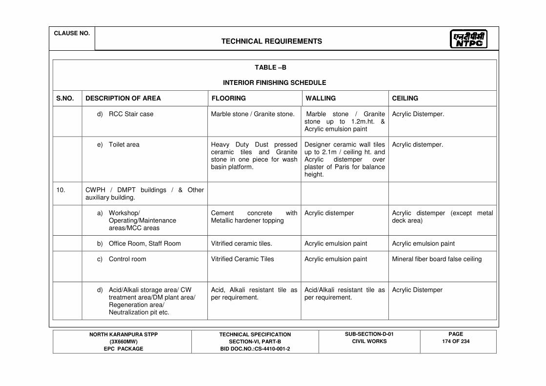
CLAUSE NO.
TECHNICAL REQUIREMENTS
NORTH KARANPURA STPP
(3X660MW)
EPC PACKAGE
TECHNICAL SPECIFICATION
SECTION-VI, PART-B
BID DOC.NO.:CS-4410-001-2
SUB-SECTION-D-01
CIVIL WORKS
PAGE
174 OF 234
TABLE –B
INTERIOR FINISHING SCHEDULE
S.NO. DESCRIPTION OF AREA FLOORING WALLING CEILING
d) RCC Stair case Marble stone / Granite stone. Marble stone / Granite stone up to 1.2m.ht. & Acrylic emulsion paint
Acrylic Distemper.
e) Toilet area Heavy Duty Dust pressed ceramic tiles and Granite stone in one piece for wash basin platform.
Designer ceramic wall tiles up to 2.1m / ceiling ht. and Acrylic distemper over plaster of Paris for balance height.
Acrylic distemper.
10. CWPH / DMPT buildings / & Other auxiliary building.
a) Workshop/ Operating/Maintenance areas/MCC areas
Cement concrete with Metallic hardener topping
Acrylic distemper Acrylic distemper (except metal deck area)
b) Office Room, Staff Room Vitrified ceramic tiles. Acrylic emulsion paint Acrylic emulsion paint
c) Control room
Vitrified Ceramic Tiles Acrylic emulsion paint
Mineral fiber board false ceiling
d) Acid/Alkali storage area/ CW treatment area/DM plant area/ Regeneration area/ Neutralization pit etc.
Acid, Alkali resistant tile as per requirement.
Acid/Alkali resistant tile as per requirement.
Acrylic Distemper
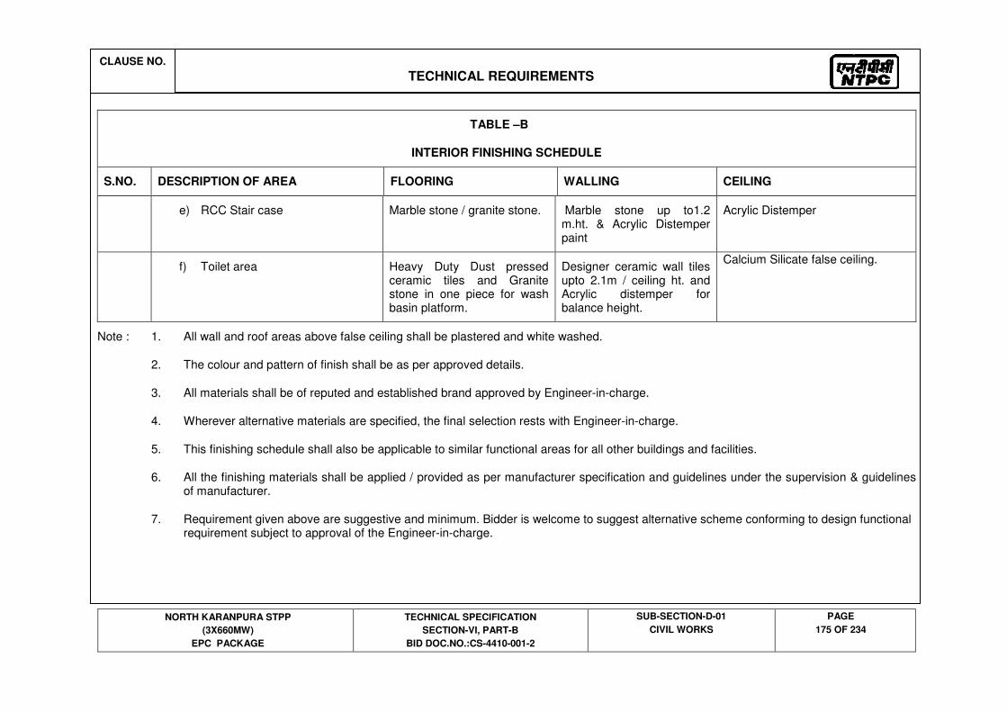
CLAUSE NO.
TECHNICAL REQUIREMENTS
NORTH KARANPURA STPP
(3X660MW)
EPC PACKAGE
TECHNICAL SPECIFICATION
SECTION-VI, PART-B
BID DOC.NO.:CS-4410-001-2
SUB-SECTION-D-01
CIVIL WORKS
PAGE
175 OF 234
TABLE –B
INTERIOR FINISHING SCHEDULE
S.NO. DESCRIPTION OF AREA FLOORING WALLING CEILING
e) RCC Stair case Marble stone / granite stone. Marble stone up to1.2 m.ht. & Acrylic Distemper paint
Acrylic Distemper
f) Toilet area Heavy Duty Dust pressed ceramic tiles and Granite stone in one piece for wash basin platform.
Designer ceramic wall tiles upto 2.1m / ceiling ht. and Acrylic distemper for balance height.
Calcium Silicate false ceiling.
Note : 1. All wall and roof areas above false ceiling shall be plastered and white washed.
2. The colour and pattern of finish shall be as per approved details.
3. All materials shall be of reputed and established brand approved by Engineer-in-charge.
4. Wherever alternative materials are specified, the final selection rests with Engineer-in-charge.
5. This finishing schedule shall also be applicable to similar functional areas for all other buildings and facilities.
6. All the finishing materials shall be applied / provided as per manufacturer specification and guidelines under the supervision & guidelines of manufacturer.
7. Requirement given above are suggestive and minimum. Bidder is welcome to suggest alternative scheme conforming to design functional requirement subject to approval of the Engineer-in-charge.

CLAUSE NO.
TECHNICAL REQUIREMENTS
NORTH KARANPURA STPP
(3X660MW)
EPC PACKAGE
TECHNICAL SPECIFICATION
SECTION-VI, PART-B
BID DOC.NO.:CS-4410-001-2
SUB-SECTION-D-01
CIVIL WORKS
PAGE
176 OF 234
TABLE –C
EXTERIOR FINISHES SCHEDULE
Sl.No. DESCRIPTION OF AREA WALL AND PROJECTIONS SOFFIT OF PROJECTIONS
1. Main plant building & Fire walls in Transformer yard; Other Auxilliary building in steel framed structure.
Resin bonded granular texture finish of approved colour/colour combination over plastered surface on masonry/concrete.
Approved colour/ colour combination of colour coated metal cladding
Premium Acrylic Smooth Exterior Paint over plastered surface.
Approved colour/ colour combination of colour coated metal cladding.
2. Building with concrete frame work, etc.
Premium Acrylic Smooth Exterior Paint of approved colour/colour combination.
For Service building/ Admin. Bldg. / canteen & Auditorium. Aluminium composite Panel Cladding in combination with Resin bonded Granular texture finish (50:50)
Premium Acrylic Smooth Exterior Paint over plastered surface.
3. Steel Structure, trestles, etc. High performance Paint of approved specification and shade.
NOTE : 1. The colour and pattern of finish shall be as finalized by Engineer.
2. All materials shall be of reputed and established brand approved by Engineer.
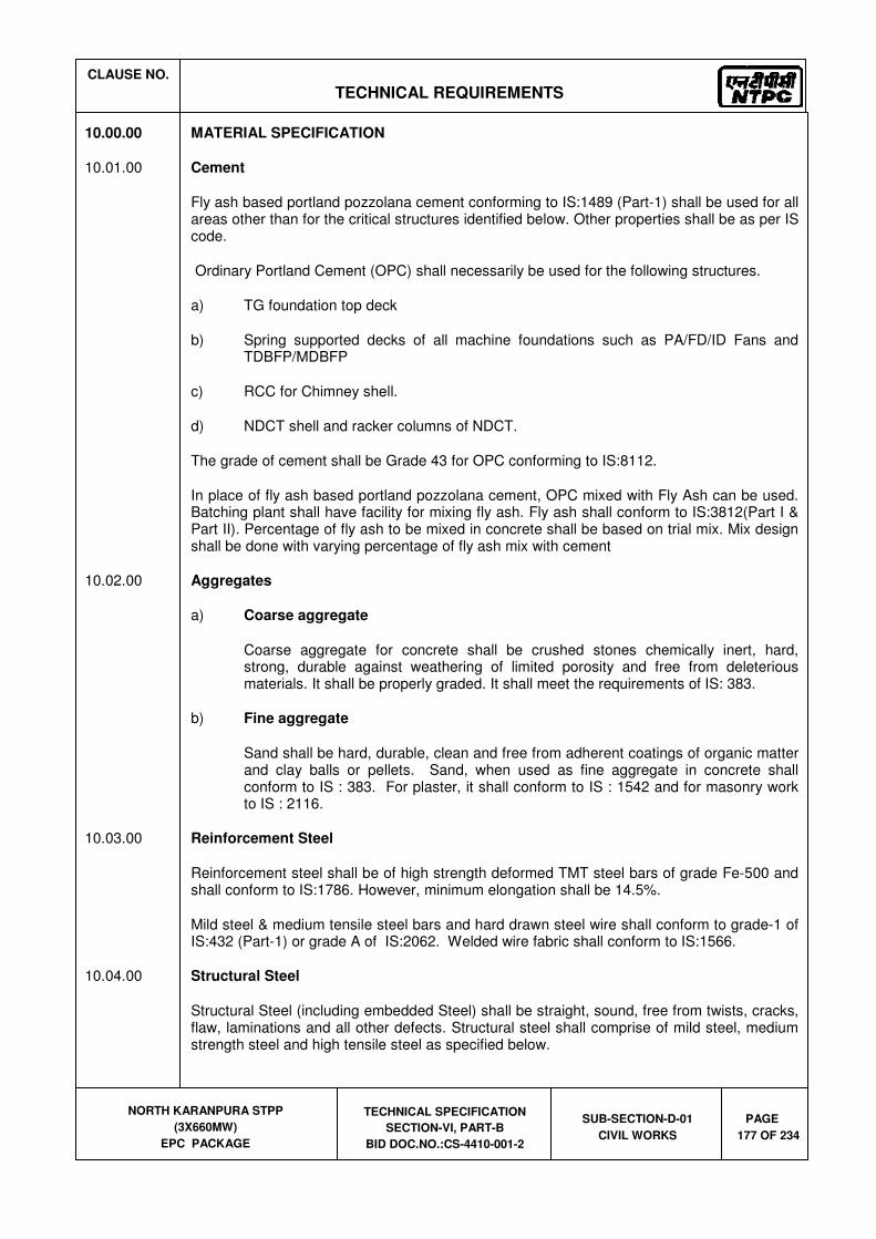
CLAUSE NO.
TECHNICAL REQUIREMENTS
NORTH KARANPURA STPP
(3X660MW)
EPC PACKAGE
TECHNICAL SPECIFICATION
SECTION-VI, PART-B
BID DOC.NO.:CS-4410-001-2
SUB-SECTION-D-01
CIVIL WORKS
PAGE
177 OF 234
10.00.00 MATERIAL SPECIFICATION
10.01.00 Cement
Fly ash based portland pozzolana cement conforming to IS:1489 (Part-1) shall be used for all areas other than for the critical structures identified below. Other properties shall be as per IS code.
Ordinary Portland Cement (OPC) shall necessarily be used for the following structures.
a) TG foundation top deck
b) Spring supported decks of all machine foundations such as PA/FD/ID Fans and TDBFP/MDBFP
c) RCC for Chimney shell.
d) NDCT shell and racker columns of NDCT.
The grade of cement shall be Grade 43 for OPC conforming to IS:8112.
In place of fly ash based portland pozzolana cement, OPC mixed with Fly Ash can be used. Batching plant shall have facility for mixing fly ash. Fly ash shall conform to IS:3812(Part I & Part II). Percentage of fly ash to be mixed in concrete shall be based on trial mix. Mix design shall be done with varying percentage of fly ash mix with cement
10.02.00 Aggregates
a) Coarse aggregate
Coarse aggregate for concrete shall be crushed stones chemically inert, hard, strong, durable against weathering of limited porosity and free from deleterious materials. It shall be properly graded. It shall meet the requirements of IS: 383.
b) Fine aggregate
Sand shall be hard, durable, clean and free from adherent coatings of organic matter and clay balls or pellets. Sand, when used as fine aggregate in concrete shall conform to IS : 383. For plaster, it shall conform to IS : 1542 and for masonry work to IS : 2116.
10.03.00 Reinforcement Steel
Reinforcement steel shall be of high strength deformed TMT steel bars of grade Fe-500 and shall conform to IS:1786. However, minimum elongation shall be 14.5%.
Mild steel & medium tensile steel bars and hard drawn steel wire shall conform to grade-1 of IS:432 (Part-1) or grade A of IS:2062. Welded wire fabric shall conform to IS:1566.
10.04.00 Structural Steel
Structural Steel (including embedded Steel) shall be straight, sound, free from twists, cracks, flaw, laminations and all other defects. Structural steel shall comprise of mild steel, medium strength steel and high tensile steel as specified below.
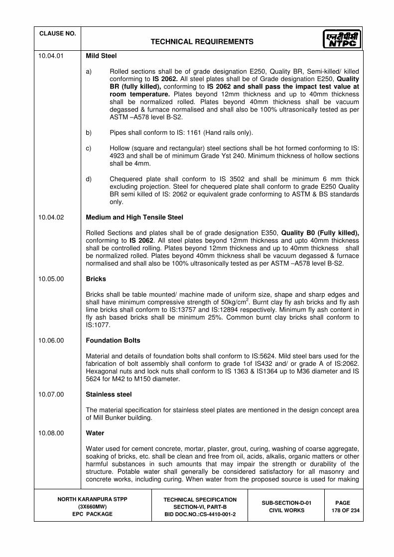
CLAUSE NO.
TECHNICAL REQUIREMENTS
NORTH KARANPURA STPP
(3X660MW)
EPC PACKAGE
TECHNICAL SPECIFICATION
SECTION-VI, PART-B
BID DOC.NO.:CS-4410-001-2
SUB-SECTION-D-01
CIVIL WORKS
PAGE
178 OF 234
10.04.01 Mild Steel
a) Rolled sections shall be of grade designation E250, Quality BR, Semi-killed/ killed conforming to IS 2062. All steel plates shall be of Grade designation E250, Quality BR (fully killed), conforming to IS 2062 and shall pass the impact test value at room temperature. Plates beyond 12mm thickness and up to 40mm thickness shall be normalized rolled. Plates beyond 40mm thickness shall be vacuum degassed & furnace normalised and shall also be 100% ultrasonically tested as per ASTM –A578 level B-S2.
b) Pipes shall conform to IS: 1161 (Hand rails only).
c) Hollow (square and rectangular) steel sections shall be hot formed conforming to IS: 4923 and shall be of minimum Grade Yst 240. Minimum thickness of hollow sections shall be 4mm.
d) Chequered plate shall conform to IS 3502 and shall be minimum 6 mm thick excluding projection. Steel for chequered plate shall conform to grade E250 Quality BR semi killed of IS: 2062 or equivalent grade conforming to ASTM & BS standards only.
10.04.02 Medium and High Tensile Steel
Rolled Sections and plates shall be of grade designation E350, Quality B0 (Fully killed), conforming to IS 2062. All steel plates beyond 12mm thickness and upto 40mm thickness shall be controlled rolling. Plates beyond 12mm thickness and up to 40mm thickness shall be normalized rolled. Plates beyond 40mm thickness shall be vacuum degassed & furnace normalised and shall also be 100% ultrasonically tested as per ASTM –A578 level B-S2.
10.05.00 Bricks
Bricks shall be table mounted/ machine made of uniform size, shape and sharp edges and shall have minimum compressive strength of 50kg/cm
2. Burnt clay fly ash bricks and fly ash
lime bricks shall conform to IS:13757 and IS:12894 respectively. Minimum fly ash content in fly ash based bricks shall be minimum 25%. Common burnt clay bricks shall conform to IS:1077.
10.06.00 Foundation Bolts
Material and details of foundation bolts shall conform to IS:5624. Mild steel bars used for the fabrication of bolt assembly shall conform to grade 1of IS432 and/ or grade A of IS:2062. Hexagonal nuts and lock nuts shall conform to IS 1363 & IS1364 up to M36 diameter and IS 5624 for M42 to M150 diameter.
10.07.00 Stainless steel
The material specification for stainless steel plates are mentioned in the design concept area of Mill Bunker building.
10.08.00 Water
Water used for cement concrete, mortar, plaster, grout, curing, washing of coarse aggregate, soaking of bricks, etc. shall be clean and free from oil, acids, alkalis, organic matters or other harmful substances in such amounts that may impair the strength or durability of the structure. Potable water shall generally be considered satisfactory for all masonry and concrete works, including curing. When water from the proposed source is used for making

CLAUSE NO.
TECHNICAL REQUIREMENTS
NORTH KARANPURA STPP
(3X660MW)
EPC PACKAGE
TECHNICAL SPECIFICATION
SECTION-VI, PART-B
BID DOC.NO.:CS-4410-001-2
SUB-SECTION-D-01
CIVIL WORKS
PAGE
179 OF 234
the concrete, the maximum permissible impurities, development of strength and initial setting time of concrete shall meet the requirements of IS:456.
All materials brought for incorporation in works shall be of best quality as per IS unless specified otherwise.
10.08.00 Statutory Requirements
Bidder shall comply with all the applicable statutory rules pertaining to Factories Act, Fire Safety Rules at Tariff Advisory Committee. Water Act for pollution control, Explosives Act, etc.
Provisions of safety, health and welfare according to Factories Act shall be complied with. These shall include provision of continuous walkways along the crane - girder level on both sides of building, comfortable approach to EOT crane cabin, railing, fire escape, locker room for workmen, pantry, toilets, rest room etc.
Provisions for fire proof doors, number of staircases, fire separation wall, lath plastering/encasing the structural members (in fire prone areas), type of glazing etc. shall be made according to the recommendations of Tarrif Advisory Committee.
Statutory clearances and norms of State Pollution Control Board shall be followed.
Bidder shall obtain approval of Civil/Architectural drawings from concerned authorities before taking up the construction work.
11.00.00 Inspection, Testing And Quality Control
11.01.00 Sampling and testing of major items of civil works viz. earthwork, concreting, structural steel work (including welding), piling, sheeting, etc. shall be carried out in accordance with the requirements of this specification. Wherever nothing is specified relevant Indian Standards shall be followed. In absence of Indian Standard equivalent International Standards may be used.
The Bidder shall submit and finalise a detailed field Quality Assurance Programme before starting of the construction work according to the requirement of this specification. This shall include frequency of sampling and testing, nature/type of test, method of test, setting of a testing laboratory, arrangement of testing apparatus/equipment, deployment of qualified/experienced manpower, preparation of format for record, Field Quality Plan, etc. Tests shall be done in the field and/or at a laboratory approved by the Engineer. The Bidder shall furnish the test certificate from the manufacturer’s of various materials to be used in the construction.
11.02.00 Workmanship and dimensional shall be checked as stipulated below.
12.00.00 ANNEXURES
(a) List Of Codes And Standards
All applicable standards, references, specifications, codes of practice, etc., shall be the latest edition including all applicable official amendments and revisions. A complete set of all these documents shall be available at site with Bidder. List of some of the applicable Standards, in original Codes and references is as given in Annexure-a of this specification.
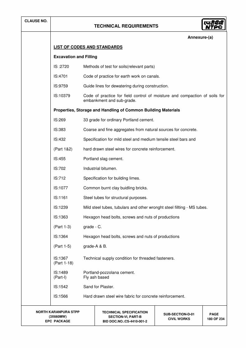
CLAUSE NO.
TECHNICAL REQUIREMENTS
NORTH KARANPURA STPP
(3X660MW)
EPC PACKAGE
TECHNICAL SPECIFICATION
SECTION-VI, PART-B
BID DOC.NO.:CS-4410-001-2
SUB-SECTION-D-01
CIVIL WORKS
PAGE
180 OF 234
Annexure-(a)
LIST OF CODES AND STANDARDS
Excavation and Filling
IS :2720 Methods of test for soils(relevant parts)
IS:4701 Code of practice for earth work on canals.
IS:9759 Guide lines for dewatering during construction.
IS:10379 Code of practice for field control of moisture and compaction of soils for embankment and sub-grade.
Properties, Storage and Handling of Common Building Materials
IS:269 33 grade for ordinary Portland cement.
IS:383 Coarse and fine aggregates from natural sources for concrete.
IS:432 Specification for mild steel and medium tensile steel bars and
(Part 1&2) hard drawn steel wires for concrete reinforcement.
IS:455 Portland slag cement.
IS:702 Industrial bitumen.
IS:712 Specification for building limes.
IS:1077 Common burnt clay buidling bricks.
IS:1161 Steel tubes for structural purposes.
IS:1239 Mild steel tubes, tubulars and other wronght steel fillting - MS tubes.
IS:1363 Hexagon head bolts, screws and nuts of productions
(Part 1-3) grade - C.
IS:1364 Hexagon head bolts, screws and nuts of productions
(Part 1-5) grade-A & B.
IS:1367 Technical supply condition for threaded fasteners. (Part 1-18) IS:1489 Portland-pozzolana cement. (Part-I) Fly ash based IS:1542 Sand for Plaster. IS:1566 Hard drawn steel wire fabric for concrete reinforcement.

CLAUSE NO.
TECHNICAL REQUIREMENTS
NORTH KARANPURA STPP
(3X660MW)
EPC PACKAGE
TECHNICAL SPECIFICATION
SECTION-VI, PART-B
BID DOC.NO.:CS-4410-001-2
SUB-SECTION-D-01
CIVIL WORKS
PAGE
181 OF 234
IS:1786 High strength deformed steel bars & wires for concrete reinforcement. IS:2062 Hot Rolled Low, Medium and High Tensile Structural Steel IS:2116 Sand for masonry mortars. IS : 2185 Hollow & solid concrete blocks. (Part 1) (Part 2) Hollow & solid light weight concrete blocks. IS:2386 Testing of aggregates for concrete. (Part I-VIII) IS:3812 Specification for fly ash for use as pozzolona and admixture. IS:4082 Recommendation on stacking and storage of construction materiel and
components at site IS:8112 43 grade ordinary portland cement. IS:8500 Structural steel-Microalloyed (Medium and high strength qualities). IS:12269 53 grade ordinary portland cement. IS:12894 Specification for fly ash lime bricks. IS:13757 Burnt clay fly ash building bricks. Cast in-situ Concrete and Allied Works IS:280 Mild steel wire for general engineering purpose. IS:456 Code of practice for plain and reinforcement concrete. IS:457 Code of practice for general construction of plain and reinforced concrete for
dams and other massive structures. IS:516 Method of test for strength of concrete. IS:1199 Methods of sampling and analysis of concrete. IS:1791 General requirement for batch type concrete mixers. IS:1834 Hot applied sealing compound for joints in concrete. IS:1838 Preformed fillers for expansion joints in concrete pavement and structures. IS:2438 Specification for roller pan mixers. IS:2502 Code of practice for bending and fixing of bars for concrete reinforcement. IS:2505 Concrete vibrators - immersion type. IS:2506 General requirements for screed board concrete vibrators. IS:2722 Specification for Portable Swing weigh batchers for concrete (single and
double bucket type).

CLAUSE NO.
TECHNICAL REQUIREMENTS
NORTH KARANPURA STPP
(3X660MW)
EPC PACKAGE
TECHNICAL SPECIFICATION
SECTION-VI, PART-B
BID DOC.NO.:CS-4410-001-2
SUB-SECTION-D-01
CIVIL WORKS
PAGE
182 OF 234
IS:2750 Steel scaffoldings IS:2751 Recommended practice for welding of mild steel plain and deformed bars for
reinforced construction. IS:3150 Hexagonal wire netting for general purposes. IS:3366 Specification for pan vibrators. IS:3370 Code of practice for concrete structures for the (Part 1-4) storage of liquids. IS:3558 Code of practice for use of immersion vibrators for consolidating concrete. IS:4014 Code of practice for steel tubular scaffolding. (Part-1&2) IS:4326 Code of practice for earth quake resistant design and construction of
buildings. IS:4656 Form vibrators for concrete. IS:4925 Concrete batching and mixing plant. IS:4990 Plywood for concrete shuttering work. IS:5256 Code of practice for sealing expansion joints in concrete lining on canals. IS:5525 Recommendations for detailing of reinforcement in reinforced concrete
works. IS:6461 Glossary of terms relating to cement concrete. IS:6494 Code of practice for water proofing of underground reservoir and swimming
pools. IS:6509 Code of practice for installation of joints in concrete pavements. IS:7861 Code of practice for extreme weather concreting. (Part -1&2) IS:9012 Recommended practice for shotcreting. IS:9103 Admixtures for concrete. IS:9417 Recommendations for welding cold worked bars for reinforced concrete
construction. IS:10262 Recommended guidelines for concrete mix design. IS:11384 Code of practice for composite construction in structural steel and concrete. IS:12118 Two parts polysulphide based sealants. IS:12200 Code of practice for provision of water stops at transverse construction joints
in masonry and concrete dams.

CLAUSE NO.
TECHNICAL REQUIREMENTS
NORTH KARANPURA STPP
(3X660MW)
EPC PACKAGE
TECHNICAL SPECIFICATION
SECTION-VI, PART-B
BID DOC.NO.:CS-4410-001-2
SUB-SECTION-D-01
CIVIL WORKS
PAGE
183 OF 234
IS:13311 Non destructive testing of concrete - methods of test. (Part 1) Ultrasonic pulse velocity. (Part 2) Rebound hammer. SP-16 Design codes for reinforced concrete to IS:456-1978. SP-23 Hand book of concrete mixes. SP-24 Explanatory handbook on Indian standards code for plain and reinforced
concrete. (IS : 456) SP-34 Hand book on concrete reinforcement and detailing. ACI-318 American Concrete Institute code for structural concrete. Precast Concrete Works SP:7 National Building Code - Structural Design (Part 6/Sec.7) Prefabrication and system building and mixed / composite construction. IS:10297 Code of practice for design and construction of floors and roofs using
precast reinforced/prestressed concrete ribbed or cored slab units. IS:10505 Code of practice for construction of floors and roofs using pre-cast reinforced
concrete waffle units. IS:15658 Pre-cast concrete block for paving. Masonry & Allied Works IS:1905 Code of practice for structural use of unreinforced masonry. IS: 2185 Part-1 Concrete Masonry Units - Specification Part 1 Hollow and Solid
Concrete Blocks Part-3 Specification for concrete masonry units: Part 2 Hollow and solid light
weight concrete blocks IS:2212 Code of practice for brick work. IS:2250 Code of practice for preparation and use of masonry mortars. IS:2572 Code of practice for construction of hollow concrete block masonry. SP:20 Hand book on masonry design and construction. Sheeting Works IS:277 Galvanised steel sheets (Plan & corrugated). IS:513 Cold-rolled low carbon steel sheets & strips. IS:730 Hook bolts for corrugated sheet roofing.

CLAUSE NO.
TECHNICAL REQUIREMENTS
NORTH KARANPURA STPP
(3X660MW)
EPC PACKAGE
TECHNICAL SPECIFICATION
SECTION-VI, PART-B
BID DOC.NO.:CS-4410-001-2
SUB-SECTION-D-01
CIVIL WORKS
PAGE
184 OF 234
IS:801 Code of practice for use of cold formed light gauge steel structural members in general building construction.
IS:2527 Code of practice for fixing rain water gutters and down pipe for roof drainage. IS:7178 Technical supply condition for tapping screw. IS:8183 Bonded mineral wool. IS:8869 Washers for corrugated sheet roofing. IS:12093 Code of practice for laying and fixing of sloped roof covering using plain and
corrugated galvanised steel sheets. IS:12436 Preformed rigid Polyurethane (PUR) and isocyanurate (PIR) foams for
thermal insulation. IS:12866 Plastic translucent sheets made from thermosetting polyester resin (glass
fibre reinforced). IS:14246 Continuously pre-painted galvanised steel sheets and coils. BS:5950 Code of practice for design of light gauge profiled (Part-6) steel sheeting Fabrication and Erection of Structural Steel Works IS:800 Code of practice for General Construction of steel. IS:813 Scheme for symbols for welding. IS:814 Covered electrodes for manual metal arc welding of carbon & carbon
manganese steel. IS:816 Code of practice for use of metal arc welding for general construction in mild
steel. IS:817 Code of practice for training and testing of metal arc welders. IS:1024 Welding in bridges and substructured subject to dynamic. IS:1181 Qualifying tests for Metal Arc welders (engaged in welding structures other
than pipes). IS:1182 Recommended practice for Radiographic examination of fusion welded butt
joints in steel plates IS:1608 Mechanical testing of metals - tensile testing IS:1852 Rolling and Cutting Tolerances for Hot rolled steel products. IS:2016 Specification for Plain washers. IS:2595 Code of practice for Radiographic testing

CLAUSE NO.
TECHNICAL REQUIREMENTS
NORTH KARANPURA STPP
(3X660MW)
EPC PACKAGE
TECHNICAL SPECIFICATION
SECTION-VI, PART-B
BID DOC.NO.:CS-4410-001-2
SUB-SECTION-D-01
CIVIL WORKS
PAGE
185 OF 234
IS:2629 Hot dip galvanising of iron and steel IS:3502 Steel chequred plate. IS:3613 Acceptance tests for wire flux combination for submerged arc welding. IS:3658 Code of practice for liquid penetrant flaw detection. IS:3664 Code of practice for ultra sonic pulse echo testing contact and immersion
method IS:3757 High strength structural bolts. IS:4000 High strength bolts in steel structure - code of practice. IS:4353 Sub merged arc welding of mild steel and low alloy steel Recommendation IS:4759 Hot dip zinc coating on structural steel and other allied products. IS:5334 Code of practice for magnetic particle flaw detection of welds. IS:5369 General requirements for plain washers and lock washer IS : 6623 High strength structural nuts. IS:6649 Hardened and tampered washers for high strength structural bolts & nuts. IS:6911 Stainless steel plate, sheet and strip. IS:7205 Safety code for erection of structural steel. IS:7215 Tolerances for fabrication of structural steel. IS:7307 Approved test for welding procedures (Part - I) Fusion welding of steel. IS:7310 Approval test for welders working to approval welding procedure. (Part-I) Fusion welding of steel IS:9178 Criteria for design of steel bins for storage of bulk material. (Part-1to 3) IS:9595 Recommendations for metal arc welding of carbon & carbon manganese
steel. IS:12843 Tolerances for erection of steel structures. SP:6 ISI Hand book for structural Engineers. (Part 1 to 7) Plastering and Allied Works IS:1661 Code of practice for application of cement and cement lime plaster finishes. IS:2402 Code of practice for external rendered finishes.

CLAUSE NO.
TECHNICAL REQUIREMENTS
NORTH KARANPURA STPP
(3X660MW)
EPC PACKAGE
TECHNICAL SPECIFICATION
SECTION-VI, PART-B
BID DOC.NO.:CS-4410-001-2
SUB-SECTION-D-01
CIVIL WORKS
PAGE
186 OF 234
IS:2547 Gypsum building plaster. (Parts 1&2) Acid and Alkali Resistant Lining IS:158 Ready mixed paint, brushing, bituminous, black, lead free, acid, alkali & heat
resisting. IS:412 Expanded metal steel sheets for general purpose.
IS:4441 Code of practice for use of silica type chemical resistant mortars.
IS:4443 Code of practice for use of resin type chemical resistant mortars.
IS:4456 Method of Test for chemical resistant tiles. (Part I & II) IS:4457 Ceramic unglazed vitreous acid resisting tiles. IS:4832 Specification for chemical resistant mortars.
(Part - 1) Silicate type
(Part - 2) Resin type (Part - 3) Sulfur type IS:4860 Acid resistant bricks. IS:9510 Bitumastic acid resisting grade. Water Supply, Drainage and Sanitation IS:458 Precast concrete pipes (with & without reinforcement). IS:554 Pipe threads where pressure tight joints are made on the threads –
dimensions, tolerances and designation. IS:651 Salt glazed stoneware pipes and fittings. IS:774 Flushing cisterns for water closets and urinals. IS:775 Cast iron brackets and supports for wash basins and sinks. IS:778 Copper alloy gate, globe and check valves for water works purposes. IS:781 Cast copper alloy screw down bib taps & stop valves for water services. IS:782 Caulking lead. IS:783 Code of practice for laying of concrete pipes. IS:1172 Code of basic requirements of water supply, drainage and sanitation. IS:1230 Cast iron rain water pipes and fittings. IS:1239 Mild Steel tubes, tubulars and other wrought steel fittings (Part 1&2)

CLAUSE NO.
TECHNICAL REQUIREMENTS
NORTH KARANPURA STPP
(3X660MW)
EPC PACKAGE
TECHNICAL SPECIFICATION
SECTION-VI, PART-B
BID DOC.NO.:CS-4410-001-2
SUB-SECTION-D-01
CIVIL WORKS
PAGE
187 OF 234
IS:1536 Centrifugally cast (Spun) iron pressure pipes for water. IS:1537 Vertically cast iron pressure pipes for water, gas and sewage. IS:1538 Cast iron fittings for pressure pipe for water, gas and sewage. IS:1703 Copper alloy float valve for water supply fitting. IS:1726 Cast iron manhole covers and frames. IS:1729 Cast iron / Ductile iron drainage pipes and pipe/fittings for over ground non
pressure pipeline socket and spigot series. IS:1742 Code of practice for building drainage. IS:2064 Selection, installation and maintenance of sanitary appliances. IS:2065 Code of practice for water supply in buildings. IS:2326 Automatic flushing cisterns for urinals. IS:2548 Plastic seats and covers for water closets. IS:2556 Vitreous sanitary appliances (vitreous china). IS:3114 Code of practice for laying of cast iron pipes. IS:3311 Waste plug and its accessories for sinks and wash basins. IS:3438 Silvered glass mirrors for general purposes. IS:3486 Cast iron spigot and socket drain pipes. IS:3589 steel pipe for water and sewage (168.3 to 2540mm outside diameter) IS:3989 Centrifugally cast (Spun) iron spigot and socket soil, waste and ventilating
pipes, fittings and accessories. IS:4111 Code of practice for ancillary structure in sewerage system. (Part 1 to 5) IS:4127 Code of practice for laying of glazed stone ware pipes. IS : 4733 Methods of sampling and testing sewage effluents. IS:4764 Tolerance limits for sewage effluents discharged into inland surface waters. IS:1068 Electroplated coating of nickel plus chromium and copper plus nickel plus
chromium. IS:5329 Code of practice for sanitary pipe work above ground for buildings. IS:5382 Rubber sealing rings for gas mains, water mains and sewers. IS:5822 Code of practice for laying of electrically welded steel pipes for water supply.

CLAUSE NO.
TECHNICAL REQUIREMENTS
NORTH KARANPURA STPP
(3X660MW)
EPC PACKAGE
TECHNICAL SPECIFICATION
SECTION-VI, PART-B
BID DOC.NO.:CS-4410-001-2
SUB-SECTION-D-01
CIVIL WORKS
PAGE
188 OF 234
IS:5961 Specification for cast iron grating for drainage purpose. IS:7740 Code of practice for construction and maintenance of road gullies. IS:8931 Copper alloy fancy single taps combination tap assembly and stop valves
for water services. IS:9762 Polyethylene floats for float valves. IS:10592 Industrial emergency showers, eye and face fountains and combination
units. IS:12592 Specification for precast concrete manhole covers and frames. IS:12701 Rotational moulded polyethylene water storage tanks. IS:13983 Stainless steel sinks for domestic purposes. SP:35 Hand book on water supply and drainage with special emphasis on
plumbing. CPH&EEO Manual on sewage and sewage treatment Publication - as updated. Doors Windows and Allied Works IS:204 Tower Bolts. (Part 1) Ferrous metals (Part 2) Non - ferrous metals IS:208 Door Handles. IS:281 Mild steel sliding door bolts for use with padlocks. IS:362 Parliament Hinges. IS:419 Putty, for use on window frames. IS:451 Technical supply conditions for wood screws IS:733 Wrought aluminium and aluminium alloy bars, rods and sections for general
engineering purposes. IS:1003 Timber panelled and glazed shutters (doors shutters). (Part I) IS:1003 Timber panelled and glazed shutters (Part-1) door shutters. IS:1038 Steel doors, windows and ventilators. IS:1081 Code of practice for fixing and glazing of metal (steel and aluminium) doors,
windows and ventilators.

CLAUSE NO.
TECHNICAL REQUIREMENTS
NORTH KARANPURA STPP
(3X660MW)
EPC PACKAGE
TECHNICAL SPECIFICATION
SECTION-VI, PART-B
BID DOC.NO.:CS-4410-001-2
SUB-SECTION-D-01
CIVIL WORKS
PAGE
189 OF 234
IS:1285 Wrought aluminium and aluminium alloy extruded round tube & hollow
section (for general engineering purposes). IS:1341 Steel butt hinges. IS:1361 Steel windows for Industrial buildings. IS:1823 Floor door stoppers. IS:1868 Anodic coatings on Aluminium and its alloys. IS:2202 Wooden flush door shutters (solid core type) particle (Part-2) board face panels and hard board face panels. IS:2209 Mortice locks (vertical type) IS:2553 Safety glass. (Part-1) General purposes IS:2835 Flat transparent sheet glass. IS:3548 Code of practice for glazing in buildings. IS:3564 Door closers (Hydraulically regulated) IS:3614 Specification for fire check doors : (Part-1) plate, metal covered and rolling type. (Part-2) Resistance test and performance criteria. IS:4351 Specification for steel door frames. IS:5187 Flush bolts. IS:5437 Figured, rolled and wired glass. IS:6248 Specification for metal rolling shutters and rolling grills. IS:6315 Specification for floor springs (Hydraulically regulated) for heavy doors. IS:7196 Hold fast. IS:7452 Hot rolled steel sections for doors, windows and ventilators. IS:10019 Mild steel stays and fasteners. IS:10451 Steel sliding shutters (top hung type) IS:12823 Prelaminated particle boards.

CLAUSE NO.
TECHNICAL REQUIREMENTS
NORTH KARANPURA STPP
(3X660MW)
EPC PACKAGE
TECHNICAL SPECIFICATION
SECTION-VI, PART-B
BID DOC.NO.:CS-4410-001-2
SUB-SECTION-D-01
CIVIL WORKS
PAGE
190 OF 234
Roof Water Proofing and Allied Works IS:3067 code of practice for general design details and preparatory work for damp
proofing and water proofing of buildings. ASTM Standard specification for high solid content cold C836-89a liquid applied elastomeric water proofing membrane for use with separate
wearing course. ASTM Standard guide for high solid content cold C898-89 liquid applied elastomeric water proofing membrane for use with separate
wearing course. Floor Finishes and Allied Works IS:5318 Code of practice for laying of flexible PVC sheet and tile flooring. IS:8042 White portland cement. IS:13755 Dust pressed ceramic tiles with water absorption of 3%, E 6% (Group B11a). IS:13801 Chequered cement concrete tiles. Painting and Allied Works IS:162 Ready mixed paint, brushing fire resisting, silicate type for use on wood,
colour as required. IS:428 Distemper, oil, emulsion, colour as required. IS:1477 Code of practice for painting of terrous metals in buildings. (Part -1) Pretreatment. (Part -2) Painting. IS:1650 Specification for colours for building and decorative materials. IS:2074 Ready mixed paint, air drying, red oxide-zinc chrome, priming. IS:2338 Code of practice for finishing of wood and wood based materials. (Part -1) Operations and Workmanship. (Part -2) Schedule. IS:2395 Code of pratice for painting concrete, masonry and plaster surfaces. (Part-1) Operations and Workmanship. (Part -2) Schedule. IS:2524 Code of practice for painting of nonferrous metals in buildings. (Part -1) Pretreatment

CLAUSE NO.
TECHNICAL REQUIREMENTS
NORTH KARANPURA STPP
(3X660MW)
EPC PACKAGE
TECHNICAL SPECIFICATION
SECTION-VI, PART-B
BID DOC.NO.:CS-4410-001-2
SUB-SECTION-D-01
CIVIL WORKS
PAGE
191 OF 234
(Part -2) Painting. IS:2932 Enamel, synthetic, exterior, (a) under coating and (b) finishing. IS:2933 Enamel exterior, (a) under coating, (b) finishing. IS:4759 Hot dip zinc coatings on structural steel and other allied products. IS:5410 Specification for cement paint. IS:15489 Plastic emulsion paint. IS:6278 Code of practice for white washing and Colour washing. IS:10403 Glossary of term related to building finish. IS:12027 Silicone based water repellent IS:13238 Epoxy based zinc phosphate primer (2 pack) IS:13239 Epoxy surfacer (2 pack) IS:13467 Chlorinated rubber for paints IS:14209 Epoxy enamel, two component glossy. BS:5493 Code of practice for protective coating of iron and steel structures against
corrosion. ISO 12944 Paints and varnishes – Corrosion Protection of Steel Structures by protective
paint systems Piling and Foundation IS:1080 Code of practice for design and construction of shallow foundations on soils. IS:1904 Code of practice for design and construction of foundation in Soils : General
Requirements. IS:2314 Steel sheet piling sections. IS:2911 Code of practice for design and construction of pile foundations. (Relevant Parts) IS:2950 Code of practice for designs and construction of Raft foundation. (Part-1) Design IS:2974 Code of practice for design and construction of machine (Part-1 to 5) foundation. IS:4091 Code of practice for design and construction foundations for transmission
line towers and poles. IS:6403 Code of practice for determination of Bearing capacity of Shallow
foundations.
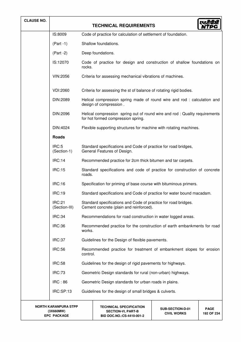
CLAUSE NO.
TECHNICAL REQUIREMENTS
NORTH KARANPURA STPP
(3X660MW)
EPC PACKAGE
TECHNICAL SPECIFICATION
SECTION-VI, PART-B
BID DOC.NO.:CS-4410-001-2
SUB-SECTION-D-01
CIVIL WORKS
PAGE
192 OF 234
IS:8009 Code of practice for calculation of settlement of foundation. (Part -1) Shallow foundations. (Part -2) Deep foundations. IS:12070 Code of practice for design and construction of shallow foundations on
rocks. VIN:2056 Criteria for assessing mechanical vibrations of machines. VDI:2060 Criteria for assessing the st of balance of rotating rigid bodies. DIN:2089 Helical compression spring made of round wire and rod : calculation and
design of compression . DIN:2096 Helical compression spring out of round wire and rod : Quality requirements
for hot formed compression spring. DIN:4024 Flexible supporting structures for machine with rotating machines. Roads IRC:5 Standard specifications and Code of practice for road bridges, (Section-1) General Features of Design. IRC:14 Recommended practice for 2cm thick bitumen and tar carpets. IRC:15 Standard specifications and code of practice for construction of concrete
roads. IRC:16 Specification for priming of base course with bituminous primers. IRC:19 Standard specifications and Code of practice for water bound macadam. IRC:21 Standard specifications and Code of practice for road bridges. (Section-III) Cement concrete (plain and reinforced). IRC:34 Recommendations for road construction in water logged areas. IRC:36 Recommended practice for the construction of earth embankments for road
works. IRC:37 Guidelines for the Design of flexible pavements. IRC:56 Recommended practice for treatment of embankment slopes for erosion
control. IRC:58 Guidelines for the design of rigid pavements for highways. IRC:73 Geometric Design standards for rural (non-urban) highways. IRC : 86 Geometric Design standards for urban roads in plains. IRC:SP:13 Guidelines for the design of small bridges & culverts.
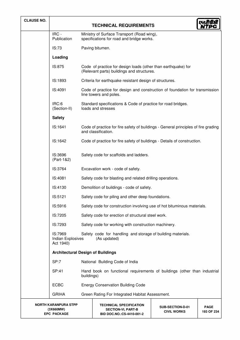
CLAUSE NO.
TECHNICAL REQUIREMENTS
NORTH KARANPURA STPP
(3X660MW)
EPC PACKAGE
TECHNICAL SPECIFICATION
SECTION-VI, PART-B
BID DOC.NO.:CS-4410-001-2
SUB-SECTION-D-01
CIVIL WORKS
PAGE
193 OF 234
IRC - Ministry of Surface Transport (Road wing), Publication specifications for road and bridge works. IS:73 Paving bitumen. Loading IS:875 Code of practice for design loads (other than earthquake) for (Relevant parts) buildings and structures. IS:1893 Criteria for earthquake resistant design of structures. IS:4091 Code of practice for design and construction of foundation for transmission
line towers and poles. IRC:6 Standard specifications & Code of practice for road bridges. (Section-II) loads and stresses Safety IS:1641 Code of practice for fire safety of buildings - General principles of fire grading
and classification. IS:1642 Code of practice for fire safety of buildings - Details of construction. IS:3696 Safety code for scaffolds and ladders. (Part-1&2)
IS:3764 Excavation work - code of safety. IS:4081 Safety code for blasting and related drilling operations. IS:4130 Demolition of buildings - code of safety. IS:5121 Safety code for piling and other deep foundations. IS:5916 Safety code for construction involving use of hot bituminous materials. IS:7205 Safety code for erection of structural steel work. IS:7293 Safety code for working with construction machinery. IS:7969 Safety code for handling and storage of building materials. Indian Explosives (As updated) Act 1940) Architectural Design of Buildings SP:7 National Building Code of India SP:41 Hand book on functional requirements of buildings (other than industrial
buildings) ECBC Energy Conservation Building Code GRIHA Green Rating For Integrated Habitat Assessment.

CLAUSE NO.
TECHNICAL REQUIREMENTS
NORTH KARANPURA STPP
(3X660MW)
EPC PACKAGE
TECHNICAL SPECIFICATION
SECTION-VI, PART-B
BID DOC.NO.:CS-4410-001-2
SUB-SECTION-D-01
CIVIL WORKS
PAGE
194 OF 234
Chimney IS:4998 Criteria for design of reinforced chimneys IS:6533 Code of practice for design and construction of steel chimneys ICAO International Civil Aviation Organisation (ICAO) DGCA Instruction of Director General of Civil Aviation , India ACI:307 Specification for the design and construction of reinforced concrete
chimneys BS:4076 Specification for steel chimneys CICIND Model Code for concrete chimneys Model code for steel chimneys ASCE Code Design and construction of steel chimney liners prepared by Task committee
on steel chimney liners. Fossil power committee, Power division published by ASCE - 1975.
IS:1554 PVC insulated (heavy duty) electric cables IS:2606 Alloy lead anodes for chromium plating IS:3043 Code of Practice for Earthing IS:9537 Conduits for electrical installations. The Indian Electricity Rules The Indian Electricity Act The Indian Electricity (Supply) Act The Indian Factories Act IS:2309 Practice for protection of buildings and allied structures against lightning
Miscellaneous IS:802 Code of practice for use of structural steel in overhead trans- (Relevant parts) mission line towers. IS:803 Code of practice for design, fabrication and erection of vertical mild
steel cylindrically welded in storage tanks. IS:10430 Criteria for design of lined canals and guidance for selection of type
of lining. IS:11592 Code of practice for selection and design of belt conveyors. IS:12867 PVC handrails covers.
IS 11504 Criteria for structural design of reinforced concrete natural draught cooling towers
BS:4485 (IV) British Standard : Code of design for water cooling towers CIRIA Design and construction of buried thin-wall pipes.
Publication IS 4671 Expanded polystyrene for thermal insulation purposes.

CLAUSE NO.
TECHNICAL REQUIREMENTS
NORTH KARANPURA STPP
(3X660MW)
EPC PACKAGE
TECHNICAL SPECIFICATION
SECTION-VI, PART-B
BID DOC.NO.:CS-4410-001-2
SUB-SECTION-D-01
CIVIL WORKS
PAGE
195 OF 234
ANNEXURE (b)
CONSTRUCTION METHODOLOGY
Construction and erection activities shall be fully mechanised from the start of the work.
All excavation and backfilling work shall be done using excavators, loaders, dumpers, dozers, poclains, excavator mounted rock breakers, rollers, sprinklers, water tankers, etc. Manual excavation can be done only on isolated places with specific approval of engineer.
For controlled rock blasting specialized agency, equipped with sensors to assess the impact of the blast on the adjoining existing structures, shall be employed.
Dewatering shall be done using the combination of electrical and standby diesel pumps.
Pile installation equipment suitable for flushing with air lift technique shall be used for construction of bored piles.
For concreting, weigh batching plants, transit mixers, concrete pumps, hoists, etc. shall be used.
All fabrication and erection activities of structural steel shall be carried out using automatic submerged arc welding machines, cutting machines, gantry cranes, crawler mounted heavy cranes and other equipment like heavy plate bending machines, shearing machines, lathe, milling machines, etc. Use of derricks shall not be permitted. Special enclosures, for blast cleaning of steel structure surface preparation, shall be used.
All handling of materials shall be with cranes. Heavy trailers shall be used for transportation.
Mechanized modular units of scaffolding and shuttering shall be used.
Grouting shall be carried out using hydaulically controlled grouting equipment.
Roadwork shall be done using pavers, rollers and premix plant.
All finishing items shall be installed using appropriate modern mechanical tools. Manual punching etc. shall not be permitted.
Heavy duty hoists for lifting of construction materials shall be deployed. Compressors for cleaning of foundations and other surfaces shall be used.
Field laboratory shall be provided with all modern equipment for survey, testing of soil, aggregates, concrete, welding, etc. For testing of steel works, ultrasonic testing machines, radiographic testing machines, dye penetration test equipment, destruction testing equipment, etc. shall be deployed.
All persons working at site shall be provided with necessary safety equipment and all safety aspects shall be duly considered for each construction/ erection activity. Moreover, only the persons who are trained in the respective trade shall be employed for executing that particular work.

CLAUSE NO.
TECHNICAL REQUIREMENTS
NORTH KARANPURA STPP
(3X660MW)
EPC PACKAGE
TECHNICAL SPECIFICATION
SECTION-VI, PART-B
BID DOC.NO.:CS-4410-001-2
SUB-SECTION-D-01
CIVIL WORKS
PAGE
196 OF 234
ANNEXURE (b)
CONSTRUCTION METHODOLOGY
Construction and erection activities shall be fully mechanised from the start of the work.
All excavation and backfilling work shall be done using excavators, loaders, dumpers, dozers, poclains, excavator mounted rock breakers, rollers, sprinklers, water tankers, etc. Manual excavation can be done only on isolated places with specific approval of engineer.
For controlled rock blasting specialized agency, equipped with sensors to assess the impact of the blast on the adjoining existing structures, shall be employed.
Dewatering shall be done using the combination of electrical and standby diesel pumps.
Pile installation equipment suitable for flushing with air lift technique shall be used for construction of bored piles.
For concreting, weigh batching plants, transit mixers, concrete pumps, hoists, etc. shall be used.
All fabrication and erection activities of structural steel shall be carried out using automatic submerged arc welding machines, cutting machines, gantry cranes, crawler mounted heavy cranes and other equipment like heavy plate bending machines, shearing machines, lathe, milling machines, etc. Use of derricks shall not be permitted. Special enclosures, for blast cleaning of steel structure surface preparation, shall be used.
All handling of materials shall be with cranes. Heavy trailers shall be used for transportation.
Mechanized modular units of scaffolding and shuttering shall be used.
Grouting shall be carried out using hydaulically controlled grouting equipment.
Roadwork shall be done using pavers, rollers and premix plant.
All finishing items shall be installed using appropriate modern mechanical tools. Manual punching etc. shall not be permitted.
Heavy duty hoists for lifting of construction materials shall be deployed. Compressors for cleaning of foundations and other surfaces shall be used.
Field laboratory shall be provided with all modern equipment for survey, testing of soil, aggregates, concrete, welding, etc. For testing of steel works, ultrasonic testing machines, radiographic testing machines, dye penetration test equipment, destruction testing equipment, etc. shall be deployed.
All persons working at site shall be provided with necessary safety equipment and all safety aspects shall be duly considered for each construction/ erection activity. Moreover, only the persons who are trained in the respective trade shall be employed for executing that particular work.

CLAUSE NO.
TECHNICAL REQUIREMENTS
NORTH KARANPURA STPP
(3X660MW)
EPC PACKAGE
TECHNICAL SPECIFICATION
SECTION-VI, PART-B
BID DOC.NO.:CS-4410-001-2
SUB-SECTION-D-01
CIVIL WORKS
PAGE
233 OF 234
ANNEXURE – (h)
Specification For High Performance Moisture Compatible Corrosion Resistant Coating System (for Concrete Surfaces of IDCT)
a) The coating system shall be water compatible, compatible for applying in wet conditions also and shall be tolerant to under-prepared surfaces and existing residual tar / paint. The system shall also be quick curing so as to be suitable for application during shut downs.
The coating material shall be stored in the manner as per recommendations of the manufacturer until ready for use. The coating material shall be used within the manufacturer’s written recommended shelf life.
b) The coating system shall conform to the following :
PROPERTIES OF PAINT
Coating System High Performance Moisture Compatible Corrosion Resistant Coating System
Volume Solids 70%
Specific Gravity (ASTM-D-1475) 1.25 ± 0.1
Dry Film Thickness (ASTM-D-1186) 160 ± 10 µm per coat
Coverage 4 - 4.5 sq.m/ ltr
Touch Dry 2 Hours
Recoating 24 Hours
PROPERTIES OF COATING
Salt Spray (ASTM-B 117) 2000 Hour
Resistance to sea water
(Carried out up o 6 mont s)
Passes
Coating Resistance
(Carried out upto 6 months)
109 Ω. cm2
Ad esion (ASTM-D 4541) 4.5 kN minimu
Flexibility (ASTM-D-522)
Elo gation
1/8" passes
33%
Impact (ASTM G 14–04) 45 cm passes