Embed Size (px)
Citation preview
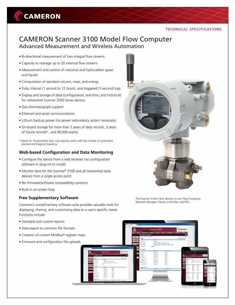
CAMERON Scanner 3100 Model Flow ComputerAdvanced Measurement and Wireless Automation
• Bi-directional measurement of two integral flow streams
• Capacity to manage up to 20 external flow streams
• Measurement and control of industrial and hydrocarbon gases and liquids
• Computation of standard volume, mass, and energy
• Daily, interval (1 second to 12 hours), and triggered (1-second) logs
• Display and storage of data (configuration, real-time, and historical) for networked Scanner 2000 Series devices
• Gas chromatograph support
• Ethernet and serial communications
• Lithium backup power (no power redundancy system necessary)
• On-board storage for more than 5 years of daily records, 3 years of hourly records*, and 98,000 events
* Based on 14-parameter logs. Log capacity varies with the number of parameters selected and logging frequency.
Web-based Configuration and Data Monitoring
• Configure the device from a web browser (no configuration software or plug-ins to install)
• Monitor data for the Scanner® 3100 and all networked slave devices from a single access point
• No firmware/software compatibility concerns
• Built-in on-screen help
Free Supplementary Software
Cameron’s complimentary software suite provides valuable tools for displaying, sharing, and customizing data to a user’s specific needs. Functions include:
• Standard and custom reports
• Data export to common file formats
• Creation of custom Modbus® register maps
• Firmware and configuration file uploads
The Scanner 3100 is four devices in one: Flow Computer,Network Manager, Process Controller, and RTU.
TECHNICAL SPECIFICATIONS
Network Manager
When multiple points of measurement are required, the Scanner 3100’s distributed flow computing platform and optional wireless communications create a scalable automation solution capable of supporting up to 22 flow streams.
• Automatically integrates up to 20 wired and/or wireless Scanner flow computers
• Inherent protection from data loss (data is stored at the point of measurement before being copied to the Scanner 3100)
• Communicates wirelessly with Scanner 2100 EFM via SmartMesh® radio
• Data management and protocol customization software simplifies SCADA integration with an established host
• Supports Ethernet communications to a host computer
• Communicates with radios, modems, chromatographs, and other peripheral devices via high-speed serial communications
For more information about networking capabilities, see the CAMERON Flow Computer Solutions brochure.
Modbus Integration
The Scanner 3100 communicates via Modbus slave and master protocols.
Acting as a slave device, the Scanner responds to queries via Enron Modbus, Modbus TCP, and Modbus RTU.
Using master protocol, the Scanner can also be deployed in a central computing architecture to collect differential pressure, pressure, temperature, and other input variables via cable-saving multi-drop RS-485 technology. The Scanner 3100 can collect up to 384 data points from Modbus devices such as Cameron’s 800 series pressure transmitters.
The Scanner 3100’s Modbus master functionality provides connectivity to wireless transmitter gateways servicing WirelessHART®, ISA100, OleumTech, and other protocols.
**
*Offered in association with OleumTech™ Corporation. ** Compatible with eFCAS (a Cameron SCADA solution offered in
association with CPU, LLC) and other SCADA products.
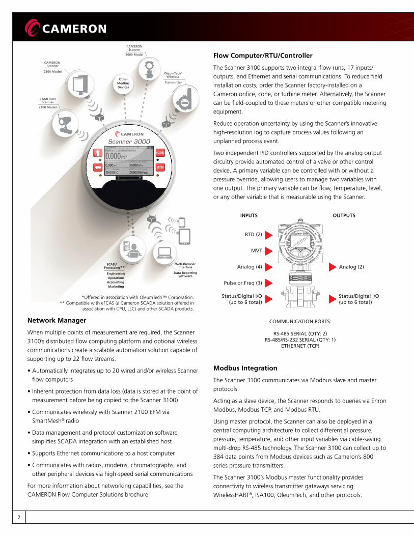
Flow Computer/RTU/Controller
The Scanner 3100 supports two integral flow runs, 17 inputs/outputs, and Ethernet and serial communications. To reduce field installation costs, order the Scanner factory-installed on a Cameron orifice, cone, or turbine meter. Alternatively, the Scanner can be field-coupled to these meters or other compatible metering equipment.
Reduce operation uncertainty by using the Scanner’s innovative high-resolution log to capture process values following an unplanned process event.
Two independent PID controllers supported by the analog output circuitry provide automated control of a valve or other control device. A primary variable can be controlled with or without a pressure override, allowing users to manage two variables with one output. The primary variable can be flow, temperature, level, or any other variable that is measurable using the Scanner.
INPUTS OUTPUTS
RTD (2)
MVT
Analog (4)
Status/Digital I/O(up to 6 total)
Status/Digital I/O(up to 6 total)
Pulse or Freq (3)
Analog (2)
COMMUNICATION PORTS:
RS-485 SERIAL (QTY: 2)RS-485/RS-232 SERIAL (QTY: 1)
ETHERNET (TCP)
2
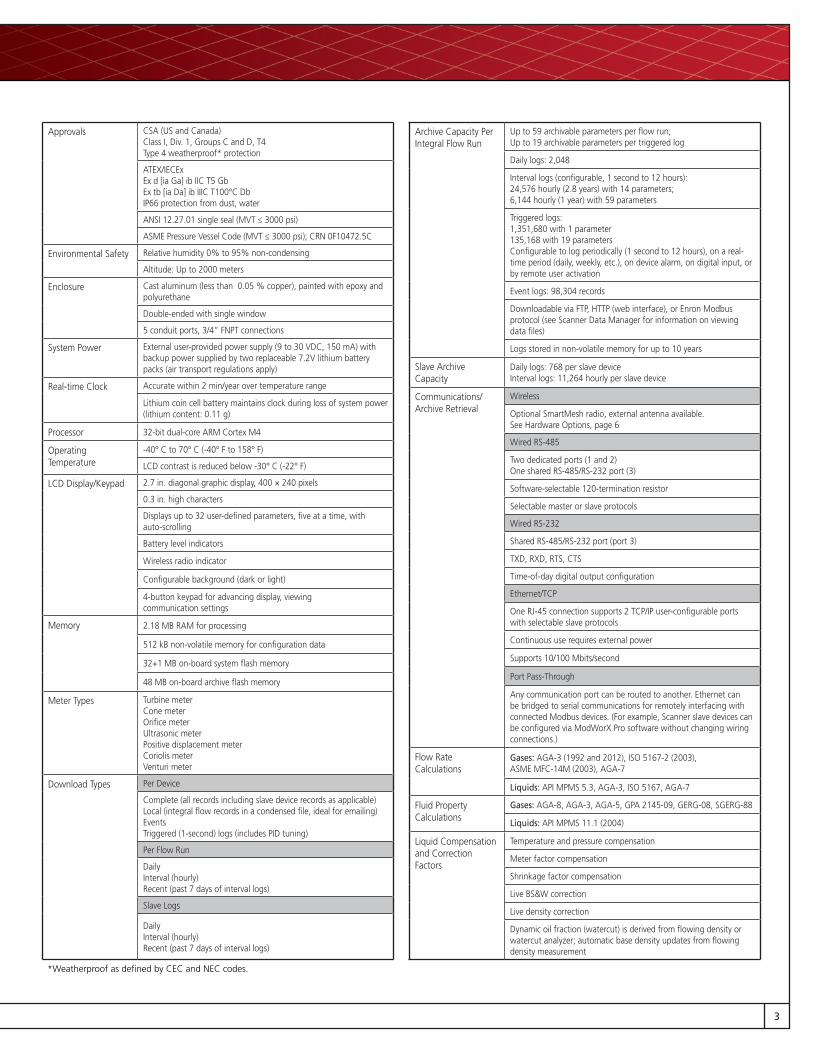
Approvals CSA (US and Canada) Class I, Div. 1, Groups C and D, T4Type 4 weatherproof* protection
ATEX/IECExEx d [ia Ga] ib IIC T5 GbEx tb [ia Da] ib IIIC T100°C DbIP66 protection from dust, water
ANSI 12.27.01 single seal (MVT ≤ 3000 psi)
ASME Pressure Vessel Code (MVT ≤ 3000 psi); CRN 0F10472.5C
Environmental Safety Relative humidity 0% to 95% non-condensing
Altitude: Up to 2000 meters
Enclosure Cast aluminum (less than 0.05 % copper), painted with epoxy and polyurethane
Double-ended with single window
5 conduit ports, 3/4” FNPT connections
System Power External user-provided power supply (9 to 30 VDC, 150 mA) with backup power supplied by two replaceable 7.2V lithium battery packs (air transport regulations apply)
Real-time Clock Accurate within 2 min/year over temperature range
Lithium coin cell battery maintains clock during loss of system power (lithium content: 0.11 g)
Processor 32-bit dual-core ARM Cortex M4
Operating Temperature
-40° C to 70° C (-40° F to 158° F)
LCD contrast is reduced below -30° C (-22° F)
LCD Display/Keypad 2.7 in. diagonal graphic display, 400 × 240 pixels
0.3 in. high characters
Displays up to 32 user-defined parameters, five at a time, withauto-scrolling
Battery level indicators
Wireless radio indicator
Configurable background (dark or light)
4-button keypad for advancing display, viewing communication settings
Memory 2.18 MB RAM for processing
512 kB non-volatile memory for configuration data
32+1 MB on-board system flash memory
48 MB on-board archive flash memory
Meter Types Turbine meterCone meterOrifice meterUltrasonic meterPositive displacement meterCoriolis meterVenturi meter
Download Types Per Device
Complete (all records including slave device records as applicable)Local (integral flow records in a condensed file, ideal for emailing)EventsTriggered (1-second) logs (includes PID tuning)
Per Flow Run
DailyInterval (hourly)Recent (past 7 days of interval logs)
Slave Logs
DailyInterval (hourly) Recent (past 7 days of interval logs)
Archive Capacity Per Integral Flow Run
Up to 59 archivable parameters per flow run; Up to 19 archivable parameters per triggered log
Daily logs: 2,048
Interval logs (configurable, 1 second to 12 hours): 24,576 hourly (2.8 years) with 14 parameters; 6,144 hourly (1 year) with 59 parameters
Triggered logs:1,351,680 with 1 parameter 135,168 with 19 parameters Configurable to log periodically (1 second to 12 hours), on a real-time period (daily, weekly, etc.), on device alarm, on digital input, or by remote user activation
Event logs: 98,304 records
Downloadable via FTP, HTTP (web interface), or Enron Modbus protocol (see Scanner Data Manager for information on viewing data files)
Logs stored in non-volatile memory for up to 10 years
Slave Archive Capacity
Daily logs: 768 per slave device Interval logs: 11,264 hourly per slave device
Communications/Archive Retrieval
Wireless
Optional SmartMesh radio, external antenna available. See Hardware Options, page 6
Wired RS-485
Two dedicated ports (1 and 2)One shared RS-485/RS-232 port (3)
Software-selectable 120-termination resistor
Selectable master or slave protocols
Wired RS-232
Shared RS-485/RS-232 port (port 3)
TXD, RXD, RTS, CTS
Time-of-day digital output configuration
Ethernet/TCP
One RJ-45 connection supports 2 TCP/IP user-configurable ports with selectable slave protocols
Continuous use requires external power
Supports 10/100 Mbits/second
Port Pass-Through
Any communication port can be routed to another. Ethernet can be bridged to serial communications for remotely interfacing with connected Modbus devices. (For example, Scanner slave devices can be configured via ModWorX Pro software without changing wiring connections.)
Flow Rate Calculations
Gases: AGA-3 (1992 and 2012), ISO 5167-2 (2003), ASME MFC-14M (2003), AGA-7
Liquids: API MPMS 5.3, AGA-3, ISO 5167, AGA-7
Fluid Property Calculations
Gases: AGA-8, AGA-3, AGA-5, GPA 2145-09, GERG-08, SGERG-88
Liquids: API MPMS 11.1 (2004)
Liquid Compensation and CorrectionFactors
Temperature and pressure compensation
Meter factor compensation
Shrinkage factor compensation
Live BS&W correction
Live density correction
Dynamic oil fraction (watercut) is derived from flowing density or watercut analyzer; automatic base density updates from flowing density measurement
*Weatherproof as defined by CEC and NEC codes.
3

Flow Streams Two integral compensated flow runs
Up to 20 remote flow runs via local area Scanner network
Three additional integral flow runs for uncompensated measurement via pulse/frequency inputs
Up to eight gas streams using gas chromatograph inputs or user-entered compositions
16-point calibrations for all inputs (linear factor, multipoint, and multi-point meter factor calibrations supported)
Bi-directional flow measurement
Stacked inputs for rangeability
Analog Inputs 4 channels
1-5 V, 0-5 V, 4-20 mA, or 0-20 mA
Accuracy ± 0.030% of span max. error @ 25° C (77° F)
Temperature effect ± 0.25% of span over operating range
Impedance > 60 Kohm for 1-5V input; approximately 250 ohm for 4-20 mA input
Over-voltage protection ± 30 VDC
A/D resolution 22 bits
Linearity error ± 0.020% max.; ± 0.010% typical
Single-ended inputs
Sample rate: 0.1 seconds to 12 hours
Four previous calibrations available for restore
Configurable shut-off for saving power when transducer warm-up period is not required
Integral battery backup
RTD Inputs 2 channels
100-ohm platinum RTD with 2-wire, 3-wire, or 4-wire interface
Range -40° C to 427° C (-40° F to 800° F)
Accuracy: 0.2°C (0.36°F) over sensing range at calibrated temperature
Temperature effect ±0.3° C (0.54° F) over operating range
A/D resolution 24 bits
Sample rate: 0.1 seconds to 12 hours
Configurable shut-off for saving power when transducer warm-up period is not required
Pulse/Frequency (TFM) Inputs
3 channels
Maximum voltage: 30 VDC
Maximum frequency: 10,000 Hz
Gated transmitter power for each input channel
Transmitter voltage supply: 10 VDC @ 20 mA, protected to 50 mA
TFM channel 3 has no sleep mode and increased power consumption
Measures uncorrected gas or liquid volume from a turbine, PD, Coriolis, or ultrasonic meter; measures mass from a Coriolis meter
Accepts contact closure, open collector, or DC pulse (3-30 VDC) outputs, and turbine magnetic pickup outputs
Configurable turbine sensitivity (20, 50, 100 mV, peak-to-peak)
Analog Outputs 2 channels
Type 4 to 20 mA, optically isolated, externally powered
Accuracy (after calibration) ± 0.1% of span max. error at 77° F (25° C)
50 ppm/° C (27.8 ppm/° F) temperature drift
Output load R (ohms) = {supply (volts) – 5.5} / 0.02
Maximum voltage: 30 VDC
D/A resolution: 16 bits
Calibration (zero and full-scale) via software
Programmable output alarm value for use during loss of power or communication to CPU
Regulates control valve in PID control applications
Digital I/O 6 channels, user configurable as input or output
DIO1, DIO2, DIO3, and DIO4 are optically isolated with a max. output of 60 mA @ 30 VDC
DIO5 and DIO6 are non-isolated with a max. output of 500 mA @ 30 VDC
Input Types
Control switch Pulse Open collector Contact closure
Special functions: Advance display Turn transmitter on/offReset flow run totals.Reset pulse input totalsUnlatch DIOsReset trigger archive
Output Modes
Pulse (based on pulse count or time period)
Alarm (based on the status of any or all selected alarms – up to 32 user-configured alarms are selectable)
Conditional (value above or below setpoint, out of setpoint range)
Programmed (time of day or output state – normally open/normally closed)
Pulse Output
Maximum frequency: 50 Hz
Configurable pulse duration (10 msec to 1 day)
Configurable pulse representation (1 pulse = 1 MCF) based on time or volume
Based on any accumulator (flow run or turbine meter run)
Alarm Output
Low/high
Out-of-range
Status/diagnostic
User Interface Web browser based (access via laptop, tablet, smart phone)
Complete configuration, calibration, and maintenance of flow runs, I/O, and gas streams
Real-time data polling, data downloads
Recent interval and daily logs (up to 7 days) viewable in interface (other historical logs viewable in Scanner Data Manager)
Three user security levels, up to 20 operators
Configuration of Modbus slave/master communications
4

MVT Specifications
• Linearized measurements for static pressure and differential pressure
• Measures pressure in absolute and displays in gauge
• Standard MVT has bottom ports, ideal for gas measurement
• Can be inverted for liquid measurement (LCD auto-corrects for easy viewing)*
• Process temperature: -40° F to 250° F (-40° C to 121° C)
• User-adjustable sample time and damping
• Complies with pre-qualified materials of NACE MR0175/ISO 15156**
* Side port MVT for liquid measurement is available by special order.** This certification does not imply or warrant the application of the MVT in compliance
with NACE MR0175/ISO 15156 service conditions in which the MVT is installed.
MVT Accuracy
Differential Pressure± 0.05% of range for all except 30 in. H2O± 0.1% of range for 30 in. H2O
Static Pressure ± 0.05% of range
Temperature Effect 0.25% of full scale over operating range
Stability(Long-Term Drift)
Less than ±0.05 % of URL per year over a five-year period
Resolution 24 bits
Effect on Differential Pressure for a 100-psi Pressure Change
Differential Pressure Range* (in. H20)
Zero Shift(% URL)
Span Shift(% reading)
± 30 .05 .01
± 200** .01 .01
± 400 .04 .01
± 840 .04 .01
* ± indicates bi-directional capabilities. Example: A range of 30 in. H20 is -30 to +30 H20.** 200 x 300 psi has a zero shift of .007% and a span shift of 0.01%.
MVT Pressure Ranges*
Static Pressure/SWP(psia)
Differential Pressure(in. H20)
Maximum Overrange Pressure (psia)
100 ± 30 150
300 ± 200 or 840 450
500 ± 30 or 200 750
1500 ± 200, 400, or 840 2250
3000 ± 200, 400, or 840 4500
5300 ± 200, 400, or 840 7420
* Custom ranges available by special order.
Materials of Construction
Body Bolts and NutsB7/2H alloy steel, standard (see table below for alternate materials)
Process Cover 316 SS*
Process Cover Gasket Glass-filled PTFE
Diaphragm 316L SS*
Vent/DrainSS bleed (316 SS plug is standard for NACE and coastal applications)
* Custom ranges available by special order.
Body Bolts and Nuts (non-process wetted)
B7/2H alloy steel
B7M/2HM alloy steel
316SS17-4 PH
SSInconel
718
NACE Use
No Yes No No Yes
Coastal Use
Possible* Possible* Yes No** Yes
Max. Pressure
5300 1500 1500 3000 5300
Coating PlatedBlack oxide
None None None
* B7 and B7M alloy steel is susceptible to corrosion.**Chloride stress cracking risk.
Dimensions and Weight
10.76(273.18)
10.28(261.04)
5.43(138.00)
6.35(161.4)
MVT 1/4-18 NPTprocess connections
11.27(286.29)
centers2.125
(53.98)
2.68(68.0)
2.68(68.0)
5.43(138.0)8.47
(215.2)
8.31(211.1)
Scanner 3100 Base Unit (no MVT, no batteries) 9.1 lb (4.1 kg)MVT 8.3 lb (3.8 kg)Batteries (2 stick-style battery packs) 1.1 lb (0.5 kg) Total Weight (Wired Version)* 18.4 lb (8.3 kg)Direct-Mount Antenna and Coupler (Wireless) 0.6 lb (0.3 kg) Total Weight (Wireless Version)* 19.0 lb (8.6 kg)
1.77(45.00)
1.77(45.00)
Dimensions in inches (millimeters)
3.15(80.0)
(back)(front)
*Includes MVT and batteries
5
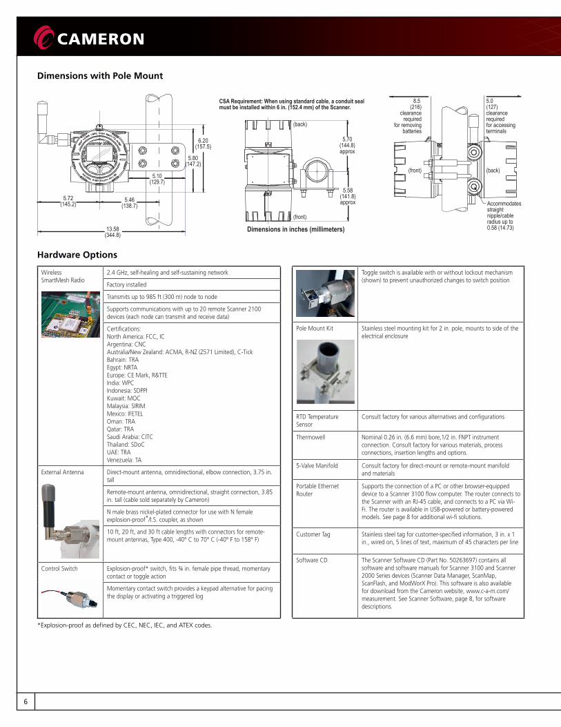
Dimensions with Pole Mount
CSA Requirement: When using standard cable, a conduit seal must be installed within 6 in. (152.4 mm) of the Scanner.
8.5 (216)
clearancerequired
for removingbatteries
5.0 (127)clearance requiredfor accessing terminals
(front) (back)
5.70(144.8)approx
5.58(141.8)approx5.72
(145.2)5.46
(138.7)
13.58(344.8)
5.80(147.2)
6.20(157.5)
Accommodatesstraight nipple/cable radius up to 0.58 (14.73)
(front)
(back)
5.10(129.7)
Dimensions in inches (millimeters)
Hardware Options
Wireless SmartMesh Radio
2.4 GHz, self-healing and self-sustaining network
Factory installed
Transmits up to 985 ft (300 m) node to node
Supports communications with up to 20 remote Scanner 2100 devices (each node can transmit and receive data)
Certifications:North America: FCC, IC Argentina: CNC Australia/New Zealand: ACMA, R-NZ (Z571 Limited), C-Tick Bahrain: TRA Egypt: NRTA Europe: CE Mark, R&TTE India: WPC Indonesia: SDPPI Kuwait: MOC Malaysia: SIRIM Mexico: IFETEL Oman: TRA Qatar: TRA Saudi Arabia: CITC Thailand: SDoC UAE: TRA Venezuela: TA
External Antenna Direct-mount antenna, omnidirectional, elbow connection, 3.75 in. tall
Remote-mount antenna, omnidirectional, straight connection, 3.85 in. tall (cable sold separately by Cameron)
N male brass nickel-plated connector for use with N female explosion-proof*/I.S. coupler, as shown
10 ft, 20 ft, and 30 ft cable lengths with connectors for remote-mount antennas, Type 400, -40° C to 70° C (-40° F to 158° F)
Control Switch Explosion-proof* switch, fits ¾ in. female pipe thread, momentary contact or toggle action
Momentary contact switch provides a keypad alternative for pacing the display or activating a triggered log
Toggle switch is available with or without lockout mechanism (shown) to prevent unauthorized changes to switch position
Pole Mount Kit Stainless steel mounting kit for 2 in. pole, mounts to side of the electrical enclosure
RTD Temperature Sensor
Consult factory for various alternatives and configurations
Thermowell Nominal 0.26 in. (6.6 mm) bore,1/2 in. FNPT instrument connection. Consult factory for various materials, process connections, insertion lengths and options.
5-Valve Manifold Consult factory for direct-mount or remote-mount manifold and materials
Portable Ethernet Router
Supports the connection of a PC or other browser-equipped device to a Scanner 3100 flow computer. The router connects to the Scanner with an RJ-45 cable, and connects to a PC via Wi-Fi. The router is available in USB-powered or battery-powered models. See page 8 for additional wi-fi solutions.
Customer Tag Stainless steel tag for customer-specified information, 3 in. x 1 in., wired on, 5 lines of text, maximum of 45 characters per line
Software CD The Scanner Software CD (Part No. 50263697) contains all software and software manuals for Scanner 3100 and Scanner 2000 Series devices (Scanner Data Manager, ScanMap, ScanFlash, and ModWorX Pro). This software is also available for download from the Cameron website, www.c-a-m.com/measurement. See Scanner Software, page 8, for software descriptions.
*Explosion-proof as defined by CEC, NEC, IEC, and ATEX codes.
6
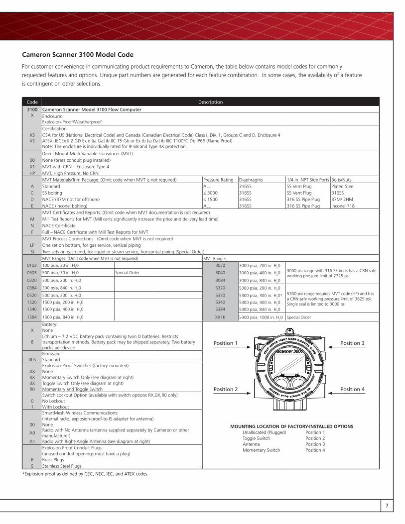
Cameron Scanner 3100 Model Code
For customer convenience in communicating product requirements to Cameron, the table below contains model codes for commonly requested features and options. Unique part numbers are generated for each feature combination. In some cases, the availability of a feature is contingent on other selections.
Code Description
3100 Cameron Scanner Model 3100 Flow ComputerX Enclosure:
Explosion-Proof/WeatherproofCertification:
X5 CSA for US (National Electrical Code) and Canada (Canadian Electrical Code) Class I, Div. 1, Groups C and D, Enclosure 4XE ATEX, IECEx II 2 GD Ex d [ia Ga] ib IIC T5 Gb or Ex tb [ia Da] ib IIIC T100°C Db IP66 (Flame Proof)
Note: The enclosure is individually rated for IP 68 and Type 4X protection.
Direct Mount Multi-Variable Transducer (MVT):00 None (brass conduit plug installed)X1 MVT with CRN – Enclosure Type 4HP MVT, High Pressure, No CRN
MVT Materials/Trim Package: (Omit code when MVT is not required) Pressure Rating Diaphragms 1/4 in. NPT Side Ports Bolts/NutsA Standard ALL 316SS SS Vent Plug Plated SteelC SS bolting ≤ 3000 316SS SS Vent Plug 316SSD NACE (B7M not for offshore) ≤ 1500 316SS 316 SS Pipe Plug B7M/ 2HME NACE (Inconel bolting) ALL 316SS 316 SS Pipe Plug Inconel 718
MVT Certificates and Reports: (Omit code when MVT documentation is not required)M Mill Test Reports for MVT (Mill certs significantly increase the price and delivery lead time)N NACE CertificateF Full – NACE Certificate with Mill Test Reports for MVT
MVT Process Connections: (Omit code when MVT is not required)LP One set on bottom, for gas service, vertical pipingSI Two sets on each end, for liquid or steam service, horizontal piping (Special Order)
MVT Ranges: (Omit code when MVT is not required) MVT Ranges:
0103 100 psia, 30 in. H20 3020 3000 psia, 200 in. H203000 psi range with 316 SS bolts has a CRN safe working pressure limit of 2725 psi.
0503 500 psia, 30 in. H20 Special Order 3040 3000 psia, 400 in. H20
0320 300 psia, 200 in. H20 3084 3000 psia, 840 in. H20
0384 300 psia, 840 in. H20 5320 5300 psia, 200 in. H205300-psi range requires MVT code (HP) and has a CRN safe working pressure limit of 3625 psi. Single seal is limited to 3000 psi.
0520 500 psia, 200 in. H20 5330 5300 psia, 300 in. H20*
1520 1500 psia, 200 in. H20 5340 5300 psia, 400 in. H20
1540 1500 psia, 400 in. H20 5384 5300 psia, 840 in. H20
1584 1500 psia, 840 in. H20 XX1K >300 psia, 1000 in. H20 Special Order
Battery:X None
8Lithium – 7.2 VDC battery pack containing twin D batteries. Restricts transportation methods. Battery pack may be shipped separately. Two battery packs per deviceFirmware:
00S StandardExplosion-Proof Switches (factory-mounted):
XX NoneRX Momentary Switch Only (see diagram at right)0X Toggle Switch Only (see diagram at right)R0 Momentary and Toggle Switch
Switch Lockout Option (available with switch options RX,0X,R0 only):0 No Lockout1 With Lockout
SmartMesh Wireless Communications: (internal radio, explosion-proof-to-IS adapter for antenna)
00 None
A0Radio with No Antenna (antenna supplied separately by Cameron or other manufacturer)
A1 Radio with Right-Angle Antenna (see diagram at right)Explosion Proof Conduit Plugs: (unused conduit openings must have a plug)
B Brass PlugsS Stainless Steel Plugs
*Explosion-proof as defined by CEC, NEC, IEC, and ATEX codes.
Position 1
Position 2
Position 3
Position 4
MOUNTING LOCATION OF FACTORY-INSTALLED OPTIONSUnallocated (Plugged) Position 1Toggle Switch Position 2Antenna Position 3Momentary Switch Position 4
7

Wi-Fi Connections
A wireless router connected to the Ethernet port of the Scanner 3100 allows users to connect wirelessly to the Scanner using a PC or other web-enabled device. If an existing wi-fi network is not available to support this connection, users can create a wi-fi access point using one of the following solutions:
• A portable battery-powered router
• A permanent Class I, Div. 2 qualified router assembly with an optional solar power subsystem and optional cellular connectivity
Scanner Software
The Scanner 3100 web interface eliminates the need for PC-based configuration software. However, Cameron’s PC software suite equips Scanner 3100 users with additional tools for presenting and sharing data, and maintaining their measurement system. The software is available for download from the Cameron website free of charge or can be purchased as a CD.
Commissioning, Training, and Support Services
As a leading provider of flow equipment to worldwide oil, gas and process industries, Cameron offers a full range of services and expert support to help customers improve productivity, enhance system performance, and increase profitability.
Our skilled field service personnel are trained to maintain, replace, refurbish, and support measurement equipment. Our services include, but are not limited to:
• Measurement consulting
• Start-up assistance and commissioning
• Measurement audits
• Field services, shop repair, and calibration
• System health checks and maintenance
• Product training and measurement seminars
For a service quote, contact your regional Cameron representative.
Scanner Data Manager
Data analysis, reporting, and export/conversion tool
Tabular and trend presentations
Customized reports
ScanMap Tool for creating custom Scanner 3100 Modbus register maps, including user-specified units, rates, and register names for SCADA integration
Firmware-specific templates
Auto-generated protocol manual (for print or upload to web interface)
ScanFlash Firmware, configuration, and custom protocol map upload utility
ModWorX Pro Configuration of Scanner 2000 Series devices
© 2015 Cameron | Cameron, Scanner and ModWorX are registered trademarks of Cameron. All others
are registered trademarks or trademarks of their respective owners. | 2/16 AD02076M
NORTH AND SOUTH AMERICA3250 Briarpark Drive, Suite 300Houston, TX 77042USATel 1 800 654 [email protected]
EUROPE, AFRICA,CASPIAN AND RUSSIALongfield RoadTunbridge Wells, Kent TN2 3EYEngland, UKTel 44 1892 [email protected]
ASIA PACIFICSuite 16.02 Menara AmFirstNo. 1 Jalan 19/346300 Petaling JayaSelangor Darul EhsanMalaysiaTel 603 7954 0145 [email protected]
MIDDLE EASTMiddle East FZEPlot No S10408, South ZonePO Box 263011Jebel Ali, Dubai, UAETel 971 4 802 [email protected]
www.c-a-m.com/measurement