Embed Size (px)
Citation preview

ULT800 TEE Transducer Leakage Current Tester
Users Guide
PN 2461434 August 2005, Rev.2, 11/13 © 2006, 2013 Fluke Corporation, All rights reserved. Printed in USA All product names are trademarks of their respective companies.
Warranty and Product Support
Fluke Biomedical warrants this instrument against defects in materials and workmanship for one full year from the date of original purchase. During the warranty period, we will repair or, at our option, replace at no charge a product that proves to be defective, provided you return the product, shipping prepaid, to Fluke Biomedical. This warranty does not apply if the product has been damaged by accident or misuse or as the result of service or modification by other than Fluke Biomedical. IN NO EVENT SHALL FLUKE BIOMEDICAL BE LIABLE FOR CONSEQUENTIAL DAMAGES.
Only serialized products and their accessory items (those products and items bearing a distinct serial number tag) are covered under this one–year warranty. PHYSICAL DAMAGE CAUSED BY MISUSE OR PHYSICAL ABUSE IS NOT COVERED UNDER THE WARRANTY. Items such as cables and nonserialized modules are not covered under this warranty.
Recalibration of instruments is not covered under the warranty.
This warranty gives you specific legal rights, and you may also have other rights which vary from state to state, province to province, or country to country. This warranty is limited to repairing the instrument to Fluke Biomedical’s speci-fications.
Warranty Disclaimer
Should you elect to have your instrument serviced and/or calibrated by some-one other than Fluke Biomedical, please be advised that the original warranty covering your product becomes void when the tamper-resistant Quality Seal is removed or broken without proper factory authorization. We strongly recom-mend, therefore, that you send your instrument to Fluke Biomedical for factory service and calibration, especially during the original warranty period.
Notices
All Rights Reserved Copyright 2013, Fluke Biomedical. No part of this publication may be repro-duced, transmitted, transcribed, stored in a retrieval system, or translated into any language without the written permission of Fluke Biomedical.
Copyright Release Fluke Biomedical agrees to a limited copyright release that allows you to repro-duce manuals and other printed materials for use in service training programs and other technical publications. If you would like other reproductions or distribu-tions, submit a written request to Fluke Biomedical.
Unpacking and Inspection Follow standard receiving practices upon receipt of the instrument. Check the shipping carton for damage. If damage is found, stop unpacking the instrument. Notify the carrier and ask for an agent to be present while the instrument is un-packed. There are no special unpacking instructions, but be careful not to dam-age the instrument when unpacking it. Inspect the instrument for physical dam-age such as bent or broken parts, dents, or scratches.
Technical Support For application support or answers to technical questions, either email [email protected] or call 1-800- 850-4608 or 1-440-248-9300. In Europe, email: [email protected] or call +31-40-2965314.
Claims Our routine method of shipment is via common carrier, FOB origin. Upon deliv-ery, if physical damage is found, retain all packing materials in their original con-dition and contact the carrier immediately to file a claim. If the instrument is deliv-ered in good physical condition but does not operate within specifications, or if there are any other problems not caused by shipping damage, please contact Fluke Biomedical or your local sales representative.

Returns and Repairs Return Procedure
All items being returned (including all warranty-claim shipments) must be sent freight-prepaid to our factory location. When you return an instrument to Fluke Biomedical, we recommend using United Parcel Service, Federal Express, or Air Parcel Post. We also recommend that you insure your shipment for its actual re-placement cost. Fluke Biomedical will not be responsible for lost shipments or in-struments that are received in damaged condition due to improper packaging or handling.
Use the original carton and packaging material for shipment. If they are not avail-able, we recommend the following guide for repackaging:
• Use a double–walled carton of sufficient strength for the weight being shipped.
• Use heavy paper or cardboard to protect all instrument surfaces. Use nona-brasive material around all projecting parts.
• Use at least four inches of tightly packed, industry-approved, shock-absorbent material around the instrument.
Returns for partial refund/credit:
Every product returned for refund/credit must be accompanied by a Return Mate-rial Authorization (RMA) number, obtained from our Order Entry Group at 1-800-648-7952 or 1-425-446-6945.
Repair and calibration:
To find the nearest service center, goto www.flukebiomedical.com/service or
In the U.S.A.:
Cleveland Calibration Lab Tel: 1-800-850-4606 x2564 Email: [email protected]
In Europe, Middle East, and Africa:
Eindhoven Calibration Lab Tel: +31-40-2675300 Email: [email protected]
Everett Calibration Lab Tel: 1-888-99 FLUKE (1-888-993-5853) Email: [email protected]
In Asia:
Everett Calibration Lab Tel: +425-446-6945 Email: [email protected]
To ensure the accuracy of the Product is maintained at a high level, Fluke Bio-medical recommends the product be calibrated at least once every 12 months. Calibration must be done by qualified personnel. Contact your local Fluke Bio-medical representative for calibration.

Certification This instrument was thoroughly tested and inspected. It was found to meet Fluke Biomedical’s manufacturing specifications when it was shipped from the factory. Calibration measurements are traceable to the National Institute of Standards and Technology (NIST). Devices for which there are no NIST calibration stand-ards are measured against in-house performance standards using accepted test procedures.
WARNING Unauthorized user modifications or application beyond the published specifica-tions may result in electrical shock hazards or improper operation. Fluke Biomed-ical will not be responsible for any injuries sustained due to unauthorized equip-ment modifications.
Restrictions and Liabilities Information in this document is subject to change and does not represent a com-mitment by Fluke Biomedical. Changes made to the information in this document will be incorporated in new editions of the publication. No responsibility is as-sumed by Fluke Biomedical for the use or reliability of software or equipment that is not supplied by Fluke Biomedical, or by its affiliated dealers.
Manufacturing Location The ULT800 Ultrasound Transducer Leakage Current Tester is manufactured in Everett, WA, U.S.A.


i
Table of Contents
Title Page
Introduction ................................................................................ 1 Safety Information ...................................................................... 1 Symbols ..................................................................................... 2 Key Features .............................................................................. 3 Controls and Indicators .............................................................. 4 Specifications ............................................................................. 6 Using the ULT800 ...................................................................... 7 Checking the Battery .................................................................. 11 Checking Solution Conductivity .................................................. 11 Testing for Transducer Leakage Current .................................... 12 Maintenance ............................................................................... 12
Cleaning ................................................................................. 13 Battery .................................................................................... 14 Calibration .............................................................................. 15
Accessories ................................................................................ 16

ULT800 Users Guide
ii

iii
List of Tables
Table Title Page
1. Symbols ..................................................................................... 2 2. Controls and Indicators .............................................................. 5 3. Accessories ................................................................................ 16
List of Figures
Figure Title Page
1. Controls and Indicators .............................................................. 4 2. Disinfection Basin Test Setup .................................................... 9 3. Disinfection/Storage Tube Setup ................................................ 10

ULT800 Users Guide
iv

1
Introduction The ULT800 TEE Transducer Leakage Current Tester measures the leakage current of ultrasound transducers independent of their ultrasound systems. Use the hand-held, battery-operated instrument during the routine transducer cleaning procedure conducted between patients.
Safety Information
Warning To prevent possible electric shock, fire, or personal injury:
• Read all safety Information before you use the Product.
• Use the Product only as specified, or the protection supplied by the Product can be compromised.
• Remove the batteries if the Product is not used for an extended period of time, or if stored in temperatures above 50 °C. If the batteries are not removed, battery leakage can damage the Product.
• The battery door must be closed and locked before you operate the Product.
• Replace the batteries when the low battery indicator shows to prevent incorrect measurements.
• Carefully read all instructions.
• Do not touch voltages >30 V ac rms, 42 V ac peak, or 60 V dc.
• Do not use and disable the Product if it is damaged.
• Do not use the Product if it operates incorrectly.
• Examine the case before you use the Product. Look for cracks or missing plastic. Carefully look at the insulation around the terminals.
• Use this Product indoors only.
A Warning identifies conditions and procedures that are dangerous to the user. A Caution identifies conditions and procedures that can cause damage to the Product or the equipment under test.

ULT800 Users Guide
2
• Do not use the Product around explosive gas, vapor, or in damp or wet environments.
Symbols Table 1 is a list of symbols used on the Product and in this Users Guide.
Table 1. Symbols
Symbol Description
Important information. Refer to manual.
Hazardous Voltage
Conforms to European Union directives
Conforms to relevant North American Safety Standards.
Conforms to relevant Australian EMC requirements
Conforms to relevant Australian EMC standards
Standby - On
Battery
Conforms to relevant South Korean EMC Standards.
This product complies with the WEEE Directive (2002/96/EC) marking requirements. The affixed label indicates that you must not discard this electrical/electronic product in domestic household waste. Product Category: With reference to the equipment types in the WEEE Directive Annex I, this product is classed as category 9 "Monitoring and Control Instrumentation" product. Do not dispose of this product as unsorted municipal waste. Go to Fluke’s website for recycling information.
In addition to verifying that the ultrasound transducers are safe for patient use, the ULT800 makes it possible to reduce expensive repairs. Identifying transducers that exceed safe leakage currents early may allow for repairs to be made before a transducer becomes non-repairable.

Ultrasound Transducer Leakage Current Tester Key Features
3
Key Features • Hand-held instrument
• Stand-alone operation
• Direct measurement of leakage current
• Pass/Fail display of test results
• Battery operation for safety
• Independent of 120 or 240 V ac systems
• Built-in self-test circuit
• Auto shut off to conserve battery

ULT800 Users Guide
4
Controls and Indicators Input connectors are interchangeable and provide for inputting an ultrasound transducer adapter and the dual conductivity electrode. Refer to Figure 1 and Table 2 for complete control and indicator descriptions.
ULT800TEE TRANSDUCERLEAKAGE CURRENT TESTER
INSTRUCTIONS:1. Connect the transducer and the adapters to the ULT 800.
2. Press the ON/TEST button and wait for the READY light.
3. Select CONDUCTIVITY and press the ON/TEST Button-
Wait for the PASS light.4. Select LEAKAGE and press the ON/TEST button again-
observe PASS or FAIL light. If test fails, DO NOT USE
TRANSDUCER. Refer to the user’s manual.
LEAKAGE
READY
LOW BAT
CONDUCTIVITY
Biomedical
FAIL
ON
TEST
PASS
ecy10f.eps
Figure 1. Controls and Indicators

Ultrasound Transducer Leakage Current Tester Controls and Indicators
5
Table 2. Controls and Indicators
Item Description
READY Glows amber when the self-test procedure completes (approx. 8 sec.). The ULT800 is then ready for testing.
PASS Glows green when either the Conductivity Test or Leakage Test passes.
FAIL Glows red when either the Conductivity Test or the Leakage Test fails. Pulses red when the Leakage Test results in less than 20 μA, indicating a possible open circuit condition with invalid test results.
LOW BAT Flashes red to indicate that the battery requires replacement.
LEAKAGE/CONDUCTIVITY SWITCH
Selects the test to perform.
ON/TEST BUTTON Turns the ULT800 on and initiates the selected test.
BATTERY COMPARTMENT (not shown): Holds a 9-volt alkaline battery. The instrument automatically powers off if you do not perform a test within 12 seconds.
ULT800 Users Guide
6
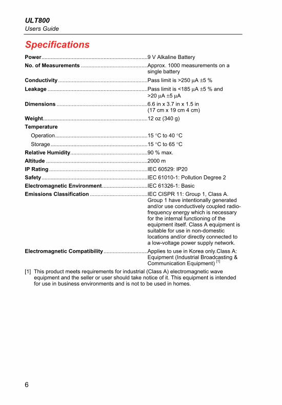
Specifications Power ...................................................................... 9 V Alkaline Battery
No. of Measurements ............................................ Approx. 1000 measurements on a single battery
Conductivity ........................................................... Pass limit is >250 μA ±5 %
Leakage .................................................................. Pass limit is <185 μA ±5 % and >20 μA ±5 μA
Dimensions ............................................................ 6.6 in x 3.7 in x 1.5 in (17 cm x 19 cm 4 cm)
Weight ..................................................................... 12 oz (340 g)
Temperature
Operation ............................................................. 15 °C to 40 °C
Storage ................................................................ 15 °C to 65 °C
Relative Humidity ................................................... 90 % max.
Altitude ................................................................... 2000 m
IP Rating ................................................................. IEC 60529: IP20
Safety ...................................................................... IEC 61010-1: Pollution Degree 2
Electromagnetic Environment .............................. IEC 61326-1: Basic
Emissions Classification ...................................... IEC CISPR 11: Group 1, Class A. Group 1 have intentionally generated and/or use conductively coupled radio-frequency energy which is necessary for the internal functioning of the equipment itself. Class A equipment is suitable for use in non-domestic locations and/or directly connected to a low-voltage power supply network.
Electromagnetic Compatibility ............................. Applies to use in Korea only.Class A: Equipment (Industrial Broadcasting & Communication Equipment) [1]
[1] This product meets requirements for industrial (Class A) electromagnetic wave equipment and the seller or user should take notice of it. This equipment is intended for use in business environments and is not to be used in homes.

Ultrasound Transducer Leakage Current Tester Using the ULT800
7
Using the ULT800 Warning
To avoid personal injury, do not touch the dual conductivity electrode rods. Voltage is present on the rods during a test.
Inspect the conductivity probe for damaged insulation or exposed metal. To avoid personal injury, replace a damaged conductivity probe before using.
Caution
To avoid damage to the transducer, observe the immersion levels. Do not immerse or allow the cable or connector of a transducer to become wet.
The ULT800 TEE Transducer Leakage Current Tester is a portable, self-contained, battery-operated device. It measures the leakage current of the devices attached to its connectors. The ULT800 applies 120 V ac, 60 Hz to devices placed in a conductive bath (basin or storage tube). The ULT800 measures the current and compares the results to an internal threshold. The instrument displays the results as a PASS or FAIL indication. It also performs an internal self-calibration on each measurement cycle.
Connect the transducer to be tested to the ULT800 via a unique adapter. The ULT800 performs the measurement with the transducer immersed in either the cleaning solution or saline. To insure that the leakage current test is accurate, first test the conductivity of the fluid. A special dual element probe also connected to the ULT800 tests the conductivity of the fluid. A green PASS light or a red FAIL light indicates the results of the conductivity and leakage current tests.
The ULT800 makes two types of measurements. The Leakage Test measures the current between the probe and the electrode. The Conductivity Test measures the conductivity of the bath solution between the two electrodes.
ULT800 Users Guide
8
Figures 2 and 3 show some typical test setups. You can use other setups, as long as you observe the following rules:
1. Connect the ultrasound probe you are testing to the probe adapter. See the list of available adapters under Accessories.
2. Place the probe you are testing in a saline bath with the entire critical area of the probe fully immersed.
3. Place the dual electrode (Part No. 2392502 or 2392569) in the saline bath to a depth of at least one inch.
4. Plug the probe adapter and the electrode wire connectors into the ULT800. The connections are fully interchangeable.

Ultrasound Transducer Leakage Current Tester Using the ULT800
9
ULT800TEE TRANSDUCERLEAKAGE CURRENT TESTER
INSTRUCTIONS:1. Connect the transducer and the adapters to the ULT 800.
2. Press the ON/TEST button and wait for the READY light.
3. Select CONDUCTIVITY and press the ON/TEST Button-Wait for the PASS light.
4. Select LEAKAGE and press the ON/TEST button again-observe PASS or FAIL light. If test fails, DO NOT USETRANSDUCER. Refer to the user’s manual.
ON
READY PASS FAIL LOW BAT
TESTCONDUCTIVITY
LEAKAGE
Biomedical
Transducer-SpecificAdapter
Dual ConductivityElectrodes
FlukeULT800
X
ecy02f.eps
Figure 2. Disinfection Basin Test Setup
ULT800 Users Guide
10
TEE TRANSDUCERLEAKAGE CURRENT TESTER
ULT800
INSTRUCTIONS:1. Connect the transducer and the adapters to the ULT 800.
2. Press the ON/TEST button and wait for the READY light.
3. Select CONDUCTIVITY and press the ON/TEST Button-Wait for the PASS light.
4. Select LEAKAGE and press the ON/TEST button again-observe PASS or FAIL light. If test fails, DO NOT USETRANSDUCER. Refer to the user’s manual.
ON
READY PASS FAIL LOW BAT
TESTCONDUCTIVITY
LEAKAGE
Biomedical
Dual ConductivityElectrode with 600/213 Extenders
Disinfectionand StorageTube
Transducer-Specific Adapter
FlukeULT800 X
ecy03f.eps
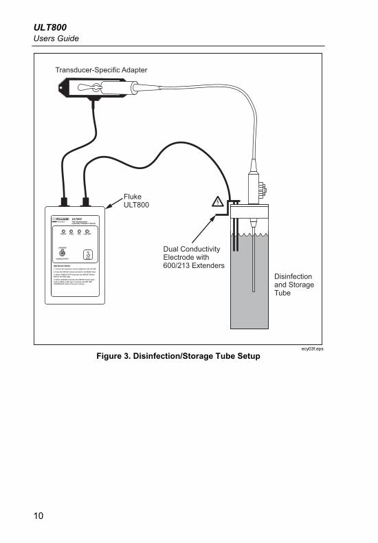
Figure 3. Disinfection/Storage Tube Setup

Ultrasound Transducer Leakage Current Tester Checking the Battery
11
Checking the Battery Note
The LOW BAT light flashes red to indicate that the battery needs replacement.
1. Use the LEAKAGE/CONDUCTIVITY switch to select CONDUCTIVITY.
2. Press the ON/TEST button to turn on the ULT800.
The self-check routine starts, calibrating the unit. All four LED indicators flash in sequence, continuing for five cycles. The READY light glows amber when the self-test routine completes with a successful battery test.
Checking Solution Conductivity Note
The LED indicating a test result remains on for 12 seconds. The ULT800 then powers off to conserve the battery. To resume testing, power on the ULT800, allow the self-check/battery test to complete, and then reinitiate the test.
1. Select CONDUCTIVITY.
2. Press the ON/TEST button to perform a measurement cycle.
3. At the end of the measurement cycle (two seconds), the LED indicates the results of the test.
The green PASS light illuminates if the solution passed the Conductivity Test. The red FAIL light illuminates if the solution failed the Conductivity Test. Check that you have immersed the electrodes to a depth of at least 25 mm (1 inch) and that they are firmly connected to the ULT800, then retest. If the failure repeats, replace the solution and then retest.

ULT800 Users Guide
12
Testing for Transducer Leakage Current Note
Perform the Leakage Test only if the Conductivity Test passes.
1. Select LEAKAGE.
2. Press the ON/TEST button to perform a leakage measurement.
The green PASS light illuminates if the transducer passed the leakage current test. The red FAIL light illuminates if the transducer failed the leakage current test. If there is less than 20 μA of leakage current, the red light pulses, indicating a possible open circuit condition with invalid test results.
Maintenance Your ULT800 needs little maintenance or special care. However, treat it as a calibrated measuring instrument. Avoid dropping or other mechanical abuse that could cause a shift in the calibrated settings.
Warning To prevent possible electrical shock, fire, or personal injury:
• Batteries contain hazardous chemicals that can cause burns or explode. If exposure to chemicals occurs, clean with water and get medical aid.
• Do not disassemble the battery.
• Do not disassemble or crush battery cells and battery packs.
• Do not keep cells or batteries in a container where the terminals can be shorted.
• Do not put battery cells and battery packs near heat or fire. Do not put in sunlight.

Ultrasound Transducer Leakage Current Tester Maintenance
13
• Do not operate the Product with covers removed or the case open. Hazardous voltage exposure is possible.
• Use only specified replacement parts.
• Have an approved technician repair the Product.
For safe operation and maintenance of the Product:
• Repair the Product before use if the battery leaks.
• Do not short the battery terminals together.
• Keep cells and battery packs clean and dry. Clean dirty connectors with a dry, clean cloth.
Cleaning
Caution
Do not put fluid on the Product surface. Fluid leakage into the electrical circuitry may cause the Product to fail.
Caution
Do not use spray cleaners on the Product. This can push fluid into the Product and cause electronic component damage.
Clean the ULT800 occasionally; use a damp cloth and mild detergent. Take care to prevent the entrance of liquids.
Wipe down the adapter cables with the same care. Inspect them for damage to and deterioration of the insulation. Check the connections for integrity. Keep transducer adapter clean and dry.
ULT800 Users Guide
14
Battery
Warning The 9-volt alkaline battery provided with the ULT800 may explode or leak if recharged, inserted improperly, disposed of in a fire, or mixed with different battery types. Dispose of the battery in accordance with any applicable state or local regulations.
The ULT800 uses a standard 9-volt alkaline battery. The battery has a life expectancy of approximately 1000 measurements. Replace the battery yearly, regardless of its condition.
Ultrasound Transducer Leakage Current Tester Maintenance
15
Calibration
Warning Examine the calibration label on the back of the ULT800 prior to each use. Do not use a ULT800 with an expired calibration label. A ULT800 without a calibration label or with the anti-tamper case label broken is out of calibration. A ULT800 that is out of calibration can cause excessive leakage current exposure to the patient; risk of injury to the patient could result.
Caution
Avoid dropping the ULT800 or allowing other mechanical abuse that could cause a shift in the ULT800’s calibrated settings.
The ULT800 requires yearly Fluke factory calibration, which uses appropriate tools and reference instruments that are traceable to the National Institute of Standards and Technology (NIST). Factory calibration provides a calibration sticker on the back of the ULT800 to verify that the calibration was performed.
To locate a service center, visit the Fluke web site at www.fluke.com, or contact Fluke at [email protected]. Call from anywhere in the world at +1-425-446-5500 or call for service in the USA at 1-888-99-FLUKE (1-888-993-5853.)

ULT800 Users Guide
16
Accessories
Table 3. Accessories
Part Number
Model Number
Description
2392427 600/102FG Chassis ground probe, 8-foot coiled cord
2392502 600/212FG Dual conductivity electrode
2392525 600/214FG Hard-sided carrying case
2392533 600/215FG Conductivity cable
2392569 600/220FG Dual conductivity probe – for use with Cidex 2032 tray.
Refer to Table 3 for a list of accessories for the ULT800. Available transducer-specific adapters are listed on Fluke Biomedical’s web site. www.flukebiomedical.com/electrical safety analyzers/ULT800.