Embed Size (px)
Citation preview
Tegile Intelligent Flash Array & Cisco UCS: Configuration Guide
Harrison Waller | Tegile Systems
Revision 1.0
January 13, 2015

Page: 2
Copyright
Copyright © 2015 Tegile Systems™, ALL RIGHTS RESERVED
Notice: No part of this publication may be reproduced or transmitted in any form or by any means, electronic or mechanical, including photocopying and recording, or stored in a database or retrieval system for any purpose, without the express written permission of Tegile Systems (hereinafter referred to as “Tegile”).
Tegile reserves the right to make changes to this document at any time without notice and assumes no responsibility for its use. Tegile products and services only can be ordered under the terms and conditions of Tegile's applicable agreements. All of the features described in this document may not be available currently. Refer to the latest product announcement or contact your local Tegile sales office for information on feature and product availability. This document includes the latest information available at the time of publication.
Tegile™ is a trademark of Tegile Systems in the United States, and other countries. All other trademarks, service marks, and company names in this document are properties of their respective owners.
Tegile Systems, Inc. | 7999 Gateway Blvd. | Suite 120 | Newark | CA | 94560 | (855) 483-4453
Page: 3
Table of Contents
Copyright ............................................................................................................................................................................... 2
Introduction .......................................................................................................................................................................... 5
Tegile Overview .................................................................................................................................................................... 5
UCS Storage Connectivity Overview ................................................................................................................................ 6
Fibre Channel with UCS and Tegile Array ...................................................................................................................... 8
UCS Fibre Channel in NPV Mode ................................................................................................................. 8
UCS and FC Direct Connect (Switching Mode) ......................................................................................... 9
Fibre Channel Configuration .......................................................................................................................................... 10
UCS Configuration for End Host (NPV) Mode ........................................................................................ 10
UCS Configuration for FC Direct Connect ............................................................................................... 11
Ensure that FI is in FC Switch mode ..................................................................................................... 11
Create VSANs ............................................................................................................................................ 11
Set FI ports to FC Storage Mode ........................................................................................................... 13
Zone WWPNs ............................................................................................................................................. 13
Boot from SAN Configuration ............................................................................................................... 14
iSCSI with UCS and Tegile Arrays .................................................................................................................................. 16
Tegile Transparent iSCSI Failover .............................................................................................................. 16
UCS Direct Connect with iSCSI .................................................................................................................. 16
iSCSI Configuration ........................................................................................................................................................... 16
General Tips for iSCSI vNICs ....................................................................................................................... 16
UCS iSCSI Boot and Fabric Failover .......................................................................................................... 17
iSCSI Configuration with Direct Connect ................................................................................................. 18
Tegile Array iSCSI Configuration ........................................................................................................... 18
Page: 4
UCS Configuration .................................................................................................................................... 22
NFS with UCS and Tegile Arrays .................................................................................................................................... 27
UCS with Direct Connect NFS Using Appliance Ports .......................................................................... 27
Failure Scenarios to Consider .................................................................................................................... 29
Fabric Interconnect failure ..................................................................................................................... 30
IOM or all uplinks to FI failure ............................................................................................................... 30
Appliance port failure .............................................................................................................................. 31
Tegile array controller failure ................................................................................................................ 32
NFS Configuration ............................................................................................................................................................ 32
Direct Connect ............................................................................................................................................... 33
Tegile Array NFS Configuration ............................................................................................................. 33
UCS NFS Configuration ........................................................................................................................... 34
General Configuration Settings of UCS ....................................................................................................................... 34
Configure UCS Port-Channel ...................................................................................................................... 35
Chassis to FI Port-Channel ..................................................................................................................... 35
FI to uplink switch Port-Channel ........................................................................................................... 36
Switch and End Host mode ........................................................................................................................ 37
Appliance Port configuration ..................................................................................................................... 38
OS Images and drivers .................................................................................................................................................... 41
Conclusion .......................................................................................................................................................................... 41
References ......................................................................................................................................................................... 41
Page: 5
Introduction
This paper will provide an overview of the various storage features, connectivity options, and best practices when using the Cisco Unified Computing System (UCS) with Tegile Intelligent Flash Arrays. This document focuses on storage behavior in detail, for both block and file protocols and all the best practices for using these protocols with the combined UCS and Tegile “stack”. There is not an application or specific use case focus for this paper. There are existing Cisco Validated Designs that you can reference for a deeper understanding of how to configure the UCS and Tegile systems, in detail, for various application-centric use cases. Tegile encourages you to review the joint VDI paper located at:
http://www.cisco.com/c/en/us/solutions/collateral/data-center-virtualization/unified-computing/whitepaper_C11-727638.html
Tegile Overview
Tegile is pioneering a new generation of affordable, feature-rich storage arrays, which are dramatically faster and can store more data than standard arrays. Tegile is led by a successful team of industry veterans, and is committed to a philosophy of "Customer First."
Tegile Intelligent Flash Arrays are purpose-built to address both performance and capacity needs.
High Performance: Tegile arrays are architected from the ground-up to use flash storage in an intelligent and optimal manner. The patented IntelliFlash architecture accelerates performance to solid-state speeds without sacrificing the capacity or cost advantage of hard-disk storage. Tegile arrays are significantly faster than legacy arrays and considerably less expensive than all solid-state disk-based arrays.
Storage Eff ic iency: Inline deduplication and compression enhance usable capacity well beyond raw capacity, reducing storage capacity requirements by as much as 90 percent.
Avai labi l ity : Tegile arrays are designed for redundancy, with no single point-of-failure. The rich set of available features includes multiple RAID options, snapshots, cloning, and remote replication, with proactive monitoring and alerts for timely notification when issues arise, and they are included at no extra cost.
Single Platform for Mult iple Workloads: Tegile arrays support both SAN and NAS protocols for storage access. Desktop images can be deployed using NFS, iSCSI or Fibre Channel protocol, while you can provision data folders for the Microsoft Windows virtual desktops using CIFS on the same array.
Page: 6
Scalabil ity : Tegile’s product line includes hybrid and all-flash configurations, which provide progressively increasing performance as they scale. The product line also includes storage expansion shelves to add capacity to the storage arrays. The expansion shelves can include a all solid-state drives, all hard-disk drives, or a mixture of solid-state and hard disk drives (SSDs and HDDs).
Tegile arrays balance performance, capacity, features, and price that can satisfy the needs of the most demanding environments.
This document covers the setup and configuration of the Tegile array with the Cisco UCS blade infrastructure. The sections are divided by protocols -- FC, iSCSI, and NFS with a general discussion, and then delving into configuration of both the UCS and the Tegile array.
Contact Tegile Support for any questions/feedback ([email protected]).
UCS Storage Connectivity Overview
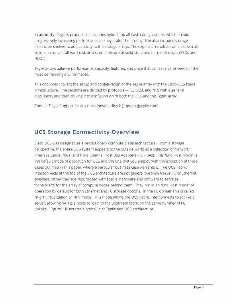
Cisco UCS was designed as a revolutionary compute blade architecture. From a storage perspective, the entire UCS system appears to the outside world as a collection of Network Interface Cards (NICs) and Fibre Channel Host Bus Adapters (FC HBAs). This “End Host Mode” is the default mode of operation for UCS and the one that you employ with the exception of those cases outlined in this paper, where a particular business case warrants it. The UCS Fabric Interconnects at the top of the UCS architecture are not general purpose Nexus FC or Ethernet switches, rather they are repurposed with special hardware and software to serve as “controllers” for the array of compute nodes behind them. They run in an “End Host Mode” of operation by default for both Ethernet and FC storage options. In the FC domain this is called NPort Virtualization or NPV mode. This mode allows the UCS Fabric Interconnects to act like a server, allowing multiple hosts to login to the upstream fabric on the same number of FC uplinks. Figure 1 illustrates a typical joint Tegile and UCS architecture.
Page: 7
Figure 1 - Standard Tegile and UCS Architecture
Storage I/O enters and departs the UCS system on the Fabric Interconnect through the use of uplink ports. There are different types of uplink ports and other special port types when using UCS in a direct attach configuration. This document discusses those ports types.
Page: 8
Fibre Channel with UCS and Tegile Array
The use of FCoE (Fibre Channel over Ethernet) in UCS blade architecture is completely transparent to the host operating system. The OS simply detects the 10G Ethernet, FC PCIe device handles, and associated device drivers. Many customers have deployed FC storage targets with Tegile and UCS using the Nexus 5000 or MDS family of FC switches, although UCS does support Brocade and other vendors.
The Tegile array for Fibre Channel is an asymmetric active-active array supporting ALUA. This means that all paths display as active but I/O is only concurrent on the controller owning the resource or LUNs. Each controller can have its own pool and LUNs, thereby allowing active I/O from each controller.
UCS Fibre Channel in NPV Mode
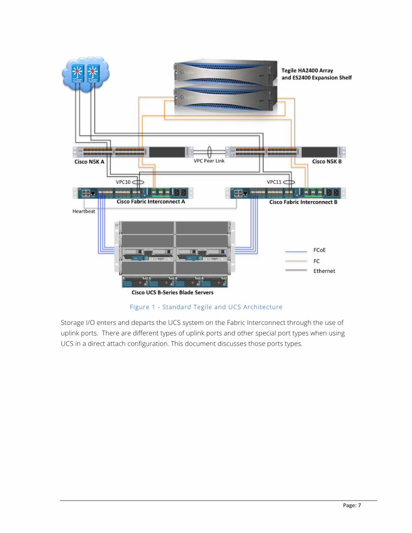
The Fabric interconnects, when set in NPV mode, allow you to configure ports as NP_ports. This requires that an upstream FC switch is running in NPIV mode (Figure 2). Most modern FC switches on the market support this mode of operation. Note that UCS does not require Cisco upstream FC switches as NPIV is an industry standard.
Figure 2 - Switched (NPV) Environment
Page: 9
UCS and FC Direct Connect (Switching Mode)
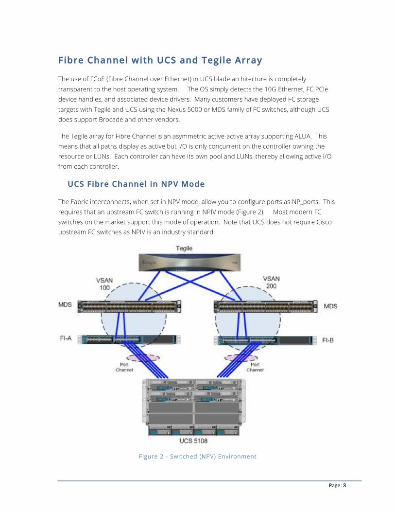
UCS 2.1(1) introduced zoning policies built into UCS Manager. This allows a direct connect mode of operation for FC attach without requiring zoning services from an upstream FC switch. Prior to 2.1(1), direct connect was supported but zoning required an upstream FC switch. Cisco HCL listings (see References) supports the use of Tegile arrays directly connected to the UCS FI through “FC storage ports”. Additionally, you must configure the implicit service profile-based zoning in UCSM for a supported configuration. UCSM does not support open or default zoning.
UCS supports FC Direct Connect mode only in release 2.1(1) and onwards. Prior to UCS release 2.1(1), UCS only supported NPV mode, which required upstream FC switches.
Figure 3 – Direct Connect Environment
Page: 10
Fibre Channel Configuration
The FC configuration with Boot from SAN (BFS) is probably the most intuitive of the protocol setups. The Tegile Array supports both NPV (End Host) and Direct Connect (switching) modes of operation so the following sections highlight the important parts of configuring each of the environments with a larger focus on direct connect due to its uniqueness.
Also, since a lot of the configuration is redundant between the two environments, the majority of the steps are in the direct connect setup to avoid redundancy.
UCS Configuration for End Host (NPV) Mode
In End Host mode, (see Switch and End Host mode section) you connect or uplink all Fabric Interconnect ports to Fibre Channel switches. You must also connect the array ports to the uplink switch and manage all zoning configuration managed from that switch/fabric.
Set the FI ports connecting to the FC switches as an FC Uplink Port . For high availability, connect at least two ports from each FI to the uplinked switches.
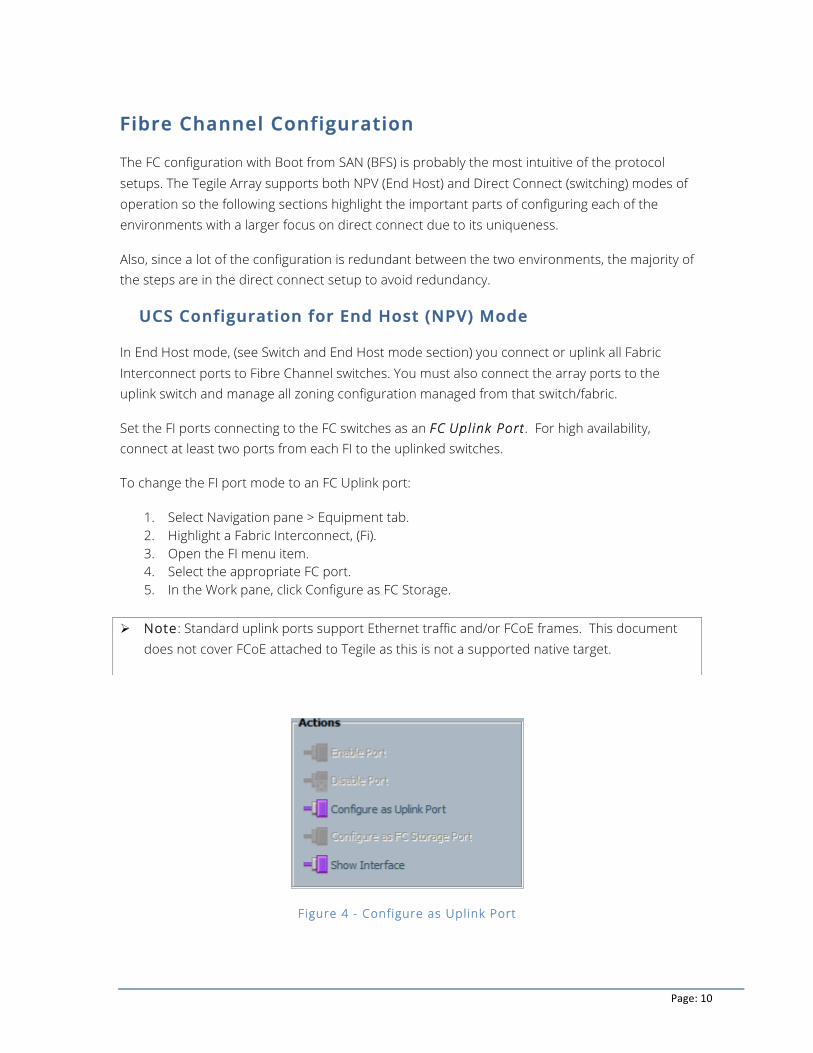
To change the FI port mode to an FC Uplink port:
1. Select Navigation pane > Equipment tab. 2. Highlight a Fabric Interconnect, (Fi). 3. Open the FI menu item. 4. Select the appropriate FC port. 5. In the Work pane, click Configure as FC Storage.
Figure 4 - Configure as Uplink Port
Ø Note: Standard uplink ports support Ethernet traffic and/or FCoE frames. This document does not cover FCoE attached to Tegile as this is not a supported native target.
Page: 11
UCS Configuration for FC Direct Connect
Configuring the environment for a Direct Connect (DC) configuration consists of:
1. Ensure that FI is in FC switch mode 2. Create required VSANs 3. Set FI ports to FC Storage Mode 4. Zone WWPNs
For reference, see Figure 3.
Ensure that FI is in FC Switch mode
With a direct connect environment the FIs need to act like a switch to handle the FC connections properly, hence, the Switching mode term.
Configuring the FIs into a specific mode is discussed multiple times within this document due to the various permutations of each configuration. To minimize redundancy, this document describes this setup once in the Switch and End Host mode.
Create VSANs
A Best Practice is to separate the storage array VSANs from any FC uplinks. The concept of this design is to allow a user to have both direct connect and upstream fabric attached arrays simultaneously and use VSANs to separate the traffic.
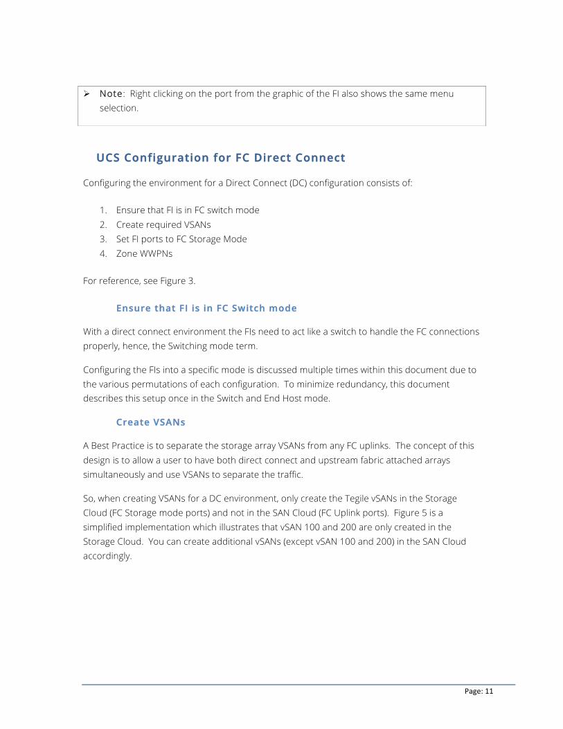
So, when creating VSANs for a DC environment, only create the Tegile vSANs in the Storage Cloud (FC Storage mode ports) and not in the SAN Cloud (FC Uplink ports). Figure 5 is a simplified implementation which illustrates that vSAN 100 and 200 are only created in the Storage Cloud. You can create additional vSANs (except vSAN 100 and 200) in the SAN Cloud accordingly.
Ø Note: Right clicking on the port from the graphic of the FI also shows the same menu selection.
Page: 12
Figure 5 - Create vSANs in Storage Cloud only
To create a storage VSAN:
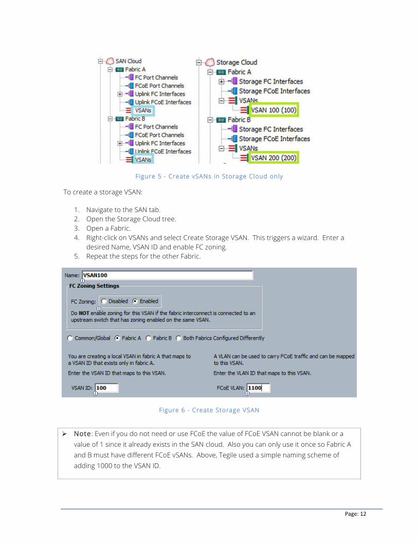
1. Navigate to the SAN tab. 2. Open the Storage Cloud tree. 3. Open a Fabric. 4. Right-click on VSANs and select Create Storage VSAN. This triggers a wizard. Enter a
desired Name, VSAN ID and enable FC zoning. 5. Repeat the steps for the other Fabric.
Figure 6 - Create Storage VSAN
Ø Note: Even if you do not need or use FCoE the value of FCoE VSAN cannot be blank or a value of 1 since it already exists in the SAN cloud. Also you can only use it once so Fabric A and B must have different FCoE vSANs. Above, Tegile used a simple naming scheme of adding 1000 to the VSAN ID.
Page: 13
Set FI ports to FC Storage Mode
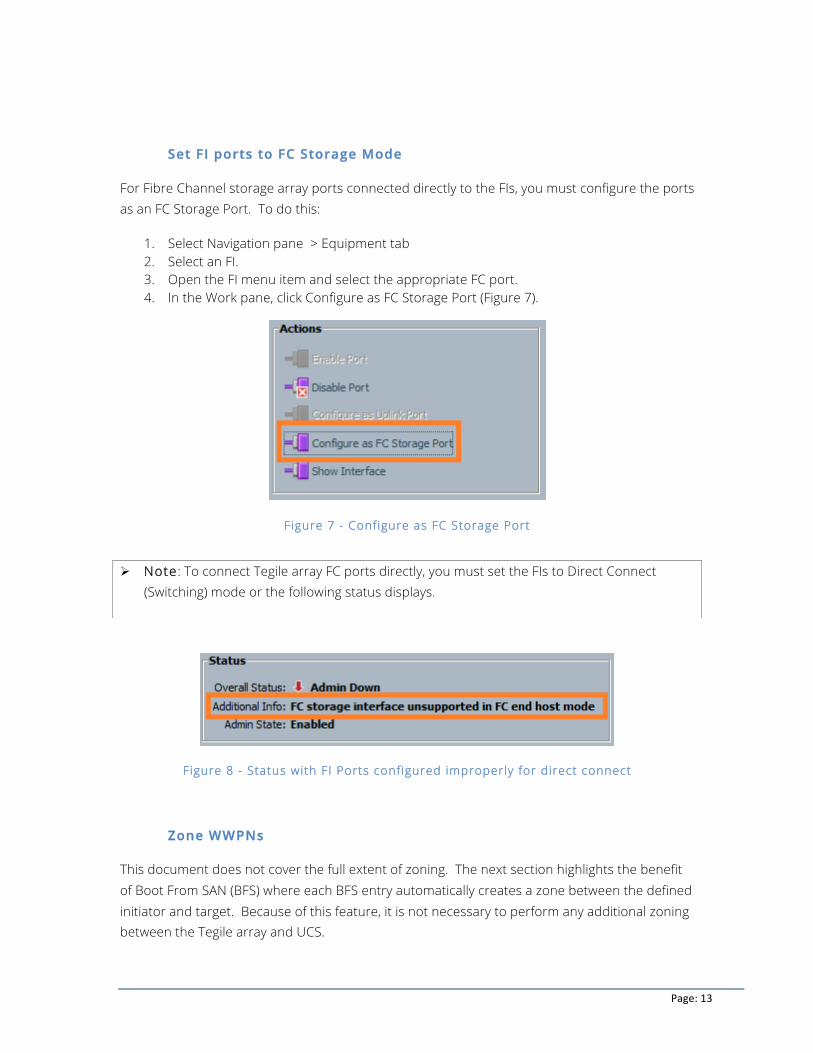
For Fibre Channel storage array ports connected directly to the FIs, you must configure the ports as an FC Storage Port. To do this:
1. Select Navigation pane > Equipment tab 2. Select an FI. 3. Open the FI menu item and select the appropriate FC port. 4. In the Work pane, click Configure as FC Storage Port (Figure 7).
Figure 7 - Configure as FC Storage Port
Figure 8 - Status with FI Ports configured improperly for direct connect
Zone WWPNs
This document does not cover the full extent of zoning. The next section highlights the benefit of Boot From SAN (BFS) where each BFS entry automatically creates a zone between the defined initiator and target. Because of this feature, it is not necessary to perform any additional zoning between the Tegile array and UCS.
Ø Note: To connect Tegile array FC ports directly, you must set the FIs to Direct Connect (Switching) mode or the following status displays.
Page: 14
If not performing BFS or if you need additional zoning configuration Tegile encourages you to check the Cisco website on UCS zoning configuration for further details.
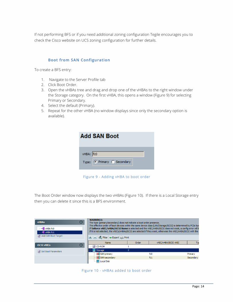
Boot from SAN Configuration
To create a BFS entry:
1. Navigate to the Server Profile tab 2. Click Boot Order. 3. Open the vHBAs tree and drag and drop one of the vHBAs to the right window under
the Storage category. On the first vHBA, this opens a window (Figure 9) for selecting Primary or Secondary.
4. Select the default (Primary). 5. Repeat for the other vHBA (no window displays since only the secondary option is
available).
Figure 9 - Adding vHBA to boot order
The Boot Order window now displays the two vHBAs (Figure 10). If there is a Local Storage entry then you can delete it since this is a BFS environment.
Figure 10 - vHBAs added to boot order
Page: 15
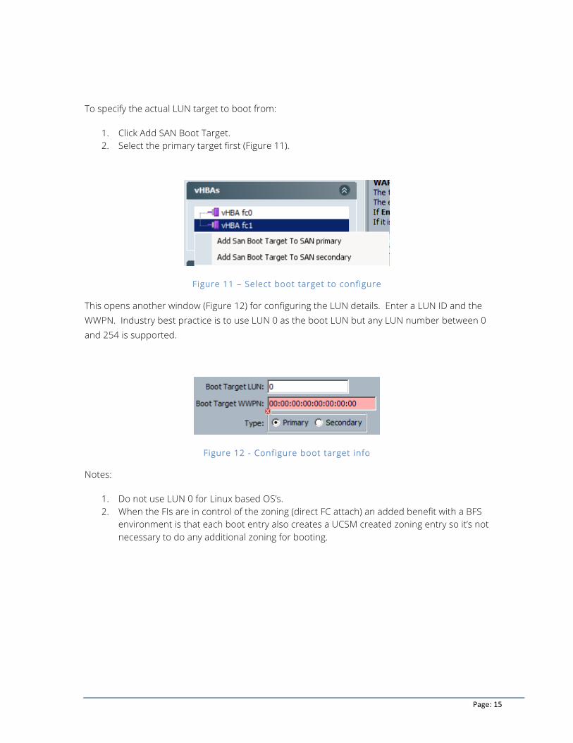
To specify the actual LUN target to boot from:
1. Click Add SAN Boot Target. 2. Select the primary target first (Figure 11).
Figure 11 – Select boot target to configure
This opens another window (Figure 12) for configuring the LUN details. Enter a LUN ID and the WWPN. Industry best practice is to use LUN 0 as the boot LUN but any LUN number between 0 and 254 is supported.
Figure 12 - Configure boot target info
Notes:
1. Do not use LUN 0 for Linux based OS’s. 2. When the FIs are in control of the zoning (direct FC attach) an added benefit with a BFS
environment is that each boot entry also creates a UCSM created zoning entry so it’s not necessary to do any additional zoning for booting.

Page: 16
iSCSI with UCS and Tegile Arrays
UCS 2.0 introduced the ability to boot from iSCSI targets. This is accomplished through a new object in UCS called an “iSCSI vNIC” which is an overlay, or child object, of the normal UCS “vNIC”. The iSCSI vNIC has a variety of properties and consumes various pools and policies, all of which are there to allow UCS to properly configure the Option ROM memory of the adapter. Once the server has completed the boot cycle the iSCSI vNIC is not in the I/O path any longer and all of the I/O is performed through the normal vNICs and host iSCSI initiator if using the VIC adapter. UCSM release 2.1(1) or later is recommended as some nuances of iSCSI booting in UCSM that existed previously have been addressed with this release.
Tegile Transparent iSCSI Failover
For iSCSI on Tegile arrays, each storage controller in an HA pair services only its own LUNs unless a controller fails. That means that during normal operations the host only accesses a LUN through the owning controller’s network ports. After a failover, the LUNs are accessed through the backup controller using the same floating IP address. From a host’s perspective, nothing has changed or occurred.
UCS Direct Connect with iSCSI
The use of Appliance ports on the UCS FIs enable a user to directly attach the FIs to the Tegile family of arrays for a lower cost, pod-like deployment of UCS and Tegile. Tegile recommends segregating iSCSI ports and management ports into separate VLANs on the. Configuring VLANs on the Tegile array is not necessary.
iSCSI Configuration
The uplink mode of operation for iSCSI data LUNs (no booting) is, by default, supported by Cisco as this is considered a mature network configuration. In addition, the Tegile array has been thoroughly tested by Tegile in direct connect mode of operation with BFS.
This configuration section focuses mainly on the direct connect environment and discusses the nuances for setting Boot from SAN. Tegile encourages you to review the Cisco UCS HCL for the specifics on what topologies require explicit support and which are natively supported.
General Tips for iSCSI vNICs
When configuring the UCS profile for an iSCSI connected server always put the primary iSCSI vNIC on the lowest vNIC PCIe device so it is discovered first. The way to manage this is to
Page: 17
assign the primary iSCSI vNIC to the lowest numbered vNIC name, assuming you will then use a placement policy to ensure this vNIC is discovered first. However, if you do not use a placement policy, the first vNIC is usually discovered first. In an ESXi installation, the first vNIC discovered will also be assigned to the ESXi management port so modifying that port will be necessary.
Previous versions of UCSM 2.1(2) would create a default iQN for each iSCSI vNIC. This would lead to having one iSCSI vNIC for each fabric for a total of two iQNs on different parent vNICs pinned to the different fabrics.
Starting with the 2.1(2) release, the user could optionally choose to have one iQN created per service profile. This “single iQN” option was added since the UCS implementation of iSCSI is software-based and thus, the industry best practice is to have a single iQN per host (service profile).
Note that HA is still provided since the single logical iQN will simply reference any of the available underlying vNIC and iSCSI vNIC combinations if the primary fails.
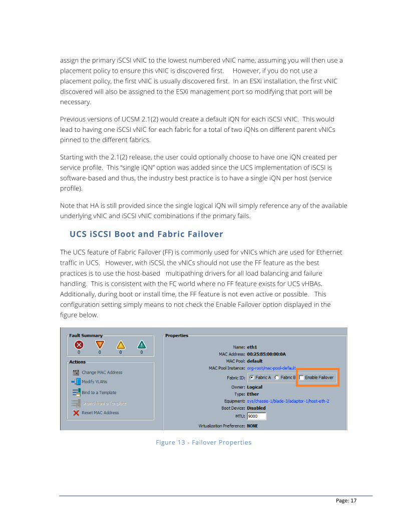
UCS iSCSI Boot and Fabric Failover
The UCS feature of Fabric Failover (FF) is commonly used for vNICs which are used for Ethernet traffic in UCS. However, with iSCSI, the vNICs should not use the FF feature as the best practices is to use the host-based multipathing drivers for all load balancing and failure handling. This is consistent with the FC world where no FF feature exists for UCS vHBAs. Additionally, during boot or install time, the FF feature is not even active or possible. This configuration setting simply means to not check the Enable Failover option displayed in the figure below.
Figure 13 - Fai lover Properties
Page: 18
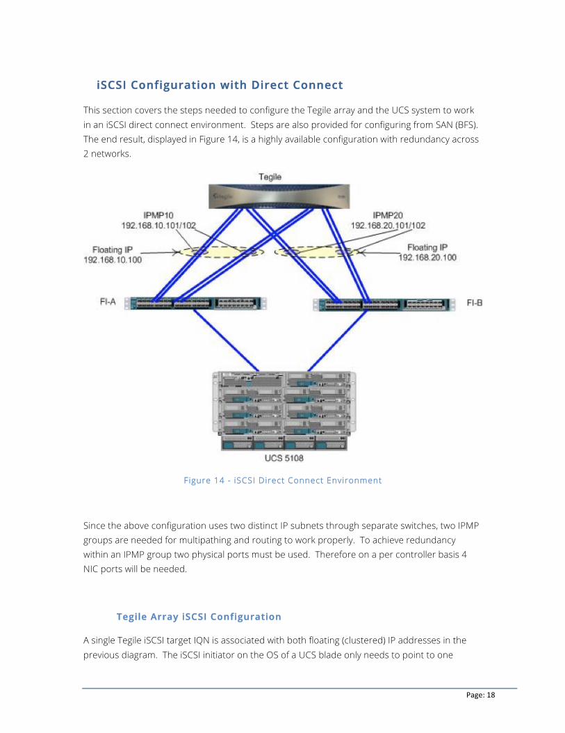
iSCSI Configuration with Direct Connect
This section covers the steps needed to configure the Tegile array and the UCS system to work in an iSCSI direct connect environment. Steps are also provided for configuring from SAN (BFS). The end result, displayed in Figure 14, is a highly available configuration with redundancy across 2 networks.
Figure 14 - iSCSI Direct Connect Environment
Since the above configuration uses two distinct IP subnets through separate switches, two IPMP groups are needed for multipathing and routing to work properly. To achieve redundancy within an IPMP group two physical ports must be used. Therefore on a per controller basis 4 NIC ports will be needed.
Tegile Array iSCSI Configuration
A single Tegile iSCSI target IQN is associated with both floating (clustered) IP addresses in the previous diagram. The iSCSI initiator on the OS of a UCS blade only needs to point to one
Page: 19
floating IP address to discover both available IPs (paths). This document discusses more details about the UCS iSCSI boot profile settings later.
To configure a profile to boot off of an iSCSI LUN, you must perform the following prerequisites on the Tegile array:
1. Configure jumbo frames 2. Configure IPMP groups 3. Configure Floating Service IP 4. Add iSCSI target 5. Add iSCSI initiator 6. Map LUNs
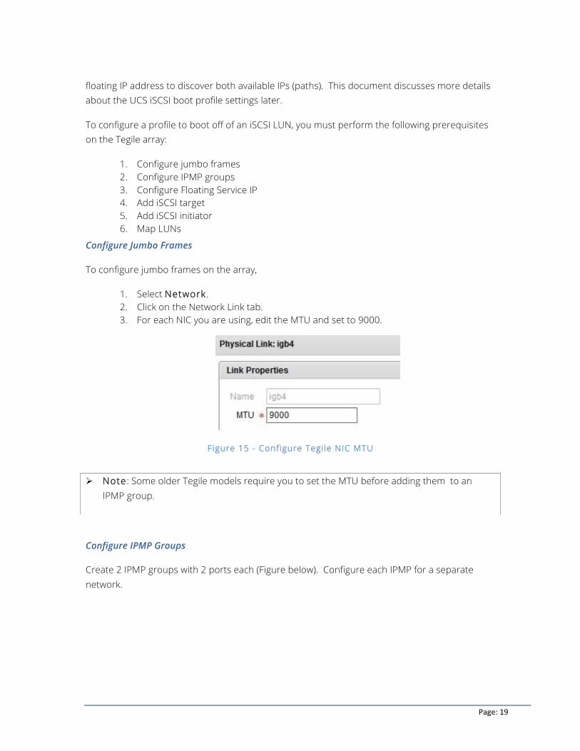
Configure Jumbo Frames
To configure jumbo frames on the array,
1. Select Network. 2. Click on the Network Link tab. 3. For each NIC you are using, edit the MTU and set to 9000.
Figure 15 - Configure Tegile NIC MTU
Configure IPMP Groups
Create 2 IPMP groups with 2 ports each (Figure below). Configure each IPMP for a separate network.
Ø Note: Some older Tegile models require you to set the MTU before adding them to an IPMP group.
Page: 20
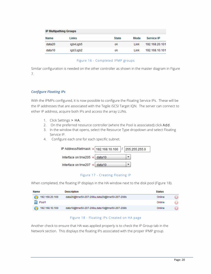
Figure 16 - Completed IPMP groups
Similar configuration is needed on the other controller as shown in the master diagram in Figure 7.
Configure Floating IPs
With the IPMPs configured, it is now possible to configure the Floating Service IPs. These will be the IP addresses that are associated with the Tegile iSCSI Target IQN. The server can connect to either IP address, acquire both IPs and access the array LUNs.
1. Click Settings > HA. 2. On the preferred resource controller (where the Pool is associated) click Add. 3. In the window that opens, select the Resource Type dropdown and select Floating
Service IP. 4. Configure each one for each specific subnet.
Figure 17 - Creating Floating IP
When completed, the floating IP displays in the HA window next to the disk pool (Figure 18).
Figure 18 - Floating IPs Created on HA page
Another check to ensure that HA was applied properly is to check the IP Group tab in the Network section. This displays the floating IPs associated with the proper IPMP group.
Page: 21
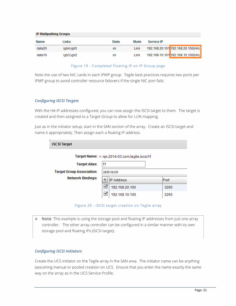
Figure 19 - Completed Floating IP on IP Group page
Note the use of two NIC cards in each IPMP group. Tegile best practices requires two ports per IPMP group to avoid controller resource failovers if the single NIC port fails.
Configuring iSCSI Targets
With the HA IP addresses configured, you can now assign the iSCSI target to them. The target is created and then assigned to a Target Group to allow for LUN mapping.
Just as in the initiator setup, start in the SAN section of the array. Create an iSCSI target and name it appropriately. Then assign each a floating IP address.
Figure 20 - iSCSI target creation on Tegile array
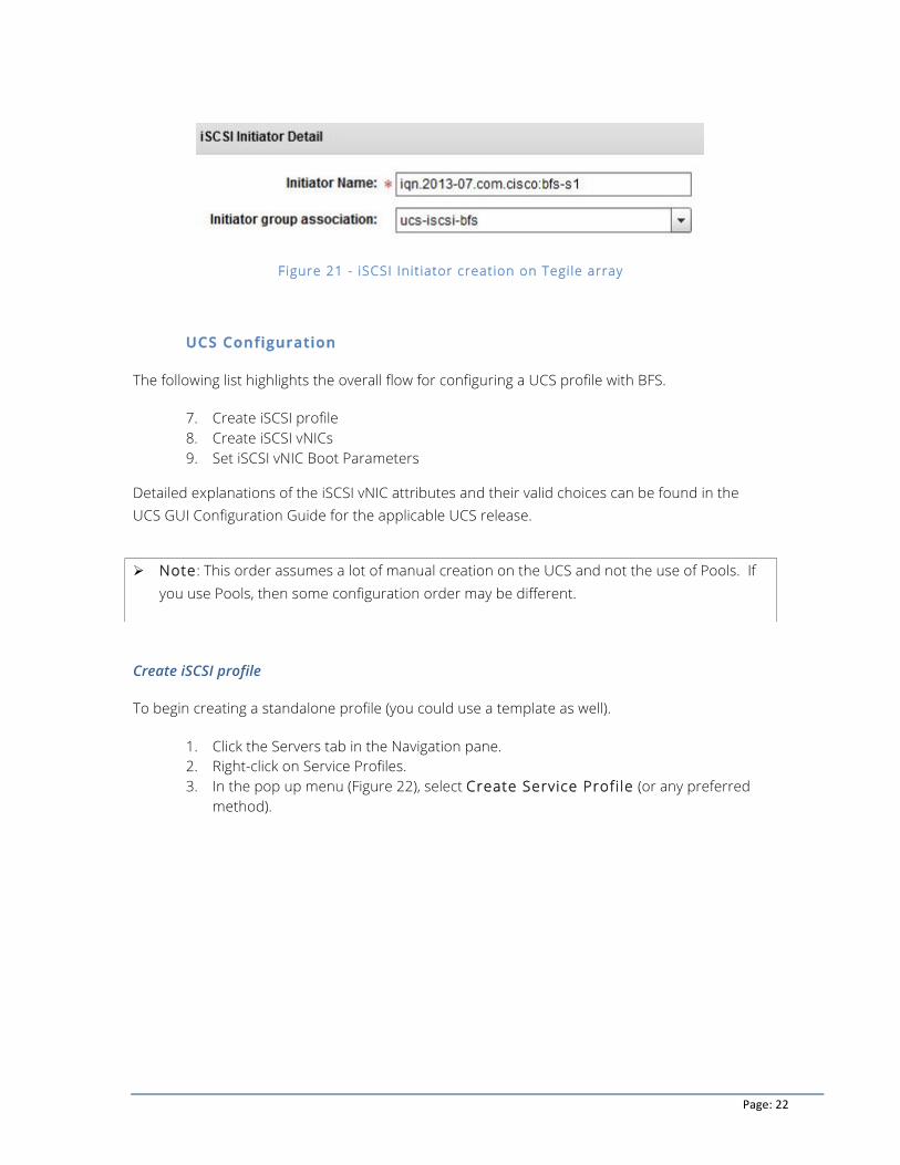
Configuring iSCSI Initiators
Create the UCS initiator on the Tegile array in the SAN area. The initiator name can be anything (assuming manual or pooled creation on UCS. Ensure that you enter the name exactly the same way on the array as in the UCS Service Profile.
Ø Note: This example is using the storage pool and floating IP addresses from just one array controller. The other array controller can be configured in a similar manner with its own storage pool and floating IPs (iSCSI target).
Page: 22
Figure 21 - iSCSI Init iator creation on Tegile array
UCS Configuration
The following list highlights the overall flow for configuring a UCS profile with BFS.
7. Create iSCSI profile 8. Create iSCSI vNICs 9. Set iSCSI vNIC Boot Parameters
Detailed explanations of the iSCSI vNIC attributes and their valid choices can be found in the UCS GUI Configuration Guide for the applicable UCS release.
Create iSCSI profile
To begin creating a standalone profile (you could use a template as well).
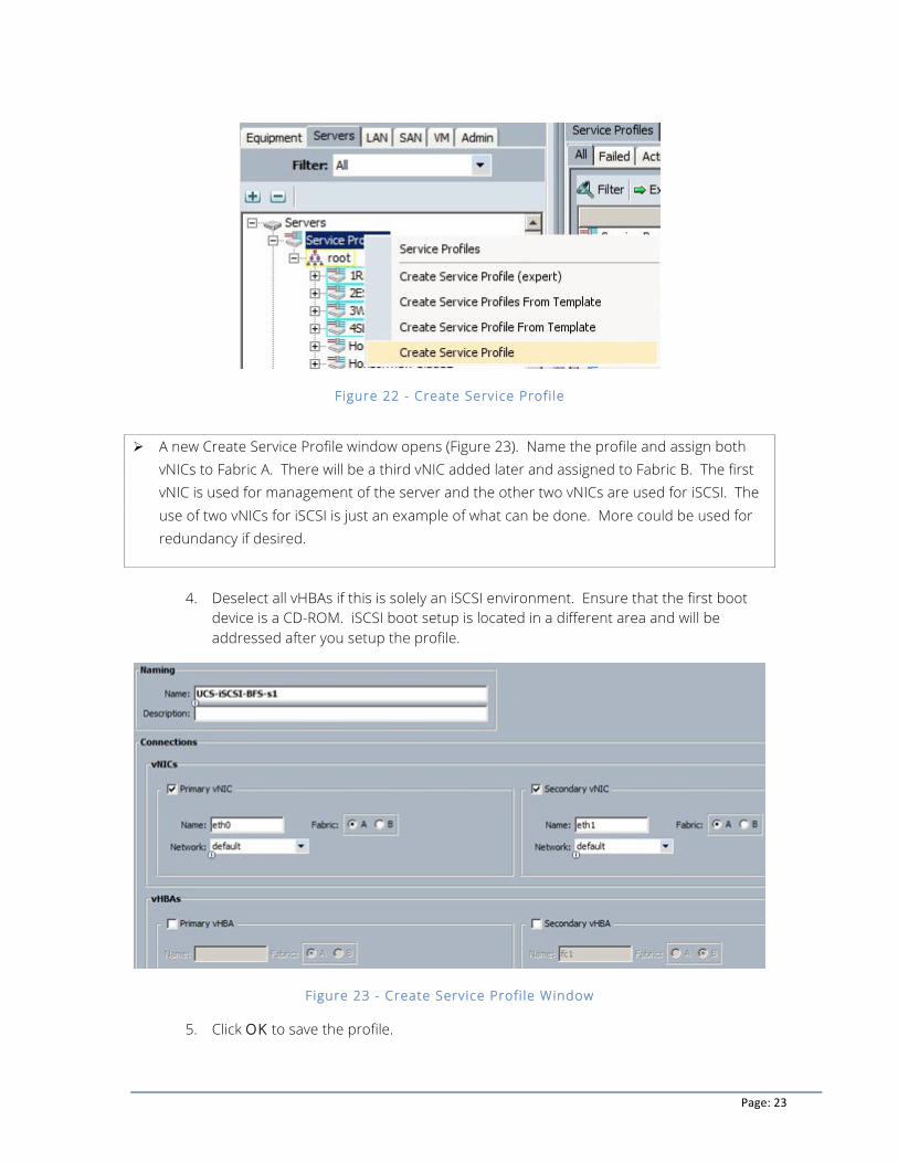
1. Click the Servers tab in the Navigation pane. 2. Right-click on Service Profiles. 3. In the pop up menu (Figure 22), select Create Service Profi le (or any preferred
method).
Ø Note: This order assumes a lot of manual creation on the UCS and not the use of Pools. If you use Pools, then some configuration order may be different.
Page: 23
Figure 22 - Create Service Profi le
4. Deselect all vHBAs if this is solely an iSCSI environment. Ensure that the first boot
device is a CD-ROM. iSCSI boot setup is located in a different area and will be addressed after you setup the profile.
Figure 23 - Create Service Profi le Window
5. Click OK to save the profile.
Ø A new Create Service Profile window opens (Figure 23). Name the profile and assign both vNICs to Fabric A. There will be a third vNIC added later and assigned to Fabric B. The first vNIC is used for management of the server and the other two vNICs are used for iSCSI. The use of two vNICs for iSCSI is just an example of what can be done. More could be used for redundancy if desired.
Page: 24
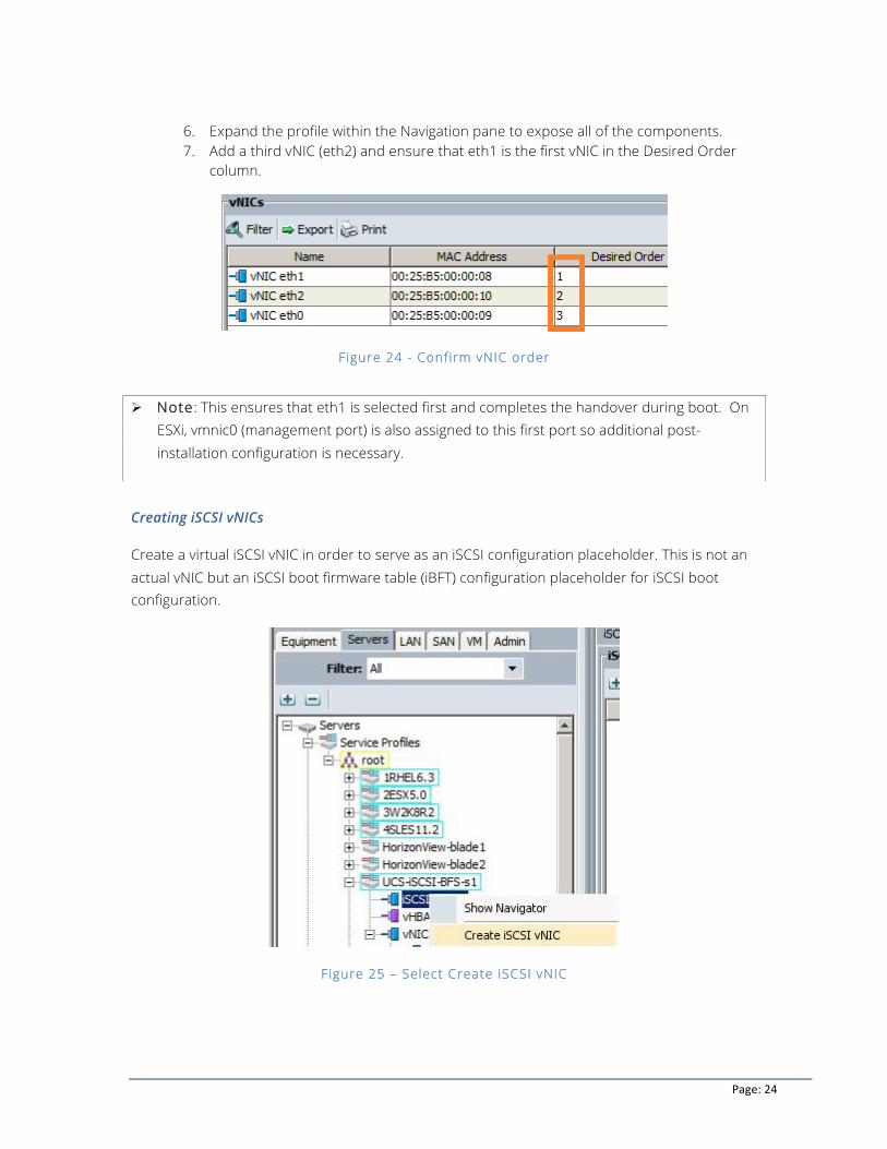
6. Expand the profile within the Navigation pane to expose all of the components. 7. Add a third vNIC (eth2) and ensure that eth1 is the first vNIC in the Desired Order
column.
Figure 24 - Confirm vNIC order
Creating iSCSI vNICs
Create a virtual iSCSI vNIC in order to serve as an iSCSI configuration placeholder. This is not an actual vNIC but an iSCSI boot firmware table (iBFT) configuration placeholder for iSCSI boot configuration.
Figure 25 – Select Create iSCSI vNIC
Ø Note: This ensures that eth1 is selected first and completes the handover during boot. On ESXi, vmnic0 (management port) is also assigned to this first port so additional post-installation configuration is necessary.
Page: 25
To create an iSCSI vNIC:
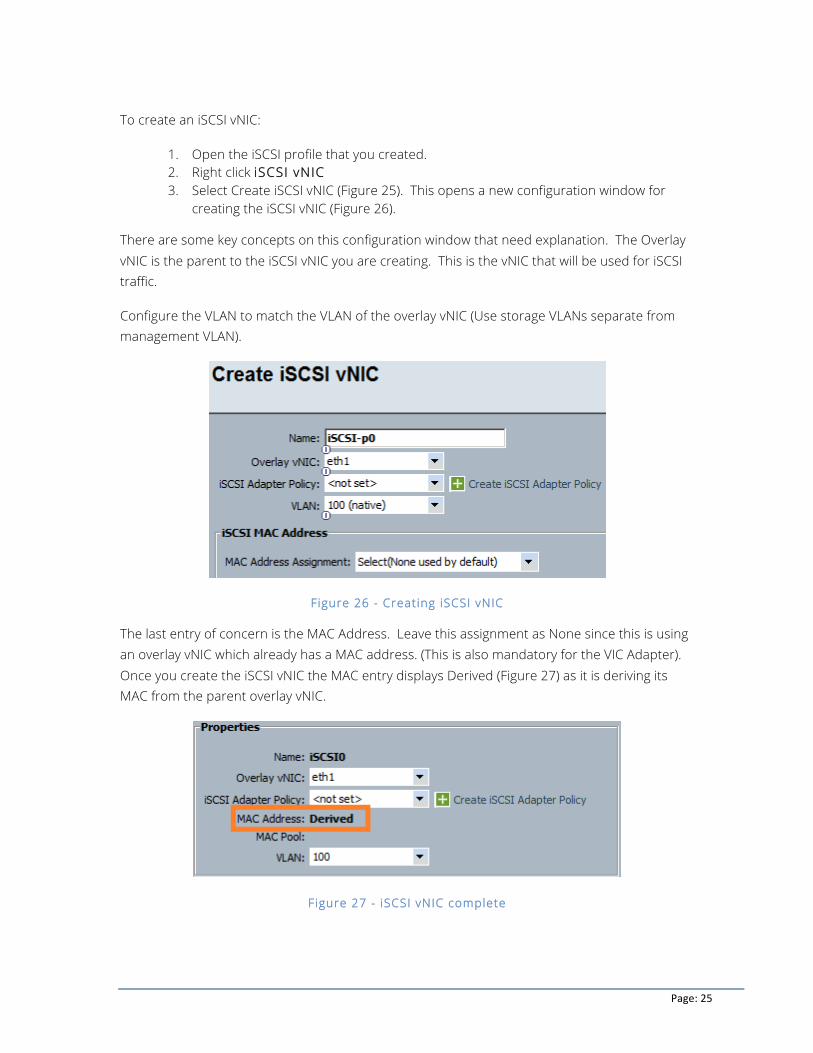
1. Open the iSCSI profile that you created. 2. Right click iSCSI vNIC 3. Select Create iSCSI vNIC (Figure 25). This opens a new configuration window for
creating the iSCSI vNIC (Figure 26).
There are some key concepts on this configuration window that need explanation. The Overlay vNIC is the parent to the iSCSI vNIC you are creating. This is the vNIC that will be used for iSCSI traffic.
Configure the VLAN to match the VLAN of the overlay vNIC (Use storage VLANs separate from management VLAN).
Figure 26 - Creating iSCSI vNIC
The last entry of concern is the MAC Address. Leave this assignment as None since this is using an overlay vNIC which already has a MAC address. (This is also mandatory for the VIC Adapter). Once you create the iSCSI vNIC the MAC entry displays Derived (Figure 27) as it is deriving its MAC from the parent overlay vNIC.
Figure 27 - iSCSI vNIC complete
Page: 26
Set iSCSI vNIC Boot Parameters
To configure the iSCSI boot parameters:
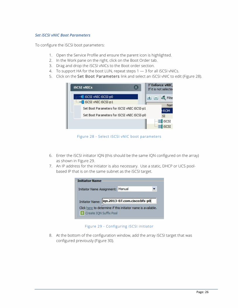
1. Open the Service Profile and ensure the parent icon is highlighted. 2. In the Work pane on the right, click on the Boot Order tab. 3. Drag and drop the iSCSI vNICs to the Boot order section. 4. To support HA for the boot LUN, repeat steps 1 — 3 for all iSCSI vNICs. 5. Click on the Set Boot Parameters link and select an iSCSI vNIC to edit (Figure 28).
Figure 28 - Select iSCSI vNIC boot parameters
6. Enter the iSCSI initiator IQN (this should be the same IQN configured on the array) as shown in Figure 29.
7. An IP address for the initiator is also necessary. Use a static, DHCP or UCS pool-based IP that is on the same subnet as the iSCSI target.
Figure 29 - Configuring iSCSI init iator
8. At the bottom of the configuration window, add the array iSCSI target that was configured previously (Figure 30).
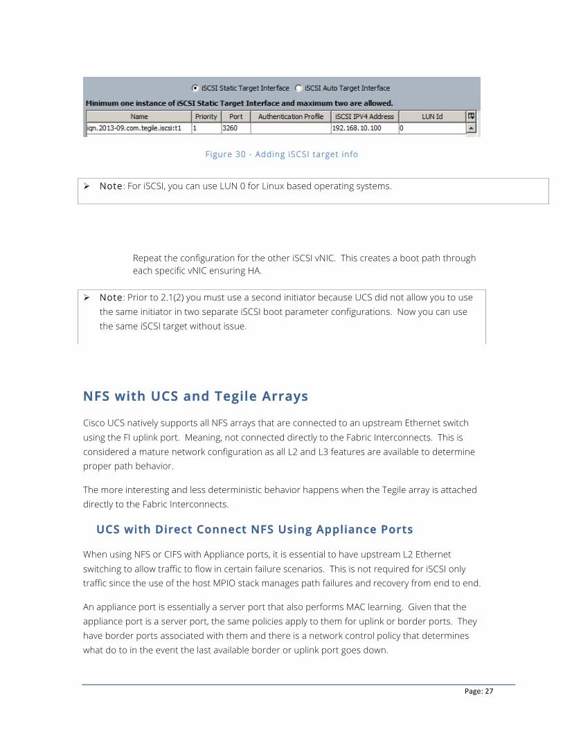
Page: 27
Figure 30 - Adding iSCSI target info
Repeat the configuration for the other iSCSI vNIC. This creates a boot path through each specific vNIC ensuring HA.
NFS with UCS and Tegile Arrays
Cisco UCS natively supports all NFS arrays that are connected to an upstream Ethernet switch using the FI uplink port. Meaning, not connected directly to the Fabric Interconnects. This is considered a mature network configuration as all L2 and L3 features are available to determine proper path behavior.
The more interesting and less deterministic behavior happens when the Tegile array is attached directly to the Fabric Interconnects.
UCS with Direct Connect NFS Using Appliance Ports
When using NFS or CIFS with Appliance ports, it is essential to have upstream L2 Ethernet switching to allow traffic to flow in certain failure scenarios. This is not required for iSCSI only traffic since the use of the host MPIO stack manages path failures and recovery from end to end.
An appliance port is essentially a server port that also performs MAC learning. Given that the appliance port is a server port, the same policies apply to them for uplink or border ports. They have border ports associated with them and there is a network control policy that determines what do to in the event the last available border or uplink port goes down.
Ø Note: For iSCSI, you can use LUN 0 for Linux based operating systems.
Ø Note: Prior to 2.1(2) you must use a second initiator because UCS did not allow you to use the same initiator in two separate iSCSI boot parameter configurations. Now you can use the same iSCSI target without issue.
Page: 28
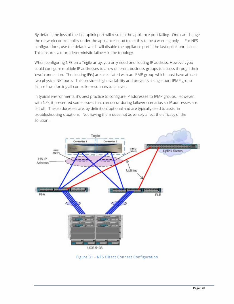
By default, the loss of the last uplink port will result in the appliance port failing. One can change the network control policy under the appliance cloud to set this to be a warning only. For NFS configurations, use the default which will disable the appliance port if the last uplink port is lost. This ensures a more deterministic failover in the topology.
When configuring NFS on a Tegile array, you only need one floating IP address. However, you could configure multiple IP addresses to allow different business groups to access through their ‘own’ connection. The floating IP(s) are associated with an IPMP group which must have at least two physical NIC ports. This provides high availability and prevents a single port IPMP group failure from forcing all controller resources to failover.
In typical environments, it’s best practice to configure IP addresses to IPMP groups. However, with NFS, it presented some issues that can occur during failover scenarios so IP addresses are left off. These addresses are, by definition, optional and are typically used to assist in troubleshooting situations. Not having them does not adversely affect the efficacy of the solution.
Figure 31 - NFS Direct Connect Configuration
Page: 29
Failure Scenarios to Consider
The primary reason why Tegile requires L2 upstream switches is that the failures between Tegile and UCS are not coordinated. The technologies are unaware of each other’s failure detection logic and subsequent processing. Therefore, in situations where Tegile sees a failure but UCS does not, or visa-versa, you can have black hole traffic if you do not have the upstream L2 switches. For cases where both UCS and Tegile see “hard link down” there is no problem and traffic can failover.
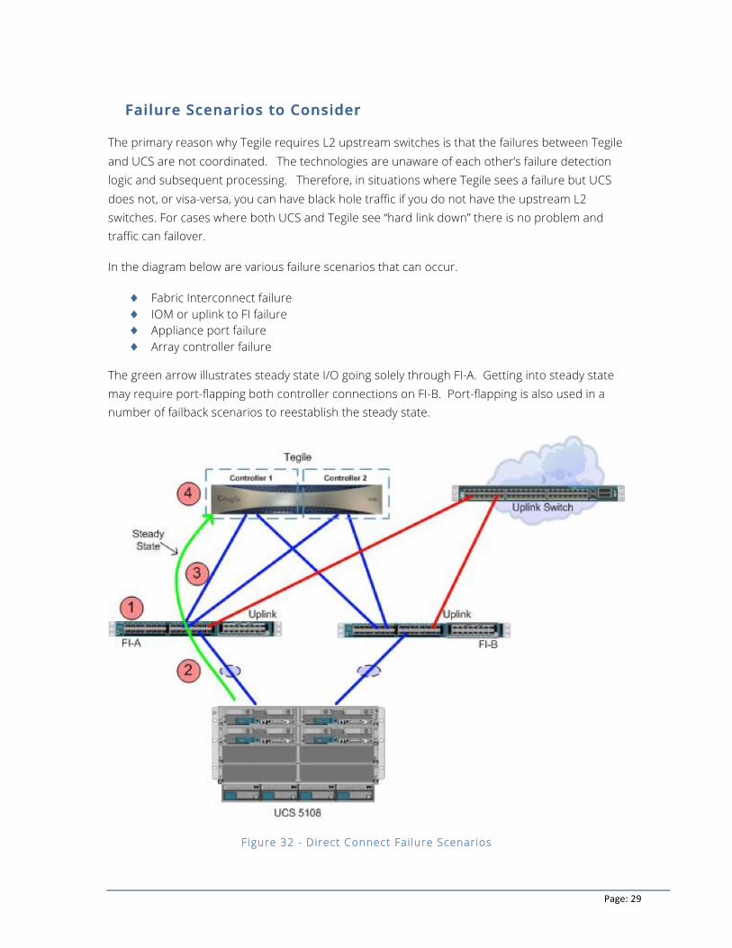
In the diagram below are various failure scenarios that can occur.
♦ Fabric Interconnect failure ♦ IOM or uplink to FI failure ♦ Appliance port failure ♦ Array controller failure
The green arrow illustrates steady state I/O going solely through FI-A. Getting into steady state may require port-flapping both controller connections on FI-B. Port-flapping is also used in a number of failback scenarios to reestablish the steady state.
Figure 32 - Direct Connect Fai lure Scenarios
Page: 30
Fabric Interconnect failure
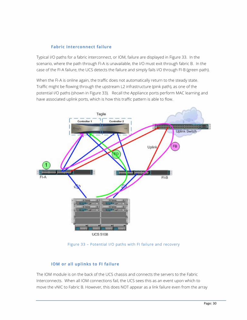
Typical I/O paths for a fabric interconnect, or IOM, failure are displayed in Figure 33. In the scenario, where the path through FI-A is unavailable, the I/O must exit through fabric B. In the case of the FI-A failure, the UCS detects the failure and simply fails I/O through FI-B (green path).
When the FI-A is online again, the traffic does not automatically return to the steady state. Traffic might be flowing through the upstream L2 infrastructure (pink path), as one of the potential I/O paths (shown in Figure 33). Recall the Appliance ports perform MAC learning and have associated uplink ports, which is how this traffic pattern is able to flow.
Figure 33 – Potential I/O paths with FI fai lure and recovery
IOM or all uplinks to FI failure
The IOM module is on the back of the UCS chassis and connects the servers to the Fabric Interconnects. When all IOM connections fail, the UCS sees this as an event upon which to move the vNIC to Fabric B. However, this does NOT appear as a link failure even from the array
Page: 31
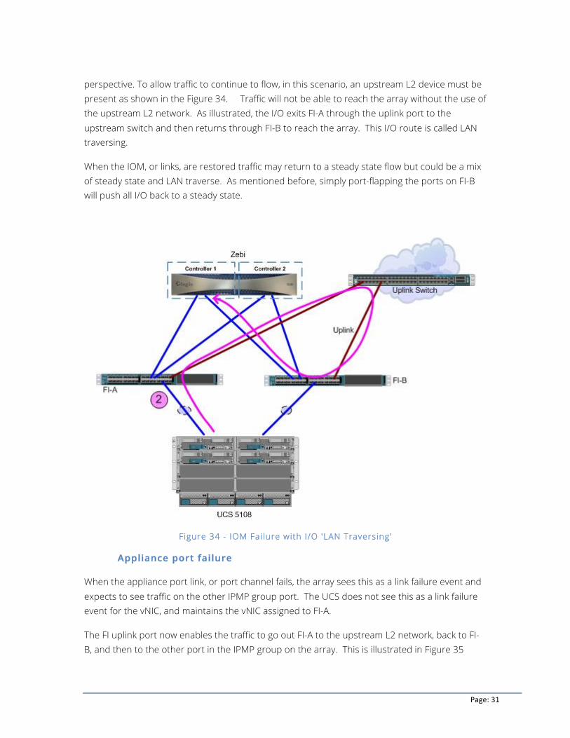
perspective. To allow traffic to continue to flow, in this scenario, an upstream L2 device must be present as shown in the Figure 34. Traffic will not be able to reach the array without the use of the upstream L2 network. As illustrated, the I/O exits FI-A through the uplink port to the upstream switch and then returns through FI-B to reach the array. This I/O route is called LAN traversing.
When the IOM, or links, are restored traffic may return to a steady state flow but could be a mix of steady state and LAN traverse. As mentioned before, simply port-flapping the ports on FI-B will push all I/O back to a steady state.
Figure 34 - IOM Failure with I/O 'LAN Traversing'
Appliance port failure
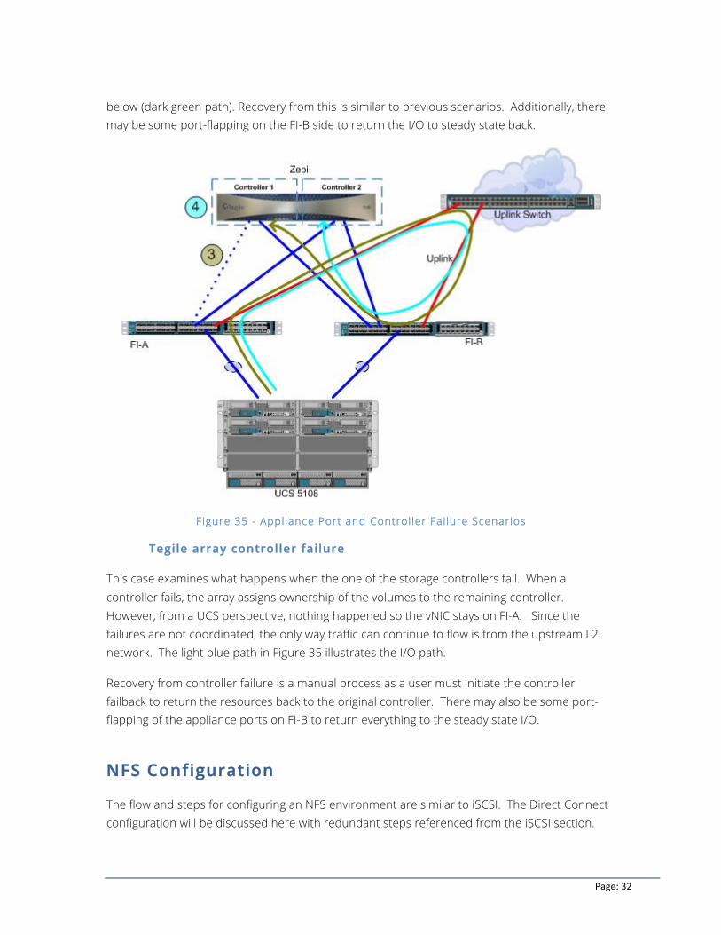
When the appliance port link, or port channel fails, the array sees this as a link failure event and expects to see traffic on the other IPMP group port. The UCS does not see this as a link failure event for the vNIC, and maintains the vNIC assigned to FI-A.
The FI uplink port now enables the traffic to go out FI-A to the upstream L2 network, back to FI-B, and then to the other port in the IPMP group on the array. This is illustrated in Figure 35
Page: 32
below (dark green path). Recovery from this is similar to previous scenarios. Additionally, there may be some port-flapping on the FI-B side to return the I/O to steady state back.
Figure 35 - Appliance Port and Controller Fai lure Scenarios
Tegile array controller failure
This case examines what happens when the one of the storage controllers fail. When a controller fails, the array assigns ownership of the volumes to the remaining controller. However, from a UCS perspective, nothing happened so the vNIC stays on FI-A. Since the failures are not coordinated, the only way traffic can continue to flow is from the upstream L2 network. The light blue path in Figure 35 illustrates the I/O path.
Recovery from controller failure is a manual process as a user must initiate the controller failback to return the resources back to the original controller. There may also be some port-flapping of the appliance ports on FI-B to return everything to the steady state I/O.
NFS Configuration
The flow and steps for configuring an NFS environment are similar to iSCSI. The Direct Connect configuration will be discussed here with redundant steps referenced from the iSCSI section.
Page: 33
Direct Connect
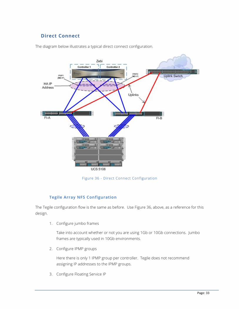
The diagram below illustrates a typical direct connect configuration.
Figure 36 - Direct Connect Configuration
Tegile Array NFS Configuration
The Tegile configuration flow is the same as before. Use Figure 36, above, as a reference for this design.
1. Configure jumbo frames
Take into account whether or not you are using 1Gb or 10Gb connections. Jumbo frames are typically used in 10Gb environments.
2. Configure IPMP groups
Here there is only 1 IPMP group per controller. Tegile does not recommend assigning IP addresses to the IPMP groups.
3. Configure Floating Service IP
Page: 34
Assign a floating IP to the IPMP groups. You can assign multiple floating IPs – for example, to give specific access to a particular group.
There is no mapping for NFS so you only need to create a share in the Tegile project. This is a simple process and is not discussed in this document. For more information, see the Tegile User Guide.
UCS NFS Configuration
As there were many similarities between iSCSI and NFS configuration with the array, so to with the UCS profiles. One of major differences is that there is no overlay iSCSI vNIC.
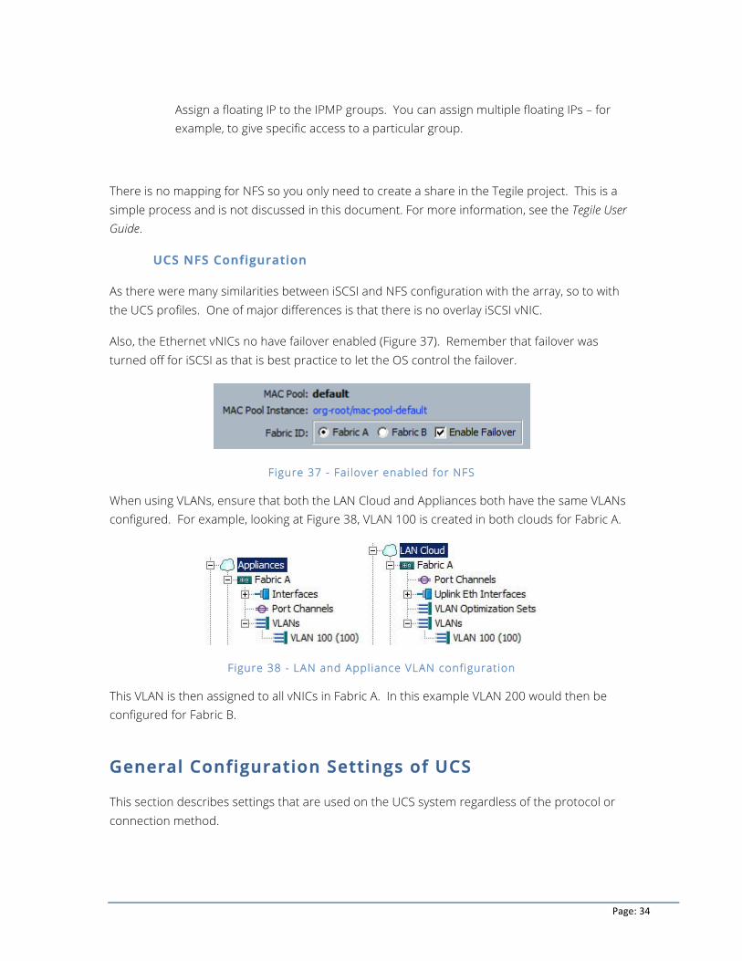
Also, the Ethernet vNICs no have failover enabled (Figure 37). Remember that failover was turned off for iSCSI as that is best practice to let the OS control the failover.
Figure 37 - Fai lover enabled for NFS
When using VLANs, ensure that both the LAN Cloud and Appliances both have the same VLANs configured. For example, looking at Figure 38, VLAN 100 is created in both clouds for Fabric A.
Figure 38 - LAN and Appliance VLAN configuration
This VLAN is then assigned to all vNICs in Fabric A. In this example VLAN 200 would then be configured for Fabric B.
General Configuration Settings of UCS
This section describes settings that are used on the UCS system regardless of the protocol or connection method.
Page: 35
Configure UCS Port-Channel
There are two levels of port-channels to consider. The Chassis to Fabric Interconnect and the Fabric Interconnect to the Switch or Tegile array (for direct connect).
Chassis to FI Port-Channel
A port-channel creates a combined pipe for increased bandwidth and redundancy on the IOM module to FI connections. You can set port-channels on a global, or per chassis basis, and it provides a balanced I/O load on the back plane and allows for easier usability from the management perspective.
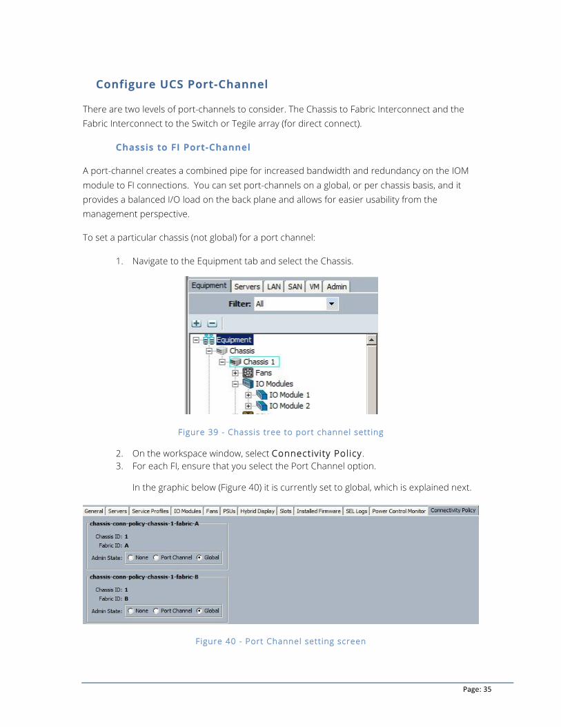
To set a particular chassis (not global) for a port channel:
1. Navigate to the Equipment tab and select the Chassis.
Figure 39 - Chassis tree to port channel setting
2. On the workspace window, select Connectivity Policy. 3. For each FI, ensure that you select the Port Channel option.
In the graphic below (Figure 40) it is currently set to global, which is explained next.
Figure 40 - Port Channel sett ing screen
Page: 36
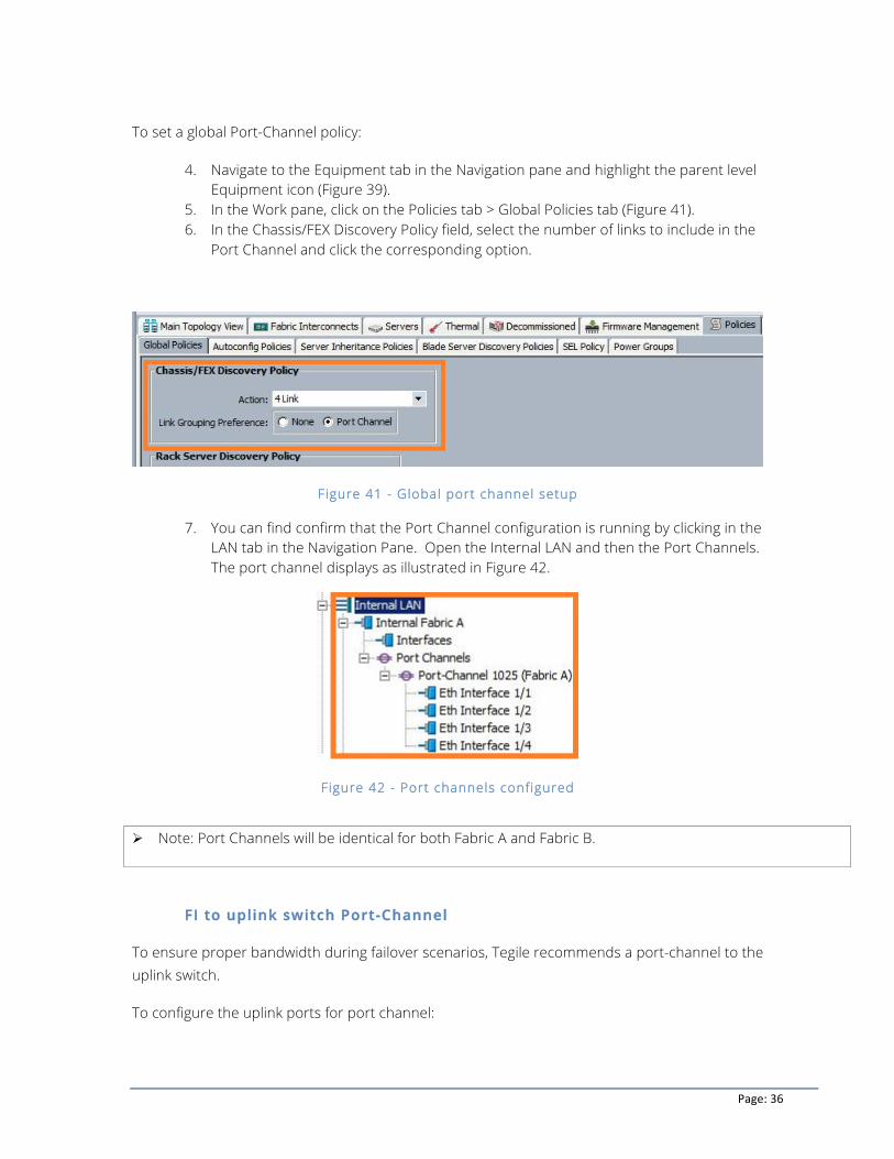
To set a global Port-Channel policy:
4. Navigate to the Equipment tab in the Navigation pane and highlight the parent level Equipment icon (Figure 39).
5. In the Work pane, click on the Policies tab > Global Policies tab (Figure 41). 6. In the Chassis/FEX Discovery Policy field, select the number of links to include in the
Port Channel and click the corresponding option.
Figure 41 - Global port channel setup
7. You can find confirm that the Port Channel configuration is running by clicking in the LAN tab in the Navigation Pane. Open the Internal LAN and then the Port Channels. The port channel displays as illustrated in Figure 42.
Figure 42 - Port channels configured
FI to uplink switch Port-Channel
To ensure proper bandwidth during failover scenarios, Tegile recommends a port-channel to the uplink switch.
To configure the uplink ports for port channel:
Ø Note: Port Channels will be identical for both Fabric A and Fabric B.
Page: 37
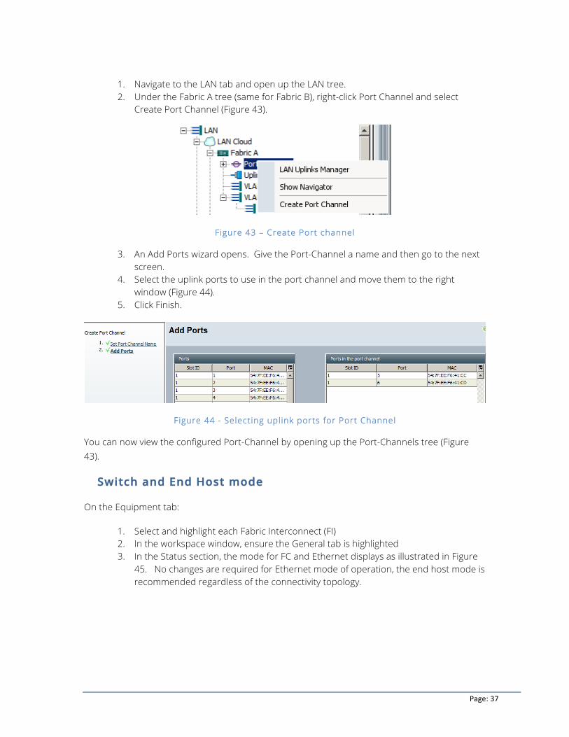
1. Navigate to the LAN tab and open up the LAN tree. 2. Under the Fabric A tree (same for Fabric B), right-click Port Channel and select
Create Port Channel (Figure 43).
Figure 43 – Create Port channel
3. An Add Ports wizard opens. Give the Port-Channel a name and then go to the next screen.
4. Select the uplink ports to use in the port channel and move them to the right window (Figure 44).
5. Click Finish.
Figure 44 - Selecting uplink ports for Port Channel
You can now view the configured Port-Channel by opening up the Port-Channels tree (Figure 43).
Switch and End Host mode
On the Equipment tab:
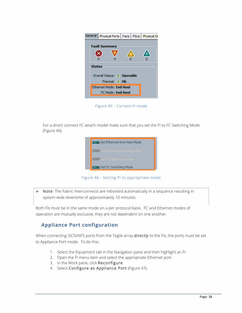
1. Select and highlight each Fabric Interconnect (FI) 2. In the workspace window, ensure the General tab is highlighted 3. In the Status section, the mode for FC and Ethernet displays as illustrated in Figure
45. No changes are required for Ethernet mode of operation, the end host mode is recommended regardless of the connectivity topology.
Page: 38
Figure 45 - Current FI mode
For a direct connect FC attach model make sure that you set the FI to FC Switching Mode (Figure 46).
Figure 46 - Setting FI to appropriate mode
Both FIs must be in the same mode on a per protocol basis. FC and Ethernet modes of operation are mutually exclusive, they are not dependent on one another.
Appliance Port configuration
When connecting iSCSI/NFS ports from the Tegile array directly to the FIs, the ports must be set to Appliance Port mode. To do this:
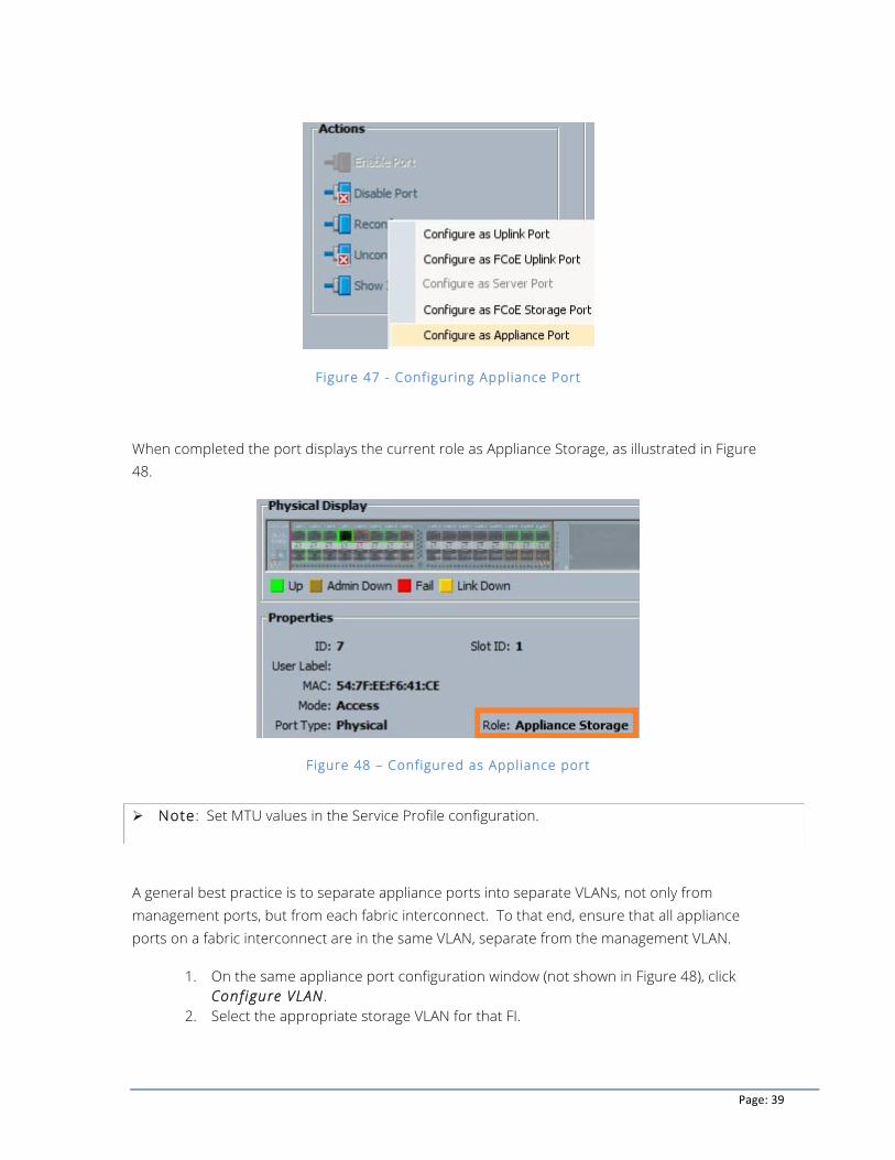
1. Select the Equipment tab in the Navigation pane and then highlight an FI. 2. Open the FI menu item and select the appropriate Ethernet port. 3. In the Work pane, click Reconfigure 4. Select Configure as Appliance Port (Figure 47).
Ø Note: The Fabric Interconnects are rebooted automatically in a sequence resulting in system wide downtime of approximately 10 minutes.
Page: 39
Figure 47 - Configuring Appliance Port
When completed the port displays the current role as Appliance Storage, as illustrated in Figure 48.
Figure 48 – Configured as Appliance port
A general best practice is to separate appliance ports into separate VLANs, not only from management ports, but from each fabric interconnect. To that end, ensure that all appliance ports on a fabric interconnect are in the same VLAN, separate from the management VLAN.
1. On the same appliance port configuration window (not shown in Figure 48), click Configure VLAN .
2. Select the appropriate storage VLAN for that FI.
Ø Note: Set MTU values in the Service Profile configuration.
Page: 40
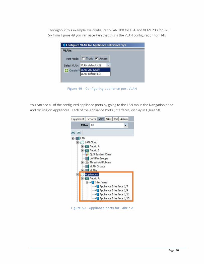
Throughout this example, we configured VLAN 100 for FI-A and VLAN 200 for FI-B. So from Figure 49 you can ascertain that this is the VLAN configuration for FI-B.
Figure 49 - Configuring appliance port VLAN
You can see all of the configured appliance ports by going to the LAN tab in the Navigation pane and clicking on Appliances. Each of the Appliance Ports (Interfaces) display in Figure 50.
Figure 50 - Appliance ports for Fabric A
Page: 41
OS Images and drivers
When installing an operating system, there are two drivers that you must install. They must be the correct supported version. The drivers are the enic (Network) and fnic (FC) drivers. There are a few methods for installing the proper drivers.
You can either obtain the Cisco image of the OS which contains the proper drivers, or you can download the drivers and install them manually after the OS installation. Either method works. Visit the Cisco website to find the appropriate images and drivers.
Conclusion
There are a wide variety of methods for connecting external storage to the UCS system. The long standing industry best practices for FC, iSCSI and NFS/CIFS apply with no changes for UCS unless you wish to deploy a “direct connect” topology with UCS and the storage. Using both Tegile and UCS in a combined best practices manner results in a reliable, flexible and scalable compute and storage solution.
References
Cisco UCS Manager GUI Configuration Guides http://www.cisco.com/en/US/products/ps10281/products_configuration_example09186a0080bfcb0a.shtml
http://www.cisco.com/c/en/us/support/docs/servers-unified-computing/ucs-infrastructure-ucs-manager-software/116082-config-ucs-das-00.html
Cisco UCS B-series OS Instal lat ion Guides http://www.cisco.com/en/US/products/ps10280/products_installation_and_configuration_guides_list.html
Cisco server HCL
The following documents cover operating system versions, blade models, adapter models and the necessary Ethernet and FC driver versions for these combinations.
http://www.cisco.com/en/US/products/ps10477/prod_technical_reference_list.html