Embed Size (px)
Citation preview
Tekelec EAGLE® 5
Release 42.0
Feature Manual - ATINP910-5904-001 Revision A
September 2010
Copyright 2010 Tekelec. All Rights Reserved. Printed in USA.Legal Information can be accessed from the Main Menu of the optical disc or on the
Tekelec Customer Support web site in the Legal Information folder of the Product Support tab.

Table of Contents
Chapter 1: Introduction.......................................................................7Introduction...............................................................................................................................8Scope and Audience.................................................................................................................8Manual Organization................................................................................................................9Related Publications.................................................................................................................9Documentation Availability, Packaging, and Updates.......................................................9Documentation Admonishments..........................................................................................10Customer Care Center............................................................................................................10Emergency Response..............................................................................................................13Locate Product Documentation on the Customer Support Site.......................................13
Chapter 2: Feature Description........................................................14ATINP Feature Overview......................................................................................................15The ATINPQ Local Subsystem..............................................................................................15ATINP Configuration Options..............................................................................................17ATINP Protocol Handling of MSUs.....................................................................................26ATINP Return Result Message.............................................................................................27ATINP Error Response MSU Encoding...............................................................................31Hardware Requirements........................................................................................................32MPS/EPAP Platform..............................................................................................................32
EPAP/PDBA Overview.............................................................................................34Subscriber Data Provisioning....................................................................................35EPAP (EAGLE Provisioning Application Processor)............................................37Service Module Cards................................................................................................38Network Connections.................................................................................................41
Chapter 3: EAGLE 5 ISS ATINP Commands................................46EAGLE 5 ISS Commands.......................................................................................................47Maintenance Commands.......................................................................................................48
rept-stat-sccp................................................................................................................50EAGLE 5 ISS Debug Commands..........................................................................................50
Chapter 4: ATINP Configuration....................................................51Introduction.............................................................................................................................52
ii910-5904-001 Revision A, September 2010
EPAP Entity Provisioning..........................................................................................52System Prerequisites...................................................................................................52ATINP Feature Prerequisites.....................................................................................53
ATINP Configuration Procedure..........................................................................................54Adding a Service Module Card............................................................................................55Enabling ATINP, Setting STP Options, and Turning On ATINP....................................59Enabling the Service Portability Feature.............................................................................60Provisioning True Point Codes and Capability Point Codes...........................................61Provisioning the ATINPQ Local Subsystem.......................................................................63
Adding the ATINPQ Local Subsystem Application..............................................63Removing a Local Subsystem Application..............................................................64
Provisioning the ATINP Service Selector............................................................................65Adding an ATINP Service Selector..........................................................................65Removing a Service Selector......................................................................................66Changing an Existing Service Selector to an ATINP Service Selector.................68
Provisioning the ATINP Options..........................................................................................70Activating the ATINPQ Local Subsystem...........................................................................71Turning On the Service Portability Feature........................................................................72Turning Off the Service Portability Feature........................................................................73Changing the State of a Subsystem Application................................................................74
Taking the Subsystem Application Offline.............................................................75Taking the Subsystem Application Online..............................................................76
The 1100 TPS/DSM for ITU NP Feature.............................................................................76Enable the 1100 TPS/DSM for ITU NP Feature......................................................79Turn On the 1100 TPS/DSM for ITU NP Feature..................................................79Turn Off the 1100 TPS/DSM for ITU NP Feature..................................................80
Activating the E5-SM4G Throughput Capacity Feature...................................................81
Chapter 5: ATINP Measurements...................................................84ATINP Measurements............................................................................................................85
Chapter 6: Maintenance.....................................................................87ATINPQ Subsystem Alarms (UAMs)..................................................................................88ATINPQ Subsystem UIMs.....................................................................................................88EPAP Status and Alarms........................................................................................................90
DSM Status Requests..................................................................................................90EPAP System Status Reports.................................................................................................91Code and Application Data Loading...................................................................................92
DSM Code Loading.....................................................................................................92EPAP Application Data Loading..............................................................................92
iii910-5904-001 Revision A, September 2010

Glossary....................................................................................................................95
iv910-5904-001 Revision A, September 2010
List of FiguresFigure 1: MPS/EPAP Platform Architecture..................................................................................32Figure 2: Subscriber Data Provisioning Architecture (High Level).............................................35Figure 3: Database Administrative Architecture............................................................................37Figure 4: Customer Provisioning Network.....................................................................................42Figure 5: EPAP Sync Network..........................................................................................................43Figure 6: DSM Networks....................................................................................................................43Figure 7: Dial-Up PPP Network........................................................................................................45Figure 8: Obit Message for Abort of Card Loading.......................................................................94
v910-5904-001 Revision A, September 2010
List of TablesTable 1: Admonishments...................................................................................................................10Table 2: ATINP Options.....................................................................................................................17Table 3: RTDB Lookup Success Determination..............................................................................27Table 4: Encoded Number Portability Status value.......................................................................30Table 5: Service Module Card Provisioning and Reload Settings................................................40Table 6: EPAP IP Addresses in the DSM Network........................................................................44Table 7: Commands used for ATINP...............................................................................................47Table 8: Maintenance Commands.....................................................................................................49Table 9: System Prerequisites............................................................................................................52Table 10: ATINP Feature Prerequisite..............................................................................................53Table 11: Service Module Card Locations.......................................................................................56Table 12: System Prerequisites for Adding a Service Module Card............................................56Table 13: Prerequisite for Adding an E5-SM4G Service Module Card.......................................57Table 14: ATINPQ Local Subsystem Prerequisites........................................................................63Table 15: Subsystem Allow/Inhibit..................................................................................................72Table 16: System Prerequisites..........................................................................................................77Table 17: Feature Prerequisites..........................................................................................................78Table 18: Maximum E5-SM4G Card and System TPS Capacity...................................................81Table 19: System Prerequisites..........................................................................................................82Table 20: E5-SM4G Throughput Capacity Feature Prerequisite..................................................82Table 21: Pegs for Per System and Per SSP......................................................................................85Table 22: ATINPQ UAMs..................................................................................................................88Table 23: ATINPQ UIMs....................................................................................................................89
vi910-5904-001 Revision A, September 2010
Chapter
1Introduction
This chapter contains a brief description of theATINP feature. The contents include sections about
Topics:
• Introduction.....8 the manual scope, audience, and organization; how• Scope and Audience.....8 to find related publications; and how to contact
Tekelec for assistance.• Manual Organization.....9• Related Publications.....9• Documentation Availability, Packaging, and
Updates.....9• Documentation Admonishments.....10• Customer Care Center.....10• Emergency Response.....13• Locate Product Documentation on the Customer
Support Site.....13
7910-5904-001 Revision A, September 2010
Introduction
Before number portability, SCPs and other querying nodes could easily determine which network thesubscriber belonged to based on the digits dialed by the caller. With number portability, subscriberdigits cannot be relied upon to determine the subscriber's network.
Anytime Interrogation Number Portability Query (ATINP) is an EAGLE 5 ISS feature that providesa method for querying entities to obtain number portability and routing information for subscribersdirectly from an EAGLE 5 ISS.
ATINP provides number portability functions for decoding the information in the incoming ATI querymessage, number conditioning before the RTDB lookup, determining the success or failure of theRTDB lookup, and formatting the Return Result or Error Response based on the result of the lookup.ATINP is fully compliant with the ATI standards for Global Number Portability in 3GPP TS 23.066V7.0.0 (2007-06), Support of Mobile Number Portability.
ATINP supports the use of Additional Subscriber Data (ASD) in formatting response messages.
ATINP supports Service Portability functions that allow a subscriber to keep the same phone numberwhen switching from one type of network or service technology to another within the same operator’snetwork. With Service Portability, the subscriber remains with the same operator, but receives servicefrom a different network technology supported by that operator or moves from one physical networkto another, with both networks operated by the same service provider. The Service Portability (S-Port)feature allows RTDB GRN Entity digits to be used as Service Portability prefixes for own-networkGSM and IS41 subscribers in response digit formats.
ATINP supports functions to cluster CNLs into groups referred to as ROPs, which can be used tosimplify routing and simple billing analysis in cases where the number of supported CNLs is verylarge. The Generic Routing Number field is used to store ROP information.
The ATINPQ local subsystem in the EAGLE 5 ISS processes ITU-TCAP ATI messages with the requestedinformation parameter "MNP Requested Info". The EAGLE 5 ISS responds with an ATI ACK messagethat contains number portability and routing information, or with an ATI NACK message if therequested information cannot be provided. The original ATI query is discarded.
ATINP is an EPAP-based feature that requires EPAP provisioning data from the Real Time Database(RTDB). Subscriber data is transferred from customer databases to the EPAP. The EPAP formats theRTDB and loads it to each Service Module card on the EAGLE 5 ISS. The RTDB data is used in obtainingnumber portability information and in determining how to correctly format the ATI ACK responsemessage. See MPS/EPAP Platform for more information about EPAP.
Scope and Audience
This manual is intended for anyone responsible for installing, maintaining, and using the ATINPfeature in the EAGLE 5 ISS. Users of this manual and the others in the EAGLE 5 ISS family of documentsmust have a working knowledge of telecommunications and network installations.
8910-5904-001 Revision A, September 2010
IntroductionFeature Manual - ATINP
Manual Organization
This document is organized into the following chapters:
• Introduction contains general information about the ATINP documentation, the organization of thismanual, and how to get technical assistance.
• Feature Description provides a functional description of the ATINP feature, including networkperspectives, assumptions and limitations, a database overview, Service Module provisioning andreloading, ATINP user interface, and an audit overview.
• EAGLE 5 ISS ATINP Commands describes the commands that can be used for ATINP featureconfiguration and maintenance functions.
• ATINP Configuration provides procedures for configuring the ATINP feature for use in the EAGLE5 ISS.
• ATINP Measurements describes ATINP-related measurements, measurements reports, and methodsof collection.
• Maintenance describes ATINP-related UAMs and UIMs, EPAP status and alarm reporting, DSMstatus reporting to the EPAP, system hardware verification, system status reporting, and code andapplication data loading.
Related Publications
For information about additional publications that are related to this document, refer to the RelatedPublications document. The Related Publications document is published as a part of the ReleaseDocumentation and is also published as a separate document on the Tekelec Customer Support Site.
Documentation Availability, Packaging, and Updates
Tekelec provides documentation with each system and in accordance with contractual agreements.For General Availability (GA) releases, Tekelec publishes a complete EAGLE 5 ISS documentation set.For Limited Availability (LA) releases, Tekelec may publish a documentation subset tailored to specificfeature content or hardware requirements. Documentation Bulletins announce a new or updatedrelease.
The Tekelec EAGLE 5 ISS documentation set is released on an optical disc. This format allows for easysearches through all parts of the documentation set.
The electronic file of each manual is also available from the Tekelec Customer Support site. This siteallows for 24-hour access to the most up-to-date documentation, including the latest versions of FeatureNotices.
Printed documentation is available for GA releases on request only and with a lead time of six weeks.The printed documentation set includes pocket guides for commands and alarms. Pocket guides mayalso be ordered separately. Exceptions to printed documentation are:
9910-5904-001 Revision A, September 2010
IntroductionFeature Manual - ATINP
• Hardware or Installation manuals are printed without the linked attachments found in the electronicversion of the manuals.
• The Release Notice is available only on the Customer Support site.
Note: Customers may print a reasonable number of each manual for their own use.
Documentation is updated when significant changes are made that affect system operation. Updatesresulting from Severity 1 and 2 Problem Reports (PRs) are made to existing manuals. Other changesare included in the documentation for the next scheduled release. Updates are made by re-issuing anelectronic file to the customer support site. Customers with printed documentation should contacttheir Sales Representative for an addendum. Occasionally, changes are communicated first with aDocumentation Bulletin to provide customers with an advanced notice of the issue until officiallyreleased in the documentation. Documentation Bulletins are posted on the Customer Support site andcan be viewed per product and release.
Documentation Admonishments
Admonishments are icons and text throughout this manual that alert the reader to assure personalsafety, to minimize possible service interruptions, and to warn of the potential for equipment damage.
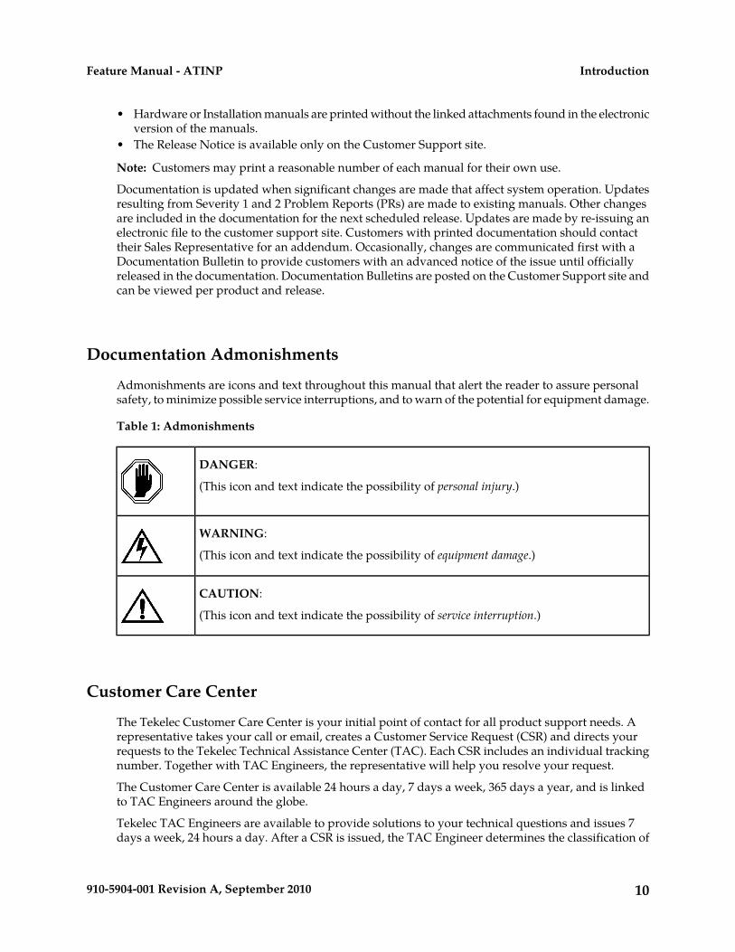
Table 1: Admonishments
DANGER:
(This icon and text indicate the possibility of personal injury.)
WARNING:
(This icon and text indicate the possibility of equipment damage.)
CAUTION:
(This icon and text indicate the possibility of service interruption.)
Customer Care Center
The Tekelec Customer Care Center is your initial point of contact for all product support needs. Arepresentative takes your call or email, creates a Customer Service Request (CSR) and directs yourrequests to the Tekelec Technical Assistance Center (TAC). Each CSR includes an individual trackingnumber. Together with TAC Engineers, the representative will help you resolve your request.
The Customer Care Center is available 24 hours a day, 7 days a week, 365 days a year, and is linkedto TAC Engineers around the globe.
Tekelec TAC Engineers are available to provide solutions to your technical questions and issues 7days a week, 24 hours a day. After a CSR is issued, the TAC Engineer determines the classification of
10910-5904-001 Revision A, September 2010
IntroductionFeature Manual - ATINP

the trouble. If a critical problem exists, emergency procedures are initiated. If the problem is not critical,normal support procedures apply. A primary Technical Engineer is assigned to work on the CSR andprovide a solution to the problem. The CSR is closed when the problem is resolved.
Tekelec Technical Assistance Centers are located around the globe in the following locations:
Tekelec - Global
Email (All Regions): [email protected]
• USA and Canada
Phone:
1-888-FOR-TKLC or 1-888-367-8552 (toll-free, within continental USA and Canada)
1-919-460-2150 (outside continental USA and Canada)
TAC Regional Support Office Hours:
8:00 a.m. through 5:00 p.m. (GMT minus 5 hours), Monday through Friday, excluding holidays• Central and Latin America (CALA)
Phone:
USA access code +1-800-658-5454, then 1-888-FOR-TKLC or 1-888-367-8552 (toll-free)
TAC Regional Support Office Hours (except Brazil):
10:00 a.m. through 7:00 p.m. (GMT minus 6 hours), Monday through Friday, excluding holidays
• Argentina
Phone:
0-800-555-5246 (toll-free)• Brazil
Phone:
0-800-891-4341 (toll-free)
TAC Regional Support Office Hours:
8:30 a.m. through 6:30 p.m. (GMT minus 3 hours), Monday through Friday, excluding holidays• Chile
Phone:
1230-020-555-5468• Colombia
Phone:
01-800-912-0537• Dominican Republic
Phone:
1-888-367-8552• Mexico
11910-5904-001 Revision A, September 2010
IntroductionFeature Manual - ATINP

Phone:
001-888-367-8552• Peru
Phone:
0800-53-087• Puerto Rico
Phone:
1-888-367-8552 (1-888-FOR-TKLC)• Venezuela
Phone:
0800-176-6497
• Europe, Middle East, and Africa
Regional Office Hours:
8:30 a.m. through 5:00 p.m. (GMT), Monday through Friday, excluding holidays
• Signaling
Phone:
+44 1784 467 804 (within UK)• Software Solutions
Phone:
+33 3 89 33 54 00
• Asia
• India
Phone:
+91 124 436 8552 or +91 124 436 8553
TAC Regional Support Office Hours:
10:00 a.m. through 7:00 p.m. (GMT plus 5 1/2 hours), Monday through Saturday, excludingholidays
• Singapore
Phone:
+65 6796 2288
TAC Regional Support Office Hours:
9:00 a.m. through 6:00 p.m. (GMT plus 8 hours), Monday through Friday, excluding holidays
12910-5904-001 Revision A, September 2010
IntroductionFeature Manual - ATINP

Emergency Response
In the event of a critical service situation, emergency response is offered by the Tekelec Customer CareCenter 24 hours a day, 7 days a week. The emergency response provides immediate coverage, automaticescalation, and other features to ensure that the critical situation is resolved as rapidly as possible.
A critical situation is defined as a problem with an EAGLE 5 ISS that severely affects service, traffic,or maintenance capabilities, and requires immediate corrective action. Critical problems affect serviceand/or system operation resulting in:
• A total system failure that results in loss of all transaction processing capability• Significant reduction in system capacity or traffic handling capability• Loss of the system’s ability to perform automatic system reconfiguration• Inability to restart a processor or the system• Corruption of system databases that requires service affecting corrective actions• Loss of access for maintenance or recovery operations• Loss of the system ability to provide any required critical or major trouble notification
Any other problem severely affecting service, capacity/traffic, billing, and maintenance capabilitiesmay be defined as critical by prior discussion and agreement with the Tekelec Customer Care Center.
Locate Product Documentation on the Customer Support Site
Access to Tekelec's Customer Support site is restricted to current Tekelec customers only. This sectiondescribes how to log into the Tekelec Customer Support site and locate a document. Viewing thedocument requires Adobe Acrobat Reader, which can be downloaded at www.adobe.com.
1. Log into the Tekelec Customer Support site.
Note: If you have not registered for this new site, click the Register Here link. Have your customernumber available. The response time for registration requests is 24 to 48 hours.
2. Click the Product Support tab.3. Use the Search field to locate a document by its part number, release number, document name, or
document type. The Search field accepts both full and partial entries.4. Click a subject folder to browse through a list of related files.5. To download a file to your location, right-click the file name and select Save Target As.
13910-5904-001 Revision A, September 2010
IntroductionFeature Manual - ATINP
Chapter
2Feature Description
This chapter describes the functions provided bythe ATINP feature, including MSU protocol
Topics:
• ATINP Feature Overview.....15 handling, ATI message decoding, and responsemessage formatting.• The ATINPQ Local Subsystem.....15
• ATINP Configuration Options.....17 The chapter includes an overview of the EAGLEProvisioning Application Processor (EPAP). EPAP• ATINP Protocol Handling of MSUs.....26provides the Realtime Database (RTDB) that is usedin the database lookup functions.
• ATINP Return Result Message.....27• ATINP Error Response MSU Encoding.....31• Hardware Requirements.....32• MPS/EPAP Platform.....32
14910-5904-001 Revision A, September 2010
ATINP Feature Overview
ATINP Functions
The ATINP feature provides number portability functions and Service Portability functions for decodingthe incoming ATI message, conditioning the MSISDN to International format if needed, performingthe RTDB lookup, and determining the result of the lookup.
ATINP configuration options affect the following functions and values:
• Number conditioning of the incoming MSISDN digits before RTDB lookup is performed• Determination of a successful RTDB lookup• Controlling whether the IMSI, MSISDN, and Routing Number parameters will be included or not
included in the ATI ACK response message.• Formatting of the IMSI, MSISDN, and Routing Number parameters in the ATI ACK response
message, and the maximum number of digits to be used from the SRFISMSI or entity ID in theencoding format.
• Default routing number and outbound message digits delimiter to be used in outbound messageformats
• Use of GRN digits as Routing Number digits in the ATI ACK response message for own-networksubscribers. (One example is using GRN digits for ROP information; EPAP 13.0 or later is required)
Response message handling functions determine whether a success or failure response is needed (orno response), format the information in the response message, send the response, and issue anyrequired UIMs and network management messages.
ATINP Considerations
The GTT feature must be on before the ATINP feature can be enabled.
The ATINP feature must be enabled before configuration options can be provisioned in theATINPQOPTS table for ATINP. The Service Portability feature must be also enabled before theATINPQOPTS SPORTTYPE configuration option can be provisioned to use Service Portability withATINP.
The ATINP feature and the Service Portability feature must be turned on before Service Portabilityprocessing will occur for ATI Query messages.
Note: The Service Portability feature, the IDP A-party Blacklist feature, and support for ROP data alluse GRN data for different purposes. The IDP A-party Blacklist feature is mutually exclusive with theService Portability feature; the restriction is enforced in feature provisioning. There is no enforcedrestriction for the Service Portability feature and ROP data support to be mutually exclusive. It isexpected that Support for ROP and Service Portability will be not be used in the same EAGLE 5 ISSsystem.
The ATINPQ Local Subsystem
Local subsystems in the EAGLE 5 ISS are maintainable entities for query and response that are usedwhen the STP acts as an SCP. Specific point codes can be defined for routing to local subsystems
15910-5904-001 Revision A, September 2010
Feature DescriptionFeature Manual - ATINP
independently of the STP in the network. A local subsystem can be taken online and offline as neededin the system.
The ATINPQ local subsystem in the EAGLE 5 ISS processes ITU-TCAP ATI messages with the requestedinformation parameter "MNP Requested Info". The EAGLE 5 ISS responds with an ATI ACK messagethat contains number portability and routing information, or with an ATI NACK message if therequested information cannot be provided. The original ATI query is discarded.
ATINP supports ANSI MTP/SCCP and ITU-TCAP ATI query or ITU MTP/SCCP and ITU-TCAP ATIquery.
For ATINP, EAGLE 5 ISS supports ANSI, ITU-I, ITU-N, ITU-I Spare, and ITU-N Spare capability pointcode types. ITU-N24 point codes are not supported. Capability point codes for the ATINPQ localsubsystem can be configured only after the ATINP feature is enabled.
The ATINPQ local subsystem can have a mate subsystem and a concerned point code group assignedto it. The ATINPQ local subsystem cannot be set to Load Shared mode (as end nodes do not performload sharing), but can be set only to Dominant or Solitary mode. The ATINPQ local subsystem can beentered in MAP table if the ATINP feature is enabled.
The ATINPQ local subsystem can be taken online and offline using the procedures in Changing theState of a Subsystem Application.
Messages for the ATINPQ Local Subsystem
Messages for the ATINPQ local subsystem can arrive Rt-on-SSN or Rt-on-GT. All MSUs must containeither the EAGLE 5 ISS true or secondary point code (TSPC), or the ATINPQ capability point code(CPC) in the DPC field of the message. Traditionally, messages for local subsystems were allowed tohave the DPC as the EAGLE 5 ISS STP CPC. However, it is strongly recommended to use the ATINPQCPC for ATI queries, and not the CPC of the STP for network management issues that can arise.
Rt-on-SSN Handling
If the message arrives Rt-on-SSN, it must contain the EAGLE 5 ISS ATINPQ subsystem number in theCalled Party Subsystem field of the message.
If the ATINPQ local subsystem is online, the DPC field can contain either the EAGLE 5 ISS true orsecondary point code or the ATINPQ capability point code. Any response message will use the trueor secondary point code assigned to the EAGLE 5 ISS as the OPC. Because the EAGLE 5 ISS cannotgenerate an SSP when a message arrives Rt-on-SSN for the EAGLE 5 ISS CPC, nodes sending Rt-on-SSNtraffic should use the true or secondary point code.
If the ATINPQ local subsystem is offline and the mated subsystem is available, the EAGLE 5 ISS willgenerate a network management message to force the network to transition traffic to the mate.
Rt-on-GT Handling
Rt-on-GT MSUs can arrive either with SCCP CdPA information that matches an EAGLE 5 ISS serviceselector, or with a GTA address that has been provisioned to translate to the ATINPQ local subsystem.
If the ATINPQ subsystem is online, the DPC field can contain either the EAGLE 5 ISS true or secondarypoint code or the ATINPQ capability point code. The query is directed to the local subsystem andprocessed. Any response message will use the true or secondary point code assigned to the EAGLE5 ISS as the OPC.
If the ATINPQ local subsystem is offline and the mated subsystem is available, the EAGLE 5 ISS willact as both STP and SCP, and reroute the message to the mated subsystem. If a Rt-on-GT messagearrives for the EAGLE 5 ISS true or secondary point code, the EAGLE 5 ISS cannot generate a TFP.
16910-5904-001 Revision A, September 2010
Feature DescriptionFeature Manual - ATINP
The EAGLE 5 ISS handles and reroutes these messages, instead of forcing the adjacent node to routeto the mate. Therefore, nodes that send Rt-on-GT traffic to an EAGLE 5 ISS should use anf ATINPQCPC, not the EAGLE 5 ISS TSPC.
Network Management Responses
The EAGLE 5 ISS must reply to network management queries about the current state of the localsubsystem. When the local subsystem changes state, network management messages are sent to theCSPC group.
Multiple Local Subsystems
The EAGLE 5 ISS supports provisioning Capability Point Codes for two or more local subsystems,allowing local subsystems for two or more EPAP-based features to operate at the same time in thesystem. For example, local subsystems for the ATINP feature and the EIR feature can coexist in thesystem.
Though queries meant for any local system will still be processed if they are sent with DPC = STPCPC, it is strongly recommended not to use the STP CPC for such queries. Instead, the CPC for theappropriate subsystem should be used as the DPC of the message. For instance, for LNP queries usethe LNP CPC, not the STP CPC. For ATI queries, use the ATINPQ CPC, and so on.
ATINP Configuration Options
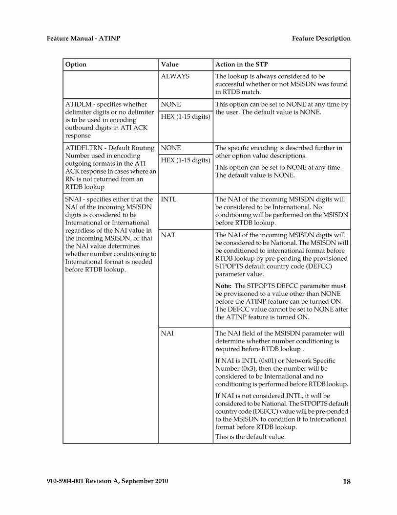
The ATINP configuration options described in Table 2: ATINP Options are used for the followingfunctions:
• Specify the format of the IMSI, MSISDN, and Routing Number parameters in the ATI ACK responsemessage, and the maximum number of digits to be used from the SRFIMSI or Entity ID in theencoding format.
• Determine whether the IMSI, MSISDN, or Routing Number parameter is included or not includedin the ATI ACK response message.
• Specify the default routing number and outbound message digits delimiter to be used in outboundmessage formats.
• Specify the number conditioning to be performed on the MSISDN digits in the incoming ATI querymessage before RTDB lookup is performed, and indicate the determination of a successful RTDBlookup.
• Specify Service Portability processing that can be performed for ATI messages.
Table 2: ATINP Options
Action in the STPValueOption
MSISDN lookup is considered successful whenany match is found (RN, SP, and match with
ANYATINPTYPE - specifies when anRTDB lookup is successful
no entity, GRN with PT=0xFF). See ATINPProtocol Handling of MSUs for a description ofdetermination of success.
Note: This specifically excludes the case whenMSISDN was not found in RTDB.
17910-5904-001 Revision A, September 2010
Feature DescriptionFeature Manual - ATINP
Action in the STPValueOption
The lookup is always considered to besuccessful whether or not MSISDN was foundin RTDB match.
ALWAYS
This option can be set to NONE at any time bythe user. The default value is NONE.
NONEATIDLM - specifies whetherdelimiter digits or no delimiteris to be used in encoding HEX (1-15 digits)outbound digits in ATI ACKresponse
The specific encoding is described further inother option value descriptions.
This option can be set to NONE at any time.The default value is NONE.
NONEATIDFLTRN - Default RoutingNumber used in encodingoutgoing formats in the ATIACK response in cases where anRN is not returned from anRTDB lookup
HEX (1-15 digits)
The NAI of the incoming MSISDN digits willbe considered to be International. No
INTLSNAI - specifies either that theNAI of the incoming MSISDN
conditioning will be performed on the MSISDNbefore RTDB lookup.
digits is considered to beInternational or Internationalregardless of the NAI value in
The NAI of the incoming MSISDN digits willbe considered to be National. The MSISDN will
NATthe incoming MSISDN, or thatthe NAI value determines
be conditioned to international format beforewhether number conditioning toRTDB lookup by pre-pending the provisionedInternational format is needed
before RTDB lookup. STPOPTS default country code (DEFCC)parameter value.
Note: The STPOPTS DEFCC parameter mustbe provisioned to a value other than NONEbefore the ATINP feature can be turned ON.The DEFCC value cannot be set to NONE afterthe ATINP feature is turned ON.
The NAI field of the MSISDN parameter willdetermine whether number conditioning isrequired before RTDB lookup .
If NAI is INTL (0x01) or Network SpecificNumber (0x3), then the number will be
NAI
considered to be International and noconditioning is performed before RTDB lookup.
If NAI is not considered INTL, it will beconsidered to be National. The STPOPTS defaultcountry code (DEFCC) value will be pre-pendedto the MSISDN to condition it to internationalformat before RTDB lookup.This is the default value.
18910-5904-001 Revision A, September 2010
Feature DescriptionFeature Manual - ATINP
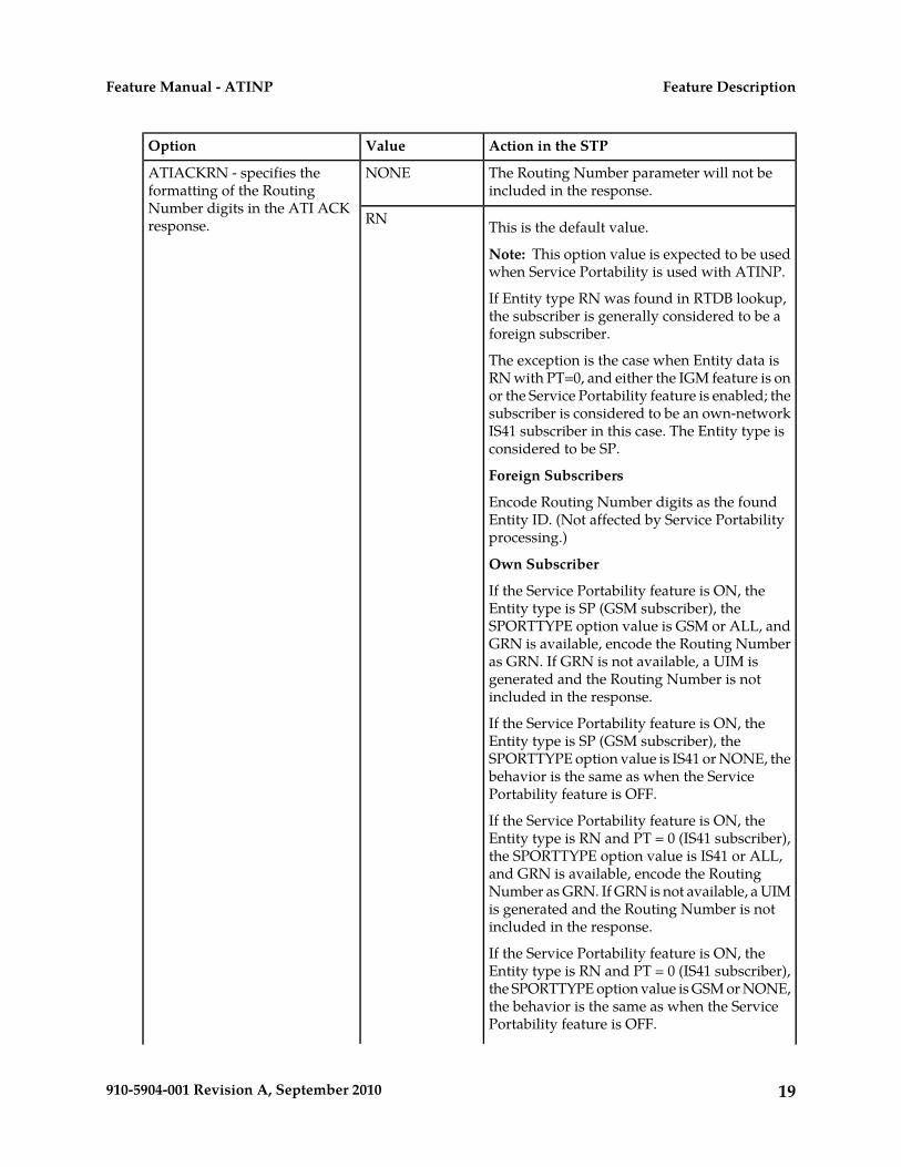
Action in the STPValueOption
The Routing Number parameter will not beincluded in the response.
NONEATIACKRN - specifies theformatting of the RoutingNumber digits in the ATI ACKresponse. This is the default value.RN
Note: This option value is expected to be usedwhen Service Portability is used with ATINP.
If Entity type RN was found in RTDB lookup,the subscriber is generally considered to be aforeign subscriber.
The exception is the case when Entity data isRN with PT=0, and either the IGM feature is onor the Service Portability feature is enabled; thesubscriber is considered to be an own-networkIS41 subscriber in this case. The Entity type isconsidered to be SP.
Foreign Subscribers
Encode Routing Number digits as the foundEntity ID. (Not affected by Service Portabilityprocessing.)
Own Subscriber
If the Service Portability feature is ON, theEntity type is SP (GSM subscriber), theSPORTTYPE option value is GSM or ALL, andGRN is available, encode the Routing Numberas GRN. If GRN is not available, a UIM isgenerated and the Routing Number is notincluded in the response.
If the Service Portability feature is ON, theEntity type is SP (GSM subscriber), theSPORTTYPE option value is IS41 or NONE, thebehavior is the same as when the ServicePortability feature is OFF.
If the Service Portability feature is ON, theEntity type is RN and PT = 0 (IS41 subscriber),the SPORTTYPE option value is IS41 or ALL,and GRN is available, encode the RoutingNumber as GRN. If GRN is not available, a UIMis generated and the Routing Number is notincluded in the response.
If the Service Portability feature is ON, theEntity type is RN and PT = 0 (IS41 subscriber),the SPORTTYPE option value is GSM or NONE,the behavior is the same as when the ServicePortability feature is OFF.
19910-5904-001 Revision A, September 2010
Feature DescriptionFeature Manual - ATINP
Action in the STPValueOption
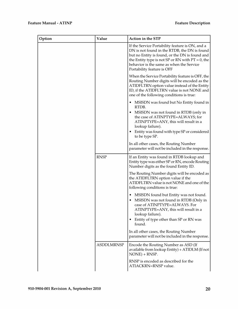
If the Service Portability feature is ON, and aDN is not found in the RTDB, the DN is foundbut no Entity is found, or the DN is found andthe Entity type is not SP or RN with PT = 0, thebehavior is the same as when the ServicePortability feature is OFF
When the Service Portability feature is OFF, theRouting Number digits will be encoded as theATIDFLTRN option value instead of the EntityID, if the ATIDFLTRN value is not NONE andone of the following conditions is true:
• MSISDN was found but No Entity found inRTDB.
• MSISDN was not found in RTDB (only inthe case of ATINPTYPE=ALWAYS; forATINPTYPE=ANY, this will result in alookup failure).
• Entity was found with type SP or consideredto be type SP.
In all other cases, the Routing Numberparameter will not be included in the response.
If an Entity was found in RTDB lookup andEntity type was either SP or RN, encode RoutingNumber digits as the found Entity ID.
The Routing Number digits will be encoded asthe ATIDFLTRN option value if the
RNSP
ATIDFLTRN value is not NONE and one of thefollowing conditions is true:
• MSISDN found but Entity was not found.• MSISDN was not found in RTDB (Only in
case of ATINPTYPE=ALWAYS. ForATINPTYPE=ANY, this will result in alookup failure).
• Entity of type other than SP or RN wasfound.
In all other cases, the Routing Numberparameter will not be included in the response.
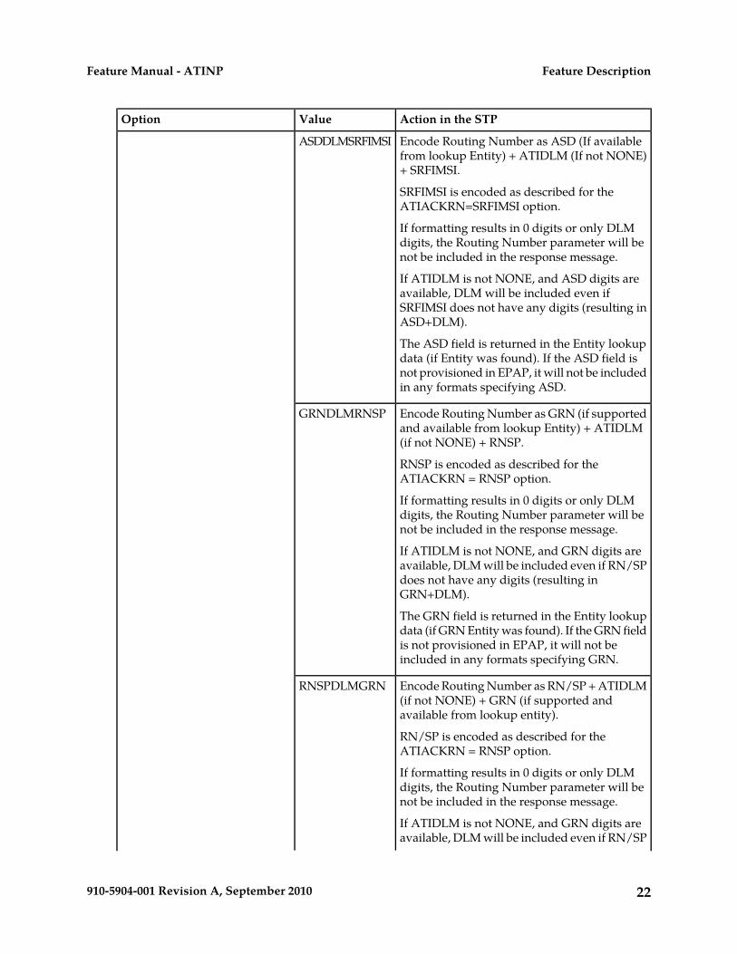
Encode the Routing Number as ASD (Ifavailable from lookup Entity) + ATIDLM (If notNONE) + RNSP.
RNSP is encoded as described for theATIACKRN=RNSP value.
ASDDLMRNSP
20910-5904-001 Revision A, September 2010
Feature DescriptionFeature Manual - ATINP
Action in the STPValueOption
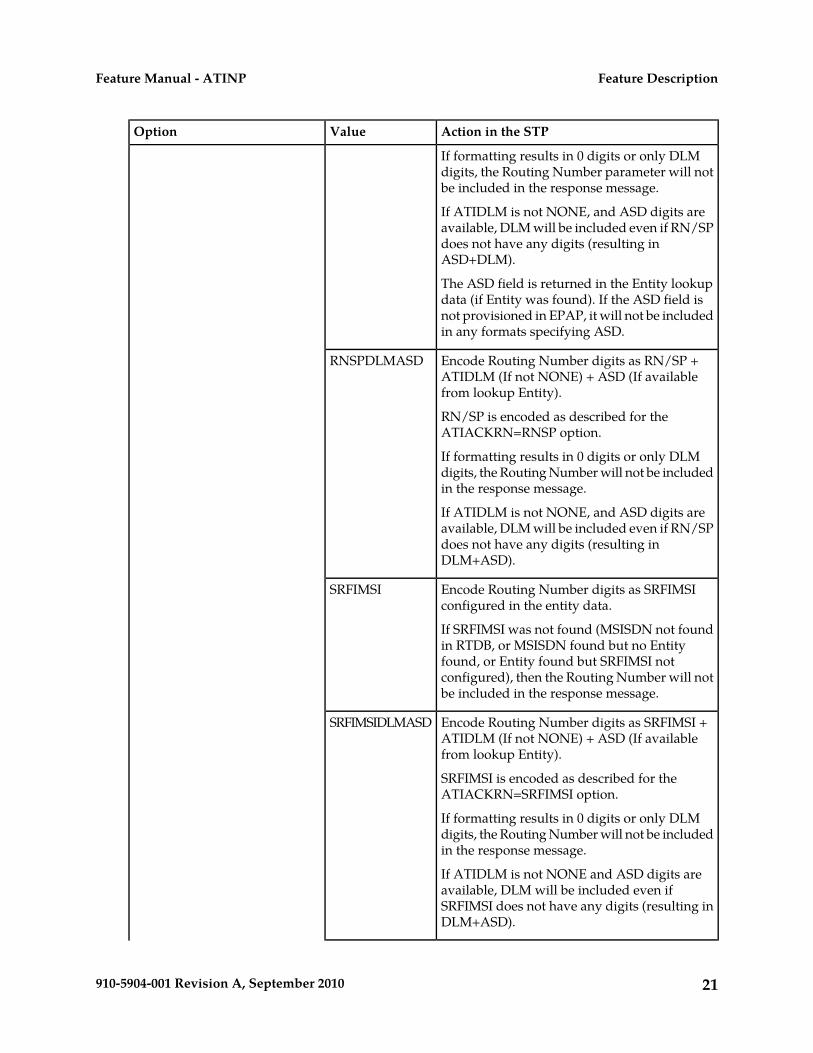
If formatting results in 0 digits or only DLMdigits, the Routing Number parameter will notbe included in the response message.
If ATIDLM is not NONE, and ASD digits areavailable, DLM will be included even if RN/SPdoes not have any digits (resulting inASD+DLM).
The ASD field is returned in the Entity lookupdata (if Entity was found). If the ASD field isnot provisioned in EPAP, it will not be includedin any formats specifying ASD.
Encode Routing Number digits as RN/SP +ATIDLM (If not NONE) + ASD (If availablefrom lookup Entity).
RN/SP is encoded as described for theATIACKRN=RNSP option.
RNSPDLMASD
If formatting results in 0 digits or only DLMdigits, the Routing Number will not be includedin the response message.
If ATIDLM is not NONE, and ASD digits areavailable, DLM will be included even if RN/SPdoes not have any digits (resulting inDLM+ASD).
Encode Routing Number digits as SRFIMSIconfigured in the entity data.
If SRFIMSI was not found (MSISDN not foundin RTDB, or MSISDN found but no Entity
SRFIMSI
found, or Entity found but SRFIMSI notconfigured), then the Routing Number will notbe included in the response message.
Encode Routing Number digits as SRFIMSI +ATIDLM (If not NONE) + ASD (If availablefrom lookup Entity).
SRFIMSI is encoded as described for theATIACKRN=SRFIMSI option.
SRFIMSIDLMASD
If formatting results in 0 digits or only DLMdigits, the Routing Number will not be includedin the response message.
If ATIDLM is not NONE and ASD digits areavailable, DLM will be included even ifSRFIMSI does not have any digits (resulting inDLM+ASD).
21910-5904-001 Revision A, September 2010
Feature DescriptionFeature Manual - ATINP
Action in the STPValueOption
Encode Routing Number as ASD (If availablefrom lookup Entity) + ATIDLM (If not NONE)+ SRFIMSI.
SRFIMSI is encoded as described for theATIACKRN=SRFIMSI option.
ASDDLMSRFIMSI
If formatting results in 0 digits or only DLMdigits, the Routing Number parameter will benot be included in the response message.
If ATIDLM is not NONE, and ASD digits areavailable, DLM will be included even ifSRFIMSI does not have any digits (resulting inASD+DLM).
The ASD field is returned in the Entity lookupdata (if Entity was found). If the ASD field isnot provisioned in EPAP, it will not be includedin any formats specifying ASD.
Encode Routing Number as GRN (if supportedand available from lookup Entity) + ATIDLM(if not NONE) + RNSP.
RNSP is encoded as described for theATIACKRN = RNSP option.
GRNDLMRNSP
If formatting results in 0 digits or only DLMdigits, the Routing Number parameter will benot be included in the response message.
If ATIDLM is not NONE, and GRN digits areavailable, DLM will be included even if RN/SPdoes not have any digits (resulting inGRN+DLM).
The GRN field is returned in the Entity lookupdata (if GRN Entity was found). If the GRN fieldis not provisioned in EPAP, it will not beincluded in any formats specifying GRN.
Encode Routing Number as RN/SP + ATIDLM(if not NONE) + GRN (if supported andavailable from lookup entity).
RN/SP is encoded as described for theATIACKRN = RNSP option.
RNSPDLMGRN
If formatting results in 0 digits or only DLMdigits, the Routing Number parameter will benot be included in the response message.
If ATIDLM is not NONE, and GRN digits areavailable, DLM will be included even if RN/SP
22910-5904-001 Revision A, September 2010
Feature DescriptionFeature Manual - ATINP
Action in the STPValueOption
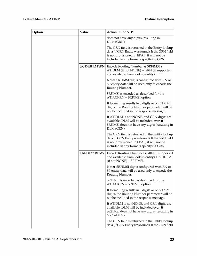
does not have any digits (resulting inDLM+GRN).
The GRN field is returned in the Entity lookupdata (if GRN Entity was found). If the GRN fieldis not provisioned in EPAP, it will not beincluded in any formats specifying GRN.
Encode Routing Number as SRFIMSI +ATIDLM (if not NONE) + GRN (if supportedand available from lookup entity).
Note: SRFIMSI digits configured with RN orSP entity data will be used only to encode theRouting Number.
SRFIMSIDLMGRN
SRFIMSI is encoded as described for theATIACKRN = SRFIMSI option.
If formatting results in 0 digits or only DLMdigits, the Routing Number parameter will benot be included in the response message.
If ATIDLM is not NONE, and GRN digits areavailable, DLM will be included even ifSRFIMSI does not have any digits (resulting inDLM+GRN).
The GRN field is returned in the Entity lookupdata (if GRN Entity was found). If the GRN fieldis not provisioned in EPAP, it will not beincluded in any formats specifying GRN.
Encode Routing Number as GRN (if supportedand available from lookup entity) + ATIDLM(if not NONE) + SRFIMSI.
Note: SRFIMSI digits configured with RN orSP entity data will be used only to encode theRouting Number.
GRNDLMSRFIMSI
SRFIMSI is encoded as described for theATIACKRN = SRFIMSI option.
If formatting results in 0 digits or only DLMdigits, the Routing Number parameter will benot be included in the response message.
If ATIDLM is not NONE, and GRN digits areavailable, DLM will be included even ifSRFIMSI does not have any digits (resulting inGRN+DLM).
The GRN field is returned in the Entity lookupdata (if GRN Entity was found). If the GRN field
23910-5904-001 Revision A, September 2010
Feature DescriptionFeature Manual - ATINP
Action in the STPValueOption
is not provisioned in EPAP, it will not beincluded in any formats specifying GRN.
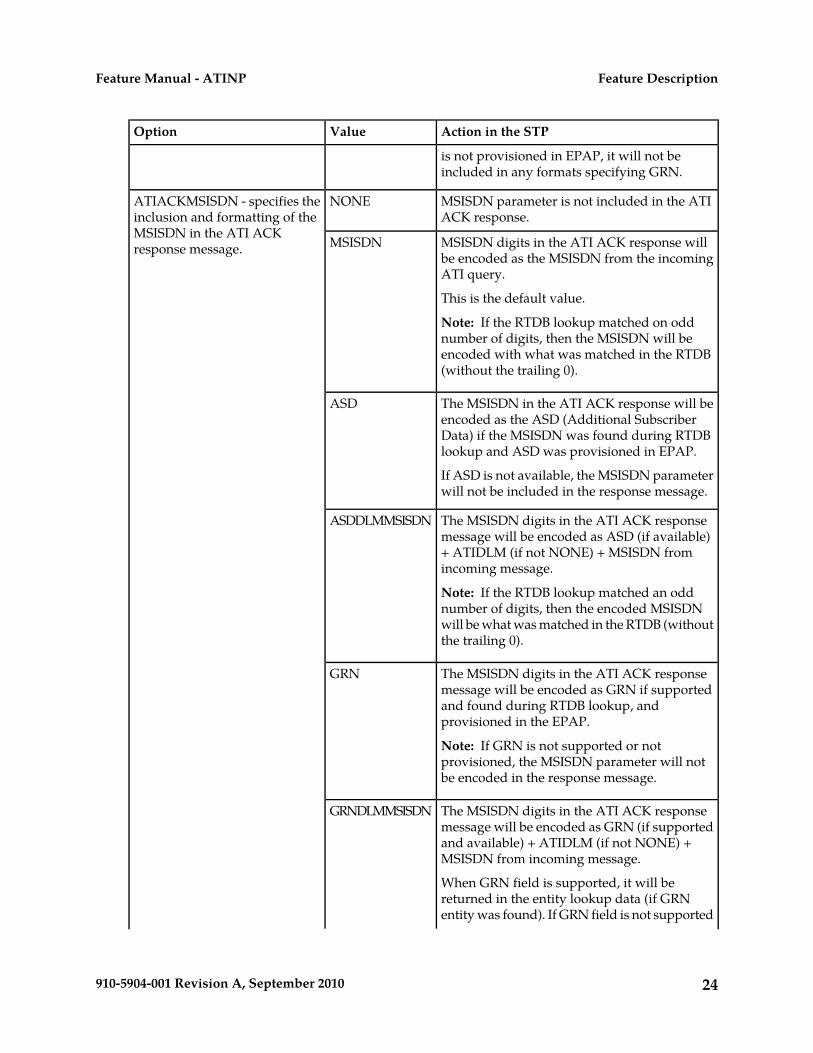
MSISDN parameter is not included in the ATIACK response.
NONEATIACKMSISDN - specifies theinclusion and formatting of theMSISDN in the ATI ACKresponse message. MSISDN digits in the ATI ACK response will
be encoded as the MSISDN from the incomingATI query.
This is the default value.
MSISDN
Note: If the RTDB lookup matched on oddnumber of digits, then the MSISDN will beencoded with what was matched in the RTDB(without the trailing 0).
The MSISDN in the ATI ACK response will beencoded as the ASD (Additional Subscriber
ASD
Data) if the MSISDN was found during RTDBlookup and ASD was provisioned in EPAP.
If ASD is not available, the MSISDN parameterwill not be included in the response message.
The MSISDN digits in the ATI ACK responsemessage will be encoded as ASD (if available)
ASDDLMMSISDN
+ ATIDLM (if not NONE) + MSISDN fromincoming message.
Note: If the RTDB lookup matched an oddnumber of digits, then the encoded MSISDNwill be what was matched in the RTDB (withoutthe trailing 0).
The MSISDN digits in the ATI ACK responsemessage will be encoded as GRN if supported
GRN
and found during RTDB lookup, andprovisioned in the EPAP.
Note: If GRN is not supported or notprovisioned, the MSISDN parameter will notbe encoded in the response message.
The MSISDN digits in the ATI ACK responsemessage will be encoded as GRN (if supported
GRNDLMMSISDN
and available) + ATIDLM (if not NONE) +MSISDN from incoming message.
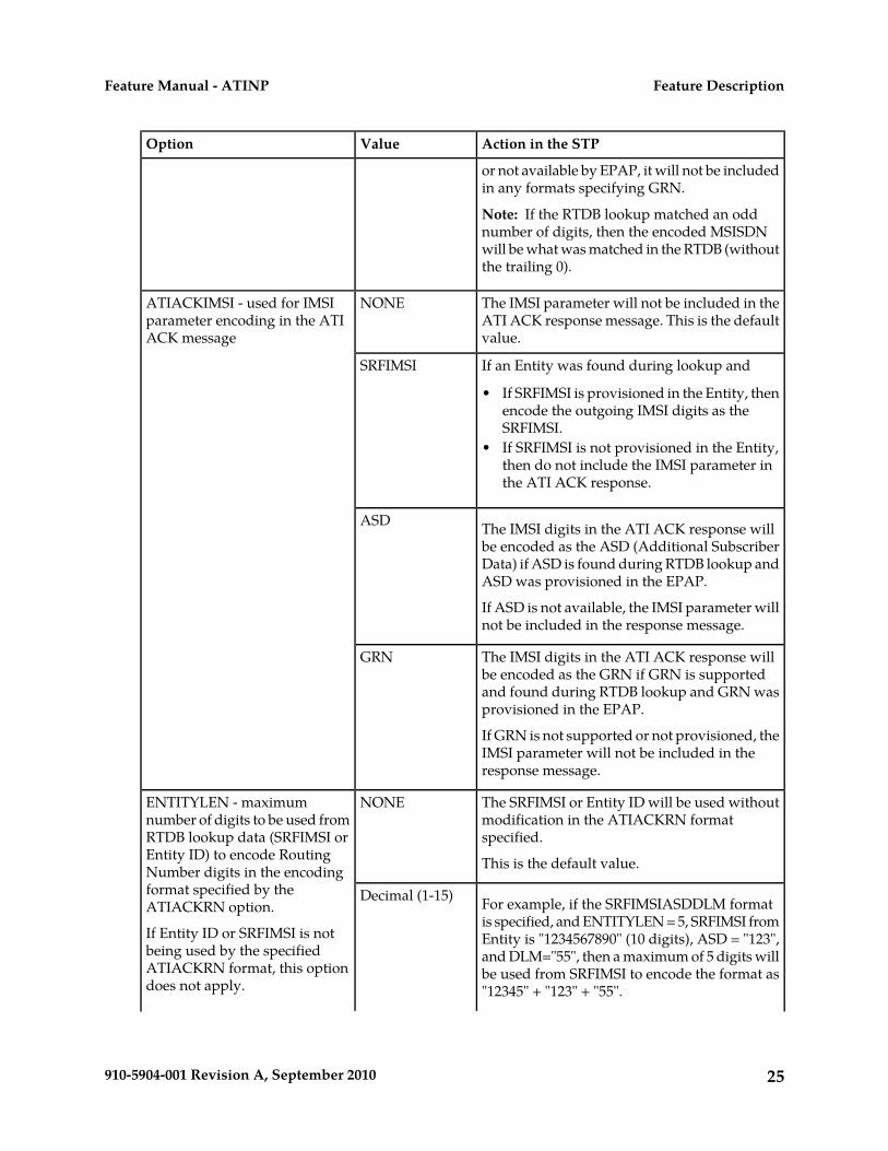
When GRN field is supported, it will bereturned in the entity lookup data (if GRNentity was found). If GRN field is not supported
24910-5904-001 Revision A, September 2010
Feature DescriptionFeature Manual - ATINP
Action in the STPValueOption
or not available by EPAP, it will not be includedin any formats specifying GRN.
Note: If the RTDB lookup matched an oddnumber of digits, then the encoded MSISDNwill be what was matched in the RTDB (withoutthe trailing 0).
The IMSI parameter will not be included in theATI ACK response message. This is the defaultvalue.
NONEATIACKIMSI - used for IMSIparameter encoding in the ATIACK message
If an Entity was found during lookup andSRFIMSI
• If SRFIMSI is provisioned in the Entity, thenencode the outgoing IMSI digits as theSRFIMSI.
• If SRFIMSI is not provisioned in the Entity,then do not include the IMSI parameter inthe ATI ACK response.
The IMSI digits in the ATI ACK response willbe encoded as the ASD (Additional Subscriber
ASD
Data) if ASD is found during RTDB lookup andASD was provisioned in the EPAP.
If ASD is not available, the IMSI parameter willnot be included in the response message.
The IMSI digits in the ATI ACK response willbe encoded as the GRN if GRN is supported
GRN
and found during RTDB lookup and GRN wasprovisioned in the EPAP.
If GRN is not supported or not provisioned, theIMSI parameter will not be included in theresponse message.
The SRFIMSI or Entity ID will be used withoutmodification in the ATIACKRN formatspecified.
This is the default value.
NONEENTITYLEN - maximumnumber of digits to be used fromRTDB lookup data (SRFIMSI orEntity ID) to encode RoutingNumber digits in the encodingformat specified by theATIACKRN option.
If Entity ID or SRFIMSI is notbeing used by the specified
For example, if the SRFIMSIASDDLM formatis specified, and ENTITYLEN = 5, SRFIMSI fromEntity is "1234567890" (10 digits), ASD = "123",and DLM="55", then a maximum of 5 digits will
Decimal (1-15)
ATIACKRN format, this optiondoes not apply.
be used from SRFIMSI to encode the format as"12345" + "123" + "55".
25910-5904-001 Revision A, September 2010
Feature DescriptionFeature Manual - ATINP
Action in the STPValueOption
If ENTITYLEN = "NONE" then all 10 digits fromSRFIMSI would have been used.
The same applies to formats that will encodean Entity ID.
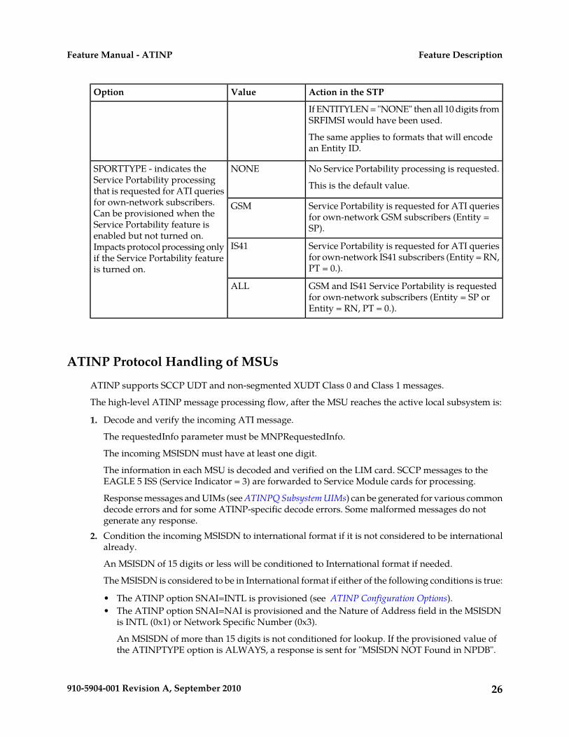
No Service Portability processing is requested.
This is the default value.
NONESPORTTYPE - indicates theService Portability processingthat is requested for ATI queriesfor own-network subscribers. Service Portability is requested for ATI queries
for own-network GSM subscribers (Entity =SP).
GSMCan be provisioned when theService Portability feature isenabled but not turned on.
Service Portability is requested for ATI queriesfor own-network IS41 subscribers (Entity = RN,PT = 0.).
IS41Impacts protocol processing onlyif the Service Portability featureis turned on.
GSM and IS41 Service Portability is requestedfor own-network subscribers (Entity = SP orEntity = RN, PT = 0.).
ALL
ATINP Protocol Handling of MSUs
ATINP supports SCCP UDT and non-segmented XUDT Class 0 and Class 1 messages.
The high-level ATINP message processing flow, after the MSU reaches the active local subsystem is:
1. Decode and verify the incoming ATI message.
The requestedInfo parameter must be MNPRequestedInfo.
The incoming MSISDN must have at least one digit.
The information in each MSU is decoded and verified on the LIM card. SCCP messages to theEAGLE 5 ISS (Service Indicator = 3) are forwarded to Service Module cards for processing.
Response messages and UIMs (see ATINPQ Subsystem UIMs) can be generated for various commondecode errors and for some ATINP-specific decode errors. Some malformed messages do notgenerate any response.
2. Condition the incoming MSISDN to international format if it is not considered to be internationalalready.
An MSISDN of 15 digits or less will be conditioned to International format if needed.
The MSISDN is considered to be in International format if either of the following conditions is true:
• The ATINP option SNAI=INTL is provisioned (see ATINP Configuration Options).• The ATINP option SNAI=NAI is provisioned and the Nature of Address field in the MSISDN
is INTL (0x1) or Network Specific Number (0x3).
An MSISDN of more than 15 digits is not conditioned for lookup. If the provisioned value ofthe ATINPTYPE option is ALWAYS, a response is sent for "MSISDN NOT Found in NPDB".
26910-5904-001 Revision A, September 2010
Feature DescriptionFeature Manual - ATINP
A trailing Stop Digit (0xF) in the MSISDN is treated as filler and will not be considered as partof the MSISDN during lookup.
3. Search the RTDB to locate the conditioned MSISDN.
If the conditioned MSISDN is not found in the individual entries, the range entries are searched(odd/even number lookups are supported).
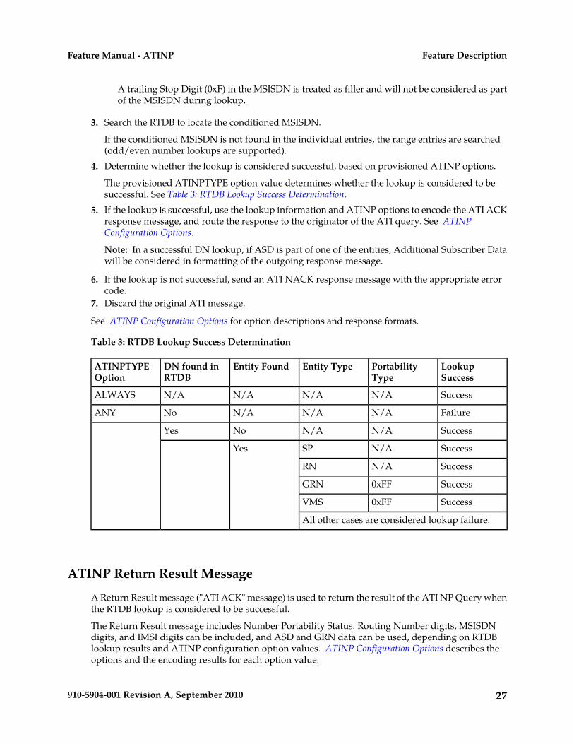
4. Determine whether the lookup is considered successful, based on provisioned ATINP options.
The provisioned ATINPTYPE option value determines whether the lookup is considered to besuccessful. See Table 3: RTDB Lookup Success Determination.
5. If the lookup is successful, use the lookup information and ATINP options to encode the ATI ACKresponse message, and route the response to the originator of the ATI query. See ATINPConfiguration Options.
Note: In a successful DN lookup, if ASD is part of one of the entities, Additional Subscriber Datawill be considered in formatting of the outgoing response message.
6. If the lookup is not successful, send an ATI NACK response message with the appropriate errorcode.
7. Discard the original ATI message.
See ATINP Configuration Options for option descriptions and response formats.
Table 3: RTDB Lookup Success Determination
LookupSuccess
PortabilityType
Entity TypeEntity FoundDN found inRTDB
ATINPTYPEOption
SuccessN/AN/AN/AN/AALWAYS
FailureN/AN/AN/ANoANY
SuccessN/AN/ANoYes
SuccessN/ASPYes
SuccessN/ARN
Success0xFFGRN
Success0xFFVMS
All other cases are considered lookup failure.
ATINP Return Result Message
A Return Result message ("ATI ACK" message) is used to return the result of the ATI NP Query whenthe RTDB lookup is considered to be successful.
The Return Result message includes Number Portability Status. Routing Number digits, MSISDNdigits, and IMSI digits can be included, and ASD and GRN data can be used, depending on RTDBlookup results and ATINP configuration option values. ATINP Configuration Options describes theoptions and the encoding results for each option value.
27910-5904-001 Revision A, September 2010
Feature DescriptionFeature Manual - ATINP
Routing Number
If the ATIACKRN option value is not none, routing number information is included in the responsemessage. The ATIACKRN option values determine the data from the RTDB lookup that is used in theoutgoing RN. (See ATINP Configuration Options.)
A default routing number can be provisioned using the ATIDFLTRN option, to be used in the outgoingmessage formats when an RN is not returned from the RTDB lookup.
Additional Subscriber Data is included in some of the formats of the return result information if it isavailable in the found Entity. The following formats consider Additional Subscriber Data (ASD) digitsfor encoding the outgoing RN parameter:
• ASD+DLM+RNSP• RNSP+DLM+ASD• SRFIMSI+DLM+ASD• ASD+DLM+SRFIMSI
Generic Routing Number (GRN) digits included in an Entity can be used in formatting the outgoingRN. The Generic Routing Number can be used in identifying GSM or IS41 own-network subscribersfor Service Portability, or for identifying members of ROPs (CNL clusters). The following formatsconsider Generic Routing Number (GRN) digits for encoding the outgoing RN parameter:
• GRN+DLM+RNSP• RNSP+DLM+GRN• SRFIMSI+DLM+GRN• GRN+DLM+SRFIMSI
Note: If the RTDB Entity type is RN with PT=0 and either the IGM feature is On or the ServicePortability feature is enabled, the subscriber is considered to be an own-network IS41 subscriber, andthe Entity type is treated as SP. See the ATIACKRN=RN configuration option description in ATINPConfiguration Options.
A maximum of 40 digits will be encoded in the routeingNumber field. Though the specified lengthof routeingNumber is 1-5 bytes, ATINP allows encoding of up to 40 digits, based on the ATIACKRNATINP option value. if the format results in more than 40 digits, the digits will be truncated to satisfythe 40-digit limit. If truncation of digits occurs, UIM 1403 “LSS: Dgts truncated in encd parms” willbe generated.
An outbound message digits delimiter and a maximum number of digits to be used from Entity datacan be provisioned for use in the encoding formats.
If an odd number of digits is encoded, a filler of 0xF is used as the last digit.
IMSI Digits
If the ATIACKIMSI option value is not none, IMSI digits are included in the response, as indicatedby the following ATIACKIMSI values:
• SRFIMSI - If an Entity was found during lookup and SRFIMSI was provisioned in the Entity, thenthe IMSI digits are encoded as the SRFIMSI value.
• ASD - If an Entity was found during RTDB lookup and ASD (Additional Subscriber Data) wasprovisioned in the EPAP Entity, then IMSI digits are encoded as the ASD. If ASD is not available,the IMSI parameter will not be encoded in the response message.
28910-5904-001 Revision A, September 2010
Feature DescriptionFeature Manual - ATINP

• GRN - If an Entity was found during RTDB lookup and GRN (Generic Routing Number) wasprovisioned in the EPAP Entity, then IMSI digits are encoded as the GRN. If GRN is not available,the IMSI parameter will not be encoded in the response message.
The ASD format considers ASD digits for encoding the outgoing IMSI parameter.
The Generic Routing Number can be used in identifying GSM or IS41 own-network subscribers forService Portability, or for identifying members of ROPs (CNL clusters). The GRN format considersGRN digits for encoding the outgoing IMSI parameter.
If an odd number of digits is encoded, a filler of 0xF is used as the last digit.
MSISDN
If the ATIACKMSISDN option value is not none, MSISDN digits are included in the response. Thedigits can be either the MSISDN from the incoming message, Additional Subscriber Data found in theEPAP Entity, Generic Routing Number found in the EPAP Entity, or a combination of MSISDN, ASDor GRN, and digits delimiter.
The following formats consider ASD digits for encoding the outgoing MSISDN parameter:
• ASD• ASD+DLM+MSISDN
Generic Routing Number (GRN) digits included in an Entity can be used in formatting the outgoingMSISDN. The Generic Routing Number can be used in identifying GSM or IS41 own-networksubscribers for Service Portability, or for identifying members of ROPs (CNL clusters). The followingformats consider GRN digits for encoding the outgoing MSISDN parameter:
• GRN• GRN+DLM+MSISDN
A maximum of 40 digits will be encoded in the MSISDN digits field. Though the specified length ofMSISDN is 1-9 bytes – 1 byte for nature of address/numbering plan, eight bytes for digits, ATINPwill allow encoding of up to 40 digits for this field, based on the ATIACKMSISDN ATINP optionvalue. If the format results in more than 40 digits, the digits will be truncated to satisfy the 40 digitlimit. UIM 1403: “LSS: Dgts truncated in encd parms” will be generated.
If an odd number of digits was encoded, a filler of 0xF is used as the last digit. The Nature of Addressfield will be copied from the incoming MSISDN.
Number Portability Status
The portability type of the MSISDN can represent the following types of numbers:
• An own number ported out• An own number not ported out• A foreign number ported in• A foreign number ported to foreign network• Foreign number not known to be ported
Because the existing EPAP portability does not support options for “Own number not ported out”and “Foreign number ported in”, this feature cannot distinguish between these two types of numbersthat belong to own network. Using configured data, a best fit match will be made for returning numberportability status (encoded value is in parentheses), as follows:
29910-5904-001 Revision A, September 2010
Feature DescriptionFeature Manual - ATINP
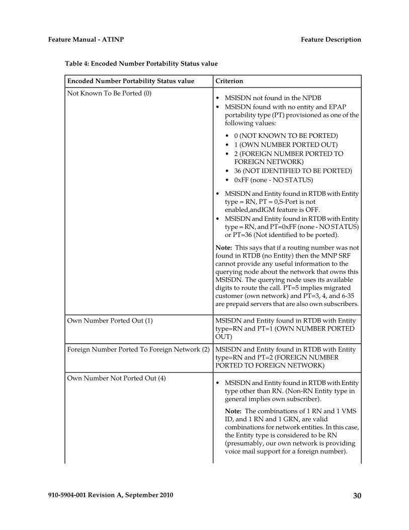
Table 4: Encoded Number Portability Status value
CriterionEncoded Number Portability Status value
Not Known To Be Ported (0)• MSISDN not found in the NPDB• MSISDN found with no entity and EPAP
portability type (PT) provisioned as one of thefollowing values:
• 0 (NOT KNOWN TO BE PORTED)• 1 (OWN NUMBER PORTED OUT)• 2 (FOREIGN NUMBER PORTED TO
FOREIGN NETWORK)• 36 (NOT IDENTIFIED TO BE PORTED)• 0xFF (none - NO STATUS)
• MSISDN and Entity found in RTDB with Entitytype = RN, PT = 0,S-Port is notenabled,andIGM feature is OFF.
• MSISDN and Entity found in RTDB with Entitytype = RN, and PT=0xFF (none - NO STATUS)or PT=36 (Not identified to be ported).
Note: This says that if a routing number was notfound in RTDB (no Entity) then the MNP SRFcannot provide any useful information to thequerying node about the network that owns thisMSISDN. The querying node uses its availabledigits to route the call. PT=5 implies migratedcustomer (own network) and PT=3, 4, and 6-35are prepaid servers that are also own subscribers.
MSISDN and Entity found in RTDB with Entitytype=RN and PT=1 (OWN NUMBER PORTEDOUT)
Own Number Ported Out (1)
MSISDN and Entity found in RTDB with Entitytype=RN and PT=2 (FOREIGN NUMBERPORTED TO FOREIGN NETWORK)
Foreign Number Ported To Foreign Network (2)
Own Number Not Ported Out (4)• MSISDN and Entity found in RTDB with Entity
type other than RN. (Non-RN Entity type ingeneral implies own subscriber).
Note: The combinations of 1 RN and 1 VMSID, and 1 RN and 1 GRN, are validcombinations for network entities. In this case,the Entity type is considered to be RN(presumably, our own network is providingvoice mail support for a foreign number).
30910-5904-001 Revision A, September 2010
Feature DescriptionFeature Manual - ATINP
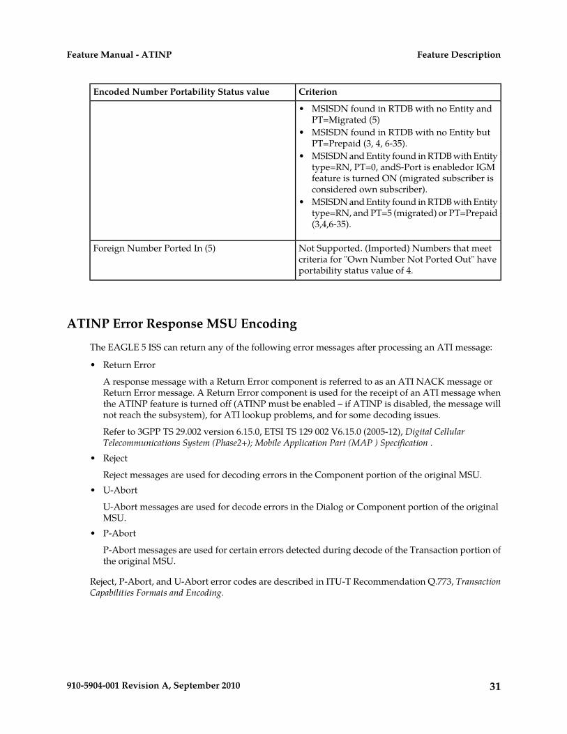
CriterionEncoded Number Portability Status value
• MSISDN found in RTDB with no Entity andPT=Migrated (5)
• MSISDN found in RTDB with no Entity butPT=Prepaid (3, 4, 6-35).
• MSISDN and Entity found in RTDB with Entitytype=RN, PT=0, andS-Port is enabledor IGMfeature is turned ON (migrated subscriber isconsidered own subscriber).
• MSISDN and Entity found in RTDB with Entitytype=RN, and PT=5 (migrated) or PT=Prepaid(3,4,6-35).
Not Supported. (Imported) Numbers that meetcriteria for "Own Number Not Ported Out" haveportability status value of 4.
Foreign Number Ported In (5)
ATINP Error Response MSU Encoding
The EAGLE 5 ISS can return any of the following error messages after processing an ATI message:
• Return Error
A response message with a Return Error component is referred to as an ATI NACK message orReturn Error message. A Return Error component is used for the receipt of an ATI message whenthe ATINP feature is turned off (ATINP must be enabled – if ATINP is disabled, the message willnot reach the subsystem), for ATI lookup problems, and for some decoding issues.
Refer to 3GPP TS 29.002 version 6.15.0, ETSI TS 129 002 V6.15.0 (2005-12), Digital CellularTelecommunications System (Phase2+); Mobile Application Part (MAP ) Specification .
• Reject
Reject messages are used for decoding errors in the Component portion of the original MSU.• U-Abort
U-Abort messages are used for decode errors in the Dialog or Component portion of the originalMSU.
• P-Abort
P-Abort messages are used for certain errors detected during decode of the Transaction portion ofthe original MSU.
Reject, P-Abort, and U-Abort error codes are described in ITU-T Recommendation Q.773, TransactionCapabilities Formats and Encoding.
31910-5904-001 Revision A, September 2010
Feature DescriptionFeature Manual - ATINP
Hardware Requirements
EPAP-related features that perform an RTDB lookup require Service Module cards (DSM cards orE5-SM4G cards) running the VSCCP application. The EAGLE 5 ISS can be equipped with:
• Up to 25 (24+1) Service Module cards when EPAP is running in a T1000 AS• Up to 32 (31+1) Service Module cards when EPAP is running in a T1200 AS
Features that do not perform an RTDB lookup require Service Module cards only for GTT processingthat might be performed for the feature. These features can coexist in systems with EPAP, but do notrequire an EPAP connection.
MPS/EPAP Platform
Tekelec provides the Multi-Purpose Server (MPS) platform as a subsystem of the EAGLE 5 ISS. TheMPS provides support for EPAP-related features that perform Real Time Database (RTDB) lookups.
The MPS is composed of hardware and software components that interact to create a secure andreliable platform. For details about the MPS hardware, refer to Tekelec 1000 Application Server HardwareManual or Tekelec 1200 Application Server Hardware Manual. The MPS provides the means of connectingthe customer provisioning application with the EAGLE 5 ISS and accepts the customer numberportability data, while accommodating numbers of varying lengths.
The EAGLE Provisioning Application Processor (EPAP) is software that runs on the MPS hardwareplatform. It collects and organizes customer provisioning data, and forwards the data to the EAGLE5 ISS Service Module cards. Figure 1: MPS/EPAP Platform Architecture shows the overall systemarchitecture from customer provisioning through the MPS subsystem to the EAGLE 5 ISS ServiceModule card databases.
Note: In this manual, Service Module card refers to either a DSM card or an E5-SM4G card unless aspecific card is required. For more information about the supported cards, refer to EAGLE 5 ISSHardware Manual.
Figure 1: MPS/EPAP Platform Architecture
32910-5904-001 Revision A, September 2010
Feature DescriptionFeature Manual - ATINP

Design Overview and System Layout
Figure 1: MPS/EPAP Platform Architecture identifies the tasks, databases and interfaces which constitutethe overall system architecture. The system consists of two mated MPS servers. Each MPS containstwo EPAP platforms - EPAP A and EPAP B with each containing a Real Time Database (RTDB) ,Provisioning Database (PDB), servers, optical media, modems, and either network hubs when usinga T1000 AS system or network switches when using a T1200 AS system . Each MPS and its associatedEPAPs is an EPAP system ; the EPAP system and the mated EAGLE 5 ISS are the mated EPAP system. Each EPAP system is either a T1000 AS or a T1200 AS system with a total of four Ethernet interfaces:one from each EPAP to the 100BASE-T Ethernet and one from each EPAP to either a 10BASE-T or a100BASE-T Ethernet. Refer to Table 5: Service Module Card Provisioning and Reload Settings for the linkspeed.
On the EAGLE 5 ISS, a set of Service Module cards, which hold the RTDB, is part of the STP. Twohigh-speed Ethernet links connect the Service Module cards and the EPAPs. One of the links is a100BASE-T Ethernet bus, and the other is either a 10BASE-T or a 100BASE-T Ethernet bus. Refer toTable 5: Service Module Card Provisioning and Reload Settings for the link speed.
33910-5904-001 Revision A, September 2010
Feature DescriptionFeature Manual - ATINP

The RTDB is provisioned and maintained through the EPAPs. EPAP A and EPAP B act as the activeEPAP and the standby EPAP. One link serves as the active link, and the other link as the standby link.Only one EPAP and one link are active at a time. The database is provisioned through the active linkby the active EPAP; the other EPAP provides redundancy.
If the active EPAP fails, the standby EPAP takes over the role of active EPAP and continues to provisionthe subscriber database. If the active link fails, the active EPAP switches to the standby link to continueprovisioning the Service Module cards. The two Ethernet links are part of the DSM network.
Another 100BASE-T Ethernet link exists between the EPAPs; that link is called the EPAP Sync Network.
The major modules on the EPAP are:
• Service Module card provisioning module• Maintenance module• RTDB module• PDB module
The Service Module card provisioning module is responsible for updating subscriber databases onthe EAGLE 5 ISS Service Module cards using the Reliable Multicast Transport Protocol (RMTP)multicast. The maintenance module is responsible for the proper functioning of the EPAP platform.The PDB module is responsible for preparing and maintaining the Real Time Database, which is thegolden copy of the subscriber database. The PDB module can run on one of the EPAPs of either matedEAGLE 5 ISS.
Functional Overview
The main function of the MPS/EPAP platform is to provision data from the customer network to theService Module cards on the EAGLE 5 ISS. Subscriber database records are continuously updatedfrom the customer network to the PDB. The PDB module communicates with the maintenance moduleand the RTDB task over a TCP/IP connection to provision the Service Module cards on the EAGLE 5ISS. The maintenance module is responsible for the overall stability and performance of the system.
The RTDB on the EPAP contains a coherent, current copy of the subscriber database. If the currentcopy of the RTDB on the Service Module cards becomes out-of-sync because of missed provisioningor card rebooting, the EPAP Service Module card provisioning module sends database informationthrough the provisioning link to the Service Module cards. The Service Module cards are reprovisionedwith current subscriber information.
EPAP/PDBA Overview
The EAGLE Provisioning Application Processor (EPAP) platform and the Provisioning DatabaseApplication (PDBA), coupled with the Provisioning Database Interface (PDBI) facilitate the userdatabase required for EAGLE 5 ISS EPAP-based features. The following functions are supported:
• Accept and store subscription data provisioned by the customer• Update and reload subscriber databases on the Service Module cards
The PDBA operates on the master Provisioning Database (PDB). The EPAP and PDBA are both installedon the MPS hardware platform.
The EPAP platform performs the following:
• Maintains an exact copy of the real time database (RTDB) on the EPAP
34910-5904-001 Revision A, September 2010
Feature DescriptionFeature Manual - ATINP
• Distributes the subscription database to the Service Module cards• Maintains a redundant copy of the RTDB database
The EPAP platform is a mated pair of processors (the upper processor, called EPAP A, and the lowerprocessor, EPAP B) contained in one frame.
During normal operation, information flows through the EPAP/PDBA software with no intervention.Subscription data is generated at one or more operations centers and is delivered to the PDBA througha TCP socket interface (PDBI). The PDBA software stores and replicates data on EPAP A on the matedEPAP system. The data is then transmitted by the EPAPs across a private network to the ServiceModule cards located in the EAGLE 5 ISS frame.
The primary interface to the PDBA consists of machine-to-machine messages. The interface is definedby Tekelec and is described in the Provisioning Database Interface Manual. Provisioning softwarecompatible with the EPAP socket interface can be created or updated using the interface described inthat manual.
Additionally, a direct user interface is provided on each EPAP to allow for configuration, maintenance,debugging, and platform operations. A direct user interface is also provided by the PDBA forconfiguration and database maintenance.
The MPS/EPAP is an open-systems platform and easily accommodates the required high provisioningrates. Compared to the traditional OAM platform, the persistent database and provisioning in an opensystems platform provides these benefits:
• Variety of hardware components and vendors• Availability of third party communication and database tools• Standard communication protocols• Availability of personnel with related experience
Each EPAP server maintains a copy of the Real Time Database (RTDB) in order to provision the EAGLE5 ISS Service Module cards. The EPAP server must comply with the hardware requirements in theMPS Hardware Manual. Figure 1: MPS/EPAP Platform Architecture illustrates the EPAP architecturecontained in the MPS subsystem.
Each EPAP has a dedicated optical media drive. One EPAP per EAGLE 5 ISS platform has a modemcapable of supporting remote diagnostics, configuration, and maintenance. These remote operationsare performed through EPAP login sessions and are accessible across the customer network as wellas through a direct terminal connection to the EPAP using an RS232 connection. Refer to Tekelec 1000Application Server Hardware Manual or Tekelec 1200 Application Server Hardware Manual for details aboutthe hardware devices and network connections.
Subscriber Data Provisioning
Figure 2: Subscriber Data Provisioning Architecture (High Level) shows a high-level view of the subscriberdata provisioning architecture. Only those parts of the EAGLE 5 ISS platform that are relevant tosubscriber data provisioning are shown. This section defines requirements for the Provisioning DatabaseInterface (PDBI) between the EPAP and the operator's provisioning system (OPS). Provisioning clientsconnect to the EPAPs via the PDBI. This interface contains commands that allow all of the provisioningand retrieval of subscription data. The PDBI is used for real-time provisioning of subscriber andnetwork entity data only. Refer to Provisioning Database Interface Manual for more details.Figure 2: Subscriber Data Provisioning Architecture (High Level)
35910-5904-001 Revision A, September 2010
Feature DescriptionFeature Manual - ATINP
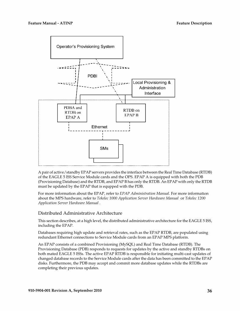
A pair of active/standby EPAP servers provides the interface between the Real Time Database (RTDB)of the EAGLE 5 ISS Service Module cards and the OPS. EPAP A is equipped with both the PDB(Provisioning Database) and the RTDB, and EPAP B has only the RTDB. An EPAP with only the RTDBmust be updated by the EPAP that is equpped with the PDB.
For more information about the EPAP, refer to EPAP Administration Manual. For more informationabout the MPS hardware, refer to Tekelec 1000 Application Server Hardware Manual or Tekelec 1200Application Server Hardware Manual .
Distributed Administrative ArchitectureThis section describes, at a high level, the distributed administrative architecture for the EAGLE 5 ISS,including the EPAP.
Databases requiring high update and retrieval rates, such as the EPAP RTDB, are populated usingredundant Ethernet connections to Service Module cards from an EPAP MPS platform.
An EPAP consists of a combined Provisioning (MySQL) and Real Time Database (RTDB). TheProvisioning Database (PDB) responds to requests for updates by the active and standby RTDBs onboth mated EAGLE 5 ISSs. The active EPAP RTDB is responsible for initiating multi-cast updates ofchanged database records to the Service Module cards after the data has been committed to the EPAPdisks. Furthermore, the PDB may accept and commit more database updates while the RTDBs arecompleting their previous updates.
36910-5904-001 Revision A, September 2010
Feature DescriptionFeature Manual - ATINP
It is this overlapping of database updates, coupled with an RTDB transactional database engine andfast download time, that allows larger amounts of data at a time to be transferred from the PDB.Committing larger amounts of data at a time to the RTDB (versus a single update at a time) allowsfaster overall transaction rates to be achieved. The boundaries of the transaction rates become moreclosely related to cache size and disk cache flush time than the disk access time of a single update.Thus, successful completion of EPAP database updates only guarantees that the PDB has been updated,but it does not mean the RTDB has completed the update and sent the new subscription data to theService Module card.
The EPAP architecture contains a local provisioning terminal and a modem for remote access, as wellas other functions. A backup device can be used to back up or restore the provisioning database. Thelocal provisioning terminal is used to manually repair the standby EPAP RTDB or to turn the subscriberdatabase audit on or off. For additional information, refer to Tekelec 1000 Application Server HardwareManual, Tekelec 1200 Application Server Hardware Manual, and EPAP Administration Manual.
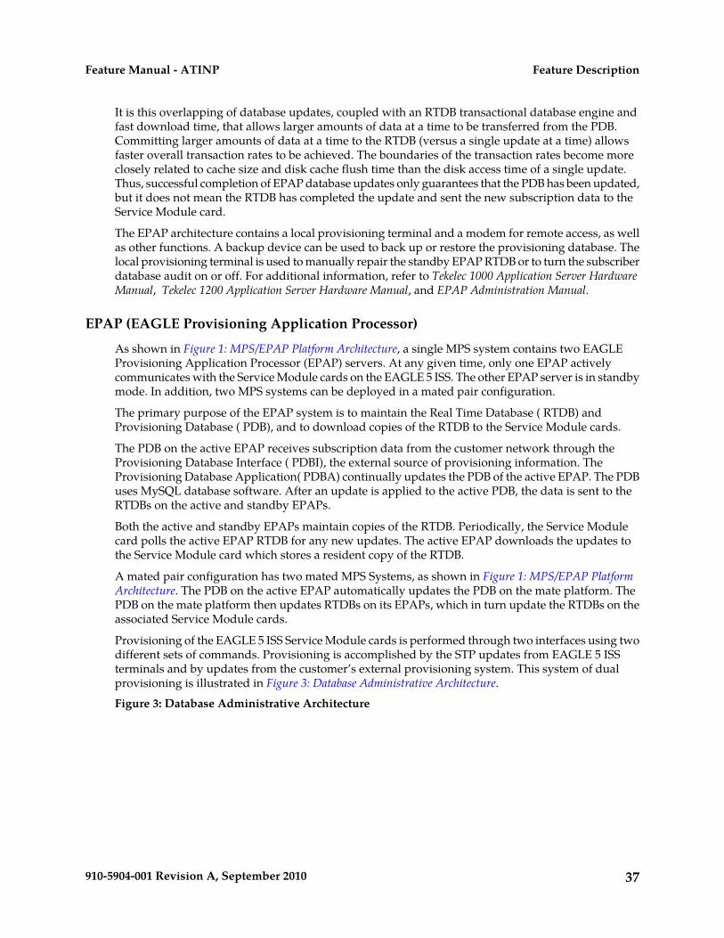
EPAP (EAGLE Provisioning Application Processor)
As shown in Figure 1: MPS/EPAP Platform Architecture, a single MPS system contains two EAGLEProvisioning Application Processor (EPAP) servers. At any given time, only one EPAP activelycommunicates with the Service Module cards on the EAGLE 5 ISS. The other EPAP server is in standbymode. In addition, two MPS systems can be deployed in a mated pair configuration.
The primary purpose of the EPAP system is to maintain the Real Time Database ( RTDB) andProvisioning Database ( PDB), and to download copies of the RTDB to the Service Module cards.
The PDB on the active EPAP receives subscription data from the customer network through theProvisioning Database Interface ( PDBI), the external source of provisioning information. TheProvisioning Database Application( PDBA) continually updates the PDB of the active EPAP. The PDBuses MySQL database software. After an update is applied to the active PDB, the data is sent to theRTDBs on the active and standby EPAPs.
Both the active and standby EPAPs maintain copies of the RTDB. Periodically, the Service Modulecard polls the active EPAP RTDB for any new updates. The active EPAP downloads the updates tothe Service Module card which stores a resident copy of the RTDB.
A mated pair configuration has two mated MPS Systems, as shown in Figure 1: MPS/EPAP PlatformArchitecture. The PDB on the active EPAP automatically updates the PDB on the mate platform. ThePDB on the mate platform then updates RTDBs on its EPAPs, which in turn update the RTDBs on theassociated Service Module cards.
Provisioning of the EAGLE 5 ISS Service Module cards is performed through two interfaces using twodifferent sets of commands. Provisioning is accomplished by the STP updates from EAGLE 5 ISSterminals and by updates from the customer’s external provisioning system. This system of dualprovisioning is illustrated in Figure 3: Database Administrative Architecture.Figure 3: Database Administrative Architecture
37910-5904-001 Revision A, September 2010
Feature DescriptionFeature Manual - ATINP
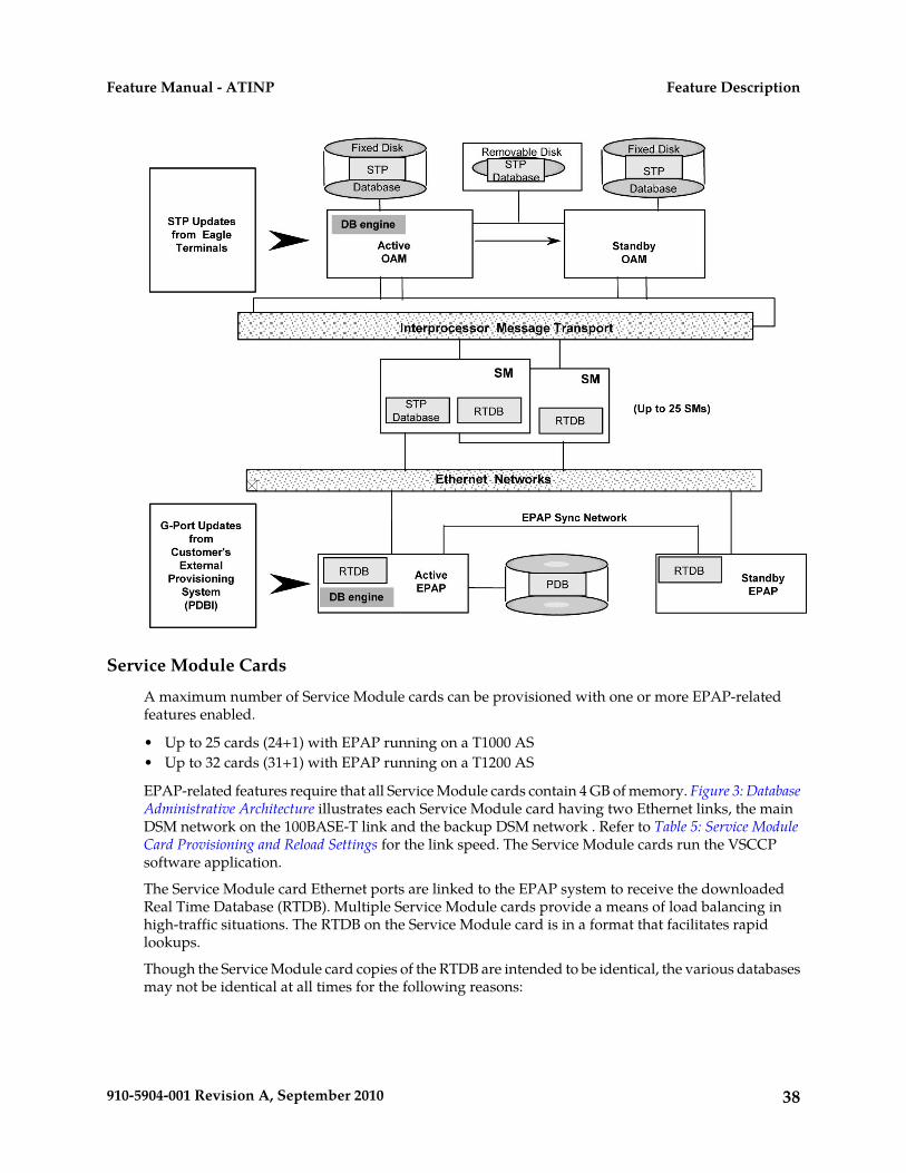
Service Module Cards
A maximum number of Service Module cards can be provisioned with one or more EPAP-relatedfeatures enabled.
• Up to 25 cards (24+1) with EPAP running on a T1000 AS• Up to 32 cards (31+1) with EPAP running on a T1200 AS
EPAP-related features require that all Service Module cards contain 4 GB of memory. Figure 3: DatabaseAdministrative Architecture illustrates each Service Module card having two Ethernet links, the mainDSM network on the 100BASE-T link and the backup DSM network . Refer to Table 5: Service ModuleCard Provisioning and Reload Settings for the link speed. The Service Module cards run the VSCCPsoftware application.
The Service Module card Ethernet ports are linked to the EPAP system to receive the downloadedReal Time Database (RTDB). Multiple Service Module cards provide a means of load balancing inhigh-traffic situations. The RTDB on the Service Module card is in a format that facilitates rapidlookups.
Though the Service Module card copies of the RTDB are intended to be identical, the various databasesmay not be identical at all times for the following reasons:
38910-5904-001 Revision A, September 2010
Feature DescriptionFeature Manual - ATINP
• When a Service Module card is initialized, the card downloads the current copy of the databasefrom the EPAP. While that card is being loaded, it cannot receive new updates that have arrivedat the EPAP since reload began.
• Card databases can become out-of-sync with the EPAP RTDB when the EPAP receives updatesfrom its provisioning source, but it has not yet sent the updates down to the Service Module cards.Updates are applied to the Provisioning Database (PDB) as they are received.
Two possible scenarios contribute to a condition where a Service Module card may not have enoughmemory to hold the entire database:
• The database is downloaded successfully to the Service Module card, but subsequent updateseventually increase the size of the database beyond the capacity of the Service Module card memory.In this situation, it is desirable for EPAP-related features to continue processing transactions, eventhough the database might not be up-to-date.
• When a Service Module card is booted and it is determined then that the card does not have enoughmemory for the entire database, the database is not loaded on that card. Each Service Module cardis responsible for recognizing and reporting its out-of-memory conditions by means of alarms.
Overview of EPAP to Service Module Card Communications
Before discussing Service Module card status reporting or EPAP status reporting, it is helpful tounderstand the communications between the Service Module cards and the EPAP in broad terms.
• UDP - sending Service Module card status messages
The Service Module cards and EPAPs create a UDP (User Datagram Protocol) socket which is usedfor status messages. One of the last things a Service Module card does when it is initialized is tosend a status message to the EPAP, containing the Service Module ID, database level, and memorysize. The EPAP maintains tables containing the last known status of each Service Module card.EPAP uses these to determine whether or not the Service Module card needs to download thedatabase.
• IP - reporting EPAP maintenance data
The Service Module cards create an TCP socket when they are initialized, and listen for connectionrequests. During initialization or after a loss of connectivity, the active EPAP chooses one of theService Module cards and issues a Connect to establish the TCP/IP connection with that ServiceModule card which is referred to as the primary Service Module card. The purpose of this link isto provide a path for reporting EPAP alarms and to forward maintenance blocks to the ServiceModule card.
• IP Multicast - downloading GSM database
Because of the large size of the database and the need to download it quickly on up to 32 ServiceModule cards, EPAP-related features use a technique known as IP multicasting. This technique isbased on Reliable Multicast Transport Protocol-II (RMTP-II), a product of GlobalcastCommunications. IP multicasting downloads the RTDB and database updates to all of the ServiceModule cards simultaneously.
The administration of IP multicasting is based on the concept of a “tree”, or stream of data, whichis constantly being broadcast by the EPAP. Service Module cards that need to download the realtime database or to receive database updates “join the tree”. Service Module cards can also “leavethe tree”, typically when the database fills their available memory.
39910-5904-001 Revision A, September 2010
Feature DescriptionFeature Manual - ATINP
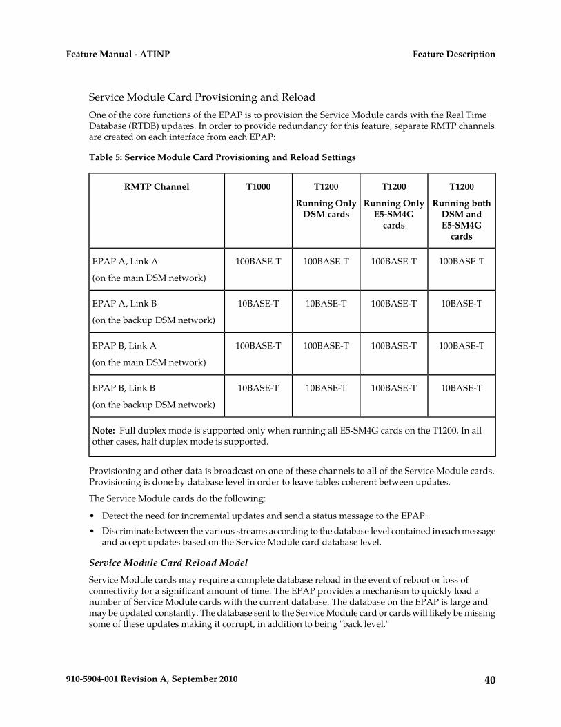
Service Module Card Provisioning and ReloadOne of the core functions of the EPAP is to provision the Service Module cards with the Real TimeDatabase (RTDB) updates. In order to provide redundancy for this feature, separate RMTP channelsare created on each interface from each EPAP:
Table 5: Service Module Card Provisioning and Reload Settings
T1200
Running bothDSM andE5-SM4G
cards
T1200
Running OnlyE5-SM4G
cards
T1200
Running OnlyDSM cards
T1000RMTP Channel
100BASE-T100BASE-T100BASE-T100BASE-TEPAP A, Link A
(on the main DSM network)
10BASE-T100BASE-T10BASE-T10BASE-TEPAP A, Link B
(on the backup DSM network)
100BASE-T100BASE-T100BASE-T100BASE-TEPAP B, Link A
(on the main DSM network)
10BASE-T100BASE-T10BASE-T10BASE-TEPAP B, Link B
(on the backup DSM network)
Note: Full duplex mode is supported only when running all E5-SM4G cards on the T1200. In allother cases, half duplex mode is supported.
Provisioning and other data is broadcast on one of these channels to all of the Service Module cards.Provisioning is done by database level in order to leave tables coherent between updates.
The Service Module cards do the following:
• Detect the need for incremental updates and send a status message to the EPAP.• Discriminate between the various streams according to the database level contained in each message
and accept updates based on the Service Module card database level.
Service Module Card Reload ModelService Module cards may require a complete database reload in the event of reboot or loss ofconnectivity for a significant amount of time. The EPAP provides a mechanism to quickly load anumber of Service Module cards with the current database. The database on the EPAP is large andmay be updated constantly. The database sent to the Service Module card or cards will likely be missingsome of these updates making it corrupt, in addition to being "back level."
40910-5904-001 Revision A, September 2010
Feature DescriptionFeature Manual - ATINP

EPAP Continuous Reload
It is important to understand how the EPAP handles reloading of multiple Service Module cards fromdifferent starting points. Reload begins when the first Service Module card requires it. Records areread sequentially from the Real Time Database (RTDB) from an arbitrary starting point, wrappingback to the beginning. If another Service Module card requires reloading at this time, it uses the existingrecord stream and notifies the Service Module card provisioning task of the first record it read. Thiscontinues until all Service Module cards are satisfied.
Service Module Card Database Levels and Reloading
The current database level when the reload started is of special importance during reload. When aService Module card detects that the last record has been received, it sends a status message back tothe EPAP indicating the database level at the start of reload. This action starts incremental loading.The Service Module card continues to reload until it is completely caught up with the current level ofthe RTDB. As database records are sent to the Service Module cards during reload, normal provisioningcan change those records. All records changed between the start and end of reloading must beincrementally loaded before the database is coherent and usable by the Service Module card.
The following terminology is used here for the stages of database reload for a given Service Modulecard.
• Stage 1 loading: The database is being copied record for record from the golden RTDB in the EPAPto the Service Module card RTDB. The database is incoherent during stage 1 loading.
• Incremental update: The database is receiving all of the updates missed during stage 1 loading orsome other reason, such as network outage, processor limitation, or lost communication. Thedatabase is coherent, but back-level during incremental update.
• Current: The database is receiving current updates from the Service Module card provisioningtask.
• Coherent: The database is at a whole database level which means not currently updating recordsbelonging to a database level.
EPAP Status and Error Reporting via Maintenance BlocksThe EPAP forwards all status and error messages to the Service Module cards in maintenance blocks.Maintenance blocks are asynchronously sent whenever the EPAP has something to report. Themaintenance blocks eventually update EPAP Device Control Blocks (DCBs) located on the EAGLE 5ISS. The DCBs provide the status information that is received when a rept-stat-mps command isissued.
Network Connections
Several customer and Tekelec-installed private networks are required to support the provisioning ofsubscription data. These networks are:
• Customer Provisioning Network• EPAP Sync Network• DSM Networks• Dial-Up PPP Network
The following discussion is an overview of these private networks. It expands on the networks in thearchitecture diagram shown in Figure 4: Customer Provisioning Network. (For details about configuringthese networks, refer to the EPAP Administration Manual.)
41910-5904-001 Revision A, September 2010
Feature DescriptionFeature Manual - ATINP
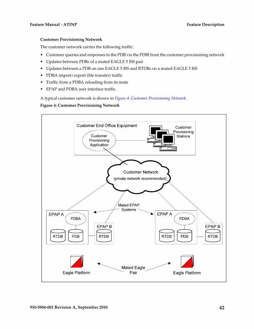
Customer Provisioning Network
The customer network carries the following traffic:
• Customer queries and responses to the PDB via the PDBI from the customer provisioning network• Updates between PDBs of a mated EAGLE 5 ISS pair• Updates between a PDB on one EAGLE 5 ISS and RTDBs on a mated EAGLE 5 ISS• PDBA import/export (file transfer) traffic• Traffic from a PDBA reloading from its mate• EPAP and PDBA user interface traffic.
A typical customer network is shown in Figure 4: Customer Provisioning Network.Figure 4: Customer Provisioning Network
42910-5904-001 Revision A, September 2010
Feature DescriptionFeature Manual - ATINP

Although a dedicated network is recommended, it is possible that unrelated customer traffic can usethe network as well. The determination, either to have a dedicated network or to allow other customertraffic, should be based on available external Ethernet bandwidth and network performanceconsiderations.
EPAP Sync Network
The T1000 EPAP sync network carries RTDB and maintenance application traffic between active andstandby EPAP servers on an MPS system. It synchronizes the contents of the RTDBs of both EPAP Aand B. The EPAP Sync network is a single Ethernet connection between EPAP A and EPAP B runningat 100BASE-T, as shown in Figure 5: EPAP Sync Network. The T1200 EPAP Sync network is truncatedwith the EPAP back up DSM connection and communicates through the switch.Figure 5: EPAP Sync Network
DSM Networks
The DSM networks are shown in Figure 6: DSM Networks. They carry provisioning data from the activeEPAP RTDB to the Service Module cards. They also carry reload and maintenance traffic to the ServiceModule cards.
The DSM networks consist of two Ethernet networks: the main DSM network running at 100BASE-T,and the backup DSM network running at either 10BASE-T or 100Base-T. Refer to Table 6: EPAP IPAddresses in the DSM Network for the link speed. Both Ethernet networks connect EPAP A and EPAPB with every Service Module card on a single EAGLE 5 ISS platform.Figure 6: DSM Networks
43910-5904-001 Revision A, September 2010
Feature DescriptionFeature Manual - ATINP

Maintenance information is sent from the active EPAP to an arbitrarily selected Service Module card.The selected Service Module card is known as the primary Service Module card. Static information isexchanged across this interface at initialization, and dynamic information is exchanged on occasion.
While much of the traditional OAM provisioning and database functionality is implemented on theEPAP, the maintenance reporting mechanism is still the OAM.
The first and second octets of the EPAP network addresses for this network are 192.168. (The first twooctets for private class C networks are defined in RFC 1918.)
The third octet is customer specifiable for each DSM network. It is important to select values that donot interfere with the customer's network addressing scheme.
The fourth octet of the address is specified as follows:
• If the EPAP is configured as “EPAP A”, the fourth octet has a value of 100.• If the EPAP is configured as “EPAP B”, the fourth octet has a value of 200.
Table 6: EPAP IP Addresses in the DSM Network summarizes the contents of each octet.
Table 6: EPAP IP Addresses in the DSM Network
ValueOctet
1921
1682
One customer-provisioned value for DSM network A and another for DSM network B3
100 for EPAP A and 200 for EPAP B4
44910-5904-001 Revision A, September 2010
Feature DescriptionFeature Manual - ATINP
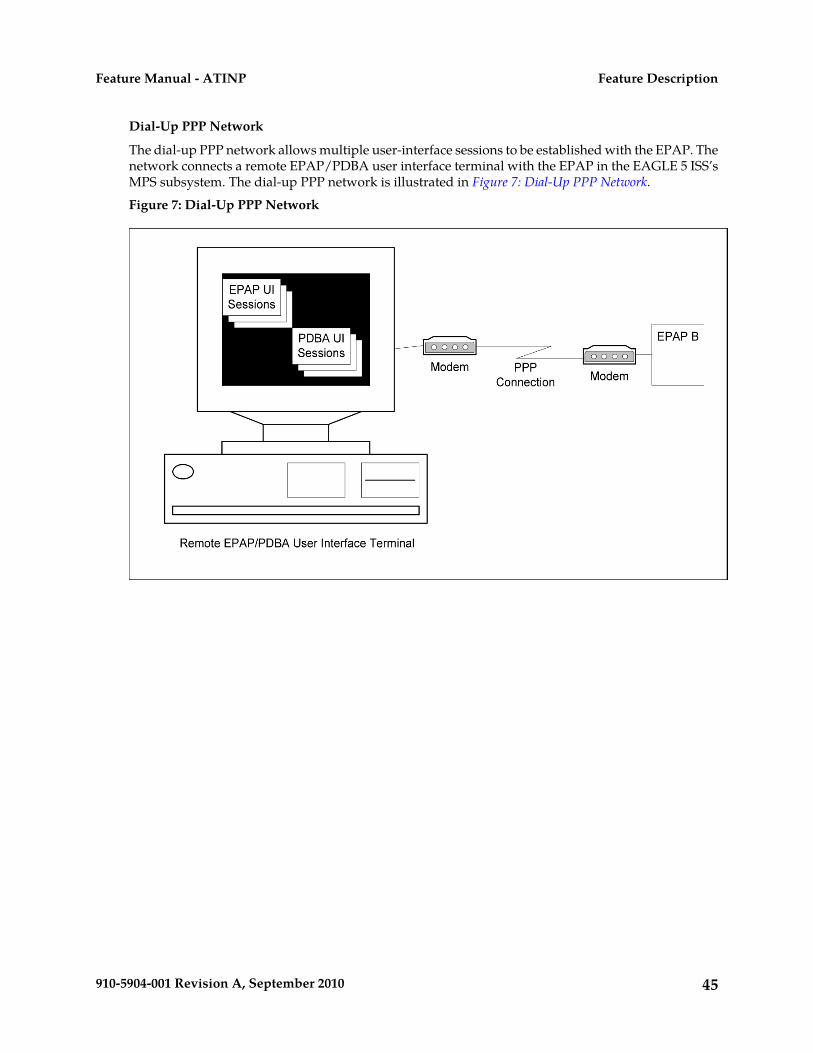
Dial-Up PPP Network
The dial-up PPP network allows multiple user-interface sessions to be established with the EPAP. Thenetwork connects a remote EPAP/PDBA user interface terminal with the EPAP in the EAGLE 5 ISS’sMPS subsystem. The dial-up PPP network is illustrated in Figure 7: Dial-Up PPP Network.Figure 7: Dial-Up PPP Network
45910-5904-001 Revision A, September 2010
Feature DescriptionFeature Manual - ATINP

Chapter
3EAGLE 5 ISS ATINP Commands
This chapter contains brief descriptions of theEAGLE 5 ISS commands that are used for the
Topics:
• EAGLE 5 ISS Commands.....47 configuration and maintenance for the ATI NumberPortability Query (ATINP) feature.• Maintenance Commands.....48
• EAGLE 5 ISS Debug Commands.....50
46910-5904-001 Revision A, September 2010
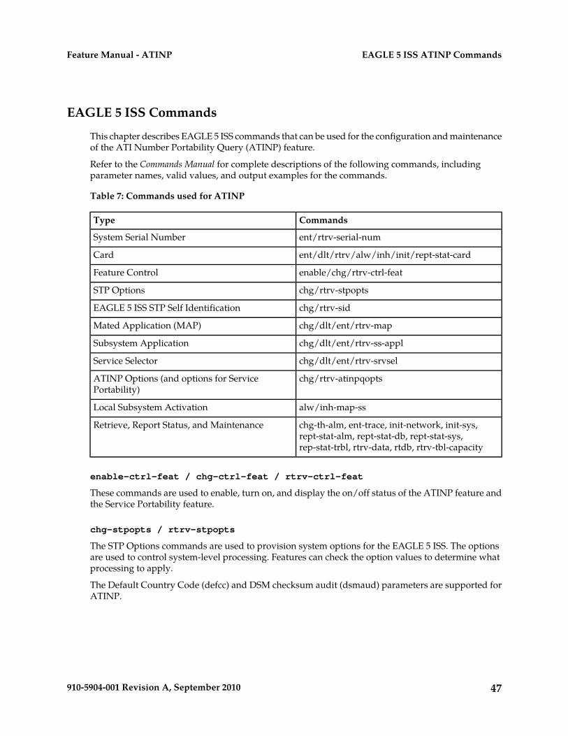
EAGLE 5 ISS Commands
This chapter describes EAGLE 5 ISS commands that can be used for the configuration and maintenanceof the ATI Number Portability Query (ATINP) feature.
Refer to the Commands Manual for complete descriptions of the following commands, includingparameter names, valid values, and output examples for the commands.
Table 7: Commands used for ATINP
CommandsType
ent/rtrv-serial-numSystem Serial Number
ent/dlt/rtrv/alw/inh/init/rept-stat-cardCard
enable/chg/rtrv-ctrl-featFeature Control
chg/rtrv-stpoptsSTP Options
chg/rtrv-sidEAGLE 5 ISS STP Self Identification
chg/dlt/ent/rtrv-mapMated Application (MAP)
chg/dlt/ent/rtrv-ss-applSubsystem Application
chg/dlt/ent/rtrv-srvselService Selector
chg/rtrv-atinpqoptsATINP Options (and options for ServicePortability)
alw/inh-map-ssLocal Subsystem Activation
chg-th-alm, ent-trace, init-network, init-sys,rept-stat-alm, rept-stat-db, rept-stat-sys,rep-stat-trbl, rtrv-data, rtdb, rtrv-tbl-capacity
Retrieve, Report Status, and Maintenance
enable-ctrl-feat / chg-ctrl-feat / rtrv-ctrl-feat
These commands are used to enable, turn on, and display the on/off status of the ATINP feature andthe Service Portability feature.
chg-stpopts / rtrv-stpopts
The STP Options commands are used to provision system options for the EAGLE 5 ISS. The optionsare used to control system-level processing. Features can check the option values to determine whatprocessing to apply.
The Default Country Code (defcc) and DSM checksum audit (dsmaud) parameters are supported forATINP.
47910-5904-001 Revision A, September 2010
EAGLE 5 ISS ATINP CommandsFeature Manual - ATINP
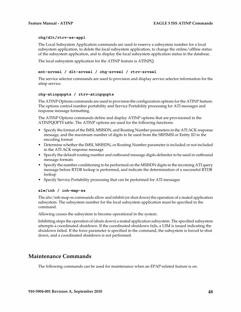
chg/dlt/rtrv-ss-appl
The Local Subsystem Application commands are used to reserve a subsystem number for a localsubsystem application, to delete the local subsystem application, to change the online/offline statusof the subsystem application, and to display the local subsystem application status in the database.
The local subsystem application for the ATINP feature is ATINPQ.
ent-srvsel / dlt-srvsel / chg-srvsel / rtrv-srvsel
The service selector commands are used to provision and display service selector information for theatinp service.
chg-atinpqopts / rtrv-atinpqopts
The ATINP Options commands are used to provision the configuration options for the ATINP feature.The options control number portability and Service Portability processing for ATI messages andresponse message formatting.
The ATINP Options commands define and display ATINP options that are provisioned in theATINPQOPTS table. The ATINP options are used for the following functions:
• Specify the format of the IMSI, MSISDN, and Routing Number parameters in the ATI ACK responsemessage, and the maximum number of digits to be used from the SRFIMSI or Entity ID in theencoding format
• Determine whether the IMSI, MSISDN, or Routing Number parameter is included or not includedin the ATI ACK response message
• Specify the default routing number and outbound message digits delimiter to be used in outboundmessage formats
• Specify the number conditioning to be performed on the MSISDN digits in the incoming ATI querymessage before RTDB lookup is performed, and indicate the determination of a successful RTDBlookup
• Specify Service Portability processing that can be performed for ATI messages
alw/inh / inh-map-ss
The alw/inh-map-ss commands allow and inhibit (or shut down) the operation of a mated applicationsubsystem. The subsystem number for the local subsystem application must be specified in thecommand.
Allowing causes the subsystem to become operational in the system.
Inhibiting stops the operation of (shuts down) a mated application subsystem. The specified subsystemattempts a coordinated shutdown. If the coordinated shutdown fails, a UIM is issued indicating theshutdown failed. If the force parameter is specified in the command, the subsystem is forced to shutdown, and a coordinated shutdown is not performed.
Maintenance Commands
The following commands can be used for maintenance when an EPAP-related feature is on.
48910-5904-001 Revision A, September 2010
EAGLE 5 ISS ATINP CommandsFeature Manual - ATINP
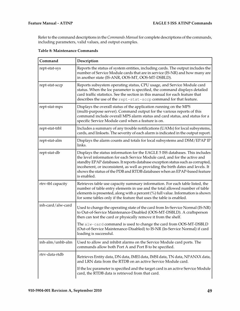
Refer to the command descriptions in the Commands Manual for complete descriptions of the commands,including parameters, valid values, and output examples.
Table 8: Maintenance Commands
DescriptionCommand
Reports the status of system entities, including cards. The output includes thenumber of Service Module cards that are in service (IS-NR) and how many arein another state (IS-ANR, OOS-MT, OOS-MT-DSBLD).
rept-stat-sys
Reports subsystem operating status, CPU usage, and Service Module cardstatus. When the loc parameter is specified, the command displays detailed
rept-stat-sccp
card traffic statistics. See the section in this manual for each feature thatdescribes the use of the rept-stat-sccp command for that feature.
Displays the overall status of the application running on the MPS(multi-purpose server). Command output for the various reports of this
rept-stat-mps
command include overall MPS alarm status and card status, and status for aspecific Service Module card when a feature is on.
Includes a summary of any trouble notifications (UAMs) for local subsystems,cards, and linksets. The severity of each alarm is indicated in the output report.
rept-stat-trbl
Displays the alarm counts and totals for local subsystems and DSM/EPAP IPlinks.
rept-stat-alm
Displays the status information for the EAGLE 5 ISS databases. This includesthe level information for each Service Module card, and for the active and
rept-stat-db
standby EPAP databases. It reports database exception status such as corrupted,incoherent, or inconsistent, as well as providing the birth dates and levels. Itshows the status of the PDB and RTDB databases when an EPAP-based featureis enabled.
Retrieves table use capacity summary information. For each table listed, thenumber of table entry elements in use and the total allowed number of table
rtrv-tbl capacity
elements is presented, along with a percent (%) full value. Information is shownfor some tables only if the feature that uses the table is enabled.
Used to change the operating state of the card from In-Service Normal (IS-NR)to Out-of-Service Maintenance-Disabled (OOS-MT-DSBLD). A craftspersonthen can test the card or physically remove it from the shelf.
inh-card/alw-card
The alw-card command is used to change the card from OOS-MT-DSBLD(Out-of-Service Maintenance-Disabled) to IS-NR (In-Service Normal) if cardloading is successful.
Used to allow and inhibit alarms on the Service Module card ports. Thecommands allow both Port A and Port B to be specified.
inh-alm/unhb-alm
Retrieves Entity data, DN data, IMEI data, IMSI data, TN data, NPANXX data,and LRN data from the RTDB on an active Service Module card.
rtrv-data-rtdb
If the loc parameter is specified and the target card is an active Service Modulecard, the RTDB data is retrieved from that card.
49910-5904-001 Revision A, September 2010
EAGLE 5 ISS ATINP CommandsFeature Manual - ATINP
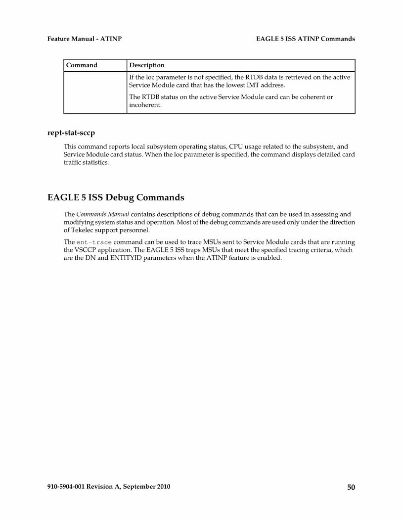
DescriptionCommand
If the loc parameter is not specified, the RTDB data is retrieved on the activeService Module card that has the lowest IMT address.
The RTDB status on the active Service Module card can be coherent orincoherent.
rept-stat-sccp
This command reports local subsystem operating status, CPU usage related to the subsystem, andService Module card status. When the loc parameter is specified, the command displays detailed cardtraffic statistics.
EAGLE 5 ISS Debug Commands
The Commands Manual contains descriptions of debug commands that can be used in assessing andmodifying system status and operation. Most of the debug commands are used only under the directionof Tekelec support personnel.
The ent-trace command can be used to trace MSUs sent to Service Module cards that are runningthe VSCCP application. The EAGLE 5 ISS traps MSUs that meet the specified tracing criteria, whichare the DN and ENTITYID parameters when the ATINP feature is enabled.
50910-5904-001 Revision A, September 2010
EAGLE 5 ISS ATINP CommandsFeature Manual - ATINP
Chapter
4ATINP Configuration
This chapter provides procedures for configuringthe ATINP feature for use in the EAGLE 5 ISS.
Topics:
• Introduction.....52• ATINP Configuration Procedure.....54• Adding a Service Module Card.....55• Enabling ATINP, Setting STP Options, and
Turning On ATINP.....59• Enabling the Service Portability Feature.....60• Provisioning True Point Codes and Capability
Point Codes.....61• Provisioning the ATINPQ Local Subsystem.....63• Provisioning the ATINP Service Selector.....65• Provisioning the ATINP Options.....70• Activating the ATINPQ Local Subsystem.....71• Turning On the Service Portability Feature.....72• Turning Off the Service Portability Feature.....73• Changing the State of a Subsystem
Application.....74• The 1100 TPS/DSM for ITU NP Feature.....76• Activating the E5-SM4G Throughput Capacity
Feature.....81
51910-5904-001 Revision A, September 2010
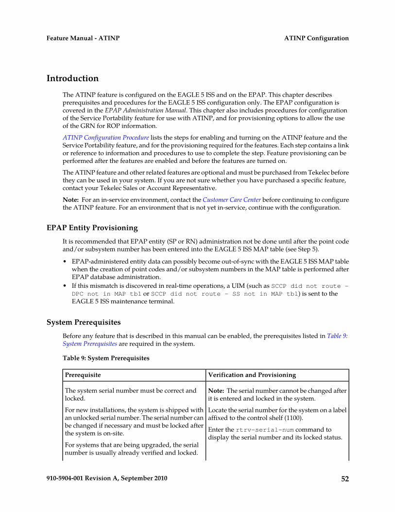
Introduction
The ATINP feature is configured on the EAGLE 5 ISS and on the EPAP. This chapter describesprerequisites and procedures for the EAGLE 5 ISS configuration only. The EPAP configuration iscovered in the EPAP Administration Manual. This chapter also includes procedures for configurationof the Service Portability feature for use with ATINP, and for provisioning options to allow the useof the GRN for ROP information.
ATINP Configuration Procedure lists the steps for enabling and turning on the ATINP feature and theService Portability feature, and for the provisioning required for the features. Each step contains a linkor reference to information and procedures to use to complete the step. Feature provisioning can beperformed after the features are enabled and before the features are turned on.
The ATINP feature and other related features are optional and must be purchased from Tekelec beforethey can be used in your system. If you are not sure whether you have purchased a specific feature,contact your Tekelec Sales or Account Representative.
Note: For an in-service environment, contact the Customer Care Center before continuing to configurethe ATINP feature. For an environment that is not yet in-service, continue with the configuration.
EPAP Entity Provisioning
It is recommended that EPAP entity (SP or RN) administration not be done until after the point codeand/or subsystem number has been entered into the EAGLE 5 ISS MAP table (see Step 5).
• EPAP-administered entity data can possibly become out-of-sync with the EAGLE 5 ISS MAP tablewhen the creation of point codes and/or subsystem numbers in the MAP table is performed afterEPAP database administration.
• If this mismatch is discovered in real-time operations, a UIM (such as SCCP did not route -DPC not in MAP tbl or SCCP did not route - SS not in MAP tbl) is sent to theEAGLE 5 ISS maintenance terminal.
System Prerequisites
Before any feature that is described in this manual can be enabled, the prerequisites listed in Table 9:System Prerequisites are required in the system.
Table 9: System Prerequisites
Verification and ProvisioningPrerequisite
Note: The serial number cannot be changed afterit is entered and locked in the system.
The system serial number must be correct andlocked.
For new installations, the system is shipped withan unlocked serial number. The serial number can
Locate the serial number for the system on a labelaffixed to the control shelf (1100).
be changed if necessary and must be locked afterthe system is on-site. Enter the rtrv-serial-num command to
display the serial number and its locked status.For systems that are being upgraded, the serialnumber is usually already verified and locked.
52910-5904-001 Revision A, September 2010
ATINP ConfigurationFeature Manual - ATINP
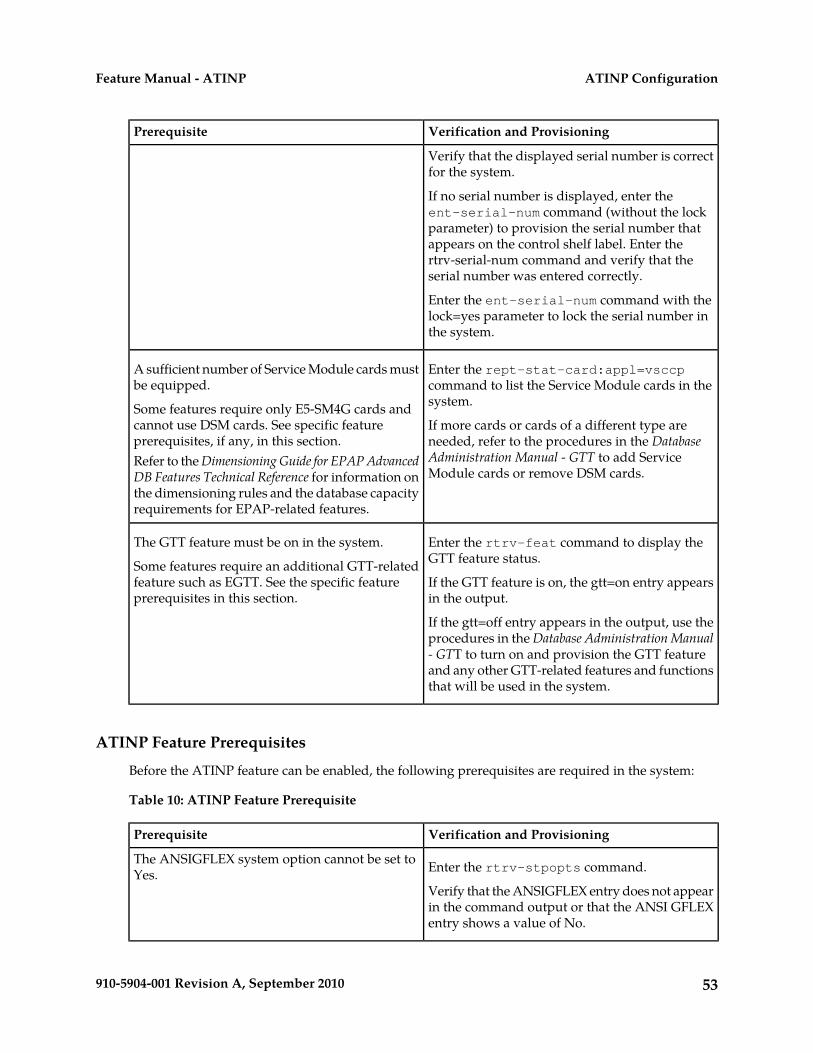
Verification and ProvisioningPrerequisite
Verify that the displayed serial number is correctfor the system.
If no serial number is displayed, enter theent-serial-num command (without the lockparameter) to provision the serial number thatappears on the control shelf label. Enter thertrv-serial-num command and verify that theserial number was entered correctly.
Enter the ent-serial-num command with thelock=yes parameter to lock the serial number inthe system.
Enter the rept-stat-card:appl=vsccpcommand to list the Service Module cards in thesystem.
A sufficient number of Service Module cards mustbe equipped.
Some features require only E5-SM4G cards andcannot use DSM cards. See specific featureprerequisites, if any, in this section.
If more cards or cards of a different type areneeded, refer to the procedures in the DatabaseAdministration Manual - GTT to add ServiceModule cards or remove DSM cards.
Refer to the Dimensioning Guide for EPAP AdvancedDB Features Technical Reference for information onthe dimensioning rules and the database capacityrequirements for EPAP-related features.
Enter the rtrv-feat command to display theGTT feature status.
The GTT feature must be on in the system.
Some features require an additional GTT-relatedfeature such as EGTT. See the specific featureprerequisites in this section.
If the GTT feature is on, the gtt=on entry appearsin the output.
If the gtt=off entry appears in the output, use theprocedures in the Database Administration Manual- GTT to turn on and provision the GTT featureand any other GTT-related features and functionsthat will be used in the system.
ATINP Feature Prerequisites
Before the ATINP feature can be enabled, the following prerequisites are required in the system:
Table 10: ATINP Feature Prerequisite
Verification and ProvisioningPrerequisite
Enter the rtrv-stpopts command.The ANSIGFLEX system option cannot be set toYes.
Verify that the ANSIGFLEX entry does not appearin the command output or that the ANSI GFLEXentry shows a value of No.
53910-5904-001 Revision A, September 2010
ATINP ConfigurationFeature Manual - ATINP
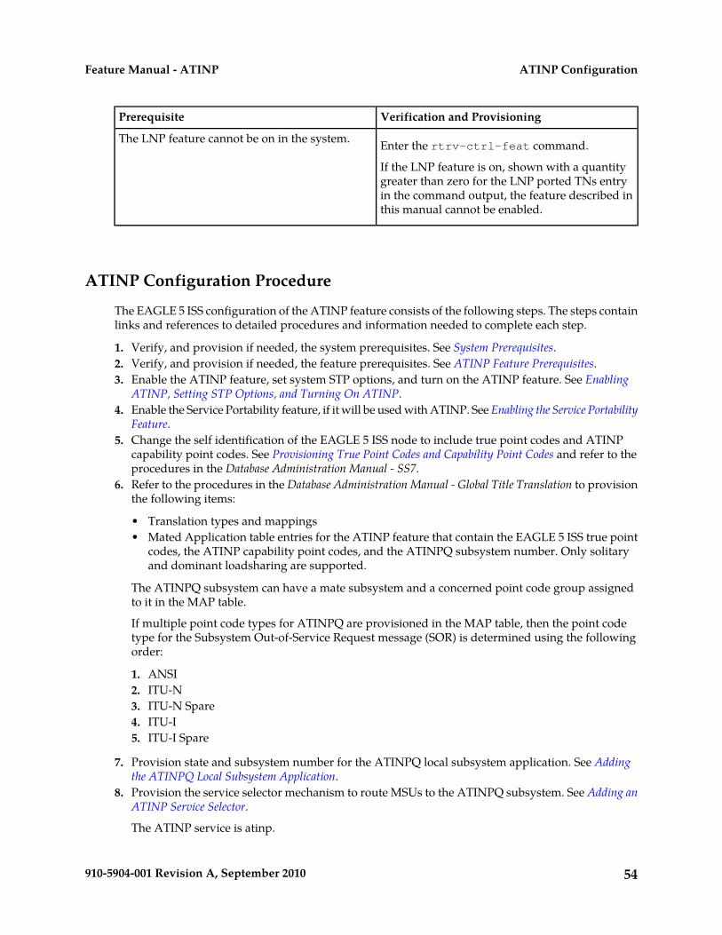
Verification and ProvisioningPrerequisite
Enter the rtrv-ctrl-feat command.The LNP feature cannot be on in the system.
If the LNP feature is on, shown with a quantitygreater than zero for the LNP ported TNs entryin the command output, the feature described inthis manual cannot be enabled.
ATINP Configuration Procedure
The EAGLE 5 ISS configuration of the ATINP feature consists of the following steps. The steps containlinks and references to detailed procedures and information needed to complete each step.
1. Verify, and provision if needed, the system prerequisites. See System Prerequisites.2. Verify, and provision if needed, the feature prerequisites. See ATINP Feature Prerequisites.3. Enable the ATINP feature, set system STP options, and turn on the ATINP feature. See Enabling
ATINP, Setting STP Options, and Turning On ATINP.4. Enable the Service Portability feature, if it will be used with ATINP. See Enabling the Service Portability
Feature.5. Change the self identification of the EAGLE 5 ISS node to include true point codes and ATINP
capability point codes. See Provisioning True Point Codes and Capability Point Codes and refer to theprocedures in the Database Administration Manual - SS7.
6. Refer to the procedures in the Database Administration Manual - Global Title Translation to provisionthe following items:
• Translation types and mappings• Mated Application table entries for the ATINP feature that contain the EAGLE 5 ISS true point
codes, the ATINP capability point codes, and the ATINPQ subsystem number. Only solitaryand dominant loadsharing are supported.
The ATINPQ subsystem can have a mate subsystem and a concerned point code group assignedto it in the MAP table.
If multiple point code types for ATINPQ are provisioned in the MAP table, then the point codetype for the Subsystem Out-of-Service Request message (SOR) is determined using the followingorder:
1. ANSI2. ITU-N3. ITU-N Spare4. ITU-I5. ITU-I Spare
7. Provision state and subsystem number for the ATINPQ local subsystem application. See Addingthe ATINPQ Local Subsystem Application.
8. Provision the service selector mechanism to route MSUs to the ATINPQ subsystem. See Adding anATINP Service Selector.
The ATINP service is atinp.
54910-5904-001 Revision A, September 2010
ATINP ConfigurationFeature Manual - ATINP
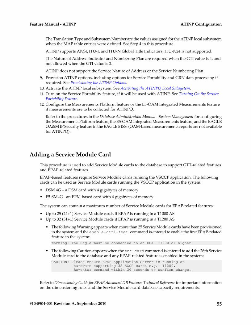
The Translation Type and Subsystem Number are the values assigned for the ATINP local subsystemwhen the MAP table entries were defined. See Step 4 in this procedure.
ATINP supports ANSI, ITU-I, and ITU-N Global Title Indicators; ITU-N24 is not supported.
The Nature of Address Indicator and Numbering Plan are required when the GTI value is 4, andnot allowed when the GTI value is 2.
ATINP does not support the Service Nature of Address or the Service Numbering Plan.9. Provision ATINP options, including options for Service Portability and GRN data processing if
required. See Provisioning the ATINP Options.10. Activate the ATINP local subsystem. See Activating the ATINPQ Local Subsystem.11. Turn on the Service Portability feature, if it will be used with ATINP. See Turning On the Service
Portability Feature.12. Configure the Measurements Platform feature or the E5-OAM Integrated Measurements feature
if measurements are to be collected for ATINPQ.
Refer to the procedures in the Database Administration Manual - System Management for configuringthe Measurements Platform feature, the E5-OAM Integrated Measurements feature, and the EAGLEOA&M IP Security feature in the EAGLE 5 ISS. (OAM-based measurements reports are not availablefor ATINPQ).
Adding a Service Module Card
This procedure is used to add Service Module cards to the database to support GTT-related featuresand EPAP-related features.
EPAP-based features require Service Module cards running the VSCCP application. The followingcards can be used as Service Module cards running the VSCCP application in the system:
• DSM 4G – a DSM card with 4 gigabytes of memory• E5-SM4G - an EPM-based card with 4 gigabytes of memory
The system can contain a maximum number of Service Module cards for EPAP-related features:
• Up to 25 (24+1) Service Module cards if EPAP is running in a T1000 AS• Up to 32 (31+1) Service Module cards if EPAP is running in a T1200 AS
• The following Warning appears when more than 25 Service Module cards have been provisionedin the system and the enable-ctrl-feat command is entered to enable the first EPAP-relatedfeature in the system:Warning: The Eagle must be connected to an EPAP T1200 or higher
• The following Caution appears when the ent-card commend is entered to add the 26th ServiceModule card to the database and any EPAP-related feature is enabled in the system:CAUTION: Please ensure EPAP Application Server is running on hardware supporting 32 SCCP cards e.g.: T1200. Re-enter command within 30 seconds to confirm change.
Refer to Dimensioning Guide for EPAP Advanced DB Features Technical Reference for important informationon the dimensioning rules and the Service Module card database capacity requirements.
55910-5904-001 Revision A, September 2010
ATINP ConfigurationFeature Manual - ATINP
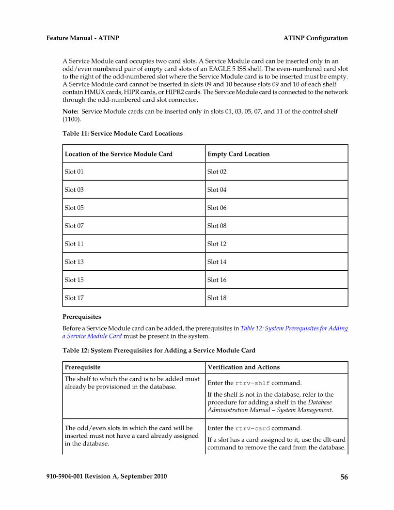
A Service Module card occupies two card slots. A Service Module card can be inserted only in anodd/even numbered pair of empty card slots of an EAGLE 5 ISS shelf. The even-numbered card slotto the right of the odd-numbered slot where the Service Module card is to be inserted must be empty.A Service Module card cannot be inserted in slots 09 and 10 because slots 09 and 10 of each shelfcontain HMUX cards, HIPR cards, or HIPR2 cards. The Service Module card is connected to the networkthrough the odd-numbered card slot connector.
Note: Service Module cards can be inserted only in slots 01, 03, 05, 07, and 11 of the control shelf(1100).
Table 11: Service Module Card Locations
Empty Card LocationLocation of the Service Module Card
Slot 02Slot 01
Slot 04Slot 03
Slot 06Slot 05
Slot 08Slot 07
Slot 12Slot 11
Slot 14Slot 13
Slot 16Slot 15
Slot 18Slot 17
Prerequisites
Before a Service Module card can be added, the prerequisites in Table 12: System Prerequisites for Addinga Service Module Card must be present in the system.
Table 12: System Prerequisites for Adding a Service Module Card
Verification and ActionsPrerequisite
Enter the rtrv-shlf command.The shelf to which the card is to be added mustalready be provisioned in the database.
If the shelf is not in the database, refer to theprocedure for adding a shelf in the DatabaseAdministration Manual – System Management.
Enter the rtrv-card command.The odd/even slots in which the card will beinserted must not have a card already assignedin the database. If a slot has a card assigned to it, use the dlt-card
command to remove the card from the database.
56910-5904-001 Revision A, September 2010
ATINP ConfigurationFeature Manual - ATINP
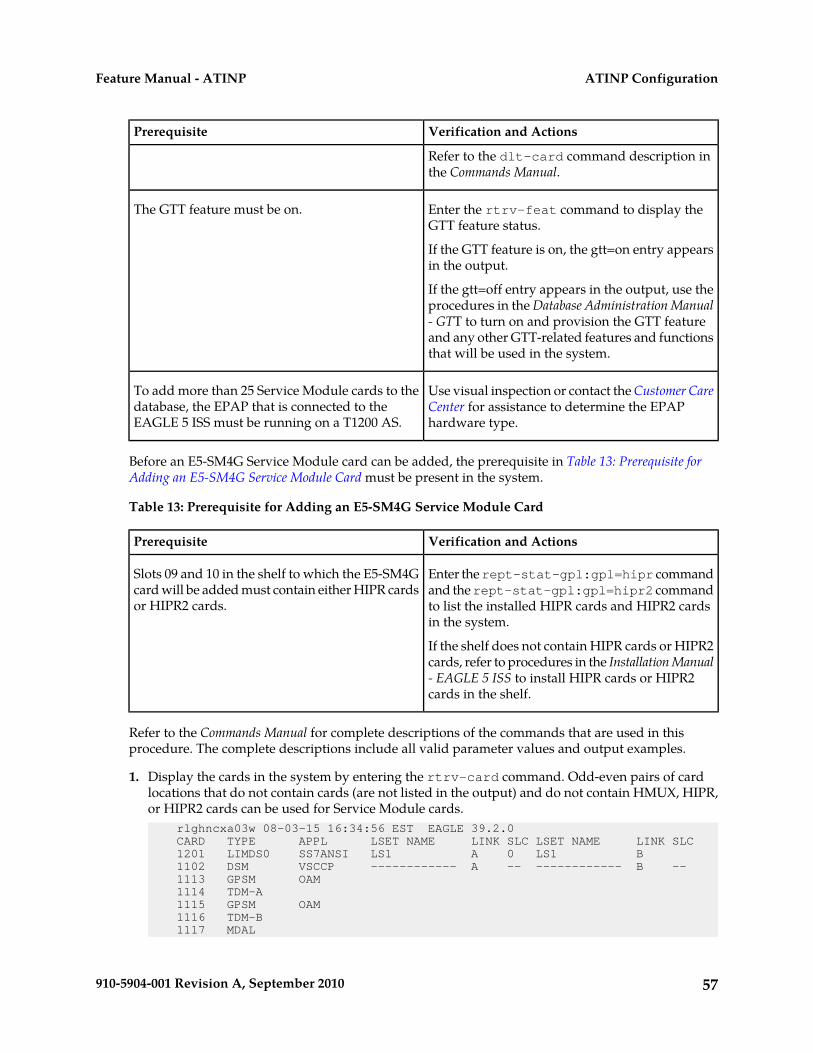
Verification and ActionsPrerequisite
Refer to the dlt-card command description inthe Commands Manual.
Enter the rtrv-feat command to display theGTT feature status.
The GTT feature must be on.
If the GTT feature is on, the gtt=on entry appearsin the output.
If the gtt=off entry appears in the output, use theprocedures in the Database Administration Manual- GTT to turn on and provision the GTT featureand any other GTT-related features and functionsthat will be used in the system.
Use visual inspection or contact the Customer CareCenter for assistance to determine the EPAPhardware type.
To add more than 25 Service Module cards to thedatabase, the EPAP that is connected to theEAGLE 5 ISS must be running on a T1200 AS.
Before an E5-SM4G Service Module card can be added, the prerequisite in Table 13: Prerequisite forAdding an E5-SM4G Service Module Card must be present in the system.
Table 13: Prerequisite for Adding an E5-SM4G Service Module Card
Verification and ActionsPrerequisite
Enter the rept-stat-gpl:gpl=hipr commandand the rept-stat-gpl:gpl=hipr2 command
Slots 09 and 10 in the shelf to which the E5-SM4Gcard will be added must contain either HIPR cardsor HIPR2 cards. to list the installed HIPR cards and HIPR2 cards
in the system.
If the shelf does not contain HIPR cards or HIPR2cards, refer to procedures in the Installation Manual- EAGLE 5 ISS to install HIPR cards or HIPR2cards in the shelf.
Refer to the Commands Manual for complete descriptions of the commands that are used in thisprocedure. The complete descriptions include all valid parameter values and output examples.
1. Display the cards in the system by entering the rtrv-card command. Odd-even pairs of cardlocations that do not contain cards (are not listed in the output) and do not contain HMUX, HIPR,or HIPR2 cards can be used for Service Module cards. rlghncxa03w 08-03-15 16:34:56 EST EAGLE 39.2.0 CARD TYPE APPL LSET NAME LINK SLC LSET NAME LINK SLC 1201 LIMDS0 SS7ANSI LS1 A 0 LS1 B 1102 DSM VSCCP ------------ A -- ------------ B -- 1113 GPSM OAM 1114 TDM-A 1115 GPSM OAM 1116 TDM-B 1117 MDAL
57910-5904-001 Revision A, September 2010
ATINP ConfigurationFeature Manual - ATINP
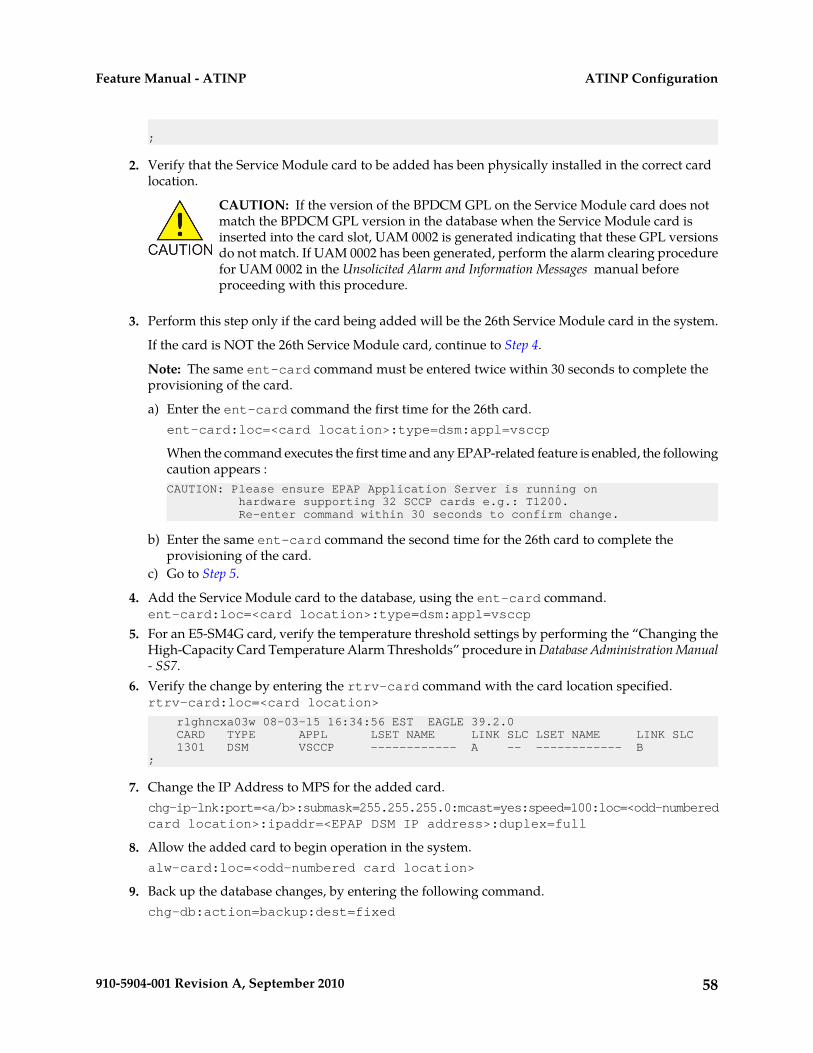
;
2. Verify that the Service Module card to be added has been physically installed in the correct cardlocation.
CAUTION: If the version of the BPDCM GPL on the Service Module card does notmatch the BPDCM GPL version in the database when the Service Module card isinserted into the card slot, UAM 0002 is generated indicating that these GPL versionsdo not match. If UAM 0002 has been generated, perform the alarm clearing procedurefor UAM 0002 in the Unsolicited Alarm and Information Messages manual beforeproceeding with this procedure.
3. Perform this step only if the card being added will be the 26th Service Module card in the system.
If the card is NOT the 26th Service Module card, continue to Step 4.
Note: The same ent-card command must be entered twice within 30 seconds to complete theprovisioning of the card.
a) Enter the ent-card command the first time for the 26th card.ent-card:loc=<card location>:type=dsm:appl=vsccp
When the command executes the first time and any EPAP-related feature is enabled, the followingcaution appears :CAUTION: Please ensure EPAP Application Server is running on hardware supporting 32 SCCP cards e.g.: T1200. Re-enter command within 30 seconds to confirm change.
b) Enter the same ent-card command the second time for the 26th card to complete theprovisioning of the card.
c) Go to Step 5.
4. Add the Service Module card to the database, using the ent-card command.ent-card:loc=<card location>:type=dsm:appl=vsccp
5. For an E5-SM4G card, verify the temperature threshold settings by performing the “Changing theHigh-Capacity Card Temperature Alarm Thresholds” procedure in Database Administration Manual- SS7.
6. Verify the change by entering the rtrv-card command with the card location specified.rtrv-card:loc=<card location>
rlghncxa03w 08-03-15 16:34:56 EST EAGLE 39.2.0 CARD TYPE APPL LSET NAME LINK SLC LSET NAME LINK SLC 1301 DSM VSCCP ------------ A -- ------------ B ;
7. Change the IP Address to MPS for the added card.chg-ip-lnk:port=<a/b>:submask=255.255.255.0:mcast=yes:speed=100:loc=<odd-numberedcard location>:ipaddr=<EPAP DSM IP address>:duplex=full
8. Allow the added card to begin operation in the system.alw-card:loc=<odd-numbered card location>
9. Back up the database changes, by entering the following command.chg-db:action=backup:dest=fixed
58910-5904-001 Revision A, September 2010
ATINP ConfigurationFeature Manual - ATINP
The following messages should appear; the active Maintenance and Administration SubsystemProcessor (MASP) appears first.
BACKUP (FIXED) : MASP A - Backup starts on active MASP.BACKUP (FIXED) : MASP A - Backup on active MASP to fixed disk complete.BACKUP (FIXED) : MASP A - Backup starts on standby MASP.BACKUP (FIXED) : MASP A - Backup on standby MASP to fixed disk complete.
10. Repeat this procedure for each Service Module card that needs to be added to the system.
Enabling ATINP, Setting STP Options, and Turning On ATINP
This procedure is used to enable the ATINP feature, set the system STP options, and turn on the ATINPfeature in the EAGLE 5 ISS.
• The ATINP feature must be enabled using the ATINP feature part number 893022101 and a featureaccess key.
Note: Controlled features must be purchased before you can receive the feature access key to useto enable the feature. If you are not sure if you have purchased a feature and received the featureaccess key, contact your Tekelec Sales Representative or Account Representative.
When the ATINP feature is enabled, it is permanently enabled. The ATINP feature cannot betemporarily enabled.
Note: Provisioning of ATINP options and other information can be done after the feature is enabledand before the feature is turned on.
• After the ATINP feature has been enabled, the STP option for the default country code must bechanged from NONE to an appropriate value for ATINP.
The chg-stpopts and rtrv-stpopts commands support the defcc and dsmaud parametersfor the ATINP feature.
In the rtrv-stpopts command output, the defcc parameter is displayed with value NONE whenthe ATINP feature is enabled.
• After the ATINP feature has been enabled, the STP options are set, and database provisioning iscomplete, the ATINP feature status must be set to on (the feature must be “turned on”).
After the ATINP feature is enabled and turned on, the ATINP feature can be turned off again.
When the feature is turned on:
• The defcc parameter value cannot be set to NONE.• The DSM audit running state (dsmaud) parameter of the chg-stpopts command can be
provisioned for ATINP.• The dsmaud parameter is displayed with value off when the ATINP feature is turned on.
1. Enable the ATINP feature, by entering the enable-ctrl-feat command.enable-ctrl-feat:partnum=893022101:fak=<feature access key>
Note: The feature access key (the fak parameter) is provided by Tekelec. If you do not have thecontrolled feature part number or the feature access key for the feature, contact your Tekelec SalesRepresentative or Account Representative.
59910-5904-001 Revision A, September 2010
ATINP ConfigurationFeature Manual - ATINP
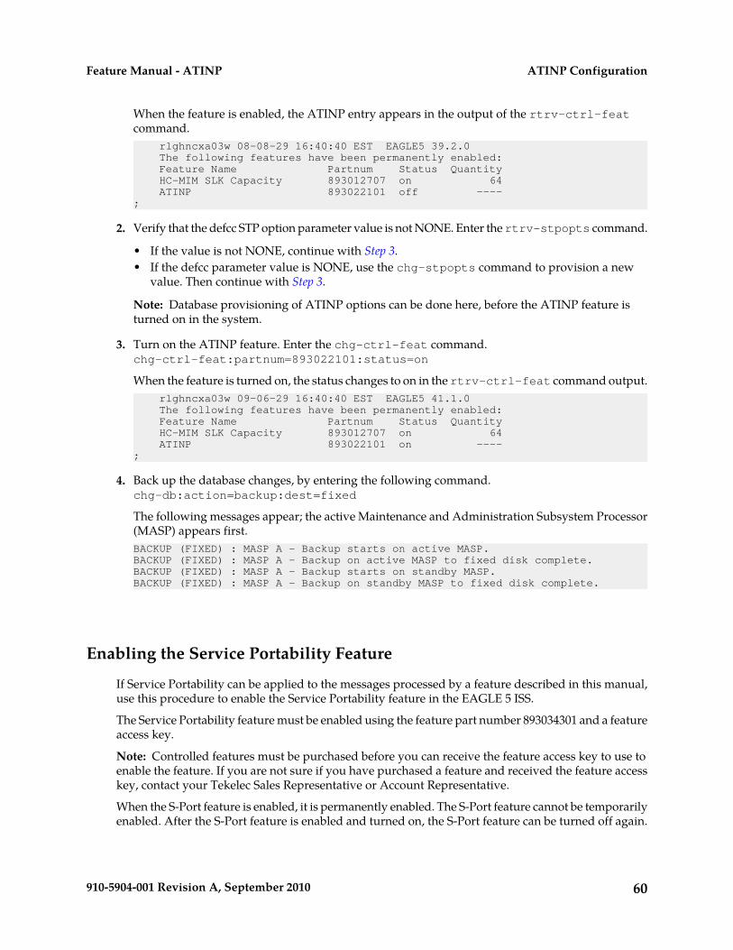
When the feature is enabled, the ATINP entry appears in the output of the rtrv-ctrl-featcommand. rlghncxa03w 08-08-29 16:40:40 EST EAGLE5 39.2.0 The following features have been permanently enabled: Feature Name Partnum Status Quantity HC-MIM SLK Capacity 893012707 on 64 ATINP 893022101 off ----;
2. Verify that the defcc STP option parameter value is not NONE. Enter the rtrv-stpopts command.
• If the value is not NONE, continue with Step 3.• If the defcc parameter value is NONE, use the chg-stpopts command to provision a new
value. Then continue with Step 3.
Note: Database provisioning of ATINP options can be done here, before the ATINP feature isturned on in the system.
3. Turn on the ATINP feature. Enter the chg-ctrl-feat command.chg-ctrl-feat:partnum=893022101:status=on
When the feature is turned on, the status changes to on in the rtrv-ctrl-feat command output. rlghncxa03w 09-06-29 16:40:40 EST EAGLE5 41.1.0 The following features have been permanently enabled: Feature Name Partnum Status Quantity HC-MIM SLK Capacity 893012707 on 64 ATINP 893022101 on ----;
4. Back up the database changes, by entering the following command.chg-db:action=backup:dest=fixed
The following messages appear; the active Maintenance and Administration Subsystem Processor(MASP) appears first.BACKUP (FIXED) : MASP A - Backup starts on active MASP.BACKUP (FIXED) : MASP A - Backup on active MASP to fixed disk complete.BACKUP (FIXED) : MASP A - Backup starts on standby MASP.BACKUP (FIXED) : MASP A - Backup on standby MASP to fixed disk complete.
Enabling the Service Portability Feature
If Service Portability can be applied to the messages processed by a feature described in this manual,use this procedure to enable the Service Portability feature in the EAGLE 5 ISS.
The Service Portability feature must be enabled using the feature part number 893034301 and a featureaccess key.
Note: Controlled features must be purchased before you can receive the feature access key to use toenable the feature. If you are not sure if you have purchased a feature and received the feature accesskey, contact your Tekelec Sales Representative or Account Representative.
When the S-Port feature is enabled, it is permanently enabled. The S-Port feature cannot be temporarilyenabled. After the S-Port feature is enabled and turned on, the S-Port feature can be turned off again.
60910-5904-001 Revision A, September 2010
ATINP ConfigurationFeature Manual - ATINP
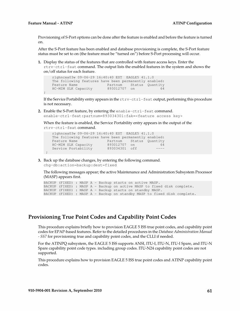
Provisioning of S-Port options can be done after the feature is enabled and before the feature is turnedon.
After the S-Port feature has been enabled and database provisioning is complete, the S-Port featurestatus must be set to on (the feature must be “turned on”) before S-Port processing will occur.
1. Display the status of the features that are controlled with feature access keys. Enter thertrv-ctrl-feat command. The output lists the enabled features in the system and shows theon/off status for each feature. rlghncxa03w 09-06-29 16:40:40 EST EAGLE5 41.1.0 The following features have been permanently enabled: Feature Name Partnum Status Quantity HC-MIM SLK Capacity 893012707 on 64;
If the Service Portability entry appears in the rtrv-ctrl-feat output, performing this procedureis not necessary.
2. Enable the S-Port feature, by entering the enable-ctrl-feat command.enable-ctrl-feat:partnum=893034301:fak=<feature access key>
When the feature is enabled, the Service Portability entry appears in the output of thertrv-ctrl-feat command. rlghncxa03w 09-06-29 16:40:40 EST EAGLE5 41.1.0 The following features have been permanently enabled: Feature Name Partnum Status Quantity HC-MIM SLK Capacity 893012707 on 64 Service Portability 893034301 off ---- ;
3. Back up the database changes, by entering the following command.chg-db:action=backup:dest=fixed
The following messages appear; the active Maintenance and Administration Subsystem Processor(MASP) appears first.BACKUP (FIXED) : MASP A - Backup starts on active MASP.BACKUP (FIXED) : MASP A - Backup on active MASP to fixed disk complete.BACKUP (FIXED) : MASP A - Backup starts on standby MASP.BACKUP (FIXED) : MASP A - Backup on standby MASP to fixed disk complete.
Provisioning True Point Codes and Capability Point Codes
This procedure explains briefly how to provision EAGLE 5 ISS true point codes, and capability pointcodes for EPAP-based features. Refer to the detailed procedures in the Database Administration Manual- SS7 for provisioning true and capability point codes, and the CLLI if needed.
For the ATINPQ subsystem, the EAGLE 5 ISS supports ANSI, ITU-I, ITU-N, ITU-I Spare, and ITU-NSpare capability point code types. including group codes. ITU-N24 capability point codes are notsupported.
This procedure explains how to provision EAGLE 5 ISS true point codes and ATINP capability pointcodes.
61910-5904-001 Revision A, September 2010
ATINP ConfigurationFeature Manual - ATINP
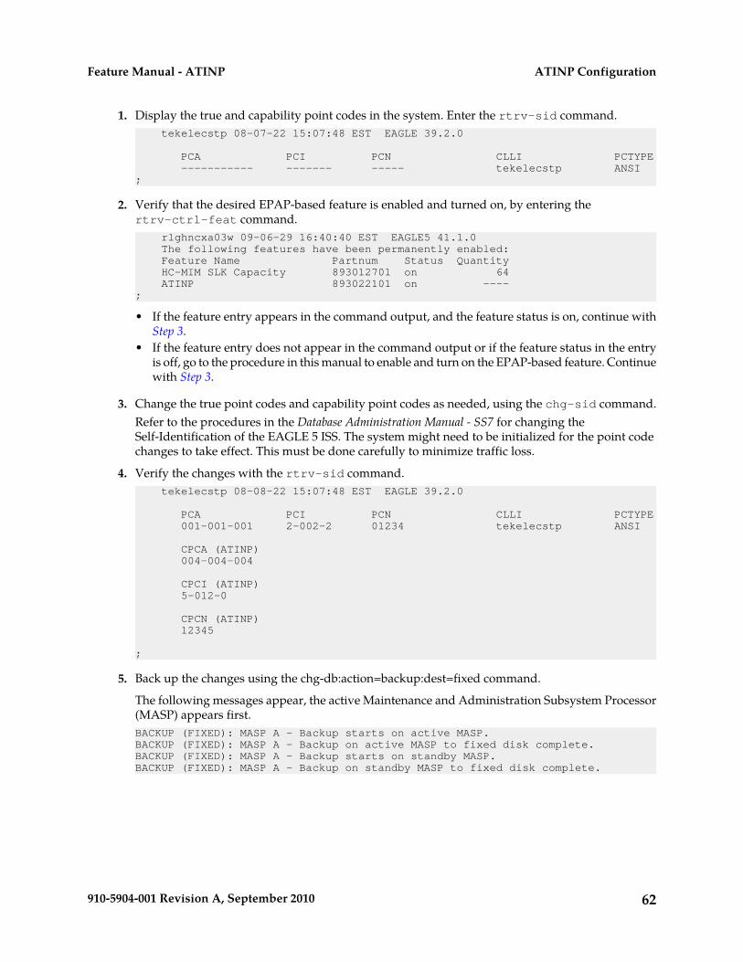
1. Display the true and capability point codes in the system. Enter the rtrv-sid command. tekelecstp 08-07-22 15:07:48 EST EAGLE 39.2.0
PCA PCI PCN CLLI PCTYPE ----------- ------- ----- tekelecstp ANSI;
2. Verify that the desired EPAP-based feature is enabled and turned on, by entering thertrv-ctrl-feat command. rlghncxa03w 09-06-29 16:40:40 EST EAGLE5 41.1.0 The following features have been permanently enabled: Feature Name Partnum Status Quantity HC-MIM SLK Capacity 893012701 on 64 ATINP 893022101 on ----;
• If the feature entry appears in the command output, and the feature status is on, continue withStep 3.
• If the feature entry does not appear in the command output or if the feature status in the entryis off, go to the procedure in this manual to enable and turn on the EPAP-based feature. Continuewith Step 3.
3. Change the true point codes and capability point codes as needed, using the chg-sid command.Refer to the procedures in the Database Administration Manual - SS7 for changing theSelf-Identification of the EAGLE 5 ISS. The system might need to be initialized for the point codechanges to take effect. This must be done carefully to minimize traffic loss.
4. Verify the changes with the rtrv-sid command. tekelecstp 08-08-22 15:07:48 EST EAGLE 39.2.0
PCA PCI PCN CLLI PCTYPE 001-001-001 2-002-2 01234 tekelecstp ANSI
CPCA (ATINP) 004-004-004
CPCI (ATINP) 5-012-0
CPCN (ATINP) 12345
;
5. Back up the changes using the chg-db:action=backup:dest=fixed command.
The following messages appear, the active Maintenance and Administration Subsystem Processor(MASP) appears first.BACKUP (FIXED): MASP A - Backup starts on active MASP.BACKUP (FIXED): MASP A - Backup on active MASP to fixed disk complete.BACKUP (FIXED): MASP A - Backup starts on standby MASP.BACKUP (FIXED): MASP A - Backup on standby MASP to fixed disk complete.
62910-5904-001 Revision A, September 2010
ATINP ConfigurationFeature Manual - ATINP
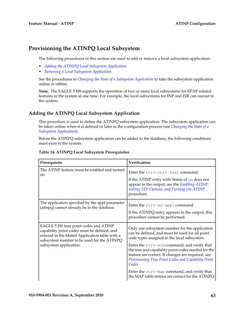
Provisioning the ATINPQ Local Subsystem
The following procedures in this section are used to add or remove a local subsystem application:
• Adding the ATINPQ Local Subsystem Application• Removing a Local Subsystem Application
See the procedures in Changing the State of a Subsystem Application to take the subsystem applicationonline or offline.
Note: The EAGLE 5 ISS supports the operation of two or more local subsystems for EPAP-relatedfeatures in the system at one time. For example, the local subsystems for INP and EIR can coexist inthe system.
Adding the ATINPQ Local Subsystem Application
This procedure is used to define the ATINPQ subsystem application. The subsystem application canbe taken online when it is defined or later in the configuration process (see Changing the State of aSubsystem Application).
Before the ATINPQ subsystem application can be added to the database, the following conditionsmust exist in the system:
Table 14: ATINPQ Local Subsystem Prerequisites
VerificationPrerequisite
Enter the rtrv-ctrl-feat command.The ATINP feature must be enabled and turnedon
If the ATINP entry with Status of on does notappear in the output, see the Enabling ATINP,Setting STP Options, and Turning On ATINPprocedure.
Enter the rtrv-ss-appl command.The application specified by the appl parameter(atinpq) cannot already be in the database.
If the ATINPQ entry appears in the output, thisprocedure cannot be performed.
Only one subsystem number for the applicationcan be defined, and must be used for all pointcode types assigned to the local subsystem.
EAGLE 5 ISS true point codes and ATINPcapability point codes must be defined, andentered in the Mated Application table with asubsystem number to be used for the ATINPQsubsystem application. Enter the rtrv-sid command, and verify that
the true and capability point codes needed for thefeature are correct. If changes are required, seeProvisioning True Point Codes and Capability PointCodes
Enter the rtrv-map command, and verify thatthe MAP table entries are correct for the ATINPQ
63910-5904-001 Revision A, September 2010
ATINP ConfigurationFeature Manual - ATINP
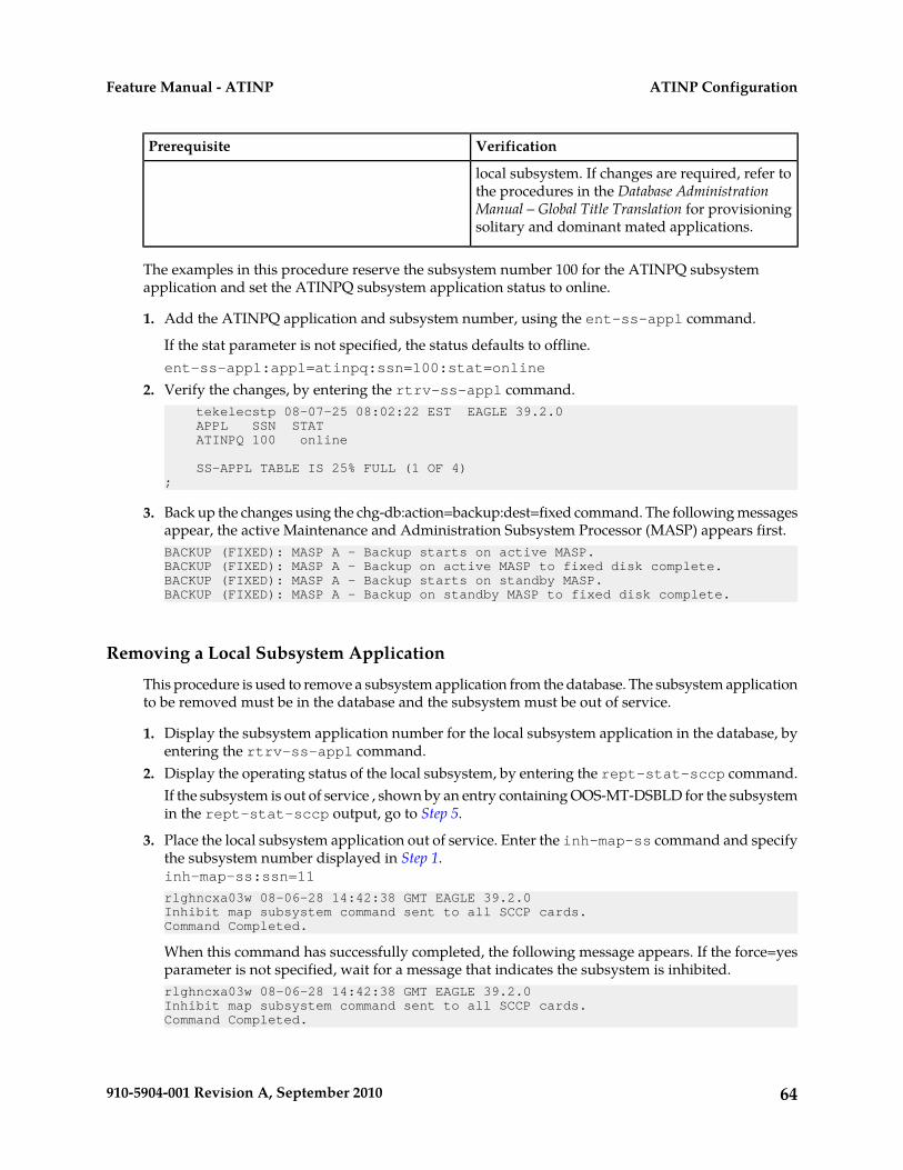
VerificationPrerequisite
local subsystem. If changes are required, refer tothe procedures in the Database AdministrationManual – Global Title Translation for provisioningsolitary and dominant mated applications.
The examples in this procedure reserve the subsystem number 100 for the ATINPQ subsystemapplication and set the ATINPQ subsystem application status to online.
1. Add the ATINPQ application and subsystem number, using the ent-ss-appl command.
If the stat parameter is not specified, the status defaults to offline.ent-ss-appl:appl=atinpq:ssn=100:stat=online
2. Verify the changes, by entering the rtrv-ss-appl command. tekelecstp 08-07-25 08:02:22 EST EAGLE 39.2.0 APPL SSN STAT ATINPQ 100 online
SS-APPL TABLE IS 25% FULL (1 OF 4);
3. Back up the changes using the chg-db:action=backup:dest=fixed command. The following messagesappear, the active Maintenance and Administration Subsystem Processor (MASP) appears first.BACKUP (FIXED): MASP A - Backup starts on active MASP.BACKUP (FIXED): MASP A - Backup on active MASP to fixed disk complete.BACKUP (FIXED): MASP A - Backup starts on standby MASP.BACKUP (FIXED): MASP A - Backup on standby MASP to fixed disk complete.
Removing a Local Subsystem Application
This procedure is used to remove a subsystem application from the database. The subsystem applicationto be removed must be in the database and the subsystem must be out of service.
1. Display the subsystem application number for the local subsystem application in the database, byentering the rtrv-ss-appl command.
2. Display the operating status of the local subsystem, by entering the rept-stat-sccp command.If the subsystem is out of service , shown by an entry containing OOS-MT-DSBLD for the subsystemin the rept-stat-sccp output, go to Step 5.
3. Place the local subsystem application out of service. Enter the inh-map-ss command and specifythe subsystem number displayed in Step 1.inh-map-ss:ssn=11
rlghncxa03w 08-06-28 14:42:38 GMT EAGLE 39.2.0Inhibit map subsystem command sent to all SCCP cards.Command Completed.
When this command has successfully completed, the following message appears. If the force=yesparameter is not specified, wait for a message that indicates the subsystem is inhibited.rlghncxa03w 08-06-28 14:42:38 GMT EAGLE 39.2.0Inhibit map subsystem command sent to all SCCP cards.Command Completed.
64910-5904-001 Revision A, September 2010
ATINP ConfigurationFeature Manual - ATINP
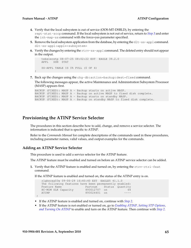
4. Verify that the local subsystem is out of service (OOS-MT-DSBLD), by entering therept-stat-sccp command. If the local subsystem is not out of service, return to Step 3 and enterthe inh-map-ss command with the force=yes parameter specified.
5. Remove the local subsystem application from the database, by entering the dlt-ss-appl command.dlt-ss-appl:appl=<subsystem>
6. Verify the changes by entering the rtrv-ss-appl command. The deleted entry should not appearin the output. tekelecstp 08-07-25 08:02:22 EST EAGLE 39.2.0 APPL SSN STAT
SS-APPL TABLE IS 0% FULL (0 OF 4);
7. Back up the changes using the chg-db:action=backup:dest=fixed command.The following messages appear, the active Maintenance and Administration Subsystem Processor(MASP) appears first.BACKUP (FIXED): MASP A - Backup starts on active MASP.BACKUP (FIXED): MASP A - Backup on active MASP to fixed disk complete.BACKUP (FIXED): MASP A - Backup starts on standby MASP.BACKUP (FIXED): MASP A - Backup on standby MASP to fixed disk complete.
Provisioning the ATINP Service Selector
The procedures in this section describe how to add, change, and remove a service selector. Theinformation is indicated that is specific to ATINP.
Refer to the Commands Manual for complete descriptions of the commands used in these procedures,including parameter names, valid values, and output examples for the commands.
Adding an ATINP Service Selector
This procedure is used to add a service selector for the ATINP feature.
The ATINP feature must be enabled and turned on before an ATINP service selector can be added.
1. Verify that the ATINP feature is enabled and turned on, by entering the rtrv-ctrl-featcommand.
If the ATINP feature is enabled and turned on, the status of the ATINP entry is on. rlghncxa03w 09-06-29 16:40:40 EST EAGLE5 41.1.0 The following features have been permanently enabled: Feature Name Partnum Status Quantity HC-MIM SLK Capacity 893012707 on 64 ATINP 893024401 on ---- ;
• If the ATINP feature is enabled and turned on, continue with Step 2.• If the ATINP feature is not enabled or turned on, go to Enabling ATINP, Setting STP Options,
and Turning On ATINP to enable and turn on the ATINP feature. Then continue with Step 2.
65910-5904-001 Revision A, September 2010
ATINP ConfigurationFeature Manual - ATINP
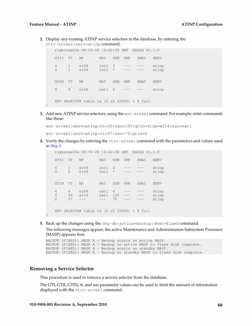
2. Display any existing ATINP service selectors in the database, by entering thertrv-srvsel:serv=atinp command. rlghncxa03w 08-06-28 14:42:38 GMT EAGLE 41.1.0
GTII TT NP NAI SSN SNP SNAI SERV
4 1 e164 intl 3 --- --- atinp 4 2 e164 intl * --- --- atinp
GTIN TT NP NAI SSN SNP SNAI SERV
4 4 e164 natl 4 --- --- atinp
SRV SELECTOR table is (3 of 20992) 1 % full ;
3. Add new ATINP service selectors, using the ent-srvsel command. For example, enter commandslike these:
ent-srvsel:serv=atinp:tt=35:ssn=100:gtin=4:np=e214:nai=natl
ent-srvsel:serv=atinp:tt=57:ssn=75:gtin=2
4. Verify the changes by entering the rtrv-srvsel command with the parameters and values usedin Step 3. rlghncxa03w 08-06-28 14:42:38 GMT EAGLE 41.1.0
GTII TT NP NAI SSN SNP SNAI SERV
4 1 e164 intl 3 --- --- atinp 4 2 e164 intl * --- --- atinp
GTIN TT NP NAI SSN SNP SNAI SERV
4 4 e164 natl 4 --- --- atinp 4 35 e214 natl 100 --- --- atinp 2 57 --- --- 75 --- --- atinp
SRV SELECTOR table is (5 of 20992) 1 % full ;
5. Back up the changes using the chg-db:action=backup:dest=fixed command.The following messages appear, the active Maintenance and Administration Subsystem Processor(MASP) appears first.BACKUP (FIXED): MASP A - Backup starts on active MASP.BACKUP (FIXED): MASP A - Backup on active MASP to fixed disk complete.BACKUP (FIXED): MASP A - Backup starts on standby MASP.BACKUP (FIXED): MASP A - Backup on standby MASP to fixed disk complete.
Removing a Service Selector
This procedure is used to remove a service selector from the database.
The GTI, GTII, GTIN, tt, and ssn parameter values can be used to limit the amount of informationdisplayed with the rtrv-srvsel command.
66910-5904-001 Revision A, September 2010
ATINP ConfigurationFeature Manual - ATINP
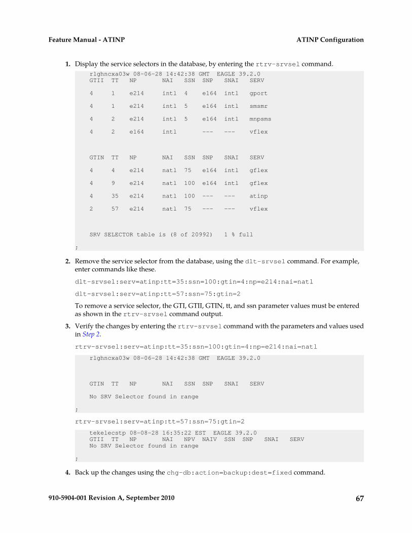
1. Display the service selectors in the database, by entering the rtrv-srvsel command. rlghncxa03w 08-06-28 14:42:38 GMT EAGLE 39.2.0 GTII TT NP NAI SSN SNP SNAI SERV
4 1 e214 intl 4 e164 intl gport
4 1 e214 intl 5 e164 intl smsmr
4 2 e214 intl 5 e164 intl mnpsms
4 2 e164 intl --- --- vflex
GTIN TT NP NAI SSN SNP SNAI SERV
4 4 e214 natl 75 e164 intl gflex
4 9 e214 natl 100 e164 intl gflex
4 35 e214 natl 100 --- --- atinp
2 57 e214 natl 75 --- --- vflex
SRV SELECTOR table is (8 of 20992) 1 % full
;
2. Remove the service selector from the database, using the dlt-srvsel command. For example,enter commands like these.
dlt-srvsel:serv=atinp:tt=35:ssn=100:gtin=4:np=e214:nai=natl
dlt-srvsel:serv=atinp:tt=57:ssn=75:gtin=2
To remove a service selector, the GTI, GTII, GTIN, tt, and ssn parameter values must be enteredas shown in the rtrv-srvsel command output.
3. Verify the changes by entering the rtrv-srvsel command with the parameters and values usedin Step 2.
rtrv-srvsel:serv=atinp:tt=35:ssn=100:gtin=4:np=e214:nai=natl
rlghncxa03w 08-06-28 14:42:38 GMT EAGLE 39.2.0
GTIN TT NP NAI SSN SNP SNAI SERV
No SRV Selector found in range
;
rtrv-srvsel:serv=atinp:tt=57:ssn=75:gtin=2
tekelecstp 08-08-28 16:35:22 EST EAGLE 39.2.0 GTII TT NP NAI NPV NAIV SSN SNP SNAI SERV No SRV Selector found in range
;
4. Back up the changes using the chg-db:action=backup:dest=fixed command.
67910-5904-001 Revision A, September 2010
ATINP ConfigurationFeature Manual - ATINP
The following messages appear, the active Maintenance and Administration Subsystem Processor(MASP) appears first.BACKUP (FIXED): MASP A - Backup starts on active MASP.BACKUP (FIXED): MASP A - Backup on active MASP to fixed disk complete.BACKUP (FIXED): MASP A - Backup starts on standby MASP.BACKUP (FIXED): MASP A - Backup on standby MASP to fixed disk complete.
Changing an Existing Service Selector to an ATINP Service Selector
This procedure is used to change an existing non-ATINP service selector to a ATINP service selector.
The only parameters that can be changed using this procedure are::nserv
New DSM service type, ATINP:nsnp
An ATINP service selector cannot contain an SNP value; if the service selector beingchanged contains an SNP value, this value must be changed to none with thisparameter.
:nsnaiAn ATINP service selector cannot contain an SNAI value; if the service selector beingchanged contains an SNAI value, this value must be changed to none with thisparameter.
The chg-srvsel command requires that the following parameters be specified with the values shownin the rtrv-srvsel output for the service selector that is being changed. If any of these parametervalues need to be changed for a ATINP service selector, use the procedure in Removing a Service Selectorto remove the existing service selector. Then use the procedure in Adding an ATINP Service Selector toadd the new ATINP service selector with the new parameter information.:gtii/gtin/gtin24
Global title indicator for ITU international (gtii), ITU national using 14-bit point codes(gtin), and ITU national using 24-bit point codes (gtin24).
:ttTranslation type
:ssnSubsystem number
:naiNature of address indicator
:naivNature of address indicator value
:npNumbering plan
:npvNumbering plan value
68910-5904-001 Revision A, September 2010
ATINP ConfigurationFeature Manual - ATINP
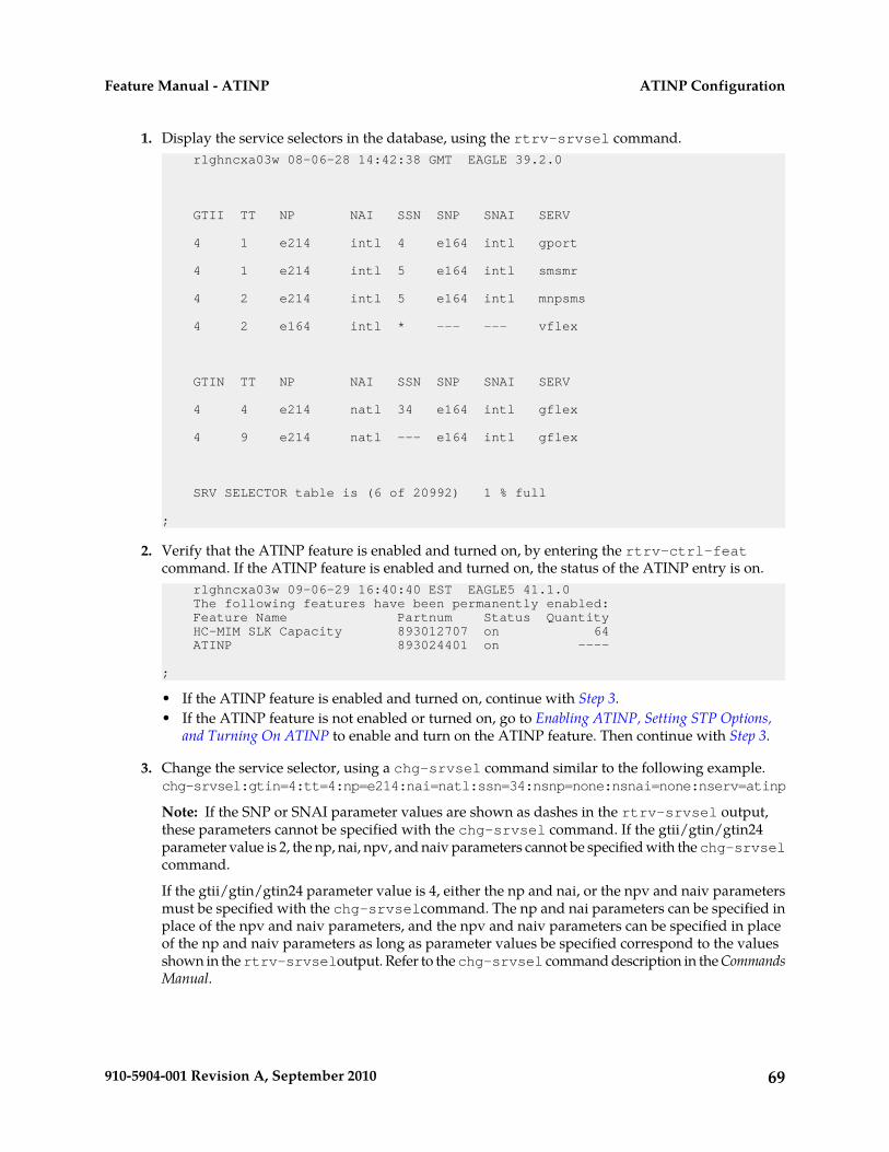
1. Display the service selectors in the database, using the rtrv-srvsel command. rlghncxa03w 08-06-28 14:42:38 GMT EAGLE 39.2.0
GTII TT NP NAI SSN SNP SNAI SERV
4 1 e214 intl 4 e164 intl gport
4 1 e214 intl 5 e164 intl smsmr
4 2 e214 intl 5 e164 intl mnpsms
4 2 e164 intl * --- --- vflex
GTIN TT NP NAI SSN SNP SNAI SERV
4 4 e214 natl 34 e164 intl gflex
4 9 e214 natl --- e164 intl gflex
SRV SELECTOR table is (6 of 20992) 1 % full
;
2. Verify that the ATINP feature is enabled and turned on, by entering the rtrv-ctrl-featcommand. If the ATINP feature is enabled and turned on, the status of the ATINP entry is on. rlghncxa03w 09-06-29 16:40:40 EST EAGLE5 41.1.0 The following features have been permanently enabled: Feature Name Partnum Status Quantity HC-MIM SLK Capacity 893012707 on 64 ATINP 893024401 on ----
;
• If the ATINP feature is enabled and turned on, continue with Step 3.• If the ATINP feature is not enabled or turned on, go to Enabling ATINP, Setting STP Options,
and Turning On ATINP to enable and turn on the ATINP feature. Then continue with Step 3.
3. Change the service selector, using a chg-srvsel command similar to the following example.chg-srvsel:gtin=4:tt=4:np=e214:nai=natl:ssn=34:nsnp=none:nsnai=none:nserv=atinp
Note: If the SNP or SNAI parameter values are shown as dashes in the rtrv-srvsel output,these parameters cannot be specified with the chg-srvsel command. If the gtii/gtin/gtin24parameter value is 2, the np, nai, npv, and naiv parameters cannot be specified with the chg-srvselcommand.
If the gtii/gtin/gtin24 parameter value is 4, either the np and nai, or the npv and naiv parametersmust be specified with the chg-srvselcommand. The np and nai parameters can be specified inplace of the npv and naiv parameters, and the npv and naiv parameters can be specified in placeof the np and naiv parameters as long as parameter values be specified correspond to the valuesshown in the rtrv-srvseloutput. Refer to the chg-srvsel command description in the CommandsManual.
69910-5904-001 Revision A, September 2010
ATINP ConfigurationFeature Manual - ATINP
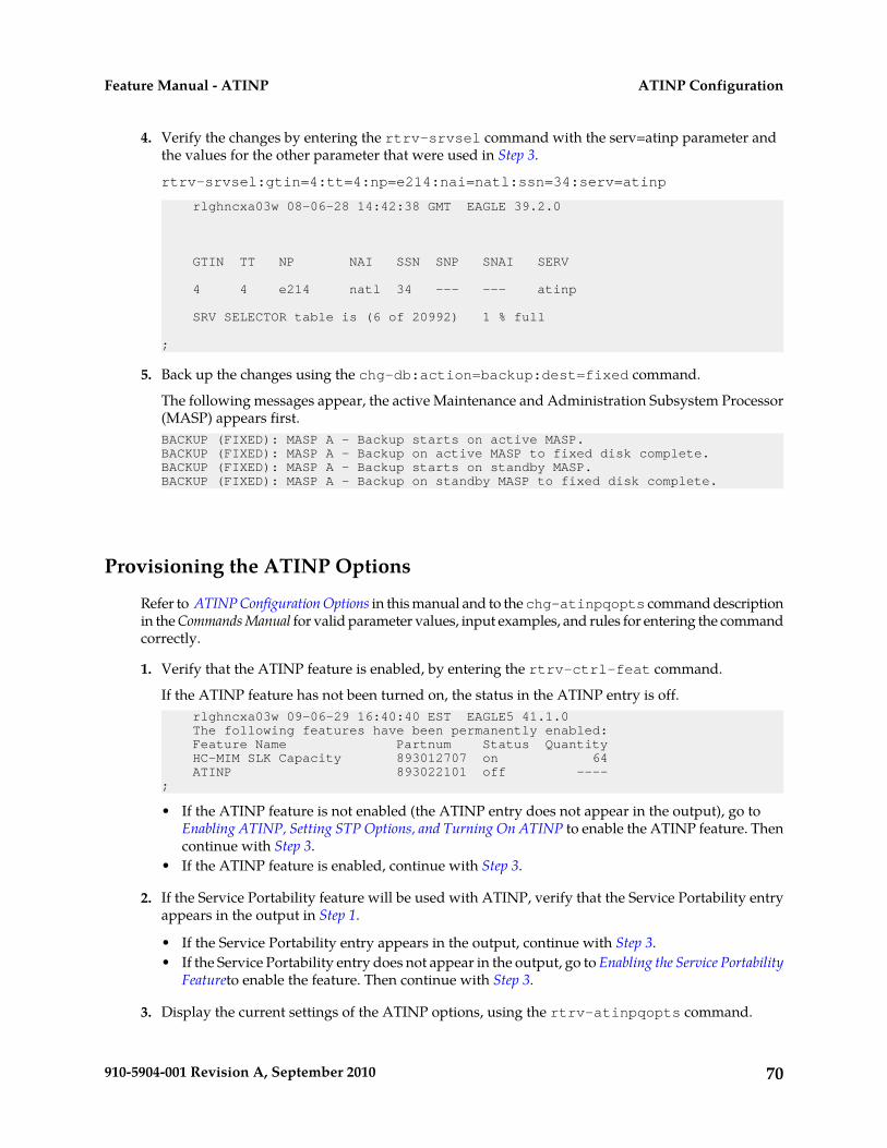
4. Verify the changes by entering the rtrv-srvsel command with the serv=atinp parameter andthe values for the other parameter that were used in Step 3.
rtrv-srvsel:gtin=4:tt=4:np=e214:nai=natl:ssn=34:serv=atinp
rlghncxa03w 08-06-28 14:42:38 GMT EAGLE 39.2.0
GTIN TT NP NAI SSN SNP SNAI SERV
4 4 e214 natl 34 --- --- atinp
SRV SELECTOR table is (6 of 20992) 1 % full
;
5. Back up the changes using the chg-db:action=backup:dest=fixed command.
The following messages appear, the active Maintenance and Administration Subsystem Processor(MASP) appears first.BACKUP (FIXED): MASP A - Backup starts on active MASP.BACKUP (FIXED): MASP A - Backup on active MASP to fixed disk complete.BACKUP (FIXED): MASP A - Backup starts on standby MASP.BACKUP (FIXED): MASP A - Backup on standby MASP to fixed disk complete.
Provisioning the ATINP Options
Refer to ATINP Configuration Options in this manual and to the chg-atinpqopts command descriptionin the Commands Manual for valid parameter values, input examples, and rules for entering the commandcorrectly.
1. Verify that the ATINP feature is enabled, by entering the rtrv-ctrl-feat command.
If the ATINP feature has not been turned on, the status in the ATINP entry is off. rlghncxa03w 09-06-29 16:40:40 EST EAGLE5 41.1.0 The following features have been permanently enabled: Feature Name Partnum Status Quantity HC-MIM SLK Capacity 893012707 on 64 ATINP 893022101 off ----;
• If the ATINP feature is not enabled (the ATINP entry does not appear in the output), go toEnabling ATINP, Setting STP Options, and Turning On ATINP to enable the ATINP feature. Thencontinue with Step 3.
• If the ATINP feature is enabled, continue with Step 3.
2. If the Service Portability feature will be used with ATINP, verify that the Service Portability entryappears in the output in Step 1.
• If the Service Portability entry appears in the output, continue with Step 3.• If the Service Portability entry does not appear in the output, go to Enabling the Service Portability
Featureto enable the feature. Then continue with Step 3.
3. Display the current settings of the ATINP options, using the rtrv-atinpqopts command.
70910-5904-001 Revision A, September 2010
ATINP ConfigurationFeature Manual - ATINP

4. Change the ATINP options to the required settings, by entering the chg-atinpqopts commandwith at least one of the ATINP option parameters specified. If Service Portability will be used withATINP, change the ATINP options that apply to Service Portability to the required settings.Refer to ATINP Configuration Options in this manual and to the chg-atinpqopts commanddescription in the Commands Manual for valid parameter values, input examples, and rules forentering the command correctly.chg-atinpqopts:atinptype=<type>:snai=<snai>:atidlm=<delimiter>
5. Verify the changes, by entering the rtrv-atinpqopts command.6. If the ATINP feature was not turned on (status is off in the output in Step 1), go to Enabling ATINP,
Setting STP Options, and Turning On ATINP to turn on the feature.7. Back up the changes, using the chg-db:action=backup:dest=fixed command.
These messages appear, the active Maintenance and Administration Subsystem Processor (MASP)appears first.BACKUP (FIXED) : MASP A - Backup starts on active MASP.BACKUP (FIXED) : MASP A - Backup on active MASP to fixed disk complete.BACKUP (FIXED) : MASP A - Backup starts on standby MASP.BACKUP (FIXED) : MASP A - Backup on standby MASP to fixed disk complete.
Activating the ATINPQ Local Subsystem
The procedure in this section explains how to activate the ATINPQ local subsystem.
When all feature configuration is complete, the ATINPQ subsystem application must taken onlineand the local subsystem must be activated to allow it to begin operation.
When the local subsystem operating state is Inhibited, the chg-ss-appl command can be used tochange the online or offline database state of the subsystem. The rtrv-ss-appl command displaysthe online or offline provisioned value.
When the first Service Module card is loaded, this state tells whether the subsystem should beconsidered allowed (online) or inhibited (offline). This is a database state. If the command is accepted,then the change is made to the tables and can be read after an init-sys command is entered toinitialize the system.
When the Service Module cards are in-service and the subsystem application is online, thealw/inh-map-ss commands can be used to change the dynamic operating state of the local subsystemto allowed or inhibited. The inh-map-ss command does not necessarily force a state change, becauseit can fail if the mate does not send an SOG. The force=yes parameter must be specified to bypass theSOR/SOG exchange and inhibit immediately. (There is no rtrv-map-ss command.)
The procedures in Changing the State of a Subsystem Application explain how to take a local subsystemonline and offline.
71910-5904-001 Revision A, September 2010
ATINP ConfigurationFeature Manual - ATINP
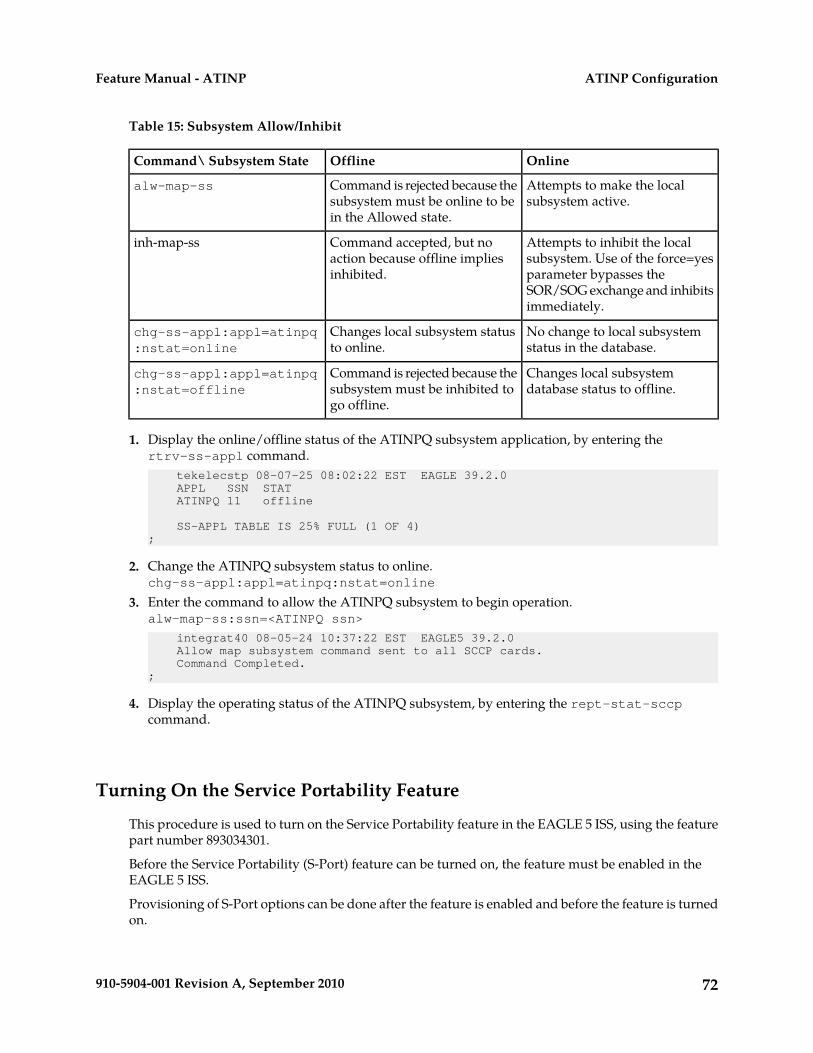
Table 15: Subsystem Allow/Inhibit
OnlineOfflineCommand\ Subsystem State
Attempts to make the localsubsystem active.
Command is rejected because thesubsystem must be online to bein the Allowed state.
alw-map-ss
Attempts to inhibit the localsubsystem. Use of the force=yes
Command accepted, but noaction because offline impliesinhibited.
inh-map-ss
parameter bypasses theSOR/SOG exchange and inhibitsimmediately.
No change to local subsystemstatus in the database.
Changes local subsystem statusto online.
chg-ss-appl:appl=atinpq:nstat=online
Changes local subsystemdatabase status to offline.
Command is rejected because thesubsystem must be inhibited togo offline.
chg-ss-appl:appl=atinpq:nstat=offline
1. Display the online/offline status of the ATINPQ subsystem application, by entering thertrv-ss-appl command. tekelecstp 08-07-25 08:02:22 EST EAGLE 39.2.0 APPL SSN STAT ATINPQ 11 offline
SS-APPL TABLE IS 25% FULL (1 OF 4);
2. Change the ATINPQ subsystem status to online.chg-ss-appl:appl=atinpq:nstat=online
3. Enter the command to allow the ATINPQ subsystem to begin operation.alw-map-ss:ssn=<ATINPQ ssn>
integrat40 08-05-24 10:37:22 EST EAGLE5 39.2.0 Allow map subsystem command sent to all SCCP cards. Command Completed.;
4. Display the operating status of the ATINPQ subsystem, by entering the rept-stat-sccpcommand.
Turning On the Service Portability Feature
This procedure is used to turn on the Service Portability feature in the EAGLE 5 ISS, using the featurepart number 893034301.
Before the Service Portability (S-Port) feature can be turned on, the feature must be enabled in theEAGLE 5 ISS.
Provisioning of S-Port options can be done after the feature is enabled and before the feature is turnedon.
72910-5904-001 Revision A, September 2010
ATINP ConfigurationFeature Manual - ATINP
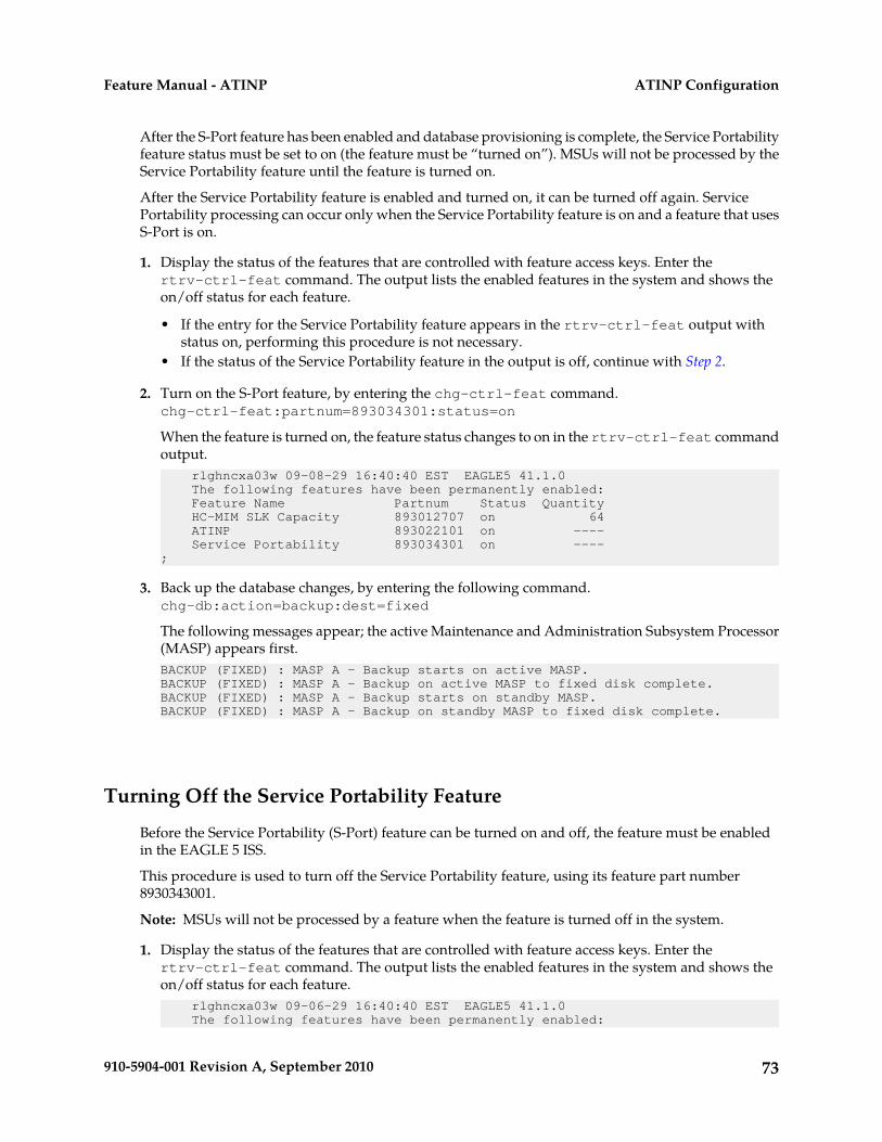
After the S-Port feature has been enabled and database provisioning is complete, the Service Portabilityfeature status must be set to on (the feature must be “turned on”). MSUs will not be processed by theService Portability feature until the feature is turned on.
After the Service Portability feature is enabled and turned on, it can be turned off again. ServicePortability processing can occur only when the Service Portability feature is on and a feature that usesS-Port is on.
1. Display the status of the features that are controlled with feature access keys. Enter thertrv-ctrl-feat command. The output lists the enabled features in the system and shows theon/off status for each feature.
• If the entry for the Service Portability feature appears in the rtrv-ctrl-feat output withstatus on, performing this procedure is not necessary.
• If the status of the Service Portability feature in the output is off, continue with Step 2.
2. Turn on the S-Port feature, by entering the chg-ctrl-feat command.chg-ctrl-feat:partnum=893034301:status=on
When the feature is turned on, the feature status changes to on in the rtrv-ctrl-feat commandoutput. rlghncxa03w 09-08-29 16:40:40 EST EAGLE5 41.1.0 The following features have been permanently enabled: Feature Name Partnum Status Quantity HC-MIM SLK Capacity 893012707 on 64 ATINP 893022101 on ---- Service Portability 893034301 on ----;
3. Back up the database changes, by entering the following command.chg-db:action=backup:dest=fixed
The following messages appear; the active Maintenance and Administration Subsystem Processor(MASP) appears first.BACKUP (FIXED) : MASP A - Backup starts on active MASP.BACKUP (FIXED) : MASP A - Backup on active MASP to fixed disk complete.BACKUP (FIXED) : MASP A - Backup starts on standby MASP.BACKUP (FIXED) : MASP A - Backup on standby MASP to fixed disk complete.
Turning Off the Service Portability Feature
Before the Service Portability (S-Port) feature can be turned on and off, the feature must be enabledin the EAGLE 5 ISS.
This procedure is used to turn off the Service Portability feature, using its feature part number8930343001.
Note: MSUs will not be processed by a feature when the feature is turned off in the system.
1. Display the status of the features that are controlled with feature access keys. Enter thertrv-ctrl-feat command. The output lists the enabled features in the system and shows theon/off status for each feature. rlghncxa03w 09-06-29 16:40:40 EST EAGLE5 41.1.0 The following features have been permanently enabled:
73910-5904-001 Revision A, September 2010
ATINP ConfigurationFeature Manual - ATINP
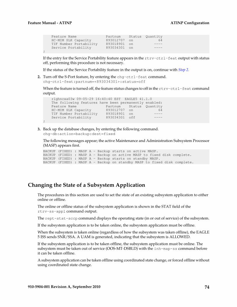
Feature Name Partnum Status Quantity HC-MIM SLK Capacity 893012707 on 64 TIF Number Portability 893018901 on ---- Service Portability 893034301 on ---- ;
If the entry for the Service Portability feature appears in the rtrv-ctrl-feat output with statusoff, performing this procedure is not necessary.
If the status of the Service Portability feature in the output is on, continue with Step 2.
2. Turn off the S-Port feature, by entering the chg-ctrl-feat command.chg-ctrl-feat:partnum=<893034301>:status=off
When the feature is turned off, the feature status changes to off in the rtrv-ctrl-feat commandoutput. rlghncxa03w 09-05-29 16:40:40 EST EAGLE5 41.1.0 The following features have been permanently enabled: Feature Name Partnum Status Quantity HC-MIM SLK Capacity 893012707 on 64 TIF Number Portability 893018901 on ---- Service Portability 893034301 off ----;
3. Back up the database changes, by entering the following command.chg-db:action=backup:dest=fixed
The following messages appear; the active Maintenance and Administration Subsystem Processor(MASP) appears first.BACKUP (FIXED) : MASP A - Backup starts on active MASP.BACKUP (FIXED) : MASP A - Backup on active MASP to fixed disk complete.BACKUP (FIXED) : MASP A - Backup starts on standby MASP.BACKUP (FIXED) : MASP A - Backup on standby MASP to fixed disk complete.
Changing the State of a Subsystem Application
The procedures in this section are used to set the state of an existing subsystem application to eitheronline or offline.
The online or offline status of the subsystem application is shown in the STAT field of thertrv-ss-appl command output.
The rept-stat-sccp command displays the operating state (in or out of service) of the subsystem.
If the subsystem application is to be taken online, the subsystem application must be offline.
When the subsystem is taken online (regardless of how the subsystem was taken offline), the EAGLE5 ISS sends SNR/SSA. A UAM is generated, indicating that the subsystem is ALLOWED.
If the subsystem application is to be taken offline, the subsystem application must be online. Thesubsystem must be taken out of service (OOS-MT-DSBLD) with the inh-map-ss command beforeit can be taken offline.
A subsystem application can be taken offline using coordinated state change, or forced offline withoutusing coordinated state change.
74910-5904-001 Revision A, September 2010
ATINP ConfigurationFeature Manual - ATINP
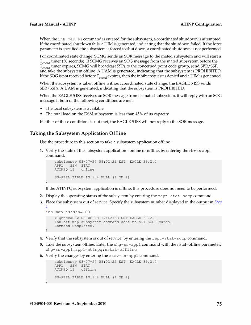
When the inh-map-ss command is entered for the subsystem, a coordinated shutdown is attempted.If the coordinated shutdown fails, a UIM is generated, indicating that the shutdown failed. If the forceparameter is specified, the subsystem is forced to shut down; a coordinated shutdown is not performed.
For coordinated state change, SCMG sends an SOR message to the mated subsystem and will start aTcoord timer (30 seconds). If SCMG receives an SOG message from the mated subsystem before theTcoord timer expires, SCMG will broadcast SSPs to the concerned point code group, send SBR/SSP,and take the subsystem offline. A UAM is generated, indicating that the subsystem is PROHIBITED.If the SOG is not received before Tcoord expires, then the inhibit request is denied and a UIM is generated.
When the subsystem is taken offline without coordinated state change, the EAGLE 5 ISS sendsSBR/SSPs. A UAM is generated, indicating that the subsystem is PROHIBITED.
When the EAGLE 5 ISS receives an SOR message from its mated subsystem, it will reply with an SOGmessage if both of the following conditions are met:
• The local subsystem is available• The total load on the DSM subsystem is less than 45% of its capacity
If either of these conditions is not met, the EAGLE 5 ISS will not reply to the SOR message.
Taking the Subsystem Application Offline
Use the procedure in this section to take a subsystem application offline.
1. Verify the state of the subsystem application - online or offline, by entering the rtrv-ss-applcommand. tekelecstp 08-07-25 08:02:22 EST EAGLE 39.2.0 APPL SSN STAT ATINPQ 11 online
SS-APPL TABLE IS 25% FULL (1 OF 4);
If the ATINPQ subsystem application is offline, this procedure does not need to be performed.
2. Display the operating status of the subsystem by entering the rept-stat-sccp command.3. Place the subsystem out of service. Specify the subsystem number displayed in the output in Step
1.inh-map-ss:ssn=100
rlghncxa03w 08-06-28 14:42:38 GMT EAGLE 39.2.0 Inhibit map subsystem command sent to all SCCP cards. Command Completed.;
4. Verify that the subsystem is out of service, by entering the rept-stat-sccp command.5. Take the subsystem offline. Enter the chg-ss-appl command with the nstat=offline parameter.
chg-ss-appl:appl=atinpq:nstat=offline
6. Verify the changes by entering the rtrv-ss-appl command. tekelecstp 08-07-25 08:02:22 EST EAGLE 39.2.0 APPL SSN STAT ATINPQ 11 offline
SS-APPL TABLE IS 25% FULL (1 OF 4);
75910-5904-001 Revision A, September 2010
ATINP ConfigurationFeature Manual - ATINP
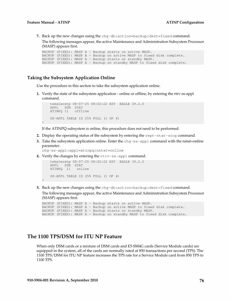
7. Back up the new changes using the chg-db:action=backup:dest=fixed command.The following messages appear, the active Maintenance and Administration Subsystem Processor(MASP) appears first.BACKUP (FIXED): MASP A - Backup starts on active MASP.BACKUP (FIXED): MASP A - Backup on active MASP to fixed disk complete.BACKUP (FIXED): MASP A - Backup starts on standby MASP.BACKUP (FIXED): MASP A - Backup on standby MASP to fixed disk complete.
Taking the Subsystem Application Online
Use the procedure in this section to take the subsystem application online.
1. Verify the state of the subsystem application - online or offline, by entering the rtrv-ss-applcommand. tekelecstp 08-07-25 08:02:22 EST EAGLE 39.2.0 APPL SSN STAT ATINPQ 11 offline
SS-APPL TABLE IS 25% FULL (1 OF 4);
If the ATINPQ subsystem is online, this procedure does not need to be performed.
2. Display the operating status of the subsystem by entering the rept-stat-sccp command.3. Take the subsystem application online. Enter the chg-ss-appl command with the nstat=online
parameter.chg-ss-appl:appl=atinpq:nstat=online
4. Verify the changes by entering the rtrv-ss-appl command. tekelecstp 08-07-25 08:02:22 EST EAGLE 39.2.0 APPL SSN STAT ATINPQ 11 online
SS-APPL TABLE IS 25% FULL (1 OF 4);
5. Back up the new changes using the chg-db:action=backup:dest=fixed command.The following messages appear, the active Maintenance and Administration Subsystem Processor(MASP) appears first.BACKUP (FIXED): MASP A - Backup starts on active MASP.BACKUP (FIXED): MASP A - Backup on active MASP to fixed disk complete.BACKUP (FIXED): MASP A - Backup starts on standby MASP.BACKUP (FIXED): MASP A - Backup on standby MASP to fixed disk complete.
The 1100 TPS/DSM for ITU NP Feature
When only DSM cards or a mixture of DSM cards and E5-SM4G cards (Service Module cards) areequipped in the system, all of the cards are normally rated at 850 transactions per second (TPS). The1100 TPS/DSM for ITU NP feature increases the TPS rate for a Service Module card from 850 TPS to1100 TPS.
76910-5904-001 Revision A, September 2010
ATINP ConfigurationFeature Manual - ATINP
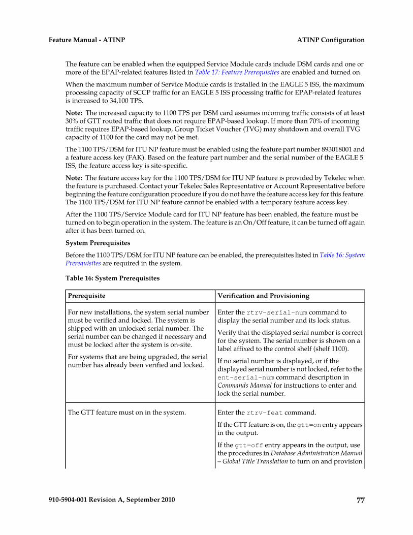
The feature can be enabled when the equipped Service Module cards include DSM cards and one ormore of the EPAP-related features listed in Table 17: Feature Prerequisites are enabled and turned on.
When the maximum number of Service Module cards is installed in the EAGLE 5 ISS, the maximumprocessing capacity of SCCP traffic for an EAGLE 5 ISS processing traffic for EPAP-related featuresis increased to 34,100 TPS.
Note: The increased capacity to 1100 TPS per DSM card assumes incoming traffic consists of at least30% of GTT routed traffic that does not require EPAP-based lookup. If more than 70% of incomingtraffic requires EPAP-based lookup, Group Ticket Voucher (TVG) may shutdown and overall TVGcapacity of 1100 for the card may not be met.
The 1100 TPS/DSM for ITU NP feature must be enabled using the feature part number 893018001 anda feature access key (FAK). Based on the feature part number and the serial number of the EAGLE 5ISS, the feature access key is site-specific.
Note: The feature access key for the 1100 TPS/DSM for ITU NP feature is provided by Tekelec whenthe feature is purchased. Contact your Tekelec Sales Representative or Account Representative beforebeginning the feature configuration procedure if you do not have the feature access key for this feature.The 1100 TPS/DSM for ITU NP feature cannot be enabled with a temporary feature access key.
After the 1100 TPS/Service Module card for ITU NP feature has been enabled, the feature must beturned on to begin operation in the system. The feature is an On/Off feature, it can be turned off againafter it has been turned on.
System Prerequisites
Before the 1100 TPS/DSM for ITU NP feature can be enabled, the prerequisites listed in Table 16: SystemPrerequisites are required in the system.
Table 16: System Prerequisites
Verification and ProvisioningPrerequisite
Enter the rtrv-serial-num command todisplay the serial number and its lock status.
For new installations, the system serial numbermust be verified and locked. The system isshipped with an unlocked serial number. The Verify that the displayed serial number is correct
for the system. The serial number is shown on alabel affixed to the control shelf (shelf 1100).
serial number can be changed if necessary andmust be locked after the system is on-site.
For systems that are being upgraded, the serialnumber has already been verified and locked. If no serial number is displayed, or if the
displayed serial number is not locked, refer to theent-serial-num command description inCommands Manual for instructions to enter andlock the serial number.
Enter the rtrv-feat command.The GTT feature must on in the system.
If the GTT feature is on, the gtt=on entry appearsin the output.
If the gtt=off entry appears in the output, usethe procedures in Database Administration Manual– Global Title Translation to turn on and provision
77910-5904-001 Revision A, September 2010
ATINP ConfigurationFeature Manual - ATINP
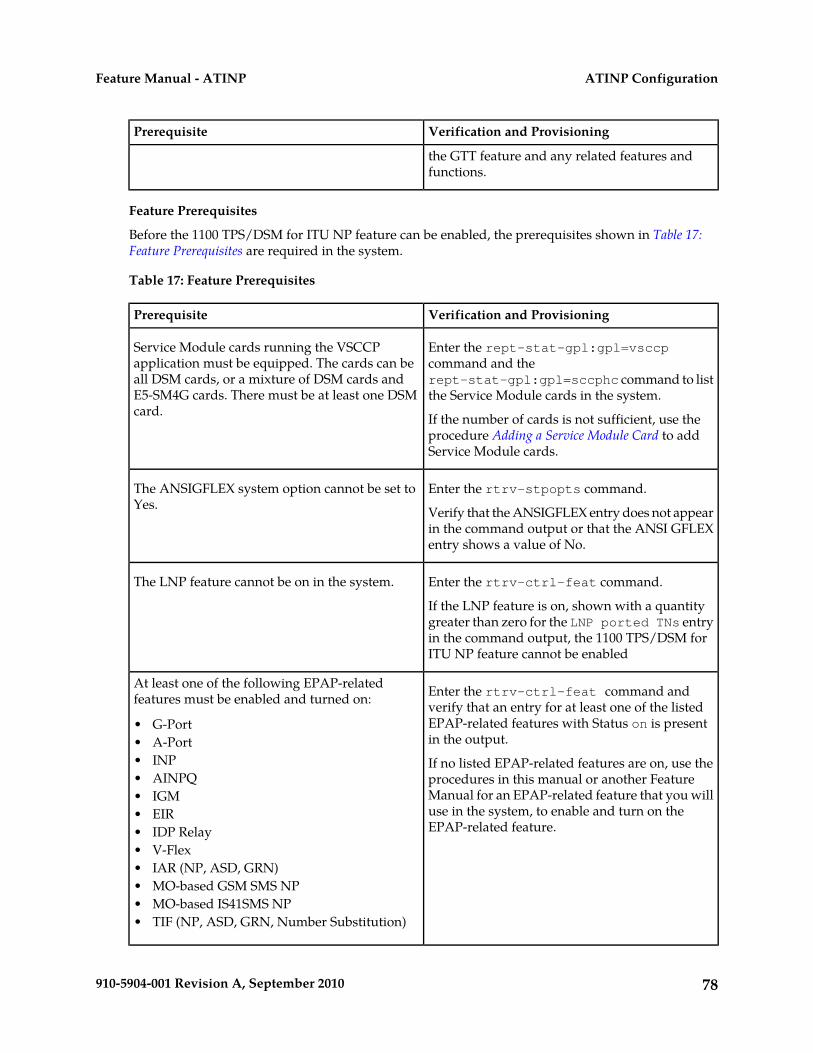
Verification and ProvisioningPrerequisite
the GTT feature and any related features andfunctions.
Feature Prerequisites
Before the 1100 TPS/DSM for ITU NP feature can be enabled, the prerequisites shown in Table 17:Feature Prerequisites are required in the system.
Table 17: Feature Prerequisites
Verification and ProvisioningPrerequisite
Enter the rept-stat-gpl:gpl=vsccpcommand and the
Service Module cards running the VSCCPapplication must be equipped. The cards can beall DSM cards, or a mixture of DSM cards and rept-stat-gpl:gpl=sccphc command to list
the Service Module cards in the system.E5-SM4G cards. There must be at least one DSMcard. If the number of cards is not sufficient, use the
procedure Adding a Service Module Card to addService Module cards.
Enter the rtrv-stpopts command.The ANSIGFLEX system option cannot be set toYes. Verify that the ANSIGFLEX entry does not appear
in the command output or that the ANSI GFLEXentry shows a value of No.
Enter the rtrv-ctrl-feat command.The LNP feature cannot be on in the system.
If the LNP feature is on, shown with a quantitygreater than zero for the LNP ported TNs entryin the command output, the 1100 TPS/DSM forITU NP feature cannot be enabled
Enter the rtrv-ctrl-feat command andverify that an entry for at least one of the listed
At least one of the following EPAP-relatedfeatures must be enabled and turned on:
EPAP-related features with Status on is presentin the output.
• G-Port• A-Port
If no listed EPAP-related features are on, use theprocedures in this manual or another Feature
• INP• AINPQ
Manual for an EPAP-related feature that you will• IGMuse in the system, to enable and turn on theEPAP-related feature.
• EIR• IDP Relay• V-Flex• IAR (NP, ASD, GRN)• MO-based GSM SMS NP• MO-based IS41SMS NP• TIF (NP, ASD, GRN, Number Substitution)
78910-5904-001 Revision A, September 2010
ATINP ConfigurationFeature Manual - ATINP
This section provides the following procedures for the 1100 TPS/DSM for ITU NP feature:
• Enable the 1100 TPS/DSM for ITU NP Feature• Turn On the 1100 TPS/DSM for ITU NP Feature• Turn Off the 1100 TPS/DSM for ITU NP Feature
Refer to the Commands Manual for descriptions of the commands used in the procedures, includingparameter names and valid values, rules for using the command correctly, and output examples.
Enable the 1100 TPS/DSM for ITU NP Feature
This procedure is used to enable the 1100 TPS/DSM for ITU NP feature.
1. Enable the 1100 TPS/DSM for ITU NP feature with part number 893018001 and the feature accesskey.
enable-ctrl-feat:partnum=893018001:fak=<feature access key>
2. Verify the change by entering the rtrv-ctrl-feat command with the 1100 TPS/DSM for ITUNP feature part number 893018001.
rtrv-ctrl-feat:partnum=893018001
rlghncxa03w 09-08-24 21:15:37 EST EAGLE 40.1.0The following features have been permanently enabled: Feature Name Partnum Status Quantity HC-MIM SLK Capacity 893012707 on 64Prepaid SMS Intercept Ph1 893006701 on ----1100 TPS/DSM for ITU NP 893018001 off ---- ;
3. Back up the changes using the chg-db:action=backup:dest=fixed command.The following messages appear, the active Maintenance and Administration Subsystem Processor(MASP) appears first.BACKUP (FIXED) : MASP A - Backup starts on active MASP. BACKUP (FIXED) : MASP A - Backup on active MASP to fixed disk complete. BACKUP (FIXED) : MASP A - Backup starts on standby MASP. BACKUP (FIXED) : MASP A - Backup on standby MASP to fixed disk complete.
Turn On the 1100 TPS/DSM for ITU NP Feature
This procedure is used to turn on the 1100 TPS/DSM for ITU NP feature, after it has been enabled orturned off.
Note: If the EPAP-based traffic is higher than 70% of all traffic on the EAGLE 5 ISS, the DSM cardperformance may not reach 1100 TPS per DSM card.
1. Enter the chg-ctrl-feat command the first time and specify the 1100 TPS/DSM feature partnumber 893018001and the status=on parameter value.
chg-ctrl-feat:partnum=893018001:status=on
The following message is displayed:CAUTION: Rated TPS for this feature supports an engineered GTTtraffic mix of no more than 70 percent EPAP-based traffic.Re-enter the command within 30 seconds to confirm change.
79910-5904-001 Revision A, September 2010
ATINP ConfigurationFeature Manual - ATINP
2. Re-enter the command the second time within 30 seconds to turn on the 1100 TPS/DSM for ITUNP feature.
chg-ctrl-feat:partnum=893018001:status=on
3. Verify the change by entering the rtrv-ctrl-feat command with the 1100 TPS/DSM for ITUNP feature part number.
rtrv-ctrl-feat:partnum=893018001
rlghncxa03w 09-08-24 21:15:37 EST EAGLE 40.1.0The following features have been permanently enabled: Feature Name Partnum Status Quantity HC-MIM SLK Capacity 893012707 on 64Prepaid SMS Intercept Ph1 893006701 on ----1100 TPS/DSM for ITU NP 893018001 on ---- ;
4. Back up the database changes using the chg-db:action=backup:dest=fixed command.The following messages appear, the active Maintenance and Administration Subsystem Processor(MASP) appears first.BACKUP (FIXED): MASP A - Backup starts on active MASP.BACKUP (FIXED): MASP A - Backup on active MASP to fixed disk complete.BACKUP (FIXED): MASP A - Backup starts on standby MASP.BACKUP (FIXED): MASP A - Backup on standby MASP to fixed disk complete.
Turn Off the 1100 TPS/DSM for ITU NP Feature
This procedure is used to turn off the 1100 TPS/DSM for ITU NP feature, after it has been enabledand turned on.
1. Enter the chg-ctrl-feat command the first time and specify the 1100 TPS/DSM feature partnumber 893018001 and the status=off parameter value.
chg-ctrl-feat:partnum=893018001:status=off
The following message is displayed:CAUTION: This command decreases the total TPS of the SCCP system from 1100 to 850 TPS for each DSM card.
2. Re-enter the command the second time within 30 seconds to turn off the 1100 TPS/DSM for ITUNP feature.
3. Back up the database changes using the chg-db:action=backup:dest=fixed command.The following messages appear, the active Maintenance and Administration Subsystem Processor(MASP) appears first.BACKUP (FIXED): MASP A - Backup starts on active MASP.BACKUP (FIXED): MASP A - Backup on active MASP to fixed disk complete.BACKUP (FIXED): MASP A - Backup starts on standby MASP.BACKUP (FIXED): MASP A - Backup on standby MASP to fixed disk complete.
80910-5904-001 Revision A, September 2010
ATINP ConfigurationFeature Manual - ATINP
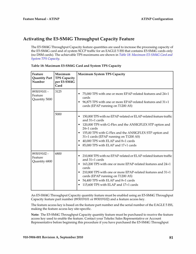
Activating the E5-SM4G Throughput Capacity Feature
The E5-SM4G Throughput Capacity feature quantities are used to increase the processing capacity ofthe E5-SM4G card and of system SCCP traffic for an EAGLE 5 ISS that contains E5-SM4G cards only(no DSM cards). The achievable TPS maximums are shown in Table 18: Maximum E5-SM4G Card andSystem TPS Capacity.
Table 18: Maximum E5-SM4G Card and System TPS Capacity
Maximum System TPS CapacityMaximumTPS Capacityper E5-SM4GCard
FeatureQuantity PartNumber
3125893019101 -FeatureQuantity 5000
• 75,000 TPS with one or more EPAP-related features and 24+1cards
• 96,875 TPS with one or more EPAP-related features and 31+1cards (EPAP running on T1200 AS)
5000• 150,000 TPS with no EPAP-related or ELAP-related feature traffic
and 31+1 cards• 120,000 TPS with G-Flex and the ANSIGFLEX STP option and
24+1 cards• 155,00 TPS with G-Flex and the ANSIGFLEX STP option and
31+1 cards (EPAP running on T1200 AS)• 40,000 TPS with ELAP and 8+1 cards• 85,000 TPS with ELAP and 17+1 cards
6800893019102 -FeatureQuantity 6800
• 210,800 TPS with no EPAP-related or ELAP-related feature trafficand 31+1 cards
• 163,200 TPS with one or more EPAP-related features and 24+1cards
• 210,800 TPS with one or more EPAP-related features and 31+1cards (EPAP running on T1200 AS)
• 54,400 TPS with ELAP and 8+1 cards• 115,600 TPS with ELAP and 17+1 cards
An E5-SM4G Throughput Capacity quantity feature must be enabled using an E5-SM4G ThroughputCapacity feature part number (893019101 or 893019102) and a feature access key.
The feature access key is based on the feature part number and the serial number of the EAGLE 5 ISS,making the feature access key site-specific.
Note: The E5-SM4G Throughput Capacity quantity feature must be purchased to receive the featureaccess key used to enable the feature. Contact your Tekelec Sales Representative or AccountRepresentative before beginning this procedure if you have purchased the E5-SM4G Throughput
81910-5904-001 Revision A, September 2010
ATINP ConfigurationFeature Manual - ATINP
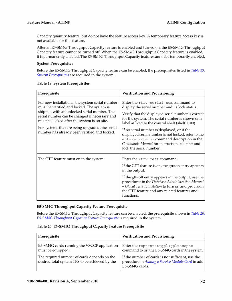
Capacity quantity feature, but do not have the feature access key. A temporary feature access key isnot available for this feature.
After an E5-SM4G Throughput Capacity feature is enabled and turned on, the E5-SM4G ThroughputCapacity feature cannot be turned off. When the E5-SM4G Throughput Capacity feature is enabled,it is permanently enabled. The E5-SM4G Throughput Capacity feature cannot be temporarily enabled.
System Prerequisites
Before the E5-SM4G Throughput Capacity feature can be enabled, the prerequisites listed in Table 19:System Prerequisites are required in the system.
Table 19: System Prerequisites
Verification and ProvisioningPrerequisite
Enter the rtrv-serial-num command todisplay the serial number and its lock status.
For new installations, the system serial numbermust be verified and locked. The system isshipped with an unlocked serial number. The Verify that the displayed serial number is correct
for the system. The serial number is shown on alabel affixed to the control shelf (shelf 1100).
serial number can be changed if necessary andmust be locked after the system is on-site.
For systems that are being upgraded, the serialnumber has already been verified and locked. If no serial number is displayed, or if the
displayed serial number is not locked, refer to theent-serial-num command description in theCommands Manual for instructions to enter andlock the serial number.
Enter the rtrv-feat command.The GTT feature must on in the system.
If the GTT feature is on, the gtt=on entry appearsin the output.
If the gtt=off entry appears in the output, use theprocedures in the Database Administration Manual– Global Title Translation to turn on and provisionthe GTT feature and any related features andfunctions.
E5-SM4G Throughput Capacity Feature Prerequisite
Before the E5-SM4G Throughput Capacity feature can be enabled, the prerequisite shown in Table 20:E5-SM4G Throughput Capacity Feature Prerequisite is required in the system.
Table 20: E5-SM4G Throughput Capacity Feature Prerequisite
Verification and ProvisioningPrerequisite
Enter the rept-stat-gpl:gpl=sccphccommand to list the E5-SM4G cards in the system.
E5-SM4G cards running the VSCCP applicationmust be equipped.
The required number of cards depends on thedesired total system TPS to be achieved by the
If the number of cards is not sufficient, use theprocedure in Adding a Service Module Card to addE5-SM4G cards.
82910-5904-001 Revision A, September 2010
ATINP ConfigurationFeature Manual - ATINP
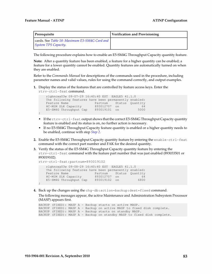
Verification and ProvisioningPrerequisite
cards. See Table 18: Maximum E5-SM4G Card andSystem TPS Capacity.
The following procedure explains how to enable an E5-SM4G Throughput Capacity quantity feature.
Note: After a quantity feature has been enabled, a feature for a higher quantity can be enabled; afeature for a lower quantity cannot be enabled. Quantity features are automatically turned on whenthey are enabled.
Refer to the Commands Manual for descriptions of the commands used in the procedure, includingparameter names and valid values, rules for using the command correctly, and output examples.
1. Display the status of the features that are controlled by feature access keys. Enter thertrv-ctrl-feat command. rlghncxa03w 09-07-29 16:40:40 EST EAGLE5 41.1.0 The following features have been permanently enabled: Feature Name Partnum Status Quantity HC-MIM SLK Capacity 893012707 on 64 E5-SM4G Throughput Cap 893019101 on 5000;
• If the rtrv-ctrl-feat output shows that the correct E5-SM4G Throughput Capacity quantityfeature is enabled and its status is on, no further action is necessary.
• If no E5-SM4G Throughput Capacity feature quantity is enabled or a higher quantity needs tobe enabled, continue with step Step 2.
2. Enable the E5-SM4G Throughput Capacity quantity feature by entering the enable-ctrl-featcommand with the correct part number and FAK for the desired quantity.
3. Verify the status of the E5-SM4G Throughput Capacity quantity feature by entering thertrv-ctrl-feat command with the feature part number that was just enabled (893033501 or893019102).rtrv-ctrl-feat:partnum=893019102
rlghncxa03w 09-08-29 16:40:40 EST EAGLE5 41.1.0 The following features have been permanently enabled: Feature Name Partnum Status Quantity HC-MIM SLK Capacity 893012707 on 64 E5-SM4G Throughput Cap 893019102 on 6800;
4. Back up the changes using the chg-db:action=backup:dest=fixed command.The following messages appear, the active Maintenance and Administration Subsystem Processor(MASP) appears first.BACKUP (FIXED): MASP A - Backup starts on active MASP.BACKUP (FIXED): MASP A - Backup on active MASP to fixed disk complete.BACKUP (FIXED): MASP A - Backup starts on standby MASP.BACKUP (FIXED): MASP A - Backup on standby MASP to fixed disk complete.
83910-5904-001 Revision A, September 2010
ATINP ConfigurationFeature Manual - ATINP

Chapter
5ATINP Measurements
This chapter describes the measurements that canbe collected and generated for the ATINP feature.
Topics:
• ATINP Measurements.....85
84910-5904-001 Revision A, September 2010
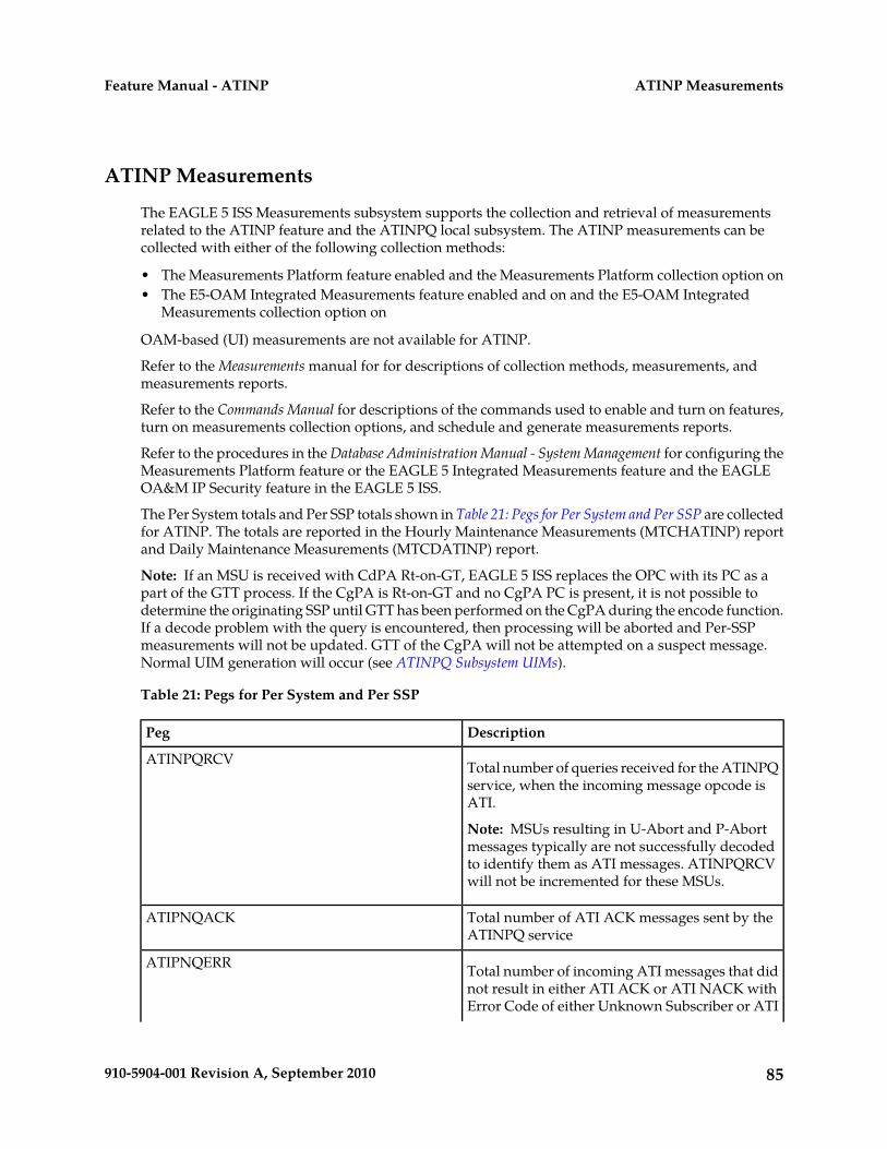
ATINP Measurements
The EAGLE 5 ISS Measurements subsystem supports the collection and retrieval of measurementsrelated to the ATINP feature and the ATINPQ local subsystem. The ATINP measurements can becollected with either of the following collection methods:
• The Measurements Platform feature enabled and the Measurements Platform collection option on• The E5-OAM Integrated Measurements feature enabled and on and the E5-OAM Integrated
Measurements collection option on
OAM-based (UI) measurements are not available for ATINP.
Refer to the Measurements manual for for descriptions of collection methods, measurements, andmeasurements reports.
Refer to the Commands Manual for descriptions of the commands used to enable and turn on features,turn on measurements collection options, and schedule and generate measurements reports.
Refer to the procedures in the Database Administration Manual - System Management for configuring theMeasurements Platform feature or the EAGLE 5 Integrated Measurements feature and the EAGLEOA&M IP Security feature in the EAGLE 5 ISS.
The Per System totals and Per SSP totals shown in Table 21: Pegs for Per System and Per SSP are collectedfor ATINP. The totals are reported in the Hourly Maintenance Measurements (MTCHATINP) reportand Daily Maintenance Measurements (MTCDATINP) report.
Note: If an MSU is received with CdPA Rt-on-GT, EAGLE 5 ISS replaces the OPC with its PC as apart of the GTT process. If the CgPA is Rt-on-GT and no CgPA PC is present, it is not possible todetermine the originating SSP until GTT has been performed on the CgPA during the encode function.If a decode problem with the query is encountered, then processing will be aborted and Per-SSPmeasurements will not be updated. GTT of the CgPA will not be attempted on a suspect message.Normal UIM generation will occur (see ATINPQ Subsystem UIMs).
Table 21: Pegs for Per System and Per SSP
DescriptionPeg
Total number of queries received for the ATINPQservice, when the incoming message opcode isATI.
ATINPQRCV
Note: MSUs resulting in U-Abort and P-Abortmessages typically are not successfully decodedto identify them as ATI messages. ATINPQRCVwill not be incremented for these MSUs.
Total number of ATI ACK messages sent by theATINPQ service
ATIPNQACK
Total number of incoming ATI messages that didnot result in either ATI ACK or ATI NACK with
ATIPNQERR
Error Code of either Unknown Subscriber or ATI
85910-5904-001 Revision A, September 2010
ATINP MeasurementsFeature Manual - ATINP

DescriptionPeg
Not Allowed. (The ATI NACK is considered tobe a TC_END TCAP message with a Return Errorcomponent.)
Note: MSUs resulting in U-Abort and P-Abortmessages typically are not successfully decodedto identify them as ATI messages. ATINPQERRwill not be incremented for these MSUs.
86910-5904-001 Revision A, September 2010
ATINP MeasurementsFeature Manual - ATINP

Chapter
6Maintenance
This chapter describes the EAGLE 5 ISS maintenancefunctions that can be used for the ATiNP feature.
Topics:
• ATINPQ Subsystem Alarms (UAMs).....88 This chapter also provides an overview of the• ATINPQ Subsystem UIMs.....88 interaction between the EPAP in the MPS subsystem
and the EAGLE 5 ISS.• EPAP Status and Alarms.....90• EPAP System Status Reports.....91• Code and Application Data Loading.....92
87910-5904-001 Revision A, September 2010
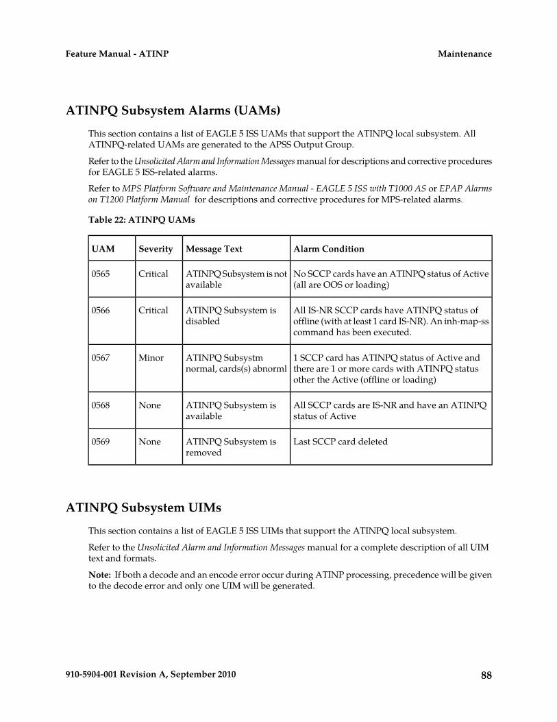
ATINPQ Subsystem Alarms (UAMs)
This section contains a list of EAGLE 5 ISS UAMs that support the ATINPQ local subsystem. AllATINPQ-related UAMs are generated to the APSS Output Group.
Refer to the Unsolicited Alarm and Information Messages manual for descriptions and corrective proceduresfor EAGLE 5 ISS-related alarms.
Refer to MPS Platform Software and Maintenance Manual - EAGLE 5 ISS with T1000 AS or EPAP Alarmson T1200 Platform Manual for descriptions and corrective procedures for MPS-related alarms.
Table 22: ATINPQ UAMs
Alarm ConditionMessage TextSeverityUAM
No SCCP cards have an ATINPQ status of Active(all are OOS or loading)
ATINPQ Subsystem is notavailable
Critical0565
All IS-NR SCCP cards have ATINPQ status ofoffline (with at least 1 card IS-NR). An inh-map-sscommand has been executed.
ATINPQ Subsystem isdisabled
Critical0566
1 SCCP card has ATINPQ status of Active andthere are 1 or more cards with ATINPQ statusother the Active (offline or loading)
ATINPQ Subsystmnormal, cards(s) abnorml
Minor0567
All SCCP cards are IS-NR and have an ATINPQstatus of Active
ATINPQ Subsystem isavailable
None0568
Last SCCP card deletedATINPQ Subsystem isremoved
None0569
ATINPQ Subsystem UIMs
This section contains a list of EAGLE 5 ISS UIMs that support the ATINPQ local subsystem.
Refer to the Unsolicited Alarm and Information Messages manual for a complete description of all UIMtext and formats.
Note: If both a decode and an encode error occur during ATINP processing, precedence will be givento the decode error and only one UIM will be generated.
88910-5904-001 Revision A, September 2010
MaintenanceFeature Manual - ATINP

Table 23: ATINPQ UIMs
ActionDescriptionTextUIM
None - the second attempt willbe ignored
A second attempt to inhibit theATINPQ subsystem has beenmade while the first is still beingprocessed.
Inh ATINPQ SSrequest alrdyoutstanding
1395
No action necessary.The attempted inhibit of theATINPQ subsystem failed. A
Failure InhibitingATINPQ SS
1396
response SOG was not receivedfrom the mate.
Verify that the incoming ATI NPquery has Subscriber Identity andRequested Info parameters.
A required parameter wasmissing in the ATI NP query.
LSS: MissingMandatoryParameter
1397
Verify that the SubscriberIdentity parameter length is at
The Subscriber Identityparameter in the ATI NP querywas found to be mistyped.
ATINPQ: Badlyformatted Subs Id
1398
least 2 bytes (1 byte length fieldof MSISDN). If greater than 2bytes, the Subscriber Identitylength must be equal to 2 + thelength of the MSISDN.
The Choice for SubscriberIdentity in the ATI NP query isnot the MSISDN.
ATINPQ:Subscriber Identitynot MSISDN
1399
The MSISDN length in SubscriberInformation was 0, or the
LSS: InvalidMSISDN digitslength
1400
MSISDN had only one 0xF (filler)digit.
The Requested Info parameter inthe incoming ATI NP query was
ATINPQ: InvalidRequested Info
1402
invalid. Either the length of theRequested Info parameter doesnot contain MNP Requested Info,or the parameter is badlyformatted.
Verify the expected number ofdigits in routeingNumber and
One or more encoded digitsparameter in the ATI ACK
LSS: Dgtstruncated in encdparms
1403
MSISDN fields. These depend onthe combination of requested
response had to be truncated totit maximum allowed encodeddigits. formatting for routeingNumber
and MSISDN fields(ATINPQOPTS, ATIACKRN, andATIACKMSISDN options), digitsin incoming ATI NP query, andthe result of RTDB lookup.
89910-5904-001 Revision A, September 2010
MaintenanceFeature Manual - ATINP
ActionDescriptionTextUIM
Verify EPAP provisioning for thesubscriber.
Service Portability required useof RTDB GRN for encodingresponse; however GRN was notprovisioned.
S-Port: MissingGRN for srvc prtdsubs
1426
EPAP Status and Alarms
Because EPAP has no direct means of accepting user input or displaying output messages on EAGLE5 ISS terminals, maintenance, measurements, and status information are routed through a ServiceModule card. EPAP sends two types of messages to the Service Module card: EPAP Maintenance Blocksand DSM Status Requests. Each message type is discussed in the following sections.
EPAP Maintenance Blocks
The active EPAP generates and sends maintenance blocks to the primary Service Module card. Onemaintenance block is sent as soon as the IP link is established between the active EPAP and the primaryService Module card. Additional maintenance blocks are sent whenever the EPAP needs to report anychange in status or error conditions. The information returned in maintenance blocks is included inthe output of the rept-stat-mps and rept-stat-sccp commands.
The EPAP sends maintenance blocks that contain at least the following information:
• Status of EPAP 'A' - actual states are active, standby, and down (inoperative). Maintenance blocksinclude a field for this information so that it can be forwarded to the EPAP A Device Control Block(DCB), where it is available for the output of the rept-stat-mps command.
• Status of EPAP 'B' - actual states are active, standby, and down (inoperative). Maintenance blocksinclude a field for this information so that it can be forwarded to the EPAP B DCB, where it isavailable for the output of the rept-stat-mps command.
• Identification of Active EPAP - a field to identify the active EPAP.• Congestion Indicator - an indicator showing provisioning link congestion. The link between the
EPAPs and the external source of provisioning data can become congested in high-provisioningtraffic situations. When this occurs and subsequently as the congestion clears, the EPAP sendsmaintenance blocks to the Service Module card. The EPAP must ensure that no more than onemaintenance block per second is sent to the primary Service Module card if the only reason is toreport a change in congestion status.
• Alarm Conditions - an error code field. If the EPAP needs to report an alarm condition, it puts anappropriate UAM identifier in this field.
• Current MPS Database Size - a field indicating the current RTDB size. The Service Module carduses this information to calculate the percentage of memory utilized by the RTDB.
DSM Status Requests
When the EPAP needs to know the status of a Service Module card, it sends a DSM status request tothat Service Module card. Because status messages are sent over UDP, the EPAP broadcasts the DSM
90910-5904-001 Revision A, September 2010
MaintenanceFeature Manual - ATINP
status request (to all Service Module cards) and each Service Module card returns its status to theEPAP.
DSM Status Reporting to the EPAP
The sections that follow describe the DSM status reporting for the EPAP.
DSM Status Messages – When Sent
Service Module cards send a DSM status message to the EPAP when any the following events occurin the Service Module card:
• The Service Module card is booted.• The Service Module card receives a DSM Status Request message from the EPAP• The Service Module card determines that it needs to download the entire database, for example,
if the Service Module card determines that the RTDB needs to be downloaded (for instance, if thedatabase is totally corrupted), or if a craftsperson requests that the database be reloaded.
• The Service Module card starts receiving database downloads or database updates. When a ServiceModule card starts downloading the RTDB or accepting database updates, it sends a DSM StatusMessage informing the EPAP of the first record received. This helps the EPAP keep track ofdownloads in progress.
DSM Status Messages Fields
The DSM Status Message provides the following information to the EPAP:
• DSM Memory Size. When the Service Module card is initialized, it determines the amount ofmemory present. The EPAP uses the value to determine if the Service Module card has enoughmemory to hold the RTDB.
Refer to the Dimensioning Guide for EPAP Advanced DB Features Technical Reference for importantinformation on the dimensioning rules and the Service Module card database capacity requirements.
• Load Mode Status. This indicator indicates whether or not 80% of the IS-NR (In-Service Normal)LIMs have access to SCCP services.
EPAP System Status Reports
This section describes the following EPAP status reporting:
• System status• EPAP-based feature status• DSM memory capacity status• Loading mode support status
System Status Reporting
The rept-stat-sys command and the rept-stat-sccp command supports the Service Modulecards running the VSCCP application. EPAP-based feature statistics are reported in the
91910-5904-001 Revision A, September 2010
MaintenanceFeature Manual - ATINP
rept-stat-sccp command. Refer to the Commands Manual for descriptions of the commands andtheir output .
MPS Status Reporting
The rept-stat-mps command reports the status of the MPS system, particularly the provisioningsystem. See Maintenance Commands for more details.
DSM Memory Capacity Status Reporting
As mentioned in the DSM Status Reporting to the EPAP, the Service Module card sends a message tothe EPAP containing the amount of memory on the Service Module board. The EPAP determineswhether the DSM has enough memory to store the RTDB and sends an ack or nak back to the ServiceModule card indicating whether or not the Service Module card has an adequate amount of memory.Refer to the Dimensioning Guide for EPAP Advanced DB Features Technical Reference for importantinformation on the dimensioning rules and the DSM database capacity requirements.
The rept-stat-mps:loc=xxxx command shows the amount of memory used by the RTDB as apercent of available Service Module card memory.
Loading Mode Support Status Reporting
The OAM application determines whether or not the system is in an unstable loading mode becauseit knows the state of all LIM and Service Module cards in the system. When the loading mode isunstable, the rept-stat-sys command reports the existence of the unstable loading mode and thespecific conditions that caused it. See EPAP Application Data Loading for more details.
Code and Application Data Loading
In general, administrative updates can occur while a Service Module card is loading. The ServiceModule card should remain in an in-transition state if the STP portion of the database has completedloading and is waiting for the RTDB to download.
DSM Code Loading
The EAGLE 5 ISS OAM performs code loading of the Service Module card.
EPAP Application Data Loading
In order to support both RTDB and EAGLE 5 ISS data loading, the VSCCP GPL verifies its hardwareconfiguration during initialization to determine if it has the capacity to support the RTDB.
The VSCCP GPL application data loader registers all tables for loading, independent of featureprovisioning and main board and applique hardware configuration. As a result, load requests arealways identical. During loading, multiple Service Module card load requests are combined into asingle download, reducing the overall download time. The Service Module card card stores or discardsRTDB table data based on whether or not it has RTDB-capable hardware for EPAP-based features.
The OAM, on the other hand, downloads or sets memory boundaries for configuration options andservice selector tables only for provisioned features. When a feature is not provisioned, the OAM does
92910-5904-001 Revision A, September 2010
MaintenanceFeature Manual - ATINP
not attempt to read its tables from disk. Instead, empty tables (tables without entries) are downloaded.All other tables requested for loading are read from disk and downloaded routinely.
80% Threshold of Support
Loading mode is based on the ability of the system to provide SCCP service to at least 80% of the LIMs.
VSCCP Capacity
An insufficient number of Service Module cards that are in an IS-NR or OOS-MT-DSBLD state relativeto 80% of the number of provisioned LIMs is called a “failure to provide adequate SCCP capacity.”
Insufficient SCCP Service
It is possible for LIM cards or Service Module cards to be inhibited or to have problems that preventthem from operating normally. If enough Service Module cards are out of service, it may not be possiblefor the remaining IS-NR Service Module cards to service at least 80% of the number of IS-NR LIMcards. This is called “insufficient SCCP service.” When this occurs, some of the LIM cards are deniedSCCP service. It is possible to inhibit LIMs to bring the ratio back to 16:1 or better.
Conditions That Create an Unstable Loading ModeCurrent system implementation interrupts and stops card loading upon execution of an STP databasechg command. Loading mode support denies the execution of EAGLE 5 ISS database chg commandswhen the system is in an unstable loading mode. An unstable loading mode exists when any of thefollowing conditions are true:
• The system's maintenance baseline has not been established.• Less than 80% of the number of LIMs provisioned are in an IS-NR or OOS-MT-DSBLD state.• The number of IS-NR and OOS-MT-DSBLD Service Module cards is insufficient to service at least
80% of all provisioned LIMs.• Insufficient SCCP service occurs when an insufficient number of IS-NR Service Module cards are
available to service at least 80% of the number of IS-NR LIMs.• LIM cards are being denied SCCP service and any Service Module cards are in an abnormal state
(OOS-MT-DSBLD, IS-ANR).
Actions Taken When the System is in an Unstable Loading Mode
• No affect on RTDB downloads or updates.
Unstable loading mode has no impact on RTDB downloads or the stream of RTDB updates.• The rept-stat-sys command reports unstable loading mode.
When the loading mode is unstable, the rept-stat-sys command reports the existence of theunstable loading mode and the specific trigger that caused it.
• No EAGLE 5 ISS database updates allowed.
When in an unstable loading mode, the EAGLE 5 ISS does not accept database updates. Whenupdates are rejected, the reason is given as: E3112 Cmd Rej: Loading Mode unstable due to SCCPservice is deficient.
The inh-card and alw-card commands can be used to alter SCCP service levels to achieve the80% threshold. This can be repeated for each card until the system is able to supply SCCP services
93910-5904-001 Revision A, September 2010
MaintenanceFeature Manual - ATINP

to at least 80% of the IS-NR LIM cards. The remaining 20% LIM or supporting Service Modulecards may remain out of service until the stream of database updates ceases. This stream of updatescan be temporarily interrupted to allow the remaining 20% of the system to come in service.
Once an EAGLE 5 ISS database has been loaded, that database can be updated (as long as thesystem is not in an unstable loading mode). However, if an database update comes in duringEAGLE 5 ISS database loading, the Service Module card stops the current loading, issues a class01D7 obit, and reboots. The obit is shown in the following example.Figure 8: Obit Message for Abort of Card Loading
Using the force Option
Use the force option to execute commands that would put the system in unstable loading mode. Ifexecuting the ent-card command or inh-card command would cause the system to enter anunstable loading mode, use the force option in the command.
94910-5904-001 Revision A, September 2010
MaintenanceFeature Manual - ATINP
GlossaryA
Data AcknowledgementACK
Additional Subscriber DataASD
Additional data that is associatedwith a subscriber (DN) or a rangeof subscribers.
Any Time InterrogationATI
An ATI message allows an externalserver to interrogate an HLR andobtain information about thelocation and/or state of a GSMsubscriber.
ATI Number Portability Queryfeature
ATINP
ATI Number Portability Query(Name of the local subsystem)
ATINPQ
C
Small Geographic AreaCNL
Concerned Signaling Point CodeCSPC
The point code that receivessubsystem allowed and subsystemprohibited status messages about aparticular global title translationnode. These messages are broadcastfrom SCCP management.
D
All data that can be administered bythe user, including cards, destination
Database
point codes, gateway screening
95910-5904-001 Revision A, September 2010

D
tables, global title translation tables,links, LNP services, LNP serviceproviders, location routing numbers,routes, shelves, subsystemapplications, and 10 digit telephonenumbers.
Device Control BlockDCB
E
EAGLE Provisioning ApplicationProcessor
EPAP
Features that require EPAPconnection and use the Real Time
EPAP-related features
Database (RTDB) for lookup ofsubscriber information.
• ANSI Number Portability Query(AINPQ)
• ANSI-41 AnalyzedInformationQuery – no EPAP/ELAP(ANSI41 AIQ)
• Anytime Interrogation NumberPortability (ATI NumberPortability, ATINP)
• AINPQ, INP, G-Port SRI Queryfor Prepaid, GSM MAP SRIRedirect, IGM, and ATINPSupport for ROP
• A-Port Circular Route Prevention(A-Port CRP)
• Equipment Identity Register(EIR)
• G-Flex C7 Relay (G-Flex)• G-Flex MAP Layer Routing
(G-Flex MLR)• G-Port SRI Query for Prepaid• GSM MAP SRI Redirect to
Serving HLR (GSM MAP SRIRedirect)
• GSM Number Portability(G-Port)
• IDP A-Party Blacklist• IDP A-Party Routing
96910-5904-001 Revision A, September 2010
GlossaryFeature Manual - ATINP

E
• IDP Relay Additional SubscriberData (IDPR ASD)
• IDP Relay Generic RoutingNumber (IDPR GRN)
• IDP Service Key Routing (IDP SKRouting)
• IDP Screening for Prepaid• INAP-based Number Portability
(INP)• Info Analyzed Relay Additional
Subscriber Data (IAR ASD)• Info Analyzed Relay Base (IAR
Base)• Info Analyzed Relay Generic
Routing Number (IAR GRN)• Info Analyzed Relay Number
Portability (IAR NP)• INP Circular Route Prevention
(INP CRP)• IS41 Mobile Number Portability
(A-Port)• IS41 GSM Migration (IGM)• MNP Circular Route Prevention
(MNPCRP)• MO-based GSM SMS NP• MO-based IS41 SMS NP• MO SMS Generic Routing
Number (MO SMS GRN)• MO- SMS B-Party Routing• MO SMS IS41-to-GSM Migration• MT-based GSM SMS NP• MT-based GSM MMS NP• MT-based IS41 SMS NP• MTP Routed Messages for SCCP
Applications (MTP Msgs forSCCP Apps)
• MTP Routed Gateway ScreeningStop Action (MTPRTD GWS StopAction)
• Portability Check for MO SMS• Prepaid IDP Query Relay (IDP
Relay, IDPR)• Prepaid SMS Intercept Phase 1
(PPSMS)• Service Portability (S-Port)
97910-5904-001 Revision A, September 2010
GlossaryFeature Manual - ATINP

E
• S-Port Subscriber Differentiation• Triggerless ISUP Framework
Additional Subscriber Data (TIFASD)
• Triggerless ISUP FrameworkGeneric Routing Number (TIFGRN)
• Triggerless ISUP NumberPortability (TIF NP)
• Triggerless ISUP FrameworkNumber Substitution (TIF NS)
• Triggerless ISUP Framework SCSForwarding (TIF SCSForwarding)
• Triggerless ISUP FrameworkSimple Number Substitution (TIFSNS)
• Voice Mail Router (V-Flex)
G
Generic Routing NumberGRN
Global System for MobileCommunications
GSM
I
See IS41 GSM MigrationIGM
International Mobile SubscriberIdentity
IMSI
Internet ProtocolIP
IP specifies the format of packets,also called datagrams, and theaddressing scheme. The networklayer for the TCP/IP protocol suitewidely used on Ethernet networks,defined in STD 5, RFC 791. IP is aconnectionless, best-effort packetswitching protocol. It providespacket routing, fragmentation and
98910-5904-001 Revision A, September 2010
GlossaryFeature Manual - ATINP
I
re-assembly through the data linklayer.
Integrated Signaling SystemISS
L
Link Interface ModuleLIM
Provides access to remote SS7, IPand other network elements, such asa Signaling Control Point (SCP)through a variety of signalinginterfaces (DS0, MPL, E1/T1 MIM,LIM-ATM, E1-ATM, IPLIMx,IPGWx). The LIMs consist of a mainassembly and possibly, an interfaceappliqué board. These appliquésprovide level one and some leveltwo functionality on SS7 signalinglinks.
Signaling LinkLink
Signaling Link
Carries signaling within a Link Setusing a specific Association. A Linkcan belong to only one Link Set andone Association. There is generallyone Link per Association in a LinkSet.
M
Multi-Purpose ServerMPS
The Multi-Purpose Server providesdatabase/reload functionality and avariety of high capacity/high speedoffboard database functions forapplications. The MPS resides in theGeneral Purpose Frame.
Mobile Station InternationalSubscriber Directory Number
MSISDN
99910-5904-001 Revision A, September 2010
GlossaryFeature Manual - ATINP
M
The MSISDN is the network specificsubscriber number of a mobilecommunications subscriber. This isnormally the phone number that isused to reach the subscriber.
N
Nature of Address IndicatorNAI
Standard method of identifyingusers who request access to anetwork.
O
Operations, Administration, andMaintenance
OAM
The application that operates theMaintenance and AdministrationSubsystem which controls theoperation of the EAGLE 5 ISS.
Operator Provisioning SystemOPS
P
Provisioning DatabasePDB
Provisioning Database ApplicationPDBA
There are two Provisioning DatabaseApplications (PDBAs), one in EPAPA on each EAGLE 5 ISS. They followan Active/Standby model. Theseprocesses are responsible forupdating and maintaining theProvisioning Database (PDB).
Provisioning Database InterfacePDBI
The interface consists of thedefinition of provisioning messagesonly. The customer must write aclient application that uses the PDBIrequest/response messages tocommunicate with the PDBA.
100910-5904-001 Revision A, September 2010
GlossaryFeature Manual - ATINP
P
Point-to-Point ProtocolPPP
R
Request for CommentRFC
RFCs are standards-trackdocuments, which are officialspecifications of the Internet protocolsuite defined by the InternetEngineering Task Force (IETF) andits steering group the IESG.
Reliable Multicast TransportProtocol
RMTP
Routing NumberRN
Large Geographic Area (Groups ofCNLs)
ROP
Real Time DatabaseRTDB
S
Service Control PointSCP
Service Control Points (SCP) arenetwork intelligence centers wheredatabases or call processinginformation is stored. The primaryfunction of SCPs is to respond toqueries from other SPs by retrievingthe requested information from theappropriate database, and sendingit back to the originator of therequest.
Secure Copy
DSM card or E5-SM4G card thatcontains the Real Time Database
Service Module card
(RTDB) downloaded from an EPAPor ELAP system.
101910-5904-001 Revision A, September 2010
GlossaryFeature Manual - ATINP
S
Service Nature of Address IndicatorSNAI
An internal G-Port parameter thatallows a user to specify how tointerpret the signaling connectioncontrol part (SCCP) called partyaddress (CdPA) GTA of aLOCREQ/SMSREQ message.
Subsystem Out-of-Service GrantSOG
Service Order Gateway
Support of Optimal RoutingSOR
System Out of Service Request
Signaling PointSP
A set of signaling equipmentrepresented by a unique point codewithin an SS7 domain.
Subsystem NumberSSN
The subsystem number of a givenpoint code. The subsystem numberidentifies the SCP application thatshould receive the message, or thesubsystem number of the destinationpoint code to be assigned to the LNPsubsystem of the EAGLE 5 ISS.
A value of the routing indicatorportion of the global title translationdata commands indicating that nofurther global title translation isrequired for the specified entry.
Signal Transfer PointSTP
STPs are ultra-reliable, high speedpacket switches at the heart of SS7networks, which terminate all linktypes except F-links. STPs are nearlyalways deployed in mated pairs forreliability reasons. Their primary
102910-5904-001 Revision A, September 2010
GlossaryFeature Manual - ATINP
S
functions are to provide access toSS7 networks and to provide routingof signaling messages within andamong signaling networks.
T
Transfer Control ProtocolTCP
Transmission ControlProtocol/Internet Protocol
TCP/IP
TransFer Prohibited (Msg)TFP
A procedure included in thesignaling route management(functionality) used to inform asignaling point of the unavailabilityof a signaling route.
True or Secondary Point CodeTSPC
U
Unsolicited Alarm MessageUAM
A message sent to a user interfacewhenever there is a fault that isservice-affecting or when a previousproblem is corrected. Each messagehas a trouble code and textassociated with the troublecondition.
User Datagram ProtocolUDP
Unsolicited Information MessageUIM
A message sent to a user interfacewhenever there is a fault that is notservice-affecting or when a previousproblem is corrected. Each messagehas a trouble code and textassociated with the troublecondition.
103910-5904-001 Revision A, September 2010
GlossaryFeature Manual - ATINP

V
VxWorks Signaling ConnectionControl Part
VSCCP
The application used by the ServiceModule card to supportEPAP-related features and LNPfeatures. If an EPAP-related or LNPfeature is not turned on, and aService Module card is present, theVSCCP application processes normalGTT traffic.
104910-5904-001 Revision A, September 2010
GlossaryFeature Manual - ATINP


![Oracle® Communications EAGLE LNP Application Processor...TEKELEC Acronym Guide, MS005077, Current Version, Tekelec. [2] Software Incremental upgrade Procedure Template, TM005124,](https://img.pdfslide.net/doc/110x75/60299b78d1748a3165615d13/oracle-communications-eagle-lnp-application-processor-tekelec-acronym-guide.jpg)