Embed Size (px)
Citation preview

Erasmus Mundus Programme:
ADVANCED MASTERS IN STRUCTURAL ANALYSIS OF MONUMENTS AND HISTORICAL CONSTRUCTIONS
Consortium Institutions: UNIVERSITY OF MINHO, PORTUGAL
CZECH TECHNICAL UNIVERSITY IN PRAGUE, CZECH REPUBLIC
UNIVERSITY OF PADOVA, ITALY
TECHNICAL UNIVERSITY OF CATALONIA, SPAIN
Satellite Participant: INSTITUTE OF THEORETICAL AND APPLIED MECHANICS, CZECH REPUBLIC
Durability problems of 20th century
reinforced concrete heritage
structures and their restorations
By:Tekeste Teshome Gebregziabhier
Supervisor: Pere Roca I Fabregat
Barcelona, July 2008

Durability problems of 20th century reinforced concrete heritage structures and their restorations
Erasmus Mundus Programme
ADVANCED MASTERS IN STRUCTURAL ANALYSIS OF MONUMENTS AND HISTORICAL CONSTRUCTIONS 1
Acknowledgement
I am hereby to acknowledge the continuous support and help I got from my supervisor Prof.
Pere Roca I Fabregat, who is always positive and helpful for his students.
I would like also to thank Ms. Kidmealem Getachew, my best friend, for her continuous moral
support and advice from the beginning to the end of this master’s course.
Last but not least, I would like to thank all the students of the “Advanced Masters in
Structural Analysis of Monuments and Historical Constructions, SAHC”, the first edition 2007-
2008, for their experience sharing and cooperation in the day to day life here in Europe.
Tekeste Teshome Gebregziabhier
Durability problems of 20th century reinforced concrete heritage structures and their restorations
Erasmus Mundus Programme
ADVANCED MASTERS IN STRUCTURAL ANALYSIS OF MONUMENTS AND HISTORICAL CONSTRUCTIONS 2
Abstract
This paper presents a study on the 20th century reinforced concrete heritage structures, thier
durability problems, thier repair and restorations according to the conservation principles of
heritage structures and the repair principles of reinforced concrete structures.The common
problems on reinforced concrete heritage structures such as reinforcement corrosion, alkali
aggregate reaction, freeze thaw and overloading of the structure are identified and thier
respective repair methods presented. Even though so many causes exist that contribute for
durability problems of reinforced concrete heritage structures, the mentioned ones are the
most common appearing in most cases.
The evaluation methods and steps to be followed in determining/assessing the conditions of
the deteriorated/distressed reinforced concrete heritage structures and thier safety levels are
briefly presented. The factors to be considered in assessing the compatibilty of repair
materials and methods to the old concrete and the current practice of using new materails
and techniques for repair of reinforced concrete heriatges which are showing long term
performance problems are also included.
Case studies of typical reinorced concrete heritages already repaired and strengthened, and
damage identification of Palau Blaugrana in Barcelona are also presented to strengthen the
previous parts of the paper.
The extent or possibility to which the available repair and stregthening methods fit for
reinforced concrete heritage structures are assessed based on the principles for the reapir of
reinforced concrete structures and the conservation principles of heritage structures from
recommendations. The new repair materials and methods are weighted with conservation
principles of heritages. In addition, general proposals on the repairs and restorations on
reinforced concrete heritage structures are made.

Durability problems of 20th century reinforced concrete heritage structures and their restorations
Erasmus Mundus Programme
ADVANCED MASTERS IN STRUCTURAL ANALYSIS OF MONUMENTS AND HISTORICAL CONSTRUCTIONS 3
TABLE OF CONTENTS
1. Introduction....................................................................................................................... 6 1.1 Motivation................................................................................................................. 6 1.2 Objectives ...................................................................................................................... 7 1.3 Methodology................................................................................................................... 8 1.4 Organization of the document ........................................................................................ 8
2. Common problems of Reinforced concrete Heritage Structures ......................................... 9 2.1 History of Reinforced concrete....................................................................................... 9 2.2 Reinforced concrete heritages ....................................................................................... 9
2.2.1 Reinforced concrete heritage typologies ............................................................... 11 2.3 Causes of reinforced concrete deterioration ................................................................ 14 2.3 Major signs of concrete deterioration ........................................................................... 15 2.4 Corrosion of reinforcement........................................................................................... 19
2.4.1 Factors affecting corrosion of steel in concrete ..................................................... 21 2.4.2 Mechanisms of corrosion....................................................................................... 23 2.4.3 Forms of corrosion................................................................................................. 24 2.4.4 Chloride induced reinforcement corrosion............................................................. 24 2.4.5 Carbonation induced reinforcement corrosion....................................................... 28 2.4.6 Condition evaluation of corrosion .......................................................................... 31 2.4.7 Consequences of corrosion................................................................................... 33 2.4.8 Rehabilitation of corrosion damaged reinforced concrete structures .................... 34
2.5 Alkali aggregate reaction.............................................................................................. 41 2.5.1 Alkali silica reaction (ASR) .................................................................................... 42 2.5.2 Identification of ASR.............................................................................................. 43 2.5.3 Symptoms or indications of ASR........................................................................... 44 2.5.4 Mitigating ASR in existing concrete ....................................................................... 45
2.6 Freeze thaw in concrete............................................................................................... 46 2.6.1 Rehabilitation of freeze thaw damages ................................................................. 48
2.7 Overloading of Reinforced concrete Heritages ............................................................ 48 2.7.1 Mitigation of overloading........................................................................................ 49
3. Planning for reinforced concrete heritages/structures repair, restoration and preservation
............................................................................................................................................... 50 3.1 Introduction .................................................................................................................. 50 3.2 Condition Survey.......................................................................................................... 51 3.3 Laboratory investigation ............................................................................................... 52

Durability problems of 20th century reinforced concrete heritage structures and their restorations
Erasmus Mundus Programme
ADVANCED MASTERS IN STRUCTURAL ANALYSIS OF MONUMENTS AND HISTORICAL CONSTRUCTIONS 4
3.4 Nondestructive Testing (NDT)...................................................................................... 53 3.5 Minor or partially destructive testing............................................................................. 53
4 Methods for repair and Rehabilitation of reinforced concrete heritages/structures ............ 56 4.1 Introduction .................................................................................................................. 56 4.2 Objectives repair or strengthening ............................................................................... 57 4.3 Repair and strengthening methods .............................................................................. 58
4.3.1 Judicious neglect or do nothing ............................................................................. 59 4.3.2 Repair of cracking.................................................................................................. 59 4.3.3 Repair of spalling................................................................................................... 64 4.3.4 Repair of overloading and deflection (Strengthening and upgrading) ................... 66 4.3.5 Seismic upgrading using shear walls .................................................................... 74 4.3.6 Cathodic Protection and protective surface treatments......................................... 75
5. Compatibility of repair materials ........................................................................................ 76 5.1 Introduction .................................................................................................................. 76 5.2 Patch Repairs............................................................................................................... 76
5.2.1 Dimensional compatibility ...................................................................................... 77 5.2.2 Bond compatibility and durability ........................................................................... 78 5.2.3 Structural and mechanical compatibility ................................................................ 78 5.2.4 Electrochemical compatibility ................................................................................ 80 5.2.5 Permeability compatibility ...................................................................................... 80 5.2.6 Chemical compatibility........................................................................................... 80
5.3 FRP and protective surface treatments........................................................................ 80 5.4 Corrosion Protection techniques .................................................................................. 81
6 Principles for the repair of Reinforced Concrete Structures ............................................... 82 6.1 Introduction .................................................................................................................. 82 6.2 Defects in reinforced concrete heritage ....................................................................... 83 6.3 Options, principles and methods.................................................................................. 84
6.3.1 Principles for the repair and protection of damages to the concrete ..................... 84 6.3.2 Principles for the repair and protection of damages due to reinforcement corrosion
........................................................................................................................................ 86 7 Repair and strengthening Proposals .................................................................................. 87
7.1 Introduction .................................................................................................................. 87 1.2 Possibility of use of conservation principles................................................................. 88
1.2.1 Conservation principles from recommendations ................................................... 88 1.2.2 Acceptability or extent of repair and strengthening methods................................. 91
Durability problems of 20th century reinforced concrete heritage structures and their restorations
Erasmus Mundus Programme
ADVANCED MASTERS IN STRUCTURAL ANALYSIS OF MONUMENTS AND HISTORICAL CONSTRUCTIONS 5
1.3 New materials and techniques ..................................................................................... 95 1.4 General proposals........................................................................................................ 97
8 Case studies ..................................................................................................................... 100 8.1 Unity temple: Structural repair and Conservation [24] ............................................... 100 8.2 Rehabilitation and strengthening of an old industrial mill reinforced concrete building at
Overijse, Belgium [25] ...................................................................................................... 103 8.3 Cathodic protection repairs in multi-storey buildings on the Dutch coast[7]............... 108 8.4 Palau Blaugrana......................................................................................................... 111
9. Conclusions ..................................................................................................................... 115
Durability problems of 20th century reinforced concrete heritage structures and their restorations
Erasmus Mundus Programme
ADVANCED MASTERS IN STRUCTURAL ANALYSIS OF MONUMENTS AND HISTORICAL CONSTRUCTIONS 6
1. INTRODUCTION
“Heritage is our legacy from the past, what we live with today, and what we pass on to future
generations. Our cultural and natural heritages are both irreplaceable sources of life and
inspiration. What makes the concept of World Heritage exceptional is its universal
application. World Heritage sites belong to all the peoples of the world, irrespective of the
territory on which they are located.” UNESCO
In previous centuries, most of the historical heritage structures were built with masonry and
wooden/timber structures. But after the advent of reinforced concrete at the late 19th and
early 20th centuries, most structures were built with reinforced concrete, of which some of
the important structures are nowadays considered as heritages. Over the past decades,
there has been a growing awareness in the world of the importance of preserving our
heritage. In turn, this has caused more reinforced concrete structures to fall within the
jurisdiction of the heritage sector.
1.1 Motivation
The advent of reinforced concrete at the late 19th and early 20th century urges the massive
construction of reinforced concrete structures such as buildings, bridges and other
structures, that replaces the previous masonry and timber structures. This is the cause of
modernization of the late 19th and 20th century reinforced concrete structures. The more
advance in production of construction materials and architectural concepts cause more
reinforced concrete structures to be built in this era. But as the passage of time shows, this
reinforced concrete material that once beleived to be eternal shows durability problems due
to deterioration/distress of the structure on the long term.
Some of these reinforced concrete structures built at that time are nowadays considered to
be heritage structures by organizations like UNESCO . Over the past decades, there has
been a growing awareness in the world of the importance of preserving our heritage
structures. In turn, this has caused more reinforced concrete structures to fall within the
classifications of the heritage sector.
Due to the deterioration/distress of these reinforced concrete heritage structures, their repair
and maintenance is becoming indespensible to prolong the service life of the structures. The
repair and strengthening of these reinforced concrete heritage structures are posing
challenges to conservation professionals/restorers these days. It is a common practice to
repair these structures based on past experience, and with the new materials and techniques
availabe today.

Durability problems of 20th century reinforced concrete heritage structures and their restorations
Erasmus Mundus Programme
ADVANCED MASTERS IN STRUCTURAL ANALYSIS OF MONUMENTS AND HISTORICAL CONSTRUCTIONS 7
The need for the preparation of this paper is due to these increasing number of reinforced
concrete structures being regarded as heritage structures and the most common durability
and strength problems they are facing. This report intends to identify some of the most
common deterioration/distress problems of reinforced concrete heritage structures and their
repair methods, the extent the current repair methods can be applied based on the existing
principles of conservation of heritage structures and repair principles of reinforced concrete
structures.
The paper also proposes the compatibility between the available repair methods with the
existing conservation principles of heritage structures.
1.2 Objectives
The main objectives of this paper are the identification of the common durability problems in
reinforced concrete heritage structures and their repair and restoration methods, and the
possibility of using available conservation principles of heritage structures and repair
principles reinforced concrete structures in reinforced concrete heritage structures.
Specific objectives:
State of the art of the most common durability problems of reinforced concrete
structures/heritages
To search for traditional and modern methods of repair, strengthening and upgrading
of the reinforced concrete structures/ heritages
The possibility of extension of the European Standard EN1504 (Repair Principles of
reinforced concrete structures) to reinforced concrete heritage structures.
The possibility of using conservation principles(such as ICOMOS, ISCARSAH) of
heritage structures to reinforced concrete structures/heritages
Problems of new repair materials and techniques against conservation principles
Proposals of the writer of the paper about the repair and strengthening of reinforced
concrete heritages.
Analysis of case studies on damage identification and repair
Conclusions
Partial Objectives:
Sites visits to reinforced concrete structures in Barcelona
Palau Blaugrana (thin shell reinforced concrete structure)

Durability problems of 20th century reinforced concrete heritage structures and their restorations
Erasmus Mundus Programme
ADVANCED MASTERS IN STRUCTURAL ANALYSIS OF MONUMENTS AND HISTORICAL CONSTRUCTIONS 8
1.3 Methodology
This paper presents the problems of reinforced concrete heritage structures and the
challenges in their repair methods as compiled from books, journals and internet sources that
are believed to be common in modern reinforced concrete structures. There is no absolute
document referred about reinforced concrete heritage structures. Reference is made on
reinforced concrete structures and supported by principles of conservation of heritage
structures from recommendations and repair principles of reinforced concrete structures from
the European Standard EN1504.
1.4 Organization of the document
The organization of this report is outlined as below:
Chapter 1 Motivation and objectives of this thesis topic or paper
Chapter 2 Introduction about reinforced concrete heritage structures,thier typologies and
their similarity with modern reinforced concrete structures. Common problems of
reinforced concrete problems are outlined, which are also believed to occur in
reinforced concrete heritage structures.
Chapter 3 Planning for reinforced concrete structures repair, restoration and preservation,
which are also to be followed in heritage structures are discussed.
Chapter 4 Repair, strengthening and upgrading of reinforced concrete heritages, which are
commonly used in the past and nowadays, new techniques and repair materials
common these days.
Chapter 5 Compatibility between the repair materials and techniques with the substrate
deteriorated/distressed reinforced concrete fabric.
Chapter 6 Possibility of extending the repair principles of reinforced concrete structures
(EN1504) to reinforced concrete heritage structures.
Chapter 7 Proposals on the repair and strengthening of reinforced concrete heritage
structures based on repair principles of reinforced concrete structures (EN1504)
and conservation principles of heritage structures to reinforced concrete heritage
structures.
Chapter 8 Analysis of case studies on problems and repair of structures
Chapter 9 Conclusions
Durability problems of 20th century reinforced concrete heritage structures and their restorations
Erasmus Mundus Programme
ADVANCED MASTERS IN STRUCTURAL ANALYSIS OF MONUMENTS AND HISTORICAL CONSTRUCTIONS 9
2. COMMON PROBLEMS OF REINFORCED CONCRETE HERITAGE STRUCTURES
2.1 History of Reinforced concrete
Reinforced concrete is comparatively a new or recent construction material from the late 19th
and early 20th century, and its invention is usually attributed to Joseph-Louis Lambot in
1848. Joseph Monier, a French gardener, patented a design for reinforced garden tubs in
1867, and later patented reinforced concrete beams and posts for railway and road
guardrails. The major developments of reinforced concrete have taken place since the year
1900 [34].
2.2 Reinforced concrete heritages
Reinforced concrete heritages are those structures which are built at the end of the 19th
century and at the beginning of the 20th century. These structures are designed and
constructed by different architects and designers around the world across the 19th and 20th
centuries. Some of them are constructed to commomerate a person or an event in the past,
some to show the technology and modernization of the era and others for another services
and reasons. They are nowadays classified as heritages due to the special nature with
respect to other similar structures. Their classification under heritage structures is effected by
organizations such as UNESCO.
Reinforced concrete is a new construction material, once believed an eternal construction
material. But as the passage of time shows, it is facing major problems in strength and
durability as the structures were/are exposed to various external or internal aggressions that
would lead to the deterioration of the concrete structure, which in turn necessitates either
their maintenance work or even sometimes replacement of the existing structural concrete.
The repair of reinforced concrete heritages is posing challenges to conservation engineers
since there are no special techniques developed for them. There is very little information
about the repair and strengthening of the concrete heritage structures, which lead to the use
of modern techniques that are used in modern structures. Today there are lots of techniques
for repair and strengthening of newly built reinforced concrete structures, which are invariably
used in reinforced concrete heritages. This study needs further development in the future
considering different cases to reinforced concrete heritage structures.
But there still exist a paradox in the difference between modern and heritage reinforced
concrete heritage structures. It is generally can be told that since reinforced concrete is a
comparatively new construction material (~100 years old), it is reasonable to tell that most of

Durability problems of 20th century reinforced concrete heritage structures and their restorations
Erasmus Mundus Programme
ADVANCED MASTERS IN STRUCTURAL ANALYSIS OF MONUMENTS AND HISTORICAL CONSTRUCTIONS 10
the problems of the modern reinforced concrete structures also exist in historic reinforced
concrete structures. This further show the possibility of using testing methods, repair and
strengthening methods etc of modern concrete to be used for heritage reinforced concrete
heritages with in certain limitations until further developments.
It is worthwhile to mention that most of the reinforced concrete that are classified nowadays
as heritage structures are also of the 20th century reinforced concrete structures. Thus,
reinforced concrete structures will share common properties whether they are modern or
heritage structures. This does not mean that there is no difference between reinforced
concrete structures at the beginning or mid of 20th century and now; it is clear that a lot of
modifications of the reinforced concrete materials (cement, steel, aggregate, additives etc)
are made since then. In addition, the environmental conditions are changing rapidly from
time to time increasing the ingress of aggressive agents in to the reinforced concrete
structures.
The big controversy still now is what makes ordinary reinforced concrete structures to be
regarded as heritage structures? A bridge giving a service now may be regarded as a
heritage someday. Nowadays so many bridges are also regarded as reinforced concrete
heritages.
The following questions are not still answered about reinforced concrete heritages:
Which type of structures shall be categorized as reinforced concrete heritages?
What are the criterions to call them heritage? For example, The Unity Temple in
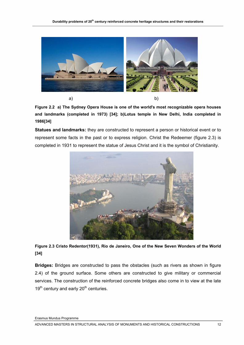
figure 2.1 is constructed in 1905-1908, but the Sydney Opera House (figure 2.2.a) is
completed 1973(relatively newer), but both of them are heritages.
Which type of intervention techniques are best for their restoration and repair?
Other factors not listed here
What are the key points that make reinforced concrete structures to be regarded as heritage
structures?
If a special thing or event was related in the past to their construction
If the monument is built to commemorate a person or an important event
If the structure is from the beginning of the 20th century and it is still in service
If the structure survived typical historical event that damages other structures
Other factors
In this paper the most common problems of heritage reinforced concrete structures and their
causes, the available testing methods and identification, the way the deteriorated structures
can be repaired and maintained, the methods used in the strengthening of these heritages,

Durability problems of 20th century reinforced concrete heritage structures and their restorations
Erasmus Mundus Programme
ADVANCED MASTERS IN STRUCTURAL ANALYSIS OF MONUMENTS AND HISTORICAL CONSTRUCTIONS 11
principles for repair and strengthening, case studies, and some recommendations and
conclusions are drawn for the 20th C reinforced concrete heritage structures based on the
recommendations of modern reinforced concrete structures.
2.2.1 Reinforced concrete heritage typologies
There are various types of reinforced concrete heritage structures: shell and dome
structures, bridges, cathedrals, buildings, towers, landmarks etc. These structures are
designed and constructed by different architects around the world across the 19th and 20th
centuries. Some of them are constructed to commomerate a person or an event in the past,
some to show the technology and modernization of the era and the others for another
services and reasons.
Heritage buildings: buildings are used or intended for supporting or sheltering any use or
continuous occupancy. The unity temple in figure 2.1 was constructed to give service as a
chapel and public gatherings at the time.
Figure 2.1 the Unity temple in Oak Park, Illinois (built between 1905 and 1908) [34]
Shell and dome structures: shells are used as roof structures in buildings. The use of thin
shell structure allows wide areas to be spanned without the use of internal supports giving an
open, unobstructed interior. Modern thin concrete shells, which began to appear in the
1920s, are made from thin steel reinforced concrete, and in many cases lack any ribs or
additional reinforcing structures, relying wholly on the shell structure itself.
Durability problems of 20th century reinforced concrete heritage structures and their restorations
Erasmus Mundus Programme
ADVANCED MASTERS IN STRUCTURAL ANALYSIS OF MONUMENTS AND HISTORICAL CONSTRUCTIONS 12
a) b)
Figure 2.2 a) The Sydney Opera House is one of the world's most recognizable opera houses and landmarks (completed in 1973) [34]; b)Lotus temple in New Delhi, India completed in 1986[34]
Statues and landmarks: they are constructed to represent a person or historical event or to
represent some facts in the past or to express religion. Christ the Redeemer (figure 2.3) is
completed in 1931 to represent the statue of Jesus Christ and it is the symbol of Christianity.
Figure 2.3 Cristo Redentor(1931), Rio de Janeiro, One of the New Seven Wonders of the World [34]
Bridges: Bridges are constructed to pass the obstacles (such as rivers as shown in figure
2.4) of the ground surface. Some others are constructed to give military or commercial
services. The construction of the reinforced concrete bridges also come in to view at the late
19th century and early 20th centuries.

Durability problems of 20th century reinforced concrete heritage structures and their restorations
Erasmus Mundus Programme
ADVANCED MASTERS IN STRUCTURAL ANALYSIS OF MONUMENTS AND HISTORICAL CONSTRUCTIONS 13
a) b)
c)
Figure 2.4 a) The Paulins Kill Viaduct, Hainesburg, New Jersey completed in 1910, a pioneer in the use of reinforced concrete [34]; b)Pont de Châtellérault in France (1900) [34];c) The Salginatobel Bridge (1930) in the Swiss Alps, it was declared a Historic Civil Engineering Landmark in 1991[34].
Towers: Towers were constructed throughout history for different purposes as: to provide its
users with an advantage in surveying defensive positions and obtaining a better view of the
surrounding areas, including battlefields; to communicate information over greater distances(
figure 2.5.b); for recreation; as a symbol of church spire (figure 2.5.a) etc [34].

Durability problems of 20th century reinforced concrete heritage structures and their restorations
Erasmus Mundus Programme
ADVANCED MASTERS IN STRUCTURAL ANALYSIS OF MONUMENTS AND HISTORICAL CONSTRUCTIONS 14
a) b)
Figure 2.5 a) Reinforced concrete tower at Sainte Jeanne d'Arc Church (Nice, France, 1926–1933) [34]; b)CN Tower (the world's tallest completed freestanding structure) in Toronto, Ontario, Canada (1973 – 1976) [34]
2.3 Causes of reinforced concrete deterioration
Deterioration/distress of historic reinforced concrete can occur due to the following causes
(factors) [33]: Environmental factors: which are typically moisture and carbon dioxide
Materials and workmanship:
- Early aggregates used absorb water and produce a weak and porous
concrete. It also leads to the alkali aggregate reactions which lead to cracking
and white surface staining. Aggregates were not always graded by size that
created poorly consolidated and weak concrete
- The use of sea water and beach sand in the mix or use of calcium chloride as
an additive which causes long term problems
- Poor concrete vibration which leaves voids at critical structural sections
- Structural design defects, for example, the amount of protective concrete
cover around reinforcing bars was often insufficient. There was also limited or
no standard for reinforced concrete constructions; and etc.
Improper maintenance of historic buildings can cause long-term deterioration of
concrete. Water is a principal source of damage to historic concrete.
Durability problems of 20th century reinforced concrete heritage structures and their restorations
Erasmus Mundus Programme
ADVANCED MASTERS IN STRUCTURAL ANALYSIS OF MONUMENTS AND HISTORICAL CONSTRUCTIONS 15
In addition, as cited in the introduction (section 2.2 above ), it is reasonable to consider that
the problems of modern and heritage reinforced concrete structures be similar.
Basically the causes of the deterioration of the reinforced concrete structures can be
classified in to four main categories depending on the causes of deterioration [7]:
1. Mechanical actions, e.g. impact, overloading, movement caused by settlement,
vibration, blasting etc.
2. Chemical actions( such as AAR and direct chemical exposure) and biological actions
from the environment
3. Physical actions, e.g. freeze-thaw action, thermal cracking, moisture movement, salt
crystallization and erosion
4. Reinforcement corrosion: due to chloride ion and carbonation mainly. Electropotential
corrosion between steel reinforcement and another existing metal with in the concrete
is not considered here.
Most of the problems occurring in reinforced concrete structures, which are also believed
common in reinforced concrete heritages, are listed in Table 2.1 below along with their
causes and preventions. All the problems stated below in table 2.1 contribute in the changes
in color, texture, strength, chemical composition of the concrete heritage structures, or other
properties of a natural or artificial material used in the structure.
2.3 Major signs of concrete deterioration
There are different mechanisms for the manifestations or signs of deteriorated reinforced
concrete structures depending on their cause. The common signs of concrete deterioration
can be summarized as [33]:
1. Cracking: Every concrete will crack, but varying in depth, width, direction, pattern,
location, and cause. Cracks can be either active (which widen, deepen, or migrate
through the concrete) or dormant (inactive) which can facilitate moisture ingress
cause further damage if they are not repaired.
2. Structural cracks: can result from temporary or continued overloads, uneven
foundation settling, or original design inadequacies.
3. Spalling: is the loss of surface material in patches of varying size because of
corrosion of reinforcement steel, freeze thaw actions etc.

Durability problems of 20th century reinforced concrete heritage structures and their restorations
Erasmus Mundus Programme
ADVANCED MASTERS IN STRUCTURAL ANALYSIS OF MONUMENTS AND HISTORICAL CONSTRUCTIONS 16
4. Deflection: is the bending or sagging or reinforced concrete structural elements such
as beams, columns, slabs etc which can be due to overloading, corrosion of steel, by
inadequate construction techniques, or by concrete creep. 5. Stain: is a white powdery surface which may be caused by alkali aggregate
reactions. The stain can be colored due to the corrosion of reinforcement. 6. Erosion: due to wind, rain etc 7. Corrosion: is the rusting of the reinforcing steel in concrete mainly due to carbonation
of concrete and the ingress of chloride ions. The rust will expand in volume and
creates cracking and spalling of concrete. In addition, it reduces the load carrying
capacity of the structural member.

Durability problems of 20th century reinforced concrete heritage structures and their restorations
Erasmus Mundus Programme
ADVANCED MASTERS IN STRUCTURAL ANALYSIS OF MONUMENTS AND HISTORICAL CONSTRUCTIONS 17
Table 2.1 Common problems and causes of reinforced concrete heritage structures [1]
Problems Causes Laboratory
analysis Symptoms Prevention Accidental
loading Impact; explosion;
Earthquakes No Spalling or cracking of concrete
Can't be prevented, but reduce the impact
Acid attack highly concentrated
acids nearby the concrete structures
to identify the specific acid
present
Highly alkaline concrete material affected by acids causing loss of cement paste and aggregate from the matrix and reinforcement attack causes staining, cracking and spalling
Concrete with a low water-cement ratio(w/c) or
appropriate surface coating or treatment
Aggressive water attack
water with low concentration of dissolved salts
to measure the aggressiveness of
the water
leaching of surface produces rough concrete
surface
Coating susceptible areas with nonportland-cement-
based coating
Alkali-silica reaction
Reaction of aggregates containing silica with
highly alkaline solutions, forming a solid that expands in the presence of water
Petrographic examination
Random cracking; Map or pattern of cracking and
swelling of concrete
Removal or replacement of damaged concrete and/or a
protective waterproofing render
Sulfate attack
Attack of concrete by naturally occurring
sulfates found in soil or in solution in ground
water adjacent to concrete structures
To determine occurrence of
reactions
softening and loss of surface layers; Map or pattern of cracking and
disintegration of concrete
Remove all suspect and degraded concrete, and
patch or full repair using a polymer mortar
Construction errors
Poor workmanship and carelessness No
Enhance the adverse impacts of other
mechanisms or accelerate the penetration of
aggressive agents(CO2,Cl2...) in to
the concrete
To know what this construction errors are and
following aggressive inspection program
corrosion of reinforcement
Differences in concrete of Moisture content,
chloride content, oxygen content and
electric potential difference
Determination of chloride content in
the concrete, to determine the
amount of concrete to be removed during repair
Rust staining of concrete followed by
cracking(following the reinforcement)and spalling
Use of concrete with low permeability, providing
adequate cover to reinforcement
Inadequate structural design No
Spallig due to higher compressive stresses and
cracking due to high tensile stresses
Review of initial designs
Design errors
Poor design details No
cracking due to localized concentrations of high
stresses, that allows the passage of water and
chemicals
Careful review of plans and specifications; correcting the
detailing
Freezing and thawing
Expansion of the pore water in the cement
paste and aggregate in cold climates
Laboratory examination of the core taken from the damaged structure
Varies from surface scaling to disintegration
Removal and replacement of damaged concrete with
concrete having low w/c and air entrainer admixture, and
providing drainage

Durability problems of 20th century reinforced concrete heritage structures and their restorations
Erasmus Mundus Programme
ADVANCED MASTERS IN STRUCTURAL ANALYSIS OF MONUMENTS AND HISTORICAL CONSTRUCTIONS 18
Differential movement among various elements of the
structure
review of instrumentation
data to determine the movement
Cracking or spalling or faulty alignment of
structural members; movement in non
structural elements
Geotechnical solutions Settlement and
movement (due to failure of
foundation materials)
Subsidence: the entire structures or a single
element of the structure is moving with respect to the reamining structure
review of instrumentation
data to determine the movement
Cracking or spalling or faulty alignment of
structural members; movement in non
structural elements
Foundation soil strengthening by injection or grouting; underpinning; installing
perforated drain pipe around the foundation
Plastic shrinkage: occurs before setting. Bleeding of the paste allows evaporation of water at the surface
No
cracks at the surface due to tensile stresses if the
evaporation is faster than the water supplied
not common for heritage structures, but common for patch repair materials used
on the existing concrete substrate
Shrinkage(loss of moisture from concrete) Drying shrinkage: long
term loss of moisture from concrete after
setting
No
Shrinkage and restraints from other parts of the
structure creates tensile stresses that leads to
shallow and fine cracks, the cracks being
orthogonal or blocky in pattern
These cracks are aesthetic defects and as a rule no need of repair. If the effect need to be masked, surface grinding
followed by a flood application with silicon is
recommended
Internally generated temperature
differences: caused by hydration of cement
No thermal cracks as the tensile strength of the concrete is exceeded
It is rare in historic concrete, but the retoration of concrete by overlaying face the problem. To avoid this thermal stress by using low cement content, using combination of cement and pozzolans, placing the concrete at minimum temperatures,using aggregates of low modulus of elasticity and thermal coefficient
Externally generated temperature
differences: caused by variations in climatic
conditions
No thermal cracks as the tensile strength of the concrete is exceeded
Provision of contraction and expansion joints; providing
reinforcing steel (temperature steel) to distribute the cracks and to minimize the size or
crack already occurred ; careful review of repair
materials
Temperature changes(change volume of concrete)
Fire No Integrity loss, spalling or cracking
Fire alarm systems and prevention of sources of
fire???
Over loading
The structure was designed using the previous available code that may be inadequate for current conditions; change in the use of the structure which lead to overloading and movements
No
Cracking, deformation and other damages due to
bending, shearing ,torsion etc
Strengthen or repair the structure according to current
use and standard

Durability problems of 20th century reinforced concrete heritage structures and their restorations
Erasmus Mundus Programme
ADVANCED MASTERS IN STRUCTURAL ANALYSIS OF MONUMENTS AND HISTORICAL CONSTRUCTIONS 19
Of all the problems listed in table 2.1 above, the most common durability problems of
reinforced concrete structures/heritages such as corrosion of reinforcing steel, alkali silica
reaction, freeze thaw and overloading of the structure are discussed below.
2.4 Corrosion of reinforcement
Nowadays, most reinforced concrete structures are showing strength and durability related
problems leading to the reduction in durability and service life of the structure. Reinforced
concrete materials are mostly used in load bearing elements of structures (both for modern
and heritage reinforced concrete structures). One of the most known cause for the reduction
of durability of these structures is the corrosion of the reinforcing steel. Concrete is a weak
material under tension, so reinforcing steel is embedded in concrete is to carry tension loads,
which is usually affected by the corrosion of the reinforcement. The corrosion leads to the
reduction of the material strength and the ductility of the structure, which in turn poses a treat
to historical reinforced concrete heritages/structures. This reduction in durability and service
life causes economic impacts as repairing expenses are comparatively high. In addition, it
leads to social and environmental impacts due to the decrease of reliability and safety [12] as
sown in figure 2.6 below.
Figure 2.6 Corrosion of reinforcement/tendons causes the collapse 0f the roof of the former Congress Hall in Berlin in 1980 [37] According to [12], with increasing duration of exposure to a corrosive environment, the steel
mass loss increases leading to a significance increase of the applied stress and a significant
reduction of the tensile ductility of the reinforcing steel. [12] Shows that reinforcing bars
subjected to corrosion may suffer a relatively modest loss of strength but a significant loss of
ductility.

Durability problems of 20th century reinforced concrete heritage structures and their restorations
Erasmus Mundus Programme
ADVANCED MASTERS IN STRUCTURAL ANALYSIS OF MONUMENTS AND HISTORICAL CONSTRUCTIONS 20
The deterioration of reinforced concrete structures can be caused by:
• The attack of the integrity of concrete due to chemical and acid attacks, freeze thaw
and other factors.
• The attack of the embedded reinforcing steel, for example by chloride and
carbonation.
In general, corrosion of the embedded reinforcing steel is the principal cause of the
deterioration of concrete structures [4].
This section will discuss the problems associated with corrosion of steel in reinforced
concrete and the factors responsible for the degradation of the mechanical properties of
reinforced concrete. Corrosion of the reinforcement steel is caused due to [4]:
Inadequate concrete cover to the reinforcement
Leaving the reinforcement exposed to the aggressive environment
Presence or contact of different types metals having different electrochemical
potential( galvanic corrosion)
The main causes for corrosion of reinforcement can be generalized as follows [5]:
1. When the rebar in the concrete is exposed to the chlorides either contributed
from the concrete ingredients or penetrated from the surrounding chloride-
bearing environment;
2. Carbonation of concrete or penetration of acidic gases into the concrete;
3. Factors related to concrete quality, such as water cement (w/c) ratio, cement
content, impurities in the concrete ingredients, presence of surface cracks,
etc.
4. Factors related to the external environment, such as moisture, oxygen,
humidity, temperature, bacterial attack, stray currents, etc.
The assessment of the causes and extent of corrosion is carried out using various
electrochemical techniques.
It is believed that the surrounding concrete is able to prevent corrosion in the reinforcement
in three different ways [5] and [6]:
Hydration products of cement in concrete form a high alkalinity (pH=12-13) that
passivates the reinforcement thereby preventing it from corrosion.
Well-consolidated and properly cured concrete with a low w/c ratio has a low
permeability, which minimizes penetration of corrosion inducing agents, such as
chloride, carbon dioxide, moisture, etc. to the steel surface.
The high electrical resistivity of concrete restricts the rate of corrosion by reducing the
flow of electrical current from the anodic to the cathodic sites.
Durability problems of 20th century reinforced concrete heritage structures and their restorations
Erasmus Mundus Programme
ADVANCED MASTERS IN STRUCTURAL ANALYSIS OF MONUMENTS AND HISTORICAL CONSTRUCTIONS 21
2.4.1 Factors affecting corrosion of steel in concrete
The factors contributing for the corrosion of reinforcement in concrete can be generalized as
External and Internal factors.
1. External factors: include environmental factors as follows[5]:
Availability of oxygen and moisture at rebar level. Moisture fulfills the
electrolytic requirement of the corrosion cell.
Carbonation and entry of acidic gaseous pollutants( SO2 and NO2) due to
their tendency to reduce the pH of the concrete, leading to reinforcement
corrosion, loss of passivity of concrete against reinforcement corrosion, and
catastrophic reinforcement corrosion, as indicated in Table 2.2 [5]. Table 2.2 State of reinforcement corrosion at various pH levels
pH of concrete State of reinforcement corrosion
Below 9.5 Commencement of steel corrosion
At 8.0 Passive film on the steel surface disappears
Below 7 Catastrophic corrosion occurs
Aggressive anions, mostly chloride ions, reaching to the rebar level, either
through the concrete ingredients or from the external environment: which
increases the corrosion rate, but the change in pH of concrete is insignificant.
Some countries limit the total chloride content in concrete codes as presented
in Table 2.3 [5]. Table 2.3 Chloride content limits, as recommended by some codes of practices
Country Recommended limits of chloride content(% by mass of cement)
USA 0.15% for chloride exposure and o.3% for chloride free exposures
UK 0.3%
India 0.15%
Stray currents
Relative humidity and temperature
Bacterial action
2. Internal factors: these includes concrete and steel quality parameters as described
below[5]:
Cement composition: The cement in the concrete provides protection to the
reinforcing steel against corrosion by maintaining a high pH in the order of
12.5–13.

Durability problems of 20th century reinforced concrete heritage structures and their restorations
Erasmus Mundus Programme
ADVANCED MASTERS IN STRUCTURAL ANALYSIS OF MONUMENTS AND HISTORICAL CONSTRUCTIONS 22
Impurities in aggregate: Aggregates containing chloride salts cause serious
corrosion problems, particularly those associated with sea-water and those
whose natural sites are in ground water containing high concentration of
chloride ions.
Impurities in mixing or curing water(Chloride sources).
Admixtures: addition of chloride set accelerators (CaCl2 was widely used until
the mid 1970s) to accelerate the hydration of cement.
Water-cement ratio (w/c): it does not by itself control the rate of corrosion of
reinforcement. The ingress of aggressive agents depends on the permeability
of concrete, which is a function of w/c ratio that affects the corrosion of rebar.
The following effects can be observed related to w/c ratio:
- The depth of penetration of a particular chloride threshold value
increases with an increase in the w/c ratio.
- Carbonation depth has been found to be linearly increasing with an
increase in the w/c ratio.
- The oxygen diffusion coefficient is also found to be increasing with
an increase in the w/c ratio.
Low w/c ratio decreases the concrete permeability, which in turn reduces the
chloride penetration, carbon dioxide penetration, and oxygen diffusion in to
concrete.
Cement content: Due to inadequate amount of cement in mix the concrete is
not consolidated properly leading to the formation of honeycombs and other
surface defects. These honeycombs and surface defects help in the
penetration and diffusion of corrosion causing agents, such as Cl−, H2O, O2,
CO2, etc., in concrete. This results in the initiation of reinforcement corrosion.
Aggregate size and grading: Aggregate grading is another factor, which
should be considered for high quality impermeable concrete. he coefficient of
permeability of concrete increases considerably with increasing size of
aggregates. The proportioning of coarse and fine aggregates is important for
the production of a workable and durable concrete.
Poor construction practices:
Cover to the reinforcement: Cover depth has a significant effect in case of
corrosion due to penetration of either chloride or carbonation. Risk of
reinforcement corrosion increases with low cover thicknesses.
Chemical composition and structure of the reinforcing steel:

Durability problems of 20th century reinforced concrete heritage structures and their restorations
Erasmus Mundus Programme
ADVANCED MASTERS IN STRUCTURAL ANALYSIS OF MONUMENTS AND HISTORICAL CONSTRUCTIONS 23
Of all the factors that aggravates the corrosion of the embedded reinforcement, carbonation
and chloride ions cause the most significant deterioration problems in reinforced concrete
structures(figure 2.7). These two factors will be discussed in detail in the following sections.
Figure 2.7 Initiation of mechanisms of steel corrosion in concrete [12]
2.4.2 Mechanisms of corrosion
Reinforcement corrosion is an electrochemical process (Figure 2.8), at the anode iron is
oxidized to iron ions that pass into solution, and at the cathode oxygen is reduced to hydroxyl
ions. The anode and the cathode form a corrosion cell, with the flow of electrons in the steel
and of ions in the concrete pore solution leading to the corrosion of reinforcement. The
corrosion product will expand 4-6 times the original or parent volume of iron or steel.
at anode Fe--- Fe++ + 2e
at cathode O2 + 2H2O +4e--- 4OH-
combined reaction 4Fe +3 O2+2H2O--- 2Fe2O3.H2O (rust)
Figure 2.8 Corrosion of iron and steel occurs in the simultaneous presence of water and oxygen [14].

Durability problems of 20th century reinforced concrete heritage structures and their restorations
Erasmus Mundus Programme
ADVANCED MASTERS IN STRUCTURAL ANALYSIS OF MONUMENTS AND HISTORICAL CONSTRUCTIONS 24
Figure 2.9 the corrosion reaction on steel [3]
2.4.3 Forms of corrosion
There are generally two common forms of corrosion: Pitting and uniform corrosion. Pitting
corrosion is a localized corrosion which can be created due to the attack of corrosion agents
acting on specific locations as compared to the whole steel mass. Uniform corrosion is acting
uniformly all over the steel mass. Pitting corrosion is known to cause the most severe
deterioration problems in reinforced concrete structures. 2.4.4 Chloride induced reinforcement corrosion
The durability of reinforced concrete structures is affected by the penetration of chloride ions,
the main sources of chloride ions being [3]:
Either contributed from concrete ingredients including deliberate addition of chloride
set accelerators(CaCl2 was widely used until the mid 1970s), use of sea water in the
mix and using contaminated aggregate (usually sea dredged aggregates which were
unwashed or inadequately washed) or
Penetrated or diffused from the surrounding chloride-bearing environment or marine
environment.
Concrete

Durability problems of 20th century reinforced concrete heritage structures and their restorations
Erasmus Mundus Programme
ADVANCED MASTERS IN STRUCTURAL ANALYSIS OF MONUMENTS AND HISTORICAL CONSTRUCTIONS 25
Figure 2.10 reinforcement corrosion caused by chloride ingress [21]
The diffusion of chloride from the surrounding environment in to concrete is the major
problem in most parts of the world.
Once the chloride content at the reinforcement reaches a threshold value (as shown in Table
2.4[8]) and enough oxygen and moisture are present, the reinforcement corrosion will be
initiated, that may form corrosion products including various oxides of iron which are
relatively lower density and occupy much more volume than the original iron. Corrosion
products then accumulate in the concrete–steel interface transition zone; generate expansive
pressure on the surrounding concrete, and the pressure builds to such a high level that
cause crack initiation and propagation [6].
In addition to the cracking in surrounding concrete, chloride-induced reinforcement corrosion
results in loss of the concrete–steel interface bond, and reduction of the cross-sectional area
of reinforcement, thus reducing the load carrying capacity of concrete structure [6].

Durability problems of 20th century reinforced concrete heritage structures and their restorations
Erasmus Mundus Programme
ADVANCED MASTERS IN STRUCTURAL ANALYSIS OF MONUMENTS AND HISTORICAL CONSTRUCTIONS 26
Table 2.4 Corrosion risk in concrete containing the chlorides (Pullar-Strecker, 1987) [8]
Chloride(per % by weight) Condition of concrete adjacent Corrosion risk to reinforcement Less than 0.4% 1. Carbonated High 2. Uncarbonated, made with Cement containing less than Moderate 8% or more C3A in total Cementious material 3. Uncarbonated, made with Cement containing 8% or more C3A in total cementious material 0.4%-1% 1.As above High 2. As above High 3. As above Moderate More than 1.0% All cases High
2.4.4.1 Chloride attack mechanism The penetration of chloride ions through the porous concrete media may result in the
accumulation of chloride content at reinforcement level. The chloride ion attacks the passive
layer but, unlike carbonation, there is no overall drop in pH. Chloride act as catalysts to
corrosion when there is sufficient concentration at the rebar surface to break down the
passive layer. They are not consumed in the process but help to break down the passive
layer of oxide on the steel and allow the corrosion process to proceed quickly. This is
illustrated in Figure 2.11 below. This makes chloride attack difficult to remedy as chloride are
hard to eliminate [3].
Figure 2.11 the breakdown of the passive layer and ‘recycling chlorides’ [3]
The chloride-induced reinforcement corrosion process of reinforced concrete structures can
be divided roughly into three phases as shown in Figure 2.12 [6].
Durability problems of 20th century reinforced concrete heritage structures and their restorations
Erasmus Mundus Programme
ADVANCED MASTERS IN STRUCTURAL ANALYSIS OF MONUMENTS AND HISTORICAL CONSTRUCTIONS 27
Figure 2.12 Chloride induced reinforcement corrosion process [6].
1st Phase( Chloride penetration): The penetration or diffusion of chloride from the
concrete surface through the concrete cover toward the reinforcement;
Figure 2.13Chloride penetration and corrosion initiation [8]
2nd Phase (Rust expansion): The 2nd phase starts when the chloride content at the
reinforcement reaches a threshold value to initiate the corrosion process at time
tinitiation. This phase is dominated by the reinforcement rust expansion, during which
the corrosion products accumulates in the concrete-steel interface transition zone.
Once voids in the interface transition zone are occupied completely with the rust at
time tstress, further rust accumulation will trigger expansive stress and then cracking
in the surrounding concrete, which indicates the start of the third phase.
a) b) c
Figure 2.14 a) Free expansion of rust; b) rust growth and accumulation; c) stress initiation. [3] and [8]
Concrete
Steel
Durability problems of 20th century reinforced concrete heritage structures and their restorations
Erasmus Mundus Programme
ADVANCED MASTERS IN STRUCTURAL ANALYSIS OF MONUMENTS AND HISTORICAL CONSTRUCTIONS 28
3rd Phase: In this last phase, the rust expansion-induced cracks propagate from the
reinforcement to the surrounding concrete leading to the spalling and delamination of
the concrete as shown in Figure 2.10. Corners tend to crack first on corroding
reinforced concrete structures. This is because the oxygen, water, chlorides and
carbon dioxide have two faces as path ways to the steel. Delamination occurs as
corrosion proceeds on neighboring rebars and the horizontal cracks join up as shown
Figure 2.15.
a) b)
Figure 2.15 a) Concrete cracking due to rust expansion [8]; b) Corrosion induced cracking and spalling[3] 2.4.5 Carbonation induced reinforcement corrosion
Apart from chloride ions, carbonation is the other most important factor that will contribute for
the corrosion of reinforcing steel, thereby reducing the strength and durability of load carrying
reinforced concrete elements as shown in figure 2.16.
Figure 2.16 reinforcement corrosion caused by carbonation of concrete [21]

Durability problems of 20th century reinforced concrete heritage structures and their restorations
Erasmus Mundus Programme
ADVANCED MASTERS IN STRUCTURAL ANALYSIS OF MONUMENTS AND HISTORICAL CONSTRUCTIONS 29
Carbonation is the interaction of carbon dioxide gas in the atmosphere with concrete
hydrates, such as portlandite(Ca(OH)2 and Calcium silicate hydrates(CSH), producing
calcite CaCO3 and water [3] and [11]. Like many other gases carbon dioxide dissolved in
water to form an acid. Unlike most other acids the carbonic acid does not attack the cement
paste, but just neutralizes the alkalis (reduce the pH of concrete), mainly forming calcium
carbonate as shown in the chemical equations below [3]:
CO2 + H20-- H2CO3
H2CO3 + Ca(OH)2-- CaCO3 + 2H20
The calcium carbonate forms a porous line that will allow oxygen flows through surface
concrete to corrode steel reinforcement [11]. The formation of CaCO3 reduces the pH of
concrete. Carbonation is strongly linked to drying of concrete. Wet concrete does not
carbonate! [7]
Although carbonation is often considered as less severe than chloride ingress, it is much
more widespread, because it involves carbon dioxide (CO2) from air. Furthermore,
carbonation coupled with chloride ingress reduces durability of concrete exposed to de-icing
salts and marine environments, because carbonation accelerates chloride ingress [1].
Besides, ductility of concrete would decrease with an increase in the degree of carbonation
[2] and [11].
Figure 2.17 Reaction of carbon dioxide in pore water with lime and alkaline constituents [7].
Carbonation damage occurs most rapidly when there is little concrete cover over the
reinforcing steel. Carbonation can occur even when the concrete cover depth to the
reinforcing steel is high. This may be due to a very open pore structure where pores are well
connected together and allow rapid CO2 ingress by diffusion due to concentration gradients

Durability problems of 20th century reinforced concrete heritage structures and their restorations
Erasmus Mundus Programme
ADVANCED MASTERS IN STRUCTURAL ANALYSIS OF MONUMENTS AND HISTORICAL CONSTRUCTIONS 30
between porous net and environment of concrete [3] and [11]. It may also happen when
alkaline reserves in content, high water cement ratio and poor curing of the concrete.
Some of the factors that influence the resistance of reinforced concrete against carbonation
induced corrosion are [3]:
1. Carbonation rate: which is a function of concrete cover thickness
2. Cement content: as the process of carbonation is neutralizing the alkalinity of
concrete, good reserves of alkalinity is required, that is a high amount of cement
content.
3. Water-cement ratio (w/c): the water cement ratio has a direct relation with
impermeability of concrete. Carbonation can be reduced by far if the w/c ratio in
concrete is low.
4. Compaction and curing or permeability: The diffusion process is made easier if the
concrete has an open pore structure. Thus well compacted and cured concrete has
small pores and lower connectivity of pores so that CO2 can’t diffuse through the
concrete easier. Microsilica and other additives can block pores or reduce pores
sizes.
5. Cover to reinforcement: enough cover must be provided to prevent the carbonation
front advancing into the concrete to the depth of the steel within the lifetime of the
structure.
According to [3], Carbonation is common in old structures, badly built structures (particularly
building). Carbonation is rare in modern civil engineering structures where water/cement
ratios are low, cement contents are high with good compaction and curing, and there is
enough cover to prevent the Carbonation front advancing into the concrete to the depth of
the steel within the lifetime of the structure.
Wet/dry cycling on the concrete surface will accelerate carbonation by allowing carbon
dioxide gas in during the dry cycle and then supplying the water to dissolve it in the wet cycle
(according to the above equation). This gives problems in some countries in tropical or semi-
tropical regions where the cycling between wet and dry seasons seems to favour
carbonation, e.g. Hong Kong and some Pacific Rim countries [3].
Carbonation is easy to detect and measure. A PH indicator, usually phenolphthalein in a
solution of water and alcohol, will detect the change in pH across a freshly exposed concrete
face. Phenolphthalein changes from colorless at low pH (carbonated zone) to pink at high pH
(uncarbonated concrete) [3]. Measurements can be taken on concrete cores, fragments and
down drilled holes.
Durability problems of 20th century reinforced concrete heritage structures and their restorations
Erasmus Mundus Programme
ADVANCED MASTERS IN STRUCTURAL ANALYSIS OF MONUMENTS AND HISTORICAL CONSTRUCTIONS 31
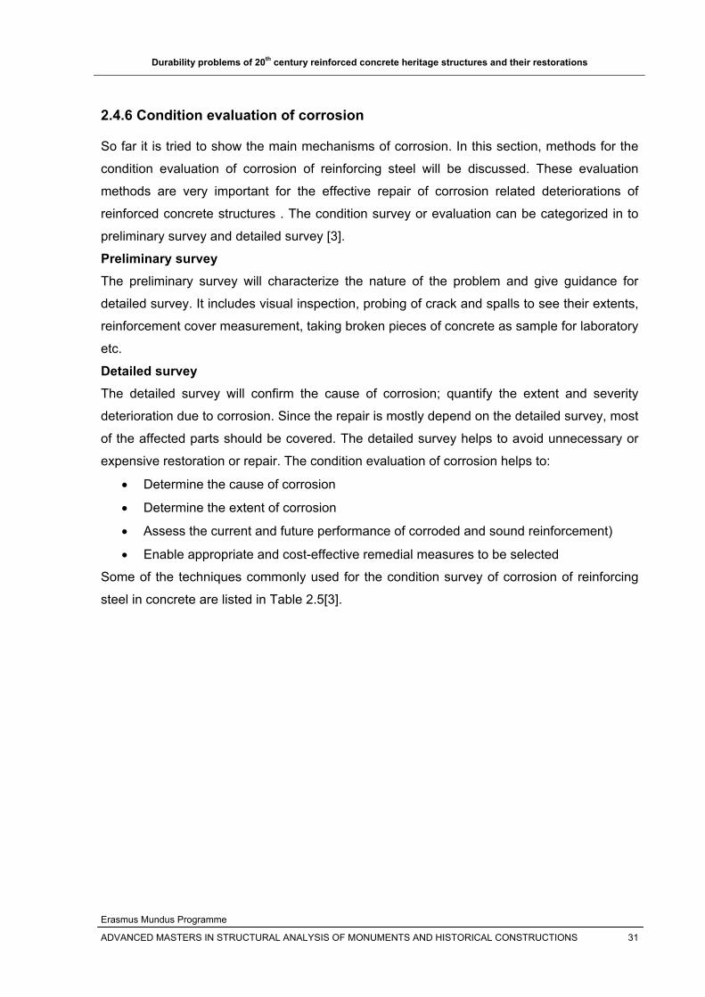
2.4.6 Condition evaluation of corrosion
So far it is tried to show the main mechanisms of corrosion. In this section, methods for the
condition evaluation of corrosion of reinforcing steel will be discussed. These evaluation
methods are very important for the effective repair of corrosion related deteriorations of
reinforced concrete structures . The condition survey or evaluation can be categorized in to
preliminary survey and detailed survey [3].
Preliminary survey The preliminary survey will characterize the nature of the problem and give guidance for
detailed survey. It includes visual inspection, probing of crack and spalls to see their extents,
reinforcement cover measurement, taking broken pieces of concrete as sample for laboratory
etc.
Detailed survey The detailed survey will confirm the cause of corrosion; quantify the extent and severity
deterioration due to corrosion. Since the repair is mostly depend on the detailed survey, most
of the affected parts should be covered. The detailed survey helps to avoid unnecessary or
expensive restoration or repair. The condition evaluation of corrosion helps to:
• Determine the cause of corrosion
• Determine the extent of corrosion
• Assess the current and future performance of corroded and sound reinforcement)
• Enable appropriate and cost-effective remedial measures to be selected
Some of the techniques commonly used for the condition survey of corrosion of reinforcing
steel in concrete are listed in Table 2.5[3].
Durability problems of 20th century reinforced concrete heritage structures and their restorations
Erasmus Mundus Programme
ADVANCED MASTERS IN STRUCTURAL ANALYSIS OF MONUMENTS AND HISTORICAL CONSTRUCTIONS 32
Table 2.5 Methods for condition survey of corrosion of reinforcing steel in concrete
Method Detect/Application Use Limitation
Visual inspection
To estimate nature and extent of surface defect
visual inspection and collecting pictures and videos about the
concrete surface using camera and
Depends on the skill of operator
Hammer/Chain Delamination of concrete
Hit the concrete surface using hammer or drag the chain over the surface to hear the sound
variation on the concrete surface
Water and deep delamination can affect result; depends on
the skill of operator
Cover meter
Rebar depth, position and size; to
check adequate cover has been
provided
Move the cover meter over the concrete surface, and the
location of the reinforcement is identified when the sound of the cover meter changes; the depth
is recorded in the instrument
They are slow, and deep cover and closely spaced bars will
affect the readings
Half cell potential
measurements
Indication of corrosion risk of
steel
Move the half cell along the concrete surface and observe
the potential difference created
Needs specialist; Very negative potentials can be found in saturated conditions where
there is no oxygen
Phenolphthalein
To estimate Carbonation depth
and future carbonation
Expose/split fresh concrete surface and spray
phenolphthalein indicator and observe the color change or
take a core sample and apply phenolphthalein in laboratory
Dark colored fine aggregates can cause problems in color
changes; Poorly consolidated and underground concrete
exposed to dissolved carbonates in the water may
not show clearly defined carbonation front;
phenolphthalein change color at PH 9 but the passive breaks at
PH 10-11
Chloride content
Chloride corrosion and chloride profile
Powdered samples from drilling will be dissolved in acid in the
laboratory; in field using Quantab strips and specific ion
electrode
Quantab strip is modest in accuracy and becomes
inaccurate by certain aggregate types; Specific ion electrode is accurate but the equipment is expensive and needs trained
personnel
Receptivity
concrete receptivity/ corrosion risk by
estimating whether steel is
depassivated
Wenner probe is used to estimate the potential difference
caused by depassivation
It is not used directly as independent measurement but
to supplement other tests
Linear Polarization
To measure corrosion rate
Polarize the steel with an electric current and monitor its effect on the half cell potential
Detection of instantaneous corrosion rate which can change with temperature, relative humidity and other
factors; there will be error in the estimated area of measurement specially at low corrosion rates
Durability problems of 20th century reinforced concrete heritage structures and their restorations
Erasmus Mundus Programme
ADVANCED MASTERS IN STRUCTURAL ANALYSIS OF MONUMENTS AND HISTORICAL CONSTRUCTIONS 33
2.4.7 Consequences of corrosion
Once reinforcement corrosion is initiated, it progresses almost at a steady rate and shortens
the durability and service life of the structure. The rate of corrosion directly affects the extent
of the remaining service life of a corroding RC structure [5]. As the corrosion is in progress,
the following two things will happen among others [1], [5] and [12]:
1. First, the cross-sectional area of the reinforcement is reduced, which in turn reduces
the load-carrying capacity of the steel while loads of a reinforced concrete structure
remain the same during the service life of the structure. The reduction in cross
sectional area of the reinforcing steel will lead to an increase of the stress applied to
the bars, which reduces the safety factors taken for the properties of the reinforcing
steel. The corrosion also reduces both the ultimate
2. Second, the products of the corrosion, iron oxide (rust), expand since they occupy
about eight times the volume of the original material. This increase in volume leads to
cracking and ultimately spalling of the concrete. The cracking and spalling of the
concrete surface impairs the appearance of the structure as shown in figure 2.18
below.
Generally the reinforcing steels are located in the zones of high tensile stresses of shear
stresses of the load bearing elements, the well being of the structure is guaranteed if the well
being of the reinforcement is maintained. As the ductility of a reinforced concrete depends on
the reinforcing steel, the reduction in ductility of the reinforcing steel will lead to collapses
without any warning. The structure without its service load bearing capacity will not give its
intended function.
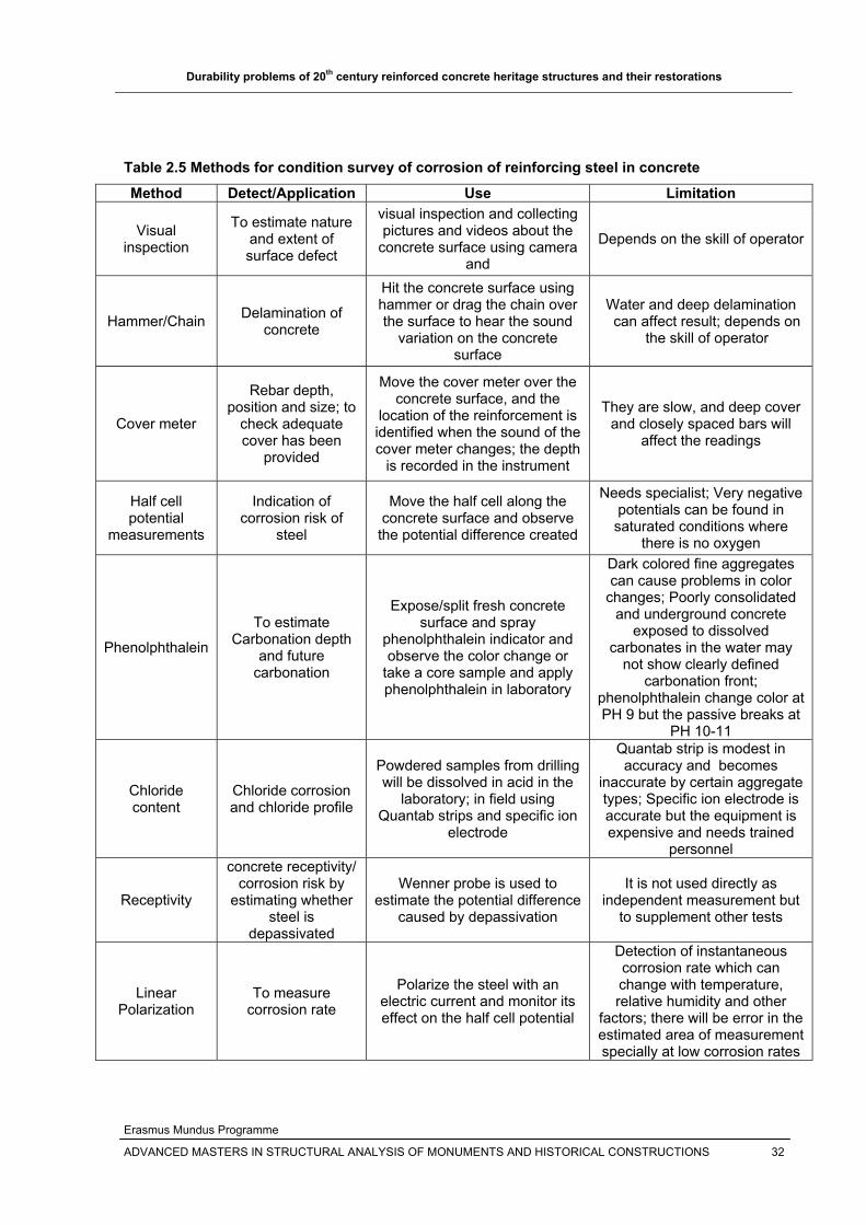
Figure 2.18 Corrosion damage in a North American elevated highway structure exposed to de-icing salts - notice spalling of the concrete cover, leaving the rebar exposed [38]

Durability problems of 20th century reinforced concrete heritage structures and their restorations
Erasmus Mundus Programme
ADVANCED MASTERS IN STRUCTURAL ANALYSIS OF MONUMENTS AND HISTORICAL CONSTRUCTIONS 34
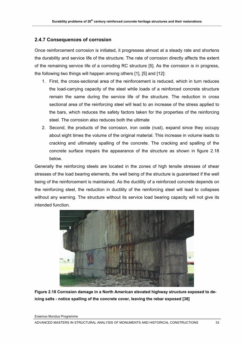
2.4.8 Rehabilitation of corrosion damaged reinforced concrete structures
There are various available physical and chemical rehabilitation techniques for rehabilitating
corrosion damaged reinforced concrete structures to extend the service life and the safety of
the structures. Before the rehabilitation starts, the causes of the damage should be identified
by in situ tests or NDT to avoid unnecessary or expensive rehabilitation costs and to select
the appropriate repair method. The appropriate repair and rehabilitation systems must be
chosen for each structure according to its type, condition and future use [3]. Once the cause
of the corrosion is known, there are common repair techniques for reinforced concrete
structures damaged by reinforcement corrosion. The repair techniques can be broadly
classified as:
1. Traditional repair methods: such as patching, Concrete placement, etc;
2. Electrochemical Techniques or methods: such as cathodic protection, chloride
removal and realkalization.
2.4.8.1 Traditional repair methods The traditional methods are those methods that have been used decades ago and are now
still in use. Most of the traditional methods need the removal of deteriorated concrete due to
chloride or carbonation before the repair method is applied.
Concrete removal and surface preparation There are a number of methods for removing concrete, the choice being depended on the
specification, budget, preferences and the scale of the concrete surface to be removed.
Pneumatic hammer, hydrojetting and milling machines are among the known concrete
removal methods [3]. The concrete removal and surface preparation includes the removal of
unsound concrete, cleaning the rebar surface and squaring the edges. The concrete must be
removed from all around the bar and behind the bar so that all the corroded part is exposed
and the dust removed as shown in figure 2.19. The cleaned steel may be coated with anti-
corrosion agents. This prepares the concrete surface for the next step that is patching .
a)
b)
Figure 2.19 Partial (a) or full depth (b) of concrete removal and reinforcement cleaning [17]

Durability problems of 20th century reinforced concrete heritage structures and their restorations
Erasmus Mundus Programme
ADVANCED MASTERS IN STRUCTURAL ANALYSIS OF MONUMENTS AND HISTORICAL CONSTRUCTIONS 35
Patches After removing the damaged concrete, the empty space will be patched or filled with either
prebagged materials or concrete mixes on site. Patching guarantee the carbonation repairs
by restoring the alkalinity of concrete, but patch repairing is not adequate to stop further
deterioration in the presence of chloride attack as patching of the corroded areas can
accelerate corrosion elsewhere [3]. In addition, while removing the concrete cover either by
spalling or concrete removal, the following two things may happen:
1. Removing the concrete will redistribute the load with in the structure, and the patch
repair may not take the load through it as the original concrete. This effect is
particularly important for slender reinforced concrete elements which are liable to
buckle.
2. The exposed steel may bend once the bond between steel and concrete is lost, which
will cause severe structural problems.
Thus patch repair should be minimized as much as possible or care must be taken for
structural members (such as columns) where the above two problems may happen. Most
writers say this is why electrochemical techniques are becoming common in repair of
deteriorated concrete, as it needs any removal concrete except deteriorated concrete. But it
is the patching repair that is common in most day to day repairs.
Protective surface treatments: Coatings, sealers, membranes and barriers Once the patching of the removed concrete surface is finished, coatings are mostly applied.
Coatings are beneficial in excluding undesirable aggressive agents such as chlorides and
carbon dioxide, water or cosmetically restoring the appearance after concrete repair [3]. They
will also hide the difference between the original concrete and new patching material.
Figure 2.20 Concrete removal, surface preparation, patching and surface treatment
1. Carbonation repair Anti-carbonation coatings: Coatings which should be applied after carbonated
concrete repair to stop further carbon dioxide ingress.
2. Chloride repair Penetrating sealers: Penetrating sealers used to reduce chloride ingress in to the
concrete, but according to [3], these sealers will accelerate carbonation.

Durability problems of 20th century reinforced concrete heritage structures and their restorations
Erasmus Mundus Programme
ADVANCED MASTERS IN STRUCTURAL ANALYSIS OF MONUMENTS AND HISTORICAL CONSTRUCTIONS 36
Drainage and guttering: This takes away chloride or salt containing water away from
the concrete surface.
Encasement and overlay: This reduces corrosion in high chloride bearing
environments. Overlay may be polymer modified concrete, low slump dense
concrete, or micro silica concretes. Overlay or encasement may absorb some of the
chlorides on the old concrete surface there by reducing the chloride level. If some or
all of the older concrete surface is removed, the overlay will reduce the high chloride
gradient that drives chloride further in to the concrete
The limitation of coatings is that, they may retain humidity in the concrete that can initiate or
enhance corrosion. When the humidity drops or temperature rises, the retained water exerts
local force that can burst the coatings.
Corrosion inhibitors Corrosion Inhibitors such as nitrite additives added to concrete are common to hinder
corrosion. Most inhibitors develop a very thin chemical layer on the steel surface that inhibits
corrosion attack or the chemical reactions that are taking place on the steel surface. The
inhibitors can be applied as coatings on the surface or on to the exposed steel at patch
repairs, incorporated in to the patch repairs, applied in grooves or drilled holes( but
expensive and damaging) in the concrete cover or incorporated into concrete overlays.
Optimum dosage of inhibitor should be applied to avoid localized or pitting attack due to
shortage of inhibitors [3].
2.4.8.2 Electrochemical techniques The use of electrochemical techniques for the repair of chloride and carbonation corrosion
has been developed during the past decades. These techniques are getting more attention
due their effectiveness in the field and laboratory. Electrochemical techniques avoid
corrosion either by stopping it or maintaining it with in reasonable limit or preventing it. The
other important feature of these techniques is that they don’t need removal concrete except
the deteriorated concrete. The most commonly used electrochemical techniques for the
control of corrosion in existing reinforced concrete structures are [16]:
1. Cathodic protection
2. Chloride removal
3. Re-alkalization
Cathodic protection is applied for structures affected by chloride corrosion. Chloride removal
and re-alkalization are applied to structures in which corrosion has not or has already
Durability problems of 20th century reinforced concrete heritage structures and their restorations
Erasmus Mundus Programme
ADVANCED MASTERS IN STRUCTURAL ANALYSIS OF MONUMENTS AND HISTORICAL CONSTRUCTIONS 37
initiated. These techniques aim at modifying the composition of concrete that is carbonated
or contains chlorides, in order to restore its original protective characteristics.
Both the protection of reinforcing steel and the restoring of the concrete alkalinity are
obtained by forcing a direct current to circulate between the anode, placed on the surface of
the reinforced concrete structure, and the reinforcement as shown in figure 2.21 below. But
the circulation of the current is believed to stimulate alkali aggregate reaction, reduce the
bond between the reinforcement and concrete or lead to the acidification of the anodic
region.
Figure 2.21 Schematic representation of application of electrochemical techniques [16]
2.4.8.2.1 Cathodic protection Cathodic protection is applied for reinforced concrete structures affected by chloride
corrosion; the steel is subjected to cathodic polarization, i.e. its potential is brought to values
more negative than the free corrosion value, so that the corrosion rate is reduced. According
to [16], this method is also found to be effective in repassivatiog steel in carbonated
concrete, but it is not mostly applied as other methods are economical. The mechanism how
this technique helps to protect chloride and carbonation corrosion is showed in figure 2.22
and 2.23 below respectively [3].

Durability problems of 20th century reinforced concrete heritage structures and their restorations
Erasmus Mundus Programme
ADVANCED MASTERS IN STRUCTURAL ANALYSIS OF MONUMENTS AND HISTORICAL CONSTRUCTIONS 38
Figure 2.22 Cathodic protection of steel in chloride-containing concrete [16]
Figure 2.23 Cathodic protection of steel in carbonated concrete [16]
To achieve the cathodic protection, the anode system will be introduced in to the concrete
surface. This anode system helps in the distribution of current on the surface of the structure
to help better protection of the reinforcing steel against corrosion. According to [16], various
methods of anode system are available such as:
Titanium mesh, wire or strip embedded in concrete with an overlay
Conductive coating with carbon powder in organic matrix
Zinc coating foil attached to concrete surface via an ion-conducting gel adhesive.
Typical applications of the anode system to various members of a reinforced concrete are
presented in figure 2.24 below [16].
Slab, wall
Column, beam
Figure 2.24 Examples of anode layouts with respect to a concrete cross section [16]

Durability problems of 20th century reinforced concrete heritage structures and their restorations
Erasmus Mundus Programme
ADVANCED MASTERS IN STRUCTURAL ANALYSIS OF MONUMENTS AND HISTORICAL CONSTRUCTIONS 39
According to [8], no concrete repair methods can put corroded metal back on to the
reinforcement except cathodic protection. It also states that the cost of cathodic protection is
as much as half of other repair methods.
a) b) Figure 2.25 Anode layouts on bridge column a) fixed anode cover coat on bridge column; b) Metal oxide mesh fixed to bridge column [8].
2.4.8.2.2 Chloride removal This electrochemical chloride removal technique uses liquid electrolytes and direct voltage to
remove the chloride ions. In this process of chloride removal, the original concrete surface is
left unchanged after treatment and this helps in the restoration of reinforced concrete
architectural heritages or monuments.
Figure 2.26 Principal Reactions involved in chloride extraction [16]
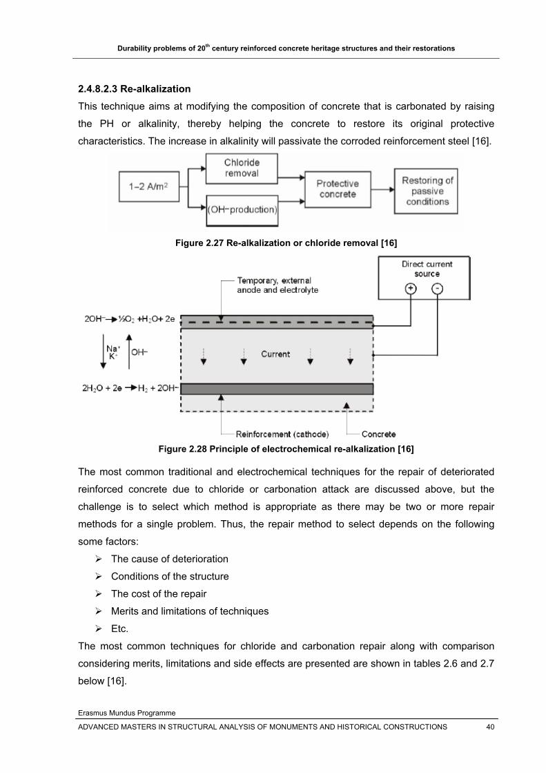
Durability problems of 20th century reinforced concrete heritage structures and their restorations
Erasmus Mundus Programme
ADVANCED MASTERS IN STRUCTURAL ANALYSIS OF MONUMENTS AND HISTORICAL CONSTRUCTIONS 40
2.4.8.2.3 Re-alkalization This technique aims at modifying the composition of concrete that is carbonated by raising
the PH or alkalinity, thereby helping the concrete to restore its original protective
characteristics. The increase in alkalinity will passivate the corroded reinforcement steel [16].
Figure 2.27 Re-alkalization or chloride removal [16]
Figure 2.28 Principle of electrochemical re-alkalization [16]
The most common traditional and electrochemical techniques for the repair of deteriorated
reinforced concrete due to chloride or carbonation attack are discussed above, but the
challenge is to select which method is appropriate as there may be two or more repair
methods for a single problem. Thus, the repair method to select depends on the following
some factors:
The cause of deterioration
Conditions of the structure
The cost of the repair
Merits and limitations of techniques
Etc.
The most common techniques for chloride and carbonation repair along with comparison
considering merits, limitations and side effects are presented are shown in tables 2.6 and 2.7
below [16].

Durability problems of 20th century reinforced concrete heritage structures and their restorations
Erasmus Mundus Programme
ADVANCED MASTERS IN STRUCTURAL ANALYSIS OF MONUMENTS AND HISTORICAL CONSTRUCTIONS 41
Table 2.6 Comparison of techniques for chloride repair
Technique Effectiveness Limitations Side effects/Problems
Patch repair and coating yes where patched
costs can rise if extra repairs
needed
structural support may be needed
Patch repair and overlay/encase
Depends on chloride level and
amount of concrete removed
Costs rise if more delaminations
found ???
Cathodic protection yes across treated area
Needs monitoring and maintenance Can aggravate ASR
Chloride removal yes across treated area Lifetime not known Can aggravate ASR
Inhibitors yes across treated area
Rate of penetration to steel not known
Low dosing could cause pitting???
Table 2.7 Comparison of techniques for carbonation repair
Technique Effectiveness Limitations Side effects/problems
Patch repair and anticarbonation
coating yes where patched
costs can rise if extra repairs
needed
Structural support may be needed
Realkalization yes across treated area
may need repeat after about
10years Can aggravate ASR
Inhibitors yes across treated area
Rate of penetration to steel not known
Low dose could cause pitting???
Future recommendation
The existing standards for calculating strength of reinforced concrete members do not
account for the appreciable property degradation of the reinforcing steel bars due to the
gradually accumulating corrosion damage. The safety factors for reinforcing steel that are
stipulated in existing standards need to include the effect of corrosion.
2.5 Alkali aggregate reaction
In recent years increasing attention has been given to problems associated to alkali
aggregate reaction due to a number of instances of ASR attack and the identification of
reactive aggregates in many countries. As it is indicated before, the aggregates used in
historic concrete absorb water and it was sensitive to alkali aggregate reactions.

Durability problems of 20th century reinforced concrete heritage structures and their restorations
Erasmus Mundus Programme
ADVANCED MASTERS IN STRUCTURAL ANALYSIS OF MONUMENTS AND HISTORICAL CONSTRUCTIONS 42
In most concrete, aggregates are more or less chemically inert. However, some aggregates
react with the alkali hydroxides in concrete, causing expansion and cracking over a period of
many years. This alkali-aggregate reaction has two forms:
1. Alkali silica reaction (ASR) and
2. Alkali-carbonate reaction (ACR)
ASR is considerably more widespread and is of more significance. In the following sections,
ASR will be discussed in detail. 2.5.1 Alkali silica reaction (ASR)
Aggregate silica reaction (ASR) is a reaction between alkalis (found in cement or added to
concrete) and reactive siliceous mineral components of the aggregate (such as chert,
quartzite, opal, strained quartz crystals) to form a solid nonexpansive calcium-alkali-silica
complex or an alkali-silica complex. The reaction product is an alkali silicate gel which on
absorption of water will expand and generate hydraulic or tensile stresses which may cause
cracking [1], [2] and [13]. The reaction that takes place is the formation of sodium and
potassium silicates by a slow and expansive reaction of the sodium and potassium
hydroxides with the available silica [13].
Figure 2.29 Expansion of aggregate silica complex in the presence of water [27]
The following factors insure the occurrence of ASR are [13]:
High alkali content of the concrete, mainly contributed from the cement in the form of
potassium oxide (K2O) and sodium oxide (Na2O)
Water - ASR will not occur if there is no available water in the concrete, since alkali-
silica gel formation requires water. The water source can be from the surrounding
cement paste or the environment [27].
The amount of reactive aggregates and the grain size of aggregates.

Durability problems of 20th century reinforced concrete heritage structures and their restorations
Erasmus Mundus Programme
ADVANCED MASTERS IN STRUCTURAL ANALYSIS OF MONUMENTS AND HISTORICAL CONSTRUCTIONS 43
Figure 2.30 The Three Necessary Components for ASR-Induced Damage in Concrete [26].
The term reactive refers to aggregates that tend to breakdown under exposure to the highly
alkaline pore solution in concrete and subsequently react with the alkali- hydroxides (sodium
and potassium) to form ASR gel [26].
The alkali-silica reaction usually occurs much later, possibly years after the concrete was
placed. Large aggregate particles generate a significant volume of gel which then takes up
water and expands within the hardened, mature concrete [35].
Generally the following phenomena will be observed once the ASR is initiated [7]:
Expansion of concrete
Small crack formation at surface
Spalling of concrete
Expulsion of alkali-silica gel
2.5.2 Identification of ASR
The best technique for the identification of ASR is the examination of concrete in thin section,
using a petrographic microscope. Alternatively, polished sections of concrete can be
examined by scanning electron microscopy (SEM) as shown in figure 2.31 and 2.32 below) .

Durability problems of 20th century reinforced concrete heritage structures and their restorations
Erasmus Mundus Programme
ADVANCED MASTERS IN STRUCTURAL ANALYSIS OF MONUMENTS AND HISTORICAL CONSTRUCTIONS 44
Figure 2.31 Polished section of concrete, viewed with a scanning electron microscope, showing a chert aggregate particle with extensive internal cracks due to alkali-silica reaction. The cracks extend from the aggregate into the nearby concrete (arrowed) [35].
Figure 2.32 Detail of the chert particle in the previous image and adjacent cement paste, showing alkali-silica gel extruded into cracks within the concrete [35]. 2.5.3 Symptoms or indications of ASR
The symptoms of ASR attacked reinforced concrete structures depends on the severity of
the attack, exposure conditions, type of structure, amount and direction of restraint (internal
or external), and other factors ,the most important being role of restraint on subsequent crack
patterns. The main symptoms of ASR are random cracking, map or pattern of cracking and
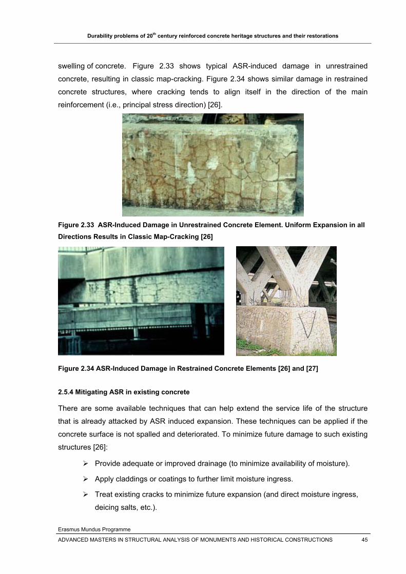
Durability problems of 20th century reinforced concrete heritage structures and their restorations
Erasmus Mundus Programme
ADVANCED MASTERS IN STRUCTURAL ANALYSIS OF MONUMENTS AND HISTORICAL CONSTRUCTIONS 45
swelling of concrete. Figure 2.33 shows typical ASR-induced damage in unrestrained
concrete, resulting in classic map-cracking. Figure 2.34 shows similar damage in restrained
concrete structures, where cracking tends to align itself in the direction of the main
reinforcement (i.e., principal stress direction) [26].
Figure 2.33 ASR-Induced Damage in Unrestrained Concrete Element. Uniform Expansion in all Directions Results in Classic Map-Cracking [26]
Figure 2.34 ASR-Induced Damage in Restrained Concrete Elements [26] and [27] 2.5.4 Mitigating ASR in existing concrete
There are some available techniques that can help extend the service life of the structure
that is already attacked by ASR induced expansion. These techniques can be applied if the
concrete surface is not spalled and deteriorated. To minimize future damage to such existing
structures [26]:
Provide adequate or improved drainage (to minimize availability of moisture).
Apply claddings or coatings to further limit moisture ingress.
Treat existing cracks to minimize future expansion (and direct moisture ingress,
deicing salts, etc.).
Durability problems of 20th century reinforced concrete heritage structures and their restorations
Erasmus Mundus Programme
ADVANCED MASTERS IN STRUCTURAL ANALYSIS OF MONUMENTS AND HISTORICAL CONSTRUCTIONS 46
Avoid future use of deicing salts that will increase alkali content within the
structure.
Restrain or confine expansion of structural element.
Chemically suppress ASR using lithium compounds If the concrete surface is deteriorated or spalled due to alkali silica reaction, the deteriorated
or spalled concrete should be removed and replaced by new concrete having the following
properties [26] and [7]:
Using non-reactive aggregates
Limiting the alkali content of concrete
Using supplementary cementing materials including fly ash, ground-granulated blast
furnace slag, and silica fume.
2.6 Freeze thaw in concrete
Water has lots of ways entering in to the concrete volume; the main reason is being the
permeability and porosity of concrete. Deterioration of concrete from freeze thaw actions may
occur when the concrete is critically saturated, which is when approximately 91% of its pores
are filled with water. The water already inside the capillary pore of cement paste and
aggregate will change to ice in cold weather thereby increasing the volume of the ice; the ice
occupies 9% more volume than that of water. This increase in volume of ice will lead to
expansion of the surrounding concrete. During warm seasons, the ice so formed will melt in
to water. This successive freezing (during cold weather) and thawing (during warm weather)
of the concrete will lead to a cumulative expansion on the concrete volume leading to the
scaling or disintegration of the concrete member when the expansion pressure is greater that
the tensile strength of concrete [1], [7], [28] and [16] . This freeze thawing is a destructive
weathering factor which depends on the temperature of the locality.
In cold climates, for example northern Europe and Canada, deicing chemicals (various salts
and alcohols) are widely used to lower the freezing point of water thereby aiding the removal
of ice from the concrete surface by melting the ice . Most common chemical deicers do not
chemically attack concrete, but the use of these deicing chemicals on concrete surfaces may
accelerate damage caused by freezing and thawing and may lead to pitting and scaling [1]
and [28]. The effect of deicing chemicals is more pronounced on flat concrete surfaces.
Deterioration of concrete by deicers is related to the complex process associated with
physical and chemical alteration in cement paste, aggregates and aggregate-paste interface
that aggravates the effect of freeze thaw in concrete volume [15].
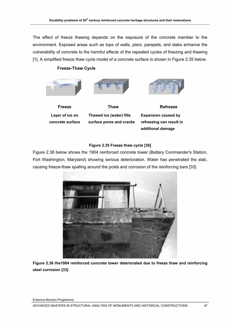
Durability problems of 20th century reinforced concrete heritage structures and their restorations
Erasmus Mundus Programme
ADVANCED MASTERS IN STRUCTURAL ANALYSIS OF MONUMENTS AND HISTORICAL CONSTRUCTIONS 47
The effect of freeze thawing depends on the exposure of the concrete member to the
environment. Exposed areas such as tops of walls, piers, parapets, and slabs enhance the
vulnerability of concrete to the harmful effects of the repeated cycles of freezing and thawing
[1]. A simplified freeze thaw cycle model of a concrete surface is shown in Figure 2.35 below.
Freeze-Thaw Cycle
Freeze
Layer of ice on concrete surface
Thaw
Thawed ice (water) fills surface pores and cracks
Refreeze
Expansion caused by refreezing can result in additional damage
Figure 2.35 Freeze thaw cycle [36]
Figure 2.36 below shows the 1904 reinforced concrete tower (Battery Commander's Station,
Fort Washington, Maryland) showing serious deterioration. Water has penetrated the slab,
causing freeze-thaw spalling around the posts and corrosion of the reinforcing bars [33]
Figure 2.36 the1904 reinforced concrete tower deteriorated due to freeze thaw and reinforcing steel corrosion [33]

Durability problems of 20th century reinforced concrete heritage structures and their restorations
Erasmus Mundus Programme
ADVANCED MASTERS IN STRUCTURAL ANALYSIS OF MONUMENTS AND HISTORICAL CONSTRUCTIONS 48
2.6.1 Rehabilitation of freeze thaw damages
The symptom of freeze thaw in reinforced concrete structure varies from surface scaling to
disintegration. Once the disintegration of the concrete has started, it may be difficult to stop
it. There are some methods that are developed to reduce the impact of freeze thaw in new
concrete [7]. Using these methods, the deteriorated part shall be removed and substituted
with a new concrete having the following characteristics:
Air-entrained concrete: the air bubbles larger than the cement pores will act as
expansion vessels that will provide a space for the ice to expand freely without
causing any surface deterioration.
Surface treatment: the freeze thaw damage occurs if the concrete is wet. Therefore,
the better solution is to prevent the ingress of water by applying a surface coat
(hydrophobic agents) that will not affect the free evaporation of water from the surface
of concrete.
Low water/cement (w/c) ratio with good curing, but according to [7], this method is
best for moderate climate regions.
According to [1], polymer coating is an effective way of repairing freeze thaw damage
provided that the coating will not form a vapor barrier that will erupt the coating by freeze
thawing cycles.
It should be kept in mind that freeze thaw may not be the only problem of the deteriorated
concrete as the cracks caused by the freeze thaw can aggravate the ingress of chloride
,carbon dioxide, water, oxygen and other aggressive agents that affects the steel
reinforcement. Thus whenever a repair for freeze thaw is taking place, it is important to check
the condition of the embedded steel reinforcement whether it is corroded or not.
2.7 Overloading of Reinforced concrete Heritages
Historic reinforced concrete structures were designed to meet the need of codes of their
time. They were designed to give a service for a specific purpose, but as time passes the use
of the structure as well as the demand they were designed for will change. This will create
deterioration of structures by cracking of stressed structural members, deflection etc. In
addition, at the beginning of the century, earth quake codes were not provided for the design
of reinforced concrete structures. Nowadays, earthquake is becoming the major treat for the
deterioration or collapse of historic reinforced concrete structures.
Durability problems of 20th century reinforced concrete heritage structures and their restorations
Erasmus Mundus Programme
ADVANCED MASTERS IN STRUCTURAL ANALYSIS OF MONUMENTS AND HISTORICAL CONSTRUCTIONS 49
The overloading of reinforced concrete structures can be caused due to the following
conditions:
The change in use of the structure typically building
The structure was designed using the previous available code that may be
inadequate for current conditions
The increased use or demand and loads for the structure, for example bridges
Due to unlimited visitor or tourist access to the reinforced concrete heritage
Seismic overloading of structures and etc.
2.7.1 Mitigation of overloading
There are some methods that are currently used for the repair and upgrading of concrete
heritages. But they are in principle invented for modern constructions. The problems due to
overloading can cause the following three typical stresses on the member:
1) Flexure or bending stresses in members
2) Shearing stresses in members
3) Punching stresses in members
The strengthening and upgrading of reinforced concrete structures/heritages are discussed
in detail in section 4. It mainly includes the overlay of concrete, FRP applications, Steel
plates and post-tensioning etc that are commonly applied in reinforced concrete structures.
Durability problems of 20th century reinforced concrete heritage structures and their restorations
Erasmus Mundus Programme
ADVANCED MASTERS IN STRUCTURAL ANALYSIS OF MONUMENTS AND HISTORICAL CONSTRUCTIONS 50
3. PLANNING FOR REINFORCED CONCRETE HERITAGES/STRUCTURES REPAIR, RESTORATION AND PRESERVATION
3.1 Introduction
The restoration scheme for a deteriorated heritage reinforced concrete structure needs an in
situ data for evaluating structural adequacy and for defining the scope of the restoration
work. To enable the extent of the areas requiring repairs to be fully defined, analyzed and
budgeted for, the condition and residual structural capacity of the various elements of the
structure must first be thoroughly and accurately assessed , which in turn needs the
gathering of in situ information on the state and material properties of the deteriorated
structure. [10].
A thorough and logical evaluation of the current condition of the concrete in a structure is the
first step of any repair or rehabilitation project. Before any intervention is decided on the
heritage structures, the following steps shall be followed [1]:
1. Evaluating the condition of concrete in the structure
It may include the design and construction history, maintenance records,
visual examination, nondestructive testing (NDT), and laboratory analysis of
concrete samples, which helps to know the condition of the concrete and the
causes of the damage.
2. Relating the existing condition of the concrete with the possible causes
The visual observations and other supporting data must be related to the
mechanism or mechanisms that caused the damage. The basic cause of the
deterioration should be identified as there may be many causes for a single
problem.
3. Selecting appropriate repair material and method to mitigate the problem
Once the cause of the damage observed in a structure has been determined,
appropriate repair materials and methods can be selected.
4. Preparation of plans and specifications
5. Execution of the work according to the plans and specifications, or appropriate
application of the repair material and methods on the structure under consideration.
A through understanding of the causes of the concrete problem is essential to perform
meaningful evaluations and successful repairs. If the cause of a problem is understood, it is
much more likely that the correct repair method will be selected and that, consequently, the
repair will be successful.
Durability problems of 20th century reinforced concrete heritage structures and their restorations
Erasmus Mundus Programme
ADVANCED MASTERS IN STRUCTURAL ANALYSIS OF MONUMENTS AND HISTORICAL CONSTRUCTIONS 51
As there may be many possible causes for a single problem, the correct cause should be
identified. For example, cracking is a symptom of distress that may have a variety of causes.
The cracking might be caused by repeated freezing and thawing of the concrete, accidental
loading, or some other cause. Only after the cause or causes are known can rational
decisions be made concerning the selection of a proper method of repair and in determining
how to avoid a repetition of the circumstances that led to the problem.
3.2 Condition Survey
A condition survey involves visual examination of exposed concrete for the purpose of
identifying and defining areas of distress or problems. These problems of concrete can be
expressed in terms of cracking, surface problems (spalling and disintegration), and joint
deterioration. This condition survey will frequently include core drilling to obtain specimens
for laboratory testing and analysis. The condition survey shall include the following steps [1]:
1. Visual inspection: is the first step in any concrete condition survey. It is used to
locate and define areas of distress or problem or deterioration of concrete. On visual
inspection, the following conditions should be observed thoroughly:
Construction faults: due to poor workmanship such as bug holes exposed
steel reinforcement, honeycombing etc.
Cracking: this can be expressed in terms of surface appearance, depth of
cracking, width of cracking, current state of activity and structural nature of
crack.
Disintegration: Disintegration of concrete is the deterioration of the concrete
into small fragments or particles resulting from any cause, the most frequent
causes being aggressive-water attack, freezing and thawing, chemical attack,
and poor construction practices. Disintegration can be expressed in terms of
spalling and dusting.
Distortion or movement: is a change in alignment of the components of a
structure.
Erosion: in the form of abrasion and cavitations
Spalling: spalling is defined as the development of fragments, usually in the
shape of flakes, detached from a larger mass. Spalling can be described in
terms of popouts(shallow, typically conical depressions in a concrete surface
due to the result of freezing of concrete that contains some unsatisfactory
aggregate particles) or that caused by the corrosion of reinforcement or other
non-corrosion-resistant embedded metal in concrete.

Durability problems of 20th century reinforced concrete heritage structures and their restorations
Erasmus Mundus Programme
ADVANCED MASTERS IN STRUCTURAL ANALYSIS OF MONUMENTS AND HISTORICAL CONSTRUCTIONS 52
Delamination: Reinforcing steel placed too near the surface or reinforcing
steel exposed to chloride ions will corrode. The iron combines with the
oxygen in water or air forming rust, or iron oxide, and a corresponding
increase in volume up to eight times the original volume. The volume
increase results in cracking over the reinforcing steel, followed by
delamination along the mat of steel and eventually by spalling. Sounding of
concrete with a hammer or chain dragging (for larger areas) provides a low-
cost, accurate method for identifying delaminated areas. Infrared
thermography is another effective method of detecting delamination.
2. Cracking survey: is the survey of the surface of the concrete structure for locating
and marking of areas of distress or problem, identifying cracks and determining the
relationship of the cracks with other problems or destructive phenomena. Crack
widths should be measured either using crack meter or comparator card. Crack
depth should also be recorded by observation of edges or insertion of fine wire or
drilling or using pulse velocity method. 3. Surface mapping: In parallel with crack survey, surface mapping of the deteriorated
concrete surface is made using detailed drawings, photographs or movies. 4. Joint survey: is the visual inspection of the joints in the structure to see the existing
condition of the joint and to check the presence of any defects as spalling, chemical
attack etc. 5. Core drilling: This is a direct method of obtaining in-situ concrete strength of
deteriorated concrete structures [10]. The core will be analyzed in the laboratory to
obtain information on the condition of the concrete. The depth of core depends on
the intended use and type of the structure. When drill hole coring is impractical or
core recovery is poor, a bore hole camera or television is used to evaluate the
interior of the concrete structure.
3.3 Laboratory investigation
After the sample is taken, laboratory analysis is performed. In this stage careful examination
of the structure and detailed tests which will positively identify the cause and extent of the
distress, and that allow prediction to be made about the remaining service life of the
structure.
The laboratory analysis includes [1]:
Petrographic analysis to describe and classify the hardened concrete;
Durability problems of 20th century reinforced concrete heritage structures and their restorations
Erasmus Mundus Programme
ADVANCED MASTERS IN STRUCTURAL ANALYSIS OF MONUMENTS AND HISTORICAL CONSTRUCTIONS 53
Chemical analysis to estimate the cement content, the original water-cement ratio,
the presence and amount of chloride and other admixtures.
Physical analysis to determine the density, compressive strength, modulus of
elasticity, Poisson’s ratio etc.
3.4 Nondestructive Testing (NDT)
The direct method of obtaining in-situ concrete strength of deteriorated concrete structures is
core drilling, but it is not always feasible to core for specimens. The solution is therefore to
use indirect non-destructive and partially destructive techniques which measure concrete
properties other than strength in combination with testing core specimens [10].
Nondestructive testing is becoming very common nowadays to determine the various relative
properties of concrete such as in-place strength, modulus of elasticity, homogeneity, and
integrity, as well as conditions of strain and stress, yield strength, Young’s modulus for the
reinforcing steel, without damaging the structure [1] and [10]. Of these, the most important
property for concrete is the compressive strength and for steel, the yield strength [10]. The
NDT method to be used will depend on the information needed, size and nature of the
project, site conditions and risk to the structure. The NDTs used commonly for concrete are
summarized in Table 3.1 below.
3.5 Minor or partially destructive testing
Partially destructive testing involves mechanical equipment which contacts the concrete
surface, applies an element of force and invariably destroys or removes a portion of the
material in the process. The extent of damage caused depends on the type of equipment and
the procedure used. In a deteriorating concrete structure, especially if the deterioration is on
the surface or within a short distance from the surface, great caution is required in using
those partially destructive test methods which penetrate only a short distance into the
material. It is recommended that those tests be always correlated with compressive strength
results obtained from drilled core samples [10]. The commonly used minor destructives
techniques are listed in Table 3.2 below.
Almost all of these test methods and techniques (listed in Table 3.1 and 3.2 except the
coring) measure properties of concrete other than strength. Therefore, a correlation has to be
established in order to enable conversion of the results to concrete compressive strength, a
necessary prerequisite for assessing structural adequacy. The test equipments and the
interpretation of the results also need professional knowledge.

Durability problems of 20th century reinforced concrete heritage structures and their restorations
Erasmus Mundus Programme
ADVANCED MASTERS IN STRUCTURAL ANALYSIS OF MONUMENTS AND HISTORICAL CONSTRUCTIONS 54
The results of NDT and MDT tests will provide good information that helps to [9]:
Determine or confirm the cause of the deterioration
Determine the extent of the deterioration
Assess current and future performance( of deteriorated and apparently sound areas)
Enable appropriate and cost-effective remedial measures to be selected
Table 3.1 Nondestructive techniques commonly applied on concrete structures [1] and [10].
NDT Applications Advantages Limitations
Rebound(Schmidt) hammer
Rebound values can be used to estimate uniformity and quality of concrete and
also to estimate the compressive strength of
concrete
Simple and quick; inexpensive; doesn’t need specialist; large coverage of area of
concrete surface with minimum time
Does not provide reliable prediction of the strength of
concrete; Measurements can be affected by smoothness of surface, moisture content of
concrete, type of course aggregate, carbonation of the
concrete surface etc.
Penetration resistance(Probe)
Penetration resistance can be used for assessing
uniformity and quality of concrete and to estimate the compressive strength
Simple, durable, needs little training to
use
Primarily measures surface and subsurface hardness; No
precise measurement for insitu strength; the probe will leave a
hole in concrete surface; coarse aggregates along the path of the probe affect the
penetration
Ultrasonic pulse velocity(UPV)
method
To determine the general condition and quality of concrete, to estimate
concrete strength, to assess the extent and severity of cracks in concrete , and to
delineate areas of deteriorated or poor quality
concrete
Quick and portable; can penetrate about
11m of good continuous concrete
Does not provide precise estimate of concrete strength,
Moisture variations and the presence of reinforcing steel can affect the results, needs
skilled personnel to analyze the result
Ultrasonic pulse echo(UPE)
To detect foreign objects (steel and plastic pipe) or
discontinuities in the concrete such as cracks, voids etc ; It can measure unknown thickness and
presence of delaminations in the thickness
Can operate under water or in the dry -------
Radar
To detect voids and steel reinforcement; To find
deteriorated areas based on the amount of water present
It is a noncontact method having fast
data acquisition
Needs highly trained personnel to operate the equipment and
for data interpretation

Durability problems of 20th century reinforced concrete heritage structures and their restorations
Erasmus Mundus Programme
ADVANCED MASTERS IN STRUCTURAL ANALYSIS OF MONUMENTS AND HISTORICAL CONSTRUCTIONS 55
Table 3.2 Common minor destructive techniques used [1] and [10]
Minor destructive
tests Applications Advantages Limitations
Pull off test
To estimate the nominal tensile strength of
concrete which can be converted to
compressive strength
Fast, Results are immediate and less sensitive to concrete
ingredients and moisture content. It is used also to
evaluate the bonding adequacy of overlays and
repair patches
Misleading results for deteriorated concrete
surface, damage to the surface
Pull out(CAPO) test[ CAPO=cut
and pull out]
The pull out force can be correlated with the
compressive strength
Reliable correlation between the pull out force and compressive strength
Damage to the surface
Break off test
An in situ direct test measurement of flexural strength of concrete, the measured force then can
be converted to compressive strength
Quick and reliable since it is not sensitive to surface
defects and concrete condition such as moisture content; suitable for bond strength of overlays and
repair patches
Hole is left after the test
Concrete: To estimate the compressive
strength and other parameters from the test
such as splitting and modulus of elasticity; to
determine the composition , air content,
freeze thaw resistance and the presence of
internal damage
Coring
Steel: To obtain samples of reinforcing steel for visual inspection and laboratory testing of
small steel specimens
Visual inspection of the interior concrete possible;
A good knowledge of the structural system is
required for locating holes to avoid highly stressed
areas; the coring will leave a hole that should be filled with compatible
concrete later
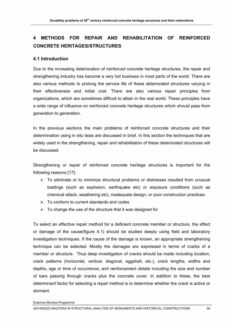
Durability problems of 20th century reinforced concrete heritage structures and their restorations
Erasmus Mundus Programme
ADVANCED MASTERS IN STRUCTURAL ANALYSIS OF MONUMENTS AND HISTORICAL CONSTRUCTIONS 56
4 METHODS FOR REPAIR AND REHABILITATION OF REINFORCED CONCRETE HERITAGES/STRUCTURES
4.1 Introduction
Due to the increasing deterioration of reinforced concrete heritage structures, the repair and
strengthening industry has become a very hot business in most parts of the world. There are
also various methods to prolong the service life of these deteriorated structures varying in
their effectiveness and initial cost. There are also various repair principles from
organizations, which are sometimes difficult to attain in the real world. These principles have
a wide range of influence on reinforced concrete heritage structures which should pass from
generation to generation.
In the previous sections the main problems of reinforced concrete structures and their
determination using in situ tests are discussed in brief. In this section the techniques that are
widely used in the strengthening, repair and rehabilitation of these deteriorated structures will
be discussed.
Strengthening or repair of reinforced concrete heritage structures is important for the
following reasons [17]:
To eliminate or to minimize structural problems or distresses resulted from unusual
loadings (such as explosion, earthquake etc) or exposure conditions (such as
chemical attack, weathering etc), inadequate design, or poor construction practices.
To conform to current standards and codes
To change the use of the structure that it was designed for
To select an effective repair method for a deficient concrete member or structure, the effect
or damage of the cause(figure 4.1) should be studied deeply using field and laboratory
investigation techniques. If the cause of the damage is known, an appropriate strengthening
technique can be selected. Mostly the damages are expressed in terms of cracks of a
member or structure. Thus deep investigation of cracks should be made including location,
crack patterns (horizontal, vertical, diagonal, eggshell, etc.), crack lengths, widths and
depths, age or time of occurrence, and reinforcement details including the size and number
of bars passing through cracks plus the concrete cover. In addition to these, the best
determinant factor for selecting a repair method is to determine whether the crack is active or
dormant.

Durability problems of 20th century reinforced concrete heritage structures and their restorations
Erasmus Mundus Programme
ADVANCED MASTERS IN STRUCTURAL ANALYSIS OF MONUMENTS AND HISTORICAL CONSTRUCTIONS 57
Active cracks: Active cracks are moving and growing. Examples include cracks
resulting from continuing foundation settlement, or cracks acting as contraction and
expansion joints. Active cracks require flexible repair materials and special design
considerations to allow for future movements. Using a rigid repair material for active
cracks typically results in cracking of the repair material and/or the adjacent concrete
Dormant cracks: Dormant cracks are stable and future movements are not
anticipated. Typically, cracking caused by drying shrinkage will be active cracks at the
beginning but eventually stabilize and become dormant. Also, if there is enough
reinforcing crossing through the crack, future movements are controlled and the crack
can be considered dormant. For dormant cracks, use either rigid or flexible repair
materials.
4.2 Objectives repair or strengthening
Every repair or strengthening scheme has specific or combination of problems to be
addressed. The main objectives of repair and strengthening are:
1. To restore the structural soundness, integrity and load carrying capacity of
deteriorated reinforced concrete structures thereby increasing the safety of the
structure (Integrity repair).
2. To stop or seal the ingress of aggressive agents that will affect the embedded
reinforcing steel( crack sealing)
3. To improve the appearance of the cracked or deteriorated concrete surface
(cosmetic repairs).
The repairs have to match the appearance of the rest of the structure in terms of mechanical
properties, colour, texture and finish. These days to match the appearance, painting both the
old surface and the new patch are becoming common.
The repairing or strengthening techniques are applied to cater for the deficiencies of typical
member or structure such as tensile capacity, shear capacity, flexural capacity, compressive
capacity, member stability, strength or stiffness or both, exposure conditions such as chloride
attack, carbonation, freeze thaw etc [17].
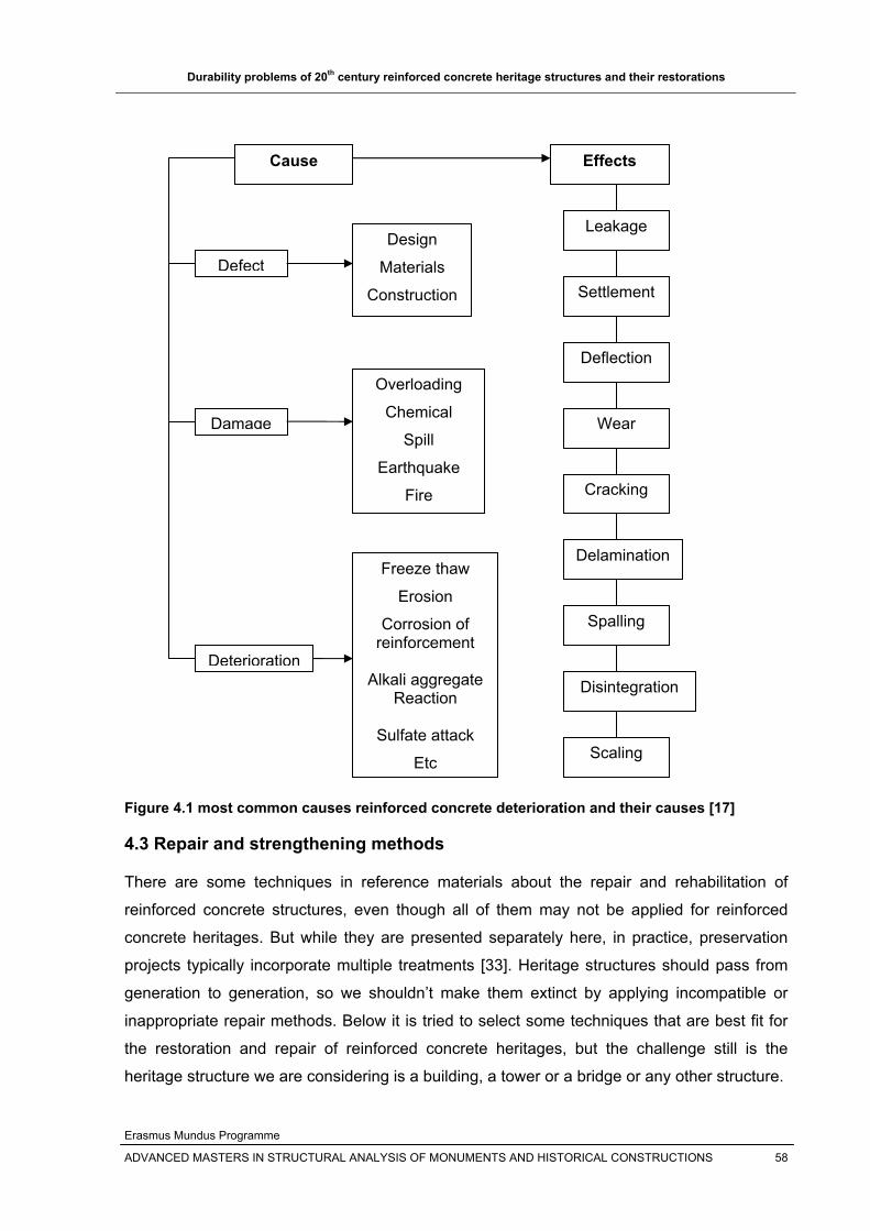
Durability problems of 20th century reinforced concrete heritage structures and their restorations
Erasmus Mundus Programme
ADVANCED MASTERS IN STRUCTURAL ANALYSIS OF MONUMENTS AND HISTORICAL CONSTRUCTIONS 58
Figure 4.1 most common causes reinforced concrete deterioration and their causes [17]
4.3 Repair and strengthening methods
There are some techniques in reference materials about the repair and rehabilitation of
reinforced concrete structures, even though all of them may not be applied for reinforced
concrete heritages. But while they are presented separately here, in practice, preservation
projects typically incorporate multiple treatments [33]. Heritage structures should pass from
generation to generation, so we shouldn’t make them extinct by applying incompatible or
inappropriate repair methods. Below it is tried to select some techniques that are best fit for
the restoration and repair of reinforced concrete heritages, but the challenge still is the
heritage structure we are considering is a building, a tower or a bridge or any other structure.
Cause
Defect
Damage
Deterioration
Design
Materials
Construction
Overloading
Chemical
Spill
Earthquake
Fire
Freeze thaw
Erosion
Corrosion of reinforcement
Alkali aggregate
Reaction
Sulfate attack
Etc
Effects
Leakage
Settlement
Deflection
Wear
Cracking
Delamination
Spalling
Disintegration
Scaling

Durability problems of 20th century reinforced concrete heritage structures and their restorations
Erasmus Mundus Programme
ADVANCED MASTERS IN STRUCTURAL ANALYSIS OF MONUMENTS AND HISTORICAL CONSTRUCTIONS 59
4.3.1 Judicious neglect or do nothing
It is the repair method of taking no action. It needs a deep investigation of the severity of the
damage. If the damage causes no operational problems for the structure and if it does not
create any future problems and deterioration of concrete, the best way to maintain this
structure is to neglect the damages on it. It should be kept in mind that, not all cracks require
repair and monitoring the crack may be the best choice. If needed, the crack can be repaired
later [30]. 4.3.2 Repair of cracking
The method to repair cracks depends on the width, depth and nature of crack (active or
dormant) of crack, varying from no repair to compatible patch repairs, injections and use of
reinforcement to close the crack opening. The patch repair material should be compatible
with the substrate concrete to avoid shrinkage and strength mismatch. Conventional
methods for the repair of crack in reinforced concrete structures are presented below:
1. Routing and sealing It is a nonstructural repair method that consists of enlarging the crack along its exposed face
(routing) and filling and sealing it( see figure 4.2) with a suitable joint sealant such as epoxy
compounds. This method is simple and economical to repair isolated, fine and large dormant
cracks. This method is ideal for horizontal surfaces but can also be used for vertical,
overheads and curved surfaces. This method is not effective for sealing active cracks as the
crack reoccur after the sealing [1] and [30]. The purposes of the sealant are to prevent:
Water from reaching the reinforcing steel,
Hydrostatic pressure from developing within the joint,
Concrete surface from staining, or
Moisture problems on the far side of the member from developing.
Figure 4.2 Repair of crack by routing and sealing [1]

Durability problems of 20th century reinforced concrete heritage structures and their restorations
Erasmus Mundus Programme
ADVANCED MASTERS IN STRUCTURAL ANALYSIS OF MONUMENTS AND HISTORICAL CONSTRUCTIONS 60
2. Drypacking It is a method for filling or repairing deep and dormant cracks( as shown in figure 4.3 below).
It is a process of ramming or tamping in to a confined area with a low water-content mortar
(minimize shrinkage, tight and durable). It is not generally used for patching shallow
depressions, for patching areas requiring filling in back of exposed reinforcement and for
patching holes extending entirely through the concrete section. Drypacking can also be used
for filling narrow slots cut for the repair of dormant cracks [1] and [30].
Figure 4.3 Dry packing a low-water cement mortar into a widened crack is an economical repair option for wide, dormant cracks [30].
3. Additional reinforcement This is the provision of additional conventional (Figure 4.4) or prestressed reinforcing steel to
repair a cracked concrete section due to tensile forces. Post-tensioning of the reinforcement
is required if major potion of the member to be strengthened or when the cracks have to be
closed (figure 4.5) [1].
Figure 4.4 Crack repair using conventional reinforcement orthogonal to the crack plane[1]
Drypacking

Durability problems of 20th century reinforced concrete heritage structures and their restorations
Erasmus Mundus Programme
ADVANCED MASTERS IN STRUCTURAL ANALYSIS OF MONUMENTS AND HISTORICAL CONSTRUCTIONS 61
Figure 4.5Crack repair with use of external prestressing strands or bars to apply a compressive force the close the crack [1].
4. Drilling and plugging It consists of drilling down the length of the crack and grouting it to form a key as shown in
figure 4.6 below .This technique is mostly used for repair of vertical cracks in walls, where
the cracks run reasonably straight lines and are accessible from one side [1].
Figure 4.6 Repair of crack by drilling and Plugging [1]
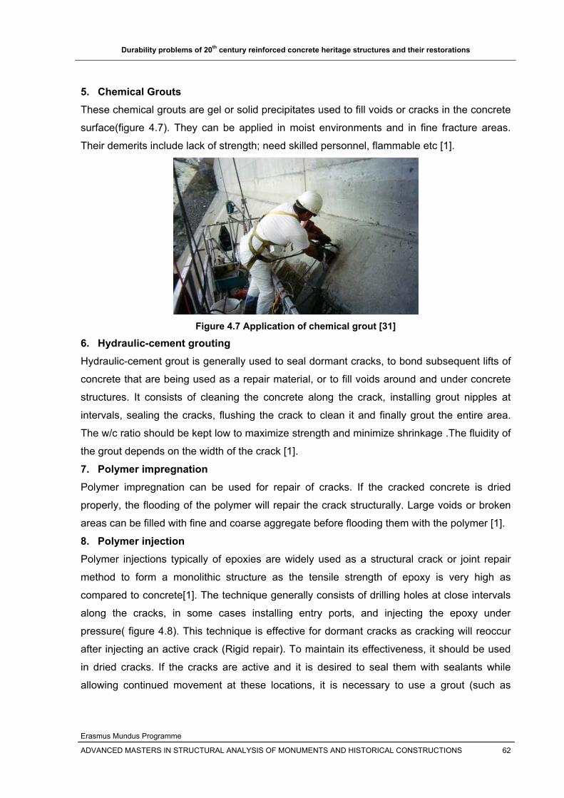
Durability problems of 20th century reinforced concrete heritage structures and their restorations
Erasmus Mundus Programme
ADVANCED MASTERS IN STRUCTURAL ANALYSIS OF MONUMENTS AND HISTORICAL CONSTRUCTIONS 62
5. Chemical Grouts These chemical grouts are gel or solid precipitates used to fill voids or cracks in the concrete
surface(figure 4.7). They can be applied in moist environments and in fine fracture areas.
Their demerits include lack of strength; need skilled personnel, flammable etc [1].
Figure 4.7 Application of chemical grout [31]
6. Hydraulic-cement grouting Hydraulic-cement grout is generally used to seal dormant cracks, to bond subsequent lifts of
concrete that are being used as a repair material, or to fill voids around and under concrete
structures. It consists of cleaning the concrete along the crack, installing grout nipples at
intervals, sealing the cracks, flushing the crack to clean it and finally grout the entire area.
The w/c ratio should be kept low to maximize strength and minimize shrinkage .The fluidity of
the grout depends on the width of the crack [1].
7. Polymer impregnation Polymer impregnation can be used for repair of cracks. If the cracked concrete is dried
properly, the flooding of the polymer will repair the crack structurally. Large voids or broken
areas can be filled with fine and coarse aggregate before flooding them with the polymer [1].
8. Polymer injection Polymer injections typically of epoxies are widely used as a structural crack or joint repair
method to form a monolithic structure as the tensile strength of epoxy is very high as
compared to concrete[1]. The technique generally consists of drilling holes at close intervals
along the cracks, in some cases installing entry ports, and injecting the epoxy under
pressure( figure 4.8). This technique is effective for dormant cracks as cracking will reoccur
after injecting an active crack (Rigid repair). To maintain its effectiveness, it should be used
in dried cracks. If the cracks are active and it is desired to seal them with sealants while
allowing continued movement at these locations, it is necessary to use a grout (such as
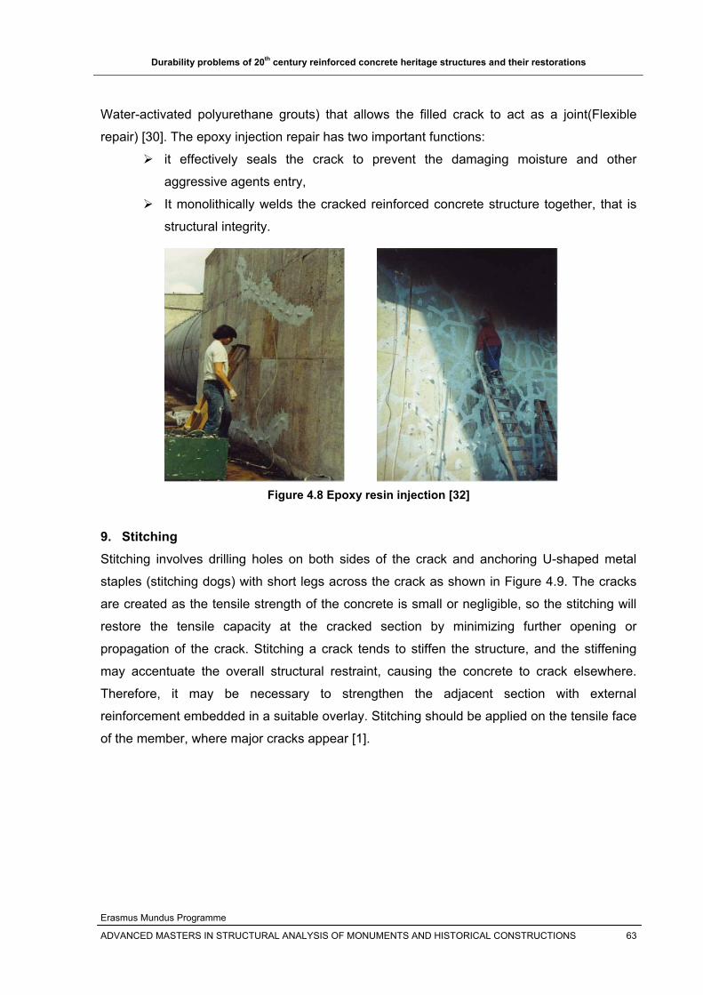
Durability problems of 20th century reinforced concrete heritage structures and their restorations
Erasmus Mundus Programme
ADVANCED MASTERS IN STRUCTURAL ANALYSIS OF MONUMENTS AND HISTORICAL CONSTRUCTIONS 63
Water-activated polyurethane grouts) that allows the filled crack to act as a joint(Flexible
repair) [30]. The epoxy injection repair has two important functions:
it effectively seals the crack to prevent the damaging moisture and other
aggressive agents entry,
It monolithically welds the cracked reinforced concrete structure together, that is
structural integrity.
Figure 4.8 Epoxy resin injection [32]
9. Stitching Stitching involves drilling holes on both sides of the crack and anchoring U-shaped metal
staples (stitching dogs) with short legs across the crack as shown in Figure 4.9. The cracks
are created as the tensile strength of the concrete is small or negligible, so the stitching will
restore the tensile capacity at the cracked section by minimizing further opening or
propagation of the crack. Stitching a crack tends to stiffen the structure, and the stiffening
may accentuate the overall structural restraint, causing the concrete to crack elsewhere.
Therefore, it may be necessary to strengthen the adjacent section with external
reinforcement embedded in a suitable overlay. Stitching should be applied on the tensile face
of the member, where major cracks appear [1].

Durability problems of 20th century reinforced concrete heritage structures and their restorations
Erasmus Mundus Programme
ADVANCED MASTERS IN STRUCTURAL ANALYSIS OF MONUMENTS AND HISTORICAL CONSTRUCTIONS 64
Figure 4.9 Repair of cracking by stitching [1]
4.3.3 Repair of spalling
Repair of spalled reinforced concrete involves the removal of the deteriorated concrete,
cleaning and treatment of reinforcing bars, and placing compatible patch material with good
bond between the substrate concrete and the repair material, that dovetails to the existing
concrete surface. Compatible matching of patch material to the existing concrete is critical for
both appearance and durability.
1. Conventional Concrete placement After the cause of the deterioration of the concrete surface is surveyed, the defective
concrete will be removed( see figure 4.10) and a new concrete that will minimize the cause of
deterioration will be placed. The new concrete should have low w/c ratio and high percentage
of coarse aggregate to minimize shrinkage cracking and that can prevent or reduce the
cause of the original concrete [1].
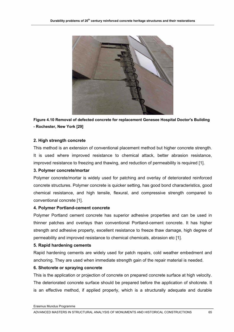
Durability problems of 20th century reinforced concrete heritage structures and their restorations
Erasmus Mundus Programme
ADVANCED MASTERS IN STRUCTURAL ANALYSIS OF MONUMENTS AND HISTORICAL CONSTRUCTIONS 65
Figure 4.10 Removal of defected concrete for replacement Genesee Hospital Doctor's Building - Rochester, New York [29]
2. High strength concrete This method is an extension of conventional placement method but higher concrete strength.
It is used where improved resistance to chemical attack, better abrasion resistance,
improved resistance to freezing and thawing, and reduction of permeability is required [1].
3. Polymer concrete/mortar Polymer concrete/mortar is widely used for patching and overlay of deteriorated reinforced
concrete structures. Polymer concrete is quicker setting, has good bond characteristics, good
chemical resistance, and high tensile, flexural, and compressive strength compared to
conventional concrete [1].
4. Polymer Portland-cement concrete Polymer Portland cement concrete has superior adhesive properties and can be used in
thinner patches and overlays than conventional Portland-cement concrete. It has higher
strength and adhesive property, excellent resistance to freeze thaw damage, high degree of
permeability and improved resistance to chemical chemicals, abrasion etc [1].
5. Rapid hardening cements Rapid hardening cements are widely used for patch repairs, cold weather embedment and
anchoring. They are used when immediate strength gain of the repair material is needed.
6. Shotcrete or spraying concrete This is the application or projection of concrete on prepared concrete surface at high velocity.
The deteriorated concrete surface should be prepared before the application of shotcrete. It
is an effective method, if applied properly, which is a structurally adequate and durable

Durability problems of 20th century reinforced concrete heritage structures and their restorations
Erasmus Mundus Programme
ADVANCED MASTERS IN STRUCTURAL ANALYSIS OF MONUMENTS AND HISTORICAL CONSTRUCTIONS 66
material that creates excellent bond with the existing prepared concrete surface. Good
surface preparation and application technique or skilled personnel are important for the
effectiveness of the method. It is widely used in a repair project where thin repair sections
and large surface areas with irregular contours are involved [1].
Figure 4.11 Application of shotcrete on external wall and inside of dome
7. Shrinkage compensating concrete Shrinkage compensation concrete is used to repair drying shrinkage damaged reinforced
concrete structures such as slabs. Shrinkage-compensating concrete will increase in volume
after setting and during hardening. The expansion of the concrete will be induce tension in
the reinforcement and compression in concrete thereby preventing tension in concrete .It can
be used as a bonded or unbonded topping over a deteriorated or cracked concrete slabs [1].
8. Polymer coatings Polymer coatings are effective in protecting the concrete from abrasion, chemical attack and
freeze thaw. Epoxy resins are used as protective coatings for concrete structures because of
their impermeability to water and resistant to chemical attack. The coatings should not act as
vapor barrier from inside that will cause the disruption of the coatings from freeze thaw
cycles [1].
4.3.4 Repair of overloading and deflection (Strengthening and upgrading)
Deflection and overloading can indicate significant structural problems and often requires the
strengthening or replacement of structural members. Deflection and overloading can lead to
structural failure and serious safety hazards. Their effects are expressed mostly by cracking,
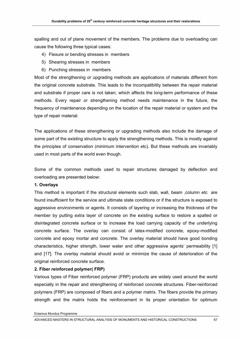
Durability problems of 20th century reinforced concrete heritage structures and their restorations
Erasmus Mundus Programme
ADVANCED MASTERS IN STRUCTURAL ANALYSIS OF MONUMENTS AND HISTORICAL CONSTRUCTIONS 67
spalling and out of plane movement of the members. The problems due to overloading can
cause the following three typical cases:
4) Flexure or bending stresses in members
5) Shearing stresses in members
6) Punching stresses in members
Most of the strengthening or upgrading methods are applications of materials different from
the original concrete substrate. This leads to the incompatibility between the repair material
and substrate if proper care is not taken, which affects the long-term performance of these
methods. Every repair or strengthening method needs maintenance in the future, the
frequency of maintenance depending on the location of the repair material or system and the
type of repair material.
The applications of these strengthening or upgrading methods also include the damage of
some part of the existing structure to apply the strengthening methods. This is mostly against
the principles of conservation (minimum intervention etc). But these methods are invariably
used in most parts of the world even though.
Some of the common methods used to repair structures damaged by deflection and
overloading are presented below:
1. Overlays This method is important if the structural elements such slab, wall, beam ,column etc are
found insufficient for the service and ultimate state conditions or if the structure is exposed to
aggressive environments or agents. It consists of layering or increasing the thickness of the
member by putting extra layer of concrete on the existing surface to restore a spalled or
disintegrated concrete surface or to increase the load carrying capacity of the underlying
concrete surface. The overlay can consist of latex-modified concrete, epoxy-modified
concrete and epoxy mortar and concrete. The overlay material should have good bonding
characteristics, higher strength, lower water and other aggressive agents’ permeability [1]
and [17]. The overlay material should avoid or minimize the cause of deterioration of the
original reinforced concrete surface.
2. Fiber reinforced polymer( FRP) Various types of Fiber reinforced polymer (FRP) products are widely used around the world
especially in the repair and strengthening of reinforced concrete structures. Fiber-reinforced
polymers (FRP) are composed of fibers and a polymer matrix. The fibers provide the primary
strength and the matrix holds the reinforcement in its proper orientation for optimum

Durability problems of 20th century reinforced concrete heritage structures and their restorations
Erasmus Mundus Programme
ADVANCED MASTERS IN STRUCTURAL ANALYSIS OF MONUMENTS AND HISTORICAL CONSTRUCTIONS 68
properties. The most widely FRP products used are made from glass fiber (GFRP), carbon
fiber (CFRP) and aramid fiber (AFRP).
The various products of FRP include laminates (sheets), rods and tendons. The laminates
are bonded external to the structure to be strengthened, and the rods and tendons are
embedded in the concrete to replace the function of the reinforcing steel. They are used to
reinforce existing structures, either to restore the minimum performance requirements or to
extend the function of the structure [7]. This strengthening method has several advantages
over the traditional ones, especially due to higher strength, low weight and improved
durability of the composite material [18].
FRP as reinforcement in existing structures The various products of FRP include laminates (sheets), rods and tendons. The laminates
are bonded external to the structure to be strengthened, and the rods and tendons are
embedded in the concrete to replace the function of the reinforcing steel. The most widely
use of FRP in existing reinforced concrete structures is as external reinforcement where the
FRP is externally bonded to the structural member.
They are used to reinforce existing structures, either to restore the minimum performance
requirements or to extend the function of the structure [7]. This strengthening method has
several advantages over the traditional ones, especially due to higher strength, low weight
and improved durability of the composite material [18].
Applications of FRP include:
1. Reinforcement of concrete columns by wrapping FRP sheets around them to improve
the structural integrity and to prevent buckling of the reinforcement
2. Flexural strengthening of beam and slab or deck of bridges and buildings by
externally bonded reinforcement or near surface mounted FRP
3. Shear strengthening of beam
4. Wrapping damaged bridge piers to prevent collapse
The most widely uses of FRP include:
Strengthening of deteriorated reinforced concrete structure due to load carrying
capacity problems( bending, shear …)
To strengthen reinforced concrete structures that are not designed for earthquake
actions
To strengthen a structure (typically building and bridges) for the change of use of
building for new live load requirements as shown in figure 4.12 and 4.13.

Durability problems of 20th century reinforced concrete heritage structures and their restorations
Erasmus Mundus Programme
ADVANCED MASTERS IN STRUCTURAL ANALYSIS OF MONUMENTS AND HISTORICAL CONSTRUCTIONS 69
Figure 4.12 strengthening of the roof slab Kings College Hospital, London, UK [42]
To guarantee future structural safety
Figure 4.13 Strengthening of the Rhine Bridge Oberriet, Meiningen, Switzerland [42]
Even though these FRP products have lots of advantages over conventional methods of
strengthening, their limitations and disadvantages should be considered when they are
applied for a specific repair or strengthening project. The bond condition between the FRP
and concrete surface, their exposure condition etc should be studied before their application
to the structure to be strengthened.
3. Steel plates and Post-tensioning Steel plates are applied to deficient structural members to strengthen or upgrade the
capacity of the member. But as can be seen from the figures below, they need the
destruction of the member by drilling to tie the plates in to the concrete and extra overlay
material to cover them to similarize the member.
Post tensioning of members (typically in bridge members) is another strengthening and
upgrading of members when they are found deficient for the demand. The reinforcement can
be post-tensioned insider or outside of the member.
FRP
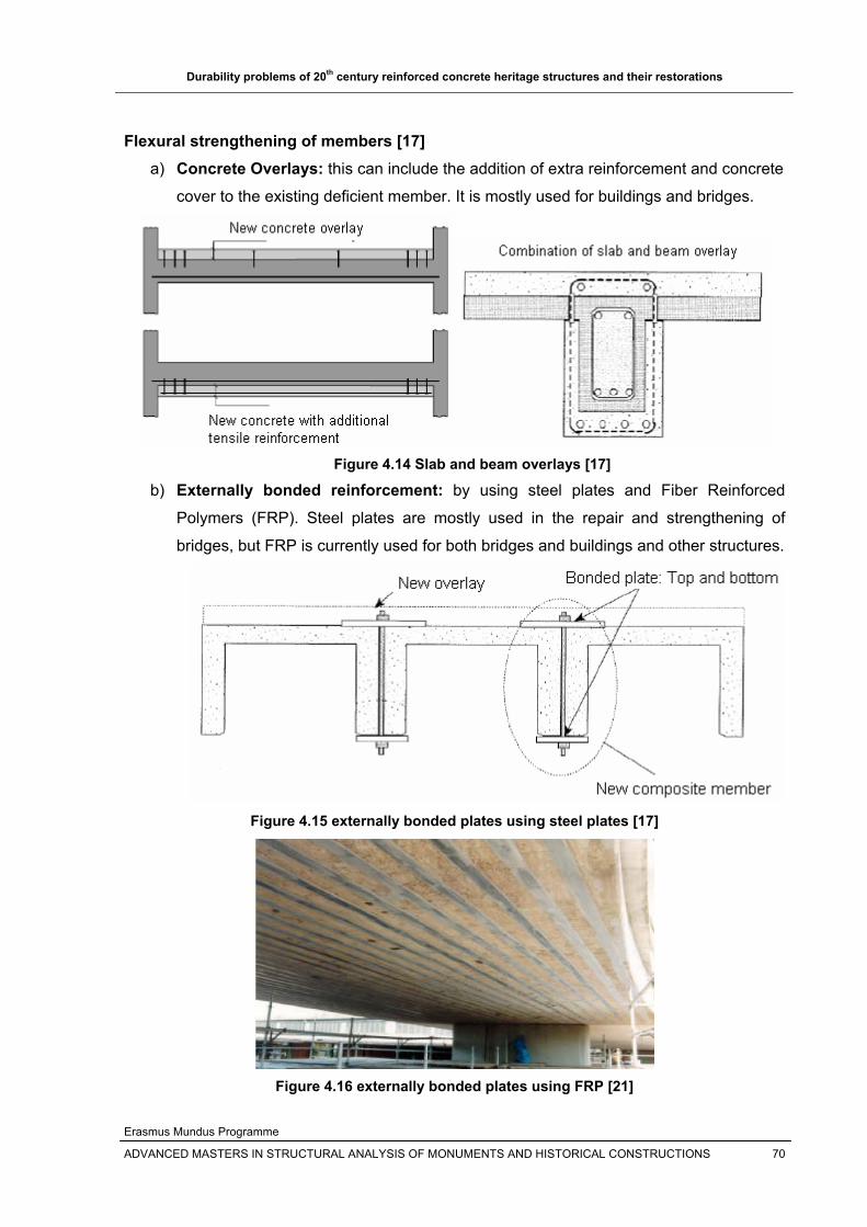
Durability problems of 20th century reinforced concrete heritage structures and their restorations
Erasmus Mundus Programme
ADVANCED MASTERS IN STRUCTURAL ANALYSIS OF MONUMENTS AND HISTORICAL CONSTRUCTIONS 70
Flexural strengthening of members [17] a) Concrete Overlays: this can include the addition of extra reinforcement and concrete
cover to the existing deficient member. It is mostly used for buildings and bridges.
Figure 4.14 Slab and beam overlays [17]
b) Externally bonded reinforcement: by using steel plates and Fiber Reinforced
Polymers (FRP). Steel plates are mostly used in the repair and strengthening of
bridges, but FRP is currently used for both bridges and buildings and other structures.
Figure 4.15 externally bonded plates using steel plates [17]
Figure 4.16 externally bonded plates using FRP [21]

Durability problems of 20th century reinforced concrete heritage structures and their restorations
Erasmus Mundus Programme
ADVANCED MASTERS IN STRUCTURAL ANALYSIS OF MONUMENTS AND HISTORICAL CONSTRUCTIONS 71
c) External post tensioning: it is widely used in bridges.
Figure 4.17 external post-tensioning of a bridge [17]
d) Span length shortening: this can create a negative moment at the new supports
which can creates tension on the upper side of the member, which can cause
damage if provision at the new support is not provided.
Figure 4.18 span length shortening [17]
External Post-tensioning
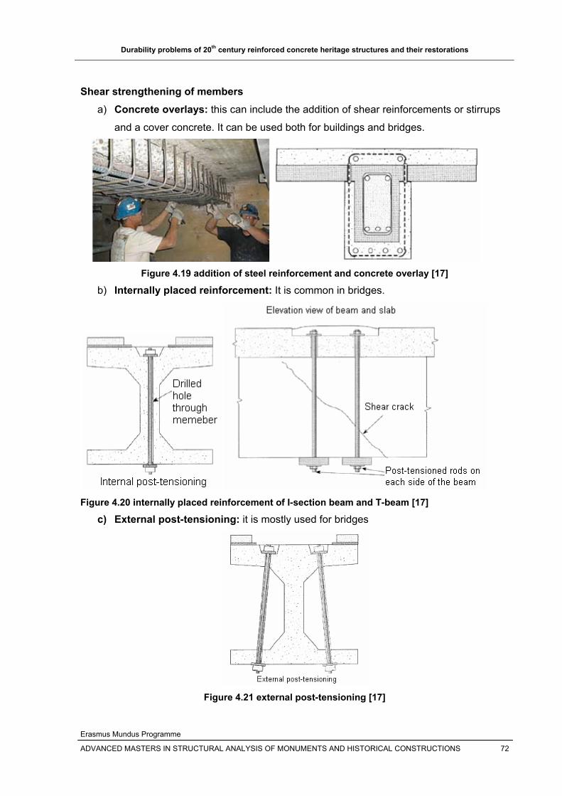
Durability problems of 20th century reinforced concrete heritage structures and their restorations
Erasmus Mundus Programme
ADVANCED MASTERS IN STRUCTURAL ANALYSIS OF MONUMENTS AND HISTORICAL CONSTRUCTIONS 72
Shear strengthening of members a) Concrete overlays: this can include the addition of shear reinforcements or stirrups
and a cover concrete. It can be used both for buildings and bridges.
Figure 4.19 addition of steel reinforcement and concrete overlay [17]
b) Internally placed reinforcement: It is common in bridges.
Figure 4.20 internally placed reinforcement of I-section beam and T-beam [17]
c) External post-tensioning: it is mostly used for bridges
Figure 4.21 external post-tensioning [17]

Durability problems of 20th century reinforced concrete heritage structures and their restorations
Erasmus Mundus Programme
ADVANCED MASTERS IN STRUCTURAL ANALYSIS OF MONUMENTS AND HISTORICAL CONSTRUCTIONS 73
Bolts bonded to the hole
using epoxy
Punching strengthening [17] a) Increase the depth of the member or overlay: this can include the addition of extra
concrete layer on the member to increase the punching depth or the influence area of
punching. This method is widely used both for buildings and bridge structures.
Figure 4.22 shear strengthening by overlay [17]
b) Transversal reinforcement
Figure 4.23 shear strengthening using internal post-tensioning and using bolts [17]
c) Fiber reinforced polymers (FRP)
Figure 4.24 punching strengthening using FRP [17]
Fiber reinforced polymer (FRP)
Column

Durability problems of 20th century reinforced concrete heritage structures and their restorations
Erasmus Mundus Programme
ADVANCED MASTERS IN STRUCTURAL ANALYSIS OF MONUMENTS AND HISTORICAL CONSTRUCTIONS 74
d) Enlarger the column head with concrete: this method is used to increase the
punching perimeter and depth.
Figure 4.25 enlarging the column head of a column to increase punching resistance [17]
e) Enlarger the column head with steel: steel plates and ribs are applied on the
influence area of punching to resist the punching force.
Figure 4.26 enlarging column head with steel plates and ribs [17]
4.3.5 Seismic upgrading using shear walls
Reinforced concrete structures built in the early and middle 20th century were not designed
for earthquake actions. If there is no reinforced concrete shear wall in the load bearing
system to resist lateral loads and lend rigidity to the building, the effect of earthquake will be
more. Due to frequent occurrence of earthquakes nowadays, these structures are becoming
deteriorated. Recent developments have shown that is able to strengthen them using FRP
and by introducing shear walls on the existing structure.
The use of external shear walls on the strengthening of Primary schools in Turkey against
earthquakes is shown in figure 4.27 below [22].
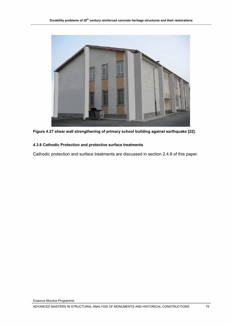
Durability problems of 20th century reinforced concrete heritage structures and their restorations
Erasmus Mundus Programme
ADVANCED MASTERS IN STRUCTURAL ANALYSIS OF MONUMENTS AND HISTORICAL CONSTRUCTIONS 75
Figure 4.27 shear wall strengthening of primary school building against earthquake [22]. 4.3.6 Cathodic Protection and protective surface treatments
Cathodic protection and surface treatments are discussed in section 2.4.8 of this paper.

Durability problems of 20th century reinforced concrete heritage structures and their restorations
Erasmus Mundus Programme
ADVANCED MASTERS IN STRUCTURAL ANALYSIS OF MONUMENTS AND HISTORICAL CONSTRUCTIONS 76
5. COMPATIBILITY OF REPAIR MATERIALS
5.1 Introduction
The repair of most reinforced structures is becoming a common market for contractors in
most parts of the world. Most of these structures are in need of repair because of the aging
and design life of the structures in addition to the aggressive environmental problems and
unexpected loading conditions. Lots of repairs are also undertaken in the past, but it cannot
be said that all the repairs were effective, mainly because of the difference in properties
between the substrate (original concrete) and the repair material, that is compatibility.
Compatibility of the repair material with the existing substrate is very important to get good
repair of the deteriorated reinforced concrete structures. This forces the use of simple repair
approach which uses repair material with properties close to the existing substrate.
Reinforced concrete repairs in the first half of the 20th century were relatively simple and
used primarily replacement of damaged or deteriorated concrete with conventional Portland
cement based concretes, mortars, grouts or gunites (sprayed mortars). But the use of
Portland cement based repair materials showed unsatisfactory outcomes. Since after the
1960’s new enhanced concrete repair materials such as polymer modifiers for Portland
cement based products and pure polymers such as epoxy resins etc are introduced in to the
repair industry [19].
To get an effective repair system, the following key factors about the repair material should
be studied taking in to account the existing substrate concrete[1] and [19]:
The properties of the repair material;
The sensitivity and durability of the repair material;
The physical and chemical exposure conditions to which the repair material will be
subjected ;
The physical and chemical compatibility of the repair material with the substrate
concrete, before making a final selection as to which type of repair material to use.
5.2 Patch Repairs
The repair materials typically consist of plain cementitious mortar; polymer modified
cementitious mortar and resin mortar, the main difference between these repair systems
being their mechanical properties. The plane cementitious mortar has lower mechanical
properties closest to most substrate concretes. But Polymer modified cementious mortars
and resin mortars are of higher strength and resistance and should be used if the following
conditions exist [19]:
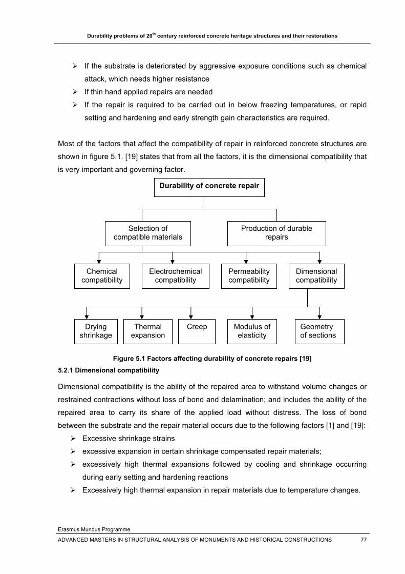
Durability problems of 20th century reinforced concrete heritage structures and their restorations
Erasmus Mundus Programme
ADVANCED MASTERS IN STRUCTURAL ANALYSIS OF MONUMENTS AND HISTORICAL CONSTRUCTIONS 77
If the substrate is deteriorated by aggressive exposure conditions such as chemical
attack, which needs higher resistance
If thin hand applied repairs are needed
If the repair is required to be carried out in below freezing temperatures, or rapid
setting and hardening and early strength gain characteristics are required.
Most of the factors that affect the compatibility of repair in reinforced concrete structures are
shown in figure 5.1. [19] states that from all the factors, it is the dimensional compatibility that
is very important and governing factor.
Figure 5.1 Factors affecting durability of concrete repairs [19]
5.2.1 Dimensional compatibility
Dimensional compatibility is the ability of the repaired area to withstand volume changes or
restrained contractions without loss of bond and delamination; and includes the ability of the
repaired area to carry its share of the applied load without distress. The loss of bond
between the substrate and the repair material occurs due to the following factors [1] and [19]:
Excessive shrinkage strains
excessive expansion in certain shrinkage compensated repair materials;
excessively high thermal expansions followed by cooling and shrinkage occurring
during early setting and hardening reactions
Excessively high thermal expansion in repair materials due to temperature changes.
Durability of concrete repair
Selection of compatible materials
Production of durable repairs
Chemical compatibility
Electrochemical compatibility
Permeability compatibility
Dimensional compatibility
Drying shrinkage
Thermal expansion
Creep Modulus of elasticity
Geometry of sections
Durability problems of 20th century reinforced concrete heritage structures and their restorations
Erasmus Mundus Programme
ADVANCED MASTERS IN STRUCTURAL ANALYSIS OF MONUMENTS AND HISTORICAL CONSTRUCTIONS 78
The size, shape and thickness of the area being repaired, the amount of reinforcing and
anchorage [if any], modulus of elasticity, strain capacity and creep of the repair material also
affect the dimensional compatibility of reinforced concrete.
Thus, the repair material should neither shrink nor expand once installed and should have
the same modulus of elasticity and thermal expansion characteristics with that of the
substrate concrete. But to get absolute repair materials with these properties may be a
challenge and thus repair materials which are as close in their properties as the substrate
should be used so that they will not shrink or expand to the extent they crack. To minimize
the cracks, steel or synthetic fibers can be incorporated in to the repair material. 5.2.2 Bond compatibility and durability
The performance of any concrete repair is highly dependent on the quality of bond of the
repair material to the substrate concrete(bond compatibility) and how long it will be
maintained(bond durability). When the repaired element or structure is subjected to
excessive stresses, failure will occur in the weakest portion either in the repair material or in
the substrate or the bond between them. The main causes of the stresses in the bond
interface of repairs are:
Plastic and drying shrinkage strains, creep etc in the repair material
Heat generation from early heat of hydration or polymer reaction thermal stresses
Dead loads and changing live loads ,dynamic loads, impact loads, changes in
moisture gradient in the repaired system
Thermal stresses from temperature changes, or external heat sources.
Apart from the properties of the repair material, the bond compatibility and durability depends
on:
1. Surface preparation of the substrate concrete and its roughness;
2. The optimal moisture condition of the substrate concrete, which depends on the
repair material being used.
3. The temperature of the substrate concrete 5.2.3 Structural and mechanical compatibility
There are two kinds of repairs that are mostly done on reinforced concrete:
1. Non structural or cosmetic repairs: in which stress-carrying is not a major
consideration for the repair,

Durability problems of 20th century reinforced concrete heritage structures and their restorations
Erasmus Mundus Programme
ADVANCED MASTERS IN STRUCTURAL ANALYSIS OF MONUMENTS AND HISTORICAL CONSTRUCTIONS 79
2. Structural repairs: where the repair patch is required to carry the load originally
carried by the removed concrete. There should be a property match between the
patch repair material and the structural concrete.
In addition to repair compatibility of shrinkage and coefficient of thermal expansion, which
can occur in nonstructural repair also, compatibility in modulus of elasticity and creep
characteristics between the repair material and the substrate concrete is required for
structural repairs. Such incompatibilities exist mostly in polymer modified concrete repair
materials. Repair materials with excessively high stiffness (modulus of elasticity) should be
avoided, as this may cause the repaired area to attract undue load.
The general requirements of patch repair materials ([1] and [19]) for structural compatibility
are presented in table 5.1 below. Table 5.1 General requirements of patch repair materials for structural compatibility [19]
Property Relation of repair mortar(R) to concrete substrate(C)
Strength in compression, tension
and flexure R ] C
Modulus in compression, tension
and flexure R ~ C
Poisson’s ratio Depends on modulus and type of repair
Coefficient of thermal expansion R ~ C
Adhesion in tension and shear R ] C
Curing and long term shrinkage R ] C
Strain capacity R ] C
Creep Dependent on whether creep causes desirable or
undesirable effects
Fatigue performance R ] C
Even though polymer modified concretes show incompatibilities (as compared to Portland
cement based concrete) with the substrate concrete, they have the following good
advantages:
low permeability to ingress of chlorides and other aggressive chemicals;
ability to rapidly set and harden and for the structure to be quickly returned to service
excellent chemical resistance to attack from many aggressive chemicals;
Ability to be applied in much thinner layers/sections than Portland cement based
repair concretes.
They have better tensile, adhesive and bond strengths; low shrinkage values and the
ability to redistribute stresses at the bond interface.

Durability problems of 20th century reinforced concrete heritage structures and their restorations
Erasmus Mundus Programme
ADVANCED MASTERS IN STRUCTURAL ANALYSIS OF MONUMENTS AND HISTORICAL CONSTRUCTIONS 80
5.2.4 Electrochemical compatibility
If the deterioration of reinforced concrete is due to reinforcement corrosion, the repair
includes the removal of deteriorated concrete and replacing it with a new patch repair.
Electrochemical compatibility is the ability of the repair system to inhibit subsequent
corrosion of reinforcement, both within the repair area and in the surrounding non-repaired
reinforced concrete. Researches showed that the use of repair materials of similar
composition, density and permeability to the surrounding concrete in the repair area will
maximize electrochemical compatibility. 5.2.5 Permeability compatibility
The permeability compatibility of the repair material with the substrate concrete is very
important. The repair material should have the following properties [1] and [19]:
The repair material should prevent the diffusion or ingress of chloride ions, thereby
maintaining electrochemical compatibility between the substrate concrete and repair
material;
The repair material should allow the substrate concrete to breath, as low permeable
or impermeable repair material could cause saturation of the substrate concrete
behind the repair which can cause failure at the bond line or due to freeze thaw if the
substrate is nonair-entrained concrete. 5.2.6 Chemical compatibility
Chemical compatibility involves selection of a repair material such that it does not have any
adverse effects on the repaired substrate component or structure. For example:
The repair material shouldn’t release chloride ions which could interfere with
reinforcing steel corrosion inhibition in the substrate concrete
The repair materials shouldn’t add sodium or potassium ions in to the substrate
concrete which will aggravate alkali-aggregate reactivity (AAR) in a substrate
concrete made with an AAR susceptible aggregate.
The repair material should not create electrochemical incompatibility that will induce
corrosion of embedded steel reinforcement; and etc.
5.3 FRP and protective surface treatments
FRP is a good repair material that has good advantages in mitigating the deficiencies of
reinforced concrete structures such as flexure, shear etc. Several studies show the
debonding of FRP from the concrete surface due to strain incompatibility.
The incompatibility problem that occurs in protective surface treatments is the debonding and
cracking of a coating system. In general, even when the concrete surface is well prepared,

Durability problems of 20th century reinforced concrete heritage structures and their restorations
Erasmus Mundus Programme
ADVANCED MASTERS IN STRUCTURAL ANALYSIS OF MONUMENTS AND HISTORICAL CONSTRUCTIONS 81
the surface layer/concrete interface will still be very vulnerable. When the substrate is not
prepared properly, the concrete itself is often the weak link in the system. The problem of
cracking and debonding of concrete coatings is due to restrained stresses [7].
5.4 Corrosion Protection techniques
Most of the corrosion protection techniques are developed for new concretes and it is
questionable to think that they can be absolutely effective in inhibiting corrosion in old
concretes as the electrochemisty in a repair system differs from that occurring in new
constructions.
If the steel in the repair area is embedded halfway in existing, chloride-contaminated
concrete and halfway in new repair material, strong corrosion cells may develop. The
half of the bar in the existing concrete will become anodic and will corrode at a rapid
rate, driven by the other half acting as a cathode [20].
If concrete is removed completely from around the reinforcement and replaced by a
repair material, reactions similar to those mentioned above can accelerate the
corrosion of the steel at the perimeter of the repair in the surrounding existing
concrete as shown in figure 5.2 [20].
Figure 5.2 Corrosion of reinforcement at the repair perimeter [20]
According to [34], the risk of corrosion in concrete repair due to electrochemical
incompatibility between ‘‘old’’ and ‘‘new’’ portions of the structure is always present.

Durability problems of 20th century reinforced concrete heritage structures and their restorations
Erasmus Mundus Programme
ADVANCED MASTERS IN STRUCTURAL ANALYSIS OF MONUMENTS AND HISTORICAL CONSTRUCTIONS 82
6 PRINCIPLES FOR THE REPAIR OF REINFORCED CONCRETE STRUCTURES
6.1 Introduction
Still now there are no principles for the repair and protection of reinforced concrete heritage
structures. But due to the controversy between modern and heritage structures, restorers are
using the usual norms of repair and protection of European Standards EN 1504.The
principles of repair and protection are set out in the European Standard EN 1504. These
principles can be extended to historical structures, but it needs a deep investigation when the
repair methods behind these principles of repairs are applied to the historic reinforced
concrete fabric.
The structure of EN 1504 is as shown in figure 6.1 below.
Figure 6.1 Structure of EN1504 [21]
From the structure of EN 1504, the principles can be extended to heritage reinforced
concrete; but care must be taken when using principles related to repair materials and repair
methods, that is EN 1504-2 to 7. The repair materials that will be used should have same
properties to the substrate so as to act together after the repair material is placed. The repair
methods should not be invasive and should not change the original appearance of the
heritage.
EN 1504-1
EN 1504-8
EN 1504-9
EN 1504-10
EN 1504-1 Definitions
EN 1504-9
Principles for the
use of the
products
EN 1504-10 Site
application and
quality control of
the works
EN 1504-2 to 7:Products
-Surface protection
-repair mortars
-bonding materials
-injection materials
-anchoring products
-coatings for steel
EN1504-8 Quality control of
the products
Further test methods
Test methods
(about 65 standards)
EN 13 396
(Chloride ingress)
.
.
.
EN 14 497
(Filtration stability)
Can be used or extended to historic reinforced
concrete since they are principles that are also be
followed not only in historic reinforced concrete
structures but also in all heritage structures.
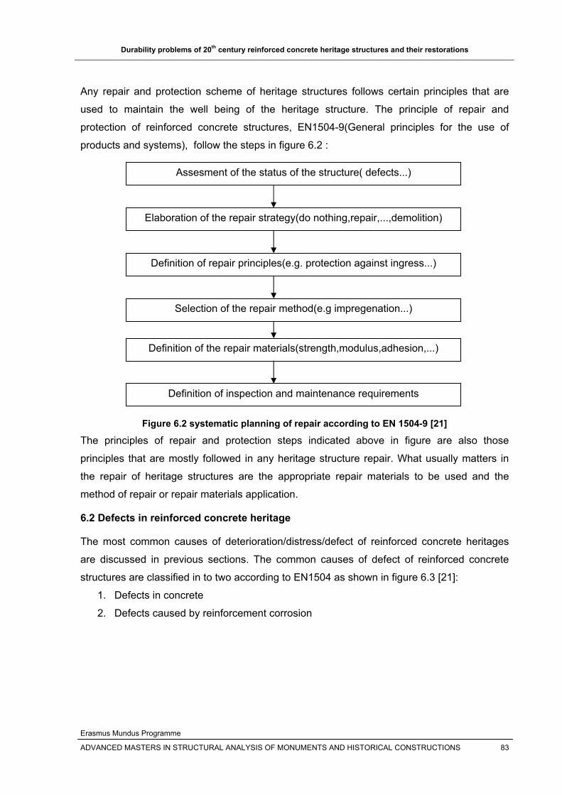
Durability problems of 20th century reinforced concrete heritage structures and their restorations
Erasmus Mundus Programme
ADVANCED MASTERS IN STRUCTURAL ANALYSIS OF MONUMENTS AND HISTORICAL CONSTRUCTIONS 83
Any repair and protection scheme of heritage structures follows certain principles that are
used to maintain the well being of the heritage structure. The principle of repair and
protection of reinforced concrete structures, EN1504-9(General principles for the use of
products and systems), follow the steps in figure 6.2 :
Figure 6.2 systematic planning of repair according to EN 1504-9 [21]
The principles of repair and protection steps indicated above in figure are also those
principles that are mostly followed in any heritage structure repair. What usually matters in
the repair of heritage structures are the appropriate repair materials to be used and the
method of repair or repair materials application.
6.2 Defects in reinforced concrete heritage
The most common causes of deterioration/distress/defect of reinforced concrete heritages
are discussed in previous sections. The common causes of defect of reinforced concrete
structures are classified in to two according to EN1504 as shown in figure 6.3 [21]:
1. Defects in concrete
2. Defects caused by reinforcement corrosion
Assesment of the status of the structure( defects...)
Elaboration of the repair strategy(do nothing,repair,...,demolition)
Definition of repair principles(e.g. protection against ingress...)
Selection of the repair method(e.g impregenation...)
Definition of the repair materials(strength,modulus,adhesion,...)
Definition of inspection and maintenance requirements
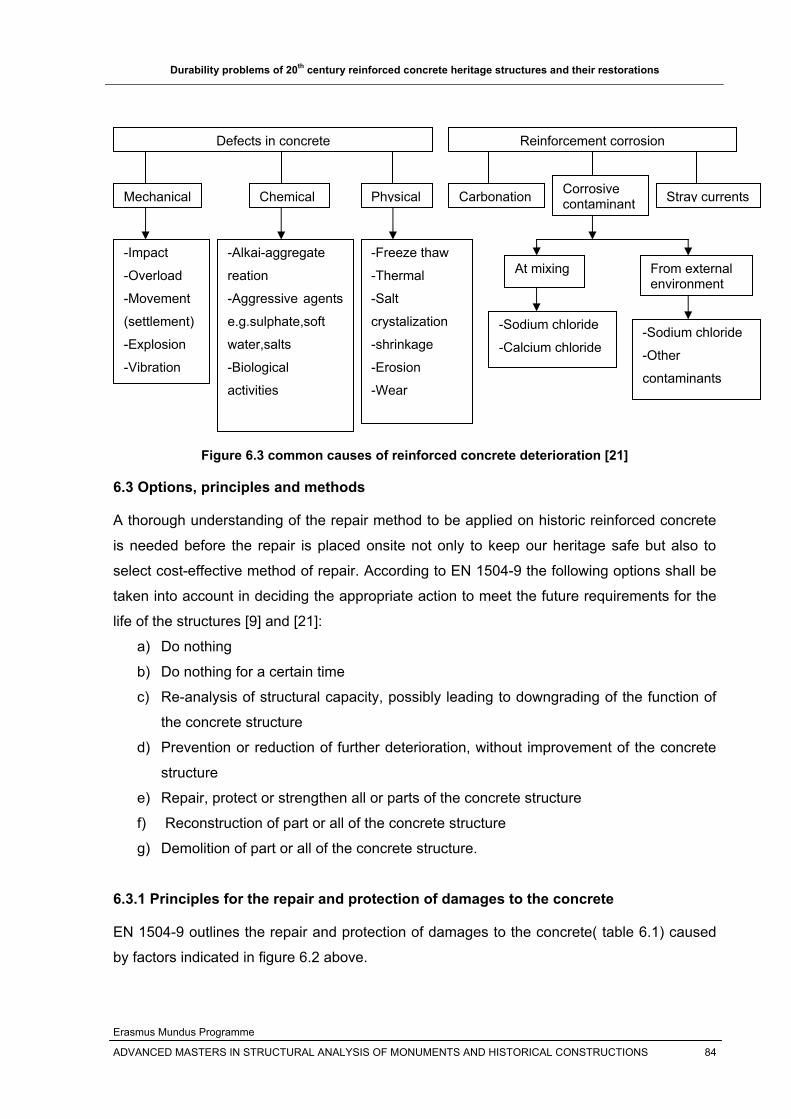
Durability problems of 20th century reinforced concrete heritage structures and their restorations
Erasmus Mundus Programme
ADVANCED MASTERS IN STRUCTURAL ANALYSIS OF MONUMENTS AND HISTORICAL CONSTRUCTIONS 84
Figure 6.3 common causes of reinforced concrete deterioration [21]
6.3 Options, principles and methods
A thorough understanding of the repair method to be applied on historic reinforced concrete
is needed before the repair is placed onsite not only to keep our heritage safe but also to
select cost-effective method of repair. According to EN 1504-9 the following options shall be
taken into account in deciding the appropriate action to meet the future requirements for the
life of the structures [9] and [21]:
a) Do nothing
b) Do nothing for a certain time
c) Re-analysis of structural capacity, possibly leading to downgrading of the function of
the concrete structure
d) Prevention or reduction of further deterioration, without improvement of the concrete
structure
e) Repair, protect or strengthen all or parts of the concrete structure
f) Reconstruction of part or all of the concrete structure
g) Demolition of part or all of the concrete structure.
6.3.1 Principles for the repair and protection of damages to the concrete
EN 1504-9 outlines the repair and protection of damages to the concrete( table 6.1) caused
by factors indicated in figure 6.2 above.
Defects in concrete Reinforcement corrosion
Mechanical Chemical Physical Carbonation Corrosive contaminant Stray currents
-Impact
-Overload
-Movement
(settlement)
-Explosion
-Vibration
-Alkai-aggregate
reation
-Aggressive agents
e.g.sulphate,soft
water,salts
-Biological
activities
-Freeze thaw
-Thermal
-Salt
crystalization
-shrinkage
-Erosion
-Wear
At mixing From external environment
-Sodium chloride
-Calcium chloride -Sodium chloride
-Other
contaminants

Durability problems of 20th century reinforced concrete heritage structures and their restorations
Erasmus Mundus Programme
ADVANCED MASTERS IN STRUCTURAL ANALYSIS OF MONUMENTS AND HISTORICAL CONSTRUCTIONS 85
Table 6.1 Principles for repair and protection for damages to the concrete [7 &21]
Principle No. Principle and its definition Methods based on the principle Principle 1[PI] Protection against ingress
Reducing or preventing ingress of adverse agents, e.g. water, other liquids, vapour, gas, chemicals and biological agents
1.1 Impregnation Applying liquid products that penetrate the concrete and block the pore system. 1.2 Surface coating with and without crack bridging ability 1.3 Locally bandaged cracksa 1.4 Filling cracks 1.5 Transferring cracks in to jointsa 1.6 Erecting external panelsab
1.7 Applying membranesb Principle 2[MC] Moisture Control
Adjusting and maintaining the moisture content in concrete with in a specified range of values
2.1 Hydrophobic impregnation 2.2 Surface coating 2.3 Sheltering or over claddingab 2.4 Electrochemical treatmentab
Applying a potential difference across sections of the concrete to assist or resist the passage of water through concrete. (Not for reinforced concrete without assessment of the risk of inducing corrosion.)
Principle 3[CR] Concrete Restoration Restoring the original concrete of a structural element to the originally specified shape and function. Restoring the concrete structure by replacing part of it
3.1 Applying mortar by hand 3.2 Recasting with concrete 3.3 Spraying concrete or mortar 3.4 Replacing elements
Principle 4[SS] Structural Strengthening Increasing or restoring the structural load-bearing capacity of an element of the concrete structure
4.1 Adding or replacing embedded or external steel bars 4.2 Installing bonded rebars in preformed or drilled holes in the concrete 4.3 Plate bonding 4.4 Adding mortar or concrete 4.5 Injecting cracks, voids or Interstices 4.6 Filling cracks, voids or interstices 4.7 Prestressing – (post tensioning)a
Principle 5[PR] Physical Resistance Increasing resistance to physical or mechanical attack
5.1 Overlays or coatings 5.2 Impregnation
Principle 6[RC] Resistance to Chemicals Increasing resistance of the concrete surface to deteriorations by chemical attack.
5.1 Overlays or coatings 5.2 Impregnation
aThese methods may make use of products and systems not covered by the EN 1504 series bInclusion of methods in EN 1405 does not imply these methods have been approved
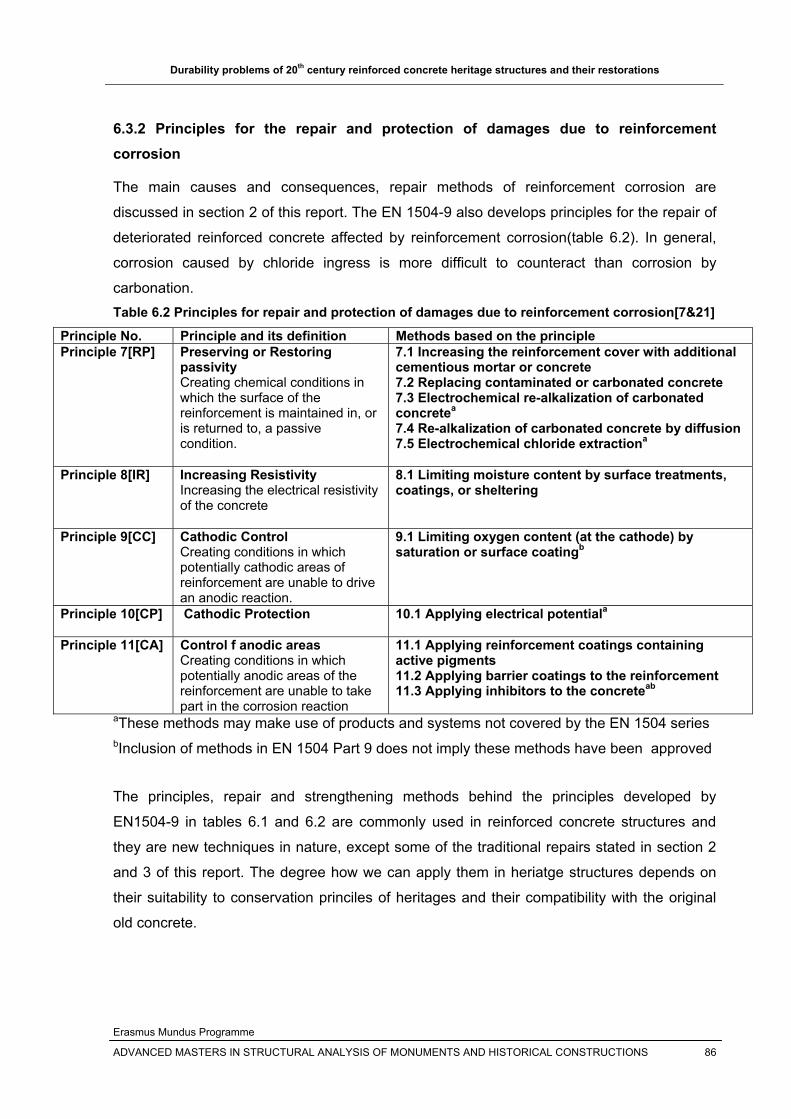
Durability problems of 20th century reinforced concrete heritage structures and their restorations
Erasmus Mundus Programme
ADVANCED MASTERS IN STRUCTURAL ANALYSIS OF MONUMENTS AND HISTORICAL CONSTRUCTIONS 86
6.3.2 Principles for the repair and protection of damages due to reinforcement corrosion
The main causes and consequences, repair methods of reinforcement corrosion are
discussed in section 2 of this report. The EN 1504-9 also develops principles for the repair of
deteriorated reinforced concrete affected by reinforcement corrosion(table 6.2). In general,
corrosion caused by chloride ingress is more difficult to counteract than corrosion by
carbonation. Table 6.2 Principles for repair and protection of damages due to reinforcement corrosion[7&21]
Principle No. Principle and its definition Methods based on the principle Principle 7[RP] Preserving or Restoring
passivity Creating chemical conditions in which the surface of the reinforcement is maintained in, or is returned to, a passive condition.
7.1 Increasing the reinforcement cover with additional cementious mortar or concrete 7.2 Replacing contaminated or carbonated concrete 7.3 Electrochemical re-alkalization of carbonated concretea 7.4 Re-alkalization of carbonated concrete by diffusion 7.5 Electrochemical chloride extractiona
Principle 8[IR] Increasing Resistivity Increasing the electrical resistivity of the concrete
8.1 Limiting moisture content by surface treatments, coatings, or sheltering
Principle 9[CC] Cathodic Control Creating conditions in which potentially cathodic areas of reinforcement are unable to drive an anodic reaction.
9.1 Limiting oxygen content (at the cathode) by saturation or surface coatingb
Principle 10[CP] Cathodic Protection
10.1 Applying electrical potentiala
Principle 11[CA] Control f anodic areas Creating conditions in which potentially anodic areas of the reinforcement are unable to take part in the corrosion reaction
11.1 Applying reinforcement coatings containing active pigments 11.2 Applying barrier coatings to the reinforcement 11.3 Applying inhibitors to the concreteab
aThese methods may make use of products and systems not covered by the EN 1504 series bInclusion of methods in EN 1504 Part 9 does not imply these methods have been approved
The principles, repair and strengthening methods behind the principles developed by
EN1504-9 in tables 6.1 and 6.2 are commonly used in reinforced concrete structures and
they are new techniques in nature, except some of the traditional repairs stated in section 2
and 3 of this report. The degree how we can apply them in heriatge structures depends on
their suitability to conservation princiles of heritages and their compatibility with the original
old concrete.
Durability problems of 20th century reinforced concrete heritage structures and their restorations
Erasmus Mundus Programme
ADVANCED MASTERS IN STRUCTURAL ANALYSIS OF MONUMENTS AND HISTORICAL CONSTRUCTIONS 87
7 REPAIR AND STRENGTHENING PROPOSALS
7.1 Introduction
In this section, various aspects concerning the possibility of using conservation principles of
heritages in reinforced concrete heritage structures, acceptability of repair and strengthening
methods based on the conservation principles of heritage structures and the use of new
materials in the repair and restoration of these heritage structures. Section 2.2 of this paper
states some ideas and typologies eventhough the difference between modern and heritage
reinforced concrete structures is an ambiguous issue until these days. The most common
differences can be from:
The material properties (cement, aggregate, steel, admixtures…). At the beginning of
the 20th century, reinforced concrete structures were built with aggregates taken from
the sea sides and not properly graded;Portland cement was widely used; steel
reinforcements were mostly smooth and not resistant like the reinforcements
nowadays etc.
Technology at the time of construction: In old structures, mixers of concrete, vibrators
to vibrate the fresh concrete to avoid air voids etc were not available that leads to the
porosity of old concrete structures.
Basis of design: the design codes and specifications available in the beginning of the
century were not sufficient like the codes and provisions currently available.
Intended uses: Modern structures are mostly designed for specific purposes and they
will serve this function in the future, but old reinforced concrete structures faced
variations in the use of the structure.
Exposure conditions: the environmental exposure conditions at the beginning of the
century and now are different, leading to the design of resistant structures based on
the environmental conditions. This new environmental condition will pose problems
for the old reinforced concrete structures.
Other factors not listed here
But bot modern and heritage reinforced concrete structures share most of the common
problems in reinforced concrete. Apparently, it can also be told that the repair and
strengthening methods used for modern reinforced concretes can be used with limitations to
reinforced concrete heritage structures. The limitations are being based on the principles of
restoration of heritage structures.
Durability problems of 20th century reinforced concrete heritage structures and their restorations
Erasmus Mundus Programme
ADVANCED MASTERS IN STRUCTURAL ANALYSIS OF MONUMENTS AND HISTORICAL CONSTRUCTIONS 88
The principles used for the restoration of heritage reinforced concrete heritages should
combine the principles used for restoration of heritage structures (such as authenticity,
minimum intervention etc) and principles for the repair or reinforced concrete structures
according to the European Standard EN 1504 . EN1504 provides the steps to be followed in
the repair and strengthening of reinforced concrete structures along with the materials and
available repair and strengthening methods.
1.2 Possibility of use of conservation principles
Most of the time, following the principles of conservation in the repair and strengthening of
reinforced concrete heritages is a very complex task that needs complete understanding of
the cause of deterioration/distress and the correct meaning of the principle. The principles of
conservation are so restrictive that sometimes can’t be attained in reality. In the field, it is a
common practice to set a principle in the paper or word and difficult to change it in to field
applications.
Restoration, rehabilitation, repair and strengthening of 20th century heritage structures
according to restoration principles is at an infant stage, especially for reinforced concrete
heritage structures. But based on the experience on the restoration of other heritage
structures (such as masonry structures), this paper investigates wehther the available
conservation principles of heritage structures can be extended to reinforced concrete
heritage structures. 1.2.1 Conservation principles from recommendations
The planning of the repair, strengthening and restoration of reinforced concrete heritage
structures are detailed in section 3 of this paper. These plans of restorations are mostly
guided by the existing restoration principles from concerned organizations. There are some
conservation principles drawn by organizations, such as the Venice charter,
ICOMOS/ISCARSAH recommendations[46], to keep the heritage structures in their natural
condition. These charters and recommendations are developed as past invasive and
uncontrolled repairs cause the devastation of heritage structures. Thus, these charters and
recommendations will pose regulations in minimizing the use of the repair materials and
methods used to preserve the historic heritages thereby guarantying the future of the
heritages. Some of the principles which are believed to act on reinforced concrete heritages
are briefed below [23].
Authenticity The value of the reinforced concrete heritage structure is in the originality of the materials
and components of the of the reinforced concrete heritage. Repair and strengthening

Durability problems of 20th century reinforced concrete heritage structures and their restorations
Erasmus Mundus Programme
ADVANCED MASTERS IN STRUCTURAL ANALYSIS OF MONUMENTS AND HISTORICAL CONSTRUCTIONS 89
interventions should, as far as possible, respect the original concept, construction techniques
and historical value of the structure (including historical materials) and of the historical
evidence that it provides [23]. Authenticity in reinforced concrete heritages repair depends on
the repair material and method used to repair the structure. For example, the use of
cementious materials in the repair will keep the originality of materials as opposed to FRP or
post-tensioning or steel plate applications that are not similar with the original concrete.
Minimum intervention Intervention or repair of a heritage should be minimized based on the existing damage and
the extent of the damage. Not all damages of structures need intervention, thus conservation
principles pose to minimize repair or intervention. Depending on the cause and extent of
deterioration of the reinforced concrete heritage, repair interventions should be undertaken
provided that invasive repair methods such as post-tensioning, that will change the
authenticity of the heritage, be minimized. Any deterioration /distress in reinforced concrete
directly or indirectly affect the load bearing reinforcing steel embedded in the concrete.
Therefore the principle of minimum intervention depends on the extent on deterioration in
reinforced concrete structures.
Reversibility of repair The principles of conservation recommend checking the possibility of dismantling the
restoration in the future, with no damage to the original parts. Where possible, any measures
adopted should be “reversible” so that they can be removed and replaced with more suitable
measures if new knowledge or ideas of repair is acquired in the future. Where they are not
completely reversible, interventions should not compromise later interventions [23]. The
repair materials and methods should also respect the original concept, materials and
construction techniques. For example, repair methods using FRP can be regarded as
reversible and patching and concrete placements as irreversible.
A full understanding of the structural behavior and material characteristics Every repair and restoration project begins with the understanding of material characteristics
and over all structural behavior. It is essential to identify initially the techniques that were
used and construction methods, on subsequent changes, on the phenomena that have
occurred, and, finally, on its present state. This will lead to an effective selection of repair
material and method, and reduces unnecessary costs in the restoration [23].
Assumption of new technologies As the technology progresses, different repair materials and repair methods are being
invented. Writers recommend the use of these new materials and techniques provided that
their adequacy is scientifically proven. But only scientific proof is not enough, they should be

Durability problems of 20th century reinforced concrete heritage structures and their restorations
Erasmus Mundus Programme
ADVANCED MASTERS IN STRUCTURAL ANALYSIS OF MONUMENTS AND HISTORICAL CONSTRUCTIONS 90
tested on real cases on deteriorated structures. For example, FRP is a strong repair material
that complements the deficiency in load bearing capacity of reinforced structures, but how is
it possible to guarantee whether it will act the way it was assumed when it is applied on
deteriorated reinforced concrete structures?
Address the root causes instead of the symptoms The design of any repair or intervention should be based on a full understanding of the real
causes that have caused the damage or deterioration of the reinforced concrete heritage and
of those that will act in the future [23]. For example, corrosion of reinforcing steel will cause
crack near the surrounding concrete. Thus, the repair material and method should address to
stop/ reduce the corrosion of the reinforcement not to close or patch the open crack. In
addition, one symptom can be caused by combination of factors or causes, thus before
intervention identification of the cause of deterioration of the reinforced concrete heritage is
important to have appropriate repair material and method, and to minimize unnecessary
repair expenses.
Compatibility of the repair material and original substrate concrete The compatibility of the repair material and the original substrate concrete can be said the
most governing factor in the effectiveness of the repair and restoration. The characteristics of
materials used in restoration work (in particular new materials) and their compatibility with
existing materials should be fully established. The repair material should be compatible,
capable of providing the deficiency of the older concrete and it shouldn’t create any long-term
side effects on the repaired structure. The use of cementious materials in the repair will at
least provide the compatibility requirement, even though it depend whether polymer modified
concretes are used or not. On the contrary, new repair materials such FRP or post-
tensioning or steel plate applications are creating compatibility problems.
Less Invasive restorations Before the principles for restorations and recommendations were drawn, repair and
restorations were done on thumb rules and using the available techniques and materials.
These invasive solutions caused the devastation of many heritage structures. It is essential
to decide first whether the deterioration/ distress of concrete need an intervention, and the
effective repair material and method to address the problem. Traditional repair materials and
methods seem to be less invasive as experience modified them on the long run, but the
newly developed systems are applied invariably in reinforced concrete heritages believing
that they are effective since most of them are scientifically based. For example, the
introduction of reinforced concrete/ steel column to support an overloaded slab seems
invasive solution that will affect the aesthetics and original structure, the application of FRP

Durability problems of 20th century reinforced concrete heritage structures and their restorations
Erasmus Mundus Programme
ADVANCED MASTERS IN STRUCTURAL ANALYSIS OF MONUMENTS AND HISTORICAL CONSTRUCTIONS 91
and overlay gives a less invasive solutions. Cathodic protection of the corroded
reinforcement can be said the least invasive method of repair than other methods.
Durability of restorations All the repair principles are applied to select appropriate and compatible repair material to
restore a reinforced concrete heritage, the last thing being forecasting the durability of the
restorations and repairs applied. Every repair material is not eternal and it certainly needs
maintenance sometime in the future after its application. The repair system should not
require “repair of the repair” with in few years of its applications. Thus, when a repair method
is selected, it’s short-term and long-term performance of the repair should be understood
before its application. For instance, the application of patch repair in some part of corrosion
deteriorated concrete surface will aggravate the corrosion of reinforcement in the perimeter
of patch repair, reducing the durability of the repair.
Repair is always preferable to replacement To maintain the authenticity of the reinforced concrete heritage and to save unnecessary
expenses in restoration, repair of the damaged concrete seems more viable than
replacement but depending on the severity and cause of deterioration. Replacement of a
structural member usually imparts another damage to near by structural members (by
changing the load path during construction) and monolithicity can’t be guaranteed near the
joints of the new and old members, which is the weak point in most structures.
Minimize subsequent intervention Experience in the restoration of heritage structures showed that so many of the repairs made
in the past are in need of another repair, i.e. “repair of the repair”. If an intervention is made
on reinforced concrete heritage structures, adequate maintenance should be done to limit or
postpone the need for subsequent intervention.
Monitoring of the repair While the repair is on process, it is essential to control and monitor the repair. For example
while repairing a crack, monitoring should be done on the repair to check whether the repair
stabilized or closed the crack, and if not to opt other methods. 1.2.2 Acceptability or extent of repair and strengthening methods
Even though recommendations force to minimize restorations, restorations of reinforced
concrete heritage structures are done invariably all over the world. There are so many repair
materials and techniques that are widely used in the repair of reinforced concrete structures.
Some repair methods in the past showed durability problems after they are applied due to
the incompatibility and invasiveness of the methods.

Durability problems of 20th century reinforced concrete heritage structures and their restorations
Erasmus Mundus Programme
ADVANCED MASTERS IN STRUCTURAL ANALYSIS OF MONUMENTS AND HISTORICAL CONSTRUCTIONS 92
Which methods are acceptable even though they are against conservation principles of
heritage structures (incompatible, invasive etc)?
Do nothing In masonry structures where the problems have sustained for centuries or long time without
any collapse of the heritage structure, the “do nothing” option of repair may be good not to
disturb the stable damage on the structure. But in reinforced concrete structure, this option of
repair seems to be vague to apply. For example, once the corrosion of the structure is
started/ initiated, waiting may aggravate the corrosion rate there by increasing the
deterioration of the structure. This option of repair may lead to further deterioration and even
collapse of the structures. The writer of this paper suggests the “do nothing for a certain time”
option of repair to identify the cause of the damage and its progress.
Concrete placement When the reinforced concrete heritage structure is deteriorated due to alkali aggregate
reactions, it is barely possible to repair it with other methods of repair except placement of
the deteriorated concrete with a new repair material, having special property, which will
reduce the cause of deterioration in the future.
In addition, for freeze thaw damaged structures, the repair can be carried out depending on
the severity of deterioration.
If the deterioration is less, coating the surface may reduce further damage??? That
will reduce the entrance of water and deicing salts.
If the deterioration is severe, the affected concrete should be removed and replaced
with a new non porous concrete with modified property than the original. But this
method of repair is invasive and against the conservation principle of minimum
intervention.
This method is not reversible and against minimum intervention, and thus should be
minimized unless conditions force it to be the only repair method.
Patch repair Patch repair can be effective for repair of deteriorated concrete if the deterioration cause is
other than corrosion of reinforcing steel such as freeze thaw and alkali silica reactions. This
method is an old and traditional, thus lots of experience in patch repairing.
Matching colour between the new repair and the existing concrete substrate will
create a great problem in most repair works. This has led to the painting of the
repaired and old concrete surface.
Mostly it is not a reversible repair method
Durability problems of 20th century reinforced concrete heritage structures and their restorations
Erasmus Mundus Programme
ADVANCED MASTERS IN STRUCTURAL ANALYSIS OF MONUMENTS AND HISTORICAL CONSTRUCTIONS 93
Should be minimized to repair corrosion caused deterioration of concrete as it creates
corrosion on the perimeter of repair.
Compatibility with minimum intervention depends on the amount to be applied.
Shotcrete or spraying concrete When the area to be repaired is very large and repairing the member by patching is difficult
(as in the case of the under side of thin shells and domes), shotcrete can be the sole solution
of restoration and repairing. This repair method is:
Not reversible
Dependent on the compatibility between the original concrete and the repair material
for its durability.
Polymer modified concretes Polymer modified concretes are effective in fulfilling the deficiency of deteriorated concrete
due to chemical attacks, alkali silica reactions and freeze thawing. Compatibility between the
repair material and the substrate should be kept to reduce long term durability problems and
subsequent repair needs.
Invasive depending on the area to be repaired
Not reversible
Dependent on the compatibility between the original concrete and the repair material
for its durability.
Injections Injections should be used when the area and volume of deteriorated/distressed concrete is
large. It should be kept in mind that this repair method will work if the cause of deterioration
is not reinforcement corrosion as injecting deterioration caused by reinforcement corrosion
will not stop or reduce further corrosion of the reinforing bar and deterioration. Injections can
close the cracks and bring about monolithicity of the deteriorated concrete.
Not reversible
Invasive
Compatibility of the substrate concrete and the injection should be kept to get
effective repair.
Overlays They are commonly used in the repair of heritage buildings and bridges. Overlays are
effective for overloading repairs and to increase the cover to the reinforcement there by
preventing the ingress of aggressive agents at the reinforcing steel level.
Compatibility of the overlay is crucial to guarantee effective repair and long term
durability

Durability problems of 20th century reinforced concrete heritage structures and their restorations
Erasmus Mundus Programme
ADVANCED MASTERS IN STRUCTURAL ANALYSIS OF MONUMENTS AND HISTORICAL CONSTRUCTIONS 94
Repair is not reversible
Against minimum intervention
FRP These days the application of FRP is diverse in almost all reinforced concrete structures.
FRP applications are common repair and strengthening methods for overloaded buildings
and bridges. As compared to other strengthening and upgrading methods( such as post-
tensioning), it is a better repair method due to the following reasons:
Can easily be removed( reversibility of repair)
Does not affect the substrate reinforced concrete fabric, it is just applied external to
the surface
Lower upgrade cost( economical repair method)
Speed and ease of application( making the heriatge functional with in short time)
It will not significantly change the dimension of the structure to be strengthened.
Thus FRP can be applied for buildings and bridges provided that the compatibility problems it
has with substrate concrete have to be improved.
Cathodic Protection Where reinforced concrete heritage structures are deteriorated/ distressed due to corrosion
of reinforcing steel, cathodic protection will give effective protection measures as compared
to other methods. Other repair methods such as patch repair will cause future reinforcing
steel corrosion in the perimeter of the patch.
It is less invasive method of repair
Minimum intervention on the reinforced concrete fabric
Cathodic protection acts all along the surface of the concrete surface that will ensure
maximum protection as compared to other methods.
The writer of the paper suggests the use of cathodic protection whenever the cause of
deterioration is corrosion of reinforcing steel provided that the continuity of the reinforcement
in the old concrete shall be verified.
Post-tensioning This method is widely used in the strengthening and upgrading of overloaded reinforced
concrete bridges. In some cases it includes the drilling of members and inserting the
reinforcement cable to be post-tensioned. This method is:
Invasive as it sometimes may damage the original concrete to apply the method
Against minimum intervention
Not compatible with the substrate concrete

Durability problems of 20th century reinforced concrete heritage structures and their restorations
Erasmus Mundus Programme
ADVANCED MASTERS IN STRUCTURAL ANALYSIS OF MONUMENTS AND HISTORICAL CONSTRUCTIONS 95
Authenticity of the original struture will be affected
Though it has limitations of conservation principles, it is an effective technique for bridge
repair and strengthening as other methods except FRP can’t be applied for strengthening of
bridge load bearing elements.
Shear wall applications Previous reinforced concrete structures at the beginning of the century were designed
without the consideration of earthquakes, thereby needing their upgrading these days . The
use of internal or external shear walls is becoming common in some countries like Turkey to
counteract the earthquakes. The application of internal or external shear walls on the
strengthening of earthquake prone reinforced concrete structures/buildings may be essential
what ever limitations it has. The method is:
Invasive
Reversible but will cause damage on the concrete fabric in the process
Compatibility at the joint between the old concrete and new wall can be attained if
appropriate repair material is selected
Against authenticity and original concept
1.3 New materials and techniques
Nowadays a lot of new repair materials are available in the market and so does the repair
techniques. This is due to the increased number of historic structures/monuments and the
frequent occurrence of deterioration on them that needs immediate repair or strengthening.
The increasing interest of preserving heritage all over the world makes the advancement of
applied sciences and advanced technologies in the production of different repair materials.
But for many of the products, the uncertainty in their effectiveness is a common question as
they are only laboratory test products and their long-term effect can’t be told surely. In
addition, these new materials will be applied on historic constructions made from materials
whose properties and production are not properly known( for example the ungraded
aggregates in seas that were used). It is undeniable on the need to check the similarity in
properties of these new repair materials and the existing historic concrete material.
The most important goal to achieve in using these new materials is to obtain a repaired
structure that has identical appearance, colour, texture, elasticity, porosity etc with the
original construction material, which is the compatibility between the new material and old
concrete substrate. In the actual repair world, many repair materials and repair methods are
effective for only short period of time because they can be affected by environmental factors
Durability problems of 20th century reinforced concrete heritage structures and their restorations
Erasmus Mundus Programme
ADVANCED MASTERS IN STRUCTURAL ANALYSIS OF MONUMENTS AND HISTORICAL CONSTRUCTIONS 96
and incompatibility between materials, which needs the “repair of repair” with in few years
after the repair is placed.
Most of the modern repair techniques are based on assumptions and they seem effective
since they are scientifically based and tested in the laboratory where every condition is
satisfied, but the condition on repair site is different from laboratory. For example, Cathodic
protection is effective in protecting the corrosion of reinforcement, but how it is possible to
check the reinforcements in the existing concrete are electrically connected to each other?
The assumptions on which the new repair materials and techniques are based needs deep
study whether that assumption works for the existing deteriorated reinforced structure or not.
Most of the tests for the repair materials are done on new concrete samples, not on historic
concrete. Thus how can it be directly applied for historic concrete? The method should be
modified using the properties of historic concrete that has a little bit different properties and
concrete ingredients.
ICOMOS 20th Century heritage committe outlined the use of new materials in the repair of
heritage structures as:
“The introduction of many new materials - plastics, different types of glass, fibreglass,
synthetic rubber, fibreboard, metals and so on - the use of new component-based building
systems and the use of traditional materials in new ways are characteristics of the modern-
century building industry. This has, however, spawned some difficult conservation problems
for these buildings that can be summarized as:
the use of new materials with unproven performance records;
the use of new materials without knowledge of best practice methods for use;
the use of traditional materials in new ways, or in combination with new materials;
poor workmanship and quality control (new materials chosen for reasons of
economy);
the use of prefabricated, component-based construction systems;
the rapid development of materials and their equally rapid supercession;
the effect of pollutants on modern materials;
the use of materials now identified as hazardous;
the lack of an established salvage industry for modern buildings.” [43].
In other historical structures, typically masonry, it is possible to wait without intervention as
the damages on the structures sustain on the structures since centuries and still available
without causing any collapse. On the contrary, in reinforced concrete heritages, if the

Durability problems of 20th century reinforced concrete heritage structures and their restorations
Erasmus Mundus Programme
ADVANCED MASTERS IN STRUCTURAL ANALYSIS OF MONUMENTS AND HISTORICAL CONSTRUCTIONS 97
damage of the structure is observed, it is a must to intervene as the damage increase in
magnitude and cause collapse of the structure. For example, if the reinforced concrete is
attacked either by alkali aggregate reaction or freeze thaw, the concrete surface will start to
deteriorate and cracking/spalling which facilitates the ingress of aggressive agents like
chloride ions and carbon dioxide that will increase the magnitude of corrosion. In this case,
there is nothing to wait, thus once the concrete structure deteriorates or spalls to higher
magnitudes, it must be repaired. Now will come the question of the type of material and
repair method to use. There are two options for this repair:
Using available new repair materials to avoid any immediate failure
Perform the analysis of substrate and look for a compatible materials and repair
methods. But to attain this, it is a relatively complex task and it needs more time and
specialists, which will aggravate the deterioration until restoration.
It is not the intention of this paper to critisize the new materials and techniques, but their
effectiveness should be checked when they are applied on old reinforced concrete materials.
Experience showed that some of the new repair materials and techniques showed effective
repairs in existing reinforced concrete structures. But their compatibility with old reinforced
concretes of the late 19th and early 20th centuries should be checked.
1.4 General proposals
The writer of the report recommends the following general repair comments on the existing
repair materials and techniques.
Before making a decision on structural intervention it is crucial first determine the
causes of damage/deterioration of the reinforced concrete, and then to evaluate the
present level of structural safety of the reinforced concrete heritage. It also provides
whether immediate intervention is necessary or not.
Traditional repair methods such as patch repairing should be used to repair
deteriorations caused by factors other than corrosion of the reinforcement. They are
effective in repairing spallings and pop-outs from the reinforced concrete fabric
surface. In addition, they were used for long time and experience of the restorers can
be used in the restoration of reinforced concrete heritges.
When modern repair materials and methods are used for repair and strengthening of
reinforce concrete heritage structures, it is better if they are based on similar past
experience.
Repair principles based on EN 1504 (for reinforced concrete structures) shall be
extended for repair of reinforced concrete heritages with some limitations until further

Durability problems of 20th century reinforced concrete heritage structures and their restorations
Erasmus Mundus Programme
ADVANCED MASTERS IN STRUCTURAL ANALYSIS OF MONUMENTS AND HISTORICAL CONSTRUCTIONS 98
research works are done specifically for the so called reinforced concrete heritage
structures.
Most modern repair materials and techniques are based on assumptions for their
effectiveness. When they are used in the repair and strengthening of heritage
structures, the substrate (deteriorated concrete) should fulfill some of the
assumptions or requirements that the repair materials and techniques are based on.
Instead of adding extra structural members, for example addition of column to support
the overloaded slab, improve the existing member by increasing the cross-section of
the member or by using modern strengthening techniques that will not affect the
authenticity(originality) and aesthetics of the heritage structure.
When the reinforced heritage structure is prone to earthquakes and it was designed
previously without the consideration of earthquake, additional earthquake systems
such as shear walls shall be included in the structure or by wraping FRP in lateral
load resisting members. The shear walls can be placed inside or outside of the
structure depending on the easiness and aesthetics.
When the reinforced concrete heritage structure is damaged by freeze thaw, chemical
attacks and alkali aggregate reactions, it is sometimes not possible to repair the
deteriorated concrete. Thus, the removal and placement of the deteriorated concrete
by new resistant concrete for the deficiency of the structure is an effective method of
repair instead of trying to stop further degradation.
New technologies, materials and techniques can be used in the repair and restoration
of reinforced concrete heritages provided that their adequacy is both scientifically and
practically proven in the repair of modern reinforced concrete structures.
No repair and strengthening action should be undertaken on the reinforced concrete
heritage structure without ascertaining the likely benefit and harm of the repair
materials and techniques to the reinforced concrete heritage structure. The long term
performance/ durability of the repair/strengthening material and method should be
studied before selection of repair options and interventions.
When the area of deteriorated concrete to be repaired is very large and if the
structure is of significant height (as in domes), shotcrete or spraying of concrete can
give an effective and economical means of repair as compared to other methods.
When the volume of deteriorated concrete to be repaired is very large, injection can
be an effective method of repair to reunite the structure and maintain monolithicity of
the overall structure.
Durability problems of 20th century reinforced concrete heritage structures and their restorations
Erasmus Mundus Programme
ADVANCED MASTERS IN STRUCTURAL ANALYSIS OF MONUMENTS AND HISTORICAL CONSTRUCTIONS 99
When a repair material is selected, it should first be checked by applying on a sample
area of the deteriorated concrete surface to see whether if fulfils the basic
considerations taken to select the repair material.
Repair methods to be applied should not significantly change the dimension of the
structures and the original structural system. For example, FRP can be applied with
out significant change on the shape of the member to be repaired.
The restoration of reinforced concrete heritage structures should be done by
contractors/qualified professionals having experience on the same field (repair and
restoration of reinforced concrete heritages) and the quality of the contractor should
be checked at initial stages before the restoration progresses. Faulty concrete repair
can worsen structural problems and lead to further damage or safety hazards.
The repair should sustain for longer period of time between maintenances, but in the
actual world the opposite happens. The repaired structures needs another repair with
in few years of its applications, this may be due to the incompatibility of the repair
materials and method or intervening without knowing the actual cause of deterioration
or carelessness.
The correction and elimination of concrete problems can be difficult, time-consuming,
and costly. Yet the temptation to resort to temporary solutions should be avoided,
since their failure can expose a building to further and more serious deterioration, and
in some cases can mask underlying structural problems that could lead to serious
safety hazards
As long as one continues to blindly use repair and protection methods applicable for
newly constructed structures for reinforced concrete heriatge structures repair and
strengthening, the devastation of the heritage structures will progress and the cost of
‘‘repairing the repairs’’ will be on the rise. For example, concerning cathodic
protection a broader understanding of the electrochemical differences between new
and original substrate concrete is necessary for effective protection of reinforcement
in repaired structures .
Modern architecture should as much as possible reduce the use of new materials,
whose longetrm performances not fully understood, and techniques in the repair and
restoration of reinforced concrete heritage structures. To minimize the common
problems of repairs, architects and engineers should work together to get an effective
repair.

Durability problems of 20th century reinforced concrete heritage structures and their restorations
Erasmus Mundus Programme
ADVANCED MASTERS IN STRUCTURAL ANALYSIS OF MONUMENTS AND HISTORICAL CONSTRUCTIONS 100
8 CASE STUDIES
8.1 Unity temple: Structural repair and Conservation [24]
The unity temple(fig. 8.1) in Oak park, Illinois was designed by Frank Lloyd Wright and
completed in 1907. It is one of the well known early uses of reinforced cast-in-place concrete
structure in USA [24].
Figure 8.1 west façade of unity temple: Worship temple (left) and Unity house for social gatherings (right) [24]
As the passage of time passes, this landmark reinforced concrete heritage suffers from
material and system deterioration, which necessitates the repair of the heritage. The
concrete is investigated and a historical structure report prepared in 1987. The investigation
included the assessment of the condition of the roof slab structure on the west overhang of
the temple.
Materials for construction of structural elements At the time of construction, two types of concretes were used: light weight concrete and
normal weight concrete;
Elements of the building that resists compressive stresses such as foundations, walls
and piers( see fig. 8.2) were constructed from normal weight concrete, composed of
Portland cement, sand and lime stone aggregate.
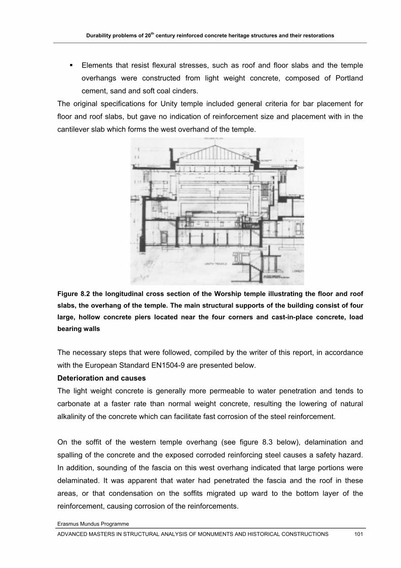
Durability problems of 20th century reinforced concrete heritage structures and their restorations
Erasmus Mundus Programme
ADVANCED MASTERS IN STRUCTURAL ANALYSIS OF MONUMENTS AND HISTORICAL CONSTRUCTIONS 101
Elements that resist flexural stresses, such as roof and floor slabs and the temple
overhangs were constructed from light weight concrete, composed of Portland
cement, sand and soft coal cinders.
The original specifications for Unity temple included general criteria for bar placement for
floor and roof slabs, but gave no indication of reinforcement size and placement with in the
cantilever slab which forms the west overhand of the temple.
Figure 8.2 the longitudinal cross section of the Worship temple illustrating the floor and roof slabs, the overhang of the temple. The main structural supports of the building consist of four large, hollow concrete piers located near the four corners and cast-in-place concrete, load bearing walls
The necessary steps that were followed, compiled by the writer of this report, in accordance
with the European Standard EN1504-9 are presented below.
Deterioration and causes The light weight concrete is generally more permeable to water penetration and tends to
carbonate at a faster rate than normal weight concrete, resulting the lowering of natural
alkalinity of the concrete which can facilitate fast corrosion of the steel reinforcement.
On the soffit of the western temple overhang (see figure 8.3 below), delamination and
spalling of the concrete and the exposed corroded reinforcing steel causes a safety hazard.
In addition, sounding of the fascia on this west overhang indicated that large portions were
delaminated. It was apparent that water had penetrated the fascia and the roof in these
areas, or that condensation on the soffits migrated up ward to the bottom layer of the
reinforcement, causing corrosion of the reinforcements.

Durability problems of 20th century reinforced concrete heritage structures and their restorations
Erasmus Mundus Programme
ADVANCED MASTERS IN STRUCTURAL ANALYSIS OF MONUMENTS AND HISTORICAL CONSTRUCTIONS 102
Laboratory analyses of the concrete specimen from the west overhang also indicated that:
The concrete used was of higher water-cement ratio, causing porous and weak
concrete.
Freeze thaw damage through out the depth of the specimen
The concrete was fully carbonated and contain significant amounts of chloride
In the early 1970’s, a rehabilitation program was performed by applying a shotcrete coating
to the exterior of the building with the exception of these cantilever soffit overhang slabs.
The above integrated damages/ deterioration on the west overhang causes lost in strength of
the overhang slab, which necessitate the repair of the overhang.
Figure 8.3 the deteriorated and spalled west overhang of the temple
Repair strategy/Options Various repair schemes, with their drawbacks, were considered for the repair of the
deteriorated west overhang temple:
1. Replacement of the fascia and repair of the original soffit surface
2. Addition of columns: have negative aesthetic impact
3. Suspension cables: they would set up alternate load paths for the cantilever loads
and introduce unanticipated stresses in to other portions of the structure.
4. Replacement of the structural cantilever with materials other than concrete, but these
schemes raised difficulty of implementation, drainage, susceptibility to future
deterioration, and related long term problems.
Western overhang of the temple
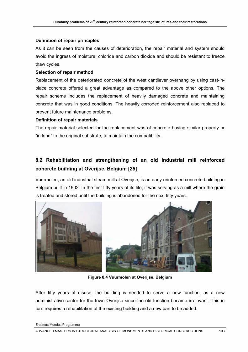
Durability problems of 20th century reinforced concrete heritage structures and their restorations
Erasmus Mundus Programme
ADVANCED MASTERS IN STRUCTURAL ANALYSIS OF MONUMENTS AND HISTORICAL CONSTRUCTIONS 103
Definition of repair principles As it can be seen from the causes of deterioration, the repair material and system should
avoid the ingress of moisture, chloride and carbon dioxide and should be resistant to freeze
thaw cycles.
Selection of repair method Replacement of the deteriorated concrete of the west cantilever overhang by using cast-in-
place concrete offered a great advantage as compared to the above other options. The
repair scheme includes the replacement of heavily damaged concrete and maintaining
concrete that was in good conditions. The heavily corroded reinforcement also replaced to
prevent future maintenance problems.
Definition of repair materials The repair material selected for the replacement was of concrete having similar property or
“in-kind” to the original substrate, to maintain the compatibility.
8.2 Rehabilitation and strengthening of an old industrial mill reinforced concrete building at Overijse, Belgium [25]
Vuurmolen, an old industrial steam mill at Overijse, is an early reinforced concrete building in
Belgium built in 1902. In the first fifty years of its life, it was serving as a mill where the grain
is treated and stored until the building is abandoned for the next fifty years.
Figure 8.4 Vuurmolen at Overijse, Belgium
After fifty years of disuse, the building is needed to serve a new function, as a new
administrative center for the town Overijse since the old function became irrelevant. This in
turn requires a rehabilitation of the existing building and a new part to be added.
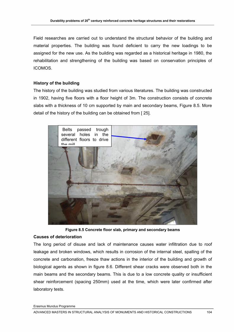
Durability problems of 20th century reinforced concrete heritage structures and their restorations
Erasmus Mundus Programme
ADVANCED MASTERS IN STRUCTURAL ANALYSIS OF MONUMENTS AND HISTORICAL CONSTRUCTIONS 104
Field researches are carried out to understand the structural behavior of the building and
material properties. The building was found deficient to carry the new loadings to be
assigned for the new use. As the building was regarded as a historical heritage in 1980, the
rehabilitation and strengthening of the building was based on conservation principles of
ICOMOS.
History of the building The history of the building was studied from various literatures. The building was constructed
in 1902, having five floors with a floor height of 3m. The construction consists of concrete
slabs with a thickness of 10 cm supported by main and secondary beams, Figure 8.5. More
detail of the history of the building can be obtained from [ 25].
Figure 8.5 Concrete floor slab, primary and secondary beams
Causes of deterioration The long period of disuse and lack of maintenance causes water infiltration due to roof
leakage and broken windows, which results in corrosion of the internal steel, spalling of the
concrete and carbonation, freeze thaw actions in the interior of the building and growth of
biological agents as shown in figure 8.6. Different shear cracks were observed both in the
main beams and the secondary beams. This is due to a low concrete quality or insufficient
shear reinforcement (spacing 250mm) used at the time, which were later confirmed after
laboratory tests.
Belts passed trough several holes in the different floors to drive the mill

Durability problems of 20th century reinforced concrete heritage structures and their restorations
Erasmus Mundus Programme
ADVANCED MASTERS IN STRUCTURAL ANALYSIS OF MONUMENTS AND HISTORICAL CONSTRUCTIONS 105
Figure 8.6 Damaged concrete (left) and moss growth on the structure (right)
Field research and laboratory testing Field research and laboratory testing are carried out to gather more detailed information
about the carbonation depth and concrete strength.
To quantify the magnitude and depth of carbonation, phenolphthalein (pH indicator) was
used on the holes drilled on representative floor levels(fig.8.7). The result showed that the
concrete was carbonated about 3cm from the top and from the bottom. The reinforcement
cover is limited to 2 cm in the existing slabs; this means that no protection of the steel
reinforcement is available.
Figure 8.7 Test results of phenolphthalein test on the hole drilled on representative slab
To determine the concrete strength/ the load bearing capacity of the structural members
such as beams, columns and slabs, non-destructive tests (NDT‘s such as ultra-sonic and
sclerometer testing) and destructive tests (core drilling) were made. The experiment
Colorless (carbonated)
Pink Color (Un-carbonated)

Durability problems of 20th century reinforced concrete heritage structures and their restorations
Erasmus Mundus Programme
ADVANCED MASTERS IN STRUCTURAL ANALYSIS OF MONUMENTS AND HISTORICAL CONSTRUCTIONS 106
confirmed the low quality concrete used at the time and the steel grade and the spacing of
shear reinforcements (250mm).
Therapy The repair includes two stages:
1. Rehabilitation of building materials to minimize future corrosion of reinforcement The deteriorated concrete is removed and the surface cleaned by grit blasting. Steel rebars
with a section loss of more than 25% are replaced; if the cross section loss remains limited
(<25%), the steel rebars are treated. Rust is removed and a layer of anti -rust coating is
applied. A repair epoxy mortar is applied to restore the original cross-section of the concrete
element. Protective coating is provided to protect the reinforced concrete from future
atmospheric contaminants and carbonation, see Figure 8.8.
Protective coating on concrete
Re
Figure 8.8 Rehabilitation of corroded steel depending on carbonation depth
2. Strengthening of the building for the new function, that is the upgrading of floor slab, beams and columns Since the new use of the building is as an administrative seat of the government Overijse,
the load bearing elements need upgrading for the new function or live load requirement.
Slab: The original 10cm thick concrete slab is supplemented with additional 8cm concrete
cover, which is fixed on top of the existing slab. This top layer will serve as an extended
compressive zone for the total floor system, for which additional compressive reinforcement
is required. Lightweight concrete is used to minimize the added permanent load. The floor is
fixed to the main and secondary beams by means of dowels, Figure 8.9, to obtain a T-
shaped section, requiring less strengthening.
Repair mortar
Anti-rust coated reinforcing steel
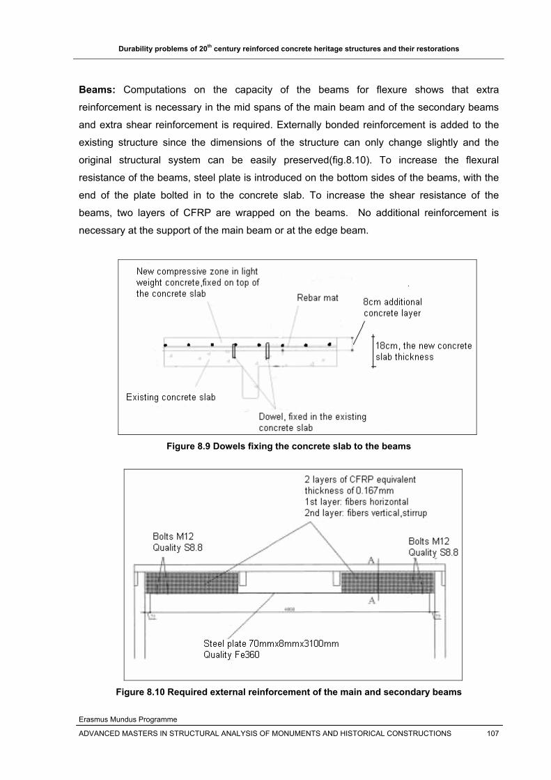
Durability problems of 20th century reinforced concrete heritage structures and their restorations
Erasmus Mundus Programme
ADVANCED MASTERS IN STRUCTURAL ANALYSIS OF MONUMENTS AND HISTORICAL CONSTRUCTIONS 107
Beams: Computations on the capacity of the beams for flexure shows that extra
reinforcement is necessary in the mid spans of the main beam and of the secondary beams
and extra shear reinforcement is required. Externally bonded reinforcement is added to the
existing structure since the dimensions of the structure can only change slightly and the
original structural system can be easily preserved(fig.8.10). To increase the flexural
resistance of the beams, steel plate is introduced on the bottom sides of the beams, with the
end of the plate bolted in to the concrete slab. To increase the shear resistance of the
beams, two layers of CFRP are wrapped on the beams. No additional reinforcement is
necessary at the support of the main beam or at the edge beam.
Figure 8.9 Dowels fixing the concrete slab to the beams
Figure 8.10 Required external reinforcement of the main and secondary beams

Durability problems of 20th century reinforced concrete heritage structures and their restorations
Erasmus Mundus Programme
ADVANCED MASTERS IN STRUCTURAL ANALYSIS OF MONUMENTS AND HISTORICAL CONSTRUCTIONS 108
Columns Columns are strengthened to both lateral loads and axial compression loads. Steel plates,
fixed to the concrete by bolts, are provided on both sides of the column to resist bending
stresses that will be caused by lateral loads (from wind loads etc). To increase the resistance
of axial compression forces, different layers of CFRP are taking in to account the magnitude
of compressive forces the column will support. For example, at the ground level where the
compressive force is higher, 5 layers of CFRP are wrapped horizontally around the column
and less number of layers in the successive upper layers.
Figure 8.11 Strengthening of columns by wrapping CFRP horizontal fibers and steel plate
8.3 Cathodic protection repairs in multi-storey buildings on the Dutch coast[7]
This is the repair case study of two multi-story holiday resort buildings in in Zantvoort (near
Amsterdam), along the North Sea coast of Netherlands, to illustrate the protection of
reinforcement corrosion by cathodic protection. The balcony slabs of these multi-storey
buildings showed severe cracking due to chloride-initiated corrosion( see fig.8.12). The
edges of the balcony slabs were affected particularly due to the protruding position of the
edge rims and the presence of a water-hole at the ceiling of the balcony slab.
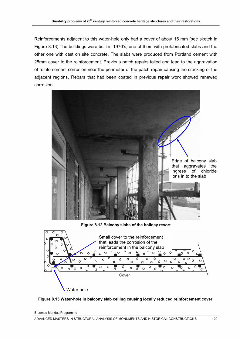
Durability problems of 20th century reinforced concrete heritage structures and their restorations
Erasmus Mundus Programme
ADVANCED MASTERS IN STRUCTURAL ANALYSIS OF MONUMENTS AND HISTORICAL CONSTRUCTIONS 109
Reinforcements adjacent to this water-hole only had a cover of about 15 mm (see sketch in
Figure 8.13).The buildings were built in 1970’s, one of them with prefabricated slabs and the
other one with cast on site concrete. The slabs were produced from Portland cement with
25mm cover to the reinforcement. Previous patch repairs failed and lead to the aggravation
of reinforcement corrosion near the perimeter of the patch repair causing the cracking of the
adjacent regions. Rebars that had been coated in previous repair work showed renewed
corrosion.
Figure 8.12 Balcony slabs of the holiday resort
Figure 8.13 Water-hole in balcony slab ceiling causing locally reduced reinforcement cover.
Water hole
Edge of balcony slab that aggravates the ingress of chloride ions in to the slab
Small cover to the reinforcement that leads the corrosion of the reinforcement in the balcony slab
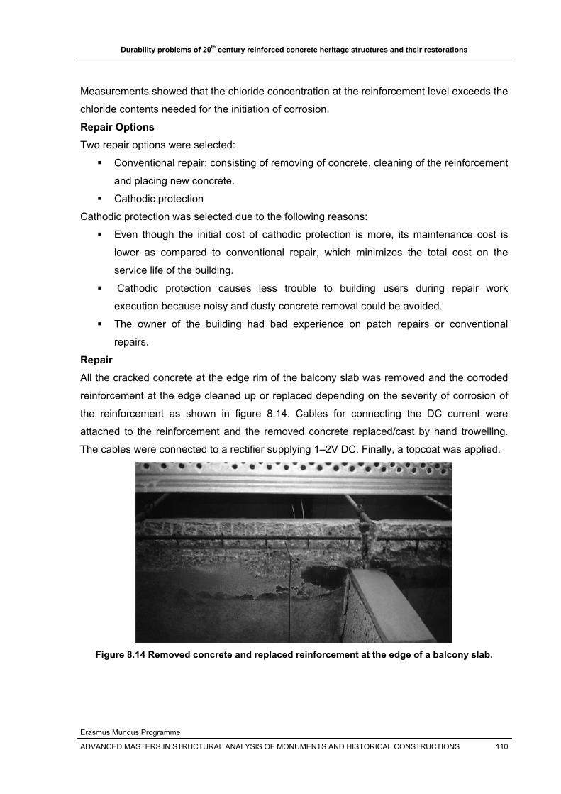
Durability problems of 20th century reinforced concrete heritage structures and their restorations
Erasmus Mundus Programme
ADVANCED MASTERS IN STRUCTURAL ANALYSIS OF MONUMENTS AND HISTORICAL CONSTRUCTIONS 110
Measurements showed that the chloride concentration at the reinforcement level exceeds the
chloride contents needed for the initiation of corrosion.
Repair Options Two repair options were selected:
Conventional repair: consisting of removing of concrete, cleaning of the reinforcement
and placing new concrete.
Cathodic protection
Cathodic protection was selected due to the following reasons:
Even though the initial cost of cathodic protection is more, its maintenance cost is
lower as compared to conventional repair, which minimizes the total cost on the
service life of the building.
Cathodic protection causes less trouble to building users during repair work
execution because noisy and dusty concrete removal could be avoided.
The owner of the building had bad experience on patch repairs or conventional
repairs.
Repair All the cracked concrete at the edge rim of the balcony slab was removed and the corroded
reinforcement at the edge cleaned up or replaced depending on the severity of corrosion of
the reinforcement as shown in figure 8.14. Cables for connecting the DC current were
attached to the reinforcement and the removed concrete replaced/cast by hand trowelling.
The cables were connected to a rectifier supplying 1–2V DC. Finally, a topcoat was applied.
Figure 8.14 Removed concrete and replaced reinforcement at the edge of a balcony slab.

Durability problems of 20th century reinforced concrete heritage structures and their restorations
Erasmus Mundus Programme
ADVANCED MASTERS IN STRUCTURAL ANALYSIS OF MONUMENTS AND HISTORICAL CONSTRUCTIONS 111
8.4 Palau Blaugrana
The Palau Blaugrana is the sports venue used for FC Barcelonas football, roller hockey and
futsal training sessions and official matches. Inaugurated on October 23, 1971, it was
designed by Catalan architects Francesc Cavaller and Josep Soteras (fig.8.15). Its main
feature is its large dome, made of reinforced concrete. At the time, it was one of the most
modern and impressive structure in Spain [38]. The large dome is made from a thin
reinforced concrete shell structure of thickness 70mm and span of 80m [39].
Figure 8.15 Palau Blaugrana external view (left) and inside view of the dome (right)
The roof dome is made of cast in-situ reinforced concrete ribs and pre-cast shell elements as
shown in figures 8.16 and 8.17. The ribs are the main structural elements which will transfer
the load along the rib axis to the supports.
Figure 8.16 dome at construction stage
Pre-cast shell elements
Place for in-situ reinforced
concrete ribs
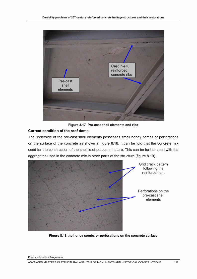
Durability problems of 20th century reinforced concrete heritage structures and their restorations
Erasmus Mundus Programme
ADVANCED MASTERS IN STRUCTURAL ANALYSIS OF MONUMENTS AND HISTORICAL CONSTRUCTIONS 112
Figure 8.17 Pre-cast shell elements and ribs
Current condition of the roof dome The underside of the pre-cast shell elements possesses small honey combs or perforations
on the surface of the concrete as shown in figure 8.18. It can be told that the concrete mix
used for the construction of the shell is of porous in nature. This can be further seen with the
aggregates used in the concrete mix in other parts of the structure (figure 8.19).
Figure 8.18 the honey combs or perforations on the concrete surface
Pre-cast shell
elements
Cast in-situ reinforced concrete ribs
Grid crack pattern following the
reinforcement
Perforations on the pre-cast shell
elements

Durability problems of 20th century reinforced concrete heritage structures and their restorations
Erasmus Mundus Programme
ADVANCED MASTERS IN STRUCTURAL ANALYSIS OF MONUMENTS AND HISTORICAL CONSTRUCTIONS 113
Figure 8.19 poor quality round aggregates used in the concrete mix
It is apparent that most shell and dome structures are made from thin reinforced concrete
elements that provide only smaller cover to the reinforcement. Further more, to decrease the
permanent loading on the roof, it is a usual practice to use light weight concretes, which are
porous in nature most of the time. This leads the aggravation of the ingress of aggressive
agents at the reinforcement level.
Figures 8.18 and 8.20 show that the under side of the thin pre-cast shell elements shows
grids of cracks following the locations of the reinforcing steel. This is reasonably due to the
corrosion of the reinforcing steel in the thin pre-cast shell elements. This may be due to:
Inadequate cover to the reinforcement as the thickness of the shell is only 70mm,
which cause the carbonation of the concrete to be facilitated
Use of light weight concrete which is usually porous which is more permeable to
water and carbon dioxide causing carbonation of concrete. The water vapor source
can be from the spectators and athletes respiration or slight infiltration from the top of
the dome if it was appropriately painted with water repellants.
The use of low quality or round, un-graded aggregates used in the concrete mix
causes the porosity of concrete.
Inadequate curing as the pre-cast shell elements that makes the concrete porous.
Inadequate compaction,
Round and un-graded aggregates used in other parts of the
structure

Durability problems of 20th century reinforced concrete heritage structures and their restorations
Erasmus Mundus Programme
ADVANCED MASTERS IN STRUCTURAL ANALYSIS OF MONUMENTS AND HISTORICAL CONSTRUCTIONS 114
Figure 8.20 grid cracks of the under side of the thin reinforced concrete shell elements
Further studies on what the real cause of the problem, the current condition and safety level
of this thin shell reinforced concrete should be made.

Durability problems of 20th century reinforced concrete heritage structures and their restorations
Erasmus Mundus Programme
ADVANCED MASTERS IN STRUCTURAL ANALYSIS OF MONUMENTS AND HISTORICAL CONSTRUCTIONS 115
9. CONCLUSIONS
The decision on which modern reinforced concrete structures are heritage and should be
preserved is a very diffcult one and more sutdies are needed.It is generally can be told that,
since reinforced concrete is a comparatively new construction material (~100 years old),
most of the durability problems, testing methods, repair and strengthening methods etc of
reinforced concrete structures shall be considered for heritage reinforced concrete heritages
with certain limitations based on the principles of conservation of heritage structures(such as
ICOMOS) and the repair principles of reinforced concrete structures such as EN1504.
There are comparatively many factors for the deterioration/distress of reinforced concrete
heritage structures. Majority of the problems originate from the construction materials used at
the time that helps the ingress of other environmental factors that aggravates the
deterioration of concrete. Of all the factors that affect the durability of reinforced concrete
heritage structures, reinforcement corrosion is the major factor. Further more, Alkali
aggregate reactions and freeze thaw cycles. Overloading of the structures is also becoming
very common these days due to the change in use of the structures and unexpected events
such as earthquakes.
The assessment, design and repair of reinforced concrete heritage structures are more
complex than for new construction. This needs a better understanding of the mechanism
involved in concrete deterioration as they may relate to environmental conditions in which
structures perform; of the effects of material modifications, and of the controlling parameters
of new composites. The repair methods to be applied on the structure mostly combines two
or methods of repair. Cathodic protection seems to be appropriate to repair corrosion caused
deterioration of concrete, if it is combined with patching of the deteriorated concrete
substrate. FRP can be used in the upgrading of load bearing reinforced concrete structural
members, as it doesn’t change the dimension of the structure and due to its higher strength.
All other strengthening methods can be applied on the structure but taking in to account their
preference and durability in the long run and their compatibility with conservation principles.
Compatibility of repair materials and substrate concrete is essential not only to prolong the
durability of the repair but also to maintain the originality/authenticity and the aesthetics of
the structure. Material property of the repair material and the substrate concrete, geometry
etc should match to attain effective repair for long tem with out frequent repairs of the repair.

Durability problems of 20th century reinforced concrete heritage structures and their restorations
Erasmus Mundus Programme
ADVANCED MASTERS IN STRUCTURAL ANALYSIS OF MONUMENTS AND HISTORICAL CONSTRUCTIONS 116
Modern architecture should as much as possible reduce the use of new materials (e.g. FRP,
repair mortars,...), whose long term performances are not fully understood, and techniques in
the repair and restoration of reinforced concrete heritage structures. To minimize the
common problems of repairs, architects and engineers should work together to get an
effective repair.
Focusing on high performance/strength new repair materials may lead to unacceptable
damage to the substrate concrete even though the new materials will address some of the
durability problems in construction. The effectiveness of these new repair materials should
be tested and maximized in the field applications on the existing structure instead of only
laboratory tests.
The available new repair materials and techniques that are used in reinforced concrete
structures can be applied to historic reinforced concrete provided that it is compatible with
the old concrete and its long term performance is understood and the guidance and control is
governed by the conservation principles of heritage and repair principles of reinforced
concrete structures.
The conservation principles of heritage structures from recommendations are difficult to
attain in reinforced concrete heritages structures. This means that some flexibilities on the
principles should be made and it should be combined with the repair principles for the repair
of reinforced concrete structures (EN 1504) to get a conducive principles for future repairs.
Durability problems of reinforced concrete did not sustain for long time like masonry heritage
structures, and thus repair can’t be delayed to see the causes of deterioration as the damage
or deterioration or distress will propagate easily and reach the reinforcement level leading to
corrosion of the reinforcement and further damages.
For any reinforced concrete heriatge structure, preventive maintenance is preferable to repair
or replacements of part or all of the structure, which has shown bad experiences in the past.
The preservation of reinforced concrete heritage needs deep understanding of the causes of
the problems, thier repair methods and materials that thier performance are understood.
Architects and engineers should work together to preserve the reinforced concrete heritage
structures with out compromising thier identity to pass the heritage structures for the coming
generations.
Durability problems of 20th century reinforced concrete heritage structures and their restorations
Erasmus Mundus Programme
ADVANCED MASTERS IN STRUCTURAL ANALYSIS OF MONUMENTS AND HISTORICAL CONSTRUCTIONS 117
Reference: [1] Department of the army, U.S army corpse of Engineers, Engineering and design: Evaluation
and repair of concrete structures, Washington DC, June 1995
[2] M. Levitt, Concrete materials, problems and solutions, E & FN Spon, UK, 2003
[3] Corrosion of steel in concrete, Book details not found but organized by organizations such as
ACI, ASTM etc.
[4] C.A. Apostolopoulos & P.G. Koutsoukos, Study of the corrosion of reinforcement in concrete
elements used for the repair of monuments, University of Patras, Patras, Greece, Available
online at www.sciencedirect.com
[5] Shamsad Ahmad, Reinforcement corrosion in concrete structures, its monitoring and service
life prediction––a review, Department of Civil Engineering, King Fahd University of Petroleum
and Minerals, Dhahran, Saudi Arabia, December 2002
[6] Dong Chen & Sankaran Mahadevan, Chloride-induced reinforcement corrosion and
concrete cracking simulation, Cement & Concrete Composites 30 (2008) 227–238
[7] Jan Bijen, Durability of engineering structures: Design, repair and maintenance, Woodhead
Publishing Limited, England, 2003
[8] Geoff Mays, Durability of concrete structures: investigation, repair, protection, E & FN Spon,
UK, 2003
[9] Report of a working party: the Concrete Society, Technical Report No.54, Diagnosis of
deterioration in concrete structures: Identification of defects, evaluation and development of
remedial action, The Concrete Society, 2000
[10] D. C. K. Tay and C. T. Tam, in-situ investigation of the strength of deteriorated concrete,
Elsevier Science Ltd, Construction and Building Materials, Vol. 10, No. 1, pp. 17-26, 1996,
GB.
[11] Emmanuel Roziere , Ahmed Loukili and François Cussigh, A performance based approach
for durability of concrete exposed to carbonation, Construction and Building Materials xxx
(2008) xxx–xxx, www.sciencedirect.com
[12] C.A. Apostolopoulos and V.G. Papadakis, Consequences of steel corrosion on the ductility
properties of reinforcement bar, www.sciencedirect.com
[13]Alkali silica reaction, Elkem ASA Materials, Norway
[14] R. Miguel, Advanced Masters in Structural Analysis of Monuments and Historical
Constructions, SAHC 2007-2008, Course material SA6:Restoration and Conservation of
Materials
[15] HYOMIN LEE, ROBERT D. CODY, ANITA M. CODY, AND PAUL G. SPRY, Effects of
Various Deicing Chemicals on Pavement Concrete Deterioration , Department of
Geological and Atmospheric Sciences, Iowa State University, Ames, Iowa .
Durability problems of 20th century reinforced concrete heritage structures and their restorations
Erasmus Mundus Programme
ADVANCED MASTERS IN STRUCTURAL ANALYSIS OF MONUMENTS AND HISTORICAL CONSTRUCTIONS 118
[16] Luca Bertolini, Bernhard Elsener, Pietro Pedeferri, Rob Polder, Corrosion of steel in
concrete: Prevention, Diagnosis, Repair; WILEY-VCH, Germany, 2004
[17] J. Sena Cruz, Advanced Masters in Structural Analysis of Monuments and Historical
Constructions, SAHC 2007-2008, Course material SA5:Repairing and strengthening
techniques
[18] M.R. Esfahania, M.R. Kianoushb, A.R. Tajaria , Flexural behaviour of reinforced concrete
beams strengthened by CFRP sheets, 2006, www.sciencedirect.com
[19] D. R. Morgan, Compatibility of concrete repair materials Systems, Construction and Building
Materials, Vol. 10, No. I, pp. 51-61, 1996, Great Britain
[20] Alexander M. Vaysburd &Peter H. Emmons , Corrosion inhibitors and other protective
systems in concrete repair: concepts or misconcepts, Cement & Concrete Composites 26
(2004) 255–263
[21] M. Raupach, Concrete Repair According to the new European Standard EN-1504, RWTH
Aachen, ibac
[22] M. Yasar Kaltakcia, M. Hakan Arslana, Ulku S. Yilmaza, H. Derya Arslan, A new approach on
the strengthening of primary school buildings in Turkey: An application of external shear
wall Strengthening of primary school in turkey, Building and Environment 43 (2008) 983–
990
[23] Pere Roca, Advanced Masters in Structural Analysis of Monuments and Historical
Constructions, SAHC 2007-2008, Course material SA1:History of Construction and of
Conservation
[24] Stephen J. Kelley, The Role of the Engineer in Preservation, APT Bulletin, Association
for Preservation Technology International (APT), 1991
[25] Figeys, W., Schueremans, L., Van Gemert, D., Preservation of the RC-monument
‘Vuurmolen’ (1902) at Overijse, Belgium,
[26] US Department of transportation, Federal Highway Administration, Alkali-silica Reaction,
http://www.tfhrc.gov/pavement/pccp/pubs/03047/02.htm
[27]Portland cement association, Alkali aggregate reactions, Washington DC
http://www.cement.org/tech/cct_dur_AAR.asp
[28] Concrete Experts International ApS, Freeze - Thaw Deterioration of Concrete, Denmark,
www.concrete-experts.com/pages/ft.htm
[29] DRC associates, Concrete Repair and Reconstruction, Genesee Hospital Doctor's Building -
Rochester, New York
http://www.drc-associates.com/p_concrete_reconstruction.htm

Durability problems of 20th century reinforced concrete heritage structures and their restorations
Erasmus Mundus Programme
ADVANCED MASTERS IN STRUCTURAL ANALYSIS OF MONUMENTS AND HISTORICAL CONSTRUCTIONS 119
[30] Kim D. Basham, Concrete cracking, L&M Construction Chemicals, Concrete Engineering
Specialists LLC,USA,
http://www.lmcc.com/news/summer2006/summer2006-04.asp,
[31] Pier A Mid Rehabilitation Inc., Chemical Grouts, Houston, USA
http://www.pier-a-mid.com/grouting.aspx
[32] Epoxy.com, A Division of Epoxy Systems Inc, Concrete epoxy ejection, Florida & Vermont,
USA
http://www.epoxysystems.com/injection.htm
[33] William B. Coney, Preservation of historic concrete Problems and approaches, Technical
preservation services, National park service, U.S Department of the interior, USA
www.nps.gov/history/hps/tps/briefs/brief15.htm
[34] Wikipedia, www.wikipedia.org
[35] Understanding Cement, WHD Microanalysis Consultants Ltd, Alkali-silica reaction in
concrete, UK,
http://www.understanding-cement.com/alkali-silica.html
[36] Sure-Gro Inc.,Ice melting solutions, Ontario, Canada www.icemelter.ca/traction/roofs_e.php
[37] House of World Cultures, The Architecture, Berlin, Germany
www.hkw.de/en/hkw/gebauede/architektur/index.php
[38] C.M. Hansson: "Concrete: The Advanced Material for the 21st Century", Metallurgical and
Materials Transactions A, 1995, pp.1321-1341,
www.corrosion-club.com/concretehistory1.htm
[39] Palau Blaugrana, Barcelona, Spain
http://www.fcbarcelona.com/web/english/club/club_avui/territori_barca/palau_blau
grana/palaublaugrana.html,
[40] Nicolas Janberg ICS., Structurae,Palau Blaugrana
http://en.structurae.de/structures/data/index.cfm?ID=s0034928
[41] International Council of Monuments and Sites (ICOMOS), International Charters for
Conservation and Restoration, France,
http://www.international.icomos.org
[42] L C Hollaway and M B Leeming, Strengthening of reinforced concrete structures: Using
externally-bonded FRP composites in structural and civil engineering, Woodhead
publishing limited, England, 1999
[43] Susan Macdonald, ICOMOS:20th Century Heritage: Recognition, Protection and
practical challenges, Austaralia
http://www.international.icomos.org/risk/2002/20th2002.htm#