Embed Size (px)
Citation preview
Programmer Manual
TDS3000 & TDS3000B SeriesDigital Phosphor Oscilloscopes
071-0381-02
This document applies to firmware version 3.00and above.
www.tektronix.com
Copyright � Tektronix, Inc. All rights reserved. Licensed software products are owned by Tektronix or its suppliers andare protected by United States copyright laws and international treaty provisions.
Use, duplication, or disclosure by the Government is subject to restrictions as set forth in subparagraph (c)(1)(ii) of theRights in Technical Data and Computer Software clause at DFARS 252.227-7013, or subparagraphs (c)(1) and (2) of theCommercial Computer Software – Restricted Rights clause at FAR 52.227-19, as applicable.
Tektronix products are covered by U.S. and foreign patents, issued and pending. Information in this publication supercedesthat in all previously published material. Specifications and price change privileges reserved.
Tektronix, Inc., P.O. Box 500, Beaverton, OR 97077
TEKTRONIX and TEK are registered trademarks of Tektronix, Inc.
DPX, WaveAlert, and e*Scope are trademarks of Tektronix, Inc.

Contacting Tektronix
Phone 1-800-833-9200*
Address Tektronix, Inc.Department or name (if known)14200 SW Karl Braun DriveP.O. Box 500Beaverton, OR 97077USA
Web site www.tektronix.com
Sales support 1-800-833-9200, select option 1*
Service support 1-800-833-9200, select option 2*
Technical support Email: [email protected]
1-800-833-9200, select option 3*1-503-627-2400
6:00 a.m. – 5:00 p.m. Pacific time
* This phone number is toll free in North America. After office hours, please leave avoice mail message.Outside North America, contact a Tektronix sales office or distributor; see theTektronix web site for a list of offices.
TDS3000 & TDS3000B Programmer Manual i
Table of Contents
PrefaceRelated Manuals vii. . . . . . . . . . . . . . . . . . . . . . . . . . . . . . . . . . . . . . . . . . . . . . . . . . Contacting Tektronix viii. . . . . . . . . . . . . . . . . . . . . . . . . . . . . . . . . . . . . . . . . . . . . .
Getting StartedOverview of the Manual 1–2. . . . . . . . . . . . . . . . . . . . . . . . . . . . . . . . . . . . . . . . . . . . Communication Modules 1–4. . . . . . . . . . . . . . . . . . . . . . . . . . . . . . . . . . . . . . . . . . . Installing a Communication Module 1–6. . . . . . . . . . . . . . . . . . . . . . . . . . . . . . . . . . Connector Locations 1–7. . . . . . . . . . . . . . . . . . . . . . . . . . . . . . . . . . . . . . . . . . . . . . Setting Up Ethernet Remote Communications 1–8. . . . . . . . . . . . . . . . . . . . . . . . . . Setting Up GPIB Remote Communications 1–22. . . . . . . . . . . . . . . . . . . . . . . . . . . . . Setting Up RS-232 Remote Communications 1–25. . . . . . . . . . . . . . . . . . . . . . . . . . . Comparing GPIB and RS-232 1–30. . . . . . . . . . . . . . . . . . . . . . . . . . . . . . . . . . . . . . .
Command Syntax and CommandsCommand and Query Structure 2–1. . . . . . . . . . . . . . . . . . . . . . . . . . . . . . . . . . . . . . Clearing the Oscilloscope Output Queue 2–4. . . . . . . . . . . . . . . . . . . . . . . . . . . . . . . Command Entry 2–4. . . . . . . . . . . . . . . . . . . . . . . . . . . . . . . . . . . . . . . . . . . . . . . . . . Constructed Mnemonics 2–7. . . . . . . . . . . . . . . . . . . . . . . . . . . . . . . . . . . . . . . . . . . . Argument Types 2–8. . . . . . . . . . . . . . . . . . . . . . . . . . . . . . . . . . . . . . . . . . . . . . . . . .
Command Groups 2–11. . . . . . . . . . . . . . . . . . . . . . . . . . . . . . . . . . . . . . . . . . Acquisition Commands 2–11. . . . . . . . . . . . . . . . . . . . . . . . . . . . . . . . . . . . . . . . . . . . Alias Commands 2–12. . . . . . . . . . . . . . . . . . . . . . . . . . . . . . . . . . . . . . . . . . . . . . . . . Calibration and Diagnostic Commands 2–13. . . . . . . . . . . . . . . . . . . . . . . . . . . . . . . . Cursor Commands 2–14. . . . . . . . . . . . . . . . . . . . . . . . . . . . . . . . . . . . . . . . . . . . . . . . Display Commands 2–16. . . . . . . . . . . . . . . . . . . . . . . . . . . . . . . . . . . . . . . . . . . . . . . Ethernet Commands 2–17. . . . . . . . . . . . . . . . . . . . . . . . . . . . . . . . . . . . . . . . . . . . . . . File System Commands 2–18. . . . . . . . . . . . . . . . . . . . . . . . . . . . . . . . . . . . . . . . . . . . Front Panel Commands 2–18. . . . . . . . . . . . . . . . . . . . . . . . . . . . . . . . . . . . . . . . . . . . Hard Copy Commands 2–19. . . . . . . . . . . . . . . . . . . . . . . . . . . . . . . . . . . . . . . . . . . . . Horizontal Commands 2–19. . . . . . . . . . . . . . . . . . . . . . . . . . . . . . . . . . . . . . . . . . . . . ITU601 Digital Video Commands (TDS3SDI Only) 2–20. . . . . . . . . . . . . . . . . . . . . Limit Test Commands (TDS3LIM Only) 2–21. . . . . . . . . . . . . . . . . . . . . . . . . . . . . . Mask Commands (TDS3TMT Only) 2–22. . . . . . . . . . . . . . . . . . . . . . . . . . . . . . . . . . Math Commands 2–27. . . . . . . . . . . . . . . . . . . . . . . . . . . . . . . . . . . . . . . . . . . . . . . . . Measurement Commands 2–28. . . . . . . . . . . . . . . . . . . . . . . . . . . . . . . . . . . . . . . . . . . Miscellaneous Commands 2–31. . . . . . . . . . . . . . . . . . . . . . . . . . . . . . . . . . . . . . . . . . RS-232 Commands 2–32. . . . . . . . . . . . . . . . . . . . . . . . . . . . . . . . . . . . . . . . . . . . . . . Save and Recall Commands 2–32. . . . . . . . . . . . . . . . . . . . . . . . . . . . . . . . . . . . . . . . . Status and Error Commands 2–33. . . . . . . . . . . . . . . . . . . . . . . . . . . . . . . . . . . . . . . . Trigger Commands 2–34. . . . . . . . . . . . . . . . . . . . . . . . . . . . . . . . . . . . . . . . . . . . . . . . Vertical Commands 2–38. . . . . . . . . . . . . . . . . . . . . . . . . . . . . . . . . . . . . . . . . . . . . . . Waveform Commands 2–39. . . . . . . . . . . . . . . . . . . . . . . . . . . . . . . . . . . . . . . . . . . . .
Command Descriptions 2–45. . . . . . . . . . . . . . . . . . . . . . . . . . . . . . . . . . . . . .
Table of Contents
ii TDS3000 & TDS3000B Programmer Manual
Status and EventsRegisters 3–1. . . . . . . . . . . . . . . . . . . . . . . . . . . . . . . . . . . . . . . . . . . . . . . . . . . . . . . . Queues 3–5. . . . . . . . . . . . . . . . . . . . . . . . . . . . . . . . . . . . . . . . . . . . . . . . . . . . . . . . . Event Handling Sequence 3–6. . . . . . . . . . . . . . . . . . . . . . . . . . . . . . . . . . . . . . . . . . Synchronization Methods 3–7. . . . . . . . . . . . . . . . . . . . . . . . . . . . . . . . . . . . . . . . . . . Messages 3–12. . . . . . . . . . . . . . . . . . . . . . . . . . . . . . . . . . . . . . . . . . . . . . . . . . . . . . .
Programming ExamplesGPIB Examples 4–2. . . . . . . . . . . . . . . . . . . . . . . . . . . . . . . . . . . . . . . . . . . . . . . . . . RS-232 Examples 4–5. . . . . . . . . . . . . . . . . . . . . . . . . . . . . . . . . . . . . . . . . . . . . . . . .
AppendicesAppendix A: Character Charts A–1. . . . . . . . . . . . . . . . . . . . . . . . . . . . . . .
Appendix B: Reserved Words B–1. . . . . . . . . . . . . . . . . . . . . . . . . . . . . . . .
Appendix C: Interface Specifications C–1. . . . . . . . . . . . . . . . . . . . . . . . . . Appendix D: Factory Initialization Settings D–1. . . . . . . . . . . . . . . . . . . . .
Glossary and Index
Table of Contents
TDS3000 & TDS3000B Programmer Manual iii
List of Figures
Figure 1–1: Common message elements 1–2. . . . . . . . . . . . . . . . . . . . . . . .
Figure 1–2: Functional groupings and an alphabetical list of commands 1–2. . . . . . . . . . . . . . . . . . . . . . . . . . . . . . . . . . . . . . . .
Figure 1–3: Service Requests (SRQs) provide for event (interrupt) driven programs 1–3. . . . . . . . . . . . . . . . . . . . . . . . . . . . . .
Figure 1–4: The disk that accompanies this manual 1–3. . . . . . . . . . . . . . Figure 1–5: Communication module connectors 1–5. . . . . . . . . . . . . . . . .
Figure 1–6: TDS3EM LEDs 1–5. . . . . . . . . . . . . . . . . . . . . . . . . . . . . . . . . . Figure 1–7: Communication module mounting location 1–6. . . . . . . . . . .
Figure 1–8: Communication module location 1–7. . . . . . . . . . . . . . . . . . . .
Figure 1–9: The Ethernet Network Settings menu 1–9. . . . . . . . . . . . . . . . Figure 1–10: The Change Instrument Settings screen 1–10. . . . . . . . . . . . .
Figure 1–11: The Ethernet Printer Settings window 1–16. . . . . . . . . . . . . . Figure 1–12: VISA configuration window 1–19. . . . . . . . . . . . . . . . . . . . . .
Figure 1–13: TekVisa Add Remote Host dialog box 1–20. . . . . . . . . . . . . . Figure 1–14: TekVisa Delete Remote Resource dialog box 1–21. . . . . . . . .
Figure 1–15: How to stack GPIB connectors 1–23. . . . . . . . . . . . . . . . . . . .
Figure 1–16: Typical GPIB network configurations 1–23. . . . . . . . . . . . . . Figure 1–17: Selecting the System: I/O menu 1–24. . . . . . . . . . . . . . . . . . . .
Figure 1–18: The RS-232 connector pin assignments 1–25. . . . . . . . . . . . . Figure 1–19: RS-232 parameter settings 1–26. . . . . . . . . . . . . . . . . . . . . . . .
Figure 2–1: Command Message Elements 2–2. . . . . . . . . . . . . . . . . . . . . .
Figure 2–2: Block Argument Example 2–10. . . . . . . . . . . . . . . . . . . . . . . . .
Figure 3–1: The Standard Event Status Register (SESR) 3–1. . . . . . . . . .
Figure 3–2: The Status Byte Register (SBR) 3–2. . . . . . . . . . . . . . . . . . . . . Figure 3–3: The Device Event Status Enable Register (DESER) 3–3. . . .
Figure 3–4: The Event Status Enable Register (ESER) 3–4. . . . . . . . . . . . Figure 3–5: The Service Request Enable Register (SRER) 3–4. . . . . . . . .
Figure 3–6: Status and Event Handling Process 3–6. . . . . . . . . . . . . . . . . Figure 3–7: Command Processing Without Using
Synchronization 3–8. . . . . . . . . . . . . . . . . . . . . . . . . . . . . . . . . . . . . . . . .
Figure 3–8: Processing Sequence With Synchronization 3–8. . . . . . . . . . .
Figure 4–1: Equipment needed to run the GPIB and RS-232 example programs 4–1. . . . . . . . . . . . . . . . . . . . . . . . . . . .
Table of Contents
iv TDS3000 & TDS3000B Programmer Manual
List of Tables
Table 1–1: TDS3000 and TDS3000B Series communication modules 1–4
Table 1–2: Ethernet Network Settings side menu 1–10. . . . . . . . . . . . . . . . Table 1–3: Ethernet Printer Settings side menu 1–12. . . . . . . . . . . . . . . . .
Table 1–4: RS-232 adapter cables 1–25. . . . . . . . . . . . . . . . . . . . . . . . . . . . . Table 1–5: RS-232 default settings 1–27. . . . . . . . . . . . . . . . . . . . . . . . . . . .
Table 1–6: RS-232 troubleshooting 1–29. . . . . . . . . . . . . . . . . . . . . . . . . . . . Table 1–7: Comparison of GPIB and RS-232 interfaces 1–30. . . . . . . . . .
Table 2–1: BNF Symbols and Meanings 2–1. . . . . . . . . . . . . . . . . . . . . . . .
Table 2–2: Command Message Elements 2–2. . . . . . . . . . . . . . . . . . . . . . .
Table 2–3: Comparison of Header Off and On Responses 2–3. . . . . . . . . Table 2–4: Acquisition commands 2–11. . . . . . . . . . . . . . . . . . . . . . . . . . . .
Table 2–5: Alias commands 2–12. . . . . . . . . . . . . . . . . . . . . . . . . . . . . . . . . . Table 2–6: Calibration and diagnostic commands 2–13. . . . . . . . . . . . . . .
Table 2–7: Cursor commands 2–14. . . . . . . . . . . . . . . . . . . . . . . . . . . . . . . . Table 2–8: Display commands 2–16. . . . . . . . . . . . . . . . . . . . . . . . . . . . . . . .
Table 2–9: Ethernet commands 2–17. . . . . . . . . . . . . . . . . . . . . . . . . . . . . . .
Table 2–10: File system commands 2–18. . . . . . . . . . . . . . . . . . . . . . . . . . . . Table 2–11: Front panel commands 2–18. . . . . . . . . . . . . . . . . . . . . . . . . . .
Table 2–12: Hard copy commands 2–19. . . . . . . . . . . . . . . . . . . . . . . . . . . . Table 2–13: Horizontal commands 2–19. . . . . . . . . . . . . . . . . . . . . . . . . . . .
Table 2–14: ITU601 commands 2–20. . . . . . . . . . . . . . . . . . . . . . . . . . . . . . . Table 2–15: Limit Test commands 2–21. . . . . . . . . . . . . . . . . . . . . . . . . . . .
Table 2–16: Mask commands 2–22. . . . . . . . . . . . . . . . . . . . . . . . . . . . . . . . Table 2–17: Available TDS3TMT ITU-T G.703 mask standards 2–26. . .
Table 2–18: Available TDS3TMT ANSI T1.102 mask standards 2–26. . .
Table 2–19: Math commands 2–27. . . . . . . . . . . . . . . . . . . . . . . . . . . . . . . . Table 2–20: Measurement commands 2–28. . . . . . . . . . . . . . . . . . . . . . . . .
Table 2–21: Miscellaneous commands 2–31. . . . . . . . . . . . . . . . . . . . . . . . . Table 2–22: RS-232 commands 2–32. . . . . . . . . . . . . . . . . . . . . . . . . . . . . . .
Table 2–23: Save and Recall commands 2–32. . . . . . . . . . . . . . . . . . . . . . . . Table 2–24: Status and Error commands 2–33. . . . . . . . . . . . . . . . . . . . . . .
Table 2–25: Trigger commands 2–34. . . . . . . . . . . . . . . . . . . . . . . . . . . . . . .
Table 2–26: Vertical commands 2–38. . . . . . . . . . . . . . . . . . . . . . . . . . . . . . Table 2–27: Binary data ranges 2–40. . . . . . . . . . . . . . . . . . . . . . . . . . . . . . .
Table of Contents
TDS3000 & TDS3000B Programmer Manual v
Table 2–28: Waveform commands 2–42. . . . . . . . . . . . . . . . . . . . . . . . . . . .
Table 2–29: Commands that affect BUSY? response 2–56. . . . . . . . . . . . . Table 2–30: Offset Ranges using a 1x Probe 2–67. . . . . . . . . . . . . . . . . . . .
Table 2–31: CURVE query error conditions 2–90. . . . . . . . . . . . . . . . . . . . Table 2–32: CURVE command error conditions 2–90. . . . . . . . . . . . . . . . .
Table 2–33: DATa and WFMPre parameter settings 2–94. . . . . . . . . . . . .
Table 2–34: XY format pairs 2–105. . . . . . . . . . . . . . . . . . . . . . . . . . . . . . . . . Table 2–35: XY format pairs 2–114. . . . . . . . . . . . . . . . . . . . . . . . . . . . . . . . .
Table 2–36: FPAnel:PRESS arguments 2–138. . . . . . . . . . . . . . . . . . . . . . . . Table 2–37: Advanced Math expression elements 2–202. . . . . . . . . . . . . . . .
Table 2–38: MATH1: commands 2–208. . . . . . . . . . . . . . . . . . . . . . . . . . . . . Table 2–39: Commands that generate
an operation complete message 2–243. . . . . . . . . . . . . . . . . . . . . . . . . . . Table 2–40: HDTV formats 2–296. . . . . . . . . . . . . . . . . . . . . . . . . . . . . . . . . .
Table 2–41: Video trigger line range values 2–298. . . . . . . . . . . . . . . . . . . . .
Table 2–42: TRIGger:DELay commands 2–307. . . . . . . . . . . . . . . . . . . . . . . Table 2–43: TRIGger:MAIn commands 2–309. . . . . . . . . . . . . . . . . . . . . . .
Table 2–44: Additional WFMPre commands 2–330. . . . . . . . . . . . . . . . . . . .
Table 3–1: SESR bit functions 3–2. . . . . . . . . . . . . . . . . . . . . . . . . . . . . . . . Table 3–2: SBR bit functions 3–3. . . . . . . . . . . . . . . . . . . . . . . . . . . . . . . . .
Table 3–3: No event messages 3–12. . . . . . . . . . . . . . . . . . . . . . . . . . . . . . . .
Table 3–4: Command error messages – CME Bit 5 3–12. . . . . . . . . . . . . . Table 3–5: Execution error messages – EXE Bit 4 3–14. . . . . . . . . . . . . . .
Table 3–6: Device error messages – DDE Bit 3 3–17. . . . . . . . . . . . . . . . . . Table 3–7: System event messages 3–18. . . . . . . . . . . . . . . . . . . . . . . . . . . .
Table 3–8: Execution warning messages – EXE Bit 4 3–18. . . . . . . . . . . . . Table 3–9: Internal warning messages 3–19. . . . . . . . . . . . . . . . . . . . . . . . .
Table A–1: The TDS3000 and TDS3000B Character Set A–1. . . . . . . . . . Table A–2: ASCII & GPIB code chart A–3. . . . . . . . . . . . . . . . . . . . . . . . . .
Table C–1: TDS3000 & TDS3000B Series supported standard interface messages C–2. . . . . . . . . . . . . . . . . . . . . . . . . . . . . . . . . . . . . .
Table D–1: Factory initialization settings D–1. . . . . . . . . . . . . . . . . . . . . . .

Table of Contents
vi TDS3000 & TDS3000B Programmer Manual
TDS3000 & TDS3000B Programmer Manual vii
Preface
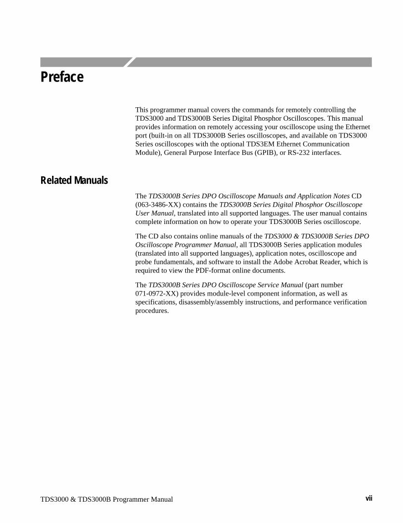
This programmer manual covers the commands for remotely controlling theTDS3000 and TDS3000B Series Digital Phosphor Oscilloscopes. This manualprovides information on remotely accessing your oscilloscope using the Ethernetport (built-in on all TDS3000B Series oscilloscopes, and available on TDS3000Series oscilloscopes with the optional TDS3EM Ethernet CommunicationModule), General Purpose Interface Bus (GPIB), or RS-232 interfaces.
Related ManualsThe TDS3000B Series DPO Oscilloscope Manuals and Application Notes CD(063-3486-XX) contains the TDS3000B Series Digital Phosphor OscilloscopeUser Manual, translated into all supported languages. The user manual containscomplete information on how to operate your TDS3000B Series oscilloscope.
The CD also contains online manuals of the TDS3000 & TDS3000B Series DPOOscilloscope Programmer Manual, all TDS3000B Series application modules(translated into all supported languages), application notes, oscilloscope andprobe fundamentals, and software to install the Adobe Acrobat Reader, which isrequired to view the PDF-format online documents.
The TDS3000B Series DPO Oscilloscope Service Manual (part number071-0972-XX) provides module-level component information, as well asspecifications, disassembly/assembly instructions, and performance verificationprocedures.
Preface
viii TDS3000 & TDS3000B Programmer Manual
Contacting Tektronix
Phone 1-800-833-9200*
Address Tektronix, Inc.Department or name (if known)14200 SW Karl Braun DriveP.O. Box 500Beaverton, OR 97077USA
Web site www.tektronix.com
Sales support 1-800-833-9200, select option 1*
Service support 1-800-833-9200, select option 2*
Technical support Email: [email protected]
1-800-833-9200, select option 3*1-503-627-2400
6:00 a.m. – 5:00 p.m. Pacific time
* This phone number is toll free in North America. After office hours, please leave avoice mail message.Outside North America, contact a Tektronix sales office or distributor; see theTektronix web site for a list of offices.
TDS3000 & TDS3000B Programmer Manual 1–1
Getting Started
You can write computer programs that remotely set the oscilloscope front panelcontrols or that take measurements and read those measurements for furtheranalysis or storage.
To help you get started with programming the oscilloscope, this section includesthe following sections:
� Overview of the Manual summarizes the type of programming informationcontained in each major section of this manual (page 1–2).
� Installing a Communication Module provides instructions to install one ofthe optional communication modules (page 1–6).
� Connector Locations shows the RS-232 and GPIB connector locations onthe back panel of the TDS3000B Series (page 1–7).
� Setting Up Ethernet Remote Communications describes setting up forEthernet 10baseT remote control, including connecting the oscilloscope andsetting the appropriate front-panel controls (page 1–8).
� Setting Up GPIB Remote Communications describes setting up for GPIBremote control, including connecting the oscilloscope and setting theappropriate front-panel controls (page 1–22).
� Setting Up RS-232 Remote Communications describes setting up for RS-232remote control, including connecting the oscilloscope and setting theappropriate front-panel controls (page 1–25).
� Comparing GPIB and RS-232 compares the characteristics of the GPIB andRS-232 interfaces (page 1–30).
Getting Started
1–2 TDS3000 & TDS3000B Programmer Manual
Overview of the ManualThe information contained in each major section of this manual is describedbelow.
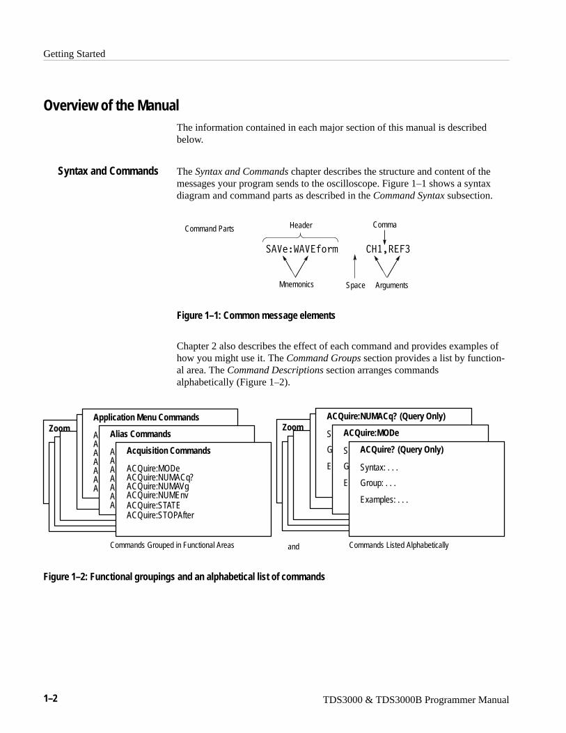
The Syntax and Commands chapter describes the structure and content of themessages your program sends to the oscilloscope. Figure 1–1 shows a syntaxdiagram and command parts as described in the Command Syntax subsection.
Comma
���������������� �������
Header
Mnemonics ArgumentsSpace
Command Parts
Figure 1–1: Common message elements
Chapter 2 also describes the effect of each command and provides examples ofhow you might use it. The Command Groups section provides a list by function-al area. The Command Descriptions section arranges commandsalphabetically (Figure 1–2).
ZoomZoom
Commands Grouped in Functional Areas Commands Listed Alphabetically
ACQuire? (Query Only)
Syntax: . . .
Group: . . .
Examples: . . .
ACQuire:MODe
S
G
E
ACQuire:NUMACq? (Query Only)
S
G
E
Acquisition Commands
ACQuire:MODeACQuire:NUMACq?ACQuire:NUMAVgACQuire:NUMEnvACQuire:STATEACQuire:STOPAfter
Alias Commands
AAAAAAA
Application Menu Commands
AAAAAAA
and
Figure 1–2: Functional groupings and an alphabetical list of commands
Syntax and Commands
Getting Started
TDS3000 & TDS3000B Programmer Manual 1–3
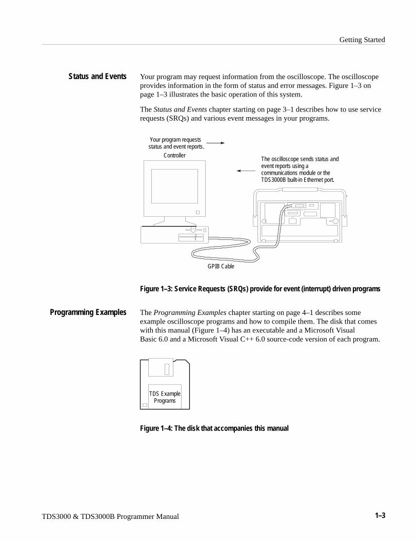
Your program may request information from the oscilloscope. The oscilloscopeprovides information in the form of status and error messages. Figure 1–3 onpage 1–3 illustrates the basic operation of this system.
The Status and Events chapter starting on page 3–1 describes how to use servicerequests (SRQs) and various event messages in your programs.
Your program requestsstatus and event reports.
The oscilloscope sends status andevent reports using acommunications module or theTDS3000B built-in Ethernet port.
GPIB Cable
Controller
Figure 1–3: Service Requests (SRQs) provide for event (interrupt) driven programs
The Programming Examples chapter starting on page 4–1 describes someexample oscilloscope programs and how to compile them. The disk that comeswith this manual (Figure 1–4) has an executable and a Microsoft VisualBasic 6.0 and a Microsoft Visual C++ 6.0 source-code version of each program.
TDS ExamplePrograms
Figure 1–4: The disk that accompanies this manual
Status and Events
Programming Examples
Getting Started
1–4 TDS3000 & TDS3000B Programmer Manual
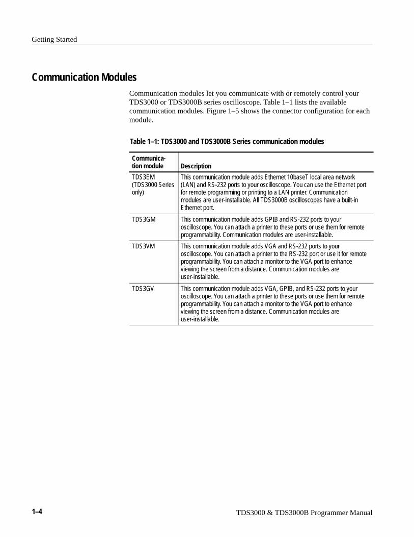
Communication ModulesCommunication modules let you communicate with or remotely control yourTDS3000 or TDS3000B series oscilloscope. Table 1–1 lists the availablecommunication modules. Figure 1–5 shows the connector configuration for eachmodule.
Table 1–1: TDS3000 and TDS3000B Series communication modules
Communica-tion module Description
TDS3EM(TDS3000 Seriesonly)
This communication module adds Ethernet 10baseT local area network(LAN) and RS-232 ports to your oscilloscope. You can use the Ethernet portfor remote programming or printing to a LAN printer. Communicationmodules are user-installable. All TDS3000B oscilloscopes have a built-inEthernet port.
TDS3GM This communication module adds GPIB and RS-232 ports to youroscilloscope. You can attach a printer to these ports or use them for remoteprogrammability. Communication modules are user-installable.
TDS3VM This communication module adds VGA and RS-232 ports to youroscilloscope. You can attach a printer to the RS-232 port or use it for remoteprogrammability. You can attach a monitor to the VGA port to enhanceviewing the screen from a distance. Communication modules areuser-installable.
TDS3GV This communication module adds VGA, GPIB, and RS-232 ports to youroscilloscope. You can attach a printer to these ports or use them for remoteprogrammability. You can attach a monitor to the VGA port to enhanceviewing the screen from a distance. Communication modules areuser-installable.
Getting Started
TDS3000 & TDS3000B Programmer Manual 1–5
TDS3GM
TDS3VM
RS-232
TDS3EM
Ethernet
RS-232
RS-232
GPIB
VGA
TDS3GV
RS-232GPIB VGA
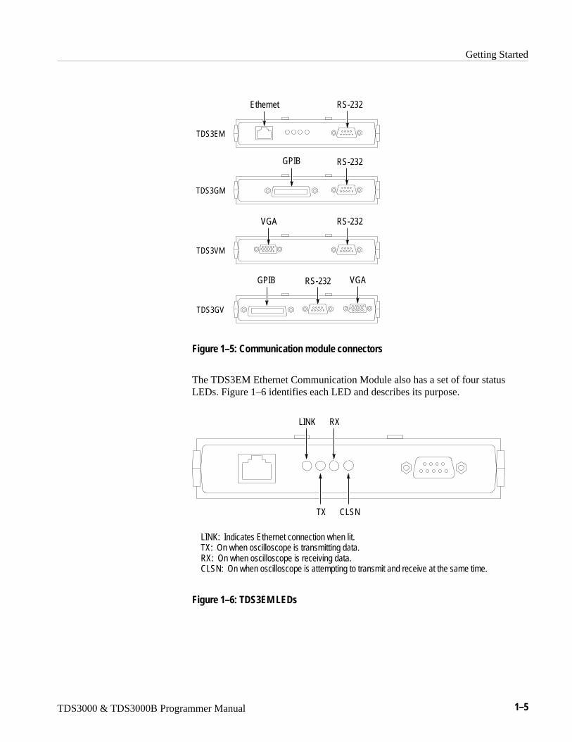
Figure 1–5: Communication module connectors
The TDS3EM Ethernet Communication Module also has a set of four statusLEDs. Figure 1–6 identifies each LED and describes its purpose.
LINK
TX
RX
CLSN
LINK: Indicates Ethernet connection when lit.TX: On when oscilloscope is transmitting data.RX: On when oscilloscope is receiving data.CLSN: On when oscilloscope is attempting to transmit and receive at the same time.
Figure 1–6: TDS3EM LEDs
Getting Started
1–6 TDS3000 & TDS3000B Programmer Manual
Installing a Communication Module
CAUTION. To avoid damage to the oscilloscope or communication module,observe all ESD precautions described in the User manual.
NOTE. Do not install a TDS3EM module into a TDS3000B Series. Installing theTDS3EM module into a TDS3000B Series oscilloscope will cause both thebuilt-in Ethernet port and the module’s Ethernet port to stop functioning.
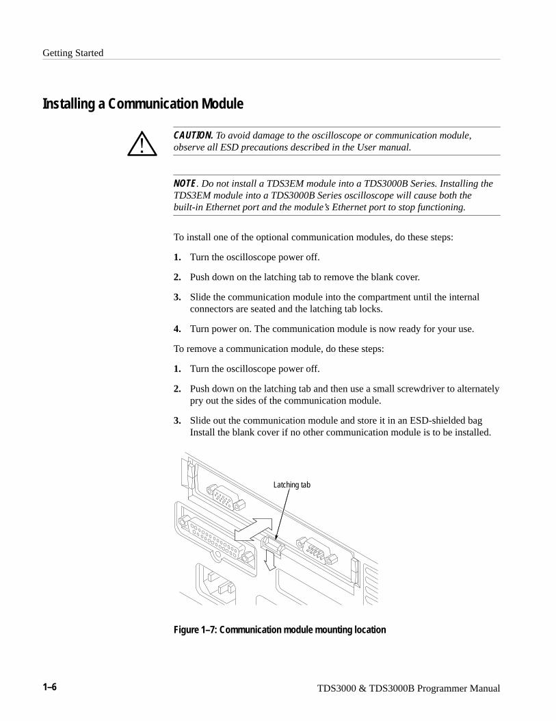
To install one of the optional communication modules, do these steps:
1. Turn the oscilloscope power off.
2. Push down on the latching tab to remove the blank cover.
3. Slide the communication module into the compartment until the internalconnectors are seated and the latching tab locks.
4. Turn power on. The communication module is now ready for your use.
To remove a communication module, do these steps:
1. Turn the oscilloscope power off.
2. Push down on the latching tab and then use a small screwdriver to alternatelypry out the sides of the communication module.
3. Slide out the communication module and store it in an ESD-shielded bagInstall the blank cover if no other communication module is to be installed.
Latching tab
Figure 1–7: Communication module mounting location
Getting Started
TDS3000 & TDS3000B Programmer Manual 1–7
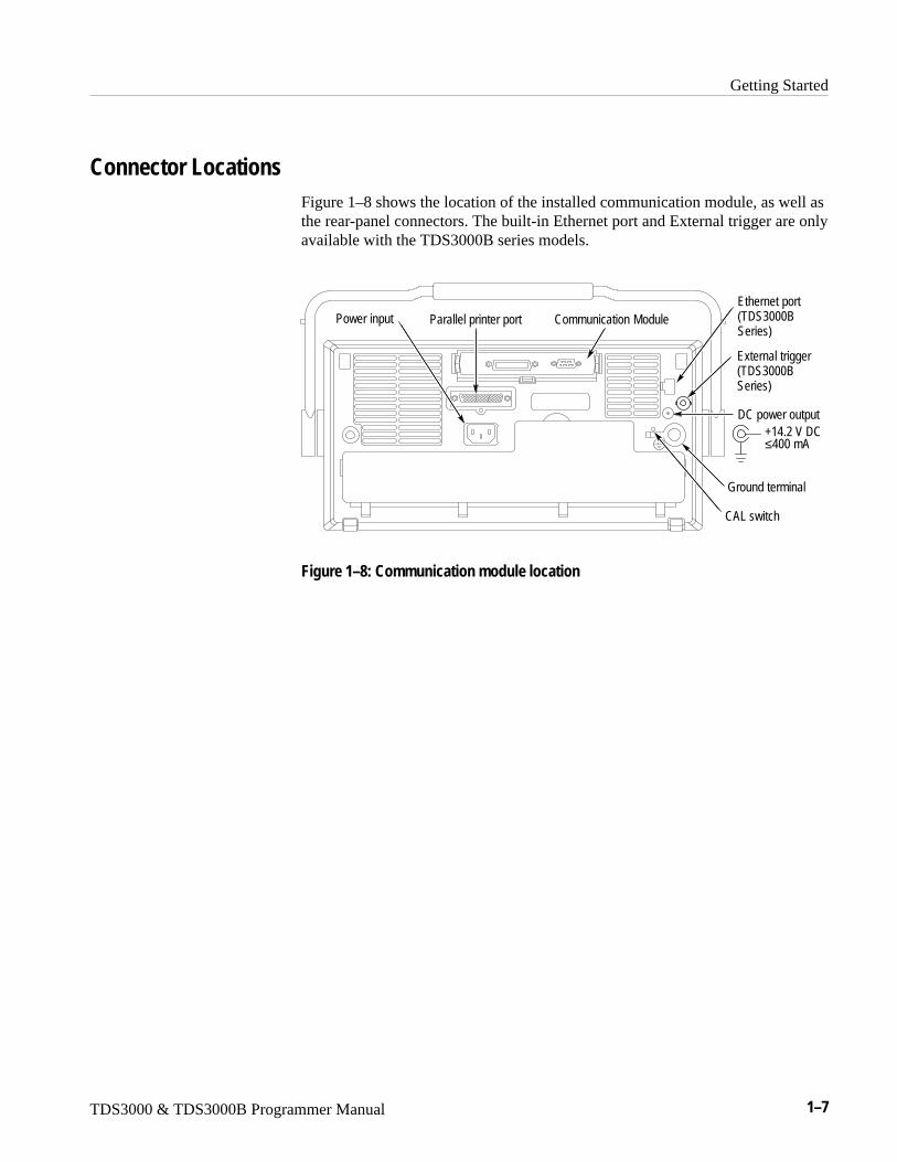
Connector LocationsFigure 1–8 shows the location of the installed communication module, as well asthe rear-panel connectors. The built-in Ethernet port and External trigger are onlyavailable with the TDS3000B series models.
Communication ModulePower input Parallel printer portEthernet port(TDS3000BSeries)
External trigger(TDS3000BSeries)
DC power output+14.2 V DC≤400 mA
Ground terminal
CAL switch
Figure 1–8: Communication module location

Getting Started
1–8 TDS3000 & TDS3000B Programmer Manual
Setting Up Ethernet Remote CommunicationsThe following sections describe how to set up the Ethernet communications fornetwork hard copy printing and remote programmability. The Ethernet portrequires a straight-through 10BaseT cable with RJ-45 connector. No transceiveris necessary.
To connect the oscilloscope to the network, you need to obtain information fromyour network administrator. For your convenience, make two photocopies of theform shown below and send them to your network administrator to fill in. Theadministrator can then return one copy and keep the other copy for filing.
TDS3000B Ethernet Setup Form for_______________________________________
TDS3000B Ethernet Hardware address : : : : :(User: copy this address from the UTILITY > System: I/O > Ethernet Network Settings > Change Instrument Settingsscreen before sending this form to the network administrator)
Type of IP address requested: Dynamic (DHCP/BOOTP) � Static � (User: See page G–1 of the TDS3000B Series DPO Oscilloscope User Manual for information on dynamic and static IPaddresses)
1 Settings (from network admin.):Instrument Name___________________Instrument (IP) Address______.______.______.______ Domain Name: __________________________DNS IP Address: ______.______.______.______Gateway IP Address: ______.______.______.______Subnet mask ______.______.______.______HTTP Port:________
(User: Enter these values on the UTILITY > I/O > Ethernet Network Settings > Change Instrument Settingsscreen)
2 Network Administrator: Please provide network information about the following printer:Printer Location: ____________________________________________Printer Make: _________________ Model: ______________________(User: fill in above printer information before sending form)
Printer Network Name: ______________Printer Server Name: ________________Print Server IP Address: _____._____._____._____
(User: Enter above information on the UTILITY > I/O > Ethernet Printer Settings > Add Printer screen.
Contacting Your NetworkAdministrator
Getting Started
TDS3000 & TDS3000B Programmer Manual 1–9
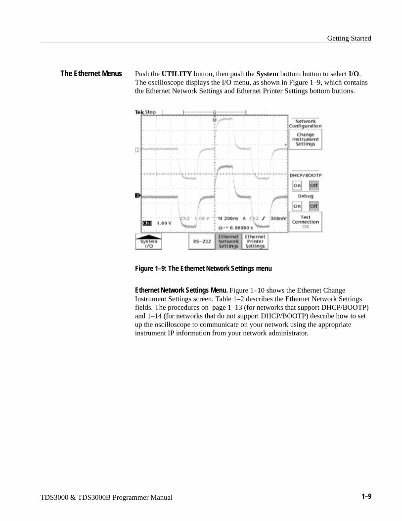
Push the UTILITY button, then push the System bottom button to select I/O.The oscilloscope displays the I/O menu, as shown in Figure 1–9, which containsthe Ethernet Network Settings and Ethernet Printer Settings bottom buttons.
Figure 1–9: The Ethernet Network Settings menu
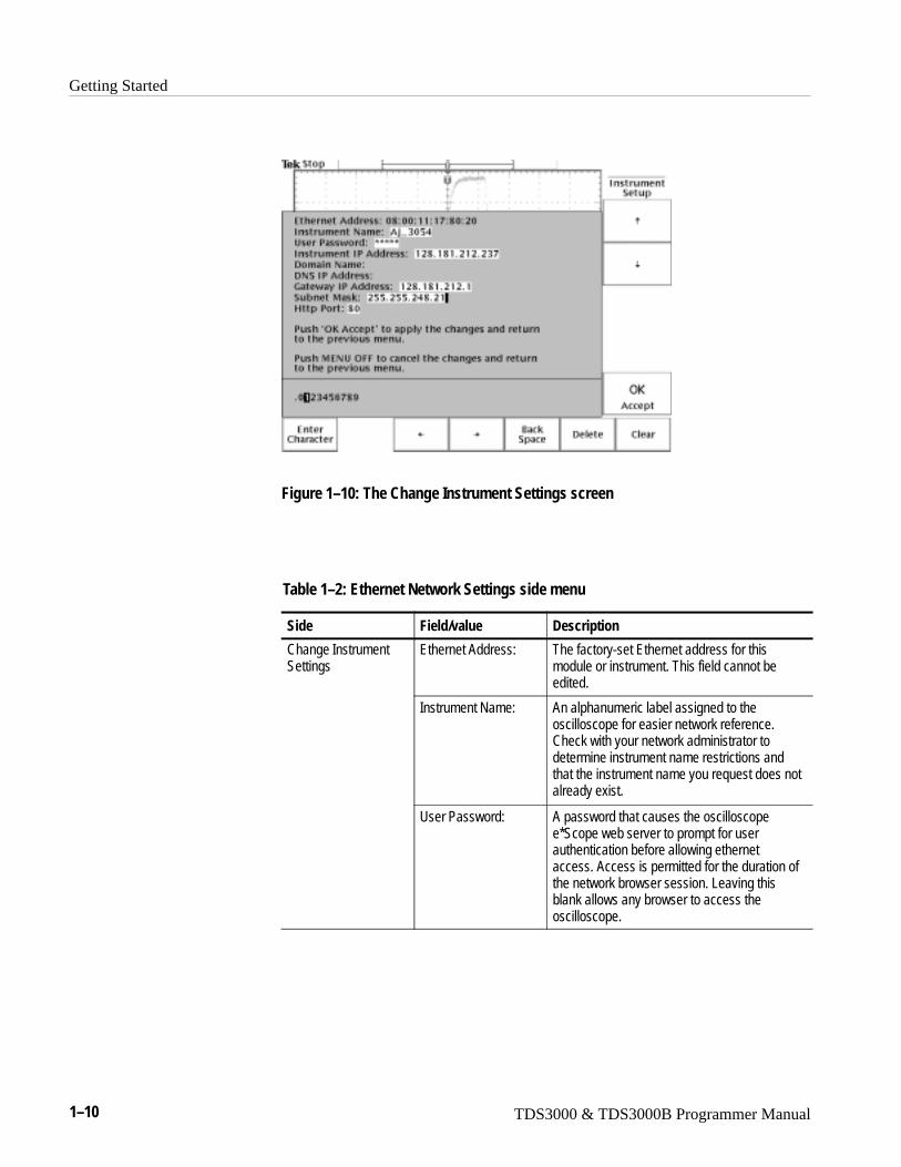
Ethernet Network Settings Menu. Figure 1–10 shows the Ethernet ChangeInstrument Settings screen. Table 1–2 describes the Ethernet Network Settingsfields. The procedures on page 1–13 (for networks that support DHCP/BOOTP)and 1–14 (for networks that do not support DHCP/BOOTP) describe how to setup the oscilloscope to communicate on your network using the appropriateinstrument IP information from your network administrator.
The Ethernet Menus
Getting Started
1–10 TDS3000 & TDS3000B Programmer Manual
Figure 1–10: The Change Instrument Settings screen
Table 1–2: Ethernet Network Settings side menu
Side Field/value Description
Change InstrumentSettings
Ethernet Address: The factory-set Ethernet address for thismodule or instrument. This field cannot beedited.
Instrument Name: An alphanumeric label assigned to theoscilloscope for easier network reference.Check with your network administrator todetermine instrument name restrictions andthat the instrument name you request does notalready exist.
User Password: A password that causes the oscilloscopee*Scope web server to prompt for userauthentication before allowing ethernetaccess. Access is permitted for the duration ofthe network browser session. Leaving thisblank allows any browser to access theoscilloscope.
Getting Started
TDS3000 & TDS3000B Programmer Manual 1–11
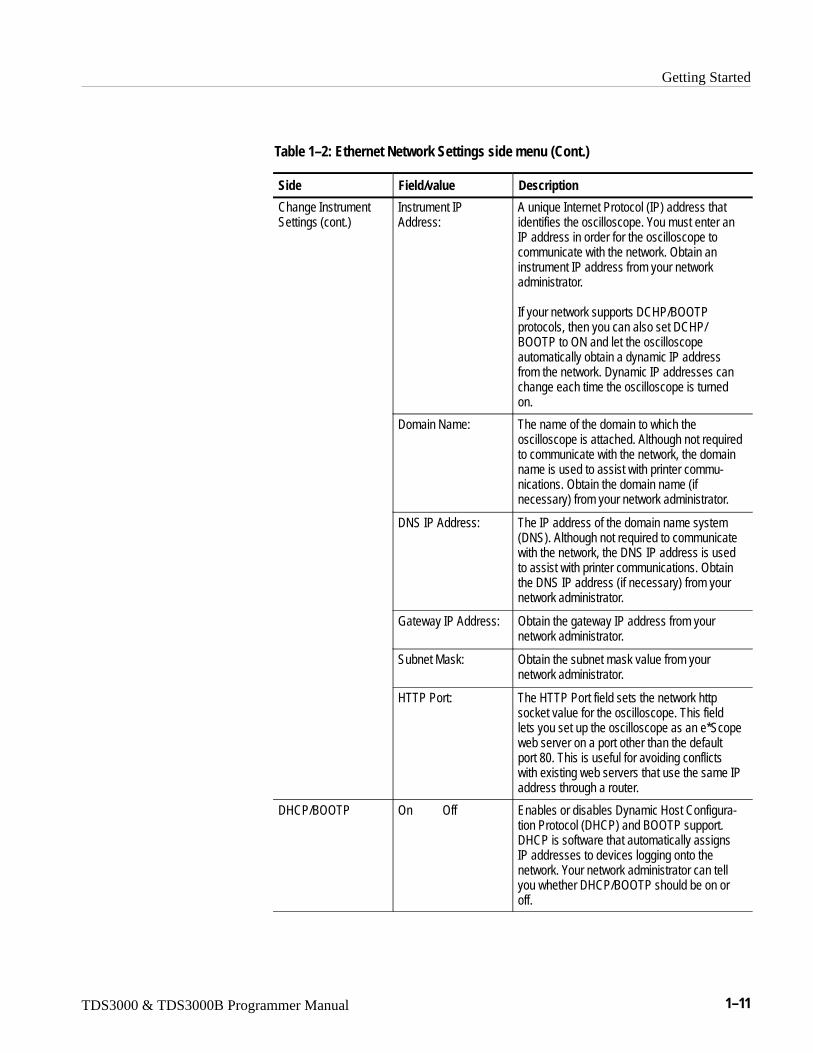
Table 1–2: Ethernet Network Settings side menu (Cont.)
Side DescriptionField/value
Change InstrumentSettings (cont.)
Instrument IP Address:
A unique Internet Protocol (IP) address thatidentifies the oscilloscope. You must enter anIP address in order for the oscilloscope tocommunicate with the network. Obtain aninstrument IP address from your networkadministrator.
If your network supports DCHP/BOOTPprotocols, then you can also set DCHP/BOOTP to ON and let the oscilloscopeautomatically obtain a dynamic IP addressfrom the network. Dynamic IP addresses canchange each time the oscilloscope is turnedon.
Domain Name: The name of the domain to which theoscilloscope is attached. Although not requiredto communicate with the network, the domainname is used to assist with printer commu-nications. Obtain the domain name (ifnecessary) from your network administrator.
DNS IP Address: The IP address of the domain name system(DNS). Although not required to communicatewith the network, the DNS IP address is usedto assist with printer communications. Obtainthe DNS IP address (if necessary) from yournetwork administrator.
Gateway IP Address: Obtain the gateway IP address from yournetwork administrator.
Subnet Mask: Obtain the subnet mask value from yournetwork administrator.
HTTP Port: The HTTP Port field sets the network httpsocket value for the oscilloscope. This fieldlets you set up the oscilloscope as an e*Scopeweb server on a port other than the defaultport 80. This is useful for avoiding conflictswith existing web servers that use the same IPaddress through a router.
DHCP/BOOTP On Off Enables or disables Dynamic Host Configura-tion Protocol (DHCP) and BOOTP support.DHCP is software that automatically assignsIP addresses to devices logging onto thenetwork. Your network administrator can tellyou whether DHCP/BOOTP should be on oroff.
Getting Started
1–12 TDS3000 & TDS3000B Programmer Manual
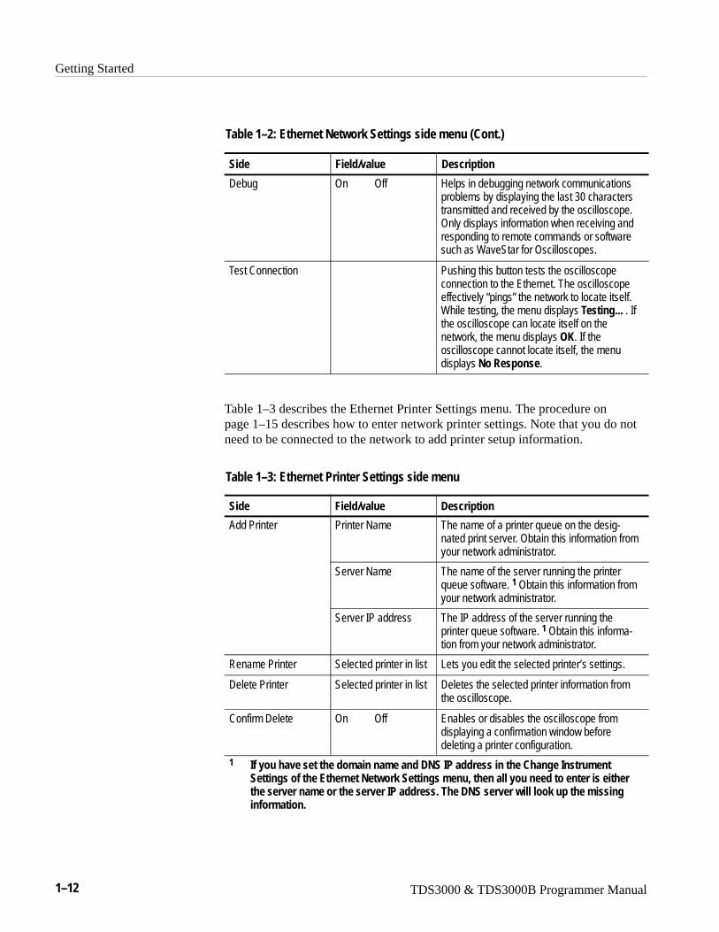
Table 1–2: Ethernet Network Settings side menu (Cont.)
Side DescriptionField/value
Debug On Off Helps in debugging network communicationsproblems by displaying the last 30 characterstransmitted and received by the oscilloscope.Only displays information when receiving andresponding to remote commands or softwaresuch as WaveStar for Oscilloscopes.
Test Connection Pushing this button tests the oscilloscopeconnection to the Ethernet. The oscilloscopeeffectively “pings” the network to locate itself.While testing, the menu displays Testing... . Ifthe oscilloscope can locate itself on thenetwork, the menu displays OK. If theoscilloscope cannot locate itself, the menudisplays No Response.
Table 1–3 describes the Ethernet Printer Settings menu. The procedure onpage 1–15 describes how to enter network printer settings. Note that you do notneed to be connected to the network to add printer setup information.
Table 1–3: Ethernet Printer Settings side menu
Side Field/value Description
Add Printer Printer Name The name of a printer queue on the desig-nated print server. Obtain this information fromyour network administrator.
Server Name The name of the server running the printerqueue software. 1 Obtain this information fromyour network administrator.
Server IP address The IP address of the server running theprinter queue software. 1 Obtain this informa-tion from your network administrator.
Rename Printer Selected printer in list Lets you edit the selected printer’s settings.
Delete Printer Selected printer in list Deletes the selected printer information fromthe oscilloscope.
Confirm Delete On Off Enables or disables the oscilloscope fromdisplaying a confirmation window beforedeleting a printer configuration.
1 If you have set the domain name and DNS IP address in the Change InstrumentSettings of the Ethernet Network Settings menu, then all you need to enter is eitherthe server name or the server IP address. The DNS server will look up the missinginformation.
Getting Started
TDS3000 & TDS3000B Programmer Manual 1–13
You need to set two types of Ethernet parameters for the oscilloscope; theoscilloscope IP address and one or more remote printer addresses. The oscillo-scope IP address uniquely identifies the oscilloscope to other devices on thenetwork, and is required for the oscilloscope to communicate over the network.
The remote printer addresses enable you to send hard copy printouts to aspecified network printer. You can store multiple network printer configurations.
Ethernet Network Settings: DHCP/BOOTP supported. The purpose of a DHCP(Dynamic Host Configuration Protocol) or BOOTP (Boot Protocol) server is toissue an IP address to a network device that requests an address. The IP addressenables that device to communicate with the network. This is similar to thepersonal computer Plug&Play concept.
The following procedure presumes that you have installed the TDS3EMCommunication Module and cable into a TDS3000 Series oscilloscope.TDS3000B Series simply requires a RJ-45 connector with 10BaseT cableattached to the oscilloscope Ethernet port.
If your network supports DHCP/BOOTP, do these steps:
1. Power on the oscilloscope.
2. Push the UTILITY front panel button.
3. Push the System screen button to select I/O.
4. Push the Ethernet Network Settings screen button.
5. Push the Change Instrument Settings side button to display the InstrumentSetup dialog box.
6. Push the DHCP/BOOTP side button to select On. The screen displays theclock icon while it is talking with the network to obtain an IP address for theoscilloscope. This step should only take a few moments, but the actual timewill vary depending on your network. The clock icon disappears when thetask is finished.
To verify that the network assigned an IP address to the oscilloscope, pushthe Change Instrument Settings side button to display the oscilloscopeEthernet settings. The instrument IP address field should now be filled in.
If the instrument IP address field is blank, then the oscilloscope was not ableto obtain an IP address from the network. Contact your network administra-tor for help.
Setting the OscilloscopeEthernet Parameters
Getting Started
1–14 TDS3000 & TDS3000B Programmer Manual
NOTE. If the DHCP/BOOTP server assigns a dynamic IP address, then the valuein the Instrument IP Address field may be different each time you power on theoscilloscope. This is not a problem if you are mostly sending hard copy to anetwork printer. However, if you intend to remotely control the oscilloscope, astatic IP address is more convenient, as the oscilloscope IP address does notchange, making it easier for remote devices to access the oscilloscope.
Ethernet Network Settings: DHCP/BOOTP Not Supported. If your network does notsupport DHCP/BOOTP, you must enter the Ethernet settings manually. You canobtain these settings from your network administrator by using the form onpage 1–8.
The following procedure presumes that you have installed the TDS3EMCommunication Module and cable into a TDS3000 Series oscilloscope.TDS3000B Series oscilloscopes simply require an RJ-45 connector with10BaseT cable attached to the oscilloscope Ethernet port.
Do these steps to enter the Ethernet parameters:
1. Use the Ethernet network setup form on page 1–8 to request the necessarynetwork information from your network administrator.
2. Power on the oscilloscope.
3. Push the UTILITY front panel button.
4. Push the System screen button to select I/O.
5. Push the Ethernet Network Settings screen button.
6. Push the Change Instrument Settings side button to display the InstrumentSetup dialog box.
7. Push the side menu ↑and ↓ buttons to select a field to edit.
8. Enter the required information from the Ethernet network setup form intoeach field:
� The general purpose knob selects a character in the character list. The listof available characters changes depending on which field is selected.
� The Enter Character button enters the selected character from thecharacter list at the cursor position in the current field. You can also usethe SELECT button next to the general purpose knob to enter theselected character.
� The ← and → buttons move the cursor left or right in the current field.
Getting Started
TDS3000 & TDS3000B Programmer Manual 1–15
� The Back Space button deletes the character to the left of the cursorposition in the field.
� The Delete button deletes the character at the cursor position in the field.
� The Clear button deletes all characters from the current field.
9. Push the OK Accept side button to apply the field settings. Push the MENUOFF button to exit from the menu without applying any changes.
10. Push the Test Connection side menu button to verify that the Ethernetsettings are correct and that the oscilloscope can locate itself on the network.
11. If the oscilloscope does not establish a connection to the network, check thatyou correctly entered the Ethernet instrument settings, and that you haveconnected the oscilloscope to the Ethernet connector with an appropriate10baseT cable. If the settings and cable are correct, contact your networkadministrator for help.
Ethernet Printer Settings. This procedure presumes that you have successfullyestablished communications with the network by using one of the previousprocedures.
Do these steps to add a network printer to the oscilloscope (you can store up to21 printers in the Ethernet network printer list):
1. Obtain the printer name, server name, and server IP address of the networkprinter or printers to which you are sending hard copy data.
2. Power on the oscilloscope.
3. Push the UTILITY menu button.
4. Push the System screen button and select the I/O System.
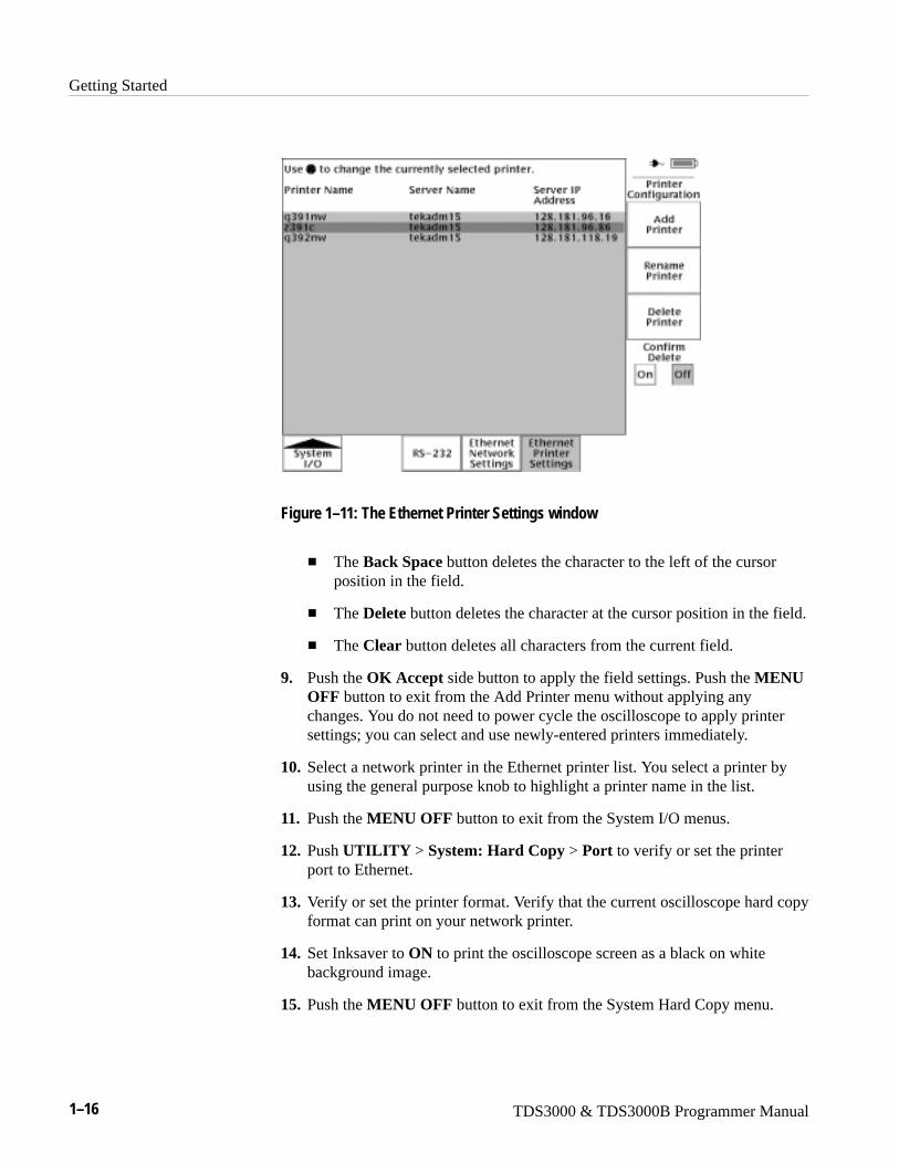
5. Push the Ethernet Printer Settings screen button. The oscilloscope displaysthe Printer Configuration window, as shown in Figure 1–11.
6. Push the Add Printer screen button to display the Add Printer dialog box.
7. Push the side menu ↑and ↓ buttons to select a field to edit.
8. Enter the required information into each field:
� The general purpose knob selects a character in the character list. The listof available characters changes depending on which field is selected.
� The Enter Character button enters the selected character from thecharacter list. You can also use the SELECT button next to the generalpurpose knob to enter the selected character.
� The ← and → buttons move the cursor left or right in the current field.
Getting Started
1–16 TDS3000 & TDS3000B Programmer Manual
Figure 1–11: The Ethernet Printer Settings window
� The Back Space button deletes the character to the left of the cursorposition in the field.
� The Delete button deletes the character at the cursor position in the field.
� The Clear button deletes all characters from the current field.
9. Push the OK Accept side button to apply the field settings. Push the MENUOFF button to exit from the Add Printer menu without applying anychanges. You do not need to power cycle the oscilloscope to apply printersettings; you can select and use newly-entered printers immediately.
10. Select a network printer in the Ethernet printer list. You select a printer byusing the general purpose knob to highlight a printer name in the list.
11. Push the MENU OFF button to exit from the System I/O menus.
12. Push UTILITY > System: Hard Copy > Port to verify or set the printerport to Ethernet.
13. Verify or set the printer format. Verify that the current oscilloscope hard copyformat can print on your network printer.
14. Set Inksaver to ON to print the oscilloscope screen as a black on whitebackground image.
15. Push the MENU OFF button to exit from the System Hard Copy menu.
Getting Started
TDS3000 & TDS3000B Programmer Manual 1–17
16. Test the network printer by pressing the hard copy button. The printer shouldprint the current screen. If the printer does not print the screen, check thefollowing:
� Hard copy port is set to Ethernet.
� Hard copy file format is compatible with the network printer.
� The printer IP and server information you entered is correct.
� The network printer is powered on and is online.
17. To print to a different network printer, push UTILITY > System: I/O >Ethernet Printer Settings, and use the general purpose knob to select anetwork printer. Make sure that you also set/verify the hard copy file formatwhen you change network printers.
The following error conditions can occur when you are having networkproblems. Read the text that follows to help rectify the problem.
Print Server Not Responding. This notifier displays when the oscilloscopeattempts to send data to the selected network printer but the network refuses theconnection to the network printer. This usually means that the network printerserver is offline or the print server IP address is incorrect.
If DNS is available then you can verify the network print server data by enteringthe printer name and either (but not both) the print server name or the IP address.The DNS protocol will fill in the missing data if the user-supplied data is correct.
If DNS is not available, then contact your network administrator for help.
Printer Not Responding. This notifier displays when the oscilloscope attempts tosend data to the selected network printer but the print server is unable to forwardthe data to the network printer. This usually means that the network printer isoffline or the printer name is incorrect. Contact your network administrator toobtain the correct printer queue name.
DNS Server Not responding. This notifier displays when either the Domaininformation (Domain name or IP address) is not correct, or the print server nameor printer server IP address is not validated (via the Domain Name Server).
You enable DNS protocol by entering the DNS IP address and the domain nameusing the Ethernet Network Setup menu. DNS enables the oscilloscope to querythe network for either the name of a device with a specified IP address, or the IPaddress of a named device. DNS fills in missing settings when you enter partialprinter configuration information.
Ethernet Error Messages
DNS Protocol
Getting Started
1–18 TDS3000 & TDS3000B Programmer Manual
The VISA standard, developed by the VXI plug&play Systems Alliance,provides a common Input/Output (I/O) library for software developers so thatsoftware from different vendors can run on the same platform. All applicationsthat communicate with the Ethernet must use the Tektronix version of VISA,referred to in this document as TekVisa. TekVisa must be installed and config-ured on each PC that communicates with Ethernet. The TekVisa software is partof the Tektronix Software Solutions CD that came with this product.
NOTE. If you are connecting the oscilloscope to a network just to print screenhard copy data, or if you are using e*Scope capabilities in a browser, you do notneed to install or configure TekVisa software.
The following sections describe how to install and configure the TekVisasoftware on a PC.
Installing TekVisa for Ethernet. Do the following steps to install TekVisa softwarefor Ethernet communications:
NOTE. If you already installed TekVisa while installing the WaveStar softwareversion 2.3, using the default settings for Standard or Custom Version installa-tions, you do not need to install the Ethernet TekVisa software; it is the samesoftware. However, if you selected Custom Version as part of your WaveStarinstallation, and deselected the VXI-11 option, you need to reinstall the TekVisasoftware.
If you have installed TekVisa from an earlier version of WaveStar Software forOscilloscopes, please reinstall TekVisa from the Tektronix Software Solutions CDthat came with this product.
1. Insert the WaveStar CD-ROM into the CD-ROM drive. The mainWaveStar installation screen appears, with four tabs along the top. If theWaveStar installation screen does not display automatically, run ��������������, where X is the CD drive letter.
2. Select the TDS3EM tab. The installer opens the Ethernet information screenwith a menu bar the top of the installer screen.
3. Select Install in the menu bar to install TekVisa software. The installationwizard appears next and walks you through the rest of the installationprocess. Follow the instructions in the installation wizard.
Ethernet, VISA, andTekVisa
Getting Started
TDS3000 & TDS3000B Programmer Manual 1–19
Included with the TekVisa installation is the Visa configuration utility, which letsyou add or remove network hosts (instruments). Once the instrument is added tothe TekVisa configuration, you can communicate with the instrument by usingWaveStar’s Instrument Manager program or a proprietary software program.
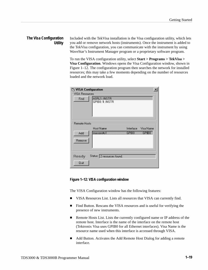
To run the VISA configuration utility, select Start > Programs > TekVisa >Visa Configuration. Windows opens the Visa Configuration window, shown inFigure 1–12. The configuration program then searches the network for installedresources; this may take a few moments depending on the number of resourcesloaded and the network load.
Figure 1–12: VISA configuration window
The VISA Configuration window has the following features:
� VISA Resources List. Lists all resources that VISA can currently find.
� Find Button. Rescans the VISA resources and is useful for verifying thepresence of new instruments.
� Remote Hosts List. Lists the currently configured name or IP address of theremote host. Interface is the name of the interface on the remote host(Tektronix Visa uses GPIB0 for all Ethernet interfaces). Visa Name is theresource name used when this interface is accessed through VISA.
� Add Button. Activates the Add Remote Host Dialog for adding a remoteinterface.
The Visa ConfigurationUtility
Getting Started
1–20 TDS3000 & TDS3000B Programmer Manual
� Remove Button. Removes the host selected in the Remote Hosts list anddisplays the dialog box for before removing the host.
NOTE. Always remove host information for any equipment no longer connectedto the network in order to reduce the VISA instrument search time. Searching forunconnected instruments drastically increases the time it takes to locate andconnect to an instrument.
� Status Displays. The status box displays helpful information about the lastoperation performed. The Busy / Ready indicator shows when the utility isbusy. When the utility is busy, changes cannot be made.
� Quit Button. Quits the application.
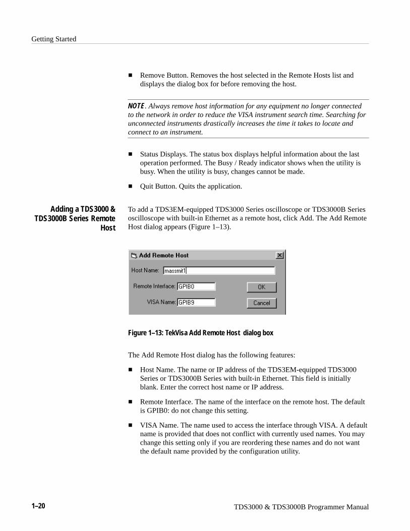
To add a TDS3EM-equipped TDS3000 Series oscilloscope or TDS3000B Seriesoscilloscope with built-in Ethernet as a remote host, click Add. The Add RemoteHost dialog appears (Figure 1–13).
Figure 1–13: TekVisa Add Remote Host dialog box
The Add Remote Host dialog has the following features:
� Host Name. The name or IP address of the TDS3EM-equipped TDS3000Series or TDS3000B Series with built-in Ethernet. This field is initiallyblank. Enter the correct host name or IP address.
� Remote Interface. The name of the interface on the remote host. The defaultis GPIB0: do not change this setting.
� VISA Name. The name used to access the interface through VISA. A defaultname is provided that does not conflict with currently used names. You maychange this setting only if you are reordering these names and do not wantthe default name provided by the configuration utility.
Adding a TDS3000 &TDS3000B Series Remote
Host
Getting Started
TDS3000 & TDS3000B Programmer Manual 1–21
� OK Button. Adds the host (as configured) to VISA. If the Add fails, amessage displays and the dialog remains open. If the Add succeeds, thedialog closes and a Find operation updates the main window.
� Cancel Button. Closes the dialog with no changes.
To add a remote host, do these steps:
1. In the Add Remote Host dialog, enter the host name or IP address of the newinterface. The setting for Remote Interfaces must remain at the default(GPIB0). The VISA name can remain at the default as well. The indicatedvalue (for example, GPIB12) is the name that refers to this GPIB interfacethrough VISA.
2. Click OK. The new interface appears in the Remote Hosts box. If theTDS3EM-equipped TDS3000 Series or TDS3000B Series with built-inEthernet is running and configured, the instrument name appears in theResources Box.
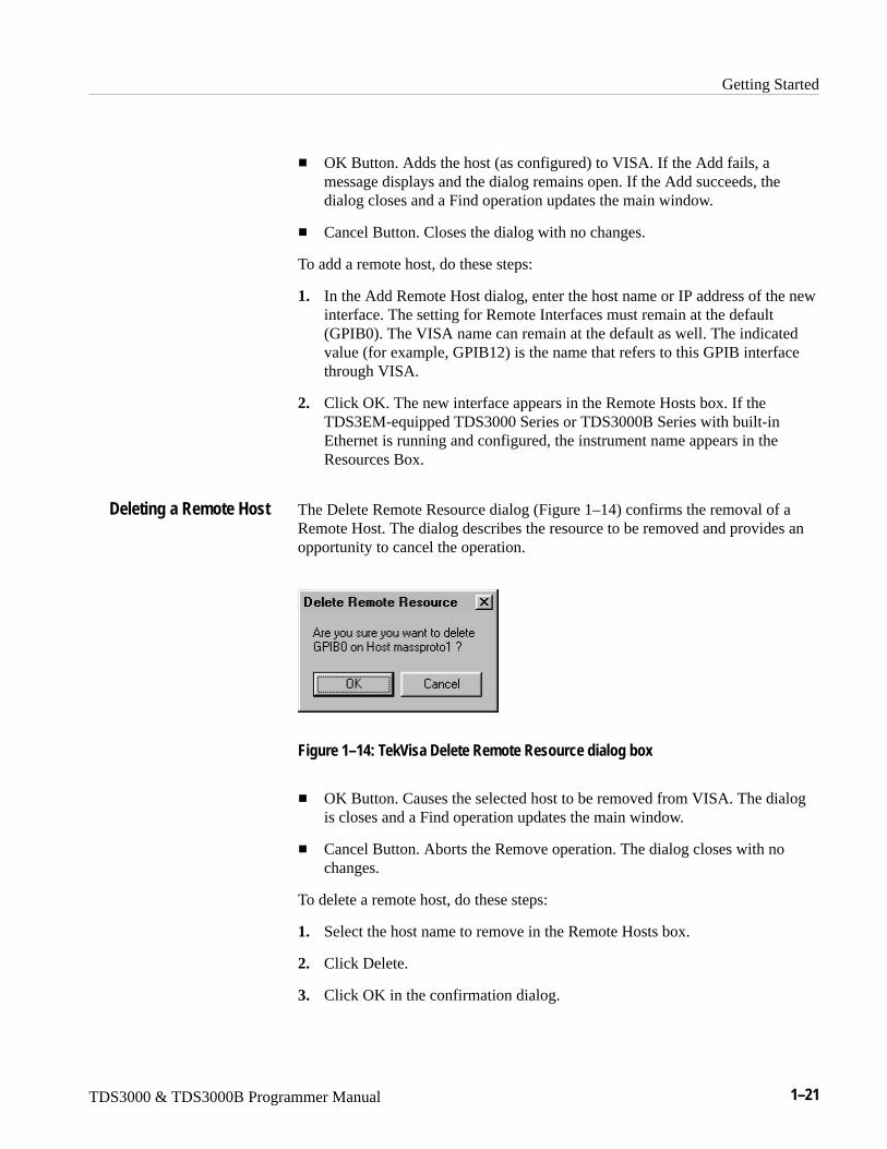
The Delete Remote Resource dialog (Figure 1–14) confirms the removal of aRemote Host. The dialog describes the resource to be removed and provides anopportunity to cancel the operation.
Figure 1–14: TekVisa Delete Remote Resource dialog box
� OK Button. Causes the selected host to be removed from VISA. The dialogis closes and a Find operation updates the main window.
� Cancel Button. Aborts the Remove operation. The dialog closes with nochanges.
To delete a remote host, do these steps:
1. Select the host name to remove in the Remote Hosts box.
2. Click Delete.
3. Click OK in the confirmation dialog.
Deleting a Remote Host
Getting Started
1–22 TDS3000 & TDS3000B Programmer Manual
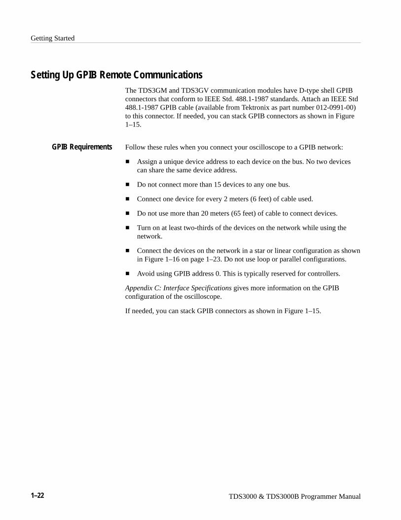
Setting Up GPIB Remote CommunicationsThe TDS3GM and TDS3GV communication modules have D-type shell GPIBconnectors that conform to IEEE Std. 488.1-1987 standards. Attach an IEEE Std488.1-1987 GPIB cable (available from Tektronix as part number 012-0991-00)to this connector. If needed, you can stack GPIB connectors as shown in Figure1–15.
Follow these rules when you connect your oscilloscope to a GPIB network:
� Assign a unique device address to each device on the bus. No two devicescan share the same device address.
� Do not connect more than 15 devices to any one bus.
� Connect one device for every 2 meters (6 feet) of cable used.
� Do not use more than 20 meters (65 feet) of cable to connect devices.
� Turn on at least two-thirds of the devices on the network while using thenetwork.
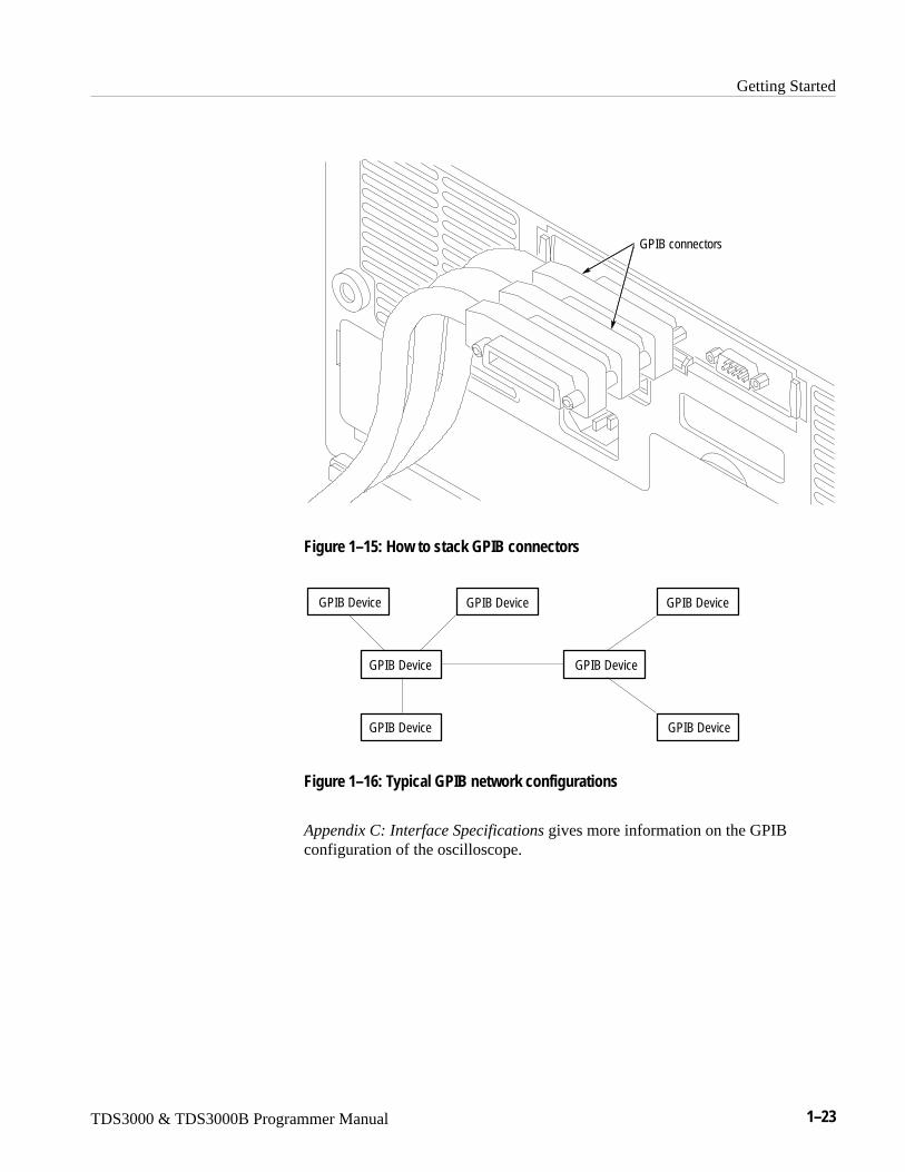
� Connect the devices on the network in a star or linear configuration as shownin Figure 1–16 on page 1–23. Do not use loop or parallel configurations.
� Avoid using GPIB address 0. This is typically reserved for controllers.
Appendix C: Interface Specifications gives more information on the GPIBconfiguration of the oscilloscope.
If needed, you can stack GPIB connectors as shown in Figure 1–15.
GPIB Requirements
Getting Started
TDS3000 & TDS3000B Programmer Manual 1–23
GPIB connectors
Figure 1–15: How to stack GPIB connectors
GPIB Device
GPIB Device
GPIB Device
GPIB Device
GPIB Device
GPIB Device
GPIB Device
Figure 1–16: Typical GPIB network configurations
Appendix C: Interface Specifications gives more information on the GPIBconfiguration of the oscilloscope.
Getting Started
1–24 TDS3000 & TDS3000B Programmer Manual
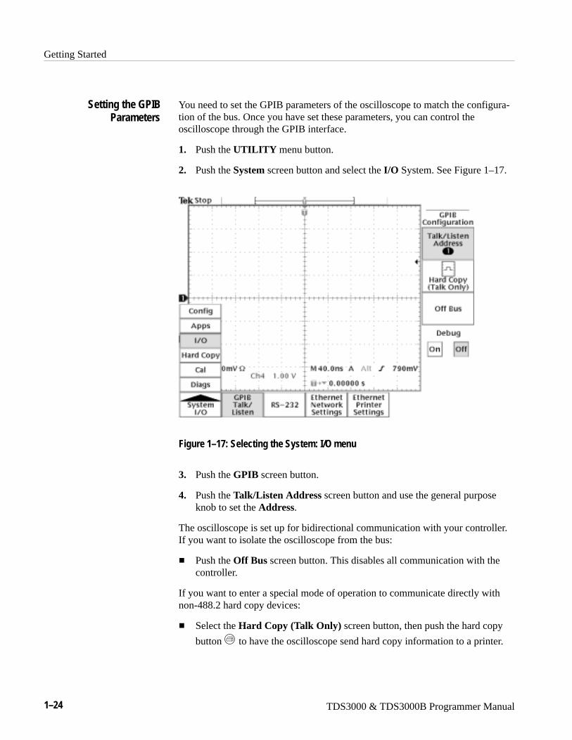
You need to set the GPIB parameters of the oscilloscope to match the configura-tion of the bus. Once you have set these parameters, you can control theoscilloscope through the GPIB interface.
1. Push the UTILITY menu button.
2. Push the System screen button and select the I/O System. See Figure 1–17.
Figure 1–17: Selecting the System: I/O menu
3. Push the GPIB screen button.
4. Push the Talk/Listen Address screen button and use the general purposeknob to set the Address.
The oscilloscope is set up for bidirectional communication with your controller.If you want to isolate the oscilloscope from the bus:
� Push the Off Bus screen button. This disables all communication with thecontroller.
If you want to enter a special mode of operation to communicate directly withnon-488.2 hard copy devices:
� Select the Hard Copy (Talk Only) screen button, then push the hard copy
button to have the oscilloscope send hard copy information to a printer.
Setting the GPIBParameters
Getting Started
TDS3000 & TDS3000B Programmer Manual 1–25
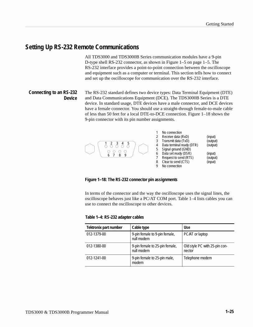
Setting Up RS-232 Remote CommunicationsAll TDS3000 and TDS3000B Series communication modules have a 9-pinD-type shell RS-232 connector, as shown in Figure 1–5 on page 1–5. TheRS-232 interface provides a point-to-point connection between the oscilloscopeand equipment such as a computer or terminal. This section tells how to connectand set up the oscilloscope for communication over the RS-232 interface.
The RS-232 standard defines two device types: Data Terminal Equipment (DTE)and Data Communications Equipment (DCE). The TDS3000B Series is a DTEdevice. In standard usage, DTE devices have a male connector, and DCE deviceshave a female connector. You should use a straight-through female-to-male cableof less than 50 feet for a local DTE-to-DCE connection. Figure 1–18 shows the9-pin connector with its pin number assignments.
1 No connection2 Receive data (RxD) (input)3 Transmit data (TxD) (output)4 Data terminal ready (DTR) (output)5 Signal ground (GND)6 Data set ready (DSR) (input)7 Request to send (RTS) (output)8 Clear to send (CTS) (input)9 No connection
1 2 3 4 5
6 7 8 9
Figure 1–18: The RS-232 connector pin assignments
In terms of the connector and the way the oscilloscope uses the signal lines, theoscilloscope behaves just like a PC/AT COM port. Table 1–4 lists cables you canuse to connect the oscilloscope to other devices.
Table 1–4: RS-232 adapter cables
Tektronix part number Cable type Use
012-1379-00 9-pin female to 9-pin female,null modem
PC/AT or laptop
012-1380-00 9-pin female to 25-pin female,null modem
Old style PC with 25-pin con-nector
012-1241-00 9-pin female to 25-pin male,modem
Telephone modem
Connecting to an RS-232Device
Getting Started
1–26 TDS3000 & TDS3000B Programmer Manual
Follow these guidelines when connecting the oscilloscope to another RS-232device:
� Do not connect the output line of one DTE device to the output line ofanother DTE device.
� Connect the signal ground of the oscilloscope to the signal ground of theexternal device.
� Connect the chassis ground of the oscilloscope to the chassis ground of theexternal device.
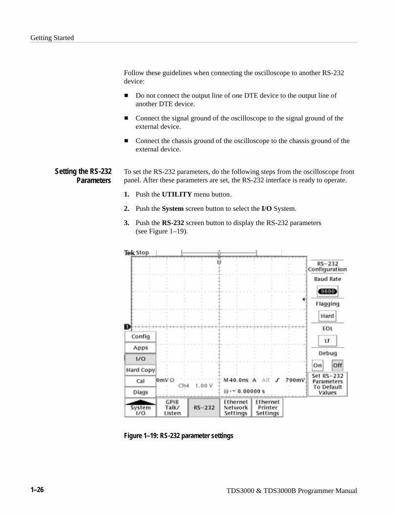
To set the RS-232 parameters, do the following steps from the oscilloscope frontpanel. After these parameters are set, the RS-232 interface is ready to operate.
1. Push the UTILITY menu button.
2. Push the System screen button to select the I/O System.
3. Push the RS-232 screen button to display the RS-232 parameters (see Figure 1–19).
Figure 1–19: RS-232 parameter settings
Setting the RS-232Parameters
Getting Started
TDS3000 & TDS3000B Programmer Manual 1–27
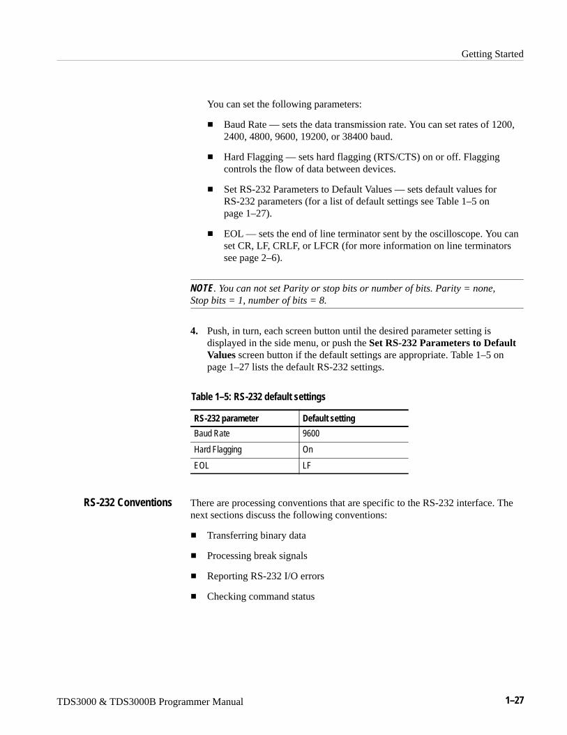
You can set the following parameters:
� Baud Rate — sets the data transmission rate. You can set rates of 1200,2400, 4800, 9600, 19200, or 38400 baud.
� Hard Flagging — sets hard flagging (RTS/CTS) on or off. Flaggingcontrols the flow of data between devices.
� Set RS-232 Parameters to Default Values — sets default values forRS-232 parameters (for a list of default settings see Table 1–5 onpage 1–27).
� EOL — sets the end of line terminator sent by the oscilloscope. You canset CR, LF, CRLF, or LFCR (for more information on line terminatorssee page 2–6).
NOTE. You can not set Parity or stop bits or number of bits. Parity = none,Stop bits = 1, number of bits = 8.
4. Push, in turn, each screen button until the desired parameter setting isdisplayed in the side menu, or push the Set RS-232 Parameters to DefaultValues screen button if the default settings are appropriate. Table 1–5 onpage 1–27 lists the default RS-232 settings.
Table 1–5: RS-232 default settings
RS-232 parameter Default setting
Baud Rate 9600
Hard Flagging On
EOL LF
There are processing conventions that are specific to the RS-232 interface. Thenext sections discuss the following conventions:
� Transferring binary data
� Processing break signals
� Reporting RS-232 I/O errors
� Checking command status
RS-232 Conventions
Getting Started
1–28 TDS3000 & TDS3000B Programmer Manual
Transferring Binary Data. When using the RS-232 port to transfer binary data tothe oscilloscope, note the following points:
� Using RTS/CTS (hard) flagging guarantees no data loss.
� All eight bits of binary data contain meaningful information. To make surethat all eight bits are received or transmitted, configure the RS-232 devicethat is connected to the oscilloscope to receive and transmit eight-bitcharacters (set the RS-232 word length to eight bits).
Processing Break Signals. When the oscilloscope senses a break signal on theRS-232 port, it returns DCL followed by the end of line terminator. Internally,the oscilloscope acts as if it received a GPIB <DCL> command, causing theoscilloscope to flush input and output buffers and then wait for a new command.Break signals do not change oscilloscope settings or stored data and do notinterrupt front-panel operation or nonprogrammable functions.
If a break signal is sent in the middle of a character stream, several charactersimmediately preceding or following the break may be lost. The controller shouldwait until it receives the DCL and the end of line terminator string beforesending more characters.
Reporting RS-232 I/O Errors. Errors are reported when there is a problem withframing, or input buffer overruns. To report errors, the oscilloscope posts anevent code (refer to Section 3, Status and Events on page 3–1). When an erroroccurs, the oscilloscope discards all input and output and waits for a newcommand. A count of these errors since last power on is included in RS-232 I/ODebug status.
Push UTILITY screen button, select I/O, select RS-232, then Debug menu toenable the debug window to see the RS-232 status, errors data transmitted, anddata received.
Use the following statements to help you interpret the status reported in the errorlog:
� If hard flagging is on and CTS is Low, the oscilloscope will not transmit anydata.
� If hard flagging is off, you should ignore the value of CTS since theoscilloscope ignores it.
The RS232 Errors line of the error log lists the number of framing and overrunerrors since the last power on.
Checking Command Status. If you want to check the status of each commandsent, you can append a *STB? query after every command and read the responsestring.
Getting Started
TDS3000 & TDS3000B Programmer Manual 1–29
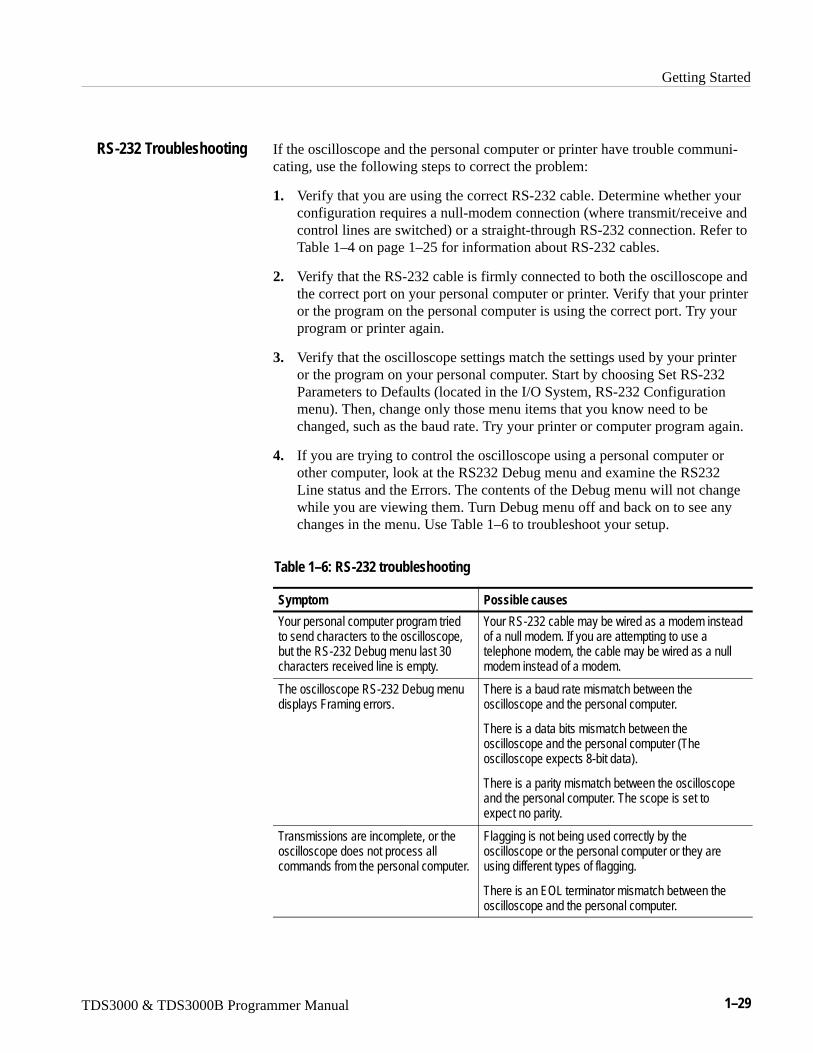
If the oscilloscope and the personal computer or printer have trouble communi-cating, use the following steps to correct the problem:
1. Verify that you are using the correct RS-232 cable. Determine whether yourconfiguration requires a null-modem connection (where transmit/receive andcontrol lines are switched) or a straight-through RS-232 connection. Refer toTable 1–4 on page 1–25 for information about RS-232 cables.
2. Verify that the RS-232 cable is firmly connected to both the oscilloscope andthe correct port on your personal computer or printer. Verify that your printeror the program on the personal computer is using the correct port. Try yourprogram or printer again.
3. Verify that the oscilloscope settings match the settings used by your printeror the program on your personal computer. Start by choosing Set RS-232Parameters to Defaults (located in the I/O System, RS-232 Configurationmenu). Then, change only those menu items that you know need to bechanged, such as the baud rate. Try your printer or computer program again.
4. If you are trying to control the oscilloscope using a personal computer orother computer, look at the RS232 Debug menu and examine the RS232Line status and the Errors. The contents of the Debug menu will not changewhile you are viewing them. Turn Debug menu off and back on to see anychanges in the menu. Use Table 1–6 to troubleshoot your setup.
Table 1–6: RS-232 troubleshooting
Symptom Possible causes
Your personal computer program triedto send characters to the oscilloscope,but the RS-232 Debug menu last 30characters received line is empty.
Your RS-232 cable may be wired as a modem insteadof a null modem. If you are attempting to use atelephone modem, the cable may be wired as a nullmodem instead of a modem.
The oscilloscope RS-232 Debug menudisplays Framing errors.
There is a baud rate mismatch between theoscilloscope and the personal computer.
There is a data bits mismatch between theoscilloscope and the personal computer (Theoscilloscope expects 8-bit data).
There is a parity mismatch between the oscilloscopeand the personal computer. The scope is set toexpect no parity.
Transmissions are incomplete, or theoscilloscope does not process allcommands from the personal computer.
Flagging is not being used correctly by theoscilloscope or the personal computer or they areusing different types of flagging.
There is an EOL terminator mismatch between theoscilloscope and the personal computer.
RS-232 Troubleshooting
Getting Started
1–30 TDS3000 & TDS3000B Programmer Manual
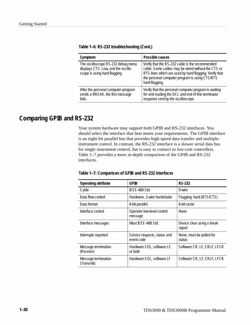
Table 1–6: RS-232 troubleshooting (Cont.)
Symptom Possible causes
The oscilloscope RS-232 debug menudisplays CTS: Low, and the oscillo-scope is using hard flagging.
Verify that the RS-232 cable is the recommendedcable. Some cables may be wired without the CTS orRTS lines which are used by hard flagging. Verify thatthe personal computer program is using CTS/RTShard flagging.
After the personal computer programsends a BREAK, the first messagefails.
Verify that the personal computer program is waitingfor and reading the DCL and end of line terminatorresponse sent by the oscilloscope.
Comparing GPIB and RS-232Your system hardware may support both GPIB and RS-232 interfaces. Youshould select the interface that best meets your requirements. The GPIB interfaceis an eight-bit parallel bus that provides high-speed data transfer and multiple-instrument control. In contrast, the RS-232 interface is a slower serial data busfor single instrument control, but is easy to connect to low-cost controllers. Table 1–7 provides a more in-depth comparison of the GPIB and RS-232interfaces.
Table 1–7: Comparison of GPIB and RS-232 interfaces
Operating attribute GPIB RS-232
Cable IEEE-488 Std. 9-wire
Data flow control Hardware, 3-wire handshake Flagging: hard (RTS/CTS)
Data format 8-bit parallel 8-bit serial
Interface control Operator low-level controlmessage
None
Interface messages Most IEEE-488 Std. Device clear using a breaksignal
Interrupts reported Service requests, status andevent code
None, must be polled forstatus
Message termination(Receive)
Hardware EOL, software LF,or both
Software CR, LF, CRLF, LFCR
Message termination(Transmit)
Hardware EOL, software LF Software CR, LF, CRLF, LFCR
Getting Started
TDS3000 & TDS3000B Programmer Manual 1–31
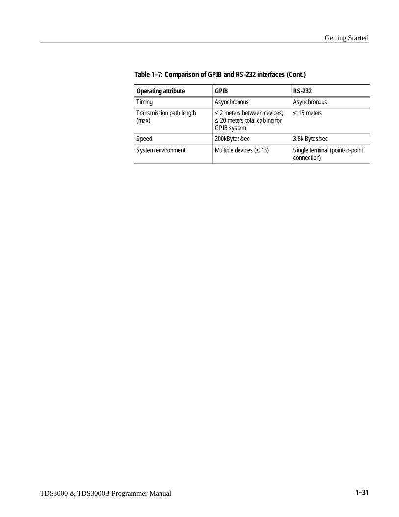
Table 1–7: Comparison of GPIB and RS-232 interfaces (Cont.)
Operating attribute RS-232GPIB
Timing Asynchronous Asynchronous
Transmission path length(max)
≤ 2 meters between devices;≤ 20 meters total cabling forGPIB system
≤ 15 meters
Speed 200kBytes/sec 3.8k Bytes/sec
System environment Multiple devices (≤ 15) Single terminal (point-to-pointconnection)

Getting Started
1–32 TDS3000 & TDS3000B Programmer Manual
TDS3000 & TDS3000B Programmer Manual 2–1
Command Syntax
You can control the oscilloscope through the GPIB interface using commandsand queries. This section describes the syntax these commands and queries use.It also describes the conventions the oscilloscope uses to process them. The nextsection, entitled Command Groups, lists the commands and queries themselves.
You transmit commands to the oscilloscope using the enhanced AmericanStandard Code for Information Interchange (ASCII) character encoding.Appendix A: Character Charts on page A–3 contains a chart of the ASCIIcharacter set.
This manual describes commands and queries using Backus-Naur Form (BNF)notation and syntax diagrams.
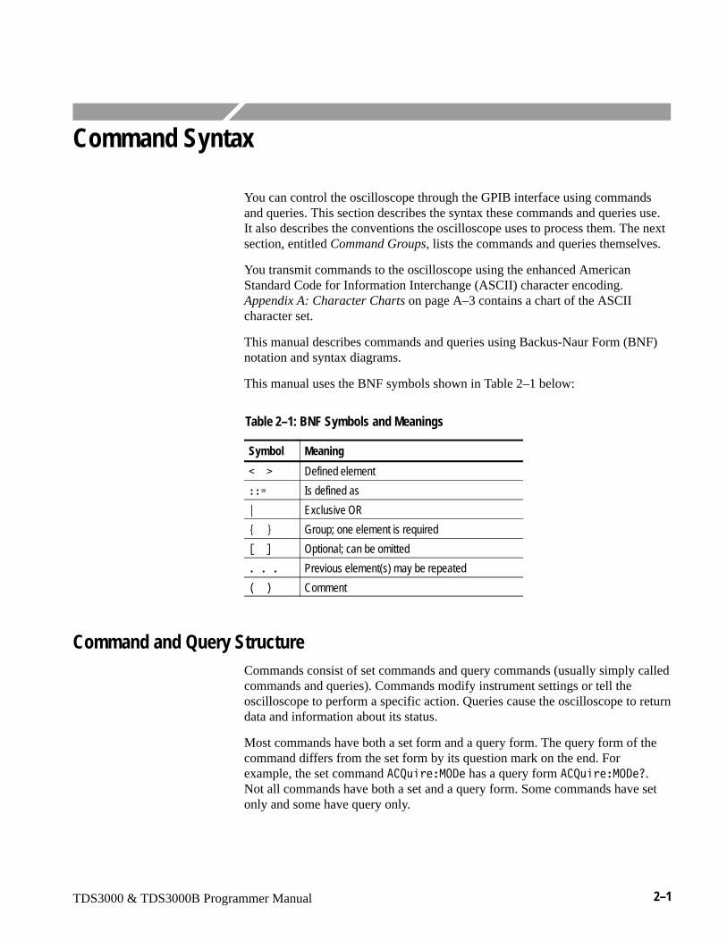
This manual uses the BNF symbols shown in Table 2–1 below:
Table 2–1: BNF Symbols and Meanings
Symbol Meaning
�� Defined element
��! Is defined as
" Exclusive OR
#�$ Group; one element is required
%�& Optional; can be omitted
�'�(� Previous element(s) may be repeated
)�* Comment
Command and Query StructureCommands consist of set commands and query commands (usually simply calledcommands and queries). Commands modify instrument settings or tell theoscilloscope to perform a specific action. Queries cause the oscilloscope to returndata and information about its status.
Most commands have both a set form and a query form. The query form of thecommand differs from the set form by its question mark on the end. Forexample, the set command � +,���-./� has a query form � +,���-./�0.Not all commands have both a set and a query form. Some commands have setonly and some have query only.
Command Syntax
2–2 TDS3000 & TDS3000B Programmer Manual
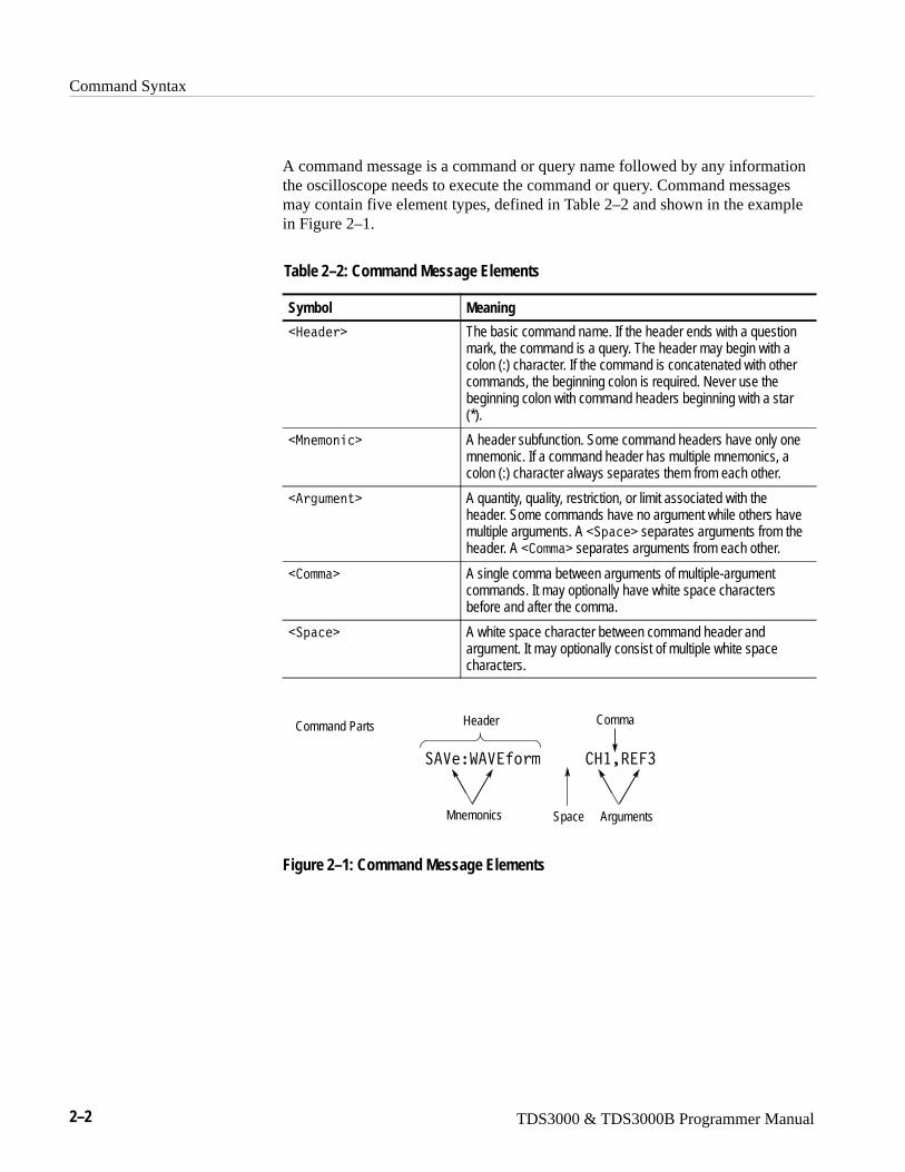
A command message is a command or query name followed by any informationthe oscilloscope needs to execute the command or query. Command messagesmay contain five element types, defined in Table 2–2 and shown in the examplein Figure 2–1.
Table 2–2: Command Message Elements
Symbol Meaning
����1� The basic command name. If the header ends with a questionmark, the command is a query. The header may begin with acolon (:) character. If the command is concatenated with othercommands, the beginning colon is required. Never use thebeginning colon with command headers beginning with a star(*).
�-�����2 A header subfunction. Some command headers have only onemnemonic. If a command header has multiple mnemonics, acolon (:) character always separates them from each other.
��3,���� A quantity, quality, restriction, or limit associated with theheader. Some commands have no argument while others havemultiple arguments. A ��4�2� separates arguments from theheader. A � ��� separates arguments from each other.
� ��� A single comma between arguments of multiple-argumentcommands. It may optionally have white space charactersbefore and after the comma.
��4�2� A white space character between command header andargument. It may optionally consist of multiple white spacecharacters.
Comma
���������������� �������
Header
Mnemonics ArgumentsSpace
Command Parts
Figure 2–1: Command Message Elements
Command Syntax
TDS3000 & TDS3000B Programmer Manual 2–3
Commands have the structure:
%�&����1� %��4�2� ��3,���� %� ��� ��3,���� &���&
A command header consists of one or more mnemonics arranged in a hierarchi-cal or tree structure. The first mnemonic is the base or root of the tree and eachsubsequent mnemonic is a level or branch off the previous one. Commands at ahigher level in the tree may affect those at a lower level. The leading colon (:)always returns you to the base of the command tree.
Queries have the structure:
� %�&����1� 0
� %�&����1� 0%��4�2� ��3,���� %� ��� ��3,���� &���&
You can specify a query command at any level within the command tree unlessotherwise noted. These branch queries return information about all the mnemon-ics below the specified branch or level. For example, 5�673�����/7���8.4�returns the rising or falling slope for the A edge trigger. 5�673�����/7�0returns the trigger coupling, source, and slope for A edge trigger. 5�673��� setsthe trigger level and returns the current A trigger parameters.
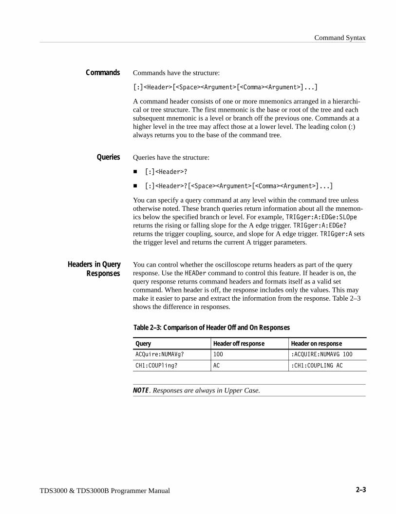
You can control whether the oscilloscope returns headers as part of the queryresponse. Use the ���/� command to control this feature. If header is on, thequery response returns command headers and formats itself as a valid setcommand. When header is off, the response includes only the values. This maymake it easier to parse and extract the information from the response. Table 2–3shows the difference in responses.
Table 2–3: Comparison of Header Off and On Responses
Query Header off response Header on response
� +,���9:-��30 �;; �� +:6���9:-��7��;;
��� .:<���30 � � ��� .:<8697��
NOTE. Responses are always in Upper Case.
Commands
Queries
Headers in QueryResponses
Command Syntax
2–4 TDS3000 & TDS3000B Programmer Manual
Clearing the Oscilloscope Output QueueYou can clear the Output Queue and reset the oscilloscope to accept a newcommand or query by using the Device Clear (DCL) GPIB interface command.
Command EntryThe following rules apply:
� You can enter commands in upper or lower case.
� You can precede any command with white space characters. White spacecharacters include any combination of the ASCII control characters 00through 09 and 0B through 20 hexadecimal (0 through 9 and 11 through 32decimal).
� The oscilloscope ignores commands consisting of any combination of whitespace characters and line feeds.
You can abbreviate many oscilloscope commands. Each command listing in theCommands section shows the minimum acceptable abbreviations in capitals. Forexample, you can enter the command � +,���9:-��3 simply as � +�9:-�� or�2=��,��>.
NOTE. Keep in mind that abbreviation rules change over time as new TDSmodels are introduced. Thus, for the most robust code, use the full spelling.Avoid using the command abbreviations.
If you use the ���/� command to have command headers included as part ofquery responses, you can further control whether the returned headers areabbreviated or are full-length. The ���?�� command lets you control this.
You can concatenate any combination of set commands and queries using asemicolon (;). The oscilloscope executes concatenated commands in the orderreceived.
When concatenating commands and queries, you must follow these rules:
1. Separate completely different headers by a semicolon and by the beginningcolon on all commands but the first. For example, the commands 5�67@3��-./��9.�-�� and � +,���9:-��3��; would be concatenated into asingle command:
5�673��-./��9.�-��A�� +,���9:-��3��;
Abbreviating Commands
Concatenating Commands
Command Syntax
TDS3000 & TDS3000B Programmer Manual 2–5
2. If concatenated commands have headers that differ by only the last mnemon-ic, you can abbreviate the second command and eliminate the beginningcolon. For example, you can concatenate the commands � +,���-./��9���4� and � +,���9:-��3�B into a single command:
� +,���-./���9���4�A�9:-��3�B
The longer version works equally well:
� +,���-./���9���4�A�� +,���9:-��3�B
3. Never precede a star (*) command with a colon:
� +,���-./���9���4�AC5�7
Any commands that follow will be processed as if the star command was notthere so
� +,���-./���9���4�AC5�7A9:-��3�B
will set the acquisition mode to envelope and set the number of acquisitionsfor averaging to 10.
4. When you concatenate queries, the responses to all the queries are concate-nated into a single response message. For example, if the display graticule isset to Full and the display style is set to dotsonly, the concatenated query
/6�4��D�7����2,��0A�5E���/.5���D0
will return either �/6�<8�E�7��56 :8���:88A�/6�<8�E��5E8��/.5�.98E�� if header is on, or �:88A� if header is off.
5. Set commands and queries may be concatenated in the same message. Forexample,
� +,���-./��9.�-��A9:-��30A�5�5�0
is a valid message that sets the acquisition mode to normal. The messagethen queries the number of acquisitions for averaging and the acquisitionstate. Concatenated commands and queries are executed in the orderreceived.
Command Syntax
2–6 TDS3000 & TDS3000B Programmer Manual
Here are some invalid concatenations:
� /6�<��D�7����2,����:88A� +,���9:-��3�B
(no colon before � +,��)
� /6�<��D�7����2,����:88A�/.5�.98E�.��
(extra colon before /.5���D — could use /6�<��D�/.5���D�.�� instead)
� /6�<��D�7����2,����:88A�C5�7
(colon before a star (C) command)
� -�5���.��F������ ������;�@�A�.��F�����<.������G�;��
(levels of mnemonics are different—either remove the second use of�.��F����� or place �-�5� in from of �.��F�����<.�����)
This manual uses ��.- (End of message) to represent a message terminator.
Symbol Meaning
��.- Message terminator
GPIB End of Message Terminators. GPIB EOM terminators can be the ENDmessage (EOI asserted concurrently with the last data byte), the ASCII code forline feed (LF) sent as the last data byte, or both. The oscilloscope alwaysterminates messages with LF and EOI. White space is allowed before theterminator; for example, CR LF is acceptable.
RS-232 End of Message Terminators. RS-232 EOM terminators can be a CR(carriage return), LF (line feed), CRLF (carriage return followed by a line feed),or LFCR (line feed followed by a carriage return). When receiving, the oscillo-scope accepts all four combinations as valid input message terminators regard-less of the currently selected terminator. When a combination of multiplecharacters is selected (CRLF or LFCR), the oscilloscope interprets the firstcharacter as the terminator; the oscilloscope interprets the second character as anull command.
Message Terminators
Command Syntax
TDS3000 & TDS3000B Programmer Manual 2–7
Constructed MnemonicsSome header mnemonics specify one of a range of mnemonics. For example, achannel mnemonic can be either ��, �H, ��, or �I. You use these mnemon-ics in the command just as you do any other mnemonic. For example, there is a ����.8�� command, and there is also a �H��.8�� command. In the commanddescriptions, this list of choices is abbreviated as ��� .
When cursors are displayed, commands may specify which cursor of the pair touse.
Symbol Meaning
<.�656.9�� A cursor selector; �� is either � or H.
Commands can specify which measurement to set or query as a mnemonic in theheader. Up to four automated measurements may be displayed with eachdisplayed waveform. The displayed measurements are specified in this way:
Symbol Meaning
-����� A measurement specifier; �� is either � [top], H, �, orI[bottom].
Commands specify the channel to use as a mnemonic in the header.
Symbol Meaning
��� A channel specifier; �� is either �, H, �, or I.
Commands can specify the reference waveform to use as a mnemonic in theheader.
Symbol Meaning
����� A reference waveform specifier; �� is either �, H, �, or I.
Cursor PositionMnemonics
Measurement SpecifierMnemonics
Channel Mnemonics
Reference WaveformMnemonics
Command Syntax
2–8 TDS3000 & TDS3000B Programmer Manual
In some commands, you can specify a waveform regardless of whether it is achannel waveform, a math waveform, or a reference waveform. Specify such awaveform as follows:
Symbol Meaning
�J�� Can be ��� , -�5� or �����
Argument TypesThe argument of a command may be in one of several forms. The individualdescriptions of each command tell which argument types to use with thatcommand.
Many oscilloscope commands require numeric arguments. The syntax shows theformat that the oscilloscope returns in response to a query. This is also thepreferred format when sending the command to the oscilloscope though any ofthe formats will be accepted. This manual represents these arguments as follows:
Symbol Meaning
�9�� Signed integer value
�9�H Floating point value without an exponent
�9�� Floating point value with an exponent
Most numeric arguments will be automatically forced to a valid setting, either byrounding or truncating, when an invalid number is input unless otherwise notedin the command description.
Waveform Mnemonics
Numeric Arguments
Command Syntax
TDS3000 & TDS3000B Programmer Manual 2–9
Some commands accept or return data in the form of a quoted string, which issimply a group of ASCII characters enclosed by a single quote (K) or doublequote (L). For example:
L�M��������=,��1�����3L
Symbol Meaning
�+����3 Quoted string of ASCII text
Follow these rules when you use quoted strings:
1. A quoted string can include any character defined in the 7-bit ASCIIcharacter set. (See Appendix A: Character Charts on page A–3).
2. Use the same type of quote character to open and close the string:
L�M��������>���1�����3L
3. You can mix quotation marks within a string as long as you follow theprevious rule:
L�M���������K�22�4��N��K�����3L
4. You can include a quote character within a string simply by repeating thequote. For example,
LM��������LL���OL
5. Strings can have upper or lower case characters.
6. If you use a GPIB network, you cannot terminate a quoted string with theEND message before the closing delimiter.
7. A carriage return or line feed imbedded in a quoted string does not terminatethe string, but is treated as just another character in the string.
8. The maximum length of a quoted string returned from a query is 1000characters.
Here are some invalid strings:
� L6�>���1�����3��3,����K
(quotes are not of the same type)
� L������.6 L
(termination character is embedded in the string)
Quoted String Arguments

Command Syntax
2–10 TDS3000 & TDS3000B Programmer Manual
Several oscilloscope commands use a block argument form:
Symbol Meaning
�9P/�3 A nonzero digit character, in the range 1–9
�/�3 A digit character, in the range 0–9
�/ M� A character with the hex equivalent of 00 through FFhexadecimal (0 through 255 decimal)
�?�2O A block of data bytes, defined as:
�?�2O ���!�
#�Q�9P/�3 �/�3 %�/�3 ���&%�/ M� ���&
�"�Q;%�/ M� ���&�������� �$
�9P/�3 specifies the number of �/�3 elements that follow. Taken together, the�/�3 elements form a decimal integer that specifies how many �/ M� elements follow.
Figure 2–2 provides a diagram of block argument use.
�86���/��69��R��5:4�L�QH���:5.������� ,��A���8�2�������.9
Block HeaderSpecifies Number of
Length Digits that Follow
Specifies Data Length
Block Argument
Figure 2–2: Block Argument Example
Block Arguments
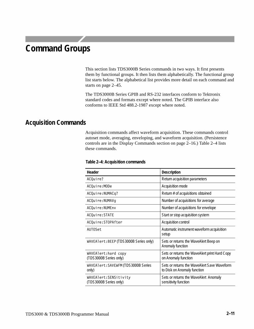
TDS3000 & TDS3000B Programmer Manual 2–11
Command Groups
This section lists TDS3000B Series commands in two ways. It first presentsthem by functional groups. It then lists them alphabetically. The functional grouplist starts below. The alphabetical list provides more detail on each command andstarts on page 2–45.
The TDS3000B Series GPIB and RS-232 interfaces conform to Tektronixstandard codes and formats except where noted. The GPIB interface alsoconforms to IEEE Std 488.2-1987 except where noted.
Acquisition CommandsAcquisition commands affect waveform acquisition. These commands controlautoset mode, averaging, enveloping, and waveform acquisition. (Persistencecontrols are in the Display Commands section on page 2–16.) Table 2–4 liststhese commands.
Table 2–4: Acquisition commands
Header Description
� +,��0 Return acquisition parameters
� +,���-./� Acquisition mode
� +,���9:-� =0 Return # of acquisitions obtained
� +,���9:-��3 Number of acquisitions for average
� +,���9:-��> Number of acquisitions for envelope
� +,����5�5� Start or stop acquisition system
� +,����5.<���� Acquisition control
�:5.��� Automatic instrument waveform acquisitionsetup
���������?��< (TDS3000B Series only) Sets or returns the WaveAlert Beep onAnomaly function
���������M�1�24D (TDS3000B Series only)
Sets or returns the WaveAlert print Hard Copyon Anomaly function
���������������- (TDS3000B Seriesonly)
Sets or returns the WaveAlert Save Waveformto Disk on Anomaly function
�����������9����>��D (TDS3000B Series only)
Sets or returns the WaveAlert Anomalysensitivity function
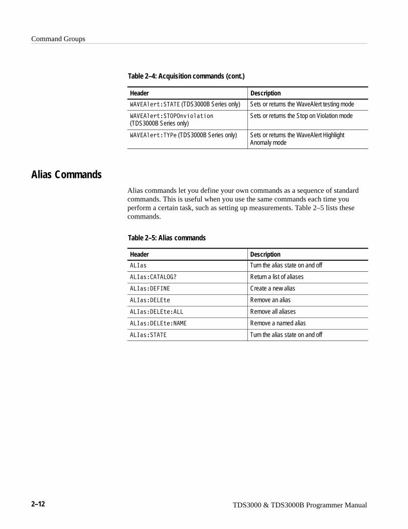
Command Groups
2–12 TDS3000 & TDS3000B Programmer Manual
Table 2–4: Acquisition commands (cont.)
Header Description
����������5�5� (TDS3000B Series only) Sets or returns the WaveAlert testing mode
����������5.<.�>������
(TDS3000B Series only)Sets or returns the Stop on Violation mode
���������5E<� (TDS3000B Series only) Sets or returns the WaveAlert HighlightAnomaly mode
Alias CommandsAlias commands let you define your own commands as a sequence of standardcommands. This is useful when you use the same commands each time youperform a certain task, such as setting up measurements. Table 2–5 lists thesecommands.
Table 2–5: Alias commands
Header Description
�86�� Turn the alias state on and off
�86��� �5�8.70 Return a list of aliases
�86���/��69� Create a new alias
�86���/�8��� Remove an alias
�86���/�8�����88 Remove all aliases
�86���/�8����9�-� Remove a named alias
�86����5�5� Turn the alias state on and off
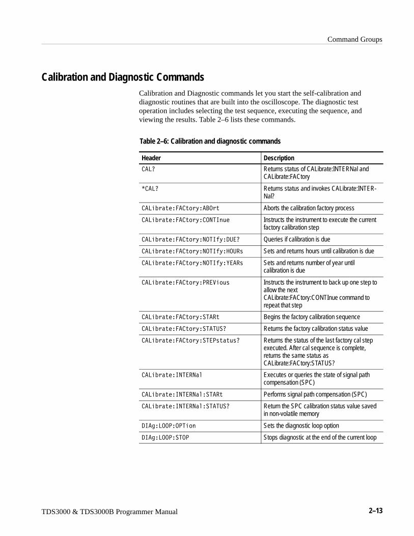
Command Groups
TDS3000 & TDS3000B Programmer Manual 2–13
Calibration and Diagnostic CommandsCalibration and Diagnostic commands let you start the self-calibration anddiagnostic routines that are built into the oscilloscope. The diagnostic testoperation includes selecting the test sequence, executing the sequence, andviewing the results. Table 2–6 lists these commands.
Table 2–6: Calibration and diagnostic commands
Header Description
�80 Returns status of CALibrate:INTERNal andCALibrate:FACtory
C �80 Returns status and invokes CALibrate:INTER-Nal?
�8�N������ �D��?.� Aborts the calibration factory process
�8�N������ �D� .956�,� Instructs the instrument to execute the currentfactory calibration step
�8�N������ �D�9.56�D�/:�0 Queries if calibration is due
�8�N������ �D�9.56�D��.:�� Sets and returns hours until calibration is due
�8�N������ �D�9.56�D�E���� Sets and returns number of year untilcalibration is due
�8�N������ �D�<����,� Instructs the instrument to back up one step toallow the nextCALibrate:FACtory:CONTInue command torepeat that step
�8�N������ �D��5��� Begins the factory calibration sequence
�8�N������ �D��5�5:�0 Returns the factory calibration status value
�8�N������ �D��5�<����,�0 Returns the status of the last factory cal stepexecuted. After cal sequence is complete,returns the same status asCALibrate:FACtory:STATUS?
�8�N����695��9�� Executes or queries the state of signal pathcompensation (SPC)
�8�N����695��9����5��� Performs signal path compensation (SPC)
�8�N����695��9����5�5:�0 Return the SPC calibration status value savedin non-volatile memory
/6�3�8..<�.<5�� Sets the diagnostic loop option
/6�3�8..<��5.< Stops diagnostic at the end of the current loop
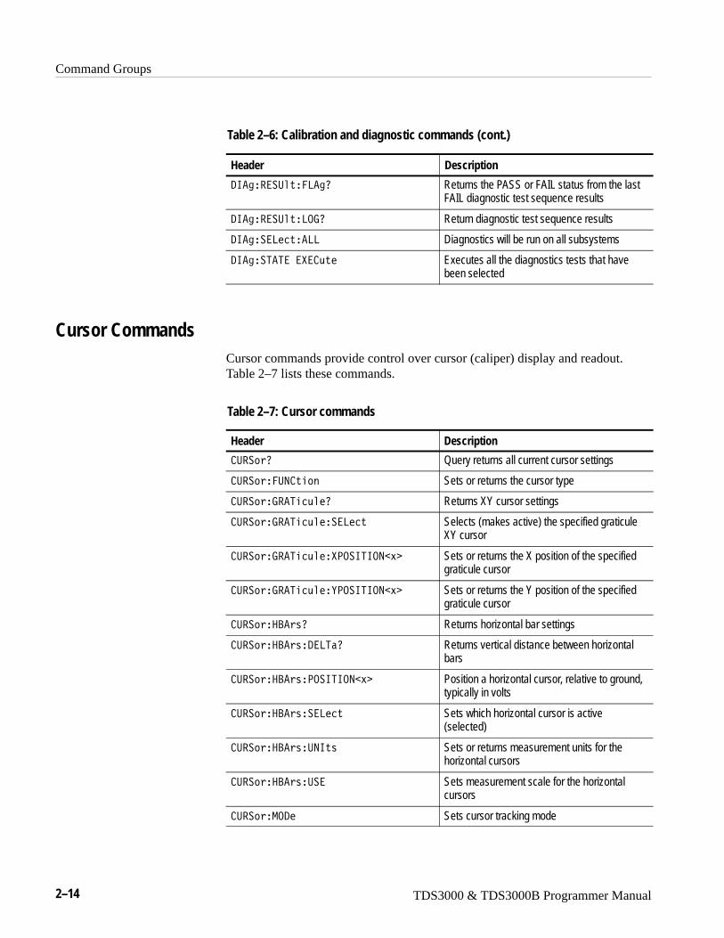
Command Groups
2–14 TDS3000 & TDS3000B Programmer Manual
Table 2–6: Calibration and diagnostic commands (cont.)
Header Description
/6�3����:����8�30 Returns the PASS or FAIL status from the lastFAIL diagnostic test sequence results
/6�3����:���8.70 Return diagnostic test sequence results
/6�3���8�2���88 Diagnostics will be run on all subsystems
/6�3��5�5����� ,�� Executes all the diagnostics tests that havebeen selected
Cursor CommandsCursor commands provide control over cursor (caliper) display and readout.Table 2–7 lists these commands.
Table 2–7: Cursor commands
Header Description
:��0 Query returns all current cursor settings
:����:9 ��� Sets or returns the cursor type
:���7��5�2,��0 Returns XY cursor settings
:���7��5�2,�����8�2� Selects (makes active) the specified graticuleXY cursor
:���7��5�2,����<.�656.9�� Sets or returns the X position of the specifiedgraticule cursor
:���7��5�2,���E<.�656.9�� Sets or returns the Y position of the specifiedgraticule cursor
:����?��0 Returns horizontal bar settings
:����?���/�85�0 Returns vertical distance between horizontalbars
:����?���<.�656.9�� Position a horizontal cursor, relative to ground,typically in volts
:����?�����8�2� Sets which horizontal cursor is active(selected)
:����?���:96�� Sets or returns measurement units for thehorizontal cursors
:����?���:�� Sets measurement scale for the horizontalcursors
:���-./� Sets cursor tracking mode
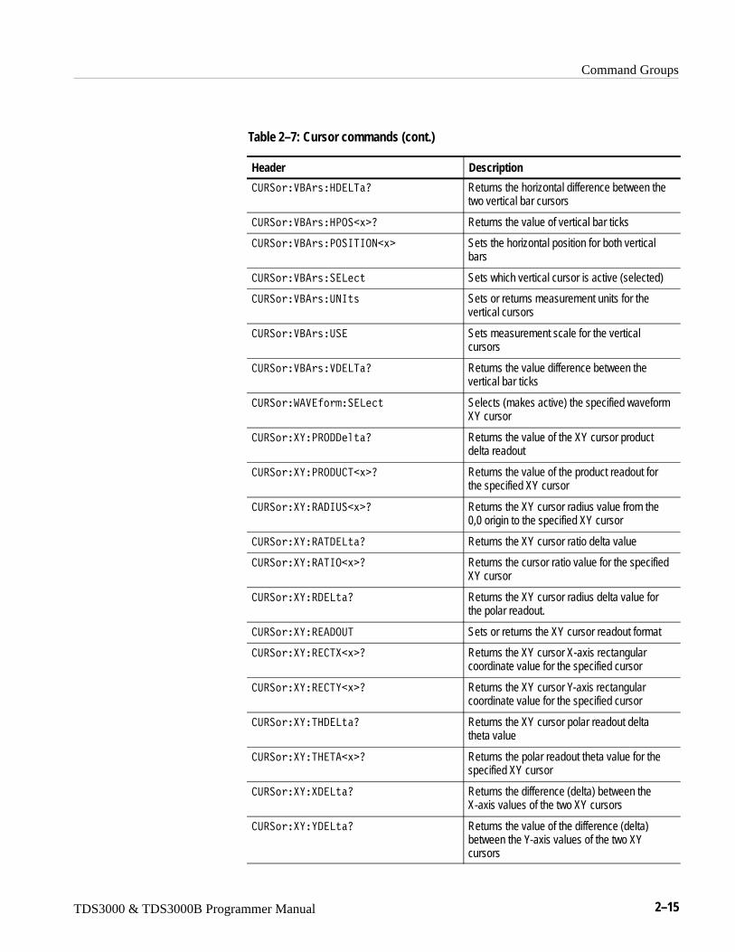
Command Groups
TDS3000 & TDS3000B Programmer Manual 2–15
Table 2–7: Cursor commands (cont.)
Header Description
:����?����/�85�0 Returns the horizontal difference between thetwo vertical bar cursors
:����?����<.��� 0 Returns the value of vertical bar ticks
:����?���<.�656.9�� Sets the horizontal position for both verticalbars
:����?�����8�2� Sets which vertical cursor is active (selected)
:����?���:96�� Sets or returns measurement units for thevertical cursors
:����?���:�� Sets measurement scale for the verticalcursors
:����?����/�85�0 Returns the value difference between thevertical bar ticks
:������������8�2� Selects (makes active) the specified waveformXY cursor
:����E�<�.//����0 Returns the value of the XY cursor productdelta readout
:����E�<�./: 5�� 0 Returns the value of the product readout forthe specified XY cursor
:����E���/6:��� 0 Returns the XY cursor radius value from the0,0 origin to the specified XY cursor
:����E���5/�8��0 Returns the XY cursor ratio delta value
:����E���56.�� 0 Returns the cursor ratio value for the specifiedXY cursor
:����E��/�8��0 Returns the XY cursor radius delta value forthe polar readout.
:����E����/.:5 Sets or returns the XY cursor readout format
:����E��� 5��� 0 Returns the XY cursor X-axis rectangularcoordinate value for the specified cursor
:����E��� 5E�� 0 Returns the XY cursor Y-axis rectangularcoordinate value for the specified cursor
:����E�5�/�8��0 Returns the XY cursor polar readout deltatheta value
:����E�5��5��� 0 Returns the polar readout theta value for thespecified XY cursor
:����E��/�8��0 Returns the difference (delta) between theX-axis values of the two XY cursors
:����E�E/�8��0 Returns the value of the difference (delta)between the Y-axis values of the two XYcursors
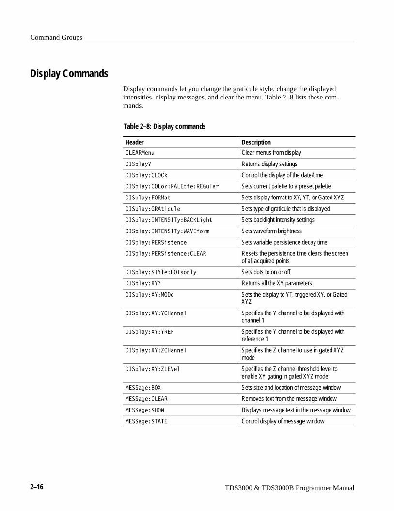
Command Groups
2–16 TDS3000 & TDS3000B Programmer Manual
Display CommandsDisplay commands let you change the graticule style, change the displayedintensities, display messages, and clear the menu. Table 2–8 lists these com-mands.
Table 2–8: Display commands
Header Description
8���-��, Clear menus from display
/6�4��D0 Returns display settings
/6�4��D� 8. O Control the display of the date/time
/6�4��D� .8�<�8�������7,�� Sets current palette to a preset palette
/6�4��D��.�-�� Sets display format to XY, YT, or Gated XYZ
/6�4��D�7����2,�� Sets type of graticule that is displayed
/6�4��D�695�9�65D�?� S8�3M� Sets backlight intensity settings
/6�4��D�695�9�65D������� Sets waveform brightness
/6�4��D�<��������2� Sets variable persistence decay time
/6�4��D�<��������2�� 8��� Resets the persistence time clears the screenof all acquired points
/6�4��D��5E���/.5���D Sets dots to on or off
/6�4��D��E0 Returns all the XY parameters
/6�4��D��E�-./� Sets the display to YT, triggered XY, or GatedXYZ
/6�4��D��E�E ������ Specifies the Y channel to be displayed withchannel 1
/6�4��D��E�E��� Specifies the Y channel to be displayed withreference 1
/6�4��D��E�P ������ Specifies the Z channel to use in gated XYZmode
/6�4��D��E�P8���� Specifies the Z channel threshold level toenable XY gating in gated XYZ mode
-����3��?.� Sets size and location of message window
-����3�� 8��� Removes text from the message window
-����3����.� Displays message text in the message window
-����3���5�5� Control display of message window
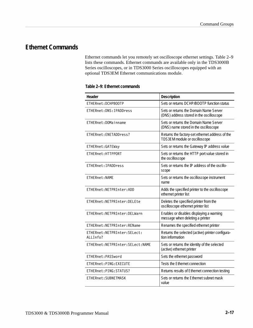
Command Groups
TDS3000 & TDS3000B Programmer Manual 2–17
Ethernet CommandsEthernet commands let you remotely set oscilloscope ethernet settings. Table 2–9lists these commands. Ethernet commands are available only in the TDS3000BSeries oscilloscopes, or in TDS3000 Series oscilloscopes equipped with anoptional TDS3EM Ethernet communications module.
Table 2–9: Ethernet commands
Header Description
�5�������/ �<?..5< Sets or returns DCHP/BOOTP function status
�5�������/9��6<�//��� Sets or returns the Domain Name Server(DNS) address stored in the oscilloscope
�5�������/.-������� Sets or returns the Domain Name Server(DNS) name stored in the oscilloscope
�5��������9�5�//���0 Returns the factory-set ethernet address of theTDS3EM module or oscilloscope
�5�������7�5���D Sets or returns the Gateway IP address value
�5��������55<<.�5 Sets or returns the HTTP port value stored inthe oscilloscope
�5�������6<�//��� Sets or returns the IP address of the oscillo-scope
�5�������9�-� Sets or returns the oscilloscope instrumentname
�5�������9�5<�6�����// Adds the specified printer to the oscilloscopeethernet printer list
�5�������9�5<�6����/�8��� Deletes the specified printer from theoscilloscope ethernet printer list
�5�������9�5<�6����/�8��� Enables or disables displaying a warningmessage when deleting a printer
�5�������9�5<�6������9��� Renames the specified ethernet printer
�5�������9�5<�6������8�2��
�886��0
Returns the selected (active) printer configura-tion information
�5�������9�5<�6������8�2��9�-� Sets or returns the identity of the selected(active) ethernet printer
�5�������<���J1 Sets the ethernet password
�5�������<697���� :5� Tests the Ethernet connection
�5�������<697��5�5:�0 Returns results of Ethernet connection testing
�5��������:?9�5-��S Sets or returns the Ethernet subnet maskvalue
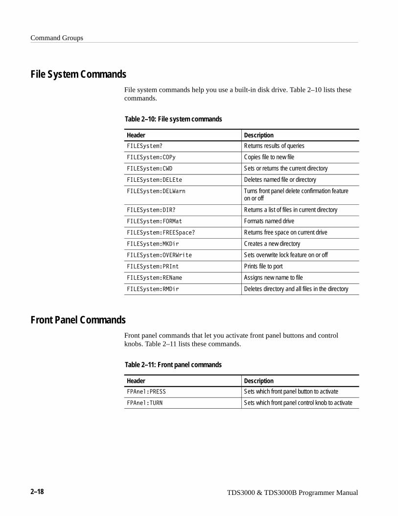
Command Groups
2–18 TDS3000 & TDS3000B Programmer Manual
File System CommandsFile system commands help you use a built-in disk drive. Table 2–10 lists thesecommands.
Table 2–10: File system commands
Header Description
�68��D����0 Returns results of queries
�68��D����� .<D Copies file to new file
�68��D����� �/ Sets or returns the current directory
�68��D�����/�8��� Deletes named file or directory
�68��D�����/�8��� Turns front panel delete confirmation featureon or off
�68��D�����/6�0 Returns a list of files in current directory
�68��D������.�-�� Formats named drive
�68��D����������4�2�0 Returns free space on current drive
�68��D�����-S/� Creates a new directory
�68��D�����.������� Sets overwrite lock feature on or off
�68��D�����<�6�� Prints file to port
�68��D�������9��� Assigns new name to file
�68��D������-/� Deletes directory and all files in the directory
Front Panel CommandsFront panel commands that let you activate front panel buttons and controlknobs. Table 2–11 lists these commands.
Table 2–11: Front panel commands
Header Description
�<�����<���� Sets which front panel button to activate
�<�����5:�9 Sets which front panel control knob to activate
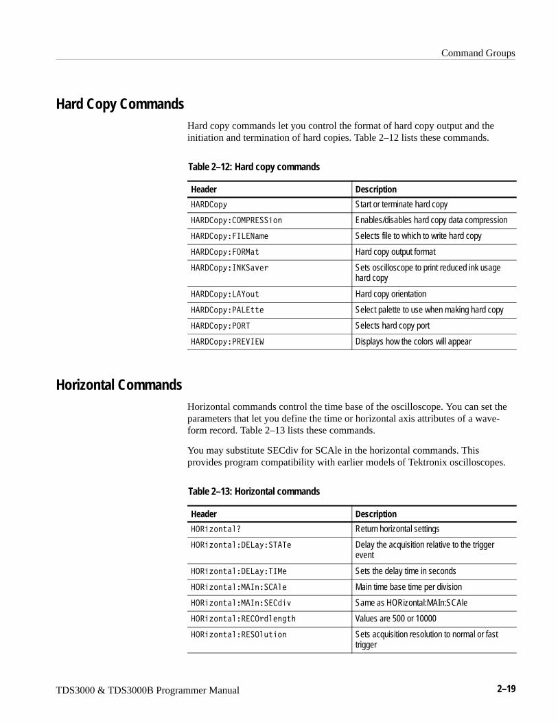
Command Groups
TDS3000 & TDS3000B Programmer Manual 2–19
Hard Copy CommandsHard copy commands let you control the format of hard copy output and theinitiation and termination of hard copies. Table 2–12 lists these commands.
Table 2–12: Hard copy commands
Header Description
���/ 4D Start or terminate hard copy
���/ 4D� .-<������ Enables/disables hard copy data compression
���/ 4D��68�9��� Selects file to which to write hard copy
���/ 4D��.�-�� Hard copy output format
���/ 4D�69S��>� Sets oscilloscope to print reduced ink usagehard copy
���/ 4D�8�E,� Hard copy orientation
���/ 4D�<�8���� Select palette to use when making hard copy
���/ 4D�<.�5 Selects hard copy port
���/ 4D�<���6�� Displays how the colors will appear
Horizontal CommandsHorizontal commands control the time base of the oscilloscope. You can set theparameters that let you define the time or horizontal axis attributes of a wave-form record. Table 2–13 lists these commands.
You may substitute SECdiv for SCAle in the horizontal commands. Thisprovides program compatibility with earlier models of Tektronix oscilloscopes.
Table 2–13: Horizontal commands
Header Description
�.��F����0 Return horizontal settings
�.��F�����/�8�D��5�5� Delay the acquisition relative to the triggerevent
�.��F�����/�8�D�56-� Sets the delay time in seconds
�.��F�����-�6��� ��� Main time base time per division
�.��F�����-�6���� 1�> Same as HORizontal:MAIn:SCAle
�.��F������� .1���3�M Values are 500 or 10000
�.��F��������.�,��� Sets acquisition resolution to normal or fasttrigger
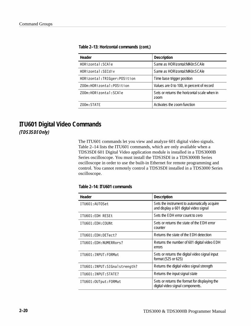
Command Groups
2–20 TDS3000 & TDS3000B Programmer Manual
Table 2–13: Horizontal commands (cont.)
Header Description
�.��F������ ��� Same as HORizontal:MAIn:SCAle
�.��F������� 1�> Same as HORizontal:MAIn:SCAle
�.��F�����5�673��<.����� Time base trigger position
P..���.��F�����<.����� Values are 0 to 100, in percent of record
P..���.��F������ ��� Sets or returns the horizontal scale when inzoom
P..���5�5� Activates the zoom function
ITU601 Digital Video Commands(TDS3SDI Only)
The ITU601 commands let you view and analyze 601 digital video signals.Table 2–14 lists the ITU601 commands, which are only available when aTDS3SDI 601 Digital Video application module is installed in a TDS3000BSeries oscilloscope. You must install the TDS3SDI in a TDS3000B Seriesoscilloscope in order to use the built-in Ethernet for remote programming andcontrol. You cannot remotely control a TDS3SDI installed in a TDS3000 Seriesoscilloscope.
Table 2–14: ITU601 commands
Header Description
65:T;���:5.��� Sets the instrument to automatically acquireand display a 601 digital video signal
65:T;���/������� Sets the EDH error count to zero
65:T;���/�� .:9� Sets or returns the state of the EDH errorcounter
65:T;���/��/�5�2�0 Returns the state of the EDH detection
65:T;���/��9:-����0 Returns the number of 601 digital video EDHerrors
65:T;��69<:5��.�-�� Sets or returns the digital video signal inputformat (525 or 625)
65:T;��69<:5��67�������3�M0 Returns the digital video signal strength
65:T;��69<:5��5�5�0 Returns the input signal state
65:T;��.:54,���.�-�� Sets or returns the format for displaying thedigital video signal components.
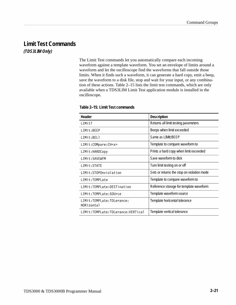
Command Groups
TDS3000 & TDS3000B Programmer Manual 2–21
Limit Test Commands(TDS3LIM Only)
The Limit Test commands let you automatically compare each incomingwaveform against a template waveform. You set an envelope of limits around awaveform and let the oscilloscope find the waveforms that fall outside thoselimits. When it finds such a waveform, it can generate a hard copy, emit a beep,save the waveform to a disk file, stop and wait for your input, or any combina-tion of these actions. Table 2–15 lists the limit test commands, which are onlyavailable when a TDS3LIM Limit Test application module is installed in theoscilloscope.
Table 2–15: Limit Test commands
Header Description
86-��0 Returns all limit testing parameters
86-���?��< Beeps when limit exceeded
86-���?�8� Same as LIMit:BEEP
86-��� .-4��� ��� Template to compare waveform to
86-������/ 4D Prints a hard copy when limit exceeded
86-���������- Save waveform to disk
86-����5�5� Turn limit testing on or off
86-����5.<.�>������ Sets or returns the stop on violation mode
86-���5�-<8��� Template to compare waveform to
86-���5�-<8����/��5������ Reference storage for template waveform
86-���5�-<8�����.:2� Template waveform source
86-���5�-<8����5.8���2��
�.��F����
Template horizontal tolerance
86-���5�-<8����5.8���2�����5�2�� Template vertical tolerance
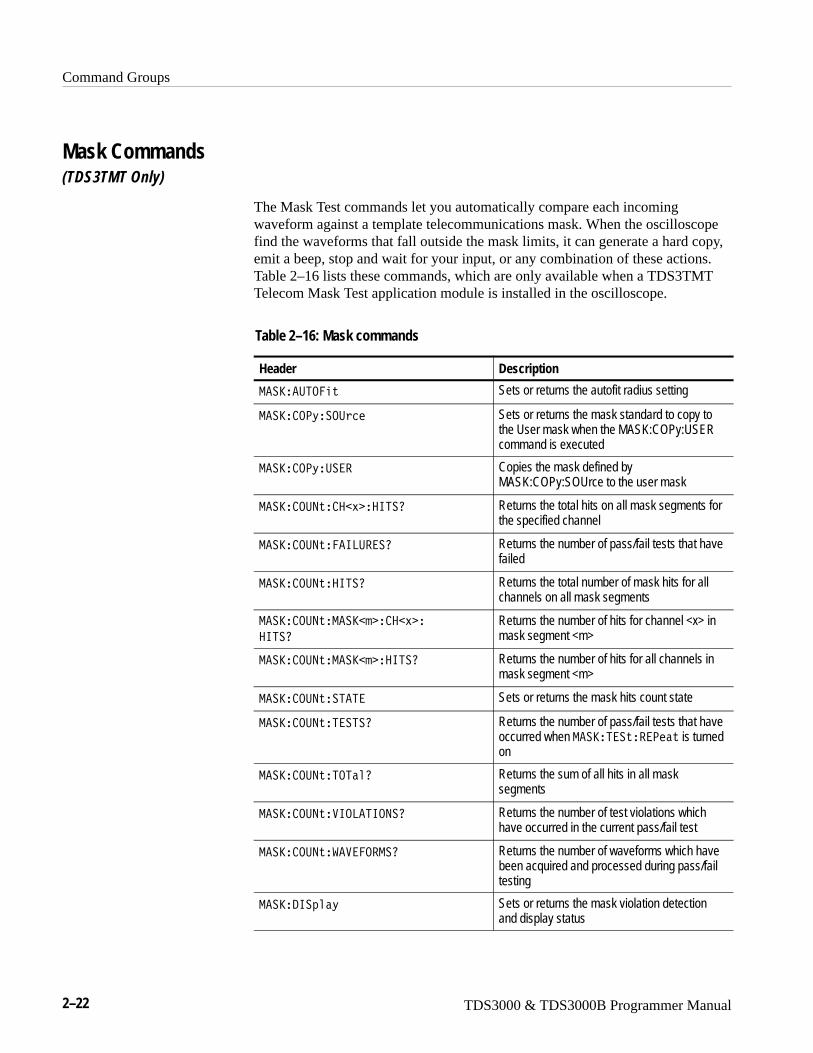
Command Groups
2–22 TDS3000 & TDS3000B Programmer Manual
Mask Commands(TDS3TMT Only)
The Mask Test commands let you automatically compare each incomingwaveform against a template telecommunications mask. When the oscilloscopefind the waveforms that fall outside the mask limits, it can generate a hard copy,emit a beep, stop and wait for your input, or any combination of these actions. Table 2–16 lists these commands, which are only available when a TDS3TMTTelecom Mask Test application module is installed in the oscilloscope.
Table 2–16: Mask commands
Header Description
-��S��:5.��� Sets or returns the autofit radius setting
-��S� .<D��.:2� Sets or returns the mask standard to copy tothe User mask when the MASK:COPy:USERcommand is executed
-��S� .<D�:��� Copies the mask defined byMASK:COPy:SOUrce to the user mask
-��S� .:9�� ��� ��65�0 Returns the total hits on all mask segments forthe specified channel
-��S� .:9����68:���0 Returns the number of pass/fail tests that havefailed
-��S� .:9���65�0 Returns the total number of mask hits for allchannels on all mask segments
-��S� .:9��-��S�� � ��� �
�65�0
Returns the number of hits for channel <x> inmask segment <m>
-��S� .:9��-��S�� ��65�0 Returns the number of hits for all channels inmask segment <m>
-��S� .:9���5�5� Sets or returns the mask hits count state
-��S� .:9��5��5�0 Returns the number of pass/fail tests that haveoccurred when -��S�5������<��� is turnedon
-��S� .:9��5.5��0 Returns the sum of all hits in all masksegments
-��S� .:9���6.8�56.9�0 Returns the number of test violations whichhave occurred in the current pass/fail test
-��S� .:9�������.�-�0 Returns the number of waveforms which havebeen acquired and processed during pass/failtesting
-��S�/6�4��D Sets or returns the mask violation detectionand display status
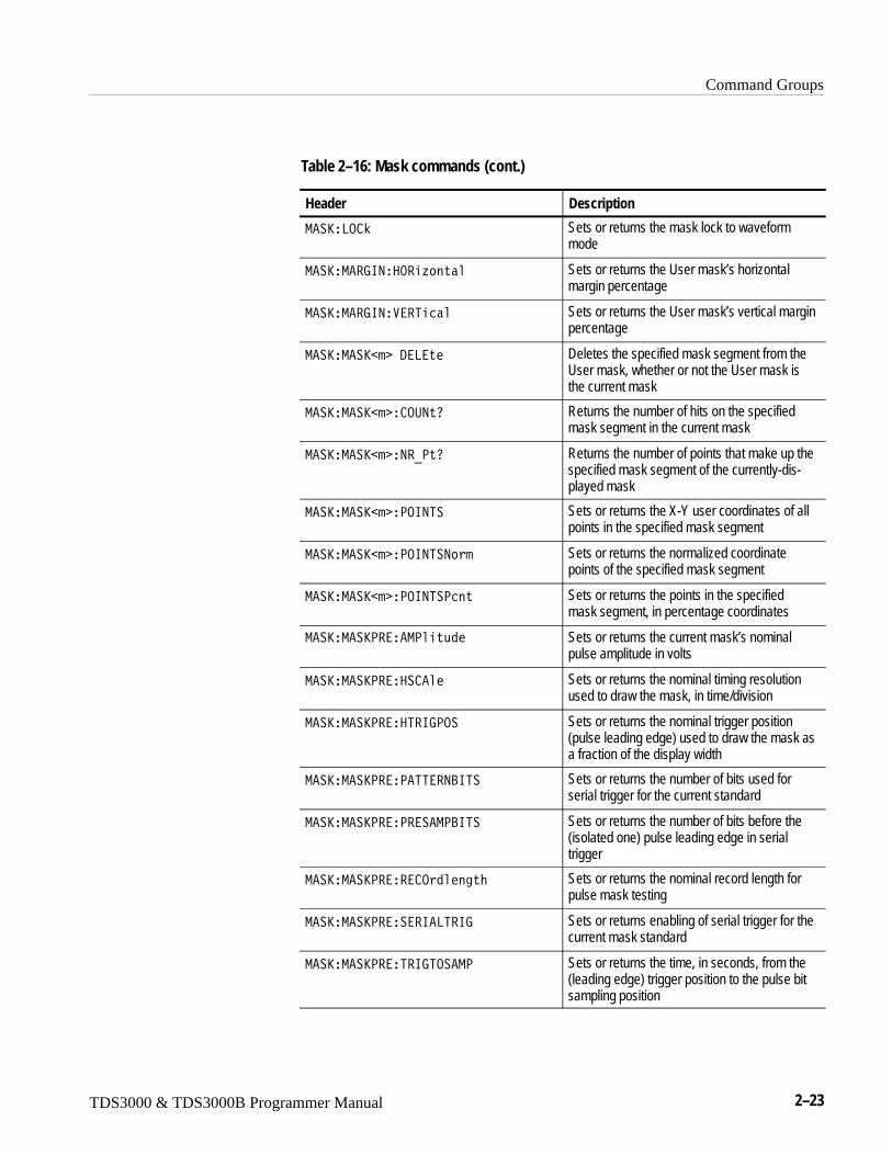
Command Groups
TDS3000 & TDS3000B Programmer Manual 2–23
Table 2–16: Mask commands (cont.)
Header Description
-��S�8. O Sets or returns the mask lock to waveformmode
-��S�-��769��.��F���� Sets or returns the User mask’s horizontalmargin percentage
-��S�-��769����5�2�� Sets or returns the User mask’s vertical marginpercentage
-��S�-��S�� �/�8��� Deletes the specified mask segment from theUser mask, whether or not the User mask isthe current mask
-��S�-��S�� � .:9�0 Returns the number of hits on the specifiedmask segment in the current mask
-��S�-��S�� �9�U<�0 Returns the number of points that make up thespecified mask segment of the currently-dis-played mask
-��S�-��S�� �<.695� Sets or returns the X-Y user coordinates of allpoints in the specified mask segment
-��S�-��S�� �<.695�9� Sets or returns the normalized coordinatepoints of the specified mask segment
-��S�-��S�� �<.695�<2�� Sets or returns the points in the specifiedmask segment, in percentage coordinates
-��S�-��S<����-<���,1� Sets or returns the current mask’s nominalpulse amplitude in volts
-��S�-��S<����� ��� Sets or returns the nominal timing resolutionused to draw the mask, in time/division
-��S�-��S<����5�67<.� Sets or returns the nominal trigger position(pulse leading edge) used to draw the mask asa fraction of the display width
-��S�-��S<���<�55��9?65� Sets or returns the number of bits used forserial trigger for the current standard
-��S�-��S<���<����-<?65� Sets or returns the number of bits before the(isolated one) pulse leading edge in serialtrigger
-��S�-��S<����� .1���3�M Sets or returns the nominal record length forpulse mask testing
-��S�-��S<������6�85�67 Sets or returns enabling of serial trigger for thecurrent mask standard
-��S�-��S<���5�675.��-< Sets or returns the time, in seconds, from the(leading edge) trigger position to the pulse bitsampling position
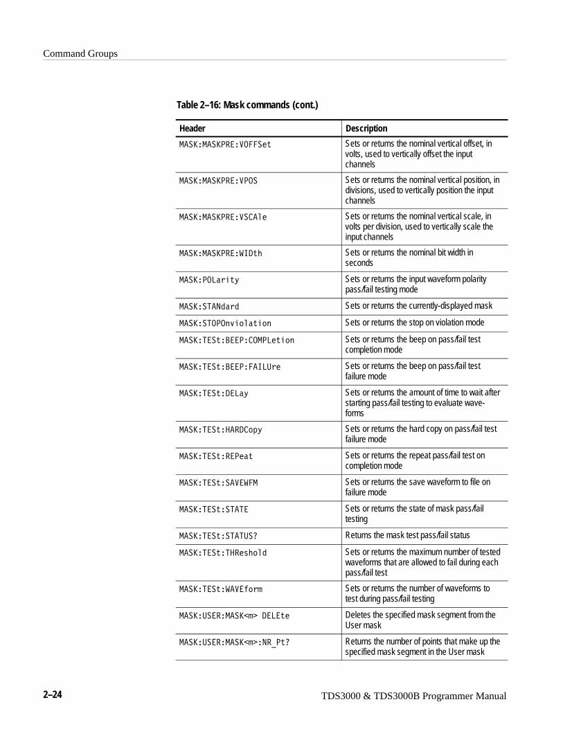
Command Groups
2–24 TDS3000 & TDS3000B Programmer Manual
Table 2–16: Mask commands (cont.)
Header Description
-��S�-��S<����.����� Sets or returns the nominal vertical offset, involts, used to vertically offset the inputchannels
-��S�-��S<����<.� Sets or returns the nominal vertical position, indivisions, used to vertically position the inputchannels
-��S�-��S<����� ��� Sets or returns the nominal vertical scale, involts per division, used to vertically scale theinput channels
-��S�-��S<����6/�M Sets or returns the nominal bit width inseconds
-��S�<.8���D Sets or returns the input waveform polaritypass/fail testing mode
-��S��5�91�1 Sets or returns the currently-displayed mask
-��S��5.<.�>������ Sets or returns the stop on violation mode
-��S�5����?��<� .-<8���� Sets or returns the beep on pass/fail testcompletion mode
-��S�5����?��<���68:� Sets or returns the beep on pass/fail testfailure mode
-��S�5����/�8�D Sets or returns the amount of time to wait afterstarting pass/fail testing to evaluate wave-forms
-��S�5�������/ 4D Sets or returns the hard copy on pass/fail testfailure mode
-��S�5������<��� Sets or returns the repeat pass/fail test oncompletion mode
-��S�5����������- Sets or returns the save waveform to file onfailure mode
-��S�5�����5�5� Sets or returns the state of mask pass/failtesting
-��S�5�����5�5:�0 Returns the mask test pass/fail status
-��S�5����5����M�1 Sets or returns the maximum number of testedwaveforms that are allowed to fail during eachpass/fail test
-��S�5���������� Sets or returns the number of waveforms totest during pass/fail testing
-��S�:����-��S�� �/�8��� Deletes the specified mask segment from theUser mask
-��S�:����-��S�� �9�U<�0 Returns the number of points that make up thespecified mask segment in the User mask
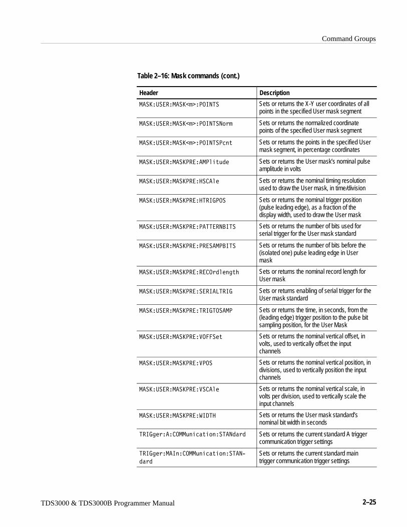
Command Groups
TDS3000 & TDS3000B Programmer Manual 2–25
Table 2–16: Mask commands (cont.)
Header Description
-��S�:����-��S�� �<.695� Sets or returns the X-Y user coordinates of allpoints in the specified User mask segment
-��S�:����-��S�� �<.695�9�� Sets or returns the normalized coordinatepoints of the specified User mask segment
-��S�:����-��S�� �<.695�<2�� Sets or returns the points in the specified Usermask segment, in percentage coordinates
-��S�:����-��S<����-<���,1� Sets or returns the User mask’s nominal pulseamplitude in volts
-��S�:����-��S<����� ��� Sets or returns the nominal timing resolutionused to draw the User mask, in time/division
-��S�:����-��S<����5�67<.� Sets or returns the nominal trigger position(pulse leading edge), as a fraction of thedisplay width, used to draw the User mask
-��S�:����-��S<���<�55��9?65� Sets or returns the number of bits used forserial trigger for the User mask standard
-��S�:����-��S<���<����-<?65� Sets or returns the number of bits before the(isolated one) pulse leading edge in Usermask
-��S�:����-��S<����� .1���3�M Sets or returns the nominal record length forUser mask
-��S�:����-��S<������6�85�67 Sets or returns enabling of serial trigger for theUser mask standard
-��S�:����-��S<���5�675.��-< Sets or returns the time, in seconds, from the(leading edge) trigger position to the pulse bitsampling position, for the User Mask
-��S�:����-��S<����.����� Sets or returns the nominal vertical offset, involts, used to vertically offset the inputchannels
-��S�:����-��S<����<.� Sets or returns the nominal vertical position, indivisions, used to vertically position the inputchannels
-��S�:����-��S<����� ��� Sets or returns the nominal vertical scale, involts per division, used to vertically scale theinput channels
-��S�:����-��S<����6/5� Sets or returns the User mask standard’snominal bit width in seconds
5�673���� .--,��2������5�91�1 Sets or returns the current standard A triggercommunication trigger settings
5�673��-�6�� .--,��2������5�9@
1�1
Sets or returns the current standard maintrigger communication trigger settings

Command Groups
2–26 TDS3000 & TDS3000B Programmer Manual
Table 2–17: Available TDS3TMT ITU-T G.703 mask standards
Standard Description
8. S �� Clock interface coaxial pair 2.048 Mb/s
8. S�D�����2�� Clock interface symmetric pair 2.048 Mb/s
/�; ��� DS-0 data contra-directional 64 kb/s
/�;/,N�� DS-0 double 64 kb/s
/�;���3�� DS-0 single 64 kb/s
/�;5����3 DS-0 timing 64 kb/s
/������ Old DS1 rate 1.544 Mb/s
7V;�/�� G.703 DS1 1.544 Mb/s
/�H��5� �� DS2 rate coaxial pair 6.312 Mb/s
/�H��5��D�����2�� DS2 rate symmetric pair 6.312 Mb/s
/������ Old DS3 rate 44.736 Mb/s
7V;�/�� G.703 DS3 44.736 Mb/s
�� �� E1 coaxial pair 2.048 Mb/s
���D�����2�� E1 symmetrical pair 2.048 Mb/s
�H E2 8.448 Mb/s
�� E3 34.368 Mb/s
9.9� Turns off mask testing and erases currentmask from the screen
��5��H-N�� 32.068 Mb/s
Table 2–18: Available TDS3TMT ANSI T1.102 mask standards
Standard Description
/�� DS1 rate 1.544 Mb/s
/��� DS1A 2.048 Mb/s
/�� DS1C 3.152 Mb/s
/�H DS2 6.312 Mb/s
/�� DS3 44.736 Mb/s

Command Groups
TDS3000 & TDS3000B Programmer Manual 2–27
Table 2–18: Available TDS3TMT ANSI T1.102 mask standards (cont.)
Standard Description
�5��<,��� STS-1 pulse 51.84 Mb/s
9.9� Turns off mask testing and erases currentmask from the screen
Math CommandsMath commands provide access to math function definition. This table includesthe TDS3FFT FFT and TDS3AAM Advanced Analysis application moduleremote command syntax.
Table 2–19: Math commands
Header Description
-�5�0 Returns definition for the math waveform
-�5��/��69� Sets or returns the math waveform definitionfor the active math operation (as set byMATH:TYPe)
-�5���.��F�����<.������9��
(TDS3FFT, TDS3AAM)Sets the math horizontal display positionfor FFT and dual waveform math withreference sources only
-�5���.��F������ ����9��
(TDS3FFT, TDS3AAM)Sets the math horizontal display scale for FFTand dual waveform math with referencesources only
-�5���.��F�����:96��
(TDS3AAM)Sets or returns the math horizontal measure-ment units label
-�5���<� 5���-�7
(TDS3FFT, TDS3AAM)Sets or returns the FFT waveform verticalscale type (linear or dB)
-�5���<� 5����691J
(TDS3FFT, TDS3AAM)Sets or returns the FFT window value
-�5��5E<� Sets or returns the math function (Dual, FFT,DPO, or Advanced)
-�5������� (TDS3AAM) Sets or returns the value of the user-definedvariable VAR1 or VAR2
-�5�����5�2���<.������9�� Sets the math waveform display position
-�5�����5�2���� ����9�� Sets the vertical display scale
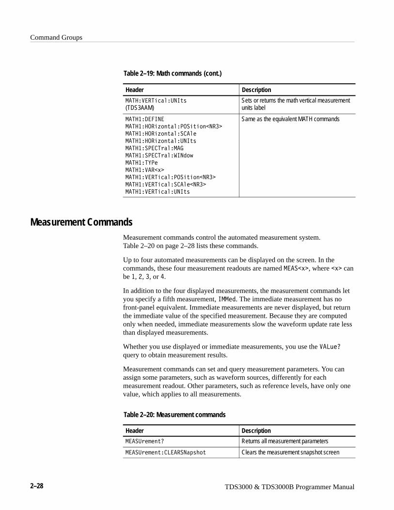
Command Groups
2–28 TDS3000 & TDS3000B Programmer Manual
Table 2–19: Math commands (cont.)
Header Description
-�5�����5�2���:96��
(TDS3AAM)Sets or returns the math vertical measurementunits label
-�5���/��69�
-�5����.��F�����<.������9��
-�5����.��F������ ���
-�5����.��F�����:96��
-�5����<� 5���-�7
-�5����<� 5����691J
-�5���5E<�
-�5��������
-�5������5�2���<.������9��
-�5������5�2���� ����9��
-�5������5�2���:96��
Same as the equivalent MATH commands
Measurement CommandsMeasurement commands control the automated measurement system.Table 2–20 on page 2–28 lists these commands.
Up to four automated measurements can be displayed on the screen. In thecommands, these four measurement readouts are named -����� , where �� canbe �, H, �, or I.
In addition to the four displayed measurements, the measurement commands letyou specify a fifth measurement, 6--�1. The immediate measurement has nofront-panel equivalent. Immediate measurements are never displayed, but returnthe immediate value of the specified measurement. Because they are computedonly when needed, immediate measurements slow the waveform update rate lessthan displayed measurements.
Whether you use displayed or immediate measurements, you use the ��8,�0query to obtain measurement results.
Measurement commands can set and query measurement parameters. You canassign some parameters, such as waveform sources, differently for eachmeasurement readout. Other parameters, such as reference levels, have only onevalue, which applies to all measurements.
Table 2–20: Measurement commands
Header Description
-���:�����0 Returns all measurement parameters
-���:������ 8����9�4�M� Clears the measurement snapshot screen
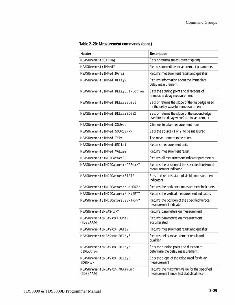
Command Groups
TDS3000 & TDS3000B Programmer Manual 2–29
Table 2–20: Measurement commands (cont.)
Header Description
-���:������7�5��3 Sets or returns measurement gating
-���:������6--�10 Returns immediate measurement parameters
-���:������6--�1�/�5�0 Returns measurement result and qualifier
-���:������6--�1�/�8�D0 Returns information about the immediatedelay measurement
-���:������6--�1�/�8�D�/6��2��� Sets the starting point and directions ofimmediate delay measurement
-���:������6--�1�/�8�D��/7�� Sets or returns the slope of the first edge usedfor the delay waveform measurement
-���:������6--�1�/�8�D��/7�H Sets or returns the slope of the second edgeused for the delay waveform measurement
-���:������6--�1��.:2� Channel to take measurement from
-���:������6--�1��.:� ��� Sets the source (1 or 2) to be measured
-���:������6--�1�5E<� The measurement to be taken
-���:������6--�1�:96��0 Returns measurement units
-���:������6--�1���8,�0 Returns measurement result
-���:������69/6 ���0 Returns all measurement indicator parameters
-���:������69/6 �����.�P�� 0 Returns the position of the specified horizontalmeasurement indicator
-���:������69/6 �����5�5� Sets and returns state of visible measurementindicators
-���:������69/6 ����9:-�.�P0 Returns the horizontal measurement indicators
-���:������69/6 ����9:-���50 Returns the vertical measurement indicators
-���:������69/6 �������5�� 0 Returns the position of the specified verticalmeasurement indicator
-���:������-����� 0 Returns parameters on measurement
-���:������-����� .:9�0
(TDS3AAM)Returns parameters on measurementaccumulated
-���:������-����� �/�5�0 Returns measurement result and qualifier
-���:������-����� �/�8�D0 Returns delay measurement result andqualifier
-���:������-����� �/�8�D�
/6��2���
Sets the starting point and direction todetermine the delay measurement
-���:������-����� �/�8�D�
�/7���
Sets the slope of the edge used for delaymeasurement
-���:������-����� �-����,�0
(TDS3AAM)Returns the maximum value for the specifiedmeasurement since last statistical reset
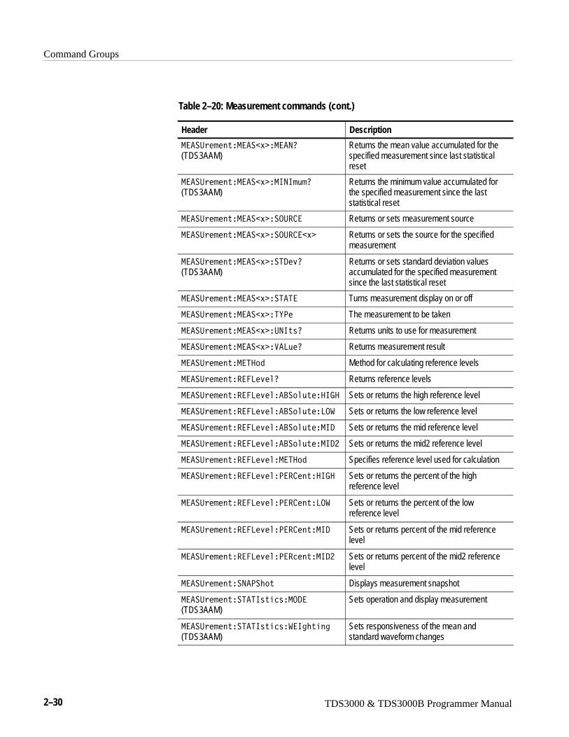
Command Groups
2–30 TDS3000 & TDS3000B Programmer Manual
Table 2–20: Measurement commands (cont.)
Header Description
-���:������-����� �-��90
(TDS3AAM)Returns the mean value accumulated for thespecified measurement since last statisticalreset
-���:������-����� �-696�,�0
(TDS3AAM)Returns the minimum value accumulated forthe specified measurement since the laststatistical reset
-���:������-����� ��.:� � Returns or sets measurement source
-���:������-����� ��.:� ��� Returns or sets the source for the specifiedmeasurement
-���:������-����� ��5/�>0
(TDS3AAM)Returns or sets standard deviation valuesaccumulated for the specified measurementsince the last statistical reset
-���:������-����� ��5�5� Turns measurement display on or off
-���:������-����� �5E<� The measurement to be taken
-���:������-����� �:96��0 Returns units to use for measurement
-���:������-����� ���8,�0 Returns measurement result
-���:������-�5�1 Method for calculating reference levels
-���:���������8�>��0 Returns reference levels
-���:���������8�>����?��,����67� Sets or returns the high reference level
-���:���������8�>����?��,���8.� Sets or returns the low reference level
-���:���������8�>����?��,���-6/ Sets or returns the mid reference level
-���:���������8�>����?��,���-6/H Sets or returns the mid2 reference level
-���:���������8�>���-�5�1 Specifies reference level used for calculation
-���:���������8�>���<�� �����67� Sets or returns the percent of the highreference level
-���:���������8�>���<�� ����8.� Sets or returns the percent of the lowreference level
-���:���������8�>���<�� ����-6/ Sets or returns percent of the mid referencelevel
-���:���������8�>���<��2����-6/H Sets or returns percent of the mid2 referencelevel
-���:�������9�<�M� Displays measurement snapshot
-���:�������5�56���2��-./�
(TDS3AAM)Sets operation and display measurement
-���:�������5�56���2����63M���3
(TDS3AAM)Sets responsiveness of the mean andstandard waveform changes
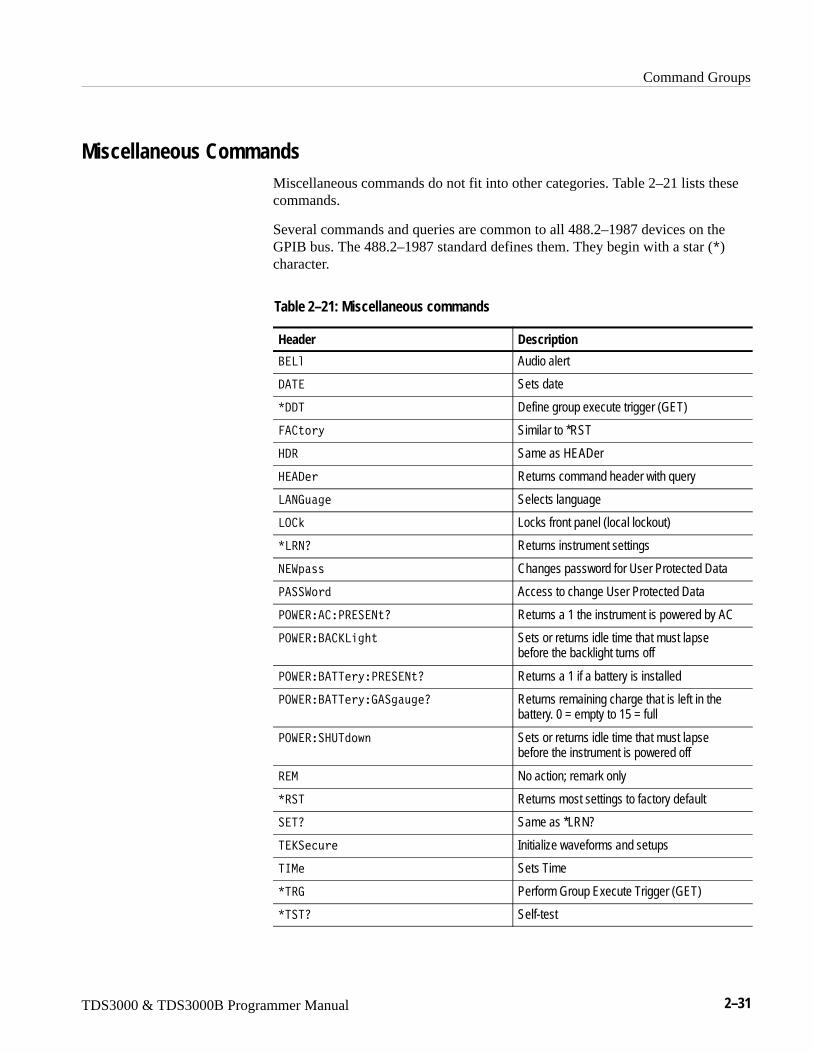
Command Groups
TDS3000 & TDS3000B Programmer Manual 2–31
Miscellaneous CommandsMiscellaneous commands do not fit into other categories. Table 2–21 lists thesecommands.
Several commands and queries are common to all 488.2–1987 devices on theGPIB bus. The 488.2–1987 standard defines them. They begin with a star (C)character.
Table 2–21: Miscellaneous commands
Header Description
?�8� Audio alert
/�5� Sets date
C//5 Define group execute trigger (GET)
�� �D Similar to *RST
�/� Same as HEADer
���/� Returns command header with query
8�97,�3� Selects language
8. O Locks front panel (local lockout)
C8�90 Returns instrument settings
9��4��� Changes password for User Protected Data
<����1 Access to change User Protected Data
<.����� �<����9�0 Returns a 1 the instrument is powered by AC
<.����?� S8�3M� Sets or returns idle time that must lapsebefore the backlight turns off
<.����?�55�D�<����9�0 Returns a 1 if a battery is installed
<.����?�55�D�7��3�,3�0 Returns remaining charge that is left in thebattery. 0 = empty to 15 = full
<.������:51J� Sets or returns idle time that must lapsebefore the instrument is powered off
��- No action; remark only
C��5 Returns most settings to factory default
��50 Same as *LRN?
5�S��2,� Initialize waveforms and setups
56-� Sets Time
C5�7 Perform Group Execute Trigger (GET)
C5�50 Self-test
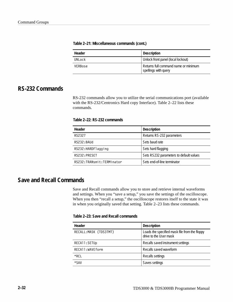
Command Groups
2–32 TDS3000 & TDS3000B Programmer Manual
Table 2–21: Miscellaneous commands (cont.)
Header Description
:982O Unlock front panel (local lockout)
���?�� Returns full command name or minimumspellings with query
RS-232 CommandsRS-232 commands allow you to utilize the serial communications port (availablewith the RS-232/Centronics Hard copy Interface). Table 2–22 lists thesecommands.
Table 2–22: RS-232 commands
Header Description
��H�H0 Returns RS-232 parameters
��H�H�?�:1 Sets baud rate
��H�H����/���33��3 Sets hard flagging
��H�H�<����5 Sets RS232 parameters to default values
��H�H�5��9�����5��-���� Sets end-of-line terminator
Save and Recall CommandsSave and Recall commands allow you to store and retrieve internal waveformsand settings. When you “save a setup,” you save the settings of the oscilloscope.When you then “recall a setup,” the oscilloscope restores itself to the state it wasin when you originally saved that setting. Table 2–23 lists these commands.
Table 2–23: Save and Recall commands
Header Description
�� �88�-��S�)5/��5-5* Loads the specified mask file from the floppydrive to the User mask
�� ������5:4 Recalls saved instrument settings
�� ���������� Recalls saved waveform
C� 8 Recalls settings
C��� Saves settings
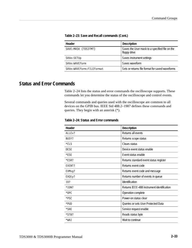
Command Groups
TDS3000 & TDS3000B Programmer Manual 2–33
Table 2–23: Save and Recall commands (Cont.)
Header Description
�����-��S�)5/��5-5* Saves the User mask to a specified file on thefloppy drive
�������5:4 Saves instrument settings
����������� Saves waveform
�������������68����� Sets or returns file format for saved waveforms
Status and Error CommandsTable 2–24 lists the status and error commands the oscilloscope supports. Thesecommands let you determine the status of the oscilloscope and control events.
Several commands and queries used with the oscilloscope are common to alldevices on the GPIB bus. IEEE Std 488.2–1987 defines these commands andqueries. They begin with an asterisk (C).
Table 2–24: Status and Error commands
Header Description
�88�>0 Returns all events
?:�E0 Returns scope status
C 8� Clears status
/��� Device event status enable
C��� Event status enable
C���0 Returns standard event status register
���950 Returns event code
��-�30 Returns event code and message
��+�D0 Returns number of events in queue
6/0 Identification
C6/90 Returns IEEE-488 instrument identification
C.< Operation complete
C<� Power-on status clear
C<:/ Queries or sets User Protected Data
C��� Service request enable
C�5?0 Reads status byte
C��6 Wait to continue
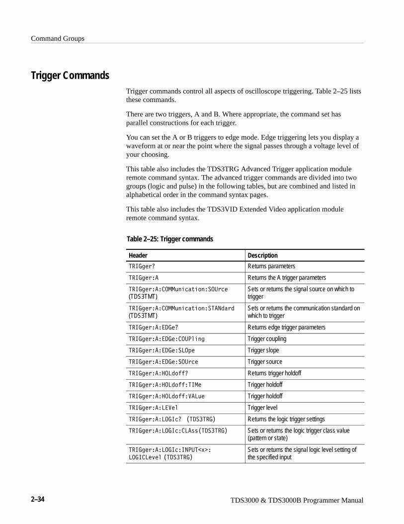
Command Groups
2–34 TDS3000 & TDS3000B Programmer Manual
Trigger CommandsTrigger commands control all aspects of oscilloscope triggering. Table 2–25 liststhese commands.
There are two triggers, A and B. Where appropriate, the command set hasparallel constructions for each trigger.
You can set the A or B triggers to edge mode. Edge triggering lets you display awaveform at or near the point where the signal passes through a voltage level ofyour choosing.
This table also includes the TDS3TRG Advanced Trigger application moduleremote command syntax. The advanced trigger commands are divided into twogroups (logic and pulse) in the following tables, but are combined and listed inalphabetical order in the command syntax pages.
This table also includes the TDS3VID Extended Video application moduleremote command syntax.
Table 2–25: Trigger commands
Header Description
5�673�0 Returns parameters
5�673��� Returns the A trigger parameters
5�673���� .--,��2������.:2�
(TDS3TMT)Sets or returns the signal source on which totrigger
5�673���� .--,��2������5�91�1
(TDS3TMT)Sets or returns the communication standard onwhich to trigger
5�673�����/7�0 Returns edge trigger parameters
5�673�����/7�� .:<���3 Trigger coupling
5�673�����/7���8.4� Trigger slope
5�673�����/7���.:2� Trigger source
5�673�����.81��0 Returns trigger holdoff
5�673�����.81���56-� Trigger holdoff
5�673�����.81�����8,� Trigger holdoff
5�673����8���� Trigger level
5�673����8.7620 �)5/��5�7* Returns the logic trigger settings
5�673����8.762� 8���)5/��5�7* Sets or returns the logic trigger class value(pattern or state)
5�673����8.762�69<:5�� �
8.76 8�>�� )5/��5�7*Sets or returns the signal logic level setting ofthe specified input
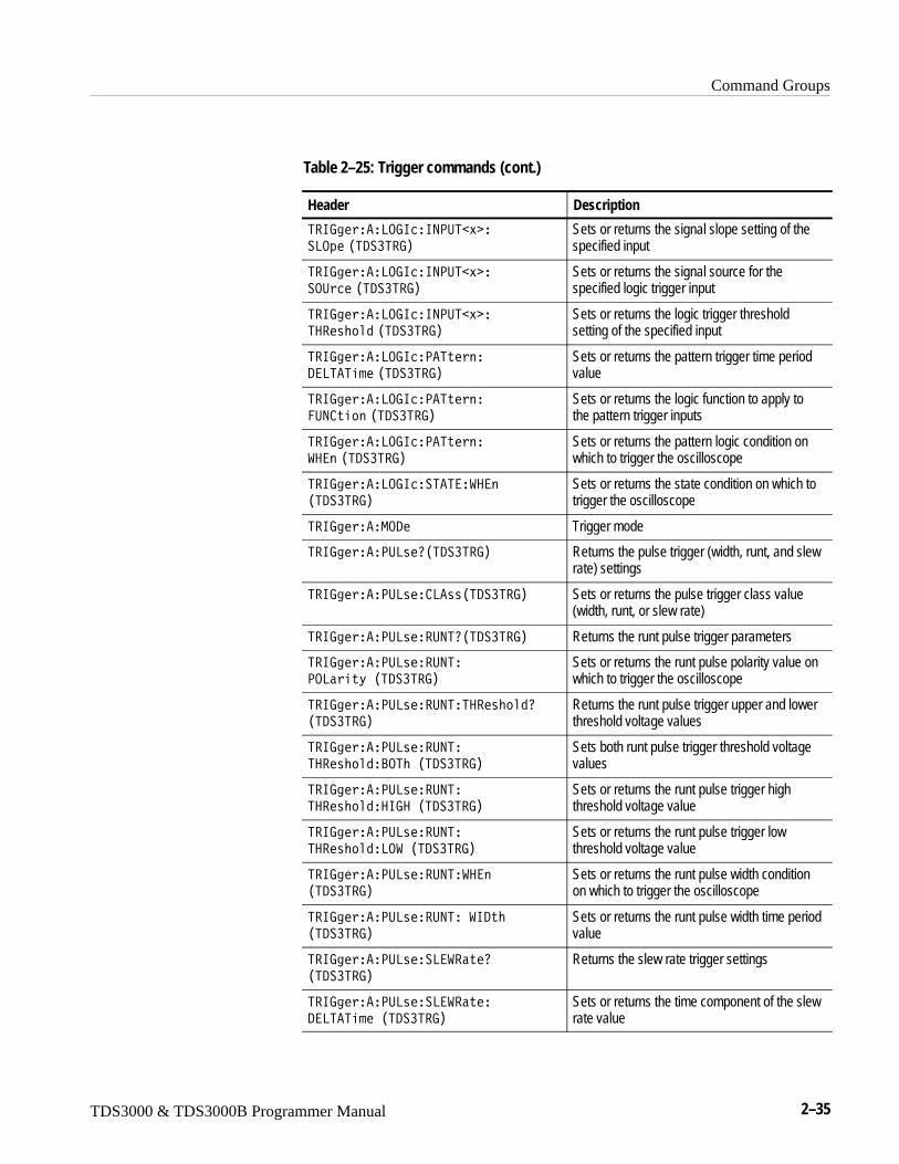
Command Groups
TDS3000 & TDS3000B Programmer Manual 2–35
Table 2–25: Trigger commands (cont.)
Header Description
5�673����8.762�69<:5�� �
�8.4� )5/��5�7*Sets or returns the signal slope setting of thespecified input
5�673����8.762�69<:5�� �
�.:2� )5/��5�7*Sets or returns the signal source for thespecified logic trigger input
5�673����8.762�69<:5�� �
5����M�1 )5/��5�7*Sets or returns the logic trigger thresholdsetting of the specified input
5�673����8.762�<�5����
/�85�5��� )5/��5�7*Sets or returns the pattern trigger time periodvalue
5�673����8.762�<�5����
�:9 ��� )5/��5�7*Sets or returns the logic function to apply tothe pattern trigger inputs
5�673����8.762�<�5����
���� )5/��5�7*Sets or returns the pattern logic condition onwhich to trigger the oscilloscope
5�673����8.762��5�5������
)5/��5�7*
Sets or returns the state condition on which totrigger the oscilloscope
5�673����-./� Trigger mode
5�673����<:8��0)5/��5�7* Returns the pulse trigger (width, runt, and slewrate) settings
5�673����<:8��� 8���)5/��5�7* Sets or returns the pulse trigger class value(width, runt, or slew rate)
5�673����<:8����:950)5/��5�7* Returns the runt pulse trigger parameters
5�673����<:8����:95�
<.8���D�)5/��5�7*
Sets or returns the runt pulse polarity value onwhich to trigger the oscilloscope
5�673����<:8����:95�5����M�10
)5/��5�7*
Returns the runt pulse trigger upper and lowerthreshold voltage values
5�673����<:8����:95�
5����M�1�?.5M�)5/��5�7*
Sets both runt pulse trigger threshold voltagevalues
5�673����<:8����:95�
5����M�1��67��)5/��5�7*
Sets or returns the runt pulse trigger highthreshold voltage value
5�673����<:8����:95�
5����M�1�8.��)5/��5�7*
Sets or returns the runt pulse trigger lowthreshold voltage value
5�673����<:8����:95�����
)5/��5�7*
Sets or returns the runt pulse width conditionon which to trigger the oscilloscope
5�673����<:8����:95���6/�M
)5/��5�7*
Sets or returns the runt pulse width time periodvalue
5�673����<:8����8������0
)5/��5�7*
Returns the slew rate trigger settings
5�673����<:8����8�������
/�85�5����)5/��5�7*
Sets or returns the time component of the slewrate value
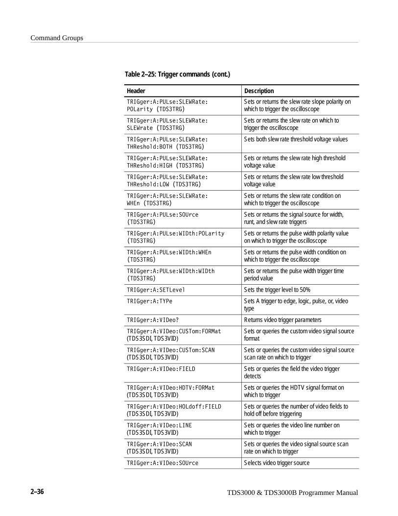
Command Groups
2–36 TDS3000 & TDS3000B Programmer Manual
Table 2–25: Trigger commands (cont.)
Header Description
5�673����<:8����8�������
<.8���D�)5/��5�7*
Sets or returns the slew rate slope polarity onwhich to trigger the oscilloscope
5�673����<:8����8�������
�8������)5/��5�7*
Sets or returns the slew rate on which totrigger the oscilloscope
5�673����<:8����8�������
5����M�1�?.5��)5/��5�7*
Sets both slew rate threshold voltage values
5�673����<:8����8�������
5����M�1��67��)5/��5�7*
Sets or returns the slew rate high thresholdvoltage value
5�673����<:8����8�������
5����M�1�8.��)5/��5�7*
Sets or returns the slew rate low thresholdvoltage value
5�673����<:8����8�������
�����)5/��5�7*
Sets or returns the slew rate condition onwhich to trigger the oscilloscope
5�673����<:8����.:2�
)5/��5�7*
Sets or returns the signal source for width,runt, and slew rate triggers
5�673����<:8����6/�M�<.8���D
)5/��5�7*
Sets or returns the pulse width polarity valueon which to trigger the oscilloscope
5�673����<:8����6/�M�����
)5/��5�7*
Sets or returns the pulse width condition onwhich to trigger the oscilloscope
5�673����<:8����6/�M��6/�M
)5/��5�7*
Sets or returns the pulse width trigger timeperiod value
5�673������58�>�� Sets the trigger level to 50%
5�673����5E<� Sets A trigger to edge, logic, pulse, or, videotype
5�673�����6/�0 Returns video trigger parameters
5�673�����6/�� :�5���.�-��
(TDS3SDI, TDS3VID)Sets or queries the custom video signal sourceformat
5�673�����6/�� :�5��� �9
(TDS3SDI, TDS3VID)Sets or queries the custom video signal sourcescan rate on which to trigger
5�673�����6/���6�8/ Sets or queries the field the video triggerdetects
5�673�����6/���/5���.�-��
(TDS3SDI, TDS3VID)Sets or queries the HDTV signal format onwhich to trigger
5�673�����6/���.81����6�8/
(TDS3SDI, TDS3VID)Sets or queries the number of video fields tohold off before triggering
5�673�����6/��869�
(TDS3SDI, TDS3VID)Sets or queries the video line number onwhich to trigger
5�673�����6/��� �9
(TDS3SDI, TDS3VID)Sets or queries the video signal source scanrate on which to trigger
5�673�����6/���.:2� Selects video trigger source

Command Groups
TDS3000 & TDS3000B Programmer Manual 2–37
Table 2–25: Trigger commands (cont.)
Header Description
5�673�����6/���5�91�1 Selects video trigger standard
5�673�����6/���E���� Same as TRIGger:A:VIDeo:SOUrce
5�673��?0 Returns the B trigger level
5�673��?�?E Sets the B trigger to delay by time or events
5�673��?��/7�0 Returns the trigger coupling, source, and theslope of the B trigger
5�673��?��/7�� .:<���3 Sets the B trigger coupling
5�673��?��/7���8.4� B trigger slope
5�673��?��/7���.:2� B trigger source
5�673��?����95�0 Returns the current delayed trigger eventparameters
5�673��?����95�� .:9� Delay by events count for the B trigger
5�673��?�8���� B trigger level
5�673��?���58�>�� Sets the trigger level to 50%
5�673��?��5�5� Enables/disables the B trigger
5�673��?�56-� Minimum time between A and B trigger
5�673��?�5E<� Sets B trigger to edge, logic, pulse, or, videotype
5�673��/�8�D��/7�� .:<���3
5�673��/�8�D��/7���8.4�
5�673��/�8�D��/7���.:2�
5�673��/�8�D����95�� .:9�
5�673��/�8�D�8����
5�673��/�8�D���58�>��
5�673��/�8�D��5�5�
5�673��/�8�D�56-�
5�673��/�8�D�5E<�
Same as the equivalent B trigger commands;for compatibility with earlier oscilloscopes
5�673����5������<�.N�
(4-channel TDS3000B Series instrumentsonly)
Sets or returns the external input probe factor
5�673����5������E:9��
(4-channel TDS3000B Series instrumentsonly)
Sets or returns the external input vertical units
5�673���.� � Forces a trigger event
5�673���5�5�0 Returns trigger system status
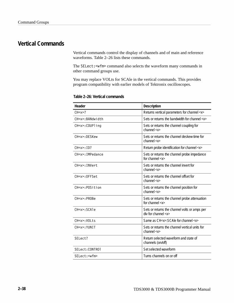
Command Groups
2–38 TDS3000 & TDS3000B Programmer Manual
Vertical CommandsVertical commands control the display of channels and of main and referencewaveforms. Table 2–26 lists these commands.
The ��8�2���J�� command also selects the waveform many commands inother command groups use.
You may replace VOLts for SCAle in the vertical commands. This providesprogram compatibility with earlier models of Tektronix oscilloscopes.
Table 2–26: Vertical commands
Header Description
��� 0 Returns vertical parameters for channel <x>
��� �?�91J�1�M Sets or returns the bandwidth for channel <x>
��� � .:<���3 Sets or returns the channel coupling forchannel <x>
��� �/��S�J Sets or returns the channel deskew time forchannel <x>
��� �6/0 Return probe identification for channel <x>
��� �6-<�1��2� Sets or returns the channel probe impedancefor channel <x>
��� �69��� Sets or returns the channel invert for channel <x>
��� �.����� Sets or returns the channel offset for channel <x>
��� �<.����� Sets or returns the channel position forchannel <x>
��� �<�.?� Sets or returns the channel probe attenuationfor channel <x>
��� �� ��� Sets or returns the channel volts or amps perdiv for channel <x>
��� ��.8�� Same as CH<x>:SCAle for channel <x>
��� �E:965 Sets or returns the channel vertical units forchannel <x>
��8�2�0 Return selected waveform and state ofchannels (on/off)
��8�2�� .95�.� Set selected waveform
��8�2���J�� Turns channels on or off
Command Groups
TDS3000 & TDS3000B Programmer Manual 2–39
Waveform CommandsWaveform commands let you transfer waveform data points to and from theoscilloscope. Waveform data points are a collection of values that define awaveform. One data value usually represents one data point in the waveformrecord. When working with peak detect or envelope waveforms, each data valueis either the min or max of a min/max pair. Before you transfer waveform data,you must specify the data format, record length, and waveform source.
Table 2–28 on page 2–42 lists these commands.
Acquired waveform data uses 9 or more bits to represent each data point. Thenumber of bits used depends on the acquisition mode specified when youacquired the data. Data acquired in SAMple, ENVelope, or PEAKdetect modeuses 9 bits per waveform data point. Data acquired in AVErage mode uses up to14 bits per point. For more information on the acquisition modes see theACQuire: MODe command on page 2–45.
The DATa:WIDth command lets you specify the number of bytes per data pointwhen transferring data to and from the oscilloscope. If you specify two bytes fordata, the acquired waveform data is left-shifted to be left-justified in the 16-bit(2 byte) data quantity. If you specify one byte for data, the least significant bit(s)are ignored.
The oscilloscope can transfer waveform data in either ASCII or binary format.You specify the format with the DATa:ENCdg command.
ASCII data — is represented by signed integer values. The range of the valuesdepends on the byte width specified. One byte wide data ranges from –128 to127. Two byte wide data ranges from –32768 to 32767.
Each data value requires two to seven characters. This includes one to fivecharacters to represent the value, another character, if the value is negative, torepresent a minus sign, and a comma to separate the data points.
An example ASCII waveform data string may look like this:
:�����4�2� W��;�W�;X�W��;�W��;�W�;X�W�;V�W�;X�W�;V�
W�;T�W�;G�W�;��W�;;�WXV�WX;�WBI�WB;
Use ASCII to obtain more human readable and easier to format output thanbinary. However, it may require more bytes to send the same values with ASCIIthan it does with binary. This may reduce transmission speeds.
Waveform Data Formats
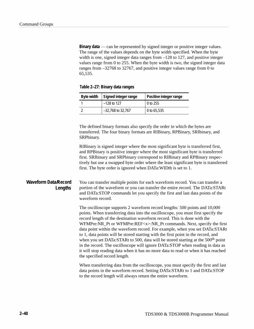
Command Groups
2–40 TDS3000 & TDS3000B Programmer Manual
Binary data — can be represented by signed integer or positive integer values.The range of the values depends on the byte width specified. When the bytewidth is one, signed integer data ranges from –128 to 127, and positive integervalues range from 0 to 255. When the byte width is two, the signed integer dataranges from –32768 to 32767, and positive integer values range from 0 to65,535.
Table 2–27: Binary data ranges
Byte width Signed integer range Positive integer range
1 –128 to 127 0 to 255
2 –32,768 to 32,767 0 to 65,535
The defined binary formats also specify the order in which the bytes aretransferred. The four binary formats are RIBinary, RPBinary, SRIbinary, andSRPbinary.
RIBinary is signed integer where the most significant byte is transferred first,and RPBinary is positive integer where the most significant byte is transferredfirst. SRIbinary and SRPbinary correspond to RIBinary and RPBinary respec-tively but use a swapped byte order where the least significant byte is transferredfirst. The byte order is ignored when DATa:WIDth is set to 1.
You can transfer multiple points for each waveform record. You can transfer aportion of the waveform or you can transfer the entire record. The DATa:STARtand DATa:STOP commands let you specify the first and last data points of thewaveform record.
The oscilloscope supports 2 waveform record lengths: 500 points and 10,000points. When transferring data into the oscilloscope, you must first specify therecord length of the destination waveform record. This is done with theWFMPre:NR_Pt or WFMPre:REF<x>:NR_Pt commands. Next, specify the firstdata point within the waveform record. For example, when you set DATa:STARtto 1, data points will be stored starting with the first point in the record, andwhen you set DATa:STARt to 500, data will be stored starting at the 500th pointin the record. The oscilloscope will ignore DATa:STOP when reading in data asit will stop reading data when it has no more data to read or when it has reachedthe specified record length.
When transferring data from the oscilloscope, you must specify the first and lastdata points in the waveform record. Setting DATa:STARt to 1 and DATa:STOPto the record length will always return the entire waveform.
Waveform Data/RecordLengths
Command Groups
TDS3000 & TDS3000B Programmer Manual 2–41
The DATa:SOUrce command specifies the waveform source when transferring awaveform from the oscilloscope. You can only transfer one waveform at at time.
You can transfer in to the oscilloscope one waveform at a time. Waveforms sentto the oscilloscope are always stored in one of the four reference memorylocations. You can specify the reference memory location with the DATa:DESTi-nation command.
Each waveform that you transfer has an associated waveform preamble thatcontains information such as the horizontal scale, the vertical scale, and othersettings in place when the waveform was created. Refer to the WFMPrecommands starting on page 2–318 for more information about the waveformpreamble.
Once you transfer the waveform data to the controller, you can convert the datapoints into voltage values for analysis using information from the waveformpreamble. The 7�5��- (get waveform) program on the diskettes that come withthis manual shows how you can scale data.
You can transfer waveforms from the oscilloscope to an external controller usingthe following sequence:
1. Select the waveform source using the DATa:SOUrce command.
2. Specify the waveform data format using DATa:ENCdg.
3. Specify the number of bytes per data point using DATa:WIDth.
4. Specify the portion of the waveform that you want to transfer usingDATa:STARt and DATa:STOP.
5. Transfer waveform preamble information using the WFMPRe? query.
6. Transfer waveform data from the oscilloscope using the CURVe? query.
You can transfer waveform data to one of the four reference waveforms in theoscilloscope using the following sequence:
Waveform Data Locationsand Memory Allocation
Waveform Preamble
Scaling Waveform Data
Transferring WaveformData from theoscilloscope
Transferring WaveformData to the oscilloscope
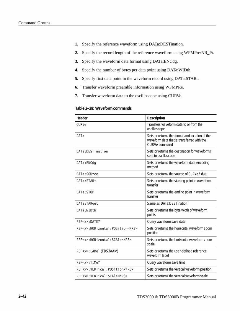
Command Groups
2–42 TDS3000 & TDS3000B Programmer Manual
1. Specify the reference waveform using DATa:DESTination.
2. Specify the record length of the reference waveform using WFMPre:NR_Pt.
3. Specify the waveform data format using DATa:ENCdg.
4. Specify the number of bytes per data point using DATa:WIDth.
5. Specify first data point in the waveform record using DATa:STARt.
6. Transfer waveform preamble information using WFMPRe.
7. Transfer waveform data to the oscilloscope using CURVe.
Table 2–28: Waveform commands
Header Description
:��� Transfers waveform data to or from theoscilloscope
/�5� Sets or returns the format and location of thewaveform data that is transferred with theCURVe command
/�5��/��5������ Sets or returns the destination for waveformssent to oscilloscope
/�5���9 13 Sets or returns the waveform data encodingmethod
/�5���.:2� Sets or returns the source of :���0 data
/�5���5��� Sets or returns the starting point in waveformtransfer
/�5���5.< Sets or returns the ending point in waveformtransfer
/�5��5��3�� Same as DATa:DESTination
/�5���6/�M Sets or returns the byte width of waveformpoints
����� �/�5�0 Query waveform save date
����� ��.��F�����<.������9�� Sets or returns the horizontal waveform zoomposition
����� ��.��F������ ����9�� Sets or returns the horizontal waveform zoomscale
����� �8�?�� (TDS3AAM) Sets or returns the user-defined referencewaveform label
����� �56-�0 Query waveform save time
����� ����5�2���<.������9�� Sets or returns the vertical waveform position
����� ����5�2���� ����9�� Sets or returns the vertical waveform scale
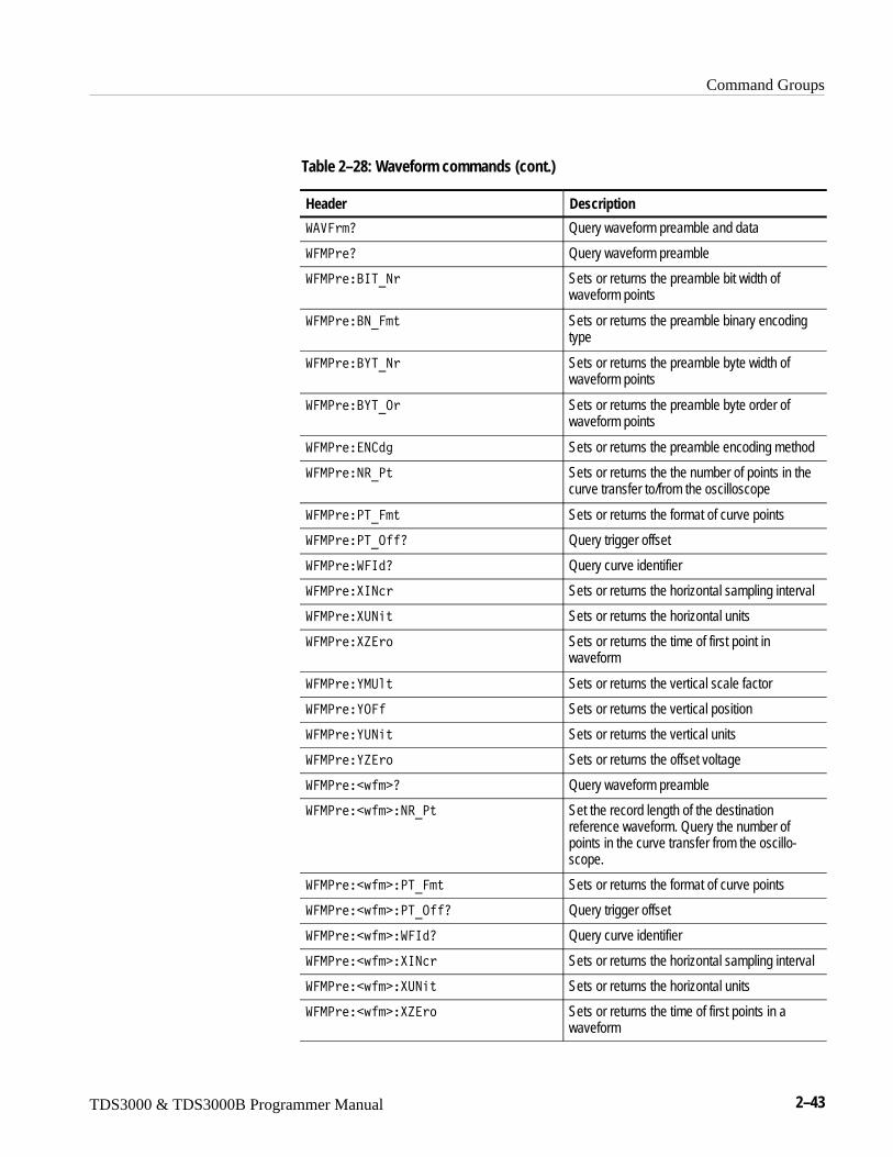
Command Groups
TDS3000 & TDS3000B Programmer Manual 2–43
Table 2–28: Waveform commands (cont.)
Header Description
�����0 Query waveform preamble and data
��-<�0 Query waveform preamble
��-<��?65U9 Sets or returns the preamble bit width ofwaveform points
��-<��?9U��� Sets or returns the preamble binary encodingtype
��-<��?E5U9 Sets or returns the preamble byte width ofwaveform points
��-<��?E5U. Sets or returns the preamble byte order ofwaveform points
��-<���9 13 Sets or returns the preamble encoding method
��-<��9�U<� Sets or returns the the number of points in thecurve transfer to/from the oscilloscope
��-<��<5U��� Sets or returns the format of curve points
��-<��<5U.��0 Query trigger offset
��-<����610 Query curve identifier
��-<���692 Sets or returns the horizontal sampling interval
��-<���:9�� Sets or returns the horizontal units
��-<���P� Sets or returns the time of first point inwaveform
��-<��E-:�� Sets or returns the vertical scale factor
��-<��E.�� Sets or returns the vertical position
��-<��E:9�� Sets or returns the vertical units
��-<��EP� Sets or returns the offset voltage
��-<���J�� 0 Query waveform preamble
��-<���J�� �9�U<� Set the record length of the destinationreference waveform. Query the number ofpoints in the curve transfer from the oscillo-scope.
��-<���J�� �<5U��� Sets or returns the format of curve points
��-<���J�� �<5U.��0 Query trigger offset
��-<���J�� ���610 Query curve identifier
��-<���J�� ��692 Sets or returns the horizontal sampling interval
��-<���J�� ��:9�� Sets or returns the horizontal units
��-<���J�� ��P� Sets or returns the time of first points in awaveform
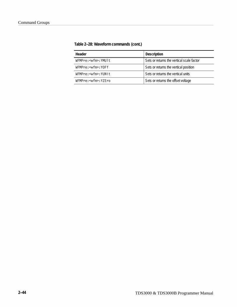
Command Groups
2–44 TDS3000 & TDS3000B Programmer Manual
Table 2–28: Waveform commands (cont.)
Header Description
��-<���J�� �E-:�� Sets or returns the vertical scale factor
��-<���J�� �E.�� Sets or returns the vertical position
��-<���J�� �E:9�� Sets or returns the vertical units
��-<���J�� �EP� Sets or returns the offset voltage
TDS3000 & TDS3000B Programmer Manual 2–45
Command Descriptions
You can use commands to either set instrument features or query instrumentvalues. You can use some commands to do both, some to only set, and some toonly query. Commands that are set only are labeled with the words “(Set Only)”next to the command. Commands that are query only are labeled with the words“(Query Only)” next to the command.
This manual shows the minimal command headers, mnemonics, and argumentsin upper case. For example, to use the minimal form of the ACQuire:MODecommand just type ACQ:MOD (or acq:mod).
ACQuire? (Query Only)Returns all the current acquisition parameters.
Acquisition
� +,��0
� +:6��0
might return the string �� +:6����5.<��5����:9�5.<A�5�5���A-./���-<8�A9:-�9��BA9:-��7��T for the current acquisition parameters.
ACQuire:MODeSets or queries the acquisition mode of the oscilloscope. This affects all livewaveforms. This command is equivalent to setting Mode in the ACQUIREmenu.
Waveforms are the displayed data point values taken from acquisition intervals.Each acquisition interval represents a time duration set by the horizontal scale(time per division). The oscilloscope sampling system always samples at themaximum rate, and so an acquisition interval may include more than one sample.
The acquisition mode, which you set using this ACQuire:MODe command,determines how the final value of the acquisition interval is generated from themany data samples.
Acquisition
Group
Syntax
Examples
Group
Command Descriptions
2–46 TDS3000 & TDS3000B Programmer Manual
� +,���-./��#���-4���"�<��S1���2��"�����3��"��9���4��$
��-4�� specifies that the displayed data point value is simply the first sampledvalue that was taken during the acquisition interval. In sample mode, allwaveform data has 9 bits of precision. You can request 16 bit data with aCURVe? query, but the lower-order 7 bits of data will be zero. ��-4�� is thedefault mode.
<��S1���2� specifies the display of the high-low range of the samples takenfrom a single waveform acquisition. The high-low range is displayed as avertical column that extends from the highest to the lowest value sampled duringthe acquisition interval. <��S1���2� mode can reveal the presence of aliasing ornarrow spikes.
����3� specifies averaging mode, where the resulting waveform shows anaverage of ��-4�� data points from several separate waveform acquisitions. Thenumber of waveform acquisitions that go into making up the average waveformis set or queried using the ACQuire:NUMAVg command.
�9���4� specifies envelope mode, where the resulting waveform shows the<��S1���2� range of data points from several separate waveform acquisitions.The number of waveform acquisitions that go into making up the envelopewaveform is set or queried using the ACQuire:NUMENv command.
� +:6���-./���9��8.<� sets the acquisition mode to display a waveform that is an envelope of manyindividual waveform acquisitions.
� +:6���-./�0
might return �9��8.<�.
ACQuire:NUMAVg, ACQuire:NUMENv, CURVe?, DATa:WIDth
ACQuire:NUMACq? (Query Only)Indicates the number of acquisitions that have taken place since startingacquisition. This value is reset to zero when any Acquisition, Horizontal, orVertical arguments that affect the waveform are modified. The maximum numberof acquisitions that can be counted is 230–1. Counting stops when this number isreached. This is the same value that is displayed in the ACQUIRE menu.
Acquisition
� +,���9:-� =0
Syntax
Arguments
Examples
Related Commands
Group
Syntax
Command Descriptions
TDS3000 & TDS3000B Programmer Manual 2–47
� +:6���9:-� +0
might return �G;, indicating that 350 acquisitions took place since an AC-QUIRE:STATE RUN command was executed.
ACQuire:STATE
ACQuire:NUMAVgSets the number of waveform acquisitions that make up an averaged waveform.This is equivalent to setting the Average count in the Acquisition Mode menu.
Acquisition
� +,���9:-��3��9��
� +,���9:-��30
�9�� is the number of waveform acquisitions to average, from 2 to 512 (mustbe a power of two).
� +:6���9:-��7��T
specifies that an averaged waveform will show the result of combining 16separately acquired waveforms.
� +:6���9:-��70
might return TI, indicating that there are 64 acquisitions specified for averaging.
ACQuire:MODe
ACQuire:NUMEnvSets the number of waveform acquisitions that make up an envelope waveform.This is equivalent to setting the Envelope count in the Acquisition Mode sidemenu.
Acquisition
Examples
Related Commands
Group
Syntax
Arguments
Examples
Related Commands
Group
Command Descriptions
2–48 TDS3000 & TDS3000B Programmer Manual
� +,���9:-��>�#��9�� �"�69�6�����$
� +,���9:-��>0
�9�� � 0 is the number of waveform acquisitions, from 2 to 512 (must be apower of two). The envelope will restart after the specified number of envelopeshave been acquired or when the ACQuire:STATE RUN command is sent.
69�6���� or �9�� = 0 or 999999999 specifies continuous enveloping.
NOTE. If you set the acquisition system to single sequence, envelope mode, andset the number of envelopes to infinity, the oscilloscope will envelope a maximumof 513 acquisitions.
999999999 is returned for INFInite.
� +:6���9:-�9���T
specifies that an enveloped waveform will show the result of combining 16separately acquired waveforms.
� +:6���9:-�9�0
might return XXXXXXXXX, indicating that acquisitions are acquired infinitely forenveloped waveforms.
ACQuire:MODe
ACQuire:STATESets or returns the acquisition state. This is the equivalent of pressing thefront-panel RUN/STOP button. If ACQuire:STOPAfter is set to SEQuence,other signal events may also stop a waveform acquisition.
Acquisition
� +,����5�5��#�.���"�.9�"��:9�"��5.<�"��9�� �$
� +,����5�5�0
Syntax
Arguments
Returns
Examples
Related Commands
Group
Syntax
Command Descriptions
TDS3000 & TDS3000B Programmer Manual 2–49
.�� or �5.< or �9�� = 0 stops acquisitions.
.9 or �:9 or �9�� � 0 starts acquisition and display of waveforms. If thecommand was issued in the middle of an acquisition sequence (for instanceaveraging or enveloping), �:9 restarts the sequence, discarding any dataaccumulated prior to the �5.<. It also resets the number of acquisitions.
� +:6����5�5���:9 starts acquisition of waveform data and resets the number of acquisitions count(NUMACQ) to zero.
� +:6����5�5�0 returns either ; or �, depending on whether the acquisition system is running.
ACQuire:NUMACq?, ACQuire:STOPAfter
ACQuire:STOPAfterTells the oscilloscope when to stop taking acquisitions.
Acquisition
� +,����5.<�����#��:9�54�"���+,��2��$
� +,����5.<����0
�:9�54 specifies that the run and stop state should be determined by the userpressing the front-panel RUN/STOP button.
��+,��2� specifies “single sequence” operation, where the oscilloscope stopsafter it has acquired enough waveforms to satisfy the conditions of the acquisi-tion mode. For example, if the acquisition mode is set to sample, and thehorizontal scale is set to a speed that allows real-time operation, then theoscilloscope stops acquisition after digitizing a waveform from a single triggerevent. However, if the acquisition mode is set to average 128 waveforms, thenthe oscilloscope stops acquiring data only after all 128 waveforms have beenacquired. The ACQuire: STATE command and the front-panel RUN/STOPbutton will also stop acquisition when the oscilloscope is in single sequencemode.
Arguments
Examples
Related Commands
Group
Syntax
Arguments
Command Descriptions
2–50 TDS3000 & TDS3000B Programmer Manual
NOTE. If you set the acquisition system to single sequence, envelope mode, andset the number of envelopes to infinity, the oscilloscope will envelope a maximumof 513 acquisitions.
� +:6����5.<��5����:9�54 sets the oscilloscope to stop acquisition when the user presses the front-panelRUN/STOP button.
� +:6����5.<��5��0 might return ��+:�9 �.
ACQuire:MODe, ACQuire:STATE
ALIasTurns command aliases on or off. This command is identical to theALIas:STATE command.
Alias
�86���#�.���"�.9�"��9�� �$
�86��0
.�� or �9�� = 0 turns alias expansion off. If a defined alias label is sent whenALIas is OFF, an execution error (102, “Syntax error: illegal use of alias-alias”)will be generated.
.9 or �9�� � 0 turns alias expansion on. When a defined alias is received, thespecified command sequence is substituted for the alias and executed.
�86���.9
turns the alias feature on.
�86��0
returns � when aliases are on.
Examples
Related Commands
Group
Syntax
Arguments
Examples
Command Descriptions
TDS3000 & TDS3000B Programmer Manual 2–51
ALIas:CATALOG? (Query Only)Returns a list of the currently defined alias labels, separated by commas. If noaliases are defined, the query returns the string LL.
Alias
�86��� �5�8.70
�+����3 %��+����3 ���&
�86��� �5�8.70
might return the string L��5:<�L�L5��5-�9:�L�L/���:85L, showing there are3 aliases named SETUP1, TESTMENU1, and DEFAULT.
ALIas:DEFINEAssigns a sequence of program messages to an alias label. These messages arethen substituted for the alias whenever it is received as a command or query,provided ALIas:STATE has been turned ON. The ALIas:DEFIne? query returnsthe definition of a selected alias.
Up to 10 aliases can be defined at one time. Aliases can not be recursive.
Alias
�86���/��69���+����3 � ��� #��+����3 �"��?�2O �$
�86���/��69�0��+����3
The first �+����3 is the alias label. This label cannot be a command name.Labels must start with a letter, and can contain only letters, numbers, andunderscores. The label must be ≤12 characters.
The second �+����3 or �?�2O is a complete sequence of program messages.The messages can contain only valid commands that must be separated bysemicolons and must follow all rules for concatenating commands (seepage 2–4). The sequence must be ≤256 characters.
Group
Syntax
Returns
Examples
Group
Syntax
Arguments
Command Descriptions
2–52 TDS3000 & TDS3000B Programmer Manual
NOTE. Attempting to give two aliases the same name causes an execution error.To give a new alias the name of an existing alias, you must first delete theexisting alias.
�86���/��69��L�5�L�L��� �88���5:<�GA��:5.��5���� :5�A
���8� 5� ���.9L
defines an alias named “ST1” that sets up the oscilloscope.using information insetup 5.
�86���/��69�0�L�5�L
might return ��86���/��69��L�5�L�QH�X��� �88���5:<�GA��:5.��5��� :5�A���8� 5� ���.9
ALIas:DELEte (Set Only)Removes a specified alias. This command is identical to ALIas:DELEte:NAMe.
Alias
�86���/�8�����+����3
�+����3 is the name of the alias you want to remove. Using ALIas:DELEtewithout specifying an alias causes an execution error. �+����3 must be anexisting alias.
�86���/�8�5��L��5:<�L deletes the alias named SETUP1.
ALIas:DELEte:ALL (Set Only)Deletes all existing aliases.
Alias
�86���/�8�����88
�86���/�8�5���88
deletes all aliases.
Examples
Group
Syntax
Arguments
Examples
Group
Syntax
Examples
Command Descriptions
TDS3000 & TDS3000B Programmer Manual 2–53
ALIas:DELEte:NAMe (Set Only)Removes a specified alias. This command is identical to ALIas:DELEte.
Alias
�86���/�8����9�-���+����3
�+����3 is the name of the alias to remove. Using ALIas:DELEte:NAMewithout specifying an alias causes an execution error. �+����3 must be anexisting alias.
�86���/�8�5��9�-��L�5��5:<L deletes the alias named STARTUP.
ALIas:STATETurns aliases on or off. This command is identical to the ALIas command.
Alias
�86����5�5��#�.���"�.9�"��9�� �$
�86����5�5�0
.�� or �9�� = 0 turns alias expansion off. If a defined alias is sent whenALIas:STATE is OFF, a command error (102) is generated.
.9 or �9�� � 0 turns alias expansion on. When a defined alias is received, thespecified command sequence is substituted for the alias and executed.
�86����5�5��.��
turns the command alias feature off.
�86����5�5�0
returns ; when the alias feature is off.
Group
Syntax
Arguments
Examples
Group
Syntax
Arguments
Examples
Command Descriptions
2–54 TDS3000 & TDS3000B Programmer Manual
ALLEv? (Query Only)Causes the oscilloscope to return all events and their messages, and removes thereturned events from the Event Queue. The messages are separated by commas.Use the *ESR? query to enable the events to be returned. For a completediscussion of the use of these registers, see page 3–1. This command is similar torepeatedly sending *EVMsg? queries to the instrument.
Status and error
�88�>0
The event code and message in the following format:
��>���� 1� � ��� �+����3 %� ��� ��>���� 1� � ���
�+����3 ���&
�+����3 ��!��-����3� A%� ����1 &
� ����1 is the command that caused the error and may be returned when acommand error is detected by the oscilloscope. As much of the command will bereturned as possible without exceeding the 60 character limit of the �-����3� and � ����1 strings combined. The command string is right-justified.
�88��0
might return the string ��88���HHHG�L-���,���������9�J�>���������,�A�L�IH;�L+,�D�:95��-69�5�/A�L.
*CLS, DESE, *ESE, *ESR?, EVENT?, EVMsg?, EVQty, *SRE, *STB?
AUTOSet (Set Only)Sets the oscilloscope to automatically adjust its vertical, horizontal, and triggercontrols to provide a stable display of the selected waveform. This is equivalentto pressing the front-panel AUTOSET button. For a detailed description of theautoset function, see Autoset in the Reference section of the TDS3000B SeriesUser Manual.
Acquire
�:5.����#���� ,���"�:9/.�"��6/��"������1��"��8�����$
Group
Syntax
Returns
Examples
Related Commands
Group
Syntax
Command Descriptions
TDS3000 & TDS3000B Programmer Manual 2–55
��� ,�� sets the oscilloscope to automatically provide a stable display of theactive edge–triggered waveform.
:9/. restores the oscilloscope settings to those present prior to the autosetexecution.
�6/� Sets the oscilloscope to display a broadcast-standard video waveformtriggered on all lines. The video waveform must be NTSC, PAL, or SECAM-compliant, with a horizontal scan rate from 15 kHz to 20 kHz.
�����1� sets the oscilloscope to automatically provide a stable display of theactive video waveform, triggered on all fields. TDS3VID, TDS3SDI only.
�8���� sets the oscilloscope to automatically provide a stable display of theactive video waveform, triggered on all lines. TDS3VID, TDS3SDI only.
�:5.��5���� :5�
Autosets the oscilloscope to automatically acquire and display an edge-triggeredsignal.
BELl (Set Only)Emits an audible tone from the oscilloscope.
Miscellaneous
?�8�
?�88
emits an audible tone from the oscilloscope.
BUSY? (Query Only)Returns the status of the oscilloscope. This command allows you to synchronizethe operation of the oscilloscope with your application program. Synchronizationmethods are described on page 3–7.
Status and error
?:�E0
Arguments
Examples
Group
Syntax
Examples
Group
Syntax
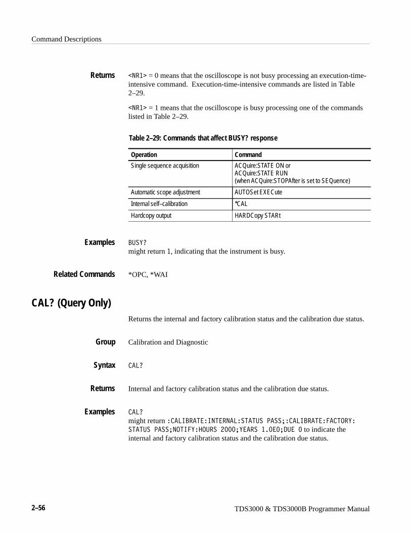
Command Descriptions
2–56 TDS3000 & TDS3000B Programmer Manual
�9�� = 0 means that the oscilloscope is not busy processing an execution-time-intensive command. Execution-time-intensive commands are listed in Table2–29.
�9�� = 1 means that the oscilloscope is busy processing one of the commandslisted in Table 2–29.
Table 2–29: Commands that affect BUSY? response
Operation Command
Single sequence acquisition ACQuire:STATE ON orACQuire:STATE RUN (when ACQuire:STOPAfter is set to SEQuence)
Automatic scope adjustment AUTOSet EXECute
Internal self–calibration *CAL
Hardcopy output HARDCopy STARt
?:�E0
might return �, indicating that the instrument is busy.
*OPC, *WAI
CAL? (Query Only)Returns the internal and factory calibration status and the calibration due status.
Calibration and Diagnostic
�80
Internal and factory calibration status and the calibration due status.
�80
might return � �86?��5��695��9�8��5�5:��<���A� �86?��5���� 5.�E��5�5:��<���A9.56�E��.:���H;;;AE�������;�;A/:��; to indicate theinternal and factory calibration status and the calibration due status.
Returns
Examples
Related Commands
Group
Syntax
Returns
Examples

Command Descriptions
TDS3000 & TDS3000B Programmer Manual 2–57
*CAL? (Query Only)Runs an internal self-calibration and returns the oscilloscope calibration status.
NOTE. Disconnect or otherwise removeall input signals prior to startingself-calibration.
The self-calibration can take several minutes to complete. No other commandsare executed until calibration is complete.
Calibration and Diagnostic
C �80
�9�� = 0 indicates that the calibration did not complete successfully.
�9�� � 0 indicates that the calibration completed without errors.
C �80
performs an internal self-calibration and might return � to indicate that thecalibration was successful.
CALibrate:FACtoryThis command is the same as CALibrate:FACtory:STARt.
CALibrate:FACtory:ABOrt (Set Only)Causes the oscilloscope to abort the factory calibration process, reset to thecalibration initialization step, and exit without saving calibration data or statusinformation.
Calibration and Diagnostic
�8�N������ �D��?.�
�86?��5���� 5.�E��?.�5
aborts the current factory calibration process.
Group
Syntax
Returns
Examples
Group
Syntax
Examples
Command Descriptions
2–58 TDS3000 & TDS3000B Programmer Manual
CALibrate:FACtory:CONTInue (Set Only)Instructs the instrument to execute the current factory calibration step. Thecalibration step number is incremented on completion of this step, independentof the step pass/fail status. Follow this command with CALibrate:FACtory:STEPstatus? to determine execution status. Use CALibrate:|FACtory:PREVious (followed by a CALibrate:FACtory:CONTinue) to repeat afactory calibration step that failed.
If the current step is the last step and the calibration succeeds, new calibrationdata (and pass status) is saved to non-volatile memory and the oscilloscopereturns to normal operation in the same state it was in before beginning factorycalibration.
If the current step is the last step and any factory calibration step has failed(without a successful pass for repeated steps), a fail status will be saved tonon-volatile memory. Factory calibration data will not be saved to non-volatilememory if the factory status is FAIL.
Calibration and Diagnostic
�8�N������ �D� .956�,�
CALibrate:FACtory:NOTIfy:DUE? (Query Only)Queries if calibration is due.
Calibration and Diagnostic
�8�N������ �D�9.56�D�/:�0
�9�� = 1 indicates the oscilloscope is due for calibration.
�9�� = 0 indicates the oscilloscope is not due for calibration.
�86?��5���� 5.�E�9.56�E�/:�0
might return : �86?��5���� 5.�E�9.56�E�/:��;�indicating that factorycalibration is not due.
Group
Syntax
Group
Syntax
Returns
Examples

Command Descriptions
TDS3000 & TDS3000B Programmer Manual 2–59
CALibrate:FACtory:NOTIfy:HOURsSets or returns hours when calibration is due.
Calibration and Diagnostic
�8�N������ �D�9.56�D��.:���#�69�6�����"��9�� �$
�8�N������ �D�9.56�D��.:��0
�9�� = is the number of hours, 500 to 10000, before the instrument displays anotifier saying that calibration is due. Numbers entered are rounded to thenearest valid number.
69�6���� = disables the calibration due notifier display feature.
�86?��5���� 5.�E�9.56�E��.:����G;;
sets the calibration notification time to 1500 hours.
�86?��5���� 5.�E�9.56�E��.:��0
might return : �86?��5���� 5.�E�9.56�E��.:���H;;; indicating that thecalibration due notifier will be displayed 2000 hours after the last calibration.
CALibrate:FACtory:NOTIfy:YEARsSets or returns the number of years when calibration is due.
Calibration and Diagnostic
�8�N������ �D�9.56�D�E�����#�69�6�����"��9�� �$
�8�N������ �D�9.56�D�E����0
�9�� = is the number of years, 0.5 to 5, before the instrument displays a notifiersaying that calibration is due. Numbers entered are rounded to the nearest validnumber.
69�6���� = disables this feature.
Group
Syntax
Arguments
Examples
Group
Syntax
Arguments
Command Descriptions
2–60 TDS3000 & TDS3000B Programmer Manual
�86?��5���� 5.�E�9.56�E�E�������G�;
sets the calibration due time to 1.5 years.
�86?��5���� 5.�E�9.56�E�E����0
might return � �86?��5���� 5.�E�9.56�E�E�������G�; indicating that thecalibration due notifier will be displayed 1.5 years after the last calibration.
CALibrate:FACtory:PREVious (Set Only)This command backs up the calibration steps one step so that the next CALi-brate:FACtory:CONTInue command will repeat the factory calibration step thatjust finished. Repeated CALibrate:FACtory:PREVious commands can back up asmany calibration steps as desired (until step one is reached). The appropriatenotifier (with signal source information) is displayed after the factory calibrationstep is adjusted.
Calibration and Diagnostic
�8�N������ �D�<����,�
�86?��5���� 5.�E�<���6.:�
backs up the calibration steps one step.
CALibrate:FACtory:STARt (Set Only)The factory calibration process consists of a series of steps. This commandinitializes the factory calibration sequence, but performs no actual signal pathcharacterization.
The calibration process automatically sets up the oscilloscope for each step. Donot send any other commands that change the state of the oscilloscope until thecalibration process is complete. Send the CALibrate:FACtory:CONTInuecommand to begin the selected calibration step (after the appropriate signalsource is connected). Send CALibrate:ABOrt or *RST to abort the calibrationprocess.
Calibration and Diagnostic
�8�N������ �D��5���
Examples
Group
Syntax
Examples
Group
Syntax
Command Descriptions
TDS3000 & TDS3000B Programmer Manual 2–61
�86?��5���� 5.�E��5��5
initializes the factory calibration sequence.
CALibrate:FACtory:STATUS? (Query Only)Returns the factory calibration status value saved in non-volatile memory.
Calibration and Diagnostic
�8�N������ �D��5�5:�0
�86?��5���� 5.�E��5�5:�0
might return � �86?��5���� 5.�E��5�5:��<��� indicating that factorycalibration passed.
CALibrate:FACtory:STEPstatus? (Query Only)Returns pass during oscilloscope power on without regard to actual calibrationstatus. Returns pass or fail for the factory calibration step that most recentlyexecuted when factory calibration is in progress. Use this query to synchronizeprogrammed factory calibration steps.
Calibration and Diagnostic
�8�N������ �D��5�<����,�0
�86?��5���� 5.�E��5�<�5�5:�0
might return � �86?��5���� 5.�E��5�<�5�5:����68 if the last oscilloscopecalibration step did not pass.
CALibrate:INTERNal (Set Only)Executes the signal path compensation (SPC) calibration process. The calibrationalgorithm takes a few minutes to complete. No other command is executed untilcalibration is complete. The oscilloscope state is saved before SPC execution andrestored afterwards. Pass/fail status is saved in nonvolatile memory.
Calibration and Diagnostic
Examples
Group
Syntax
Examples
Group
Syntax
Examples
Group
Command Descriptions
2–62 TDS3000 & TDS3000B Programmer Manual
�8�N����695��9��
�86?��5��695��9�8
performs an internal self-calibration (SPC).
�8�N����695��9����5���
CALibrate:INTERNal:STARt (Set Only)Performs a signal path compensation (SPC). The calibration algorithm takes afew minutes to complete. No other command is executed until calibration iscomplete. The oscilloscope state is saved before SPC execution and restoredafterwards. Pass/fail status is saved in nonvolatile memory.
Calibration and Diagnostic
�8�N����695��9����5���
�86?��5��695��9�8��5��5
Starts a signal path compensation (SPC).
�8�N����695��9����5�5:�0
CALibrate:INTERNal:STATUS? (Query Only)Returns the SPC calibration status value saved in non-volatile memory.
Calibration and Diagnostic
�8�N����695��9����5�5:�0
PASS indicates that the last calibration completed without any errors detected.
FAIL indicates that the last calibration did not complete successfully.
UNCAL indicates that the non-volatile memory has failed.
Syntax
Examples
Related Commands
Group
Syntax
Examples
Related Commands
Group
Syntax
Returns
Command Descriptions
TDS3000 & TDS3000B Programmer Manual 2–63
�86?��5��695��9�8��5�5:�0
might return � �86?��5��695��9�8��5�5:��:9 �8Y if non-volatile memoryhas failed.
�8�N����695��9����5���
CH<x>? (Query Only)Returns the vertical parameters of the specified channel. Because CH<x>:SCAleand CH<x>:VOLts are identical, only CH<x>:SCAle is returned.
Vertical
��� 0
��0
might return the string � ���� �8���;�;�W�A<.�656.9�;�;�;A.����5�;�;�;A .:<8697�/ A?�9/�6/5���:88A/��S���;�;�;A
6-<�/�9 ��-�7A<�.?����;�;AE:965�L�LA69���5�; for channel 1.
CH<x>:BANdwidthSets or queries the bandwidth setting of the specified channel. This is equivalentto setting Bandwidth in the Vertical menu.
Vertical
��� �?�91J�1�M�#�5����D�"�.9�����D�"��:8��$
��� �?�91J�1�M0
�� specifies the input channel. Valid values are 1, 2, 3, and 4.
5����D sets the channel bandwidth to 20 MHz.
.9�����D sets the channel bandwidth to 150 MHz. This argument is notavailable on some models.
�:8� sets the channel bandwidth to the full bandwidth of the oscilloscope.
Examples
Related Commands
Group
Syntax
Examples
Group
Syntax
Arguments

Command Descriptions
2–64 TDS3000 & TDS3000B Programmer Manual
�H�?�9/�6/5��5��95E
sets the bandwidth of channel 2 to 20 MHz.
���?�9/�6/5�0
might return �:88, which indicates that there is no bandwidth limiting onchannel 1.
CH<x>:COUPlingSets or queries the input attenuator coupling setting of the specified channel.This is equivalent to setting Coupling in the Vertical menu.
Vertical
��� � .:<���3�#�� �"�/ �"�79/�$
��� � .:<���30
�� specifies the input channel. Valid values are 1, 2, 3, and 4.
� sets the specified channel to AC coupling. Attempting to set a channel to ACcoupling when the channel has an active Level II probe attached, generates ahardware configuration error.
/ sets the specified channel to DC coupling.
79/ sets the specified channel to ground. Only a flat ground-level waveform willbe displayed.
��� .:<8697��
establishes AC coupling on channel 1.
��� .:<86970
might return / , indicating that channel 3 is set to DC coupling.
CH<x>:IMPedance
Examples
Group
Syntax
Arguments
Examples
Related Commands
Command Descriptions
TDS3000 & TDS3000B Programmer Manual 2–65
CH<x>:DESKewSets or queries the horizontal deskew time for this channel. This is equivalent tosetting Deskew in the VERTICAL > Probe Setup menu and entering a valuewith the general purpose knob. Deskew lets you compensate for time delaydifferences between input channels caused by signals coming in on cables ofdifferent length.
Vertical
��� �/��S�J��9��
��� �/��S�J0
�� specifies the input channel. Valid values are 1, 2, 3, and 4.
�9�� is the deskew time for this channel. The range is –10.0 ns to +10.0 nswith a resolution of 20 ps. Out of range values are clipped.
���/��S��0
might return LWI�;�W��L, indicating that the channel 1 deskew setting is –40.0 ps.
CH<x>:ID? (Query Only)Returns the probe identification including model name for level II probes.Returns a null string for non level II probes.
Vertical
��� �6/0
�� specifies the input channel. Valid values are 1, 2, 3, and 4.
���6/0
might return L<THI�L
Group
Syntax
Arguments
Examples
Group
Syntax
Arguments
Examples

Command Descriptions
2–66 TDS3000 & TDS3000B Programmer Manual
CH<x>:IMPedanceSets or returns the channel probe impedance.
Vertical
��� �6-<�1��2��#��6��D�"�-�7�$
��� �6-<�1��2�0
�� specifies the input channel. Valid values are 1, 2, 3, and 4.
�6��D sets the specified channel to 50 � impedance.
-�7 sets the specified channel to 1 M� impedance.
���6-<�/�9 �0
might return MEG.
CH<x>:INVertSets or returns the specified channel signal invert setting. This command isequivalent to setting Invert in the Vertical menu.
Vertical
��� �69����#��9�� �"�.9�"�.���$
��� �69���0
�� specifies the input channel. Valid values are 1, 2, 3, and 4.
�9�� = 0 or OFF sets the channel to invert off (normal display).
�9�� = 1 or ON sets the channel to invert on.
��� �69���50
might return 0, indicating that channel 1 is not inverted.
Group
Syntax
Arguments
Examples
Group
Syntax
Arguments
Examples
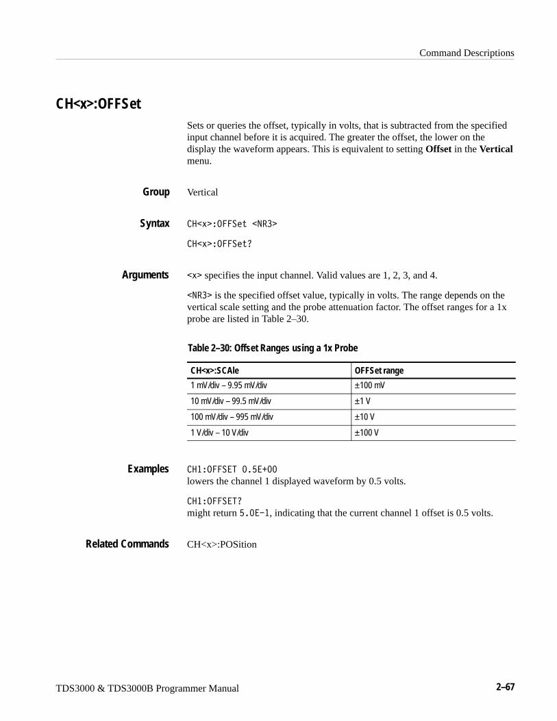
Command Descriptions
TDS3000 & TDS3000B Programmer Manual 2–67
CH<x>:OFFSetSets or queries the offset, typically in volts, that is subtracted from the specifiedinput channel before it is acquired. The greater the offset, the lower on thedisplay the waveform appears. This is equivalent to setting Offset in the Verticalmenu.
Vertical
��� �.�������9��
��� �.�����0
�� specifies the input channel. Valid values are 1, 2, 3, and 4.
�9�� is the specified offset value, typically in volts. The range depends on thevertical scale setting and the probe attenuation factor. The offset ranges for a 1xprobe are listed in Table 2–30.
Table 2–30: Offset Ranges using a 1x Probe
CH<x>:SCAle OFFSet range
1 mV/div – 9.95 mV/div ±100 mV
10 mV/div – 99.5 mV/div ±1 V
100 mV/div – 995 mV/div ±10 V
1 V/div – 10 V/div ±100 V
���.����5�;�G�Y;;
lowers the channel 1 displayed waveform by 0.5 volts.
���.����50
might return G�;�W�, indicating that the current channel 1 offset is 0.5 volts.
CH<x>:POSition
Group
Syntax
Arguments
Examples
Related Commands
Command Descriptions
2–68 TDS3000 & TDS3000B Programmer Manual
CH<x>:POSitionSets or queries the vertical position of the specified channel. The position valueis applied to the signal before digitization. This is equivalent to setting Positionin the Vertical menu or adjusting the front-panel Vertical POSITION knob.
Vertical
��� �<.�������9��
��� �<.�����0
�� specifies the input channel. Valid values are 1, 2, 3, and 4.
�9�� is the desired position, in divisions from the center graticule. The range is±5 divisions.
�H�<.�656.9�����Y;;
positions the channel 2 input signal 1.3 divisions above the center of the display.
���<.�656.90
might return W����Y;;, indicating that the current position of channel 1 is at–1.3 divisions.
CH<x>:OFFSet
CH<x>:PRObeSets or returns the gain factor of the probe that is attached to the specifiedchannel.
Vertical
��� �<�.N���9��
��� �<�.N�0
Group
Syntax
Arguments
Examples
Related Commands
Group
Syntax
Command Descriptions
TDS3000 & TDS3000B Programmer Manual 2–69
�� specifies the input channel. Valid values are 1, 2, 3, and 4.
�9�� is the gain factor (output/input) of the probe. If the attached probe hasonly one legal gain value gain, attempting to set the gain to another value resultsin a Hardware Configuration error.
�I�<�.?�0
might return ��;�W� for a 10x probe.
CH<x>:SCAleSets or queries the vertical gain of the specified channel. This is equivalent tosetting Fine Scale in the Vertical menu or adjusting the front-panel VerticalSCALE knob.
Vertical
��� �� �����9��
��� �� ���0
�� specifies the input channel. Valid values are 1, 2, 3, and 4.
�9�� is the gain, in user units per division. The range is 10 V per division to1 mV per division when using a 1x, 1 megohm, voltage probe.
�I�� �8����;�W�
sets the channel 4 gain to 10 units per division.
�H�� �8�0
might return ��;�Y;, indicating that the current units per division setting ofchannel 2 is 1 unit per division.
CH<x>:VOLts
Arguments
Examples
Group
Syntax
Arguments
Examples
Related Commands
Command Descriptions
2–70 TDS3000 & TDS3000B Programmer Manual
CH<x>:VOLtsSets or queries the vertical gain of the specified channel. This command isidentical to the CH<x>:SCAle command and is included for compatibilitypurposes. Only CH<x>:SCAle is returned in response to a CH<x>? query.
Vertical
��� ��.8����9��
��� ��.8��0
�� specifies the input channel. Valid values are 1, 2, 3, and 4.
�9�� is the gain, in user units per division. The range is 10 V per division to1 mV per division when using a 1x, 1 megohm, voltage probe.
�I��.85��H�;;�;
sets the channel 4 gain to 2.00 units per division.
�H��.85�0
might return ��;�Y;, indicating that the current units per division setting ofchannel 2 is 1 unit per division.
CH<x>:SCAle
CH<x>:YUNitSets or returns the units of the specified channel.
Vertical
��� �E:9����+����3
��� �E:9��0
Group
Syntax
Arguments
Examples
Related Commands
Group
Syntax
Command Descriptions
TDS3000 & TDS3000B Programmer Manual 2–71
�� specifies the input channel. Valid values are 1, 2, 3, and 4.
�+����3 is either “V” for volts or “A” for amps as the units.
��� �E:9650 might return: �I�E:965�R�L.
CLEARMenu (Set Only)Clears the current menu from the display. This command is equivalent topressing the MENU OFF button on the front panel.
Display
8���-��,
8���-�9:
clears the menu from the display.
*CLS (Set Only)Clears the oscilloscope status data structures.
Status and Error
DESE, *ESE, *ESR?, EVENT?, EVMsg?, *SRE, *STB?
C 8�
The *CLS command clears the following:
� the Event Queue
� the Standard Event Status Register (SESR)
� the Status Byte Register (except the MAV bit; see below)
If the *CLS command immediately follows an ��.6 , the Output Queue andMAV bit (Status Byte Register bit 4) are also cleared. MAV indicates informa-tion is in the output queue. The device clear (DCL) GPIB control message willclear the output queue and thus MAV. *CLS does not clear the output queue or
Arguments
Examples
Group
Syntax
Examples
Group
Related Commands
Syntax
Command Descriptions
2–72 TDS3000 & TDS3000B Programmer Manual
MAV. (A complete discussion of these registers and bits, and of event handlingin general, begins on page 3–1.)
*CLS can suppress a Service Request that is to be generated by an *OPC. Thiswill happen if a hardcopy output or single sequence acquisition operation is stillbeing processed when the *CLS command is executed.
CURSor? (Query Only)Returns all current cursor settings for the active cursor.
Cursor
:��0
:��.�0 might return � :��.���:9 56.9�.��A-./��5�� SA�?����:965�L�LA<.�656.9����H;;;;;;;�WIA<.�656.9H���T;;;;;;;;�W�A�/�85�
I�GT�;A�/�85����IB�W�A��8� 5� :��.��A�<.���I�BI�;A�<.�H
H�B�W�A� :��.���?����<.�656.9��G�GH�;A<.�656.9H�H�IB�;A/�85�
��;I�;A��8� 5� :��.��A:965��L�L as the current cursor settings.
CURSor:FUNCtionSelects or returns the cursor type. Cursors are attached to the selected waveform.WAVEform and GRATicule cursors are only valid in XY or XYZ displays. Thiscommand is equivalent to setting Function in the CURSOR menu.
Cursor
:����:9 ����#��?���"�.���"��������"��?���"�7��5�2,���$
:����:9 ���0
�?�� specifies horizontal bar cursors that measure vertical parameters (typicallyvolts).
.�� removes the cursors from the display.
�?�� specifies vertical bar cursors that measure horizontal parameters (typicallytime).
Group
Syntax
Examples
Group
Syntax
Arguments
Command Descriptions
TDS3000 & TDS3000B Programmer Manual 2–73
������ specifies waveform XY cursors.
7��5�2,�� specifies graticule XYcursors. TDS3AAM only.
:��.���:9 56.9��?���
selects vertical bar type cursors.
CURSor:GRATicule? (Query Only)(TDS3AAM Only)
Returns the current settings for the XY graticule cursors, where XPOSITION1and YPOSITION1 refers to the reference cursor, and XPOSITION2 andYPOSITION2 refers to the delta cursor.
Cursor
CURSor:WAVEform?
:���7��5�2,��0
:��.��7��56 :8�0
might return � :��.��7��56 :8����8� 5� :��.��EA�<.�656.9��WG�B�W�AE<.�656.9��WH�;�;A�<.�656.9H�H�H�W�AE<.�656.9H���H�;.
CURSor:GRAticule:SELect(TDS3AAM Only)
Sets (makes active) or returns the specified XY display graticule cursor. Thiscommand is equivalent to pressing the SELECT button on the front panel whenthe Graticule cursors are active.
Cursor
:���7����2,�����8�2��#� :��.��� ��"� :��.��� E�$
:���7����2,�����8�2�0
Examples
Group
Related Commands
Syntax
Examples
Group
Syntax
Command Descriptions
2–74 TDS3000 & TDS3000B Programmer Manual
:��.��� � specifies the X-axis cursor of the specified graticule cursor, wheren = 1 for the reference cursor, and n = 2 for the delta cursor.
:��.��� E specifies the Y-axis cursor of the specified graticule cursor, wheren = 1 for the reference cursor, and n = 2 for the delta cursor.
:��.��7��56 :8����8� 5� :��.�H�
selects the graticule delta X-axis cursor as the active cursor.
CURSor:GRAticule:XPOSITION<x>(TDS3AAM Only)
Sets or returns the position of the XY graticule cursor’s X-axis cursor for thereference or delta cursor.
Cursor
:���7����2,����<.�656.9�� ��9��
:���7����2,����<.�656.9�� ?
�� specifies which graticule cursor, where x = 1 for the reference cursor andx = 2 for the delta cursor.
�9�� is the X cursor position value.
:��.��7��56 :8���<.�656.9�0
might return :���7����2,����<.�656.9��W��II�;
CURSor:GRAticule:YPOSITION<x>(TDS3AAM Only)
Sets or returns the position of the XY graticule cursor’s Y-axis cursor for thereference or delta cursor.
Cursor
:���7����2,���E<.�656.9��
:���7����2,���E<.�656.9�� ?
Arguments
Examples
Group
Syntax
Arguments
Examples
Group
Syntax
Command Descriptions
TDS3000 & TDS3000B Programmer Manual 2–75
�� specifies which graticule cursor, where x = 1 for the reference cursor andx = 2 for the delta cursor
�9�� is the Y cursor position value.
:��.��7��56 :8��E<.�656.9�0
might return :���7����2,���E<.�656.9��H�;I�;
CURSor:HBArs? (Query Only)Returns the current settings for the horizontal bar cursors.
Cursor
:����?��0
:��.���?���0
might return � :��.���?����<.�656.9��;�;�;A<.�656.9H�;�;�;A/�85�;�;�;A��8� 5� :��.��A:965��L�L.
CURSor:HBArs:DELTa? (Query Only)Returns the vertical difference between the two horizontal bar cursors.
Cursor
:����?���/�85�0
�9�� indicates the vertical difference between the two H Bar cursors.
:��.���?����/�85�0
might return � :��.���?����/�85��G�;B�; for the difference between the twocursors.
:����?���:96��0
Arguments
Examples
Group
Syntax
Examples
Group
Syntax
Returns
Examples
Related Commands

Command Descriptions
2–76 TDS3000 & TDS3000B Programmer Manual
CURSor:HBArs:POSITION<x>Sets or queries the position of the specified horizontal bar cursor relative toground.
Cursor
:����?���<.�656.9�� ��9��
:����?���<.�656.9�� 0
�� specifies the cursor. Valid values are 1 and 2.
�9�� specifies the cursor position relative to ground, typically in volts.
:��.���?����<.�656.9��H�;�Y�
positions horizontal cursor 2 at 20.0 units, typically volts, relative to ground.
:��.���?����<.�656.9H0
might return � :��.���?����<.�656.9H�;�;�;, indicating that one of thehorizontal bar cursors is at 0.0 units, typically volts, relative to ground.
CURSor:HBArs:SELectSets or returns which horizontal bar cursor is active for front-panel control. Theactive cursor will be displayed as a solid horizontal line and can be moved usingthe front-panel general purpose knob when cursors are displayed. The unselectedcursor will be displayed as a dashed horizontal line. This command is equivalentto pressing the SELECT button on the front panel when cursors are displayed.
Cursor
:����?�����8�2��#� :��.���"� :��.�H�$
:����?�����8�2�0
:��.�� selects the first horizontal bar cursor.
:��.�H selects the second horizontal bar cursor.
Group
Syntax
Arguments
Examples
Group
Syntax
Arguments
Command Descriptions
TDS3000 & TDS3000B Programmer Manual 2–77
:��.���?������8� 5� :��.��
selects the first horizontal bar cursor as the active cursor.
:��.���?������8� 50
returns � :��.���?������8� 5� :��.�� when the first cursor is the activecursor.
CURSor:HBArs:UNItsSets or queries the measurement units for the horizontal bar cursors.
Cursor
:����?���:96����+����3
:����?���:96��0
<QString> is V for volts, A for amps, AA for amps2, A/V for amps/volts, V/Afor volts/amps, VV for volts2, W for watts, % for percentage, or IRE when theIRE graticule is selected.
:��.���?����:965�0
returns � :��.���?����:965��L6��L when the horizontal bar cursor units areIRE.
CURSor:HBArs:USE (Set Only)Sets the horizontal bar cursor measurement scale. This command is onlyapplicable when ratio cursors are on.
Cursor
:����?���:���#� :�����"��6��1�>��$
� :���� sets the H Bar measurement scale so that 0% is the current positionof the lowest H Bar cursor and 100% is the current position of the highest H Barcursor. Moving the cursors after executing this command does not change the 0%or 100% scale points.
Examples
Group
Syntax
Arguments
Examples
Group
Syntax
Arguments
Command Descriptions
2–78 TDS3000 & TDS3000B Programmer Manual
��6��1�>� sets H Bar measurement scale so that 5 screen major divisions is100%, where 0% is –2.5 divisions and 100% is +2.5 divisions from the centerhorizontal graticule.
:��.���?����:����6��1�>� sets the H Bar measurement scale so that 5 screen major divisions equals 100%.
:����?���:96��
CURSor:MODeSets or returns the cursor tracking mode,
Cursor
:���-./��#69/�4��1����"�5�� O�$
:���-./�0
�69/�4��1��� Sets the cursors to move independently.
�5�� O sets the cursors to move together when cursor 1 is selected. Enablingtracking mode automatically selects cursor 1 as the active cursor. If cursor 2 isselected while in tracking mode, only cursor 2 will move.
:��.��-./��5�� S sets the oscilloscope so that both cursors move at the same time.
CURSor:VBArs:HDELTa? (Query Only)Returns the horizontal difference between the two vertical bar cursors.
Cursor
:����?����/�85�0
�9�� indicates the horizontal difference between the 2 vertical bar cursors. Theunits are specified by the CURSor:HBArs:UNIts? query.
Examples
Related Commands
Group
Syntax
Arguments
Examples
Group
Syntax
Returns
Command Descriptions
TDS3000 & TDS3000B Programmer Manual 2–79
:��.���?�����/�85�0
might return � :��.���?�����/�85����;BB;;;;;;�W�� indicating the timebetween the vertical bar cursors is 1.088 milliseconds.
CURSor:VBArs:UNIts
CURSor:VBArs:HPOS<x>? (Query Only)Returns the horizontal value of the specified vertical bar ticks.
Cursor
:����?����<.��� 0
�� specifies the cursor. Valid values are 1 and 2.
<NR3> indicates the value of one of the tics. The units are specified by theCURSor:VBArs:UNIts command.
:��.���?�����<.�H0
might return � :��.���?�����<.�H���;;�WT, indicating the value of onevertical bar tick.
CURSor:VBArs:UNIts
CURSor:VBArs:POSITION<x>Sets or returns a horizontal position of the specified vertical bar cursor. TheCURSor:VBArs:UNIts command specifies units. The position can appear inunits of time (s), or frequency (Hz).
Cursor
:����?���<.�656.9�� ��9��
:����?���<.�656.9�� 0
Examples
Related Commands
Group
Syntax
Arguments
Returns
Examples
Related Commands
Group
Syntax
Command Descriptions
2–80 TDS3000 & TDS3000B Programmer Manual
�� specifies the cursor. Valid values are 1 and 2.
�9�� specifies the cursor position in the units specified by the CUR-Sor:VBArs:UNIts command. The position is relative to the trigger position.
:��.���?����<.�656.9H�X�;;�WT
positions vertical bar cursor 2 at 9 �s from the trigger.
:��.���?����<.�656.9�0
might return � :��.���?����<.�656.9����;;�WT, indicating that vertical barcursor 1 is at 1 �s.
CURSor:VBArs:UNIts, CURSor:VBArs:HPOS?
CURSor:VBArs:SELectSelects which vertical bar cursor is active. The active cursor will be displayed asa solid vertical line and can be moved using the front-panel general purpose knobwhen the CURSOR menu is active. The unselected cursor will be displayed as adashed vertical line. This command is equivalent to pressing the SELECTbutton on the front panel when the CURSOR menu is displayed.
Cursor
:����?�����8�2��#� :��.���"� :��.�H�$
:����?�����8�2�0
:��.�� specifies the first vertical bar cursor.
:��.�H specifies the second vertical bar cursor.
:��.���?������8� 5� :��.�H
selects the second vertical bar cursor as the active cursor.
:��.���?������8� 50
returns � :��.���?������8� 5� :��.�� when the first vertical bar cursor isthe active cursor.
Arguments
Examples
Related Commands
Group
Syntax
Arguments
Examples
Command Descriptions
TDS3000 & TDS3000B Programmer Manual 2–81
CURSor:VBArs:UNItsSets or returns the units for the vertical bar cursors. This command is equivalentto setting Time Units in the CURSOR menu.
Cursor
:����?���:96����+����3
:����?���:96��0
<QString> is either L�L for seconds, L�FL for Hertz, LZL for percent, orL1�3���L as the unit of measure.
:��.���?����:965��L�L
sets the units for the vertical bar cursors to seconds.
:��.���?����:965�0
returns � :��.���?����:965��L�FL when the vertical bar cursor units are hertz.
CURSor:VBArs:POSITION<x>
CURSor:VBArs:USE (Set Only)Sets the vertical bar cursor measurement scale. This command only applicablewhen ratio cursors are on.
Cursor
:����?���:���#� :�����"��6��1�>��$
� :���� sets the V Bar measurement scale so that 0% is the current positionof the left-most V Bar cursor and 100% is the current position of the right-mostV Bar cursor. Moving the cursors after executing this command does not changethe 0% or 100% scale points.
��6��1�>� sets V Bar measurement scale so that 5 screen major divisions is100%, where 0% is –2.5 divisions and 100% is +2.5 divisions from the centervertical graticule.
Group
Syntax
Arguments
Examples
Related Commands
Group
Syntax
Arguments
Command Descriptions
2–82 TDS3000 & TDS3000B Programmer Manual
:��.���?����:��� :���95 sets the V Bar measurement scale to use the current cursor positions as 0% and100% of scale if units are set to %.
CURSor:VBArs:UNIts
CURSor:VBArs:VDELTa? (Query Only)Returns the vertical difference between the two vertical bar cursor ticks. Theunits are specified by the CURSor:HBArs:UNIts query.
Cursor
:����?����/�85�0
�9�� indicates the horizontal difference between the two vertical bar cursors.
:��.���?�����/�85�0
might return � :��.���?�����/�85����;TI�Y;, indicating that the verticaldifference between the vertical bar cursors ticks is 1.064 units.
CURSor:HBArs:UNIts
CURSor:WAVEform? (Query Only)Returns the active (selected) waveform XY cursor.
Cursor
:���������0
:��.��������0
might return � :��.�������.�-���8� 5� :��.�H.
CURSor:GRATicule?
Examples
Related Commands
Group
Syntax
Returns
Examples
Related Commands
Group
Syntax
Examples
Related Commands

Command Descriptions
TDS3000 & TDS3000B Programmer Manual 2–83
CURSor:WAVEform:SELectSelects (makes active) or returns the specified XY display waveform cursor. Thiscommand is equivalent to pressing the SELECT button on the front panel whenthe XY Waveform cursors are active. Use the CURSor:VBArs commands toposition the XY waveform cursors.
Cursor
:������������8�2��#� :��.���"� :��.�H�$
:������������8�2�0
:��.�� sets the XY waveform reference cursor as the active cursor.
:��.�H sets the XY waveform delta cursor as the active cursor.
:��.�������.�-���8� 5� :��.�H
selects the XY waveform delta cursor as the active cursor.
CURSor:XY:PRODDelta? (Query Only)(TDS3AAM Only)
Returns the value of the XY cursor product delta readout. XY display mode, XYcursors, and Product readout must be enabled prior to executing this command.
Cursor
:����E�<�.//����0
:����E�<�.//����0
might return :����E�<�.//�����H��TI��
CURSor:XY:PRODUCT<x>, CURSor:XY:READOUT, DISplay:XY:MODe
Group
Syntax
Arguments
Examples
Group
Syntax
Examples
Related Commands
Command Descriptions
2–84 TDS3000 & TDS3000B Programmer Manual
CURSor:XY:PRODUCT<x>? (Query Only)(TDS3AAM Only)
Returns the value of the product readout for the specified XY cursor. XY displaymode, XY cursors, and Product readout must be enabled prior to executing thiscommand.
Cursor
:����E�<�./: 5�� 0
�� specifies the XY cursor, where x = 1 for the reference cursor and x = 2 forthe delta cursor.
:��.���E�<�./: 5�0
might return :��.���E�<�./: 5��H�H��H.
CURSor:XY:PRODUCT<x>, CURSor:XY:READOUT, DISplay:XY:MODe
CURSor:XY:RADIUS<x>? (Query Only)(TDS3AAM Only)
Returns the XY cursor radius value from the 0,0 origin to the specified XYcursor. XY display mode, XY cursors, and Polar readout must be enabled priorto executing this command.
Cursor
:����E���/6:��� 0
�� , where x = 1 for the reference cursor and x = 2 for the delta cursor.
:��.���E���/6:�0
might return :��.���E���/6:�����XH�;.
CURSor:XY:READOUT, DISplay:XY:MODe
Group
Syntax
Arguments
Examples
Related Commands
Group
Syntax
Arguments
Examples
Related Commands
Command Descriptions
TDS3000 & TDS3000B Programmer Manual 2–85
CURSor:XY:RATDELta? (Query Only)(TDS3AAM Only)
Returns the XY cursor ratio delta value. XY display mode, XY cursors, andRatio readout must be enabled prior to executing this command.
Cursor
:����E���5/�8��0
:��.���E���5/�85�0
might return :��.���E���5/�8���WT����W�.
CURSor:XY:READOUT, DISplay:XY:MODe
CURSor:XY:RATIO<x>? (Query Only)(TDS3AAM Only)
Returns the cursor ratio value for the specified XY cursor. XY display mode, XYcursors, and Ratio readout must be enabled prior to executing this command.
Cursor
:����E���56.�� 0
�� , where x = 1 for the reference cursor and x = 2 for the delta cursor.
:��.���E���56.H0
might return :��.���E���56.H�G����W�.
CURSor:XY:READOUT, DISplay:XY:MODe
Group
Syntax
Examples
Related Commands
Group
Syntax
Arguments
Examples
Related Commands
Command Descriptions
2–86 TDS3000 & TDS3000B Programmer Manual
CURSor:XY:RDELta? (Query Only)(TDS3AAM Only)
Returns the XY cursor radius delta value for the polar readout. XY display mode,XY cursors, and Polar readout must be enabled prior to executing this command.
Cursor
:����E��/�8��0
:��.���E��/�85�0
might return :��.���E��/�85��T�X�G�;.
CURSor:XY:READOUT, DISplay:XY:MODe
CURSor:XY:READOUT(TDS3AAM Only)
Sets or returns the XY cursor readout type.
Cursor
:����E����/.:5�#�<.8�� 1�"�<�./,2��"���5��"��� 5��3,���$
:����E����/.:50
<.8�� 1 sets the xy cursor readout mode to display position values in polarcoordinates.
<�./,2� sets the xy cursor readout mode to display position values as theproduct of the XY cursor positions.
��5� sets the xy cursor readout mode to display position values as the ratio ofthe X and Y postions.
�� 5��3,�� sets the xy cursor readout mode to display postition values inrectangular coordinates (distinct X and Y cursor positions).
:��.���E����/.:50
might return :����E����/.:5�<�./: 5.
Group
Syntax
Examples
Related Commands
Group
Syntax
Arguments
Examples
Command Descriptions
TDS3000 & TDS3000B Programmer Manual 2–87
CURSor:XY:RECTX<x>? (Query Only)(TDS3AAM Only)
Returns the XY cursor X-axis rectangular coordinate value for the specifiedcursor. XY display mode, XY cursors, and Rectangular readout must be enabledprior to executing this command.
Cursor
:����E��� 5��� 0
�� , where x = 1 for the reference cursor and x = 2 for the delta cursor..
:��.���E��� 5�H0
might return :��.���E��� 5�H���VH�;
CURSor:XY:READOUT, DISplay:XY:MODe
CURSor:XY:RECTY<x>? (Query Only)(TDS3AAM Only)
Returns the XY cursor Y-axis rectangular coordinate value for the specifiedcursor. XY display mode, XY cursors, and Rectangular readout must be enabledprior to executing this command.
Cursor
:����E��� 5E�� 0
�� , where x = 1 for the reference cursor and x = 2 for the delta cursor..
:����E��� 5E�0
might return :��.���E��� 5EH�WH�VT�;
CURSor:XY:READOUT, DISplay:XY:MODe
Group
Syntax
Arguments
Examples
Related Commands
Group
Syntax
Arguments
Examples
Related Commands

Command Descriptions
2–88 TDS3000 & TDS3000B Programmer Manual
CURSor:XY:THDELta? (Query Only)(TDS3AAM Only)
Returns the XY cursor polar readout delta theta value. XY display mode, XYcursors, and Polar readout must be enabled prior to executing this command.
Cursor
:����E�5�/�8��0
:��.���E�5�/�85�0
might return :��.���E�5�/�85��W���VT��
CURSor:XY:READOUT, DISplay:XY:MODe
CURSor:XY:THETA<x>? (Query Only)(TDS3AAM Only)
Returns the polar readout theta value for the specified XY cursor. XY displaymode, XY cursors, and Polar readout must be enabled prior to executing thiscommand.
Cursor
:����E�5��5��� 0
�� , where x = 1 for the reference cursor and x = 2 for the delta cursor..
:��.���E�5��5�H0
might return :��.���E�5��5�H�H�V���
CURSor:XY:READOUT, DISplay:XY:MODe
Group
Syntax
Examples
Related Commands
Group
Syntax
Arguments
Examples
Related Commands
Command Descriptions
TDS3000 & TDS3000B Programmer Manual 2–89
CURSor:XY:XDELta? (Query Only)(TDS3AAM Only)
Returns the difference (delta) between the X-axis values of the two XY cursors.XY display mode, XY cursors, and Rectangular readout must be enabled prior toexecuting this command.
Cursor
:����E��/���0
:��.���E��/�85�0
might return :��.���E��/�85��G�BB�;
CURSor:XY:READOUT, DISplay:XY:MODe
CURSor:XY:YDELta? (Query Only)(TDS3AAM Only)
Returns the value of the difference (delta) between the Y-axis values of the twoXY cursors. XY display mode, XY cursors, and Rectangular readout must beenabled prior to executing this command.
Cursor
:����E��/���0
:��.���E�E/�85�0
might return :��.���E�E/�85��W��TI�;
Group
Syntax
Examples
Related Commands
Group
Syntax
Examples
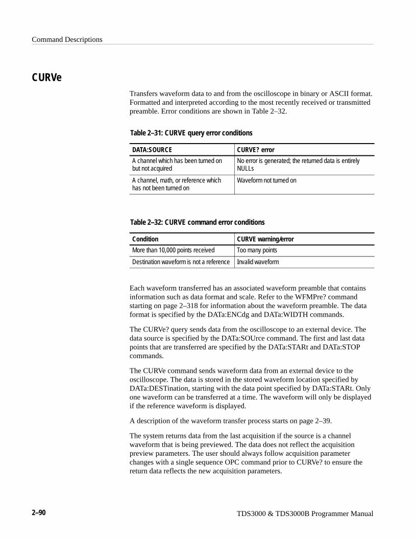
Command Descriptions
2–90 TDS3000 & TDS3000B Programmer Manual
CURVeTransfers waveform data to and from the oscilloscope in binary or ASCII format.Formatted and interpreted according to the most recently received or transmittedpreamble. Error conditions are shown in Table 2–32.
Table 2–31: CURVE query error conditions
DATA:SOURCE CURVE? error
A channel which has been turned onbut not acquired
No error is generated; the returned data is entirelyNULLs
A channel, math, or reference whichhas not been turned on
Waveform not turned on
Table 2–32: CURVE command error conditions
Condition CURVE warning/error
More than 10,000 points received Too many points
Destination waveform is not a reference Invalid waveform
Each waveform transferred has an associated waveform preamble that containsinformation such as data format and scale. Refer to the WFMPre? commandstarting on page 2–318 for information about the waveform preamble. The dataformat is specified by the DATa:ENCdg and DATa:WIDTH commands.
The CURVe? query sends data from the oscilloscope to an external device. Thedata source is specified by the DATa:SOUrce command. The first and last datapoints that are transferred are specified by the DATa:STARt and DATa:STOPcommands.
The CURVe command sends waveform data from an external device to theoscilloscope. The data is stored in the stored waveform location specified byDATa:DESTination, starting with the data point specified by DATa:STARt. Onlyone waveform can be transferred at a time. The waveform will only be displayedif the reference waveform is displayed.
A description of the waveform transfer process starts on page 2–39.
The system returns data from the last acquisition if the source is a channelwaveform that is being previewed. The data does not reflect the acquisitionpreview parameters. The user should always follow acquisition parameterchanges with a single sequence OPC command prior to CURVe? to ensure thereturn data reflects the new acquisition parameters.
Command Descriptions
TDS3000 & TDS3000B Programmer Manual 2–91
Waveform
DATa, WFMPre?
:����#��?�2O �"����2�2,>� �$
:���0
�?�2O is the waveform data in binary format. The waveform is formatted as:Q�� �DDD �1��� where �� is the number of y bytes. For example, if �DDD =500, then �� = 3. �DDD is the number of bytes to transfer. If width is 1 then allbytes on the bus are single data points. If width is 2 then all bytes on the bus are2-byte pairs. Use the /�5���6/�M command to set the width. <data> is the curvedata. See the 7�5��-� or 7�5��-�?�� examples in the accompanying disk formore specifics.
���2�2,>� is the waveform data in ASCII format. The format for ASCII datais �9�� %��9�� ���& where each �9�� represents a data point.
:���0
might return, for ASCII data: :���;�;�;�;�W����;�W��;�;�W��;�;�W��;�W��
W����;�;�;�W��;�;�W��;�����;�W��;�;�W��;�;�W��;�;�
Group
Related Commands
Syntax
Arguments
Examples
Command Descriptions
2–92 TDS3000 & TDS3000B Programmer Manual
DATaSets or returns the format and location of the waveform data that is transferredwith the CURVe command. Since DATa:DESTination and DATa:TARget areequivalent, only DATa:DESTination is returned by the DATa? query.
Waveform
/�5��#�6965�$
/�5�0
6965 initializes the waveform data parameters to their factory defaults.
/�5�0
might return the string �/�5���9 /7��<?69��EA/��569�56.9����IA��.:� ����IA�5��5��A�5.<�G;;A�6/5��H
CURVE, WAVFrm?
DATa:DESTinationSets or returns the reference memory location for storing waveform data that istransferred into the oscilloscope by the CURVe command. This command isidentical to the DATa:TARget command.
Waveform
/�5��/��5������������
/�5��/��5������0
����� (����, ���H, ���� or ���I) is the reference memory location where thewaveform will be stored.
This means that you cannot have a channel or math waveform as a destination.
Group
Syntax
Arguments
Examples
Related Commands
Group
Syntax
Arguments
Command Descriptions
TDS3000 & TDS3000B Programmer Manual 2–93
/�5��/��569�56.9�����
stores incoming waveform data in reference memory 3.
/�5��/��569�56.90
might return ���H as the reference memory location that is currently selected.
DATa:ENCdgSets or returns the format of the waveform data. This command is equivalent tosetting WFMPre:ENCdg, WFMPre:BN_Fmt, and WFMPre:BYT_Or as shownin Table 2–33. Setting the DATa:ENCdg value causes the correspondingWFMPre values to be updated and vice versa.
Waveform
/�5���9 13�#��� 6��"��6?���D�"��<?���D�"���6N���D�"
���<N���D�$
/�5���9 130
�� 6� specifies the ASCII representation of signed integer (�6?���D) data. Ifthis is the value at power-on, the WFMPre values for BN_Fmt, BYT_Or, andENCdg are set as RP, MSB, and ASC respectively.
�6?���D specifies signed integer data-point representation with the mostsignificant byte transferred first. This format results in the fastest data transferrate when DATa:WIDth is set to 2.
The range is –128 to 127 when DATa:WIDth is 1. Zero is center screen. Therange is –32768 to 32767 when DATa:WIDth is 2. The upper limit is onedivision above the top of the screen and the lower limit is one division below thebottom of the screen.
�<?���D specifies positive integer data-point representation with the mostsignificant byte transferred first.
The range is 0 to 255 when DATa:WIDth is 1. Center screen is 127. The range is0 to 65,535 when DATa:WIDth is 2. The upper limit is one division above thetop of the screen and the lower limit is one division below the bottom of thescreen.
��6N���D is the same as �6?���D except that the byte order is swapped,meaning that the least significant byte is transferred first. This format is usefulwhen transferring data to IBM compatible PCs.
Examples
Group
Syntax
Arguments
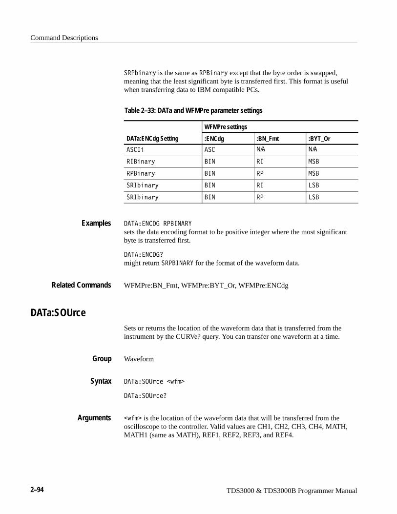
Command Descriptions
2–94 TDS3000 & TDS3000B Programmer Manual
��<N���D is the same as �<?���D except that the byte order is swapped,meaning that the least significant byte is transferred first. This format is usefulwhen transferring data to IBM compatible PCs.
Table 2–33: DATa and WFMPre parameter settings
WFMPre settings
DATa:ENCdg Setting :ENCdg :BN_Fmt :BYT_Or
�� 6� �� N/A N/A
�6?���D ?69 �6 -�?
�<?���D ?69 �< -�?
��6N���D ?69 �6 8�?
��6N���D ?69 �< 8�?
/�5���9 /7��<?69��E
sets the data encoding format to be positive integer where the most significantbyte is transferred first.
/�5���9 /70
might return ��<?69��E for the format of the waveform data.
WFMPre:BN_Fmt, WFMPre:BYT_Or, WFMPre:ENCdg
DATa:SOUrceSets or returns the location of the waveform data that is transferred from theinstrument by the CURVe? query. You can transfer one waveform at a time.
Waveform
/�5���.:2���J��
/�5���.:2�0
�J�� is the location of the waveform data that will be transferred from theoscilloscope to the controller. Valid values are CH1, CH2, CH3, CH4, MATH,MATH1 (same as MATH), REF1, REF2, REF3, and REF4.
Examples
Related Commands
Group
Syntax
Arguments

Command Descriptions
TDS3000 & TDS3000B Programmer Manual 2–95
/�5���.:� �����H
specifies that reference waveform two will be transferred in the next CURVE?query.
/�5���.:� �0
might return ��, indicating that channel 1 is the source for the waveform datathat is transferred using a CURVE? query.
DATa:STARtSets or returns the starting data point for waveform transfer. This commandallows for the transfer of partial waveforms to and from the oscilloscope.
Waveform
/�5���5�����9��
/�5���5���0
�9�� ranges from 1 to the record length, and is the first data point that will betransferred. Data will be transferred from �9�� to DATa:STOP or the recordlength, whichever is less. If �9�� is greater than the record length then no datawill be transferred.
When DATa:STOP is less than DATa:STARt, the values are swapped internallyfor CURVe?
/�5���5��5��;
specifies that the waveform transfer will begin with data point 10.
/�5���5��50
might return H�I as the first waveform data point that will be transferred.
CURVe?, DATa:STOP
Examples
Group
Syntax
Arguments
Examples
Related Commands
Command Descriptions
2–96 TDS3000 & TDS3000B Programmer Manual
DATa:STOPSets or returns the last data point that will be transferred when using the CURVe?query. This allows the transfer of partial waveforms to the controller.
When using the CURVe command, the oscilloscope will stop reading data whenthere is no more data to read or when the specified record length has beenreached so this command will be ignored.
Waveform
/�5���5.<��9��
/�5���5.<0
�9�� ranges from 1 to the record length, and is the last data point that will betransferred. If �9�� is greater than the record length then data will be transferredup to the record length. If both DATa:STARt and DATa:STOP are greater thanthe record length, an execution error will be reported.
If you always want to transfer complete waveforms, just set DATa:STARt to 1and DATa:STOP to the maximum record length.
When DATa:STOP is less than DATa:STARt, the values are swapped internallyfor CURVe?
/�5���5.<�X;;;
specifies that the waveform transfer will stop at data point 9000.
/�5���5.<0
might return �G;; as the last data point that will be transferred.
CURVe?, DATa:STARt
Group
Syntax
Arguments
Examples
Related Commands
Command Descriptions
TDS3000 & TDS3000B Programmer Manual 2–97
DATa:TARgetSets or returns the location for storing waveform data transferred to theinstrument using the CURVe command. This command is equivalent to theDATa:DESTINATION command and is included for compatibility with olderTektronix instruments.
Waveform
/�5��5��3��������
/�5��5��3��0
�� specifies reference memory location 1 (REF1) through 4 (REF4).
/�5��5��7�50
might return /�5��5��7�5����H.
CURVe
DATa:WIDthSets or returns the number of bytes per data point in the waveform transferredusing the CURVe command.
Waveform
/�5���6/�M��9��
/�5���6/�M0
�9�� = 1 specifies that there is 1 byte (8 bits) per point.
�9�� = 2 specifies that there are 2 bytes (16 bits) per point. This format isuseful for AVErage waveforms.
/�5���6/�M��
sets the data width to 1 byte per data point for CURVe data.
CURVe, WFMPre:BIT_Nr, WFMPre:BYT_Nr
Group
Syntax
Arguments
Examples
Related Commands
Group
Syntax
Arguments
Examples
Related Commands
Command Descriptions
2–98 TDS3000 & TDS3000B Programmer Manual
DATESets or returns the date that the oscilloscope can display.
Miscellaneous
/�5���+����3
/�5�0
�+����3 is a date in the form RDDDDW��W11L. where �� refers to a two-digitmonth number from 01 to 12, 11 refers to a two-digit day number in the month.,and DDDD refers to a four-digit year number. There must a dash (–) after the DDDDand after the ��.
/�5��LH;;;W;�WH;L
specifies that the date is set to January 20th, 2000.
DISplay: CLOCk, TIMe
*DDTAllows the user to specify a command or a list of commands that are executedwhen the instrument receives a *TRG command or the GET GPIB interfacemessage. *DDT is just a special alias that *TRG uses.
Miscellaneous
C//5�#��?�2O �"��+����3 �$
C//50
�?�2O or �+����3 is a complete sequence of program messages. Themessages can contain only valid commands that must be separated by semico-lons and must follow all rules for concatenating commands (see page 2–4). Thesequence must be ≤255 characters. �?�2O format is always returned as a queryresponse.
Group
Syntax
Arguments
Examples
Related Commands
Group
Syntax
Arguments
Command Descriptions
TDS3000 & TDS3000B Programmer Manual 2–99
C//5�QH���:5.��5���� :5�A���8� 5������.9
performs autoset and selects REF1.
ALlas:DEFINE, *TRG
DESESets or returns the bits in the Device Event Status Enable Register (DESER).The DESER is the mask that determines whether events are reported to theStandard Event Status Register (SESR), and entered into the Event Queue. For amore detailed discussion of the use of these registers, see page 3–1.
Status and Error
/�����9��
/���0
�9�� is a value in the range from 0 to 255. The binary bits of the DESER areset according to this value. For example, /����H;X sets the DESER to the binaryvalue 11010001 (that is, the most significant bit in the register is set to 1, thenext most significant bit to 1, the next bit to 0, etc.).
The power-on default for DESER is all bits set if C<� is 1. If C<� is 0, theDESER maintains its value through a power cycle.
NOTE. Setting the DESER and the ESER to the same value allows only thosecodes to be entered into the Event Queue and summarized on the ESB bit (bit 5)of the Status Byte Register. Use the C��� command to set the ESER. A discussionof event handling begins on page 3–1.
/����H;X
sets the DESER to binary 11010001, which enables the PON, URQ, EXE, andOPC bits.
/���0
might return the string �/�����BT, showing that the DESER contains the binaryvalue 10111010.
*CLS, *ESE, *ESR?, EVENT?, EVMsg?, *SRE, *STB?
Examples
Related Commands
Group
Syntax
Arguments
Examples
Related Commands
Command Descriptions
2–100 TDS3000 & TDS3000B Programmer Manual
DIAg:LOOP:OPTionSets the diagnostic loop option.
Calibration and Diagnostic
/6�3�8..<�.<5���#�8��E�"��68".9��68".9 �$
/6�3�8..<�.<5��0
�8��E� continues looping until diagnostics are stopped via the front panel or byan instrument command.
��68 causes looping until the first diagnostic failure or until diagnostics arestopped.
.9��68 causes looping on a specific test group as long as a FAIL status isreturned from the test.
.9 � executes diagnostics test sequence once.
/6�7�8..<�.<56.9���68
stops the diagnostic loop after the first failure.
DIAg:LOOP:STOP (Set Only)Stops diagnostic at the end of the current loop.
Calibration and Diagnostic
/6�3�8..<��5.<
/6�7�8..<��5.<
stops diagnostic at the end of the current loop.
Group
Syntax
Arguments
Examples
Group
Syntax
Examples
Command Descriptions
TDS3000 & TDS3000B Programmer Manual 2–101
DIAg:RESUlt:FLAg? (Query Only)Returns the pass/fail status from the last diagnostic test sequence execution. TheDIAg:RESUlt:LOG? query can be used to determine which test(s) has failed.
Calibration and Diagnostic
/6�3����:����8�30
<��� indicating that all of the selected diagnostic tests have passed.
��6� indicating that at least one of the selected diagnostic tests has failed.
/6�7����:85��8�70
returns either �/6�7����:85��8�7�<��� or ��6�.
DIAg:RESUlt:LOG?
DIAg:RESUlt:LOG? (Query Only)Returns the internal results log from the last diagnostic test sequence execution.The list contains all modules and module interfaces that were tested along withthe pass/fail status of each.
Calibration and Diagnostic
/6�3����:���8.70
�+����3 in the following format:
�����,� WW�-1,������� %������,� WW�-1,������� ���&
/6�7����:85�8.70
might return �/6�7����:85�8.7�L4���WW <:�4���WW/��4��D�4���WW���<�����4���WW6.�4���WW�2=,�������4���WW�//�4���WW�44��2�����S�D�
4���WW�.-L�
DIAg:RESUlt:FLAg?
Group
Syntax
Returns
Examples
Related Commands
Group
Syntax
Returns
Examples
Related Commands
Command Descriptions
2–102 TDS3000 & TDS3000B Programmer Manual
DIAg:SELect:ALL (Set Only)Specifies that all system test sequences will be run when the DIAg:STATEEXECUte command is sent.
Calibration and Diagnostic
/6�3���8�2���88��88
�88 selects functional, memory, and register tests for the acquisition, processorand display systems.
DIAg:SELect:<function> (Set Only)Sets the oscilloscope to run diagnotics on the specified system function.
Calibration and Diagnostic
/6�3���8�2����,�2���
�,�2��� specifies a single oscilloscope function on which to run diagnostics.Valid values are:
�<<S�D��<<S�D tests the application keys.
<:� <: tests the CPU.
/6�4��D�/6�4��D tests the display.
/�8.<<E1��O��8.<<E1��O tests the disk drive unit.
�<������<���� tests the front panel controls.
6.�6. tests the IO ports.
�.-��.- tests the system read only memory.
/6�7���8� 5� <:� <:
sets the oscilloscope to run just CPU tests.
Group
Syntax
Arguments
Group
Syntax
Arguments
Examples
Command Descriptions
TDS3000 & TDS3000B Programmer Manual 2–103
DIAg:STATE EXECute (Set Only)Executes the diagnostic tests that have been specified with the DIAg:SELectcommand.
When the test sequence has completed, any of the modules or module interfacesthat failed diagnostics are displayed on the screen and stored in an internal logfile. The pass/fail status will be returned by the DIAg:RESUlt:FLAg? query, andthe internal log will be returned by the DIAg:RESUlt:LOG? query. Thiscommand is equivalent to running Extended Diagnostics by selecting OKConfirm Run Test when Execute is selected in the UTILITY menu andSystem is set to Diags.
NOTE. The DIAg:STATE EXECute command can take 30 seconds or more torespond. This command does not return control to the instrument controller untildiagnostics are complete.
Calibration and Diagnostic
/6�3��5�5����� ,��
��� ,�� runs the diagnostic test sequences specified by the DIAg:SELectcommand. When complete, the oscilloscope will return to the state it was in justprior to the test. Pass/fail status of the tests can be returned by executing theDIAg:RESUlt:FLAg? query.
/6�7��5�5����� :5�
executes all the diagnostic tests that have been selected.
DISplay? (Query Only)Returns the current display settings.
Display
/6�4��D0
Group
Syntax
Arguments
Examples
Group
Syntax
Command Descriptions
2–104 TDS3000 & TDS3000B Programmer Manual
/6�<8�E0
returns to the current display settings. might return �/6�<8�E��.�-�5�E5A�5E8���� 5.��A�685����69�A<���6�5@�9 ��G;;�;�W�A7��56 :8���:88A5�675��A695�9�65E�.����88�BGA
�����.�-�V;A5��5�T;A .95���5��G;
DISplay:CLOCkControls the display of the date and time. This is equivalent to setting DisplayDate/Time in the UTILITY menu.
Display
/6�4��D� 8. O�#�.���"�.9�"��9�� �$
/6�4��D� 8. O0
�.�� or �9�� = 0 removes the clock from the display.
�.9 or �9�� � 0 displays the clock on the display.
/6�<8�E� 8. S�.9
sets the display to show the time and date.
DISplay:COLor:PALEtte:REGularSets or returns the color palette of displayed waveforms. This command isequivalent to setting Color Palette in the DISPLAY menu.
Display
/6�4��D� .8�<�8�������7,���#�9.�-���"�-.9.2M���$
/6�4��D� .8�<�8�������7,��0
�9.�-�� selects the factory default color palette.
�-.9 selects the monochrome color palette.
Examples
Group
Syntax
Arguments
Examples
Group
Syntax
Arguments
Command Descriptions
TDS3000 & TDS3000B Programmer Manual 2–105
/6�<8�E� .8.��<�8�55����7:8��0
might return �/6�<8�E� .8.��<�8�55����7:8���9.�-�8 indicating thatNormal is selected.
HARDCopy:PALEtte
DISplay:FORMatSets or returns the display format. This command is equivalent to settingXY Display in the DISPLAY menu.
Display
/6�4��D��.�-���#�7�5�/�DF�"��E�"�E5�"��� ��24��$
/6�4��D��.�-��0
7�5�/�DF displays XY signals only when the Z (gating) channel is true. GatedXYZ is similar to analog oscilloscope modulated XYZ mode except that thedisplayed XY signal is either on or off; there is no intensity modulation. GatedXYZ is useful for showing constellation diagrams.
�E displays the voltage of one waveform against the voltage of another. Thesources that make up an �E waveform are predefined and are listed inTable 2–34. Displaying one source causes its corresponding source to bedisplayed.
Table 2–34: XY format pairs
X-Axis source Y-Axis source
Ch1 Ch2, Ch3, or Ch4
Ref1 Ref2, Ref3, or Ref4
E5 sets the display to a voltage versus time format and is the default displayformat.
�� ��24� sets the display to a vectorscope format. TDS3VID, TDS3SDIonly.
Examples
Related Commands
Group
Syntax
Arguments
Command Descriptions
2–106 TDS3000 & TDS3000B Programmer Manual
/6�<8�E��.�-�5�E5
selects a voltage versus time format for the display.
/6�<8�E��.�-�50
might return �E for the display format.
DISplay:XY:MODe
DISplay:GRAticuleSelects the type of graticule that is displayed. The TDS3VID and TDS3SDIapplication modules add IRE, mV, and PAL graticules to the standard graticulecommand, as well as a vectorscope display mode.
Display
/6�4��D�7����2,���#� �.������"�������"��:8��"�7�61�| 6���"�-��"�� ��24��"�<�8�$�
/6�4��D�7����2,��0
�.����� specifies a frame and cross hairs only.
����� specifies just a frame.
�:8� specifies a frame, a grid, and cross hairs.
7�61 specifies a frame and grid only.
6�� sets the vertical and horizontal scales, and displays a graticule for measuringNTSC-standard video signals. TDS3VID, TDS3SDI only.
-� or <�8 sets the vertical and horizontal scales, and displays an appropriategraticule for measuring PAL-standard video signals. TDS3VID, TDS3SDI only.
�� ��24� displays a vectorscope format screen for measuring NTSC-stan-dard or analog HDTV color difference video signals. TDS3VID, TDS3SDI only.
Examples
Related Commands
Group
Syntax
Arguments
Command Descriptions
TDS3000 & TDS3000B Programmer Manual 2–107
/6�<8�E�7��56 :8�����-�
sets the graticule type to display the frame only.
/6�<8�E�7��56 :8�0
returns �:88 when all graticule elements (grid, frame, and cross hairs) areselected.
/6�<8�E�7��56 :8��6��
Displays an IRE graticule.
DISplay:INTENSITy:BACKLightSets or returns the backlight intensity for the display. This is equivalent to settingBacklight Intensity in the DISPLAY menu.
Display
/6�4��D�695�9�65D�?� S8�3M��#��67��"�-�/�,��"�8.��$
/6�4��D�695�9�65D�?� S8�3M�0
/6�<8�E�695�9�65E�?� S867�50
might return �/6�<8�E�695�9�65E�?� S867�5��67�
DISplay:INTENSITy:WAVEformSets the intensity of the waveforms. This command is equivalent to adjusting theWAVEFORM INTENSITY knob.
Display
/6�4��D�695�9�65D���������9��
/6�4��D�695�9�65D�������0
�9�� is the waveform intensity and ranges from 1 to 100 percent.
/6�<8�E�695�9�65E������.�-0
might return �/6�<8�E�695�9�65E������.�-�T; as the intensity of thewaveforms.
Examples
Group
Syntax
Examples
Group
Syntax
Arguments
Examples
Command Descriptions
2–108 TDS3000 & TDS3000B Programmer Manual
DISplay:PERSistenceSets the length of time that data points are displayed. This command is equiva-lent to changing Persist Time in the Waveform Display menu.
Display
/6�4��D�<��������2��#��9�� �"�69�6�����"��:5.�"�-696�,��$
/6�4��D�<��������2�0
�9�� specifies the time, in seconds, that waveform points are displayed on thescreen.
69�6���� displays waveform points until a control change resets the acquisitionsystem.
�:5. specifies that the waveform persistence is controlled by the front panelWAVEFORM INTENSITY knob.
-696�,� specifies that the waveform persistence is set to the minimum value of0.0E0.
/6�<8�E�<���6�5�9 ���
specifies that the waveform points are displayed fading for 3 seconds before theycompletely disappear.
DISplay:INTENSITy:WAVEform
DISplay:PERSistence:CLEAR (Set Only)Resets the persist time countdown and clears the display of all acquired points.This command is equivalent to pressing the Clear Persistence button in theWaveform Display menu.
Display
/6�4��D�<��������2�� 8���
/6�<8�E�<���6�5�9 �� 8���
clears the waveform display.
Group
Syntax
Arguments
Examples
Related Commands
Group
Syntax
Examples

Command Descriptions
TDS3000 & TDS3000B Programmer Manual 2–109
DISplay:PERSistence, DISplay:INTENSITy:WAVEform
DISplay:PICture:AUTOContrast(TDS3VID, TDS3SDI Only)
Sets or returns the video picture mode autocontrast setting.
Display
/6�4��D�<6 �,���:5. ������#�.���"�.9�"��9�� �$
/6�4��D�<6 �,���:5. �����0
�.�� or �9�� = 0 disables picture autocontrast mode.
�.9 or �9�� � 0 enables picture autocontrast mode.
/6�<8�E�<6 5:����:5. .95���50
might return /6�<8�E�<6 5:����:5. .95���5�.9, indicating that the videopicture autocontrast mode is enabled.
DISplay:PICture:BRIghtness, DISplay:PICture:CONTRAst, DISplay:PICture:STATE
DISplay:PICture:BRIghtness(TDS3VID, TDS3SDI Only)
Sets or returns the video picture mode brightness setting.
Display
/6�4��D�<6 �,��?�63M�������9�� �
/6�4��D�<6 �,��?�63M�����0
Related Commands
Group
Syntax
Arguments
Examples
Related Commands
Group
Syntax
Command Descriptions
2–110 TDS3000 & TDS3000B Programmer Manual
�9�� sets the picture brightness value from 0 to 100. DISplay:PICture:AUTO-Contrast must be OFF in order to set the brightness value.
/6�<8�E�<6 5:���?�67�59���0
might return /6�<8�E�<6 5:���?�67�59�����I, indicating that the videopicture brightness setting is 34.
DISplay:PICture:AUTOContrast, DISplay:PICture:CONTRAst, DISplay:PICture:STATE
DISplay:PICture:CONTRAst(TDS3VID, TDS3SDI Only)
Sets or returns the video picture mode contrast setting.
Display
/6�4��D�<6 �,�� .95������9�� �
/6�4��D�<6 �,�� .95����0
�9�� sets the picture contrast value from 0 to 100. DISplay:PICture:AUTOCon-trast must be OFF in order to set the contrast value.
/6�<8�E�<6 5:��� .95���50
might return /6�<8�E�<6 5:��� .95���5�IG, indicating that the video picturecontrast setting is 45.
DISplay:PICture:AUTOContrast, DISplay:PICture:BRIghtness, DISplay:PICture:STATE
Arguments
Examples
Related Commands
Group
Syntax
Arguments
Examples
Related Commands
Command Descriptions
TDS3000 & TDS3000B Programmer Manual 2–111
DISplay:PICture:STATE(TDS3VID, TDS3SDI Only)
Sets or returns the video picture mode setting.
Display
/6�4��D�<6 �,���5�5��#�.���"�.9�"��9�� �$
/6�4��D�<6 �,���5�5�0
�.�� or �9�� = 0 disables video picture mode.
�.9 or �9�� � 0 enables video picture mode.
/6�<8�E�<6 5:����5�5�0
might return /6�<8�E�<6 5:����5�5��.9, indicating that the video picturemode is enabled.
DISplay:PICture:BRIghtness, DISplay:PICture:CONTRAst, DISplay:PICture:AUTOContrast
DISplay:STYle:DOTsonlySelects waveform display style to dots only for XY & YT modes. This commandis equivalent to setting Dots Only in the Waveform Display menu.
Display
/6�4��D��5E���/.5���D�#�.9�"�.���"��9�� �$
/6�4��D��5E���/.5���D0
.9 or 9�� � 1 sets the waveform display style to Dots Only.
.�� or 9�� � 0 sets Dots Only to Off.
Group
Syntax
Arguments
Examples
Related Commands
Group
Syntax
Arguments
Command Descriptions
2–112 TDS3000 & TDS3000B Programmer Manual
/6�<8�E��5E8��/.5�.98E�.9
sets the display to Dots Only.
/6�<8�E��5E8��/.5�.98E0
might return �/6�<8�E��5E8��/.5�.98E�� indicating that the waveformdisplay is set to Dots Only.
DISplay:VECtorscope:STATE(TDS3VID, TDS3SDI Only)
Sets or returns the video vectorscope state setting. This is equivalent to turningVectorscope mode on or off from the front panel.
Display
/6�4��D��� ��24���5�5��#�.9�"�.���"��9�� �$
/6�4��D��� ��24���5�5�0
.9 or 9�� � 1 enables the vectorscope display mode.
.�� or 9�� � 0 disables the vectorscope display mode.
/6�<8�E��� 5.�� .<���5�5�0
might return �/6�<8�E��� 5.�� .<���5�5��; indicating that the vectorscopedisplay mode is disabled (off).
DISplay:VECtorscope:TY_SETTING(TDS3VID, TDS3SDI Only)
Sets or returns the video vectorscope display type setting state. Note that thisdoes not actually turn on the vectorscope display type, but just sets the typevalue.
Display
/6�4��D��� ��24��5EU��55697�#�.9��,�1�1�"�����95E��>��"�
�9�� �$
/6�4��D��� ��24��5EU��556970
Examples
Group
Syntax
Arguments
Examples
Group
Syntax

Command Descriptions
TDS3000 & TDS3000B Programmer Manual 2–113
.9��,�1�1 or 9�� � 1 sets the vectorscope display mode to 100%.
����95E��>� or 9�� � 0 sets the vectorscope display mode to 75%.
/6�<8�E��� 5.�� .<��5EU��556970
might return �/6�<8�E��� 5.�� .<��5EU��55697�� indicating that thevectorscope display mode is set to 100%.
DISplay:VECtorscope:TYPE(TDS3VID, TDS3SDI Only)
Sets or returns the video vectorscope display type setting.
Display
/6�4��D��� ��24��5E<��#�.9��,�1�1�"�����95E��>��"��9�� �$
/6�4��D��� ��24��5E<�0
.9��,�1�1 or 9�� � 1 sets the vectorscope display mode to 100% colorbars.
����95E��>� or 9�� � 0 sets the vectorscope display mode to 75% colorbars.
/6�<8�E��� 5.�� .<��5E<�0
might return �/6�<8�E��� 5.�� .<��5E<��� indicating that the vectorscopedisplay mode is set to 100%.
Display:XY? (Query Only)Returns all XY and Gated XYZ parameters.
Display
/6�4��D��E0
/6�<8�E��E0
might return �/6�<8�E��E�-./��.��AE ��99�8�.��AE�������HAP ��99�8.��AP8���8�;�; indicating the XY display is off.
Arguments
Examples
Group
Syntax
Arguments
Examples
Group
Syntax
Examples
Command Descriptions
2–114 TDS3000 & TDS3000B Programmer Manual
/6�4��D��E�-./���/6�4��D��E�E ������
DISplay:XY:MODeSets or returns the display mode. This command is equivalent to settingXY Display in the DISPLAY menu.
Display
/6�4��D��E�-./��#�.���"�5�673��"�7�5�1�DF�"��� ��24��$
/6�4��D��E�-./�0
.�� sets the display to a voltage versus time format and is the normal mode.
5�673� displays the voltage of one waveform against the voltage of another.The sources that make up an �E waveform are predefined and are listed inTable 2–35. Displaying one source causes its corresponding source to bedisplayed.
Table 2–35: XY format pairs
X-Axis source Y-Axis source
Ch1 Ch2, Ch3, or Ch4
Ref1 Ref2, Ref3, or Ref4
7�5�1�DF displays XY signals only when the Z (gating) channel is true. GatedXYZ is similar to analog oscilloscope modulated XYZ mode except that thedisplayed XY signal is either on or off; there is no intensity modulation. GatedXYZ is useful for showing constellation diagrams. Use the DISplay:XY:ZCHan-nel and DISplay:XY:ZLEVel commands to specify the Z channel and Z channelthreshold level.
�� ��24� sets the display to a video vectorscope display mode. TDS3VID,TDS3SDI only.
/6�<8�E��E�-./��.��
Selects a voltage versus time format for the display.
/6�<8�E��E�-./�0
might return �/6�<8�E��E�-./��5�677�� indicating a triggered XY displayformat.
Related Commands
Group
Syntax
Arguments
Examples
Command Descriptions
TDS3000 & TDS3000B Programmer Manual 2–115
DISplay:XY:YCHannel, DISplay:XY:YREF, DISplay:XY:ZCHannel, DISplay:XY:ZLEVel, DISplay:FORMat
DISplay:XY:YCHannelSpecifies the Y channel to be displayed with channel 1 in Triggered XY displaymode.
Display
/6�4��D��E�E �������#� �H�"� ���"� �I�"�.���$
/6�4��D��E�E ������0
�H , ��, and �I specify the channel displayed with channel 1 in Triggered XYDisplay mode.
.�� sets the Y Channel to off or none which turns off or prevents the CH1 versusCH �� �waveform from being displayed in Triggered XY or prevents it fromcoming on if Triggered XY is turned on later.
/6�<8�E��E�E ��99�8� �H
sets channel 2 to be displayed with channel 1 in Triggered XY mode.
/6�<8�E��E�E ��99�80
might return :/6�<8�E��E�E ��99�8� �H indicating that channel 2 will be theY channel in Triggered XY mode.
DISplay:XY:MODe, DISplay:XY:YREF, DISplay:XY?
DISplay:XY:YREFSpecifies the Y channel to be displayed with reference 1 in Triggered XY displaymode.
Display
/6�4��D��E�E����#����H�"������"����I�"�.���$
/6�4��D��E�E���0
Related Commands
Group
Syntax
Arguments
Examples
Related Commands
Group
Syntax
Command Descriptions
2–116 TDS3000 & TDS3000B Programmer Manual
���H , ����, and ���I specify the reference displayed with REF1 in TriggeredXY Display mode.
.�� set the Y reference to off which turns off or prevents the REF1 versusREF<x> waveform from being displayed in Triggered XY or prevents it fromcoming on if Triggered XY is turned on later.
/6�<8�E��E�E�������H
sets REF2 to be displayed with REF1 in Triggered XY mode.
DISplay:XY:MODe, DISplay:XY:YCHannel
DISplay:XY:ZCHannelSpecifies the Z channel to use in gated XYZ mode. Gated XYZ is similar toanalog oscilloscope modulated XYZ mode except that the displayed XY signal iseither on or off; there is no intensity modulation. Gated XYZ is useful forshowing constellation diagrams.
Display
/6�4��D��E�P �������#�0�"� �H�"� ���"� �I�$
/6�4��D��E�P ������0
� �H�W� �I specifies which channel to use as the Z channel source.
/6�<8�E��E�P ��99�8� �H sets oscilloscope channel 2 as the Z channel source in gated XYZ mode.
DISplay:XY:ZLEVelSpecifies the Z channel threshold level to enable XY gating in gated XYZ mode.
Display
/6�4��D��E�P8������9��
/6�4��D��E�P8����0
Arguments
Examples
Related Commands
Group
Syntax
Arguments
Examples
Group
Syntax
Command Descriptions
TDS3000 & TDS3000B Programmer Manual 2–117
�9�� sets the Z channel threshold level. Z-channel signals above the thresholdare true and open the XY signal gate; Z-channel signals below the threshold arefalse and close the XY signal gate. The gating channel is always a high-truelogic; to emulate a low-true logic, invert the Z-channel signal.
/6�<8�E��E�P8���8���H�; sets the Z channel threshold level to 1.2 volts.
*ESESets or returns the bits in the Event Status Enable Register (ESER). The ESERprevents events from being reported to the Status Byte Register (STB). For amore detailed discussion of the use of these registers, see page 3–1.
Status and Error
C�����9��
C���0
�9�� is a value in the range from 0 through 255. The binary bits of the ESERare set according to this value.
The power-on default for ESER is 0 if C<� is 1. If C<� is 0, the ESERmaintains its value through a power cycle.
NOTE. Setting the DESER and the ESER to the same value allows only thosecodes to be entered into the Event Queue and summarized on the ESB bit (bit 5)of the Status Byte Register. Use the /��� command to set the DESER. Adiscussion of event handling begins on page 3–1.
C����H;X
sets the ESER to binary 11010001, which enables the PON, URQ, EXE, andOPC bits.
C���0
might return the value �BT, showing that the ESER contains the binary value10111010.
*CLS, DESE, *ESR?, EVENT?, EVMsg? *SRE, *STB?
Arguments
Examples
Group
Syntax
Arguments
Examples
Related Commands
Command Descriptions
2–118 TDS3000 & TDS3000B Programmer Manual
*ESR? (Query Only)Returns the contents of the Standard Event Status Register (SESR). *ESR? alsoclears the SESR (since reading the SESR clears it). For a more detaileddiscussion of the use of these registers, see page 3–1.
Status and Error
C���0
C���0
might return the value H��, showing that the SESR contains binary 11010101.
ALLEv?, *CLS, DESE, *ESE, EVENT?, EVMsg?, *SRE, *STB?
ETHERnet:DCHPBOOTP(TDS3000B Series and TDS3EM Only)
Sets or returns the network initialization search for a DCHP/BOOTP server.
Ethernet
�5�������/ �<?..5<�#�.���"�.9�"���� �$
�5�������/ �<?..5<0
.9 or �� � 1 enables the oscilloscope to search the network for a DCHP orBOOTP server in order to automatically assign a dynamic IP address to theoscilloscope.
NOTE. Do not use DCHP/BOOTP searching if your oscilloscope has beenassigned a static address on a network. If you set this command to ON, theDCHP/BOOTP search will delete or change your static IP address information.
.�� or �� � 0 disables the oscilloscope to search the network for a DCHP orBOOTP server.
Group
Syntax
Example
Related Commands
Group
Syntax
Arguments
Command Descriptions
TDS3000 & TDS3000B Programmer Manual 2–119
�5���9�5�/ �<?..5<�.9 sets the oscilloscope to search for a DCHP or BOOTP server and assign adynamic IP address to the oscilloscope.
ETHERnet:DNS:IPADDress(TDS3000B Series and TDS3EM Only)
Sets or returns the network Domain Name Server (DNS) IP address.
Ethernet
�5�������/9��6<�//�����+����3
�5�������/9��6<�//���0
�+����3 is a standard IP address value, enclosed in quotes.
�5���9�5�/9��6<�//�����L�HB��XT��H��HHL
sets the DNS IP address that the oscilloscope uses to communicate with thenetwork.
ETHERnet:DOMainname(TDS3000B Series and TDS3EM Only)
Sets or returns the network domain name.
Ethernet
�5�������/.-���������+����3
�5�������/.-�������0
�+����3 �is the network domain name, enclosed in quotes.
�5���9�5�/.-�699�-��L��4M���-D24�2�L sets the domain name that the oscilloscope uses to communicate with thenetwork.
Example
Group
Syntax
Arguments
Example
Group
Syntax
Arguments
Example
Command Descriptions
2–120 TDS3000 & TDS3000B Programmer Manual
ETHERnet:ENETADDress? (Query Only)(TDS3000B Series and TDS3EM Only)
Returns the ethernet address value assigned to the TDS3EM Ethernet commu-nication module or the TDS3000B Series oscilloscope. This is assigned at thefactory and can not be changed.
Ethernet
�5��������9�5�//���0
�5���9�5��9�5�//����0 returns an ethernet address such as L;H�;;����;���H�;�L
ETHERnet:GATEWay(TDS3000B Series and TDS3EM Only)
Sets or returns the remote interface gateway IP address.
Ethernet
�5�������7�5���D��+����3 �
�5�������7�5���D0
�+����3 is a standard IP address value, enclosed in quotes.
�5���9�5�7�5���E�L�HB��I���T��L
sets the gateway IP address.
Group
Syntax
Example
Group
Syntax
Arguments
Example
Command Descriptions
TDS3000 & TDS3000B Programmer Manual 2–121
ETHERnet:HTTPPORT(TDS3000B Series and TDS3EM Only)
Sets or returns the remote interface HTTP port value.
Ethernet
�5��������55<<.�5��+����3 �
�5��������55<<.�50
�+����3 is an integer port number, enclosed in quotes.
�5���9�5��55<<.�5�LIGL
sets the HTTP port value to 45.
ETHERnet:IPADDress(TDS3000B Series and TDS3EM Only)
Sets or returns the IP address assigned to the oscilloscope.
Ethernet
�5�������6<�//�����+����3 �
�5�������6<�//���0
�+����3 is a standard IP address value, enclosed in quotes.
�5���9�5�6<�//�����L�H���;��VB�X;L
sets the oscilloscope’s IP address.
Group
Syntax
Arguments
Example
Group
Syntax
Arguments
Examples
Command Descriptions
2–122 TDS3000 & TDS3000B Programmer Manual
ETHERnet:NAME(TDS3000B Series and TDS3EM Only)
Sets or returns the network name assigned to the oscilloscope.
Ethernet
�5�������9�-���+����3 �
�5�������9�-�0
�+����3 is the network name assigned to the oscilloscope, enclosed in quotes.
�5���9�5�9�-��L��N�24��L
sets the oscilloscope’s network name.
ETHERnet:NETPRInter:ADD (Set Only)(TDS3000B Series and TDS3EM Only)
Adds the specified printer name and parameters to the oscilloscope ethernetprinter list.
Ethernet
�5�������9�5<�6�����//��+����3 �
�+����3 is a quoted composite string that contains, in the following order, thenetwork printer name, printer server name, and print server IP address. Each fieldis delimited by a semicolon (;). The printer name is always required, and eitherthe server name or server IP address is required. If you do not use all three fields,the missing field delimiter must still be used.
NOTE. If DNS services are not available, all these fields must be filled in.
Adding a printer that already exists in the list is equivalent to doing a renameprinter operation; the new settings replace the existing printer settings.
Group
Syntax
Arguments
Examples
Group
Syntax
Arguments
Command Descriptions
TDS3000 & TDS3000B Programmer Manual 2–123
�5���9�5�9�5<�695����//�L+-�4�A4���>��A�HB��H�����H�L
adds a printer to the oscilloscope printer list.
�5���9�5�9�5<�695����//�L�<T;;14�A�<��>�AL
adds a printer to the oscilloscope printer list. Note that only the network printername and print server name are entered, and that the required IP addressdelimiter is at the end of the string. This example assumes that DNS services areavailable to supply the printer server IP address.
ETHERnet:NETPRInter:DELEte (Set Only)(TDS3000B Series and TDS3EM Only)
Deletes the specified printer from the oscilloscope network printer list.
Ethernet
�5�������9�5<�6����/�8�����+����3
�+����3 is a quoted composite string that contains, in the following order, thenetwork printer name, printer server name, and print server IP address. Each fieldis delimited by a semicolon (;). The printer name is required, and either theserver name or server IP address is required. If you do not use all three fields,you must still use the missing field delimiters.
�5���9�5�9�5<�695���/�8�5��L+-�4�A4���>��A�HB��H�����H�L
deletes the specified printer from the oscilloscope network printer list
ETHERnet:NETPRInter:DELWarn(TDS3000B Series and TDS3EM Only)
Sets or returns the oscilloscope on-screen printer delete warning message. Nodeletion warning message is sent over the network.
Ethernet
�5�������9�5<�6����/�8����#�.���"�.9�"���� �$
�5�������9�5<�6����/�8���0
Examples
Group
Syntax
Arguments
Examples
Group
Syntax
Command Descriptions
2–124 TDS3000 & TDS3000B Programmer Manual
.�� turns off delete warning
.9 turns on delete warning
�� is an integer number where nr1 = 0 turns off delete warning, and nr1 ≠ 0turns on delete warning.
�5���9�5�9�5<�695���/�8���9�� sets the oscilloscope to display a warning message on the oscilloscope screenwhenever a front-panel delete printer action occurs.
ETHERnet:NETPRInter:REName (Set Only)(TDS3000B Series and TDS3EM Only)
Renames the specified printer name and/or parameters in the oscilloscopeethernet printer list.
Ethernet
�5�������9�5<�6������9�����+����3 ��+����3
�+����3 is a quoted composite string that contains, in the following order, thenetwork printer name, printer server name, and print server IP address. Each fieldis delimited by a semicolon (;). The printer name is always required, and eitherthe server name or server IP address is required. If you do not use all three fields,the missing field delimiter must still be used. The first Qstring is the originalprinter information, and the second Qstring is the new printer information.
�5���9�5�9�5<�695�����9�-��L+-�4�A4���>��A�HB��H�����H�L�
L+-�2�A4���>��A�HB��H�����H�L renames the network printer name from QMSprt to QMScolor.
Arguments
Examples
Group
Syntax
Arguments
Examples
Command Descriptions
TDS3000 & TDS3000B Programmer Manual 2–125
ETHERnet:NETPRInter:SELect:ALLInfo? (Query Only)(TDS3000B Series and TDS3EM Only)
Returns a composite string that contains the active (selected) network printername, printer server name, and print server IP address.
Ethernet
�5�������9�5<�6������8�2���886��0
�5���9�5�9�5<�695�����8� 5��8869�.0 might return L<M����G;A5�O��>�A��X�H��GT��HL.
ETHERnet:NETPRInter:SELect:NAME(TDS3000B Series and TDS3EM Only)
Sets or returns the network printer to use for hard copy output.
Ethernet
�5�������9�5<�6������8�2��9�-���+����3 �
�5�������9�5<�6������8�2��9�-�0
�+����3 is the network printer name, enclosed in quotes.
�5���9�5�9�5<�695�����8� 5�9�-��L5�O<�T;L sets the oscilloscope to use the network printer named TekP360.
Group
Syntax
Examples
Group
Syntax
Arguments
Examples
Command Descriptions
2–126 TDS3000 & TDS3000B Programmer Manual
ETHERnet:PASSWord (Set Only)(TDS3000B Series and TDS3EM Only)
This command sets the Ethernet access password.
Ethernet
�5�������<����1�L�1L�L��JL
�1 is the current password, enclosed in quotes. If there is no current password,enter a null character (two quotes with no character between).
��J is a new password, enclosed in quotes.
�5���9�5�<����.�/�LO���HL�LP�9G� replaces the current Ethernet password karma2 with the new password ZEN53.
ETHERnet:PING:EXECUTE (Set Only)(TDS3000B Series and TDS3EM Only)
This command tests the Ethernet connection by performing a ping operation.
Ethernet
�5�������<697���� :5�
�5���9�5�<697���� :5� sets the oscilloscope to execute a ping operation to attempt to identify itself onthe Ethernet.
ETHERnet:PING:STATUS
Group
Syntax
Arguments
Examples
Group
Syntax
Examples
Related Commands
Command Descriptions
TDS3000 & TDS3000B Programmer Manual 2–127
ETHERnet:PING:STATUS? (Query Only)(TDS3000B Series and TDS3EM Only)
This command returns the last-issued status message from the Ethernet Pingcommand.
Ethernet
�5�������<697��5�5:�0�#�9�����"�.S�"�9.���<.9���"�5�E697�$
9���� if �5�������<697���� :5� command has never been sent during thispower-on session.
.S if the most recent �5�������<697���� :5� command was successfully sent.
9.���<.9�� if the �5�������<697���� :5� command failed to find theoscilloscope on the network.
5�E697 the �5�������<697���� :5� command is still trying to connect to thenetwork.
�5���9�5�<697��5�5:�0 might return 9����
ETHERnet:PING:EXECUTE
ETHERnet:SUBNETMASK(TDS3000B Series and TDS3EM Only)
Sets or returns the remote interface subnet mask value.
Ethernet
�5��������:?9�5-��S��+����3
�5��������:?9�5-��S0
�+����3 is the subnet mask value, enclosed in quotes.
Group
Syntax
Arguments
Examples
Related Commands
Group
Syntax
Arguments
Command Descriptions
2–128 TDS3000 & TDS3000B Programmer Manual
�5���9�5��:?9�5-��S�LHGG�HGG�HGG�;L sets the subnet mask value using standard IP address notation format.
EVENT? (Query Only)Returns from the Event Queue an event code that provides information about theresults of the last *ESR? read. EVENT? also removes the returned value fromthe Event Queue. A discussion of event handling begins on page 3–1.
Status and Error
ALLEv?, *CLS, DESE, *ESE, *ESR?, EVMsg?, *SRE, *STB?
���950
���950
might return the response ����95���;, showing that there was an error in acommand header.
Examples
Group
Related Commands
Syntax
Examples
Command Descriptions
TDS3000 & TDS3000B Programmer Manual 2–129
EVMsg? (Query Only)Returns from the Event Queue a single event code associated with the results ofthe last *ESR? read, and returns the event code along with an explanatorymessage. A more detailed discussion of event handling begins on page 3–1.
Status and Error
��-�30
The event code and message in the following format:
��>���� 1� � ��� �+����3 %��>���� 1� � ��� �+����3 ���&
�+����3 �!�-����3� A%� ����1 &
where � ����1 is the command that caused the error and may be returnedwhen a command error is detected by the oscilloscope. As much of the commandwill be returned as possible without exceeding the 60 character limit of the�-����3� and � ����1 strings combined. The command string is right-justified.
��-�70
might return the message ���-�7���;�L ����1�M��1���L.
ALLEv?, *CLS, DESE, *ESE, *ESR?, EVENT?, *SRE, *STB?
EVQty? (Query Only)Returns the number of event codes that are in the Event Queue. This is usefulwhen using the ALLEv? query since it lets you know exactly how many eventswill be returned.
Status and Error
��+�D0
��+5E0
might return :��+5E � as the number of event codes in the Event Queue.
ALLEv?, EVENT?, EVMsg?
Group
Syntax
Returns
Examples
Related Commands
Group
Syntax
Examples
Related Commands
Command Descriptions
2–130 TDS3000 & TDS3000B Programmer Manual
FACtory (Set Only)Resets the oscilloscope to its factory default settings (see Appendix D). TheFACtory command performs an *RST command, resets waveform transmissionparameters (DATA:START, DATA:STOP, DATA:WIDTH, and so on), resetsevents status (PSC, DESE, ESE, SRE), deletes aliases, and resets to HEAD-ER:ON.
Miscellaneous
�� �D
*PSC, *RCL, RECAll:SETUp, *RST, *SAV, SAVe:SETUp, TEKSecure
FILESystem? (Query Only)Returns a composite results to the following queries: FILESsystem:CWD?,FILESystem:DELWArn?, FILESystem:OVERWrite?
File system
�68��D����0
�68��E5�-0
might return ��68��E�5�-� �/�R�1;�[LA/�8���9��A.�����65����(Confirm Delete on, Overwrite Lock on).
FILESsystem:CWD?, FILESystem:DELWarn, FILESystem:OVERWrite
Group
Syntax
Related Commands
Group
Syntax
Examples
Related Commands
Command Descriptions
TDS3000 & TDS3000B Programmer Manual 2–131
FILESystem:COPy (Set Only)Copies a named file or files to a new file. The new file may be in a totallyseparate directory than the old file. Also, you can use wild card characters (*.*)to copy multiple files with one command.
File system
�68��D����� .<D�#���,2�������4��M ��1���������������4��M �"
��,2��1��2�D�4��M ��1���������������4��M �"���,2�
1��2�D�4��M ��1����������1��2�D�4��M �$
������4��M is a quoted string that defines the file name and path. Input the filepath using the form �1�>� [�1� [��������� . �1�>� and one or more�1� s are optional. If you do not specify them, the oscilloscope will copy thefile in the current directory. ��������� stands for a filename of up to 8characters and can be followed by a period (“.”) and a 3-character extension. Youcan also use the inclusive filename C�C in the source file path to copy all files.
�1��2�D�4��M is a quoted string that defines the directory. Input thedirectory using the form �1�>� [�1� [�1��2�D����� . �1�>� and oneor more �1� s are optional. If you do not specify them, the oscilloscope willcopy the directory in the current directory. �1��2�D����� stands for adirectory name of up to 8 characters and can be followed by a period (“.”) and a3-character extension.
The current directory refers to the name of a directory as returned by theFILESystem:CWD? query.
�68��E�5�-� .<E�R5�S;;;;����5L�R�1;�[5�S;;;;����5L
copies the file named 5�S;;;;����5 on the current drive to a file named5�S;;;;����5 on the drive �1;� in the root directory.
�68��E�5�-� .<E�R�1;�[E.:�/6�[5�S;;;;����5L�R�1;�[-E/6�L
copies the file named 5�S;;;;����5 on the �1;� drive and the E.:�/6�directory to the -E/6� directory on the same drive.
�68��E�5�-� .<E�RE.:�/6�L�R�1;�[-E/6�L
copies the files in the E.:�/6� directory in the current directory to the -E/6�directory on the �1;� drive.
Group
Syntax
Arguments
Examples
Command Descriptions
2–132 TDS3000 & TDS3000B Programmer Manual
FILESystem:CWDSets or returns the current working directory (CWD) path. This remote interfaceworking directory is not the same as the working directory used by the oscillo-scope menus.
File system
�68��D����� �/��1��2�D�4��M
�68��D����� �/0
�1��2�D�4��M is a quoted string that defines the directory name and path.
�68��E�5�-� �/ R�1;�[-E/6�Lwill define �1;�[-E/6��as the current directory.
�68��E�5�-� �/0
might return ��68��E�5�-� �/�L�1;�[-E/6�L if that is the current directory.
FILESystem:DELEte (Set Only)Deletes a named file.
File system
�68��D�����/�8����������4��M
������4��M is a quoted string that defines the file name and path. Input the filepath using the form �1�>� [�1� [��������� . �1�>� and one or more�1� s are optional. If you do not specify them, the TDS will delete the file inthe current directory. ��������� stands for a filename of up to 8 characters andcan be followed by a period (“.”) and a 3-character extension. You can also usethe inclusive filename C�C to delete all files. If <file path> defines a directory,the directory as well as all of the files and subdirectories it contains are deleted.
The current directory refers to the name of a directory as returned by theFILESystem:CWD query.
Group
Syntax
Arguments
Examples
Group
Syntax
Arguments
Command Descriptions
TDS3000 & TDS3000B Programmer Manual 2–133
�68��E�5�-�/�8�5��R9.5U-69����5L
deletes the file named 9.5U-69����5 in the current directory.
�68��E�5�-�/�8�5��RC�CL
deletes all the files in the current directory.
FILESystem:DELWarnTurns on or off the file-delete warning message. No deletion warning message isreturned via the remote interface.
File system
�68��D�����/�8��� #�.9�"�.���"��9�� �$
�68��D�����/�8���0
.9 or �9�� ���; turns on the front-panel delete warning.
.�� or �9�� �!�; turns off the front-panel delete warning.
�68��E�5�-�/�8���9�.��
disables the front-panel delete warning.
�68��E�5�-�/�8���90
might return ��68��E�5�-�/�8���9�; indicating the front-panel warning isdisabled.
FILESystem:DIR (Query Only)Returns a list of quoted strings. Each string contains the name of a file ordirectory in the current directory.
The current directory refers to the name of a directory as returned by theFILESystem:CWD query.
File system
�68��D�����/6�0
�68��E�5�-�/6�0
returns a list of files and directories in the current directory.
Examples
Group
Syntax
Arguments
Examples
Group
Syntax
Examples
Command Descriptions
2–134 TDS3000 & TDS3000B Programmer Manual
FILESystem:FORMat (Set Only)Formats a named drive.
File system
�68��D������.�-����1�>������
�1�>������ is a quoted string that defines the disk drive to format. �1;�refers to the floppy-disk drive built into the oscilloscope.
�68��E�5�-��.�-�5�R�1;�L
formats the media on drive fd0:.
FILESystem:FREESpace (Query Only)Returns the amount of freespace (in bytes) on the current drive.
File system
�68��D����������4�2�0
�9�� is the amount of freespace (in bytes) available on the current drive. Theoscilloscope returns zero for read-only disks and when no disk is present.
�68��E�5�-������4�2�0
might return ; as the amount of freespace available if the disk was full.
FILESystem:MKDir (Set Only)Make a new directory.
File system
�68��D�����-S/���1��2�D�4��M
Group
Syntax
Arguments
Examples
Group
Syntax
Returns
Examples
Group
Syntax
Command Descriptions
TDS3000 & TDS3000B Programmer Manual 2–135
�1��2�D�4��M is a quoted string that defines the directory. Input thedirectory using the form �1�>� [�1� [�1��2�D����� . �1�>� and oneor more �1� s are optional. If you do not specify them, the oscilloscope willcreate the directory in the current directory. �1��2�D����� stands for adirectory name of up to 8 characters and can be followed by a period (“.”) and a3-character extension.
The current directory refers to the name of a directory as returned by theFILESystem:CWD query.
�68��E�5�-�-S/6��R9��5<6 �L
creates the directory named 9��5<6 � in the current directory.
FILESystem:OVERWriteTurns on or off the front panel file-overwrite protection. Turning on file-over-write protection prevents writing over existing files. Overwrite Lock has noeffect on commands received via the remote interface.
File system
�68��D�����.������� #�.9�"�.���"��9�� �$
�68��D�����.�������?
.9 or �9�� ���; turns on the file-overwrite protection.
.�� or �9�� �!�; turns off the file-overwrite protection.
�68��E�5�-�.�����65��.��
lets you overwrite existing files.
�68��E�5�-�.�����65�0
might return � indicating you cannot overwrite existing files.
Arguments
Examples
Group
Syntax
Arguments
Examples
Command Descriptions
2–136 TDS3000 & TDS3000B Programmer Manual
FILESystem:PRInt (Set Only)Prints a named file to the named port.
File system
�68��D�����<�6��������4��M �#�7<6N�"���H�H�"� �9���2��"�
�5������$
������4��M is a quoted string that defines the file name and path. Input the filepath using the form �1�>� [�1� [��������� . �1�>� and one or more�1� s are optional. If you do not specify them, the oscilloscope will print thefile in the current directory. ��������� stands for a filename of up to 8characters and can be followed by a period (“.”) and a 3-character extension.
The current directory refers to the name of a directory as returned by theFILESystem:CWD command.
7<6N specifies that the hard copy is sent out the GPIB port.
�9���2� specifies that the hard copy is sent out the Centronics port.
��H�H specifies that the hard copy is sent out the RS232 port.
�5������ specifies that the hard copy is sent out the Ethernet port.
�68��E�5�-�<�695�R5�S;;;;;�6?-L� �95�.96 �
sends the file named 5�S;;;;;�6?- out the Centronics port.
FILESystem:REName (Set Only)Assigns a new name to a file. You can also move a file by specifying the newname in a different directory.
File system
�68��D�������9������1������4��M ����J������4��M
��1������4��M is a quoted string that defines the file to rename. Input the filepath using the form �1�>� [�1� [��������� . �1�>� and one or more�1� s are optional. If you do not specify them, the oscilloscope will look forthe filename in the current directory.
Group
Syntax
Arguments
Examples
Group
Syntax
Arguments
Command Descriptions
TDS3000 & TDS3000B Programmer Manual 2–137
���J������4��M is a quoted string that defines the new name of the file. Inputthe file path using the form �1�>� [�1� [��������� . �1�>� and one ormore �1� s are optional. If you do not specify them, the oscilloscope will placethe newly named file in the current directory.
The current directory refers to the name of a directory as returned by theFILESystem:CWD query.
�68��E�5�-���9�-��R5�S;;;;;���5L�R-E��5���5L
gives the file named 5�S;;;;;���5 the new name of -E��5���5. The fileremains in the current directory.
FILESystem:RMDir (Set Only)Deletes a named directory.
File System
�68��D������-/���1��2�D�4��M
�1��2�D�4��M is a quoted string that defines the directory. Input thedirectory using the form �1�>� [�1� [�1��2�D����� . �1�>� and oneor more �1� s are optional. If you do not specify them, the oscilloscope willdelete the directory in the current directory. �1��2�D����� stands for adirectory name of up to 8 characters and can be followed by a period (.) and a3-character extension.
�68��E�5�-��-/6��R9��5<6 �L
deletes the directory named 9��5<6 � in the current directory.
Examples
Group
Syntax
Arguments
Examples
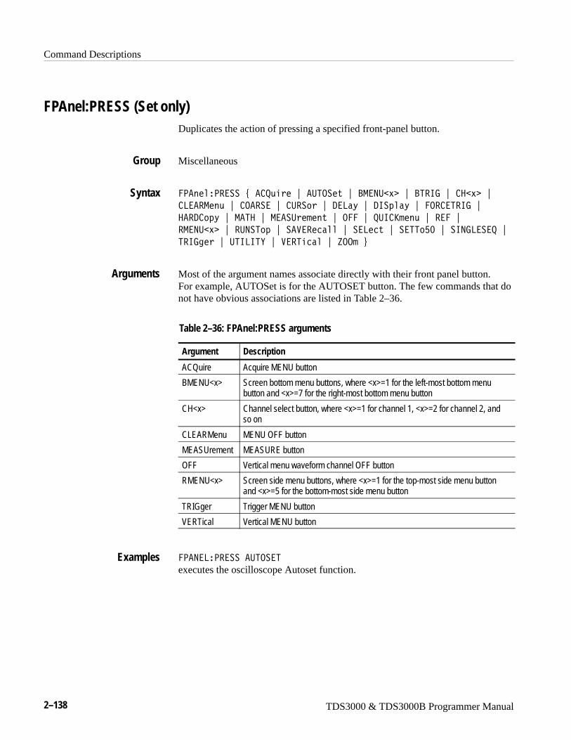
Command Descriptions
2–138 TDS3000 & TDS3000B Programmer Manual
FPAnel:PRESS (Set only)Duplicates the action of pressing a specified front-panel button.
Miscellaneous
�<�����<�����#�� +,���"��:5.����"�?-�9:�� �"�?5�67�"� ��� �"
8���-��,�"� .�����"� :���"�/�8�D�"�/6�4��D�"��.� �5�67�"
���/ 4D�"�-�5��"�-���:������"�.���"�+:6 S���,�"�����"�
�-�9:�� �"��:9�54�"�������2����"���8�2��"���55G;�"��6978���+�"
5�673��"�:56865E�"����5�2���"�P..��$
Most of the argument names associate directly with their front panel button. For example, AUTOSet is for the AUTOSET button. The few commands that donot have obvious associations are listed in Table 2–36.
Table 2–36: FPAnel:PRESS arguments
Argument Description
ACQuire Acquire MENU button
BMENU<x> Screen bottom menu buttons, where <x>=1 for the left-most bottom menubutton and <x>=7 for the right-most bottom menu button
CH<x> Channel select button, where <x>=1 for channel 1, <x>=2 for channel 2, andso on
CLEARMenu MENU OFF button
MEASUrement MEASURE button
OFF Vertical menu waveform channel OFF button
RMENU<x> Screen side menu buttons, where <x>=1 for the top-most side menu buttonand <x>=5 for the bottom-most side menu button
TRIGger Trigger MENU button
VERTical Vertical MENU button
�<�9�8�<������:5.��5
executes the oscilloscope Autoset function.
Group
Syntax
Arguments
Examples
Command Descriptions
TDS3000 & TDS3000B Programmer Manual 2–139
FPAnel:TURN (Set only)Duplicates the action of turning a specified front-panel control knob.
Miscellaneous
�<�����5:�9�#�%�7<S9.?�"��.�P<.��"��.�P� �8��"�695�9�65E�"
5�678���8�"����5<.��"����5� �8��&����� �$
Most of the argument names associate directly with their front panel knob. For example, GPKNOB is for the general purpose knob, HORZSCALE is for thehorizontal scale knob, and so on.
� (comma) separates the control knob argument from the numeric rotation valueargument. You do not need a white space between the arguments and the comma.
�� represents the rotation direction and magnitude of rotation. Negative valuesrepresent a counterclockwise knob rotation, and positive values represent aclockwise rotation. The magnitude of <n> specifies the amount of the turn,where <n> = 1 represents turning the knob one unit, <n> = 2 represents turningthe knob two units, <n> = 5 represents turning the knob five units, and so on.The range of units depends on which front panel knob is specified.
�<�9�8�5:�9�5�678���8��;
duplicates turning the front panel Trigger LEVEL knob clockwise by 10 units.
HARDCopySends a copy of the screen display to the port specified by HARDCopy:PORT.The format and layout of the output is specified with the HARDCopy:FORMatand HARDCopy:LAYout commands. This command is equivalent to pressing
the front panel Hard Copy button ( ).
The HARDCopy? query returns format, palette, layout, file name, preview, inksaver, compression mode, and port information.
NOTE. This command is NOT IEEE Std 488.2-1987 compatible.
Hard copy
Group
Syntax
Arguments
Examples
Group
Command Descriptions
2–140 TDS3000 & TDS3000B Programmer Manual
���/ 4D�#��?.��"� 8����4��"��5����$
���/ 4D0
�?.� terminates the hard copy output in process.
8����4� is equivalent to ABOrt.
�5��� initiates a screen copy that can be stored in a file or redirected to aprinting device.
NOTE. Use the *WAI command between HARDCopy STARt commands to ensurethat the first hard copy is complete before starting another.
���/ .<E��?.�5
stops any hard copy output that is in process.
HARDCopy:COMPRESSionSets or returns the hard copy compression feature. Setting this command to Oncauses the oscilloscope to compress hard copy output into gnuzip-format files(*.gz) prior to sending the file out of the specified hard copy port. .gz files arecompatible with GZIP (shareware) or WinZip utilities.
Hard copy
���/ 4D� .-<�������%�.9�"�.���"���� �&�
���/ 4D� .-<������0
.9 causes the oscilloscope to compress hard copy output files into gnuzip-formatfiles (*.gz).
NOTE. Hard copy compression is disabled when the output port is set toCentronics.
.�� disables hard copy file compression.
�� is an integer number where nr1 = 0 turns off compression, and nr1 ≠ 0 turnson compression.
Syntax
Arguments
Examples
Group
Syntax
Arguments
Command Descriptions
TDS3000 & TDS3000B Programmer Manual 2–141
���/ .<E� .-<����6.9�.9 enables hard copy file compression.
HARDCopy:FILENameSpecifies the file that hard copy data is written to on the next ���/ .<E��5��5command. To do multiple hard copies using the ���/ .<E��5��5 command youmust change the ���/ 4D��68�9��� before each ���/ .<E��5��5 or the samefile will be overwritten each time. ���/ 4D��68�9��� file names are notchecked for syntactical correctness until ���/ .<E��5��5 is received. (This is afeature that allows you to specify directories that may not exist yet, as long asthey are eventually created.)
Hard copy
HARDCopy
���/ 4D��68�9����������4��M �
���/ 4D��68�9���0
������4��M specifies that the hard copy is sent to the named file.������4��M is a quoted string that defines the file name and path. Input the file pathusing the form �1�>� �1� [��������� . �1�>� and one or more �1� sare optional. If you do not specify them, the oscilloscope will write the file to thecurrent directory. ��������� stands for a filename of up to 8 charactersfollowed by a period (.) and any 3-character suffix. If a suffix is supplied, it isignored. The only way to specify the hard copy format is using the HARDCO-PY:FORMAT command (or set it in the menu). That is, if the hard copy formatis TIFF, then the command HARDCOPY:FILENAME “NEXTFILE.DJ” doesnot change the hard copy format to DeskJet. The file which actually gets writtento disk is called “NEXTFILE.TIF” and the contents of the file are in TIFFformat.
The current directory refers to the name of a directory as returned by theFILESystem:CWD query.
���/ .<E��68�9�-� R5�S�6?-Lselects 5�S�6?- as the selected file name to write the hard copy to during thenext hard copy.
���/ .<E��68�9�-�0
might return ����/ .<E��68�9�-��L5�S�6?-L as the selected file name.
Examples
Group
Related Commands
Syntax
Examples
Command Descriptions
2–142 TDS3000 & TDS3000B Programmer Manual
HARDCopy:FORMatSelects the output data format for hardcopies. This is equivalent to settingFormat in the UTILITY/Hard Copy menu.
Hard copy
���/ 4D��.�-���#�5/��<�5�"�?-<�"�?-< ��"�/��S\�5�"�/��S\�5 �"
�<� ��"��<�-��"��<�.��"�695��8����"�8����\���"�< ��"
< �2��"��8��"�5�6�O]���"�56���"�/<:�IIG�"�?\ B;�"�<97$
���/ 4D��.�-��0
5/��<�5 sets the hard copy file format to the TDS3PRT plug-in thermal printerformat.
?-< sets the hard copy file format to Windows monochrome image format.
?-< � sets the hard copy file format to Windows color image format.
/��S\�5 sets the hard copy file format to HP monochrome ink-jet printer format.
/��S\�5 sets the hard copy file format to HP color inkjet printer format.
�<� � sets the hard copy file format to Encapsulated PostScript color imageformat.
�<�-� sets the hard copy file format to Encapsulated PostScript monochromeimage format.
�<�.� sets the hard copy file format to Epson 9-pin and 24-pin dot matrix printerformat.
695��8��� sets the hard copy file format to Interleaf image object format.
8����\�� sets the hard copy file format to HP monochrome laser printer format.
< � sets the hard copy file format to PC Paintbrush monochrome image fileformat.
< �2� sets the hard copy file format to PC Paintbrush color image fileformat.
�8� sets the hard copy file format to Windows color image file format.
5�6�O]�� sets the hard copy file format to HP monochrome ink-jet printerformat.
56�� sets the hard copy file format to tag image file format.
Group
Syntax
Arguments
Command Descriptions
TDS3000 & TDS3000B Programmer Manual 2–143
/<:�IIG sets the hard copy file format to Seiko DPU-3445 thermal printerformat.
?\ B; sets the hard copy file format to Canon BJC-50, BJC-80 color printerformat.
<97 sets the hard copy file format to Portable Network Graphics format.
���/ .<E��.�-�5�?-< �
sets the hard copy output format to 2��N����4.
���/ .<E��.�-�50
might return ����/ .<E��.�-�5�695��8��� as the hard copy output format.
HARDCopy:INKSaverChanges hard copy output to print color traces and graticule on a white back-ground while retaining waveform color information (except for channel 1, whichprints a dark blue because yellow does not show up well is difficult to see on awhite background). This option can significantly reduce print time and quantitiesof ink required compared with WYSIWYG dark background images. Returns 1when inksaver is on and 0 when inksaver is turned off.
Hard copy:
���/ 4D�69S��>��#��9�� �"�.9�"�.���$
���/ 4D�69S��>�0
.9 or �9�� ��0 sets the ink saver mode on.
.�� or �9�� = 0 sets the ink saver mode off.
���/ .<E�69S������.9
will cause subsequent hard copy output and preview commands to displaygrayscale menus on a white background.
Examples
Group
Syntax
Arguments
Examples
Command Descriptions
2–144 TDS3000 & TDS3000B Programmer Manual
HARDCopy:LAYoutSelects the printing orientation. This is equivalent to setting Layout in theUTILITY > System:Hard Copy > Options menu.
Hard copy
���/ 4D�8�E,��#�8�91�2�4��"�<.�5�����$
���/ 4D�8�E,�0
8�9/�2�4� specifies that the bottom of the hard copy is along the long side ofthe page.
<.�5���� specifies that the bottom of the hard copy is along the short side of thepage. This is the standard format.
���/ .<E�8�E.:50
might return ����/ .<E�8�E.:5�<.�5��65 as the hard copy page-layoutformat.
HARDCopy:PALEtteEquivalent to DISplay:COLor:PALEtte:REGular.
Hard copy
HARDCopy, DISplay:COLor:PALEtte:REGular
���/ 4D�<�8�����#�9.�-���"�-.9.2M���$
���/ 4D�<�8����0
���/ .<E�<�8�55��-.9.2M��
would change the display to monochrome waveforms, but retain color readoutsand menu items.
Group
Syntax
Arguments
Examples
Group
Related Commands
Syntax
Examples
Command Descriptions
TDS3000 & TDS3000B Programmer Manual 2–145
HARDCopy:PORTSets or returns where to send the hard copy data on the next hard copy command(i.e. HARDCOPY START command). This is equivalent to setting Port in theUTILITY > Hard Copy menu.
Hard copy
HARDCopy
���/ 4D�<.�5�#� �9���2��"��68��"�7<6N�"���H�H�"��5�������$
���/ 4D�<.�50
�9���2� specifies that the hard copy is sent out the Centronics port.
�68� specifies that the hard copy is stored in the file named in theHARDCOPY:FILENAME command.
7<6N specifies that the hard copy is sent out the GPIB port (available withoptional TDS3GM and TDS3GV communication modules).
��H�H specifies that the hard copy is sent out the RS232 port (available onoptional TDS3VM, TDS3GM, TDS3EM and TDS3GV communicationmodules).
�5������ specifies that the hard copy is sent out the 10baseT Ethernet port(available with optional TDS3EM Ethernet Communication Module orTDS3000B).
���/ .<E�<.�50
might return ����/ .<E�<.�5�7<6? as the selected hard copy output port.
HARDCopy:PREVIEWChanges the display screen to simulate hard copy output. The result depends onthe current Format, Layout, Palette, and Inksaver selections. It may be mono-chrome (black and white), grayscale, limited color, or full color.
Hard copy:
Group
Related Commands
Syntax
Arguments
Examples
Group
Command Descriptions
2–146 TDS3000 & TDS3000B Programmer Manual
���/ 4D�<���6���#��9�� �"�.9�"�.���$
���/ 4D�<���6��0
.9 or �9�� ��0 sets the display screen to simulate hard copy output.
.�� or �9�� = 0 turns off the simulation of hard copy output.
���/ .<E�<���6���.9
will change the display to simulate hard copy output with the current format,layout, palette, and inksaver options.
HDRThis command is identical to the HEADer query and is included for compatibili-ty with older Tektronix instruments.
Miscellaneous
�/��#��9�� �"�.���"�.9�$
�/�0
HEADerSets or returns the Response Header Enable State that sets the oscilloscope toeither include or omit headers on query responses. This command does not affectIEEE Std. 488.2-1987 Common Commands (those starting with an asterisk);they never return headers.
Miscellaneous
���/��#��9�� �"�.���"�.9�$
���/�0
Syntax
Arguments
Examples
Group
Syntax
Group
Syntax
Command Descriptions
TDS3000 & TDS3000B Programmer Manual 2–147
.9 or �9�� ��0 sets the Response Header Enable State to true. This causes theoscilloscope to include headers on applicable query responses. You can then usethe query response as a command.
.�� or �9�� = 0 sets the Response Header Enable State to false. This causes theoscilloscope to omit headers on query responses so that only the argument isreturned.
���/���.��
causes the oscilloscope to omit headers from query responses.
���/��0
might return ����/����, showing that the Response Header Enable State is true.
VERBose
HORizontal? (Query Only)Returns all oscilloscope horizontal settings. The commands HORizon-tal:MAIn:SCAle, HORizontal:MAIn:SECdiv, HORizontal:SCAle, and HORi-zontal:SECdiv are equivalent so HORizontal:MAIn:SCAle is the only value thatis returned.
Horizontal
�.��F����0
�.�6P.95�80
might return the string ��.�6P.95�8����.8:56.9�8.�A5�677���<.�656.9V�T�;A��.�6P.95�8�-�69�� �8����;�W�A��.�6P.95�8�/�8�E��5�5�
;A56-��W��;;;;;;;;;�W�
HORizontal:DELay:STATESets or returns the horizontal delay on or off. Delay off means that the acquisi-tion is positioned relative to the trigger position (HORizontal:TRIGger:POSi-tion). Delay on means that the acquisition is positioned relative to the delay time(HORizontal:DELay:TIMe).
Horizontal
Arguments
Examples
Related Commands
Group
Syntax
Examples
Group
Command Descriptions
2–148 TDS3000 & TDS3000B Programmer Manual
�.��F�����/�8�D��5�5��#�.9�"�.���$
�.��F�����/�8�D��5�5�0
.9 or �9�� ��0 sets the delay on so that the acquisition is positioned relative tothe delay time.
.�� or �9�� = 0 sets the delay off so that the acquisition is positioned relativeto the trigger position.
�.�6P.95�8�/�8�E��5�5��.9
sets the delay state to on.
HORizontal:DELay:TIMeSets or returns the delay time between the trigger and the center of the screen.The delay time begins at the trigger location; the acquisition is centered at theend of the delay time.
Horizontal
�.��F�����/�8�D�56-���9��
�.��F�����/�8�D�56-�0
�9�� is the time, in seconds, between the trigger and the center of the screen. Itcan vary from 100% pretrigger (which means the trigger point is off screen to theright), measured in seconds, to about 50 s (depending on time base setting) posttrigger (which means the trigger point is off screen to the left). Delay time ispositive when the trigger is located to the left of the center screen.
�.�6P.95�8�/�8�E�56-��H�;�W�
sets the delay time between the trigger and the center of the screen to 2 ms.
HORizontal:DELay:STATE
Syntax
Arguments
Examples
Group
Syntax
Arguments
Examples
Related Commands
Command Descriptions
TDS3000 & TDS3000B Programmer Manual 2–149
HORizontal:MAIn:SCAleSets the time per division for the main time base. The specified scale value isrounded to a valid scale setting.
Horizontal
�.��F�����-�6��� �����9��
�.��F�����-�6��� ���0
�9�� is the time per division. The range is 10 s to 1, 2, or 4 ns (depending on model), in a 1–2–4 sequence.
�.�6P.95�8�-�69�� �8��H�WT
sets the main scale to 2 �s per division.
HORizontal:DELay:TIMe, HORizontal:MAIn:SECdiv
HORizontal:MAIn:SECdivSets the time per division for the main time base. This command is identical tothe HORizontal:MAIn:SCAle command. It is provided to maintain programcompatibility with some older models of Tektronix oscilloscopes.
Horizontal
�.��F�����-�6���� 1�>��9��
�.��F�����-�6���� 1�>0
HORizontal:MAIn:SCAle
Group
Syntax
Arguments
Examples
Related Commands
Group
Syntax
Related Commands
Command Descriptions
2–150 TDS3000 & TDS3000B Programmer Manual
HORizontal:RECORDLengthSets the number of data points that are acquired for each record.
Horizontal
�.��F������� .�/8��3�M��9��
�.��F������� .�/8��3�M0
�9�� is the record length in points. Valid values are 500 and 10000.
�.�6P.95�8��� .�/8�975��G;;
specifies that 500 data points will be acquired for each record.
�.�6P.95�8��� .�/8�975�0
might return �;;;; as the number of data points per record.
HORizontal:RESOlution
HORizontal:RESOlutionSets the acquisition resolution (record length) to Low or High. This commandperforms the same function as �.��F������� .�/8��3�M.
Horizontal
�.��F��������.8,����#�8.��"��67��$
�.��F��������.8,���0
�8.� sets the horizontal resolution to 500 points.
��67� sets the horizontal resolution to 10,000 points.
�.�6P.95�8��� .�/8�975�0
might return ��.�6P.95�8����.8:56.9��67�.
�.��F������� .�/8��3�M
Group
Syntax
Arguments
Examples
Related Commands
Group
Syntax
Arguments
Examples
Related Commands
Command Descriptions
TDS3000 & TDS3000B Programmer Manual 2–151
HORizontal:SCAleSets the time per division for the main time base and is identical to the HORi-zontal:MAIn:SCAle command. It is provided to maintain program compatibilitywith some older models of Tektronix oscilloscopes.
Horizontal
�.��F������ �����9��
�.��F������ ���0
HORizontal:SECdivSets the time per division for the main time base and is identical to the HORi-zontal:MAIn:SCAle command. It is included here for compatibility purposes.
Horizontal
�.��F������� 1�>��9��
�.��F������� 1�>0
HORizontal:TRIGger:POSitionSets or returns the position of the trigger. This is only applied when delay modeis off.
Horizontal
�.��F�����5�673��<.�������9��
�.��F�����5�673��<.�����0
�9�� is from 0 to 100 % and is the amount of pretrigger information in thewaveform.
�.�6P.95�8�5�677���<.�656.90
might return ��.�6P.95�8�5�677���<.�656.9�G;.
Group
Syntax
Group
Syntax
Group
Syntax
Arguments
Examples
Command Descriptions
2–152 TDS3000 & TDS3000B Programmer Manual
ID? (Query Only)Returns information about the oscilloscope, including the model number,options, application modules, and firmware version.
Status and Error
6/0
The instrument id in the following format:
5�S[��1����,�N� � ��X��� 5��������J���>������,�N�
�4���[�1,�� ��>������,�N�
6/0
might return 6/�5�S[5/���;GI� ��X��� 5����>��;;�5/��7-�>��;;5/����5�>��;;�5/��5�7�>��;;�5/���6/�>��;;
*IDN? (Query Only)Returns the same oscilloscope information as the ID? command except the datais formatted according to Tektronix Codes & Formats.
Status and Error
C6/90
The instrument id in the following format:
5�S5�.96����1����,�N� �;� ��X��� 5��������J���>������,�N�
�4���[�1,�� ��>������,�N�
C6/90
might return the response5�S5�.96��5/���;GI�;� ��X��� 5����>��;;�5/��7-�>��;;
5/����5�>��;;�5/��5�7�>��;;�5/���6/�>��;;
ID?
Group
Syntax
Returns
Examples
Group
Syntax
Returns
Examples
Related Commands
Command Descriptions
TDS3000 & TDS3000B Programmer Manual 2–153
ITU601:AUTOSet (Set Only)(TDS3000B Series with TDS3SDI Only)
Executes the TDS3SDI autoset function to automatically acquire and display the601 digital video signal in the specified format.
TDS3SDI
65:T;���:5.����#��88����1��"��888�����"��7?�"�E �"�E<?<��$
�88����1� sets the oscilloscope to display the 601 digital video signal as acomposite signal on channel 1, triggered on all fields.
�888���� sets the oscilloscope to display the 601 digital video signal as acomposite signal on channel 1, triggered on all lines.
�7? sets the oscilloscope to display the 601 digital video signal RGB videoinformation on channels 2, 3, and 4.
E sets the oscilloscope to display the 601 digital video signal YC videoinformation on channels 3 and 4.
E<?<� sets the oscilloscope to display the 601 digital video signal YPbPr videoinformation on channels 2, 3, and 4.
65:T;���:5.��5��7?
sets the oscilloscope to display the TDS3SDI 601 digital video signal R, G, andB components.
ITU601:EDH (Set Only)(TDS3000B Series with TDS3SDI Only)
Sets the TDS3SDI EDH error counter to zero.
TDS3SDI
65:T;���/�������
65:T;���/������5
resets the TDS3SDI EDH error counter to zero.
Group
Syntax
Arguments
Examples
Group
Syntax
Examples
Command Descriptions
2–154 TDS3000 & TDS3000B Programmer Manual
ITU601:EDH:COUNt(TDS3000B Series with TDS3SDI Only)
Sets or returns the state of the TDS3SDI EDH error counter.
TDS3SDI
65:T;���/�� .:9��#�.���"�.9�"��9�� �$
65:T;���/�� .:9�0
.�� or �9�� = 0 disables the EDH error count function.
.9 or �9�� = 1 enables the EDH error count function.
65:T;���/�� .:95�.9
Enables the EDH error count function.
ITU601:EDH:DETect? (Query Only)(TDS3000B Series with TDS3SDI Only)
Returns the state of the TDS3SDI EDH detect CRC mode. Used to indicate if the601 digital video signal contains CRC data.
TDS3SDI
65:T;���/��/�5�2�0
65:T;���/��/�5� 50
might return the response 65:T;���/��/�5� 5�.9, indicating that EDH CRCerror detection is enabled.
Group
Syntax
Arguments
Examples
Group
Syntax
Examples
Command Descriptions
TDS3000 & TDS3000B Programmer Manual 2–155
ITU601:EDH:NUMERRors? (Query Only)(TDS3000B Series with TDS3SDI Only)
Returns the number of errors stored in the TDS3SDI EDH error counter.
TDS3SDI
65:T;���/��9:-����0
65:T;���/��9:-���.��0
might return the response 65:T;���/��9:-���.���;, indication that the EDHerror counter value is zero (no errors).
ITU601:INPUT:FORMat(TDS3000B Series with TDS3SDI Only)
Sets or returns the TDS3SDI 601 digital video input signal format.
TDS3SDI
65:T;��69<:5��.�-���#��:5.�"��GHG�"��THG�"��9�� �$
65:T;��69<:5��.�-��0
�:5. or �9�� � 3 sets the oscilloscope to automatically detect and set the inputsignal format.
�GHG or �9�� � 1 sets the oscilloscope to trigger on 525-line 601 digital videosignals.
�THG or �9�� = 2 sets the oscilloscope to trigger on 625-line 601 digital videosignals.
65:T;��69<:5��.�-�5��:5.
sets the oscilloscope to automatically detect and set the 601 digital video signalinput format.
Group
Syntax
Examples
Group
Syntax
Arguments
Examples
Command Descriptions
2–156 TDS3000 & TDS3000B Programmer Manual
ITU601:INPUT:SIGnalstrength? (Query Only)(TDS3000B Series with TDS3SDI Only)
Returns the value of the TDS3SDI input signal strength parameter. The signalstrenght value is an integer in the range of 0 to 5, where 0 = no signal presentand 5 = maximum signal strength.
TDS3SDI
65:T;��69<:5��67�������3�M0
65:T;��69<:5��679�8�5��975�0
might return the response 65:T;��69<:5��679�8�5��975���.
ITU601:INPUT:STATE? (Query Only)(TDS3000B Series with TDS3SDI Only)
Returns the TDS3SDI input signal state value. Valid return values are MISSING(no 601 digital signal is present), S525 (an S525 601 digital signal is present),and S625 (an S625 601 digital signal is present).
TDS3SDI
65:T;��69<:5��5�5�0
65:T;��69<:5��5�5�0
might/sets return the response 65:T;��69<:5��5�5�0�-6��697, indicating thatthere is no 601 digital video signal connected to the TDS3SDI module.
Group
Syntax
Examples
Group
Syntax
Examples
Command Descriptions
TDS3000 & TDS3000B Programmer Manual 2–157
ITU601:OUTput:FORMat(TDS3000B Series with TDS3SDI Only)
Sets or returns the TDS3SDI video signal output display format.
TDS3SDI
65:T;��.:54,���.�-���#�.���"�7?��"��7?�"�E �"�E<?<��$
65:T;��.:54,���.�-��0
.�� sets the TDS3SDI module to turn off its signal output.
7?� sets the TDS3SDI module to output GBR color signal information.
�7? sets the TDS3SDI module to output RGB color signal information.
E sets the TDS3SDI module to output YC color signal information.
E<?<� sets the TDS3SDI module to output YPbPr color signal information.
65:T;��.:5<:5��.�-�5��7?
sets the TDS3SDI module to output the 601 digital video signal information inRGB format.
LANGuageSets or returns the user interface display language. This command only affectsthe oscilloscope displayed language; remote commands and their responses arealways in English.
Miscellaneous
8�97,�3��#��978��M�"����92M�"�7��-���"�65�8����"�<.�5:3,����"
�<�9��M�"��:������"\�<������"�S.�����"5��/������2M������"
�6-<�����12M������$
8�97,�3�0
8�97:�7�0
might return : 8�97:�7���9786��
Group
Syntax
Arguments
Examples
Group
Syntax
Examples
Command Descriptions
2–158 TDS3000 & TDS3000B Programmer Manual
LIMit? (Query Only)(TDS3LIM Only)
Returns all limit testing parameters.
Limit Test
86-��0
86-650
might return:�86-65�?��<�.��A� .-<���� �������A �H�9.9�A ���9.9�A �I�9.9�A
�86-65����/ .<E�.��A������-�.��A�5�5��.��A�5.<.9�6.8�56.9
.��A5�-<8�5��/��569�56.9�����A�.:� �� ��A5.8���9 ���.�6P.95�8
I�;�@HA���56 �8�I�;�@H.
LIMit:BEEP(TDS3LIM Only)
Sets or returns the TDS3LIM beep on error setting. The beep sounds when thewaveform data exceeds the limits set in the limit test, if the limit state is on.
Limit Test
86-���?��<�#�.���"�.9�"��9�� �$
86-���?��<0
.�� or �9�� = 0 turns off the beep when any waveform data exceeds the limitsset by the limit test.
.9 or �9�� � 0 turns on the beep.
86-65�?��<�.9
specifies that the beep is to sound when any waveform data exceeds the limitsspecified in the limit test.
86-65�?��<0
returns either ; or �, indicating whether the beep is to sound when any waveformdata exceeds the limits specified in the limit test.
Group
Syntax
Examples
Group
Syntax
Arguments
Examples
Command Descriptions
TDS3000 & TDS3000B Programmer Manual 2–159
LIMit:COMPARE:CH<x>(TDS3LIM Only)
Sets or returns the template against which to compare the waveform acquiredthrough the specified channel. The template can be a waveform saved in any ofthe reference locations REF1 through REF4, or none.
Limit Test
86-��� .-<���� ��� �#�9.9��"������ �$
86-��� .-<���� ��� 0
M�� is a channel, where <x> is 1, 2, 3, or 4.
9.9� turns off limit testing for the specified channel.
����� is a reference waveform, where <x> is 1, 2, 3, or 4.
86-65� .-<���� �������
specifies REF1 as the template waveform against which to compare waveformsacquired on CH1.
86-65� .-<���� �H0
might return 86-65� .-<���� �H����I, indicating that waveforms acquired onCH2 will be compared to the limit test template waveform stored in REF4.
CURve, LIMit:TEMPLate, LIMit:TEMPLate:DESTination, LIMit:TEM-PLate:SOUrce, WFMPre
LIMit:HARDCopy(TDS3LIM Only)
Sets or returns the TDS3LIM hard copy on error setting. When ON, thiscommand executes a screen hard copy operation when any waveform dataexceeds the limits set in the limit test, if the limit state is on. The hard copyoperation uses the port, format, and layout settings specified using the HARD-Copy commands.
Limit Test
Group
Syntax
Arguments
Examples
Related Commands
Group
Command Descriptions
2–160 TDS3000 & TDS3000B Programmer Manual
86-������/ 4D�#�.���"�.9�"��9�� �$
86-������/ 4D0
.9 or �9�� � 0 turns on the hard copy operation when any waveform dataexceeds the limits set by the limit test.
.�� or �9�� = 0 turns off the hard copy operation.
86-������/ 4D�.9
specifies that the hard copy operation occurs when any waveform data exceedsthe limits specified in the limit test.
86-������/ 4D0
returns either ; or �, indicating whether the hard copy operation occurs when anywaveform data exceeds the limits specified in the limit test.
LIMit:COMPARE:CH<x>, LIMit:STATE, HARDCopy
LIMit:SAVEWFM(TDS3LIM Only)
Sets or returns the TDS3LIM save waveform to file on limit test failure setting.When enabled, this command copies waveform data from all active waveformsthat have limit tests failures to a file on the oscilloscope disk drive. The fileformat is specified by the SAVe:WAVEform:FILEFormat command. Set the filesave format to Internal File Format to minimize file size.
Limit Test
86-���������-�#�.���"�.9�"��9�� �$
86-���������-0
.�� or �9�� = 0 turns off save waveform to disk for limit testing.
.9 or �9�� � 0 turns on save waveform to disk for limit testing.
86-65�������-�.9
specifies that save waveform to disk is in effect.
86-65��5�5�0
returns either ; or �, indicating whether save waveform to disk is in effect.
Syntax
Arguments
Examples
Related Commands
Group
Syntax
Arguments
Examples

Command Descriptions
TDS3000 & TDS3000B Programmer Manual 2–161
SAVEWFM, SAVe:WAVEform:FILEFormat
LIMit:STATE(TDS3LIM Only)
Turns limit testing on or off, or returns whether limit testing is in effect.
Limit Test
86-����5�5��#�.���"�.9�"��9�� �$
86-����5�5�0
.�� or �9�� = 0 turns off limit testing.
.9 or �9�� � 0 turns on limit testing.
86-65��5�5��.9
specifies that limit testing of waveforms is in effect.
86-65��5�5�0
returns either ; or �, indicating whether limit testing of waveforms is in effect.
CURve, LIMit:BEEP, LIMit:COMPARE:CH<x>, LIMit:HARDCopy, LIM-it:TEMPLate, WFMPre
LIMit:STOPOnviolation(TDS3LIM Only)
Sets or returns the TDS3LIM stop on violation setting. When enabled, thiscommand stops waveform acquisitions on the first occurance of a limit testviolation. LIMit:STATE must be ON for the oscilloscope to detect violations.
Limit Test
86-����5.<.�>�������#�.���"�.9�$
86-����5.<.�>������0
Related Commands
Group
Syntax
Arguments
Examples
Related Commands
Group
Syntax
Command Descriptions
2–162 TDS3000 & TDS3000B Programmer Manual
.�� = 0 turns off the stop on violation.
.9 � 0 turns on the stop on violation.
86-65��5.<.�>������0
might return OFF that indicates the stop on violation is turned off.
-��S��5.<.�>������
LIMit:TEMPLate (Set Only)(TDS3LIM Only)
Uses the values specified by LIMit:TEMPLate:SOUrce, LIMit:TEMPLate:TOLerance:HORizontal, and LIMit:TEMPLate:TOLerance:VERTical to create alimit test template and store the template in the reference waveform memorylocation specified in LIMit:TEMPLate:DESTination. You can compare thewaveform acquired through the specified channel against this template. Thetemplate can be a waveform saved in any of the reference locations REF1through REF4.
Limit Test
86-���5�-<8�����5.��
�5.�� creates a template with the specified source waveform and tolerances, andstores it in the destination reference waveform to be used in limit testingcomparisons.
86-65�5�-<8�5���5.��
creates a template with the specified source waveform and tolerances, and storesit in the destination reference waveform to be used in limit testing comparisons.
LIMit:TEMPLate:DESTination, LIMit:TEMPLate:SOUrce
Arguments
Examples
Related Commands
Group
Syntax
Arguments
Examples
Related Commands
Command Descriptions
TDS3000 & TDS3000B Programmer Manual 2–163
LIMit:TEMPLate:DESTination(TDS3LIM Only)
Sets or returns the destination reference waveform that the LIMit:TEMPLateSTORe command will use.
Limit Test
86-���5�-<8����/��5������������
86-���5�-<8����/��5������0
����� specifies the reference waveform destination in which the templatewaveform is to be stored.
86-65�5�-<8�5��/��569�56.9����H
specifies that the template waveform referred to with the LIMit:TEMPLateSTORe command is stored as the REF2 waveform.
LIMit:COMPARE:CH<x>, LIMit:TEMPLate, LIMit:TEMPLate:SOUrce
LIMit:TEMPLate:SOUrce(TDS3LIM Only)
Sets or returns the source channel, or reference waveform that LIMit:TEMPLateSTORe will use in deriving the limit test template waveform.
Limit Test
86-���5�-<8�����.:2��#� ��� �"������ �$
86-���5�-<8�����.:2�0
��� specifies that the template waveform source is the waveform currentlybeing acquired using the specified channel.
����� specifies that the template waveform source is the waveform currentlystored as the specified reference waveform.
Group
Syntax
Arguments
Examples
Related Commands
Group
Syntax
Arguments
Command Descriptions
2–164 TDS3000 & TDS3000B Programmer Manual
86-65�5�-<8�5���.:� �� �H
specifies that the template waveform for limit tests is the waveform currentlyacquired using channel 2.
86-65�5�-<8�5���.:� �0
might return CH2, specifying that the template waveform source for limit tests isthe waveform currently stored as the channel 2 waveform.
LIMit:COMPARE:CH<x>, LIMit:TEMPLate, LIMit:TEMPLate:DESTination
LIMit:TEMPLate:TOLerance:HORizontal(TDS3LIM Only)
Sets or returns the amount, in units of horizontal divisions, by which the sourcewaveform is varied horizontally when creating the destination templatewaveform.
Limit Test
86-���5�-<8����5.8���2���.��F������9��
86-���5�-<8����5.8���2���.��F����0
�9�� is the amount, in horizontal divisions, by which the source waveform ishorizontally modified to generate the template that is stored in the destinationreference. The range is 0 to 5 divisions.
86-65�5�-<8�5��5.8���9 ���.�6P.95�8���;
specifies that the source waveform is modified horizontally by ±1.0 horizontaldivision when generating the template waveform.
86-65�5�-<8�5��5.8���9 ���.�6P.95�80
might return ��;, specifying that the source waveform is modified horizontallyby ±1.0 horizontal division when generating the template waveform.
LIMit:COMPARE:CH<x>
Examples
Related Commands
Group
Syntax
Arguments
Examples
Related Commands
Command Descriptions
TDS3000 & TDS3000B Programmer Manual 2–165
LIMit:TEMPLate:TOLerance:VERTical(TDS3LIM Only)
Sets or returns the amount, in units of vertical divisions, by which the sourcewaveform is varied vertically when creating the destination waveform.
Limit Test
86-���5�-<8����5.8���2�����5�2����9��
86-���5�-<8����5.8���2�����5�2��0
�9�� is the amount, in vertical divisions, by which the source waveform isvaried vertically when creating the test waveform. The range is 0 to 5 divisions.
86-65�5�-<8�5��5.8���9 �����56 �8���;
specifies that the source waveform is vertically varied by ±1.0 vertical divisionwhen creating this test waveform.
86-65�5�-<8�5��5.8���9 �����56 �80
might return ��;, specifying that the source waveform is vertically varied by±1.0 vertical division when creating this test waveform.
LIMit:COMPARE:CH<x>
Group
Syntax
Arguments
Examples
Related Commands
Command Descriptions
2–166 TDS3000 & TDS3000B Programmer Manual
LOCkSets or returns the front panel lock state. This command lets you disable allfront-panel buttons and knobs to prevent manual instrument setting changeswhile remotely controlling the oscilloscope. There is no front-panel equivalent.
Miscellaneous
8. O�#��88�"�9.9��$
8. O0
�88 disables all front-panel controls.
9.9� enables all front-panel controls. This is equivalent to the UNLock ALLcommand.
NOTE. If the oscilloscope is in the Remote With Lockout State (RWLS), the LOCkNONe command has no effect. For more information, see the ANSI-IEEE Std.488.1-1987 Standard Digital Interface for Programmable Instrumentation,section 2.8.3 on RL State Descriptions.
8. S0
returns 9.9� when the front-panel controls are enabled by this command.
8. O��88
locks the front-panel controls.
UNLock
Group
Syntax
Arguments
Examples
Related Commands
Command Descriptions
TDS3000 & TDS3000B Programmer Manual 2–167
*LRN? (Query Only)Returns a string listing the oscilloscope settings. You can use this string to returnthe oscilloscope to the state it was in when you made the *LRN? query.
Miscellaneous
HEADer, SET?, VERBose
C8�90
NOTE. The *LRN? query always returns a string including command headers,regardless of the setting of the HEADer command. This is because the returnedstring is intended to be sent back to the oscilloscope as a command string. TheVERBose command can still be used normally to specify whether the returnedheaders should be abbreviated.
C8�90
a partial response might look like this:����/����A����?.����A��86����5�5���A�� +:6���-./��
��-<8�A9:-��7��TA9:-�9���TA�5�5���A�5.<��5��
�:9�5.<A�/6�<8�E� .8.��<�8�55����7:8���9.�-�8A�/6�<8�E��5E8��/.5@
�.98E�;A�/6�<8�E�<���6�5�9 ��;�;�;A 8. S�;A7��56 :8�
�:88A695�9�65E������.�-�TGA?� S867�5��67�A�/6�<8�E��E�-./�
.��AE ��99�8� �HAE����.��A���8� 5� ���;A �H��A ���;A �I�;A-�5�
;A�����;A���H�;A�����;A���I�;A .95�.8� �HA����/ .<E��.�-�5
< � .8.�A<.�5��68�A8�E.:5�8�9/� �<�A��.�6P.95�8����.8:56.9
8.�A5�677���<.�656.9���;H��A��.�6P.95�8�-�69�� �8�
H�;�WIA��.�6P.95�8�/�8�E��5�5��;A
Group
Related Commands
Syntax
Examples
Command Descriptions
2–168 TDS3000 & TDS3000B Programmer Manual
MASK:AUTOFit(TDS3TMT Only)
Sets or returns the autofit radius setting used for waveform positioning. Autofitdoes a incremental waveform position redraw to attempt to fit the waveform to amask. MASK:DISplay must be On to enable Autofit functionality.
Mask
-��S��:5.��� #��9�� �"�.���$
-��S��:5.���0
�9�� is an integer number from 0 to 10, where 0 turns the autofit function off,and 1-10 turns the autofit function on and defines the autofit radius. Autofitrepositions the waveform in 1-pixel increments to attempt to fit the waveform toa mask. The Autofit radius defines the size of a square search grid radius of (2 � radius + 1) � (2 � radius + 1) pixels, centered on the waveform position.
Autofit moves the waveform using a spiral pattern, testing for mask violations ateach position. For example, the following table represents a spiral pattern for aradius value of two, where the number in the table represents the order of thewavefrom moves, and the position of the number represents the position thewaveform is offset relative to the starting point (● ). A radius of two attempts tofit the waeform in 25 tries (start position plus 24).
X����;�������H����
HI������H��������I
H���B���● ���I����G
HH��V���T���G����T
H���H;���X���B���V
.�� sets the autofit function off.
-��S��:5.�65�.�� turns autofit off.
Group
Syntax
Arguments
Examples
Command Descriptions
TDS3000 & TDS3000B Programmer Manual 2–169
MASK:COPy:SOUrce(TDS3TMT Only)
Sets or returns the mask standard to copy to the User mask when theMASK:COPy:USER command is executed.
Mask
-��S� .<D��.:2��#� 8. S ���"� 8. S�D�����2���"�/�; ���"/�;/,N���"�/�;���3���"�/�;5����3�"�/�� �"�/�������"�/�H�
"�/�H��5� ���"�/�H��5��D�����2���"�/�������"��� ���
"����D�����2���"��H�"����"�7V;�/���"�7V;�/���"�9.9��"���5��H-N��
"��5��<,����$
-��S� .<D��.:2�0
8. S ���through��5��<,��� are the telecom mask test standards available inTDS3TMT that you can copy to the user mask location.
-��S� .<E��.:� ���� .�� sets ITU-T E1 coaxial (2.048 Mb/s) as the mask standard to copy to the usermask location when -��S� .<D�:��� is executed.
-��S� .<D�:���
MASK:COPy:USER(TDS3TMT Only)
Copies the mask defined by MASK:COPy:SOUrce to the user mask.
Mask
-��S� .<D�:���
-��S� .<E�:��� copies the mask defined by MASK:COPy:SOUrce to the user mask.
-��S� .<D��.:2�
Group
Syntax
Arguments
Examples
Related Commands
Group
Syntax
Examples
Related Commands
Command Descriptions
2–170 TDS3000 & TDS3000B Programmer Manual
MASK:COUNt:CH<x>:HITS? (Query Only)(TDS3TMT Only)
Returns the total hits on all mask segments for the specified channel. Hitcounting must be turned on (MASK:COUNt:STATE and MASK:DISplay toON).
Mask
-��S� .:9�� ��� ��65�0
�� is an integer in the range of 1 to 4 that sets which scope channel to query formask hits.
-��S� .:95� �H��65�0 might return ��B.
MASK:COUNt:FAILURES? (Query Only)(TDS3TMT Only)
Returns the number of pass/fail tests that have failed. When MASK:TESt:RE-Peat is 1, this query returns the number of failed tests, andMASK:COUNt:TESTS? returns the total number of tests.
Mask
-��S� .:9����68:���0
-��S� .:95���68:���0 might return GI.
-��S�5������<���, -��S� .:9��5��5�0
Group
Syntax
Arguments
Examples
Group
Syntax
Examples
Related Commands
Command Descriptions
TDS3000 & TDS3000B Programmer Manual 2–171
MASK:COUNt:HITS? (Query Only)(TDS3TMT Only)
Returns the total number of mask hits for all channels on all mask segments.
Mask
-��S� .:9���65�0
-��S� .:95��65�0 might return GTI.
-��S� .:9����68:���0, -��S� .:9�� ��2 ��65�0
MASK:COUNt:MASK<m>:CH<x>:HITS? (Query Only)(TDS3TMT Only)
Returns the number of hits for channel <x> in mask segment <m>. A masksegment is one of the polygons that make up a mask.
Mask
-��S� .:9��-��S�� � ��� ��65�0
�� is the mask segment number, with a valid range of 1-8.
�� is the oscilloscope channel, with a valid range of 1-4.
-��S� .:95�-��SH� �I��65�0 might return �I.
-��S� .:9�� ��� ��65�0, -��S� .:9����68:���0,-��S� .:9���65�0, -��S� .:9��-��S�� ��65�0
Group
Syntax
Examples
Related Commands
Group
Syntax
Arguments
Examples
Related Commands
Command Descriptions
2–172 TDS3000 & TDS3000B Programmer Manual
MASK:COUNt:MASK<m>:HITS? (Query Only)(TDS3TMT Only)
Returns the number of hits for all channels in the specified mask segment.
Mask
-��S� .:9��-��S�� ��65�0
�� is the mask segment number, with a valid range of 1-8.
-��S� .:95�-��S���65�0 might return �HI.
-��S� .:9�� ��� ��65�0, -��S� .:9����68:���0, -��S� .:9���65�0-��S� .:9��-��S�� � ��� ��65�0
MASK:COUNt:STATE(TDS3TMT Only)
Sets or returns the mask hits count state. MASK:DISplay must be ON to enableMASK:COUNt:STATE to count mask violations.
Mask
-��S� .:9���5�5��#�.���"�.9�"��9�� �$
-��S� .:9���5�5�0
.9 turns on mask hit counting.
.�� turns off mask hit counting.
�9�� is an integer number where NR1 = 0 turns off mask hit counting, and NR1 ≠ 0 turns on mask hit counting.
-��S� .:95��5�5��.9 turns on mask hit counting.
Group
Syntax
Arguments
Examples
Related Commands
Group
Syntax
Arguments
Examples
Command Descriptions
TDS3000 & TDS3000B Programmer Manual 2–173
MASK:COUNt:TESTS? (Query Only)(TDS3TMT Only)
Returns the number of pass/fail tests that have occurred when -��S�5������@<��� is turned on.
Mask
-��S� .:9��5��5�0
-��S� .:95�5��5�0 might return G;.
-��S� .:9����68:���0
MASK:COUNt:TOTal? (Query Only)(TDS3TMT Only)
Returns the sum of all hits in all mask segments.This command is the same as-��S� .:9���65�0 and is kept for compatibility with other Tektronix oscillo-scopes.
Mask
-��S� .:9��5.5��0
-��S� .:95�5.5�80 might return GT;.
-��S� .:9���65�0
Group
Syntax
Examples
Related Commands
Group
Syntax
Examples
Related Commands
Command Descriptions
2–174 TDS3000 & TDS3000B Programmer Manual
MASK:COUNt:VIOLATIONS? (Query Only)(TDS3TMT Only)
Returns the number of test violations which have occurred in the current pass/failtest. A test violation occurs when any part of a channel waveform falls withinany mask segment.
Mask
-��S� .:9���6.8�56.9�0
-��S� .:95��6.8�56.9�0 might return GT;.
-��S� .:9��5��5�0, -��S� .:9��5.5��0, -��S� .:9�������.�-�0
MASK:COUNt:WAVEFORMS? (Query Only)(TDS3TMT Only)
Returns the number of waveforms which have been acquired and processedduring the current pass/fail test.
Mask
-��S� .:9�������.�-�0
-��S� .:95������.�-�0 might return �;;;.
-��S� .:9��5��5�0, -��S� .:9��5.5��0, -��S� .:9���6.8�56.9�0
Group
Syntax
Examples
Related Commands
Group
Syntax
Examples
Related Commands
Command Descriptions
TDS3000 & TDS3000B Programmer Manual 2–175
MASK:DISplay(TDS3TMT Only)
Sets or returns the mask violation detection and display status. Enablingdetection and display causes waveform points which violate the mask to bedisplayed in an intensified color so that mask violation points are clearly visibleon the display. MASK:DISplay is set to ON if MASK:TESt:STATE,MASK:COUNt:STATE, or MASK:STOPOnviolation are set to ON.
Mask
-��S�/6�4��D�#�.���"�.9�"��9�� �$
-��S�/6�4��D0
.�� turns off mask violation detection and display.
.9 turns on mask violation detection and display.
�9�� is an integer number where NR1 = 0 turns off mask violation detectionand display, and NR1 ≠ 0 turns on mask violation detection and display.
-��S� .:95������.�-��.9 sets the oscilloscope to detect and highlight mask violations.
MASK:LOCk(TDS3TMT Only)
Sets or returns the mask lock to waveform mode. Mask lock locks the mask tothe waveform such that changes to the horizontal and/or vertical scale settingsredraws the mask segments in proportion. This feature allows for expandinghorizontal and/or vertical settings to zoom in on waveforms and masks tovisually examine violation areas in more detail. You can only use Mask Lock onstopped acquisitions or when pass/fail testing is not running.
Mask
-��S�8. O�#�.���"�.9�"��9�� �$
-��S�8. O0
Group
Syntax
Arguments
Examples
Group
Syntax
Command Descriptions
2–176 TDS3000 & TDS3000B Programmer Manual
.�� turns off mask lock to waveform.
.9 turns on mask lock to waveform.
�9�� is an integer number where NR1 = 0 turns off mask lock to waveform,and NR1 ≠ 0 turns on mask lock to waveform.
-��S�8. O�.�� turns off mask lock to waveform.
MASK:MARGIN:VERTical(TDS3TMT Only)
Sets or returns the User mask’s vertical margin percentage. This commandredraws the vertical mask margins by the specified percentage, where the verticalmargin percent is the percentage of the User mask’s nominal pulse amplitude.This command affects all segments in the User mask. Segment vertical marginsmove away from the nominal waveform pulse position for positive percentagevalues, and towards the nominal waveform pulse position for negative percent-age values. This command only operates on User (custom) masks.
Mask
-��S�-��769����5�2����9��
-��S�-��769����5�2��0
�9�� is a real number that sets the User mask margins as a percentage of theuser mask’s nominal pulse amplitude.
-��S�-��769����56 �8�G
Increases the User mask vertical dimensions by 5%.
Arguments
Examples
Group
Syntax
Arguments
Examples
Command Descriptions
TDS3000 & TDS3000B Programmer Manual 2–177
MASK:MASK<m> DELEte(TDS3TMT Only)
Deletes the specified mask segment from the User mask, whether or not the Usermask is the current mask.
Mask
-��S�-��S�� �/�8���
�� is an integer number that specifies the User mask segment number to deletefrom the User mask
-��S�-��SH�/�8�5� deletes mask segment 2 from the User mask
MASK:MASK<m>:COUNt? (Query Only)(TDS3TMT Only)
Returns the number of hits on the specified mask segment in the current mask.To enable hits counting, set MASK:COUNt:STATE to ON.
Mask
-��S�-��S�� � .:9�0
�� is an integer number that specifies a mask segment number in the currentmask.
-��S�-��S�� .:95 might return -��S�-��S�� .:9��BGT.
Group
Syntax
Arguments
Examples
Group
Syntax
Arguments
Examples
Command Descriptions
2–178 TDS3000 & TDS3000B Programmer Manual
MASK:MASK<m>:NR_Pt? (Query Only)(TDS3TMT Only)
Returns the number of points that make up the specified mask segment of thecurrently-displayed mask. Each mask point consists of an X-Y pair of coordi-nates.
Mask
-��S�-��S�� �9�U<�0
�� is an integer number that specifies a mask segment number in the currently-displayed mask.
-��S�-��SH�9�U<50 might return -��S�-��S�9�U<��G
MASK:MASK<m>:POINTS(TDS3TMT Only)
Sets or returns the X-Y coordinates of all points in the specified mask segmentreferenced to the mask’s nominal horizontal and vertical scale. The query formreturns point coordinates from the displayed mask. The set form defines newpoints in the User mask, replacing any existing points in the specified User masksegment.
Mask
-��S�-��S�� �<.695���9�� ���9�� �%���9�� ���9�� �&
-��S�-��S�� �<.695�0
Group
Syntax
Arguments
Examples
Group
Syntax
Command Descriptions
TDS3000 & TDS3000B Programmer Manual 2–179
�� specifies the mask segment number in the current mask (query form), or theUser mask (set form).
�9�� refers to the coordinates of one of the vertices in the mask. Each pair ofnumbers is the horizontal and vertical coordinates of a mask segment vertex. Thepairs must be listed in a counterclockwise order. If the vertical or horizontal scaleor position is changed after this command and then the query form of thiscommand is issued, then the value returned will not be the same. If just one pairis input then they are ignored and the mask segment is marked as undefined. Thedefault is no points in the mask segment.
-��S�-��SH�<.695��WH;;�WX����H��H;;�WX����H��;�;��H�I
defines the points in mask segment 2.
MASK:MASK<m>:POINTSNorm(TDS3TMT Only)
Sets or returns the normalized coordinate points of the specified mask segment.Each point is defined as an X-Y pair, where the first value in the pair is the Xcoordinate, and the second value in the pair is the Y coordinate. Values arenormalized values based on the amplitude and pulse width of the currentstandard.
The query form of this command returns the point coordinates of the specifiedmask segment of the current mask standard. The set form of this command onlyaffects the User mask, regardless of the current mask standard. Any currentlyexisting points in the User mask segment are deleted.
Mask
-��S�-��S�� �<.695�9���9�� ���9�� �%���9�� ���9�� �&
-��S�-��S�� �<.695�9�0
�9�� is a floating point number that defines a normalized mask point.
-��S�-��S��<.695�9.�-0 might return W;�TT��;�I��;��GXB��;�I��W;�HG��;�B
Arguments
Examples
Group
Syntax
Arguments
Examples
Command Descriptions
2–180 TDS3000 & TDS3000B Programmer Manual
MASK:MASK<m>:POINTSPcnt(TDS3TMT Only)
Sets or returns the points in the specified mask segment, in graticule percentagecoordinates. Each point is defined as an X-Y pair, where the first value in thepair is the X coordinate, and the second value in the pair is the Y coordinate.Values are screen-based percentages where 0.0, 0.0 is the upper-left corner of thegraticule, and 100.0, 100.0 is the lower-right corner of the graticule.
The query form of this command returns the point coordinates of the specifiedmask segment of the current mask standard. The set form of this command onlyaffects the User mask, regardless of the current mask standard. Any currentlyexisting points in the User mask segment are deleted.
Mask
-��S�-��S�� �<.695�<2����9�� ���9�� �%���9�� ���9�� �&
-��S�-��S�� �<.695�<2��0
�� is the mask segment number.
�9�� refers to the coordinates of one of the vertexes in the mask. Each pair ofNR3 values is the horizontal and vertical coordinates of a mask vertex. The pairsmust be listed in counterclockwise order. Resolution of NR3 is to the nearestpixel.
A mask segment cannot horizontally fold back on itself.
To define a User mask segment as an upper segment, the upper mask segmentmust have a single horizontal line segment on its top edge. Similarly, to define aUser mask segment as a lower segment, the lower mask segment must have asingle horizontal line segment on its bottom edge.
-��S�-��S��<.695�< 95��V�B��GT�G��GV�B��GT�G���V�B�����G
defines the points in mask segment 3.
Group
Syntax
Arguments
Examples
Command Descriptions
TDS3000 & TDS3000B Programmer Manual 2–181
MASK:MASKPRE:AMPlitude(TDS3TMT Only)
Sets or returns the current mask’s nominal pulse amplitude in volts. The queryform of this command returns the nominal pulse amplitude of the displayedmask. The set form of this command only affects the User mask, regardless ofthe current (displayed) mask.
Mask
-��S�-��S<����-<���,1���9�� �
-��S�-��S<����-<���,1�0
�9�� is a floating-point number that sets the nominal pulse amplitude in volts.
-��S�-��S<����-<865:/��H�I sets the User mask nominal pulse amplitude to 2.4 volts.
-��S�-��S<����� ���
MASK:MASKPRE:HSCAle(TDS3TMT Only)
Sets or returns the nominal timing resolution used to draw the mask, intime/division. The query form of this command returns the nominal timingresolution of the displayed mask. The set form of this command only affects theUser mask, regardless of the current (displayed) mask.
Mask
-��S�-��S<����� �����9�� �
-��S�-��S<����� ���0
Group
Syntax
Arguments
Examples
Related Commands
Group
Syntax
Command Descriptions
2–182 TDS3000 & TDS3000B Programmer Manual
�9�� is a floating point number that sets the mask drawing timing resolution.
-��S�-��S<����� �8��I;�WX sets the nominal timing resolution used to draw the current standard’s pulseshape to 40 nanoseconds per division.
-��S�-��S<����5�67<.�
MASK:MASKPRE:HTRIGPOS(TDS3TMT Only)
Sets or returns the nominal trigger position (pulse leading edge) used to draw themask as a fraction of the display width. The query form of this command returnsthe nominal trigger position of the displayed mask. The set form of thiscommand only affects the User mask, regardless of the current (displayed) mask.
Mask
-��S�-��S<����5�67<.���9�� �
-��S�-��S<����5�67<.�0
�9�� is a floating point number in the range of 0 to 1 that sets the trigger pointas a fraction of the display width, referenced from the left edge of the graticule.
-��S�-��S<����5�67<.��;�T sets the User mask nominal pulse leading edge position to the 6th horizontalgraticule division.
-��S�-��S<����� ���0
Arguments
Examples
Related Commands
Group
Syntax
Arguments
Examples
Related Commands
Command Descriptions
TDS3000 & TDS3000B Programmer Manual 2–183
MASK:MASKPRE:PATTERNBITS(TDS3TMT Only)
Sets or returns the number of bits used for serial trigger for the current standard.For example, DS1 requires six bits; four leading zeros, a one, and a trailing zero.The query form of this command returns the serial bit value of the displayedmask. The set form of this command only affects the User mask, regardless ofthe current (displayed) mask.
Mask
-��S�-��S<���<�55��9?65���9��
-��S�-��S<���<�55��9?65�0
�9�� is an integer that sets the number of bits.
-��S�-��S<���<�55��9?65��T sets the User mask number of serial pattern bits to 6.
-��S�-��S<���<����-<?65�
-��S�-��S<������6�85�67
MASK:MASKPRE:PRESAMPBITS(TDS3TMT Only)
Sets or returns the number of bits before the (isolated one) pulse leading edge inserial trigger pass/fail testing. For example, DS1 has four leading zeros. Thequery form of this command returns the presample bit value of the displayedmask. The set form of this command only affects the User mask, regardless ofthe current (displayed) mask.
Mask
-��S�-��S<���<����-<?65���9��
-��S�-��S<���<����-<?65�0
�9�� is an integer number that sets the number of bits before the trigger pulse.
Group
Syntax
Arguments
Examples
Related Commands
Group
Syntax
Arguments
Command Descriptions
2–184 TDS3000 & TDS3000B Programmer Manual
-��S�-��S<���<����-<?65��I sets the User mask number of bits before the trigger pulse to 4.
-��S�-��S<���<�55��9?65�
-��S�-��S<������6�85�67
MASK:MASKPRE:RECOrdlength(TDS3TMT Only)
Sets or returns the nominal record length for pulse mask testing. Fixed at 500 or10,000 points for the TDS3000 Series oscilloscopes. The query form of thiscommand returns the record length value of the displayed mask. The set form ofthis command only affects the User mask, regardless of the current (displayed)mask.
Mask
-��S�-��S<����� .1���3�M��9��
-��S�-��S<����� .1���3�M0
�9�� is an integer number that sets the record length. All values other than 500are ignored.
-��S�-��S<����� .�/8�975��G;; sets the User mask record length to 500 points.
MASK:MASKPRE:SERIALTRIG(TDS3TMT Only)
Sets or returns enabling of serial trigger pass/fail testing for the current maskstandard. The query form of this command returns the serial trigger setting of thedisplayed mask. The set form of this command only affects the User mask,regardless of the current (displayed) mask.
Mask
-��S�-��S<������6�85�67�#�.���"�.9�"��9�� $
-��S�-��S<������6�85�670
Examples
Related Commands
Group
Syntax
Arguments
Examples
Group
Syntax
Command Descriptions
TDS3000 & TDS3000B Programmer Manual 2–185
.�� disables serial triggering.
.9 enables serial triggering.
�9�� is an integer number where NR1 = 0 turns off serial triggering, and NR1 ≠0 turns on serial triggering.
-��S�-��S<������6�85�67�� turns on serial triggering for the User mask.
-��S�-��S<���<�55��9?65�0, -��S�-��S<���<����-<?65�
MASK:MASKPRE:TRIGTOSAMP(TDS3TMT Only)
Sets or returns the time, in seconds, from the (leading edge) trigger position tothe pulse bit sampling position. The query form of this command returns thetime value of the displayed mask. The set form of this command only affects theUser mask, regardless of the current (displayed) mask.
Mask
-��S�-��S<���5�675.��-<��9��
-��S�-��S<���5�675.��-<0
�9�� is a floating point number that sets the time to the pulse bit samplingposition.
-��S�-��S<���5�675.��-<��TH�WX sets the User mask time from the (leading edge) trigger position to the pulse bitsampling position to 162 nanoseconds.
-��S�-��S<����6/�M
Arguments
Examples
Related Commands
Group
Syntax
Arguments
Examples
Related Commands
Command Descriptions
2–186 TDS3000 & TDS3000B Programmer Manual
MASK:MASKPRE:VOFFSet(TDS3TMT Only)
Sets or returns the nominal vertical offset, in volts, used to vertiaclly offset theinput channels. The query form of this command returns the offset value of thedisplayed mask. The set form of this command only affects the User mask,regardless of the current (displayed) mask.
Mask
-��S�-��S<����.�������9��
-��S�-��S<����.�����0
�9�� is a floating point number that sets the nominal vertical offset in volts.
-��S�-��S<����.����5�;�; sets the User mask nominal vertical offset to 0.0 volts.
-��S�-��S<����<.���-��S�-��S<����� ���
MASK:MASKPRE:VPOS(TDS3TMT Only)
Sets or returns the nominal vertical position, in divisions, used to verticallyposition the input channels. The query form of this command returns the verticalposition value of the displayed mask. The set form of this command only affectsthe User mask, regardless of the current (displayed) mask.
Mask
-��S�-��S<����<.���9��
-��S�-��S<����<.�0
�9�� is a floating point number that sets the nominal vertical position indivisions.
-��S�-��S<����<.��W;�B sets the User mask nominal vertical position to –0.8 divisions.
Group
Syntax
Arguments
Examples
Related Commands
Group
Syntax
Arguments
Examples
Command Descriptions
TDS3000 & TDS3000B Programmer Manual 2–187
-��S�-��S<����.�������-��S�-��S<����<.���-��S�-��S<����� ���
MASK:MASKPRE:VSCAle(TDS3TMT Only)
Sets or returns the nominal vertical scale, in volts per division, used to verticallyscale the input channels. The query form of this command returns the verticalscale value of the displayed mask. The set form of this command only affects theUser mask, regardless of the current (displayed) mask.
Mask
-��S�-��S<����� �����9��
-��S�-��S<����� ���0
�9�� is a floating point number that sets the nominal vertical scale in volts perdivision.
-��S�-��S<����� �8��H;;�W� sets the User mask nominal vertical scale to 200 millivolts per division.
-��S�-��S<����.�������-��S�-��S<����<.�
MASK:MASKPRE:WIDth(TDS3TMT Only)
Sets or returns the nominal bit width in seconds. The query form of thiscommand returns the bit width value of the displayed mask. The set form of thiscommand only affects the User mask, regardless of the current (displayed) mask.
Mask
-��S�-��S<����6/�M��9��
-��S�-��S<����6/�M0
�9�� is a floating point number that sets the nominal bit width in seconds.
Related Commands
Group
Syntax
Arguments
Examples
Related Commands
Group
Syntax
Arguments
Command Descriptions
2–188 TDS3000 & TDS3000B Programmer Manual
-��S�-��S<����6/5��TIB�WX sets the User mask nominal bit width to 648 nanoseconds (1.544 Mbits/second).
-��S�-��S<���5�675.��-<
MASK:POLarity(TDS3TMT Only)
Sets or returns the input waveform polarity for the pass/fail test. This commandonly applies when MASK:TESt:STATE is on.
Mask
-��S�<.8���D�#?.5M�"�9�7���>��"�<.�656���$
-��S�<.8���D0
?.5M sets the pass/fail test to test both positive and negative waveforms. Theoscilloscope tests all positive pulses until 1/2 of the waveforms have been tested.Then the oscilloscope inverts all active channels and performs the remainingtests on negative pulses.
9�7���>� inverts all active channels and performs the pass/fail test on negativepulses.
<.�656�� performs the pass/fail test on positive pulses.
-��S�<.8��65E�?.5� sets pass/fail to test both positive (normal) and negative (inverted) waveforms.
-��S�5�����5�5�
Examples
Related Commands
Group
Syntax
Arguments
Examples
Related Commands
Command Descriptions
TDS3000 & TDS3000B Programmer Manual 2–189
MASK:STANdard(TDS3TMT Only)
Set or returns the currently-displayed mask. To turn mask display off, set thestandard to NONe.
Mask
-��S��5�91�1�#� 8. S ���"� 8. S�D�����2���"�/�; ����
"�/�;/,N���"�/�;���3���"�/�;5����3�"�/�� �"�/�������"�/�H�
"�/�H��5� ���"�/�H��5��D�����2���"�/�������"��� ���
"����D�����2���"��H�"����"�7V;�/���"�7V;�/���"�9.9��"���5��H-N��
"��5��<,���"�:���-��O�$
-��S��5�91�10
8. S ���through�:���-��O are the available TDS3TMT masks.
-��S��5�9/��/��5��<:8�� sets the current mask to �5��<,���.
MASK:STOPOnviolation(TDS3TMT Only)
Sets or returns the stop on violation setting. When enabled, this command stopswaveform acquisitions on the first occurance of a waveform violation.MASK:DISplay must be ON for the oscilloscope to detect violations.
Mask
-��S��5.<.�>�������#�.���"�.9�"��9�� �$
-��S��5.<.�>������0
.�� turns off mask test stop on violation.
.9 stops waveform acquisition on the first occurance of a mask violation.
�9�� is an integer number where NR1 = 0 turns off stop on violation, and NR1 ≠ 0 turns on stop on violation.
Group
Syntax
Arguments
Examples
Group
Syntax
Arguments
Command Descriptions
2–190 TDS3000 & TDS3000B Programmer Manual
-��S��5.<.9�6.8�56.9�.9 sets the oscilloscope to stop waveform acquisition on the first occurance of awaveform violation.
MASK:TESt:BEEP:COMPLetion(TDS3TMT Only)
Sets or returns the beep on pass/fail test completion mode. When enabled, thiscommand causes the oscilloscope to emit a tone when the mask pass/fail teststatus changes to either ‘Passed’ or ‘Failed.’
Mask
-��S�5����?��<� .-<8�����#�.���"�.9�"��9�� �$
-��S�5����?��<� .-<8����0
.�� turns off pass/fail beep on completion.
.9 turns on pass/fail beep on completion.
�9�� is an integer number where NR1 = 0 turns off pass/fail beep on comple-tion, and NR1 ≠ 0 turns on pass/fail beep on completion.
-��S�5��5�?��<� .-<8�56.9�.9 turns on pass/fail beep on completion.
MASK:TESt:BEEP:FAILUre(TDS3TMT Only)
Sets or returns the beep on pass/fail test failure mode. When enabled, thiscommand causes the oscilloscope to emit a tone when the pass/fail statuschanges to ‘Failing.’
Mask
-��S�5����?��<���68:��#�.���"�.9�"��9�� �$
-��S�5����?��<���68:�0
Examples
Group
Syntax
Arguments
Examples
Group
Syntax
Command Descriptions
TDS3000 & TDS3000B Programmer Manual 2–191
.�� turns off pass/fail beep on failure.
.9 turns on pass/fail beep on failure.
�9�� is an integer number where NR1 = 0 turns off pass/fail beep on failure,and NR1 ≠ 0 turns on pass/fail beep on failure.
-��S�5��5�?��<���68:���.�� turns off pass/fail beep on failure.
MASK:TESt:DELay(TDS3TMT Only)
Sets or returns the amount of time, in seconds, to wait after starting pass/failtesting to evaluate waveforms. This is useful if the test system requires ‘settling’time prior to evaluating waveforms.
Mask
-��S�5����/�8�D��9��
-��S�5����/�8�D0
�9�� is a floating point number that specifies the amount of time, in seconds, todelay the start of the pass/fail test.
-��S�5��5�/�8�E�� delays waveform evaluation by 1 second after the start of pass/fail testing.
MASK:TESt:HARDCopy(TDS3TMT Only)
Sets or returns the hard copy on pass/fail test failure mode. When enabled, thiscommand causes the oscilloscope to generate a hard copy, using the currentoscilloscope hard copy settings, as soon as the pass/fail testing status changes to‘Failing.’
Arguments
Examples
Group
Syntax
Arguments
Examples
Command Descriptions
2–192 TDS3000 & TDS3000B Programmer Manual
NOTE. The oscilloscope generates a hard copy only on the first violation thatcauses the pass/fail test to fail. To generate a hard copy file for every violationoccurrence, set MASK:TESt:REPeat to ON and set MASK:TESt:WAVEform to 1.Use this technique only when the expected number of violations is small and theviolation occurs intermittently.
Mask
-��S�5�������/ 4D�#�.���"�.9�"��9�� �$
-��S�5�������/ 4D0
.�� turns off generate hard copy on failure.
.9 turns on generate hard copy on failure.
�9�� is an integer number where NR1 = 0 turns off generate hard copy onfailure, and NR1 ≠ 0 turns on generate hard copy on failure.
-��S�5��5����/ .<E�.9 turns on generate hard copy on failure.
MASK:TESt:REPeat(TDS3TMT Only)
Sets or returns the repeat pass/fail test on completion mode. When enabled, thiscommand repeats the pass/fail test cycle at the completion of the previous testcycle.
Mask
-��S�5������<����#�.���"�.9�"��9�� �$
-��S�5������<���0
.�� turns off repeat on completion.
.9 turns on repeat on completion.
�9�� is an integer number where NR1 = 0 turns off repeat on completion, andNR1 ≠ 0 turns on repeat on completion.
Group
Syntax
Arguments
Examples
Group
Syntax
Arguments
Command Descriptions
TDS3000 & TDS3000B Programmer Manual 2–193
-��S�5��5���<��5�.9 causes the oscilloscope to continuously repeat the pass/fail test.
MASK:TESt:SAVEWFM(TDS3TMT Only)
Sets or returns the save waveform to file on failure setting. When enabled, thiscommand copies waveform data from all active channels to files when thepass/fail test status changes to ‘Failing.’ Set the file save format to Internal FileFormat to minimize file size.
NOTE. The oscilloscope saves files only on the first violation that causes thepass/fail test to fail. To generate a waveform file for every violation occurrence,set MASK:TESt:REPeat to ON and set MASK:TESt:WAVEform to 1. Use thistechnique only when the expected number of violations is small and the violationoccurs intermittently.
Mask
-��S�5����������-�#�.���"�.9�"��9�� �$
-��S�5����������-0
.�� turns off copying all active channel waveforms to fils.
.9 turns on copying all active channel waveforms to files.
�9�� is an integer number where NR1 = 0 turns off copying all active channelwaveforms to files, and NR1 ≠ 0 turns on copying all active channel waveformsto files.
-��S�5��5�������-�.9 sets the oscilloscope to save the failing waveform data to files.
Examples
Group
Syntax
Arguments
Examples
Command Descriptions
2–194 TDS3000 & TDS3000B Programmer Manual
MASK:TESt:STATE(TDS3TMT Only)
Sets or returns the state of mask pass/fail testing. When enabled, this commandresets the pass/fail status information and starts pass/fail mask testing. Thiscommand also generates an ”Operation Complete” message when pass/failtesting completes. Refer to the BUSY? and *OPC commands in the TDS3000Series Programmer Manual for information on synchronizing a controller withpass/fail testing.
Mask
-��S�5�����5�5��#�.���"�.9�"��9�� �$
-��S�5�����5�5�0
.�� turns off mask pass/fail testing.
.9 turns on mask pass/fail testing.
�9�� is an integer number where NR1 = 0 turns off mask pass/fail testing, andNR1 ≠ 0 turns on mask pass/fail testing.
-��S�5��5��5�5��.9 turns on mask pass/fail testing.
MASK:TESt:STATUS? (Query Only)(TDS3TMT Only)
Returns the pass/fail test status. This command returns one of: OFF, DELAY,PASSING, PASSED, FAILING, FAILED, and VIOLATION. OFF occurs beforestarting a pass/fail test. VIOLATION occurs when acquisitions are stopped dueto a mask violation while stop on violations is enabled. DELAY occurs when theoscilloscope is waiting for the specified pre-test delay time to elapse.
Mask
-��S�5�����5�5:�0
-��S�5��5��5�5:�0 might return -��S�5�����5�5:��<���697.
Group
Syntax
Arguments
Examples
Group
Syntax
Examples
Command Descriptions
TDS3000 & TDS3000B Programmer Manual 2–195
MASK:TESt:THReshold(TDS3TMT Only)
Sets or returns the maximum number of tested waveforms that are allowed to failduring each pass/fail test before the pass/fail test status changes from PASSINGto FAILING.
Mask
-��S�5����5����M�1��9��
-��S�5����5����M�10
�9�� is an integer number that sets the maximum number of tested waveformsthat can fail during each pass/fail test before the test fails.
-��S�5��5�5�����.8/0 might return -��S�5����5����M�1��H
MASK:TESt:WAVEform(TDS3TMT Only)
Sets or returns the number of waveforms to test during pass/fail testing. IfAveraging is on, this is the number of averaged waveforms to test duringpass/fail testing.
Mask
-��S�5������������9��
-��S�5����������0
�9�� is an integer number that sets the number of tested (sampled or averaged)waveforms to test for each pass/fail test.
-��S�5��5������.�-0 might return G;;.
Group
Syntax
Arguments
Examples
Group
Syntax
Arguments
Examples
Command Descriptions
2–196 TDS3000 & TDS3000B Programmer Manual
MASK:USER:MASK<m> DELEte(TDS3TMT Only)
Deletes the specified mask segment from the User mask, whether or not the Usermask is the current mask.
Mask
-��S�:����-��S�� �/�8���
�� is an integer number that specifies the User mask segment number to deletefrom the User mask.
-��S�:����-��S��/�8�5� deletes mask segment three from the User mask.
MASK:USER:MASK<m>:NR_Pt? (Query Only)(TDS3TMT Only)
Returns the number of points that make up the specified User mask segment.Each mask point consists of an X-Y pair of coordinates.
Mask
-��S�:����-��S�� �9�U<�0
�� is an integer number that specifies a User mask segment number.
-��S�:����-��SH�9�U<50 might return -��S�:����-��SH�9�U<��G
Group
Syntax
Arguments
Examples
Group
Syntax
Arguments
Examples
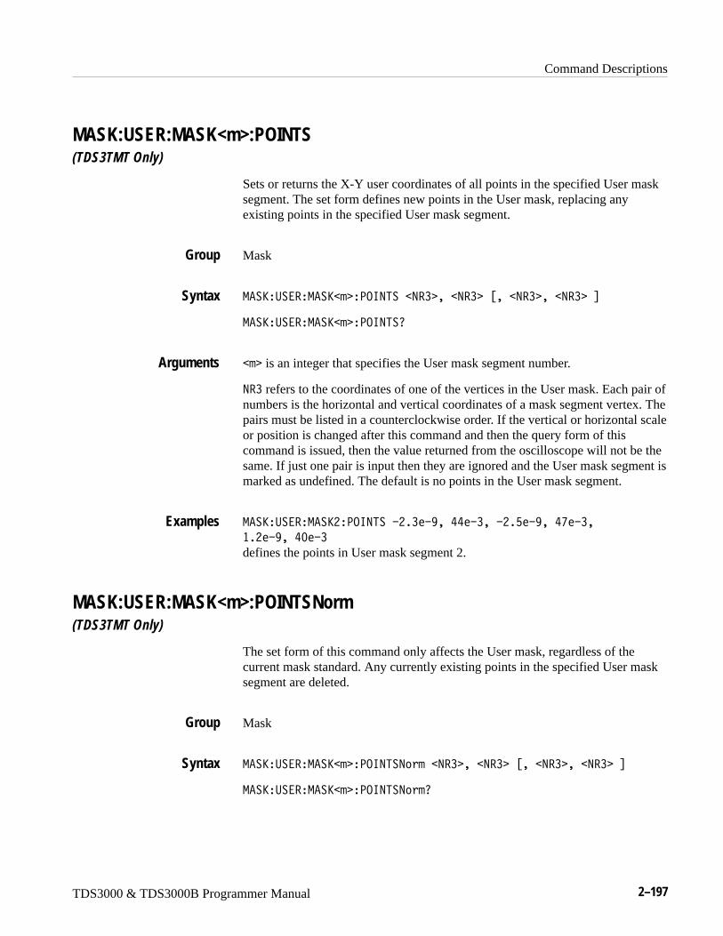
Command Descriptions
TDS3000 & TDS3000B Programmer Manual 2–197
MASK:USER:MASK<m>:POINTS(TDS3TMT Only)
Sets or returns the X-Y user coordinates of all points in the specified User masksegment. The set form defines new points in the User mask, replacing anyexisting points in the specified User mask segment.
Mask
-��S�:����-��S�� �<.695���9�� ���9�� �%���9�� ���9�� �&
-��S�:����-��S�� �<.695�0
�� is an integer that specifies the User mask segment number.
9�� refers to the coordinates of one of the vertices in the User mask. Each pair ofnumbers is the horizontal and vertical coordinates of a mask segment vertex. Thepairs must be listed in a counterclockwise order. If the vertical or horizontal scaleor position is changed after this command and then the query form of thiscommand is issued, then the value returned from the oscilloscope will not be thesame. If just one pair is input then they are ignored and the User mask segment ismarked as undefined. The default is no points in the User mask segment.
-��S�:����-��SH�<.695��WH���WX��II�W���WH�G�WX��IV�W���
��H�WX��I;�W�
defines the points in User mask segment 2.
MASK:USER:MASK<m>:POINTSNorm(TDS3TMT Only)
The set form of this command only affects the User mask, regardless of thecurrent mask standard. Any currently existing points in the specified User masksegment are deleted.
Mask
-��S�:����-��S�� �<.695�9���9�� ���9�� �%���9�� ���9�� �&
-��S�:����-��S�� �<.695�9�0
Group
Syntax
Arguments
Examples
Group
Syntax
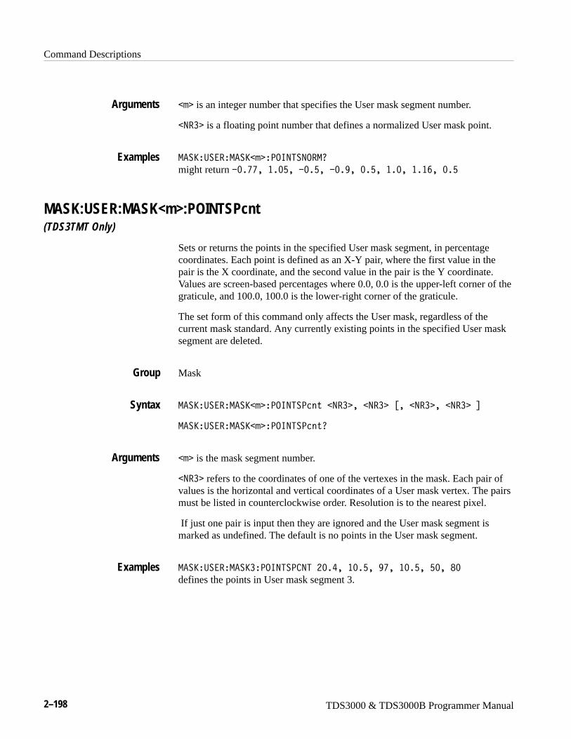
Command Descriptions
2–198 TDS3000 & TDS3000B Programmer Manual
�� is an integer number that specifies the User mask segment number.
�9�� is a floating point number that defines a normalized User mask point.
-��S�:����-��S�� �<.695�9.�-0 might return W;�VV����;G��W;�G��W;�X��;�G����;�����T��;�G
MASK:USER:MASK<m>:POINTSPcnt(TDS3TMT Only)
Sets or returns the points in the specified User mask segment, in percentagecoordinates. Each point is defined as an X-Y pair, where the first value in thepair is the X coordinate, and the second value in the pair is the Y coordinate.Values are screen-based percentages where 0.0, 0.0 is the upper-left corner of thegraticule, and 100.0, 100.0 is the lower-right corner of the graticule.
The set form of this command only affects the User mask, regardless of thecurrent mask standard. Any currently existing points in the specified User masksegment are deleted.
Mask
-��S�:����-��S�� �<.695�<2����9�� ���9�� �%���9�� ���9�� �&
-��S�:����-��S�� �<.695�<2��0
�� is the mask segment number.
�9�� refers to the coordinates of one of the vertexes in the mask. Each pair ofvalues is the horizontal and vertical coordinates of a User mask vertex. The pairsmust be listed in counterclockwise order. Resolution is to the nearest pixel.
If just one pair is input then they are ignored and the User mask segment ismarked as undefined. The default is no points in the User mask segment.
-��S�:����-��S��<.695�< 95�H;�I���;�G��XV���;�G��G;��B;
defines the points in User mask segment 3.
Arguments
Examples
Group
Syntax
Arguments
Examples
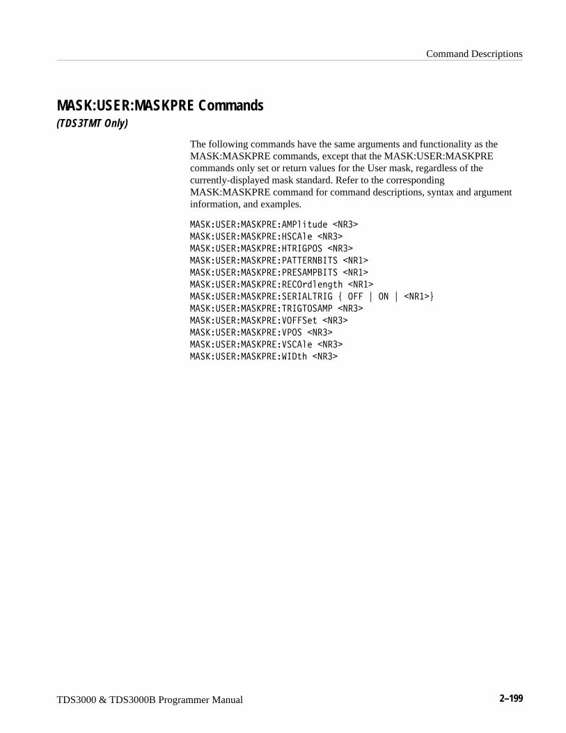
Command Descriptions
TDS3000 & TDS3000B Programmer Manual 2–199
MASK:USER:MASKPRE Commands(TDS3TMT Only)
The following commands have the same arguments and functionality as theMASK:MASKPRE commands, except that the MASK:USER:MASKPREcommands only set or return values for the User mask, regardless of thecurrently-displayed mask standard. Refer to the correspondingMASK:MASKPRE command for command descriptions, syntax and argumentinformation, and examples.
-��S�:����-��S<����-<���,1���9��
-��S�:����-��S<����� �����9��
-��S�:����-��S<����5�67<.���9��
-��S�:����-��S<���<�55��9?65���9��
-��S�:����-��S<���<����-<?65���9��
-��S�:����-��S<����� .1���3�M��9��
-��S�:����-��S<������6�85�67�#�.���"�.9�"��9�� $
-��S�:����-��S<���5�675.��-<��9��
-��S�:����-��S<����.�������9��
-��S�:����-��S<����<.���9��
-��S�:����-��S<����� �����9��
-��S�:����-��S<����6/�M��9��
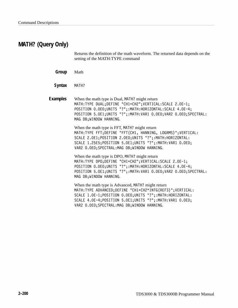
Command Descriptions
2–200 TDS3000 & TDS3000B Programmer Manual
MATH? (Query Only)Returns the definition of the math waveform. The returned data depends on thesetting of the MATH:TYPE command
Math
-�5�0
When the math type is Dual, -�5�0 might return -�5��5E<��/:�8A/��69��L ��Y �HLA���56 �8�� �8��H�;�W�A
<.�656.9�;�;�;A:965��L0LA�-�5���.�6P.95�8�� �8��I�;�WIA
<.�656.9�G�;��A:965��L0LA�-�5�������;�;�;A���H�;�;�;A�<� 5��8�
-�7�/?A�69/.����99697.
When the math type is FFT, -�5�0 might return -�5��5E<����5A/��69��L��5) ������99697��8.7�-�*LA���56 �8�
� �8��H�;��A<.�656.9�H�;�;A:965��L0LA�-�5���.�6P.95�8�
� �8����HG�GA<.�656.9�G�;��A:965��L0LA�-�5�������;�;�;A
���H�;�;�;A�<� 5��8�-�7�/?A�69/.����99697.
When the math type is DPO, -�5�0 might return -�5��5E<��/<.A/��69��L ��Y �HLA���56 �8�� �8��H�;�W�A
<.�656.9�;�;�;A:965��L0LA�-�5���.�6P.95�8�� �8��I�;�WIA
<.�656.9�G�;��A:965��L0LA�-�5�������;�;�;A���H�;�;�;A�<� 5��8�
-�7�/?A�69/.����99697.
When the math type is Advanced, -�5�0 might return -�5��5E<���/��9 �/A/��69��L ��Y �HC6957)����*LA���56 �8�
� �8����;�W�A<.�656.9�;�;�;A:965��L0LA�-�5���.�6P.95�8�
� �8��I�;�WIA<.�656.9�G�;��A:965��L0LA�-�5�������;�;�;A
���H�;�;�;A�<� 5��8�-�7�/?A�69/.����99697.
Group
Syntax
Examples
Command Descriptions
TDS3000 & TDS3000B Programmer Manual 2–201
MATH:DEFINESets or returns the current math function as a text string. For TDS3FFT andTDS3AAM, this command also sets or returns the math FFT parameters. For theTDS3AAM, this command also sets or returns the advanced math parameters.This is equivalent to setting the math parameters in the Math menu. The syntaxof this command depends on the value of the MATH:TYPe command, as well aswhich application module is installed in the instrument.
Math
-�5��/��69���+����3
Where the syntax for �+����3 is:
Dual Wfm Math and DPO Math: L��,2� �4��� ��,2� L
FFT Math: L��5�)��,2� %��J��1J ���2����3 &*L
Advanced Math: L���4����� L
For the Dual Wfm Math and DPO Math, �+����3 contains the expressionL��,2� �4��� ��,2� L.
�,2� sets the signal or reference source. Valid choices are: ��, �H, ��, �I,����, ���H, ����, or ���I. �� and �I are only available on four-channelinstruments.
4��� sets the operation to apply to the two waveforms. For Dual WfmMath, valid operators are Y (addition), W (subtraction), C (multiplication), and [ (division).
For DPO Math, valid operators are Y (addition), W (subtraction), and C (multiplication). There is no division in DPO math.
For FFT math, �+����3 contains the expression L��5�)��,2� %��J��1J ���2����3 &*L.
�,2� sets the signal or reference source from which to generate an FFTwaveform. Valid choices are: ��, �H, ��, �I, ����, ���H, ����, or ���I. �� and �I are only available on four-channel instruments.
Group
Syntax
Dual and DPO Arguments
FFT Arguments

Command Descriptions
2–202 TDS3000 & TDS3000B Programmer Manual
J��1J is an optional argument that sets the FFT window algorithm to apply tothe source signal. Valid choices are �� 5��3,��, ��-���3, ��9���3, and?8�2O���M���. Each window is a trade-off between frequency resolution andmagnitude accuracy. What you want to measure, and your source signalcharacteristics, help determine which window to use.
�2����3 is an optional argument that sets the FFT waveform vertical scale type.Valid choices are: 8.7�� and 869����.
Refer to the TDS3FFT FFT Application Module User Manual or the TDS3AAMAdvanced Analysis Application Module User Manual for more information onFFT windows and scaling.
For Advanced Math, �+����3 contains the expression L���4����� L.
��4����� is a syntactically-correct sequence of valid waveform sources,measurements, mathematical operators, and numeric constants.
Table 2–37: Advanced Math expression elements
Expression Description
CH1-CH4, REF1-REF4 Specifies a waveform data source.
FFT( , INTG( , DIFF( Executes a Fast Fourier Transform, integration, or differentiationoperation on the expression that follows. The FFT operator mustbe the first (left-most) operator in an expression. All theseoperations must end with a right parenthesis.
AMPlitude( , AREa( ,BURst( , CARea(CMEan( , CRMs( ,DELay( , FALL( , FREQuency( , HIGH( ,LOW( , MAXimum( ,MEAN( , MINImum( ,NDUty( , NOVershoot( , NWIdth( , PDUTy( , PERIod( , PHAse(PK2pk( , POVershoot( ,PWIdth( , RISe( , RMS(
Executes the selected measurement operation on the waveform(active or reference) that follows. All these operations must endwith a right parenthesis.
VAR1, VAR2 Adds the user-defined variable to the expression. Refer to theMATH:VAR<x> command.
+ , – , * , / Executes an addition, subtraction, multiplication, or divisionoperation on the following expression. + and – are also unary;use – to negate the expression that follows.
Advanced MathArguments
Command Descriptions
TDS3000 & TDS3000B Programmer Manual 2–203
Table 2–37: Advanced Math expression elements (Cont.)
Expression Description
( ) , Parentheses provide a way to control evaluation order in anexpression. The comma is used to separate the “from” and “to”waveforms in Delay and Phase measurement operations.
1-0 , . , E Specifies a numeric value in (optional) scientific notation.
-�5��5E<��/:�8A�-�5��/��69��L �HC���IL
sets the math type to Dual and displays a Dual math waveform that is the productof the channel 1 waveform and the REF4 waveform.
-�5��5E<����5A�-�5��/��69��L��5)� ���*L
sets the math type to FFT and displays an FFT waveform of the channel 1waveform, using the current FFT scale and window settings.
-�5��5E<����5A�-�5��/��69��L��5)� ������--��869����-��*L
sets the math type to FFT and displays an FFT waveform of the channel 3waveform, using the Hamming window, with linear rms scaling.
-�5��/��69�0 might return -�5��/��69��L��5) ��C �I*L
-�5��5E<���/��9 �/A�-�5��/��69��L6957)����C ��*Y/�8�E) ��� �H*L
sets the math type to FFT and displays an advanced math waveform that is theintegration of the product of REF1 and CH3 plus the result of the delaymeasurement between channel 1 and 2.
MATH:TYPE
MATH:HORizontal:POSitionSets or returns the math horizontal display position for FFT or math waveformsthat only have reference waveform source waveforms.
Math
-�5���.��F�����<.�������9��
-�5���.��F�����<.�����0
�9�� is the % of the math waveform (divided by 100) that precedes centerscreen. It can very from 0.0e0 to 1.0e0.
Examples
Related Commands
Group
Syntax
Arguments
Command Descriptions
2–204 TDS3000 & TDS3000B Programmer Manual
-�5���.�6P.95�8�<.�656.9���;�@�
sets the horizontal position to 10% pretrigger
MATH:HORizontal:SCAleSets or returns the math horizontal display scale for FFT or for dual mathwaveforms that have source waveforms that are reference waveforms. Thehorizontal scale of a dual math waveform with a channel source waveform is setthrough the HORizontal:SCAle command.
Math
-�5���.��F������ �����9��
-�5���.��F������ ���0
�9�� is the math horizontal scale in seconds.
-�5���.�6P.95�8�� �8�0
might return �-�5���.�6P.95�8�� �8��H�;�WI indicating that the mathhorizontal scale is 200 �s.
MATH:HORizontal:UNITs(TDS3AAM Only)
Sets or returns the math waveform horizontal measurement unit value.
Math
-�5���.��F�����:965���+����3
-�5���.��F�����:965�0
�+����3 is a text label to apply to horizontal units when the horizontal unit is“?” (unknown unit value).
-�5���.�6P.95�8�:965�0
might return �-�5���.�6P.95�8�:965��L0L indicating that the math horizontalunit label for unknown values is the default question mark unit.
Examples
Group
Syntax
Arguments
Examples
Group
Syntax
Arguments
Examples
Command Descriptions
TDS3000 & TDS3000B Programmer Manual 2–205
MATH:SPECTral:MAG(TDS3FFT, TDS3AAM Only)
Sets or returns the FFT math waveform vertical display scale.
Math
-�5���<� 5���-�7�#�/?�"�869����$
-�5���<� 5���-�70
/? sets the FFT vertical scale to dBV RMS.
869��� sets the FFT vertical scale to linear RMS.
-�5���<� 5��8�-�70
might return �-�5���<� 5���-�7�1? indicating the the FFT vertical scale isset to dB.
MATH:SPECTral:WINdow(TDS3FFT, TDS3AAM Only)
Sets or returns the FFT math waveform window algorithm setting.
Math
-�5���<� 5����691J�#�?8�2O���M����"���-���3�"���9���3�"
�� 5��3,���$
-�5���<� 5����691J0
?8�2O���M��� sets the FFT waveform to use the Blackman-Harris windowalgorithm.
��-���3 sets the FFT waveform to use the Hamming window algorithm.
��9���3 sets the FFT waveform to use the Hanning window algorithm.
�� 5��3,�� sets the FFT waveform to use the Rectangular window algorithm.
-�5���<� 5��8��69/.����99697
sets the FFT math waveform window algorithm to Hanning.
Group
Syntax
Arguments
Examples
Group
Syntax
Arguments
Examples
Command Descriptions
2–206 TDS3000 & TDS3000B Programmer Manual
MATH:TYPeSets or returns the math waveform mode type.
Math
-�5��5E<��#��/���2�1�"�/<.�"�/:�8�"���5�$
-�5��5E<�0
�/���2�1 sets the math waveform mode to advanced math. TDS3AAM only.
/<. sets the math waveform mode to DPO math. TDS3AAM only.
/:�8 sets the math waveform mode to dual waveform math.
��5 sets the math waveform mode to FFT math. TDS3AAM, TDS3FFT only.
-�5��5E<����5
sets the math waveform mode to FFT.
MATH:DEFINE
MATH:VAR<x>(TDS3AAM Only)
Sets or returns the value of the user-defined math variable that can be used aspart of an advanced math waveform expression.
Math
-�5������� ���9��
-�5������� 0
�� specifies which variable to define, where <x> = 1 for VAR1 and <x> = 2 forVAR2.
�9�� is a numeric value in scientific notation that sets the value of the specifiedvariable.
Group
Syntax
Arguments
Examples
Related Commands
Group
Syntax
Arguments
Command Descriptions
TDS3000 & TDS3000B Programmer Manual 2–207
-�5���������HG���
sets the value of VAR1 to 1251.
MATH:VERTical:POSitionSets or returns the math waveform display position.
Math
-�5�����5�2���<.�������9��
-�5�����5�2���<.�����0
�9�� is the math vertical position in divisions from center screen.
-�5�����56 �8�<.�656.90
might return �-�5�����56 �8�<.�656.9�W��;�; indicating the the mathwaveform is 3 division below center screen.
MATH:VERTical:SCAleSets the vertical display scale. This command is equivalent to changing theVertical SCALE knob that controls the waveform zoom factors. The mathwaveform scale is not affected by this control. The math calculation softwareautomatically determines the optimum vertical scale through examination ofinput waveform data.
NOTE. The vertical display scale is reset to the waveform preamble scale, when avertical scale change to a math source waveform results in a new math autoscaleoperation. The vertical display scale should be changed only after math sourcewaveform adjustments are complete.
Math
-�5�����5�2���� �����9��
-�5�����5�2���� ���0
Examples
Group
Syntax
Arguments
Examples
Group
Syntax
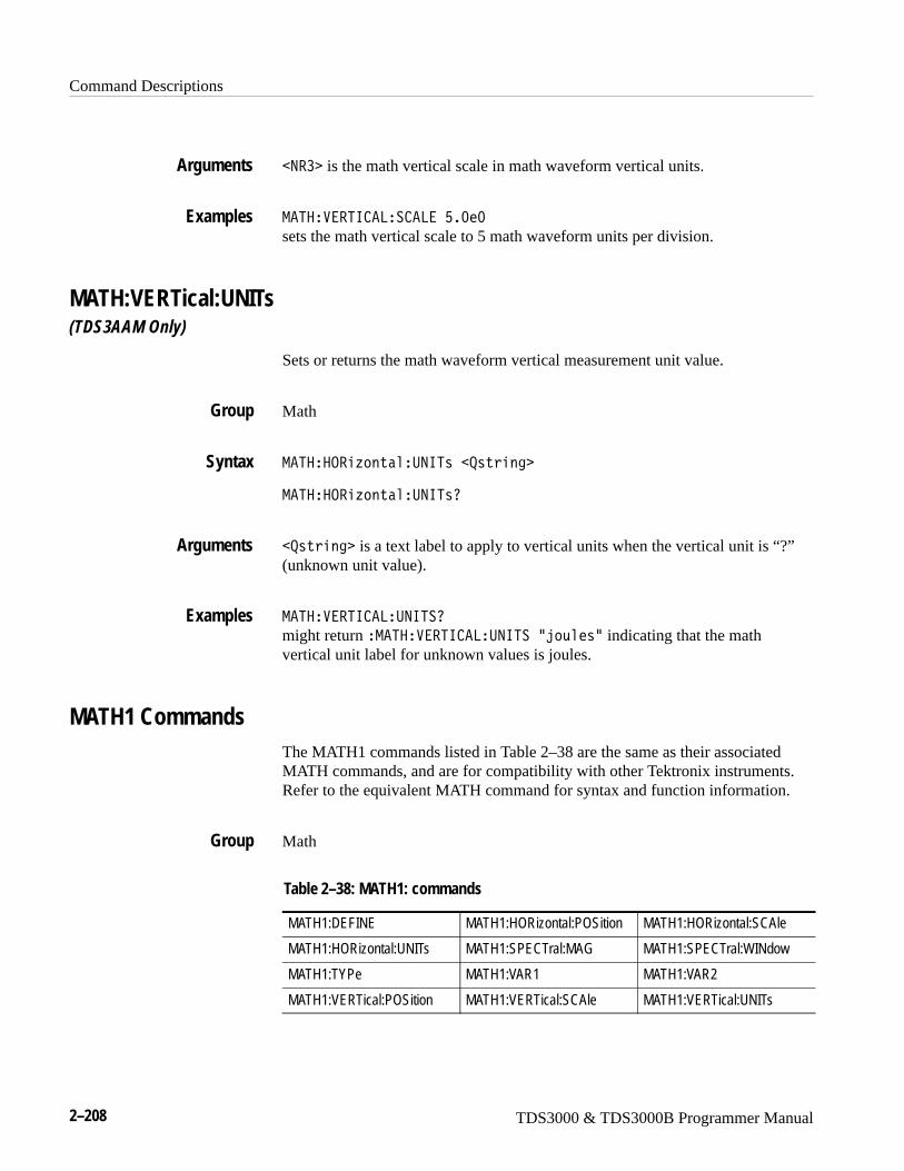
Command Descriptions
2–208 TDS3000 & TDS3000B Programmer Manual
�9�� is the math vertical scale in math waveform vertical units.
-�5�����56 �8�� �8��G�;�;
sets the math vertical scale to 5 math waveform units per division.
MATH:VERTical:UNITs(TDS3AAM Only)
Sets or returns the math waveform vertical measurement unit value.
Math
-�5���.��F�����:965���+����3
-�5���.��F�����:965�0
�+����3 is a text label to apply to vertical units when the vertical unit is “?”(unknown unit value).
-�5�����56 �8�:965�0
might return �-�5�����56 �8�:965��L],���L indicating that the mathvertical unit label for unknown values is joules.
MATH1 CommandsThe MATH1 commands listed in Table 2–38 are the same as their associatedMATH commands, and are for compatibility with other Tektronix instruments.Refer to the equivalent MATH command for syntax and function information.
Math
Table 2–38: MATH1: commands
MATH1:DEFINE MATH1:HORizontal:POSition MATH1:HORizontal:SCAle
MATH1:HORizontal:UNITs MATH1:SPECTral:MAG MATH1:SPECTral:WINdow
MATH1:TYPe MATH1:VAR1 MATH1:VAR2
MATH1:VERTical:POSition MATH1:VERTical:SCAle MATH1:VERTical:UNITs
Arguments
Examples
Group
Syntax
Arguments
Examples
Group
Command Descriptions
TDS3000 & TDS3000B Programmer Manual 2–209
MEASUrement? (Query Only)Returns all measurement values for the last-acquired waveform.
Measurement
-���:�����0
-���:��-�950
might return��-���:��-�95�-�����5E<�����+:�9 EA:965��L�L� .:95�;A-696-:-�;�
;�;�;A-��6-:-�;�;�;A-��9�;�;�;A�5//���;�;�;A�.:� ��� ��A�.:� �H
�HA/�8�E�/6�� 56.9��.����/�A�/7����6���A�/7�H��6��A�-���:��@
-�95�-������5�5��;A�-���:��-�95�-���H�5E<��<��6./A:965��L�LA .:95
;A-696-:-�;�;�;A-��6-:-�;�;�.A-��9�;�;�;A�5//���;�;�;A�.:� ��
��A�.:� �H� �HA/�8�E�/6�� 56.9��.����/�A�/7����6��A�/7�H
�6��A�-���:��-�95�-���H��5�5��;A�-���:��-�95�-�����5E<��<�@
�6./A:965��L�LA .:95�;A-696-:-�;�;�;A-��6-:-�;�;�;A-��9
;�;�;A-��9�;�;�;A�5//���;�;�;A�.:� ��� ��A�.:� �H
�HA/�8�E�/6�� 56.9��.����/�A�/7����6��A�/7�H��6��A�-���:��@
-�95�-�����5�5��;A�-���:��-�95�-���I�5E<��<��6./A:965�
L�LA .:95;A-696-:-�;�;�;A-��6-:-�;�;�;A-��9�;�;�;A�5//��
;�;�;A�.:� ��� ��A�.:� �H� �HA�/�8�E�/6�� 56.9��.����/�A�/7��
�6��A�/7�H��6��A�-���:��-�95�-���I��5�5��;A�-���:��@
-�95�6--�/�5E<��<��6./A:965��L�LA�.:� ��� ��A�.:� �H
�HA/�8�E�/6�� 56.9��.����/�A�/7����6��A�/7�H��6��A�-���:��@
-�95�7�5697�.��A69/6 �5.����5�5��.��A9:-�.�P�;A9:-���5�;A�.�P�
;�;�;A�.�PH�;�;�;A�.�P��;�;�;A�.�PI�;�;�;A���5��;�;�;A���5H
;�;�;A���5��;�;�;A���5I�;�;�;A�-���:��-�95�-�5�./��:5.A���8�@
��8�-�5�./�<�� �95A�?�.8:5���67��;�;�;A8.��;�;�;A-6/�;�;�;A-6/H
;�;�;A�-���:��-�95����8���8�<�� �95��67��X�;��A8.����;��A-6/
G�;��A-6/H�G�;��A�-���:��-�95��5�56�56 ��-./��.��A��67�5697��H
MEASUrement:CLEARSNapshotRemoves the measurement snapshot display.
Measurement
-���:������ 8����9�4�M�
-���:��-�95� 8����9�<��.5
Group
Syntax
Example
Group
Syntax
Examples
Command Descriptions
2–210 TDS3000 & TDS3000B Programmer Manual
MEASUrement:GATingSets or returns measurement gating.
Measurement
-���:������7�5��3�#�� �����"� :���"�.���$
-���:������7�5��30
.�� turns off measurement gating.
� ���� limits measurements to the portion of the waveform displayed on thescreen.
:�� limits measurements to the portion of the waveform between the verticalbar cursors, even if they are off screen.
-���:��-�95�7�5697�� ���9
limits measurements to the portion of the waveform displayed on the screen.
-���:��-�95�7�56970
might return -���:��-�95�7�5697� :��.�showing measurements are limited to the portion of the waveform between thevertical bar cursors.
MEASUrement:IMMed? (Query Only)Returns all immediate measurement setup parameters.
Measurement
-���:������6--�10
-���:��-�95�6--�/0
might return �-���:��-�95�6--�/�5E<��<��6./A:965��L�LA�.:� �� ��A�.:� �H� �HA/�8�E�/6�� 56.9��.����/�A�/7����6��A�/7�H��6��
Group
Syntax
Arguments
Examples
Group
Syntax
Examples
Command Descriptions
TDS3000 & TDS3000B Programmer Manual 2–211
MEASUrement:IMMed:DATa? (Query Only)Returns the measurement result and qualifier for the immediate measurementspecified by the MEASUrement:IMMed:TYPe command. The measurement istaken on the source specified by a MEASUrement:IMMed:SOURCE command.Returns both the measurement result and the status of the result.
Measurement
-���:������6--�1�/�5�0��9�� ���9��
�9�� is the measurement result.
�9�� is one of the execution errors shown in Table 3–5 on page 3–14, or it is 0if there is no error.
-���:��-�95�6--�/�/�5�0
might return �-���:��-�95�6--�/�/�5��X�X�XT���G�WI��;
MEASUrement:IMMed:VALue?
MEASUrement:IMMed:DELay? (Query Only)Returns information about the immediate delay measurement.
Measurement
-���:������6--�1�/�8�D0
-���:��-�95�6--�/�/�8�E0
might return �-���:��-�95�6--�/�/�8�E��/7����6��A�/7�H��6��A/6�� 56.9��.����/�
Group
Syntax
Arguments
Examples
Related Commands
Group
Syntax
Examples
Command Descriptions
2–212 TDS3000 & TDS3000B Programmer Manual
MEASUrement:IMMed:DELay:DIREctionSets or returns the starting point and direction that determines the delay “to”edge when taking an immediate delay measurement. Use the MEASUre-ment:IMMed:SOURCE2 command to specify the delay “to” waveform.
Measurement
-���:������6--�1�/�8�D�/6��2����#?� S��1��"��.���1�$
-���:������6--�1�/�8�D�/6��2���0
?� S��1� means that the search starts at the end of the waveform and looks forthe last rising or falling edge in the waveform. The slope of the edge is specifiedby MEASUrement:IMMed:DELay:EDGE2.
�.���1� means that the search starts at the beginning of the waveform andlooks for the first rising or falling edge in the waveform. The slope of the edge isspecified by MEASUrement:IMMed:DELay:EDGE2.
-���:��-�95�6--�/�/�8�E�/6�� 56.9��.����/�
starts searching from the beginning of the waveform record.
-���:��-�95�6--�/�/�8�E�/6�� 56.90
returns either ?� S���/� or �.����/�.
MEASUrement:IMMed:DELay:EDGE<x>Sets or returns the slope of the edge that is used for the delay “from” or “to”waveform when taking an immediate delay measurement. The waveform isspecified by MEASUrement:IMMed:SOURCE<x>.
Measurement
MEASUrement:IMMed:SOURCE<x>
-���:������6--�1�/�8�D��/7��� �#���88�"��6���$
-���:������6--�1�/�8�D��/7��� 0
Group
Syntax
Arguments
Examples
Group
Syntax
Command Descriptions
TDS3000 & TDS3000B Programmer Manual 2–213
�� specifies which waveform to use, where <x> = 1 is the “from” waveform,and <x> = 2 is the “to” waveform.
��88 specifies the falling edge.
�6�� specifies the rising edge.
-���:��-�95�6--�/�/�8�E��/7����6��
specifies that the “from” waveform rising edge be used for the immediate delaymeasurement.
-���:��-�95�6--�/�/�8�E��/7��0
returns either �6�� or ��88.
MEASUrement:IMMed:SOUrceSpecifies the source to measure “from” when taking an immediate delaymeasurement or phase measurement. This command is the same as the MEA-SUrement:IMMed:SOURCE1 command.
MEASUrement:IMMed:SOURCE<x>Specifies the source to measure “from” or “to” when taking an immediate delaymeasurement or phase measurement.
Measurement
-���:������6--�1��.:� ��� �#� ��� �"�-�5��"�-�5���"������ �$
-���:������6--�1��.:� �0
�.:� ��� specifies which waveform to use, where <x> = 1 is the “from”waveform, and <x> = 2 is the “to” waveform.
��� is an input channel.
-�5� or -�5�� is the math waveform.
����� is a reference waveform.
-���:��-�95�6--�/��.:� ���-�5��
specifies MATH1 as the immediate measurement source.
Arguments
Examples
Group
Syntax
Arguments
Examples
Command Descriptions
2–214 TDS3000 & TDS3000B Programmer Manual
MEASUrement:IMMed:TYPeSpecifies the immediate measurement.
Measurement
-���:������6--�1�5E<��#��-<���,1��"������"�?:����"� �����"�
-����"� �-��"�/�8�E�"���88�"����+,��2D�"��67��"�8.��"�-����,��"
-��9�"�-696�,��"�9/:�D�"�9.���M��"�9�61�M�"�</:�D�"�<��61�"
<�����"�<SH4O�"�<.���M��"�<�61�M�"��6���"��-��$
-���:������6--�1�5E<�0
Information on how measurements are derived:.
�-<���,1� is the high value minus the low value.
���� is the area between the curve and ground over the active waveform the highvalue minus the low value. TDS3AAM only.
?:��� is the time from the first MidRef crossing to the last MidRef crossing.
���� (cycle area) is the area between the curve and ground over one cycle.TDS3AAM only.
-��� is the arithmetic mean over one cycle.
�-� is the true Root Mean Square voltage over one cycle.
/�8�D is the delay from one waveform’s edge event to another. TDS3AAM only.
��88 is the time that it takes for the falling edge of a pulse to fall from a HighRefvalue to a LowRef value of its final value.
���+,��2D is the reciprocal of the period measured in hertz.
�67� is the 100% reference level.
8.� is the 0% reference level.
-����,� is the highest amplitude (voltage).
-��9 for general purpose measurements, is the arithmetic mean over the entirewaveform. For histogram measurements, it is the average of all acquired pointswithin or on the histogram box.
-696�,� is the lowest amplitude (voltage).
9/:�D is the ratio of the negative pulse width to the signal period expressed as apercentage.
Group
Syntax
Arguments
Command Descriptions
TDS3000 & TDS3000B Programmer Manual 2–215
9.���M� is the negative overshoot, expressed as:
NOVershoot � 100 ��(Low � Minimum)
Amplitude�
9�61�M is the distance (time) between MidRef (usually 50%) amplitude points ofa negative pulse.
</:�D is the ratio of the positive pulse width to the signal period expressed as apercentage.
<��61 is the time, in seconds, it takes for one complete signal cycle to happen.
<���� is the phase difference from the selected waveform to the designatedwaveform.
<SH4O is the absolute difference between the maximum and minimum amplitude.It can be used with both general purpose and histogram measurements.
<.���M� is the positive overshoot, expressed as:
POVershoot � 100 ��(Maximum � High)
Amplitude�
<�61�M is the distance (time) between MidRef (usually 50%) amplitude points ofa positive pulse.
�6�� is the time that it takes for the leading edge of a pulse to rise from a lowreference value to a high reference value of its final value.
�-� is the true Root Mean Square voltage.
-���:��-�95�6--�/�5E<�����+:�9 E
defines the immediate measurement to be a frequency measurement.Examples
Command Descriptions
2–216 TDS3000 & TDS3000B Programmer Manual
MEASUrement:IMMed:UNIts? (Query Only)Returns the units for the immediate measurement.
Measurement
-���:������6--�1�:96��0
�+����3 returns L�L for volts, L�L for seconds, L�FL for hertz, LZL forpercent, L�L for amps, L�L for watts, for ohms, L1?L for decibels, L0L forunknown, and L�L for non-dimensional units. Measurements on math waveformscan return the following units: L�[�L, L�[�L, L��L, L�[�L, L1?�L, L1?[�L,L�[�L, L�[�L, L��L, L�[�L, L1?�L, L1?[�L, L��L, L�[�L, L��L, L�[�L, L��L,L�[�L, L1?�L, L1?[�L, L�1?L, L�[1?L, L�1?L, L�[1?L, L�1?L, L�[1?L, L1?1?L,and L1?[1?L.
-���:��-�95�6--�/�:965�0
might return L�L, indicating that the units for the immediate measurement areseconds.
MEASUrement:IMMed:TYPe
MEASUrement:IMMed:VALue? (Query Only)Immediately executes the immediate measurement specified by the MEASUre-ment:IMMed:TYPe command. The measurement is taken on the source specifiedby a MEASUrement:IMMed:SOURCE command.
Measurement
-���:������6--�1���8,�0
�9��
MEASUrement:IMMed:DATa?
Group
Syntax
Returns
Examples
Related Commands
Group
Syntax
Returns
Related Commands
Command Descriptions
TDS3000 & TDS3000B Programmer Manual 2–217
MEASUrement:INDICators? (Query Only)Returns all measurement indicator parameters.
Measurement
-���:������69/6 ���0
-���:��-�95�69/6 �5.��0 might return�-���:��-�95�69/6 �5.����5�5��-����A9:-�.�P�;A9:-���5�IA�.�P�
V�G�;A�.�PH�W��I;;;;;;XG�TV�;A�.�P��;�;�;A�.�PI�;�;�;A���5�
WT��G��H��WTA���5H�W���VXVG��WTA���5��WT�I;XI��WTA���5I�WT�I;��WT
MEASUrement:INDICators:HORZ<x>? (Query Only)Returns the position of the specified horizontal measurement indicator �� ,where �� can be 1, 2, 3, or 4.
Measurement
-���:������69/6 �����.�P�� 0
-���:��-�95�69/6 �5.����.�P�0 might return�-���:��-�95�69/6 �5.����.�P��@H�;�@� indicating that horizontalindicator1 has a value of -2mV.
MEASUrement:INDICators:NUMHORZ? (Query Only)Returns the number of horizontal measurement indicators currently beingdisplayed.
Measurement
-���:������69/6 ����9:-�.�P0
-���:��-�95�69/6 �5.���9:-�.�P0 might return�-���:��-�95�69/6 �5.���9:-�.�P�H indicating that there are currently 2horizontal lines drawn on the graticule showing where the measurementspecified by -���:������69/6 �����5�5� is being performed.
Group
Syntax
Examples
Group
Syntax
Examples
Group
Syntax
Examples
Command Descriptions
2–218 TDS3000 & TDS3000B Programmer Manual
MEASUrement:INDICators:NUMVERT? (Query Only)Returns the number of vertical measurement indicators currently being dis-played.
Measurement
-���:������69/6 ����9:-���50
-���:��-�95�69/6 �5.���9:-���50 might return�-���:��-�95�69/6 �5.���9:-���5�H indicating that there are currently 2vertical lines drawn on the graticule showing where the measurement specifiedby -���:������69/6 �����5�5� is being performed.
MEASUrement:INDICators:STATESet or returns the state of visible measurement indicators. Performs the sameoperations as the front panel Measurement Indicators menu.
Measurement
-���:������69/6 �����5�5��#�.���"�-����� $
-���:������69/6 �����5�5�0
.�� turns off visible measurement indicators.
-����� turns on the display of visible measurement indicators for measurement�� , where �� can be 1, 2, 3, or 4. There must be an active measurement beforeyou can activate an indicator for a specified measurement.
-���:��-�95�69/6 �5.����5�5��-���H
turns on the display of visible measurement indicators for measurement 2.
-���:��-�95�69/6 �5.����5�5�0
might return -���:��-�95�69/6 �5.����5�5��.�� indicating that nomeasurement indicators are active.
Group
Syntax
Examples
Group
Syntax
Arguments
Examples
Command Descriptions
TDS3000 & TDS3000B Programmer Manual 2–219
MEASUrement:INDICators:VERT<x>? (Query Only)Returns the value of the specified vertical measurement indicator �� from thetrigger point, where �� can be 1, 2, 3, or 4. A negative value means that theindicator is positioned earlier in the waveform record than the trigger point.
Measurement
-���:������69/6 �������5�� 0
-���:��-�95�69/6 �5.������5H0 might return�-���:��-�95�69/6 �5.������5H�@��VHIG;V�WT indicating that the secondmeasurement indicator is positioned 3.72 �s before the trigger point.
MEASUrement:MEAS<x>? (Query Only)Returns all measurement parameters for the specified active measurement <x>.
Measurement
-���:������-����� 0
Measurement parameters, for the specified measurement.
-���:��-�95�-����0
might return: �-���:��-�95�-�����5E<��<��6./A:965��L�LA .:95;A-696-:-�;�;�;A-��6-:-�;�;�;A-��9�;�;�;A�5//���;�;�;A�.:� ��
��A�.:� �H� �HA/�8�E�/6�� 56.9��.����/�A�/7����6��A�-���:��@
-�95�-������5�5��;
MEASUrement:MEAS<x>:COUNt? (Query Only)(TDS3AAM Only)
Returns the number of values accumulated for this measurement since the laststatistical reset. Some values may have been ignored because they generated anerror.
Measurement
Group
Syntax
Examples
Group
Syntax
Returns
Examples
Group
Command Descriptions
2–220 TDS3000 & TDS3000B Programmer Manual
-���:������-����� � .:9�0
<NR3>
-���:��-�95�-����� .:950
might return: �-���:�-����� .:9���HIV;;;;;;�Y�
MEASUrement:MEAS<x>:DATa? (Query Only)Returns the measurement result and qualifier for the measurement specified by<x>. Returns both the measurement result and the status of the result.
Measurement
-���:������-����� �/�5�0��9�� ���9��
�9�� is the measurement result.
�9�� is one of the execution errors shown in Table 3–5 on page 3–14, or it is 0if there is no error.
-���:��-�95�-�����/�5�0
might return �-���:��-�95�-�����/�5��X�X�XT���G�WI��;
MEASUrement:MEAS<x>:VALue?
MEASUrement:MEAS<x>:DELay? (Query Only)(TDS3AAM Only)
Returns the delay measurement parameters for the delay measurement specifiedby <x>.
Measurement
-���:������-����� �/�8�D0
Syntax
Returns
Examples
Group
Syntax
Arguments
Examples
Related Commands
Group
Syntax
Command Descriptions
TDS3000 & TDS3000B Programmer Manual 2–221
-���:��-�95�-�����/�8�E0
might return �-���:��-�95�-�����/�8�E��/7����6��A�/7�H��6��A/6�� 56.9��.����/�.
MEASUrement:MEAS<x>:DELay:DIREction(TDS3AAM Only)
Sets or returns the starting point and direction that determines the delay “to”edge when taking a delay measurement. The waveform is specified byMEASUrement:MEAS<X>:SOURCE2. This command is equivalent to settingthe direction in the Delay Edges and Direction side menu items.
Measurement
-���:������-����� �/�8�D�/6��2����#�?� S��1��"��.���1��$
-���:������-����� �/�8�D�/6��2���0
?� S��1� means that the search starts at the end of the waveform and looks forthe last rising or falling edge in the waveform. The slope of the edge is specifiedby MEASUrement:MEAS<x>:DELay:EDGE2.
�.���1� means that the search starts at the beginning of the waveform andlooks for the first rising or falling edge in the waveform. The slope of the edge isspecified by MEASUrement:MEAS<x>:DELay:EDGE2.
-���:��-�95�-�����/�8�E�/6�� 56.9�?� S���/�
starts searching from the end of the waveform record.
-���:��-�95�-�����/�8�E�/6�� 56.90
might return �.����/� for the search direction.
MEASUrement:MEAS<x>:DELay:EDGE1Sets or returns the slope of the edge that is used for the delay “from” waveformwhen taking a delay measurement. The waveform is specified byMEASUrement:MEAS<x>:SOURCE1. This command is equivalent to selectingthe edges in the MEASURE > Delay side menu.
Measurement
Examples
Group
Syntax
Arguments
Examples
Group
Command Descriptions
2–222 TDS3000 & TDS3000B Programmer Manual
-���:������-����� �/�8�D��/7���#���88�"��6���$
-���:������-����� �/�8�D��/7��0
��88 specifies the falling edge.
�6�� specifies the rising edge.
-���:��-�95�-�����/�8�E��/7����6��
specifies that the rising edge be used for measurement 3.
-���:��-�95�-�����/�8�E��/7��0
returns either �6�� or ��88 for measurement 1.
MEASUrement:MEAS<x>:DELay:EDGE2Sets or returns the slope of the edge that is used for the delay “to” waveformwhen taking a delay measurement. The waveform is specified byMEASUrement:MEAS<x>:SOURCE2. This command is equivalent to selectingthe edges in the MEASURE > Delay side menu.
Measurement
-���:������-����� �/�8�D��/7�H�#���88�"��6���$
-���:������-����� �/�8�D��/7�H0
��88 specifies the falling edge.
�6�� specifies the rising edge.
-���:��-�95�-���H�/�8�E��/7�H��6��
specifies that the rising edge be used for the second delay measurement.
-���:��-�95�-���H�/�8�E��/7�H0
might return ��88 showing that the falling or negative edge of the waveform isused for the second measurement.
Syntax
Arguments
Examples
Group
Syntax
Arguments
Examples

Command Descriptions
TDS3000 & TDS3000B Programmer Manual 2–223
MEASUrement:MEAS<x>:MAXimum? (Query Only)(TDS3AAM Only)
Returns the maximum value found for the specified measurement since the laststatistical reset.
Measurement
-���:������-����� �-����,�0
<NR3>
-���:��-�95�-�����-��6-:-0
might return: �-���:�-�����-���I��B�WX
MEASUrement:MEAS<x>:MEAN? (Query Only)(TDS3AAM Only)
Returns the mean value accumulated for the specified measurement since the laststatistical reset.
Measurement
-���:������-����� �-��90
<NR3>
-���:��-�95�-�����-��90
might return: �-���:�-�����-��9�G�I�V��WX
Group
Syntax
Returns
Examples
Group
Syntax
Returns
Examples
Command Descriptions
2–224 TDS3000 & TDS3000B Programmer Manual
MEASUrement:MEAS<x>:MINImum? (Query Only)(TDS3AAM Only)
Returns the minimum value found for the specified measurement since the laststatistical reset.
Measurement
-���:������-����� �-696�,�0
<NR3>
-���:��-�95�-�����-690
might return: �-���:�-�����-696���VG�WX
MEASUrement:MEAS<x>:SOURCE[1]Sets or returns the source for all single channel measurements. SOUrce isequivalent to SOURCE1.
Measurement
-���:������-����� ��.:2��#� ��� �"�-�5�%�&�"������ �$
-���:������-����� ��.:� ���#� ��� �"�-�5�%�&�"������ �$
-���:������-����� ��.:2�0
-���:������-����� ��.:� ��0
��� is an input channel.
-�5� or -�5�� is the math waveform.
����� is a reference waveform.
-���:��-�95�-���H��.:� ���-�5��
specifies MATH as the measurement 2 source.
Group
Syntax
Returns
Examples
Group
Syntax
Arguments
Examples
Command Descriptions
TDS3000 & TDS3000B Programmer Manual 2–225
MEASUrement:MEAS<x>:SOURCE2Sets or returns the source to measure “to” when taking a delay measurement orphase measurement. This is equivalent to setting the source in the Delay fromSelected Wfm side menu or the Phase from Selected Wfm side menu.
Measurement
-���:������-����� ��.:� �H�#� ��� �"�-�5��"������ �$
-���:������-����� ��.:� �H0
��� is an input channel.
-�5� is the math waveform.
����� is a reference waveform.
-���:��-�95�-���I��.:� �H� ��
sets channel 1 as the delay “to” source when making delay measurements.
-���:��-�95�-���H��.:� �H0
might return -�5�.
MEASUrement:MEAS<x>:STATETurns the measurement specified by <x> on or off. The source specified byMEASUrement:MEAS<x>:SOURCE1 must be active for the measurement to bedisplayed. The source can be activated using the SELect:CH<x> command.
Measurement
-���:������-����� ��5�5��#�.���"�.9�"��9�� �$
-���:������-����� ��5�5�0
.�� or �9�� = 0 turns the specified measurement off. You can also turn the stateoff by turning the source off.
.9 or �9�� � 0 turns the specified measurement on.
Group
Syntax
Arguments
Examples
Group
Syntax
Arguments
Command Descriptions
2–226 TDS3000 & TDS3000B Programmer Manual
-���:��-�95�-������5�5��.9
turns measurement defined as MEAS1 on.
-���:��-�95�-���I��5�5�0
returns either ; or �, indicating the state of MEAS4.
MEASUrement:MEAS<x>:STDdev? (Query Only)TDS3AAM Only
Returns the standard deviation of values accumulated for this measurement sincethe last statistical reset.
Measurement
-���:������-����� ��5/1�>0
<NR3>
-���:��-�95�-������5//��0
might return: �-���:�-������5/�H��;�W�H
MEASUrement:MEAS<x>:TYPeSets or returns the measurement type for the measurement specified byMEAS<x>. This is equivalent to selecting the measurement in the SelectMeasurement side menu. To see the measurement value on the display theMEASUrement STATE must be set to ON.
Measurement
-���:������6--�1�5E<��#��-<���,1��"������"�?:����"� �����"�
-����"� �-��"�/�8�E�"���88�"����+,��2D�"��67��"�8.��"�-����,��"
-��9�"�-696�,��"�9/:�D�"�9.���M��"�9�61�M�"�</:�D�"�<��61�"
<�����"�<SH4O�"�<.���M��"�<�61�M�"��6���"��-��
-���:������-����� �5E<�0
Information on how measurements are derived:.
�-<���,1� is the high value minus the low value.
Examples
Group
Syntax
Returns
Examples
Group
Syntax
Arguments
Command Descriptions
TDS3000 & TDS3000B Programmer Manual 2–227
���� is the area between the curve and ground over the active waveform the highvalue minus the low value. TDS3AAM only.
?:��� is the time from the first MidRef crossing to the last MidRef crossing.
���� (cycle area) is the area between the curve and ground over one cycle.TDS3AAM only.
-��� is the arithmetic mean over one cycle.
�-� is the true Root Mean Square voltage over one cycle.
/�8�D is the delay from one waveform’s edge event to another.
��88 is the time that it takes for the falling edge of a pulse to fall from a HighRefvalue to a LowRef value of its final value.
���+,��2D is the reciprocal of the period measured in hertz.
�67� is the 100% reference level.
8.� is the 0% reference level.
-����,� is the highest amplitude (voltage).
-��9 for general purpose measurements, is the arithmetic mean over the entirewaveform. For histogram measurements, it is the average of all acquired pointswithin or on the histogram box.
-696�,� is the lowest amplitude (voltage).
9/:�D is the ratio of the negative pulse width to the signal period expressed as apercentage.
9.���M� is the negative overshoot, expressed as:
NOVershoot � 100 ��(Low � Minimum)
Amplitude�
9�61�M is the distance (time) between MidRef (usually 50%) amplitude points ofa negative pulse.
</:�D is the ratio of the positive pulse width to the signal period expressed as apercentage.
<��61 is the time, in seconds, it takes for one complete signal cycle to happen.
<���� is the phase difference from the selected waveform to the designatedwaveform.
Command Descriptions
2–228 TDS3000 & TDS3000B Programmer Manual
<SH4O is the absolute difference between the maximum and minimum amplitude.It can be used with both general purpose and histogram measurements.
<.���M� is the positive overshoot, expressed as:
POVershoot � 100 ��(Maximum � High)
Amplitude�
<�61�M is the distance (time) between MidRef (usually 50%) amplitude points ofa positive pulse.
�6�� is the time that it takes for the leading edge of a pulse to rise from a lowreference value to a high reference value of its final value.
�-� is the true Root Mean Square voltage.
-���:��-�95�-�����5E<���-�
specifies MEAS3 to calculate the Root Mean Square voltage.
MEASUrement:MEAS<x>:UNIts? (Query Only)Returns the units for the measurement specified by MEASUre-ment:MEAS<x>:TYPe.
Measurement
-���:������-����� �:96��0
�+����3 returns L�L for volts, L�L for seconds, L�PL for hertz, or LZL forpercent. L�L for amps, L�L for watts, L0L for unknown, and L�L for non-dimen-sional units. Measurements on math waveforms can return the following units:L�[�L, L�[�L, L��L, L�[�L, L1?�L, L1?[�L, L�[�L, L�[�L, L��L, L�[�L, L1?�L,L1?[�L, L��L, L�[�L, L��L, L�[�L, L��L, L�[�L, L1?�L, L1?[�L, L�1?L,L�[1?L, L�1?L, L�[1?L, L�1?L, L�[1?L, L1?1?L, and L1?[1?L.
-���:��-�95�-�����:965�0
might return LZL, indicating the units for Measurement 3 are percent.
Examples
Group
Syntax
Returns
Examples
Command Descriptions
TDS3000 & TDS3000B Programmer Manual 2–229
MEASUrement:MEAS<x>:VALue? (Query Only)Returns the value that has been calculated for the measurement specified by <x>.
NOTE. This value is a display value and is updated on the oscilloscope screenapproximately every 1/3 second.
Measurement
-���:������-����� ���8,�0
-���:��-�95�-�������8:�0
might return -���:��-�95�-�������8:����VIH�WT, indicating the measure-ment value displayed at the time the command was executed.
MEASUrement:MEAS<x>:DATa?
MEASUrement:METHodSets or returns the method used to calculate the 0% and 100% reference level.This is equivalent to setting the High-Low Setup in the MEASURE menu.
Measurement
-���:������-�5�1�#��,��"��6��3���"�-69-���$
-���:������-�5�10
�6��3�� sets the high and low waveform levels statistically using a histogramalgorithm.
-69-�� sets the high and low waveform levels to MAX and MIN, respectively.
�,� chooses the best method (HIStogram or MINMax) for each dataset.
Group
Syntax
Examples
Related Commands
Group
Syntax
Arguments
Command Descriptions
2–230 TDS3000 & TDS3000B Programmer Manual
-���:��-�95�-�5�./��6�5.7��-
specifies that the high and low reference levels are set statistically.
-���:��-�95�-�5�./0
returns �-���:��-�95�-�5�./�-69-�� when the reference levels are set to MINand MAX.
MEASUrement:REFLevel? (Query Only)Returns the reference level method and the reference levels in absolute andpercent terms.
Measurement
-���:���������8�>��0
-���:��-�95����8���80
might return �-���:��-�95����8���8�-�5�./�<�� �95A�?�.8:5���67�G�;�;A8.��;�;�;A-6/�H�G�.A-6/H�;�;�;A-���:��-�95����8���8�<��@
�95��67��X�;��A8.����;��A-6/�G�;��A-6/H�G�;��.
MEASUrement:REFLevel:ABSolute:HIGHSets or returns the high reference level, and is the 100% reference level whenMEASUrement:REFLevel:METHod is set to ABSolute. This command isequivalent to setting the Reference Levels in the MEASURE menu.
Measurement
-���:���������8�>����?��,����67���9��
-���:���������8�>����?��,����67�0
�9�� is the high reference level, in volts. The default is 0.0 V.
-���:��-�95����8���8��?�.8:5���67����V�
sets the high reference level to 1.71 Volts.
Examples
Group
Syntax
Examples
Group
Syntax
Arguments
Examples
Command Descriptions
TDS3000 & TDS3000B Programmer Manual 2–231
MEASUrement:REFLevel:ABSolute:LOWSets or returns the low reference level, and is the 0% reference level whenMEASUrement:REFLevel:METHod is set to ABSolute. This command isequivalent to setting the Reference Levels in the MEASURE menu.
Measurement
-���:���������8�>����?��,���8.���9��
-���:���������8�>����?��,���8.�0
�9�� is the low reference level, in volts. The default is 0.0 V.
-���:��-�95����8���8��?�.8:5��8.�0
might return �-���:��-�95����8���8��?�.8:5��8.��;�;�Y; as the lowreference level.
MEASUrement:REFLevel:ABSolute:MIDSets or returns the mid reference level, and is the 50% reference level whenMEASUrement:REFLevel:METHod is set to ABSolute. This command isequivalent to setting the Reference Levels in the MEASURE menu.
Measurement
-���:���������8�>����?��,���-6/��9��
-���:���������8�>����?��,���-6/0
�9�� is the mid reference level, in volts. The default is 0.0 V.
-���:��-�95����8���8��?�.8:5��-6/�H�V�
sets the mid reference level to 2.71 Volts.
Group
Syntax
Arguments
Examples
Group
Syntax
Arguments
Examples
Command Descriptions
2–232 TDS3000 & TDS3000B Programmer Manual
MEASUrement:REFLevel:ABSolute:MID2Sets or returns the mid2 reference level for the “to” waveform when taking adelay measurement, and is the 50% reference level when MEASUrement:RE-FLevel:METHod is set to ABSolute. This command is equivalent to setting theReference Levels in the MEASURE menu.
Measurement
-���:���������8�>����?��,���-6/H��9��
-���:���������8�>����?��,���-6/H0
�9�� is the mid reference level, in volts. The default is 0.0 V.
-���:��-�95����8���8��?�.8:5��-6/H�;�G
sets the mid reference level for the delay waveform to 0.5 volts.
MEASUrement:REFLevel:METHodSpecifies which reference levels are used for measurement calculations. Thiscommand is equivalent to setting the Set Levels in the MEASURE > ReferenceLevels menu.
Measurement
-���:���������8�>���-�5�1�#��?��,���"�<�� ����$
-���:���������8�>���-�5�10
�?��,�� specifies that the reference levels are set explicitly using theMEASUrement:REFLevel:ABSolute commands. This method is useful whenprecise values are required. For instance, when designing to published interfacespecifications such as RS-232-C.
<�� ��� specifies that the reference levels are calculated as a percent relative toHIGH and LOW. The percentages are defined using the MEASUrement:REFLe-vel:PERCent commands.
Group
Syntax
Arguments
Examples
Group
Syntax
Arguments
Command Descriptions
TDS3000 & TDS3000B Programmer Manual 2–233
-���:��-�95����8���8�-�5�./��?�.8:5�
specifies that explicit user-defined values are used for the reference levels.
-���:��-�95����8���8�-�5�./0
returns either �?��,�� or <�� �95, indicating the reference levels used.
MEASUrement:REFLevel:PERCent:HIGHSets or returns the percent, where 100% is equal to HIGH, that is used tocalculate the high reference level when MEASUrement:REFLevel:METHod isset to PERCent. This command is equivalent to setting the relevant ReferenceLevels in the MEASURE menu.
Measurement
-���:���������8�>���<�� �����67���9��
-���:���������8�>���<�� �����67�0
�9�� ranges from 0 to 100 percent, and is the high reference level. The default is 90%.
-���:��-�95����8���8�<�� �95��67��XG
specifies that the high reference level is set to 95% of HIGH.
MEASUrement:REFLevel:PERCent:LOWSets or returns the percent, where 100% is equal to HIGH, that is used tocalculate the low reference level when MEASUrement:REFLevel:METHod is setto PERCent. This command is equivalent to setting the relevant ReferenceLevels in the MEASURE menu.
Measurement
-���:���������8�>���<�� ����8.���9��
-���:���������8�>���<�� ����8.�0
�9�� ranges from 0 to 100 percent, and is the low reference level.The default is 10%.
Examples
Group
Syntax
Arguments
Examples
Group
Syntax
Arguments
Command Descriptions
2–234 TDS3000 & TDS3000B Programmer Manual
-���:��-�95����8���8�<�� �95�8.�0
might return :-���:��-�95����8���8�<�� �95�8.����G��, meaning that thelow reference level is 15% of HIGH.
MEASUrement:REFLevel:PERCent:MIDSets or returns the percent, where 100% is equal to HIGH, that is used tocalculate the mid reference level when MEASUrement:REFLevel:METHod isset to PERCent. This command is equivalent to setting the relevant ReferenceLevels in the MEASURE menu.
Measurement
-���:���������8�>���<�� ����-6/��9��
-���:���������8�>���<�� ����-6/0
�9�� ranges from 0 to 100 percent, and is the mid reference level. The default is 50%.
-���:��-�95����8���8�<�� �95�-6/�T;
specifies that the mid reference level is set to 60% of HIGH.
MEASUrement:REFLevel:PERCent:MID2Sets or returns the percent, where 100% is equal to HIGH, that is used tocalculate the mid2 reference level for the second waveform specified whentaking a delay measurement. This command is equivalent to setting the relevantReference Levels in the MEASURE menu.
Measurement
-���:���������8�>���<�� ����-6/H��9��
-���:���������8�>���<�� ����-6/H0
�9�� ranges from 0 to 100 percent, and is the mid reference level. The default is 50%.
Examples
Group
Syntax
Arguments
Examples
Group
Syntax
Arguments
Command Descriptions
TDS3000 & TDS3000B Programmer Manual 2–235
-���:��-�95����8���8�<�� �95�-6/H�I;
specifies that the mid reference level is set to 40% of HIGH.
MEASUrement:SNAPShot (Set Only)Displays the measurement snapshot list on the oscilloscope screen, which is a listof the immediate values of all available measurements for the active signal.
Measurement
-���:�������9�<�M�
-���:��-�95��9�<��.5
MEASUrement:STATIstics:MODE(TDS3AAM Only)
Controls the operation and display of measurement statistics.
Measurement
-���:�������5�56���2��-./��#�.���"�-69-���"�-��9�5/1�>�$
-���:�������5�56���2��-./�0
.�� turns measurements off. This is the default value.
-69-�� turns on statistics and displays the min and max statistics.
-��9�5/1�> turns on statistics and displays the mean and standard deviationstatistics.
-���:��-�95��5�56�56 ��-./��-69-��
turns on statistics and displays the min and max statistics.
Examples
Group
Syntax
Examples
Group
Syntax
Arguments
Examples

Command Descriptions
2–236 TDS3000 & TDS3000B Programmer Manual
MEASUrement:STATIstics:WEIghting(TDS3AAM Only)
Controls the responsiveness of mean and standard deviation to waveformchanges.
Measurement
-���:�������5�56���2����63M���3��9��
-���:�������5�56���2����63M���30
�9�� is the time constant for the mean and standard deviation statisticalaccumulations.
-���:��-�95��5�56�56 ����67�5697�I
sets the weighting to 4.
MESSage:BOXDefines the size and position of the message window. This command does notdisplay the window unless MESSage:STATE is ON.
Display
-����3��?.����� ��E� ���H ��EH
-����3��?.�0
��� and ��H = 0 to 639, and are pixel positions along the horizontal axis. ��� defines the left and ��H defines the right side of the window.
�E� and �EH = 0 to 479, and are pixel positions along the vertical axis. �E� defines the top and �EH defines the bottom of the window. The reserved heightof all characters is 16 pixels so the window must be at least that high to fullydisplay characters.
Group
Syntax
Arguments
Examples
Group
Syntax
Arguments
Command Descriptions
TDS3000 & TDS3000B Programmer Manual 2–237
MESSage:CLEARRemoves the message text from the message window.
Display
-����3�� 8���
-����7�� 8���
removes the message from the message box.
MESSage:SHOWClears the contents of the message window and displays the new message in thewindow.
Display
-����3����.���+����3
-����3����.�0
�+����3 is the message and can include any of the characters shown in theTDS Character Chart in Appendix A as well as characters from the Cyrillic,Korean, Japanese, and Chinese character sets. The maximum length of themessage is 1000 characters; longer strings are ignored.
The message area is the height and width you have set using the MESSage:BOXcommand. The length of the message that fits in the message area depends on thecontents of the message because the width of characters varies.
If the message exceeds the limits of the message box, either horizontally orvertically, the portion of the message that exceeds the limits will not bedisplayed. The message string itself is not altered. The entire message can bereturned as a query response regardless of what is displayed in the message box.
The message is left-justified, and is displayed on a single line starting with thetop most line in the window. A new line character can be embedded in the stringto position the message on multiple lines. You can also use white space and tabcharacters to position the message within a line. Text which does not fit withinthe message box is truncated. Defining a message box text string erases anypreviously displayed text within the message box.
Group
Syntax
Examples
Group
Syntax
Arguments
Command Descriptions
2–238 TDS3000 & TDS3000B Programmer Manual
You can send a tab by transmitting a tab character (\t or \x09) followed by twocharacters representing the most significant eight bits followed by the leastsignificant eight bits of a 16-bit number. The number specifies the pixel columnrelative to the left margin of the message area. For example, to tab to pixel 13,send TAB (\t or \x09), NUL (decimal 0), and CR (decimal 13).
For example, using hexadecimal escape sequences, MESSAGE:SHOW’\x09\x01\x17Hello’ when sent as a command would cause the ’Hello’ to bedisplayed starting at pixel position 279 relative to the left margin set by theMESSAGE:BOX command. If you want to display characters starting at position279, then 279 = 0x0117; split the hexadecimal number into two characters 0x01and 0x17 and send \x09\x01\x17.
Special characters which control decoration are two character sequences wherethe first character is an escape (0x1b) and the second character is as follows:
� Bit 7 0
� Bit 6 If set, inverse video is toggled from current state and the following text is displayed in the new inverse state until the state is toggled again. Remaining bits are ignored.
� Bit 5 If set, the color index in the four LSB’s (bits 0 through 3) is applied to the foreground or background color depending on the fg/bg bit (bit 4).
� bit 4 If set, color change is applied to the background,otherwise applies to the foreground.
� bit 0–3 Specifies the color index (0 through 15) to change color to as follows:
� Index 0 Black (background)
� Index 1 Yellow (Ch1)
� Index 2 Cyan (Ch2)
� Index 3 Magenta (Ch3)
� Index 4 Green (Ch4)
� Index 5 Red (math)
� Index 6 White (reference)
� Index 7 Orange
� Index 8 Gray (graticule)
� Index 9 White (text)
Command Descriptions
TDS3000 & TDS3000B Programmer Manual 2–239
� Index 10 Tek Blue
� Index 11 Bright Blue
� Index 12 undefined
� Index 13 Blue
� Index 14 undefined
� Index 15 Dark Blue
� Bit 4 If set, the foreground color is set to the default foreground color.
� Bit 3 If set, the background color is set to the default background color.
� Bit 2 undefined
� Bit 1 undefined
� Bit 0 undefined
The ESC (escape) character followed by the @ character turns inverse video onor off and can be embedded in the message string. Example: “abcESC@de-fESC@ghi” specifies the string “abcdefghi” where the “def” portion is displayedin inverse video.
Example: “abcESC#defESC)ESC@ghi” specifies the string “abcdefghi” wherethe “def” portion appears in the channel 3 color (magenta) and the “ghi” portionappears in the normal text color except it’s in inverse video.
An alternate way to enter characters is octal escape sequences. This consists of abackslash followed by numerals in the standard C language printf fashion.
Another way to enter characters is \xnn where the nn is the hexadecimal value ofthe character to display.
An advantage of these methods is that any controller program can be used.Another advantage is it’s easy to access characters with the high bit set, that is,those characters with a decimal value greater than 127.
Command Descriptions
2–240 TDS3000 & TDS3000B Programmer Manual
An alternate way to enter certain characters is with a backslash followed by asingle character (following “standard” Unix) as follows:
� n newline (carriage return and linefeed)
� \ backslash (\\ is required to get a backslash character)
� j Japanese character encoding, the next two characters make one hexadecimal JIS value as explained later
� t horizontal tab; the next 2 characters specify the pixel column to tab to as explained earlier
� u Unicode encoding, the next two characters make one hexadecimal Unicode value as explained later
If a backslash is followed by an undefined special character, the backslash isignored and the character following it is accepted as is.
NOTE. The use of any escape codes other than those described above mayproduce unpredictable results.
To specify Russian, Chinese, and Korean, use the 16 bit Unicode valuecharacters as shown in the example disk files. For additional information see TheUnicode Standard, Version 2.0. Only characters used in the oscilloscope areavailable. Unicode values are represented in a quoted string as “\uxxyy” wherexx and yy are both hexadecimal values and xx and yy are concatenated to form asingle hexadecimal number. For example, “\u0413” is the Cyrillic capital letterGHE and 0413 is the Unicode value for that character. English and Europeancharacters can also be specified using the \u Unicode sequence. In that case xx issimply 00 and yy is the hexadecimal equivalent of the 8 bit character value.
To specify Japanese characters, use the 16 bit Japanese Interchange Standard(JIS X 0208-1983) value. JIS values are represented in a quoted string as“\jxxyy” where xx and yy are both hexadecimal values and xx and yy areconcatenated to form a single hexadecimal number.
Supported Unicode and JIS characters are shown in the CHARSETS directory ofthe disk which accompanies this manual.
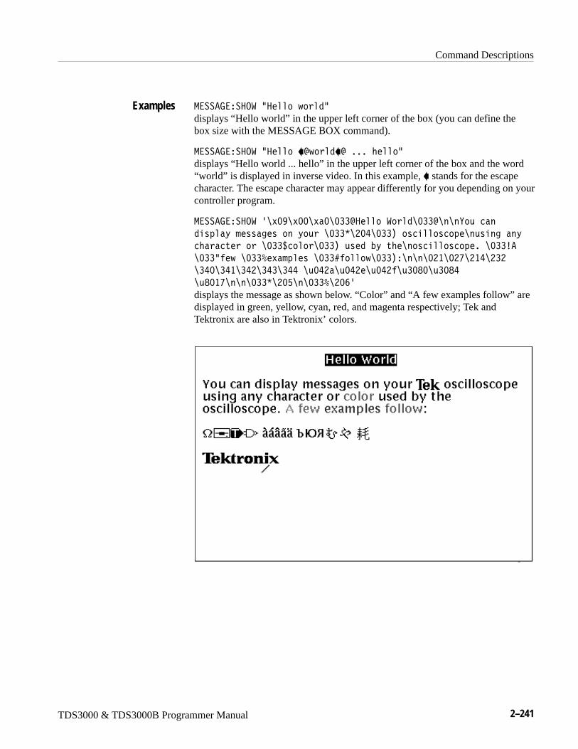
Command Descriptions
TDS3000 & TDS3000B Programmer Manual 2–241
-����7����.��L�����J�1L
displays “Hello world” in the upper left corner of the box (you can define thebox size with the MESSAGE BOX command).
-����7����.��L������^J�1�^�����M���L
displays “Hello world ... hello” in the upper left corner of the box and the word“world” is displayed in inverse video. In this example, � stands for the escapecharacter. The escape character may appear differently for you depending on yourcontroller program.
-����7����.��K��;X��;;���;�;��^�������1�;��^����E,�2��
1��4��D������3�����D,��;��C�H;I�;��*��2����24���,���3���D
2M��2�����;��_2��;��*�,��1�ND��M����2����24����;��`�
�;��L��J��;��Z����4�����;��Q���J�;��*������;H��;HV�H�I�H�H
��I;��I���IH��I���II��,;IH��,;IH��,;IH��,�;B;�,�;BI
�,B;�V�����;��C�H;G���;��Z�H;TK
displays the message as shown below. “Color” and “A few examples follow” aredisplayed in green, yellow, cyan, red, and magenta respectively; Tek andTektronix are also in Tektronix’ colors.
Examples
Command Descriptions
2–242 TDS3000 & TDS3000B Programmer Manual
MESSage:STATEControls the display of the message window.
Display
-����3���5�5��#�.���"�.9�"��9�� �$
-����3���5�5�0
�.�� or �9�� = 0 removes the message window from the display.
�.9 or �9�� � 0 displays the message window and its contents on the display.
MESSage:BOX, MESSage:SHOW
NEWpass (No Query Form)Changes the password that enables access to password protected data. ThePASSWord command must be successfully executed before using this commandor an execution error will be generated.
Miscellaneous
9��4�����+����3
�+����3 is the new password. The password can include up to 10 characters.
9��<����L�D4���J1L
creates a new password for accessing the user protected data.
PASSWord, *PUD
Group
Syntax
Arguments
Related Commands
Group
Syntax
Arguments
Examples
Related Commands
Command Descriptions
TDS3000 & TDS3000B Programmer Manual 2–243
*OPCGenerates the operation complete message in the Standard Event Status Register(SESR) when all pending operations finish. The *OPC? query places the ASCIIcharacter “1” into the output queue when all pending operations are finished. The*OPC? response is not available to read until all pending operations finish. For acomplete discussion of the use of these registers and the output queue, see page 3–1.
Status and Error
C.<
C.< 0
The *OPC command allows you to synchronize the operation of the oscilloscopewith your application program. Synchronization methods are described startingon page 3–7. Table 2–39 shows commands that generate an Operation Completemessage.
Table 2–39: Commands that Generate an Operation Complete Message
Operation Command
Automatic scope adjustment AUTOSet EXECute
Internal self-calibration *CAL
Single sequence acquisition ACQuire:STATE ON orACQuire:STATE RUN (when ACQuire:STOPAfter is set toSEQuence)
Hardcopy output HARDCopy STARt
BUSY?, *WAI
Group
Syntax
Related Commands
Command Descriptions
2–244 TDS3000 & TDS3000B Programmer Manual
PASSWord (No Query Form)Enables the *PUD and NEWpass set commands. Sending PASSWord withoutany arguments disables these same commands. Once the password is successful-ly entered, the *PUD and NEWpass commands are enabled until the oscilloscopeis powered off, or until the FACtory command, the PASSWord command withno arguments, or the *RST command is issued.
To change the password, you must first enter the valid password with thePASSWord command and then change to your new password with the NEWpasscommand. Remember that the password is case sensitive.
Miscellaneous
<����1
<����1��+����3
�+����3 is the password and can include up to 10 characters. The factorydefault password is “XYZZY”and is always valid.
<����.�/�L�EPPEL
Enables the *PUB and NEWpass set commands.
<����.�/
Disables the *PUD and NEWpass set commands. You can still use the queryversion of *PUD.
NEWpass, *PUD
Group
Syntax
Arguments
Examples
Related Commands
Command Descriptions
TDS3000 & TDS3000B Programmer Manual 2–245
*PSCSets and queries the power-on status flag that controls the automatic power-onhandling of the DESER, SRER, and ESER registers. When *PSC is true, theDESER register is set to 255 and the SRER and ESER registers are set to 0 atpower-on. When *PSC is false, the current values in the DESER, SRER, andESER registers are preserved in nonvolatile memory when power is shut off andare restored at power-on. For a complete discussion of the use of these registers,see page 3–1.
Status and Error
C<� ��9��
C<� 0
�9�� = 0 sets the power-on status clear flag to false, disables the power-on clearand allows the oscilloscope to possibly assert SRQ after power-on.
�9�� � 0 sets the power-on status clear flag true. Sending *PSC 1 thereforeenables the power-on status clear and prevents any SRQ assertion after power-on. Using an out-of-range value causes an execution warning.
C<� �;
sets the power-on status clear flag to false.
C<� 0
might return the value 1, showing that the power-on status clear flag is set totrue.
DESE, *ESE, FACtory, *RST, *SRE
POWer:AC:PRESENt? (Query Only)Indicates if the instrument is being powered by AC or Battery
Miscellaneous
<.���� �<����9�0
Group
Syntax
Arguments
Examples
Related Commands
Group
Syntax
Command Descriptions
2–246 TDS3000 & TDS3000B Programmer Manual
�9�� = 0 indicates the oscilloscope is being powered by battery.
�9�� = 1 indicates the oscilloscope is being powered by AC.
<.����� �<����950 might return �<.����� �<����95��.
<.���?�55�D�<����9�0
POWer:BACKLightSets or returns the idle time that must elapse before the backlight is turned off.When the oscilloscope is running on AC power, idle time is ignored.
Miscellaneous
<.���?� S8�3M��#��9�� �"�69�6�����$
<.���?� S8�3M�0
�9�� = minutes of idle time before the backlight is turned off. 999999999 isused for infinity, but any value greater than 15 (max timeout) will be rounded toinfinity.
INFinite disables the timer meaning the backlight will not turn off automatically.
<.����?� S867�5�G
sets the backlight to turn off after the oscilloscope has been idle for 5 minutes.
<.�����:51J�
POWer:BATTery:GASgauge? (Query Only)Indicates the remaining charge left in the battery.
Miscellaneous
<.���?�55�D�7��3�,3�0
Arguments
Examples
Related Commands
Group
Syntax
Arguments
Examples
Related Commands
Group
Syntax
Command Descriptions
TDS3000 & TDS3000B Programmer Manual 2–247
�9�� is a value with a range from 0 to 15 that indicates the remaining charge inthe battery; 0 means the battery is fully discharged and 15 means the battery isfully charged
<.����?�55��E�7��7�:7�0 might return �<.����?�55��E�7��7�:7���G�
<.���?�55��E�<����950
POWer:BATTery:PRESENt? (Query Only)Indicates if there is a battery in the instrument.
Miscellaneous
<.���?�55�D�<����9�0
�9�� = 0 indicates there is no battery in the instrument.
�9�� = 1 indicates there is a battery in the instrument.
<.����?�55��E�<����950 might return �<.����?�55��E�<����95�;�
<.���� �<����9�0
POWer:SHUTdownSets or returns the idle time that must elapse before the oscilloscope is turnedoff. When the oscilloscope is running on AC power, idle time is ignored.
Miscellaneous
<.�����:51J��#��9�� �"�69�6�����$
<.������:51J�0
Arguments
Examples
Related Commands
Group
Syntax
Arguments
Examples
Related Commands
Group
Syntax
Command Descriptions
2–248 TDS3000 & TDS3000B Programmer Manual
�9�� = the number of minutes of idle time before the oscilloscope is poweredoff. 999999999 is used for infinity, but any value greater than 15 (max timeout)will be rounded to infinity.
INFinite disables the timer meaning the oscilloscope will not power offautomatically.
<.������:5/.�9�G
Instrument will power off after the oscilloscope has been idle for 5 minutes.
*PUDSets or returns a string of Protected User Data. This data is protected by thePASSWord command. You can modify it only by first entering the correctpassword. The password is not necessary to query the data. This data isdisplayed in the UTILITY System Config menu. This command acceptsEuropean, Russian, and Asian characters; see the MESSAGE:SHOW commandfor details. Query always returns <Block> type response.
Miscellaneous
C<:/��?�2O ���+����3
C<:/0
�?�2O is a string containing up to 300 characters.
C<:/�QHHX5M�������,�����N���3������
stores the string “This instrument belongs to me” in the user protected data area.
C<:/0
might return QHH�<4��D��� �4��D��.
PASSWord
Arguments
Examples
Group
Syntax
Arguments
Examples
Related Commands
Command Descriptions
TDS3000 & TDS3000B Programmer Manual 2–249
REBOOT (No Query Form)Reboots (restarts) the oscilloscope firmware. This is the equivalent of powercycling the oscilloscope.
Miscellaneous
��?..5
*RCL (No Query Form)Restores the state of the oscilloscope from a copy of its settings stored inmemory. (The settings are stored using the *SAV command.) This command isequivalent to RECAll:SETUp and performs the same function as the RecallSaved Setup item in the SAVE/RECALL menu.
Save and Recall
C� 8��9��
�9�� is a value in the range from 1 to 10. A value of 1 to 10, specifies a savedsetup storage location.
C� 8��
restores the oscilloscope setup from a copy of the settings stored in setuplocation 3.
FACtory, *LRN?, RECAll:SETUp, *RST, *SAV, SAVe:SETUp
RECAll:MASK(TDS3TMT Only)
Loads the specified mask file from the floppy drive into the User mask.
Save and Recall
�� ����-��S��+����3
Group
Syntax
Group
Syntax
Arguments
Examples
Related Commands
Group
Syntax
Command Descriptions
2–250 TDS3000 & TDS3000B Programmer Manual
�+����3 is the path and file name, enclosed in quotes, of the mask file to loadfrom the floppy drive into the User mask.
�� ����-��S�L�1;��2,����H���OL loads the file 2,����H���O from the floppy drive into the User mask.
�����-��S��+����3
RECAll:SETUp (No Query Form)Restores a stored or factory front-panel setup of the oscilloscope. This commandis equivalent to selecting Recall Saved Setup or Recall Factory Setup in theSAVE/RECALL menu.
Save and Recall
�� ������5:4�#��� �D�"��9�� �"�������4��M �$
�� �D selects the factory setup. Initializes instrument settings to factorydefaults, excluding: GPIB, hard copy, RS232 parameters, file instrument settingparameters, calibration notification time, battery off time, backlight time-outs,and user’s language.
�9�� is a value in the range from 1 to 10 and specifies a setup storage location.
������4��M is the name of the file where the setup will be recalled from.
������4��M is a quoted string that defines the file name and path. Input the filepath using the form �1�>� [�1� [��������� . �1�>� and one or more�1� s are optional. If you do not specify them, the oscilloscope will read thefile from the current directory. ��������� stands for a filename of up to 8characters followed by a period (“.”) and any 3-character extension. Do not usewild card characters.
The current directory refers to the name of a directory as returned by theFILESystem:CWD command.
Arguments
Examples
Related Commands
Group
Syntax
Arguments
Command Descriptions
TDS3000 & TDS3000B Programmer Manual 2–251
�� �88���5:<��� 5.�E
recalls (and makes current) the front panel setup to the factory defaults.
�� �88���5:<��
recalls the front panel setup from setup1.
�� �88���5:<�R5�S;;;;;���5L
recalls the front panel setup from the file 5�S;;;;;���5 in the current directory.
DELEte:SETUp, FACtory, *RCL, *RST, *SAV, SAVe:SETUp
RECAll:WAVEform (No Query Form)Recalls a stored waveform into a reference location. This command is similar toselecting From File in the Recall Waveform item in the SAVE/RECALL menu.Only files saved in the internal file format can be recalled; see the SAVE:WAVE-FORM:FILEFORMAT command.
Save and Recall
�� �����������������4��M ������
����� is the location in internal reference memory where the waveform isrecalled to.
������4��M is a quoted string that defines the file name and path. Input the filepath using the form �1�>� [�1� [��������� . �1�>� and one or more�1� s are optional. If you do not specify them, the oscilloscope will recall thewaveform from the current directory. ��������� stands for a filename of up to8 characters followed by a period (“.”) and any 3-character extension. Do not usewild card characters.
The current directory refers to the name of a directory as returned by theFILESystem:CWD command.
�� �88������.�-�R5�S;;;;;�6��L�����
recalls the waveform stored in the file named TEK00000.ISF to referencelocation 1.
Examples
Related Commands
Group
Syntax
Arguments
Examples
Command Descriptions
2–252 TDS3000 & TDS3000B Programmer Manual
REF<x>:DATE? (Query Only)Returns reference waveform save date. Saving a waveform to a referencewaveform will create a new save date.
Waveform
����� �/�5�0
���I�/�5�0
might return “09-10-99” in the form mm-dd-yy.
REF<x>:HORizontal:POSitionSets reference waveform horizontal display position from 0.0 to 100.0. Thehorizontal display position for a reference waveform is the same for zoom on andoff.
Waveform
����� ��.��F�����<.�������9��
����� ��.��F�����<.�����0
�9�� is from 0 to 100 and is percent of the waveform that is displayed left ofthe center graticule
����� ��.�6P.95�8�<.�656.90
might return ������.�6P.95�8�<.�656.9�G�;��
REF<x>:HORizontal:SCAleSets reference waveform horizontal display scale in horizontal units/div. Thehorizontal display scale for a reference waveform is the same for zoom on andoff.
Waveform
Group
Syntax
Examples
Group
Syntax
Arguments
Examples
Group
Command Descriptions
TDS3000 & TDS3000B Programmer Manual 2–253
����� ��.��F������ �����9��
����� ��.��F������ ���0
�9�� is the time per division. The range is from acquired time/div to (acquiredtime/div/200) for 10,000 point reference waveforms, and to (acquired time/div/10) for 500 point reference waveforms.
������.�6P.95�8�� �8�0
might return ������.�6P.95�8�� �8��I�;�WI
REF<x>:LABELSets or returns the specified reference waveform label. See MESSage:SHOWcommand for information on how to enter non-English characters.
Waveform
����� �8�?�8��+����3
����� �8�?�80
�+����3 is a string, enclosed in quotes, that contains the label text.
���I�8�?�80
might return ���I�8�?�8�L �O�����HL.
REF<x>:TIMe? (Query Only)Returns reference waveform save time. Saving a waveform to a referencewaveform will create a new save time.
Waveform
����� �56-�0
����� �56-�0
might return “16:54:05”
Syntax
Arguments
Examples
Group
Syntax
Arguments
Examples
Group
Syntax
Examples
Command Descriptions
2–254 TDS3000 & TDS3000B Programmer Manual
REF<x>:VERTical:POSitionSets the reference waveform vertical display position in vertical divisions;equivalent to adjusting the Vertical POSITION knob when REF<x> is theselected waveform.
Waveform
����� ����5�2���<.�������9��
����� ����5�2���<.�����0
�9�� is the reference waveform’s display vertical position.
���H����56 �8�<.�656.9���;�
sets the vertical position for the Ref2 waveform to +1 division.
REF<x>:VERTical:SCAleSets reference waveform vertical display scale in vertical units/div;equivalent to adjusting the Vertical SCALE knob when REF<x> is the selected waveform.
Waveform
����� ����5�2���� �����9��
����� ����5�2���� ���0
�9�� is the reference waveform’s display vertical scale.
��������56 �8�� �8����;
will display REF1 at 1 V/div
Group
Syntax
Arguments
Examples
Group
Syntax
Arguments
Examples
Command Descriptions
TDS3000 & TDS3000B Programmer Manual 2–255
REM (No Query Form)Specifies a comment. This line is ignored by the instrument.
Miscellaneous
��-��+����3
�+����3 is a string that can have a maximum of 255 characters.
��-�L5M��������2�����L
is ignored by the instrument.
*RST (No Query Form)*RST returns the instrument settings to the factory defaults (see Appendix D:Factory Initialization Settings).
The *RST command does not alter the following:
� The state of the IEEE Std 488.1–1987 interface.
� The selected IEEE Std 488.1–1987 address of the oscilloscope.
� Calibration data that affect device specifications.
� The Output Queue.
� The Service Request Enable Register setting.
� The Standard Event Status Enable Register setting.
� The Power-on status clear flag setting.
� Alias definitions.
� Stored settings.
� The *PUD? response.
Status and Error
FACtory, *PSC, *RCL, RECAll:SETUp, *SAV, SAVe:SETUp
C��5
Group
Syntax
Arguments
Examples
Group
Related Commands
Syntax
Command Descriptions
2–256 TDS3000 & TDS3000B Programmer Manual
RS232? (Query Only)Returns the RS232 settings.
RS232
��H�H0
None
��H�H0 might return: ���H�H�?�:/��BI;;A5��9�-65�5��-69�5.��8�A���/�8�77697�.9�
RS232:BAUdSets or returns RS-232 interface transmission speed.
RS232
��H�H�?�:1��9��
��H�H�?�:10
�9�� is a rate of 1200, 2400, 4800, 9600, 19200, or 38400 baud.
��H�H�?�:/�XT;;
sets the transmission rate to 9600 baud.
Group
Syntax
Arguments
Examples
Group
Syntax
Arguments
Examples
Command Descriptions
TDS3000 & TDS3000B Programmer Manual 2–257
RS232:HARDFlaggingSets or returns the input and output hard flagging over the RS-232 port. It usesthe RTS (Request To Send) and CTS (Clear To Send) lines to control datatransmission. On output, the oscilloscope transmits data only when CTS isasserted. When CTS is not asserted, the oscilloscope stops transmitting data. Oninput, it asserts RTS until the receive queue is full. Then it unasserts RTS to stoptransmission from an external printer. CTS remains unasserted until the receivequeue is not full. At that time, CTS is asserted again to restart transmission.
RS232
��H�H����/���33��3�#�.9�"�.���"��9�� �$
��H�H����/���33��30
�.9 ���9�� ��; turn on hardflagging.
�.�� ���9�� �!�; turn off hardflagging (RTS always asserted).
��H�H����/�8�77697�.9
turns on hard flagging.
RS232:PRESet (No Query Form)Sets RS-232 parameters to default values. The RS232? query will show the newsettings
��H�H�?�:/�XT;;
��H�H����/�8�77697�.9
��H�H�5��9�-65�5��-69�5.��8�
Miscellaneous
��H�H�<�����
None.
��H�H�<����5
sets RS232 parameters to the default values.
Group
Syntax
Arguments
Examples
Group
Syntax
Arguments
Examples
Command Descriptions
2–258 TDS3000 & TDS3000B Programmer Manual
RS232?, RS232: BAUd, RS232: HARDFlagging
RS232:TRANsmit:TERMinatorSets or returns the end-of-line (EOL) terminator. When transmitting, theoscilloscope appends the terminator to the end of each message. When receiving,the oscilloscope accepts all four terminators, regardless of the currently selectedterminator. When a combination of multiple characters is selected (CRLF orLFCR), the oscilloscope interprets the first character as the terminator; it treatsthe second character as a null command.
CR represents an ASCII carriage return character (0x0D) and LF represents anASCII linefeed character (0x0A).
Miscellaneous
��H�H�5��9�����5��-�����#� ��"�8��"� �8��"�8� �$
��H�H�5��9�����5��-����0
� � selects the carriage return character as the EOL terminator.
�8� selects the line feed character as the EOL terminator.
� �8� selects the carriage return and line feed characters as the EOL terminator.
�8� selects the line feed and carriage return characters as the EOL terminator.
��H�H�5��9�-65�5��-69�5.�� �
sets the carriage return as the EOL terminator.
RS232?, RS232: HARDFlagging
Related Commands
Group
Syntax
Arguments
Examples
Related Commands
Command Descriptions
TDS3000 & TDS3000B Programmer Manual 2–259
*SAV (Set Only)(Save) stores the state of the oscilloscope into a specified internal setup location.You can later use the *RCL command to restore the oscilloscope to this savedstate. This is equivalent to selecting the Save Current Setup menu item in theSAVE/RECALL menu.
Save and Recall
C�����9��
�9�� is a value in the range from 1 to 10 and specifies a location. Any settingsthat have been stored previously at this location will be overwritten.
C����H
saves the current settings in internal setup location 2.
FACtory, *RCL, RECAll:SETUp, SAVe:SETUp
SAVe:MASKTDS3TMT Only
Saves the User mask to the specified mask file on the floppy drive.
Save and Recall
�����-��S��+����3
�+����3 is the path and file name, enclosed in quotes, to which to save theUser mask data on the floppy drive.
�������5:<�R .��H�-�SR
saves the user mask information to the file .��H�-�S in the current directory.
Group
Syntax
Arguments
Examples
Related Commands
Group
Syntax
Arguments
Examples
Command Descriptions
2–260 TDS3000 & TDS3000B Programmer Manual
SAVe:SETUp (Set Only)Saves the current front-panel setup into the specified internal setup location orfile. This is equivalent to selecting the Save Current Setup menu item in theSAVE/RECALL menu.
Save and Recall
�������5:4�#��9�� �"�������4��M �$
�9�� is a value in the range from 1 to 10 and specifies a location. Any settingsthat have been stored previously at this location will be overwritten.
������4��M is a quoted string that defines the file name and path. Input the filepath using the form �1�>� [�1� [��������� . �1�>� and one or more�1� s are optional. If you do not specify them, the oscilloscope will write thefile to the current directory. ��������� stands for a filename of up to 8characters followed by a period (“.”) and a 3-char extension. We recommend youuse “���5” for the extension to identify files that store setup data.
The current directory refers to the name of a directory as returned by theFILESystem:CWD query.
�������5:<�G
saves the current front-panel setup in internal setup location 5.
�������5:<�R5�S;;;;;���5R
saves the current front-panel setup to the file 5�S;;;;;���5 in the currentdirectory.
RECAll:SETUp, *RCL, *SAV
SAVe:WAVEform (Set Only)Stores a waveform in one of four reference memory locations or a file. Thiscommand is equivalent to selecting the Save Waveform menu item in theSAVE/RECALL menu.
Save and Recall
�������������J�� �#������ �"�������4��M �$
Group
Syntax
Arguments
Examples
Related Commands
Group
Syntax
Command Descriptions
TDS3000 & TDS3000B Programmer Manual 2–261
�J�� is CH<x>, MATH<x>, or REF<x>, and is the waveform that will besaved.
����� is the location where the waveform will be stored.
������4��M is a quoted string that defines the file name and path. Input the filepath using the form �1�>� [�1� [��������� . �1�>� and one or more�1� s are optional. If you do not specify them, the oscilloscope will write thefile to the current directory. ��������� stands for a filename of up to 8characters followed by a period (“.”) and the proper 3-character extension.Internal format waveforms use the “.ISF” extension, spreadsheet files use the“.CSV” extension, and Mathcad files use the “.DAT” extension. However, theoscilloscope stores the waveform in the format specified by the SAVE:WAVE-FORM:FILEFORMAT command, not the format specified in the suffix.
The current directory refers to the name of a directory as returned by theFILESystem:CWD query.
����������.�-�-�5������
saves the math waveform in reference memory location 2.
����������.�-�-�5���R5�S;;;;;�6��R
saves the math1 waveform (which is the same as the MATH waveform) to thefile 5�S;;;;;�6�� in the current directory.
SAVe:WAVEform:FILEFormat
SAVe:WAVEform:FILEFormatSets or queries the file format for saved waveforms. Only internal format filescan be recalled into the oscilloscope.
Save and Recall
�������������68������#�695��9���"��<���/�M����"�-�5� �1�$
�������������68�����0
695��9�� specifies the internal format. Internal format files should have a .ISFextension. The format will be the same as that output from the commands“WFMPRE:ENCDG BINARY;WAVFRM?” (with ASCII waveform preambleinformation).
Arguments
Examples
Related Commands
Group
Syntax
Arguments
Command Descriptions
2–262 TDS3000 & TDS3000B Programmer Manual
�<���/�M��� specifies the spreadsheet format. Spreadsheet format files shouldhave a .CSV extension. Each waveform data point consists of two floating pointvalues, an X (typically time) value and a Y (typically amplitude) value. Each XYpair is separated by carriage return (0x0D) and line feed (0x0A) characters. Eachvalue except the last one in the file is followed by a comma (0x2C).
-�5� �1 specifies the MathCad format. MathCad format files should have a.DAT extension.
If you are writing a MathCad program, you should be aware that the TDS-MathCad file has the following features:
� ASCII format
� first four values contain header information
� first header value holds the oscilloscope waveform record length
� second header value holds time, in seconds, between samples
� third header value holds the trigger position(expressed as an index in the data position)
� fourth header value refers to the fractional trigger position
� delimiters are carriage returns and line feeds (CRLF)
����������.�-��68��.�-�5��<���/����5
specifies the waveform, when saved, will be stored in a spreadsheet-compatibleformat.
SAVe:WAVEform, RECALL:WAVEform
SELect? (Query Only)Returns the display status of all waveforms and the selected (control) waveform.
Vertical
��8�2�0
��8� 50
might return ���8� 5� ����A �H��A ���;A �I�;A-�5��;A�����;A���H�;A�����;A���I�;A .95�.8� ��, indicating that channel 1 and 2are displayed on the screen and channel 1 is the selected (control) waveform.
Examples
Related Commands
Group
Syntax
Examples
Command Descriptions
TDS3000 & TDS3000B Programmer Manual 2–263
SELect:CONTROlSets or queries the waveform that is currently affected by the cursor and verticalcommands.
Vertical
��8�2�� .95�.���J��
��8�2�� .95�.�0
�J�� is CH<x>, MATH<x>, or REF<x>, and will be the selected waveform.
9.9� if all waveforms are off. 9.9� is ignored on input.
��� ��-�5��� �������� if it is the waveform affected by the cursor andvertical commands.
��8� 5� .95�.80
might return :��8� 5� .95�.8�-�5�� indicating -�5�� is the selected wave-form.
SELect:<wfm>Turns the specified waveform ON or OFF. Turning a waveform ON makes it theselected waveform.
Vertical
��8�2���J�� �#�.���"�.9�$
��8�2���J�� 0
�J�� specifies the waveform to display. Valid values are ��, �H, ��, �I,-�5�, -�5�� (same as MATH), ����, ���H, ����, and ���I.
.�� or 0 turns off the display of the specified waveform.
.9 or 1 turns on the display of the specified waveform. The waveform alsobecomes the selected waveform.
Group
Syntax
Arguments
Returns
Examples
Group
Syntax
Arguments
Command Descriptions
2–264 TDS3000 & TDS3000B Programmer Manual
��8� 5� �H�.9
turns the channel 2 display on and selects channel 2.
��8� 5�����0
might return ������ indicating that the REF1 waveform is being displayed.
SET? (Query Only)Returns a string listing the oscilloscope settings, except for configurationinformation for the calibration values. You can use this string to return theoscilloscope to the state it was in when you made the SET? query. Thiscommand is identical to the *LRN? command.
Miscellaneous
��50
NOTE. The SET? query always returns a string with command headers,regardless of the setting of the HEADer command. This is because the returnedstring is intended to be able to be sent back to the oscilloscope as a commandstring. The VERBose command can still be used to specify whether the returnedheaders should be abbreviated or full length.
��50
a partial return string may look like this:����/����A����?.����A��86����5�5���A�� +:6���-./��
��-<8�A9:-��7��TA9:-�9���TA�5�5���A�5.<��5��
�:9�5.<A�/6�<8�E� .8.��<�8�55����7:8���9.�-�8A�/6�<8�E��5E8��/.5@
�.98E�;A�/6�<8�E�<���6�5�9 ��;�;�;A 8. S�;A7��56 :8�
�:88A695�9�65E������.�-�TGA?� S867�5��67�A�/6�<8�E��E�-./�
.��AE ��99�8� �HAE����.��A���8� 5� ���;A �H��A ���;A �I�;A-�5�
;A�����;A���H�;A�����;A���I�;A .95�.8� �HA����/ .<E��.�-�5
< � .8.�A<.�5��68�A8�E.:5�8�9/� �<�A��.�6P.95�8����.8:56.9
8.�A5�677���<.�656.9���;H��A��.�6P.95�8�-�69�� �8�
H�;�WIA��.�6P.95�8�/�8�E��5�5��;A
HEADer, *LRN?, VERBose
Examples
Group
Syntax
Examples
Related Commands
Command Descriptions
TDS3000 & TDS3000B Programmer Manual 2–265
SETUp<x>:DATE? (Query Only)Sets or returns the date when the specified instrument setup was saved.
Waveform
��5:4�� �/�5�0
��5:<I�/�5�0
might return ��5:<I�/�5��L;I@�B@;�L.
SETUp<x>:LABELSets or returns the specified instrument setup label. See the MESSage:SHOWcommand for information on how to enter non-English characters.
Waveform
��5:4�� �8�?�8��+����3
��5:4�� �8�?�80
�+����3 is a string, enclosed in quotes, that contains the label text.
��5:<I�8�?�80
might return ���I�8�?�8�L5����HL.
SETUp<x>:TIME? (Query Only)Sets or returns the time that the specified instrument setup was saved.
Waveform
��5:4�� �56-�0
��5:<H�56-�0
might return ��5:<H�56-��L�G�HI�;VL.
Group
Syntax
Examples
Group
Syntax
Arguments
Examples
Group
Syntax
Examples
Command Descriptions
2–266 TDS3000 & TDS3000B Programmer Manual
*SRE(Service Request Enable) sets and queries the bits in the Service Request EnableRegister (SRER). For a complete discussion of the use of these registers, seepage 3–1.
Status and Error
C�����9��
C���0
�9�� is a value in the range from 0 to 255. The binary bits of the SRER are setaccording to this value. Using an out-of-range value causes an execution error.The power-on default for SRER is 0 if C<� is 1. If C<� is 0, the SRER Attainsits value through a power cycle.
C����IB
sets the bits in the SRER to 00110000 binary.
C���0
might return a value of �H, showing that the bits in the SRER have the binaryvalue 00100000.
*CLS, DESE, *ESE, *ESR?, EVENT?, EVMsg?, FACtory, *PSC, *STB?
*STB? (Query Only)(Read Status Byte) query returns the contents of the Status Byte Register (SBR)using the Master Summary Status (MSS) bit. For a complete discussion of theuse of these registers, see page 3–1.
Status and Error
C�5?0
�9��
Group
Syntax
Arguments
Examples
Related Commands
Group
Syntax
Returns
Command Descriptions
TDS3000 & TDS3000B Programmer Manual 2–267
C�5?0
might return the value XT, showing that the SBR contains the binary value01100000.
*CLS, DESE, *ESE, *ESR?, EVENT?, EVMsg?, FACtory, *SRE
SYStemSets or returns the UTILITY menu’s System menu setting. This command doesnot display the System menu when executed.
Miscellaneous
�E�����#��<<��"� �8�N����"� .9�67�"�/6�3�"����/ 4D�"�6.�$
�E����0
The arguments correspond to the UTILITY menu System menu items.
�E����0
might return �E�5�-� .9�67.
TEKSecureInitializes both waveform and setup memories. This overwrites any previouslystored data.
TEKSecure writes zeros in all waveform reference memory, regardless ofselected record length, and puts all setups in the factory init state.
TEKSecure then verifies that the waveform and setup memories are in thedesired state. It asserts a pass or a fail event on completion.
Miscellaneous
5�S��2,�
Examples
Related Commands
Group
Syntax
Arguments
Examples
Group
Syntax
Command Descriptions
2–268 TDS3000 & TDS3000B Programmer Manual
TIMeSets or queries the current time
Miscellaneous
56-���+����3
56-�0
�+����3 is a time in the form RMM������L.MM refers to the hour number from 01 to 24.�� refers to the minute number from 00 to 59.�� refers to the seconds number from 00 to 59. There must be a colon after the MM and after the ��. Use two digits for each of the MM, ��, and ��.
56-��L;��HI�;;L
sets the time to 01:24 AM.
DATE, DISplay: CLOCk
TRIGgerForces a trigger event to occur, and the TRIGger query returns the current triggerparameters.
Trigger
5�673���.� �
5�673�0
�.� � creates a trigger event. If TRIGger:STATE is REAdy, the acquisition willcomplete, otherwise this command will be ignored. This is equivalent to pressingthe front-panel FORCE TRIG button.
Group
Syntax
Arguments
Examples
Related Commands
Group
Syntax
Arguments
Command Descriptions
TDS3000 & TDS3000B Programmer Manual 2–269
5�677����.� � forces a trigger event to occur.
5�677��0
might return �5�677�����-./���:5.A5E<���/7�A�.8/.�����8:�H�G;B�WVA�5�677������/7���.:� �� ��A .:<8697�/ A�8.<�
�6��A�5�677������6/�.��5�9/��/�95� A�.:� �� ��A�6�8/
�88869��A�5�677�����8���8�H�T�W�A�5�677���?��5�5��;A?E
56-�A���95�� .:95��A�5�677���?�56-�����H�WBA5E<���/7�A8���8
;�;�;A�/7���.:� �� ��A .:<8697�/ A�8.<���6��
TRIGger:A? (Query Only)Returns the current A trigger parameters.
Trigger
5�673���0
5�677����0
might return�5�677�����-./���:5.A5E<���/7�A�.8/.���56-�H�G;B�WVA�5�677������/7���.:� �� ��A� .:<8697�/ A�8.<�
�6��A�5�677������6/�.��5�9/��/�95� A�.:� �� ��A�6�8/��88869��A
�5�677�����8���8�G�G��
TRIGger:A:COMMunication:SOUrce(TDS3TMT Only)
Sets or returns the current mask standard’s trigger source. The set mode of thiscommand only applies to the User mask A trigger settings. The query mode ofthis command returns the current mask A trigger settings.
Trigger
5�673���� .--,��2������.:2��#��85������3�"� ��� �"���5�"
��5�;�"�869��"����5�2���$
5�673���� .--,��2������,2�0
Examples
Group
Syntax
Examples
Group
Syntax
Command Descriptions
2–270 TDS3000 & TDS3000B Programmer Manual
�85������3 sets the trigger source to alternate between each displayed inputchannel.
��� sets the trigger source to the specified input channel, where <x> is 1, 2, 3,or 4.
��5 sets the trigger source to the regular external trigger input connector with asignal input range of –0.8 V to +0.8 V. EXT is not available in 4-channelTDS3000 Series instruments.
��5�; sets the trigger source to the reduced external trigger with a signal inputrange of –8 V to +8 V. EXT10 is not available in 4-channel TDS3000 Seriesinstruments.
869� sets the trigger source to the AC line frequency.
NOTE. LINE is not available when the instrument is operating on battery power.
���5�2�� sets the trigger source to the lowest numbered displayed channel.
5�673���� .--,��2������.:2�� �H sets the communications A trigger source to oscilloscope channel 2.
TRIGger:A:COMMunication:STANdard(TDS3TMT Only)
Sets or returns the current mask standard’s trigger settings. The set mode of thiscommand only applies to the User mask A trigger settings. The query mode ofthis command returns the current mask A trigger settings.
Trigger
5�673���� .--,��2������5�91�1�#� 8. S ���"� 8. S�D�����2���
"�/�; ����"�/�;/,N���"�/�;���3���"�/�;5����3�"�/�� �"�/������
"�/�H�"�/�H��5� ���"�/�H��5��D�����2���"�/�������"��� ���
"����D�����2���"��H�"����"�7V;�/���"�7V;�/���"���5��H-N��
"��5��<,����$
5�673���� .--,��2������5�91�10
8. S ����M,3M���5��H-N�� specifies the communication standard triggersettings to apply to the A trigger.
Arguments
Examples
Group
Syntax
Arguments
Command Descriptions
TDS3000 & TDS3000B Programmer Manual 2–271
5�673���� .--,��2������5�91�1��H sets the A trigger parameters to those required to test E2 waveforms.
5�673��-�6�� .--,��2������5�91�1
TRIGger:A:EDGe? (Query Only)Returns the trigger coupling, source, and slope for the A edge trigger.
Trigger
5�673�����/7�0
5�677������/7�0
might return �5�677������/7���.:� �� ��A .:<8697�/ A�8.<���6��
TRIGger:A:EDGe:COUPlingSets or queries the type of coupling for the A edge trigger. This is equivalent tosetting Coupling in the Trigger menu.
Trigger
5�673�����/7�� .:<���3�#�� �"�/ �"�����]�"�8���]�"�9.6���]�$
5�673�����/7�� .:<���30
� selects LFRej trigger coupling. AC coupling is for backward compatibilityand will not be returned by a query.
/ selects DC trigger coupling.
����] coupling removes the high frequency components of the DC signal.
8���] coupling removes the low frequency components of the AC signal.
9.6���] selects DC low sensitivity. It requires added signal amplitude for morestable, less false triggering.
5�677������/7�� .:<8697�/
sets the A edge trigger coupling to DC.
Examples
Related Commands
Group
Syntax
Examples
Group
Syntax
Arguments
Examples
Command Descriptions
2–272 TDS3000 & TDS3000B Programmer Manual
TRIGger:A:EDGe:SLOpeSelects a rising or falling slope for the A edge trigger. This is equivalent tosetting Slope in the Trigger menu.
Trigger
5�673�����/7���8.4��#���88�"��6���$
5�673�����/7���8.4�0
��88 specifies to trigger on the falling or negative edge of a signal.
�6�� specifies to trigger on the rising or positive edge of a signal.
5�677������/7���8.<���6��
sets the A edge trigger to occur on the rising slope.
TRIGger:A:EDGe:SOUrceSets or queries the source for the A edge trigger. This is equivalent to settingSource in the Trigger menu.
Trigger
5�673�����/7���.:2��#���5�"���5�;�"����5�2�� "� ��� �"�869��"��85������3�$
5�673�����/7���.:2�0
��5 sets the trigger source to the regular external trigger input connector with asignal input range of –0.8 V to +0.8 V. EXT is not available in 4 channelTDS3000 Series instruments.
��5�; sets the trigger source to the reduced external trigger with a signal inputrange of –8 V to +8 V. EXT10 is not available in 4 channel TDS3000 Seriesinstruments.
���5�2�� sets the trigger source to the lowest numbered displayed channel.
��� sets the trigger source to the specified input channel, where <x> is 1, 2, 3,or 4.
Group
Syntax
Arguments
Examples
Group
Syntax
Arguments
Command Descriptions
TDS3000 & TDS3000B Programmer Manual 2–273
869� sets the trigger source to the AC line frequency.
NOTE. LINE is not available when the instrument is operating on battery power.
�85������3 sets the trigger source to alternate between each displayed inputchannel.
5�677������/7���.:� ��869�
specifies the AC line voltage as the A edge trigger source.
5�677������/7���.:� �0
might return �5�677������/7���.:� �� �H for the A edge trigger source.
TRIGger:A:HOLdoff? (Query Only)Returns the A trigger holdoff time.
Trigger
5�673�����.81��0
5�677������.8/.��0
might return �5�677������.8/.���56-��H�G;B�WV.
TRIGger:A:HOLdoff:TIMeSets or queries the A trigger holdoff time. This is equivalent to setting Holdoff(Time) in the Mode & Holdoff side menu.
Trigger
5�673�����.81���56-���9��
5�673�����.81���56-�0
5�677������.8/.���56-��H�G�WV
to set the holdoff value to 250.8 ns.
Examples
Group
Syntax
Examples
Group
Syntax
Examples
Command Descriptions
2–274 TDS3000 & TDS3000B Programmer Manual
TRIGger:A:HOLdoff:VALueSets or queries the A trigger holdoff time as a percent of record. This isequivalent to setting Holdoff (% of record) in the Mode & Holdoff side menu.
Trigger
5�673�����.81�����8,���9��
5�673�����.81�����8,�0
�9�� from 0 to 100 and is a percent of the holdoff range.
5�677������.8/.�����8:��G;
to set the holdoff value to 50% of record.
TRIGger:A:LEVelSets the A trigger level. This command is equivalent to adjusting the front-panelTrigger LEVEL knob.
Trigger
5�673����8�����#�� 8�"�558�"��9�� �$
5�673����8����0
� 8 specifies a preset ECL level of –1.3 V.
558 specifies a preset TTL level of 1.4 V.
�9�� is the A trigger level, in volts.
5�677�����8���80
might return �5�677�����8���8���I�;, indicating that the A edge trigger levelis set to 1.4 V.
5�677�����8���8�;�G
sets the A trigger level to 0.5 V.
Group
Syntax
Arguments
Examples
Group
Syntax
Arguments
Examples
Command Descriptions
TDS3000 & TDS3000B Programmer Manual 2–275
TRIGger:A:LOGIc? (Query Only)(TDS3TRG Only)
Returns the current logic trigger parameters.
Trigger
5�673����8.7620
5�677�����8.76 0
might return �5�677�����8.76 �69<:5���.:� �� ��A8.76 8���88.�A�8.<���6��A5�����.8/���I;;;;;;;;;A�5�677�����8.76 � 8���
<�55��9A<�55��9��:9 56.9��9/A/�85�56-��;�;;;;;;��TBA���9
5�:�A�5�677�����8.76 ��5�5�����9�5�:�
TRIGger:A:LOGIc:CLAss(TDS3TRG Only)
Sets or returns the logic trigger class value. This command is equivalent toselecting Class in the Trigger menu when the Type is set to Logic.
Trigger
5�673����8.762� 8����#�<�5����"��5�5��$
5�673����8.762� 8���0
<�5��� enables pattern triggering, which triggers the oscilloscope when thelogic condition (pattern) on two inputs is met.
�5�5� enables state triggering, which triggers the oscilloscope when thespecified condition on one channel (state) is met after a second channel (clock)condition is met.
5�677�����8.76 � 8���0
might return 5�677�����8.76 � 8�����5�5�
Group
Syntax
Examples
Group
Syntax
Arguments
Examples
Command Descriptions
2–276 TDS3000 & TDS3000B Programmer Manual
TRIGger:A:LOGIc:INPUT<x>:LOGICLevel(TDS3TRG Only)
Sets or returns the signal logic of the specified logic trigger input.
Trigger
5�673����8.762�69<:5�� �8.76 8�>���#��67��"�8.��$
5�673����8.762�69<:5�� �8.76 8�>��0
�� sets the logic trigger input source. Valid values are 1 and 2
�67� sets the input logic level to high. Defining a signal as high-true means thatsignal levels above (more positive than) the threshold level are true, and signallevels below (more negative than) the threshold level are false.
8.� sets the input logic level to low. Defining a signal as low-true means thatsignal levels below (more negative than) the threshold level are true, and signallevels above (more positive than) the threshold level are false.
5�677�����8.76 �69<:5H�8.76 8���8��67�
sets the logic trigger input 2 to high-true logic.
TRIGger:A:LOGIc:INPUT2:SLOpe(TDS3TRG Only)
Sets or returns the state logic trigger slope setting for the logic trigger input 2.
Trigger
5�673����8.762�69<:5H��8.4��#��6���"���88�$
5�673����8.762�69<:5H��8.4�0
�6�� sets the specified input slope to a rising signal edge.
��88 sets the specified input slope to a falling signal edge.
5�677�����8.76 �69<:5H��8.<���6��
sets input 2 signal slope to rising.
Group
Syntax
Arguments
Examples
Group
Syntax
Arguments
Examples
Command Descriptions
TDS3000 & TDS3000B Programmer Manual 2–277
TRIGger:A:LOGIc:INPUT<x>:SOUrce(TDS3TRG Only)
Sets or returns the input signal source for the pattern trigger, which requires twoinput signal sources.
Trigger
5�673����8.762�69<:5�� ��.:2��#� ��� �$
5�673����8.762�69<:5�� ��.:2��#� ��� �"���5�"���5�;�$
5�673����8.762�69<:5�� ��.:2��#� ��� �"���5�"���5�;�$
5�673����8.762�69<:5�� ��.:2�0
� the logic input. Valid values are 1 and 2.
��� sets the oscilloscope logic trigger input signal source to the specifiedchannel, where <x> is 1, 2, 3, or 4.
��5����5�; sets the external trigger channel to the specified input. EXT andEXT10 are not available in TDS3000 Series 4-channel instruments.
5�677�����8.76 �69<:5���.:� ����5
sets the logic input 1 source to the external trigger input.
TRIGger:A:LOGIc:INPUT<x>:THReshold(TDS3TRG Only)
Sets or returns the pattern and state logic trigger single threshold voltage valuefor the specified input.
Trigger
5�673����8.762�69<:5�� �5����M�1�#��9�� �"�� 8�"�558�$
5�673����8.762�69<:5�� �5����M�10
Group
Syntax (TDS30004-channel)
Syntax (TDS30002-channel)
Syntax (TDS3000B allmodels)
Query Syntax (all)
Arguments
Examples
Group
Syntax
Command Descriptions
2–278 TDS3000 & TDS3000B Programmer Manual
� is the specified logic trigger input. Valid values are 1 and 2.
�9�� is a floating point value with exponent that sets the threshold voltagevalue for the specified logic trigger input.
� 8 sets the threshold voltage value of the specified input to –1.3 V.
558 sets the threshold voltage value of the specified input to 1.4 V.
5�677�����8.76 �69<:5H�5�����.8/�W��G�;
sets the threshold voltage of input 2 to –1.5 V.
TRIGger:A:LOGIc:PATtern:DELTATime(TDS3TRG Only)
Sets or returns the pattern trigger time value. The time value is used as part ofthe pattern trigger condition to determine if the duration of a logic pattern meetsthe specified time constraints.
Trigger
5�673����8.762�<�5����/�85�5�����9��
5�673����8.762�<�5����/�85�5���0
�9�� is a floating point value with exponent that sets the pattern trigger timevalue. This argument has a range of 39.6E–9 (39.6 ns) to 10.0E0 (10 s), inincrements of 13.2 ns. Values that are not an increment of 13.2 ns are rounded tothe nearest correct value.
5�677�����8.76 �<�55��9�/�85�5����V��HB�WB
sets the pattern trigger delta time value to 712.8 ns.
TRIGger:A:LOGIc:PATtern:FUNCtion(TDS3TRG Only)
Sets or returns the logic function to apply to the pattern trigger inputs.
Trigger
Arguments
Examples
Group
Syntax
Arguments
Examples
Group
Command Descriptions
TDS3000 & TDS3000B Programmer Manual 2–279
5�673����8.762�<�5�����:9 ����#��9/�"�9�91�"�9.��"�.��$
5�673����8.762�<�5�����:9 ���0
�9/��9�91��9.���.� set the Boolean logic operation to apply to the logicpattern trigger inputs.
5�677�����8.76 �<�55��9��:9 56.9�9�9/ sets the pattern trigger logic function to NAND.
TRIGger:A:LOGIc:PATtern:WHEn(TDS3TRG Only)
Sets or returns the pattern logic condition on which to trigger the oscilloscope.
Trigger
5�673����8.762�<�5���������#�5�:��"���8���"�8���5M���"�-.��5M��
"��+,���"�9.5�+,���$
5�673�����8.762��<�5���������0
5�:� triggers the oscilloscope when the pattern becomes true.
��8�� triggers the oscilloscope when the pattern becomes false.
8���5M�� triggers the oscilloscope when the input pattern is true for a timeperiod less than the time period specified in 5�673����8.762�<�5����/�85�5���.
-.��5M�� triggers the oscilloscope when the input pattern is true for a timeperiod more (greater) than the time period specified in 5�673����8.762�<�5@����/�85�5���.
�+,�� triggers the oscilloscope when the input pattern is true for a time periodequal to the time period specified in 5�673����8.762�<�5����/�85�5���,within a ±5% tolerance.
9.5�+,�� triggers the oscilloscope when the input pattern is true for a timeperiod greater than or less than (not equal to) the time period specified in5�673����8.762�<�5����/�85�5���, within a ±5% tolerance.
Syntax
Arguments
Examples
Group
Syntax
Arguments
Command Descriptions
2–280 TDS3000 & TDS3000B Programmer Manual
5�677�����8.76 �<�55��9����9�8���5��9
sets the oscilloscope to trigger when the pattern is true for a time period less thanthe pattern trigger delta time setting.
TRIGger:A:LOGIc:STATE:WHEn(TDS3TRG Only)
Sets or returns the state condition on which to trigger the oscilloscope.
Trigger
5�673����8.762��5�5�������#�5�:��"���8���$
5�673����8.762��5�5������0
5�:� triggers the oscilloscope if the state signal is true when the clock signalslope is true.
��8�� triggers the oscilloscope if the state signal is false when the clock signalslope is true.
5�677�����8.76 ��5�5�����90
might return 5�677�����8.76 ��5�5�����9�5�:�.
TRIGger:A:MODeSets or queries the A trigger mode. This command is equivalent to selectingMode & Holdoff in the Trigger menu.
Trigger
5�673����-./��#��:5.�"�9.�-���$
5�673����-./�0
�:5. generates a trigger if a trigger is not detected within a specific time period.
9.�-�� waits for a valid trigger event.
Examples
Group
Syntax
Arguments
Examples
Group
Syntax
Arguments
Command Descriptions
TDS3000 & TDS3000B Programmer Manual 2–281
5�677�����-./���:5.
specifies that a trigger event is automatically generated.
TRIGger:A:PULse? (Query Only)(TDS3TRG Only)
Returns the pulse trigger parameters.
Trigger
5�673����<:8��0
5�677�����<:8��0
might return 5�677�����<:8��� 8�����6/5�A�.:� �� ��A<.8��65E�65���A�6/5�����9�-.��5��9A�6/5��;�;;;;;��BB;A�5�67@
7�����<:8����:95�5�����.8/��67��;�B;;;;;;;;;A8.�
H�;;;;;;;;;;A�5�677�����<:8����:95����9�8���5��9A�6/5�
;�;;;;;��BB;A�5�677�����<:8����8����5��/�85�56-�
;�;;;;;��BB;A5�����.8/��67��;�B;;;;;;;;;A8.��H�;;;;;;;;;;A
�5�677�����<:8����8����5�����9����5��5��9.
TRIGger:A:PULse:CLAss(TDS3TRG Only)
Sets or returns the pulse trigger class value. This command is equivalent toselecting Class in the Trigger menu when the trigger Type is set to Pulse.
Trigger
5�673����<:8��� 8����#��6/�M�"��:95�"��8�������$
5�673����<:8��� 8���0
�6/�M sets the oscilloscope pulse trigger class to width. The width mode triggersthe oscilloscope when the source signal meets specified pulse width constraints.
�:95 sets the oscilloscope pulse trigger class to runt. The runt mode triggers theoscilloscope when the source signal meets specified pulse threshold and optionalwidth constraints.
Examples
Group
Syntax
Examples
Group
Syntax
Arguments
Command Descriptions
2–282 TDS3000 & TDS3000B Programmer Manual
�8������ sets the oscilloscope pulse trigger class to slew rate. The slew ratemode triggers the oscilloscope when the source signal meets specified slew rateconstraints.
5�677�����<:8��� 8�����6/5�
sets the oscilloscope pulse trigger class to width trigger.
TRIGger:A:PULse:RUNT? (Query Only)(TDS3TRG Only)
Returns the runt pulse trigger settings.
Trigger
5�673����<:8����:950
5�677�����<:8����:950
might return �5�677�����<:8����:95�5�����.8/��67��H�B;;;;;;;;;A8.�;�V;;;;;;;;;A�5�677�����<:8����:95����9�8���5��9A�6/5�
;�;;;;;��BB;.
TRIGger:A:PULse:RUNT:POLarity(TDS3TRG Only)
Sets or returns the runt-pulse logic trigger signal polarity value.
Trigger
5�673�����:95�<:8���<.8���D�#��65M��"�<.�656���"�9�7���>��$
5�673�����:95�<:8���<.8���D0
�65M� sets the oscilloscope to trigger on either <.�656�� or 9�7���>� polarityrunt signals.
<.�656�� sets the oscilloscope to trigger only on positive-polarity runt pulses.
9�7���>� sets the oscilloscope to trigger only on negative-polarity runt pulses.
Examples
Group
Syntax
Examples
Group
Syntax
Arguments
Command Descriptions
TDS3000 & TDS3000B Programmer Manual 2–283
5�677�����<:8���<.8��65E�9�7�56��
specifies that the oscilloscope only trigger on negative-polarity runt pulses.
TRIGger:A:PULse:RUNT:THReshold? (Query Only)(TDS3TRG Only)
Returns the runt pulse trigger upper and lower threshold voltage values.
Trigger
5�673����<:8����:95�5����M�10
5�677�����<:8����:95�5�����.8/0
might return �5�677�����<:8����:95�5�����.8/��67��H�;;�Y;A8.�B;;�;�W�.
TRIGger:A:PULse:RUNT:THReshold:BOTh(TDS3TRG Only)
Sets the value of both runt pulse signal thresholds. This command is equivalentto setting Set to TTL or Set to ECL in the Runt Trigger menu’s Thresholdsside menu item.
Trigger
5�673����<:8����:95�5����M�1�?.5M�#�558�"�� 8�$
558 sets the upper (high) threshold value to 2.0 V and the lower threshold valueto 0.8 V.
� 8 sets the upper (high) threshold value to –1.1 V and the lower threshold valueto –1.5 V.
5�677�����<:8����:95�5�����.8/�?.5��558
sets the upper and lower runt pulse trigger threshold voltages to TTL voltagelevels.
Examples
Group
Syntax
Examples
Group
Syntax
Arguments
Examples
Command Descriptions
2–284 TDS3000 & TDS3000B Programmer Manual
TRIGger:A:PULse:RUNT:THReshold:HIGH(TDS3TRG Only)
Sets or returns the runt pulse signal high threshold voltage value. This commandis equivalent to setting the threshold in the runt pulse Thresholds side menu.
Trigger
5�673����<:8����:95�5����M�1��67���9��
5�673����<:8����:95�5����M�1��67�0
�9�� is a floating point value with exponent that sets the runt pulse highthreshold voltage value.
5�677�����<:8����:95�5�����.8/��67����B�;
sets the runt pulse high threshold voltage value to 1.8 volts.
TRIGger:A:PULse:RUNT:THReshold:LOW(TDS3TRG Only)
Sets or returns the runt pulse signal low threshold voltage value. This commandis equivalent to setting the threshold in the runt pulse Thresholds side menu.
Trigger
5�673����<:8����:95�5����M�1�8.���9��
5�673����<:8����:95�5����M�1�8.�0
�9�� is a floating point value with exponent that sets the runt pulse lowthreshold voltage value.
5�677�����<:8����:95�5�����.8/�8.��WV;;�;�W�
sets the runt pulse low threshold voltage value to –700 mV.
Group
Syntax
Arguments
Examples
Group
Syntax
Arguments
Examples
Command Descriptions
TDS3000 & TDS3000B Programmer Manual 2–285
TRIGger:A:PULse:RUNT:WHEn(TDS3TRG Only)
Sets or returns the runt pulse width condition on which to trigger the oscillo-scope.
Trigger
5�673����<:8����:95����9�#�. ,��"�8���5M���"�-.��5M���"�
�+,���"�9.5�+,���$
5�673����<:8����:95����90
. ,� triggers the oscilloscope on any runt signal regardless of width.
8���5M�� triggers the oscilloscope when the runt pulse width is true for a timeperiod less than the time period specified in 5�673����<:8����:95��6/�M.
-.��5M�� triggers the oscilloscope when the runt pulse width is true for a timeperiod more (greater) than the time period specified in 5�673����<:8����:95��6/�M.
�+,�� triggers the oscilloscope when the runt pulse width is true for a timeperiod equal to the time period specified in 5�673����<:8����:95��6/�M,within a ±5% tolerance.
9.5�+,�� triggers the oscilloscope when the runt pulse width is true for a timeperiod greater than or less than (not equal to) the time period specified in5�673����<:8����:95��6/�M, within a ±5% tolerance.
5�677�����<:8����:95����9�-.��5��9
sets the runt trigger to occur when the oscilloscope detects a runt pulse widerthan the specified width.
TRIGger:A:PULse:RUNT:WIDth(TDS3TRG Only)
Sets or returns the runt pulse width time period value. This command isequivalent to entering a value in the runt pulse trigger menu’s Trigger Whenside menu.
Trigger
Group
Syntax
Arguments
Examples
Group
Command Descriptions
2–286 TDS3000 & TDS3000B Programmer Manual
5�673����<:8����:95��6/�M��9��
5�673����<:8����:95��6/�M0
�9�� is a floating point value with exponent that sets the runt pulse trigger timevalue. This argument has a range of 39.6E–9 (39.6 ns) to 10.0E0 (10 s), inincrements of 13.2 ns. Values that are not an increment of 13.2 ns are rounded tothe nearest correct value.
5�677�����<:8����:95��6/5���G�WT
sets the minimum width of the pulse runt trigger to 15.0084 �s.
TRIGger:A:PULse:SLEWRate? (Query Only)(TDS3TRG Only)
Returns the slew rate trigger settings.
Trigger
5�673����<:8����8������0
5�677�����<:8����8����5�0
might return 5�677�����<:8����8����5��/�85�56-��;�;;;;;��BB;A5�����.8/��67��W;�B;;;;;;;;A8.��WH�;;;;;;;;;A
�5�677�����<:8����8����5�����9����5��5��9
TRIGger:A:PULse:SLEWRate:DELTATime(TDS3TRG Only)
Sets or returns the time component of the slew rate value. The oscilloscope usesthe delta time value and the threshold voltage values to calculate the target slewrate ((high threshold voltage – low threshold voltage) ÷ delta time).
Trigger
5�673����<:8����8�������/�85�5�����9��
5�673����<:8����8�������/�85�5���0
Syntax
Arguments
Examples
Group
Syntax
Examples
Group
Syntax
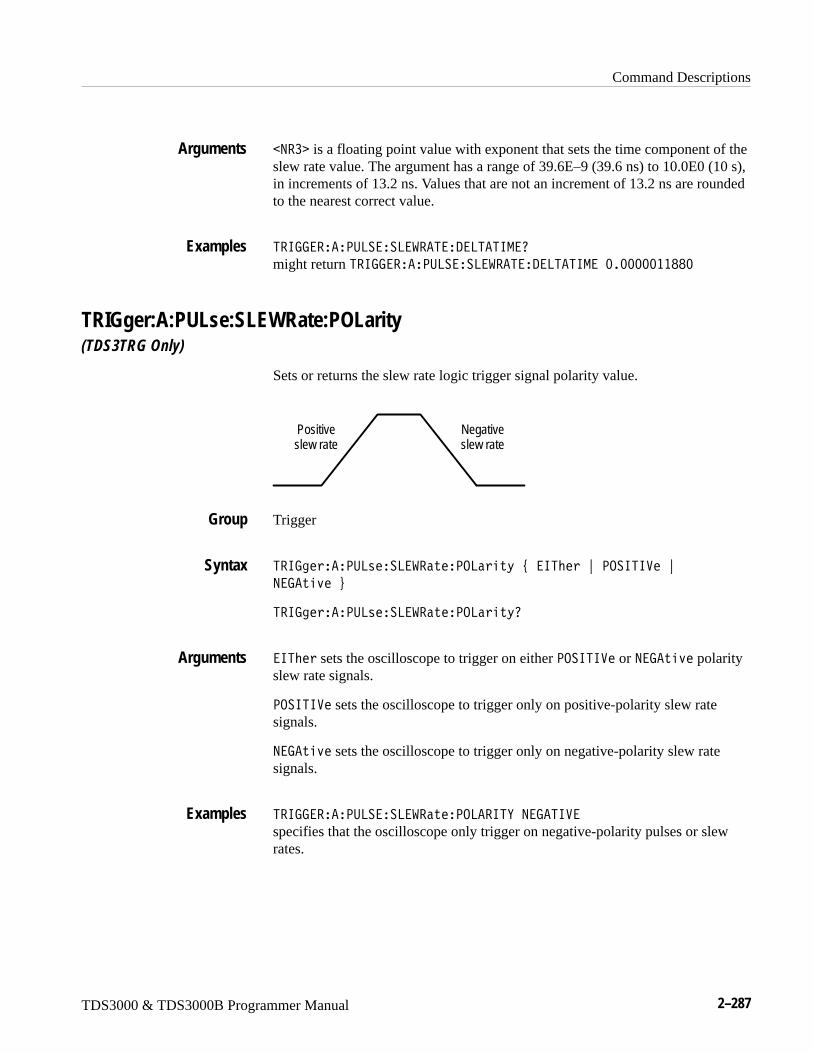
Command Descriptions
TDS3000 & TDS3000B Programmer Manual 2–287
�9�� is a floating point value with exponent that sets the time component of theslew rate value. The argument has a range of 39.6E–9 (39.6 ns) to 10.0E0 (10 s),in increments of 13.2 ns. Values that are not an increment of 13.2 ns are roundedto the nearest correct value.
5�677�����<:8����8����5��/�85�56-�0
might return 5�677�����<:8����8����5��/�85�56-��;�;;;;;��BB;
TRIGger:A:PULse:SLEWRate:POLarity(TDS3TRG Only)
Sets or returns the slew rate logic trigger signal polarity value.
Positiveslew rate
Negativeslew rate
Trigger
5�673����<:8����8�������<.8���D�#��65M��"�<.�656���"�
9�7���>��$
5�673����<:8����8�������<.8���D0
�65M� sets the oscilloscope to trigger on either <.�656�� or 9�7���>� polarityslew rate signals.
<.�656�� sets the oscilloscope to trigger only on positive-polarity slew ratesignals.
9�7���>� sets the oscilloscope to trigger only on negative-polarity slew ratesignals.
5�677�����<:8����8�������<.8��65E�9�7�56��
specifies that the oscilloscope only trigger on negative-polarity pulses or slewrates.
Arguments
Examples
Group
Syntax
Arguments
Examples
Command Descriptions
2–288 TDS3000 & TDS3000B Programmer Manual
TRIGger:A:PULse:SLEWRate:SLEWRate(TDS3TRG Only)
Sets or returns the slew rate value in volts per second.
Trigger
5�673����<:8����8��������8��������9��
5�673����<:8����8��������8������0
�9�� is a floating point value with exponent that sets the slew rate value asvolts per second
5�673����<:8����8��������8������0
might return 5�677�����<:8����8����5���8����5����GIV�W�, indicating aslew rate of 1.54 mV/s.
TRIGger:A:PULse:SLEWRate:THReshold:BOTh(TDS3TRG Only)
Sets the slew rate source signal threshold values.
Trigger
5�673����<:8����8�������5����M�1�?.5M�#�558�"�� 8�$
558 sets the upper threshold to 2.0 V and the lower threshold to 0.8 V.
� 8 sets the upper threshold to –1.1 V and the lower threshold to –1.5 V.
5�677�����<:8����8����5��5�����.8/�?.5��558
sets the upper slew rate threshold value to 1.8 V and the lower threshold value to0.8 V.
Group
Syntax
Arguments
Examples
Group
Syntax
Arguments
Examples
Command Descriptions
TDS3000 & TDS3000B Programmer Manual 2–289
TRIGger:A:PULse:SLEWRate:THReshold:HIGH(TDS3TRG Only)
Sets or returns the slew rate source signal high threshold voltage value.
Trigger
5�673����<:8����8�������5����M�1��67���9��
5�673����<:8����8�������5����M�1��67�0
�9�� is a floating point value with exponent that sets the slew rate trigger signalhigh threshold voltage value.
5�677�����<:8����8����5��5�����.8/��67��I���;
sets the slew rate high threshold voltage value to 4.1 volts.
TRIGger:A:PULse:SLEWRate:THReshold:LOW(TDS3TRG Only)
Sets or returns the slew rate source signal low threshold voltage value.
Trigger
5�673����<:8����8�������5����M�1�8.���9��
5�673����<:8����8�������5����M�1�8.�0
�9�� is a floating point value with exponent that sets the slew rate trigger signallow threshold voltage value.
5�677�����<:8����8����5��5�����.8/�8.��W��G�;
sets the slew rate low threshold voltage value to –1.5 volts.
Group
Syntax
Arguments
Examples
Group
Syntax
Arguments
Examples
Command Descriptions
2–290 TDS3000 & TDS3000B Programmer Manual
TRIGger:A:PULse:SLEWRate:WHEn(TDS3TRG Only)
Sets or returns the slew rate condition on which to trigger the oscilloscope.Thecondition is based on the slew rate calculated from the values set by the5�673����<:8����8�������/�85�5��� and 5�673����<:8����8��@�����5����M�1 commands.
Trigger
5�673����<:8����8������������#����5��5M���"��8.����M���
"��+,���"�9.5�+,���$
5�673����<:8����8�����������0
���5��5M�� triggers the oscilloscope when the signal slew rate is faster than thecalculated slew rate.
�8.����M�� triggers the oscilloscope when the signal slew rate is slower thanthe calculated slew rate.
�+,�� triggers the oscilloscope when the signal slew rate is equal to thecalculated slew rate within a ±5% tolerance.
9.5�+,�� triggers the oscilloscope when the signal slew rate is not equal to thecalculated slew rate within a ±5% tolerance.
5�677�����<:8����8����5�����9�9.5�+:�8
sets the oscilloscope to trigger when the slew rate is not equal to the calculatedslew rate.
TRIGger:A:PULse:SOUrce(TDS3TRG Only)
Sets or returns the signal source for width, runt, and slew rate pulse triggers. Thiscommand is equivalent to selecting a trigger signal source in the Source sidemenu.
Trigger
Group
Syntax
Arguments
Examples
Group
Command Descriptions
TDS3000 & TDS3000B Programmer Manual 2–291
5�673����<:8����.:2��#���5�"���5�;�"����5�2�� "� ��� �"�869��"��85������3�$
5�673����<:8����.:2�0
��5 sets the pulse trigger source to the regular external trigger input connectorwith a signal input range of –0.8 V to +0.8 V. EXT is not available in four-chan-nel TDS3000 Series instruments.
��5�; sets the pulse trigger source to the reduced external trigger with a signalinput range of –8 V to +8 V. EXT10 is not available in four-channel TDS3000Series instruments.
���5�2�� sets the pulse trigger source to the lowest numbered displayedchannel.
��� sets the pulse trigger source to the specified input channel, where <x> is1, 2, 3, or 4.
869� sets the pulse trigger source to the AC line frequency.
NOTE. LINE is not available when the instrument is operating on battery power.
�85������3 sets the pulse trigger source to alternate between each displayedinput channel.
5�677�����<:8����.:� �� ��
sets the pulse trigger signal source to channel 3.
TRIGger:A:PULse:WIDth:POLarityTDS3TRG Only
Sets or returns the pulse-width logic trigger signal polarity value.
Trigger
5�673����<:8����6/�M�<.8���D�#�<.�656���"�9�7���>��$
5�673����<:8����6/�M�<.8���D0
<.�656�� sets the oscilloscope to trigger only on positive-polarity pulses.
9�7���>� sets the oscilloscope to trigger only on negative-polarity pulses.
Syntax
Arguments
Examples
Group
Syntax
Arguments
Command Descriptions
2–292 TDS3000 & TDS3000B Programmer Manual
5�677�����<:8����6/5��<.8��65E�9�7�56��
specifies that the oscilloscope only trigger on negative-polarity pulse signals.
TRIGger:A:PULse:WIDth:WHEnTDS3TRG Only
Sets or returns the pulse width condition on which to trigger the oscilloscope.This is equivalent to selecting the condition in the Pulse Width Trigger Whenside menu.
Trigger
5�673����<:8����6/�M������#�8���5M���"�-.��5M���"��+,���"
9.5�+,���$
5�673����<:8����6/�M�����0
8���5M�� triggers the oscilloscope when the pulse width is true for less than thetime period specified in 5�673����<:8����6/�M��6/�M.
-.��5M�� triggers the oscilloscope when the pulse width is true for more(greater) than the time period specified in 5�673����<:8����6/�M��6/�M.
�+,�� triggers the oscilloscope when the pulse width is equal to the time periodspecified in 5�673����<:8����6/�M��6/�M, within a ±5% tolerance.
9.5�+,�� triggers the oscilloscope when the pulse width is greater than or lessthan (not equal to) the time period specified in 5�673����<:8����6/�M��6/�M,within a ±5% tolerance.
5�677�����<:8����6/5�����9�-.��5��9
sets the oscilloscope to trigger on pulse width signals that are more (wider) thana specified time period .
TRIGger:A:PULse:WIDth:WIDthTDS3TRG Only
Sets or returns the pulse width trigger time period value.
Trigger
Examples
Group
Syntax
Arguments
Examples
Group
Command Descriptions
TDS3000 & TDS3000B Programmer Manual 2–293
5�673����<:8����6/�M��6/�M��9��
5�673����<:8����6/�M��6/�M0
�9�� is a floating point value with exponent that sets the pulse width triggertime value. This argument has a range of 39.6E–9 (39.6 ns) to 10.0E0 (10 s), inincrements of 13.2 ns. Values that are not an increment of 13.2 ns are rounded tothe nearest correct value.
5�677�����<:8����6/5���6/5�0
might return 5�677�����<:8����6/5�����9�-.��5��9A�6/5��;�;;;;;��BB;.
TRIGger:A:SETLevel (Set Only)Sets the trigger level to 50%. This is equivalent to pressing the front-panel SETTO 50% button.
Trigger
5�673������58�>��
5�677�������58���8
sets the trigger level midway between MAX and MIN.
TRIGger:A:TYPeSets or queries the type of A trigger. This is equivalent to setting Type in theTrigger menu.
Trigger
5�673����5E<��#��/7��"��6/��"� .--,��2�����"�8.762�"�<:8���$
5�673����5E<�0
Syntax
Arguments
Examples
Group
Syntax
Examples
Group
Syntax
Command Descriptions
2–294 TDS3000 & TDS3000B Programmer Manual
.--,��2���� sets the A trigger parameters for communications (mask)testing. TDS3TMT only.
�/7� sets the oscilloscope to trigger when a signal passes through a singlespecified voltage level in a specified direction (edge triggering).
8.762 sets the oscilloscope to trigger when when the logic condition on twochannels is true. TDS3TRG only.
<:8�� sets the oscilloscope to trigger when a signal meets a specified pulsewidth condition. TDS3TRG only.
�6/� sets the oscilloscope to trigger on video signals.
5�677�����5E<�0
might return �5�677�����5E<���6/�. indicating that the A trigger type is avideo trigger.
TRIGger:A:VIDeo? (Query Only)Returns the A video trigger parameters.
Trigger
5�673�����6/�0
5�677������6/�.0
might return: �5�677������6/�.��5�9/��/�95� A�.:� �� ��A�6�8/�88869��A�.8/.����6�8/�;�;�;A�5�677������6/�.�869���A� �9���5�� as the current A video trigger parameters.
TRIGger:A:VIDeo:CUSTom:FORMatTDS3VID, TDS3SDI Only
Sets or queries the custom video signal format.
Trigger
5�673�����6/�� :�5���.�-���#�695��8�2�1�"�<�.7����>��$
5�673�����6/�� :�5���.�-��0
Arguments
Examples
Group
Syntax
Examples
Group
Syntax
Command Descriptions
TDS3000 & TDS3000B Programmer Manual 2–295
695��8�2�1 specifies that the video signal is interlaced.
<�.7����>� specifies that the video signal is progressive.
5�677������6/�.� :�5.-��.�-�50
might return 5�677������6/�.� :�5.-��.�-�5�695��8� �/.
TRIGger:A:VIDeo:CUSTom:SCANTDS3VID, TDS3SDI Only
Sets or queries the custom video signal scan rate on which to trigger.
Trigger
5�673�����6/�� :�5��� �9�#���5���"���5�H�"���5���"���5�I�"
��5�G�$
5�673�����6/�� :�5��� �90
��5�� specifies a horizontal scan rate of 15-20 kHz.
��5�H specifies a horizontal scan rate of 20-25 kHz.
��5�� specifies a horizontal scan rate of 25-35 kHz.
��5�I specifies a horizontal scan rate of 35-50 kHz.
��5�G specifies a horizontal scan rate of 50-65 kHz.
5�677������6/�.� :�5.-�� �90
might return 5�677������6/�.� :�5.-�� �9���5��.
TRIGger:A:VIDeo:FIELDSets or queries the field the video trigger detects.
Trigger
5�673�����6/���6�8/�#�.//�"����9�"��88����1��"��888�����"
�6�8/��"��6�8/H�"�9:-���2�$
5�673�����6/���6�8/0
Arguments
Examples
Group
Syntax
Arguments
Examples
Group
Syntax

Command Descriptions
2–296 TDS3000 & TDS3000B Programmer Manual
.// specifies to trigger on interlaced video odd fields.
���9 specifies to trigger on interlaced video even fields.
�88����1� specifies to trigger on the interlaced video odd fields.
�888���� specifies all video lines.
�6�8/� specifies interlaced video field 1. Same as odd.
�6�8/H specifies interlaced video field 2. Same as even.
9:-���2 specifies to trigger on the video signal line specified in the TRIGger:A:VIDeo:LINE command. TDS3VID, TDS3SDI only
5�677������6/�.��6�8/�
selects field 1.
TRIGger:A:VIDeo:HDTV:FORMat(TDS3VID, TDS3SDI Only)
Sets or queries the analog HDTV video signal format on which to trigger.
Trigger
5�673�����6/���/5�L�.�-���#��/�;B;6G;�"��/�;B;6T;�"��/�;B;<HI�"
�/�;B;<HG�"��/�;B;��HI�"��/IB;<T;�"��/VH;<T;�$
5�673�����6/���/5���.�-��0
Available HDTV formats are:
Table 2–40: HDTV formats
HDTV format Description
1080I50 1125 Lines (1080 active), 1920 x 1080 pixel, interlaced, 60 fps
1080I60 1125 lines (1080 active), 1920 x 1080 pixel, interlaced, 50 fps
1080P24 1125 lines (1080 active), 1920 x 1080 pixel, progressive, 24 fps
1080P25 1125 lines (1080 active), 1920 x 1080 pixel, progressive, 25 fps
1080SF24 1125 Lines (1080 active), 1920 x 1080 pixel, progressive (sF), 24 fps
Arguments
Examples
Group
Syntax
Arguments
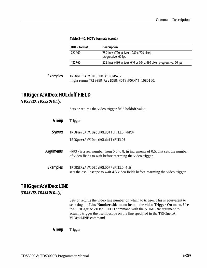
Command Descriptions
TDS3000 & TDS3000B Programmer Manual 2–297
Table 2–40: HDTV formats (cont.)
HDTV format Description
720P60 750 lines (720 active), 1280 x 720 pixel, progressive, 60 fps
480P60 525 lines (480 active), 640 or 704 x 480 pixel, progressive, 60 fps
5�677������6/�.��/5���.�-�50
might return 5�677������6/�.��/5���.�-�5��;B;6T;.
TRIGger:A:VIDeo:HOLdoff:FIELD(TDS3VID, TDS3SDI Only)
Sets or returns the video trigger field holdoff value.
Trigger
5�673�����6/���.81.����6�8/��9��
5�673�����6/���.81����6�8/0
�9�� is a real number from 0.0 to 8, in increments of 0.5, that sets the numberof video fields to wait before rearming the video trigger.
5�677������6/�.��.8/.����6�8/�I�G
sets the oscilloscope to wait 4.5 video fields before rearming the video trigger.
TRIGger:A:VIDeo:LINE(TDS3VID, TDS3SDI Only)
Sets or returns the video line number on which to trigger. This is equivalent toselecting the Line Number side-menu item in the video Trigger On menu. Usethe TRIGger:A:VIDeo:FIELD command with the NUMERic argument toactually trigger the oscilloscope on the line specified in the TRIGger:A:VIDeo:LINE command.
Trigger
Examples
Group
Syntax
Arguments
Examples
Group
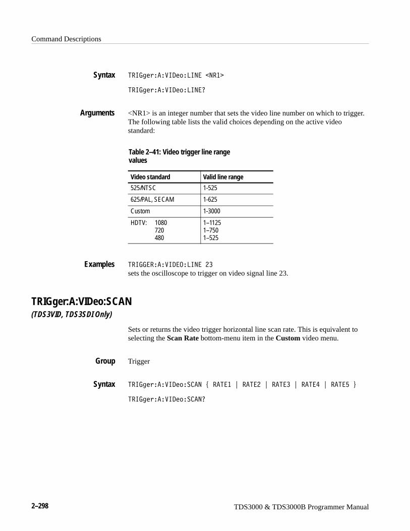
Command Descriptions
2–298 TDS3000 & TDS3000B Programmer Manual
5�673�����6/��869���9��
5�673�����6/��869�0
<NR1> is an integer number that sets the video line number on which to trigger.The following table lists the valid choices depending on the active videostandard:
Table 2–41: Video trigger line rangevalues
Video standard Valid line range
525/NTSC 1-525
625/PAL, SECAM 1-625
Custom 1-3000
HDTV: 1080720480
1–11251–7501–525
5�677������6/�.�869��H�
sets the oscilloscope to trigger on video signal line 23.
TRIGger:A:VIDeo:SCAN(TDS3VID, TDS3SDI Only)
Sets or returns the video trigger horizontal line scan rate. This is equivalent toselecting the Scan Rate bottom-menu item in the Custom video menu.
Trigger
5�673�����6/��� �9�#���5���"���5�H�"���5���"���5�I�"���5�G�$
5�673�����6/��� �90
Syntax
Arguments
Examples
Group
Syntax
Command Descriptions
TDS3000 & TDS3000B Programmer Manual 2–299
��5�� sets the video line scan rate range to 15-20 kHz. This is the standardbroadcast rate.
��5�H sets the video line scan rate range to 20-25 kHz.
��5�� sets the video line scan rate range to 25-35 kHz.
��5�I sets the video line scan rate range to 35-50 kHz.
��5�G sets the video line scan rate range to 50-65 kHz.
5�677������6/�.�� �9���5�H
sets the video line scan range to 20-25 kHz.
TRIGger:A:VIDeo:SOUrceSets or queries the source for the A video trigger. This is equivalent to selectingSource in the Trigger menu and a desired channel from the side menu.
Trigger
5�673�����6/���.:2��#���5�"���5�;�"����5�2�� "� ��� �"�869��"��85������3�$
5�673�����6/���.:2�0
��5 sets the video trigger source to the regular external trigger input connectorwith a signal input range of –0.8 V to +0.8 V. EXT is not available in 4 channelTDS3000 Series instruments.
��5�; sets the video trigger source to the reduced external trigger with a signalinput range of –8 V to +8 V. EXT10 is not available in 4 channel TDS3000Series instruments.
���5�2�� sets the video trigger source to the lowest numbered displayedchannel.
��� sets the video trigger source to the specified input channel, where <x> is1, 2, 3, or 4.
Arguments
Examples
Group
Syntax
Arguments
Command Descriptions
2–300 TDS3000 & TDS3000B Programmer Manual
869� sets the video trigger source to the AC line frequency.
NOTE. LINE is not available when the instrument is operating on battery power.
�85������3 sets the video trigger source to sequentially trigger on eachdisplayed input channel.
5�677������6/�.��.:� �� ��
selects channel 1 as the source for the A video trigger.
TRIGger:A:VIDeo:STANdardSets or queries the video trigger standard. This is equivalent to selecting thestandard in the video Standard pop-up (525/NTSC, 625/PAL, or SECAM).
Trigger
5�673�����6/���5�91�1�#�95�2�"�<�8�"��� �-�"� :�5��"��/5��$
5�673�����6/���5�91�10
95�2 specifies the NTSC 525/59.94/2:1 standard.
<�8 specifies the PAL 625/50/2:1 standard.
�� �- specifies the SECAM standard.
:�5� sets the oscilloscope to use custom video horizontal scan rate parametersas set by 5�673�����6/��� �9. TDS3VID, TDS3SDI only.
�/5� sets the oscilloscope to use HDTV scan rate parameters as set by 5�673�����6/���/5���.�-��. TDS3VID, TDS3SDI only.
5�677������6/�.��5�9/��/�95�
sets the oscilloscope to trigger on NTSC-standard video signals.
Examples
Group
Syntax
Arguments
Examples
Command Descriptions
TDS3000 & TDS3000B Programmer Manual 2–301
TRIGger:A:VIDeo:SYStemThis command is the same as TRIGger:A:VIDeo:STANdard, and is forcompatibility with other Tektronix instruments.
TRIGger:BSets or returns the current B trigger parameters.
Trigger
5�673��?���58�>��
5�673��?0
��58�>�� sets the B trigger voltage level to 50% of the source peak-to-peaksignal.
5�677���?0
might return �5�677���?��5�5��;A?E�56-�A���95�� .:95��A�5�677���?�56-�����H�@BA8���8���;�@�A�/7���.:� �� �HA
.:<8697�/ A�8.<���6��
TRIGger:B:BYSets the B trigger to delay by time or events.
Trigger
5�673��?�?E�#�56-��"����95��$
5�673��?�?E0
5�677���?�?E����95�
sets the B trigger to delay by events.
Group
Syntax
Arguments
Examples
Group
Syntax
Examples
Command Descriptions
2–302 TDS3000 & TDS3000B Programmer Manual
TRIGger:B:EDGe? (Query Only)Returns the trigger coupling, source, and slope for the B edge trigger.
Trigger
5�673��?��/7�0
5�677���?��/7�0
might return �.:� �� ��A .:<8697�/ A�8.<���6��
TRIGger:B:EDGe:COUPlingSets or queries the type of coupling for the B edge trigger. This is equivalent tosetting Coupling in the Trigger menu.
Trigger
5�673��?��/7�� .:<���3�#�/ �"�����]�"�8���]�"�9.6���]�"�� �$
5�673��?��/7�� .:<���30
/ selects DC trigger coupling.
� selects LFRej trigger coupling. AC coupling is for backward compatibilityand will not be returned by a query.
����] coupling removes the high frequency components of the DC signal.
8���] coupling removes the low frequency components of the AC signal.
9.6���] selects DC low sensitivity. It requires added signal amplitude for morestable, less false triggering.
5�677���?��/7�� .:<8697�/
sets the B edge trigger coupling to DC.
Group
Syntax
Examples
Group
Syntax
Arguments
Examples
Command Descriptions
TDS3000 & TDS3000B Programmer Manual 2–303
TRIGger:B:EDGe:SLOpeSelects a rising or falling slope for the B edge trigger. This is equivalent tosetting Slope in the Trigger menu.
Trigger
5�673��?��/7���8.4��#���88�"��6���$
5�673��?��/7���8.4�0
��88 specifies to trigger on the falling or negative edge of a signal.
�6�� specifies to trigger on the rising or positive edge of a signal.
5�677���?��/7���8.<���6��
sets the B edge trigger to occur on the rising slope.
TRIGger:B:EDGe:SOUrceSets or queries the source for the B edge trigger. This is equivalent to settingSource in the Trigger menu.
Trigger
5�673��?��/7���.:2��#�869��"� ��� �"���5�"���5�;�$
5�673��?��/7���.:2�0
869� sets the B trigger source to the AC line frequency. LINE is not availablewhen the instrument is operating on battery power.
��� sets the B trigger source to the specified input channel, where <x> is 1, 2,3, or 4.
��5 sets the B trigger source to the regular external trigger input connector witha signal input range of –0.8 V to +0.8 V. EXT is not available in 4-channelTDS3000 Series instruments.
��5�; sets the B trigger source to the reduced external trigger with a signal inputrange of –8 V to +8 V. EXT10 is not available in 4-channel TDS3000 Seriesinstruments.
Group
Syntax
Arguments
Examples
Group
Syntax
Arguments
Command Descriptions
2–304 TDS3000 & TDS3000B Programmer Manual
5�677���?��/7���.:� ��869�specifies the AC line voltage as the B edge trigger source.
5�677���?��/7���.:� �0
might return �H for the B edge trigger source.
TRIGger:B:EVENTS? (Query Only)Returns the current delayed trigger event parameter.
Trigger
5�673��?����95�0��9�� �
5�677���?����95�0
might return 14 indicating the B trigger occurs on the 14th occurance of a B trigger event, after the A trigger occurs.
TRIGger:B:EVENTS:COUNtSets and returns the number of B trigger events that must occur before theB trigger occurs when TRIGger:DELay:BY is set to EVENTS.
Trigger
5�673��?����95�� .:9���9��
5�677���?����95�� .:95�I
specifies that the B trigger will occur on the fourth B trigger event.
Examples
Group
Syntax
Examples
Group
Syntax
Examples
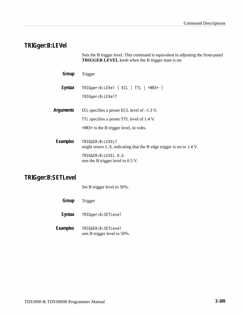
Command Descriptions
TDS3000 & TDS3000B Programmer Manual 2–305
TRIGger:B:LEVelSets the B trigger level. This command is equivalent to adjusting the front-panelTRIGGER LEVEL knob when the B trigger state is on.
Trigger
5�673��?�8�����#�� 8�"�558�"��9�� �$
5�673��?�8����0
� 8 specifies a preset ECL level of –1.3 V.
558 specifies a preset TTL level of 1.4 V.
�9�� is the B trigger level, in volts.
5�677���?�8���80
might return ��I, indicating that the B edge trigger is set to 1.4 V.
5�677���?�8���8�;�G
sets the B trigger level to 0.5 V.
TRIGger:B:SETLevelSet B trigger level to 50%.
Trigger
5�673��?���58�>��
5�677���?���58�>��
sets B trigger level to 50%.
Group
Syntax
Arguments
Examples
Group
Syntax
Examples
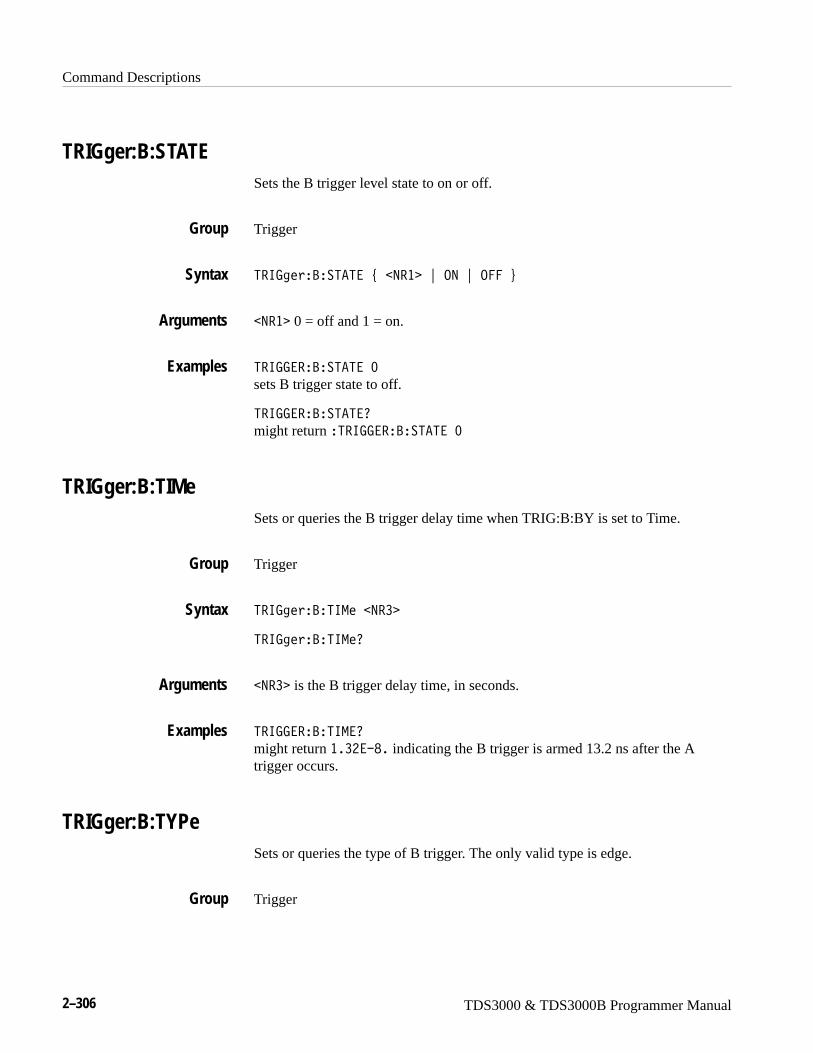
Command Descriptions
2–306 TDS3000 & TDS3000B Programmer Manual
TRIGger:B:STATESets the B trigger level state to on or off.
Trigger
5�673��?��5�5��#��9�� �"�.9�"�.���$
�9�� 0 = off and 1 = on.
5�677���?��5�5��;
sets B trigger state to off.
5�677���?��5�5�0�
might return �5�677���?��5�5��;
TRIGger:B:TIMeSets or queries the B trigger delay time when TRIG:B:BY is set to Time.
Trigger
5�673��?�56-���9��
5�673��?�56-�0
�9�� is the B trigger delay time, in seconds.
5�677���?�56-�0
might return ���H�WB� indicating the B trigger is armed 13.2 ns after the Atrigger occurs.
TRIGger:B:TYPeSets or queries the type of B trigger. The only valid type is edge.
Trigger
Group
Syntax
Arguments
Examples
Group
Syntax
Arguments
Examples
Group
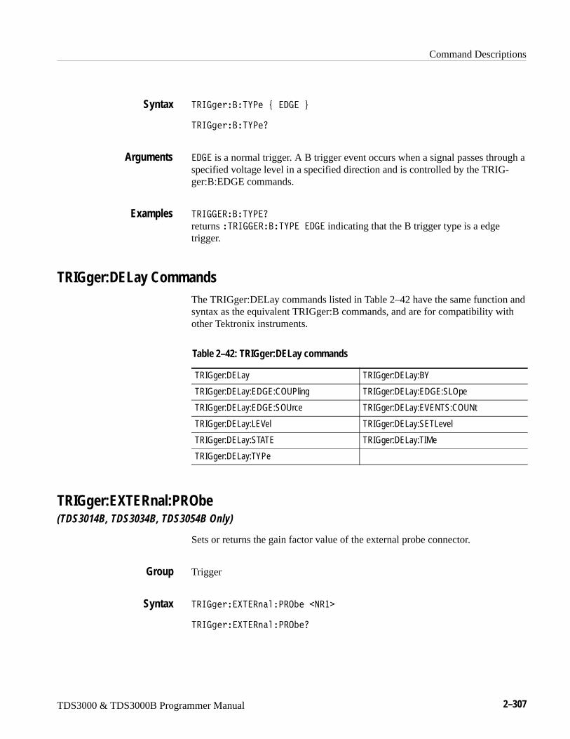
Command Descriptions
TDS3000 & TDS3000B Programmer Manual 2–307
5�673��?�5E<��#��/7��$
5�673��?�5E<�0
�/7� is a normal trigger. A B trigger event occurs when a signal passes through aspecified voltage level in a specified direction and is controlled by the TRIG-ger:B:EDGE commands.
5�677���?�5E<�0
returns �5�677���?�5E<���/7� indicating that the B trigger type is a edgetrigger.
TRIGger:DELay CommandsThe TRIGger:DELay commands listed in Table 2–42 have the same function andsyntax as the equivalent TRIGger:B commands, and are for compatibility withother Tektronix instruments.
Table 2–42: TRIGger:DELay commands
TRIGger:DELay TRIGger:DELay:BY
TRIGger:DELay:EDGE:COUPling TRIGger:DELay:EDGE:SLOpe
TRIGger:DELay:EDGE:SOUrce TRIGger:DELay:EVENTS:COUNt
TRIGger:DELay:LEVel TRIGger:DELay:SETLevel
TRIGger:DELay:STATE TRIGger:DELay:TIMe
TRIGger:DELay:TYPe
TRIGger:EXTERnal:PRObe(TDS3014B, TDS3034B, TDS3054B Only)
Sets or returns the gain factor value of the external probe connector.
Trigger
5�673����5������<�.N���9��
5�673����5������<�.N�0
Syntax
Arguments
Examples
Group
Syntax
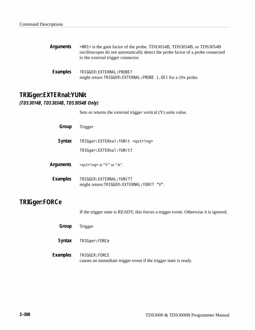
Command Descriptions
2–308 TDS3000 & TDS3000B Programmer Manual
�9�� is the gain factor of the probe. TDS3014B, TDS3034B, or TDS3054Boscilloscopes do not automatically detect the probe factor of a probe connectedto the external trigger connector.
5�677�����5��9�8�<�.?�0
might return 5�677�����5��9�8�<�.?����;�� for a 10x probe.
TRIGger:EXTERnal:YUNit(TDS3014B, TDS3034B, TDS3054B Only)
Sets or returns the external trigger vertical (Y) units value.
Trigger
5�673����5������E:9����=����3
5�673����5������E:9��0
�=����3 is “V” or “A”.
5�677�����5��9�8�E:9650
might return:5�677�����5��9�8�E:965�R�L.
TRIGger:FORCeIf the trigger state is READY, this forces a trigger event. Otherwise it is ignored.
Trigger
5�673���.� �
5�677����.� �
causes an immediate trigger event if the trigger state is ready.
Arguments
Examples
Group
Syntax
Arguments
Examples
Group
Syntax
Examples
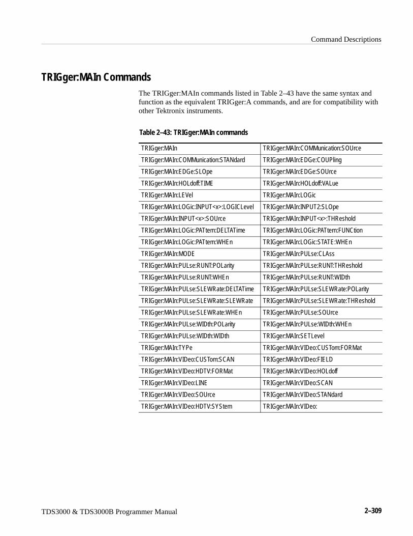
Command Descriptions
TDS3000 & TDS3000B Programmer Manual 2–309
TRIGger:MAIn CommandsThe TRIGger:MAIn commands listed in Table 2–43 have the same syntax andfunction as the equivalent TRIGger:A commands, and are for compatibility withother Tektronix instruments.
Table 2–43: TRIGger:MAIn commands
TRIGger:MAIn TRIGger:MAIn:COMMunication:SOUrce
TRIGger:MAIn:COMMunication:STANdard TRIGger:MAIn:EDGe:COUPling
TRIGger:MAIn:EDGe:SLOpe TRIGger:MAIn:EDGe:SOUrce
TRIGger:MAIn:HOLdoff:TIME TRIGger:MAIn:HOLdoff:VALue
TRIGger:MAIn:LEVel TRIGger:MAIn:LOGic
TRIGger:MAIn:LOGic:INPUT<x>:LOGICLevel TRIGger:MAIn:INPUT2:SLOpe
TRIGger:MAIn:INPUT<x>:SOUrce TRIGger:MAIn:INPUT<x>:THReshold
TRIGger:MAIn:LOGic:PATtern:DELTATime TRIGger:MAIn:LOGic:PATtern:FUNCtion
TRIGger:MAIn:LOGic:PATtern:WHEn TRIGger:MAIn:LOGic:STATE:WHEn
TRIGger:MAIn:MODE TRIGger:MAIn:PULse:CLAss
TRIGger:MAIn:PULse:RUNT:POLarity TRIGger:MAIn:PULse:RUNT:THReshold
TRIGger:MAIn:PULse:RUNT:WHEn TRIGger:MAIn:PULse:RUNT:WIDth
TRIGger:MAIn:PULse:SLEWRate:DELTATime TRIGger:MAIn:PULse:SLEWRate:POLarity
TRIGger:MAIn:PULse:SLEWRate:SLEWRate TRIGger:MAIn:PULse:SLEWRate:THReshold
TRIGger:MAIn:PULse:SLEWRate:WHEn TRIGger:MAIn:PULse:SOUrce
TRIGger:MAIn:PULse:WIDth:POLarity TRIGger:MAIn:PULse:WIDth:WHEn
TRIGger:MAIn:PULse:WIDth:WIDth TRIGger:MAIn:SETLevel
TRIGger:MAIn:TYPe TRIGger:MAIn:VIDeo:CUSTom:FORMat
TRIGger:MAIn:VIDeo:CUSTom:SCAN TRIGger:MAIn:VIDeo:FIELD
TRIGger:MAIn:VIDeo:HDTV:FORMat TRIGger:MAIn:VIDeo:HOLdoff
TRIGger:MAIn:VIDeo:LINE TRIGger:MAIn:VIDeo:SCAN
TRIGger:MAIn:VIDeo:SOUrce TRIGger:MAIn:VIDeo:STANdard
TRIGger:MAIn:VIDeo:HDTV:SYStem TRIGger:MAIn:VIDeo:
Command Descriptions
2–310 TDS3000 & TDS3000B Programmer Manual
TRIGger:STATE? (Query Only)Returns the current state of the triggering system.
Trigger
5�673���5�5�0
�:5. indicates that the oscilloscope is in auto mode and acquires data even in theabsence of a trigger.
��-�/ indicates that the oscilloscope is acquiring pretrigger information. Alltriggers are ignored when TRIGger:STATE is ARMed.
���/E indicates that all pretrigger information has been acquired and theoscilloscope is ready to accept a trigger.
���� indicates that acquisition is stopped or that all channels are off.
5�673� indicates that the oscilloscope has seen a trigger and is acquiring theposttrigger information.
5�677����5�5�0
might return���-�/, indicating that pretrigger data is being acquired.
Group
Syntax
Returns
Examples
Command Descriptions
TDS3000 & TDS3000B Programmer Manual 2–311
*TRG (Set Only)(Trigger) executes commands that are defined by *DDT.
The Group Execute Trigger (GET) interface message has the same effect as the*TRG command.
Miscellaneous
C5�7
C5�7
immediately executes all commands that have been defined by *DDT.
Alias commands, *DDT
*TST? (Query Only)(Self-Test) Tests the GPIB interface and returns a 0.
Miscellaneous
C5�50
�9�� and is always 0.
Group
Syntax
Examples
Related Commands
Group
Syntax
Returns
Command Descriptions
2–312 TDS3000 & TDS3000B Programmer Manual
UNLock (Set Only)Unlocks the front panel. This command is equivalent to LOCk NONe.
NOTE. If the oscilloscope is in the Remote With Lockout State (RWLS), theUNLOCk command has no effect. For more information see the ANSI-IEEE Std.488.1-1987 Standard Digital Interface for Programmable Instrumentation,section 2.8.3 on RL State Descriptions.
Miscellaneous
:982O��88
�88 specifies all front-panel buttons and knobs.
LOCk
VERBoseSets and queries the Verbose State that controls the length of keywords on queryresponses. Keywords can be both headers and arguments. This command doesnot affect IEEE Std 488.2-1987 Common Commands (those starting with anasterisk).
Miscellaneous
���?���#�.���"�.9�"��9�� �$
���?��0
.9 or �9�� � 0 sets the Verbose State true, which returns full-length keywordsfor applicable setting queries.
.�� or �9�� = 0 sets the Verbose State false, which returns minimum-lengthkeywords for applicable setting queries.
Group
Syntax
Arguments
Related Commands
Group
Syntax
Arguments
Command Descriptions
TDS3000 & TDS3000B Programmer Manual 2–313
���?.���.9
sets the Verbose State true.
���?.��0
might return the value �, showing that the Verbose State is true.
HEADer, *LRN?, SET?
*WAI (Set Only)(Wait) Prevents the oscilloscope from executing further commands or queriesuntil all pending operations finish. This command allows you to synchronize theoperation of the oscilloscope with your application program. Synchronizationmethods are described on page 3–7.
Status and Error
C��6
BUSY?, *OPC
WAVFrm? (Query Only)Returns WFMPre? and CURVe? data for the waveform specified by theDATa:SOUrce command. This command is equivalent to sending WFMPre?;CURVe?. If the waveform specified by the DATa:SOUrce command is notdisplayed, the oscilloscope returns only the waveform transmission parameters)?E5U9��?65U9���9 13��?9U�����?E5U.*.
The WFMPre response is first, followed by the CURVe response with anintervening semicolon.
Waveform
�����0
See WFMPre? and CURVe? commands.
CURVe, DATa:SOUrce, WFMPre?
Examples
Related Commands
Group
Syntax
Related Commands
Group
Syntax
Returns
Related Commands
Command Descriptions
2–314 TDS3000 & TDS3000B Programmer Manual
WAVEAlert:BEEP(TDS3000B Series Only)
The beep sounds when a new waveform data varies significantly from theaccumulated (DPO) display of previous waveforms.
Acquisition
���������?��<�#�.���"�.9�"��9�� �$
���������?��<0
.�� or �9�� = 0 turns off the beep when a new waveform is significantlydifferent.
.9 or �9�� � 0 turns on the beep.
Either 0 or 1 corresponding to beep OFF or ON.
�����8��5�?��<�.9
specifies that the beep is to sound when a new waveform data varies significantlyfrom previous waveforms.
�����8��5�?��<0
returns either ; or �, indicating whether the beep is to sound when a newwaveform varies significantly from previous waveforms.
WAVEAlert:HARDCopy(TDS3000B Series Only)
Executes a hardcopy operation on the waveform when a new waveform datavaries significantly from the accumulated (DPO) display of previous waveforms.The hardcopy operation uses the port, and prints in the format and layout,specified using the HARDCopy commands.
Acquisition
������������/ 4D�#�.���"�.9�"��9�� �$
������������/ 4D0
Group
Syntax
Arguments
Returns
Examples
Group
Syntax
Command Descriptions
TDS3000 & TDS3000B Programmer Manual 2–315
.9 or �9�� � 0 turns on the hardcopy operation for the waveform when a newwaveform is significantly different.
.�� or �9�� = 0 turns off the hardcopy operation.
�����8��5����/ .<E�.9
specifies that the hardcopy operation occurs when a new waveform data variessignificantly from previous waveforms.
�����8��5����/ .<E0
returns either ; or �, indicating whether the hardcopy operation occurs when anew waveform data varies significantly from previous waveforms.
WAVEAlert:SAVEWFM(TDS3000B Series Only)
Sets or returns saving WaveAlert anomaly waveforms to file.
Acquisition
���������������-�#�.���"�.9�"��9�� �$
���������������-0
.�� or �9�� = 0 disables saving anomaly waveforms to a file.
.9 or �9�� � 0 enables saving anomaly waveforms to a file.
�����8��5�������-�.9
specifies that the oscilloscope save an anomaly waveform to a floppy disk file.
Arguments
Examples
Group
Syntax
Arguments
Examples
Command Descriptions
2–316 TDS3000 & TDS3000B Programmer Manual
WAVEAlert:SENSitivity(TDS3000B Series Only)
Sets or returns the WaveAlert anomaly detection sensitivity parameter.
Acquisition
�����������9����>��D�#��9�� �$
�����������9����>��D0
�9�� sets the anomaly sensitivity percentage value, and ranges from 1 to 100.
�����8��5���9�656�65E0
might return �����8��5���9�656�65E�T�;��, indicating that sensitivity is setto 60%.
WAVEAlert:STATE(TDS3000B Series Only)
Sets or returns the WaveAlert testing state.
Acquisition
����������5�5��#�.���"�.9�"��9�� �$
����������5�5�0
.�� or �9�� = 0 turns off WaveAlert testing.
.9 or �9�� � 0 turns on WaveAlert testing.
����������5�5��.9
specifies that WaveAlert waveform anomaly detection is in effect.
����������5�5�0
returns either ; or �, indicating whether WaveAlert testing is in effect.
Group
Syntax
Arguments
Examples
Group
Syntax
Arguments
Examples
Command Descriptions
TDS3000 & TDS3000B Programmer Manual 2–317
WAVEAlert:STOPOnviolation(TDS3000B Series Only)
Sets or returns the WaveAlert stop on violation setting. When enabled, thiscommand stops waveform acquisitions on the first occurance of a WaveAlertwaveform anomaly.
Acquisition
����������5.<.�>�������#�.���"�.9�$
����������5.<.�>������0
.�� or 0 turns off the stop on violation mode.
.9 or 1 turns on the stop on violation mode.
�����8��5��5.<.9�6.8�56.90
returns either ; or �, indicating whether stop on violation is off or on.
WAVEAlert:TYPe(TDS3000B Series Only)
Sets or returns the WaveAlert anomaly waveform highlight type.
Acquisition
���������5E<��#��95���"��9.-��D�$
���������5E<�0
�95�� sets the oscilloscope to highlight the entire anomalous waveform.
�9.-��D sets the oscilloscope to highlight just that portion of the anomalouswaveform that is different than the base waveform.
�����8��5�5E<�0 might return ���������5E<���95��, indicating that the entire anomalywaveform is highlighted.
Group
Syntax
Arguments
Examples
Group
Syntax
Arguments
Examples
Command Descriptions
2–318 TDS3000 & TDS3000B Programmer Manual
WFMPre? (Query Only)Returns waveform transmission and formatting parameters for the waveformspecified by the DATa:SOUrce command. If the waveform specified by theDATa:SOUrce command is not displayed, the oscilloscope returns only thewaveform transmission parameters )?E5U9��?65U9���9 13��?9U�����?E5U.*.
Waveform
��-<�0
The format of the response is:
?E5U9��9�� A?65U9��9�� A�9 13�#��� �"�?69�$A
?9U����#��6�"��<�$A?E5U.�#�8�?�"�-�?�$A9�U<���9�� A
��6/��+����3 A<5U�-5�#�9��"�E$A�692��9�� A
<5U.����9�� A�P����9�� A�:9����+����3 AE-:����9�� A�EP�
�9�� AE.����9�� AE:9����+����3
��-<��0
might return���-<���?E5U9���A?65U9��BA�9 /7��� A?9U�-5��<A?E5U.��-�?A
9�U<5��;;;;A��6/�L M���/ �2,4���3����;�W���[1�>��I�;�WI��[1�>�
�;;;;�4���������4����1�LA<5U�-5�EA�69 ��I�;�WVA<5U.���;A
�P��.�WH�;�W�A�:965�L�LAE-:85�I�;�W�AEP��.�;�;�;AE.���;�;�;A
E:965�L�L
WAVFrm?, WFMPre:<wfm>?
WFMPre:BIT_NrSets or queries the number of bits per waveform point for the waveform to betransferred. Changing the value of WFMPre:BIT_Nr also changes the values ofWFMPRe:BYT_Nr and DATa:WIDth.
Waveform
��-<��?65U9��9��
��-<��?65U90
Group
Syntax
Returns
Example
Related Commands
Group
Syntax
Command Descriptions
TDS3000 & TDS3000B Programmer Manual 2–319
�9�� is either 8 or 16, and is equivalent to WFMPre:BYT_Nr * 8 andDATa:WIDth * 8.
��-<���?65U9�0
might return B, indicating that there are 8 bits per waveform point.
DATa:WIDth, WFMPre:BYT_Nr
WFMPre:BN_FmtSets or queries the format of binary data for the waveform to be transferred.Changing the value of WFMPre:BN_Fmt also changes the value ofDATa:ENCdg.
Waveform
��-<��?9U����#��6�"��<�$
��-<��?9U���0
�6 specifies signed integer data-point representation.
�< specifies positive integer data-point representation.
��-<���?9U�-5��<
specifies that the binary waveform data are positive integer data-points.
��-<���?9U�-50
returns either �6 or �< as the current waveform data format.
DATa:ENCdg, WFMPre:BYT_Or, WFMPre:ENCdg
Arguments
Examples
Related Commands
Group
Syntax
Arguments
Examples
Related Commands
Command Descriptions
2–320 TDS3000 & TDS3000B Programmer Manual
WFMPre:BYT_NrSets or queries the data width for the waveform to be transferred. This commandis equivalent to DATa:WIDth. Changing WFMPre:BYT_Nr also changesWFMPre:BIT_Nr and DATa:WIDth.
Waveform
��-<��?E5U9��9��
��-<��?E5U90
�9�� is an integer in the range of 1 to 2 that sets the number of bytes per point.
��-<���?E5U9��H
specifies that there are 2 bytes per waveform data point.
DATa:WIDth, WFMPre:BIT_Nr
WFMPre:BYT_OrSets or queries which byte of binary waveform data is transmitted first during awaveform data transfer when DATa:WIDth or WFMPre:BYT_Nr is set to 2, orWFMPre:BIT_Nr is set to 16. Changing WFMPre:BYT_Or changesDATa:ENCdg (if DATa:ENCdg is not ASCIi). This specification only hasmeaning when WFMPre:ENCdg is BIN.
Waveform
��-<��?E5U.�#�8�?�"�-�?�$
��-<��?E5U.0
8�? selects the least significant byte to be transmitted first.
-�? selects the most significant bye to be transmitted first.
Group
Syntax
Arguments
Examples
Related Commands
Group
Syntax
Arguments
Command Descriptions
TDS3000 & TDS3000B Programmer Manual 2–321
��-<���?E5U.��-�?
specifies that the most significant byte in the waveform data is transferred first.
��-<���?E5U.�0
returns either -�? or 8�? depending on which data byte is transferred first.
DATa:ENCdg, WFMPre:BN_Fmt, WFMPre:ENCdg
WFMPre:ENCdgSets or queries the type of encoding for waveform data transferred with theCURVe command. Changing WFMPre:ENCdg also changes DATa:ENCdg.
Waveform
��-<���9 13�#��� �"�?69�$
��-<���9 130
�� specifies ASCII curve data.
?69 specifies binary curve data.
��-<����9 /7���
specifies that the waveform data is in ASCII format.
��-<����9 /70
might return ?69, indicating that the waveform data is in binary format.
DATa:ENCdg, WFMPre:BYT_Or, WFMPre:BN_Fmt
Examples
Related Commands
Group
Syntax
Arguments
Examples
Related Commands
Command Descriptions
2–322 TDS3000 & TDS3000B Programmer Manual
WFMPre:NR_PtThe set form of this command sets the record length of the reference waveformspecified by DATA:DESTination. Allowable record lengths are 500 and 10000.
The query form of this command returns the number of points that will bereturned by the next CURVe query. The number of points is the greater of theabsolute value of (DATa:STOP – DATA:STARt) +1, or the record length of thesource waveform specified by DATA:SOUrce. If the source waveform is not onor displayed, the query generates an error and returns event code 2244.
Waveform
��-<��9�U<��#�G;;�"��;;;;�$
��-<��9�U<�0
��-<��9�U<�0
returns the number of waveform points in the next CURVE query.
DATa:ENCdg, WFMPre:BYT_Or, WFMPre:BN_Fmt
WFMPre:PT_FmtThe set form of this command sets the format (Y or ENV) of the referencewaveform as specified by the DATa:DESTination command.
The query form returns the format of the waveform specified by theDATa:SOUrce command, if that waveform is on or displayed. If the waveform isnot displayed, the query form of this command generates an error and returnsevent code 2244.
Waveform
��-<��<5U����#��9��"�E�$
��-<��<5U���0
Group
Syntax
Examples
Related Commands
Group
Syntax
Command Descriptions
TDS3000 & TDS3000B Programmer Manual 2–323
E specifies a normal waveform where one ASCII or binary data point istransmitted for each point in the waveform record. Only y values are explicitlytransmitted. Absolute coordinates are given by:
Xn � XZEro � XINcr (n–PT_Off)
Yn � YZEro � YMUlt (yn � YOFf)
�9� specifies that the oscilloscope transmit the waveform as minimum andmaximum point pairs. Peak detect and envelope waveforms use an ENV format.Only y values are explicitly transmitted. Absolute coordinates are given by:
Xn � XZEro � XINcr (n–PT_Off)
Ynmin� YZEro � YMUlt (ynmin
� YOFf)
Ynmax � YZEro � YMUlt (ynmax � YOFf)
��-<���<5U�-5�E
sets the waveform data point format to Y.
��-<���<5U�-50
returns either E or �9�.
WFMPre:PT_OffThe set form of this command is ignored. The query form always returns a 0, ifthe waveform specified by DATA:SOUrce is on or displayed. If the waveform isnot displayed, the query form generates an error and returns event code 2244.This command is listed for compatibility with other Tektronix oscilloscopes.
Waveform
��-<��<5U.��
��-<��<5U.��0
Arguments are ignored.
WFMPre:<wfm>:PT_Off
Arguments
Examples
Group
Syntax
Arguments
Related Commands
Command Descriptions
2–324 TDS3000 & TDS3000B Programmer Manual
WFMPre:WFId? (Query Only)Returns a descriptive string from the waveform specified in the DATa:SOUrcecommand, if that waveform is on or displayed. If that waveform is not on ordisplayed, the query fails and the oscilloscope generates an execution error withevent code 2244 (waveform requested is not on).
Waveform
��-<����610
None.
��-<�����610
YT waveform:���-<�����6/�L M�,�/ �2,4���3����;�W���[1�>��I�;�WI��[1�>���;;;;4���������4����1�L
Non-FFT Math waveform:���-<�����6/�L-��M��/ �2,4���3��G�;�WH��[1�>��I�;�WI��[1�>�
�;;;;�4���������4����1�L
FFT waveform:���-<�����6/�L-��M��/ �2,4���3��H�;���1?[1�>��I�;�W���F[1�>�
�;;;;�4���������4����1�L
WFMPre:<wfm>:WFId?
WFMPre:XINcrThe set form of this command specifies the interval (seconds per point fornon-FFT, Hertz per point for FFT) between samples of the reference waveformspecified by the DATa:DESTination command. The oscilloscope uses this valueto calculate the seconds/division or Hertz/division units shown in the status,cursor and measurement readouts when displaying a reference waveform.
The query form returns the interval between samples of the waveform specifiedby the DATa:SOUrce command, if that waveform is on or displayed. If thatwaveform is not on or displayed, the query fails and the oscilloscope generatesan execution error with event code 2244 (waveform requested is not on).
Waveform
Group
Syntax
Arguments
Examples
Related Commands
Group

Command Descriptions
TDS3000 & TDS3000B Programmer Manual 2–325
��-<���692��9��
��-<���6920
�9�� is the sampling interval in seconds or Hertz per point.
WFMPre:<wfm>:XINcr
WFMPre:XUNitThe set form of this command is only valid for reference waveforms. The onlyvalid units are “s” and “Hz”. If an attempt is made to set the XUNit to somethingother than “s” or “Hz”, event 224 (illegal parameter value) is generated. Setting areference waveform’s XUNit to Hz causes the oscilloscope to display thereference waveform as an FFT waveform.
The query form returns the horizontal units for the waveform specified byDATa:SOURce (“s” for seconds, “Hz” for Hertz). If the waveform specified byDATa:SOURce is not displayed, the query fails and the oscilloscope generates anexecution error with event code 2244 (waveform requested is not on).
Waveform
��-<���:9����=����3
��-<���:9��0
�=����3 is “s” or “Hz”.
WFMPre:<wfm>:XUNit
Syntax
Arguments
Related Commands
Group
Syntax
Arguments
Related Commands
Command Descriptions
2–326 TDS3000 & TDS3000B Programmer Manual
WFMPre:XZEroThe set form of this command specifies the position, in XUNits, of the firstsample of the reference waveform specified by the DATa:DESTination com-mand.
The query form returns the position of the first sample of the waveform specifiedby the DATa:SOUrce command, if that waveform is on or displayed. If thatwaveform is not on or displayed, the query fails and the oscilloscope generatesan execution error with event code 2244 (waveform requested is not on).
NOTE. The oscilloscope uses XZEro when calculating cursor readouts.
Waveform
��-<���P���9��
��-<���P�0
�9�� is the position, in XUNits, of the first sample in the waveform.If XUNits is “s”, �9�� is the time of the first sample in this waveform.
WFMPre:<wfm>:XZEro
WFMPre:YMUltThe set form of this command sets the vertical scale factor of the referencewaveform specified by the DATa:DESTination command, expressed in YUNitsper waveform data point level. For 1 byte waveform data, there are 256 datapoint levels; for 2 byte waveform data there are 65536 data point levels.
Note that for a given waveform record, both YMUlt and YZEro have to be aconsistent set; otherwise vertical cursor readouts and vertical measurements maygive incorrect results.
The query form returns the vertical scale factor of the waveform specified by theDATa:SOUrce command, if that waveform is on or displayed. If that waveformis not on or displayed, the query fails and the oscilloscope generates an executionerror with event code 2244 (waveform requested is not on).
Waveform
Group
Syntax
Arguments
Related Commands
Group
Command Descriptions
TDS3000 & TDS3000B Programmer Manual 2–327
��-<��E-:����9��
��-<��E-:��0
�9�� is the vertical scale factor, in YUNits (usually volts) per data point level.
WFMPre:YUNit
WFMPre:YOFfYOFf specifies the vertical position of a waveform. YOFf is a value, expressedin waveform data point levels, used to convert waveform record values to YUNitvalues using the following formula (where dl is data levels; curve_in_dl is a datapoint from CURVe?):
value_in_units = ((curve_in_dl – YOFF_in_dl) * YMULT) + YZERO_in_units
The set form of this command stores a value for the reference waveformspecified by the DATa:DESTination command. This value does not affect howthe oscilloscope displays the waveform, but does affect the cursor readouts andvertical measurements.
The query form returns the vertical position of the waveform specified by theDATa:SOUrce command, in data levels, if that waveform is on or displayed. Ifthat waveform is not on or displayed, the query fails and the oscilloscopegenerates an execution error with event code 2244 (waveform requested is noton).
Waveform
��-<��E.����9��
��-<��E.��0
�9�� is a value expressed in waveform data point levels.
Syntax
Arguments
Related Commands
Group
Syntax
Arguments
Command Descriptions
2–328 TDS3000 & TDS3000B Programmer Manual
WFMPre:YUNitThe set form of this command sets the vertical units for the reference waveformspecified by DATa:DESTination.
NOTE. It is possible to set a combination of WFMPre:XUNit and WFMPre:YU-Nit that is inconsistent (for example, seconds with dB or Hertz with volts). Theoscilloscope will not warn you of this condition. The oscilloscope usesWFMPre:XUNit to determine if the waveform is YT or FFT.
The query form returns the vertical units of the waveform specified by theDATa:SOUrce command, if that waveform is on or displayed. If that waveformis not on or displayed, the query fails and the oscilloscope generates an executionerror with event code 2244 (waveform requested is not on).
Waveform
��-<��E:9����+����3
��-<��E:9��0
�=����3 is “V”, “VV”, “s”, “Hz”, “%”, “div”, “S/s”, “ohms”, “A”, “W”, “min”,“degrees”, “?”, “AA”, “hr”, “day”, “dB”, “B”, “/Hz”, “IRE”, “V/V”, “V/A”, “VW”,“V/W”, “VdB”, “V/dB”, “A/V”, “A/A”, “AW”, “A/W”, “AdB”, “A/dB”, “WV”,“W/V”, “WA”, “W/A”, “WW”, “W/W”, “WdB”, “W/dB”, “dBV”, “dB/V”, “dBA”,“dB/A”, “dBW”, “dB/W”, “dBdB”, or “dB/dB”
<qstring> shown above
��-<��E:9���R�L
J��4��D,���0
might return����-<���E:965�L1?L
WFMPre:YUNit, WFMPre:<wfm>:YUNit, WFMPre:YMUlt
Group
Syntax
Arguments
Returns
Examples
Related Commands
Command Descriptions
TDS3000 & TDS3000B Programmer Manual 2–329
WFMPre:YZEroYZEro specifies the vertical offset of a waveform. YZEro is a value, expressed inYUNits, used to convert waveform record values to YUNit values using thefollowing formula (where dl is data levels; curve_in_dl is a data point fromCURVe?):
value_in_units = ((curve_in_dl – YOFF_in_dl) * YMULT) + YZERO_in_units
The set form of this command stores a value for the reference waveformspecified by the DATa:DESTination command. This value does not affect howthe oscilloscope displays the waveform, but does affect the cursor readouts andvertical measurements.
Note that for a given waveform record, both YMUlt and YZEro have to be aconsistent set; otherwise vertical cursor readouts and vertical measurements maygive incorrect results.
The query form returns the vertical offset of the waveform specified by theDATa:SOUrce command, in YUNits, if that waveform is on or displayed. If thatwaveform is not on or displayed, the query fails and the oscilloscope generatesan execution error with event code 2244 (waveform requested is not on).
Waveform
��-<��EP���9��
��-<��EP�0
�9�� is a value, expressed in YUNits.
WFMPre:<wfm>:YZEro
Group
Syntax
Arguments
Related Commands
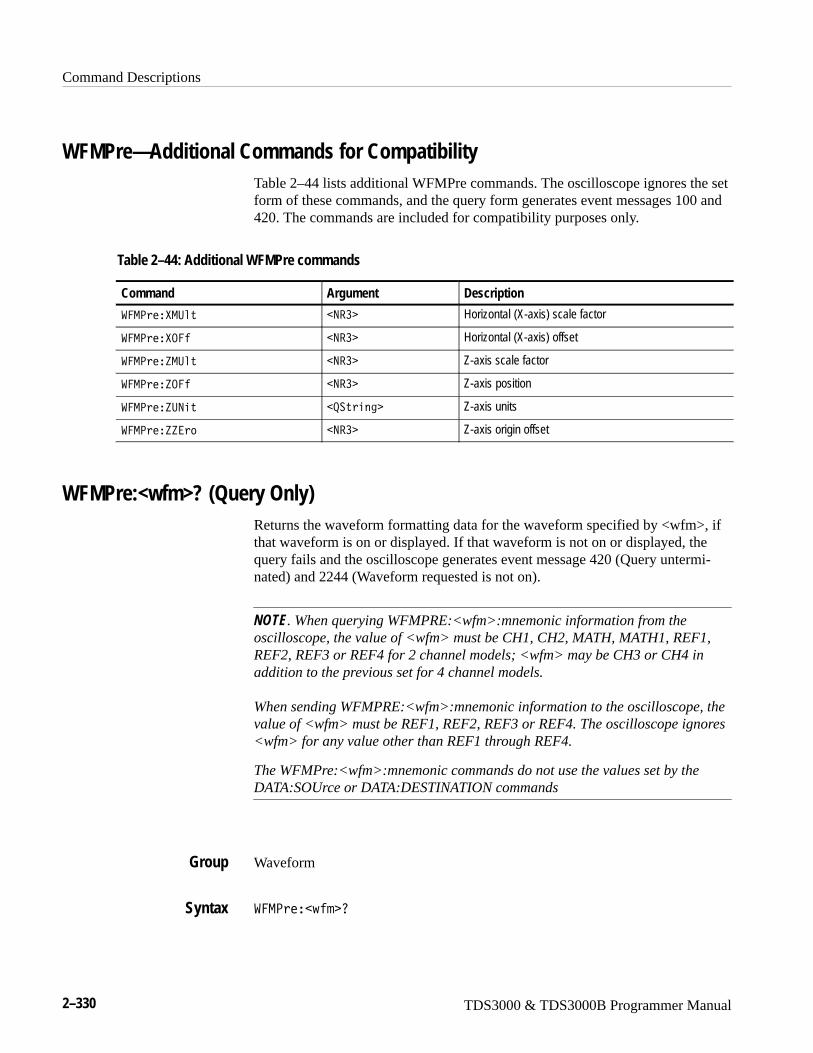
Command Descriptions
2–330 TDS3000 & TDS3000B Programmer Manual
WFMPre—Additional Commands for CompatibilityTable 2–44 lists additional WFMPre commands. The oscilloscope ignores the setform of these commands, and the query form generates event messages 100 and420. The commands are included for compatibility purposes only.
Table 2–44: Additional WFMPre commands
Command Argument Description
��-<���-:�� �9�� Horizontal (X-axis) scale factor
��-<���.�� �9�� Horizontal (X-axis) offset
��-<��P-:�� �9�� Z-axis scale factor
��-<��P.�� �9�� Z-axis position
��-<��P:9�� �+����3 Z-axis units
��-<��PP� �9�� Z-axis origin offset
WFMPre:<wfm>? (Query Only)Returns the waveform formatting data for the waveform specified by <wfm>, ifthat waveform is on or displayed. If that waveform is not on or displayed, thequery fails and the oscilloscope generates event message 420 (Query untermi-nated) and 2244 (Waveform requested is not on).
NOTE. When querying WFMPRE:<wfm>:mnemonic information from theoscilloscope, the value of <wfm> must be CH1, CH2, MATH, MATH1, REF1,REF2, REF3 or REF4 for 2 channel models; <wfm> may be CH3 or CH4 inaddition to the previous set for 4 channel models.
When sending WFMPRE:<wfm>:mnemonic information to the oscilloscope, thevalue of <wfm> must be REF1, REF2, REF3 or REF4. The oscilloscope ignores<wfm> for any value other than REF1 through REF4.
The WFMPre:<wfm>:mnemonic commands do not use the values set by theDATA:SOUrce or DATA:DESTINATION commands
Waveform
��-<���J�� 0
Group
Syntax
Command Descriptions
TDS3000 & TDS3000B Programmer Manual 2–331
The format of the response is:
:WFMPre:�J�� ���6/��+����3 A<5U�-5�#��9��"�E�$A9�U<���9�� A�692��9�� A<5U.����9�� A�P���9�� A�:9����+����3 A
E-:����9�� AEP���9�� AE.����9�� AE:9����+����3
��-<��� ��0
might return���-<��� �����6/�L M���/ �2,4���3����;�W���[1�>��I�;�WI��[1�>�
�;;;;�4���������4����1�LA<5U�-5�EA9�U<5�H;;A�69 ��I�;�WVA<5U.��
;A�P��.�WI�;�WIA�:965�L�LAE-:85�I�;�W�AEP��.�;�;�;AE.���G�T��AE:@
965�L�L
WFMPre?
WFMPre:<wfm>:NR_PtThe set form of this command sets the record length of the reference waveformspecified by source/destination waveform. Allowable record lengths are 500 and10000.
The query form of this command returns the number of points that will bereturned by the next CURVe query. The number of points is the greater of theabsolute value of (DATa:STOP – DATA:STARt) +1, or the record length of thesource waveform specified by DATA:SOUrce. If the source waveform is not onor displayed, the query generates an error and returns event code 2244.
Waveform
��-<���J�� �9�U<��#�G;;�"��;;;;�$
��-<���J�� �9�U<�0
�J�� specifies the source or destination waveform; refer to page 2–330 for adescription of <wfm>.
�;;;; sets the record length to 10,000 points.
�;;;; sets the record length to 10,000 points.
Returns
Example
Related Commands
Group
Syntax
Arguments
Command Descriptions
2–332 TDS3000 & TDS3000B Programmer Manual
��-<���J�� �9�U<�0
returns the number of waveform points in the next CURVE query.
DATa:ENCdg, WFMPre:BYT_Or, WFMPre:BN_Fmt
WFMPre:<wfm>:PT_FmtSame as WFMPre:PT_Fmt, with the exception that <wfm> specifies thesource/destination waveform instead of DATA:SOURCE and DATA:DESTINA-TION.
WFMPre:<wfm>:PT_OffSame as WFMPre:PT_Off, with the exception that <wfm> specifies thesource/destination waveform instead of DATA:SOURCE and DATA:DESTINA-TION.
WFMPre:<wfm>:WFId? (Query Only)Same as WFMPre:WFId, with the exception that <wfm> specifies the sourcewaveform instead of DATA:SOURCE.
WFMPre:<wfm>:XINcrSame as WFMPre:XINcr, with the exception that <wfm> specifies the source/destination waveform instead of DATA:SOURCE and DATA:DESTINATION.
WFMPre:<wfm>:XUNitSame as WFMPre:XUNit, with the exception that <wfm> specifies the source/destination waveform instead of DATA:SOURCE and DATA:DESTINATION.
WFMPre:<wfm>:XZEroSame as WFMPre:XZEro, with the exception that <wfm> specifies thesource/destination waveform instead of DATA:SOURCE and DATA:DESTINA-TION.
Examples
Related Commands
Command Descriptions
TDS3000 & TDS3000B Programmer Manual 2–333
WFMPre:<wfm>:YMUltSame as WFMPre:YMUlt, with the exception that <wfm> specifies thesource/destination waveform instead of DATA:SOURCE and DATA:DESTINA-TION.
WFMPre:<wfm>:YOFfSame as WFMPre:YOFf, with the exception that <wfm> specifies the source/destination waveform instead of DATA:SOURCE and DATA:DESTINATION.
WFMPre:<wfm>:YUNitSame as WFMPre:YUNit, with the exception that <wfm> specifies the source/destination waveform instead of DATA:SOURCE and DATA:DESTINATION.
WFMPre:<wfm>:YZEroSame as WFMPre:YZEro, with the exception that <wfm> specifies thesource/destination waveform instead of DATA:SOURCE and DATA:DESTINA-TION.
ZOOm:HORizontal:POSitionSets or queries the horizontal position when in zoom.
Horizontal
P..���.��F�����<.�������9��
P..���.��F�����<.�����0
�9�� is the horizontal position in percent of record. Position range is from 0%to 100%.
P..-��.�6P.95�8�<.�656.90
might return �P..-��.�6P.95�8�<.�656.9�G�;�W�
Group
Syntax
Arguments
Examples
Command Descriptions
2–334 TDS3000 & TDS3000B Programmer Manual
ZOOm:HORizontal:SCAleSets or queries the horizontal scale when in zoom.
Horizontal
P..���.��F������ �����9��
P..���.��F������ ���0
�9�� is the horizontal scale in seconds.
P..���.��F������ ���
might return �P..-��.�6P.95�8�� �8����;�;
ZOOm:STATESets or queries the zoom state mode.
Horizontal
P..���5�5��#���9�� �"�.9�"�.���$
P..���5�5�0
�.�� or ��9�� = 0 turns off zoom.
�.9 or ��9�� = 1 turns on zoom.
P..���5�5��;
sets the zoom state to off.
P..���5�5�0
might return �P..-��5�5��; for the zoom state.
Group
Syntax
Arguments
Examples
Group
Syntax
Arguments
Examples
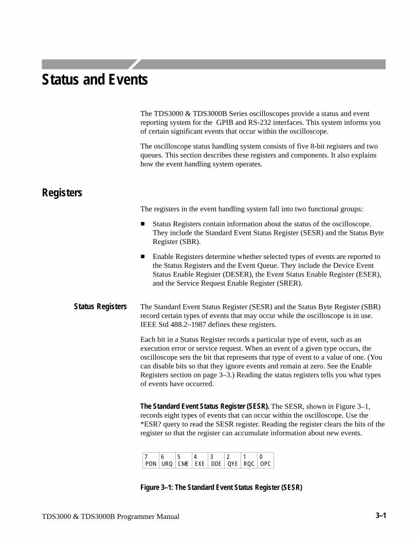
TDS3000 & TDS3000B Programmer Manual 3–1
Status and Events
The TDS3000 & TDS3000B Series oscilloscopes provide a status and eventreporting system for the GPIB and RS-232 interfaces. This system informs youof certain significant events that occur within the oscilloscope.
The oscilloscope status handling system consists of five 8-bit registers and twoqueues. This section describes these registers and components. It also explainshow the event handling system operates.
RegistersThe registers in the event handling system fall into two functional groups:
� Status Registers contain information about the status of the oscilloscope.They include the Standard Event Status Register (SESR) and the Status ByteRegister (SBR).
� Enable Registers determine whether selected types of events are reported tothe Status Registers and the Event Queue. They include the Device EventStatus Enable Register (DESER), the Event Status Enable Register (ESER),and the Service Request Enable Register (SRER).
The Standard Event Status Register (SESR) and the Status Byte Register (SBR)record certain types of events that may occur while the oscilloscope is in use.IEEE Std 488.2–1987 defines these registers.
Each bit in a Status Register records a particular type of event, such as anexecution error or service request. When an event of a given type occurs, theoscilloscope sets the bit that represents that type of event to a value of one. (Youcan disable bits so that they ignore events and remain at zero. See the EnableRegisters section on page 3–3.) Reading the status registers tells you what typesof events have occurred.
The Standard Event Status Register (SESR). The SESR, shown in Figure 3–1,records eight types of events that can occur within the oscilloscope. Use the*ESR? query to read the SESR register. Reading the register clears the bits of theregister so that the register can accumulate information about new events.
PON URQ CME EXE DDE QYE RQC OPC7 6 5 4 3 2 1 0
Figure 3–1: The Standard Event Status Register (SESR)
Status Registers
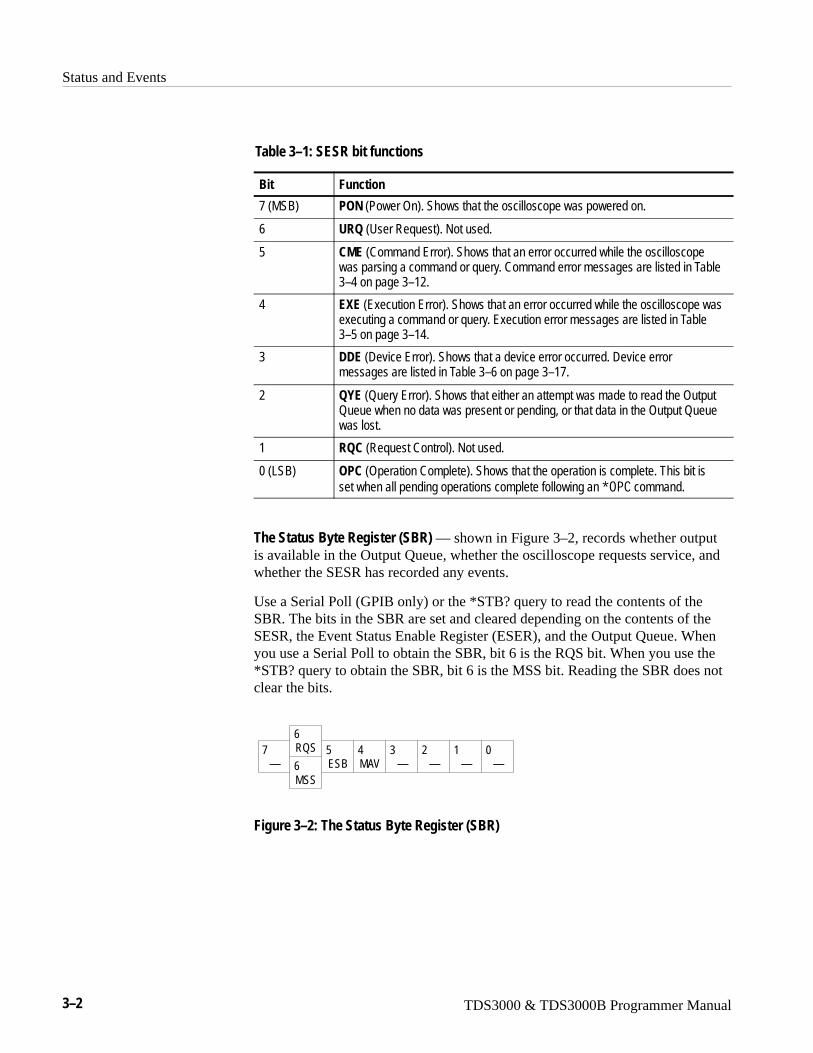
Status and Events
3–2 TDS3000 & TDS3000B Programmer Manual
Table 3–1: SESR bit functions
Bit Function
7 (MSB) PON (Power On). Shows that the oscilloscope was powered on.
6 URQ (User Request). Not used.
5 CME (Command Error). Shows that an error occurred while the oscilloscopewas parsing a command or query. Command error messages are listed in Table3–4 on page 3–12.
4 EXE (Execution Error). Shows that an error occurred while the oscilloscope wasexecuting a command or query. Execution error messages are listed in Table3–5 on page 3–14.
3 DDE (Device Error). Shows that a device error occurred. Device errormessages are listed in Table 3–6 on page 3–17.
2 QYE (Query Error). Shows that either an attempt was made to read the OutputQueue when no data was present or pending, or that data in the Output Queuewas lost.
1 RQC (Request Control). Not used.
0 (LSB) OPC (Operation Complete). Shows that the operation is complete. This bit isset when all pending operations complete following an C.< command.
The Status Byte Register (SBR) — shown in Figure 3–2, records whether outputis available in the Output Queue, whether the oscilloscope requests service, andwhether the SESR has recorded any events.
Use a Serial Poll (GPIB only) or the *STB? query to read the contents of theSBR. The bits in the SBR are set and cleared depending on the contents of theSESR, the Event Status Enable Register (ESER), and the Output Queue. Whenyou use a Serial Poll to obtain the SBR, bit 6 is the RQS bit. When you use the*STB? query to obtain the SBR, bit 6 is the MSS bit. Reading the SBR does notclear the bits.
—RQS
ESB MAV — — — —MSS
76
5 4 3 2 1 06
Figure 3–2: The Status Byte Register (SBR)
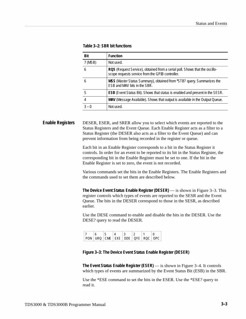
Status and Events
TDS3000 & TDS3000B Programmer Manual 3–3
Table 3–2: SBR bit functions
Bit Function
7 (MSB) Not used.
6 RQS (Request Service), obtained from a serial poll. Shows that the oscillo-scope requests service from the GPIB controller.
6 MSS (Master Status Summary), obtained from *STB? query. Summarizes theESB and MAV bits in the SBR.
5 ESB (Event Status Bit). Shows that status is enabled and present in the SESR.
4 MAV (Message Available). Shows that output is available in the Output Queue.
3 – 0 Not used.
DESER, ESER, and SRER allow you to select which events are reported to theStatus Registers and the Event Queue. Each Enable Register acts as a filter to aStatus Register (the DESER also acts as a filter to the Event Queue) and canprevent information from being recorded in the register or queue.
Each bit in an Enable Register corresponds to a bit in the Status Register itcontrols. In order for an event to be reported to its bit in the Status Register, thecorresponding bit in the Enable Register must be set to one. If the bit in theEnable Register is set to zero, the event is not recorded.
Various commands set the bits in the Enable Registers. The Enable Registers andthe commands used to set them are described below.
The Device Event Status Enable Register (DESER) — is shown in Figure 3–3. Thisregister controls which types of events are reported to the SESR and the EventQueue. The bits in the DESER correspond to those in the SESR, as describedearlier.
Use the DESE command to enable and disable the bits in the DESER. Use theDESE? query to read the DESER.
PON URQ CME EXE DDE QYE RQC OPC7 6 5 4 3 2 1 0
Figure 3–3: The Device Event Status Enable Register (DESER)
The Event Status Enable Register (ESER) — is shown in Figure 3–4. It controlswhich types of events are summarized by the Event Status Bit (ESB) in the SBR.
Use the *ESE command to set the bits in the ESER. Use the *ESE? query toread it.
Enable Registers
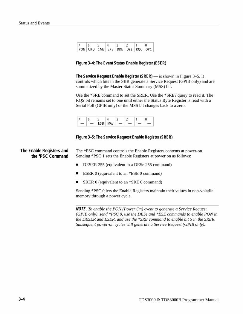
Status and Events
3–4 TDS3000 & TDS3000B Programmer Manual
PON URQ CME EXE DDE QYE RQC OPC7 6 5 4 3 2 1 0
Figure 3–4: The Event Status Enable Register (ESER)
The Service Request Enable Register (SRER) — is shown in Figure 3–5. Itcontrols which bits in the SBR generate a Service Request (GPIB only) and aresummarized by the Master Status Summary (MSS) bit.
Use the *SRE command to set the SRER. Use the *SRE? query to read it. TheRQS bit remains set to one until either the Status Byte Register is read with aSerial Poll (GPIB only) or the MSS bit changes back to a zero.
— — ESB MAV — — — —7 6 5 4 3 2 1 0
Figure 3–5: The Service Request Enable Register (SRER)
The *PSC command controls the Enable Registers contents at power-on.Sending *PSC 1 sets the Enable Registers at power on as follows:
� DESER 255 (equivalent to a DESe 255 command)
� ESER 0 (equivalent to an *ESE 0 command)
� SRER 0 (equivalent to an *SRE 0 command)
Sending *PSC 0 lets the Enable Registers maintain their values in non-volatilememory through a power cycle.
NOTE. To enable the PON (Power On) event to generate a Service Request(GPIB only), send *PSC 0, use the DESe and *ESE commands to enable PON inthe DESER and ESER, and use the *SRE command to enable bit 5 in the SRER.Subsequent power-on cycles will generate a Service Request (GPIB only).
The Enable Registers andthe *PSC Command
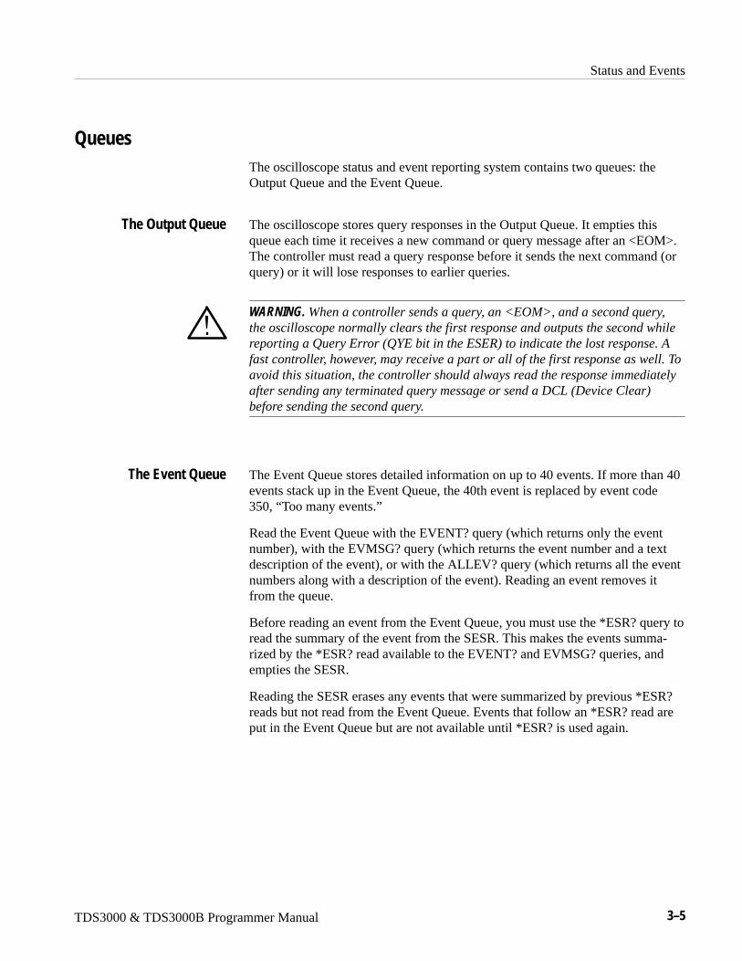
Status and Events
TDS3000 & TDS3000B Programmer Manual 3–5
QueuesThe oscilloscope status and event reporting system contains two queues: theOutput Queue and the Event Queue.
The oscilloscope stores query responses in the Output Queue. It empties thisqueue each time it receives a new command or query message after an <EOM>.The controller must read a query response before it sends the next command (orquery) or it will lose responses to earlier queries.
WARNING. When a controller sends a query, an <EOM>, and a second query,the oscilloscope normally clears the first response and outputs the second whilereporting a Query Error (QYE bit in the ESER) to indicate the lost response. Afast controller, however, may receive a part or all of the first response as well. Toavoid this situation, the controller should always read the response immediatelyafter sending any terminated query message or send a DCL (Device Clear)before sending the second query.
The Event Queue stores detailed information on up to 40 events. If more than 40events stack up in the Event Queue, the 40th event is replaced by event code350, “Too many events.”
Read the Event Queue with the EVENT? query (which returns only the eventnumber), with the EVMSG? query (which returns the event number and a textdescription of the event), or with the ALLEV? query (which returns all the eventnumbers along with a description of the event). Reading an event removes itfrom the queue.
Before reading an event from the Event Queue, you must use the *ESR? query toread the summary of the event from the SESR. This makes the events summa-rized by the *ESR? read available to the EVENT? and EVMSG? queries, andempties the SESR.
Reading the SESR erases any events that were summarized by previous *ESR?reads but not read from the Event Queue. Events that follow an *ESR? read areput in the Event Queue but are not available until *ESR? is used again.
The Output Queue
The Event Queue
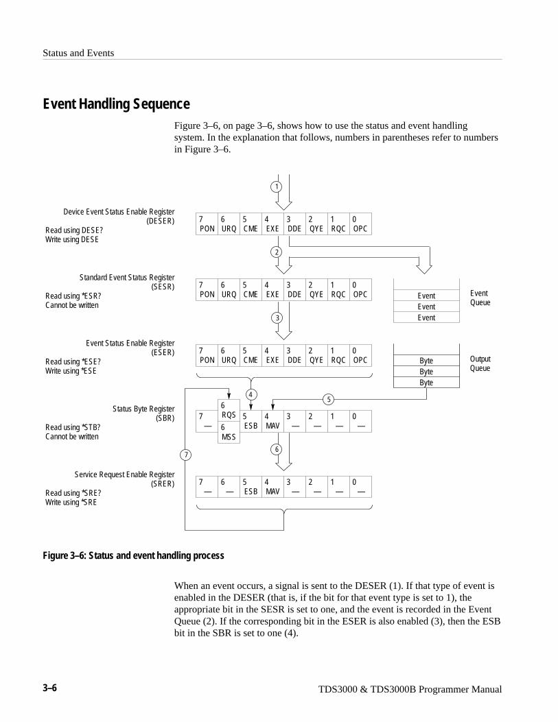
Status and Events
3–6 TDS3000 & TDS3000B Programmer Manual
Event Handling SequenceFigure 3–6, on page 3–6, shows how to use the status and event handlingsystem. In the explanation that follows, numbers in parentheses refer to numbersin Figure 3–6.
Device Event Status Enable Register(DESER)
Read using DESE?Write using DESE
Standard Event Status Register(SESR)
Read using *ESR?Cannot be written
Event Status Enable Register(ESER)
Read using *ESE?Write using *ESE
Status Byte Register(SBR)
Read using *STB?Cannot be written
Service Request Enable Register(SRER)
Read using *SRE?Write using *SRE
EventQueue
OutputQueue
EventEventEvent
ByteByteByte
1
2
3
4
67
5
PON URQ CME EXE DDE QYE RQC OPC7 6 5 4 3 2 1 0
PON URQ CME EXE DDE QYE RQC OPC7 6 5 4 3 2 1 0
PON URQ CME EXE DDE QYE RQC OPC7 6 5 4 3 2 1 0
—RQS
ESB MAV — — — —MSS
76
5 4 3 2 1 06
— — ESB MAV — — — —7 6 5 4 3 2 1 0
Figure 3–6: Status and event handling process
When an event occurs, a signal is sent to the DESER (1). If that type of event isenabled in the DESER (that is, if the bit for that event type is set to 1), theappropriate bit in the SESR is set to one, and the event is recorded in the EventQueue (2). If the corresponding bit in the ESER is also enabled (3), then the ESBbit in the SBR is set to one (4).
Status and Events
TDS3000 & TDS3000B Programmer Manual 3–7
When output is sent to the Output Queue, the MAV bit in the SBR is set toone (5).
When a bit in the SBR is set to one and the corresponding bit in the SRER isenabled (6), the MSS bit in the SBR is set to one and a service request(GPIB only) is generated (7).
Synchronization MethodsAlthough most remote interface commands are completed almost immediatelyafter being received by the oscilloscope, some commands start a process thatrequires more time. For example, once a HARDCOPY START command isexecuted it may be a few seconds before the hard copy operation is complete.Rather than remain idle while the operation is in process, the oscilloscope willcontinue processing other commands. This means that some operations will notbe completed in the order that they were sent.
Sometimes the result of an operation depends on the result of an earlieroperation. A first operation must complete before the next one gets processed.The oscilloscope status and event reporting system provide ways to do this.
For example, a typical application might involve acquiring a single-sequencewaveform and then taking a measurement on the acquired waveform. You coulduse the following command sequence to do this:
��- “Set up single-sequence acquisition” ��8� 5� ���.9
�.�6P.95�8��� .�/8�975��G;;
� +:6���-./����-<8�
� +:6����5.<��5�����+:�9 �
��- “Acquire waveform data” � +:6����5�5��.9
��- “Set up the measurement parameters” -���:��-�95�6--�/�5E<���-<865:/�
-���:��-�95�6--�/��.:� �� ��
��- “Take amplitude measurement on acquired data” -���:��-�95�6--�/���8:�0
The acquisition of the waveform requires extended processing time. It may notfinish before the oscilloscope takes an amplitude measurement (See Figure 3–7).This can result in an incorrect amplitude value.
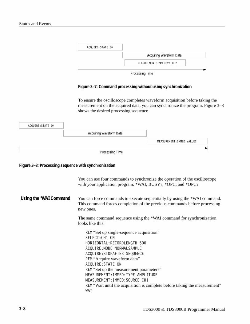
Status and Events
3–8 TDS3000 & TDS3000B Programmer Manual
-���:��-�95�6--�/���8:�0
Processing Time
Acquiring Waveform Data
� +:6����5�5��.9
Figure 3–7: Command processing without using synchronization
To ensure the oscilloscope completes waveform acquisition before taking themeasurement on the acquired data, you can synchronize the program. Figure 3–8shows the desired processing sequence.
-���:��-�95�6--�/���8:�0
Processing Time
Acquiring Waveform Data
� +:6����5�5��.9
Figure 3–8: Processing sequence with synchronization
You can use four commands to synchronize the operation of the oscilloscopewith your application program: *WAI, BUSY?, *OPC, and *OPC?.
You can force commands to execute sequentially by using the *WAI command.This command forces completion of the previous commands before processingnew ones.
The same command sequence using the *WAI command for synchronizationlooks like this:
��- “Set up single-sequence acquisition”��8� 5� ���.9
�.�6P.95�8��� .�/8�975��G;;
� +:6���-./��9.�-�8��-<8�
� +:6����5.<��5�����+:�9 �
��- “Acquire waveform data”� +:6����5�5��.9
��- “Set up the measurement parameters”-���:��-�95�6--�/�5E<���-<865:/�
-���:��-�95�6--�/��.:� �� ��
��- “Wait until the acquisition is complete before taking the measurement”��6
Using the *WAI Command
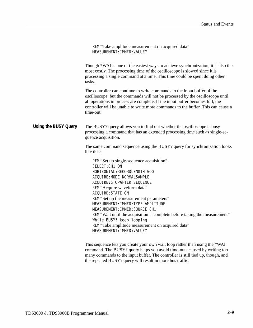
Status and Events
TDS3000 & TDS3000B Programmer Manual 3–9
��- “Take amplitude measurement on acquired data”-���:��-�95�6--�/���8:�0
Though *WAI is one of the easiest ways to achieve synchronization, it is also themost costly. The processing time of the oscilloscope is slowed since it isprocessing a single command at a time. This time could be spent doing othertasks.
The controller can continue to write commands to the input buffer of theoscilloscope, but the commands will not be processed by the oscilloscope untilall operations in process are complete. If the input buffer becomes full, thecontroller will be unable to write more commands to the buffer. This can cause atime-out.
The BUSY? query allows you to find out whether the oscilloscope is busyprocessing a command that has an extended processing time such as single-se-quence acquisition.
The same command sequence using the BUSY? query for synchronization lookslike this:
��- “Set up single-sequence acquisition”��8� 5� ���.9
�.�6P.95�8��� .�/8�975��G;;
� +:6���-./��9.�-�8��-<8�
� +:6����5.<��5�����+:�9 �
��- “Acquire waveform data”� +:6����5�5��.9
��- “Set up the measurement parameters”-���:��-�95�6--�/�5E<���-<865:/�
-���:��-�95�6--�/��.:� �� ��
��- “Wait until the acquisition is complete before taking the measurement”�M����?:�E0�O��4��4��3
��- “Take amplitude measurement on acquired data”-���:��-�95�6--�/���8:�0
This sequence lets you create your own wait loop rather than using the *WAIcommand. The BUSY? query helps you avoid time-outs caused by writing toomany commands to the input buffer. The controller is still tied up, though, andthe repeated BUSY? query will result in more bus traffic.
Using the BUSY Query
Status and Events
3–10 TDS3000 & TDS3000B Programmer Manual
If the corresponding status registers are enabled, the *OPC command sets theOPC bit in the Standard Event Status Register (SESR) when an operation iscomplete. You achieve synchronization by using this command with either aserial poll or service request handler. Use the *OPC command to guarantee allprevious commands have been processed and are applied to all dependentwaveform operations.
Serial Poll Method (GPIB only). Enable the OPC bit in the Device Event StatusEnable Register (DESER) and the Event Status Enable Register (ESER) usingthe DESE and *ESE commands. When the operation is complete, the OPC bit inthe Standard Event Status Register (SESR) will be enabled and the Event StatusBit (ESB) in the Status Byte Register will be enabled.
The same command sequence using the *OPC command for synchronizationwith serial polling looks like this:
��- “Set up single-sequence acquisition” ��8� 5� ���.9
�.�6P.95�8��� .�/8�975��G;;
� +:6���-./����-<8�
� +:6����5.<��5�����+:�9 �
��- “Enable the status registers” /�����
C�����
C����;
��- “Acquire waveform data” � +:6����5�5��.9
��- “Set up the measurement parameters” -���:��-�95�6--�/�5E<���-<865:/�
-���:��-�95�6--�/��.:� �� ��
��- “Wait until the acquisition is complete before taking the measurement” C.<
�M����������4���!�;��O��4��4��3
��- “Take amplitude measurement on acquired data” -���:��-�95�6--�/���8:�0
This technique requires less bus traffic than did looping on ?:�E0.
Service Request Method (GPIB only). Enable the OPC bit in the Device EventStatus Enable Register (DESER) and the Event Status Enable Register (ESER)using the DESE and *ESE commands. You can also enable service requests bysetting the ESB bit in the Service Request Enable Register (SRER) using the*SRE command. When the operation is complete, a Service Request will begenerated.
Using the *OPC Command
Status and Events
TDS3000 & TDS3000B Programmer Manual 3–11
The same command sequence using the *OPC command for synchronizationlooks like this:
��- “Set up single-sequence acquisition” ��8� 5� ���.9
�.�6P.95�8��� .�/8�975��G;;
� +:6���-./����-<8�
� +:6����5.<��5�����+:�9 �
��- “Enable the status registers” /�����
C�����
C�����H
��- “Acquire waveform data” � +:6����5�5��.9
��- “Set up the measurement parameters” -���:��-�95�6--�/�5E<���-<865:/�
-���:��-�95�6--�/��.:� �� ��
��- “Wait until the acquisition is complete before taking the measurement” C.<
<3���2����J�1�1�����������O���,2M�������O����M�
1�>�2����5M����+��JM������2���������,4����M������O����1
��,���2�������M������O�
��- “Take amplitude measurement on acquired data” -���:��-�95�6--�/���8:�0
This technique is more efficient but requires more sophisticated programming.
The *OPC? query places a 1 in the Output Queue once an operation is complete.A timeout could occur if you try to read the output queue before there is any datain it.
The same command sequence using the *OPC? query for synchronization lookslike this:
��- “Set up single-sequence acquisition” ��8� 5� ���.9
�.�6P.95�8��� .�/8�975��G;;
� +:6���-./����-<8�
� +:6����5.<��5�����+:�9 �
��- “Acquire waveform data” � +:6����5�5��.9
��- “Set up the measurement parameters” -���:��-�95�6--�/�5E<���-<865:/�
-���:��-�95�6--�/��.:� �� ��
��- “Wait until the acquisition is complete before taking the measurement” C.< 0
���������1����.,�4,��+,�,��
Using the *OPC? Query
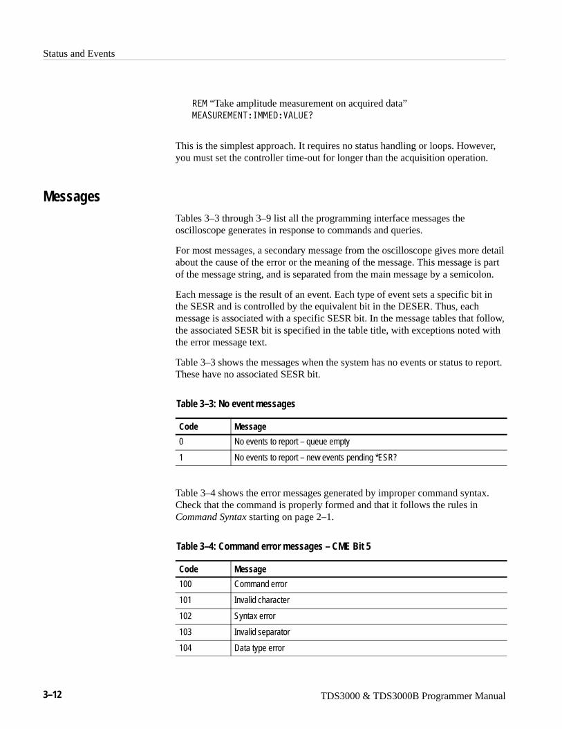
Status and Events
3–12 TDS3000 & TDS3000B Programmer Manual
��- “Take amplitude measurement on acquired data” -���:��-�95�6--�/���8:�0
This is the simplest approach. It requires no status handling or loops. However,you must set the controller time-out for longer than the acquisition operation.
MessagesTables 3–3 through 3–9 list all the programming interface messages theoscilloscope generates in response to commands and queries.
For most messages, a secondary message from the oscilloscope gives more detailabout the cause of the error or the meaning of the message. This message is partof the message string, and is separated from the main message by a semicolon.
Each message is the result of an event. Each type of event sets a specific bit inthe SESR and is controlled by the equivalent bit in the DESER. Thus, eachmessage is associated with a specific SESR bit. In the message tables that follow,the associated SESR bit is specified in the table title, with exceptions noted withthe error message text.
Table 3–3 shows the messages when the system has no events or status to report.These have no associated SESR bit.
Table 3–3: No event messages
Code Message
0 No events to report – queue empty
1 No events to report – new events pending *ESR?
Table 3–4 shows the error messages generated by improper command syntax.Check that the command is properly formed and that it follows the rules inCommand Syntax starting on page 2–1.
Table 3–4: Command error messages – CME Bit 5
Code Message
100 Command error
101 Invalid character
102 Syntax error
103 Invalid separator
104 Data type error
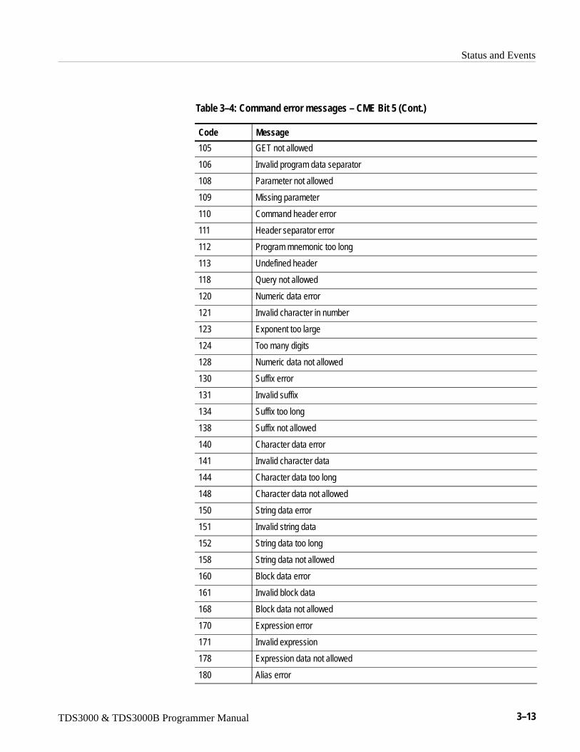
Status and Events
TDS3000 & TDS3000B Programmer Manual 3–13
Table 3–4: Command error messages – CME Bit 5 (Cont.)
Code Message
105 GET not allowed
106 Invalid program data separator
108 Parameter not allowed
109 Missing parameter
110 Command header error
111 Header separator error
112 Program mnemonic too long
113 Undefined header
118 Query not allowed
120 Numeric data error
121 Invalid character in number
123 Exponent too large
124 Too many digits
128 Numeric data not allowed
130 Suffix error
131 Invalid suffix
134 Suffix too long
138 Suffix not allowed
140 Character data error
141 Invalid character data
144 Character data too long
148 Character data not allowed
150 String data error
151 Invalid string data
152 String data too long
158 String data not allowed
160 Block data error
161 Invalid block data
168 Block data not allowed
170 Expression error
171 Invalid expression
178 Expression data not allowed
180 Alias error
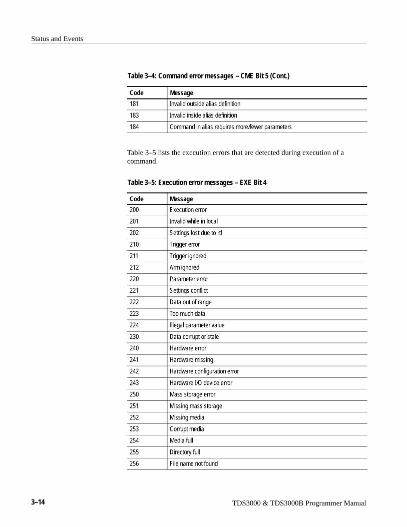
Status and Events
3–14 TDS3000 & TDS3000B Programmer Manual
Table 3–4: Command error messages – CME Bit 5 (Cont.)
Code Message
181 Invalid outside alias definition
183 Invalid inside alias definition
184 Command in alias requires more/fewer parameters
Table 3–5 lists the execution errors that are detected during execution of acommand.
Table 3–5: Execution error messages – EXE Bit 4
Code Message
200 Execution error
201 Invalid while in local
202 Settings lost due to rtl
210 Trigger error
211 Trigger ignored
212 Arm ignored
220 Parameter error
221 Settings conflict
222 Data out of range
223 Too much data
224 Illegal parameter value
230 Data corrupt or stale
240 Hardware error
241 Hardware missing
242 Hardware configuration error
243 Hardware I/O device error
250 Mass storage error
251 Missing mass storage
252 Missing media
253 Corrupt media
254 Media full
255 Directory full
256 File name not found
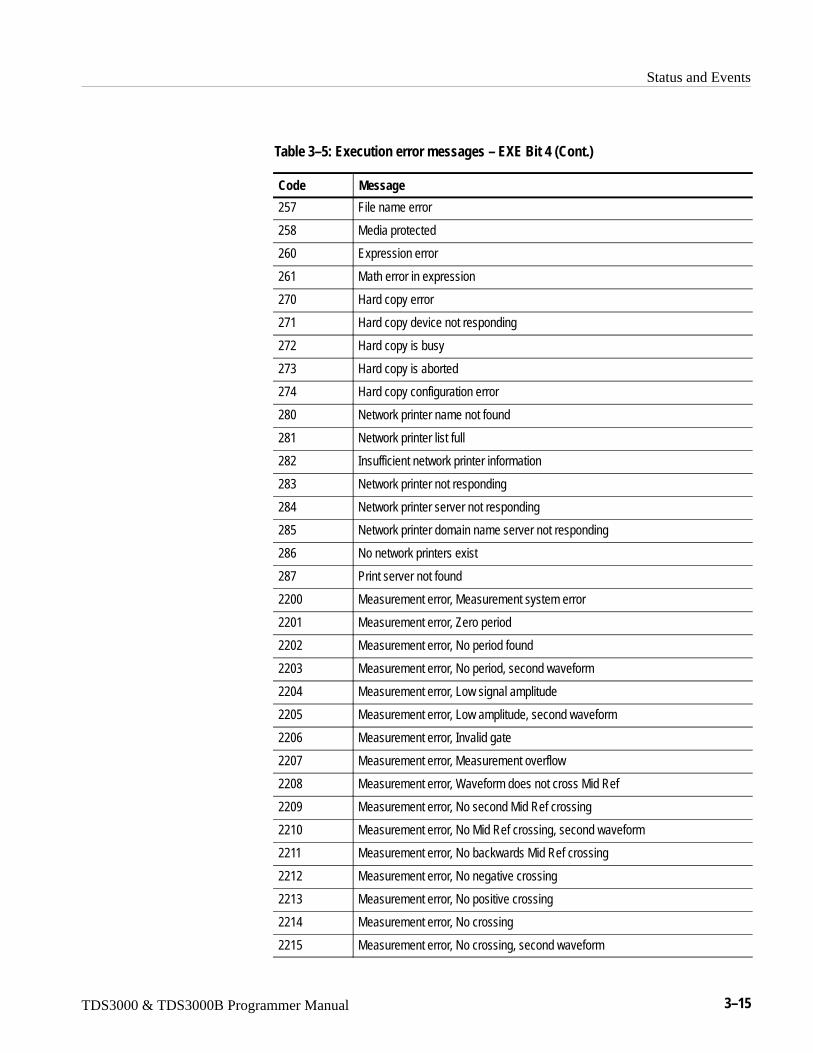
Status and Events
TDS3000 & TDS3000B Programmer Manual 3–15
Table 3–5: Execution error messages – EXE Bit 4 (Cont.)
Code Message
257 File name error
258 Media protected
260 Expression error
261 Math error in expression
270 Hard copy error
271 Hard copy device not responding
272 Hard copy is busy
273 Hard copy is aborted
274 Hard copy configuration error
280 Network printer name not found
281 Network printer list full
282 Insufficient network printer information
283 Network printer not responding
284 Network printer server not responding
285 Network printer domain name server not responding
286 No network printers exist
287 Print server not found
2200 Measurement error, Measurement system error
2201 Measurement error, Zero period
2202 Measurement error, No period found
2203 Measurement error, No period, second waveform
2204 Measurement error, Low signal amplitude
2205 Measurement error, Low amplitude, second waveform
2206 Measurement error, Invalid gate
2207 Measurement error, Measurement overflow
2208 Measurement error, Waveform does not cross Mid Ref
2209 Measurement error, No second Mid Ref crossing
2210 Measurement error, No Mid Ref crossing, second waveform
2211 Measurement error, No backwards Mid Ref crossing
2212 Measurement error, No negative crossing
2213 Measurement error, No positive crossing
2214 Measurement error, No crossing
2215 Measurement error, No crossing, second waveform
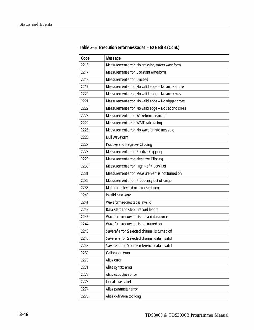
Status and Events
3–16 TDS3000 & TDS3000B Programmer Manual
Table 3–5: Execution error messages – EXE Bit 4 (Cont.)
Code Message
2216 Measurement error, No crossing, target waveform
2217 Measurement error, Constant waveform
2218 Measurement error, Unused
2219 Measurement error, No valid edge – No arm sample
2220 Measurement error, No valid edge – No arm cross
2221 Measurement error, No valid edge – No trigger cross
2222 Measurement error, No valid edge – No second cross
2223 Measurement error, Waveform mismatch
2224 Measurement error, WAIT calculating
2225 Measurement error, No waveform to measure
2226 Null Waveform
2227 Positive and Negative Clipping
2228 Measurement error, Positive Clipping
2229 Measurement error, Negative Clipping
2230 Measurement error, High Ref < Low Ref
2231 Measurement error, Measurement is not turned on
2232 Measurement error, Frequency out of range
2235 Math error, Invalid math description
2240 Invalid password
2241 Waveform requested is invalid
2242 Data start and stop > record length
2243 Waveform requested is not a data source
2244 Waveform requested is not turned on
2245 Saveref error, Selected channel is turned off
2246 Saveref error, Selected channel data invalid
2248 Saveref error, Source reference data invalid
2260 Calibration error
2270 Alias error
2271 Alias syntax error
2272 Alias execution error
2273 Illegal alias label
2274 Alias parameter error
2275 Alias definition too long
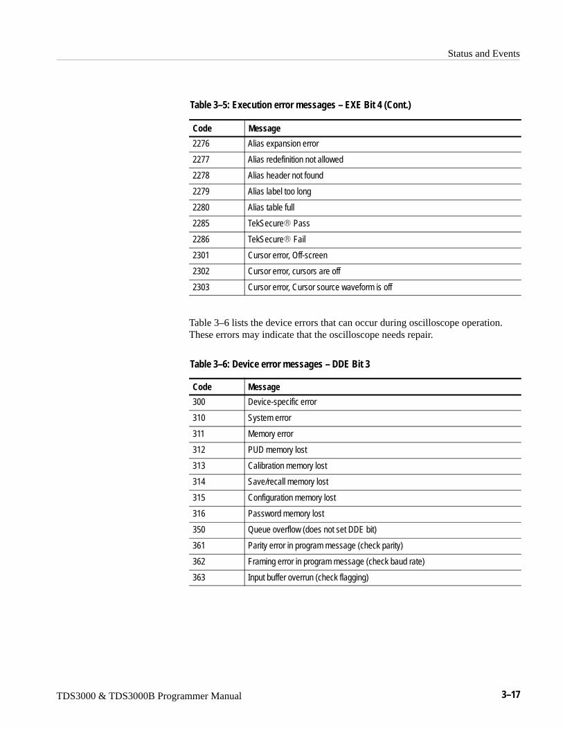
Status and Events
TDS3000 & TDS3000B Programmer Manual 3–17
Table 3–5: Execution error messages – EXE Bit 4 (Cont.)
Code Message
2276 Alias expansion error
2277 Alias redefinition not allowed
2278 Alias header not found
2279 Alias label too long
2280 Alias table full
2285 TekSecure� Pass
2286 TekSecure� Fail
2301 Cursor error, Off-screen
2302 Cursor error, cursors are off
2303 Cursor error, Cursor source waveform is off
Table 3–6 lists the device errors that can occur during oscilloscope operation.These errors may indicate that the oscilloscope needs repair.
Table 3–6: Device error messages – DDE Bit 3
Code Message
300 Device-specific error
310 System error
311 Memory error
312 PUD memory lost
313 Calibration memory lost
314 Save/recall memory lost
315 Configuration memory lost
316 Password memory lost
350 Queue overflow (does not set DDE bit)
361 Parity error in program message (check parity)
362 Framing error in program message (check baud rate)
363 Input buffer overrun (check flagging)

Status and Events
3–18 TDS3000 & TDS3000B Programmer Manual
Table 3–7 lists the system event messages. These messages are generatedwhenever certain system conditions occur.
Table 3–7: System event messages
Code Message
400 Query event
401 Power on (PON bit 7 set)
402 Operation complete (OPC bit 0 set)
403 User request (URQ bit 6 set)
404 Power fail (DDE bit 3 set)
405 Request control
410 Query INTERRUPTED (QYE bit 2 set)
420 Query UNTERMINATED (QYE bit 2 set)
430 Query DEADLOCKED (QYE bit 2 set)
440 Query UNTERMINATED after indefinite response (QYE bit 2 set)
Table 3–8 lists warning messages that do not interrupt the flow of commandexecution. These notify you that you may get unexpected results.
Table 3–8: Execution warning messages – EXE Bit 4
Code Message
500 Execution warning
510 String data too long, truncated
525 Parameter underrange
526 Parameter overrange
527 Parameter rounded
528 Parameter out of range
530 Data stop > stop, Values swapped internally
531 Data stop > record length, Curve truncated
532 Curve data too long, Curve truncated
540 Measurement warning
541 Measurement warning, Low signal amplitude
542 Measurement warning, Unstable histogram
543 Measurement warning, Low resolution
544 Measurement warning, Uncertain edge

Status and Events
TDS3000 & TDS3000B Programmer Manual 3–19
Table 3–8: Execution warning messages – EXE Bit 4 (Cont.)
Code Message
545 Measurement warning, Invalid in minmax
546 Measurement warning, Need 3 edges
547 Measurement warning, Clipping positive/negative
548 Measurement warning, Clipping positive
549 Measurement warning, Clipping negative
Table 3–9 shows internal errors that indicate an internal fault in the oscilloscope.
Table 3–9: Internal warning messages
Code Message
600 Internal warning
630 Internal warning, 50 � overload

Status and Events
3–20 TDS3000 & TDS3000B Programmer Manual

TDS3000 & TDS3000B Programmer Manual 4–1
Programming Examples
The example programs illustrate methods you can use to control the oscilloscopefrom the GPIB or RS-232 interface. The diskette that comes with this manualcontains listings for these programs.
The programs run on a PC compatible system equipped with a Tektronixinstument or (National Instruments) GPIB board and associated drivers or anRS-232 (COM) serial port. For example, the GPIB programs work with aTektronix S3FG220 or (National Instruments AT–GPIB/TNT) GPIB package(see Figure 4–1).
(Tektronix S3FG220 orNational Instruments
AT-GPIB/TNT)
PC compatible
and
GPIB board
or
Figure 4–1: Equipment needed to run the GPIB and RS-232 example programs
Programming Examples
4–2 TDS3000 & TDS3000B Programmer Manual
GPIB ExamplesAll the example GPIB programs assume that the GPIB system recognizes theoscilloscope as DEV1 and the PC (controller) as GPIB0. You can assign thesenames using different methods depending on your operating system. In WindowsNT, you can assign these names through the Control PanelGPIBConfigureButton. In Windows 95, you can assign the GPIB name through the ControlPanelSystem IconDevice ManagerDisplayAT–GPIB/TNTGPIB.
The example GPIB software includes:
-���: measures a parameter of an oscilloscope waveform.
.--: shows communication between the controller and the oscilloscope.
7�5��-: reads a waveform from the oscilloscope and stores its time and voltagevalues in a file.
58: a talker-listener program.
The example programs diskette contains programs written in Microsoft VisualBASIC 6.0 and Microsoft Visual C ++ 6.0.
Visual Basic code is found in the V–BASIC6 directory and Visual C ++ code is inV–CPLUS6. Within both of these directories, executable versions of theprograms are in the PROGRAMS subdirectory. Source versions are in theSOURCES subdirectory.
A ���/-� file in each directory has the latest documentation.
If you wish to develop code, you will need to use files that come with the GPIBsystem. Specifically, the GPIB Visual Basic programs use GPIBIO.BAS andNIGLOBAL.BAS. The Visual C++ programs use DECL_32.h and GPIB_32.obj.
NOTE. The GPIB programs you compile in the Sources directory work with theTektronix S3FG220 (National Instruments AT–GPIB/TNT) GPIB system. It maytake extra steps or changes to get them to work with older Tektronix GURU andother GPIB systems.
Compiling the ExamplePrograms
Programming Examples
TDS3000 & TDS3000B Programmer Manual 4–3
Compiling and Linking Your Example Visual C++ Programs. To make an executablefor any of the files (for example, AUTOSET project), perform the followingsteps:
1. Install Visual C++.
2. Install the Tektronix S3FG220 or (National Instruments AT–GPIB/TNT)GPIB board and drivers. Remember to identify the GPIB device as DEV1,see GPIB Examples section for more information, and to reboot your PC toinitialize the GPIB drivers.
3. Copy the files from the examples diskette to your hard disk. For example, ifthe current drive is hard disk C, you want to store the examples in drive C,and the examples diskette is in drive B:
a. Invoke the Microsoft Explorer program.
b. Drag the b:\GPIB\V–CPLUS6\SOURCES folder onto the C drive.
4. Set up a project for each example. The example below creates a new projectfor the AUTOSET example program.
a. Invoke Visual C++.
b. Select “New” from the File menu.
c. Choose “New Win32 Console Application”
d. Give the project a name, for example, AutoSet.
e. Select “Empty Project”.
f. Add the following files to the project from the Project menu:
autoset.c
gpibwrite.c
gpiberr.c
gpibread.c
gpibwait.c
decl–32.h (provided by National Instruments)
gpib–32.obj (provided by National Instruments)
5. To compile and link your sample program, choose “BUILD ALL” from theBuild menu.
6. To run the sample program, choose RUN from the “BUILD” menu.
Programming Examples
4–4 TDS3000 & TDS3000B Programmer Manual
Compiling and Linking Your Example Visual BASIC Programs. To make anexecutable for any of the following files, perform the following steps:
1. Install Visual BASIC 6.0
2. Install the Tektronix S3FG220 or (National Instruments AT–GPIB/TNT)GPIB board and drivers. Remember to identify the GPIB device as DEV1,see GPIB Examples section for more information, and to reboot your PC toinitialize the GPIB drivers.
3. Copy the files from the examples diskette to your hard disk. For example, ifthe current drive is hard disk C, you want to store the examples in drive C,and the examples diskette is in drive B:
a. Invoke the Microsoft Explorer program.
b. Drag the b:\GPIB\V–BASIC6\SOURCES folder onto the C drive.
4. Compile and run the source code simply by:
a. Open the SOURCES folder.
b. Find the “project” you are interested in.
c. Open the project folder.
d. Open the filename.vbp within the project folder. This will invoketheVisual Basic program and also the project.
e. Press the Start button from Visual Basic’s menu. This will compile andrun your program.
You will find that each project has a form <filename.frm> and three modulesexcept for the getWfm project which has four modules <filename.bas>. Twomodules are from National Instruments – �?6?W�H�?�����1�9678.?�8�?���
NOTE. The example programs disable front-panel operation while they arerunning, and reenable it when they terminate. If your program terminatesprematurely, front-panel operation may remain disabled. To re-enable front-pan-el operation, do one of the following: cycle power on the oscilloscope or sendthe GPIB command :98. S��88 to unlock the front panel. You can send the:98. S��88 command with the TL program included in your example programsdisk.
Programming Examples
TDS3000 & TDS3000B Programmer Manual 4–5
RS-232 ExamplesThe example RS-232 programs use the COM port of a PC. The example RS-232software includes:
-���: measures a parameter of an oscilloscope waveform.
.--: shows communication between the personal computer and the oscillo-scope.
7�5��-: reads a waveform from the oscilloscope and stores its time and voltagevalues in a file.
58: a talker-listener program.
The example programs diskette contains programs written in Microsoft VisualBasic 6.0.
Visual Basic code is found in the V–BASIC6 directory. Within both of thesedirectories, executable versions of the programs are in the PROGRAMSsubdirectory. Source versions are in the SOURCES subdirectory.
A ���/-� file in each directory has the latest documentation.
NOTE. The programs you compile in the Sources directory may require extrasteps or changes to get them to work with your system.
Compiling and Linking Your Example Programs. To make an executable for any ofthe following files, perform the following:
1. Install Visual Basic 6.0.
2. Connect the oscilloscope to the COM2 port of the personal computer. Set theoscilloscope RS-232 parameters to the default values.
3. Copy the files from the examples diskette to your hard disk. For example, ifthe current drive is hard disk C, you want to store the examples in drive C,and the examples diskette is in drive B:
a. Invoke the Microsoft Explorer program.
b. Drag the b:\RS232\SOURCES\V–Basic6 folder onto the C drive.
4. Compile and run the source code:
a. Open the SOURCES folder.
b. Find the “project” you are interested in.
Compiling the ExamplePrograms
Programming Examples
4–6 TDS3000 & TDS3000B Programmer Manual
c. Open the project folder.
d. Open the filename.vbp within the project folder, this will invoke VisualBasic program and also the project.
e. Press the Start button from Visual Basic’s menu. This will compile andrun your program.
You will find that each project has a form <filename.frm> and a modules<finename.bas>.
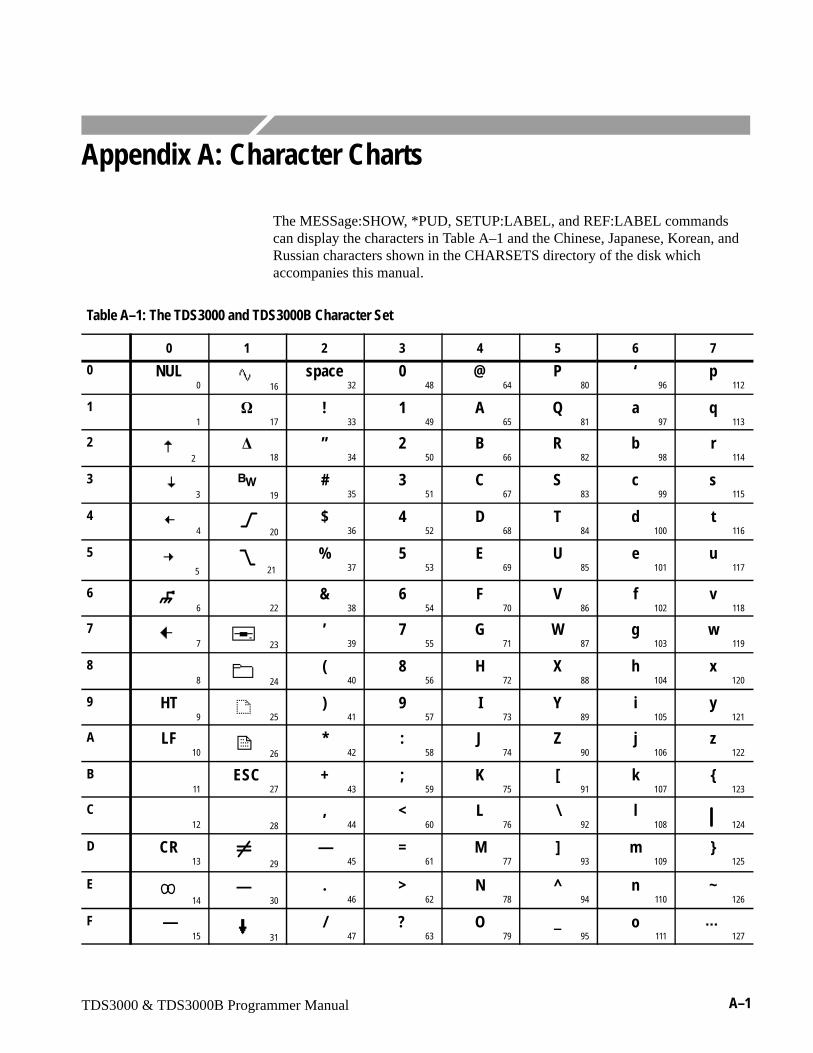
TDS3000 & TDS3000B Programmer Manual A–1
Appendix A: Character Charts
The MESSage:SHOW, *PUD, SETUP:LABEL, and REF:LABEL commandscan display the characters in Table A–1 and the Chinese, Japanese, Korean, andRussian characters shown in the CHARSETS directory of the disk whichaccompanies this manual.
Table A–1: The TDS3000 and TDS3000B Character Set
0 1 2 3 4 5 6 7
0 NUL0
16
space32
048
@64
P80
‘96
p112
1 1
�17
!33
149
A65
Q81
a97
q113
2 2
�18
”34
250
B66
R82
b98
r114
3 3
�� 19
#35
351
C67
S83
c99
s115
44
20
$36
452
D68
T84
d100
t116
5 5
21
%37
553
E69
U85
e101
u117
6 6
�22
&38
654
F70
V86
f102
v118
77 23
’39
755
G71
W87
g103
w119
8 8
24
(40
856
H72
X88
h104
x120
9 HT9
25
)41
957
I73
Y89
i105
y121
A LF10
26
*42
:58
J74
Z90
j106
z122
B 11
ESC27
+43
;59
K75
[91
k107
{123
C 12
28
,44
<60
L76
\92
l108
124
D CR13
29
—45
=61
M77
]93
m109
}125
E 14
—30
.46
>62
N78
^94
n110
~126
F —15
31
/47
?63
O79
_95
o111
127

Appendix A: Character Charts
A–2 TDS3000 & TDS3000B Programmer Manual
Table A–1: The TDS3000 and TDS3000B Character Set (Cont.)
8 9 A B C D E F
0 R1128
144
160176
À192 208
à224 240
1 R2129 145 161 177
Á193
Ñ209
á225
ñ241
2 R3130 146 162 178
Â194
Ò210
â226
ò242
3 R4 131
147 163 179
Ã195
Ó211
ã227
ó243
4132
148 164 180
Ä196
Ô212
ä228
ô244
5 133
149 165 181 197
Õ213 229
õ245
6 134 150 166 182 198
Ö214 230
ö246
7135
151 167 183
Ç199
�215
ç231
�247
8 136
152 168 184
È200
�216
è232 248
9137
153 169 185
É201
Ù217
é233
ù249
A138
154 170 186
Ê202
Ú218
ê234
ú250
B 139 155 171 187
Ë203
Û219
ë235
û251
C 140
156 172 188
Ì204
Ü220
ì236
ü252
D141
157 173 189
Í205 221
í237 253
E 142
158 174 190
Î206 222
î238 254
F143
159 175 191
Ï207
ß223
ï239
ÿ255
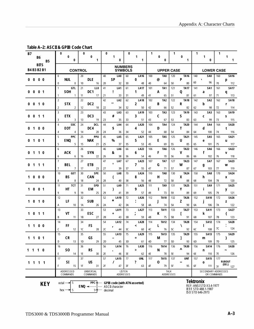
Appendix A: Character Charts
TDS3000 & TDS3000B Programmer Manual A–3
Table A–2: ASCII & GPIB Code ChartB7
B6B5
00
0
00
1
01
0
01
1
10
0
10
1
11
0
11
1
BITSB4 B3 B2 B1 �������
�����
� ���� ��������� ����������
0 0 0 00
NUL0 0
20DLE
10 16
40 LA0SP
20 32
60 LA160
30 48
100 TA0@
40 64
120 TA16P
50 80
140 SA0
60 96
160 SA16p
70 112
0 0 0 11 GTL
SOH1 1
21 LL0DC1
11 17
41 LA1!
21 33
61 LA171
31 49
101 TA1A
41 65
121 TA17Q
51 81
141 SA1a
61 97
161 SA17q
71 113
0 0 1 02
STX2 2
22DC2
12 18
42 LA2
22 34�
62 LA182
32 50
102 TA2B
42 66
122 TA18R
52 82
142 SA2b
62 98
162 SA18r
72 114
0 0 1 13
ETX3 3
23DC3
13 19
43 LA3#
23 35
63 LA193
33 51
103 TA3C
43 67
123 TA19S
53 83
143 SA3c
63 99
163 SA19s
73 115
0 1 0 04 SDC
EOT4 4
24 DCLDC4
14 20
44 LA4$
24 36
64 LA204
34 52
104 TA4D
44 68
124 TA20T
54 84
144 SA4d
64 100
164 SA20t
74 116
0 1 0 15 PPC
ENQ5 5
25 PPUNAK
15 21
45 LA5%
25 37
65 LA215
35 53
105 TA5E
45 69
125 TA21U
55 85
145 SA5e
65 101
165 SA21u
75 117
0 1 1 06
ACK6 6
26SYN
16 22
46 LA6&
26 38
66 LA226
36 54
106 TA6F
46 70
126 TA22V
56 86
146 SA6f
66 102
166 SA22v
76 118
0 1 1 17
BEL7 7
27ETB
17 23
47 LA7
27 39�
67 LA237
37 55
107 TA7G
47 71
127 TA23W
57 87
147 SA7g
67 103
167 SA23w
77 119
1 0 0 010 GET
BS8 8
30 SPECAN
18 24
50 LA8(
28 40
70 LA248
38 56
110 TA8H
48 72
130 TA24X
58 88
150 SA8h
68 104
170 SA24x
78 120
1 0 0 111 TCT
HT9 9
31 SPDEM
19 25
51 LA9)
29 41
71 LA259
39 57
111 TA9I
49 73
131 TA25Y
59 89
151 SA9i
69 105
171 SA25y
79 121
1 0 1 012
LFA 10
32SUB
1A 26
52 LA10
2A 42*
72 LA26
3A 58:
112 TA10J
4A 74
132 TA26Z
5A 90
152 SA10j
6A 106
172 SA26z
7A 122
1 0 1 113
VTB 11
33ESC
1B 27
53 LA11+
2B 43
73 LA27
3B 59;
113 TA11K
4B 75
133 TA27[
5B 91
153 SA11k
6B 107
173 SA27{
7B 123
1 1 0 014
FFC 12
34FS
1C 28
54 LA12
2C 44,
74 LA28<
3C 60
114 TA12L
4C 76
134 TA28\
5C 92
154 SA12l
6C 108
174 SA28
7C 124
1 1 0 115
CRD 13
35GS
1D 29
55 LA13–
2D 45
75 LA29=
3D 61
115 TA13M
4D 77
135 TA29]
5D 93
155 SA13m
6D 109
175 SA29}
7D 125
1 1 1 016
SOE 14
36RS
1E 30
56 LA14
2E 46.
76 LA30>
3E 62
116 TA14N
4E 78
136 TA30
5E 94^
156 SA14n
6E 110
176 SA30
7E 126~
1 1 1 117
SIF 15
37US
1F 31
57 LA15/
2F 47
77 UNL?
3F 63
117 TA15O
4F 79
137 UNT
5F 95–
157 SA15o
6F 111
177
7F 127
RUBOUT(DEL)
ADDRESSEDCOMMANDS
UNIVERSALCOMMANDS
LISTENADDRESSES
TALKADDRESSES
SECONDARY ADDRESSESOR COMMANDS
TektronixREF: ANSI STD X3.4-1977IEEE STD 488.1-1987ISO STD 646-2973
5 PPCENQ
5 5
GPIB code (with ATN asserted)
hex
octal
decimalASCII characterKEY

Appendix A: Character Charts
A–4 TDS3000 & TDS3000B Programmer Manual

TDS3000 & TDS3000B Programmer Manual B–1
Appendix B: Reserved Words
The following is a list of the reserved words of the digitizing oscilloscope. Donot use these words for aliases. Capital letters identify the required minimumspelling. Hint: Use the full spelling for the most robust code as the minimumspelling rules may change over time and from model to model.
*CAL*CLS*DDT*ESE*ESR*IDN*LRN*OPC*PSC*PUD*RCL*RST*SAV*SRE*STB*TRG*TST*WAIAABOrtABSoluteACACQUISitionACQuireACTionADCADDADDRessADVancedALIasALLALLEvALLFieldsALLInfoALLLinesALTernating
ALWAYSAMPlitudeANDANOMalyAPPSAREaASCASCIiASETupAUTOAUTOContrastAUTOFitAUTOSetAVErageBBACKLightBACKWardsBANdwidthBATTeryBAUdBEEPBELlBINBIT_NrBJC80BLAckmanharrisBMENU1BMENU2BMENU3BMENU4BMENU5BMENU6BMENU7BMPBMPColorBN_Fmt
BOThBOXBRIghtnessBTRIGBURstBUSYBYBYT_NrBYT_OrCALibrateCAReaCATALOGCENtronicsCH1CH2CH3CH4CLAssCLEARCLEARMenuCLEARSNapshotCLEARSpoolCLOCKCoaxCLOCKSymmetricalCLOCkCMEanCOARSECOLDstartCOLorCOMMunicationCPMPARECOMPLetionCOMPRESSionCONTInueCONFIGCONTRAst
CONTROlCOPyCOUNtCOUPlingCPUCRCRLfCRMsCROSSHairCURSorCURSOR1CURSOR1XCURSOR1YCURSOR2CURSOR2XCURSOR2YCURVeCURrentCUSTomCWDDATEDATaDBDCDEFINEDELEteDELTATimeDELTaDELWarnDELayDESEDESKJETDESKJETColorDESKewDESTinationDHCPBOOTP
DIAgDIRDIREctionDISplayDNSDOMainnameDOTsonlyDPODPU3445DS0ContraDS0DoubleDS0SingleDS0TimingDS1DS1ADS1CDS1RateDS2DS2CoaxDS2RATECoaxDS2RATESymmetricalDS2SymmetricalDS3DS3RateDUALDUEE1CoaxE1SymmetricalE2E3ECLEDGeEDGE1EDGE2EDHEITher
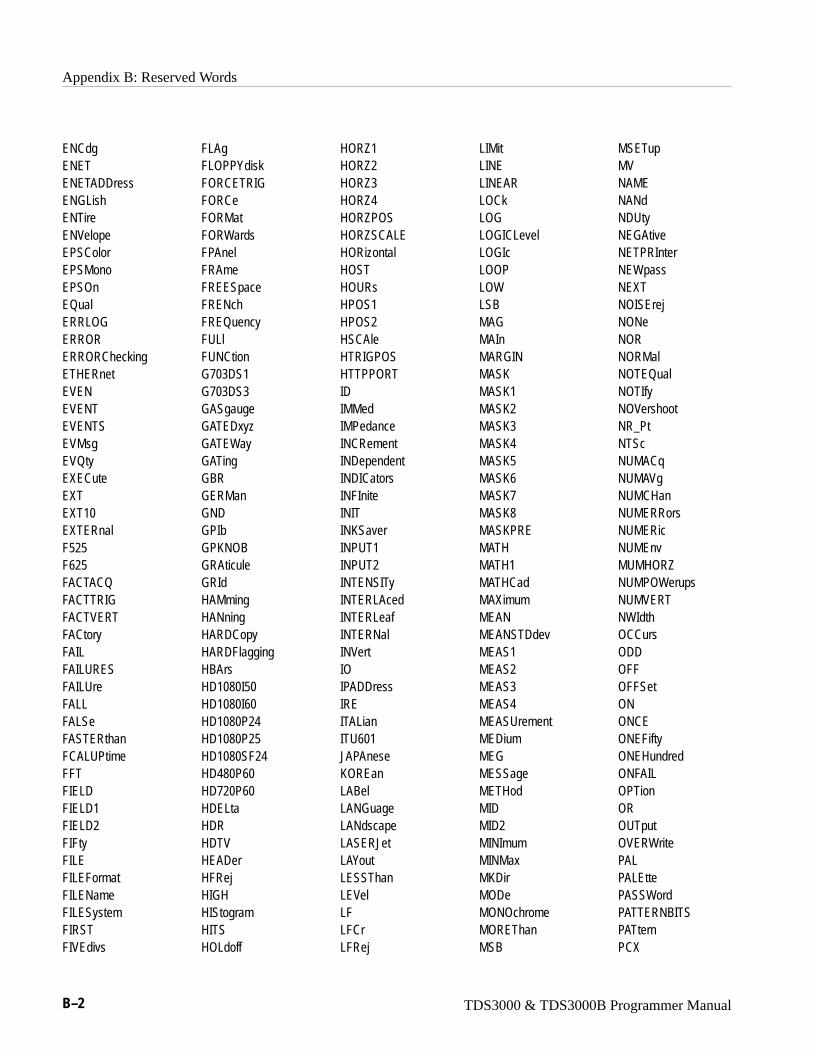
Appendix B: Reserved Words
B–2 TDS3000 & TDS3000B Programmer Manual
ENCdgENETENETADDressENGLishENTireENVelopeEPSColorEPSMonoEPSOnEQualERRLOGERRORERRORCheckingETHERnetEVENEVENTEVENTSEVMsgEVQtyEXECuteEXTEXT10EXTERnalF525F625FACTACQFACTTRIGFACTVERTFACtoryFAILFAILURESFAILUreFALLFALSeFASTERthanFCALUPtimeFFTFIELDFIELD1FIELD2FIFtyFILEFILEFormatFILENameFILESystemFIRSTFIVEdivs
FLAgFLOPPYdiskFORCETRIGFORCeFORMatFORWardsFPAnelFRAmeFREESpaceFRENchFREQuencyFULlFUNCtionG703DS1G703DS3GASgaugeGATEDxyzGATEWayGATingGBRGERManGNDGPIbGPKNOBGRAticuleGRIdHAMmingHANningHARDCopyHARDFlaggingHBArsHD1080I50HD1080I60HD1080P24HD1080P25HD1080SF24HD480P60HD720P60HDELtaHDRHDTVHEADerHFRejHIGHHIStogramHITSHOLdoff
HORZ1HORZ2HORZ3HORZ4HORZPOSHORZSCALEHORizontalHOSTHOURsHPOS1HPOS2HSCAleHTRIGPOSHTTPPORTIDIMMedIMPedanceINCRementINDependentINDICatorsINFIniteINITINKSaverINPUT1INPUT2INTENSITyINTERLAcedINTERLeafINTERNalINVertIOIPADDressIREITALianITU601JAPAneseKOREanLABelLANGuageLANdscapeLASERJetLAYoutLESSThanLEVelLFLFCrLFRej
LIMitLINELINEARLOCkLOGLOGICLevelLOGIcLOOPLOWLSBMAGMAInMARGINMASKMASK1MASK2MASK3MASK4MASK5MASK6MASK7MASK8MASKPREMATHMATH1MATHCadMAXimumMEANMEANSTDdevMEAS1MEAS2MEAS3MEAS4MEASUrementMEDiumMEGMESSageMETHodMIDMID2MINImumMINMaxMKDirMODeMONOchromeMOREThanMSB
MSETupMVNAMENANdNDUtyNEGAtiveNETPRInterNEWpassNEXTNOISErejNONeNORNORMalNOTEQualNOTIfyNOVershootNR_PtNTScNUMACqNUMAVgNUMCHanNUMERRorsNUMERicNUMEnvMUMHORZNUMPOWerupsNUMVERTNWIdthOCCursODDOFFOFFSetONONCEONEFiftyONEHundredONFAILOPTionOROUTputOVERWritePALPALEttePASSWordPATTERNBITSPATternPCX
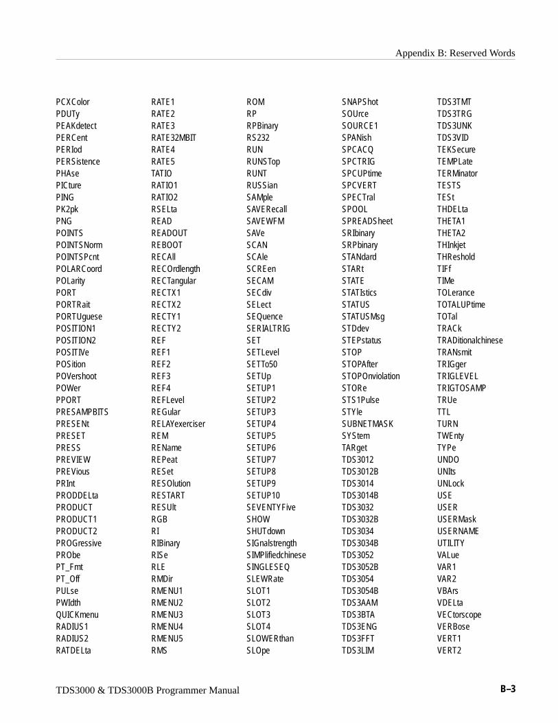
Appendix B: Reserved Words
TDS3000 & TDS3000B Programmer Manual B–3
PCXColorPDUTyPEAKdetectPERCentPERIodPERSistencePHAsePICturePINGPK2pkPNGPOINTSPOINTSNormPOINTSPcntPOLARCoordPOLarityPORTPORTRaitPORTUguesePOSITION1POSITION2POSITIVePOSitionPOVershootPOWerPPORTPRESAMPBITSPRESENtPRESETPRESSPREVIEWPREViousPRIntPRODDELtaPRODUCTPRODUCT1PRODUCT2PROGressivePRObePT_FmtPT_OffPULsePWIdthQUICKmenuRADIUS1RADIUS2RATDELta
RATE1RATE2RATE3RATE32MBITRATE4RATE5TATIORATIO1RATIO2RSELtaREADREADOUTREBOOTRECAllRECOrdlengthRECTangularRECTX1RECTX2RECTY1RECTY2REFREF1REF2REF3REF4REFLevelREGularRELAYexerciserREMRENameREPeatRESetRESOlutionRESTARTRESUltRGBRIRIBinaryRISeRLERMDirRMENU1RMENU2RMENU3RMENU4RMENU5RMS
ROMRPRPBinaryRS232RUNRUNSTopRUNTRUSSianSAMpleSAVERecallSAVEWFMSAVeSCANSCAleSCREenSECAMSECdivSELectSEQuenceSERIALTRIGSETSETLevelSETTo50SETUpSETUP1SETUP2SETUP3SETUP4SETUP5SETUP6SETUP7SETUP8SETUP9SETUP10SEVENTYFiveSHOWSHUTdownSIGnalstrengthSIMPlifiedchineseSINGLESEQSLEWRateSLOT1SLOT2SLOT3SLOT4SLOWERthanSLOpe
SNAPShotSOUrceSOURCE1SPANishSPCACQSPCTRIGSPCUPtimeSPCVERTSPECTralSPOOLSPREADSheetSRIbinarySRPbinarySTANdardSTARtSTATESTATIsticsSTATUSSTATUSMsgSTDdevSTEPstatusSTOPSTOPAfterSTOPOnviolationSTOReSTS1PulseSTYleSUBNETMASKSYStemTARgetTDS3012TDS3012BTDS3014TDS3014BTDS3032TDS3032BTDS3034TDS3034BTDS3052TDS3052BTDS3054TDS3054BTDS3AAMTDS3BTATDS3ENGTDS3FFTTDS3LIM
TDS3TMTTDS3TRGTDS3UNKTDS3VIDTEKSecureTEMPLateTERMinatorTESTSTEStTHDELtaTHETA1THETA2THInkjetTHResholdTIFfTIMeTOLeranceTOTALUPtimeTOTalTRACkTRADitionalchineseTRANsmitTRIGgerTRIGLEVELTRIGTOSAMPTRUeTTLTURNTWEntyTYPeUNDOUNItsUNLockUSEUSERUSERMaskUSERNAMEUTILITYVALueVAR1VAR2VBArsVDELtaVECtorscopeVERBoseVERT1VERT2
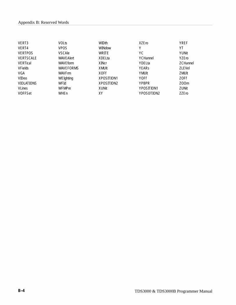
Appendix B: Reserved Words
B–4 TDS3000 & TDS3000B Programmer Manual
VERT3VERT4VERTPOSVERTSCALEVERTicalVFieldsVGAVIDeoVIOLATIONSVLinesVOFFSet
VOLtsVPOSVSCAleWAVEAlertWAVEformWAVEFORMSWAVFrmWEIghtingWFIdWFMPreWHEn
WIDthWINdowWRITEXDELtaXINcrXMUltXOFfXPOSITION1XPOSITION2XUNitXY
XZEroYYCYCHannelYDELtaYEARsYMUltYOFfYPBPRYPOSITION1YPOSOTION2
YREFYTYUNitYZEroZCHannelZLEVelZMUltZOFfZOOmZUNitZZEro
TDS3000 & TDS3000B Programmer Manual C–1
Appendix C: Interface Specifications
This appendix describes details of the GPIB remote interface of the oscilloscope.Normally, you will not need this information to use the oscilloscope, but theinformation is useful when connecting to controllers of unusual configuration.
GPIB Function SubsetsThe oscilloscope supports many GPIB function subsets, as listed below. Some ofthe listings describe subsets that the oscilloscope does not support.
� SH1 (Source Handshake). The oscilloscope can transmit multiline messagesacross the GPIB.
� AH1 (Acceptor Handshake). The oscilloscope can receive multilinemessages across the GPIB.
� T5 (Talker). The oscilloscope becomes a talker when its talk address is sentwith the ATN (Attention) line asserted. It can send both response data andstatus information when responding to a serial poll. It ceases to be a talkerwhen the talk address if another device is sent with ATN asserted. Theoscilloscope has talk-only capability for hardcopy operation.
� L4 (Listener). The oscilloscope becomes a listener when its listen address issent with the ATN (Attention) line asserted. The oscilloscope does not havelisten-only capability.
� SR1 (Service Request). The oscilloscope asserts an SRQ (Service Request)line to notify the controller when it requires service.
� RL1 (Remote/Local). The oscilloscope responds to both the GTL (Go ToLocal) and LLO (Local Lock Out) interface messages.
� PP0 (Parallel Poll). The oscilloscope has no parallel poll capability. It doesnot respond to the following interface messages: PPC, PPD, PPE, and PPU.The oscilloscope does not send out a status message when the ATN(Attention) and EOI (End or Identify) lines are asserted simultaneously.
� DC1 (Device Clear). The oscilloscope responds to the DCL (Device Clear)and, when made a listener, the SDC (Selected Device Clear) interfacemessages.
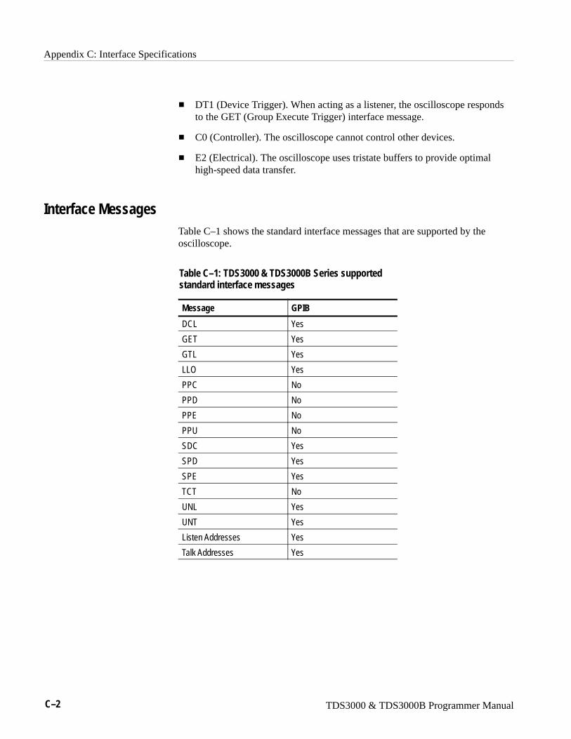
Appendix C: Interface Specifications
C–2 TDS3000 & TDS3000B Programmer Manual
� DT1 (Device Trigger). When acting as a listener, the oscilloscope respondsto the GET (Group Execute Trigger) interface message.
� C0 (Controller). The oscilloscope cannot control other devices.
� E2 (Electrical). The oscilloscope uses tristate buffers to provide optimalhigh-speed data transfer.
Interface MessagesTable C–1 shows the standard interface messages that are supported by theoscilloscope.
Table C–1: TDS3000 & TDS3000B Series supportedstandard interface messages
Message GPIB
DCL Yes
GET Yes
GTL Yes
LLO Yes
PPC No
PPD No
PPE No
PPU No
SDC Yes
SPD Yes
SPE Yes
TCT No
UNL Yes
UNT Yes
Listen Addresses Yes
Talk Addresses Yes
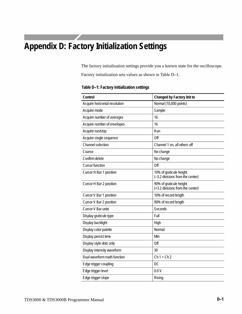
TDS3000 & TDS3000B Programmer Manual D–1
Appendix D: Factory Initialization Settings
The factory initialization settings provide you a known state for the oscilloscope.
Factory initialization sets values as shown in Table D–1.
Table D–1: Factory initialization settings
Control Changed by Factory Init to
Acquire horizontal resolution Normal (10,000 points)
Acquire mode Sample
Acquire number of averages 16
Acquire number of envelopes 16
Acquire run/stop Run
Acquire single sequence Off
Channel selection Channel 1 on, all others off
Coarse No change
Confirm delete No change
Cursor function Off
Cursor H Bar 1 position 10% of graticule height(–3.2 divisions from the center)
Cursor H Bar 2 position 90% of graticule height(+3.2 divisions from the center)
Cursor V Bar 1 position 10% of record length
Cursor V Bar 2 position 90% of record length
Cursor V Bar units Seconds
Display graticule type Full
Display backlight High
Display color palette Normal
Display persist time Min
Display style dots only Off
Display intensity waveform 30
Dual waveform math function Ch 1 + Ch 2
Edge trigger coupling DC
Edge trigger level 0.0 V
Edge trigger slope Rising

Appendix D: Factory Initialization Settings
D–2 TDS3000 & TDS3000B Programmer Manual
Table D–1: Factory initialization settings (Cont.)
Control Changed by Factory Init to
Edge trigger source Channel 1
Horizontal delay On
Horizontal delay time 0 ns
Horizontal trigger position 10%
Horizontal time/doiv 400 �s/div
Horizontal zoom Off
Horizontal zoom position 50%
Horizontal zoom time/div 400��s/div
Measure gating Off (Full Record)
Measure high-low setup Min-Max
Measure high reference 90% and 0 V (units)
Measure low reference 10% and 0 V (units)
Measure mid reference 50% and 0 V (units)
Overwrite lock No change
Reference waveforms No change
Saved setups No change
Trigger holdoff 250.8 ns
Trigger mode Auto
Trigger type Edge
Utility language No change
Utility date/time display On
Utility I/O No change
Utility hard copy No change
Vertical bandwidth Full
Vertical coupling DC 1 M�
Vertical invert Off
Vertical offset 0 V
Vertical position 0 div
Vertical probe setup Voltage, 10 X, unless there is a probe attached
Vertical volts/div 100 mV/div
Video trigger standard 525/NTSC
Video trigger on Any line
Waveform file format No change
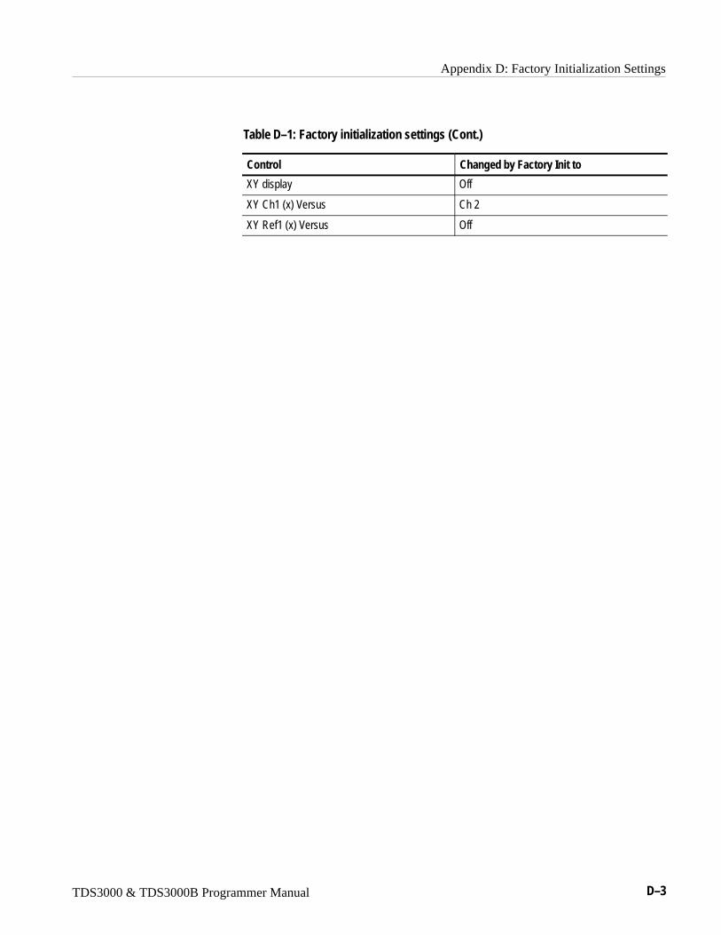
Appendix D: Factory Initialization Settings
TDS3000 & TDS3000B Programmer Manual D–3
Table D–1: Factory initialization settings (Cont.)
Control Changed by Factory Init to
XY display Off
XY Ch1 (x) Versus Ch 2
XY Ref1 (x) Versus Off

Appendix D: Factory Initialization Settings
D–4 TDS3000 & TDS3000B Programmer Manual
TDS3000 & TDS3000B Programmer Manual Glossary–1
Glossary
ASCIIAcronym for the American Standard Code for Information Interchange.Controllers transmit commands to the oscilloscope using ASCII characterencoding.
AddressA 7-bit code that identifies an instrument on the communication bus. Thedigitizing oscilloscope must have a unique address for the controller torecognize and transmit commands to it.
Backus-Naur Form (BNF)A standard notation system for command syntax diagrams. The syntaxdiagrams in this manual use BNF notation.
ControllerA computer or other device that sends commands to and accepts responsesfrom the digitizing oscilloscope.
EOIA mnemonic referring to the control line “End or Identify” on the GPIBinterface bus. One of the two possible end-of-message terminators.
EOMA generic acronym referring to the end-of-message terminator. Theend-of-message terminator can be either an EOI or the ASCII code for linefeed (LF).
Equivalent-time sampling (ET)A sampling mode in which the oscilloscope acquires signals over manyrepetitions of the event. The TDS3000 Series Series Digitizing Oscilloscopesuse a type of equivalent time sampling called random equivalent timesampling. It utilizes an internal clock that runs asynchronously with respectto the input signal and the signal trigger. The oscilloscope takes samplescontinuously, independent of the trigger position, and displays them basedon the time difference between the sample and the trigger. Although thesamples are taken sequentially in time, they are random with respect to thetrigger.
Real-time samplingA sampling mode where the oscilloscope samples fast enough to completelyfill a waveform record from a single trigger event. Use real-time sampling tocapture single-shot or transient events.
Glossary
Glossary–2 TDS3000 & TDS3000B Programmer Manual
GPIBAcronym for General Purpose Interface Bus, the common name for thecommunications interface system defined in IEEE Std 488.
IEEEAcronym for the Institute for Electrical and Electronic Engineers.
JISJapanese Industrial Standard is an encoding scheme which assigns a uniquehexadecimal value to each Japanese character.
QuickBASICA computer language (distributed by Microsoft) that is based on theBeginner’s All-Purpose Symbolic Instruction Code.
QuickCA computer language (distributed by Microsoft) that is based on C.
RS-232A serial, full-duplex, asynchronous communication port that followsANSI/EIA/TIA–562–1989[1], ANSI/EIA/TIA–574–1990[2], and CCITTV.24–1989[3] standards.
TekSecureA Tektronix custom command that initializes both waveform and setupmemories. This overwrites any previously stored data.
UnicodeUnicode Standard is a uniform encoding scheme for written characters andtext. This international character code for information processing includescharacters for the major scripts of the world, as well as technical symbols incommon use. The Unicode Standard is modeled on the ASCII character set,but uses a 16-bit encoding to support full multilingual text.
TDS3000 & TDS3000B Programmer Manual Index–1
IndexAAbbreviating, command, 2–4ACQUIRE?, 2–45ACQUIRE:MODE, 2–45ACQUIRE:NUMACQ?, 2–46ACQUIRE:NUMAVG, 2–47ACQUIRE:NUMENV, 2–47ACQUIRE:STATE, 2–48ACQUIRE:STOPAFTER, 2–49Acquisition command group, 2–11Acquisition commands
ACQUIRE?, 2–45ACQUIRE:MODE, 2–45ACQUIRE:NUMACQ?, 2–46ACQUIRE:NUMAVG, 2–47ACQUIRE:NUMENV, 2–47ACQUIRE:STATE, 2–48ACQUIRE:STOPAFTER, 2–49AUTOSET, 2–54WAVEALERT:BEEP, 2–314WAVEALERT:HARDCOPY, 2–314WAVEALERT:SAVEWFM, 2–315WAVEALERT:SENSITIVITY, 2–316WAVEALERT:STATE, 2–316WAVEALERT:STOPONVIOLATION, 2–317WAVEALERT:TYPE, 2–317
acquisition run/stop, 2–48Address, Definition of, Glossary–1ALIAS, 2–50Alias command group, 2–12Alias commands
ALIAS, 2–50ALIAS:CATALOG?, 2–51ALIAS:DEFINE, 2–51ALIAS:DELETE, 2–52ALIAS:DELETE:ALL, 2–52ALIAS:DELETE:NAME, 2–53ALIAS:STATE, 2–53
ALIAS:CATALOG?, 2–51ALIAS:DEFINE, 2–51ALIAS:DELETE, 2–52ALIAS:DELETE:ALL, 2–52ALIAS:DELETE:NAME, 2–53ALIAS:STATE, 2–53ALLEV?, 2–54Argument, command, 2–2ASCII, 2–1, Glossary–1Audio indicator, 2–55AUTOSET, 2–54
BBackus-Naur Form, 2–1
Definition of, Glossary–1BELL, 2–55Block, command argument, 2–10BNF, Glossary–1BNF (Backus-Naur form), 2–1BUSY?, 2–55
CCALIBRATE:FACTORY:ABORT, 2–57CALIBRATE:FACTORY:CONTINUE, 2–58CALIBRATE:FACTORY:NOTIFY:DUE?, 2–58CALIBRATE:FACTORY:NOTIFY:HOURS, 2–59CALIBRATE:FACTORY:NOTIFY:YEARS, 2–59CALIBRATE:FACTORY:PREVIOUS, 2–60CALIBRATE:FACTORY:START, 2–60CALIBRATE:FACTORY:STATUS?, 2–61CALIBRATE:FACTORY:STEPSTATUS?, 2–61CALIBRATE:INTERNAL, 2–61CALIBRATE:INTERNAL:START, 2–62CALIBRATE:INTERNAL:STATUS?, 2–62Calibration and diagnostic command group, 2–13Calibration and diagnostic commands
*CAL?, 2–57CAL?, 2–56CALIBRATE:FACTORY:ABORT, 2–57CALIBRATE:FACTORY:CONTINUE, 2–58CALIBRATE:FACTORY:NOTIFY:DUE?, 2–58CALIBRATE:FACTORY:NOTIFY:HOURS, 2–59CALIBRATE:FACTORY:NOTIFY:YEARS, 2–59CALIBRATE:FACTORY:PREVIOUS, 2–60CALIBRATE:FACTORY:START, 2–60CALIBRATE:FACTORY:STATUS?, 2–61CALIBRATE:FACTORY:STEPSTATUS?, 2–61CALIBRATE:INTERNAL, 2–61CALIBRATE:INTERNAL:START, 2–62CALIBRATE:INTERNAL:STATUS?, 2–62DIAG:LOOP:OPTION, 2–100DIAG:LOOP:STOP, 2–100DIAG:RESULT:FLAG?, 2–101DIAG:RESULT:LOG?, 2–101DIAG:SELECT:<function>, 2–102DIAG:SELECT:ALL, 2–102DIAG:STATE:EXECUTE, 2–103
CH<x>?, 2–63CH<x>:BANDWIDTH, 2–63
Index
Index–2 TDS3000 & TDS3000B Programmer Manual
CH<x>:COUPLING, 2–64CH<x>:DESKEW, 2–65CH<x>:ID?, 2–65CH<x>:IMPEDANCE, 2–66CH<x>:INVERT, 2–66CH<x>:OFFSET, 2–67CH<x>:POSITION, 2–68CH<x>:PROBE, 2–68CH<x>:SCALE, 2–69CH<x>:VOLTS, 2–70CH<x>:YUNIT, 2–70Channel, command mnemonic, 2–7checking RS-232 command status, 1–28CH<x>, command mnemonic, 2–7Clear Status, 2–71CLEARMENU, 2–71*CLS, 2–71Command
Abbreviating, 2–4Argument, 2–2Block argument, 2–10Common, 2–31, 2–33Concatenating, 2–4Header, 2–2Message, 2–2Mnemonic, 2–2Query, 2–1Rules for forming, 2–1Separator, 2–2Set, 2–1Syntax, 2–1
Command argumentNumeric, 2–8Quoted string, 2–9
Command Descriptions, 1–2Command group
Acquisition, 2–11Alias Command, 2–12Calibration and diagnostic, 2–13Cursor, 2–14Display, 2–16Ethernet, 2–17File system, 2–18Front panel, 2–18Hard copy, 2–19Horizontal, 2–19ITU601, 2–20Limit test, 2–21Mask, 2–22Math, 2–27Measurement, 2–28Miscellaneous, 2–31RS-232, 2–32
Save and recall, 2–32Status and error, 2–33Trigger, 2–34Vertical, 2–38Waveform, 2–39
Command Groups, 1–2Command mnemonic
Channel, 2–7CH<x>, 2–7Cursor position, 2–7Measurement specifier, 2–7MEAS<x>, 2–7POSITION<x>, 2–7Reference waveform, 2–7REF<x>, 2–7Waveform, 2–8<wfm>, 2–8
Command Syntax, 2–1Command syntax, BNF (Backus-Naur form), 2–1Commands, 1–2
Parts of, 1–2Common command, 2–31, 2–33Common GPIB commands
*CAL?, 2–57CAL?, 2–56*CLS, 2–71
communication module installation, 1–6communication modules, 1–4
description, 1–4installing, 1–6
compressing hard copy files, 2–140Computers, connecting RS-232, 1–25Concatenating, command, 2–4Connecting to an RS-232 device, 1–25Controller, Definition of, Glossary–1Cursor command group, 2–14Cursor commands
CURSOR?, 2–72CURSOR:FUNCTION, 2–72CURSOR:GRATICULE?, 2–73CURSOR:GRATICULE:SELECT, 2–73CURSOR:GRATICULE:XPOSITION<X>, 2–74CURSOR:GRATICULE:YPOSITION<X>, 2–74CURSOR:HBARS?, 2–75CURSOR:HBARS:DELTA?, 2–75CURSOR:HBARS:POSITION<x>, 2–76CURSOR:HBARS:SELECT, 2–76CURSOR:HBARS:UNITS, 2–77CURSOR:HBARS:USE, 2–77CURSOR:MODE, 2–78CURSOR:VBARS:HDELTA?, 2–78CURSOR:VBARS:HPOS<x>?, 2–79CURSOR:VBARS:POSITION<x>, 2–79
Index
TDS3000 & TDS3000B Programmer Manual Index–3
CURSOR:VBARS:SELECT, 2–80CURSOR:VBARS:UNITS, 2–81CURSOR:VBARS:USE, 2–81CURSOR:VBARS:VDELTA?, 2–82CURSOR:WAVEFORM?, 2–82CURSOR:WAVEFORM:SELECT, 2–83CURSOR:XY:PRODDELTA?, 2–83CURSOR:XY:PRODUCT<x>?, 2–84CURSOR:XY:RADIUS<x>?, 2–84CURSOR:XY:RATDELTA?, 2–85CURSOR:XY:RATIO<x>?, 2–85CURSOR:XY:RDELTA?, 2–86CURSOR:XY:READOUT, 2–86CURSOR:XY:RECTX<X>?, 2–87CURSOR:XY:RECTY<x>?, 2–87CURSOR:XY:THDELTA?, 2–88CURSOR:XY:THETA<x>?, 2–88CURSOR:XY:XDELTA?, 2–89CURSOR:XY:YDELTA?, 2–89
Cursor position, command mnemonic, 2–7CURSOR?, 2–72CURSOR:FUNCTION, 2–72CURSOR:GRATICULE?, 2–73CURSOR:GRATICULE:SELECT, 2–73CURSOR:GRATICULE:XPOSITION<X>, 2–74CURSOR:GRATICULE:YPOSITION<X>, 2–74CURSOR:HBARS?, 2–75CURSOR:HBARS:DELTA?, 2–75CURSOR:HBARS:POSITION<x>, 2–76CURSOR:HBARS:SELECT, 2–76CURSOR:HBARS:UNITS, 2–77CURSOR:HBARS:USE, 2–77CURSOR:MODE, 2–78CURSOR:VBARS:HDELTA?, 2–78CURSOR:VBARS:HPOS<x>?, 2–79CURSOR:VBARS:POSITION<x>, 2–79CURSOR:VBARS:SELECT, 2–80CURSOR:VBARS:UNITS, 2–81CURSOR:VBARS:USE, 2–81CURSOR:VBARS:VDELTA?, 2–82CURSOR:WAVEFORM?, 2–82CURSOR:WAVEFORM:SELECT, 2–83CURSOR:XY:PRODDELTA?, 2–83CURSOR:XY:PRODUCT<x>?, 2–84CURSOR:XY:RADIUS<x>?, 2–84CURSOR:XY:RATDELTA?, 2–85CURSOR:XY:RATIO<x>?, 2–85CURSOR:XY:RDELTA?, 2–86CURSOR:XY:READOUT, 2–86CURSOR:XY:RECTX<x>, 2–87CURSOR:XY:RECTY<x>?, 2–87CURSOR:XY:THDELTA?, 2–88CURSOR:XY:THETA<x>?, 2–88
CURSOR:XY:XDELTA?, 2–89CURSOR:XY:YDELTA?, 2–89CURVE, 2–90
DDATA, 2–92DATA:DESTINATION, 2–92DATA:ENCDG, 2–93DATA:SOURCE, 2–94DATA:START, 2–95DATA:STOP, 2–96DATA:TARGET, 2–97DATA:WIDTH, 2–97DATE, 2–98DCL, C–2*DDT, 2–98deleting a specific alias item, 2–52, 2–53deleting all aliases, 2–52DESE command, 2–99, 3–3DESER register, 2–99, 2–245, 3–3Device Clear, 2–4, C–2DIAG:LOOP:OPTION, 2–100DIAG:LOOP:STOP, 2–100DIAG:RESULT:FLAG?, 2–101DIAG:RESULT:LOG?, 2–101DIAG:SELECT:<function>, 2–102DIAG:SELECT:ALL, 2–102DIAG:STATE:EXECUTE, 2–103Disks included with this manual, 1–3Display command group, 2–16Display commands
CLEARMENU, 2–71DISPLAY?, 2–103DISPLAY:CLOCK, 2–104DISPLAY:COLOR:PALETTE:REGULAR, 2–104DISPLAY:FORMAT, 2–105DISPLAY:GRATICULE, 2–106DISPLAY:INTENSITY:BACKLIGHT, 2–107DISPLAY:INTENSITY:WAVEFORM, 2–107DISPLAY:PERSISTENCE, 2–108DISPLAY:PERSISTENCE:CLEAR, 2–108DISPLAY:PICTURE:AUTOCONTRAST, 2–109DISPLAY:PICTURE:BRIGHTNESS, 2–109DISPLAY:PICTURE:CONTRAST, 2–110DISPLAY:PICTURE:STATE, 2–111DISPLAY:STYLE:DOTSONLY, 2–111DISPLAY:VECTORSCOPE:STATE, 2–112DISPLAY:VECTORSCOPE:TY_SETTING, 2–112DISPLAY:VECTORSCOPE:TYPE, 2–113DISPLAY:XY?, 2–113DISPLAY:XY:MODE, 2–114
Index
Index–4 TDS3000 & TDS3000B Programmer Manual
DISPLAY:XY:YCHANNEL, 2–115DISPLAY:XY:YREF, 2–115DISPLAY:XY:ZCHANNEL, 2–116DISPLAY:XY:ZLEVEL, 2–116displaying data and time. See DISPLAY:CLOCKMESSAGE:BOX, 2–236MESSAGE:CLEAR, 2–237MESSAGE:SHOW, 2–237MESSAGE:STATE, 2–242
DISPLAY?, 2–103DISPLAY:CLOCK, 2–104DISPLAY:COLOR:PALETTE:REGULAR, 2–104DISPLAY:FORMAT, 2–105DISPLAY:GRATICULE, 2–106DISPLAY:INTENSITY:BACKLIGHT, 2–107DISPLAY:INTENSITY:WAVEFORM, 2–107DISPLAY:PERSISTENCE, 2–108DISPLAY:PERSISTENCE:CLEAR, 2–108DISPLAY:PICTURE:AUTOCONTRAST, 2–109DISPLAY:PICTURE:BRIGHTNESS, 2–109DISPLAY:PICTURE:CONTRAST, 2–110DISPLAY:PICTURE:STATE, 2–111DISPLAY:STYLE:DOTSONLY, 2–111DISPLAY:VECTORSCOPE:STATE, 2–112DISPLAY:VECTORSCOPE:TY_SETTING, 2–112DISPLAY:VECTORSCOPE:TYPE, 2–113DISPLAY:XY?, 2–113DISPLAY:XY:MODE, 2–114DISPLAY:XY:YCHANNEL, 2–115DISPLAY:XY:YREF, 2–115DISPLAY:XY:ZCHANNEL, 2–116DISPLAY:XY:ZLEVEL, 2–116
EEdge trigger, 2–271, 2–293, 2–302End or Identify, Glossary–1envelope waveform acquisitions setting, 2–47EOI, Glossary–1EOM, Glossary–1EOM (end of message), 2–6Equivalent-time sampling, random, Glossary–1Error message, programming interface, 3–12Error messages, 1–3*ESE, 2–117, 3–3ESER register, 2–117, 2–245, 3–3*ESR?, 2–118*ESR? query, 3–1Ethernet
adding TDS3000/B to network, 1–20DNS protocol, 1–17
error messages, 1–17network settings, 1–8parameters, 1–13printer settings, 1–15setup menus, 1–9TekVISA, 1–18VISA, 1–18VISA configuration utility, 1–19
Ethernet command group, 2–17Ethernet commands
ETHERNET:DCHPBOOTP, 2–118ETHERNET:DNS:IPADDRESS, 2–119ETHERNET:DOMAINNAME, 2–119ETHERNET:ENETADDRESS?, 2–120ETHERNET:GATEWAY, 2–120ETHERNET:HTTPPORT, 2–121ETHERNET:IPADDRESS, 2–121ETHERNET:NAME, 2–122ETHERNET:NETPRINTER:ADD, 2–122ETHERNET:NETPRINTER:DELETE, 2–123ETHERNET:NETPRINTER:DELWARN, 2–123ETHERNET:NETPRINTER:RENAME, 2–124ETHERNET:NETPRINTER:SELECT:ALLINFO,
2–125ETHERNET:NETPRINTER:SELECT:NAME, 2–125ETHERNET:PASSWORD, 2–126ETHERNET:PING:EXECUTE, 2–126ETHERNET:PING:STATUS?, 2–127ETHERNET:SUBNETMASK, 2–127
ETHERNET:DCHPBOOTP, 2–118ETHERNET:DNS:IPADDRESS, 2–119ETHERNET:DOMAINNAME, 2–119ETHERNET:ENETADDRESS?, 2–120ETHERNET:GATEWAY, 2–120ETHERNET:HTTPPORT, 2–121ETHERNET:IPADDRESS, 2–121ETHERNET:NAME, 2–122ETHERNET:NETPRINTER:ADD, 2–122ETHERNET:NETPRINTER:DELETE, 2–123ETHERNET:NETPRINTER:DELWARN, 2–123ETHERNET:NETPRINTER:RENAME, 2–124ETHERNET:NETPRINTER:SELECT:ALLINFO, 2–125ETHERNET:NETPRINTER:SELECT:NAME, 2–125ETHERNET:PASSWORD, 2–126ETHERNET:PING:EXECUTE, 2–126ETHERNET:PING:STATUS?, 2–127ETHERNET:SUBNETMASK, 2–127Event handling, 3–1, 3–6Event query, 2–128Event queue, 2–128, 3–5
Index
TDS3000 & TDS3000B Programmer Manual Index–5
EVENT?, 2–128EVMSG?, 2–129EVQTY?, 2–129Example programs, 1–3, 4–1
On disk, 1–3
FFACTORY, 2–130Factory initialization settings, D–1–D–4File system command group, 2–18File system commands
FILESYSTEM:COPY, 2–131FILESYSTEM:CWD, 2–132FILESYSTEM:DELETE, 2–132FILESYSTEM:DELWARN, 2–133FILESYSTEM:DIR?, 2–133FILESYSTEM:FORMAT, 2–134FILESYSTEM:FREESPACE, 2–134FILESYSTEM:MKDIR, 2–134FILESYSTEM:OVERWRITE, 2–135FILESYSTEM:PRINT, 2–136FILESYSTEM:RENAME, 2–136FILESYSTEM:RMDIR, 2–137
FILESYSTEM?, 2–130FILESYSTEM:COPY, 2–131FILESYSTEM:CWD, 2–132FILESYSTEM:DELETE, 2–132FILESYSTEM:DELWARN, 2–133FILESYSTEM:DIR, 2–133FILESYSTEM:FORMAT, 2–134FILESYSTEM:FREESPACE, 2–134FILESYSTEM:MKDIR, 2–134FILESYSTEM:OVERWRITE, 2–135FILESYSTEM:PRINT, 2–136FILESYSTEM:RENAME, 2–136FILESYSTEM:RMDIR, 2–137FPANEL:PRESS, 2–138FPANEL:TURN, 2–139front panel button control, 2–138Front panel command group, 2–18front panel knob control, 2–139
GGET, C–2Glitch trigger, 2–281Go to local, C–2GPIB, Glossary–2
communication module, 1–4comparing GPIB and RS-232, 1–30Configurations, 1–22Connection rules, 1–22EOM (end of message), 2–6Function subsets, C–1parameters, 1–24
Group execute trigger, C–2GTL, C–2
HHard copy command group, 2–19Hard copy commands
HARDCOPY, 2–139HARDCOPY:COMPRESSION, 2–140HARDCOPY:FILENAME, 2–141HARDCOPY:FORMAT, 2–142HARDCOPY:INKSAVER, 2–143HARDCOPY:LAYOUT, 2–144HARDCOPY:PALETTE, 2–144HARDCOPY:PORT, 2–145HARDCOPY:PREVIEW, 2–145
HARDCOPY, 2–139HARDCOPY:COMPRESSION, 2–140HARDCOPY:FILENAME, 2–141HARDCOPY:FORMAT, 2–142HARDCOPY:INKSAVER, 2–143HARDCOPY:LAYOUT, 2–144HARDCOPY:PALETTE, 2–144HARDCOPY:PORT, 2–145HARDCOPY:PREVIEW, 2–145HDR, 2–146HEADER, 2–146Header
Command, 2–2, 2–146Included in query response, 2–146, 2–312
Horizontal command group, 2–19Horizontal commands
HORIZONTAL?, 2–147HORIZONTAL:DELAY:STATE, 2–147HORIZONTAL:DELAY:TIME, 2–148HORIZONTAL:MAIN:SCALE, 2–149HORIZONTAL:MAIN:SECDIV, 2–149HORIZONTAL:RECORDLENGTH, 2–150HORIZONTAL:RESOLUTION, 2–150
Index
Index–6 TDS3000 & TDS3000B Programmer Manual
HORIZONTAL:SCALE, 2–151HORIZONTAL:SECDIV, 2–151HORIZONTAL:TRIGGER:POSITION, 2–151ZOOM:HORIZONTAL:POSITION, 2–333ZOOM:HORIZONTAL:SCALE, 2–334ZOOM:STATE, 2–334
HORIZONTAL?, 2–147HORIZONTAL:DELAY:STATE, 2–147HORIZONTAL:DELAY:TIME, 2–148HORIZONTAL:MAIN:SCALE, 2–149HORIZONTAL:MAIN:SECDIV, 2–149HORIZONTAL:RECORDLENGTH, 2–150HORIZONTAL:RESOLUTION, 2–150HORIZONTAL:SCALE, 2–151HORIZONTAL:SECDIV, 2–151HORIZONTAL:TRIGGER:POSITION, 2–151
IID?, 2–152*IDN?, 2–152IEEE, Glossary–2IEEE Std 488.2-1987, 2–31, 2–33Interface message, C–2ITU601 digital video command group, 2–20ITU601:AUTOSET, 2–153ITU601:EDH RESET, 2–153ITU601:EDH:COUNT, 2–154ITU601:EDH:DETECT?, 2–154ITU601:EDH:NUMERRORS?, 2–155ITU601:INPUT:FORMAT, 2–155ITU601:INPUT:SIGNALSTRENGTH, 2–156ITU601:INPUT:STATE?, 2–156ITU601:OUTPUT:FORMAT, 2–157
JJIS, 2–240, Glossary–2
LLANGUAGE, 2–157Limit test command group, 2–21Limit Test commands
LIMIT?, 2–158LIMIT:BEEP, 2–158LIMIT:COMPARE:CH<x>, 2–159LIMIT:HARDCOPY, 2–159LIMIT:SAVEWFM, 2–160LIMIT:STATE, 2–161LIMIT:STOPONVIOLATION, 2–161
LIMIT:TEMPLATE, 2–162LIMIT:TEMPLATE:DESTINATION, 2–163LIMIT:TEMPLATE:SOURCE, 2–163LIMIT:TEMPLATE:TOLERANCE: VERTICAL, 2–165LIMIT:TEMPLATE:TOLERANCE:HORIZONTAL,
2–164LIMIT?, 2–158LIMIT:BEEP, 2–158LIMIT:COMPARE:CH<X>, 2–159LIMIT:HARDCOPY, 2–159LIMIT:SAVEWFM, 2–160LIMIT:STATE, 2–161LIMIT:STOPONVIOLATION, 2–161LIMIT:TEMPLATE, 2–162LIMIT:TEMPLATE:DESTINATION, 2–163LIMIT:TEMPLATE:SOURCE, 2–163LIMIT:TEMPLATE:TOLERANCE: VERTICAL, 2–165LIMIT:TEMPLATE:TOLERANCE:HORIZONTAL, 2–164LLO, C–2Local lock out, C–2LOCK, 2–166Logic trigger, 2–275, 2–293*LRN?, 2–167
MManual trigger, Simulation with command, 2–311Mask command group, 2–22Mask Test commands
MASK:AUTOFIT, 2–168MASK:COPY:SOURCE, 2–169MASK:COPY:USER, 2–169MASK:COUNT:CH<c>:HITS?, 2–170MASK:COUNT:FAILURES?, 2–170MASK:COUNT:HITS?, 2–171MASK:COUNT:MASK<m>:CH<x>:HITS?, 2–171MASK:COUNT:MASK<m>:HITS?, 2–172MASK:COUNT:STATE, 2–172MASK:COUNT:TESTS?, 2–173MASK:COUNT:TOTAL?, 2–173MASK:COUNT:VIOLATIONS?, 2–174MASK:COUNT:WAVEFORMS?, 2–174MASK:DISPLAY, 2–175MASK:LOCK, 2–175MASK:MARGIN:VERTICAL, 2–176MASK:MASK<m>:COUNT?, 2–177MASK:MASK<m>:NR_PT?, 2–178MASK:MASK<m>:POINTS, 2–178MASK:MASK<m>:POINTSNORM, 2–179MASK:MASK<m>:POINTSPCNT, 2–180MASK:MASK<m>DELETE, 2–177MASK:MASKPRE:AMPLITUDE, 2–181

Index
TDS3000 & TDS3000B Programmer Manual Index–7
MASK:MASKPRE:HSCALE, 2–181MASK:MASKPRE:HTRIGPOS, 2–182MASK:MASKPRE:PATTERNBITS, 2–183MASK:MASKPRE:PRESAMPBITS, 2–183MASK:MASKPRE:RECORDLENGTH, 2–184MASK:MASKPRE:SERIALTRIG, 2–184MASK:MASKPRE:TRIGTOSAMP, 2–185MASK:MASKPRE:VOFFSET, 2–186MASK:MASKPRE:VPOS, 2–186MASK:MASKPRE:VSCALE, 2–187MASK:MASKPRE:WIDTH, 2–187MASK:POLARITY, 2–188MASK:STANDARD, 2–189MASK:STOPONVIOLATION, 2–189MASK:TEST:BEEP:COMPLETION, 2–190MASK:TEST:BEEP:FAILURE, 2–190MASK:TEST:DELAY, 2–191MASK:TEST:HARDCOPY, 2–191MASK:TEST:REPEAT, 2–192MASK:TEST:SAVEWFM, 2–193MASK:TEST:STATE, 2–194MASK:TEST:STATUS?, 2–194MASK:TEST:THRESHOLD, 2–195MASK:TEST:WAVEFORM, 2–195MASK:USER:MASK<m> DELETE, 2–196MASK:USER:MASK<m>:NR_PT?, 2–196MASK:USER:MASK<m>:POINTS, 2–197MASK:USER:MASK<m>:POINTSNORM, 2–197MASK:USER:MASK<m>:POINTSPCNT, 2–198MASK:USER:MASKPRE COMMANDS, 2–199
MASK:AUTOFIT, 2–168MASK:COPY:SOURCE, 2–169MASK:COPY:USER, 2–169MASK:COUNT:CH<c>HITS?, 2–170MASK:COUNT:FAILURES?, 2–170MASK:COUNT:HITS?, 2–171MASK:COUNT:MASK<m>:CH<x>:HITS?, 2–171MASK:COUNT:MASK<m>:HITS?, 2–172MASK:COUNT:STATE, 2–172MASK:COUNT:TESTS?, 2–173MASK:COUNT:TOTAL?, 2–173MASK:COUNT:VIOLATIONS?, 2–174MASK:COUNT:WAVEFORMS?, 2–174MASK:DISPLAY, 2–175MASK:LOCK, 2–175MASK:MARGIN:VERTICAL, 2–176MASK:MASK<m>:POINTS, 2–178MASK:MASK<m>:POINTSNORM, 2–179MASK:MASK<m>:POINTSPCNT, 2–180MASK:MASK<m>COUNT?, 2–177MASK:MASK<m>DELETE, 2–177MASK:MASK<m>NR_PT?, 2–178MASK:MASKPRE:AMPLITUDE, 2–181
MASK:MASKPRE:HSCALE, 2–181MASK:MASKPRE:HTRIGPOS, 2–182MASK:MASKPRE:PATTERNBITS, 2–183MASK:MASKPRE:PRESAMPBITS, 2–183MASK:MASKPRE:RECORDLENGTH, 2–184MASK:MASKPRE:SERIALTRIG, 2–184MASK:MASKPRE:TRIGTOSAMP, 2–185MASK:MASKPRE:VOFFSET, 2–186MASK:MASKPRE:VPOS, 2–186MASK:MASKPRE:VSCALE, 2–187MASK:MASKPRE:WIDTH, 2–187MASK:POLARITY, 2–188MASK:STANDARD, 2–189MASK:STOPONVIOLATION, 2–189MASK:TEST:BEEP:COMPLETION, 2–190MASK:TEST:BEEP:FAILURE, 2–190MASK:TEST:DELAY, 2–191MASK:TEST:HARDCOPY, 2–191MASK:TEST:REPEAT, 2–192MASK:TEST:SAVEWFM, 2–193MASK:TEST:STATE, 2–194MASK:TEST:STATUS?, 2–194MASK:TEST:THRESHOLD, 2–195MASK:TEST:WAVEFORM, 2–195MASK:USER:MASK<m> DELETE, 2–196MASK:USER:MASK<m>:NR_PT?, 2–196MASK:USER:MASK<m>:POINTS, 2–197MASK:USER:MASK<m>:POINTSNORM, 2–197MASK:USER:MASK<m>:POINTSPCNT, 2–198MASK:USER:MASKPRE COMMANDS, 2–199Math command group, 2–27Math commands
MATH?, 2–200MATH:DEFINE, 2–201MATH:HORIZONTAL:POSITION, 2–203MATH:HORIZONTAL:SCALE, 2–204MATH:HORIZONTAL:UNITS, 2–204MATH:SPECTRAL:MAG, 2–205MATH:SPECTRAL:WINDOW, 2–205MATH:TYPE, 2–206MATH:VAR<X>, 2–206MATH:VERTICAL POSITION, 2–207MATH:VERTICAL:SCALE, 2–207MATH:VERTICAL:UNITS, 2–208MATH1, 2–208
MATH?, 2–200MATH:DEFINE, 2–201MATH:HORIZONTAL:POSITION, 2–203MATH:HORIZONTAL:SCALE, 2–204MATH:HORIZONTAL:UNITS, 2–204MATH:SPECTRAL:MAG, 2–205MATH:SPECTRAL:WINDOW, 2–205MATH:TYPE, 2–206
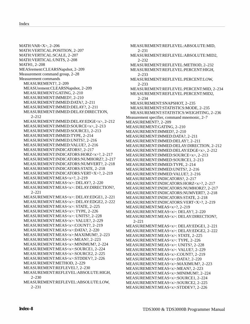
Index
Index–8 TDS3000 & TDS3000B Programmer Manual
MATH:VAR<X>, 2–206MATH:VERTICAL:POSITION, 2–207MATH:VERTICAL:SCALE, 2–207MATH:VERTICAL:UNITS, 2–208MATH1, 2–208MEASrement:CLEARSNapshot, 2–209Measurement command group, 2–28Measurement commands
MEASUREMENT?, 2–209MEASUrement:CLEARSNapshot, 2–209MEASUREMENT:GATING, 2–210MEASUREMENT:IMMED?, 2–210MEASUREMENT:IMMED:DATA?, 2–211MEASUREMENT:IMMED:DELAY?, 2–211MEASUREMENT:IMMED:DELAY:DIRECTION,
2–212MEASUREMENT:IMMED:DELAY:EDGE<x>, 2–212MEASUREMENT:IMMED:SOURCE<x>, 2–213MEASUREMENT:IMMED:SOURCE1, 2–213MEASUREMENT:IMMED:TYPE, 2–214MEASUREMENT:IMMED:UNITS?, 2–216MEASUREMENT:IMMED:VALUE?, 2–216MEASUREMENT:INDICATORS?, 2–217MEASUREMENT:INDICATORS:HORZ<x>?, 2–217MEASUREMENT:INDICATORS:NUMHORZ?, 2–217MEASUREMENT:INDICATORS:NUMVERT?, 2–218MEASUREMENT:INDICATORS:STATE, 2–218MEASUREMENT:INDICATORS:VERT<X>?, 2–219MEASUREMENT:MEAS<x>?, 2–219MEASUREMENT:MEAS<x>: DELAY?, 2–220MEASUREMENT:MEAS<x>: DELAY:DIRECTION?,
2–221MEASUREMENT:MEAS<x>: DELAY:EDGE1, 2–221MEASUREMENT:MEAS<x>: DELAY:EDGE2, 2–222MEASUREMENT:MEAS<x>: STATE, 2–225MEASUREMENT:MEAS<x>: TYPE, 2–226MEASUREMENT:MEAS<x>: UNITS?, 2–228MEASUREMENT:MEAS<x>: VALUE?, 2–229MEASUREMENT:MEAS<x>:COUNT?, 2–219MEASUREMENT:MEAS<x>:DATA?, 2–220MEASUREMENT:MEAS<x>:MAXIMUM?, 2–223MEASUREMENT:MEAS<x>:MEAN?, 2–223MEASUREMENT:MEAS<x>:MINIMUM?, 2–224MEASUREMENT:MEAS<x>:SOURCE1, 2–224MEASUREMENT:MEAS<x>:SOURCE2, 2–225MEASUREMENT:MEAS<x>:STDDEV?, 2–226MEASUREMENT:METHOD, 2–229MEASUREMENT:REFLEVEL?, 2–230MEASUREMENT:REFLEVEL:ABSOLUTE:HIGH,
2–230MEASUREMENT:REFLEVEL:ABSOLUTE:LOW,
2–231
MEASUREMENT:REFLEVEL:ABSOLUTE:MID,2–231
MEASUREMENT:REFLEVEL:ABSOLUTE:MID2,2–232
MEASUREMENT:REFLEVEL:METHOD, 2–232MEASUREMENT:REFLEVEL:PERCENT:HIGH,
2–233MEASUREMENT:REFLEVEL:PERCENT:LOW,
2–233MEASUREMENT:REFLEVEL:PERCENT:MID, 2–234MEASUREMENT:REFLEVEL:PERCENT:MID2,
2–234MEASUREMENT:SNAPSHOT, 2–235MEASUREMENT:STATISTICS:MODE, 2–235MEASUREMENT:STATISTICS:WEIGHTING, 2–236
Measurement specifier, command mnemonic, 2–7MEASUREMENT?, 2–209MEASUREMENT:GATING, 2–210MEASUREMENT:IMMED?, 2–210MEASUREMENT:IMMED:DATA?, 2–211MEASUREMENT:IMMED:DELAY?, 2–211MEASUREMENT:IMMED:DELAY:DIRECTION, 2–212MEASUREMENT:IMMED:DELAY:EDGE<x>, 2–212MEASUREMENT:IMMED:SOURCE<x>, 2–213MEASUREMENT:IMMED:SOURCE1, 2–213MEASUREMENT:IMMED:TYPE, 2–214MEASUREMENT:IMMED:UNITS?, 2–216MEASUREMENT:IMMED:VALUE?, 2–216MEASUREMENT:INDICATORS?, 2–217MEASUREMENT:INDICATORS:HORZ<x>?, 2–217MEASUREMENT:INDICATORS:NUMHORZ?, 2–217MEASUREMENT:INDICATORS:NUMVERT?, 2–218MEASUREMENT:INDICATORS:STATE, 2–218MEASUREMENT:INDICATORS:VERT<X>?, 2–219MEASUREMENT:MEAS<x>?, 2–219MEASUREMENT:MEAS<x>: DELAY?, 2–220MEASUREMENT:MEAS<x>: DELAY:DIRECTION?,
2–221MEASUREMENT:MEAS<x>: DELAY:EDGE1, 2–221MEASUREMENT:MEAS<x>: DELAY:EDGE2, 2–222MEASUREMENT:MEAS<x>: STATE, 2–225MEASUREMENT:MEAS<x>: TYPE, 2–226MEASUREMENT:MEAS<x>: UNITS?, 2–228MEASUREMENT:MEAS<x>: VALUE?, 2–229MEASUREMENT:MEAS<x>:COUNT?, 2–219MEASUREMENT:MEAS<x>:DATA?, 2–220MEASUREMENT:MEAS<x>:MAXIMUM?, 2–223MEASUREMENT:MEAS<x>:MEAN?, 2–223MEASUREMENT:MEAS<x>:MINIMUM?, 2–224MEASUREMENT:MEAS<x>:SOURCE1, 2–224MEASUREMENT:MEAS<x>:SOURCE2, 2–225MEASUREMENT:MEAS<x>:STDDEV?, 2–226
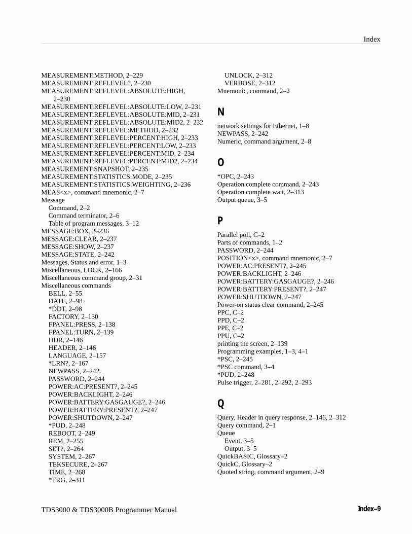
Index
TDS3000 & TDS3000B Programmer Manual Index–9
MEASUREMENT:METHOD, 2–229MEASUREMENT:REFLEVEL?, 2–230MEASUREMENT:REFLEVEL:ABSOLUTE:HIGH,
2–230MEASUREMENT:REFLEVEL:ABSOLUTE:LOW, 2–231MEASUREMENT:REFLEVEL:ABSOLUTE:MID, 2–231MEASUREMENT:REFLEVEL:ABSOLUTE:MID2, 2–232MEASUREMENT:REFLEVEL:METHOD, 2–232MEASUREMENT:REFLEVEL:PERCENT:HIGH, 2–233MEASUREMENT:REFLEVEL:PERCENT:LOW, 2–233MEASUREMENT:REFLEVEL:PERCENT:MID, 2–234MEASUREMENT:REFLEVEL:PERCENT:MID2, 2–234MEASUREMENT:SNAPSHOT, 2–235MEASUREMENT:STATISTICS:MODE, 2–235MEASUREMENT:STATISTICS:WEIGHTING, 2–236MEAS<x>, command mnemonic, 2–7Message
Command, 2–2Command terminator, 2–6Table of program messages, 3–12
MESSAGE:BOX, 2–236MESSAGE:CLEAR, 2–237MESSAGE:SHOW, 2–237MESSAGE:STATE, 2–242Messages, Status and error, 1–3Miscellaneous, LOCK, 2–166Miscellaneous command group, 2–31Miscellaneous commands
BELL, 2–55DATE, 2–98*DDT, 2–98FACTORY, 2–130FPANEL:PRESS, 2–138FPANEL:TURN, 2–139HDR, 2–146HEADER, 2–146LANGUAGE, 2–157*LRN?, 2–167NEWPASS, 2–242PASSWORD, 2–244POWER:AC:PRESENT?, 2–245POWER:BACKLIGHT, 2–246POWER:BATTERY:GASGAUGE?, 2–246POWER:BATTERY:PRESENT?, 2–247POWER:SHUTDOWN, 2–247*PUD, 2–248REBOOT, 2–249REM, 2–255SET?, 2–264SYSTEM, 2–267TEKSECURE, 2–267TIME, 2–268*TRG, 2–311
UNLOCK, 2–312VERBOSE, 2–312
Mnemonic, command, 2–2
Nnetwork settings for Ethernet, 1–8NEWPASS, 2–242Numeric, command argument, 2–8
O*OPC, 2–243Operation complete command, 2–243Operation complete wait, 2–313Output queue, 3–5
PParallel poll, C–2Parts of commands, 1–2PASSWORD, 2–244POSITION<x>, command mnemonic, 2–7POWER:AC:PRESENT?, 2–245POWER:BACKLIGHT, 2–246POWER:BATTERY:GASGAUGE?, 2–246POWER:BATTERY:PRESENT?, 2–247POWER:SHUTDOWN, 2–247Power-on status clear command, 2–245PPC, C–2PPD, C–2PPE, C–2PPU, C–2printing the screen, 2–139Programming examples, 1–3, 4–1*PSC, 2–245*PSC command, 3–4*PUD, 2–248Pulse trigger, 2–281, 2–292, 2–293
QQuery, Header in query response, 2–146, 2–312Query command, 2–1Queue
Event, 3–5Output, 3–5
QuickBASIC, Glossary–2QuickC, Glossary–2Quoted string, command argument, 2–9
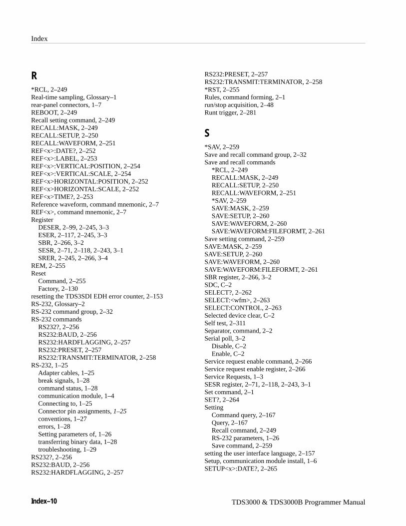
Index
Index–10 TDS3000 & TDS3000B Programmer Manual
R*RCL, 2–249Real-time sampling, Glossary–1rear-panel connectors, 1–7REBOOT, 2–249Recall setting command, 2–249RECALL:MASK, 2–249RECALL:SETUP, 2–250RECALL:WAVEFORM, 2–251REF<x>:DATE?, 2–252REF<x>:LABEL, 2–253REF<x>:VERTICAL:POSITION, 2–254REF<x>:VERTICAL:SCALE, 2–254REF<x>HORIZONTAL:POSITION, 2–252REF<x>HORIZONTAL:SCALE, 2–252REF<x>TIME?, 2–253Reference waveform, command mnemonic, 2–7REF<x>, command mnemonic, 2–7Register
DESER, 2–99, 2–245, 3–3ESER, 2–117, 2–245, 3–3SBR, 2–266, 3–2SESR, 2–71, 2–118, 2–243, 3–1SRER, 2–245, 2–266, 3–4
REM, 2–255Reset
Command, 2–255Factory, 2–130
resetting the TDS3SDI EDH error counter, 2–153RS-232, Glossary–2RS-232 command group, 2–32RS-232 commands
RS232?, 2–256RS232:BAUD, 2–256RS232:HARDFLAGGING, 2–257RS232:PRESET, 2–257RS232:TRANSMIT:TERMINATOR, 2–258
RS-232, 1–25Adapter cables, 1–25break signals, 1–28command status, 1–28communication module, 1–4Connecting to, 1–25Connector pin assignments, 1–25conventions, 1–27errors, 1–28Setting parameters of, 1–26transferring binary data, 1–28troubleshooting, 1–29
RS232?, 2–256RS232:BAUD, 2–256RS232:HARDFLAGGING, 2–257
RS232:PRESET, 2–257RS232:TRANSMIT:TERMINATOR, 2–258*RST, 2–255Rules, command forming, 2–1run/stop acquisition, 2–48Runt trigger, 2–281
S*SAV, 2–259Save and recall command group, 2–32Save and recall commands
*RCL, 2–249RECALL:MASK, 2–249RECALL:SETUP, 2–250RECALL:WAVEFORM, 2–251*SAV, 2–259SAVE:MASK, 2–259SAVE:SETUP, 2–260SAVE:WAVEFORM, 2–260SAVE:WAVEFORM:FILEFORMT, 2–261
Save setting command, 2–259SAVE:MASK, 2–259SAVE:SETUP, 2–260SAVE:WAVEFORM, 2–260SAVE:WAVEFORM:FILEFORMT, 2–261SBR register, 2–266, 3–2SDC, C–2SELECT?, 2–262SELECT:<wfm>, 2–263SELECT:CONTROL, 2–263Selected device clear, C–2Self test, 2–311Separator, command, 2–2Serial poll, 3–2
Disable, C–2Enable, C–2
Service request enable command, 2–266Service request enable register, 2–266Service Requests, 1–3SESR register, 2–71, 2–118, 2–243, 3–1Set command, 2–1SET?, 2–264Setting
Command query, 2–167Query, 2–167Recall command, 2–249RS-232 parameters, 1–26Save command, 2–259
setting the user interface language, 2–157Setup, communication module install, 1–6SETUP<x>:DATE?, 2–265

Index
TDS3000 & TDS3000B Programmer Manual Index–11
SETUP<x>:LABEL, 2–265SETUP<x>:TIME?, 2–265Slewrate trigger, 2–281SPD, C–2SPE, C–2*SRE command, 2–266, 3–4SRER register, 2–245, 2–266, 3–4SRQ, 1–3Status, 3–1Status and error command group, 2–33Status and error commands
ALLEV?, 2–54BUSY?, 2–55*CLS, 2–71DESE, 2–99, 3–3*ESE, 2–117, 3–3*ESR?, 2–118, 3–1EVENT?, 2–128EVMSG?, 2–129EVQTY?, 2–129FILESYSTEM?, 2–130ID?, 2–152*IDN?, 2–152*OPC, 2–243*PSC, 2–245, 3–4*RST, 2–255*SRE, 2–266, 3–4*STB?, 2–266, 3–2*TST?, 2–311*WAI, 2–313
Status and Events, 1–3*STB?, 2–266*STB? query, 3–2Syntax
BNF (Backus-Naur form), 2–1Command, 2–1
syntax and command description, 1–2SYSTEM, 2–267
TTable, programming message, 3–12TCT, C–2TDS3LIM commands, 2–21TDS3SDI commands, 2–20
ITU601:AUTOSET, 2–153ITU601:EDH RESET, 2–153ITU601:EDH:COUNT, 2–154ITU601:EDH:DETECT?, 2–154ITU601:EDH:NUMERRORS?, 2–155ITU601:INPUT:FORMAT, 2–155ITU601:INPUT:SIGNALSTRENGTH, 2–156
ITU601:INPUT:STATE?, 2–156ITU601:OUTPUT:FORMAT, 2–157
TDS3SDI EDH error counter, 2–153TDS3TMT commands, 2–22TEKSECURE, 2–267TEKSecure, Glossary–2Telecom mask test commands, 2–22Terminator, command message, 2–6TIME, 2–268Time base, Manual trigger simulation, 2–311*TRG, 2–311TRIGGER, 2–268Trigger command group, 2–34Trigger commands
TRIGGER, 2–268TRIGGER:A?, 2–269TRIGGER:A:COMMUNICATION:SOURCE, 2–269TRIGGER:A:COMMUNICATION:STANDARD, 2–270TRIGGER:A:EDGE?, 2–271TRIGGER:A:EDGE:COUPLING, 2–271TRIGGER:A:EDGE:SLOPE, 2–272TRIGGER:A:EDGE:SOURCE, 2–272TRIGGER:A:HOLDOFF?, 2–273TRIGGER:A:HOLDOFF:TIME, 2–273TRIGGER:A:HOLDOFF:VALUE, 2–274TRIGGER:A:LEVEL, 2–274TRIGGER:A:LOGIC?, 2–275TRIGGER:A:LOGIC:CLASS, 2–275TRIGGER:A:LOGIC:INPUT<x>:LOGICLEVEL,
2–276TRIGGER:A:LOGIC:INPUT<x>SOURCE, 2–277TRIGGER:A:LOGIC:INPUT<x>THRESHOLD, 2–277TRIGGER:A:LOGIC:INPUT2:SLOPE, 2–276TRIGGER:A:LOGIC:PATTERN:DELTATIME, 2–278TRIGGER:A:LOGIC:PATTERN:FUNCTION, 2–278TRIGGER:A:LOGIC:PATTERN:WHEN, 2–279TRIGGER:A:LOGIC:STATE:WHEN, 2–280TRIGGER:A:MODE, 2–280TRIGGER:A:PULSE?, 2–281TRIGGER:A:PULSE:CLASS, 2–281TRIGGER:A:PULSE:RUNT?, 2–282TRIGGER:A:PULSE:RUNT:POLARITY, 2–282TRIGGER:A:PULSE:RUNT:THRESHOLD?, 2–283TRIGGER:A:PULSE:RUNT:THRESHOLD:BOTH,
2–283TRIGGER:A:PULSE:RUNT:THRESHOLD:HIGH,
2–284TRIGGER:A:PULSE:RUNT:THRESHOLD:LOW,
2–284TRIGGER:A:PULSE:RUNT:WHEN, 2–285TRIGGER:A:PULSE:RUNT:WIDTH, 2–285TRIGGER:A:PULSE:SLEWRATE?, 2–286
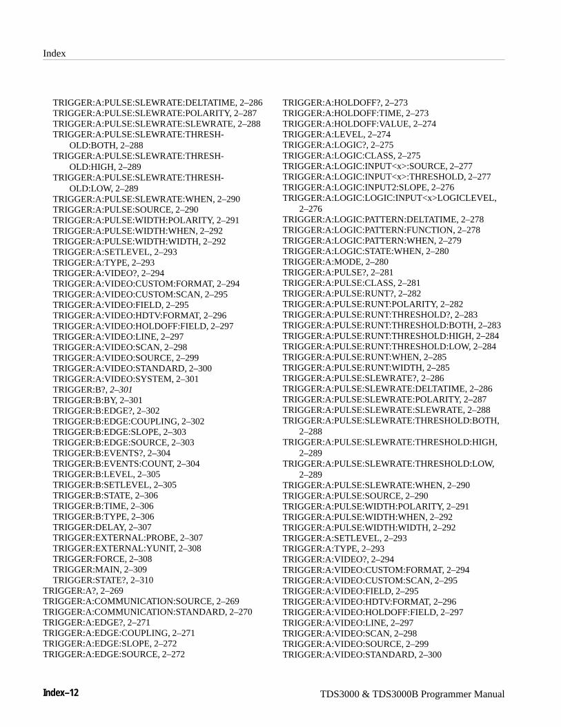
Index
Index–12 TDS3000 & TDS3000B Programmer Manual
TRIGGER:A:PULSE:SLEWRATE:DELTATIME, 2–286TRIGGER:A:PULSE:SLEWRATE:POLARITY, 2–287TRIGGER:A:PULSE:SLEWRATE:SLEWRATE, 2–288TRIGGER:A:PULSE:SLEWRATE:THRESH-
OLD:BOTH, 2–288TRIGGER:A:PULSE:SLEWRATE:THRESH-
OLD:HIGH, 2–289TRIGGER:A:PULSE:SLEWRATE:THRESH-
OLD:LOW, 2–289TRIGGER:A:PULSE:SLEWRATE:WHEN, 2–290TRIGGER:A:PULSE:SOURCE, 2–290TRIGGER:A:PULSE:WIDTH:POLARITY, 2–291TRIGGER:A:PULSE:WIDTH:WHEN, 2–292TRIGGER:A:PULSE:WIDTH:WIDTH, 2–292TRIGGER:A:SETLEVEL, 2–293TRIGGER:A:TYPE, 2–293TRIGGER:A:VIDEO?, 2–294TRIGGER:A:VIDEO:CUSTOM:FORMAT, 2–294TRIGGER:A:VIDEO:CUSTOM:SCAN, 2–295TRIGGER:A:VIDEO:FIELD, 2–295TRIGGER:A:VIDEO:HDTV:FORMAT, 2–296TRIGGER:A:VIDEO:HOLDOFF:FIELD, 2–297TRIGGER:A:VIDEO:LINE, 2–297TRIGGER:A:VIDEO:SCAN, 2–298TRIGGER:A:VIDEO:SOURCE, 2–299TRIGGER:A:VIDEO:STANDARD, 2–300TRIGGER:A:VIDEO:SYSTEM, 2–301TRIGGER:B?, 2–301TRIGGER:B:BY, 2–301TRIGGER:B:EDGE?, 2–302TRIGGER:B:EDGE:COUPLING, 2–302TRIGGER:B:EDGE:SLOPE, 2–303TRIGGER:B:EDGE:SOURCE, 2–303TRIGGER:B:EVENTS?, 2–304TRIGGER:B:EVENTS:COUNT, 2–304TRIGGER:B:LEVEL, 2–305TRIGGER:B:SETLEVEL, 2–305TRIGGER:B:STATE, 2–306TRIGGER:B:TIME, 2–306TRIGGER:B:TYPE, 2–306TRIGGER:DELAY, 2–307TRIGGER:EXTERNAL:PROBE, 2–307TRIGGER:EXTERNAL:YUNIT, 2–308TRIGGER:FORCE, 2–308TRIGGER:MAIN, 2–309TRIGGER:STATE?, 2–310
TRIGGER:A?, 2–269TRIGGER:A:COMMUNICATION:SOURCE, 2–269TRIGGER:A:COMMUNICATION:STANDARD, 2–270TRIGGER:A:EDGE?, 2–271TRIGGER:A:EDGE:COUPLING, 2–271TRIGGER:A:EDGE:SLOPE, 2–272TRIGGER:A:EDGE:SOURCE, 2–272
TRIGGER:A:HOLDOFF?, 2–273TRIGGER:A:HOLDOFF:TIME, 2–273TRIGGER:A:HOLDOFF:VALUE, 2–274TRIGGER:A:LEVEL, 2–274TRIGGER:A:LOGIC?, 2–275TRIGGER:A:LOGIC:CLASS, 2–275TRIGGER:A:LOGIC:INPUT<x>:SOURCE, 2–277TRIGGER:A:LOGIC:INPUT<x>:THRESHOLD, 2–277TRIGGER:A:LOGIC:INPUT2:SLOPE, 2–276TRIGGER:A:LOGIC:LOGIC:INPUT<x>LOGICLEVEL,
2–276TRIGGER:A:LOGIC:PATTERN:DELTATIME, 2–278TRIGGER:A:LOGIC:PATTERN:FUNCTION, 2–278TRIGGER:A:LOGIC:PATTERN:WHEN, 2–279TRIGGER:A:LOGIC:STATE:WHEN, 2–280TRIGGER:A:MODE, 2–280TRIGGER:A:PULSE?, 2–281TRIGGER:A:PULSE:CLASS, 2–281TRIGGER:A:PULSE:RUNT?, 2–282TRIGGER:A:PULSE:RUNT:POLARITY, 2–282TRIGGER:A:PULSE:RUNT:THRESHOLD?, 2–283TRIGGER:A:PULSE:RUNT:THRESHOLD:BOTH, 2–283TRIGGER:A:PULSE:RUNT:THRESHOLD:HIGH, 2–284TRIGGER:A:PULSE:RUNT:THRESHOLD:LOW, 2–284TRIGGER:A:PULSE:RUNT:WHEN, 2–285TRIGGER:A:PULSE:RUNT:WIDTH, 2–285TRIGGER:A:PULSE:SLEWRATE?, 2–286TRIGGER:A:PULSE:SLEWRATE:DELTATIME, 2–286TRIGGER:A:PULSE:SLEWRATE:POLARITY, 2–287TRIGGER:A:PULSE:SLEWRATE:SLEWRATE, 2–288TRIGGER:A:PULSE:SLEWRATE:THRESHOLD:BOTH,
2–288TRIGGER:A:PULSE:SLEWRATE:THRESHOLD:HIGH,
2–289TRIGGER:A:PULSE:SLEWRATE:THRESHOLD:LOW,
2–289TRIGGER:A:PULSE:SLEWRATE:WHEN, 2–290TRIGGER:A:PULSE:SOURCE, 2–290TRIGGER:A:PULSE:WIDTH:POLARITY, 2–291TRIGGER:A:PULSE:WIDTH:WHEN, 2–292TRIGGER:A:PULSE:WIDTH:WIDTH, 2–292TRIGGER:A:SETLEVEL, 2–293TRIGGER:A:TYPE, 2–293TRIGGER:A:VIDEO?, 2–294TRIGGER:A:VIDEO:CUSTOM:FORMAT, 2–294TRIGGER:A:VIDEO:CUSTOM:SCAN, 2–295TRIGGER:A:VIDEO:FIELD, 2–295TRIGGER:A:VIDEO:HDTV:FORMAT, 2–296TRIGGER:A:VIDEO:HOLDOFF:FIELD, 2–297TRIGGER:A:VIDEO:LINE, 2–297TRIGGER:A:VIDEO:SCAN, 2–298TRIGGER:A:VIDEO:SOURCE, 2–299TRIGGER:A:VIDEO:STANDARD, 2–300
Index
TDS3000 & TDS3000B Programmer Manual Index–13
TRIGGER:A:VIDEO:SYSTEM, 2–301TRIGGER:B?, 2–301TRIGGER:B:BY, 2–301TRIGGER:B:EDGE?, 2–302TRIGGER:B:EDGE:COUPLING, 2–302TRIGGER:B:EDGE:SLOPE, 2–303TRIGGER:B:EDGE:SOURCE, 2–303TRIGGER:B:EVENTS?, 2–304TRIGGER:B:EVENTS:COUNT, 2–304TRIGGER:B:LEVEL, 2–305TRIGGER:B:SETLEVEL, 2–305TRIGGER:B:STATE, 2–306TRIGGER:B:TIME, 2–306TRIGGER:B:TYPE, 2–306TRIGGER:DELAY, 2–307TRIGGER:EXTERNAL:PROBE, 2–307TRIGGER:EXTERNAL:YUNIT, 2–308TRIGGER:FORCE, 2–308TRIGGER:MAIN, 2–309TRIGGER:STATE?, 2–310*TST? query, 2–311turning alias state on or off, 2–53
UUnicode, 2–240, Glossary–2UNL, C–2Unlisten, C–2UNLOCK, 2–312UNT, C–2Untalk, C–2
VVERBOSE, 2–312Vertical command group, 2–38Vertical commands
CH<x>?, 2–63CH<x>:BANDWIDTH, 2–63CH<x>:COUPLING, 2–64CH<x>:DESKEW, 2–65CH<x>:ID?, 2–65CH<x>:IMPEDANCE, 2–66CH<x>:INVERT, 2–66CH<x>:OFFSET, 2–67CH<x>:POSITION, 2–68CH<x>:PROBE, 2–68CH<x>:SCALE, 2–69CH<x>:VOLTS, 2–70CH<x>:YUNIT, 2–70SELECT?, 2–262SELECT:<wfm>, 2–263
SELECT:CONTROL, 2–263Video trigger, 2–293, 2–294
W*WAI, 2–313Wait for operation complete, 2–313WAVEALERT:BEEP, 2–314WAVEALERT:HARDCOPY, 2–314WAVEALERT:SAVEWFM, 2–315WAVEALERT:SENSITIVITY, 2–316WAVEALERT:STATE, 2–316WAVEALERT:STOPONVIOLATION, 2–317WAVEALERT:TYPE, 2–317Waveform, command mnemonic, 2–8Waveform command group, 2–39Waveform commands
CURVE, 2–90DATA, 2–92DATA:DESTINATION, 2–92DATA:ENCDG, 2–93DATA:SOURCE, 2–94DATA:START, 2–95DATA:STOP, 2–96DATA:TARGET, 2–97DATA:WIDTH, 2–97REF<x>:DATE?, 2–252REF<x>:HORIZONTAL:POSITION, 2–252REF<x>:LABEL, 2–253REF<x>:TIME?, 2–253REF<x>:VERTICAL:POSITION, 2–254REF<x>:VERTICAL:SCALE, 2–254REF<x>HORIZONTAL:SCALE, 2–252SETUP<x>:DATE?, 2–265SETUP<x>:LABEL, 2–265SETUP<x>:TIME?, 2–265WAVFRM?, 2–313WFMPRE?, 2–318WFMPRE:<wfm>?, 2–330WFMPRE:<wfm>:PT_FMT, 2–332WFMPRE:<wfm>:PT_OFF, 2–332WFMPRE:<wfm>:WFID?, 2–332WFMPRE:<wfm>:XINCR, 2–332WFMPRE:<wfm>:XUNIT, 2–332WFMPRE:<wfm>:XZERO, 2–332WFMPRE:<wfm>:YMULT, 2–333WFMPRE:<wfm>:YOFF, 2–333WFMPRE:<wfm>:YUNIT, 2–333WFMPRE:<wfm>:YZERO, 2–333WFMPRE:<wfm>NR_PT, 2–331WFMPRE:BIT_NR, 2–318WFMPRE:BN_FMT, 2–319
Index
Index–14 TDS3000 & TDS3000B Programmer Manual
WFMPRE:BYT_NR, 2–320WFMPRE:BYT_OR, 2–320WFMPRE:ENCDG, 2–321WFMPRE:NR_PT, 2–322WFMPRE:PT_FMT, 2–322WFMPRE:PT_OFF, 2–323WFMPRE:WFID, 2–324WFMPRE:XINCR, 2–324WFMPRE:XMULT, 2–330WFMPRE:XOFF, 2–330WFMPRE:XUNIT, 2–325WFMPRE:XZERO, 2–326WFMPRE:YMULT, 2–326WFMPRE:YOFF, 2–327WFMPRE:YUNIT, 2–328WFMPRE:YZERO, 2–329WFMPRE:ZMULT, 2–330WFMPRE:ZOFF, 2–330WFMPRE:ZUNIT, 2–330WFMPRE:ZZERO, 2–330
WAVFRM?, 2–313<wfm>, command mnemonic, 2–8WFMPRE?, 2–318WFMPRE:<wfm>?, 2–330WFMPRE:<wfm>:PT_FMT, 2–332WFMPRE:<wfm>:PT_OFF, 2–332WFMPRE:<wfm>:WFID?, 2–332WFMPRE:<wfm>:XINCR, 2–332WFMPRE:<wfm>:XUNIT, 2–332WFMPRE:<wfm>:XZERO, 2–332WFMPRE:<wfm>:YMULT, 2–333WFMPRE:<wfm>:YOFF, 2–333
WFMPRE:<wfm>:YUNIT, 2–333WFMPRE:<wfm>:YZERO, 2–333WFMPRE:<wfm>NR_PT, 2–331WFMPRE:BIT_NR, 2–318WFMPRE:BN_FMT, 2–319WFMPRE:BYT_NR, 2–320WFMPRE:BYT_OR, 2–320WFMPRE:ENCDG, 2–321WFMPRE:NR_PT, 2–322WFMPRE:PT_FMT, 2–322WFMPRE:PT_OFF, 2–323WFMPRE:WFID, 2–324WFMPRE:XINCR, 2–324WFMPRE:XMULT, 2–330WFMPRE:XOFF, 2–330WFMPRE:XUNIT, 2–325WFMPRE:XZERO, 2–326WFMPRE:YMULT, 2–326WFMPRE:YOFF, 2–327WFMPRE:YUNIT, 2–328WFMPRE:YZERO, 2–329WFMPRE:ZMULT, 2–330WFMPRE:ZOFF, 2–330WFMPRE:ZUNIT, 2–330WFMPRE:ZZERO, 2–330Width trigger, 2–281, 2–292
ZZOOM:HORIZONTAL:POSITION, 2–333ZOOM:HORIZONTAL:SCALE, 2–334ZOOM:STATE, 2–334