Embed Size (px)
Citation preview
User Manual
Tektronix Logic Analyzer Family
Version 4.1 Software
071-0863-01
www.tektronix.com
Copyright © Tektronix, Inc. All rights reserved. Licensed software products are owned by Tektronix or its suppliers and
are protected by United States copyright laws and international treaty provisions.
Use, duplication, or disclosure by the Government is subject to restrictions as set forth in subparagraph (c)(1)(ii) of the
Rights in Technical Data and Computer Software clause at DFARS 252.227-7013, or subparagraphs (c)(1) and (2) of the
Commercial Computer Software -- Restricted Rights clause at FAR 52.227-19, as applicable.
Tektronix products are covered by U.S. and foreign patents, issued and pending. Information in this publication supercedes
that in all previously published material. Specifications and price change privileges reserved.
Tektronix, Inc., 14200 SW Karl Braun Drive, Beaverton, OR 97077
TEKTRONIX and TEK are registered trademarks of Tektronix, Inc.

HARDWARE WARRANTY
Tektronix warrants that the products that it manufactures and sells will be free from defects in materials and workmanship
for a period of one (1) year from the date of shipment. If a product proves defective during this warranty period, Tektronix,
at its option, either will repair the defective product without charge for parts and labor, or will provide a replacement in
exchange for the defective product.
In order to obtain service under this warranty, Customer must notify Tektronix of the defect before the expiration of the
warranty period and make suitable arrangements for the performance of service. Customer shall be responsible for
packaging and shipping the defective product to the service center designated by Tektronix, with shipping charges prepaid.
Tektronix shall pay for the return of the product to Customer if the shipment is to a location within the country in which the
Tektronix service center is located. Customer shall be responsible for paying all shipping charges, duties, taxes, and any
other charges for products returned to any other locations.
This warranty shall not apply to any defect, failure or damage caused by improper use or improper or inadequate
maintenance and care. Tektronix shall not be obligated to furnish service under this warranty a) to repair damage resulting
from attempts by personnel other than Tektronix representatives to install, repair or service the product; b) to repair
damage resulting from improper use or connection to incompatible equipment; c) to repair any damage or malfunction
caused by the use of non-Tektronix supplies; or d) to service a product that has been modified or integrated with other
products when the effect of such modification or integration increases the time or difficulty of servicing the product.
THIS WARRANTY IS GIVEN BY TEKTRONIX IN LIEU OF ANY OTHER WARRANTIES, EXPRESS OR
IMPLIED. TEKTRONIX AND ITS VENDORS DISCLAIM ANY IMPLIED WARRANTIES OF
MERCHANTABILITY OR FITNESS FOR A PARTICULAR PURPOSE. TEKTRONIX’ RESPONSIBILITY TO
REPAIR OR REPLACE DEFECTIVE PRODUCTS IS THE SOLE AND EXCLUSIVE REMEDY PROVIDED TO
THE CUSTOMER FOR BREACH OF THIS WARRANTY. TEKTRONIX AND ITS VENDORS WILL NOT BE
LIABLE FOR ANY INDIRECT, SPECIAL, INCIDENTAL, OR CONSEQUENTIAL DAMAGES IRRESPECTIVE
OF WHETHER TEKTRONIX OR THE VENDOR HAS ADVANCE NOTICE OF THE POSSIBILITY OF SUCH
DAMAGES.
SOFTWARE WARRANTY
Tektronix warrants that the media on which this software product is furnished and the encoding of the programs on the
media will be free from defects in materials and workmanship for a period of three (3) months from the date of shipment.
If a medium or encoding proves defective during the warranty period, Tektronix will provide a replacement in exchange
for the defective medium. Except as to the media on which this software product is furnished, this software product is
provided “as is” without warranty of any kind, either express or implied. Tektronix does not warrant that the functions
contained in this software product will meet Customer’s requirements or that the operation of the programs will be
uninterrupted or error-free.
In order to obtain service under this warranty, Customer must notify Tektronix of the defect before the expiration of the
warranty period. If Tektronix is unable to provide a replacement that is free from defects in materials and workmanship
within a reasonable time thereafter, Customer may terminate the license for this software product and return this software
product and any associated materials for credit or refund.
THIS WARRANTY IS GIVEN BY TEKTRONIX IN LIEU OF ANY OTHER WARRANTIES, EXPRESS OR
IMPLIED. TEKTRONIX AND ITS VENDORS DISCLAIM ANY IMPLIED WARRANTIES OF
MERCHANTABILITY OR FITNESS FOR A PARTICULAR PURPOSE. TEKTRONIX’ RESPONSIBILITY TO
REPLACE DEFECTIVE MEDIA OR REFUND CUSTOMER’S PAYMENT IS THE SOLE AND EXCLUSIVE
REMEDY PROVIDED TO THE CUSTOMER FOR BREACH OF THIS WARRANTY. TEKTRONIX AND ITS
VENDORS WILL NOT BE LIABLE FOR ANY INDIRECT, SPECIAL, INCIDENTAL, OR CONSEQUENTIAL
DAMAGES IRRESPECTIVE OF WHETHER TEKTRONIX OR THE VENDOR HAS ADVANCE NOTICE OF
THE POSSIBILITY OF SUCH DAMAGES.
Tektronix Logic Analyzer Family User Manual, Version 4.1 Software i
Table of Contents
General Safety Summary xv. . . . . . . . . . . . . . . . . . . . . . . . . . . . . . . . . . .
Preface xvii. . . . . . . . . . . . . . . . . . . . . . . . . . . . . . . . . . . . . . . . . . . . . . . . . . .Related Documentation xviii. . . . . . . . . . . . . . . . . . . . . . . . . . . . . . . . . . . . . . . . . . .Terms Used in this Manual xviii. . . . . . . . . . . . . . . . . . . . . . . . . . . . . . . . . . . . . . . . .What’s New in This Manual xix. . . . . . . . . . . . . . . . . . . . . . . . . . . . . . . . . . . . . . . .Contacting Tektronix xx. . . . . . . . . . . . . . . . . . . . . . . . . . . . . . . . . . . . . . . . . . . . .
Getting Started
Getting Started 1--1. . . . . . . . . . . . . . . . . . . . . . . . . . . . . . . . . . . . . . . . . . . .TLA600 Series Logic Analyzers 1--1. . . . . . . . . . . . . . . . . . . . . . . . . . . . . . . . . . . .TLA700 Series Logic Analyzer 1--2. . . . . . . . . . . . . . . . . . . . . . . . . . . . . . . . . . . . .Accessories 1--3. . . . . . . . . . . . . . . . . . . . . . . . . . . . . . . . . . . . . . . . . . . . . . . . . . . . .Installation 1--4. . . . . . . . . . . . . . . . . . . . . . . . . . . . . . . . . . . . . . . . . . . . . . . . . . . . .Installing Expansion Mainframes 1--5. . . . . . . . . . . . . . . . . . . . . . . . . . . . . . . . . . . .Installing TLA 700 Modules 1--9. . . . . . . . . . . . . . . . . . . . . . . . . . . . . . . . . . . . . . .Connecting Accessories 1--9. . . . . . . . . . . . . . . . . . . . . . . . . . . . . . . . . . . . . . . . . . .Connecting Probes 1--12. . . . . . . . . . . . . . . . . . . . . . . . . . . . . . . . . . . . . . . . . . . . . . .First Time Operation 1--16. . . . . . . . . . . . . . . . . . . . . . . . . . . . . . . . . . . . . . . . . . . . .Turning On the TLA600 Series Logic Analyzer 1--16. . . . . . . . . . . . . . . . . . . . . . . .Turning On the TLA700 Series Logic Analyzer 1--18. . . . . . . . . . . . . . . . . . . . . . . .Powering On the Mainframes 1--20. . . . . . . . . . . . . . . . . . . . . . . . . . . . . . . . . . . . . . .Turning Off the TLA700 Series Mainframe 1--20. . . . . . . . . . . . . . . . . . . . . . . . . .Performing the Incoming Inspection 1--21. . . . . . . . . . . . . . . . . . . . . . . . . . . . . . . . .Backing Up User Files 1--22. . . . . . . . . . . . . . . . . . . . . . . . . . . . . . . . . . . . . . . . . . . .Removing the Replaceable Hard Disk Drive (TLA700 Series Only) 1--23. . . . . . . .Connecting Probes to the Target System 1--25. . . . . . . . . . . . . . . . . . . . . . . . . . . . . .Additional Information 1--28. . . . . . . . . . . . . . . . . . . . . . . . . . . . . . . . . . . . . . . . . . . .
Operating Basics
Functional Overview 2--1. . . . . . . . . . . . . . . . . . . . . . . . . . . . . . . . . . . . . . .Front Panel Controls 2--1. . . . . . . . . . . . . . . . . . . . . . . . . . . . . . . . . . . . . . . . . . . . . .TLA600 Series External Connectors 2--4. . . . . . . . . . . . . . . . . . . . . . . . . . . . . . . . .TLA600 Series Chassis Ground Connections 2--5. . . . . . . . . . . . . . . . . . . . . . . . . .TLA700 Series External Connectors 2--5. . . . . . . . . . . . . . . . . . . . . . . . . . . . . . . . .TLA700 Series Chassis Ground Connections 2--6. . . . . . . . . . . . . . . . . . . . . . . . . .
Approaching the TLA Application Windows 2--9. . . . . . . . . . . . . . . . . . .System Window 2--9. . . . . . . . . . . . . . . . . . . . . . . . . . . . . . . . . . . . . . . . . . . . . . . . .Setup Windows 2--11. . . . . . . . . . . . . . . . . . . . . . . . . . . . . . . . . . . . . . . . . . . . . . . . . .Trigger Windows 2--12. . . . . . . . . . . . . . . . . . . . . . . . . . . . . . . . . . . . . . . . . . . . . . . .Data Windows 2--14. . . . . . . . . . . . . . . . . . . . . . . . . . . . . . . . . . . . . . . . . . . . . . . . . . .MagniVu Data 2--16. . . . . . . . . . . . . . . . . . . . . . . . . . . . . . . . . . . . . . . . . . . . . . . . . . .Saving and Loading Setups and Data 2--16. . . . . . . . . . . . . . . . . . . . . . . . . . . . . . . . .Customizing the Display 2--17. . . . . . . . . . . . . . . . . . . . . . . . . . . . . . . . . . . . . . . . . .Programmatic Control 2--18. . . . . . . . . . . . . . . . . . . . . . . . . . . . . . . . . . . . . . . . . . . .
Approaching the Pattern Generator Application Windows 2--19. . . . . . .
Table of Contents
ii Tektronix Logic Analyzer Family User Manual, Version 4.1 Software
System Window 2--20. . . . . . . . . . . . . . . . . . . . . . . . . . . . . . . . . . . . . . . . . . . . . . . . .Setup Windows 2--20. . . . . . . . . . . . . . . . . . . . . . . . . . . . . . . . . . . . . . . . . . . . . . . . .Program Window 2--21. . . . . . . . . . . . . . . . . . . . . . . . . . . . . . . . . . . . . . . . . . . . . . . .PG Run Properties Dialog Box 2--24. . . . . . . . . . . . . . . . . . . . . . . . . . . . . . . . . . . . . .
Operating Basics 2--25. . . . . . . . . . . . . . . . . . . . . . . . . . . . . . . . . . . . . . . . . .Sampling and Digitizing a Signal 2--25. . . . . . . . . . . . . . . . . . . . . . . . . . . . . . . . . . .LA Module Block Diagram 2--26. . . . . . . . . . . . . . . . . . . . . . . . . . . . . . . . . . . . . . . .DSO Module Block Diagram 2--28. . . . . . . . . . . . . . . . . . . . . . . . . . . . . . . . . . . . . . .Pattern Generator Module Block Diagram 2--29. . . . . . . . . . . . . . . . . . . . . . . . . . . .Logic Analyzer Physical Model 2--31. . . . . . . . . . . . . . . . . . . . . . . . . . . . . . . . . . . . .Logic Analyzer Conceptual Model 2--32. . . . . . . . . . . . . . . . . . . . . . . . . . . . . . . . . .Intermodule Interactions and Time Correlation 2--32. . . . . . . . . . . . . . . . . . . . . . . . .Listing-Data Concepts 2--33. . . . . . . . . . . . . . . . . . . . . . . . . . . . . . . . . . . . . . . . . . . .Microprocessor Support 2--35. . . . . . . . . . . . . . . . . . . . . . . . . . . . . . . . . . . . . . . . . . .High-Level Language (Source Code) Support 2--35. . . . . . . . . . . . . . . . . . . . . . . . . .Waveform Data Concepts 2--37. . . . . . . . . . . . . . . . . . . . . . . . . . . . . . . . . . . . . . . . . .Performance Analysis Concepts 2--43. . . . . . . . . . . . . . . . . . . . . . . . . . . . . . . . . . . . .Comparing Acquired Data Against Saved Data 2--44. . . . . . . . . . . . . . . . . . . . . . . . .Repetitive Acquisitions 2--45. . . . . . . . . . . . . . . . . . . . . . . . . . . . . . . . . . . . . . . . . . .Symbol Support 2--46. . . . . . . . . . . . . . . . . . . . . . . . . . . . . . . . . . . . . . . . . . . . . . . . .
Reference
Setup 3--1. . . . . . . . . . . . . . . . . . . . . . . . . . . . . . . . . . . . . . . . . . . . . . . . . . . .Starting From the System Window 3--1. . . . . . . . . . . . . . . . . . . . . . . . . . . . . . . . . .Setting Up the LA Module 3--3. . . . . . . . . . . . . . . . . . . . . . . . . . . . . . . . . . . . . . . . .Setting Up the Trigger Program 3--13. . . . . . . . . . . . . . . . . . . . . . . . . . . . . . . . . . . . .Setting Up the DSO Module 3--33. . . . . . . . . . . . . . . . . . . . . . . . . . . . . . . . . . . . . . . .Setting Up the External Oscilloscope 3--39. . . . . . . . . . . . . . . . . . . . . . . . . . . . . . . .Setting Up the Pattern Generator Module 3--42. . . . . . . . . . . . . . . . . . . . . . . . . . . . .Setting Up the Pattern Generator Program 3--45. . . . . . . . . . . . . . . . . . . . . . . . . . . . .System Trigger 3--50. . . . . . . . . . . . . . . . . . . . . . . . . . . . . . . . . . . . . . . . . . . . . . . . . .Arming Modules 3--52. . . . . . . . . . . . . . . . . . . . . . . . . . . . . . . . . . . . . . . . . . . . . . . . .Intermodule and External Signaling 3--53. . . . . . . . . . . . . . . . . . . . . . . . . . . . . . . . . .Merging Modules 3--55. . . . . . . . . . . . . . . . . . . . . . . . . . . . . . . . . . . . . . . . . . . . . . . .Saving and Loading Setups, Triggers, and Data 3--56. . . . . . . . . . . . . . . . . . . . . . . .System Options 3--61. . . . . . . . . . . . . . . . . . . . . . . . . . . . . . . . . . . . . . . . . . . . . . . . . .Menu Shortcut Keys 3--62. . . . . . . . . . . . . . . . . . . . . . . . . . . . . . . . . . . . . . . . . . . . . .
Acquisition 3--63. . . . . . . . . . . . . . . . . . . . . . . . . . . . . . . . . . . . . . . . . . . . . . .Starting and Stopping Acquisition 3--63. . . . . . . . . . . . . . . . . . . . . . . . . . . . . . . . . . .Viewing Acquisition Activity 3--65. . . . . . . . . . . . . . . . . . . . . . . . . . . . . . . . . . . . . . .If the Logic Analyzer Does Not Trigger 3--66. . . . . . . . . . . . . . . . . . . . . . . . . . . . . .
Display 3--69. . . . . . . . . . . . . . . . . . . . . . . . . . . . . . . . . . . . . . . . . . . . . . . . . .Opening an Existing Data Window 3--70. . . . . . . . . . . . . . . . . . . . . . . . . . . . . . . . . .Opening a Saved Data Window 3--71. . . . . . . . . . . . . . . . . . . . . . . . . . . . . . . . . . . . .Aligning Saved Data with Current Data 3--71. . . . . . . . . . . . . . . . . . . . . . . . . . . . . .Creating a New Data Window 3--72. . . . . . . . . . . . . . . . . . . . . . . . . . . . . . . . . . . . . .General Purpose Data Window Shortcut Keys 3--73. . . . . . . . . . . . . . . . . . . . . . . . .
Waveform Window 3--75. . . . . . . . . . . . . . . . . . . . . . . . . . . . . . . . . . . . . . . .Types of Waveforms 3--76. . . . . . . . . . . . . . . . . . . . . . . . . . . . . . . . . . . . . . . . . . . . . .Reading the Waveform Indicators 3--78. . . . . . . . . . . . . . . . . . . . . . . . . . . . . . . . . . .
Table of Contents
Tektronix Logic Analyzer Family User Manual, Version 4.1 Software iii
Zoom Box 3--79. . . . . . . . . . . . . . . . . . . . . . . . . . . . . . . . . . . . . . . . . . . . . . . . . . . . . .Taking Cursor Measurements 3--80. . . . . . . . . . . . . . . . . . . . . . . . . . . . . . . . . . . . . . .Automatic Waveform Measurements 3--81. . . . . . . . . . . . . . . . . . . . . . . . . . . . . . . . .Jumping to Specific Data Locations 3--84. . . . . . . . . . . . . . . . . . . . . . . . . . . . . . . . .Searching Data 3--86. . . . . . . . . . . . . . . . . . . . . . . . . . . . . . . . . . . . . . . . . . . . . . . . . .Locking Windows 3--87. . . . . . . . . . . . . . . . . . . . . . . . . . . . . . . . . . . . . . . . . . . . . . . .MagniVu Data 3--88. . . . . . . . . . . . . . . . . . . . . . . . . . . . . . . . . . . . . . . . . . . . . . . . . . .Comparing Waveform Data 3--89. . . . . . . . . . . . . . . . . . . . . . . . . . . . . . . . . . . . . . . .Adjusting the Waveform Window 3--90. . . . . . . . . . . . . . . . . . . . . . . . . . . . . . . . . . .Customizing the Waveform Window Data 3--93. . . . . . . . . . . . . . . . . . . . . . . . . . . .Exporting Waveform Data 3--93. . . . . . . . . . . . . . . . . . . . . . . . . . . . . . . . . . . . . . . . .Waveform Window Shortcut Keys 3--94. . . . . . . . . . . . . . . . . . . . . . . . . . . . . . . . . . .Overlay Waveforms 3--94. . . . . . . . . . . . . . . . . . . . . . . . . . . . . . . . . . . . . . . . . . . . . .
Listing Window 3--97. . . . . . . . . . . . . . . . . . . . . . . . . . . . . . . . . . . . . . . . . . .Reading the Listing Window Indicators 3--97. . . . . . . . . . . . . . . . . . . . . . . . . . . . . . .Taking Cursor Measurements 3--99. . . . . . . . . . . . . . . . . . . . . . . . . . . . . . . . . . . . . . .Jumping to Specific Data Locations 3--99. . . . . . . . . . . . . . . . . . . . . . . . . . . . . . . . .Searching Data 3--101. . . . . . . . . . . . . . . . . . . . . . . . . . . . . . . . . . . . . . . . . . . . . . . . . .Locking Windows 3--102. . . . . . . . . . . . . . . . . . . . . . . . . . . . . . . . . . . . . . . . . . . . . . . .MagniVu Data 3--102. . . . . . . . . . . . . . . . . . . . . . . . . . . . . . . . . . . . . . . . . . . . . . . . . . .Comparing Listing Data 3--103. . . . . . . . . . . . . . . . . . . . . . . . . . . . . . . . . . . . . . . . . . .Adjusting the Listing Window 3--105. . . . . . . . . . . . . . . . . . . . . . . . . . . . . . . . . . . . . .Customizing the Listing Window Data Area 3--107. . . . . . . . . . . . . . . . . . . . . . . . . . .Exporting Listing Data 3--108. . . . . . . . . . . . . . . . . . . . . . . . . . . . . . . . . . . . . . . . . . . .Listing Window Shortcut Keys 3--111. . . . . . . . . . . . . . . . . . . . . . . . . . . . . . . . . . . . .
Source Window 3--113. . . . . . . . . . . . . . . . . . . . . . . . . . . . . . . . . . . . . . . . . . .Creating a Source Window 3--114. . . . . . . . . . . . . . . . . . . . . . . . . . . . . . . . . . . . . . . . .Reading the Source Window Indicators 3--114. . . . . . . . . . . . . . . . . . . . . . . . . . . . . . .Jumping to Specific Data Locations 3--115. . . . . . . . . . . . . . . . . . . . . . . . . . . . . . . . .Moving Through Source Files 3--116. . . . . . . . . . . . . . . . . . . . . . . . . . . . . . . . . . . . . .Searching for Source Data 3--119. . . . . . . . . . . . . . . . . . . . . . . . . . . . . . . . . . . . . . . . .Adjusting the Source Window 3--120. . . . . . . . . . . . . . . . . . . . . . . . . . . . . . . . . . . . . .Customizing the Source Window Data Area 3--120. . . . . . . . . . . . . . . . . . . . . . . . . . .Locating Source Files 3--121. . . . . . . . . . . . . . . . . . . . . . . . . . . . . . . . . . . . . . . . . . . . .Source Window Shortcut Keys 3--123. . . . . . . . . . . . . . . . . . . . . . . . . . . . . . . . . . . . . .
Histogram Window 3--125. . . . . . . . . . . . . . . . . . . . . . . . . . . . . . . . . . . . . . . .Measuring Histogram Data 3--126. . . . . . . . . . . . . . . . . . . . . . . . . . . . . . . . . . . . . . . . .Creating a Histogram Window 3--127. . . . . . . . . . . . . . . . . . . . . . . . . . . . . . . . . . . . . .Adjusting the Histogram Window 3--128. . . . . . . . . . . . . . . . . . . . . . . . . . . . . . . . . . .Customizing the Histogram Window Data Area 3--129. . . . . . . . . . . . . . . . . . . . . . . .Exporting Histogram Data 3--130. . . . . . . . . . . . . . . . . . . . . . . . . . . . . . . . . . . . . . . . .Histogram Window Shortcut Keys 3--132. . . . . . . . . . . . . . . . . . . . . . . . . . . . . . . . . . .
Appendices
Appendix A: Specifications A--1. . . . . . . . . . . . . . . . . . . . . . . . . . . . . . . . . .Characteristic Tables A--1. . . . . . . . . . . . . . . . . . . . . . . . . . . . . . . . . . . . . . . . . . . . .Atmospheric Characteristics for the Tektronix Logic Analyzer Family A--2. . . . . .Certifications and Compliances A--3. . . . . . . . . . . . . . . . . . . . . . . . . . . . . . . . . . . . .TLA600 Series Logic Analyzer Specifications A--5. . . . . . . . . . . . . . . . . . . . . . . . .TLA700 System Specifications A--17. . . . . . . . . . . . . . . . . . . . . . . . . . . . . . . . . . . . .TLA715 Dual Monitor Portable Mainframe Characteristics A--22. . . . . . . . . . . . . .
Table of Contents
iv Tektronix Logic Analyzer Family User Manual, Version 4.1 Software
TLA714 Portable Mainframe Characteristics A--28. . . . . . . . . . . . . . . . . . . . . . . . . .Benchtop and Expansion Mainframe Characteristics A--33. . . . . . . . . . . . . . . . . . .TLA721 Dual Monitor Benchtop Controller Characteristics A--38. . . . . . . . . . . . .TLA720 Benchtop Controller Characteristics A--41. . . . . . . . . . . . . . . . . . . . . . . . .LA Module Characteristics A--43. . . . . . . . . . . . . . . . . . . . . . . . . . . . . . . . . . . . . . . .DSO Module Characteristics A--50. . . . . . . . . . . . . . . . . . . . . . . . . . . . . . . . . . . . . . .TLA7PG2 Pattern Generator Module Characteristics A--56. . . . . . . . . . . . . . . . . . . .External Oscilloscope (iView) Characteristics A--59. . . . . . . . . . . . . . . . . . . . . . . . . .
Appendix B: TLA Symbol File Format B--1. . . . . . . . . . . . . . . . . . . . . . . .TSF Headers B--2. . . . . . . . . . . . . . . . . . . . . . . . . . . . . . . . . . . . . . . . . . . . . . . . . . . .TSF Pattern Symbols B--3. . . . . . . . . . . . . . . . . . . . . . . . . . . . . . . . . . . . . . . . . . . . .TSF Range Symbols B--4. . . . . . . . . . . . . . . . . . . . . . . . . . . . . . . . . . . . . . . . . . . . . .
Appendix C: Pattern Generator Physical-Logical Conversion C--1. . . . .
Appendix D: TLA700 Module Installation D--1. . . . . . . . . . . . . . . . . . . .Setting the Logical Address D--1. . . . . . . . . . . . . . . . . . . . . . . . . . . . . . . . . . . . . . . .Merging Modules D--2. . . . . . . . . . . . . . . . . . . . . . . . . . . . . . . . . . . . . . . . . . . . . . . .Installing Modules in the Portable Mainframe D--3. . . . . . . . . . . . . . . . . . . . . . . . .Installing Modules in the Benchtop or Expansion Mainframes D--3. . . . . . . . . . . . .Module Keying D--5. . . . . . . . . . . . . . . . . . . . . . . . . . . . . . . . . . . . . . . . . . . . . . . . . .Covering Empty Slots D--5. . . . . . . . . . . . . . . . . . . . . . . . . . . . . . . . . . . . . . . . . . . . .
Appendix E: Merging Modules E--1. . . . . . . . . . . . . . . . . . . . . . . . . . . . . .Logic Analyzer Module Merging Rules E--1. . . . . . . . . . . . . . . . . . . . . . . . . . . . . . .Pattern Generator Module Merging Rules E--3. . . . . . . . . . . . . . . . . . . . . . . . . . . .Logic Analyzer Merge Procedures E--4. . . . . . . . . . . . . . . . . . . . . . . . . . . . . . . . . . .Installing the Merged Logic Analyzer Modules in the Mainframe E--9. . . . . . . . . .Calibrating the Merged Modules E--10. . . . . . . . . . . . . . . . . . . . . . . . . . . . . . . . . . . .Removing Merged Logic Analyzer Modules from the Mainframe E--10. . . . . . . . . .Storing the Logic Analyzer Module Merge Cable E--11. . . . . . . . . . . . . . . . . . . . . . .
Appendix F: Power Cord and Line Fuse Requirements for the Benchtop
and Expansion Mainframes F--1. . . . . . . . . . . . . . . . . . . . . . . . . . . . . .
Appendix G: Installing Software G--1. . . . . . . . . . . . . . . . . . . . . . . . . . . .Restoring the Hard Disk Image G--2. . . . . . . . . . . . . . . . . . . . . . . . . . . . . . . . . . . . .Flashing the BIOS G--3. . . . . . . . . . . . . . . . . . . . . . . . . . . . . . . . . . . . . . . . . . . . . . .Reinstalling the Hard Disk Image G--11. . . . . . . . . . . . . . . . . . . . . . . . . . . . . . . . . . .Reinstalling the TLA Application Software G--16. . . . . . . . . . . . . . . . . . . . . . . . . .Reinstalling the Pattern Generator Application Software G--17. . . . . . . . . . . . . . . .Installing the Remote Operation Software G--18. . . . . . . . . . . . . . . . . . . . . . . . . . . .Installing the TLAVu Software G--19. . . . . . . . . . . . . . . . . . . . . . . . . . . . . . . . . . . . .Installing the PatGenVu Software G--20. . . . . . . . . . . . . . . . . . . . . . . . . . . . . . . . . .
Table of Contents
Tektronix Logic Analyzer Family User Manual, Version 4.1 Software v
Appendix H: User Service H--1. . . . . . . . . . . . . . . . . . . . . . . . . . . . . . . . . . .Service Offerings H--1. . . . . . . . . . . . . . . . . . . . . . . . . . . . . . . . . . . . . . . . . . . . . . . .Service Options H--2. . . . . . . . . . . . . . . . . . . . . . . . . . . . . . . . . . . . . . . . . . . . . . . . . .General Care H--4. . . . . . . . . . . . . . . . . . . . . . . . . . . . . . . . . . . . . . . . . . . . . . . . . . . .Module Self Calibration H--4. . . . . . . . . . . . . . . . . . . . . . . . . . . . . . . . . . . . . . . . . . .Preventive Maintenance H--4. . . . . . . . . . . . . . . . . . . . . . . . . . . . . . . . . . . . . . . . . . .In Case of Problems H--6. . . . . . . . . . . . . . . . . . . . . . . . . . . . . . . . . . . . . . . . . . . . . .Repacking for Shipment H--17. . . . . . . . . . . . . . . . . . . . . . . . . . . . . . . . . . . . . . . . . . .
Glossary
Index
Table of Contents
vi Tektronix Logic Analyzer Family User Manual, Version 4.1 Software
List of Figures
Figure 1--1: TLA600 series logic analyzers 1--1. . . . . . . . . . . . . . . . . . . . .
Figure 1--2: TLA700 portable mainframe 1--2. . . . . . . . . . . . . . . . . . . . . .
Figure 1--3: TLA700 benchtop mainframe with an expansion
mainframe 1--3. . . . . . . . . . . . . . . . . . . . . . . . . . . . . . . . . . . . . . . . . . . .
Figure 1--4: Benchtop mainframe and one expansion mainframe 1--6. .
Figure 1--5: Benchtop mainframe and two expansion mainframes 1--7.
Figure 1--6: Portable mainframe shown with two expansion
mainframes 1--8. . . . . . . . . . . . . . . . . . . . . . . . . . . . . . . . . . . . . . . . . . .
Figure 1--7: TLA600 series accessories connections 1--10. . . . . . . . . . . . . .
Figure 1--8: TLA700 series accessories connections 1--11. . . . . . . . . . . . . .
Figure 1--9: Connecting the logic analyzer probes to a TLA600
logic analyzer 1--13. . . . . . . . . . . . . . . . . . . . . . . . . . . . . . . . . . . . . . . . . .
Figure 1--10: Connecting the logic analyzer probes to a
TLA700 module 1--14. . . . . . . . . . . . . . . . . . . . . . . . . . . . . . . . . . . . . . . .
Figure 1--11: Connecting the pattern generator probes 1--15. . . . . . . . . . .
Figure 1--12: Line fuse and power cord connector locations 1--17. . . . . . .
Figure 1--13: On/Standby switch locations 1--17. . . . . . . . . . . . . . . . . . . . .
Figure 1--14: Line fuse and power cord connector locations 1--19. . . . . . .
Figure 1--15: On/Standby switch locations 1--20. . . . . . . . . . . . . . . . . . . . .
Figure 1--16: Depress the hard disk drive latch 1--23. . . . . . . . . . . . . . . . .
Figure 1--17: Unlatching the hard disk drive cartridge 1--24. . . . . . . . . . .
Figure 1--18: Removing the hard disk drive cartridge 1--24. . . . . . . . . . . .
Figure 1--19: 17-channel general purpose probe 1--26. . . . . . . . . . . . . . . . .
Figure 1--20: P6434 high-density probe connections 1--27. . . . . . . . . . . . .
Figure 2--1: TLA61X/62X Logic analyzer front panel 2--1. . . . . . . . . . . .
Figure 2--2: TLA715 Portable mainframe front panel 2--2. . . . . . . . . . . .
Figure 2--3: GlidePoint pad 2--2. . . . . . . . . . . . . . . . . . . . . . . . . . . . . . . . . .
Figure 2--4: Trackball 2--3. . . . . . . . . . . . . . . . . . . . . . . . . . . . . . . . . . . . . .
Figure 2--5: TLA600 series external connectors 2--4. . . . . . . . . . . . . . . . .
Figure 2--6: Location of ground connection 2--5. . . . . . . . . . . . . . . . . . . .
Figure 2--7: TLA700 series external connectors 2--6. . . . . . . . . . . . . . . . .
Figure 2--8: Location of ground connections 2--7. . . . . . . . . . . . . . . . . . . .
Figure 2--9: Window usage control flow 2--9. . . . . . . . . . . . . . . . . . . . . . .
Figure 2--10: System window on a TLA600 series 2--10. . . . . . . . . . . . . . .
Figure 2--11: System window on a TLA700 series 2--10. . . . . . . . . . . . . . .
Table of Contents
Tektronix Logic Analyzer Family User Manual, Version 4.1 Software vii
Figure 2--12: LA Setup window 2--11. . . . . . . . . . . . . . . . . . . . . . . . . . . . . .
Figure 2--13: DSO Setup window 2--12. . . . . . . . . . . . . . . . . . . . . . . . . . . . .
Figure 2--14: LA Trigger window 2--13. . . . . . . . . . . . . . . . . . . . . . . . . . . . .
Figure 2--15: DSO Trigger window 2--13. . . . . . . . . . . . . . . . . . . . . . . . . . .
Figure 2--16: Comparing regular and MagniVu data 2--16. . . . . . . . . . . .
Figure 2--17: Using a property sheet to customize the display 2--18. . . . .
Figure 2--18: Window usage control flow 2--19. . . . . . . . . . . . . . . . . . . . . .
Figure 2--19: System window 2--20. . . . . . . . . . . . . . . . . . . . . . . . . . . . . . . .
Figure 2--20: Module Setup tab 2--21. . . . . . . . . . . . . . . . . . . . . . . . . . . . . .
Figure 2--21: Block Tab 2--22. . . . . . . . . . . . . . . . . . . . . . . . . . . . . . . . . . . . .
Figure 2--22: Listing window 2--23. . . . . . . . . . . . . . . . . . . . . . . . . . . . . . . .
Figure 2--23: Waveform Window 2--24. . . . . . . . . . . . . . . . . . . . . . . . . . . .
Figure 2--24: Pattern Generator Run Properties dialog box 2--24. . . . . . .
Figure 2--25: Acquiring a digital signal (LA module) 2--25. . . . . . . . . . . .
Figure 2--26: Acquiring an analog signal (DSO module) 2--26. . . . . . . . . .
Figure 2--27: Block diagram of the LA module acquisition and
storage 2--26. . . . . . . . . . . . . . . . . . . . . . . . . . . . . . . . . . . . . . . . . . . . . . .
Figure 2--28: Block diagram of the DSO module acquisition and
storage 2--28. . . . . . . . . . . . . . . . . . . . . . . . . . . . . . . . . . . . . . . . . . . . . . .
Figure 2--29: Block diagram of the pattern generator module 2--29. . . . .
Figure 2--30: Logic analyzer physical model 2--31. . . . . . . . . . . . . . . . . . . .
Figure 2--31: Logic analyzer conceptual model 2--32. . . . . . . . . . . . . . . . . .
Figure 2--32: Listing data 2--34. . . . . . . . . . . . . . . . . . . . . . . . . . . . . . . . . . .
Figure 2--33: Listing window with analog data 2--34. . . . . . . . . . . . . . . . . .
Figure 2--34: Listing data using a microprocessor support package 2--35
Figure 2--35: High-level source code 2--36. . . . . . . . . . . . . . . . . . . . . . . . . .
Figure 2--36: Source code viewed as acquired data 2--36. . . . . . . . . . . . . .
Figure 2--37: Waveform data 2--37. . . . . . . . . . . . . . . . . . . . . . . . . . . . . . . .
Figure 2--38: Using the DSO module to capture a runt pulse 2--38. . . . . .
Figure 2--39: LA module sampling resolution 2--39. . . . . . . . . . . . . . . . . . .
Figure 2--40: Aliasing 2--40. . . . . . . . . . . . . . . . . . . . . . . . . . . . . . . . . . . . . . .
Figure 2--41: LA module triggering on a glitch 2--42. . . . . . . . . . . . . . . . .
Figure 2--42: DSO module triggering on a glitch 2--42. . . . . . . . . . . . . . . .
Figure 2--43: Viewing the performance of code with a
Histogram window 2--43. . . . . . . . . . . . . . . . . . . . . . . . . . . . . . . . . . . . .
Figure 2--44: Using color to show memory differences in a
Listing window 2--44. . . . . . . . . . . . . . . . . . . . . . . . . . . . . . . . . . . . . . . .
Figure 2--45: Defining repetitive setups 2--45. . . . . . . . . . . . . . . . . . . . . . . .
Figure 2--46: Using symbols in a trigger program 2--46. . . . . . . . . . . . . . .
Table of Contents
viii Tektronix Logic Analyzer Family User Manual, Version 4.1 Software
Figure 2--47: Waveforms using pattern symbols 2--48. . . . . . . . . . . . . . . . .
Figure 2--48: Listing data using range symbols 2--48. . . . . . . . . . . . . . . . .
Figure 2--49: Symbols dialog box 2--49. . . . . . . . . . . . . . . . . . . . . . . . . . . . .
Figure 2--50: Load Symbol Options dialog box 2--50. . . . . . . . . . . . . . . . .
Figure 3--1: System window 3--1. . . . . . . . . . . . . . . . . . . . . . . . . . . . . . . . .
Figure 3--2: Opening a Waveform window from the System window 3--2
Figure 3--3: The LA module Setup window 3--3. . . . . . . . . . . . . . . . . . . .
Figure 3--4: Setup window with the QSTART support package 3--4. . . .
Figure 3--5: Sample Suppression dialog box 3--5. . . . . . . . . . . . . . . . . . . .
Figure 3--6: Selecting channels for memory compare 3--6. . . . . . . . . . . .
Figure 3--7: Enabling data compare 3--6. . . . . . . . . . . . . . . . . . . . . . . . . . .
Figure 3--8: Colored-out channels in Internal 2x Clocking mode 3--11. . .
Figure 3--9: Channel grouping table in the Setup window 3--12. . . . . . . .
Figure 3--10: The Activity Indicators dialog box 3--12. . . . . . . . . . . . . . . .
Figure 3--11: Probe Thresholds dialog box 3--13. . . . . . . . . . . . . . . . . . . . .
Figure 3--12: Sample EasyTrigger program 3--15. . . . . . . . . . . . . . . . . . . .
Figure 3--13: Sample PowerTrigger program 3--15. . . . . . . . . . . . . . . . . . .
Figure 3--14: EasyTrigger tab structure 3--17. . . . . . . . . . . . . . . . . . . . . . .
Figure 3--15: PowerTrigger tab structure 3--25. . . . . . . . . . . . . . . . . . . . . .
Figure 3--16: Overview portion of LA Trigger window 3--26. . . . . . . . . . .
Figure 3--17: Trigger detail portion of LA Trigger window 3--26. . . . . . .
Figure 3--18: Clause Definition dialog box (Trigger Resources
list box) 3--27. . . . . . . . . . . . . . . . . . . . . . . . . . . . . . . . . . . . . . . . . . . . . . .
Figure 3--19: Clause Definition dialog box (Trigger Actions
list box) 3--30. . . . . . . . . . . . . . . . . . . . . . . . . . . . . . . . . . . . . . . . . . . . . . .
Figure 3--20: Using trigger storage 3--31. . . . . . . . . . . . . . . . . . . . . . . . . . . .
Figure 3--21: DSO Setup window 3--34. . . . . . . . . . . . . . . . . . . . . . . . . . . . .
Figure 3--22: DSO Setup window vertical input settings 3--36. . . . . . . . . .
Figure 3--23: DSO Setup window Horizontal settings 3--37. . . . . . . . . . . .
Figure 3--24: External Oscilloscope Setup tab 3--40. . . . . . . . . . . . . . . . . .
Figure 3--25: External Oscilloscope Trigger tab 3--41. . . . . . . . . . . . . . . . .
Figure 3--26: External Oscilloscope Connections tab 3--42. . . . . . . . . . . . .
Figure 3--27: Module Setup window 3--43. . . . . . . . . . . . . . . . . . . . . . . . . .
Figure 3--28: Channel Setup window 3--44. . . . . . . . . . . . . . . . . . . . . . . . . .
Figure 3--29: Probe Setup window 3--44. . . . . . . . . . . . . . . . . . . . . . . . . . . .
Figure 3--30: Signals Setup window 3--45. . . . . . . . . . . . . . . . . . . . . . . . . . .
Figure 3--31: Block Definition window 3--46. . . . . . . . . . . . . . . . . . . . . . . .
Figure 3--32: Sequence Definition window 3--47. . . . . . . . . . . . . . . . . . . . .
Table of Contents
Tektronix Logic Analyzer Family User Manual, Version 4.1 Software ix
Figure 3--33: Drag the vertical bar to the left to display the
sequence flow graphic 3--48. . . . . . . . . . . . . . . . . . . . . . . . . . . . . . . . . . .
Figure 3--34: Sequence flow graphic 3--48. . . . . . . . . . . . . . . . . . . . . . . . . .
Figure 3--35: Subsequence Definition window 3--49. . . . . . . . . . . . . . . . . .
Figure 3--36: Event Definition window 3--50. . . . . . . . . . . . . . . . . . . . . . . .
Figure 3--37: System Trigger dialog box 3--51. . . . . . . . . . . . . . . . . . . . . . .
Figure 3--38: Signals property page 3--53. . . . . . . . . . . . . . . . . . . . . . . . . . .
Figure 3--39: Merging modules 3--56. . . . . . . . . . . . . . . . . . . . . . . . . . . . . . .
Figure 3--40: Logic analyzer conceptual model 3--57. . . . . . . . . . . . . . . . . .
Figure 3--41: Saving a system with data 3--58. . . . . . . . . . . . . . . . . . . . . . .
Figure 3--42: Loading a saved system that does not match the
current system 3--59. . . . . . . . . . . . . . . . . . . . . . . . . . . . . . . . . . . . . . . . .
Figure 3--43: Load System Options dialog box 3--60. . . . . . . . . . . . . . . . . .
Figure 3--44: Defining setups for Repetitive mode 3--65. . . . . . . . . . . . . . .
Figure 3--45: The Status Monitor 3--65. . . . . . . . . . . . . . . . . . . . . . . . . . . . .
Figure 3--46: The Listing and Waveform windows 3--69. . . . . . . . . . . . . . .
Figure 3--47: Opening a data window 3--70. . . . . . . . . . . . . . . . . . . . . . . . .
Figure 3--48: New Data Window wizard 3--72. . . . . . . . . . . . . . . . . . . . . . .
Figure 3--49: Waveform window 3--75. . . . . . . . . . . . . . . . . . . . . . . . . . . . . .
Figure 3--50: Waveform types 3--76. . . . . . . . . . . . . . . . . . . . . . . . . . . . . . . .
Figure 3--51: Magnitude waveform 3--77. . . . . . . . . . . . . . . . . . . . . . . . . . .
Figure 3--52: Range readouts 3--77. . . . . . . . . . . . . . . . . . . . . . . . . . . . . . . .
Figure 3--53: Waveform window cursors and marks 3--78. . . . . . . . . . . . .
Figure 3--54: Waveform window zoom box 3--79. . . . . . . . . . . . . . . . . . . . .
Figure 3--55: Measurement Setup dialog box 3--81. . . . . . . . . . . . . . . . . . .
Figure 3--56: Sawtooth waveform with automatic measurements 3--84. . .
Figure 3--57: Using the Go To dialog box to jump to the system
trigger 3--85. . . . . . . . . . . . . . . . . . . . . . . . . . . . . . . . . . . . . . . . . . . . . . . .
Figure 3--58: Using the Overview Mark bar to jump to a data
location 3--85. . . . . . . . . . . . . . . . . . . . . . . . . . . . . . . . . . . . . . . . . . . . . . .
Figure 3--59: Defining search criteria 3--86. . . . . . . . . . . . . . . . . . . . . . . . .
Figure 3--60: Suppressed samples in a Waveform window 3--87. . . . . . . .
Figure 3--61: Lock Windows dialog box 3--87. . . . . . . . . . . . . . . . . . . . . . .
Figure 3--62: MagniVu data 3--88. . . . . . . . . . . . . . . . . . . . . . . . . . . . . . . . .
Figure 3--63: Selecting compare data colors in the Waveform
Window property page 3--90. . . . . . . . . . . . . . . . . . . . . . . . . . . . . . . . . .
Figure 3--64: Add Waveform dialog box 3--91. . . . . . . . . . . . . . . . . . . . . . .
Figure 3--65: Waveform with a glitch 3--92. . . . . . . . . . . . . . . . . . . . . . . . . .
Figure 3--66: Waveform tab of the Waveform Properties
dialog box 3--93. . . . . . . . . . . . . . . . . . . . . . . . . . . . . . . . . . . . . . . . . . . . .
Table of Contents
x Tektronix Logic Analyzer Family User Manual, Version 4.1 Software
Figure 3--67: Example of an overlay waveform 3--95. . . . . . . . . . . . . . . . .
Figure 3--68: Waveform properties tab 3--95. . . . . . . . . . . . . . . . . . . . . . . .
Figure 3--69: Listing window 3--97. . . . . . . . . . . . . . . . . . . . . . . . . . . . . . . .
Figure 3--70: Listing window cursors and marks 3--98. . . . . . . . . . . . . . . .
Figure 3--71: Using the Go To dialog box to jump to the system
trigger 3--100. . . . . . . . . . . . . . . . . . . . . . . . . . . . . . . . . . . . . . . . . . . . . . . .
Figure 3--72: Using the Overview Mark bar to jump to a data
location 3--100. . . . . . . . . . . . . . . . . . . . . . . . . . . . . . . . . . . . . . . . . . . . . . .
Figure 3--73: Defining search criteria 3--101. . . . . . . . . . . . . . . . . . . . . . . . .
Figure 3--74: Lock Windows dialog box 3--102. . . . . . . . . . . . . . . . . . . . . . .
Figure 3--75: Selecting compare data colors in the Listing
Window tab 3--103. . . . . . . . . . . . . . . . . . . . . . . . . . . . . . . . . . . . . . . . . . .
Figure 3--76: Viewing LA compare data in a Listing window 3--104. . . . . .
Figure 3--77: Add Column dialog box 3--106. . . . . . . . . . . . . . . . . . . . . . . . .
Figure 3--78: Export Data dialog box 3--108. . . . . . . . . . . . . . . . . . . . . . . . . .
Figure 3--79: Export Data Options dialog box 3--109. . . . . . . . . . . . . . . . . .
Figure 3--80: Source window 3--113. . . . . . . . . . . . . . . . . . . . . . . . . . . . . . . . .
Figure 3--81: Accessing the New Data Window wizard 3--114. . . . . . . . . . .
Figure 3--82: Source window cursors and marks 3--114. . . . . . . . . . . . . . . .
Figure 3--83: Using the Go To dialog box to jump to the cursor
location 3--115. . . . . . . . . . . . . . . . . . . . . . . . . . . . . . . . . . . . . . . . . . . . . . .
Figure 3--84: Source window controls 3--116. . . . . . . . . . . . . . . . . . . . . . . . .
Figure 3--85: Defining source search criteria 3--119. . . . . . . . . . . . . . . . . . .
Figure 3--86: Source Files property page 3--121. . . . . . . . . . . . . . . . . . . . . . .
Figure 3--87: Modify Search Path list dialog box 3--122. . . . . . . . . . . . . . . .
Figure 3--88: Histogram window 3--125. . . . . . . . . . . . . . . . . . . . . . . . . . . . .
Figure 3--89: Selecting the data source for the Histogram window 3--126.
Figure 3--90: Measuring events with the Histogram window 3--127. . . . . .
Figure 3--91: Export Histogram dialog box 3--130. . . . . . . . . . . . . . . . . . . . .
Figure 3--92: ASCII histogram data file 3--131. . . . . . . . . . . . . . . . . . . . . . . .
Figure A--1: Dimensions of the TLA600 series logic analyzer A--16. . . . . .
Figure A--2: Dimensions of TLA715 portable mainframe A--27. . . . . . . . .
Figure A--3: Dimensions of TLA714 portable mainframe A--32. . . . . . . . .
Figure A--4: Dimensions of the benchtop and expansion mainframe A--37
Figure A--5: Dimensions of the benchtop and expansion mainframe
with rackmount option A--37. . . . . . . . . . . . . . . . . . . . . . . . . . . . . . . . . .
Figure D--1: Logical address switches D--2. . . . . . . . . . . . . . . . . . . . . . . . .
Figure D--2: Installing modules D--4. . . . . . . . . . . . . . . . . . . . . . . . . . . . . .
Table of Contents
Tektronix Logic Analyzer Family User Manual, Version 4.1 Software xi
Figure D--3: Module keying D--5. . . . . . . . . . . . . . . . . . . . . . . . . . . . . . . . .
Figure D--4: Installing panel covers on the portable mainframe D--6. . .
Figure D--5: Installing panel covers on the benchtop mainframes D--6. .
Figure E--1: Location of modules in a two way merge E--2. . . . . . . . . . .
Figure E--2: Location of modules in a three way merge E--3. . . . . . . . . .
Figure E--3: Removing the cover E--5. . . . . . . . . . . . . . . . . . . . . . . . . . . . .
Figure E--4: Feeding the merge cable through the cover E--6. . . . . . . . . .
Figure E--5: Seating the cover on the chassis E--7. . . . . . . . . . . . . . . . . . .
Figure E--6: Lining up the two modules E--8. . . . . . . . . . . . . . . . . . . . . . .
Figure E--7: Dressing the merge cable before installing the cover E--11. .
Figure F--1: Power cord identification chart F--2. . . . . . . . . . . . . . . . . . . .
Figure H--1: TLA startup sequence H--12. . . . . . . . . . . . . . . . . . . . . . . . . . .
Figure H--2: Example ResMan32 program output H--15. . . . . . . . . . . . . . .
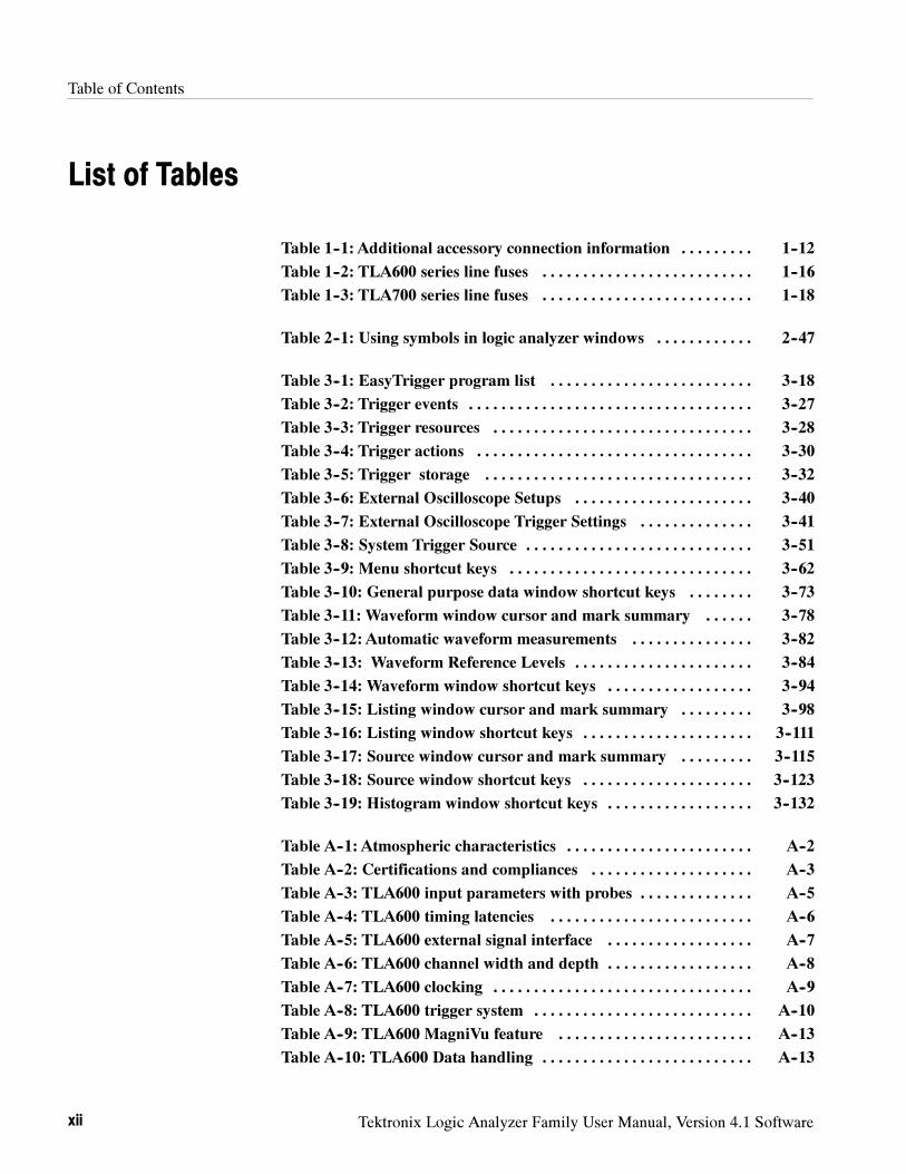
Table of Contents
xii Tektronix Logic Analyzer Family User Manual, Version 4.1 Software
List of Tables
Table 1--1: Additional accessory connection information 1--12. . . . . . . . .
Table 1--2: TLA600 series line fuses 1--16. . . . . . . . . . . . . . . . . . . . . . . . . .
Table 1--3: TLA700 series line fuses 1--18. . . . . . . . . . . . . . . . . . . . . . . . . .
Table 2--1: Using symbols in logic analyzer windows 2--47. . . . . . . . . . . .
Table 3--1: EasyTrigger program list 3--18. . . . . . . . . . . . . . . . . . . . . . . . .
Table 3--2: Trigger events 3--27. . . . . . . . . . . . . . . . . . . . . . . . . . . . . . . . . . .
Table 3--3: Trigger resources 3--28. . . . . . . . . . . . . . . . . . . . . . . . . . . . . . . .
Table 3--4: Trigger actions 3--30. . . . . . . . . . . . . . . . . . . . . . . . . . . . . . . . . .
Table 3--5: Trigger storage 3--32. . . . . . . . . . . . . . . . . . . . . . . . . . . . . . . . .
Table 3--6: External Oscilloscope Setups 3--40. . . . . . . . . . . . . . . . . . . . . .
Table 3--7: External Oscilloscope Trigger Settings 3--41. . . . . . . . . . . . . .
Table 3--8: System Trigger Source 3--51. . . . . . . . . . . . . . . . . . . . . . . . . . . .
Table 3--9: Menu shortcut keys 3--62. . . . . . . . . . . . . . . . . . . . . . . . . . . . . .
Table 3--10: General purpose data window shortcut keys 3--73. . . . . . . .
Table 3--11: Waveform window cursor and mark summary 3--78. . . . . .
Table 3--12: Automatic waveform measurements 3--82. . . . . . . . . . . . . . .
Table 3--13: Waveform Reference Levels 3--84. . . . . . . . . . . . . . . . . . . . . .
Table 3--14: Waveform window shortcut keys 3--94. . . . . . . . . . . . . . . . . .
Table 3--15: Listing window cursor and mark summary 3--98. . . . . . . . .
Table 3--16: Listing window shortcut keys 3--111. . . . . . . . . . . . . . . . . . . . .
Table 3--17: Source window cursor and mark summary 3--115. . . . . . . . .
Table 3--18: Source window shortcut keys 3--123. . . . . . . . . . . . . . . . . . . . .
Table 3--19: Histogram window shortcut keys 3--132. . . . . . . . . . . . . . . . . .
Table A--1: Atmospheric characteristics A--2. . . . . . . . . . . . . . . . . . . . . . .
Table A--2: Certifications and compliances A--3. . . . . . . . . . . . . . . . . . . .
Table A--3: TLA600 input parameters with probes A--5. . . . . . . . . . . . . .
Table A--4: TLA600 timing latencies A--6. . . . . . . . . . . . . . . . . . . . . . . . .
Table A--5: TLA600 external signal interface A--7. . . . . . . . . . . . . . . . . .
Table A--6: TLA600 channel width and depth A--8. . . . . . . . . . . . . . . . . .
Table A--7: TLA600 clocking A--9. . . . . . . . . . . . . . . . . . . . . . . . . . . . . . . .
Table A--8: TLA600 trigger system A--10. . . . . . . . . . . . . . . . . . . . . . . . . . .
Table A--9: TLA600 MagniVu feature A--13. . . . . . . . . . . . . . . . . . . . . . . .
Table A--10: TLA600 Data handling A--13. . . . . . . . . . . . . . . . . . . . . . . . . .
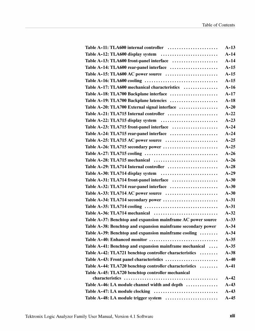
Table of Contents
Tektronix Logic Analyzer Family User Manual, Version 4.1 Software xiii
Table A--11: TLA600 internal controller A--13. . . . . . . . . . . . . . . . . . . . . .
Table A--12: TLA600 display system A--14. . . . . . . . . . . . . . . . . . . . . . . . .
Table A--13: TLA600 front-panel interface A--14. . . . . . . . . . . . . . . . . . . .
Table A--14: TLA600 rear-panel interface A--15. . . . . . . . . . . . . . . . . . . . .
Table A--15: TLA600 AC power source A--15. . . . . . . . . . . . . . . . . . . . . . .
Table A--16: TLA600 cooling A--15. . . . . . . . . . . . . . . . . . . . . . . . . . . . . . . .
Table A--17: TLA600 mechanical characteristics A--16. . . . . . . . . . . . . . .
Table A--18: TLA700 Backplane interface A--17. . . . . . . . . . . . . . . . . . . . .
Table A--19: TLA700 Backplane latencies A--18. . . . . . . . . . . . . . . . . . . . .
Table A--20: TLA700 External signal interface A--20. . . . . . . . . . . . . . . . .
Table A--21: TLA715 Internal controller A--22. . . . . . . . . . . . . . . . . . . . . .
Table A--22: TLA715 display system A--23. . . . . . . . . . . . . . . . . . . . . . . . .
Table A--23: TLA715 front-panel interface A--24. . . . . . . . . . . . . . . . . . . .
Table A--24: TLA715 rear-panel interface A--24. . . . . . . . . . . . . . . . . . . . .
Table A--25: TLA715 AC power source A--25. . . . . . . . . . . . . . . . . . . . . . .
Table A--26: TLA715 secondary power A--25. . . . . . . . . . . . . . . . . . . . . . . .
Table A--27: TLA715 cooling A--26. . . . . . . . . . . . . . . . . . . . . . . . . . . . . . . .
Table A--28: TLA715 mechanical A--26. . . . . . . . . . . . . . . . . . . . . . . . . . . .
Table A--29: TLA714 Internal controller A--28. . . . . . . . . . . . . . . . . . . . . .
Table A--30: TLA714 display system A--29. . . . . . . . . . . . . . . . . . . . . . . . .
Table A--31: TLA714 front-panel interface A--30. . . . . . . . . . . . . . . . . . . .
Table A--32: TLA714 rear-panel interface A--30. . . . . . . . . . . . . . . . . . . . .
Table A--33: TLA714 AC power source A--30. . . . . . . . . . . . . . . . . . . . . . .
Table A--34: TLA714 secondary power A--31. . . . . . . . . . . . . . . . . . . . . . . .
Table A--35: TLA714 cooling A--31. . . . . . . . . . . . . . . . . . . . . . . . . . . . . . . .
Table A--36: TLA714 mechanical A--32. . . . . . . . . . . . . . . . . . . . . . . . . . . .
Table A--37: Benchtop and expansion mainframe AC power source A--33
Table A--38: Benchtop and expansion mainframe secondary power A--34
Table A--39: Benchtop and expansion mainframe cooling A--34. . . . . . . .
Table A--40: Enhanced monitor A--35. . . . . . . . . . . . . . . . . . . . . . . . . . . . . .
Table A--41: Benchtop and expansion mainframe mechanical A--35. . . .
Table A--42: TLA721 benchtop controller characteristics A--38. . . . . . . .
Table A--43: Front panel characteristics A--40. . . . . . . . . . . . . . . . . . . . . . .
Table A--44: TLA720 benchtop controller characteristics A--41. . . . . . . .
Table A--45: TLA720 benchtop controller mechanical
characteristics A--42. . . . . . . . . . . . . . . . . . . . . . . . . . . . . . . . . . . . . . . . .
Table A--46: LA module channel width and depth A--43. . . . . . . . . . . . . .
Table A--47: LA module clocking A--43. . . . . . . . . . . . . . . . . . . . . . . . . . . .
Table A--48: LA module trigger system A--45. . . . . . . . . . . . . . . . . . . . . . .
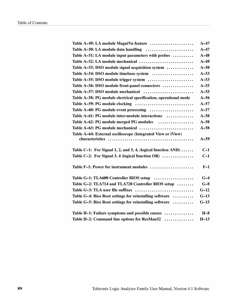
Table of Contents
xiv Tektronix Logic Analyzer Family User Manual, Version 4.1 Software
Table A--49: LA module MagniVu feature A--47. . . . . . . . . . . . . . . . . . . . .
Table A--50: LA module data handling A--47. . . . . . . . . . . . . . . . . . . . . . .
Table A--51: LA module input parameters with probes A--48. . . . . . . . . .
Table A--52: LA module mechanical A--49. . . . . . . . . . . . . . . . . . . . . . . . . .
Table A--53: DSO module signal acquisition system A--50. . . . . . . . . . . . .
Table A--54: DSO module timebase system A--53. . . . . . . . . . . . . . . . . . . .
Table A--55: DSO module trigger system A--53. . . . . . . . . . . . . . . . . . . . . .
Table A--56: DSO module front-panel connectors A--55. . . . . . . . . . . . . . .
Table A--57: DSO module mechanical A--55. . . . . . . . . . . . . . . . . . . . . . . .
Table A--58: PG module electrical specification, operational mode A--56
Table A--59: PG module clocking A--57. . . . . . . . . . . . . . . . . . . . . . . . . . . .
Table A--60: PG module event processing A--57. . . . . . . . . . . . . . . . . . . . .
Table A--61: PG module inter-module interactions A--58. . . . . . . . . . . . .
Table A--62: PG module merged PG modules A--58. . . . . . . . . . . . . . . . .
Table A--63: PG module mechanical A--58. . . . . . . . . . . . . . . . . . . . . . . . . .
Table A--64: External oscilloscope (Integrated View or iView)
characteristics A--59. . . . . . . . . . . . . . . . . . . . . . . . . . . . . . . . . . . . . . . . .
Table C--1: For Signal 1, 2, and 3, 4, (logical function AND) C--1. . . . . .
Table C--2: For Signal 3, 4 (logical function OR) C--1. . . . . . . . . . . . . . .
Table F--1: Power for instrument modules F--1. . . . . . . . . . . . . . . . . . . . .
Table G--1: TLA600 Controller BIOS setup G--4. . . . . . . . . . . . . . . . . . .
Table G--2: TLA714 and TLA720 Controller BIOS setup G--8. . . . . . . .
Table G--3: TLA user file suffixes G--12. . . . . . . . . . . . . . . . . . . . . . . . . . . .
Table G--4: Bios Boot settings for reinstalling software G--13. . . . . . . . . .
Table G--5: Bios Boot settings for reinstalling software G--15. . . . . . . . . .
Table H--1: Failure symptoms and possible causes H--8. . . . . . . . . . . . . .
Table H--2: Command line options for ResMan32 H--13. . . . . . . . . . . . . .
Tektronix Logic Analyzer Family User Manual, Version 4.1 Software xv
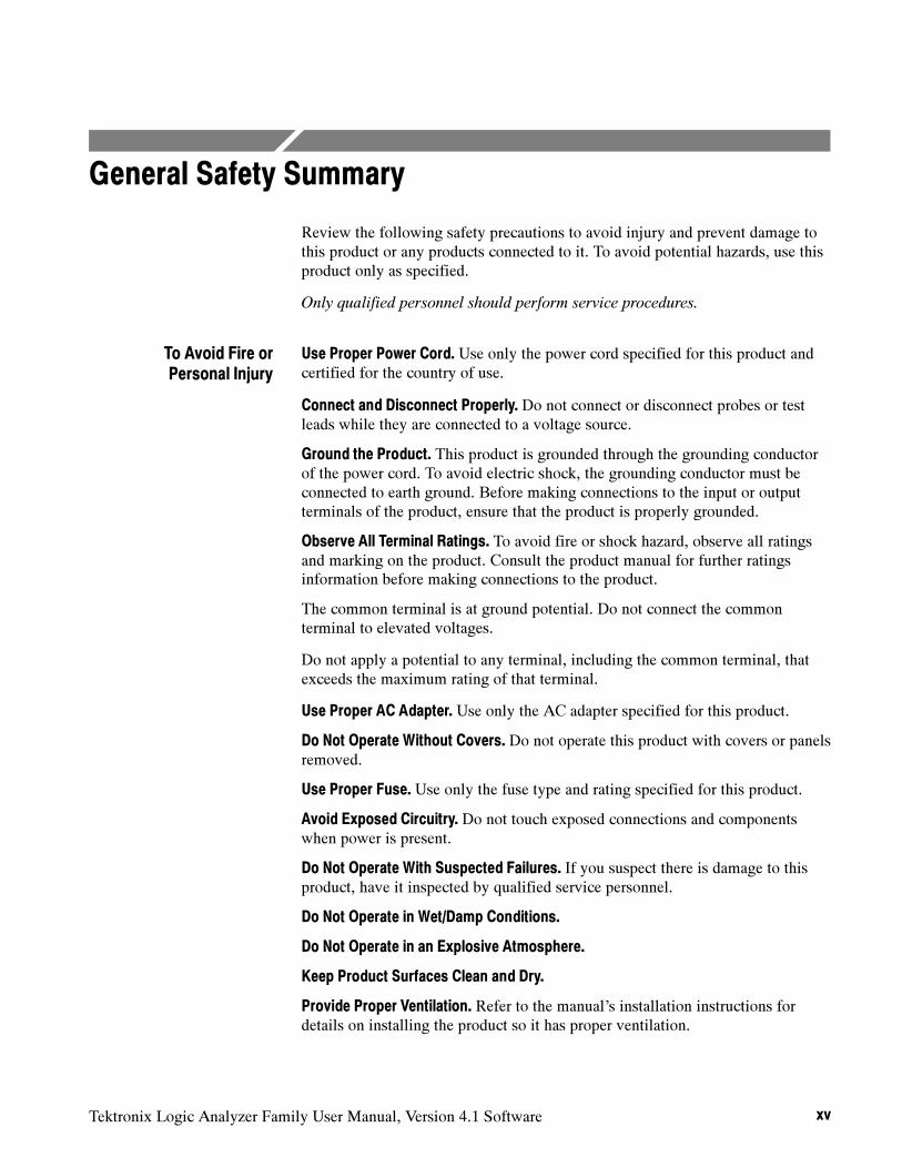
General Safety Summary
Review the following safety precautions to avoid injury and prevent damage tothis product or any products connected to it. To avoid potential hazards, use thisproduct only as specified.
Only qualified personnel should perform service procedures.
Use Proper Power Cord. Use only the power cord specified for this product andcertified for the country of use.
Connect and Disconnect Properly. Do not connect or disconnect probes or testleads while they are connected to a voltage source.
Ground the Product. This product is grounded through the grounding conductorof the power cord. To avoid electric shock, the grounding conductor must beconnected to earth ground. Before making connections to the input or outputterminals of the product, ensure that the product is properly grounded.
Observe All Terminal Ratings. To avoid fire or shock hazard, observe all ratingsand marking on the product. Consult the product manual for further ratingsinformation before making connections to the product.
The common terminal is at ground potential. Do not connect the commonterminal to elevated voltages.
Do not apply a potential to any terminal, including the common terminal, thatexceeds the maximum rating of that terminal.
Use Proper AC Adapter. Use only the AC adapter specified for this product.
Do Not Operate Without Covers. Do not operate this product with covers or panelsremoved.
Use Proper Fuse. Use only the fuse type and rating specified for this product.
Avoid Exposed Circuitry. Do not touch exposed connections and componentswhen power is present.
Do Not Operate With Suspected Failures. If you suspect there is damage to thisproduct, have it inspected by qualified service personnel.
Do Not Operate in Wet/Damp Conditions.
Do Not Operate in an Explosive Atmosphere.
Keep Product Surfaces Clean and Dry.
Provide Proper Ventilation. Refer to the manual’s installation instructions fordetails on installing the product so it has proper ventilation.
To Avoid Fire orPersonal Injury
General Safety Summary
xvi Tektronix Logic Analyzer Family User Manual, Version 4.1 Software
Terms in this Manual. These terms may appear in this manual:
WARNING.Warning statements identify conditions or practices that could result
in injury or loss of life.
CAUTION. Caution statements identify conditions or practices that could result in
damage to this product or other property.
Terms on the Product. These terms may appear on the product:
DANGER indicates an injury hazard immediately accessible as you read themarking.
WARNING indicates an injury hazard not immediately accessible as you read themarking.
CAUTION indicates a hazard to property including the product.
Symbols on the Product. The following symbols may appear on the product:
Protective Ground
(Earth) Terminal
CAUTION
Refer to Manual
Double
Insulated
WARNING
High Voltage
Symbols and Terms
Tektronix Logic Analyzer Family User Manual, Version 4.1 Software xvii
Preface
This manual contains operating information for the Tektronix Logic Analyzerfamily. The manual consists of the following sections:
Getting Started. Provides basic information about installing and using thelogic analyzer.
Operating Basics. Provides an overview of the logic analyzer connectors,introduces you to the logic analyzer and pattern generator windows, andexplains the basic operation of the Tektronix Logic Analyzer.
Reference. Provides detailed information of the logic analyzer. This sectionis broken down according to the window types.
Appendix A: Specifications. Lists the environmental, physical, and electricalproperties of the logic analyzer family.
Appendix B: TLA700 Symbol File Format. Provides information on thecontents of symbol files using the TLA700 Symbol File format.
Appendix C: PG Physical-Logical Conversion. Provides information onusing signals between the LA module, DSO module, and the PG module.
Appendix D: TLA700 Module Installation. Provides installation instructionsfor logic analyzer modules. Refer to this appendix if you need to installmodules in the TLA700 mainframes.
Appendix E: Merging Modules. Provides instructions for merging modules tocreate wider mainframes for specific applications.
Appendix F: Power Cord and Line Fuse Requirements for the Benchtop and
Expansion Mainframes. Provides information on the power and fuserequirements for the benchtop and expansion mainframes.
Appendix G: Installing Software. Provides instructions for reinstalling thesystem and application software and firmware.
Appendix H: User Service. Provides user service information.
Preface
xviii Tektronix Logic Analyzer Family User Manual, Version 4.1 Software
Related Documentation
In addition to this user manual, the following documentation is available for yourTektronix logic analyzer:
The online help provides information about the user interface, the TLA700Programmatic Interface (TPI), and the TLAScript interface. To view theonline help, select Help Topics from the Help menu. The TLAScript onlinehelp provides links to related topics in TPI.
The TLA7PG2 online help provides information about the pattern generatoruser interface and the Pattern Generator Programmatic Interface (PPI). Toview the online help, select Help Topics from the Help menu in theTLA7PG2 application.
The online release notes provide last-minute product and software informa-tion not included in this manual. Refer to Release Notes on page 1--29 forinformation on viewing the release notes.
A series of microprocessor support instruction manuals provide operatingand service instructions for the individual microprocessor support packages.
The TLA7QS QuickStart Training Manual provides training exercises to helpyou learn key features of the logic analyzer. The training manual is designedto be used with the TLA7QS QuickStart training board.
A series of service manuals provide board-level service information for thelogic analyzer modules and mainframes.
A series of probe manuals provide detailed instructions for using individuallogic analyzer and pattern generator probes.
Terms Used in this Manual
The following terms are used throughout this manual. Refer to the Glossary forinformation on other logic analyzer terminology.
LA Module. An abbreviation and generic term for the logic analyzermodule.
DSO Module. An abbreviation and generic term for the oscilloscopemodule.
PG Module. An abbreviation and generic term for the pattern generatormodule.
Preface
Tektronix Logic Analyzer Family User Manual, Version 4.1 Software xix
What’s New in This Manual
The Tektronix Logic Analyzer family consists of the TLA600 and TLA700series logic analyzers, and all of the accessories and supports that can be usedwith them. This manual includes information on product enhancements, newfeatures, and information on using these to improve your instrument performanceand reliability. Specifically, this manual has been updated to include informationon the following:
Integrated View (iView) with TLA--TDS Interoperability. You can nowview data from your TDS oscilloscope directly on your TLA600/700 logicanalyzer display, allowing you to quickly track down elusive digital signalquality problems. Access the highest performance Tektronix oscilloscopeswith capabilities of up to 4 GHz bandwidth, 20 GS/s sample rate, and up to32 Mb depth per channel to solve your toughest signal integrity problems.
Simplify the setup of your TDS with the TLA with the built-in iViewConnection Wizard that shows you how to connect both instruments usingthe iView External Oscilloscope Cable. You will be able to set up crosstriggering as needed, acquire data, and automatically view the LA and TDSacquisition data in a single, time-correlated window on the logic analyzer.
Enhanced DSO Interface. You can perform DSO measurements and dragand drop waveforms over each other to view overlapping waveform data.
EasyTrigger. Simplify trigger setup by choosing one of several predefinedtrigger programs. Each one comes with a graphic showing the signalconditions necessary for a trigger in addition to a text description. UseEasyTrigger to concentrate on quickly solving elusive problems rather thanspending hours on the nuances of logic analyzer trigger programming. Youcan view and even build upon the underlying trigger programming of eachEasyTrigger by switching to the classic PowerTrigger programming view.
Screen Capture Tool. Use this tool to capture any part of the TLA displayto a graphic file or send it directly to a printer with a single keystroke, usingTechSmith’s SnagIt. Capture the entire screen, a specific window, or anarea of the screen. File formats supported include GIF, JPEG, TIF, PCX,PNG, BMP, and AVI.
Preface
xx Tektronix Logic Analyzer Family User Manual, Version 4.1 Software
Contacting Tektronix
Phone 1-800-833-9200*
Address Tektronix, Inc.Department or name (if known)14200 SW Karl Braun DriveP.O. Box 500Beaverton, OR 97077USA
Web site www.tektronix.com
Sales support 1-800-833-9200, select option 1*
Service support 1-800-833-9200, select option 2*
Technical support Email: [email protected]
1-800-833-9200, select option 3*1-503-627-2400
6:00 a.m. -- 5:00 p.m. Pacific time
* This phone number is toll free in North America. After office hours, please leave avoice mail message.Outside North America, contact a Tektronix sales office or distributor; see theTektronix web site for a list of offices.

Getting Started

Tektronix Logic Analyzer Family User Manual, Version 4.1 Software 1- 1
Getting Started
The Tektronix Logic Analyzer family consists of the TLA600 and TLA700series logic analyzers, and all of the accessories and supports that can be usedwith them. For more information about availability, contact your Tektronixrepresentative and view the Tektronix website at: www.tektronix.com.
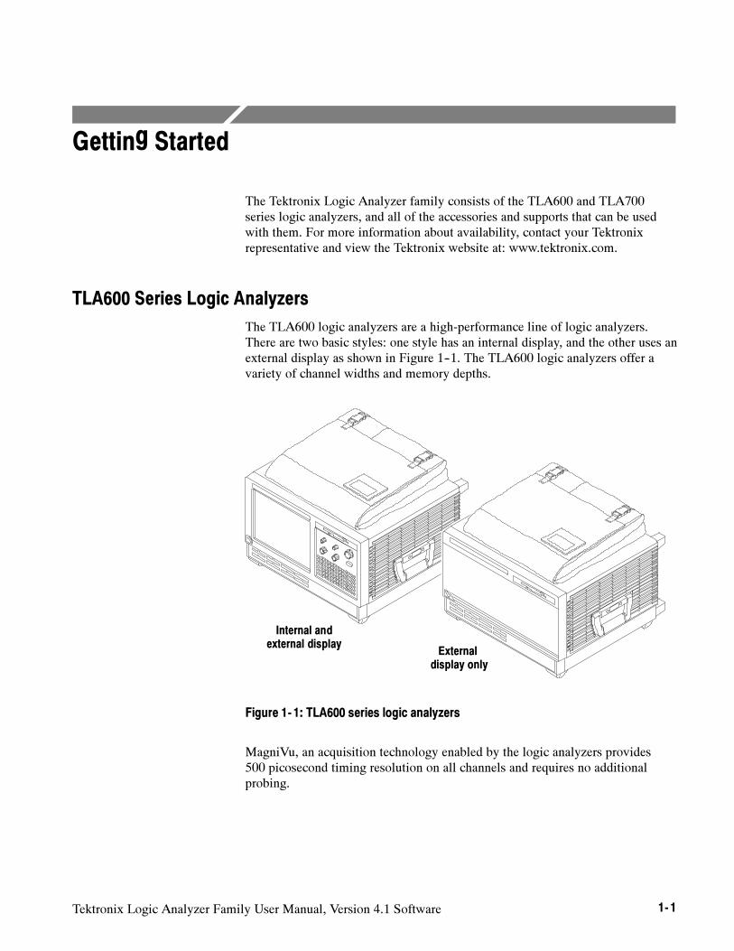
TLA600 Series Logic Analyzers
The TLA600 logic analyzers are a high-performance line of logic analyzers.There are two basic styles: one style has an internal display, and the other uses anexternal display as shown in Figure 1--1. The TLA600 logic analyzers offer avariety of channel widths and memory depths.
Internal andexternal display
Externaldisplay only
Figure 1- 1: TLA600 series logic analyzers
MagniVu, an acquisition technology enabled by the logic analyzers provides500 picosecond timing resolution on all channels and requires no additionalprobing.
Getting Started
1- 2 Tektronix Logic Analyzer Family User Manual, Version 4.1 Software
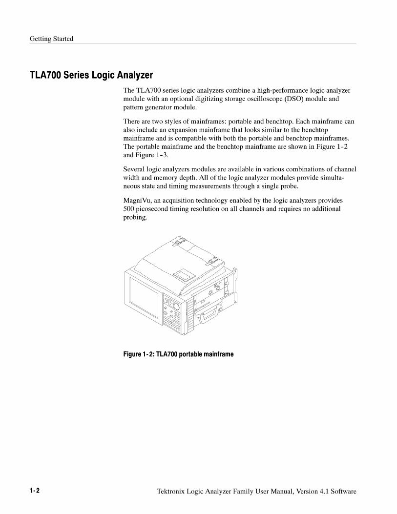
TLA700 Series Logic Analyzer
The TLA700 series logic analyzers combine a high-performance logic analyzermodule with an optional digitizing storage oscilloscope (DSO) module andpattern generator module.
There are two styles of mainframes: portable and benchtop. Each mainframe canalso include an expansion mainframe that looks similar to the benchtopmainframe and is compatible with both the portable and benchtop mainframes.The portable mainframe and the benchtop mainframe are shown in Figure 1--2and Figure 1--3.
Several logic analyzers modules are available in various combinations of channelwidth and memory depth. All of the logic analyzer modules provide simulta-neous state and timing measurements through a single probe.
MagniVu, an acquisition technology enabled by the logic analyzers provides500 picosecond timing resolution on all channels and requires no additionalprobing.
Figure 1- 2: TLA700 portable mainframe
Getting Started
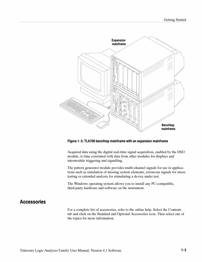
Tektronix Logic Analyzer Family User Manual, Version 4.1 Software 1- 3
Benchtopmainframe
Expansionmainframe
Figure 1- 3: TLA700 benchtop mainframe with an expansion mainframe
Acquired data using the digital real-time signal acquisition, enabled by the DSOmodule, is time correlated with data from other modules for displays andintermodule triggering and signalling.
The pattern generator module provides multi-channel signals for use in applica-tions such as simulation of missing system elements, erroneous signals for stresstesting or extended analysis for stimulating a device under test.
The Windows operating system allows you to install any PC-compatible,third-party hardware and software on the instrument.
Accessories
For a complete list of accessories, refer to the online help. Select the Contentstab and click on the Standard and Optional Accessories icon. Then select one ofthe topics for more information.
Getting Started
1- 4 Tektronix Logic Analyzer Family User Manual, Version 4.1 Software
Installation
This section describes the steps needed to install your Tektronix logic analyzer.
Verify that you have received all of the parts of your logic analyzer using theshipping list. You should also verify the following:
Verify that you have the correct power cords for your geographical area.
Verify that you have backup copies of the installed software. Store thebackup software in a safe location where you can easily retrieve the softwarefor maintenance purposes.
Verify that you have the correct probes (and modules if you have a TLA700series logic analyzer).
Verify that you have all the standard and optional accessories that youordered.
NOTE. Keep the software packaging available because you will need it to enter
the Windows software registration number when you first turn on the logic
analyzer.
Fill out and send in the customer registration card that is packaged with thismanual.
Read this section before installing the logic analyzer. This section describes siteconsiderations, power requirements, and ground connections for your logicanalyzer.
CAUTION. Ensure a two inch (5.1 cm) clearance at the bottom and sides of the
instrument to ensure proper cooling.
TLA600 and TLA714/715 Logic Analyzers.You can use the TLA600 and TLA715logic analyzer on a bench or on a cart in the normal position (on the bottom feet).
You can also use the logic analyzer while it rests on the rear feet. If you use theinstrument while it is resting on the rear feet, make sure that you properly routeany cables coming out of the rear of the instrument to avoid damaging them.
TLA720/721 Benchtop and TLA7XM Expansion Mainframes. The benchtop andexpansion mainframes are designed to operate on a bench or in a rackmountenvironment.
Check the Shipping List
Site Considerations
Getting Started
Tektronix Logic Analyzer Family User Manual, Version 4.1 Software 1- 5
Do not stack more then one expansion mainframe on top of the benchtopmainframe or stack more than one expansion mainframe on top of anotherexpansion mainframe.
If you need to stack more than two benchtop and expansion mainframes, installthe mainframes in a rack. Rackmount kits are available from third-party vendors.Please refer to the online help under Standard and Optional Accessories for partnumbers on the rackmount kits.
CAUTION. Because of the size and weight of the benchtop and expansion
mainframes use care when lifting or moving the mainframe to avoid personal
injury while performing the installation procedures.
For safety always use two people to lift or move the mainframes.
Installing Expansion Mainframes
This section describes how to install a TLA7XM expansion mainframe. If yourlogic analyzer does not contain any expansion mainframes, you can skip thissection. Observe the following guidelines when installing expansion mainframes:
Do not stack more than one mainframe on top of another mainframe withouta rackmount kit.
The expansion module must be installed in slot 0 of the expansion main-frame.
NOTE. Verify that all mainframes are powered off before continuing the
installation procedure.
The expansion module can be installed in any slot of the benchtop mainframeexcept 0--2, which is reserved for the benchtop controller module. If you are onlyinstalling one expansion mainframe, you can install the expansion module inslot 12 to keep the expansion cables out of your way.
NOTE. If you are installing more than two expansion mainframes, always use a
rackmount kit. Do not stack more than one expansion mainframe on top of a
benchtop or another expansion mainframe. Contact your local Tektronix
representative for information on site considerations for multiple mainframes.
Installing in a benchtopMainframe
Getting Started
1- 6 Tektronix Logic Analyzer Family User Manual, Version 4.1 Software
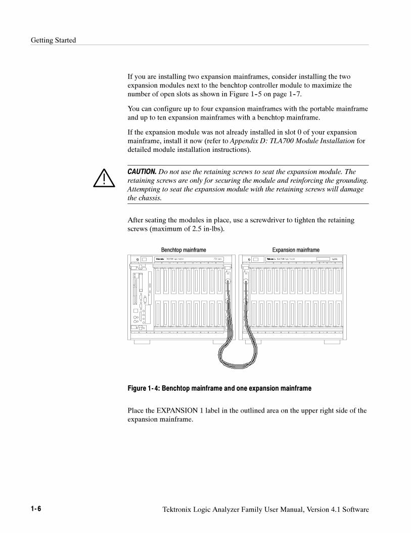
If you are installing two expansion mainframes, consider installing the twoexpansion modules next to the benchtop controller module to maximize thenumber of open slots as shown in Figure 1--5 on page 1--7.
You can configure up to four expansion mainframes with the portable mainframeand up to ten expansion mainframes with a benchtop mainframe.
If the expansion module was not already installed in slot 0 of your expansionmainframe, install it now (refer to Appendix D: TLA700 Module Installation fordetailed module installation instructions).
CAUTION. Do not use the retaining screws to seat the expansion module. The
retaining screws are only for securing the module and reinforcing the grounding.
Attempting to seat the expansion module with the retaining screws will damage
the chassis.
After seating the modules in place, use a screwdriver to tighten the retainingscrews (maximum of 2.5 in-lbs).
Expansion mainframeBenchtop mainframe
Figure 1- 4: Benchtop mainframe and one expansion mainframe
Place the EXPANSION 1 label in the outlined area on the upper right side of theexpansion mainframe.
Getting Started
Tektronix Logic Analyzer Family User Manual, Version 4.1 Software 1- 7
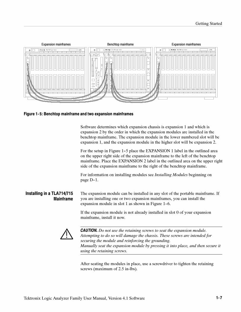
Benchtop mainframeExpansion mainframes Expansion mainframes
Figure 1- 5: Benchtop mainframe and two expansion mainframes
Software determines which expansion chassis is expansion 1 and which isexpansion 2 by the order in which the expansion modules are installed in thebenchtop mainframe. The expansion module in the lower numbered slot will beexpansion 1, and the expansion module in the higher slot will be expansion 2.
For the setup in Figure 1--5 place the EXPANSION 1 label in the outlined areaon the upper right side of the expansion mainframe to the left of the benchtopmainframe. Place the EXPANSION 2 label in the outlined area on the upper rightside of the expansion mainframe to the right of the benchtop mainframe.
For information on installing modules see Installing Modules beginning onpage D--1.
The expansion module can be installed in any slot of the portable mainframe. Ifyou are installing one or two expansion mainframes, you can install theexpansion module in slot 1 as shown in Figure 1--6.
If the expansion module is not already installed in slot 0 of your expansionmainframe, install it now.
CAUTION. Do not use the retaining screws to seat the expansion module.
Attempting to do so will damage the chassis. These screws are intended for
securing the module and reinforcing the grounding.
Manually seat the expansion module by pressing it into place, and then secure it
using the retaining screws.
After seating the modules in place, use a screwdriver to tighten the retainingscrews (maximum of 2.5 in-lbs).
Installing in a TLA714/715Mainframe
Getting Started
1- 8 Tektronix Logic Analyzer Family User Manual, Version 4.1 Software
Portable mainframe
Expansion mainframe Expansion mainframe
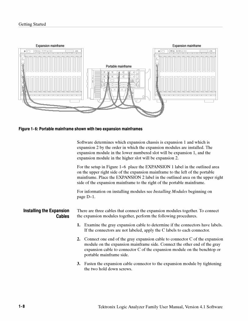
Figure 1- 6: Portable mainframe shown with two expansion mainframes
Software determines which expansion chassis is expansion 1 and which isexpansion 2 by the order in which the expansion modules are installed. Theexpansion module in the lower numbered slot will be expansion 1, and theexpansion module in the higher slot will be expansion 2.
For the setup in Figure 1--6 place the EXPANSION 1 label in the outlined areaon the upper right side of the expansion mainframe to the left of the portablemainframe. Place the EXPANSION 2 label in the outlined area on the upper rightside of the expansion mainframe to the right of the portable mainframe.
For information on installing modules see Installing Modules beginning onpage D--1.
There are three cables that connect the expansion modules together. To connectthe expansion modules together, perform the following procedures.
1. Examine the gray expansion cable to determine if the connectors have labels.If the connectors are not labeled, apply the C labels to each connector.
2. Connect one end of the gray expansion cable to connector C of the expansionmodule on the expansion mainframe side. Connect the other end of the grayexpansion cable to connector C of the expansion module on the benchtop orportable mainframe side.
3. Fasten the expansion cable connector to the expansion module by tighteningthe two hold down screws.
Installing the ExpansionCables
Getting Started
Tektronix Logic Analyzer Family User Manual, Version 4.1 Software 1- 9
CAUTION. Do not use the hold down screws to seat the expansion cable. The hold
down screws are only for securing the cable to the module and reinforcing the
grounding. Attempting to seat the expansion cable with the hold down screws
will damage the connectors on the chassis.
4. Examine the two blue expansion cables to determine if the connectors arelabeled A and B. If the cables are labeled A and B, select the B cable andproceed to step 6.
5. If the cables are not labeled, select either blue expansion cable and label eachconnector with the B label. Select the other cable and apply the A labels toeach connector.
6. Connect one end of the blue expansion cable to connector B of the expansionmodule on the expansion mainframe side. Connect the other end of the blueexpansion cable to connector B of the expansion module on the benchtop orportable mainframe side.
7. Fasten the expansion cable connector to the expansion module by tighteningthe two hold down screws.
8. Connect one end of the blue expansion cable to connector A of the expansionmodule on the expansion mainframe side. Connect the other end of the blueexpansion cable to connector A of the expansion module on the benchtop orportable mainframe side.
9. Fasten the expansion cable connector to the expansion module by tighteningthe two hold down screws.
Installing TLA 700 Modules
If you need to install additional modules for the TLA700 series logic analyzers,refer to Appendix D: TLA700 Module Installation for detailed instructions.
Connecting Accessories
After installing the mainframes and modules, you can connect the accessoriessuch as external monitors, keyboard, and printer.
Getting Started
1- 10 Tektronix Logic Analyzer Family User Manual, Version 4.1 Software
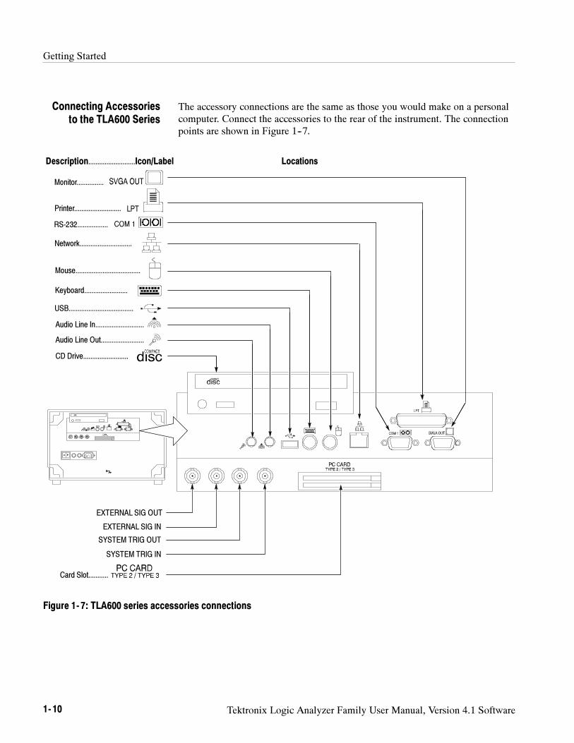
The accessory connections are the same as those you would make on a personalcomputer. Connect the accessories to the rear of the instrument. The connectionpoints are shown in Figure 1--7.
Monitor...............
Printer..........................
RS-232.................
Network.............................
Mouse....................................
Keyboard........................
USB....................................
CD Drive.........................
Card Slot...........
Description..........................Icon/Label Locations
Audio Line In...........................
Audio Line Out........................
EXTERNAL SIG OUT
EXTERNAL SIG IN
SYSTEM TRIG OUT
SYSTEM TRIG IN
Figure 1- 7: TLA600 series accessories connections
Connecting Accessoriesto the TLA600 Series
Getting Started
Tektronix Logic Analyzer Family User Manual, Version 4.1 Software 1- 11
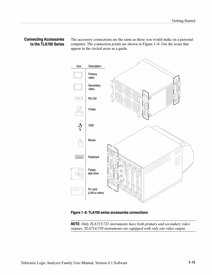
The accessory connections are the same as those you would make on a personalcomputer. The connection points are shown in Figure 1--8. Use the icons thatappear in the circled areas as a guide.
Primaryvideo
Mouse
Keyboard
Printer
RS-232
PC card(LAN or other)
Floppydisk drive
Icon Description
USB
Secondaryvideo
Figure 1- 8: TLA700 series accessories connections
NOTE. Only TLA715/721 instruments have both primary and secondary video
outputs. TLA714/720 instruments are equipped with only one video output.
Connecting Accessoriesto the TLA700 Series
Getting Started
1- 12 Tektronix Logic Analyzer Family User Manual, Version 4.1 Software
Table 1--1 provides additional information on accessories.
Table 1- 1: Additional accessory connection information
Item Description
Monitor If you use a non-standard monitor, you may need to change thethe Windows display settings to achieve the proper resolution.
Printer Connect the printer to the ECP (enhanced parallel port)connector directly. If your printer has a DB--25 connector, usethe adapter cable that came with your logic analyzer to connectto the ECP connector.
Connecting Probes
After you have connected all of the accessories, you should now connect theprobes to the instrument. Refer to the appropriate section for your instrument.
For additional information on the individual probes, refer to the instructions thatcame with your probes.
Additional AccessoryConnection Information
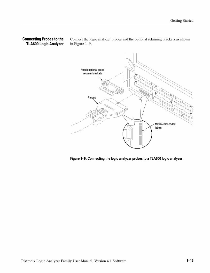
Getting Started
Tektronix Logic Analyzer Family User Manual, Version 4.1 Software 1- 13
Connect the logic analyzer probes and the optional retaining brackets as shownin Figure 1--9.
Match color-codedlabels
Attach optional proberetainer brackets
Probes
Figure 1- 9: Connecting the logic analyzer probes to a TLA600 logic analyzer
Connecting Probes to theTLA600 Logic Analyzer
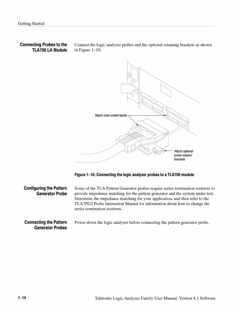
Getting Started
1- 14 Tektronix Logic Analyzer Family User Manual, Version 4.1 Software
Connect the logic analyzer probes and the optional retaining brackets as shownin Figure 1--10.
Match color-coded labels
Attach optionalprobe retainerbrackets
Figure 1- 10: Connecting the logic analyzer probes to a TLA700 module
Some of the TLA Pattern Generator probes require series termination resistors toprovide impedance matching for the pattern generator and the system under test.Determine the impedance matching for your application, and then refer to theTLA7PG2 Probe Instruction Manual for information about how to change theseries termination resistors.
Power down the logic analyzer before connecting the pattern generator probe.
Connecting Probes to theTLA700 LA Module
Configuring the PatternGenerator Probe
Connecting the PatternGenerator Probes
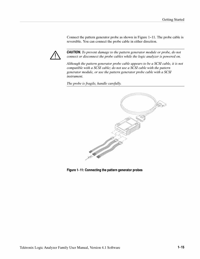
Getting Started
Tektronix Logic Analyzer Family User Manual, Version 4.1 Software 1- 15
Connect the pattern generator probe as shown in Figure 1--11. The probe cable isreversible. You can connect the probe cable in either direction.
CAUTION. To prevent damage to the pattern generator module or probe, do not
connect or disconnect the probe cables while the logic analyzer is powered on.
Although the pattern generator probe cable appears to be a SCSI cable, it is not
compatible with a SCSI cable; do not use a SCSI cable with the pattern
generator module, or use the pattern generator probe cable with a SCSI
instrument.
The probe is fragile, handle carefully.
Figure 1- 11: Connecting the pattern generator probes
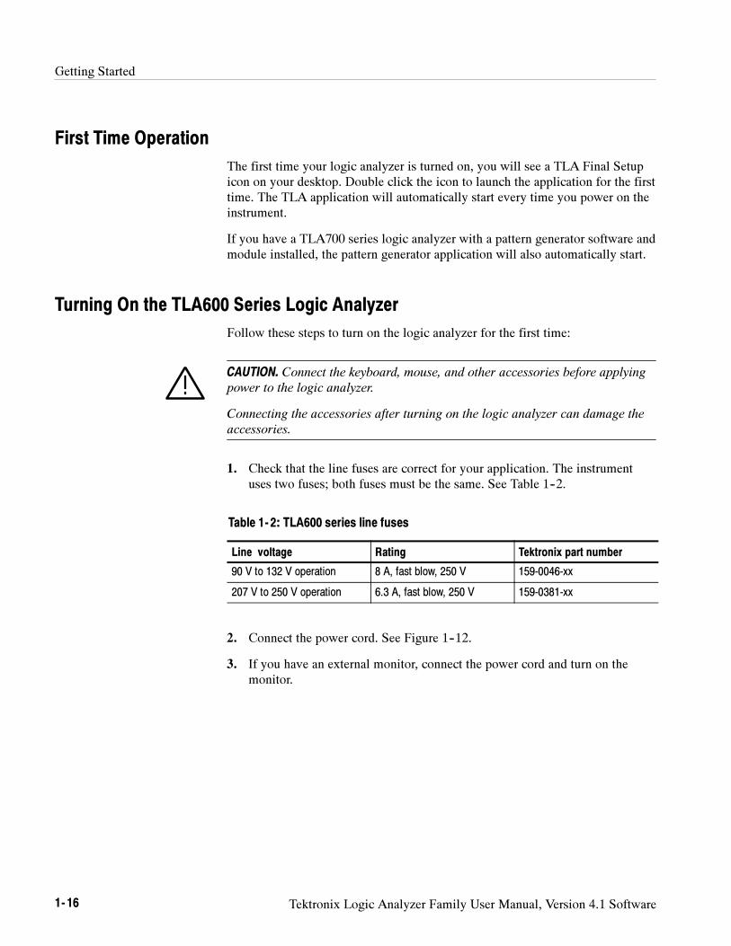
Getting Started
1- 16 Tektronix Logic Analyzer Family User Manual, Version 4.1 Software
First Time Operation
The first time your logic analyzer is turned on, you will see a TLA Final Setupicon on your desktop. Double click the icon to launch the application for the firsttime. The TLA application will automatically start every time you power on theinstrument.
If you have a TLA700 series logic analyzer with a pattern generator software andmodule installed, the pattern generator application will also automatically start.
Turning On the TLA600 Series Logic Analyzer
Follow these steps to turn on the logic analyzer for the first time:
CAUTION. Connect the keyboard, mouse, and other accessories before applying
power to the logic analyzer.
Connecting the accessories after turning on the logic analyzer can damage the
accessories.
1. Check that the line fuses are correct for your application. The instrumentuses two fuses; both fuses must be the same. See Table 1--2.
Table 1- 2: TLA600 series line fuses
Line voltage Rating Tektronix part number
90 V to 132 V operation 8 A, fast blow, 250 V 159-0046-xx
207 V to 250 V operation 6.3 A, fast blow, 250 V 159-0381-xx
2. Connect the power cord. See Figure 1--12.
3. If you have an external monitor, connect the power cord and turn on themonitor.
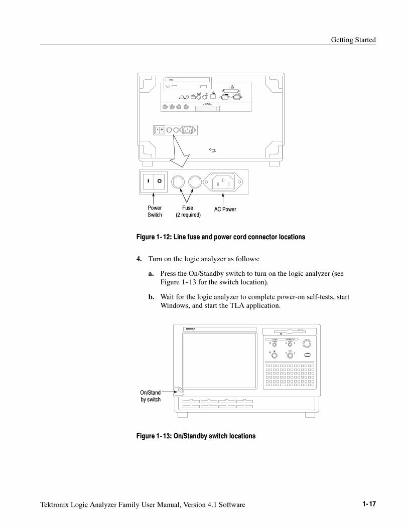
Getting Started
Tektronix Logic Analyzer Family User Manual, Version 4.1 Software 1- 17
AC PowerFuse(2 required)
PowerSwitch
Figure 1- 12: Line fuse and power cord connector locations
4. Turn on the logic analyzer as follows:
a. Press the On/Standby switch to turn on the logic analyzer (seeFigure 1--13 for the switch location).
b. Wait for the logic analyzer to complete power-on self-tests, startWindows, and start the TLA application.
On/Standby switch
Figure 1- 13: On/Standby switch locations
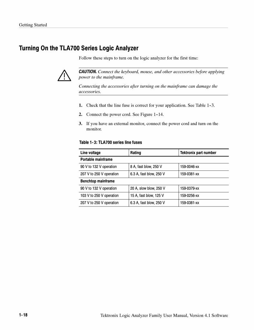
Getting Started
1- 18 Tektronix Logic Analyzer Family User Manual, Version 4.1 Software
Turning On the TLA700 Series Logic Analyzer
Follow these steps to turn on the logic analyzer for the first time:
CAUTION. Connect the keyboard, mouse, and other accessories before applying
power to the mainframe.
Connecting the accessories after turning on the mainframe can damage the
accessories.
1. Check that the line fuse is correct for your application. See Table 1--3.
2. Connect the power cord. See Figure 1--14.
3. If you have an external monitor, connect the power cord and turn on themonitor.
Table 1- 3: TLA700 series line fuses
Line voltage Rating Tektronix part number
Portable mainframe
90 V to 132 V operation 8 A, fast blow, 250 V 159-0046-xx
207 V to 250 V operation 6.3 A, fast blow, 250 V 159-0381-xx
Benchtop mainframe
90 V to 132 V operation 20 A, slow blow, 250 V 159-0379-xx
103 V to 250 V operation 15 A, fast blow, 125 V 159-0256-xx
207 V to 250 V operation 6.3 A, fast blow, 250 V 159-0381-xx
Getting Started
Tektronix Logic Analyzer Family User Manual, Version 4.1 Software 1- 19
AC power and fuse
Figure 1- 14: Line fuse and power cord connector locations
CAUTION. Although the benchtop mainframe can use the power cord with the
15 A plug, mainframes operating at low line (90 VAC) with four or more
instrument modules may require the power cord with the 20 A plug.
If you have four or more modules in your mainframe, you must determine the
correct fuse and power cord combination to avoid overloading the power
distribution system.
See Power Cord and Line Fuse Requirements for the Benchtop Mainframe forfurther information.
4. Turn on the mainframe as follows:
a. Press the On/Standby switch to turn on the mainframe (see Figure 1--15for the switch location).
b. Wait for the mainframe to complete power-on self-tests, start Windows,and start the TLA700 application.
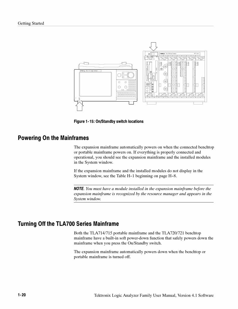
Getting Started
1- 20 Tektronix Logic Analyzer Family User Manual, Version 4.1 Software
Figure 1- 15: On/Standby switch locations
Powering On the Mainframes
The expansion mainframe automatically powers on when the connected benchtopor portable mainframe powers on. If everything is properly connected andoperational, you should see the expansion mainframe and the installed modulesin the System window.
If the expansion mainframe and the installed modules do not display in theSystem window, see the Table H--1 beginning on page H--8.
NOTE. You must have a module installed in the expansion mainframe before the
expansion mainframe is recognized by the resource manager and appears in the
System window.
Turning Off the TLA700 Series Mainframe
Both the TLA714/715 portable mainframe and the TLA720/721 benchtopmainframe have a built-in soft power-down function that safely powers down themainframe when you press the On/Standby switch.
The expansion mainframe automatically powers down when the benchtop orportable mainframe is turned off.
Getting Started
Tektronix Logic Analyzer Family User Manual, Version 4.1 Software 1- 21
Performing the Incoming Inspection
Incoming inspection consists of verifying the basic operation of the logicanalyzer. The power-on diagnostics check the basic functionality. Thesediagnostics run every time you turn on the logic analyzer.
You can also verify more detailed functionality by running the self calibrationand extended diagnostics.
NOTE. Allow the mainframe and modules to warm up for 30 minutes before
running the self calibration.
Disconnect any probes attached to the modules. Then select the System menu,and point to Calibration and Diagnostics. Run the self calibration followed bythe extended diagnostics by selecting the proper tab. Results of the tests displayon the individual property page.
If you are using a pattern generator, select the Pattern Generator System menuand point to Calibration and Diagnostics. Run the self calibration followed bythe extended diagnostics by selecting the proper tab. Results of the tests displayon the individual property page.
NOTE. The time required to run the self calibration on the logic analyzer
modules depends on the number of acquisition channels.
Modules with a large number of channels may take several minutes to run the
self calibration.
Connect the logic analyzer probes to a signal source, start an acquisition, andverify that the acquired data is displayed in either the listing or waveformwindows.
NOTE. If you connect probes to any channels besides the A2 and A3 groups, you
must define the groups and channels in the Setup window before acquiring data
on other probe channels.
Checking the LogicAnalyzer Probes
(Optional)
Getting Started
1- 22 Tektronix Logic Analyzer Family User Manual, Version 4.1 Software
Connect the oscilloscope probes to the Probe Compensation connector on thefront panel of the DSO module. You can then run the Calibrate Probe function ineach vertical setup page for the module.
Set up a simple pattern generator program to output a signal to the probes.Connect an oscilloscope probe to the probe outputs and verify that the signal ispresent at the probe outputs.
To check the mainframe diagnostics not covered by the TLA Applicationsoftware. Run the QA+Win32 diagnostics or the TLA700 Mainframe Diagnos-tics located under the Windows Start menu under the Tektronix TLA700programs. Exit the TLA Application before running the external diagnostics.
Backing Up User Files
Back up your user files on a regular basis. Use the Windows back up tools orcopy the files to floppy disks, to a network drive, or to another media. Alwayskeep a backup copy of files that you access on a regular basis.
Checking the DSO Probes(Optional)
Checking the PatternGenerator Probes
(Optional)
Checking the Mainframe(Optional)
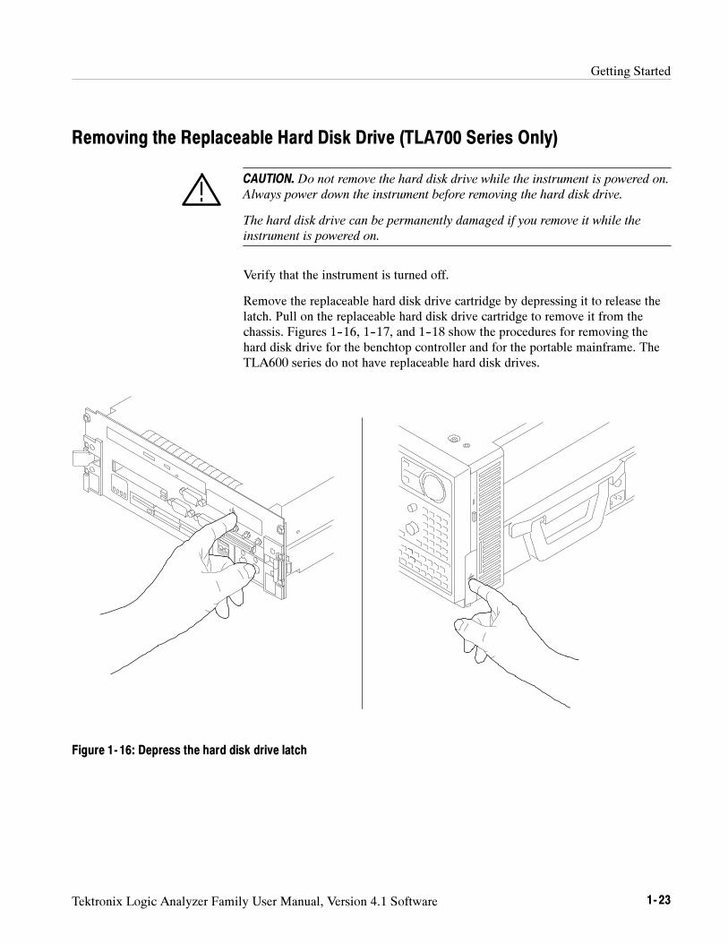
Getting Started
Tektronix Logic Analyzer Family User Manual, Version 4.1 Software 1- 23
Removing the Replaceable Hard Disk Drive (TLA700 Series Only)
CAUTION. Do not remove the hard disk drive while the instrument is powered on.
Always power down the instrument before removing the hard disk drive.
The hard disk drive can be permanently damaged if you remove it while the
instrument is powered on.
Verify that the instrument is turned off.
Remove the replaceable hard disk drive cartridge by depressing it to release thelatch. Pull on the replaceable hard disk drive cartridge to remove it from thechassis. Figures 1--16, 1--17, and 1--18 show the procedures for removing thehard disk drive for the benchtop controller and for the portable mainframe. TheTLA600 series do not have replaceable hard disk drives.
Figure 1- 16: Depress the hard disk drive latch
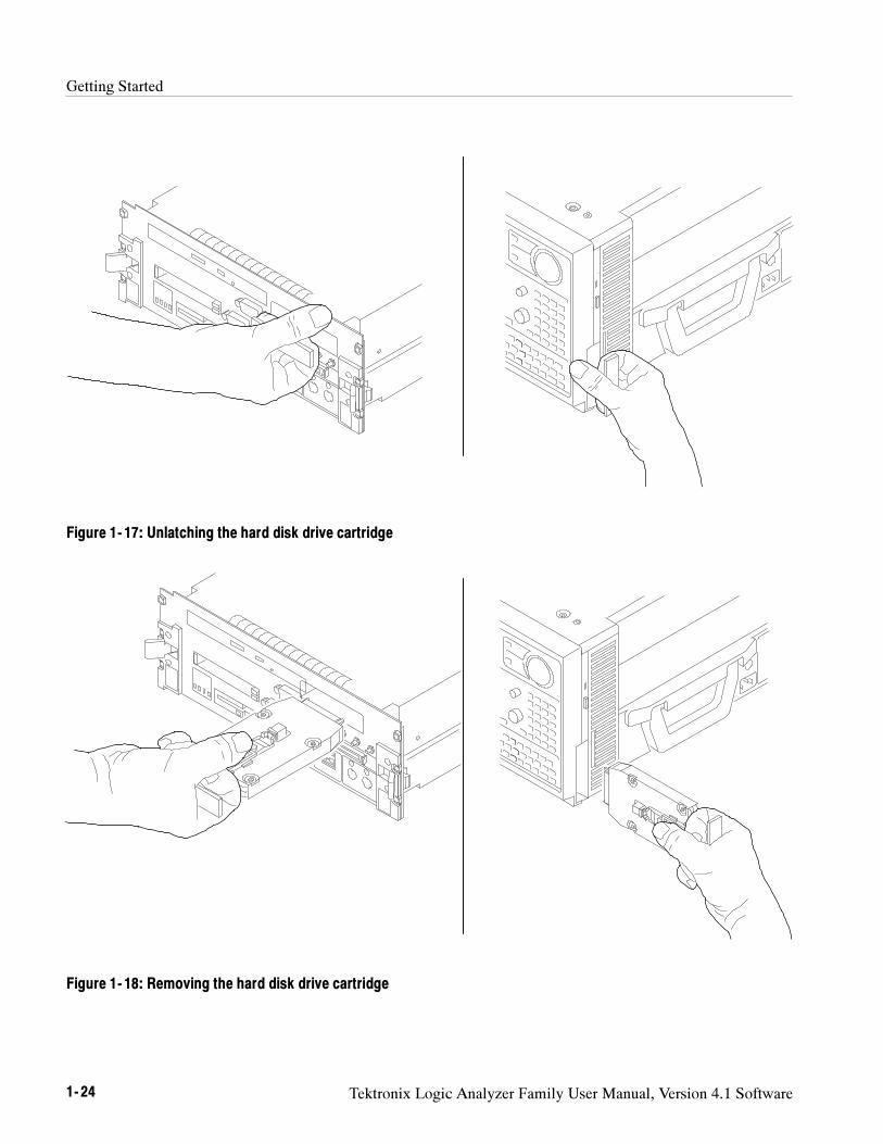
Getting Started
1- 24 Tektronix Logic Analyzer Family User Manual, Version 4.1 Software
Figure 1- 17: Unlatching the hard disk drive cartridge
Figure 1- 18: Removing the hard disk drive cartridge
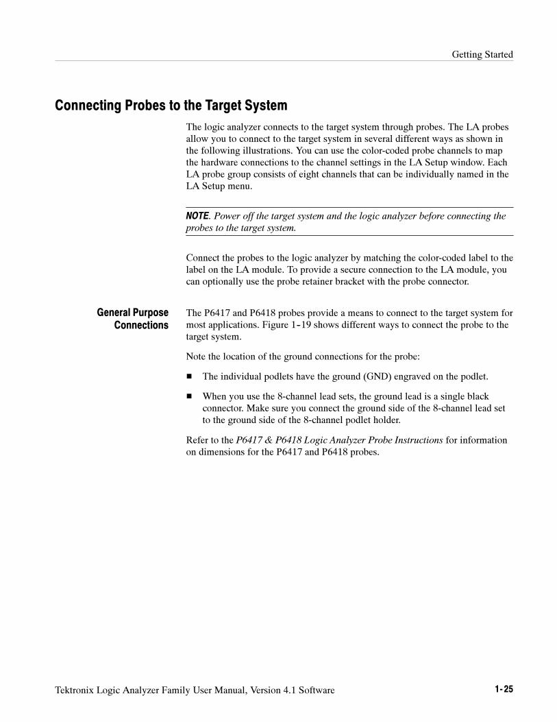
Getting Started
Tektronix Logic Analyzer Family User Manual, Version 4.1 Software 1- 25
Connecting Probes to the Target System
The logic analyzer connects to the target system through probes. The LA probesallow you to connect to the target system in several different ways as shown inthe following illustrations. You can use the color-coded probe channels to mapthe hardware connections to the channel settings in the LA Setup window. EachLA probe group consists of eight channels that can be individually named in theLA Setup menu.
NOTE. Power off the target system and the logic analyzer before connecting the
probes to the target system.
Connect the probes to the logic analyzer by matching the color-coded label to thelabel on the LA module. To provide a secure connection to the LA module, youcan optionally use the probe retainer bracket with the probe connector.
The P6417 and P6418 probes provide a means to connect to the target system formost applications. Figure 1--19 shows different ways to connect the probe to thetarget system.
Note the location of the ground connections for the probe:
The individual podlets have the ground (GND) engraved on the podlet.
When you use the 8-channel lead sets, the ground lead is a single blackconnector. Make sure you connect the ground side of the 8-channel lead setto the ground side of the 8-channel podlet holder.
Refer to the P6417 & P6418 Logic Analyzer Probe Instructions for informationon dimensions for the P6417 and P6418 probes.
General PurposeConnections
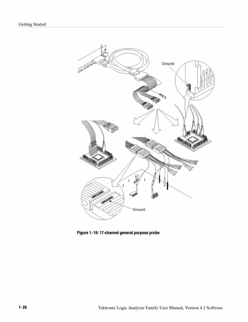
Getting Started
1- 26 Tektronix Logic Analyzer Family User Manual, Version 4.1 Software
Figure 1- 19: 17-channel general purpose probe
Getting Started
Tektronix Logic Analyzer Family User Manual, Version 4.1 Software 1- 27
The P6434 Mass Termination Probe allows you to connect 34 LA channels to amicroprocessor probe adapter or directly to the target system. To connect to thetarget system directly, you must include compatible Mictor connectors in yourcircuit board design.
Figure 1--20 shows two ways of connecting the LA module to a target system.For more information on the P6434 Mass Termination Probe and how to connectit to your target system, refer to the P6434 Mass Termination Probe Instructions.
Figure 1- 20: P6434 high-density probe connections
All LA probes can be connected to microprocessor adapters. Refer to thedocumentation that comes with your microprocessor disassembler package fordetails about connecting the probes to the microprocessor adapters and to thetarget system.
High-Density ProbeConnections
MicroprocessorConnections
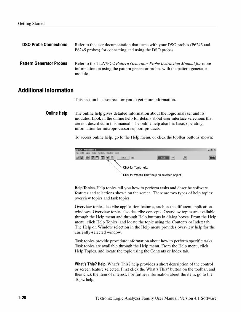
Getting Started
1- 28 Tektronix Logic Analyzer Family User Manual, Version 4.1 Software
Refer to the user documentation that came with your DSO probes (P6243 andP6245 probes) for connecting and using the DSO probes.
Refer to the TLA7PG2 Pattern Generator Probe Instruction Manual for moreinformation on using the pattern generator probes with the pattern generatormodule.
Additional Information
This section lists sources for you to get more information.
The online help gives detailed information about the logic analyzer and itsmodules. Look in the online help for details about user interface selections thatare not described in this manual. The online help also has basic operatinginformation for microprocessor support products.
To access online help, go to the Help menu, or click the toolbar buttons shown:
Click for Topic help.
Click for What’s This? help on selected object.
Help Topics.Help topics tell you how to perform tasks and describe softwarefeatures and selections shown on the screen. There are two types of help topics:overview topics and task topics.
Overview topics describe application features, such as the different applicationwindows. Overview topics also describe concepts. Overview topics are availablethrough the Help menu and through Help buttons in dialog boxes. From the Helpmenu, click Help Topics, and locate the topic using the Contents or Index tab.The Help on Window selection in the Help menu provides overview help for thecurrently-selected window.
Task topics provide procedure information about how to perform specific tasks.Task topics are available through the Help menu. From the Help menu, clickHelp Topics, and locate the topic using the Contents or Index tab.
What’s This? Help.What’s This? help provides a short description of the controlor screen feature selected. First click the What’s This? button on the toolbar, andthen click the item of interest. For further information about the item, go to theTopic help.
DSO Probe Connections
Pattern Generator Probes
Online Help
Getting Started
Tektronix Logic Analyzer Family User Manual, Version 4.1 Software 1- 29
TPI Online Help. Select Help on TPI from the drop-down help menu forinformation on using the TLA Programmatic Interface. A printable version of theTPI online help is available on the instrument. Click Start > Programs >Tektronix Logic Analyzer > TLA Documentation > TPI Manual.
TLAScript Online Help. TLAScript is a script that works with TPI. Select Helpfrom the menu bar within the TLAScript application. To start TLAScript, selectStart > Programs > Tektronix Logic Analyzer > TLAScript.
TLAVu and PatGenVu. Applications that provide you with the ability to viewyour TLA data offline on your own Windows PC. Both TLAVu and PatGenVuare versions of the TLA application and Pattern Generator software that containonline help content that is identical to the help provided in the respectiveapplications.
Pattern Generator Online Help. Select Help on TLA7PG2 from the drop-downhelp menu for information on using the TLA Pattern Generator.
PPI Online Help. Select Help on the TLA7PG2 PPI from the drop-down helpmenu for information on using the TLA Pattern Generator. A printable version ofthe PPI online help is available on the instrument. Click Start > Programs >Tektronix Pattern Generator > Pattern Generator Documentation > PPI Manual.
To access the Logic Analyzer Release Notes, select Start > Programs > TektronixLogic Analyzer > TLA Release Notes.
Windows Online Help. Information about Windows features is available throughthe Windows help system. Access Windows help as you would with anyWindows application.
The online Release Notes contain information about this release of the logicanalyzer application and pattern generator application. Check the Release Notesfor information such as software compatibility and software version differencesfrom earlier releases.
To access the Logic Analyzer Release Notes, click Start > Programs > TektronixLogic Analyzer > TLA Release Notes.
To access the Pattern Generator Release Notes, click Start > Programs >Tektronix Pattern Generator > Pattern Generator Release Notes.
Release Notes

Getting Started
1- 30 Tektronix Logic Analyzer Family User Manual, Version 4.1 Software

Operating Basics

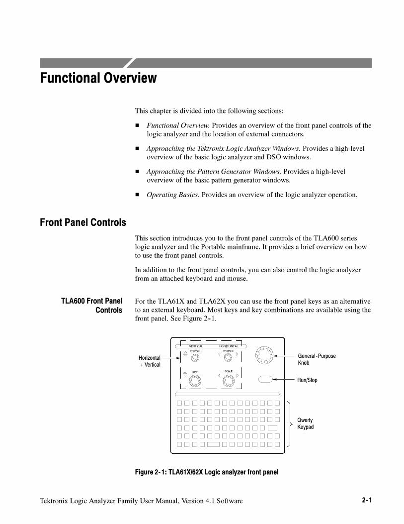
Tektronix Logic Analyzer Family User Manual, Version 4.1 Software 2- 1
Functional Overview
This chapter is divided into the following sections:
Functional Overview. Provides an overview of the front panel controls of thelogic analyzer and the location of external connectors.
Approaching the Tektronix Logic Analyzer Windows. Provides a high-leveloverview of the basic logic analyzer and DSO windows.
Approaching the Pattern Generator Windows. Provides a high-leveloverview of the basic pattern generator windows.
Operating Basics. Provides an overview of the logic analyzer operation.
Front Panel Controls
This section introduces you to the front panel controls of the TLA600 serieslogic analyzer and the Portable mainframe. It provides a brief overview on howto use the front panel controls.
In addition to the front panel controls, you can also control the logic analyzerfrom an attached keyboard and mouse.
For the TLA61X and TLA62X you can use the front panel keys as an alternativeto an external keyboard. Most keys and key combinations are available using thefront panel. See Figure 2--1.
Horizontal+ Vertical
General--PurposeKnob
Run/Stop
QwertyKeypad
Figure 2- 1: TLA61X/62X Logic analyzer front panel
TLA600 Front PanelControls
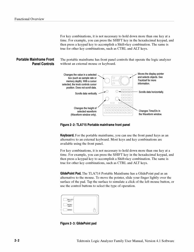
Functional Overview
2- 2 Tektronix Logic Analyzer Family User Manual, Version 4.1 Software
For key combinations, it is not necessary to hold down more than one key at atime. For example, you can press the SHIFT key in the hexadecimal keypad, andthen press a keypad key to accomplish a Shift+key combination. The same istrue for other key combinations, such as CTRL and ALT keys.
The portable mainframe has front panel controls that operate the logic analyzerwithout an external mouse or keyboard.
Scrolls data horizontally.
Changes the height ofselected waveform
(Waveform window only).
Scrolls data vertically.
Changes the value in a selectedbox (such as sample rate or
memory depth). With a cursorselected, the knob controls cursor
position. Does not scroll data.
Changes Time/Div inthe Waveform window.
Moves the display pointerand selects objects. SeeTrackball for moreinformation.
Figure 2- 2: TLA715 Portable mainframe front panel
Keyboard. For the portable mainframe, you can use the front panel keys as analternative to an external keyboard. Most keys and key combinations areavailable using the front panel.
For key combinations, it is not necessary to hold down more than one key at atime. For example, you can press the SHIFT key in the hexadecimal keypad, andthen press a keypad key to accomplish a Shift+key combination. The same istrue for other key combinations, such as CTRL and ALT keys.
GlidePoint Pad. The TLA714 Portable Mainframe has a GlidePoint pad as analternative to the mouse. To move the pointer, slide your finger lightly over thesurface of the pad. Tap the surface to simulate a click of the left mouse button, oruse the control buttons to select the type of operation.
Figure 2- 3: GlidePoint pad
Portable Mainframe FrontPanel Controls
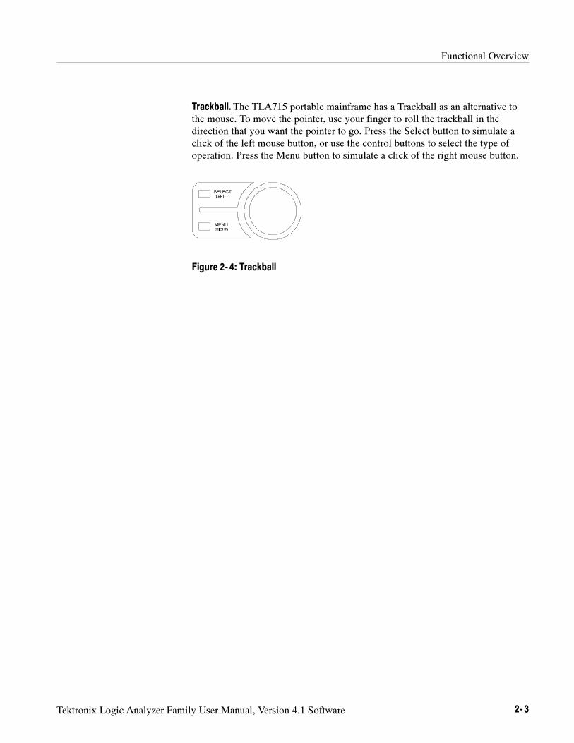
Functional Overview
Tektronix Logic Analyzer Family User Manual, Version 4.1 Software 2- 3
Trackball. The TLA715 portable mainframe has a Trackball as an alternative tothe mouse. To move the pointer, use your finger to roll the trackball in thedirection that you want the pointer to go. Press the Select button to simulate aclick of the left mouse button, or use the control buttons to select the type ofoperation. Press the Menu button to simulate a click of the right mouse button.
Figure 2- 4: Trackball
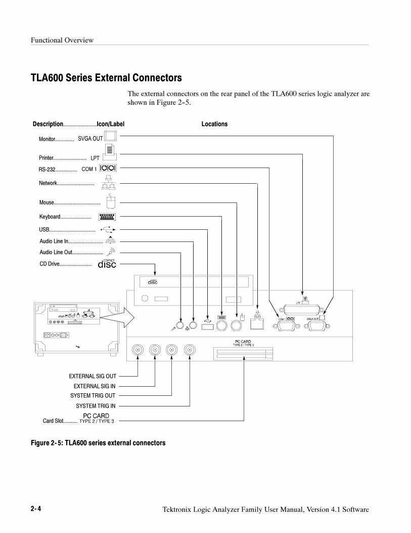
Functional Overview
2- 4 Tektronix Logic Analyzer Family User Manual, Version 4.1 Software
TLA600 Series External Connectors
The external connectors on the rear panel of the TLA600 series logic analyzer areshown in Figure 2--5.
Monitor...............
Printer..........................
RS-232.................
Network.............................
Mouse....................................
Keyboard........................
USB....................................
CD Drive.........................
Card Slot...........
Description..........................Icon/Label Locations
Audio Line In...........................
Audio Line Out........................
EXTERNAL SIG OUT
EXTERNAL SIG IN
SYSTEM TRIG OUT
SYSTEM TRIG IN
Figure 2- 5: TLA600 series external connectors
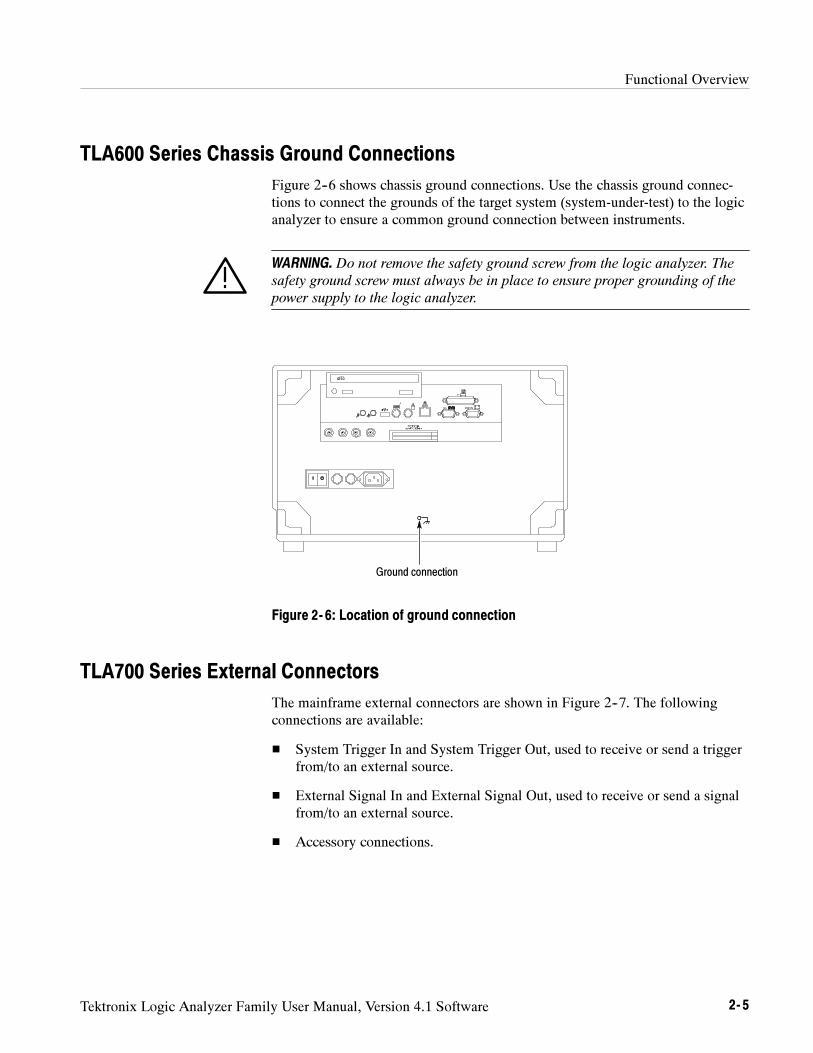
Functional Overview
Tektronix Logic Analyzer Family User Manual, Version 4.1 Software 2- 5
TLA600 Series Chassis Ground Connections
Figure 2--6 shows chassis ground connections. Use the chassis ground connec-tions to connect the grounds of the target system (system-under-test) to the logicanalyzer to ensure a common ground connection between instruments.
WARNING. Do not remove the safety ground screw from the logic analyzer. The
safety ground screw must always be in place to ensure proper grounding of the
power supply to the logic analyzer.
Ground connection
Figure 2- 6: Location of ground connection
TLA700 Series External Connectors
The mainframe external connectors are shown in Figure 2--7. The followingconnections are available:
System Trigger In and System Trigger Out, used to receive or send a triggerfrom/to an external source.
External Signal In and External Signal Out, used to receive or send a signalfrom/to an external source.
Accessory connections.
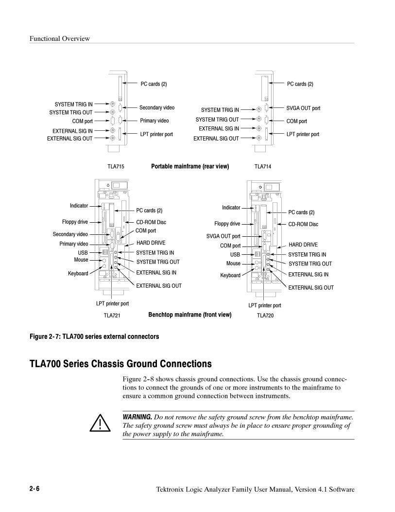
Functional Overview
2- 6 Tektronix Logic Analyzer Family User Manual, Version 4.1 Software
PC cards (2)
Secondary video
Primary video
LPT printer port
SYSTEM TRIG IN
SYSTEM TRIG OUT
EXTERNAL SIG IN
EXTERNAL SIG OUT
HARD DRIVE
Keyboard
Mouse
CD-ROM Disc
USB
Floppy drive
Indicator
COM port
Benchtop mainframe (front view)
PC cards (2)
Secondary video
Primary video
LPT printer port
SYSTEM TRIG IN
SYSTEM TRIG OUT
EXTERNAL SIG IN
EXTERNAL SIG OUT
COM port
PC cards (2)
SVGA OUT port
COM port
LPT printer port
SYSTEM TRIG IN
SYSTEM TRIG OUT
EXTERNAL SIG IN
EXTERNAL SIG OUT
PC cards (2)
SVGA OUT port
COM port
LPT printer port
SYSTEM TRIG IN
SYSTEM TRIG OUT
EXTERNAL SIG IN
EXTERNAL SIG OUT
HARD DRIVE
Keyboard
Mouse
CD-ROM Disc
USB
Floppy drive
Indicator
Portable mainframe (rear view)TLA715 TLA714
TLA721 TLA720
Figure 2- 7: TLA700 series external connectors
TLA700 Series Chassis Ground Connections
Figure 2--8 shows chassis ground connections. Use the chassis ground connec-tions to connect the grounds of one or more instruments to the mainframe toensure a common ground connection between instruments.
WARNING. Do not remove the safety ground screw from the benchtop mainframe.
The safety ground screw must always be in place to ensure proper grounding of
the power supply to the mainframe.
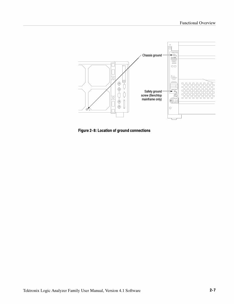
Functional Overview
Tektronix Logic Analyzer Family User Manual, Version 4.1 Software 2- 7
Chassis ground
Safety groundscrew (Benchtopmainframe only)
Figure 2- 8: Location of ground connections

Functional Overview
2- 8 Tektronix Logic Analyzer Family User Manual, Version 4.1 Software
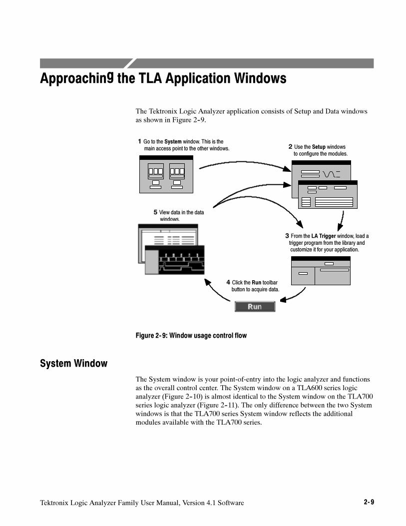
Tektronix Logic Analyzer Family User Manual, Version 4.1 Software 2- 9
Approaching the TLA Application Windows
The Tektronix Logic Analyzer application consists of Setup and Data windowsas shown in Figure 2--9.
1 Go to the System window. This is themain access point to the other windows. 2 Use the Setup windows
to configure the modules.
3 From the LA Trigger window, load atrigger program from the library andcustomize it for your application.
4 Click the Run toolbarbutton to acquire data.
5 View data in the datawindows.
Figure 2- 9: Window usage control flow
System Window
The System window is your point-of-entry into the logic analyzer and functionsas the overall control center. The System window on a TLA600 series logicanalyzer (Figure 2--10) is almost identical to the System window on the TLA700series logic analyzer (Figure 2--11). The only difference between the two Systemwindows is that the TLA700 series System window reflects the additionalmodules available with the TLA700 series.
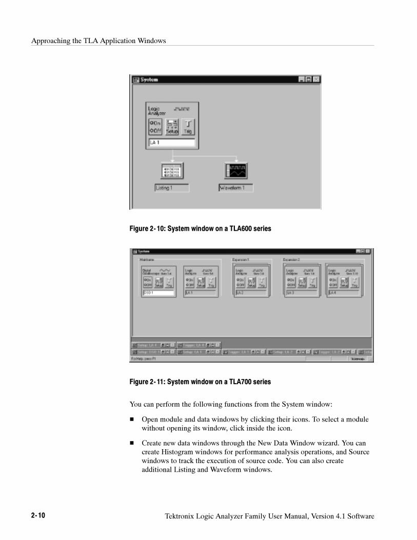
Approaching the TLA Application Windows
2- 10 Tektronix Logic Analyzer Family User Manual, Version 4.1 Software
Figure 2- 10: System window on a TLA600 series
Figure 2- 11: System window on a TLA700 series
You can perform the following functions from the System window:
Open module and data windows by clicking their icons. To select a modulewithout opening its window, click inside the icon.
Create new data windows through the New Data Window wizard. You cancreate Histogram windows for performance analysis operations, and Sourcewindows to track the execution of source code. You can also createadditional Listing and Waveform windows.
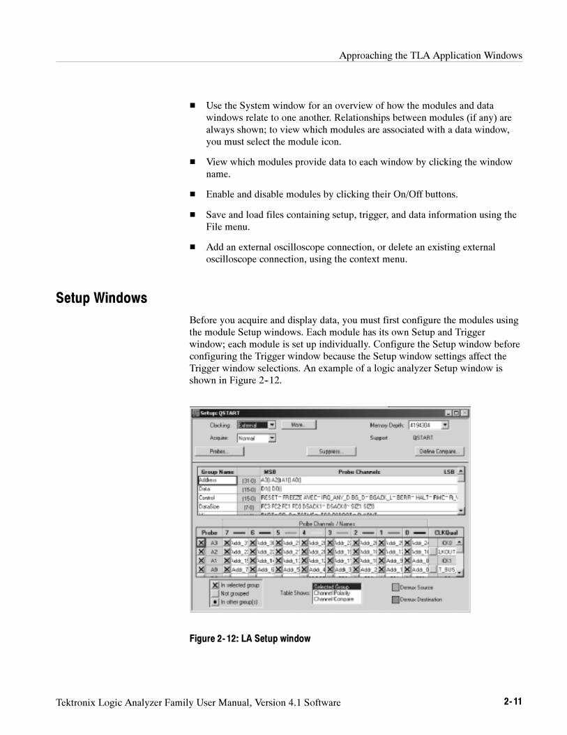
Approaching the TLA Application Windows
Tektronix Logic Analyzer Family User Manual, Version 4.1 Software 2- 11
Use the System window for an overview of how the modules and datawindows relate to one another. Relationships between modules (if any) arealways shown; to view which modules are associated with a data window,you must select the module icon.
View which modules provide data to each window by clicking the windowname.
Enable and disable modules by clicking their On/Off buttons.
Save and load files containing setup, trigger, and data information using theFile menu.
Add an external oscilloscope connection, or delete an existing externaloscilloscope connection, using the context menu.
Setup Windows
Before you acquire and display data, you must first configure the modules usingthe module Setup windows. Each module has its own Setup and Triggerwindow; each module is set up individually. Configure the Setup window beforeconfiguring the Trigger window because the Setup window settings affect theTrigger window selections. An example of a logic analyzer Setup window isshown in Figure 2--12.
Figure 2- 12: LA Setup window
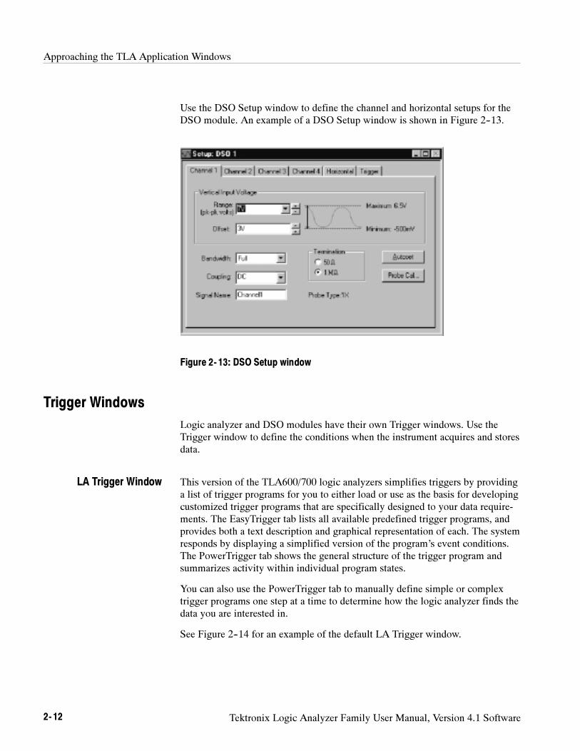
Approaching the TLA Application Windows
2- 12 Tektronix Logic Analyzer Family User Manual, Version 4.1 Software
Use the DSO Setup window to define the channel and horizontal setups for theDSO module. An example of a DSO Setup window is shown in Figure 2--13.
Figure 2- 13: DSO Setup window
Trigger Windows
Logic analyzer and DSO modules have their own Trigger windows. Use theTrigger window to define the conditions when the instrument acquires and storesdata.
This version of the TLA600/700 logic analyzers simplifies triggers by providinga list of trigger programs for you to either load or use as the basis for developingcustomized trigger programs that are specifically designed to your data require-ments. The EasyTrigger tab lists all available predefined trigger programs, andprovides both a text description and graphical representation of each. The systemresponds by displaying a simplified version of the program’s event conditions.The PowerTrigger tab shows the general structure of the trigger program andsummarizes activity within individual program states.
You can also use the PowerTrigger tab to manually define simple or complextrigger programs one step at a time to determine how the logic analyzer finds thedata you are interested in.
See Figure 2--14 for an example of the default LA Trigger window.
LA Trigger Window
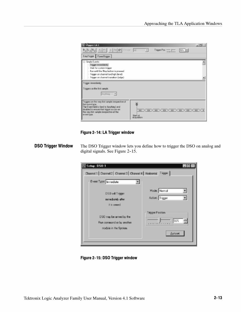
Approaching the TLA Application Windows
Tektronix Logic Analyzer Family User Manual, Version 4.1 Software 2- 13
Figure 2- 14: LA Trigger window
The DSO Trigger window lets you define how to trigger the DSO on analog anddigital signals. See Figure 2--15.
Figure 2- 15: DSO Trigger window
DSO Trigger Window
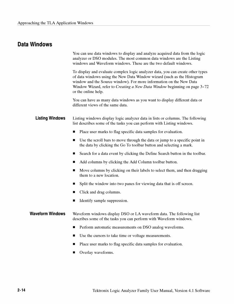
Approaching the TLA Application Windows
2- 14 Tektronix Logic Analyzer Family User Manual, Version 4.1 Software
Data Windows
You can use data windows to display and analyze acquired data from the logicanalyzer or DSO modules. The most common data windows are the Listingwindows and Waveform windows. These are the two default windows.
To display and evaluate complex logic analyzer data, you can create other typesof data windows using the New Data Window wizard (such as the Histogramwindow and the Source window). For more information on the New DataWindow Wizard, refer to Creating a New Data Window beginning on page 3--72or the online help.
You can have as many data windows as you want to display different data ordifferent views of the same data.
Listing windows display logic analyzer data in lists or columns. The followinglist describes some of the tasks you can perform with Listing windows.
Place user marks to flag specific data samples for evaluation.
Use the scroll bars to move through the data or jump to a specific point inthe data by clicking the Go To toolbar button and selecting a mark.
Search for a data event by clicking the Define Search button in the toolbar.
Add columns by clicking the Add Column toolbar button.
Move columns by clicking on their labels to select them, and then draggingthem to a new location.
Split the window into two panes for viewing data that is off screen.
Click and drag columns.
Identify sample suppression.
Waveform windows display DSO or LA waveform data. The following listdescribes some of the tasks you can perform with Waveform windows.
Perform automatic measurements on DSO analog waveforms.
Use the cursors to take time or voltage measurements.
Place user marks to flag specific data samples for evaluation.
Overlay waveforms.
Listing Windows
Waveform Windows
Approaching the TLA Application Windows
Tektronix Logic Analyzer Family User Manual, Version 4.1 Software 2- 15
Identify sample suppression.
View collections of logic analyzer module waveforms as busforms.
View the value of a logic analyzer module waveform group versus timeusing magnitude mode.
Expand and contract busforms.
Move waveforms by clicking their labels to select them and then draggingthem to a new location.
Split the window into two panes for viewing data that is off screen.
Use the scroll bars to move through the data or jump to a specific point inthe data by clicking the Go To toolbar button and selecting a mark.
Histogram windows display logic analyzer data as histograms. You useHistogram windows to evaluate the performance of software, which is alsoknown as performance analysis. The following list describes some of the tasksyou can perform with Histogram windows.
Use the scroll bars to move through the data.
Sort histogram data by ranges, counts, or percentages.
Change the magnification of histogram bars to view the data in greaterdetail.
Split the window into two panes for viewing data that is off screen.
View various statistics on the acquired data.
Source windows display source data. You can track the execution of source code,based on the data displayed in a Listing window. The following list describessome of the tasks you can perform with Source windows.
Step through source code statements.
Turn source code line numbers on or off.
Place user marks to flag specific data samples for evaluation.
Use the scroll bars to move through the data, or jump to a specific point inthe data by clicking the Go To toolbar button and selecting a mark.
Search for source code statements by clicking the Define Search button inthe toolbar.
Determine whether there is any acquired data for the corresponding sourcefile displayed in the Source window.
Histogram Windows
Source Windows
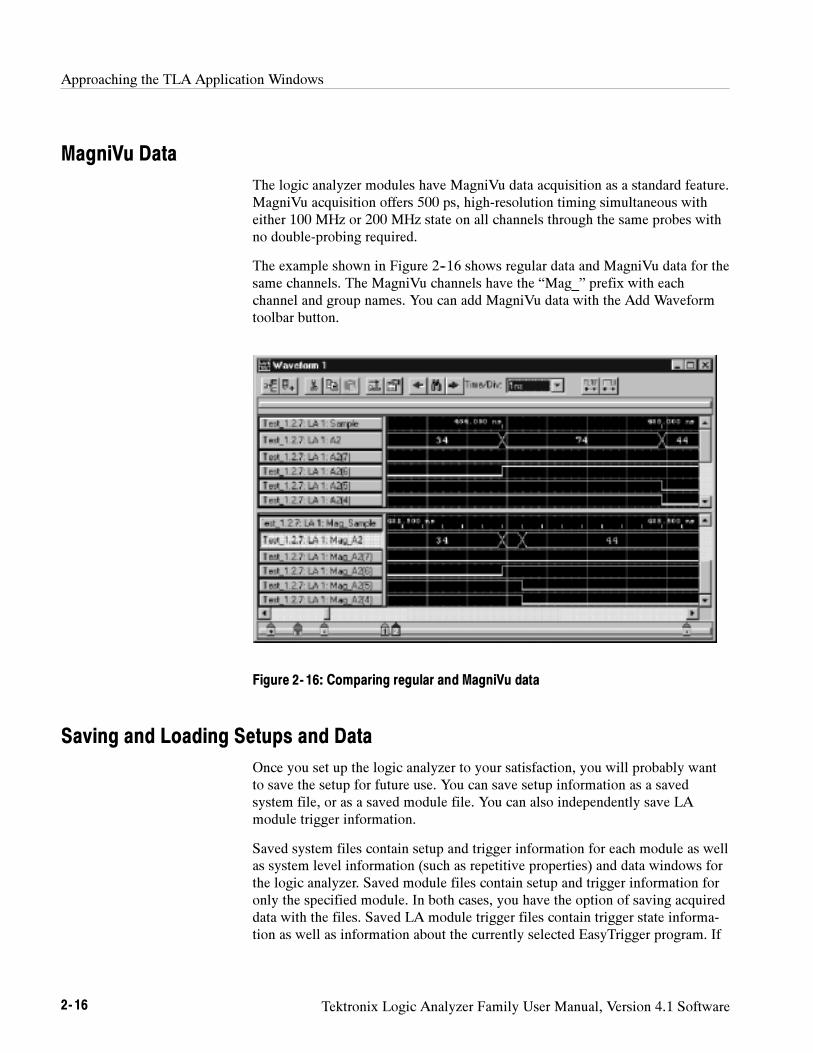
Approaching the TLA Application Windows
2- 16 Tektronix Logic Analyzer Family User Manual, Version 4.1 Software
MagniVu Data
The logic analyzer modules have MagniVu data acquisition as a standard feature.MagniVu acquisition offers 500 ps, high-resolution timing simultaneous witheither 100 MHz or 200 MHz state on all channels through the same probes withno double-probing required.
The example shown in Figure 2--16 shows regular data and MagniVu data for thesame channels. The MagniVu channels have the “Mag_” prefix with eachchannel and group names. You can add MagniVu data with the Add Waveformtoolbar button.
Figure 2- 16: Comparing regular and MagniVu data
Saving and Loading Setups and Data
Once you set up the logic analyzer to your satisfaction, you will probably wantto save the setup for future use. You can save setup information as a savedsystem file, or as a saved module file. You can also independently save LAmodule trigger information.
Saved system files contain setup and trigger information for each module as wellas system level information (such as repetitive properties) and data windows forthe logic analyzer. Saved module files contain setup and trigger information foronly the specified module. In both cases, you have the option of saving acquireddata with the files. Saved LA module trigger files contain trigger state informa-tion as well as information about the currently selected EasyTrigger program. If
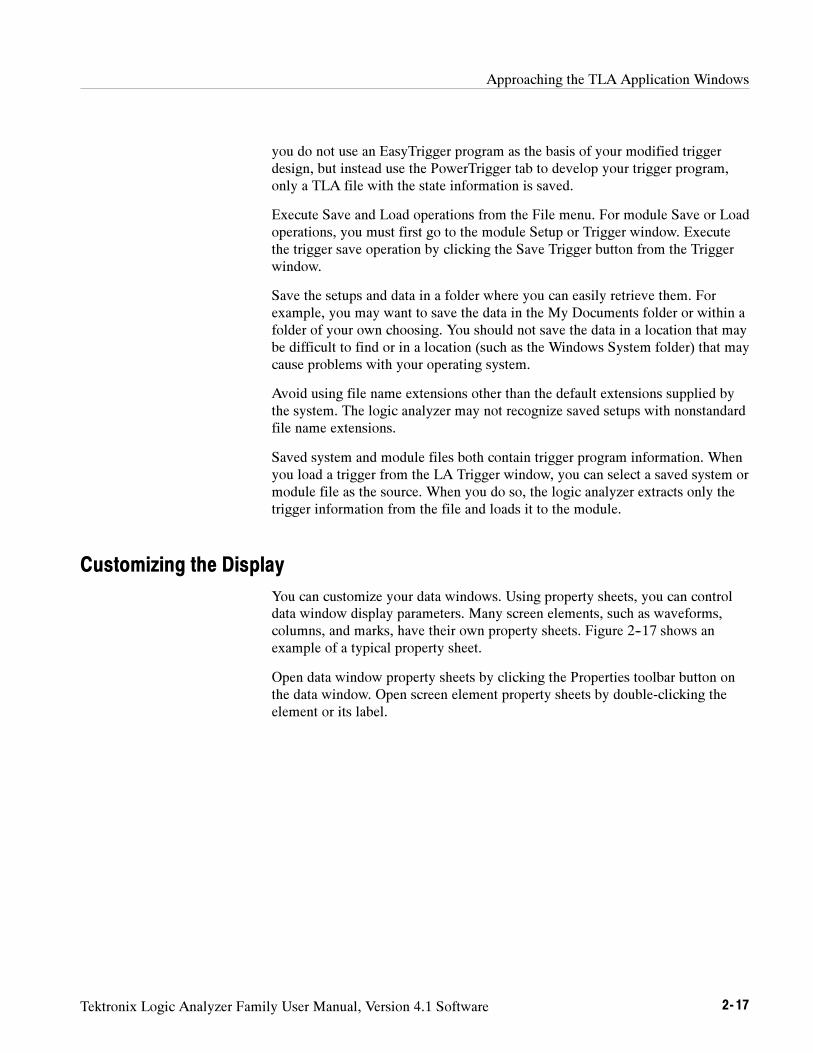
Approaching the TLA Application Windows
Tektronix Logic Analyzer Family User Manual, Version 4.1 Software 2- 17
you do not use an EasyTrigger program as the basis of your modified triggerdesign, but instead use the PowerTrigger tab to develop your trigger program,only a TLA file with the state information is saved.
Execute Save and Load operations from the File menu. For module Save or Loadoperations, you must first go to the module Setup or Trigger window. Executethe trigger save operation by clicking the Save Trigger button from the Triggerwindow.
Save the setups and data in a folder where you can easily retrieve them. Forexample, you may want to save the data in the My Documents folder or within afolder of your own choosing. You should not save the data in a location that maybe difficult to find or in a location (such as the Windows System folder) that maycause problems with your operating system.
Avoid using file name extensions other than the default extensions supplied bythe system. The logic analyzer may not recognize saved setups with nonstandardfile name extensions.
Saved system and module files both contain trigger program information. Whenyou load a trigger from the LA Trigger window, you can select a saved system ormodule file as the source. When you do so, the logic analyzer extracts only thetrigger information from the file and loads it to the module.
Customizing the Display
You can customize your data windows. Using property sheets, you can controldata window display parameters. Many screen elements, such as waveforms,columns, and marks, have their own property sheets. Figure 2--17 shows anexample of a typical property sheet.
Open data window property sheets by clicking the Properties toolbar button onthe data window. Open screen element property sheets by double-clicking theelement or its label.
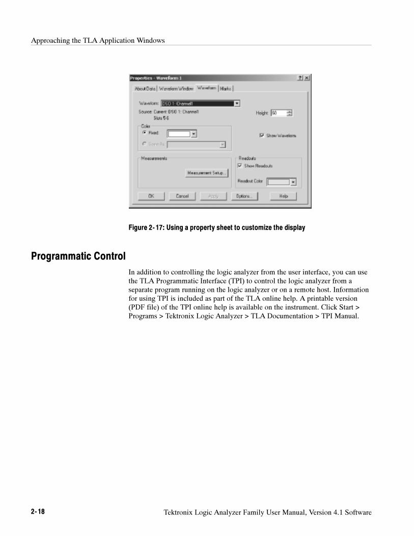
Approaching the TLA Application Windows
2- 18 Tektronix Logic Analyzer Family User Manual, Version 4.1 Software
Figure 2- 17: Using a property sheet to customize the display
Programmatic Control
In addition to controlling the logic analyzer from the user interface, you can usethe TLA Programmatic Interface (TPI) to control the logic analyzer from aseparate program running on the logic analyzer or on a remote host. Informationfor using TPI is included as part of the TLA online help. A printable version(PDF file) of the TPI online help is available on the instrument. Click Start >Programs > Tektronix Logic Analyzer > TLA Documentation > TPI Manual.
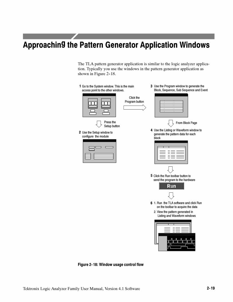
Tektronix Logic Analyzer Family User Manual, Version 4.1 Software 2- 19
Approaching the Pattern Generator Application Windows
The TLA pattern generator application is similar to the logic analyzer applica-tion. Typically you use the windows in the pattern generator application asshown in Figure 2--18.
1. Run the TLA software and click Runon the toolbar to acquire the data
2. View the pattern generated inListing and Waveform windows
Click the Run toolbar button tosend the program to the hardware
Click theProgram button
Press theSetup button
Go to the System window. This is the mainaccess point to the other windows.
Use the Setup window toconfigure the module
Use the Program window to generate theBlock, Sequence, Sub Sequence and Event
From Block Page
Use the Listing or Waveform window togenerate the pattern data for eachblock
1
2
3
4
5
6
Figure 2- 18: Window usage control flow
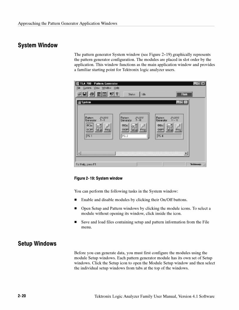
Approaching the Pattern Generator Application Windows
2- 20 Tektronix Logic Analyzer Family User Manual, Version 4.1 Software
System Window
The pattern generator System window (see Figure 2--19) graphically representsthe pattern generator configuration. The modules are placed in slot order by theapplication. This window functions as the main application window and providesa familiar starting point for Tektronix logic analyzer users.
Figure 2- 19: System window
You can perform the following tasks in the System window:
Enable and disable modules by clicking their On/Off buttons.
Open Setup and Pattern windows by clicking the module icons. To select amodule without opening its window, click inside the icon.
Save and load files containing setup and pattern information from the Filemenu.
Setup Windows
Before you can generate data, you must first configure the modules using themodule Setup windows. Each pattern generator module has its own set of Setupwindows. Click the Setup icon to open the Module Setup window and then selectthe individual setup windows from tabs at the top of the windows.
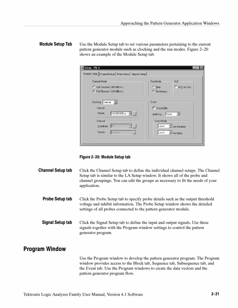
Approaching the Pattern Generator Application Windows
Tektronix Logic Analyzer Family User Manual, Version 4.1 Software 2- 21
Use the Module Setup tab to set various parameters pertaining to the currentpattern generator module such as clocking and the run modes. Figure 2--20shows an example of the Module Setup tab.
Figure 2- 20: Module Setup tab
Click the Channel Setup tab to define the individual channel setups. The ChannelSetup tab is similar to the LA Setup window. It shows all of the probe andchannel groupings. You can edit the groups as necessary to fit the needs of yourapplication.
Click the Probe Setup tab to specify probe details such as the output thresholdvoltage and inhibit information. The Probe Setup window shows the detailedsettings of all probes connected to the pattern generator module.
Click the Signal Setup tab to define the input and output signals. Use thesesignals together with the Program window settings to control the patterngenerator program.
Program Window
Use the Program window to develop the pattern generator program. The Programwindow provides access to the Block tab, Sequence tab, Subsequence tab, andthe Event tab. Use the Program windows to create the data vectors and thepattern generator program flow.
Module Setup Tab
Channel Setup tab
Probe Setup tab
Signal Setup tab
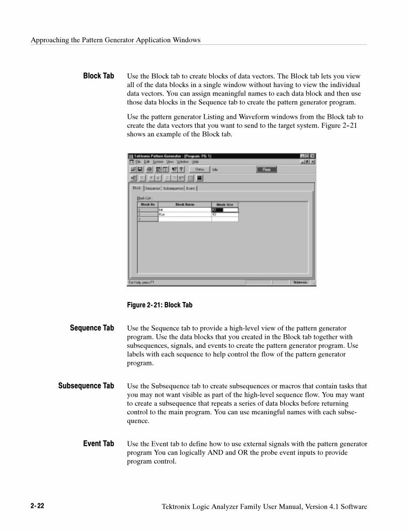
Approaching the Pattern Generator Application Windows
2- 22 Tektronix Logic Analyzer Family User Manual, Version 4.1 Software
Use the Block tab to create blocks of data vectors. The Block tab lets you viewall of the data blocks in a single window without having to view the individualdata vectors. You can assign meaningful names to each data block and then usethose data blocks in the Sequence tab to create the pattern generator program.
Use the pattern generator Listing and Waveform windows from the Block tab tocreate the data vectors that you want to send to the target system. Figure 2--21shows an example of the Block tab.
Figure 2- 21: Block Tab
Use the Sequence tab to provide a high-level view of the pattern generatorprogram. Use the data blocks that you created in the Block tab together withsubsequences, signals, and events to create the pattern generator program. Uselabels with each sequence to help control the flow of the pattern generatorprogram.
Use the Subsequence tab to create subsequences or macros that contain tasks thatyou may not want visible as part of the high-level sequence flow. You may wantto create a subsequence that repeats a series of data blocks before returningcontrol to the main program. You can use meaningful names with each subse-quence.
Use the Event tab to define how to use external signals with the pattern generatorprogram You can logically AND and OR the probe event inputs to provideprogram control.
Block Tab
Sequence Tab
Subsequence Tab
Event Tab
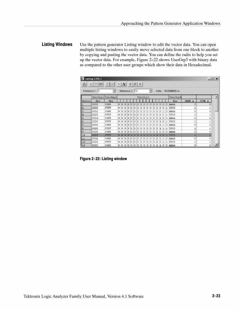
Approaching the Pattern Generator Application Windows
Tektronix Logic Analyzer Family User Manual, Version 4.1 Software 2- 23
Use the pattern generator Listing window to edit the vector data. You can openmultiple listing windows to easily move selected data from one block to anotherby copying and pasting the vector data. You can define the radix to help you setup the vector data. For example, Figure 2--22 shows UserGrp3 with binary dataas compared to the other user groups which show their data in Hexadecimal.
Figure 2- 22: Listing window
Listing Windows
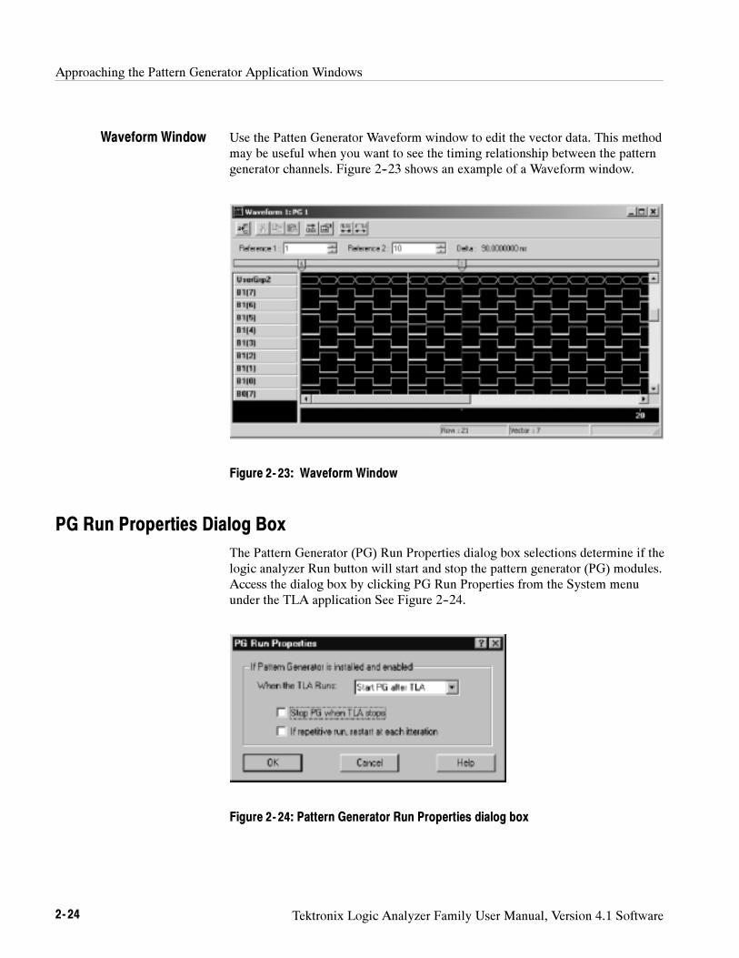
Approaching the Pattern Generator Application Windows
2- 24 Tektronix Logic Analyzer Family User Manual, Version 4.1 Software
Use the Patten Generator Waveform window to edit the vector data. This methodmay be useful when you want to see the timing relationship between the patterngenerator channels. Figure 2--23 shows an example of a Waveform window.
Figure 2- 23: Waveform Window
PG Run Properties Dialog Box
The Pattern Generator (PG) Run Properties dialog box selections determine if thelogic analyzer Run button will start and stop the pattern generator (PG) modules.Access the dialog box by clicking PG Run Properties from the System menuunder the TLA application See Figure 2--24.
Figure 2- 24: Pattern Generator Run Properties dialog box
Waveform Window
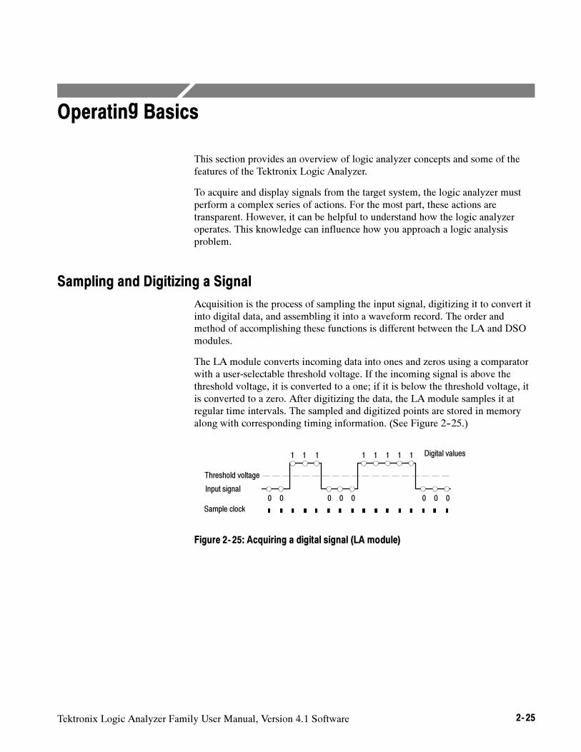
Tektronix Logic Analyzer Family User Manual, Version 4.1 Software 2- 25
Operating Basics
This section provides an overview of logic analyzer concepts and some of thefeatures of the Tektronix Logic Analyzer.
To acquire and display signals from the target system, the logic analyzer mustperform a complex series of actions. For the most part, these actions aretransparent. However, it can be helpful to understand how the logic analyzeroperates. This knowledge can influence how you approach a logic analysisproblem.
Sampling and Digitizing a Signal
Acquisition is the process of sampling the input signal, digitizing it to convert itinto digital data, and assembling it into a waveform record. The order andmethod of accomplishing these functions is different between the LA and DSOmodules.
The LA module converts incoming data into ones and zeros using a comparatorwith a user-selectable threshold voltage. If the incoming signal is above thethreshold voltage, it is converted to a one; if it is below the threshold voltage, itis converted to a zero. After digitizing the data, the LA module samples it atregular time intervals. The sampled and digitized points are stored in memoryalong with corresponding timing information. (See Figure 2--25.)
0 0
1
Input signal
Digital values
Sample clock
1 1
0
1 1
0 0
1 1
0
1
0 0
Threshold voltage
Figure 2- 25: Acquiring a digital signal (LA module)
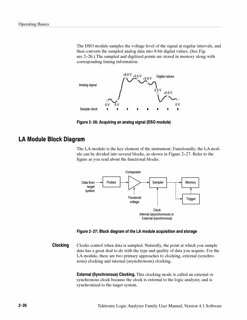
Operating Basics
2- 26 Tektronix Logic Analyzer Family User Manual, Version 4.1 Software
The DSO module samples the voltage level of the signal at regular intervals, andthen converts the sampled analog data into 8-bit digital values. (See Fig-ure 2--26.) The sampled and digitized points are stored in memory along withcorresponding timing information.
+5.5 V+5.0 V
+6.0 V
0 V
+2.0 V2.5 V
0 V 0 V
Sample clock
Analog signal
Digital values
Figure 2- 26: Acquiring an analog signal (DSO module)
LA Module Block Diagram
The LA module is the key element of the instrument. Functionally, the LAmod-ule can be divided into several blocks, as shown in Figure 2--27. Refer to thefigure as you read about the functional blocks.
ProbesData fromtargetsystem
Comparator
Thresholdvoltage
Memory
Trigger
Sampler
ClockInternal (asynchronous) orExternal (synchronous)
Figure 2- 27: Block diagram of the LA module acquisition and storage
Clocks control when data is sampled. Naturally, the point at which you sampledata has a great deal to do with the type and quality of data you acquire. For theLA module, there are two primary approaches to clocking, external (synchro-nous) clocking and internal (asynchronous) clocking.
External (Synchronous) Clocking. This clocking mode is called an external orsynchronous clock because the clock is external to the logic analyzer, and issynchronized to the target system.
Clocking
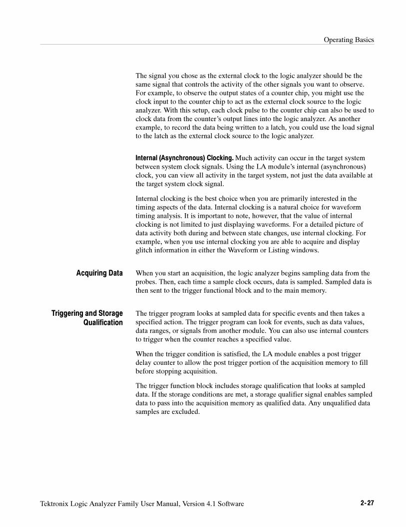
Operating Basics
Tektronix Logic Analyzer Family User Manual, Version 4.1 Software 2- 27
The signal you chose as the external clock to the logic analyzer should be thesame signal that controls the activity of the other signals you want to observe.For example, to observe the output states of a counter chip, you might use theclock input to the counter chip to act as the external clock source to the logicanalyzer. With this setup, each clock pulse to the counter chip can also be used toclock data from the counter’s output lines into the logic analyzer. As anotherexample, to record the data being written to a latch, you could use the load signalto the latch as the external clock source to the logic analyzer.
Internal (Asynchronous) Clocking.Much activity can occur in the target systembetween system clock signals. Using the LA module’s internal (asynchronous)clock, you can view all activity in the target system, not just the data available atthe target system clock signal.
Internal clocking is the best choice when you are primarily interested in thetiming aspects of the data. Internal clocking is a natural choice for waveformtiming analysis. It is important to note, however, that the value of internalclocking is not limited to just displaying waveforms. For a detailed picture ofdata activity both during and between state changes, use internal clocking. Forexample, when you use internal clocking you are able to acquire and displayglitch information in either the Waveform or Listing windows.
When you start an acquisition, the logic analyzer begins sampling data from theprobes. Then, each time a sample clock occurs, data is sampled. Sampled data isthen sent to the trigger functional block and to the main memory.
The trigger program looks at sampled data for specific events and then takes aspecified action. The trigger program can look for events, such as data values,data ranges, or signals from another module. You can also use internal countersto trigger when the counter reaches a specified value.
When the trigger condition is satisfied, the LA module enables a post triggerdelay counter to allow the post trigger portion of the acquisition memory to fillbefore stopping acquisition.
The trigger function block includes storage qualification that looks at sampleddata. If the storage conditions are met, a storage qualifier signal enables sampleddata to pass into the acquisition memory as qualified data. Any unqualified datasamples are excluded.
Acquiring Data
Triggering and StorageQualification
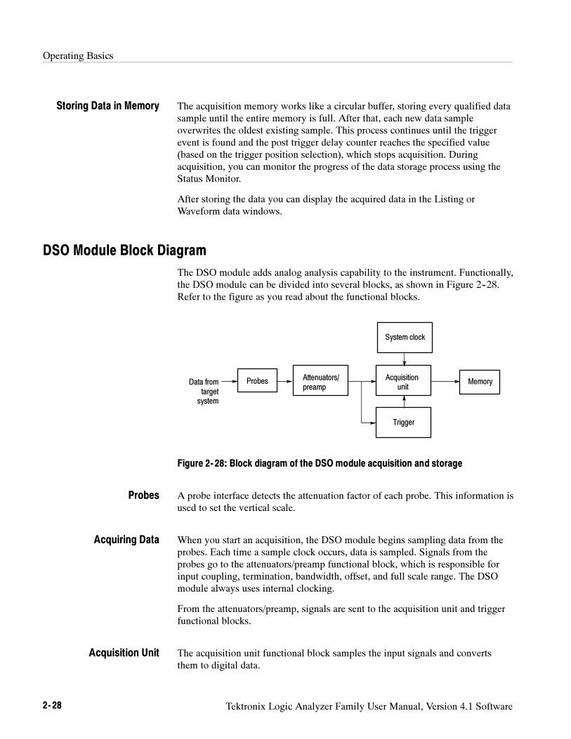
Operating Basics
2- 28 Tektronix Logic Analyzer Family User Manual, Version 4.1 Software
The acquisition memory works like a circular buffer, storing every qualified datasample until the entire memory is full. After that, each new data sampleoverwrites the oldest existing sample. This process continues until the triggerevent is found and the post trigger delay counter reaches the specified value(based on the trigger position selection), which stops acquisition. Duringacquisition, you can monitor the progress of the data storage process using theStatus Monitor.
After storing the data you can display the acquired data in the Listing orWaveform data windows.
DSO Module Block Diagram
The DSO module adds analog analysis capability to the instrument. Functionally,the DSO module can be divided into several blocks, as shown in Figure 2--28.Refer to the figure as you read about the functional blocks.
ProbesData fromtargetsystem
Memory
Trigger
Attenuators/preamp
Acquisitionunit
System clock
Figure 2- 28: Block diagram of the DSO module acquisition and storage
A probe interface detects the attenuation factor of each probe. This information isused to set the vertical scale.
When you start an acquisition, the DSO module begins sampling data from theprobes. Each time a sample clock occurs, data is sampled. Signals from theprobes go to the attenuators/preamp functional block, which is responsible forinput coupling, termination, bandwidth, offset, and full scale range. The DSOmodule always uses internal clocking.
From the attenuators/preamp, signals are sent to the acquisition unit and triggerfunctional blocks.
The acquisition unit functional block samples the input signals and convertsthem to digital data.
Storing Data in Memory
Probes
Acquiring Data
Acquisition Unit
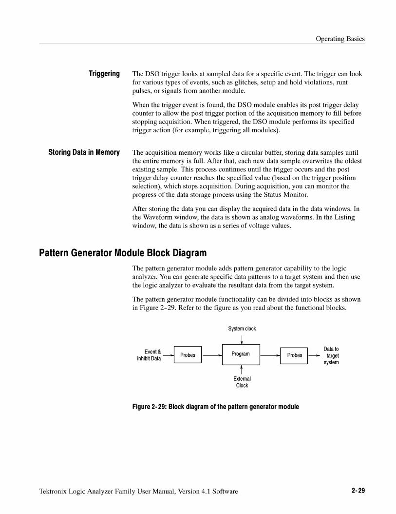
Operating Basics
Tektronix Logic Analyzer Family User Manual, Version 4.1 Software 2- 29
The DSO trigger looks at sampled data for a specific event. The trigger can lookfor various types of events, such as glitches, setup and hold violations, runtpulses, or signals from another module.
When the trigger event is found, the DSO module enables its post trigger delaycounter to allow the post trigger portion of the acquisition memory to fill beforestopping acquisition. When triggered, the DSO module performs its specifiedtrigger action (for example, triggering all modules).
The acquisition memory works like a circular buffer, storing data samples untilthe entire memory is full. After that, each new data sample overwrites the oldestexisting sample. This process continues until the trigger occurs and the posttrigger delay counter reaches the specified value (based on the trigger positionselection), which stops acquisition. During acquisition, you can monitor theprogress of the data storage process using the Status Monitor.
After storing the data you can display the acquired data in the data windows. Inthe Waveform window, the data is shown as analog waveforms. In the Listingwindow, the data is shown as a series of voltage values.
Pattern Generator Module Block Diagram
The pattern generator module adds pattern generator capability to the logicanalyzer. You can generate specific data patterns to a target system and then usethe logic analyzer to evaluate the resultant data from the target system.
The pattern generator module functionality can be divided into blocks as shownin Figure 2--29. Refer to the figure as you read about the functional blocks.
ProbesEvent &
Inhibit Data
ExternalClock
Program
System clock
ProbesData totargetsystem
Figure 2- 29: Block diagram of the pattern generator module
Triggering
Storing Data in Memory
Operating Basics
2- 30 Tektronix Logic Analyzer Family User Manual, Version 4.1 Software
The probe interface serves two purposes, to detect event and inhibit informationand to output data to a target system. In addition to sending pattern generatordata to the target system, the probe also sends clock and strobe information.
You can connect up to four probes to a single module. Each probe supports eithereight or 16 channels.
The pattern generator program is the heart of the pattern generator module. Youcan create blocks of data vectors to work together to create complex patterngenerator programs. The program uses external and internal events to determinespecific actions such as loops and branches to other data blocks. The programcan be controlled by an internally selected clock or by an external clock througha front-panel BNC connector.
Use the Sequence Definition page of the Program window to set up and define asequence events that make up the pattern generator program. Each sequence linedetermines how the pattern generator will use blocks of data that you define inthe Pattern Generator Listing or Waveform window. You can set up the programto wait for specific events or signals and then jump to a different sequence whenan event is either true or false.
You can also set up the pattern generator to single step through programs andoutput a single set of vectors with each clock cycle. This is useful for trouble-shooting or debugging setups.
Probes
Pattern GeneratorProgram
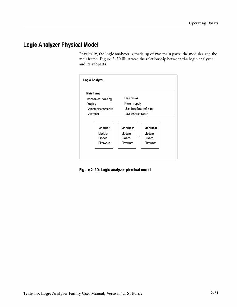
Operating Basics
Tektronix Logic Analyzer Family User Manual, Version 4.1 Software 2- 31
Logic Analyzer Physical Model
Physically, the logic analyzer is made up of two main parts: the modules and themainframe. Figure 2--30 illustrates the relationship between the logic analyzerand its subparts.
Module 1
Mainframe
Mechanical housing
Display
Module 2 Module n
Communications bus
Controller
Logic Analyzer
Disk drives
Power supply
User interface software
Module
Probes
Firmware
Module
Probes
Firmware
Module
Probes
Firmware
Low-level software
Figure 2- 30: Logic analyzer physical model
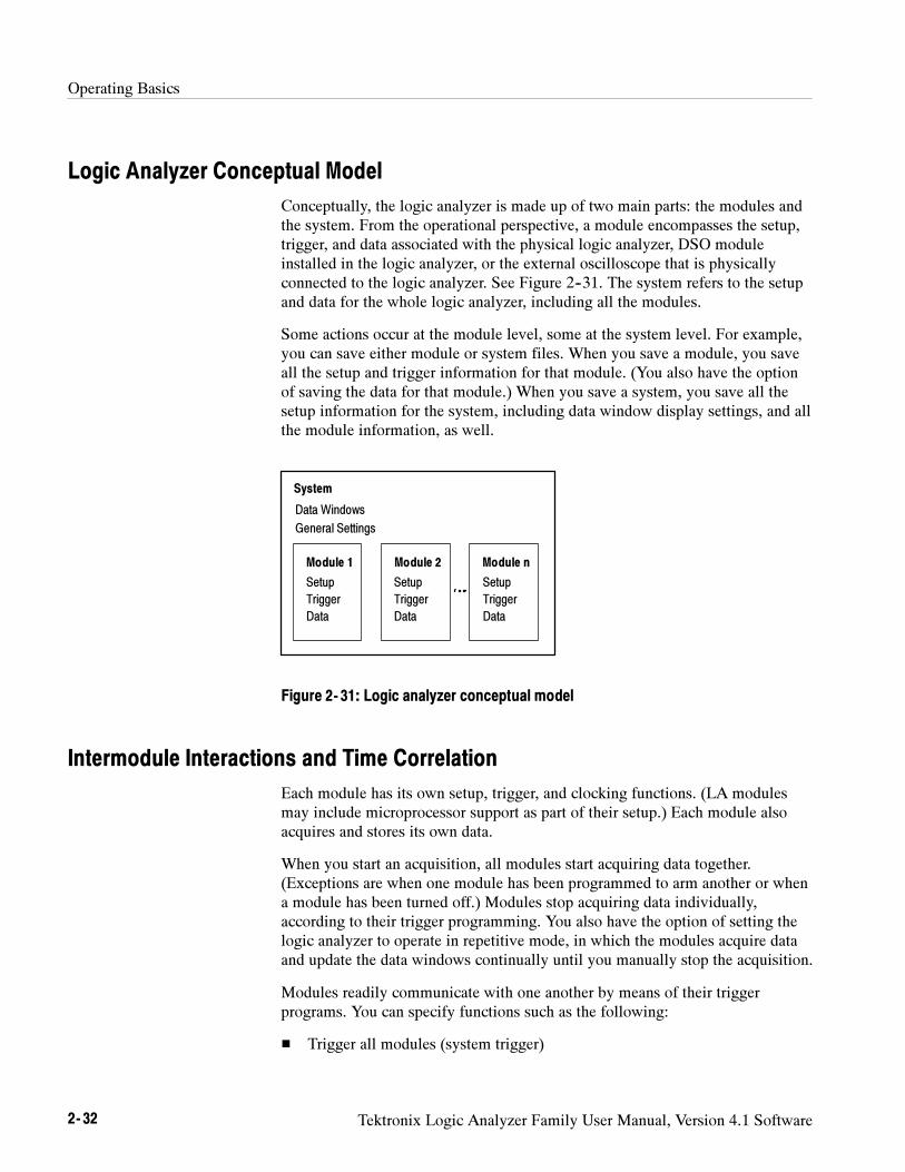
Operating Basics
2- 32 Tektronix Logic Analyzer Family User Manual, Version 4.1 Software
Logic Analyzer Conceptual Model
Conceptually, the logic analyzer is made up of two main parts: the modules andthe system. From the operational perspective, a module encompasses the setup,trigger, and data associated with the physical logic analyzer, DSO moduleinstalled in the logic analyzer, or the external oscilloscope that is physicallyconnected to the logic analyzer. See Figure 2--31. The system refers to the setupand data for the whole logic analyzer, including all the modules.
Some actions occur at the module level, some at the system level. For example,you can save either module or system files. When you save a module, you saveall the setup and trigger information for that module. (You also have the optionof saving the data for that module.) When you save a system, you save all thesetup information for the system, including data window display settings, and allthe module information, as well.
Setup
Trigger
Data
Module 1
System
Data Windows
General Settings
Module 2 Module n
Setup
Trigger
Data
Setup
Trigger
Data
Figure 2- 31: Logic analyzer conceptual model
Intermodule Interactions and Time Correlation
Each module has its own setup, trigger, and clocking functions. (LA modulesmay include microprocessor support as part of their setup.) Each module alsoacquires and stores its own data.
When you start an acquisition, all modules start acquiring data together.(Exceptions are when one module has been programmed to arm another or whena module has been turned off.) Modules stop acquiring data individually,according to their trigger programming. You also have the option of setting thelogic analyzer to operate in repetitive mode, in which the modules acquire dataand update the data windows continually until you manually stop the acquisition.
Modules readily communicate with one another by means of their triggerprograms. You can specify functions such as the following:
Trigger all modules (system trigger)
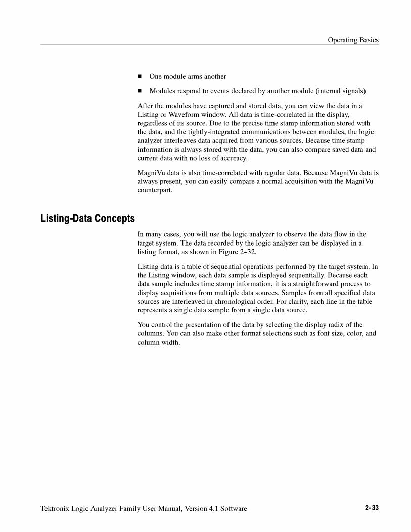
Operating Basics
Tektronix Logic Analyzer Family User Manual, Version 4.1 Software 2- 33
One module arms another
Modules respond to events declared by another module (internal signals)
After the modules have captured and stored data, you can view the data in aListing or Waveform window. All data is time-correlated in the display,regardless of its source. Due to the precise time stamp information stored withthe data, and the tightly-integrated communications between modules, the logicanalyzer interleaves data acquired from various sources. Because time stampinformation is always stored with the data, you can also compare saved data andcurrent data with no loss of accuracy.
MagniVu data is also time-correlated with regular data. Because MagniVu data isalways present, you can easily compare a normal acquisition with the MagniVucounterpart.
Listing-Data Concepts
In many cases, you will use the logic analyzer to observe the data flow in thetarget system. The data recorded by the logic analyzer can be displayed in alisting format, as shown in Figure 2--32.
Listing data is a table of sequential operations performed by the target system. Inthe Listing window, each data sample is displayed sequentially. Because eachdata sample includes time stamp information, it is a straightforward process todisplay acquisitions from multiple data sources. Samples from all specified datasources are interleaved in chronological order. For clarity, each line in the tablerepresents a single data sample from a single data source.
You control the presentation of the data by selecting the display radix of thecolumns. You can also make other format selections such as font size, color, andcolumn width.
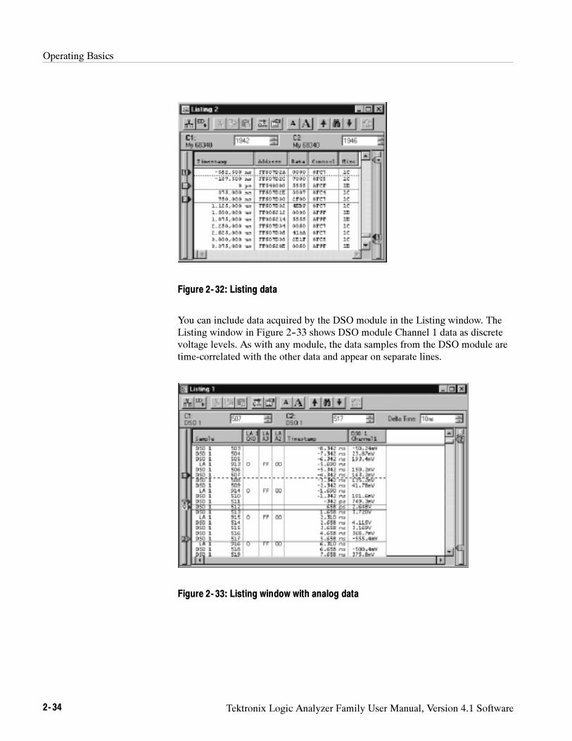
Operating Basics
2- 34 Tektronix Logic Analyzer Family User Manual, Version 4.1 Software
Figure 2- 32: Listing data
You can include data acquired by the DSO module in the Listing window. TheListing window in Figure 2--33 shows DSO module Channel 1 data as discretevoltage levels. As with any module, the data samples from the DSO module aretime-correlated with the other data and appear on separate lines.
Figure 2- 33: Listing window with analog data
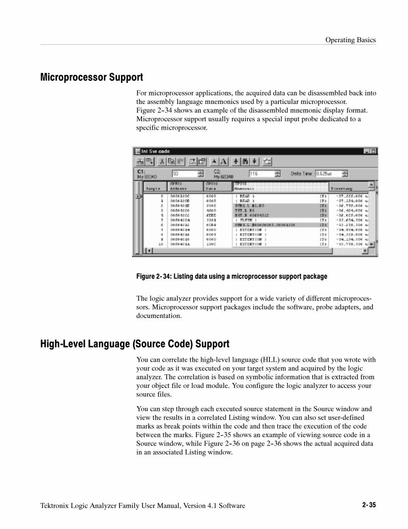
Operating Basics
Tektronix Logic Analyzer Family User Manual, Version 4.1 Software 2- 35
Microprocessor Support
For microprocessor applications, the acquired data can be disassembled back intothe assembly language mnemonics used by a particular microprocessor.Figure 2--34 shows an example of the disassembled mnemonic display format.Microprocessor support usually requires a special input probe dedicated to aspecific microprocessor.
Figure 2- 34: Listing data using a microprocessor support package
The logic analyzer provides support for a wide variety of different microproces-sors. Microprocessor support packages include the software, probe adapters, anddocumentation.
High-Level Language (Source Code) Support
You can correlate the high-level language (HLL) source code that you wrote withyour code as it was executed on your target system and acquired by the logicanalyzer. The correlation is based on symbolic information that is extracted fromyour object file or load module. You configure the logic analyzer to access yoursource files.
You can step through each executed source statement in the Source window andview the results in a correlated Listing window. You can also set user-definedmarks as break points within the code and then trace the execution of the codebetween the marks. Figure 2--35 shows an example of viewing source code in aSource window, while Figure 2--36 on page 2--36 shows the actual acquired datain an associated Listing window.
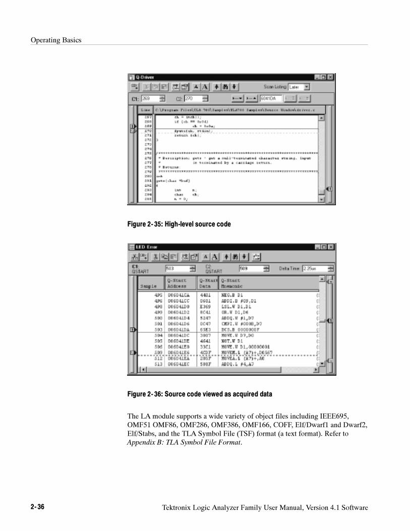
Operating Basics
2- 36 Tektronix Logic Analyzer Family User Manual, Version 4.1 Software
Figure 2- 35: High-level source code
Figure 2- 36: Source code viewed as acquired data
The LA module supports a wide variety of object files including IEEE695,OMF51 OMF86, OMF286, OMF386, OMF166, COFF, Elf/Dwarf1 and Dwarf2,Elf/Stabs, and the TLA Symbol File (TSF) format (a text format). Refer toAppendix B: TLA Symbol File Format.
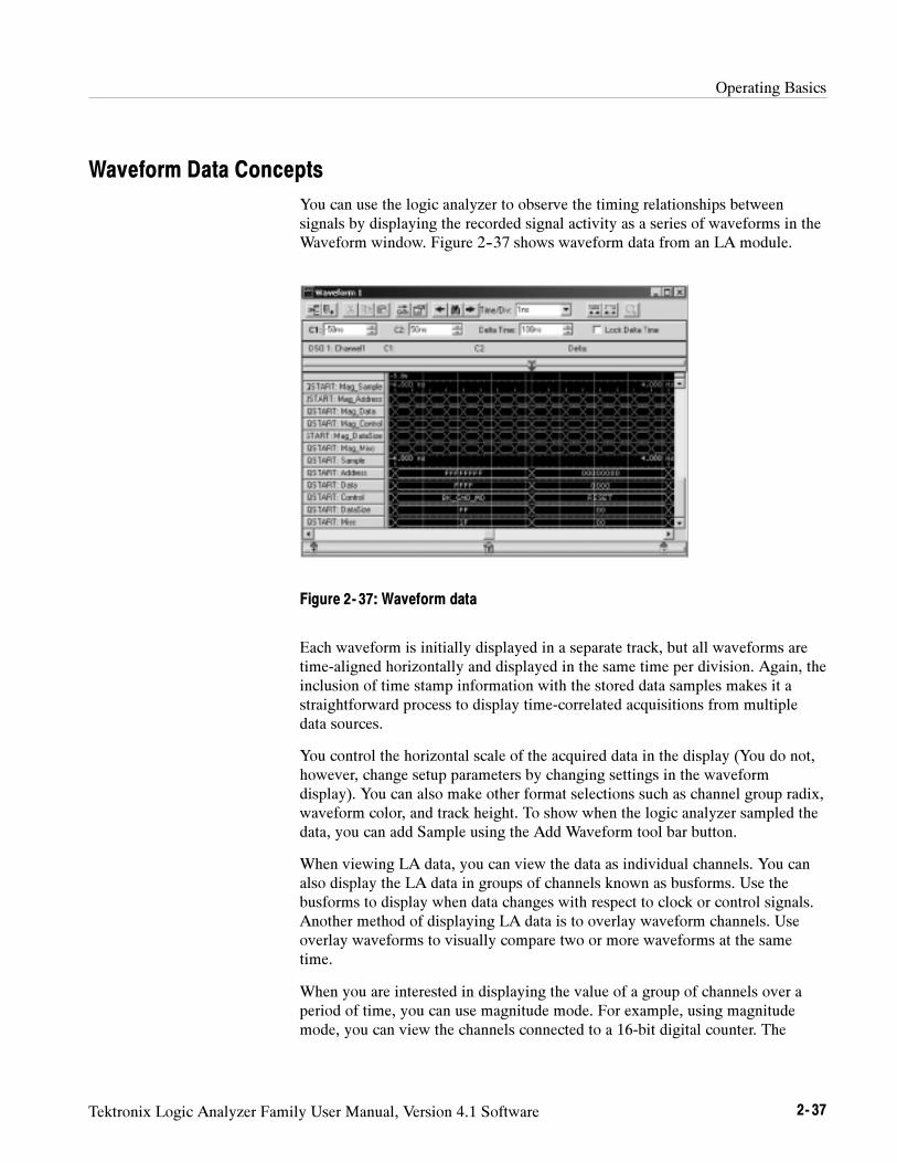
Operating Basics
Tektronix Logic Analyzer Family User Manual, Version 4.1 Software 2- 37
Waveform Data Concepts
You can use the logic analyzer to observe the timing relationships betweensignals by displaying the recorded signal activity as a series of waveforms in theWaveform window. Figure 2--37 shows waveform data from an LA module.
Figure 2- 37: Waveform data
Each waveform is initially displayed in a separate track, but all waveforms aretime-aligned horizontally and displayed in the same time per division. Again, theinclusion of time stamp information with the stored data samples makes it astraightforward process to display time-correlated acquisitions from multipledata sources.
You control the horizontal scale of the acquired data in the display (You do not,however, change setup parameters by changing settings in the waveformdisplay). You can also make other format selections such as channel group radix,waveform color, and track height. To show when the logic analyzer sampled thedata, you can add Sample using the Add Waveform tool bar button.
When viewing LA data, you can view the data as individual channels. You canalso display the LA data in groups of channels known as busforms. Use thebusforms to display when data changes with respect to clock or control signals.Another method of displaying LA data is to overlay waveform channels. Useoverlay waveforms to visually compare two or more waveforms at the sametime.
When you are interested in displaying the value of a group of channels over aperiod of time, you can use magnitude mode. For example, using magnitudemode, you can view the channels connected to a 16-bit digital counter. The
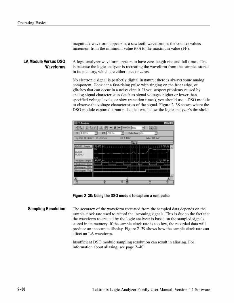
Operating Basics
2- 38 Tektronix Logic Analyzer Family User Manual, Version 4.1 Software
magnitude waveform appears as a sawtooth waveform as the counter valuesincrement from the minimum value (00) to the maximum value (FF).
A logic analyzer waveform appears to have zero-length rise and fall times. Thisis because the logic analyzer is recreating the waveform from the samples storedin its memory, which are either ones or zeros.
No electronic signal is perfectly digital in nature; there is always some analogcomponent. Consider a fast-rising pulse with ringing on the front edge, orglitches that can occur in a noisy circuit. If you suspect problems caused byanalog signal characteristics (such as signal voltages higher or lower thanspecified voltage levels, or slow transition times), you should use a DSO moduleto observe the voltage characteristics of the signal. Figure 2--38 shows where theDSO module captured a runt pulse that was below the logic analyzer’s threshold.
Figure 2- 38: Using the DSO module to capture a runt pulse
The accuracy of the waveform recreated from the sampled data depends on thesample clock rate used to record the incoming signals. This is due to the fact thatthe waveform re-created by the logic analyzer is based on the sampled signalsstored in its memory. If the sample clock rate is too low, the recorded data willproduce an inaccurate display. Figure 2--39 shows how the sample clock rate canaffect an LA waveform.
Insufficient DSO module sampling resolution can result in aliasing. Forinformation about aliasing, see page 2--40.
LA Module Versus DSOWaveforms
Sampling Resolution
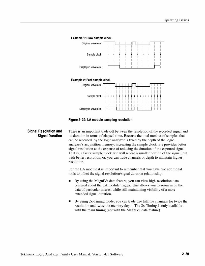
Operating Basics
Tektronix Logic Analyzer Family User Manual, Version 4.1 Software 2- 39
Displayed waveform
Sample clock
Original waveform
Displayed waveform
Sample clock
Original waveform
Example 1: Slow sample clock
Example 2: Fast sample clock
Figure 2- 39: LA module sampling resolution
There is an important trade-off between the resolution of the recorded signal andits duration in terms of elapsed time. Because the total number of samples thatcan be recorded by the logic analyzer is fixed by the depth of the logicanalyzer’s acquisition memory, increasing the sample clock rate provides bettersignal resolution at the expense of reducing the duration of the captured signal.That is, a faster sample clock rate will record a smaller portion of the signal, butwith better resolution; or, you can trade channels or depth to maintain higherresolution.
For the LA module it is important to remember that you have two additionaltools to offset the signal resolution/signal duration relationship:
By using the MagniVu data feature, you can view high-resolution datacentered about the LA module trigger. This allows you to zoom in on thedata of particular interest while still maintaining visibility of a moreextended signal duration.
By using 2x-Timing mode, you can trade one half the channels for twice theresolution and twice the memory depth. The 2x-Timing is only availablewith the main timing (not with the MagniVu data feature).
Signal Resolution andSignal Duration
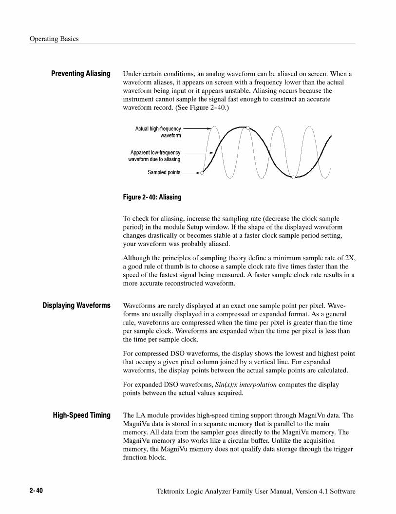
Operating Basics
2- 40 Tektronix Logic Analyzer Family User Manual, Version 4.1 Software
Under certain conditions, an analog waveform can be aliased on screen. When awaveform aliases, it appears on screen with a frequency lower than the actualwaveform being input or it appears unstable. Aliasing occurs because theinstrument cannot sample the signal fast enough to construct an accuratewaveform record. (See Figure 2--40.)
Actual high-frequencywaveform
Apparent low-frequencywaveform due to aliasing
Sampled points
Figure 2- 40: Aliasing
To check for aliasing, increase the sampling rate (decrease the clock sampleperiod) in the module Setup window. If the shape of the displayed waveformchanges drastically or becomes stable at a faster clock sample period setting,your waveform was probably aliased.
Although the principles of sampling theory define a minimum sample rate of 2X,a good rule of thumb is to choose a sample clock rate five times faster than thespeed of the fastest signal being measured. A faster sample clock rate results in amore accurate reconstructed waveform.
Waveforms are rarely displayed at an exact one sample point per pixel. Wave-forms are usually displayed in a compressed or expanded format. As a generalrule, waveforms are compressed when the time per pixel is greater than the timeper sample clock. Waveforms are expanded when the time per pixel is less thanthe time per sample clock.
For compressed DSO waveforms, the display shows the lowest and highest pointthat occupy a given pixel column joined by a vertical line. For expandedwaveforms, the display points between the actual sample points are calculated.
For expanded DSO waveforms, Sin(x)/x interpolation computes the displaypoints between the actual values acquired.
The LA module provides high-speed timing support through MagniVu data. TheMagniVu data is stored in a separate memory that is parallel to the mainmemory. All data from the sampler goes directly to the MagniVu memory. TheMagniVu memory also works like a circular buffer. Unlike the acquisitionmemory, the MagniVu memory does not qualify data storage through the triggerfunction block.
Preventing Aliasing
Displaying Waveforms
High-Speed Timing
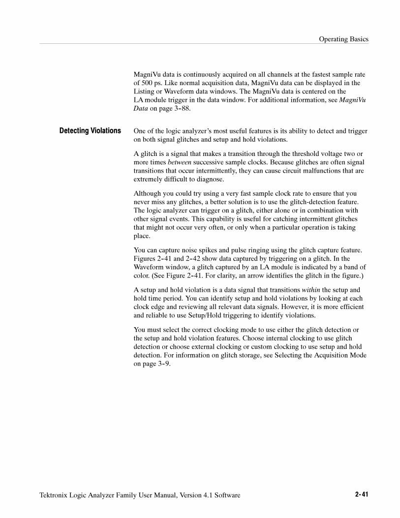
Operating Basics
Tektronix Logic Analyzer Family User Manual, Version 4.1 Software 2- 41
MagniVu data is continuously acquired on all channels at the fastest sample rateof 500 ps. Like normal acquisition data, MagniVu data can be displayed in theListing or Waveform data windows. The MagniVu data is centered on theLAmodule trigger in the data window. For additional information, seeMagniVu
Data on page 3--88.
One of the logic analyzer’s most useful features is its ability to detect and triggeron both signal glitches and setup and hold violations.
A glitch is a signal that makes a transition through the threshold voltage two ormore times between successive sample clocks. Because glitches are often signaltransitions that occur intermittently, they can cause circuit malfunctions that areextremely difficult to diagnose.
Although you could try using a very fast sample clock rate to ensure that younever miss any glitches, a better solution is to use the glitch-detection feature.The logic analyzer can trigger on a glitch, either alone or in combination withother signal events. This capability is useful for catching intermittent glitchesthat might not occur very often, or only when a particular operation is takingplace.
You can capture noise spikes and pulse ringing using the glitch capture feature.Figures 2--41 and 2--42 show data captured by triggering on a glitch. In theWaveform window, a glitch captured by an LA module is indicated by a band ofcolor. (See Figure 2--41. For clarity, an arrow identifies the glitch in the figure.)
A setup and hold violation is a data signal that transitions within the setup andhold time period. You can identify setup and hold violations by looking at eachclock edge and reviewing all relevant data signals. However, it is more efficientand reliable to use Setup/Hold triggering to identify violations.
You must select the correct clocking mode to use either the glitch detection orthe setup and hold violation features. Choose internal clocking to use glitchdetection or choose external clocking or custom clocking to use setup and holddetection. For information on glitch storage, see Selecting the Acquisition Modeon page 3--9.
Detecting Violations
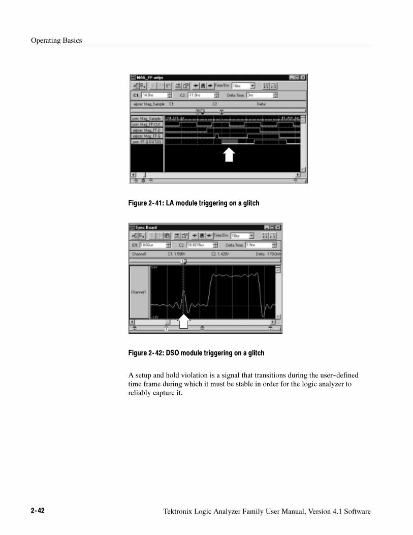
Operating Basics
2- 42 Tektronix Logic Analyzer Family User Manual, Version 4.1 Software
Figure 2- 41: LA module triggering on a glitch
Figure 2- 42: DSO module triggering on a glitch
A setup and hold violation is a signal that transitions during the user--definedtime frame during which it must be stable in order for the logic analyzer toreliably capture it.
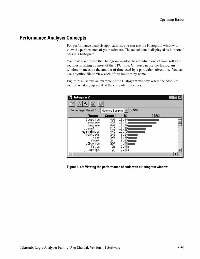
Operating Basics
Tektronix Logic Analyzer Family User Manual, Version 4.1 Software 2- 43
Performance Analysis Concepts
For performance analysis applications, you can use the Histogram window toview the performance of your software. The actual data is displayed as horizontalbars in a histogram.
You may want to use the Histogram window to see which one of your softwareroutines is taking up most of the CPU time. Or, you can use the Histogramwindow to measure the amount of time used by a particular subroutine. You canuse a symbol file to view each of the routines by name.
Figure 2--43 shows an example of the Histogram window where the StopLiteroutine is taking up most of the computer resources.
Figure 2- 43: Viewing the performance of code with a Histogram window
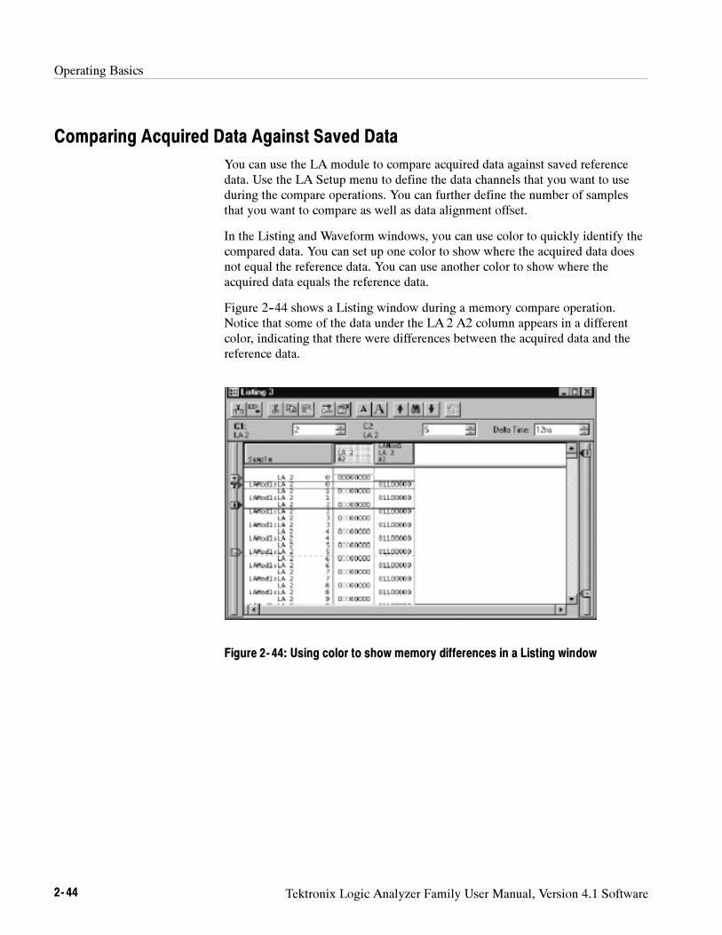
Operating Basics
2- 44 Tektronix Logic Analyzer Family User Manual, Version 4.1 Software
Comparing Acquired Data Against Saved Data
You can use the LA module to compare acquired data against saved referencedata. Use the LA Setup menu to define the data channels that you want to useduring the compare operations. You can further define the number of samplesthat you want to compare as well as data alignment offset.
In the Listing and Waveform windows, you can use color to quickly identify thecompared data. You can set up one color to show where the acquired data doesnot equal the reference data. You can use another color to show where theacquired data equals the reference data.
Figure 2--44 shows a Listing window during a memory compare operation.Notice that some of the data under the LA 2 A2 column appears in a differentcolor, indicating that there were differences between the acquired data and thereference data.
Figure 2- 44: Using color to show memory differences in a Listing window
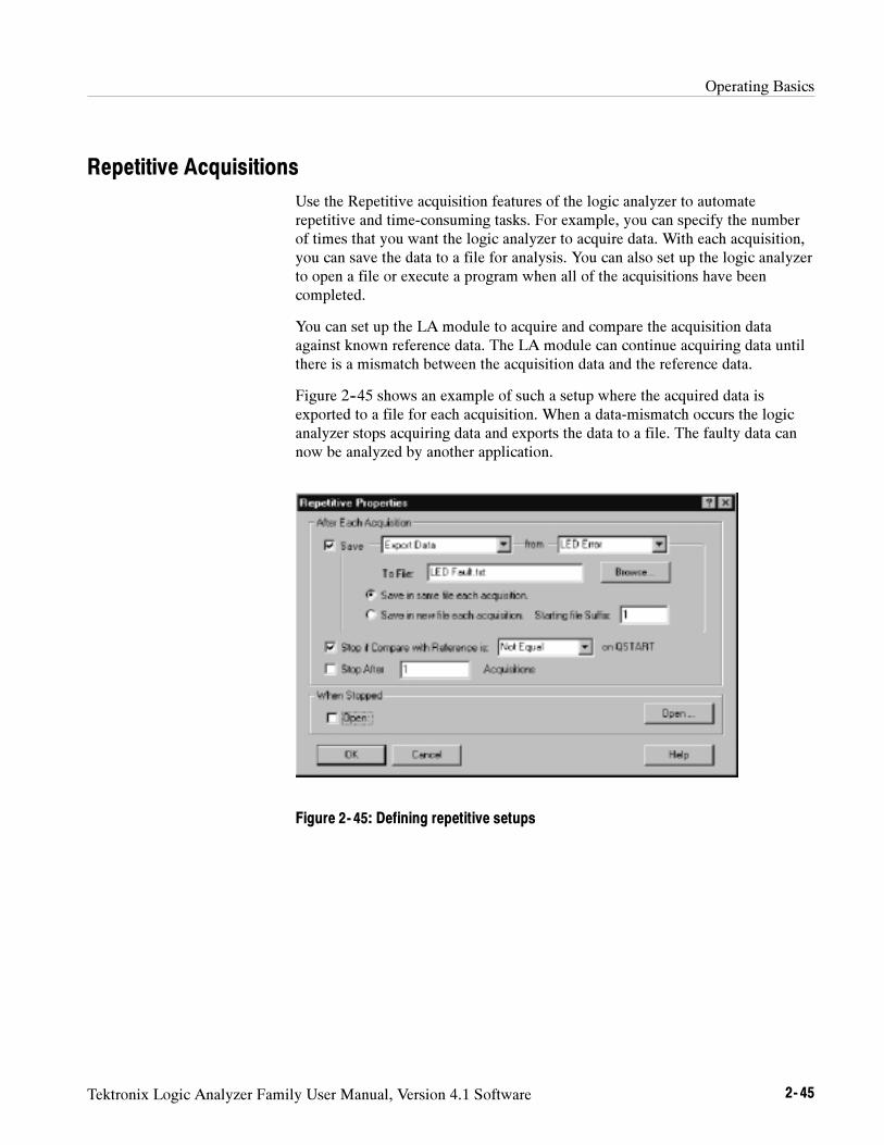
Operating Basics
Tektronix Logic Analyzer Family User Manual, Version 4.1 Software 2- 45
Repetitive Acquisitions
Use the Repetitive acquisition features of the logic analyzer to automaterepetitive and time-consuming tasks. For example, you can specify the numberof times that you want the logic analyzer to acquire data. With each acquisition,you can save the data to a file for analysis. You can also set up the logic analyzerto open a file or execute a program when all of the acquisitions have beencompleted.
You can set up the LA module to acquire and compare the acquisition dataagainst known reference data. The LA module can continue acquiring data untilthere is a mismatch between the acquisition data and the reference data.
Figure 2--45 shows an example of such a setup where the acquired data isexported to a file for each acquisition. When a data-mismatch occurs the logicanalyzer stops acquiring data and exports the data to a file. The faulty data cannow be analyzed by another application.
Figure 2- 45: Defining repetitive setups
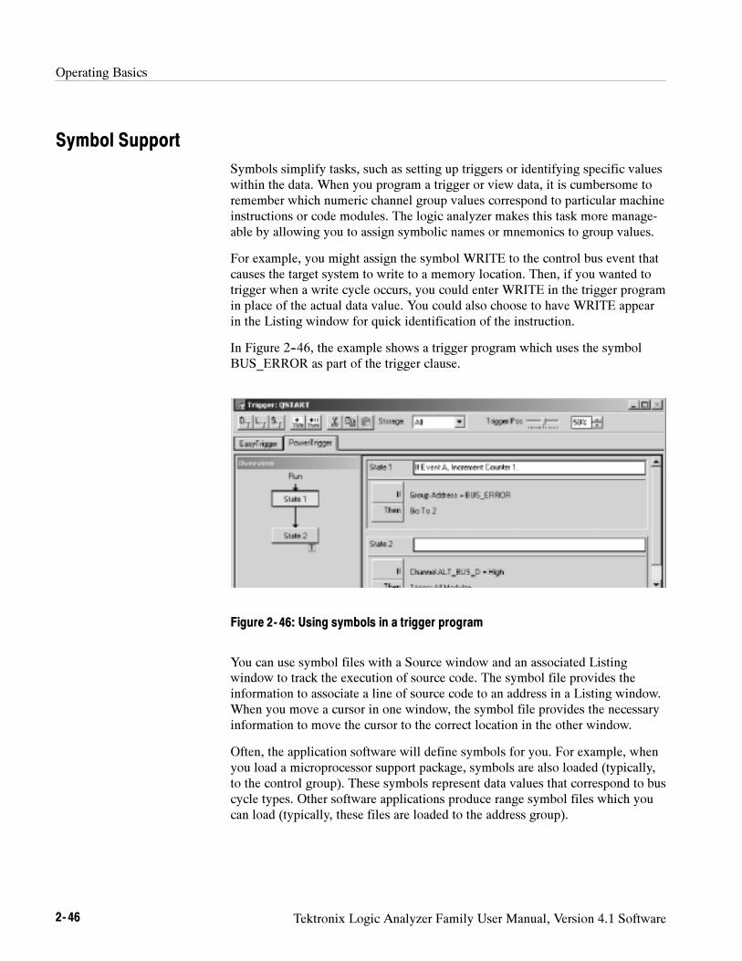
Operating Basics
2- 46 Tektronix Logic Analyzer Family User Manual, Version 4.1 Software
Symbol Support
Symbols simplify tasks, such as setting up triggers or identifying specific valueswithin the data. When you program a trigger or view data, it is cumbersome toremember which numeric channel group values correspond to particular machineinstructions or code modules. The logic analyzer makes this task more manage-able by allowing you to assign symbolic names or mnemonics to group values.
For example, you might assign the symbol WRITE to the control bus event thatcauses the target system to write to a memory location. Then, if you wanted totrigger when a write cycle occurs, you could enter WRITE in the trigger programin place of the actual data value. You could also choose to have WRITE appearin the Listing window for quick identification of the instruction.
In Figure 2--46, the example shows a trigger program which uses the symbolBUS_ERROR as part of the trigger clause.
Figure 2- 46: Using symbols in a trigger program
You can use symbol files with a Source window and an associated Listingwindow to track the execution of source code. The symbol file provides theinformation to associate a line of source code to an address in a Listing window.When you move a cursor in one window, the symbol file provides the necessaryinformation to move the cursor to the correct location in the other window.
Often, the application software will define symbols for you. For example, whenyou load a microprocessor support package, symbols are also loaded (typically,to the control group). These symbols represent data values that correspond to buscycle types. Other software applications produce range symbol files which youcan load (typically, these files are loaded to the address group).
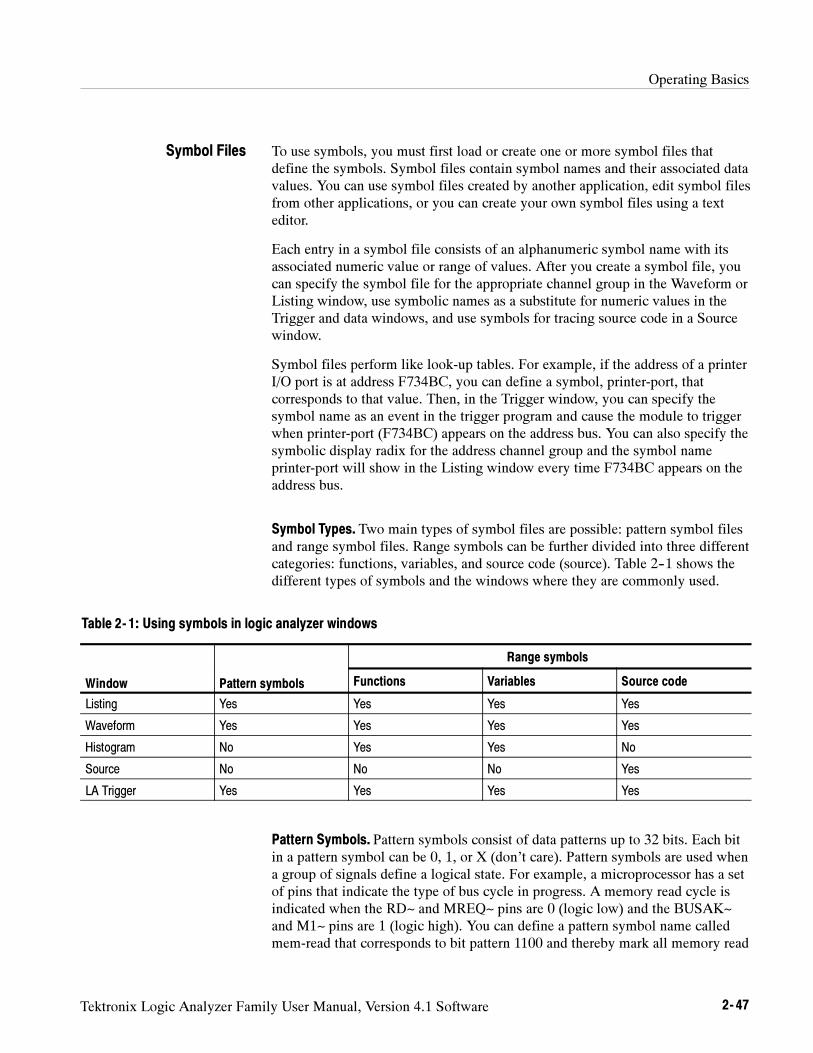
Operating Basics
Tektronix Logic Analyzer Family User Manual, Version 4.1 Software 2- 47
To use symbols, you must first load or create one or more symbol files thatdefine the symbols. Symbol files contain symbol names and their associated datavalues. You can use symbol files created by another application, edit symbol filesfrom other applications, or you can create your own symbol files using a texteditor.
Each entry in a symbol file consists of an alphanumeric symbol name with itsassociated numeric value or range of values. After you create a symbol file, youcan specify the symbol file for the appropriate channel group in the Waveform orListing window, use symbolic names as a substitute for numeric values in theTrigger and data windows, and use symbols for tracing source code in a Sourcewindow.
Symbol files perform like look-up tables. For example, if the address of a printerI/O port is at address F734BC, you can define a symbol, printer-port, thatcorresponds to that value. Then, in the Trigger window, you can specify thesymbol name as an event in the trigger program and cause the module to triggerwhen printer-port (F734BC) appears on the address bus. You can also specify thesymbolic display radix for the address channel group and the symbol nameprinter-port will show in the Listing window every time F734BC appears on theaddress bus.
Symbol Types. Two main types of symbol files are possible: pattern symbol filesand range symbol files. Range symbols can be further divided into three differentcategories: functions, variables, and source code (source). Table 2--1 shows thedifferent types of symbols and the windows where they are commonly used.
Table 2- 1: Using symbols in logic analyzer windows
Range symbols
Window Pattern symbols Functions Variables Source code
Listing Yes Yes Yes Yes
Waveform Yes Yes Yes Yes
Histogram No Yes Yes No
Source No No No Yes
LA Trigger Yes Yes Yes Yes
Pattern Symbols. Pattern symbols consist of data patterns up to 32 bits. Each bitin a pattern symbol can be 0, 1, or X (don’t care). Pattern symbols are used whena group of signals define a logical state. For example, a microprocessor has a setof pins that indicate the type of bus cycle in progress. A memory read cycle isindicated when the RD~ and MREQ~ pins are 0 (logic low) and the BUSAK~and M1~ pins are 1 (logic high). You can define a pattern symbol name calledmem-read that corresponds to bit pattern 1100 and thereby mark all memory read
Symbol Files

Operating Basics
2- 48 Tektronix Logic Analyzer Family User Manual, Version 4.1 Software
bus cycles in the Listing window. For other bus cycles the logic state of thesepins is also important and you can define different bit patterns for each cycletype.
Figure 2--47 shows pattern symbols used in a Waveform window.
Figure 2- 47: Waveforms using pattern symbols
Range Symbols. Range symbols define a range of 32-bit addresses represented bya contiguous set of integers, marked by specific lower and upper bounds. Thedifferent types of range symbols are discussed in detail under TLA Symbol File
Format beginning on page B--1.
When defining a range symbol file, do not overlap ranges of values. If rangesoverlap, they may not be recognized. For example, if SYM1 covers the range1000--3FFF, and SYM2 covers 2000--2FFF, then the values in range 2000--2FFFmay be recognized as either SYM1 or SYM2, and the values in the range3000--3FFF may not be recognized as SYM1 at all.
The range symbols shown in Figure 2--48 define subroutine boundaries.
Figure 2- 48: Listing data using range symbols
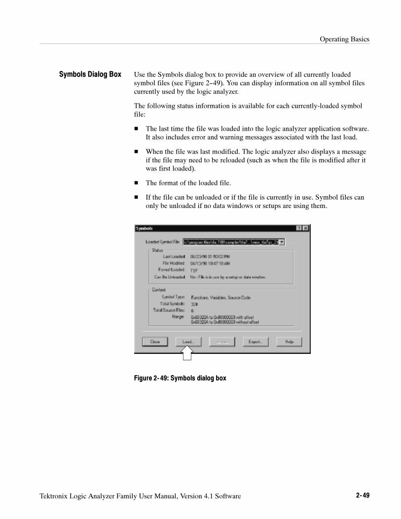
Operating Basics
Tektronix Logic Analyzer Family User Manual, Version 4.1 Software 2- 49
Use the Symbols dialog box to provide an overview of all currently loadedsymbol files (see Figure 2--49). You can display information on all symbol filescurrently used by the logic analyzer.
The following status information is available for each currently-loaded symbolfile:
The last time the file was loaded into the logic analyzer application software.It also includes error and warning messages associated with the last load.
When the file was last modified. The logic analyzer also displays a messageif the file may need to be reloaded (such as when the file is modified after itwas first loaded).
The format of the loaded file.
If the file can be unloaded or if the file is currently in use. Symbol files canonly be unloaded if no data windows or setups are using them.
Figure 2- 49: Symbols dialog box
Symbols Dialog Box
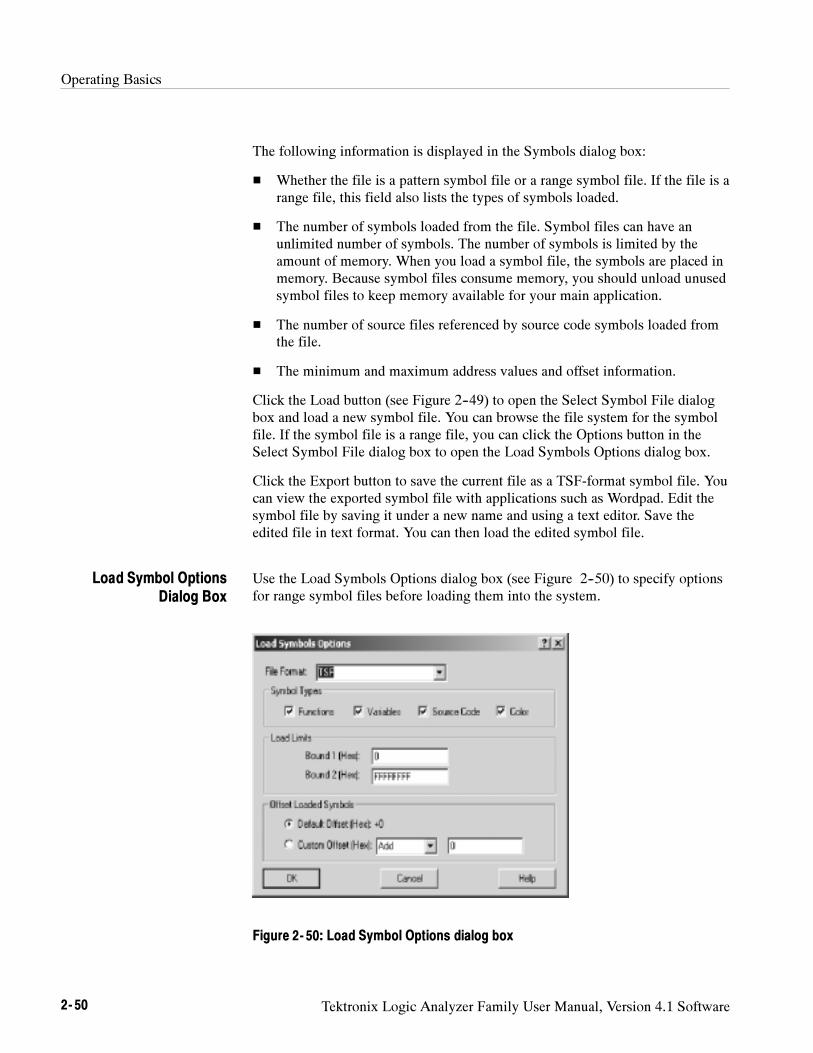
Operating Basics
2- 50 Tektronix Logic Analyzer Family User Manual, Version 4.1 Software
The following information is displayed in the Symbols dialog box:
Whether the file is a pattern symbol file or a range symbol file. If the file is arange file, this field also lists the types of symbols loaded.
The number of symbols loaded from the file. Symbol files can have anunlimited number of symbols. The number of symbols is limited by theamount of memory. When you load a symbol file, the symbols are placed inmemory. Because symbol files consume memory, you should unload unusedsymbol files to keep memory available for your main application.
The number of source files referenced by source code symbols loaded fromthe file.
The minimum and maximum address values and offset information.
Click the Load button (see Figure 2--49) to open the Select Symbol File dialogbox and load a new symbol file. You can browse the file system for the symbolfile. If the symbol file is a range file, you can click the Options button in theSelect Symbol File dialog box to open the Load Symbols Options dialog box.
Click the Export button to save the current file as a TSF-format symbol file. Youcan view the exported symbol file with applications such as Wordpad. Edit thesymbol file by saving it under a new name and using a text editor. Save theedited file in text format. You can then load the edited symbol file.
Use the Load Symbols Options dialog box (see Figure 2--50) to specify optionsfor range symbol files before loading them into the system.
Figure 2- 50: Load Symbol Options dialog box
Load Symbol OptionsDialog Box
Operating Basics
Tektronix Logic Analyzer Family User Manual, Version 4.1 Software 2- 51
Select one or more of the symbols types to load. If you want to use the symbolfile with the Source window, you should click the Source Code check box.
You can enter a decimal number for the maximum number of symbols to load.The maximum number of symbols that you can load is limited only by theamount of memory available. The file loads symbols until the specifiedmaximum number of symbols is reached. Additional symbols are ignored, evenif they fall within the Bound 1 and Bound 2 range limits.
The Bound 1 and Bound 2 fields define the range of symbol addresses that willbe loaded. You can enter any hexadecimal values from 0 through FFFFFFFF.Symbols with values outside of these limits are ignored and will not be loaded.
NOTE. If the lower bound of the range symbol is within the Bound 1 and Bound 2
limits and the higher bound is not, the entire symbol will be valid. However, if
the higher bound is within the Bound 1 and Bound 2 limits and the lower bound
is not, the entire symbol will be ignored.
Select either Default Offset or Custom Offset to apply an offset to the symbolvalues. If you select Default Offset, the default offset is read from the source fileand applied to each symbol in the file as it is loaded. If you select CustomOffset, you can add or subtract the specified offset value to each symbol in thefile as it is loaded. You can choose any 32-bit hexadecimal value from 0 toFFFFFFFF.
When you enter bound values, enter the values without an offset value. If yourapplication adds an offset, you must subtract the offset value before you enter thebound values.

Operating Basics
2- 52 Tektronix Logic Analyzer Family User Manual, Version 4.1 Software

Reference

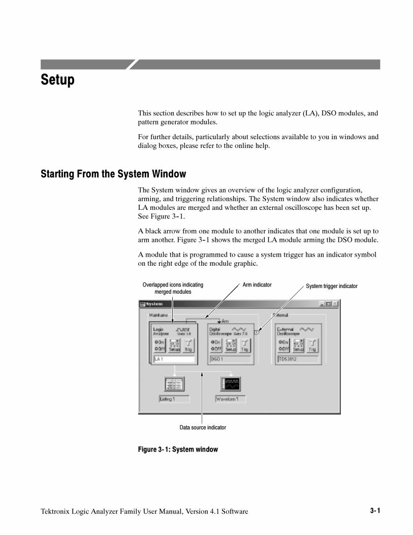
Tektronix Logic Analyzer Family User Manual, Version 4.1 Software 3- 1
Setup
This section describes how to set up the logic analyzer (LA), DSO modules, andpattern generator modules.
For further details, particularly about selections available to you in windows anddialog boxes, please refer to the online help.
Starting From the System Window
The System window gives an overview of the logic analyzer configuration,arming, and triggering relationships. The System window also indicates whetherLA modules are merged and whether an external oscilloscope has been set up.See Figure 3--1.
A black arrow from one module to another indicates that one module is set up toarm another. Figure 3--1 shows the merged LA module arming the DSO module.
A module that is programmed to cause a system trigger has an indicator symbolon the right edge of the module graphic.
Data source indicator
Overlapped icons indicatingmerged modules
System trigger indicatorArm indicator
Figure 3- 1: System window
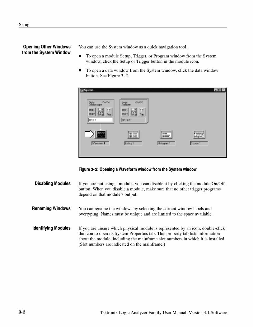
Setup
3- 2 Tektronix Logic Analyzer Family User Manual, Version 4.1 Software
You can use the System window as a quick navigation tool.
To open a module Setup, Trigger, or Program window from the Systemwindow, click the Setup or Trigger button in the module icon.
To open a data window from the System window, click the data windowbutton. See Figure 3--2.
Figure 3- 2: Opening a Waveform window from the System window
If you are not using a module, you can disable it by clicking the module On/Offbutton. When you disable a module, make sure that no other trigger programsdepend on that module’s output.
You can rename the windows by selecting the current window labels andovertyping. Names must be unique and are limited to the space available.
If you are unsure which physical module is represented by an icon, double-clickthe icon to open its System Properties tab. This property tab lists informationabout the module, including the mainframe slot numbers in which it is installed.(Slot numbers are indicated on the mainframe.)
Opening Other Windowsfrom the System Window
Disabling Modules
Renaming Windows
Identifying Modules
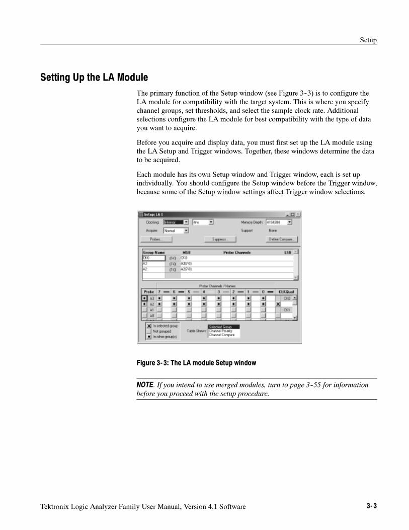
Setup
Tektronix Logic Analyzer Family User Manual, Version 4.1 Software 3- 3
Setting Up the LA Module
The primary function of the Setup window (see Figure 3--3) is to configure theLA module for compatibility with the target system. This is where you specifychannel groups, set thresholds, and select the sample clock rate. Additionalselections configure the LA module for best compatibility with the type of datayou want to acquire.
Before you acquire and display data, you must first set up the LA module usingthe LA Setup and Trigger windows. Together, these windows determine the datato be acquired.
Each module has its own Setup window and Trigger window, each is set upindividually. You should configure the Setup window before the Trigger window,because some of the Setup window settings affect Trigger window selections.
Figure 3- 3: The LA module Setup window
NOTE. If you intend to use merged modules, turn to page 3--55 for information
before you proceed with the setup procedure.
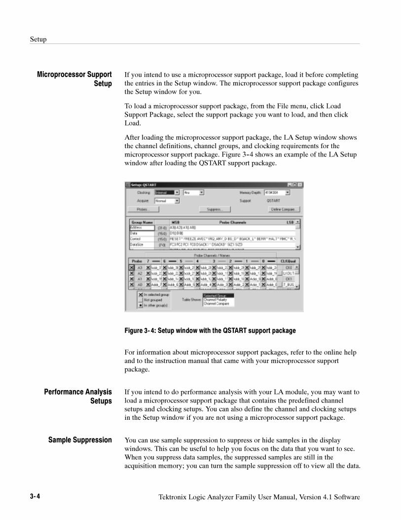
Setup
3- 4 Tektronix Logic Analyzer Family User Manual, Version 4.1 Software
If you intend to use a microprocessor support package, load it before completingthe entries in the Setup window. The microprocessor support package configuresthe Setup window for you.
To load a microprocessor support package, from the File menu, click LoadSupport Package, select the support package you want to load, and then clickLoad.
After loading the microprocessor support package, the LA Setup window showsthe channel definitions, channel groups, and clocking requirements for themicroprocessor support package. Figure 3--4 shows an example of the LA Setupwindow after loading the QSTART support package.
Figure 3- 4: Setup window with the QSTART support package
For information about microprocessor support packages, refer to the online helpand to the instruction manual that came with your microprocessor supportpackage.
If you intend to do performance analysis with your LA module, you may want toload a microprocessor support package that contains the predefined channelsetups and clocking setups. You can also define the channel and clocking setupsin the Setup window if you are not using a microprocessor support package.
You can use sample suppression to suppress or hide samples in the displaywindows. This can be useful to help you focus on the data that you want to see.When you suppress data samples, the suppressed samples are still in theacquisition memory; you can turn the sample suppression off to view all the data.
Microprocessor SupportSetup
Performance AnalysisSetups
Sample Suppression
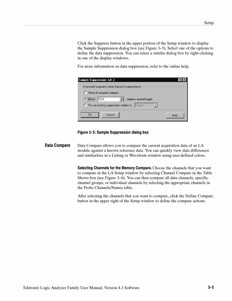
Setup
Tektronix Logic Analyzer Family User Manual, Version 4.1 Software 3- 5
Click the Suppress button in the upper portion of the Setup window to displaythe Sample Suppression dialog box (see Figure 3--5). Select one of the options todefine the data suppression. You can select a similar dialog box by right-clickingin one of the display windows.
For more information on data suppression, refer to the online help.
Figure 3- 5: Sample Suppression dialog box
Data Compare allows you to compare the current acquisition data of an LAmodule against a known reference data. You can quickly view data differencesand similarities in a Listing or Waveform window using user-defined colors.
Selecting Channels for the Memory Compare. Choose the channels that you wantto compare in the LA Setup window by selecting Channel Compare in the TableShows box (see Figure 3--6). You can then compare all data channels, specificchannel groups, or individual channels by selecting the appropriate channels inthe Probe Channels/Names table.
After selecting the channels that you want to compare, click the Define Comparebutton in the upper right of the Setup window to define the compare actions.
Data Compare
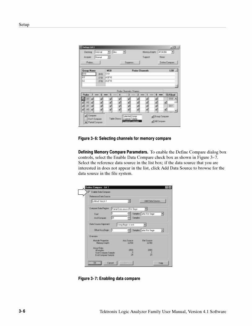
Setup
3- 6 Tektronix Logic Analyzer Family User Manual, Version 4.1 Software
Figure 3- 6: Selecting channels for memory compare
Defining Memory Compare Parameters. To enable the Define Compare dialog boxcontrols, select the Enable Data Compare check box as shown in Figure 3--7.Select the reference data source in the list box; if the data source that you areinterested in does not appear in the list, click Add Data Source to browse for thedata source in the file system.
Figure 3- 7: Enabling data compare
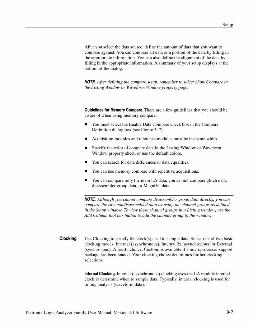
Setup
Tektronix Logic Analyzer Family User Manual, Version 4.1 Software 3- 7
After you select the data source, define the amount of data that you want tocompare against. You can compare all data or a portion of the data by filling inthe appropriate information. You can also define the alignment of the data byfilling in the appropriate information. A summary of your setup displays at thebottom of the dialog.
NOTE. After defining the compare setup, remember to select Show Compare in
the Listing Window or Waveform Window property page.
Guidelines for Memory Compare. There are a few guidelines that you should beaware of when using memory compare:
You must select the Enable Data Compare check box in the CompareDefinition dialog box (see Figure 3--7).
Acquisition modules and reference modules must be the same width.
Specify the color of compare data in the Listing Window or WaveformWindow property sheet, or use the default colors.
You can search for data differences or data equalities.
You can use memory compare with repetitive acquisitions.
You can compare only the main LA data, you cannot compare glitch data,disassembler group data, or MagniVu data.
NOTE. Although you cannot compare disassembler group data directly, you can
compare the raw nondisassembled data by using the channel groups as defined
in the Setup window. To view these channel groups in a Listing window, use the
Add Column tool bar button to add the channel group to the window.
Use Clocking to specify the clock(s) used to sample data. Select one of two basicclocking modes, Internal (asynchronous), Internal 2x (asynchronous) or External(synchronous). A fourth choice, Custom, is available if a microprocessor supportpackage has been loaded. Your clocking choice determines further clockingselections.
Internal Clocking. Internal (asynchronous) clocking uses the LA module internalclock to determine when to sample data. Typically, internal clocking is used fortiming analysis (waveform data).
Clocking
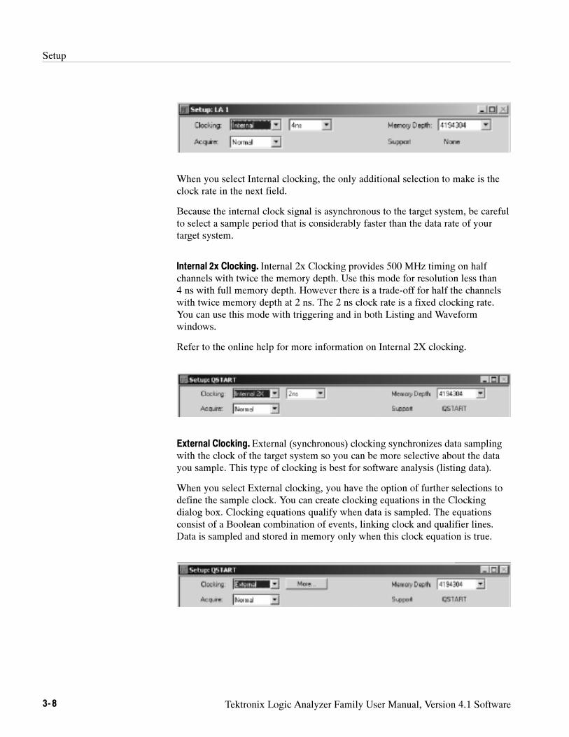
Setup
3- 8 Tektronix Logic Analyzer Family User Manual, Version 4.1 Software
When you select Internal clocking, the only additional selection to make is theclock rate in the next field.
Because the internal clock signal is asynchronous to the target system, be carefulto select a sample period that is considerably faster than the data rate of yourtarget system.
Internal 2x Clocking. Internal 2x Clocking provides 500 MHz timing on halfchannels with twice the memory depth. Use this mode for resolution less than4 ns with full memory depth. However there is a trade-off for half the channelswith twice memory depth at 2 ns. The 2 ns clock rate is a fixed clocking rate.You can use this mode with triggering and in both Listing and Waveformwindows.
Refer to the online help for more information on Internal 2X clocking.
External Clocking. External (synchronous) clocking synchronizes data samplingwith the clock of the target system so you can be more selective about the datayou sample. This type of clocking is best for software analysis (listing data).
When you select External clocking, you have the option of further selections todefine the sample clock. You can create clocking equations in the Clockingdialog box. Clocking equations qualify when data is sampled. The equationsconsist of a Boolean combination of events, linking clock and qualifier lines.Data is sampled and stored in memory only when this clock equation is true.
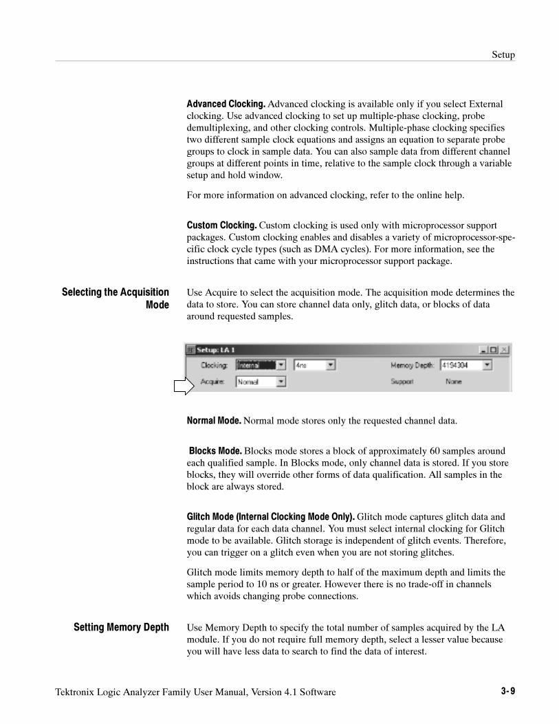
Setup
Tektronix Logic Analyzer Family User Manual, Version 4.1 Software 3- 9
Advanced Clocking.Advanced clocking is available only if you select Externalclocking. Use advanced clocking to set up multiple-phase clocking, probedemultiplexing, and other clocking controls. Multiple-phase clocking specifiestwo different sample clock equations and assigns an equation to separate probegroups to clock in sample data. You can also sample data from different channelgroups at different points in time, relative to the sample clock through a variablesetup and hold window.
For more information on advanced clocking, refer to the online help.
Custom Clocking. Custom clocking is used only with microprocessor supportpackages. Custom clocking enables and disables a variety of microprocessor-spe-cific clock cycle types (such as DMA cycles). For more information, see theinstructions that came with your microprocessor support package.
Use Acquire to select the acquisition mode. The acquisition mode determines thedata to store. You can store channel data only, glitch data, or blocks of dataaround requested samples.
Normal Mode.Normal mode stores only the requested channel data.
Blocks Mode. Blocks mode stores a block of approximately 60 samples aroundeach qualified sample. In Blocks mode, only channel data is stored. If you storeblocks, they will override other forms of data qualification. All samples in theblock are always stored.
Glitch Mode (Internal Clocking Mode Only).Glitch mode captures glitch data andregular data for each data channel. You must select internal clocking for Glitchmode to be available. Glitch storage is independent of glitch events. Therefore,you can trigger on a glitch even when you are not storing glitches.
Glitch mode limits memory depth to half of the maximum depth and limits thesample period to 10 ns or greater. However there is no trade-off in channelswhich avoids changing probe connections.
Use Memory Depth to specify the total number of samples acquired by the LAmodule. If you do not require full memory depth, select a lesser value becauseyou will have less data to search to find the data of interest.
Selecting the AcquisitionMode
Setting Memory Depth
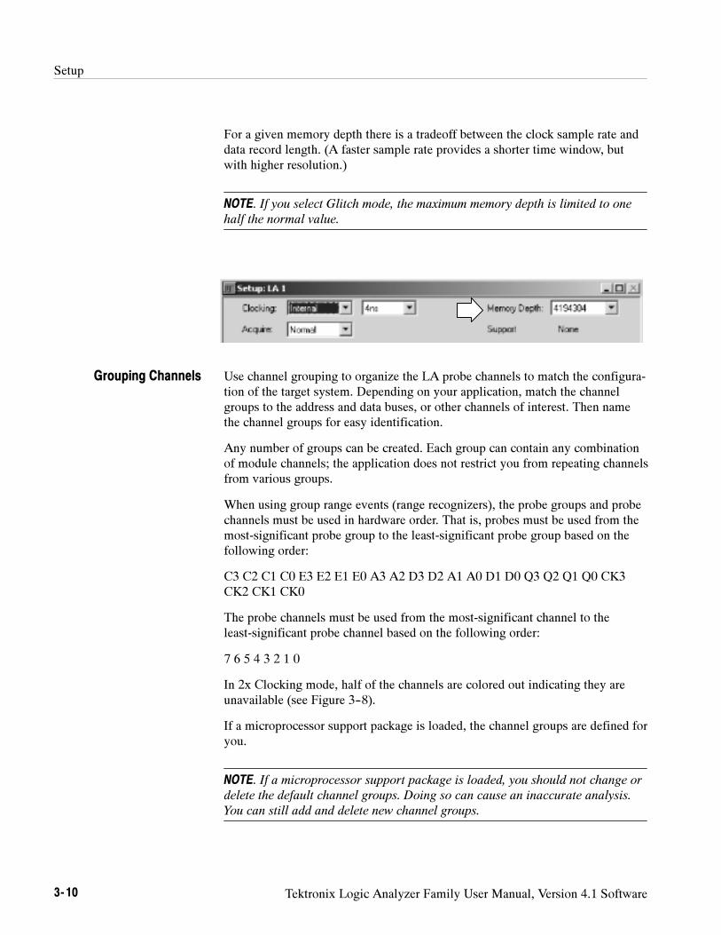
Setup
3- 10 Tektronix Logic Analyzer Family User Manual, Version 4.1 Software
For a given memory depth there is a tradeoff between the clock sample rate anddata record length. (A faster sample rate provides a shorter time window, butwith higher resolution.)
NOTE. If you select Glitch mode, the maximum memory depth is limited to one
half the normal value.
Use channel grouping to organize the LA probe channels to match the configura-tion of the target system. Depending on your application, match the channelgroups to the address and data buses, or other channels of interest. Then namethe channel groups for easy identification.
Any number of groups can be created. Each group can contain any combinationof module channels; the application does not restrict you from repeating channelsfrom various groups.
When using group range events (range recognizers), the probe groups and probechannels must be used in hardware order. That is, probes must be used from themost-significant probe group to the least-significant probe group based on thefollowing order:
C3 C2 C1 C0 E3 E2 E1 E0 A3 A2 D3 D2 A1 A0 D1 D0 Q3 Q2 Q1 Q0 CK3CK2 CK1 CK0
The probe channels must be used from the most-significant channel to theleast-significant probe channel based on the following order:
7 6 5 4 3 2 1 0
In 2x Clocking mode, half of the channels are colored out indicating they areunavailable (see Figure 3--8).
If a microprocessor support package is loaded, the channel groups are defined foryou.
NOTE. If a microprocessor support package is loaded, you should not change or
delete the default channel groups. Doing so can cause an inaccurate analysis.
You can still add and delete new channel groups.
Grouping Channels
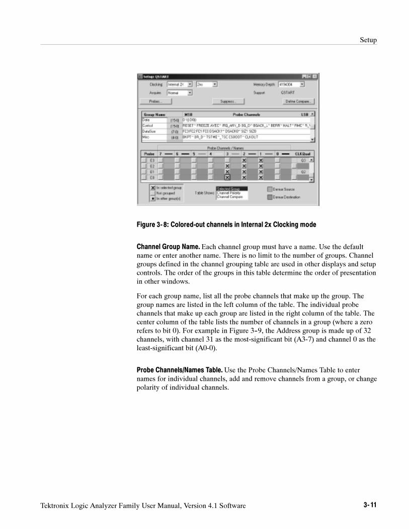
Setup
Tektronix Logic Analyzer Family User Manual, Version 4.1 Software 3- 11
Figure 3- 8: Colored-out channels in Internal 2x Clocking mode
Channel Group Name. Each channel group must have a name. Use the defaultname or enter another name. There is no limit to the number of groups. Channelgroups defined in the channel grouping table are used in other displays and setupcontrols. The order of the groups in this table determine the order of presentationin other windows.
For each group name, list all the probe channels that make up the group. Thegroup names are listed in the left column of the table. The individual probechannels that make up each group are listed in the right column of the table. Thecenter column of the table lists the number of channels in a group (where a zerorefers to bit 0). For example in Figure 3--9, the Address group is made up of 32channels, with channel 31 as the most-significant bit (A3-7) and channel 0 as theleast-significant bit (A0-0).
Probe Channels/Names Table.Use the Probe Channels/Names Table to enternames for individual channels, add and remove channels from a group, or changepolarity of individual channels.
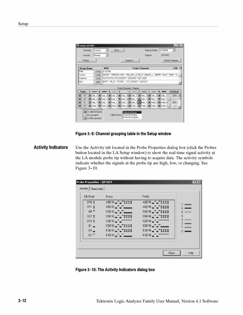
Setup
3- 12 Tektronix Logic Analyzer Family User Manual, Version 4.1 Software
Figure 3- 9: Channel grouping table in the Setup window
Use the Activity tab located in the Probe Properties dialog box (click the Probesbutton located in the LA Setup window) to show the real-time signal activity atthe LA module probe tip without having to acquire data. The activity symbolsindicate whether the signals at the probe tip are high, low, or changing. SeeFigure 3--10.
Figure 3- 10: The Activity Indicators dialog box
Activity Indicators
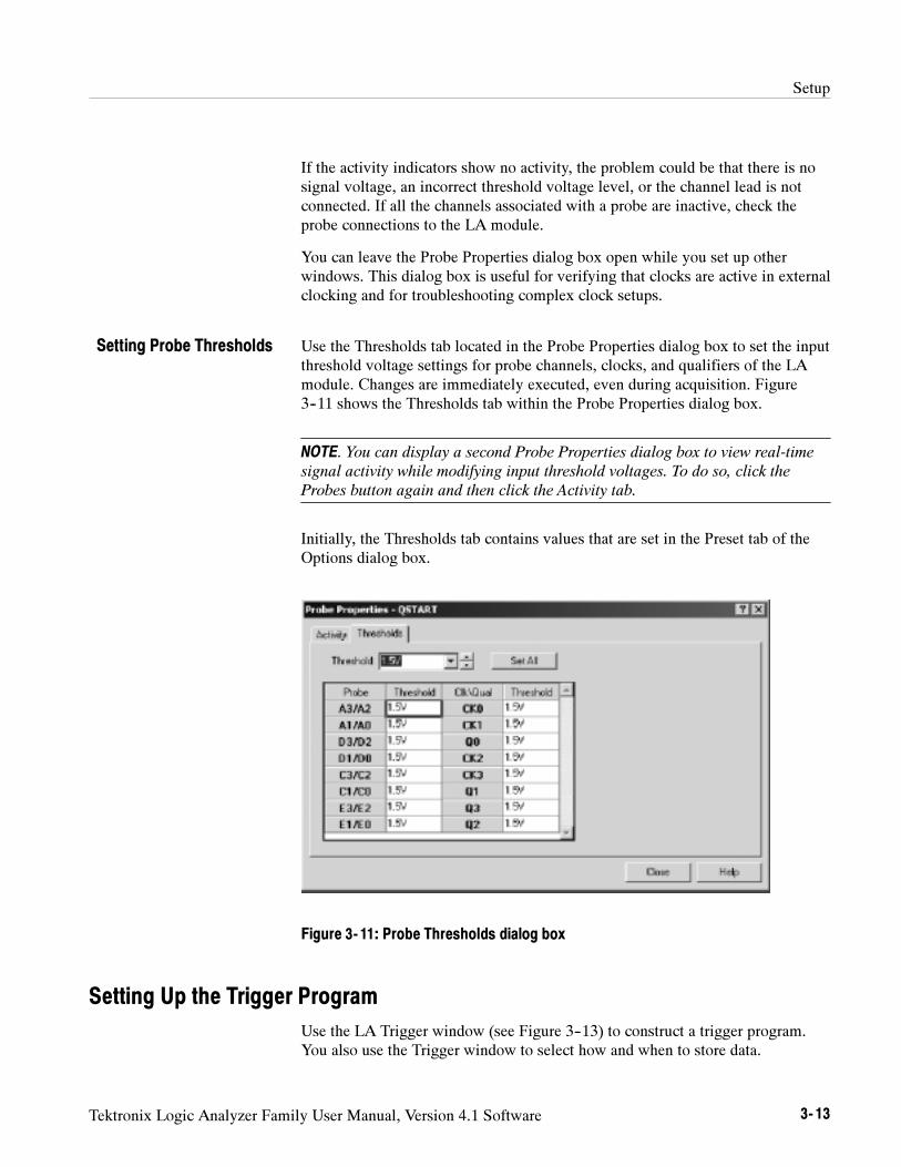
Setup
Tektronix Logic Analyzer Family User Manual, Version 4.1 Software 3- 13
If the activity indicators show no activity, the problem could be that there is nosignal voltage, an incorrect threshold voltage level, or the channel lead is notconnected. If all the channels associated with a probe are inactive, check theprobe connections to the LA module.
You can leave the Probe Properties dialog box open while you set up otherwindows. This dialog box is useful for verifying that clocks are active in externalclocking and for troubleshooting complex clock setups.
Use the Thresholds tab located in the Probe Properties dialog box to set the inputthreshold voltage settings for probe channels, clocks, and qualifiers of the LAmodule. Changes are immediately executed, even during acquisition. Figure3--11 shows the Thresholds tab within the Probe Properties dialog box.
NOTE. You can display a second Probe Properties dialog box to view real-time
signal activity while modifying input threshold voltages. To do so, click the
Probes button again and then click the Activity tab.
Initially, the Thresholds tab contains values that are set in the Preset tab of theOptions dialog box.
Figure 3- 11: Probe Thresholds dialog box
Setting Up the Trigger Program
Use the LA Trigger window (see Figure 3--13) to construct a trigger program.You also use the Trigger window to select how and when to store data.
Setting Probe Thresholds
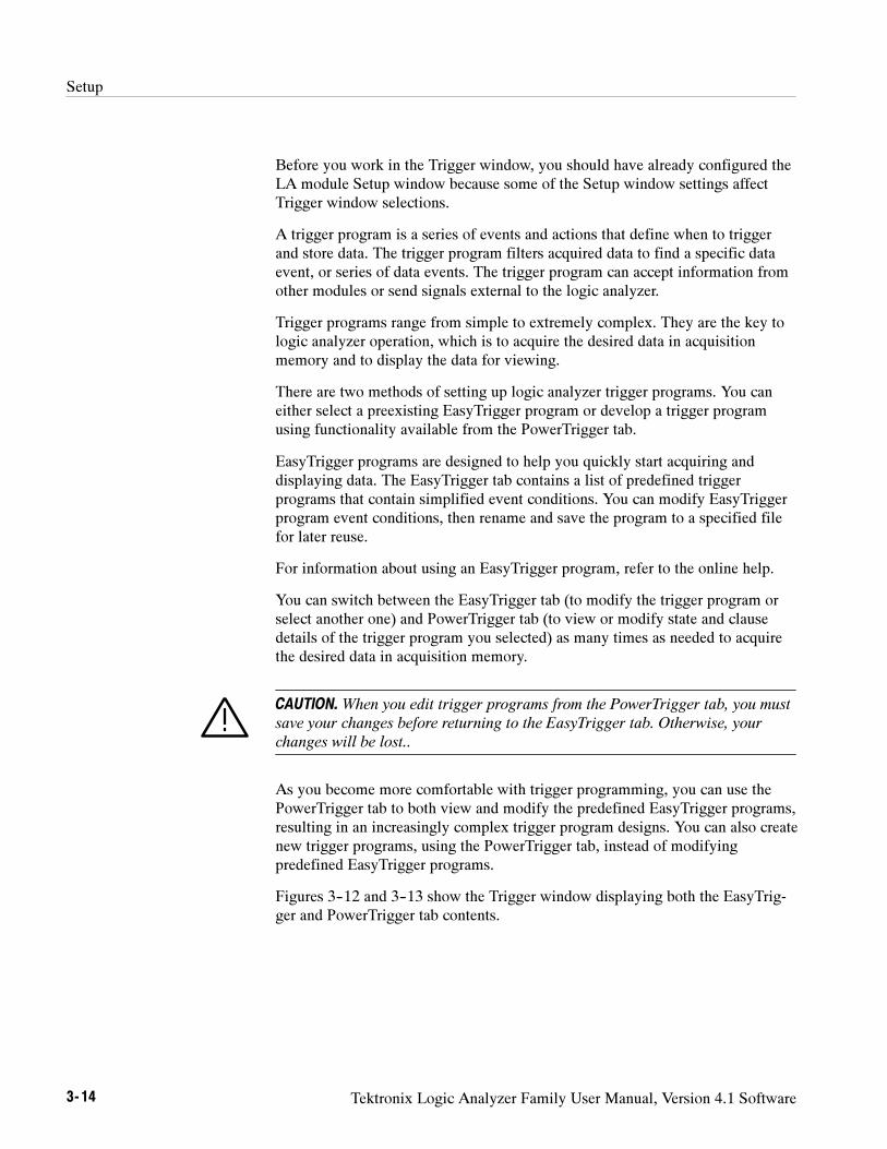
Setup
3- 14 Tektronix Logic Analyzer Family User Manual, Version 4.1 Software
Before you work in the Trigger window, you should have already configured theLA module Setup window because some of the Setup window settings affectTrigger window selections.
A trigger program is a series of events and actions that define when to triggerand store data. The trigger program filters acquired data to find a specific dataevent, or series of data events. The trigger program can accept information fromother modules or send signals external to the logic analyzer.
Trigger programs range from simple to extremely complex. They are the key tologic analyzer operation, which is to acquire the desired data in acquisitionmemory and to display the data for viewing.
There are two methods of setting up logic analyzer trigger programs. You caneither select a preexisting EasyTrigger program or develop a trigger programusing functionality available from the PowerTrigger tab.
EasyTrigger programs are designed to help you quickly start acquiring anddisplaying data. The EasyTrigger tab contains a list of predefined triggerprograms that contain simplified event conditions. You can modify EasyTriggerprogram event conditions, then rename and save the program to a specified filefor later reuse.
For information about using an EasyTrigger program, refer to the online help.
You can switch between the EasyTrigger tab (to modify the trigger program orselect another one) and PowerTrigger tab (to view or modify state and clausedetails of the trigger program you selected) as many times as needed to acquirethe desired data in acquisition memory.
CAUTION.When you edit trigger programs from the PowerTrigger tab, you must
save your changes before returning to the EasyTrigger tab. Otherwise, your
changes will be lost..
As you become more comfortable with trigger programming, you can use thePowerTrigger tab to both view and modify the predefined EasyTrigger programs,resulting in an increasingly complex trigger program designs. You can also createnew trigger programs, using the PowerTrigger tab, instead of modifyingpredefined EasyTrigger programs.
Figures 3--12 and 3--13 show the Trigger window displaying both the EasyTrig-ger and PowerTrigger tab contents.
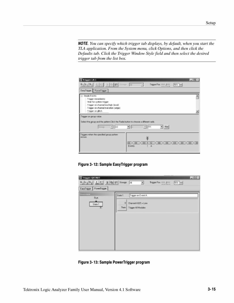
Setup
Tektronix Logic Analyzer Family User Manual, Version 4.1 Software 3- 15
NOTE. You can specify which trigger tab displays, by default, when you start the
TLA application. From the System menu, click Options, and then click the
Defaults tab. Click the Trigger Window Style field and then select the desired
trigger tab from the list box.
Figure 3- 12: Sample EasyTrigger program
Figure 3- 13: Sample PowerTrigger program
Setup
3- 16 Tektronix Logic Analyzer Family User Manual, Version 4.1 Software
A Trigger program consists of one or more states (up to 16). Only one state isactive at a time.
Each state is made up of one or more clauses. If you use more than four triggerevent resources in a state, you can have up to four clauses per state. If you havefour or fewer trigger event resources in a state, you can define up to 16 clausesper state.
Clauses are made up of two parts: an If statement, that defines the data event ofinterest, and a Then statement, which specifies the action taken when the Ifstatement is true. You can define up to eight events per If statement and up toeight trigger actions per Then statement.
During each sample clock cycle, all clauses within the active state simultaneous-ly evaluate each data sample. Clauses are evaluated from top (State #1, IF-ThenClause #1) to bottom. When one of the clauses goes true (the event defined in theIf statement occurs), then the logic analyzer performs the action(s) specified inthe Then statement. There are several actions to choose from, includingtriggering the system and transferring control of the trigger program to anotherstate.
NOTE. If multiple clauses are true in the same clock cycle, the earliest clause in
the state that is evaluated as true will have its action(s) executed.
Complete details of a trigger program’s structure are only available from thePowerTrigger tab, allowing you to either view details hidden in the EasyTriggertab view, or change the composition of the states and clauses. The triggerprogram structure that displays from the EasyTrigger tab is predefined, and isbased on the trigger program that you select. Using a predefined trigger structureallows you to begin using triggers without having to initially specify all of theavailable program implementation details.
Trigger Program Structure
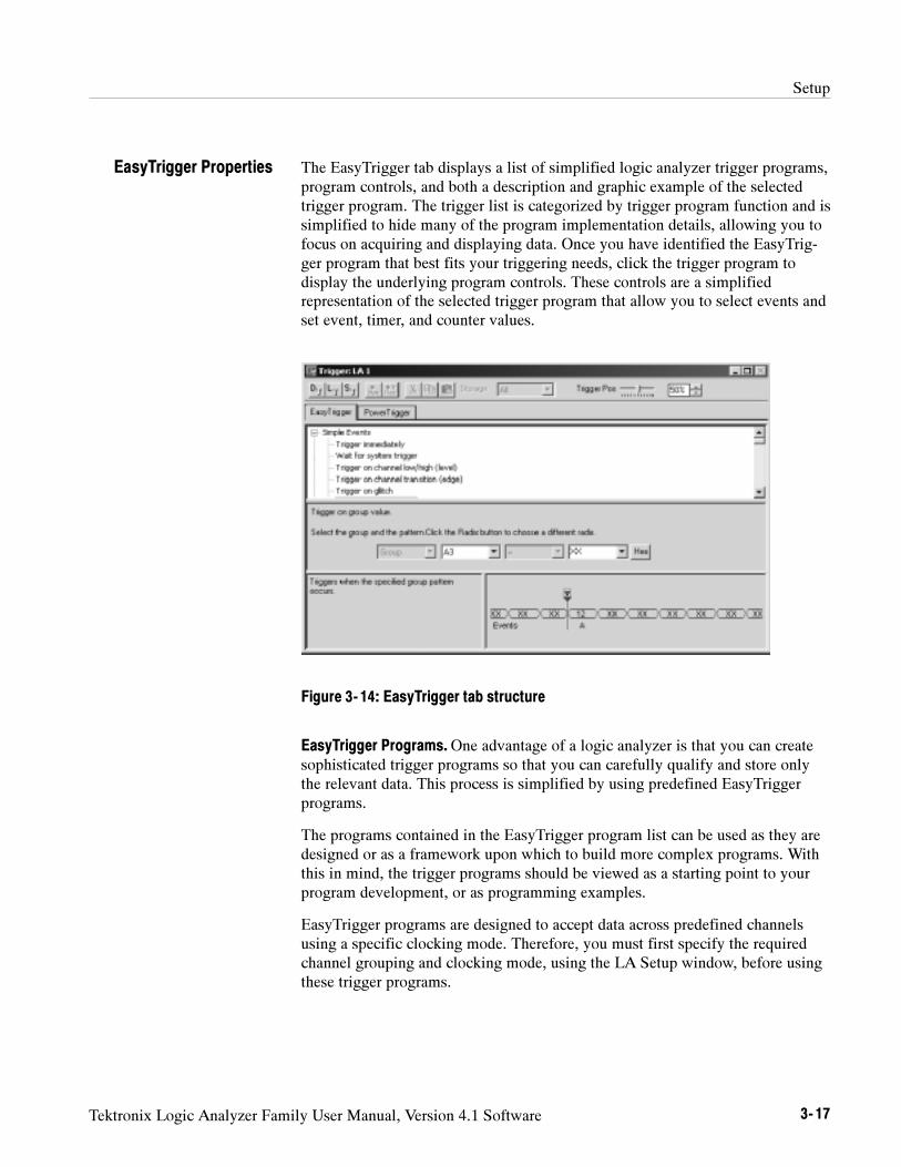
Setup
Tektronix Logic Analyzer Family User Manual, Version 4.1 Software 3- 17
The EasyTrigger tab displays a list of simplified logic analyzer trigger programs,program controls, and both a description and graphic example of the selectedtrigger program. The trigger list is categorized by trigger program function and issimplified to hide many of the program implementation details, allowing you tofocus on acquiring and displaying data. Once you have identified the EasyTrig-ger program that best fits your triggering needs, click the trigger program todisplay the underlying program controls. These controls are a simplifiedrepresentation of the selected trigger program that allow you to select events andset event, timer, and counter values.
Figure 3- 14: EasyTrigger tab structure
EasyTrigger Programs.One advantage of a logic analyzer is that you can createsophisticated trigger programs so that you can carefully qualify and store onlythe relevant data. This process is simplified by using predefined EasyTriggerprograms.
The programs contained in the EasyTrigger program list can be used as they aredesigned or as a framework upon which to build more complex programs. Withthis in mind, the trigger programs should be viewed as a starting point to yourprogram development, or as programming examples.
EasyTrigger programs are designed to accept data across predefined channelsusing a specific clocking mode. Therefore, you must first specify the requiredchannel grouping and clocking mode, using the LA Setup window, before usingthese trigger programs.
EasyTrigger Properties
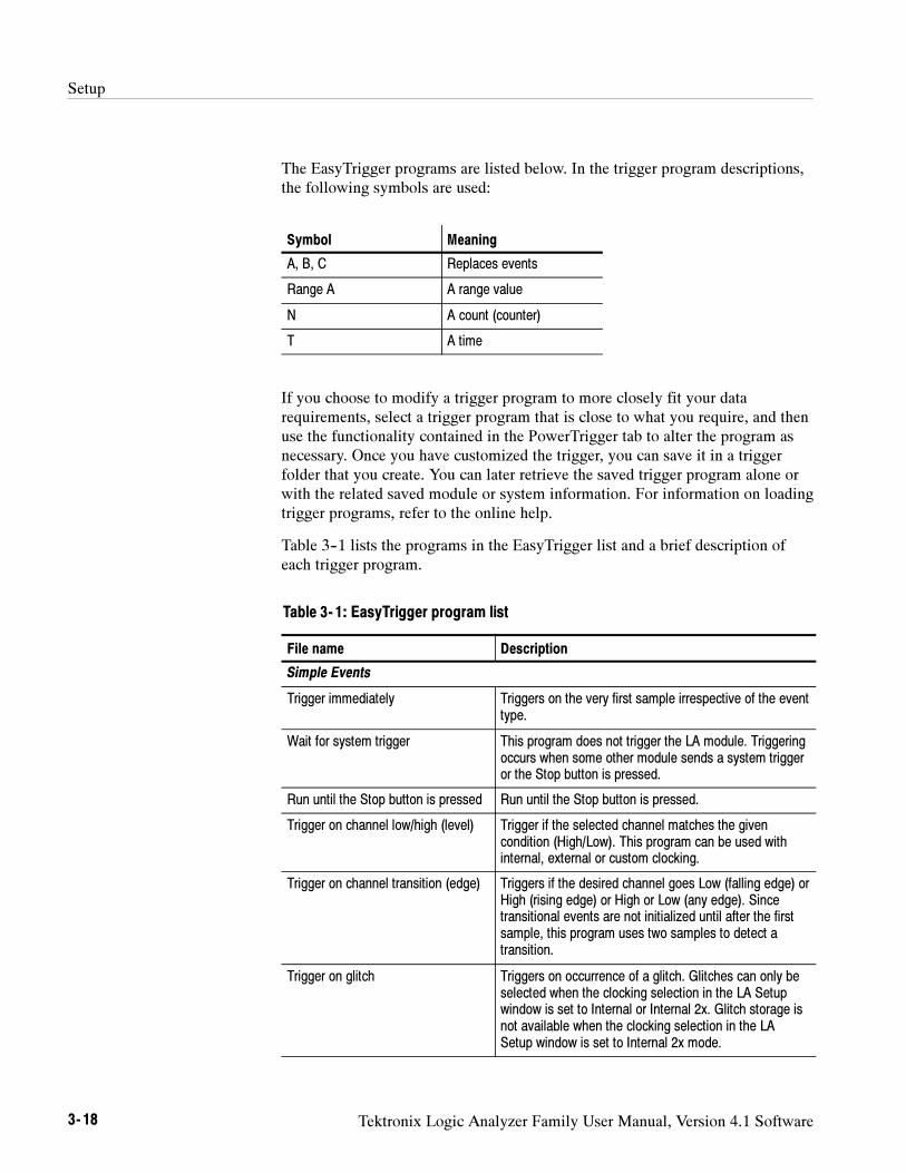
Setup
3- 18 Tektronix Logic Analyzer Family User Manual, Version 4.1 Software
The EasyTrigger programs are listed below. In the trigger program descriptions,the following symbols are used:
Symbol Meaning
A, B, C Replaces events
Range A A range value
N A count (counter)
T A time
If you choose to modify a trigger program to more closely fit your datarequirements, select a trigger program that is close to what you require, and thenuse the functionality contained in the PowerTrigger tab to alter the program asnecessary. Once you have customized the trigger, you can save it in a triggerfolder that you create. You can later retrieve the saved trigger program alone orwith the related saved module or system information. For information on loadingtrigger programs, refer to the online help.
Table 3--1 lists the programs in the EasyTrigger list and a brief description ofeach trigger program.
Table 3- 1: EasyTrigger program list
File name Description
Simple Events
Trigger immediately Triggers on the very first sample irrespective of the eventtype.
Wait for system trigger This program does not trigger the LA module. Triggeringoccurs when some other module sends a system triggeror the Stop button is pressed.
Run until the Stop button is pressed Run until the Stop button is pressed.
Trigger on channel low/high (level) Trigger if the selected channel matches the givencondition (High/Low). This program can be used withinternal, external or custom clocking.
Trigger on channel transition (edge) Triggers if the desired channel goes Low (falling edge) orHigh (rising edge) or High or Low (any edge). Sincetransitional events are not initialized until after the firstsample, this program uses two samples to detect atransition.
Trigger on glitch Triggers on occurrence of a glitch. Glitches can only beselected when the clocking selection in the LA Setupwindow is set to Internal or Internal 2x. Glitch storage isnot available when the clocking selection in the LASetup window is set to Internal 2x mode.
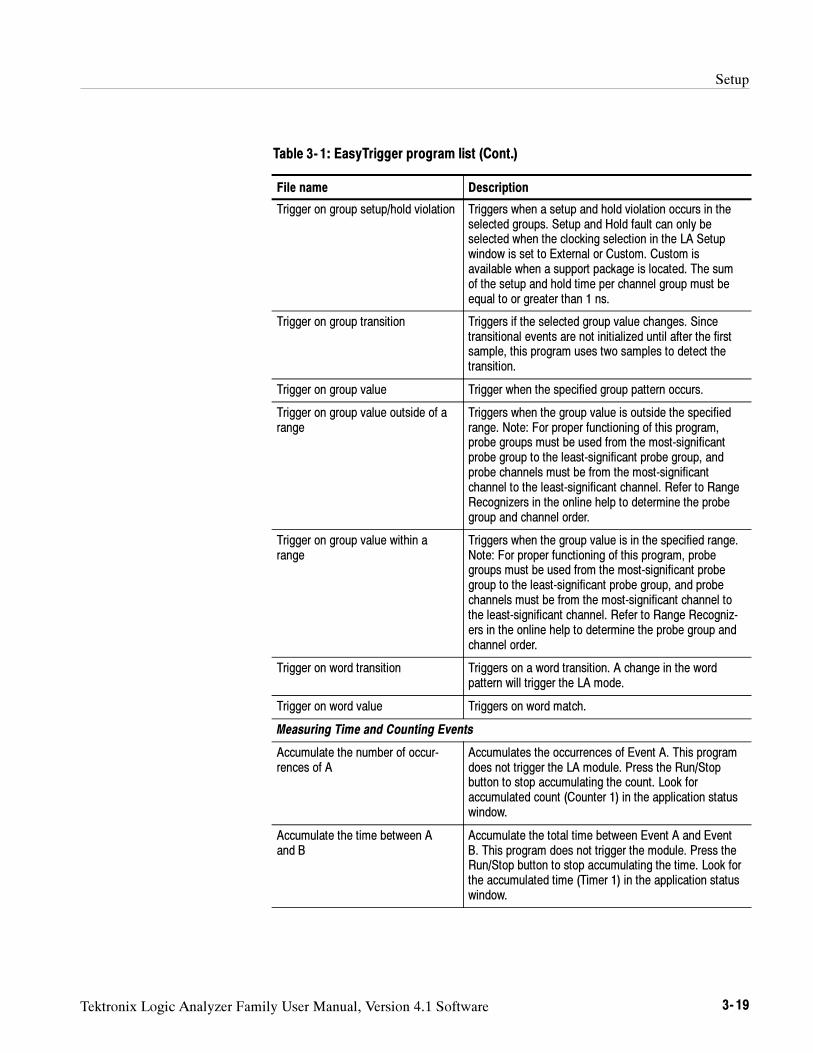
Setup
Tektronix Logic Analyzer Family User Manual, Version 4.1 Software 3- 19
Table 3- 1: EasyTrigger program list (Cont.)
File name Description
Trigger on group setup/hold violation Triggers when a setup and hold violation occurs in theselected groups. Setup and Hold fault can only beselected when the clocking selection in the LA Setupwindow is set to External or Custom. Custom isavailable when a support package is located. The sumof the setup and hold time per channel group must beequal to or greater than 1 ns.
Trigger on group transition Triggers if the selected group value changes. Sincetransitional events are not initialized until after the firstsample, this program uses two samples to detect thetransition.
Trigger on group value Trigger when the specified group pattern occurs.
Trigger on group value outside of arange
Triggers when the group value is outside the specifiedrange. Note: For proper functioning of this program,probe groups must be used from the most-significantprobe group to the least-significant probe group, andprobe channels must be from the most-significantchannel to the least-significant channel. Refer to RangeRecognizers in the online help to determine the probegroup and channel order.
Trigger on group value within arange
Triggers when the group value is in the specified range.Note: For proper functioning of this program, probegroups must be used from the most-significant probegroup to the least-significant probe group, and probechannels must be from the most-significant channel tothe least-significant channel. Refer to Range Recogniz-ers in the online help to determine the probe group andchannel order.
Trigger on word transition Triggers on a word transition. A change in the wordpattern will trigger the LA mode.
Trigger on word value Triggers on word match.
Measuring Time and Counting Events
Accumulate the number of occur-rences of A
Accumulates the occurrences of Event A. This programdoes not trigger the LA module. Press the Run/Stopbutton to stop accumulating the count. Look foraccumulated count (Counter 1) in the application statuswindow.
Accumulate the time between Aand B
Accumulate the total time between Event A and EventB. This program does not trigger the module. Press theRun/Stop button to stop accumulating the time. Look forthe accumulated time (Timer 1) in the application statuswindow.
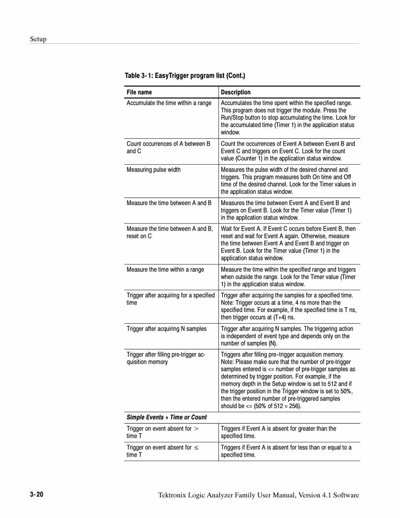
Setup
3- 20 Tektronix Logic Analyzer Family User Manual, Version 4.1 Software
Table 3- 1: EasyTrigger program list (Cont.)
File name Description
Accumulate the time within a range Accumulates the time spent within the specified range.This program does not trigger the module. Press theRun/Stop button to stop accumulating the time. Look forthe accumulated time (Timer 1) in the application statuswindow.
Count occurrences of A between Band C
Count the occurrences of Event A between Event B andEvent C and triggers on Event C. Look for the countvalue (Counter 1) in the application status window.
Measuring pulse width Measures the pulse width of the desired channel andtriggers. This program measures both On time and Offtime of the desired channel. Look for the Timer values inthe application status window.
Measure the time between A and B Measures the time between Event A and Event B andtriggers on Event B. Look for the Timer value (Timer 1)in the application status window.
Measure the time between A and B,reset on C
Wait for Event A. If Event C occurs before Event B, thenreset and wait for Event A again. Otherwise, measurethe time between Event A and Event B and trigger onEvent B. Look for the Timer value (Timer 1) in theapplication status window.
Measure the time within a range Measure the time within the specified range and triggerswhen outside the range. Look for the Timer value (Timer1) in the application status window.
Trigger after acquiring for a specifiedtime
Trigger after acquiring the samples for a specified time.Note: Trigger occurs at a time, 4 ns more than thespecified time. For example, if the specified time is T ns,then trigger occurs at (T+4) ns.
Trigger after acquiring N samples Trigger after acquiring N samples. The triggering actionis independent of event type and depends only on thenumber of samples (N).
Trigger after filling pre-trigger ac-quisition memory
Triggers after filling pre--trigger acquisition memory.Note: Please make sure that the number of pre-triggersamples entered is <= number of pre-trigger samples asdetermined by trigger position. For example, if thememory depth in the Setup window is set to 512 and ifthe trigger position in the Trigger window is set to 50%,then the entered number of pre-triggered samplesshould be <= (50% of 512 = 256).
Simple Events + Time or Count
Trigger on event absent for>time T
Triggers if Event A is absent for greater than thespecified time.
Trigger on event absent for≤time T
Triggers if Event A is absent for less than or equal to aspecified time.
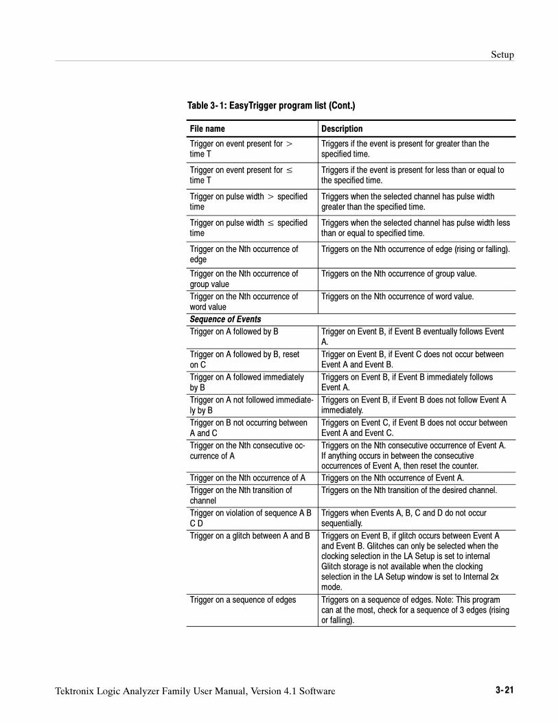
Setup
Tektronix Logic Analyzer Family User Manual, Version 4.1 Software 3- 21
Table 3- 1: EasyTrigger program list (Cont.)
File name Description
Trigger on event present for>time T
Triggers if the event is present for greater than thespecified time.
Trigger on event present for≤time T
Triggers if the event is present for less than or equal tothe specified time.
Trigger on pulse width> specifiedtime
Triggers when the selected channel has pulse widthgreater than the specified time.
Trigger on pulse width≤ specifiedtime
Triggers when the selected channel has pulse width lessthan or equal to specified time.
Trigger on the Nth occurrence ofedge
Triggers on the Nth occurrence of edge (rising or falling).
Trigger on the Nth occurrence ofgroup value
Triggers on the Nth occurrence of group value.
Trigger on the Nth occurrence ofword value
Triggers on the Nth occurrence of word value.
Sequence of Events
Trigger on A followed by B Trigger on Event B, if Event B eventually follows EventA.
Trigger on A followed by B, reseton C
Trigger on Event B, if Event C does not occur betweenEvent A and Event B.
Trigger on A followed immediatelyby B
Triggers on Event B, if Event B immediately followsEvent A.
Trigger on A not followed immediate-ly by B
Triggers on Event B, if Event B does not follow Event Aimmediately.
Trigger on B not occurring betweenA and C
Triggers on Event C, if Event B does not occur betweenEvent A and Event C.
Trigger on the Nth consecutive oc-currence of A
Triggers on the Nth consecutive occurrence of Event A.If anything occurs in between the consecutiveoccurrences of Event A, then reset the counter.
Trigger on the Nth occurrence of A Triggers on the Nth occurrence of Event A.
Trigger on the Nth transition ofchannel
Triggers on the Nth transition of the desired channel.
Trigger on violation of sequence A BC D
Triggers when Events A, B, C and D do not occursequentially.
Trigger on a glitch between A and B Triggers on Event B, if glitch occurs between Event Aand Event B. Glitches can only be selected when theclocking selection in the LA Setup is set to internalGlitch storage is not available when the clockingselection in the LA Setup window is set to Internal 2xmode.
Trigger on a sequence of edges Triggers on a sequence of edges. Note: This programcan at the most, check for a sequence of 3 edges (risingor falling).
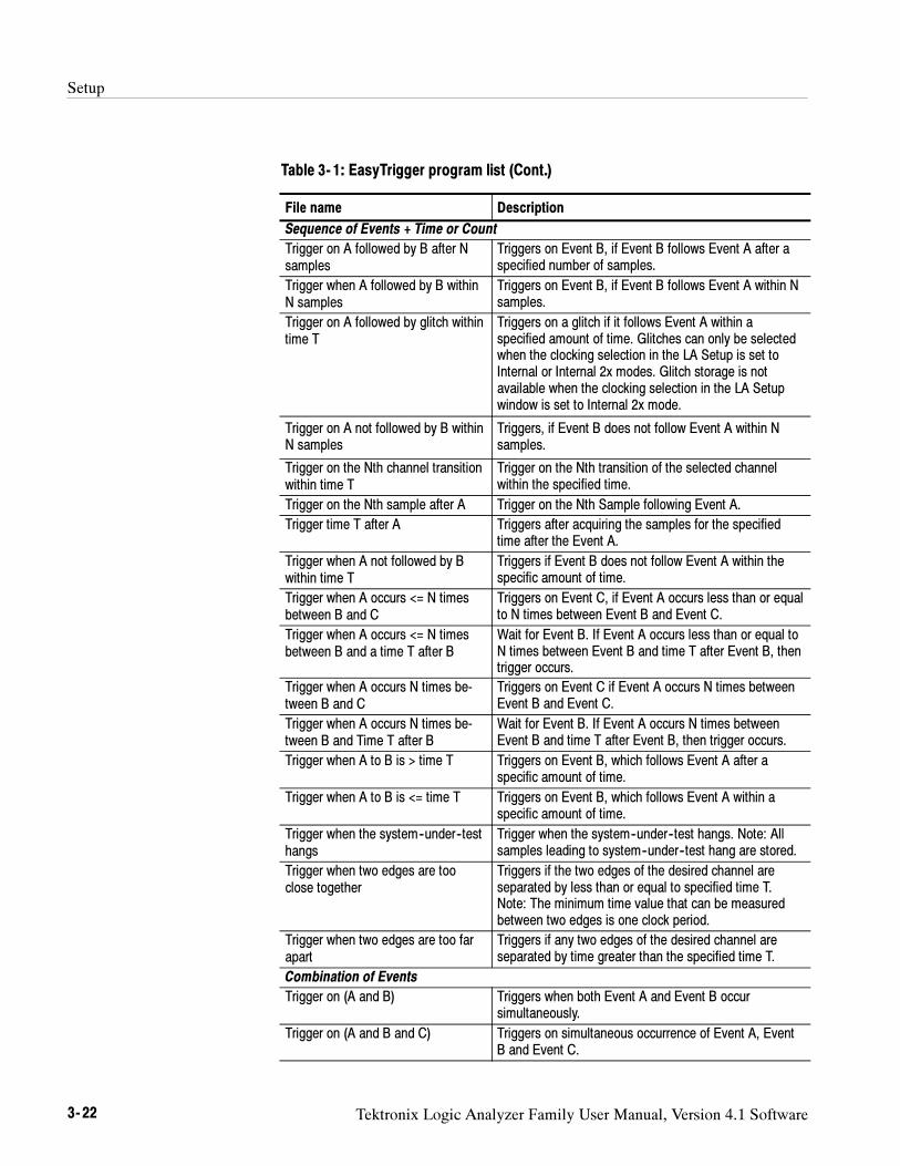
Setup
3- 22 Tektronix Logic Analyzer Family User Manual, Version 4.1 Software
Table 3- 1: EasyTrigger program list (Cont.)
File name Description
Sequence of Events + Time or Count
Trigger on A followed by B after Nsamples
Triggers on Event B, if Event B follows Event A after aspecified number of samples.
Trigger when A followed by B withinN samples
Triggers on Event B, if Event B follows Event A within Nsamples.
Trigger on A followed by glitch withintime T
Triggers on a glitch if it follows Event A within aspecified amount of time. Glitches can only be selectedwhen the clocking selection in the LA Setup is set toInternal or Internal 2x modes. Glitch storage is notavailable when the clocking selection in the LA Setupwindow is set to Internal 2x mode.
Trigger on A not followed by B withinN samples
Triggers, if Event B does not follow Event A within Nsamples.
Trigger on the Nth channel transitionwithin time T
Trigger on the Nth transition of the selected channelwithin the specified time.
Trigger on the Nth sample after A Trigger on the Nth Sample following Event A.
Trigger time T after A Triggers after acquiring the samples for the specifiedtime after the Event A.
Trigger when A not followed by Bwithin time T
Triggers if Event B does not follow Event A within thespecific amount of time.
Trigger when A occurs <= N timesbetween B and C
Triggers on Event C, if Event A occurs less than or equalto N times between Event B and Event C.
Trigger when A occurs <= N timesbetween B and a time T after B
Wait for Event B. If Event A occurs less than or equal toN times between Event B and time T after Event B, thentrigger occurs.
Trigger when A occurs N times be-tween B and C
Triggers on Event C if Event A occurs N times betweenEvent B and Event C.
Trigger when A occurs N times be-tween B and Time T after B
Wait for Event B. If Event A occurs N times betweenEvent B and time T after Event B, then trigger occurs.
Trigger when A to B is > time T Triggers on Event B, which follows Event A after aspecific amount of time.
Trigger when A to B is <= time T Triggers on Event B, which follows Event A within aspecific amount of time.
Trigger when the system--under--testhangs
Trigger when the system--under--test hangs. Note: Allsamples leading to system--under--test hang are stored.
Trigger when two edges are tooclose together
Triggers if the two edges of the desired channel areseparated by less than or equal to specified time T.Note: The minimum time value that can be measuredbetween two edges is one clock period.
Trigger when two edges are too farapart
Triggers if any two edges of the desired channel areseparated by time greater than the specified time T.
Combination of Events
Trigger on (A and B) Triggers when both Event A and Event B occursimultaneously.
Trigger on (A and B and C) Triggers on simultaneous occurrence of Event A, EventB and Event C.
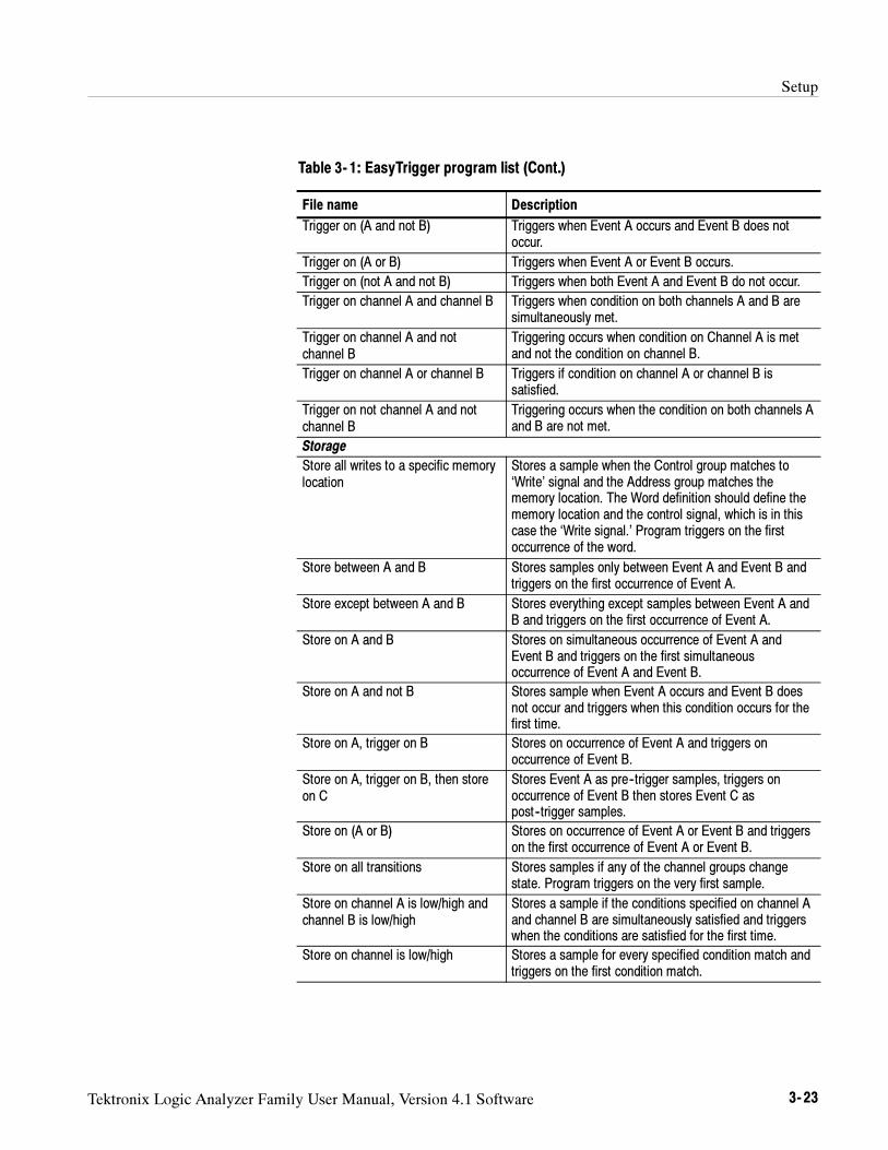
Setup
Tektronix Logic Analyzer Family User Manual, Version 4.1 Software 3- 23
Table 3- 1: EasyTrigger program list (Cont.)
File name Description
Trigger on (A and not B) Triggers when Event A occurs and Event B does notoccur.
Trigger on (A or B) Triggers when Event A or Event B occurs.
Trigger on (not A and not B) Triggers when both Event A and Event B do not occur.
Trigger on channel A and channel B Triggers when condition on both channels A and B aresimultaneously met.
Trigger on channel A and notchannel B
Triggering occurs when condition on Channel A is metand not the condition on channel B.
Trigger on channel A or channel B Triggers if condition on channel A or channel B issatisfied.
Trigger on not channel A and notchannel B
Triggering occurs when the condition on both channels Aand B are not met.
Storage
Store all writes to a specific memorylocation
Stores a sample when the Control group matches to‘Write’ signal and the Address group matches thememory location. The Word definition should define thememory location and the control signal, which is in thiscase the ‘Write signal.’ Program triggers on the firstoccurrence of the word.
Store between A and B Stores samples only between Event A and Event B andtriggers on the first occurrence of Event A.
Store except between A and B Stores everything except samples between Event A andB and triggers on the first occurrence of Event A.
Store on A and B Stores on simultaneous occurrence of Event A andEvent B and triggers on the first simultaneousoccurrence of Event A and Event B.
Store on A and not B Stores sample when Event A occurs and Event B doesnot occur and triggers when this condition occurs for thefirst time.
Store on A, trigger on B Stores on occurrence of Event A and triggers onoccurrence of Event B.
Store on A, trigger on B, then storeon C
Stores Event A as pre--trigger samples, triggers onoccurrence of Event B then stores Event C aspost--trigger samples.
Store on (A or B) Stores on occurrence of Event A or Event B and triggerson the first occurrence of Event A or Event B.
Store on all transitions Stores samples if any of the channel groups changestate. Program triggers on the very first sample.
Store on channel A is low/high andchannel B is low/high
Stores a sample if the conditions specified on channel Aand channel B are simultaneously satisfied and triggerswhen the conditions are satisfied for the first time.
Store on channel is low/high Stores a sample for every specified condition match andtriggers on the first condition match.
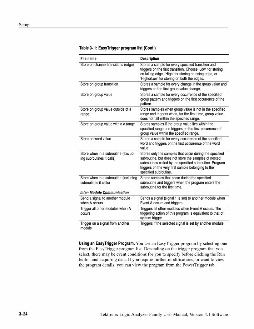
Setup
3- 24 Tektronix Logic Analyzer Family User Manual, Version 4.1 Software
Table 3- 1: EasyTrigger program list (Cont.)
File name Description
Store on channel transitions (edge) Stores a sample for every specified transition andtriggers on the first transition. Choose ’Low’ for storingon falling edge, ’High’ for storing on rising edge, or’HighorLow’ for storing on both the edges.
Store on group transition Stores a sample for every change in the group value andtriggers on the first group value change.
Store on group value Stores a sample for every occurrence of the specifiedgroup pattern and triggers on the first occurrence of thepattern.
Store on group value outside of arange
Stores samples when group value is not in the specifiedrange and triggers when, for the first time, group valuedoes not fall within the specified range.
Store on group value within a range Stores samples if the group value lies within thespecified range and triggers on the first occurrence ofgroup value within the specified range.
Store on word value Stores a sample for every occurrence of the specifiedword and triggers on the first occurrence of the wordvalue.
Store when in a subroutine (exclud-ing subroutines it calls)
Stores only the samples that occur during the specifiedsubroutine, but does not store the samples of nestedsubroutines called by the specified subroutine. Programtriggers on the very first sample belonging to thespecified subroutine.
Store when in a subroutine (includingsubroutines it calls)
Stores samples that occur during the specifiedsubroutine and triggers when the program enters thesubroutine for the first time.
Inter-Module Communication
Send a signal to another modulewhen A occurs
Sends a signal (signal 1 is set) to another module whenEvent A occurs and triggers.
Trigger all other modules when Aoccurs
Triggers all other modules when Event A occurs. Thetriggering action of this program is equivalent to that ofsystem trigger.
Trigger on a signal from anothermodule
Triggers if the selected signal is set by another module.
Using an EasyTrigger Program.You use an EasyTrigger program by selecting onefrom the EasyTrigger program list. Depending on the trigger program that youselect, there may be event conditions for you to specify before clicking the Runbutton and acquiring data. If you require further modifications, or want to viewthe program details, you can view the program from the PowerTrigger tab.
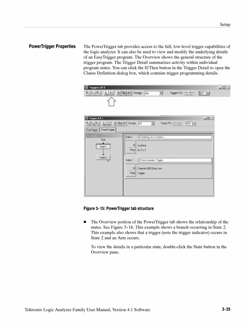
Setup
Tektronix Logic Analyzer Family User Manual, Version 4.1 Software 3- 25
The PowerTrigger tab provides access to the full, low-level trigger capabilities ofthe logic analyzer. It can also be used to view and modify the underlying detailsof an EasyTrigger program. The Overview shows the general structure of thetrigger program. The Trigger Detail summarizes activity within individualprogram states. You can click the If/Then button in the Trigger Detail to open theClause Definition dialog box, which contains trigger programming details.
Figure 3- 15: PowerTrigger tab structure
The Overview portion of the PowerTrigger tab shows the relationship of thestates. See Figure 3--16. This example shows a branch occurring in State 2.This example also shows that a trigger (note the trigger indicator) occurs inState 2 and an Arm occurs.
To view the details in a particular state, double-click the State button in theOverview pane.
PowerTrigger Properties
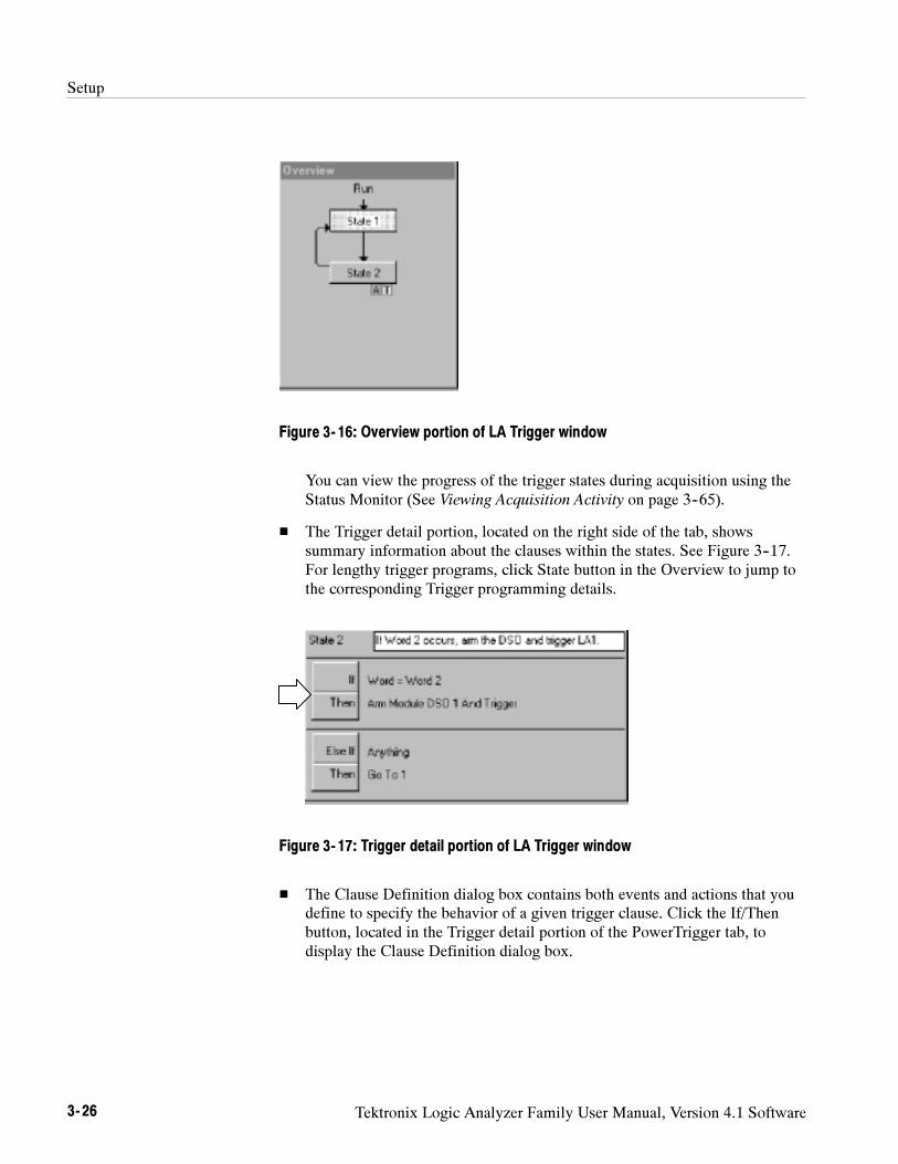
Setup
3- 26 Tektronix Logic Analyzer Family User Manual, Version 4.1 Software
Figure 3- 16: Overview portion of LA Trigger window
You can view the progress of the trigger states during acquisition using theStatus Monitor (See Viewing Acquisition Activity on page 3--65).
The Trigger detail portion, located on the right side of the tab, showssummary information about the clauses within the states. See Figure 3--17.For lengthy trigger programs, click State button in the Overview to jump tothe corresponding Trigger programming details.
Figure 3- 17: Trigger detail portion of LA Trigger window
The Clause Definition dialog box contains both events and actions that youdefine to specify the behavior of a given trigger clause. Click the If/Thenbutton, located in the Trigger detail portion of the PowerTrigger tab, todisplay the Clause Definition dialog box.
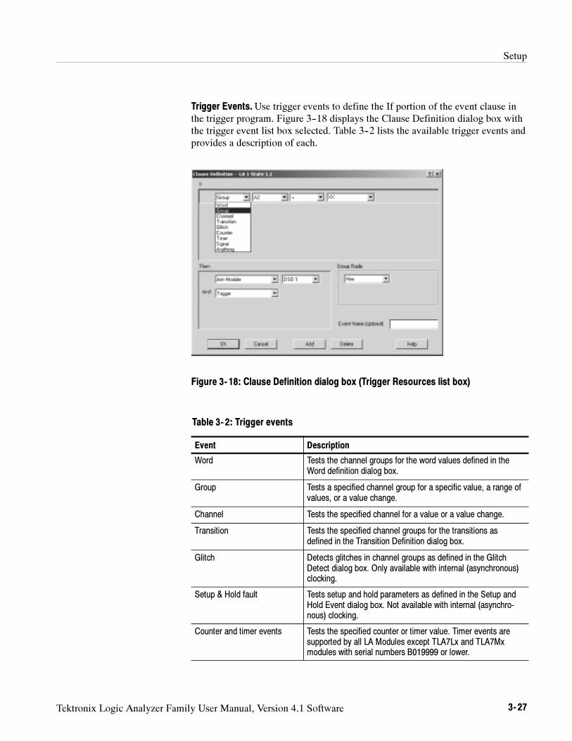
Setup
Tektronix Logic Analyzer Family User Manual, Version 4.1 Software 3- 27
Trigger Events.Use trigger events to define the If portion of the event clause inthe trigger program. Figure 3--18 displays the Clause Definition dialog box withthe trigger event list box selected. Table 3--2 lists the available trigger events andprovides a description of each.
Figure 3- 18: Clause Definition dialog box (Trigger Resources list box)
Table 3- 2: Trigger events
Event Description
Word Tests the channel groups for the word values defined in theWord definition dialog box.
Group Tests a specified channel group for a specific value, a range ofvalues, or a value change.
Channel Tests the specified channel for a value or a value change.
Transition Tests the specified channel groups for the transitions asdefined in the Transition Definition dialog box.
Glitch Detects glitches in channel groups as defined in the GlitchDetect dialog box. Only available with internal (asynchronous)clocking.
Setup & Hold fault Tests setup and hold parameters as defined in the Setup andHold Event dialog box. Not available with internal (asynchro-nous) clocking.
Counter and timer events Tests the specified counter or timer value. Timer events aresupported by all LA Modules except TLA7Lx and TLA7Mxmodules with serial numbers B019999 or lower.
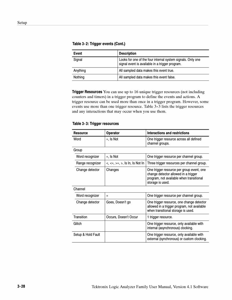
Setup
3- 28 Tektronix Logic Analyzer Family User Manual, Version 4.1 Software
Table 3- 2: Trigger events (Cont.)
Event Description
Signal Looks for one of the four internal system signals. Only onesignal event is available in a trigger program.
Anything All sampled data makes this event true.
Nothing All sampled data makes this event false.
Trigger Resources You can use up to 16 unique trigger resources (not includingcounters and timers) in a trigger program to define the events and actions. Atrigger resource can be used more than once in a trigger program. However, someevents use more than one trigger resource. Table 3--3 lists the trigger resourcesand any interactions that may occur when you use them.
Table 3- 3: Trigger resources
Resource Operator Interactions and restrictions
Word =, Is Not One trigger resource across all definedchannel groups.
Group
Word recognizer =, Is Not One trigger resource per channel group.
Range recognizer <, <=, >=, >, Is In, Is Not In Three trigger resources per channel group.
Change detector Changes One trigger resource per group event, onechange detector allowed in a triggerprogram, not available when transitionalstorage is used.
Channel
Word recognizer = One trigger resource per channel group.
Change detector Goes, Doesn’t go One trigger resource, one change detectorallowed in a trigger program, not availablewhen transitional storage is used.
Transition Occurs, Doesn’t Occur 1 trigger resource.
Glitch One trigger resource, only available withinternal (asynchronous) clocking.
Setup & Hold Fault One trigger resource, only available withexternal (synchronous) or custom clocking.
Setup
Tektronix Logic Analyzer Family User Manual, Version 4.1 Software 3- 29
Table 3- 3: Trigger resources (Cont.)
Resource Interactions and restrictionsOperator
Counter >, <= 0 trigger resources, 2 counters or 2 timers.Maximum width 51 bitsMaximum clocking 250 MHzMaximum count 251 --1
Counter 1 and 2 events conflict with Timer1 and 2 events respectively.
Timer >, <= 0 trigger resources, 2 counters or 2 timersMaximum width 51 bitsMaximum clocking 250 MHzMaximum time 2,000,000 S
(23 days)
Counter 1 and 2 events conflict with Timer1 and 2 events respectively.
Signal (Signal in) Is True, Is False One trigger resource, uses one of foursystem signals. Only one signal event isavailable in a trigger program.
Anything 0 trigger resources. Used as a placeholder.Not available with the OR conjunction.
Nothing 0 trigger resources. Used as a placeholderwith the OR conjunction.
Trigger Actions After defining the events in the If (event) portion of the clause,you can select one or more trigger actions to complete the clause. Figure 3--19displays the Clause Definition dialog box with the trigger Resources list boxselected. Table 3--4 lists the trigger actions available for your trigger program.
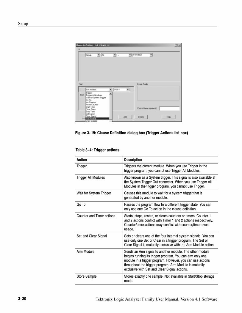
Setup
3- 30 Tektronix Logic Analyzer Family User Manual, Version 4.1 Software
Figure 3- 19: Clause Definition dialog box (Trigger Actions list box)
Table 3- 4: Trigger actions
Action Description
Trigger Triggers the current module. When you use Trigger in thetrigger program, you cannot use Trigger All Modules.
Trigger All Modules Also known as a System trigger. This signal is also available atthe System Trigger Out connector. When you use Trigger AllModules in the trigger program, you cannot use Trigger.
Wait for System Trigger Causes this module to wait for a system trigger that isgenerated by another module.
Go To Passes the program flow to a different trigger state. You canonly use one Go To action in the clause definition.
Counter and Timer actions Starts, stops, resets, or clears counters or timers. Counter 1and 2 actions conflict with Timer 1 and 2 actions respectively.Counter/timer actions may conflict with counter/timer eventusage.
Set and Clear Signal Sets or clears one of the four internal system signals. You canuse only one Set or Clear in a trigger program. The Set orClear Signal is mutually exclusive with the Arm Module action.
Arm Module Sends an Arm signal to another module. The other modulebegins running its trigger program. You can arm only onemodule in a trigger program. However, you can use actionsthroughout the trigger program. Arm Module is mutuallyexclusive with Set and Clear Signal actions.
Store Sample Stores exactly one sample. Not available in Start/Stop storagemode.
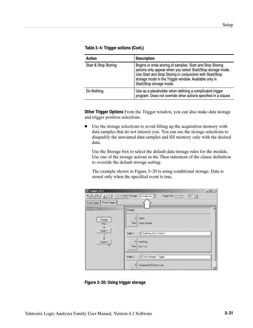
Setup
Tektronix Logic Analyzer Family User Manual, Version 4.1 Software 3- 31
Table 3- 4: Trigger actions (Cont.)
Action Description
Start & Stop Storing Begins or ends storing of samples. Start and Stop Storingactions only appear when you select Start/Stop storage mode.Use Start and Stop Storing in conjunction with Start/Stopstorage mode in the Trigger window. Available only inStart/Stop storage mode.
Do Nothing Use as a placeholder when defining a complicated triggerprogram. Does not override other actions specified in a clause.
Other Trigger Options From the Trigger window, you can also make data storageand trigger position selections.
Use the storage selections to avoid filling up the acquisition memory withdata samples that do not interest you. You can use the storage selections todisqualify the unwanted data samples and fill memory only with the desireddata.
Use the Storage box to select the default data storage rules for the module.Use one of the storage actions in the Then statement of the clause definitionto override the default storage setting.
The example shown in Figure 3--20 is using conditional storage. Data isstored only when the specified event is true.
Figure 3- 20: Using trigger storage
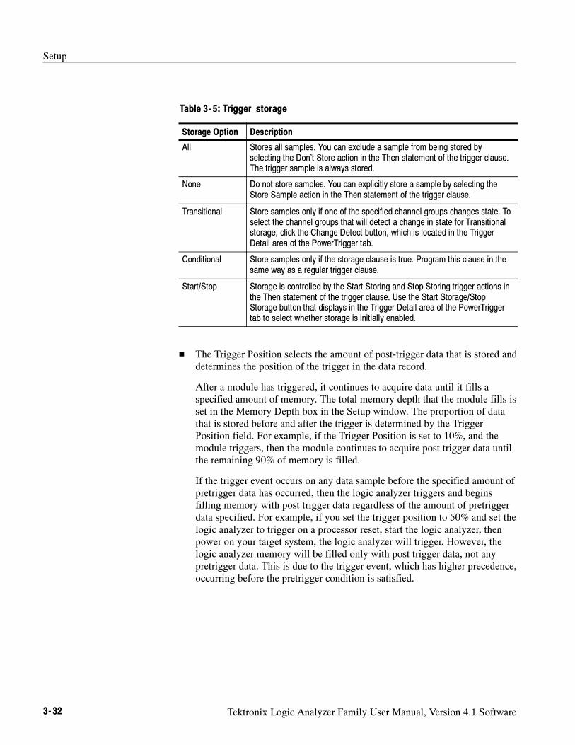
Setup
3- 32 Tektronix Logic Analyzer Family User Manual, Version 4.1 Software
Table 3- 5: Trigger storage
Storage Option Description
All Stores all samples. You can exclude a sample from being stored byselecting the Don’t Store action in the Then statement of the trigger clause.The trigger sample is always stored.
None Do not store samples. You can explicitly store a sample by selecting theStore Sample action in the Then statement of the trigger clause.
Transitional Store samples only if one of the specified channel groups changes state. Toselect the channel groups that will detect a change in state for Transitionalstorage, click the Change Detect button, which is located in the TriggerDetail area of the PowerTrigger tab.
Conditional Store samples only if the storage clause is true. Program this clause in thesame way as a regular trigger clause.
Start/Stop Storage is controlled by the Start Storing and Stop Storing trigger actions inthe Then statement of the trigger clause. Use the Start Storage/StopStorage button that displays in the Trigger Detail area of the PowerTriggertab to select whether storage is initially enabled.
The Trigger Position selects the amount of post-trigger data that is stored anddetermines the position of the trigger in the data record.
After a module has triggered, it continues to acquire data until it fills aspecified amount of memory. The total memory depth that the module fills isset in the Memory Depth box in the Setup window. The proportion of datathat is stored before and after the trigger is determined by the TriggerPosition field. For example, if the Trigger Position is set to 10%, and themodule triggers, then the module continues to acquire post trigger data untilthe remaining 90% of memory is filled.
If the trigger event occurs on any data sample before the specified amount ofpretrigger data has occurred, then the logic analyzer triggers and beginsfilling memory with post trigger data regardless of the amount of pretriggerdata specified. For example, if you set the trigger position to 50% and set thelogic analyzer to trigger on a processor reset, start the logic analyzer, thenpower on your target system, the logic analyzer will trigger. However, thelogic analyzer memory will be filled only with post trigger data, not anypretrigger data. This is due to the trigger event, which has higher precedence,occurring before the pretrigger condition is satisfied.
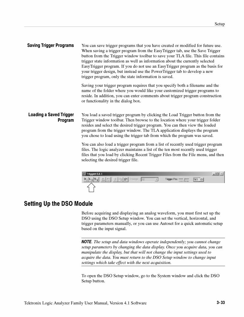
Setup
Tektronix Logic Analyzer Family User Manual, Version 4.1 Software 3- 33
You can save trigger programs that you have created or modified for future use.When saving a trigger program from the EasyTrigger tab, use the Save Triggerbutton from the Trigger window toolbar to save your TLA file. This file containstrigger state information as well as information about the currently selectedEasyTrigger program. If you do not use an EasyTrigger program as the basis foryour trigger design, but instead use the PowerTrigger tab to develop a newtrigger program, only the state information is saved.
Saving your trigger program requires that you specify both a filename and thename of the folder where you would like your customized trigger programs toreside. In addition, you can enter comments about trigger program constructionor functionality in the dialog box.
You load a saved trigger program by clicking the Load Trigger button from theTrigger window toolbar. Then browse to the location where your trigger folderresides and select the desired trigger program. You can then view the loadedprogram from the trigger window. The TLA application displays the programyou chose to load using the trigger tab from which the program was saved.
You can also load a trigger program from a list of recently used trigger programfiles. The logic analyzer maintains a list of the ten most recently used triggerfiles that you load by clicking Recent Trigger Files from the File menu, and thenselecting the desired trigger file.
Setting Up the DSO Module
Before acquiring and displaying an analog waveform, you must first set up theDSO using the DSO Setup window. You can set the vertical, horizontal, andtrigger parameters manually, or you can use Autoset for a quick automatic setupbased on the input signal.
NOTE. The setup and data windows operate independently; you cannot change
setup parameters by changing the data display. Once you acquire data, you can
manipulate the display, but that will not change the input settings used to
acquire the data. You must return to the DSO Setup window to change input
settings which take effect with the next acquisition.
To open the DSO Setup window, go to the System window and click the DSOSetup button.
Saving Trigger Programs
Loading a Saved TriggerProgram
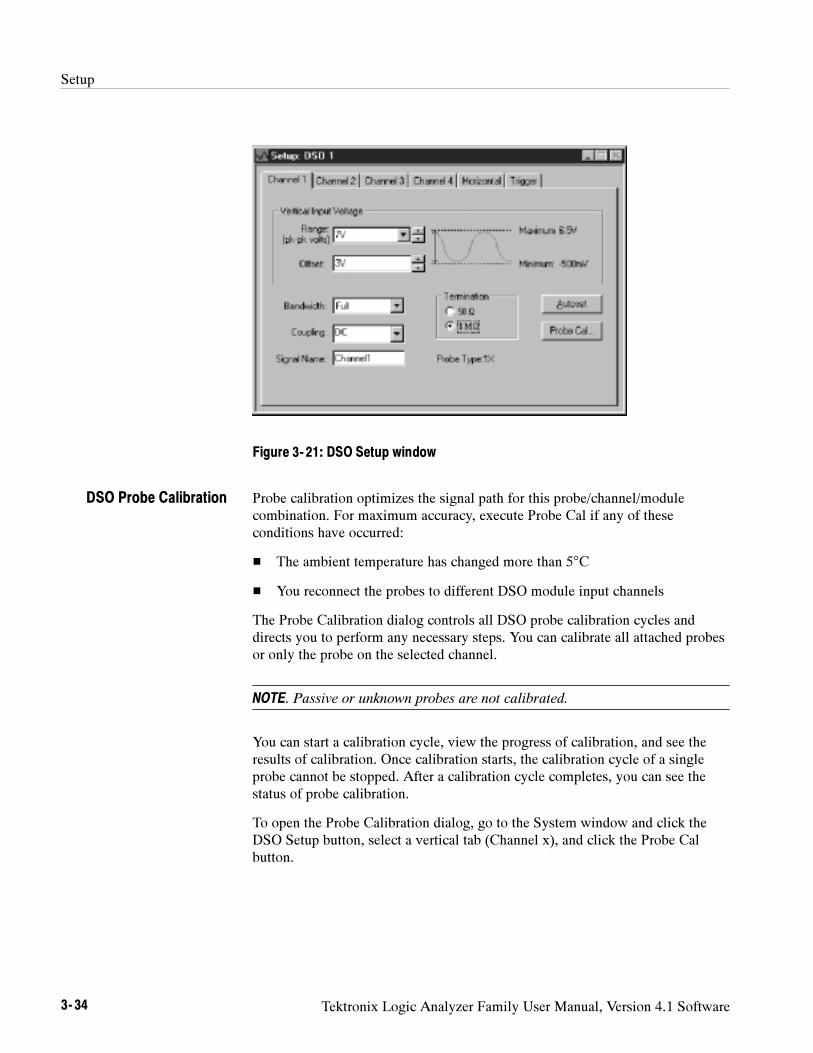
Setup
3- 34 Tektronix Logic Analyzer Family User Manual, Version 4.1 Software
Figure 3- 21: DSO Setup window
Probe calibration optimizes the signal path for this probe/channel/modulecombination. For maximum accuracy, execute Probe Cal if any of theseconditions have occurred:
The ambient temperature has changed more than 5°C
You reconnect the probes to different DSO module input channels
The Probe Calibration dialog controls all DSO probe calibration cycles anddirects you to perform any necessary steps. You can calibrate all attached probesor only the probe on the selected channel.
NOTE. Passive or unknown probes are not calibrated.
You can start a calibration cycle, view the progress of calibration, and see theresults of calibration. Once calibration starts, the calibration cycle of a singleprobe cannot be stopped. After a calibration cycle completes, you can see thestatus of probe calibration.
To open the Probe Calibration dialog, go to the System window and click theDSO Setup button, select a vertical tab (Channel x), and click the Probe Calbutton.
DSO Probe Calibration
Setup
Tektronix Logic Analyzer Family User Manual, Version 4.1 Software 3- 35
NOTE. You should execute the DSO module self--calibration if the ambient
operating temperature has changed more than 5C since last calibration. Also,
you should execute the self calibration once a week if vertical settings of 50 mV
full scale or less are used. Perform self calibration after a 30 minute warm up.
To open the Self Calibration tab from the System menu, click Calibration and
Diagnostics. and then click the Self Calibration tab.
Use Autoset when you need to see a signal in a circuit, but do not know thesignal amplitude or frequency. Autoset automatically chooses the DSO setupvalues based on the input signal at the time you clicked the Autoset button.
Autoset works best on repetitive signals that do not have a DC offset component.If the Autoset setup does not display the waveform as you want it, you can easilychange the setup manually.
To set the DSO input values based on the input signal:
1. From the System window, click the DSO Setup button.
2. Click the Autoset button from any tab in the DSO Setup window.
The Autoset selections apply to all input channels, the horizontal setup, andthe trigger setup, regardless of which Autoset button was clicked.
3. If the signal changes, or you move the probe to another signal, click Autosetagain to reset the setup values.
Autoset affects only the DSO setup; it does not affect data window settings. Youmay need to adjust data window settings for optimum display of the data.
Use the vertical controls to adjust vertical input voltage parameters. SeeFigure 3--22.
To open the page containing the vertical controls from the System window, clickthe DSO Setup button and then select one of the Channel tabs.
Autoset
Vertical Controls
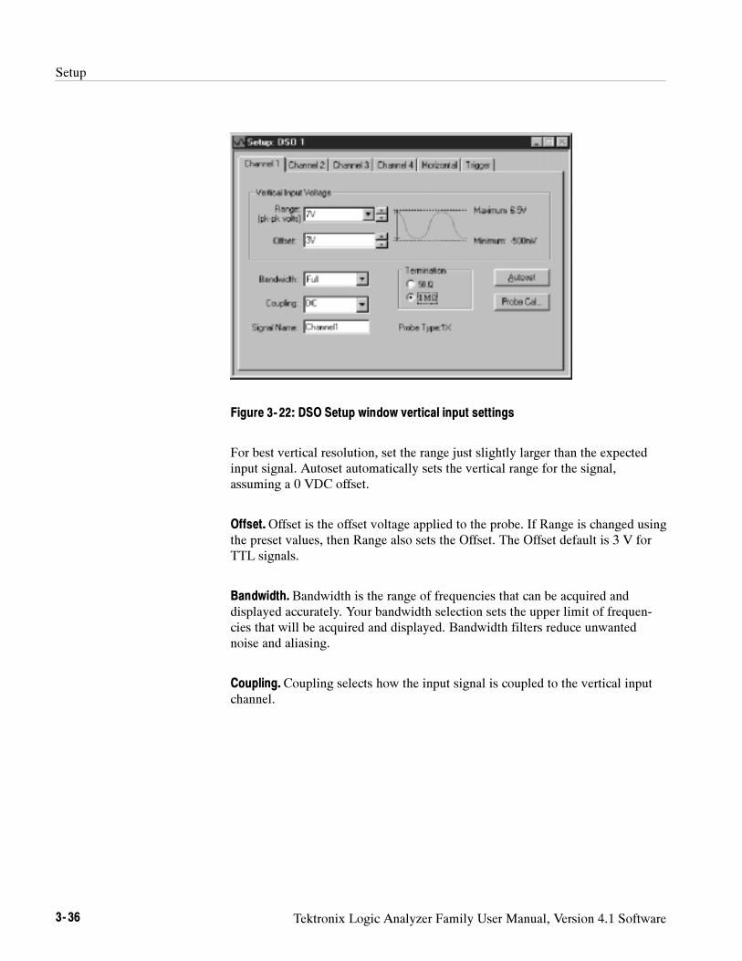
Setup
3- 36 Tektronix Logic Analyzer Family User Manual, Version 4.1 Software
Figure 3- 22: DSO Setup window vertical input settings
For best vertical resolution, set the range just slightly larger than the expectedinput signal. Autoset automatically sets the vertical range for the signal,assuming a 0 VDC offset.
Offset.Offset is the offset voltage applied to the probe. If Range is changed usingthe preset values, then Range also sets the Offset. The Offset default is 3 V forTTL signals.
Bandwidth. Bandwidth is the range of frequencies that can be acquired anddisplayed accurately. Your bandwidth selection sets the upper limit of frequen-cies that will be acquired and displayed. Bandwidth filters reduce unwantednoise and aliasing.
Coupling. Coupling selects how the input signal is coupled to the vertical inputchannel.
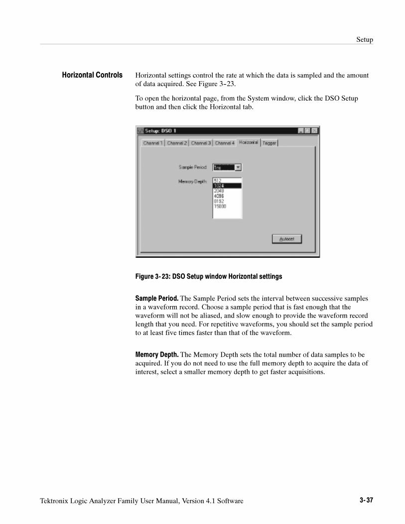
Setup
Tektronix Logic Analyzer Family User Manual, Version 4.1 Software 3- 37
Horizontal settings control the rate at which the data is sampled and the amountof data acquired. See Figure 3--23.
To open the horizontal page, from the System window, click the DSO Setupbutton and then click the Horizontal tab.
Figure 3- 23: DSO Setup window Horizontal settings
Sample Period. The Sample Period sets the interval between successive samplesin a waveform record. Choose a sample period that is fast enough that thewaveform will not be aliased, and slow enough to provide the waveform recordlength that you need. For repetitive waveforms, you should set the sample periodto at least five times faster than that of the waveform.
Memory Depth. The Memory Depth sets the total number of data samples to beacquired. If you do not need to use the full memory depth to acquire the data ofinterest, select a smaller memory depth to get faster acquisitions.
Horizontal Controls
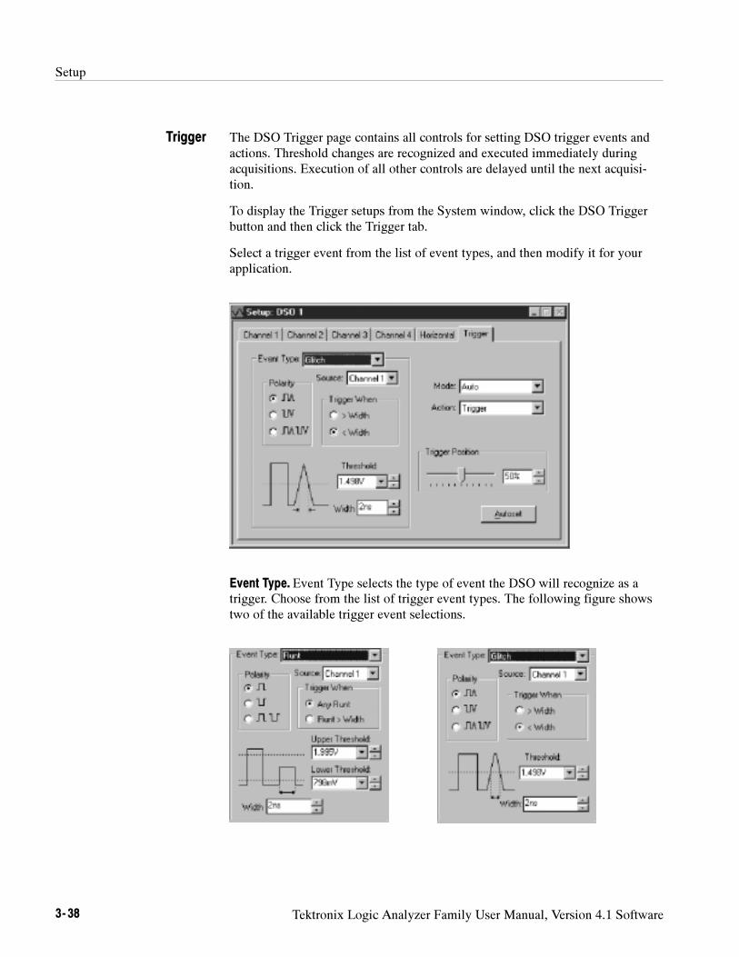
Setup
3- 38 Tektronix Logic Analyzer Family User Manual, Version 4.1 Software
The DSO Trigger page contains all controls for setting DSO trigger events andactions. Threshold changes are recognized and executed immediately duringacquisitions. Execution of all other controls are delayed until the next acquisi-tion.
To display the Trigger setups from the System window, click the DSO Triggerbutton and then click the Trigger tab.
Select a trigger event from the list of event types, and then modify it for yourapplication.
Event Type. Event Type selects the type of event the DSO will recognize as atrigger. Choose from the list of trigger event types. The following figure showstwo of the available trigger event selections.
Trigger
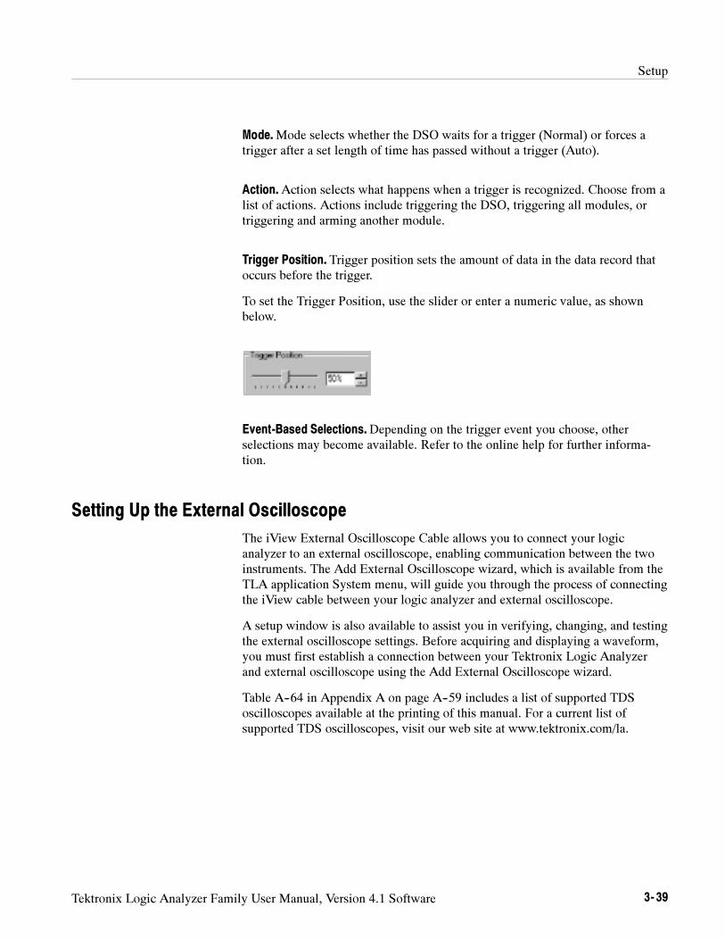
Setup
Tektronix Logic Analyzer Family User Manual, Version 4.1 Software 3- 39
Mode.Mode selects whether the DSO waits for a trigger (Normal) or forces atrigger after a set length of time has passed without a trigger (Auto).
Action.Action selects what happens when a trigger is recognized. Choose from alist of actions. Actions include triggering the DSO, triggering all modules, ortriggering and arming another module.
Trigger Position. Trigger position sets the amount of data in the data record thatoccurs before the trigger.
To set the Trigger Position, use the slider or enter a numeric value, as shownbelow.
Event-Based Selections.Depending on the trigger event you choose, otherselections may become available. Refer to the online help for further informa-tion.
Setting Up the External Oscilloscope
The iView External Oscilloscope Cable allows you to connect your logicanalyzer to an external oscilloscope, enabling communication between the twoinstruments. The Add External Oscilloscope wizard, which is available from theTLA application System menu, will guide you through the process of connectingthe iView cable between your logic analyzer and external oscilloscope.
A setup window is also available to assist you in verifying, changing, and testingthe external oscilloscope settings. Before acquiring and displaying a waveform,you must first establish a connection between your Tektronix Logic Analyzerand external oscilloscope using the Add External Oscilloscope wizard.
Table A--64 in Appendix A on page A--59 includes a list of supported TDSoscilloscopes available at the printing of this manual. For a current list ofsupported TDS oscilloscopes, visit our web site at www.tektronix.com/la.
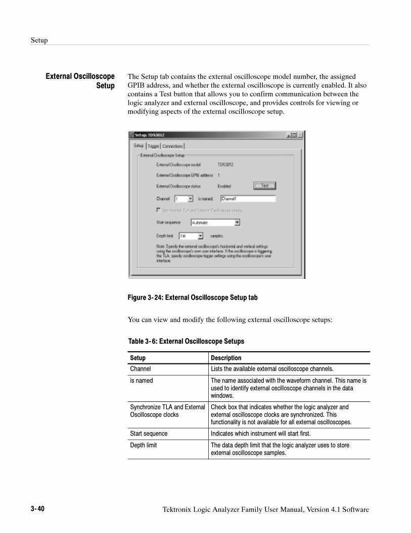
Setup
3- 40 Tektronix Logic Analyzer Family User Manual, Version 4.1 Software
The Setup tab contains the external oscilloscope model number, the assignedGPIB address, and whether the external oscilloscope is currently enabled. It alsocontains a Test button that allows you to confirm communication between thelogic analyzer and external oscilloscope, and provides controls for viewing ormodifying aspects of the external oscilloscope setup.
Figure 3- 24: External Oscilloscope Setup tab
You can view and modify the following external oscilloscope setups:
Table 3- 6: External Oscilloscope Setups
Setup Description
Channel Lists the available external oscilloscope channels.
is named The name associated with the waveform channel. This name isused to identify external oscilloscope channels in the datawindows.
Synchronize TLA and ExternalOscilloscope clocks
Check box that indicates whether the logic analyzer andexternal oscilloscope clocks are synchronized. Thisfunctionality is not available for all external oscilloscopes.
Start sequence Indicates which instrument will start first.
Depth limit The data depth limit that the logic analyzer uses to storeexternal oscilloscope samples.
External OscilloscopeSetup
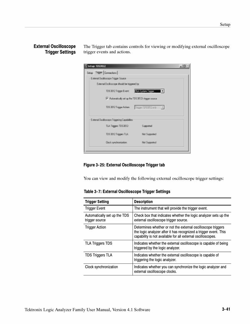
Setup
Tektronix Logic Analyzer Family User Manual, Version 4.1 Software 3- 41
The Trigger tab contains controls for viewing or modifying external oscilloscopetrigger events and actions.
Figure 3- 25: External Oscilloscope Trigger tab
You can view and modify the following external oscilloscope trigger settings:
Table 3- 7: External Oscilloscope Trigger Settings
Trigger Setting Description
Trigger Event The instrument that will provide the trigger event.
Automatically set up the TDStrigger source
Check box that indicates whether the logic analyzer sets up theexternal oscilloscope trigger source.
Trigger Action Determines whether or not the external oscilloscope triggersthe logic analyzer after it has recognized a trigger event. Thiscapability is not available for all external oscilloscopes.
TLA Triggers TDS Indicates whether the external oscilloscope is capable of beingtriggered by the logic analyzer.
TDS Triggers TLA Indicates whether the external oscilloscope is capable oftriggering the logic analyzer.
Clock synchronization Indicates whether you can synchronize the logic analyzer andexternal oscilloscope clocks.
External OscilloscopeTrigger Settings
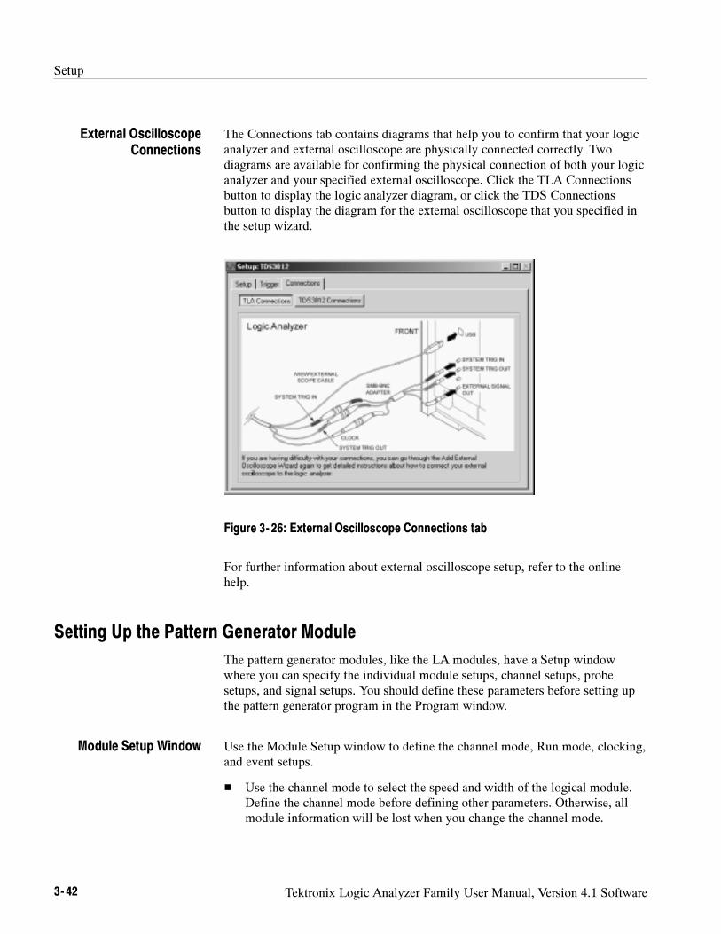
Setup
3- 42 Tektronix Logic Analyzer Family User Manual, Version 4.1 Software
The Connections tab contains diagrams that help you to confirm that your logicanalyzer and external oscilloscope are physically connected correctly. Twodiagrams are available for confirming the physical connection of both your logicanalyzer and your specified external oscilloscope. Click the TLA Connectionsbutton to display the logic analyzer diagram, or click the TDS Connectionsbutton to display the diagram for the external oscilloscope that you specified inthe setup wizard.
Figure 3- 26: External Oscilloscope Connections tab
For further information about external oscilloscope setup, refer to the onlinehelp.
Setting Up the Pattern Generator Module
The pattern generator modules, like the LA modules, have a Setup windowwhere you can specify the individual module setups, channel setups, probesetups, and signal setups. You should define these parameters before setting upthe pattern generator program in the Program window.
Use the Module Setup window to define the channel mode, Run mode, clocking,and event setups.
Use the channel mode to select the speed and width of the logical module.Define the channel mode before defining other parameters. Otherwise, allmodule information will be lost when you change the channel mode.
External OscilloscopeConnections
Module Setup Window
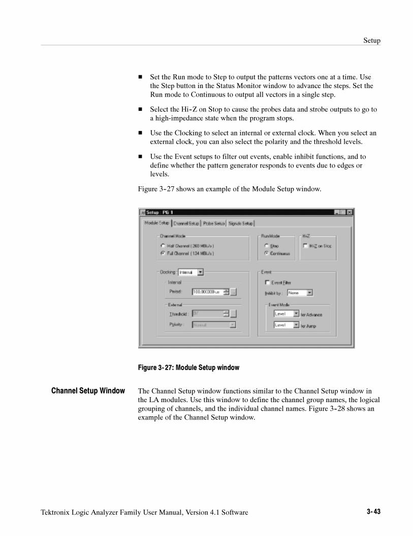
Setup
Tektronix Logic Analyzer Family User Manual, Version 4.1 Software 3- 43
Set the Run mode to Step to output the patterns vectors one at a time. Usethe Step button in the Status Monitor window to advance the steps. Set theRun mode to Continuous to output all vectors in a single step.
Select the Hi--Z on Stop to cause the probes data and strobe outputs to go toa high-impedance state when the program stops.
Use the Clocking to select an internal or external clock. When you select anexternal clock, you can also select the polarity and the threshold levels.
Use the Event setups to filter out events, enable inhibit functions, and todefine whether the pattern generator responds to events due to edges orlevels.
Figure 3--27 shows an example of the Module Setup window.
Figure 3- 27: Module Setup window
The Channel Setup window functions similar to the Channel Setup window inthe LA modules. Use this window to define the channel group names, the logicalgrouping of channels, and the individual channel names. Figure 3--28 shows anexample of the Channel Setup window.
Channel Setup Window
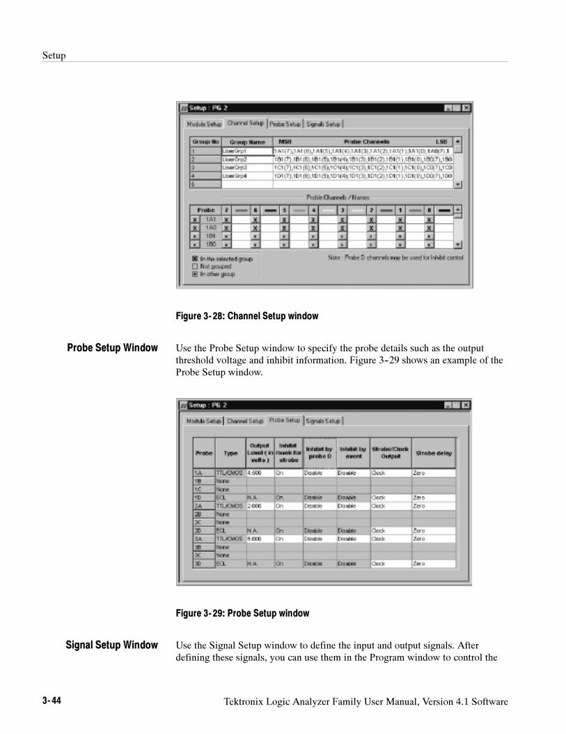
Setup
3- 44 Tektronix Logic Analyzer Family User Manual, Version 4.1 Software
Figure 3- 28: Channel Setup window
Use the Probe Setup window to specify the probe details such as the outputthreshold voltage and inhibit information. Figure 3--29 shows an example of theProbe Setup window.
Figure 3- 29: Probe Setup window
Use the Signal Setup window to define the input and output signals. Afterdefining these signals, you can use them in the Program window to control the
Probe Setup Window
Signal Setup Window
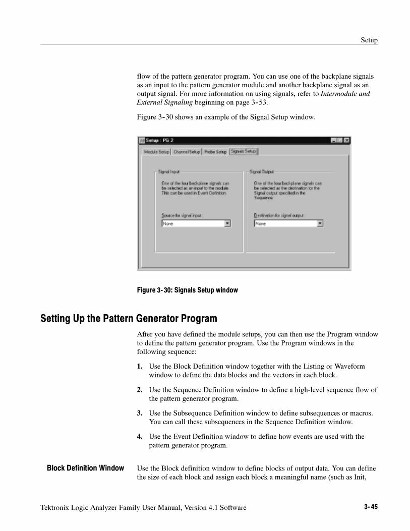
Setup
Tektronix Logic Analyzer Family User Manual, Version 4.1 Software 3- 45
flow of the pattern generator program. You can use one of the backplane signalsas an input to the pattern generator module and another backplane signal as anoutput signal. For more information on using signals, refer to Intermodule and
External Signaling beginning on page 3--53.
Figure 3--30 shows an example of the Signal Setup window.
Figure 3- 30: Signals Setup window
Setting Up the Pattern Generator Program
After you have defined the module setups, you can then use the Program windowto define the pattern generator program. Use the Program windows in thefollowing sequence:
1. Use the Block Definition window together with the Listing or Waveformwindow to define the data blocks and the vectors in each block.
2. Use the Sequence Definition window to define a high-level sequence flow ofthe pattern generator program.
3. Use the Subsequence Definition window to define subsequences or macros.You can call these subsequences in the Sequence Definition window.
4. Use the Event Definition window to define how events are used with thepattern generator program.
Use the Block definition window to define blocks of output data. You can definethe size of each block and assign each block a meaningful name (such as Init,
Block Definition Window
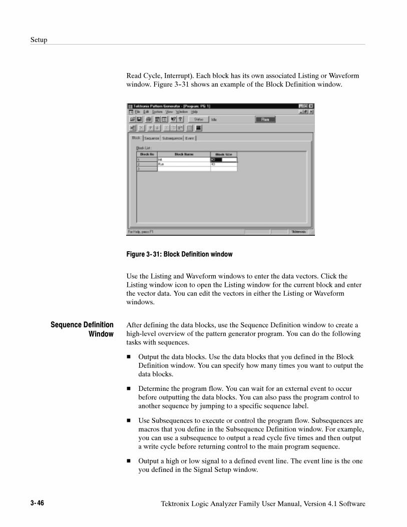
Setup
3- 46 Tektronix Logic Analyzer Family User Manual, Version 4.1 Software
Read Cycle, Interrupt). Each block has its own associated Listing or Waveformwindow. Figure 3--31 shows an example of the Block Definition window.
Figure 3- 31: Block Definition window
Use the Listing and Waveform windows to enter the data vectors. Click theListing window icon to open the Listing window for the current block and enterthe vector data. You can edit the vectors in either the Listing or Waveformwindows.
After defining the data blocks, use the Sequence Definition window to create ahigh-level overview of the pattern generator program. You can do the followingtasks with sequences.
Output the data blocks. Use the data blocks that you defined in the BlockDefinition window. You can specify how many times you want to output thedata blocks.
Determine the program flow. You can wait for an external event to occurbefore outputting the data blocks. You can also pass the program control toanother sequence by jumping to a specific sequence label.
Use Subsequences to execute or control the program flow. Subsequences aremacros that you define in the Subsequence Definition window. For example,you can use a subsequence to output a read cycle five times and then outputa write cycle before returning control to the main program sequence.
Output a high or low signal to a defined event line. The event line is the oneyou defined in the Signal Setup window.
Sequence DefinitionWindow
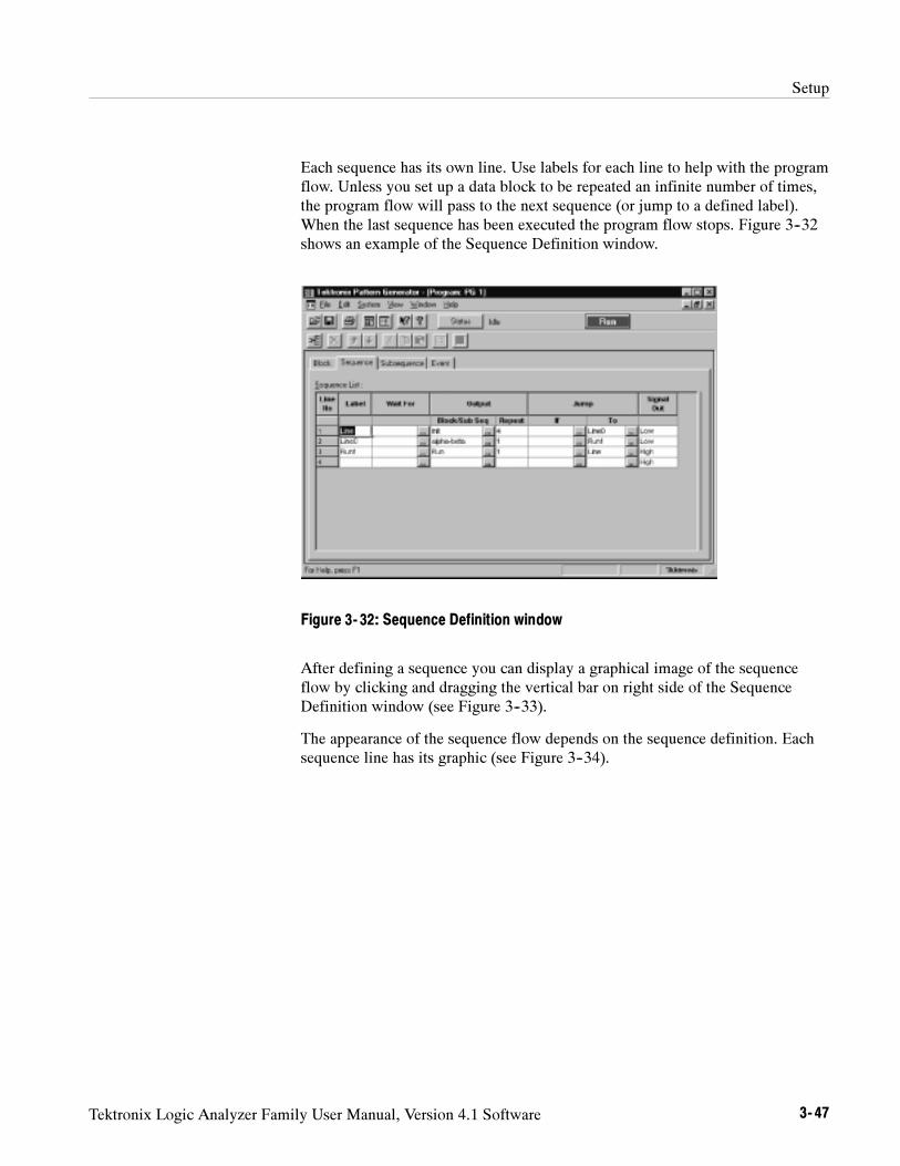
Setup
Tektronix Logic Analyzer Family User Manual, Version 4.1 Software 3- 47
Each sequence has its own line. Use labels for each line to help with the programflow. Unless you set up a data block to be repeated an infinite number of times,the program flow will pass to the next sequence (or jump to a defined label).When the last sequence has been executed the program flow stops. Figure 3--32shows an example of the Sequence Definition window.
Figure 3- 32: Sequence Definition window
After defining a sequence you can display a graphical image of the sequenceflow by clicking and dragging the vertical bar on right side of the SequenceDefinition window (see Figure 3--33).
The appearance of the sequence flow depends on the sequence definition. Eachsequence line has its graphic (see Figure 3--34).
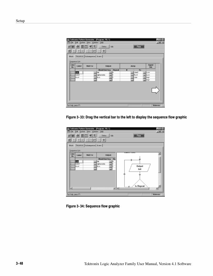
Setup
3- 48 Tektronix Logic Analyzer Family User Manual, Version 4.1 Software
Figure 3- 33: Drag the vertical bar to the left to display the sequence flow graphic
Figure 3- 34: Sequence flow graphic
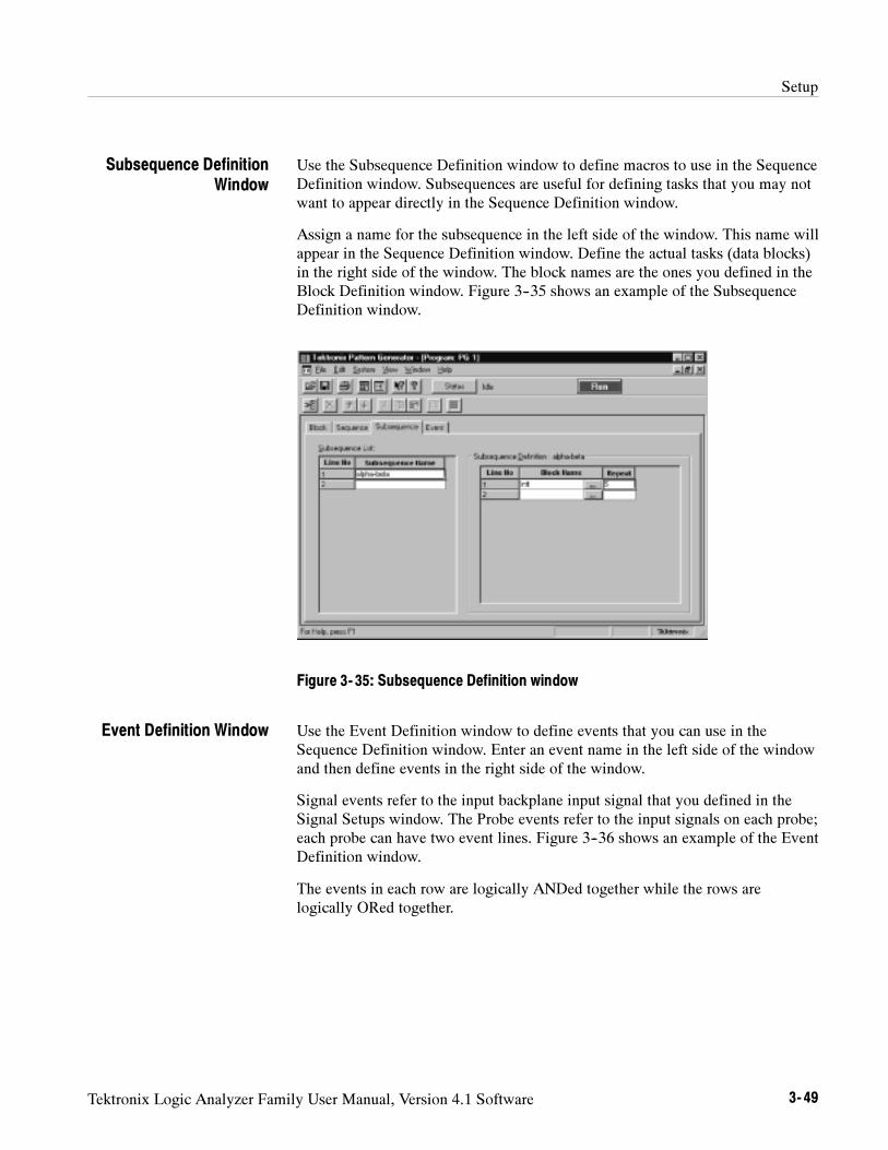
Setup
Tektronix Logic Analyzer Family User Manual, Version 4.1 Software 3- 49
Use the Subsequence Definition window to define macros to use in the SequenceDefinition window. Subsequences are useful for defining tasks that you may notwant to appear directly in the Sequence Definition window.
Assign a name for the subsequence in the left side of the window. This name willappear in the Sequence Definition window. Define the actual tasks (data blocks)in the right side of the window. The block names are the ones you defined in theBlock Definition window. Figure 3--35 shows an example of the SubsequenceDefinition window.
Figure 3- 35: Subsequence Definition window
Use the Event Definition window to define events that you can use in theSequence Definition window. Enter an event name in the left side of the windowand then define events in the right side of the window.
Signal events refer to the input backplane input signal that you defined in theSignal Setups window. The Probe events refer to the input signals on each probe;each probe can have two event lines. Figure 3--36 shows an example of the EventDefinition window.
The events in each row are logically ANDed together while the rows arelogically ORed together.
Subsequence DefinitionWindow
Event Definition Window
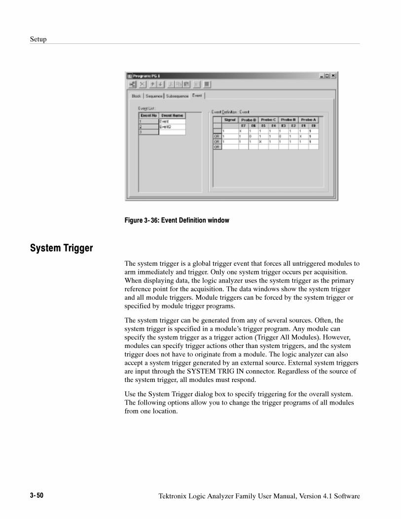
Setup
3- 50 Tektronix Logic Analyzer Family User Manual, Version 4.1 Software
Figure 3- 36: Event Definition window
System Trigger
The system trigger is a global trigger event that forces all untriggered modules toarm immediately and trigger. Only one system trigger occurs per acquisition.When displaying data, the logic analyzer uses the system trigger as the primaryreference point for the acquisition. The data windows show the system triggerand all module triggers. Module triggers can be forced by the system trigger orspecified by module trigger programs.
The system trigger can be generated from any of several sources. Often, thesystem trigger is specified in a module’s trigger program. Any module canspecify the system trigger as a trigger action (Trigger All Modules). However,modules can specify trigger actions other than system triggers, and the systemtrigger does not have to originate from a module. The logic analyzer can alsoaccept a system trigger generated by an external source. External system triggersare input through the SYSTEM TRIG IN connector. Regardless of the source ofthe system trigger, all modules must respond.
Use the System Trigger dialog box to specify triggering for the overall system.The following options allow you to change the trigger programs of all modulesfrom one location.
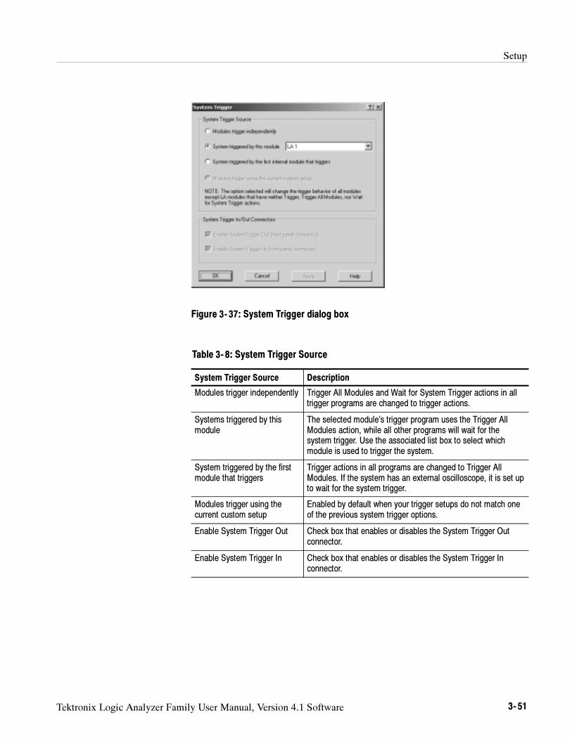
Setup
Tektronix Logic Analyzer Family User Manual, Version 4.1 Software 3- 51
Figure 3- 37: System Trigger dialog box
Table 3- 8: System Trigger Source
System Trigger Source Description
Modules trigger independently Trigger All Modules and Wait for System Trigger actions in alltrigger programs are changed to trigger actions.
Systems triggered by thismodule
The selected module’s trigger program uses the Trigger AllModules action, while all other programs will wait for thesystem trigger. Use the associated list box to select whichmodule is used to trigger the system.
System triggered by the firstmodule that triggers
Trigger actions in all programs are changed to Trigger AllModules. If the system has an external oscilloscope, it is set upto wait for the system trigger.
Modules trigger using thecurrent custom setup
Enabled by default when your trigger setups do not match oneof the previous system trigger options.
Enable System Trigger Out Check box that enables or disables the System Trigger Outconnector.
Enable System Trigger In Check box that enables or disables the System Trigger Inconnector.
Setup
3- 52 Tektronix Logic Analyzer Family User Manual, Version 4.1 Software
NOTE. When you apply a system trigger option, your choice will only affect those
modules that currently have a trigger action. Logic analyzer trigger actions
include “Trigger,” “Trigger All Modules,” and “Wait for System Trigger.” DSO
and external oscilloscope modules are always affected because all of their
actions result in triggering the module.
It is not uncommon to have a condition where the acquisition completed, butwhere an explicit system trigger did not occur. (This means that there was neitheran external system trigger, nor a system trigger generated internally by a moduletrigger program.) To ensure that a time reference exists for the acquisition, thelogic analyzer must designate a system trigger. If no system trigger is generatedduring an acquisition (the modules are internally triggered), the logic analyzerdesignates the latest-occurring module trigger as the system trigger.
NOTE. If an acquisition does not complete, due to one or more modules not
receiving a trigger or not completing post-trigger acquisition, then you can
manually stop the acquisition by clicking the Stop button. Clicking the Stop
button effectively generates a system trigger and completes the acquisition.
The system trigger is a latched event and it resets to a false state betweenacquisitions. The external system trigger input uses real-time gating and is onlyactive (capable of latching system triggers) during the actual acquisition period.
The logic analyzer can also send an internally-generated system trigger out to thetarget system or to other test equipment through the SYSTEM TRIG OUTconnector. All the external signal inputs and outputs operate at TTL levels. Theconnectors are located at the rear of the portable mainframe and at the front ofthe benchtop mainframe. For more information about external signalingcapabilities, see Intermodule and External Signaling on page 3--53.
Arming Modules
Using the arm feature, you can use one module to control when another moduleaccepts triggers. When module A arms module B, this means that module B doesnot begin looking for a trigger until it receives an arm signal.
Arming is accomplished through trigger actions. For the LA module, arming isspecified in the Clause Definition dialog box; for the DSO module, arming isspecified in the Trigger page. A module can arm any one of the other modules.The designated module can be armed by only one module. The same armingaction can, however, appear multiple times within the same trigger program.
Arms are latched events that, once set, cannot be cleared until the acquisition iscompleted.
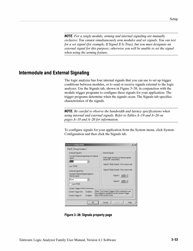
Setup
Tektronix Logic Analyzer Family User Manual, Version 4.1 Software 3- 53
NOTE. For a single module, arming and internal signaling are mutually
exclusive. You cannot simultaneously arm modules and set signals. You can test
for a set signal (for example, If Signal X Is True), but you must designate an
external signal for this purpose; otherwise you will be unable to set the signal
when using the arming feature.
Intermodule and External Signaling
The logic analyzer has four internal signals that you can use to set up triggerconditions between modules, or to send or receive signals external to the logicanalyzer. Use the Signals tab, shown in Figure 3--38, in conjunction with themodule trigger programs to configure these signals for your application. Thetrigger programs determine when the signals occur. The Signals tab specifiescharacteristics of the signals.
NOTE. Be careful to observe the bandwidth and latency specifications when
using internal and external signals. Refer to Tables A--19 and A--20 on
pages A--18 and A--20 for information.
To configure signals for your application from the System menu, click SystemConfiguration and then click the Signals tab.
Figure 3- 38: Signals property page
Setup
3- 54 Tektronix Logic Analyzer Family User Manual, Version 4.1 Software
Only one module in the system can drive Signal 1 and only one module candrive Signal 2. When used with the expansion mainframe, all modules that driveSignal 3 should be in the same mainframe and all modules that drive Signal 4should be in the same mainframe.
The logic analyzer and DSO modules use a logical expression (True/False) forSignals 1, 2, 3, and 4. However, the pattern generator module uses a physicalexpression (High/Low) for these signals. Please use the tables in Appendix C:
Pattern Generator Physical-Logical Conversion to convert physical expressionsto logical expressions or vice versa.
All logic analyzer modules can set and clear any of the four internal signals. TheDSO can set but not clear any signal. The logical output of these signals can beused as an event in other modules’ trigger programs. You can also connect theinternal signals to the External Signal In and External Signal Out connectors onthe mainframe, so that you can use an external signal as a trigger event or send asignal out when a trigger condition is met.
Internal signaling is for users with special trigger programming requirements.Internal signaling adds flexibility to trigger programming, but also addscomplexity. When using internal signaling you must take care that the signals arecorrectly set and cleared, and that the trigger programs for all modules arecompatible with regard to signal usage. Also, you must have correctly set theinternal signal attributes in the Signals tab of the System Configuration dialogbox.
Internal signaling is accomplished through trigger actions specified in the ClauseDefinition dialog box and the DSO Trigger tab.
NOTE. Arming and internal signaling are mutually exclusive. You cannot
simultaneously arm modules and set signals. You can test for a set signal (for
example, If Signal X Is True), but unless you have designated an external signal
for this purpose, you will be unable to set the signal when using the arming
feature.
Signal Logic Function. To use internal signals, you must select which internalsignal logic function is appropriate for your trigger program. Signals 1 and 2(high speed) can be asserted by only one module each. For signals 3 and 4, themodules can be wired-OR or wired-AND. Selecting the OR function means thatany module can assert the signal. Selecting AND means that all modules mustset the signal for it to be asserted. The same logic applies to clearing signals.
The logic function applies only at a module level, not to multiple set/clearstatements within a single module.
Internal Signals
Setup
Tektronix Logic Analyzer Family User Manual, Version 4.1 Software 3- 55
NOTE. Be careful when using wired-AND internal signals. If your trigger
depends on an internal signal, all modules must set the signal for it to be
asserted, or the trigger will not occur. If you change your trigger program,
remember to update the logic function settings accordingly.
The logic analyzer can send and receive signals to/from the target system usingthe External Signal In and External Signal Out connectors on the mainframe. Usethe External Signal In function to include a signal from your target system aspart of the trigger setup. Use the External Signal Out function to send a signal tothe target system or other test equipment when a trigger condition is met.
The connection from the module to the external connector is made by one of thefour internal signals. You must designate which internal signal is to be used forthis purpose.
The external signal connectors are located at the rear of the portable mainframeand at the front of the benchtop mainframe. The external signals all operate atTTL logic levels.
System Trigger In/Out Connector check boxes reflect the current state of theSystem Trigger In and System Trigger Out connectors, and can be used to bothenable and disable them.
If an external scope is enabled, the options chosen in System Trigger Source canaffect the values and sensitivity of the System Trigger In/Out checkboxes.
Merging Modules
A merged LA module set consist of a master module and one or two slavemodules. A merged pattern generator module consists of a master module and upto four slave modules.
LA Modules must have the same maximum state speed and must be physicallyconnected in the mainframe before they can be merged by software. Modulesmust be adjacent and connected as described in Appendix E: Merging Modules.
Merged pattern generator modules are not physically connected in the mainframebut must be in adjacent slots in the same mainframe.
Modules that are capable of being merged, are shown in the Merge Modulesproperty page with a merge button. See Figure 3--39.
To open the Merge Modules tab from the System menu, click System Configura-tion, and then click the Merge Modules tab.
External Signals
System TriggerIn/Out Connectors
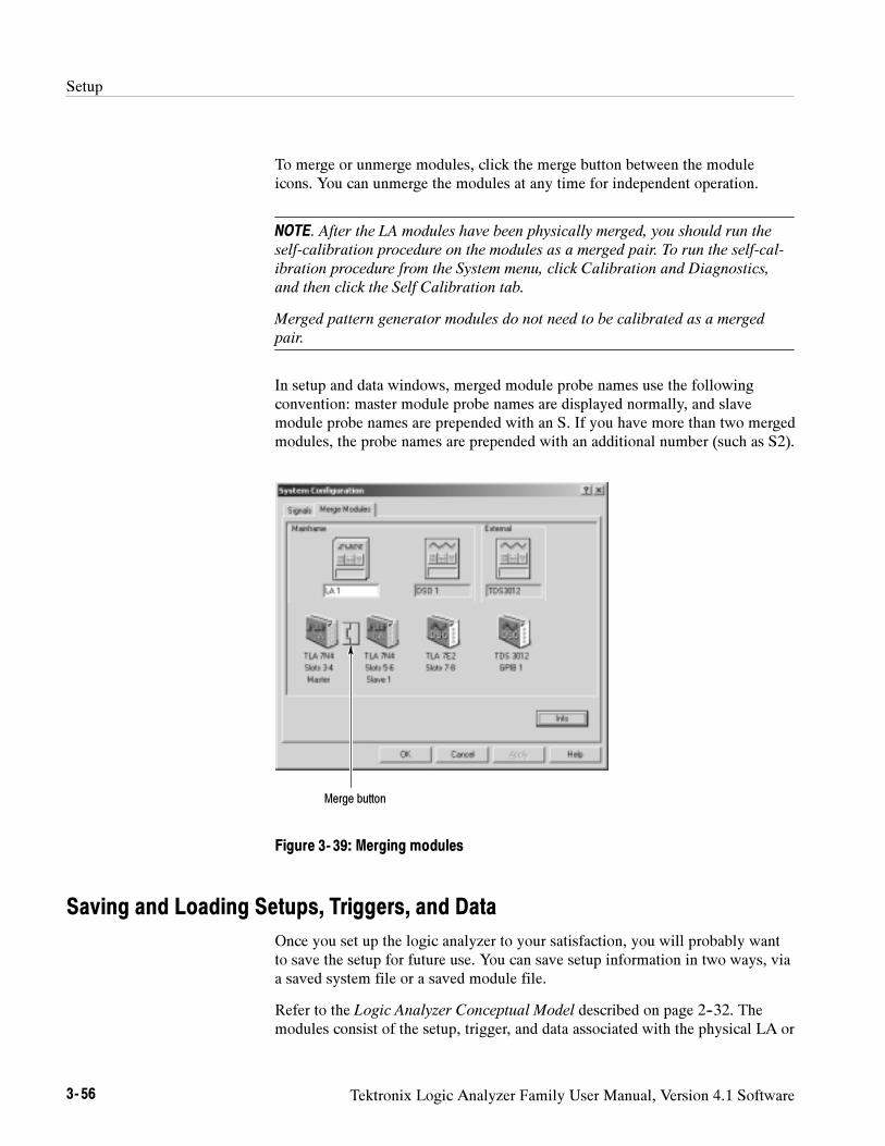
Setup
3- 56 Tektronix Logic Analyzer Family User Manual, Version 4.1 Software
To merge or unmerge modules, click the merge button between the moduleicons. You can unmerge the modules at any time for independent operation.
NOTE. After the LA modules have been physically merged, you should run the
self-calibration procedure on the modules as a merged pair. To run the self-cal-
ibration procedure from the System menu, click Calibration and Diagnostics,
and then click the Self Calibration tab.
Merged pattern generator modules do not need to be calibrated as a merged
pair.
In setup and data windows, merged module probe names use the followingconvention: master module probe names are displayed normally, and slavemodule probe names are prepended with an S. If you have more than two mergedmodules, the probe names are prepended with an additional number (such as S2).
Merge button
Figure 3- 39: Merging modules
Saving and Loading Setups, Triggers, and Data
Once you set up the logic analyzer to your satisfaction, you will probably wantto save the setup for future use. You can save setup information in two ways, viaa saved system file or a saved module file.
Refer to the Logic Analyzer Conceptual Model described on page 2--32. Themodules consist of the setup, trigger, and data associated with the physical LA or
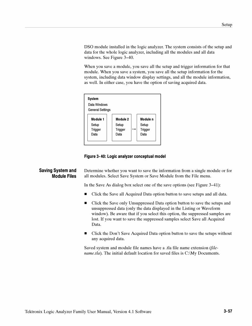
Setup
Tektronix Logic Analyzer Family User Manual, Version 4.1 Software 3- 57
DSO module installed in the logic analyzer. The system consists of the setup anddata for the whole logic analyzer, including all the modules and all datawindows. See Figure 3--40.
When you save a module, you save all the setup and trigger information for thatmodule. When you save a system, you save all the setup information for thesystem, including data window display settings, and all the module information,as well. In either case, you have the option of saving acquired data.
Setup
Trigger
Data
Module 1
System
Data Windows
General Settings
Module 2 Module n
Setup
Trigger
Data
Setup
Trigger
Data
Figure 3- 40: Logic analyzer conceptual model
Determine whether you want to save the information from a single module or forall modules. Select Save System or Save Module from the File menu.
In the Save As dialog box select one of the save options (see Figure 3--41):
Click the Save all Acquired Data option button to save setups and all data.
Click the Save only Unsuppressed Data option button to save the setups andunsuppressed data (only the data displayed in the Listing or Waveformwindow). Be aware that if you select this option, the suppressed samples arelost. If you want to save the suppressed samples select Save all AcquiredData.
Click the Don’t Save Acquired Data option button to save the setups withoutany acquired data.
Saved system and module file names have a .tla file name extension (file-name.tla). The initial default location for saved files is C:\My Documents.
Saving System andModule Files
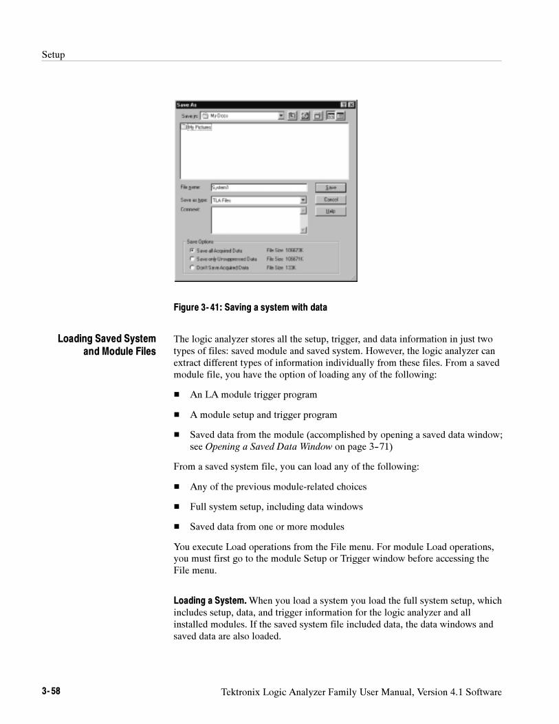
Setup
3- 58 Tektronix Logic Analyzer Family User Manual, Version 4.1 Software
Figure 3- 41: Saving a system with data
The logic analyzer stores all the setup, trigger, and data information in just twotypes of files: saved module and saved system. However, the logic analyzer canextract different types of information individually from these files. From a savedmodule file, you have the option of loading any of the following:
An LA module trigger program
A module setup and trigger program
Saved data from the module (accomplished by opening a saved data window;see Opening a Saved Data Window on page 3--71)
From a saved system file, you can load any of the following:
Any of the previous module-related choices
Full system setup, including data windows
Saved data from one or more modules
You execute Load operations from the File menu. For module Load operations,you must first go to the module Setup or Trigger window before accessing theFile menu.
Loading a System.When you load a system you load the full system setup, whichincludes setup, data, and trigger information for the logic analyzer and allinstalled modules. If the saved system file included data, the data windows andsaved data are also loaded.
Loading Saved Systemand Module Files
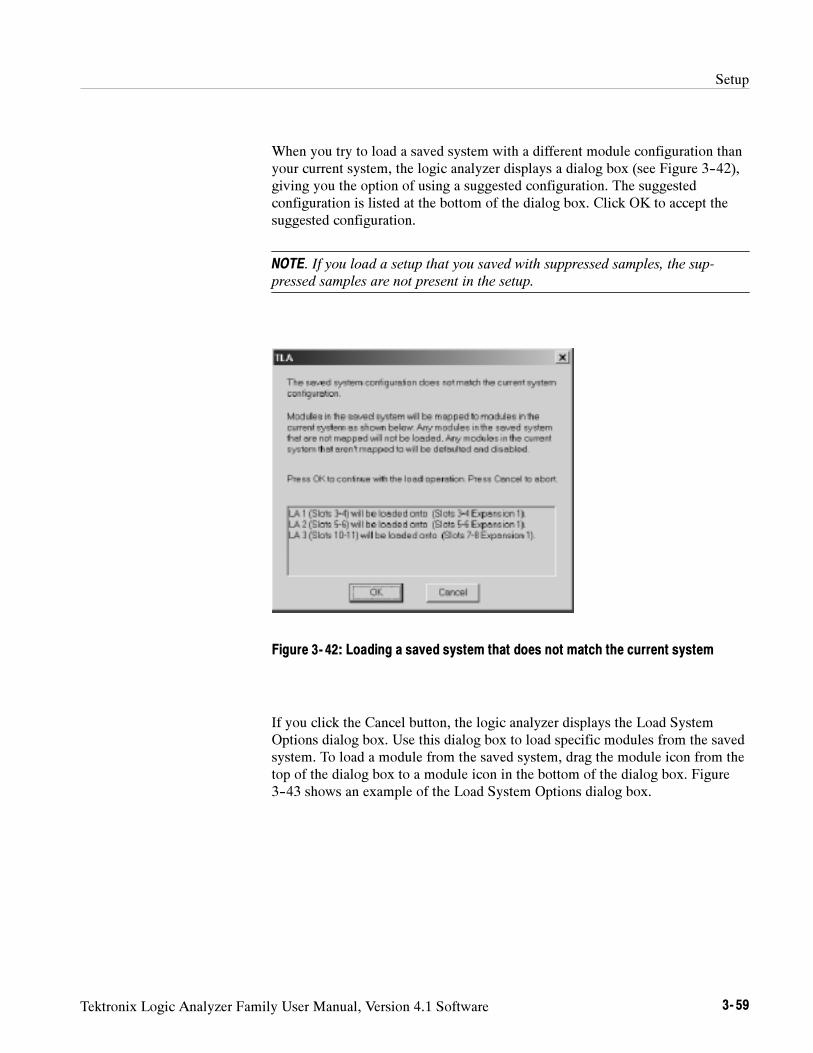
Setup
Tektronix Logic Analyzer Family User Manual, Version 4.1 Software 3- 59
When you try to load a saved system with a different module configuration thanyour current system, the logic analyzer displays a dialog box (see Figure 3--42),giving you the option of using a suggested configuration. The suggestedconfiguration is listed at the bottom of the dialog box. Click OK to accept thesuggested configuration.
NOTE. If you load a setup that you saved with suppressed samples, the sup-
pressed samples are not present in the setup.
Figure 3- 42: Loading a saved system that does not match the current system
If you click the Cancel button, the logic analyzer displays the Load SystemOptions dialog box. Use this dialog box to load specific modules from the savedsystem. To load a module from the saved system, drag the module icon from thetop of the dialog box to a module icon in the bottom of the dialog box. Figure3--43 shows an example of the Load System Options dialog box.
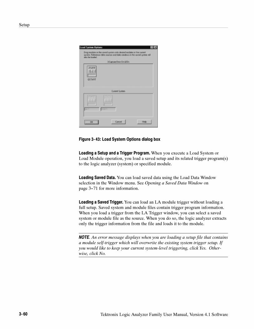
Setup
3- 60 Tektronix Logic Analyzer Family User Manual, Version 4.1 Software
Figure 3- 43: Load System Options dialog box
Loading a Setup and a Trigger Program.When you execute a Load System orLoad Module operation, you load a saved setup and its related trigger program(s)to the logic analyzer (system) or specified module.
Loading Saved Data.You can load saved data using the Load Data Windowselection in the Window menu. See Opening a Saved Data Window onpage 3--71 for more information.
Loading a Saved Trigger.You can load an LA module trigger without loading afull setup. Saved system and module files contain trigger program information.When you load a trigger from the LA Trigger window, you can select a savedsystem or module file as the source. When you do so, the logic analyzer extractsonly the trigger information from the file and loads it to the module.
NOTE. An error message displays when you are loading a setup file that contains
a module self-trigger which will overwrite the existing system trigger setup. If
you would like to keep your current system-level triggering, click Yes. Other-
wise, click No.
Setup
Tektronix Logic Analyzer Family User Manual, Version 4.1 Software 3- 61
Creating a Personalized Trigger folder. To create your own list of triggerprograms, follow these steps:
1. Create a folder in a convenient location.
2. Go to the Trigger window containing the trigger program you want to save.
3. Go to the File menu and select Save Module As.
4. In the Save As dialog box, navigate to your trigger program folder.
5. Name the new file, and use the Comment box to enter descriptive comments.
6. Make sure that Save Acquired Data is not selected.
7. Click Save.
To return the logic analyzer to its default condition, go to the File menu and clickDefault System.
System Options
The logic analyzer provides several property pages where you can set or changesystem options. To access the system options, select Options from the Systemmenu and choose the property page you are interested in.
Use the Color tab to create, remove, and modify color schemes.
Use the Defaults tab to specify the defaults throughout the application. Thesettings you enter will be the default settings when you create new datawindows.
Use the Preference tab to specify user preferences, such as changing thecolor of the Run or Stop buttons or hiding the Status bar.
Use the Presets tab to view and modify preset names and values such asprobe threshold voltages and DSO vertical range or vertical offset values.
Use the Start-Up tab to select which system setup (such as a previous systemor a saved system setup) to open after you power on the logic analyzer.
Use the System Source Files tab to define the location of source files andsuffixes used to create new Source windows.
Loading Default Settings
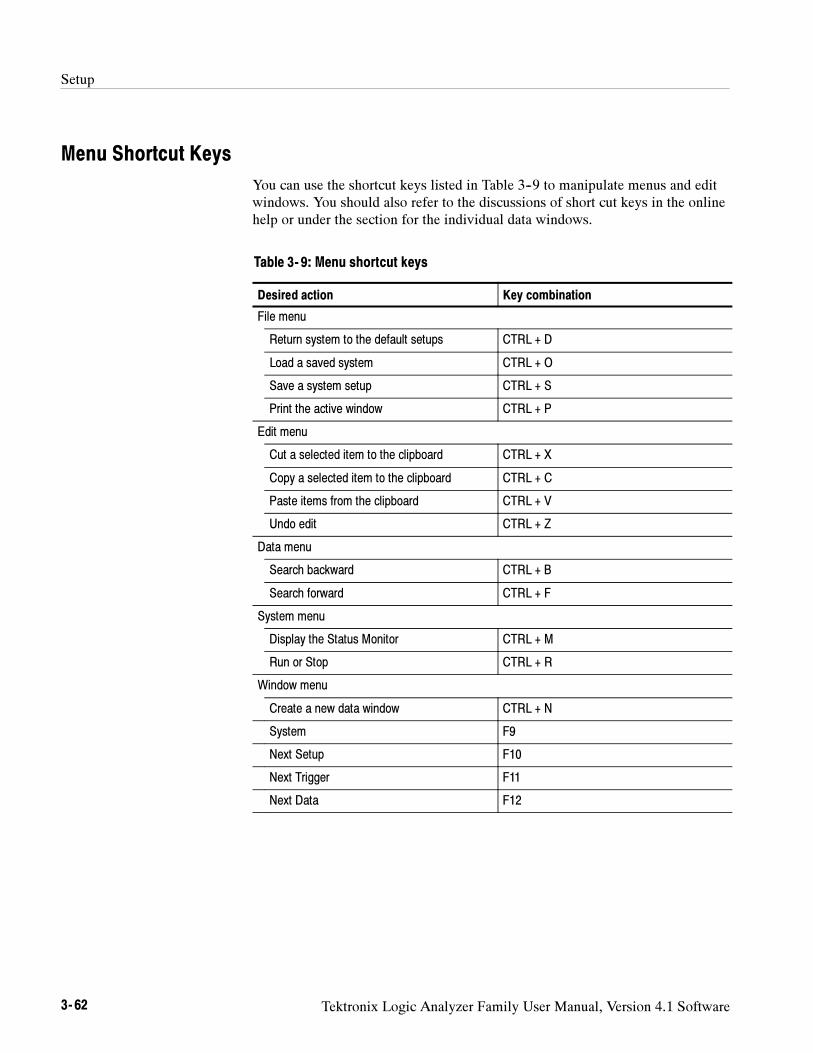
Setup
3- 62 Tektronix Logic Analyzer Family User Manual, Version 4.1 Software
Menu Shortcut Keys
You can use the shortcut keys listed in Table 3--9 to manipulate menus and editwindows. You should also refer to the discussions of short cut keys in the onlinehelp or under the section for the individual data windows.
Table 3- 9: Menu shortcut keys
Desired action Key combination
File menu
Return system to the default setups CTRL + D
Load a saved system CTRL + O
Save a system setup CTRL + S
Print the active window CTRL + P
Edit menu
Cut a selected item to the clipboard CTRL + X
Copy a selected item to the clipboard CTRL + C
Paste items from the clipboard CTRL + V
Undo edit CTRL + Z
Data menu
Search backward CTRL + B
Search forward CTRL + F
System menu
Display the Status Monitor CTRL + M
Run or Stop CTRL + R
Window menu
Create a new data window CTRL + N
System F9
Next Setup F10
Next Trigger F11
Next Data F12
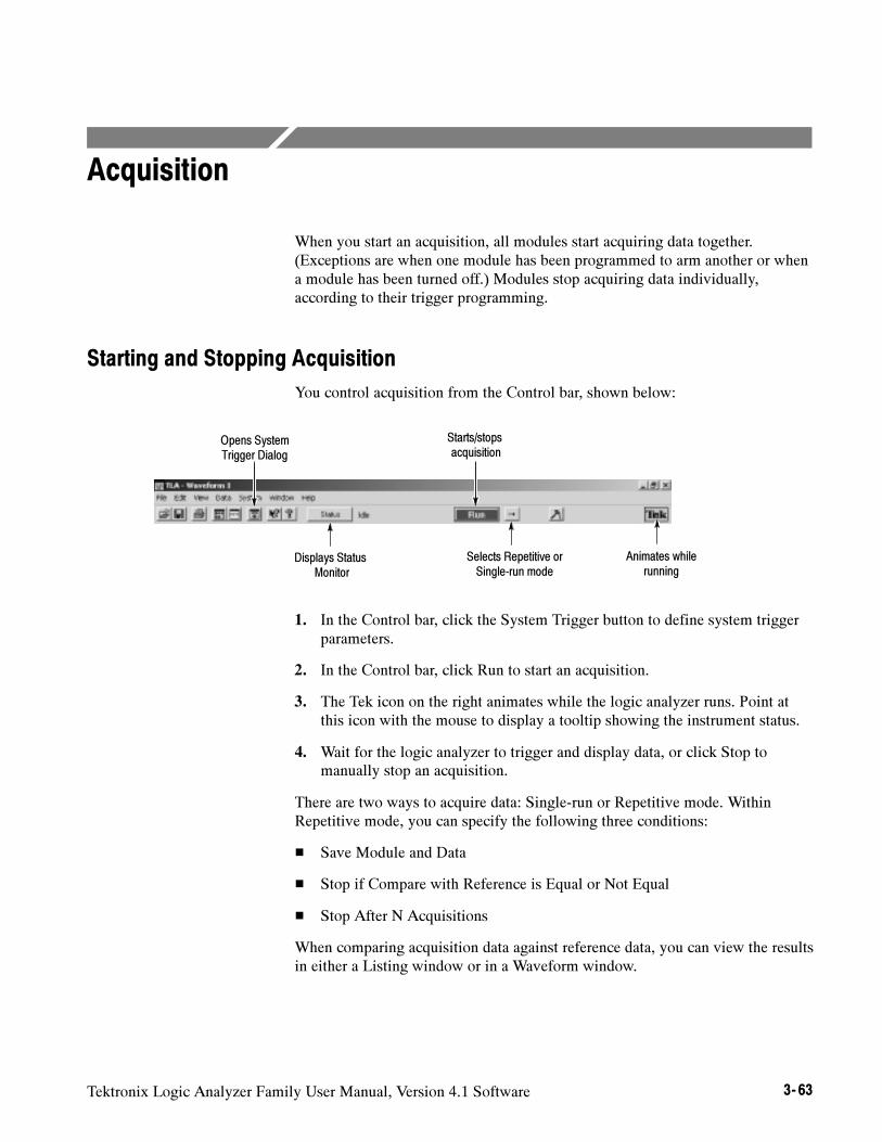
Tektronix Logic Analyzer Family User Manual, Version 4.1 Software 3- 63
Acquisition
When you start an acquisition, all modules start acquiring data together.(Exceptions are when one module has been programmed to arm another or whena module has been turned off.) Modules stop acquiring data individually,according to their trigger programming.
Starting and Stopping Acquisition
You control acquisition from the Control bar, shown below:
Animates whilerunning
Selects Repetitive orSingle-run mode
Starts/stopsacquisition
Displays StatusMonitor
Opens SystemTrigger Dialog
1. In the Control bar, click the System Trigger button to define system triggerparameters.
2. In the Control bar, click Run to start an acquisition.
3. The Tek icon on the right animates while the logic analyzer runs. Point atthis icon with the mouse to display a tooltip showing the instrument status.
4. Wait for the logic analyzer to trigger and display data, or click Stop tomanually stop an acquisition.
There are two ways to acquire data: Single-run or Repetitive mode. WithinRepetitive mode, you can specify the following three conditions:
Save Module and Data
Stop if Compare with Reference is Equal or Not Equal
Stop After N Acquisitions
When comparing acquisition data against reference data, you can view the resultsin either a Listing window or in a Waveform window.
Acquisition
3- 64 Tektronix Logic Analyzer Family User Manual, Version 4.1 Software
In Single-run mode, the logic analyzer automatically stops acquiring anddisplays data when it fulfills the setup conditions. Use Single-run mode to findand display a specific event.
During acquisition, the logic analyzer monitors the data, looking for the eventsyou specified in the Trigger windows. When the specified events occur, the logicanalyzer responds according to the selections you made in the Setup and Triggerwindows.
In Repetitive mode, the logic analyzer keeps acquiring data until you click Stopor until it fulfills the stop conditions.
You can use Repetitive mode as follows:
To observe the same waveform or listing for a period of time
To stop after a set number of acquisitions for a period of time and look fordifferences
After each acquisition you can have the logic analyzer do the following tasks:
Save the system or module setups and data
Export the data to separate files or overwrite the same file
Compare the acquisition data against data in another LA module or a savedLA module file
To open a file or execute a set of defined tasks after the acquisition iscomplete. For example, you can execute a command such as sending emailor paging you that the logic analyzer has stopped.
Select Repetitive Properties from the System menu to select the different optionsfor the Repetitive mode. Figure 3--44 shows an example of the RepetitiveProperties dialog box.
NOTE. You can minimize the time between acquisitions by specifying compare
conditions under the LA Setup window, deleting (not just minimizing) all data
windows, and then starting the logic analyzer. When the logic analyzer fulfills
the compare conditions, you can create a new data window with the New Data
Window wizard to view the data.
Single Run Mode
Repetitive Mode
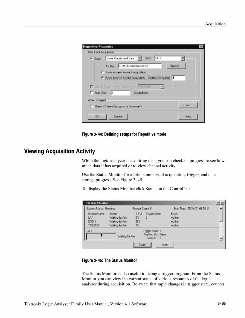
Acquisition
Tektronix Logic Analyzer Family User Manual, Version 4.1 Software 3- 65
Figure 3- 44: Defining setups for Repetitive mode
Viewing Acquisition Activity
While the logic analyzer is acquiring data, you can check its progress to see howmuch data it has acquired or to view channel activity.
Use the Status Monitor for a brief summary of acquisition, trigger, and datastorage progress. See Figure 3--45.
To display the Status Monitor click Status on the Control bar.
Figure 3- 45: The Status Monitor
The Status Monitor is also useful to debug a trigger program. From the StatusMonitor you can view the current status of various resources of the logicanalyzer during acquisition. Be aware that rapid changes in trigger state, counter
Acquisition
3- 66 Tektronix Logic Analyzer Family User Manual, Version 4.1 Software
values, timer values, and the internal signals cannot be accurately displayed inreal time in the Status Monitor.
If the Logic Analyzer Does Not Trigger
If the logic analyzer does not trigger, then you should check the following:
Check that your target system is powered on.
Check the System window to verify that required modules are turned on.
If the module has correctly clocked data, acquired the specified events,triggered, but has not stopped, the module probably has not acquired enoughadditional data to fill acquisition memory. Click Stop to manually stop theacquisition, and then change the module Memory Depth (reduce) or TriggerPosition (increase).
The following conditions apply to the LA module only:
Check the Status Monitor for an external clock warning. If the LA is notreceiving an external clock, the Status Monitor displays the followingmessage: External Clock Source Idle.
Check for signal activity at the probe tip. If there is no activity, then checkthe probe connections.
Check the clock signal to make sure that the LA module is actually clockingdata. Problems with the clock signal can impact setups using externalclocking, custom clocking (microprocessor support packages only), orstorage qualification.
Similar to the previous item, check clock qualifier signals and clockingequations.
Check the threshold voltages for probes and clocks.
If the module is correctly clocking data and the data events have occurred,but the trigger program did not generate a trigger, then you should check thetrigger program itself. The trigger program might not be reaching the statethat generates the trigger. Use the Status Monitor to track trigger programprogress and identify the state in which trigger progress stops.
Check the complexity of your trigger program. If your trigger program is toonarrowly defined, or over-specified, the trigger program might not acquirethe desired data or might not trigger. A less-specific trigger program mightacquire the desired data and will also verify that you have set up the properclocking and threshold levels.
LA Module

Acquisition
Tektronix Logic Analyzer Family User Manual, Version 4.1 Software 3- 67
The following condition applies to the DSO module only:
Check the trigger Mode setting. If Mode is set to Normal, and the data doesnot meet the trigger conditions, the module will not trigger. (Conversely, ifMode is set to Auto, the module will trigger after a set length of time, even ifthe specified data does not occur.)
The following conditions apply only if you are using arming or intermoduletriggering:
Internal signal logic function. If your trigger depends on setting an internalsignal, and that signal has been set to Wired-And, all modules in the systemmust set the signal or it cannot assert.
If any modules are turned off, check that the trigger program is not waitingfor input from an inactive module.
Because the logic analyzer does not clear the first transition indication, checkthat the LA modules always show a first transition indication (even if there areno probes attached).
To avoid triggering on a false first transition indication, set the first state to “IfAnything, Go to Next State.” This will use a state, but it ensures that you do nottrigger on a false transition indication.
DSO Module
Arming or IntermoduleTriggering
First Transition IndicationProblems
Acquisition
3- 68 Tektronix Logic Analyzer Family User Manual, Version 4.1 Software
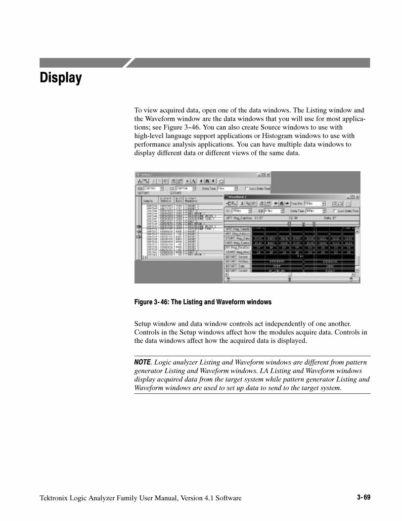
Tektronix Logic Analyzer Family User Manual, Version 4.1 Software 3- 69
Display
To view acquired data, open one of the data windows. The Listing window andthe Waveform window are the data windows that you will use for most applica-tions; see Figure 3--46. You can also create Source windows to use withhigh-level language support applications or Histogram windows to use withperformance analysis applications. You can have multiple data windows todisplay different data or different views of the same data.
Figure 3- 46: The Listing and Waveform windows
Setup window and data window controls act independently of one another.Controls in the Setup windows affect how the modules acquire data. Controls inthe data windows affect how the acquired data is displayed.
NOTE. Logic analyzer Listing and Waveform windows are different from pattern
generator Listing and Waveform windows. LA Listing and Waveform windows
display acquired data from the target system while pattern generator Listing and
Waveform windows are used to set up data to send to the target system.
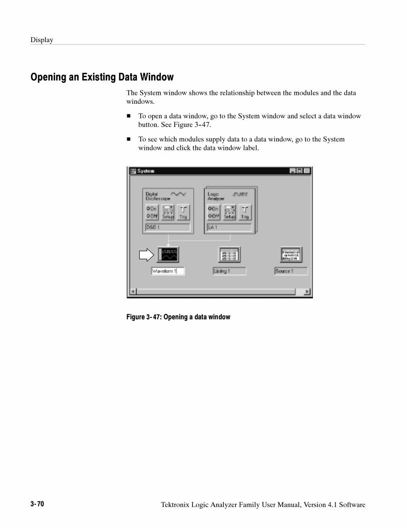
Display
3- 70 Tektronix Logic Analyzer Family User Manual, Version 4.1 Software
Opening an Existing Data Window
The System window shows the relationship between the modules and the datawindows.
To open a data window, go to the System window and select a data windowbutton. See Figure 3--47.
To see which modules supply data to a data window, go to the Systemwindow and click the data window label.
Figure 3- 47: Opening a data window
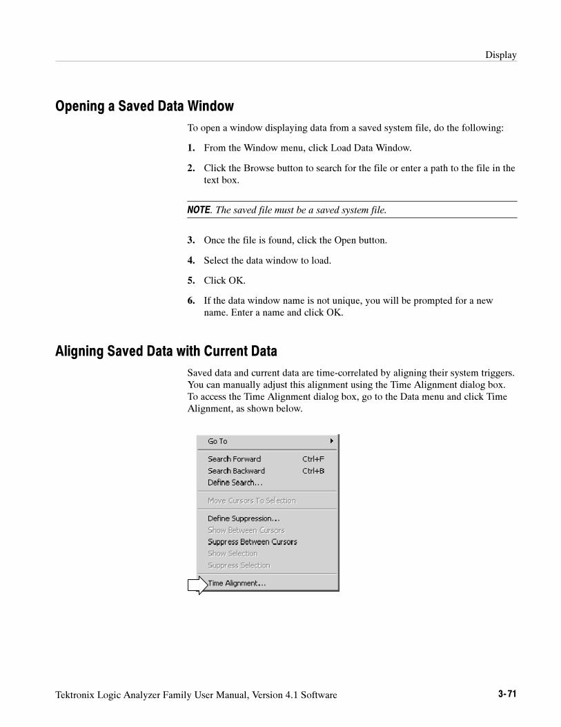
Display
Tektronix Logic Analyzer Family User Manual, Version 4.1 Software 3- 71
Opening a Saved Data Window
To open a window displaying data from a saved system file, do the following:
1. From the Window menu, click Load Data Window.
2. Click the Browse button to search for the file or enter a path to the file in thetext box.
NOTE. The saved file must be a saved system file.
3. Once the file is found, click the Open button.
4. Select the data window to load.
5. Click OK.
6. If the data window name is not unique, you will be prompted for a newname. Enter a name and click OK.
Aligning Saved Data with Current Data
Saved data and current data are time-correlated by aligning their system triggers.You can manually adjust this alignment using the Time Alignment dialog box.To access the Time Alignment dialog box, go to the Data menu and click TimeAlignment, as shown below.
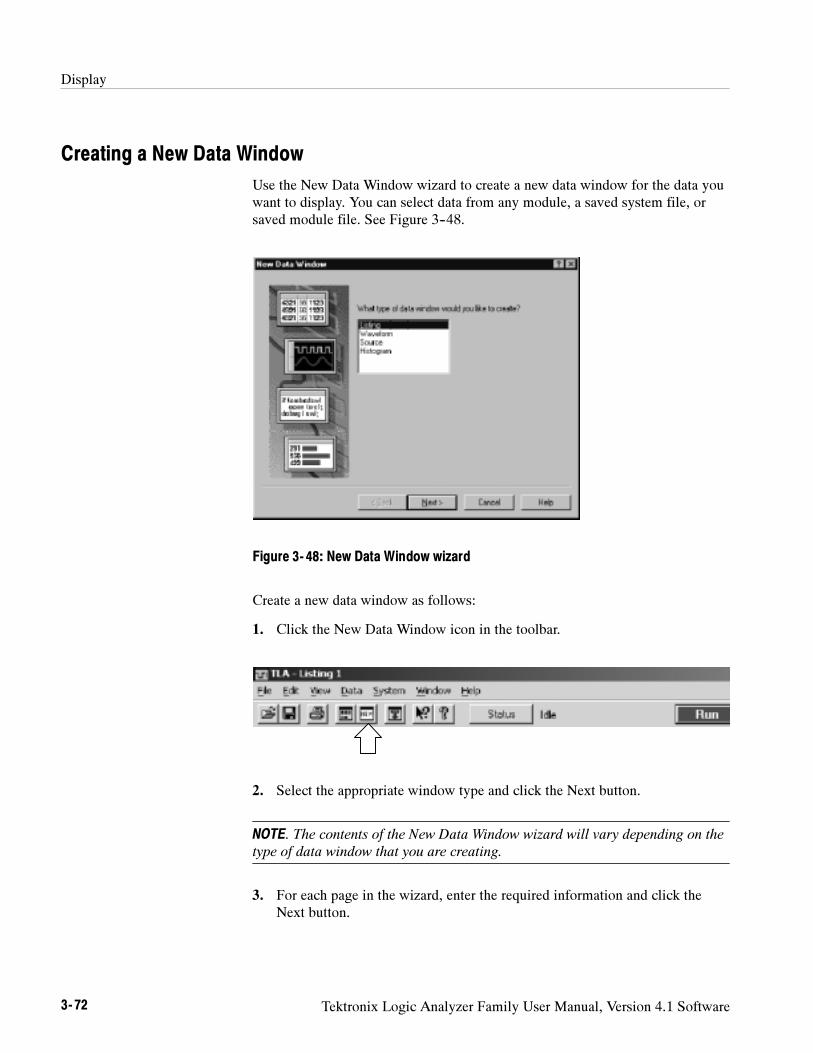
Display
3- 72 Tektronix Logic Analyzer Family User Manual, Version 4.1 Software
Creating a New Data Window
Use the New Data Window wizard to create a new data window for the data youwant to display. You can select data from any module, a saved system file, orsaved module file. See Figure 3--48.
Figure 3- 48: New Data Window wizard
Create a new data window as follows:
1. Click the New Data Window icon in the toolbar.
2. Select the appropriate window type and click the Next button.
NOTE. The contents of the New Data Window wizard will vary depending on the
type of data window that you are creating.
3. For each page in the wizard, enter the required information and click theNext button.
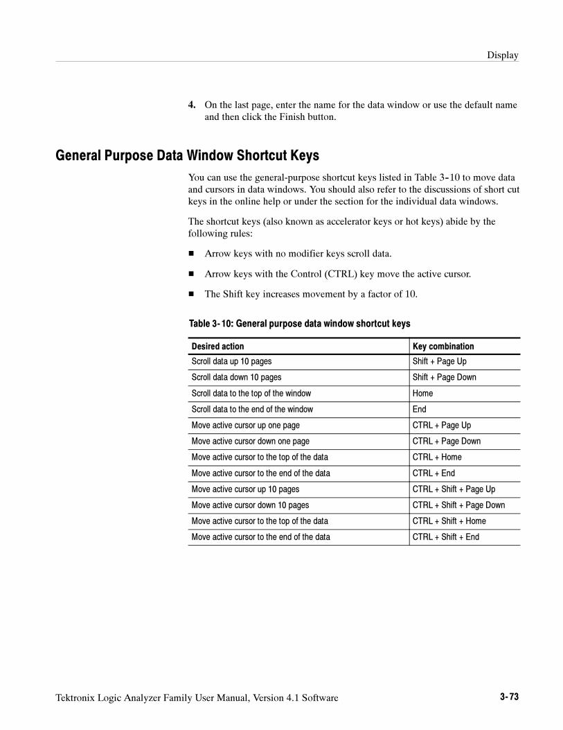
Display
Tektronix Logic Analyzer Family User Manual, Version 4.1 Software 3- 73
4. On the last page, enter the name for the data window or use the default nameand then click the Finish button.
General Purpose Data Window Shortcut Keys
You can use the general-purpose shortcut keys listed in Table 3--10 to move dataand cursors in data windows. You should also refer to the discussions of short cutkeys in the online help or under the section for the individual data windows.
The shortcut keys (also known as accelerator keys or hot keys) abide by thefollowing rules:
Arrow keys with no modifier keys scroll data.
Arrow keys with the Control (CTRL) key move the active cursor.
The Shift key increases movement by a factor of 10.
Table 3- 10: General purpose data window shortcut keys
Desired action Key combination
Scroll data up 10 pages Shift + Page Up
Scroll data down 10 pages Shift + Page Down
Scroll data to the top of the window Home
Scroll data to the end of the window End
Move active cursor up one page CTRL + Page Up
Move active cursor down one page CTRL + Page Down
Move active cursor to the top of the data CTRL + Home
Move active cursor to the end of the data CTRL + End
Move active cursor up 10 pages CTRL + Shift + Page Up
Move active cursor down 10 pages CTRL + Shift + Page Down
Move active cursor to the top of the data CTRL + Shift + Home
Move active cursor to the end of the data CTRL + Shift + End

Display
3- 74 Tektronix Logic Analyzer Family User Manual, Version 4.1 Software
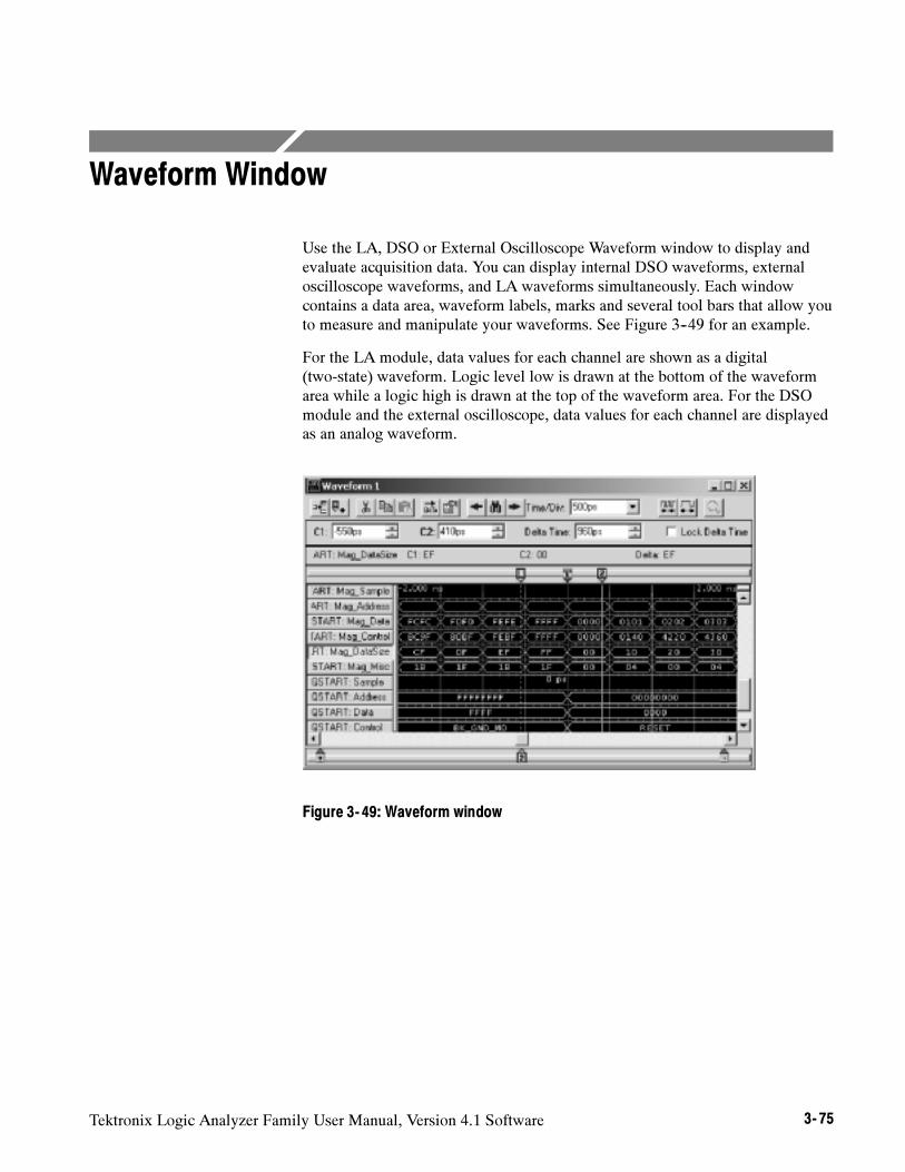
Tektronix Logic Analyzer Family User Manual, Version 4.1 Software 3- 75
Waveform Window
Use the LA, DSO or External Oscilloscope Waveform window to display andevaluate acquisition data. You can display internal DSO waveforms, externaloscilloscope waveforms, and LA waveforms simultaneously. Each windowcontains a data area, waveform labels, marks and several tool bars that allow youto measure and manipulate your waveforms. See Figure 3--49 for an example.
For the LA module, data values for each channel are shown as a digital(two-state) waveform. Logic level low is drawn at the bottom of the waveformarea while a logic high is drawn at the top of the waveform area. For the DSOmodule and the external oscilloscope, data values for each channel are displayedas an analog waveform.
Figure 3- 49: Waveform window
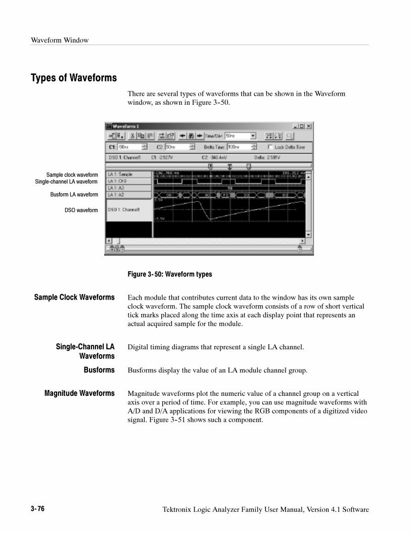
Waveform Window
3- 76 Tektronix Logic Analyzer Family User Manual, Version 4.1 Software
Types of Waveforms
There are several types of waveforms that can be shown in the Waveformwindow, as shown in Figure 3--50.
Sample clock waveformSingle-channel LA waveform
Busform LA waveform
DSO waveform
Figure 3- 50: Waveform types
Each module that contributes current data to the window has its own sampleclock waveform. The sample clock waveform consists of a row of short verticaltick marks placed along the time axis at each display point that represents anactual acquired sample for the module.
Digital timing diagrams that represent a single LA channel.
Busforms display the value of an LA module channel group.
Magnitude waveforms plot the numeric value of a channel group on a verticalaxis over a period of time. For example, you can use magnitude waveforms withA/D and D/A applications for viewing the RGB components of a digitized videosignal. Figure 3--51 shows such a component.
Sample Clock Waveforms
Single-Channel LAWaveforms
Busforms
Magnitude Waveforms
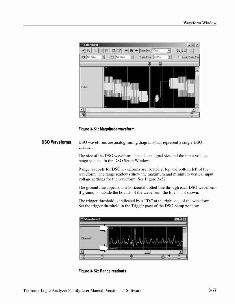
Waveform Window
Tektronix Logic Analyzer Family User Manual, Version 4.1 Software 3- 77
Figure 3- 51: Magnitude waveform
DSO waveforms are analog timing diagrams that represent a single DSOchannel.
The size of the DSO waveform depends on signal size and the input voltagerange selected in the DSO Setup Window.
Range readouts for DSO waveforms are located at top and bottom left of thewaveform. The range readouts show the maximum and minimum vertical inputvoltage settings for the waveform. See Figure 3--52.
The ground line appears as a horizontal dotted line through each DSO waveform.If ground is outside the bounds of the waveform, the line is not shown.
The trigger threshold is indicated by a “T>” at the right side of the waveform.Set the trigger threshold in the Trigger page of the DSO Setup window.
Figure 3- 52: Range readouts
DSO Waveforms
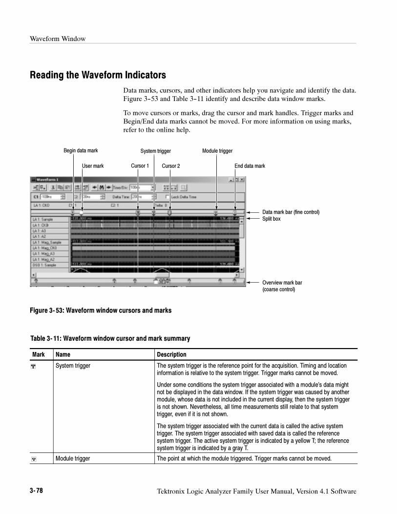
Waveform Window
3- 78 Tektronix Logic Analyzer Family User Manual, Version 4.1 Software
Reading the Waveform Indicators
Data marks, cursors, and other indicators help you navigate and identify the data.Figure 3--53 and Table 3--11 identify and describe data window marks.
To move cursors or marks, drag the cursor and mark handles. Trigger marks andBegin/End data marks cannot be moved. For more information on using marks,refer to the online help.
System trigger
Cursor 1User mark
Data mark bar (fine control)
Overview mark bar(coarse control)
Begin data mark
End data mark
Split box
Cursor 2
Module trigger
Figure 3- 53: Waveform window cursors and marks
Table 3- 11: Waveform window cursor and mark summary
Mark Name Description
System trigger The system trigger is the reference point for the acquisition. Timing and locationinformation is relative to the system trigger. Trigger marks cannot be moved.
Under some conditions the system trigger associated with a module’s data mightnot be displayed in the data window. If the system trigger was caused by anothermodule, whose data is not included in the current display, then the system triggeris not shown. Nevertheless, all time measurements still relate to that systemtrigger, even if it is not shown.
The system trigger associated with the current data is called the active systemtrigger. The system trigger associated with saved data is called the referencesystem trigger. The active system trigger is indicated by a yellow T; the referencesystem trigger is indicated by a gray T.
Module trigger The point at which the module triggered. Trigger marks cannot be moved.
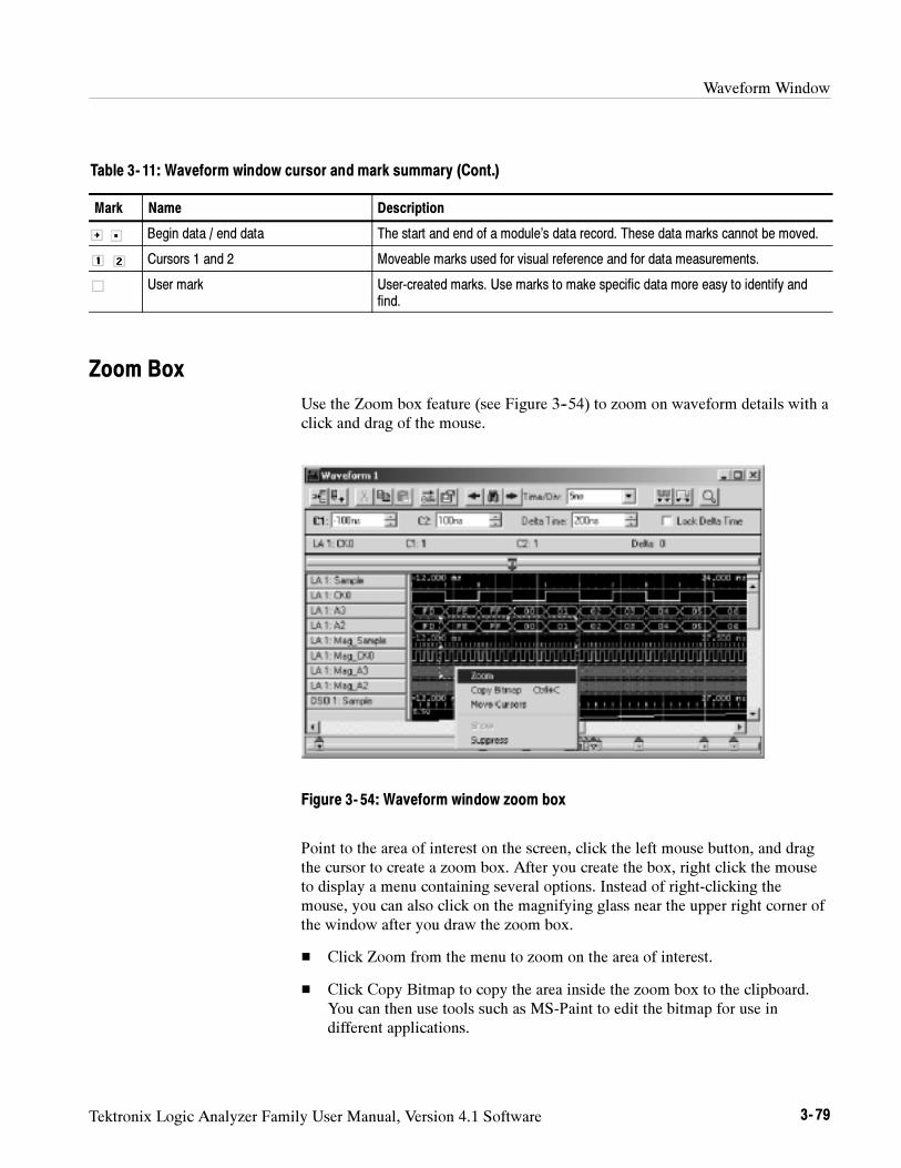
Waveform Window
Tektronix Logic Analyzer Family User Manual, Version 4.1 Software 3- 79
Table 3- 11: Waveform window cursor and mark summary (Cont.)
Mark DescriptionName
Begin data / end data The start and end of a module’s data record. These data marks cannot be moved.
Cursors 1 and 2 Moveable marks used for visual reference and for data measurements.
User mark User-created marks. Use marks to make specific data more easy to identify andfind.
Zoom Box
Use the Zoom box feature (see Figure 3--54) to zoom on waveform details with aclick and drag of the mouse.
Figure 3- 54: Waveform window zoom box
Point to the area of interest on the screen, click the left mouse button, and dragthe cursor to create a zoom box. After you create the box, right click the mouseto display a menu containing several options. Instead of right-clicking themouse, you can also click on the magnifying glass near the upper right corner ofthe window after you draw the zoom box.
Click Zoom from the menu to zoom on the area of interest.
Click Copy Bitmap to copy the area inside the zoom box to the clipboard.You can then use tools such as MS-Paint to edit the bitmap for use indifferent applications.
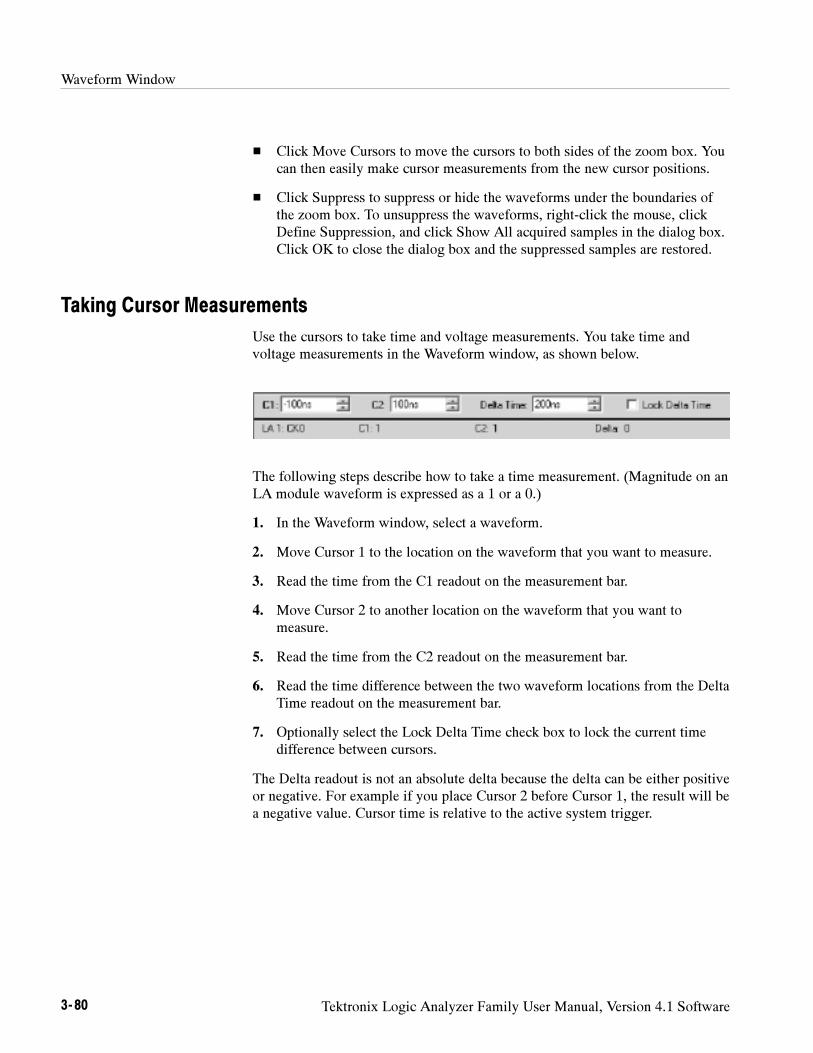
Waveform Window
3- 80 Tektronix Logic Analyzer Family User Manual, Version 4.1 Software
Click Move Cursors to move the cursors to both sides of the zoom box. Youcan then easily make cursor measurements from the new cursor positions.
Click Suppress to suppress or hide the waveforms under the boundaries ofthe zoom box. To unsuppress the waveforms, right-click the mouse, clickDefine Suppression, and click Show All acquired samples in the dialog box.Click OK to close the dialog box and the suppressed samples are restored.
Taking Cursor Measurements
Use the cursors to take time and voltage measurements. You take time andvoltage measurements in the Waveform window, as shown below.
The following steps describe how to take a time measurement. (Magnitude on anLA module waveform is expressed as a 1 or a 0.)
1. In the Waveform window, select a waveform.
2. Move Cursor 1 to the location on the waveform that you want to measure.
3. Read the time from the C1 readout on the measurement bar.
4. Move Cursor 2 to another location on the waveform that you want tomeasure.
5. Read the time from the C2 readout on the measurement bar.
6. Read the time difference between the two waveform locations from the DeltaTime readout on the measurement bar.
7. Optionally select the Lock Delta Time check box to lock the current timedifference between cursors.
The Delta readout is not an absolute delta because the delta can be either positiveor negative. For example if you place Cursor 2 before Cursor 1, the result will bea negative value. Cursor time is relative to the active system trigger.
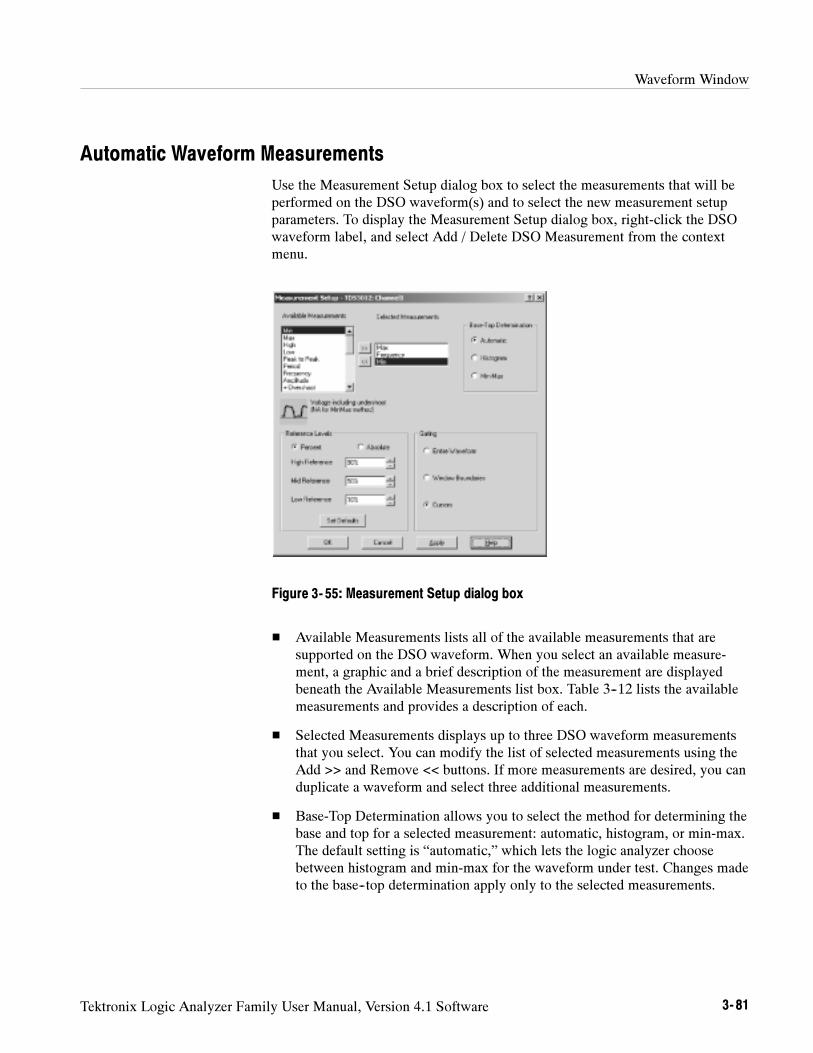
Waveform Window
Tektronix Logic Analyzer Family User Manual, Version 4.1 Software 3- 81
Automatic Waveform Measurements
Use the Measurement Setup dialog box to select the measurements that will beperformed on the DSO waveform(s) and to select the new measurement setupparameters. To display the Measurement Setup dialog box, right-click the DSOwaveform label, and select Add / Delete DSO Measurement from the contextmenu.
Figure 3- 55: Measurement Setup dialog box
Available Measurements lists all of the available measurements that aresupported on the DSO waveform. When you select an available measure-ment, a graphic and a brief description of the measurement are displayedbeneath the Available Measurements list box. Table 3--12 lists the availablemeasurements and provides a description of each.
Selected Measurements displays up to three DSO waveform measurementsthat you select. You can modify the list of selected measurements using theAdd >> and Remove << buttons. If more measurements are desired, you canduplicate a waveform and select three additional measurements.
Base-Top Determination allows you to select the method for determining thebase and top for a selected measurement: automatic, histogram, or min-max.The default setting is “automatic,” which lets the logic analyzer choosebetween histogram and min-max for the waveform under test. Changes madeto the base--top determination apply only to the selected measurements.
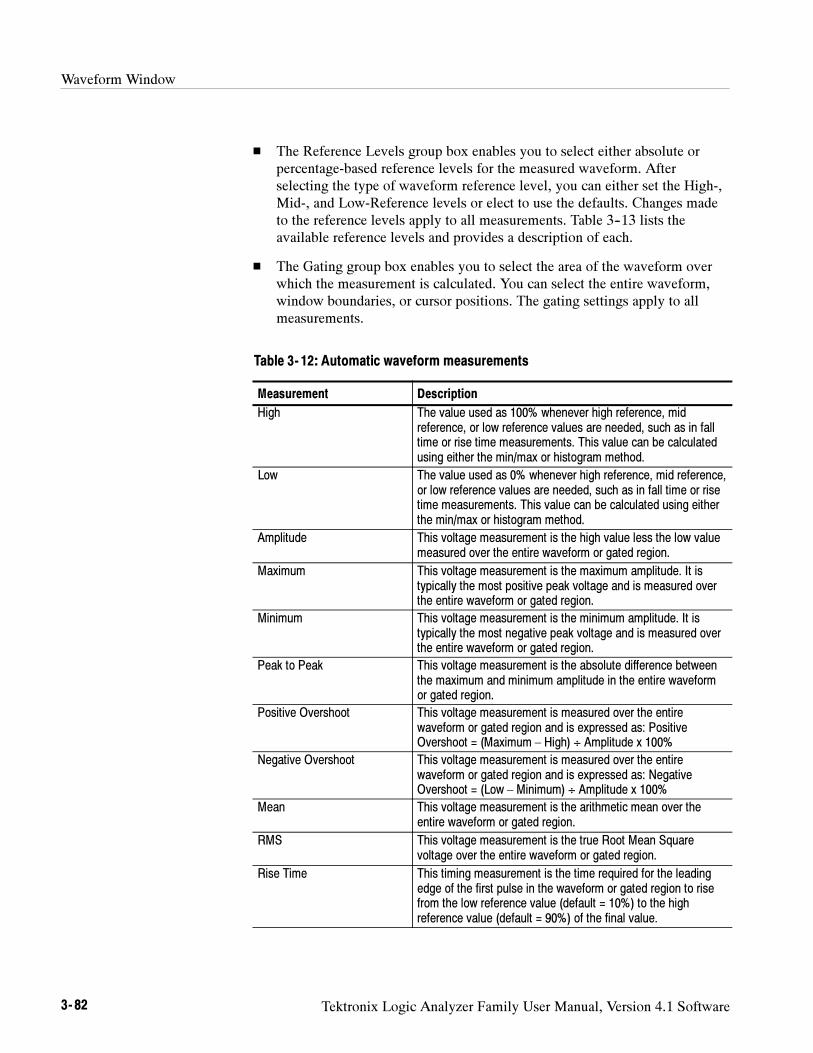
Waveform Window
3- 82 Tektronix Logic Analyzer Family User Manual, Version 4.1 Software
The Reference Levels group box enables you to select either absolute orpercentage-based reference levels for the measured waveform. Afterselecting the type of waveform reference level, you can either set the High-,Mid-, and Low-Reference levels or elect to use the defaults. Changes madeto the reference levels apply to all measurements. Table 3--13 lists theavailable reference levels and provides a description of each.
The Gating group box enables you to select the area of the waveform overwhich the measurement is calculated. You can select the entire waveform,window boundaries, or cursor positions. The gating settings apply to allmeasurements.
Table 3- 12: Automatic waveform measurements
Measurement Description
High The value used as 100% whenever high reference, midreference, or low reference values are needed, such as in falltime or rise time measurements. This value can be calculatedusing either the min/max or histogram method.
Low The value used as 0% whenever high reference, mid reference,or low reference values are needed, such as in fall time or risetime measurements. This value can be calculated using eitherthe min/max or histogram method.
Amplitude This voltage measurement is the high value less the low valuemeasured over the entire waveform or gated region.
Maximum This voltage measurement is the maximum amplitude. It istypically the most positive peak voltage and is measured overthe entire waveform or gated region.
Minimum This voltage measurement is the minimum amplitude. It istypically the most negative peak voltage and is measured overthe entire waveform or gated region.
Peak to Peak This voltage measurement is the absolute difference betweenthe maximum and minimum amplitude in the entire waveformor gated region.
Positive Overshoot This voltage measurement is measured over the entirewaveform or gated region and is expressed as: PositiveOvershoot = (Maximum – High) ÷ Amplitude x 100%
Negative Overshoot This voltage measurement is measured over the entirewaveform or gated region and is expressed as: NegativeOvershoot = (Low – Minimum) ÷ Amplitude x 100%
Mean This voltage measurement is the arithmetic mean over theentire waveform or gated region.
RMS This voltage measurement is the true Root Mean Squarevoltage over the entire waveform or gated region.
Rise Time This timing measurement is the time required for the leadingedge of the first pulse in the waveform or gated region to risefrom the low reference value (default = 10%) to the highreference value (default = 90%) of the final value.
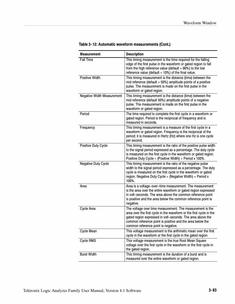
Waveform Window
Tektronix Logic Analyzer Family User Manual, Version 4.1 Software 3- 83
Table 3- 12: Automatic waveform measurements (Cont.)
Measurement Description
Fall Time This timing measurement is the time required for the fallingedge of the first pulse in the waveform or gated region to fallfrom the high reference value (default = 90%) to the lowreference value (default = 10%) of the final value.
Positive Width This timing measurement is the distance (time) between themid reference (default = 50%) amplitude points of a positivepulse. The measurement is made on the first pulse in thewaveform or gated region.
Negative Width Measurement This timing measurement is the distance (time) between themid reference (default 50%) amplitude points of a negativepulse. The measurement is made on the first pulse in thewaveform or gated region.
Period The time required to complete the first cycle in a waveform orgated region. Period is the reciprocal of frequency and ismeasured in seconds.
Frequency This timing measurement is a measure of the first cycle in awaveform or gated region. Frequency is the reciprocal of theperiod; it is measured in Hertz (Hz) where one Hz is one cycleper second.
Positive Duty Cycle This timing measurement is the ratio of the positive pulse widthto the signal period expressed as a percentage. The duty cycleis measured on the first cycle in the waveform or gated region.Positive Duty Cycle = (Positive Width) ÷ Period x 100%.
Negative Duty Cycle This timing measurement is the ratio of the negative pulsewidth to the signal period expressed as a percentage. The dutycycle is measured on the first cycle in the waveform or gatedregion. Negative Duty Cycle = (Negative Width) ÷ Period x100%.
Area Area is a voltage--over--time measurement. The measurementis the area over the entire waveform or gated region expressedin volt--seconds. The area above the common reference pointis positive and the area below the common reference point isnegative.
Cycle Area The voltage over time measurement. The measurement is thearea over the first cycle in the waveform or the first cycle in thegated region expressed in volt--seconds. The area above thecommon reference point is positive and the area below thecommon reference point is negative.
Cycle Mean This voltage measurement is the arithmetic mean over the firstcycle in the waveform or the first cycle in the gated region.
Cycle RMS This voltage measurement is the true Root Mean Squarevoltage over the first cycle in the waveform or the first cycle inthe gated region.
Burst Width This timing measurement is the duration of a burst and ismeasured over the entire waveform or gated region.
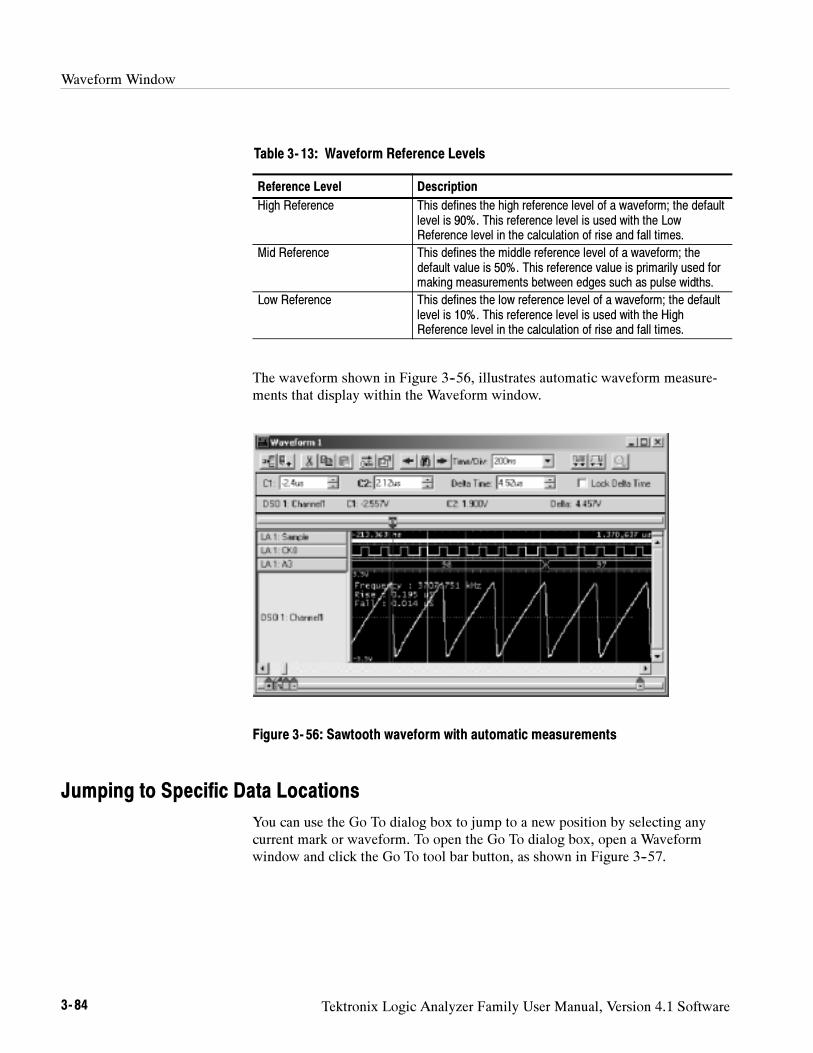
Waveform Window
3- 84 Tektronix Logic Analyzer Family User Manual, Version 4.1 Software
Table 3- 13: Waveform Reference Levels
Reference Level Description
High Reference This defines the high reference level of a waveform; the defaultlevel is 90%. This reference level is used with the LowReference level in the calculation of rise and fall times.
Mid Reference This defines the middle reference level of a waveform; thedefault value is 50%. This reference value is primarily used formaking measurements between edges such as pulse widths.
Low Reference This defines the low reference level of a waveform; the defaultlevel is 10%. This reference level is used with the HighReference level in the calculation of rise and fall times.
The waveform shown in Figure 3--56, illustrates automatic waveform measure-ments that display within the Waveform window.
Figure 3- 56: Sawtooth waveform with automatic measurements
Jumping to Specific Data Locations
You can use the Go To dialog box to jump to a new position by selecting anycurrent mark or waveform. To open the Go To dialog box, open a Waveformwindow and click the Go To tool bar button, as shown in Figure 3--57.
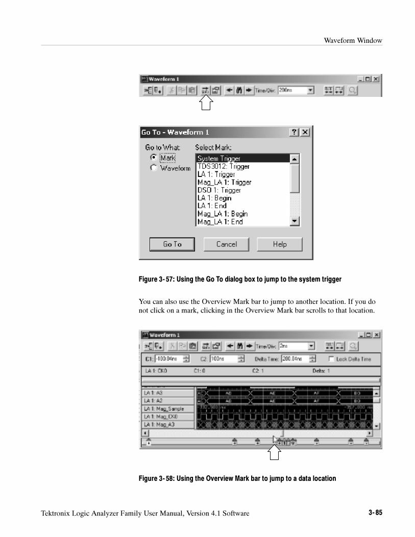
Waveform Window
Tektronix Logic Analyzer Family User Manual, Version 4.1 Software 3- 85
Figure 3- 57: Using the Go To dialog box to jump to the system trigger
You can also use the Overview Mark bar to jump to another location. If you donot click on a mark, clicking in the Overview Mark bar scrolls to that location.
Figure 3- 58: Using the Overview Mark bar to jump to a data location
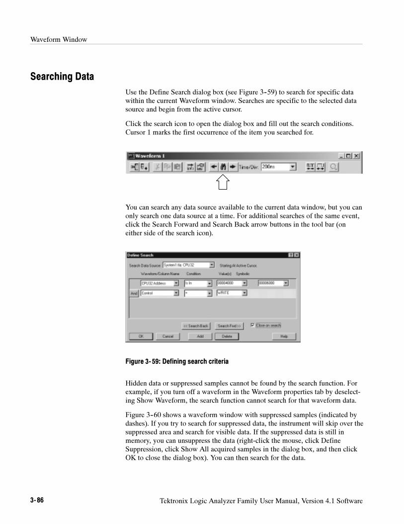
Waveform Window
3- 86 Tektronix Logic Analyzer Family User Manual, Version 4.1 Software
Searching Data
Use the Define Search dialog box (see Figure 3--59) to search for specific datawithin the current Waveform window. Searches are specific to the selected datasource and begin from the active cursor.
Click the search icon to open the dialog box and fill out the search conditions.Cursor 1 marks the first occurrence of the item you searched for.
You can search any data source available to the current data window, but you canonly search one data source at a time. For additional searches of the same event,click the Search Forward and Search Back arrow buttons in the tool bar (oneither side of the search icon).
Figure 3- 59: Defining search criteria
Hidden data or suppressed samples cannot be found by the search function. Forexample, if you turn off a waveform in the Waveform properties tab by deselect-ing Show Waveform, the search function cannot search for that waveform data.
Figure 3--60 shows a waveform window with suppressed samples (indicated bydashes). If you try to search for suppressed data, the instrument will skip over thesuppressed area and search for visible data. If the suppressed data is still inmemory, you can unsuppress the data (right-click the mouse, click DefineSuppression, click Show All acquired samples in the dialog box, and then clickOK to close the dialog box). You can then search for the data.
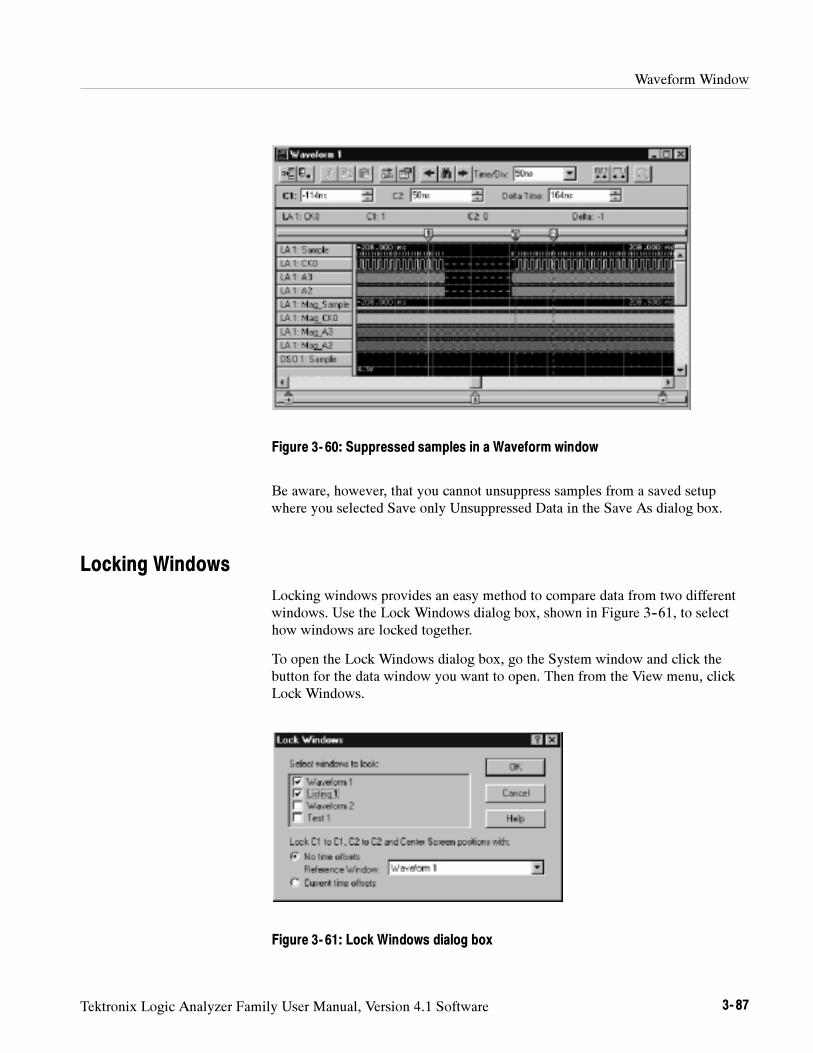
Waveform Window
Tektronix Logic Analyzer Family User Manual, Version 4.1 Software 3- 87
Figure 3- 60: Suppressed samples in a Waveform window
Be aware, however, that you cannot unsuppress samples from a saved setupwhere you selected Save only Unsuppressed Data in the Save As dialog box.
Locking Windows
Locking windows provides an easy method to compare data from two differentwindows. Use the Lock Windows dialog box, shown in Figure 3--61, to selecthow windows are locked together.
To open the Lock Windows dialog box, go the System window and click thebutton for the data window you want to open. Then from the View menu, clickLock Windows.
Figure 3- 61: Lock Windows dialog box
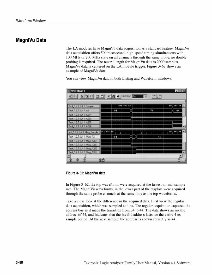
Waveform Window
3- 88 Tektronix Logic Analyzer Family User Manual, Version 4.1 Software
MagniVu Data
The LA modules have MagniVu data acquisition as a standard feature. MagniVudata acquisition offers 500 picosecond, high-speed timing simultaneous with100 MHz or 200 MHz state on all channels through the same probe; no doubleprobing is required. The record length for MagniVu data is 2000 samples.MagniVu data is centered on the LA module trigger. Figure 3--62 shows anexample of MagniVu data.
You can view MagniVu data in both Listing and Waveform windows.
Figure 3- 62: MagniVu data
In Figure 3--62, the top waveforms were acquired at the fastest normal samplerate. The MagniVu waveforms, in the lower part of the display, were acquiredthrough the same probe channels at the same time as the top waveforms.
Take a close look at the difference in the acquired data. First view the regulardata acquisition, which was sampled at 4 ns. The regular acquisition captured theaddress bus as it made the transition from 34 to 44. The data shows an invalidaddress of 74, and indicates that the invalid address lasts for the entire 4 nssample period. At the next sample, the address is shown correctly as 44.
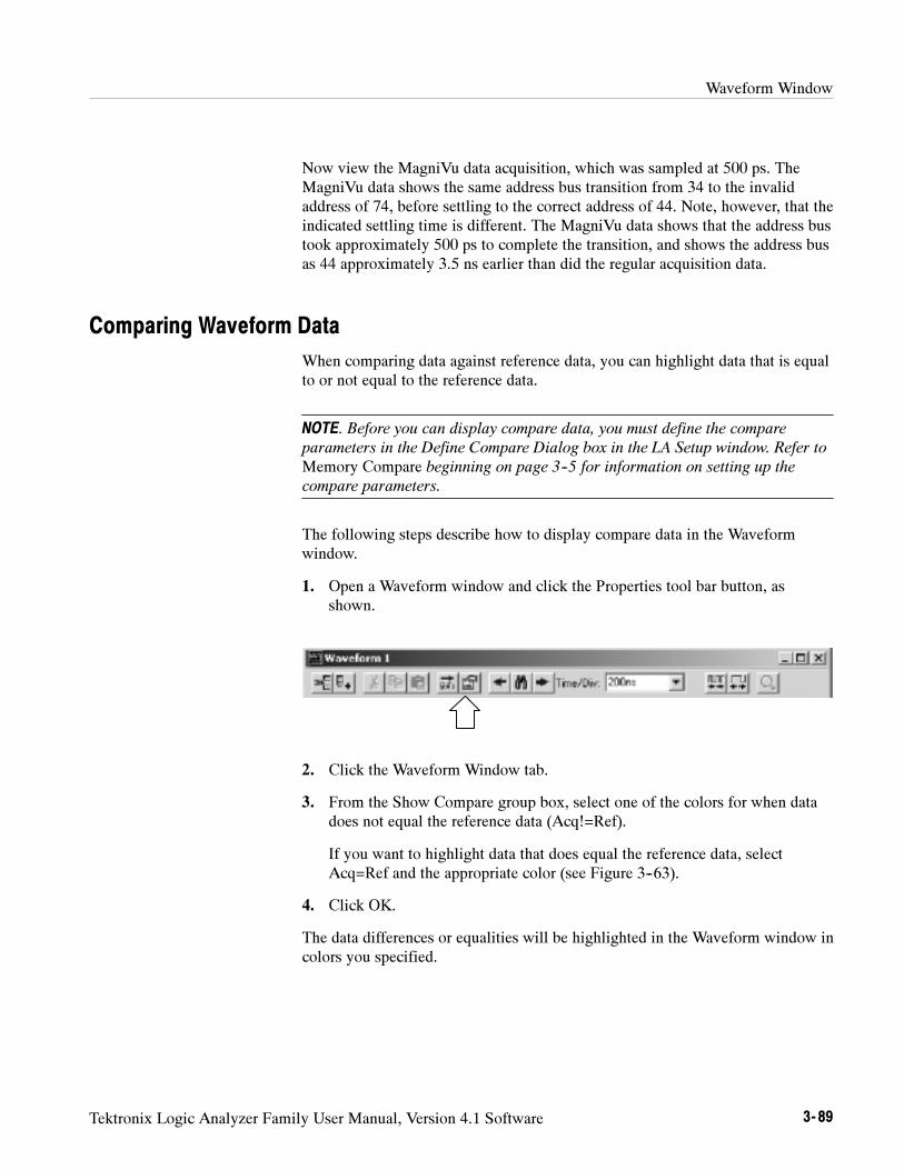
Waveform Window
Tektronix Logic Analyzer Family User Manual, Version 4.1 Software 3- 89
Now view the MagniVu data acquisition, which was sampled at 500 ps. TheMagniVu data shows the same address bus transition from 34 to the invalidaddress of 74, before settling to the correct address of 44. Note, however, that theindicated settling time is different. The MagniVu data shows that the address bustook approximately 500 ps to complete the transition, and shows the address busas 44 approximately 3.5 ns earlier than did the regular acquisition data.
Comparing Waveform Data
When comparing data against reference data, you can highlight data that is equalto or not equal to the reference data.
NOTE. Before you can display compare data, you must define the compare
parameters in the Define Compare Dialog box in the LA Setup window. Refer to
Memory Compare beginning on page 3--5 for information on setting up the
compare parameters.
The following steps describe how to display compare data in the Waveformwindow.
1. Open a Waveform window and click the Properties tool bar button, asshown.
2. Click the Waveform Window tab.
3. From the Show Compare group box, select one of the colors for when datadoes not equal the reference data (Acq!=Ref).
If you want to highlight data that does equal the reference data, selectAcq=Ref and the appropriate color (see Figure 3--63).
4. Click OK.
The data differences or equalities will be highlighted in the Waveform window incolors you specified.
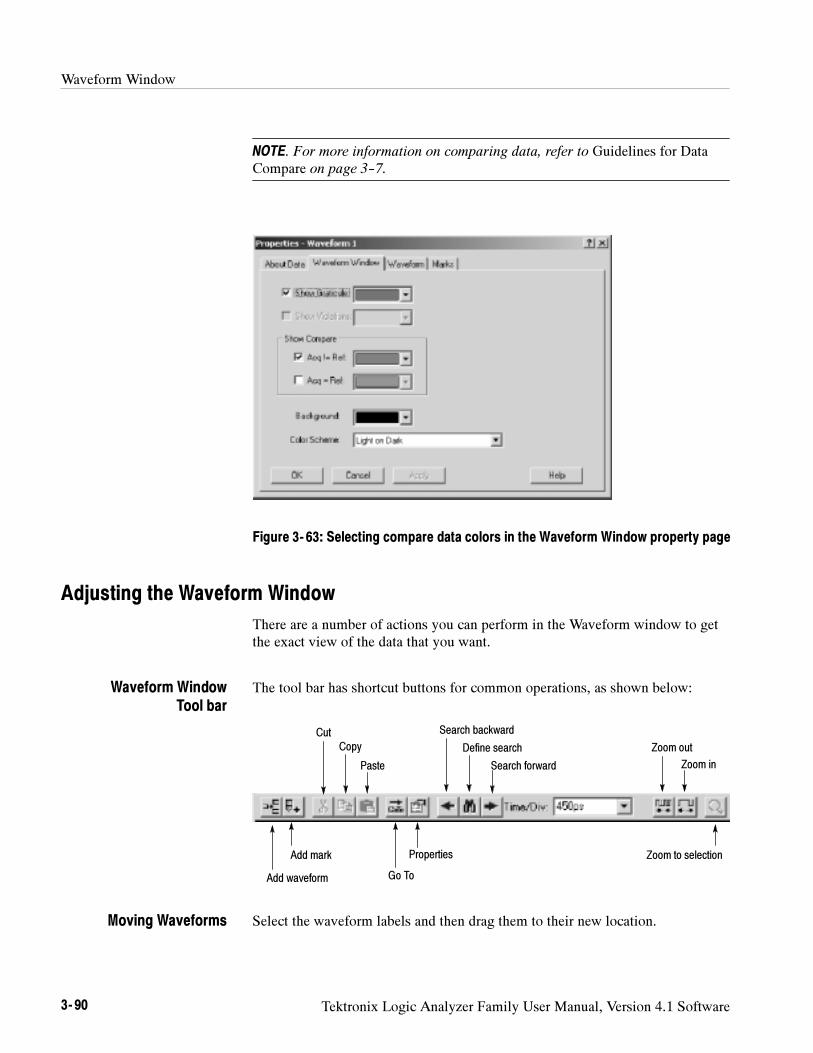
Waveform Window
3- 90 Tektronix Logic Analyzer Family User Manual, Version 4.1 Software
NOTE. For more information on comparing data, refer to Guidelines for DataCompare on page 3--7.
Figure 3- 63: Selecting compare data colors in the Waveform Window property page
Adjusting the Waveform Window
There are a number of actions you can perform in the Waveform window to getthe exact view of the data that you want.
The tool bar has shortcut buttons for common operations, as shown below:
Add waveform
Add mark
Cut
Copy
Paste
Go To
Properties
Search forward
Define search
Search backward
Zoom out
Zoom in
Zoom to selection
Select the waveform labels and then drag them to their new location.
Waveform WindowTool bar
Moving Waveforms
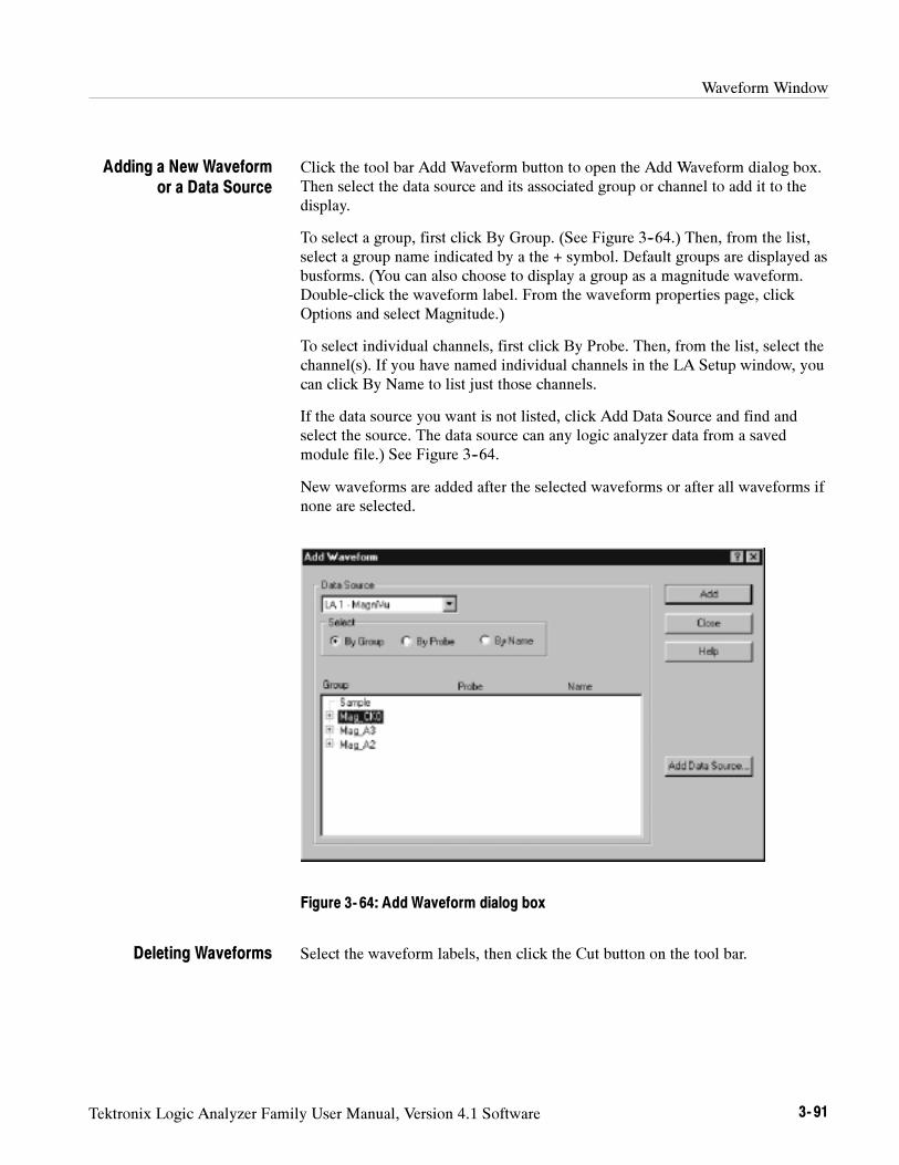
Waveform Window
Tektronix Logic Analyzer Family User Manual, Version 4.1 Software 3- 91
Click the tool bar Add Waveform button to open the Add Waveform dialog box.Then select the data source and its associated group or channel to add it to thedisplay.
To select a group, first click By Group. (See Figure 3--64.) Then, from the list,select a group name indicated by a the + symbol. Default groups are displayed asbusforms. (You can also choose to display a group as a magnitude waveform.Double-click the waveform label. From the waveform properties page, clickOptions and select Magnitude.)
To select individual channels, first click By Probe. Then, from the list, select thechannel(s). If you have named individual channels in the LA Setup window, youcan click By Name to list just those channels.
If the data source you want is not listed, click Add Data Source and find andselect the source. The data source can any logic analyzer data from a savedmodule file.) See Figure 3--64.
New waveforms are added after the selected waveforms or after all waveforms ifnone are selected.
Figure 3- 64: Add Waveform dialog box
Select the waveform labels, then click the Cut button on the tool bar.
Adding a New Waveformor a Data Source
Deleting Waveforms
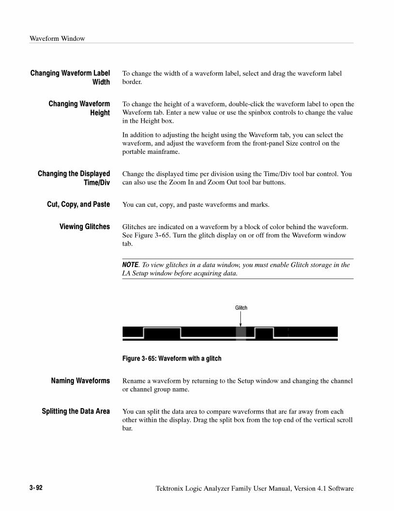
Waveform Window
3- 92 Tektronix Logic Analyzer Family User Manual, Version 4.1 Software
To change the width of a waveform label, select and drag the waveform labelborder.
To change the height of a waveform, double-click the waveform label to open theWaveform tab. Enter a new value or use the spinbox controls to change the valuein the Height box.
In addition to adjusting the height using the Waveform tab, you can select thewaveform, and adjust the waveform from the front-panel Size control on theportable mainframe.
Change the displayed time per division using the Time/Div tool bar control. Youcan also use the Zoom In and Zoom Out tool bar buttons.
You can cut, copy, and paste waveforms and marks.
Glitches are indicated on a waveform by a block of color behind the waveform.See Figure 3--65. Turn the glitch display on or off from the Waveform windowtab.
NOTE. To view glitches in a data window, you must enable Glitch storage in the
LA Setup window before acquiring data.
Glitch
Figure 3- 65: Waveform with a glitch
Rename a waveform by returning to the Setup window and changing the channelor channel group name.
You can split the data area to compare waveforms that are far away from eachother within the display. Drag the split box from the top end of the vertical scrollbar.
Changing Waveform LabelWidth
Changing WaveformHeight
Changing the DisplayedTime/Div
Cut, Copy, and Paste
Viewing Glitches
Naming Waveforms
Splitting the Data Area
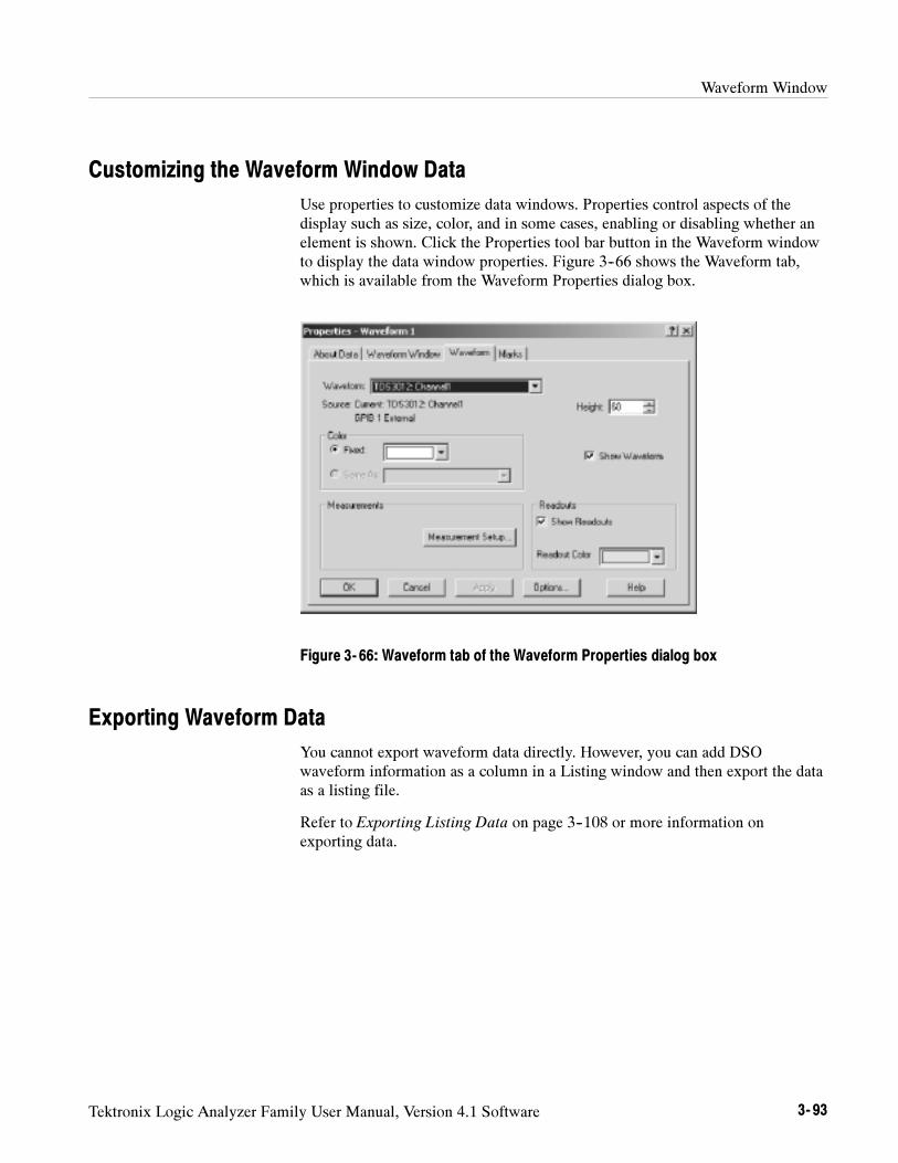
Waveform Window
Tektronix Logic Analyzer Family User Manual, Version 4.1 Software 3- 93
Customizing the Waveform Window Data
Use properties to customize data windows. Properties control aspects of thedisplay such as size, color, and in some cases, enabling or disabling whether anelement is shown. Click the Properties tool bar button in the Waveform windowto display the data window properties. Figure 3--66 shows the Waveform tab,which is available from the Waveform Properties dialog box.
Figure 3- 66: Waveform tab of the Waveform Properties dialog box
Exporting Waveform Data
You cannot export waveform data directly. However, you can add DSOwaveform information as a column in a Listing window and then export the dataas a listing file.
Refer to Exporting Listing Data on page 3--108 or more information onexporting data.
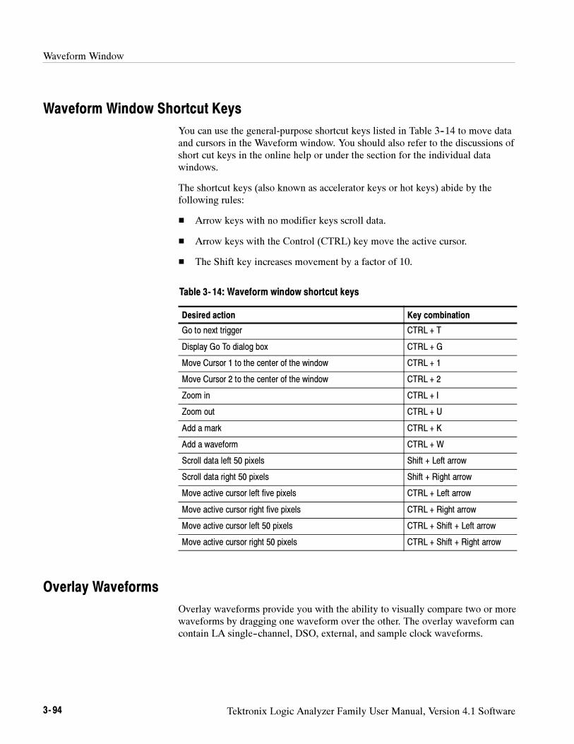
Waveform Window
3- 94 Tektronix Logic Analyzer Family User Manual, Version 4.1 Software
Waveform Window Shortcut Keys
You can use the general-purpose shortcut keys listed in Table 3--14 to move dataand cursors in the Waveform window. You should also refer to the discussions ofshort cut keys in the online help or under the section for the individual datawindows.
The shortcut keys (also known as accelerator keys or hot keys) abide by thefollowing rules:
Arrow keys with no modifier keys scroll data.
Arrow keys with the Control (CTRL) key move the active cursor.
The Shift key increases movement by a factor of 10.
Table 3- 14: Waveform window shortcut keys
Desired action Key combination
Go to next trigger CTRL + T
Display Go To dialog box CTRL + G
Move Cursor 1 to the center of the window CTRL + 1
Move Cursor 2 to the center of the window CTRL + 2
Zoom in CTRL + I
Zoom out CTRL + U
Add a mark CTRL + K
Add a waveform CTRL + W
Scroll data left 50 pixels Shift + Left arrow
Scroll data right 50 pixels Shift + Right arrow
Move active cursor left five pixels CTRL + Left arrow
Move active cursor right five pixels CTRL + Right arrow
Move active cursor left 50 pixels CTRL + Shift + Left arrow
Move active cursor right 50 pixels CTRL + Shift + Right arrow
Overlay Waveforms
Overlay waveforms provide you with the ability to visually compare two or morewaveforms by dragging one waveform over the other. The overlay waveform cancontain LA single--channel, DSO, external, and sample clock waveforms.
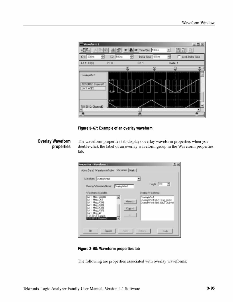
Waveform Window
Tektronix Logic Analyzer Family User Manual, Version 4.1 Software 3- 95
Figure 3- 67: Example of an overlay waveform
The waveform properties tab displays overlay waveform properties when youdouble-click the label of an overlay waveform group in the Waveform propertiestab.
Figure 3- 68: Waveform properties tab
The following are properties associated with overlay waveforms:
Overlay Waveformproperties
Waveform Window
3- 96 Tektronix Logic Analyzer Family User Manual, Version 4.1 Software
Waveform lists the label that displays in the Waveform window. You canselect a different waveform from the list. The list contains the names of allwaveforms in the active window. The initial waveform is the selectedwaveform or the first waveform if no waveform is selected. The list box isempty if multiple waveforms are selected.
Overlay Waveform Name permits you to rename overlay waveforms.
Height controls the height of the waveform. Height can range from 10 to500 pixels. The default height of an LA waveform is 18 pixels while thedefault height of a DSO waveform or external oscilloscope waveform is 60pixels.
Waveforms Available lists all of the individual waveforms and preexistingoverlay waveforms. You can move and copy waveforms in this list to theOverlay Waveforms list using the Move>> and Copy>> buttons, respective-ly. You can also remove waveforms from the Overlay Waveforms list andreturn them to the Waveforms Available list using the << button.
Overlay Waveforms lists the waveforms currently in the selected overlaywaveform group. You can move and copy waveforms from the WaveformsAvailable list to this list using the Move>> and Copy>> buttons, respective-ly. You can also remove waveforms from the Waveforms In Group list andreturn them to the Waveforms Available list using the << button.
To change waveform properties from the System window, click a Waveform datawindow icon, double--click the label of a waveform, and then click the Wave-form tab.
To create an overlay waveform, click a waveform label and then drag it to asecond waveform that you want to overlay. As you drag the waveform label, adrop marker displays at the left edge of the waveform label. Use this marker todetermine which waveform label you will be selecting to form the overlay. Whenthe Add Overlay Waveform Name dialog box appears, enter a name for thewaveform or use the default name.
For more information about creating overlay waveforms, or removing awaveform from an overlay waveform, refer to the online help.
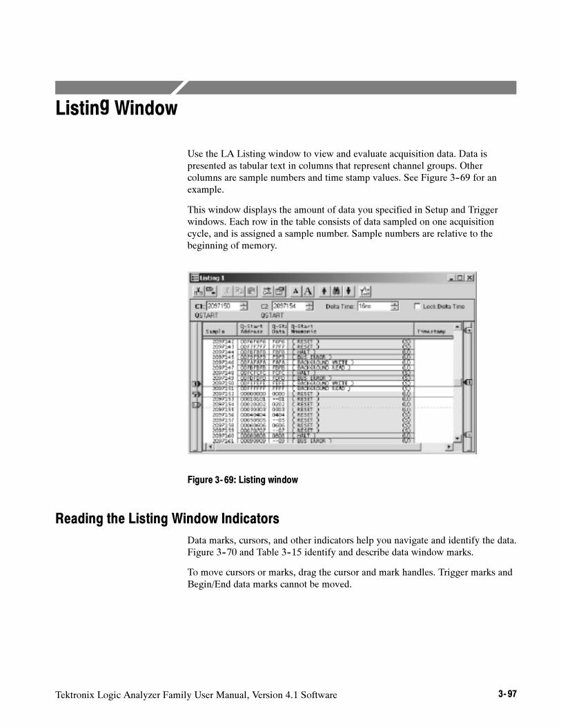
Tektronix Logic Analyzer Family User Manual, Version 4.1 Software 3- 97
Listing Window
Use the LA Listing window to view and evaluate acquisition data. Data ispresented as tabular text in columns that represent channel groups. Othercolumns are sample numbers and time stamp values. See Figure 3--69 for anexample.
This window displays the amount of data you specified in Setup and Triggerwindows. Each row in the table consists of data sampled on one acquisitioncycle, and is assigned a sample number. Sample numbers are relative to thebeginning of memory.
Figure 3- 69: Listing window
Reading the Listing Window Indicators
Data marks, cursors, and other indicators help you navigate and identify the data.Figure 3--70 and Table 3--15 identify and describe data window marks.
To move cursors or marks, drag the cursor and mark handles. Trigger marks andBegin/End data marks cannot be moved.
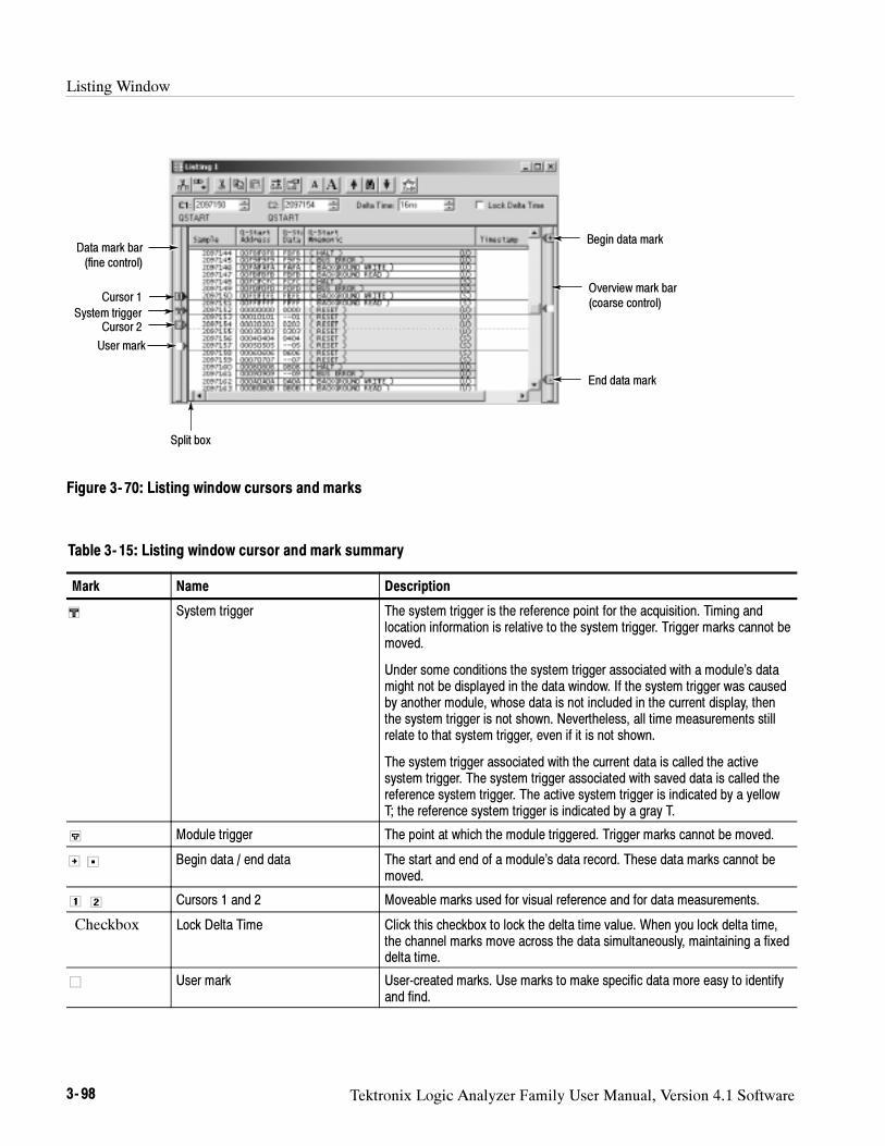
Listing Window
3- 98 Tektronix Logic Analyzer Family User Manual, Version 4.1 Software
Cursor 1
Data mark bar(fine control)
User mark
System trigger
Split box
Overview mark bar(coarse control)
End data mark
Begin data mark
Cursor 2
Figure 3- 70: Listing window cursors and marks
Table 3- 15: Listing window cursor and mark summary
Mark Name Description
System trigger The system trigger is the reference point for the acquisition. Timing andlocation information is relative to the system trigger. Trigger marks cannot bemoved.
Under some conditions the system trigger associated with a module’s datamight not be displayed in the data window. If the system trigger was causedby another module, whose data is not included in the current display, thenthe system trigger is not shown. Nevertheless, all time measurements stillrelate to that system trigger, even if it is not shown.
The system trigger associated with the current data is called the activesystem trigger. The system trigger associated with saved data is called thereference system trigger. The active system trigger is indicated by a yellowT; the reference system trigger is indicated by a gray T.
Module trigger The point at which the module triggered. Trigger marks cannot be moved.
Begin data / end data The start and end of a module’s data record. These data marks cannot bemoved.
Cursors 1 and 2 Moveable marks used for visual reference and for data measurements.
Checkbox Lock Delta Time Click this checkbox to lock the delta time value. When you lock delta time,the channel marks move across the data simultaneously, maintaining a fixeddelta time.
User mark User-created marks. Use marks to make specific data more easy to identifyand find.
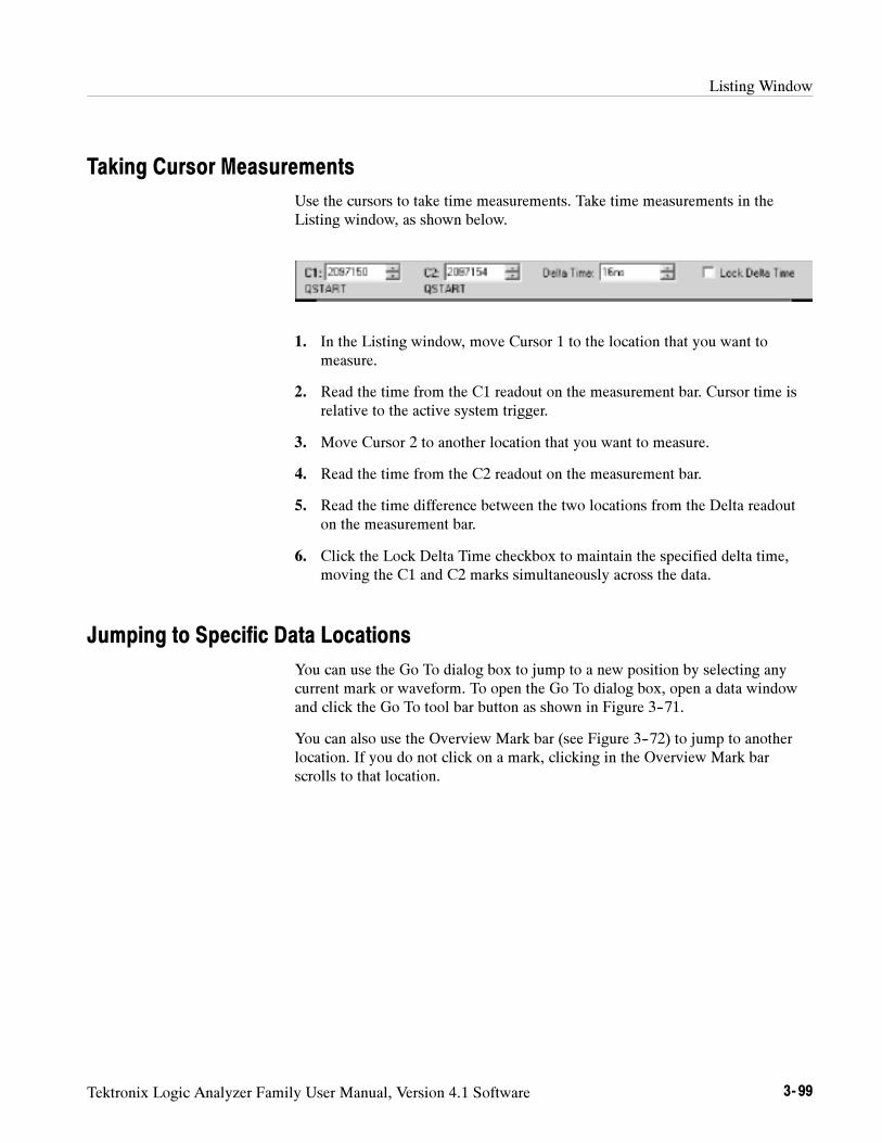
Listing Window
Tektronix Logic Analyzer Family User Manual, Version 4.1 Software 3- 99
Taking Cursor Measurements
Use the cursors to take time measurements. Take time measurements in theListing window, as shown below.
1. In the Listing window, move Cursor 1 to the location that you want tomeasure.
2. Read the time from the C1 readout on the measurement bar. Cursor time isrelative to the active system trigger.
3. Move Cursor 2 to another location that you want to measure.
4. Read the time from the C2 readout on the measurement bar.
5. Read the time difference between the two locations from the Delta readouton the measurement bar.
6. Click the Lock Delta Time checkbox to maintain the specified delta time,moving the C1 and C2 marks simultaneously across the data.
Jumping to Specific Data Locations
You can use the Go To dialog box to jump to a new position by selecting anycurrent mark or waveform. To open the Go To dialog box, open a data windowand click the Go To tool bar button as shown in Figure 3--71.
You can also use the Overview Mark bar (see Figure 3--72) to jump to anotherlocation. If you do not click on a mark, clicking in the Overview Mark barscrolls to that location.
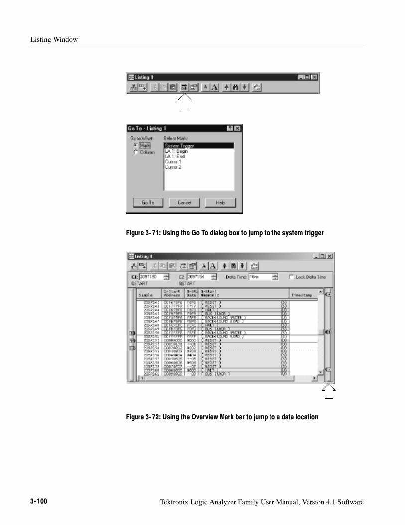
Listing Window
3- 100 Tektronix Logic Analyzer Family User Manual, Version 4.1 Software
Figure 3- 71: Using the Go To dialog box to jump to the system trigger
Figure 3- 72: Using the Overview Mark bar to jump to a data location
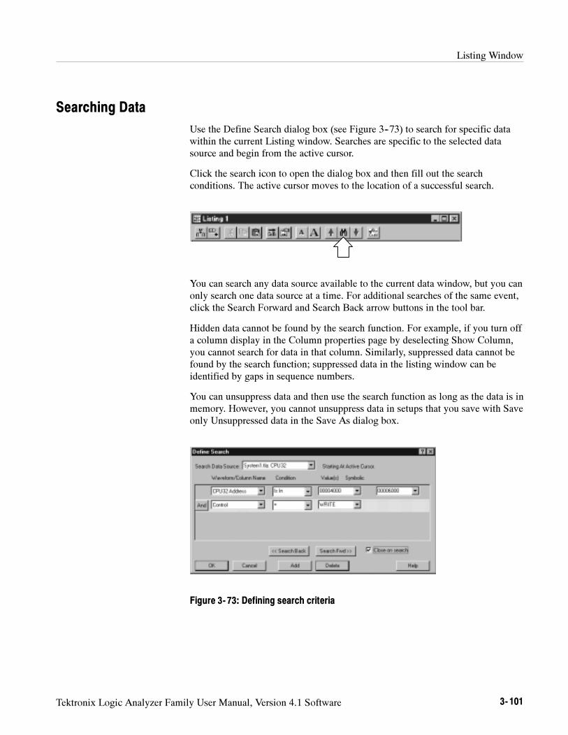
Listing Window
Tektronix Logic Analyzer Family User Manual, Version 4.1 Software 3- 101
Searching Data
Use the Define Search dialog box (see Figure 3--73) to search for specific datawithin the current Listing window. Searches are specific to the selected datasource and begin from the active cursor.
Click the search icon to open the dialog box and then fill out the searchconditions. The active cursor moves to the location of a successful search.
You can search any data source available to the current data window, but you canonly search one data source at a time. For additional searches of the same event,click the Search Forward and Search Back arrow buttons in the tool bar.
Hidden data cannot be found by the search function. For example, if you turn offa column display in the Column properties page by deselecting Show Column,you cannot search for data in that column. Similarly, suppressed data cannot befound by the search function; suppressed data in the listing window can beidentified by gaps in sequence numbers.
You can unsuppress data and then use the search function as long as the data is inmemory. However, you cannot unsuppress data in setups that you save with Saveonly Unsuppressed data in the Save As dialog box.
Figure 3- 73: Defining search criteria
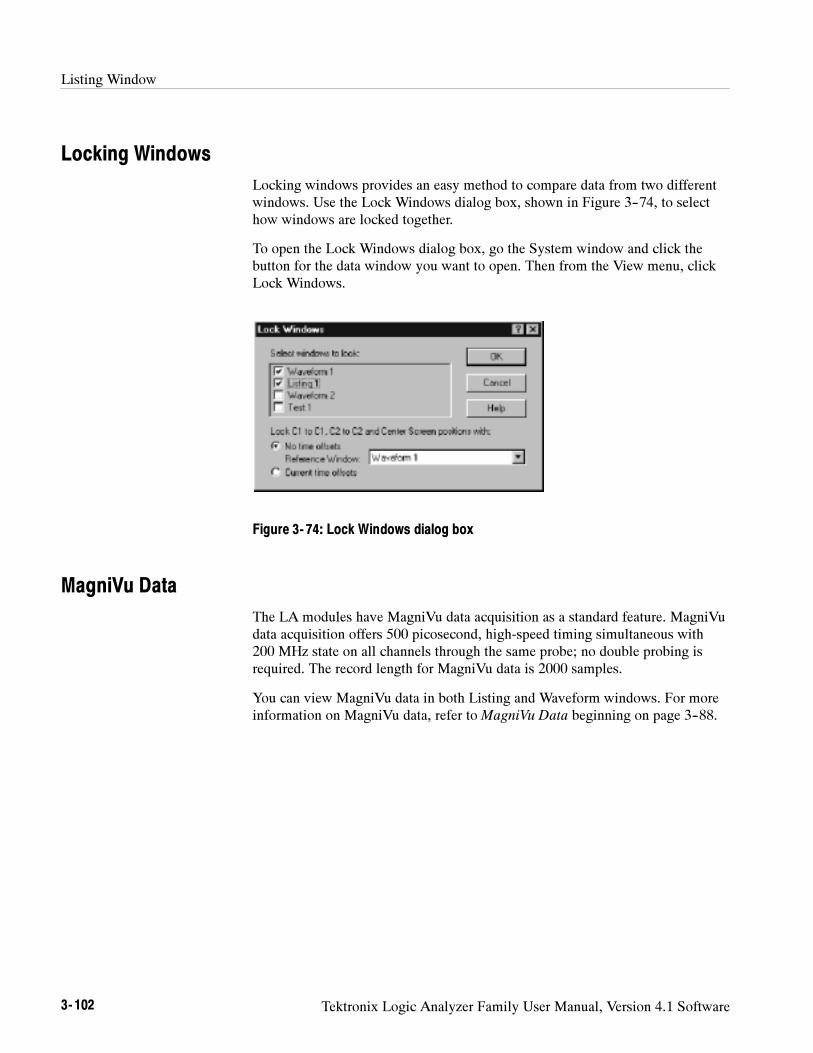
Listing Window
3- 102 Tektronix Logic Analyzer Family User Manual, Version 4.1 Software
Locking Windows
Locking windows provides an easy method to compare data from two differentwindows. Use the Lock Windows dialog box, shown in Figure 3--74, to selecthow windows are locked together.
To open the Lock Windows dialog box, go the System window and click thebutton for the data window you want to open. Then from the View menu, clickLock Windows.
Figure 3- 74: Lock Windows dialog box
MagniVu Data
The LA modules have MagniVu data acquisition as a standard feature. MagniVudata acquisition offers 500 picosecond, high-speed timing simultaneous with200 MHz state on all channels through the same probe; no double probing isrequired. The record length for MagniVu data is 2000 samples.
You can view MagniVu data in both Listing and Waveform windows. For moreinformation on MagniVu data, refer to MagniVu Data beginning on page 3--88.
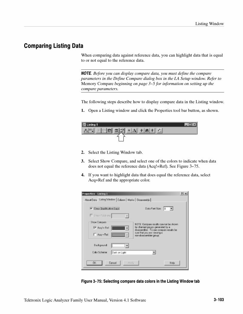
Listing Window
Tektronix Logic Analyzer Family User Manual, Version 4.1 Software 3- 103
Comparing Listing Data
When comparing data against reference data, you can highlight data that is equalto or not equal to the reference data.
NOTE. Before you can display compare data, you must define the compare
parameters in the Define Compare dialog box in the LA Setup window. Refer to
Memory Compare beginning on page 3--5 for information on setting up the
compare parameters.
The following steps describe how to display compare data in the Listing window.
1. Open a Listing window and click the Properties tool bar button, as shown.
2. Select the Listing Window tab.
3. Select Show Compare, and select one of the colors to indicate when datadoes not equal the reference data (Acq!=Ref). See Figure 3--75.
4. If you want to highlight data that does equal the reference data, selectAcq=Ref and the appropriate color.
Figure 3- 75: Selecting compare data colors in the Listing Window tab
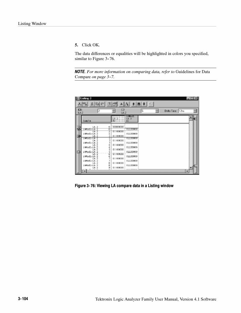
Listing Window
3- 104 Tektronix Logic Analyzer Family User Manual, Version 4.1 Software
5. Click OK.
The data differences or equalities will be highlighted in colors you specified,similar to Figure 3--76.
NOTE. For more information on comparing data, refer to Guidelines for DataCompare on page 3--7.
Figure 3- 76: Viewing LA compare data in a Listing window
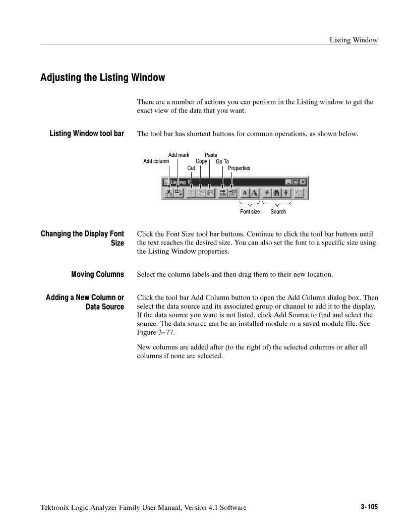
Listing Window
Tektronix Logic Analyzer Family User Manual, Version 4.1 Software 3- 105
Adjusting the Listing Window
There are a number of actions you can perform in the Listing window to get theexact view of the data that you want.
The tool bar has shortcut buttons for common operations, as shown below.
Add columnAdd mark
CutCopy
PasteGo To
Properties
SearchFont size
Click the Font Size tool bar buttons. Continue to click the tool bar buttons untilthe text reaches the desired size. You can also set the font to a specific size usingthe Listing Window properties.
Select the column labels and then drag them to their new location.
Click the tool bar Add Column button to open the Add Column dialog box. Thenselect the data source and its associated group or channel to add it to the display.If the data source you want is not listed, click Add Source to find and select thesource. The data source can be an installed module or a saved module file. SeeFigure 3--77.
New columns are added after (to the right of) the selected columns or after allcolumns if none are selected.
Listing Window tool bar
Changing the Display FontSize
Moving Columns
Adding a New Column orData Source
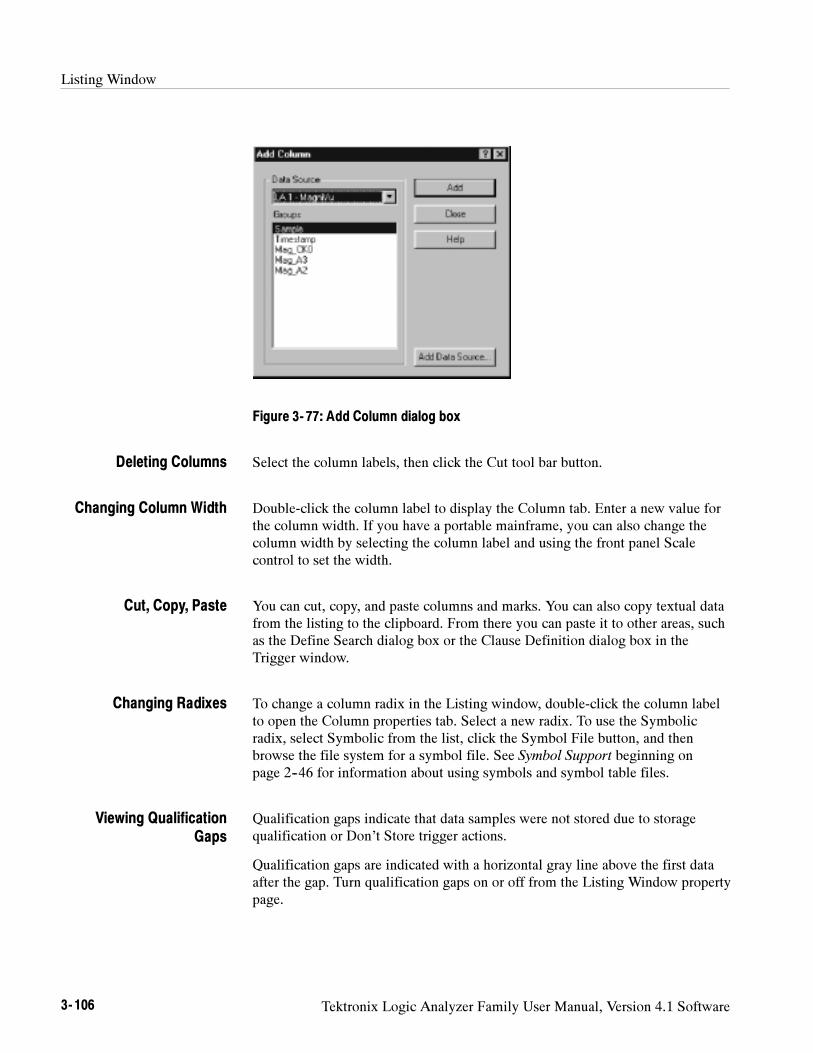
Listing Window
3- 106 Tektronix Logic Analyzer Family User Manual, Version 4.1 Software
Figure 3- 77: Add Column dialog box
Select the column labels, then click the Cut tool bar button.
Double-click the column label to display the Column tab. Enter a new value forthe column width. If you have a portable mainframe, you can also change thecolumn width by selecting the column label and using the front panel Scalecontrol to set the width.
You can cut, copy, and paste columns and marks. You can also copy textual datafrom the listing to the clipboard. From there you can paste it to other areas, suchas the Define Search dialog box or the Clause Definition dialog box in theTrigger window.
To change a column radix in the Listing window, double-click the column labelto open the Column properties tab. Select a new radix. To use the Symbolicradix, select Symbolic from the list, click the Symbol File button, and thenbrowse the file system for a symbol file. See Symbol Support beginning onpage 2--46 for information about using symbols and symbol table files.
Qualification gaps indicate that data samples were not stored due to storagequalification or Don’t Store trigger actions.
Qualification gaps are indicated with a horizontal gray line above the first dataafter the gap. Turn qualification gaps on or off from the Listing Window propertypage.
Deleting Columns
Changing Column Width
Cut, Copy, Paste
Changing Radixes
Viewing QualificationGaps
Listing Window
Tektronix Logic Analyzer Family User Manual, Version 4.1 Software 3- 107
Both glitches and setup and hold violations are shown in the display byhighlighted text of the complete sample for all radixes except binary, octal, andhexadecimal. In those radixes, only the violation bits are highlighted. Turnviolations on or off from the Listing Window properties tab. To view glitches,you must set clocking to Internal and select Glitches in the Acquire box of theSetup window before making an acquisition. To view setup and hold violations,you must set clocking to External and select Setup/Hold in the Acquire box ofthe Setup window before making an acquisition.
NOTE. To view glitches in a data window, you must enable Glitch storage in the
Acquire box of the LA Setup window before acquiring data. To view setup and
hold violations, you must enable Setup/Hold storage in the Acquire box of the LA
Setup window before acquiring data.
Rename a column by returning to the LA Setup window and changing thechannel group name.
For microprocessor support packages, you can change the disassembly formatused in the Listing window. Use the Disassembly properties tab to select thedisplay format of disassembly groups. You must have a support package loadedfor this page to be active.
You can split the data area to compare columns that are far away from each otherwithin the display. Drag the split box from the left end of the horizontal scrollbar.
Customizing the Listing Window Data Area
Use the Listing Properties dialog box to customize data in the Listing window.The related properties tabs control aspects of the listing display such as size,color, and in some cases, enabling or disabling whether an element is shown.Click the Properties tool bar button to display the Listing Window properties.Then select one of the properties tabs to change the data you are interested in.
Viewing Violations
Naming Columns
Changing theDisassembly Format
Splitting the Data Area
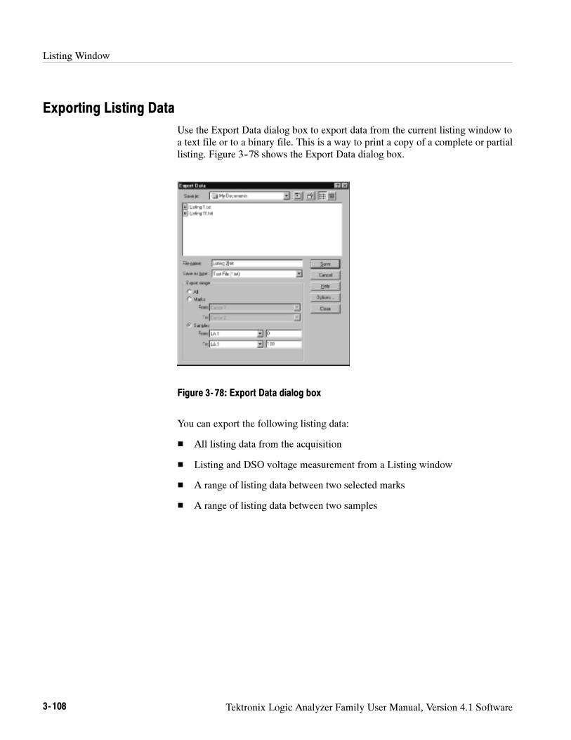
Listing Window
3- 108 Tektronix Logic Analyzer Family User Manual, Version 4.1 Software
Exporting Listing Data
Use the Export Data dialog box to export data from the current listing window toa text file or to a binary file. This is a way to print a copy of a complete or partiallisting. Figure 3--78 shows the Export Data dialog box.
Figure 3- 78: Export Data dialog box
You can export the following listing data:
All listing data from the acquisition
Listing and DSO voltage measurement from a Listing window
A range of listing data between two selected marks
A range of listing data between two samples
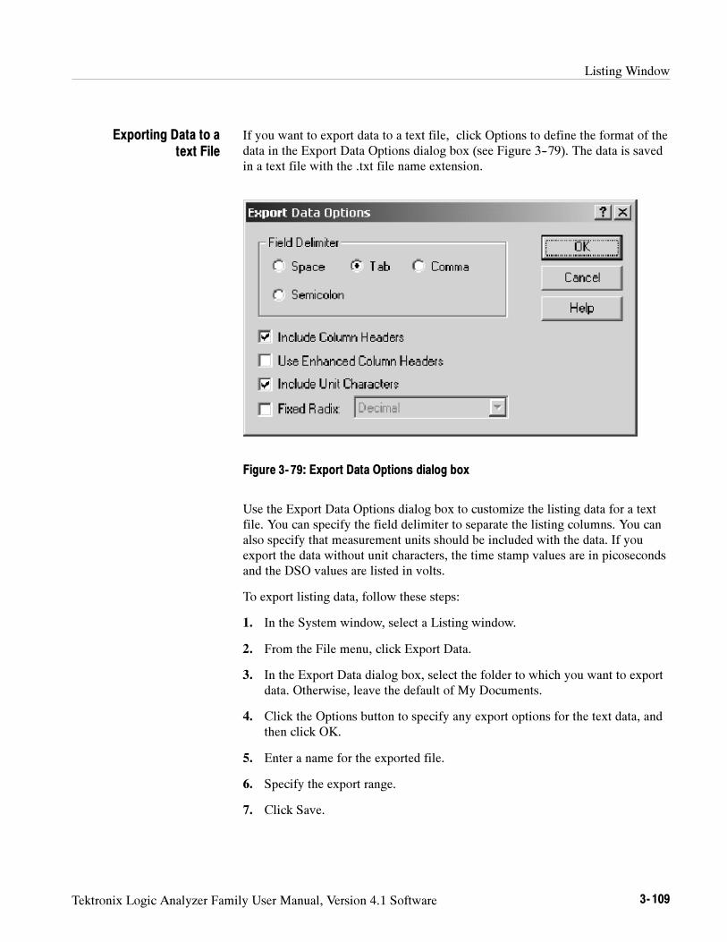
Listing Window
Tektronix Logic Analyzer Family User Manual, Version 4.1 Software 3- 109
If you want to export data to a text file, click Options to define the format of thedata in the Export Data Options dialog box (see Figure 3--79). The data is savedin a text file with the .txt file name extension.
Figure 3- 79: Export Data Options dialog box
Use the Export Data Options dialog box to customize the listing data for a textfile. You can specify the field delimiter to separate the listing columns. You canalso specify that measurement units should be included with the data. If youexport the data without unit characters, the time stamp values are in picosecondsand the DSO values are listed in volts.
To export listing data, follow these steps:
1. In the System window, select a Listing window.
2. From the File menu, click Export Data.
3. In the Export Data dialog box, select the folder to which you want to exportdata. Otherwise, leave the default of My Documents.
4. Click the Options button to specify any export options for the text data, andthen click OK.
5. Enter a name for the exported file.
6. Specify the export range.
7. Click Save.
Exporting Data to atext File
Listing Window
3- 110 Tektronix Logic Analyzer Family User Manual, Version 4.1 Software
You can also export the listing data as a binary file with a .tbf (TLA700 BinaryFormat) file name extension. This option is only available if the data window isfrom a single data source. You can export any data that appears in a Listingwindow, including DSO and MagniVu data. This option is useful when you writeapplications that need to use binary data. It is also faster than exporting an ASCIIfile and the file size is often smaller.
LA Module Binary Export File Format. The LA module binary data is exported as astream of bytes with the following characteristics:
The binary data uses big-endian fields (the most significant bit is theleft-most bit).
Each group column field is zero-padded on the most significant end to thenearest byte.
Sample numbers and mnemonics groups are not exported.
Time stamp data is seven bytes wide and represents the number of picosec-onds since the start of the acquisition.
The left-most column in the Listing window display corresponds to the firstexported field of a sample.
The first sample in the Listing window appears at the beginning of theexported file.
MagniVu data follows the same guidelines as regular listing data.
DSO Module Binary Export File Format. The DSO module binary data (when usedin a Listing window) is exported as a stream of bytes with the followingcharacteristics:
The binary data uses little-endian fields (the most significant bit is theright-most bit).
Each channel field is a 16-bit value.
Sample numbers, mnemonics groups, and time stamp values are notexported.
The left-most column in the Listing window display corresponds to the firstexported field of a sample.
The first sample in the Listing window appears at the beginning of theexported file.
DSO data values are in twos-compliment format.
Exporting Data as aBinary File
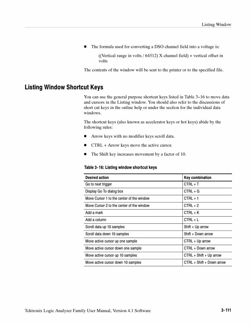
Listing Window
Tektronix Logic Analyzer Family User Manual, Version 4.1 Software 3- 111
The formula used for converting a DSO channel field into a voltage is:
((Vertical range in volts / 64512) X channel field) + vertical offset involts
The contents of the window will be sent to the printer or to the specified file.
Listing Window Shortcut Keys
You can use the general purpose shortcut keys listed in Table 3--16 to move dataand cursors in the Listing window. You should also refer to the discussions ofshort cut keys in the online help or under the section for the individual datawindows.
The shortcut keys (also known as accelerator keys or hot keys) abide by thefollowing rules:
Arrow keys with no modifier keys scroll data.
CTRL + Arrow keys move the active cursor.
The Shift key increases movement by a factor of 10.
Table 3- 16: Listing window shortcut keys
Desired action Key combination
Go to next trigger CTRL + T
Display Go To dialog box CTRL + G
Move Cursor 1 to the center of the window CTRL + 1
Move Cursor 2 to the center of the window CTRL + 2
Add a mark CTRL + K
Add a column CTRL + L
Scroll data up 10 samples Shift + Up arrow
Scroll data down 10 samples Shift + Down arrow
Move active cursor up one sample CTRL + Up arrow
Move active cursor down one sample CTRL + Down arrow
Move active cursor up 10 samples CTRL + Shift + Up arrow
Move active cursor down 10 samples CTRL + Shift + Down arrow
Listing Window
3- 112 Tektronix Logic Analyzer Family User Manual, Version 4.1 Software
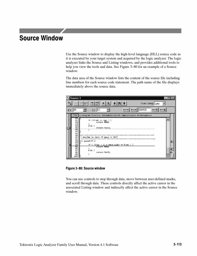
Tektronix Logic Analyzer Family User Manual, Version 4.1 Software 3- 113
Source Window
Use the Source window to display the high-level language (HLL) source code asit is executed by your target system and acquired by the logic analyzer. The logicanalyzer links the Source and Listing windows, and provides additional tools tohelp you view the tools and data. See Figure 3--80 for an example of a Sourcewindow.
The data area of the Source window lists the content of the source file includingline numbers for each source code statement. The path name of the file displaysimmediately above the source data.
Figure 3- 80: Source window
You can use controls to step through data, move between user-defined marks,and scroll through data. These controls directly affect the active cursor in theassociated Listing window and indirectly affect the active cursor in the Sourcewindow.
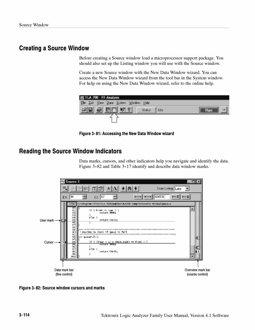
Source Window
3- 114 Tektronix Logic Analyzer Family User Manual, Version 4.1 Software
Creating a Source Window
Before creating a Source window load a microprocessor support package. Youshould also set up the Listing window you will use with the Source window.
Create a new Source window with the New Data Window wizard. You canaccess the New Data Window wizard from the tool bar in the System window.For help on using the New Data Window wizard, refer to the online help.
Figure 3- 81: Accessing the New Data Window wizard
Reading the Source Window Indicators
Data marks, cursors, and other indicators help you navigate and identify the data.Figure 3--82 and Table 3--17 identify and describe data window marks.
Cursor
User mark
Data mark bar(fine control)
Overview mark bar(coarse control)
Figure 3- 82: Source window cursors and marks
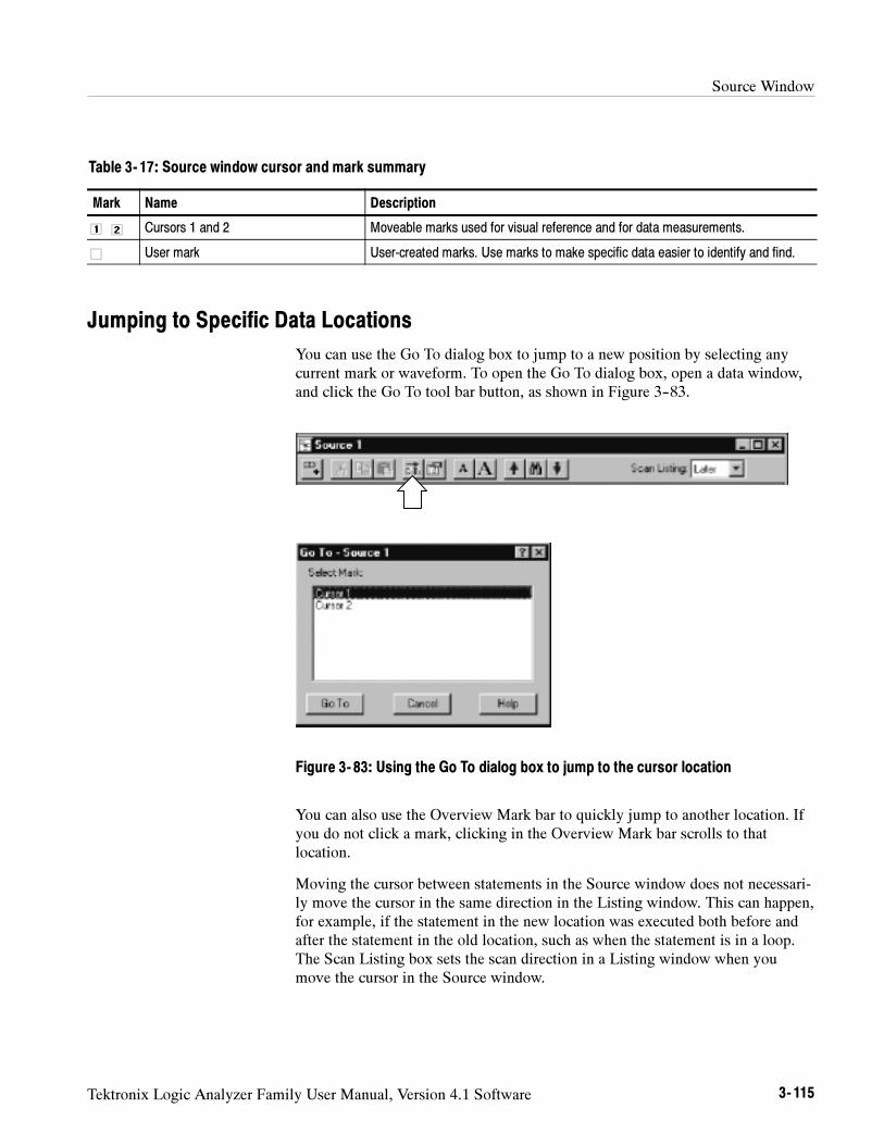
Source Window
Tektronix Logic Analyzer Family User Manual, Version 4.1 Software 3- 115
Table 3- 17: Source window cursor and mark summary
Mark Name Description
Cursors 1 and 2 Moveable marks used for visual reference and for data measurements.
User mark User-created marks. Use marks to make specific data easier to identify and find.
Jumping to Specific Data Locations
You can use the Go To dialog box to jump to a new position by selecting anycurrent mark or waveform. To open the Go To dialog box, open a data window,and click the Go To tool bar button, as shown in Figure 3--83.
Figure 3- 83: Using the Go To dialog box to jump to the cursor location
You can also use the Overview Mark bar to quickly jump to another location. Ifyou do not click a mark, clicking in the Overview Mark bar scrolls to thatlocation.
Moving the cursor between statements in the Source window does not necessari-ly move the cursor in the same direction in the Listing window. This can happen,for example, if the statement in the new location was executed both before andafter the statement in the old location, such as when the statement is in a loop.The Scan Listing box sets the scan direction in a Listing window when youmove the cursor in the Source window.
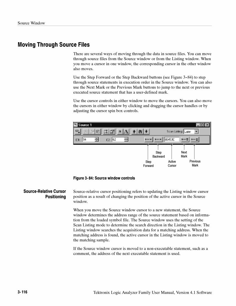
Source Window
3- 116 Tektronix Logic Analyzer Family User Manual, Version 4.1 Software
Moving Through Source Files
There are several ways of moving through the data in source files. You can movethrough source files from the Source window or from the Listing window. Whenyou move a cursor in one window, the corresponding cursor in the other windowalso moves.
Use the Step Forward or the Step Backward buttons (see Figure 3--84) to stepthrough source statements in execution order in the Source window. You can alsouse the Next Mark or the Previous Mark buttons to jump to the next or previousexecuted source statement that has a user-defined mark.
Use the cursor controls in either window to move the cursors. You can also movethe cursors in either window by clicking and dragging the cursor handles or byadjusting the cursor spin box controls.
StepForward
StepBackward
ActiveCursor
NextMark
PreviousMark
Figure 3- 84: Source window controls
Source-relative cursor positioning refers to updating the Listing window cursorposition as a result of changing the position of the active cursor in the Sourcewindow.
When you move the Source window cursor to a new statement, the Sourcewindow determines the address range of the source statement based on informa-tion from the loaded symbol file. The Source window uses the setting of theScan Listing mode to determine the search direction in the Listing window. TheListing window searches the acquisition data for a matching address. When thematching address is found, the active cursor in the Listing window is moved tothe matching sample.
If the Source window cursor is moved to a non-executable statement, such as acomment, the address of the next executable statement is used.
Source-Relative CursorPositioning
Source Window
Tektronix Logic Analyzer Family User Manual, Version 4.1 Software 3- 117
Listing-relative cursor positioning refers to updating the Source window cursorposition as a result of changing the active cursor position in the Listing window.
When you move the Listing window cursor to a new sample, the active Sourcewindow cursor attempts to move to a corresponding source statement in theSource window. The Source window uses information from the loaded symbolfile to convert the address of the Listing cursor position to a source file name andstatement (line number) location. The Source window then updates the activeSource window cursor position and displays the corresponding source statement.
Use the Step Forward and Step Backward buttons to trace the execution order ofsource statements. Click the Step Forward button to move to the next executedsource statement. Click the Step Backward button to move to the previousexecuted source statement.
When you click the Step Forward or Step Backward buttons, the Source windowtells the Listing window to search forward or backward (beginning at the activeListing cursor) for the next or previous executed source statement. When a matchis found, the Listing window positions the active Listing cursor to the matchingsample. The Source window converts the address to a file name and line number,and then updates the active Source cursor position to the corresponding sourcestatement. The statement may be located in a source file that is different than theoriginal displayed file. In this case, the new file is displayed and the cursor isplaced on the proper statement.
A single line in the Source window may consist of more than one statement, forexample:
for ( i=0; i < NUM_STATES; i++)
The next executed statement in the Listing window may appear on the same linein the Source window as the current statement. However, the next executedstatement may also appear on a different line (before or after the currentstatement), or in a different file. Click the Step Forward and Step Backwardbuttons to move the cursor between statements in execution order.
The ability of the Source window to discriminate between multiple statements onthe same line depends on the amount of information provided by the codegeneration tools. If there is enough information to identify multiple statementsper line, the Source window cursors will include character highlighting toidentify individual statements on a line.
Use the Next Mark and Previous Mark buttons to move the active cursor in theSource window to the next or previous executed user-defined mark position (ifany marks have been defined). Next and previous refer to the execution sequenceand not to the position of the mark in the window.
Listing-Relative CursorPositioning
Step Forward and StepBackward Buttons
Next Mark and PreviousMark Buttons
Source Window
3- 118 Tektronix Logic Analyzer Family User Manual, Version 4.1 Software
The Next Mark and Previous Mark buttons operate similar to the Step Forwardand Step Backward buttons. However, rather than stepping through everyexecuted statement, you can define marks in the Source window as breakpointsand then step between marks in execution order to move though the source code.
When you click the Next Mark or Previous Mark buttons, the Source windowtells the Listing window to search for addresses corresponding to the markedsource statements. When a corresponding sample is found, the Listing windowpositions its active cursor to the matching sample. The Source window convertsthe address to a file name and line number. It then updates the active Sourcecursor position and displays the corresponding source statement.
If the code generation tools provide column information for symbol files, youcan mark individual statements of multiple-statement lines in the source code.You can then use the Next Mark and Previous Mark buttons to step between themarks and highlight the individual statements.
The Next Mark and Previous Mark buttons are not active if there are no marksdefined in the Source window.
The active cursor readout displays the address of the source statement at theactive cursor. The address shown is the low address bound. The radix of theaddress is always hexadecimal. If you position the cursor on a non-executablestatement, such as a comment or white space, the address of the next executablestatement is displayed.
Use the active cursor readout to jump to a new location in the source file. Enteran address in this field and the active cursor moves to the correspondingstatement. If you enter an address that does not correspond directly to the addressof a source statement, the next statement will be used and the address is adjusted.
You can copy and paste the readout value into other locations such as in theevent portion of the Clause Definition dialog in the LA Trigger window.
There are situations when you move the cursor in the Listing window to alocation where there is no corresponding source statement. The cursor in theSource window remains at the current location and changes the color of theSource window to signify that an uncorrelated state exists between the Sourceand Listing windows. When this happens, you can click the Step Forward or theStep Backward buttons to search for an executable source line in the Listingwindow; this correlates the active cursors in both windows.
Active Cursor Readout
Uncorrelated State
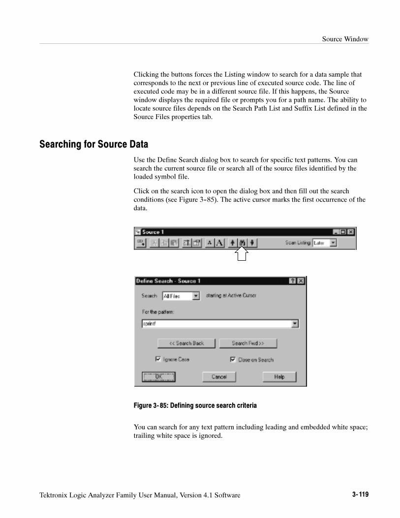
Source Window
Tektronix Logic Analyzer Family User Manual, Version 4.1 Software 3- 119
Clicking the buttons forces the Listing window to search for a data sample thatcorresponds to the next or previous line of executed source code. The line ofexecuted code may be in a different source file. If this happens, the Sourcewindow displays the required file or prompts you for a path name. The ability tolocate source files depends on the Search Path List and Suffix List defined in theSource Files properties tab.
Searching for Source Data
Use the Define Search dialog box to search for specific text patterns. You cansearch the current source file or search all of the source files identified by theloaded symbol file.
Click on the search icon to open the dialog box and then fill out the searchconditions (see Figure 3--85). The active cursor marks the first occurrence of thedata.
Figure 3- 85: Defining source search criteria
You can search for any text pattern including leading and embedded white space;trailing white space is ignored.
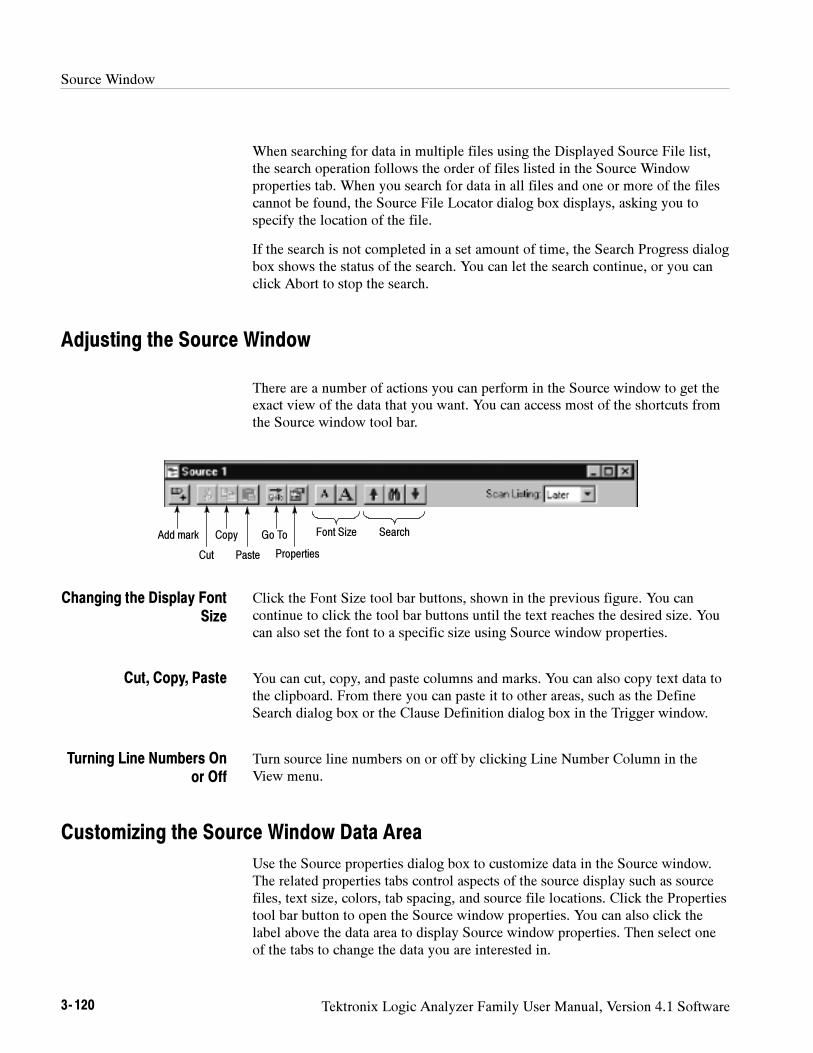
Source Window
3- 120 Tektronix Logic Analyzer Family User Manual, Version 4.1 Software
When searching for data in multiple files using the Displayed Source File list,the search operation follows the order of files listed in the Source Windowproperties tab. When you search for data in all files and one or more of the filescannot be found, the Source File Locator dialog box displays, asking you tospecify the location of the file.
If the search is not completed in a set amount of time, the Search Progress dialogbox shows the status of the search. You can let the search continue, or you canclick Abort to stop the search.
Adjusting the Source Window
There are a number of actions you can perform in the Source window to get theexact view of the data that you want. You can access most of the shortcuts fromthe Source window tool bar.
Font SizeAdd mark Search
Cut
Copy
Paste
Go To
Properties
Click the Font Size tool bar buttons, shown in the previous figure. You cancontinue to click the tool bar buttons until the text reaches the desired size. Youcan also set the font to a specific size using Source window properties.
You can cut, copy, and paste columns and marks. You can also copy text data tothe clipboard. From there you can paste it to other areas, such as the DefineSearch dialog box or the Clause Definition dialog box in the Trigger window.
Turn source line numbers on or off by clicking Line Number Column in theView menu.
Customizing the Source Window Data Area
Use the Source properties dialog box to customize data in the Source window.The related properties tabs control aspects of the source display such as sourcefiles, text size, colors, tab spacing, and source file locations. Click the Propertiestool bar button to open the Source window properties. You can also click thelabel above the data area to display Source window properties. Then select oneof the tabs to change the data you are interested in.
Changing the Display FontSize
Cut, Copy, Paste
Turning Line Numbers Onor Off
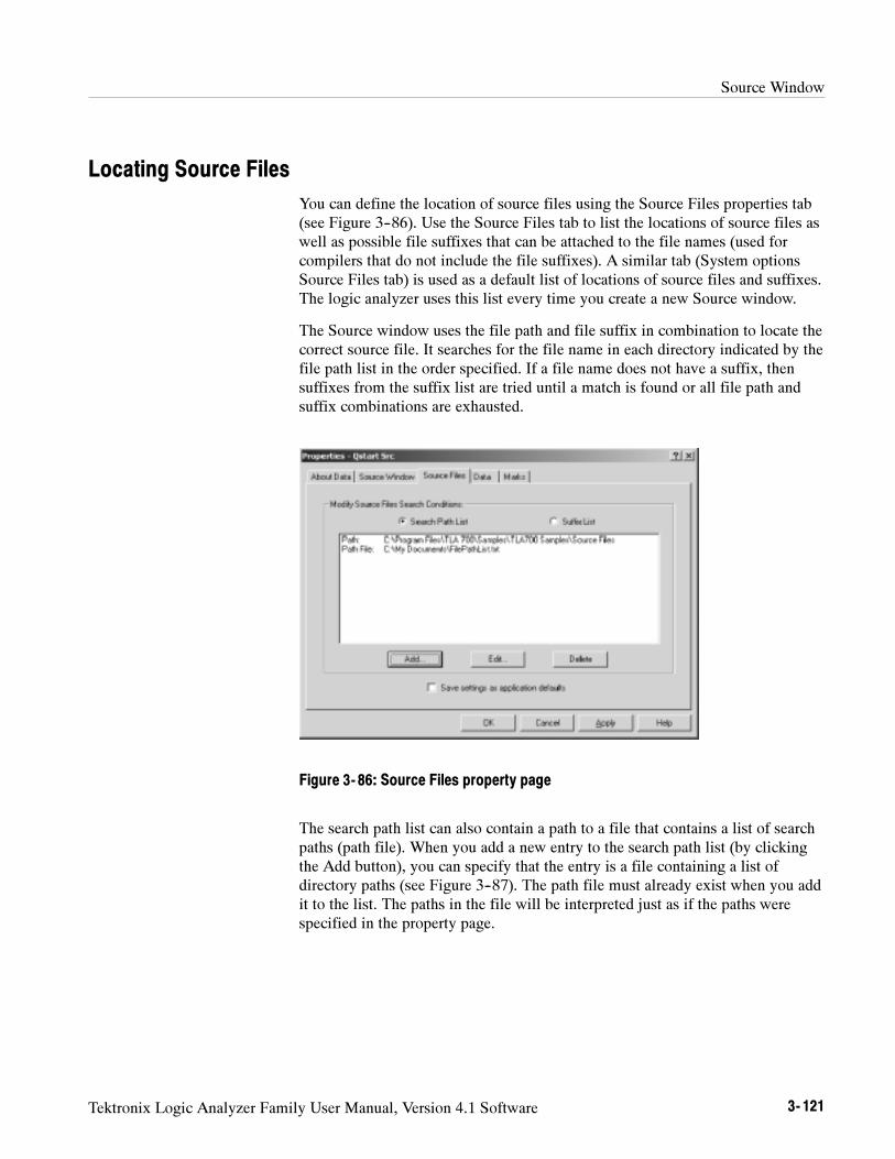
Source Window
Tektronix Logic Analyzer Family User Manual, Version 4.1 Software 3- 121
Locating Source Files
You can define the location of source files using the Source Files properties tab(see Figure 3--86). Use the Source Files tab to list the locations of source files aswell as possible file suffixes that can be attached to the file names (used forcompilers that do not include the file suffixes). A similar tab (System optionsSource Files tab) is used as a default list of locations of source files and suffixes.The logic analyzer uses this list every time you create a new Source window.
The Source window uses the file path and file suffix in combination to locate thecorrect source file. It searches for the file name in each directory indicated by thefile path list in the order specified. If a file name does not have a suffix, thensuffixes from the suffix list are tried until a match is found or all file path andsuffix combinations are exhausted.
Figure 3- 86: Source Files property page
The search path list can also contain a path to a file that contains a list of searchpaths (path file). When you add a new entry to the search path list (by clickingthe Add button), you can specify that the entry is a file containing a list ofdirectory paths (see Figure 3--87). The path file must already exist when you addit to the list. The paths in the file will be interpreted just as if the paths werespecified in the property page.
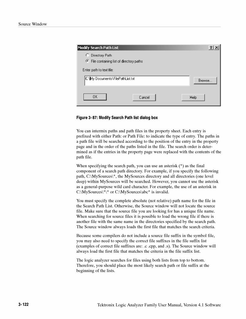
Source Window
3- 122 Tektronix Logic Analyzer Family User Manual, Version 4.1 Software
Figure 3- 87: Modify Search Path list dialog box
You can intermix paths and path files in the property sheet. Each entry isprefixed with either Path: or Path File: to indicate the type of entry. The paths ina path file will be searched according to the position of the entry in the propertypage and in the order of the paths listed in the file. The search order is deter-mined as if the entries in the property page were replaced with the contents of thepath file.
When specifying the search path, you can use an asterisk (*) as the finalcomponent of a search path directory. For example, if you specify the followingpath, C:\MySources\*, the MySources directory and all directories (one leveldeep) within MySources will be searched. However, you cannot use the asteriskas a general-purpose wild card character. For example, the use of an asterisk inC:\MySources\*\* or C:\MySources\abc* is invalid.
You must specify the complete absolute (not relative) path name for the file inthe Search Path List. Otherwise, the Source window will not locate the sourcefile. Make sure that the source file you are looking for has a unique file name.When searching for source files it is possible to load the wrong file if there isanother file with the same name in the directories specified by the search path.The Source window always loads the first file that matches the search criteria.
Because some compilers do not include a source file suffix in the symbol file,you may also need to specify the correct file suffixes in the file suffix list(examples of correct file suffixes are: .c .cpp, and .s). The Source window willalways load the first file that matches the criteria in the file suffix list.
The logic analyzer searches for files using both lists from top to bottom.Therefore, you should place the most likely search path or file suffix at thebeginning of the lists.
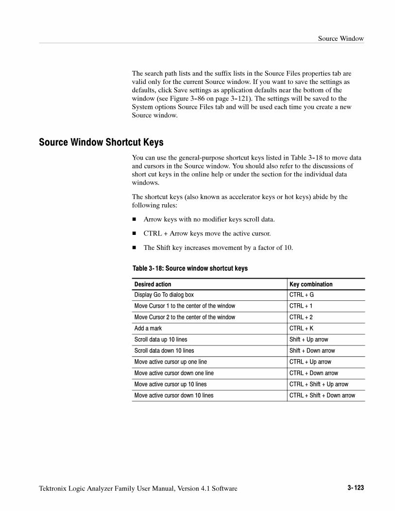
Source Window
Tektronix Logic Analyzer Family User Manual, Version 4.1 Software 3- 123
The search path lists and the suffix lists in the Source Files properties tab arevalid only for the current Source window. If you want to save the settings asdefaults, click Save settings as application defaults near the bottom of thewindow (see Figure 3--86 on page 3--121). The settings will be saved to theSystem options Source Files tab and will be used each time you create a newSource window.
Source Window Shortcut Keys
You can use the general-purpose shortcut keys listed in Table 3--18 to move dataand cursors in the Source window. You should also refer to the discussions ofshort cut keys in the online help or under the section for the individual datawindows.
The shortcut keys (also known as accelerator keys or hot keys) abide by thefollowing rules:
Arrow keys with no modifier keys scroll data.
CTRL + Arrow keys move the active cursor.
The Shift key increases movement by a factor of 10.
Table 3- 18: Source window shortcut keys
Desired action Key combination
Display Go To dialog box CTRL + G
Move Cursor 1 to the center of the window CTRL + 1
Move Cursor 2 to the center of the window CTRL + 2
Add a mark CTRL + K
Scroll data up 10 lines Shift + Up arrow
Scroll data down 10 lines Shift + Down arrow
Move active cursor up one line CTRL + Up arrow
Move active cursor down one line CTRL + Down arrow
Move active cursor up 10 lines CTRL + Shift + Up arrow
Move active cursor down 10 lines CTRL + Shift + Down arrow

Source Window
3- 124 Tektronix Logic Analyzer Family User Manual, Version 4.1 Software
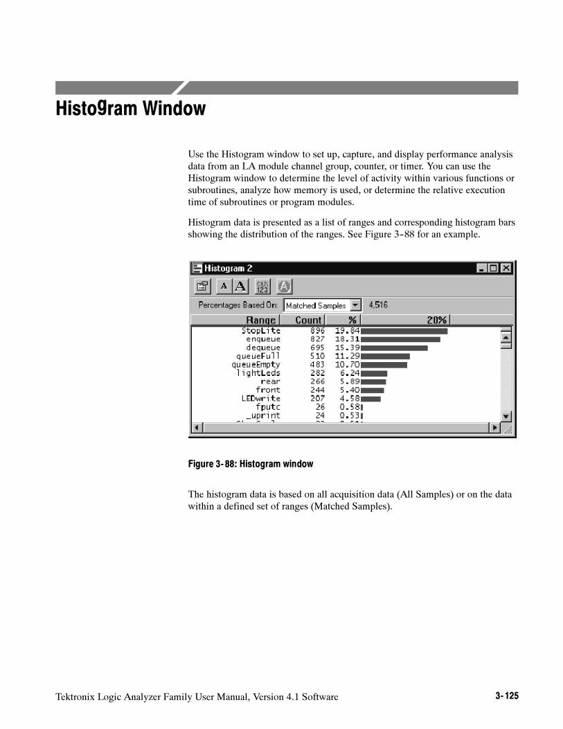
Tektronix Logic Analyzer Family User Manual, Version 4.1 Software 3- 125
Histogram Window
Use the Histogram window to set up, capture, and display performance analysisdata from an LA module channel group, counter, or timer. You can use theHistogram window to determine the level of activity within various functions orsubroutines, analyze how memory is used, or determine the relative executiontime of subroutines or program modules.
Histogram data is presented as a list of ranges and corresponding histogram barsshowing the distribution of the ranges. See Figure 3--88 for an example.
Figure 3- 88: Histogram window
The histogram data is based on all acquisition data (All Samples) or on the datawithin a defined set of ranges (Matched Samples).
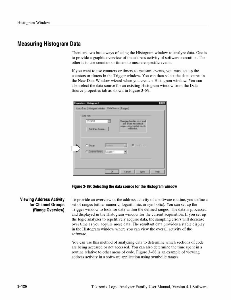
Histogram Window
3- 126 Tektronix Logic Analyzer Family User Manual, Version 4.1 Software
Measuring Histogram Data
There are two basic ways of using the Histogram window to analyze data. One isto provide a graphic overview of the address activity of software execution. Theother is to use counters or timers to measure specific events.
If you want to use counters or timers to measure events, you must set up thecounters or timers in the Trigger window. You can then select the data source inthe New Data Window wizard when you create a Histogram window. You canalso select the data source for an existing Histogram window from the DataSource properties tab as shown in Figure 3--89.
Figure 3- 89: Selecting the data source for the Histogram window
To provide an overview of the address activity of a software routine, you define aset of ranges (either numeric, logarithmic, or symbolic). You can set up theTrigger window to look for data within the defined ranges. The data is processedand displayed in the Histogram window for the current acquisition. If you set upthe logic analyzer to repetitively acquire data, the sampling errors will decreaseover time as you acquire more data. The resultant data provides a stable displayin the Histogram window where you can view the overall activity of thesoftware.
You can use this method of analyzing data to determine which sections of codeare being accessed or not accessed. You can also determine the time spent in aroutine relative to other areas of code. Figure 3--88 is an example of viewingaddress activity in a software application using symbolic ranges.
Viewing Address Activityfor Channel Groups(Range Overview)
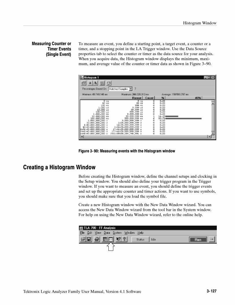
Histogram Window
Tektronix Logic Analyzer Family User Manual, Version 4.1 Software 3- 127
To measure an event, you define a starting point, a target event, a counter or atimer, and a stopping point in the LA Trigger window. Use the Data Sourceproperties tab to select the counter or timer as the data source for your analysis.When you acquire data, the Histogram window displays the minimum, maxi-mum, and average value of the counter or timer data as shown in Figure 3--90.
Figure 3- 90: Measuring events with the Histogram window
Creating a Histogram Window
Before creating the Histogram window, define the channel setups and clocking inthe Setup window. You should also define your trigger program in the Triggerwindow. If you want to measure an event, you should define the trigger eventsand set up the appropriate counter and timer actions. If you want to use symbols,you should make sure that you load the symbol file.
Create a new Histogram window with the New Data Window wizard. You canaccess the New Data Window wizard from the tool bar in the System window.For help on using the New Data Window wizard, refer to the online help.
Measuring Counter orTimer Events(Single Event)
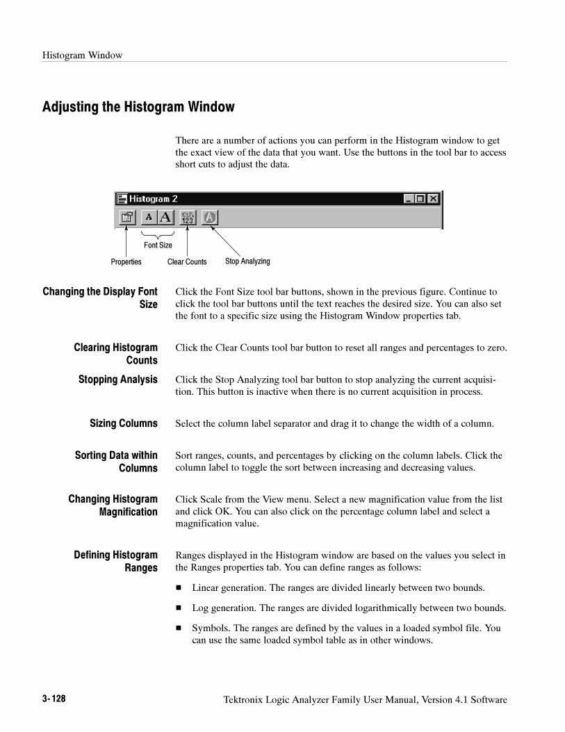
Histogram Window
3- 128 Tektronix Logic Analyzer Family User Manual, Version 4.1 Software
Adjusting the Histogram Window
There are a number of actions you can perform in the Histogram window to getthe exact view of the data that you want. Use the buttons in the tool bar to accessshort cuts to adjust the data.
Stop AnalyzingClear Counts
Font Size
Properties
Click the Font Size tool bar buttons, shown in the previous figure. Continue toclick the tool bar buttons until the text reaches the desired size. You can also setthe font to a specific size using the Histogram Window properties tab.
Click the Clear Counts tool bar button to reset all ranges and percentages to zero.
Click the Stop Analyzing tool bar button to stop analyzing the current acquisi-tion. This button is inactive when there is no current acquisition in process.
Select the column label separator and drag it to change the width of a column.
Sort ranges, counts, and percentages by clicking on the column labels. Click thecolumn label to toggle the sort between increasing and decreasing values.
Click Scale from the View menu. Select a new magnification value from the listand click OK. You can also click on the percentage column label and select amagnification value.
Ranges displayed in the Histogram window are based on the values you select inthe Ranges properties tab. You can define ranges as follows:
Linear generation. The ranges are divided linearly between two bounds.
Log generation. The ranges are divided logarithmically between two bounds.
Symbols. The ranges are defined by the values in a loaded symbol file. Youcan use the same loaded symbol table as in other windows.
Changing the Display FontSize
Clearing HistogramCounts
Stopping Analysis
Sizing Columns
Sorting Data withinColumns
Changing HistogramMagnification
Defining HistogramRanges
Histogram Window
Tektronix Logic Analyzer Family User Manual, Version 4.1 Software 3- 129
You can split the data area to compare ranges that are far away from each otherwithin the display. Drag the split box from the top of the horizontal scroll bar.
Customizing the Histogram Window Data Area
Use properties to customize data in the Histogram window. The HistogramProperties dialog box controls aspects of the Histogram display such as ranges,bounds, font size, color, and data source information. Click the Properties toolbar button to open the Histogram Properties dialog box. Then select the specifictab you are interested in.
Here are some guidelines for using and customizing the Histogram window.
Data is accumulated until you explicitly clear the data.
There is no limit to the number of symbolic ranges for histogram data.
You can analyze live LA data or saved LA data (reference data).
You can use up to 32 bits of data in a address group.
You can enable or disable channel group polarity.
You can change colors for the foreground, background, and histogram barsas needed.
You can change the data font size as necessary to view the data.
Splitting the Data Area
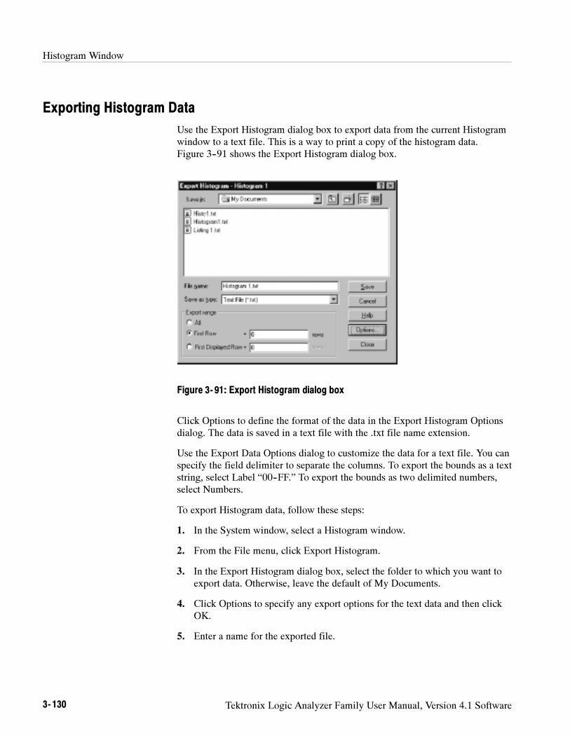
Histogram Window
3- 130 Tektronix Logic Analyzer Family User Manual, Version 4.1 Software
Exporting Histogram Data
Use the Export Histogram dialog box to export data from the current Histogramwindow to a text file. This is a way to print a copy of the histogram data.Figure 3--91 shows the Export Histogram dialog box.
Figure 3- 91: Export Histogram dialog box
Click Options to define the format of the data in the Export Histogram Optionsdialog. The data is saved in a text file with the .txt file name extension.
Use the Export Data Options dialog to customize the data for a text file. You canspecify the field delimiter to separate the columns. To export the bounds as a textstring, select Label “00--FF.” To export the bounds as two delimited numbers,select Numbers.
To export Histogram data, follow these steps:
1. In the System window, select a Histogram window.
2. From the File menu, click Export Histogram.
3. In the Export Histogram dialog box, select the folder to which you want toexport data. Otherwise, leave the default of My Documents.
4. Click Options to specify any export options for the text data and then clickOK.
5. Enter a name for the exported file.
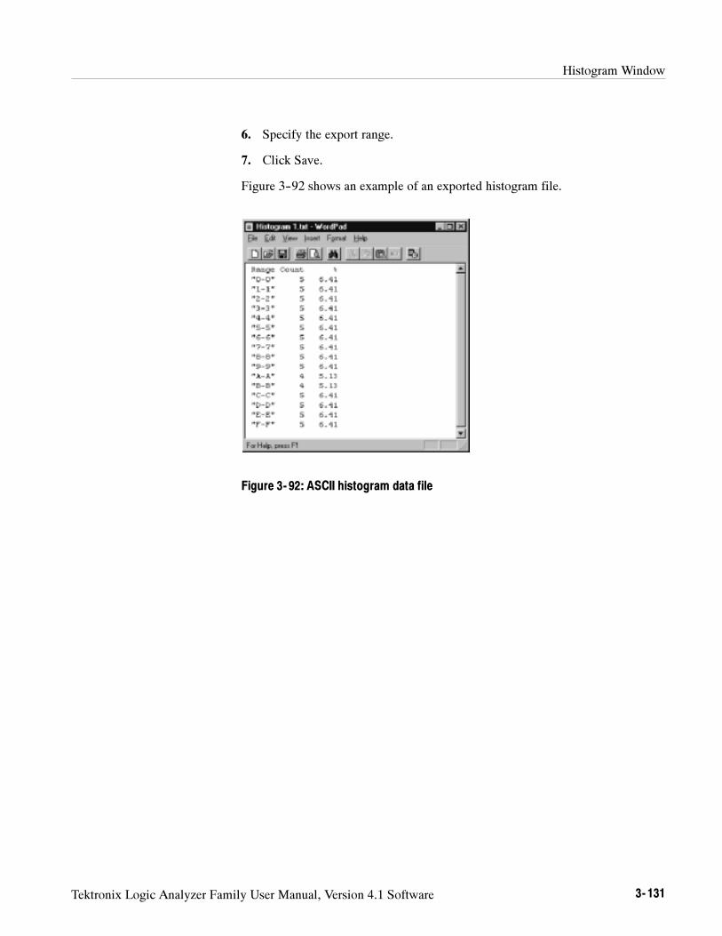
Histogram Window
Tektronix Logic Analyzer Family User Manual, Version 4.1 Software 3- 131
6. Specify the export range.
7. Click Save.
Figure 3--92 shows an example of an exported histogram file.
Figure 3- 92: ASCII histogram data file
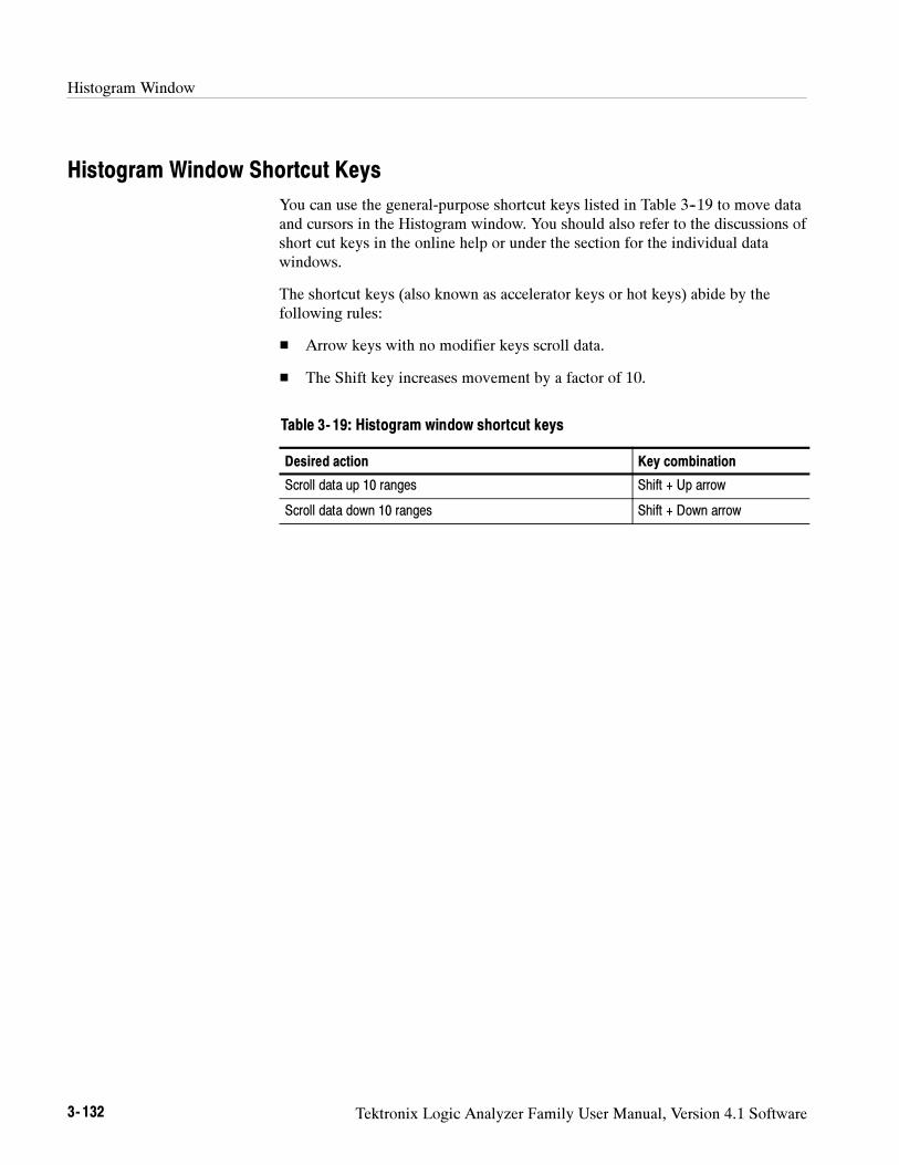
Histogram Window
3- 132 Tektronix Logic Analyzer Family User Manual, Version 4.1 Software
Histogram Window Shortcut Keys
You can use the general-purpose shortcut keys listed in Table 3--19 to move dataand cursors in the Histogram window. You should also refer to the discussions ofshort cut keys in the online help or under the section for the individual datawindows.
The shortcut keys (also known as accelerator keys or hot keys) abide by thefollowing rules:
Arrow keys with no modifier keys scroll data.
The Shift key increases movement by a factor of 10.
Table 3- 19: Histogram window shortcut keys
Desired action Key combination
Scroll data up 10 ranges Shift + Up arrow
Scroll data down 10 ranges Shift + Down arrow

Appendices

Tektronix Logic Analyzer Family User Manual, Version 4.1 Software A- 1
Appendix A: Specifications
This chapter lists the specifications for the Tektronix Logic Analyzer family andthe associated modules.
Characteristic Tables
All specifications are guaranteed unless noted Typical. Typical characteristicsdescribe typical or average performance and provide useful reference informa-tion.
Specifications that are marked with the symbol are checked directly (orindirectly) in the Tektronix Logic Analyzer Family Performance Verification and
Adjustment Technical Reference Manual.
For mainframes and modules, the performance limits in this specification arevalid with these conditions:
The logic analyzer must be in an environment with temperature, altitude,humidity, and vibration within the operating limits described in thesespecifications.
The logic analyzer must have had a warm-up period of at least 30 minutes.
For modules, the performance limits in this specification are valid with theseconditions:
The modules must be installed in a Logic Analyzer Mainframe.
The module must have been calibrated/adjusted at an ambient temperaturebetween +20C and +30C.
The DSO module must have had its signal-path-compensation routine(self calibration or self cal) last executed after at least a 30 minute warm-upperiod.
After the warm-up period, the DSO module must have had its signal-path-compensation routine last executed at an ambient temperature within ±5Cof the current ambient temperature.
For optimum performance using an external oscilloscope, please consult thedocumentation for any external oscilloscopes used with your Tektronix LogicAnalyzer to determine the warm-up period and signal-path compensationrequirements.
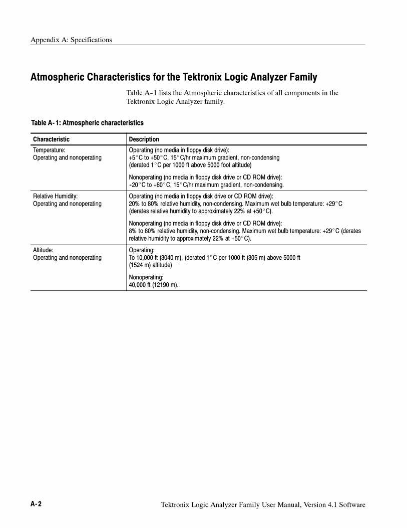
Appendix A: Specifications
A- 2 Tektronix Logic Analyzer Family User Manual, Version 4.1 Software
Atmospheric Characteristics for the Tektronix Logic Analyzer Family
Table A--1 lists the Atmospheric characteristics of all components in theTektronix Logic Analyzer family.
Table A- 1: Atmospheric characteristics
Characteristic Description
Temperature:Operating and nonoperating
Operating (no media in floppy disk drive):+5C to +50C, 15C/hr maximum gradient, non-condensing(derated 1C per 1000 ft above 5000 foot altitude)
Nonoperating (no media in floppy disk drive or CD ROM drive):--20C to +60C, 15C/hr maximum gradient, non-condensing.
Relative Humidity:Operating and nonoperating
Operating (no media in floppy disk drive or CD ROM drive):20% to 80% relative humidity, non-condensing. Maximum wet bulb temperature: +29C(derates relative humidity to approximately 22% at +50C).
Nonoperating (no media in floppy disk drive or CD ROM drive):8% to 80% relative humidity, non-condensing. Maximum wet bulb temperature: +29C (deratesrelative humidity to approximately 22% at +50C).
Altitude:Operating and nonoperating
Operating:To 10,000 ft (3040 m), (derated 1C per 1000 ft (305 m) above 5000 ft(1524 m) altitude)
Nonoperating:40,000 ft (12190 m).
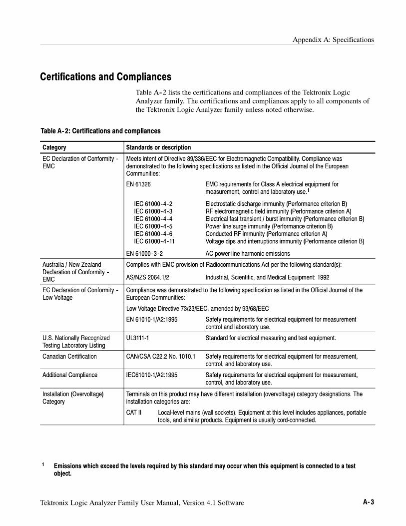
Appendix A: Specifications
Tektronix Logic Analyzer Family User Manual, Version 4.1 Software A- 3
Certifications and Compliances
Table A--2 lists the certifications and compliances of the Tektronix LogicAnalyzer family. The certifications and compliances apply to all components ofthe Tektronix Logic Analyzer family unless noted otherwise.
Table A- 2: Certifications and compliances
Category Standards or description
EC Declaration of Conformity --EMC
Meets intent of Directive 89/336/EEC for Electromagnetic Compatibility. Compliance wasdemonstrated to the following specifications as listed in the Official Journal of the EuropeanCommunities:
EN 61326 EMC requirements for Class A electrical equipment formeasurement, control and laboratory use.1
IEC 61000--4--2 Electrostatic discharge immunity (Performance criterion B)IEC 61000--4--3 RF electromagnetic field immunity (Performance criterion A)IEC 61000--4--4 Electrical fast transient / burst immunity (Performance criterion B)IEC 61000--4--5 Power line surge immunity (Performance criterion B)IEC 61000--4--6 Conducted RF immunity (Performance criterion A)IEC 61000--4--11 Voltage dips and interruptions immunity (Performance criterion B)
EN 61000--3--2 AC power line harmonic emissions
Australia / New ZealandDeclaration of Conformity
Complies with EMC provision of Radiocommunications Act per the following standard(s):Declaration of Conformity --EMC AS/NZS 2064.1/2 Industrial, Scientific, and Medical Equipment: 1992
EC Declaration of Conformity --Low Voltage
Compliance was demonstrated to the following specification as listed in the Official Journal of theEuropean Communities:g
Low Voltage Directive 73/23/EEC, amended by 93/68/EEC
EN 61010-1/A2:1995 Safety requirements for electrical equipment for measurementcontrol and laboratory use.
U.S. Nationally RecognizedTesting Laboratory Listing
UL3111-1 Standard for electrical measuring and test equipment.
Canadian Certification CAN/CSA C22.2 No. 1010.1 Safety requirements for electrical equipment for measurement,control, and laboratory use.
Additional Compliance IEC61010-1/A2:1995 Safety requirements for electrical equipment for measurement,Additional Compliance IEC61010 1/A2:1995 Safety requirements for electrical equipment for measurement,control, and laboratory use.
Installation (Overvoltage)Category
Terminals on this product may have different installation (overvoltage) category designations. Theinstallation categories are:
CAT II Local-level mains (wall sockets). Equipment at this level includes appliances, portabletools, and similar products. Equipment is usually cord-connected.
1 Emissions which exceed the levels required by this standard may occur when this equipment is connected to a testobject.
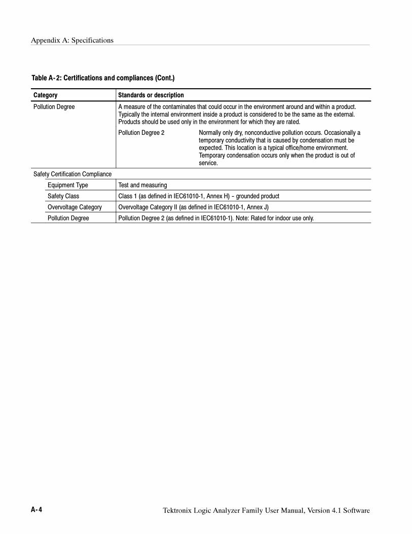
Appendix A: Specifications
A- 4 Tektronix Logic Analyzer Family User Manual, Version 4.1 Software
Table A- 2: Certifications and compliances (Cont.)
Category Standards or description
Pollution Degree A measure of the contaminates that could occur in the environment around and within a product.Typically the internal environment inside a product is considered to be the same as the external.Products should be used only in the environment for which they are rated.
Pollution Degree 2 Normally only dry, nonconductive pollution occurs. Occasionally atemporary conductivity that is caused by condensation must beexpected. This location is a typical office/home environment.Temporary condensation occurs only when the product is out ofservice.
Safety Certification Compliance
Equipment Type Test and measuring
Safety Class Class 1 (as defined in IEC61010-1, Annex H) -- grounded product
Overvoltage Category Overvoltage Category II (as defined in IEC61010-1, Annex J)
Pollution Degree Pollution Degree 2 (as defined in IEC61010-1). Note: Rated for indoor use only.
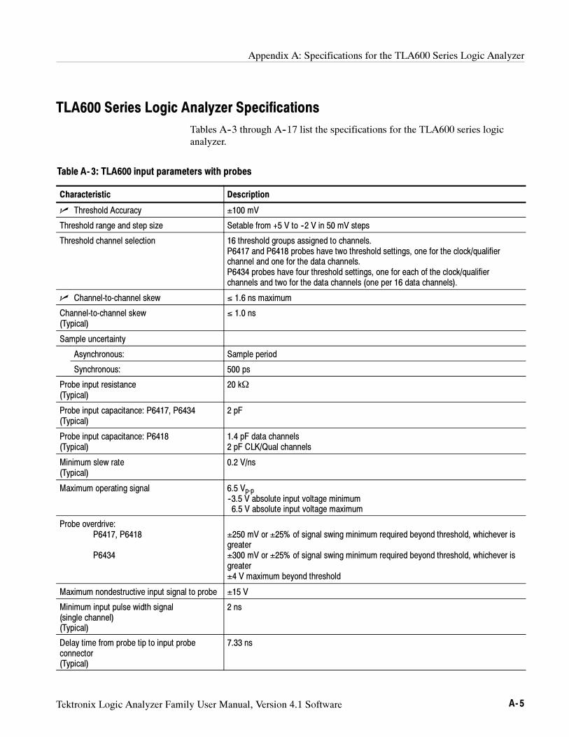
Appendix A: Specifications for the TLA600 Series Logic Analyzer
Tektronix Logic Analyzer Family User Manual, Version 4.1 Software A- 5
TLA600 Series Logic Analyzer Specifications
Tables A--3 through A--17 list the specifications for the TLA600 series logicanalyzer.
Table A- 3: TLA600 input parameters with probes
Characteristic Description
Threshold Accuracy ±100 mV
Threshold range and step size Setable from +5 V to --2 V in 50 mV steps
Threshold channel selection 16 threshold groups assigned to channels.P6417 and P6418 probes have two threshold settings, one for the clock/qualifierchannel and one for the data channels.P6434 probes have four threshold settings, one for each of the clock/qualifierchannels and two for the data channels (one per 16 data channels).
Channel-to-channel skew ≤ 1.6 ns maximum
Channel-to-channel skew(Typical)
≤ 1.0 ns
Sample uncertainty
Asynchronous: Sample period
Synchronous: 500 ps
Probe input resistance(Typical)
20 kΩ
Probe input capacitance: P6417, P6434(Typical)
2 pF
Probe input capacitance: P6418(Typical)
1.4 pF data channels2 pF CLK/Qual channels
Minimum slew rate(Typical)
0.2 V/ns
Maximum operating signal 6.5 Vp-p--3.5 V absolute input voltage minimum6.5 V absolute input voltage maximum
Probe overdrive:P6417, P6418
P6434
±250 mV or ±25% of signal swing minimum required beyond threshold, whichever isgreater±300 mV or ±25% of signal swing minimum required beyond threshold, whichever isgreater±4 V maximum beyond threshold
Maximum nondestructive input signal to probe ±15 V
Minimum input pulse width signal(single channel)(Typical)
2 ns
Delay time from probe tip to input probeconnector(Typical)
7.33 ns
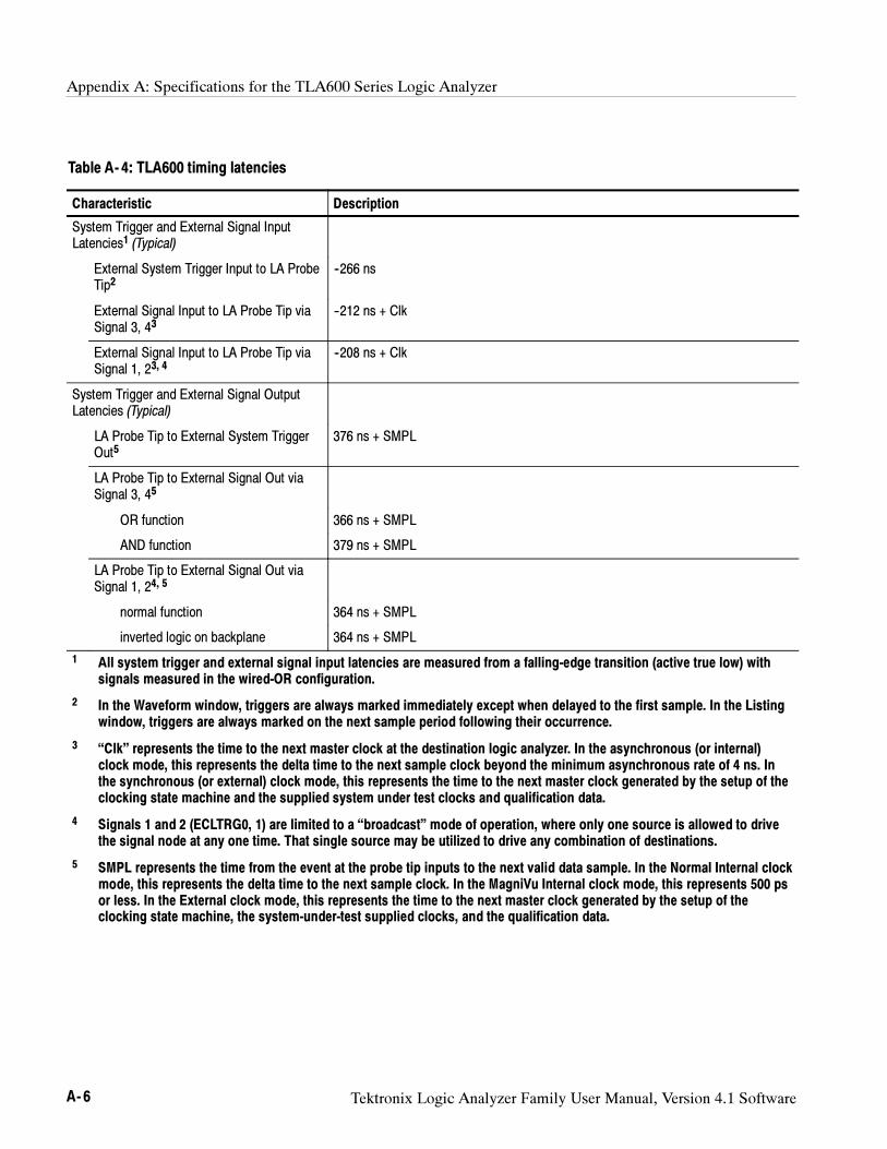
Appendix A: Specifications for the TLA600 Series Logic Analyzer
A- 6 Tektronix Logic Analyzer Family User Manual, Version 4.1 Software
Table A- 4: TLA600 timing latencies
Characteristic Description
System Trigger and External Signal InputLatencies1 (Typical)
External System Trigger Input to LA ProbeTip2
--266 ns
External Signal Input to LA Probe Tip viaSignal 3, 43
--212 ns + Clk
External Signal Input to LA Probe Tip viaSignal 1, 23, 4
--208 ns + Clk
System Trigger and External Signal OutputLatencies (Typical)
LA Probe Tip to External System TriggerOut5
376 ns + SMPL
LA Probe Tip to External Signal Out viaSignal 3, 45
OR function 366 ns + SMPL
AND function 379 ns + SMPL
LA Probe Tip to External Signal Out viaSignal 1, 24, 5
normal function 364 ns + SMPL
inverted logic on backplane 364 ns + SMPL
1 All system trigger and external signal input latencies are measured from a falling-edge transition (active true low) withsignals measured in the wired-OR configuration.
2 In the Waveform window, triggers are always marked immediately except when delayed to the first sample. In the Listingwindow, triggers are always marked on the next sample period following their occurrence.
3 “Clk” represents the time to the next master clock at the destination logic analyzer. In the asynchronous (or internal)clock mode, this represents the delta time to the next sample clock beyond the minimum asynchronous rate of 4 ns. Inthe synchronous (or external) clock mode, this represents the time to the next master clock generated by the setup of theclocking state machine and the supplied system under test clocks and qualification data.
4 Signals 1 and 2 (ECLTRG0, 1) are limited to a “broadcast” mode of operation, where only one source is allowed to drivethe signal node at any one time. That single source may be utilized to drive any combination of destinations.
5 SMPL represents the time from the event at the probe tip inputs to the next valid data sample. In the Normal Internal clockmode, this represents the delta time to the next sample clock. In the MagniVu Internal clock mode, this represents 500 psor less. In the External clock mode, this represents the time to the next master clock generated by the setup of theclocking state machine, the system-under-test supplied clocks, and the qualification data.
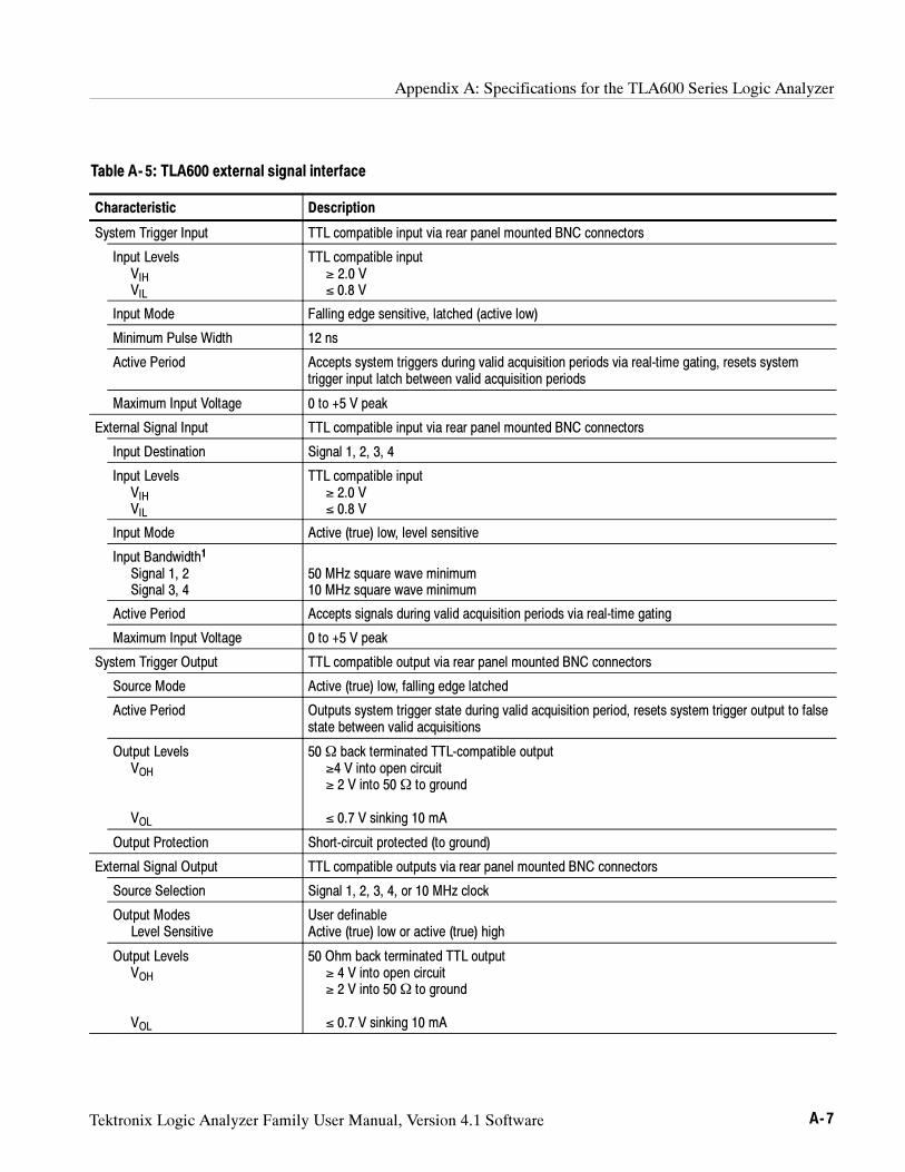
Appendix A: Specifications for the TLA600 Series Logic Analyzer
Tektronix Logic Analyzer Family User Manual, Version 4.1 Software A- 7
Table A- 5: TLA600 external signal interface
Characteristic Description
System Trigger Input TTL compatible input via rear panel mounted BNC connectors
Input LevelsVIHVIL
TTL compatible input≥ 2.0 V≤ 0.8 V
Input Mode Falling edge sensitive, latched (active low)
Minimum Pulse Width 12 ns
Active Period Accepts system triggers during valid acquisition periods via real-time gating, resets systemtrigger input latch between valid acquisition periods
Maximum Input Voltage 0 to +5 V peak
External Signal Input TTL compatible input via rear panel mounted BNC connectors
Input Destination Signal 1, 2, 3, 4
Input LevelsVIHVIL
TTL compatible input≥ 2.0 V≤ 0.8 V
Input Mode Active (true) low, level sensitive
Input Bandwidth1
Signal 1, 2Signal 3, 4
50 MHz square wave minimum10 MHz square wave minimum
Active Period Accepts signals during valid acquisition periods via real-time gating
Maximum Input Voltage 0 to +5 V peak
System Trigger Output TTL compatible output via rear panel mounted BNC connectors
Source Mode Active (true) low, falling edge latched
Active Period Outputs system trigger state during valid acquisition period, resets system trigger output to falsestate between valid acquisitions
Output LevelsVOH
VOL
50Ω back terminated TTL-compatible output≥4 V into open circuit≥ 2 V into 50Ω to ground
≤ 0.7 V sinking 10 mA
Output Protection Short-circuit protected (to ground)
External Signal Output TTL compatible outputs via rear panel mounted BNC connectors
Source Selection Signal 1, 2, 3, 4, or 10 MHz clock
Output ModesLevel Sensitive
User definableActive (true) low or active (true) high
Output LevelsVOH
VOL
50 Ohm back terminated TTL output≥ 4 V into open circuit≥ 2 V into 50Ω to ground
≤ 0.7 V sinking 10 mA
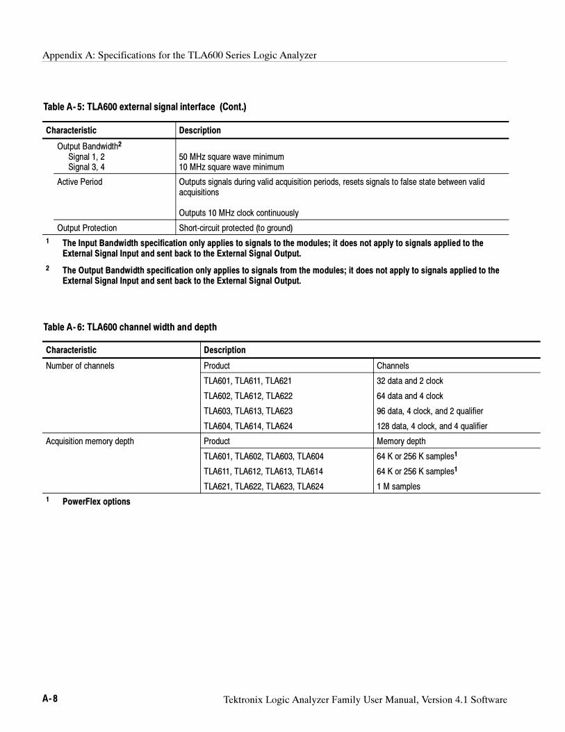
Appendix A: Specifications for the TLA600 Series Logic Analyzer
A- 8 Tektronix Logic Analyzer Family User Manual, Version 4.1 Software
Table A- 5: TLA600 external signal interface (Cont.)
Characteristic Description
Output Bandwidth2
Signal 1, 2Signal 3, 4
50 MHz square wave minimum10 MHz square wave minimum
Active Period Outputs signals during valid acquisition periods, resets signals to false state between validacquisitions
Outputs 10 MHz clock continuously
Output Protection Short-circuit protected (to ground)
1 The Input Bandwidth specification only applies to signals to the modules; it does not apply to signals applied to theExternal Signal Input and sent back to the External Signal Output.
2 The Output Bandwidth specification only applies to signals from the modules; it does not apply to signals applied to theExternal Signal Input and sent back to the External Signal Output.
Table A- 6: TLA600 channel width and depth
Characteristic Description
Number of channels Product Channels
TLA601, TLA611, TLA621 32 data and 2 clock
TLA602, TLA612, TLA622 64 data and 4 clock
TLA603, TLA613, TLA623 96 data, 4 clock, and 2 qualifier
TLA604, TLA614, TLA624 128 data, 4 clock, and 4 qualifier
Acquisition memory depth Product Memory depth
TLA601, TLA602, TLA603, TLA604 64 K or 256 K samples1
TLA611, TLA612, TLA613, TLA614 64 K or 256 K samples1
TLA621, TLA622, TLA623, TLA624 1 M samples
1 PowerFlex options
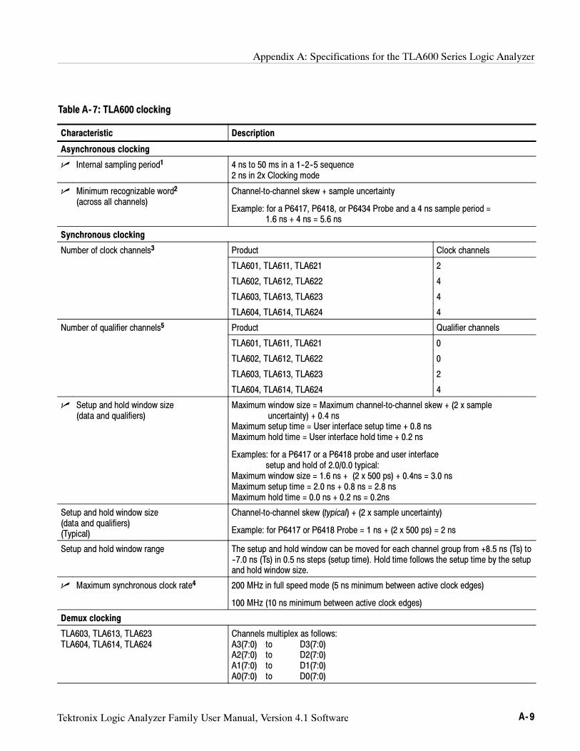
Appendix A: Specifications for the TLA600 Series Logic Analyzer
Tektronix Logic Analyzer Family User Manual, Version 4.1 Software A- 9
Table A- 7: TLA600 clocking
Characteristic Description
Asynchronous clocking
Internal sampling period1 4 ns to 50 ms in a 1--2--5 sequence2 ns in 2x Clocking mode
Minimum recognizable word2
(across all channels)Channel-to-channel skew + sample uncertainty
Example: for a P6417, P6418, or P6434 Probe and a 4 ns sample period =1.6 ns + 4 ns = 5.6 ns
Synchronous clocking
Number of clock channels3 Product Clock channels
TLA601, TLA611, TLA621 2
TLA602, TLA612, TLA622 4
TLA603, TLA613, TLA623 4
TLA604, TLA614, TLA624 4
Number of qualifier channels5 Product Qualifier channels
TLA601, TLA611, TLA621 0
TLA602, TLA612, TLA622 0
TLA603, TLA613, TLA623 2
TLA604, TLA614, TLA624 4
Setup and hold window size(data and qualifiers)
Maximum window size = Maximum channel-to-channel skew + (2 x sampleuncertainty) + 0.4 ns
Maximum setup time = User interface setup time + 0.8 nsMaximum hold time = User interface hold time + 0.2 ns
Examples: for a P6417 or a P6418 probe and user interfacesetup and hold of 2.0/0.0 typical:
Maximum window size = 1.6 ns + (2 x 500 ps) + 0.4ns = 3.0 nsMaximum setup time = 2.0 ns + 0.8 ns = 2.8 nsMaximum hold time = 0.0 ns + 0.2 ns = 0.2ns
Setup and hold window size(data and qualifiers)(Typical)
Channel-to-channel skew (typical) + (2 x sample uncertainty)
Example: for P6417 or P6418 Probe = 1 ns + (2 x 500 ps) = 2 ns
Setup and hold window range The setup and hold window can be moved for each channel group from +8.5 ns (Ts) to--7.0 ns (Ts) in 0.5 ns steps (setup time). Hold time follows the setup time by the setupand hold window size.
Maximum synchronous clock rate4 200 MHz in full speed mode (5 ns minimum between active clock edges)
100 MHz (10 ns minimum between active clock edges)
Demux clocking
TLA603, TLA613, TLA623TLA604, TLA614, TLA624
Channels multiplex as follows:A3(7:0) to D3(7:0)A2(7:0) to D2(7:0)A1(7:0) to D1(7:0)A0(7:0) to D0(7:0)
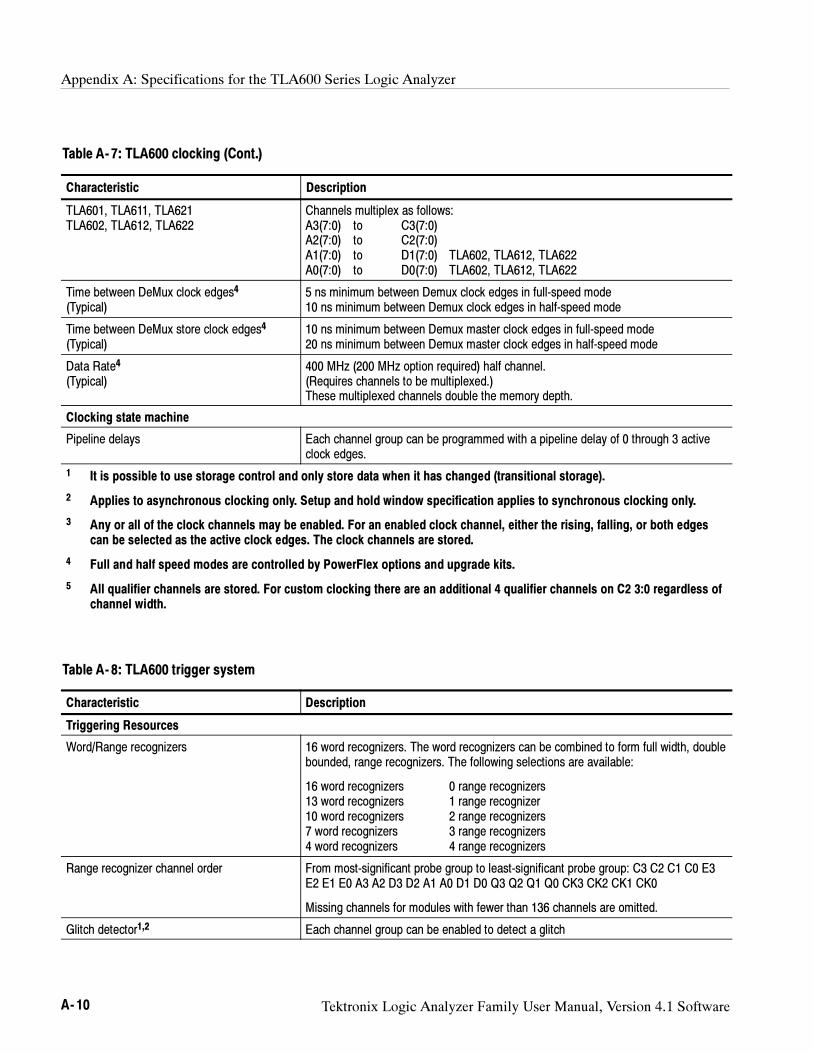
Appendix A: Specifications for the TLA600 Series Logic Analyzer
A- 10 Tektronix Logic Analyzer Family User Manual, Version 4.1 Software
Table A- 7: TLA600 clocking (Cont.)
Characteristic Description
TLA601, TLA611, TLA621TLA602, TLA612, TLA622
Channels multiplex as follows:A3(7:0) to C3(7:0)A2(7:0) to C2(7:0)A1(7:0) to D1(7:0) TLA602, TLA612, TLA622A0(7:0) to D0(7:0) TLA602, TLA612, TLA622
Time between DeMux clock edges4
(Typical)5 ns minimum between Demux clock edges in full-speed mode10 ns minimum between Demux clock edges in half-speed mode
Time between DeMux store clock edges4
(Typical)10 ns minimum between Demux master clock edges in full-speed mode20 ns minimum between Demux master clock edges in half-speed mode
Data Rate4
(Typical)400 MHz (200 MHz option required) half channel.(Requires channels to be multiplexed.)These multiplexed channels double the memory depth.
Clocking state machine
Pipeline delays Each channel group can be programmed with a pipeline delay of 0 through 3 activeclock edges.
1 It is possible to use storage control and only store data when it has changed (transitional storage).
2 Applies to asynchronous clocking only. Setup and hold window specification applies to synchronous clocking only.
3 Any or all of the clock channels may be enabled. For an enabled clock channel, either the rising, falling, or both edgescan be selected as the active clock edges. The clock channels are stored.
4 Full and half speed modes are controlled by PowerFlex options and upgrade kits.
5 All qualifier channels are stored. For custom clocking there are an additional 4 qualifier channels on C2 3:0 regardless ofchannel width.
Table A- 8: TLA600 trigger system
Characteristic Description
Triggering Resources
Word/Range recognizers 16 word recognizers. The word recognizers can be combined to form full width, doublebounded, range recognizers. The following selections are available:
16 word recognizers 0 range recognizers13 word recognizers 1 range recognizer10 word recognizers 2 range recognizers7 word recognizers 3 range recognizers4 word recognizers 4 range recognizers
Range recognizer channel order From most-significant probe group to least-significant probe group: C3 C2 C1 C0 E3E2 E1 E0 A3 A2 D3 D2 A1 A0 D1 D0 Q3 Q2 Q1 Q0 CK3 CK2 CK1 CK0
Missing channels for modules with fewer than 136 channels are omitted.
Glitch detector1,2 Each channel group can be enabled to detect a glitch
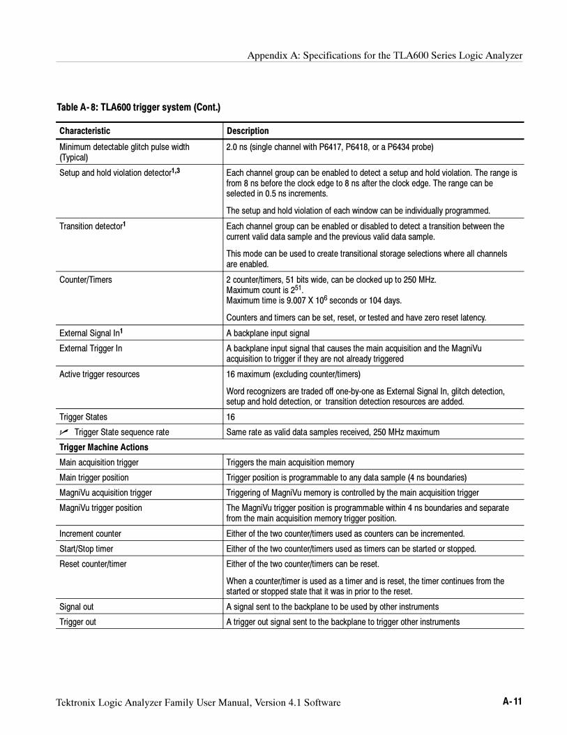
Appendix A: Specifications for the TLA600 Series Logic Analyzer
Tektronix Logic Analyzer Family User Manual, Version 4.1 Software A- 11
Table A- 8: TLA600 trigger system (Cont.)
Characteristic Description
Minimum detectable glitch pulse width(Typical)
2.0 ns (single channel with P6417, P6418, or a P6434 probe)
Setup and hold violation detector1,3 Each channel group can be enabled to detect a setup and hold violation. The range isfrom 8 ns before the clock edge to 8 ns after the clock edge. The range can beselected in 0.5 ns increments.
The setup and hold violation of each window can be individually programmed.
Transition detector1 Each channel group can be enabled or disabled to detect a transition between thecurrent valid data sample and the previous valid data sample.
This mode can be used to create transitional storage selections where all channelsare enabled.
Counter/Timers 2 counter/timers, 51 bits wide, can be clocked up to 250 MHz.Maximum count is 251.Maximum time is 9.007 X 10⁶ seconds or 104 days.
Counters and timers can be set, reset, or tested and have zero reset latency.
External Signal In1 A backplane input signal
External Trigger In A backplane input signal that causes the main acquisition and the MagniVuacquisition to trigger if they are not already triggered
Active trigger resources 16 maximum (excluding counter/timers)
Word recognizers are traded off one-by-one as External Signal In, glitch detection,setup and hold detection, or transition detection resources are added.
Trigger States 16
Trigger State sequence rate Same rate as valid data samples received, 250 MHz maximum
Trigger Machine Actions
Main acquisition trigger Triggers the main acquisition memory
Main trigger position Trigger position is programmable to any data sample (4 ns boundaries)
MagniVu acquisition trigger Triggering of MagniVu memory is controlled by the main acquisition trigger
MagniVu trigger position The MagniVu trigger position is programmable within 4 ns boundaries and separatefrom the main acquisition memory trigger position.
Increment counter Either of the two counter/timers used as counters can be incremented.
Start/Stop timer Either of the two counter/timers used as timers can be started or stopped.
Reset counter/timer Either of the two counter/timers can be reset.
When a counter/timer is used as a timer and is reset, the timer continues from thestarted or stopped state that it was in prior to the reset.
Signal out A signal sent to the backplane to be used by other instruments
Trigger out A trigger out signal sent to the backplane to trigger other instruments
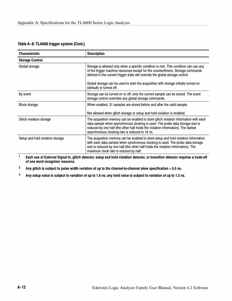
Appendix A: Specifications for the TLA600 Series Logic Analyzer
A- 12 Tektronix Logic Analyzer Family User Manual, Version 4.1 Software
Table A- 8: TLA600 trigger system (Cont.)
Characteristic Description
Storage Control
Global storage Storage is allowed only when a specific condition is met. This condition can use anyof the trigger machine resources except for the counter/timers. Storage commandsdefined in the current trigger state will override the global storage control.
Global storage can be used to start the acquisition with storage initially turned on(default) or turned off.
By event Storage can be turned on or off; only the current sample can be stored. The eventstorage control overrides any global storage commands.
Block storage When enabled, 31 samples are stored before and after the valid sample.
Not allowed when glitch storage or setup and hold violation is enabled.
Glitch violation storage The acquisition memory can be enabled to store glitch violation information with eachdata sample when asynchronous clocking is used. The probe data storage size isreduced by one half (the other half holds the violation information). The fastestasynchronous clocking rate is reduced to 10 ns.
Setup and hold violation storage The acquisition memory can be enabled to store setup and hold violation informationwith each data sample when synchronous clocking is used. The probe data storagesize is reduced by one half (the other half holds the violation information). Themaximum clock rate is reduced by half.
1 Each use of External Signal In, glitch detector, setup and hold violation detector, or transition detector requires a trade-offof one word recognizer resource.
2 Any glitch is subject to pulse width variation of up to the channel-to-channel skew specification + 0.5 ns.
3 Any setup value is subject to variation of up to 1.8 ns; any hold value is subject to variation of up to 1.2 ns.
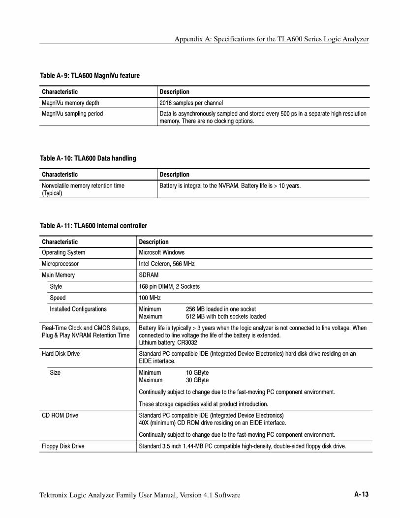
Appendix A: Specifications for the TLA600 Series Logic Analyzer
Tektronix Logic Analyzer Family User Manual, Version 4.1 Software A- 13
Table A- 9: TLA600 MagniVu feature
Characteristic Description
MagniVu memory depth 2016 samples per channel
MagniVu sampling period Data is asynchronously sampled and stored every 500 ps in a separate high resolutionmemory. There are no clocking options.
Table A- 10: TLA600 Data handling
Characteristic Description
Nonvolatile memory retention time(Typical)
Battery is integral to the NVRAM. Battery life is > 10 years.
Table A- 11: TLA600 internal controller
Characteristic Description
Operating System Microsoft Windows
Microprocessor Intel Celeron, 566 MHz
Main Memory SDRAM
Style 168 pin DIMM, 2 Sockets
Speed 100 MHz
Installed Configurations Minimum 256 MB loaded in one socketMaximum 512 MB with both sockets loaded
Real-Time Clock and CMOS Setups,Plug & Play NVRAM Retention Time
Battery life is typically > 3 years when the logic analyzer is not connected to line voltage. Whenconnected to line voltage the life of the battery is extended.Lithium battery, CR3032
Hard Disk Drive Standard PC compatible IDE (Integrated Device Electronics) hard disk drive residing on anEIDE interface.
Size Minimum 10 GByteMaximum 30 GByte
Continually subject to change due to the fast-moving PC component environment.
These storage capacities valid at product introduction.
CD ROM Drive Standard PC compatible IDE (Integrated Device Electronics)40X (minimum) CD ROM drive residing on an EIDE interface.
Continually subject to change due to the fast-moving PC component environment.
Floppy Disk Drive Standard 3.5 inch 1.44-MB PC compatible high-density, double-sided floppy disk drive.
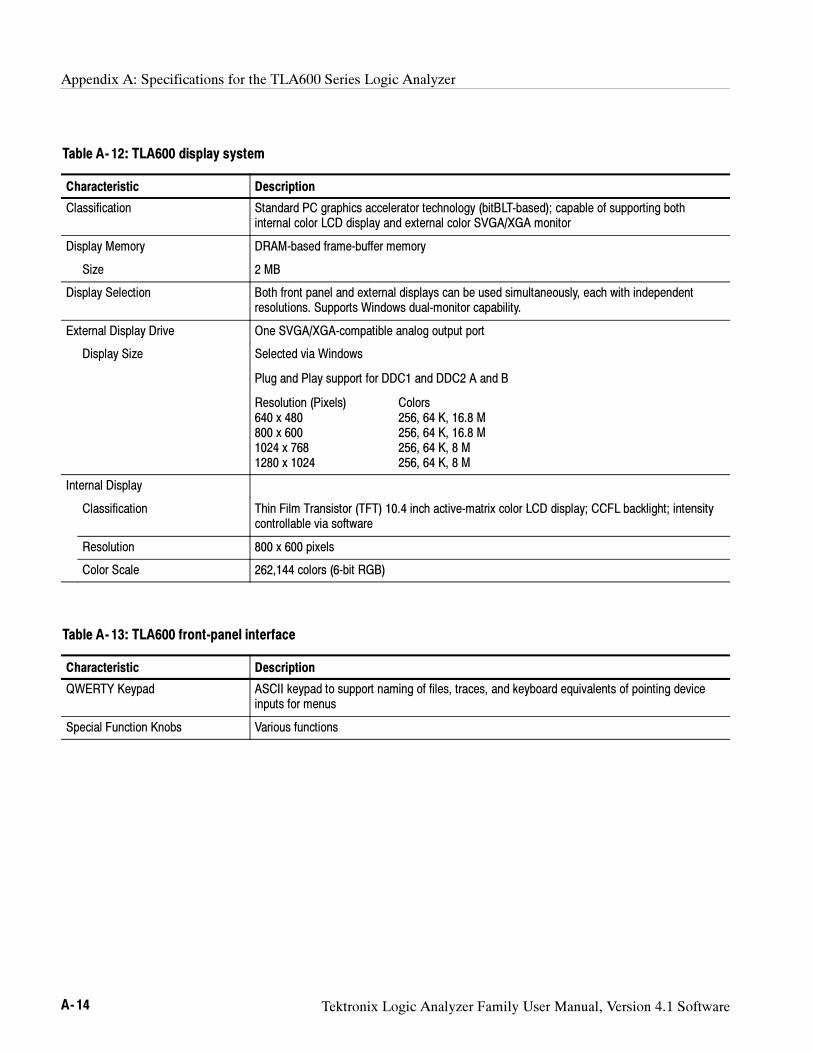
Appendix A: Specifications for the TLA600 Series Logic Analyzer
A- 14 Tektronix Logic Analyzer Family User Manual, Version 4.1 Software
Table A- 12: TLA600 display system
Characteristic Description
Classification Standard PC graphics accelerator technology (bitBLT-based); capable of supporting bothinternal color LCD display and external color SVGA/XGA monitor
Display Memory DRAM-based frame-buffer memory
Size 2 MB
Display Selection Both front panel and external displays can be used simultaneously, each with independentresolutions. Supports Windows dual-monitor capability.
External Display Drive One SVGA/XGA-compatible analog output port
Display Size Selected via Windows
Plug and Play support for DDC1 and DDC2 A and B
Resolution (Pixels) Colors640 x 480 256, 64 K, 16.8 M800 x 600 256, 64 K, 16.8 M1024 x 768 256, 64 K, 8 M1280 x 1024 256, 64 K, 8 M
Internal Display
Classification Thin Film Transistor (TFT) 10.4 inch active-matrix color LCD display; CCFL backlight; intensitycontrollable via software
Resolution 800 x 600 pixels
Color Scale 262,144 colors (6-bit RGB)
Table A- 13: TLA600 front-panel interface
Characteristic Description
QWERTY Keypad ASCII keypad to support naming of files, traces, and keyboard equivalents of pointing deviceinputs for menus
Special Function Knobs Various functions
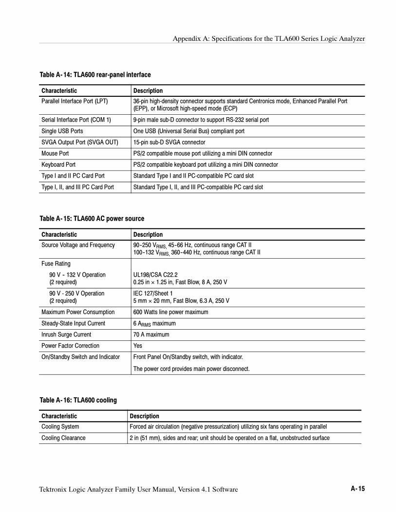
Appendix A: Specifications for the TLA600 Series Logic Analyzer
Tektronix Logic Analyzer Family User Manual, Version 4.1 Software A- 15
Table A- 14: TLA600 rear-panel interface
Characteristic Description
Parallel Interface Port (LPT) 36-pin high-density connector supports standard Centronics mode, Enhanced Parallel Port(EPP), or Microsoft high-speed mode (ECP)
Serial Interface Port (COM 1) 9-pin male sub-D connector to support RS-232 serial port
Single USB Ports One USB (Universal Serial Bus) compliant port
SVGA Output Port (SVGA OUT) 15-pin sub-D SVGA connector
Mouse Port PS/2 compatible mouse port utilizing a mini DIN connector
Keyboard Port PS/2 compatible keyboard port utilizing a mini DIN connector
Type I and II PC Card Port Standard Type I and II PC-compatible PC card slot
Type I, II, and III PC Card Port Standard Type I, II, and III PC-compatible PC card slot
Table A- 15: TLA600 AC power source
Characteristic Description
Source Voltage and Frequency 90--250 VRMS, 45--66 Hz, continuous range CAT II100--132 VRMS, 360--440 Hz, continuous range CAT II
Fuse Rating
90 V -- 132 V Operation(2 required)
UL198/CSA C22.20.25 in × 1.25 in, Fast Blow, 8 A, 250 V
90 V - 250 V Operation(2 required)
IEC 127/Sheet 15 mm × 20 mm, Fast Blow, 6.3 A, 250 V
Maximum Power Consumption 600 Watts line power maximum
Steady-State Input Current 6 ARMS maximum
Inrush Surge Current 70 A maximum
Power Factor Correction Yes
On/Standby Switch and Indicator Front Panel On/Standby switch, with indicator.
The power cord provides main power disconnect.
Table A- 16: TLA600 cooling
Characteristic Description
Cooling System Forced air circulation (negative pressurization) utilizing six fans operating in parallel
Cooling Clearance 2 in (51 mm), sides and rear; unit should be operated on a flat, unobstructed surface
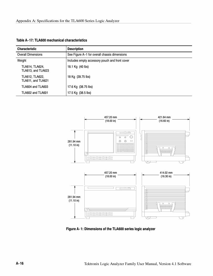
Appendix A: Specifications for the TLA600 Series Logic Analyzer
A- 16 Tektronix Logic Analyzer Family User Manual, Version 4.1 Software
Table A- 17: TLA600 mechanical characteristics
Characteristic Description
Overall Dimensions See Figure A--1 for overall chassis dimensions
Weight Includes empty accessory pouch and front cover
TLA614, TLA624,TLA613, and TLA623
18.1 Kg (40 lbs)
TLA612, TLA622,TLA611, and TLA621
18 Kg (39.75 lbs)
TLA604 and TLA603 17.6 Kg (38.75 lbs)
TLA602 and TLA601 17.5 Kg (38.5 lbs)
421.64 mm(16.60 in)
281.94 mm(11.10 in)
457.20 mm(18.00 in)
414.02 mm(16.30 in)
281.94 mm(11.10 in)
457.20 mm(18.00 in)
Figure A- 1: Dimensions of the TLA600 series logic analyzer
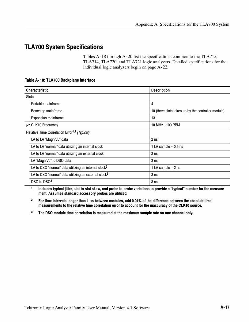
Appendix A: Specifications for the TLA700 System
Tektronix Logic Analyzer Family User Manual, Version 4.1 Software A- 17
TLA700 System Specifications
Tables A--18 through A--20 list the specifications common to the TLA715,TLA714, TLA720, and TLA721 logic analyzers. Detailed specifications for theindividual logic analyzers begin on page A--22.
Table A- 18: TLA700 Backplane interface
Characteristic Description
Slots
Portable mainframe 4
Benchtop mainframe 10 (three slots taken up by the controller module)
Expansion mainframe 13
CLK10 Frequency 10 MHz ±100 PPM
Relative Time Correlation Error1,2 (Typical)
LA to LA “MagniVu” data 2 ns
LA to LA “normal” data utilizing an internal clock 1 LA sample -- 0.5 ns
LA to LA “normal” data utilizing an external clock 2 ns
LA “MagniVu” to DSO data 3 ns
LA to DSO “normal” data utilizing an internal clock3 1 LA sample + 2 ns
LA to DSO “normal” data utilizing an external clock3 3 ns
DSO to DSO3 3 ns
1 Includes typical jitter, slot-to-slot skew, and probe-to-probe variations to provide a “typical” number for the measure-ment. Assumes standard accessory probes are utilized.
2 For time intervals longer than 1 s between modules, add 0.01% of the difference between the absolute timemeasurements to the relative time correlation error to account for the inaccuracy of the CLK10 source.
3 The DSO module time correlation is measured at the maximum sample rate on one channel only.
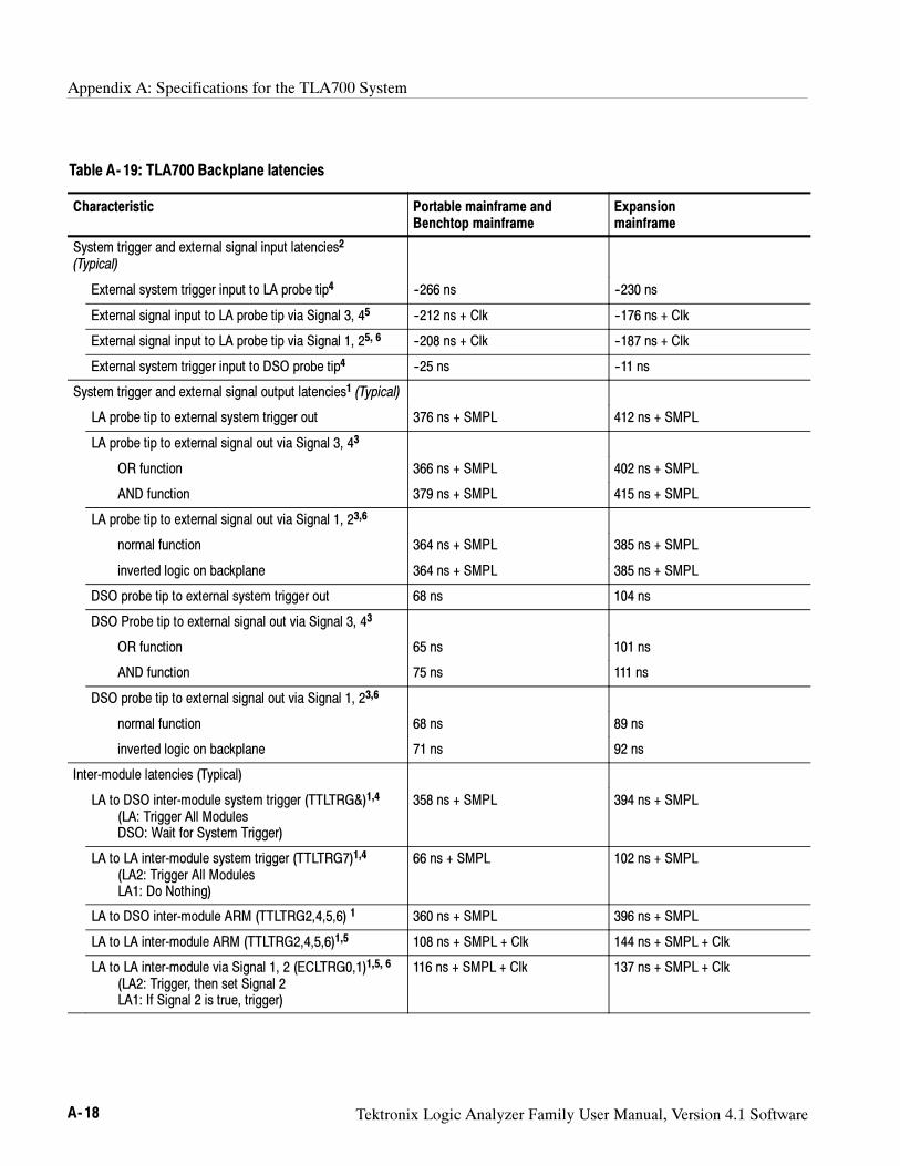
Appendix A: Specifications for the TLA700 System
A- 18 Tektronix Logic Analyzer Family User Manual, Version 4.1 Software
Table A- 19: TLA700 Backplane latencies
Characteristic Portable mainframe andBenchtop mainframe
Expansionmainframe
System trigger and external signal input latencies2
(Typical)
External system trigger input to LA probe tip4 --266 ns --230 ns
External signal input to LA probe tip via Signal 3, 45 --212 ns + Clk --176 ns + Clk
External signal input to LA probe tip via Signal 1, 25, 6 --208 ns + Clk --187 ns + Clk
External system trigger input to DSO probe tip4 --25 ns --11 ns
System trigger and external signal output latencies1 (Typical)
LA probe tip to external system trigger out 376 ns + SMPL 412 ns + SMPL
LA probe tip to external signal out via Signal 3, 43
OR function 366 ns + SMPL 402 ns + SMPL
AND function 379 ns + SMPL 415 ns + SMPL
LA probe tip to external signal out via Signal 1, 23,6
normal function 364 ns + SMPL 385 ns + SMPL
inverted logic on backplane 364 ns + SMPL 385 ns + SMPL
DSO probe tip to external system trigger out 68 ns 104 ns
DSO Probe tip to external signal out via Signal 3, 43
OR function 65 ns 101 ns
AND function 75 ns 111 ns
DSO probe tip to external signal out via Signal 1, 23,6
normal function 68 ns 89 ns
inverted logic on backplane 71 ns 92 ns
Inter-module latencies (Typical)
LA to DSO inter-module system trigger (TTLTRG&)1,4
(LA: Trigger All ModulesDSO: Wait for System Trigger)
358 ns + SMPL 394 ns + SMPL
LA to LA inter-module system trigger (TTLTRG7)1,4
(LA2: Trigger All ModulesLA1: Do Nothing)
66 ns + SMPL 102 ns + SMPL
LA to DSO inter-module ARM (TTLTRG2,4,5,6) 1 360 ns + SMPL 396 ns + SMPL
LA to LA inter-module ARM (TTLTRG2,4,5,6)1,5 108 ns + SMPL + Clk 144 ns + SMPL + Clk
LA to LA inter-module via Signal 1, 2 (ECLTRG0,1)1,5, 6
(LA2: Trigger, then set Signal 2LA1: If Signal 2 is true, trigger)
116 ns + SMPL + Clk 137 ns + SMPL + Clk
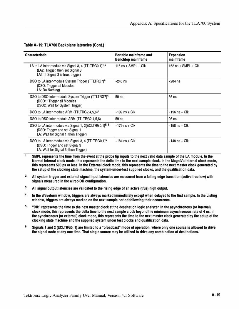
Appendix A: Specifications for the TLA700 System
Tektronix Logic Analyzer Family User Manual, Version 4.1 Software A- 19
Table A- 19: TLA700 Backplane latencies (Cont.)
Characteristic Expansionmainframe
Portable mainframe andBenchtop mainframe
LA to LA inter-module via Signal 3, 4 (TTLTRG0,1)1,5
(LA2: Trigger, then set Signal 3LA1: If Signal 3 is true, trigger)
116 ns + SMPL + Clk 152 ns + SMPL + Clk
DSO to LA inter-module System Trigger (TTLTRG7)4
(DSO: Trigger all ModulesLA: Do Nothing)
--240 ns --204 ns
DSO to DSO inter-module System Trigger (TTLTRG7)4
(DSO1: Trigger all ModulesDSO2: Wait for System Trigger)
50 ns 86 ns
DSO to LA inter-module ARM (TTLTRG2,4,5,6)5 --192 ns + Clk --156 ns + Clk
DSO to DSO inter-module ARM (TTLTRG2,4,5,6) 59 ns 95 ns
DSO to LA inter-module via Signal 1, 2(ECLTRG0,1)5, 6
(DSO: Trigger and set Signal 1LA: Wait for Signal 1, then Trigger)
--179 ns + Clk --158 ns + Clk
DSO to LA inter-module via Signal 3, 4 (TTLTRG0,1)5
(DSO: Trigger and set Signal 3LA: Wait for Signal 3; then Trigger)
--184 ns + Clk --148 ns + Clk
1 SMPL represents the time from the event at the probe tip inputs to the next valid data sample of the LA module. In theNormal Internal clock mode, this represents the delta time to the next sample clock. In the MagniVu Internal clock mode,this represents 500 ps or less. In the External clock mode, this represents the time to the next master clock generated bythe setup of the clocking state machine, the system-under-test supplied clocks, and the qualification data.
2 All system trigger and external signal input latencies are measured from a falling-edge transition (active true low) withsignals measured in the wired-OR configuration.
3 All signal output latencies are validated to the rising edge of an active (true) high output.
4 In the Waveform window, triggers are always marked immediately except when delayed to the first sample. In the Listingwindow, triggers are always marked on the next sample period following their occurrence.
5 “Clk” represents the time to the next master clock at the destination logic analyzer. In the asynchronous (or internal)clock mode, this represents the delta time to the next sample clock beyond the minimum asynchronous rate of 4 ns. Inthe synchronous (or external) clock mode, this represents the time to the next master clock generated by the setup of theclocking state machine and the supplied system under test clocks and qualification data.
6 Signals 1 and 2 (ECLTRG0, 1) are limited to a “broadcast” mode of operation, where only one source is allowed to drivethe signal node at any one time. That single source may be utilized to drive any combination of destinations.
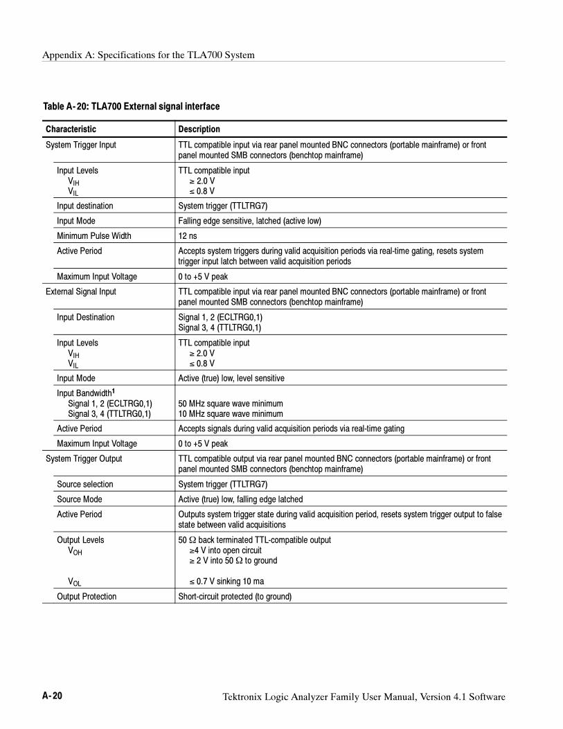
Appendix A: Specifications for the TLA700 System
A- 20 Tektronix Logic Analyzer Family User Manual, Version 4.1 Software
Table A- 20: TLA700 External signal interface
Characteristic Description
System Trigger Input TTL compatible input via rear panel mounted BNC connectors (portable mainframe) or frontpanel mounted SMB connectors (benchtop mainframe)
Input LevelsVIHVIL
TTL compatible input≥ 2.0 V≤ 0.8 V
Input destination System trigger (TTLTRG7)
Input Mode Falling edge sensitive, latched (active low)
Minimum Pulse Width 12 ns
Active Period Accepts system triggers during valid acquisition periods via real-time gating, resets systemtrigger input latch between valid acquisition periods
Maximum Input Voltage 0 to +5 V peak
External Signal Input TTL compatible input via rear panel mounted BNC connectors (portable mainframe) or frontpanel mounted SMB connectors (benchtop mainframe)
Input Destination Signal 1, 2 (ECLTRG0,1)Signal 3, 4 (TTLTRG0,1)
Input LevelsVIHVIL
TTL compatible input≥ 2.0 V≤ 0.8 V
Input Mode Active (true) low, level sensitive
Input Bandwidth1
Signal 1, 2 (ECLTRG0,1)Signal 3, 4 (TTLTRG0,1)
50 MHz square wave minimum10 MHz square wave minimum
Active Period Accepts signals during valid acquisition periods via real-time gating
Maximum Input Voltage 0 to +5 V peak
System Trigger Output TTL compatible output via rear panel mounted BNC connectors (portable mainframe) or frontpanel mounted SMB connectors (benchtop mainframe)
Source selection System trigger (TTLTRG7)
Source Mode Active (true) low, falling edge latched
Active Period Outputs system trigger state during valid acquisition period, resets system trigger output to falsestate between valid acquisitions
Output LevelsVOH
VOL
50Ω back terminated TTL-compatible output≥4 V into open circuit≥ 2 V into 50Ω to ground
≤ 0.7 V sinking 10 ma
Output Protection Short-circuit protected (to ground)
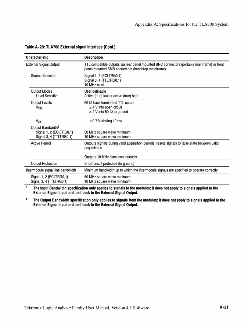
Appendix A: Specifications for the TLA700 System
Tektronix Logic Analyzer Family User Manual, Version 4.1 Software A- 21
Table A- 20: TLA700 External signal interface (Cont.)
Characteristic Description
External Signal Output TTL compatible outputs via rear panel mounted BNC connectors (portable mainframe) or frontpanel mounted SMB connectors (benchtop mainframe)
Source Selection Signal 1, 2 (ECLTRG0,1)Signal 3, 4 (TTLTRG0,1)10 MHz clock
Output ModesLevel Sensitive
User definableActive (true) low or active (true) high
Output LevelsVOH
VOL
50Ω back terminated TTL output≥ 4 V into open circuit≥ 2 V into 50Ω to ground
≤ 0.7 V sinking 10 ma
Output Bandwidth2
Signal 1, 2 (ECLTRG0,1)Signal 3, 4 (TTLTRG0,1)
50 MHz square wave minimum10 MHz square wave minimum
Active Period Outputs signals during valid acquisition periods, resets signals to false state between validacquisitions
Outputs 10 MHz clock continuously
Output Protection Short-circuit protected (to ground)
Intermodule signal line bandwidth Minimum bandwidth up to which the intermodule signals are specified to operate correctly
Signal 1, 2 (ECLTRG0,1)Signal 3, 4 (TTLTRG0,1)
50 MHz square wave minimum10 MHz square wave minimum
1 The Input Bandwidth specification only applies to signals to the modules; it does not apply to signals applied to theExternal Signal Input and sent back to the External Signal Output.
2 The Output Bandwidth specification only applies to signals from the modules; it does not apply to signals applied to theExternal Signal Input and sent back to the External Signal Output.
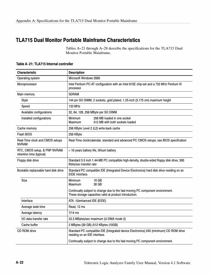
Appendix A: Specifications for the TLA715 Dual Monitor Portable Mainframe
A- 22 Tektronix Logic Analyzer Family User Manual, Version 4.1 Software
TLA715 Dual Monitor Portable Mainframe Characteristics
Tables A--21 through A--28 describe the specifications for the TLA715 DualMonitor Portable Mainframe.
Table A- 21: TLA715 Internal controller
Characteristic Description
Operating system Microsoft Windows 2000
Microprocessor Intel Pentium PC-AT configuration with an Intel 815E chip-set and a 733 MHz Pentium IIIprocessor
Main memory SDRAM
Style 144 pin SO DIMM, 2 sockets, gold plated, 1.25-inch (3.175 cm) maximum height
Speed 133 MHz
Available configurations 32, 64, 128, 256 MByte per SO DIMM
Installed configurations Minimum 256 MB loaded in one socketMaximum 512 MB with both sockets loaded
Cache memory 256 KByte Level 2 (L2) write-back cache
Flash BIOS 256 KByte
Real-Time clock and CMOS setupsNVRAM
Real-Time clock/calendar, standard and advanced PC CMOS setups; see BIOS specification
RTC, CMOS setup, & PNP NVRAMretention time (typical)
> 10 years battery life, lithium battery
Floppy disk drive Standard 3.5 inch 1.44-MB PC compatible high-density, double-sided floppy disk drive, 500Kbits/sec transfer rate
Bootable replaceable hard disk drive Standard PC compatible IDE (Integrated Device Electronics) hard disk drive residing on anEIDE interface.
Size Minimum 10 GBMaximum 30 GB
Continually subject to change due to the fast-moving PC component environment.These storage capacities valid at product introduction.
Interface ATA --5/enhanced IDE (EIDE)
Average seek time Read, 12 ms
Average latency 7/14 ms
I/O data transfer rate 33.3 MBytes/sec maximum (U-DMA mode 2)
Cache buffer 2 MBytes (30 GB) /512 KBytes (10GB)
CD ROM drive Standard PC compatible IDE (Integrated device Electronics) 24X (minimum) CD ROM driveresiding on an IDE interface.
Continually subject to change due to the fast-moving PC component environment.
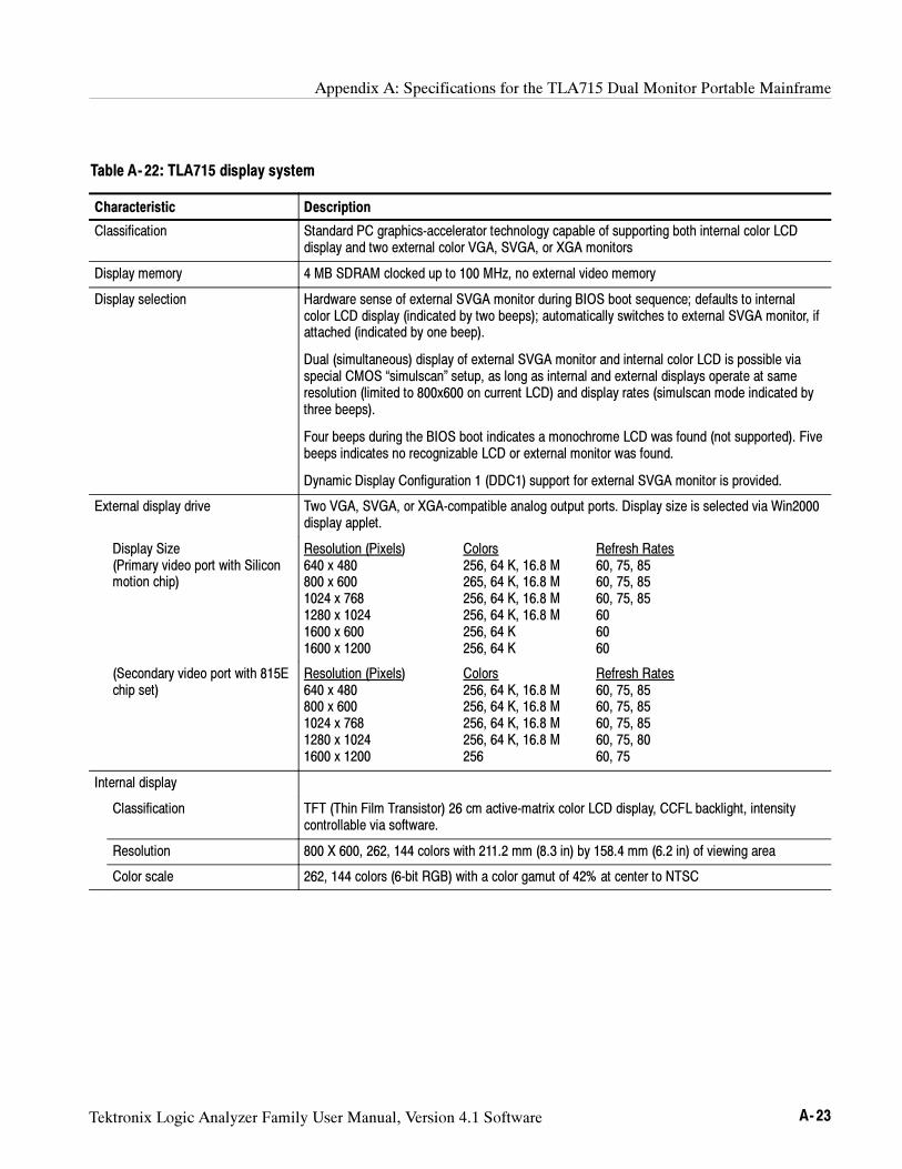
Appendix A: Specifications for the TLA715 Dual Monitor Portable Mainframe
Tektronix Logic Analyzer Family User Manual, Version 4.1 Software A- 23
Table A- 22: TLA715 display system
Characteristic Description
Classification Standard PC graphics-accelerator technology capable of supporting both internal color LCDdisplay and two external color VGA, SVGA, or XGA monitors
Display memory 4 MB SDRAM clocked up to 100 MHz, no external video memory
Display selection Hardware sense of external SVGA monitor during BIOS boot sequence; defaults to internalcolor LCD display (indicated by two beeps); automatically switches to external SVGA monitor, ifattached (indicated by one beep).
Dual (simultaneous) display of external SVGA monitor and internal color LCD is possible viaspecial CMOS “simulscan” setup, as long as internal and external displays operate at sameresolution (limited to 800x600 on current LCD) and display rates (simulscan mode indicated bythree beeps).
Four beeps during the BIOS boot indicates a monochrome LCD was found (not supported). Fivebeeps indicates no recognizable LCD or external monitor was found.
Dynamic Display Configuration 1 (DDC1) support for external SVGA monitor is provided.
External display drive Two VGA, SVGA, or XGA-compatible analog output ports. Display size is selected via Win2000display applet.
Display Size(Primary video port with Siliconmotion chip)
Resolution (Pixels) Colors Refresh Rates640 x 480 256, 64 K, 16.8 M 60, 75, 85800 x 600 265, 64 K, 16.8 M 60, 75, 851024 x 768 256, 64 K, 16.8 M 60, 75, 851280 x 1024 256, 64 K, 16.8 M 601600 x 600 256, 64 K 601600 x 1200 256, 64 K 60
(Secondary video port with 815Echip set)
Resolution (Pixels) Colors Refresh Rates640 x 480 256, 64 K, 16.8 M 60, 75, 85800 x 600 256, 64 K, 16.8 M 60, 75, 851024 x 768 256, 64 K, 16.8 M 60, 75, 851280 x 1024 256, 64 K, 16.8 M 60, 75, 801600 x 1200 256 60, 75
Internal display
Classification TFT (Thin Film Transistor) 26 cm active-matrix color LCD display, CCFL backlight, intensitycontrollable via software.
Resolution 800 X 600, 262, 144 colors with 211.2 mm (8.3 in) by 158.4 mm (6.2 in) of viewing area
Color scale 262, 144 colors (6-bit RGB) with a color gamut of 42% at center to NTSC
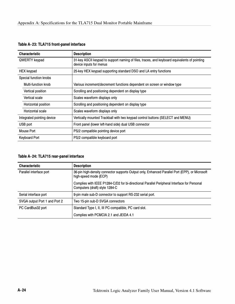
Appendix A: Specifications for the TLA715 Dual Monitor Portable Mainframe
A- 24 Tektronix Logic Analyzer Family User Manual, Version 4.1 Software
Table A- 23: TLA715 front-panel interface
Characteristic Description
QWERTY keypad 31-key ASCII keypad to support naming of files, traces, and keyboard equivalents of pointingdevice inputs for menus
HEX keypad 25-key HEX keypad supporting standard DSO and LA entry functions
Special function knobs
Multi-function knob Various increment/decrement functions dependent on screen or window type
Vertical position Scrolling and positioning dependent on display type
Vertical scale Scales waveform displays only
Horizontal position Scrolling and positioning dependent on display type
Horizontal scale Scales waveform displays only
Integrated pointing device Vertically mounted Trackball with two keypad control buttons (SELECT and MENU)
USB port Front panel (lower left-hand side) dual USB connector
Mouse Port PS/2 compatible pointing device port
Keyboard Port PS/2 compatible keyboard port
Table A- 24: TLA715 rear-panel interface
Characteristic Description
Parallel interface port 36-pin high-density connector supports Output only, Enhanced Parallel Port (EPP), or Microsofthigh-speed mode (ECP)
Complies with IEEE P1284-C/D2 for bi-directional Parallel Peripheral Interface for PersonalComputers (draft) style 1284-C
Serial interface port 9-pin male sub-D connector to support RS-232 serial port.
SVGA output Port 1 and Port 2 Two 15-pin sub-D SVGA connectors
PC CardBus32 port Standard Type I, II, III PC-compatible, PC card slot.
Complies with PCMCIA 2.1 and JEIDA 4.1
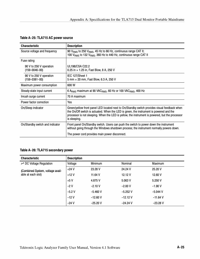
Appendix A: Specifications for the TLA715 Dual Monitor Portable Mainframe
Tektronix Logic Analyzer Family User Manual, Version 4.1 Software A- 25
Table A- 25: TLA715 AC power source
Characteristic Description
Source voltage and frequency 90 VRMS to 250 VRMS, 45 Hz to 66 Hz, continuous range CAT II;100 VRMS to 132 VRMS, 360 Hz to 440 Hz, continuous range CAT II
Fuse rating
90 V to 250 V operation(159--0046--00)
UL198/CSA C22.20.25 in × 1.25 in, Fast Blow, 8 A, 250 V
90 V to 250 V operation(159--0381--00)
IEC 127/Sheet 15 mm × 20 mm, Fast Blow, 6.3 A, 250 V
Maximum power consumption 600 W
Steady-state input current 6 ARMS maximum at 90 VACRMS, 60 Hz or 100 VACRMS, 400 Hz
Inrush surge current 70 A maximum
Power factor correction Yes
On/Sleep indicator Green/yellow front panel LED located next to On/Standby switch provides visual feedback whenthe On/Off switch is actuated. When the LED is green, the instrument is powered and theprocessor is not sleeping. When the LED is yellow, the instrument is powered, but the processoris sleeping.
On/Standby switch and indicator Front panel On/Standby switch. Users can push the switch to power down the instrumentwithout going through the Windows shutdown process; the instrument normally powers down.
The power cord provides main power disconnect.
Table A- 26: TLA715 secondary power
Characteristic Description
DC Voltage Regulation Voltage Minimum Nominal Maximum
(Combined System, voltage avail- +24 V 23.28 V 24.24 V 25.20 V(Combined System, voltage avail-able at each slot) +12 V 11.64 V 12.12 V 12.60 V
+5 V 4.875 V 5.063 V 5.250 V
--2 V --2.10 V --2.00 V --1.90 V
--5.2 V --5.460 V --5.252 V --5.044 V
--12 V --12.60 V --12.12 V --11.64 V
--24 V --25.20 V --24.24 V --23.28 V
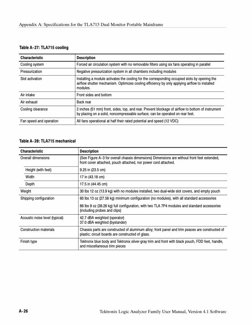
Appendix A: Specifications for the TLA715 Dual Monitor Portable Mainframe
A- 26 Tektronix Logic Analyzer Family User Manual, Version 4.1 Software
Table A- 27: TLA715 cooling
Characteristic Description
Cooling system Forced air circulation system with no removable filters using six fans operating in parallel
Pressurization Negative pressurization system in all chambers including modules
Slot activation Installing a module activates the cooling for the corresponding occupied slots by opening theairflow shutter mechanism. Optimizes cooling efficiency by only applying airflow to installedmodules.
Air intake Front sides and bottom
Air exhaust Back rear
Cooling clearance 2 inches (51 mm) front, sides, top, and rear. Prevent blockage of airflow to bottom of instrumentby placing on a solid, noncompressable surface; can be operated on rear feet.
Fan speed and operation All fans operational at half their rated potential and speed (12 VDC)
Table A- 28: TLA715 mechanical
Characteristic Description
Overall dimensions (See Figure A--3 for overall chassis dimensions) Dimensions are without front feet extended,front cover attached, pouch attached, nor power cord attached.
Height (with feet) 9.25 in (23.5 cm)
Width 17 in (43.18 cm)
Depth 17.5 in (44.45 cm)
Weight 30 lbs 12 oz (13.9 kg) with no modules installed, two dual-wide slot covers, and empty pouch
Shipping configuration 60 lbs 13 oz (27.58 kg) minimum configuration (no modules), with all standard accessories
86 lbs 9 oz (39.26 kg) full configuration, with two TLA 7P4 modules and standard accessories(including probes and clips)
Acoustic noise level (typical) 42.7 dBA weighted (operator)37.0 dBA weighted (bystander)
Construction materials Chassis parts are constructed of aluminum alloy; front panel and trim peaces are constructed ofplastic; circuit boards are constructed of glass.
Finish type Tektronix blue body and Tektronix silver-gray trim and front with black pouch, FDD feet, handle,and miscellaneous trim pieces
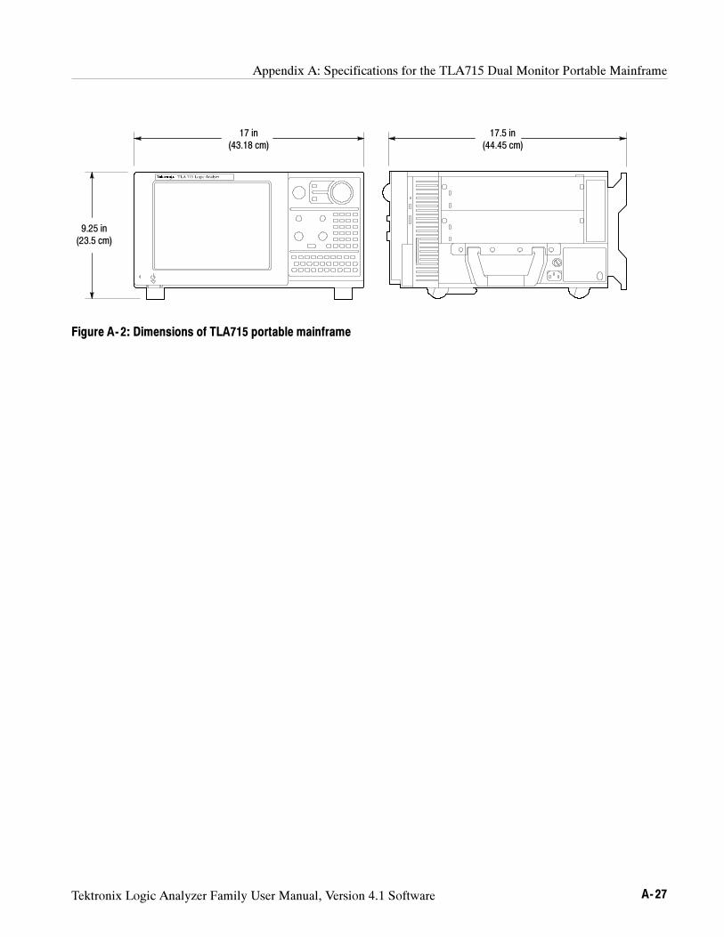
Appendix A: Specifications for the TLA715 Dual Monitor Portable Mainframe
Tektronix Logic Analyzer Family User Manual, Version 4.1 Software A- 27
17 in(43.18 cm)
9.25 in(23.5 cm)
17.5 in(44.45 cm)
Figure A- 2: Dimensions of TLA715 portable mainframe
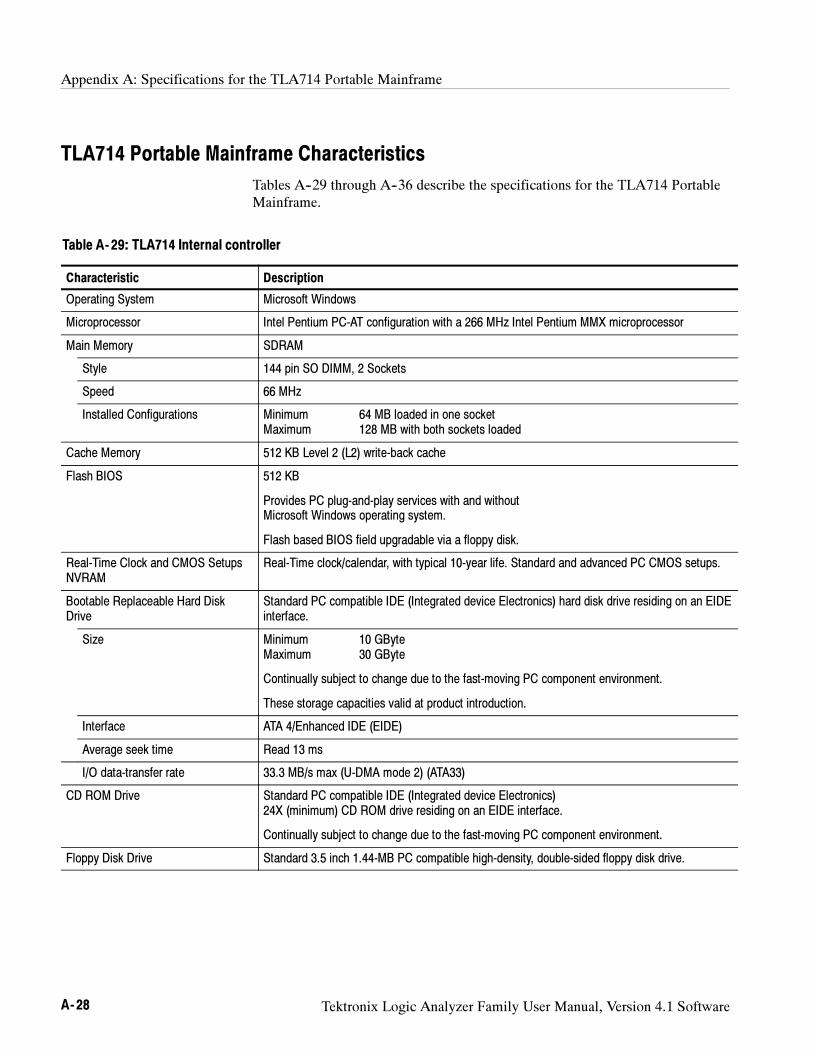
Appendix A: Specifications for the TLA714 Portable Mainframe
A- 28 Tektronix Logic Analyzer Family User Manual, Version 4.1 Software
TLA714 Portable Mainframe Characteristics
Tables A--29 through A--36 describe the specifications for the TLA714 PortableMainframe.
Table A- 29: TLA714 Internal controller
Characteristic Description
Operating System Microsoft Windows
Microprocessor Intel Pentium PC-AT configuration with a 266 MHz Intel Pentium MMX microprocessor
Main Memory SDRAM
Style 144 pin SO DIMM, 2 Sockets
Speed 66 MHz
Installed Configurations Minimum 64 MB loaded in one socketMaximum 128 MB with both sockets loaded
Cache Memory 512 KB Level 2 (L2) write-back cache
Flash BIOS 512 KB
Provides PC plug-and-play services with and withoutMicrosoft Windows operating system.
Flash based BIOS field upgradable via a floppy disk.
Real-Time Clock and CMOS SetupsNVRAM
Real-Time clock/calendar, with typical 10-year life. Standard and advanced PC CMOS setups.
Bootable Replaceable Hard DiskDrive
Standard PC compatible IDE (Integrated device Electronics) hard disk drive residing on an EIDEinterface.
Size Minimum 10 GByteMaximum 30 GByte
Continually subject to change due to the fast-moving PC component environment.
These storage capacities valid at product introduction.
Interface ATA 4/Enhanced IDE (EIDE)
Average seek time Read 13 ms
I/O data-transfer rate 33.3 MB/s max (U-DMA mode 2) (ATA33)
CD ROM Drive Standard PC compatible IDE (Integrated device Electronics)24X (minimum) CD ROM drive residing on an EIDE interface.
Continually subject to change due to the fast-moving PC component environment.
Floppy Disk Drive Standard 3.5 inch 1.44-MB PC compatible high-density, double-sided floppy disk drive.
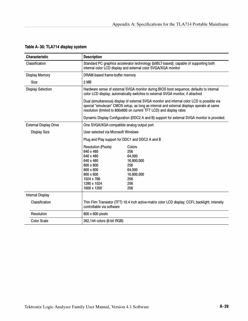
Appendix A: Specifications for the TLA714 Portable Mainframe
Tektronix Logic Analyzer Family User Manual, Version 4.1 Software A- 29
Table A- 30: TLA714 display system
Characteristic Description
Classification Standard PC graphics accelerator technology (bitBLT-based); capable of supporting bothinternal color LCD display and external color SVGA/XGA monitor
Display Memory DRAM-based frame-buffer memory
Size 2 MB
Display Selection Hardware sense of external SVGA monitor during BIOS boot sequence; defaults to internalcolor LCD display; automatically switches to external SVGA monitor, if attached
Dual (simultaneous) display of external SVGA monitor and internal color LCD is possible viaspecial “simulscan” CMOS setup, as long as internal and external displays operate at sameresolution (limited to 800x600 on current TFT LCD) and display rates
Dynamic Display Configuration (DDC2 A and B) support for external SVGA monitor is provided.
External Display Drive One SVGA/XGA-compatible analog output port
Display Size User selected via Microsoft Windows
Plug and Play support for DDC1 and DDC2 A and B
Resolution (Pixels) Colors640 x 480 256640 x 480 64,000640 x 480 16,800,000800 x 600 256800 x 600 64,000800 x 600 16,800,0001024 x 768 2561280 x 1024 2561600 x 1200 256
Internal Display
Classification Thin Film Transistor (TFT) 10.4 inch active-matrix color LCD display; CCFL backlight; intensitycontrollable via software
Resolution 800 x 600 pixels
Color Scale 262,144 colors (6-bit RGB)
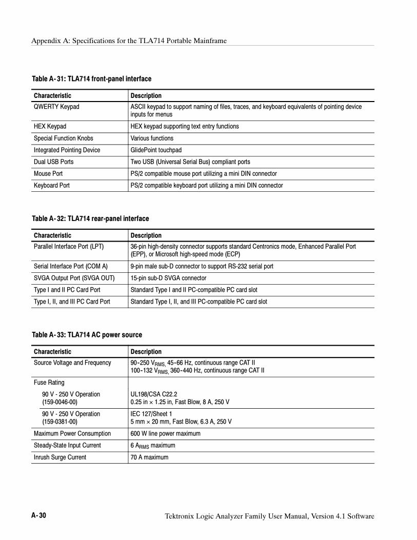
Appendix A: Specifications for the TLA714 Portable Mainframe
A- 30 Tektronix Logic Analyzer Family User Manual, Version 4.1 Software
Table A- 31: TLA714 front-panel interface
Characteristic Description
QWERTY Keypad ASCII keypad to support naming of files, traces, and keyboard equivalents of pointing deviceinputs for menus
HEX Keypad HEX keypad supporting text entry functions
Special Function Knobs Various functions
Integrated Pointing Device GlidePoint touchpad
Dual USB Ports Two USB (Universal Serial Bus) compliant ports
Mouse Port PS/2 compatible mouse port utilizing a mini DIN connector
Keyboard Port PS/2 compatible keyboard port utilizing a mini DIN connector
Table A- 32: TLA714 rear-panel interface
Characteristic Description
Parallel Interface Port (LPT) 36-pin high-density connector supports standard Centronics mode, Enhanced Parallel Port(EPP), or Microsoft high-speed mode (ECP)
Serial Interface Port (COM A) 9-pin male sub-D connector to support RS-232 serial port
SVGA Output Port (SVGA OUT) 15-pin sub-D SVGA connector
Type I and II PC Card Port Standard Type I and II PC-compatible PC card slot
Type I, II, and III PC Card Port Standard Type I, II, and III PC-compatible PC card slot
Table A- 33: TLA714 AC power source
Characteristic Description
Source Voltage and Frequency 90--250 VRMS, 45--66 Hz, continuous range CAT II100--132 VRMS, 360--440 Hz, continuous range CAT II
Fuse Rating
90 V - 250 V Operation(159-0046-00)
UL198/CSA C22.20.25 in × 1.25 in, Fast Blow, 8 A, 250 V
90 V - 250 V Operation(159-0381-00)
IEC 127/Sheet 15 mm × 20 mm, Fast Blow, 6.3 A, 250 V
Maximum Power Consumption 600 W line power maximum
Steady-State Input Current 6 ARMS maximum
Inrush Surge Current 70 A maximum
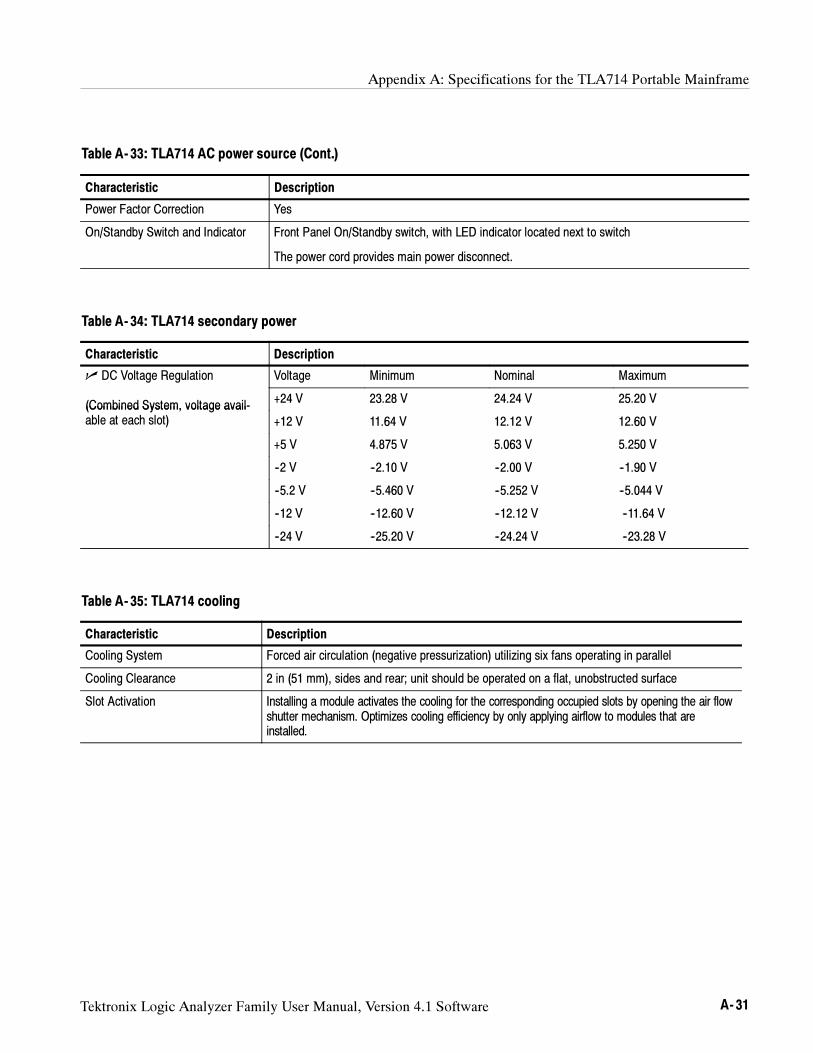
Appendix A: Specifications for the TLA714 Portable Mainframe
Tektronix Logic Analyzer Family User Manual, Version 4.1 Software A- 31
Table A- 33: TLA714 AC power source (Cont.)
Characteristic Description
Power Factor Correction Yes
On/Standby Switch and Indicator Front Panel On/Standby switch, with LED indicator located next to switch
The power cord provides main power disconnect.
Table A- 34: TLA714 secondary power
Characteristic Description
DC Voltage Regulation Voltage Minimum Nominal Maximum
(Combined System, voltage avail- +24 V 23.28 V 24.24 V 25.20 V(Combined System, voltage avail-able at each slot) +12 V 11.64 V 12.12 V 12.60 V
+5 V 4.875 V 5.063 V 5.250 V
--2 V --2.10 V --2.00 V --1.90 V
--5.2 V --5.460 V --5.252 V --5.044 V
--12 V --12.60 V --12.12 V --11.64 V
--24 V --25.20 V --24.24 V --23.28 V
Table A- 35: TLA714 cooling
Characteristic Description
Cooling System Forced air circulation (negative pressurization) utilizing six fans operating in parallel
Cooling Clearance 2 in (51 mm), sides and rear; unit should be operated on a flat, unobstructed surface
Slot Activation Installing a module activates the cooling for the corresponding occupied slots by opening the air flowshutter mechanism. Optimizes cooling efficiency by only applying airflow to modules that areinstalled.
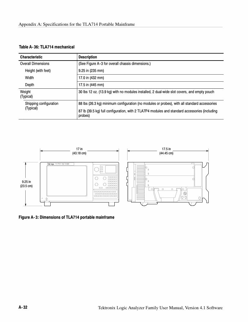
Appendix A: Specifications for the TLA714 Portable Mainframe
A- 32 Tektronix Logic Analyzer Family User Manual, Version 4.1 Software
Table A- 36: TLA714 mechanical
Characteristic Description
Overall Dimensions (See Figure A--3 for overall chassis dimensions.)
Height (with feet) 9.25 in (235 mm)
Width 17.0 in (432 mm)
Depth 17.5 in (445 mm)
Weight(Typical)
30 lbs 12 oz. (13.9 kg) with no modules installed, 2 dual-wide slot covers, and empty pouch
Shipping configuration(Typical)
88 lbs (26.3 kg) minimum configuration (no modules or probes), with all standard accessories
87 lb (39.5 kg) full configuration, with 2 TLA7P4 modules and standard accessories (includingprobes)
17 in(43.18 cm)
9.25 in(23.5 cm)
17.5 in(44.45 cm)
Figure A- 3: Dimensions of TLA714 portable mainframe
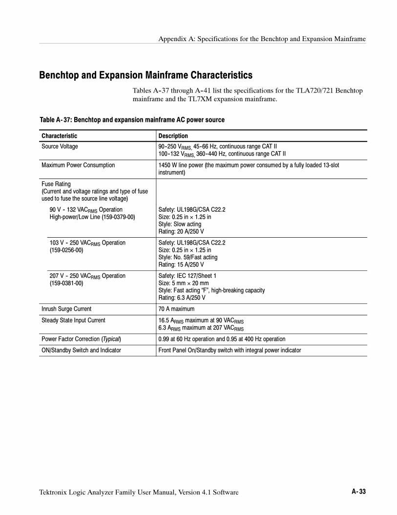
Appendix A: Specifications for the Benchtop and Expansion Mainframe
Tektronix Logic Analyzer Family User Manual, Version 4.1 Software A- 33
Benchtop and Expansion Mainframe Characteristics
Tables A--37 through A--41 list the specifications for the TLA720/721 Benchtopmainframe and the TL7XM expansion mainframe.
Table A- 37: Benchtop and expansion mainframe AC power source
Characteristic Description
Source Voltage 90--250 VRMS, 45--66 Hz, continuous range CAT II100--132 VRMS, 360--440 Hz, continuous range CAT II
Maximum Power Consumption 1450 W line power (the maximum power consumed by a fully loaded 13-slotinstrument)
Fuse Rating(Current and voltage ratings and type of fuseused to fuse the source line voltage)
90 V -- 132 VACRMS OperationHigh-power/Low Line (159-0379-00)
Safety: UL198G/CSA C22.2Size: 0.25 in × 1.25 inStyle: Slow actingRating: 20 A/250 V
103 V -- 250 VACRMS Operation(159-0256-00)
Safety: UL198G/CSA C22.2Size: 0.25 in × 1.25 inStyle: No. 59/Fast actingRating: 15 A/250 V
207 V -- 250 VACRMS Operation(159-0381-00)
Safety: IEC 127/Sheet 1Size: 5 mm × 20 mmStyle: Fast acting “F”, high-breaking capacityRating: 6.3 A/250 V
Inrush Surge Current 70 A maximum
Steady State Input Current 16.5 ARMS maximum at 90 VACRMS6.3 ARMS maximum at 207 VACRMS
Power Factor Correction (Typical) 0.99 at 60 Hz operation and 0.95 at 400 Hz operation
ON/Standby Switch and Indicator Front Panel On/Standby switch with integral power indicator
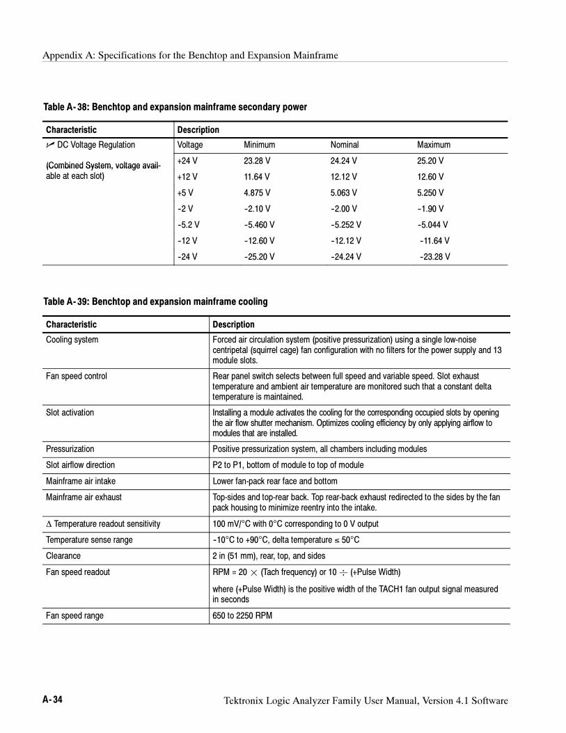
Appendix A: Specifications for the Benchtop and Expansion Mainframe
A- 34 Tektronix Logic Analyzer Family User Manual, Version 4.1 Software
Table A- 38: Benchtop and expansion mainframe secondary power
Characteristic Description
DC Voltage Regulation Voltage Minimum Nominal Maximum
(Combined System, voltage avail- +24 V 23.28 V 24.24 V 25.20 V(Combined System, voltage avail-able at each slot) +12 V 11.64 V 12.12 V 12.60 V
+5 V 4.875 V 5.063 V 5.250 V
--2 V --2.10 V --2.00 V --1.90 V
--5.2 V --5.460 V --5.252 V --5.044 V
--12 V --12.60 V --12.12 V --11.64 V
--24 V --25.20 V --24.24 V --23.28 V
Table A- 39: Benchtop and expansion mainframe cooling
Characteristic Description
Cooling system Forced air circulation system (positive pressurization) using a single low-noisecentripetal (squirrel cage) fan configuration with no filters for the power supply and 13module slots.
Fan speed control Rear panel switch selects between full speed and variable speed. Slot exhausttemperature and ambient air temperature are monitored such that a constant deltatemperature is maintained.
Slot activation Installing a module activates the cooling for the corresponding occupied slots by openingthe air flow shutter mechanism. Optimizes cooling efficiency by only applying airflow tomodules that are installed.
Pressurization Positive pressurization system, all chambers including modules
Slot airflow direction P2 to P1, bottom of module to top of module
Mainframe air intake Lower fan-pack rear face and bottom
Mainframe air exhaust Top-sides and top-rear back. Top rear-back exhaust redirected to the sides by the fanpack housing to minimize reentry into the intake.
∆ Temperature readout sensitivity 100 mV/°C with 0°C corresponding to 0 V output
Temperature sense range --10°C to +90°C, delta temperature ≤ 50°C
Clearance 2 in (51 mm), rear, top, and sides
Fan speed readout RPM = 20¢ (Tach frequency) or 10 (+Pulse Width)
where (+Pulse Width) is the positive width of the TACH1 fan output signal measuredin seconds
Fan speed range 650 to 2250 RPM
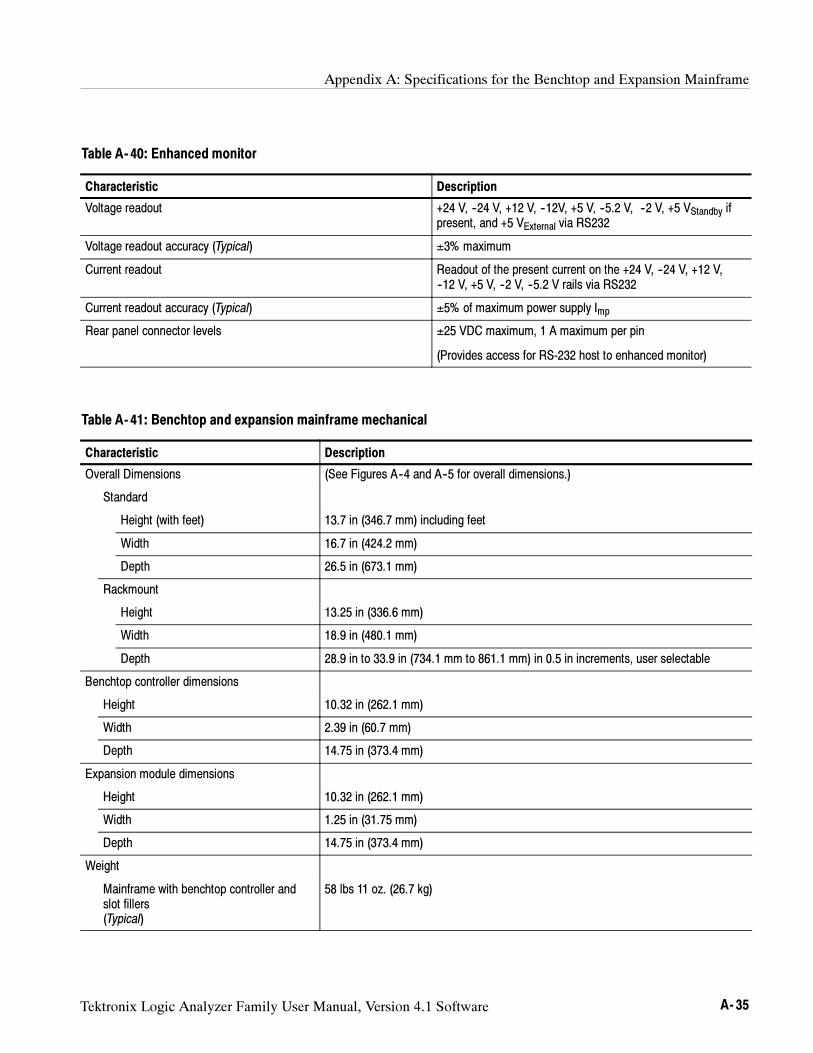
Appendix A: Specifications for the Benchtop and Expansion Mainframe
Tektronix Logic Analyzer Family User Manual, Version 4.1 Software A- 35
Table A- 40: Enhanced monitor
Characteristic Description
Voltage readout +24 V, --24 V, +12 V, --12V, +5 V, --5.2 V, --2 V, +5 VStandby ifpresent, and +5 VExternal via RS232
Voltage readout accuracy (Typical) ±3% maximum
Current readout Readout of the present current on the +24 V, --24 V, +12 V,--12 V, +5 V, --2 V, --5.2 V rails via RS232
Current readout accuracy (Typical) ±5% of maximum power supply Imp
Rear panel connector levels ±25 VDC maximum, 1 A maximum per pin
(Provides access for RS-232 host to enhanced monitor)
Table A- 41: Benchtop and expansion mainframe mechanical
Characteristic Description
Overall Dimensions (See Figures A--4 and A--5 for overall dimensions.)
Standard
Height (with feet) 13.7 in (346.7 mm) including feet
Width 16.7 in (424.2 mm)
Depth 26.5 in (673.1 mm)
Rackmount
Height 13.25 in (336.6 mm)
Width 18.9 in (480.1 mm)
Depth 28.9 in to 33.9 in (734.1 mm to 861.1 mm) in 0.5 in increments, user selectable
Benchtop controller dimensions
Height 10.32 in (262.1 mm)
Width 2.39 in (60.7 mm)
Depth 14.75 in (373.4 mm)
Expansion module dimensions
Height 10.32 in (262.1 mm)
Width 1.25 in (31.75 mm)
Depth 14.75 in (373.4 mm)
Weight
Mainframe with benchtop controller andslot fillers(Typical)
58 lbs 11 oz. (26.7 kg)
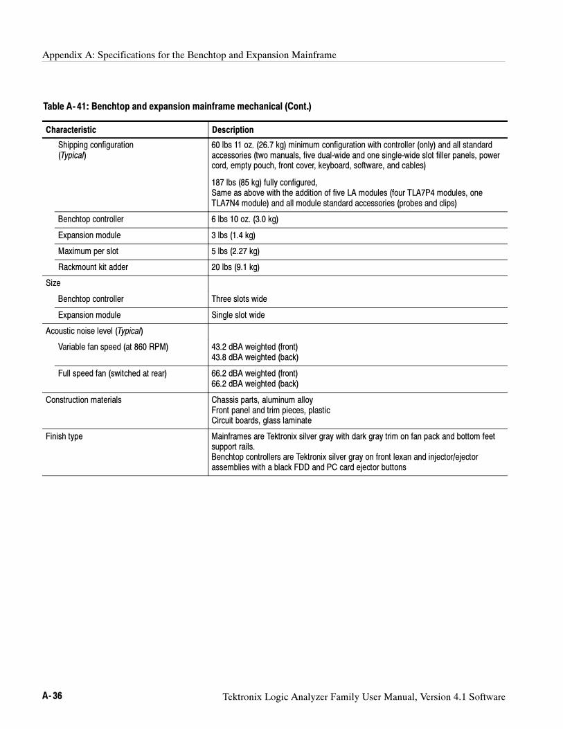
Appendix A: Specifications for the Benchtop and Expansion Mainframe
A- 36 Tektronix Logic Analyzer Family User Manual, Version 4.1 Software
Table A- 41: Benchtop and expansion mainframe mechanical (Cont.)
Characteristic Description
Shipping configuration(Typical)
60 lbs 11 oz. (26.7 kg) minimum configuration with controller (only) and all standardaccessories (two manuals, five dual-wide and one single-wide slot filler panels, powercord, empty pouch, front cover, keyboard, software, and cables)
187 lbs (85 kg) fully configured,Same as above with the addition of five LA modules (four TLA7P4 modules, oneTLA7N4 module) and all module standard accessories (probes and clips)
Benchtop controller 6 lbs 10 oz. (3.0 kg)
Expansion module 3 lbs (1.4 kg)
Maximum per slot 5 lbs (2.27 kg)
Rackmount kit adder 20 lbs (9.1 kg)
Size
Benchtop controller Three slots wide
Expansion module Single slot wide
Acoustic noise level (Typical)
Variable fan speed (at 860 RPM) 43.2 dBA weighted (front)43.8 dBA weighted (back)
Full speed fan (switched at rear) 66.2 dBA weighted (front)66.2 dBA weighted (back)
Construction materials Chassis parts, aluminum alloyFront panel and trim pieces, plasticCircuit boards, glass laminate
Finish type Mainframes are Tektronix silver gray with dark gray trim on fan pack and bottom feetsupport rails.Benchtop controllers are Tektronix silver gray on front lexan and injector/ejectorassemblies with a black FDD and PC card ejector buttons
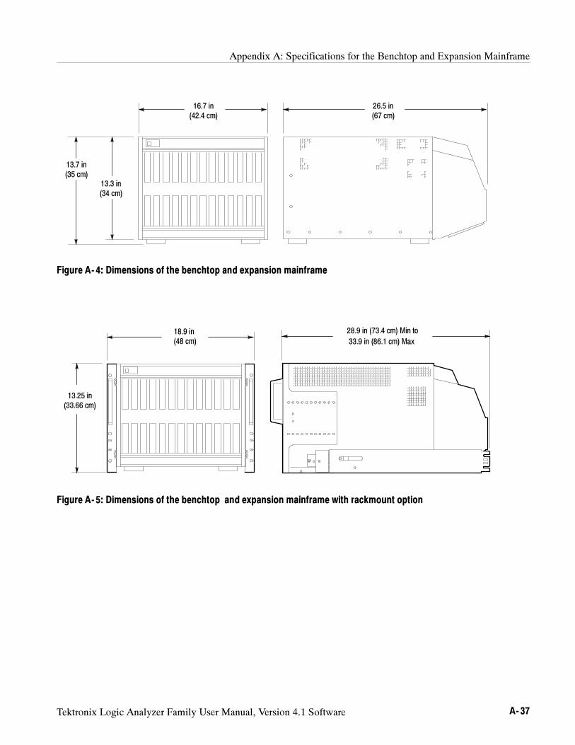
Appendix A: Specifications for the Benchtop and Expansion Mainframe
Tektronix Logic Analyzer Family User Manual, Version 4.1 Software A- 37
13.7 in(35 cm)
16.7 in(42.4 cm)
26.5 in(67 cm)
13.3 in(34 cm)
Figure A- 4: Dimensions of the benchtop and expansion mainframe
18.9 in(48 cm)
28.9 in (73.4 cm) Min to
33.9 in (86.1 cm) Max
13.25 in(33.66 cm)
Figure A- 5: Dimensions of the benchtop and expansion mainframe with rackmount option
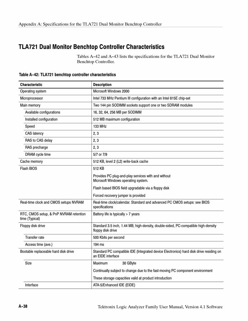
Appendix A: Specifications for the TLA721 Dual Monitor Benchtop Controller
A--38 Tektronix Logic Analyzer Family User Manual, Version 4.1 Software
TLA721 Dual Monitor Benchtop Controller Characteristics
Tables A--42 and A--43 lists the specifications for the TLA721 Dual Monitor
Benchtop Controller.
Table A--42: TLA721 benchtop controller characteristics
Characteristic Description
Operating system Microsoft Windows 2000
Microprocessor Intel 733 MHz Pentium III configuration with an Intel 815E chip-set
Main memory Two 144 pin SODIMM sockets support one or two SDRAM modules
Available configurations 16, 32, 64, 256 MB per SODIMM
Installed configuration 512 MB maximum configuration
Speed 133 MHz
CAS latency 2, 3
RAS to CAS delay 2, 3
RAS precharge 2, 3
DRAM cycle time 5/7 or 7/9
Cache memory 512 KB, level 2 (L2) write-back cache
Flash BIOS 512 KB
Provides PC plug-and-play services with and withoutMicrosoft Windows operating system.
Flash based BIOS field upgradable via a floppy disk
Forced recovery jumper is provided
Real-time clock and CMOS setups NVRAM Real-time clock/calendar. Standard and advanced PC CMOS setups: see BIOSspecifications
RTC, CMOS setup, & PnP NVRAM retentiontime (Typical)
Battery life is typically > 7 years
Floppy disk drive Standard 3.5 inch, 1.44 MB, high-density, double-sided, PC-compatible high-densityfloppy disk drive
Transfer rate 500 Kbits per second
Access time (ave.) 194 ms
Bootable replaceable hard disk drive Standard PC compatible IDE (Integrated device Electronics) hard disk drive residing onan EIDE interface
Size Maximum 30 GByte
Continually subject to change due to the fast-moving PC component environment
These storage capacities valid at product introduction
Interface ATA-5/Enhanced IDE (EIDE)
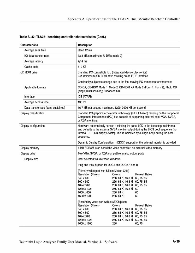
Appendix A: Specifications for the TLA721 Dual Monitor Benchtop Controller
Tektronix Logic Analyzer Family User Manual, Version 4.1 Software A--39
Table A--42: TLA721 benchtop controller characteristics (Cont.)
Characteristic Description
Average seek time Read 12 ms
I/O data-transfer rate 33.3 MB/s maximum (U-DMA mode 2)
Average latency 7/14 ms
Cache buffer 512 KB
CD ROM drive Standard PC compatible IDE (Integrated device Electronics)24X (minimum) CD ROM drive residing on an EIDE interface
Continually subject to change due to the fast-moving PC component environment
Applicable formats CD-DA; CE-ROM Mode 1, Mode 2; CD-ROM XA Mode 2 (Form 1, Form 2); Photo CD(single/multi session); Enhanced CD
Interface IDE (ATAPI)
Average access time 130 ms
Data-transfer rate (burst sustained) 16.7 MB per second maximum, 1290--3000 KB per second
Display classification Standard PC graphics accelerator technology (bitBLT based) residing on the PeripheralComponent Interconnect (PCI) bus capable of supporting external color VGA, SVGA,or XGA monitors
Display configuration Hardware automatically senses a missing flat panel LCD in the benchtop mainframeand defaults to the external SVGA monitor output during the BIOS boot sequence (nointernal TFT LCD display exists). This is indicated by a single beep during the bootsequence.
Dynamic Display Configuration 1 (DDC1) support for the external monitor is provided.
Display memory 4 MB SDRAM is on board the video controller; no external video memory
Display drive Two VGA, SVGA, or XGA compatible analog output ports
Display size User selected via Microsoft Windows
Plug and Play support for DDC1 and DDC2 A and B
(Primary video port with Silicon Motion Chip)Resolution (Pixels) Colors Refresh Rates640 x 480 256, 64 K, 16.8 M 60, 75, 85800 x 600 256, 64 K, 16.8 M 60, 75, 851024 x768 256, 64 K, 16.8 M 60, 75, 851280 x 1024 256, 64 K, 16.8 M 601600 x 600 256, 64 K 601600 x 1200 256, 64 K 60
(Secondary video port with 815E Chip set)Resolution (Pixels) Colors Refresh Rates640 x 480 256, 64 K, 16.8 M 60, 75, 85800 x 600 256, 64 K, 16.8 M 60, 75, 851024 x768 256, 64 K, 16.8 M 60, 75, 851280 x 1024 256, 64 K, 16.8 M 60, 75, 851600 x 1200 256 60, 75
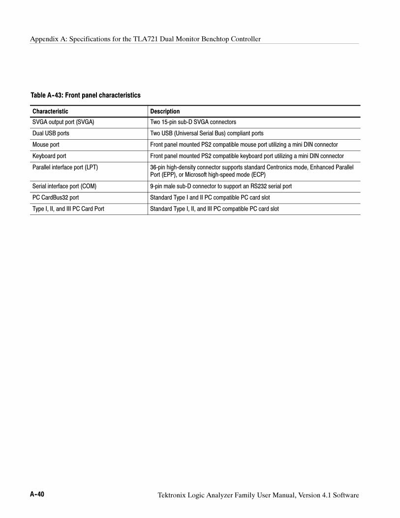
Appendix A: Specifications for the TLA721 Dual Monitor Benchtop Controller
A--40 Tektronix Logic Analyzer Family User Manual, Version 4.1 Software
Table A--43: Front panel characteristics
Characteristic Description
SVGA output port (SVGA) Two 15-pin sub-D SVGA connectors
Dual USB ports Two USB (Universal Serial Bus) compliant ports
Mouse port Front panel mounted PS2 compatible mouse port utilizing a mini DIN connector
Keyboard port Front panel mounted PS2 compatible keyboard port utilizing a mini DIN connector
Parallel interface port (LPT) 36-pin high-density connector supports standard Centronics mode, Enhanced ParallelPort (EPP), or Microsoft high-speed mode (ECP)
Serial interface port (COM) 9-pin male sub-D connector to support an RS232 serial port
PC CardBus32 port Standard Type I and II PC compatible PC card slot
Type I, II, and III PC Card Port Standard Type I, II, and III PC compatible PC card slot
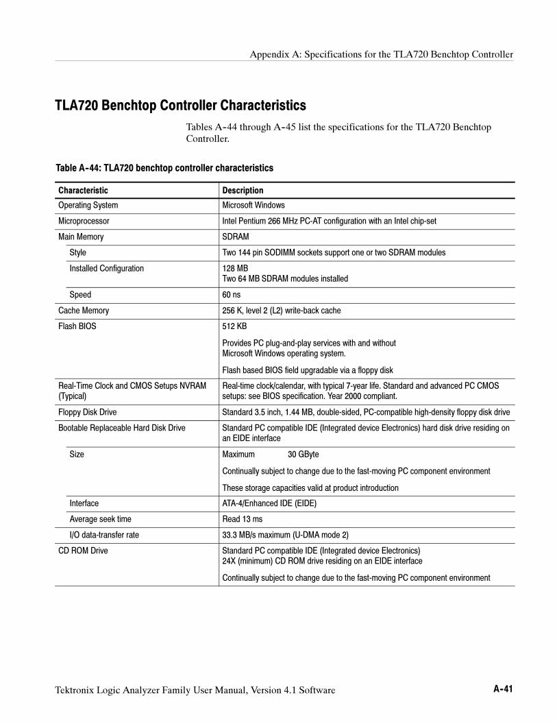
Appendix A: Specifications for the TLA720 Benchtop Controller
Tektronix Logic Analyzer Family User Manual, Version 4.1 Software A--41
TLA720 Benchtop Controller Characteristics
Tables A--44 through A--45 list the specifications for the TLA720 Benchtop
Controller.
Table A--44: TLA720 benchtop controller characteristics
Characteristic Description
Operating System Microsoft Windows
Microprocessor Intel Pentium 266 MHz PC-AT configuration with an Intel chip-set
Main Memory SDRAM
Style Two 144 pin SODIMM sockets support one or two SDRAM modules
Installed Configuration 128 MBTwo 64 MB SDRAM modules installed
Speed 60 ns
Cache Memory 256 K, level 2 (L2) write-back cache
Flash BIOS 512 KB
Provides PC plug-and-play services with and withoutMicrosoft Windows operating system.
Flash based BIOS field upgradable via a floppy disk
Real-Time Clock and CMOS Setups NVRAM(Typical)
Real-time clock/calendar, with typical 7-year life. Standard and advanced PC CMOSsetups: see BIOS specification. Year 2000 compliant.
Floppy Disk Drive Standard 3.5 inch, 1.44 MB, double-sided, PC-compatible high-density floppy disk drive
Bootable Replaceable Hard Disk Drive Standard PC compatible IDE (Integrated device Electronics) hard disk drive residing onan EIDE interface
Size Maximum 30 GByte
Continually subject to change due to the fast-moving PC component environment
These storage capacities valid at product introduction
Interface ATA-4/Enhanced IDE (EIDE)
Average seek time Read 13 ms
I/O data-transfer rate 33.3 MB/s maximum (U-DMA mode 2)
CD ROM Drive Standard PC compatible IDE (Integrated device Electronics)24X (minimum) CD ROM drive residing on an EIDE interface
Continually subject to change due to the fast-moving PC component environment
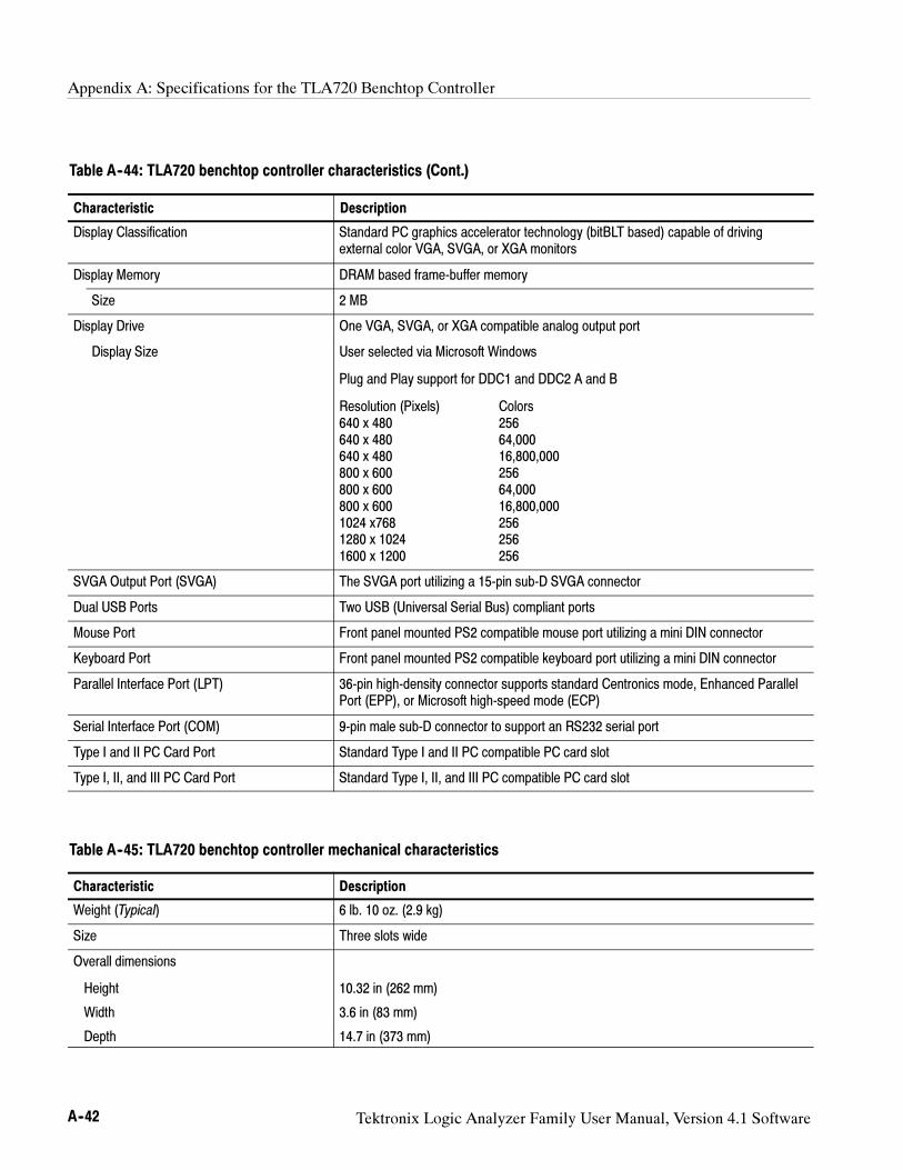
Appendix A: Specifications for the TLA720 Benchtop Controller
A--42 Tektronix Logic Analyzer Family User Manual, Version 4.1 Software
Table A--44: TLA720 benchtop controller characteristics (Cont.)
Characteristic Description
Display Classification Standard PC graphics accelerator technology (bitBLT based) capable of drivingexternal color VGA, SVGA, or XGA monitors
Display Memory DRAM based frame-buffer memory
Size 2 MB
Display Drive One VGA, SVGA, or XGA compatible analog output port
Display Size User selected via Microsoft Windows
Plug and Play support for DDC1 and DDC2 A and B
Resolution (Pixels) Colors640 x 480 256640 x 480 64,000640 x 480 16,800,000800 x 600 256800 x 600 64,000800 x 600 16,800,0001024 x768 2561280 x 1024 2561600 x 1200 256
SVGA Output Port (SVGA) The SVGA port utilizing a 15-pin sub-D SVGA connector
Dual USB Ports Two USB (Universal Serial Bus) compliant ports
Mouse Port Front panel mounted PS2 compatible mouse port utilizing a mini DIN connector
Keyboard Port Front panel mounted PS2 compatible keyboard port utilizing a mini DIN connector
Parallel Interface Port (LPT) 36-pin high-density connector supports standard Centronics mode, Enhanced ParallelPort (EPP), or Microsoft high-speed mode (ECP)
Serial Interface Port (COM) 9-pin male sub-D connector to support an RS232 serial port
Type I and II PC Card Port Standard Type I and II PC compatible PC card slot
Type I, II, and III PC Card Port Standard Type I, II, and III PC compatible PC card slot
Table A--45: TLA720 benchtop controller mechanical characteristics
Characteristic Description
Weight (Typical) 6 lb. 10 oz. (2.9 kg)
Size Three slots wide
Overall dimensions
Height 10.32 in (262 mm)
Width 3.6 in (83 mm)
Depth 14.7 in (373 mm)
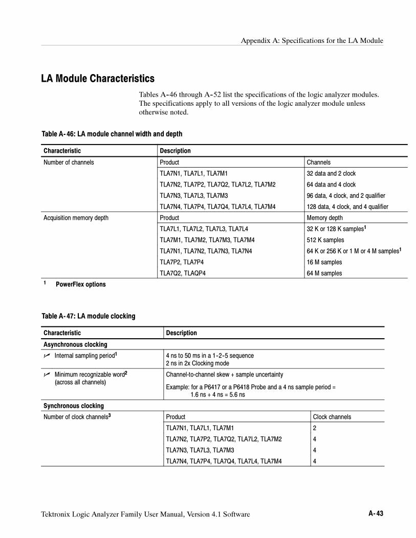
Appendix A: Specifications for the LA Module
Tektronix Logic Analyzer Family User Manual, Version 4.1 Software A- 43
LA Module Characteristics
Tables A--46 through A--52 list the specifications of the logic analyzer modules.The specifications apply to all versions of the logic analyzer module unlessotherwise noted.
Table A- 46: LA module channel width and depth
Characteristic Description
Number of channels Product Channels
TLA7N1, TLA7L1, TLA7M1 32 data and 2 clock
TLA7N2, TLA7P2, TLA7Q2, TLA7L2, TLA7M2 64 data and 4 clock
TLA7N3, TLA7L3, TLA7M3 96 data, 4 clock, and 2 qualifier
TLA7N4, TLA7P4, TLA7Q4, TLA7L4, TLA7M4 128 data, 4 clock, and 4 qualifier
Acquisition memory depth Product Memory depth
TLA7L1, TLA7L2, TLA7L3, TLA7L4 32 K or 128 K samples1
TLA7M1, TLA7M2, TLA7M3, TLA7M4 512 K samples
TLA7N1, TLA7N2, TLA7N3, TLA7N4 64 K or 256 K or 1 M or 4 M samples1
TLA7P2, TLA7P4 16 M samples
TLA7Q2, TLAQP4 64 M samples
1 PowerFlex options
Table A- 47: LA module clocking
Characteristic Description
Asynchronous clocking
Internal sampling period1 4 ns to 50 ms in a 1--2--5 sequence2 ns in 2x Clocking mode
Minimum recognizable word2
(across all channels)Channel-to-channel skew + sample uncertainty
Example: for a P6417 or a P6418 Probe and a 4 ns sample period =1.6 ns + 4 ns = 5.6 ns
Synchronous clocking
Number of clock channels3 Product Clock channels
TLA7N1, TLA7L1, TLA7M1 2
TLA7N2, TLA7P2, TLA7Q2, TLA7L2, TLA7M2 4
TLA7N3, TLA7L3, TLA7M3 4
TLA7N4, TLA7P4, TLA7Q4, TLA7L4, TLA7M4 4
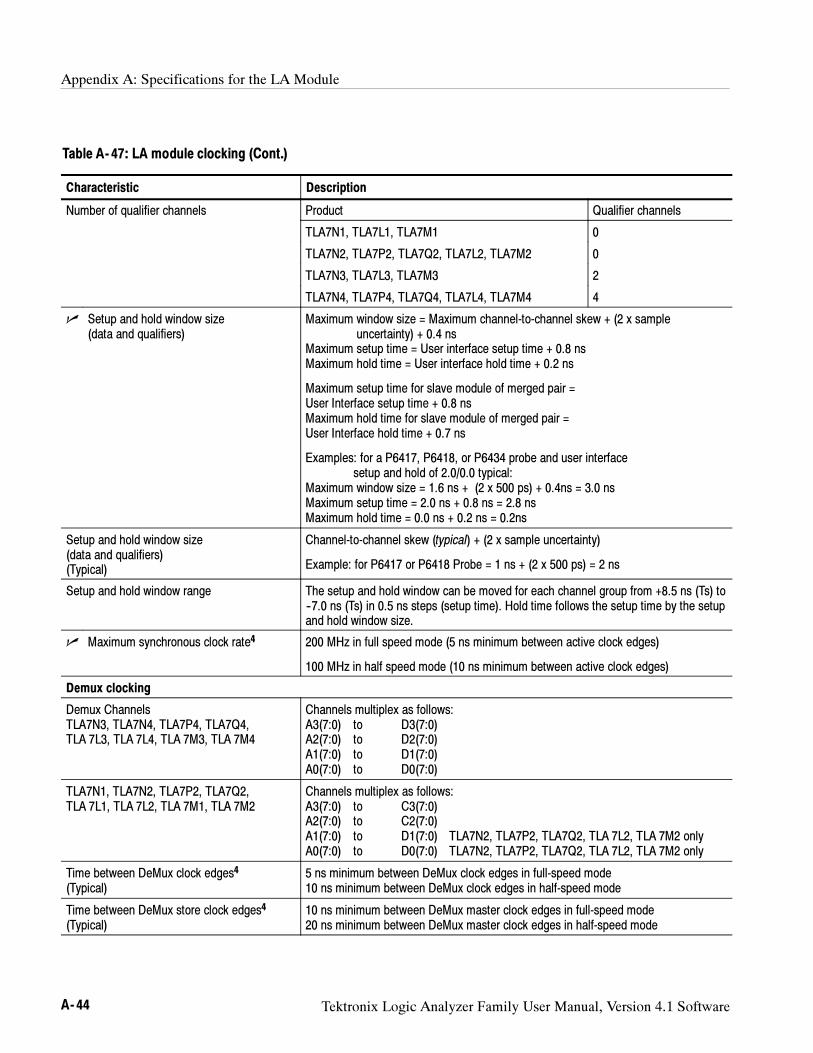
Appendix A: Specifications for the LA Module
A- 44 Tektronix Logic Analyzer Family User Manual, Version 4.1 Software
Table A- 47: LA module clocking (Cont.)
Characteristic Description
Number of qualifier channels Product Qualifier channels
TLA7N1, TLA7L1, TLA7M1 0
TLA7N2, TLA7P2, TLA7Q2, TLA7L2, TLA7M2 0
TLA7N3, TLA7L3, TLA7M3 2
TLA7N4, TLA7P4, TLA7Q4, TLA7L4, TLA7M4 4
Setup and hold window size(data and qualifiers)
Maximum window size = Maximum channel-to-channel skew + (2 x sampleuncertainty) + 0.4 ns
Maximum setup time = User interface setup time + 0.8 nsMaximum hold time = User interface hold time + 0.2 ns
Maximum setup time for slave module of merged pair =User Interface setup time + 0.8 nsMaximum hold time for slave module of merged pair =User Interface hold time + 0.7 ns
Examples: for a P6417, P6418, or P6434 probe and user interfacesetup and hold of 2.0/0.0 typical:
Maximum window size = 1.6 ns + (2 x 500 ps) + 0.4ns = 3.0 nsMaximum setup time = 2.0 ns + 0.8 ns = 2.8 nsMaximum hold time = 0.0 ns + 0.2 ns = 0.2ns
Setup and hold window size(data and qualifiers)(Typical)
Channel-to-channel skew (typical) + (2 x sample uncertainty)
Example: for P6417 or P6418 Probe = 1 ns + (2 x 500 ps) = 2 ns
Setup and hold window range The setup and hold window can be moved for each channel group from +8.5 ns (Ts) to--7.0 ns (Ts) in 0.5 ns steps (setup time). Hold time follows the setup time by the setupand hold window size.
Maximum synchronous clock rate4 200 MHz in full speed mode (5 ns minimum between active clock edges)
100 MHz in half speed mode (10 ns minimum between active clock edges)
Demux clocking
Demux ChannelsTLA7N3, TLA7N4, TLA7P4, TLA7Q4,TLA 7L3, TLA 7L4, TLA 7M3, TLA 7M4
Channels multiplex as follows:A3(7:0) to D3(7:0)A2(7:0) to D2(7:0)A1(7:0) to D1(7:0)A0(7:0) to D0(7:0)
TLA7N1, TLA7N2, TLA7P2, TLA7Q2,TLA 7L1, TLA 7L2, TLA 7M1, TLA 7M2
Channels multiplex as follows:A3(7:0) to C3(7:0)A2(7:0) to C2(7:0)A1(7:0) to D1(7:0) TLA7N2, TLA7P2, TLA7Q2, TLA 7L2, TLA 7M2 onlyA0(7:0) to D0(7:0) TLA7N2, TLA7P2, TLA7Q2, TLA 7L2, TLA 7M2 only
Time between DeMux clock edges4
(Typical)5 ns minimum between DeMux clock edges in full-speed mode10 ns minimum between DeMux clock edges in half-speed mode
Time between DeMux store clock edges4
(Typical)10 ns minimum between DeMux master clock edges in full-speed mode20 ns minimum between DeMux master clock edges in half-speed mode
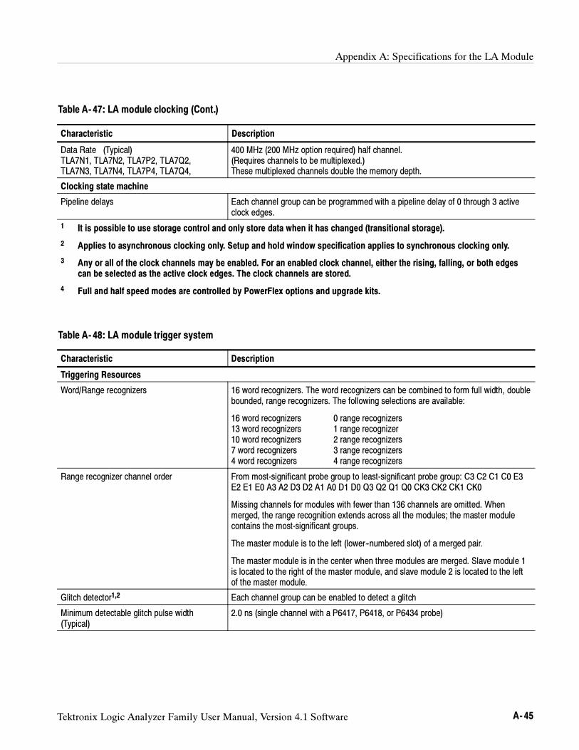
Appendix A: Specifications for the LA Module
Tektronix Logic Analyzer Family User Manual, Version 4.1 Software A- 45
Table A- 47: LA module clocking (Cont.)
Characteristic Description
Data Rate (Typical)TLA7N1, TLA7N2, TLA7P2, TLA7Q2,TLA7N3, TLA7N4, TLA7P4, TLA7Q4,
400 MHz (200 MHz option required) half channel.(Requires channels to be multiplexed.)These multiplexed channels double the memory depth.
Clocking state machine
Pipeline delays Each channel group can be programmed with a pipeline delay of 0 through 3 activeclock edges.
1 It is possible to use storage control and only store data when it has changed (transitional storage).
2 Applies to asynchronous clocking only. Setup and hold window specification applies to synchronous clocking only.
3 Any or all of the clock channels may be enabled. For an enabled clock channel, either the rising, falling, or both edgescan be selected as the active clock edges. The clock channels are stored.
4 Full and half speed modes are controlled by PowerFlex options and upgrade kits.
Table A- 48: LA module trigger system
Characteristic Description
Triggering Resources
Word/Range recognizers 16 word recognizers. The word recognizers can be combined to form full width, doublebounded, range recognizers. The following selections are available:
16 word recognizers 0 range recognizers13 word recognizers 1 range recognizer10 word recognizers 2 range recognizers7 word recognizers 3 range recognizers4 word recognizers 4 range recognizers
Range recognizer channel order From most-significant probe group to least-significant probe group: C3 C2 C1 C0 E3E2 E1 E0 A3 A2 D3 D2 A1 A0 D1 D0 Q3 Q2 Q1 Q0 CK3 CK2 CK1 CK0
Missing channels for modules with fewer than 136 channels are omitted. Whenmerged, the range recognition extends across all the modules; the master modulecontains the most-significant groups.
The master module is to the left (lower--numbered slot) of a merged pair.
The master module is in the center when three modules are merged. Slave module 1is located to the right of the master module, and slave module 2 is located to the leftof the master module.
Glitch detector1,2 Each channel group can be enabled to detect a glitch
Minimum detectable glitch pulse width(Typical)
2.0 ns (single channel with a P6417, P6418, or P6434 probe)
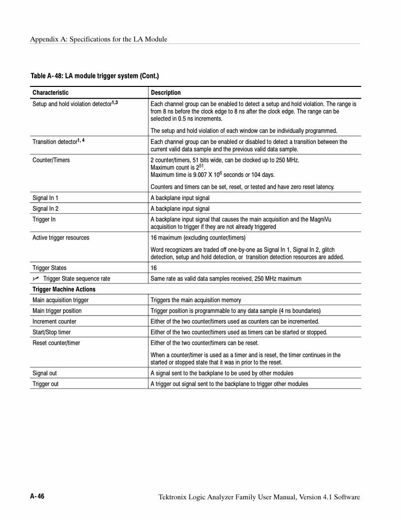
Appendix A: Specifications for the LA Module
A- 46 Tektronix Logic Analyzer Family User Manual, Version 4.1 Software
Table A- 48: LA module trigger system (Cont.)
Characteristic Description
Setup and hold violation detector1,3 Each channel group can be enabled to detect a setup and hold violation. The range isfrom 8 ns before the clock edge to 8 ns after the clock edge. The range can beselected in 0.5 ns increments.
The setup and hold violation of each window can be individually programmed.
Transition detector1, 4 Each channel group can be enabled or disabled to detect a transition between thecurrent valid data sample and the previous valid data sample.
Counter/Timers 2 counter/timers, 51 bits wide, can be clocked up to 250 MHz.Maximum count is 251.Maximum time is 9.007 X 10⁶ seconds or 104 days.
Counters and timers can be set, reset, or tested and have zero reset latency.
Signal In 1 A backplane input signal
Signal In 2 A backplane input signal
Trigger In A backplane input signal that causes the main acquisition and the MagniVuacquisition to trigger if they are not already triggered
Active trigger resources 16 maximum (excluding counter/timers)
Word recognizers are traded off one-by-one as Signal In 1, Signal In 2, glitchdetection, setup and hold detection, or transition detection resources are added.
Trigger States 16
Trigger State sequence rate Same rate as valid data samples received, 250 MHz maximum
Trigger Machine Actions
Main acquisition trigger Triggers the main acquisition memory
Main trigger position Trigger position is programmable to any data sample (4 ns boundaries)
Increment counter Either of the two counter/timers used as counters can be incremented.
Start/Stop timer Either of the two counter/timers used as timers can be started or stopped.
Reset counter/timer Either of the two counter/timers can be reset.
When a counter/timer is used as a timer and is reset, the timer continues in thestarted or stopped state that it was in prior to the reset.
Signal out A signal sent to the backplane to be used by other modules
Trigger out A trigger out signal sent to the backplane to trigger other modules
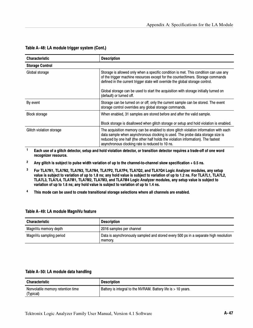
Appendix A: Specifications for the LA Module
Tektronix Logic Analyzer Family User Manual, Version 4.1 Software A- 47
Table A- 48: LA module trigger system (Cont.)
Characteristic Description
Storage Control
Global storage Storage is allowed only when a specific condition is met. This condition can use anyof the trigger machine resources except for the counter/timers. Storage commandsdefined in the current trigger state will override the global storage control.
Global storage can be used to start the acquisition with storage initially turned on(default) or turned off.
By event Storage can be turned on or off; only the current sample can be stored. The eventstorage control overrides any global storage commands.
Block storage When enabled, 31 samples are stored before and after the valid sample.
Block storage is disallowed when glitch storage or setup and hold violation is enabled.
Glitch violation storage The acquisition memory can be enabled to store glitch violation information with eachdata sample when asynchronous clocking is used. The probe data storage size isreduced by one half (the other half holds the violation information). The fastestasynchronous clocking rate is reduced to 10 ns.
1 Each use of a glitch detector, setup and hold violation detector, or transition detector requires a trade-off of one wordrecognizer resource.
2 Any glitch is subject to pulse width variation of up to the channel-to-channel skew specification + 0.5 ns.
3 For TLA7N1, TLA7N2, TLA7N3, TLA7N4, TLA7P2, TLA7P4, TLA7Q2, and TLA7Q4 Logic Analyzer modules, any setupvalue is subject to variation of up to 1.8 ns; any hold value is subject to variation of up to 1.2 ns. For TLA7L1, TLA7L2,TLA7L3, TLA7L4, TLA7M1, TLA7M2, TLA7M3, and TLA7M4 Logic Analyzer modules, any setup value is subject tovariation of up to 1.6 ns; any hold value is subject to variation of up to 1.4 ns.
4 This mode can be used to create transitional storage selections where all channels are enabled.
Table A- 49: LA module MagniVu feature
Characteristic Description
MagniVu memory depth 2016 samples per channel
MagniVu sampling period Data is asynchronously sampled and stored every 500 ps in a separate high resolutionmemory.
Table A- 50: LA module data handling
Characteristic Description
Nonvolatile memory retention time(Typical)
Battery is integral to the NVRAM. Battery life is > 10 years.
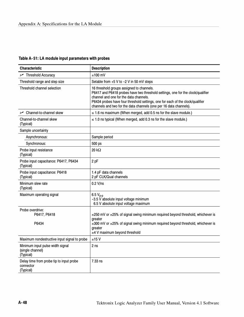
Appendix A: Specifications for the LA Module
A- 48 Tektronix Logic Analyzer Family User Manual, Version 4.1 Software
Table A- 51: LA module input parameters with probes
Characteristic Description
Threshold Accuracy ±100 mV
Threshold range and step size Setable from +5 V to --2 V in 50 mV steps
Threshold channel selection 16 threshold groups assigned to channels.P6417 and P6418 probes have two threshold settings, one for the clock/qualifierchannel and one for the data channels.P6434 probes have four threshold settings, one for each of the clock/qualifierchannels and two for the data channels (one per 16 data channels).
Channel-to-channel skew ≤ 1.6 ns maximum (When merged, add 0.5 ns for the slave module.)
Channel-to-channel skew(Typical)
≤ 1.0 ns typical (When merged, add 0.3 ns for the slave module.)
Sample uncertainty
Asynchronous: Sample period
Synchronous: 500 ps
Probe input resistance(Typical)
20 kΩ
Probe input capacitance: P6417, P6434(Typical)
2 pF
Probe input capacitance: P6418(Typical)
1.4 pF data channels2 pF CLK/Qual channels
Minimum slew rate(Typical)
0.2 V/ns
Maximum operating signal 6.5 Vp-p--3.5 V absolute input voltage minimum6.5 V absolute input voltage maximum
Probe overdrive:P6417, P6418
P6434
±250 mV or ±25% of signal swing minimum required beyond threshold, whichever isgreater±300 mV or ±25% of signal swing minimum required beyond threshold, whichever isgreater±4 V maximum beyond threshold
Maximum nondestructive input signal to probe ±15 V
Minimum input pulse width signal(single channel)(Typical)
2 ns
Delay time from probe tip to input probeconnector(Typical)
7.33 ns
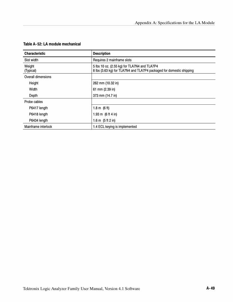
Appendix A: Specifications for the LA Module
Tektronix Logic Analyzer Family User Manual, Version 4.1 Software A- 49
Table A- 52: LA module mechanical
Characteristic Description
Slot width Requires 2 mainframe slots
Weight(Typical)
5 lbs 10 oz. (2.55 kg) for TLA7N4 and TLA7P48 lbs (3.63 kg) for TLA7N4 and TLA7P4 packaged for domestic shipping
Overall dimensions
Height 262 mm (10.32 in)
Width 61 mm (2.39 in)
Depth 373 mm (14.7 in)
Probe cables
P6417 length 1.8 m (6 ft)
P6418 length 1.93 m (6 ft 4 in)
P6434 length 1.6 m (5 ft 2 in)
Mainframe interlock 1.4 ECL keying is implemented
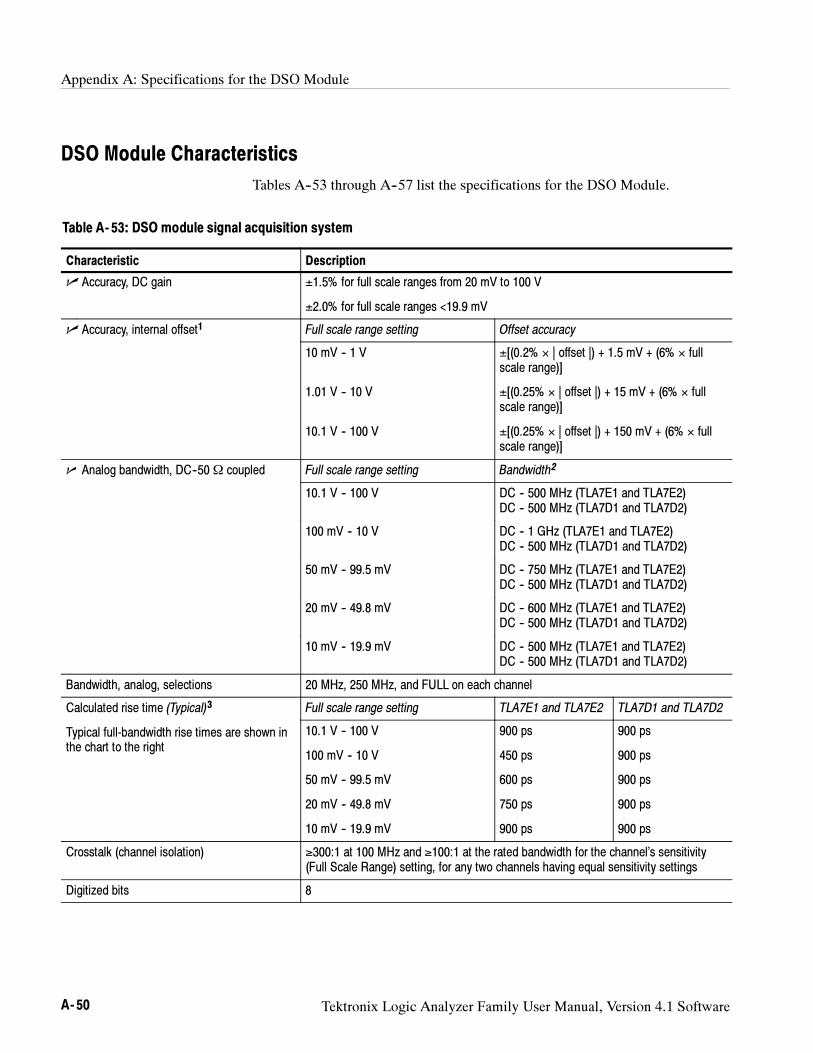
Appendix A: Specifications for the DSO Module
A- 50 Tektronix Logic Analyzer Family User Manual, Version 4.1 Software
DSO Module Characteristics
Tables A--53 through A--57 list the specifications for the DSO Module.
Table A- 53: DSO module signal acquisition system
Characteristic Description
Accuracy, DC gain ±1.5% for full scale ranges from 20 mV to 100 V
±2.0% for full scale ranges <19.9 mV
Accuracy, internal offset1 Full scale range setting Offset accuracy
10 mV -- 1 V
1.01 V -- 10 V
10.1 V -- 100 V
±[(0.2% × | offset |) + 1.5 mV + (6% × fullscale range)]
±[(0.25% × | offset |) + 15 mV + (6% × fullscale range)]
±[(0.25% × | offset |) + 150 mV + (6% × fullscale range)]
Analog bandwidth, DC--50Ω coupled Full scale range setting Bandwidth2
10.1 V -- 100 V DC -- 500 MHz (TLA7E1 and TLA7E2)DC -- 500 MHz (TLA7D1 and TLA7D2)
100 mV -- 10 V DC -- 1 GHz (TLA7E1 and TLA7E2)DC -- 500 MHz (TLA7D1 and TLA7D2)
50 mV -- 99.5 mV DC -- 750 MHz (TLA7E1 and TLA7E2)DC -- 500 MHz (TLA7D1 and TLA7D2)
20 mV -- 49.8 mV DC -- 600 MHz (TLA7E1 and TLA7E2)DC -- 500 MHz (TLA7D1 and TLA7D2)
10 mV -- 19.9 mV DC -- 500 MHz (TLA7E1 and TLA7E2)DC -- 500 MHz (TLA7D1 and TLA7D2)
Bandwidth, analog, selections 20 MHz, 250 MHz, and FULL on each channel
Calculated rise time (Typical)3 Full scale range setting TLA7E1 and TLA7E2 TLA7D1 and TLA7D2
Typical full-bandwidth rise times are shown inthe chart to the right
10.1 V -- 100 V
100 mV -- 10 V
50 mV -- 99.5 mV
20 mV -- 49.8 mV
10 mV -- 19.9 mV
900 ps
450 ps
600 ps
750 ps
900 ps
900 ps
900 ps
900 ps
900 ps
900 ps
Crosstalk (channel isolation) ≥300:1 at 100 MHz and ≥100:1 at the rated bandwidth for the channel’s sensitivity(Full Scale Range) setting, for any two channels having equal sensitivity settings
Digitized bits 8
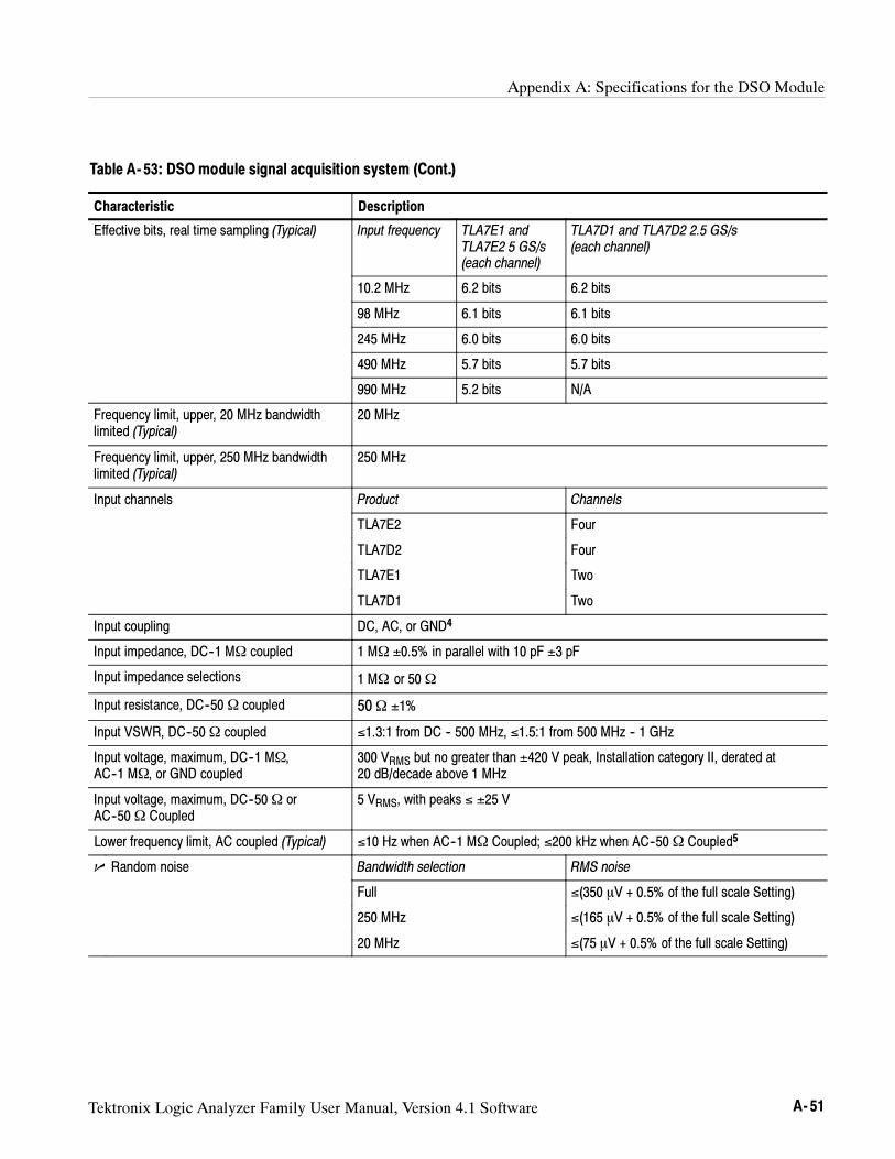
Appendix A: Specifications for the DSO Module
Tektronix Logic Analyzer Family User Manual, Version 4.1 Software A- 51
Table A- 53: DSO module signal acquisition system (Cont.)
Characteristic Description
Effective bits, real time sampling (Typical) Input frequency TLA7E1 andTLA7E2 5 GS/s(each channel)
TLA7D1 and TLA7D2 2.5 GS/s(each channel)
10.2 MHz 6.2 bits 6.2 bits
98 MHz 6.1 bits 6.1 bits
245 MHz 6.0 bits 6.0 bits
490 MHz 5.7 bits 5.7 bits
990 MHz 5.2 bits N/A
Frequency limit, upper, 20 MHz bandwidthlimited (Typical)
20 MHz
Frequency limit, upper, 250 MHz bandwidthlimited (Typical)
250 MHz
Input channels Product Channels
TLA7E2 Four
TLA7D2 Four
TLA7E1 Two
TLA7D1 Two
Input coupling DC, AC, or GND4
Input impedance, DC--1 MΩ coupled 1 MΩ ±0.5% in parallel with 10 pF ±3 pF
Input impedance selections 1 MΩ or 50Ω
Input resistance, DC--50Ω coupled 50Ω ±1%
Input VSWR, DC--50Ω coupled ≤1.3:1 from DC -- 500 MHz, ≤1.5:1 from 500 MHz -- 1 GHz
Input voltage, maximum, DC--1 MΩ,AC--1 MΩ, or GND coupled
300 VRMS but no greater than ±420 V peak, Installation category II, derated at20 dB/decade above 1 MHz
Input voltage, maximum, DC--50Ω orAC--50Ω Coupled
5 VRMS, with peaks ≤ ±25 V
Lower frequency limit, AC coupled (Typical) ≤10 Hz when AC--1 MΩ Coupled; ≤200 kHz when AC--50Ω Coupled5
Random noise Bandwidth selection RMS noise
Full ≤(350 V + 0.5% of the full scale Setting)
250 MHz ≤(165 V + 0.5% of the full scale Setting)
20 MHz ≤(75 V + 0.5% of the full scale Setting)
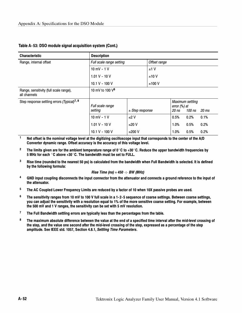
Appendix A: Specifications for the DSO Module
A- 52 Tektronix Logic Analyzer Family User Manual, Version 4.1 Software
Table A- 53: DSO module signal acquisition system (Cont.)
Characteristic Description
Range, internal offset Full scale range setting Offset range
10 mV -- 1 V
1.01 V -- 10 V
10.1 V -- 100 V
±1 V
±10 V
±100 V
Range, sensitivity (full scale range),all channels
10 mV to 100 V6
Step response settling errors (Typical)7, 8
Full scale rangesetting ± Step response
Maximum settlingerror (%) at20 ns 100 ns 20 ms
10 mV -- 1 V
1.01 V -- 10 V
10.1 V -- 100 V
≤2 V
≤20 V
≤200 V
0.5% 0.2% 0.1%
1.0% 0.5% 0.2%
1.0% 0.5% 0.2%
1 Net offset is the nominal voltage level at the digitizing oscilloscope input that corresponds to the center of the A/DConverter dynamic range. Offset accuracy is the accuracy of this voltage level.
2 The limits given are for the ambient temperature range of 0C to +30C. Reduce the upper bandwidth frequencies by5 MHz for each C above +30C. The bandwidth must be set to FULL.
3 Rise time (rounded to the nearest 50 ps) is calculated from the bandwidth when Full Bandwidth is selected. It is definedby the following formula:
Rise Time (ns) = 450 BW (MHz)4 GND input coupling disconnects the input connector from the attenuator and connects a ground reference to the input of
the attenuator.
5 The AC Coupled Lower Frequency Limits are reduced by a factor of 10 when 10X passive probes are used.
6 The sensitivity ranges from 10 mV to 100 V full scale in a 1- 2- 5 sequence of coarse settings. Between coarse settings,you can adjust the sensitivity with a resolution equal to 1% of the more sensitive coarse setting. For example, betweenthe 500 mV and 1 V ranges, the sensitivity can be set with 5 mV resolution.
7 The Full Bandwidth settling errors are typically less than the percentages from the table.
8 The maximum absolute difference between the value at the end of a specified time interval after the mid-level crossing ofthe step, and the value one second after the mid-level crossing of the step, expressed as a percentage of the stepamplitude. See IEEE std. 1057, Section 4.8.1, Settling Time Parameters.
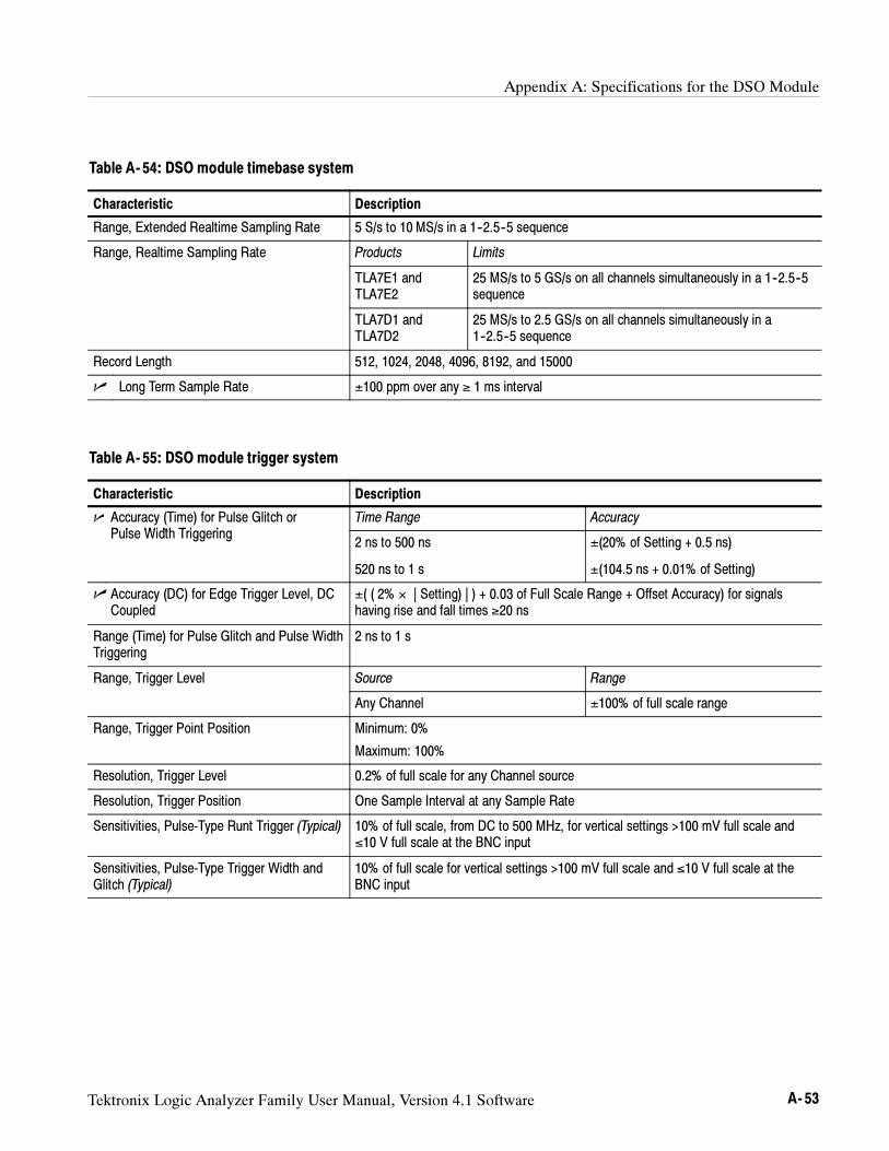
Appendix A: Specifications for the DSO Module
Tektronix Logic Analyzer Family User Manual, Version 4.1 Software A- 53
Table A- 54: DSO module timebase system
Characteristic Description
Range, Extended Realtime Sampling Rate 5 S/s to 10 MS/s in a 1--2.5--5 sequence
Range, Realtime Sampling Rate Products Limits
TLA7E1 andTLA7E2
25 MS/s to 5 GS/s on all channels simultaneously in a 1--2.5--5sequence
TLA7D1 andTLA7D2
25 MS/s to 2.5 GS/s on all channels simultaneously in a1--2.5--5 sequence
Record Length 512, 1024, 2048, 4096, 8192, and 15000
Long Term Sample Rate ±100 ppm over any ≥ 1 ms interval
Table A- 55: DSO module trigger system
Characteristic Description
Accuracy (Time) for Pulse Glitch orP l Width T i i
Time Range AccuracyPulse Width Triggering
2 ns to 500 ns
520 ns to 1 s
±(20% of Setting + 0.5 ns)
±(104.5 ns + 0.01% of Setting)
Accuracy (DC) for Edge Trigger Level, DCCoupled
±( ( 2% × | Setting) | ) + 0.03 of Full Scale Range + Offset Accuracy) for signalshaving rise and fall times ≥20 ns
Range (Time) for Pulse Glitch and Pulse WidthTriggering
2 ns to 1 s
Range, Trigger Level Source Range
Any Channel ±100% of full scale range
Range, Trigger Point Position Minimum: 0%
Maximum: 100%
Resolution, Trigger Level 0.2% of full scale for any Channel source
Resolution, Trigger Position One Sample Interval at any Sample Rate
Sensitivities, Pulse-Type Runt Trigger (Typical) 10% of full scale, from DC to 500 MHz, for vertical settings >100 mV full scale and≤10 V full scale at the BNC input
Sensitivities, Pulse-Type Trigger Width andGlitch (Typical)
10% of full scale for vertical settings >100 mV full scale and ≤10 V full scale at theBNC input
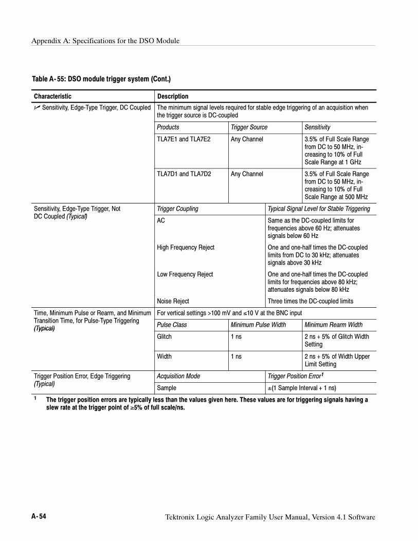
Appendix A: Specifications for the DSO Module
A- 54 Tektronix Logic Analyzer Family User Manual, Version 4.1 Software
Table A- 55: DSO module trigger system (Cont.)
Characteristic Description
Sensitivity, Edge-Type Trigger, DC Coupled The minimum signal levels required for stable edge triggering of an acquisition whenthe trigger source is DC-coupled
Products Trigger Source Sensitivity
TLA7E1 and TLA7E2 Any Channel 3.5% of Full Scale Rangefrom DC to 50 MHz, in-creasing to 10% of FullScale Range at 1 GHz
TLA7D1 and TLA7D2 Any Channel 3.5% of Full Scale Rangefrom DC to 50 MHz, in-creasing to 10% of FullScale Range at 500 MHz
Sensitivity, Edge-Type Trigger, NotDC C l d (T i l)
Trigger Coupling Typical Signal Level for Stable TriggeringDC Coupled (Typical)
AC Same as the DC-coupled limits forfrequencies above 60 Hz; attenuatessignals below 60 Hz
High Frequency Reject One and one-half times the DC-coupledlimits from DC to 30 kHz; attenuatessignals above 30 kHz
Low Frequency Reject One and one-half times the DC-coupledlimits for frequencies above 80 kHz;attenuates signals below 80 kHz
Noise Reject Three times the DC-coupled limits
Time, Minimum Pulse or Rearm, and MinimumT iti Ti f P l T T i i
For vertical settings >100 mV and ≤10 V at the BNC inputTransition Time, for Pulse-Type Triggering(Typical)
Pulse Class Minimum Pulse Width Minimum Rearm Width(Typical)
Glitch 1 ns 2 ns + 5% of Glitch WidthSetting
Width 1 ns 2 ns + 5% of Width UpperLimit Setting
Trigger Position Error, Edge Triggering(T i l)
Acquisition Mode Trigger Position Error1
(Typical)Sample ±(1 Sample Interval + 1 ns)
1 The trigger position errors are typically less than the values given here. These values are for triggering signals having aslew rate at the trigger point of ≥5% of full scale/ns.
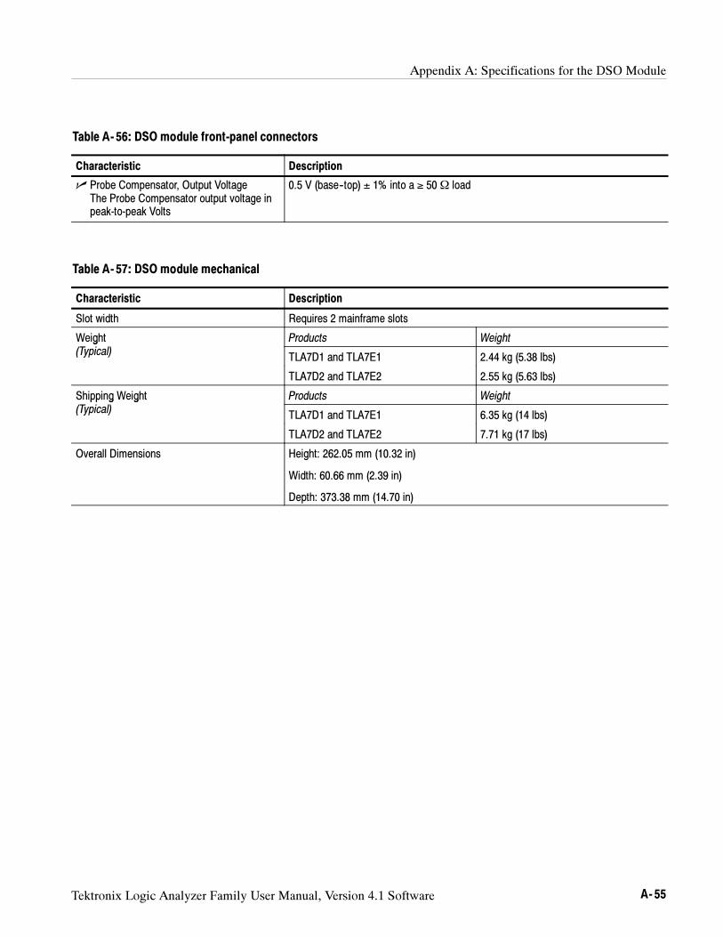
Appendix A: Specifications for the DSO Module
Tektronix Logic Analyzer Family User Manual, Version 4.1 Software A- 55
Table A- 56: DSO module front-panel connectors
Characteristic Description
Probe Compensator, Output VoltageThe Probe Compensator output voltage inpeak-to-peak Volts
0.5 V (base--top) ± 1% into a ≥ 50Ω load
Table A- 57: DSO module mechanical
Characteristic Description
Slot width Requires 2 mainframe slots
Weight Products Weightg(Typical) TLA7D1 and TLA7E1 2.44 kg (5.38 lbs)
TLA7D2 and TLA7E2 2.55 kg (5.63 lbs)
Shipping Weight Products Weightpp g g(Typical) TLA7D1 and TLA7E1 6.35 kg (14 lbs)
TLA7D2 and TLA7E2 7.71 kg (17 lbs)
Overall Dimensions Height: 262.05 mm (10.32 in)
Width: 60.66 mm (2.39 in)
Depth: 373.38 mm (14.70 in)
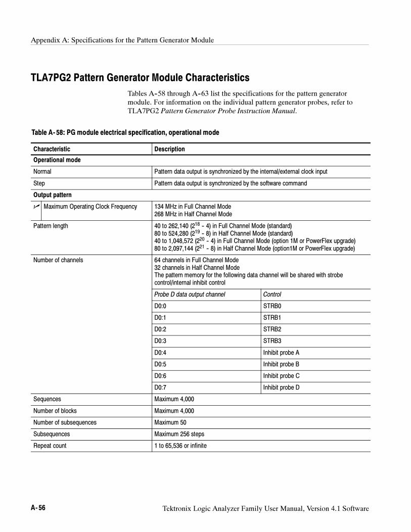
Appendix A: Specifications for the Pattern Generator Module
A- 56 Tektronix Logic Analyzer Family User Manual, Version 4.1 Software
TLA7PG2 Pattern Generator Module Characteristics
Tables A--58 through A--63 list the specifications for the pattern generatormodule. For information on the individual pattern generator probes, refer toTLA7PG2 Pattern Generator Probe Instruction Manual.
Table A- 58: PG module electrical specification, operational mode
Characteristic Description
Operational mode
Normal Pattern data output is synchronized by the internal/external clock input
Step Pattern data output is synchronized by the software command
Output pattern
Maximum Operating Clock Frequency 134 MHz in Full Channel Mode268 MHz in Half Channel Mode
Pattern length 40 to 262,140 (218 -- 4) in Full Channel Mode (standard)80 to 524,280 (219 -- 8) in Half Channel Mode (standard)40 to 1,048,572 (220 -- 4) in Full Channel Mode (option 1M or PowerFlex upgrade)80 to 2,097,144 (221 -- 8) in Half Channel Mode (option1M or PowerFlex upgrade)
Number of channels 64 channels in Full Channel Mode32 channels in Half Channel ModeThe pattern memory for the following data channel will be shared with strobecontrol/internal inhibit control
Probe D data output channel Control
D0:0 STRB0
D0:1 STRB1
D0:2 STRB2
D0:3 STRB3
D0:4 Inhibit probe A
D0:5 Inhibit probe B
D0:6 Inhibit probe C
D0:7 Inhibit probe D
Sequences Maximum 4,000
Number of blocks Maximum 4,000
Number of subsequences Maximum 50
Subsequences Maximum 256 steps
Repeat count 1 to 65,536 or infinite
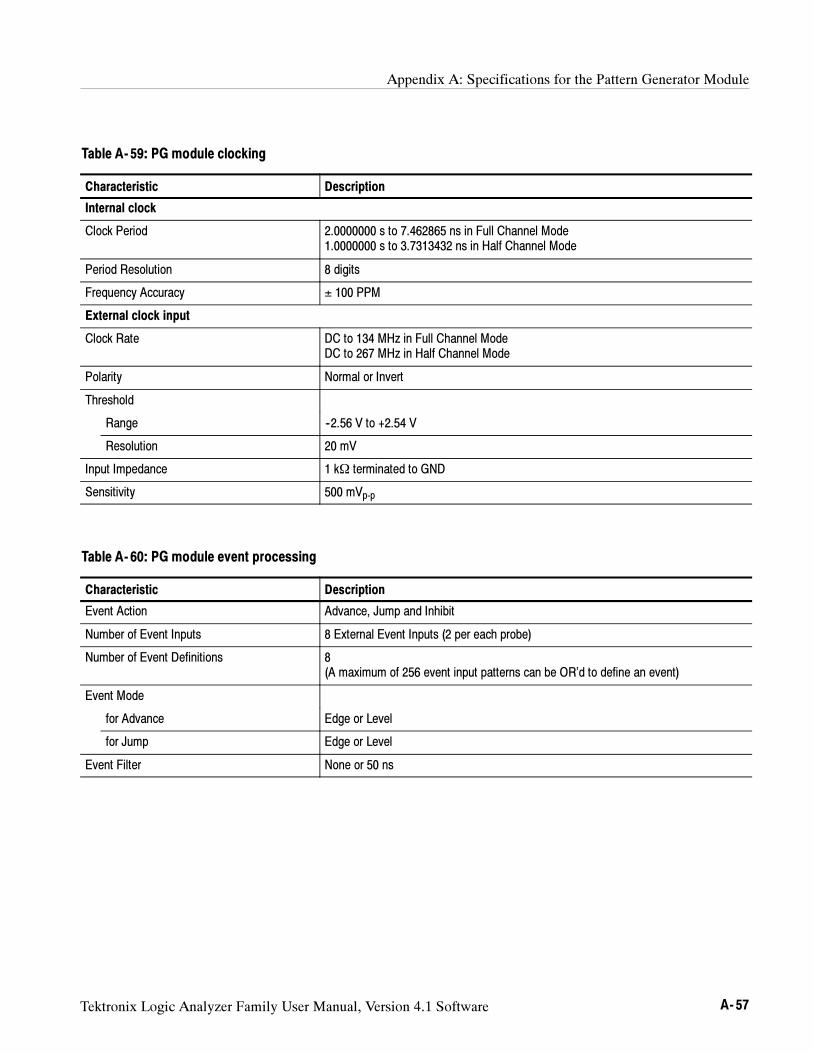
Appendix A: Specifications for the Pattern Generator Module
Tektronix Logic Analyzer Family User Manual, Version 4.1 Software A- 57
Table A- 59: PG module clocking
Characteristic Description
Internal clock
Clock Period 2.0000000 s to 7.462865 ns in Full Channel Mode1.0000000 s to 3.7313432 ns in Half Channel Mode
Period Resolution 8 digits
Frequency Accuracy ± 100 PPM
External clock input
Clock Rate DC to 134 MHz in Full Channel ModeDC to 267 MHz in Half Channel Mode
Polarity Normal or Invert
Threshold
Range --2.56 V to +2.54 V
Resolution 20 mV
Input Impedance 1 kΩ terminated to GND
Sensitivity 500 mVp-p
Table A- 60: PG module event processing
Characteristic Description
Event Action Advance, Jump and Inhibit
Number of Event Inputs 8 External Event Inputs (2 per each probe)
Number of Event Definitions 8(A maximum of 256 event input patterns can be OR’d to define an event)
Event Mode
for Advance Edge or Level
for Jump Edge or Level
Event Filter None or 50 ns
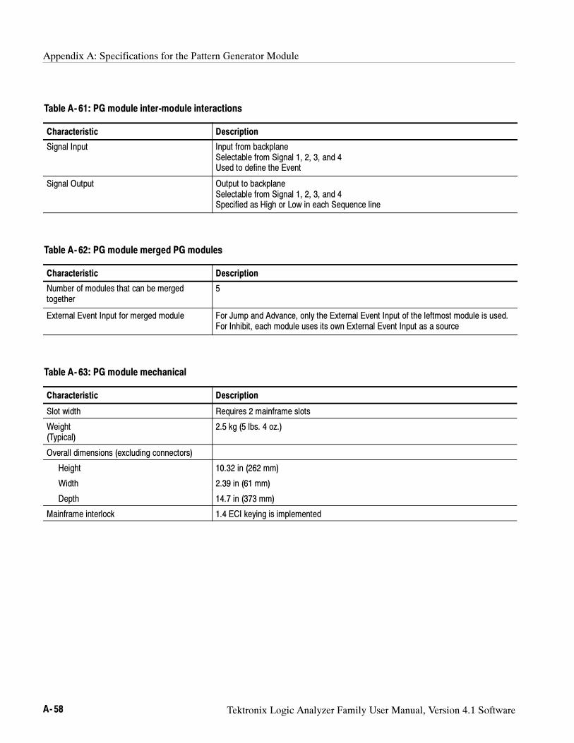
Appendix A: Specifications for the Pattern Generator Module
A- 58 Tektronix Logic Analyzer Family User Manual, Version 4.1 Software
Table A- 61: PG module inter-module interactions
Characteristic Description
Signal Input Input from backplaneSelectable from Signal 1, 2, 3, and 4Used to define the Event
Signal Output Output to backplaneSelectable from Signal 1, 2, 3, and 4Specified as High or Low in each Sequence line
Table A- 62: PG module merged PG modules
Characteristic Description
Number of modules that can be mergedtogether
5
External Event Input for merged module For Jump and Advance, only the External Event Input of the leftmost module is used.For Inhibit, each module uses its own External Event Input as a source
Table A- 63: PG module mechanical
Characteristic Description
Slot width Requires 2 mainframe slots
Weight(Typical)
2.5 kg (5 lbs. 4 oz.)
Overall dimensions (excluding connectors)
Height 10.32 in (262 mm)
Width 2.39 in (61 mm)
Depth 14.7 in (373 mm)
Mainframe interlock 1.4 ECI keying is implemented
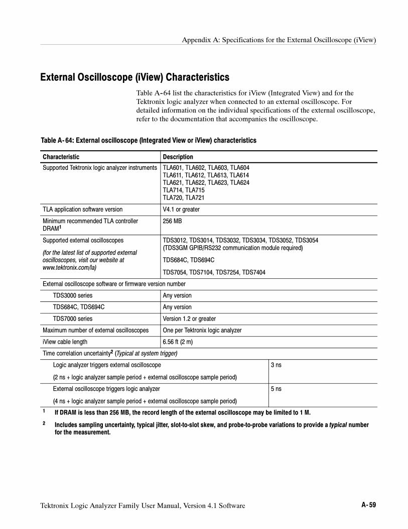
Appendix A: Specifications for the External Oscilloscope (iView)
Tektronix Logic Analyzer Family User Manual, Version 4.1 Software A- 59
External Oscilloscope (iView) Characteristics
Table A--64 list the characteristics for iView (Integrated View) and for theTektronix logic analyzer when connected to an external oscilloscope. Fordetailed information on the individual specifications of the external oscilloscope,refer to the documentation that accompanies the oscilloscope.
Table A- 64: External oscilloscope (Integrated View or iView) characteristics
Characteristic Description
Supported Tektronix logic analyzer instruments TLA601, TLA602, TLA603, TLA604TLA611, TLA612, TLA613, TLA614TLA621, TLA622, TLA623, TLA624TLA714, TLA715TLA720, TLA721
TLA application software version V4.1 or greater
Minimum recommended TLA controllerDRAM1
256 MB
Supported external oscilloscopes
(for the latest list of supported externaloscilloscopes, visit our website atwww.tektronix.com/la)
TDS3012, TDS3014, TDS3032, TDS3034, TDS3052, TDS3054(TDS3GM GPIB/RS232 communication module required)
TDS684C, TDS694C
TDS7054, TDS7104, TDS7254, TDS7404
External oscilloscope software or firmware version number
TDS3000 series Any version
TDS684C, TDS694C Any version
TDS7000 series Version 1.2 or greater
Maximum number of external oscilloscopes One per Tektronix logic analyzer
iView cable length 6.56 ft (2 m)
Time correlation uncertainty2 (Typical at system trigger)
Logic analyzer triggers external oscilloscope
(2 ns + logic analyzer sample period + external oscilloscope sample period)
3 ns
External oscilloscope triggers logic analyzer
(4 ns + logic analyzer sample period + external oscilloscope sample period)
5 ns
1 If DRAM is less than 256 MB, the record length of the external oscilloscope may be limited to 1 M.
2 Includes sampling uncertainty, typical jitter, slot-to-slot skew, and probe-to-probe variations to provide a typical numberfor the measurement.
Appendix A: Specifications for the External Oscilloscope (iView)
A- 60 Tektronix Logic Analyzer Family User Manual, Version 4.1 Software
Tektronix Logic Analyzer Family User Manual, Version 4.1 Software B- 1
Appendix B: TLA Symbol File Format
The logic analyzer can extract range symbol information directly from objectfiles. The following are some of the formats. Check with your Tektronixrepresentative for a complete listing of available formats.
OMF51, OMF86, OMF166, OMF286, OMF386, IEEE695, COFF,ELF/DWARF1 and DWARF2, and ELF/STABS
Users whose code generation tools do not generate these file formats can useTLA Symbol File (TSF) format (a text format). The TSF format is used by thelogic analyzer when it exports symbol files. The logic analyzer can also read filesin this format.
TLA symbol files consist of alphanumeric symbol names and associated datavalues. The files contain a header line and lines defining the symbol names andvalues. Fields on a line are separated with white space (blank spaces or tabs).The formats for the pattern symbol files and the various range symbol filesdiffer; if you need to use pattern symbols and range symbols, use separate files.
Both TLA range and pattern symbol files have a .tsf file name extension(filename.tsf).
The first few lines of a TSF symbol file are typically comment lines describingwhen and how the file was generated.
# TLA Symbol File# Created on Friday, May 29, 1998 at 09:52:03# From file: ”c:\quickstart\tla7qs.x”
All lines in a TSF file that begin with a number sign (#) character are treated ascomments, unless the very next character is a plus sign (+). The plus signsignifies a file reader directive. (An example of a file reader directive “#+” canbe seen in the TSF header definition on the next page.) The number signcharacter can also initiate a comment on the end of a symbol definition or otheruncommented lines. All text between the number sign and the end of the line istreated as a comment and ignored.
Appendix B: TLA Symbol File Format
B- 2 Tektronix Logic Analyzer Family User Manual, Version 4.1 Software
TSF Headers
A TSF header identifies the file format version to potential file readers. Itspecifies whether the file contains pattern or range symbols, the radix used tospecify symbol values, and an optional offset amount to be added to each symbolvalue (for range symbol files).
The TSF Header is a file directive which means that the following informationbegins with the special character combination of a number sign characterfollowed immediately by a plus sign (#+). This is not a comment line. Thespecial character sequence is used to mark instructions to the file reader; theseinstructions are called file directives.
The following examples show sample file headers for a pattern symbol file and arange symbol file. The first two lines are comments included for readability; theyare not required as part of the file header.
# TSF Format Type Display Radix File Radix# =============== ======= ============= ==========#+ Version 2.1.0 PATTERN HEX HEX
# TSF Format Type Display Radix File Radix Offset# =============== ===== ============= ========== ========#+ Version 2.1.0 RANGE HEX HEX 00000000
The File Format Version number contains three fields. The first two fields are theformat major and minor version numbers. The logic analyzer will only read TSFfiles where the major and minor version number of the file is less than or equalto that of the TLA TSF symbol file reader. The third field is used to denoteminor format changes which do not impact the file reader.
The File Format Version number is followed by a key word, PATTERN orRANGE, which signifies the type of symbols to be found in the file. TSF filescan contain either type of symbols, but no single file can contain both. Theheader specifies the type for all symbols in the file.
The Display Radix field sets the default radix that will be used to display thenumeric symbol value. For range symbol files this field must be one of the keywords: HEX, DEC, OCT, or BIN. For pattern symbol files, only the key words:HEX, OCT, or BIN are allowed.
The File Radix field specifies the radix used by the symbol values in this file.Like the Display Radix field, the File Radix field must be one of the key words:HEX, DEC, OCT, or BIN for range symbol files, or HEX, OCT, or BIN forpattern symbol files.
Appendix B: TLA Symbol File Format
Tektronix Logic Analyzer Family User Manual, Version 4.1 Software B- 3
The Offset field specifies an offset value and is applicable only to range symbolfiles. The offset value is specified in the radix indicated by the File Radix field.This offset value will be added to the lower and upper bounds of each rangesymbol that is read from the file. The offset is a 32-bit value, so it can have anyvalue between 0x00000000 and 0xFFFFFFFF. If the sum of the offset and arange symbol bound value exceeds the 32-bit limit of 0xFFFFFFFF, theoverflow bit is discarded. Negative offsets are specified by using a twoscomplement value for the offset.
TSF Pattern Symbols
Each pattern symbol in a TSF pattern file consists of two fields. The first field isthe symbol name, and the second is the symbol pattern. The symbol name is asequence of ASCII characters of up to 220 characters in length, although it isimpractical to display symbol values much longer than 32 characters. Symbolnames longer than 220 characters will be truncated during loading. Thecharacters in a symbol name can be any character with an ASCII value between0x21 (the exclamation point character, !) and 0x7E (the tilde character, ~). Youcan use symbol names with embedded spaces by enclosing the Symbol Name indouble quotes.
# Symbol Symbol Optional Foreground# Name Pattern and Background Color# ====== ======== ====================
NUL X0000000SOH X0000001 @red @yellowSTX X0000010”ETX 0x03” X0000011
The symbol pattern consists of numerals in the radix specified by the File Radixfield in the header, and Xs signifying “don’t-care” values. The number of bitsrepresented by each character position in the pattern depends on the selectedradix. For a radix of HEX, each character represents 4 bits. For an OCT radix,each character represents 3 bits; and for a BIN radix, each character representsone bit.
Symbol order in a TSF pattern file is important. When selecting the symbol todisplay for a particular value, the logic analyzer scans the list of pattern symbolsfrom top to bottom. It selects the first symbol for which all non-don’t-care bits ofthe symbol match the corresponding bits of the target symbol.
Appendix B: TLA Symbol File Format
B- 4 Tektronix Logic Analyzer Family User Manual, Version 4.1 Software
TSF Range Symbols
There are four different types of range symbols:
Function
Variable
Source
Color
Each of these types define a range of 32-bit addresses associated with someentity.
Function range symbols define the beginning and ending addresses whereinstructions that implement a function are located in memory.
Variable range symbols define the beginning and ending addresses where thevalue of a variable is located in memory.
Source range symbols are similar to function range symbols, except that theaddress range for a source symbol describes the location of the instructions thatimplement just one source statement. (Source symbols also contain file name,line number, and an optional column range that define the location of the sourcecode associated with the symbol.)
Color range symbols define a display color for any value that falls within arange.
Each of the types of range symbols appear in a separate section of the file. Eachsection begins with a file directive indicating the type of symbols that follow.The sections may appear in any order, and can be broken up and separated byother sections if necessary.
The first section might be variables, followed by functions, then followed byanother variable section. Each section is also optional, however some logicanalyzer applications are unable to use the symbol file if the appropriate type ofsymbols are not present. For example, the source window is only able tocorrelate with a listing window if the symbol file contains source symbols.
Range symbol names follow the same rules as pattern symbol names. Thesymbol name is a sequence of ASCII characters of up to 220 characters in length,even though it is impractical to display symbol values much longer than 32characters.
Symbol names longer than 220 characters will be truncated during loading. Thecharacters in a symbol name can be any character with an ASCII value between0x21 (the exclamation point character, !) and 0x7E (the tilde character, ~). Youcan use symbol names with embedded spaces by enclosing the Symbol Name indouble quotes.
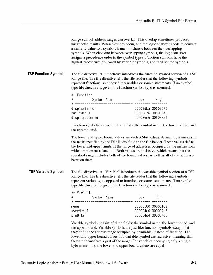
Appendix B: TLA Symbol File Format
Tektronix Logic Analyzer Family User Manual, Version 4.1 Software B- 5
Range symbol address ranges can overlap. This overlap sometimes producesunexpected results. When overlaps occur, and the logic analyzer needs to converta numeric value to a symbol, it must to choose between the overlappingsymbols. When choosing between overlapping symbols, the logic analyzerassigns a precedence order to the symbol types. Function symbols have thehighest precedence, followed by variable symbols, and then source symbols.
The file directive “#+ Function” introduces the function symbol section of a TSFRange file. The file directive tells the file reader that the following symbolsrepresent functions, as opposed to variables or source statements. If no symboltype file directive is given, the function symbol type is assumed.
#+ Function# Symbol Name Low High# ============================== ======== ========displayBanner 006035ba 00603675buildMenus 00603676 006036e5displayLCDmenu 006036e6 0060372f
Function symbols consist of three fields: the symbol name, the lower bound, andthe upper bound.
The lower and upper bound values are each 32-bit values, defined by numerals inthe radix specified by the File Radix field in the file header. These values definethe lower and upper limits of the range of addresses occupied by the instructionswhich implement a function. Both values are inclusive, which means that thespecified range includes both of the bound values, as well as all of the addressesbetween them.
The file directive “#+ Variable” introduces the variable symbol section of a TSFRange file. The file directive tells the file reader that the following symbolsrepresent variables, as opposed to functions or source statements. If no symboltype file directive is given, the function symbol type is assumed.
#+ Variable# Symbol Name Low High# ============================== ======== ========menu 00000100 00000102userMenu1 000004c0 000004c2binBits 000004d4 000004d6
Variable symbols consist of three fields: the symbol name, the lower bound, andthe upper bound. Variable symbols are just like function symbols except thatthey define the address range occupied by a variable, instead of function. Thelower and upper bound values of a variable symbol are inclusive, meaning thatthey are themselves a part of the range. For variables occupying only a singlebyte in memory, the lower and upper bound values are equal.
TSF Function Symbols
TSF Variable Symbols
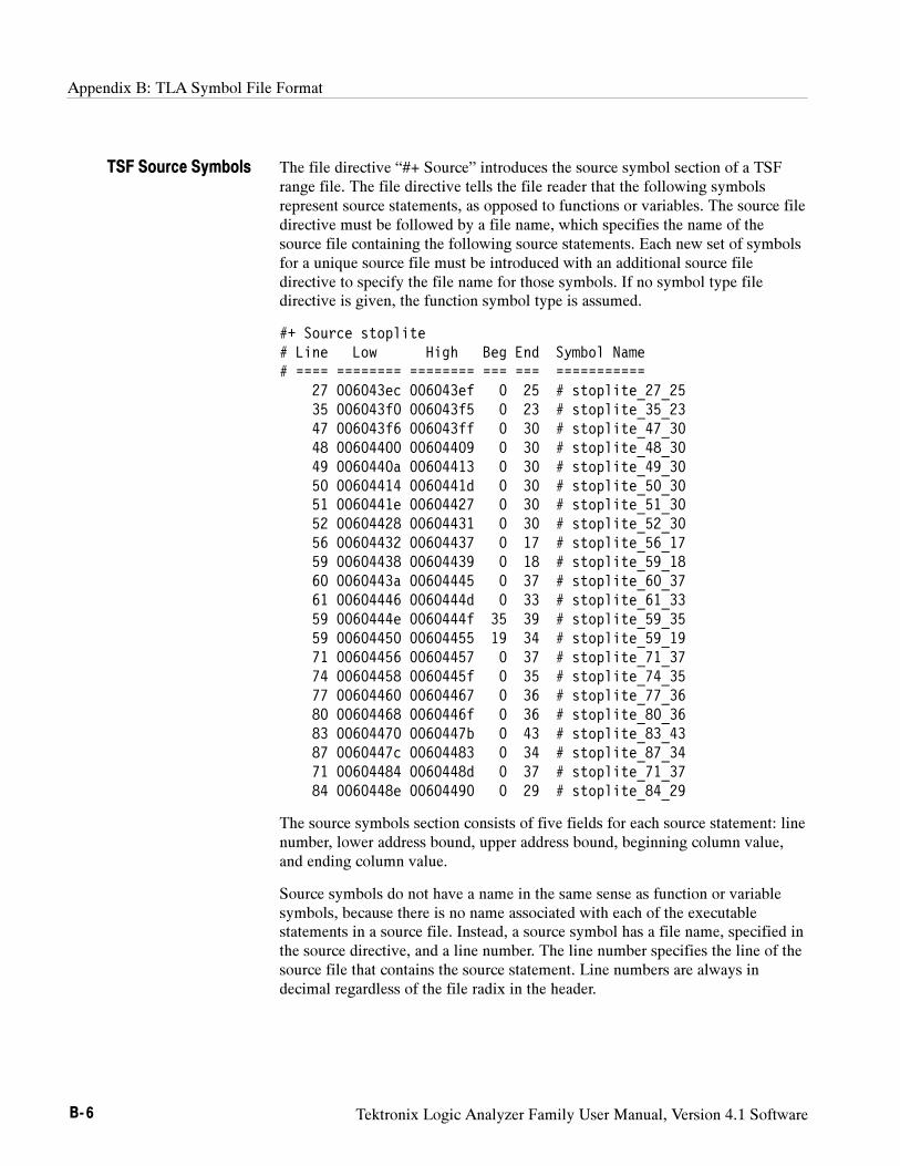
Appendix B: TLA Symbol File Format
B- 6 Tektronix Logic Analyzer Family User Manual, Version 4.1 Software
The file directive “#+ Source” introduces the source symbol section of a TSFrange file. The file directive tells the file reader that the following symbolsrepresent source statements, as opposed to functions or variables. The source filedirective must be followed by a file name, which specifies the name of thesource file containing the following source statements. Each new set of symbolsfor a unique source file must be introduced with an additional source filedirective to specify the file name for those symbols. If no symbol type filedirective is given, the function symbol type is assumed.
#+ Source stoplite# Line Low High Beg End Symbol Name# ==== ======== ======== === === ===========
27 006043ec 006043ef 0 25 # stoplite_27_2535 006043f0 006043f5 0 23 # stoplite_35_2347 006043f6 006043ff 0 30 # stoplite_47_3048 00604400 00604409 0 30 # stoplite_48_3049 0060440a 00604413 0 30 # stoplite_49_3050 00604414 0060441d 0 30 # stoplite_50_3051 0060441e 00604427 0 30 # stoplite_51_3052 00604428 00604431 0 30 # stoplite_52_3056 00604432 00604437 0 17 # stoplite_56_1759 00604438 00604439 0 18 # stoplite_59_1860 0060443a 00604445 0 37 # stoplite_60_3761 00604446 0060444d 0 33 # stoplite_61_3359 0060444e 0060444f 35 39 # stoplite_59_3559 00604450 00604455 19 34 # stoplite_59_1971 00604456 00604457 0 37 # stoplite_71_3774 00604458 0060445f 0 35 # stoplite_74_3577 00604460 00604467 0 36 # stoplite_77_3680 00604468 0060446f 0 36 # stoplite_80_3683 00604470 0060447b 0 43 # stoplite_83_4387 0060447c 00604483 0 34 # stoplite_87_3471 00604484 0060448d 0 37 # stoplite_71_3784 0060448e 00604490 0 29 # stoplite_84_29
The source symbols section consists of five fields for each source statement: linenumber, lower address bound, upper address bound, beginning column value,and ending column value.
Source symbols do not have a name in the same sense as function or variablesymbols, because there is no name associated with each of the executablestatements in a source file. Instead, a source symbol has a file name, specified inthe source directive, and a line number. The line number specifies the line of thesource file that contains the source statement. Line numbers are always indecimal regardless of the file radix in the header.
TSF Source Symbols
Appendix B: TLA Symbol File Format
Tektronix Logic Analyzer Family User Manual, Version 4.1 Software B- 7
The lower and upper bound values for a source symbol are similar to those offunction and variable symbols. For source symbols, these bounds represent therange of addresses occupied by the instructions that implement a single sourcestatement.
The bound values are defined in the file radix specified in the header and canrange in value from 0x00000000 to 0xFFFFFFFF. The lower and upper boundaddresses are inclusive, just like other symbols. A source symbol for aninstruction occupying a single memory location has matching lower and upperbound values.
The beginning and ending column fields of a source statement are optional.When present, and non-zero, they define the beginning and ending columnposition for the source statement.
The beginning and ending column values define the location of the statement inthe line. This is especially useful when there are multiple statements on a singleline, because it makes it possible to define a separate symbol for each statement.When the column information is not present, or is set to zero, the symbol isassumed to correspond to the entire line.
Only a few compilers generate column information, but when the information ispresent in the symbol file, the logic analyzer uses the column information toprovide highly accurate source code correlation. The example source symbols onthe previous page show typical column values.
In most cases only one of the column values is non-zero. This is because thoselines contain only one statement, and the compiler specified only the column atwhich the statement ended. Some compilers specify only the beginning columnposition for such lines, in which case the beginning value would be non-zero andthe ending value zero.
Note that there are three symbols corresponding to line 59 of the file. Line 59 ofthe original source file contains the following statement:
for (i = 0; i < NUM_STATES; i++)
This one line contains three separate statements. The first statement is theinitialization (i = 0), the second statement is the test (i < NUM_STATES), andthe third statement is the increment (i++).
Although all three statements appear on the same line, each generates a separateset of instructions, and the symbols in the example define unique address rangesfor each. This enables the Source window to accurately indicate which of thethree statements on the line is associated with any given address.
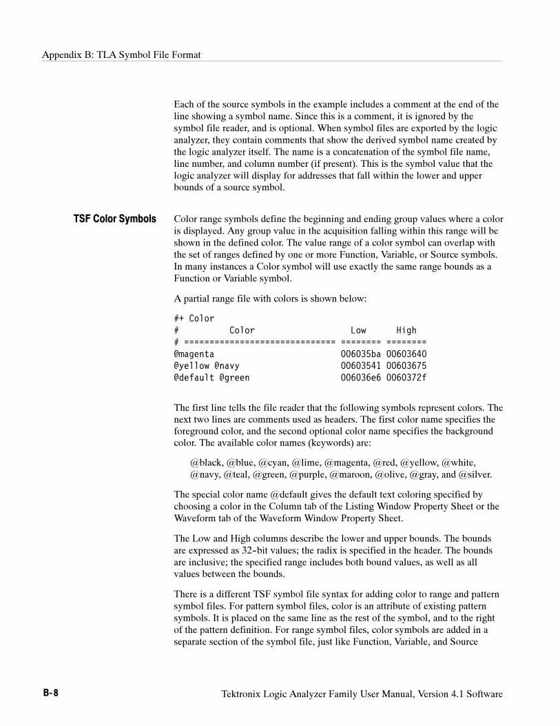
Appendix B: TLA Symbol File Format
B- 8 Tektronix Logic Analyzer Family User Manual, Version 4.1 Software
Each of the source symbols in the example includes a comment at the end of theline showing a symbol name. Since this is a comment, it is ignored by thesymbol file reader, and is optional. When symbol files are exported by the logicanalyzer, they contain comments that show the derived symbol name created bythe logic analyzer itself. The name is a concatenation of the symbol file name,line number, and column number (if present). This is the symbol value that thelogic analyzer will display for addresses that fall within the lower and upperbounds of a source symbol.
Color range symbols define the beginning and ending group values where a coloris displayed. Any group value in the acquisition falling within this range will beshown in the defined color. The value range of a color symbol can overlap withthe set of ranges defined by one or more Function, Variable, or Source symbols.In many instances a Color symbol will use exactly the same range bounds as aFunction or Variable symbol.
A partial range file with colors is shown below:
#+ Color# Color Low High# ============================== ======== ========@magenta 006035ba 00603640@yellow @navy 00603541 00603675@default @green 006036e6 0060372f
The first line tells the file reader that the following symbols represent colors. Thenext two lines are comments used as headers. The first color name specifies theforeground color, and the second optional color name specifies the backgroundcolor. The available color names (keywords) are:
@black, @blue, @cyan, @lime, @magenta, @red, @yellow, @white,@navy, @teal, @green, @purple, @maroon, @olive, @gray, and @silver.
The special color name @default gives the default text coloring specified bychoosing a color in the Column tab of the Listing Window Property Sheet or theWaveform tab of the Waveform Window Property Sheet.
The Low and High columns describe the lower and upper bounds. The boundsare expressed as 32--bit values; the radix is specified in the header. The boundsare inclusive; the specified range includes both bound values, as well as allvalues between the bounds.
There is a different TSF symbol file syntax for adding color to range and patternsymbol files. For pattern symbol files, color is an attribute of existing patternsymbols. It is placed on the same line as the rest of the symbol, and to the rightof the pattern definition. For range symbol files, color symbols are added in aseparate section of the symbol file, just like Function, Variable, and Source
TSF Color Symbols
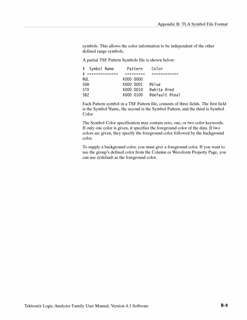
Appendix B: TLA Symbol File Format
Tektronix Logic Analyzer Family User Manual, Version 4.1 Software B- 9
symbols. This allows the color information to be independent of the otherdefined range symbols.
A partial TSF Pattern Symbols file is shown below:
# Symbol Name Pattern Color# ============== ========= ============NUL X000 0000SOH X000 0001 @blueSTX X000 0010 @white @redSBZ X000 0100 @default @teal
Each Pattern symbol in a TSF Pattern file, consists of three fields. The first fieldis the Symbol Name, the second is the Symbol Pattern, and the third is SymbolColor.
The Symbol Color specification may contain zero, one, or two color keywords.If only one color is given, it specifies the foreground color of the data. If twocolors are given, they specify the foreground color followed by the backgroundcolor.
To supply a background color, you must give a foreground color. If you want touse the group’s defined color from the Column or Waveform Property Page, youcan use @default as the foreground color.
Appendix B: TLA Symbol File Format
B- 10 Tektronix Logic Analyzer Family User Manual, Version 4.1 Software
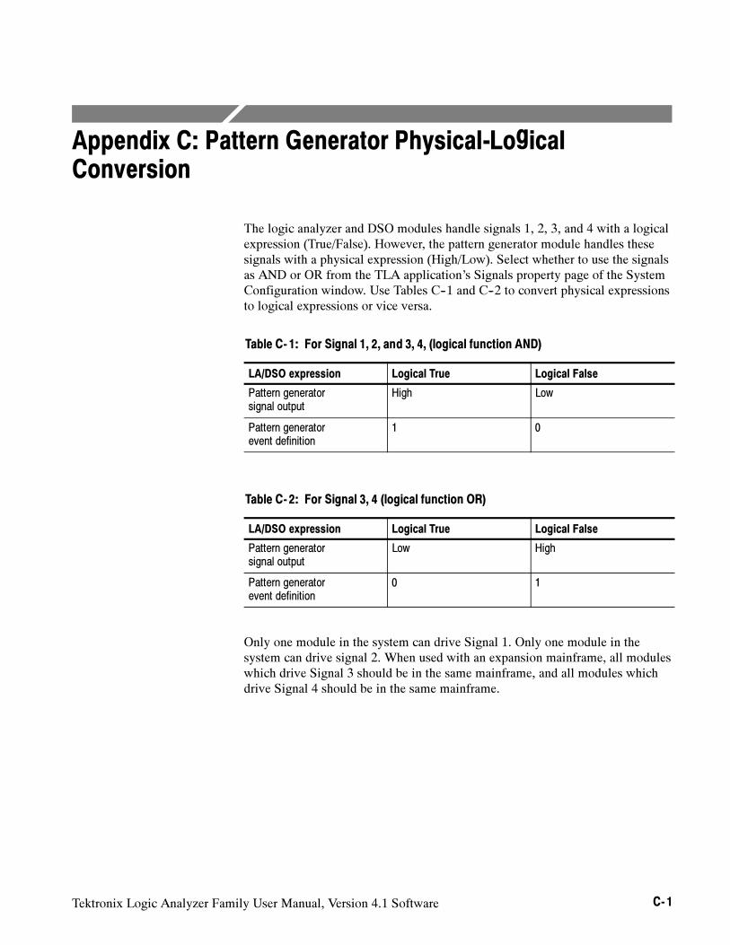
Tektronix Logic Analyzer Family User Manual, Version 4.1 Software C- 1
Appendix C: Pattern Generator Physical-LogicalConversion
The logic analyzer and DSO modules handle signals 1, 2, 3, and 4 with a logicalexpression (True/False). However, the pattern generator module handles thesesignals with a physical expression (High/Low). Select whether to use the signalsas AND or OR from the TLA application’s Signals property page of the SystemConfiguration window. Use Tables C--1 and C--2 to convert physical expressionsto logical expressions or vice versa.
Table C- 1: For Signal 1, 2, and 3, 4, (logical function AND)
LA/DSO expression Logical True Logical False
Pattern generatorsignal output
High Low
Pattern generatorevent definition
1 0
Table C- 2: For Signal 3, 4 (logical function OR)
LA/DSO expression Logical True Logical False
Pattern generatorsignal output
Low High
Pattern generatorevent definition
0 1
Only one module in the system can drive Signal 1. Only one module in thesystem can drive signal 2. When used with an expansion mainframe, all moduleswhich drive Signal 3 should be in the same mainframe, and all modules whichdrive Signal 4 should be in the same mainframe.
Appendix C: Pattern Generator Physical--Logical Conversion
C- 2 Tektronix Logic Analyzer Family User Manual, Version 4.1 Software
Tektronix Logic Analyzer Family User Manual, Version 4.1 Software D- 1
Appendix D: TLA700 Module Installation
This section describes the steps to install modules in your TLA700 Series LogicAnalyzer for the first time. It is written from the perspective that you purchasedmost of the items uninstalled and you intend to install all of the different items.
CAUTION. Do not install or remove any modules while the instrument is powered
on, doing so can damage the modules or the mainframe.
Always power down the instrument before removing or inserting modules.
If your instrument does not have the modules preinstalled, the following is asuggestion to take advantage of airflow cooling.
Setting the Logical Address
Every module in the instrument must have a unique logical address; no twomodules can have the same address. Two rotary switches on the rear panel selectthe logical address. Although Figure D--1 shows an LA module, the addressswitches are identical for all TLA modules. Read the following descriptionsbefore changing the logical address.
NOTE. Do not set any module to logical address to 00. Logical address 00 is
reserved exclusively for the controller.
The factory default switch setting is FF (Dynamic Auto Configuration). Withdynamic logical address auto configuration selected, the instrument automatical-ly sets the address to an unused value. For example, if there are modules set toaddresses 01 and 02 already in your system, the resource manager will automati-cally assign the module an address other than 01 or 02. This allows you to freelymove the modules around without reconfiguring the logical address.
Static logical address selections set the address to a fixed static logical addressvalue. You can select any static addresses between 01 and FE hexadecimal (1 to254 decimal). If you set the logical address switches to any other setting than FF,you must verify that no two modules (or devices) share the same address.
Dynamic Logical AddressAuto Configuration
Static Logical Address
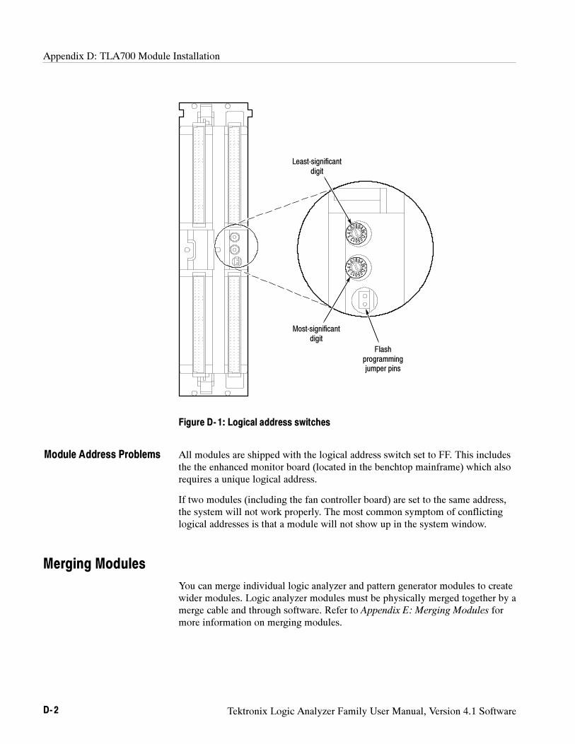
Appendix D: TLA700 Module Installation
D- 2 Tektronix Logic Analyzer Family User Manual, Version 4.1 Software
Most-significantdigit
Least-significantdigit
Flashprogrammingjumper pins
Figure D- 1: Logical address switches
All modules are shipped with the logical address switch set to FF. This includesthe the enhanced monitor board (located in the benchtop mainframe) which alsorequires a unique logical address.
If two modules (including the fan controller board) are set to the same address,the system will not work properly. The most common symptom of conflictinglogical addresses is that a module will not show up in the system window.
Merging Modules
You can merge individual logic analyzer and pattern generator modules to createwider modules. Logic analyzer modules must be physically merged together by amerge cable and through software. Refer to Appendix E: Merging Modules formore information on merging modules.
Module Address Problems
Appendix D: TLA700 Module Installation
Tektronix Logic Analyzer Family User Manual, Version 4.1 Software D- 3
Installing Modules in the Portable Mainframe
You can install any of the modules in any slot that the module key will allow;see Figure D--3. If you intend to merge the modules, disregard the followingsuggestions and refer to the merging modules rules on page E--1. If you are notmerging the modules, and for air flow considerations, you should follow theseguidelines:
If a single LA module is to be installed, install it in slots 3--4. Place a doublewidth slot cover over slots 1--2.
If an LA module is to be installed with a DSO module, install the DSOmodule in slots 1--2, and the LA module in slots 3--4.
If two LA modules are to be installed, install the module with the highestchannel count in slots 1--2. Install the module with the lower channel countin slots 3--4.
If two LA modules are to be installed, install the module with the largestmemory in slots 3--4. Install the module with the lower memory in slots 1--2.
Use a screwdriver to tighten the retaining screws to 2.5 in-lbs after seating themodules in place. See Figure D--2.
Installing Modules in the Benchtop or Expansion Mainframes
You must install the benchtop controller in the benchtop mainframe in slots 0--2(the TLA7XM Expansion Module must be located in slot 0). You can install anyof the modules in any slot that the module key will allow; see Figure D--3.
If you intend to merge the modules, disregard the following suggestions andrefer to the merging modules rules on page E--1. If you are not merging themodules, and for air flow considerations, you should follow these guidelines:
If a single LA module is to be installed, install it in slots 3--4. Place a doublewidth slot cover over slots 5--6, 7--8, 9--10 and 11--12.
If an LA module is to be installed with a DSO module, install the LAmodule in slots 3--4, and the DSO module in slots 5--6. Place double widthslot covers over slots 7--8, 9--10 and 11--12.
If two or more LA modules are to be installed, install the module with thehighest channel count in slots 3--4. Install the module with the lower channelcount in slots 5--6. Place double width slot covers over slots 7--8, 9--10and 11--12.
If two or more LA modules are to be installed, install the module with thelargest memory in slots 3--4. Install the module with the lower memory inslots 5--6. Place double width slot covers over slots 7--8, 9--10 and 11--12.
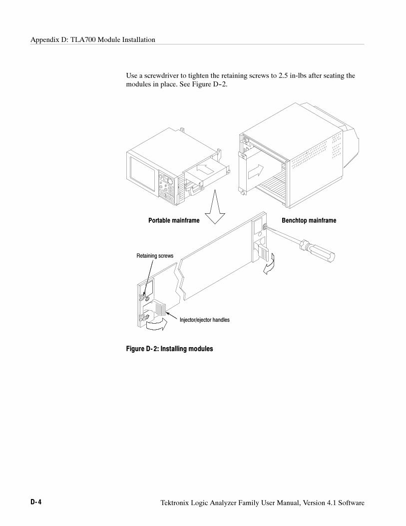
Appendix D: TLA700 Module Installation
D- 4 Tektronix Logic Analyzer Family User Manual, Version 4.1 Software
Use a screwdriver to tighten the retaining screws to 2.5 in-lbs after seating themodules in place. See Figure D--2.
Portable mainframe Benchtop mainframe
Injector/ejector handles
Retaining screws
Figure D- 2: Installing modules
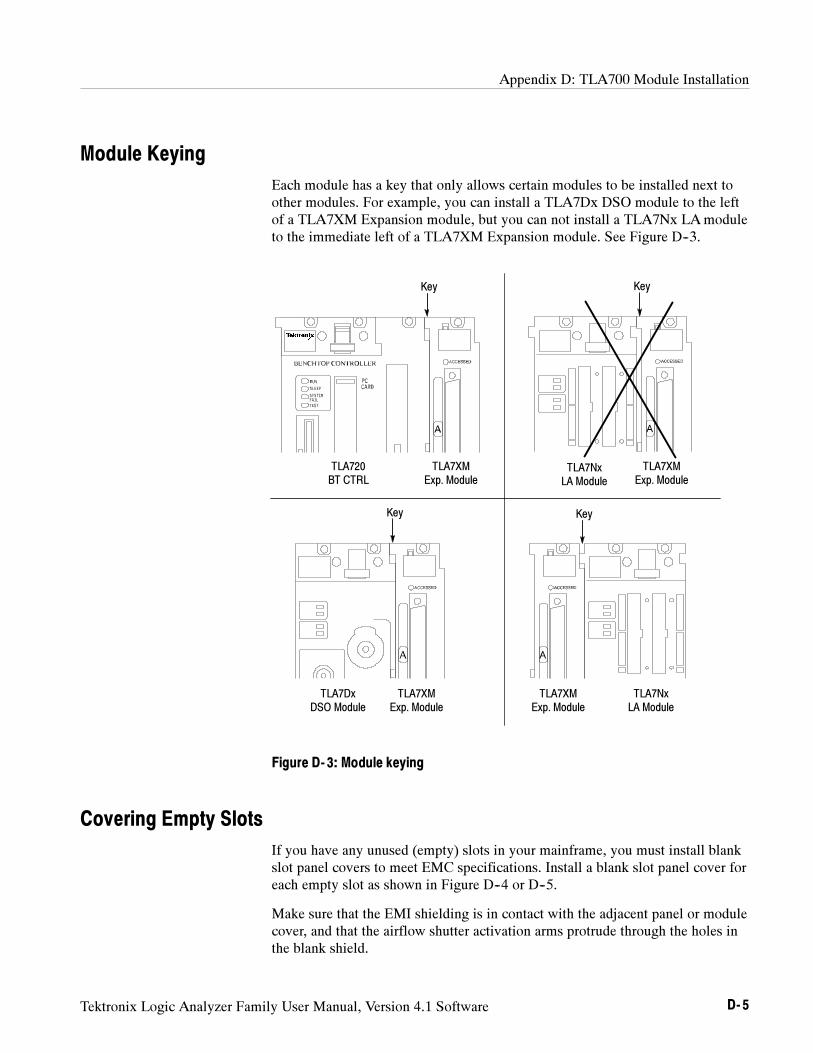
Appendix D: TLA700 Module Installation
Tektronix Logic Analyzer Family User Manual, Version 4.1 Software D- 5
Module Keying
Each module has a key that only allows certain modules to be installed next toother modules. For example, you can install a TLA7Dx DSO module to the leftof a TLA7XM Expansion module, but you can not install a TLA7Nx LAmoduleto the immediate left of a TLA7XM Expansion module. See Figure D--3.
TLA720BT CTRL
TLA7DxDSO Module
TLA7XMExp. Module
TLA7XMExp. Module
Key
Key
TLA7XMExp. Module
TLA7NxLA Module
TLA7NxLA Module
TLA7XMExp. Module
Key
Key
Figure D- 3: Module keying
Covering Empty Slots
If you have any unused (empty) slots in your mainframe, you must install blankslot panel covers to meet EMC specifications. Install a blank slot panel cover foreach empty slot as shown in Figure D--4 or D--5.
Make sure that the EMI shielding is in contact with the adjacent panel or modulecover, and that the airflow shutter activation arms protrude through the holes inthe blank shield.
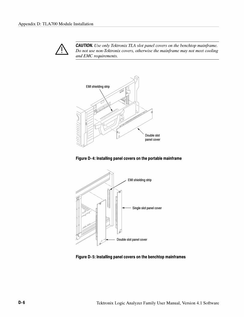
Appendix D: TLA700 Module Installation
D- 6 Tektronix Logic Analyzer Family User Manual, Version 4.1 Software
CAUTION. Use only Tektronix TLA slot panel covers on the benchtop mainframe.
Do not use non-Tektronix covers, otherwise the mainframe may not meet cooling
and EMC requirements.
Double slotpanel cover
EMI shielding strip
Figure D- 4: Installing panel covers on the portable mainframe
EMI shielding strip
Double slot panel cover
Single slot panel cover
Figure D- 5: Installing panel covers on the benchtop mainframes
Tektronix Logic Analyzer Family User Manual, Version 4.1 Software E- 1
Appendix E: Merging Modules
This appendix describes how to merge TLA700 series logic analyzer and patterngenerator modules to form wider modules.
A merged logic analyzer module set consists of a master logic analyzer moduleand one or two slave logic analyzer modules physically connected together by amerge cable, and merged in software. Review the guidelines under LogicAnalyzer Module Merging Rules and then follow the steps to physically connectthe modules together before installing the modules in the mainframe.
A merged pattern generator module set consists of a master pattern generatormodule and up to four slave pattern generator modules merged in software.Review the guidelines under Pattern Generator Module Merging Rules onpage E--3 before installing the modules in the mainframe.
Logic Analyzer Module Merging Rules
The following logic analyzer module merging rules must be followed:
Only modules with 102 channels or more can be merged.
Logic analyzer modules must be in adjacent slots and physically connected.
Logic analyzer modules can not be merged across mainframes (between thebenchtop mainframe and one or more expansion mainframes), because themodules must be physically adjacent and physically connected.
Logic analyzer modules of unequal synchronous clock rate can not bemerged.
Merging logic analyzer modules of unequal memory depths will result in themerged modules assuming the depth of the shallowest module.
When merging logic analyzer modules of unequal channel widths, use thelogic analyzer module with the higher number of channels as the mastermodule.
The logic analyzer modules must have the same firmware version.
Two or three TLA7Nx, TLA7Px, or TLA7Qx logic analyzer modules can bemerged together. Two TLA7Lx and TLA7Mx logic analyzer modules can bemerged together.
TLA7Nx, TLA7Px, and TLA7Qx Logic analyzer modules can not be mergedwith TLA7Lx and TLA7Mx Logic analyzer modules. (Even if they areconnected together.)
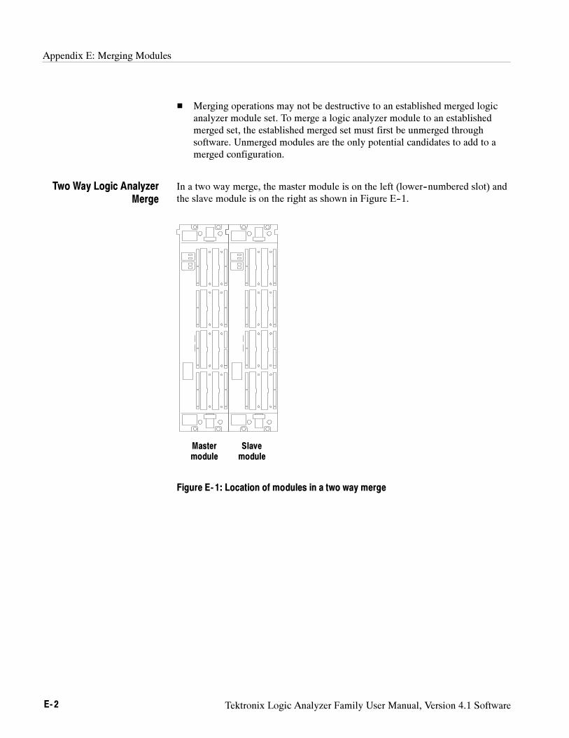
Appendix E: Merging Modules
E- 2 Tektronix Logic Analyzer Family User Manual, Version 4.1 Software
Merging operations may not be destructive to an established merged logicanalyzer module set. To merge a logic analyzer module to an establishedmerged set, the established merged set must first be unmerged throughsoftware. Unmerged modules are the only potential candidates to add to amerged configuration.
In a two way merge, the master module is on the left (lower--numbered slot) andthe slave module is on the right as shown in Figure E--1.
Mastermodule
Slavemodule
Figure E- 1: Location of modules in a two way merge
Two Way Logic AnalyzerMerge
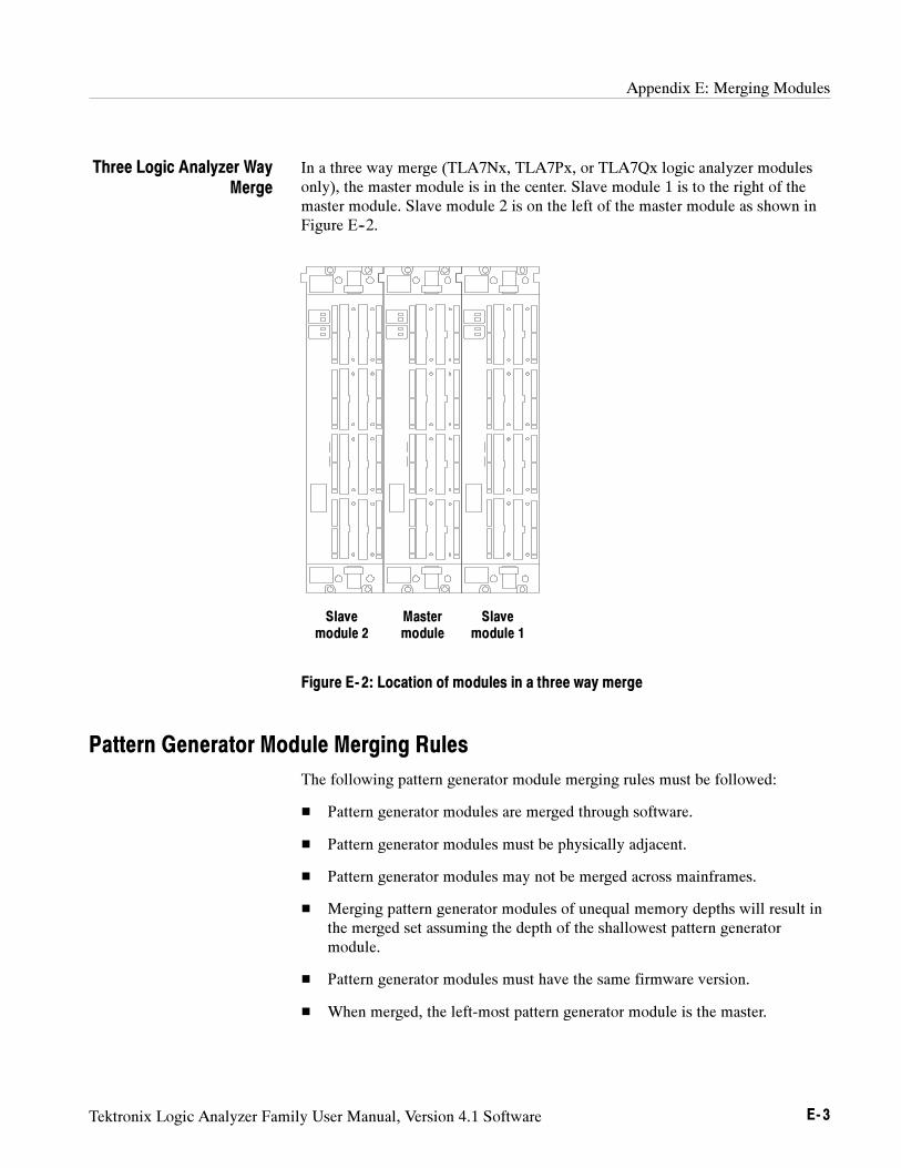
Appendix E: Merging Modules
Tektronix Logic Analyzer Family User Manual, Version 4.1 Software E- 3
In a three way merge (TLA7Nx, TLA7Px, or TLA7Qx logic analyzer modulesonly), the master module is in the center. Slave module 1 is to the right of themaster module. Slave module 2 is on the left of the master module as shown inFigure E--2.
Mastermodule
Slavemodule 1
Slavemodule 2
Figure E- 2: Location of modules in a three way merge
Pattern Generator Module Merging Rules
The following pattern generator module merging rules must be followed:
Pattern generator modules are merged through software.
Pattern generator modules must be physically adjacent.
Pattern generator modules may not be merged across mainframes.
Merging pattern generator modules of unequal memory depths will result inthe merged set assuming the depth of the shallowest pattern generatormodule.
Pattern generator modules must have the same firmware version.
When merged, the left-most pattern generator module is the master.
Three Logic Analyzer WayMerge
Appendix E: Merging Modules
E- 4 Tektronix Logic Analyzer Family User Manual, Version 4.1 Software
Logic Analyzer Merge Procedures
Use the following procedures to physically merge the logic analyzer modulestogether.
The following procedure is used for merging two logic analyzer modules to forma merged set with a higher logic analyzer channel count. For information onmerging three modules, see page E--9.
CAUTION. Static discharge can damage any semiconductor component in the
logic analyzer module.
Discharge the static voltage from your body by wearing a grounded antistatic
wrist strap while performing the merge procedure.
Perform the following steps to merge two modules:
1. Turn the mainframe off.
2. Determine which module will be designated as the slave module and whichmodule will be the master module.
3. Lay the slave module on the right side (as viewed from the front panel).
4. Remove the screws from the module cover with a screwdriver with a T-10Torx tip; refer to Figure E--3 on page E--5.
5. Remove the screws near the front of the module.
6. Remove the screws holding the merge cable bracket to the cover.
7. Remove the top part of the cable bracket and set it aside.
8. Remove the module cover and locate the merge cable.
Two Way Logic AnalyzerMerge Procedure
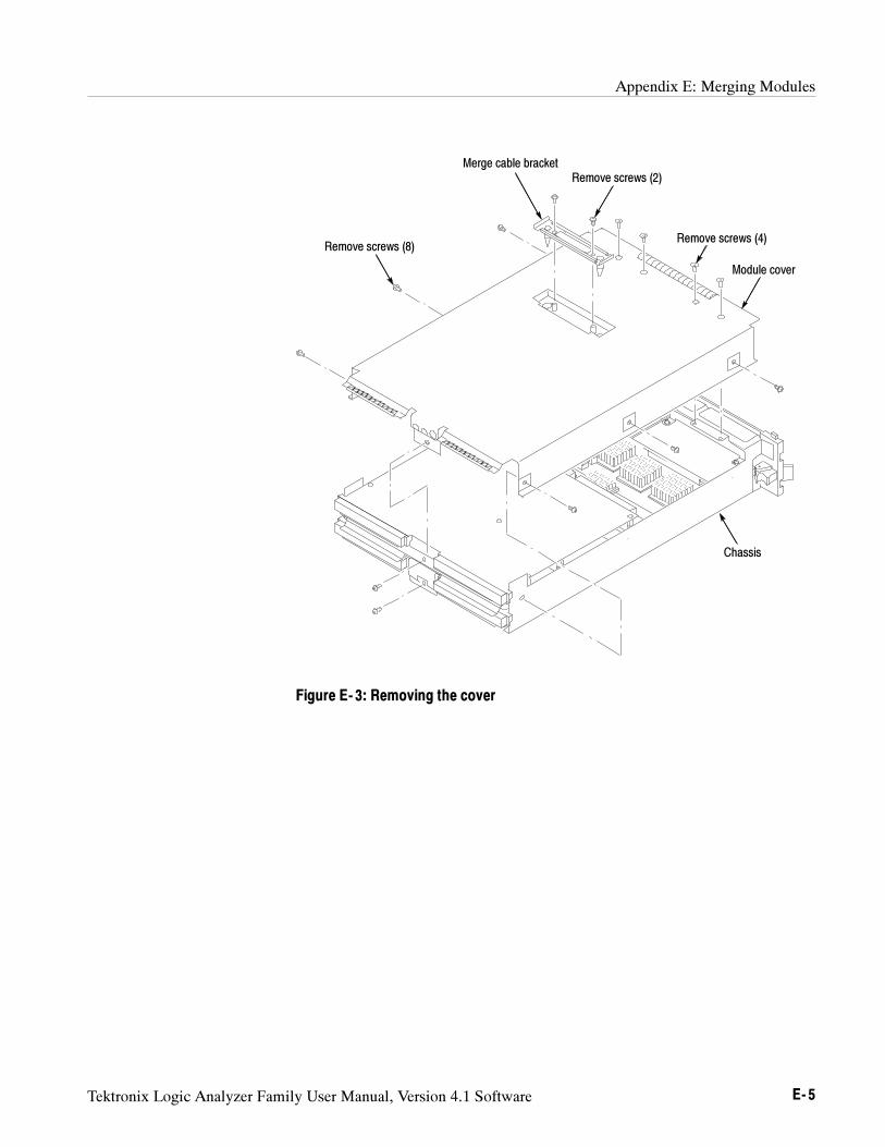
Appendix E: Merging Modules
Tektronix Logic Analyzer Family User Manual, Version 4.1 Software E- 5
Module cover
Chassis
Remove screws (2)Merge cable bracket
Remove screws (8)Remove screws (4)
Figure E- 3: Removing the cover
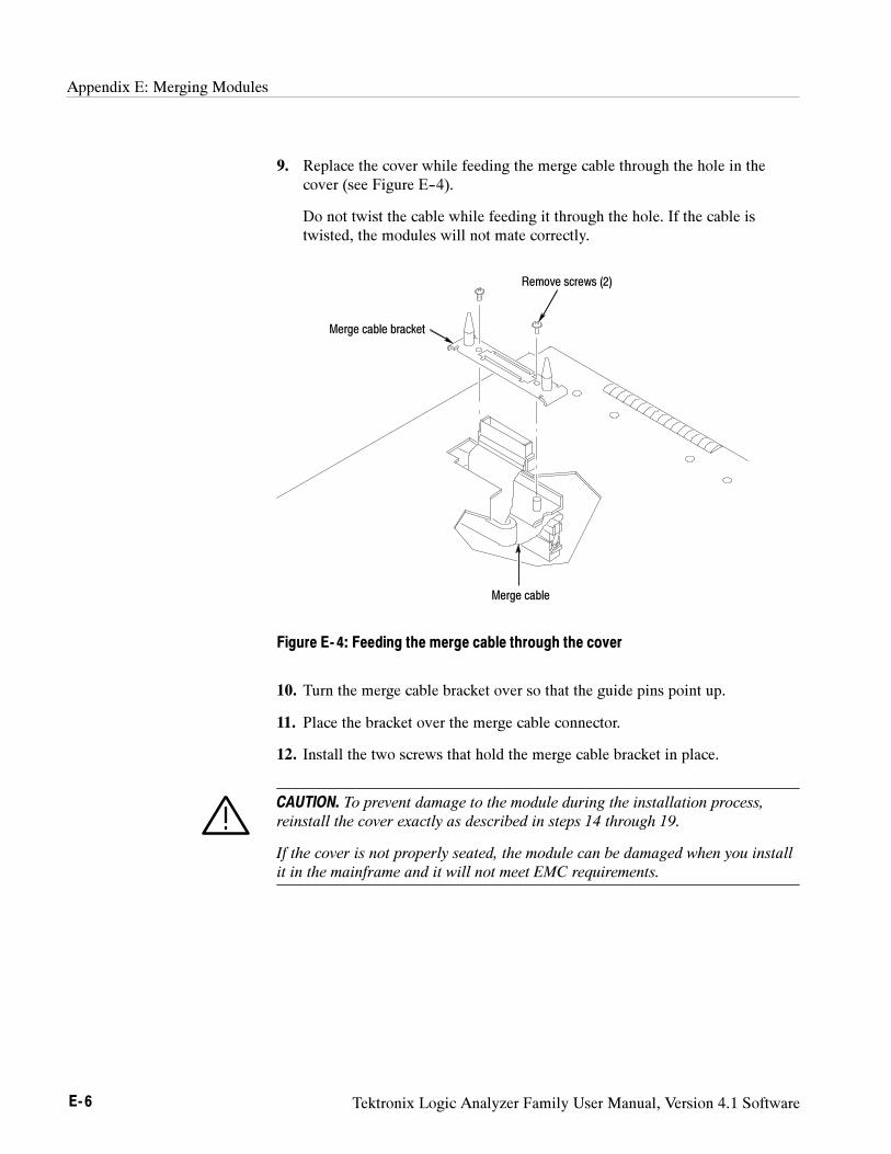
Appendix E: Merging Modules
E- 6 Tektronix Logic Analyzer Family User Manual, Version 4.1 Software
9. Replace the cover while feeding the merge cable through the hole in thecover (see Figure E--4).
Do not twist the cable while feeding it through the hole. If the cable istwisted, the modules will not mate correctly.
Remove screws (2)
Merge cable
Merge cable bracket
Figure E- 4: Feeding the merge cable through the cover
10. Turn the merge cable bracket over so that the guide pins point up.
11. Place the bracket over the merge cable connector.
12. Install the two screws that hold the merge cable bracket in place.
CAUTION. To prevent damage to the module during the installation process,
reinstall the cover exactly as described in steps 14 through 19.
If the cover is not properly seated, the module can be damaged when you install
it in the mainframe and it will not meet EMC requirements.
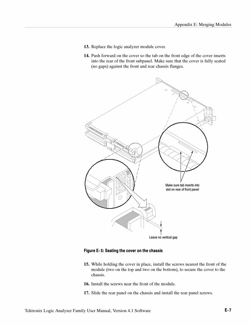
Appendix E: Merging Modules
Tektronix Logic Analyzer Family User Manual, Version 4.1 Software E- 7
13. Replace the logic analyzer module cover.
14. Push forward on the cover so the tab on the front edge of the cover insertsinto the rear of the front subpanel. Make sure that the cover is fully seated(no gaps) against the front and rear chassis flanges.
Leave no vertical gap
Make sure tab inserts intoslot on rear of front panel
Figure E- 5: Seating the cover on the chassis
15. While holding the cover in place, install the screws nearest the front of themodule (two on the top and two on the bottom), to secure the cover to thechassis.
16. Install the screws near the front of the module.
17. Slide the rear panel on the chassis and install the rear panel screws.
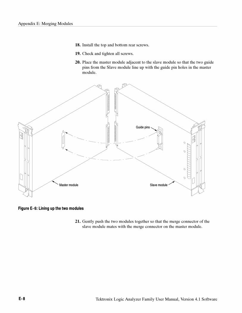
Appendix E: Merging Modules
E- 8 Tektronix Logic Analyzer Family User Manual, Version 4.1 Software
18. Install the top and bottom rear screws.
19. Check and tighten all screws.
20. Place the master module adjacent to the slave module so that the two guidepins from the Slave module line up with the guide pin holes in the mastermodule.
Master module Slave module
Guide pins
Figure E- 6: Lining up the two modules
21. Gently push the two modules together so that the merge connector of theslave module mates with the merge connector on the master module.
Appendix E: Merging Modules
Tektronix Logic Analyzer Family User Manual, Version 4.1 Software E- 9
The following procedure is used for merging three logic analyzer modulestogether to form a merged set with a higher logic analyzer channel count.
In a three way merge (TLA7Nx, TLA7Px, and TLA7Qx logic analyzer modulesonly), the master module is in the center. Slave module 1 is to the right of themaster module. Slave module 2 is on the left of the master module as shown inFigure E--2 on page E--3.
CAUTION. Static discharge can damage any semiconductor component in the
logic analyzer module.
Discharge the static voltage from your body by wearing a grounded antistatic
wrist strap while performing the merge procedure.
Perform the Two Way Logic Analyzer Merge Procedure beginning on page E--4.
Perform the following steps to merge the second slave module:
1. Lay the two merged module set on their right hand side (as viewed from thefront panel).
2. Follow the procedure beginning on page E--4 to merge the second slavemodule to the left of the center master module.
Installing the Merged Logic Analyzer Modules in the Mainframe
After merging the modules, perform the following steps to install the mergedmodules in the mainframe:
1. Hold the merged modules such that the modules do not become separatedand line up the modules with the slot guides in the mainframe.
2. Push the merged modules into the mainframe until they rest against the rearpanel connector.
3. Use the injector/ejector handles to fully seat the modules one at a time.Tighten the module retainer screws.
4. Verify that the modules are fully seated before powering on the mainframe.
Three Way Logic AnalyzerMerge Procedure
Appendix E: Merging Modules
E- 10 Tektronix Logic Analyzer Family User Manual, Version 4.1 Software
Calibrating the Merged Modules
Always calibrate each module separately, then calibrate the merged set.
After powering on the mainframe, calibrate the merged modules by followingthese steps:
1. Select the System window. If you are calibrating pattern generator modules,select the System window from the pattern generator application.
2. From the menu bar, select System.
3. Select Calibration and Diagnostics.
4. Select the Self Calibration tab.
5. Select (highlight) the modules to be calibrated.
6. Press the Run button in the merge calibrate dialog box.
Removing Merged Logic Analyzer Modules from the Mainframe
Perform the following steps to remove merged modules from the mainframe:
1. Identify the modules that you want to remove.
2. Loosen the retainer screws for the modules (top and bottom).
NOTE. Use the ejector handles to just loosen the modules from the rear panel
connector before sliding the merged modules out of the mainframe.
3. Use the ejector handles to disconnect the modules from the rear panelconnector one at a time.
4. Slide the modules out of the mainframe at the same time.
5. Gently pry the modules apart.
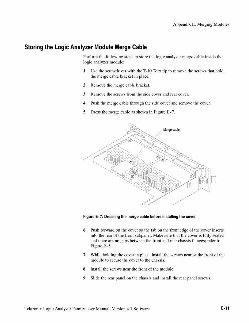
Appendix E: Merging Modules
Tektronix Logic Analyzer Family User Manual, Version 4.1 Software E- 11
Storing the Logic Analyzer Module Merge Cable
Perform the following steps to store the logic analyzer merge cable inside thelogic analyzer module:
1. Use the screwdriver with the T-10 Torx tip to remove the screws that holdthe merge cable bracket in place.
2. Remove the merge cable bracket.
3. Remove the screws from the side cover and rear cover.
4. Push the merge cable through the side cover and remove the cover.
5. Dress the merge cable as shown in Figure E--7.
Merge cable
Figure E- 7: Dressing the merge cable before installing the cover
6. Push forward on the cover so the tab on the front edge of the cover insertsinto the rear of the front subpanel. Make sure that the cover is fully seatedand there are no gaps between the front and rear chassis flanges; refer toFigure E--5.
7. While holding the cover in place, install the screws nearest the front of themodule to secure the cover to the chassis.
8. Install the screws near the front of the module.
9. Slide the rear panel on the chassis and install the rear panel screws.
Appendix E: Merging Modules
E- 12 Tektronix Logic Analyzer Family User Manual, Version 4.1 Software
10. Install the top and bottom rear screws.
11. Install the merge cable bracket so that the guide pins point into the module.
12. Install and tighten the screws on the merge cable bracket.
13. Verify that you have installed and tightened all screws on the module.
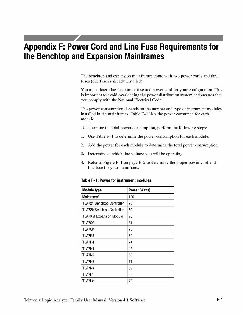
Tektronix Logic Analyzer Family User Manual, Version 4.1 Software F- 1
Appendix F: Power Cord and Line Fuse Requirements forthe Benchtop and Expansion Mainframes
The benchtop and expansion mainframes come with two power cords and threefuses (one fuse is already installed).
You must determine the correct fuse and power cord for your configuration. Thisis important to avoid overloading the power distribution system and ensures thatyou comply with the National Electrical Code.
The power consumption depends on the number and type of instrument modulesinstalled in the mainframes. Table F--1 lists the power consumed for eachmodule.
To determine the total power consumption, perform the following steps:
1. Use Table F--1 to determine the power consumption for each module.
2. Add the power for each module to determine the total power consumption.
3. Determine at which line voltage you will be operating.
4. Refer to Figure F--1 on page F--2 to determine the proper power cord andline fuse for your mainframe.
Table F- 1: Power for instrument modules
Module type Power (Watts)
Mainframe1 100
TLA721 Benchtop Controller 70
TLA720 Benchtop Controller 50
TLA7XM Expansion Module 20
TLA7Q2 51
TLA7Q4 75
TLA7P2 50
TLA7P4 74
TLA7N1 45
TLA7N2 58
TLA7N3 71
TLA7N4 82
TLA7L1 55
TLA7L2 73
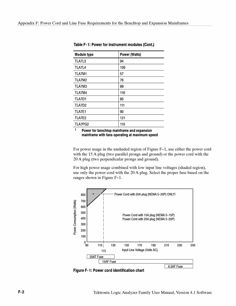
Appendix F: Power Cord and Line Fuse Requirements for the Benchtop and Expansion Mainframes
F- 2 Tektronix Logic Analyzer Family User Manual, Version 4.1 Software
Table F- 1: Power for instrument modules (Cont.)
Module type Power (Watts)
TLA7L3 94
TLA7L4 109
TLA7M1 57
TLA7M2 76
TLA7M3 99
TLA7M4 116
TLA7D1 80
TLA7D2 111
TLA7E1 90
TLA7E2 121
TLA7PG2 110
1 Power for benchtop mainframe and expansionmainframe with fans operating at maximum speed
For power usage in the unshaded region of Figure F--1, use either the power cordwith the 15 A plug (two parallel prongs and ground) or the power cord with the20 A plug (two perpendicular prongs and ground).
For high power usage combined with low input line voltages (shaded region),use only the power cord with the 20 A plug. Select the proper fuse based on theranges shown in Figure F--1.
Pow
erConsumption(W
atts)
800
700
600
500
400
300
200
100
0
Input Line Voltage (Volts AC)
90 110
115
130 150 170 190 210 230 250
20AT Fuse
15AF Fuse
6.3AF Fuse
Power Cord with 20A plug (NEMA 5--20P) ONLY!
Power Cord with 15A plug (NEMA 5--15P)Power Cord with 20A plug (NEMA 5--20P)
Figure F- 1: Power cord identification chart
Appendix F: Power Cord and Line Fuse Requirements for the Benchtop and Expansion Mainframes
Tektronix Logic Analyzer Family User Manual, Version 4.1 Software F- 3
For example, assume that your TLA721 benchtop system consists of fourTLA7Q4 Logic Analyzer Modules and one TLA7E2 DSO Module. Also assumethat you will be operating the mainframe at 90 VAC.
Add 121 Watts (for the DSO Module) + 4 X 75 Watts (for the logic analyzermodules) + 70 Watts (for the controller) + 100 Watts for the mainframe to comeup with a total value of 591 Watts.
Because the power consumption (at 90 VAC) is approaching the shaded area ofthe graph in Figure F--1, you should consider using the 20A power cord.
NOTE. If you are configuring an expansion mainframe, remember to use the
power value for the expansion module instead of the benchtop controller.

Appendix F: Power Cord and Line Fuse Requirements for the Benchtop and Expansion Mainframes
F- 4 Tektronix Logic Analyzer Family User Manual, Version 4.1 Software
Tektronix Logic Analyzer Family User Manual, Version 4.1 Software G- 1
Appendix G: Installing Software
Most of the software comes factory-installed when you receive your logicanalyzer. You should only need to refer to this appendix if you reinstall yoursoftware. These instructions only refer to reinstalling the latest version of theapplication software running on the Windows 2000 Professional operatingsystem. If you want to upgrade to the latest application software version and tothe Windows 2000 Professional operating system, contact your local Tektronixrepresentative about purchasing either the TLA6UP or TLA7UP field upgradekits. This appendix also provides information on installing related logic analyzersoftware on a PC for remote operation or for offline applications.
There are two methods for reinstalling software on your logic analyzer: reinstallthe entire software on your hard disk, or reinstall individual software compo-nents.
NOTE. If you are installing or reinstalling any software on a remote PC, make
sure that the software version matches that of the main application on the logic
analyzer.
Refer to the following sections within this appendix to install or reinstallsoftware:
To reinstall the entire software on your logic analyzer, refer to the instruc-tions under Restoring the Hard Disk Image beginning on page G--2.
To reinstall the latest version of Tektronix Logic Analyzer applicationsoftware, follow the instructions under Reinstalling the TLA Application
Software beginning on page G--16.
To reinstall the latest version of Tektronix Pattern Generator applicationsoftware, follow the instructions under Reinstalling the Pattern Generator
Application Software beginning on page G--17.
To reinstall the latest version of the TPI or PPI remote operation softwarefollow the instructions under Installing the Remote Operation Software
beginning on page G--18.
To reinstall the latest version of the TLAVu offline software, refer toInstalling the TLAVu Software beginning on page G--19.
To reinstall the latest version of the PatGenVu offline software, refer toInstalling the PatGenVu Software beginning on page G--20.
To reinstall other software, refer to the instructions that came with yoursoftware.
Appendix G: Installing Software
G- 2 Tektronix Logic Analyzer Family User Manual, Version 4.1 Software
Restoring the Hard Disk Image
The next several pages describe the steps needed to restore the logic analyzerapplication software and operating system on the hard disk. The followingprocedures will overwrite the entire contents of your hard disk. You must backup any files that you want saved to another media before completing theseprocedures.
These procedures assume that you are restoring TLA application software V4.1and the Windows 2000 Professional operating system. If your instrument doesnot have TLA application software V4.1, you are encouraged to purchase one ofthe TLA6UP or TLA7UP field upgrade kits. Contact your local Tektronixrepresentatives for more information on the upgrade kits.
The restore procedures will also restore the Pattern Generator applicationsoftware and any other software applications that came with your logic analyzer.
CAUTION. The software installation procedure using the Hard Disk Image CD
will overwrite the entire contents of your hard disk. If you want to save any files
or software applications on the hard disk, back them up to another media (a
second hard drive, floppy disks, or a network drive) before continuing with this
procedure.
TLA600, TLA714, or TLA720 Instruments.Before restoring the software on yourinstrument, you are encouraged to update the BIOS settings. To update the BIOSor to verify the BIOS settings, follow the procedures under Flashing the BIOS
before restoring the software on your hard disk.
If you feel that your BIOS settings do not need updating, continue with the stepsunder Reinstalling the Hard Disk Image beginning on page G--11.
TLA715 or TLA721 Instruments. If you have a TLA715 or TLA721 logic analyzer,there is no need to update the BIOS settings. Continue with the steps underReinstalling the Hard Disk Image beginning on page G--11.
Appendix G: Installing Software
Tektronix Logic Analyzer Family User Manual, Version 4.1 Software G- 3
Flashing the BIOS
You may need to flash the controller BIOS on your logic analyzer to update thecontroller with the latest flash image before reinstalling software on the harddisk. The procedures for flashing the BIOS differ between the TLA600 logicanalyzers and the TLA700 logic analyzers. Refer to the proper procedure beforeflashing the BIOS image on your logic analyzer.
This procedure is only necessary if you need to update the latest flash image. Toflash the BIOS, complete the following steps:
1. Exit all applications and power off the logic analyzer.
2. Insert the TLA600 BIOS disk, Version P09, in the floppy disk drive.
3. Power on the logic analyzer and allow the logic analyzer to boot from thefloppy disk. After booting from the floppy disk, the program on the floppydisk will automatically flash the BIOS on the TLA600 controller.
4. Wait for the flash procedure to complete.
5. After the flash procedure has completed, power off the logic analyzer andremove the floppy disk.
CAUTION. Do not remove the floppy disk drive or power down the logic analyzer
during the flash operation. Doing so will cause the system to become inoperable.
This procedure is necessary after replacing the hard disk or when the CMOSsettings are corrupted or lost. To configure the Controller BIOS, complete thefollowing steps:
1. Power on the logic analyzer and press function key F2 before the logicanalyzer boots the Windows operating system.
2. Press function key F9, select Yes, and then press Enter to set the defaultsettings. Verify that the hard disk was auto-recognized and that the correctsize of the hard disk is displayed in the Primary Master setting.
3. Verify that all of the settings are the same as the settings in Table G--1.
4. Press function key F10 to exit and save the BIOS setup.
Flashing the BIOS on theTLA600 Logic Analyzer
Setting Up the TLA600Controller BIOS
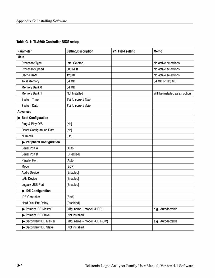
Appendix G: Installing Software
G- 4 Tektronix Logic Analyzer Family User Manual, Version 4.1 Software
Table G- 1: TLA600 Controller BIOS setup
Parameter Setting/Description 2nd Field setting Memo
Main
Processor Type Intel Celeron No active selections
Processor Speed 500 MHz No active selections
Cache RAM 128 KB No active selections
Total Memory 64 MB 64 MB or 128 MB
Memory Bank 0 64 MB
Memory Bank 1 Not Installed Will be installed as an option
System Time Set to current time
System Date Set to current date
Advanced
Boot Configuration
Plug & Play O/S [No]
Reset Configuration Data [No]
Numlock [Off]
Peripheral Configuration
Serial Port A [Auto]
Serial Port B [Disabled]
Parallel Port [Auto]
Mode [ECP]
Audio Device [Enabled]
LAN Device [Enabled]
Legacy USB Port [Enabled]
IDE Configuration
IDE Controller [Both]
Hard Disk Pre-Delay [Disabled]
Primary IDE Master [Mfg. name -- model] (HDD) e.g.: Autodectable
Primary IDE Slave [Not installed]
Secondary IDE Master [Mfg. name -- model] (CD ROM) e.g.: Autodectable
Secondary IDE Slave [Not installed]
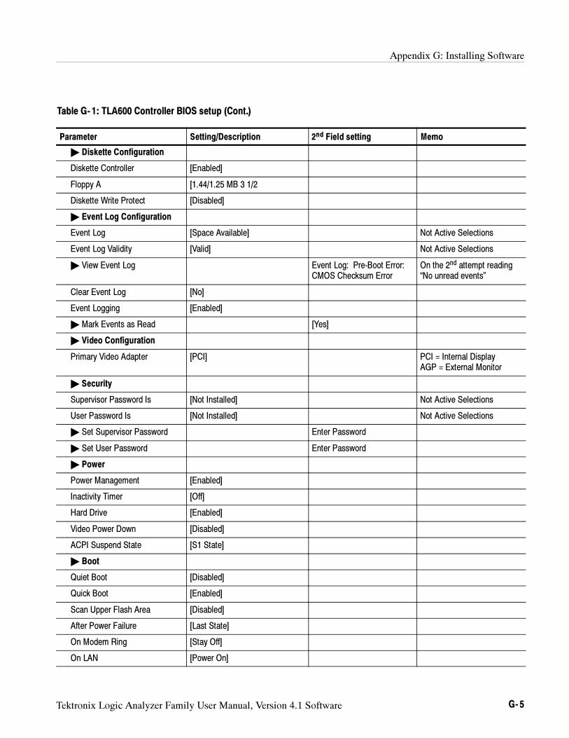
Appendix G: Installing Software
Tektronix Logic Analyzer Family User Manual, Version 4.1 Software G- 5
Table G- 1: TLA600 Controller BIOS setup (Cont.)
Parameter Memo2nd Field settingSetting/Description
Diskette Configuration
Diskette Controller [Enabled]
Floppy A [1.44/1.25 MB 3 1/2
Diskette Write Protect [Disabled]
Event Log Configuration
Event Log [Space Available] Not Active Selections
Event Log Validity [Valid] Not Active Selections
View Event Log Event Log: Pre-Boot Error:CMOS Checksum Error
On the 2nd attempt reading“No unread events”
Clear Event Log [No]
Event Logging [Enabled]
Mark Events as Read [Yes]
Video Configuration
Primary Video Adapter [PCI] PCI = Internal DisplayAGP = External Monitor
Security
Supervisor Password Is [Not Installed] Not Active Selections
User Password Is [Not Installed] Not Active Selections
Set Supervisor Password Enter Password
Set User Password Enter Password
Power
Power Management [Enabled]
Inactivity Timer [Off]
Hard Drive [Enabled]
Video Power Down [Disabled]
ACPI Suspend State [S1 State]
Boot
Quiet Boot [Disabled]
Quick Boot [Enabled]
Scan Upper Flash Area [Disabled]
After Power Failure [Last State]
On Modem Ring [Stay Off]
On LAN [Power On]
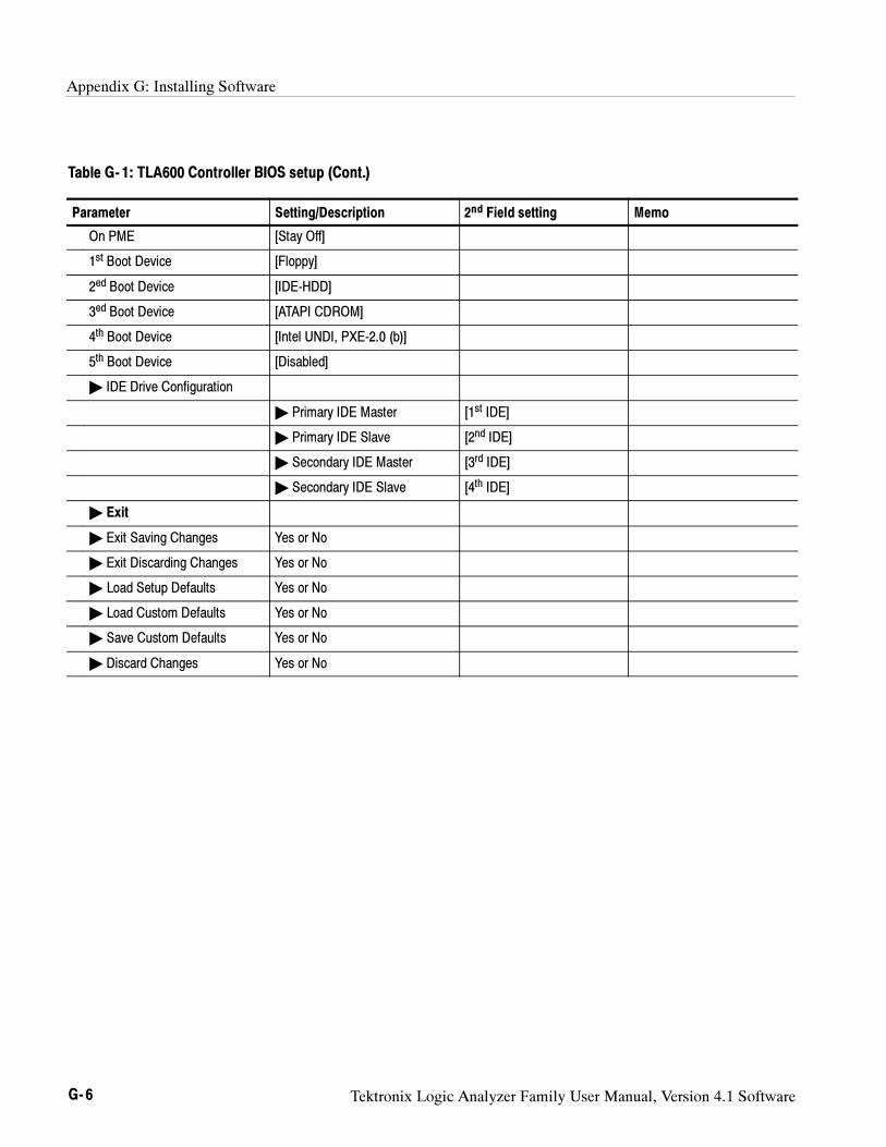
Appendix G: Installing Software
G- 6 Tektronix Logic Analyzer Family User Manual, Version 4.1 Software
Table G- 1: TLA600 Controller BIOS setup (Cont.)
Parameter Memo2nd Field settingSetting/Description
On PME [Stay Off]
1st Boot Device [Floppy]
2ed Boot Device [IDE-HDD]
3ed Boot Device [ATAPI CDROM]
4th Boot Device [Intel UNDI, PXE-2.0 (b)]
5th Boot Device [Disabled]
IDE Drive Configuration
Primary IDE Master [1st IDE]
Primary IDE Slave [2nd IDE]
Secondary IDE Master [3rd IDE]
Secondary IDE Slave [4th IDE]
Exit
Exit Saving Changes Yes or No
Exit Discarding Changes Yes or No
Load Setup Defaults Yes or No
Load Custom Defaults Yes or No
Save Custom Defaults Yes or No
Discard Changes Yes or No
Appendix G: Installing Software
Tektronix Logic Analyzer Family User Manual, Version 4.1 Software G- 7
This procedure is only necessary if you need to update the latest flash image. Toflash the BIOS, complete the following steps (use the TLA700 BIOS floppy diskthat came with your instrument or with the TLA7UP Upgrade kit):
1. Power on the logic analyzer and press function key F2 before the Windowsoperating system starts. The BIOS Setup menu displays.
2. From the BIOS Setup menu, go to the Exit menu.
3. Insert the TLA700 BIOS disk in the floppy disk drive.
4. From the Exit menu, choose Exit & Update BIOS.
5. When the system displays a dialog box asking if you want to proceed withthe Flash update, confirm your choice.
The display goes blank during the flash operation, which lasts about oneminute. When the BIOS update is complete, the logic analyzer automaticallyreboots.
6. Remove the BIOS disk from the floppy disk drive.
CAUTION. Do not remove the floppy disk drive or power down the logic analyzer
during the flash operation. Doing so will cause the system to become inoperable.
This procedure is necessary after replacing the hard disk or when the CMOSsettings are corrupted or lost. To configure the Controller BIOS, complete thefollowing steps:
1. Power on the logic analyzer and press function key F2 before the logicanalyzer boots the Windows operating system.
2. Press function key F9, select Yes and then press Enter to set the defaultsettings. Verify that the hard disk was auto-recognized and that the correctsize of the hard disk is displayed in the Primary Master setting.
3. If you have a TLA715 or TLA721 logic analyzer, all of the settings are thedefault settings. Press function key F10 to exit and save the BIOS setup andthen continue with the hard disk image installation procedure beginning onpage G--11.
4. If you have a TLA714 or TLA720 logic analyzer verify that all of thesettings are the same as the settings in Table G--2.
5. Press function key F10 to exit and save the BIOS setup.
Flashing the BIOS on theTLA714 or TLA720 Logic
Analyzers
Setting Up the TLA700Controller BIOS
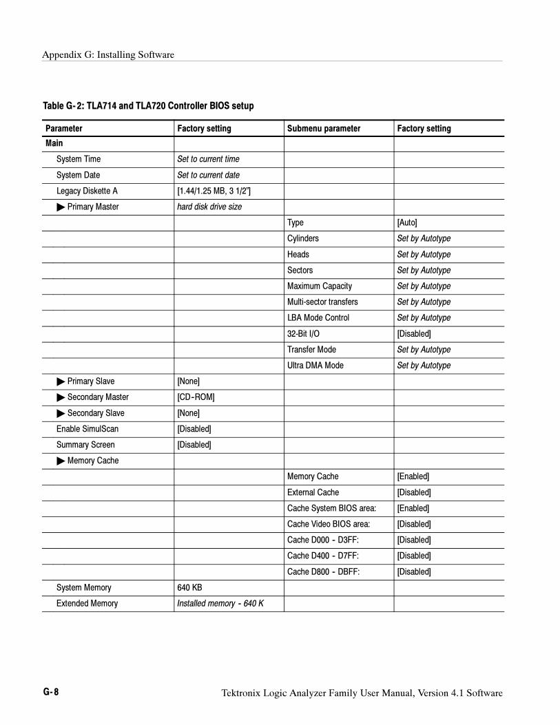
Appendix G: Installing Software
G- 8 Tektronix Logic Analyzer Family User Manual, Version 4.1 Software
Table G- 2: TLA714 and TLA720 Controller BIOS setup
Parameter Factory setting Submenu parameter Factory setting
Main
System Time Set to current time
System Date Set to current date
Legacy Diskette A [1.44/1.25 MB, 3 1/2”]
Primary Master hard disk drive size
Type [Auto]
Cylinders Set by Autotype
Heads Set by Autotype
Sectors Set by Autotype
Maximum Capacity Set by Autotype
Multi-sector transfers Set by Autotype
LBA Mode Control Set by Autotype
32-Bit I/O [Disabled]
Transfer Mode Set by Autotype
Ultra DMA Mode Set by Autotype
Primary Slave [None]
Secondary Master [CD--ROM]
Secondary Slave [None]
Enable SimulScan [Disabled]
Summary Screen [Disabled]
Memory Cache
Memory Cache [Enabled]
External Cache [Disabled]
Cache System BIOS area: [Enabled]
Cache Video BIOS area: [Disabled]
Cache D000 -- D3FF: [Disabled]
Cache D400 -- D7FF: [Disabled]
Cache D800 -- DBFF: [Disabled]
System Memory 640 KB
Extended Memory Installed memory -- 640 K
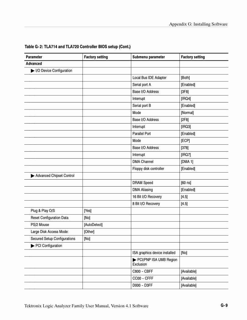
Appendix G: Installing Software
Tektronix Logic Analyzer Family User Manual, Version 4.1 Software G- 9
Table G- 2: TLA714 and TLA720 Controller BIOS setup (Cont.)
Parameter Factory settingSubmenu parameterFactory setting
Advanced
I/O Device Configuration
Local Bus IDE Adapter [Both]
Serial port A [Enabled]
Base I/O Address [3F8]
Interrupt [IRQ4]
Serial port B [Enabled]
Mode [Normal]
Base I/O Address [2F8]
Interrupt [IRQ3]
Parallel Port [Enabled]
Mode [ECP]
Base I/O Address [378]
Interrupt [IRQ7]
DMA Channel [DMA 1]
Floppy disk controller [Enabled]
Advanced Chipset Control
DRAM Speed [60 ns]
DMA Aliasing [Enabled]
16 Bit I/O Recovery [4.5]
8 Bit I/O Recovery [4.5]
Plug & Play O/S [Yes]
Reset Configuration Data [No]
PS/2 Mouse [AutoDetect]
Large Disk Access Mode: [Other]
Secured Setup Configurations [No]
PCI Configuration
ISA graphics device installed [No]
PCI/PNP ISA UMB RegionExclusion
C800 -- CBFF [Available]
CC00 -- CFFF [Available]
D000 -- D3FF [Available]
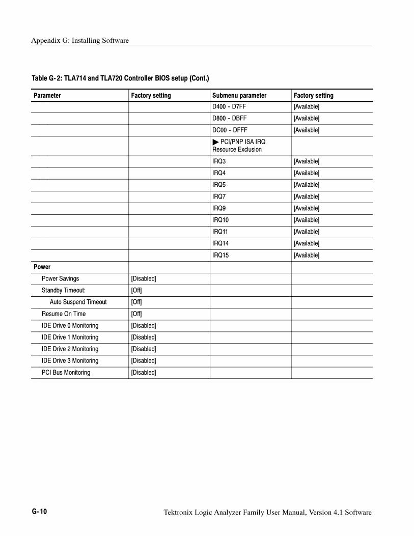
Appendix G: Installing Software
G- 10 Tektronix Logic Analyzer Family User Manual, Version 4.1 Software
Table G- 2: TLA714 and TLA720 Controller BIOS setup (Cont.)
Parameter Factory settingSubmenu parameterFactory setting
D400 -- D7FF [Available]
D800 -- DBFF [Available]
DC00 -- DFFF [Available]
PCI/PNP ISA IRQResource Exclusion
IRQ3 [Available]
IRQ4 [Available]
IRQ5 [Available]
IRQ7 [Available]
IRQ9 [Available]
IRQ10 [Available]
IRQ11 [Available]
IRQ14 [Available]
IRQ15 [Available]
Power
Power Savings [Disabled]
Standby Timeout: [Off]
Auto Suspend Timeout [Off]
Resume On Time [Off]
IDE Drive 0 Monitoring [Disabled]
IDE Drive 1 Monitoring [Disabled]
IDE Drive 2 Monitoring [Disabled]
IDE Drive 3 Monitoring [Disabled]
PCI Bus Monitoring [Disabled]
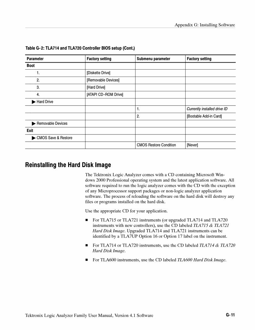
Appendix G: Installing Software
Tektronix Logic Analyzer Family User Manual, Version 4.1 Software G- 11
Table G- 2: TLA714 and TLA720 Controller BIOS setup (Cont.)
Parameter Factory settingSubmenu parameterFactory setting
Boot
1. [Diskette Drive]
2. [Removable Devices]
3. [Hard Drive]
4. [ATAPI CD--ROM Drive]
Hard Drive
1. Currently installed drive ID
2. [Bootable Add-in Card]
Removable Devices
Exit
CMOS Save & Restore
CMOS Restore Condition [Never]
Reinstalling the Hard Disk Image
The Tektronix Logic Analyzer comes with a CD containing Microsoft Win-dows 2000 Professional operating system and the latest application software. Allsoftware required to run the logic analyzer comes with the CD with the exceptionof any Microprocessor support packages or non-logic analyzer applicationsoftware. The process of reloading the software on the hard disk will destroy anyfiles or programs installed on the hard disk.
Use the appropriate CD for your application.
For TLA715 or TLA721 instruments (or upgraded TLA714 and TLA720instruments with new controllers), use the CD labeled TLA715 & TLA721
Hard Disk Image. Upgraded TLA714 and TLA721 instruments can beidentified by a TLA7UP Option 16 or Option 17 label on the instrument.
For TLA714 or TLA720 instruments, use the CD labeled TLA714 & TLA720
Hard Disk Image.
For TLA600 instruments, use the CD labeled TLA600 Hard Disk Image.
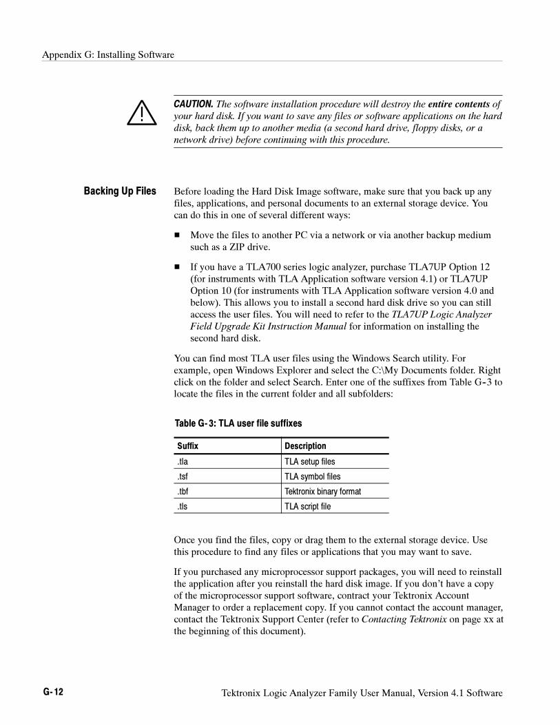
Appendix G: Installing Software
G- 12 Tektronix Logic Analyzer Family User Manual, Version 4.1 Software
CAUTION. The software installation procedure will destroy the entire contents of
your hard disk. If you want to save any files or software applications on the hard
disk, back them up to another media (a second hard drive, floppy disks, or a
network drive) before continuing with this procedure.
Before loading the Hard Disk Image software, make sure that you back up anyfiles, applications, and personal documents to an external storage device. Youcan do this in one of several different ways:
Move the files to another PC via a network or via another backup mediumsuch as a ZIP drive.
If you have a TLA700 series logic analyzer, purchase TLA7UP Option 12(for instruments with TLA Application software version 4.1) or TLA7UPOption 10 (for instruments with TLA Application software version 4.0 andbelow). This allows you to install a second hard disk drive so you can stillaccess the user files. You will need to refer to the TLA7UP Logic Analyzer
Field Upgrade Kit Instruction Manual for information on installing thesecond hard disk.
You can find most TLA user files using the Windows Search utility. Forexample, open Windows Explorer and select the C:\My Documents folder. Rightclick on the folder and select Search. Enter one of the suffixes from Table G--3 tolocate the files in the current folder and all subfolders:
Table G- 3: TLA user file suffixes
Suffix Description
.tla TLA setup files
.tsf TLA symbol files
.tbf Tektronix binary format
.tls TLA script file
Once you find the files, copy or drag them to the external storage device. Usethis procedure to find any files or applications that you may want to save.
If you purchased any microprocessor support packages, you will need to reinstallthe application after you reinstall the hard disk image. If you don’t have a copyof the microprocessor support software, contract your Tektronix AccountManager to order a replacement copy. If you cannot contact the account manager,contact the Tektronix Support Center (refer to Contacting Tektronix on page xx atthe beginning of this document).
Backing Up Files
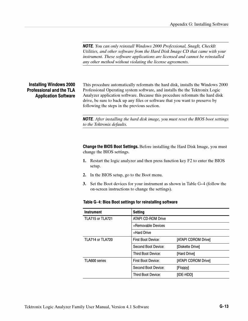
Appendix G: Installing Software
Tektronix Logic Analyzer Family User Manual, Version 4.1 Software G- 13
NOTE. You can only reinstall Windows 2000 Professional, SnagIt, CheckIt
Utilities, and other software from the Hard Disk Image CD that came with your
instrument. These software applications are licensed and cannot be reinstalled
any other method without violating the license agreements.
This procedure automatically reformats the hard disk, installs the Windows 2000Professional Operating system software, and installs the the Tektronix LogicAnalyzer application software. Because this procedure reformats the hard diskdrive, be sure to back up any files or software that you want to preserve byfollowing the steps in the previous section.
NOTE. After installing the hard disk image, you must reset the BIOS boot settings
to the Tektronix defaults.
Change the BIOS Boot Settings. Before installing the Hard Disk Image, you mustchange the BIOS settings.
1. Restart the logic analyzer and then press function key F2 to enter the BIOSsetup.
2. In the BIOS setup, go to the Boot menu.
3. Set the Boot devices for your instrument as shown in Table G--4 (follow theon-screen instructions to change the settings).
Table G- 4: Bios Boot settings for reinstalling software
Instrument Setting
TLA715 or TLA721 ATAPI CD-ROM Drive
+Removable Devices
+Hard Drive
TLA714 or TLA720 First Boot Device: [ATAPI CDROM Drive]
Second Boot Device: [Diskette Drive]
Third Boot Device: [Hard Drive]
TLA600 series First Boot Device: [ATAPI CDROM Drive]
Second Boot Device: [Floppy]
Third Boot Device: [IDE-HDD]
Installing Windows 2000Professional and the TLA
Application Software
Appendix G: Installing Software
G- 14 Tektronix Logic Analyzer Family User Manual, Version 4.1 Software
4. Save the settings by pressing function key F10 and confirm that you want tosave the new settings.
Load the Hard Disk Image. Complete the following steps to load the Hard DiskImage.
1. Insert the Hard Disk Image CD in the CD-ROM drive.
2. Reboot the logic analyzer.
3. Review the license agreement. If you agree to the terms of the licenseagreement, proceed with the next step.
NOTE. Use care when prompting through the software license agreement to avoid
confirming that you want to cancel the software installation procedure.
4. When you have completed reviewing the software license agreement, theEasyRestore dialog box displays and prompts you to either continue orcancel the upgrade process. Click Continue to begin loading the contents ofthe upgrade CD.
5. The EasyRestore program displays a warning that the contents of your harddisk will be destroyed in you choose to continue. Click Yes to continue theprocess.
6. The program will automatically start and guide you through the rest of theprocedure. The image loading procedure is fully automatic and takesapproximately 15 minutes to complete.
The image loading procedure automatically installs and sets up the logicanalyzer application. You should not need to make any changes to the setupto use the logic analyzer.
7. After the image is loaded, remove the CD from the CD-ROM drive andreboot the logic analyzer.
8. The Systems Settings Change error message displays, prompting you torestart the instrument before your changes can take effect. Click Yes torestart the instrument.
9. Reinstall any user files that you backed up previously. Reinstall any software(such as the microprocessor support packages) that you want to use on thelogic analyzer.
10. If desired, reconfigure the TLA network interface.
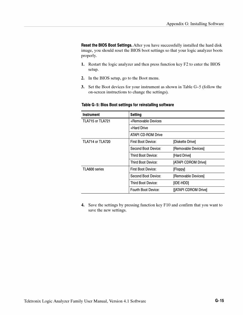
Appendix G: Installing Software
Tektronix Logic Analyzer Family User Manual, Version 4.1 Software G- 15
Reset the BIOS Boot Settings.After you have successfully installed the hard diskimage, you should reset the BIOS boot settings so that your logic analyzer bootsproperly.
1. Restart the logic analyzer and then press function key F2 to enter the BIOSsetup.
2. In the BIOS setup, go to the Boot menu.
3. Set the Boot devices for your instrument as shown in Table G--5 (follow theon-screen instructions to change the settings).
Table G- 5: Bios Boot settings for reinstalling software
Instrument Setting
TLA715 or TLA721 +Removable Devices
+Hard Drive
ATAPI CD-ROM Drive
TLA714 or TLA720 First Boot Device: [Diskette Drive]
Second Boot Device: [Removable Devices]
Third Boot Device: [Hard Drive]
Third Boot Device: [ATAPI CDROM Drive]
TLA600 series First Boot Device: [Floppy]
Second Boot Device: [Removable Devices]
Third Boot Device: [IDE-HDD]
Fourth Boot Device: [[ATAPI CDROM Drive]
4. Save the settings by pressing function key F10 and confirm that you want tosave the new settings.
Appendix G: Installing Software
G- 16 Tektronix Logic Analyzer Family User Manual, Version 4.1 Software
Reinstalling the TLA Application Software
Complete the following steps to reinstall the latest version of the TLA applica-tion software. Use these steps as a first resort to recovering from applicationsoftware problems. If you still experience problems with the software aftercompleting these steps, you are recommended to complete the steps underRestoring the Hard Disk Image beginning on page G--2.
While using this procedure you will be asked to log on as Administrator. Thelogic analyzer is initially set up to automatically log on as Administrator (withno password) so you may not see the log in prompt. If the network setups havebeen changed on your instrument, make sure that you log on as Administrator oras a user who has administrator privileges. Failure to do so can prevent thesoftware upgrade from completing successfully.
1. Log on to the instrument as Administrator and quit any applications.
2. Install Disc 1 of the Tektronix Logic Analyzer Family Application Softwarein the CD-ROM drive of the logic analyzer.
3. Click Run in the Windows Start menu to display the Run dialog box.
4. Enter D:\TLA Application SW\Disk1\Setup.exe in the Run dialog box (ifyour CD-ROM drive is not the D-drive enter the appropriate letter for yourdrive).
5. Click OK to perform the installation.
If you have an existing version of the software on the hard disk, theinstallation program will detect it and ask if you want to remove it. Followthe on-screen instructions to remove the software, answering “Yes” to anyprompts. Reboot the instrument when prompted. Repeat Step 4 to reinstallthe software following any on-screen prompts.
6. After the software has been successfully installed, restart the instrument.
Appendix G: Installing Software
Tektronix Logic Analyzer Family User Manual, Version 4.1 Software G- 17
Reinstalling the Pattern Generator Application Software
Complete the following steps to reinstall the latest version of the patterngenerator application software. Use these steps as a first resort to recoveringfrom application software problems. If you still experience problems with thesoftware after completing these steps, you are recommended to complete thesteps under Restoring the Hard Disk Image beginning on page G--2.
While using this procedure you will be asked to log on as Administrator. Theinstrument is initially set up to automatically log on as Administrator (with nopassword) so you may not see the log in prompt. If the network setups have beenchanged on your instrument, make sure that you log on as Administrator or as auser who has administrator privileges. Failure to do so can prevent the softwareupgrade from completing successfully.
1. Log on to the instrument as Administrator.
2. Install Disc 1 of the Tektronix Logic Analyzer Family Application Softwarein the CD-ROM drive of the logic analyzer.
3. Click Run in the Windows Start menu to display the Run dialog box.
4. Enter D:\Pattern Generator Application SW\Disk1\Setup.exe in the Rundialog box (if your CD-ROM drive is not the D-drive enter the appropriateletter for your drive).
5. Click OK to perform the installation.
If you have an existing version of the software on the hard disk, theinstallation program will detect it and ask if you want to remove it. Followthe on-screen instructions to remove the software, answering “Yes” to anyprompts. Reboot the instrument when prompted. Repeat Step 4 to reinstallthe software following any on-screen prompts.
6. After the software has been successfully installed, restart the instrument.
Appendix G: Installing Software
G- 18 Tektronix Logic Analyzer Family User Manual, Version 4.1 Software
Installing the Remote Operation Software
The TPI client software and the PPI client software are two software packagesthat allow you to remotely control the logic analyzer or pattern generator from aremote PC. These software packages are located on Disc 1 of the dual CD-ROMset. You must ensure that the version of the TPI and PPI client software is thesame as that of TLA and pattern generator application on your logic analyzer.
Complete the following steps to update the client software packages on your PC.If you have an older version already installed on your PC, the program willautomatically detect it and replace it during the upgrade process.
1. Install Disc 1 of the Tektronix Logic Analyzer Family Application Softwarein the CD-ROM drive of the PC.
2. Click Run in the Windows Start menu to display the Run dialog box.
3. To install the TPI client software, enter D:\TPI Client SW\Disk1\Setup.exein the Run dialog box.
4. To install the PPI client software, enter D:\PPI Client SW\Disk1\Setup.exein the Run dialog box.
5. Click OK to perform the installation. Follow any on-screen instructions.
6. If you have an earlier version of either software package installed on yourPC, the Setup.exe program will uninstall the application before installing thenew version. If any messages appear asking you for permission to removeunused shared files or any read-only files, select Yes to All.
Appendix G: Installing Software
Tektronix Logic Analyzer Family User Manual, Version 4.1 Software G- 19
Installing the TLAVu Software
TLAVu application software allows you to view data and create setups for yourlogic analyzer on a PC. You must ensure that the version of the TLAVuapplication software is the same as that of TLA application. The TLAVuapplication software is located on Disc 2 of the dual CD-ROM set.
Complete the following steps to update the TLAVu application software on yourPC. If you have an older version already installed on your PC, the program willautomatically detect it and replace it during the upgrade process.
1. Install Disc 2 of the Tektronix Logic Analyzer Family Application Softwarein the CD-ROM drive of the PC.
2. Click Run in the Windows Start menu to display the Run dialog box.
3. Enter D:\TLAVu\Disk1\Setup.exe in the Run dialog box.
4. Click OK to perform the installation. Follow any on-screen instructions.
5. If you have an earlier version of the TLAVu application installed on your PC,the Setup.exe program will uninstall the old application before installing thenew version. If any messages appear asking you for permission to removeunused shared files or any read-only files, select Yes to All.
NOTE. The ReadMe file for the TLAVu application contains most of the
information that you need to run the application. Access the ReadMe file by
selecting: Start → Programs → Tektronix Logic Analyzer → TLA Documenta-
tion → TLAVu ReadMe.
Appendix G: Installing Software
G- 20 Tektronix Logic Analyzer Family User Manual, Version 4.1 Software
Installing the PatGenVu Software
The PatGenVu application software allows you to view data and create setups foryour pattern generator on a PC. You must ensure that the versions of thePatGenVu software are the same as the pattern generator application. ThePatGenVu software application is located on Disc 2 of the dual CD-ROM set.
Complete the following steps to upgrade the PatGenVu application software onyour PC. If you have an older version already installed on your PC, theinstallation program will automatically detect it and replace it during the upgradeprocess.
1. Install Disc 2 of the Tektronix Logic Analyzer Family Application Softwarein the CD-ROM drive of the PC.
2. Click Run in the Windows Start menu to display the Run dialog box.
3. Enter D:\PatGenVu\Disk1\Setup.exe in the Run dialog box.
4. Click OK to perform the installation. Follow any on-screen instructions.
5. If you have an earlier version of the PatGenVu application installed on yourPC, the Setup.exe program will uninstall the old application before installingthe new version. If any messages appear asking you for permission toremove unused shared files or any read-only files, select Yes to All.
NOTE. The ReadMe file for the PatGenVu application contains most of the
information that you need to run the application. Access the ReadMe file by
selecting: Start → Programs → Tektronix Pattern Generator → Pattern
Generator Documentation → PatGenVu ReadMe
Tektronix Logic Analyzer Family User Manual, Version 4.1 Software H- 1
Appendix H: User Service
This appendix describes service information and procedures for the Tektronixlogic analyzers. Mainframe and module service troubleshooting procedures arelocated in the service manuals.
Service Offerings
Tektronix provides service to cover repair under warranty as well as otherservices that are designed to meet your specific service needs.
Whether providing warranty repair service or any of the other services listedbelow, Tektronix service technicians are well equipped to service the logicanalyzers. Services are provided at Tektronix Services Centers and on-site at
your facility, depending on your location.
Tektronix warrants this product for one year from date of purchase. (Thewarranty appears behind the title page in this manual.) Tektronix techniciansprovide warranty service at most Tektronix service locations worldwide. TheTektronix product catalog lists all service locations worldwide or you can visit uson our Customer Services World Center web site at:
www.tektronix.com/Measurement/Service
In addition to warranty repair, Tektronix Service offers calibration and otherservices which provide cost-effective solutions to your service needs and quality-standards compliance requirements. Our instruments are supported worldwide bythe leading-edge design, manufacturing, and service resources of Tektronix toprovide the best possible service.
The following services can be tailored to fit your requirements for calibrationand/or repair of the TLA logic analyzers:
Service Options. Tektronix Service Options can be selected at the time youpurchase your instrument. You select these options to provide the services thatbest meet your service needs. These service options are listed on the TektronixService Options page following the title page of this manual.
Warranty Repair Service
Calibration and RepairService
Appendix H: User Service
H- 2 Tektronix Logic Analyzer Family User Manual, Version 4.1 Software
Service Agreements. If service options are not added to the instrument purchase,then service agreements are available on an annual basis to provide calibrationservices or post-warranty repair coverage for the TLA logic analyzers. Serviceagreements may be customized to meet special turn-around time and/or on-siterequirements.
Service on Demand. Tektronix also offers calibration and repair services on a“per-incident” basis that is available with standard prices for many products.
Self Service. Tektronix supports repair to the replaceable-part level by providingfor circuit board (module) exchange.
Use this service to reduce down-time for repair by exchanging faulty circuitboards for remanufactured ones. Tektronix ships updated and tested exchangeboards. Each board comes with a 90-day service warranty.
For More Information. Contact your local Tektronix service center or salesengineer for more information on any of the calibration and repair services.
Service Options
Tektronix offers the following service options. These options are modular,flexible, and easy to order with your instrument. Designed to ease installationand startup, to support tracking of calibration to requirements of ISO9000, and toprovide for extended repair coverage, these options help fix your long-termmaintenance costs and eliminate unplanned expenditures. These options can beconverted from service at Tektronix service depots to service on-site (see OptionS1 and S3), which helps keep downtime to a minimum.
Appendix H: User Service
Tektronix Logic Analyzer Family User Manual, Version 4.1 Software H- 3
The following service options are available for your TLA600 series logicanalyzer.
Three years repair coverage Option R3 Extends product repair warranty to a total ofthree years.
Three years of calibration services Option C3 Provides factory calibration certification ondelivery, plus two more years of calibrationcoverage. Throughout the coverage period theinstrument will be calibrated according to itsRecommended Calibration Interval.
Test data Option D1 Provides initial Test Data Report from factoryon delivery.
Test data Option D3 Provides test data on delivery plus a Test DataReport for every calibration performed during3 years of coverage -- requires Option C3.
The following service options are available for your TLA700 series logicanalyzer.
Three years repair coverage Option R3 Extends product repair warranty to a total ofthree years.
Three years of calibration services Option C3 Provides factory calibration certification ondelivery, plus two more years of calibrationcoverage. Throughout the coverage period theinstrument will be calibrated according to itsRecommended Calibration Interval.
One year upgrade to on-site service1, 2 Option S1 Upgrades the standard one year, “return todepot” warranty to an on-site warranty.
Three year upgrade to on-site service1, 2 Option S3 Upgrades any C3, D3, and R3 options pur-chased to on-site coverage for three years.
Test data Option D1 Provides initial Test Data Report from factoryon delivery.
Test data Option D3 Provides test data on delivery plus a Test DataReport for every calibration performed during3 years of coverage -- requires Option C3.
Product installation service Option IN Provides initial product installation/configura-tion and start-up training session includingfront panel and product familiarization.
1 Availability of installation and on-site services depends on the type of product and may vary by geography.
2 Upgrade options are ordered with the mainframe products and cover individual modules.
TLA600 Series ServiceOptions
TLA700 Series ServiceOptions
Appendix H: User Service
H- 4 Tektronix Logic Analyzer Family User Manual, Version 4.1 Software
General Care
Protect the instrument from adverse weather conditions. The instrument is notwaterproof.
Do not store or leave the instrument where the LCD display will be exposed todirect sunlight for long periods of time.
CAUTION. To avoid damage to the instrument, do not expose it to sprays, liquids,
or solvents.
Module Self Calibration
Use the Self Calibration property page to run self calibration procedures forinstalled modules and merged modules. For all modules, you should run theseprocedures after repair. At a minimum, you should run these procedures once ayear. For the DSO module you should also run these procedures if the ambientoperating temperature has changed more than 5C since last calibration or once aweek if vertical settings of 50 mV full scale or less are used.
Perform self calibration after a 30 minute warm up.
To run the self-calibration procedure, go to the System menu and selectCalibration and Diagnostics. Click Self Calibration.
NOTE. For merged modules, run the self-calibration procedure on the modules
as a merged set.
Preventive Maintenance
Once a year the electrical performance should be checked and the instrumentaccuracy certified (calibrated). This service should be performed by a qualifiedservice technician using the procedures outlined in the appropriate servicemanual for the Tektronix Logic Analyzer product.
Preventive maintenance mainly consists of periodic cleaning. Periodic cleaningreduces instrument breakdown and increases reliability. Clean the instrument asneeded, based on the operating environment. Dirty conditions may require morefrequent cleaning than computer room conditions.
Appendix H: User Service
Tektronix Logic Analyzer Family User Manual, Version 4.1 Software H- 5
The LCD flat panel is a soft plastic display and must be treated with care duringcleaning.
CAUTION. Improper cleaning agents or methods can damage the flat panel
display.
Do not use abrasive cleaners or commercial glass cleaners to clean the display
surface.
Do not spray liquids directly on the display surface.
Do not scrub the display with excessive force.
Clean the flat panel display surface by gently rubbing the display with aclean-room wipe (such as Wypall Medium Duty Wipes, #05701, available fromKimberly-Clark Corporation).
If the display is very dirty, moisten the wipe with distilled water or a 75%isopropyl alcohol solution and gently rub the display surface. Avoid using excessforce or you may damage the plastic display surface.
Clean the exterior surfaces with a dry, lint-free cloth or a soft-bristle brush. If dirtremains, use a cloth or swab dampened with a 75% isopropyl alcohol solution. Aswab is useful for cleaning in narrow spaces around the controls and connectors.Do not use abrasive compounds on any part of the instrument.
CAUTION. Avoid getting moisture inside the instrument during external cleaning;
and use only enough solution to dampen the cloth or swab.
Do not wash the front-panel On/Standby switch. Cover the switch while washing
the instrument.
Use only deionized water when cleaning. Use a 75% isopropyl alcohol solution
as a cleanser and rinse with deionized water.
Do not use chemical cleaning agents; they may damage the instrument. Avoid
chemicals that contain benzene, toluene, xylene, acetone, or similar solvents.
The floppy disk drive requires routine maintenance to operate at maximumefficiency. The disks can be damaged if dirt and dust accumulate on therecording surfaces. To prevent damage, the disks should be properly stored intheir protective containers where they will not be exposed to dust or dirt. Inaddition, the head should be cleaned periodically.
Flat Panel DisplayCleaning
Exterior Surfaces
Floppy Disk Drive
Appendix H: User Service
H- 6 Tektronix Logic Analyzer Family User Manual, Version 4.1 Software
You will need a 3.5-inch floppy disk head-cleaning kit for routine maintenance.Perform the routine maintenance as follows:
Clean the face of the floppy disk drive monthly with a dampened cloth.
CAUTION. Do not allow moisture to enter the disk drive. When power is applied,
the internal components can be damaged.
Clean the head monthly. Follow the instructions provided with the head-cleaning kit.
In Case of Problems
This section provides information to help you address problems you mayencounter while installing and using your logic analyzer.
The logic analyzer runs power-on diagnostics every time you power on theinstrument. You can view the results of the diagnostics by selecting Calibrationand Diagnostics from the System menu. You can run more detailed diagnosticsby selecting Extended diagnostics. Here you can run all tests, loop on one ormore tests, or loop on a test until a failure occurs.
The following diagnostic tools are available with your logic analyzer:
Power-On Diagnostics. Power-on diagnostics run when you first turn on the logicanalyzer, or when you first start the TLA or the pattern generator application. Ifany diagnostic failures occur during turn on, the Calibration and Diagnosticsproperty page appears.
Extended Diagnostics. Extended diagnostics test the logic analyzer morethoroughly than the power-on diagnostics. The extended diagnostics test themodules in the benchtop mainframe as well as the modules in the expansionmainframe(s). You can use the extended diagnostics to isolate problems to anindividual module.
Before running the extended diagnostics, disconnect any attached probes.
NOTE. Some items in the extended diagnostics menu will fail if a LA module,
DSO module, or pattern generator module is running. Stop all modules before
performing the extended diagnostics.
Diagnostics
Appendix H: User Service
Tektronix Logic Analyzer Family User Manual, Version 4.1 Software H- 7
TLA Mainframe Diagnostics. The TLA mainframe diagnostics program is a standalone Windows application. These diagnostics check operation of the mainframebeyond the basic PC circuitry. These diagnostics also check the front panel knobsof the portable mainframe.
Expansion Mainframe Diagnostics.At power-on, the expansion mainframe runstwo power-on diagnostics: “Power, Cables A & B and config”, and “Cable CConnection Test”.
If either of these power-on diagnostics fail, none of the modules associated withthe expansion mainframe, and possibly the expansion mainframe itself, will berecognized. The result will be as if the expansion mainframe was not connected.
Turn off the mainframes. Remove the two blue expansion cables and the grayexpansion cable. Examine the connectors for bent or missing pins. Reconnect thetwo blue expansion cables and the expansion cable, and tighten the twoconnector screws. Turn on the mainframes and try again.
CheckIt Utilities. The CheckIt Utilities is a separate Windows application locatedin the Windows Start Programs menu. The diagnostics check the basic PCoperations of the controller. (Earlier versions of the logic analyzers usedQA+Win32 diagnostics.)
Your logic analyzer comes with most software installed. Before running any ofthe diagnostics, you should check the online release notes to verify the logicanalyzer software is compatible with the module firmware.
Many software problems can be due to corrupted or missing software files. Inmost cases the easiest way to solve software problems is to reinstall the softwareand follow the on-screen instructions. Refer to Upgrading Software forinstructions on reinstalling or upgrading software.
Refer to Table H--1 on page H--8 for a list of software and hardware trouble-shooting information and recommended action. Note that this table can be usedto identify problems for the entire Tektronix logic analyzer family.
If you suspect problems with the application software, contact your localTektronix representative.
If you are certain that you have installed the logic analyzer correctly, run theextended diagnostics (located under the System menu) to identify any problems.
If your logic analyzer powers up so that you have access to the desktop, run theCheckIt Utilities software to identify possible controller hardware problems.
Software Problems
Hardware Problems
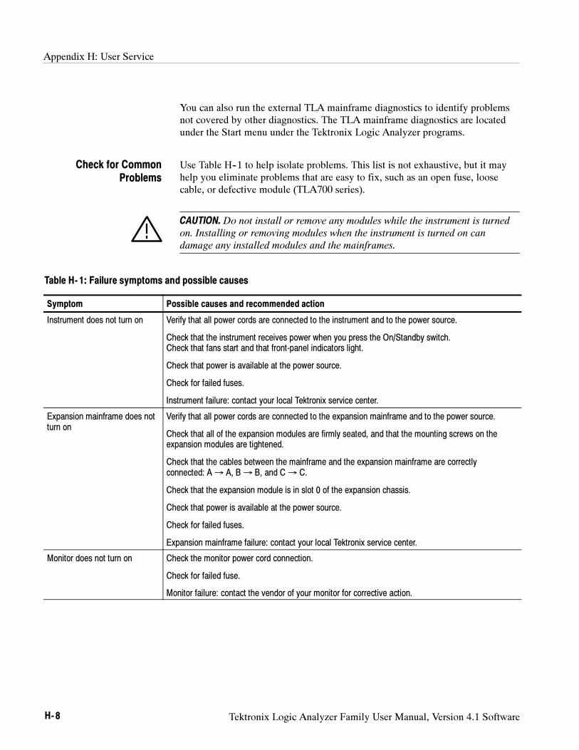
Appendix H: User Service
H- 8 Tektronix Logic Analyzer Family User Manual, Version 4.1 Software
You can also run the external TLA mainframe diagnostics to identify problemsnot covered by other diagnostics. The TLA mainframe diagnostics are locatedunder the Start menu under the Tektronix Logic Analyzer programs.
Use Table H--1 to help isolate problems. This list is not exhaustive, but it mayhelp you eliminate problems that are easy to fix, such as an open fuse, loosecable, or defective module (TLA700 series).
CAUTION. Do not install or remove any modules while the instrument is turned
on. Installing or removing modules when the instrument is turned on can
damage any installed modules and the mainframes.
Table H- 1: Failure symptoms and possible causes
Symptom Possible causes and recommended action
Instrument does not turn on Verify that all power cords are connected to the instrument and to the power source.
Check that the instrument receives power when you press the On/Standby switch.Check that fans start and that front-panel indicators light.
Check that power is available at the power source.
Check for failed fuses.
Instrument failure: contact your local Tektronix service center.
Expansion mainframe does notturn on
Verify that all power cords are connected to the expansion mainframe and to the power source.
Check that all of the expansion modules are firmly seated, and that the mounting screws on theexpansion modules are tightened.
Check that the cables between the mainframe and the expansion mainframe are correctlyconnected: A→ A, B→ B, and C→ C.
Check that the expansion module is in slot 0 of the expansion chassis.
Check that power is available at the power source.
Check for failed fuses.
Expansion mainframe failure: contact your local Tektronix service center.
Monitor does not turn on Check the monitor power cord connection.
Check for failed fuse.
Monitor failure: contact the vendor of your monitor for corrective action.
Check for CommonProblems
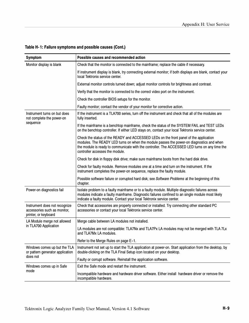
Appendix H: User Service
Tektronix Logic Analyzer Family User Manual, Version 4.1 Software H- 9
Table H- 1: Failure symptoms and possible causes (Cont.)
Symptom Possible causes and recommended action
Monitor display is blank Check that the monitor is connected to the mainframe; replace the cable if necessary.
If instrument display is blank, try connecting external monitor; if both displays are blank, contact yourlocal Tektronix service center.
External monitor controls turned down; adjust monitor controls for brightness and contrast.
Verify that the monitor is connected to the correct video port on the instrument.
Check the controller BIOS setups for the monitor.
Faulty monitor; contact the vendor of your monitor for corrective action.
Instrument turns on but doesnot complete the power-onsequence
If the instrument is a TLA700 series, turn off the instrument and check that all of the modules arefully inserted.
If the mainframe is a benchtop mainframe, check the status of the SYSTEM FAIL and TEST LEDson the benchtop controller. If either LED stays on, contact your local Tektronix service center.
Check the status of the READY and ACCESSED LEDs on the front panel of the applicationmodules. The READY LED turns on when the module passes the power-on diagnostics and whenthe module is ready to communicate with the controller. The ACCESSED LED turns on any time thecontroller accesses the module.
Check for disk in floppy disk drive; make sure mainframe boots from the hard disk drive.
Check for faulty module. Remove modules one at a time and turn on the instrument. If theinstrument completes the power-on sequence, replace the faulty module.
Possible software failure or corrupted hard disk; see Software Problems at the beginning of thischapter.
Power-on diagnostics fail Isolate problem to a faulty mainframe or to a faulty module. Multiple diagnostic failures acrossmodules indicate a faulty mainframe. Diagnostic failures confined to an single module most likelyindicate a faulty module. Contact your local Tektronix service center.
Instrument does not recognizeaccessories such as monitor,printer, or keyboard
Check that accessories are properly connected or installed. Try connecting other standard PCaccessories or contact your local Tektronix service center.
LA Module merge not allowedin TLA700 Application
Merge cable between LA modules not installed.
LA modules are not compatible: TLA7Nx and TLA7Px LA modules may not be merged with TLA 7Lxand TLA7Mx LA modules.
Refer to the Merge Rules on page E--1.
Windows comes up but the TLAor pattern generator applicationdoes not
Instrument not set up to start the TLA application at power-on. Start application from the desktop, bydouble-clicking on the TLA Final Setup icon located on your desktop.
Faulty or corrupt software. Reinstall the application software.
Windows comes up in Safemode
Exit the Safe mode and restart the instrument.
Incompatible hardware and hardware driver software. Either install hardware driver or remove theincompatible hardware.
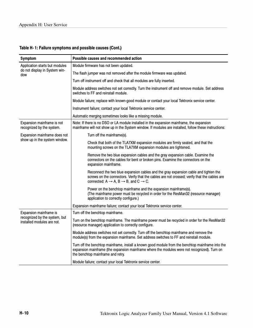
Appendix H: User Service
H- 10 Tektronix Logic Analyzer Family User Manual, Version 4.1 Software
Table H- 1: Failure symptoms and possible causes (Cont.)
Symptom Possible causes and recommended action
Application starts but modulesdo not display in System win-dow
Module firmware has not been updated.
The flash jumper was not removed after the module firmware was updated.
Turn off instrument off and check that all modules are fully inserted.
Module address switches not set correctly. Turn the instrument off and remove module. Set addressswitches to FF and reinstall module.
Module failure; replace with known-good module or contact your local Tektronix service center.
Instrument failure; contact your local Tektronix service center.
Automatic merging sometimes looks like a missing module.
Expansion mainframe is notrecognized by the system.
Expansion mainframe does notshow up in the system window.
Note: If there is no DSO or LA module installed in the expansion mainframe, the expansionmainframe will not show up in the System window. If modules are installed, follow these instructions:
Turn off the mainframe(s).
Check that both of the TLA7XM expansion modules are firmly seated, and that themounting screws on the TLA7XM expansion modules are tightened.
Remove the two blue expansion cables and the gray expansion cable. Examine theconnectors on the cables for bent or broken pins. Examine the connectors on theexpansion mainframe.
Reconnect the two blue expansion cables and the gray expansion cable and tighten thescrews on the connectors. Verify that the cables are not crossed; verify that the cables areconnected: A→ A, B→ B, and C→ C.
Power on the benchtop mainframe and the expansion mainframe(s).(The mainframe power must be recycled in order for the ResMan32 (resource manager)application to correctly configure.)
Expansion mainframe failure; contact your local Tektronix service center.
Expansion mainframe isrecognized by the system, butinstalled modules are not.
Turn off the benchtop mainframe.
Turn on the benchtop mainframe. The mainframe power must be recycled in order for the ResMan32(resource manager) application to correctly configure.
Module address switches not set correctly. Turn off the benchtop mainframe and remove themodule(s) from the expansion mainframe. Set address switches to FF and reinstall module.
Turn off the benchtop mainframe, install a known good module from the benchtop mainframe into theexpansion mainframe (the expansion mainframe where the modules were not recognized). Turn onthe benchtop mainframe and retry.
Module failure; contact your local Tektronix service center.
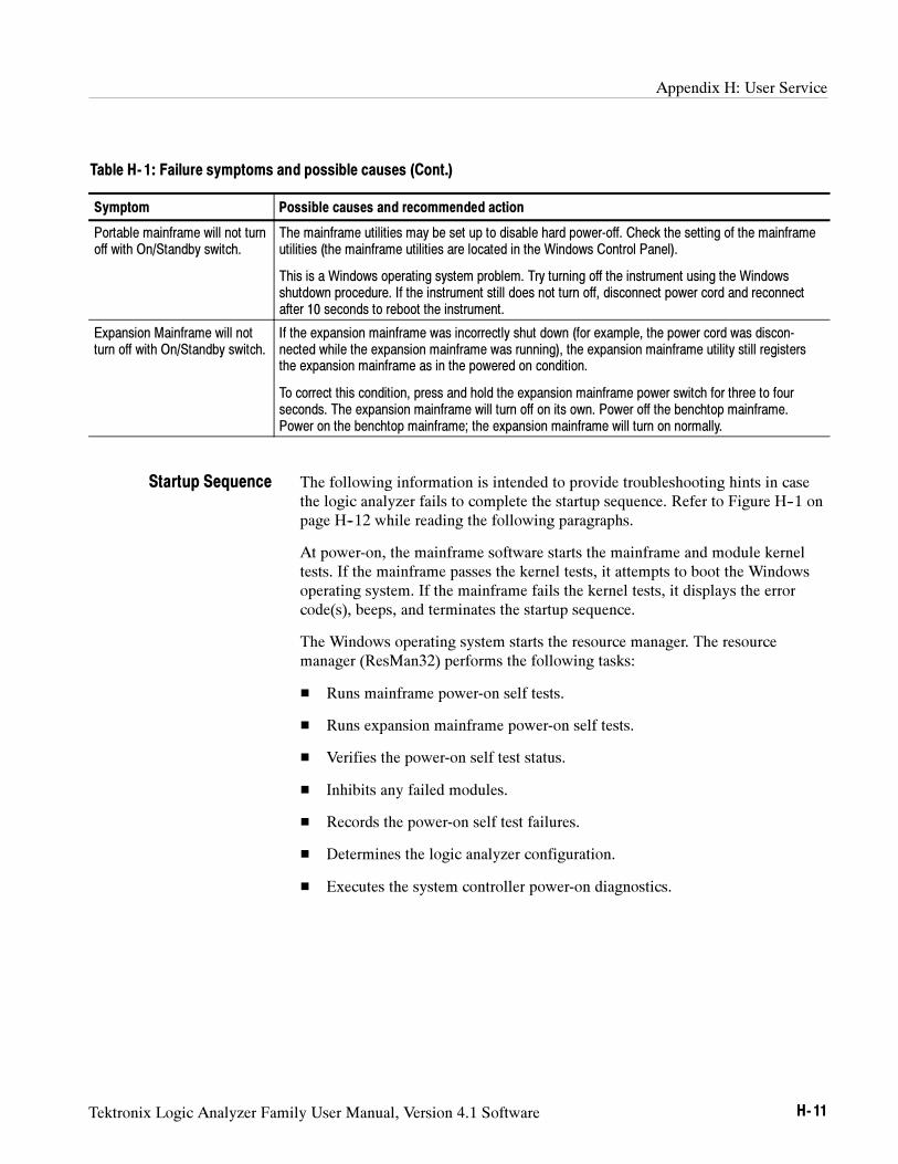
Appendix H: User Service
Tektronix Logic Analyzer Family User Manual, Version 4.1 Software H- 11
Table H- 1: Failure symptoms and possible causes (Cont.)
Symptom Possible causes and recommended action
Portable mainframe will not turnoff with On/Standby switch.
The mainframe utilities may be set up to disable hard power-off. Check the setting of the mainframeutilities (the mainframe utilities are located in the Windows Control Panel).
This is a Windows operating system problem. Try turning off the instrument using the Windowsshutdown procedure. If the instrument still does not turn off, disconnect power cord and reconnectafter 10 seconds to reboot the instrument.
Expansion Mainframe will notturn off with On/Standby switch.
If the expansion mainframe was incorrectly shut down (for example, the power cord was discon-nected while the expansion mainframe was running), the expansion mainframe utility still registersthe expansion mainframe as in the powered on condition.
To correct this condition, press and hold the expansion mainframe power switch for three to fourseconds. The expansion mainframe will turn off on its own. Power off the benchtop mainframe.Power on the benchtop mainframe; the expansion mainframe will turn on normally.
The following information is intended to provide troubleshooting hints in casethe logic analyzer fails to complete the startup sequence. Refer to Figure H--1 onpage H--12 while reading the following paragraphs.
At power-on, the mainframe software starts the mainframe and module kerneltests. If the mainframe passes the kernel tests, it attempts to boot the Windowsoperating system. If the mainframe fails the kernel tests, it displays the errorcode(s), beeps, and terminates the startup sequence.
The Windows operating system starts the resource manager. The resourcemanager (ResMan32) performs the following tasks:
Runs mainframe power-on self tests.
Runs expansion mainframe power-on self tests.
Verifies the power-on self test status.
Inhibits any failed modules.
Records the power-on self test failures.
Determines the logic analyzer configuration.
Executes the system controller power-on diagnostics.
Startup Sequence
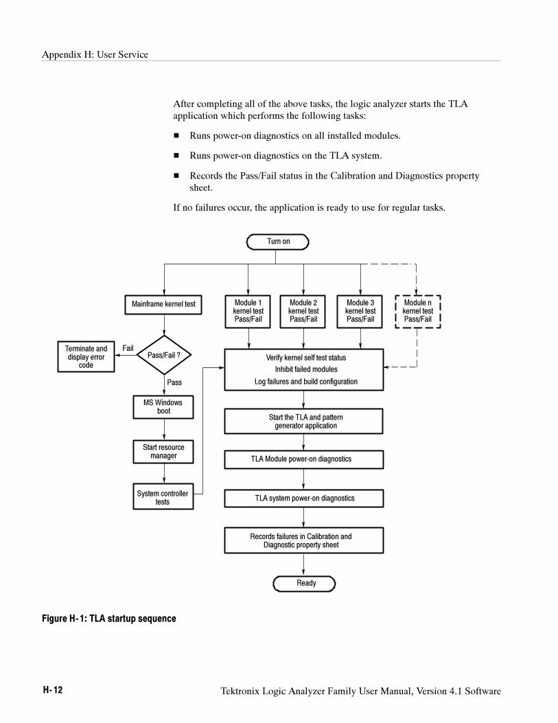
Appendix H: User Service
H- 12 Tektronix Logic Analyzer Family User Manual, Version 4.1 Software
After completing all of the above tasks, the logic analyzer starts the TLAapplication which performs the following tasks:
Runs power-on diagnostics on all installed modules.
Runs power-on diagnostics on the TLA system.
Records the Pass/Fail status in the Calibration and Diagnostics propertysheet.
If no failures occur, the application is ready to use for regular tasks.
Turn on
Mainframe kernel test
Pass/Fail ?
Module 1kernel testPass/Fail
Module 2kernel testPass/Fail
Module 3kernel testPass/Fail
Verify kernel self test status
Inhibit failed modules
Log failures and build configuration
Start the TLA and patterngenerator application
TLA Module power-on diagnostics
TLA system power-on diagnostics
Records failures in Calibration andDiagnostic property sheet
Ready
FailTerminate anddisplay error
code
Pass
MS Windowsboot
Start resourcemanager
System controllertests
Module nkernel testPass/Fail
Figure H- 1: TLA startup sequence
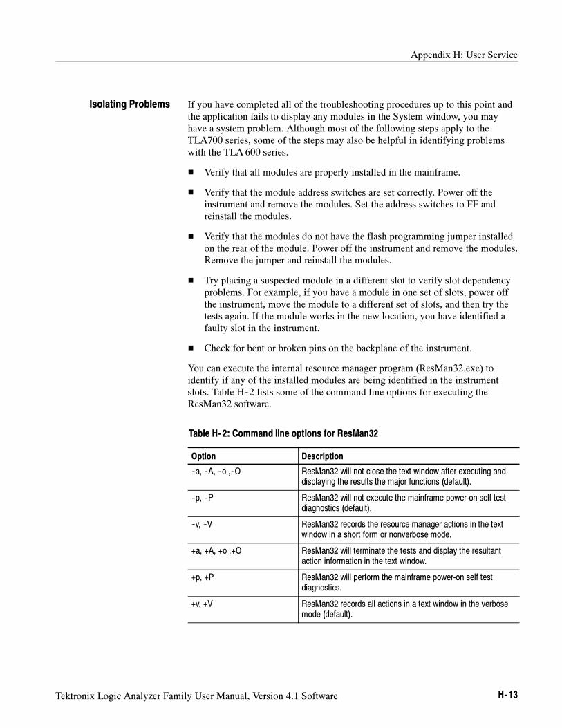
Appendix H: User Service
Tektronix Logic Analyzer Family User Manual, Version 4.1 Software H- 13
If you have completed all of the troubleshooting procedures up to this point andthe application fails to display any modules in the System window, you mayhave a system problem. Although most of the following steps apply to theTLA700 series, some of the steps may also be helpful in identifying problemswith the TLA 600 series.
Verify that all modules are properly installed in the mainframe.
Verify that the module address switches are set correctly. Power off theinstrument and remove the modules. Set the address switches to FF andreinstall the modules.
Verify that the modules do not have the flash programming jumper installedon the rear of the module. Power off the instrument and remove the modules.Remove the jumper and reinstall the modules.
Try placing a suspected module in a different slot to verify slot dependencyproblems. For example, if you have a module in one set of slots, power offthe instrument, move the module to a different set of slots, and then try thetests again. If the module works in the new location, you have identified afaulty slot in the instrument.
Check for bent or broken pins on the backplane of the instrument.
You can execute the internal resource manager program (ResMan32.exe) toidentify if any of the installed modules are being identified in the instrumentslots. Table H--2 lists some of the command line options for executing theResMan32 software.
Table H- 2: Command line options for ResMan32
Option Description
--a, --A, --o ,--O ResMan32 will not close the text window after executing anddisplaying the results the major functions (default).
--p, --P ResMan32 will not execute the mainframe power-on self testdiagnostics (default).
--v, --V ResMan32 records the resource manager actions in the textwindow in a short form or nonverbose mode.
+a, +A, +o ,+O ResMan32 will terminate the tests and display the resultantaction information in the text window.
+p, +P ResMan32 will perform the mainframe power-on self testdiagnostics.
+v, +V ResMan32 records all actions in a text window in the verbosemode (default).
Isolating Problems
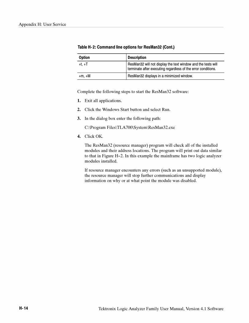
Appendix H: User Service
H- 14 Tektronix Logic Analyzer Family User Manual, Version 4.1 Software
Table H- 2: Command line options for ResMan32 (Cont.)
Option Description
+t, +T ResMan32 will not display the text window and the tests willterminate after executing regardless of the error conditions.
+m, +M ResMan32 displays in a minimized window.
Complete the following steps to start the ResMan32 software:
1. Exit all applications.
2. Click the Windows Start button and select Run.
3. In the dialog box enter the following path:
C:\Program Files\TLA700\System\ResMan32.exe
4. Click OK.
The ResMan32 (resource manager) program will check all of the installedmodules and their address locations. The program will print out data similarto that in Figure H--2. In this example the mainframe has two logic analyzermodules installed.
If resource manager encounters any errors (such as an unsupported module),the resource manager will stop further communications and displayinformation on why or at what point the module was disabled.
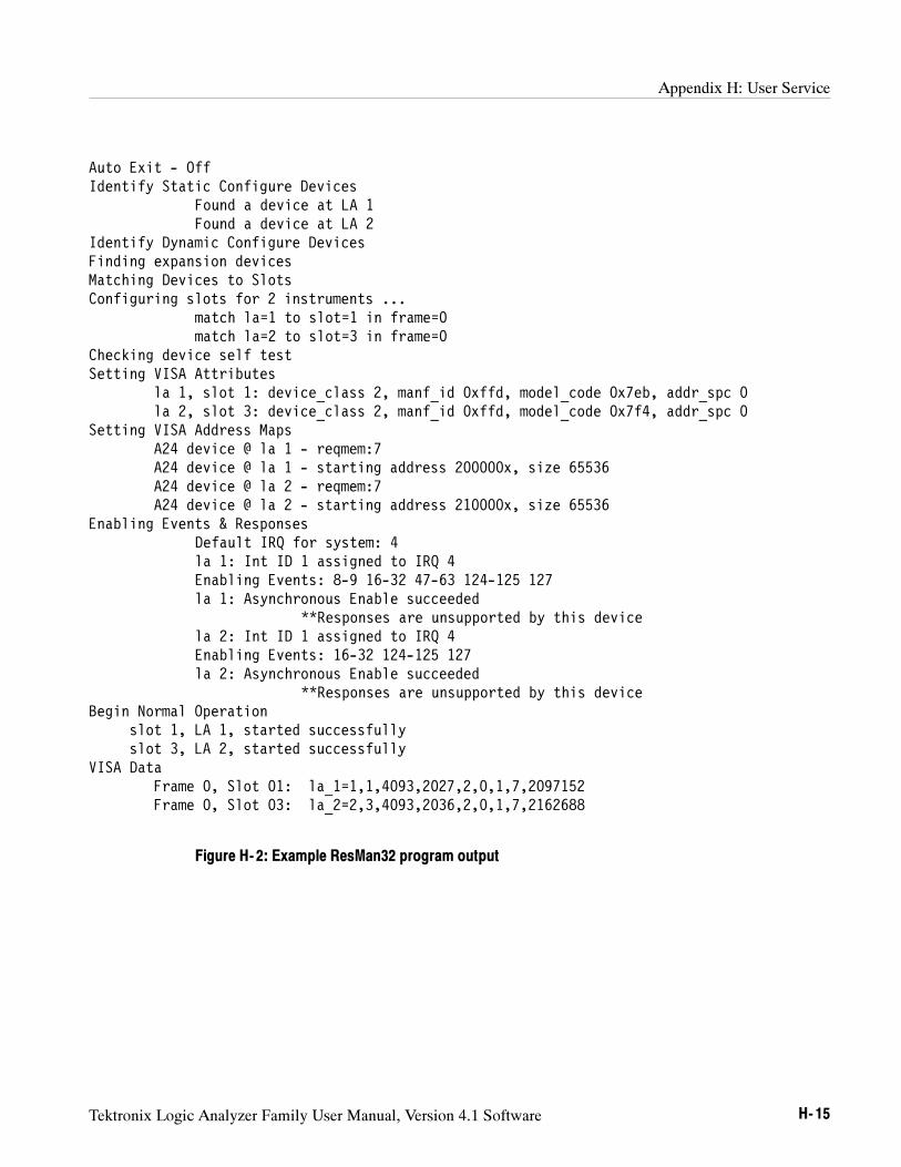
Appendix H: User Service
Tektronix Logic Analyzer Family User Manual, Version 4.1 Software H- 15
Auto Exit - OffIdentify Static Configure Devices
Found a device at LA 1Found a device at LA 2
Identify Dynamic Configure DevicesFinding expansion devicesMatching Devices to SlotsConfiguring slots for 2 instruments ...
match la=1 to slot=1 in frame=0match la=2 to slot=3 in frame=0
Checking device self testSetting VISA Attributes
la 1, slot 1: device_class 2, manf_id 0xffd, model_code 0x7eb, addr_spc 0la 2, slot 3: device_class 2, manf_id 0xffd, model_code 0x7f4, addr_spc 0
Setting VISA Address MapsA24 device @ la 1 - reqmem:7A24 device @ la 1 - starting address 200000x, size 65536A24 device @ la 2 - reqmem:7A24 device @ la 2 - starting address 210000x, size 65536
Enabling Events & ResponsesDefault IRQ for system: 4la 1: Int ID 1 assigned to IRQ 4Enabling Events: 8-9 16-32 47-63 124-125 127la 1: Asynchronous Enable succeeded
**Responses are unsupported by this devicela 2: Int ID 1 assigned to IRQ 4Enabling Events: 16-32 124-125 127la 2: Asynchronous Enable succeeded
**Responses are unsupported by this deviceBegin Normal Operation
slot 1, LA 1, started successfullyslot 3, LA 2, started successfully
VISA DataFrame 0, Slot 01: la_1=1,1,4093,2027,2,0,1,7,2097152Frame 0, Slot 03: la_2=2,3,4093,2036,2,0,1,7,2162688
Figure H- 2: Example ResMan32 program output
Appendix H: User Service
H- 16 Tektronix Logic Analyzer Family User Manual, Version 4.1 Software
Because the expansion mainframe adds a level of complexity to troubleshootingproblems, this section will concentrate on tips to aid you in troubleshootingexpansion mainframe related problems.
If you have exhausted all of the failure symptoms and possible causes listedTable H--1 beginning on page H--8, try some of the following tips.
Look and Listen for the Expansion Mainframe Power-On Sequence. There arecertain signs that the expansion mainframe is not powering up correctly. Bylooking and listening to these signs you can determine if the expansion main-frame is not powering up due to missing signals from the expansion module.
Upon powering up the benchtop mainframe, the expansion module sends a signalfrom the benchtop mainframe to the expansion module in the expansionmainframe via the three expansion cables. If the expansion mainframe does notreceive this signal, the expansion mainframe will not power up.
If the power on signal is received by the expansion mainframe, the fan starts andthe lamp on the mainframe lights. Further indications that the mainframereceives signals from the expansion module are blinking lights on the expansionmodule and on other installed modules.
Substitute a Known Good Expansion Module. If you have a known good expansionmodule, try the following procedure:
1. Verify that the expansion module is installed in slot 0 and that the logicaladdress switches on the back of the module are set to FF.
2. Try swapping the expansion module from the benchtop mainframe with theexpansion module from the expansion mainframe. This sometimes worksbecause one module is a sender while the other module is a receiver.
CAUTION. The single-wide expansion module requires up to 60 lbs. of insertion
force to engage it into the back plane. Do not use the mounting screws to engage
the module into the backplane of the chassis.
The mounting screws will not provide enough force to seat the expansion
module, and you can easily strip the threads.
3. Install the known good expansion module in slot 0 of the expansion chassis.
4. Power on the benchtop mainframe and check for normal operation.
5. If the failure symptoms are still present with the known good expansionmodule, the problem is most likely in the expansion mainframe.
Expansion MainframeProblems
Appendix H: User Service
Tektronix Logic Analyzer Family User Manual, Version 4.1 Software H- 17
6. If your expansion mainframe operates normally with the known goodexpansion module, then the suspect expansion module needs to be serviced.
Check the Expansion Mainframe. If you do not have a known good expansionmodule, perform the following procedure:
1. Remove all modules from the expansion mainframe except the for theexpansion module.
2. Power on the benchtop mainframe and determine if the expansion mainframeis recognized by the instrument.
Replace the Expansion Module with a Benchtop Controller Module.Make theexpansion mainframe simulate a benchtop mainframe. Do this by removing theexpansion module from the slot 0 position in the expansion mainframe andreplacing it with a known good benchtop controller module from the benchtopmainframe.
Because the expansion mainframe is set up to power on from a signal from theexpansion module (which is no longer present) you need to press the On/Standbyswitch on the expansion mainframe.
If the expansion mainframe powers on correctly, the problem can be isolated toeither the expansion module(s) or to the expansion cable(s).
Repacking for Shipment
If a mainframe or module is to be shipped to a Tektronix field office for repair,attach a tag to the mainframe or module showing the owner’s name and address,the serial number, and a description of the problem(s) encountered and/or servicerequired. If you return a module, always include the module and the probes sothat the entire unit can be tested.
When packing an instrument for shipment, use the original packaging. If it isunavailable or not fit for use, contact your Tektronix representative to obtain newpackaging.

Appendix H: User Service
H- 18 Tektronix Logic Analyzer Family User Manual, Version 4.1 Software

Glossary

Tektronix Logic Analyzer Family User Manual, Version 4.1 Software Glossary- 1
Glossary
AC coupling
A DSO mode that blocks the DC component of a signal but passes thedynamic (AC) component of the signal. Useful for observing an AC signalthat is normally riding on a DC signal.
Acquisition
The process of sampling signals from input channels, processing the results,and displaying the data.
Active module
The module highlighted by the pointer in the System window.
Aliasing
The condition that occurs when data is sampled at a rate slower than the rateat which data changes. When this happens, misleading data is displayedbecause the instrument misses the changes in data that occurred betweensample points. Data pulses that fall between samples meet the technicaldefinition of a glitch and are stored and displayed as glitches. See alsoasynchronous acquisition and glitch.
For DSO data, the displayed waveform may appear to be untriggered andmuch lower in frequency. For complex waveforms, distortion occurs due tothe impact of aliasing on the high-order harmonics.
All samples
A Histogram window term. The total number of data samples analyzed.
Arm
To specify when the module should begin looking for a trigger.
Assert
To cause a signal or line to change from its logic false state to its logic truestate.
Asynchronous acquisition
An acquisition that is made using a clock signal generated internally by thelogic analyzer. This clock is unrelated to the clock in the system under test,and you can set it to a different rate. You should use an asynchronous clockrate that is five to ten times faster than your data rate to avoid aliasing. Seealso Aliasing.
Glossary
Glossary- 2 Tektronix Logic Analyzer Family User Manual, Version 4.1 Software
Attenuation
The degree the amplitude of a signal is reduced when it passes through anattenuating device such as a DSO probe or attenuator (the ratio of the inputmeasure to the output measure). For example, a 10X probe attenuates, orreduces, the input voltage of a signal by a factor of 10.
Benchtop Chassis
A benchtop chassis is a benchtop mainframe without a benchtop controllerinstalled.
Chassis
A chassis is a mainframe without a controller or expansion module installed.
Clause
A trigger program term. The combination of one or more events (Ifstatements) or actions (Then statements). When the Event is satisfied, theaction is performed. See also State.
Clock cycle
A clock sequence that includes both high- and low-going transitions.
Clock equation
The Boolean combination of events needed to generate a storage clock. Youcan define a variety of clock inputs and link them using Boolean operators.Data will be sampled and stored in memory only when this clock equation istrue.
Clock qualification
The process of filtering out irrelevant data by combining an acquisition clockwith one or more bus signals.
Clock qualifier
An external signal that acts as a gate for the acquisition clock. When theexternal signal is false, the acquisition clock is not allowed to load acquireddata into the acquisition memory.
COFF file formats
The COFF (Common Object File Format) format contains a number ofvariations and extensions, such as ECOFF and XCOFF. This flexibilityenables it to be used with a wide variety of different microprocessors. Somecode-generation tool vendors also extend this format in nonstandard waysthat may make their files unreadable by the TLA logic analyzers.
Color range symbols
Color range symbols define the beginning and ending group values wherecolor is displayed.
Counter
A trigger program device that records occurrences of an event.
Glossary
Tektronix Logic Analyzer Family User Manual, Version 4.1 Software Glossary- 3
Cursors
Paired markers that you can use to make measurements between two datalocations.
Custom clocking
Custom clocking is used only with microprocessor support packages.Custom clocking can enable and disable a variety of microprocessor-specificclock cycle types (such as DMA cycles).
Data differences
Highlighted data in a Listing or Waveform window that indicate that thereare differences between the acquired data and saved data during a compareoperation.
Data equalities
Highlighted data in a Listing or Waveform window that indicate that thereare no differences between the acquired data and saved data during acompare operation.
Data sample
The data logged in during one occurrence (or one cycle) of the acquisitionclock. A data sample contains one bit for every channel.
Data window
A window used to display acquired data. There are two types of datawindows, Listing windows and Waveform windows.
DC coupling
A DSO mode that passes both AC and DC signal components to the DSOcircuit. Available for both the trigger system and the vertical system.
Delta measurement
The difference between two points in memory. For example, the voltagedifference between the two cursors in a selected waveform.
Demultiplex
To identify and separate multiplexed signals (for instance, some signals froma microprocessor). To separate different signals sharing the same line andorganize those signals into useful information.
Digital real-time signal acquisition
A digitizing technique that samples the input signal with a sample frequencyof four to five times the DSO bandwidth. Combined with sin(x)/x interpola-tion, all frequency components of the input up to the bandwidth areaccurately displayed.
Digitizing
The process of converting a continuous analog signal such as a waveform toa set of discrete numbers representing the amplitude of the signal at specificpoints in time.
Glossary
Glossary- 4 Tektronix Logic Analyzer Family User Manual, Version 4.1 Software
Don’t care
A symbol (X) used in place of a numeric character to indicate that the valueof a channel or character is to be ignored.
EasyTrigger program list
A collection of predefined trigger programs for the LA module. You can loadan individual program into the Trigger window and modify it for yourrequirements.
Edge
A signal transition from low to high, or high to low.
Edge trigger
Triggering that occurs when the module detects the source passing through aspecified voltage level in a specified direction (the trigger slope).
Event condition
Event conditions are a logical combination of trigger events within a singleclause. If you set up a logical AND statement, all event conditions in theclause must be fulilled before the clause can execute the action. If you set upa logical OR statement, any one of the event conditions can be fulfilledbefore the clause can execute the action.
Expansion Chassis
An expansion chassis is an expansion mainframe without an expansionmodule installed.
External clock
A clock external to the logic analyzer and usually synchronous with thesystem under test.
Internal signal
An internal communication line that can be set as a marker. An internalsignal can be used as either an event or an action in a trigger program. Whenused as an event, the internal signal is tested for true/false value like anyother event; when used as an action, the signal can simply be set or clearedas the result of a condition being satisfied.
Glitch
An unintentional signal that makes a transition through the threshold voltagetwo or more times between successive sample clock cycles. Noise spikes andpulse ringing are examples of glitches.
Ground (GND) coupling
A DSO coupling option that disconnects the input signal from the verticalsystem.
Histogram window
A data window used to observe the performance of software routines.
Glossary
Tektronix Logic Analyzer Family User Manual, Version 4.1 Software Glossary- 5
IEEE695 file format
This object file format refers to the IEEE695 specification. This format isused primarily by compilers for a wide variety of Motorola microprocessorsand compatible microprocessors from other vendors. This format providesfor the inclusion of column information in source symbols, but not allcompilers use this capability.
Internal clock
A clock mode in which the sampling of input logic signals occurs asynchro-nously to the activity of the system under test.
Interpolation
Display method used to connect the sample points acquired and display themas a continuous waveform. The logic analyzer uses sin(x)/x interpolation todisplay DSO signals.
Linear generation
A Histogram window term. The histogram ranges are evenly distributedfrom the highest range boundary to the lowest range boundary.
Listing window
A data window used to observe the data flow in the system under test. Theacquired data is displayed in a listing (tabular text) format.
Log generation
A Histogram window term. The histogram ranges are distributed over alogarithmic scale.
MagniVu data
High-speed data stored in a special memory.
Matched samples
A Histogram window term. The total number of data samples analyzed thatmatched a defined range. These samples exclude any samples outside of thedefined ranges.
Merge modules
To physically or logically join LA modules together to form a single modulewith greater channel width.
Microprocessor support
Optional microprocessor support software that allows the logic analyzer todisassemble data acquired from microprocessors.
Mnemonic disassembly
A display format for data acquired from a microprocessor or a data bus. Alogic analyzer decodes bus activity and displays it in formats such as: cycletypes, instruction names, and interrupt levels. Advanced forms of mnemonicdisassembly can detect queue flushes, and provide a display that resemblesthe original assembly language source code listing.
Glossary
Glossary- 6 Tektronix Logic Analyzer Family User Manual, Version 4.1 Software
Module
The unit that plugs into a mainframe, providing instrument capabilities suchas logic analysis.
Module trigger (trigger)
A trigger specific to a single module. When a module trigger occurs, themodule continues to acquire data until the specified amount of posttriggerdata is acquired, and then stops.
OMF51 file format
This format holds symbolic information and executable images for a 8051 orequivalent microprocessor.
OMF86 file format
A file format that holds symbolic information and executable images for an8086 or equivalent microprocessor. It is also used for code intended to run on80286, 80386, or higher-level microprocessors in real or 8086-compatiblemode.
OMF166 file format
This format holds symbolic information and executable images for theSiemens (Infinion) C166 microprocessor family, or equivalentmicroprocessor.
OMF286/386 file formats
These file formats hold symbolic informaton and executable images for80286 80386, or equivalent microprocessors. They are also used forexecutable images intended to run on the 8086 or other microprocessors inthe 80x86 families.
PCMCIA
An acronym for Personal Computer Memory Card Industry Association.
Podlet
A circuit contained in a flex lead and attached to a probe that providessquare-pin connections to the circuit under test for one data acquisitionchannel and a ground pin.
Pretrigger
The specified portion of the data record that contains data acquired beforethe trigger event.
Post trigger
The specified portion of the data record that contains data acquired after thetrigger event.
Probe adapter
A microprocessor-specific lead set that connects the LA module probe to asystem under test.
Glossary
Tektronix Logic Analyzer Family User Manual, Version 4.1 Software Glossary- 7
Qualification gap
Qualification gaps indicate that data samples were not stored due to storagequalification or Don’t Store trigger actions. In a Listing window, qualifica-tion gaps are indicated by a horizontal gray line. In a Waveform window,qualification gaps are indicated by a blank vertical gap.
Range recognizer
A trigger term. Use range recognizers to trigger the logic analyzer on rangesof data.
Record length
The specified number of samples in an acquisition.
Sample clock
The clock signal that determines the points in time when themodule
samples data. A sample clock can be set up to occur at regular intervalsspecified by an internal clock (asynchronous acquisition), or to occur when aBoolean expression combining an external clock and qualifier signals is“true” (synchronous acquisition).
Sample rate
The frequency at which data is logged into the logic analyzer.
Sampling
The process of capturing an input signal, such as a voltage, at a discretepoint in time and holding it constant so that it can be quantized.
Skew
The relative time difference between input channels, specified in terms ofone edge relative to another. Also, the misrepresentation of data caused byparallel channels with different propagation delays.
Source Window
A data window where you can view the execution of source code.
Standby (STBY)
The off-like state when the instrument in not in use. Some circuits are activeeven while the instrument is in the standby state.
State
A trigger program term. A step in a trigger program, made up of one or moreclauses. See also clause.
Storage qualification
The process of filtering out data that has been acquired but which you do notwant to store in acquisition memory. This allows you to avoid filling up yourmodule’s acquisition memory with irrelevant data samples.
Glossary
Glossary- 8 Tektronix Logic Analyzer Family User Manual, Version 4.1 Software
Symbolic range generation
A Histogram window term. The histogram ranges are defined in a rangesymbol file. The highest and lowest ranges depend on the maximum andminimum boundaries for the ranges defined in the symbol file.
Symbolic radix
A format that allows you to substitute mnemonics (names) for radix numbersin the Trigger and data windows.
Synchronous acquisition
An acquisition that is made using a clock signal generated external to thelogic analyzer. This clock is usually the clock in the system under test. Theexternal clock is usually synchronous with the system under test and may ormay not be periodic.
System trigger (trigger all)
An overriding command to all modules that causes them to stop looking fora trigger, and to acquire their posttrigger data, regardless of whether theyhave been armed or have fulfilled their own trigger conditions. The systemtrigger also functions as the primary reference point for the entire dataacquisition. In data windows, timing and location information is relative tothe system trigger.
Time correlation
The tracking of independent events captured by different modules andindicating how they relate to each other in time. Specifically, the chronolog-ical interleaving of data from different modules into a single display. Showsreal-time interactions between independently clocked circuits.
Time stamp
A separate clock value stored with each acquisition cycle.
Timer
A trigger program device that records elapsed time.
Threshold voltage
The voltage to which the input signals are compared.
Trigger
An event or condition that leads to the end of an acquisition cycle. Whenstarted, the instrument continuously acquires data from a system under testuntil the trigger occurs. After triggering, the instrument continues to acquiredata until the post-fill requirement is met.
Trigger position
Where the trigger resides in acquisition memory. Electing to place the triggerin the center of memory means that half of the acquisition consists of datathat occurred after the trigger.
Glossary
Tektronix Logic Analyzer Family User Manual, Version 4.1 Software Glossary- 9
Trigger program
A series of conditions, similar to software code, that defines the data youwant to capture and view. The trigger program also specifies actions for dataevents. The trigger program filters acquired data to find a specific data eventor series of data events. The trigger program can accept information fromother modules or send signals external to the logic analyzer.
TSF
TLA Symbol File (TSF) format (a text format). The TSF format is used bythe logic analyzer when it exports symbol files.
Unassert
To cause a signal or line to change from its logic true state to its logic falsestate.
Waveform window
A data window used to observe timing relationships in the system under test.The acquired data is displayed as a series of waveforms.
Word recognizer
A trigger term. Word recognizers are specific patterns of data or words. Useword recognizers to trigger the logic analyzer on specific data combinations.

Glossary
Glossary- 10 Tektronix Logic Analyzer Family User Manual, Version 4.1 Software

Index

Tektronix Logic Analyzer Family User Manual, Version 4.1 Software Index- 1
Index
Symbols.tbf format
DSO module data, 3--110LA module data, 3--110
Numbers2x-Timing, 2--39
AAC coupling, Glossary--1Accelerator keys
general purpose data window, 3--73Histogram window, 3--132Listing window, 3--111menu keys, 3--62Source window, 3--123Waveform window, 3--94
Accessories, connectingTLA600 series, 1--10TLA700 series, 1--11
Acquisition, 2--25, 3--63, Glossary--1asynchronous, 2--27, Glossary--1DSO module, 2--26LA module, 2--25MagniVu data, 3--88, 3--102mode, 3--9module relationship, 2--32synchronous, 2--26, Glossary--8
Active Cursor readout, 3--118Active module, Glossary--1Activity Indicators dialog box, 3--12Add Column dialog box, 3--105Add Waveform dialog box, 3--91Address, Tektronix, xxAdvanced clocking, 3--9Aliasing, 2--40, Glossary--1
bandwidth filters, 3--36Aligning data, 3--71All samples, Glossary--1Application
PatGenVu, 1--29starting, 1--16TLAVu, 1--29
Applying powerTLA600 series, 1--16TLA700 series, 1--18
Arm, Glossary--1arming modules, 3--52indicator, 3--1
Assert, Glossary--1Asynchronous acquisition, 2--27, Glossary--1Attenuation, 2--28, Glossary--2Autoconfiguration, module, D--1Autoset, 3--35
BBandwidth, DSO module setup, 3--36Basic installation, 1--4Battery, real time clock, A--13Benchtop chassis, Glossary--2Benchtop mainframe
AC power source, A--33cooling, A--34dimensions, A--37mechanical, A--35secondary power, A--34
Binary data, exporting, 3--110BIOS
configuring, G--3, G--7flashing, G--3setup table
TLA600 series, G--4TLA714 and TLA720, G--8
Block Definition window, Pattern Generator module,3--45
Block diagramDSO module, 2--28, 2--28LA module, 2--26pattern generator module, 2--29
Blocks mode, 3--9Busforms, 2--37, 3--76
CCalibrating, merged modules, E--10Calibration, DSO probe, 3--34Calibration service, H--1Change detectors, 3--28Channel activity, 3--12Channel group, 3--10
adding/removing channels, 3--11hardware order, 3--10name, 3--11, 3--92, 3--107polarity of channels, 3--11
Index
Index- 2 Tektronix Logic Analyzer Family User Manual, Version 4.1 Software
probe thresholds, 3--13Channel Setup window, Pattern Generator module,
3--43Characteristics
iView, A--59TLA714 portable mainframe, A--28TLA715 portable mainframe, A--22TLA720 benchtop controller, A--41TLA721 benchtop controller, A--38TLA7Dx DSO module, A--50TLA7Ex DSO module, A--50TLA7Lx logic analyzer module, A--43TLA7Mx logic analyzer module, A--43TLA7Nx logic analyzer module, A--43TLA7PG2 pattern generator module, A--56TLA7Px logic analyzer module, A--43
Chassis, Glossary--2Chassis ground location
TLA600 series, 2--5TLA700 series, 2--6
Checking the shipping list, 1--4Clause, 3--16, Glossary--2Clause Definition dialog box, 3--31, 3--52
PowerTrigger, 3--26Cleaning, H--5
LCD display, H--5Clock, 2--26
advanced, 3--9custom, 3--9cycle, Glossary--2DSO module, 3--37equation, 3--8, Glossary--2external, 2--26, 3--8, Glossary--4internal, 2--27, 3--7, Glossary--5multiple-phase, 3--9problems, 3--66qualification, Glossary--2qualifier, Glossary--2sample clock, 3--7, 3--37, Glossary--7sample clock waveform, 3--76sample rate vs. memory depth, 3--10
COFF file formats, Glossary--2Color in data windows, 3--61, 3--93, 3--107, 3--120,
3--129Color range symbols, Glossary--2Color symbols, B--8Column
adding, 3--105changing width, 3--106cut, copy, and paste, 3--106cutting, 3--106moving, 3--105naming, 3--107
Columns, sizing histograms, 3--128Compare data, displaying, 3--89, 3--103Comparing
listing data, 3--103waveform data, 3--89
Comparing data, 2--44overlay waveforms, 2--37
Condition trigger, Glossary--8Configuring, P6470 pattern generator probes, 1--14Connecting
accessoriesTLA600 series, 1--10TLA700 series, 1--11
LA probesTLA600 series, 1--13TLA700 series, 1--14
pattern generator probes, TLA 700 series, 1--14Connectors, external
TLA600 series, 2--4TLA700 series, 2--5
Contacting Tektronix, xxController BIOS, setup table
TLA600 series, G--4TLA714 and TLA720, G--8
Copying text, 3--106, 3--120Counter, Glossary--2Coupling, 3--36Cover plate installation, D--5Creating a Histogram window, 3--127Creating a Source window, 3--114Cursors, 3--78, 3--80, 3--97, 3--99, 3--114, 3--116,
Glossary--3Custom clock, 3--9Custom clocking, Glossary--3Customer registration card, 1--4Customer Service web address, H--1Cutting
columns, 3--91, 3--106columns, marks, 3--106marks, 3--120waveforms, marks, 3--92
DData, exporting, 3--108, 3--130Data differences, Glossary--3Data equalities, Glossary--3Data marks, 3--78, 3--97, 3--114Data rate, logic analyzer module, A--45Data sample, Glossary--3Data source, adding, 3--91, 3--105Data window, 2--14, 3--69, Glossary--3
Index
Tektronix Logic Analyzer Family User Manual, Version 4.1 Software Index- 3
marks, cursors, and indicators, 3--97splitting the data area, 3--107
DC coupling, Glossary--3Default settings, 3--61
trigger tab, 3--15Delta measurement, 3--80, 3--99, Glossary--3Demultiplex, Glossary--3
clock setting, 3--9Diagnostics, H--6
expansion mainframe, H--7extended, H--6mainframe, H--7power on, H--6start up sequence tree, H--12
Differences. See Data differencesDigital real-time signal acquisition, Glossary--3Digitizing, 2--25, Glossary--3Disabling modules, 3--2Disassembly format, changing, 3--107Documentation list, xviiiDon’t care, Glossary--4DSO, data, viewing in a Listing window, 2--34DSO module
acquisition, 2--26block diagram, 2--28description, 1--3export binary data, 3--110horizontal controls, 3--37self calibration, H--4setup, 3--33trigger controls, 3--38vertical controls, 3--35
DSO probe calibration, 3--34DSO setup, Autoset, 3--35DSO Setup window, 3--33DSO Trigger window, 2--13, 3--38Dynamic autoconfiguration, D--1
EEasyTrigger, xixEasyTrigger
modifying programs, 3--14, 3--18program list, 3--17, 3--18, Glossary--4
combination of events, 3--22inter--module communication, 3--24measuring time and counting events, 3--19sequence of events, 3--21sequence of events and time or count, 3--22simple events, 3--18simple events and time or count, 3--20storage, 3--23
programs, 3--14, 3--17properties, 3--17using programs, 3--24window, 2--12
ECOFF. See COFF file formatsEdge, Glossary--4Edge trigger, Glossary--4Equalities. See Data equalitiesEvent condition, Glossary--4Event Definition window, Pattern Generator module,
3--49Event trigger, Glossary--8Expansion cables, installing, 1--8Expansion chassis, Glossary--4
mechanical, A--35Expansion mainframe
AC power source, A--33cooling, A--34diagnostics, H--7dimensions, A--37installing, 1--5secondary power, A--34specifications, A--33troubleshooting, H--16
Expansion module, installingin a benchtop mainframe, 1--5in a TLA714, 1--7in a TLA715, 1--7
Exportingbinary data, 3--110histogram data, 3--130listing data, 3--108text data, 3--109
Exporting data, 3--108Extended diagnostics, H--6External
clock, 2--26, 3--8, Glossary--4signal connectors, 3--50
TLA600 series, 2--4TLA700 series, 2--5
signals, 3--50, 3--53, 3--55External connectors, 2--6External Oscilloscope
connections, 3--42setup, 3--39setup wizard, 3--39trigger settings, 3--41
External oscilloscope, specifications, A--59Performance requirements, A--1
Index
Index- 4 Tektronix Logic Analyzer Family User Manual, Version 4.1 Software
FFile format
COFF, Glossary--2IEEE695, Glossary--5OMF166, Glossary--6OMF286, Glossary--6OMF386, Glossary--6OMF51, Glossary--6OMF86, Glossary--6
File name extensionsaved files, 3--57symbol files, B--1
Font in Histogram window, 3--128Font in Listing window, 3--105Font in Source window, 3--120Front panel controls
portable mainframe, 2--2TLA600 series, 2--1
Function symbols, B--5Fuse
locationTLA600 series, 1--17TLA700 series, 1--19
requirementsTLA600 series, 1--16TLA700 series, 1--18
Fuse requirementsbenchtop mainframe, F--2expansion mainframe, F--2
GGap, qualification, 3--106, Glossary--7General maintenance, H--4General safety summary, xv
symbols and terms, xvito avoid fire, xvto avoid personal injury, xv
Glidepoint pad, 2--3portable mainframe, 2--2
Glitch, 2--41, 3--9, Glossary--4glitch mode, 3--9Listing window, 3--107Waveform window, 3--92
Go To dialog box, 3--84, 3--99, 3--115Ground
chassisTLA600 series, 2--5TLA700 series, 2--6
safetyTLA600 series, 2--5
TLA700 series, 2--6Ground (GND) coupling, Glossary--4Ground line indicator in DSO waveforms, 3--77Guidelines, for merging modules, E--1
HHard disk, reformatting, G--13Hard disk drive, removal, 1--23Hard disk image, installing, G--11Hardware problems, H--7Help, online, 1--28High-level language, 2--35, 3--113Histogram ranges
defining, 3--128linear generation, 3--128log generation, 3--128symbols, 3--128
Histogram window, 2--15, 2--43, 3--125, Glossary--4accelerator keys, 3--132changing font size, 3--128clearing counts, 3--128columns, 3--128creating, 3--127customizing the display, 3--129exporting data, 3--130hot keys, 3--132magnification, 3--128measuring events, 3--127shortcut keys, 3--132sorting data, 3--128splitting the data area, 3--129stopping analysis, 3--128viewing address activity, 3--126
Horizontal controlsDSO setup, 3--37Waveform window, 3--92
Hot keysgeneral purpose data window, 3--73Histogram window, 3--132Listing window, 3--111menu keys, 3--62Source window, 3--123Waveform window, 3--94
IIEEE695 file format, Glossary--5Incoming inspection
checking probes, 1--21checking the mainframe, 1--22
Index
Tektronix Logic Analyzer Family User Manual, Version 4.1 Software Index- 5
performing, 1--21Installing
expansion cables, 1--8expansion mainframe, 1--5expansion module
in a benchtop mainframe, 1--5in a TLA714, 1--7in a TLA715, 1--7
merged modules, E--9Installing software, G--13
PatGenVu, G--20Pattern Generator application software, G--17PPI software, G--18TLA application software, G--16TLAVU software, G--19TPI software, G--18
Intermodule signals, 3--53Internal clock, 2--27, 3--7, Glossary--5Internal signal, 3--53, 3--67, Glossary--4Interpolation, 2--40, Glossary--5Isolating system problems, H--13iView, xixiView cable, 3--39
JJumping to specific data locations, 3--84, 3--99, 3--115
KKeypad
portable mainframe, 2--2TLA600 series, 2--1
LLA data, overlay waveforms, 2--37LA module
acquisition, 2--25block diagram, 2--26description, 1--2export binary data, 3--110self calibration, H--4setup, 3--3trigger setup, 3--13
LA Setup window, 3--3LA Trigger window, 2--12, 3--13
window structure, 3--17Linear generation, 3--128, Glossary--5Listing window, 2--14, Glossary--5
accelerator keys, 3--111changing font size, 3--105columns, 3--105cursors, 3--99customizing the display, 3--107disassembly format, 3--107exporting binary data, 3--110exporting data, 3--108exporting text data, 3--109hot keys, 3--111jumping to specific data locations, 3--99LA module, 3--97locking data windows together, 3--102pattern generator, 2--23qualification gaps, 3--106searching data, 3--101shortcut keys, 3--111viewing DSO data, 2--34
Listing-data concepts, 2--33Load Symbol Options dialog box, 2--50Load System Options dialog box, 3--59Loading symbol files, 2--50Locking windows, 3--87, 3--102Log generation, 3--128, Glossary--5Logic analyzer
chassis ground, TLA600 series, 2--5conceptual model, 2--32connecting LA probes
TLA600 series, 1--13TLA700 series, 1--14
connecting pattern generator probes, TLA 700 series,1--14
installing software, G--1physical model, 2--31power cord location, TLA600 series, 1--17powering on, TLA600 series, 1--16shipping list, 1--4site considerations, 1--4TLA600 Series description, 1--1TLA700 Series description, 1--2
Logic analyzer modulemerge cable location, E--4merging, E--1merging guidelines, E--1
Logic analyzer probes, connectingTLA600 series, 1--13TLA700 series, 1--14
Logical addressmodule, D--1module switch location, D--2setting, D--1
Index
Index- 6 Tektronix Logic Analyzer Family User Manual, Version 4.1 Software
troubleshooting problems, D--2
MMagnifying data in Histogram windows, 3--128Magnitude mode, 2--37Magnitude waveforms, 3--76MagniVu data, 2--16, 2--33, 2--39, 2--40, 3--88, 3--102,
Glossary--5Mainframe
calibrating merged modules, E--10chassis ground, TLA700 series, 2--6configuring P6470 pattern generator probes, 1--14connecting accessories
TLA600 series, 1--10TLA700 series, 1--11
connecting LA probes, TLA700 series, 1--14connecting pattern generator probes, TLA 700 series,
1--14diagnostics, H--7equipment required to merge modules, E--4fuse location, TLA700 series, 1--18fuse requirements
for the benchtop mainframe, F--1for the expansion mainframe, F--1TLA700 series, 1--18
incoming inspection, 1--21installing merged modules, E--9merging modules rules, E--1module installation
in the benchtop mainframe, D--3in the expansion mainframe, D--5in the portable mainframe, D--3keying, D--5
panel cover, D--5power cord location, TLA700 series, 1--19power cord requirements
for the benchtop mainframe, F--1for the expansion mainframe, F--1
powering on, TLA700 series, 1--18removing merged modules, E--10storing the merge cable, E--11
MaintenanceBIOS configuration
TLA600, G--3TLA700, G--7
calibrating merged modules, E--10common problem check list, H--8equipment required to merge modules, E--4expansion mainframe troubleshooting, H--16installing merged modules, E--9installing software, G--1
isolating system problems, H--13merging modules rules, E--1removing merged modules, E--10storing the merge cable, E--11
Manuals list, xviiiMarks, 3--78, 3--97, 3--114
cut, copy, and paste, 3--92, 3--106, 3--120using the mark bar to jump to a new location, 3--85,
3--99, 3--115Matched samples, Glossary--5Measurement setup, 3--81
waveform, 3--81Measuring counter or timer events in Histogram
windows, 3--127Measuring using cursors, 3--80, 3--99Memory
TLA600, A--13TLA714, A--28TLA715, A--22TLA720, A--41TLA721, A--38
Memory compare, 3--5channel setups, 3--5guidelines, 3--7
Memory depth, 2--39, 3--9, 3--37Merge cable, storing, E--11Merge modules, 3--55, Glossary--5
self calibration, 3--56, H--4Merged modules
calibrating, E--10guidelines, E--1installing, E--9removing, E--10
Merging modules, E--1equipment required, E--4installation, E--9merge cable location, E--4three way merge procedure, E--9two way merge procedure, E--4
Microprocessor support, 3--4, 3--107, Glossary--5channel grouping, 3--10custom clock, 3--9
Mnemonic disassembly, Glossary--5Module, 2--31, Glossary--6
arming another module, 3--52disabling, 3--2dynamic autoconfiguration of address, D--1identifying slot number, 3--2installing
in the benchtop mainframe, D--3in the expansion mainframe, D--5in the portable mainframe, D--3
Index
Tektronix Logic Analyzer Family User Manual, Version 4.1 Software Index- 7
intermodule interactions, 2--32joining LA modules. See Merge moduleskeying, D--5logical address, D--1logical address switch location, D--2merge cable location, E--4merging, E--1merging guidelines, E--1not appearing in the System window, D--2power requirements, F--1
expansion mainframe, F--1self calibration, 3--55, H--4static logical address, D--1three way merge procedure, E--9time correlation, 2--32turning on/off, 3--2two way merge procedure, E--4
Module Setup window, Pattern Generator module, 3--42Module trigger, Glossary--6Multiple-phase clocking, 3--9
NNaming
channel groups, 3--11columns, 3--107merged module probe names, 3--56waveforms, 3--92windows, 3--2
New Data Window wizard, 3--72Next Mark and Previous Mark buttons, 3--117Normal acquisition mode, 3--9
OObject file format
COFF, Glossary--2IEEE695, Glossary--5OMF166, Glossary--6OMF286, Glossary--6OMF386, Glossary--6OMF51, Glossary--6OMF86, Glossary--6
OffsetDSO module, 3--36range symbols, 2--51, B--2
OMF166 file format, Glossary--6OMF286/386 file formats, Glossary--6OMF51 file format, Glossary--6OMF86 file format, Glossary--6On/Standby switch
benchtop mainframe, 1--19
portable mainframe, 1--19TLA600 series, 1--17
Online help, 1--28help topics, 1--28pattern generator help, 1--29PPI help, 1--29TLAScript, 1--29TPI online help, 1--29What’s This? help, 1--28Windows online help, 1--29
Options, system, 3--61Overlay waveforms, 3--94
PPanel cover installation, D--5Pattern Generation, physical--logical conversion, C--1Pattern Generator
Listing window, 2--23Waveform window, 2--24
Pattern Generator moduleBlock Definition window, 3--45block diagram, 2--29Channel Setup window, 3--43description, 1--3Event Definition window, 3--49Module Setup window, 3--42Probe Setup window, 3--44Sequence Definition window, 3--46Signals Setup window, 3--44Subsequence Definition window, 3--49
Pattern generator modulemerging, E--1merging guidelines, E--3run properties dialog box, 2--24specifications, A--56
Pattern generator probesconfiguring P6470, 1--14connecting, TLA 700 series, 1--14
Pattern symbols, 2--47, B--3PC card connector
TLA600 series, 2--4TLA700 series, 2--5
PCMCIA, Glossary--6Performance analysis, 2--43External oscilloscope, A--1Phone number, Tektronix, xxPodlet, Glossary--6Pointing device, 2--3Polarity, LA channels, 3--11Post trigger, Glossary--6Power cord, identification chart, F--2
Index
Index- 8 Tektronix Logic Analyzer Family User Manual, Version 4.1 Software
Power requirementsbenchtop mainframe, F--1expansion mainframe, F--1
Power-down procedureTLA714/715, 1--20TLA720/721, 1--20
Power-on diagnostics, H--6Power-on procedure
benchtop mainframe, 1--19portable mainframe, 1--19TLA600 series, 1--17TLA714, 1--19TLA720, 1--19
PowerTriggeractions, 3--29clause definition, 3--26detail, 3--26events, 3--27modifying programs, 3--14overview, 3--25properties, 3--25resources, 3--28storage, 3--31window, 2--12
Pretrigger, Glossary--6Preventive maintenance, H--4
cleaning, H--5disks, floppy disk drive, H--5LCD display, H--5
Probe adapter, Glossary--6Probe calibration, DSO module, 3--34Probe channel activity, 3--12Probe Channels/Names table, 3--11Probe podlet, Glossary--6Probe properties, displaying two dialog boxes, 3--13Probe Setup window, Pattern Generator module, 3--44Probe thresholds
DSO vertical input, 3--35LA channels, 3--13
Probesconfiguring P6470 pattern generator probes, 1--14connecting LA probes
TLA600 series, 1--13TLA700 series, 1--14
connecting pattern generator probes, TLA 700 series,1--14
Problem check list, H--8Problems
hardware, H--7software, H--7
Product support, contact information, xxProgram window, 2--21Programmatic control, 2--18
Properties, 3--93, 3--107, 3--120, 3--129overlay waveform, 3--95
QQualification
clock, Glossary--2gaps, 3--106, Glossary--7storage, 2--27, 3--31, Glossary--7
Qualifier, clock, Glossary--2
RRadix, 3--106
binary, glitch display, 3--107changing, 3--106symbolic, 2--46, 3--106, Glossary--8
Range readouts in DSO waveforms, 3--77Range recognizer, Glossary--7Range recognizers, 3--10, 3--28Range symbols, 2--47
color, B--4, Glossary--2function, B--4source, B--4variable, B--4
Record length, 3--9, 3--31, 3--37, Glossary--7Registration card, 1--4Reinstalling software, G--13
PatGenVu, G--20Pattern Generator application software, G--17PPI software, G--18TLA application software, G--16TLAVu software, G--19TPI software, G--18
Release notes, 1--29removing the hard disk drive, 1--23Repacking for shipment, H--17–H--18Repair service, H--1Repetitive acquisition, 3--64Requirements, site consideration, 1--4ResMan (resource manager), H--11Resource manager (ResMan), H--11Rules, for merging modules, E--1Run properties dialog box, pattern generator module,
2--24Run/Stop button, 3--63
SSample
clock, 2--26, 2--39, 3--7, 3--76, Glossary--7
Index
Tektronix Logic Analyzer Family User Manual, Version 4.1 Software Index- 9
data, Glossary--3period, DSO, 3--37rate, 2--38, 2--40, Glossary--7
Sample suppression, 3--59Sampling, Glossary--7Sampling and digitizing a signal, 2--25Sampling resolution, 2--38Saved files, 2--16, 3--56, 3--57
file name extension, 3--57loading, 3--58
saved data, 3--60saved trigger, 3--60setups and trigger programs, 3--33, 3--60system file, 3--58
module and system, 2--32saving, 3--57trigger programs, 3--33
Scan Listing box, 3--115Screen Capture , xixSearching data, 3--86, 3--101, 3--119Self calibration, 3--56, H--4Sequence Definition window, Pattern Generator
module, 3--46Service
common problem check list, H--8expansion mainframe diagnostics, H--7expansion mainframe troubleshooting, H--16for more information, H--2isolating system problems, H--13mainframe diagnostics, H--7options
TLA600 series, H--3TLA700 series, H--3
self service, H--2service on demand, H--2
Service offerings, H--1calibration and repair service, H--1for more information, H--2self service, H--2service agreements, H--2service on demand, H--2service options, H--1warranty repair service, H--1
Service support, contact information, xxService, user, preventive maintenance, H--4Setting the logical address, D--1Setup window, 2--11, 2--20, 3--1Shipping, H--17Shipping list, checking, 1--4Shortcut keys
general purpose data window, 3--73Histogram window, 3--132Listing window, 3--111
menu keys, 3--62Source window, 3--123Waveform window, 3--94
Signals Setup window, Pattern Generator module, 3--44Signals tab, 3--53Sin(x)/x interpolation, 2--40Single-run acquisition, 3--64Skew, Glossary--7Slot covers, D--5Slot fillers, D--5Slot numbers, 3--2Software
BIOS configurationTLA600, G--3TLA700, G--7
expansion mainframe diagnostics, H--7extended diagnostics, H--6installing, G--1, G--13
PatGenVu, G--20Pattern Generator application software, G--17PPI software, G--18TLA application software, G--16TLAVU software, G--19TPI software, G--18
mainframe diagnostics, H--7power on diagnostics, H--6problems, H--7starting the application, 1--16
Sorting data in Histogram windows, 3--128Source Files property tab, 3--121Source symbols, B--6Source window, 2--15, 3--113, Glossary--7
accelerator keys, 3--123buttons, 3--117changing font size, 3--120creating, 3--114cursors, 3--116customizing the display, 3--120hot keys, 3--123jumping to specific data locations, 3--115marks, cursors, and indicators, 3--114scan listing, 3--115searching data, 3--119shortcut keys, 3--123Source Files property tab, 3--121
Specifications, A--1expansion mainframe, A--33iView, A--59LA acquisition memory depth, A--43LA channel width, A--43LA clock channels, A--43LA data rate, A--45LA qualifier channels, A--44
Index
Index- 10 Tektronix Logic Analyzer Family User Manual, Version 4.1 Software
P6417 probe capacitance, A--5, A--48P6418 probe capacitance, A--5, A--48P6434 probe capacitance, A--5, A--48TLA600 series, A--5TLA700 series, A--17TLA720 benchtop mainframe, A--33TLA721 benchtop mainframe, A--33TLA7PG2 Pattern Generator Module, A--56TLA7XM, A--33
Splitting the data area, 3--92, 3--107, 3--129Standby (STBY), Glossary--7Starting and stopping acquisition, 3--63Startup sequence, H--11State, 3--16, Glossary--7Static logical address, D--1
default settings, D--2problems, D--2switch location, D--2
Status bar, hiding, 3--61Status Monitor, 3--65Step Forward and Step Backward buttons, 3--117Storage qualification, 2--27, 3--31, Glossary--7Storing data, 2--28, 2--29Subsequence Definition window, Pattern Generator
module, 3--49Suppressed data, 3--87Symbol files
color symbols, B--8function symbols, B--5loading, 2--50pattern symbols, B--3range, B--4source symbols, B--6variable symbols, B--5viewing the status, 2--49
Symbolic radix, 2--46, Glossary--8Symbolic range generation, Glossary--8Symbols
color symbols, B--8function symbols, B--5histogram ranges, 3--128pattern symbols, B--3range, B--4source symbols, B--6variable symbols, B--5
Symbols and symbol files, 2--46file name extension, B--1TLA symbol file format (TSF), B--1
Symbols and terms, xviSymbols dialog box, 2--49Synchronous acquisition, 2--26, Glossary--8System
expansion mainframe troubleshooting, H--16
isolating problems, H--13System defaults, 3--61System options, 3--61System trigger, 3--50, 3--71, Glossary--8
source, 3--51System window, 2--9, 2--20, 3--1, 3--70
TTechnical support, contact information, xxTektronix, contacting, xxTektronix binary format, 3--110Text data, exporting, 3--109Three way merge procedure, E--9Threshold voltage, Glossary--8Thresholds
DSO vertical input, 3--35indicator in DSO waveform, 3--77LA channels, 3--13
Time Alignment dialog box, 3--71Time correlation, 2--32, 2--37, 3--71, Glossary--8Time per div in Waveform window, 3--92Time stamp, 2--33, Glossary--8Timer, Glossary--8Timing, 2x-Timing mode, 2--39TLA application window, overview, 2--9TLA symbol file format, B--1TLA--TDS interoperability, xixTLA600, BIOS configuration, G--3TLA600 series
logic analyzer description, 1--1specifications, A--5
TLA700, BIOS configuration, G--7TLA700 Series
logic analyzer description, 1--2system specifications, A--17
TLA720 Benchtop MainframeAC power source, A--33cooling, A--34dimensions, A--37mechanical, A--35secondary power, A--34
TLA721 Benchtop MainframeAC power source, A--33cooling, A--34dimensions, A--37mechanical, A--35secondary power, A--34
TLA7XMinstalling, 1--5installing the expansion cables, 1--8installing the expansion module
Index
Tektronix Logic Analyzer Family User Manual, Version 4.1 Software Index- 11
in a benchtop mainframe, 1--5in a TLA715, 1--7
TLA7XM Expansion Chassis, mechanical, A--35TLA7XM Expansion mainframe
AC power source, A--33cooling, A--34secondary power, A--34specifications, A--33
TLA7XM specifications, A--33Toolbar
Histogram window, 3--128Listing window, 3--105Source window, 3--120Waveform window, 3--90
TPI, 2--18Trackball, 2--3Trigger, 2--27, Glossary--8
clause, 3--16, Glossary--2DSO module, 2--29DSO module setup, 3--38indicator, 3--1LA trigger actions, 3--29LA trigger events, 3--27LA trigger resources, 3--28LA Trigger window configuration, 3--13position, 3--32, 3--39, Glossary--8problems, 3--66program, 3--14, Glossary--9
creating your own, 3--61debugging, 3--65loading saved, 3--33saving, 3--33setting/clearing signals, 3--53structure, 3--16
state, 3--16storage qualification, 3--31system, 3--50, 3--71, Glossary--8
external signal, 2--4, 2--5, 3--50Trigger Options, 3--31Trigger settings, external oscilloscope, 3--41Troubleshooting, H--6
common problem check list, H--8expansion mainframe, H--16isolating system problems, H--13logic analyzer does not trigger, 3--66module address problems, D--2
TSF, file formats, B--1, Glossary--9TSF color symbols, B--8TSF function symbols, B--5TSF pattern file header, B--2TSF range file header, B--2TSF Range Symbols
color, B--4
function, B--4source, B--4variable, B--4
TSF source symbols, B--6TSF variable symbols, B--5Turning on
TLA600 series, 1--16TLA700 series, 1--18
Two way merge procedure, E--4
UUnassert, Glossary--9URL, Tektronix, xxUser service
general maintenance, H--4preventive maintenance, H--4
VVariable symbols, B--5Vertical controls, DSO setup, 3--35Video output
in a TLA715/721, 1--11in a TLA714/720, 1--11primary and secondary, 1--11
Viewingglitches, 3--107setup and hold violations, 3--107violations, 3--107
Violation, 2--41detecting, 2--41setup and hold, 2--41
WWarranty repair service, H--1Waveform, properties, overlay, 3--95Waveform data concepts, 2--37Waveform measurements, list, 3--81Waveform window, 2--14, Glossary--9
accelerator keys, 3--94cursors, 3--80customizing the display, 3--93DSO module, 3--75External Oscilloscope module, 3--75hot keys, 3--94jumping to specific data locations, 3--84LA module, 3--75locking data windows together, 3--87marks, cursors, and indicators, 3--78
Index
Index- 12 Tektronix Logic Analyzer Family User Manual, Version 4.1 Software
pattern generator, 2--24searching data, 3--86shortcut keys, 3--94splitting the data area, 3--92zoom, 3--92
Waveformsadding, 3--91busforms, 3--76changing height, 3--92changing horizontal scale, 3--92changing width, 3--92compression/expansion in display, 2--40cut, copy, paste, 3--92cutting, 3--91DSO ground line indicator, 3--77DSO range readouts, 3--77DSO trigger threshold indicator, 3--77DSO waveforms, 2--38, 3--77LA waveforms, 2--38magnitude, 3--76magnitude waveforms, 2--37measurement, automatic, 3--81moving, 3--90naming, 3--92overlay, 3--94sample clock waveforms, 3--76sin(x)/x interpolation, 2--40single-channel LA waveforms, 3--76types, 3--76
Web site address, Tektronix, xxWeld modules. See Merge modulesWindow
data window, 2--14, 3--69, Glossary--3
creating a new data window, 3--72opening a saved data window, 3--71
DSO Setup window, 3--33DSO Trigger window, 2--13, 3--38DSO Waveform window, 3--75External Oscilloscope Waveform window, 3--75Histogram window, 2--15, 3--125LA Listing window, 3--97LA Setup window, 3--3LA Trigger window, 2--12, 3--13LA Waveform window, 3--75Listing window, 2--14, Glossary--5locking data windows together, 3--87, 3--102opening, 3--2, 3--70Program window, 2--21renaming, 3--2Setup window, 2--11, 2--20Source window, 2--15, 3--113System window, 2--9, 2--20, 3--1, 3--70Waveform window, 2--14, Glossary--9
Word recognizer, Glossary--9Word recognizers, 3--28World Wide Web address, Customer Service, H--1
XXCOFF. See COFF file formats
ZZoom, 3--92Zoom box, 3--79