Embed Size (px)
Citation preview
I n t e r n a t i o n a l T e l e c o m m u n i c a t i o n U n i o n
ITU-T G.9903TELECOMMUNICATION STANDARDIZATION SECTOR OF ITU
(08/2017)
SERIES G: TRANSMISSION SYSTEMS AND MEDIA, DIGITAL SYSTEMS AND NETWORKS Access networks – In premises networks
Narrowband orthogonal frequency division multiplexing power line communication transceivers for G3-PLC networks
Recommendation ITU-T G.9903
ITU-T G-SERIES RECOMMENDATIONS TRANSMISSION SYSTEMS AND MEDIA, DIGITAL SYSTEMS AND NETWORKS
INTERNATIONAL TELEPHONE CONNECTIONS AND CIRCUITS G.100–G.199 GENERAL CHARACTERISTICS COMMON TO ALL ANALOGUE CARRIER-TRANSMISSION SYSTEMS
G.200–G.299
INDIVIDUAL CHARACTERISTICS OF INTERNATIONAL CARRIER TELEPHONE SYSTEMS ON METALLIC LINES
G.300–G.399
GENERAL CHARACTERISTICS OF INTERNATIONAL CARRIER TELEPHONE SYSTEMS ON RADIO-RELAY OR SATELLITE LINKS AND INTERCONNECTION WITH METALLIC LINES
G.400–G.449
COORDINATION OF RADIOTELEPHONY AND LINE TELEPHONY G.450–G.499 TRANSMISSION MEDIA AND OPTICAL SYSTEMS CHARACTERISTICS G.600–G.699 DIGITAL TERMINAL EQUIPMENTS G.700–G.799 DIGITAL NETWORKS G.800–G.899 DIGITAL SECTIONS AND DIGITAL LINE SYSTEM G.900–G.999 MULTIMEDIA QUALITY OF SERVICE AND PERFORMANCE – GENERIC AND USER-RELATED ASPECTS
G.1000–G.1999
TRANSMISSION MEDIA CHARACTERISTICS G.6000–G.6999 DATA OVER TRANSPORT – GENERIC ASPECTS G.7000–G.7999 PACKET OVER TRANSPORT ASPECTS G.8000–G.8999 ACCESS NETWORKS G.9000–G.9999
Metallic access networks G.9700–G.9799 Optical line systems for local and access networks G.9800–G.9899 In premises networks G.9900–G.9999
For further details, please refer to the list of ITU-T Recommendations.
Rec. ITU-T G.9903 (08/2017) i
Recommendation ITU-T G.9903
Narrowband orthogonal frequency division multiplexing power line communication transceivers for G3-PLC networks
Summary Recommendation ITU-T G.9903 contains the physical layer (PHY) and data link layer (DLL) specification for the G3-PLC narrowband orthogonal frequency division multiplexing (OFDM) power line communication transceivers, for communications via alternating current and direct current electric power lines over frequencies below 500 kHz. The control parameters that determine spectral content, power spectral density (PSD) mask requirements, and the set of tools and procedures to support the measurement and reduction of the transmit PSD can be found in Recommendation ITU-T G.9901. This Recommendation adds several corrections of and improvements to the PHY, the DLL, and the routing parts of the specification. It also integrates Amendment 1 to Recommendation ITU-T G.9903 (2014), adding support for coexistence with other narrowband PLC technologies via the preamble-based coexistence mechanism specified in clause 10 of IEEE 1901.2.
History
Edition Recommendation Approval Study Group Unique ID* 1.0 ITU-T G.9903 2012-10-29 15 11.1002/1000/11823 1.1 ITU-T G.9903 (2012) Amd. 1 2013-05-07 15 11.1002/1000/11897 2.0 ITU-T G.9903 2013-05-07 15 11.1002/1000/12049 3.0 ITU-T G.9903 2014-02-22 15 11.1002/1000/12088 3.1 ITU-T G.9903 (2014) Amd. 1 2015-08-13 15 11.1002/1000/12539 4.0 ITU-T G.9903 2017-08-13 15 11.1002/1000/13333
Keywords Narrowband power line communications, G3-PLC, OFDM, PHY, physical layer, MAC medium access control, routing, LOADng
____________________ * To access the Recommendation, type the URL http://handle.itu.int/ in the address field of your web
browser, followed by the Recommendation's unique ID. For example, http://handle.itu.int/11.1002/1000/11830-en.

ii Rec. ITU-T G.9903 (08/2017)
FOREWORD
The International Telecommunication Union (ITU) is the United Nations specialized agency in the field of telecommunications, information and communication technologies (ICTs). The ITU Telecommunication Standardization Sector (ITU-T) is a permanent organ of ITU. ITU-T is responsible for studying technical, operating and tariff questions and issuing Recommendations on them with a view to standardizing telecommunications on a worldwide basis.
The World Telecommunication Standardization Assembly (WTSA), which meets every four years, establishes the topics for study by the ITU-T study groups which, in turn, produce Recommendations on these topics.
The approval of ITU-T Recommendations is covered by the procedure laid down in WTSA Resolution 1.
In some areas of information technology which fall within ITU-T's purview, the necessary standards are prepared on a collaborative basis with ISO and IEC.
NOTE
In this Recommendation, the expression "Administration" is used for conciseness to indicate both a telecommunication administration and a recognized operating agency.
Compliance with this Recommendation is voluntary. However, the Recommendation may contain certain mandatory provisions (to ensure, e.g., interoperability or applicability) and compliance with the Recommendation is achieved when all of these mandatory provisions are met. The words "shall" or some other obligatory language such as "must" and the negative equivalents are used to express requirements. The use of such words does not suggest that compliance with the Recommendation is required of any party.
INTELLECTUAL PROPERTY RIGHTS
ITU draws attention to the possibility that the practice or implementation of this Recommendation may involve the use of a claimed Intellectual Property Right. ITU takes no position concerning the evidence, validity or applicability of claimed Intellectual Property Rights, whether asserted by ITU members or others outside of the Recommendation development process.
As of the date of approval of this Recommendation, ITU had received notice of intellectual property, protected by patents, which may be required to implement this Recommendation. However, implementers are cautioned that this may not represent the latest information and are therefore strongly urged to consult the TSB patent database at http://www.itu.int/ITU-T/ipr/.
ITU 2017
All rights reserved. No part of this publication may be reproduced, by any means whatsoever, without the prior written permission of ITU.
Rec. ITU-T G.9903 (08/2017) iii
Table of Contents Page 1 Scope ............................................................................................................................ 1
2 References..................................................................................................................... 1
3 Conventions and definitions ......................................................................................... 2 3.1 Conventions .................................................................................................... 2 3.2 Terms defined elsewhere ................................................................................ 2 3.3 Terms defined in this Recommendation ......................................................... 2
4 Abbreviations and acronyms ........................................................................................ 3
5 Introduction to OFDM and the power line channel ...................................................... 5
6 General description ....................................................................................................... 6 6.1 Overall infrastructure ...................................................................................... 6 6.2 Coexistence with other PLC networks ........................................................... 7
7 Physical layer specification .......................................................................................... 8 7.1 Introduction .................................................................................................... 8 7.2 System parameters .......................................................................................... 9 7.3 Data rate, Reed-Solomon block size and maximum PSDU length ................ 9 7.4 Frame structure ............................................................................................... 15 7.5 Preamble ......................................................................................................... 16 7.6 Frame control header ...................................................................................... 18 7.7 Payload of PHY frame .................................................................................... 22 7.8 Scrambler ........................................................................................................ 22 7.9 FEC coding ..................................................................................................... 23 7.10 Interleaver ....................................................................................................... 25 7.11 Mapping for DBPSK/DQPSK/D8PSK........................................................... 30 7.12 Frequency domain pre-emphasis .................................................................... 32 7.13 OFDM generation (IFFT and CP addition) .................................................... 32 7.14 Windowing ..................................................................................................... 32 7.15 Tone masking and tone mapping .................................................................... 33 7.16 Coherent modulation scheme ......................................................................... 34 7.17 PHY primitives ............................................................................................... 40
8 Transmitter specifications ............................................................................................. 50 8.1 Output level measurement .............................................................................. 50 8.2 Transmit spectrum mask ................................................................................. 50 8.3 Transmitter attenuation ................................................................................... 50 8.4 Spurious transmission ..................................................................................... 50 8.5 System clock frequency tolerance .................................................................. 50 8.6 Transmitter spectral flatness ........................................................................... 52 8.7 Crossing MV/LV transformer ........................................................................ 52
iv Rec. ITU-T G.9903 (08/2017)
Page 8.8 MV coupler (informative) .............................................................................. 52 8.9 AC phase detection ......................................................................................... 54
9 Data link layer specifications........................................................................................ 56 9.1 Introduction .................................................................................................... 56 9.2 Conventions .................................................................................................... 56 9.3 MAC sublayer specification ........................................................................... 56 9.4 IPv6 adaptation sublayer specifications ......................................................... 104 9.5 Functional description .................................................................................... 165
10 Security ......................................................................................................................... 166 10.1 Access control and authentication .................................................................. 166 10.2 Confidentiality and integrity ........................................................................... 168 10.3 Anti-replay and DoS prevention ..................................................................... 168 10.4 Authentication and key distribution protocol – Selections from [IETF
RFC 3748] ...................................................................................................... 169 10.5 EAP method .................................................................................................... 170
Annex A – Protocol implementation conformance statement ................................................. 175 A.1 Overview ........................................................................................................ 175 A.2 PICS proforma tables ..................................................................................... 175
Annex B – Routing cost ........................................................................................................... 178 B.1 Composite metric method ............................................................................... 178
Annex C – Device starting sequence of messages ................................................................... 180
Annex D – The lightweight on-demand Ad hoc distance-vector routing protocol – next generation (LOADng) ................................................................................................... 181 D.1 Introduction .................................................................................................... 181 D.2 Terminology and notation .............................................................................. 181 D.3 Applicability statement ................................................................................... 182 D.4 Protocol overview and functioning ................................................................ 182 D.5 Protocol parameters ........................................................................................ 185 D.6 Protocol message content ............................................................................... 186 D.7 Information base ............................................................................................. 188 D.8 LOADng router sequence numbers ................................................................ 190 D.9 Route maintenance ......................................................................................... 191 D.10 Unidirectional link handling ........................................................................... 191 D.11 Common rules for RREQ and RREP messages ............................................. 192 D.12 Route requests (RREQs) ................................................................................. 195 D.13 Route replies (RREPs) .................................................................................... 196 D.14 Route errors (RERRs) ..................................................................................... 199 D.15 Route reply acknowledgments (RREP_ACKs) .............................................. 201 D.16 Metrics ............................................................................................................ 202
Rec. ITU-T G.9903 (08/2017) v
Page D.17 Security considerations ................................................................................... 202
Annex E – Commissioning in 6LoWPAN ............................................................................... 205 E.1 Introduction .................................................................................................... 205 E.2 Terminology ................................................................................................... 205 E.3 Bootstrapping ................................................................................................. 207 E.4 IANA consideration ........................................................................................ 214 E.5 Security considerations ................................................................................... 214
Annex F – Regional requirements for Japan ............................................................................ 215 F.1 Overview ........................................................................................................ 215 F.2 Physical layer specifications for ARIB bandplan ........................................... 215 F.3 Data link layer specifications ......................................................................... 216
Annex G – Regional requirements for the USA ...................................................................... 217
Appendix I – Examples on encoding and decoding ................................................................. 218 I.1 Example for data encoding ............................................................................. 218 I.2 Example for data decoding ............................................................................. 218
Appendix II – Test vectors for cryptographic building blocks ................................................ 219 II.1 Introduction .................................................................................................... 219
Bibliography............................................................................................................................. 221

Rec. ITU-T G.9903 (08/2017) 1
Recommendation ITU-T G.9903
Narrowband orthogonal frequency division multiplexing power line communication transceivers for G3-PLC networks
1 Scope Recommendation ITU-T G.9903 contains the physical layer (PHY) and data link layer (DLL) specification for the G3-PLC narrowband orthogonal frequency division multiplexing (OFDM) power line communication transceivers, for communications via alternating current and direct current electric power lines over frequencies below 500 kHz. This Recommendation supports indoor and outdoor communications over low-voltage lines, medium-voltage lines, through transformer low-voltage to medium-voltage and through transformer medium-voltage to low-voltage power lines in both urban and long distance rural communications. This Recommendation addresses grid to utility meter applications, advanced metering infrastructure (AMI), and other 'Smart Grid' applications such as the charging of electric vehicles, home automation, and home area networking (HAN) communications scenarios. This Recommendation supports coexistence with other narrowband PLC technologies via frequency division and via the preamble-based coexistence mechanism specified in clause 10 of [IEEE 1901.2]. This Recommendation does not contain the control parameters that determine spectral content, power spectral density (PSD) mask requirements and the set of tools and procedures to support the reduction and measurement of the transmit PSD; all of which are detailed in Recommendation [ITU-T G.9901].
2 References The following ITU-T Recommendations and other references contain provisions which, through reference in this text, constitute provisions of this Recommendation. At the time of publication, the editions indicated were valid. All Recommendations and other references are subject to revision; users of this Recommendation are therefore encouraged to investigate the possibility of applying the most recent edition of the Recommendations and other references listed below. A list of the currently valid ITU-T Recommendations is regularly published. The reference to a document within this Recommendation does not give it, as a stand-alone document, the status of a Recommendation. [ITU-T G.9901] Recommendation ITU-T G.9901 (2014), Narrowband orthogonal frequency
division multiplexing power line communication transceivers – Power spectral density specification.
[ITU-T G.9905] Recommendation ITU-T G.9905 (2013), Centralized metric-based source routing.
[ARIB STD-T84] ARIB STD-T84, Power Line Communication Equipment (10kHz – 450kHz). [CISPR16-1-2] International Electrotechnical Commission, CISPR 16-1-2:2014,
Specification for radio disturbance and immunity measuring apparatus and methods – Part 1-2: Radio disturbance and immunity measuring apparatus – Coupling devices for conducted disturbance measurements.
[IEEE 802-2001] IEEE Std 802-2001 (R2007), IEEE Standard for Local and Metropolitan Area Networks. Overview and Architecture.
[IEEE 802.2] IEEE 802.2:1998, Information technology – Telecommunications and information exchange between systems – Local and metropolitan area networks – Specific requirements – Part 2: Logical Link Control.
2 Rec. ITU-T G.9903 (08/2017)
[IEEE 802.15.4] IEEE 802.15.4:2006, IEEE Standard for Information technology – Telecommunications and information exchange between systems – Local and metropolitan area networks – Specific requirements – Part 15.4: Wireless Medium Access (MAC) and Physical Layer (PHY) Specifications for Low-Rate Wireless Personal Area Networks (WPANs).
[IEEE 1901.2] IEEE 1901.2 (2013), IEEE Standard for Low-Frequency (less than 500 kHz) Narrowband Power Line Communications for Smart Grid Applications.
[IETF RFC 2119] IETF RFC 2119 (1997), Key words for use in RFCs to Indicate Requirement Levels.
[IETF RFC 2284] IETF RFC 2284 (1998), PPP Extensible Authentication Protocol (EAP). [IETF RFC 2865] IETF RFC 2865 (2000), Remote Authentication Dial In User Service
(RADIUS). [IETF RFC 3748] IETF RFC 3748 (2004), Extensible Authentication Protocol (EAP). [IETF RFC 4291] IETF RFC 4291 (2006), IP Version 6 Addressing Architecture. [IETF RFC 4764] IETF RFC 4764 (2007), The EAP-PSK Protocol: A Pre-Shared Key
Extensible Authentication Protocol (EAP) Method. [IETF RFC 4861] IETF RFC 4861 (2007), Neighbor Discovery for IP version 6 (IPv6). [IETF RFC 4862] IETF RFC 4862 (2007), Ipv6 Stateless Address Autoconfiguration. [IETF RFC 4944] IETF RFC 4944 (2007), Transmission of IPv6 Packets over
IEEE 802.15.4 Networks. [IETF RFC 5444] IETF RFC 5444 (2009), Generalized Mobile Ad Hoc Network (MANET)
Packet/Message Format. [IETF RFC 6282] IETF RFC 6282 (2011), Compression Format for IPv6 Datagrams over
IEEE 802.15.4-Based Networks. [IETF RFC 6775] IETF RFC 6775 (2012), Neighbor Discovery Optimization for IPv6 over
Low-Power Wireless Personal Area Networks (6LoWPANs). [TTC JJ-300.11] TTC standard JJ-300.11 (2014): Homenetwork Communication Interface for
ECHONET Lite (ITU-T G.9903 Narrow band OFDM PLC), version 2.0.
3 Conventions and definitions
3.1 Conventions Binary numbers are indicated by the prefix '0b' followed by the binary digits. Hexadecimal numbers are indicated by the prefix '0x' followed by the hexadecimal digits.
3.2 Terms defined elsewhere None.
3.3 Terms defined in this Recommendation This Recommendation defines the following terms: 3.3.1 active tone: A tone that carries data according to the tone map field. Masked tones and pilot tones are not active tones. 3.3.2 inactive tone: A tone that carries dummy data according to the tone map field. Masked tones and pilot tones are not inactive tones.
Rec. ITU-T G.9903 (08/2017) 3
3.3.3 masked tone: A tone with a null amplitude according to the tone mask parameter. Thus, it contributes neither to the OFDM signal's power spectrum density nor to the LQI calculation. 3.3.4 modulation scheme: Two modulation schemes are defined: differential and coherent. 3.3.5 modulation type: The following modulation types are defined: robust modes, BPSK, DBPSK, QPSK, DQPSK, 8-PSK, D8PSK, and 16-QAM. 3.3.6 pilot tone: A tone used in coherent modulation schemes that carries a specific pattern in order to help the receiver with clock recovery and channel estimation. 3.3.7 tone map: A bitmap containing a list of the sub-bands (groups of tones) that are either active (bit set to 1) or inactive (bit set to zero). A bit in the bitmap represents a group of consecutive tones and the number of tones per group depends on the bandplan.
4 Abbreviations and acronyms This Recommendation uses the following abbreviations and acronyms: 6LoWPAN IPv6 over Low power Wireless Personal Area Network 8-PSK 8 Phase Shift Keying 16-QAM 16 Quadrature Amplitude Modulation AAA Authentication, Authorization and Accounting ACK Acknowledge ADP Adaptation AFE Analogue Front End AGC Automatic Gain Control AMM Automated Meter Management AMN Artificial Mains Network ARQ Automatic Repeat Request BPSK Binary Phase Shift Keying CIFS Contention Inter-Frame Space CP Cyclic Prefix CRC Cyclic Redundancy Check D8PSK Differential 8 Phase Shift Keying DBPSK Differential Binary Phase Shift Keying DCI Destination Context Identifier DQPSK Differential Quadrature Phase Shift Keying DSI Device Specific Information EAP Extensible Authentication Protocol ED End Device EIFS Extended Inter-frame Space FCH Frame Control Header FEC Forward Error Correction
4 Rec. ITU-T G.9903 (08/2017)
FFT Fast Fourier Transform FL Frame Length GF Galois Field GI Guard Interval GMK Group Master Key GTS Guaranteed Time Slot (see [IEEE 802.15.4]) HPCW High Priority Contention Window IB Information Base ICI Inter-Carrier Interference IFFT Inverse Fast Fourier Transform IFS Inter-frame Spacing IS Information System LBA LoWPAN Bootstrapping Agent LBD LoWPAN Bootstrapping Device LBP LoWPAN Boostrapping Protocol LBS LoWPAN Bootstrapping Server LFSR Linear Feedback Shift Register LQ Link Quality LSB Least Significant Bit LSF Last Segment Flag MAC Media Access Control MIB Management Information Base MPDU MAC Protocol Data Unit MSB Most Significant Bit MSE Mean Square Error NACK Negative Acknowledgement NIB Neighbour Information Base NPCW Normal Priority Contention Window NSDU Network Service Data Unit OFDM Orthogonal Frequency Division Multiplexing PAN Personal Area Network PAR Peak to Average Ratio PCS Physical Carrier Sense PDC Phase Detection Counter PHY Physical layer PIB PAN Information Base PICS Protocol Implementation Conformance Statement
Rec. ITU-T G.9903 (08/2017) 5
PLC Power Line Communication PN Pseudo Noise POS Personal Operating Space PPDU PHY Protocol Data Unit PPM Parts Per Million PSDU PHY Service Data Unit PSI PAN Specific Information PSK Pre-Shared Key QPSK Quadrature Phase Shift Keying RA Router Advertisement RADIUS Remote Authentication Dial in User Service RERR Route Error RES Reserved (bit fields) RIFS Response Inter-frame Space rms Root Mean Square RREP Route Reply RREQ Route Request RS Reed-Solomon RX Receiver SC Segment Count SCI Source Context Identifier S-FSK Spread Frequency Shift Keying SN Sequence Number SNR Signal to Noise Ratio SSCS Service-Specific Convergence Sublayer TMI Tone Map Index TMR Tone Map Request TX Transmitter TX Transmit VCS Virtual Carrier Sense Furthermore, the abbreviations given in the following clauses also apply: – clause 4 of [IEEE 802.15.4]. – clause 1.2 of [IETF RFC 4944].
5 Introduction to OFDM and the power line channel Power line communication has been used for many decades, but a variety of new services and applications require greater reliability and higher data rates. However, the power line channel is very hostile. Channel characteristics and parameters vary with frequency, location, time and the
6 Rec. ITU-T G.9903 (08/2017)
type of equipment connected to it. The lower frequency regions from 10 kHz to 200 kHz are especially susceptible to interference. Besides background noise, the power line channel is subject to impulsive noise and narrowband interference and group delays of up to several hundred microseconds. OFDM is a modulation technique that efficiently utilizes the assigned bandwidth, allowing the use of advanced channel coding techniques. This combination enables a very robust communication in the presence of narrowband interference, impulsive noise and frequency selective attenuation. OFDM-based ITU-T G.9903 specifications address the following main objectives: 1) provide robust communication in extremely harsh power line channels; 2) provide a minimum of 20 kbit/s effective data rate in the normal mode of operation; 3) provide the ability of notching selected frequencies, allowing the cohabitation with S-FSK
narrow-band communication; 4) provide a dynamic tone adoption capability to varying power line channel to ensure a
robust communication.
6 General description
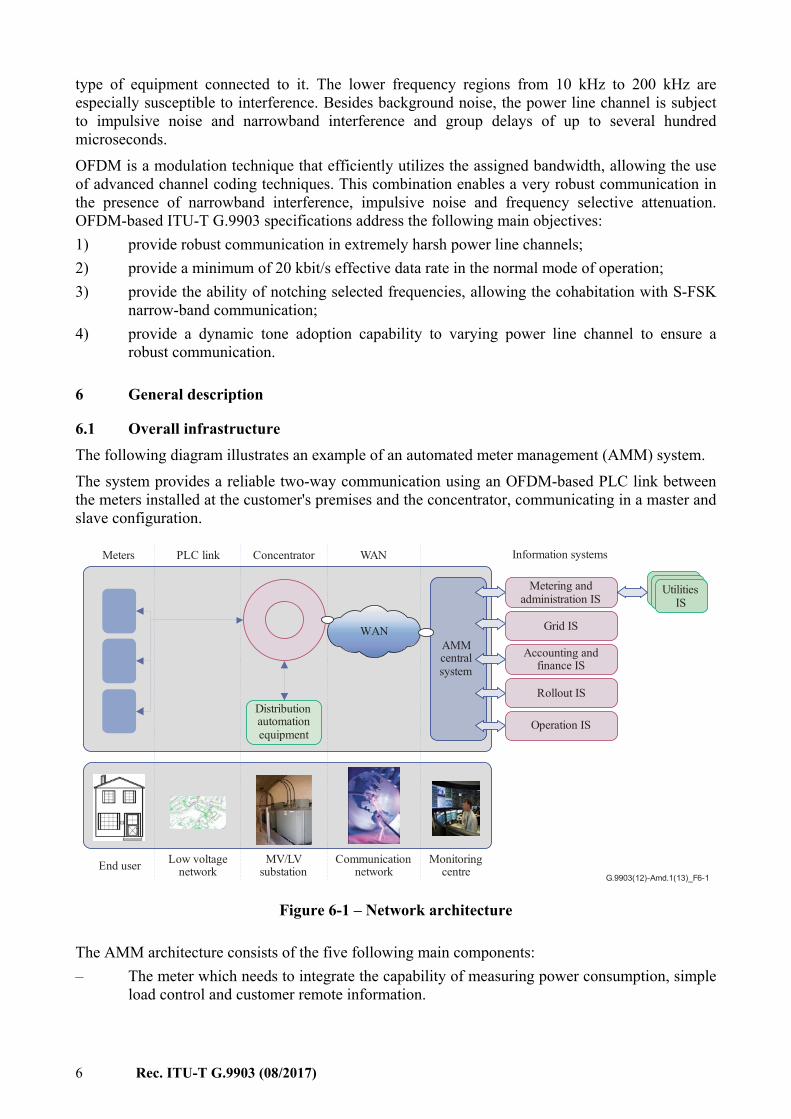
6.1 Overall infrastructure The following diagram illustrates an example of an automated meter management (AMM) system. The system provides a reliable two-way communication using an OFDM-based PLC link between the meters installed at the customer's premises and the concentrator, communicating in a master and slave configuration.
G.9903(12)-Amd.1(13)_F6-1
Metering andadministration IS
Grid IS
Accounting andfinance IS
Rollout IS
Operation IS
End user Low voltagenetwork
MV/LVsubstation
Communicationnetwork
Monitoringcentre
AMMcentralsystem
Meters ConcentratorPLC link Information systemsWAN
WAN
Distributionautomationequipment
UtilitiesIS
Figure 6-1 – Network architecture
The AMM architecture consists of the five following main components: – The meter which needs to integrate the capability of measuring power consumption, simple
load control and customer remote information.
Rec. ITU-T G.9903 (08/2017) 7
– The hub which acts as an intermediary between the AMM information system (IS) and the meters. Complementary equipment supplied by the electrical network that can be connected downstream of the hub.
– The PLC (LAN) technology which allows the use of a low-voltage electrical network to exchange data and commands between meters and hubs.
– A remote connection (WAN) allows connection between the hubs and the AMM central IS. – The central system, which not only handles its own functional services but also supplies
metering services to the existing or forthcoming enterprise services (deployment IS, network IS, management-finance IS, customer-supplier IS-Intervention management IS, etc.). The customer-supplier IS is the interface between the suppliers and AMM for handling their requirements.
6.2 Coexistence with other PLC networks Two mechanisms are defined to allow coexistence between ITU-T G.9903 devices and other narrowband PLC technologies operating in the same frequency band: – frequency division coexistence; – preamble-based coexistence.
6.2.1 Frequency division coexistence mechanism A first method consists in assigning non-overlapping bandplans to devices complying with this Recommendation within communication range. A second method is to exploit the tone masking feature (see clause 7.15 and description of macToneMask attribute in Table 9-15) to avoid any overlapping frequencies. Frequency division coexistence provides a means to ensure coexistence between devices complying with this Recommendation and both single (e.g., existing narrowband Frequency Shift Keying/Phase Shift Keying systems) and multiple carrier PLC systems.
6.2.2 Preamble-based coexistence mechanism (optional) Devices complying with this Recommendation may support the preamble-based coexistence mechanism specified in clauses 10.2.2 and 10.3 to 10.5 of [IEEE 1901.2] to fairly share the medium with other types of narrowband PLC technologies supporting the same preamble-based coexistence mechanism. Support for this coexistence mechanism is optional in this Recommendation, with the exception given in Annex G. If devices complying with this Recommendation support the preamble-based coexistence mechanism, then Tables 10-2 and 10-3 of [IEEE 1901.2] shall be revised as specified below. The IDs (identifiers) listed in Table 10-2 of [IEEE 1901.2] shall be replaced by the identifiers listed in Table 6-1.
Table 6-1 – Attributes for the preamble-based coexistence mechanism
Attribute Identifier
Beta 0x0117 aMacMaxCoexistenceBackoffs 0x0118 macAlpha 0x0119 K 0x011A macNdcTime 0x011B
NOTE – The other attributes listed in Table 10-2 of [IEEE 1901.2] (aCEIFS, macLongPreambleDuration, macDCEIFS, macMinChannelIdleTime) do not require an identifier as their values depend exclusively on the values of other attributes which have their own identifier.
8 Rec. ITU-T G.9903 (08/2017)
The IDs (identifiers) and default values listed in Table 10-3 of [IEEE 1901.2] shall be replaced by the ones listed in Table 6-2.
Table 6-2 – Coexistence control PIB attributes
Attribute Identifier Default value
macCoexPreambleDetectionEnabled 0x011C FALSE macCoexPreambleEnabled 0x011D FALSE
7 Physical layer specification This clause specifies the physical layer block using the orthogonal frequency division multiplexing (OFDM) system in the CENELEC and FCC bandplans.
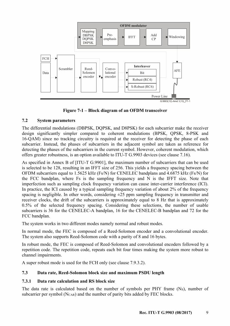
7.1 Introduction The power line channel is very hostile. Channel characteristics and parameters vary with frequency, location, time and the type of equipment connected to it. The lower frequency regions from 10 kHz to 200 kHz are especially susceptible to interference. Furthermore, the power line is a very frequency selective channel. Besides background noise, it is subject to impulsive noise often occurring at 50/60 Hz and narrowband interference and group delays of up to several hundred microseconds. OFDM can efficiently utilize limited bandwidth channels allowing the use of advanced channel coding techniques. This combination facilitates a very robust communication over a power line channel. Figure 7-1 shows the block diagram of an OFDM transmitter. The available bandwidth is divided into a number of sub-channels, which can be viewed as many independent Phase Shift Keying modulated subcarriers with different non-interfering (orthogonal) subcarrier frequencies. Convolutional and Reed-Solomon coding provide redundancy bits allowing the receiver to recover lost bits caused by background and impulsive noise. A time-frequency interleaving scheme is used to decrease the correlation of received noise at the input of the decoder, providing diversity. The OFDM signal is generated by performing inverse fast Fourier transform (IFFT) on the complex-valued signal points produced by differentially encoded phase modulation that are allocated to individual subcarriers. An OFDM symbol is built by appending a cyclic prefix to the beginning of each block generated by IFFT. The length of a cyclic prefix is chosen so that the channel group delay does not cause excessive interference between successive OFDM symbols. Windowing reduces the out-of-band leakage of the transmit signals. Channel estimation is used for link adaptation. Based on the quality of the received signal, the receiver (if requested by the transmitter) shall feed back the suggested modulation scheme to be used by the transmitting station in subsequent packets transmitted to the same receiver. Moreover, the system differentiates the subcarriers with insufficient SNR and does not transmit data on them.
Rec. ITU-T G.9903 (08/2017) 9
G.9903(12)-Amd.1(13)_F7-1
Power Line
AddCP Windowing
Data
FCH
S-Robust (RC6)
MappingDBPSKDQPSKD8PSK
IFFT
AFEScrambler Reed-Solomonencoder
Convo-lutionalencoder
Interleaver
Robust (RC4)
Pre-emphasis
OFDM modulator
Bit
Figure 7-1 – Block diagram of an OFDM transceiver
7.2 System parameters The differential modulations (DBPSK, DQPSK, and D8PSK) for each subcarrier make the receiver design significantly simpler compared to coherent modulations (BPSK, QPSK, 8-PSK and 16-QAM) since no tracking circuitry is required at the receiver for detecting the phase of each subcarrier. Instead, the phases of subcarriers in the adjacent symbol are taken as reference for detecting the phases of the subcarriers in the current symbol. However, coherent modulation, which offers greater robustness, is an option available to ITU-T G.9903 devices (see clause 7.16). As specified in Annex B of [ITU-T G.9901], the maximum number of subcarriers that can be used is selected to be 128, resulting in an IFFT size of 256. This yields a frequency spacing between the OFDM subcarriers equal to 1.5625 kHz (Fs/N) for CENELEC bandplans and 4.6875 kHz (Fs/N) for the FCC bandplan, where Fs is the sampling frequency and N is the IFFT size. Note that imperfection such as sampling clock frequency variation can cause inter-carrier interference (ICI). In practice, the ICI caused by a typical sampling frequency variation of about 2% of the frequency spacing is negligible. In other words, considering ±25 ppm sampling frequency in transmitter and receiver clocks, the drift of the subcarriers is approximately equal to 8 Hz that is approximately 0.5% of the selected frequency spacing. Considering these selections, the number of usable subcarriers is 36 for the CENELEC-A bandplan, 16 for the CENELEC-B bandplan and 72 for the FCC bandplan. The system works in two different modes namely normal and robust modes. In normal mode, the FEC is composed of a Reed-Solomon encoder and a convolutional encoder. The system also supports Reed-Solomon code with a parity of 8 and 16 bytes. In robust mode, the FEC is composed of Reed-Solomon and convolutional encoders followed by a repetition code. The repetition code, repeats each bit four times making the system more robust to channel impairments. A super robust mode is used for the FCH only (see clause 7.9.3.2).
7.3 Data rate, Reed-Solomon block size and maximum PSDU length
7.3.1 Data rate calculation and RS block size The data rate is calculated based on the number of symbols per PHY frame (NS), number of subcarrier per symbol (NCAR) and the number of parity bits added by FEC blocks.

10 Rec. ITU-T G.9903 (08/2017)
An example of how to calculate the data rate is given below using the following CENELEC-A bandplan parameters: – Number of FFT points N = 256 – Number of subcarriers NCAR = 36 – Number of overlapped samples NO = 8 – Number of cyclic prefix samples NCP = 30 – Number of FCH symbols NFCH = 13 – Sampling frequency Fs = 0.4 MHz – Number of symbols in preamble NPRE = 9.5 Consider the system in the CENELEC-A band working in the robust mode. The total number of bits carried by the whole PHY frame is equal to: Total_No_Bits = NS × NCAR = 40 × 36 = 1 440 bits The number of bits required at the input of the robust encoder is given by: No_Bits_Robust = 1440 × RobustRate = 1440 × 1/4 = 360 bits Considering the fact that the convolutional encoder has a rate equal to 1/2 (CCRate = 1/2) and also consider adding CCZerotail = 6 bits of zeros to terminate the states of the encoder to all zero states then the maximum number of symbols at the output of the Reed-Solomon encoder (MAXRSbytes) shall be equal to: MAXRS = floor No × CC − CC8 = floor 360 × 0.5 − 68 = 21 Removing 8 bytes associated with the parity bits (in robust mode) we obtain: DataLength = (21 – ParityLength) × 8 = 104 bits These 104 bits are carried within the duration of a PHY frame. The duration of a PHY frame is calculated by the following formula: T = (N + N ) × (N + N − N ) + (N × N)F Where NPRE, N, NO and NCP are the number of symbols in the preamble, FFT length, the number of samples overlapped at each side of one symbol and the number of samples in the cyclic prefix, respectively. NFCH is the number of symbols in the FCH. The FS is the sampling frequency. Substituting the above numbers in the equation, TFrame (PHY frame duration) for a 40-symbol frame is obtained as follows: T = (40 + 13) × (256 + 22) + (9.5 × 256)400000 = 0.043 s Therefore the data rate is calculated as: Data rate = 104/0.042 ~ 2.4 kbit/s
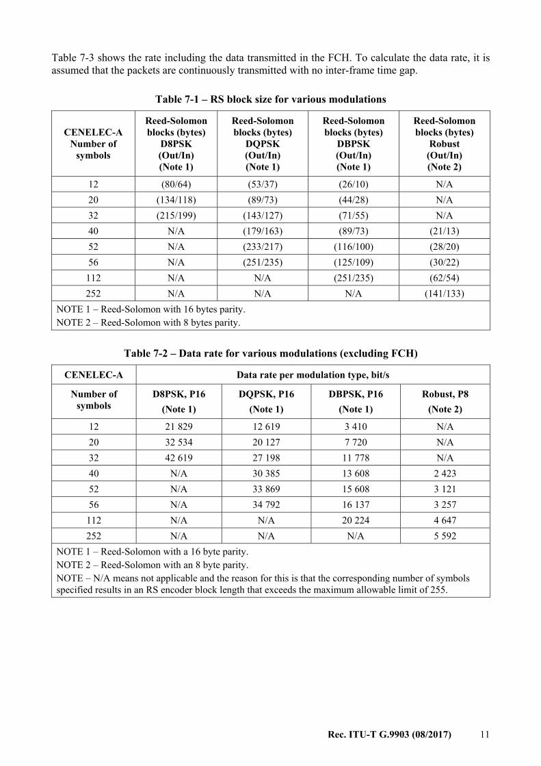
7.3.1.1 CENELEC-A bandplan Mandatory values for the OFDM control parameters for the CENELEC-A bandplan are given in Table B.1 of [ITU-T G.9901]. The frequency band used for the CENELEC-A bandplan is defined in Table B.2 of [ITU-T G.9901]. The number of symbols in each PHY (physical layer) frame is selected based on two parameters, the required data rate and the acceptable robustness. The number of symbols, Reed-Solomon block sizes and data rate associated with 36 tones is tabulated in Tables 7-1 and 7-2.
Rec. ITU-T G.9903 (08/2017) 11
Table 7-3 shows the rate including the data transmitted in the FCH. To calculate the data rate, it is assumed that the packets are continuously transmitted with no inter-frame time gap.
Table 7-1 – RS block size for various modulations
CENELEC-A Number of
symbols
Reed-Solomon blocks (bytes)
D8PSK (Out/In) (Note 1)
Reed-Solomon blocks (bytes)
DQPSK (Out/In) (Note 1)
Reed-Solomon blocks (bytes)
DBPSK (Out/In) (Note 1)
Reed-Solomon blocks (bytes)
Robust (Out/In) (Note 2)
12 (80/64) (53/37) (26/10) N/A 20 (134/118) (89/73) (44/28) N/A 32 (215/199) (143/127) (71/55) N/A 40 N/A (179/163) (89/73) (21/13) 52 N/A (233/217) (116/100) (28/20) 56 N/A (251/235) (125/109) (30/22)
112 N/A N/A (251/235) (62/54) 252 N/A N/A N/A (141/133)
NOTE 1 – Reed-Solomon with 16 bytes parity. NOTE 2 – Reed-Solomon with 8 bytes parity.
Table 7-2 – Data rate for various modulations (excluding FCH)
CENELEC-A Data rate per modulation type, bit/s
Number of symbols
D8PSK, P16 (Note 1)
DQPSK, P16
(Note 1) DBPSK, P16
(Note 1) Robust, P8
(Note 2)
12 21 829 12 619 3 410 N/A 20 32 534 20 127 7 720 N/A 32 42 619 27 198 11 778 N/A 40 N/A 30 385 13 608 2 423 52 N/A 33 869 15 608 3 121 56 N/A 34 792 16 137 3 257
112 N/A N/A 20 224 4 647 252 N/A N/A N/A 5 592
NOTE 1 – Reed-Solomon with a 16 byte parity. NOTE 2 – Reed-Solomon with an 8 byte parity. NOTE – N/A means not applicable and the reason for this is that the corresponding number of symbols specified results in an RS encoder block length that exceeds the maximum allowable limit of 255.
12 Rec. ITU-T G.9903 (08/2017)
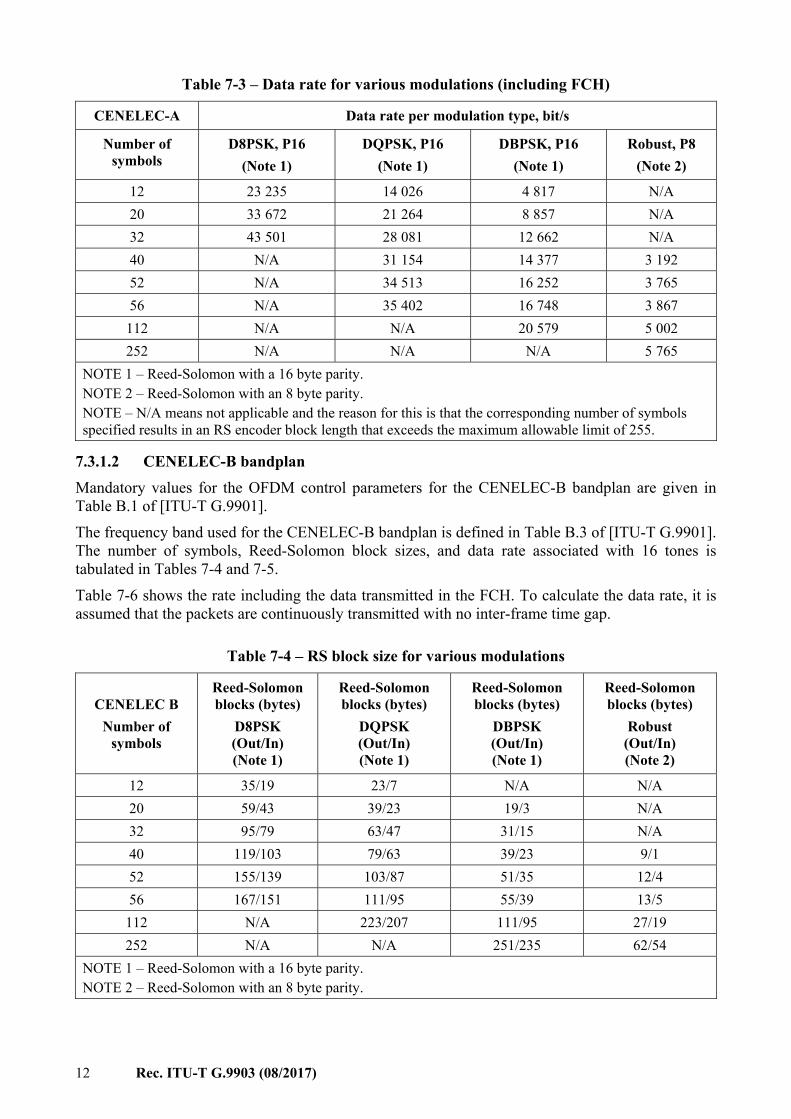
Table 7-3 – Data rate for various modulations (including FCH)
CENELEC-A Data rate per modulation type, bit/s
Number of symbols
D8PSK, P16 (Note 1)
DQPSK, P16 (Note 1)
DBPSK, P16 (Note 1)
Robust, P8 (Note 2)
12 23 235 14 026 4 817 N/A 20 33 672 21 264 8 857 N/A 32 43 501 28 081 12 662 N/A 40 N/A 31 154 14 377 3 192 52 N/A 34 513 16 252 3 765 56 N/A 35 402 16 748 3 867
112 N/A N/A 20 579 5 002 252 N/A N/A N/A 5 765
NOTE 1 – Reed-Solomon with a 16 byte parity. NOTE 2 – Reed-Solomon with an 8 byte parity. NOTE – N/A means not applicable and the reason for this is that the corresponding number of symbols specified results in an RS encoder block length that exceeds the maximum allowable limit of 255.
7.3.1.2 CENELEC-B bandplan Mandatory values for the OFDM control parameters for the CENELEC-B bandplan are given in Table B.1 of [ITU-T G.9901]. The frequency band used for the CENELEC-B bandplan is defined in Table B.3 of [ITU-T G.9901]. The number of symbols, Reed-Solomon block sizes, and data rate associated with 16 tones is tabulated in Tables 7-4 and 7-5. Table 7-6 shows the rate including the data transmitted in the FCH. To calculate the data rate, it is assumed that the packets are continuously transmitted with no inter-frame time gap.
Table 7-4 – RS block size for various modulations
CENELEC B Number of
symbols
Reed-Solomon blocks (bytes)
D8PSK (Out/In) (Note 1)
Reed-Solomon blocks (bytes)
DQPSK (Out/In) (Note 1)
Reed-Solomon blocks (bytes)
DBPSK (Out/In) (Note 1)
Reed-Solomon blocks (bytes)
Robust (Out/In) (Note 2)
12 35/19 23/7 N/A N/A 20 59/43 39/23 19/3 N/A 32 95/79 63/47 31/15 N/A 40 119/103 79/63 39/23 9/1 52 155/139 103/87 51/35 12/4 56 167/151 111/95 55/39 13/5
112 N/A 223/207 111/95 27/19 252 N/A N/A 251/235 62/54
NOTE 1 – Reed-Solomon with a 16 byte parity. NOTE 2 – Reed-Solomon with an 8 byte parity.
Rec. ITU-T G.9903 (08/2017) 13
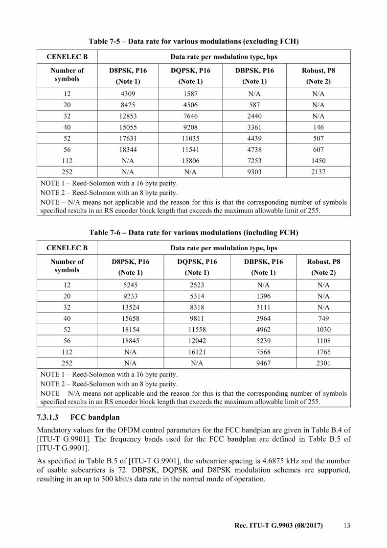
Table 7-5 – Data rate for various modulations (excluding FCH)
CENELEC B Data rate per modulation type, bps
Number of symbols
D8PSK, P16 (Note 1)
DQPSK, P16 (Note 1)
DBPSK, P16 (Note 1)
Robust, P8 (Note 2)
12 4309 1587 N/A N/A 20 8425 4506 587 N/A 32 12853 7646 2440 N/A 40 15055 9208 3361 146 52 17631 11035 4439 507 56 18344 11541 4738 607
112 N/A 15806 7253 1450 252 N/A N/A 9303 2137
NOTE 1 – Reed-Solomon with a 16 byte parity. NOTE 2 – Reed-Solomon with an 8 byte parity. NOTE – N/A means not applicable and the reason for this is that the corresponding number of symbols specified results in an RS encoder block length that exceeds the maximum allowable limit of 255.
Table 7-6 – Data rate for various modulations (including FCH)
CENELEC B Data rate per modulation type, bps
Number of symbols
D8PSK, P16 (Note 1)
DQPSK, P16 (Note 1)
DBPSK, P16 (Note 1)
Robust, P8 (Note 2)
12 5245 2523 N/A N/A 20 9233 5314 1396 N/A 32 13524 8318 3111 N/A 40 15658 9811 3964 749 52 18154 11558 4962 1030 56 18845 12042 5239 1108
112 N/A 16121 7568 1765 252 N/A N/A 9467 2301
NOTE 1 – Reed-Solomon with a 16 byte parity. NOTE 2 – Reed-Solomon with an 8 byte parity. NOTE – N/A means not applicable and the reason for this is that the corresponding number of symbols specified results in an RS encoder block length that exceeds the maximum allowable limit of 255.
7.3.1.3 FCC bandplan Mandatory values for the OFDM control parameters for the FCC bandplan are given in Table B.4 of [ITU-T G.9901]. The frequency bands used for the FCC bandplan are defined in Table B.5 of [ITU-T G.9901]. As specified in Table B.5 of [ITU-T G.9901], the subcarrier spacing is 4.6875 kHz and the number of usable subcarriers is 72. DBPSK, DQPSK and D8PSK modulation schemes are supported, resulting in an up to 300 kbit/s data rate in the normal mode of operation.

14 Rec. ITU-T G.9903 (08/2017)
The number of symbols in each PHY frame is selected based on two parameters, the required data rate and the acceptable robustness. The number of symbols, Reed-Solomon block sizes and data rate associated with 72 tones are tabulated for several values as examples in Tables 7-7 and 7-8.
Table 7-7 – RS block size for various modulations
FCC Number of
symbols
Reed-Solomon blocks (bytes)
D8PSK (Out/In) (Note 1)
Reed-Solomon blocks (bytes)
DQPSK (Out/In) (Note 1)
Reed-Solomon blocks (bytes)
DBPSK (Out/In) (Note 1)
Reed-Solomon blocks (bytes)
Robust (Out/In) (Note 2)
12 (161/145) (107/91) (53/37) (12/4) 20 N/A (179/163) (89/73) (21/13) 28 N/A (251/235) (125/109) (30/22)
NOTE 1 – Reed-Solomon with a 16 byte parity. NOTE 2 – Reed-Solomon with an 8 byte parity.
Table 7-8 – Data rate for various modulations (excluding FCH)
FCC Number of
symbols
Data rate (bit/s)
D8PSK (Note 1)
Data rate (bit/s)
DQPSK (Note 1)
Data rate (bit/s)
DBPSK (Note 1)
Data rate (bit/s)
Robust (Note 2)
12 152,899 95,957 39,015 4,217 20 N/A 138,135 61,864 11,016 28 N/A 166,469 77,213 15,584
NOTE 1 – Reed-Solomon with a 16 byte parity. NOTE 2 – Reed-Solomon with an 8 byte parity.
7.3.2 Maximum PSDU length calculation The maximum PSDU length in bytes for an ITU-T G.9903 PHY packet (Max_PSDUBytes) is a function of the PHY configuration comprising of the number of available subcarriers per symbol (NCAR), modulation type (MOD) and other dependent parameters. Given a PHY configuration, Max_PSDUBytes can be calculated using the following set of equations: = × min , ( × 8 + ) × _× × _ × where: – MaxRSBlockSize = 255 bytes, – NS is the number of symbols in the PHY packet, – CCRate = 0.5, – CCZeroTail = 6, – FLBand = 4 for CENELEC bandplans and FLBand = 1 for FCC bandplan, – FLmax is the maximum possible frame length (FLmax = 63 for CENELEC bandplans,
FLmax = 511 for FCC bandplan), – Rep_Code denotes the repetition coding (Rep_Code = 4 for Robust mode; Rep_Code = 1
for all other modes),
Rec. ITU-T G.9903 (08/2017) 15
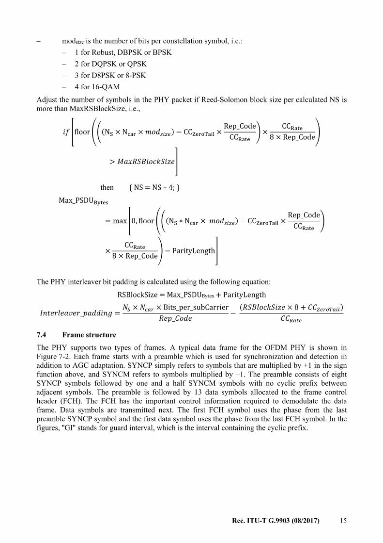
– modsize is the number of bits per constellation symbol, i.e.: – 1 for Robust, DBPSK or BPSK – 2 for DQPSK or QPSK – 3 for D8PSK or 8-PSK – 4 for 16-QAM
Adjust the number of symbols in the PHY packet if Reed-Solomon block size per calculated NS is more than MaxRSBlockSize, i.e.,
floor (N × N × ) − CC × Rep_CodeCC × CC8 × Rep_Code>
then { NS = NS – 4; } Max_PSDU = max 0, floor (N ∗ N × ) − CC × Rep_CodeCC× CC8 × Rep_Code − ParityLength
The PHY interleaver bit padding is calculated using the following equation: RSBlockSize = Max_PSDUBytes + ParityLength _ = × × Bits_per_subCarrier_ − ( × 8 + ) 7.4 Frame structure The PHY supports two types of frames. A typical data frame for the OFDM PHY is shown in Figure 7-2. Each frame starts with a preamble which is used for synchronization and detection in addition to AGC adaptation. SYNCP simply refers to symbols that are multiplied by +1 in the sign function above, and SYNCM refers to symbols multiplied by –1. The preamble consists of eight SYNCP symbols followed by one and a half SYNCM symbols with no cyclic prefix between adjacent symbols. The preamble is followed by 13 data symbols allocated to the frame control header (FCH). The FCH has the important control information required to demodulate the data frame. Data symbols are transmitted next. The first FCH symbol uses the phase from the last preamble SYNCP symbol and the first data symbol uses the phase from the last FCH symbol. In the figures, ''GI'' stands for guard interval, which is the interval containing the cyclic prefix.
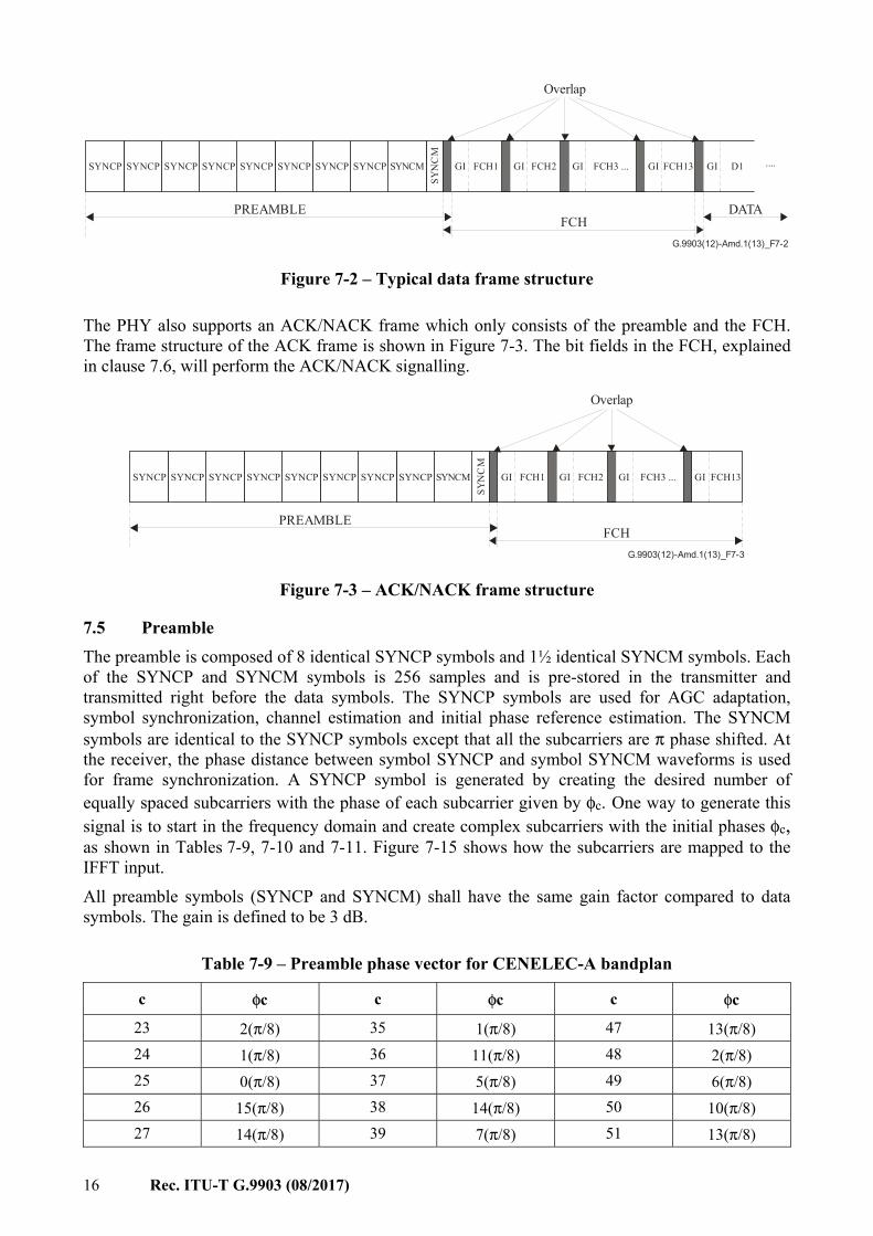
16 Rec. ITU-T G.9903 (08/2017)
G.9903(12)-Amd.1(13)_F7-2
SYNCP SYNCP
FCHDATA
SYNCPSYNCP SYNCPSYNCPSYNCP SYNCM
SYN
CM
GI D1 ....GI GI
PREAMBLE
SYNCP GI FCH1 GI FCH2 FCH3 ... FCH13
Overlap
Figure 7-2 – Typical data frame structure
The PHY also supports an ACK/NACK frame which only consists of the preamble and the FCH. The frame structure of the ACK frame is shown in Figure 7-3. The bit fields in the FCH, explained in clause 7.6, will perform the ACK/NACK signalling.
G.9903(12)-Amd.1(13)_F7-3
SYNCP SYNCP
FCH
SYNCPSYNCP SYNCPSYNCPSYNCP SYNCMSY
NC
MGI GI
PREAMBLE
SYNCP GI FCH1 GI FCH2 FCH3 ... FCH13
Overlap
Figure 7-3 – ACK/NACK frame structure
7.5 Preamble The preamble is composed of 8 identical SYNCP symbols and 1½ identical SYNCM symbols. Each of the SYNCP and SYNCM symbols is 256 samples and is pre-stored in the transmitter and transmitted right before the data symbols. The SYNCP symbols are used for AGC adaptation, symbol synchronization, channel estimation and initial phase reference estimation. The SYNCM symbols are identical to the SYNCP symbols except that all the subcarriers are π phase shifted. At the receiver, the phase distance between symbol SYNCP and symbol SYNCM waveforms is used for frame synchronization. A SYNCP symbol is generated by creating the desired number of equally spaced subcarriers with the phase of each subcarrier given by φc. One way to generate this signal is to start in the frequency domain and create complex subcarriers with the initial phases φc, as shown in Tables 7-9, 7-10 and 7-11. Figure 7-15 shows how the subcarriers are mapped to the IFFT input. All preamble symbols (SYNCP and SYNCM) shall have the same gain factor compared to data symbols. The gain is defined to be 3 dB.
Table 7-9 – Preamble phase vector for CENELEC-A bandplan
c φc c φc c φc
23 2(π/8) 35 1(π/8) 47 13(π/8) 24 1(π/8) 36 11(π/8) 48 2(π/8) 25 0(π/8) 37 5(π/8) 49 6(π/8) 26 15(π/8) 38 14(π/8) 50 10(π/8) 27 14(π/8) 39 7(π/8) 51 13(π/8)
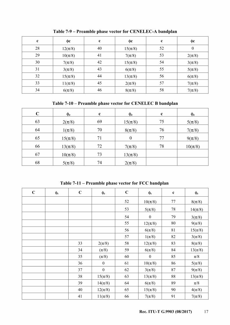
Rec. ITU-T G.9903 (08/2017) 17
Table 7-9 – Preamble phase vector for CENELEC-A bandplan
c φc c φc c φc
28 12(π/8) 40 15(π/8) 52 0 29 10(π/8) 41 7(π/8) 53 2(π/8) 30 7(π/8) 42 15(π/8) 54 3(π/8) 31 3(π/8) 43 6(π/8) 55 5(π/8) 32 15(π/8) 44 13(π/8) 56 6(π/8) 33 11(π/8) 45 2(π/8) 57 7(π/8) 34 6(π/8) 46 8(π/8) 58 7(π/8)
Table 7-10 – Preamble phase vector for CENELEC B bandplan
C φc c φc c φc 63 2(π/8) 69 15(π/8) 75 5(π/8)
64 1(π/8) 70 8(π/8) 76 7(π/8)
65 15(π/8) 71 0 77 9(π/8)
66 13(π/8) 72 7(π/8) 78 10(π/8)
67 10(π/8) 73 13(π/8)
68 5(π/8) 74 2(π/8)
Table 7-11 – Preamble phase vector for FCC bandplan
C φc C φc C φc c φc
52 10(π/8) 77 8(π/8)
53 5(π/8) 78 14(π/8)
54 0 79 3(π/8) 55 12(π/8) 80 9(π/8) 56 6(π/8) 81 15(π/8) 57 1(π/8) 82 3(π/8) 33 2(π/8) 58 12(π/8) 83 8(π/8) 34 (π/8) 59 6(π/8) 84 13(π/8) 35 (π/8) 60 0 85 π/8 36 0 61 10(π/8) 86 5(π/8) 37 0 62 3(π/8) 87 9(π/8) 38 15(π/8) 63 13(π/8) 88 13(π/8) 39 14(π/8) 64 6(π/8) 89 π/8 40 12(π/8) 65 15(π/8) 90 4(π/8) 41 11(π/8) 66 7(π/8) 91 7(π/8)
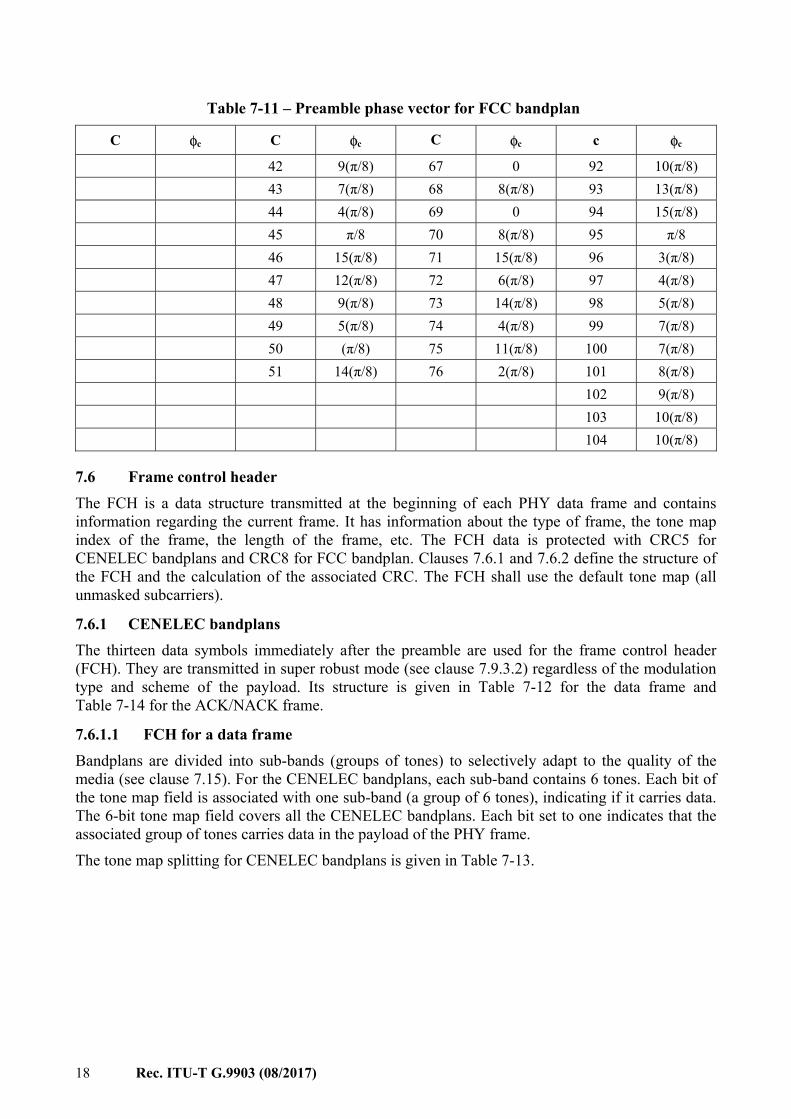
18 Rec. ITU-T G.9903 (08/2017)
Table 7-11 – Preamble phase vector for FCC bandplan
C φc C φc C φc c φc
42 9(π/8) 67 0 92 10(π/8) 43 7(π/8) 68 8(π/8) 93 13(π/8) 44 4(π/8) 69 0 94 15(π/8) 45 π/8 70 8(π/8) 95 π/8 46 15(π/8) 71 15(π/8) 96 3(π/8) 47 12(π/8) 72 6(π/8) 97 4(π/8) 48 9(π/8) 73 14(π/8) 98 5(π/8) 49 5(π/8) 74 4(π/8) 99 7(π/8) 50 (π/8) 75 11(π/8) 100 7(π/8) 51 14(π/8) 76 2(π/8) 101 8(π/8) 102 9(π/8) 103 10(π/8) 104 10(π/8)
7.6 Frame control header The FCH is a data structure transmitted at the beginning of each PHY data frame and contains information regarding the current frame. It has information about the type of frame, the tone map index of the frame, the length of the frame, etc. The FCH data is protected with CRC5 for CENELEC bandplans and CRC8 for FCC bandplan. Clauses 7.6.1 and 7.6.2 define the structure of the FCH and the calculation of the associated CRC. The FCH shall use the default tone map (all unmasked subcarriers).
7.6.1 CENELEC bandplans The thirteen data symbols immediately after the preamble are used for the frame control header (FCH). They are transmitted in super robust mode (see clause 7.9.3.2) regardless of the modulation type and scheme of the payload. Its structure is given in Table 7-12 for the data frame and Table 7-14 for the ACK/NACK frame.
7.6.1.1 FCH for a data frame Bandplans are divided into sub-bands (groups of tones) to selectively adapt to the quality of the media (see clause 7.15). For the CENELEC bandplans, each sub-band contains 6 tones. Each bit of the tone map field is associated with one sub-band (a group of 6 tones), indicating if it carries data. The 6-bit tone map field covers all the CENELEC bandplans. Each bit set to one indicates that the associated group of tones carries data in the payload of the PHY frame. The tone map splitting for CENELEC bandplans is given in Table 7-13.
Rec. ITU-T G.9903 (08/2017) 19
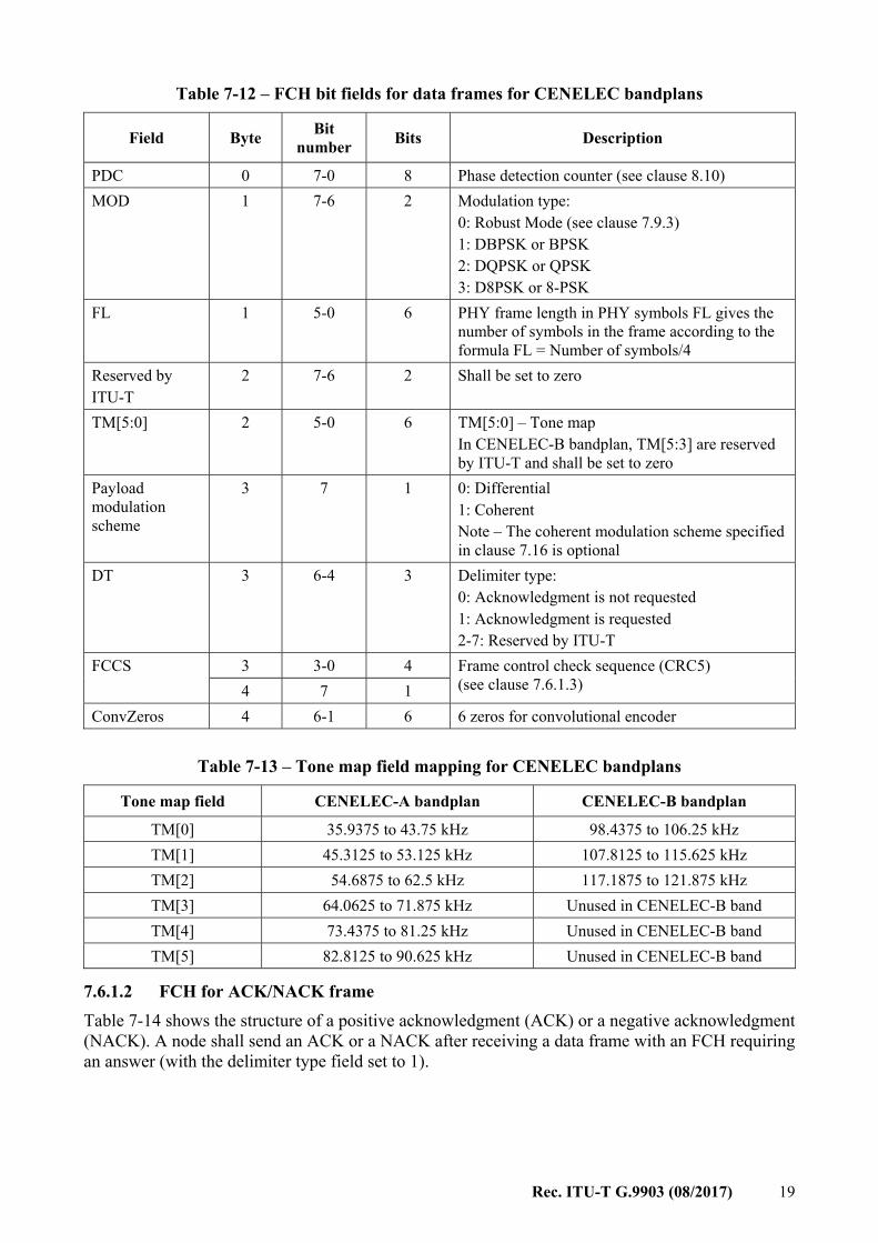
Table 7-12 – FCH bit fields for data frames for CENELEC bandplans
Field Byte Bit number Bits Description
PDC 0 7-0 8 Phase detection counter (see clause 8.10) MOD 1 7-6 2 Modulation type:
0: Robust Mode (see clause 7.9.3) 1: DBPSK or BPSK 2: DQPSK or QPSK 3: D8PSK or 8-PSK
FL 1 5-0 6 PHY frame length in PHY symbols FL gives the number of symbols in the frame according to the formula FL = Number of symbols/4
Reserved by ITU-T
2 7-6 2 Shall be set to zero
TM[5:0] 2 5-0 6 TM[5:0] – Tone map In CENELEC-B bandplan, TM[5:3] are reserved by ITU-T and shall be set to zero
Payload modulation scheme
3 7 1 0: Differential 1: Coherent Note – The coherent modulation scheme specified in clause 7.16 is optional
DT 3 6-4 3 Delimiter type: 0: Acknowledgment is not requested 1: Acknowledgment is requested 2-7: Reserved by ITU-T
FCCS 3 3-0 4 Frame control check sequence (CRC5) (see clause 7.6.1.3) 4 7 1
ConvZeros 4 6-1 6 6 zeros for convolutional encoder
Table 7-13 – Tone map field mapping for CENELEC bandplans
Tone map field CENELEC-A bandplan CENELEC-B bandplan
TM[0] 35.9375 to 43.75 kHz 98.4375 to 106.25 kHz TM[1] 45.3125 to 53.125 kHz 107.8125 to 115.625 kHz TM[2] 54.6875 to 62.5 kHz 117.1875 to 121.875 kHz TM[3] 64.0625 to 71.875 kHz Unused in CENELEC-B band TM[4] 73.4375 to 81.25 kHz Unused in CENELEC-B band TM[5] 82.8125 to 90.625 kHz Unused in CENELEC-B band
7.6.1.2 FCH for ACK/NACK frame Table 7-14 shows the structure of a positive acknowledgment (ACK) or a negative acknowledgment (NACK). A node shall send an ACK or a NACK after receiving a data frame with an FCH requiring an answer (with the delimiter type field set to 1).
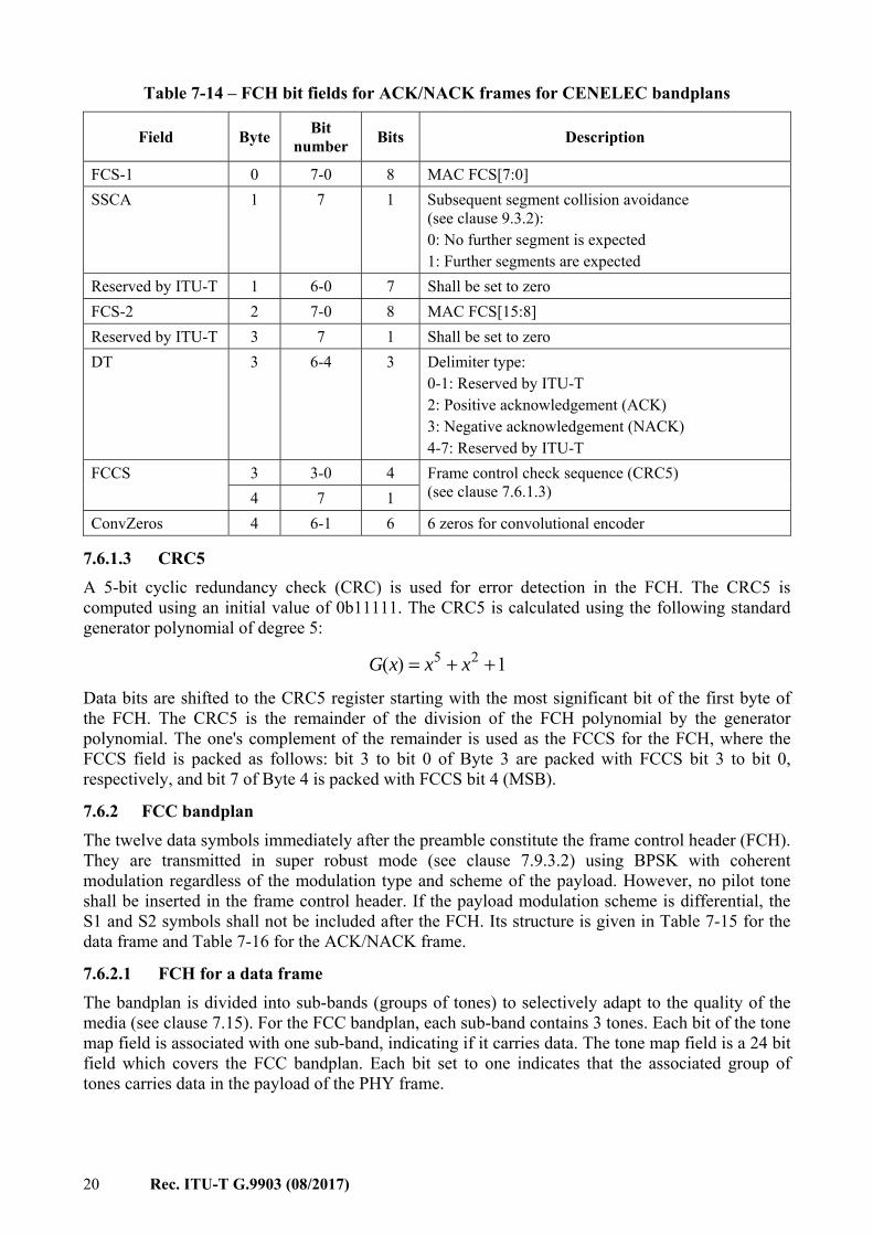
20 Rec. ITU-T G.9903 (08/2017)
Table 7-14 – FCH bit fields for ACK/NACK frames for CENELEC bandplans
Field Byte Bit number Bits Description
FCS-1 0 7-0 8 MAC FCS[7:0] SSCA 1 7 1 Subsequent segment collision avoidance
(see clause 9.3.2): 0: No further segment is expected 1: Further segments are expected
Reserved by ITU-T 1 6-0 7 Shall be set to zero FCS-2 2 7-0 8 MAC FCS[15:8] Reserved by ITU-T 3 7 1 Shall be set to zero DT 3 6-4 3 Delimiter type:
0-1: Reserved by ITU-T 2: Positive acknowledgement (ACK) 3: Negative acknowledgement (NACK) 4-7: Reserved by ITU-T
FCCS 3 3-0 4 Frame control check sequence (CRC5) (see clause 7.6.1.3) 4 7 1
ConvZeros 4 6-1 6 6 zeros for convolutional encoder
7.6.1.3 CRC5 A 5-bit cyclic redundancy check (CRC) is used for error detection in the FCH. The CRC5 is computed using an initial value of 0b11111. The CRC5 is calculated using the following standard generator polynomial of degree 5: 1)( 25 ++= xxxG Data bits are shifted to the CRC5 register starting with the most significant bit of the first byte of the FCH. The CRC5 is the remainder of the division of the FCH polynomial by the generator polynomial. The one's complement of the remainder is used as the FCCS for the FCH, where the FCCS field is packed as follows: bit 3 to bit 0 of Byte 3 are packed with FCCS bit 3 to bit 0, respectively, and bit 7 of Byte 4 is packed with FCCS bit 4 (MSB).
7.6.2 FCC bandplan The twelve data symbols immediately after the preamble constitute the frame control header (FCH). They are transmitted in super robust mode (see clause 7.9.3.2) using BPSK with coherent modulation regardless of the modulation type and scheme of the payload. However, no pilot tone shall be inserted in the frame control header. If the payload modulation scheme is differential, the S1 and S2 symbols shall not be included after the FCH. Its structure is given in Table 7-15 for the data frame and Table 7-16 for the ACK/NACK frame.
7.6.2.1 FCH for a data frame The bandplan is divided into sub-bands (groups of tones) to selectively adapt to the quality of the media (see clause 7.15). For the FCC bandplan, each sub-band contains 3 tones. Each bit of the tone map field is associated with one sub-band, indicating if it carries data. The tone map field is a 24 bit field which covers the FCC bandplan. Each bit set to one indicates that the associated group of tones carries data in the payload of the PHY frame.
Rec. ITU-T G.9903 (08/2017) 21
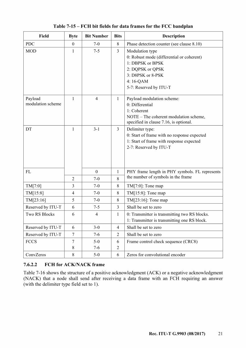
Table 7-15 – FCH bit fields for data frames for the FCC bandplan
Field Byte Bit Number Bits Description
PDC 0 7-0 8 Phase detection counter (see clause 8.10) MOD 1 7-5 3 Modulation type
0: Robust mode (differential or coherent) 1: DBPSK or BPSK 2: DQPSK or QPSK 3: D8PSK or 8-PSK 4: 16-QAM 5-7: Reserved by ITU-T
Payload modulation scheme
1 4 1 Payload modulation scheme: 0: Differential 1: Coherent NOTE – The coherent modulation scheme, specified in clause 7.16, is optional.
DT 1 3-1 3 Delimiter type: 0: Start of frame with no response expected 1: Start of frame with response expected 2-7: Reserved by ITU-T
FL 0 1 PHY frame length in PHY symbols. FL represents the number of symbols in the frame 2 7-0 8
TM[7:0] 3 7-0 8 TM[7:0]: Tone map TM[15:8] 4 7-0 8 TM[15:8]: Tone map TM[23:16] 5 7-0 8 TM[23:16]: Tone map Reserved by ITU-T 6 7-5 3 Shall be set to zero Two RS Blocks 6 4 1 0: Transmitter is transmitting two RS blocks.
1: Transmitter is transmitting one RS block. Reserved by ITU-T 6 3-0 4 Shall be set to zero Reserved by ITU-T 7 7-6 2 Shall be set to zero FCCS 7
8 5-0 7-6
6 2
Frame control check sequence (CRC8)
ConvZeros 8 5-0 6 Zeros for convolutional encoder
7.6.2.2 FCH for ACK/NACK frame Table 7-16 shows the structure of a positive acknowledgment (ACK) or a negative acknowledgment (NACK) that a node shall send after receiving a data frame with an FCH requiring an answer (with the delimiter type field set to 1).
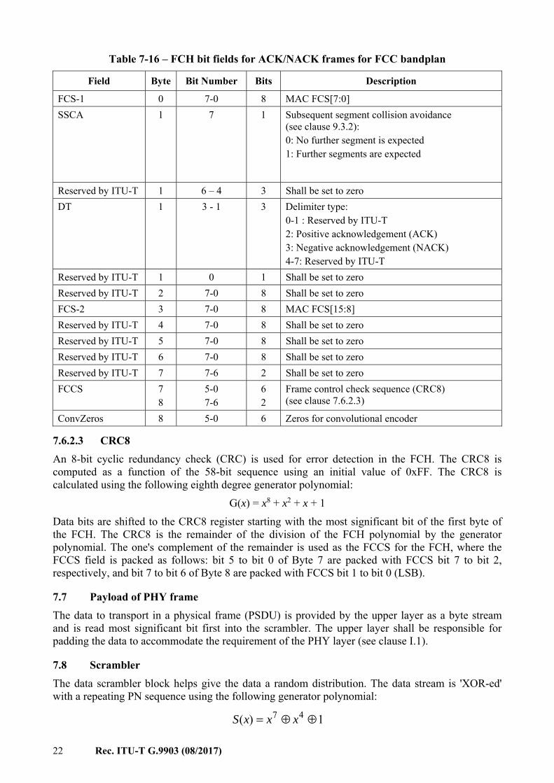
22 Rec. ITU-T G.9903 (08/2017)
Table 7-16 – FCH bit fields for ACK/NACK frames for FCC bandplan
Field Byte Bit Number Bits Description
FCS-1 0 7-0 8 MAC FCS[7:0] SSCA 1 7 1 Subsequent segment collision avoidance
(see clause 9.3.2): 0: No further segment is expected 1: Further segments are expected
Reserved by ITU-T 1 6 – 4 3 Shall be set to zero DT 1 3 - 1 3 Delimiter type:
0-1 : Reserved by ITU-T 2: Positive acknowledgement (ACK) 3: Negative acknowledgement (NACK) 4-7: Reserved by ITU-T
Reserved by ITU-T 1 0 1 Shall be set to zero Reserved by ITU-T 2 7-0 8 Shall be set to zero FCS-2 3 7-0 8 MAC FCS[15:8] Reserved by ITU-T 4 7-0 8 Shall be set to zero Reserved by ITU-T 5 7-0 8 Shall be set to zero Reserved by ITU-T 6 7-0 8 Shall be set to zero Reserved by ITU-T 7 7-6 2 Shall be set to zero FCCS 7
8 5-0 7-6
6 2
Frame control check sequence (CRC8) (see clause 7.6.2.3)
ConvZeros 8 5-0 6 Zeros for convolutional encoder
7.6.2.3 CRC8 An 8-bit cyclic redundancy check (CRC) is used for error detection in the FCH. The CRC8 is computed as a function of the 58-bit sequence using an initial value of 0xFF. The CRC8 is calculated using the following eighth degree generator polynomial: G(x) = x8 + x2 + x + 1 Data bits are shifted to the CRC8 register starting with the most significant bit of the first byte of the FCH. The CRC8 is the remainder of the division of the FCH polynomial by the generator polynomial. The one's complement of the remainder is used as the FCCS for the FCH, where the FCCS field is packed as follows: bit 5 to bit 0 of Byte 7 are packed with FCCS bit 7 to bit 2, respectively, and bit 7 to bit 6 of Byte 8 are packed with FCCS bit 1 to bit 0 (LSB).
7.7 Payload of PHY frame The data to transport in a physical frame (PSDU) is provided by the upper layer as a byte stream and is read most significant bit first into the scrambler. The upper layer shall be responsible for padding the data to accommodate the requirement of the PHY layer (see clause I.1).
7.8 Scrambler The data scrambler block helps give the data a random distribution. The data stream is 'XOR-ed' with a repeating PN sequence using the following generator polynomial: 1)( 47 ⊕⊕= xxxS
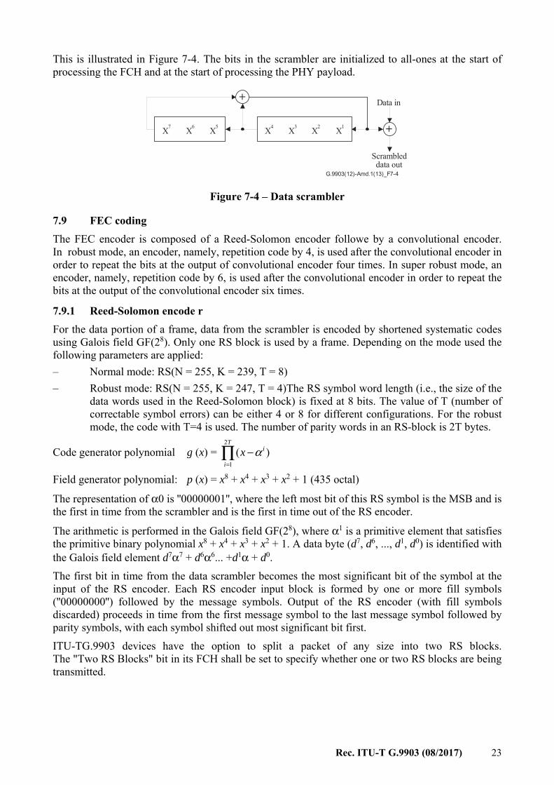
Rec. ITU-T G.9903 (08/2017) 23
This is illustrated in Figure 7-4. The bits in the scrambler are initialized to all-ones at the start of processing the FCH and at the start of processing the PHY payload.
+
+
G.9903(12)-Amd.1(13)_F7-4
Data in
Scrambleddata out
X7 X6 X5 X4 X3 X2 X1
Figure 7-4 – Data scrambler
7.9 FEC coding The FEC encoder is composed of a Reed-Solomon encoder followe by a convolutional encoder. In robust mode, an encoder, namely, repetition code by 4, is used after the convolutional encoder in order to repeat the bits at the output of convolutional encoder four times. In super robust mode, an encoder, namely, repetition code by 6, is used after the convolutional encoder in order to repeat the bits at the output of the convolutional encoder six times.
7.9.1 Reed-Solomon encode r For the data portion of a frame, data from the scrambler is encoded by shortened systematic codes using Galois field GF(28). Only one RS block is used by a frame. Depending on the mode used the following parameters are applied: – Normal mode: RS(N = 255, K = 239, T = 8) – Robust mode: RS(N = 255, K = 247, T = 4)The RS symbol word length (i.e., the size of the
data words used in the Reed-Solomon block) is fixed at 8 bits. The value of T (number of correctable symbol errors) can be either 4 or 8 for different configurations. For the robust mode, the code with T=4 is used. The number of parity words in an RS-block is 2T bytes.
Code generator polynomial g (x) =
Field generator polynomial: p (x) = x8 + x4 + x3 + x2 + 1 (435 octal)
The representation of α0 is ''00000001'', where the left most bit of this RS symbol is the MSB and is the first in time from the scrambler and is the first in time out of the RS encoder.
The arithmetic is performed in the Galois field GF(28), where α1 is a primitive element that satisfies the primitive binary polynomial x8 + x4 + x3 + x2 + 1. A data byte (d7, d6, ..., d1, d0) is identified with the Galois field element d7α7 + d6α6... +d1α + d0. The first bit in time from the data scrambler becomes the most significant bit of the symbol at the input of the RS encoder. Each RS encoder input block is formed by one or more fill symbols (''00000000'') followed by the message symbols. Output of the RS encoder (with fill symbols discarded) proceeds in time from the first message symbol to the last message symbol followed by parity symbols, with each symbol shifted out most significant bit first. ITU-TG.9903 devices have the option to split a packet of any size into two RS blocks. The "Two RS Blocks" bit in its FCH shall be set to specify whether one or two RS blocks are being transmitted.
∏=
−T
i
ix2
1)( α
24 Rec. ITU-T G.9903 (08/2017)
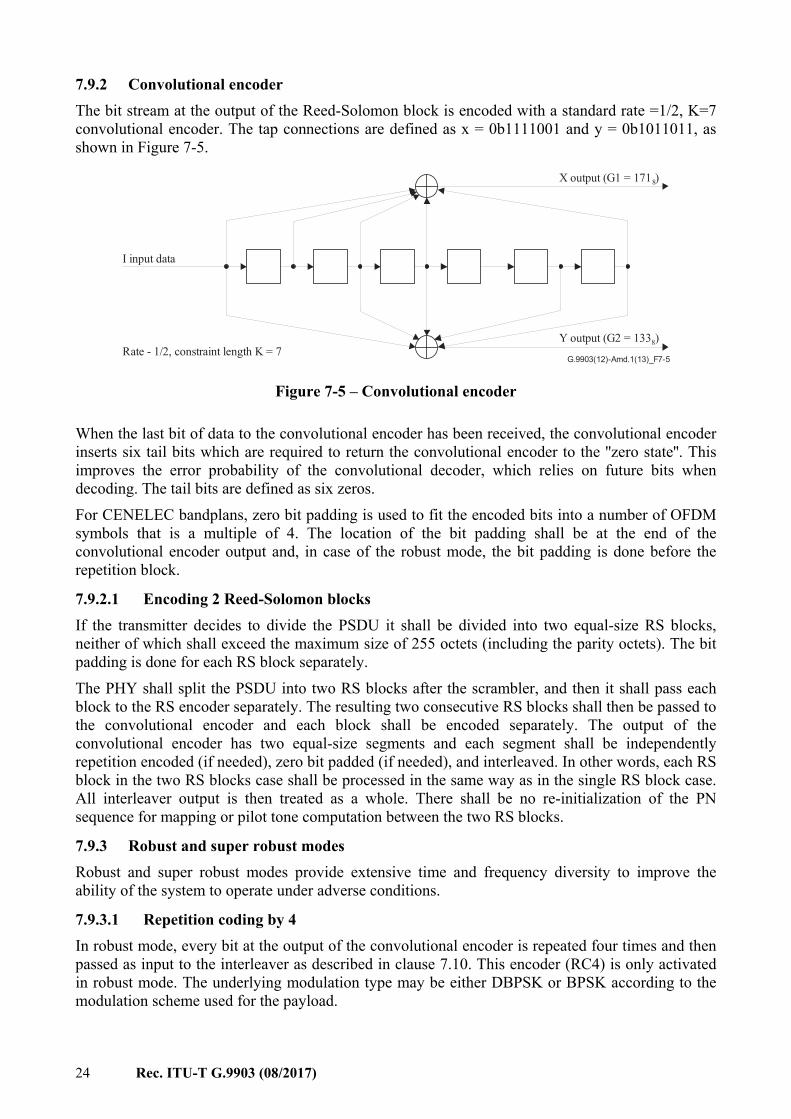
7.9.2 Convolutional encoder The bit stream at the output of the Reed-Solomon block is encoded with a standard rate =1/2, K=7 convolutional encoder. The tap connections are defined as x = 0b1111001 and y = 0b1011011, as shown in Figure 7-5.
G.9903(12)-Amd.1(13)_F7-5
I input data
X output (G1 = 171 )8
Y output (G2 = 133 )8Rate - 1/2, constraint length K = 7
Figure 7-5 – Convolutional encoder
When the last bit of data to the convolutional encoder has been received, the convolutional encoder inserts six tail bits which are required to return the convolutional encoder to the ''zero state''. This improves the error probability of the convolutional decoder, which relies on future bits when decoding. The tail bits are defined as six zeros. For CENELEC bandplans, zero bit padding is used to fit the encoded bits into a number of OFDM symbols that is a multiple of 4. The location of the bit padding shall be at the end of the convolutional encoder output and, in case of the robust mode, the bit padding is done before the repetition block.
7.9.2.1 Encoding 2 Reed-Solomon blocks If the transmitter decides to divide the PSDU it shall be divided into two equal-size RS blocks, neither of which shall exceed the maximum size of 255 octets (including the parity octets). The bit padding is done for each RS block separately. The PHY shall split the PSDU into two RS blocks after the scrambler, and then it shall pass each block to the RS encoder separately. The resulting two consecutive RS blocks shall then be passed to the convolutional encoder and each block shall be encoded separately. The output of the convolutional encoder has two equal-size segments and each segment shall be independently repetition encoded (if needed), zero bit padded (if needed), and interleaved. In other words, each RS block in the two RS blocks case shall be processed in the same way as in the single RS block case. All interleaver output is then treated as a whole. There shall be no re-initialization of the PN sequence for mapping or pilot tone computation between the two RS blocks.
7.9.3 Robust and super robust modes Robust and super robust modes provide extensive time and frequency diversity to improve the ability of the system to operate under adverse conditions.
7.9.3.1 Repetition coding by 4 In robust mode, every bit at the output of the convolutional encoder is repeated four times and then passed as input to the interleaver as described in clause 7.10. This encoder (RC4) is only activated in robust mode. The underlying modulation type may be either DBPSK or BPSK according to the modulation scheme used for the payload.
Rec. ITU-T G.9903 (08/2017) 25
7.9.3.2 Repetition coding by 6 In the super robust mode, every bit at the output of the convolutional encoder is repeated six times and then passed as input to the interleaver as described in clause 7.10. Only the FCH uses the super robust mode but without Reed-Solomon encoding. The underlying modulation type shall always be DBPSK.
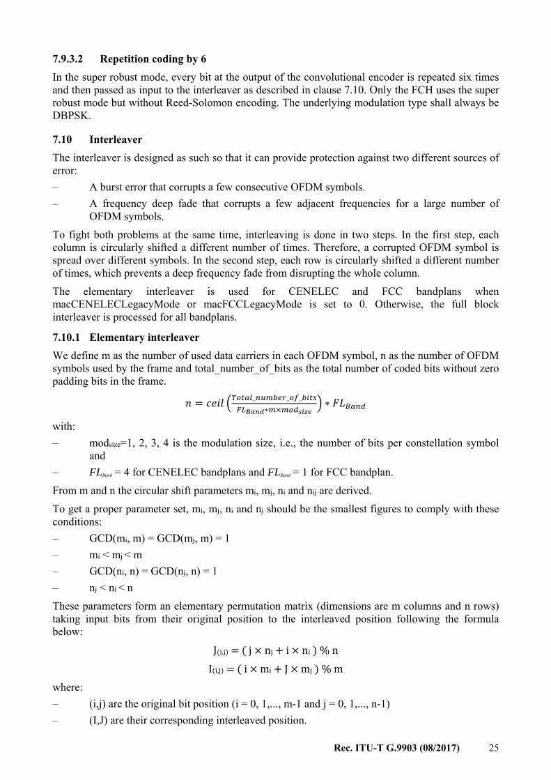
7.10 Interleaver The interleaver is designed as such so that it can provide protection against two different sources of error: – A burst error that corrupts a few consecutive OFDM symbols. – A frequency deep fade that corrupts a few adjacent frequencies for a large number of
OFDM symbols. To fight both problems at the same time, interleaving is done in two steps. In the first step, each column is circularly shifted a different number of times. Therefore, a corrupted OFDM symbol is spread over different symbols. In the second step, each row is circularly shifted a different number of times, which prevents a deep frequency fade from disrupting the whole column. The elementary interleaver is used for CENELEC and FCC bandplans when macCENELECLegacyMode or macFCCLegacyMode is set to 0. Otherwise, the full block interleaver is processed for all bandplans.
7.10.1 Elementary interleaver We define m as the number of used data carriers in each OFDM symbol, n as the number of OFDM symbols used by the frame and total_number_of_bits as the total number of coded bits without zero padding bits in the frame.
= _ _ _∗ × ∗ with: – modsize=1, 2, 3, 4 is the modulation size, i.e., the number of bits per constellation symbol
and – FLBand = 4 for CENELEC bandplans and FLBand = 1 for FCC bandplan. From m and n the circular shift parameters mi, mj, ni and nij are derived. To get a proper parameter set, mi, mj, ni and nj should be the smallest figures to comply with these conditions: – GCD(mi, m) = GCD(mj, m) = 1 – mi < mj < m – GCD(ni, n) = GCD(nj, n) = 1 – nj < ni < n These parameters form an elementary permutation matrix (dimensions are m columns and n rows) taking input bits from their original position to the interleaved position following the formula below: J(i,j) = ( j × nj + i × ni ) % n I(i,j) = ( i × mi + J × mj ) % m where: – (i,j) are the original bit position (i = 0, 1,..., m-1 and j = 0, 1,..., n-1) – (I,J) are their corresponding interleaved position.

26 Rec. ITU-T G.9903 (08/2017)
When macCENELECLegacyMode or macFCCLegacyMode is different from 0, and if the initial value I(1,0) is zero, the circular shift parameters nj and ni shall be swapped before performing interleaving. I(1,0) is computed as: I(1,0) = ( 1 × mi + J(1,0) × mj ) % m and J(1,0) = ( 0 × nj + 1 × ni ) % n. In this case, the interleaved position follows the formula below: J(i,j) = ( j × ni + i × nj ) % n I(i,j) = ( i × mi + J(i,j) × mj ) % m where: (i,j) are related to the original bit position (i = 0, 1,..., m-1 and j = 0, 1,..., n-1) (I,J) are related to the corresponding interleaved position. For DBPSK or BPSK modulation, the permutation matrix corresponds to the elementary permutation matrix while other modulations use multiple times the elementary permutation matrix. Thus, the dimensions of the permutation matrix for DQPSK, QPSK, D8PSK and 8-PSK modulations are m columns and n×modsize rows. The data to be interleaved are stored in the input buffer and shows which dimensions are m columns and n×modsize rows. The data bits are put in the input buffer row by row, as shown in Figure 7-6. Zero padding will be used to match permutation matrix dimensions.
...
...
...
G.9903(12)-Amd.1(13)_F7-6
10 m–1
m 2m–1
Subcarrier Numberi = 0...m–1
j = 0
…n
mod
_siz
e –
1×
(n mod_size–1) m× ×
m+1
n× ×mod_size m–1
Figure 7-6 – Bit order input into the input buffer
Once interleaved each bit is stored in an output buffer as shown in Figure 7-7.
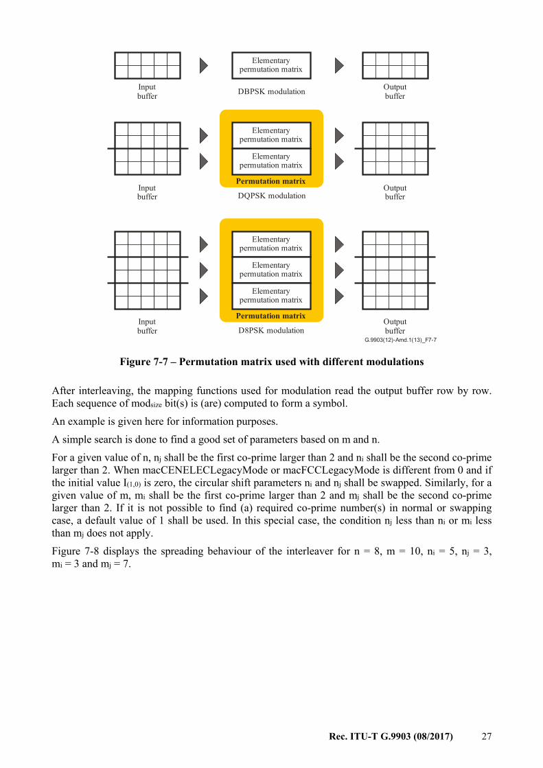
Rec. ITU-T G.9903 (08/2017) 27
G.9903(12)-Amd.1(13)_F7-7
Inputbuffer
Elementary permutation matrix
Elementary permutation matrix
DBPSK modulation
Inputbuffer
Outputbuffer
Outputbuffer
Elementary permutation matrix
Elementary permutation matrix
Elementary permutation matrix
Permutation matrix
Permutation matrix
DQPSK modulation
Elementary permutation matrix
D8PSK modulationInputbuffer
Outputbuffer
Figure 7-7 – Permutation matrix used with different modulations
After interleaving, the mapping functions used for modulation read the output buffer row by row. Each sequence of modsize bit(s) is (are) computed to form a symbol. An example is given here for information purposes. A simple search is done to find a good set of parameters based on m and n. For a given value of n, nj shall be the first co-prime larger than 2 and ni shall be the second co-prime larger than 2. When macCENELECLegacyMode or macFCCLegacyMode is different from 0 and if the initial value I(1,0) is zero, the circular shift parameters ni and nj shall be swapped. Similarly, for a given value of m, mi shall be the first co-prime larger than 2 and mj shall be the second co-prime larger than 2. If it is not possible to find (a) required co-prime number(s) in normal or swapping case, a default value of 1 shall be used. In this special case, the condition nj less than ni or mi less than mj does not apply. Figure 7-8 displays the spreading behaviour of the interleaver for n = 8, m = 10, ni = 5, nj = 3, mi = 3 and mj = 7.
28 Rec. ITU-T G.9903 (08/2017)
G.9903(12)-Amd.1(13)_F7-8
m m
n n
J j iI i j = (3 + 5 ) mod8 = (3 + 7 ) mod10
Position ( , )i j Position ( , )I J
Figure 7-8 – Example of spreading behaviour
The calculation of ni, nj, mi and mj are explained as below: – n = 8 (co-prime numbers for 8 except 1 and 2 are: 3, 5, 7). The first number is 3, so
nj = 3; and the next co-prime with 8 is 5, so ni = 5; that is the first co-prime number other than 1 and 2 of n shall be nj, and the second co-prime of n other than 1 and 2 shall be ni;
– m = 10 (co-prime numbers for 10 except 1 and 2 are: 3, 7, 9). The first number we meet in the set is 3, so mi = 3; and the next is 7, so mj = 7; that is the first co-prime of m other than 1 and 2 shall be mi, and the next co-prime shall be mj.
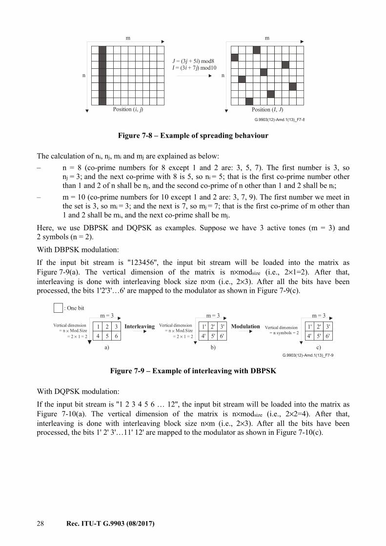
Here, we use DBPSK and DQPSK as examples. Suppose we have 3 active tones (m = 3) and 2 symbols (n = 2). With DBPSK modulation: If the input bit stream is ''123456'', the input bit stream will be loaded into the matrix as Figure 7-9(a). The vertical dimension of the matrix is n×modsize (i.e., 2×1=2). After that, interleaving is done with interleaving block size n×m (i.e., 2×3). After all the bits have been processed, the bits 1'2'3'…6' are mapped to the modulator as shown in Figure 7-9(c).
G.9903(12)-Amd.1(13)_F7-9
: One bitm = 3 m = 3 m = 3
Vertical dimension= n Mod.Size
= 2 1 = 2×
×
Vertical dimension= n Mod.Size
= 2 1 = 2×
×
Interleaving Modulation Vertical dimension= n symbols = 2
1 1' 1'2 2' 2'3 3' 3'6 6' 6'5 5' 5'4 4' 4'
a) b) c)
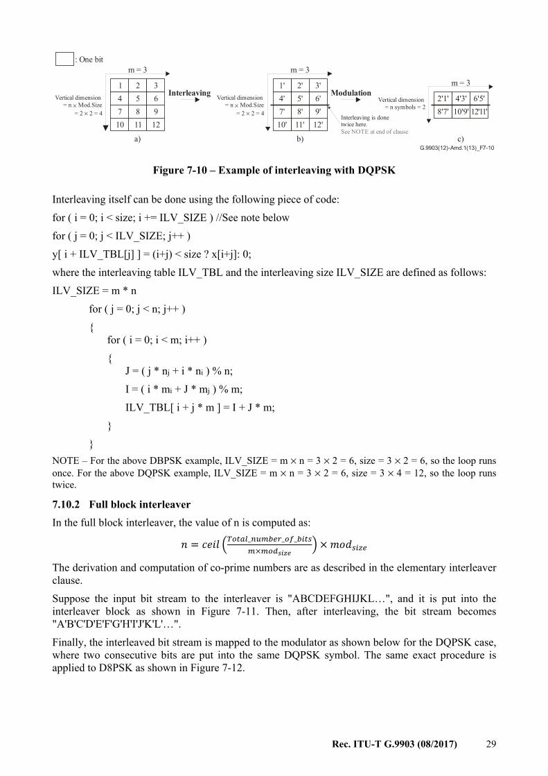
Figure 7-9 – Example of interleaving with DBPSK
With DQPSK modulation: If the input bit stream is ''1 2 3 4 5 6 … 12'', the input bit stream will be loaded into the matrix as Figure 7-10(a). The vertical dimension of the matrix is n×modsize (i.e., 2×2=4). After that, interleaving is done with interleaving block size n×m (i.e., 2×3). After all the bits have been processed, the bits 1' 2' 3'…11' 12' are mapped to the modulator as shown in Figure 7-10(c).
Rec. ITU-T G.9903 (08/2017) 29
: One bitm = 3 m = 3
m = 3
Vertical dimension= n Mod.Size
= 2 2 = 4×
×
Vertical dimension= n Mod.Size
= 2 2 = 4×
×
Interleaving ModulationVertical dimension
= n symbols = 2
1 1'2'1'
2 2'4'3'
3 3'6'5'6
912
6'9'12'
5811
5'8'
11'
4710
4'7'10'
8'7'
a) b) c)
Interleaving is donetwice here.See NOTE at end of clause
12'11'10'9'
G.9903(12)-Amd.1(13)_F7-10
Figure 7-10 – Example of interleaving with DQPSK
Interleaving itself can be done using the following piece of code: for ( i = 0; i < size; i += ILV_SIZE ) //See note below for ( j = 0; j < ILV_SIZE; j++ ) y[ i + ILV_TBL[j] ] = (i+j) < size ? x[i+j]: 0; where the interleaving table ILV_TBL and the interleaving size ILV_SIZE are defined as follows: ILV_SIZE = m * n for ( j = 0; j < n; j++ ) { for ( i = 0; i < m; i++ ) { J = ( j * nj + i * ni ) % n; I = ( i * mi + J * mj ) % m; ILV_TBL[ i + j * m ] = I + J * m; } } NOTE – For the above DBPSK example, ILV_SIZE = m × n = 3 × 2 = 6, size = 3 × 2 = 6, so the loop runs once. For the above DQPSK example, ILV_SIZE = m × n = 3 × 2 = 6, size = 3 × 4 = 12, so the loop runs twice.
7.10.2 Full block interleaver In the full block interleaver, the value of n is computed as:
= _ _ _× × The derivation and computation of co-prime numbers are as described in the elementary interleaver clause. Suppose the input bit stream to the interleaver is "ABCDEFGHIJKL…", and it is put into the interleaver block as shown in Figure 7-11. Then, after interleaving, the bit stream becomes "A'B'C'D'E'F'G'H'I'J'K'L'…". Finally, the interleaved bit stream is mapped to the modulator as shown below for the DQPSK case, where two consecutive bits are put into the same DQPSK symbol. The same exact procedure is applied to D8PSK as shown in Figure 7-12.
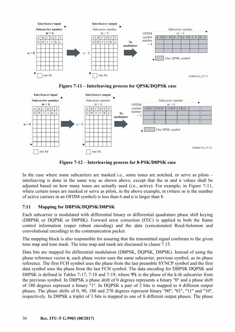
30 Rec. ITU-T G.9903 (08/2017)
G.9903(14)_F7-11
Subcarrier numberm = 6
Subcarrier numberm = 6
n = 8 n = 8
OFDMsymbolnumber
= 4
one bit one bit
Interleaver input Interleaver output
A A'G G'
B B'H H'
C C'I I'
D D'J J'
E E'K K'
F F'L L' To
modulator
A', B' C', D' E', F' G', H' I', J' K', L'
One QPSK symbol
Subcarrier numberm = 6
Figure 7-11 – Interleaving process for QPSK/DQPSK case
G.9903(14)_F7-12
Subcarrier numberm = 6
Subcarrier numberm = 6
n = 9 n = 9
OFDMsymbolnumber
= 3
one bit one bit
Interleaver input Interleaver output
A A'G G'
B B'H H'
C C'I I'
D D'J J'
E E'K K'
F F'L L' To
modulator
One 8PSK symbol
Subcarrier numberm = 6
A',B',C' D',E',F' G',H',I' J',K',L'
Figure 7-12 – Interleaving process for 8-PSK/D8PSK case
In the case where some subcarriers are masked i.e., some tones are notched, or serve as pilots – interleaving is done in the same way as shown above, except that the m and n values shall be adjusted based on how many tones are actually used (i.e., active). For example, in Figure 7-11, where certain tones are masked or serve as pilots, in the above example, m (where m is the number of active carriers in an OFDM symbol) is less than 6 and n is larger than 8.
7.11 Mapping for DBPSK/DQPSK/D8PSK Each subcarrier is modulated with differential binary or differential quadrature phase shift keying (DBPSK or DQPSK or D8PSK). Forward error correction (FEC) is applied to both the frame control information (super robust encoding) and the data (concatenated Reed-Solomon and convolutional encoding) in the communication packet. The mapping block is also responsible for assuring that the transmitted signal conforms to the given tone map and tone mask. The tone map and mask are discussed in clause 7.15. Data bits are mapped for differential modulation (DBPSK, DQPSK, D8PSK). Instead of using the phase reference vector φ, each phase vector uses the same subcarrier, previous symbol, as its phase reference. The first FCH symbol uses the phase from the last preamble SYNCP symbol and the first data symbol uses the phase from the last FCH symbol. The data encoding for DBPSK DQPSK and D8PSK is defined in Tables 7-17, 7-18 and 7-19, where Ψk is the phase of the k-th subcarrier from the previous symbol. In DBPSK a phase shift of 0 degrees represents a binary ''0'' and a phase shift of 180 degrees represent a binary ''1''. In DQPSK a pair of 2 bits is mapped to 4 different output phases. The phase shifts of 0, 90, 180 and 270 degrees represent binary ''00'', ''01'', ''11'' and ''10'', respectively. In D8PSK a triplet of 3 bits is mapped to one of 8 different output phases. The phase
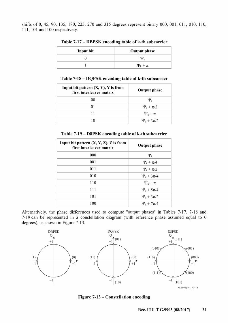
Rec. ITU-T G.9903 (08/2017) 31
shifts of 0, 45, 90, 135, 180, 225, 270 and 315 degrees represent binary 000, 001, 011, 010, 110, 111, 101 and 100 respectively.
Table 7-17 – DBPSK encoding table of k-th subcarrier
Input bit Output phase
0 Ψk 1 Ψk + π
Table 7-18 – DQPSK encoding table of k-th subcarrier
Input bit pattern (X, Y), Y is from first interleaver matrix Output phase
00 Ψk 01 Ψk + π/2 11 Ψk + π 10 Ψk + 3π/2
Table 7-19 – D8PSK encoding table of k-th subcarrier
Input bit pattern (X, Y, Z), Z is from first interleaver matrix Output phase
000 Ψk 001 Ψk + π/4 011 Ψk + π/2 010 Ψk + 3π/4 110 Ψk + π 111 Ψk + 5π/4 101 Ψk + 3π/2 100 Ψk + 7π/4
Alternatively, the phase differences used to compute ''output phases'' in Tables 7-17, 7-18 and 7-19 can be represented in a constellation diagram (with reference phase assumed equal to 0 degrees), as shown in Figure 7-13.
G.9903(14)_F7-13
DBPSK DQPSK D8PSKQ
(1) (0)
–1
+1
–1 +1
Q
(11) (00)
+1
–1 +1
(01)
(10)
Q
(110) (000)
+1
–1 +1
(011)
(101)
(010)
(111)
(001)
(100)
–1 –1
Figure 7-13 – Constellation encoding
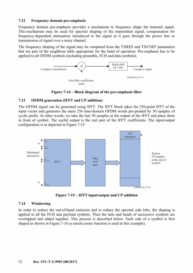
32 Rec. ITU-T G.9903 (08/2017)
7.12 Frequency domain pre-emphasis Frequency domain pre-emphasis provides a mechanism to frequency shape the transmit signal. This mechanism may be used for spectral shaping of the transmitted signal, compensation for frequency-dependent attenuation introduced to the signal as it goes through the power line or transmission of signal over a noisy channel. The frequency shaping of the signal may be computed from the TXRES and TXCOEF parameters that are part of the neighbour table appropriate for the band of operation. Pre-emphasis has to be applied to all OFDM symbols (including preamble, FCH and data symbols).
G.9903(14)_F7-14
×Complex constellation
Right shiftby 3 bits Complex output
4-bit filter coefficients(real)
Figure 7-14 – Block diagram of the pre-emphasis filter
7.13 OFDM generation (IFFT and CP addition) The OFDM signal can be generated using IFFT. The IFFT block takes the 256-point IFFT of the input vector and generates the main 256 time-domain OFDM words pre-pended by 30 samples of cyclic prefix. In other words, we take the last 30 samples at the output of the IFFT and place them in front of symbol. The useful output is the real part of the IFFT coefficients. The input/output configuration is as depicted in Figure 7-15.
G.9903(14)_F7-15
0
0
Repeat30 samplesat the end ofsymbol
C0
Modulatedsubcarriers
CPextension
IFFTTakerealpart
C46
C115
C511
Figure 7-15 – IFFT input/output and CP addition
7.14 Windowing In order to reduce the out-of-band emission and to reduce the spectral side lobe, the shaping is applied to all the FCH and payload symbols. Then the tails and heads of successive symbols are overlapped and added together. This process is described below. Each side of a symbol is first shaped as shown in Figure 7-16 (a raised cosine function is used in this example).

Rec. ITU-T G.9903 (08/2017) 33
G.9903(14)_F7-16
8 samples
(Tail)
Window function
Symbol (n–1)8 samples
(Head)
Raised cosine function
Figure 7-16 – Windowing using a raised cosine for the shaping function
The windowing function should have the sum of the overlapped head and tail samples equal to one. The window function has a value equal to one at all the remaining samples of the symbol. The 8 tail and 8 head shaped samples of the symbol from each side of the symbol are overlapped with the tail and head samples of adjacent symbols as shown in Figure 7-17.
G.9903(14)_F7-17
(n–1) symbolthHead Tail
Final symbol
Head Tail
Head Tail
n symbolth
(n+1) symbolth
(n+1) symbolth
Figure 7-17 – Overlap/add
In other words, to construct the n-th symbol, first its 8 head samples are overlapped with the 8 tail samples of the (n–1)-th symbol and its 8 tail samples are overlapped with the 8 head samples of the (n+1)-th symbol. Finally, the corresponding overlapped parts are added together. Note that the head of the first symbol is overlapped with the tail of the preamble. And the tail of the last symbol is sent out with no overlapping applied.
7.15 Tone masking and tone mapping The tone mask is a static PAN-wide parameter defined by macToneMask – see Table 9-15. Each bit set to one in the tone mask indicates that the associated tone will be used for the communication (less the significant bit representing the lowest frequency of the CENELEC or FCC bandplans). Thus, masked subcarriers are not assigned phase symbols and their amplitude is zero. The tone mask is applied to the preamble, FCH and payload. The tone map is an adaptive parameter that, based on channel estimation, contains a list of subcarriers that are to be used for communication between two ITU-T G.9903 devices. For example, the tone map contains information on which subcarriers shall not carry information, for example those subcarriers that suffer deep fades or very low SNR. The tone map shall apply only to the payload. In the case where the robust mode is used, all subcarriers are used to carry information (the tone map is all ones). ITU-T G.9903 devices shall estimate the SNR of the received signal subcarriers and adaptively select the usable tones, optimum modulation and code rate to ensure reliable communication over the power line channel. It shall also specify which power level the remote transmitter shall use and

34 Rec. ITU-T G.9903 (08/2017)
which gain values it should apply for various sections of the spectrum. The per-tone quality measurement enables the system to adaptively avoid transmitting data on subcarriers with poor quality. Using a tone map indexing system, where the index is passed from receiver to transmitter and vice versa, allows the receiver to adaptively select which group of subcarriers will be used for data transmission and which ones will be used to send dummy data that the receiver shall ignore. The goal of the adaptive tone mapping is to allow the ITU-T G.9903 receiver to achieve the greatest possible throughput given the channel conditions existing between them. In order to accomplish this goal, the receiver shall inform the remote transmitter which tones it should use to send data bits on and which tones it should use to send dummy data bits that the receiver shall ignore. The receiver shall also inform the remote transmitter how much amplification or attenuation it should apply to each of the tones. The source station's MAC layer may request a destination station to estimate a channel condition by setting the TMR bit of the MAC header as described in Table 9-5. The destination station has to estimate this particular communication link between two points and choose optimal PHY parameters. This information will be sent back to the originator as a tone map response. The parameters of the tone map response message are shown in Table 9-9. The number of tones after tone masking and tone mapping shall always be 6 or more.
7.15.1 PN modulating unused subcarriers For inactive tones (subcarriers that carry no information), the mapping function shall use binary values taken from a pseudo noise (PN) sequence. The number of required bit outputs of the PN sequence depends on the modulation types. For example, DBPSK, DQPSK and D8PSK require 1, 2 and 3 bit outputs from the PN sequence, respectively. The PN sequence shall be generated using the same generator polynomial introduced in clause 7.5. Based on Figure 7-18, the bits in the PN sequence generator shall all be initialized to ones at the start of the FCH and sequenced to the next value according to tone modulation and for every inactive, pilot, or masked carrier. For every m consecutive bits output by the LFSR for a single constellation symbol of size 2m, the first bit shall be mapped to the LSB and the last bit shall be mapped to the MSB of the constellation symbol, respectively.
+
G.9903(14)_F7-18
X7 X6 X5 X4 X3 X2 X1
Figure 7-18 – PN sequence generator using linear feedback shift register (LFSR)
7.16 Coherent modulation scheme For CENELEC bands, ITU-T G.9903 devices operate using a differential modulation scheme for FCH and payload. However, the device may support a coherent modulation scheme for the payload. If requested by the tone map response received from a neighbour node, a coherent modulation scheme shall be used with this neighbour (if supported). Otherwise, the differential modulation scheme shall be used. For an FCC band, the FCH is coded using super robust mode with BPSK modulation. This clause describes the operation of ITU-T G.9903 devices when operating in the optional coherent scheme. This clause only describes the portions of the standard that are different from the
Rec. ITU-T G.9903 (08/2017) 35
main differential scheme. Portions of the coherent transmitter that are not described here shall operate exactly as described in the differential scheme.
7.16.1 Frame structure – Coherent modulation scheme In a similar way to differential mode, the coherent mode shall support two types of frames: data frames and ACK/NACK frames. The frame structure of data frames shall be identical to the one used in differential mode except for two changes: a) The data portion of the PHY frame shall be preceded by an S1 symbol followed by an
S2 symbol, where both symbols shall be inserted between the last FCH symbol and the first data symbol. The S2 symbol shall have the same phase reference vector used in differential mode for a SYNCP symbol. The only difference from a SYNCP symbol is that the S2 symbol consists of a SYNCP symbol plus a cyclic prefix of 30 samples and an overlap of 8 samples, resulting in 278 samples when an IFFT size of 256 is used. Hence, the duration of the S2 symbol shall be the same as for that of an FCH symbol or a data symbol. The S1 symbol shall be an inverted S2 symbol (i.e., –S2), hence it will also consist of 278 samples.
b) Pilot tones shall be inserted in the data symbols as described in clause 7.16.10 on pilot tones.
The frame structure of the ACK/NACK frames for coherent mode shall be identical to the one used in differential mode.
7.16.2 Preamble – Coherent modulation scheme The preamble for the coherent scheme is composed of 8 or (8+4=12) identical SYNCP symbols followed by a SYNCM symbol that is followed by a half SYNCM symbol. The SYNCP and SYNCM symbols for the coherent scheme are identical to the ones generated in the differential scheme. The initial phases used for both schemes are shown in Table 7-11. All coherent mode preamble symbols (SYNCP, SYNCM and the additional symbols between the last FCH symbol and the first data symbol) shall have the same gain factor compared to data symbols and their gain is defined to be 3 dB, the same as in the differential mode – see clause 7.5.
7.16.3 Frame control header – Coherent modulation scheme The thirteen (CENELEC bandplans) or twelve (FCC bandplan) symbols following immediately after the preamble constitute the frame control header (FCH). The FCH has the same structure in both differential and coherent modulation schemes. The "Payload Modulation Scheme" bit in the FCH for data frames shall be used to indicate whether the payload is modulated coherently or not.
7.16.4 CRC – Coherent modulation scheme The CRC used in coherent mode shall be identical to the one used in differential mode.
7.16.5 Data scrambler – Coherent modulation scheme The data scrambler used in coherent mode shall be identical to the one used in differential mode.
7.16.6 FEC coding – Coherent modulation scheme The FEC encoder for coherent mode shall be identical to the one used for differential mode.
7.16.7 Payload padding – Coherent modulation scheme The payload padding for coherent mode shall be identical to the one used for differential mode.
7.16.8 Interleaver – Coherent modulation scheme The interleaver for coherent mode shall be identical to the interleaver in differential mode where the pilot tones shall not be considered part of the active tones and hence shall be completely ignored by
36 Rec. ITU-T G.9903 (08/2017)
the interleaver. This means that the number of subcarriers 'm' shall not include in it the pilot tones (nor the masked tones as is the case for differential mode).
7.16.9 Coherent mapping for BPSK, QPSK, 8-PSK, 16-QAM and robust modes – Coherent modulation scheme
The mapping block is responsible for assuring that the transmitted signal conforms to the given tone map and tone mask. The tone map and tone mask are discussed in clause 7.15. The tone mask is a predefined (static) system-wide parameter defining the start, stop and notch frequencies. The tone map is an adaptive parameter that, based on channel estimation, contains a list of carriers that are to be used for a particular communication between two modems. Data bits are mapped for coherent modulation (BPSK, QPSK, 8-PSK, 16-QAM or robust) as follows: For a given symbol, instead of using the same carrier, the previous symbol as its phase reference, it uses the preamble phase of the same carrier as its reference. This predefined phase reference is identical to the one that is specified for differential modulation as shown in Table 7-11. Both the FCH symbols and data symbols use the same phase reference vector.
7.16.9.1 Mapping for BPSK and robust mode – Coherent modulation scheme In BPSK (and robust) modulation a phase shift of 0° represents a binary ''0'' and a phase shift of 180° represents a binary ''1'' as illustrated in Table 7-20.
Table 7-20 – BPSK and robust encoding table of k-th subcarrier
Input bit Output phase
0 Ψk 1 Ψk + π
The constellation shall be identical to the one used for differential mode.
7.16.9.2 Mapping for QPSK modulation – Coherent modulation scheme In QPSK a pair of 2 bits is mapped to 4 different output phases. The phase shifts of 0°, 90°, 180° and 270° represent binary ''00'', ''01'', ''11'' and ''10'' respectively, as illustrated in Table 7-21.
Table 7-21 – QPSK encoding table of k-th subcarrier
Input bit pattern (X, Y), Y leaves interleaver first Output phase
00 Ψk 01 Ψk + π/2 11 Ψk + π 10 Ψk + 3π/2
The constellation shall be identical to the one used for differential mode.
7.16.9.3 Mapping for 8-PSK modulation – Coherent modulation scheme In 8-PSK a triplet of 3 bits is mapped to one of 8 different output phases. The phase shifts of 0°, 45°, 90°, 135°, 180°, 225°, 270° and 315° represent binary 000, 001, 011, 010, 110, 111, 101 and 100 respectively, as illustrated in Table 7-22.
Rec. ITU-T G.9903 (08/2017) 37
Table 7-22 – 8-PSK encoding table of k-th subcarrier
Input bit pattern (X, Y, Z), Z leaves interleaver first Output phase
000 Ψk 001 Ψk + π/4 011 Ψk + π/2 010 Ψk + 3π/4 110 Ψk + π 111 Ψk + 5π/4 101 Ψk + 3π/2 100 Ψk + 7π/4
The constellation shall be identical to the one used for differential mode.
7.16.9.4 Mapping for 16-QAM modulation (applies only to FCC bandplan) – Coherent modulation scheme
The 16-QAM modulation is optional. In 16-QAM modulation, 4 bits are mapped to one of sixteen different constellation points. The mapping is shown in Figure 7-19 and Table 7-23.
G.9903(14)_F7-19
I
Q
0101
1101
0111
1111
+1 +3
+3
+1
Figure 7-19 – 16-QAM constellation diagram
The complete constellation description is given in Table 7-23.
Table 7-23 – Mapping for 16-QAM
Bits [d1d0] I
Bit [d3d2] Q
00 −3 00 −3 10 −1 10 −1 11 1 11 1 01 3 01 3
The resulting outputs values ''d'' are formed by multiplying the resulting (I+jQ) value by a normalization factor equal to 1 (10)⁄ :
= ( + ) × ( )
38 Rec. ITU-T G.9903 (08/2017)
The purpose of the normalization factor is to achieve the same average power for all mappings.
7.16.10 Pilot tones – Coherent modulation scheme Pilot tones can be used in coherent mode to help with clock recovery and channel estimation, particularly in harsh environments where strong noise and frequent channel variations occur. Pilot tones shall only be inserted in data symbols and shall not be inserted in FCH symbols. For pilot tone assignment, the pilot indices shall be sequentially enumerated over only the active subcarrier set: P(i,j) = (OFFSET + (FreqSpacing × i) + 2 × j)%MACTIVE (7-1) Where: – P(i,j) is the relative position of pilot i in symbol j within the set of active subcarriers.
The set of active subcarriers is enumerated as 0, 1, 2….., MACTIVE-1 – M is the number of subcarriers per symbol in a given band (M=36 for CENELEC A;
M=16 for CENELEC B; M=72 for FCC) – MACTIVE is the number of subcarriers in the bandplan that are not masked nor inactive
(MACTIVE ≤ M) – FreqSpacing = Frequency spacing between pilots within the same symbol expressed in
multiples of the subcarrier spacing (12 for CENELEC A; 8 for CENELEC B; 12 for FCC band)
– i = pilot index = 0,1,2,…,ceil(MACTIVE /FreqSpacing)-1 – j = symbol number = 0,1,2,3,…, N-1 – N = total number of data symbols per frame. – OFFSET (6 for CENELEC A and CENELEC B; 36 for FCC). The absolute pilot tone index with respect to FFT numbering is given by: Pabs(i,j) = STARTINDEX+ QACTIVE (P(i,j)) (7-2) Where: – Q = [0, 1, 2,..., M-1] is a vector of the relative indices of the subcarriers of a given band.
Length(Q) = M – QACTIVE is a vector of the relative indices of the active subcarriers of the given band.
QACTIVE is derived from Q by excluding inactive and masked subcarriers. Length(QACTIVE) = MACTIVE
– STARTINDEX is the absolute index with respect to FFT numbering of the first subcarrier in the bandplan (23 for CENELEC A; 63 for CENELEC B; 33 for FCC).
The pilot tones shall consist of sine waves at the specified tone frequencies modulated in QPSK using the constellation specified in clause 7.16.9.2. The bits that get mapped to the constellation points shall be generated following the PN sequence generation procedure described in clause 7.15.1. The pilot tones' indexes shall be ordered first in ascending order, and then each pilot tone shall be modulated with the output of the PN sequence generator. For every two consecutive output bits for pilot tones from the PN sequence generator, the first bit shall be mapped to the LSB of the QPSK symbol and the second bit shall be mapped to the MSB of the QPSK symbol.
Rec. ITU-T G.9903 (08/2017) 39
+
+
G.9903(14)_F7-20
Data in
Scrambleddata out
X7 X6 X5 X4 X3 X2 X1
Figure 7-20 – LFSR used to generate the data bits that are used to modulate the pilot tones
7.16.10.1 Example of pilot tone assignment Below is an example of the application of Equations (7-1) and (7-2). With the CENELEC A bandplan we have the following initial parameters: M = 36; FreqSpacing = 12; OFFSET = 6; STARTINDEX = 23; If neither masked nor inactive (ToneMap equal to 0x3F) subcarriers are present, the derived parameters are: MACTIVE = M = 36; i = [0:2] = [0 1 2] Q = [0:M] = [0:35] = [0 1 2 3 4 … 34 35]; QACTIVE = Q = [0:35]; Length(QACTIVE) = MACTIVE = 36 Given N = 10 OFDM symbols, pilot tones are allocated as follows: j = [0:9] = [0 1 2 3 4 … 8 9] P(i,j) = 6 8 10 12 14 16 18 20 22 24 18 20 22 24 26 28 30 32 34 0 30 32 34 0 2 4 6 8 10 12 Pabs (i,j) = 29 31 33 35 37 39 41 43 45 47 41 43 45 47 49 51 53 55 57 23 53 55 57 23 25 27 29 31 33 35
7.16.11 Frequency domain pre-emphasis – Coherent modulation scheme For further study.
7.16.12 OFDM generation (IFFT and CP addition) – Coherent modulation scheme OFDM generation for coherent mode shall be identical to the procedure used for differential mode.
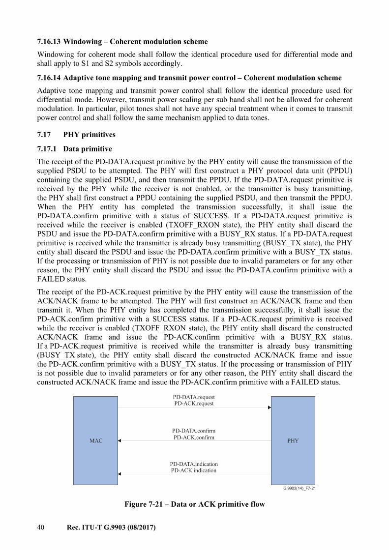
40 Rec. ITU-T G.9903 (08/2017)
7.16.13 Windowing – Coherent modulation scheme Windowing for coherent mode shall follow the identical procedure used for differential mode and shall apply to S1 and S2 symbols accordingly.
7.16.14 Adaptive tone mapping and transmit power control – Coherent modulation scheme Adaptive tone mapping and transmit power control shall follow the identical procedure used for differential mode. However, transmit power scaling per sub band shall not be allowed for coherent modulation. In particular, pilot tones shall not have any special treatment when it comes to transmit power control and shall follow the same mechanism applied to data tones.
7.17 PHY primitives
7.17.1 Data primitive The receipt of the PD-DATA.request primitive by the PHY entity will cause the transmission of the supplied PSDU to be attempted. The PHY will first construct a PHY protocol data unit (PPDU) containing the supplied PSDU, and then transmit the PPDU. If the PD-DATA.request primitive is received by the PHY while the receiver is not enabled, or the transmitter is busy transmitting, the PHY shall first construct a PPDU containing the supplied PSDU, and then transmit the PPDU. When the PHY entity has completed the transmission successfully, it shall issue the PD-DATA.confirm primitive with a status of SUCCESS. If a PD-DATA.request primitive is received while the receiver is enabled (TXOFF_RXON state), the PHY entity shall discard the PSDU and issue the PD-DATA.confirm primitive with a BUSY_RX status. If a PD-DATA.request primitive is received while the transmitter is already busy transmitting (BUSY_TX state), the PHY entity shall discard the PSDU and issue the PD-DATA.confirm primitive with a BUSY_TX status. If the processing or transmission of PHY is not possible due to invalid parameters or for any other reason, the PHY entity shall discard the PSDU and issue the PD-DATA.confirm primitive with a FAILED status. The receipt of the PD-ACK.request primitive by the PHY entity will cause the transmission of the ACK/NACK frame to be attempted. The PHY will first construct an ACK/NACK frame and then transmit it. When the PHY entity has completed the transmission successfully, it shall issue the PD-ACK.confirm primitive with a SUCCESS status. If a PD-ACK.request primitive is received while the receiver is enabled (TXOFF_RXON state), the PHY entity shall discard the constructed ACK/NACK frame and issue the PD-ACK.confirm primitive with a BUSY_RX status. If a PD-ACK.request primitive is received while the transmitter is already busy transmitting (BUSY_TX state), the PHY entity shall discard the constructed ACK/NACK frame and issue the PD-ACK.confirm primitive with a BUSY_TX status. If the processing or transmission of PHY is not possible due to invalid parameters or for any other reason, the PHY entity shall discard the constructed ACK/NACK frame and issue the PD-ACK.confirm primitive with a FAILED status.
PD-DATA.requestPD-ACK.request
PD-DATA.confirmPD-ACK.confirm
PD-DATA.indicationPD-ACK.indication
MAC PHY
G.9903(14)_F7-21
Figure 7-21 – Data or ACK primitive flow
Rec. ITU-T G.9903 (08/2017) 41
7.17.1.1 PD-DATA.request The PD-DATA.request primitive is generated by a local MAC sublayer entity and issued to its PHY entity to request the transmission of an MPDU. The semantics of the PD-DATA.request primitive is as follows: PD-DATA.request ( psduLength psdu ) Table 7-24 specifies the parameters for the PD-DATA.request primitive.
Table 7-24 – The parameters for the PD-DATA.request primitive
Name Type Valid range Description
psduLength Integer 0x00-0xEF for CENELEC bandplans 0x00-0x1EE for FCC bandplan
The number of bytes contained in the PSDU to be transmitted by the PHY entity. The effective maximum PSDU length can be derived as described in clause 7.3.2.
Psdu Integer Array Any The set of bytes forming the PSDU request to be transmitted by the PHY entity.
The PHY should start the transmission no later than 0.1×aSlotTime after the PD-DATA.request is issued by the MAC. The aSlotTime is defined in Table 9-14.
7.17.1.2 PD-DATA.confirm The PD-DATA.confirm primitive confirms the end of the transmission of an MPDU (i.e., PSDU) from a local PHY entity to a peer PHY entity. The semantics of the PD-DATA.confirm primitive is as follows: PD-DATA.confirm ( status ) Table 7-25 specifies the parameters for the PD-DATA.confirm primitive.
Table 7-25 – The parameters for the PD-DATA.confirm primitive
Name Type Valid range Description
Status Enumeration SUCCESS, BUSY_RX, BUSY_TX, FAILED
The result of the request to transmit a packet
7.17.1.3 PD-DATA.indication The PD-DATA.indication primitive indicates the transfer of an MPDU (i.e., PSDU) from the PHY to the local MAC sublayer entity. The semantics of the PD-DATA.indication primitive is as follows: PD-DATA.indication ( psduLength, psdu,
42 Rec. ITU-T G.9903 (08/2017)
ppduLinkQuality CarrierSNR, PhaseDifferential, PayloadModulationType, PayloadModulationScheme ToneMap, DT ) Table 7-26 specifies the parameters for the PD-DATA.indication primitive.
Table 7-26 – The parameters for the PD-DATA.indication primitive
Name Type Valid range Description
psduLength Integer 0x00-0xEF for CENELEC bandplans 0x00-0x1EE for FCC bandplan
The number of bytes contained in the PSDU received by the PHY entity
Psdu Integer – The set of bytes forming the PSDU received by the PHY entity
ppduLinkQuality Integer 0x00-0xFF Link quality (forward LQI) value measured during reception of the PPDU
CarrierSNR Array 0x00-0x3F The PHY provides the SNR value per each carrier of the last received frame (see clause 7.17.2.4).
PhaseDifferential Integer 0x00-0x05 The PHY computes and provides the phase difference in multiples of 60 degrees to the MAC layer of the last received frame. 0: local node and neighbour node are in phase 1: local node leads neighbour node by 60 degrees 2: local node leads neighbour node by 120 degrees 3: neighbour node and local node are in phase opposition 4: neighbour node leads local node by 120 degrees 5: neighbour node leads local node by 60 degrees
PayloadModulationType
Integer 0x00-0x04 The modulation type used in the last received frame. 0: Robust mode 1: DBPSK or BPSK 2: DQPSK or QPSK 3: D8PSK or 8-PSK 4: 16-QAM

Rec. ITU-T G.9903 (08/2017) 43
Table 7-26 – The parameters for the PD-DATA.indication primitive
Name Type Valid range Description NOTE – The 16-QAM modulation is optional and may be used in an FCC bandplan only when the coherent modulation scheme applies.
PayloadModulationScheme
Integer 0x00-0x01 The payload modulation scheme used in the last received frame. 0: Differential 1: Coherent
ToneMap Array 0x00-0x01 Tone map parameter used in the last received frame. The value of 0 indicates to the remote transmitter that dummy data should be transmitted on the corresponding subcarrier while a value of 1 indicates that valid data should be transmitted on the corresponding subcarrier.
DT Integer 0x00-0x07 Delimiter type used in the last received frame. 0: Acknowledgment is not requested 1: Acknowledgment is requested 2-7: Reserved by ITU-T
The forward LQI shall be measured for each received packet and is a characterization of the quality of the underlying power line channel. The LQI is an integer ranging from 0x00 to 0xFF and LQI values in-between shall be uniformly distributed between these two limits. The LQI value is derived from the average SNR (where averaging is done over all active tones and pilot tones, if present, in the bandplan and over all OFDM symbols in the received packet) where the SNR-to-LQI mapping is: – SNR ≤ –10 dB maps to LQI 0x00 – SNR ≥ 53.75 dB maps to LQI 0xFF – −10 < SNR < 53.75 dB is linearly interpolated between 0x00 and 0xFF (the nominal step
size is 0.25 dB). Active tones are defined as tones which carry data (pilot tones and dummy bit tones are not included). The forward LQI value is computed in the PHY and passed to the MAC with the PD-DATA.indication primitive through the ppduLinkQuality parameter – see Table 7-26. The LQI shall be measured and reported and it may be used to determine the transmission parameters, such as modulation modes.
7.17.1.4 PD-ACK.request The PD-ACK.request primitive requests to send an ACK frame to the PHY from the local MAC sublayer entity. The semantics of the PD-ACK.request primitive is as follows: PD-ACK.request ( FCH )
44 Rec. ITU-T G.9903 (08/2017)
Table 7-27 specifies the parameter for the PD-ACK.request primitive.
Table 7-27 – The parameters for the PD-ACK.request primitive
Name Type Valid range Description
FCH Structure Clause 7.6 PHY The MAC layer provides all frame control header parameters described in clause 7.6 to construct FCH frame for ACK.
7.17.1.5 PD-ACK.confirm The PD-ACK.confirm confirms the end of the transmission of an ACK packet. The semantics of the PD-ACK.confirm primitive is as follows: PD-ACK.confirm ( Status ) Table 7-28 specifies the parameter for the PD-ACK.confirm primitive.
Table 7-28 – The parameters for the PD-ACK.confirm primitive
Name Type Valid range Description
Status Enumeration SUCCESS BUSY_RX, BUSY_TX, FAILED
Confirm transmission of ACK frame
7.17.1.6 PD-ACK.indication The PD-ACK.indication primitive indicates reception of the ACK frame from the PHY to the local MAC sublayer entity. The semantics of the PD-ACK.indication primitive is as follows: PD-DATA.indication ( FCH ) Table 7-29 specifies the parameter for the PD-ACK.indication primitive.
Table 7-29 – The parameters for the PD-ACK.indication primitive
Name Type Valid range Description
FCH Structure Clause 7.6 PHY The MAC layer receives all frame control header parameters described in clause 7.6 from PHY layer.
7.17.2 Management primitives There are two types of management primitives: Get and Set. They are used to initiate commands or retrieve data from the PHY. The PLME_SET.request and PLME_SET.confirm primitives allow configuration of the PHY. The PLME_GET.request and PLME_GET.confirm primitives allow the retrieval of specific parameters from the PHY.

Rec. ITU-T G.9903 (08/2017) 45
MAC PHY
G.9903(14)_F7-22
PLME_SET.request
PLME_GET.request
PLME_SET.confirm
PLME_GET.confirm
Figure 7-22 – Management primitive flow
7.17.2.1 PLME_SET.request The semantics of the PLME_SET.request primitive is as follows: PLME_SET.request ( TXPower PayloadModulationType PayloadModulationScheme ToneMap PreEmphasis ToneMask DT ) Table 7-30 specifies the parameters for the PLME_SET.request primitive.
Table 7-30 – The parameters for the PLME_SET.request primitive
Name Type Valid range Description
TXPower Integer 0x00-0x20 The MAC layer uses this primitive to notify the PHY about the gain/power setting PHY has to use to transmit the next packet.
PayloadModulationType
Integer 0x0-0x4 This sets the transmitter modulation for the next frame: 0: Robust mode 1: DBPSK or BPSK 2: DQPSK or QPSK 3: D8PSK or 8-PSK 4: 16-QAM Note – The 16-QAM modulation is optional and may be used only in an FCC bandplan when a coherent modulation scheme applies.
PayloadModulationScheme
Integer 0x0–0x1 Defines whether the differential or optional coherent modulation scheme shall be used for the payload.
46 Rec. ITU-T G.9903 (08/2017)
Table 7-30 – The parameters for the PLME_SET.request primitive
Name Type Valid range Description 0: Differential 1: Coherent
ToneMap Array 0x0-0x1 Tone map parameter The value of 0 indicates to the remote transmitter that dummy data should be transmitted on the corresponding subcarrier while a value of 1 indicates that valid data should be transmitted on the corresponding subcarrier.
PreEmphasis Array 0x00-0x1F Specify transmit gain for each sub-band represented by tone map.
ToneMask Array 0x0-0x1 Tone mask parameter. The value of 0 indicates tone is notched, 1 indicates that tone is enabled.
DT Integer 0x00-0x07 Delimiter type as specified in Table 7-12.
7.17.2.2 PLME_SET.confirm The PHY stores new parameters and returns a new stored value back to the MAC layer. The semantics of the PLME_SET.confirm primitive is as follows: PLME_SET.confirm ( TXPower PayloadModulationType PayloadModulationScheme ToneMap PreEmphasis ToneMask DT ) Table 7-31 specifies the parameters for the PLME_SET.confirm primitive.
Table 7-31 – The parameters for the PLME_SET.confirm primitive
Name Type Valid range Description
TXPower Integer 0x00-0x20 Returns new stored value back to MAC PayloadModulationType
Integer 0x0-0x04 Returns new stored value back to MAC: 0: Robust mode 1: DBPSK or BPSK 2: DQPSK or QPSK 3: D8PSK or 8-PSK 4: 16-QAM Note – The 16-QAM modulation is optional and may be used in FCC bandplan only when coherent modulation scheme applies.
Rec. ITU-T G.9903 (08/2017) 47
Table 7-31 – The parameters for the PLME_SET.confirm primitive
Name Type Valid range Description
PayloadModulationScheme
Integer 0x0-0x1 Defines whether the differential or optional coherent modulation schemes shall be used for the payload. 0: Differential 1: Coherent
ToneMap Array 0x0-0x1 Returns new stored value back to MAC PreEmphasis Array 0x00-0x1F Returns new stored value back to MAC ToneMask Array 0x0-0x1 Returns new stored value back to MAC DT Integer 0x00-0x07 Delimiter type as specified in Table 7-12
7.17.2.3 PLME_GET.request The PLME_GET.request primitive requests the PHY to get the parameters described in Table 7-32. The semantics of the PLME_GET.request primitive is as follows: PLME_GET.request ( )
7.17.2.4 PLME_GET.confirm The semantics of the PLME_GET.confirm primitive is as follows: PLME_GET.confirm ( CarrierSNR, PhaseDifferential, PayloadModulationType, PayloadModulationScheme ToneMap, DT ) Table 7-32 specifies the parameters for the PLME_GET.confirm primitive.
48 Rec. ITU-T G.9903 (08/2017)
Table 7-32 – The parameters for the PLME_GET.confirm primitive
Name Type Valid range Description
CarrierSNR Array 0x00-0x3F The PHY provides the SNR value per each carrier of the last received frame.
PhaseDifferential Integer 0x00-0x05 The PHY computes and provides the phase difference in multiples of 60 degrees to the MAC layer of the last received frame. 0: local node and neighbour node are in phase 1: local node leads neighbour node by 60 degrees 2: local node leads neighbour node by 120 degrees 3: neighbour node and local node are in phase opposition 4: neighbour node leads local node by 120 degrees 5: neighbour node leads local node by 60 degrees
PayloadModulationType
Integer 0x00-0x04 The modulation type used in the last received frame. 0 : Robust mode 1 : DBPSK or BPSK 2 : DQPSK or QPSK 3 : D8PSK or 8-PSK 4 : 16-QAM NOTE – The 16-QAM modulation is optional and may be used in an FCC bandplan only when the coherent modulation scheme applies.
PayloadModulationScheme
Integer 0x00-0x01 The payload modulation scheme used in the last received frame. 0 : Differential 1 : Coherent
ToneMap Array 0x00-0x01 Tone map parameter used in the last received frame. The value of 0 indicates to the remote transmitter that dummy data should be transmitted on the corresponding subcarrier while a value of 1 indicates that valid data should be transmitted on the corresponding subcarrier.
DT Integer 0x00-0x07 Delimiter type used in the last received frame. 0: Acknowledgment is not requested 1: Acknowledgment is requested 2-7: Reserved by ITU-T
CarrierSNR is an array of integers ranging from 0x00 to 0x3F, where values in-between shall be uniformly distributed between these two limits. The CarrierSNR values are normalized to the range from −10 dB or lower (0x00) to 53 dB or higher (0x3F), where the value of −9 dB is represented as 0x01 and the value of 52 dB is represented as 0x3E.

Rec. ITU-T G.9903 (08/2017) 49
7.17.2.5 PLME_SET_TRX_STATE.request The PLME_SET_TRX_STATE.request primitive requests the PHY to change the state. The semantics of the PLME_SET_TRX_STATE.request primitive is as follows: PLME_SET_TRX_STATE.request ( State ) Table 7-33 specifies the parameters for the PLME_SET_TRX_STATE.request primitive.
Table 7-33 – The parameters for the PLME_SET_TRX_STATE.request primitive
Name Type Valid range Description
State Enumeration TXON_RXOFF TXOFF_RXON
Turns off the RX PHY when transmitting packet. Turns off the transmitter and enable RX when PHY is not transmitting.
7.17.2.6 PLME_SET_TRX_STATE.confirm The PLME_SET_TRX_STATE.confirm primitive confirms the changing PHY state. The semantics of the PLME_SET_TRX_STATE.confirm primitive is as follows: PLME_SET_TRX_STATE.confirm ( Status ) Table 7-34 specifies the parameters for PLME_SET_TRX_STATE.confirm primitive.
Table 7-34 – The parameters for the PLME_SET_TRX_STATE.confirm primitive
Name Type Valid range Description
Status Enumeration SUCCESS BUSY_TX BUSY_RX
Confirm RX and TX are set or provide error message if TX or RX are busy.
7.17.2.7 PLME_CS.request The PLME_CS.request primitive requests the PHY to get media status using carrier sense. The semantics of the PLME_CS.request primitive is as follows: PLME_CS.request ( )
7.17.2.8 PLME_CS.confirm The PLME_CS.confirm primitive reports media status. The semantics of the PLME_CS.confirm primitive is as follows: PLME_CS.confirm ( Status ) Table 7-35 specifies the parameters for the PLME_CS.confirm primitive.
50 Rec. ITU-T G.9903 (08/2017)
Table 7-35 – The parameters for the PLME_CS.confirm primitive
Name Type Valid range Description
Status Enumeration IDLE BUSY
Power line media status
A physical carrier sense (PCS) shall be provided by the PHY upon detection of aSlotTime preamble symbols. The PCS shall go back to idle if synchronisation has not been achieved. The status of the media is tracked by the virtual carrier sense (VCS), see clause 9.3.1 for more details.
8 Transmitter specifications
8.1 Output level measurement See the main body of [ITU-T G.9901].
8.2 Transmit spectrum mask See clause B.3 of [ITU-T G.9901].
8.3 Transmitter attenuation ITU-T G.9903 nodes shall operate with an output level determined by the value of attribute macTransmitAtten (see Table 9-15). A node shall apply to its maximum output level the attenuation level stored in attribute macTransmitAtten, allowing a reduction of its maximum output level of up to 25 dB. This attenuation is calibrated when measuring the output level using the standard Termination Networks TN1 or TN2 as specified in clause 6 of [ITU-T G.9901]. When macTransmitAtten is greater than 0, no transmitter gain shall be applied to the transmitted signal (TX GAIN shall still be stored in the neighbour table but it shall be ignored).
8.4 Spurious transmission See clause B.3.1 of [ITU-T G.9901].
8.5 System clock frequency tolerance The system clock tolerance shall be ±25 ppm maximum. The transmit frequency and symbol timing shall be derived from the same system clock oscillator.
8.6 Transmitter constellation
8.6.1 Transmitter constellation error The relative constellation rms error, averaged over all subcarriers in a symbol, and averaged over several OFDM symbols, shall not exceed –15 dB from the ideal signal rms level.
8.6.2 Transmit modulation accuracy test The transmit modulation accuracy test shall be performed by instrumentation capable of converting the transmitted signal into a stream of samples at 400 K samples per second or more, with sufficient accuracy in terms of amplitude, DC offsets and phase noise. The sampled signal shall be processed in a manner similar to an actual receiver, according to the following steps, or an equivalent procedure: 1) Pass a sequence of 37 bytes all-ones, representing a 12-symbol QPSK frame, through an
ideal floating-point transmitter and save the complex input to the IFFT block for each of the 12 data symbols as cij
ci eA ,,
Φ , where cijci eA ,
,Φ is the reference constellation point
corresponding to the -th OFDM symbol carried over the c-th subcarrier. Index 'i' shall have

Rec. ITU-T G.9903 (08/2017) 51
values between 0 and 11 while index 'c' shall be between 0 and M-1 (M is the number of subcarriers in a given bandplan). The ideal transmitter should include all the transmitter blocks specified in this Recommendation, including scrambler, forward error correction, interleaver and mapper.
2) Next, use the transmitter under test to generate the same frame using the bits specified in step 1.
3) Connect the test equipment that will simulate the receiver directly to the transmitter to detect the start of frame.
4) Save all time samples of the 12 OFDM symbols of the frame. 5) Offline, apply a floating point FFT on each OFDM symbol and store the complex values as
cijci eB ,
,Θ where 'i' is the OFDM symbol number and 'c' is the carrier number
corresponding to that symbol. cijci eB ,
,Θ represents the actually transmitted constellation
point and, ideally, cici jci
jci eBeA ,,
,,ΘΦ = .
6) Compute the mean square error (MSE) between the ideal constellation points and the actually transmitted ones obtained at the end of step 5 for each symbol as the sum of the squared Euclidean distance between the two points over all the subcarriers in the symbol. The MSE of the i-th symbol is defined as:
−
=
ΘΦ −=1
0
2
,,,,1 M
c
jci
jcii
cici eBeAM
MSE where M is the number of subcarriers per symbol in a given band (M=36 for CENELEC A;
M=24 for CENELEC B; M= 72 for FCC). 7) Next, compute the total MSE as the sum of the MSEs of the each OFDM symbols:
=
=11
0_
iiMSEMSETotal
8) Compute the average energy of the reference constellation points carried by the i-th OFDM symbol:
−
=
=1
0
2,
)( 1Avg_EnM
cci
refi A
M and the total average energy for all transmitted OFDM symbols as:
=
=11
0
)( Avg_EnTot_Eni
(ref)i
ref The normalized total MSE in dB should satisfy the following equation:
dB 15_
_log10 )(10 −<
refEnTot
MSETotal 8.6.3 Error vector magnitude limits For the EVM calculation, the calculation given in clause 8.6.2 can be re-used here. For the preamble EVM calculation, the total average energy is calculated over six symbols starting from the third symbol:
52 Rec. ITU-T G.9903 (08/2017)
a) =
=7
2
)( Avg_EnTot_Eni
(ref)i
ref b)
==
7
2_
iiMSEMSETotal
The values of EVM calculated for both data and preamble symbols shall not exceed the values given in Table 8-1.
Table 8-1 – Maximum allowed EVM values
Modulation EVM, dB (Note)
1, 2, 3 bits −15 4 bits −19
NOTE – These EVM requirements shall be met for all carriers which have equal transmit power levels; however, for 3 and 4 bit modulations, the transmit power levels under which these requirements are met may be lower than those for 1 and 2 bit modulation.
8.7 Transmitter spectral flatness The output signal voltage, when measured using a peak detector with a 200 Hz bandwidth and loaded on an artificial mains network (AMN), shall not exceed 5dB between the highest and the lowest peaks measured at the frequency of the subcarriers. When measuring the transmitter spectral flatness, no transmitter gain shall be applied to the transmitted signal (TXGAIN and TXCOEF shall be set to zero) and the AMN shall comply with clauses 4.3 and 4.4 of [CISPR16-1-2], as specified in clauses 6 and 7.1 of [ITU-T G.9901].
8.8 Crossing MV/LV transformer ITU-T G.9903 devices operate over both low-voltage and medium-voltage power lines. When operating over a medium-voltage power line an ITU-T G.9903 device can communicate with ITU-T G.9903 devices operating over low-voltage power lines. This means that the receiver on the LV side can detect the transmitted signal after it has been severely attenuated as a result of going through an MV/LV transformer. As the signal goes through the transformer, it is expected to experience overall severe attenuation in its power level as well as frequency-dependent attenuation. Both the transmitter and receiver have mechanisms to compensate for this attenuation. The transmitter can adjust its overall signal level as well as shape its power spectrum, while the receiver has an automatic gain control in order to achieve enough gain to compensate for the overall attenuation. An ITU-T G.9903 node, in addition to being able to operate in normal mode, can operate as a repeater. When configured in ''repeater'' mode, the ITU-T G.9903 node can decode received frames and then retransmit them at a higher signal level in order to partially compensate for the attenuation introduced by the transformer. The repeater, when needed, can be placed on the LV side of the MV/LV transformer.
8.9 MV coupler (informative) ITU-T G.9903 devices interface with the MV power line through a PLC coupling device, which is basically a high-pass filter whose purpose is to permit the PLC signal to pass, but to reject the power system frequency and protect the communications equipment from the power system voltage and transient voltages caused by switching operations.
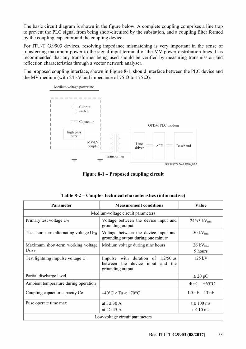
Rec. ITU-T G.9903 (08/2017) 53
The basic circuit diagram is shown in the figure below. A complete coupling comprises a line trap to prevent the PLC signal from being short-circuited by the substation, and a coupling filter formed by the coupling capacitor and the coupling device. For ITU-T G.9903 devices, resolving impedance mismatching is very important in the sense of transferring maximum power to the signal input terminal of the MV power distribution lines. It is recommended that any transformer being used should be verified by measuring transmission and reflection characteristics through a vector network analyser. The proposed coupling interface, shown in Figure 8-1, should interface between the PLC device and the MV medium (with 24 kV and impedance of 75 Ω to 175 Ω).
G.9903(12)-Amd.1(13)_F8-1
high passfilter
MV/LVcoupler AFE Baseband
Medium voltage powerline
Capacitor
Transformer
OFDM PLC modem
Cut outswitch
Linedriver
Figure 8-1 – Proposed coupling circuit
Table 8-2 – Coupler technical characteristics (informative)
Parameter Measurement conditions Value
Medium-voltage circuit parameters Primary test voltage UN Voltage between the device input and
grounding output 24/√3 kVrms
Test short-term alternating voltage UTH Voltage between the device input and grounding output during one minute
50 kVrms
Maximum short-term working voltage UMAX
Medium voltage during nine hours 26 kVrms 9 hours
Test lightning impulse voltage UL Impulse with duration of 1,2/50 us between the device input and the grounding output
125 kV
Partial discharge level ≤ 20 pC Ambient temperature during operation –40°C – +65°C
Coupling capacitor capacity Cc –40°C < Ta < +70°C 1.5 nF – 13 nF
Fuse operate time max at I ≥ 30 A at I ≥ 45 A
t ≤ 100 ms t ≤ 10 ms
Low-voltage circuit parameters
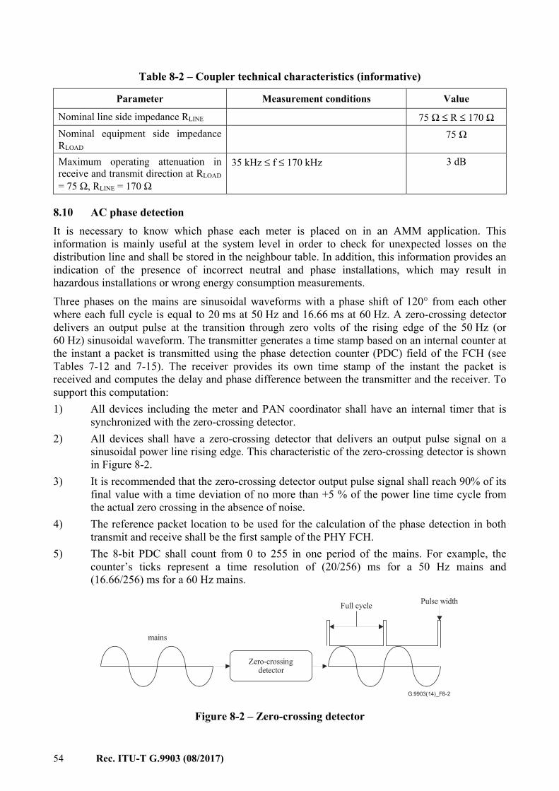
54 Rec. ITU-T G.9903 (08/2017)
Table 8-2 – Coupler technical characteristics (informative)
Parameter Measurement conditions Value
Nominal line side impedance RLINE 75 Ω ≤ R ≤ 170 Ω Nominal equipment side impedance RLOAD
75 Ω
Maximum operating attenuation in receive and transmit direction at RLOAD = 75 Ω, RLINE = 170 Ω
35 kHz ≤ f ≤ 170 kHz 3 dB
8.10 AC phase detection It is necessary to know which phase each meter is placed on in an AMM application. This information is mainly useful at the system level in order to check for unexpected losses on the distribution line and shall be stored in the neighbour table. In addition, this information provides an indication of the presence of incorrect neutral and phase installations, which may result in hazardous installations or wrong energy consumption measurements. Three phases on the mains are sinusoidal waveforms with a phase shift of 120° from each other where each full cycle is equal to 20 ms at 50 Hz and 16.66 ms at 60 Hz. A zero-crossing detector delivers an output pulse at the transition through zero volts of the rising edge of the 50 Hz (or 60 Hz) sinusoidal waveform. The transmitter generates a time stamp based on an internal counter at the instant a packet is transmitted using the phase detection counter (PDC) field of the FCH (see Tables 7-12 and 7-15). The receiver provides its own time stamp of the instant the packet is received and computes the delay and phase difference between the transmitter and the receiver. To support this computation: 1) All devices including the meter and PAN coordinator shall have an internal timer that is
synchronized with the zero-crossing detector. 2) All devices shall have a zero-crossing detector that delivers an output pulse signal on a
sinusoidal power line rising edge. This characteristic of the zero-crossing detector is shown in Figure 8-2.
3) It is recommended that the zero-crossing detector output pulse signal shall reach 90% of its final value with a time deviation of no more than +5 % of the power line time cycle from the actual zero crossing in the absence of noise.
4) The reference packet location to be used for the calculation of the phase detection in both transmit and receive shall be the first sample of the PHY FCH.
5) The 8-bit PDC shall count from 0 to 255 in one period of the mains. For example, the counter’s ticks represent a time resolution of (20/256) ms for a 50 Hz mains and (16.66/256) ms for a 60 Hz mains.
G.9903(14)_F8-2
Pulse widthFull cycle
Zero-crossingdetector
mains
Figure 8-2 – Zero-crossing detector
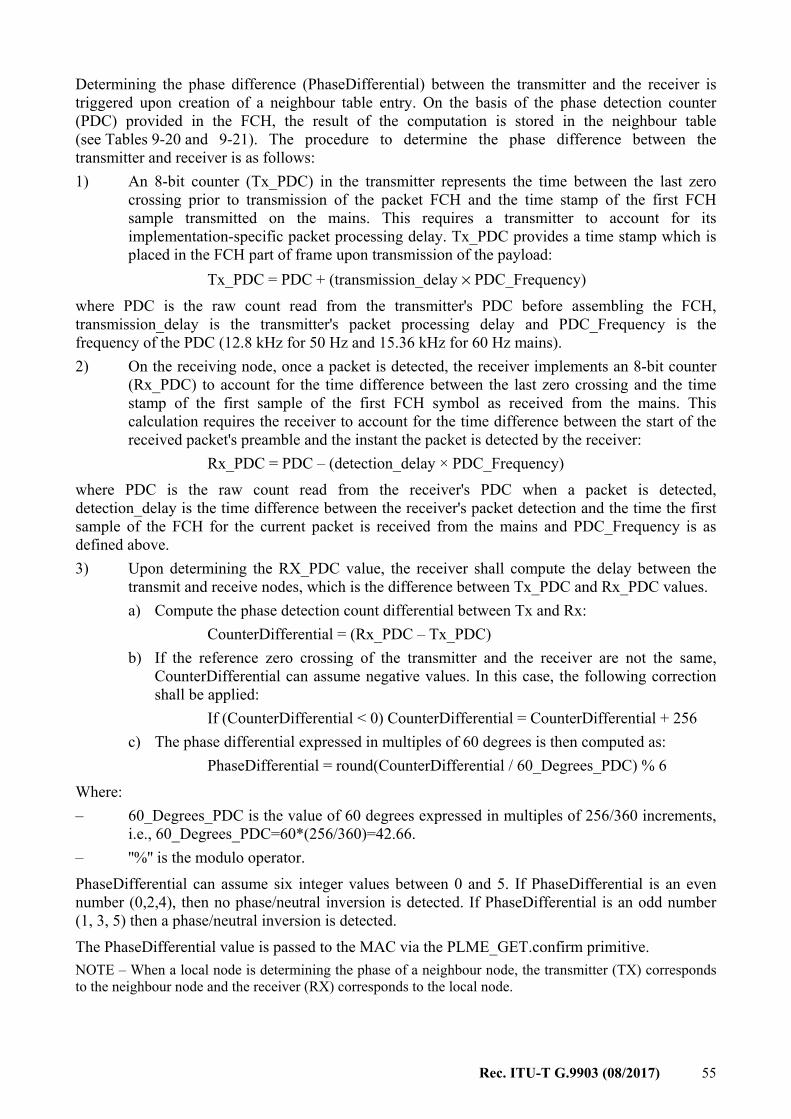
Rec. ITU-T G.9903 (08/2017) 55
Determining the phase difference (PhaseDifferential) between the transmitter and the receiver is triggered upon creation of a neighbour table entry. On the basis of the phase detection counter (PDC) provided in the FCH, the result of the computation is stored in the neighbour table (see Tables 9-20 and 9-21). The procedure to determine the phase difference between the transmitter and receiver is as follows: 1) An 8-bit counter (Tx_PDC) in the transmitter represents the time between the last zero
crossing prior to transmission of the packet FCH and the time stamp of the first FCH sample transmitted on the mains. This requires a transmitter to account for its implementation-specific packet processing delay. Tx_PDC provides a time stamp which is placed in the FCH part of frame upon transmission of the payload:
Tx_PDC = PDC + (transmission_delay × PDC_Frequency) where PDC is the raw count read from the transmitter's PDC before assembling the FCH, transmission_delay is the transmitter's packet processing delay and PDC_Frequency is the frequency of the PDC (12.8 kHz for 50 Hz and 15.36 kHz for 60 Hz mains). 2) On the receiving node, once a packet is detected, the receiver implements an 8-bit counter
(Rx_PDC) to account for the time difference between the last zero crossing and the time stamp of the first sample of the first FCH symbol as received from the mains. This calculation requires the receiver to account for the time difference between the start of the received packet's preamble and the instant the packet is detected by the receiver:
Rx_PDC = PDC – (detection_delay × PDC_Frequency) where PDC is the raw count read from the receiver's PDC when a packet is detected, detection_delay is the time difference between the receiver's packet detection and the time the first sample of the FCH for the current packet is received from the mains and PDC_Frequency is as defined above. 3) Upon determining the RX_PDC value, the receiver shall compute the delay between the
transmit and receive nodes, which is the difference between Tx_PDC and Rx_PDC values. a) Compute the phase detection count differential between Tx and Rx:
CounterDifferential = (Rx_PDC – Tx_PDC) b) If the reference zero crossing of the transmitter and the receiver are not the same,
CounterDifferential can assume negative values. In this case, the following correction shall be applied:
If (CounterDifferential < 0) CounterDifferential = CounterDifferential + 256 c) The phase differential expressed in multiples of 60 degrees is then computed as:
PhaseDifferential = round(CounterDifferential / 60_Degrees_PDC) % 6 Where: – 60_Degrees_PDC is the value of 60 degrees expressed in multiples of 256/360 increments,
i.e., 60_Degrees_PDC=60*(256/360)=42.66. – ''%'' is the modulo operator. PhaseDifferential can assume six integer values between 0 and 5. If PhaseDifferential is an even number (0,2,4), then no phase/neutral inversion is detected. If PhaseDifferential is an odd number (1, 3, 5) then a phase/neutral inversion is detected. The PhaseDifferential value is passed to the MAC via the PLME_GET.confirm primitive. NOTE – When a local node is determining the phase of a neighbour node, the transmitter (TX) corresponds to the neighbour node and the receiver (RX) corresponds to the local node.
56 Rec. ITU-T G.9903 (08/2017)
9 Data link layer specifications
9.1 Introduction The ITU-T G.9903 data link layer specification comprises two sublayers: – the MAC sublayer based on [IEEE 802.15.4]; and – the adaptation sublayer based on [IETF RFC 4944]. The present Recommendation specifies the necessary selections from and extensions to these standards.
9.2 Conventions In this clause, the status of each requirement from the reference documents is given using the following convention: – I = ''Informative''. The statements of the reference document are provided for information
only. – N = ''Normative'': The statements of the reference document shall apply without
modifications or remarks. – S = ''Selection'': The statements of the reference document shall apply with the selections
specified. – E = ''Extension'': The statements of the reference document shall apply with the extensions
(modifications and remarks noted under the part title) specified. – N/R = ''Not Relevant'': The statements of the reference document do not apply. An
explanation may be given under the part title.
9.3 MAC sublayer specification
9.3.1 Channel access
9.3.1.1 Overview The channel access is accomplished by using the carrier sense multiple access with collision avoidance (CSMA/CA) mechanism with a random back-off time. The random back-off mechanism spreads the time over which stations attempt to transmit, thereby reducing the probability of collision. Each time a device wishes to transmit data frames it shall wait for a contention period according to the packet's priority and then start the random period as described in clause 9.3.1.3. If the channel is found to be idle following the random back-off, the device shall transmit its data. If the channel is found to be busy following the random back-off, the device shall wait for the next contention period according to the packet's priority and then start another random period before trying to access the channel again. A carrier sense is a fundamental part of the distributed access procedure. The physical carrier sense (PCS) is provided by the PHY as described in clause 9.3.1.3. In the latter case, the PCS shall stay high long enough to be detected and the virtual carrier sense (VCS) to be asserted by the MAC. A virtual carrier sense mechanism tracks the expected duration of channel occupancy. Virtual carrier sense is set by the length of the received packet or upon collision including the time to wait for the next transmission window as specified in clauses 9.3.1.2 and 9.3.1.4. In these cases, the virtual carrier sense tracks the expected duration of the BUSY state of the medium. The medium shall also be considered busy when the station is transmitting. The VCS is also set upon collision, FCH decoding error or when the station powers up with respect to the EIFS. A collision occurs in each of the following circumstances: – The transmitting station receives something other than an ACK or NACK response when a
response is expected.
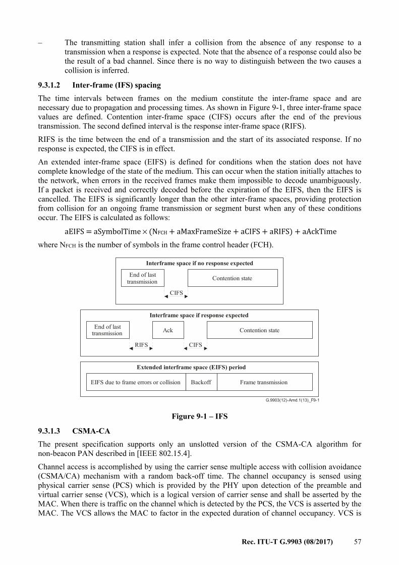
Rec. ITU-T G.9903 (08/2017) 57
– The transmitting station shall infer a collision from the absence of any response to a transmission when a response is expected. Note that the absence of a response could also be the result of a bad channel. Since there is no way to distinguish between the two causes a collision is inferred.
9.3.1.2 Inter-frame (IFS) spacing The time intervals between frames on the medium constitute the inter-frame space and are necessary due to propagation and processing times. As shown in Figure 9-1, three inter-frame space values are defined. Contention inter-frame space (CIFS) occurs after the end of the previous transmission. The second defined interval is the response inter-frame space (RIFS). RIFS is the time between the end of a transmission and the start of its associated response. If no response is expected, the CIFS is in effect. An extended inter-frame space (EIFS) is defined for conditions when the station does not have complete knowledge of the state of the medium. This can occur when the station initially attaches to the network, when errors in the received frames make them impossible to decode unambiguously. If a packet is received and correctly decoded before the expiration of the EIFS, then the EIFS is cancelled. The EIFS is significantly longer than the other inter-frame spaces, providing protection from collision for an ongoing frame transmission or segment burst when any of these conditions occur. The EIFS is calculated as follows: aEIFS = aSymbolTime × (NFCH + aMaxFrameSize + aCIFS + aRIFS) + aAckTime where NFCH is the number of symbols in the frame control header (FCH).
G.9903(12)-Amd.1(13)_F9-1
Interframe space if no response expected
End of lasttransmission Contention state
CIFS
Interframe space if response expected
End of lasttransmission Contention state
CIFS
Ack
RIFS
Extended interframe space (EIFS) period
EIFS due to frame errors or collision Frame transmissionBackoff
Figure 9-1 – IFS
9.3.1.3 CSMA-CA The present specification supports only an unslotted version of the CSMA-CA algorithm for non-beacon PAN described in [IEEE 802.15.4]. Channel access is accomplished by using the carrier sense multiple access with collision avoidance (CSMA/CA) mechanism with a random back-off time. The channel occupancy is sensed using physical carrier sense (PCS) which is provided by the PHY upon detection of the preamble and virtual carrier sense (VCS), which is a logical version of carrier sense and shall be asserted by the MAC. When there is traffic on the channel which is detected by the PCS, the VCS is asserted by the MAC. The VCS allows the MAC to factor in the expected duration of channel occupancy. VCS is
58 Rec. ITU-T G.9903 (08/2017)
set to BUSY for the duration of the detected packet or upon a collision. The medium is also considered BUSY when the station itself is transmitting. The random back-off mechanism spreads the time over which stations attempt to transmit, thereby reducing the probability of collision, using an additive decrease multiplicative increase (ADMI) back-off mechanism. The CSMA/CA algorithm shall be used before the transmission of data frames, MAC command frames and beacon frames during the active scan. If the macBroadcastMaxCWEnabled attribute is set to TRUE, then the MAC sublayer shall use the maximum CSMA contention window corresponding to macMaxBE for every broadcast data frame (excluding command and beacon frames) transmitted with normal priority to reduce network congestion. The algorithm is implemented using units of time called back-off periods, where one back-off period shall be equal to aUnitBackoffPeriod symbols, which is equal to aSlotTime. Each device shall maintain four variables for each transmission attempt: NB, NBF, minCWCount, and CW. NB is the number of times the CSMA-CA algorithm was required to back off while attempting the current transmission; this value shall be initialized to 0 before each new transmission attempt. NBF is a count of back-off attempts. It is used to control channel access fairness. minCWCount is the number of times the contention window reaches its minimum value 2macMinBE. CW is the contention window for each device. On device startup, the CW is initialized to 2macMinBE. The device shall then update the CW based on channel access success or failure as follows. For every channel access failure, the CW value doubles. The maximum value of CW is bounded by 2macMaxBE. Upon a successful transmission, the CW value is adjusted using the formula: CW[next] = max(CW[prev] − macA × 2macMinBE, 2macMinBE) The default (recommended) value of macA is set as 8. Note that if macMinBE is set to 0, collision avoidance is disabled during the first iteration of this algorithm. Figures 9-2 and 9-3 illustrate the steps of the CSMA/CA algorithm for normal and high priority packets, respectively. The MAC sublayer shall first initialize NB and NBF to zero step (1), and then proceed directly to step (2). The MAC sublayer shall wait for the correct contention window according to the packet's priority as shown in Figures 9-2 and 9-3. The MAC may also transmit the higher priority packet in the NPCW according to the normal priority back-off mechanism. When the VCS state is IDLE, meaning no IFS window is currently counted, the MAC sublayer shall invoke the CSMA process. If the channel is IDLE, then the packet is transmitted. The MAC sublayer shall check if CW = 2macMinBE. If it is verified, it shall increment the minCWCount and reset NBF to zero, otherwise it shall reset minCWCount to zero. It shall then verify whether the minCWCount > macMinCWAttempts. If yes, it shall reset CW to 2macMaxBE. It shall then go to step (4). The MAC sublayer shall delay for a random number of complete back-off periods in the range 0 to CW-1 [step (4)]:Backoff Time = Random(CW) × aSlotTime and then request that the PHY performs a PCS (physical carrier sense) [step (5)].

Rec. ITU-T G.9903 (08/2017) 59
If the channel is BUSY [step (6, No)] and if the NBF is less than macCSMAFairnessLimit, then the MAC sublayer shall increment NB and NBF and double the CW ensuring that CW does not exceed 2macMaxBE. If the NBF is greater than or equal to macCSMAFairnessLimit and it is a multiple of macK (fairness rate adaptation factor), then the CW is linearly decreased as in the case of a successful transmission. In all other cases, the CW value remains unchanged. Note that for high priority packets, the CW shall not exceed the macHighPriorityWindowSize. If the value of NB is less than or equal to macMaxCSMABackoffs, the CSMA/CA algorithm shall return to step (2). If the value of NB is greater than macMaxCSMABackoffs, the CSMA/CA algorithm shall terminate with a channel access failure status and the frame is dropped. If the channel is IDLE [step (6, Yes)], the MAC sublayer shall begin transmission of the frame at the start of the slot boundary.
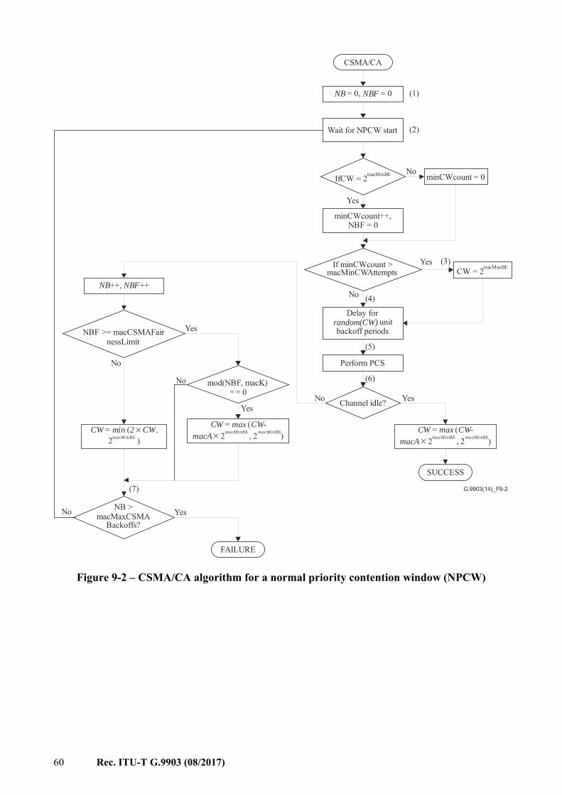
60 Rec. ITU-T G.9903 (08/2017)
G.9903(14)_F9-2
CSMA/CA
NB NBF = 0, = 0
Wait for NPCW start
(1)
Delay forunit
backoff periodsrandom(CW)
Perform PCS
(3)
No YesChannel idle?
NBF >= macCSMAFairnessLimit
NB > macMaxCSMA
Backoffs?
FAILURE
SUCCESS
(2)
(6)
(5)
(4)
If minCWcount >macMinCWAttempts
No
minCWcount++,NBF = 0
No
Yes
IfCW = 2macMinBE
Yes
minCWcount = 0
CW = 2macMaxBE
CW max CW-macA
= ( 2 , × macMinBE 2 )macMinBE
CW max CW-macA
= ( 2 , × macMinBE 2 )macMinBE
mod(NBF, macK) 0==
Yes
No
CW min 2 CW = ( ,2
× macM inBE )
No
NB NBF++, ++
Yes
(7)
YesNo
Figure 9-2 – CSMA/CA algorithm for a normal priority contention window (NPCW)
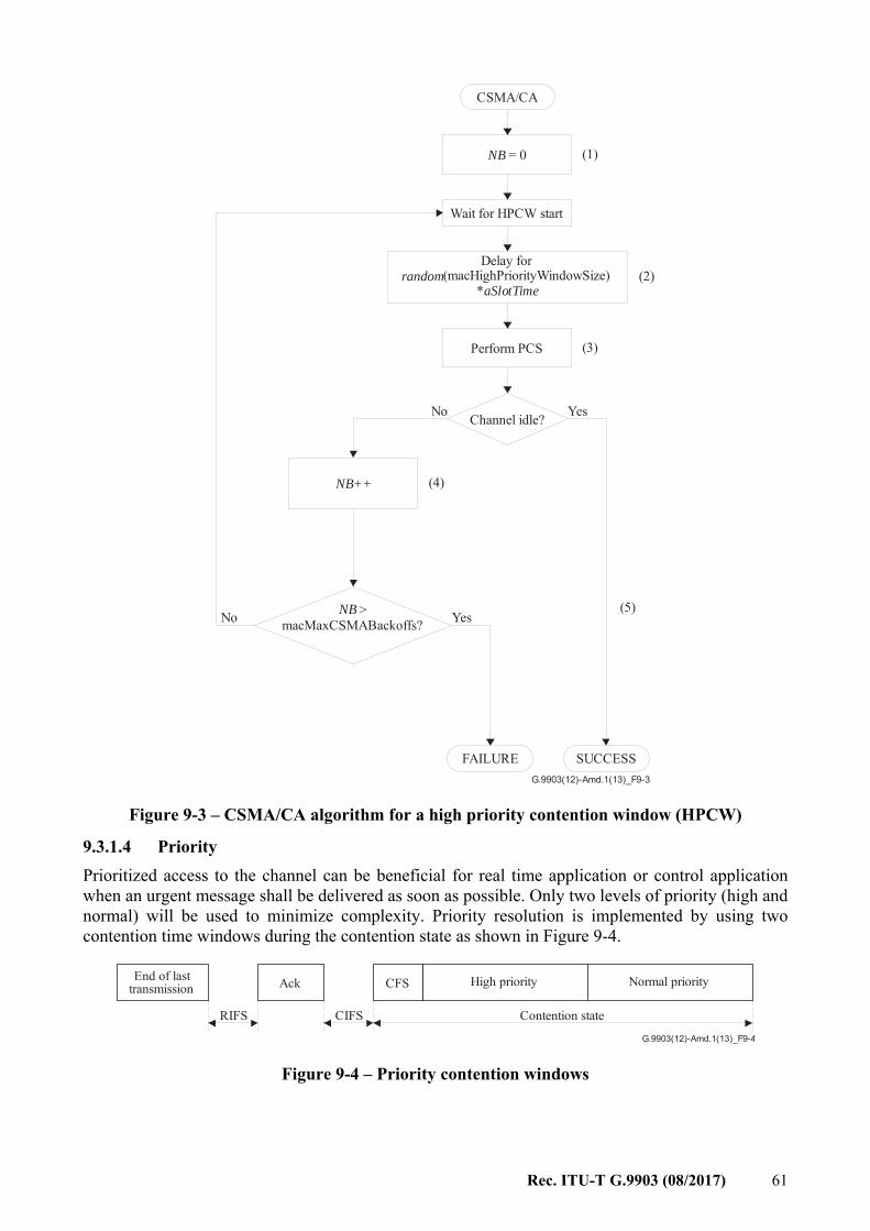
Rec. ITU-T G.9903 (08/2017) 61
G.9903(12)-Amd.1(13)_F9-3
CSMA/CA
NB = 0
Wait for HPCW start
(1)
Delay for(macHighPriorityWindowSize)
*random
aSlotTime
Perform PCS
(2)
(3)
No YesChannel idle?
(4)NB++
No YesNB >macMaxCSMABackoffs?
FAILURE SUCCESS
(5)
Figure 9-3 – CSMA/CA algorithm for a high priority contention window (HPCW)
9.3.1.4 Priority Prioritized access to the channel can be beneficial for real time application or control application when an urgent message shall be delivered as soon as possible. Only two levels of priority (high and normal) will be used to minimize complexity. Priority resolution is implemented by using two contention time windows during the contention state as shown in Figure 9-4.
G.9903(12)-Amd.1(13)_F9-4
End of lasttransmission Normal priority
CIFS
Ack
RIFS
CFS
Contention state
High priority
Figure 9-4 – Priority contention windows
62 Rec. ITU-T G.9903 (08/2017)
The first slot of contention window is called the contention free slot (CFS). The contention free slot shall be used for transmission of subsequent segments of a MAC frame without the back-off procedure to prevent possible interruption from other nodes and to simplify the MAC frame reassembly procedure on a receiver. In this case, only the first segment is sent using either a normal or high priority contention window and the rest are sent using the contention free slot. The high and normal priority stations will compete for channels during the high priority contention window (HPCW) and normal priority contention window (NPCW) correspondingly. Since HPCW is located before NPCW, high priority stations will get access to the channel before the station with normal priority. The duration of HPCW and NPCW are calculated as follow: HPCW time = macHighPriorityWindowSize × aSlotTime; NPCW time = (2maxBE × aSlotTime); CFS time = aSlotTime; Each station that does not have a packet to transmit may optionally wait for a random period in the normal priority contention window, according to the algorithm described in clause 9.3.1.3. If the MAC sublayer receives a packet for transmission during the back-off count, it may transmit the packet at the end of the count when the packet's priority is higher or equal to the current priority contention window. If there is no packet to transmit, the station may perform a PCS. If the channel is IDLE, the station may assume the IDLE state. If the channel is BUSY, the station may assume the BUSY state and may wait for the end of packet event to start the RIFS as described in clause 9.3.1.2.
9.3.1.5 ARQ The automatic repeat request (ARQ) is implemented based on acknowledged and unacknowledged retransmission. The MAC sublayer uses a response type as part of its ARQ mechanism. ACK is a traditional positive acknowledgement that when received allows the transmitter to assume successful delivery of the frame. The negative acknowledgement (NACK) is used to inform a packet originator that the receiver received the packet but it was corrupted. The usage of ACK and NACK responses is described in clause 9.3.2. If the originator does not receive an acknowledgement after a waiting period of macAckWaitDuration microseconds, it assumes that the transmission was unsuccessful and retries the frame transmission in the correct contention period as specified in clause 9.3.2.5. If an acknowledgement is still not received after several retries, the originator can choose either to terminate the transaction or to try again. When the acknowledgement is not requested, the originator assumes the transmission was successful. Also if acknowledgement is not requested the originator can retransmit the same packets few times to increase probability of data delivery. The receiver shall be able distinguish and discard redundant copies using the sequence number and segment count. The retransmitted packet will have the same sequence number and segment count as the original. The retransmission of a packet or segment shall trigger the generation of new PD-DATA.request primitive(s). A device shall not transmit a new command or a data frame during retransmission of the current frame. The acknowledgement cannot be requested for broadcast transmission. On the transmit side the ARQ shall configure the number of retransmissions (cf. macMaxFrameRetries from clause 7.4.2 of [IEEE 802.15.4]) as shown in Figure 9-5. On the receive side the ARQ generates acknowledgement for the PLC packet with the correct FCS (CRC16) if the packet corresponds to this address and may generate the NACK only when the FCS fails, but the packet corresponds to its address as shown in Figure 9-6.
Rec. ITU-T G.9903 (08/2017) 63
The received packet FCS (16 bits) will be sent back to the packet originator as a part of an acknowledgement (frame control header). All nodes will detect ACK during response time but only one station expecting ACK will accept it as acknowledgement and use 16 bit of the FCS from ACK for identification.
G.9903(12)-Amd.1(13)_F9-5
TX ARQ
Transmit packetwith response
expectedaccording toCSMA/CA
Yes SUCCESSReceive ACK?
No
ReceiveNACK?
Yes
No
No
Response timeexpired?
Yes
Wait EIFS
No
Number ofretries expired?
Yes
Discard packet
FAILURE
Figure 9-5 – Transmit ARQ
64 Rec. ITU-T G.9903 (08/2017)
G.9903(12)-Amd.1(13)_F9-6
RX ARQ
Receive packetwith response
expected
No
SUCCESS
Valid FCS?Yes
Yes
FAILURE
Valid to sendNACK?
Send NACK
Send ACK
Discard packet
No
Figure 9-6 – Receive ARQ
9.3.1.6 Segmentation and reassembly overview The ITU-T G.9903 PHY layer supports different types of modulation and tone maps. The number of data bytes of the PHY payload can change dynamically based on channel conditions. This requires implementing MAC payload fragmentation on the MAC sublayer. If the size of the MAC payload plus the MAC header is too large to fit within one PSDU, it must be partitioned into smaller segments that can each fit within a PSDU. This process of partitioning the MAC frame into PSDUs is called segmentation and the reverse process is called reassembly. The segmentation may require the addition of padding bytes to the last segment to fit the last PHY frame. The acknowledgement and retransmission occurs independently for the resulting MAC segment. All forms of addressing (unicast and broadcast) are subject to the segmentation. The segment control field definitions are shown in Table 9-5. When segmentation occurs, each resulting segment shall be created as follows: – The MAC header (MHR) and FCS (MFR) are presented in each segment. – All segments have the same value in the sequence number field, using the value assigned
for the MAC frame. Only the segment count is incremented for following segments. – Segment count (SC) shall be set to 0 for the first segment and incremented for each
following segment. – If data encryption is required it must be done before packet segmentation. On the receiver
side data decryption is done after packet reassembly. The Security Enabled field is set to 1 for all segments of a ciphered frame. The Auxiliary Security Header is only present in the first segment of a ciphered frame.
– All segments except the last one shall set the contention control (CC) bit to inform the receiver that the next PHY frame will be sent in the contention free slot. The last segment clears the contention control bit to allow the normal contention access to the channel.
Rec. ITU-T G.9903 (08/2017) 65
– For a frame that requires setting the TMR bit, the TMR bit shall be set in the last segment only.
– Last segment flag (LSF) shall be set to 1 to indicate the last segment of the MAC frame. – Segment length (SL) specifies the length of the MAC payload in bytes for the current
segment excluding the MAC header, byte padding and FCS. When security is activated, the MAC payload is constituted of the ciphered payload and the MIC-32.
The segment control fields (see Table 9-5) SL, SC and LSF are used to keep track of segments of the fragmented MAC packet and assembling the whole packet on the receiver side.
9.3.2 MAC acknowledgement The present specification does not use the MAC acknowledgement frame specified in [IEEE 802.15.4] but specifies positive and negative acknowledgements using the frame control header (see clause 7.6). The frame control header (FCH) contains information used by all stations in the network for channel access, as well as PHY receiver information used by the destination. For this reason, the frame control header has specific physical layer encoding and modulation as defined in clause 7.6. Only the frame control header will be used as positive (ACK) or negative (NACK) acknowledgement. The packet originator may request an acknowledgement by setting the delimiter type field of the frame control header (see clause 7.6).
9.3.2.1 ACK Generation If the MAC frame is received without error as determined by the FCS, the receiver shall send an ACK to the originator only if an acknowledgement is requested and the destination address and PAN ID of the frame match the receiver's device address and PAN ID.
9.3.2.2 NACK Generation If the MAC frame is received with errors as determined by the FCS, the receiver may send a NACK to the originator only if an acknowledgement is requested and the destination address and PAN ID of the frame match the receiver's device address and PAN ID. The NACK frame shall have its SSCA bit set to prevent other nodes from transmitting during retransmission.
9.3.2.3 NACK Generation avoidance If the receiver can determine that the error is caused by collision, it may avoid sending a NACK (no response) to invoke a collision state on the transmitting station. The transmitting station shall infer a collision from the absence of any response to a transmission when a response is expected.
9.3.2.4 ACK and NACK validity The transmitter shall extract the FCS field from the received ACK/NACK and compare it with the FCS of the transmitted packet to determine the validity of the response. If it matches, the ACK/NACK response is accepted otherwise it will be ignored and treated as a collision. The FCS field contains a 16-bit CRC calculated over the MHR and MAC payload parts of the frame using an MSBit endianess convention as described in [IEEE 802.15.4] clause 7.2.1.9. As an example, consider the following frame:
MHR Payload FCS
09 00 0F 61 C8 6A 1D 78 0C 01 88 77 66 55 44 33 22 11
11 22 33 44 55 66 77 88 99 AA BB CC DD EE FF 00
xxxx
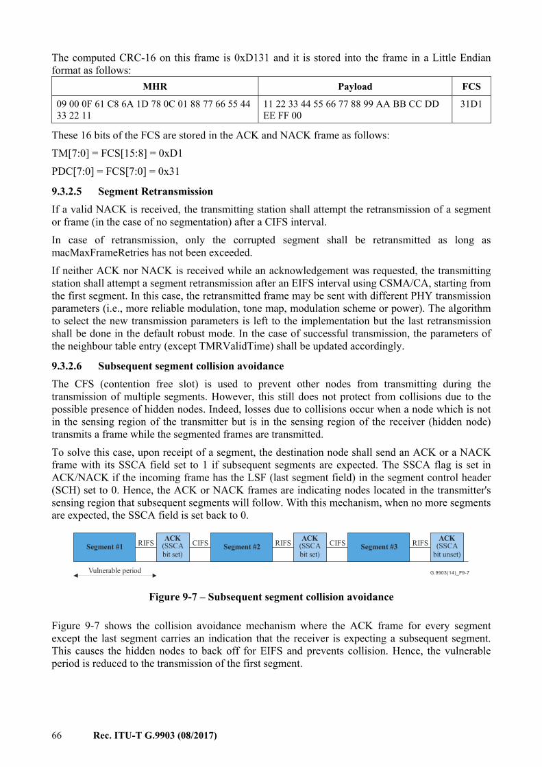
66 Rec. ITU-T G.9903 (08/2017)
The computed CRC-16 on this frame is 0xD131 and it is stored into the frame in a Little Endian format as follows:
MHR Payload FCS
09 00 0F 61 C8 6A 1D 78 0C 01 88 77 66 55 44 33 22 11
11 22 33 44 55 66 77 88 99 AA BB CC DD EE FF 00
31D1
These 16 bits of the FCS are stored in the ACK and NACK frame as follows: TM[7:0] = FCS[15:8] = 0xD1 PDC[7:0] = FCS[7:0] = 0x31
9.3.2.5 Segment Retransmission If a valid NACK is received, the transmitting station shall attempt the retransmission of a segment or frame (in the case of no segmentation) after a CIFS interval. In case of retransmission, only the corrupted segment shall be retransmitted as long as macMaxFrameRetries has not been exceeded. If neither ACK nor NACK is received while an acknowledgement was requested, the transmitting station shall attempt a segment retransmission after an EIFS interval using CSMA/CA, starting from the first segment. In this case, the retransmitted frame may be sent with different PHY transmission parameters (i.e., more reliable modulation, tone map, modulation scheme or power). The algorithm to select the new transmission parameters is left to the implementation but the last retransmission shall be done in the default robust mode. In the case of successful transmission, the parameters of the neighbour table entry (except TMRValidTime) shall be updated accordingly.
9.3.2.6 Subsequent segment collision avoidance The CFS (contention free slot) is used to prevent other nodes from transmitting during the transmission of multiple segments. However, this still does not protect from collisions due to the possible presence of hidden nodes. Indeed, losses due to collisions occur when a node which is not in the sensing region of the transmitter but is in the sensing region of the receiver (hidden node) transmits a frame while the segmented frames are transmitted. To solve this case, upon receipt of a segment, the destination node shall send an ACK or a NACK frame with its SSCA field set to 1 if subsequent segments are expected. The SSCA flag is set in ACK/NACK if the incoming frame has the LSF (last segment field) in the segment control header (SCH) set to 0. Hence, the ACK or NACK frames are indicating nodes located in the transmitter's sensing region that subsequent segments will follow. With this mechanism, when no more segments are expected, the SSCA field is set back to 0.
G.9903(14)_F9-7
Segment #1 Segment #2 Segment #3ACK
(SSCAbit set)
Vulnerable period
RIFS CIFS RIFS CIFS RIFSACK(SSCAbit set)
ACK(SSCA
bit unset)
Figure 9-7 – Subsequent segment collision avoidance
Figure 9-7 shows the collision avoidance mechanism where the ACK frame for every segment except the last segment carries an indication that the receiver is expecting a subsequent segment. This causes the hidden nodes to back off for EIFS and prevents collision. Hence, the vulnerable period is reduced to the transmission of the first segment.
Rec. ITU-T G.9903 (08/2017) 67
9.3.3 MAC sublayer service specification
9.3.3.1 Selections The MAC services and primitives are as given in clauses 7.1.1 to 7.1.17 of [IEEE 802.15.4] together with the following statements and modifications shown in Table 9-1. References to clauses in the ''Clause'' column refer to the referenced document, while references to clauses/annexes in the ''Title and remarks'' column refer to this Recommendation unless specifically indicated otherwise. The interpretation of the statement column is given in clause 9-2.
Table 9-1 – Selections from clause 7.1 of [IEEE 802.15.4]
Clause Title and remarks/modifications Statement
7.1 MAC sublayer service specification N 7.1.1 MAC data service
– MCPS-PURGE primitives are not used in this specification. S
7.1.1.1 MCPS-DATA.request N 7.1.1.1.1 Semantics of the service primitive
Extensions are described in clause 9.3.11.1 –
E
7.1.1.1.2 Appropriate usage N 7.1.1.1.3 Effect on receipt
– GTS transmission is not used – Only unslotted CSMA-CA for non-beacon-enabled PAN is used – Indirect transmission is not supported
S
7.1.1.2 MCPS-DATA.confirm N 7.1.1.2.1 Semantics of the service primitive
– Modification: Time stamp is optional and defined as the absolute time in milliseconds at which the frame was created and eventually after the encryption (32 bit value).
E
7.1.1.2.2 When generated N 7.1.1.2.3 Appropriate usage N 7.1.1.3 MCPS-DATA.indication N
7.1.1.3.1 Semantics of the service primitive Extensions are described in clause 9.3.11.2 E
7.1.1.3.2 When generated N 7.1.1.3.3 Appropriate usage N 7.1.1.4 MCPS-PURGE.request N/R 7.1.1.5 MCPS-PURGE.confirm N/R 7.1.1.6 Data service message sequence chart N 7.1.2 MAC management service N 7.1.3 Association primitives N/R
7.1.3.1 MLME-ASSOCIATE.request – MLME-ASSOCIATE.request is not used in this specification.
Association is performed by the 6LoWPAN bootstrap protocol described in clause 9.4.4.
N/R
68 Rec. ITU-T G.9903 (08/2017)
Table 9-1 – Selections from clause 7.1 of [IEEE 802.15.4]
Clause Title and remarks/modifications Statement
7.1.3.2 MLME-ASSOCIATE.indication – MLME-ASSOCIATE.indication is not used in this specification.
Association is performed by the 6LoWPAN bootstrap protocol described in clause 9.4.4.
N/R
7.1.3.3 MLME-ASSOCIATE.response – MLME-ASSOCIATE.response is not used in this specification.
Association is performed by the 6LoWPAN bootstrap protocol described in clause 9.4.4.
N/R
7.1.3.4 MLME-ASSOCIATE.confirm – MLME-ASSOCIATE.confirm is not used in this specification.
Association is performed by the 6LoWPAN bootstrap protocol described in clause 9.4.4
N/R
7.1.3.5 Association message sequence chart – The association message sequence chart described in Figure 31 shall
be ignored for this specification, as association is performed using the bootstrap mechanism described in clause 9.4.4.
N/R
7.1.4 Disassociation primitive N/R 7.1.4.1 MLME-DISASSOCIATE.request
– MLME-DISASSOCIATE.request is not used in this specification. Disassociation is performed by the 6LoWPAN bootstrap protocol described in clause 9.4.4.
N/R
7.1.4.2 MLME-DISASSOCIATE.indication – MLME-DISASSOCIATE.indication is not used in this specification.
Disassociation is performed by the 6LoWPAN bootstrap protocol described in clause 9.4.4.
N/R
7.1.4.3 MLME-DISASSOCIATE.confirm – MLME-DISASSOCIATE.confirm is not used in this specification.
Disassociation is performed by the 6LoWPAN bootstrap protocol described in clause 9.4.4.
N/R
7.1.4.4 Disassociation message sequence chart – The disassociation message sequence chart described in Figure 31 shall
be ignored for this specification, as disassociation is performed using the bootstrap mechanism described in clause 9.4.4.
N/R
7.1.5 Beacon notification primitive N 7.1.5.1 MLME-BEACON-NOTIFY.indication
– Only non-beacon-enabled PANs are used – This primitive is generated upon receipt of a beacon during an active
scan.
S
7.1.5.1.1 Semantics of the service primitive MLME-BEACON-NOTIFY.indication ( PANDescriptor ) PANDescriptor is described in Table 9-57.
S
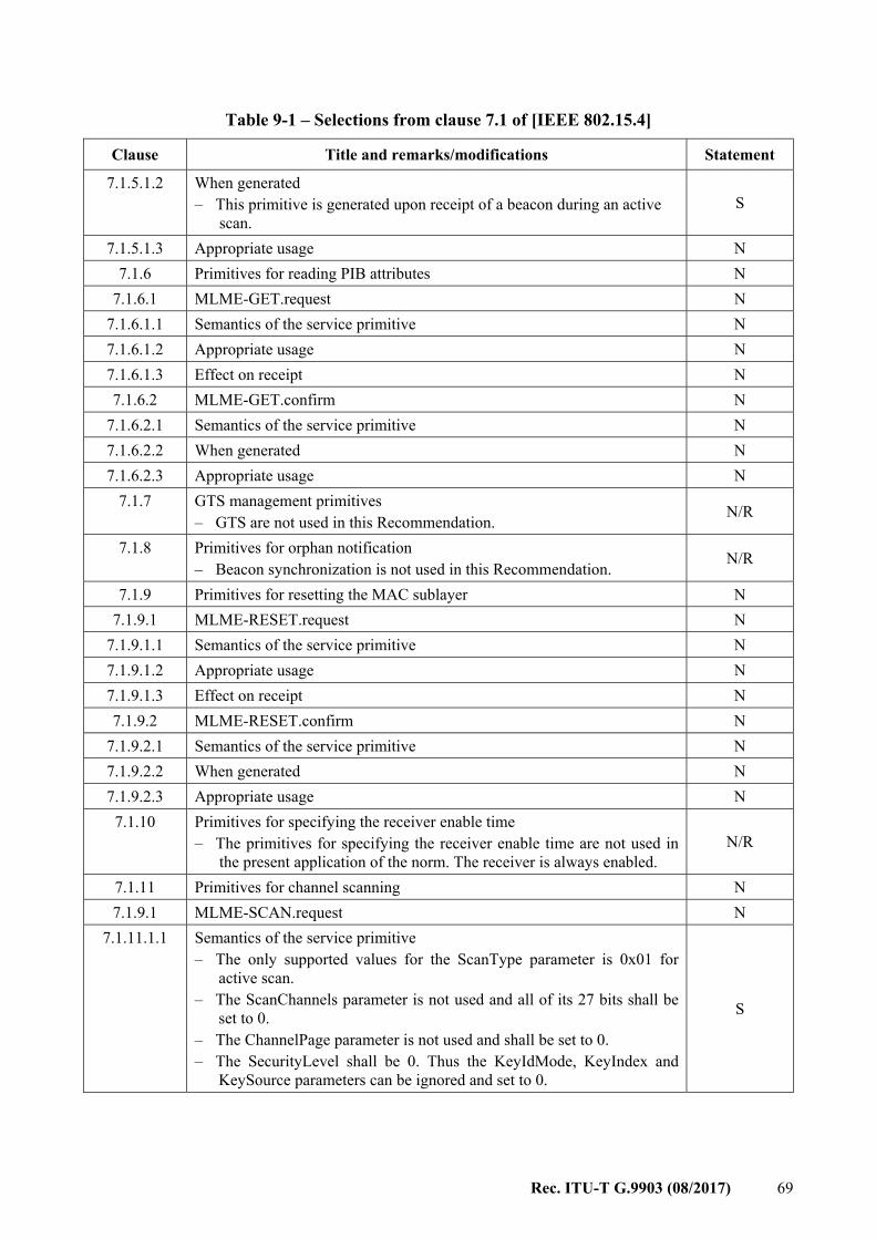
Rec. ITU-T G.9903 (08/2017) 69
Table 9-1 – Selections from clause 7.1 of [IEEE 802.15.4]
Clause Title and remarks/modifications Statement
7.1.5.1.2 When generated – This primitive is generated upon receipt of a beacon during an active
scan. S
7.1.5.1.3 Appropriate usage N 7.1.6 Primitives for reading PIB attributes N
7.1.6.1 MLME-GET.request N 7.1.6.1.1 Semantics of the service primitive N 7.1.6.1.2 Appropriate usage N 7.1.6.1.3 Effect on receipt N 7.1.6.2 MLME-GET.confirm N
7.1.6.2.1 Semantics of the service primitive N 7.1.6.2.2 When generated N 7.1.6.2.3 Appropriate usage N
7.1.7 GTS management primitives – GTS are not used in this Recommendation. N/R
7.1.8 Primitives for orphan notification – Beacon synchronization is not used in this Recommendation. N/R
7.1.9 Primitives for resetting the MAC sublayer N 7.1.9.1 MLME-RESET.request N
7.1.9.1.1 Semantics of the service primitive N 7.1.9.1.2 Appropriate usage N 7.1.9.1.3 Effect on receipt N 7.1.9.2 MLME-RESET.confirm N
7.1.9.2.1 Semantics of the service primitive N 7.1.9.2.2 When generated N 7.1.9.2.3 Appropriate usage N
7.1.10 Primitives for specifying the receiver enable time – The primitives for specifying the receiver enable time are not used in
the present application of the norm. The receiver is always enabled. N/R
7.1.11 Primitives for channel scanning N 7.1.9.1 MLME-SCAN.request N
7.1.11.1.1 Semantics of the service primitive – The only supported values for the ScanType parameter is 0x01 for
active scan. – The ScanChannels parameter is not used and all of its 27 bits shall be
set to 0. – The ChannelPage parameter is not used and shall be set to 0. – The SecurityLevel shall be 0. Thus the KeyIdMode, KeyIndex and
KeySource parameters can be ignored and set to 0.
S
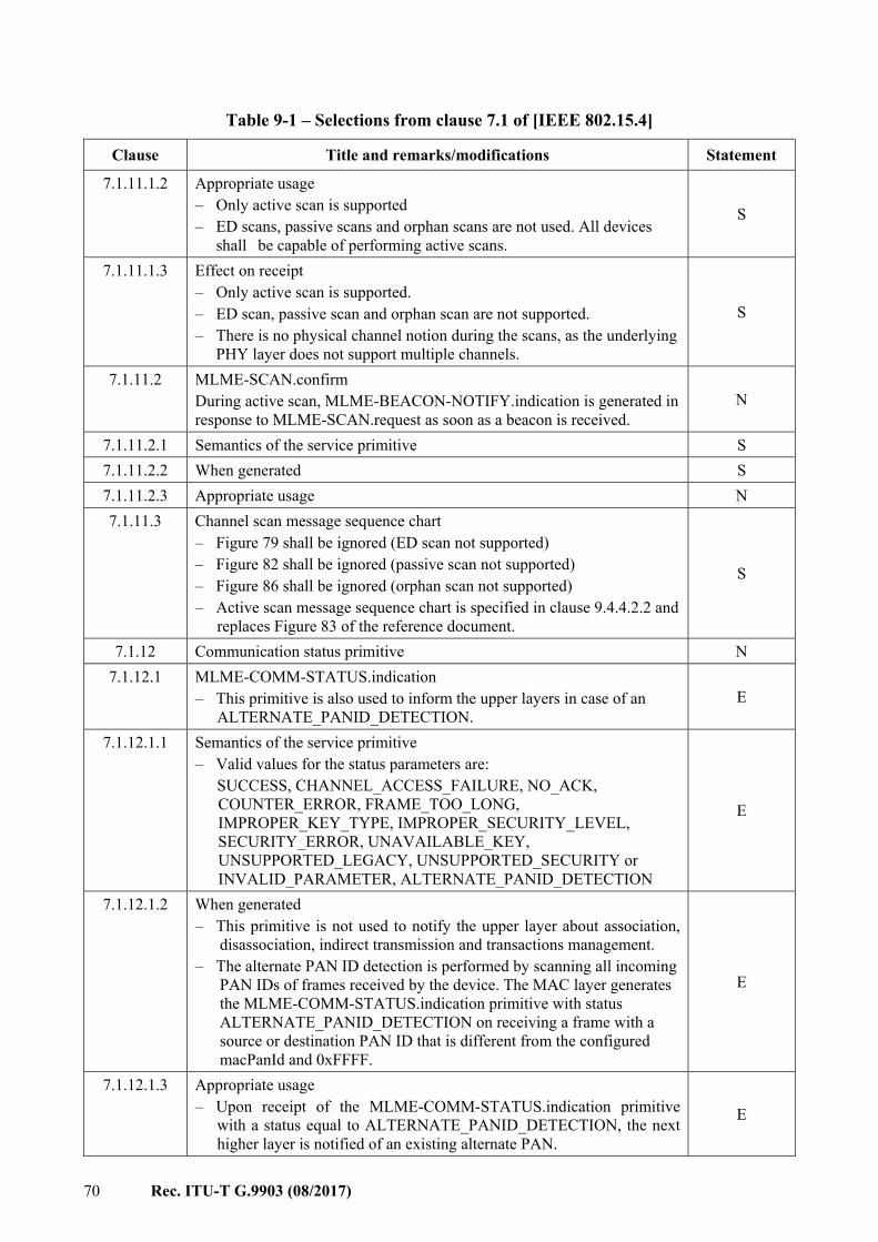
70 Rec. ITU-T G.9903 (08/2017)
Table 9-1 – Selections from clause 7.1 of [IEEE 802.15.4]
Clause Title and remarks/modifications Statement
7.1.11.1.2 Appropriate usage – Only active scan is supported – ED scans, passive scans and orphan scans are not used. All devices
shall be capable of performing active scans.
S
7.1.11.1.3 Effect on receipt – Only active scan is supported. – ED scan, passive scan and orphan scan are not supported. – There is no physical channel notion during the scans, as the underlying
PHY layer does not support multiple channels.
S
7.1.11.2 MLME-SCAN.confirm During active scan, MLME-BEACON-NOTIFY.indication is generated in response to MLME-SCAN.request as soon as a beacon is received.
N
7.1.11.2.1 Semantics of the service primitive S 7.1.11.2.2 When generated S 7.1.11.2.3 Appropriate usage N 7.1.11.3 Channel scan message sequence chart
– Figure 79 shall be ignored (ED scan not supported) – Figure 82 shall be ignored (passive scan not supported) – Figure 86 shall be ignored (orphan scan not supported) – Active scan message sequence chart is specified in clause 9.4.4.2.2 and
replaces Figure 83 of the reference document.
S
7.1.12 Communication status primitive N 7.1.12.1 MLME-COMM-STATUS.indication
– This primitive is also used to inform the upper layers in case of an ALTERNATE_PANID_DETECTION.
E
7.1.12.1.1 Semantics of the service primitive – Valid values for the status parameters are:
SUCCESS, CHANNEL_ACCESS_FAILURE, NO_ACK, COUNTER_ERROR, FRAME_TOO_LONG, IMPROPER_KEY_TYPE, IMPROPER_SECURITY_LEVEL, SECURITY_ERROR, UNAVAILABLE_KEY, UNSUPPORTED_LEGACY, UNSUPPORTED_SECURITY or INVALID_PARAMETER, ALTERNATE_PANID_DETECTION
E
7.1.12.1.2 When generated – This primitive is not used to notify the upper layer about association,
disassociation, indirect transmission and transactions management. – The alternate PAN ID detection is performed by scanning all incoming
PAN IDs of frames received by the device. The MAC layer generates the MLME-COMM-STATUS.indication primitive with status ALTERNATE_PANID_DETECTION on receiving a frame with a source or destination PAN ID that is different from the configured macPanId and 0xFFFF.
E
7.1.12.1.3 Appropriate usage – Upon receipt of the MLME-COMM-STATUS.indication primitive
with a status equal to ALTERNATE_PANID_DETECTION, the next higher layer is notified of an existing alternate PAN.
E
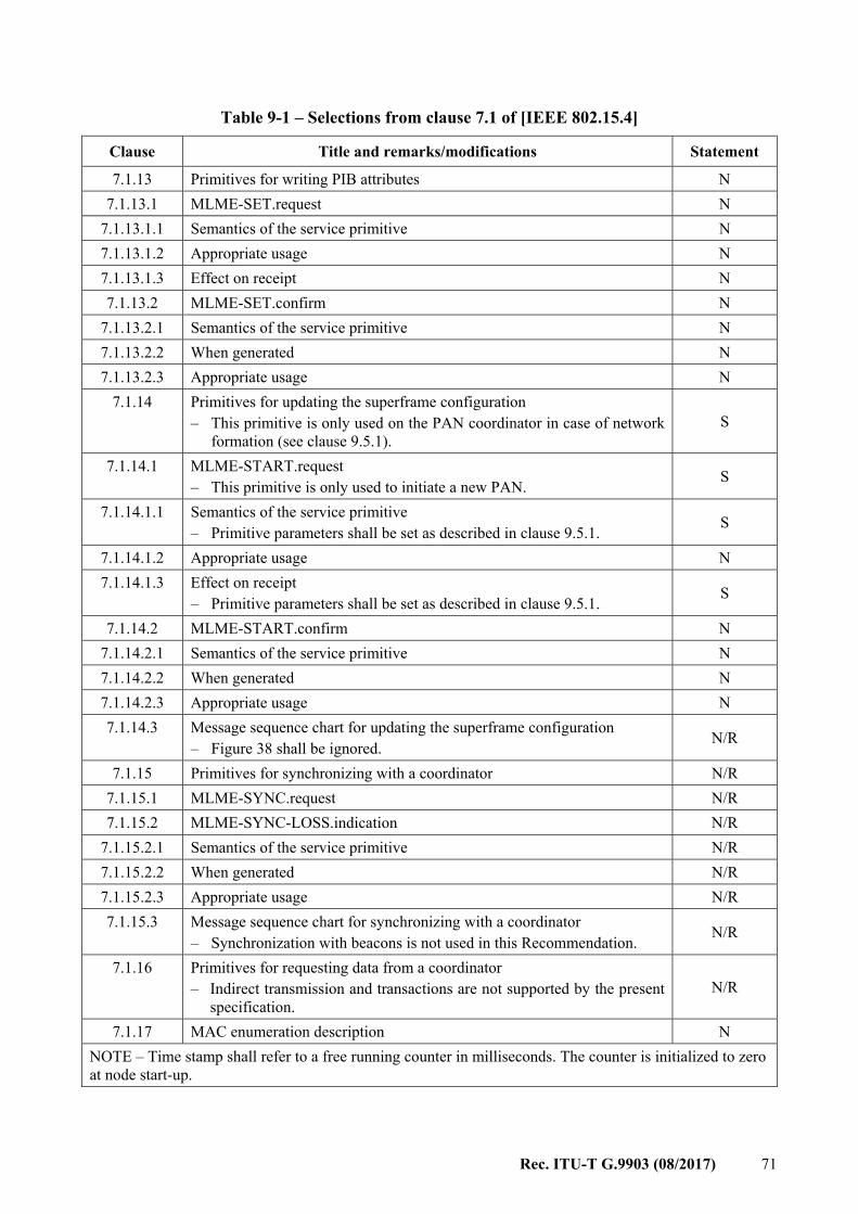
Rec. ITU-T G.9903 (08/2017) 71
Table 9-1 – Selections from clause 7.1 of [IEEE 802.15.4]
Clause Title and remarks/modifications Statement
7.1.13 Primitives for writing PIB attributes N 7.1.13.1 MLME-SET.request N
7.1.13.1.1 Semantics of the service primitive N 7.1.13.1.2 Appropriate usage N 7.1.13.1.3 Effect on receipt N 7.1.13.2 MLME-SET.confirm N
7.1.13.2.1 Semantics of the service primitive N 7.1.13.2.2 When generated N 7.1.13.2.3 Appropriate usage N
7.1.14 Primitives for updating the superframe configuration – This primitive is only used on the PAN coordinator in case of network
formation (see clause 9.5.1). S
7.1.14.1 MLME-START.request – This primitive is only used to initiate a new PAN. S
7.1.14.1.1 Semantics of the service primitive – Primitive parameters shall be set as described in clause 9.5.1. S
7.1.14.1.2 Appropriate usage N 7.1.14.1.3 Effect on receipt
– Primitive parameters shall be set as described in clause 9.5.1. S
7.1.14.2 MLME-START.confirm N 7.1.14.2.1 Semantics of the service primitive N 7.1.14.2.2 When generated N 7.1.14.2.3 Appropriate usage N 7.1.14.3 Message sequence chart for updating the superframe configuration
– Figure 38 shall be ignored. N/R
7.1.15 Primitives for synchronizing with a coordinator N/R 7.1.15.1 MLME-SYNC.request N/R 7.1.15.2 MLME-SYNC-LOSS.indication N/R
7.1.15.2.1 Semantics of the service primitive N/R 7.1.15.2.2 When generated N/R 7.1.15.2.3 Appropriate usage N/R 7.1.15.3 Message sequence chart for synchronizing with a coordinator
– Synchronization with beacons is not used in this Recommendation. N/R
7.1.16 Primitives for requesting data from a coordinator – Indirect transmission and transactions are not supported by the present
specification. N/R
7.1.17 MAC enumeration description N NOTE – Time stamp shall refer to a free running counter in milliseconds. The counter is initialized to zero at node start-up.
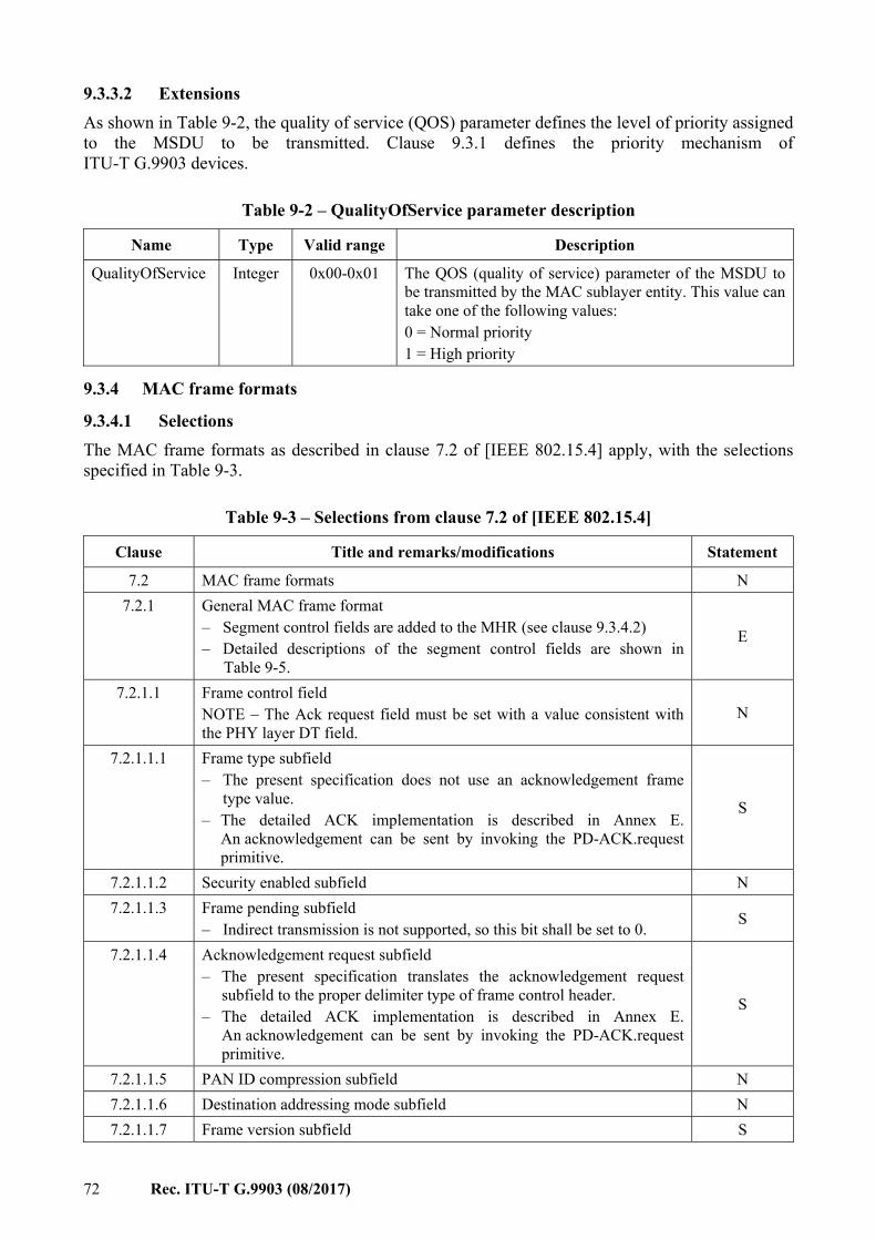
72 Rec. ITU-T G.9903 (08/2017)
9.3.3.2 Extensions As shown in Table 9-2, the quality of service (QOS) parameter defines the level of priority assigned to the MSDU to be transmitted. Clause 9.3.1 defines the priority mechanism of ITU-T G.9903 devices.
Table 9-2 – QualityOfService parameter description
Name Type Valid range Description
QualityOfService Integer 0x00-0x01 The QOS (quality of service) parameter of the MSDU to be transmitted by the MAC sublayer entity. This value can take one of the following values: 0 = Normal priority 1 = High priority
9.3.4 MAC frame formats
9.3.4.1 Selections The MAC frame formats as described in clause 7.2 of [IEEE 802.15.4] apply, with the selections specified in Table 9-3.
Table 9-3 – Selections from clause 7.2 of [IEEE 802.15.4]
Clause Title and remarks/modifications Statement
7.2 MAC frame formats N 7.2.1 General MAC frame format
– Segment control fields are added to the MHR (see clause 9.3.4.2) – Detailed descriptions of the segment control fields are shown in
Table 9-5.
E
7.2.1.1 Frame control field NOTE – The Ack request field must be set with a value consistent with the PHY layer DT field.
N
7.2.1.1.1 Frame type subfield – The present specification does not use an acknowledgement frame
type value. – The detailed ACK implementation is described in Annex E.
An acknowledgement can be sent by invoking the PD-ACK.request primitive.
S
7.2.1.1.2 Security enabled subfield N 7.2.1.1.3 Frame pending subfield
– Indirect transmission is not supported, so this bit shall be set to 0. S
7.2.1.1.4 Acknowledgement request subfield – The present specification translates the acknowledgement request
subfield to the proper delimiter type of frame control header. – The detailed ACK implementation is described in Annex E.
An acknowledgement can be sent by invoking the PD-ACK.request primitive.
S
7.2.1.1.5 PAN ID compression subfield N 7.2.1.1.6 Destination addressing mode subfield N 7.2.1.1.7 Frame version subfield S
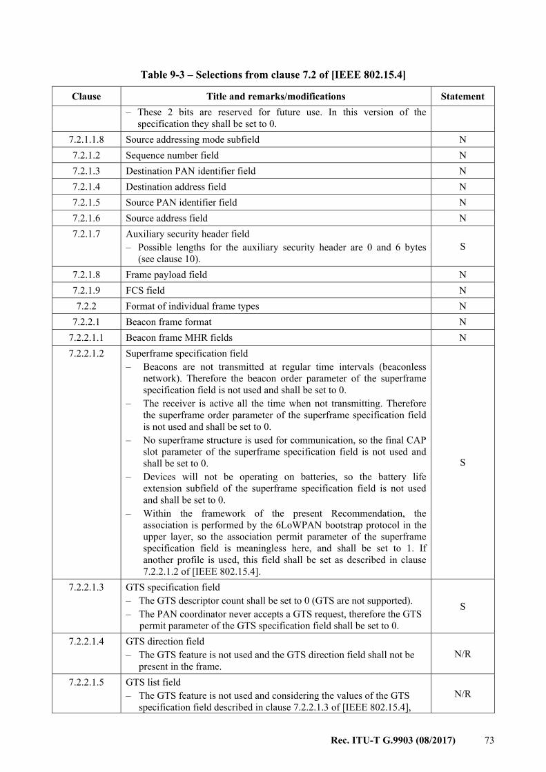
Rec. ITU-T G.9903 (08/2017) 73
Table 9-3 – Selections from clause 7.2 of [IEEE 802.15.4]
Clause Title and remarks/modifications Statement – These 2 bits are reserved for future use. In this version of the
specification they shall be set to 0. 7.2.1.1.8 Source addressing mode subfield N 7.2.1.2 Sequence number field N 7.2.1.3 Destination PAN identifier field N 7.2.1.4 Destination address field N 7.2.1.5 Source PAN identifier field N 7.2.1.6 Source address field N 7.2.1.7 Auxiliary security header field
– Possible lengths for the auxiliary security header are 0 and 6 bytes (see clause 10).
S
7.2.1.8 Frame payload field N 7.2.1.9 FCS field N 7.2.2 Format of individual frame types N
7.2.2.1 Beacon frame format N 7.2.2.1.1 Beacon frame MHR fields N 7.2.2.1.2 Superframe specification field
– Beacons are not transmitted at regular time intervals (beaconless network). Therefore the beacon order parameter of the superframe specification field is not used and shall be set to 0.
– The receiver is active all the time when not transmitting. Therefore the superframe order parameter of the superframe specification field is not used and shall be set to 0.
– No superframe structure is used for communication, so the final CAP slot parameter of the superframe specification field is not used and shall be set to 0.
– Devices will not be operating on batteries, so the battery life extension subfield of the superframe specification field is not used and shall be set to 0.
– Within the framework of the present Recommendation, the association is performed by the 6LoWPAN bootstrap protocol in the upper layer, so the association permit parameter of the superframe specification field is meaningless here, and shall be set to 1. If another profile is used, this field shall be set as described in clause 7.2.2.1.2 of [IEEE 802.15.4].
S
7.2.2.1.3 GTS specification field – The GTS descriptor count shall be set to 0 (GTS are not supported). – The PAN coordinator never accepts a GTS request, therefore the GTS
permit parameter of the GTS specification field shall be set to 0.
S
7.2.2.1.4 GTS direction field – The GTS feature is not used and the GTS direction field shall not be
present in the frame. N/R
7.2.2.1.5 GTS list field – The GTS feature is not used and considering the values of the GTS
specification field described in clause 7.2.2.1.3 of [IEEE 802.15.4], N/R
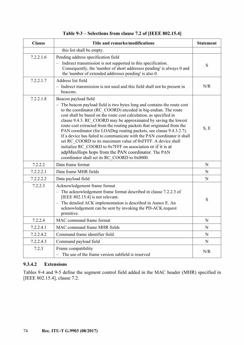
74 Rec. ITU-T G.9903 (08/2017)
Table 9-3 – Selections from clause 7.2 of [IEEE 802.15.4]
Clause Title and remarks/modifications Statement this list shall be empty.
7.2.2.1.6 Pending address specification field – Indirect transmission is not supported in this specification.
Consequently, the 'number of short addresses pending' is always 0 and the 'number of extended addresses pending' is also 0.
S
7.2.2.1.7 Address list field – Indirect transmission is not used and this field shall not be present in
beacons. N/R
7.2.2.1.8 Beacon payload field – The beacon payload field is two bytes long and contains the route cost
to the coordinator (RC_COORD) encoded in big-endian. The route cost shall be based on the route cost calculation, as specified in clause 9.4.3. RC_COORD may be approximated by saving the lowest route cost extracted from the routing packets that originated from the PAN coordinator (for LOADng routing packets, see clause 9.4.3.2.7). If a device has failed to communicate with the PAN coordinator it shall set RC_COORD to its maximum value of 0xFFFF. A device shall initialize RC_COORD to 0x7FFF on association or if it is at adpMaxHops hops from the PAN coordinator. The PAN coordinator shall set its RC_COORD to 0x0000.
S, E
7.2.2.2 Data frame format N 7.2.2.2.1 Data frame MHR fields N 7.2.2.2.2 Data payload field N 7.2.2.3 Acknowledgement frame format
– The acknowledgement frame format described in clause 7.2.2.3 of [IEEE 802.15.4] is not relevant.
– The detailed ACK implementation is described in Annex E. An acknowledgement can be sent by invoking the PD-ACK.request primitive.
S
7.2.2.4 MAC command frame format N 7.2.2.4.1 MAC command frame MHR fields N 7.2.2.4.2 Command frame identifier field N 7.2.2.4.3 Command payload field N
7.2.3 Frame compatibility – The use of the frame version subfield is reserved N/R
9.3.4.2 Extensions Tables 9-4 and 9-5 define the segment control field added in the MAC header (MHR) specified in [IEEE 802.15.4], clause 7.2.
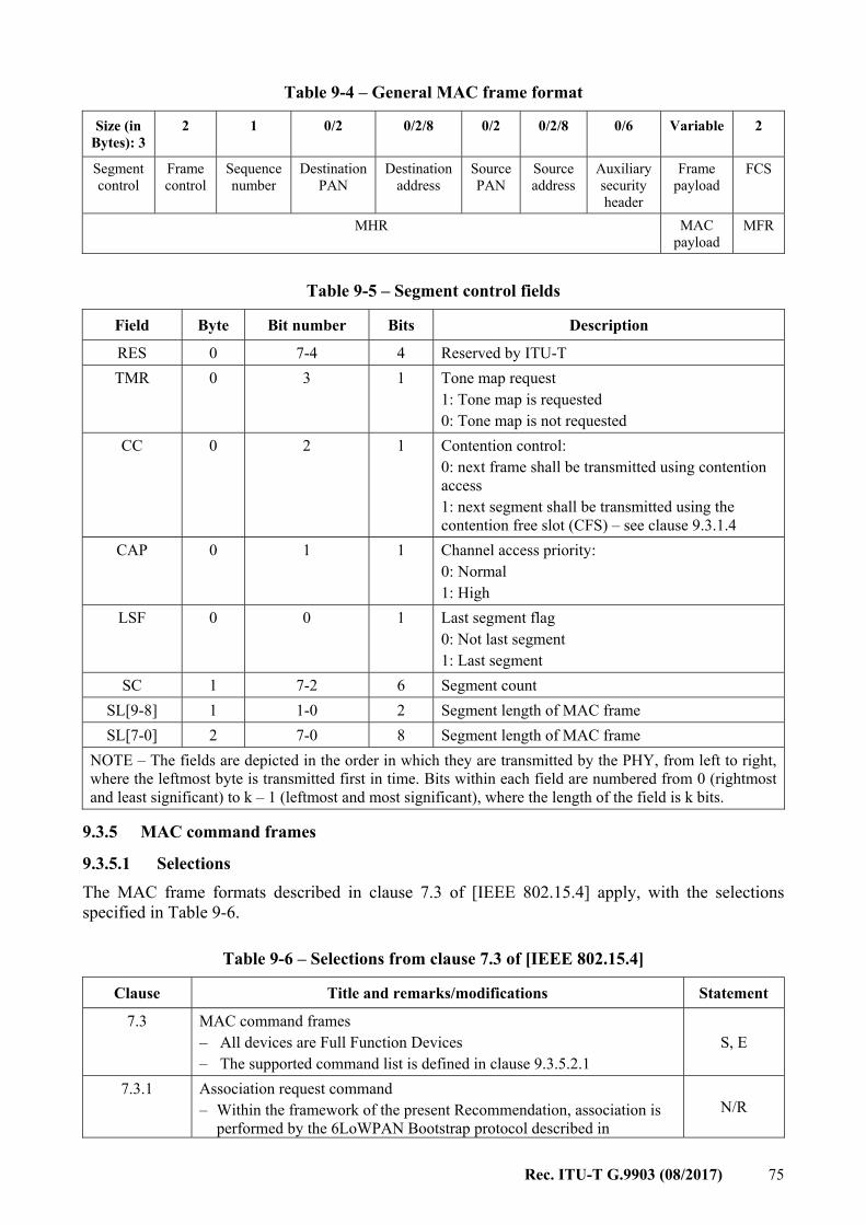
Rec. ITU-T G.9903 (08/2017) 75
Table 9-4 – General MAC frame format
Size (in Bytes): 3
2 1 0/2 0/2/8 0/2 0/2/8 0/6 Variable 2
Segment control
Frame control
Sequence number
Destination PAN
Destination address
Source PAN
Source address
Auxiliary security header
Frame payload
FCS
MHR MAC payload
MFR
Table 9-5 – Segment control fields
Field Byte Bit number Bits Description
RES 0 7-4 4 Reserved by ITU-T TMR 0 3 1 Tone map request
1: Tone map is requested 0: Tone map is not requested
CC 0 2 1 Contention control: 0: next frame shall be transmitted using contention access 1: next segment shall be transmitted using the contention free slot (CFS) – see clause 9.3.1.4
CAP 0 1 1 Channel access priority: 0: Normal 1: High
LSF 0 0 1 Last segment flag 0: Not last segment 1: Last segment
SC 1 7-2 6 Segment count SL[9-8] 1 1-0 2 Segment length of MAC frame SL[7-0] 2 7-0 8 Segment length of MAC frame
NOTE – The fields are depicted in the order in which they are transmitted by the PHY, from left to right, where the leftmost byte is transmitted first in time. Bits within each field are numbered from 0 (rightmost and least significant) to k – 1 (leftmost and most significant), where the length of the field is k bits.
9.3.5 MAC command frames
9.3.5.1 Selections The MAC frame formats described in clause 7.3 of [IEEE 802.15.4] apply, with the selections specified in Table 9-6.
Table 9-6 – Selections from clause 7.3 of [IEEE 802.15.4]
Clause Title and remarks/modifications Statement
7.3 MAC command frames – All devices are Full Function Devices – The supported command list is defined in clause 9.3.5.2.1
S, E
7.3.1 Association request command – Within the framework of the present Recommendation, association is
performed by the 6LoWPAN Bootstrap protocol described in N/R
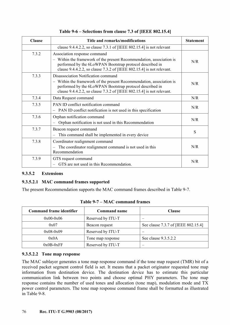
76 Rec. ITU-T G.9903 (08/2017)
Table 9-6 – Selections from clause 7.3 of [IEEE 802.15.4]
Clause Title and remarks/modifications Statement clause 9.4.4.2.2, so clause 7.3.1 of [IEEE 802.15.4] is not relevant
7.3.2 Association response command – Within the framework of the present Recommendation, association is
performed by the 6LoWPAN Bootstrap protocol described in clause 9.4.4.2.2, so clause 7.3.2 of [IEEE 802.15.4] is not relevant.
N/R
7.3.3 Disassociation Notification command – Within the framework of the present Recommendation, association is
performed by the 6LoWPAN Bootstrap protocol described in clause 9.4.4.2.2, so clause 7.3.2 of [IEEE 802.15.4] is not relevant.
N/R
7.3.4 Data Request command N/R 7.3.5 PAN ID conflict notification command
– PAN ID conflict notification is not used in this specification N/R
7.3.6 Orphan notification command – Orphan notification is not used in this Recommendation N/R
7.3.7 Beacon request command – This command shall be implemented in every device S
7.3.8 Coordinator realignment command – The coordinator realignment command is not used in this Recommendation
N/R
7.3.9 GTS request command – GTS are not used in this Recommendation. N/R
9.3.5.2 Extensions
9.3.5.2.1 MAC command frames supported The present Recommendation supports the MAC command frames described in Table 9-7.
Table 9-7 – MAC command frames
Command frame identifier Command name Clause
0x00-0x06 Reserved by ITU-T – 0x07 Beacon request See clause 7.3.7 of [IEEE 802.15.4]
0x08-0x09 Reserved by ITU-T – 0x0A Tone map response See clause 9.3.5.2.2
0x0B-0xFF Reserved by ITU-T –
9.3.5.2.2 Tone map response The MAC sublayer generates a tone map response command if the tone map request (TMR) bit of a received packet segment control field is set. It means that a packet originator requested tone map information from destination device. The destination device has to estimate this particular communication link between two points and choose optimal PHY parameters. The tone map response contains the number of used tones and allocation (tone map), modulation mode and TX power control parameters. The tone map response command frame shall be formatted as illustrated in Table 9-8.

Rec. ITU-T G.9903 (08/2017) 77
The channel estimation response command frame shall be formatted as illustrated in Table 9-8:
Table 9-8 – Tone map response format
Size (in Bytes): (see clause 7.2.2.4 of
[IEEE 802.15.4]) 1
7 (for CENELEC bandplans)
12 (for FCC bandplan) 2
MHR fields Command frame identifier (see Table 9-7)
Tone map response payload (see Tables 9-9 and 9-10)
MFR Fields
The tone map response message parameters are shown in Table 9-9 for the case of CENELEC bandplans and in Table 9-10 for the case of FCC bandplan.
Table 9-9 – Tone map response message description for CENELEC bandplans
Field Byte Bit number Bits Description
TXRES 0 7 1 Tx Gain resolution corresponding to one gain step. 0: 6 dB 1: 3 dB
TXGAIN 0 6-3 4 Desired transmitter gain specifying how many gain steps are requested.
MOD 0 2-1 2 Modulation type: 0 – Robust mode 1 – DBPSK or BPSK 2 – DQPSK or QPSK 3 – D8PSK or 8-PSK
Payload modulation scheme
0 0 1 0: Differential 1: Coherent The coherent scheme specified in clause 7.16 is optional.
Reserved by ITU-T 1 7-6 2 Shall be set to zero TM[5:0] 1 5-0 6 Tone map [5:0]
In CENELEC-B bandplan, TM[5:3] are reserved by ITU-T and shall be set to zero
LQI 2 7-0 8 Link quality indicator TXCOEF[3:0] 3 7-4 4 Specifies the number of gain steps requested for the
tones represented by TM[0] (optional) TXCOEF[7:4] 3 3-0 4 Specifies the number of gain steps requested for the
tones represented by TM[1] (optional) TXCOEF[11:8] 4 7-4 4 Specifies the number of gain steps requested for the
tones represented by TM[2] (optional) TXCOEF[15:12] 4 3-0 4 Specifies the number of gain steps requested for the
tones represented by TM[3] (optional) TXCOEF[19:16] 5 7-4 4 Specifies the number of gain steps requested for the
tones represented by TM[4] (optional) TXCOEF[23:20] 5 3-0 4 Specifies the number of gain steps requested for the
tones represented by TM[5] (optional) Reserved by ITU-T 6 7-0 8 Shall be set to zero
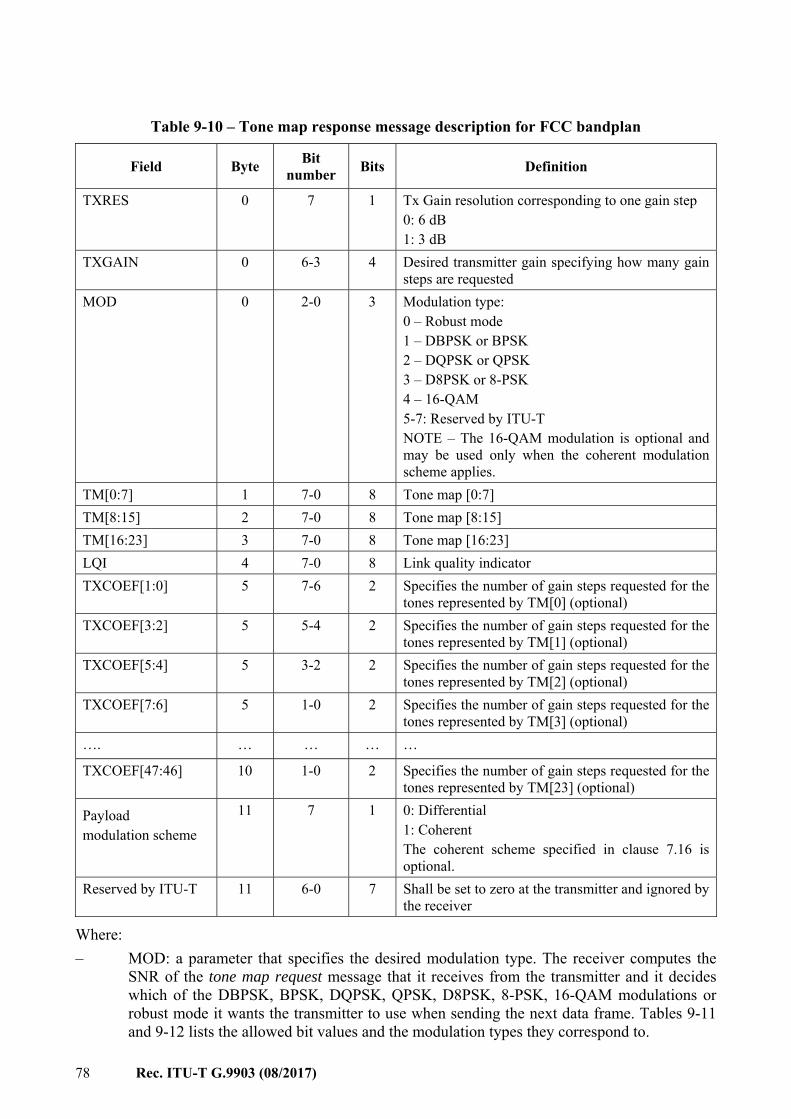
78 Rec. ITU-T G.9903 (08/2017)
Table 9-10 – Tone map response message description for FCC bandplan
Field Byte Bit number Bits Definition
TXRES 0 7 1 Tx Gain resolution corresponding to one gain step 0: 6 dB 1: 3 dB
TXGAIN 0 6-3 4 Desired transmitter gain specifying how many gain steps are requested
MOD 0 2-0 3 Modulation type: 0 – Robust mode 1 – DBPSK or BPSK 2 – DQPSK or QPSK 3 – D8PSK or 8-PSK 4 – 16-QAM 5-7: Reserved by ITU-T NOTE – The 16-QAM modulation is optional and may be used only when the coherent modulation scheme applies.
TM[0:7] 1 7-0 8 Tone map [0:7] TM[8:15] 2 7-0 8 Tone map [8:15] TM[16:23] 3 7-0 8 Tone map [16:23] LQI 4 7-0 8 Link quality indicator TXCOEF[1:0] 5 7-6 2 Specifies the number of gain steps requested for the
tones represented by TM[0] (optional) TXCOEF[3:2] 5 5-4 2 Specifies the number of gain steps requested for the
tones represented by TM[1] (optional) TXCOEF[5:4] 5 3-2 2 Specifies the number of gain steps requested for the
tones represented by TM[2] (optional) TXCOEF[7:6] 5 1-0 2 Specifies the number of gain steps requested for the
tones represented by TM[3] (optional) …. … … … …
TXCOEF[47:46] 10 1-0 2 Specifies the number of gain steps requested for the tones represented by TM[23] (optional)
Payload modulation scheme
11 7 1 0: Differential 1: Coherent The coherent scheme specified in clause 7.16 is optional.
Reserved by ITU-T 11 6-0 7 Shall be set to zero at the transmitter and ignored by the receiver
Where: – MOD: a parameter that specifies the desired modulation type. The receiver computes the
SNR of the tone map request message that it receives from the transmitter and it decides which of the DBPSK, BPSK, DQPSK, QPSK, D8PSK, 8-PSK, 16-QAM modulations or robust mode it wants the transmitter to use when sending the next data frame. Tables 9-11 and 9-12 lists the allowed bit values and the modulation types they correspond to.
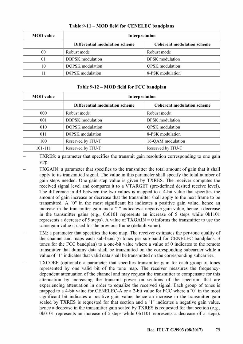
Rec. ITU-T G.9903 (08/2017) 79
Table 9-11 – MOD field for CENELEC bandplans
MOD value Interpretation
Differential modulation scheme Coherent modulation scheme
00 Robust mode Robust mode 01 DBPSK modulation BPSK modulation 10 DQPSK modulation QPSK modulation 11 D8PSK modulation 8-PSK modulation
Table 9-12 – MOD field for FCC bandplan
MOD value Interpretation
Differential modulation scheme Coherent modulation scheme
000 Robust mode Robust mode 001 DBPSK modulation BPSK modulation 010 DQPSK modulation QPSK modulation 011 D8PSK modulation 8-PSK modulation 100 Reserved by ITU-T 16-QAM modulation
101-111 Reserved by ITU-T Reserved by ITU-T
– TXRES: a parameter that specifies the transmit gain resolution corresponding to one gain step.
– TXGAIN: a parameter that specifies to the transmitter the total amount of gain that it shall apply to its transmitted signal. The value in this parameter shall specify the total number of gain steps needed. One gain step value is given by TXRES. The receiver computes the received signal level and compares it to a VTARGET (pre-defined desired receive level). The difference in dB between the two values is mapped to a 4-bit value that specifies the amount of gain increase or decrease that the transmitter shall apply to the next frame to be transmitted. A ''0'' in the most significant bit indicates a positive gain value, hence an increase in the transmitter gain and a ''1'' indicates a negative gain value, hence a decrease in the transmitter gains (e.g., 0b0101 represents an increase of 5 steps while 0b1101 represents a decrease of 5 steps). A value of TXGAIN = 0 informs the transmitter to use the same gain value it used for the previous frame (default value).
– TM: a parameter that specifies the tone map. The receiver estimates the per-tone quality of the channel and maps each sub-band (6 tones per sub-band for CENELEC bandplans, 3 tones for the FCC bandplan) to a one-bit value where a value of 0 indicates to the remote transmitter that dummy data shall be transmitted on the corresponding subcarrier while a value of ''1'' indicates that valid data shall be transmitted on the corresponding subcarrier.
– TXCOEF (optional): a parameter that specifies transmitter gain for each group of tones represented by one valid bit of the tone map. The receiver measures the frequency-dependent attenuation of the channel and may request the transmitter to compensate for this attenuation by increasing the transmit power on sections of the spectrum that are experiencing attenuation in order to equalize the received signal. Each group of tones is mapped to a 4-bit value for CENELEC-A or a 2-bit value for FCC where a ''0'' in the most significant bit indicates a positive gain value, hence an increase in the transmitter gain scaled by TXRES is requested for that section and a ''1'' indicates a negative gain value, hence a decrease in the transmitter gain scaled by TXRES is requested for that section (e.g., 0b0101 represents an increase of 5 steps while 0b1101 represents a decrease of 5 steps).
80 Rec. ITU-T G.9903 (08/2017)
Implementing this feature is optional and it is intended for frequency selective channels. If this feature is not implemented, the value zero shall be used.
– The LQI value is computed in the PHY and passed to the MAC with the PD-DATA.indication primitive through the ppduLinkQuality parameter – see Table 7-26.
– Payload modulation scheme: a parameter that specifies the modulation scheme used for the PHY payload. A value of 0 indicates to the remote transmitter that a differential scheme shall be used, while a value of ''1'' indicates that a coherent scheme shall be used. If the receiver does not implement the optional coherent scheme, this field is ignored and differential modulation will be used by the remote device.
On receipt of a tone map response command frame, the MAC sublayer updates the neighbour table with the corresponding tone map and communication parameters for that device. If no entry already exists in the table for that device a new entry may be added, based on implementation-dependent limitations. The neighbour table is defined in Table 9-21. The following procedure shall be used to perform the adaptive tone mapping function: a) When a station is ready to transmit data it will first check if the neighbour table already has
a record related to the destination device address. If the record does not exist or is expired (TMRValidTime counter is ''0''), the MAC sublayer sets the TMR bit of an outgoing packet segment control field and requests new tone map information. In this case the MAC data shall be sent in robust mode (note that the TMR bit shall not be set for MAC frames other than data frames and tone map responses and that the use of the TMR bit in the tone map response frame is optional):
b) If a neighbour table record exists (TMRValidTime is greater than ''0''), the MAC sublayer does not need to send a tone map request message. In this case, the MAC sublayer uses information from the neighbour table to properly configure the physical TX in transmitting mode and construct the frame control header (FCH) of the outgoing frame.
c) When the destination station receives a data frame it shall check the tone map request bit in the segment control field. If the bit is set, the destination station shall measure the per-carrier quality of the channel, construct and send a tone map response message back to the originator station. The destination station shall not send a tone map response message if the tone map request bit is not set. The tone map response message shall always be transmitted using the default robust mode. The destination device uses parameters from the frame control header to decode the MAC data fields.
d) The destination station shall attempt to send a tone map response message as soon as possible after receiving a tone map request message from the source station.
e) If the source station receives a tone map response message, it will update a neighbour table record related to the destination address with a new tone map, modulation and TX gain parameters. If the record does not exist, the MAC sublayer will create a new one. The TMRValidTime shall be set to macTMRTTL (defined in clause 9.3.6.2.2). After receiving a tone map response message, a device shall begin to use the updated neighbour table information for all transmissions to the associated destination until the TMRValidTime field reaches the value ''0''.
f) If the source station does not receive a tone map response message after transmitting a tone map request message to a certain destination, it shall set the tone map request bit in the segment control of the next MAC data frame that it wants to transmit to the same destination. In other words, the MAC sublayer will continue to transmit a tone map request message to the same destination.
g) The MAC sublayer shall not send a tone map request message to the destination device if no data has been sent to this device.
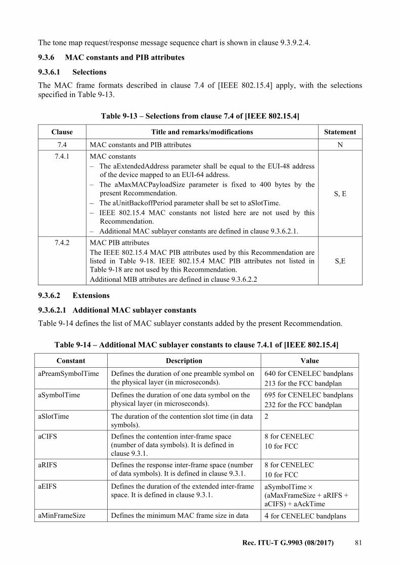
Rec. ITU-T G.9903 (08/2017) 81
The tone map request/response message sequence chart is shown in clause 9.3.9.2.4.
9.3.6 MAC constants and PIB attributes
9.3.6.1 Selections The MAC frame formats described in clause 7.4 of [IEEE 802.15.4] apply, with the selections specified in Table 9-13.
Table 9-13 – Selections from clause 7.4 of [IEEE 802.15.4]
Clause Title and remarks/modifications Statement
7.4 MAC constants and PIB attributes N 7.4.1 MAC constants
– The aExtendedAddress parameter shall be equal to the EUI-48 address of the device mapped to an EUI-64 address.
– The aMaxMACPayloadSize parameter is fixed to 400 bytes by the present Recommendation.
– The aUnitBackoffPeriod parameter shall be set to aSlotTime. – IEEE 802.15.4 MAC constants not listed here are not used by this
Recommendation. – Additional MAC sublayer constants are defined in clause 9.3.6.2.1.
S, E
7.4.2 MAC PIB attributes The IEEE 802.15.4 MAC PIB attributes used by this Recommendation are listed in Table 9-18. IEEE 802.15.4 MAC PIB attributes not listed in Table 9-18 are not used by this Recommendation. Additional MIB attributes are defined in clause 9.3.6.2.2
S,E
9.3.6.2 Extensions
9.3.6.2.1 Additional MAC sublayer constants Table 9-14 defines the list of MAC sublayer constants added by the present Recommendation.
Table 9-14 – Additional MAC sublayer constants to clause 7.4.1 of [IEEE 802.15.4]
Constant Description Value
aPreamSymbolTime Defines the duration of one preamble symbol on the physical layer (in microseconds).
640 for CENELEC bandplans 213 for the FCC bandplan
aSymbolTime Defines the duration of one data symbol on the physical layer (in microseconds).
695 for CENELEC bandplans 232 for the FCC bandplan
aSlotTime The duration of the contention slot time (in data symbols).
2
aCIFS Defines the contention inter-frame space (number of data symbols). It is defined in clause 9.3.1.
8 for CENELEC 10 for FCC
aRIFS Defines the response inter-frame space (number of data symbols). It is defined in clause 9.3.1.
8 for CENELEC 10 for FCC
aEIFS Defines the duration of the extended inter-frame space. It is defined in clause 9.3.1.
aSymbolTime × (aMaxFrameSize + aRIFS + aCIFS) + aAckTime
aMinFrameSize Defines the minimum MAC frame size in data 4 for CENELEC bandplans
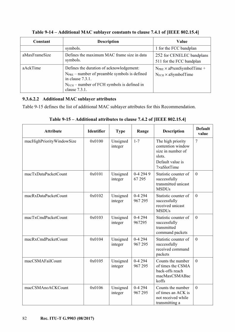
82 Rec. ITU-T G.9903 (08/2017)
Table 9-14 – Additional MAC sublayer constants to clause 7.4.1 of [IEEE 802.15.4]
Constant Description Value symbols. 1 for the FCC bandplan
aMaxFrameSize Defines the maximum MAC frame size in data symbols.
252 for CENELEC bandplans 511 for the FCC bandplan
aAckTime Defines the duration of acknowledgement: NPRE – number of preamble symbols is defined in clause 7.3.1. NFCH – number of FCH symbols is defined in clause 7.3.1.
NPRE × aPremSymbolTime + NFCH × aSymbolTime
9.3.6.2.2 Additional MAC sublayer attributes Table 9-15 defines the list of additional MAC sublayer attributes for this Recommendation.
Table 9-15 – Additional attributes to clause 7.4.2 of [IEEE 802.15.4]
Attribute Identifier Type Range Description Defaultvalue
macHighPriorityWindowSize 0x0100 Unsigned integer
1-7 The high priority contention window size in number of slots. Default value is 7×aSlotTime
7
macTxDataPacketCount 0x0101 Unsigned integer
0-4 294 967 295
Statistic counter of successfully transmitted unicast MSDUs
0
macRxDataPacketCount 0x0102 Unsigned integer
0-4 294 967 295
Statistic counter of successfully received unicast MSDUs
0
macTxCmdPacketCount 0x0103 Unsigned integer
0-4 294 967295
Statistic counter of successfully transmitted command packets
0
macRxCmdPacketCount 0x0104 Unsigned integer
0-4 294 967 295
Statistic counter of successfully received command packets
0
macCSMAFailCount 0x0105 Unsigned integer
0-4 294 967 295
Counts the number of times the CSMA back-offs reach macMaxCSMABackoffs
0
macCSMAnoACKCount 0x0106 Unsigned integer
0-4 294 967 295
Counts the number of times an ACK is not received while transmitting a
0
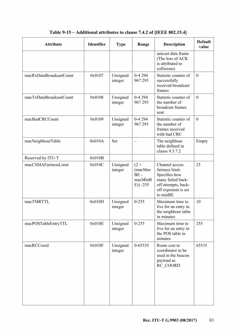
Rec. ITU-T G.9903 (08/2017) 83
Table 9-15 – Additional attributes to clause 7.4.2 of [IEEE 802.15.4]
Attribute Identifier Type Range Description Defaultvalue
unicast data frame (The loss of ACK is attributed to collisions)
macRxDataBroadcastCount 0x0107 Unsigned integer
0-4 294 967 295
Statistic counter of successfully received broadcast frames
0
macTxDataBroadcastCount 0x0108 Unsigned integer
0-4 294 967 295
Statistic counter of the number of broadcast frames sent
0
macBadCRCCount 0x0109 Unsigned integer
0-4 294 967 295
Statistic counter of the number of frames received with bad CRC
0
macNeighbourTable 0x010A Set – The neighbour table defined in clause 9.3.7.2
Empty
Reserved by ITU-T 0x010B macCSMAFairnessLimit 0x010C Unsigned
integer (2 × (macMaxBE - macMinBE)) -255
Channel access fairness limit. Specifies how many failed back-off attempts, back-off exponent is set to minBE
25
macTMRTTL 0x010D Unsigned integer
0-255 Maximum time to live for an entry in the neighbour table in minutes
10
macPOSTableEntryTTL 0x010E Unsigned integer
0-255 Maximum time to live for an entry in the POS table in minutes
255
macRCCoord 0x010F Unsigned integer
0-65535 Route cost to coordinator to be used in the beacon payload as RC_COORD
65535
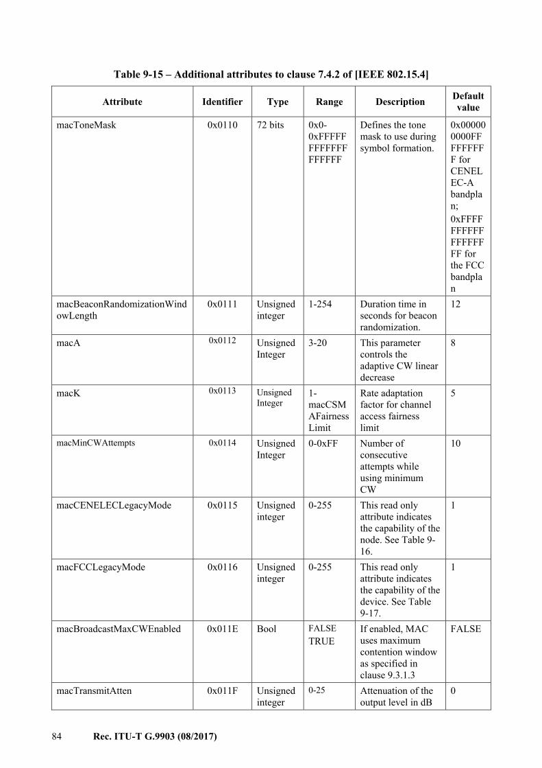
84 Rec. ITU-T G.9903 (08/2017)
Table 9-15 – Additional attributes to clause 7.4.2 of [IEEE 802.15.4]
Attribute Identifier Type Range Description Defaultvalue
macToneMask 0x0110 72 bits 0x0-0xFFFFFFFFFFFFFFFFFF
Defines the tone mask to use during symbol formation.
0x000000000FFFFFFFFF for CENELEC-A bandplan; 0xFFFFFFFFFFFFFFFFFF for the FCC bandplan
macBeaconRandomizationWindowLength
0x0111 Unsigned integer
1-254 Duration time in seconds for beacon randomization.
12
macA 0x0112
Unsigned Integer
3-20 This parameter controls the adaptive CW linear decrease
8
macK 0x0113 Unsigned Integer
1- macCSMAFairnessLimit
Rate adaptation factor for channel access fairness limit
5
macMinCWAttempts 0x0114 Unsigned Integer
0-0xFF Number of consecutive attempts while using minimum CW
10
macCENELECLegacyMode 0x0115 Unsigned integer
0-255 This read only attribute indicates the capability of the node. See Table 9-16.
1
macFCCLegacyMode 0x0116 Unsigned integer
0-255 This read only attribute indicates the capability of the device. See Table 9-17.
1
macBroadcastMaxCWEnabled 0x011E Bool FALSE TRUE
If enabled, MAC uses maximum contention window as specified in clause 9.3.1.3
FALSE
macTransmitAtten 0x011F Unsigned integer
0-25 Attenuation of the output level in dB
0
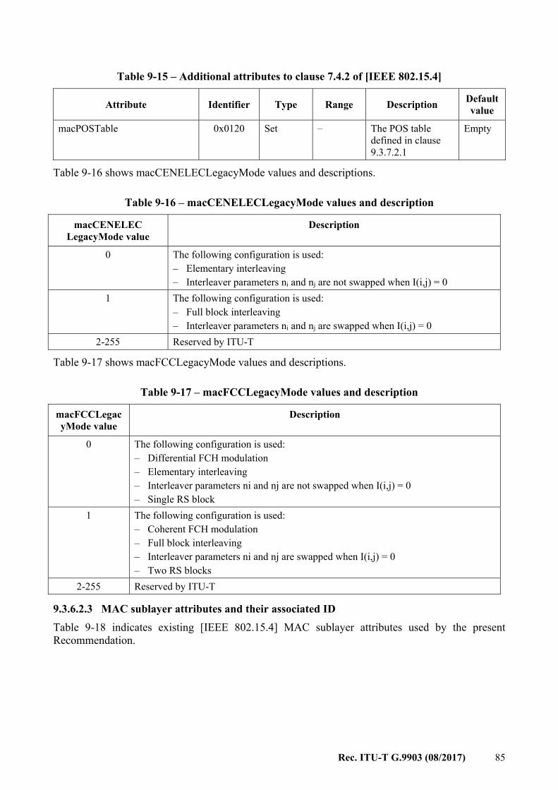
Rec. ITU-T G.9903 (08/2017) 85
Table 9-15 – Additional attributes to clause 7.4.2 of [IEEE 802.15.4]
Attribute Identifier Type Range Description Defaultvalue
macPOSTable 0x0120 Set – The POS table defined in clause 9.3.7.2.1
Empty
Table 9-16 shows macCENELECLegacyMode values and descriptions.
Table 9-16 – macCENELECLegacyMode values and description
macCENELEC LegacyMode value
Description
0 The following configuration is used: – Elementary interleaving – Interleaver parameters ni and nj are not swapped when I(i,j) = 0
1 The following configuration is used: – Full block interleaving – Interleaver parameters ni and nj are swapped when I(i,j) = 0
2-255 Reserved by ITU-T
Table 9-17 shows macFCCLegacyMode values and descriptions.
Table 9-17 – macFCCLegacyMode values and description
macFCCLegacyMode value
Description
0 The following configuration is used: – Differential FCH modulation – Elementary interleaving – Interleaver parameters ni and nj are not swapped when I(i,j) = 0 – Single RS block
1 The following configuration is used: – Coherent FCH modulation – Full block interleaving – Interleaver parameters ni and nj are swapped when I(i,j) = 0 – Two RS blocks
2-255 Reserved by ITU-T
9.3.6.2.3 MAC sublayer attributes and their associated ID Table 9-18 indicates existing [IEEE 802.15.4] MAC sublayer attributes used by the present Recommendation.
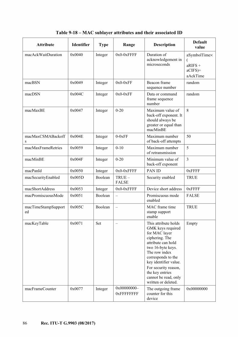
86 Rec. ITU-T G.9903 (08/2017)
Table 9-18 – MAC sublayer attributes and their associated ID
Attribute Identifier Type Range Description Default value
macAckWaitDuration 0x0040 Integer 0x0-0xFFFF Duration of acknowledgement in microseconds
aSymbolTime×( aRIFS + aCIFS)+ aAckTime
macBSN 0x0049 Integer 0x0-0xFF Beacon frame sequence number
random
macDSN 0x004C Integer 0x0-0xFF Data or command frame sequence number
random
macMaxBE 0x0047 Integer 0-20 Maximum value of back-off exponent. It should always be greater or equal than macMinBE
8
macMaxCSMABackoffs
0x004E Integer 0-0xFF Maximum number of back-off attempts
50
macMaxFrameRetries 0x0059 Integer 0-10 Maximum number of retransmission
5
macMinBE 0x004F Integer 0-20 Minimum value of back-off exponent
3
macPanId 0x0050 Integer 0x0-0xFFFF PAN ID 0xFFFF macSecurityEnabled 0x005D Boolean TRUE –
FALSE Security enabled TRUE
macShortAddress 0x0053 Integer 0x0-0xFFFF Device short address 0xFFFF macPromiscuousMode 0x0051 Boolean – Promiscuous mode
enabled FALSE
macTimeStampSupported
0x005C Boolean – MAC frame time stamp support enable
TRUE
macKeyTable 0x0071 Set – This attribute holds GMK keys required for MAC layer ciphering. The attribute can hold two 16-byte keys. The row index corresponds to the key identifier value. For security reason, the key entries cannot be read, only written or deleted.
Empty
macFrameCounter 0x0077 Integer 0x00000000– 0xFFFFFFFF
The outgoing frame counter for this device
0x00000000

Rec. ITU-T G.9903 (08/2017) 87
9.3.7 MAC functional description
9.3.7.1 Selections The MAC functional description described in clause 7.5 of [IEEE 802.15.4] applies, with the selections specified in Table 9-19.
Table 9-19 – Selections from clause 7.5 of [IEEE 802.15.4]
Clause Title and remarks/modifications Statement
7.5 MAC functional description – beacon-enabled PAN and GTS are not supported – GTS contention free access is not supported.
S
7.5.1 Channel access – See clause 9.3.1 for the channel access functional description. E
7.5.1.1 Superframe structure N/R 7.5.1.2 Incoming and outgoing frame structure N/R 7.5.1.3 Inter-frame (IFS) spacing
– See clause 9.3.1 for the inter-frame spacing description. E
7.5.1.4 CSMA-CA algorithm – See clause 9.3.1 for a description of the CSMA-CA algorithm
(including priority, ARQ, segmentation and reassembly overview). E
7.5.2 Starting and maintaining PANs N 7.5.2.1 Scanning through channels
– Passive scanning is not supported – Orphan scanning is not supported – ED scanning is not supported – Active scanning is the only supported scanning mode – As there is no channel page or channel list notion at the physical level,
a scan request is agnostic to a physical channel.
S
7.5.2.1.1 ED channel scan – ED channel scan is not supported by the present Recommendation N/R
7.5.2.1.2 Active channel scan – Active channel scan is only used by an un-associated device prior to
starting association and by the PAN coordinator prior to starting a new network.
– As there is no channel page or channel list notion at the physical level, a scan request does not care about a particular channel.
S
7.5.2.1.3 Passive channel scan – Passive channel scan is not supported by the present Recommendation. N/R
7.5.2.1.4 Orphan channel scan – Orphan channel scan is not supported by the present Recommendation. N/R
7.5.2.2 PAN identifier conflict resolution PAN conflict handling is not used in this specification. N/R
7.5.2.3 Starting and realigning a PAN N 7.5.2.3.1 Starting a PAN N 7.5.2.3.2 Realigning a PAN
– PAN realignment is not supported by the present specification. N/R
88 Rec. ITU-T G.9903 (08/2017)
Table 9-19 – Selections from clause 7.5 of [IEEE 802.15.4]
Clause Title and remarks/modifications Statement
7.5.2.3.3 Realignment in a PAN – PAN realignment is not supported by the present specification. N/R
7.5.2.3.4 Updating superframe configuration and channel PIB attributes – The macBeaconOrder parameter shall be set to 15 to have a beaconless
PAN. – The phyCurrentPage and phyCurrentChannel parameters are not used
and shall be set to 0.
S
7.5.2.4 Beacon generation – Only non-beacon-enabled PAN are used – Beacon shall be transmitted using the robust mode – Beacon transmission shall be randomized between 0 and
macBeaconRandomizationWindowLength seconds – When the node is waiting for its beacon transmission it shall ignore any
additional incoming beacon request frame
S, E
7.5.2.5 Device discovery – Device discovery is done using the active scanning procedure
described in clause 9.4.4.2.2.2, to force a coordinator to send a beacon. E
7.5.3 Association and disassociation N 7.5.3.1 Association
– Association is fully described in clause 9.4.4. N/R
7.5.3.2 Disassociation – Disassociation is fully described in clause 9.4.4. N/R
7.5.4 Synchronization N/R 7.5.4.1 Synchronization with beacons
– Beacon synchronization is not used in this Recommendation. N/R
7.5.4.2 Synchronization without beacons N/R 7.5.4.3 Orphaned device realignment
Network connection status shall be supervised by the upper layers. N/R
7.5.5 Transaction handling – Transactions are not supported in the present Recommendation. N/R
7.5.6 Transmission, reception and acknowledgement N 7.5.6.1 Transmission N 7.5.6.2 Reception and rejection N 7.5.6.3 Extracting pending data from a coordinator N/R 7.5.6.4 Use of acknowledgements and retransmissions N 7.5.6.4.1 No acknowledgement E 7.5.6.4.2 Acknowledgement
– The present Recommendation defines an acknowledgement differently. The detailed ACK implementation is described in clause 9.3.2.
E
7.5.6.4.3 Retransmissions N 7.5.6.5 Promiscuous mode N 7.5.6.6 Transmission scenario N
Rec. ITU-T G.9903 (08/2017) 89
Table 9-19 – Selections from clause 7.5 of [IEEE 802.15.4]
Clause Title and remarks/modifications Statement
7.5.7 GTS allocation and management – GTS are not used in this Recommendation N/R
7.5.8 Frame security N 7.5.8.1 Security-related MAC PIB attributes
– Key table contains two 16-byte keys. They represent GMK as described in clause 10.5.2. The adpActiveKeyIndex parameter selects the key used to cipher outgoing frames.
– Device table is used – Security level table is not used – Automatic request attributes are not used – Default key source is not used.
S
7.5.8.1.1 Key table – Key table contains two 16-byte keys. S
7.5.8.1.2 Device table The table is only used to provide the anti-replay mechanism on incoming frames (key selection and blacklist are not used).
S
7.5.8.1.3 Minimum security level table N/R 7.5.8.1.4 Frame counter
The frame counter shall be restored after a power cycle or when MLME-RESET.request is invoked. The stored value needs to be greater than the last used frame count. Management of reset and recovery of the frame-counter is beyond the scope of this recommendation and shall be handled at higher layers.
E
7.5.8.1.5 Automatic request attributes N/R 7.5.8.1.6 Default key source N/R 7.5.8.1.7 PAN coordinator address N/R 7.5.8.2 Functional description N 7.5.8.2.1 Outgoing frame security procedure N 7.5.8.2.2 Outgoing frame key retrieval procedure N/R 7.5.8.2.3 Incoming frame security procedure
– The KeyIndex parameter selects the actual key from Key table. S
7.5.8.2.4 Incoming frame security material retrieval procedure N/R 7.5.8.2.5 KeyDescriptor lookup table N/R 7.5.8.2.6 Blacklist checking procedure N/R 7.5.8.2.7 DeviceDescriptor lookup procedure N/R 7.5.8.2.8 Incoming security level checking procedure N/R 7.5.8.2.9 Incoming key usage policy checking procedure N/R
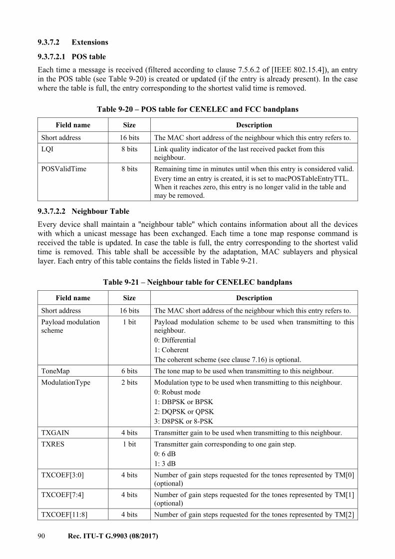
90 Rec. ITU-T G.9903 (08/2017)
9.3.7.2 Extensions
9.3.7.2.1 POS table Each time a message is received (filtered according to clause 7.5.6.2 of [IEEE 802.15.4]), an entry in the POS table (see Table 9-20) is created or updated (if the entry is already present). In the case where the table is full, the entry corresponding to the shortest valid time is removed.
Table 9-20 – POS table for CENELEC and FCC bandplans
Field name Size Description
Short address 16 bits The MAC short address of the neighbour which this entry refers to. LQI 8 bits Link quality indicator of the last received packet from this
neighbour. POSValidTime 8 bits Remaining time in minutes until when this entry is considered valid.
Every time an entry is created, it is set to macPOSTableEntryTTL. When it reaches zero, this entry is no longer valid in the table and may be removed.
9.3.7.2.2 Neighbour Table Every device shall maintain a ''neighbour table'' which contains information about all the devices with which a unicast message has been exchanged. Each time a tone map response command is received the table is updated. In case the table is full, the entry corresponding to the shortest valid time is removed. This table shall be accessible by the adaptation, MAC sublayers and physical layer. Each entry of this table contains the fields listed in Table 9-21.
Table 9-21 – Neighbour table for CENELEC bandplans
Field name Size Description
Short address 16 bits The MAC short address of the neighbour which this entry refers to. Payload modulation scheme
1 bit Payload modulation scheme to be used when transmitting to this neighbour. 0: Differential 1: Coherent The coherent scheme (see clause 7.16) is optional.
ToneMap 6 bits The tone map to be used when transmitting to this neighbour. ModulationType 2 bits Modulation type to be used when transmitting to this neighbour.
0: Robust mode 1: DBPSK or BPSK 2: DQPSK or QPSK 3: D8PSK or 8-PSK
TXGAIN 4 bits Transmitter gain to be used when transmitting to this neighbour. TXRES 1 bit Transmitter gain corresponding to one gain step.
0: 6 dB 1: 3 dB
TXCOEF[3:0] 4 bits Number of gain steps requested for the tones represented by TM[0] (optional)
TXCOEF[7:4] 4 bits Number of gain steps requested for the tones represented by TM[1] (optional)
TXCOEF[11:8] 4 bits Number of gain steps requested for the tones represented by TM[2]
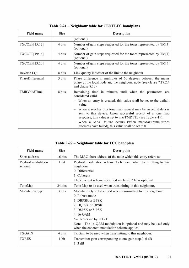
Rec. ITU-T G.9903 (08/2017) 91
Table 9-21 – Neighbour table for CENELEC bandplans
Field name Size Description (optional)
TXCOEF[15:12] 4 bits Number of gain steps requested for the tones represented by TM[3] (optional)
TXCOEF[19:16] 4 bits Number of gain steps requested for the tones represented by TM[4] (optional)
TXCOEF[23:20] 4 bits Number of gain steps requested for the tones represented by TM[5] (optional)
Reverse LQI 8 bits Link quality indicator of the link to the neighbour PhaseDifferential 3 bits Phase difference in multiples of 60 degrees between the mains
phase of the local node and the neighbour node (see clause 7.17.2.4 and clause 8.10)
TMRValidTime 8 bits Remaining time in minutes until when the parameters are considered valid. – When an entry is created, this value shall be set to the default
value. – When it reaches 0, a tone map request may be issued if data is
sent to this device. Upon successful receipt of a tone map response, this value is set to macTMRTTL (see Table 9-15).
– When a MAC failure occurs (when macMaxFrameRetries attempts have failed), this value shall be set to 0.
Table 9-22 – Neighbour table for FCC bandplan
Field name Size Description
Short address 16 bits The MAC short address of the node which this entry refers to. Payload modulation scheme
1 bit Payload modulation scheme to be used when transmitting to this neighbour 0: Differential 1: Coherent The coherent scheme specified in clause 7.16 is optional.
ToneMap 24 bits Tone Map to be used when transmitting to this neighbour. ModulationType 3 bits Modulation type to be used when transmitting to this neighbour.
0: Robust mode 1: DBPSK or BPSK 2: DQPSK or QPSK 3: D8PSK or 8-PSK 4: 16-QAM 5-7: Reserved by ITU-T Note – The 16-QAM modulation is optional and may be used only when the coherent modulation scheme applies.
TXGAIN 4 bits Tx Gain to be used when transmitting to this neighbour. TXRES 1 bit Transmitter gain corresponding to one gain step.0: 6 dB
1: 3 dB
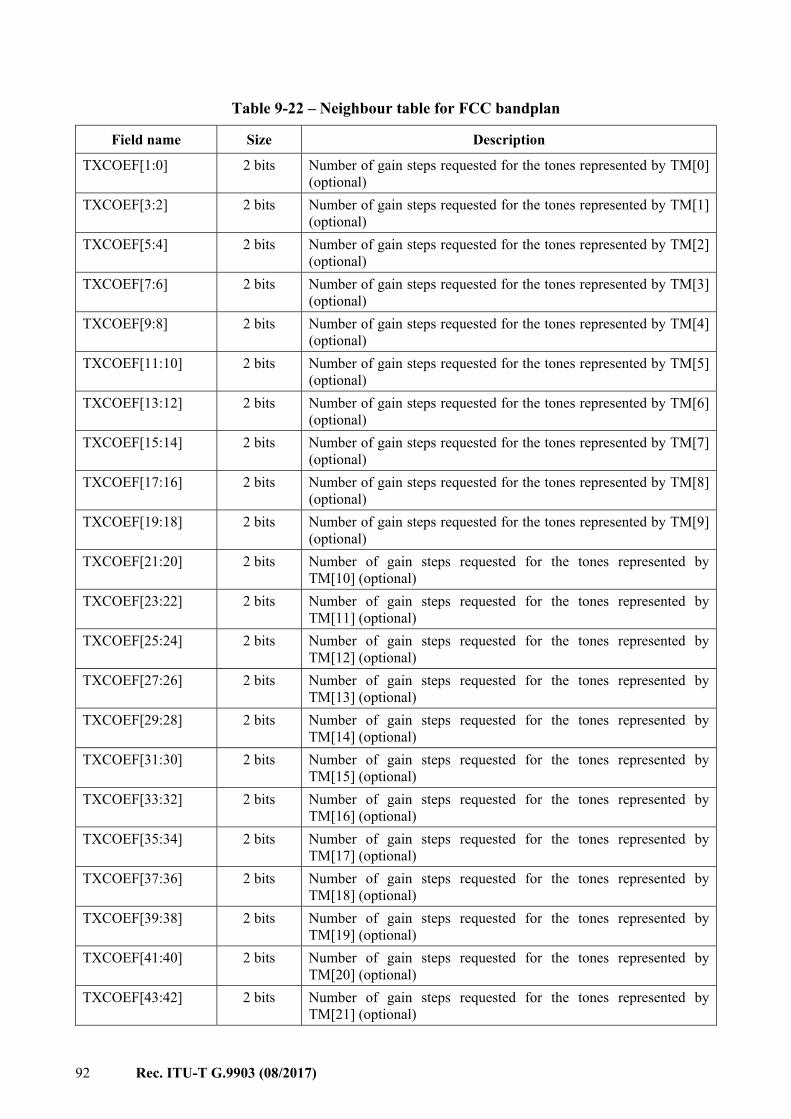
92 Rec. ITU-T G.9903 (08/2017)
Table 9-22 – Neighbour table for FCC bandplan
Field name Size Description
TXCOEF[1:0] 2 bits Number of gain steps requested for the tones represented by TM[0] (optional)
TXCOEF[3:2] 2 bits Number of gain steps requested for the tones represented by TM[1] (optional)
TXCOEF[5:4] 2 bits Number of gain steps requested for the tones represented by TM[2] (optional)
TXCOEF[7:6] 2 bits Number of gain steps requested for the tones represented by TM[3] (optional)
TXCOEF[9:8] 2 bits Number of gain steps requested for the tones represented by TM[4] (optional)
TXCOEF[11:10] 2 bits Number of gain steps requested for the tones represented by TM[5] (optional)
TXCOEF[13:12] 2 bits Number of gain steps requested for the tones represented by TM[6] (optional)
TXCOEF[15:14] 2 bits Number of gain steps requested for the tones represented by TM[7] (optional)
TXCOEF[17:16] 2 bits Number of gain steps requested for the tones represented by TM[8] (optional)
TXCOEF[19:18] 2 bits Number of gain steps requested for the tones represented by TM[9] (optional)
TXCOEF[21:20] 2 bits Number of gain steps requested for the tones represented by TM[10] (optional)
TXCOEF[23:22] 2 bits Number of gain steps requested for the tones represented by TM[11] (optional)
TXCOEF[25:24] 2 bits Number of gain steps requested for the tones represented by TM[12] (optional)
TXCOEF[27:26] 2 bits Number of gain steps requested for the tones represented by TM[13] (optional)
TXCOEF[29:28] 2 bits Number of gain steps requested for the tones represented by TM[14] (optional)
TXCOEF[31:30] 2 bits Number of gain steps requested for the tones represented by TM[15] (optional)
TXCOEF[33:32] 2 bits Number of gain steps requested for the tones represented by TM[16] (optional)
TXCOEF[35:34] 2 bits Number of gain steps requested for the tones represented by TM[17] (optional)
TXCOEF[37:36] 2 bits Number of gain steps requested for the tones represented by TM[18] (optional)
TXCOEF[39:38] 2 bits Number of gain steps requested for the tones represented by TM[19] (optional)
TXCOEF[41:40] 2 bits Number of gain steps requested for the tones represented by TM[20] (optional)
TXCOEF[43:42] 2 bits Number of gain steps requested for the tones represented by TM[21] (optional)
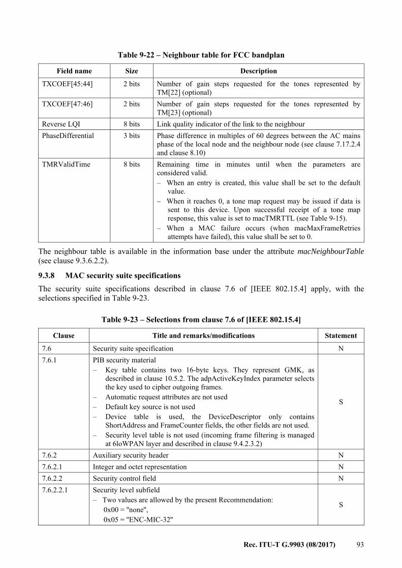
Rec. ITU-T G.9903 (08/2017) 93
Table 9-22 – Neighbour table for FCC bandplan
Field name Size Description
TXCOEF[45:44] 2 bits Number of gain steps requested for the tones represented by TM[22] (optional)
TXCOEF[47:46] 2 bits Number of gain steps requested for the tones represented by TM[23] (optional)
Reverse LQI 8 bits Link quality indicator of the link to the neighbour PhaseDifferential 3 bits Phase difference in multiples of 60 degrees between the AC mains
phase of the local node and the neighbour node (see clause 7.17.2.4 and clause 8.10)
TMRValidTime 8 bits Remaining time in minutes until when the parameters are considered valid. – When an entry is created, this value shall be set to the default
value. – When it reaches 0, a tone map request may be issued if data is
sent to this device. Upon successful receipt of a tone map response, this value is set to macTMRTTL (see Table 9-15).
– When a MAC failure occurs (when macMaxFrameRetries attempts have failed), this value shall be set to 0.
The neighbour table is available in the information base under the attribute macNeighbourTable (see clause 9.3.6.2.2).
9.3.8 MAC security suite specifications The security suite specifications described in clause 7.6 of [IEEE 802.15.4] apply, with the selections specified in Table 9-23.
Table 9-23 – Selections from clause 7.6 of [IEEE 802.15.4]
Clause Title and remarks/modifications Statement
7.6 Security suite specification N 7.6.1 PIB security material
– Key table contains two 16-byte keys. They represent GMK, as described in clause 10.5.2. The adpActiveKeyIndex parameter selects the key used to cipher outgoing frames.
– Automatic request attributes are not used – Default key source is not used – Device table is used, the DeviceDescriptor only contains
ShortAddress and FrameCounter fields, the other fields are not used. – Security level table is not used (incoming frame filtering is managed
at 6loWPAN layer and described in clause 9.4.2.3.2)
S
7.6.2 Auxiliary security header N 7.6.2.1 Integer and octet representation N 7.6.2.2 Security control field N 7.6.2.2.1 Security level subfield
– Two values are allowed by the present Recommendation: 0x00 = ''none'', 0x05 = ''ENC-MIC-32''
S
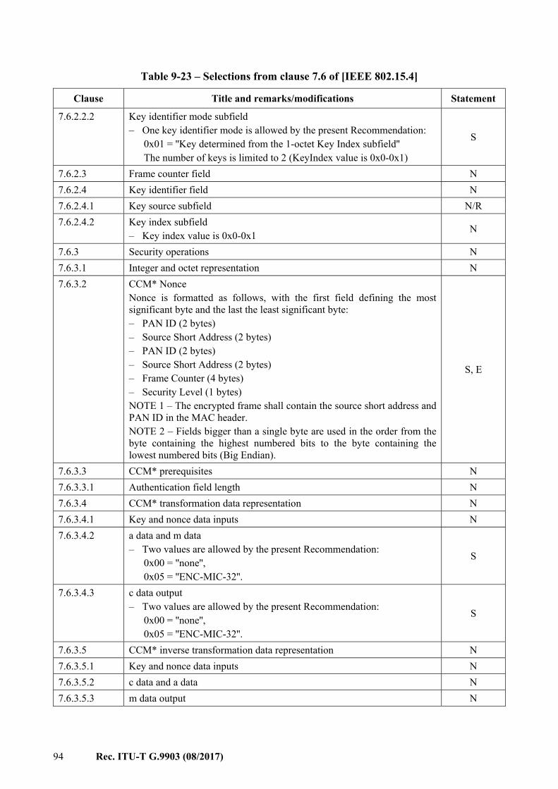
94 Rec. ITU-T G.9903 (08/2017)
Table 9-23 – Selections from clause 7.6 of [IEEE 802.15.4]
Clause Title and remarks/modifications Statement
7.6.2.2.2 Key identifier mode subfield – One key identifier mode is allowed by the present Recommendation:
0x01 = ''Key determined from the 1-octet Key Index subfield'' The number of keys is limited to 2 (KeyIndex value is 0x0-0x1)
S
7.6.2.3 Frame counter field N 7.6.2.4 Key identifier field N 7.6.2.4.1 Key source subfield N/R 7.6.2.4.2 Key index subfield
– Key index value is 0x0-0x1 N
7.6.3 Security operations N 7.6.3.1 Integer and octet representation N 7.6.3.2 CCM* Nonce
Nonce is formatted as follows, with the first field defining the most significant byte and the last the least significant byte: – PAN ID (2 bytes) – Source Short Address (2 bytes) – PAN ID (2 bytes) – Source Short Address (2 bytes) – Frame Counter (4 bytes) – Security Level (1 bytes) NOTE 1 – The encrypted frame shall contain the source short address and PAN ID in the MAC header. NOTE 2 – Fields bigger than a single byte are used in the order from the byte containing the highest numbered bits to the byte containing the lowest numbered bits (Big Endian).
S, E
7.6.3.3 CCM* prerequisites N 7.6.3.3.1 Authentication field length N 7.6.3.4 CCM* transformation data representation N 7.6.3.4.1 Key and nonce data inputs N 7.6.3.4.2 a data and m data
– Two values are allowed by the present Recommendation: 0x00 = ''none'', 0x05 = ''ENC-MIC-32''.
S
7.6.3.4.3 c data output – Two values are allowed by the present Recommendation:
0x00 = ''none'', 0x05 = ''ENC-MIC-32''.
S
7.6.3.5 CCM* inverse transformation data representation N 7.6.3.5.1 Key and nonce data inputs N 7.6.3.5.2 c data and a data N 7.6.3.5.3 m data output N
Rec. ITU-T G.9903 (08/2017) 95
9.3.9 Message sequence chart illustrating MAC – PHY
9.3.9.1 Selections The message sequence chart illustrating MAC – PHY interaction described in clause 7.7 of [IEEE 802.15.4] applies, with the selections specified in Table 9-24.
Table 9-24 – Selections from clause 7.7 of [IEEE 802.15.4]
Clause Title and remarks/modifications Statement
7.7 Message sequence chart illustrating MAC-PHY interaction – Figure 78: replaced by clause 9.3.9.2.1 – Figure 79: N/R – Figure 80: N/R – Figure 81: N/R – Figure 82: N/R – Figure 83: replaced by clause 9.3.9.2.2 – Figures 84 and 85: replaced by clause 9.3.9.2.3 – Figure 86: N/R – Additional figure about channel estimation in clause 9.3.9.2.4
S, E
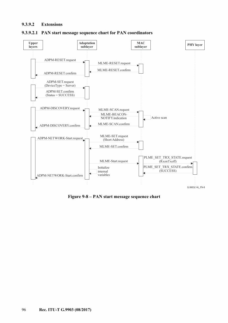
96 Rec. ITU-T G.9903 (08/2017)
9.3.9.2 Extensions
9.3.9.2.1 PAN start message sequence chart for PAN coordinators
G.9903(14)_F9-8
Upperlayers
ADPM-RESET.request
Adaptationsublayer
MACsublayer
MLME-RESET.request
MLME-RESET.confirmADPM-RESET.confirm
PHY layer
ADPM-SET.request(DeviceType = Server)
ADPM-SET.confirm(Status = SUCCESS)
ADPM-DISCOVERY.request MLME-SCAN.request
Active scanMLME-BEACON-NOTIFY.indication
MLME-SCAN.confirmADPM-DISCOVERY.confirm
ADPM-NETWORK-Start.request MLME-SET.request(Short Address)
MLME-SET.confirm
MLME-Start.request
Initializeinternalvariables
PLME_SET_TRX_STATE.request(RxonTxoff)
PLME_SET_TRX_STATE.confirm(SUCCESS)
ADPM-NETWORK-Start.confirm
Figure 9-8 – PAN start message sequence chart
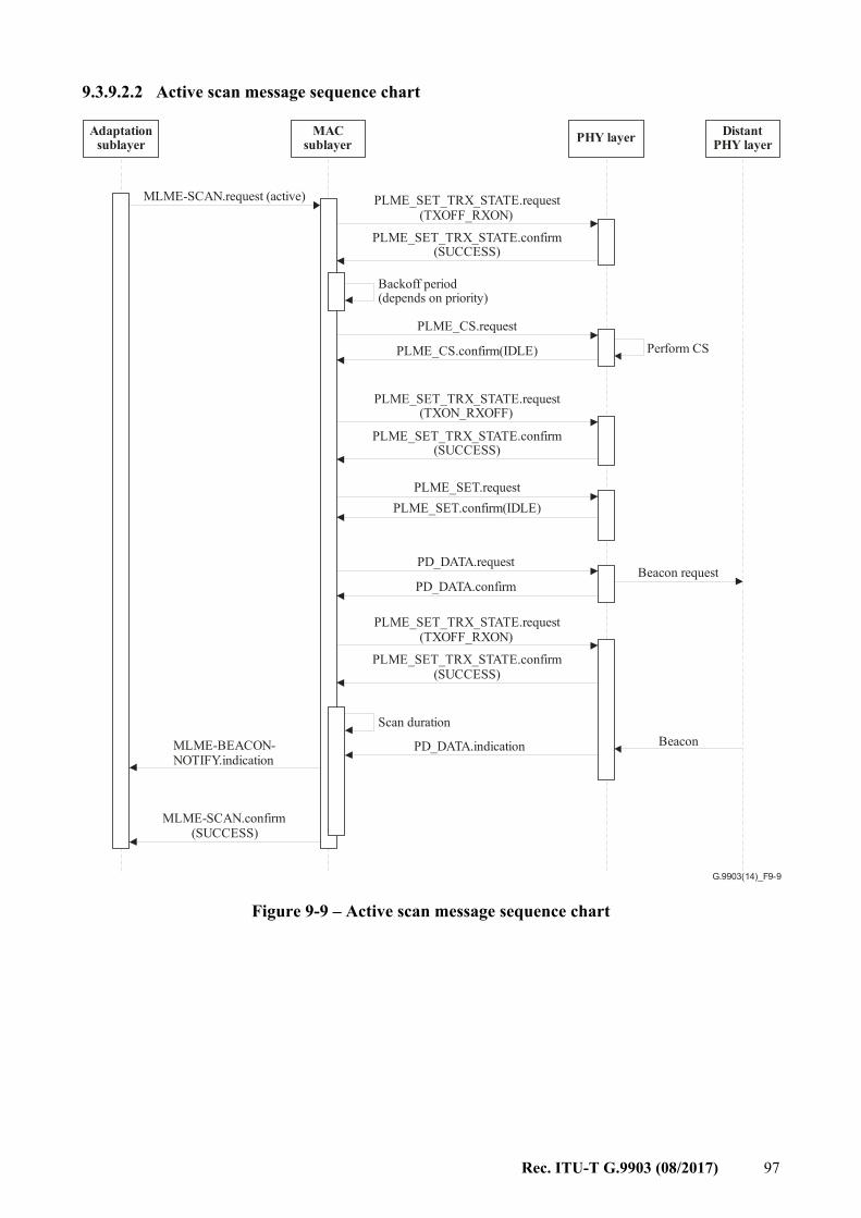
Rec. ITU-T G.9903 (08/2017) 97
9.3.9.2.2 Active scan message sequence chart
G.9903(14)_F9-9
Adaptationsublayer
MACsublayer PHY layer Distant
PHY layer
MLME-SCAN.request (active) PLME_SET_TRX_STATE.request(TXOFF_RXON)
PLME_SET_TRX_STATE.confirm(SUCCESS)
Backoff period(depends on priority)
PLME_CS.request
PLME_CS.confirm(IDLE) Perform CS
PLME_SET_TRX_STATE.request(TXON_RXOFF)
PLME_SET_TRX_STATE.confirm(SUCCESS)
PLME_SET.requestPLME_SET.confirm(IDLE)
PD_DATA.requestBeacon request
PD_DATA.confirm
PLME_SET_TRX_STATE.request(TXOFF_RXON)
PLME_SET_TRX_STATE.confirm(SUCCESS)
Scan durationBeaconPD_DATA.indicationMLME-BEACON-
NOTIFY.indication
MLME-SCAN.confirm(SUCCESS)
Figure 9-9 – Active scan message sequence chart
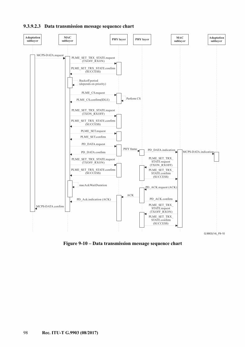
98 Rec. ITU-T G.9903 (08/2017)
9.3.9.2.3 Data transmission message sequence chart
G.9903(14)_F9-10
Adaptationsublayer
Adaptationsublayer
MACsublayer
MACsublayerPHY layer PHY layer
MCPS-DATA.requestPLME_SET_TRX_STATE.request
(TXOFF_RXON)
PLME_SET_TRX_STATE.confirm(SUCCESS)
Backoff period(depends on priority)
PLME_CS.request
PLME_CS.confirm(IDLE) Perform CS
PLME_SET_TRX_STATE.request(TXON_RXOFF)
PLME_SET_TRX_STATE.confirm(SUCCESS)
PLME_SET.request
PLME_SET.confirm
PD_DATA.request
PD_DATA.confirm
PLME_SET_TRX_STATE.request(TXOFF_RXON)
PLME_SET_TRX_STATE.confirm(SUCCESS)
macAckWaitDuration
PD_Ack.indication (ACK)
MCPS-DATA.confirm
PHY frame PD_DATA.indication
PLME_SET_TRX_STATE.request
(TXON_RXOFF)PLME_SET_TRX_
STATE.confirm(SUCCESS)
ACK
PD_ACK.request (ACK)
PD_ACK.confirm
MCPS-DATA.indication
PLME_SET_TRX_STATE.confirm
(SUCCESS)
PLME_SET_TRX_STATE.request
(TXOFF_RXON)
Figure 9-10 – Data transmission message sequence chart
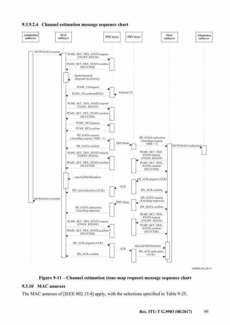
Rec. ITU-T G.9903 (08/2017) 99
9.3.9.2.4 Channel estimation message sequence chart
G.9903(14)_F9-11
Adaptationsublayer
Adaptationsublayer
MACsublayer
MACsublayerPHY layer PHY layer
MCPS-DATA.requestPLME_SET_TRX_STATE.request
(TXOFF_RXON)
PLME_SET_TRX_STATE.confirm(SUCCESS)
Backoff period(depends on priority)
PLME_CS.request
PLME_CS.confirm(IDLE) Perform CS
PLME_SET_TRX_STATE.request(TXON_RXOFF)
PLME_SET_TRX_STATE.confirm(SUCCESS)
PLME_SET.request
PLME_SET.confirm
PD_DATA.request(ToneMap request, TMR = 1)
PD_DATA.confirm
PLME_SET_TRX_STATE.request(TXOFF_RXON)
PLME_SET_TRX_STATE.confirm(SUCCESS)
macAckWaitDuration
PD_Ack.indication (ACK)
MCPS-DATA.confirm
PHY frame
PD_DATA.indication(ToneMap request,
TMR = 1)
PLME_SET_TRX_STATE.request
(TXON_RXOFF)PLME_SET_TRX_
STATE.confirm(SUCCESS)
ACK
PD_ACK.request (ACK)
PD_DATA.request(ToneMap response)
PD_ACK.confirm
PD_DATA.confirm
MCPS-DATA.indication
PLME_SET_TRX_STATE.confirm
(SUCCESS)
PLME_SET_TRX_STATE.request
(TXOFF_RXON)
PHY frame
PD_DATA.indication(ToneMap response)
PLME_SET_TRX_STATE.request(TXON_RXOFF)
PLME_SET_TRX_STATE.confirm(SUCCESS)
PD_ACK.request (ACK)
PD_ACK.confirm
ACKmacAckWaitDuration
PD_ACK.indication(ACK)
Figure 9-11 – Channel estimation (tone map request) message sequence chart
9.3.10 MAC annexes The MAC annexes of [IEEE 802.15.4] apply, with the selections specified in Table 9-25.
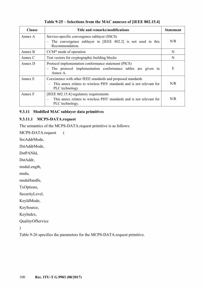
100 Rec. ITU-T G.9903 (08/2017)
Table 9-25 – Selections from the MAC annexes of [IEEE 802.15.4]
Clause Title and remarks/modifications Statement
Annex A Service-specific convergence sublayer (SSCS) – The convergence sublayer in [IEEE 802.2] is not used in this
Recommendation. N/R
Annex B CCM* mode of operation N Annex C Test vectors for cryptographic building blocks N Annex D Protocol implementation conformance statement (PICS)
– The protocol implementation conformance tables are given in Annex A.
E
Annex E Coexistence with other IEEE standards and proposed standards – This annex relates to wireless PHY standards and is not relevant for
PLC technology. N/R
Annex F [IEEE 802.15.4] regulatory requirements – This annex relates to wireless PHY standards and is not relevant for
PLC technology. N/R
9.3.11 Modified MAC sublayer data primitives
9.3.11.1 MCPS-DATA.request The semantics of the MCPS-DATA.request primitive is as follows: MCPS-DATA.request ( SrcAddrMode, DstAddrMode, DstPANId, DstAddr, msduLength, msdu, msduHandle, TxOptions, SecurityLevel, KeyIdMode, KeySource, KeyIndex, QualityOfService ) Table 9-26 specifies the parameters for the MCPS-DATA.request primitive.
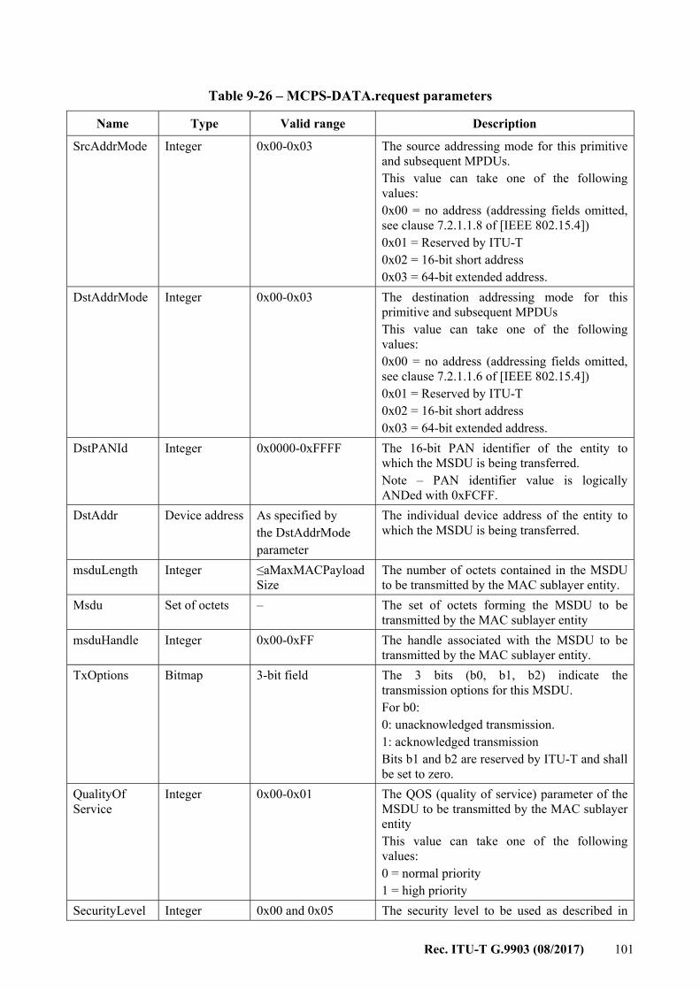
Rec. ITU-T G.9903 (08/2017) 101
Table 9-26 – MCPS-DATA.request parameters
Name Type Valid range Description
SrcAddrMode Integer 0x00-0x03 The source addressing mode for this primitive and subsequent MPDUs. This value can take one of the following values: 0x00 = no address (addressing fields omitted, see clause 7.2.1.1.8 of [IEEE 802.15.4]) 0x01 = Reserved by ITU-T 0x02 = 16-bit short address 0x03 = 64-bit extended address.
DstAddrMode Integer 0x00-0x03 The destination addressing mode for this primitive and subsequent MPDUs This value can take one of the following values: 0x00 = no address (addressing fields omitted, see clause 7.2.1.1.6 of [IEEE 802.15.4]) 0x01 = Reserved by ITU-T 0x02 = 16-bit short address 0x03 = 64-bit extended address.
DstPANId Integer 0x0000-0xFFFF The 16-bit PAN identifier of the entity to which the MSDU is being transferred. Note – PAN identifier value is logically ANDed with 0xFCFF.
DstAddr Device address As specified by the DstAddrMode parameter
The individual device address of the entity to which the MSDU is being transferred.
msduLength Integer ≤aMaxMACPayload Size
The number of octets contained in the MSDU to be transmitted by the MAC sublayer entity.
Msdu Set of octets – The set of octets forming the MSDU to be transmitted by the MAC sublayer entity
msduHandle Integer 0x00-0xFF The handle associated with the MSDU to be transmitted by the MAC sublayer entity.
TxOptions Bitmap 3-bit field The 3 bits (b0, b1, b2) indicate the transmission options for this MSDU. For b0: 0: unacknowledged transmission. 1: acknowledged transmission Bits b1 and b2 are reserved by ITU-T and shall be set to zero.
QualityOf Service
Integer 0x00-0x01 The QOS (quality of service) parameter of the MSDU to be transmitted by the MAC sublayer entity This value can take one of the following values: 0 = normal priority 1 = high priority
SecurityLevel Integer 0x00 and 0x05 The security level to be used as described in
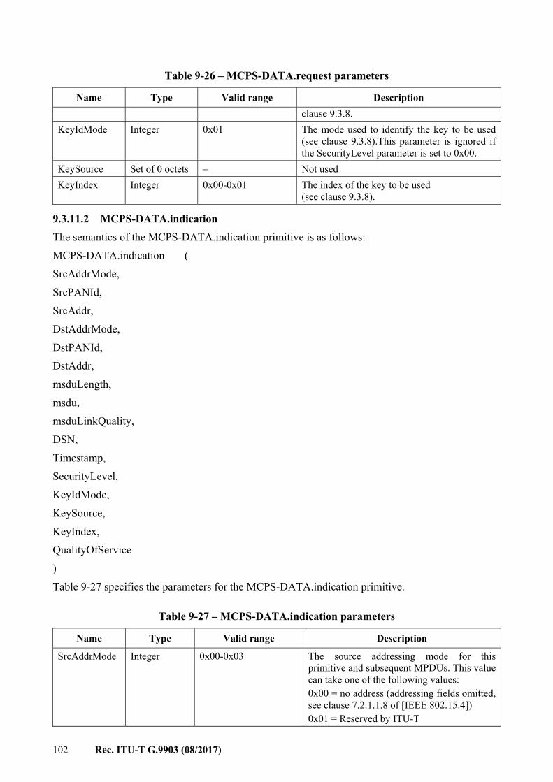
102 Rec. ITU-T G.9903 (08/2017)
Table 9-26 – MCPS-DATA.request parameters
Name Type Valid range Description clause 9.3.8.
KeyIdMode Integer 0x01 The mode used to identify the key to be used (see clause 9.3.8).This parameter is ignored if the SecurityLevel parameter is set to 0x00.
KeySource Set of 0 octets – Not used KeyIndex Integer 0x00-0x01 The index of the key to be used
(see clause 9.3.8).
9.3.11.2 MCPS-DATA.indication The semantics of the MCPS-DATA.indication primitive is as follows: MCPS-DATA.indication ( SrcAddrMode, SrcPANId, SrcAddr, DstAddrMode, DstPANId, DstAddr, msduLength, msdu, msduLinkQuality, DSN, Timestamp, SecurityLevel, KeyIdMode, KeySource, KeyIndex, QualityOfService ) Table 9-27 specifies the parameters for the MCPS-DATA.indication primitive.
Table 9-27 – MCPS-DATA.indication parameters
Name Type Valid range Description
SrcAddrMode Integer 0x00-0x03 The source addressing mode for this primitive and subsequent MPDUs. This value can take one of the following values: 0x00 = no address (addressing fields omitted, see clause 7.2.1.1.8 of [IEEE 802.15.4]) 0x01 = Reserved by ITU-T
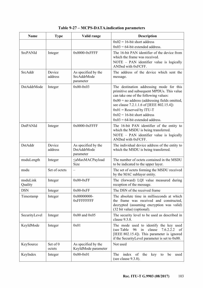
Rec. ITU-T G.9903 (08/2017) 103
Table 9-27 – MCPS-DATA.indication parameters
Name Type Valid range Description 0x02 = 16-bit short address 0x03 = 64-bit extended address.
SrcPANId Integer 0x0000-0xFFFF The 16-bit PAN identifier of the device from which the frame was received. NOTE – PAN identifier value is logically ANDed with 0xFCFF.
SrcAddr Device address
As specified by the SrcAddrMode parameter
The address of the device which sent the message.
DstAddrMode Integer 0x00-0x03 The destination addressing mode for this primitive and subsequent MPDUs. This value can take one of the following values: 0x00 = no address (addressing fields omitted, see clause 7.2.1.1.6 of [IEEE 802.15.4]) 0x01 = Reserved by ITU-T 0x02 = 16-bit short address 0x03 = 64-bit extended address.
DstPANId Integer 0x0000-0xFFFF The 16-bit PAN identifier of the entity to which the MSDU is being transferred. NOTE – PAN identifier value is logically ANDed with 0xFCFF.
DstAddr Device address
As specified by the DstAddrMode parameter
The individual device address of the entity to which the MSDU is being transferred.
msduLength Integer ≤aMaxMACPayload Size
The number of octets contained in the MSDU to be indicated to the upper layer.
msdu Set of octets – The set of octets forming the MSDU received by the MAC sublayer entity.
msduLink Quality
Integer 0x00-0xFF The (forward) LQI value measured during reception of the message.
DSN Integer 0x00-0xFF The DSN of the received frame Timestamp Integer 0x00000000-
0xFFFFFFFF The absolute time in milliseconds at which the frame was received and constructed, decrypted (assuming encryption was valid) (32 bit value) (optional).
SecurityLevel Integer 0x00 and 0x05 The security level to be used as described in clause 9.3.8.
KeyIdMode Integer 0x01 The mode used to identify the key used (see Table 96 in clause 7.6.2.2.2 of [IEEE 802.15.4]). This parameter is ignored if the SecurityLevel parameter is set to 0x00.
KeySource Set of 0 octets
As specified by the KeyIdMode parameter
Not used
KeyIndex Integer 0x00-0x01 The index of the key to be used (see clause 9.3.8).
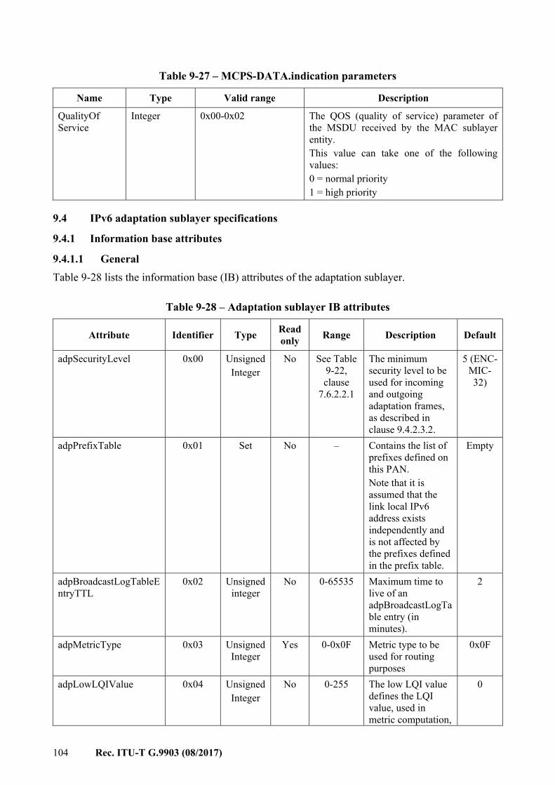
104 Rec. ITU-T G.9903 (08/2017)
Table 9-27 – MCPS-DATA.indication parameters
Name Type Valid range Description
QualityOf Service
Integer 0x00-0x02 The QOS (quality of service) parameter of the MSDU received by the MAC sublayer entity. This value can take one of the following values: 0 = normal priority 1 = high priority
9.4 IPv6 adaptation sublayer specifications
9.4.1 Information base attributes
9.4.1.1 General Table 9-28 lists the information base (IB) attributes of the adaptation sublayer.
Table 9-28 – Adaptation sublayer IB attributes
Attribute Identifier Type Readonly Range Description Default
adpSecurityLevel 0x00 Unsigned Integer
No See Table 9-22, clause
7.6.2.2.1
The minimum security level to be used for incoming and outgoing adaptation frames, as described in clause 9.4.2.3.2.
5 (ENC-MIC-32)
adpPrefixTable 0x01 Set No – Contains the list of prefixes defined on this PAN. Note that it is assumed that the link local IPv6 address exists independently and is not affected by the prefixes defined in the prefix table.
Empty
adpBroadcastLogTableEntryTTL
0x02 Unsigned integer
No 0-65535 Maximum time to live of an adpBroadcastLogTable entry (in minutes).
2
adpMetricType 0x03 UnsignedInteger
Yes 0-0x0F Metric type to be used for routing purposes
0x0F
adpLowLQIValue 0x04 Unsigned Integer
No 0-255 The low LQI value defines the LQI value, used in metric computation,
0
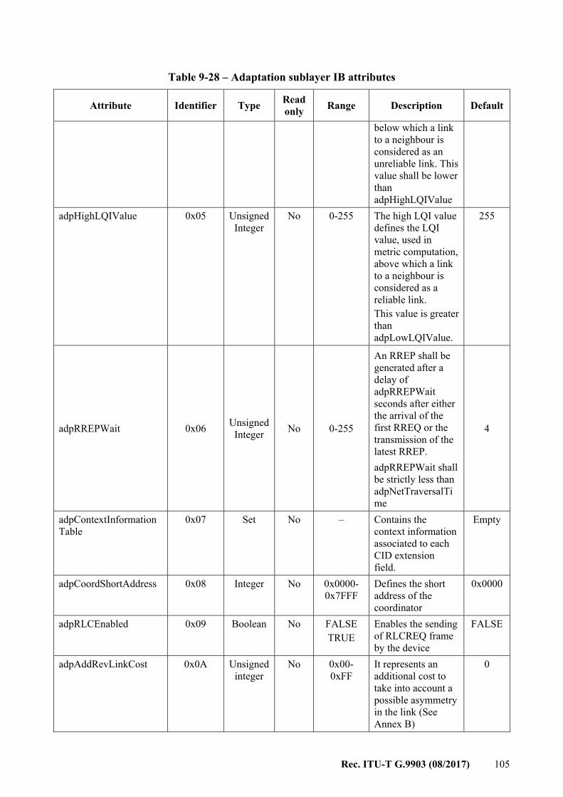
Rec. ITU-T G.9903 (08/2017) 105
Table 9-28 – Adaptation sublayer IB attributes
Attribute Identifier Type Readonly Range Description Default
below which a link to a neighbour is considered as an unreliable link. This value shall be lower than adpHighLQIValue
adpHighLQIValue 0x05 Unsigned Integer
No 0-255 The high LQI value defines the LQI value, used in metric computation, above which a link to a neighbour is considered as a reliable link. This value is greater than adpLowLQIValue.
255
adpRREPWait 0x06 Unsigned Integer No 0-255
An RREP shall be generated after a delay of adpRREPWait seconds after either the arrival of the first RREQ or the transmission of the latest RREP. adpRREPWait shall be strictly less than adpNetTraversalTime
4
adpContextInformationTable
0x07 Set No – Contains the context information associated to each CID extension field.
Empty
adpCoordShortAddress 0x08 Integer No 0x0000-0x7FFF
Defines the short address of the coordinator
0x0000
adpRLCEnabled 0x09 Boolean No FALSE TRUE
Enables the sending of RLCREQ frame by the device
FALSE
adpAddRevLinkCost 0x0A Unsigned integer
No 0x00-0xFF
It represents an additional cost to take into account a possible asymmetry in the link (See Annex B)
0
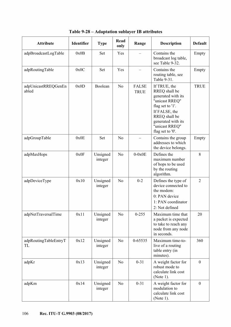
106 Rec. ITU-T G.9903 (08/2017)
Table 9-28 – Adaptation sublayer IB attributes
Attribute Identifier Type Readonly Range Description Default
adpBroadcastLogTable 0x0B Set Yes – Contains the broadcast log table, see Table 9-32.
Empty
adpRoutingTable 0x0C Set Yes – Contains the routing table, see Table 9-31.
Empty
adpUnicastRREQGenEnabled
0x0D Boolean No FALSE TRUE
If TRUE, the RREQ shall be generated with its ''unicast RREQ'' flag set to '1'. If FALSE, the RREQ shall be generated with its ''unicast RREQ'' flag set to '0'.
TRUE
adpGroupTable 0x0E Set No – Contains the group addresses to which the device belongs.
Empty
adpMaxHops 0x0F Unsigned integer
No 0-0x0E Defines the maximum number of hops to be used by the routing algorithm.
8
adpDeviceType 0x10 Unsignedinteger
No 0-2 Defines the type of device connected to the modem: 0: PAN device 1: PAN coordinator 2: Not defined
2
adpNetTraversalTime 0x11 Unsigned integer
No 0-255 Maximum time that a packet is expected to take to reach any node from any node in seconds.
20
adpRoutingTableEntryTTL
0x12 Unsigned integer
No 0-65535 Maximum time-to-live of a routing table entry (in minutes).
360
adpKr 0x13 Unsigned integer
No 0-31 A weight factor for robust mode to calculate link cost (Note 1).
0
adpKm 0x14 Unsigned integer
No 0-31 A weight factor for modulation to calculate link cost (Note 1).
0
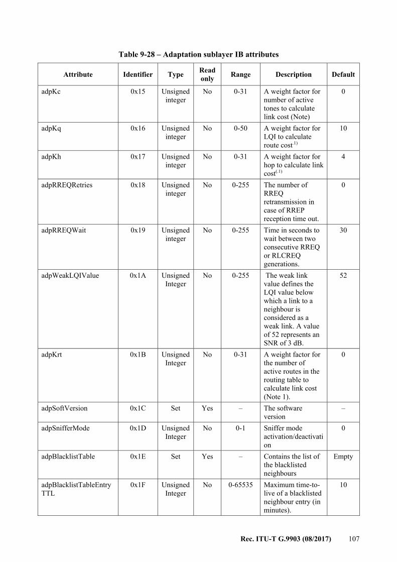
Rec. ITU-T G.9903 (08/2017) 107
Table 9-28 – Adaptation sublayer IB attributes
Attribute Identifier Type Readonly Range Description Default
adpKc 0x15 Unsigned integer
No 0-31 A weight factor for number of active tones to calculate link cost (Note)
0
adpKq 0x16 Unsigned integer
No 0-50 A weight factor for LQI to calculate route cost.1)
10
adpKh 0x17 Unsigned integer
No 0-31 A weight factor for hop to calculate link cost(.1)
4
adpRREQRetries 0x18 Unsigned integer
No 0-255 The number of RREQ retransmission in case of RREP reception time out.
0
adpRREQWait 0x19 Unsigned integer
No 0-255 Time in seconds to wait between two consecutive RREQ or RLCREQ generations.
30
adpWeakLQIValue 0x1A Unsigned Integer
No 0-255 The weak link value defines the LQI value below which a link to a neighbour is considered as a weak link. A value of 52 represents an SNR of 3 dB.
52
adpKrt 0x1B Unsigned Integer
No 0-31 A weight factor for the number of active routes in the routing table to calculate link cost (Note 1).
0
adpSoftVersion 0x1C Set Yes – The software version
–
adpSnifferMode 0x1D Unsigned Integer
No 0-1 Sniffer mode activation/deactivation
0
adpBlacklistTable 0x1E Set Yes – Contains the list of the blacklisted neighbours
Empty
adpBlacklistTableEntryTTL
0x1F Unsigned Integer
No 0-65535 Maximum time-to-live of a blacklisted neighbour entry (in minutes).
10

108 Rec. ITU-T G.9903 (08/2017)
Table 9-28 – Adaptation sublayer IB attributes
Attribute Identifier Type Readonly Range Description Default
adpMaxJoinWaitTime 0x20 Unsigned Integer
No 0-1023 Network join timeout in seconds for LBD
20
adpPathDiscoveryTime 0x21 Unsigned integer
No 0-255 Timeout for path discovery in seconds
40
adpActiveKeyIndex 0x22 Unsigned Integer
Yes 0-1 Index of the active GMK to be used for data transmission (Note 2).
0
adpDestinationAddressSet
0x23 Set No – Contains the list of the addresses of the device for which this LOADng router is providing connectivity
Empty
adpDefaultCoordRouteEnabled
0x24 Boolean No FALSETRUE
If TRUE, the adaptation layer adds a default route to the coordinator after successful completion of the bootstrapping procedure. If FALSE no default route will be created.
FALSE
adpDisableDefaultRouting
0xF0 Boolean No FALSE TRUE
If TRUE, the default routing (LOADng) is disabled. If FALSE, the default routing (LOADng) is enabled. See clause 9.4.3.
FALSE
NOTE 1 – Link cost calculation is provided in Annex B. NOTE 2 – Write access to this attribute can be used if the ADP internal re-keying procedure is not applied.
An example of an IPv6 prefix table entry compliant with [IETF RFC 4861] is given in Table 9-29. The IPv6 prefix table is available in the information base under the attribute adpPrefixTable (see Table 9-28).
Rec. ITU-T G.9903 (08/2017) 109
Table 9-29 – Example of prefix table entry (informative)
Field Length Description
Prefix length 8 bits Number of leading bits in the prefix that are valid. The value ranges from 0 to 128.
L 1 bit 1-bit on-link flag A 1 bit 1-bit autonomous address-configuration flag
Valid lifetime 32 bits Length of time in seconds during which the prefix is valid for the purpose of on-link determination
Preferred lifetime 32 bits Length of time in seconds during which addresses generated from the prefix remain preferred
Prefix Variable IPv6 address or a prefix of an IPv6 address
The adpContextInformationTable is a data set of 16 entries. An example of the structure of each entry compliant with [IETF RFC 6775] is given in Table 9-30.
Table 9-30 – Context information table entry (informative)
Field Length Description
CID 4 bits Corresponds to the 4-bit context information used for source and destination addresses (SCI, DCI).
Context length 8 bits Indicates the length of the carried context (up to 128-bit contexts may be carried.
Context variable Corresponds to the carried context used for compression/decompression purposes.
C 1 bit Indicates if the context is valid for use in compression. Valid Lifetime 16 bits Remaining time in minutes during which the context information table
is considered valid. It is updated upon receipt of the advertised context.
9.4.1.2 Routing, broadcast and blacklisted neighbour table description Table 9-31 describes the routing table entry. Its entries are updated by the routing set defined as per clause 9.4.3.1 (see clause D.7.1 in Table 9-37). The routing table is available in the information base under the attribute adpRoutingTable (see Table 9-28).
Table 9-31 – Routing table entry
Field Terminology used in Annex D for
routing set
Length Description
Destination Address
R_dest_addr 16 bits Address of the destination.
Next Hop Address
R_next_addr 16 bits Address of the next hop on the route towards the destination.
Route Cost R_metric 16 bits Cumulative link cost along the route towards the destination (see Annex B).
Hop count R_hop_count 4 bits Number of hops of the selected route to the destination.
Weak Link Count
R_weak_link_count 4 bits Number of weak links to destination. It ranges from 0 to adpMaxHops.
110 Rec. ITU-T G.9903 (08/2017)
Table 9-31 – Routing table entry
Field Terminology used in Annex D for
routing set
Length Description
Valid Time 16 bits Remaining time in minutes until when this entry in the routing table is considered valid.
Table 9-32 describes the broadcast log table entry. The broadcast log table is available in the information base under the attribute adpBroadcastLogTable (see Table 9-28).
Table 9-32 – Broadcast log table entry
Field Length Description
Source Address 16 bits The 16-bit source address of a broadcast packet. This is the address of the broadcast initiator.
Sequence Number 8 bits The sequence number contained in the BC0 header. Valid Time 16 bits Remaining time in minutes until when this entry in the broadcast log
table is considered valid.
Table 9-33 describes the blacklisted neighbour table entry. Its entries are updated by the blacklisted neighbour set defined as per clause 9.4.3.1 (see clause D.7.3 in Table 9-37). The blacklisted neighbour table is available in the information base under the attribute adpBlacklistTable (see Table 9-28).
Table 9-33 – Blacklisted neighbour table entry
Field Terminology used in Annex D
Length Description
Blacklisted Neighbour Address
B_neighbour_address 16 bits The 16-bit address of the blacklisted neighbour.
Valid Time 16 bits Remaining time in minutes until when this entry in the blacklisted neighbour table is considered valid.
9.4.2 Data frame format, datagram transmission and addressing
9.4.2.1 Selections from [IETF RFC 4944] The data frame format, the theory of operation for datagram transmission using the IEEE 802.15.4 MAC sublayer and the addressing scheme are specified in [IETF RFC 4944] using the selections listed in Table 9-34.
Table 9-34 – Selections from [IETF RFC 4944]
Clause Title and remarks/modifications Statement
1 Introduction N 1.1 Requirements notation N 1.2 Terms used N 2 [IEEE 802.15.4] mode for IP
– Data frames shall be acknowledged S
Rec. ITU-T G.9903 (08/2017) 111
Table 9-34 – Selections from [IETF RFC 4944]
Clause Title and remarks/modifications Statement – Only non-beacon-enabled networks are used.
3 Addressing modes N 4 Maximum transmission unit N 5 LoWPAN adaptation layer and frame format
– Extension: additional command frame header: see clause 9.4.2.3.1. – When more than one LoWPAN header is used in the same packet,
they shall appear in the following order: Mesh addressing header Broadcast header Fragmentation header Command frame header (see clause 9.4.2.3.1).
E
5.1 Dispatch type and header ESC pattern '01 111111' shall be updated with '01 000000' as defined in [IETF RFC 6282].
N
5.2 Mesh addressing type and header – The value of the HopsLeft field shall not exceed adpMaxHops
(see clause 9.4.2.1) NOTE – When the node is the originator and next hop is the final destination address, the mesh header shall be omitted in the frame.
S
5.3 Fragmentation type and header N 6 Stateless address auto-configuration
– The 64-bit interface identifier (see [IETF RFC 4291]) shall be derived from a "pseudo 48-bit address" formed with the PAN identifier and the short address as follows: 0xYYYY:00FF:FE00:XXXX where 0xYYYY is the PAN identifier and XXXX is the short address.
– Additional care shall be taken when choosing a PAN identifier, so as not to interfere with I/G and U/L bits of the interface identifier. If the PAN identifiers are chosen randomly, then they shall be logically ANDed with 0xFCFF.
S
7 IPv6 link local address N 8 Unicast address mapping N 9 Multicast address mapping N 10 Header compression N/R 10.1 Encoding of IPv6 header fields N/R 10.2 Encoding of UDP header fields N/R 10.3 Non-compressed fields N/R 10.3.1 Non-compressed IPv6 fields N/R 10.3.2 Non-compressed and partially compressed UDP fields N/R 11 Frame delivery in a link-layer mesh S 11.1 LoWPAN broadcast N 12 IANA considerations N 13 Security considerations N 14 Acknowledgements N/R
112 Rec. ITU-T G.9903 (08/2017)
Table 9-34 – Selections from [IETF RFC 4944]
Clause Title and remarks/modifications Statement
15 References N/R 15.1 Normative references N 15.2 Informative references I Appendix A Alternatives for delivery of frames in a mesh N/R
9.4.2.2 Selections from [IETF RFC 6282] [IETF RFC 6282] specifies a header compression format that updates the one defined in clause 10 of [IETF RFC 4944]. The selections of [IETF RFC 6282] listed in Table 9-35 apply.
Table 9-35 – Selections from [IETF RFC 6282]
Clause Title and remarks/modifications Statement
1 Introduction N 1.1 Requirements language N 2 Specific updates to [IETF RFC 4944] N 3 IPv6 header compression N 3.1 LOWPAN_IPHC Encoding Format N 3.1.1 Base format N 3.1.2 Context identifier extension N 3.2 IPv6 header encoding N 3.2.1 Traffic class and flow label compression N 3.2.2 Deriving IIDs from the encapsulating header
– 64 bit interface identifiers are created as described in clause 6 of [IETF RFC 4944].
S
3.2.3 Stateless multicast address compression N 3.2.4 Stateful multicast address compression N 4 IPv6 next header compression N 4.1 LOWPAN_NHC format N 4.2 IPv6 extension header compression
– If applicable, the fragment Header's "Reserved" field shall be processed as a regular IPv6 extension header "Length" field.
– Trailing padding options (Pad1 or PadN) may be elided for any type of IPv6 header.
– Headers following an IPv6 fragment header shall not be compressed.
S
4.3 UDP header compression N 4.3.1 Compressing UDP ports N 4.3.2 Compressing UDP Checksum N 4.3.3 UDP LOWPAN_NHC format N 5 IANA considerations N 6 Security considerations N
Rec. ITU-T G.9903 (08/2017) 113
Table 9-35 – Selections from [IETF RFC 6282]
Clause Title and remarks/modifications Statement
7 Acknowledgements N/R 8 References N/R 8.1 Normative references N 8.2 Informative references I
9.4.2.3 Extensions
9.4.2.3.1 Command frame header In addition to the LoWPAN header specified in [IETF RFC 4944], this Recommendation defines a new one: command frame header. This is used for the mesh routing procedure defined in clause 9.4.3. As shown in Figure 9-12, the ADP sublayer command frames are identified using the ESC header type (see clause 5.1 of [IETF RFC 4944]), followed by an 8-bit dispatch field indicating the type of ADP command. This header shall be in the last position if more than one header is present in the 6LowPAN frame.
Figure 9-12 – Command frame header format
The ADP sublayer command frames are specified in Table 9-36.
Table 9-36 – Command frame header identifier
Command Command Id Comments Specified in…
LOADng message 0x01 Used for LOADng routing protocol (default-routing)
Clause 9.4.3
LoWPAN bootstrapping protocol message
0x02 Used for LoWPAN Bootstrap procedure
Clause 9.4.4
Reserved by ITU-T 0x03-0x0F Reserved by ITU-T CMSR protocol messages 0x10-0x1F Used when the default-routing
LOADng is disabled and CMSR (non-default routing) as specified in [ITU-T G.9905] is used in its place.
[ITU-T G.9905]
9.4.2.3.2 Security processing for adaptation layer frames As the bootstrapping protocol is implemented in the adaptation layer and is required to use frames without any additional security at the MAC layer, the management of the security level for incoming and outgoing frames is implemented by the adaptation layer. For incoming frames: – If the frame contains the LBP protocol, it is processed as described in clause 9.4.4.
114 Rec. ITU-T G.9903 (08/2017)
– Otherwise, if MCPS-Data.indication SecurityLevel < adpSecurityLevel, the frame is dropped.
For outgoing frames: – If the frame contains the LBP protocol, it is sent as described in clause 9.4.4. – Otherwise, MCPS-Data.request SecurityLevel is set to adpSecurityLevel.
9.4.3 Mesh routing In this clause, the protocol messages employ the following notation: MsgType.field where: – MsgType is the type of a message (e.g., RREQ) – field is the field in the message (e.g., originator).
9.4.3.1 Selections from Annex D LOADng is the ITU-T G.9903 default routing mechanism and shall be supported by ITU-T G.9903 devices. In this Recommendation, the LOADng protocol specified in Annex D is exclusively used in the context of layer-2 routing and the term ''routing domain'' used in Annex D shall be interpreted as ''layer-2 routing domain.'' The LOADng protocol specified in Annex H may however be disabled. This allows ITU-T G.9903 devices to support either point-to-point single hop communication or a non-default routing protocol. The mesh routing as described in Annex D applies, with the selections specified in Table 9-37.
Table 9-37 – Selections from Annex D
Clause Title and remarks/modifications Statement
D.1 Introduction N D.2 Terminology and notation N D.2.1 Message and message field notation N D.2.2 Variable notation N D.2.3 Other notation N D.2.4 Terminology
– Route metric is the same as route cost – Link metric is the same as link cost.
S
D.3 Applicability statement – Only 16-bit addressing is supported. S
D.4 Protocol overview and functioning N D.4.1 Overview N D.4.2 LOADng routers and LOADng interfaces
– The RREP_ACK message is not supported. S
D.4.3 Information base overview – The routing set is an internal data set of the LOADng routing protocol.
It is used to update the routing table which is stored within the adaptation layer MIB under the adpRoutingTable attribute.
– The local interface set is stored within the MAC layer MIB under the macShortAddress attribute.
– The Blacklisted neighbour set is stored within the adaptation layer MIB
S
Rec. ITU-T G.9903 (08/2017) 115
Table 9-37 – Selections from Annex D
Clause Title and remarks/modifications Statement under the adpBlacklistTable attribute.
– The destination address set is stored within the adaptation layer MIB under the adpDestinationAddressSet attribute.
– The pending acknowledgement set is not supported. D.4.4 Signalling overview
– The RREP_ACK message is not supported. Validation that a link is bidirectional is performed using the RREP message ACK frame.
S, E
D.5 Protocol parameters N D.5.1 Protocol and port numbers N/R D.5.2 Router parameters
– NET_TRAVERSAL_TIME is stored within the adaptation layer MIB under the adpNetTraversalTime attribute.
– RREQ_RETRIES is stored within the adaptation layer MIB under the adpRREQRetries attribute.
– RREQ_MIN_INTERVAL is related to the adpRREQWait attribute which is stored within the adaptation layer MIB.
– R_HOLD_TIME is related to the adpRoutingTableEntryTTL attribute stored within the adaptation layer MIB. R_HOLD_TIME = adpRoutingTableEntryTTL.
– MAX_DIST is linked to the adpKr, adpKm, adpKc, adpKq, adpKh attributes which are stored in the adaptation layer MIB and the route cost calculation described in Annex B.
– B_HOLD_TIME is stored within the adaptation layer MIB under the adpBlacklistTableEntryTTL attribute.
– MAX_HOP_LIMIT is stored within the adaptation layer MIB under the adpMaxHops attribute.
– The following parameter is added: WEAK_LINK_THRESHOLD is stored within the adaptation layer MIB under the adpWeakLQIValue attribute.
S, E
D.5.3 Interface parameters – RREQ_MAX_JITTER is not supported. – RREQ_ACK_REQUIRED is not supported. – USE_BIDIRECTIONAL_LINK_ONLY is always set to TRUE. – RREQ_ACK_TIMEOUT is not supported. – RREP_ACK_REQUIRED is not supported.
S
D.5.4 Constants N D.6 Protocol message content N D.6.1 Route request (RREQ) message
– RREQ.addr-length = 1 (exclusively 6LoWPAN 16-bit short addresses are used).
– The following field is added: RREQ.weak-link-count is an unsigned integer and specifies the total number of weak link hops which the packet has traversed from RREQ.originator. RREQ.weak-link-count is mutable. – Message format is described in clause 9.4.3.2.7.2.
S, E

116 Rec. ITU-T G.9903 (08/2017)
Table 9-37 – Selections from Annex D
Clause Title and remarks/modifications Statement
D.6.2 Route reply (RREP) message – RREP.addr-length = 1 (exclusively 6LoWPAN 16-bit short addresses
are used) – RREP.ackrequired flag is always cleared ('0'). – The following field is added: RREP.weak-link-count is an unsigned integer and specifies the total number of weak link hops which the packet has traversed from RREP.originator RREP.weak-link-count is mutable – Message format is described in clause 9.4.3.2.7.2.
S, E
D.6.3 Route reply acknowledgement (RREP_ACK) message N/R D.6.4 Route error (RERR) message
– RERR.addr-length = 1 (exclusively 6LoWPAN 16-bit short addresses are used)
– Error code definition is given in Table 9-38 – Message format is described in clause 9.4.3.2.7.3.
S, E
D.7 Information base N D.7.1 Routing set
– Routing tuples include the following additional field: R_weak_link_count is the number of weak link hops of the selected route to the destination with address R_dest_addr. (See Table 9-31).
E
D.7.2 Local interface set N D.7.3 Blacklisted neighbour set
Modification: The blacklisted neighbour table available in the adaptation layer MIB under the adpBlacklistTable attribute stores: Blacklisted Neighbour Address Valid Time: associated remaining time in seconds until when this entry in the blacklisted neighbour table is considered valid. B_valid_time is not used.
E
D.7.4 Destination address set N D.7.5 Pending acknowledgement set N/R D.8 LOADng router sequence numbers
When the same short address is always allocated to a PAN device, it is recommended to restore the LOADng router sequence number after a power cycle.
N
D.9 Route maintenance N D.10 Unidirectional link handling
– MAC acknowledgment signalling is used to handle unidirectional links. Practically, MCPS-DATA.confirm status triggers blacklisting for the following possible values: TRANSACTION_EXPIRED, NO_ACK
N
D.10.1 Blacklist usage N D.11 Common rules for RREQ and RREP messages
– Add the following variable: weak-link-count is a variable, representing the weak-link-count, as included in the received RREQ or RREP message.
E
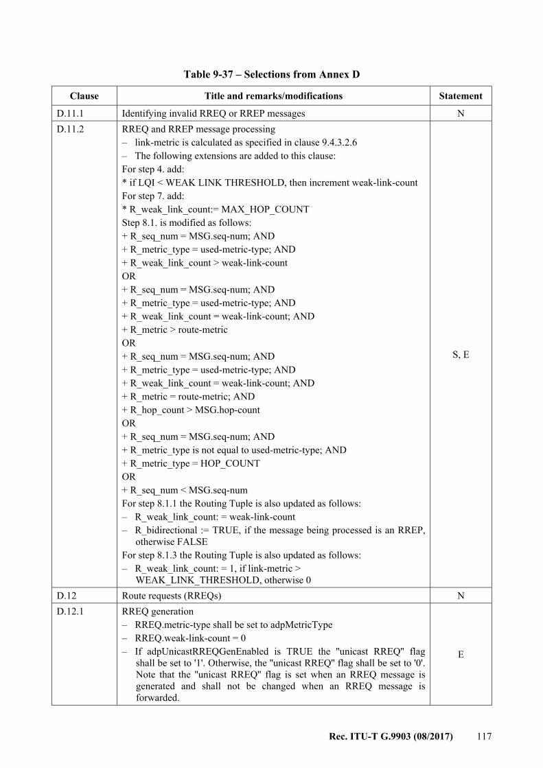
Rec. ITU-T G.9903 (08/2017) 117
Table 9-37 – Selections from Annex D
Clause Title and remarks/modifications Statement
D.11.1 Identifying invalid RREQ or RREP messages N D.11.2 RREQ and RREP message processing
– link-metric is calculated as specified in clause 9.4.3.2.6 – The following extensions are added to this clause: For step 4. add: * if LQI < WEAK LINK THRESHOLD, then increment weak-link-count For step 7. add: * R_weak_link_count:= MAX_HOP_COUNT Step 8.1. is modified as follows: + R_seq_num = MSG.seq-num; AND + R_metric_type = used-metric-type; AND + R_weak_link_count > weak-link-count OR + R_seq_num = MSG.seq-num; AND + R_metric_type = used-metric-type; AND + R_weak_link_count = weak-link-count; AND + R_metric > route-metric OR + R_seq_num = MSG.seq-num; AND + R_metric_type = used-metric-type; AND + R_weak_link_count = weak-link-count; AND + R_metric = route-metric; AND + R_hop_count > MSG.hop-count OR + R_seq_num = MSG.seq-num; AND + R_metric_type is not equal to used-metric-type; AND + R_metric_type = HOP_COUNT OR + R_seq_num < MSG.seq-num For step 8.1.1 the Routing Tuple is also updated as follows: – R_weak_link_count: = weak-link-count – R_bidirectional := TRUE, if the message being processed is an RREP,
otherwise FALSE For step 8.1.3 the Routing Tuple is also updated as follows: – R_weak_link_count: = 1, if link-metric >
WEAK_LINK_THRESHOLD, otherwise 0
S, E
D.12 Route requests (RREQs) N D.12.1 RREQ generation
– RREQ.metric-type shall be set to adpMetricType – RREQ.weak-link-count = 0 – If adpUnicastRREQGenEnabled is TRUE the ''unicast RREQ'' flag
shall be set to '1'. Otherwise, the ''unicast RREQ'' flag shall be set to '0'. Note that the ''unicast RREQ'' flag is set when an RREQ message is generated and shall not be changed when an RREQ message is forwarded.
E
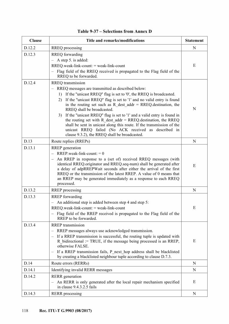
118 Rec. ITU-T G.9903 (08/2017)
Table 9-37 – Selections from Annex D
Clause Title and remarks/modifications Statement
D.12.2 RREQ processing N D.12.3 RREQ forwarding
– A step 5. is added: RREQ.weak-link-count: = weak-link-count – Flag field of the RREQ received is propagated to the Flag field of the
RREQ to be forwarded.
E
D.12.4 RREQ transmission – RREQ messages are transmitted as described below:
1) If the ''unicast RREQ'' flag is set to '0', the RREQ is broadcasted. 2) If the ''unicast RREQ'' flag is set to '1' and no valid entry is found
in the routing set such as R_dest_addr = RREQ.destination, the RREQ shall be broadcasted.
3) If the ''unicast RREQ'' flag is set to '1' and a valid entry is found in the routing set with R_dest_addr = RREQ.destination, the RREQ shall be sent in unicast along this route. If the transmission of the unicast RREQ failed (No ACK received as described in clause 9.3.2), the RREQ shall be broadcasted.
N
D.13 Route replies (RREPs) N D.13.1 RREP generation
– RREP.weak-link-count: = 0 – An RREP in response to a (set of) received RREQ messages (with
identical RREQ.originator and RREQ.seq-num) shall be generated after a delay of adpRREPWait seconds after either the arrival of the first RREQ or the transmission of the latest RREP. A value of 0 means that an RREP may be generated immediately as a response to each RREQ processed.
E
D.13.2 RREP processing N D.13.3 RREP forwarding
– An additional step is added between step 4 and step 5: RREQ.weak-link-count: = weak-link-count – Flag field of the RREP received is propagated to the Flag field of the
RREP to be forwarded.
E
D.13.4 RREP transmission – RREP messages always use acknowledged transmission. – If a RREP transmission is successful, the routing tuple is updated with
R_bidirectional := TRUE, if the message being processed is an RREP, otherwise FALSE.
– If a RREP transmission fails, P_next_hop address shall be blacklisted by creating a blacklisted neighbour tuple according to clause D.7.3.
E
D.14 Route errors (RERRs) N D.14.1 Identifying invalid RERR messages N D.14.2 RERR generation
– An RERR is only generated after the local repair mechanism specified in clause 9.4.3.2.5 fails
E
D.14.3 RERR processing N

Rec. ITU-T G.9903 (08/2017) 119
Table 9-37 – Selections from Annex D
Clause Title and remarks/modifications Statement
D.14.4 RERR forwarding N D.14.5 RERR transmission N D.15 Route reply acknowledgements (RREP_ACKs) N/R D.15.1 Identifying invalid RREP_ACK messages N/R D.15.2 RREP_ACK generation N/R D.15.3 RREP_ACK processing N/R D.15.4 RREP_ACK forwarding N/R D.15.5 RREP_ACK transmission N/R D.16 Metrics
The following metric types are defined: – COMPOSITE_METRIC = 0x0F (see Annex B) – HOP_COUNT = 0x00 (considering only the number of hops)
E
D.16.1 Specifying new metrics N D.17 Security considerations I D.17.1 Confidentiality I D.17.2 Integrity I D.17.3 Channel jamming and state explosion I D.17.4 Interaction with external routing domains I
9.4.3.2 Extensions to Annex D
9.4.3.2.1 Unicast packet routing The routing of the unicast packet is performed using the following algorithm on receipt of an MCPS-DATA.indication from the MAC layer (see also Figure 9-13 for the corresponding flow-chart): IF (MAC destination address = address of device) IF (No mesh header present in 6loWPAN headers)
(1)
Generate an ADPD-DATA.indication primitive to indicate the arrival of a frame to the upper layer, with the following characteristics (see clause 9.4.6.1.4): – DstAddrMode = 0x02 – DstAddr = MAC destination address – SrcAddr = MAC source address – NsduLength = length of the payload – Nsdu = the payload – LinkQualityIndicator = msduLinkQuality (see clause 9.3.11.2) – SecurityEnabled = (SecurityLevel != 0)
ELSE IF (6LoWPAN destination address = 6LoWPAN address of device) or an
address stored in the destination address set
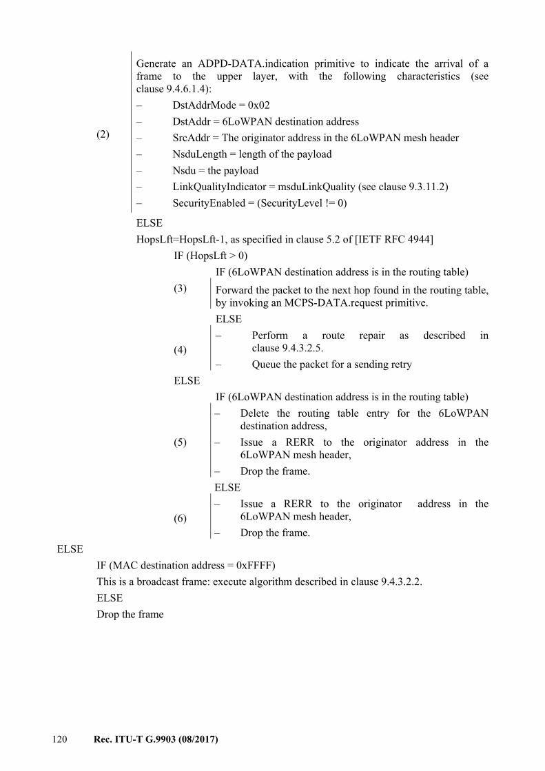
120 Rec. ITU-T G.9903 (08/2017)
(2)
Generate an ADPD-DATA.indication primitive to indicate the arrival of a frame to the upper layer, with the following characteristics (see clause 9.4.6.1.4): – DstAddrMode = 0x02 – DstAddr = 6LoWPAN destination address – SrcAddr = The originator address in the 6LoWPAN mesh header – NsduLength = length of the payload – Nsdu = the payload – LinkQualityIndicator = msduLinkQuality (see clause 9.3.11.2) – SecurityEnabled = (SecurityLevel != 0)
ELSE HopsLft=HopsLft-1, as specified in clause 5.2 of [IETF RFC 4944] IF (HopsLft > 0) IF (6LoWPAN destination address is in the routing table) (3) Forward the packet to the next hop found in the routing table,
by invoking an MCPS-DATA.request primitive. ELSE
(4) – Perform a route repair as described in
clause 9.4.3.2.5. – Queue the packet for a sending retry
ELSE IF (6LoWPAN destination address is in the routing table)
(5)
– Delete the routing table entry for the 6LoWPAN destination address,
– Issue a RERR to the originator address in the 6LoWPAN mesh header,
– Drop the frame. ELSE
(6) – Issue a RERR to the originator address in the
6LoWPAN mesh header, – Drop the frame.
ELSE IF (MAC destination address = 0xFFFF) This is a broadcast frame: execute algorithm described in clause 9.4.3.2.2. ELSE Drop the frame
Rec. ITU-T G.9903 (08/2017) 121
Figure 9-13 – Unicast packet routing processing
9.4.3.2.2 Multicast/broadcast
9.4.3.2.2.1 Packet routing The packet routing mechanism is based on clause 11.1 of [IETF RFC 4944]. This clause details more precisely the routing of broadcast and multicast packets. As described in clause 11.1 of [IETF RFC 4944], each broadcast packet has a BC0 header containing a sequence number. Each time a node sends a broadcast packet, it shall increment this sequence number. Each node shall have a broadcast log table. This table is used for routing broadcast packets and each entry contains the parameters described in Table 9-32. Each time a device receives a broadcast address with a HopsLft field of a mesh header (see clause 5.2 of [IETF RFC 4944]) strictly greater than 0, it shall check if an entry already exists in the broadcast log table having the same SrcAddr and SeqNumber. If an entry exists, the received frame is silently discarded. Otherwise, a new entry is added in the table and the TimeToLive field is initialized with the value adpBroadcastLogTableEntryTTL (see Table 9-28). When this value reaches 0, the entry is removed from the broadcast log table.
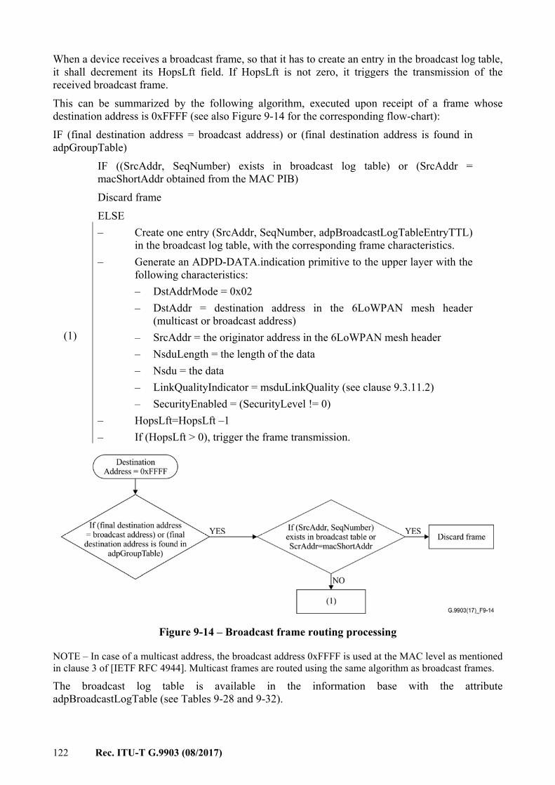
122 Rec. ITU-T G.9903 (08/2017)
When a device receives a broadcast frame, so that it has to create an entry in the broadcast log table, it shall decrement its HopsLft field. If HopsLft is not zero, it triggers the transmission of the received broadcast frame. This can be summarized by the following algorithm, executed upon receipt of a frame whose destination address is 0xFFFF (see also Figure 9-14 for the corresponding flow-chart): IF (final destination address = broadcast address) or (final destination address is found in adpGroupTable) IF ((SrcAddr, SeqNumber) exists in broadcast log table) or (SrcAddr =
macShortAddr obtained from the MAC PIB) Discard frame ELSE
(1)
– Create one entry (SrcAddr, SeqNumber, adpBroadcastLogTableEntryTTL) in the broadcast log table, with the corresponding frame characteristics.
– Generate an ADPD-DATA.indication primitive to the upper layer with the following characteristics: – DstAddrMode = 0x02 – DstAddr = destination address in the 6LoWPAN mesh header
(multicast or broadcast address) – SrcAddr = the originator address in the 6LoWPAN mesh header – NsduLength = the length of the data – Nsdu = the data – LinkQualityIndicator = msduLinkQuality (see clause 9.3.11.2) – SecurityEnabled = (SecurityLevel != 0)
– HopsLft=HopsLft –1 – If (HopsLft > 0), trigger the frame transmission.
Figure 9-14 – Broadcast frame routing processing
NOTE – In case of a multicast address, the broadcast address 0xFFFF is used at the MAC level as mentioned in clause 3 of [IETF RFC 4944]. Multicast frames are routed using the same algorithm as broadcast frames.
The broadcast log table is available in the information base with the attribute adpBroadcastLogTable (see Tables 9-28 and 9-32).
Rec. ITU-T G.9903 (08/2017) 123
9.4.3.2.2.2 Groups Each device can belong to one or more groups of devices. The IB attribute adpGroupTable (see Table 9-28) stores a list of 16-bit group addresses. When the device receives a MAC broadcast message and if the final destination address in the 6LoWPAN mesh header is equal to one of the 16-bit group addresses in adpGroupTable, then an ADPD-DATA.indication primitive is generated to the upper layer (as described in clause 9.4.3.2.2.1). Groups can be added or removed from the adpGroupTable using the ADPM-SET.request primitive. The size of this table is implementation specific and shall have at least one entry. The way groups are managed by upper layers is beyond the scope of this document.
9.4.3.2.3 Route discovery
9.4.3.2.3.1 Manual route discovery A manual route discovery can be triggered by the upper layer, for maintenance or performance purposes. This is done through the invocation of the ADPM-ROUTE-DISCOVERY.request primitive. The adaptation sublayer then generates an RREQ frame and executes the algorithms as described in clause 9.4.3.1. After the algorithm is completed, the adaptation sublayer generates an ADPM-ROUTE-DISCOVERY.confirm primitive with the corresponding status code and eventually modifies its routing table. Only one route discovery procedure can be processed at the same time. Any other ADPM-ROUTE-DISCOVERY.request will be ignored. All devices shall support the LOADng protocol and modify their routing tables accordingly.
9.4.3.2.3.2 Automatic route discovery If an ADPD.DATA.request primitive is invoked with its DiscoverRoute parameter set to TRUE, and if no entry is available in the routing table for the device designated by DstAddr, then the adaptation layer generates an RREQ and executes the algorithms described in clause 9.4.3.1 in order to find a route to the destination. If the route discovery succeeds, then the data frame is sent to the destination according to the newly discovered route. If the route discovery fails, then the adaptation layer shall generate an ADPD-DATA.confirm primitive with the status code ROUTE_ERROR. If an ADPD.DATA.request primitive is invoked with its DiscoverRoute parameter set to FALSE, and if no entry is available in the routing table for the device designated by DstAddr, then the adaptation layer shall generate an ADPD-DATA.confirm primitive with the status code ROUTE_ERROR. Route repairing procedures are described in clause 9.4.3.2.5.
9.4.3.2.3.3 Route Request generation frequency limit A node shall wait adpRREQWait seconds between two successive RREQ generations to limit the number of broadcast packets in the network. The definition of the adpRREQWait attribute is given in clause 9.4.1.1.
9.4.3.2.4 Path discovery
9.4.3.2.4.1 Operation A path discovery can be triggered by the upper layers, for maintenance or performance purposes. This is done through the invocation of the ADPM-PATH-DISCOVERY.request primitive.
124 Rec. ITU-T G.9903 (08/2017)
The adaptation sublayer then generates a path request frame (PREQ) and executes the algorithms described in the following sub-clauses. After the algorithm is completed (upon receipt of the path reply frame (PREP) with an expected originator corresponding to the path discovery destination (DstAddr) or after adpPathDiscoveryTime elapsed after PREQ transmission), the adaptation sublayer generates an ADPM-PATH-DISCOVERY.confirm primitive to the upper layer. A path reply frame received adpPathDiscoveryTime seconds after its PREQ frame has been transmitted shall be ignored. DstAddr (destination field in the PREQ frame and expected originator field in the PREP frame) is used as the identifier of the path discovery, so that only one path discovery procedure can be processed for the same destination at the same time. A second call to path discovery for the same destination when the first one is still in progress shall result in a ALREADY_IN_PROGRESS status. A PREQ frame is sent along the forward path while carrying an updated hop-by-hop link Cost information associated with the metric type field is given by ADPM-PATH-DISCOVERY.request. Similarly, a PREP frame is sent along the reverse path while carrying updated hop-by-hop link cost information. Note that the metric type field (PathMetricType) given by ADPM-PATH-DISCOVERY.request shares the same identifiers and computation procedures with the adpMetricType attribute. However, they may be different (i.e., path discovery can collect a metric different from the one used for routing). During a path discovery, link repair, route error and routing table updates shall not be allowed.
Generating a path request (PREQ) The node that generates the PREQ message (see clause 9.4.3.2.7.4) shall: Set the destination address of the node towards where the PREQ message will be propagated, as directed by the upper layers. Set its own address as the originator address. Set the metric type (as directed by the upper layers) designating the link cost to report in path discovery messages. Then, the actions described in transmitting a PREQ shall apply.
Processing a path request (PREQ) On receiving a path request (PREQ), the i-th node on the forward path shall (see clause 9.4.3.2.7.4): Append its 16-bit address to the Hop-i forward path field. Append the link cost designated by the PathMetricType and updated with the incoming frame to the Hop-i forward path link cost field. If the metric is not supported by the node, then the "Metric Not Supported" (MNS) field is set to 1 and its link cost field is set to 0. If the PREQ destination address is the address of the node that received the PREQ message or an address stored in its destination address set, then the PREQ is not forwarded and the PREP generation applies. Otherwise, the actions described in transmitting a PREQ shall apply.
Transmitting a path request (PREQ) If the PREQ destination address is found in the routing table, then the PREQ message is forwarded to the next hop towards destination (see clause 9.4.3.2.1). Yet, route repair procedure is not used. If the PREQ destination address is not found in the routing table or if the PREQ transmission fails, then PREP generation applies.
Rec. ITU-T G.9903 (08/2017) 125
Generating a path reply (PREP) The node that generates the PREP message (see clause 9.4.3.2.7.5) shall: Set the PREQ originator address as the destination address. Set the PREQ destination address as the expected originator address. Set the originator to its own address or the PREQ destination when it is in the destination address set. Append the PathMetricType, the MNS and the reserved bits, the forward path addresses and their associated link cost as conveyed by the PREQ message. Then, the actions described in transmitting a PREP shall apply.
Processing a path reply (PREP) On receiving a path reply (PREP), the j-th node on the reverse path shall (see clause 9.4.3.2.7.5): Append its 16-bit address to Hop-j reverse path field. Append the link cost designated by the PathMetricType and updated with the incoming frame to Hop-j forward path link cost field. If the metric is not supported by the node, then the "Metric Not Supported" (MNS) field is set to 1 and its link cost field is set to 0. If the PREP destination address is the address of the node receiving the PREP, then an ADPM-PATH-DISCOVERY.confirm (see clause 9.4.6.2.21) is sent to the upper layer with the PathAddress field containing a table of addresses of the nodes constituting the path (or part of the path) and their associated forward and reverse link costs. Otherwise, the actions described in transmitting a PREQ shall apply.
Transmitting a path reply (PREP) If the PREP destination address is found in the routing table, then the node just forwards the PREP message to the next hop towards destination (see clause 9.4.3.2.1). Yet, route repair procedure is not used. If the PREP destination address is not found in the routing table or if the PREP transmission fails, then the node discards the PREP.
9.4.3.2.5 Route repair and route error A route repair is performed in two cases: – when an intermediate node receives a packet for a destination address which is not present
in the routing table, – when a transmission is assumed unsuccessfull (MCPS-DATA.confirm status equals to
TRANSACTION_EXPIRED or NO_ACK). The data packet pending is buffered during the route repair procedure. For a route repair, the node follows the route discovery procedure (see clause 9.4.3) with the following characteristics: – RREQ is generated with the originator address set to its own address and the destination
address set to the data packet's final destination address – Hop Limit field is set to
– adpMaxHops, in case the route repair is triggered by the originator of the data frame following an unsuccessful transmission;
– (HopLeft – 1), in case the route repair is triggered by an intermediate node with HopLeft value taken from the data frame that triggers the route repair procedure
126 Rec. ITU-T G.9903 (08/2017)
– Route repair flag in the RREQ message is set to '1' – RREP messages generated in response to these RREQ messages, have their repair flag set
to '1' If the route discovery is successful, the node updates its routing table and shall transmit the buffered data packet to the destination through the new route. If the packet transmission fails again due to a link break, then the route repair is considered failed and shall not be performed again. If the route repair procedure fails at an intermediate node, then this node sends an RERR to the originator and the buffered data packet is discarded. The RERR message carries an error code that indicates the reason of the repair failure. The error codes are defined in Table 9-38. RRER generation shall comply with clause 9.4.3.2.3.3.
Table 9-38 – Routing error codes
Code Description
0 No available route 1 to 251 ITU-T reserved
252 to 255 Unassigned: reserved for experimental usage
9.4.3.2.6 Link cost computation Both forward and reverse link costs may be used for route cost computation as defined in Annex B. While the forward link cost can be computed from the received RREQ, the reverse link cost can be obtained by the following methods: 1) Using the neighbour table: If the previous hop information is in the neighbour table and is still valid, it can be used to compute reverse link cost. 2) Using RLCREQ (reverse link cost request) and RLCREP (reverse link cost reply): If adpRLCEnabled is set to TRUE, a unicast RLCREQ may be sent to the previous hop to request the reverse link cost. Upon receipt of the RLCREQ, the previous hop shall compute the reverse link cost and reply with RLCREP such as RLCREP.link-cost = reverse link cost. A LOADng router shall wait at least adpRREQWait seconds between two consecutive RLCREQ messages.
9.4.3.2.7 Routing packet and message formats The packet and message formats which are described in this clause shall be used for the implementation of LOADng (see Annex D).
9.4.3.2.7.1 General packet format Generation, forwarding and processing of the packet shall follow the LOADng protocol. Some of the routing packets are expected to have their content changed for each hop. Accordingly 6loWPAN mesh header and broadcast header shall not be used: – when RREQ messages are broadcasted, RREQ messages are sent to the MAC layer
broadcast address without a 6loWPAN broadcast header. – All routing messages are sent without 6loWPAN mesh header. The general format for all packets, generated, forwarded and processed according to Annex D, is given in Figure 9-15 and Table 9-39.

Rec. ITU-T G.9903 (08/2017) 127
0 1 2 3
0 1 2 3 4 5 6 7 8 9 0 1 2 3 4 5 6 7 8 9 0 1 2 3 4 5 6 7 8 9 0 1
Type Message
Figure 9-15 – General routing message format
Table 9-39 – Packet field descriptions
Field Length Description
Type 8 bits Specifies the type of the message 0 for RREQ messages 1 for RREP messages 2 for RERR messages 252 for PREQ messages 253 for PREP messages 254 for RLCREQ messages 255 for RLCREP messages
Message Variable The field is described in clause 9.4.3.2.7.2 for RREQ and RREP messages, in clause 9.4.3.2.7.3 for RRER messages, in clause 9.4.3.2.7.4 for PREQ messages, in clause 9.4.3.2.7.5 for PREP messages, in clause 9.4.3.2.7.6 for RLCREQ messages and in clause 9.4.3.2.7.7 for RLCREP.
9.4.3.2.7.2 Route request (RREQ) and route reply (RREP) message format The RREQ and RREP messages are identified with the type field equal to 0 and 1 respectively. The RREQ and RREP formats are given in Figure 9-16 and Table 9-40, and are generated, forwarded and processed according to Annex D. 0 1 2 3
0 1 2 3 4 5 6 7 8 9 0 1 2 3 4 5 6 7 8 9 0 1 2 3 4 5 6 7 8 9 0 1
Destination Originator
Sequence-Number Flags Metric type Route-cost
Hop limit Hop Count Weak link Reserved
Figure 9-16 – RREQ and RREP message format
Table 9-40 – Route request (RREQ) and route reply (RREP) message field descriptions
Field Length Description
Destination 16 bits Destination address of RREQ or RREP Originator 16 bits Originator address of RREQ or RREP
128 Rec. ITU-T G.9903 (08/2017)
Table 9-40 – Route request (RREQ) and route reply (RREP) message field descriptions
Field Length Description
Sequence-Number 16 bits Refers to RREQ.seq-num or RREP.seq-num (see Annex D). Flags 4 bits Specifies the interpretation of the remainder message:
For RREQ messages: bit 0 (route repair): when set ('1'), the RREQ message is triggered for a route repair procedure as described in clause 9.4.3.2.5. bit 1 (unicast RREQ): when set ('1'), the RREQ message is sent in unicast along an already installed route towards RREQ.destination if such a valid route exists in the routing set. Otherwise, it is broadcasted. bits 2 to 3 (reserved by ITU-T): shall be set to zero. For RREP messages: bit 0 (route repair): when set ('1'), the RREP message is triggered for a route repair procedure as described in clause 9.4.3.2.5. bits 1 to 3 (reserved by ITU-T): shall be set to zero. Endianess: bit 0 is the most significant bit (MSB) of the field, and bit 3 is the least significant bit (LSB).
Metric Type 4 bits Metric type used for routing and shall be set to adpMetricType (see Table 9-28).
Route Cost 16 bits Cumulative link cost along the route towards the destination. Refers to RREQ.route-metric or RREP.route-metric.
Hop Limit 4 bits Maximum number of hops of the route. Refers to RREQ.hop-limit or RREP.hop-limit.
Hop Count 4 bits Number of hops of the route. Refers to RREQ.hop-count or RREP.hop-count.
Weak Link Count 4 bits Total number of weak links which the message has traversed from RREQ.originator or RREP.originator.
Reserved by ITU-T 4 bits Shall be set to zero.
9.4.3.2.7.3 Route error (RERR) message format The RERR message is identified with the type field equal to 2. The RERR format is given in Figure 9-17 and Table 9-41, and is generated, forwarded and processed according to Annex D.
0 1 2 3
0 1 2 3 4 5 6 7 8 9 0 1 2 3 4 5 6 7 8 9 0 1 2 3 4 5 6 7 8 9 0 1
Destination Originator
Error Code Unreachable-Address Hop limit Reserved
Figure 9-17 – RERR message format
Rec. ITU-T G.9903 (08/2017) 129
Table 9-41 – Route error (RERR) message field descriptions
Field Length Definition
Destination 16 bits Destination address of RERR packet Originator 16 bits Originator address of RERR packet ErrorCode 8 bits Error code definition is given in Table 9-38 Unreachable-Address 16 bits Refers to RERR.unreachableAddress (see Annex D) Hop Limit 4 bits Refers to RERR.hop-limit (see Annex D). Reserved by ITU-T 4 bits Shall be set to zero.
9.4.3.2.7.4 Path request (PREQ) message format The PREQ message is identified with the type field equal to 252. It is generated, forwarded and processed according to clause 9.4.3.2.4. The PREQ message format is shown in Figure 9-18 and its field definitions are given in Table 9-42.
0 1 2 3
0 1 2 3 4 5 6 7 8 9 0 1 2 3 4 5 6 7 8 9 0 1 2 3 4 5 6 7 8 9 0 1
Destination Originator
PathMetricType Reserved
Hop-1 Forward Path Address MNS
Reserved Hop-1 Forward Path Link Cost
... ... ... ...
Hop-N Forward Path Address MNS
Reserved Hop-N Forward Path Link Cost
Figure 9-18 – PREQ message format
Table 9-42 – Path request (PREQ) message field descriptions
Field Length Description
Destination 16 bits Destination address of the PREQ packet Originator 16 bits Originator address of the PREQ packet PathMetricType 4 bits Metric type to be used for reporting the link cost Reserved by ITU-T 28 bits Shall be set to 0 Hop-1 Forward Path Address
16 bits 16-bit address of the first node on the forward path
Hop-1 Forward Path MNS
1 bit Metric not supported field by the first node on the forward path 0 : The metric is supported by the node 1 : The metric is not supported by the node
Reserved by ITU-T 7 bits Shall be set to 0 Hop-1 Forward Path Link Cost
8 bits Link cost of the first node on the forward path
130 Rec. ITU-T G.9903 (08/2017)
Table 9-42 – Path request (PREQ) message field descriptions
Field Length Description
Hop-N Forward Path Address
16 bits 16-bit address of the last node on the forward path
Hop-N Forward Path MNS
1 bit Metric not supported field by the last node on the forward path 0 : The metric is supported by the node 1 : The metric is not supported by the node
Reserved by ITU-T 7 bits Shall be set to 0 Hop-N Forward Path Link Cost
8 bits Link cost of the last node on the forward path
9.4.3.2.7.5 Path reply (PREP) message format The PREP message is identified with the type field equal to 253. It is generated, forwarded and processed according to clause 9.4.3.2.4. The PREP message format is shown in Figure 9-19 and its field definitions are given in Table 9-43. The greyed-out cells in Figure 9-19 and Table 9-43 contain the forward path fields taken from the PREQ message which remain unchanged in the PREP message. 0 1 2 3
0 1 2 3 4 5 6 7 8 9 0 1 2 3 4 5 6 7 8 9 0 1 2 3 4 5 6 7 8 9 0 1
Destination Expected Originator
PathMetricType Reserved Originator
Hop-1 Forward Path Address MNS
Reserved Hop-1 Forward Path Link Cost
... ... ... ...
Hop-N Forward Path Address MNS
Reserved Hop-N Forward Path Link Cost
Hop-1 Reverse Path Address MNS
Reserved Hop-1 Reverse Path Link Cost
... ... ... ...
Hop-1 Reverse Path Address MNS
Reserved Hop-1 Reverse Path Link Cost
Figure 9-19 – PREP message format
Rec. ITU-T G.9903 (08/2017) 131
Table 9-43 – Path reply (PREP) message field description
Field Length Description
Destination 16 bits Destination address of the PREP packet Expected Originator
16 bits Destination address of the PREQ packet (and expected originator of the PREP packet).
PathMetricType 4 bits Metric type to be used for reporting the link cost Reserved by ITU-T 12bits Shall be set to 0 Originator 16 bits Originator address of the PREP packet. Hop-1 Forward Path Address
16 bits 16-bit address of the first node on the forward path
Hop-1 Forward Path MNS
1 bit Metric not supported by the first node on the forward path 0 : The metric is supported by the node 1 : The metric is not supported by the node
Reserved by ITU-T 7 bits Shall be set to 0 Hop-1 Forward Path Link Cost
8 bits Link cost of the first node on the forward path
... ... ... Hop-1 Reverse Path Address
16 bits 16-bit address of the first node on the reverse path
Hop-1 Reverse Path MNS
1 bit Metric not supported field by the first node on the reverse path 0 : The metric is supported by the node 1 : The metric is not supported by the node
Reserved by ITU-T 7 bits Shall be set to 0 Hop-1 Reverse Path Link Cost
8 bits Link cost of the first node on the reverse path
... ... ... Hop-M Reverse Path Address
16 bits 16-bit address of the last node on the reverse path
Hop-M Reverse Path MNS
1 bit Metric not supported by the last node on the reverse path 0 : The metric is supported by the node 1 : The metric is not supported by the node
Reserved by ITU-T 7 bits Shall be set to 0 Hop-M Reverse Path Link Cost
8 bits Link cost of the last node on the reverse path
NOTE – The greyed-out cells contain the forward path fields taken from the PREQ message which remain unchanged in the PREP message.
9.4.3.2.7.6 RLCREQ message format The RLCREQ message is identified with the type field equal to 254. It is generated and processed according to clause 9.4.3.2.6. The RLCREQ message format is shown in Figure 9-20 and its field definitions are given in Table 9-44.
132 Rec. ITU-T G.9903 (08/2017)
0
1
2
3
0 1 2 3 4 5 6 7 8 9 0 1 2 3 4 5 6 7 8 9 0 1 2 3 4 5 6 7 8 9 0 1
Destination Originator
Metric type Reserved
Figure 9-20 – RLCREQ message format
Table 9-44 – RLCREQ message field descriptions
Field Length Description
Destination 16 bits Destination address of the RLCREQ packet Originator 16 bits Originator address of the RLCREQ packet Metric-type 4 bits Metric type used for routing and shall be set to adpMetricType
(see Table 9-28). Reserved by ITU-T
4 bits Shall be set to 0.
9.4.3.2.7.7 RLCREP message format The RLCREP message is identified with the type field equal to 255. It is generated and processed according to clause 9.4.3.2.6. The RLCREP message format is shown in Figure 9-21 and its field definitions are given in Table 9-45.
0 1 2 3
0 1 2 3 4 5 6 7 8 9 0 1 2 3 4 5 6 7 8 9 0 1 2 3 4 5 6 7 8 9 0 1
Destination Originator
Metric type Reserved Link Cost
Figure 9-21 – RLCREP message format
Table 9-45 – RLCREP message field descriptions
Field Length Description
Destination 16 bits Destination address of the RLCREP packet Originator 16 bits Originator address of the RLCREP packet Metric type 4 bits Metric type used for routing and shall be set to adpMetricType
(see Table 9-28). Reserved by ITU-T
4 bits Shall be set to 0.
Link cost 8 bits Link cost from the destination to the originator of the RLCREP packet.
Rec. ITU-T G.9903 (08/2017) 133
9.4.4 Commissioning of new devices
9.4.4.1 Selections from Annex E The commissioning of new devices on an existing network described in Annex E applies, with the selections specified in Table 9-46.
Table 9-46 – Selections from Annex E
Clause Title and remarks/modifications Statement
E.1 Introduction N E.2 Terminology N E.2.1 Requirements notation N E.3 Bootstrapping
– Obtaining a 16-bit short address and security credentials are mandatory parts of the commissioning process.
S
E.3.1 Resetting the device N E.3.2 Scanning through channels
– For getting the information of other devices within POS, the device shall perform an active scan.
S
E.3.3 LoWPAN bootstrapping mechanism – 'LBA discovery phase' is described in clause 9.4.4.2.2. E
E.3.3.1 LoWPAN bootstrapping protocol message format N E.3.3.1.1 LBP message
– Some enhancements and clarifications to the LBP message format are given in clause 9.4.4.2.1.
E
E.3.3.2 LoWPAN bootstrapping information base The "Short_Addr" attribute is sent during bootstrapping and stored in the macShortAddress attribute in MAC PIB The following parameters are not sent, but set locally – PAN_ID corresponds to the macPanId attribute in MAC PIB – Address_of_LBS corresponds to the adpCoordShortAddress attribute
in ADP IB The other parameters listed are not supported. Additional parameters are defined in clause 9.4.4.2.1.3.
S, E
E.3.3.3 LBA discovering phase – Some enhancements and clarifications to 6LoWPAN bootstrapping
procedure are given in clause 9.4.4.2.2. – The LBD shall perform an active scan instead of broadcasting an LBA
solicitation message.
E
E.3.3.4 LoWPAN bootstrapping protocol (LBP) S E.3.3.5 LBP in secured 6LoWPAN
LBP messages exchanged between the LBD and LBA (the LBS takes the LBA role if no relaying is needed) are sent with the following content: – MAC layer: – The LBD uses its EUI-64 address – The LBA uses its 16-bit short address. The choice of the LBA is
controlled by ADPM-NETWORK-JOIN.request LBAAddress parameter
– Destination and source PAN ID = The PAN ID passed as an
S
134 Rec. ITU-T G.9903 (08/2017)
Table 9-46 – Selections from Annex E
Clause Title and remarks/modifications Statement argument to the ADPM-NETWORK-JOIN.request primitive
– Quality of service = normal priority – SecurityLevel = no security – The adaptation layer only contains the LBP message, no other header
is allowed. LBP messages exchanged between the LBA and LBS are relayed by using the routing algorithm as described in clause 9.4.4 with the DiscoverRoute parameter set to TRUE and the SecurityLevel set to a adpSecurityLevel.
E.3.3.6 Role of entities in LBP – If an LBD does not find any LBA during the LBA discovery phase, it
shall still perform LBA discoveries as long as it is not commissioned. Note that LBA discovery is done using active scans rather than broadcasting LBA solicitation messages.
– Only secured networks are used. – Blacklisting by the LBA is not supported.
S
E.3.4 Assigning the short address Short addresses are assigned in a centralized fashion by the LBS. S
E.3.5 Obtaining IPv6 address Obtaining a non-link-local IPv6 address is out of the scope of this Recommendation.
N/R
E.3.6 Configuration parameters – The values of the configuration parameters shall be: CHANNEL_LIST = 0xFFFF800 (not used) SCAN_DURATION = ADPM-DISCOVERY.request duration parameter value (see clause 9.4.6.2.2) SUPERFRAME_ORDER = 15 BEACON_ORDER = 15 START_RETRY_TIME = 0 (not used) JOIN_RETRY_TIME = 0 (not used) ASSOCIATION_RETRY_TIME = 0 (not used)
M
E.4 IANA consideration N/R E.5 Security considerations N
9.4.4.2 Extensions to Annex E
9.4.4.2.1 LoWPAN bootstrapping protocol (LBP) message format
9.4.4.2.1.1 General The LBP message format and the details of its related fields are described in Figure 9-22 and Table 9-47, respectively.
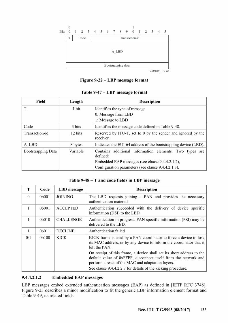
Rec. ITU-T G.9903 (08/2017) 135
G.9903(14)_F9-22
00
Bits 01
1 12 23 34 45 56 7 8 9
Transaction-id
A_LBD
Bootstrapping data
CodeT
Figure 9-22 – LBP message format
Table 9-47 – LBP message format
Field Length Description
T 1 bit Identifies the type of message 0: Message from LBD 1: Message to LBD
Code 3 bits Identifies the message code defined in Table 9-48. Transaction-id 12 bits Reserved by ITU-T, set to 0 by the sender and ignored by the
receiver. A_LBD 8 bytes Indicates the EUI-64 address of the bootstrapping device (LBD).Bootstrapping Data Variable Contains additional information elements. Two types are
defined: Embedded EAP messages (see clause 9.4.4.2.1.2), Configuration parameters (see clause 9.4.4.2.1.3).
Table 9-48 – T and code fields in LBP message
T Code LBD message Description
0 0b001 JOINING The LBD requests joining a PAN and provides the necessary authentication material
1 0b001 ACCEPTED Authentication succeeded with the delivery of device specific information (DSI) to the LBD
1 0b010 CHALLENGE Authentication in progress. PAN specific information (PSI) may be delivered to the LBD.
1 0b011 DECLINE Authentication failed 0/1 0b100 KICK KICK frame is used by a PAN coordinator to force a device to lose
its MAC address, or by any device to inform the coordinator that it left the PAN. On receipt of this frame, a device shall set its short address to the default value of 0xFFFF, disconnect itself from the network and perform a reset of the MAC and adaptation layers. See clause 9.4.4.2.2.7 for details of the kicking procedure.
9.4.4.2.1.2 Embedded EAP messages LBP messages embed extended authentication messages (EAP) as defined in [IETF RFC 3748]. Figure 9-23 describes a minor modification to fit the generic LBP information element format and Table 9-49, its related fields.
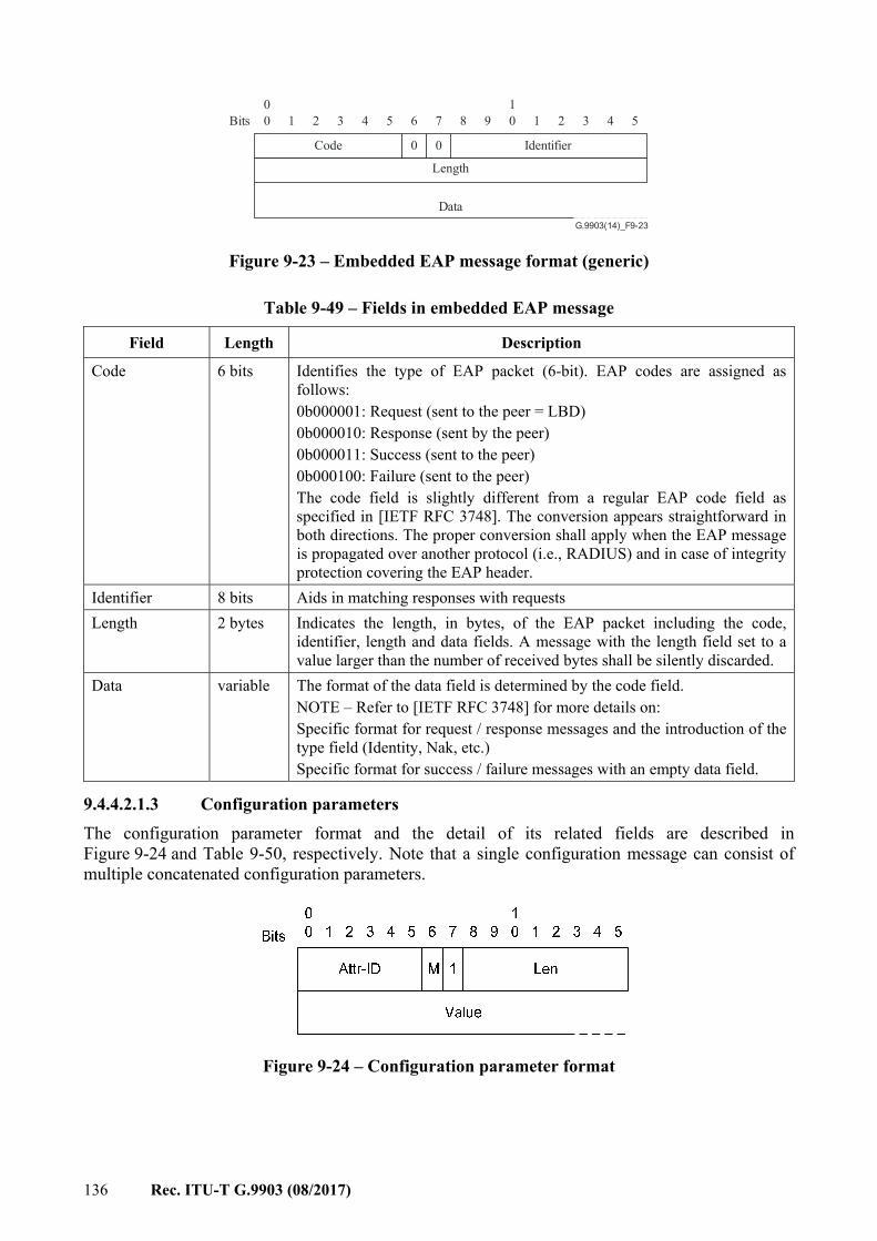
136 Rec. ITU-T G.9903 (08/2017)
G.9903(14)_F9-23
00
Bits 01
1 12 23 34 45 56
0
7
0
8 9
Identifier
Data
Length
Code
Figure 9-23 – Embedded EAP message format (generic)
Table 9-49 – Fields in embedded EAP message
Field Length Description
Code 6 bits Identifies the type of EAP packet (6-bit). EAP codes are assigned as follows: 0b000001: Request (sent to the peer = LBD) 0b000010: Response (sent by the peer) 0b000011: Success (sent to the peer) 0b000100: Failure (sent to the peer) The code field is slightly different from a regular EAP code field as specified in [IETF RFC 3748]. The conversion appears straightforward in both directions. The proper conversion shall apply when the EAP message is propagated over another protocol (i.e., RADIUS) and in case of integrity protection covering the EAP header.
Identifier 8 bits Aids in matching responses with requests Length 2 bytes Indicates the length, in bytes, of the EAP packet including the code,
identifier, length and data fields. A message with the length field set to a value larger than the number of received bytes shall be silently discarded.
Data variable The format of the data field is determined by the code field. NOTE – Refer to [IETF RFC 3748] for more details on: Specific format for request / response messages and the introduction of the type field (Identity, Nak, etc.) Specific format for success / failure messages with an empty data field.
9.4.4.2.1.3 Configuration parameters The configuration parameter format and the detail of its related fields are described in Figure 9-24 and Table 9-50, respectively. Note that a single configuration message can consist of multiple concatenated configuration parameters.
Figure 9-24 – Configuration parameter format
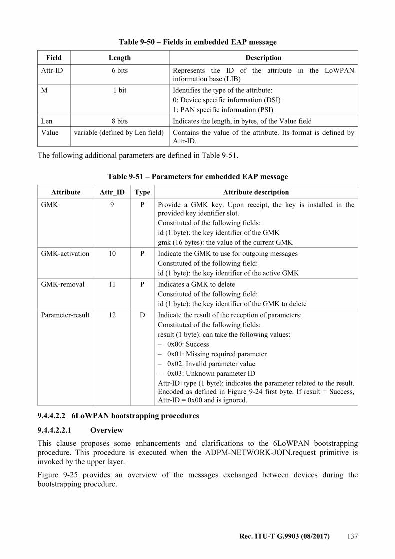
Rec. ITU-T G.9903 (08/2017) 137
Table 9-50 – Fields in embedded EAP message
Field Length Description
Attr-ID 6 bits Represents the ID of the attribute in the LoWPAN information base (LIB)
M 1 bit Identifies the type of the attribute: 0: Device specific information (DSI) 1: PAN specific information (PSI)
Len 8 bits Indicates the length, in bytes, of the Value field Value variable (defined by Len field) Contains the value of the attribute. Its format is defined by
Attr-ID.
The following additional parameters are defined in Table 9-51.
Table 9-51 – Parameters for embedded EAP message
Attribute Attr_ID Type Attribute description GMK 9 P Provide a GMK key. Upon receipt, the key is installed in the
provided key identifier slot. Constituted of the following fields: id (1 byte): the key identifier of the GMK gmk (16 bytes): the value of the current GMK
GMK-activation 10 P Indicate the GMK to use for outgoing messages Constituted of the following field: id (1 byte): the key identifier of the active GMK
GMK-removal 11 P Indicates a GMK to delete Constituted of the following field: id (1 byte): the key identifier of the GMK to delete
Parameter-result 12 D Indicate the result of the reception of parameters: Constituted of the following fields: result (1 byte): can take the following values: – 0x00: Success – 0x01: Missing required parameter – 0x02: Invalid parameter value – 0x03: Unknown parameter ID Attr-ID+type (1 byte): indicates the parameter related to the result. Encoded as defined in Figure 9-24 first byte. If result = Success, Attr-ID = 0x00 and is ignored.
9.4.4.2.2 6LoWPAN bootstrapping procedures
9.4.4.2.2.1 Overview This clause proposes some enhancements and clarifications to the 6LoWPAN bootstrapping procedure. This procedure is executed when the ADPM-NETWORK-JOIN.request primitive is invoked by the upper layer. Figure 9-25 provides an overview of the messages exchanged between devices during the bootstrapping procedure.
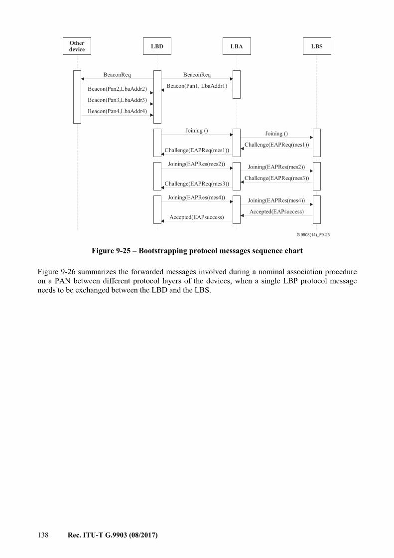
138 Rec. ITU-T G.9903 (08/2017)
G.9903(14)_F9-25
Otherdevice LBSLBALBD
BeaconReqBeaconReq
Beacon(Pan1, LbaAddr1)Beacon(Pan2,LbaAddr2)
Beacon(Pan3,LbaAddr3)
Joining () Joining ()
Challenge(EAPReq(mes1))Challenge(EAPReq(mes1))
Joining(EAPRes(mes2)) Joining(EAPRes(mes2))
Challenge(EAPReq(mes3))Challenge(EAPReq(mes3))
Joining(EAPRes(mes4))
Accepted(EAPsuccess)
Joining(EAPRes(mes4))
Accepted(EAPsuccess)
Beacon(Pan4,LbaAddr4)
Figure 9-25 – Bootstrapping protocol messages sequence chart
Figure 9-26 summarizes the forwarded messages involved during a nominal association procedure on a PAN between different protocol layers of the devices, when a single LBP protocol message needs to be exchanged between the LBD and the LBS.
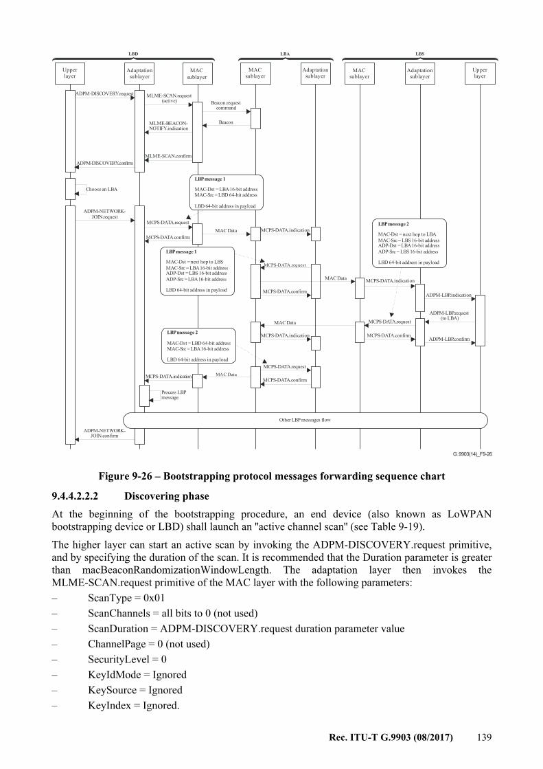
Rec. ITU-T G.9903 (08/2017) 139
G.9903(14)_F9-26
Upperlayer
Adaptationsublayer
MACsublayer
MACsublayer
ADPM-DISCOVERY.request MLME-SCAN.request(active)
MLME-BEACON-NOTIFY.indication
Beacon.requestcommand
MAC sublayer
Adaptationsublayer
Beacon
MLME-SCAN.confirm
LBD LBA
Adaptationsublayer
LBS
Upperlayer
LBP message 1
MAC-Dst = LBA 16-bit addressMAC-Src = LBD 64-bit address
LBD 64-bit address in payload
MCPS-DATA.indication
Choose an LBA
ADPM-NETWORK-JOIN.request
MCPS-DATA.request
MCPS-DATA.confirmMAC Data
ADPM-DISCOVERY.confirm
MCPS-DATA.request
MAC Data
MCPS-DATA.confirm
MCPS-DATA.indication
ADPM-LBP.indication
MAC Data
MCPS-DATA.indication
ADPM-LBP.request(to LBA)
LBP message 2
MAC-Dst = next hop to LBAMAC-Src = LBS 16-bit addressADP-Dst = LBA 16-bit addressADP-Src = LBS 16-bit address
LBD 64-bit address in payload
LBP message 2
MAC-Dst = LBD 64-bit addressMAC-Src = LBA 16-bit address
LBD 64-bit address in payload
LBP message 1
MAC-Dst = next hop to LBSMAC-Src = LBA 16-bit addressADP-Dst = LBS 16-bit addressADP-Src = LBA 16-bit address
LBD 64-bit address in payload
MCPS-DATA.request
MCPS-DATA.confirm
MCPS-DATA.request
MCPS-DATA.confirmMAC DataMCPS-DATA.indication
Process LBPmessage
ADPM-NETWORK-JOIN.confirm
ADPM-LBP.confirm
Other LBP messages flow
Figure 9-26 – Bootstrapping protocol messages forwarding sequence chart
9.4.4.2.2.2 Discovering phase At the beginning of the bootstrapping procedure, an end device (also known as LoWPAN bootstrapping device or LBD) shall launch an ''active channel scan'' (see Table 9-19). The higher layer can start an active scan by invoking the ADPM-DISCOVERY.request primitive, and by specifying the duration of the scan. It is recommended that the Duration parameter is greater than macBeaconRandomizationWindowLength. The adaptation layer then invokes the MLME-SCAN.request primitive of the MAC layer with the following parameters: – ScanType = 0x01 – ScanChannels = all bits to 0 (not used) – ScanDuration = ADPM-DISCOVERY.request duration parameter value – ChannelPage = 0 (not used) – SecurityLevel = 0 – KeyIdMode = Ignored – KeySource = Ignored – KeyIndex = Ignored.
140 Rec. ITU-T G.9903 (08/2017)
The LBD sends a 1-hop broadcast Beacon.request frame and any full feature device in the neighbourhood shall reply by sending a beacon frame with its PAN identifier, short address and capabilities, as defined in Table 9-19. Upon receiving each beacon frame, the MAC layer in the LBD issues an MLME-BEACON-NOTIFY.indication primitive with the PANDescriptor parameters corresponding to the beacon. At the end of scan duration, the adaptation layer generates an ADPM-DISCOVERY.confirm primitive which contains the PANDescriptorList. The choice of the LBA to be used for joining the network is implementation-specific but can be based on the following criteria: – minimum value of route cost to coordinator – maximum value of beacon link quality – short address, according to a round robin algorithm. After finishing the scan procedure, the device can join the network following the procedure described in clause 9.4.4.2.2.6.
9.4.4.2.2.3 Access control phase Once the discovery phase is finished, the LBD send an LBP JOINING frame to the LBA. This frame includes a field that carries the EUI-64 address of the joining LBD. This frame, as any other frame during the initial part of the bootstrapping process, is transmitted between the LBD and the LBA without any additional security at the MAC layer. When received by the LBA, this frame is relayed by the LBA to the LBS. It is assumed that the LBA is fully bootstrapped with the full capability to directly transmit any message to the LBS in a secure way. The LBP protocol has been designed to fit two different authentication architectures: – the authentication function is directly supported by the LBS and in this case all the
authentication material (access lists, credentials, etc.) shall be loaded in the LBS; or – the authentication function is supported by a remote (and usually centralized) AAA server,
and in this case, the LBS is only in charge of forwarding the EAP messages to the AAA server over a standard AAA protocol (i.e., RADIUS [IETF RFC 2865]).
The following procedure description is only based on the first architecture but extension to the second one appears straightforward. So, when received by the LBS, the EUI-64 address may be compared with an access control list (white list or black list) with the following possibilities: – this address does not fit the access control list and the LBS send back an LBP DECLINE
message, embedding an EAP failure message; or – this address fit the access control list (or the access control is not implemented) and the
LBS sends back an LBP CHALLENGE message, embedding an EAP request message. This latter message also carries the first authentication message.
– In this version of this Recommendation, the EAP identity phase is skipped as proposed by [IETF RFC 3748] to directly move to the authentication phase by sending the first message of the selected EAP method.
– The EAP identity phase could be reintroduced later when the need for roaming features arise.
In both cases, these messages are relayed by the LBA to the LBD.
Rec. ITU-T G.9903 (08/2017) 141
9.4.4.2.2.4 Authentication and key distribution phase The authentication phase is wholly dependent on the EAP method in place. The EAP protocol is very flexible and supports various EAP methods. Each method is characterized by its credentials (shared secret, certificate, SIM cards, etc.) and by its signature and encryption algorithms. Refer to clause 10.5 for further details on the proposed EAP method used in this Recommendation. Note that if addition of other EAP methods is possible, care must be taken to validate the security of the chosen method before integration. EAP methods that have been deprecated must not be provided (e.g., EAP-MD5). Methods are ordinary based on two round-trip exchanges: – the first one for mutual authentication and initial exchange of ciphering material; – the second one for mutual control of session keys derivation. At the end, the EAP method used should provide the LBD with: – Group session keys for a global PAN security. These keys are shared by all the
authenticated nodes in the PAN. Every MAC data frame with the SecurityEnabled field set to 1, except those involved in the initial phases of the bootstrapping procedure, is securely transmitted with encryption and decryption at every hop. These group keys shall be refreshed periodically or when a node is detached from the PAN. Group key updates are handled by higher layers.
– Optionally, configuration parameters are provided by the LBS. Other keys may be derived for additional security services provided at the application level. As the short address is used during the encryption process (see Table 9-23, clause 7.6.3.2), it is recommended that its attribution respects the following rule: a short address shall be assigned to only one node (no address re-use) for a given Group session key. When the Group session key is changed, unused addresses can be re-assigned to different nodes.
9.4.4.2.2.5 Authorization and initial configuration phase Upon completion of the authentication and key distribution process, the LBS shall send back an LBP DECLINE message if the authentication has failed. This message is relayed by the LBA to the LBD to inform the LBD that the LBS did not accept the join request of LBD. If the LBS accepts the join request of the LBD, it sends back an LBP ACCEPTED message, embedding an EAP success message within it. This message is relayed by the LBA to the LBD. At this stage, the LBD owns a 16-bit short address and a session key allowing the secure transmission of the messages within the PAN. Upon receipt of the LBP message, the LBD may set up an optimized route to the LBS with the help of the LOADng protocol (see clause 9.4.3). If the ADP IB attribute adpDefaultCoordRouteEnabled is set to TRUE, the path used by the device during association phase shall be stored in the routing set as an initial route between LBD and LBS without invoking the LOADng protocol. For that purpose the adaptation layer shall create or update an initial default entry to the routing set as follows: – R_dest_addr = adpCoordShortAddress – R_next_addr = LBA address – R_metric = 0x7FFF – R_metric_type = adpMetricType – R_hop_count = adpMaxHops – R_weak_link_count = adpMaxHops
142 Rec. ITU-T G.9903 (08/2017)
– R_seq_num = -1 – R_bidirectional = TRUE – R_local_iface_addr = macShortAddress – R_valid_time = adpRoutingTableEntryTTL If adpDefaultCoordRouteEnabled is set to TRUE and once the join procedure has been successfully completed, it is recommended to issue an ADPM-ROUTE-DISCOVERY towards the PAN coordinator with the adpUnicastRREQGenEnabled ADP IB attribute set to TRUE to refresh the initial routing table entry and to announce the route to the PAN coordinator.
9.4.4.2.2.6 Joining a PAN for any node except coordinator The network joining procedure is performed by a device which is not a PAN coordinator and does not have a short address (default short address of a device upon reset is 0xffff which means no short address). During this procedure, the device is authenticated, associated with the network and receives GMK and a short address assigned by the coordinator. After a successful discovery phase as described in clause 9.4.4.2.2.2, this procedure may be triggered by invocation of the ADPM-NETWORK JOIN.request primitive with PAN ID and LBAAddress of one of the discovered devices as listed in PANDescriptor of ADPM-DISCOVERY.confirm. The selection criteria for PAN ID and LBAAddress is implementation specific. If the join is successful, the upper layer is informed by a successful ADPM-NETWORK-JOIN.confirm which includes the assigned short address and PAN ID of the network. In case of failure, this procedure may be repeated after repeating the discovery phase. If the join procedure is not complete within adpMaxJoinWaitTime, a fail confirmation shall be sent to the upper layer. The upper layer in the LBS receives the join request of a device as well as subsequent authentication messages as ADPM-LBP.indication primitives with embedded LBP messages. It also sends the authentication messages as well as acceptance and short address embedded in LBP messages to the LBD by invoking ADPM-LBP.request. The processing of received LBP messages and the construction of LBP messages to be sent to the LBD is performed in the upper layer of the LBS. This includes the processing and construction of EAP messages as described in clause 10.5. In the LBD, all the LBP messages are processed internally and the upper layer is not aware of the message exchanges during the authentication procedure. Upon completion or timeout, the upper layer of the LBD receives an ADPM-NETWORK-JOIN.confirm with success or failure status.
9.4.4.2.2.7 Leaving a PAN – Removal of a device by the PAN coordinator The PAN coordinator may instruct a device to remove itself from the network invoking the ADPM-LBP.request primitive, using a KICK frame. This frame is a standard LBP message frame with its T field set to 1 and its code field set to 0b100. The bootstrapping data in that message shall be empty. When a device receives this message, it shall check if the A_LBD field of the LBP message is its own address. If not, the message is silently discarded. Otherwise, the device shall perform the following steps: – acknowledge the frame if necessary – set its 16-bit short address to 0xFFFF; – generate an ADPM-NETWORK-LEAVE.indication – invoke an MLME-RESET.request primitive with the SetDefaultPIB parameter set to TRUE – invoke its ADPM-RESET.request primitive to reset itself.
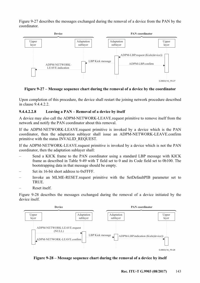
Rec. ITU-T G.9903 (08/2017) 143
Figure 9-27 describes the messages exchanged during the removal of a device from the PAN by the coordinator.
G.9903(14)_F9-27
Upperlayer
Adaptationsublayer
Adaptationsublayer
Upperlayer
PAN coordinatorDevice
ADPM-LBP.request (Kick(device))
LBP Kick messageADPM-NETWORK-
LEAVE.indicationADPM-LBP.confirm
Figure 9-27 – Message sequence chart during the removal of a device by the coordinator
Upon completion of this procedure, the device shall restart the joining network procedure described in clause 9.4.4.2.2.
9.4.4.2.2.8 Leaving a PAN – Removal of a device by itself A device may also call the ADPM-NETWORK-LEAVE.request primitive to remove itself from the network and notify the PAN coordinator about this removal. If the ADPM-NETWORK-LEAVE.request primitive is invoked by a device which is the PAN coordinator, then the adaptation sublayer shall issue an ADPM-NETWORK-LEAVE.confirm primitive with the status INVALID_REQUEST. If the ADPM-NETWORK-LEAVE.request primitive is invoked by a device which is not the PAN coordinator, then the adaptation sublayer shall: – Send a KICK frame to the PAN coordinator using a standard LBP message with KICK
frame as described in Table 9-49 with T field set to 0 and its Code field set to 0b100. The bootstrapping data in that message should be empty.
– Set its 16-bit short address to 0xFFFF. – Invoke an MLME-RESET.request primitive with the SetDefaultPIB parameter set to
TRUE. – Reset itself. Figure 9-28 describes the messages exchanged during the removal of a device initiated by the device itself.
G.9903(14)_F9-28
Upperlayer
Adaptationsublayer
Adaptationsublayer
Upperlayer
PAN coordinatorDevice
ADPM-LBP.indication (Kick(device))LBP Kick message
ADPM-NETWORK-LEAVE.request(NULL)
ADPM-NETWORK-LEAVE.confirm
Figure 9-28 – Message sequence chart during the removal of a device by itself
144 Rec. ITU-T G.9903 (08/2017)
On the PAN coordinator side, an ADPM-LBP.indication containing the KICK message is generated to inform the upper layers. This message contains the 64-bit address of the device which had removed itself from the PAN.
9.4.5 Sniffer mode (optional mode) This mode is used to support monitoring of the transmitted packets on the power line. Once activated, the modem will process all packets regardless of their destination address. The sniffer modem shall generate an ADPD-DATA.indication for any received packet. The modem activated in sniffer mode shall not forward packets. If a sniffer modem receives a fragment, it shall add an IPv6 fragment header to the packet so the upper layer can detect it. The fragment offset field and the identification field shall be set to the offset of the LOWPAN header and the Datagram_Tag respectively.
9.4.6 Adaptation sublayer service primitives
9.4.6.1 ADP data primitives
9.4.6.1.1 Overview The ADPD is used to transport the NSDU to other devices on the network and supports the following primitives: – ADPD-DATA.request – ADPD-DATA.confirm – ADPD-DATA.indication.
9.4.6.1.2 ADPD-DATA.request
9.4.6.1.2.1 Semantics of the service primitive This primitive requests the transfer of the NSDU to another device or multiple devices. The semantics of this primitive are as follows: ADPD-DATA.request ( NsduLength, Nsdu, NsduHandle, DiscoverRoute, QualityOfService, )
Table 9-52 – Parameters of the ADPD-DATA.request primitive
Name Type Valid range
Description
NsduLength Integer 0-1 280 The size of the NSDU, in bytes Nsdu Set of octets – The NSDU to send NsduHandle Integer 0x00-0xFF The handle of the NSDU to transmit. This parameter
is used to identify in the ADPD-DATA.confirm primitive which request it is concerned with. It can be randomly chosen by the application layer.
DiscoverRoute Boolean TRUE or FALSE
If TRUE, a route discovery procedure will be performed prior to sending the frame if a route to the
Rec. ITU-T G.9903 (08/2017) 145
Table 9-52 – Parameters of the ADPD-DATA.request primitive
Name Type Valid range
Description
destination is not available in the routing table. If FALSE, no route discovery is performed.
QualityOfService Integer 0x00-0x01 The requested quality of service (QoS) of the frame to send. Allowed values are: 0x00 = normal priority 0x01 = high priority
9.4.6.1.2.2 When generated This primitive is generated by the upper layer to request the sending of a given NSDU.
9.4.6.1.2.3 Effect on receipt If this primitive is received when the device has not joined a network, the adaptation sublayer will issue an ADPD-DATA.confirm primitive with the status INVALID_REQUEST. Otherwise, the ADPD constructs a 6LoWPAN frame with the following characteristics depending on the transmission mode. – In the case of a unicast frame:
– If the destination is not a neighbour of the device, the mesh addressing header is present as described in clause 5.2 of [IETF RFC 4944], where: – V shall be set to 1, to specify that the originator address is a 16-bit network
address; – F shall be set to 1, to specify that the originator address is a 16-bit network address; – HopsLft = MaxHops; – Originator address = The 16-bit network address of the sending device, available in
the NIB; – Final destination address = 16-bit destination address of the device designated by
the IPv6 address ''DstAddr''. – The broadcast header is not present.
– If necessary, the fragmentation header shall be present to transport NSDUs which do not fit in an entire IEEE 802.15.4 frame. In this case, clause 5.3 of [IETF RFC 4944] applies.
– In the case of a multicast frame: – The mesh addressing header is present as described in clause 5.2 of [IETF RFC 4944],
where – V shall be set to 1, to specify that the originator address is a 16-bit network
address; – F shall be set to 1, to specify that the originator address is a 16-bit network address; – HopsLft = MaxHops; – Originator address = The 16-bit network address of the sending device, available in
the NIB; – Final destination address = multicast group address; – The broadcast header is present with the following values:
146 Rec. ITU-T G.9903 (08/2017)
– Sequence number = previous sequence number + 1 – If necessary, the fragmentation header shall be present to transport NSDUs which do
not fit in an entire IEEE 802.15.4 frame. In this case, clause 5.3 of [IETF RFC 4944] applies.
Once the frame is constructed, it is routed according to the procedures described in clause 9.4.3.2.1 if the destination address is a unicast address. If the frame is to be transmitted, the MCPS-Data.request primitive is invoked, with the following parameters in the case of a unicast sending: – SrcAddrMode = 0x02, for 16-bit address – DstAddrMode = 0x02, for 16-bit address – SrcPANId = DstPANId = the value of macPANId obtained from the MAC PIB – SrcAddr = the value of macShortAddr obtained from the MAC PIB – DstAddr = the 16-bit address of the next hop determined by the routing procedure – msduLength = the length of the frame, or fragment in the case of fragmentation, in bytes – msdu = the frame itself – msduHandle = NsduHandle – TxOptions:
– b0 = 1 – SecurityLevel = dpSecurityLevel – KeyIdMode, KeySource: Ignored – KeyIndex: Ignored if SecurityLevel=0; otherwise it depends on the security policy. In the case of a broadcast (or multicast) frame, the MCPS-Data.request primitive is invoked with the following parameters: – SrcAddrMode = 0x02, for 16-bit address – DstAddrMode = 0x02, for 16-bit address – SrcPANId = DstPANId = the value of macPANId obtained from the MAC PIB – SrcAddr = the value of macShortAddr obtained from the MAC PIB – DstAddr = 0xFFFF – msduLength = the length of the frame, or fragment in the case of fragmentation, in bytes – msdu = the frame itself – msduHandle = NsduHandle – TxOptions:
– b0 = 1 – SecurityLevel = dpSecurityLevel – KeyIdMode, KeySource: Ignored – KeyIndex: Ignored if SecurityLevel=0; otherwise it depends on the security policy. If adpDisableDefaultRouting is set to TRUE and no non-default routing mechanism is separately specified, point-to-point single hop communication between ITU-T G.9903 devices can be established in the following way: the mesh addressing header is not included in unicast frames and the DstAddr field in MCPS-Data.request is set to the 16-bit destination address of the device designated by the IPv6 destination address without consulting the routing table or the neighbour table.
Rec. ITU-T G.9903 (08/2017) 147
If security processing fails for that frame it shall be discarded and an ADPD-DATA.confirm primitive shall be generated with the status code returned by the security processing suite. If the DiscoverRoute parameter is set to TRUE then, the route discovery procedure shall be initiated prior to sending the frame in case the final destination address is not available in the routing table. For a complete description of this procedure, see clause 9.4.3.
9.4.6.1.3 ADPD-DATA.confirm
9.4.6.1.3.1 Semantics of the service primitive This primitive reports the result of a previous ADPD-DATA.request primitive. The semantics of this primitive are as follows: ADPD-DATA.confirm ( Status, NsduHandle )
Table 9-53 – Parameters of the ADPD-DATA.confirm primitive
Name Type Valid range Description
Status Enum SUCCESS, INVALID_IPV6_FRAME, INVALID_REQUEST, NO_KEY, BAD_CCM_OUTPUT, ROUTE_ERROR, BT_TABLE_FULL, FRAME_NOT_BUFFERED or any status values returned from security suite or the MCPS-DATA.confirm primitive
The status code of a previous ADPD-DATA.request identified by its NsduHandle.
NsduHandle Integer 0x00-0xFF The handle of the NSDU confirmed by this primitive.
9.4.6.1.3.2 When generated This primitive is generated in response to an ADPD-DATA.request primitive. The status parameter indicates if the request succeeded or the reason for failure.
9.4.6.1.3.3 Effect on receipt On receipt of this primitive, the upper layer is notified of the status of a previous ADPD-DATA.request primitive.
9.4.6.1.4 ADPD-DATA.indication
9.4.6.1.4.1 Semantics of the service primitive This primitive is used to transfer received data from the adaptation sublayer to the upper layer. The semantics of this primitive are as follows: ADPD-DATA.indication ( NsduLength,
148 Rec. ITU-T G.9903 (08/2017)
Nsdu, LinkQualityIndicator, )
Table 9-54 – Parameters of the ADPD-DATA.indication primitive
Name Type Valid range Description
NsduLength Integer 0-1280 The size of the NSDU, in bytes Nsdu Set of octets – The received NSDU LinkQualityIndicator Integer 0x00-0xFF The value of the link quality during the receipt
of the frame.
9.4.6.1.4.2 When generated This primitive is generated by the adaptation sublayer when a valid data frame whose final destination is the current station that has been received.
9.4.6.1.4.3 Effect on receipt On generation of this primitive the upper layer is notified of the arrival of a data frame.
9.4.6.2 ADP management service
9.4.6.2.1 Overview The ADPM allows the transport of command frames used for network maintenance. The list of primitives supported by the ADPM is: – ADPM-DISCOVERY.request – ADPM-DISCOVERY.confirm – ADPM-NETWORK-START.request – ADPM-NETWORK-START.confirm – ADPM-NETWORK-JOIN.request – ADPM-NETWORK-JOIN.confirm – ADPM-NETWORK-JOIN.indication – ADPM-NETWORK-LEAVE.request – ADPM-NETWORK-LEAVE.indication – ADPM-NETWORK-LEAVE.confirm – ADPM-RESET.request – ADPM-RESET.confirm – ADPM-GET.request – ADPM-GET.confirm – ADPM-SET.request – ADPM-SET.confirm – ADPM-NETWORK-STATUS.indication – ADPM-ROUTE-DISCOVERY.request – ADPM-ROUTE-DISCOVERY.confirm – ADPM-PATH-DISCOVERY.request – ADPM-PATH-DISCOVERY.confirm
Rec. ITU-T G.9903 (08/2017) 149
– ADPM-LBP.request – ADPM-LBP.confirm – ADPM-LBP.indication – ADPM-Buffer.indication.
9.4.6.2.2 ADPM-DISCOVERY.request
9.4.6.2.2.1 Semantics of the service primitive This primitive allows the upper layer to request the ADPM to scan for networks operating in its POS. The semantics of this primitive are as follows: ADPM-DISCOVERY.request ( Duration, )
Table 9-55 – Parameters of the ADPM-DISCOVERY.request primitive
Name Type Valid range Description
Duration Integer 0x00-0xFF The number of seconds the active scan shall last.
9.4.6.2.2.2 When generated This primitive is generated by the next upper layer to get informed of the current networks operating in the POS of the device.
9.4.6.2.2.3 Effect on receipt On receipt of this primitive, the ADP layer will initiate an active scan by invoking the MLME-SCAN.request, as described in clause 9.4.4.2.2.2.
9.4.6.2.3 ADPM-DISCOVERY.confirm
9.4.6.2.3.1 Semantics of the service primitive This primitive is generated by the ADP layer upon completion of a previous ADPM-DISCOVERY.request. The semantics of this primitive are as follows: ADPM-DISCOVERY.confirm ( Status, PANCount, PANDescriptor )
Table 9-56 – Parameters of the ADPM-DISCOVERY.confirm primitive
Name Type Valid range Description
Status Enum FAILED, SUCCESS, NO_BEACON
SUCCESS if at least one MLME-BEACON-NOTIFY.indication is received. NO_BEACON if no
150 Rec. ITU-T G.9903 (08/2017)
Table 9-56 – Parameters of the ADPM-DISCOVERY.confirm primitive
Name Type Valid range Description MLME-BEACON-NOTIFY.indication is received. In all other cases, FAILED.
PANCount Integer 0x00-0xFF The number of entries in the PANDescriptor
PANDescriptor List of PAN descriptors
This list contains the PAN descriptors as described in Table 9-57. Filtering and sorting the PAN descriptor is outside the scope of this Recommendation.
The PAN ID and LBA operating in the POS of the device.
Table 9-57 – PAN descriptor structure specification
Name Type Valid range Description
PAN ID Integer 0x0000-0xFFFF PAN identifier must be logically ANDed with 0xFCFF
The 16-bit PAN identifier.
LinkQuality Integer 0x00-0xFF The 8-bit link quality of the LBA. It is used by the associating device to select the LBA and PAN.
LBAAddress Integer 0x0000-0xFFFF The 16 bit short address of a device in this PAN to be used as the LBA by the associating device.
RC_COORD Integer 0x0000-0xFFFF The estimated route cost from the LBA to the coordinator. It is used by the associating device to select the LBA and PAN.
9.4.6.2.3.2 When generated This primitive is generated by the ADP layer for the upper layer on completion of an ADPM-DISCOVERY.request primitive.
9.4.6.2.3.3 Effect on receipt On receipt of this primitive, the upper layer is notified of the completion of the network scan and obtains a list of found LBAs.
9.4.6.2.4 ADPM-NETWORK-START.request
9.4.6.2.4.1 Semantics of the service primitive This primitive allows the upper layer to request the starting of a new network. It shall only be invoked by a device designated as the PAN coordinator during the factory process. The semantics of this primitive are as follows: ADPM-NETWORK-START.request (
Rec. ITU-T G.9903 (08/2017) 151
PANId )
Table 9-58 – Parameters of the ADPM-NETWORK-START.request primitive
Name Type Valid range Description
PANId Integer 0x0000-0xFFFF The PAN ID of the network to create; determined at the application level. NOTE – PANId value must be logically ANDed with 0xFCFF.
9.4.6.2.4.2 When generated This primitive is generated by the upper layer of the PAN coordinator to start a new network.
9.4.6.2.4.3 Effect on receipt On receipt of this primitive by a device which is not a PAN coordinator, it shall issue an ADPM-NETWORK-START.confirm primitive with the status INVALID_REQUEST. Prior to invoking this primitive, the upper layer of the PAN coordinator shall perform an ADPM-DISCOVERY.request to make sure no other network is currently operating. In case another network is operating, the upper layer may invoke the ADPM-NETWORK-START.request. On receipt of this primitive by a device which is the PAN coordinator and if no network has already been formed, the ADP layer shall perform the steps described in clause 9.5.1. On receipt of the MLME-START.confirm primitive, the ADP layer shall issue an ADPM-NETWORK-START.confirm primitive with the appropriate status code.
9.4.6.2.5 ADPM-NETWORK-START.confirm
9.4.6.2.5.1 Semantics of the service primitive This primitive reports the status of an ADPM-NETWORK-START.request. The semantics of this primitive are as follows: ADPM-NETWORK-START.confirm ( Status )
Table 9-59 – Parameters of the ADPM-NETWORK-START.confirm primitive
Name Type Valid range Description
Status Enum SUCCESS, INVALID_REQUEST, STARTUP_FAILURE or any status value returned from the MLME-START.confirm primitive
The result of the attempt to create the network.
9.4.6.2.5.2 When generated This primitive is generated by the ADP layer in response to an ADPM-NETWORK-START.request primitive and indicates if the network formation was successful or not, and an eventual reason for failure.
152 Rec. ITU-T G.9903 (08/2017)
9.4.6.2.5.3 Effect on receipt On receipt of this primitive, the next higher layer is notified about the status of its previous ADPM-NETWORK-START.request.
9.4.6.2.6 ADPM-NETWORK-JOIN.request
9.4.6.2.6.1 Semantics of the service primitive This primitive allows the next upper layer to join an existing network. The semantics of this primitive are as follows: ADPM-NETWORK-JOIN.request ( PANId, LBAAddress )
Table 9-60 – Parameters of the ADPM-NETWORK-JOIN.request primitive
Name Type Valid range Description
PANId Integer 0x0000-0xFFFF The 16-bit PAN identifier of the network to join. LBAAddress 16-bit address 0x0000-0xFFFF The 16-bit short address of the device acting as a
LoWPAN bootstrap agent as defined in Annex E.
9.4.6.2.6.2 When generated The upper layer invokes this primitive when it wishes to join an existing PAN using the MAC association procedure.
9.4.6.2.6.3 Effect on receipt On receipt of this primitive by a device which has already joined, the adaptation sublayer generates an ADPM-NETWORK-JOIN.confirm with the status INVALID_REQUEST. On receipt of this primitive by a device which has not already joined, the adaptation sublayer initiates the MAC association procedure (''bootstrap'') described in clause 9.4.4.2.2. On completion, an MLME-SET.request is invoked to set the 16-bit short address of the device which was obtained during the ''bootstrapping'' phase. Then, an ADPM-NETWORK-JOIN.confirm primitive is generated with a status of SUCCESS.
9.4.6.2.7 ADPM-NETWORK-JOIN.confirm
9.4.6.2.7.1 Semantics of the service primitive This primitive is generated by the ADP layer to indicate the completion status of a previous ADPM-NETWORK-JOIN.request. The semantics of this primitive are as follows: ADPM-NETWORK-JOIN.confirm ( Status, NetworkAddress, PANId )
Rec. ITU-T G.9903 (08/2017) 153
Table 9-61 – Parameters of the ADPM-NETWORK-JOIN.confirm primitive
Name Type Valid range Description
Status Status SUCCESS, INVALID_REQUEST, NOT_PERMITTED
The result of the attempt to join the network.
NetworkAddress Integer 0x0001-0x7FFF, 0xFFFF The 16-bit network address that was allocated to the device. If the allocation fails, this address is equal to 0xFFFF.
PANId Integer 0x0000-0xFFFF The 16-bit address of the PAN of which the device is now a member. NOTE – PANId value is logically ANDed with 0xFCFF.
9.4.6.2.7.2 When generated This primitive is generated in response to an ADPM-NETWORK-JOIN.request primitive and allows the upper layer to obtain information on the status of its request. The status NOT_PERMITTED is given if the device was unable to authenticate itself to the PAN coordinator.
9.4.6.2.7.3 Effect on receipt On receipt of this primitive, the upper layer is informed on the status of its request.
9.4.6.2.8 ADPM-NETWORK-LEAVE.request This primitive allows a non-coordinator device to remove itself from the network as described in clause 9.4.4.2.2.8. The removal of a device by the coordinator is performed using an ADPM-LBP.request according to the procedure described in clause 9.4.4.2.2.7.
9.4.6.2.8.1 Semantics of the service primitive The semantics of this primitive are as follows: ADPM-NETWORK-LEAVE.request ( )
9.4.6.2.8.2 When generated The next higher layer of a non-coordinator device generates this primitive to request to leave the network.
9.4.6.2.8.3 Effect on receipt On receipt of this primitive by a device which is not associated with any network or by a device which is a PAN coordinator, the adaptation sublayer shall issue an ADPM-NETWORK-LEAVE.confirm primitive with the status INVALID_REQUEST. On receipt of this primitive by a device which is associated with a network, the device removes itself from the network using the procedure described in clause 9.4.4.2.2.8. If that procedure is successful, then the device issues an ADPM-NETWORK-LEAVE.confirm primitive with the status SUCCESS.
154 Rec. ITU-T G.9903 (08/2017)
9.4.6.2.9 ADPM-NETWORK-LEAVE.indication
9.4.6.2.9.1 Semantics of the service primitive This primitive is generated by the ADP layer of a non-coordinator device to inform the upper layer that it has been unregistered from the network by the coordinator. The semantics of this primitive are as follows: ADPM-NETWORK-LEAVE.indication ( )
9.4.6.2.9.2 When generated This primitive is generated by the adaptation sublayer of a device when it has been removed from the network by the PAN coordinator or by the adaptation sublayer of the PAN coordinator when a device has decided to leave the network.
9.4.6.2.9.3 Effect on receipt On receipt of this primitive, the upper layer of the device is notified that it is no more a part of the PAN.
9.4.6.2.10 ADPM-NETWORK-LEAVE.confirm
9.4.6.2.10.1 Semantics of the service primitive This primitive allows the upper layer to be informed of the status of its previous ADPM-NETWORK-LEAVE.request. The semantics of this primitive are as follows: ADPM-NETWORK-LEAVE.confirm ( Status, )
Table 9-62 – Parameters of the ADPM-NETWORK-LEAVE.confirm primitive
Name Type Valid range Description
Status Enum SUCCESS, INVALID_REQUEST, UNKNOWN_DEVICE or any status returned by the MCPS-DATA.confirm primitive
The status of the request.
9.4.6.2.10.2 When generated This primitive is generated on completion of a device removal. If it is successful, the SUCCESS code is given. Otherwise, an error status is given as explained in clause 9.4.4.2.2.8.
9.4.6.2.10.3 Effect on receipt On receipt, the upper layer is notified of the result of its request.
9.4.6.2.11 ADPM-RESET.request
9.4.6.2.11.1 Semantics of the service primitive This primitive allows the upper layer to request that the ADP layer performs a reset. The semantics of this primitive are as follows: ADPM-RESET.request (
Rec. ITU-T G.9903 (08/2017) 155
) This primitive has no parameter.
9.4.6.2.11.2 When generated This primitive allows a reset of the adaptation sublayer and allows the resetting of the MIB attributes.
9.4.6.2.11.3 Effect on receipt On receipt of this primitive the following steps are performed: – the adaptation sublayer issues an MLME-RESET.request primitive with the SetDefaultPIB
parameter set to TRUE and waits for the MLME-RESET.confirm primitive; – the adaptation sublayer clears all of its internal variables and flushes its routing and
neighbour tables; – the adaptation sublayer issues an ADPM-RESET.confirm primitive with the status
SUCCESS, or DISABLE_TRX_FAILURE if the MAC reset operation failed.
9.4.6.2.12 ADPM-RESET.confirm
9.4.6.2.12.1 Semantics of the service primitive This primitive allows the upper layer to be notified of the completion of an ADPM-RESET.request primitive. The semantics of this primitive are as follows: ADPM-RESET.confirm ( Status )
Table 9-63 – Parameters of the ADPM-RESET.confirm primitive
Name Type Valid range Description
Status Enum Any status value returned from the MLMERESET.confirm primitive
The status of the request.
9.4.6.2.12.2 When generated This primitive is generated by the ADP layer when a previous ADPM-RESET.request primitive has completed.
9.4.6.2.12.3 Effect on receipt The upper layer is notified of the completion of the command.
9.4.6.2.13 ADPM-GET.request
9.4.6.2.13.1 Semantics of the service primitive This primitive allows the upper layer to get the value of an attribute from the information base. The semantics of this primitive are as follows: ADPM-GET.request ( AttributeId, AttributeIndex )

156 Rec. ITU-T G.9903 (08/2017)
Table 9-64 – Parameters of the ADPM-GET.request primitive
Name Type Valid Range Description
AttributeId Integer See clause 9.4.1 The identifier of the IB attribute to read. AttributeIndex Integer Depends on attribute,
see clause 9.4.1 The index within the table of the specified IB attribute to read. This parameter is valid only for IB attributes that are tables.
9.4.6.2.13.2 When generated This primitive is generated by the upper layer to read the value of an attribute from the IB.
9.4.6.2.13.3 Effect on receipt On receipt of this primitive, the adaptation sublayer attempts to retrieve the selected attribute in the information base. If the attribute is not found, the adaptation layer generates an ADPM-GET.confirm primitive with the status UNSUPPORTED_ATTRIBUTE. If the attribute is found (and is a table), but the AttributeIndex is out of range, the adaptation layer generates an ADPM-GET.confirm primitive with the status INVALID_INDEX. Otherwise, the adaptation sublayer generates an ADPM-GET.confirm primitive with the status SUCCESS and the value read from the IB in the AttributeValue parameter.
9.4.6.2.14 ADPM-GET.confirm
9.4.6.2.14.1 Semantics of the service primitive This primitive allows the upper layer to be informed of the status of a previously issued ADPM-GET.request primitive. The semantics of this primitive are as follows: ADPM-GET.confirm ( Status, AttributeId, AttributeIndex, AttributeValue )
Table 9-65 – Parameters of the ADPM-GET.confirm primitive
Name Type Valid range Description
Status Enum SUCCESS, UNSUPPORTED_ ATTRIBUTE or INVALID_INDEX
The status of the reading.
AttributeId Integer See clause 9.4.1 The identifier of the IB attribute read.
AttributeIndex Integer Depends on attribute, see clause 9.4.1 The index within the table of the specified IB attribute read. This parameter is valid only for IB attributes that are tables.
AttributeValue Various Attribute specific The value of the attribute read from the IB.
Rec. ITU-T G.9903 (08/2017) 157
9.4.6.2.14.2 When generated This primitive is generated by the adaptation sublayer in response to an ADPM-GET.request primitive.
9.4.6.2.14.3 Effect on receipt On receipt of this primitive the upper layer is informed on the status of its request and eventually gets the desired value.
9.4.6.2.15 ADPM-SET.request
9.4.6.2.15.1 Semantics of the service primitive This primitive allows the upper layer to set the value of an attribute in the information base. The semantics of this primitive are as follows: ADPM-SET.request ( AttributeId, AttributeIndex, AttributeValue )
Table 9-66 – Parameters of the ADPM-SET.request primitive
Name Type Valid range Description
AttributeId Integer See clause 9.4.1 The identifier of the IB attribute to write AttributeIndex Integer Depends on attribute,
see clause 9.4.1 The index within the table of the specified IB attribute to be written. This parameter is valid only for IB attributes that are tables
AttributeValue Various Depends on attribute The value to write
9.4.6.2.15.2 When generated This primitive is generated by the upper layer to write the value of an attribute in the IB.
9.4.6.2.15.3 Effect on receipt On receipt of this primitive the adaptation sublayer attempts to write the selected attribute in the information base. If the attribute is not found, the adaptation layer generates an ADPM-SET.confirm primitive with the status UNSUPPORTED_ATTRIBUTE. If the attribute is found (and is a table), but the AttributeIndex is out of range, the adaptation layer generates an ADPM-SET.confirm primitive with the status INVALID_INDEX. If the attribute is found but is read only, the adaptation layer generates an ADPM-SET.confirm primitive with the status READ_ONLY. If the attribute is found, and it is not read only but the AttributeValue is out of range, the adaptation layer generates an ADPM-SET.confirm primitive with the status INVALID_PARAMETER. Otherwise, the adaptation layer generates an ADPM-SET.confirm primitive with the status SUCCESS.
9.4.6.2.16 ADPM-SET.confirm
9.4.6.2.16.1 Semantics of the service primitive This primitive allows the upper layer to be informed about a previous ADPM-SET.request primitive. The semantics of this primitive are as follows:
158 Rec. ITU-T G.9903 (08/2017)
ADPM-SET.confirm ( Status, AttributeId, AttributeIndex )
Table 9-67 – Parameters of the ADPM-SET.confirm primitive
Name Type Valid range Description
Status Enum SUCCESS,UNSUPPORTED_ATTRIBUTE, READ_ONLY, INVALID_PARAMETER or INVALID_INDEX
The status of the writing.
AttributeId Integer See clause 9.4.1 The identifier of the IB attribute written.
AttributeIndex Integer Depends on attribute, see clause 9.4.1 The index within the table of the specified IB attribute written. This parameter is valid only for IB attributes that are tables.
9.4.6.2.16.2 When generated This primitive is generated by the adaptation layer in response to an ADPM-SET.request primitive.
9.4.6.2.16.3 Effect on receipt On receipt of this primitive, the upper layer is informed on the status of its request.
9.4.6.2.17 ADPM-NETWORK-STATUS.indication
9.4.6.2.17.1 Semantics of the service primitive This primitive allows the next higher layer of a PAN coordinator or a PAN device to be notified when a particular event occurs on the PAN. The semantics of this primitive are as follows: ADPM-NETWORK-STATUS.indication (
PAN ID, SrcAddrMode, SrcAddr, DstAddrMode, DstAddr, status, SecurityLevel, KeyIdMode, KeySource, KeyIndex
)
Rec. ITU-T G.9903 (08/2017) 159
The parameters are identical to the ones used by MLME-COMM-STATUS.indication, described in Table 9-1 and references therein.
9.4.6.2.17.2 When generated This primitive is generated if the underlying MAC layer generates an MLME-COMM-STATUS.indication.
9.4.6.2.17.3 Effect on receipt On receipt, the upper layer of a PAN coordinator or PAN device is informed that an alternate PAN ID was detected or that a MAC event occurred.
9.4.6.2.18 ADPM-ROUTE-DISCOVERY.request
9.4.6.2.18.1 Semantics of the service primitive This primitive allows the upper layer to initiate a route discovery. The semantics of this primitive are as follows: ADPM-ROUTE-DISCOVERY.request ( DstAddr, MaxHops )
Table 9-68 – Parameters of the ADPM-ROUTE-DISCOVERY.request primitive
Name Type Valid range Description
DstAddr Short address
0x00-0x7FFF The short unicast destination address of the route discovery.
MaxHops Integer 0x01-0x0E This parameter indicates the maximum number of hops allowed for the route discovery.
9.4.6.2.18.2 When generated This primitive is generated by the upper layer of a device to obtain a route to another device.
9.4.6.2.18.3 Effect on receipt An ADPM-ROUTE-DISCOVERY.confirm with the status INVALID_REQUEST is generated if the DstAddr is not a unicast IPv6 address, or if the MaxHops value is out of range. On receipt of this primitive the device will initiate a route discovery procedure as described in clause 9.4.3.2.3.
9.4.6.2.19 ADPM-ROUTE-DISCOVERY.confirm
9.4.6.2.19.1 Semantics of the service primitive This primitive allows the upper layer to be informed of the completion of a route discovery. The semantics of this primitive are as follows: ADPM-ROUTE-DISCOVERY.confirm ( Status )
160 Rec. ITU-T G.9903 (08/2017)
Table 9-69 – Parameters of the ADPM-ROUTE-DISCOVERY.confirm primitive
Name Type Valid range Description
Status Status SUCCESS, INVALID_REQUEST, ROUTE_ERROR
The status of the route discovery.
9.4.6.2.19.2 When generated This primitive is generated by the adaptation layer on completion of a route discovery, as described in clause 9.4.3.2.3 and Annex D.
9.4.6.2.19.3 Effect on receipt On receipt of this primitive the upper layer is informed on the completion of the route discovery. If the status value is SUCCESS, the routing table has been correctly updated with a brand new route to the desired destination and the device may begin sending frames to that destination.
9.4.6.2.20 ADPM-PATH-DISCOVERY.request
9.4.6.2.20.1 Semantics of the service primitive This primitive allows the upper layer to initiate a path discovery. The semantics of this primitive are as follows: ADPM-PATH-DISCOVERY.request ( DstAddr PathMetricType )
Table 9-70 – Parameters of the ADPM-PATH-DISCOVERY.request primitive
Name Type Valid range Description
DstAddr Short address 0-0x7FFF The short unicast destination address of the path discovery.
PathMetricType
Integer 0-0x0F The metric type to be used for the path discovery.
9.4.6.2.20.2 When generated This primitive is generated by the upper layer of a device to obtain the path to another device.
9.4.6.2.20.3 Effect on receipt An ADPM-PATH-DISCOVERY.confirm with the status ROUTE_ERROR is generated if the DstAddr is not in the routing table or if transmission of a PREQ message has failed. An ADPM-PATH-DISCOVERY.confirm with the status ALREADY_IN_PROGRESS shall be generated if a path discovery with the same DstAddr is being processed. On receipt of this primitive the device will initiate a path discovery procedure as described in clause 9.4.3.2.4.
9.4.6.2.21 ADPM-PATH-DISCOVERY.confirm
9.4.6.2.21.1 Semantics of the service primitive This primitive allows the upper layer to be informed of the completion of a path discovery. The semantics of this primitive are as follows:
Rec. ITU-T G.9903 (08/2017) 161
ADPM-PATH-DISCOVERY.confirm ( DstAddr, Status PathTable )
Table 9-71 – Parameters of the ADPM-PATH-DISCOVERY.confirm primitive
Name Type Valid range Description
DstAddr Device address 0-0x7FFF The short unicast destination address of the path discovery.
Status Status SUCCESS, INCOMPLETE PATH, TIMEOUT, ALREADY_IN_PROGRESS, ROUTE_ERROR
The status of the path discovery: If the desired destination has been reached, Status is set to SUCCESS. If the path discovery has only a part of the path to its desired final destination, Status is set to INCOMPLETE PATH. If adpPathDiscoveryTime seconds after PREQ transmission, no PREP has been received, Status is set to TIMEOUT. If a path discovery with the same DstAddr is being processed, Status is set to ALREADY_IN_PROGRESS. If DstAddr is not in the routing table of the path discovery initiator or the transmission of a PREQ message has failed, Status is set to ROUTE_ERROR.
PathTable Set – Table constituted of all the information contained in the received PREP message, starting from PathMetricType.
9.4.6.2.21.2 When generated This primitive is generated by the adaptation layer on completion of a path discovery as described in clause 9.4.3.2.4.
9.4.6.2.21.3 Effect on receipt On receipt of this primitive the upper layer is informed on the completion of the path discovery.
9.4.6.2.22 ADPM-LBP.request
9.4.6.2.22.1 Semantics of the service primitive This primitive allows the upper layer of the client to send the LBP message to the server modem. The semantics of this primitive are as follows: ADPM-LBP.request ( DstAddrType, DstAddr, NsduLength, Nsdu,
162 Rec. ITU-T G.9903 (08/2017)
NsduHandle, MaxHops, DiscoveryRoute, QualityOfService, SecurityEnabled )
Table 9-72 – Parameters of the ADPM-LBP.request primitive
Name Type Valid range Description
DstAddrType Integer 0x02-0x03 The type of destination address contained in the DstAddr parameter. The allowed values are: 0x02 = 2 Byte address (LBA or LBD address) 0x03 = 8 Byte address (LBD address).
DstAddr Set of octets – 16-bit address of LBA or LBD or 64 bit address (extended address of LBD)
NsduLength Integer 0-1 280 The size of the NSDU, in bytes Nsdu Set of octets – The NSDU to send NsduHandle Integer 0x00-0xFF The handle of the NSDU to transmit. This
parameter is used to identify in the ADPM-LBP.confirm primitive which request it is concerned with. It can be randomly chosen by the application layer.
MaxHops Integer 0x01-0x0E The number of times the frame will be repeated by network routers.
DiscoveryRoute Boolean TRUE-FALSE If TRUE, a route discovery procedure will be performed prior to sending the frame if a route to the destination is not available in the routing table. If FALSE, no route discovery is performed.
QualityOfService Integer 0x00-0x01 The requested quality of service (QoS) of the frame to send. Allowed values are: 0x00 = standard priority 0x01 = high priority
SecurityEnabled Boolean TRUE-FALSE If TRUE, this parameter enables the MAC layer security for sending the frame.
9.4.6.2.22.2 When generated This primitive is generated by the LBS to perform the authentication, re-keying and leave procedure.
9.4.6.2.22.3 Effect on receipt On receipt of this primitive the modem sends the coming frame to the destination.
9.4.6.2.23 ADPM-LBP.confirm
9.4.6.2.23.1 Semantics of the service primitive This primitive reports the result of a previous ADPM-LBP.request primitive. The semantics of this primitive are as follows:
Rec. ITU-T G.9903 (08/2017) 163
ADPM-LBP.confirm ( Status, NsduHandle, )
Table 9-73 – Parameters of the ADPM-LBP.confirm primitive
Name Type Valid range Description
Status Enum SUCCESS, INVALID_REQUEST, NO_KEY, BAD_CCM_OUTPUT, ROUTE_ERROR, BT_TABLE_FULL, FRAME_NOT_BUFFERED or any status values returned from the security suite or the MCPS-DATA.confirm primitive
The status code of a previous ADPM-LBP.request identified by its NsduHandle.
NsduHandle Integer 0x00-0xFF The handle of the NSDU confirmed by this primitive.
9.4.6.2.23.2 When generated This primitive is generated in response to an ADPM-LBP.request primitive, the status parameter indicates if the request succeeded or the reason for failure.
9.4.6.2.23.3 Effect on receipt On receipt of this primitive the upper layer is notified of the status of a previous ADPM-LBP.request primitive.
9.4.6.2.24 ADPM-LBP.indication
9.4.6.2.24.1 Semantics of the service primitive This primitive is used to transfer a received LBP frame from the ADP layer to the upper layer. The semantics of this primitive are as follows: ADPM-LBP.indication ( SrcAddr, NsduLength, Nsdu, LinkQualityIndicator, SecurityEnabled )
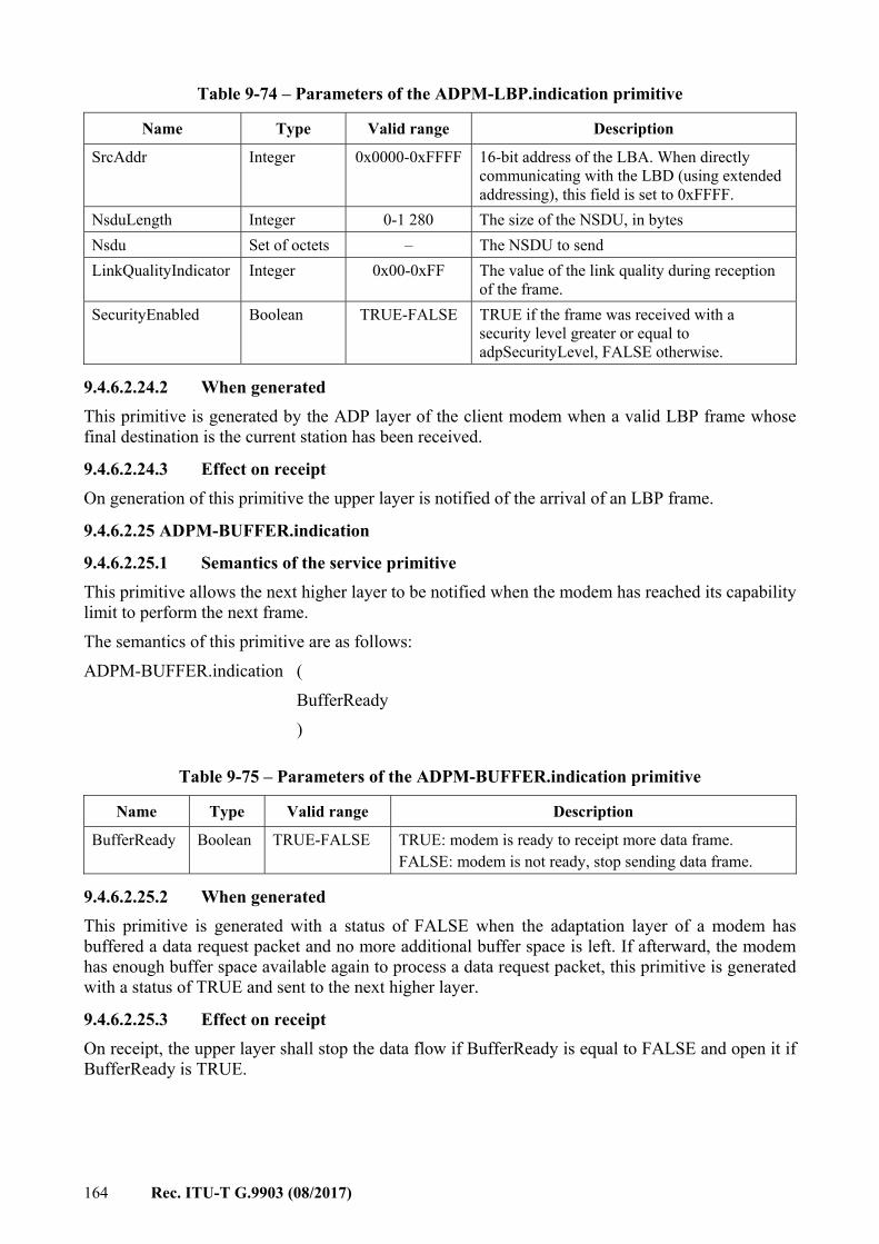
164 Rec. ITU-T G.9903 (08/2017)
Table 9-74 – Parameters of the ADPM-LBP.indication primitive
Name Type Valid range Description
SrcAddr Integer 0x0000-0xFFFF 16-bit address of the LBA. When directly communicating with the LBD (using extended addressing), this field is set to 0xFFFF.
NsduLength Integer 0-1 280 The size of the NSDU, in bytes Nsdu Set of octets – The NSDU to send LinkQualityIndicator Integer 0x00-0xFF The value of the link quality during reception
of the frame. SecurityEnabled Boolean TRUE-FALSE TRUE if the frame was received with a
security level greater or equal to adpSecurityLevel, FALSE otherwise.
9.4.6.2.24.2 When generated This primitive is generated by the ADP layer of the client modem when a valid LBP frame whose final destination is the current station has been received.
9.4.6.2.24.3 Effect on receipt On generation of this primitive the upper layer is notified of the arrival of an LBP frame.
9.4.6.2.25 ADPM-BUFFER.indication
9.4.6.2.25.1 Semantics of the service primitive This primitive allows the next higher layer to be notified when the modem has reached its capability limit to perform the next frame. The semantics of this primitive are as follows: ADPM-BUFFER.indication ( BufferReady )
Table 9-75 – Parameters of the ADPM-BUFFER.indication primitive
Name Type Valid range Description
BufferReady Boolean TRUE-FALSE TRUE: modem is ready to receipt more data frame. FALSE: modem is not ready, stop sending data frame.
9.4.6.2.25.2 When generated This primitive is generated with a status of FALSE when the adaptation layer of a modem has buffered a data request packet and no more additional buffer space is left. If afterward, the modem has enough buffer space available again to process a data request packet, this primitive is generated with a status of TRUE and sent to the next higher layer.
9.4.6.2.25.3 Effect on receipt On receipt, the upper layer shall stop the data flow if BufferReady is equal to FALSE and open it if BufferReady is TRUE.
Rec. ITU-T G.9903 (08/2017) 165
9.4.6.3 Behaviour to MAC indications
9.4.6.3.1 Overview This clause describes the behaviour of the adaptation layer in response to an unsolicited indication from the MAC layer.
9.4.6.3.2 MCPS-DATA.indication On receipt of this indication, the adaptation layer shall execute the routing algorithm as described in clause 9.4.3.
9.4.6.3.3 MLME-ASSOCIATE.indication Nothing shall be done upon receipt of this primitive by the adaptation layer.
9.4.6.3.4 MLME-DISASSOCIATE.indication Nothing shall be done upon receipt of this primitive by the adaptation layer.
9.4.6.3.5 MLME-BEACON-NOTIFY.indication When an MLME-BEACON-NOTIFY.indication is received, and if an ADPM-DISCOVERY.request is currently operating, the adaptation layer shall add the PANId to the PANDescriptorList which will be forwarded to the upper layer in the ADPM-DISCOVERY.confirm primitive.
9.4.6.3.6 MLME-GTS.indication Nothing shall be done upon receipt of this primitive by the adaptation layer.
9.4.6.3.7 MLME-ORPHAN.indication Nothing shall be done upon receipt of this primitive by the adaptation layer.
9.4.6.3.8 MLME-COMM-STATUS.indication On receipt of this primitive, the adaptation layer shall generate an ADPM-NETWORK-STATUS.indication primitive, with the parameters identical to the MLME-COMM-STATUS.indication parameters.
9.5 Functional description
9.5.1 Network formation The network formation can only be performed by the PAN coordinator. Any device other than the PAN coordinator shall not attempt to perform a network formation. Prior to the network formation, the PAN coordinator shall perform an active scan as described in clause 9.4.4.2.2.2. If the PANDescriptorList given by the ADPM-DISCOVERY.confirm primitive is empty, then the PAN coordinator can start a new network. If the PANDescriptorList is not empty, the PAN coordinator may inform the rest of the system that a PAN is already operating in the POS of the device and may start a new network afterwards. The procedures and decisions associated with this behaviour are implementation specific. After the network discovery, the PAN coordinator shall set its PAN ID to the predefined value stored in it. This value can be obtained remotely from a configuration server or locally computed. The way this PAN ID is chosen and set in the coordinator is implementation specific. NOTE – The PAN identifier shall be logically ANDed with 0xFCFF, as described in clause 6 of [IETF RFC 4944]; see also Table 9-34.
Once the PAN identifier has been determined, the adaptation sublayer shall invoke the MLME-START.request with the following parameters:
166 Rec. ITU-T G.9903 (08/2017)
– PANId = the PAN identifier computed; – LogicalChannel = 0 (not used); – ChannelPage = 0 (not used); – StartTime = 0 (not used); – BeaconOrder = 15 (beaconless network); – SuperframeOrder = 15 (not used); – PANCoordinator = TRUE; – BatteryLifeExtension = FALSE (not used); – CoordRealignment = FALSE; – CoordRealignSecurityLevel, CoordRealignKeyIdMode, CoordRealignKeySource and
CoordRealignKeyIndex: not used, shall be set to 0; – BeaconSecurityLevel = 0; – BeaconKeyIdMode, BeaconKeySource, BeaconKeyIndex: not used, shall be set to 0. The MAC sublayer then generates an MLME-START.confirm primitive with the corresponding status code, which is forwarded to the upper layers through the generation of an ADPM-NETWORK-START.confirm.
10 Security
10.1 Access control and authentication An end device (ED) may not access the network without a preliminary identification (with comparison to white or black lists) and authentication. Identification and authentication are based on two parameters that personalize every ED: – an EUI-48 MAC address as defined in [IEEE 802-2001]. This address may be easily
converted into an EUI-64 as requested by [IEEE 802.15.4] and related documents. – A 128-bit shared secret (also known as pre-shared key or PSK) used as a credential during
the authentication process. It is shared by the ED itself (also known as peer) and an authentication server. The mutual authentication is based on proof that the other party knows the PSK. It is of the highest importance that the PSK remains secret.
The identification and authentication processes are activated when an ED restarts and may also be launched at any time according to the security policy in place. The related material is carried by the 6LoWPAN bootstrapping protocol (LBP) (see clause 9.4.4) that embeds the extensible authentication protocol (EAP) (see clause 9.4.4.2.1.2). As shown in Figure 10-1, the LBP and EAP have been designed to be relayed by intermediates nodes. Then during the bootstrapping phase, if an ED (also known as LBD) that has not yet acquired a routable 16-bit address is at a 1-hop distance from the PAN coordinator (also known as LBS) they can communicate directly. Otherwise, they shall use an intermediate node (also known as LBA) located at a 1-hop distance of the LBD. Moreover, two different authentication architectures shall be considered: – The authentication server function is directly supported by the LBS and in this case all the
authentication material (access lists, credentials, etc.) shall be loaded in the LBS. – The authentication server function is supported by a remote (and usually centralized) AAA
server and in this case, the LBS is only in charge of forwarding the EAP messages to the AAA server over a standard AAA protocol (i.e., RADIUS [IETF RFC 2865]).
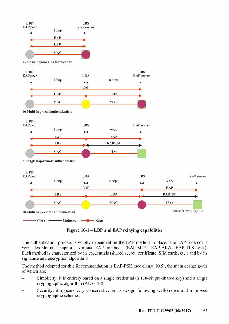
Rec. ITU-T G.9903 (08/2017) 167
G.9903(12)-Amd.1(13)_F10-1
n hops
WAN
WAN
MAC
IPv4
IPv4
1 hop
1 hop
1 hop
1 hop
MAC
MAC
MAC
MAC MAC
LBP
LBP
LBP
LBP LBP
EAP
EAP
EAP
EAP
EAP
EAP
LBP
RADIUS
RADIUS
LBDEAP peer
LBDEAP peer
LBDEAP peer
LBDEAP peer
LBSEAP server
LBSEAP server
EAP server
LBS EAP server
b) Multi hop-local authentication
c) Single hop-remote authentication
d) Multi hop-remote authentication
Clear Ciphered Relay
a) Single hop-local authentication
LBA
LBS
LBAn hops
Figure 10-1 – LBP and EAP relaying capabilities
The authentication process is wholly dependent on the EAP method in place. The EAP protocol is very flexible and supports various EAP methods (EAP-MD5, EAP-AKA, EAP-TLS, etc.). Each method is characterized by its credentials (shared secret, certificate, SIM cards, etc.) and by its signature and encryption algorithms. The method adopted for this Recommendation is EAP-PSK (see clause 10.5), the main design goals of which are: – Simplicity: it is entirely based on a single credential (a 128-bit pre-shared key) and a single
cryptographic algorithm (AES-128). – Security: it appears very conservative in its design following well-known and improved
cryptographic schemes.
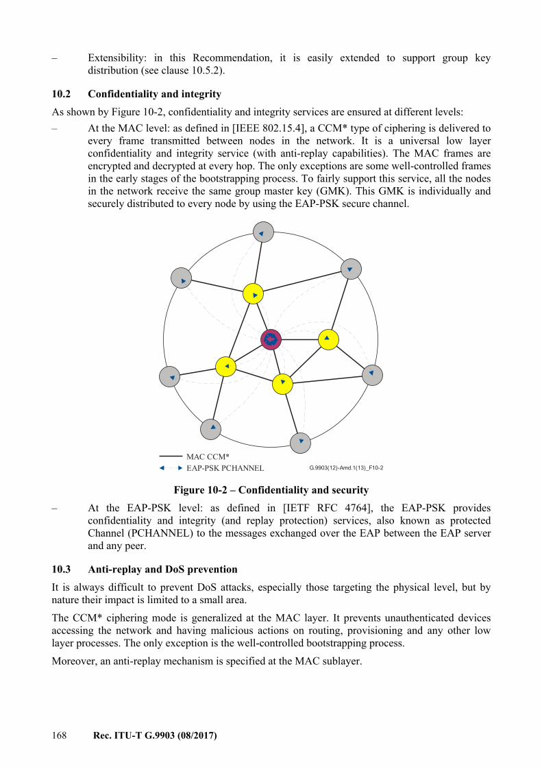
168 Rec. ITU-T G.9903 (08/2017)
– Extensibility: in this Recommendation, it is easily extended to support group key distribution (see clause 10.5.2).
10.2 Confidentiality and integrity As shown by Figure 10-2, confidentiality and integrity services are ensured at different levels: – At the MAC level: as defined in [IEEE 802.15.4], a CCM* type of ciphering is delivered to
every frame transmitted between nodes in the network. It is a universal low layer confidentiality and integrity service (with anti-replay capabilities). The MAC frames are encrypted and decrypted at every hop. The only exceptions are some well-controlled frames in the early stages of the bootstrapping process. To fairly support this service, all the nodes in the network receive the same group master key (GMK). This GMK is individually and securely distributed to every node by using the EAP-PSK secure channel.
G.9903(12)-Amd.1(13)_F10-2
MAC CCM*EAP-PSK PCHANNEL
Figure 10-2 – Confidentiality and security – At the EAP-PSK level: as defined in [IETF RFC 4764], the EAP-PSK provides
confidentiality and integrity (and replay protection) services, also known as protected Channel (PCHANNEL) to the messages exchanged over the EAP between the EAP server and any peer.
10.3 Anti-replay and DoS prevention It is always difficult to prevent DoS attacks, especially those targeting the physical level, but by nature their impact is limited to a small area. The CCM* ciphering mode is generalized at the MAC layer. It prevents unauthenticated devices accessing the network and having malicious actions on routing, provisioning and any other low layer processes. The only exception is the well-controlled bootstrapping process. Moreover, an anti-replay mechanism is specified at the MAC sublayer.
Rec. ITU-T G.9903 (08/2017) 169
10.4 Authentication and key distribution protocol – Selections from [IETF RFC 3748] Authentication and key distribution are supported by the extensible authentication protocol (EAP) as given in [IETF RFC 3748] together with the selections listed in Table 10-1.
Table 10-1 – Selections from [IETF RFC 3748]
Clause Title and remarks/modifications Statement
1 Introduction N 2 Extensible authentication protocol (EAP)
– Initial identity request (allows roaming and EAP method negotiation) is for further study and shall be bypassed.
S
2.1 Support for sequences N 2.2 EAP multiplexing model
– Only one EAP method is defined (cf. 9.4.4). S
2.3 Pass-through behaviour – Over the LBP, the code field is slightly different from a regular EAP
code field as specified in [IETF RFC 3748]. The conversion appears straightforward in both directions. The proper conversion shall apply when the EAP message is propagated over another protocol (i.e., RADIUS) and in case of integrity protection covering the EAP header.
S
2.4 Peer-to-peer operation N 3 Lower layer behaviour N
3.1 Lower layer requirements – LBP and underlying protocols provide: – Reliable transport – Error detection (CRC) – No lower layer security when bootstrapping – MTU size greater than 1 020 octets (by fragmentation) – No duplication – Ordering guaranties
S
3.2 EAP usage within PPP N/R 3.3 EAP usage within IEEE 802 N/R 3.4 Lower layer indications N
4 EAP packet format – Over the LBP, the code field is slightly different from a regular EAP
code field. S
4.1 Request and response – Over the LBP, the code field is slightly different from a regular EAP
code field. S
4.2 Success and failure – Over the LBP, the code field is slightly different from a regular EAP
code field. S
4.3 Retransmission behaviour N 5 Initial EAP request/response types
– For the type field, the only available values are 3 (''Nak'' – in response only) and the value assigned to the EAP method (see clause 10.5). Other values are left for further study.
S
170 Rec. ITU-T G.9903 (08/2017)
Table 10-1 – Selections from [IETF RFC 3748]
Clause Title and remarks/modifications Statement
5.1 Identity N/R 5.2 Notification N/R 5.3 ''Nak'' N 5.4 MD5-Challenge N/R 5.5 One-time password (OTP) N/R 5.6 Generic token card (GTC) N/R 5.7 Expanded types N/R 5.8 Experimental N/R 6 IANA considerations N 7 Security considerations N 8 Acknowledgements I 9 References N
Appendix A Changes from [IETF RFC 2284] I
10.5 EAP method The EAP protocol is very flexible and supports various EAP methods (EAP-MD5, EAP-AKA, EAP-TLS, etc.). Each method is characterized by its credentials (shared secret, certificate, SIM cards, etc.) and by its signature and encryption algorithms. For this Recommendation, the recommended method is the pre-shared key EAP method (EAP-PSK) as given in [IETF RFC 4764] together with the selections listed in Table 10-2.
Table 10-2 – Selections from [IETF RFC 4764]
Clause Title and remarks/modifications Statement
1 Introduction N 2 Protocol overview N 3 Cryptographic design of EAP-PSK N 4 EAP-PSK message flows
– EAP-PSK extension capabilities are used for group key distribution in full compliance with [IETF RFC 4764]. See clause 10.5.2.
N
5 EAP-PSK message format – EAP-PSK extension capabilities are used for group key distribution
in full compliance with [IETF RFC 4764]. See clause 10.5.2. N
6 Rules of operation for EAP-PSK protected channel N 7 IANA considerations N 8 Security considerations N 9 Security claims I
10 Acknowledgements I 11 References N
Appendix A Generation of the PSK from a password – discouraged. N/R
Rec. ITU-T G.9903 (08/2017) 171
10.5.1 Overview of the EAP-PSK According to the EAP specification the EAP-PSK supports the following key hierarchy: Pre-shared key (PSK) PSK is the long-term 128-bit credential shared by the
EAP server and the peer. Authentication key (AK) A 128-bit key derived from the PSK that the EAP peer
and server use to mutually authenticate. Key-derivation key (KDK) A 128-bit key derived from the PSK that the EAP peer
and server use to derive session keys (such as TEK, MSK and EMSK).
Transient EAP Key (TEK) A session key that is used to establish a protected channel between the EAP peer and server during the EAP authentication. EAP-PSK uses a 128-bit TEK in conjunction with AES-128 in the EAX mode of operation as a cipher suite.
Master session key (MSK) A session key derived between the EAP peer and server. The EAP-PSK generates a 512-bit MSK that may be used to provide security at the application level.
Extended master session key (EMSK) A session key derived between the EAP peer and server. The EAP-PSK generates a 512-bit EMSK. It is not used in this Recommendation and shall not be generated.
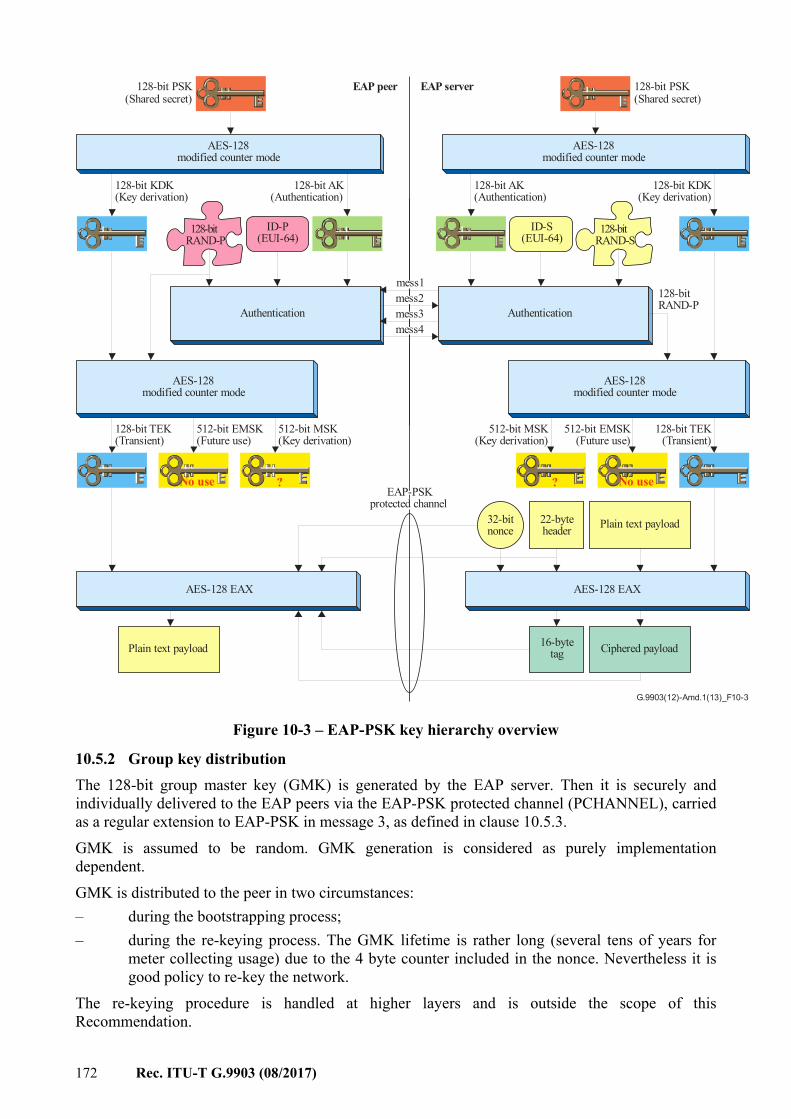
172 Rec. ITU-T G.9903 (08/2017)
128-bitRAND-P
128-bitRAND-S
G.9903(12)-Amd.1(13)_F10-3
mess1
mess3 mess4
mess2
128-bit PSK(Shared secret)
AES-128modified counter mode
128-bit KDK(Key derivation)
128-bit AK(Authentication)
Authentication
ID-S(EUI-64)
Authentication
ID-P(EUI-64)
No use?
22-byteheader Plain text payload
128-bitRAND-P
Ciphered payload16-bytetag
AES-128modified counter mode
128-bit AK(Authentication)
128-bit KDK(Key derivation)
AES-128modified counter mode
?No use
AES-128modified counter mode
512-bit MSK(Key derivation)
512-bit EMSK(Future use)
128-bit TEK(Transient)
AES-128 EAX
512-bit MSK(Key derivation)
512-bit EMSK(Future use)
128-bit TEK(Transient)
128-bit PSK(Shared secret)
Plain text payload
AES-128 EAX
32-bitnonce
EAP peer EAP server
EAP-PSKprotected channel
Figure 10-3 – EAP-PSK key hierarchy overview
10.5.2 Group key distribution The 128-bit group master key (GMK) is generated by the EAP server. Then it is securely and individually delivered to the EAP peers via the EAP-PSK protected channel (PCHANNEL), carried as a regular extension to EAP-PSK in message 3, as defined in clause 10.5.3. GMK is assumed to be random. GMK generation is considered as purely implementation dependent. GMK is distributed to the peer in two circumstances: – during the bootstrapping process; – during the re-keying process. The GMK lifetime is rather long (several tens of years for
meter collecting usage) due to the 4 byte counter included in the nonce. Nevertheless it is good policy to re-key the network.
The re-keying procedure is handled at higher layers and is outside the scope of this Recommendation.
Rec. ITU-T G.9903 (08/2017) 173
It is recommended to change the GMK on a regular basis. The following criteria can be used (whichever comes first): – every 90 days – when the PAN coordinator has sent 1000000 frames secured using the current GMK.
10.5.3 Configuration extension format The configuration extension is defined to be transported in EAP-PSK PCHANNEL, in compliance with the generic extension field (EXT) (see [IETF RFC 4764] clause 5.3). The configuration extension format and fields are described in Table 10-3.
Table 10-3 – Configuration extension fields
Field Length Description
EXT_Type 1 byte Indicates the type of the extension 0x02: configuration parameters
Parameters variable One or more configuration parameter, as defined in clause 9.4.4.2.1.3 and Figure 9-24.
NOTE – The EXT_Type value of 0x01 is reserved and should not be used in future extensions.
10.5.4 Peer side procedure Once a peer receives a configuration field embedded in a message 3, it shall apply the received parameters as defined in clause 9.4.4.2.1.3. In the case of bootstrapping, the following parameters are mandatory: Short-Addr, GMK and GMK-activation. If one or more parameter were invalid or missing, the peer sends a message 4 with R = DONE_FAILURE and an embedded configuration field with at least one Parameter-result indicating the error. If all the parameters were correct, the peer sends a message 4 with R = DONE_SUCCESS and an embedded configuration field with one Parameter-result indicating result = Success. In the case of bootstrapping, the peer keeps sending the frames in clear text up to the reception of an LBP ACCEPTED message. Then it starts sending ciphered frames using the active-GMK. In the case of re-keying, the peer keeps sending messages according to the previously assigned policy until the receipt of an LBP ACCEPTED message embedding a GMK-activation parameter. Then, it acknowledges the message with an LBP JOINING message embedding a Parameter-result and starts sending frames using the new GMK. After switching to the new GMK, a peer may keep receiving some messages encrypted with the previous GMK during a transient period. The previous GMK may be deleted after receipt of an LBP message including a GMK-remove parameter.
10.5.5 Server side procedure The bootstrapping procedure is defined in clause 9.4.4.2.2. In the case of re-keying, the EAP server generates a new GMK. The new GMK-ID shall be chosen to be different from the key identifier associated with the previous GMK. Then it executes an EAP-PSK authentication exchange (starting with message EAP-PSK #1 to Accepted1(EAPSuccess) with every formerly associated peer, in order to transmit the new GMK. These messages are exchanged directly between the LBS and the peers (an LBA relay is not used) and ciphered following the PAN security configuration.

174 Rec. ITU-T G.9903 (08/2017)
If the EAP server does not receive the EAP responses from a peer, it may retry the EAP-PSK exchange described above. The PAN coordinator may remove the peer device using the procedure described in clause 9.4.4.2.2.7 if the EAP server has failed to complete the EAP-PSK exchange. Once the EAP server has completed the GMK transmission to all peers, it may send an LBP ACCEPTED message with a GMK-activation parameter to each peer to invoke switching to the new GMK (those messages are acknowledged by the peer). On reception of the GMK-activation parameter, the peer shall empty its DeviceTable (in order to allow re-use of previously allocated short addresses). Figure 10-4 describes the messages exchanged during a GMK re-keying procedure.
G.9903(12)-Amd.1(13)_F10-4
LBSLBALBD LBS upperlayer
Challenge(EAPReq(mes1))Challenge(EAPReq(mes1))
Joining(EAPRes(mes2)) Joining(EAPRes(mes2))
Challenge(EAPReq(mes3))
Joining(EAPRes(mes4)) Joining(EAPRes(mes4))
Accepted(EAPsuccess)
Challenge(EAPReq(mes3))
Accepted(GMK-activation)Accepted(GMK-activation)
ADPM-LBP.Request(EAPReq(mes1))
ADPM-LBP.Confirm
ADPM-LBP.IndicationADPM-LBP.Request
(EAPReq(mes3))
ADPM-LBP.Confirm
ADPM-LBP.Indication
ADPM-LBP.Request(GMK-activation)
ADPM-LBP.Confirm
Joining(Parameter-result) Joining(Parameter-result) ADPM-LBP.Indication
ADPM-LBP.Request(EAPSuccess)
ADPM-LBP.ConfirmAccepted(EAPsuccess)
Repeat for all devices in PAN…
Repeat for all devices in PAN…
Figure 10-4 – GMK re-keying message sequence chart
Rec. ITU-T G.9903 (08/2017) 175
Annex A
Protocol implementation conformance statement (This annex forms an integral part of this Recommendation.)
A.1 Overview Compliance with the clauses of [IEEE 802.15.4] shall be consistent with the extensions and selections defined in this annex. The first part of this annex entirely takes as reference the protocol implementation conformance statement of [IEEE 802.15.4], Annex D. The second part of this annex gives similar tables to ensure that all items related to the physical layer of ITU-T G.9903 have been taken into account.
A.2 PICS proforma tables
A.2.1 Functional device types (from clause D.7.1 of [IEEE 802.15.4])
Table A.1 – PICS – Functional device types (from clause D.7.1 of [IEEE 802.15.4])
Item number Support
Comments N/A Yes No
FD1 X FD2 X FD3 X FD4 X FD5 X
A.2.2 PHY functions (from clause D.7.2.1 of [IEEE 802.15.4])
Table A.2 – PICS – PHY functions (from clause D.7.2.1 of [IEEE 802.15.4])
Item number Support
Comments N/A Yes No
PLF1 X PLF2 X PLF3 X Radio specific requirement PLF4 X Radio specific requirement PLF5 X Radio specific requirement PLF6 X PLF7 X Radio specific requirement PLF8 X PLF8.1 X Radio specific requirement PLF8.2 X PLF8.3 X Radio specific requirement
176 Rec. ITU-T G.9903 (08/2017)
A.2.3 PHY packet (from clause D.7.2.2 of [IEEE 802.15.4])
Table A.3 – PICS – PHY packet (from clause D.7.2.2 of [IEEE 802.15.4])
Item number Support
Comments N/A Yes No
PLP1 X
A.2.4 Radio frequency (from clause D.7.2.3 of [IEEE 802.15.4])
Table A.4 – PICS – Radio frequency (from clause D.7.2.3 of [IEEE 802.15.4])
Item number Support
Comments N/A Yes No
RF1 X Radio specific requirement RF1.1 X Radio specific requirement RF1.2 X Radio specific requirement RF1.3 X Radio specific requirement RF1.4 X Radio specific requirement RF2 X Radio specific requirement
A.2.5 MAC sublayer functions (from clause D.7.3.1 of [IEEE 802.15.4])
Table A.5 – PICS – MAC sublayer functions (from clause D.7.3.1 of [IEEE 802.15.4])
Item number Support
Comments N/A Yes No
MLF1 X MLF1.1 X Indirect transmission is not supported MLF2 X MLF2.1 X MLF2.2 X MLF2.3 X MLF3 X MLF3.1 X MLF3.2 X MLF4 X MLF5 X MLF5.1 X MLF5.2 X MLF6 X MLF7 X MLF8 X Performed by 6LoWPAN MLF9 X MLF9.1 X
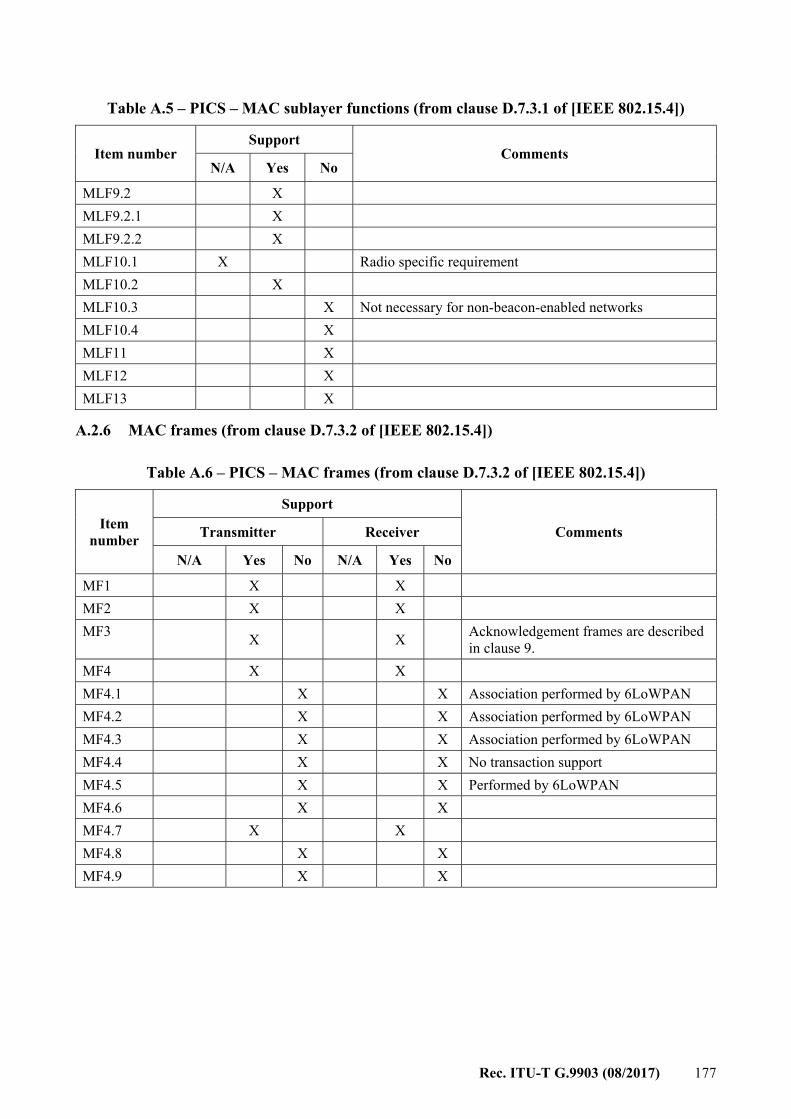
Rec. ITU-T G.9903 (08/2017) 177
Table A.5 – PICS – MAC sublayer functions (from clause D.7.3.1 of [IEEE 802.15.4])
Item number Support
Comments N/A Yes No
MLF9.2 X MLF9.2.1 X MLF9.2.2 X MLF10.1 X Radio specific requirement MLF10.2 X MLF10.3 X Not necessary for non-beacon-enabled networks MLF10.4 X MLF11 X MLF12 X MLF13 X
A.2.6 MAC frames (from clause D.7.3.2 of [IEEE 802.15.4])
Table A.6 – PICS – MAC frames (from clause D.7.3.2 of [IEEE 802.15.4])
Item number
Support
Comments Transmitter Receiver
N/A Yes No N/A Yes No
MF1 X X MF2 X X MF3 X X Acknowledgement frames are described
in clause 9. MF4 X X MF4.1 X X Association performed by 6LoWPAN MF4.2 X X Association performed by 6LoWPAN MF4.3 X X Association performed by 6LoWPAN MF4.4 X X No transaction support MF4.5 X X Performed by 6LoWPAN MF4.6 X X MF4.7 X X MF4.8 X X MF4.9 X X
178 Rec. ITU-T G.9903 (08/2017)
Annex B
Routing cost (This annex forms an integral part of this Recommendation.)
This annex describes the link cost and route cost computation to be used for routing. In this Annex, the conventional rounding rule of ''rounding half towards zero'' shall be used when values are rounded. A route cost is defined as the sum of all the link costs on the route. As described in Annex D, a route cost is a 16-bit unsigned integer, lower cost values meaning better routes. The route cost of route P, RCP, where P refers to the N-hop route going from node 0 to node N-1 through nodes 1 … N-1 is computed as:
= , where Ci,i+1 is the link cost between devices i and (i+1). Different link cost computation methods can be implemented, each identified by their respective adpMetricType value. This annex defines the link computation cost specified below.
B.1 Composite metric method The composite metric method is associated with the adpmetrictype value of 0x0F and defines the link cost as follows:
= → , → + ∗ + ℎ where Ci → j and Cj → i are the directional link costs (forward and reverse direction, respectively) between i to j. The directional link cost is computed as follow:
= ∗ + ∗ + ∗ ( ) + ∗ 0, 1, where: MODKr = 1 for robust mode, 0 for other modulations MODKm = 3 for DBPSK or BPSK modulation (including robust mode), 2 for DQPSK or
QPSK modulation, 1 for D8PSK or 8-PSK modulation and 0 for 16-QAM modulation
and adpKr, adpKm, adpKc, adpKq, adpKh and adpKrt as defined in Table 9-28. For the forward direction (Ci → j), modulation, tone map and LQI information is based on quality measurement of the received routing messages. When a unicast frame is received, the frame's modulation and tone map configuration may be used instead. For the reverse direction (Cj → i), the directional link cost may be obtained as follows (see the flowchart in Figure B.1): – Modulation, tone map and LQI information for computing the directional link cost shall be
taken from the neighbour table, if the parameters of the neighbour table entry of the destination node are valid.

Rec. ITU-T G.9903 (08/2017) 179
– If modulation, tone map and LQI information are not available and if adpRLCEnabled is set to TRUE, then the RLC mechanism defined in clause 9.4.3.2.6 shall be used. If the procedure is successful, the resulting RLCREP message will then provide the reverse directional link cost value. In case of failure, the next method shall be used.
– Else, the forward link cost is used to estimate the reverse link cost, using the formula: – → = → + adpAddRevLinkCost – adpAddRevLinkCost represents an additional cost to take into account a possible
asymmetry in the link. This attribute is defined in Table 9-28.
G.9903(14)_FB.1
NO
NO
YES
YES YES
If modulation, tone map and LQI are available in
the neighbour table
If adpEnableRLCis TRUE
Generate the directional link cost with these parameters.
If RLC procedureis successful
Generate the directionallink cost using forward Link
Cost and adpAddRevLinkCost
Generate the directional link cost with these parameters.
NO
Figure B.1 – Flowchart explaining the directional link cost computation
180 Rec. ITU-T G.9903 (08/2017)
Annex C
Device starting sequence of messages (This annex forms an integral part of this Recommendation.)
Each device shall start with an adpDeviceType attribute of Not_Defined (see Table 9-28) and then the following procedure is performed: a) Reset the equipment by sending the ADPM-RESET.request. b) Set the type of the device to PAN device or PAN coordinator mode and optionally set the
PIB parameters to configure it. c) If the equipment is a PAN device it shall perform the following steps:
– discovery procedure by invoking the ADPM-DISCOVERY.request; – if there is a PAN device or a PAN coordinator in its POS, it shall then invoke the
ADPM-NETWORK-JOIN.request to perform the bootstrapping procedure. d) Otherwise (if the equipment is a PAN coordinator) it shall perform the following steps:
– discovery procedure by invoking the ADPM-DISCOVERY.request; – if there is no PAN device in the PAN coordinator's POS, it shall invoke the
ADPM-NETWORK-START to start a network; otherwise, it should inform the rest of the system that a PAN is already operating in its POS, and may start a new network afterwards as described in clause 9.5.1. The procedures and decisions associated with this behaviour are implementation specific.
Equipment cannot send or receive data packets unless they have joined the network.
Rec. ITU-T G.9903 (08/2017) 181
Annex D
The lightweight on-demand Ad hoc distance-vector routing protocol – next generation (LOADng)
(This annex forms an integral part of this Recommendation.)
D.1 Introduction The lightweight on-demand ad-hoc distance-vector routing protocol –next generation (LOADng) is a reactive routing protocol. As a reactive protocol, the basic operations of LOADng include the generation of route requests (RREQs) by a LOADng router (originator) for when discovering a route to a destination, forwarding of such RREQs until they reach the destination LOADng router, generation of route replies (RREPs) upon receipt of an RREQ by the indicated destination, and unicast hop-by-hop forwarding of these RREPs towards the originator. If a route is detected to be broken, e.g., if forwarding of a data packet to the recorded next hop on the route towards the intended destination is detected to fail, a Route Error (RERR) message is returned to the originator of that data packet to inform the originator about the route breakage.
D.2 Terminology and notation
D.2.1 Message and message field notation LOADng routers generate and process messages, each of which has a number of distinct fields. For describing the protocol operation, specifically the generation and processing of such messages, the following notation is employed: MsgType.field where: MsgType: is the type of message (e.g., RREQ or RREP) field: is the field in the message (e.g., originator). The different messages, their fields and their meaning are described in clause D.6. The motivation for separating the high-level messages and their content from the low-level encoding and frame format for transmission is to allow discussions of the protocol logic to be separated from the message encoding and frame format, and to support different frame formats.
D.2.2 Variable notation Variables are introduced into the specification solely as a way of clarifying the description. The following notation is used: MsgType.field – If ''field'' is a field in the message MsgType, then MsgType.field is also used to represent the value of that field. bar – A variable (not prepended by MsgType), usually obtained through calculations based on the value(s) of element(s).
D.2.3 Other notation This document uses the following additional notational conventions: a:= b An assignment operator, whereby the left side (a) is assigned the value of the right side (b). c = d A comparison operator, returning TRUE if the value of the left side (c) is equal to the value of the right side (d).
182 Rec. ITU-T G.9903 (08/2017)
D.2.4 Terminology This document uses the following terminology: jLOADng router – A router that implements this routing protocol. A LOADng router is equipped
with at least one, and possibly more, LOADng interfaces. LOADng interface – A LOADng router's attachment to a communications medium, over which it
receives and generates control messages, according to this Recommendation. A LOADng interface is assigned one or more addresses.
Link – A link between two LOADng interfaces exists if either of them can receive control messages, according to this Recommendation, from the other.
Message – The fundamental entity carrying protocol information, in the form of address objects and TLVs.
Link metric – The cost (weight) of a link between a pair of LOADng interfaces. Route metric – The sum of the link metrics for the links that an RREQ or RREP has crossed.
D.3 Applicability statement LOADng is a reactive protocol, i.e., routes are discovered only when a data packet is sent by a router (e.g., on behalf of an attached host), and when the router has no route for this destination. In this case, the router floods route requests (RREQ) throughout the network for discovering the destination. Reactive protocols require state only for the routes currently in use, contrary to proactive protocols, which periodically send control traffic and store routes to all destinations in the network. Flooding RREQs may lead to frame collisions and therefore data loss. Moreover, each transmission on a network interface consumes energy, reducing the life-time of battery-driven routers. Consequently, in order to reduce the amount of control traffic, LOADng (and in general reactive protocols) are most suitable under the following constraints: – Few concurrent traffic flows in the network (i.e., traffic only flows between a few sources
and destinations). – State requirements on the router are very stringent, i.e., it is beneficial to store only few
routes on a router. Specifically, the applicability of LOADng is determined by its characteristics, which for this protocol are: – is a reactive routing protocol; – is designed to work in networks with dynamic topology in which the links may be lossy due
to collisions, channel instability or movement of routers; – supports the use of optimized flooding for RREQs; – enables any LOADng router to discover bidirectional routes to destinations in the routing
domain, i.e., to any other LOADng router, as well as hosts or networks attached to that LOADng router, in the same routing domain;
– supports addresses of any length, from 16 octets to a single octet; – supports per-destination route maintenance; if a destination becomes unreachable,
rediscovery of that single (bidirectional) route is performed, without the need for global topology recalculation.
D.4 Protocol overview and functioning The objective of this protocol is for each LOADng router to independently: – Discover a bi-directional route to any destination in the network.
Rec. ITU-T G.9903 (08/2017) 183
– Establish a route only when there is data traffic to be sent along that route. – Maintain a route only for as long as there is data traffic being sent along that route. – Generate control traffic based on network events only: when a new route is required, or
when an active route is detected broken. Specifically, this protocol does not require periodic signalling.
D.4.1 Overview These objectives are achieved, for each LOADng router, by performing the following tasks: – When having a data packet to deliver to a destination, for which no tuple in the routing set
exists and where the data packet source is local to that LOADng router (i.e., is an address in the local interface set or destination address set of that LOADng router), generate a Route Request (RREQ) encoding the destination address, and transmit this RREQ over all of its LOADng interfaces.
– Upon receiving an RREQ, insert or refresh a tuple in the Routing Set, recording a route towards the originator address from the RREQ, as well as to the neighbour LOADng router from which the RREQ was received. This will install the Reverse Route (towards the originator address from the RREQ).
– Upon receiving an RREQ, inspect the indicated destination address: – If that address is an address in the destination address set or in the local interface set of
the LOADng router, generate a Route Reply (RREP), which is unicast in a hop-by-hop fashion along the installed reverse route.
– If that address is not an address in the destination address set or in the local interface set of the LOADng router, consider the RREQ as a candidate for forwarding.
– When an RREQ is considered a candidate for forwarding, retransmit it according to the flooding operation, specified for the network.
– Upon receiving an RREP, insert or refresh a tuple in the routing set, recording a route towards the originator address from the RREP, as well as to the neighbour LOADng router, from which that RREP was received. This will install the forward route (towards the originator address from the RREP). The originator address is either an address from the local interface set of the LOADng router, or an address from its destination address set (i.e., an address of a host attached to that LOADng router).
– Upon receiving an RREP, forward it, as unicast, to the recorded next hop along the corresponding reverse route until the RREP reaches the LOADng router that has the destination address from the RREP in its local interface set or destination address set.
– When forwarding an RREQ or RREP, update the route metric, as contained in that RREQ or RREP message.
A LOADng router generating an RREQ specifies which metric type it desires. Routers receiving an RREQ will process it and update route metric information in the RREQ according to that metric, if they can. All LOADng routers, however, will update information in the RREQ so as to be able to support a ''hop-count'' default metric. If a LOADng router is not able to understand the metric type, specified in an RREQ, it will update the route metric value to its maximum value, so as to ensure that this is indicated to the further recipients of the RREQ. Once the route metric value is set to its maximum value, no LOADng router along the path towards the destination may change the value.
D.4.2 LOADng routers and LOADng interfaces A LOADng router has a set of at least one, and possibly more, LOADng interfaces. Each LOADng interface: – is configured with one or more addresses;
184 Rec. ITU-T G.9903 (08/2017)
– has a number of interface parameters. In addition to a set of LOADng interfaces as described above, each LOADng router: – has a number of router parameters; – has an information base; – generates and processes RREQ, RREP, RREP_ACK and RERR messages, according to this
Recommendation.
D.4.3 Information base overview Necessary protocol state is recorded by way of five information sets: the ''Routing Set'', the ''Local Interface Set'', the ''Blacklisted Neighbour Set'', the ''Destination Address Set'', and the ''Pending Acknowledgment Set''. The routing set contains tuples, each representing the next-hop on, and the metric of, a route towards a destination address. Additionally, the routing set records the sequence number of the last message received from the destination. This information is extracted from the message (RREQ or RREP) that generated the tuple so as to enable routing. The routing table is to be updated using this routing set. (A LOADng router may choose to use any or all destination addresses in the routing set to update the routing table, this selection is outside the scope of this Recommendation.) The local interface set contains tuples, each representing a local LOADng interface of the LOADng router. Each tuple contains a list of one or more addresses of that LOADng interface. The blacklisted neighbour set contains tuples representing neighbour LOADng interface addresses of a LOADng router with which unidirectional connectivity has been recently detected. The destination address set contains tuples representing addresses, for which the LOADng router is responsible, i.e., addresses of this LOADng router, or of hosts and networks directly attached to this LOADng router and which use it to connect to the routing domain. These addresses may in particular belong to devices which do not implement LOADng, and thus cannot process LOADng messages. A LOADng router provides connectivity to these addresses by generating RREPs in response to RREQs directed towards them. The pending acknowledgment set contains tuples, representing transmitted RREPs for which an RREP_ACK is expected, but where this RREP_ACK has not yet been received. The routing set, the blacklisted neighbour set and the pending acknowledgment set are updated by this protocol. The local interface set and the destination address set are used, but not updated by this protocol.
D.4.4 Signalling overview This protocol generates and processes the following routing messages: Route request (RREQ) – Generated by a LOADng router when it has a data packet to deliver to a given destination, where the data packet source is local to that LOADng router (i.e., is an address in the local interface set or destination address set of that LOADng router), but where it does not have an available tuple in its routing set indicating a route to that destination. An RREQ contains: – the (destination) address to which a forward route is to be discovered by way of soliciting
the LOADng router with that destination address in its local interface set or in its destination address set to generate an RREP;
– the (originator) address for which a reverse route is to be installed by RREQ forwarding and processing, i.e., the source address of the data packet which triggered the RREQ generation;
– the sequence number of the LOADng router, generating the RREQ.
Rec. ITU-T G.9903 (08/2017) 185
An RREQ is flooded through the network, according to the flooding operation specified for the network. Route reply (RREP) – Generated as a response to an RREQ by the LOADng router which has the address (destination) from the RREQ in its local interface set or in its destination address set. An RREP is sent in unicast towards the originator of that RREQ. An RREP contains: – the (originator) address to which a forward route is to be installed when forwarding the
RREP; – the (destination) address towards which the RREP is to be sent. More precisely, the
destination address determines the unicast route which the RREP follows; – the sequence number of the LOADng router, generating the RREP. Route reply acknowledgment (RREP_ACK) – Generated by a LOADng router as a response to an RREP, in order to signal to the neighbour that transmitted the RREP that the RREP was successfully received. Receipt of an RREP_ACK indicates that the link between these two neighbouring LOADng routers is bidirectional. An RREP_ACK is unicast to the neighbour from which the RREP has arrived, and is not forwarded. RREP_ACKs are generated only in response to an RREP which, by way of a flag, has explicitly indicated that an RREP_ACK is desired. Route error (RERR) – Generated by a LOADng router when a link on an active route to a destination is detected as broken by way of inability to forward a data packet towards that destination. An RERR is unicast to the source of the undeliverable data packet.
D.5 Protocol parameters The following parameters and constants are used in this specification.
D.5.1 Protocol and port numbers None.
D.5.2 Router parameters NET_TRAVERSAL_TIME is the maximum time that a packet is expected to take when traversing from one end of the network to the other. RREQ_RETRIES is the maximum number of subsequent RREQs that a particular LOADng router may generate in order to discover a route to a destination, before declaring this destination unreachable. RREQ_MIN_INTERVAL is the minimal interval (in milliseconds) of RREQs that a particular LOADng router is allowed to send. R_HOLD_TIME is the minimum time a routing tuple SHOULD be kept in the routing set after it was last refreshed. MAX_DIST is the value representing the maximum possible metric (R_metric field). B_HOLD_TIME is the time during which the link between the neighbour LOADng router and this LOADng router shall be considered as non-bidirectional, and that therefore RREQs received from that neighbour LOADng router shall be ignored during that time (B_HOLD_TIME). B_HOLD_TIME should be greater than 2 x NET_TRAVERSAL_TIME x RREQ_RETRIES, to ensure that subsequent RREQs will reach the destination via a route, excluding the link to the blacklisted neighbour. MAX_HOP_LIMIT is the maximum limit of the number of hops that LOADng routing messages are allowed to traverse.
186 Rec. ITU-T G.9903 (08/2017)
D.5.3 Interface parameters Different LOADng interfaces (on the same or on different LOADng routers) may employ different interface parameter values and may change their interface parameter values dynamically. A particular case is where all LOADng interfaces on all LOADng routers within a given LOADng routing domain employ the same set of interface parameter values. RREQ_MAX_JITTER is the default value of MAXJITTER used in [b-IETF RFC 5148] for RREQ messages forwarded by this LOADng router on this interface. RREP_ACK_REQUIRED is a Boolean flag, which indicates (if set) that the LOADng router is configured to expect that each RREP it sends be confirmed by an RREP_ACK, or (if cleared) that no RREP_ACK is expected for this interface. USE_BIDIRECTIONAL_LINK_ONLY is a Boolean flag, which indicates if the LOADng router only uses verified bidirectional links for data packet forwarding on this interface. It is set by default. If cleared, the LOADng router can use links which have not been verified to be bidirectional on this interface. RREP_ACK_TIMEOUT is the minimum amount of time after transmission of an RREP, that a LOADng router SHOULD wait for an RREP_ACK from a neighbour LOADng router, before considering the link to this neighbour to be unidirectional.
D.5.4 Constants MAX_HOP_COUNT is the maximum number of hops as representable by the encoding that is used. It shall not be used to limit the scope of a message; the router parameter MAX_HOP_LIMIT can be used to limit the scope of a LOADng routing message.
D.6 Protocol message content The protocol messages, generated and processed by LOADng, are described in this clause using the notational conventions described in clause D.2. Unless stated otherwise, the message fields described below are set by the LOADng router that generates the message, and shall not be changed by intermediate LOADng routers.
D.6.1 Route request (RREQ) messages A route request (RREQ) message has the following fields: RREQ.addr-length is an unsigned integer field, encoding the length of the originator and destination addresses as follows: RREQ.addr-length := the length of an address in octets – 1 RREQ.seq-num is an unsigned integer field, containing the sequence number (see clause D.8) of the LOADng router, generating the RREQ message. RREQ.metric-type is an unsigned integer field and specifies the type of metric requested by this RREQ. RREQ.route-metric is a unsigned integer field, of length defined by RREQ.metric-type, which specifies the route metric of the route (the sum of the link metrics of the links), through which this RREQ has travelled. RREQ.hop-count is an unsigned integer field and specifies the total number of hops which the message has traversed from the RREQ.originator. RREQ.hop-limit is an unsigned integer field and specifies the number of hops that the message is allowed to traverse. RREQ.originator is an identifier of RREQ.addr-length + 1 octets, specifying the address of the LOADng interface over which this RREQ was generated, and to which a route (the ''reverse route'') is supplied by this RREQ. In case the message is generated by a LOADng router on behalf of an
Rec. ITU-T G.9903 (08/2017) 187
attached host, RREQ.originator corresponds to an address of that host, otherwise it corresponds to an address of the sending LOADng interface of the LOADng router. RREQ.destination is an identifier of RREQ.addr-length + 1 octets, specifying the address to which the RREQ should be sent, i.e., the destination address for which a route is sought. The following fields of an RREQ message are immutable, i.e., they shall not be changed during the processing or forwarding of the message: RREQ.addr-length, RREQ.seq-num, RREQ.originator, and RREQ.destination. The following fields of an RREQ message are mutable, i.e., they will be changed by intermediate routers during processing or forwarding, as specified in clause D.12.2 and clause D.12.3: REQ.metric-type, RREQ.route-metric, RREQ.hop-limit and RREQ.hop-count. Any additional field that is added to the message by an extension to this protocol, e.g., by way of TLVs, shall be considered immutable, unless the extension specifically defines the field as mutable.
D.6.2 Route reply (RREP) messages A route reply (RREP) message has the following fields: RREP.addr-length is an unsigned integer field, encoding the length of the originator and destination addresses as follows: RREP.addr-length := the length of an address in octets – 1 RREP.seq-num is an unsigned integer field, containing the sequence number (see clause D.8) of the LOADng router, generating the RREP message. RREP.metric-type is an unsigned integer field and specifies the type of metric, requested by this RREP. RREP.route-metric is an unsigned integer field, of length defined by RREP.metric-type, which specifies the route metric of the route (the sum of the link metrics of the links) through which this RREP has travelled. RREP.ackrequired is a Boolean flag which, when set ('1'), at least one RREP_ACK shall be generated by the recipient of an RREP if the RREP is successfully processed. When cleared ('0'), an RREP_ACK shall not be generated in response to processing of the RREP. RREP.hop-count is an unsigned integer field and specifies the total number of hops which the message has traversed from RREP.originator to RREP.destination. RREP.hop-limit is an unsigned integer field and specifies the number of hops that the message is allowed to traverse. RREP.originator is an identifier of RREP.addr-length + 1 octets, specifying the address for which this RREP was generated, and to which a route (the ''forward route'') is supplied by this RREP. In case the message is generated on a LOADng router on behalf of an attached host, RREP.originator corresponds to an address of that host, otherwise it corresponds to an address of the LOADng interface of the LOADng router, over which the RREP was generated. RREP.destination is an identifier of RREP.addr-length + 1 octets, specifying the address to which the RREP should be sent (i.e., this address is equivalent to RREQ.originator of the RREQ that triggered the RREP.) The following fields of an RREP message are immutable, i.e., they shall not be changed during the processing or forwarding of the message: RREP.addr-length, RREP.seq-num, RREP.originator and RREP.destination. The following fields of an RREP message are mutable, i.e., they will be changed by intermediate routers during processing or forwarding, as specified in clause D.13.2 and clause D.13.3: RREP.metric-type, RREP.route-metric, RREP.ackrequired, RREP.hop-limit and RREP.hop-count.

188 Rec. ITU-T G.9903 (08/2017)
Any additional field that is added to the message by an extension to this protocol, e.g., by way of TLVs, shall not be considered immutable, unless the extension specifically defines the field as mutable.
D.6.3 Route reply acknowledgement (RREP_ACK) messages A route reply acknowledgement (RREP_ACK) message has the following fields: RREP_ACK.addr-length is an unsigned integer field, encoding the length of the destination and originator addresses as follows: RREP_ACK.addr-length := the length of an address in octets – 1 RREP_ACK.seq-num is an unsigned integer field and contains the value of RREP.seq-num from the RREP for which this RREP_ACK is sent. RREP_ACK.destination is an identifier of RREP_ACK.addr-length + 1 octets and contains the value of the RREP.originator field from the RREP for which this RREP_ACK is sent. RREP_ACK messages are sent only across a single link and are never forwarded.
D.6.4 Route error (RERR) messages A route error (RERR) message has the following fields: RERR.addr-length is an unsigned integer field, encoding the length of RERR.destination and RERR.unreachableAddress, as follows: RERR.addr-length := the length of an address in octets – 1 RERR.errorcode is an unsigned integer field and specifies the reason for the error message being generated. RERR.unreachableAddress is an identifier of RERR.addr-length + 1 octets, specifying an address, which has become unreachable, and for which an error is reported by way of this RERR message. RERR.originator is an identifier of RERR.addr-length + 1 octets, specifying the address of the LOADng interface over which this RERR was generated by a LOADng router. RERR.destination is an identifier of RERR.address-length + 1 octets, specifying the destination address of this RERR message. RERR.destination is in general, the source address of a data packet, for which delivery to RERR.unreachableAddress has failed, and the unicast destination of the RERR message is the LOADng router which has RERR.destination listed in a local interface tuple or in a destination address tuple. RERR.hop-limit is an unsigned integer field and specifies the number of hops that the message is allowed to traverse. The following fields of an RERR message are immutable, i.e., they shall not be changed during processing or forwarding of the message: RERR.addr-length, RERR.errorcode, RERR.unreachableAddress, RERR.originator and RERR.destination. The following fields of an RERR message are mutable, i.e., they will be changed by intermediate routers during processing or forwarding, as specified in clause D.14.3 and clause D.14.4: RERR.hop-limit. Any additional field that is added to the message by an extension to this protocol, e.g., by way of TLVs, shall be considered immutable, unless the extension specifically defines the field as mutable.
D.7 Information base Each LOADng router maintains an information base, containing the information sets necessary for protocol operation, as described in the following clauses. The organization of information into these information sets is non-normative, given so as to facilitate the description of message generation, forwarding and processing rules in this Recommendation. An implementation may choose any representation or structure for when maintaining this information.
Rec. ITU-T G.9903 (08/2017) 189
D.7.1 Routing set The routing set records the next hop on the route to each known destination, when such a route is known. It consists of routing tuples: (R_dest_addr, R_next_addr, R_metric, R_metric_type, R_hop_count, R_seq_num, R_bidirectional, R_local_iface_addr, R_valid_time) where: R_dest_addr is the address of the destination, either an address of a LOADng interface of a destination LOADng router, or an address of an interface reachable via the destination LOADng router, but which is outside the routing domain. R_next_addr is the address of the ''next hop'' on the selected route to the destination. R_metric is the metric associated with the selected route to the destination with address R_dest_addr. R_metric_type specifies the metric type for this routing tuple – in other words, how R_metric is defined and calculated. R_hop_count is the hop count of the selected route to the destination with address R_dest_addr. R_seq_num is the value of the RREQ.seq-num or RREP.seq-num field of the RREQ or RREP which installed or last updated this tuple. For the routing tuples installed by previous hop information of RREQ or RREP, R_seq_num shall be set to –1. R_bidirectional is a Boolean flag, which specifies if the routing tuple is verified as representing a bidirectional route. Data traffic SHOULD only be routed through a routing tuple with R_bidirectional flag equals TRUE, unless the LOADng router is configured as accepting routes without bidirectionality verification explicitly by setting USE_BIDIRECTIONAL_LINK_ONLY to FALSE of the interface with R_local_iface_address. R_local_iface_addr is an address of the local LOADng interface, through which the destination can be reached. R_valid_time specifies the time until when the information recorded in this routing tuple is considered valid.
D.7.2 Local interface set A LOADng router's local interface set records its local LOADng interfaces. It consists of local interface tuples, one per LOADng interface: (I_local_iface_addr_list) where: I_local_iface_addr_list is an unordered list of the network addresses of this LOADng interface. The implementation shall initialize the local interface set with at least one tuple containing at least one address of a LOADng interface. The local interface set shall be updated if there is a change of the LOADng interfaces of a LOADng router (i.e., a LOADng interface is added, removed or changes addresses).
D.7.3 Blacklisted neighbour set The blacklisted neighbour set records the neighbour LOADng interface addresses of a LOADng router, with which connectivity has been detected to be unidirectional. Specifically, the blacklisted neighbour set records neighbours from which an RREQ has been received (i.e., through which a forward route would be possible) but to which it has been determined that it is not possible to
190 Rec. ITU-T G.9903 (08/2017)
communicate (i.e., forwarding route replies via this neighbour fails, rendering installing the forward route impossible). It consists of blacklisted neighbour tuples: (B_neighbour_address, B_valid_time) where: B_neighbour_address is the address of the blacklisted neighbour LOADng interface. B_valid_time – specifies the time until when the information recorded in this tuple is considered valid.
D.7.4 Destination address set The destination address set records addresses, for which a LOADng router will generate RREPs in response to received RREQs, in addition to its own LOADng interface addresses (as listed in the local interface set). The destination address set thus represents those destinations (i.e., hosts), for which this LOADng router is providing connectivity. It consists of destination address tuples: (D_address) where: D_address is the address of a destination node attached to this LOADng router and for which this LOADng router provides connectivity. The destination address set is used for generating signalling, but is not itself updated by signalling specified in this document. Updates to the destination address set are due to changes of the environment of a LOADng router – hosts or external networks being connected to or disconnected from a LOADng router. The destination address set may be administrationally provisioned, or provisioned by external protocols.
D.7.5 Pending acknowledgment set The pending acknowledgment set contains information about RREPs which have been transmitted with the RREP.ackrequired flag set, and for which an RREP_ACK has not yet been received. It consists of pending acknowledgment tuples: (P_next_hop, P_originator, P_seq_num, P_ack_received, P_ack_timeout) where: P_next_hop is the address of the neighbour LOADng interface to which the RREP was sent. P_originator is the address of the originator of the RREP. P_seq_num is the RREP.seq-num field of the sent RREP. P_ack_received is a Boolean flag, which specifies the tuple has been acknowledged by a corresponding RREP_ACK message. The default value is FALSE. P_ack_timeout is the time after which the tuple shall be expired.
D.8 LOADng router sequence numbers Each LOADng router maintains a single sequence number, which shall be included in each RREQ or RREP message it generates. Each LOADng router shall make sure that no two messages (both RREQ and RREP) are generated with the same sequence number, and shall generate sequence numbers so that these are monotonically increasing. This sequence number is used as information for when comparing routes to the LOADng router having generated the message. However, with a limited number of bits for representing sequence numbers, wrap-around (that the sequence number is incremented from the maximum possible value to zero) can occur. To prevent this from interfering with the operation of the protocol, the following shall be observed. The
Rec. ITU-T G.9903 (08/2017) 191
term MAXVALUE designates in the following the largest possible value for a sequence number. The sequence number S1 is said to be ''greater than'' (denoted '>') the sequence number S2 if: S2 < S1 AND S1 – S2 <= MAXVALUE/2 OR S1 < S2 AND S2 – S1 > MAXVALUE/2
D.9 Route maintenance Tuples in the routing set are maintained by way of five different mechanisms: – RREQ/RREP exchange, specified in clause D.12 and clause D.13 – data traffic delivery success – data traffic delivery failure – external signals indicating that a tuple in the routing set needs updating – information expiration. Routing tuples in the routing set contain a validity time, which specifies the time until when the information recorded in this tuple is considered valid. After this time, the information in such tuples is to be considered as invalid, for the processing specified in this Recommendation. Routing tuples for actively used routes (i.e., routes via which traffic is currently transiting) SHOULD NOT be removed, unless there is evidence that they no longer provide connectivity – i.e., unless a link on that route has broken. To this end, one or more of the following mechanisms (non-exhaustive list) may be used: – If a lower layer mechanism provides signals, such as when delivery to a presumed
neighbour LOADng router fails, this signal may be used to indicate that a link has broken, trigger early expiration of a routing tuple from the routing set, and to initiate route error signalling (see clause D.14). Conversely, absence of such a signal when attempting delivery may be interpreted as validation that the corresponding routing tuple(s) are valid, and their R_valid_time refreshed correspondingly. Note that when using such a mechanism, care should be taken to prevent an intermittent error (e.g., an incidental wireless collision) triggering corrective action and signalling. This depends on the nature of the signals, provided by the lower layer, but can include the use of a hysteresis function or other statistical mechanisms.
– Conversely, for each successful delivery of a packet to a neighbour or destination, if signalled by a lower layer or a transport mechanism, or each positive confirmation of the presence of a neighbour by way of an external neighbour discovery protocol, may be interpreted as validation that the corresponding routing tuple(s) are valid, and their R_valid_time refreshed correspondingly. Note that when refreshing a routing tuple corresponding to a destination of a data packet, the routing tuple corresponding to the next hop towards that destination SHOULD also be refreshed.
Furthermore, a LOADng router may experience that a route currently used for forwarding data packets is no longer operational, and shall act to either rectify this situation locally (clause D.13) or signal this situation to the source of the data packets for which delivery was unsuccessful (clause D.14). If a LOADng router fails to deliver a data packet to a next-hop, it shall generate an RERR message, as specified in clause D.14.
D.10 Unidirectional link handling Each LOADng router shall monitor the bidirectionality of the links to its neighbours and set the R_bidirectional flag of related routing tuples when processing route replies (RREP). To this end, one or more of the following mechanisms may be used (non-exhaustive list):
192 Rec. ITU-T G.9903 (08/2017)
– If a lower layer mechanism provides signals, such as when delivery to a presumed neighbour LOADng router fails, this signal may be used to detect that a link to this neighbour is broken or is unidirectional; the LOADng router shall then blacklist the neighbour (see clause D.10.1).
– RREP_ACK message exchange, as described in clause D.15. – Upper layer mechanisms, such as transport-layer acknowledgments, may be used to detect
unidirectional or broken links. When a LOADng router detects, via one of these mechanisms, that a link to a neighbour LOADng router is unidirectional or broken, the LOADng router shall blacklist this neighbour (see clause D.10.1). Conversely, if a LOADng router detects via one of these mechanisms that a previously blacklisted LOADng router has a bidirectional link to this LOADng router, it may remove it from the blacklist before the B_valid_time of the corresponding tuple.
D.10.1 Blacklist usage The Blacklist is maintained according to clause D.7.3. When an interface of neighbour LOADng router is detected to have a unidirectional link to the LOADng router, it is blacklisted, i.e., a tuple (B_neighbour_address, B_valid_time) is created thus: – B_neighbour_address := the address of the blacklisted neighbour LOADng router interface – B_valid_time := current_time + B_HOLD_TIME. When a neighbour LOADng router interface is blacklisted, i.e., when there is a corresponding (B_neighbour_address, B_valid_time) tuple in the blacklisted neighbour set, it is temporarily not considered as a neighbour, and thus: – Every RREQ received from this neighbour LOADng router interface shall be discarded.
D.11 Common rules for RREQ and RREP messages RREQ and RREP messages, both, supply routes between their recipients and the originator of the RREQ or RREP message. The two message types therefore share common processing rules and differ only in the following: – RREQ messages are multicast or broadcast, intended to be received by all LOADng routers
in the network, whereas RREP messages are all unicast, intended to be received only by LOADng routers on a specific route towards a specific destination.
– Receipt of an RREQ message by a LOADng router, which has the RREQ.destination address in its local interface set or destination address set shall trigger the procedures for generation of an RREP message.
– Receipt of an RREP message with RREP.ackrequired set shall trigger the generation of an RREP_ACK message.
For the purpose of the processing description in this clause, the following additional notation is used: received-route-metric is a variable, representing the route metric, as included in the received RREQ or RREP message, see clause D.16. used-metric-type is a variable, representing the type of metric used for calculating received-route-metric, see clause D.16. previous-hop is the address of the LOADng router, from which the RREQ or RREP message was received. > is the comparison operator for sequence numbers, as specified in clause D.8.
Rec. ITU-T G.9903 (08/2017) 193
MSG is shorthand for either an RREQ or RREP message, used for when accessing message fields in the description of the common RREQ and RREP message processing in the following clauses. hop-count is a variable, representing the hop-count, as included in the received RREQ or RREP message. hop-limit is a variable, representing the hop-limit, as included in the received RREQ or RREP message. link-metric is a variable, representing the link metric between this LOADng router and the LOADng router from which the RREQ or RREP message was received, as calculated by the receiving LOADng router, see clause D.16. route-metric is a variable, representing the route metric, as included in the received RREQ or RREP message, plus the link-metric for the link, over which the RREQ or RREP was received, i.e., the total route cost from the originator to this LOADng router.
D.11.1 Identifying invalid RREQ or RREP messages A received RREQ or RREP message is invalid, and shall be discarded without further processing, if any of the following conditions are true: – The address length specified by this message (i.e., MSG.addr-length + 1) differs from the
length of the address(es) of this LOADng router. – The address contained in MSG.originator presents in the Local Interface Set or Destination
Address Set. – There is a tuple in the routing set where:
– R_dest_addr = MSG.originator – R_seq_num > MSG.seq-num
– For RREQ messages only, an RREQ shall be considered invalid if the previous-hop is blacklisted (i.e., its address is in a tuple in the blacklisted neighbour set, see clause D.10.1).
A LOADng router may recognize additional reasons for identifying that an RREQ or RREP message is invalid for processing, e.g., to allow a security protocol to perform the verification of integrity check values and to prevent the processing of an unverifiable RREQ or RREP message by this protocol.
D.11.2 RREQ and RREP message processing A received and valid RREQ or RREP message is processed as follows: 1) Included TLVs are processed/updated according to their specification. 2) Set the variable hop-count to MSG.hop-count + 1. 3) Set the variable hop-limit to MSG.hop-limit – 1. 4) If MSG.metric-type is known to this LOADng router, and if MSG.metric-type is not
HOP_COUNT, then: – Set the variable used-metric-type to the value of MSG.metric-type. – Determine the link metric over the link over which the message was received,
according to used-metric-type, and set the variable link-metric to the calculated value. – Compute the route metric to MSG.originator according to used-metric-type by adding
link-metric to the received-route-metric advertised by the received message, and set the variable route-metric to the calculated value.
5) Otherwise: – Set the variable used-metric-type to HOP_COUNT.
194 Rec. ITU-T G.9903 (08/2017)
– Set the variable route-metric to MAX_DIST, see clause D.16. – Set the variable link-metric to MAX_DIST.
6) Find the routing tuple (henceforth, matching routing tuple) where R_dest_addr = MSG.originator
7) If no matching routing tuple is found, then create a new matching routing tuple (the ''reverse route'' for RREQ messages or ''forward route'' for RREP messages) with: – R_dest_addr := MSG.originator – R_next_addr := previous-hop – R_metric_type := used-metric-type – R_metric := MAX_DIST – R_hop_count := hop-count – R_seq_num := –1 – R_valid_time := current time + R_HOLD_TIME – R_bidirectional := FALSE – R_local_iface_addr := the address of the LOADng interface through which the message
was received. 8) The matching routing tuple, existing or new, is compared to the received RREQ or RREP
message: If:
– R_seq_num = MSG.seq-num; AND – R_metric_type = used-metric-type; AND – R_metric > route-metric
OR – R_seq_num = MSG.seq-num; AND – R_metric_type = used-metric-type; AND – R_metric = route-metric; AND – R_hop_count > hop-count
OR – R_seq_num = MSG.seq-num; AND – R_metric_type does not equal to used-metric-type; AND – R_metric_type = HOP_COUNT
OR – R_seq_num < MSG.seq-num
Then: – The message is used for updating the routing set. The tuple that has R_dest_addr equal to
MSG.originator is updated as follows: – R_next_addr := previous-hop – R_metric_type = used-metric-type – R_metric := route-metric – R_hop_count := hop-count – R_seq_num := MSG.seq-num
Rec. ITU-T G.9903 (08/2017) 195
– R_valid_time := current time + R_HOLD_TIME – R_bidirectional := TRUE, if the message being processed is an RREP.
– If previous-hop is not equal to MSG.originator, and if there is no matching routing tuple in the routing set with R_dest_addr = previous-hop, create a new matching routing tuple with: – R_dest_addr := previous-hop – R_next_addr := previous-hop
– The routing tuple with R_dest_addr = previous-hop, existing or new, is updated as follows: – R_metric_type := used-metric-type – R_metric := link-metric – R_hop_count := 1 – R_seq_num := –1 – R_valid_time := current time + R_HOLD_TIME – R_bidirectional := TRUE, if the processed message is an RREP, otherwise FALSE. – R_local_iface_addr := the address of the LOADng interface through which the message
was received. Else: – If the message is an RREQ, it is not processed further and is not considered for forwarding. – If it is an RREP and if RREP.ackrequired is set, an RREP_ACK message shall be sent to
the previous-hop, according to clause D.15.2. The RREP is not considered for forwarding.
D.12 Route requests (RREQs) Route requests (RREQs) are generated by a LOADng router when it has data packets to deliver to a destination, where the data packet source is local to that LOADng router (i.e., is an address in the local interface set or destination address set of that LOADng router), but for which the LOADng router has no matching tuple in the routing set. Furthermore, if there is a matching tuple in the routing set with the R_bidirectional set to FALSE, and the parameter USE_BIDIRECTIONAL_LINK_ONLY of the interface with R_local_iface_address equals TRUE, an RREQ shall be generated. After originating an RREQ, a LOADng router waits for a corresponding RREP. If no such RREP is received within 2*NET_TRAVERSAL_TIME milliseconds, the LOADng router may issue a new RREQ for the sought destination (with an incremented seq_num) up to a maximum of RREQ_RETRIES times. Two consequent RREQs generated on an interface of a LOADng router SHOULD be separated at least RREQ_MIN_INTERVAL.
D.12.1 RREQ generation An RREQ message is generated according to clause D.6 with the following content: – RREQ.addr-length set to the length of the address, as specified in clause D.6; – RREQ.metric-type set to the desired metric type; – RREQ.route-metric := 0. – RREQ.seq-num set to the next unused sequence number, maintained by this LOADng
router; – RREQ.hop-count := 0; – RREQ.hop-limit := MAX_HOP_LIMIT; – RREQ.destination := the address to which a route is sought;
196 Rec. ITU-T G.9903 (08/2017)
– RREQ.originator := one address of the LOADng interface of the LOADng router that generates the RREQ. If the LOADng router is generating an RREQ on behalf of a host connected to this LOADng router, the source address of the data packet, generated by that host, is used.
D.12.2 RREQ processing The variables hop-count and hop-limit have been updated in clause D.11.2 (when processing the message) and are used in this clause. On receiving an RREQ message, a LOADng router shall process the message according to this clause: 1) If the message is invalid for processing, as defined in clause D.11.1, the message shall be
discarded without further processing. The message is not considered for forwarding. 2) Otherwise, the message is processed according to clause D.11.2. 3) If RREQ.destination is listed in I_local_iface_addr_list of any local interface tuple, or
corresponds to D_address of any destination address tuple of this LOADng router, the RREP generation process in clause D.13.1 SHALL be applied. The RREQ is not considered for forwarding.
4) Otherwise, if hop-count is less than MAX_HOP_COUNT and hop-limit is greater than 0, the message is considered for forwarding according to clause D.12.3.
D.12.3 RREQ forwarding The variables used-metric type, hop-count, hop-limit and route-metric have been updated in clause D.11.2 (when processing the message) and are used in this clause to update the content of the message to be forwarded. An RREQ considered for forwarding SHALL be updated as follows, prior to it being transmitted: 1) RREQ.metric-type := used-metric-type (as set in clause D.11.2) 2) RREQ.route-metric := route-metric (as set in clause D.11.2) 3) RREQ.hop-count := hop-count (as set in clause D.11.2) 4) RREQ.hop-limit := hop-limit (as set in clause D.11.2) An RREQ SHALL be forwarded according to the flooding operation, specified for the network. This may be by way of classic flooding, a reduced relay set mechanism such as [b-IETF RFC 6621], or any other information diffusion mechanism such as [b-IETF RFC 6206]. Care shall be taken that NET_TRAVERSAL_TIME is chosen so as to accommodate the maximum time that it may take for an RREQ to traverse the network, accounting for in-router delays incurring due to or imposed by such algorithms.
D.12.4 RREQ transmission RREQs, whether initially generated or forwarded, are sent to all neighbour LOADng routers through all interfaces in the local interface set. When an RREQ is transmitted, all receiving LOADng routers will process the RREQ message and as a consequence consider the RREQ message for forwarding at the same, or at almost the same, time. If using data link and physical layers that are subject to packet loss due to collisions, such RREQ messages SHOULD be jittered as described in [b-IETF RFC 5148], using RREQ_MAX_JITTER, in order to avoid such losses.
D.13 Route replies (RREPs) Route replies (RREPs) are generated by a LOADng router in response to an RREQ (henceforth denoted ''corresponding RREQ''), and are sent by the LOADng router which has, in either its destination address set or in its local interface set, the address from RREQ.destination. RREPs are sent hop by hop in unicast towards the originator of the RREQ, in response to which the RREP was
Rec. ITU-T G.9903 (08/2017) 197
generated, along the reverse route installed by that RREQ. A LOADng router, upon forwarding an RREP, installs the forward route towards the RREP.destination. Thus, with the forwarding of RREQs installing the reverse route and the forwarding of RREPs installing the forward route, bidirectional routes are provided between the RREQ.originator and RREQ.destination.
D.13.1 RREP generation At least one RREP SHALL be generated in response to a (set of) received RREQ messages with identical (RREQ.originator, RREQ.seq-num). An RREP may be generated immediately as a response to each RREQ processed, in order to provide the shortest possible route establishment delays, or may be generated after a certain delay after the arrival of the first RREQ, in order to use the ''best'' received RREQ (e.g., received over the lowest-cost route) but at the expense of longer route establishment delays. A LOADng router may generate further RREPs for subsequent RREQs received with the same (RREQ.originator, RREQ.seq-num) pairs, if these indicate a better route, at the expense of additional control traffic being generated. In all cases however, the content of an RREP is as follows: – RREP.addr-length set to the length of the address, as specified in clause D.6; – RREP.seq-num set to the next unused sequence number, maintained by this LOADng
router; – RREP.metric-type set to the same value as the RREQ.metric-type in the corresponding
RREQ if the metric type is known to the router. Otherwise, RREP.metric-type is set to HOP_COUNT;
– RREP.route-metric := 0; – RREP.hop-count := 0; – RREP.hop-limit := MAX_HOP_LIMIT; – RREP.destination := the address to which this RREP message is to be sent; this corresponds
to the RREQ.originator from the RREQ message, in response to which this RREP message is generated;
– RREP.originator := the address of the LOADng router, generating the RREP. If the LOADng router is generating an RREP on behalf of the hosts connected to it, or on behalf of one of the addresses contained in the LOADng routers destination address set, the host address is used.
The RREP that is generated is transmitted according to clause D.13.4.
D.13.2 RREP processing The variables hop-count and hop-limit have been updated in clause D.11.2 (when processing the message) and are used in this clause. On receiving an RREP message, a LOADng router shall process the message according to this clause: 1) If the message is invalid for processing, as defined in clause D.11.1, the message shall be
discarded without further processing. The message is not considered for forwarding. 2) Otherwise, the message is processed according to clause D.11.2. 3) If RREP.ackrequired is set, an RREP_ACK message shall be sent to the previous-hop,
according to clause D.15.2. 4) If hop-count is equal to MAX_HOP_COUNT or hop-limit is equal to 0, the message is not
considered for forwarding. 5) Otherwise, if RREP.destination is not listed in I_local_iface_addr_list of any local interface
tuple and does not correspond to D_address of any destination address tuple of this
198 Rec. ITU-T G.9903 (08/2017)
LOADng router, the RREP message is considered for forwarding according to clause D.13.3.
D.13.3 RREP forwarding The variables used-metric type, hop-count, hop-limit and route-metric have been updated in clause D.11.2 (when processing the message) and are used in this clause to update the content of the message to be forwarded. An RREP message considered for forwarding, shall be updated as follows, prior to it being transmitted: 1) RREP.metric-type := used-metric-type (as set in clause D.11.2) 2) RREP.route-metric := route-metric (as set in clause D.11.2) 3) RREP.hop-count := hop-count (as set in clause D.11.2) 4) RREP.hop-limit := hop-limit (as set in clause D.11.2) 5) The RREP is transmitted, according to clause D.13.4. The RREP message is then unicast to the next hop towards RREP.destination.
D.13.4 RREP transmission An RREP is ultimately destined for the LOADng router which has the address listed in the RREP.destination field in either its local interface set or in its destination address set. The RREP is forwarded in unicast towards that LOADng router. The RREP shall, however, be transmitted so as to allow it to be processed in each intermediate LOADng router to: – install proper forward routes; AND – permit that RREP.hop-count be updated to reflect the route. RREP transmission is accomplished by the following procedure: 1) Find the routing tuple (henceforth, the ''Matching Routing Tuple'') in the routing set, where:
– R_dest_addr = RREP.destination 2) Find the local interface tuple (henceforth, ''Matching Interface Tuple), where:
– I_local_iface_addr_list contains R_local_iface_addr from the matching routing tuple. 3) If RREP_ACK_REQUIRED is set for the LOADng interface, identified by the matching
interface tuple: – Create a new pending acknowledgment tuple with:
– P_next_hop := R_next_addr from the matching routing tuple – P_originator := RREP.originator – P_seq_num := RREP.seq-num – P_ack_received := FALSE – P_ack_timeout := current_time + RREP_ACK_TIMEOUT
– Set RREP.ackrequired to true. 4) Otherwise:
– Set RREP.ackrequired to false. 5) The RREP is transmitted over the LOADng interface, identified by the matching interface
tuple to the neighbour LOADng router, identified by R_next_addr from the matching routing tuple.
When a pending acknowledgement tuple expires, if P_ack_received = FALSE, the P_next_hop address shall be blacklisted by creating a blacklisted neighbour tuple according to clause D.7.3
Rec. ITU-T G.9903 (08/2017) 199
D.14 Route errors (RERRs) If a LOADng router fails to deliver a data packet to a next hop or a destination, and if neither the source nor destination address of that data packet belongs to the destination address set of that LOADng router, it shall generate a Route Error (RERR). This RERR shall be sent along the reverse route towards the source of the data packet for which delivery was unsuccessful (to the last LOADng router along the reverse route, if the data packet was originated by a host behind that LOADng router). The following definition is used in this clause: – ''EXPIRED'' indicates that a timer is set to a value clearly preceding the current time
(e.g., current time – 1).
D.14.1 Identifying invalid RERR messages A received RERR is invalid, and shall be discarded without further processing, if any of the following conditions are true: – The address length specified by this message (i.e., RERR.addr-length + 1) differs from the
length of the address(es) of this LOADng router. – The address contained in RERR.originator is an address of this LOADng router. A LOADng router may recognize additional reasons, external to this specification, for identifying that an RERR message is invalid for processing, e.g., to allow a security protocol to perform the verification of signatures and prevent the processing of an unverifiable RERR message by this protocol.
D.14.2 RERR generation A packet with an RERR message is generated by the LOADng router, detecting the link breakage, with the following content: – RERR.error-code := the error code corresponding to the event causing the RERR to be
generated – RERR.addr-length := the length of the address, as specified in clause D.6 – RERR.unreachableAddress := the destination address from the unsuccessfully delivered
data packet – RERR.originator := one address of the LOADng interface of the LOADng router that
generates the RERR – RERR.destination := the source address from the unsuccessfully delivered data packet,
towards which the RERR is to be sent – RERR.hop-limit := MAX_HOP_LIMIT
D.14.3 RERR processing For the purpose of the processing description below, the following additional notation is used: previous-hop is the address of the LOADng router from which the RERR was received. hop-limit is a variable, representing the hop-limit, as included in the received RERR message. Upon receiving an RERR, a LOADng router shall perform the following steps: 1) If the RERR is invalid for processing, as defined in clause D.14.1, the RERR shall be
discarded without further processing. The message is not considered for forwarding. 2) Included TLVs are processed/updated according to their specification. 3) Set the variable hop-limit to RERR.hop-limit – 1. 4) Find the routing tuple (henceforth ''Matching Routing Tuple'') in the routing set where:
200 Rec. ITU-T G.9903 (08/2017)
– R_dest_addr = RERR.unreachableAddress – R_next_addr = previous-hop
5) If no matching routing tuple is found, the RERR is not processed further but is considered for forwarding, as specified in clause D.14.4.
6) Otherwise, if one matching routing tuple is found: 1) If RERR.errorcode corresponds to ''No available route'', this matching routing tuple is
updated as follows: – R_valid_time := EXPIRED Extensions to this Recommendation may define additional error codes and may
insert processing rules here for RERRs with that error code. 2) If hop-limit is greater than 0, the RERR message is considered for forwarding, as
specified in clause D.14.4.
D.14.4 RERR forwarding An RERR is, ultimately, destined for the LOADng router which has, in either its destination address set or in its local interface set, the address from RERR.originator. An RERR, considered for forwarding is therefore processed as follows: 1) RERR.hop-limit := hop-limit (as set in clause D.14.3) 2) Find the destination address tuple (henceforth, matching destination address tuple) in the
destination address set where: – D_address = RERR.destination
3) If one or more matching destination address tuples are found, the RERR message is discarded and not retransmitted, as it has reached the final destination.
4) Otherwise, find the local interface tuple (henceforth, matching local interface tuple) in the local interface set where: – I_local_iface_addr_list contains RERR.destination.
5) If a matching local interface tuple is found, the RERR message is discarded and not retransmitted, as it has reached the final destination.
6) Otherwise, if no matching destination address tuples or local interface tuples are found, the RERR message is transmitted according to clause D.14.5.
D.14.5 RERR transmission An RERR is ultimately destined for the LOADng router which has the address listed in the RERR.destination field in either its local interface set or in its destination address set. The RERR is forwarded in unicast towards that LOADng router. The RERR shall however, be transmitted so as to allow it to be processed in each intermediate LOADng router to: – Allow intermediate LOADng routers to update their routing sets, i.e., remove tuples for this
destination. RERR transmission is accomplished by the following procedure: 1) Find the routing tuple (henceforth, the ''Matching Routing Tuple'') in the routing set, where:
– R_dest_addr = RERR.destination 2) Find the local interface tuple (henceforth, ''Matching Interface Tuple), where:
– I_local_iface_addr_list contains R_local_iface_addr from the matching routing tuple.
Rec. ITU-T G.9903 (08/2017) 201
3) The RERR is transmitted over the LOADng interface, identified by the matching interface tuple to the neighbour LOADng router, identified by R_next_addr from the matching routing tuple.
D.15 Route reply acknowledgments (RREP_ACKs) A LOADng router shall signal in a transmitted RREP that it is expecting an RREP_ACK, by setting RREP.ackrequired flag in the RREP. When doing so, the LOADng router shall also add a tuple (P_next_hop, P_originator, P_seq_num, P_ack_timeout) to the pending acknowledgment set, and set P_ack_timeout to current_time + RREP_ACK_TIMEOUT, as described in clause D.13.4. The following definition is used in this clause: ''EXPIRED'' indicates that a timer is set to a value clearly preceding the current time (e.g., current_time – 1).
D.15.1 Identifying invalid RREP_ACK messages A received RREP_ACK is invalid, and shall be discarded without further processing, if any of the following conditions are true: – The address length specified by this message (i.e., RREP_ACK.addr-length + 1) differs
from the length of the address(es) of this LOADng router. A LOADng router may recognize additional reasons, external to this Recommendation, for identifying that an RREP_ACK message is invalid for processing, e.g., to allow a security protocol to perform the verification of signatures and prevent the processing of an unverifiable RREP_ACK message by this protocol.
D.15.2 RREP_ACK generation Upon receipt of an RREP message with the RREP.ackrequired flag set, a LOADng router shall generate at least one RREP_ACK and send this RREP_ACK in unicast to the neighbour which originated the RREP. An RREP_ACK message is generated by a LOADng router with the following content: – RREP_ACK.addr-length := the length of the address, as specified in clause D.6; – RREP_ACK.seq-num := the value of the RREP.seq-num field of the received RREP; – RREP_ACK.destination := RREP.originator of the received RREP.
D.15.3 RREP_ACK processing On receiving an RREP_ACK from a LOADng neighbour LOADng router, a LOADng router shall do the following: 1) If the RREP_ACK is invalid for processing, as defined in clause D.15.1, the RREP_ACK
shall be discarded without further processing. 2) Find the routing tuple (henceforth, matching routing tuple) where:
– R_dest_addr = previous-hop; The matching routing tuple is updated as follows:
– R_bidirectional := TRUE 3) If a pending acknowledgement tuple (henceforth, matching pending acknowledgement
tuple) exists, where: – P_next_hop is the address of the LOADng router from which the RREP_ACK was
received. – P_originator = RREP_ACK.destination
202 Rec. ITU-T G.9903 (08/2017)
– P_seq_num = RREP_ACK.seq-num then the RREP has been acknowledged. The matching pending acknowledgement tuple is updated as follows:
– P_ack_received := TRUE – P_ack_timeout := EXPIRED
D.15.4 RREP_ACK forwarding An RREP_ACK is intended only for a specific direct neighbour and shall not be forwarded.
D.15.5 RREP_ACK transmission An RREP_ACK is transmitted in unicast to the neighbour LOADng router from which the RREP was received.
D.16 Metrics This Recommendation enables the use of different metrics for when calculating route metrics. Metrics as defined in LOADng are additive, and the routes that are to be created are those with the minimum sum of the metrics along that route.
D.16.1 Specifying new metrics When defining a metric, the following considerations SHOULD be taken into consideration: – The definition of the R_metric field, as well as the value of MAX_DIST.
D.17 Security considerations Currently, this protocol does not specify any special security measures. As a reactive routing protocol, this protocol is a potential target for various attacks. Various possible vulnerabilities are discussed in this clause. By way of (i) enabling inclusion of TLVs and (ii) permitting that LOADng recognizes external reasons for rejecting RREQ, RREP, RREP_ACK and RERR messages, the development of security measures, appropriate for a given deployment, is however supported. This architecture is a result of the observation that with respect to security in LOADng routed networks, ''one size rarely fits all''. This, as LOADng deployment domains have varying security requirements ranging from ''unbreakable'' to ''virtually none'', depending on, e.g., physical access to the network, or on security available on other layers. The virtue of this approach is that LOADng routing protocol specifications (and implementations) can remain ''generic'', with extensions providing proper deployment-domain specific security mechanisms.
D.17.1 Confidentiality This protocol floods route requests (RREQs) to all the LOADng routers in the network, when there is traffic to deliver to a given destination. Hence, if used in an unprotected network (such as an unprotected wireless network): – Part of the network topology is revealed to anyone who listens, specifically (i) the identity
(and existence) of the source LOADng router; (ii) the identity of the destination; and (iii) the fact that a path exists between the source LOADng router and the LOADng router from which the RREQ was received.
– The network traffic patterns are revealed to anyone who listens to the LOADng control traffic, specifically which pairs of devices communicate. If, for example, a majority of traffic originates from or terminates in a specific LOADng router, this may indicate that this LOADng router has a central role in the network.
Rec. ITU-T G.9903 (08/2017) 203
This protocol also unicasts route replies (RREPs) from the destination of an RREQ to the originator of that same RREQ. Hence, if used in an unprotected network (such as an unprotected wireless network): – Part of the network topology is revealed to anyone who is near or on the unicast path of the
RREP (such as within radio range of LOADng routers on the unicast path in an unprotected wireless network), specifically that a path from the originator (of the RREP) to the destination (of the RREP) exists.
Finally, this protocol unicasts route errors (RERRs) when an intermediate LOADng router detects that the path from a source to a destination is no longer available. Hence, if used in an unprotected network (such as an unprotected wireless network): – A disruption of the network topology is revealed to anyone who is near or on the unicast
path of the RERR (such as within radio range of LOADng routers on the unicast path in an unprotected wireless network), specifically that a path from the originator (of the RERR) to the destination (of the RERR) has been disrupted.
This protocol signalling behaviour enables, for example, an attacker to identify central devices in the network (by monitoring RREQs) so as to target an attack, and (by way of monitoring RERRs) to measure the success of an attack.
D.17.2 Integrity A LOADng router injects topological information into the network by way of transmitting RREQ and RREP messages, and removes installed topological information by way of transmitting RERR messages. If some LOADng routers for some reason, malice or malfunction, inject invalid control traffic, network integrity may be compromised. Therefore, message authentication is recommended. Different such situations may occur, for instance: 1) A LOADng router generates RREQ messages, pretending to be another LOADng router. 2) A LOADng router generates RREP messages, pretending to be another LOADng router. 3) A LOADng router generates RERR messages, pretending to be another LOADng router. 4) A LOADng router generates RERR messages, indicating that a link on a path to a
destination is broken. 5) A LOADng router forwards altered control messages. 6) A LOADng router does not forward control messages. 7) A LOADng router forwards RREPs and RREQs, but does not forward unicast data traffic. 8) A LOADng router ''replays'' previously recorded control messages from another LOADng
router. Authentication of the originator LOADng router for control messages (for situations 1, 2 and 3) and on individual links announced in the control message (for situation 2 and 4) may be used as a countermeasure. However, to prevent routers from repeating old (and correctly authenticated) information (situation 8), temporal information is required, requiring a router to positively identify such a delayed message. In general, integrity check values and other required security information may be transmitted as a separate message type, or signatures and security information may be transmitted within the control messages, using the TLV mechanism. Either option permits that ''secured'' and ''unsecured'' routers can coexist in the same network, if desired.
D.17.3 Channel jamming and state explosion A reactive protocol, LOADng control messages are generated in response to network events. For RREQs, such an event is that a data packet is present in a router which does not have a route to the destination of the data packet, or that the router receives an RERR message, invalidating a route.
204 Rec. ITU-T G.9903 (08/2017)
For RREPs, such an event is the receipt of an RREQ corresponding to a destination owned by the LOADng router. A router that forwards an RREQ records the reverse route state. A router that forwards an RREP records the forward route state. If some routers for some reason, malice or malfunction, generates excessive RREQ, RREP or RERRs, otherwise correctly functioning LOADng routers may fall victim to either ''indirect jamming'' (being ''tricked'' into generating excessive control traffic) or an explosion in the state necessary for maintaining protocol state (potentially, exhausting the available memory resources). Different such situations may occur, for instance: 1) A router, within a short time, generates RREQs to an excessive amount of destinations in
the network (possibly all destinations, possibly even destinations not present in the network), causing intermediate routers to allocate the state for the forward routes.
2) A router generates excessively frequent RREQs to the same (existing) destination, causing the corresponding LOADng router to generate excessive RREPs.
3) A router generates RERRs for a destination to the source LOADng router for traffic to that destination, causing that LOADng router to flood renewed RREQs.
For situation 1, the state required for recording forward and/or reverse routes may exceed the memory available in the intermediate LOADng routers – to the detriment of being able to record the state for other routes. This is, in particular, if a LOADng router generates RREQs for destinations ''not present in the network''. A router which, within a short time, generates RREPs to an excessive amount of destinations in the network (possibly all destinations, possibly even destinations not present in the network), will not have the same network-wide effect: an intermediate router receiving an RREP for a destination for which no reverse route exists will neither attempt forwarding the RREP nor allocate the state for the forward route. For situations 1, 2, and 3, a possible countermeasure is to rate-limit the number of control messages that a LOADng router forwards on behalf of another LOADng router. Such a rate limit should take into consideration the expected normal traffic for a given LOADng deployment. Authentication may furthermore be used so as to prohibit a LOADng router from forwarding control traffic from any non-authenticated router (with the assumption being that an authenticated router is not expected to exhibit such rogue behaviour).
D.17.4 Interaction with external routing domains Some applications may require sending messages from nodes in a domain to nodes in a different domain that may be governed by other routing mechanisms and other addressing schemes. In this case, a LOADng router device may act as a proxy between the different domains and forward application layer messages between them. A LOADng proxy router is considered as the final destination for the LOADng protocol and will respond to RREQ messages and can reach hosts in its destination address set that are inside the external domain using the routing protocol governing that domain. Care shall be taken to not allow potentially insecure and untrustworthy information to be injected into the external domain, and vice versa.
Rec. ITU-T G.9903 (08/2017) 205
Annex E
Commissioning in 6LoWPAN (This annex forms an integral part of this Recommendation.)
Abstract The commissioning process defines the startup procedure executed by any 6LoWPAN device. This document defines the startup procedure that should be followed by a 6LoWPAN device in any open or secured network.
E.1 Introduction 6LoWPAN is a low-power wireless personal area network (LoWPAN) which is comprised of the IEEE 802.15.4-2006 standard IEEE 802.15.4 devices. One of the design goals for 6LoWPAN architecture is to ensure minimum human intervention during the provisioning of a sensor device in a PAN. However, a 6LoWPAN device requires a set of pre-deployed information, called a LoWPAN information base (LIB), to find the right PAN, to successfully join with the PAN, and to establish communication within the PAN. A device needs a specific procedure, named a bootstrapping protocol for 6LoWPAN device, to collect information from the LoWPAN bootstrapping server (LBS) and to start communication in a PAN. This procedure needs to be well defined for the interoperability of devices from different vendors. This procedure involves extracting LIB, security credentials, becoming part of an existing network, obtaining a 16-bit short address, and IP settings.
E.2 Terminology Active Scan: An active scan is used by a device to locate all coordinators transmitting beacon frames within its personal operating space, which is provided by [IEEE 802.15.4]. It requests other devices to transmit the beacon frame. association: An [IEEE 802.15.4] device can be assigned a dynamic 16 bit short address during an association operation with a neighbour device (or router) which is also called the parent device. After getting the short address, a device can communicate with its parent or child by using only the assigned short address. coordinator: A full-function device (FFD) which is the principal controller of a 6LoWPAN. It is also called a PAN coordinator. It MAY initiate the synchronization of the entire 6LoWPAN by transmitting beacons. ED Scan: An ED scan allows a device to obtain a measure of the peak energy in each requested channel, which is provided by [IEEE 802.15.4]. full-function device (FFD): A device implementing the complete protocol set of [IEEE 802.15.4]. It is capable of operating as a router (multi-hop packet forwarding) for its associated neighbours. neighbour table: A table which has the information of neighbour devices in a personal operating space. LoWPAN bootstrapping information base (LIB): A set of pre-deployed information that is necessary for a particular 6LoWPAN device to find the desired PAN and to successfully join the PAN. This information is categorized into two groups; PAN specific information (PSI), which is the same for every device in a PAN (for example, PAN ID), and device specific information (DSI), which is specific for each particular node (for example short address). PSI: PAN specific information inside the LIB, a portion of information, called PSI, is the same for every device in the target PAN. For example, PAN_ID, PAN_Type, etc.
206 Rec. ITU-T G.9903 (08/2017)
DSI: Device specific information inside the LIB, other than PSI, there is some information that may vary from device to device. For example, Role_of_Device, Short_Addr, etc. LoWPAN bootstrapping device (LBD): LBD is a device that is to be deployed in the target network. LBD is assumed to have no prior information about the 6LoWPAN within which it is going to join. The only information it has is the EUI-64 address and a ''Join key'' (in the case of a secured PAN). LoWPAN bootstrapping server (LBS): An entity that contains the LIB of each device to be bootstrapped. It indexes this information with the EUI-64 address of each 6LoWPAN device. LBS has two modules in it: network management and account module (NAM) and the authentication module (AM). NAM keeps track of the LIB of each device indexed by the EUI-64 address, whereas AM participates in the authentication process on behalf of the LBD using the LBD's 'Authentication credentials'. Based on the 'LBP Message', the LBS verifies the LBD with the help of the authentication server (in the case of a secured PAN) and sends an ACCEPT message with the necessary information; otherwise it sends a DECLINE message. In the case of a secured PAN, the LBS initiates the authentication mechanism issuing an authentication request into the appropriate format that is acceptable by a particular authentication server. Any challenge or reply message from the authentication server is encapsulated in the 'LIB message' by the LBS and is sent back to the LBD through the LBA. LoWPAN bootstrapping agent (LBA): An FFD that has already joined the PAN and thus, it is already a member of the PAN. It is also a neighbour of a new LBD, and thus it helps the bootstrapping LBD by receiving LBP messages from the LBD and forwarding it to the LBS. open 6LoWPAN: An open 6LoWPAN is a PAN where any device is welcomed. close 6LoWPAN: A close 6LoWPAN is a PAN where only a pre-defined set of devices are allowed to join based on their EUI-64 address. This account is managed by the LBS. If the close 6LoWPAN is secured, it is called a secured 6LoWPAN. secured 6LoWPAN: A secured 6LoWPAN is a close 6LoWPAN that also maintains a secured message exchange in the PAN. PAN ID: The 16 bit 6LoWPAN identifier which is administratively assigned to a 6LoWPAN and is unique within the PAN. passive scan: A passive scan, like an active scan, is used by an FFD to locate all coordinators transmitting beacon frames within its personal operating space, which is provided by [IEEE 802.15.4]. The difference is that the passive scan is a receive-only operation and does not request the beacon frame. personal operating space (POS): The area within the reception range of the wireless transmission of an [IEEE 802.15.4] packet. reduced function device (RFD): An [IEEE 802.15.4] device of 6LoWPAN which does not have the functionality of the router. That is, it cannot forward IPv6 packets to the next hop device. It can only be the end device of 6LoWPAN. Short Address: A 16 bit address dynamically assigned to a device from the PAN.
E.2.1 Requirements notation The key words ''MUST'', ''MUST NOT'', ''REQUIRED'', ''SHALL'', ''SHALL NOT'', ''SHOULD'', ''SHOULD NOT'', ''RECOMMENDED'', ''MAY'', and ''OPTIONAL'' in this annex are to be interpreted as described in [IETF RFC 2119].
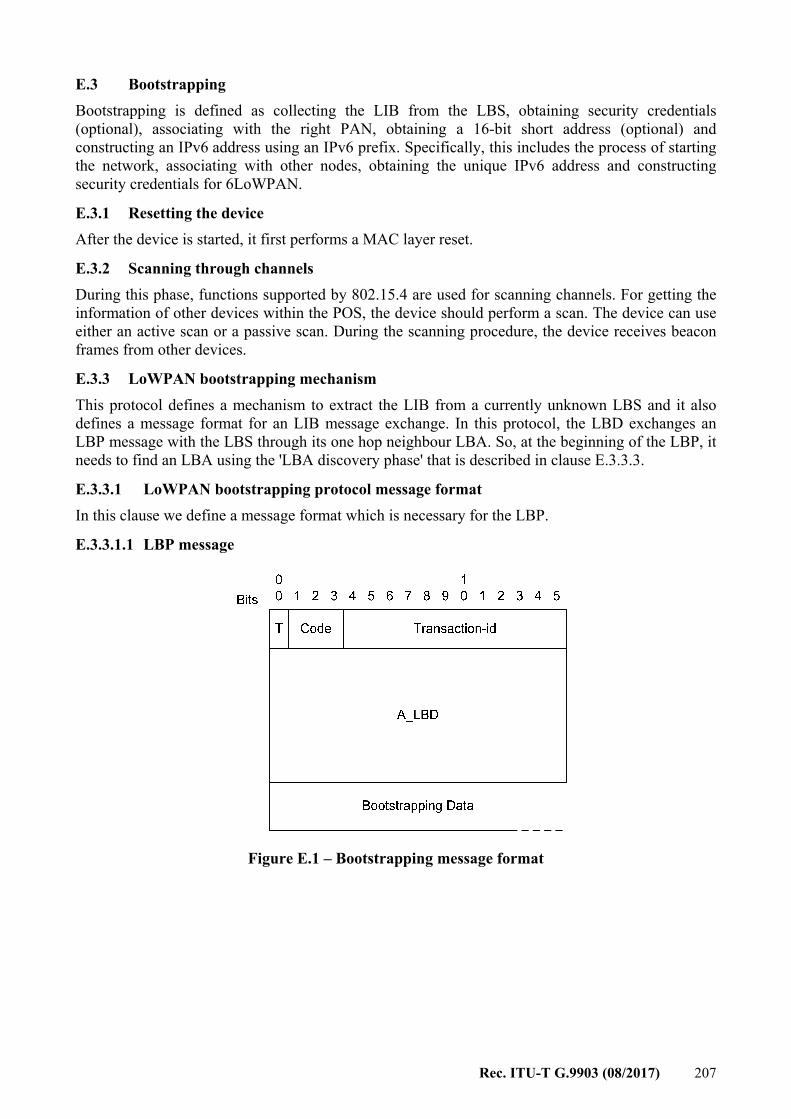
Rec. ITU-T G.9903 (08/2017) 207
E.3 Bootstrapping Bootstrapping is defined as collecting the LIB from the LBS, obtaining security credentials (optional), associating with the right PAN, obtaining a 16-bit short address (optional) and constructing an IPv6 address using an IPv6 prefix. Specifically, this includes the process of starting the network, associating with other nodes, obtaining the unique IPv6 address and constructing security credentials for 6LoWPAN.
E.3.1 Resetting the device After the device is started, it first performs a MAC layer reset.
E.3.2 Scanning through channels During this phase, functions supported by 802.15.4 are used for scanning channels. For getting the information of other devices within the POS, the device should perform a scan. The device can use either an active scan or a passive scan. During the scanning procedure, the device receives beacon frames from other devices.
E.3.3 LoWPAN bootstrapping mechanism This protocol defines a mechanism to extract the LIB from a currently unknown LBS and it also defines a message format for an LIB message exchange. In this protocol, the LBD exchanges an LBP message with the LBS through its one hop neighbour LBA. So, at the beginning of the LBP, it needs to find an LBA using the 'LBA discovery phase' that is described in clause E.3.3.3.
E.3.3.1 LoWPAN bootstrapping protocol message format In this clause we define a message format which is necessary for the LBP.
E.3.3.1.1 LBP message
Figure E.1 – Bootstrapping message format
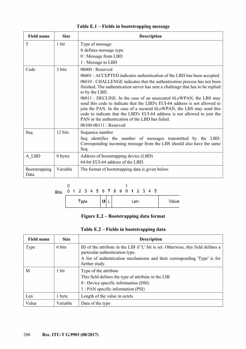
208 Rec. ITU-T G.9903 (08/2017)
Table E.1 – Fields in bootstrapping message
Field name Size Description
T 1 bit Type of message It defines message type. 0 : Message from LBD 1 : Message to LBD
Code
3 bits 0b000 : Reserved 0b001 : ACCEPTED indicates authentication of the LBD has been accepted. 0b010 : CHALLENGE indicates that the authentication process has not been finished. The authentication server has sent a challenge that has to be replied to by the LBD. 0b011 : DECLINE. In the case of an unsecured 6LoWPAN, the LBS may send this code to indicate that the LBD's EUI-64 address is not allowed to join the PAN. In the case of a secured 6LoWPAN, the LBS may send this code to indicate that the LBD's EUI-64 address is not allowed to join the PAN or the authentication of the LBD has failed. 0b100-0b111 : Reserved
Seq 12 bits Sequence number Seq identifies the number of messages transmitted by the LBD. Corresponding incoming message from the LBS should also have the same Seq.
A_LBD 8 bytes Address of bootstrapping device (LBD) 64-bit EUI-64 address of the LBD.
Bootstrapping Data
Variable The format of bootstrapping data is given below.
Figure E.2 – Bootstrapping data format
Table E.2 – Fields in bootstrapping data
Field name Size Description
Type 6 bits ID of the attribute in the LIB if 'L' bit is set. Otherwise, this field defines a particular authentication type. A list of authentication mechanisms and their corresponding 'Type' is for further study.
M 1 bit Type of the attribute This field defines the type of attribute in the LIB 0 : Device specific information (DSI) 1 : PAN specific information (PSI)
Len 1 byte Length of the value in octets Value Variable Data of the type
Rec. ITU-T G.9903 (08/2017) 209
E.3.3.2 LoWPAN bootstrapping information base One of the important goals of the LBP is to receive a set of information from the LBS by a joining LBD. This information comprises of PSI and DSI. The following table shows the attribute name, attribute ID (attr_ID), purpose of the attribute and its type.
Table E.3 – Attributes in LoWPAN bootstrapping information base
Attribute name Attr_ID Type Attribute description
PAN_ID 1 P This is the network identification for the default network.
PAN_type 2 P Secured/closed/open Address_of_LBS 3 P Address of the LBS. 0x0000 in case of no LBS. For
example in open 6LoWPAN. Join_Time 4 P It specifies the time when this node should start trying
to join the target PAN. Role_of_Device 5 D Agent/No_Agent Short_Addr 7 D 16-bit address for a new device which is unique inside
the PAN. Short_Addr_Distribution_Mechanism
8 P 0: Short address is provided by the LBS 1: Short address is assigned by the device itself
Other_Device_Specific _Info
15 D Using this attribute, a device and LBS can exchange any type of data or security key required by the device.
E.3.3.3 LBA discovering phase The LBD has to send an LBP message to the LBS server under the support of an LBA. To find the LBA, it broadcasts an LBA solicitation message within its one hop neighbours and waits for an LBA advertisement. Any device capable of being an LBS/LBA replies to the broadcast specifying its capability as an LBS/LBA. If there is any LBS in its neighbour, the LBD selects that LBS, otherwise it selects one of the LBAs.
E.3.3.4 LoWPAN bootstrapping protocol (LBP) The LBD sends an LBP message to the LBA, as it does not know the address or path to the LBS of the target PAN. The LBA forwards the LBP message to the LBS on behalf of the LBD. The LBS replies with one or multiple LBP messages destined to the LBA as the LBD is still is not part of the network. If the network is a secured 6LoWPAN and the LBD is an authentic node, we assume that the LBD has the necessary pre-deployed keys and the knowledge of the authentication mechanism necessary to authenticate in a target PAN. In this case, the LBD sends the necessary information in the 'bootstrapping data' field so that the LBS can initiate the authentication process using that 'authentication credentials'. The LBS converts the LBP message into an appropriate authentication request for the particular authentication server and sends it. A reply/challenge from the authentication server, for example an EAP authenticator or AAA server, is encapsulated in the LBP message's 'bootstrapping data' field and is sent back to the LBD through the LBA. The LBA also keeps track of successful authentication, failed authentication and an incomplete conversation of the authentication process, and maintains a 'black list' of malicious devices to avoid repeated attacks. Detecting a malicious device based on these 3 pieces of information and marking that node as 'Blacklisted' belongs to the scope of security policy and out of the scope of this Recommendation. The following figure shows a simple example of a bootstrapping mechanism.
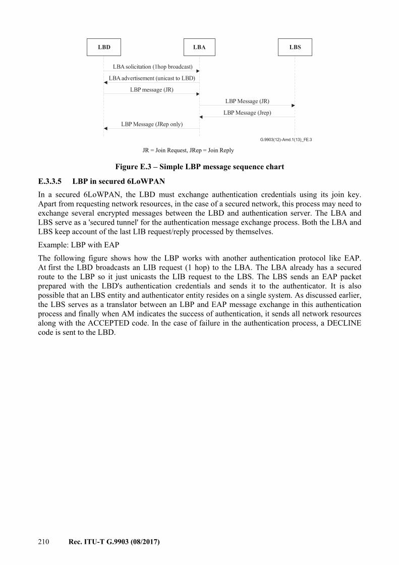
210 Rec. ITU-T G.9903 (08/2017)
G.9903(12)-Amd.1(13)_FE.3
LBA solicitation (1hop broadcast)
LBA advertisement (unicast to LBD)
LBP message (JR)
LBP Message (JR)
LBP Message (Jrep)
LBP Message (JRep only)
LBSLBALBD
JR = Join Request, JRep = Join Reply
Figure E.3 – Simple LBP message sequence chart
E.3.3.5 LBP in secured 6LoWPAN In a secured 6LoWPAN, the LBD must exchange authentication credentials using its join key. Apart from requesting network resources, in the case of a secured network, this process may need to exchange several encrypted messages between the LBD and authentication server. The LBA and LBS serve as a 'secured tunnel' for the authentication message exchange process. Both the LBA and LBS keep account of the last LIB request/reply processed by themselves. Example: LBP with EAP The following figure shows how the LBP works with another authentication protocol like EAP. At first the LBD broadcasts an LIB request (1 hop) to the LBA. The LBA already has a secured route to the LBP so it just unicasts the LIB request to the LBS. The LBS sends an EAP packet prepared with the LBD's authentication credentials and sends it to the authenticator. It is also possible that an LBS entity and authenticator entity resides on a single system. As discussed earlier, the LBS serves as a translator between an LBP and EAP message exchange in this authentication process and finally when AM indicates the success of authentication, it sends all network resources along with the ACCEPTED code. In the case of failure in the authentication process, a DECLINE code is sent to the LBD.
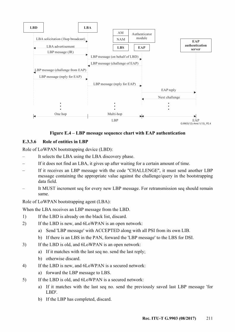
Rec. ITU-T G.9903 (08/2017) 211
...
...
...
LBD
LBS
LBA
LBA solicitation (1hop broadcast)
LBA advertisementLBP message (JR)
LBP message (on behalf of LBD)
LBP message (challenge of EAP)
LBP message (reply for EAP)
LBP message (challenge from EAP)
LBP message (reply for EAP)
EAP reply
Next challenge
Authenticatormodule
AM
NAM
EAP
Multi-hopOne hop
EAP
EAPauthentication
server
LBPG.9903(12)-Amd.1(13)_FE.4
Figure E.4 – LBP message sequence chart with EAP authentication
E.3.3.6 Role of entities in LBP Role of LoWPAN bootstrapping device (LBD): – It selects the LBA using the LBA discovery phase. – If it does not find an LBA, it gives up after waiting for a certain amount of time. – If it receives an LBP message with the code ''CHALLENGE'', it must send another LBP
message containing the appropriate value against the challenge/query in the bootstrapping data field.
– It MUST increment seq for every new LBP message. For retransmission seq should remain same.
Role of LoWPAN bootstrapping agent (LBA): When the LBA receives an LBP message from the LBD. 1) If the LBD is already on the black list, discard. 2) If the LBD is new, and 6LoWPAN is an open network:
a) Send 'LBP message' with ACCEPTED along with all PSI from its own LIB. b) If there is an LBS in the PAN, forward the 'LBP message' to the LBS for DSI.
3) If the LBD is old, and 6LoWPAN is an open network: a) If it matches with the last seq no. send the last reply; b) otherwise discard.
4) If the LBD is new, and 6LoWPAN is a secured network: a) forward the LBP message to LBS.
5) If the LBD is old, and 6LoWPAN is a secured network: a) If it matches with the last seq no. send the previously saved last LBP message 'for
LBD'. b) If the LBP has completed, discard.
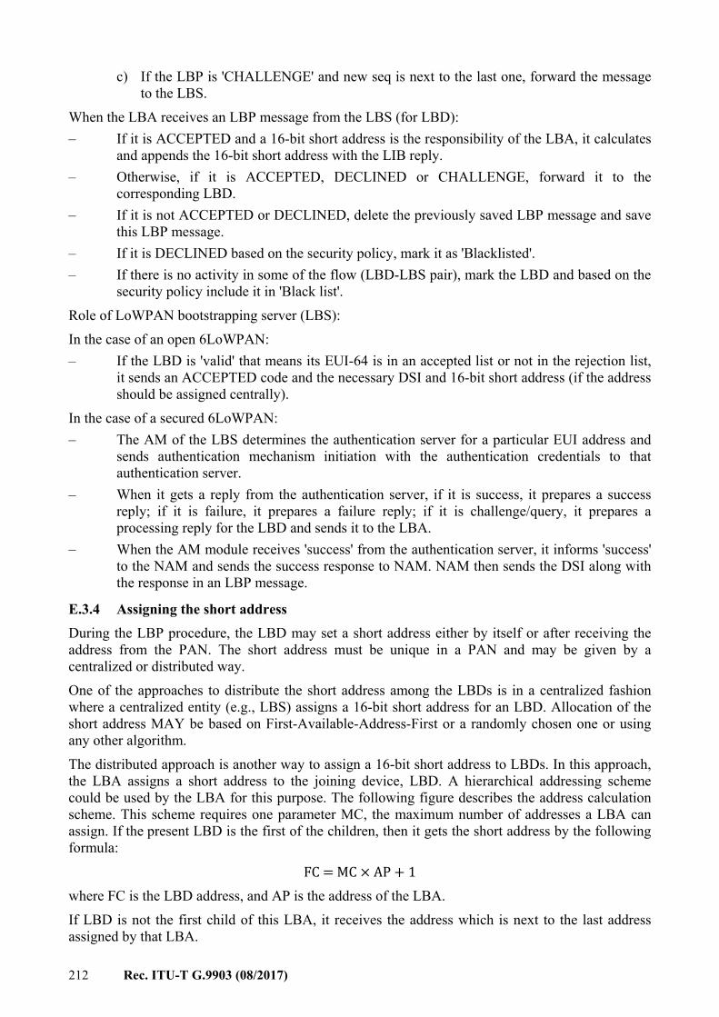
212 Rec. ITU-T G.9903 (08/2017)
c) If the LBP is 'CHALLENGE' and new seq is next to the last one, forward the message to the LBS.
When the LBA receives an LBP message from the LBS (for LBD): – If it is ACCEPTED and a 16-bit short address is the responsibility of the LBA, it calculates
and appends the 16-bit short address with the LIB reply. – Otherwise, if it is ACCEPTED, DECLINED or CHALLENGE, forward it to the
corresponding LBD. – If it is not ACCEPTED or DECLINED, delete the previously saved LBP message and save
this LBP message. – If it is DECLINED based on the security policy, mark it as 'Blacklisted'. – If there is no activity in some of the flow (LBD-LBS pair), mark the LBD and based on the
security policy include it in 'Black list'. Role of LoWPAN bootstrapping server (LBS): In the case of an open 6LoWPAN: – If the LBD is 'valid' that means its EUI-64 is in an accepted list or not in the rejection list,
it sends an ACCEPTED code and the necessary DSI and 16-bit short address (if the address should be assigned centrally).
In the case of a secured 6LoWPAN: – The AM of the LBS determines the authentication server for a particular EUI address and
sends authentication mechanism initiation with the authentication credentials to that authentication server.
– When it gets a reply from the authentication server, if it is success, it prepares a success reply; if it is failure, it prepares a failure reply; if it is challenge/query, it prepares a processing reply for the LBD and sends it to the LBA.
– When the AM module receives 'success' from the authentication server, it informs 'success' to the NAM and sends the success response to NAM. NAM then sends the DSI along with the response in an LBP message.
E.3.4 Assigning the short address During the LBP procedure, the LBD may set a short address either by itself or after receiving the address from the PAN. The short address must be unique in a PAN and may be given by a centralized or distributed way. One of the approaches to distribute the short address among the LBDs is in a centralized fashion where a centralized entity (e.g., LBS) assigns a 16-bit short address for an LBD. Allocation of the short address MAY be based on First-Available-Address-First or a randomly chosen one or using any other algorithm. The distributed approach is another way to assign a 16-bit short address to LBDs. In this approach, the LBA assigns a short address to the joining device, LBD. A hierarchical addressing scheme could be used by the LBA for this purpose. The following figure describes the address calculation scheme. This scheme requires one parameter MC, the maximum number of addresses a LBA can assign. If the present LBD is the first of the children, then it gets the short address by the following formula: FC = MC × AP + 1 where FC is the LBD address, and AP is the address of the LBA. If LBD is not the first child of this LBA, it receives the address which is next to the last address assigned by that LBA.
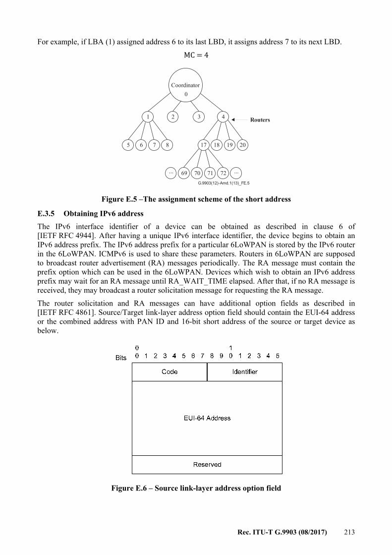
Rec. ITU-T G.9903 (08/2017) 213
For example, if LBA (1) assigned address 6 to its last LBD, it assigns address 7 to its next LBD. MC = 4
G.9903(12)-Amd.1(13)_FE.5
0Coordinator
1
5
432
6 7 8 17 18 19 20
69 70 71 72
Routers
... ...
Figure E.5 –The assignment scheme of the short address
E.3.5 Obtaining IPv6 address The IPv6 interface identifier of a device can be obtained as described in clause 6 of [IETF RFC 4944]. After having a unique IPv6 interface identifier, the device begins to obtain an IPv6 address prefix. The IPv6 address prefix for a particular 6LoWPAN is stored by the IPv6 router in the 6LoWPAN. ICMPv6 is used to share these parameters. Routers in 6LoWPAN are supposed to broadcast router advertisement (RA) messages periodically. The RA message must contain the prefix option which can be used in the 6LoWPAN. Devices which wish to obtain an IPv6 address prefix may wait for an RA message until RA_WAIT_TIME elapsed. After that, if no RA message is received, they may broadcast a router solicitation message for requesting the RA message. The router solicitation and RA messages can have additional option fields as described in [IETF RFC 4861]. Source/Target link-layer address option field should contain the EUI-64 address or the combined address with PAN ID and 16-bit short address of the source or target device as below.
Figure E.6 – Source link-layer address option field
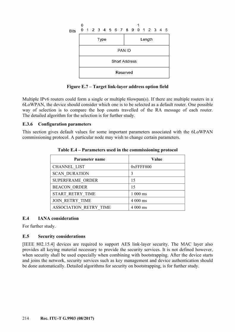
214 Rec. ITU-T G.9903 (08/2017)
Figure E.7 – Target link-layer address option field
Multiple IPv6 routers could form a single or multiple 6lowpan(s). If there are multiple routers in a 6LoWPAN, the device should consider which one is to be selected as a default router. One possible way of selection is to compare the hop counts travelled of the RA message of each router. The detailed algorithm for the selection is for further study.
E.3.6 Configuration parameters This section gives default values for some important parameters associated with the 6LoWPAN commissioning protocol. A particular node may wish to change certain parameters.
Table E.4 – Parameters used in the commissioning protocol
Parameter name Value
CHANNEL_LIST 0xFFFF800 SCAN_DURATION 3 SUPERFRAME_ORDER 15 BEACON_ORDER 15 START_RETRY_TIME 1 000 ms JOIN_RETRY_TIME 4 000 ms ASSOCIATION_RETRY_TIME 4 000 ms
E.4 IANA consideration For further study.
E.5 Security considerations [IEEE 802.15.4] devices are required to support AES link-layer security. The MAC layer also provides all keying material necessary to provide the security services. It is not defined however, when security shall be used especially when combining with bootstrapping. After the device starts and joins the network, security services such as key management and device authentication should be done automatically. Detailed algorithms for security on bootstrapping, is for further study.
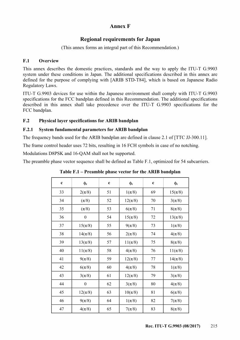
Rec. ITU-T G.9903 (08/2017) 215
Annex F
Regional requirements for Japan (This annex forms an integral part of this Recommendation.)
F.1 Overview This annex describes the domestic practices, standards and the way to apply the ITU-T G.9903 system under these conditions in Japan. The additional specifications described in this annex are defined for the purpose of complying with [ARIB STD-T84], which is based on Japanese Radio Regulatory Laws. ITU-T G.9903 devices for use within the Japanese environment shall comply with ITU-T G.9903 specifications for the FCC bandplan defined in this Recommendation. The additional specifications described in this annex shall take precedence over the ITU-T G.9903 specifications for the FCC bandplan.
F.2 Physical layer specifications for ARIB bandplan
F.2.1 System fundamental parameters for ARIB bandplan The frequency bands used for the ARIB bandplan are defined in clause 2.1 of [TTC JJ-300.11]. The frame control header uses 72 bits, resulting in 16 FCH symbols in case of no notching. Modulations D8PSK and 16-QAM shall not be supported. The preamble phase vector sequence shall be defined as Table F.1, optimized for 54 subcarriers.
Table F.1 – Preamble phase vector for the ARIB bandplan
c φc c φc c φc
33 2(π/8) 51 1(π/8) 69 15(π/8)
34 (π/8) 52 12(π/8) 70 3(π/8)
35 (π/8) 53 6(π/8) 71 8(π/8)
36 0 54 15(π/8) 72 13(π/8)
37 15(π/8) 55 9(π/8) 73 1(π/8)
38 14(π/8) 56 2(π/8) 74 4(π/8)
39 13(π/8) 57 11(π/8) 75 8(π/8)
40 11(π/8) 58 4(π/8) 76 11(π/8)
41 9(π/8) 59 12(π/8) 77 14(π/8)
42 6(π/8) 60 4(π/8) 78 1(π/8)
43 3(π/8) 61 12(π/8) 79 3(π/8)
44 0 62 3(π/8) 80 4(π/8)
45 12(π/8) 63 10(π/8) 81 6(π/8)
46 9(π/8) 64 1(π/8) 82 7(π/8)
47 4(π/8) 65 7(π/8) 83 8(π/8)
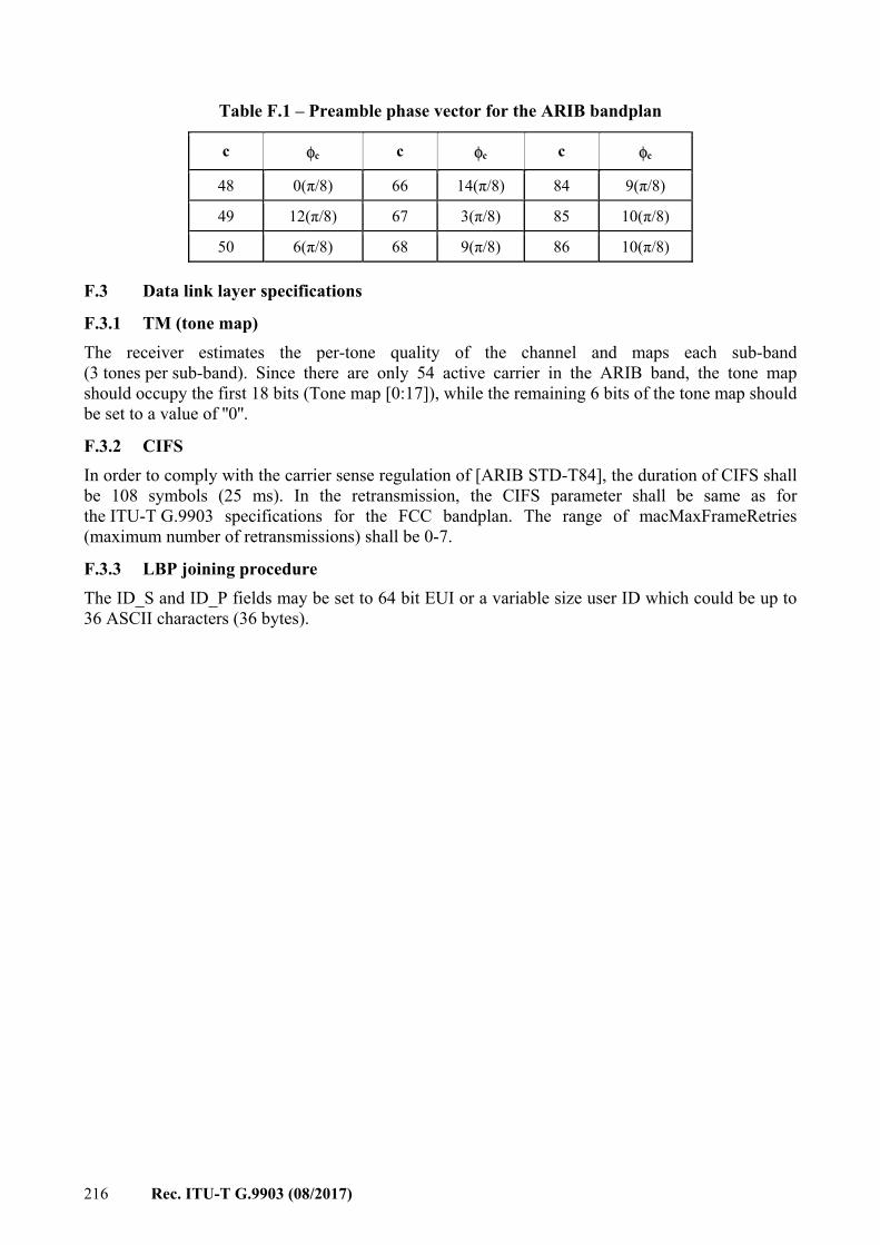
216 Rec. ITU-T G.9903 (08/2017)
Table F.1 – Preamble phase vector for the ARIB bandplan
c φc c φc c φc
48 0(π/8) 66 14(π/8) 84 9(π/8)
49 12(π/8) 67 3(π/8) 85 10(π/8)
50 6(π/8) 68 9(π/8) 86 10(π/8)
F.3 Data link layer specifications
F.3.1 TM (tone map) The receiver estimates the per-tone quality of the channel and maps each sub-band (3 tones per sub-band). Since there are only 54 active carrier in the ARIB band, the tone map should occupy the first 18 bits (Tone map [0:17]), while the remaining 6 bits of the tone map should be set to a value of ''0''.
F.3.2 CIFS In order to comply with the carrier sense regulation of [ARIB STD-T84], the duration of CIFS shall be 108 symbols (25 ms). In the retransmission, the CIFS parameter shall be same as for the ITU-T G.9903 specifications for the FCC bandplan. The range of macMaxFrameRetries (maximum number of retransmissions) shall be 0-7.
F.3.3 LBP joining procedure The ID_S and ID_P fields may be set to 64 bit EUI or a variable size user ID which could be up to 36 ASCII characters (36 bytes).
Rec. ITU-T G.9903 (08/2017) 217
Annex G
Regional requirements for the USA (This annex forms an integral part of this Recommendation.)
This annex describes the domestic practices, standards and the application method for the preamble-based coexistence mechanism in clause 6.2.2 in the USA. For devices complying with this Recommendation operating in the USA, the default value of attribute macCoexPreambleDetectionEnabled shall be set to TRUE (see Table 6-2). If the coexistence preamble is detected, then at least one narrowband PLC technology using a native preamble different from the one specified in this Recommendation is present and operating over the same frequency band. In this case, attribute macCoexPreambleEnabled (see Table 6-2) shall also be set to TRUE.
218 Rec. ITU-T G.9903 (08/2017)
Appendix I
Examples on encoding and decoding (This appendix does not form an integral part of this Recommendation.)
I.1 Example for data encoding Suppose we have a 40-byte MAC frame to send in DQPSK mode (2 bits per symbol) with 25 carriers available (due to notching and/or tone-mapping).
The size of the data at the interleaver input is equal to inter_input_size = (((40×8) + (16×8)) + 6) × 2 = 908 bits (Reed-Solomon adds 16 bytes, the convolutional encoder adds 6 bits and multiplies the size by 2). Using CENELEC bandplans (FLBand =4) as an example, the minimal interleaver buffer size: – We have 25 carriers, so m = 25. – We have n = FL× FLBand ×bits_per_symbol, so
– FL = ceiling( inter_input_size/(m × FLBand × bits_per_symbols) ) = ceiling( 908/(25×4×2) ) = ceiling( 4,54 ) = 5 and n = 40.
As m=25 and n=40, the matrix can ''store'' 1000 bits and the data is 908 bits long, so 92 bits of padding must be added. Those 92 bits of padding are split between byte padding and bit padding, the byte padding being maximized (with the constraint that the input is in bytes). So the upper layer shall add floor (92/2/8 ) = 5 bytes of padding before the data enters the scrambler, and the 12 remaining bits of bit padding shall be added by the PHY layer at the interleaver input.
I.2 Example for data decoding When decoding a frame, we need to compute the amount of bit padding to process the frame. The FCH contains the following information (decoding the example in above clause): – FL = 5 – DQPSK modulation (2 bits per symbol) – 25 carriers used (tone-map + notching information) Using CENELEC bandplans (FLBand =4) as an example, the interleaver buffer can hold 25 × (4 × FL × 2) = 1 000 bits. In these 1 000 bits: – 16×8×2 bits were added by Reed-Solomon. – 12 bits were added by the convolutional encoder. – The remaining 732 bits are a mix of data and padding:
– The data part is equal to floor (732/2/8) bytes = 45 bytes. – The bit padding is equal to 732 – (data_size × 8 × 2) bits = 12 bits.
In the 45 bytes of data, 5 bytes of byte padding are removed by the MAC layer using the ''Segment length'' header information.
Rec. ITU-T G.9903 (08/2017) 219
Appendix II
Test vectors for cryptographic building blocks (This appendix does not form an integral part of this Recommendation.)
This appendix provides sample test vectors, with the aim of providing implementers with a reference example to clarify the security mechanism. All the following test vectors are represented in hexadecimal form.
II.1 Introduction These examples illustrate the creation of MAC secured frames, through the ciphering of a MAC data frame. The common settings for the test vectors are the following: – Sender short MAC address = 0x002A – Sender PAN ID = 0x781D – Sender macDSN parameter is set to 0x29. – Sender neighbour table has one entry for MAC address 0x010C with:
– TMRValidTimeset to macTMRTTL (so no ToneMap is requested). – Modulation = DBPSK mode. – ToneMap = all sub-carriers used, TXGAIN = 0, TXCOEF = 0 for each carrier group
– Sender macFrameCounter set to 2 685 554 979 (0xA0125123). – Sender macKeyTable contains one GMK: KeyIndex = 0x00, Key =
0xAB10341145111BC3C12DE8FF11142204 – Receiver short MAC address = 0x010C – Receiver PAN ID = 0x781D – The transmission is acknowledged. – The QoS is set to normal priority.
II.1.1 Short frame ciphering In this case, the MSDU unencrypted payload is composed of 45 bytes equal to 0x75. This results in an encrypted frame that lasts for one segment only. Inputs for the encryption and authentication transformations are: – Nonce: 0x781D002A781D002AA012512305 – a data: 0x6988291D780C012A000D235112A000 – MSDU: 75757575…75 (0x75*45) Outputs after the transformations are: – MIC-32: 0xB87AB7B7 – Encrypted frame: 0100316988291D780C012A000D235112A000721D8CF9AF919FB134363150CA78ACFBE73CE52064C728B2E0388157D0F1A3C19CD14FDD0D465CF50D923B2A7FB87AB7B7000000008474
II.1.2 Long frame ciphering In this case, the MSDU unencrypted payload is composed of 300 bytes equal to 0xA2. This results in an encrypted frame that lasts for two segments.
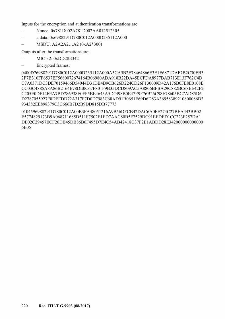
220 Rec. ITU-T G.9903 (08/2017)
Inputs for the encryption and authentication transformations are: – Nonce: 0x781D002A781D002AA012512305 – a data: 0x6988291D780C012A000D235112A000 – MSDU: A2A2A2…A2 (0xA2*300) Outputs after the transformations are: – MIC-32: 0xDD28E342 – Encrypted frames: 0400D76988291D780C012A000D235112A000A5CA5B2E78464866E3E1E6871DAF7B2C30EB32F7B310FF6537EF5680072674164B06980ADA918B22DA45ECFDA8977BAB713E13F762C4DC7A0371DC3DE70159466D54044D31DB4B9CB626D224CD26F130009D42A176B0FE8E0108ECC03C4885A8A86B2164E78DE0C67F801F9B35DCD809AC5A8806BFBA29C882BC68EE42F2C205E0DF12FEA7BD786938E0FF5BE4643A5D2498B0E47E9F76B26C98E78605BC7AD85D6D2787055927F8DEFDD72A317F7D0D7983C68AD91B0651E69D6D83A36958389210800086D3934382EE898379C3C666B7D2B9DD815DB77773 0104596988291D780C012A00B3FA48051216A9B56DFCB42DAC6A0FE274C27BEA443BB02E5774829173B9A068711685D511F7502E1ED7AAC80B5F7529DC91EEDED1CC223F257DA1DE02C29457ECF26DB45DB86B6F495D7E4C54AB42418C37F2E1ABDD28E3420000000000006E05

Rec. ITU-T G.9903 (08/2017) 221
Bibliography
[b-EUI 64] EUI-64™ (in force), Guidelines for 64-bit Global Identifier, IEEE. [b-IEEE 754-2008] IEEE 754-2008, IEEE Standard for Floating-Point Arithmetic. [b-IETF RFC 3513] IETF RFC 3513 (2003), Internet Protocol Version 6 (IPv6) Addressing
Architecture. [b-IETF RFC 3561] IETF RFC 3561 (2003), Ad hoc On-Demand Distance Vector (AODV)
Routing. [b-IETF RFC 5148] IETF RFC 5148 (2008), Jitter Considerations in Mobile Ad Hoc Networks
(MANETs). [b-IETF RFC 6130] IETF RFC 6130 (2011), Mobile Ad Hoc Network (MANET) Neighborhood
Discovery Protocol (NHDP). [b-IETF RFC 6206] IETF RFC 6206 (2011), The Trickle Algorithm. [b-IETF RFC 6621] IETF RFC 6621 (2012), Simplified Multicast Forwarding.


Printed in Switzerland Geneva, 2017
SERIES OF ITU-T RECOMMENDATIONS
Series A Organization of the work of ITU-T
Series D Tariff and accounting principles and international telecommunication/ICT economic and policy issues
Series E Overall network operation, telephone service, service operation and human factors
Series F Non-telephone telecommunication services
Series G Transmission systems and media, digital systems and networks
Series H Audiovisual and multimedia systems
Series I Integrated services digital network
Series J Cable networks and transmission of television, sound programme and other multimedia signals
Series K Protection against interference
Series L Environment and ICTs, climate change, e-waste, energy efficiency; construction, installation and protection of cables and other elements of outside plant
Series M Telecommunication management, including TMN and network maintenance
Series N Maintenance: international sound programme and television transmission circuits
Series O Specifications of measuring equipment
Series P Telephone transmission quality, telephone installations, local line networks
Series Q Switching and signalling, and associated measurements and tests
Series R Telegraph transmission
Series S Telegraph services terminal equipment
Series T Terminals for telematic services
Series U Telegraph switching
Series V Data communication over the telephone network
Series X Data networks, open system communications and security
Series Y Global information infrastructure, Internet protocol aspects, next-generation networks, Internet of Things and smart cities
Series Z Languages and general software aspects for telecommunication systems