Embed Size (px)
Citation preview

TELECOMMUNICATIONS
DISTRIBUTION DESIGN GUIDE
June 24, 2015
Prepared by:
www.summiteng.com
WSU Pullman Campus – Telecommunications Distribution Design Guide 2 June 24, 2015
Table of Contents TABLE OF CONTENTS ....................................................................................................................................... 2
1 PREFACE ................................................................................................................................................. 6
1.1 INTRODUCTION ............................................................................................................................... 6 1.2 DOCUMENT INTENT ......................................................................................................................... 7 1.3 DOCUMENT STRUCTURE ................................................................................................................. 9 1.4 STANDARDS AND GUIDELINES ....................................................................................................... 10 1.5 REQUIRED MANUFACTURERS ........................................................................................................ 11 1.6 WSUP PERSONNEL ..................................................................................................................... 12 1.7 COPYRIGHT .................................................................................................................................. 13
2 WSUP TELECOMMUNICATIONS POLICIES ................................................................................................ 14
2.1 FACILITIES SERVICES .................................................................................................................... 14 2.1.1 Facilities Services - Capital .................................................................................................... 14
2.1.1.1 SPACE ALLOCATION FOR TECHNOLOGY ............................................................................ 14 2.1.1.1.1 Telecommunications Rooms .................................................................................... 14
2.1.1.1.1.1 Main (MDF) ....................................................................................................... 15 2.1.1.1.1.2 Secondary (IDF) ............................................................................................... 15
2.1.1.1.2 Cable Trays .............................................................................................................. 16 2.1.1.1.3 OSP Pathway ........................................................................................................... 17
2.1.1.2 SYSTEM INTEGRATION ..................................................................................................... 17 2.1.1.3 DOCUMENTATION ............................................................................................................ 17
2.1.1.3.1 As-Built/Record Drawings ........................................................................................ 17 2.1.1.3.2 Cable Test Reports .................................................................................................. 17
3 PROJECT PROCEDURES ......................................................................................................................... 19
3.1 DESIGNER QUALIFICATIONS .......................................................................................................... 19 3.2 PROCEDURES RELATED TO PROJECT PHASES ............................................................................... 20
3.2.1 Construction Observation ...................................................................................................... 20 3.2.1.1 CABLE TRAYS .................................................................................................................. 20
4 DESIGN CRITERIA ................................................................................................................................... 21
4.1 PRINCIPLES OF TRANSMISSION ...................................................................................................... 22 4.2 ELECTROMAGNETIC COMPATIBILITY ............................................................................................... 22 4.3 TELECOMMUNICATIONS SPACES .................................................................................................... 23
4.3.1 Telecommunications Room Location ..................................................................................... 23 4.3.2 Telecommunications Room Sizing ........................................................................................ 24 4.3.3 Architectural Provisioning ...................................................................................................... 25 4.3.4 Environmental Provisioning ................................................................................................... 26 4.3.5 Floor-Standing Equipment Racks and Cabinets .................................................................... 28
4.3.5.1 FLOOR-STANDING EQUIPMENT RACKS .............................................................................. 29 4.3.5.2 TELECOMMUNICATIONS CABINETS .................................................................................... 29
4.3.6 Power Requirements ............................................................................................................. 30 4.3.6.1 STANDBY GENERATORS ................................................................................................... 33 4.3.6.2 UPS-SOURCED BACKUP POWER ..................................................................................... 33 4.3.6.3 TECHNICAL POWER PANELS ............................................................................................. 34 4.3.6.4 TECHNICAL POWER OUTLETS ........................................................................................... 34
4.3.6.4.1 New Construction and Modernization Projects ........................................................ 36 4.3.6.4.1.1 Telecommunications Rooms with 1 or 2 Floor-Standing Racks ....................... 36 4.3.6.4.1.2 Telecommunications Rooms with More than 2 Floor-Standing Racks ............. 37
WSU Pullman Campus – Telecommunications Distribution Design Guide 3 June 24, 2015
4.3.6.4.1.3 Other Technical Power Outlets ......................................................................... 37 4.3.6.4.2 Minor Remodel Projects ........................................................................................... 37
4.3.6.5 ADDITIONAL CONVENIENCE POWER OUTLETS ................................................................... 37 4.3.7 Grounding, Bonding, and Electrical Protection ...................................................................... 38 4.3.8 Cables Entering Telecommunications Rooms ....................................................................... 38 4.3.9 Entrance Facilities .................................................................................................................. 38
4.3.9.1 OUTSIDE PLANT CONDUIT ENTRANCE ............................................................................... 38 4.3.9.2 ROOFTOP CONDUIT ENTRANCE ........................................................................................ 38 4.3.9.3 NON-WSUP TENANT DEMARC ......................................................................................... 39
4.4 BACKBONE DISTRIBUTION SYSTEMS .............................................................................................. 39 4.4.1 Intra-Building Backbone Pathways ........................................................................................ 39
4.4.1.1 BACKBONE RACEWAY SIZE AND QUANTITY REQUIREMENTS ............................................... 40 4.4.1.1.1 Single-story buildings ............................................................................................... 40 4.4.1.1.2 Multi-story buildings ................................................................................................. 41
4.4.2 Intra-Building Backbone Cabling ........................................................................................... 41 4.4.2.1 INTRA-BUILDING BACKBONE CABLE TYPES ....................................................................... 41 4.4.2.2 STRAND AND PAIR COUNTS .............................................................................................. 42 4.4.2.3 CABLE SEGREGATION ...................................................................................................... 42 4.4.2.4 INNERDUCT FOR RISER APPLICATIONS .............................................................................. 42
4.4.3 Inter-Building (Campus) Backbone Pathways ....................................................................... 43 4.4.3.1 EXISTING CONDITIONS AT THE PULLMAN CAMPUS ............................................................. 43 4.4.3.2 DUCTBANK ...................................................................................................................... 43
4.4.3.2.1 Conduit Types .......................................................................................................... 44 4.4.3.2.2 Ground conductor .................................................................................................... 45 4.4.3.2.3 Burial Depth and Slope ............................................................................................ 45 4.4.3.2.4 Conduit Sweeps (Bends) ......................................................................................... 46 4.4.3.2.5 Ductbank Encasement ............................................................................................. 46 4.4.3.2.6 Number of Ducts ...................................................................................................... 46 4.4.3.2.7 Ductbank Length ...................................................................................................... 47 4.4.3.2.8 Separation from Other Utilities ................................................................................. 47
4.4.3.2.8.1 Proximity to Power or Other Foreign Conduits ................................................. 47 4.4.3.2.8.2 Proximity to Water, Gas, or Oil Conduits .......................................................... 48 4.4.3.2.8.3 Proximity to Steam Lines and Steam Utilidors ................................................. 48
4.4.3.2.9 Innerduct for Outside Plant Applications .................................................................. 50 4.4.3.2.10 Coordination with Utility Service Providers ............................................................ 50
4.4.3.3 MAINTENANCE HOLES AND HANDHOLES ........................................................................... 50 4.4.3.4 AERIAL DISTRIBUTION ...................................................................................................... 52 4.4.3.5 BRIDGE AND WATERWAY CROSSINGS ............................................................................... 52 4.4.3.6 WIRELESS AND RADIO SYSTEM DISTRIBUTION .................................................................. 52
4.4.4 Campus Cabling .................................................................................................................... 52 4.4.4.1 UTILITY SERVICES ........................................................................................................... 53 4.4.4.2 WIRELESS AND RADIO SYSTEM DISTRIBUTION .................................................................. 53
4.5 HORIZONTAL DISTRIBUTION SYSTEMS ........................................................................................... 53 4.5.1 Device Box Considerations .................................................................................................... 53
4.5.1.1 FOR NEW CONSTRUCTION AND FULL REMODEL ................................................................ 54 4.5.1.2 FOR OTHER PROJECTS .................................................................................................... 54
4.5.2 Horizontal Pathway Systems ................................................................................................. 55 4.5.2.1 GENERAL PATHWAY DESIGN CONSIDERATIONS ................................................................. 55 4.5.2.2 PATHWAYS FOR NEW CONSTRUCTION AND MODERNIZATION PROJECTS ............................. 56 4.5.2.3 PATHWAYS FOR MINOR REMODEL AND TELECOMMUNICATIONS-ONLY PROJECTS ............... 56 4.5.2.4 CABLE TRAY PATHWAY SYSTEMS ..................................................................................... 57 4.5.2.5 CONDUIT AND JUNCTION BOX PATHWAY SYSTEMS ............................................................ 58 4.5.2.6 SURFACE RACEWAY ........................................................................................................ 59 4.5.2.7 UNDERFLOOR DUCT SYSTEMS ......................................................................................... 59 4.5.2.8 ACCESS FLOORS ............................................................................................................. 59

WSU Pullman Campus – Telecommunications Distribution Design Guide 4 June 24, 2015
4.5.3 Horizontal Cabling Systems ................................................................................................... 59 4.5.3.1 GENERAL ........................................................................................................................ 59 4.5.3.2 TOPOLOGY ...................................................................................................................... 60 4.5.3.3 TRADITIONAL HORIZONTAL CABLING SOLUTION ................................................................. 60
4.5.3.3.1 Horizontal Cable to Support Data Applications ........................................................ 60 4.5.3.3.1.1 Innerduct for Horizontal Fiber Optic Applications ............................................. 61
4.5.3.3.2 Horizontal Cable to Support Voice Applications ...................................................... 62 4.5.3.3.3 Low-Voltage and Building Automation Systems ...................................................... 62 4.5.3.3.4 Horizontal Cross-connect (HC) ................................................................................ 63
4.5.3.4 GPON HORIZONTAL CABLING SOLUTION .......................................................................... 63 4.5.3.4.1 GPON Architecture .................................................................................................. 63 4.5.3.4.2 Academic and Administrative Buildings ................................................................... 63 4.5.3.4.3 Residence Halls ....................................................................................................... 63 4.5.3.4.4 Outlets ...................................................................................................................... 64 4.5.3.4.5 Cable Trays .............................................................................................................. 64 4.5.3.4.6 Innerduct for GPON Applications ............................................................................. 64 4.5.3.4.7 ONT Installation ....................................................................................................... 64 4.5.3.4.8 Special Applications ................................................................................................. 64 4.5.3.4.9 Telecommunications Room sizing for GPON Applications ...................................... 65
4.5.3.5 PATCH CORDS ................................................................................................................ 65 4.5.3.6 PHYSICAL SEPARATION REQUIREMENTS ........................................................................... 65
4.5.4 Work Areas ............................................................................................................................ 65 4.5.4.1 PERMANENT OFFICE SPACES ........................................................................................... 65 4.5.4.2 OPEN OFFICE/MODULAR FURNITURE ................................................................................ 66 4.5.4.3 BREAKOUT ROOMS .......................................................................................................... 67 4.5.4.4 CONFERENCE ROOMS ..................................................................................................... 67 4.5.4.5 TELECOMMUNICATIONS OUTLETS FOR SPECIAL INDOOR APPLICATIONS .............................. 69 4.5.4.6 SPECIAL OUTDOOR APPLICATIONS ................................................................................... 71 4.5.4.7 OTHER CONSIDERATIONS ................................................................................................ 72 4.5.4.8 WORKSTATION POWER OUTLETS ..................................................................................... 72
4.6 ITS CABLES AND CONNECTING HARDWARE ................................................................................... 72 4.6.1 Copper Cabling ...................................................................................................................... 72 4.6.2 Fiber Optic Cabling ................................................................................................................ 73 4.6.3 Splicing .................................................................................................................................. 73
4.7 FIRESTOP SYSTEMS ..................................................................................................................... 73 4.8 BONDING AND GROUNDING (EARTHING) ........................................................................................ 74 4.9 POWER DISTRIBUTION .................................................................................................................. 74 4.10 TELECOMMUNICATIONS ADMINISTRATION ....................................................................................... 75
4.10.1 Identification Strategy ........................................................................................................ 75 4.10.1.1 NEW TELECOMMUNICATIONS DISTRIBUTION SYSTEMS ....................................................... 76
4.11 FIELD TESTING ............................................................................................................................. 79 4.12 OUTSIDE PLANT ........................................................................................................................... 80 4.13 AUDIO/VISUAL SYSTEMS ............................................................................................................... 81
4.13.1 Audio/Visual Systems ........................................................................................................ 81 4.13.2 Distributed Paging Systems .............................................................................................. 81
4.14 BUILDING AUTOMATION SYSTEMS .................................................................................................. 81 4.15 DATA NETWORKS ......................................................................................................................... 82 4.16 WIRELESS NETWORKS .................................................................................................................. 82 4.17 ELECTRONIC SAFETY AND SECURITY ............................................................................................. 83 4.18 DATA CENTERS AND MCFS ........................................................................................................... 83
4.18.1 Sizing Considerations ........................................................................................................ 84 4.18.2 Tier Classification .............................................................................................................. 84

WSU Pullman Campus – Telecommunications Distribution Design Guide 5 June 24, 2015
4.18.3 Architectural Considerations ............................................................................................. 84 4.18.4 Environmental Provisioning ............................................................................................... 85 4.18.5 Fire Detection and Suppression ........................................................................................ 85 4.18.6 Racks and Cabinets .......................................................................................................... 85 4.18.7 Power Requirements ......................................................................................................... 86
4.18.7.1 TECHNICAL POWER PANELS ............................................................................................. 86 4.18.7.1.1 Emergency Power Off (EPO) Button ..................................................................... 87
4.18.7.2 TECHNICAL POWER OUTLETS ........................................................................................... 87 4.18.7.2.1 For Remodel Projects ............................................................................................ 88
4.18.7.3 CONVENIENCE POWER OUTLETS ...................................................................................... 88 4.18.8 Grounding, Bonding, and Electrical Protection.................................................................. 88
4.19 HEALTH CARE .............................................................................................................................. 88 4.20 RESIDENTIAL CABLING .................................................................................................................. 88 4.21 BUSINESS DEVELOPMENT AND PROJECT MANAGEMENT ................................................................. 89
4.21.1 Codes, Standards and Regulations ................................................................................... 89 5 CONSTRUCTION DOCUMENT CONTENT .................................................................................................... 90
5.1 PLANS AND DRAWINGS ................................................................................................................. 90 5.1.1 General .................................................................................................................................. 90 5.1.2 Outside Plant Site Plan Drawings .......................................................................................... 91 5.1.3 Maintenance Hole/Handhole Butterfly Diagrams ................................................................... 91 5.1.4 Inside Plant Plan Drawings .................................................................................................... 92 5.1.5 Demolition .............................................................................................................................. 92 5.1.6 Telecommunications Room Plan Details ............................................................................... 92 5.1.7 Elevation Diagrams ................................................................................................................ 93 5.1.8 Intra-Building Backbone Schematic Diagrams ...................................................................... 94
5.2 PROJECT MANUAL ........................................................................................................................ 94 5.2.1 Specifications ......................................................................................................................... 94
5.2.1.1 WSUP TELECOMMUNICATIONS CONSTRUCTION GUIDE SPECIFICATION ............................. 94 5.2.1.2 COMMON SPECIFICATION SECTIONS ................................................................................. 95
5.2.2 Fiber Link-Loss Budget Analysis ........................................................................................... 95 5.3 RECORD DRAWINGS AND DOCUMENTATION ................................................................................... 96
5.3.1 Record Drawing Content........................................................................................................ 96 5.3.2 Record Drawing Deliverables ................................................................................................ 96
6 APPENDICES .......................................................................................................................................... 97
6.1 SAMPLE TELECOMMUNICATIONS ROOM PLAN DETAILS ................................................................... 97 6.1.1 IDF: 1 Rack Reach in – 10’ x 4’ ............................................................................................. 97 6.1.2 IDF: 1 Rack – 10’ x 6’ ............................................................................................................. 98 6.1.3 IDF: 2 Racks – 10’ x 9’ ........................................................................................................... 99 6.1.4 IDF: 3 Racks – 10’ x 12’ ....................................................................................................... 100 6.1.5 IDF and MDF: 4 Racks – 10’ x 15’ ....................................................................................... 101 6.1.6 IDF and MDF: 4 Racks (2 Rows) – 9’ x 16’ ......................................................................... 102 6.1.7 MCF: 6 Racks (2 Rows) – 12’ x 16’ ..................................................................................... 103
6.2 SAMPLE RACK ELEVATION DETAIL ............................................................................................... 104 6.2.1 IDF: 1 Rack .......................................................................................................................... 105 6.2.2 IDF: 2 Racks ........................................................................................................................ 106 6.2.3 IDF and MDF: 3 Racks ........................................................................................................ 107 6.2.4 IDF and MDF: 4 Racks ........................................................................................................ 108
6.3 SAMPLE WALL ELEVATION DETAIL ............................................................................................... 109 6.4 SAMPLE FIBER OPTIC LINK-LOSS BUDGET ANALYSIS ................................................................... 110 6.5 MAINTENANCE HOLE BUTTERFLY DIAGRAM .................................................................................. 111 6.6 GLOSSARY ................................................................................................................................. 112

PREFACE INTRODUCTION
WSU Pullman Campus – Telecommunications Distribution Design Guide 6 June 24, 2015
1 Preface 1.1 Introduction
A. The Telecommunications Distribution Design Guide (TDDG) is written to communicate the requirements of the Pullman campus of Washington State University (WSUP) for the design and installation of telecommunications distribution infrastructure at WSUP facilities. • The TDDG is written for an audience of Architects, Engineers and Designers
who are responsible for the design of new or remodeled facilities for WSUP where telecommunications distribution systems currently exist or will be installed.
• It is also intended for other low-voltage telecommunications Contractors installing telecommunications distribution systems at WSUP facilities.
• This document also applies to infrastructure designed and installed by WSUP staff, when a formal design is not developed.
B. The TDDG belongs to a set of documents (depicted below) that comprise the
standard design and installation practices for all facets of technology infrastructure and systems at the Pullman Campus.

PREFACE DOCUMENT INTENT
WSU Pullman Campus – Telecommunications Distribution Design Guide 7 June 24, 2015
C. The Technology Infrastructure Design Guide (TIDG) contains information
common to all of WSUP’s Design Guides.
D. The Telecommunications Construction Guide Specification (TCGS) is a key companion to the TDDG.
• Designers shall adapt the TCGS “as written” for creating specifications for a
particular project according to the instructions in the TDDG. In other words, Designers shall use the electronic specification section documents (provided by WSUP in MSWord format) and then shall make any project-specific edits to the specifications in those documents. Any changes to the specifications shall be done using the “Revision Tracking” features in MSWord.
• Rewriting the TCGS or modifying the format structure or requirements will not be accepted.
E. Telecommunications distribution systems designed for WSUP are expected to
support and integrate voice, data, video and other low-voltage systems with common media (fiber optic and unshielded twisted pair (UTP) copper cable).
F. It is the responsibility of the telecommunications distribution systems Designer to
coordinate with the other designers on a project (architectural, electrical, mechanical, etc.) to determine that other systems are both compatible with and complementary to the telecommunications distribution systems. It is critical to coordinate between disciplines during the design phase of a project, rather than making adjustments in the field during construction.
G. This document was prepared by Summit Engineering and Consulting, P.S. and
by the Information Technology Services department at the Pullman campus of Washington State University. As technology and needs evolve, the document will be periodically updated.
• June 24, 2015 – Originally published
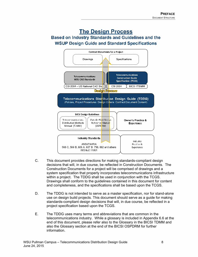
1.2 Document Intent A. The Design Process diagram below depicts the relationships between the
ANSI/TIA/EIA Standards, the BICSI Design Guidelines, the WSUP documents (TDDG, TCGS) and the project-specific Construction Documents. Telecommunications distribution infrastructure at WSUP facilities shall be designed based on the BICSI design guidelines (the TDMM, the OSPDRM and the ITSIMM) and compliant with the ANSI/TIA/EIA Standards as applied by and illustrated in the WSUP TDDG.
B. The TDDG is intended to be used in conjunction with the TDMM and OSPDRM in
order to reinforce selected TDMM content, as well as highlight any restrictions and/or limitations on TDMM and OSPDRM content in order to meet the specific requirements of WSUP facilities. The TDDG is not intended to replace or detract from the TDMM or OSPDRM.
PREFACE DOCUMENT STRUCTURE
WSU Pullman Campus – Telecommunications Distribution Design Guide 8 June 24, 2015
C. This document provides directions for making standards-compliant design decisions that will, in due course, be reflected in Construction Documents. The Construction Documents for a project will be comprised of drawings and a system specification that properly incorporates telecommunications infrastructure within a project. The TDDG shall be used in conjunction with the TCGS. Drawings shall conform to the guidelines contained in this document for content and completeness, and the specifications shall be based upon the TCGS.
D. The TDDG is not intended to serve as a master specification, nor for stand-alone use on design build projects. This document should serve as a guide for making standards-compliant design decisions that will, in due course, be reflected in a project specification based upon the TCGS.
E. The TDDG uses many terms and abbreviations that are common in the
telecommunications industry. While a glossary is included in Appendix 6.6 at the end of this document, please refer also to the Glossary in the BICSI TDMM and also the Glossary section at the end of the BICSI OSPDRM for further information.
PREFACE DOCUMENT STRUCTURE
WSU Pullman Campus – Telecommunications Distribution Design Guide 9 June 24, 2015
1.3 Document Structure The TDDG is organized in the following sections:
1. Preface 2. WSUP Telecommunications Policies 3. Project Procedures 4. Design Criteria 5. Construction Document Content 6. Appendices
A. The Preface (this section) describes this document, its intent, and its relationship
to industry standards, practices, and the various audiences affected by the document. It also describes how to use this document.
B. The WSUP Telecommunications Policies section applies specifically to WSUP
personnel. It describes internal WSUP telecommunications policies, requirements, standard practices, and processes for designing, installing and operating telecommunications infrastructure. WSUP personnel should also be aware of the instructions, requirements and guidelines for Designers contained in the other sections of this document, with respect to their application on both large-scale telecommunications distribution projects and small-scale “moves, adds, and changes” (MAC) projects. In addition, these requirements apply to in-house operations and maintenance of existing telecommunications distribution systems.
C. The Project Procedures section describes the required qualifications for
telecommunications Designers as well as the procedures that Designers must follow when working on telecommunications infrastructure projects at WSUP facilities. It includes activities that are required throughout the project as well as phase-specific requirements.
D. The Design Criteria section serves two purposes. The first is to describe the
general requirements for WSUP telecommunications infrastructure along with the typical features required for different categories of building spaces and construction types. The second purpose is to place limitations on the materials and methods described in the BICSI TDMM and OSPDRM. While the TDMM and OSPDRM describe many materials and methods that are generally accepted in the industry for providing telecommunications infrastructure, WSUP facilities have some unique characteristics that impose limitations on some of the materials and methods that otherwise might be acceptable. Some of the practices discussed in the TDMM and OSPDRM are expressly prohibited in WSUP facilities. Other practices are permitted in certain areas (residential halls, for example) but prohibited in other areas such as academic buildings. Generally speaking, if the BICSI TDMM and OSPDRM do not describe a particular material or method for use with telecommunications distribution infrastructure, it will not be allowed for WSUP facilities. In addition, the WSUP TDDG places further restrictions on the use of some materials and methods that the BICSI design guidelines support.

PREFACE STANDARDS AND GUIDELINES
WSU Pullman Campus – Telecommunications Distribution Design Guide 10 June 24, 2015
E. The Construction Document Content section defines the minimum level of
detail that WSUP requires to be present in the telecommunications portion of the Construction Documents for a project. In this section, the required types of details, along with the content in the details, are both described. This section also briefly describes the specifications that are required for a project.
F. The Appendices section provides examples, standard forms and diagrams that are required for WSUP telecommunications infrastructure.
1.4 Standards and Guidelines A. WSUP has standardized on the ANSI/TIA/EIA1 Commercial Building
Telecommunications Standards series, and has adopted the following BICSI2 design guide documents as the basis for telecommunications distribution design in WSUP facilities: • BICSI Telecommunications Distribution Methods Manual (TDMM) (13th
Edition) • BICSI Outside Plant Design Reference Manual (OSPDRM) (5th Edition) • BICSI Information Technology Systems Installation Methods Manual
(ITSIMM) (6th Edition)
The WSUP TDDG is the guide to the application of the ANSI/TIA/EIA Standards, the BICSI TDMM, the BICSI OSPDRM and the BICSI ITSIMM to the unique circumstances present in WSUP facilities and projects. All references to these manuals shall specifically address only the editions specified above. Newer editions shall be used “for reference only” until authorized by WSUP in writing or through a revised edition of the TDDG.
B. Adherence to and compliance with the codes, standards, and industry practices
listed below, along with the WSUP requirements contained in this document, is mandatory: • Washington State Rules and Regulations for Installing Electrical Wires and
Equipment (RCW 19.28, WAC 296-46 and WAC 296-401A) • Washington State Department of Labor and Industries Safety Standards for
General Safety and Health (WAC 296-24 Volume 1 Part L) • WSUP Capital Planning and Development (CPD) Uniform Design and
Construction Standards http://www.cpd.WSUP.edu/CapitalProjects/UDCS/ • National Electrical Safety Code, American National Standards Institute C2 • National Electrical Code (NEC), National Fire Protection Association (NFPA
70)
1 Effective December 29, 2000, The Washington State Department of Enterprise Services has mandated that all Washington State Agencies adopt the ANSI/TIA/EIA Commercial Building Telecommunications Standards as the basis for telecommunications distribution design in State facilities. 2 BICSI is widely considered to be the industry source for standards-compliant design guidelines for telecommunications distribution systems. See www.bicsi.org for further information.

PREFACE REQUIRED MANUFACTURERS
WSU Pullman Campus – Telecommunications Distribution Design Guide 11 June 24, 2015
• Firestop Contractors International Association (FCIA), Manual of Practice • ANSI/TIA/EIA 568-C series – Commercial Building Telecommunications
Standards • ANSI/TIA/EIA 569-B series – Commercial Building Telecommunications
Standards for Pathways and Spaces • ANSI/TIA/EIA 606-A series – Administration Standard for Commercial
Telecommunications Infrastructure • ANSI/TIA/EIA 607-A series – Commercial Building Grounding (Earthing) and
Bonding Requirements for Telecommunications • ANSI/TIA/EIA 758 series – Customer-Owned Outside Plant
Telecommunications Cabling Standard • ANSI/TIA/EIA 862 – Building Automation Systems Cabling Standard for
Commercial Buildings • ANSI/TIA/EIA 942 – Telecommunications Infrastructure Standard For Data
Centers • Fiber Optic Test Standards, TIA/EIA 455 (Series) • Optical Fiber Systems Test Procedures, TIA/EIA 526 (Series) • Local Area Network Ethernet Standard, IEEE 802.3 (Series)
C. Any request to deviate from the requirements of the National Electrical Code will not be accepted.
D. The Designer shall seek approval for designs that are not consistent with WSUP TDDG requirements. Requests to deviate from industry standards or WSUP design solutions will be considered on a case-by-case basis by the WSUP Information Technology Project Manager. Designers shall contact the WSUP Information Technology Project Manager to discuss proposed alternatives before spending significant time pursuing the option.
E. The requirements contained in the TDDG are considered to be in addition to
those listed in Instructions for Architects and Engineers Doing Business with the Division of Engineering and Architectural Services and the State of Washington Conditions of the Agreement. Where the requirements differ, the issue shall be brought to the attention of the WSUP Facilities Services Project Manager – otherwise, the more stringent requirement shall apply.
1.5 Required Manufacturers A. Telecommunications distribution systems shall be designed for construction
using materials from the current product lines of the manufacturers upon which WSUP has standardized. • For copper cabling and related materials, WSUP has standardized on the TE
AMP NETCONNECT® product line. • For GPON fiber optic cabling and related materials, WSUP has standardized
on the TE Optical LAN Solution® (OLS) product line and Zhone electronics. • For riser/backbone and outside plant fiber optic cabling and related materials,
WSUP has standardized on the Corning Cable Systems LANscape® product line.

PREFACE WSUP PERSONNEL
WSU Pullman Campus – Telecommunications Distribution Design Guide 12 June 24, 2015
• For racking-related materials, WSUP has standardized on products from Chatsworth Products Inc. ® (CPI) and Homaco®.
B. The Designer is required to incorporate only the manufacturers listed in this
document into the design (unless otherwise directed by WSUP) and to design systems that will be suitable for the use of products from these manufacturers. The construction documents shall require that the Contractor’s installation workmanship fully comply with the current installation requirements of the manufacturers of these products.
C. Designs shall comply with the manufacturer’s requirements. The construction documents shall require that the Contractor’s installation workmanship fully comply with the current installation requirements from the manufacturer, even if those requirements exceed industry standard practices. The manufacturer’s full application warranty shall be provided.
D. The Designer shall incorporate a manufacturer consistently throughout the entire
project (unless otherwise directed by WSUP) and design a telecommunications distribution system that will be suitable for the use of products from this manufacturer. Required manufacturers and their products are identified in the TCGS. • For example, ladder racking in all telecommunications rooms shall be
manufactured by a single manufacturer and cabling system materials shall be manufactured by a single manufacturer. However, it is not required that cabling and ladder racking be from the same manufacturer.
The construction documents shall require that the installation workmanship fully comply with the current installation requirements from the manufacturers of these products.
1.6 WSUP Personnel A. There are two specific WSUP personnel roles referenced in this document. The
Designer shall interact with these two individuals as direct points of contact: • Facilities Services Project Manager (FSPM) – responsible for project
management, project oversight and project budget.
• Information Technology Project Manager (ITPM) – responsible for oversight of all technology considerations, including interpretation of the requirements of this document.
B. WSUP Telecommunications Policies (Section 2 of this document) applies
specifically to WSUP personnel. In addition to the WSUP Telecommunications Policies section, WSUP personnel should be aware of the instructions, requirements, and guidelines for Designers contained in the other sections of this document. Also, the TCGS contains additional requirements related to

PREFACE COPYRIGHT
WSU Pullman Campus – Telecommunications Distribution Design Guide 13 June 24, 2015
telecommunications distribution system materials and installation methods applicable at WSUP facilities.
C. WSUP personnel should be familiar with these requirements with respect to their application on both large-scale telecommunications distribution projects and small-scale “moves, adds, and changes” projects. These requirements also apply to in-house operations and maintenance of existing telecommunications distribution systems.
1.7 Copyright Summit Engineering & Consulting retains the copyright for this document. Washington State University is authorized to edit and adapt the document. Summit Engineering & Consulting has authored similar documents for many other organizations. The document is intended (in part) to describe best practices that are found in some segments of the industry. As a result, portions of this document are similar to comparable content in documents previously prepared by Summit Engineering & Consulting for other organizations. This document does not contain any information that is proprietary or confidential to other organizations.

WSUP TELECOMMUNICATIONS POLICIES FACILITIES SERVICES
WSU Pullman Campus – Telecommunications Distribution Design Guide 14 June 24, 2015
2 WSUP Telecommunications Policies This section describes internal WSUP telecommunications policies, requirements, standard practices, and processes associated with designing, installing, maintaining, and operating telecommunications infrastructure. It is intended for an internal audience of WSUP personnel, including:
• Information Technology Services (ITS) • Information Technology Services Advisory Committee (ITSAC) • IT Executive Board (ITEB) • Facilities Services (FS) • Building Stakeholder Design Committee (BSDC) • Student Groups • Associated Students of WSU (ASWSU) • Anyone that may be involved in the design, installation, maintenance or use of
telecommunications infrastructure, network equipment or telephone equipment at a WSUP facility.
Please see Section 2 in the TIDG for internal policies covering all technologies at WSUP.
2.1 Facilities Services
2.1.1 FACILITIES SERVICES - CAPITAL
2.1.1.1 SPACE ALLOCATION FOR TECHNOLOGY
In the life of a building, technology advances occur, systems become obsolete, and the cabling and equipment components of the technology infrastructure will be changed several times. In order to keep the life-cycle costs low, it is essential that spaces and pathways supporting technology infrastructure are properly sized, properly located, and remain accessible. Please use the following guidelines when allocating space for technology infrastructure in new projects:
2.1.1.1.1 TELECOMMUNICATIONS ROOMS
When considering the budgeting requirements for a new project, the following items should be included for each telecommunications room (TR):
• TRs should be located centrically within the areas they serve. TRs should be vertically stacked from floor to floor.
• TRs require 24x7x365 air conditioning, with a preference for AC equipment that is located outside the TR with the controls in the TR. Split systems are acceptable for remodel projects.
• TR doors shall swing out of the room.
WSUP TELECOMMUNICATIONS POLICIES FACILITIES SERVICES
WSU Pullman Campus – Telecommunications Distribution Design Guide 15 June 24, 2015
ITS recognizes that floor plan space set aside for technology infrastructure reduces the amount of space that can be allocated to other valuable programs and purposes. In an effort to be frugal with University resources, the telecommunications room sizes below have been developed to be “optimally minimum.” This means that the rooms cannot serve their intended purposes and meet Code requirements if they are made smaller in either dimension. The rooms could be increased in size; however, this additional space would not necessarily be put to good use.
• During the course of design, value engineering considerations frequently target telecommunications rooms as a source of additional space that might be used for other purposes. ITS considers the spaces described below as being “already value engineered” in advance. ITS will not agree to size reductions to these spaces.
2.1.1.1.1.1 Main (MDF)
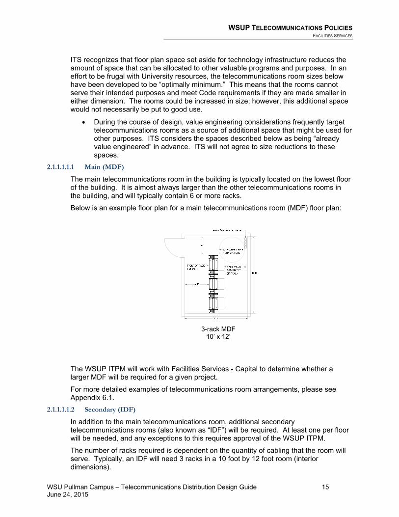
The main telecommunications room in the building is typically located on the lowest floor of the building. It is almost always larger than the other telecommunications rooms in the building, and will typically contain 6 or more racks.
Below is an example floor plan for a main telecommunications room (MDF) floor plan:
3-rack MDF
10’ x 12’
The WSUP ITPM will work with Facilities Services - Capital to determine whether a larger MDF will be required for a given project.
For more detailed examples of telecommunications room arrangements, please see Appendix 6.1.
2.1.1.1.1.2 Secondary (IDF)
In addition to the main telecommunications room, additional secondary telecommunications rooms (also known as “IDF”) will be required. At least one per floor will be needed, and any exceptions to this requires approval of the WSUP ITPM.
The number of racks required is dependent on the quantity of cabling that the room will serve. Typically, an IDF will need 3 racks in a 10 foot by 12 foot room (interior dimensions).
WSUP TELECOMMUNICATIONS POLICIES FACILITIES SERVICES
WSU Pullman Campus – Telecommunications Distribution Design Guide 16 June 24, 2015
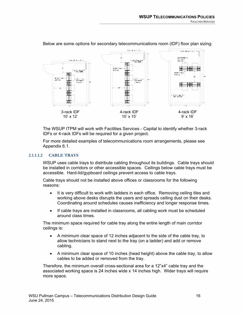
Below are some options for secondary telecommunications room (IDF) floor plan sizing:
3-rack IDF 10’ x 12’
4-rack IDF 10’ x 15’
4-rack IDF 9’ x 16’
The WSUP ITPM will work with Facilities Services - Capital to identify whether 3-rack IDFs or 4-rack IDFs will be required for a given project.
For more detailed examples of telecommunications room arrangements, please see Appendix 6.1.
2.1.1.1.2 CABLE TRAYS
WSUP uses cable trays to distribute cabling throughout its buildings. Cable trays should be installed in corridors or other accessible spaces. Ceilings below cable trays must be accessible. Hard-lid/gypboard ceilings prevent access to cable trays.
Cable trays should not be installed above offices or classrooms for the following reasons:
• It is very difficult to work with ladders in each office. Removing ceiling tiles and working above desks disrupts the users and spreads ceiling dust on their desks. Coordinating around schedules causes inefficiency and longer response times.
• If cable trays are installed in classrooms, all cabling work must be scheduled around class times.
The minimum space required for cable tray along the entire length of main corridor ceilings is:
• A minimum clear space of 12 inches adjacent to the side of the cable tray, to allow technicians to stand next to the tray (on a ladder) and add or remove cabling.
• A minimum clear space of 10 inches (head height) above the cable tray, to allow cables to be added or removed from the tray.
Therefore, the minimum overall cross-sectional area for a 12”x4” cable tray and the associated working space is 24 inches wide x 14 inches high. Wider trays will require more space.

WSUP TELECOMMUNICATIONS POLICIES FACILITIES SERVICES
WSU Pullman Campus – Telecommunications Distribution Design Guide 17 June 24, 2015
2.1.1.1.3 OSP PATHWAY
Outside plant (OSP) pathways (ductbank) and spaces (underground vaults/maintenance holes) are required to connect buildings to the campus technology infrastructure.
At a minimum, all major buildings require four OSP conduits (4 inch trade size). Preferably, buildings will have two sets of four OSP conduits (4 inch trade size), with each set of conduits routed from opposite sides of the building.
2.1.1.2 SYSTEM INTEGRATION
Significant technical advances have been made in recent years resulting in numerous systems that now communicate via the campus network. The following are examples of systems or processes that now require secure networking:
• HVAC/environmental control systems • Mechanical/DDC control systems • Irrigation control systems • Security and intrusion detection systems • Access control systems • Surveillance video systems • Handling of personally identifiable information (PII) • Financial transactions
Do not expect wireless networking to provide the capacity, reliability or security required to handle these systems. It is therefore crucial to the success of these systems that Facilities Services - Capital coordinate with ITS during the planning and design phases to ensure that adequate network equipment and infrastructure are included in the design.
2.1.1.3 DOCUMENTATION
2.1.1.3.1 AS-BUILT/RECORD DRAWINGS
When a construction project is completed, the as-built drawings or (preferably) record drawings need to be made available to ITS as follows:
• Full-size hard-copy printed drawings – the portion of the drawing set that is applicable to technology. The full set is not required, just the sheets that depict the technology features of the project.
• Facilities Services - Capital shall maintain a network-accessible archive of both CAD files and PDFs of the record drawings, organized by building. ITS shall have unrestricted access to review the information via the network.
2.1.1.3.2 CABLE TEST REPORTS
At the conclusion of each project, the telecommunications cabling subcontractor is required (in the project specifications) to provide their cable test reports. The subcontractor is also required to register the manufacturer’s warranty for the cabling infrastructure.

WSUP TELECOMMUNICATIONS POLICIES FACILITIES SERVICES
WSU Pullman Campus – Telecommunications Distribution Design Guide 18 June 24, 2015
The CPD Project Manager should require the test results and warranty registrations at the time that record drawings are submitted, and prior to final payment. A copy of this information shall be provided to ITS.

PROJECT PROCEDURES DESIGNER QUALIFICATIONS
WSU Pullman Campus – Telecommunications Distribution Design Guide 19 June 24, 2015
3 Project Procedures A. The Project Procedures section contains guidelines for architects, engineers, and
telecommunications distribution designers regarding the procedures that WSUP requires for projects that include telecommunications distribution systems. This applies both to projects that entail primarily telecommunications distribution work (such as telecommunications infrastructure replacement projects) as well as to architectural projects and other work (such as a new building) that involve telecommunications design.
B. This section is not intended to supersede the requirements in the State of Washington Conditions of the Agreement or the Instructions for Architects and Engineers, but rather to complement them, providing additional requirements that apply specifically to telecommunications design projects at WSUP facilities.
C. It is intended that the requirements in this section be considered contractually binding for
professional design firms providing telecommunications design services.
3.1 Designer Qualifications A. For the purposes of this document, the term “Designer” shall mean a person who is a
Registered Communications Distribution Designer (RCDD) who is currently in good standing with BICSI. Telecommunications designs on WSUP projects shall be produced by the RCDD. This means that the security and access controls design shall be produced by the Designer. WSUP’s communications with the telecommunications consultant shall be mainly through the RCDD. On projects where the RCDD is not the prime consultant, the RCDD shall keep the prime consultant (Architect/Engineer (A/E)) informed of all direct communications with WSUP. • The Registered Information Technology Professional (RITP) certification from BICSI
is not an acceptable substitute for the RCDD.
B. In addition to the RCDD certification, it is desirable that the RCDD have one or more of the following qualifications: • Professional Engineer (P.E.) in the electrical engineering field • RCDD/NTS certification from BICSI • RCDD/OSP certification from BICSI
C. In addition, the RCDD shall have the following qualifications: • The RCDD shall demonstrate a minimum of 5 years of experience in the design of
inside plant and outside plant telecommunications distribution systems. Experience designing telecommunications infrastructure on WSUP projects is desirable, but is not required.

PROJECT PROCEDURES PROCEDURES RELATED TO PROJECT PHASES
WSU Pullman Campus – Telecommunications Distribution Design Guide 20 June 24, 2015
• Experience not directly related to the design of telecommunications distribution systems, such as sales and/or marketing, project management, or installation experience, is not sufficient.
• The RCDD shall demonstrate that he/she has designed or has had personal design oversight of a minimum of five projects similar in size and construction cost to the current WSUP project.
• The RCDD shall be independent from and unaffiliated with any manufacturer associated with the telecommunications distribution system industry.
• The RCDD shall be completely familiar and conversant with industry and WSUP telecommunications standards.
D. The services of a professional engineer shall be required to design the following aspects of a complete telecommunications infrastructure. • Grounding and bonding • Firestopping • Electrical power distribution in telecommunications spaces • Standby Generator and associated other backup power systems systems • Telecommunications room cooling systems
E. The services of a licensed fire protection engineer shall be required to design the fire
protection and life safety systems for the telecommunications infrastructure (e.g., fire suppression, fire alarm system, etc.).
3.2 Procedures Related to Project Phases In addition to the procedures described in the TIDG for each project phase, the following requirements are specific to telecommunications infrastructure:
3.2.1 CONSTRUCTION OBSERVATION
3.2.1.1 CABLE TRAYS
Verify that the installed cable trays meet the following requirements: • Wherever cable tray passes through a wall, the wall penetration shall be finished (no
sheetrock visible) and firestopped if the wall is a fire-rated wall. • To protect technicians and cabling, all cuts to cable tray materials shall be finished smooth.
Cable trays shall not have rough or sharp edges or points. • Each segment of the cable tray requires a ground conductor bonding lug.

DESIGN CRITERIA PROCEDURES RELATED TO PROJECT PHASES
WSU Pullman Campus – Telecommunications Distribution Design Guide 21 June 24, 2015
4 Design Criteria A. The WSUP TDDG is not intended to be a comprehensive design guide resource
for telecommunications design at WSUP facilities. The Designer shall refer primarily to the BICSI TDMM for design guidance. The Construction Documents produced for each project shall be consistent with the installation practices described in the BICSI Information Technology Systems Installation Methods Manual (ITSIMM).
B. Where ANSI/TIA/EIA standards or BICSI manuals offer multiple choices with a
preferred method identified, and where the WSUP TDDG does not select one method over another or define specific requirements precluding use of the preferred method, the ANSI/TIA/EIA or BICSI-preferred method shall be selected.
C. Where ANSI/TIA/EIA Standards or BICSI manuals identify warnings regarding
potential adverse effects from certain design or installation methods, the design or installation method used shall typically be the method with the least potential for adverse effects.
D. Telecommunications distribution systems shall be designed for construction
using materials from the current product lines of the approved manufacturer.
• For copper cabling and related materials, WSUP has standardized on the TE AMP NETCONNECT® product line.
• For GPON fiber optic cabling and related materials, WSUP has standardized on the TE Optical LAN Solution® (OLS) product line and Zhone electronics.
• For riser/backbone and outside plant fiber optic cabling and related materials, WSUP has standardized on the Corning Cable Systems LANscape® product line.
• For racking-related materials, WSUP has standardized on products from Chatsworth Products Inc. ® (CPI) and Homaco®.
The Designer is required to incorporate a single manufacturer throughout the entire project into the design (unless otherwise directed by WSUP) and to design a telecommunications distribution system that will be suitable for the use of products from this manufacturer. These manufacturers and their products are identified in the TCGS. • For example, ladder racking in all telecommunications rooms shall be
manufactured by a single manufacturer, and cabling system materials shall be manufactured by a single manufacturer. However, it is not required that cabling and ladder racking be from the same manufacturer.
The construction documents shall require that the installation workmanship fully comply with the current installation requirements from the manufacturers of these products.

DESIGN CRITERIA PRINCIPLES OF TRANSMISSION
WSU Pullman Campus – Telecommunications Distribution Design Guide 22 June 24, 2015
E. Any request to deviate from the requirements of the National Electrical Code or the manufacturer’s 25-year warranty will not be accepted. The Designer shall seek approval through the WSUP Standards Variance Request (SVR) process for designs that are not consistent with WSUP TDDG requirements. Requests to deviate from industry standards or WSUP design solutions will be considered on a case-by-case basis by the WSUP ITPM. Designers may contact the WSUP ITPM to discuss proposed alternatives before spending significant time researching or preparing an SVR.
F. Telecommunications distribution infrastructure shall fully comply with the current
WSUP TDDG, the current ANSI/TIA/EIA Commercial Building Telecommunications Standards, and the National Electrical Code (NEC).
G. The following subsections are arranged to mirror the chapter sequence of the
BICSI TDMM 13th Edition (the subsection numbers below are in the form of “4.x” where x corresponds with the chapter number in the BICSI TDMM).
• Each TDDG subsection contains commentary and requirements regarding
the application of the BICSI TDMM to WSUP projects. In particular, each section contains limitations and prohibitions on specific materials and methods discussed in the BICSI TDMM.
H. Please refer to the Bibliography and Resources section and Glossary section of
the BICSI TDMM for definitions, abbreviations, acronyms, and symbols used for describing and documenting telecommunications infrastructure at WSUP facilities.
Other terms are defined in the Glossary located in Appendix 6.6 of this document.
4.1 Principles of Transmission Please refer to Chapter 1, Principles of Transmission in the BICSI TDMM for general information regarding the design of telecommunications distribution infrastructure.
4.2 Electromagnetic Compatibility Please refer to Chapter 2, Electromagnetic Compatibility in the BICSI TDMM for general information regarding the electromagnetic interference with and clearance requirements for telecommunications infrastructure. The following requirements take precedence over the BICSI TDMM guidelines for telecommunications infrastructure at WSUP facilities:
A. See Tables 2.6 and 2.7 in the BICSI TDMM, listing minimum separation distances from sources of electromagnetic interference (EMI). Telecommunications infrastructure shall not be installed closer than the minimum separation distances listed in the BICSI TDMM. Where the NEC or local codes require greater separation distances than those listed in the BICSI TDMM, the greater separation distance shall be maintained.

DESIGN CRITERIA TELECOMMUNICATIONS SPACES
WSU Pullman Campus – Telecommunications Distribution Design Guide 23 June 24, 2015
B. Separation distances apply equally to both copper cabling and fiber optic cabling. Even though fiber optic cabling is impervious to EMI, once a pathway is established for fiber, it could later be used for copper cabling.
C. OSP telecommunications infrastructure designs shall adhere to the governing
clearance requirements of the NEC and NESC.
4.3 Telecommunications Spaces Please refer to Chapter 3, Telecommunications Spaces in the BICSI TDMM for general information regarding the design of telecommunications rooms. The following requirements take precedence over the BICSI TDMM guidelines for telecommunications infrastructure at WSUP facilities:
A. In WSUP facilities, the TRs in a building may also serve as low-voltage systems equipment rooms, typically containing electronic equipment intended to serve the building or a portion of the building. The TR shall not be shared with electrical installations other than those necessary for telecommunications.
4.3.1 TELECOMMUNICATIONS ROOM LOCATION
A. The Designer shall be responsible to inform the Architect of the sizing and location requirements for Telecommunications Rooms during the Schematic Design phase of the project.
B. The most desirable location for telecommunications rooms shall be as centric as possible to the area being served. In addition, for multi-story buildings, telecommunications spaces shall be vertically aligned. This allows for clean, vertical pathway to be easily provided to each space. It also reduces the number of bends and offsets that the intra-building backbone pathway must undergo as it connects each of the telecommunications rooms. Please see the discussion in TDDG Section 4.4.1 Intra-Building Backbone Pathways for further information.
C. There shall be a minimum of one TR per building. Additional TRs shall be added
when the area to be served exceeds 10,000 square feet or where the cable lengths will exceed 295 feet between a TR and the work area telecommunications outlet, including allowance for cable slack loops. Generally, each floor of a building shall be served by a TR located on that floor.
• It is very undesirable for a TR to serve outlets on a different floor, and
requires specific advance approval by the WSUP ITPM.
D. Telecommunications Rooms shall not be co-located with any type of electrical room or mechanical room. The TR location shall maintain the separation distances identified in the Electromagnetic Compatibility (Section 4.2) of this document.
E. Telecommunications Rooms shall be accessible directly from a corridor. It is not acceptable to pass through a classroom, office, academic lab or restroom to
DESIGN CRITERIA TELECOMMUNICATIONS SPACES
WSU Pullman Campus – Telecommunications Distribution Design Guide 24 June 24, 2015
enter a telecommunications room. F. For campus main communication facilities (MCF), exterior double-door access is
preferred.
G. The telecommunications room shall not be located in any of the locations listed below: 1. Areas subject to water or steam infiltration, particularly basements. Floor
drains (with trap primers) are required if there is any risk of water entry. 2. Areas exposed to excessive heat or direct sunlight. 3. Areas exposed to corrosive atmospheric or environmental conditions. 4. Near or adjacent to potential sources of electromagnetic interference (EMI) or
radio frequency interference (RFI) such as large electric motors, power transformers, arc welding equipment, or high-power radio transmitting antennas.
5. In a shared space with electrical equipment other than equipment serving the telecommunications system.
4.3.2 TELECOMMUNICATIONS ROOM SIZING
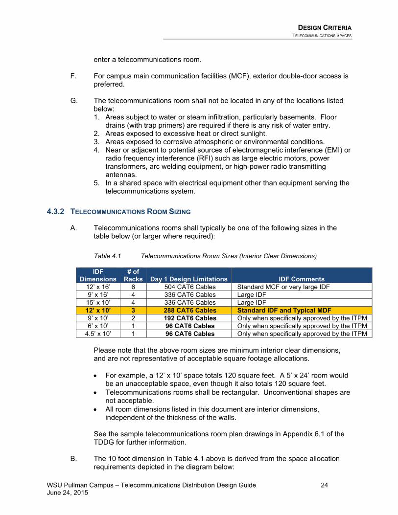
A. Telecommunications rooms shall typically be one of the following sizes in the table below (or larger where required):
Table 4.1 Telecommunications Room Sizes (Interior Clear Dimensions)
IDF Dimensions
# of Racks
Day 1 Design Limitations
IDF Comments
12’ x 16’ 6 504 CAT6 Cables Standard MCF or very large IDF 9’ x 16’ 4 336 CAT6 Cables Large IDF 15’ x 10’ 4 336 CAT6 Cables Large IDF 12’ x 10’ 3 288 CAT6 Cables Standard IDF and Typical MDF 9’ x 10’ 2 192 CAT6 Cables Only when specifically approved by the ITPM 6’ x 10’ 1 96 CAT6 Cables Only when specifically approved by the ITPM
4.5’ x 10’ 1 96 CAT6 Cables Only when specifically approved by the ITPM
Please note that the above room sizes are minimum interior clear dimensions, and are not representative of acceptable square footage allocations. • For example, a 12’ x 10’ space totals 120 square feet. A 5’ x 24’ room would
be an unacceptable space, even though it also totals 120 square feet. • Telecommunications rooms shall be rectangular. Unconventional shapes are
not acceptable. • All room dimensions listed in this document are interior dimensions,
independent of the thickness of the walls. See the sample telecommunications room plan drawings in Appendix 6.1 of the TDDG for further information.
B. The 10 foot dimension in Table 4.1 above is derived from the space allocation
requirements depicted in the diagram below:

DESIGN CRITERIA TELECOMMUNICATIONS SPACES
WSU Pullman Campus – Telecommunications Distribution Design Guide 25 June 24, 2015
Wal
l-mou
nted
Eq
uipm
ent
Wal
l-mou
nted
Eq
uipm
ent
C. If project circumstances prevent the establishment of adequately-sized
telecommunications spaces, the following options may be considered on a case-by-case basis, subject to the approval of the ITPM: 1. Reach-in closets and small room designs for minor remodel construction
projects may be considered through the SVR process. 2. Wall-mounted swing cabinets are appropriate for some remodel applications
serving small numbers of people, and where floor space for a full telecommunications room would be unavailable or impractical.
3. The Designer shall pay close attention to the requirements of the equipment that will reside in the cabinet and the space that will host the cabinet. • Cabinets shall typically be 36 inches to 48 inches high. • Some applications require cabinets that are 30 inches deep and other
applications will not permit cabinets that are more than 12 inches deep (with vertically-mounted electronics).
D. Telecommunications room sizing shall be increased if other low-voltage systems
equipment is intended to be hosted in the TR, for example fire alarm panels, security system equipment, etc. In MDFs, the Designer shall allocate wall space and rack space for head-end control devices for Access Control and Security Systems, Vending Machine systems, and HVAC systems. The Designer shall seek input from the WSUP ITPM regarding room sizing.
E. In new construction and modernization projects, telecommunications rooms shall
be sized such that ADA-required space is available after racks and equipment have been installed.
4.3.3 ARCHITECTURAL PROVISIONING
A. The Designer shall be responsible to inform the Architect of the architectural provisioning requirements for Telecommunications Rooms and to do this early in the Design Development phase of the project.

DESIGN CRITERIA TELECOMMUNICATIONS SPACES
WSU Pullman Campus – Telecommunications Distribution Design Guide 26 June 24, 2015
B. The Designer shall be responsible to review project documents and determine that the architectural requirements for the telecommunications spaces are met as described in this document. For projects where an architect is involved, the Designer shall coordinate directly with the architect, and verify that the architect’s design documentation meets these requirements. For projects without an architect, the Designer shall alert WSUP where additional architectural adjustments are needed to meet the requirements.
C. Doors shall open out (180-degree swing) from telecommunications spaces
wherever possible and shall be a minimum of 36 inches wide and 80 inches high, fitted with a lock and card access. Coordinate lock and key requirements with WSUP. Doors shall be located in hallways or other common areas. Telecommunications room doors shall never be located in another building occupant’s designated space.
• Access control electronics are required for each telecommunications room.
D. Minimum clearance height within a telecommunications space shall be 8 feet.
False ceilings (t-bar ceilings, ceiling grids, etc.) shall not be installed in telecommunications spaces. The floor, walls, and ceiling shall be sealed to reduce dust.
E. Finishes shall be light in color to enhance room lighting. Flooring materials shall
be light colored and slip-resistant. Carpet is not acceptable for telecommunications rooms. Interior floor finish and floor covering materials shall also meet the requirements in the International Building Code.
F. The walls in telecommunications rooms shall be covered with plywood which has either been treated with fire-retardant chemicals by a pressure impregnation process, or has been painted with a UL-listed, non-toxic fire-retardant intumescent coating having a Class A surface flame spread rating. The plywood shall be painted with primer and two coats of white paint.
• If an approved fire-retardant intumescent coating is used, a small plaque shall
be attached to the backboard near the door, listing the fire spread rating of the backboard, the manufacturer, and the product number of the fire-retardant intumescent coating. This information may be helpful for future maintenance activities.
Plywood backboards shall extend from 6 inches above the floor up to a height of 8 feet 6 inches above the finished floor.
4.3.4 ENVIRONMENTAL PROVISIONING
A. The Designer shall be responsible to inform the Mechanical Engineer of the environmental provisioning requirements for telecommunications rooms, and to do this early in the Design Development phase of the project.
B. The Designer shall be responsible to determine that the mechanical HVAC
requirements for the telecommunications spaces are met as described in this

DESIGN CRITERIA TELECOMMUNICATIONS SPACES
WSU Pullman Campus – Telecommunications Distribution Design Guide 27 June 24, 2015
document. For projects where a Mechanical Engineer is involved, the Designer shall coordinate directly with the engineer, and verify that the engineer’s design documentation meets these requirements. For projects without the involvement of a Mechanical Engineer, the Designer shall alert WSUP where adjustments to the mechanical infrastructure are needed to meet the requirements.
C. The Designer shall coordinate with the Mechanical Engineer to ensure that the
HVAC requirements for the telecommunications spaces are met, and that HVAC ductwork does not conflict with cable tray or conduit routing. Also, verify that HVAC motors in the ceiling are sufficiently separated from exposed cabling in cable trays so that EMI noise is not problematic. See Section 4.2 – Electromagnetic Compatibility.
D. The Mechanical Engineer shall design a proper air cooling solution that is
appropriately sized for the application. The WSU Pullman campus has a chilled water distribution system that operates year-round. This system shall be considered for use with telecommunications room cooling solutions. Heating is typically not required.
E. In addition to the requirements in the BICSI TDMM, telecommunications rooms
shall be environmentally provisioned as follows:
1. A fundamental design assumption is that all TRs will at some time contain active electronic equipment (hubs, routers, switches, etc.) even if the current design does not call for such devices. Network electronics require an HVAC system capable of operating on a 24/7/365 basis. If the building system cannot assure continuous cooling operation, a stand-alone cooling unit shall be provided for the TR. • This unit and any roof penetrations shall be located away from and not
directly above electronics of any kind, to avoid damage from condensate drip and roof leaks.
In addition, a positive pressure differential is required to (with respect to surrounding areas) help keep dust and other particles out of the room.
• Where practical, the use of outside air for cooling is encouraged.
Dehumidification and filtration may be required for systems using outdoor air.
• Where practical, WSUP encourages the use of heat reclamation features. • Environmental management and monitoring systems shall be designed
for TRs. • Typically, the building’s central air conditioning system should cool the
telecommunications rooms during summer months. During the months when the central air conditioning system is not running, a stand-alone air conditioning system shall be used to cool the telecommunications rooms.
• Split systems are preferred, with the equipment located outside the TRs wherever possible. The temperature controls shall be located inside the telecommunications rooms.
• The heat load in some telecommunications rooms is small enough that

DESIGN CRITERIA TELECOMMUNICATIONS SPACES
WSU Pullman Campus – Telecommunications Distribution Design Guide 28 June 24, 2015
simply exhausting the air is sufficient to maintain the temperature in the room. In these cases, positive pressure must still be maintained in the space to prevent the collection of dust.
2. WSUP typically provides network electronics that provide Power-over-
Ethernet. The Designer shall request power consumption data for the equipment that WSUP will use, and work with the mechanical systems designer to ensure that the cooling capacity is sufficient to support the POE heat load.
3. Minimum clearance height in the TR shall be eight feet without obstructions
(light fixtures, ducting, etc.). 4. The Designer shall carefully coordinate the location of fire suppression
sprinklers and piping in telecommunications spaces.
• Wet-pipe fire suppression sprinklers are acceptable in telecommunication rooms.
• Dry-pipe (pre-action) fire suppression sprinklers are required for data centers and main communication facilities (MCF).
• In cases of both wet-pipe and dry-pipe systems: o Sprinkler guards must be provided where sprinklers are installed less
than 8 feet above the floor. o Sprinkler heads and piping shall be mounted and routed above
walking space – not above equipment racks or the equipment they will contain.
• WSUP is usually not interested in Halon or Inergen type fire suppression systems for its facilities.
4.3.5 FLOOR-STANDING EQUIPMENT RACKS AND CABINETS
A. Each telecommunications room shall be provisioned with a full set of floor-standing 7 feet high x 19 inch wide ANSI/TIA/EIA standard open-frame equipment racks to fill the room, regardless of whether or not equipment is required at the time of construction.
• For minor remodel construction, this requirement may be waived given
budget, project size, or other limiting factors. • The use of a wall-mounted swing rack or a wall-mounted hinged bracket may
be acceptable, subject to WSUP ITPM approval via the SVR process.
B. Per Code requirements, 36 inches clearance is mandatory surrounding racks, cabinets, and any equipment that may be mounted in the racks. See the sample telecommunications room plan drawings in Appendix 6.1 of the TDDG for further information.
C. Racks shall be sized to accommodate, at a minimum, all existing and new
equipment that is to be installed in the rack plus an additional 50% available space for additional equipment that may be added in the future. If a rack is more than 50% full at design time, a spare rack shall be specified.

DESIGN CRITERIA TELECOMMUNICATIONS SPACES
WSU Pullman Campus – Telecommunications Distribution Design Guide 29 June 24, 2015
4.3.5.1 FLOOR-STANDING EQUIPMENT RACKS
A. See the sample floor plan details in Appendix 6.1 of the TDDG for rack arrangement guidance.
B. Floor-standing racks shall be securely bolted to the floor, and shall be braced to
the wall with cable ladder racking. Multiple racks in the same TR shall be interconnected with cable ladder racks.
C. The Designer shall discuss with the ITPM the potential for future requirements for
additional racks, and identify spaces for future racks on the plan drawings. (See the sample telecommunications room plan drawings in Appendix 6.1 of the TDDG for further information).
D. Racks shall be equipped with horizontal and vertical cable management modules
both front and rear, with strain relief brackets to support proper cable bend radius and to maintain strain relief for the cabling. Vertical cable management modules shall include spools/posts to manage cable slack.
1. Vertical cable management between racks shall be 12 inches wide. 2. Vertical cable management on the sides of racks shall typically be 6 inches
wide. Some applications, however, may require 8 inch or 10 inch wide vertical cable management.
E. Sometimes an equipment cabinet is required for larger IT equipment (servers,
large UPSs, etc.) with both front and rear mounting rails. The Designer shall discuss with WSUP the network electronics that will be hosted in each TR and shall design appropriate racks and cabinets to support the equipment. Racks and cabinets shall be shown on the rack elevation details in the plan drawings.
F. Ladder racking shall be provided at 7 feet above finished floor, circling the room
and crossing the room over the tops of the equipment racks.
4.3.5.2 TELECOMMUNICATIONS CABINETS
A. When planning the size and location of TRs in existing buildings, the Designer shall make every reasonable effort to meet the requirements for telecommunications rooms. In certain instances, the only viable alternative may be the use of one or several telecommunications cabinets in lieu of TRs.
B. In minor remodel projects, some buildings may not justify a separate space for a
telecommunications room. In some circumstances, sufficient space may not be available for a telecommunications room. In these instances, a wall-mounted or floor-standing telecommunications cabinet may be used.
C. Wall-mounted cabinets shall be double-hinged to permit access to both the front
and rear of the equipment. Care shall be taken to specify cabinets with strong hinges that do not begin to sag over time due to the weight of the cabinet’s contents. Telecommunications cabinets shall be constructed of heavy gauge steel with lockable doors:

DESIGN CRITERIA TELECOMMUNICATIONS SPACES
WSU Pullman Campus – Telecommunications Distribution Design Guide 30 June 24, 2015
• If the cabinet will be located in an occupied space, use a Plexiglas® door to
reduce noise. • If the cabinet is not located in an occupied space, use a mesh-screened door
to improve ventilation. D. Cabinets shall be sized to allocate space for cabling termination infrastructure,
network electronics, and UPS equipment, and shall also include space allocated for future growth. Wall space shall be allocated to permit cabinets to fully swing open.
E. Cabinets shall be equipped with horizontal wire management modules with strain
relief brackets to support proper cable bend radius and to maintain strain relief for the cabling.
F. Power and telecommunications cables for equipment housed within the cabinet
are to be contained within the cabinet. Exposed wiring or cables are not permitted. Power and telecommunications cables routed to or from the cabinet shall be contained in conduit, in surface-mounted raceway, or concealed within the adjacent wall.
• Technical power outlets serving cabinets shall be mounted inside the cabinet.
G. Each cabinet hosting equipment that produces a significant heat load shall have
front and rear screen doors, allowing air flow through the equipment. Cooling fans are typically not required.
H. Each cabinet shall have a telecommunications grounding busbar (TGB) installed
inside, in accordance with the grounding requirements discussed in the BICSI TDMM Chapter 9 Bonding and Grounding (Earthing).
I. The cabinet shall not be located in or adjacent to areas containing sources of
electromagnetic interference (EMI). See TDDG Section 4.2 Electromagnetic Compatibility (above) for further information.
4.3.6 POWER REQUIREMENTS
A. The Designer shall be responsible to determine that the power requirements for the telecommunications spaces are met as described in this document. For projects where an Electrical Engineer is involved, the Designer shall coordinate directly with the engineer, and verify that the engineer’s design documentation meets these requirements. For projects without the involvement of an electrical engineer, the Designer shall alert WSUP where additional power infrastructure is needed to meet the requirements.
B. WSUP typically provides network electronics that provide Power-over-Ethernet.
The Designer shall request power consumption data for the equipment that WSUP will use, and shall work with the electrical power distribution designer to ensure that the cooling capacity is sufficient to support the POE heat load.
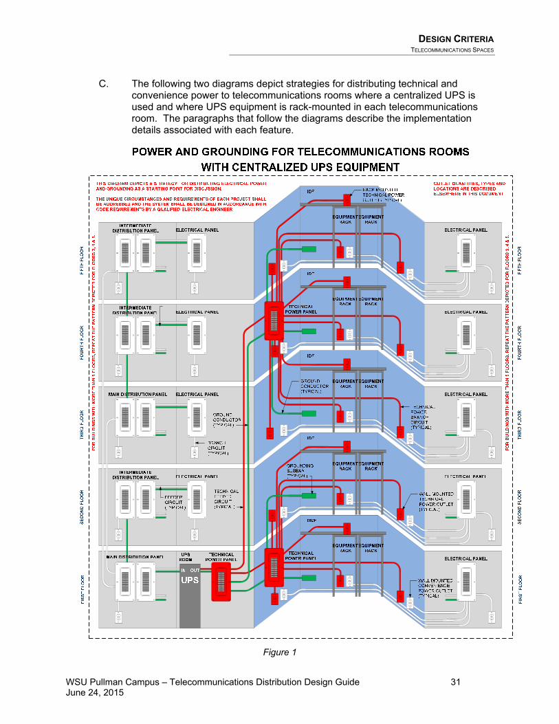
DESIGN CRITERIA TELECOMMUNICATIONS SPACES
WSU Pullman Campus – Telecommunications Distribution Design Guide 31 June 24, 2015
C. The following two diagrams depict strategies for distributing technical and convenience power to telecommunications rooms where a centralized UPS is used and where UPS equipment is rack-mounted in each telecommunications room. The paragraphs that follow the diagrams describe the implementation details associated with each feature.
Figure 1

DESIGN CRITERIA TELECOMMUNICATIONS SPACES
WSU Pullman Campus – Telecommunications Distribution Design Guide 32 June 24, 2015
MDF
FIR
ST F
LOO
RSE
CO
ND
FLO
OR
THIR
D F
LOO
R
IDF
IDF
FIR
ST F
LOO
RSE
CO
ND
FLO
OR
THIR
D F
LOO
R
FOU
RTH
FLO
OR
FIFT
H F
LOO
R
IDF
IDF
FOU
RTH
FLO
OR
FIFT
H F
LOO
R
POWER AND GROUNDING FOR TELECOMMUNICATIONS ROOMS
INTERMEDIATE DISTRIBUTION PANELELECTRICAL PANEL
TECHNICALFEEDER CIRCUIT(TYPICAL)
INTERMEDIATE DISTRIBUTION PANELELECTRICAL PANEL
MAIN DISTRIBUTION PANELELECTRICAL PANEL
BRANCH CIRCUIT(TYPICAL)
FEEDER CIRCUIT(TYPICAL)
MAINDISTRIBUTION PANELELECTRICAL PANEL
TECHNICALFEEDER CIRCUIT(TYPICAL)
INTERMEDIATE DISTRIBUTION PANELELECTRICAL PANEL
WITH DISTRIBUTED UPS EQUIPMENT
ELECTRICAL PANEL
ELECTRICAL PANEL
ELECTRICAL PANEL
TECHNICAL POWER BRANCH CIRCUIT(TYPICAL)
GROUND CONDUCTOR(TYPICAL)
TECHNICAL POWER PANEL
ELECTRICAL PANEL
ELECTRICAL PANEL
TECHNICAL POWER PANEL
EQUIPMENTRACK
EQUIPMENTRACK
EQUIPMENTRACK
EQUIPMENTRACK
EQUIPMENTRACK
EQUIPMENTRACK
EQUIPMENTRACK
EQUIPMENTRACK
EQUIPMENTRACK
EQUIPMENTRACK
WALL MOUNTED TECHNICAL POWER OUTLET(TYPICAL)
RACK MOUNTED TECHNICAL POWER OUTLET (TYPICAL)
WALL MOUNTED CONVENIENCE POWER OUTLET(TYPICAL)
GROUNDING BUSBAR(TYPICAL)
THIS DIAGRAM DEPICTS A STRATEGY FOR DISTRIBUTING ELECTRICAL POWER AND GROUNDING AS A STARTING POINT FOR DISCUSSION.
THE UNIQUE CIRCUMSTANCES AND REQUIREMENTS OF EACH PROJECT SHALL BE ADDRESSED AND THE SYSTEM SHALL BE DESIGNED IN ACCORDANCE WITH CODE REQUIREMENTS BY A QUALIFIED ELECTRICAL ENGINEER.
OUTLET QUANTITIES, TYPES AND LOCATIONS ARE DESCRIBED ELSEWHERE IN THIS DOCUMENT
UPSUPS
UPSUPS
UPSUPS
UPSUPS
UPSUPS
FOR
BU
ILD
ING
S W
ITH
MO
RE
THA
N 5
FLO
OR
S, R
EPEA
T TH
E PA
TTER
N D
EPIC
TED
FO
R F
LOO
RS
3, 4
& 5
.
FOR
BU
ILD
ING
S W
ITH
MO
RE
THA
N 5
FLO
OR
S, R
EPEA
T TH
E PA
TTER
N D
EPIC
TED
FO
R F
LOO
RS
3, 4
& 5
.
Figure 2

DESIGN CRITERIA TELECOMMUNICATIONS SPACES
WSU Pullman Campus – Telecommunications Distribution Design Guide 33 June 24, 2015
4.3.6.1 STANDBY GENERATORS
A. WSUP does not use building-specific standby generators. The campus has a campus-wide power distribution system, Feeder 13 of which is backed by a large generator. Campus policy describes very specific permitted uses for Feeder 13, which do not include providing backup power for most telecommunications rooms.
B. The Designer shall inquire with the WSUP FSPM and ITPM whether Feeder 13 will be brought to a building, and whether it can be used to support any technology systems in that building. It is unlikely that generator-backed power will be used for technology systems.
C. If Feeder 13 is brought to the building, the Designer shall work with the Electrical Engineer to design the application of Feeder 13 to provide power to:
• All telecommunications rooms • All mechanical cooling serving telecommunications rooms • Data Centers • Main Communication Facilities (MCFs)
4.3.6.2 UPS-SOURCED BACKUP POWER
A. All telecommunications rooms require backup power from uninterruptible power supply (UPS) equipment. WSUP uses VOIP telephone systems that require Power-over-Ethernet (POE) network switches to remain operational. The UPS equipment is intended to provide conditioned power during steady state operation as well as stable power long enough to ride through power interruptions of short duration (less than a minute). There is no expectation of runtime operation of any significant length.
B. The Designer shall inquire with the WSUP ITPM regarding the choice of UPS solution (centralized vs. distributed, rack-mounted) for each building.
C. Centralized UPS equipment shall be strongly considered for buildings with four or
more telecommunications rooms, for campus main communication facilities (MCF) and for data centers.
• Where rack-mounted UPS equipment will be used, the Designer shall reserve
sufficient space at the base of an equipment rack in each telecommunications room to hold the Owner-provided UPS equipment.
• WSUP has recently deployed several applications using Schneider Electric APC Symmetra centralized UPS equipment. There are benefits to WSUP to continue using this equipment on future projects, including spare parts, maintenance and operation experience, and battery replacement processes.
• Power Distribution Units (PDU) are required for each rack when using centralized UPS equipment. When PDUs are provided for main communication facilities (MCF), the PDUs shall be provided with the optional Ethernet monitoring features.
• The WSUP ITPM will specify the UPS requirements. Based on these

DESIGN CRITERIA TELECOMMUNICATIONS SPACES
WSU Pullman Campus – Telecommunications Distribution Design Guide 34 June 24, 2015
requirements, the electrical engineer on the project shall design the centralized UPS system and integrate it with the electrical power distribution system for the building.
• Centralized UPS equipment and PDUs shall be provided by the Contractor under the General Contract.
D. Rack-mounted UPS equipment may be more cost-effective for smaller buildings with fewer than four telecommunications rooms.
• The Owner-provided network electronics will plug directly into the rack-
mounted UPS equipment. Therefore, PDUs and plug strips are not required. • Where rack-mounted UPS equipment will be used, the Designer shall reserve
sufficient space at the base of an equipment rack in each telecommunications room to hold the Owner-provided UPS equipment.
E. The Designer shall work with the Electrical Engineer to design appropriate power
receptacles that will be suitable to serve the Owner-provided UPS equipment that will be used on the project.
4.3.6.3 TECHNICAL POWER PANELS
A. The technical power circuits in each telecommunications room shall originate from a technical power panel, dedicated to serving the TR. In the absence of other influencing circumstances, the panel shall be sized for 100 Amp service. The technical power panel shall not be used to supply power to sources of electromagnetic interference such as large electric motors, arc welding, or industrial equipment. • The panel shall be located in the TR. • The technical power panel shall be labeled “Telecommunications Equipment
Only.”
B. All technical power panels shall be equipped with a voltage transient surge suppression (VTSS) device.
C. It is acceptable to use a single technical power panel to serve multiple telecommunications rooms.
D. Some circumstances might not justify a dedicated technical power panel. In these cases, an available general-purpose electrical panel may be used. The Designer shall seek direction from WSUP regarding a decision not to design a dedicated technical power panel.
4.3.6.4 TECHNICAL POWER OUTLETS
A. The Designer shall obtain electrical power connection/load requirements from WSUP for each piece of equipment, and tabulate the information for review and confirmation by WSUP. This equipment may include network electronics, UPS equipment, computers/servers, phone system equipment, voice mail systems, video equipment, and service provider equipment.

DESIGN CRITERIA TELECOMMUNICATIONS SPACES
WSU Pullman Campus – Telecommunications Distribution Design Guide 35 June 24, 2015
B. WSUP intends to provide network equipment and UPS equipment for each
telecommunications room that requires 208VAC or 240VAC power sources:
• Each pair of outlets shall be sourced from separate power phases. • One of the outlets in each pair shall be UPS backed. If Feeder 13 is used for
standby power, the UPS equipment shall be installed on this circuit.
The Owner-provided UPS equipment will provide 110VAC and 208VAC outlets to meet the needs of the Owner-provided network equipment, and will connect to power distribution units supporting rack-mounted equipment.
C. The following diagrams depict the electrical power architecture that shall be
provided for each rack and cabinet that will host active equipment:
For Applications with Centralized UPS Equipment:
M AX 15 .4W/PORT
STATUS
WS-X4548-GB -RJ45V
1 2 3 4 5 6 7 8 9 10 11 12 13 14 15 16MULTI-SPEE D
GIGABIT ETHERNETS WI TCHI NG MODULE
48-PORT10/ 100/1000 BASE T
IN-LINE P OWER
3231
3029
2827
2625
2423
2221
2019
1817
4847
4645
4443
4241
4039
3837
3635
3433
1615
1413
1211
109
87
65
43
21
32313029282726252423222120191817 33 34 35 36 37 38 39 40 41 42 43 44 45 46 47 48
MAX 15.4W/PORT
STATUS
WS-X4548-GB -RJ45V
1 2 3 4 5 6 7 8 9 10 11 12 13 14 15 16MULTI-SPEE D
GIGABIT ETHERNETS WI TCHI NG MODULE
48-PORT10/ 100/1000 BASE T
IN-LINE P OWER
3231
3029
2827
2625
2423
2221
2019
1817
4847
4645
4443
4241
4039
3837
3635
3433
1615
1413
1211
109
87
65
43
21
32313029282726252423222120191817 33 34 35 36 37 38 39 40 41 42 43 44 45 46 47 48
For Applications with Distributed (Rack-mounted) UPS Equipment:
M AX 15 .4W/PORT
STATUS
WS -X4548-GB-RJ45V
1 2 3 4 5 6 7 8 9 1 0 1 1 1 2 13 14 15 16
MULTI-SPEE DGIGABIT ETHERNETSWI TCHING MODULE
48-PORT10/ 100/1000 BASE T
IN-LINE POWER
3231
3029
2827
2625
2423
2221
2019
1 81 7
4 84 7
4645
4443
4241
4039
3837
3635
3433
1615
1413
1211
109
87
65
43
21
323130292827262524232 22 12 01 91 817 33 34 35 36 37 38 39 4 0 4 1 4 2 4 3 4 4 4 5 4 6 47 48
L6-20
L6-20
L5-20
OUTLETS SHALL BE SUPPLIED FROM
TECHNICAL POWER PANEL WITH DEDICATED
CIRCUITS ON DIFFERENT PHASES
UPS
L6-30
OUTLET SHALL BE SUPPLIED FROM
TECHNICAL POWER PANEL WITH
DEDICATED CIRCUIT
OUTLET SHALL BE SUPPLIED FROM
TECHNICAL POWER PANEL WITH
DEDICATED CIRCUIT ON A PHASE THAT IS
DIFFERENT FROM THE TWO PHASES SERVING
THE L6-20 OUTLETS

DESIGN CRITERIA TELECOMMUNICATIONS SPACES
WSU Pullman Campus – Telecommunications Distribution Design Guide 36 June 24, 2015
D. At least two power outlets shall be provided (each with dedicated circuits) for exclusive use by telecommunications-related electronic equipment.
• Outlets shall be colored orange, labeled as “Technical Power” and shall show
the panel and circuit numbers. • Where 110VAC Technical power outlets are required, outlets shall be
equipped for “straight-blade plugs” (NEMA 5-20R), rather than twist-lock style receptacles.
• Where 208VAC or 240VAC technical power outlets are required, the Designer shall inquire with the WSUP ITPM to determine the plug requirements for the equipment to be served.
• Each outlet shall be equipped with a dedicated insulated solid copper equipment-grounding conductor. Ground conductors serving technical power outlets shall not be isolated ground conductors.
• See the telecommunications room plan details in Appendix 6.1 of the TDDG for technical power outlet locations.
E. The Designer shall specifically investigate the potential need for voltage or Ampere requirements other than the typical 110VAC/20 Ampere power outlet. Some UPS and network switch equipment requires specialized plugs or electrical service. The Designer shall inquire with the WSUP ITPM to determine whether any dedicated or specialized circuit requirements exist.
4.3.6.4.1 NEW CONSTRUCTION AND MODERNIZATION PROJECTS
A. Faceplates for power receptacles and light switches in the TR shall be mounted at the surface of the plywood backboard (as opposed to being recessed into a cutout in the plywood backboard). The device boxes shall be recessed into the wall (not surface-mounted).
4.3.6.4.1.1 Telecommunications Rooms with 1 or 2 Floor-Standing Racks
A. One duplex technical power outlet per floor-standing rack shall be provided to serve each rack. The outlet(s) shall be mounted on the side wall nearest the racks, approximately 18 inches behind the rack. Technical power outlets shall be mounted at the standard mounting height above the finished floor.
B. The rack nearest the wall is expected to host a rack-mounted UPS at the base of
the rack. The UPS will plug into the duplex power outlet, and the network equipment will plug into the UPS.
C. Electronic equipment in the second rack is typically powered by UPS in the first
rack. However, if necessary, another UPS can be installed in the base of the second rack, and the power cord can be routed beneath the first UPS to the second rack-dedicated technical power outlet.
D. Typically, WSUP furnishes and installs the UPS equipment.
E. For racks where WSUP intends to install equipment with dual-redundant power
supplies, two duplex technical power outlets with separate circuits shall be provided for those racks. The Designer shall inquire with WSUP whether equipment with dual power supplies will be used.
DESIGN CRITERIA TELECOMMUNICATIONS SPACES
WSU Pullman Campus – Telecommunications Distribution Design Guide 37 June 24, 2015
4.3.6.4.1.2 Telecommunications Rooms with More than 2 Floor-Standing Racks
A. The first two racks are served as described above.
B. A dedicated duplex technical power outlet (pedestal style) shall be floor-mounted near the vertical cable management of each additional rack.
C. Conduit for each pedestal outlet shall be concealed in the floor where possible.
Otherwise, the conduit shall be routed exposed from the wall to the pedestal, above the base-plates of the first and second racks. The bottom rack spaces (reserved for UPS equipment) shall not be obstructed by the power conduit.
4.3.6.4.1.3 Other Technical Power Outlets
A. In addition to the outlets intended to serve the racks, a minimum of one duplex technical power outlet shall be provided per wall (centered on the wall) except for the wall adjacent to the racks.
B. For walls more than 10’ in length, a minimum of 2 outlets shall be provided, and at intervals of no more than 6 feet between outlets.
4.3.6.4.2 MINOR REMODEL PROJECTS
A. The design shall include technical power outlets according to the “new construction” requirements, wherever possible. However, for some projects it may not be realistic or practical to meet those requirements. The following two paragraphs describe an alternative arrangement of technical power outlets that may be approved on a project-by-project basis via the SVR process:
• If it is not practical to install a new power outlet at the base of each equipment
rack, it may be acceptable to serve the rack’s power needs from a wall-mounted outlet.
• If power outlets are not installed at the base of each rack, the number of wall-
mounted technical power outlets shall be increased to an interval of one outlet every 6 feet. Power outlets in this arrangement shall be located such that they are conveniently aligned with the equipment racks to avoid inadvertent disconnection of the power cords.
B. Where telecommunications backboards are applied to existing walls with existing
power outlets and light switches, the design shall require backboards to be provided with cutouts permitting access to the existing electrical devices.
4.3.6.5 ADDITIONAL CONVENIENCE POWER OUTLETS
A. In addition to the technical power outlets described above, the design shall require the Contractor to provide other duplex convenience outlets (120VAC, 15 Ampere) that would be available for use with power tools and testing equipment. Each outlet shall be labeled with its panel identification and circuit number.
B. Where telecommunications cabinets are used in lieu of a TR, there shall be at
least one general-purpose convenience power outlet (120VAC, 15 Ampere)

DESIGN CRITERIA TELECOMMUNICATIONS SPACES
WSU Pullman Campus – Telecommunications Distribution Design Guide 38 June 24, 2015
located within six feet of each telecommunications cabinet. This outlet shall be colored consistently with other convenience outlets in the building. The general-purpose outlet shall not be used to power telecommunications equipment associated with the cabinet.
• For minor remodel projects, the number of convenience outlets in a TR can
be reduced.
C. Convenience power outlets can be circuited to the technical power panel.
4.3.7 GROUNDING, BONDING, AND ELECTRICAL PROTECTION
All equipment racks, metallic conduits, and exposed non-current-carrying metal parts of telecommunications and information technology equipment in the TR shall be bonded to the TMGB. Refer to Chapter 9 Bonding and Grounding in the BICSI TDMM and TDDG Section 4.8 for more information regarding the design of grounding, bonding and electrical protection systems.
A. Grounding and bonding conductors shall be sized according to the requirements in ANSI/TIA/EIA J-STD-607A.
B. The Designer shall design the ground conductor sizing appropriately for the application, with a minimum size of 2 AWG.
4.3.8 CABLES ENTERING TELECOMMUNICATIONS ROOMS
All cables shall be fully supported and properly transitioned throughout the length of the cables, including proper bend radius fittings at pathway transitions. Where cabling is routed vertically, it shall be appropriately secured such that the weight of the cabling does not subject the cabling to stresses that could potentially reduce the performance of the cabling.
4.3.9 ENTRANCE FACILITIES
4.3.9.1 OUTSIDE PLANT CONDUIT ENTRANCE
All WSUP utility services are delivered to the main demark on campus. Therefore, the concept of an Entrance Facility at WSUP buildings is limited to entrance conduits from the outside plant into the main telecommunications room in the building. Typically, WSUP prefers to co-locate the entrance facility with the main telecommunications room.
4.3.9.2 ROOFTOP CONDUIT ENTRANCE
The Designer shall inquire with the FSPM to determine whether the building will require any rooftop communications applications. If required, appropriately sized conduit pathway shall be designed between the roof and the topmost telecommunications room in the building. The conduits shall be terminated above the roof with a weatherhead.
DESIGN CRITERIA BACKBONE DISTRIBUTION SYSTEMS
WSU Pullman Campus – Telecommunications Distribution Design Guide 39 June 24, 2015
Rooftop conduits can be used to serve antennae for service inputs (satellite, emergency responder radio, cellular service) to provide pathway for cabling serving cameras or other devices mounted on the roof.
4.3.9.3 NON-WSUP TENANT DEMARC
The Designer shall inquire with the FSPM whether any non-WSUP tenants will occupy space in the building. In such cases, those tenants will probably need utility services delivered directly to the building. Third parties shall not have unattended access to WSUP telecommunications spaces. WSUP ITS staff are not typically available to escort third parties and their utility representatives while they work on their communications infrastructure. Therefore, a separate space shall be allocated in or near the main telecommunications room of the building for limited utility demarc applications, in a location near the entrance conduits. The service demarc for the non-WSUP tenants shall be separately segregated outside the space where WSUP cabling terminates and WSUP network equipment resides. The Designer shall inquire with the ITPM which of the following acceptable methods shall be used to separate non-WSUP tenant service equipment from WSUP equipment and cable termination locations:
• Chainlink fencing with a locking gate dividing the telecommunications room. • Anteroom/Vestibule with locking door between Anteroom and WSUP
telecommunications room. • Completely separate room.
4.4 Backbone Distribution Systems Please refer to Chapter 4, Backbone Distribution Systems in the BICSI TDMM, Chapter 5, Cabling Infrastructure, and Chapter 6, Pathways and Spaces in the BICSI OSPDRM, and Chapter 2, Pathways and Spaces in the BICSI ITSIMM for general information regarding the design of backbone distribution pathway and cabling. The following requirements take precedence over the guidelines in those documents for telecommunications infrastructure at WSUP facilities:
4.4.1 INTRA-BUILDING BACKBONE PATHWAYS
A. Intra-building backbone pathway shall utilize a physical star topology. The Designer, however, shall inquire whether another pathway topology would be appropriate for a given application. Backbone raceway shall consist of conduit, chases or shafts, sleeves, and/or vertically-mounted ladder racking.
B. All cables shall be fully supported and properly transitioned throughout the length
of the cables, including proper bend radius fittings at pathway transitions. Where cabling is routed vertically, it shall be appropriately secured such that the weight of the cabling does not subject the cabling to stresses that could potentially reduce the performance of the cabling.

DESIGN CRITERIA BACKBONE DISTRIBUTION SYSTEMS
WSU Pullman Campus – Telecommunications Distribution Design Guide 40 June 24, 2015
C. In new construction and remodel projects:
1. The main telecommunications room in the building shall have a direct pathway connection to the entrance facility.
2. All intermediate telecommunications rooms shall have direct pathway
connections to the main telecommunications room in the building.
• This is usually accomplished with vertical riser pathway (STI EzPath).
3. For buildings requiring multiple intermediate telecommunications rooms on a given floor, the secondary telecommunications rooms do not require a direct backbone pathway to the main telecommunications room. Instead, the first intermediate telecommunications room on a floor shall have a direct pathway and the other telecommunications rooms shall connect to the first via the main cable tray on that floor. • This solution is typically adequate when backbone cables are
relatively small compared to the horizontal cable load in the cable tray.
• Even though pathway from one telecommunications room may connect to another telecommunications room before connecting to the main telecommunications room, backbone cabling shall not cross-connect in the interposing telecommunications room. Intra-building backbone cabling shall be continuous (non-spliced) between the main telecommunications room and each intermediate telecommunications room.
4.4.1.1 BACKBONE RACEWAY SIZE AND QUANTITY REQUIREMENTS
A. Future growth requirements shall be considered when sizing intra-building backbone pathways. The cost to install additional spare pathways during initial construction is significantly less than the cost of retrofitting additional pathway in the future.
B. In general, for new construction and modernization projects, WSUP requires a
minimum quantity of four EzPath sleeves (4-inch size) leaving the main telecommunications room/entrance facility enroute to the intermediate telecommunications rooms on floors above. However, for buildings higher than five floors, additional EzPath sleeves shall be provided.
• For projects in existing buildings, if existing riser pathways comprised
of conduit sleeves are intended for reuse, firestopping pillows shall be used. Caulk and putty products are not permitted.
4.4.1.1.1 SINGLE-STORY BUILDINGS
A. For single-story buildings with multiple telecommunications rooms, 4-inch conduit pathways shall be routed through the ceiling, not in or under the floor slab. The Designer shall determine the number of 4-inch conduits required to serve initial and future backbone cabling requirements.
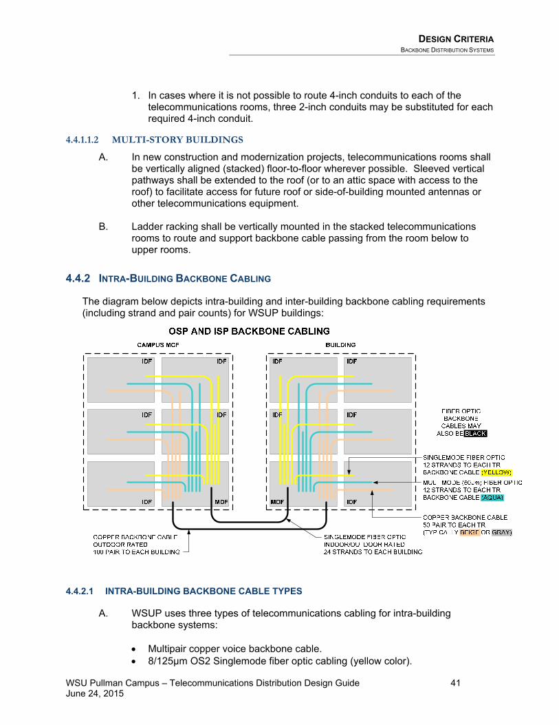
DESIGN CRITERIA BACKBONE DISTRIBUTION SYSTEMS
WSU Pullman Campus – Telecommunications Distribution Design Guide 41 June 24, 2015
1. In cases where it is not possible to route 4-inch conduits to each of the
telecommunications rooms, three 2-inch conduits may be substituted for each required 4-inch conduit.
4.4.1.1.2 MULTI-STORY BUILDINGS
A. In new construction and modernization projects, telecommunications rooms shall be vertically aligned (stacked) floor-to-floor wherever possible. Sleeved vertical pathways shall be extended to the roof (or to an attic space with access to the roof) to facilitate access for future roof or side-of-building mounted antennas or other telecommunications equipment.
B. Ladder racking shall be vertically mounted in the stacked telecommunications
rooms to route and support backbone cable passing from the room below to upper rooms.
4.4.2 INTRA-BUILDING BACKBONE CABLING
The diagram below depicts intra-building and inter-building backbone cabling requirements (including strand and pair counts) for WSUP buildings:
4.4.2.1 INTRA-BUILDING BACKBONE CABLE TYPES
A. WSUP uses three types of telecommunications cabling for intra-building backbone systems:
• Multipair copper voice backbone cable. • 8/125µm OS2 Singlemode fiber optic cabling (yellow color).

DESIGN CRITERIA BACKBONE DISTRIBUTION SYSTEMS
WSU Pullman Campus – Telecommunications Distribution Design Guide 42 June 24, 2015
• 50/125µm OM3 Multimode fiber optic cabling (aqua color). o 62.5/125µm OM1 is permitted only for additions to existing infrastructure
in a building. Do not mix multimode fiber optic cabling types in a building.
B. When a horizontal application requires 10GB communications, WSUP uses: • 8/125µm OM2 Singlemode fiber optic cabling (yellow color)
C. Splices are prohibited for backbone cabling.
4.4.2.2 STRAND AND PAIR COUNTS
A. The diagram above indicates the minimum standard provisions for all strand and pair counts. Each application should be increased above these counts if additional pairs or strands are required.
B. Backbone cable sizing (# of strands, # of pairs) shall be considered with respect to possible future requirements. The cost to add additional backbone pairs and strands during the initial installation is significantly less than the cost of adding another cable in the future. The Designer shall inquire whether 40GB or 100GB backbone bandwidths are required. These bandwidths require multiple strands for each circuit.
C. WSUP permits appropriate use of hybrid singlemode/multimode fiber optic
cabling, and allows both types of fiber to be terminated on separate bulkheads in a single fiber optic patch panel.
4.4.2.3 CABLE SEGREGATION
In no case shall copper or fiber optic backbone cabling be run in the same raceways as those used by electrical power conductors. However copper, fiber optic and other low-voltage cables are permitted to run together in shared raceways.
4.4.2.4 INNERDUCT FOR RISER APPLICATIONS
The Designer shall show on the Contract Documents where innerduct is required for routing inside plant fiber optic backbone cabling, in accordance with the following conditions:
• Innerduct is required for routing inside plant fiber optic backbone cabling through all vertical riser pathways (conduits and sleeves) that exceed 4 feet in length.
• Innerduct is also required for routing inside plant fiber optic backbone cabling through cable trays where larger outside plant cable shares the cable tray. This is a relatively rare circumstance.
• Otherwise, innerduct is not required for routing inside plant fiber optic backbone cabling. See Section 4.5.3.4.6 for innerduct requirements for horizontal and GPON applications. See Section 4.4.3.2.9 for innerduct requirements for outside plant fiber optic backbone cabling.

DESIGN CRITERIA BACKBONE DISTRIBUTION SYSTEMS
WSU Pullman Campus – Telecommunications Distribution Design Guide 43 June 24, 2015
4.4.3 INTER-BUILDING (CAMPUS) BACKBONE PATHWAYS
The Designer shall follow the guidelines in the BICSI TDMM and the BICSI OSPDRM when designing underground outside plant pathways.
4.4.3.1 EXISTING CONDITIONS AT THE PULLMAN CAMPUS
The existing conditions of the outside plant pathway infrastructure at the WSUP campus are not ideal. There is much shared use of underground tunnels by multiple different utilities, in some cases presenting circumstances that can be hostile, such as asbestos, steam and electrical power. • The WSUP ITPM shall designate the routing to be used for each outside plant cable that is
designed for a project. • The Designer shall receive training and certification from WSUP Facilities Services prior to
entering any underground spaces at the WSUP campus. Untrained, uncertified Designers shall not enter any underground spaces at the WSUP campus.
• Proper safety procedures and hardware shall be used when accessing any underground spaces.
• The ITPM and the Designer shall physically verify all OSP routes together prior to designing an OSP cable installation.
The outside plant pathway standard requirements described below are intended for application wherever circumstances will permit, and especially for new pathway installation. However, acknowledging that best-case conditions do not always exist, the WSUP ITPM will provide direction to the Designer on a case-by-case basis regarding the extent to which the design shall comply with the standard-practice requirements below.
4.4.3.2 DUCTBANK
The diagram below depicts the features of telecommunications ductbank, which are described in detail in the paragraphs that follow.

DESIGN CRITERIA BACKBONE DISTRIBUTION SYSTEMS
WSU Pullman Campus – Telecommunications Distribution Design Guide 44 June 24, 2015
4.4.3.2.1 CONDUIT TYPES
A. WSUP requires 4-inch Schedule 40 PVC for all outside plant pathway except ducts serving Blue Light Emergency Telephones, which shall be trade-size 1½ inch conduit.
B. OSP conduit shall transition from PVC to PVC-coated rigid steel conduit when it
enters within 10 feet of the building foundation, and shall route from that point to the building entrance facility. PVC-coated, rigid steel conduit is intended to defend against the shearing effects of differential ground settling around the building foundation. It also increases the protection against future landscaping activities near the building.
DESIGN CRITERIA BACKBONE DISTRIBUTION SYSTEMS
WSU Pullman Campus – Telecommunications Distribution Design Guide 45 June 24, 2015
• Transition back to PVC conduit after passing five feet inside the building foundation is acceptable as long as the conduit remains in or under the slab. Otherwise, it shall transition to rigid galvanized steel conduit.
• A maximum of fifty feet of outdoor-rated cable is permitted in a building
space. Therefore, rigid galvanized steel conduit shall be used to route the cable until it is close enough to its termination point that fifty feet or less of outdoor-rated cable (including slack loops) will be exposed.
C. The use of flexible metallic conduit and flexible non-metallic conduit is prohibited.
4.4.3.2.2 GROUND CONDUCTOR
A. A continuous ground conductor (#2 AWG) shall be installed running the length of each ductbank. The ground conductor shall be placed on the top row of conduits so that it will be detectable by underground utility locating equipment.
B. The ground conductor shall be bonded to other ground conductors from other ductbanks meeting at an underground maintenance hole or handhole.
C. The ground conductor shall be bonded to the main telecommunications
grounding busbar in the MDF or main entrance facility of the building.
4.4.3.2.3 BURIAL DEPTH AND SLOPE
A. The preferred ductbank depth is 36 inches to the top of the conduit. Where this is unattainable, a 30 inch depth is permitted. • Under no circumstances will ductbanks ever be permitted shallower than the
extent of the frost zone. In Pullman, the frost zone reaches 30 inches below the surface, according to the City of Pullman3.
B. Conduit to be used for routing entrance cables from third party service providers
to an entrance facility shall be installed per the service providers’ requirements, generally 36 to 48 inches deep. The Designer shall consult with the service providers prior to designing conduits serving an entrance facility.
C. A continuous drain slope should exist at all points along the ductbank to allow
drainage and prevent the accumulation of water.
• A drain slope of ¼ inch per foot is desirable where possible. • Where ¼ inch per foot is not possible due to inadequate natural slope or long
duct runs, a drain slope of no less than 1/8 inch per foot is acceptable. • If no other option exists, require the Contractor to provide a “center crown”
drain slope by sloping the first half of the ductbank up towards the midpoint, and then down from the midpoint to the end. Of course, the center crown technique cannot be used for conduits between a maintenance hole and a building, because water would then drain into the building.
3 http://www.pullman-wa.gov/city-of-pullman-statistics

DESIGN CRITERIA BACKBONE DISTRIBUTION SYSTEMS
WSU Pullman Campus – Telecommunications Distribution Design Guide 46 June 24, 2015
4.4.3.2.4 CONDUIT SWEEPS (BENDS)
A. WSUP has standardized on the use of factory-manufactured fiberglass sweeps with a minimum bend radius of 48 inches for all OSP ductbanks with the following exceptions and alternatives:
• Shallow curves comprised of continuous lengths of individual straight RNC
conduit are permissible with a minimum sweep radius of 40 feet. • Where cabling larger than 400-PR UTP copper is intended to be installed,
conduit bends shall have a radius larger than 48 inches. The Designer shall consult with the WSUP ITPM on a case-by-case basis to select appropriately-sized conduit sweeps.
B. The Designer shall minimize, where possible, the effects of sidewall pressure
between the cable and conduit at bend points, by designing bends with the tightest bend radii to be near the cable feed end of the duct section rather than the middle or end of the duct bank.
4.4.3.2.5 DUCTBANK ENCASEMENT
WSUP requires concrete encasement with full-length reinforcement and formed sides for all ductbanks except ducts serving Blue Light Emergency Telephones, which shall not be encased in concrete.
A. Prior to concrete being poured, the WSUP ITPM or a designated representative shall observe the OSP conduit installation to identify unacceptable installations that need to be corrected prior to concrete encasement.
B. In general, direct-buried conduit ductbanks are not permissible, unless
extenuating circumstances warrant and this is approved by WSUP through the SVR process. Should the use of direct-buried conduit ductbank be warranted, the Designer shall ensure that all bends in the ductbanks are encased in concrete.
C. Wherever cold-joints are required in concrete encasement, the design shall
require rebar spanning the joint between ductbank encasement segments.
4.4.3.2.6 NUMBER OF DUCTS
A. The OSP pathway system shall accommodate the requirements for signal and low-voltage cabling systems at WSUP facilities. The Designer shall inquire with the WSUP ITPM and FSPM about the potential for future buildings or building expansions that may adversely affect an existing or proposed distribution pathway, and accommodate those plans within the design.
B. The number of 4-inch conduits in a ductbank should be determined to meet the
needs of the specific application and should offer future expansion capability. The following list is a guideline for consideration when designing a new ductbank:

DESIGN CRITERIA BACKBONE DISTRIBUTION SYSTEMS
WSU Pullman Campus – Telecommunications Distribution Design Guide 47 June 24, 2015
• Small utility buildings up to 5,000 sq. ft.: 2 ducts (approvable on a case-by-case basis)
• Buildings up to 100,000 sq. ft.: 4 ducts • Buildings 100,000 sq. ft. to 300,000 sq. ft.: 6 ducts • Buildings larger than 300,000 sq. ft.: multiple redundant entrances with 6
ducts each • Buildings serving as a data center or a Main Communication Facility (MCF):
6 ducts
4.4.3.2.7 DUCTBANK LENGTH
A. In general, ductbank systems shall be designed with section lengths averaging 400 feet and as straight as possible.
B. The maximum permissible ductbank length (between maintenance holes and/or
buildings) is 600 ft. Ductbank runs that exceed this distance require intermediate maintenance holes or handholes. This requirement may be waived through the SVR process in rare cases having the following conditions:
• The ductbank run has no bends. • The Designer can demonstrate that the pulling tension of WSUP’s standard
OSP telecommunications cable types will not be exceeded during installation.
4.4.3.2.8 SEPARATION FROM OTHER UTILITIES
A. In general, ductbank used as pathway for telecommunications and other low-voltage cabling should not be routed with other utilities. Budgetary constraints, space limitations, and various obstructions can make this difficult to achieve at times. Should shared routing be a necessity (perhaps for overbuild construction projects), the Designer shall ensure that adequate separation exists between ducts used for telecommunications and ducts used for other utilities.
B. The pathway system shall be designed such that telecommunications and other
low-voltage systems do not share conduits, maintenance holes, or handholes with the electrical power distribution system. The telecommunications distribution pathway shall also maintain minimum separation distances from electrical power distribution infrastructure as required by WSUP.
C. Unfortunately, circumstances require some shared use of underground tunnels.
The vertical and horizontal separation requirements for OSP telecommunications pathways from other underground utility infrastructure are as follows:
4.4.3.2.8.1 Proximity to Power or Other Foreign Conduits
NESC requirements state that outside plant telecommunications conduits shall not be installed closer to power conduits or other unidentified underground conduits than: o 3 inches where the surrounding material is concrete o 4 inches where the surrounding material is masonry o 12 inches where the surrounding material is well-tamped earth

DESIGN CRITERIA BACKBONE DISTRIBUTION SYSTEMS
WSU Pullman Campus – Telecommunications Distribution Design Guide 48 June 24, 2015
The NESC requirements above are focused on safety issues, and the performance of telecommunications systems can be negatively affected by the presence of nearby sources of EMI, even though the NESC safety-related separation requirements are met. Where the Designer is concerned about EMI due to the proximity of power distribution infrastructure, the Designer shall discuss the issue with the WSUP ITPM.
4.4.3.2.8.2 Proximity to Water, Gas, or Oil Conduits
The proximity between outside plant telecommunications conduits and other non-power conduits shall not be closer than:
o 6 inches where the conduits cross o 12 inches where the conduits run parallel to each other
Telecommunications conduits running parallel to water, gas, or oil conduits shall not be installed vertically above the other conduits, but rather to the side of the conduits. This arrangement should contribute to decreased disruption to the telecommunications conduits in the event of excavation maintenance activities associated with the other nearby conduits.
4.4.3.2.8.3 Proximity to Steam Lines and Steam Utilidors
A. A minimum separation distance of 12 inches is required between a steam utilidor and telecommunications conduits.
B. Steam lines pose two primary risks to telecommunications cabling:
• Under steady state operating conditions, objects in the vicinity of steam lines
may become warm due to heat lost through the insulation of the steam line. As the temperature of telecommunications cabling increases, its performance can degrade. In situations where there is concern about the risk of exposure to steady state heat, the separation distance between the steam line and telecommunications infrastructure shall be increased.
• In the event of a steam line failure in the proximity of telecommunications
infrastructure, significant damage to the conduits and cabling can result from the high-temperature steam. In situations where there is concern about the risk of exposure to high temperatures from steam line failure events, the design shall require telecommunications conduits to be encased within an insulating sleeve in the vicinity of the risk.
C. High-temperature insulation may be necessary to protect telecommunications
conduits and cabling.
D. WSUP’s practice is to install steam lines in utilidors, rather than to direct-bury the steam lines. The utilidors are typically 3 to 4 feet high, and may be buried with 0 to 2 feet of surface cover. Therefore, the bottom of most utilidors on campus is typically somewhere between 3 and 6 feet deep.
E. The Designer shall field-investigate the actual utilidor routing to identify accurate
field conditions. Potholing to confirm record drawing information is typically required.

DESIGN CRITERIA BACKBONE DISTRIBUTION SYSTEMS
WSU Pullman Campus – Telecommunications Distribution Design Guide 49 June 24, 2015
F. Where physical conditions appear to preclude compliance with the following
requirements, an SVR shall be submitted demonstrating solutions for mitigating exposure to worst-case conditions, including steam line failure where steam vents in the direction of the telecommunications conduits.
4.4.3.2.8.3.1 Crossing Above Steam Utilidors
A. Due to the requirement to bury conduit beneath the frost line, a cover depth of 50 inches is required for a topside conduit crossing. Unless a utilidor has at least this much topside cover, it will not be possible to install a single-level conduit ductbank over the top of the utilidor while maintaining a 12 inch separation from the top of the utilidor and while keeping the conduit below the frost line.
• It is unlikely that a circumstance permitting a topside crossing will occur at
WSUP.
B. Telecommunications ductbanks shall not cross over the top of a steam utilidor in a live load area where vehicle traffic passes without the review of a Civil Engineer.
4.4.3.2.8.3.2 Crossing Beneath Steam Utilidors
A. Most commonly, where telecommunications conduits must cross a steam utilidor, the conduits must cross underneath the utilidor. Care shall be taken to avoid creating a dip in the conduit at this point where water will collect – the conduit slope shall be designed to permit any water entering the conduits to drain out. The following diagram depicts this concept:
B. The Designer shall design a utilidor crossing similar to the pre-approved solution shown in the diagram above, or some other solution that accomplishes a utilidor crossing without trapped water and without risking cable damage due to nearby steam heat. The Designer shall include details of any steam utilidor crossings in the Construction Documents.

DESIGN CRITERIA BACKBONE DISTRIBUTION SYSTEMS
WSU Pullman Campus – Telecommunications Distribution Design Guide 50 June 24, 2015
4.4.3.2.8.3.3 Direct Buried Steam Lines
A. If it becomes necessary to install telecommunications conduits in the vicinity of direct-buried steam lines, the following requirements apply:
• Telecommunications conduits shall not be installed closer than 12 inches to
steam lines, and shall cross perpendicular to the steam lines. • Direct-buried steam lines within 12 to 24 inches of telecommunications
conduits shall be encased within an insulated pipe sleeve surrounding the steam line. The sleeve shall be constructed from a material designed to withstand steam temperatures and protect against physical/mechanical damage from jets of steam. The insulated sleeve shall extend at least 5 feet on both sides of the crossing point of the telecommunications conduits.
4.4.3.2.9 INNERDUCT FOR OUTSIDE PLANT APPLICATIONS
The Designer shall show on the Contract Documents where innerduct is required for routing outside plant fiber optic backbone cabling, in accordance with the following conditions:
• Innerduct is required for routing outside plant fiber optic backbone cabling through all conduits (ductbank) and sleeves that exceed 4 feet in length.
• Innerduct is not required for routing outside plant fiber optic backbone cabling through underground tunnels.
• Innerduct is not required for routing outside plant fiber optic backbone cabling after it leaves an entrance conduit and terminates on a patch panel (within the 50-foot rule).
See Section 4.5.3.4.6 for innerduct requirements for horizontal and GPON applications. See Section 4.4.2.4 for innerduct requirements for inside plant fiber optic backbone cabling.
4.4.3.2.10 COORDINATION WITH UTILITY SERVICE PROVIDERS
The Designer shall inquire with the WSUP ITPM to determine whether services from utility service providers will be necessary. If so, the Designer shall contact the utilities to obtain their entrance pathway, entrance facility, and demarcation point requirements.
4.4.3.3 MAINTENANCE HOLES AND HANDHOLES
A. Typically, maintenance holes are installed for main ductbanks (i.e., ductbanks used for routing large portions of the telecommunications system backbone), and handholes/pullholes are installed for subsidiary ductbanks (i.e., ductbanks serving a single small building).
B. Maintenance holes and their covers shall be appropriately sized for the
application.
• Covers for maintenance holes and handholes shall be either lockable or use bolts to prevent unauthorized access.
• Diamond plate hinged covers and removable diamond plate covers are not

DESIGN CRITERIA BACKBONE DISTRIBUTION SYSTEMS
WSU Pullman Campus – Telecommunications Distribution Design Guide 51 June 24, 2015
permitted for maintenance holes at WSUP.
C. Telecommunications maintenance holes and handholes shall not be shared with electrical power distribution infrastructure. In general, powered devices should not be located in telecommunications maintenance holes and handholes.
D. The number of duct entrances in a maintenance hole or handhole should be
sized for both immediate and future requirements. Also, splayed duct entrance arrangements are preferred over center entrances.
• It is desirable to have ducts enter and exit from opposite ends of a
maintenance hole or handhole. Sidewall duct entrances should be avoided because such entrances may obstruct racking space, cause cable bends to exceed limits, interfere with cable maintenance activities, and increase construction costs during cable installation.
• WSUP recognizes that sidewall duct entry may be necessary or desirable in
some circumstances. In these cases, sidewall ducts shall enter and exit at diagonally opposite corners – ducts shall not enter and exit at the midpoints of the endwalls or sidewalls. The Designer shall ensure that endwall and sidewall duct entry in a maintenance hole or handhole will not hinder access to the maintenance hole, or to the proper installation and maintenance of cabling.
E. Ducts shall be designed to enter the maintenance holes and handholes starting
at the lowest conduit knockouts and moving upward, preserving remaining knockouts accessible for future conduit additions. The Designer shall design the duct entrances such that the relative position of each duct does not change as it enters and exits the maintenance hole or handhole. Also, the Designer shall endeavor to design ductbank arrangements so that the conduits enter and exit a sequence of maintenance holes or handholes in the same relative positions.
F. Splices in backbone fiber optic cable are not allowed, and while splices in
backbone copper cable may be permitted in some rare cases (through an approved ADR), they are discouraged. However, when sizing OSP telecommunications maintenance holes, the design shall require the Contractor to provide space for possible future splice closures when required (for example, to repair cable breaks).
G. Some situations may require placement of maintenance holes at below-typical
depths. In such cases, the top of the maintenance hole shall be placed at normal depth, and the height of maintenance hole shall be increased through the use of intermediate riser extensions between the base and the top. WSUP wishes to avoid deep-collar entrance portals wherever possible, to improve lighting and ventilation.

DESIGN CRITERIA BACKBONE DISTRIBUTION SYSTEMS
WSU Pullman Campus – Telecommunications Distribution Design Guide 52 June 24, 2015
4.4.3.4 AERIAL DISTRIBUTION
Aerial distribution of telecommunications cabling at WSUP facilities is not authorized. If an application requires aerial distribution, permission to use this method shall be requested through the SVR process.
4.4.3.5 BRIDGE AND WATERWAY CROSSINGS
A Civil Engineer shall review the construction of bridge and waterway crossing distribution systems. The design and installation shall also be reviewed by the WSUP ITPM.
4.4.3.6 WIRELESS AND RADIO SYSTEM DISTRIBUTION
A. WSUP facilities use wireless or radio systems for telecommunications with mobile units and personnel, both on and off campus. These systems typically use one or more radio antennas connected by cabling to radio transceiver equipment. In some cases, the radio equipment may be interfaced into the telephone system. The outside plant telecommunications substructure shall be designed with adequate cable routing pathways between antenna locations, radio transceiver locations, and the telephone backbone cabling system.
B. Radio antenna transmission cables that connect the antenna to the radio
transceiver emit radio frequency (RF) radiation. These cables may be routed through the common telecommunications ductbank and maintenance hole system if necessary, but shall be routed in a separate conduit from non-fiber optic telecommunications cables. Cables containing RF radiation shall be shielded cables.
C. Radio interconnection cables (for analog or digital signaling to remote radio
operating positions or to the telephone system) typically emit low levels of radio frequency radiation. These interconnection cables shall be routed through the common telecommunications ductbank and maintenance hole system. Individual conduits may be shared for these interconnection cables and other telecommunications services, and available cable pairs in telephone backbone cables may be used for these interconnections, provided that the signaling is analog or digital signaling, and is not direct radio frequency signal.
D. The Designer shall inquire with the WSUP FSPM whether a building will require rooftop satellite, wireless or radio systems. These systems typically use one or more radio antennas connected by cabling to radio transceiver equipment. If rooftop applications are required, pathways shall be designed from rooftop locations down to the nearest telecommunications room to serve these applications.
4.4.4 CAMPUS CABLING
When OSP cabling is required, the Designer shall follow the guidelines in the BICSI TDMM and the BICSI OSPDRM.
DESIGN CRITERIA HORIZONTAL DISTRIBUTION SYSTEMS
WSU Pullman Campus – Telecommunications Distribution Design Guide 53 June 24, 2015
A. The design shall require that a slack loop be installed inside the nearest maintenance hole or handhole (not stored in the TR). The Designer shall require that sufficient racking hardware be provided in the maintenance hole or handhole to support the slack loop.
B. The length of the loop shall be a minimum of 25 feet. The Designer shall consider the arrangement of the telecommunications room and the possibility of a rearrangement that might consume the cable slack. If necessary, additional slack shall be required in the design, up to the NEC limit of 50 feet of exposed OSP-rated cabling.
4.4.4.1 UTILITY SERVICES
At WSUP, telephone services, cable television services and Internet services are typically provided via campus infrastructure. The Designer shall request from the WSUP ITPM information about any needed telecommunications infrastructure to support the required services. The Designer shall also request similar information from the WSUP FSPM for requirements to support non-WSUP tenants of the building.
4.4.4.2 WIRELESS AND RADIO SYSTEM DISTRIBUTION
A. Outdoor-rated backbone cabling shall be designed to serve rooftop satellite, wireless, or other radio system applications. Lightning protection equipment shall also be designed as appropriate.
B. Radio antenna transmission cables that connect the antenna to the radio
transceiver emit radio frequency (RF) radiation. These cables may be routed in a separate conduit from other telecommunications cables. Cables containing RF radiation shall be shielded cables.
4.5 Horizontal Distribution Systems Please refer to Chapter 5, Horizontal Distribution Systems in the BICSI TDMM for general information regarding the design of horizontal distribution pathway and cabling. The following requirements take precedence over the BICSI TDMM guidelines for telecommunications infrastructure at WSUP facilities:
4.5.1 DEVICE BOX CONSIDERATIONS
A. Device boxes intended for use with low-voltage cabling (telecommunications, CATV, etc.) shall not host electrical power receptacles or power wiring. “Combo boxes” (divided, multi-gang device boxes for power and data behind a single faceplate) are not permitted.
B. Device boxes shall not be mounted in the floor (i.e. “floor boxes”) except where
no suitable alternative exists. If device boxes must be mounted in the floor, each device box shall be served with its own individual conduit – floor boxes shall not be “daisy-chained” together.
DESIGN CRITERIA HORIZONTAL DISTRIBUTION SYSTEMS
WSU Pullman Campus – Telecommunications Distribution Design Guide 54 June 24, 2015
• Power outlets may be combined with CATV and telecommunications cabling in floor boxes if the power wiring is routed to the floor boxes separately from the other cable media, and if the floor box provides for metallic barrier segregation of the power and telecommunications cabling within the box.
C. Within the limitations of the project budget, the provision of spare outlets and
spare jacks in a work area is encouraged, to provide flexibility for future needs.
D. Both telecommunications cabling and CATV coaxial cabling are permitted to be terminated in a shared device box.
E. Device boxes for telecommunications outlets shall be mounted at the same
height as the electrical power receptacles.
4.5.1.1 FOR NEW CONSTRUCTION AND FULL REMODEL
A. A device box shall be provided for each telecommunications outlet. Device boxes shall be 4”x4”x3-½” (where 2-¼” is the depth of the box and 1-¼” is the depth of the extension ring, with an overall depth of 3-½”). Device boxes shall be recess-mounted.
• WSUP requires double-gang faceplates for all telecommunications outlets.
B. Surface-mounted device boxes are not acceptable. However, for concrete
masonry unit (CMU) walls or other wall types that may obstruct cable or conduit installation, the Designer shall request direction from the WSUP ITPM on a case-by-case basis.
4.5.1.2 FOR OTHER PROJECTS
A. Existing device boxes and conduits shall be reused where they are standards-compliant or where it can be verified that the existing conduits and boxes will permit telecommunications cabling to be installed without negatively affecting the performance of the cabling. The bend radius of the cabling inside each box shall be considered carefully when evaluating existing boxes. For concealed conduits that cannot be verified, the Designer shall assist the WSUP ITPM to consider conduit length, number of bends and cable fill percentage, then decide on a case-by-case basis whether they are suitable for reuse.
B. A device box shall be provided for each telecommunications outlet. Device
boxes shall be recess-mounted wherever possible and shall be 4”x4” and at least 2-½” deep (a 3-½” depth is preferable). Surface-mounted device boxes (if required) shall be standard double gang (4” x 4”) and at least 2-½” deep.
C. Where cabling can be fished through interstitial wall spaces, it is typically
permissible to use faceplate mounting brackets in lieu of device boxes.

DESIGN CRITERIA HORIZONTAL DISTRIBUTION SYSTEMS
WSU Pullman Campus – Telecommunications Distribution Design Guide 55 June 24, 2015
4.5.2 HORIZONTAL PATHWAY SYSTEMS
The process of selecting the type of pathway that would be appropriate for a particular project shall be a cooperative effort involving the Designer and the WSUP ITPM.
4.5.2.1 GENERAL PATHWAY DESIGN CONSIDERATIONS
A. All cables shall be fully supported and properly transitioned throughout the length of the cables, including proper bend radius fittings at pathway transitions. Where cabling is routed vertically, it shall be appropriately secured such that the weight of the cabling does not subject the cabling to stresses that could potentially reduce the performance of the cabling.
B. The Designer shall discuss pathway type and size options with the WSUP ITPM.
1. The Designer shall discuss the relative merits of the pathway options
available and shall assist the WSUP ITPM and the project design team to select the most appropriate pathway solution for the project.
2. The future growth anticipated for the facilities affected by the project shall be discussed. Horizontal feeder pathways (cable trays, conduits from TRs to distribution junction boxes) shall be sized to support the initial cabling installation plus a minimum of 25% growth.
3. For new construction and full remodel projects, J-hook pathways are not permitted. For other projects, J-hook pathways shall be sized to support 100% additional cables after the original cabling installation. In other words, the pathway shall be no more than 50% full after installation is completed.
C. Spare pathway shall be designed to terminate at building perimeters where future
expansion of the building is anticipated.
D. When considering the design of a ceiling-located cable tray or J-hook pathway, the Designer shall verify that the pathway locations will comply with accessibility and clearance requirements. Cable tray and J-hook pathways routed through ceiling spaces shall be designed such that all installed cable is conveniently accessible after construction, both for cable maintenance and to install subsequent cable additions. J-hooks shall be installed at approximate intervals of 4 to 5 feet. Conduit shall be used to span inaccessible areas where the pathway will cross “hard-lid” ceilings, where ceiling tiles are not readily removable, or where accessibility is impeded.
E. Pathway routing shall remain on the same floor as the telecommunications room
and telecommunications outlets served by the pathways. Where project-specific conditions exist that justify other routing, the Designer shall request WSUP approval through the SVR process.
F. “Poke-thru” penetrations to the ceiling space of the floor below are normally not
permitted. For minor remodel construction, poke-thru penetrations may be allowed given budgetary, project size, or other limiting factors. Permission to use poke-thru pathways in any circumstance requires an SVR on a project-by-project basis, and always requires the services of a structural engineer to avoid

DESIGN CRITERIA HORIZONTAL DISTRIBUTION SYSTEMS
WSU Pullman Campus – Telecommunications Distribution Design Guide 56 June 24, 2015
irreparable structural damage.
G. All wall and floor penetrations for cabling shall be fully sleeved with bushings, and protected in accordance with the requirements in the International Building Code.
H. For on-grade slab construction, telecommunications conduits shall not be routed
in or under the slab (a designated wet environment) unless no other options exist.
• Floor boxes under conference tables in Conference Rooms and under instructor podiums in Classrooms are granted exception to this requirement.
• In any application (including Conference Rooms and Classrooms) where telecommunications conduit passes in or under an on-grade slab, outdoor-rated cabling shall be provided.
4.5.2.2 PATHWAYS FOR NEW CONSTRUCTION AND MODERNIZATION PROJECTS
A. Where ceiling spaces will be inaccessible after construction, the only permitted pathway option is conduit. J-hook pathway systems, cable tray, and wire basket are not permitted if ceiling spaces will be difficult to access after construction.
B. Surface raceways and surface-mounted device boxes are not permitted.
4.5.2.3 PATHWAYS FOR MINOR REMODEL AND TELECOMMUNICATIONS-ONLY PROJECTS
A. For minor remodel construction, there may not be an existing (or suitable space for a new) telecommunications room available on the same floor as an outlet. While pathways shall generally be designed from the device box serving the telecommunications outlet to the nearest telecommunications room on the same floor as the outlet, this requirement may be waived at the discretion of the WSUP ITPM.
B. Existing pathways shall be reused where existing raceway is standards-
compliant, or where it can be verified that the existing pathway will permit telecommunications cabling to be installed without negatively affecting the performance of the cabling. Where a pathway is concealed or cannot otherwise be verified, the Designer shall request direction from the WSUP ITPM on a case-by-case basis.
C. Where existing pathways cannot be reused, or where additional pathways are
required:
1. J-hook pathway may be used. D-ring and bridal-ring pathways are not permitted. J-hook pathways shall be established through concealed spaces. J-hook pathways shall be sized for a minimum of 100% expansion. In other words, the pathway shall be no more than 50% full after installation is completed.
DESIGN CRITERIA HORIZONTAL DISTRIBUTION SYSTEMS
WSU Pullman Campus – Telecommunications Distribution Design Guide 57 June 24, 2015
2. When 40 or more cables are designed to be routed through an area, the use of cable tray or conduit shall be considered in lieu of J-hooks.
D. It may be permissible to use faceplate mounting brackets in lieu of device boxes.
In these cases, cabling is routed to the outlet location through interstitial wall spaces. WSUP permission for this method is required on a project-by-project basis.
4.5.2.4 CABLE TRAY PATHWAY SYSTEMS
A. In general, cable tray systems shall be located in corridor or office throughway spaces, and shall not be installed above office or classroom space. Distances from EMI/RFI sources shall be maintained according to Section 4.2, Electromagnetic Compatibility (above), regardless of whether the raceway is routing copper- or fiber optic based media.
B. From a technology perspective, WSUP ITS does not have a preference for any
particular style of cable tray (solid bottom, open rungs, welded wire, etc.) so long as the cable tray performs reliably. Cable tray style shall be determined by the Designer in coordination with the Architect to ensure that the selected tray contributes to the aesthetic appearance of the building while meeting the budgetary parameters of the project.
• Steel cable tray is preferred over aluminum because aluminum is much
easier to dent and deform, either inadvertently or through careless handling during construction.
• Where the Architect wishes to have the cable tray painted to blend in with its surroundings, the Designer shall add cautionary notes to the Contract Documents prohibiting the painting of telecommunications cabling which could void the manufacturer’s warranty.
• Where solid-bottom tray is specified, the bottom shall have openings at strategic locations (not inside telecommunications rooms) to allow water to drain out. Otherwise, solid-bottom tray may channel water from leaks, condensation, or fire suppression into telecommunications rooms.
C. Wall mounting is preferred for cable tray because it provides unrestricted access
to the side of the cable tray. • Where wall mounting is not practical, use trapeze-style hangers.
D. The Designer shall coordinate the selection of the cable tray materials with the
design intent of the Architect or interior designer and the ITPM.
E. Telecommunications cable trays shall not be shared with power cables.
F. Conduit used to route cabling from the cable tray to the work area outlet shall be sized a minimum of 1 inch.
G. Ladder racking shall be used only in telecommunications rooms. It shall not be
used anywhere else.

DESIGN CRITERIA HORIZONTAL DISTRIBUTION SYSTEMS
WSU Pullman Campus – Telecommunications Distribution Design Guide 58 June 24, 2015
H. Spine-style tray is not acceptable. I. Wherever possible, WSUP prefers that cable trays be routed through non-
plenum spaces, even through plenum-rated cable is always required.
4.5.2.5 CONDUIT AND JUNCTION BOX PATHWAY SYSTEMS
A. Conduits both in and under the ground floor slab are considered “wet locations” where indoor-rated cabling is not permitted. Therefore, conduit serving the main floors of such buildings shall be routed in walls and ceilings – not in or under the slab. Intra-building and horizontal pathways shall only be installed in “dry” locations where indoor cabling can be protected from humidity levels and condensation that are beyond the intended range of indoor-only rated cable. • Floor boxes in an on-grade slab are the only permissible exception. This
application also requires outdoor-rated Category 6 cabling.
B. Where conduit runs terminate at cable trays, the conduits shall be arranged in an organized, uniform manner to facilitate an orderly cable transition from conduit to cable tray. Conduits shall terminate within a range of 3 inches to 18 inches of the cable tray.
C. Where conduit runs terminate in telecommunications rooms, the conduits shall
be arranged in an organized, uniform manner to facilitate an orderly cable transition from conduit to ladder rack.
D. Non-metallic conduit and metallic flex conduit shall not be used for horizontal
pathways, unless the WSUP ITPM has granted advance approval for its use.
E. Conduits shall not be filled beyond 40%. The Designer shall verify the outer diameter of the cabling for a project at the time of the design, to determine the maximum number of cables that can be placed inside a conduit without exceeding the 40% fill limitation.
F. In new construction, all work area outlets shall have a minimum 1-inch conduit routing from the device box to an accessible cable pulling location. The conduit size shall be increased as necessary for the quantity of cables to be installed. Where new conduit is installed in existing buildings, the Designer shall notify WSUP when existing conditions prevent the use of 1 inch trade size conduit as a minimum conduit size.
G. Device boxes shall not be “daisy-chained.” Each device box shall be complete
with its own dedicated conduit to the nearest distribution point/pathway.
H. Junction boxes and pull boxes shall be oriented for access doors to open from the area where the cable installer will normally work. For ceiling-mounted boxes, this is typically from the bottom (floor) side of the box.
I. Ceiling access to junction boxes and pull boxes shall be designed to allow full
access to the door, adequate working room for installation personnel, and proper

DESIGN CRITERIA HORIZONTAL DISTRIBUTION SYSTEMS
WSU Pullman Campus – Telecommunications Distribution Design Guide 59 June 24, 2015
looping of the cable during installation.
J. Junction boxes and pull boxes shall be located in spaces that are easily accessible during normal working hours, such as hallways and common areas. Junction boxes and pull boxes shall not be located in conference rooms or offices unless there is an overriding design reason for doing so, dependent upon approval from WSUP.
4.5.2.6 SURFACE RACEWAY
A. Surface raceway may be permissible in areas where no suitable alternatives exist. Surface raceway shall conform to bend radius requirements for the cable type being installed.
B. Surface raceway may be either plastic or metal.
4.5.2.7 UNDERFLOOR DUCT SYSTEMS
A. The design of new underfloor duct systems is discouraged. Some existing buildings have existing underfloor duct systems, and as long as the existing ducts are suitable for use with new cabling, it is permitted.
4.5.2.8 ACCESS FLOORS
A. Data Centers typically require access flooring.
B. While some open office circumstances may require access flooring, it may be more expensive than other pathway options. When considering solutions to provide cabling in open office situations, the Designer shall consider other solutions (such as floor boxes) ahead of an access flooring solution.
4.5.3 HORIZONTAL CABLING SYSTEMS
4.5.3.1 GENERAL
A. The Designer shall work with the WSUP FSPM and the WSUP ITPM to identify and understand the needs and requirements for the facility on a project-by-project basis. This includes understanding the expected future uses of the facility. The Designer shall design the horizontal cabling accordingly.
B. The Designer shall inquire with the WSUP ITPM at the start of each project to
determine whether a traditional (Category 6) telecommunications infrastructure shall be designed or whether a GPON solution shall be designed.
C. Telecommunications infrastructure designs and specifications shall be based
upon products from the required manufacturers, as defined in TDDG Section 1.5 Required Manufacturers (above).
D. Regardless of the plenum rating of the space through which horizontal cable
DESIGN CRITERIA HORIZONTAL DISTRIBUTION SYSTEMS
WSU Pullman Campus – Telecommunications Distribution Design Guide 60 June 24, 2015
passes, WSUP requires plenum-rated cabling everywhere on campus.
E. In addition to the manufacturers listed above, WSUP has selected several manufacturers of products for telecommunications cabling systems (cable, connectors, termination blocks, patch panels, etc.) and telecommunications distribution hardware (racks, cable tray, enclosures, etc.). The Designer shall incorporate only these manufacturers into the design, and shall design a telecommunications distribution system that will be suitable for the use of products from these manufacturers.
F. Splitting of wire pairs degrades the performance of the cable pairs and voids the
manufacturer’s warranty.
1. Under no circumstances shall cable pairs be split or removed from the back of a modular jack or patch panel. All four pairs of each horizontal distribution cable must be terminated to a single 8-position, 8-conductor jack.
G. Whenever moves, adds, and changes (MAC) are made to existing systems, the
new cabling shall follow the routes of existing established telecommunications cabling pathways.
4.5.3.2 TOPOLOGY
WSUP has standardized on the star topology for all horizontal cabling, with some exceptions for certain building automation systems that require or benefit greatly from ring or other topologies.
4.5.3.3 TRADITIONAL HORIZONTAL CABLING SOLUTION
4.5.3.3.1 HORIZONTAL CABLE TO SUPPORT DATA APPLICATIONS
A. At WSUP facilities, horizontal distribution copper cable and components for data applications shall be rated for and installed in compliance with the IEEE 802.3ab 1000Base-T Gigabit Ethernet standard. WSUP requires 4-pair, 100-ohm, 24 AWG, unshielded twisted-pair (UTP) copper Category 6-rated cabling for all horizontal cabling applications. There are only two exceptions to this is as follows:
• Some audio/visual applications require Category 6A cabling for HDMI
extension and HDBaseT. • Where isolated applications require 10GB network bandwidth, use
singlemode fiber optic cabling to a 10GB network switch and Category 6A patch cords from the switch to each device in the 10GB network, as depicted in the diagram below:

DESIGN CRITERIA HORIZONTAL DISTRIBUTION SYSTEMS
WSU Pullman Campus – Telecommunications Distribution Design Guide 61 June 24, 2015
10GB APPLICATION
SINGLEMODE FIBER OPTIC INTER-BUILDING CABLE
MDF
IDF WORKSTATION
MDF
MAIN COMMUNICATION FACILTY (MCF)
BUILDING
PATCH PANEL
PATCH PANEL
10G SWITCH
10GB
10GB
10GB
10GB
FIBEROUTLET
SINGLEMODE FIBER OPTIC BACKBONE CABLE(YELLOW)
SINGLEMODE FIBER OPTIC HORIZONTAL CABLE (YELLOW)
NETWORKED DEVICES
PATCH PANEL
10G SWITCH
CAT6APATCHCORD
SINGLEMODEFIBER OPTICPATCH CORD
B. Horizontal cables shall be terminated at the work area end and patch panel end with modular jacks. 1. WSUP has no color preference for horizontal cabling. 2. Regardless of the faceplate color selected by the Architect or interior
designer, Category 6 cables shall always be terminated with an Almond-colored jack. This is intended to differentiate the cable type from Category 5 cables (Gray) and Category 3 cables (Black).
C. In existing buildings, where additions are made to an existing Category 5 or 5e
installation, only Category 6 cabling shall be added. Under no circumstances shall any new cabling and termination hardware be installed that is rated less than Category 6.
4.5.3.3.1.1 Innerduct for Horizontal Fiber Optic Applications
A. The Designer shall show on the Contract Documents where innerduct is required for routing horizontal fiber optic cabling (typically a 10GB application), in accordance with the following conditions:
• Innerduct is required for routing horizontal fiber optic cabling through non-
horizontal pathways (such as riser conduits and sleeves) that exceed 4 feet in length, and which will be shared with non-horizontal cabling.
• Otherwise, innerduct is not required for routing horizontal fiber optic cabling.
B. See Section 4.4.2.4 for innerduct requirements for inside plant fiber optic backbone cabling.
C. See Section 4.4.3.2.9 for innerduct requirements for outside plant fiber optic
backbone cabling.
D. See Section 4.5.3.4.6 for innerduct requirements for GPON fiber optic cabling.

DESIGN CRITERIA HORIZONTAL DISTRIBUTION SYSTEMS
WSU Pullman Campus – Telecommunications Distribution Design Guide 62 June 24, 2015
4.5.3.3.2 HORIZONTAL CABLE TO SUPPORT VOICE APPLICATIONS
A. WSUP uses VOIP for all new voice applications. Therefore, horizontal distribution cable intended to support voice services shall be the same Category 6 cable that is used for data applications. This cabling shall meet the same performance and test requirements as cabling intended for data applications.
B. In existing buildings where Category 3 cabling currently serves voice applications
for non-VOIP telephone systems, Category 6 cable shall be used when new voice cabling is installed. WSUP is in the process of converting all of its telephone systems to VOIP. Therefore, it is prudent to install Category 6 cabling even if analog telephones are being used.
4.5.3.3.3 LOW-VOLTAGE AND BUILDING AUTOMATION SYSTEMS
A. During planning for intra-building telecommunications cabling installations, the Designer shall identify options for supporting power-limited (low-voltage) and building automation systems with the common structured cabling system, and present the options to WSUP for consideration. These options shall comply with ANSI/TIA/EIA 862 – Building Automation Systems Cabling Standard for Commercial Buildings.
B. By providing a common cabling distribution system for the various building
automation systems, it may be possible to reduce construction costs and operational costs while creating an intelligent building that can contribute many other benefits (see TDMM Chapter 16 Building Automation Systems for further information). Low-voltage systems that are capable of using a common structured cabling system (either backbone or horizontal cabling) shall be designed to use telecommunications cable and termination hardware wherever possible.
C. The Designer shall request from WSUP a list of systems that will require
telecommunications outlets for operations. The Designer shall then include horizontal cabling in the design as necessary to meet the listed requirements.
D. Some low-voltage and building automation equipment benefits from installing a
connector directly onto the horizontal cable without first terminating it in a jack.
• One significant uniqueness for Category 6 telecommunications cabling intended for use with permanently mounted equipment is detailed in the new standard ANSI/BICSI D005 - Electronic Safety and Security (ESS) Information Technology System (ITS) Design and Implementation Best Practices.
o This standard permits Category 6 cabling to be terminated on the device end of the cable using a connector (as opposed to a jack), allowing the horizontal cable to plug straight into the device.
o The Category 6 horizontal cable does not need to terminate in a faceplate-mounted jack.
o The Designer shall inquire with the WSUP ITPM before applying this solution.
DESIGN CRITERIA HORIZONTAL DISTRIBUTION SYSTEMS
WSU Pullman Campus – Telecommunications Distribution Design Guide 63 June 24, 2015
E. Other low voltage and building automation equipment uses terminals that require the cable to be terminated directly onto the equipment without using a modular jack. There is no method of testing a cable in this configuration.
• This application is not standards-compliant, and is unlikely to be approved by
the ITPM. • In most cases, it is possible to terminate the horizontal cable in a standard
outlet inside a panel, field-manufacture a half-patch cord to plug into the outlet, and then terminate the raw end of the half-patch cord directly onto the terminals of the equipment.
4.5.3.3.4 HORIZONTAL CROSS-CONNECT (HC)
WSUP has standardized on patch panels for terminating all copper horizontal telecommunications media, regardless of the intended use of the horizontal cabling, including cabling that will be used for voice, data, video, or building automation systems. There is no preference for angled or flat patch panels, other than a compelling requirement to support increased cable density through the use of angled patch panels. For existing applications, the Designer shall match existing patch panels.
4.5.3.4 GPON HORIZONTAL CABLING SOLUTION
WSUP is currently pilot-testing several GPON architectures in different building types on campus. It is anticipated that upon completion of the pilot testing, WSUP will have operational experience with these architecture options to determine which styles perform best for each building type.
4.5.3.4.1 GPON ARCHITECTURE
A. WSUP has not yet determined guidelines for selecting the GPON architecture for a given building type or application. • Generally speaking, it is desirable to locate the splitters close to the
workstation to increase the flexibility and scalability of the system over time.
4.5.3.4.2 ACADEMIC AND ADMINISTRATIVE BUILDINGS
A. The Designer shall inquire with the WSUP ITPM to get instructions regarding the number of ONT ports to allocate to each office, workstation, and other applications.
B. See the AVDG for instructions regarding the number of ONT ports to allocate to audio/visual applications, such as the instructor podiums in classrooms and the audio/visual equipment racks in conference rooms.
4.5.3.4.3 RESIDENCE HALLS
A. The telecommunications infrastructure for all residence halls shall be designed as GPON systems, and shall include television distribution via GPON.
B. The Designer shall inquire with the Director of WSUP Housing and Dining to get instructions regarding the number of ONT ports to allocate to each person, room, or apartment space in each residence hall.
DESIGN CRITERIA HORIZONTAL DISTRIBUTION SYSTEMS
WSU Pullman Campus – Telecommunications Distribution Design Guide 64 June 24, 2015
4.5.3.4.4 OUTLETS
A. All GPON outlets, regardless of application, shall be designed with a single strand of singlemode fiber optic cabling, and shall use factory-terminated cables.
4.5.3.4.5 CABLE TRAYS
A. GPON solutions typically require less cable tray capacity than traditional systems. When GPON is being designed for a new facility, the Designer shall design cable trays that are appropriately sized for GPON (smaller than traditional).
4.5.3.4.6 INNERDUCT FOR GPON APPLICATIONS
A. The Designer shall show on the Contract Documents where innerduct is required for routing GPON fiber optic cabling, in accordance with the following conditions:
• Innerduct is required for routing GPON fiber optic cabling through non-
horizontal pathways (such as riser conduits and sleeves) that exceed 4 feet in length, and which will be shared with non-GPON cabling.
• Otherwise, innerduct is not required for routing GPON fiber optic cabling.
B. See Section 4.4.2.4 for innerduct requirements for inside plant fiber optic backbone cabling.
C. See Section 4.4.3.2.9 for innerduct requirements for outside plant fiber optic
backbone cabling.
4.5.3.4.7 ONT INSTALLATION
A. WSUP requires that the Contractor furnish, install, and power-up the ONT devices at each workstation, and also verify that the data link light is active. The Contractor shall also be required to provide a spreadsheet report that correlates the ONT’s FSAN identifier with the outlet number, room name, and room number.
• The Designer shall include this requirement in the Contract Documents.
B. WSUP will configure the ONT devices after the Contractor has established successful operation of each ONT.
4.5.3.4.8 SPECIAL APPLICATIONS
A. Where multiple devices share an ONT, an outlet shall be provided in the ceiling near the zone where the devices are located. Some of the devices sharing the ONT may require a conduit in the wall and a box at standard mounting height for copper patch cords to route down from the ONT in the ceiling.
B. For WAP applications, the Designer shall inquire with the ITPM which of the
following two permissible solutions to design:
• One outlet and one ONT per WAP, mounted in a ceiling location near the WAP.
• One outlet and one ONT serving multiple WAPs in a zone.

DESIGN CRITERIA HORIZONTAL DISTRIBUTION SYSTEMS
WSU Pullman Campus – Telecommunications Distribution Design Guide 65 June 24, 2015
C. For the analog telephone applications supporting life-safety systems, provide a Category 6 cable from the nearest telecommunications room. Do not use GPON for the following: • Courtesy phone • Elevator phone
D. For all other analog telephone applications, including fax machines, use a nearby
GPON ONT to obtain a POTS connection.
4.5.3.4.9 TELECOMMUNICATIONS ROOM SIZING FOR GPON APPLICATIONS
A. For buildings being designed with GPON solutions, the main telecommunications room (MDF) shall be sized the same as buildings with traditional telecommunications infrastructure.
B. WSUP has not yet determined guidelines for sizing secondary telecommunications rooms (IDFs) in buildings being designed with GPON solutions. The Designer shall inquire with the WSUP ITPM to determine the IDF sizing strategy for a given project.
4.5.3.5 PATCH CORDS
A. Do not specify patch cords of any type. WSUP will procure both copper and fiber optic patch cords to match the quantities and lengths required for the Owner-provided equipment.
B. WSUP ITS will install all patch cords. This includes routing patch cords through
modular furniture, connecting to telephones, and also the patch panel-to-switch connections in the telecommunications rooms.
4.5.3.6 PHYSICAL SEPARATION REQUIREMENTS
There are currently no WSUP-driven applications or policies that require certain cables to be physically segregated from other cables. The only expected source of such a requirement would come from a regulatory authority. The Designer shall consider whether any such regulations exist when designing cabling applications for WSUP.
4.5.4 WORK AREAS
4.5.4.1 PERMANENT OFFICE SPACES
A. The standard treatment for each permanent office space (walls, door, etc.) is two outlets on opposite sides of the room with two jacks (two copper cables) per outlet. The outlets shall be arranged as shown in the floor plan at right, intended to complement the possible furniture orientations.

DESIGN CRITERIA HORIZONTAL DISTRIBUTION SYSTEMS
WSU Pullman Campus – Telecommunications Distribution Design Guide 66 June 24, 2015
• See GPON application guidelines in Section 4.5.3.4 of this document.
B. For larger offices, a third outlet (two jacks) shall be provided. A general guideline is to provide at least one telecommunications outlet per two power receptacles.
C. Telecommunications outlets (and companion
power receptacles) shall be mounted above desktop height.
D. If a window prevents outlets on opposite sides, two outlets may be positioned on the same wall if spaced widely apart.
E. Outlets shall not be placed on the wall with the
door or on an exterior wall. F. The Designer shall coordinate with the
furniture designers/specifiers to make sure that access to power and data outlets is not obstructed by the furniture. The Designer shall involve the ITPM in this effort.
4.5.4.2 OPEN OFFICE/MODULAR FURNITURE
A. WSUP prefers to serve open office areas using permanently mounted outlets in the wall nearest the modular furniture. Where modular furniture is not located adjacent to a wall, floor boxes are required.
• It is usually preferable to route cabling inside concealed conduits or through
interstitial wall spaces. Therefore, columns that are wrapped or furred are preferable because conduits and device boxes can be concealed inside.
• The ITPM may authorize the use of surface-mounted raceway in certain projects for columns that are not able to conceal raceway.
• Where columns and floor boxes do not exist and cannot be added, utility poles shall be designed as a last resort.
• Where columns are available, raceways shall route cabling down from the ceiling space to two outlets on opposite sides of each column, allowing furniture to sit against the columns on the sides without outlets.
• Outlets on columns shall have up to 6 jacks per outlet.
B. Raceways integrated into modular furniture shall have separate channels for power and data. The channels shall be designed with abrasion protection features.
C. The standard treatment for each modular furniture office space (cubicle) is two
jacks (two copper cables). The following diagram depicts WSUP’s preferred method of routing cabling to modular furniture:

DESIGN CRITERIA HORIZONTAL DISTRIBUTION SYSTEMS
WSU Pullman Campus – Telecommunications Distribution Design Guide 67 June 24, 2015
D. Furniture shall not obstruct access to power or telecommunications outlets. Where necessary, access panels shall be provided and/or holes shall be cut through obstructions to allow access to the outlets.
4.5.4.3 BREAKOUT ROOMS
A. Small groups meet in “Breakout Rooms.” The rooms are typically sized for 4 occupants (6 maximum) and usually do not have a conference-style table. A video panel with integrated speakers is the only audio/visual feature in Breakout Rooms.
B. One outlet shall be provided in Breakout Rooms. The outlet shall be located on a
wall opposite the door and shall be provided with two jacks.
4.5.4.4 CONFERENCE ROOMS
A. All Conference Rooms shall have conduits and boxes required to support video conferencing, even if the initial design and construction will be limited to presentation audio/visual features.
B. Typically, it is desirable to locate a wireless access point in or near each Conference Room.
C. On the end wall of each Conference Room, provide a quad power outlet and two
telecom outlets. These outlets shall be accessible inside casework as shown in the wall elevation below. The Designer shall work with the A/V designer and refer to the AVDG to provide the correct quantities, types and colors of cables for each application.
D. Behind each TV panel, provide a duplex power outlet and a telecom outlet with
two jacks. (See wall elevation at right). The Designer shall work with the A/V

DESIGN CRITERIA HORIZONTAL DISTRIBUTION SYSTEMS
WSU Pullman Campus – Telecommunications Distribution Design Guide 68 June 24, 2015
designer and refer to the AVDG to provide the correct quantities, types and colors of cables for each application.
E. Conference tables shall have floor boxes installed beneath them, with patch cords routed up from the floor box to a table-top connection point providing access to power outlets, data outlets and audio/visual inputs.
• The Designer shall work with the A/V designer and refer to the AVDG to
provide the correct quantities and types of cables for each application. • See the AVDG for guidelines about the sizing and quantity of floor boxes and
cable cubbies required for each conference table application. • The two diagrams below depict the required methods of terminating
horizontal cabling in floor boxes and cable cubbies serving conference table applications. The main determining factor is whether the table is large and stationary (“unmovable”) or whether it is intended to be flexible for rearrangement (“movable”) to serve the purposes of a specific event.
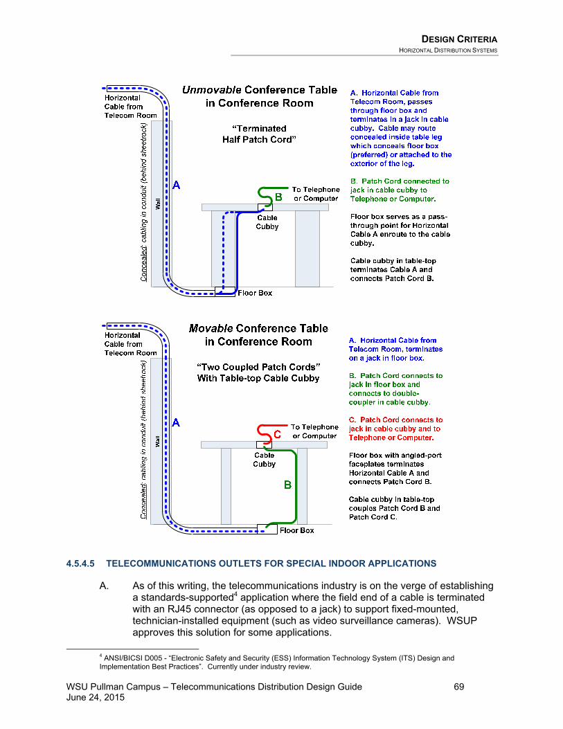
DESIGN CRITERIA HORIZONTAL DISTRIBUTION SYSTEMS
WSU Pullman Campus – Telecommunications Distribution Design Guide 69 June 24, 2015
4.5.4.5 TELECOMMUNICATIONS OUTLETS FOR SPECIAL INDOOR APPLICATIONS
A. As of this writing, the telecommunications industry is on the verge of establishing a standards-supported4 application where the field end of a cable is terminated with an RJ45 connector (as opposed to a jack) to support fixed-mounted, technician-installed equipment (such as video surveillance cameras). WSUP approves this solution for some applications.
4 ANSI/BICSI D005 - “Electronic Safety and Security (ESS) Information Technology System (ITS) Design and Implementation Best Practices”. Currently under industry review.

DESIGN CRITERIA HORIZONTAL DISTRIBUTION SYSTEMS
WSU Pullman Campus – Telecommunications Distribution Design Guide 70 June 24, 2015
• The Designer shall inquire with the ITPM which devices should be
terminated with a connector instead of a jack. • The Telecommunications Room end of the cable shall terminate in a
patch panel, just like any other horizontal cable application.
B. All WSUP facilities shall provide ubiquitous wireless network coverage. Outlets serving wireless access points (WAP) shall be designed by WSUP ITS with the use of a third-party site survey contractor. This is a two-pass process where the initial design is based on the analysis of building modeling, followed by an on-site survey during construction to identify any areas in the building where WiFi signal is weak. Additional conduits, boxes and cabling will then be added as a construction change order to augment the WiFi signal and address any weak zones. Outlets shall have two cables to each WAP, and shall be mounted at the desired WAP location. Cables for WAP outlets shall be terminated with an RJ45 connector. If the outlet is intended for future WAP use, a blank faceplate will be required and the terminated cables coiled inside. Otherwise, the Contract Documents shall be prepared to require the Contractor to install the Owner-furnished WAP device.
• See GPON application guidelines in Section 4.5.3.4 of this document. • See additional Wireless application guidelines in Section 4.16 of this
document.
C. IP video surveillance cameras shall be provided an outlet with one jack for each camera, located at the desired camera location. Cables for cameras shall be terminated with an RJ45 connector. If the outlet is intended for future camera use, a blank faceplate will be required and the terminated and labeled cable coiled inside. Otherwise, the Contract Documents shall be prepared to require the Contractor to install the Owner-furnished camera device.
D. At the discretion of the FSPM, a courtesy telephone with TDD features may be
provided in a main floor gathering space.
• See GPON application guidelines in Section 4.5.3.4 of this document.
E. Outlets will be required in mechanical and electrical spaces to provide network services to mechanical control equipment, electrical power monitoring equipment, and lighting control panels. The Designer shall address these needs on a project-by-project basis.
F. Analog telephone circuits shall be provided for elevators.
• See GPON application guidelines in Section 4.5.3.4 of this document.
G. Outlets serving digital signage shall be provided with two data jacks. WSUP currently uses a Cisco digital media player device mounted in the nearest telecommunications room. A powered adapter is used in the telecommunications
DESIGN CRITERIA HORIZONTAL DISTRIBUTION SYSTEMS
WSU Pullman Campus – Telecommunications Distribution Design Guide 71 June 24, 2015
room and behind the flat panel television to carry HDMI signals via telecommunications cabling.
H. Outlets serving televisions shall be provided with two data jacks.
I. Outlets serving copy machines shall have two jacks. A power outlet with a
dedicated circuit shall be provided adjacent to the telecommunications outlet. J. Vending machines are Ethernet-connected and require one cable per machine. K. Access Control Systems are Ethernet-connected, and require one cable at each
panel location.
L. WSUP uses SmartGrid power monitoring devices that are network-connected. Outlets shall be provided to support this equipment. The Designer shall coordinate with the Electrical Engineer and the FSPM to determine where to place outlets to support the SmartGrid devices.
M. Area of Refuge communication devices shall be provided as governed by Code.
Each device requires a communication cable terminated with a jack inside the rough-in box.
N. Outlets serving fire alarm panels, elevators, security systems, access control
systems, security systems, security scanning stations, point-of-sale equipment, etc. shall be provided under the direction of the WSUP FSPM, SSPM, LSPM, BASPM, ITPM, and non-WSUP tenants.
O. The Designer shall inquire about the requirements for any special design
considerations, including:
• Public-use telephones within WSUP facilities • Spaces within WSUP facilities which must address Architectural Barriers
Act Accessibility Standard (ABAAS) requirements • Point-of-Sale applications • ATM Machines • Reception Areas
4.5.4.6 SPECIAL OUTDOOR APPLICATIONS
A. Outdoor-rated outlets may be required to serve outdoor applications such as wireless access points, hardened convenience telephones, and emergency telephones.
B. The Designer shall inquire with the FSPM whether network-connected irrigation controllers will require an outlet and cabling.
C. Outlets serving security cameras, public access telephone systems (PATS), power monitoring equipment, security systems, irrigation controllers, etc. shall be provided under the direction of the WSUP FSPM, SSPM, LSPM, BASPM, and ITPM.

DESIGN CRITERIA ITS CABLES AND CONNECTING HARDWARE
WSU Pullman Campus – Telecommunications Distribution Design Guide 72 June 24, 2015
4.5.4.7 OTHER CONSIDERATIONS
A. WSUP rarely accepts consolidation point solutions.
B. WSUP considers undercarpet telecommunications cabling (UTC) solutions to be undesirable in most cases. The Designer shall discuss any apparent justifications for undercarpet cabling with the WSUP ITPM prior to its inclusion in a design, and shall also discuss the next best alternative to using undercarpet cabling.
4.5.4.8 WORKSTATION POWER OUTLETS
A. There shall be at least one general-purpose convenience power outlet (120VAC, 15 Ampere minimum) located within three feet of every telecommunications outlet. The Designer shall discuss any application-specific needs with WSUP IT staff and adjust the power outlet locations and amperage accordingly.
• In the case of new construction and modernization projects, the power
outlet associated with each telecommunications outlet shall be a 4”x4” device box (dual gang) with four power receptacles. Power outlets shall be mounted above desktop height, such that a user can plug in power cords without crawling under the desk. It is the Designer’s responsibility to coordinate with the electrical engineer to ensure that power outlets are located near telecommunications device boxes.
• In the case of minor remodel, historical building remodel, and telecommunications-only projects, it may be difficult to meet this requirement. Therefore, where existing power outlets are not located within six feet of each telecommunications outlet, the Designer shall alert the WSUP ITPM and request consideration of the situation on a case-by-case basis.
4.6 ITS Cables and Connecting Hardware Please refer to Chapter 6, ITS Cables and Connecting Hardware in the BICSI TDMM for information regarding the design of telecommunications cables and connecting hardware. The following requirements take precedence over the BICSI TDMM guidelines for telecommunications infrastructure at WSUP facilities:
4.6.1 COPPER CABLING
A. Copper backbone cabling shall terminate on building entrance protection equipment and patch panels. Termination of copper backbone cables on 110-blocks is no longer permitted at WSUP facilities. However, patch panels with 110-style connections (individual jack-style) and building entrance protection equipment shall be used.
• 2-pair per jack on patch panels

DESIGN CRITERIA FIRESTOP SYSTEMS
WSU Pullman Campus – Telecommunications Distribution Design Guide 73 June 24, 2015
B. The design of new telecommunications infrastructure at WSUP facilities shall not include the use of the following termination blocks or connectors. This prohibition applies to both voice and data circuits. • 110-style blocks • 66-style blocks or connectors • BIX-style blocks or connectors • LSA-style blocks or connectors • 50-position miniature ribbon connectors
C. Category 6 horizontal cables shall terminate on patch panels. See Section 4.5.3.3 in this document for further information.
4.6.2 FIBER OPTIC CABLING
A. Singlemode fiber optic cabling shall be terminated at patch panels (both riser and outside plant) and outlets using Angle-Polish, SC-style connectors (APC), with ceramic ferrules.
B. 50-micron multimode fiber optic cabling shall be terminated at patch panels (both riser and outside plant) and outlets using Ultra-Polish, SC-style connectors (UPC), with ceramic ferrules.
C. Where an application requires connectors with more than two strands of fiber
(high bandwidth applications, pre-terminated cables, etc.) MPO connectors shall be used in accordance with manufacturer recommendations. Other connector types may be approved by the WSUP ITPM on a case-by-case basis.
D. For fiber optic cabling with 24 or fewer strands, terminate all strands in the fiber –
do not leave unterminated “dark” strands. For fiber optic cabling with more than 24 strands, the Designer shall inquire with the ITPM for direction on the number of strands to terminate. Specify a patch panel with sufficient size to terminate all strands in a cable, regardless of whether all strands will be terminated at the time the cable is installed.
E. See Section 4.4.2.2 in this document for further information.
4.6.3 SPLICING
Splicing or coupling copper or fiber optic cable is prohibited for inside plant infrastructure.
4.7 Firestop Systems Please refer to Chapter 7, Firestop Systems in the BICSI TDMM for general information regarding the design of firestopping for telecommunications infrastructure. The following requirements take precedence over the BICSI TDMM guidelines for telecommunications infrastructure at WSUP facilities:
DESIGN CRITERIA BONDING AND GROUNDING (EARTHING)
WSU Pullman Campus – Telecommunications Distribution Design Guide 74 June 24, 2015
A. The Designer shall pay careful attention to the fire ratings of existing and new walls. Wherever penetrations are made through fire-rated walls, the Drawings shall identify the firestopping requirements.
B. Penetrations through fire-rated walls and floors shall be firestopped in
accordance with the requirements of the manufacturer of the firestopping materials, and to satisfy local code officials.
C. The Designer shall avoid design solutions calling for penetration of fire walls, fire
barriers, fire partitions, smoke barriers, and smoke partitions when other reasonable cable routing options exist.
D. The predominant color of fire-rated pathway devices shall be red. E. For new construction, WSUP requires re-enterable firestopping devices like the
STI EzPath for penetrations through fire-rated walls and floors.
F. Firestopping pillows are acceptable for existing buildings where conduit sleeve pathways already exist.
G. The use of firestopping putty materials is prohibited. H. WSUP Facilities Services maintains specification section 07 27 00 –
“Firestopping” which should contain telecommunications-specific firestopping requirements. The Designer shall work with the FSPM to review this specification section and verify that it is appropriately written for a given project.
4.8 Bonding and Grounding (Earthing) Please refer to Chapter 8, Bonding and Grounding (Earthing) in the BICSI TDMM for general information regarding the design of grounding, bonding and electrical protection systems. The following requirements take precedence over the BICSI TDMM guidelines for telecommunications infrastructure at WSUP facilities:
• Grounding and bonding conductors shall be sized according to the requirements in ANSI/TIA/EIA J-STD-607A and per the NEC.
4.9 Power Distribution Please refer to Chapter 9, Power Distribution in the BICSI TDMM for general information regarding the design of power distribution for telecommunications infrastructure. The following requirements take precedence over the BICSI TDMM guidelines for telecommunications infrastructure at WSUP facilities:
A. The Designer shall be responsible to determine that the electrical power distribution requirements supporting the telecommunications infrastructure are met as described in this document.
B. For projects where an electrical engineer is involved, the Designer shall
DESIGN CRITERIA TELECOMMUNICATIONS ADMINISTRATION
WSU Pullman Campus – Telecommunications Distribution Design Guide 75 June 24, 2015
coordinate directly with the engineer, and verify that the engineer’s design documentation meets these requirements. For projects without the involvement of an electrical engineer, the Designer shall alert WSUP where additional power infrastructure is needed to meet the requirements.
1. Please refer to Chapter 4, Work Areas in the BICSI TDMM and also in TDDG
Section 4.3 Work Areas for information on the power outlet requirements for work areas.
2. Please refer to Chapter 7, Telecommunications Spaces in the BICSI TDMM
and also in TDDG Section 4.3 Telecommunications Spaces for information on the power outlet requirements for TRs.
o WSUP typically provides network electronics that provide Power-over-
Ethernet. o The Designer shall request power consumption data for the
equipment that WSUP will use, and will size the power distribution infrastructure sufficient to support this equipment.
3. Please refer to Chapter 21, Data Centers in the BICSI TDMM and also in
TDDG Section 4.18 Data Centers for information on the power outlet requirements for data centers.
o WSUP data centers will typically be either Tier II or Tier III systems. o The Designer shall inquire which tier is to be designed for each
project, and design appropriate power distribution systems to support the Tier designation.
C. The Designer shall inquire which type of power conditioning/power protection
equipment should be designed for each project.
o WSUP recognizes that flywheel-based UPS equipment is available. However, the initial cost of flywheel equipment is typically very high. As a result, the return on investment is low with a lengthy time to payback. For most applications, flywheel-based UPS systems are probably cost-prohibitive.
4.10 Telecommunications Administration Please refer to Chapter 10, Telecommunications Administration in the BICSI TDMM for general information regarding the documentation and labeling of telecommunications infrastructure. The following requirements take precedence over the BICSI TDMM guidelines for telecommunications infrastructure at WSUP facilities:
4.10.1 IDENTIFICATION STRATEGY
A. The “identifier” is the unique name or description assigned to a given telecommunications infrastructure component. The Designer shall assign identifiers to the telecommunications infrastructure components listed below and

DESIGN CRITERIA TELECOMMUNICATIONS ADMINISTRATION
WSU Pullman Campus – Telecommunications Distribution Design Guide 76 June 24, 2015
clearly show the identifier assignments on the Construction Documents.
B. While it is the Contractor’s responsibility to provide marked-up drawings to the Designer indicating any construction-related changes to the identifiers, the Designer shall verify that the identifiers are clearly and accurately shown on the record drawings.
C. Telecommunications components shall not be labeled with an application-
specific identifier. Jacks shall not be labeled with the name or function of the device that is served by the jack (server name, computer type). Also, the use of “V-#” and “D-#” are inconsistent with the industry standard-based philosophy of designing cabling systems that are independent of the application, and are therefore not permitted.
D. The Designer shall prepare construction specifications that shall contain a
comprehensive listing of the identification strategy requirements.
4.10.1.1 NEW TELECOMMUNICATIONS DISTRIBUTION SYSTEMS
The items listed below shall be shown on the Construction Documents. The Designer shall assign the identifiers to the telecommunications components based on the following suggested identification strategy. The circumstances of each project may require adjustments. The Designer shall discuss with WSUP any recommendations for customization and cooperatively develop an identification strategy, prior to adopting any customizations.
A. WSUP has a campus building numbering scheme that shall be incorporated into all applicable labeling. Each building on campus has been assigned a 4- or 5-digit numeric code. The Designer shall obtain the official numbering scheme from the following website. The FSPM and ITPM can assist to provide new numbering for a new building (if needed).
http://facilitiesservices.wsu.edu/facility_roster.aspx At a minimum, buildings and rooms always have a 4-digit numeric identifier. Some buildings and rooms may also have an alpha character prefix, in addition to the 4-digit number. Some buildings and rooms may also have up to two alpha characters as a suffix. Telecommunications rooms, for example, end with the letter “T”. Up to 5 spaces are reserved for building numbering and up to 7 spaces are reserved for room numbering. Therefore, if a room or building identifier lacks an alpha character prefix, use an asterisk as a placeholder. If a room or building lacks one or both alpha characters in the suffix, just delete those character positions (no asterisk for either of those positions).
B. Telecommunications Rooms, Equipment Rooms and Data Centers shall be identified by room number, followed by the letter “T”. o For example: a telecommunications room located in Room #1242T in a
building would be identified as “1242T”.

DESIGN CRITERIA TELECOMMUNICATIONS ADMINISTRATION
WSU Pullman Campus – Telecommunications Distribution Design Guide 77 June 24, 2015
C. Racks in telecommunications rooms shall have identifiers of the form “Rack #” where “#” is the sequential rack number within a given TR, numbered from the wall out, with the rack located closest to the wall being “Rack 1”. o For example: the first rack in a given telecommunications room would have
the label “Rack 1”, the second “Rack 2”, and so on.
D. Backbone Cables shall have identifiers of the form of:
a a a a a - b* b b b b b† b† c c c c c* - d* d d d d d† d† e† e e e e†
SourceBuilding
Telecom Roomat Source
DestinationBuilding
Telecom Roomat Destination
Cable Number
When building identifiers, room identifiers, and cable numbers lack a character in a given position, an asterisk shall be used as a placeholder or that position deleted, as follows:
• * This character position should be replaced by an asterisk if the number
doesn’t include an alpha character in that position. • † This character position should be deleted if not necessary.
The Source Building is typically the MCF. The Destination Building is the customer/outlet-end of the cable. Three or four-position sequentially numbered Cable Numbers are structured as follows:
o 001-999 for UTP cables o FM01-FM99 for Multimode Fiber cables o FS01-FS99 for Singlemode Fiber cables o X01-X99 for Coax cables o Z01-Z99 for Composite cables
There is one special case for a prefix character on a cable number: cables that are owned by a third party (not WSU). For example, cables owned by Housing and Dining are labeled with a prefix of “H”. The Designer shall inquire about other prefixes that might be required for a given project.
Cables shall be labeled within 6 feet of entrance into a telecom room and within 12 inches of the fiber optic patch panel or copper termination. Cables shall also be labeled twice in maintenance holes, within 3 feet of the entrance and exit conduits. The labels shall designate the origin, destination, and owner of the cable. o For example: A 24-strand singlemode fiber optic cable (the second fiber
cable) running between Telecommunications Room 2047T in the Information Technology Building (0812) and Telecommunications Room 23T in Bohler Gymnasium (0011) shall be numbered:

DESIGN CRITERIA TELECOMMUNICATIONS ADMINISTRATION
WSU Pullman Campus – Telecommunications Distribution Design Guide 78 June 24, 2015
0 8 1 2 * - * 2 0 4 7 T 0 0 1 1 * - * 0 0 2 3 T F S 0 2
SourceBuilding
DestinationBuilding
Telecom Rmat Source
Cable Number
Telecom Rmat Destination
E. Fiber Optic Patch Panels shall have identifiers sequentially numbered in the form of “F#” where “F” stands for “Fiber” and “#” is the sequential fiber optic patch panel number terminated within a given telecommunications room. The numbering sequence does not restart for each rack. o For example: the first fiber optic patch panel would be
labeled “F1”. The second fiber optic patch panel would be labeled “F2”.
F. Ports on Patch Panels for Fiber Optic Cabling are typically pre-labeled by the
manufacturer with sequential numbers (i.e. 1 to 12). o In addition to the pre-labeling, each bulkhead/connector panel shall also be
labeled with the opposite end termination point and type of the cable terminated at that location, in the form of “aaaaa-bbbbbbb-cccc” (referencing the cable numbering discussed above).
o For example: the bulkhead/connector panel in a patch panel terminating singlemode fiber optic cable #2 (strand count is irrelevant to the labeling) whose far end terminates in Telecommunications Room 2047T in the Information Technology Building (0812) shall be numbered:
0 8 1 2 * - * 2 0 4 7 T - F S 0 2
Far EndBuilding
Telecom Rmat Far End
Cable Number
G. Building Entrance Protectors (BEP) and Copper Backbone Patch Panels shall be labeled with the far end termination point and cable of the cable terminated at that jack, in the form of “aaaaa-bbbbbbb-cccc” (referencing the cable numbering discussed above). o For example: the BEPs and Copper Backbone Patch Panels for copper cable
#121 whose far end terminates in Telecommunications Room 2047T in the Information Technology Building (0812) shall be numbered:
H. Patch Panel Jacks for Horizontal Cables shall have identifiers in the form of “aaaaa”, where:
aaaaa Room Number where outlet is located
Fiber Patch Panel
1st Fiber Patch Panel in the Rack

DESIGN CRITERIA FIELD TESTING
WSU Pullman Campus – Telecommunications Distribution Design Guide 79 June 24, 2015
Labels shall be applied to the front of the patch panel adjacent to each jack, without obscuring the jack number printed on the patch panel, and also on the cable behind the jack within 4 inches of the termination.
I. Outlet Jacks for Horizontal Cables shall have identifiers in the form of “aaaaa:bcdd”, where:
aaaaa Telecommunications Room Number serving outlet b Equipment Rack Number c Patch Panel Number dd Patch Panel Jack Number (two digits, with leading zero)
Labels shall be applied to the front of the faceplate adjacent to each jack, and also on the cable behind the jack within 4 inches of the termination. o For example: a horizontal UTP cable terminated
in patch panel jack 22 of workstation patch panel A in rack 2 in telecommunications room 020T, serving an outlet in office 050, would be labeled at the outlet as follows:
o The jack numbering on the faceplate may also be printed in two rows, one above the other, with a colon, as follows:
0020T: 2A22
4.11 Field Testing Please refer to Chapter 11, Field Testing in the BICSI TDMM for general information regarding the field-testing of telecommunications cabling. The following requirements take precedence over the BICSI TDMM guidelines for field-testing at WSUP facilities:
A. The Designer shall require the Contractor to test 100% of cabling, both field-terminated and pre-terminated cables.
• Copper cables shall be Link tested (not Channel tested).
B. Cable tester equipment shall be manufactured by Fluke.
C. The Designer shall review the cable test results submitted by the Contractor.
The test results shall be the actual native machine test results downloaded from the test equipment. In particular, the Designer shall check for the following items on the cable test reports:
• The cable test report shall be automatically produced by the test equipment. • The report shall indicate that the cable passed the test. It shall also indicate
the date of calibration, the software version, and the name of the technician

DESIGN CRITERIA OUTSIDE PLANT
WSU Pullman Campus – Telecommunications Distribution Design Guide 80 June 24, 2015
who conducted the test. The reports shall also include graphical results of the performance curves obtained during the testing.
• Indications that the cabling meets distance limitation requirements. • Indications that the wire-map of the cable is correct. • Indications that the cable test equipment was properly configured. For
copper cabling, the test equipment’s configuration parameter for Nominal Velocity of Propagation (NVP) shall match the value stated by the cabling manufacturer for the type of cable installed.
• Marginal test results (typically indicated with an asterisk “*”) are only acceptable when the condition is “over length” and when the over-length situation was intentional during design. For example, a low bandwidth device might be served by a cable that would otherwise be too long to support a high bandwidth device. Over-length issues due to choice of routing or extra service loops are not acceptable.
• For fiber optic cabling: the cable test report shall indicate a headroom dB value that is equal to or better than the value calculated in the link-loss budget.
D. The cabling performance characteristics shall meet or exceed the performance
guaranteed by the manufacturer, which may exceed standard industry requirements. In other words, even though a particular cable might pass its tests, the cable might still be rejected (requiring re-termination or replacement) if it does not meet the higher standard of performance that the manufacturer may list for its products.
E. WSUP may choose to spot-test cabling to back-check the Contractor’s test
results.
F. WSUP may choose to hire a third-party cable test company to conduct an independent cabling test.
G. The final test results shall have been verified by the Designer to be acceptable
before submission to WSUP. Test results shall be submitted to WSUP in electronic form, both in PDF form and also the original test result data files.
H. Contractors shall be required to retain a copy of the test reports for a period of at
least 5 years after installation.
4.12 Outside Plant Please refer to Chapter 12, Outside Plant in the BICSI TDMM and the BICSI OSPDRM for information regarding the design of outside plant telecommunications infrastructure. See Section 4.4.3 above.
DESIGN CRITERIA AUDIO/VISUAL SYSTEMS
WSU Pullman Campus – Telecommunications Distribution Design Guide 81 June 24, 2015
4.13 Audio/Visual Systems Please refer to Chapter 13, Audiovisual Systems in the BICSI TDMM for information regarding the design of telecommunications infrastructure to support audio/visual systems, private CATV distribution systems, and distributed paging systems at WSUP facilities.
4.13.1 AUDIO/VISUAL SYSTEMS
The Designer shall coordinate with the AVPM and reference the Audio/Visual Design Guide (AVDG) for information about the telecommunications infrastructure required to support audio/visual applications at WSUP.
4.13.2 DISTRIBUTED PAGING SYSTEMS
Please refer to Chapter 15, Overhead Paging Systems in the BICSI TDMM for information regarding the design of telecommunications infrastructure to support overhead paging systems at WSUP facilities. These systems are typically not used at WSUP. However, the Designer shall inquire with WSUP to determine whether emergency response paging systems are required for a given project.
4.14 Building Automation Systems Please refer to Chapter 14, Building Automation Systems in the BICSI TDMM for information regarding the design of telecommunications infrastructure to support building automation systems at WSUP facilities.
A. ANSI/TIA/EIA-862 applies to telecommunications infrastructure serving building automation systems (BAS). The Designer shall pay particular attention to the following BAS issues:
• Verify that the voltage and current requirements of each BAS application are
satisfied by the cabling materials to be installed. • Verify that a suitable horizontal connection point (HCP) is installed for each
BAS application.
B. BAS devices are increasingly converging onto structured cabling systems. While the design of these systems is typically outside the scope of work of the telecommunications infrastructure designer, the Designer shall design the telecommunications cabling required to support these systems.
C. Typically, BAS systems require telecommunications cabling routed from the
devices to a patch panel termination point in a designated mechanical room or other location managed by building maintenance personnel. In addition to the device-specific cables, other cables shall be designed from the telecommunications rooms to the BAS patch panels, to permit these systems to gain access to the data networks.

DESIGN CRITERIA DATA NETWORKS
WSU Pullman Campus – Telecommunications Distribution Design Guide 82 June 24, 2015
D. Horizontal connection points are only required for BAS applications. Do not use an HCP for typical voice/data/video applications.
E. The Designer shall inquire with the ITPM and the HVACPM whether a project
requires telecommunications cabling to support building automation systems.
4.15 Data Networks Please refer to Chapter 15, Data Networks in the BICSI TDMM for general information regarding the design of telecommunications infrastructure for serving local area networks. The following requirements take precedence over the BICSI TDMM guidelines for telecommunications infrastructure at WSUP facilities:
A. All WSUP facilities use the Ethernet LAN protocol. Telecommunications infrastructure for all WSUP facilities shall be designed, installed, and tested to support the Institute of Electrical and Electronic Engineers (IEEE) Ethernet 802.3 standards. WSUP networks use the 1000Base-X Gigabit Ethernet protocol based on the IEEE 802.3z standard. All newly installed cabling shall support this protocol. WSUP networks are typically based on Cisco switches (power-over Ethernet), with 10GB backbones and 1GB service to the work area.
B. The design of the network electronics is done by WSUP and is outside the scope
of work of the telecommunications Designer.
C. The Designer shall coordinate with the WSUP ITPM and HVACPM to determine the requirements for supporting the network electronics in each space. The design shall provide rack space to host WSUP’s network equipment.
4.16 Wireless Networks Please refer to Chapter 16, Wireless Networks in the BICSI TDMM and the BICSI Wireless Design Reference Manual (WDRM) for information regarding the design of telecommunications infrastructure to support wireless and microwave telecommunications systems at WSUP facilities.
A. WSUP currently uses Cisco wireless access point equipment in its buildings. This equipment operates with Power-over-Ethernet and requires one cable per device. The Designer shall accommodate POE equipment in the design, including the power and cooling requirements.
B. The Designer shall work cooperatively with the WSUP ITPM to design
telecommunications infrastructure to appropriately support wireless technologies. WSUP typically uses a third party site-survey consultant to identify appropriate WAP locations and prepare associated coverage and signal strength maps. The Designer shall show the locations where wireless access points (WAP) are desired on the drawings. During the later part of the construction process, WSUP ITS may bring the site-survey consultant to the project site to analyze the actual facility and make adjustments to the design to add or move outlets serving WAPs to improve coverage in the building.
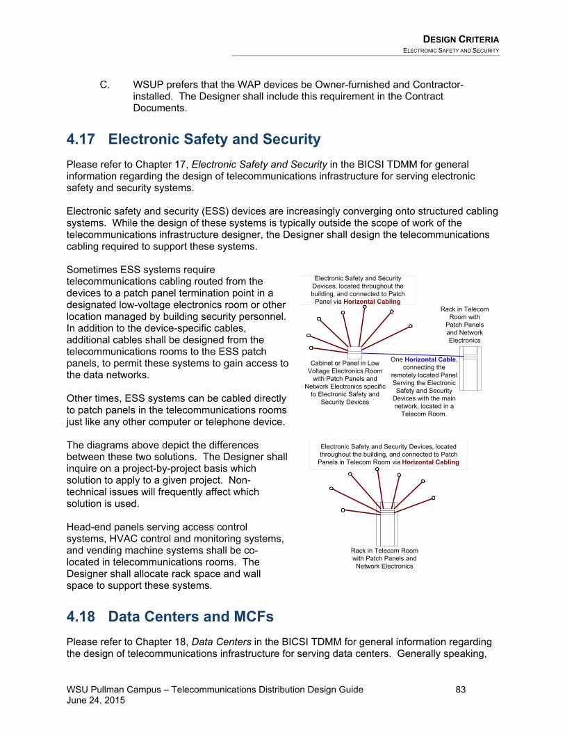
DESIGN CRITERIA ELECTRONIC SAFETY AND SECURITY
WSU Pullman Campus – Telecommunications Distribution Design Guide 83 June 24, 2015
C. WSUP prefers that the WAP devices be Owner-furnished and Contractor-installed. The Designer shall include this requirement in the Contract Documents.
4.17 Electronic Safety and Security Please refer to Chapter 17, Electronic Safety and Security in the BICSI TDMM for general information regarding the design of telecommunications infrastructure for serving electronic safety and security systems. Electronic safety and security (ESS) devices are increasingly converging onto structured cabling systems. While the design of these systems is typically outside the scope of work of the telecommunications infrastructure designer, the Designer shall design the telecommunications cabling required to support these systems. Sometimes ESS systems require telecommunications cabling routed from the devices to a patch panel termination point in a designated low-voltage electronics room or other location managed by building security personnel. In addition to the device-specific cables, additional cables shall be designed from the telecommunications rooms to the ESS patch panels, to permit these systems to gain access to the data networks. Other times, ESS systems can be cabled directly to patch panels in the telecommunications rooms just like any other computer or telephone device. The diagrams above depict the differences between these two solutions. The Designer shall inquire on a project-by-project basis which solution to apply to a given project. Non-technical issues will frequently affect which solution is used. Head-end panels serving access control systems, HVAC control and monitoring systems, and vending machine systems shall be co-located in telecommunications rooms. The Designer shall allocate rack space and wall space to support these systems.
4.18 Data Centers and MCFs Please refer to Chapter 18, Data Centers in the BICSI TDMM for general information regarding the design of telecommunications infrastructure for serving data centers. Generally speaking,
Rack in Telecom Room with
Patch Panels and Network Electronics
Cabinet or Panel in Low Voltage Electronics Room
with Patch Panels and Network Electronics specific
to Electronic Safety and Security Devices
One Horizontal Cable, connecting the
remotely located Panel Serving the Electronic Safety and Security
Devices with the main network, located in a
Telecom Room.
Rack in Telecom Room with Patch Panels and Network Electronics
Electronic Safety and Security Devices, located throughout the building, and connected to Patch
Panel via Horizontal Cabling
Electronic Safety and Security Devices, located throughout the building, and connected to Patch
Panels in Telecom Room via Horizontal Cabling

DESIGN CRITERIA DATA CENTERS AND MCFS
WSU Pullman Campus – Telecommunications Distribution Design Guide 84 June 24, 2015
WSUP follows the TIA-942 Data Center Standard in the design of data centers and larger equipment rooms. The requirements below take precedence over the BICSI TDMM guidelines. The requirements for small-scale equipment rooms are the same as for telecommunications rooms. The Designer shall inquire with WSUP whether an equipment room in a given project is intended to be designed with telecommunications room features or data center features. WSUP does not anticipate the need to construct any new Data Centers in the foreseeable future. The telecommunications infrastructure topology at WSUP is a two-level hierarchical star with several “main communication facilities” (MCF) at key locations throughout campus. It is unlikely but conceivable that a new MCF might be required at WSUP. The “Data Centers” section of this document shall apply to MCFs. All requirements for MDFs and IDFs apply to MCFs.
4.18.1 SIZING CONSIDERATIONS
A. The Designer shall consult with the WSUP ITPM to determine any sizing requirements for the Data Center on a project-by-project basis. The design shall include a minimum of 25% vacant space for future growth.
B. The power consumption profile of equipment to be hosted in the data center and
its associated heat-load profile are the two key parameters for sizing a data center. The Designer shall work with WSUP ITPM to identify the power consumption per cabinet footprint, which will have a direct correlation to the cooling requirements of the space. The quantity of equipment cabinets that can be powered and cooled in the space drives the sizing plan.
• During the life of the data center, advances in technology may shrink the
space requirements for each server, making more physical space available for additional servers. However, if there is not sufficient power to support another server, or sufficient cooling capacity to remove the heat produced by another server, then the additional space is unusable.
C. The WSUP ITPM shall approve the final space requirements and design layout
for the equipment and racks.
4.18.2 TIER CLASSIFICATION
WSUP data centers are typically designed for Tier II+ classification (redundant components, single distribution path, and N+1 redundancy). However, the Designer shall inquire with the ITPM on a project-by-project basis for the desired Tier classification of each data center or equipment room.
4.18.3 ARCHITECTURAL CONSIDERATIONS
The Data Center shall be separated from other occupancies within the building by fire-resistant-rated construction of not less than 1 hour.
DESIGN CRITERIA DATA CENTERS AND MCFS
WSU Pullman Campus – Telecommunications Distribution Design Guide 85 June 24, 2015
4.18.4 ENVIRONMENTAL PROVISIONING
Environmentally friendly solutions shall be considered in the design of data center cooling systems, incorporating heat reclamation and non-mechanical cooling features where reasonable and practical. Environmental management and monitoring systems shall be designed for data centers. Consideration shall be given to both in-row cooling and whole-room cooled air solutions. Whole-room cooled solutions shall be designed to implement hot-aisle/cold-aisle arrangements, and captured-ducting solutions for hot air return shall be considered. Air conditioning systems for technology/server and UPS rooms shall be supported by standby power systems.
4.18.5 FIRE DETECTION AND SUPPRESSION
All Data Centers shall be protected by a pre-action, dry-pipe, water-based suppression system. Fire suppression systems shall activate when two sensors detect an actionable condition.
4.18.6 RACKS AND CABINETS
Two-post equipment racks and four-post equipment cabinets are both required. The Designer shall discuss with the ITPM about the network electronics that will be hosted in each rack and cabinet in the Data Center, and shall show this equipment on the rack elevation details in the plan drawings. The Designer shall also discuss with the ITPM the potential for future additional racks and cabinets, and shall identify space on the plan drawings to accommodate them. Other styles of equipment racks and cabinets might be used in the Data Center, some of which may be proprietary to a particular system or service provider. The Designer shall plan the Data Center layout to make allowances for proprietary cabinets and racks, and allow expansion room for future equipment.
A. Floor-standing cabinets shall have front- and rear-hinged doors to permit access
to both the front and rear of the equipment. Cabinets shall be constructed of heavy-gauge steel. The side panels of the cabinet shall be removable for maintenance accessibility.
B. Each cabinet shall be vented, and where appropriate, equipped with cooling fans. C. WSUP has used APC NetShelter 750mm cabinets in recent projects. D. Each rack and cabinet shall be provided with the following telecommunications
cabling:
• 1U fiber optic patch panel, with 24 strands of singlemode fiber (APC, LC) and 24 strands of 50-micron multimode fiber (UPC, SC). The Designer shall inquire whether 62.5-micron multimode fiber is required in lieu of 50-micron.
• 1U copper patch panel with 24 jacks of Category 6 cabling installed.
DESIGN CRITERIA DATA CENTERS AND MCFS
WSU Pullman Campus – Telecommunications Distribution Design Guide 86 June 24, 2015
4.18.7 POWER REQUIREMENTS
4.18.7.1 TECHNICAL POWER PANELS
A. The WSUP campus electrical power generator distributes standby power throughout campus on Feeder 13. Data Centers and MCFs require Feeder 13.
B. A separate supply circuit serving the room shall be provided and terminated in its own electrical panel located in the Data Center. This power panel shall be designated as “Data Center Technical Power.” The Data Center technical power panel shall be used exclusively for supplying power to electronics equipment in the equipment room. Sizing of electrical power supply is dependent upon the equipment types and equipment load, and shall be calculated on a case-by-case basis, including sufficient spare capacity for future growth.
C. The technical power circuits in each Data Center shall originate from a technical
power panel, dedicated to serving the Data Center. The technical power panel shall not be used to supply power to sources of electromagnetic interference such as large electric motors, arc welding, or industrial equipment.
D. Power for critical network components such as servers, routers, switches, and
telephone systems shall always be provided through at least one uninterruptible power supply (UPS).
E. WSUP requires the use of centralized UPS equipment for Data Centers. WSUP
has used APC Symmetra 40kVA equipment on recent projects, with power distribution via whips or modules to a PDU in each rack.
• The Designer shall work with the WSUP ITPM to determine an appropriate
battery capacity on a case-by-case basis. • Upon installation, a qualified electrician shall test new centralized UPS units
for correct output voltage prior to connecting electronic equipment. • Centralized UPS equipment shall be provided with a network interface card,
so that the UPS can communicate via the network with servers and other equipment to orchestrate a coordinated safe-shutdown of the equipment in the event of an extended power outage.
• WSUP recognizes that flywheel-based UPS equipment is available.
However, the initial cost of flywheel equipment is typically very costly, and as a result, the return on investment is low with a lengthy time to payback. For most applications, flywheel-based UPS systems are probably cost-prohibitive.
F. WSUP typically uses network electronics that provide Power-over-Ethernet
(POE).
G. The Designer shall request power consumption data for the equipment that WSUP will use, and will size the power distribution infrastructure sufficient to support this equipment plus 50% growth.
DESIGN CRITERIA DATA CENTERS AND MCFS
WSU Pullman Campus – Telecommunications Distribution Design Guide 87 June 24, 2015
4.18.7.1.1 EMERGENCY POWER OFF (EPO) BUTTON
A. Where required by Code (NEC 645.A), an Emergency Power Off (EPO) push-button shall be provided near the exit of the Data Center room. The button shall be located per Code requirements, preferably at the same elevation as the light switch, at least a foot away from the light switch but not more than two feet from the door. The button shall be provided with a shield to prevent accidental actuation from inadvertent contact.
B. When the EPO button is pressed, all power to the room shall be shut off immediately, per Code requirements, except for power to light fixtures. Power to the UPS equipment shall be shut off, and power from the UPS to equipment shall also be shut off when the EPO button is pressed.
C. Provide a permanent, wall-mounted plaque near the EPO with instructions for
restarting the power following an EPO event. It is recommended that the plaque be fabricated from engraved plastic or a similar indelible material. The text on each plaque shall be specifically written for the facility. The following is an approximate example to be modified by the Electrical Engineer to reflect actual conditions at the facility:
1. Before resetting any EPO pushbutton, verify that:
• The condition has been corrected for which EPO activation occurred. • Fire suppression systems have been reset to clear alarms.
2. Reset the activated EPO Station. 3. Verify that all loads are fully energized and reset. Shunt any tripped
breakers. If air conditioning unit is not working, consult manufacturer’s startup procedures.
D. The Electrical Engineer shall prepare written guidelines describing examples of
events that would warrant pressing the EPO button. The guidelines are not expected to be a comprehensive list.
4.18.7.2 TECHNICAL POWER OUTLETS
A. Generally, the power outlet requirements that are applicable to telecommunications rooms are also applicable to equipment rooms. See TDDG Section 4.3.6 Power Requirements (above).
B. The Designer shall obtain connection/load requirements from WSUP for each piece of equipment, and tabulate the information for review and confirmation by WSUP. This equipment may include network electronics, UPS equipment, computers/servers, phone system equipment, voice mail systems, video equipment and service provider equipment.
C. Some telephone PBX equipment, UPS equipment and network switch equipment
requires specialized plugs or electrical service. The Designer shall specifically investigate the potential need for voltage or current requirements other than the

DESIGN CRITERIA HEALTH CARE
WSU Pullman Campus – Telecommunications Distribution Design Guide 88 June 24, 2015
typical 120VAC/20 Ampere power outlet, and shall coordinate with the design team to design the electrical power infrastructure to serve the needs of the equipment.
4.18.7.2.1 FOR REMODEL PROJECTS
If an equipment room is truly required in a remodel project, budget limitations and other constraints shall be resolved through actions that do not deviate from meeting the requirements of this document. In particular, the electrical power requirements of equipment in an equipment room shall not be discounted or taken lightly.
4.18.7.3 CONVENIENCE POWER OUTLETS
Convenience power outlets shall be provided as described (above) in TDDG Section 4.3.6 Power Requirements (above).
4.18.8 GROUNDING, BONDING, AND ELECTRICAL PROTECTION
All equipment racks, metallic conduits, and exposed non-current-carrying metal parts of telecommunications and information technology equipment in the Data Center shall be bonded to the TGB. Please refer to Chapter 9, Bonding and Grounding (Earthing) in the BICSI TDMM and TDDG Section 4.8 for more information regarding the design of grounding, bonding and electrical protection systems.
• The Data Center requires a dedicated/isolated ground wire routed inside a metallic conduit directly from the main electrical service-grounding electrode for PBX equipment. This ground wire is in addition to and separate from the telecommunications grounding system.
• Grounding and bonding conductors shall be sized according to the requirements in
ANSI/TIA/EIA J-STD-607A.
4.19 Health Care Please refer to Chapter 19, Health Care in the BICSI TDMM for general information regarding the design of telecommunications infrastructure for serving health care facilities. The Designer shall inquire with the FSPM whether a project will include health care-related spaces. If so, the Designer shall design telecommunications infrastructure for these spaces in compliance with TIA-1179 - Healthcare Facility Telecommunications Infrastructure Standard.
4.20 Residential Cabling Please refer to Chapter 20, Residential Cabling in the BICSI TDMM for information regarding the design of telecommunications infrastructure to support residential facilities within WSUP facilities. Residential facilities at WSUP shall be designed using GPON telecommunications infrastructure. WSUP Housing & Dining directs design decisions for residential facilities. The

DESIGN CRITERIA BUSINESS DEVELOPMENT AND PROJECT MANAGEMENT
WSU Pullman Campus – Telecommunications Distribution Design Guide 89 June 24, 2015
Designer shall inquire with both the ITPM and the IT representatives of Housing & Dining for direction regarding telecommunications infrastructure for a residential facility project.
4.21 Business Development and Project Management Please refer to Chapter 21, Business Development and Project Management in the BICSI TDMM for general information regarding design, construction and project management of telecommunications infrastructure. Please refer to TDDG Section 3 Project Procedures for WSUP-specific telecommunications project procedure requirements.
4.21.1 CODES, STANDARDS AND REGULATIONS
Please refer to Appendix A: Codes, Standards and Regulations in the BICSI TDMM for general information regarding the codes, standards and regulations that apply to telecommunications infrastructure.

CONSTRUCTION DOCUMENT CONTENT PLANS AND DRAWINGS
WSU Pullman Campus – Telecommunications Distribution Design Guide 90 June 24, 2015
5 Construction Document Content This section of the TDDG describes the content requirements that the Designer shall include when creating the Construction Documents5. This content is in addition to the content found in some generally accepted document sets.
The documents produced by the Designer and the services provided by the Designer shall comply with the requirements in the Conditions of the Agreement and the Instructions for Architects and Engineers doing Business with Division of Engineering and Architectural Services. In addition to these requirements, the Designer shall also meet the requirements in this document, including the Construction Document content requirements in this section.
Construction Documents shall communicate a fully detailed and coordinated design (rather than making adjustments in the field during construction) and are expected to result in reduced construction costs and fewer change orders. The level of detail required to meet this objective may be substantially greater than some telecommunications designers may be accustomed to providing.
The Designer shall include the following content in the Construction Documents:
5.1 Plans and Drawings
5.1.1 GENERAL
The telecommunications portion of the Construction Drawing set shall include the following:
• Cover Sheet
• Sheet List
• Site Map
• Symbol Schedule
• List of Abbreviations
• Plan Sheets
• Elevation Diagrams
• Schematic Diagrams
• Construction Details
• Demolition
All plan sheets shall be scaled, shall indicate the scale, and shall show a north arrow. All plan sheets shall show a key plan when the building or site is too big to fit on a single sheet.
5 As of this writing, the Conditions of the Agreement and the Instructions for Architects and Engineers Doing Business with Division of Engineering and Architectural Services (both published by the Washington State Department of General Administration) make reference to the term “Construction Drawings.” However, the Manual of Practice from the Construction Specifications Institute (CSI) defines “Construction Documents” as a subset of the “Contract Documents” and indicates that drawings, specifications and other written documentation are contained within the Construction Document subset. The TDDG will use the term “Construction Documents” according to CSI’s definition.

CONSTRUCTION DOCUMENT CONTENT PLANS AND DRAWINGS
WSU Pullman Campus – Telecommunications Distribution Design Guide 91 June 24, 2015
Equipment and cable identifiers shall be shown on the drawings and diagrams.
5.1.2 OUTSIDE PLANT SITE PLAN DRAWINGS
A. Provide drawings showing a scaled telecommunications distribution site plan. These drawings shall show the following:
• Maintenance hole or handhole locations (labeled with their identifiers) • Complete ductbank routing, details, and elevations • Conduit sizes, quantities, and arrangements • Section cuts • Existing and new surface conditions • Outside plant copper telecommunications cabling, including pair counts • Outside plant fiber optic telecommunications cabling, including fiber types
and strand counts • Locations of buildings, roads, poles, existing underground utilities, and other
obstructions
B. These sheets should also identify coordination arrangements where conflicts with site work for other disciplines could possibly arise, in particular indicating the separation distances between telecommunications and power or steam. The sequencing of site work also should be shown, if applicable.
C. The site plan shall show the cabling from the service providers (cable television,
telephone, etc.) and shall indicate the requirements for owner-provided maintenance holes or handholes and pathway to the point of demarcation.
D. These sheets should also identify coordination arrangements where conflicts with
site work for other disciplines could possibly arise, in particular indicating the separation distances between low-voltage and power or steam. The sequencing of site work also should be shown, if applicable.
5.1.3 MAINTENANCE HOLE/HANDHOLE BUTTERFLY DIAGRAMS
A. Butterfly diagrams are a combination of tabular information and a schematic diagram used to organize and communicate information related to the conduits and cabling in each maintenance hole and handhole. These diagrams are CAD files to be included in the project’s drawing set.
B. The Designer shall provide a set of butterfly diagrams depicting each
maintenance hole or handhole affected by the project, and showing new cabling as well as existing cabling to remain in the maintenance hole or handhole.
• Ducts to be used for new cabling shall be assigned during the course of
design, not during construction. Duct assignments must be approved by WSUP prior to the release of construction documents.

CONSTRUCTION DOCUMENT CONTENT PLANS AND DRAWINGS
WSU Pullman Campus – Telecommunications Distribution Design Guide 92 June 24, 2015
C. A second set of butterfly diagrams shall be provided for each maintenance hole or handhole that contains existing cabling intended to be demolished under the project.
D. The diagrams shall be formatted as shown in the sample butterfly diagram in
Appendix 6.5. Upon request, WSUP will provide an electronic AutoCAD file of this diagram to be used as a template as well as electronic CAD files for each butterfly diagram affected by a project.
5.1.4 INSIDE PLANT PLAN DRAWINGS
A. Scaled plan drawings shall be provided for each building showing the telecommunications applications and cabling inside the building. These drawings shall show the following:
• Routing of new pathway to be constructed during the project.
o The content of the drawings shall be coordinated with other disciplines and shall be representative of the complete pathway route that the Contractor shall use, rather than a schematic depiction.
o It is expected that the Designer will expend considerable coordination effort during the design process. Non-coordinated pathway/raceway is not acceptable to WSUP.
• Approximate locations of junction boxes and conduit bends. • The cable quantities and the raceway at any given point in the system. • Backbone distribution cabling.
B. Where new cabling will be pulled into existing conduits, the Construction
Documents shall show the routes of each existing conduit. Where it is not possible to determine the routing of existing conduits, the Designer shall inform the WSUP ITPM and seek direction on whether to use the existing conduits or design new conduits for use on the project. Typically, the Designer is required to identify such conditions during field investigation activities.
5.1.5 DEMOLITION
A. Any existing equipment and cabling intended to be no longer in use following the new installation shall be removed (salvaged and returned to the Owner undamaged and in working condition) as a part of the project. WSUP uses salvaged equipment as spare parts to support the existing equipment in other buildings.
B. Existing cabling to be demolished shall be shown on the plans and schematic
diagrams. Separate demolition plan sheets and schematic diagrams shall be provided for projects with extensive cable demolition.
5.1.6 TELECOMMUNICATIONS ROOM PLAN DETAILS
A. Construction documents for WSUP projects shall show scaled plan drawing details for the telecommunications spaces. The details shall show the footprint
CONSTRUCTION DOCUMENT CONTENT PLANS AND DRAWINGS
WSU Pullman Campus – Telecommunications Distribution Design Guide 93 June 24, 2015
and location of each of the major components in the room, including at least the following:
• Backboards • Backbone Cable Routing • Space Reserved for Utility Demarc • Ladder Racking • Entrance Conduits • Racks and Vertical Cable Mgmt • Work Area • Space for Future Racks • Space for other low-voltage systems • UPS Equipment • Termination Blocks • Entrance Protection Equipment • Grounding Busbar • PBX and Voice Mail Equipment
B. For modifications to existing telecommunications rooms, it may be necessary to
provide a demolition plan.
C. Sample telecommunications room plan diagrams are included in Appendix 6.1.
5.1.7 ELEVATION DIAGRAMS
A. The Designer shall provide scaled wall elevation details for each telecommunications room and equipment room affected by the project.
B. For remodel projects, the Designer shall produce digital photographs of each wall
depicting the existing conditions where future telecommunications rooms and equipment rooms will be located. These photos shall be provided with the wall elevation details in the Construction Documents.
C. The wall elevation details shall show the components that are mounted on the
walls in the room, including at least the following:
• Backboards • Backbone Cable Routing • Wall-mounted Electronic Equipment • Ladder Racking • Cable Management • Wall-mounted Swing Racks & Contents • Cable Slack Loops • Termination Blocks • Racks and Vertical Cable Mgmt • Grounding Busbar • Power Receptacles • Entrance Protection Equipment • Existing Devices • Entrance Conduits • Other low-voltage systems • Work Area • Space for Future Racks • Space for Future Equipment • UPS Equipment • PBX and Voice Mail • Space Reserved for Utility Demarc • Entrance Pit
D. Elevation details for each of the telecommunications racks in each
telecommunications room and equipment room shall also be provided. Rack elevation details shall show the racks and any components that are mounted on or near the racks, including at least the following:
• Patch Panels • Shelves/Drawers • Space for Future Equipment • UPS Equipment • Termination Blocks • Electronic Equipment • Existing Devices • Power Receptacles • Cable Management
E. The details shall depict the telecommunications materials that are listed in the
specification.
F. Where a project involves additions to existing racks, the elevation details shall show the existing equipment in the racks and indicate which items are existing, in addition to indicating which items are “new, to be provided under the Contract.”
CONSTRUCTION DOCUMENT CONTENT PROJECT MANUAL
WSU Pullman Campus – Telecommunications Distribution Design Guide 94 June 24, 2015
G. Examples of rack and wall elevation details are included in Appendix 6.2 and Appendix 6.3.
5.1.8 INTRA-BUILDING BACKBONE SCHEMATIC DIAGRAMS
A. A schematic diagram of the intra-building telecommunications backbone cabling is required, and shall show all termination points.
B. On projects where existing intra-building distribution cabling is to be removed, it
may be useful to provide a separate schematic diagram depicting cabling to be demolished.
5.2 Project Manual A. The Instructions for Architects and Engineers Doing Business with Division of
Engineering and Architectural Services (published by the Washington State Department of General Administration) lists requirements for the Project Manual. The State of Washington Conditions of the Agreement (also published by the Washington State Department of General Administration) lists additional requirements for the Designer.
B. The Project Manual shall contain a summary of the telecommunications work on
the project, a description of the demolition requirements (if applicable), and a discussion of the utility coordination requirements.
C. In addition to these requirements, the Project Manual shall contain the following
items as listed below:
• Horizontal Cabling Labeling Spreadsheet • Fiber Link-Loss Budget Analyses • Cutover Plans
5.2.1 SPECIFICATIONS
5.2.1.1 WSUP TELECOMMUNICATIONS CONSTRUCTION GUIDE SPECIFICATION
A. The WSUP Telecommunications Construction Guide Specification (TCGS) is a guide specification as opposed to a master specification. It does not include an exhaustive listing of all possible products or installation methods that could be employed in a telecommunications infrastructure project.
B. The TCGS is an example of a specification that shall be used for an
infrastructure replacement project or for a new facility project. It has verbiage that identifies issues that the Designer shall consider throughout the adaptation process. The Designer shall adapt the sections in the TCGS to the particular requirements of the given project.
CONSTRUCTION DOCUMENT CONTENT RECORD DRAWINGS AND DOCUMENTATION
WSU Pullman Campus – Telecommunications Distribution Design Guide 95 June 24, 2015
C. The Designer shall directly edit the TCGS for use on each project. The Designer shall notify the WSUP ITPM where changes or additions to the specifications are desired. Edits to the documents shall be performed with the “Revision Tracking” features activated. At the various project milestones when the documents are submitted to WSUP for review, the specifications shall be printed showing the revision markings.
D. The Designer shall be responsible for adding any necessary content to the
specification that is applicable to the project and not already contained in the TCGS.
E. Please refer to the more detailed instructions contained in the TCGS, both in the
Preface of that document as well as in the “hidden text” comments contained in the electronic files.
5.2.1.2 COMMON SPECIFICATION SECTIONS
There are several specification sections that are commonly used for telecommunications systems, or which contain content that supports telecommunications functionality.
Sections typically provided by the architect, but requiring Designer input:
• 099100 – Painting • 078413 – Penetration Firestopping
Sections typically provided by the Telecommunications Engineer:
• 270500 – Common Work Results for Communications • 270526 – Grounding and Bonding for Communications Systems • 270528.29 – Hangers and Supports for Communications Systems • 270528.33 – Conduits and Backboxes for Communications Systems • 270528.36 – Cable Trays for Communications Systems • 271100 – Communications Equipment Room Fittings • 271300 – Communications Backbone Cabling • 271500 – Communications Horizontal Cabling • 271523 – Communications Optical Fiber Horizontal Cabling • 273200 – Voice Communication Telephone Sets • 338126 – Communications Underground Ducts, Manholes, and Handholes • 338200 – Communications Distribution • 338243 – Grounding and Bonding for Communications Distribution
5.2.2 FIBER LINK-LOSS BUDGET ANALYSIS
A. In the Construction Documents, the Designer shall provide a link-loss budget analysis for each fiber optic cable.
B. The link-loss budget analysis shall be formatted as shown in Appendix 6.4. Upon
request, WSUP will provide an electronic spreadsheet file to be used as a template.

CONSTRUCTION DOCUMENT CONTENT RECORD DRAWINGS AND DOCUMENTATION
WSU Pullman Campus – Telecommunications Distribution Design Guide 96 June 24, 2015
5.3 Record Drawings and Documentation The Instructions for Architects and Engineers Doing Business with Division of Engineering and Architectural Services (published by the Washington State Department of General Administration) lists requirements for Record Drawings and submittals. The following requirements related to Record Drawings and submittals are in addition to the requirements listed in Instructions for Architects and Engineers Doing Business with Division of Engineering and Architectural Services:
5.3.1 RECORD DRAWING CONTENT
• The Record Drawings shall show the identifiers for the telecommunications equipment and cabling as constructed.
• The Record Drawings shall show actual measured signal levels and lengths of television distribution cabling as constructed.
5.3.2 RECORD DRAWING DELIVERABLES
The following shall be delivered to the WSUP FSPM, the second copy of which shall be given to the ITPM:
• Two copies of a CDROM containing editable 2D AutoCAD drawings (with all xrefs bound to the drawing) of the telecommunications plans, elevations, and details, in addition to the Revit or BIM model files.
• Two copies of a CDROM containing the digital photographs taken by the Designer during the project.
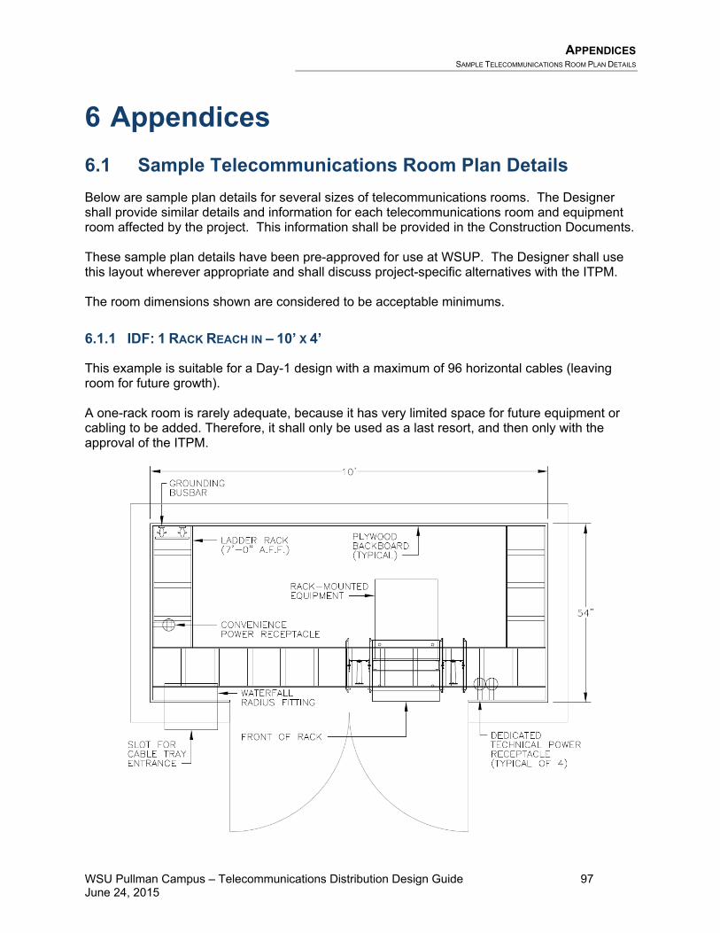
APPENDICES SAMPLE TELECOMMUNICATIONS ROOM PLAN DETAILS
WSU Pullman Campus – Telecommunications Distribution Design Guide 97 June 24, 2015
6 Appendices 6.1 Sample Telecommunications Room Plan Details Below are sample plan details for several sizes of telecommunications rooms. The Designer shall provide similar details and information for each telecommunications room and equipment room affected by the project. This information shall be provided in the Construction Documents. These sample plan details have been pre-approved for use at WSUP. The Designer shall use this layout wherever appropriate and shall discuss project-specific alternatives with the ITPM. The room dimensions shown are considered to be acceptable minimums.
6.1.1 IDF: 1 RACK REACH IN – 10’ X 4’
This example is suitable for a Day-1 design with a maximum of 96 horizontal cables (leaving room for future growth). A one-rack room is rarely adequate, because it has very limited space for future equipment or cabling to be added. Therefore, it shall only be used as a last resort, and then only with the approval of the ITPM.

APPENDICES SAMPLE TELECOMMUNICATIONS ROOM PLAN DETAILS
WSU Pullman Campus – Telecommunications Distribution Design Guide 98 June 24, 2015
6.1.2 IDF: 1 RACK – 10’ X 6’
This example is suitable for a Day-1 design with a maximum of 96 horizontal cables (leaving room for future growth). This solution is preferable over the reach-in design depicted above in section 6.1.1. A one-rack room is rarely adequate, because it has very limited space for future equipment or cabling to be added. Therefore, it shall only be used as a last resort, and then only with the approval of the ITPM.
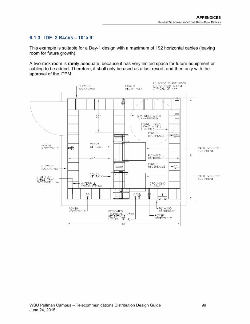
APPENDICES SAMPLE TELECOMMUNICATIONS ROOM PLAN DETAILS
WSU Pullman Campus – Telecommunications Distribution Design Guide 99 June 24, 2015
6.1.3 IDF: 2 RACKS – 10’ X 9’
This example is suitable for a Day-1 design with a maximum of 192 horizontal cables (leaving room for future growth). A two-rack room is rarely adequate, because it has very limited space for future equipment or cabling to be added. Therefore, it shall only be used as a last resort, and then only with the approval of the ITPM.

APPENDICES SAMPLE TELECOMMUNICATIONS ROOM PLAN DETAILS
WSU Pullman Campus – Telecommunications Distribution Design Guide 100 June 24, 2015
6.1.4 IDF: 3 RACKS – 10’ X 12’
This example is suitable for a Day-1 design with a maximum of 288 horizontal cables (leaving room for future growth). This is the standard IDF configuration.
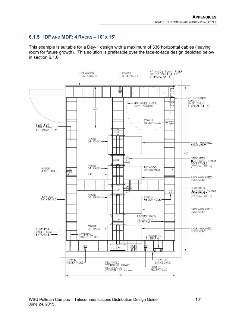
APPENDICES SAMPLE TELECOMMUNICATIONS ROOM PLAN DETAILS
WSU Pullman Campus – Telecommunications Distribution Design Guide 101 June 24, 2015
6.1.5 IDF AND MDF: 4 RACKS – 10’ X 15’
This example is suitable for a Day-1 design with a maximum of 336 horizontal cables (leaving room for future growth). This solution is preferable over the face-to-face design depicted below in section 6.1.6.
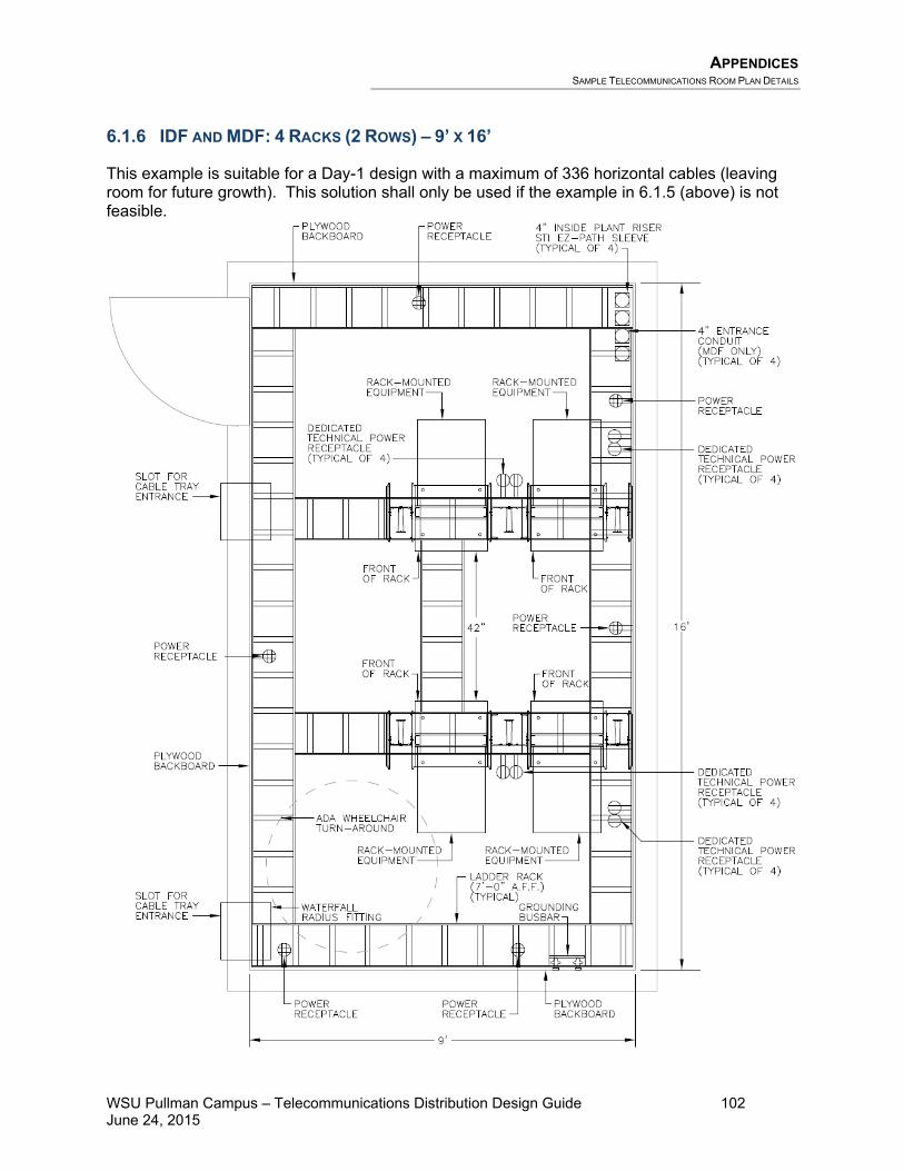
APPENDICES SAMPLE TELECOMMUNICATIONS ROOM PLAN DETAILS
WSU Pullman Campus – Telecommunications Distribution Design Guide 102 June 24, 2015
6.1.6 IDF AND MDF: 4 RACKS (2 ROWS) – 9’ X 16’
This example is suitable for a Day-1 design with a maximum of 336 horizontal cables (leaving room for future growth). This solution shall only be used if the example in 6.1.5 (above) is not feasible.

APPENDICES SAMPLE TELECOMMUNICATIONS ROOM PLAN DETAILS
WSU Pullman Campus – Telecommunications Distribution Design Guide 103 June 24, 2015
6.1.7 MCF: 6 RACKS (2 ROWS) – 12’ X 16’
This example is a starting point for designing a main communication facility (MCF). If circumstances require, this example could also be used for a telecommunications room, for a Day-1 design with a maximum of 504 horizontal cables (leaving room for future growth). This is the standard configuration for main communication facilities at WSUP.

Appendices SAMPLE RACK ELEVATION DETAIL
WSU Pullman Campus – Telecommunications Distribution Design Guide 104 June 24, 2015
6.2 Sample Rack Elevation Detail The following pages show sample scaled rack elevation details. The Designer shall provide similar information for each new or existing telecommunications room affected by the project. This information shall be provided either as a portion of the Project Manual or on the drawings, and shall be considered part of the Construction Documents. The leftmost rack shown in each elevation detail below shall be adjacent to the wall. It may be necessary in some projects to invert the left-to-right arrangement such that the fiber optic patch panel and copper backbone cabling always terminate in the rack adjacent to the wall, and so that the horizontal cabling always terminates in the rack away from the wall.

Appendices SAMPLE RACK ELEVATION DETAIL
WSU Pullman Campus – Telecommunications Distribution Design Guide 105 June 24, 2015
6.2.1 IDF: 1 RACK
A
1
2
3
4
5
6
1
2
3
4
5
6
1
2
3
4
5
6
1
2
3
4
5
6
1
2
3
4
5
6
1
2
3
4
5
6
1
2
3
4
5
6
1
2
3
4
5
6
1
2
3
4
5
6
1
2
3
4
5
6
1
2
3
4
5
6
1
2
3
4
5
6
B MC D E F G H J K L
AMPTRAC
19 20 21 22 23 2413 14 15 16 17 187 8 9 10 11 121 2 3 4 5 6
AMPTRAC
19 20 21 22 23 2413 14 15 16 17 187 8 9 10 11 121 2 3 4 5 6
AMPTRAC
19 20 21 22 23 2413 14 15 16 17 187 8 9 10 11 121 2 3 4 5 6
AMPTRAC
19 20 21 22 23 2413 14 15 16 17 187 8 9 10 11 121 2 3 4 5 6
AMPTRAC
19 20 21 22 23 2413 14 15 16 17 187 8 9 10 11 121 2 3 4 5 6
AMPTRAC
19 20 21 22 23 2413 14 15 16 17 187 8 9 10 11 121 2 3 4 5 6
AMPTRAC
19 20 21 22 23 2413 14 15 16 17 187 8 9 10 11 121 2 3 4 5 6
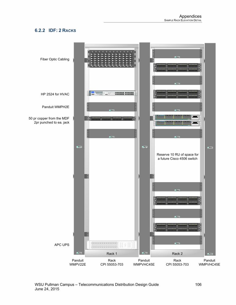
Appendices SAMPLE RACK ELEVATION DETAIL
WSU Pullman Campus – Telecommunications Distribution Design Guide 106 June 24, 2015
6.2.2 IDF: 2 RACKS
Fiber Optic Cabling
RackCPI 55053-703
HP 2524 for HVAC
PanduitWMPV22E
Panduit WMPH2E
50 pr copper from the MDF 2pr punched to ea. jack
PanduitWMPVHC45E
PanduitWMPVHC45E
APC UPS
RackCPI 55053-703
CABLE MANAGEMENT
CABLE MANAGEMENT
A
1
2
3
4
5
6
1
2
3
4
5
6
1
2
3
4
5
6
1
2
3
4
5
6
1
2
3
4
5
6
1
2
3
4
5
6
1
2
3
4
5
6
1
2
3
4
5
6
1
2
3
4
5
6
1
2
3
4
5
6
1
2
3
4
5
6
1
2
3
4
5
6
B MC D E F G H J K L
Rack 1 Rack 2
AMPTRAC
19 20 21 22 23 2413 14 15 16 17 187 8 9 10 11 121 2 3 4 5 6
AMPTRAC
19 20 21 22 23 2413 14 15 16 17 187 8 9 10 11 121 2 3 4 5 6
AMPTRAC
19 20 21 22 23 2413 14 15 16 17 187 8 9 10 11 121 2 3 4 5 6
AMPTRAC
19 20 21 22 23 2413 14 15 16 17 187 8 9 10 11 121 2 3 4 5 6
AMPTRAC
19 20 21 22 23 2413 14 15 16 17 187 8 9 10 11 121 2 3 4 5 6
AMPTRAC
19 20 21 22 23 2413 14 15 16 17 187 8 9 10 11 121 2 3 4 5 6
AMPTRAC
19 20 21 22 23 2413 14 15 16 17 187 8 9 10 11 121 2 3 4 5 6
AMPTRAC
19 20 21 22 23 2413 14 15 16 17 187 8 9 10 11 121 2 3 4 5 6
AMPTRAC
19 20 21 22 23 2413 14 15 16 17 187 8 9 10 11 121 2 3 4 5 6
Reserve 10 RU of space fora future Cisco 4506 switch

Appendices SAMPLE RACK ELEVATION DETAIL
WSU Pullman Campus – Telecommunications Distribution Design Guide 107 June 24, 2015
6.2.3 IDF AND MDF: 3 RACKS
A
1
2
3
4
5
6
1
2
3
4
5
6
1
2
3
4
5
6
1
2
3
4
5
6
1
2
3
4
5
6
1
2
3
4
5
6
1
2
3
4
5
6
1
2
3
4
5
6
1
2
3
4
5
6
1
2
3
4
5
6
1
2
3
4
5
6
1
2
3
4
5
6
B MC D E F G H J K L
AMPTRAC
19 20 21 22 23 2413 14 15 16 17 187 8 9 10 11 121 2 3 4 5 6
AMPTRAC
19 20 21 22 23 2413 14 15 16 17 187 8 9 10 11 121 2 3 4 5 6
AMPTRAC
19 20 21 22 23 2413 14 15 16 17 187 8 9 10 11 121 2 3 4 5 6
AMPTRAC
19 20 21 22 23 2413 14 15 16 17 187 8 9 10 11 121 2 3 4 5 6
AMPTRAC
19 20 21 22 23 2413 14 15 16 17 187 8 9 10 11 121 2 3 4 5 6
AMPTRAC
19 20 21 22 23 2413 14 15 16 17 187 8 9 10 11 121 2 3 4 5 6
AMPTRAC
19 20 21 22 23 2413 14 15 16 17 187 8 9 10 11 121 2 3 4 5 6
AMPTRAC
19 20 21 22 23 2413 14 15 16 17 187 8 9 10 11 121 2 3 4 5 6
AMPTRAC
19 20 21 22 23 2413 14 15 16 17 187 8 9 10 11 121 2 3 4 5 6
AMPTRAC
19 20 21 22 23 2413 14 15 16 17 187 8 9 10 11 121 2 3 4 5 6
AMPTRAC
19 20 21 22 23 2413 14 15 16 17 187 8 9 10 11 121 2 3 4 5 6
AMPTRAC
19 20 21 22 23 2413 14 15 16 17 187 8 9 10 11 121 2 3 4 5 6
AMPTRAC
19 20 21 22 23 2413 14 15 16 17 187 8 9 10 11 121 2 3 4 5 6
AMPTRAC
19 20 21 22 23 2413 14 15 16 17 187 8 9 10 11 121 2 3 4 5 6
AMPTRAC
19 20 21 22 23 2413 14 15 16 17 187 8 9 10 11 121 2 3 4 5 6
AMPTRAC
19 20 21 22 23 2413 14 15 16 17 187 8 9 10 11 121 2 3 4 5 6
AMPTRAC
19 20 21 22 23 2413 14 15 16 17 187 8 9 10 11 121 2 3 4 5 6
AMPTRAC
19 20 21 22 23 2413 14 15 16 17 187 8 9 10 11 121 2 3 4 5 6
AMPTRAC
19 20 21 22 23 2413 14 15 16 17 187 8 9 10 11 121 2 3 4 5 6
AMPTRAC
19 20 21 22 23 2413 14 15 16 17 187 8 9 10 11 121 2 3 4 5 6
AMPTRAC
19 20 21 22 23 2413 14 15 16 17 187 8 9 10 11 121 2 3 4 5 6
AMPTRAC
19 20 21 22 23 2413 14 15 16 17 187 8 9 10 11 121 2 3 4 5 6
AMPTRAC
19 20 21 22 23 2413 14 15 16 17 187 8 9 10 11 121 2 3 4 5 6
AMPTRAC
19 20 21 22 23 2413 14 15 16 17 187 8 9 10 11 121 2 3 4 5 6
AMPTRAC
19 20 21 22 23 2413 14 15 16 17 187 8 9 10 11 121 2 3 4 5 6
AMPTRAC
19 20 21 22 23 2413 14 15 16 17 187 8 9 10 11 121 2 3 4 5 6
MAX 15.4W/PORT
STATUS
WS-X4548-GB-RJ45V
1 2 3 4 5 6 7 8 9 10 11 12 13 14 15 16
MULTI-SPEEDGIGABIT ETHERNET
SWITCHING MODULE
48-PORT10/100/1000 BASE T
IN-LINE POWER
3231
3029
2827
2625
2423
2221
2019
1817
4847
4645
4443
4241
4039
3837
3635
3433
1615
1413
1211
109
87
65
43
21
32313029282726252423222120191817 33 34 35 36 37 38 39 40 41 42 43 44 45 46 47 48

Appendices SAMPLE RACK ELEVATION DETAIL
WSU Pullman Campus – Telecommunications Distribution Design Guide 108 June 24, 2015
6.2.4 IDF AND MDF: 4 RACKS
A
1 2 3 4 5 6
1 2 3 4 5 6
1 2 3 4 5 6
1 2 3 4 5 6
1 2 3 4 5 6
1 2 3 4 5 6
1 2 3 4 5 6
1 2 3 4 5 6
1 2 3 4 5 6
1 2 3 4 5 6
1 2 3 4 5 6
1 2 3 4 5 6
BM
CD
EF
GH
JK
L
AM
PTR
AC
1920
2122
2324
1314
1516
1718
78
910
1112
12
34
56
AM
PTRA
C
1920
2122
2324
1314
1516
1718
78
910
1112
12
34
56
AM
PTRA
C
1920
2122
2324
1314
1516
1718
78
910
1112
12
34
56
AM
PTRA
C
1920
2122
2324
1314
1516
1718
78
910
1112
12
34
56
AM
PTRA
C
1920
2122
2324
1314
1516
1718
78
910
1112
12
34
56
AM
PTRA
C
1920
2122
2324
1314
1516
1718
78
910
1112
12
34
56
AM
PTR
AC
1920
2122
2324
1314
1516
1718
78
910
1112
12
34
56
AM
PTR
AC
1920
2122
2324
1314
1516
1718
78
910
1112
12
34
56
AM
PTR
AC
1920
2122
2324
1314
1516
1718
78
910
1112
12
34
56
AM
PTRA
C
1920
2122
2324
1314
1516
1718
78
910
1112
12
34
56
AM
PTRA
C
1920
2122
2324
1314
1516
1718
78
910
1112
12
34
56
AM
PTRA
C
1920
2122
2324
1314
1516
1718
78
910
1112
12
34
56
AM
PTR
AC
1920
2122
2324
1314
1516
1718
78
910
1112
12
34
56
AM
PTR
AC
1920
2122
2324
1314
1516
1718
78
910
1112
12
34
56
AM
PTR
AC
1920
2122
2324
1314
1516
1718
78
910
1112
12
34
56
AM
PTR
AC
1920
2122
2324
1314
1516
1718
78
910
1112
12
34
56
AM
PTR
AC
1920
2122
2324
1314
1516
1718
78
910
1112
12
34
56
AM
PTR
AC
1920
2122
2324
1314
1516
1718
78
910
1112
12
34
56
AM
PTR
AC
1920
2122
2324
1314
1516
1718
78
910
1112
12
34
56
AM
PTR
AC
1920
2122
2324
1314
1516
1718
78
910
1112
12
34
56
AM
PTR
AC
1920
2122
2324
1314
1516
1718
78
910
1112
12
34
56
AM
PTR
AC
1920
2122
2324
1314
1516
1718
78
910
1112
12
34
56
AM
PTR
AC
1920
2122
2324
1314
1516
1718
78
910
1112
12
34
56
AM
PTR
AC
1920
2122
2324
1314
1516
1718
78
910
1112
12
34
56
AM
PTR
AC
1920
2122
2324
1314
1516
1718
78
910
1112
12
34
56
AM
PTR
AC
1920
2122
2324
1314
1516
1718
78
910
1112
12
34
56
MAX
15.4
W/P
ORT
STAT
US
WS-
X454
8-GB
-RJ4
5V
12
34
56
78
910
1112
1314
1516
MULT
I-SPE
EDGI
GABI
T ET
HERN
ETSW
ITCH
ING
MODU
LE
48-P
ORT
10/10
0/10
00 B
ASE
TIN
-LINE
POW
ER
32313029
28272625
24232221
20191817
48474645
44434241
40393837
36353433
16151413
1211109
8765
4321
3231
3029
2827
2625
2423
2221
2019
1817
3334
3536
3738
3940
4142
4344
4546
4748
AM
PTRA
C
1920
2122
2324
1314
1516
1718
78
910
1112
12
34
56
AM
PTRA
C
1920
2122
2324
1314
1516
1718
78
910
1112
12
34
56
AM
PTRA
C
1920
2122
2324
1314
1516
1718
78
910
1112
12
34
56
AM
PTRA
C
1920
2122
2324
1314
1516
1718
78
910
1112
12
34
56
AM
PTRA
C
1920
2122
2324
1314
1516
1718
78
910
1112
12
34
56
AM
PTRA
C
1920
2122
2324
1314
1516
1718
78
910
1112
12
34
56
AM
PTRA
C
1920
2122
2324
1314
1516
1718
78
910
1112
12
34
56
AM
PTRA
C
1920
2122
2324
1314
1516
1718
78
910
1112
12
34
56
MAX
15.4W
/POR
T
STAT
US
WS-
X454
8-GB-
RJ45
V
12
34
56
78
910
1112
1314
1516
MUL
TI-S
PEED
GIGA
BIT
ETHE
RNET
SWIT
CHIN
G M
ODUL
E
48-P
ORT
10/1
00/1
000 B
ASE
TIN
-LIN
E PO
WER
32313029
28272625
24232221
20191817
48474645
44434241
40393837
36353433
16151413
1211109
8765
4321
3231
3029
2827
2625
2423
2221
2019
1817
3334
3536
3738
3940
4142
4344
4546
4748

Appendices SAMPLE WALL ELEVATION DETAIL
WSU Pullman Campus – Telecommunications Distribution Design Guide 109 June 24, 2015
6.3 Sample Wall Elevation Detail This page shows a sample scaled wall elevation detail. The Designer shall provide similar information for each new or existing telecommunications room wall affected by the project. This information shall be provided either as a portion of the Project Manual or on the drawings, and shall be considered part of the Construction Documents.

Appendices SAMPLE FIBER OPTIC LINK-LOSS BUDGET ANALYSIS
WSU Pullman Campus – Telecommunications Distribution Design Guide 110 June 24, 2015
6.4 Sample Fiber Optic Link-Loss Budget Analysis The following is a sample Fiber Optic Link-Loss Budget Analysis that the Designer shall use for each new fiber optic cable designed in the project. The Designer shall submit the completed link-loss budget analyses to WSUP in both electronic and paper forms. Upon request, WSUP will provide an electronic spreadsheet of this form to be used as a template.
Cable ID: Enter Cable ID Here # of MM Strands
From: Enter MDF/Building Name Here # of SM Strands
To: Enter IDF/Building Name Here
MM 850 MM 1300 SM 1310 SM 1550Passive Cable System AttenuationFiber Loss at Operating Wavelength Cable Length (in kilometers) km
x Attenuation per km x 3.75 x 1.5 x 0.5 x 0.5 dB/km= Total Fiber Loss 0.00 0.00 0.00 0.00 dB
Connector Loss Number of Connector Pairs 2 2 2 2 pairs(Excluding Tx & Rx Connectors) x Individual Connector Pair Loss x 0.5 x 0.5 x 0.5 x 0.5 dB/pair
= Total Connector Loss 1.00 1.00 1.00 1.00 dB
Splice Loss Number of Splices splicesx Individual Splice Loss x 0.3 x 0.3 x 0.3 x 0.3 dB/splice= Total Splice Loss 0.00 0.00 0.00 0.00 dB
Other Components Loss Total Components Loss dB
Total Passive Cable System Attenuation Total Fiber Loss 0.00 0.00 0.00 0.00 dB+ Total Connector Loss + 1.00 + 1.00 + 1.00 + 1.00 dB+ Total Splice Loss + 0.00 + 0.00 + 0.00 + 0.00 dB+ Total Components Loss + 0.0 + 0.0 + 0.0 + 0.0 dB= Total System Attenuation 1.00 1.00 1.00 1.00 dB
MM 850 MM 1300 SM 1310 SM 1550Link Loss BudgetFrom Manufacturer's Specifications Average Transmitter Output -18.0 -18.0 -18.0 -18.0 dBm
Receiver Sensitivity (109 BER) -31.0 -31.0 -31.0 -31.0 dBm
System Gain Average Transmitter Power -18.0 -18.0 -18.0 -18.0 dBm- Receiver Sensitivity - -31.0 - -31.0 - -31.0 - -31.0 dBm= System Gain = 13.00 = 13.00 = 13.00 = 13.00 dB
Power Penalties Operating Margin 2.0 2.0 3.0 3.0 dB# of Fusion Splices Loss per Splice + Receiver Power Penalties + 0.0 + 0.0 + 0.0 + 0.0 dB
2 X 0.3 = + Repair Margin + 0.6 + 0.6 + 0.6 + 0.6 dB= Total Power Penalties = 2.60 = 2.60 = 3.60 = 3.60 dB
Link Loss Budget System Gain 13.00 13.00 13.00 13.00 dB- Power Penalties - 2.60 - 2.60 - 3.60 - 3.60 dB= Total Link Loss Budget = 10.40 = 10.40 = 9.40 = 9.40 dB
MM 850 MM 1300 SM 1310 SM 1550PerformanceSystem Performance Margin Link Loss Budget 10.40 10.40 9.40 9.40 dB
- Passive Cable System Attenuation - 1.00 - 1.00 - 1.00 - 1.00 dB= System Performance Margin = 9.40 = 9.40 = 8.40 = 8.40 dB
Users of this spreadsheet shall verify prior to use that the parameters and calculations are appropriate for the project, equipment, and materials that are used.

Appendices MAINTENANCE HOLE BUTTERFLY DIAGRAM
WSU Pullman Campus – Telecommunications Distribution Design Guide 111 June 24, 2015
6.5 Maintenance Hole Butterfly Diagram The following drawing is a sample butterfly diagram for an outside plant maintenance hole:

Appendices GLOSSARY
WSU Pullman Campus – Telecommunications Distribution Design Guide 112 June 24, 2015
6.6 Glossary A/E Architect/Engineer
ACPM Access Control Project Manager
APC Angle Polish Connector (singlemode fiber optic)
AVCGS Audio/Visual Construction Guide Specification
AVDG Audio/Visual Design Guide
AVPM Audio/Visual Project Manager
CDF Controlled-density fill
CGS Construction Guide Specification
CGSP Construction Guide Specification Preface
CMU Concrete masonry unit
EMI Electromagnetic interference
ESS Electronic Safety and Security
FF&E Furniture, fixtures and equipment
FSPM Facilities Services Project Manager
GC/CM General Contractor/Construction Manager
GPON Gigabit Passive Optical Network
HC Horizontal cross-connect
HCP House Cable Pair
IC Intermediate cross-connect
IDF Intermediate Distribution Frame (secondary telecommunications rooms)
ISP Inside plant
ITPM Information Technology Project Manager
MC Main cross-connect
MAC Moves, adds, and changes
MCF Main Communication Facility (campus cross-connect)
MDF Main Distribution Frame (main telecommunications room in the building)
O.D. Outside Diameter
OSP Outside plant
PDU Power distribution unit
PII Personally identifiable information
POE Power over Ethernet
RCDD Registered Communications Distribution Designer
RFI Radio frequency interference
Appendices GLOSSARY
WSU Pullman Campus – Telecommunications Distribution Design Guide 113 June 24, 2015
STP Shielded Twisted Pair
SVR Standards Variance Request
TCGS Telecommunications Construction Guide Specification
TDDG Telecommunications Distribution Design Guide
TGB Telecommunications grounding busbar
TIDG Technology Infrastructure Design Guide
TPM Technology Project Manager
TR Telecommunications room
UTC Undercarpet telecommunications cabling
UTP Unshielded twisted pair
WAP Wireless access point