Embed Size (px)
Citation preview
TELECOMMUNICATIONS
PULSE-COOE MODULATION TELEMETRY
UNIFIED S-BAND
NAL CONDITIONER
TRIPLEXER
VHF/AM
0 FREQUENCY SWITCH
P DATA LINK
S-BAND POWER AMPLIFIER
P-223 Location of main telecommunications equipment
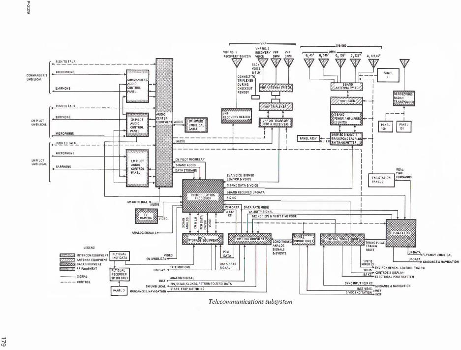
The telecommunications subsystem provides voice, television, telemetry, and tracking and ranging communications between the spacecraft and earth, between the CM and LM, and between the spacecraft and astronauts wearing the portable life support system. It also provides communications among the astronauts in the spacecraft and includes the central timing equipment for synchronization of other equipment and correlation of telemetry equipment.
For convenience, the telecommunications subsystem can be divided into four areas: intercommunications (voice), data, radio frequency equipment, and antennas. Most of the components of the telecommunications subsystem are produced by the Collins Radio Co., Cedar Rapids, Iowa.
INTERCOMMUNICATIONS
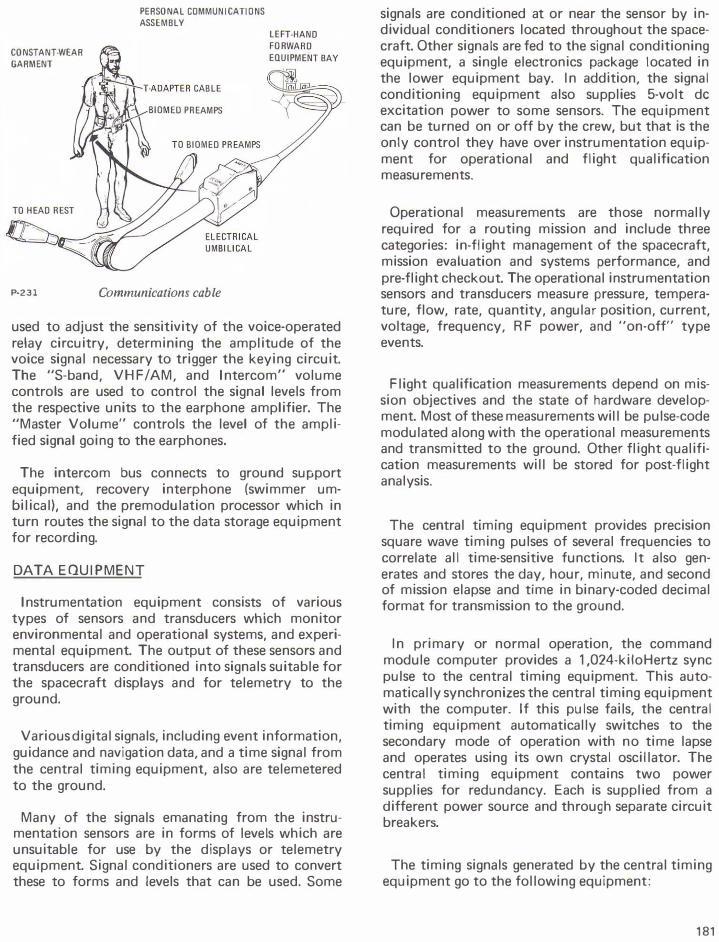
The astronauts headsets are used for all voice communications. Each headset has two independently operated earphones and two microphones with selfcontained pre-amplifiers. Each astronaut has an audio control panel on the main display console which enables him to control what comes into his headset and where he will send his voice. The headsets are connected to the audio panels by separate umbilical cables. These cables also contain wiring for the biomedical sensors in the constant-wear garment.
The three headsets and audio control panels are connected to three identical audio center modules.
173
The audio center is the assimilation and distribution point for all spacecraft voice signals. The audio signals can be routed from the center to the appropriate transmitter or receiver, the launch control center (for pre-launch checkout), the recovery forces intercom, or voice tape recorders.
Two methods of voice transmission and reception are possible: the VHF/AM transmitter-receiver and the S-band transmitter and receiver. Transmission is controlled by either the push-to-talk switch located in the astronaut's umbilical cable or the voiceoperated relay circuitry during recovery operations. The push-to-talk switch also can be used like a telegraph key for emergency transmission.
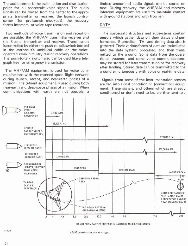
The VHF/AM equipment is used for voice communications with the manned space flight network during launch, ascent, and near-earth phases of a mission. The S-band equipment is used during both near-earth and deep-space phases of a mission. When communications with earth are not possible, a
VHF OMNI VOICE 2-GC OMNI OOWN VOICE
UP-DATA BACKUP VOICE & EMERGENCY KEY
TELEMETER (LOW BIT RATE)
TELEMETER (HIGH BIT RATE)
P 2-GC HIGH-GAIN UP-DATA, UP-VOICE DOWN VOICE, TELEMETRY
TV NEAR EARTH & DEEP SPACE
2,600 N. ML
I 38,000 N. ML
22,000 N. ML
WIDE BEAM
DEEP SPACE BLIND AREA
limited amount of audio signals can be stored on tape. During recovery, the VHF/AM and recovery intercom equipment are used to maintain contact with ground stations and with frogmen.
DATA
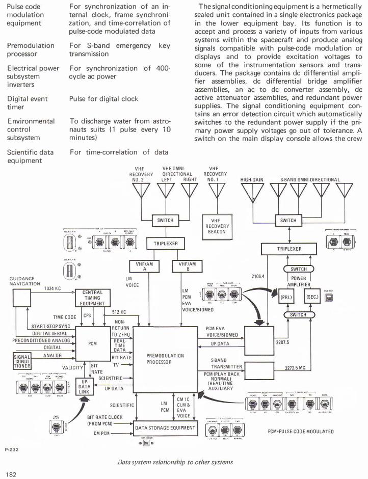
The spacecraft structure and subsystems contain sensors which gather data on their status and performance. Biomedical, TV, and timing data also is gathered. These various forms of data are assimilated into the data system, processed, and then transmitted to the ground. Some data from the operational systems, and some voice communications, may be stored for later transmission or for recovery after landing. Stored data can be transmitted to the ground simultaneously with voice or real-time data.
Signals from some of the instrumentation sensors are fed into signal conditioning (converting) equipment. These signals, and others which are already conditioned or don't need to be, are then sent to a
MEDIUM BEAM
220,000 N _ M L
200,000 N. ML
NARROW BEAM
LUNAR OPERATIONS: VH.F: VOICE, CM-LM RENDEZVOUS RADAR/ TRANSPONDER, CM-LM
HIGH-GAIN ANTENNA OPERATIONAL (2500)
P-224
174
.1 A 4.6 8.0 20.0 30.0 40 50
RANGE FROM EARTH'S SURFACE IN NAUTICAL MILES (TH OUSANDS)
CSM communication ranges
data distribution panel, which routes them to CM displays and to pulse-code modulation telemetry equipment. The latter combines them into a single signal and sends it to the premodulation processor.
The premodulation processor is the assimilation, integration, and distribution center for nearly all forms of spacecraft data. It accepts signals from telemetry, data storage, TV, central timing, and audio center equipment. It modulates, mixes, and switches these signals to the appropriate transmitter or to data storage.
Voice and data command signals from the ground received over the S-band receiver also are supplied to the processor, which routes them to the audio center equipment or the up-data link (ground command) system. Up-data is of three types: guidance and navigation data for updating the CM computer, timing data for updating the central timing equipment, and real-time commands. The commands give the ground limited control over certain spacecraft telecommunications functions.
RADIO FREQUENCY EQUIPMENT
The radio frequency equipment is the means by which voice information, telemetry data, and ranging and tracking information are transmitted and received. The equipment consists of two VHF I
AM transceivers (transmitter-receiver) in one unit, the unified S-band equipment (primary and secondary transponders and an FM transmitter), primary and secondary S-band power amplifiers (in one unit), a VHF beacon, an X-band transponder (for rendezvous radar), and the premodulation processor.
The equipment provides for voice transfer between the CM and the ground, between the CM and LM, between the CM and extravehicular astronauts, and between the CM and recovery forces. Telemetry can be transferred between the CM and the ground, from the LM to the CM and then to the ground, and from extravehicular astronauts to the CM and then to the ground. Ranging information consists of pseudo-r·andom noise and double-doppler ranging signals from the ground to the CM and back to the ground and X-band radar signals from the LM to the CM and back to the LM. The VHF beacon equipment emits a 2-second signal every 5 seconds for I ine-of-sight directionfinding to aid recovery forces in locating the CM after landing.
ANTENNAS
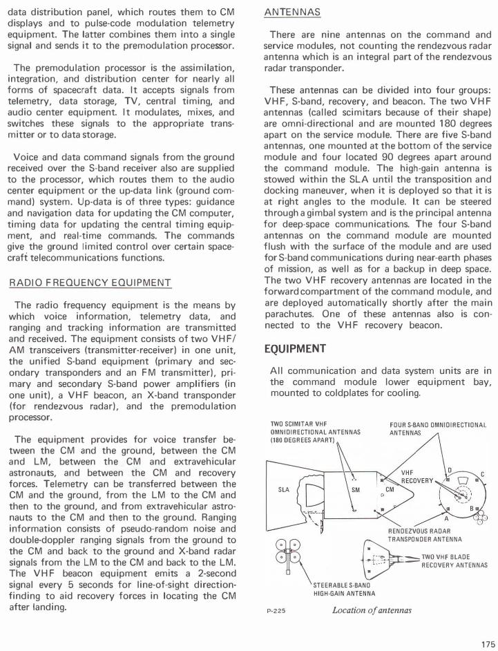
There are nine antennas on the command and service modules, not counting the rendezvous radar antenna which is an integral part of the rendezvous radar transponder.
These antennas can be divided into four groups: VHF, S-band, recovery, and beacon. The two VHF antennas (called scimitars because of their shape) are omni-directional and are mounted 1 80 degrees apart on the service module. There are five S-band antennas, one mounted at the bottom of the service module and four located 90 degrees apart around the command module. The high-gain antenna is stowed within the SLA until the transposition and docking maneuver, when it is deployed so that it is at right angles to the module. It can be steered through a gimbal system and is the principal antenna for deep-space communications. The four S-band antennas on the command module are mounted flush with the surface of the module and are used for S-band communications during near-earth phases of mission, as well as for a backup in deep space. The two VHF recovery antennas are located in the forward compartment of the command module, and are deployed automatically shortly after the main parachutes. One of these antennas also is connected to the VHF recovery beacon.
EQUIPMENT
All communication and data system units are in the command module lower equipment bay, mounted to coldplates for cooling.
lWO SCIMITAR VHF
OMNIDIRECTIONAL ANTENNAS
(180 DEGREES APART)
FOUR S·BANO OMNIDIRECTIONAL
SLA
0
P-225
ANTENNAS
RENDEZVOUS RADAR
TRANSPONDER ANTENNA
•
�--., - lWO VHF BLADE �- RECOVERY ANTENNAS
STEERABLE S-BANO
HIGH-GAIN ANTENNA
Location of antennas
175
Audio Center (Collins Radio Co., Cedar Rapids, Iowa) -Center weighs 7.9 pounds and is 4. 7 by 4.56 by 8.65 inches. It is a 28-volt, 20-watt gasket-sealed box with three identical headset amplifiers, one for each crewman. It provides communication among astronauts, between astronauts and launch pad personnel, and post-landing recovery frogmen, recording of audio signals in conjunction with tape recording equipment, and relaying of audio signals.
Central Timing Equipment (General Time Corp.) -This 1 0-pound unit provides time correlation of all spacecraft time-sensitive functions. It also generates and stores the real-time day, hour, minute, and second mission elapsed time in binary-coded decimal format for onboard recording and transmission to the Manned Space Flight Network. It is normally synchronized to a continuously generated signal from the guidance and navigation computer. If the signal is lost, backup is provided by synchronizing to a self-contained source. The unit contains two power supplies for redundancy. Each is supplied from a different power source and through separate circuit breakers. The two power supplies provide parallel 6-volt de outputs, either one of which is sufficient to power the entire unit.
Data Storage Equipment (Leach Corp., Azusa, Calif. ) - This 40-pound unit is 22 by 9.5 by 6 inches and operates from 1 1 5-volt, 3-phase, 400-Hertz and 28-volt de power. Tape is one-inch, 1 4-track Mylar. It operates at three speeds: 3. 75, 1 5, and 120 inches per second. While being played back, the tape speed is selected automatically to Provide an apparent 5 1 . 2 KBPS PCM data. It plays in a single direction, but a rewind mode is provided. It stores data and voice information during powered phases of mission and during periods of lost communications and plays them back later.
Digital Ranging Generator (RCA)-This generator, used with the VHF/AM transmitter-receiver, supplements the lunar module rendezvous radar system by providing distance-to LM information in the CM. It has solid-state circuitry and is housed in a machined-aluminum case 4 by 6 by 8.5 inches. It weighs 6- 1 / 2 pounds.
Premodulation Processor (Collins) - It is of solid state design and modular construction and has redundant circuitry. It weighs 1 4.5 pounds and is 4.7 by 6 by 10.5 inches. It requires 1 2.5 watts at 28 volts de. It provides the interface connection
176
between the spacecraft data-gathering equipment and the S-band R F electronics. It accomplishes signal modulation and demodulation, signal mixing, and the proper switching of signals so that the correct intelligence corresponding to a given mode of operation is transmitted.
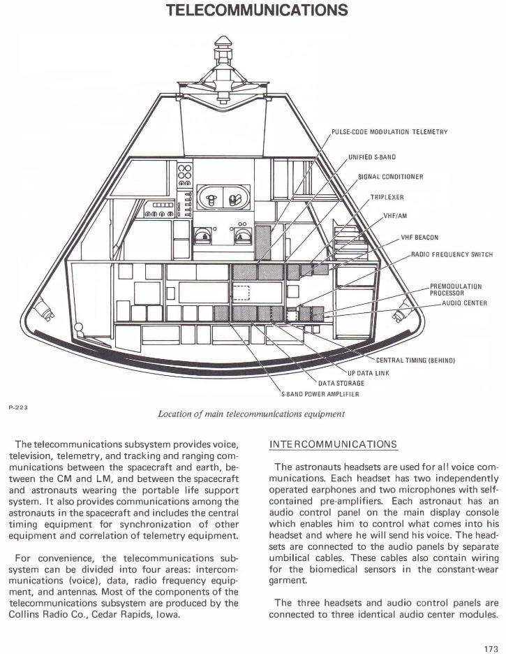
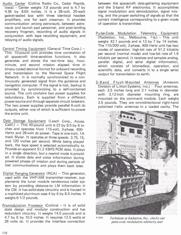
Pu lse-Code Modulation Telemetry Equipment (Radiation, Inc., Melbourne, Fla.)-This unit weighs 42.1 pounds and is 1 3 by 7 by 1 4 inches. The 1 1 5/200 volt, 3-phase, 400-Hertz unit has two modes of operation: high-bit rate of 5 1 .2 kilobits per second (normal mode) and low-bit rate of 1 . 6 kilobits per second. It receives and samples analog, parallel digital, and serial digital information, which consists of biomedical, operation, and scientific data, and converts it to a single serial output for transmission to earth.
S-Band F l u s h - M ounted Antennas (Amecom Division of Litton Systems, Inc.)- Four antennas, each 3.5 inches long and 2.1 inches in diameter with 3. 1 2-inch diameter mounting ring, are mounted on the command module. Each weighs 2.5 pounds. They are omnidirectional right-hand polarized Helix antennas in a loaded cavity. The
P-226 Technican at Radiation, Inc., checks out pulse-code modulation telemetry unit
astronaut selects the antenna he will use. They transmit and receive all S-band signals during near-earth operation and are backup for the high-gain antenna in deep space.
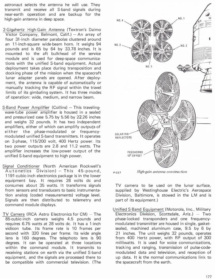
2-Gigahertz High-Gain Antenna (Textron's Dalmo Victor Company, Belmont, Calif.} -An array of four 31-inch diameter parabolas clustered around an 11-inch-square wide-beam horn. It weighs 94 pounds and is 65 by 64 by 33.78 inches. It is mounted to the aft bulkhead of the service module and is used for deep-space communications with the unified S-band equipment. Actual deployment takes place during transposition and docking phase of the mission when the spacecraft lunar adapter panels are opened. After deployment, the antenna is capable of automatically or manually tracking the R F signal within the travel limits of its gimbaling system. It has three modes of operation: wide, medium, and narrow beam.
S-Band Power Amplifier (Collins} -This travelingwave-tube power amplifier is housed in a sealed and pressurized case 5. 75 by 5.56 by 22.26 inches and weighs 32 pounds. It has two independent amplifiers, either of which can amplify outputs of either the phase-modulated or frequencymodulated unified S-band transmitters. It operates on 3-phase, 115/200 volt, 400 Hertz power. Its two power outputs are 2.8 and 11.2 watts. The amplifier increases the low-power output of the unified S-band equipment to high power.
Signal Conditioner (North American Rockwell's A u t o net ics Divis ion}- This 4 5 - p ound, 1191-cubic-inch electronics package is in the lower equipment bay. It requires 28 volts de and consumes about 35 watts. It transforms signals from sensors and transducers to basic instrumentation analog (coded measurements) voltage level. Signals are then distributed to telemetry and command module displays.
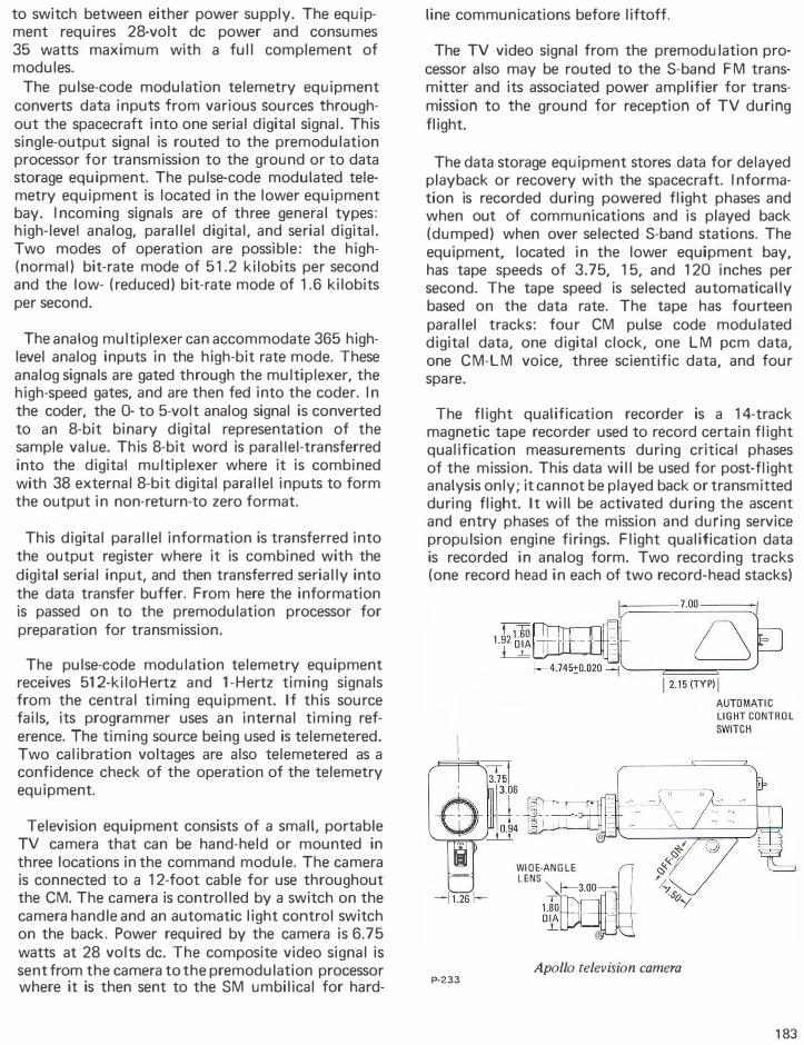
TV Camera (RCA Astro Electronics for CM} -The 85-cubic-inch camera weighs 4.5 pounds and requires 6.75 watts at 28 volts de. It has a 1-inch vidicon tube. Its frame rate is 10 frames per second with 320 lines per frame. Its wide angle lens is 160 degrees. The telephoto lens is 90 degrees. It can be operated at three I ocations within the command module. It transmits to receiving stations on earth via the unified S-band equipment, and the signals are processed there to be compatible with commercial television. (The
NO.3
FEEOHORNS 10° OFFSET
NO.5
P·227 High-gain antenna constrnction
TV camera to be used on the lunar surface, supplied by Westinghouse Electric's Aerospace Division, Baltimore, is stowed in the LM and is part of its equipment.}
Unified S-Band Equipment (Motorola, Inc., Military Electronics Division, Scottsdale, Ariz.} - Two phase-locked transponders and one frequencymodulated transmitter are housed in single, gasketsealed, machined aluminum case, 9.5 by 6 by 21 inches. The unit weighs 32 pounds, operates from 400 Hertz power, with R F output of 300 milliwatts. It is used for voice communications, tracking and ranging, transmission of pulse-codemodulated data and television, and reception of up data. It is the normal communications link to the spacecraft from the earth.
177
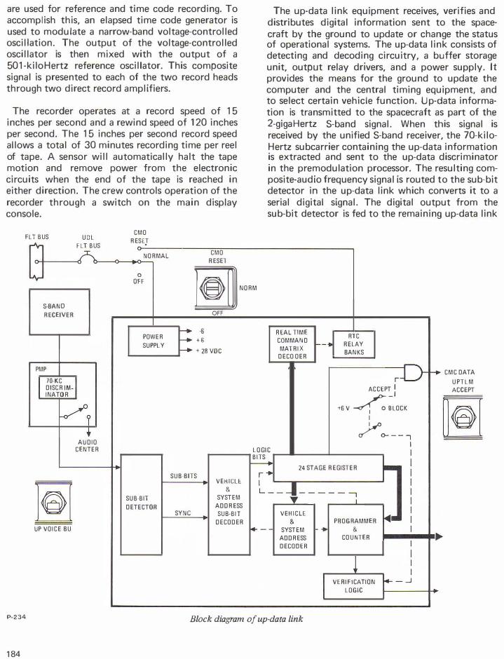
Up- D a ta Link Equipment (Motorola)-This 21-pound device is 6 by 18.3 by 9.6 inches. It receives, verifies, and distributes digital updating information sent to the spacecraft from the Manned Space Flight Network at various times throughout the mission to update or change the modes of the telecommunications systems. Data is received by the S-band receiver and routed to the up-data link.
VHF/AM Transmitter-Receiver (RCA Defense Electronic Products Communications System Division, Camden, N.J.)- It is one case housing dual transmitters and receivers for simplex or duplex operation. The enclosure contains 11 subassemblies, two coaxial relays, and two bandpass filters mounted within a three-piece hermetically sealed case. Powered from 28 volts de, the 5-watt ( R F output) unit weighs 13-1/2 pounds and is 6 by 4. 7 by 12 inches. It is used for voice communication between the command module and earth during near-earth and recovery phases of mission, for voice and data communication between the command module and lunar moduie, and between the command module and astronauts engaged in extravehicular activity.
VHF Omnidirectional Antennas (North American Rockwell's Columbus Division) -Two scimitar antennas are located on the service module 180 degrees apart. Each is 19 by 9 inches and 1-inch thick and weighs 12.5 pounds. They are stainless steel with a fiberglass skin and a covering of Teflon. They provide for two-way voice communication between the command module and earth, between the command module and the lunar module, between the command module and extravehicular activity personnel, and for voice and biomedical telemetry from the lunar module to the command module.
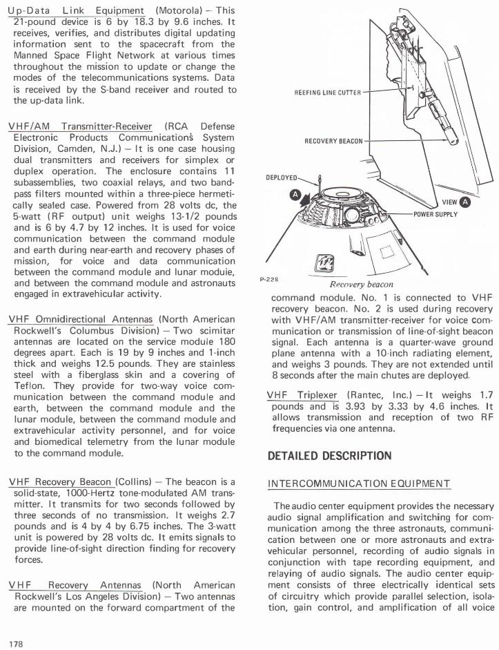
VHF Recovery Beacon (Collins) -The beacon is a solid-state, 1000-Hertz tone-modulated AM transmitter. It transmits for two seconds followed by three seconds of no transmission. It weighs 2. 7 pounds and is 4 by 4 by 6.75 inches. The 3-watt unit is powered by 28 volts de. It emits signals to provide line-of-sight direction finding for recovery forces.
VHF Recovery Antennas (North American Rockwell's Los Angeles Division) -Two antennas are mounted on the forward compartment of the
178
REEFING LINE CUTIER
P-228 Recovery beacon
command module. No. 1 is connected to VHF recovery beacon. No. 2 is used during recovery with VHF/ AM transmitter-receiver for voice communication or transmission of line-of-sight beacon signal. Each antenna is a quarter-wave ground plane antenna with a 1 0-inch radiating element, and weighs 3 pounds. They are not extended until 8 seconds after the main chutes are deployed.
VHF Triplexer (Rantec, Inc.) -It weighs 1.7 pounds and is 3.93 by 3.33 by 4.6 inches. It allows transmission and reception of two RF frequencies via one antenna.
DETAILED DESCRIPTION
INTERCOMMUNICATION EQUIPMENT
The audio center equipment provides the necessary audio signal amplification and switching for communication among the three astronauts, communication between one or more astronauts and extravehicular personnel, recording of audio signals in conjunction with tape recording equipment, and relaying of audio signals. The audio center equipment consists of three electrically identical sets of circuitry which provide parallel selection, isolation, gain control, and amplification of all voice
COMMANDER'S UMBILICAl
CM PILOT UMBILICAL
LMPILOT UMBILICAL
EARPHONE [ ._I'<Jj!! !Q. T�L _____ _
-� !Q.T�K_----
�ICROPHONE
EARPHONE
LEGEND
� INTERCOM EQUIPMENT � ANTENNA EQUIPMENT '-',�-.... � DATA EQUIPMENT
J�=��-----:=�-=-WEMmONs ....J �RfEQUIPMENT '"' DISPLAY ._:.::..:.::.:.:.:.:::::._ ___ _J
---SIGNAL
---- CONTROL
.-------VHF------.
VHF NO.1 RECOVERY BEACON
VHF NO.2 RECOVERY VHF VHF
I I
_j __________ --
Telecommunications subsystem
,---1
r:=.,� ��
communications. Each set of circuitry contains an isolation pad, diode switch, and gain control for each receiver input and an intercom channel; an isolation pad and diode switch for each transmitter modulation output and an intercom channel; an earphone amplifier and a microphone amplifier; and voice-operated relay circuitry with externally controlled sensitivity.
The equipment operates with three remote control panels to form three audio stations, each providing an astronaut with independent control. Each station can accommodate a second astronaut for emergency operation. Any or all of the transmitters can be turned on at each station. A "hot mike" enables continuous intercrew communication. When a transmitter is turned on, the corresponding receiver also is turned on. Sidetone is provided in all transmit modes.
Audio signals are provided to and from the VHF/ AM transmitter-receiver equipment, unified S-band, and the intercom bus. The intercom bus is common to all three stations and provides for the hardline cable communications among crewmen and with the launch control center and recovery force swimmers.
LM
VOICE EVA VOICE
INTERCOM VOICE TO DATA STORAGE
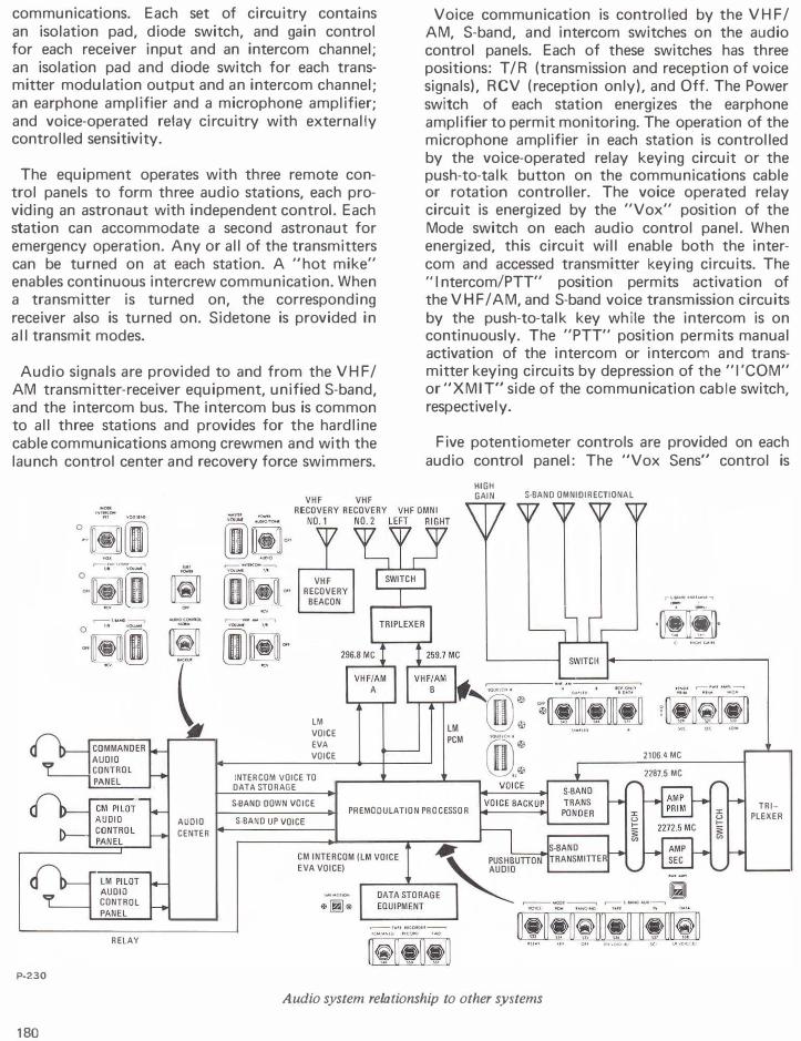
Voice communication is controlled by the VHF/ AM, S-band, and intercom switches on the audio control panels. Each of these switches has three positions: T/R (transmission and reception of voice signals), RCV (reception only), and Off. The Power switch of each station energizes the earphone amplifier to permit monitoring. The operation of the microphone amplifier in each station is controlled by the voice-operated relay keying circuit or the push-to-talk button on the communications cable or rotation controller. The voice operated relay circuit is energized by the "Vox" position of the Mode switch on each audio control panel. When energized, this circuit will enable both the intercom and accessed transmitter keying circuits. The "I ntercom/PTT" position permits activation of the VHF/AM, and S-band voice transmission circuits by the push-to-talk key while the intercom is on continuously. The "PTT" position permits manual activation of the intercom or intercom and transmitter keying circuits by depression of the "I'COM" or "XM IT" side of the communication cable switch, respective I y.
Five potentiometer controls are provided on each audio control panel: The "Vox Sens" control is
HIGH GAIN S·BAND OMNIDIRECTIONAL
-�-·,.11-..,
·[l.lli]-
2106.4 MC
2287.5 MC
S-BAND DOWN VOICE PREMODULATION PROCESSOR
TRIPLEXER
AUDIO S-BAND UP VOICE
CENTER
RELAY
P-230
Audio system relationship to other systems
180
CONSTANT-WEAR
GARMENT
PERSONAL COMMUNICATIONS
ASSEMBLY
P-231 Communications cable
used to adjust the sensitivity of the voice-operated relay circuitry, determining the amplitude of the voice signal necessary to trigger the keying circuit. The "S-band, VHF/AM, and Intercom" volume controls are used to control the signal levels from the respective units to the earphone amplifier. The "Master Volume" controls the level of the amplified signal going to the earphones.
The intercom bus connects to ground support equipment, recovery interphone (swimmer umbilical), and the premodulation processor which in turn routes the signal to the data storage equipment for recording.
DATA EQUIPMENT
Instrumentation equipment consists of various types of sensors and transducers which monitor environmental and operational systems, and experimental equipment. The output of these sensors and transducers are conditioned into signals suitable for the spacecraft displays and for telemetry to the ground.
Various digital signals, including event information, guidance and navigation data, and a time signal from the central timing equipment, also are telemetered to the ground.
Many of the signals emanating from the instrumentation sensors are in forms of levels which are unsuitable for use by the displays or telemetry equipment. Signal conditioners are used to convert these to forms and levels that can be used. Some
signals are conditioned at or near the sensor by individual conditioners located throughout the spacecraft. Other signals are fed to the signal conditioning equipment, a single electronics package located in the lower equipment bay. In addition, the signal conditioning equipment also supplies 5-volt de excitation power to some sensors. The equipment can be turned on or off by the crew, but that is the only control they have over instrumentation equipment for operational and flight qualification measurements.
Operational measurements are those normally required for a routing mission and include three categories: in-flight management of the spacecraft, mission evaluation and systems performance, and pre-flight checkout. The operational instrumentation sensors and transducers measure pressure, temperature, flow, rate, quantity, angular position, current, voltage, frequency, R F power, and "on-off" type events.
Flight qualification measurements depend on mission objectives and the state of hardware development. Most of these measurements wi II be pulse-code modulated along with the operational measurements and transmitted to the ground. Other flight qualification measurements will be stored for post-flight analysis.
The central tlmtng equipment provides precision square wave timing pulses of several frequencies to correlate all time-sensitive functions. It also generates and stores the day, hour, minute, and second of mission elapse and time in binary-coded decimal format for transmission to the ground.
In primary or normal operation, the command module computer provides a 1 ,024-kiloHertz sync pulse to the central timing equipment. This automatically synchronizes the central timing equipment with the computer. If this pulse fails, the central timing equipment automatically switches to the secondary mode of operation with no time lapse and operates using its own crystal oscillator. The central timing equipment contains two power supplies for redundancy. Each is supplied from a different power source and through separate circuit breakers.
The timing signals generated by the central timing equipment go to the following equipment:
181
Pulse code modulation equipment
Premodulation processor
Electrical power subsystem inverters
Digital event timer
Environmental control subsystem
Scientific data equipment
For synchronization of an internal clock, frame synchronization, and time-correlation of pulse-code modulated data
For S-band emergency key transmission
For synchronization of 400-cycle ac power
Pulse for digital clock
To discharge water from astronauts suits (1 pulse every 10 minutes)
For time-correlation of data
VHF OMNI· OIRECTIONAL
The signal conditioning equipment is a hermetically sealed unit contained in a single electronics package in the lower equipment bay. Its function is to accept and process a variety of inputs from various systems within the spacecraft and produce analog signals compatible with pulse-code modulation or displays and to provide excitation voltages to some of the instrumentation sensors and transducers. The package contains de differential amplifier assemblies, de differential bridge amplifier assemblies, an ac to de converter assembly, de active attenuator assemblies, and redundant power supplies. The signal conditioning equipment contains an error detection circuit which automatically switches to the redundant power supply if the primary power supply voltages go out of tolerance. A switch on the main display console allows the crew
VHF RECOVERY
NO.2 LEFT RIGHT
VHF RECOVERY
N0.1 S·BAND OMNI-DIRECTIONAL
GUIDANCE NAVIGATION
1024 KC
�------ - - ----��
®:·�·�
®..: LM VOICE
512 KC TIME CODE CPS
NON-
LM PCM
VHF RECOVERY
BEACON
EVA VOICE/BIOMED
U:ST�A�R_!:T-!ST�O�P!SY�N�C--f_.____....__._, RETURN ....... �......_ ___ .....__, PCM EVA
VOICE/BIOMEO DIGITAL SERIAL TO ZERO PRECONDITIONEO ANALOG
PCM REAL-DIGITAL TIME
DATA 1---'-'Ac:..:.NA:..:.: L:..:Dc=G __ -+f.�-,--_J BIT RATE PREMODULATION PROCESSOR
UP-DATA
S-BAND TRANSMITIER
PCM (PLAY BACK NORMAL)
(REAL·TIME AUXILIARY
lle!li!J· c .. o.u,.
CM lC LM CLM & PCM EVA '----I�·�I�IJ!i�ll��
fltU �I• OU OOiiVOI(f Ill \CI Uf\1()0(1 IIU
VOICE �I ... IUCo-Mt�
liillilli� PCM=PULSE-CODE MODULATED . .. "(... ''"' ...... ,..,
P-232
Data system relationship to other systems
182
to switch between either power supply. The equipment requires 28-volt de power and consumes 35 watts maximum with a full complement of modules.
The pulse-code modulation telemetry equipment converts data inputs from various sources throughout the spacecraft into one serial digital signal. This single-output signal is routed to the premodulation processor for transmission to the ground or to data storage equipment. The pulse-code modulated telemetry equipment is located in the lower equipment bay. Incoming signals are of three general types: high-level analog, parallel digital, and serial digital. Two modes of operation are possible: the high(normal) bit-rate mode of 51.2 kilobits per second and the low- (reduced) bit-rate mode of 1.6 kilobits per second.
The analog multiplexer can accommodate 365 highlevel analog inputs in the high-bit rate mode. These analog signals are gated through the multiplexer, the high-speed gates, and are then fed into the coder. In the coder, the 0- to 5-volt analog signal is converted to an 8-bit binary digital representation of the sample value. This 8-bit word is parallel-transferred into the digital multiplexer where it is combined with 38 external 8-bit digital parallel inputs to form the output in non-return-to zero format.
This digital parallel information is transferred into the output register where it is combined with the digital serial input, and then transferred serially into the data transfer buffer. From here the information is passed on to the premodulation processor for preparation for transmission.
The pulse-code modulation telemetry equipment receives 512-kiloHertz and 1-Hertz timing signals from the central timing equipment. If this source fails, its programmer uses an internal timing reference. The timing source being used is telemetered. Two calibration voltages are also telemetered as a confidence check of the operation of the telemetry equipment.
Television equipment consists of a small, portable TV camera that can be hand-held or mounted in three locations in the command module. The camera is connected to a 12-foot cable for use throughout the CM. The camera is controlled by a switch on the camera handle and an automatic light control switch on the back. Power required by the camera is 6.75 watts at 28 volts de. The composite video signal is sent from the camera to the premodulation processor where it is then sent to the SM umbilical for hard-
line communications before liftoff.
The TV video signal from the premodu lation processor also may be routed to the S-band FM transmitter and its associated power amplifier for transmission to the ground for reception of TV during flight.
The data storage equipment stores data for delayed playback or recovery with the spacecraft. Information is recorded during powered flight phases and when out of communications and is played back (dumped) when over selected S-band stations. The equipment, located in the lower equipment bay, has tape speeds of 3. 75, 15, and 120 inches per second. The tape speed is selected automatically based on the data rate. The tape has fourteen parallel tracks: four CM pulse code modulated digital data, one digital clock, one LM pcm data, one CM-LM voice, three scientific data, and four spare.
The flight qualification recorder is a 14-track magnetic tape recorder used to record certain flight qualification measurements during critical phases of the mission. This data will be used for post-flight analysis only; it cannot be played back or transmitted during flight. It will be activated during the ascent and entry phases of the mission and during service propulsion engine firings. Flight qualification data is recorded in analog form. Two recording tracks (one record head in each of two record-head stacks)
7.00--___,
WIOE-ANG LE LENS
Apollo television camera P-233
183
are used for reference and time code recording. To accomplish this, an elapsed time code generator is used to modulate a narrow-band voltage-controlled oscillation. The output of the voltage-controlled oscillator is then mixed with the output of a 501-kiloHertz reference oscillator. This composite signal is presented to each of the two record heads through two direct record amplifiers.
The recorder operates at a record speed of 1 5 inches per second and a rewind speed of 120 inches per second. The 15 inches per second record speed allows a total of 30 minutes recording time per reel of tape. A sensor will automatically halt the tape motion and remove power from the electronic circuits when the end of the tape is reached in either direction. The crew controls operation of the recorder through a switch on the main display console.
FL T BUS UOL
r"r FLT BUS
CMO RESET
NORMAL CMO RESEl
The up-data link equipment receives, verifies and distributes digital information sent to the spacecraft by the ground to update or change the status of operational systems. The up-data link consists of detecting and decoding circuitry, a buffer storage unit, output relay drivers, and a power supply. It provides the means for the ground to update the computer and the central timing equipment, and to select certain vehicle function. Up-data information is transmitted to the spacecraft as part of the 2-gigaHertz S-band signal. When this signal is received by the unified S-band receiver, the 70-kiloHertz subcarrier containing the up-data information is extracted and sent to the up-data discriminator in the premodulation processor. The resulting composite-audio frequency signal is routed to the sub-bit detector in the up-data link which converts it to a serial digital signal. The digital output from the sub-bit detector is fed to the remaining up-data link
LA.,- 0 [!] NORM OFF
S-BAND RECEIVER
POWER SUPPLY
PMP
I 70-KC ·I DISCR IM-INA TOR
Vy •
AUDIO CENTER
� SUB-BIT DETECTOR
UP VOICE BU
P-234
184
OFF
I-+ -6 REAL TIME RTC r--+ + 6 COMMAND �-· RELAY f-+ + 28 voc MATRIX DECO OER
BANKS
rD-ACCEPT l
+6V ��LOCK
I
� <>----, I
LOGIC I BITS r--- 24 STAGE REGISTER t-SUB-BITS r ..
VEHICLE: I & L--�-----;
I SYSTEM ADDRESS
SYNC SUB-BIT VEHICLE
�· DECODER & PROGRAMMER
I+-- SYSTEM ... & ADDRESS COUNTER DECODER
i VERIFICATION r-- _J LOGIC I
Block diagram of up-data link
r- CMC DATA
UPTLM ACCEPT
circuitry, which checks and stores the digital data, determines its proper destination, and transfers it to the appropriate system or equipment.
RADIO FREQUENCY E LECTRONICS EQUIPMENT
The radio frequency electronics equipment group includes all telecommunications which functions as radio frequency transmitters or receivers. The group includes VHF/AM transmitter-receiver equipment, unified S-band equipment, the S-band power amplifier, the premodulation processor, VHF recovery beacon equipment, and the rendezvous radar transponder.
The VHF/ AM transmitter-receiver equipment provides two-way voice communications among the CM, the ground, the LM, astronauts outside the CM, and recovery forces, relay of two-way voice from either the LM or extravehicular astronauts to the ground (via the S-band); reception of pulse-code modulated data from the LM; and reception of biomedical data from extravehicular astronauts. It is contained in a single enclosure consisting of 1 1 subassemblies, 2 coaxial relays, and 2 bandpass filt!=lrs mounted within a 3-piece hermetically sealed case in the lower equipment bay.
The equipment includes two independent VHF/ AM transmitters and two independent VHF/AM receivers. The transmitters and receivers operate on different frequencies and one receiver accepts data as well as voice. The receiver circuits are isolated up to the final common output.
The VHF/AM transmitter-receiver equipment is controlled by switches on the main display console and push-to-talk buttons. A squelch control varies the level of squelch sensitivity. The transmitters and receivers connect with the main display console, the audio center, and the triplexer. The equipment is connected through the triplexer and antenna control switch to either of the VHF omni-directional antennas in the service module or the VHF recovery antenna No. 2 in the command module.
The unified S-band equipment consists of two transponders, an FM transmitter, and their power supplies contained in a single electronics package in the lower equipment bay. It is used for voice communications, tracking and ranging, transmission of pulse-code modulated data, and reception of up-data. It also provides the sole means for transmission of TV.
S-band tracking is by the two-way or doubledoppler method. In this technique, a stable carrier of known frequency is transmitted to the spacecraft where it is received by the phase-locked receiver, multiplied by a known ratio, and then re-transmitted to the ground for comparison. Because of this, S-band equipment is also referred to as the S-band transponder.
To determine spacecraft range, the ground station phase-modulates the transmitted carrier with a pseudo-random noise binary ranging code. This code is detected by the spacecraft's S-band receiver and used to phase-modulate the carrier transmitted to the ground. The ground station receives the carrier and measures the amount of time delay between transmission of the code and reception of the same code, thereby obtaining an accurate measurement of range. Once established, this range can be continually updated by the double-doppler measurements. The ground stations also can transmit up-data commands and voice signals to the spacecraft by means of two subcarriers: 70 kiloHertz for up-data and 30 kiloHertz for up-voice.
The S-band transponder is a double-superheterodyne phase-lock loop receiver that accepts a phasemodulated radio frequency signal containing the updata and up-voice subcarriers, and a pseudo-random noise code when ranging is desired. This signal is supplied to the receiver via the triplexer in the S-band power amplifier equipment and presented to three separate detectors: the narrow-band loop phase detector, the narrow-band coherent amplitude detector, and the wide-band phase detector. In the wide-band phase detector, the intermediate frequency .is detected, and the 70-kiloHertz up-data and 30-kiloHertz up-voice subcarriers are extracted, amplified, and routed to the up-data and up-voice discriminators in the premodulation processor. When operating in a ranging mode, the pseudo-random noise ranging signal is detected, filtered, and routed to the S-band transmitter as a signal input to the phase modulator. In the loop-phase detector, the intermediate frequency signal is filtered and detected by comparing it with the loop reference frequency. The resulting de output is used to control the frequency of the voltage-controlled oscillator. The output of the voltage controlled oscillator is used as the reference frequency for receiver circuits as well as for the transmitter. The coherent amplitude detector provides the automatic gain control for receiver sensitivity control. In addition, it detects the amplitude modulation of the carrier introduced by the high-gain antenna system. This detected output is
185
LAUNCH, LM DESCENT,
TRANS EARTH DESCENT,
EARTH ORBIT, TRANS LUNAR INJECTION, PRE-LAUNCH
TRANS LUNAR FLIGHT 4000 Ml LUNAR ORBIT LUNAR SURFACE, TRANS EARTH LANDING,
INJECTION ASCENT FLIGHT RECOVERY
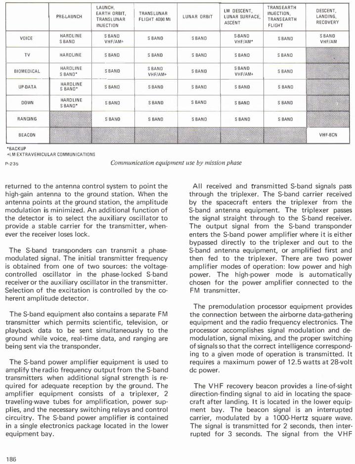
VOICE HARD LINE S BAND S BAND S BAND S·BAND S BAND
S BAND S BAND VHF/AM+ VHF/AM* VHF/AM
TV HARD LINE S BAND S BAND S BAND S BAND S BAND
BIOMEDICAL HARD LINE
S BAND S BAND S BAND S BAND
S BAND S BAND* VHF/AM+ VHF/AM+
UP-DATA HARD LINE
S BAND S BAND S BAND S BAND S BAND S BAND*
DOWN HARD LINE S BAND S BAND S BAND S BAND S BAND
S BAND* -
RANGING S BAND S BAND S BAND S BAND S BAND
., BEACON ,. I"' VHF·BCN
*BACKUP +LM EXTRAVEHICULAR COMMUNICATIONS
P-235 Communication equipment use by mission phase
returned to the antenna control system to point the high-gain antenna to the ground station. When the antenna points at the ground station, the amplitude modulation is minimized. An additional function of the detector is to select the auxiliary oscillator to provide a stable carrier for the transmitter, whenever the receiver loses lock.
The S-band transponders can transmit a phasemodulated signal. The initial transmitter frequency is obtained from one of two sources: the voltagecontrolled oscillator in the phase-locked S-band receiver or the auxiliary oscillator in the transmitter. Selection of the excitation is controlled by the coherent amplitude detector.
The S-band equipment also contains a separate FM transmitter which permits scientific, television, or playback data to be sent simultaneously to the ground while voice, real-time data, and ranging are being sent via the transponder.
The S-band power amplifier equipment is used to amplify the radio frequency output from the S-band transmitters when additional signal strength is required for adequate reception by the ground. The amplifier equipment consists of a triplexer, 2 traveling-wave tubes for amplification, power supplies, and the necessary switching relays and control circuitry. The S-band power amplifier is contained in a single electronics package located in the lower equipment bay.
186
All received and transmitted S-band signals pass through the triplexer. The S-band carrier received by the spacecraft enters the triplexer from the S-band antenna equipment. The triplexer passes the signal straight through to the S-band receiver. The output signal from the S-band transponder enters the S-band power amplifier where it is either bypassed directly to the triplexer and out to the S-band antenna equipment, or amplified first and then fed to the triplexer. There are two power amplifier modes of operation: low power and high power. The high-power mode is automatically chosen for the power amplifier connected to the FM transmitter.
The premodulation processor equipment provides the connection between the airborne data-gathering equipment and the radio frequency electronics. The processor accomplishes signal modulation and demodulation, signal mixing, and the proper switching of signals so that the correct intelligence corresponding to a given mode of operation is transmitted. It requires a maximum power of 12.5 watts at 28-volt de power.
The VHF recovery beacon provides a line-of-sight direction-finding signal to aid in locating the spacecraft after landing. It is located in the lower equipment bay. The beacon signal is an interrupted carrier, modulated by a 1 000-Hertz square wave. The signal is transmitted for 2 seconds, then interrupted for 3 seconds. The signal from the VHF
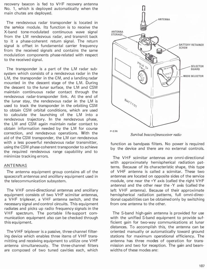
recovery beacon is fed to VHF recovery antenna No. 1, which is deployed automatically when the main chutes are deployed.
The rendezvous radar transponder is located in the service module. Its function is to receive the X-band tone-modulated continuous wave signal from the LM rendezvous radar, and transmit back to it a phase-coherent return signal. The return signal is offset in fundamental carrier frequency from the received signals and contains the same modulation components phase-related with respect to the received signal.
The transponder is a part of the LM radar subsystem which consists of a rendezvous radar in the LM, the transponder in the CM, and a landing radar mounted in the descent stage of the LM. During the descent to the lunar surface, the LM and CSM maintain continuous radar contact through the rendezvous radar-transponder link. At the end of the !unar stay, the rendezvous radar in the LM is used to track the transponder in the orbiting CSM to obtain CSM orbital conditions, which are used to calculate the launching of the LM into a rendezvous trajectory. In the rendezvous phase, the LM and CSM again maintain radar contact to obtain information needed by the LM for course correction, and rendezvous operations. With the aid of the CSM transponder, the LM can rendezvous with a less powerful rendezvous radar transmitter, using the CSM phase-coherent transponder to achieve the required rendezvous range capability and to minimize tracking errors.
ANTENNAS
The antenna equipment group contains all of the spacecraft antennas and ancillary equipment used in the telecommunication subsystem.
The VHF omni-directional antennas and ancillary equipment consists of two VHF scimitar antennas, a VHF triplexer, a VHF antenna switch, and the necessary signal and control circuits. This equipment radiates and picks up radio frequency signals in the VHF spectrum. The portable life-support communication equipment also can be checked through this equipment.
The VHF triplexer is a passive, three-channel filtering device which enables three items of VHF transmitting and receiving equipment to utilize one VHF antenna simultaneously. The three-channel filters are composed of two tuned cavities each, which
ll,, , , , ... . ,,,, • 'r
P-236
Survival beacon/transceiver radio
function as bandpass filters. No power is required by the device and there are no external controls.
The VHF scimitar antennas are omni-directional with approximately hemispherical radiation patterns. Because of its characteristic shape, this type of VHF antenna is called a scimitar. These two antennas are located on opposite sides of the service module, one near the +Y axis (called the right VHF antenna) and the other near the -Y axis (called the left VHF antenna). Because of their approximate hemispherical radiation patterns, full omni-directional capabilities can be obtained only by switching from one antenna to the other.
The S-band high-gain antenna is provided for use with the unified S-band equipment to provide sufficient gain for two-way communications at lunar distances. To accomplish this, the antenna can be oriented manually or automatically toward ground stations for maximum operational efficiency. The antenna has three modes of operation for transmission and two for reception. The gain and beamwidths of these modes are:
187
Mode Gain Beamwidth
Wide - transmit 9.2 db 40° Wide - Receive 3.8 db 40° Medium - Transmit 20.7 db 1 1 .3° Medium - Receive 22.8 db 4.5° Narrow - Transmit 26.7 db 3.9° Narrow - Receive 23.3 db 4.5°
The antenna is deployed during transposition and docking when the SLA panels are opened. After deployment, the positioning circuitry is enabled. Manual controls, position readouts, and a signal strength meter on the main display console allow normal positioning of the antenna for initial signal acquisition. After acquisition, the antenna automatically tracks the radio frequency signal within the travel limits of its gimbaling system. The operational modes can be selected by the crew.
The antenna consists of a four-parabolic dish array whose attendant feed horns are offset 1 0 degrees for the desired propagation pattern and a cluster of four feed horns enclosed in the center enclosure. In the wide mode, the center feed horns are used for transmission and reception of signals. In the medium mode, one of the parabolic dish-reflector antennas is used for transmission and all four of the dish antennas are used for reception of S-band signals. The narrow mode employs the four parabolic dish antennas for transmission and reception of S-band signals.
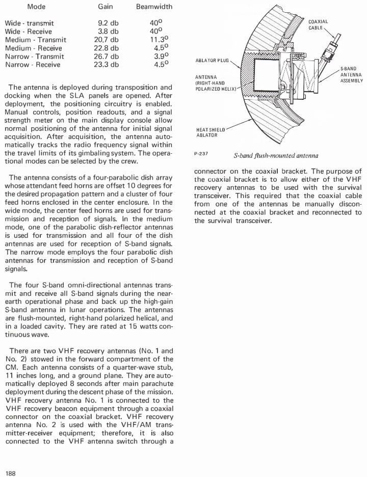
The four S-band omni-directional antennas transmit and receive all S-band signals during the nearearth operational phase and back up the high-gain S-band antenna in lunar operations. The antennas are flush-mounted, right-hand polarized helical, and in a loaded cavity. They are rated at 1 5 watts continuous wave.
There are two VHF recovery antennas (No. 1 and No. 2) stowed in the forward compartment of the CM. Each antenna consists of a quarter-wave stub, 1 1 inches long, and a ground plane. They are automatically deployed 8 seconds after main parachute deployment during the descent phase of the mission. VHF recovery antenna No. 1 is connected to the VHF recovery beacon equipment through a coaxial connector on the coaxial bracket. VHF recovery antenna No. 2 is used with the VHF I AM transmitter-receiver equipment; therefore, it is also connected to the VHF antenna switch through a
188
ABLATOR PLUG
ANTENNA
(RIGHT-HAND
POLARIZED HELIX)
HEAT SHIELD ABLATOR
P-237 S-band flush-mounted antenna
ANTENNA
ASSEMBLY
connector on the coaxial bracket. The purpose of the coaxial bracket is to allow either of the VHF recovery antennas to be used with the survival transceiver. This required that the coaxial cable from one of the antennas be manually disconnected at the coaxial bracket and reconnected to the survival transceiver.