Embed Size (px)
Citation preview

Telecommunications Network Technologies
H-NW-1
H-NW-2
H-NW-3
H-NW-4
H-NW-5
H-NW-6
H-NW-7
H-NW-8
ASP Service Performance Evaluation for Corporations
Multi-Layer, Multi-Domain Network Virtualization
Transport Network Technology
Indoor Optical Cable for Restricted Spaces
Small Satellite Earth Stations for Disaster Recovery Operations
Sea-Salt Corrosion Risk Visualization System
100-Gbit/s Optical Transmission Field Trial Using Digital Signal Processor
Programmable Network Virtualization Technologies for Future Networks
Contents
What’s Hot in R&D
Technologies for establishing a base network infrastructure including optical networks, wireless and satellite, all of which are essential to guaranteed bandwidth and broadband telecommunication.
Copyright © 2012 NTT
NTT Research and Development 2012 Review of Activities
What’s Hot in R&D Telecommunications Network Technologies
H-NW-1
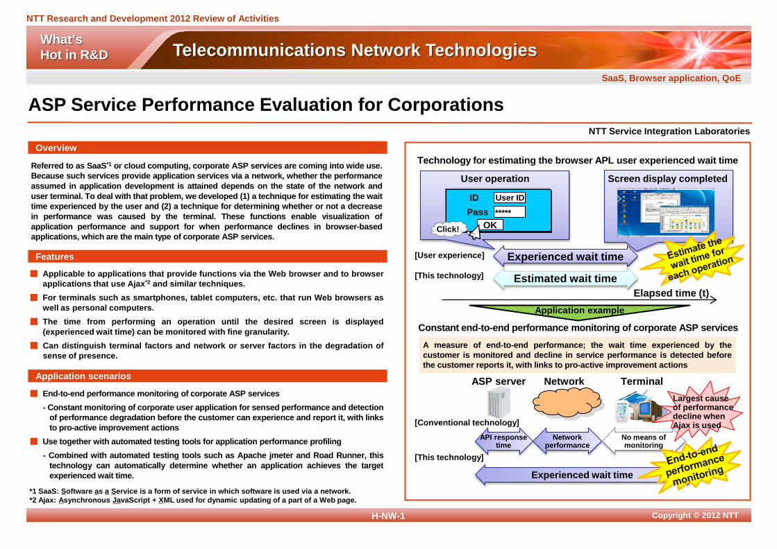
Referred to as SaaS*1 or cloud computing, corporate ASP services are coming into wide use. Because such services provide application services via a network, whether the performance assumed in application development is attained depends on the state of the network and user terminal. To deal with that problem, we developed (1) a technique for estimating the wait time experienced by the user and (2) a technique for determining whether or not a decrease in performance was caused by the terminal. These functions enable visualization of application performance and support for when performance declines in browser-based applications, which are the main type of corporate ASP services.
■ End-to-end performance monitoring of corporate ASP services - Constant monitoring of corporate user application for sensed performance and detection
of performance degradation before the customer can experience and report it, with links to pro-active improvement actions
■ Use together with automated testing tools for application performance profiling - Combined with automated testing tools such as Apache jmeter and Road Runner, this
technology can automatically determine whether an application achieves the target experienced wait time.
■ Applicable to applications that provide functions via the Web browser and to browser applications that use Ajax*2 and similar techniques.
■ For terminals such as smartphones, tablet computers, etc. that run Web browsers as well as personal computers.
■ The time from performing an operation until the desired screen is displayed (experienced wait time) can be monitored with fine granularity.
■ Can distinguish terminal factors and network or server factors in the degradation of sense of presence.
*1 SaaS: Software as a Service is a form of service in which software is used via a network. *2 Ajax: Asynchronous JavaScript + XML used for dynamic updating of a part of a Web page.
NTT Service Integration Laboratories
Overview
Features
Application scenarios
ASP Service Performance Evaluation for Corporations SaaS, Browser application, QoE
User operation
Pass
User ID
OK *****
ID
Click!
Screen display completed
Technology for estimating the browser APL user experienced wait time
Elapsed time (t)
Experienced wait time
Estimated wait time
[User experience]
[This technology]
Application example
Constant end-to-end performance monitoring of corporate ASP services
ASP server Network Terminal
Experienced wait time
API response time
Network performance
No means of monitoring
A measure of end-to-end performance; the wait time experienced by the customer is monitored and decline in service performance is detected before the customer reports it, with links to pro-active improvement actions
[Conventional technology]
[This technology]
Largest cause of performance decline when Ajax is used

Copyright © 2012 NTT
NTT Research and Development 2012 Review of Activities
What’s Hot in R&D Telecommunications Network Technologies
H-NW-2
VN #1
“Virtual network (VN)” technology enables path provisioning and route switchover on a single physical infrastructure simply by using GUI. A VN consists of commercial IP routers and switches connected by VLAN, LSP*, and wavelength-path technologies. By sharing the network resource and granting access to the path and route on the VN, we can help prevent competition between traffic and enable independent simultaneous operations.
■ Our technology provides not only communications service quickly but can dynamically respond to changes in the path architecture between data centers that correspond to the movement of virtual machines, and it can make Intercloud networks that can easily increase and decrease bandwidth.
■ A VN is provided as an IP network or Ethernet in response to the use of the service or application.
■ The VN can increase its bandwidth and change its topology in response to changing traffic demands by dynamically setting up, deleting, and switching “paths”.
■ The VN operator can set up and change the paths and routes that constitute the VN through intuitive operations on the GUI.
■ A “Global VN” can be constructed by sending path provision requests to other networks by using a standard protocol.
NTT Network Service Systems Laboratories
Overview
Features
Application scenarios
Multi-Layer, Multi-Domain Network Virtualization Network virtualization, Intercloud
* LSP: Label Switched Path
Global extension of VNs VN #3
Path management servers of other domains
VN #2
Control of optical circuits
Other network domains
VN control server
Physical network control server
Path provisioning requests

Copyright © 2012 NTT
NTT Research and Development 2012 Review of Activities
What’s Hot in R&D Telecommunications Network Technologies
H-NW-3
To meet the demand for high-volume communication traffic, we are working on high-speed transmission technology for 100 Gbit/s data transfer and new signal processing technology that integrates optical wavelength cross-connection (OXC) and packet switching. By implementing a 100 Gbit/s integrated transport system that applies the technology, we target the construction of a transport network that is economical, simple and energy-efficient through (1) high-speed and large-capacity traffic transport, (2) reduction of IP routing load on IP core routers, (3) improved operability from hardware integration, and (4) reduction of the NE Operation systems (NE-OpS).
■ Backbone network of NTT Communications ■ Metro network of NTT East Corporation and NTT West Corporation
■ Increase capacity, improve economy, simplify, and reduce power consumption for the backbone network through R&D on an new integrated transport system
■ Ultra-fast 100 Gbit/s optical transmission by applying digital coherent technology ■ Optical wavelength mesh network by applying OXC technology ■ Packet transport network applies MPLS-TP*, which guarantees communication line
quality and has maintenance and management mechanisms against failures
Overview
Features
Application scenarios
* MPLS-TP: Multi Protocol Label Switching-Transport Profile
NTT Network Service Systems Laboratories
Transport Network Technology 100 G optical transmission technology, Optical cross-connect, Packet switching
Optical transport equipment (WDM and OADM)
100 G Integrated transport equipment
10 G Wavelength
Logical path (based on packet)
Packet SW
OXC 100 G Wavelength
Current network
Future network
IP core routers
IP edge router
IP edge router
IP core routers
IP core routers
IP edge router
IP edge router
IP core routers
(2) Increase in unnecessary IP core router processing (1) Multiple 10 G links
(1) Cost reduction through 100 G links
(2) Cut-through of IP core routers by applying new integrated transport equipment that use OXC and packet SW
(4) Fewer NE-OpS
(3) Hardware interconnections required (4) Multiple NE-OpS
(3) Cost reduction and efficient operability from hardware integration

Copyright © 2012 NTT
NTT Research and Development 2012 Review of Activities
What’s Hot in R&D Telecommunications Network Technologies
H-NW-4
With a view to promoting optical broadband services, we are undertaking R&D for completely replacing copper telecommunications wire in multi-dwelling units (MDUs) by optical fiber. Specifically, we are working on in-building optical wiring technology for existing buildings. Indoor optical cable for restricted spaces that allows optical wiring through narrows spaces at doors and windows without the need to drill holes in walls.
■ The indoor optical cables for restricted spaces enable optical broadband service to be provided in multi-dwelling units even when the owners do not permit holes to be drilled in the walls.
■ We have developed single-mode HAF with lower bending-loss characteristics than those of ITU-T recommendation G.657.B3. We intend to promote optical broadband services using this optical wiring system.
■ This indoor optical cable for restricted spaces consists of a cord part and a sheet part applied to a small curved corner.
■ Single-mode hole-assisted optical fibers (HAFs) have lower bending loss. The optical signal is effectively confined because the refractive index difference between silica and air is large.
■ The iron wire of the sheet part, which is applied to restricted spaces at doors and windows, can remain bent. The sheet part can then be easily fixed by one-sided tape.
■ Increasing the bending radius by using optical slant wiring can reduce bending loss and maintain reliability.
Overview
Features
Application scenarios
*1 IDF: Intermediate Distribution Frame, *2 ONU: Optical Network Unit, *3 MDF: Main Distribution Frame, *4 FRP: Fiber Reinforced Plastic
NTT Access Network Service Systems Laboratories
Indoor Optical Cable for Restricted Spaces Hole-assisted optical fiber, Single-mode optical fiber, Optical wiring technology
シート部 コード部 Iron wire HAF FRP*4 FRP Optical
fiber
FRP Iron wire HAF
Sheet part
Single-mode hole-assisted optical fiber
Cladding Core
Hole
(1) Drop wiring through door (2) Drop wiring through window
光配線方式構築例 MDF*3
IDF
IDF*1
IDF
ONU*2
MDU
ONU
ONU
ONU
8
8
8 ONU
ONU
ONU 8 4
Sheet part Cord part
ONU

Copyright © 2012 NTT
NTT Research and Development 2012 Review of Activities
What’s Hot in R&D Telecommunications Network Technologies
H-NW-5
Our earth stations can be easily set up and can quickly start performing their mission in an area stricken by a disaster. Our terminals ensure a transmission speed of up to 384 kbits/s for the return link, which can simultaneously carry ten VoIP (Voice over Internet Protocol) channels. Their transportability has been greatly improved through equipment miniaturization and weight reductions. Moreover, our remote uplink access test program and two satellite auto-tracking antennas will dramatically improve the operator’s convenience.
■ Free public telephone services and web171 services (Disaster Emergency Broadband Message Board) will be provided to a disaster-stricken area.
■ Free public telephone services and Internet services will be provided to an event site.
NTT Access Network Service Systems Laboratories
Overview
Features
Application scenarios
Small Satellite Earth Stations for Disaster Recovery Operations Satellite communication, Disaster recovery operations, Earth station
■ The terminals can be applied to portable earth station systems without concern for network congestion because they use an exclusive frequency band operated by NTT East and NTT West.
■ Our terminals are much more portable and convenient compared with the currently available portable earth station system.
■ The equipment composition can be configured to suit the stricken area. - Vehicle-mounted type: Can be installed in a normal-sized car, so it can reach a
stricken area quickly to help restore communications. - Flyaway type: Easy to carry to a disaster area because it can be broken down and
packed into four separate carrying cases. ■ Our terminals can start performing their mission in less than 15 minutes owing to the
satellite auto-tracking function (compared with 60 minutes at present). ■ The uplink access test can be executed by remote control.
*1 UAT: Uplink Access Test, *2 PSTN: Public Switched Telephone Network
PSTN*2
Developed technology
Communication satellite operating in the Ku-band (12 GHz/14 GHz)
Public telephones
VoIP router
Satellite base
station
Remote UAT*1
program
Control office
Internet
Simple modem
Vehicle-mounted antenna Flyaway antenna
System configuration
Auto-tracking function
Stricken area
Remote control
Miniaturization, weight savings
Copyright © 2012 NTT
NTT Research and Development 2012 Review of Activities
What’s Hot in R&D Telecommunications Network Technologies
H-NW-6
Input learning data
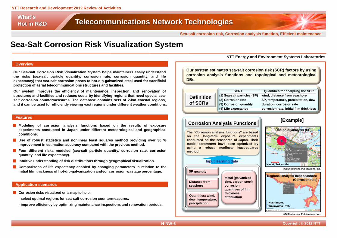
Our Sea-salt Corrosion Risk Visualization System helps maintainers easily understand the risks (sea-salt particle quantity, corrosion rate, corrosion quantity, and life expectancy) that sea-salt corrosion poses to hot-dip-galvanized steel used for sacrificial protection of aerial telecommunications structures and facilities. Our system improves the efficiency of maintenance, inspection, and renovation of structures and facilities and reduces costs by identifying regions that need special sea-salt corrosion countermeasures. The database contains sets of 2-km coastal regions, and it can be used for efficiently viewing vast regions under different weather conditions.
■ Corrosion risks visualized on a map to help: - select optimal regions for sea-salt-corrosion countermeasures. - improve efficiency by optimizing maintenance inspections and renovation periods.
■ Modeling of corrosion analysis functions based on the results of exposure experiments conducted in Japan under different meteorological and geographical conditions.
■ Use of robust statistics and nonlinear least squares method providing over 30 % improvement in estimation accuracy compared with the previous method.
■ Four different risks modeled (sea-salt particle quantity, corrosion rate, corrosion quantity, and life expectancy).
■ Intuitive understanding of risk distributions through geographical visualization. ■ Comparisons of life expectancy enabled by changing parameters in relation to the
initial film thickness of hot-dip-galvanization and-/or corrosion wastage percentage.
NTT Energy and Environment Systems Laboratories
Overview
Features
Application scenarios
Sea-Salt Corrosion Risk Visualization System Sea-salt corrosion risk, Corrosion analysis function, Efficient maintenance
SCRs Quantities for analyzing the SCR (1) Sea-salt particles (SP) wind, distance from seashore (2) Corrosion rate SP, temperature, precipitation, dew (3) Corrosion quantity duration, corrosion rate (4) Life expectancy corrosion rate, initial film thickness
Corrosion Analysis Functions [Example]
Definition of SCRs
The “Corrosion analysis functions” are based on the long-term exposure experiments conducted on the seashores of Japan. Their model parameters have been optimized by using a robust, nonlinear least-squares method.
Kushimoto, Wakayama Pref.
Regional analysis near seashore (Corrosion rate)
One-point analysis (SP)
Kasai, Tokyo Met. (C) Shobunsha Publications, Inc.
(C) Shobunsha Publications, Inc.
SP quantity
Distance from seashore
Quantities: wind, dew, temperature, precipitation
Metal (galvanized zinc, carbon steel) corrosion quantities of film thickness attenuation
Our system estimates sea-salt corrosion risk (SCR) factors by using corrosion analysis functions and topological and meteorological DBs.

Copyright © 2012 NTT
NTT Research and Development 2012 Review of Activities
What’s Hot in R&D Telecommunications Network Technologies
H-NW-7
We have developed the world’s most advanced digital signal processor (DSP) for 100-Gbit/s optical transmissions over high-speed, large-capacity optical transport networks. The DSP compensates for the degradation of signals transmitted across long distances and has a chromatic dispersion estimation function which enables fast link-up when switching optical routes. We conducted 100-Gbit/s optical transmission field trials using the DSP and confirmed its excellent performance.
■ Next-generation 100 Gbit/s backbone optical transport network ■ Future metro optical transport network
■ 100-Gbit/s optical transmission using a large-scale integrated DSP and a polarization division-modulation quadrature phase shift keying (PDM-QPSK) modulation scheme
■ Second-generation DSP equivalent to a supercomputer (100 M gates DSP) ■ Fast and accurate chromatic dispersion estimation ■ Link-up faster than the ITU-T standard switching time (50ms)
NTT Network Innovation Laboratories
Overview
Features
Application scenarios
100-Gbit/s Optical Transmission Field Trial Using Digital Signal Processor 100 G, DSP, Field trial
- This work is partly supported by R&D of “High-speed Optical Transport System Technologies” and “High-speed Optical Edge Node Technologies” by the Ministry of Internal Affairs and Communications (MIC) of Japan.
- This work is partly supported by the “Universal Link Project” of the National Institute of Information and Communications Technology (NICT) of Japan.
Fig.1 Experimental configuration for 100-Gbit/s field trial
Fig.2 Link-up demonstration result
DSF
Miura peninsula NTT-East Yokosuka
office
NTT Yokosuka R&D center
70 km 23 dB
70 km 22 dB
70 km 25 dB
70 km 22 dB
70 km 23 dB
70 km 24 dB
L-ba
nd 4
0 ch
LD
LD Q ch
Even
Odd
I ch
100 G Tx DSP PDM
IQ-mod. 100 G
Rx Front-end DSP
Optical switch
Route 2 Route 1
Sign
al le
vel (
a.u.
) Time (msec)
Optical input
Alarm pulse from clock recovery
Error signal
Route 2 420 km (6 span)
Route 1 140 km (2 span)
Sync. Sync. Error
Route switching
Link-up time 12 msec
Optical recovery
Link recovery
0 20 40
IQ-mod. WDM
coupler
Copyright © 2012 NTT
NTT Research and Development 2012 Review of Activities
What’s Hot in R&D Telecommunications Network Technologies
H-NW-8
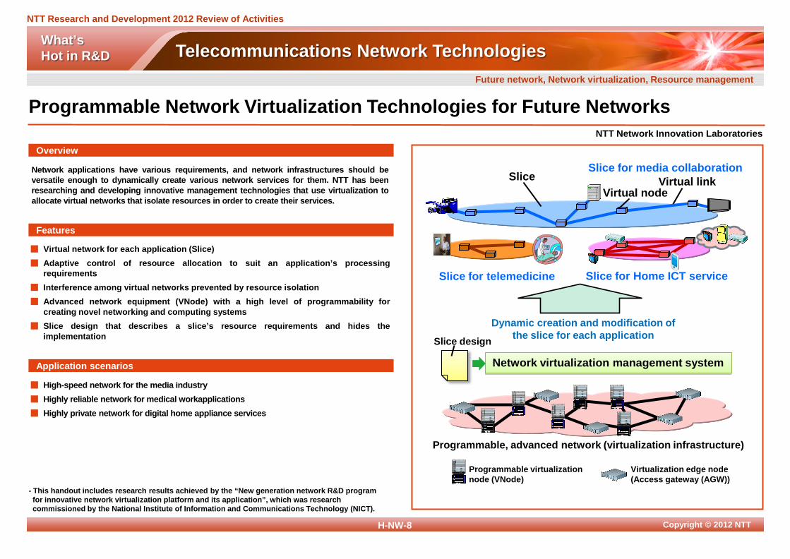
Network applications have various requirements, and network infrastructures should be versatile enough to dynamically create various network services for them. NTT has been researching and developing innovative management technologies that use virtualization to allocate virtual networks that isolate resources in order to create their services.
■ High-speed network for the media industry ■ Highly reliable network for medical workapplications ■ Highly private network for digital home appliance services
■ Virtual network for each application (Slice) ■ Adaptive control of resource allocation to suit an application’s processing
requirements ■ Interference among virtual networks prevented by resource isolation ■ Advanced network equipment (VNode) with a high level of programmability for
creating novel networking and computing systems ■ Slice design that describes a slice’s resource requirements and hides the
implementation
NTT Network Innovation Laboratories
Overview
Features
Application scenarios
Programmable Network Virtualization Technologies for Future Networks Future network, Network virtualization, Resource management
Network virtualization management system
Virtual node Virtual link
Slice for Home ICT service Slice for telemedicine
Programmable virtualization node (VNode)
Virtualization edge node (Access gateway (AGW))
Programmable, advanced network (virtualization infrastructure)
Dynamic creation and modification of the slice for each application Slice design
Slice
- This handout includes research results achieved by the “New generation network R&D program for innovative network virtualization platform and its application”, which was research commissioned by the National Institute of Information and Communications Technology (NICT).
Junip
er
Junip
er
Junip
er
Junip
er
Slice for media collaboration
Junip
er
Junip
er
Junip
er