Embed Size (px)
Citation preview
TELEDYNE ANALYTICAL INSTRUMENTS
Instruction Manual INFRARED GAS
ANALYZER COMMUNICATION
FUNCTIONS (MODBUS) TYPE: 7500 / 7600
Teledyne Analytical Instruments
2
CONTENTS 1. COMMUNICATION FUNCTIONS ...............................................…...........................3 1.1 General..............................................................................................................3 2. SPECIFICATIONS..........................................................................................................4 2.1 Communication specifications...........................................................................4 3. CONNECTION................................................................................................................5 3.1 Terminal allocation ..............................................................….........................5 3.2 Connection ...................................................................….................................5 4. SETTING OF COMMUNICATION CONDITION........................................................6 4.1 Set items.........................…................................................................................6 4.2 Setting operation................................................................................................6 5. MODBUS COMMUNICATION PROTOCOL..............................................................7 5.1 General...............................................................................................................7 5.2 Composition of message....................................................................................8 5.3 Response of slave station.................................................................................10 5.4 Function code...................................................................................................11 5.5 Calculation of error check code (CRC-16) ...................…..............................12 5.6 Transmission control procedure.......................................................................14 6. DETAILS OF MESSAGE ............................................................................................16 6.1 Read-out of word data [Function code:03H] ..................................................16 6.2 Read-out of read only word data [Function code:04H]...................................18 6.3 Write-in of word data (1 word) [Function code:06H].................…................20 6.4 Write-in of continuous word data [Function code:10H] ...........…..................21 7. ADDRESS MAP AND DATA FORMAT....................................................................23 7.1 Data format .......................................…..........................................................23 7.2 Address map ................................................…................................................25 7.3 Supplement to address map ............................................................................34 8. SAMPLE PROGRAM ................................................…..............................................36 9. TROUBLESHOOTING.................................................................................................42
Teledyne Analytical Instruments
3
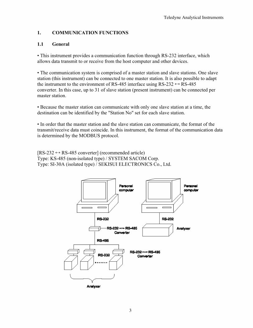
1. COMMUNICATION FUNCTIONS 1.1 General • This instrument provides a communication function through RS-232 interface, which allows data transmit to or receive from the host computer and other devices. • The communication system is comprised of a master station and slave stations. One slave station (this instrument) can be connected to one master station. It is also possible to adapt the instrument to the environment of RS-485 interface using RS-232 RS-485 converter. In this case, up to 31 of slave station (present instrument) can be connected per master station. • Because the master station can communicate with only one slave station at a time, the destination can be identified by the "Station No" set for each slave station. • In order that the master station and the slave station can communicate, the format of the transmit/receive data must coincide. In this instrument, the format of the communication data is determined by the MODBUS protocol. [RS-232 RS-485 converter] (recommended article) Type: KS-485 (non-isolated type) / SYSTEM SACOM Corp. Type: SI-30A (isolated type) / SEKISUI ELECTRONICS Co., Ltd.
Teledyne Analytical Instruments
4
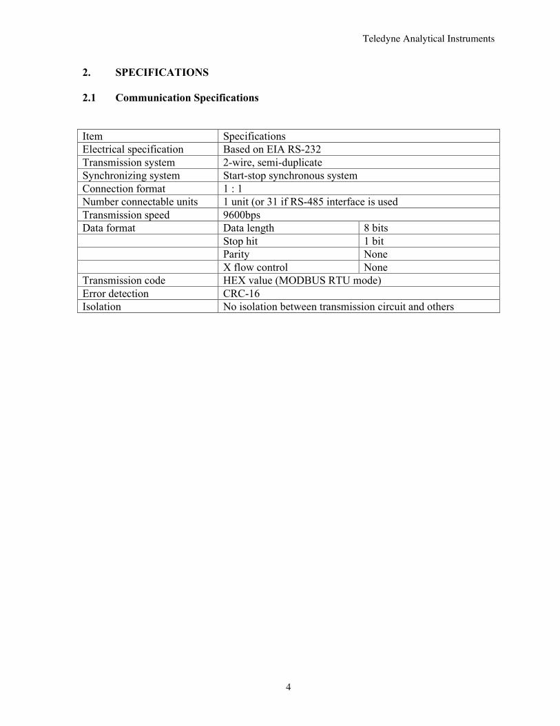
2. SPECIFICATIONS 2.1 Communication Specifications Item Specifications Electrical specification Based on EIA RS-232 Transmission system 2-wire, semi-duplicate Synchronizing system Start-stop synchronous system Connection format 1 : 1 Number connectable units 1 unit (or 31 if RS-485 interface is used Transmission speed 9600bps Data format Data length 8 bits Stop hit 1 bit Parity None X flow control None Transmission code HEX value (MODBUS RTU mode) Error detection CRC-16 Isolation No isolation between transmission circuit and others

Teledyne Analytical Instruments
5
3. CONNECTION WARNING: For avoiding electric shock and malfunctions, do not turn on power supply until all wiring has been completed. 3.1 Terminal allocation (Input / Output terminal CN2)
Terminal number Signal name Pin connection 2 Receive data 3 Transmit data 5 Signal GND
Others NC
9-pin D-Sub (male) 3.2 Connection As connecting cable, use a commercially available RS-232 reverse cable.
Connect the cable to CN2 on the input/output terminal block (on rear for 7500, separate for 7600).
Teledyne Analytical Instruments
6
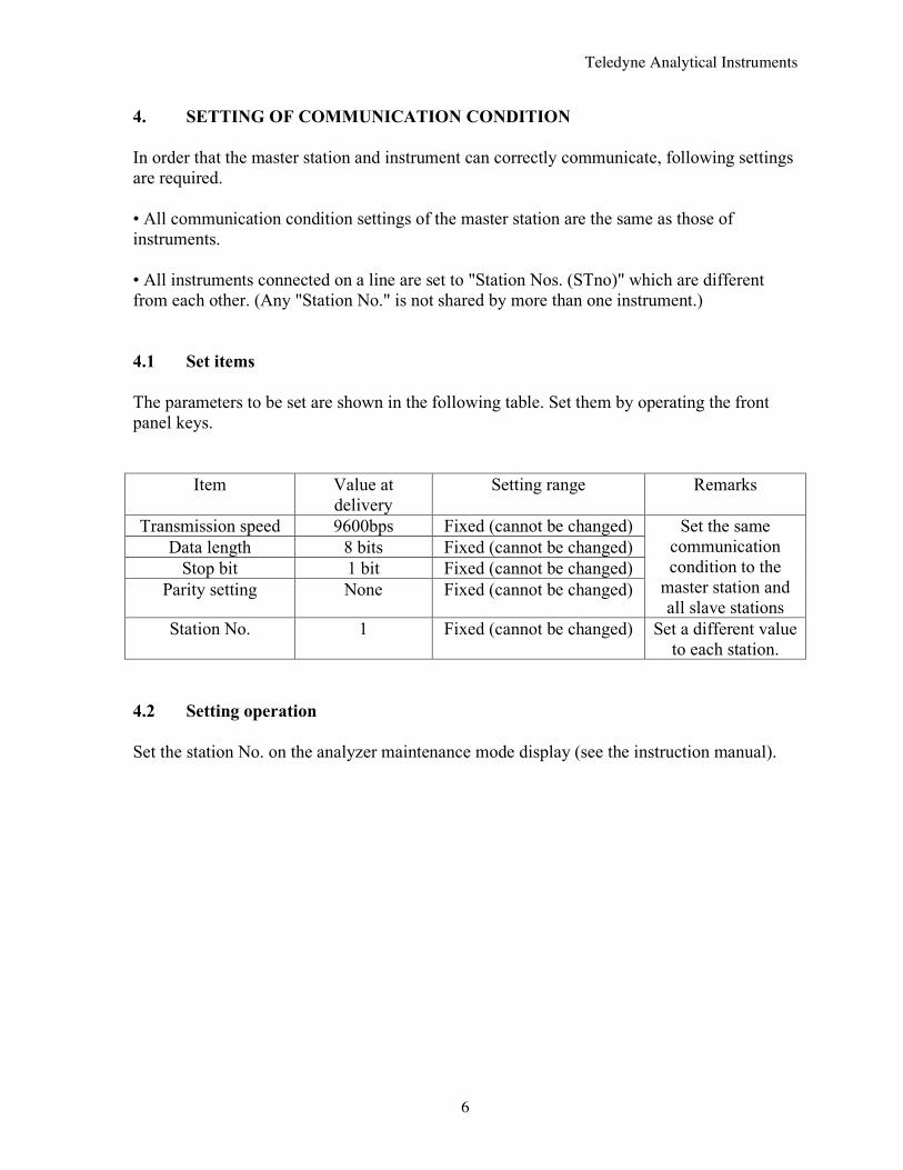
4. SETTING OF COMMUNICATION CONDITION In order that the master station and instrument can correctly communicate, following settings are required. • All communication condition settings of the master station are the same as those of instruments. • All instruments connected on a line are set to "Station Nos. (STno)" which are different from each other. (Any "Station No." is not shared by more than one instrument.) 4.1 Set items The parameters to be set are shown in the following table. Set them by operating the front panel keys.
Item Value at delivery
Setting range Remarks
Transmission speed 9600bps Fixed (cannot be changed) Data length 8 bits Fixed (cannot be changed)
Stop bit 1 bit Fixed (cannot be changed) Parity setting None Fixed (cannot be changed)
Set the same communication condition to the
master station and all slave stations
Station No. 1 Fixed (cannot be changed) Set a different value to each station.
4.2 Setting operation Set the station No. on the analyzer maintenance mode display (see the instruction manual).
Teledyne Analytical Instruments
7
5. MODBUS COMMUNICATION PROTOCOL 5.1 General The communication system by the MODBUS protocol is that the communication is always started from the master station and a slave station responds to the received message. Transmission procedures is as shown below.
1. The master station sends a command message to a slave station.
2. The slave station checks that the station No. in the received message matches with the own station No. or not.
3. If matched, the slave station executes the command and sends back the response
message.
4. If mismatched, the slave station leaves the command message and wait for the next command message.
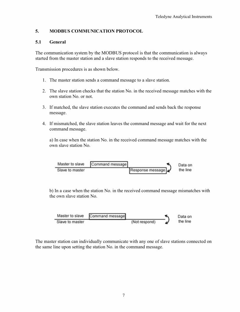
a) In case when the station No. in the received command message matches with the own slave station No.
b) In a case when the station No. in the received command message mismatches with the own slave station No.
The master station can individually communicate with any one of slave stations connected on the same line upon setting the station No. in the command message.
Teledyne Analytical Instruments
8
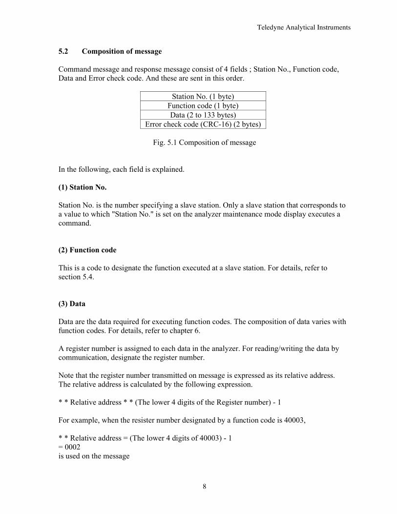
5.2 Composition of message Command message and response message consist of 4 fields ; Station No., Function code, Data and Error check code. And these are sent in this order.
Station No. (1 byte)
Function code (1 byte) Data (2 to 133 bytes)
Error check code (CRC-16) (2 bytes)
Fig. 5.1 Composition of message In the following, each field is explained. (1) Station No. Station No. is the number specifying a slave station. Only a slave station that corresponds to a value to which "Station No." is set on the analyzer maintenance mode display executes a command. (2) Function code This is a code to designate the function executed at a slave station. For details, refer to section 5.4. (3) Data Data are the data required for executing function codes. The composition of data varies with function codes. For details, refer to chapter 6. A register number is assigned to each data in the analyzer. For reading/writing the data by communication, designate the register number. Note that the register number transmitted on message is expressed as its relative address. The relative address is calculated by the following expression. * * Relative address * * (The lower 4 digits of the Register number) - 1 For example, when the resister number designated by a function code is 40003, * * Relative address = (The lower 4 digits of 40003) - 1 = 0002 is used on the message
Teledyne Analytical Instruments
9
(4) Error check code This is the code to detect message errors (change in bit) in the signal transmission. On the MODUBUS protocol (RTU mode), CRC-16 (Cycric Redundancy Check) is applied. For CRC calculation method, refer to section 5.5.
Teledyne Analytical Instruments
10
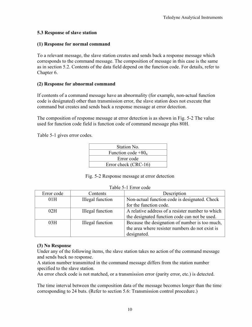
5.3 Response of slave station (1) Response for normal command To a relevant message, the slave station creates and sends back a response message which corresponds to the command message. The composition of message in this case is the same as in section 5.2. Contents of the data field depend on the function code. For details, refer to Chapter 6. (2) Response for abnormal command If contents of a command message have an abnormality (for example, non-actual function code is designated) other than transmission error, the slave station does not execute that command but creates and sends back a response message at error detection. The composition of response message at error detection is as shown in Fig. 5-2 The value used for function code field is function code of command message plus 80H. Table 5-1 gives error codes.
Station No.
Function code +80n Error code
Error check (CRC-16)
Fig. 5-2 Response message at error detection
Table 5-1 Error code Error code Contents Description
01H Illegal function Non-actual function code is designated. Check for the function code.
02H Illegal function A relative address of a resister number to which the designated function code can not be used.
03H Illegal function Because the designation of number is too much, the area where resister numbers do not exist is designated.
(3) No Response Under any of the following items, the slave station takes no action of the command message and sends back no response. A station number transmitted in the command message differs from the station number specified to the slave station. An error check code is not matched, or a transmission error (parity error, etc.) is detected. The time interval between the composition data of the message becomes longer than the time corresponding to 24 buts. (Refer to section 5.6: Transmission control procedure.)
Teledyne Analytical Instruments
11
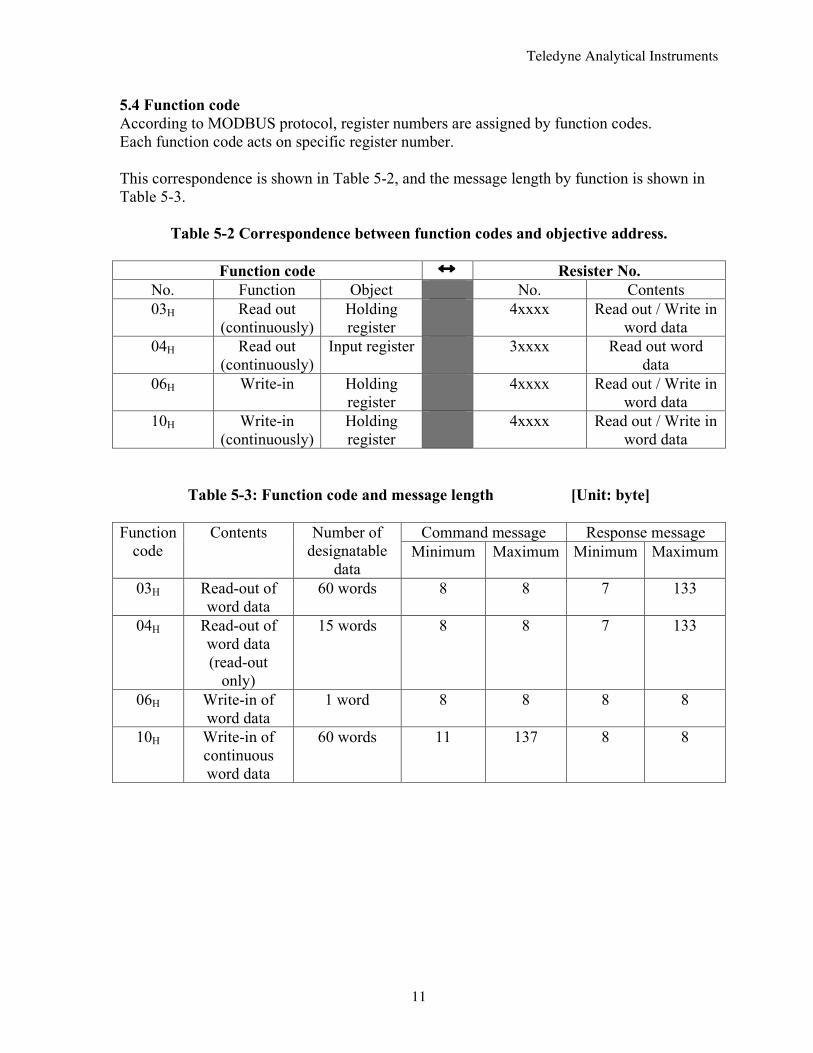
5.4 Function code According to MODBUS protocol, register numbers are assigned by function codes. Each function code acts on specific register number. This correspondence is shown in Table 5-2, and the message length by function is shown in Table 5-3.
Table 5-2 Correspondence between function codes and objective address.
Function code Resister No. No. Function Object No. Contents 03H Read out
(continuously) Holding register
4xxxx Read out / Write in word data
04H Read out (continuously)
Input register 3xxxx Read out word data
06H Write-in Holding register
4xxxx Read out / Write in word data
10H Write-in (continuously)
Holding register
4xxxx Read out / Write in word data
Table 5-3: Function code and message length [Unit: byte] Command message Response message Function
code Contents Number of
designatable data
Minimum Maximum Minimum Maximum
03H Read-out of word data
60 words 8 8 7 133
04H Read-out of word data (read-out
only)
15 words 8 8 7 133
06H Write-in of word data
1 word 8 8 8 8
10H Write-in of continuous word data
60 words 11 137 8 8
Teledyne Analytical Instruments
12
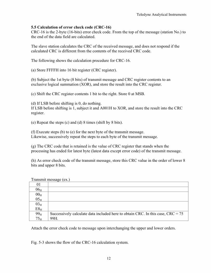
5.5 Calculation of error check code (CRC-16) CRC-16 is the 2-byte (16-bits) error check code. From the top of the message (station No.) to the end of the data field are calculated. The slave station calculates the CRC of the received message, and does not respond if the calculated CRC is different from the contents of the received CRC code. The following shows the calculation procedure for CRC-16. (a) Store FFFFH into 16 bit register (CRC register). (b) Subject the 1st byte (8 bits) of transmit message and CRC register contents to an exclusive logical summation (XOR), and store the result into the CRC register. (c) Shift the CRC register contents 1 bit to the right. Store 0 at MSB. (d) If LSB before shifting is 0, do nothing. If LSB before shifting is 1, subject it and A001H to XOR, and store the result into the CRC register. (e) Repeat the steps (c) and (d) 8 times (shift by 8 bits). (f) Execute steps (b) to (e) for the next byte of the transmit message. Likewise, successively repeat the steps to each byte of the transmit message. (g) The CRC code that is retained is the value of CRC register that stands when the processing has ended for latest byte (latest data except error code) of the transmit message. (h) As error check code of the transmit message, store this CRC value in the order of lower 8 bits and upper 8 bits. Transmit message (ex.)
01 06H 00H 05H
03H E8H
99H 75H
Successively calculate data included here to obtain CRC. In this case, CRC = 75 99H.
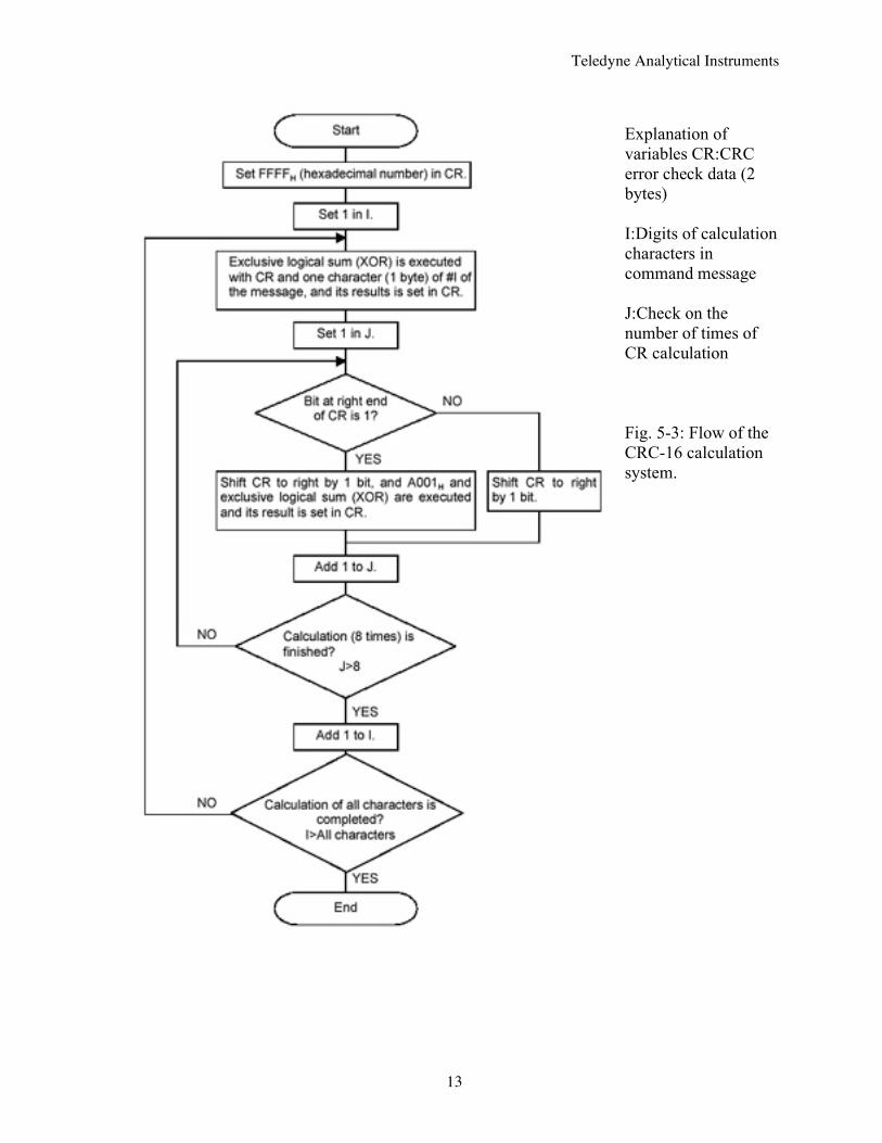
Attach the error check code to message upon interchanging the upper and lower orders. Fig. 5-3 shows the flow of the CRC-16 calculation system.
Teledyne Analytical Instruments
13
Explanation of variables CR:CRC error check data (2 bytes) I:Digits of calculation characters in command message J:Check on the number of times of CR calculation Fig. 5-3: Flow of the CRC-16 calculation system.
Teledyne Analytical Instruments
14
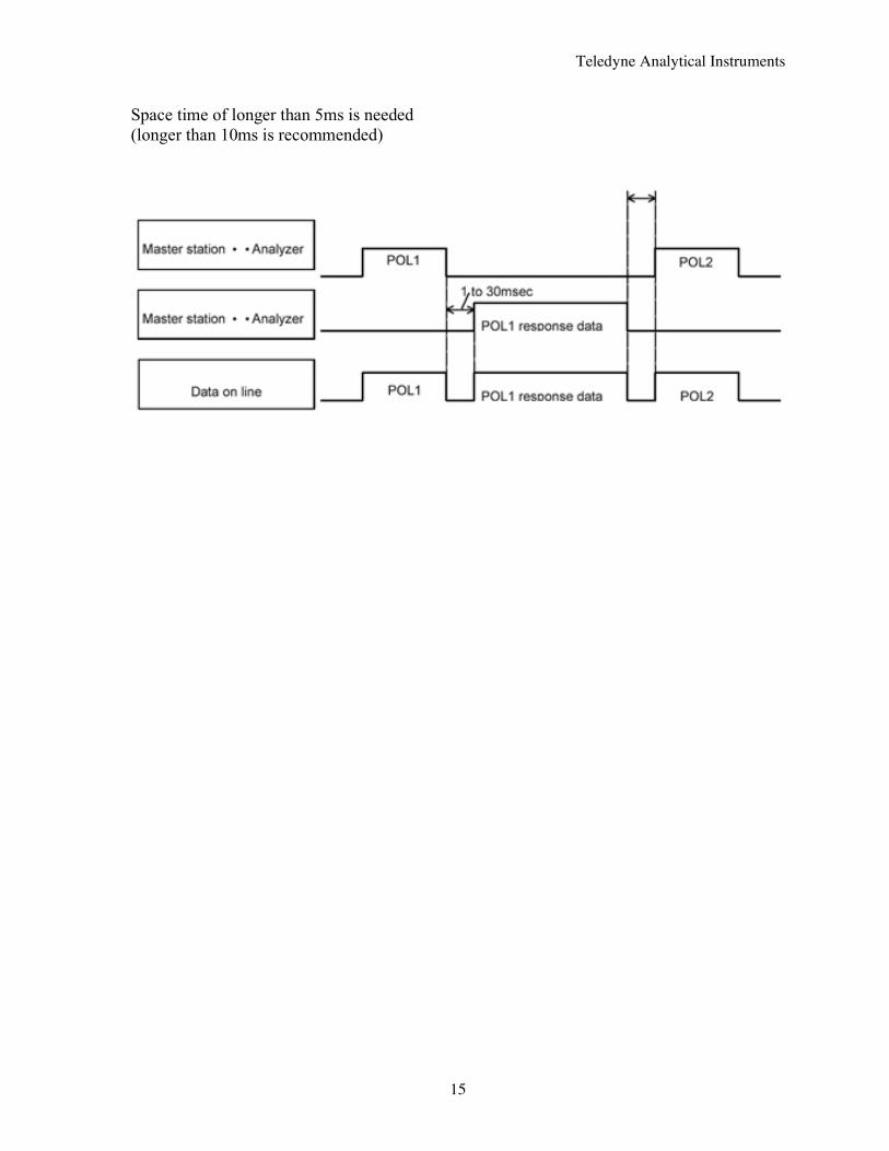
5.6 Transmission control procedure (1) Transmission procedure of master station The master station must proceed to a communication upon conforming to the following items. (1-1) Before sending a command message, provide 48 bits time or more vacant status. (1-2) For sending, the interval between bytes of a command message is below 24 bits time. (1-3) Within 24 bits time after sending a command message, the receiving status is posted. (1-4) Provide 48 bits time or more vacant status between the end of response message reception and beginning of next command message sending [same as in (1-1)]. (1-5) For ensuring the safety, make a confirmation of the response message and make an arrangement so as to provide 3 times or more retries in case of no response, error occurrence, etc. Note) The above definition is for most unfavorable value. For ensuring the safety, it’s recommended the program of the master to work with safety factors of 2 to 3. Concretely, it is advised to arrange the program for 9600 bps with 10 ms or more for vacant status (1-1), and within 1 ms for byte interval (1-2) and changeover from sending to receiving (1-3). (2) Description 1) Detection of the message frame The status on the line of the communication system is one of the 2 below. (a) Vacant status (no data on line) (b) Communication status (data is existing) Instruments connected on the line are initially at a receiving status and monitoring the line. When 24 bits time or more vacant status has appeared on the line, the end of preceding frame is assumed and, within following 24 bits time, a receiving status is posted. When data appears on the line, instruments receive it while 24 bits time or more vacant status is detected again, and the end of that frame is assumed. I.e., data which appeared on the line from the first 24 bits time or more vacant status to the next 24 bits time or more vacant status is fetched as one frame. Therefore, one frame (command message) must be sent upon confirming the following. (1-1) 48 bits time or more vacant status precedes before the command message sending. (1-2) Interval between bytes of 1 command message is smaller than 24 bits time. 2) Response of this instrument After a frame detection (24 bits time or more vacant status), this instrument carries out processing with that frame as a command message. If the command message is destined to the own station, a response message is returned. Its processing time is 1 to 30 ms (depends on contents of command message). After sending a command message, therefore, the master station must observe the following. (1-3) Receiving status is posted within 24 bits time after sending a command message.
Teledyne Analytical Instruments
15
Space time of longer than 5ms is needed (longer than 10ms is recommended)
Teledyne Analytical Instruments
16
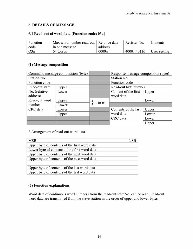
6. DETAILS OF MESSAGE 6.1 Read-out of word data [Function code: 03H] Function code
Max word number read-out in one message
Relative data address
Resister No. Contents
O3H 64 words 0000H 40001 40110 User setting (1) Message composition Command message composition (byte) Response message composition (byte) Station No. Station No. Function code Function code
Upper Read-out byte number Read-out start No. (relative address)
Lower Upper
Upper
Content of the first word data
Lower Read-out word number Lower } 1 to 64
Lower Upper CRC data Upper
Contents of the last word data Lower
Lower
CRC data Upper
* Arrangement of read-out word data MSB LSB Upper byte of contents of the first word data Lower byte of contents of the first word data Upper byte of contents of the next word data Upper byte of contents of the next word data Upper byte of contents of the last word data Upper byte of contents of the last word data (2) Function explanations Word data of continuous word numbers from the read-out start No. can be read. Read-out word data are transmitted from the slave station in the order of upper and lower bytes.
Teledyne Analytical Instruments
17
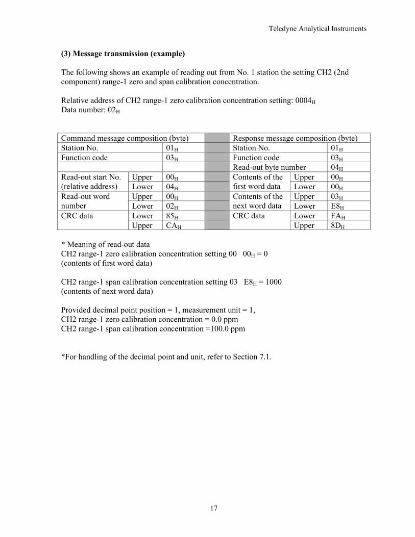
(3) Message transmission (example) The following shows an example of reading out from No. 1 station the setting CH2 (2nd component) range-1 zero and span calibration concentration. Relative address of CH2 range-1 zero calibration concentration setting: 0004H Data number: 02H Command message composition (byte) Response message composition (byte) Station No. 01H Station No. 01H Function code 03H Function code 03H Read-out byte number 04H
Upper 00H Upper 00H Read-out start No. (relative address) Lower 04H
Contents of the first word data Lower 00H
Upper 00H Upper 03H Read-out word number Lower 02H
Contents of the next word data Lower E8H
Lower 85H Lower FAH CRC data Upper CAH
CRC data Upper 8DH
* Meaning of read-out data CH2 range-1 zero calibration concentration setting 00 00H = 0 (contents of first word data) CH2 range-1 span calibration concentration setting 03 E8H = 1000 (contents of next word data) Provided decimal point position = 1, measurement unit = 1, CH2 range-1 zero calibration concentration = 0.0 ppm CH2 range-1 span calibration concentration =100.0 ppm *For handling of the decimal point and unit, refer to Section 7.1.
Teledyne Analytical Instruments
18
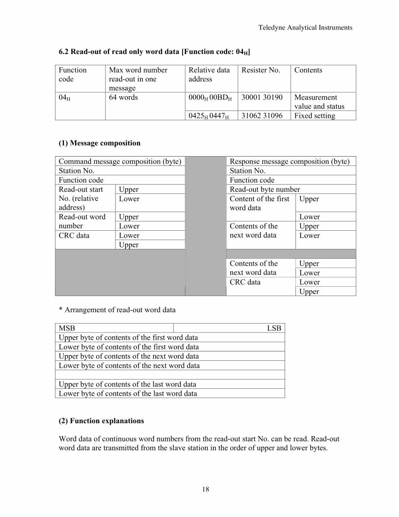
6.2 Read-out of read only word data [Function code: 04H] Function code
Max word number read-out in one message
Relative data address
Resister No. Contents
0000H 00BDH 30001 30190 Measurement value and status
04H 64 words
0425H 0447H 31062 31096 Fixed setting (1) Message composition Command message composition (byte) Response message composition (byte) Station No. Station No. Function code Function code
Upper Read-out byte number Read-out start No. (relative address)
Lower Upper
Upper
Content of the first word data
Lower Read-out word number Lower Upper
Lower CRC data Upper
Contents of the next word data
Lower
Upper Contents of the
next word data Lower Lower
CRC data Upper
* Arrangement of read-out word data MSB LSB Upper byte of contents of the first word data Lower byte of contents of the first word data Upper byte of contents of the next word data Lower byte of contents of the next word data Upper byte of contents of the last word data Lower byte of contents of the last word data (2) Function explanations Word data of continuous word numbers from the read-out start No. can be read. Read-out word data are transmitted from the slave station in the order of upper and lower bytes.
Teledyne Analytical Instruments
19
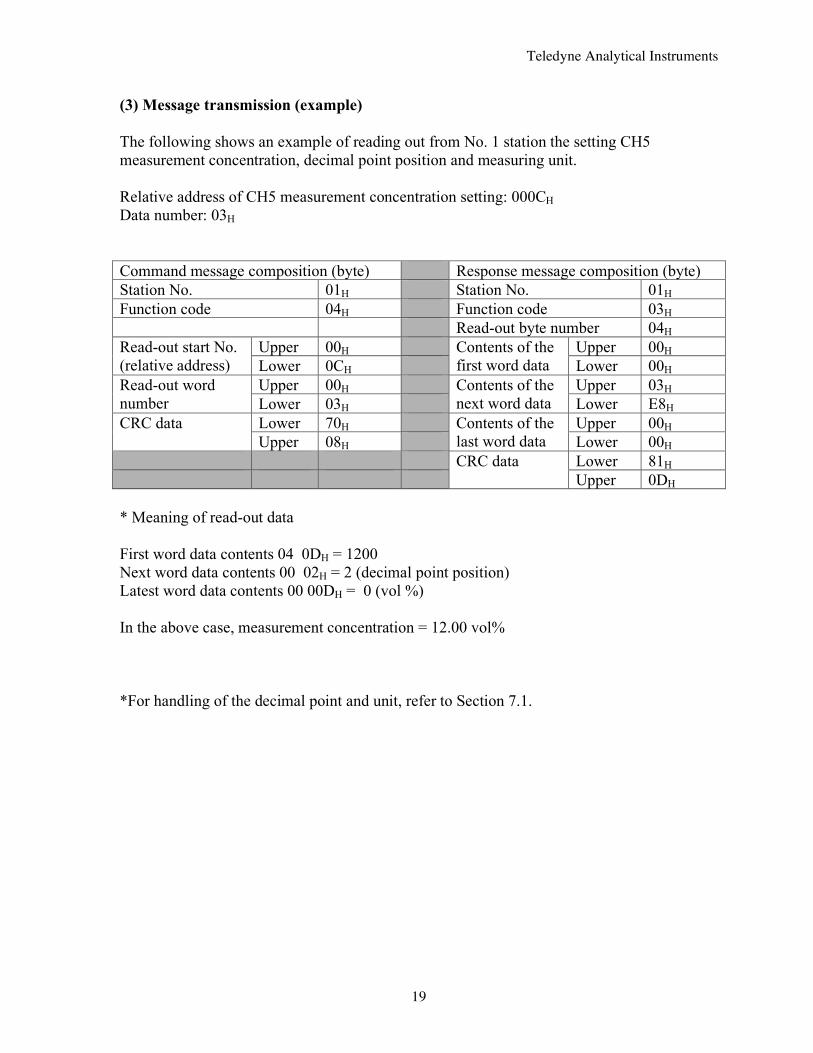
(3) Message transmission (example) The following shows an example of reading out from No. 1 station the setting CH5 measurement concentration, decimal point position and measuring unit. Relative address of CH5 measurement concentration setting: 000CH Data number: 03H Command message composition (byte) Response message composition (byte) Station No. 01H Station No. 01H Function code 04H Function code 03H Read-out byte number 04H
Upper 00H Upper 00H Read-out start No. (relative address) Lower 0CH
Contents of the first word data Lower 00H
Upper 00H Upper 03H Read-out word number Lower 03H
Contents of the next word data Lower E8H
Lower 70H Upper 00H CRC data Upper 08H
Contents of the last word data Lower 00H
Lower 81H
CRC data Upper 0DH
* Meaning of read-out data First word data contents 04 0DH = 1200 Next word data contents 00 02H = 2 (decimal point position) Latest word data contents 00 00DH = 0 (vol %) In the above case, measurement concentration = 12.00 vol% *For handling of the decimal point and unit, refer to Section 7.1.
Teledyne Analytical Instruments
20
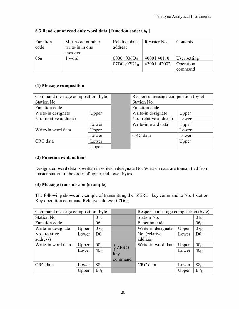
6.3 Read-out of read only word data [Function code: 06H] Function code
Max word number write-in in one message
Relative data address
Resister No. Contents
0000H 006DH 40001 40110 User setting 06H 1 word 07D0H 07D1H 42001 42002 Operation
command (1) Message composition Command message composition (byte) Response message composition (byte) Station No. Station No. Function code Function code
Upper Upper Write-in designate No. (relative address) Lower
Write-in designate No. (relative address)
Lower Upper Upper
Write-in word data Lower Write-in word data
Lower Lower Lower CRC data Upper
CRC data Upper
(2) Function explanations Designated word data is written in write-in designate No. Write-in data are transmitted from master station in the order of upper and lower bytes. (3) Message transmission (example) The following shows an example of transmitting the "ZERO" key command to No. 1 station. Key operation command Relative address: 07D0H Command message composition (byte) Response message composition (byte) Station No. 01H Station No. 01H Function code 06H Function code 06H
Upper 07H Upper 07H Write-in designate No. (relative address)
Lower D0H Write-in designate No. (relative address
Lower D0H
Upper 00H Upper 00H Write-in word data Lower 40H }ZERO
key command
Write-in word data Lower 40H
Lower 88H Lower 88H CRC data Upper B7H
CRC data Upper B7H
Teledyne Analytical Instruments
21
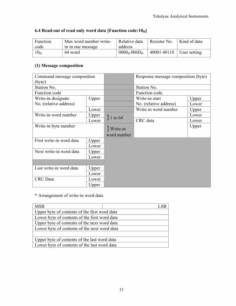
6.4 Read-out of read only word data [Function code:10H] Function code
Max word number write-in in one message
Relative data address
Resister No. Kind of data
10H 64 word 0000H 006DH 40001 40110 User setting
(1) Message composition Command message composition (byte)
Response message composition (byte)
Station No. Station No. Function code Function code
Upper Upper
Write-in start No. (relative address) Lower
Write-in designate No. (relative address)
Lower Upper Upper
Write-in word number Lower Write-in word number
Lower }1 to 64 Lower Write-in byte number }Write-in
word number
CRC data Upper
Upper First write-in word data Lower Upper Next write-in word data Lower
Upper Last write-in word data Lower Lower CRC Data Upper
* Arrangement of write-in word data MSB LSB Upper byte of contents of the first word data Lower byte of contents of the first word data Upper byte of contents of the next word data Lower byte of contents of the next word data Upper byte of contents of the last word data Lower byte of contents of the last word data
Teledyne Analytical Instruments
22
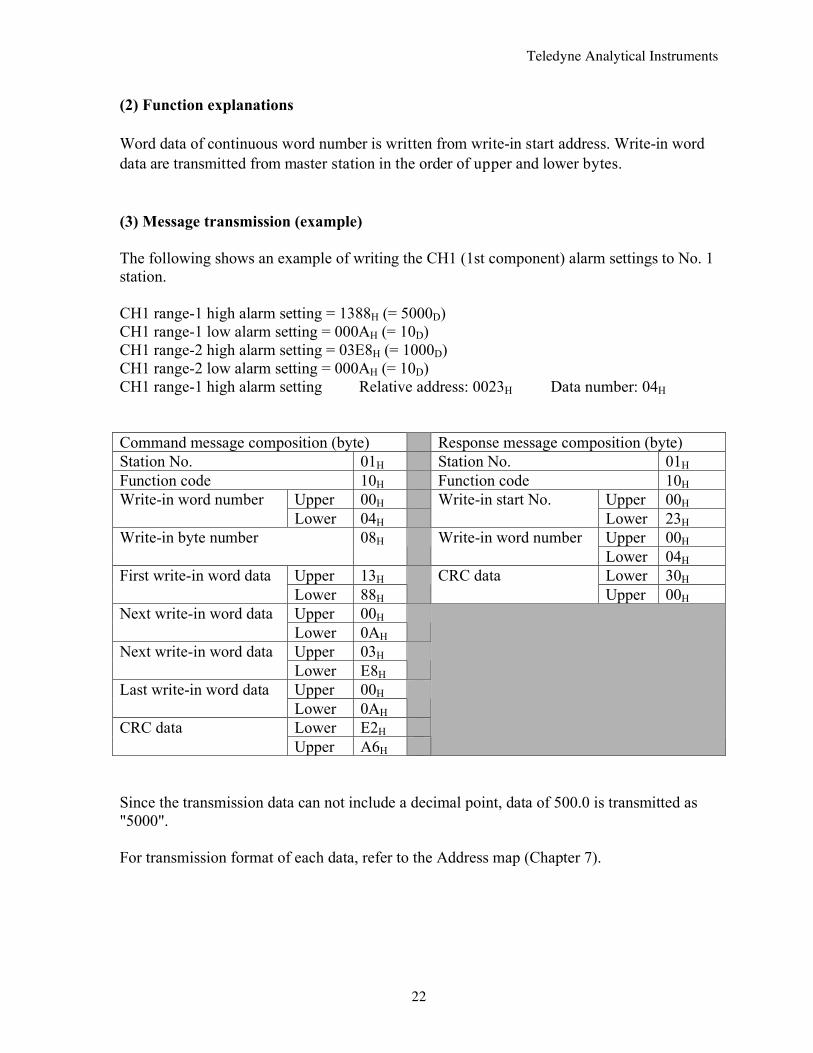
(2) Function explanations Word data of continuous word number is written from write-in start address. Write-in word data are transmitted from master station in the order of upper and lower bytes. (3) Message transmission (example) The following shows an example of writing the CH1 (1st component) alarm settings to No. 1 station. CH1 range-1 high alarm setting = 1388H (= 5000D) CH1 range-1 low alarm setting = 000AH (= 10D) CH1 range-2 high alarm setting = 03E8H (= 1000D) CH1 range-2 low alarm setting = 000AH (= 10D) CH1 range-1 high alarm setting Relative address: 0023H Data number: 04H Command message composition (byte) Response message composition (byte) Station No. 01H Station No. 01H Function code 10H Function code 10H
Upper 00H Upper 00H Write-in word number Lower 04H
Write-in start No. Lower 23H Upper 00H Write-in byte number 08H Write-in word number Lower 04H
Upper 13H Lower 30H First write-in word data Lower 88H
CRC data Upper 00H
Upper 00H Next write-in word data Lower 0AH
Upper 03H Next write-in word data Lower E8H
Upper 00H Last write-in word data Lower 0AH
Lower E2H CRC data Upper A6H
Since the transmission data can not include a decimal point, data of 500.0 is transmitted as "5000". For transmission format of each data, refer to the Address map (Chapter 7).
Teledyne Analytical Instruments
23
7. ADDRESS MAP AND DATA FORMAT 7.1 Data format 7.1.1 Transmission data format The MODBUS protocol used in this instrument is RTU (Remote Terminal Unit) mode. Transmitted data is "numeric value" and not ASCII code". 7.1.2 Handling of decimal point position and measurement unit When transmitted, the calibration concentration setting, alarm's high and low limits and measurement concentration data have no decimal point nor measurement unit. Calculate exact values of data upon point positioning as shown below. (a) Calibration concentration setting (register No. 40001 to 40020) Alarm setting (register No. 40036 to 40055) You can know the point position for each CH (channel) and each range, and unit upon reading in the decimal point position data (register No. 31087 to 31096), and the unit data (register No. 31067 to 31076). The decimal point position data has a value of 0, 1, 2 or 3. You can obtain an exact value by the following calculation.
Case 0: Calibration concentration setting data /1 Case 1: Calibration concentration setting data /10 Case 2: Calibration concentration setting data /100 Case 3: Calibration concentration setting data /1000
The unit data has a value of 0, 1, 2 or 3, that corresponds as follows.
Case 0: vol% Case 1: ppm Case 2: mg/m3 Case 3: g/m3
For example, if:
CH1 range-1 span calibration concentration setting (register No. 40002) = 2000, CH1 range-1 decimal point position (register No. 31087) = 1, and CH1 range-1 unit (register No. 31067) = 1,
the value is 200.0 ppm. For writing-in, proceed in the reverse. To obtain 200.0 ppm, write 2000 as calibration concentration setting. The decimal point position and unit are unchangeable because fixed to each CH and each range.
Teledyne Analytical Instruments
24
(b) Measurement concentration (register No. 30001 to 30036) The decimal point position and measurement unit for each concentration are stored in registers following that of concentration, and can be known by reading them in. The meaning of decimal point position data and measurement unit data values are the same as in (a) above. For example, if:
CH3 measurement concentration (register No. 30007) = 1270, CH3 decimal point position (register No. 30008) = 2, CH3 measurement unit (register No. 30009) = 0,
the value is 12.70 vol% 7.1.3 Handling at measurement data over-range Even if the measurement data is at over-range, with "— — — —" displayed on the screen, the concentration that stands then is transmitted as read-out measurement concentration.
Teledyne Analytical Instruments
25
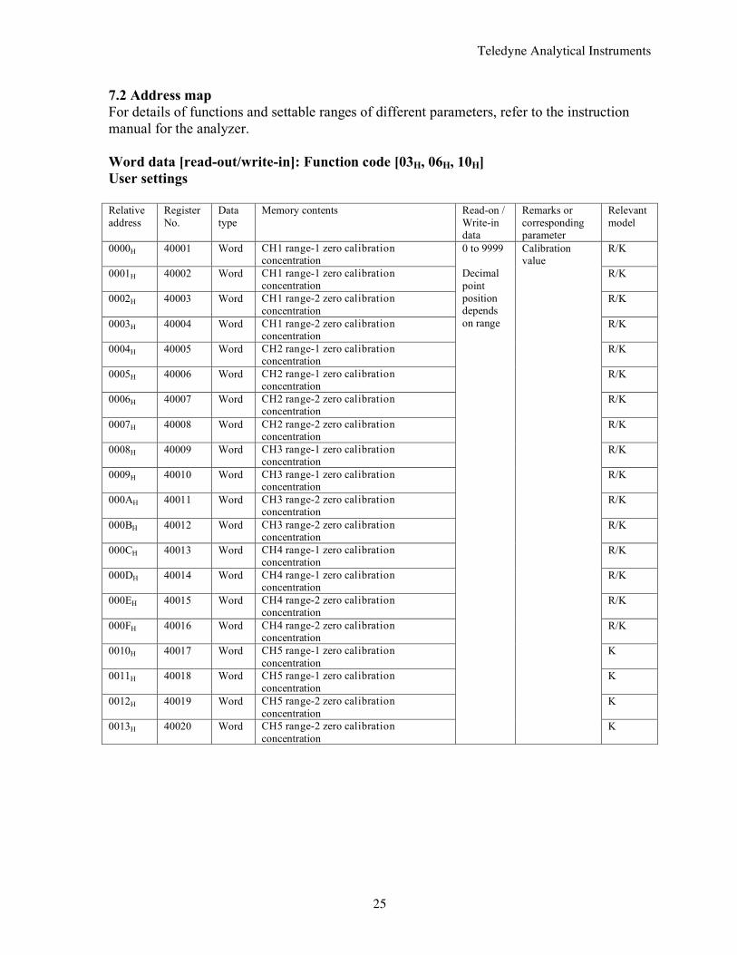
7.2 Address map For details of functions and settable ranges of different parameters, refer to the instruction manual for the analyzer. Word data [read-out/write-in]: Function code [03H, 06H, 10H] User settings Relative address
Register No.
Data type
Memory contents Read-on / Write-in data
Remarks or corresponding parameter
Relevant model
0000H 40001 Word CH1 range-1 zero calibration concentration
R/K
0001H 40002 Word CH1 range-1 zero calibration concentration
R/K
0002H 40003 Word CH1 range-2 zero calibration concentration
R/K
0003H 40004 Word CH1 range-2 zero calibration concentration
R/K
0004H 40005 Word CH2 range-1 zero calibration concentration
R/K
0005H 40006 Word CH2 range-1 zero calibration concentration
R/K
0006H 40007 Word CH2 range-2 zero calibration concentration
R/K
0007H 40008 Word CH2 range-2 zero calibration concentration
R/K
0008H 40009 Word CH3 range-1 zero calibration concentration
R/K
0009H 40010 Word CH3 range-1 zero calibration concentration
R/K
000AH 40011 Word CH3 range-2 zero calibration concentration
R/K
000BH 40012 Word CH3 range-2 zero calibration concentration
R/K
000CH 40013 Word CH4 range-1 zero calibration concentration
R/K
000DH 40014 Word CH4 range-1 zero calibration concentration
R/K
000EH 40015 Word CH4 range-2 zero calibration concentration
R/K
000FH 40016 Word CH4 range-2 zero calibration concentration
R/K
0010H 40017 Word CH5 range-1 zero calibration concentration
K
0011H 40018 Word CH5 range-1 zero calibration concentration
K
0012H 40019 Word CH5 range-2 zero calibration concentration
K
0013H 40020 Word CH5 range-2 zero calibration concentration
0 to 9999 Decimal point position depends on range
Calibration value
K
Teledyne Analytical Instruments
26
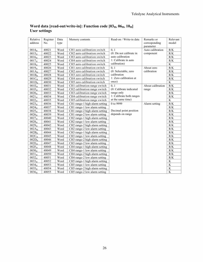
Word data [read-out/write-in]: Function code [03H, 06H, 10H] User settings Relative address
Register No.
Data type
Memory contents Read-on / Write-in data Remarks or corresponding parameter
Relevant model
0014H 40021 Word CH1 auto calibration switch R/K 0015H 40022 Word CH2 auto calibration switch R/K 0016H 40023 Word CH3 auto calibration switch R/K 0017H 40024 Word CH4 auto calibration switch R/K 0018H 40025 Word CH5 auto calibration switch
0, 1 (0: Dn not calibrate in auto calibration 1: Calibrate in auto calibration)
Auto calibration component
K 0019H 40026 Word CH1 zero calibration switch R/K 001AH 40027 Word CH2 zero calibration switch R/K 001BH 40028 Word CH3 zero calibration switch R/K 001CH 40029 Word CH4 zero calibration switch R/K 001DH 40030 Word CH5 zero calibration switch
0, 1 (0: Selectable, zero calibration 1: Zero calibration at once)
About zero calibration
K 001EH 40031 Word CH1 calibration range switch R/K 001FH 40032 Word CH2 calibration range switch R/K 0020H 40033 Word CH3 calibration range switch R/K 0021H 40034 Word CH4 calibration range switch R/K 0022H 40035 Word CH5 calibration range switch
0, 1 (0: Calibrate indicated range only 1: Calibrate both ranges at the same time)
About calibration range
K 0023H 40036 Word CH1 range-1 high alarm setting R/K 0024H 40037 Word CH1 range-1 low alarm setting R/K 0025H 40038 Word CH1 range-2 high alarm setting R/K 0026H 40039 Word CH1 range-2 low alarm setting R/K 0027H 40040 Word CH2 range-1 high alarm setting R/K 0028H 40041 Word CH2 range-1 low alarm setting R/K 0029H 40042 Word CH2 range-2 high alarm setting R/K 002AH 40043 Word CH2 range-2 low alarm setting R/K 002BH 40044 Word CH3 range-1 high alarm setting R/K 002CH 40045 Word CH3 range-1 low alarm setting R/K 002DH 40046 Word CH3 range-2 high alarm setting R/K 002EH 40047 Word CH3 range-2 low alarm setting R/K 002FH 40048 Word CH4 range-1 high alarm setting R/K 0030H 40049 Word CH4 range-1 low alarm setting R/K 0031H 40050 Word CH4 range-2 high alarm setting R/K 0032H 40051 Word CH4 range-2 low alarm setting R/K 0033H 40052 Word CH5 range-1 high alarm setting K 0034H 40053 Word CH5 range-1 low alarm setting K 0035H 40054 Word CH5 range-2 high alarm setting K 0036H 40055 Word CH5 range-2 low alarm setting
0 to 9999 Decimal point position depends on range
Alarm setting
K
Teledyne Analytical Instruments
27
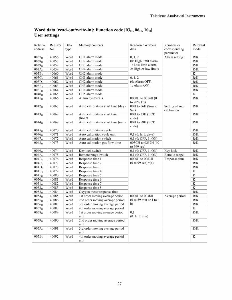
Word data [read-out/write-in]: Function code [03H, 06H, 10H] User settings Relative address
Register No.
Data type
Memory contents Read-on / Write-in data
Remarks or corresponding parameter
Relevant model
0037H 40056 Word CH1 alarm mode R/K 0038H 40057 Word CH2 alarm mode R/K 0039H 40058 Word CH3 alarm mode R/K 003AH 40059 Word CH4 alarm mode R/K 003BH 40060 Word CH5 alarm mode
0, 1, 2 (0: High limit alarm, 1: Low limit alarm, 2: High or low limit)
K 003CH 40061 Word CH1 alarm mode R/K 003DH 40062 Word CH2 alarm mode R/K 003EH 40063 Word CH3 alarm mode R/K 003FH 40064 Word CH4 alarm mode R/K 0040H 40065 Word CH5 alarm mode
0, 1, 2 (0: Alarm OFF, 1: Alarm ON)
K 0041H 40066 Word Alarm hysteresis 0000H to 0014H (0
to 20% FS)
Alarm setting
R/K
0042H 40067 Word Auto calibration start time (day) 00H to 06H (Sun to Sat)
R/K
0043H 40068 Word Auto calibration start time (hour)
00H to 23H (BCD code)
R/K
0044H 40069 Word Auto calibration start time (min) 00H to 59H (BCD code)
R/K
0045H 40070 Word Auto calibration cycle R/K 0046H 40071 Word Auto calibration cycle unit 0,1 (0: h, 1: days) R/K 0047H 40072 Word Auto calibration switch 0,1 (0: OFF, 1: ON) R/K 0048H 40073 Word Auto calibration gas flow time 003CH to 0257H (60
to 599 sec)
Setting of auto calibration
R/K
0049H 40074 Word Key lock switch 0,1 (0: OFF, 1: ON) Key lock R/K 004AH 40075 Word Remote range switch 0,1 (0: OFF, 1: ON) Remote range R/K 004BH 40076 Word Response time 1 R/K 004CH 40077 Word Response time 2 R/K 004DH 40078 Word Response time 3 R/K 004EH 40079 Word Response time 4 K 004FH 40080 Word Response time 5 K 0050H 40081 Word Response time 6 K 0051H 40082 Word Response time 7 K 0052H 40083 Word Response time 8 K 0053H 40084 Word Oxygen meter response time
0000H to 0063H (0 to 99 sec) *(a)
Response time
R/K 0054H 40085 Word 1st order moving average period R/K 0055H 40086 Word 2nd order moving average period R/K 0056H 40087 Word 3rd order moving average period R/K 0057H 40088 Word 4th order moving average period
0000H to 003bH (0 to 59 min or 1 to 4 h)
K 0058H 40089 Word 1st order moving average period
unit R/K
0059H 40090 Word 2nd order moving average period unit
R/K
005AH 40091 Word 3rd order moving average period unit
R/K
005BH 40092 Word 4th order moving average period unit
0,1 (0: h, 1: min)
Average period
K
Teledyne Analytical Instruments
28
Word data [read-out/write-in]: Function code [03H, 06H, 10H] User settings Relative address
Register No.
Data type
Memory contents Read-on / Write-in data Remarks or corresponding parameter
Relevant model
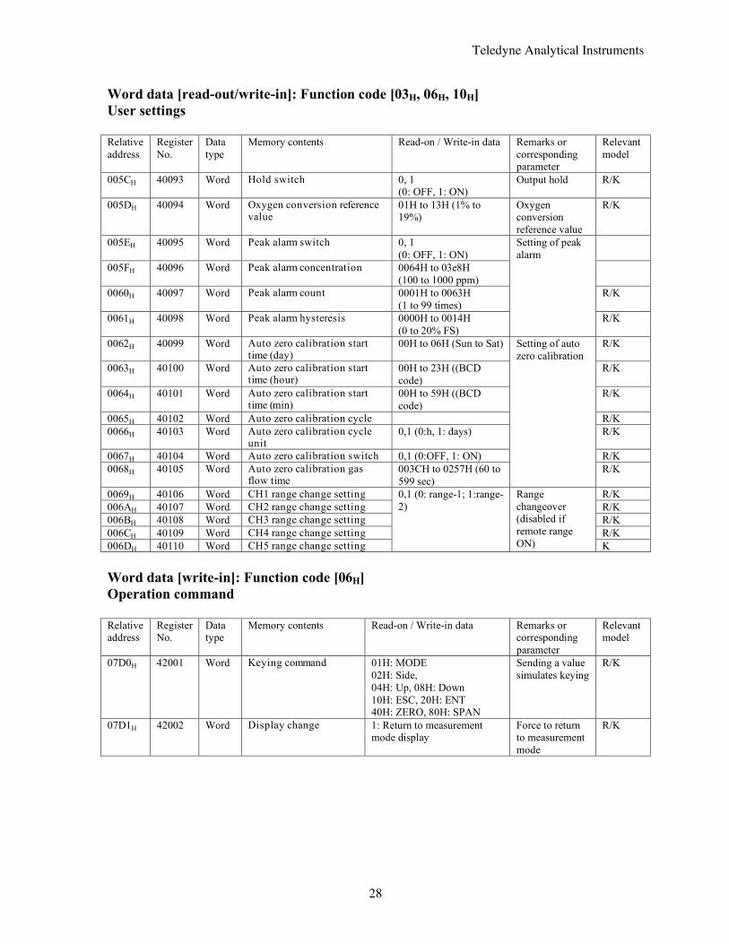
005CH 40093 Word Hold switch 0, 1 (0: OFF, 1: ON)
Output hold R/K
005DH 40094 Word Oxygen conversion reference value
01H to 13H (1% to 19%)
Oxygen conversion reference value
R/K
005EH 40095 Word Peak alarm switch 0, 1 (0: OFF, 1: ON)
005FH 40096 Word Peak alarm concentration 0064H to 03e8H (100 to 1000 ppm)
0060H 40097 Word Peak alarm count 0001H to 0063H (1 to 99 times)
R/K
0061H 40098 Word Peak alarm hysteresis 0000H to 0014H (0 to 20% FS)
Setting of peak alarm
R/K
0062H 40099 Word Auto zero calibration start time (day)
00H to 06H (Sun to Sat) R/K
0063H 40100 Word Auto zero calibration start time (hour)
00H to 23H ((BCD code)
R/K
0064H 40101 Word Auto zero calibration start time (min)
00H to 59H ((BCD code)
R/K
0065H 40102 Word Auto zero calibration cycle R/K 0066H 40103 Word Auto zero calibration cycle
unit 0,1 (0:h, 1: days) R/K
0067H 40104 Word Auto zero calibration switch 0,1 (0:OFF, 1: ON) R/K 0068H 40105 Word Auto zero calibration gas
flow time 003CH to 0257H (60 to 599 sec)
Setting of auto zero calibration
R/K
0069H 40106 Word CH1 range change setting R/K 006AH 40107 Word CH2 range change setting R/K 006BH 40108 Word CH3 range change setting R/K 006CH 40109 Word CH4 range change setting R/K 006DH 40110 Word CH5 range change setting
0,1 (0: range-1; 1:range-2)
Range changeover (disabled if remote range ON) K
Word data [write-in]: Function code [06H] Operation command Relative address
Register No.
Data type
Memory contents Read-on / Write-in data Remarks or corresponding parameter
Relevant model
07D0H 42001 Word Keying command 01H: MODE 02H: Side, 04H: Up, 08H: Down 10H: ESC, 20H: ENT 40H: ZERO, 80H: SPAN
Sending a value simulates keying
R/K
07D1H 42002 Word Display change 1: Return to measurement mode display
Force to return to measurement mode
R/K
Teledyne Analytical Instruments
29
Word data [read-out only]: Function code [04H] Measurement value and status Relative address
Register No.
Data type
Memory contents Read-on / Write-in data
Remarks or corresponding parameter
Relevant model
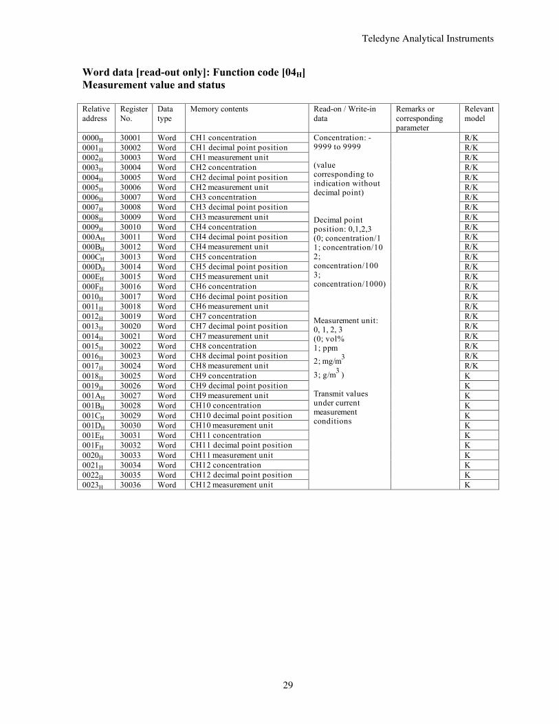
0000H 30001 Word CH1 concentration R/K 0001H 30002 Word CH1 decimal point position R/K 0002H 30003 Word CH1 measurement unit R/K 0003H 30004 Word CH2 concentration R/K 0004H 30005 Word CH2 decimal point position R/K 0005H 30006 Word CH2 measurement unit R/K 0006H 30007 Word CH3 concentration R/K 0007H 30008 Word CH3 decimal point position R/K 0008H 30009 Word CH3 measurement unit R/K 0009H 30010 Word CH4 concentration R/K 000AH 30011 Word CH4 decimal point position R/K 000BH 30012 Word CH4 measurement unit R/K 000CH 30013 Word CH5 concentration R/K 000DH 30014 Word CH5 decimal point position R/K 000EH 30015 Word CH5 measurement unit R/K 000FH 30016 Word CH6 concentration R/K 0010H 30017 Word CH6 decimal point position R/K 0011H 30018 Word CH6 measurement unit R/K 0012H 30019 Word CH7 concentration R/K 0013H 30020 Word CH7 decimal point position R/K 0014H 30021 Word CH7 measurement unit R/K 0015H 30022 Word CH8 concentration R/K 0016H 30023 Word CH8 decimal point position R/K 0017H 30024 Word CH8 measurement unit R/K 0018H 30025 Word CH9 concentration K 0019H 30026 Word CH9 decimal point position K 001AH 30027 Word CH9 measurement unit K 001BH 30028 Word CH10 concentration K 001CH 30029 Word CH10 decimal point position K 001DH 30030 Word CH10 measurement unit K 001EH 30031 Word CH11 concentration K 001FH 30032 Word CH11 decimal point position K 0020H 30033 Word CH11 measurement unit K 0021H 30034 Word CH12 concentration K 0022H 30035 Word CH12 decimal point position K 0023H 30036 Word CH12 measurement unit
Concentration: -9999 to 9999 (value corresponding to indication without decimal point) Decimal point position: 0,1,2,3 (0; concentration/1 1; concentration/10 2; concentration/100 3; concentration/1000) Measurement unit: 0, 1, 2, 3 (0; vol% 1; ppm 2; mg/m3
3; g/m3 ) Transmit values under current measurement conditions
K
Teledyne Analytical Instruments
30
Word data [read-out only]: Function code [04H] Measurement value and status Relative address
Register No.
Data type
Memory contents Read-on / Write-in data
Remarks or corresponding parameter
Relevant model
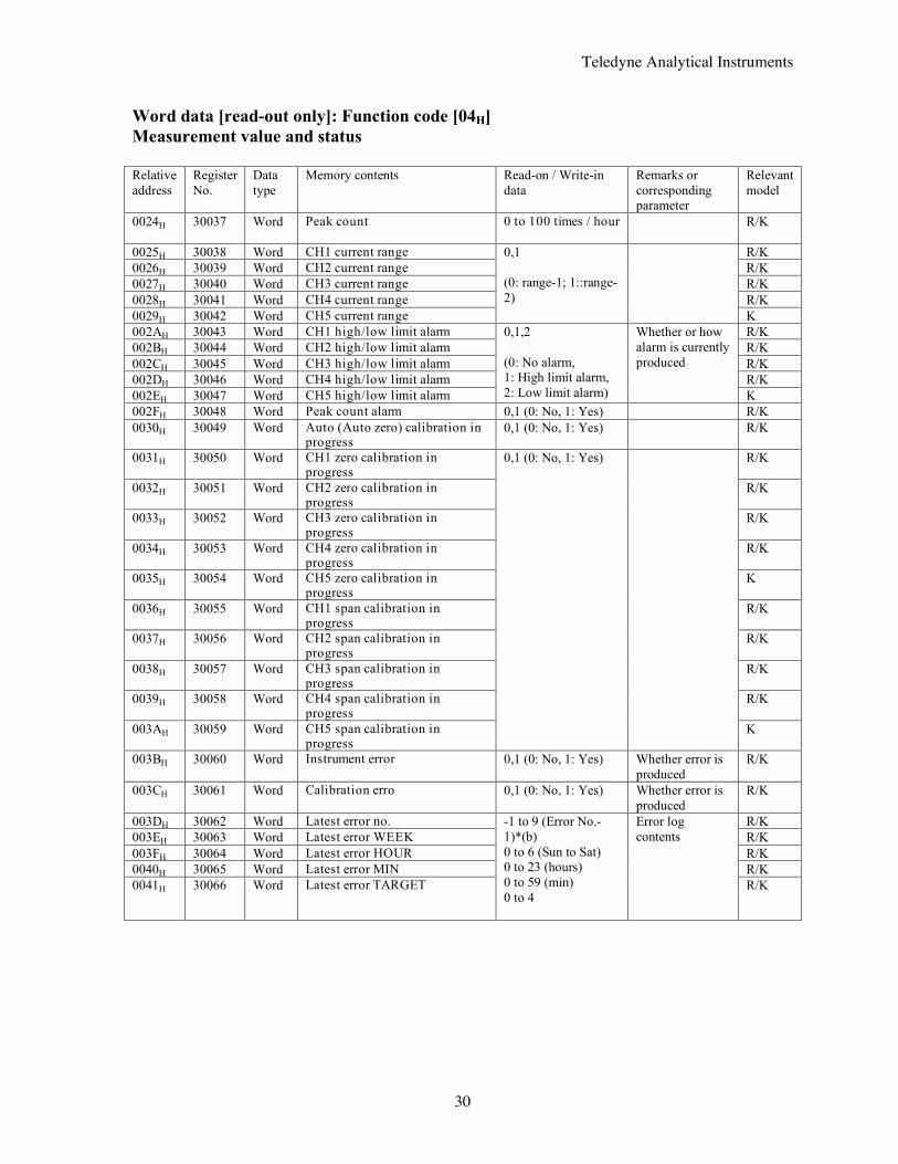
0024H 30037 Word Peak count 0 to 100 times / hour
R/K
0025H 30038 Word CH1 current range R/K 0026H 30039 Word CH2 current range R/K 0027H 30040 Word CH3 current range R/K 0028H 30041 Word CH4 current range R/K 0029H 30042 Word CH5 current range
0,1 (0: range-1; 1::range-2)
K 002AH 30043 Word CH1 high/low limit alarm R/K 002BH 30044 Word CH2 high/low limit alarm R/K 002CH 30045 Word CH3 high/low limit alarm R/K 002DH 30046 Word CH4 high/low limit alarm R/K 002EH 30047 Word CH5 high/low limit alarm
0,1,2 (0: No alarm, 1: High limit alarm, 2: Low limit alarm)
Whether or how alarm is currently produced
K 002FH 30048 Word Peak count alarm 0,1 (0: No, 1: Yes) R/K 0030H 30049 Word Auto (Auto zero) calibration in
progress 0,1 (0: No, 1: Yes) R/K
0031H 30050 Word CH1 zero calibration in progress
R/K
0032H 30051 Word CH2 zero calibration in progress
R/K
0033H 30052 Word CH3 zero calibration in progress
R/K
0034H 30053 Word CH4 zero calibration in progress
R/K
0035H 30054 Word CH5 zero calibration in progress
K
0036H 30055 Word CH1 span calibration in progress
R/K
0037H 30056 Word CH2 span calibration in progress
R/K
0038H 30057 Word CH3 span calibration in progress
R/K
0039H 30058 Word CH4 span calibration in progress
R/K
003AH 30059 Word CH5 span calibration in progress
0,1 (0: No, 1: Yes)
K
003BH 30060 Word Instrument error 0,1 (0: No, 1: Yes) Whether error is produced
R/K
003CH 30061 Word Calibration erro 0,1 (0: No, 1: Yes) Whether error is produced
R/K
003DH 30062 Word Latest error no. R/K 003EH 30063 Word Latest error WEEK R/K 003FH 30064 Word Latest error HOUR R/K 0040H 30065 Word Latest error MIN R/K 0041H 30066 Word Latest error TARGET
-1 to 9 (Error No.-1)*(b) 0 to 6 (Sun to Sat) 0 to 23 (hours) 0 to 59 (min) 0 to 4
Error log contents
R/K
Teledyne Analytical Instruments
31
Word data [read-out only]: Function code [04H] Measurement value and status Relative address
Register No.
Data type
Memory contents Read-on / Write-in data
Remarks or corresponding parameter
Relevant model
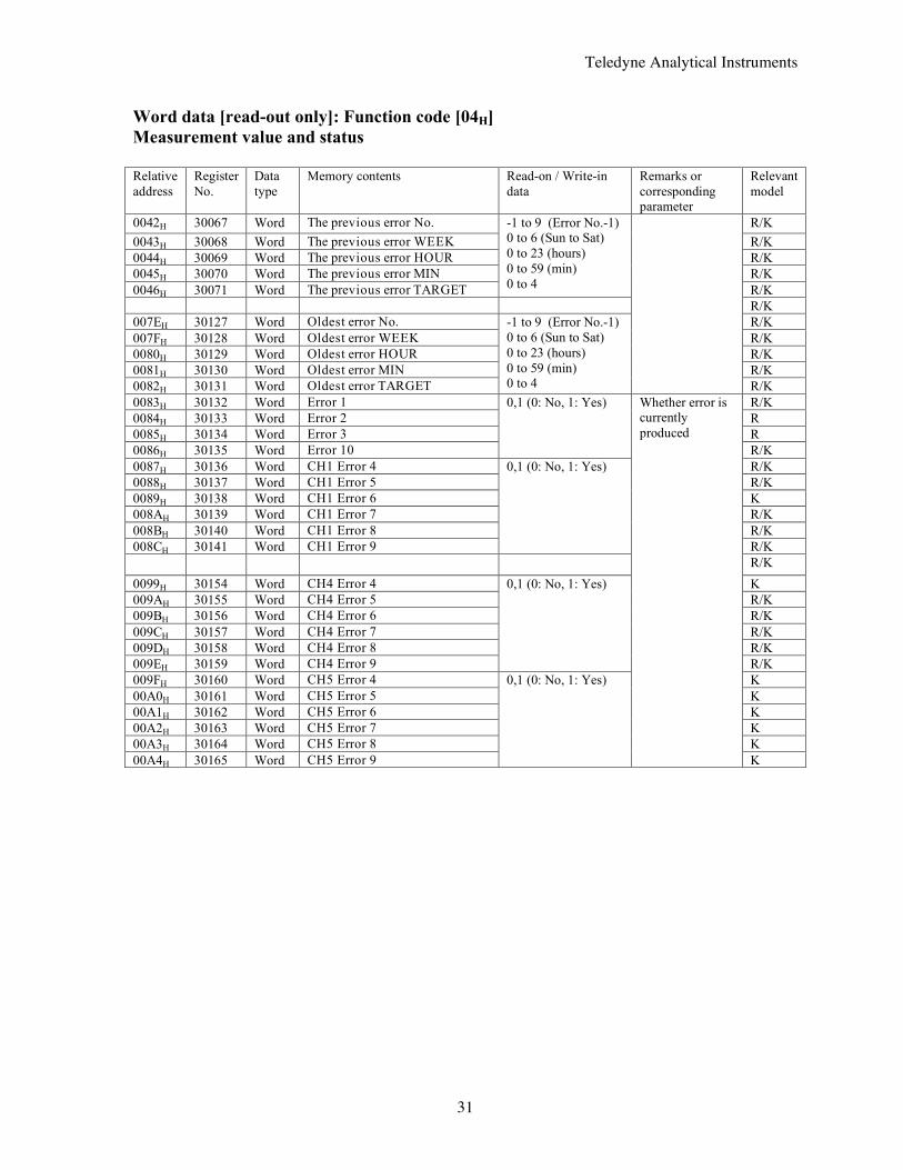
0042H 30067 Word The previous error No. R/K 0043H 30068 Word The previous error WEEK R/K 0044H 30069 Word The previous error HOUR R/K 0045H 30070 Word The previous error MIN R/K 0046H 30071 Word The previous error TARGET
-1 to 9 (Error No.-1) 0 to 6 (Sun to Sat) 0 to 23 (hours) 0 to 59 (min) 0 to 4 R/K
R/K 007EH 30127 Word Oldest error No. R/K 007FH 30128 Word Oldest error WEEK R/K 0080H 30129 Word Oldest error HOUR R/K 0081H 30130 Word Oldest error MIN R/K 0082H 30131 Word Oldest error TARGET
-1 to 9 (Error No.-1) 0 to 6 (Sun to Sat) 0 to 23 (hours) 0 to 59 (min) 0 to 4
R/K 0083H 30132 Word Error 1 R/K 0084H 30133 Word Error 2 R 0085H 30134 Word Error 3 R 0086H 30135 Word Error 10
0,1 (0: No, 1: Yes)
R/K 0087H 30136 Word CH1 Error 4 R/K 0088H 30137 Word CH1 Error 5 R/K 0089H 30138 Word CH1 Error 6 K 008AH 30139 Word CH1 Error 7 R/K 008BH 30140 Word CH1 Error 8 R/K 008CH 30141 Word CH1 Error 9
0,1 (0: No, 1: Yes)
R/K R/K 0099H 30154 Word CH4 Error 4 K 009AH 30155 Word CH4 Error 5 R/K 009BH 30156 Word CH4 Error 6 R/K 009CH 30157 Word CH4 Error 7 R/K 009DH 30158 Word CH4 Error 8 R/K 009EH 30159 Word CH4 Error 9
0,1 (0: No, 1: Yes)
R/K 009FH 30160 Word CH5 Error 4 K 00A0H 30161 Word CH5 Error 5 K 00A1H 30162 Word CH5 Error 6 K 00A2H 30163 Word CH5 Error 7 K 00A3H 30164 Word CH5 Error 8 K 00A4H 30165 Word CH5 Error 9
0,1 (0: No, 1: Yes)
Whether error is currently produced
K
Teledyne Analytical Instruments
32
Word data [read-out only]: Function code [04H] Measurement value and status Relative address
Register No.
Data type
Memory contents Read-on / Write-in data
Remarks or corresponding parameter
Relevant model
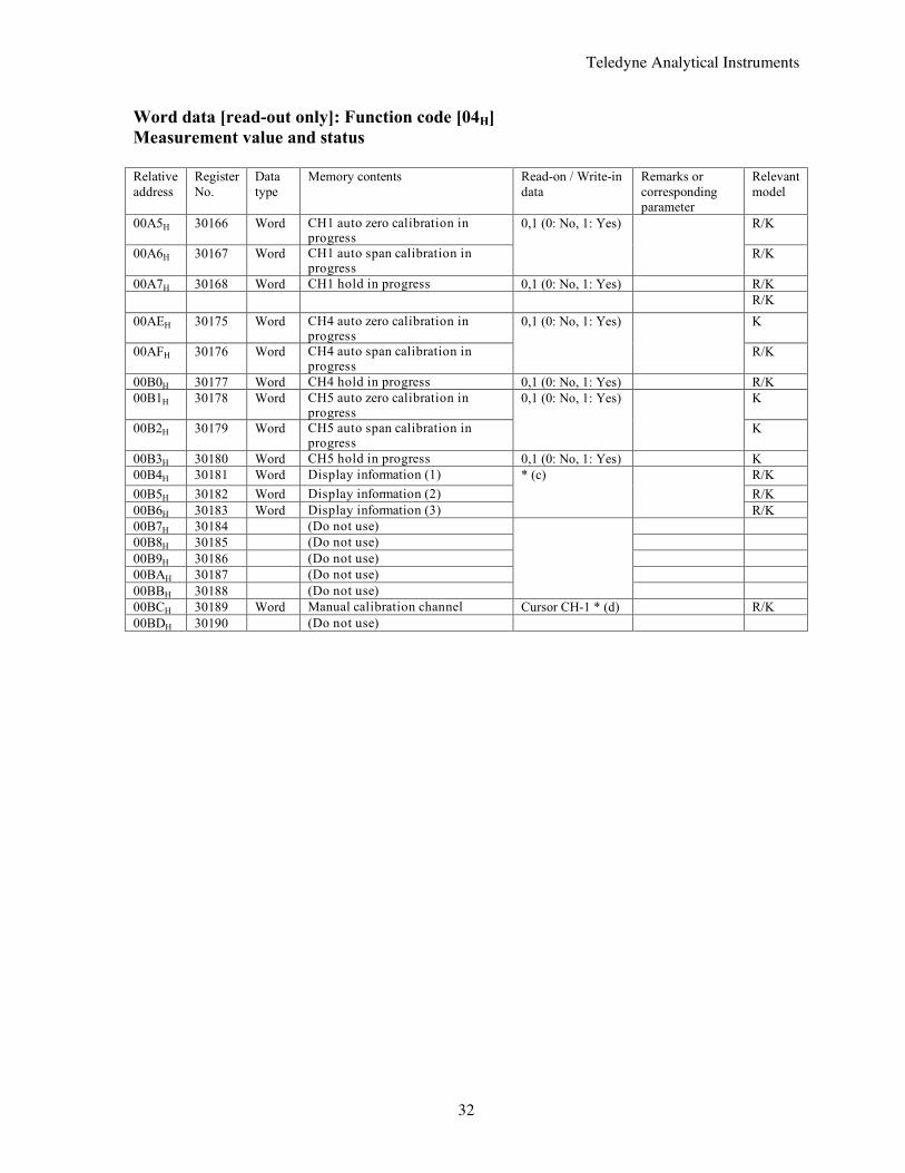
00A5H 30166 Word CH1 auto zero calibration in progress
R/K
00A6H 30167 Word CH1 auto span calibration in progress
0,1 (0: No, 1: Yes)
R/K
00A7H 30168 Word CH1 hold in progress 0,1 (0: No, 1: Yes) R/K R/K 00AEH 30175 Word CH4 auto zero calibration in
progress K
00AFH 30176 Word CH4 auto span calibration in progress
0,1 (0: No, 1: Yes)
R/K
00B0H 30177 Word CH4 hold in progress 0,1 (0: No, 1: Yes) R/K 00B1H 30178 Word CH5 auto zero calibration in
progress K
00B2H 30179 Word CH5 auto span calibration in progress
0,1 (0: No, 1: Yes)
K
00B3H 30180 Word CH5 hold in progress 0,1 (0: No, 1: Yes) K 00B4H 30181 Word Display information (1) R/K 00B5H 30182 Word Display information (2) R/K 00B6H 30183 Word Display information (3)
* (c)
R/K 00B7H 30184 (Do not use) 00B8H 30185 (Do not use) 00B9H 30186 (Do not use) 00BAH 30187 (Do not use) 00BBH 30188 (Do not use)
00BCH 30189 Word Manual calibration channel Cursor CH-1 * (d) R/K 00BDH 30190 (Do not use)
Teledyne Analytical Instruments
33
Word data [read-out only]: Function code [04H] Measurement value and status Relative address
Register No.
Data type
Memory contents Read-on / Write-in data
Remarks or corresponding parameter
Relevant model
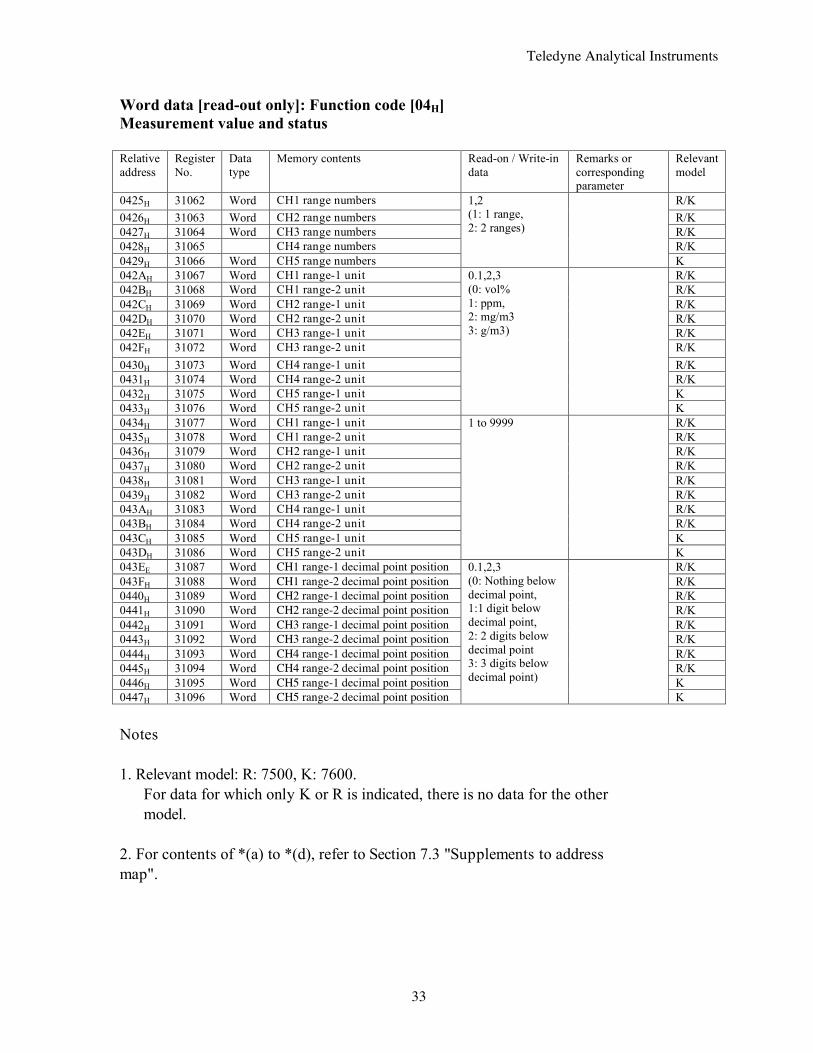
0425H 31062 Word CH1 range numbers R/K 0426H 31063 Word CH2 range numbers R/K 0427H 31064 Word CH3 range numbers R/K 0428H 31065 CH4 range numbers R/K 0429H 31066 Word CH5 range numbers
1,2 (1: 1 range, 2: 2 ranges)
K 042AH 31067 Word CH1 range-1 unit R/K 042BH 31068 Word CH1 range-2 unit R/K 042CH 31069 Word CH2 range-1 unit R/K 042DH 31070 Word CH2 range-2 unit R/K 042EH 31071 Word CH3 range-1 unit R/K 042FH 31072 Word CH3 range-2 unit R/K 0430H 31073 Word CH4 range-1 unit R/K 0431H 31074 Word CH4 range-2 unit R/K 0432H 31075 Word CH5 range-1 unit K 0433H 31076 Word CH5 range-2 unit
0.1,2,3 (0: vol% 1: ppm, 2: mg/m3 3: g/m3)
K 0434H 31077 Word CH1 range-1 unit R/K 0435H 31078 Word CH1 range-2 unit R/K 0436H 31079 Word CH2 range-1 unit R/K 0437H 31080 Word CH2 range-2 unit R/K 0438H 31081 Word CH3 range-1 unit R/K 0439H 31082 Word CH3 range-2 unit R/K 043AH 31083 Word CH4 range-1 unit R/K 043BH 31084 Word CH4 range-2 unit R/K 043CH 31085 Word CH5 range-1 unit K 043DH 31086 Word CH5 range-2 unit
1 to 9999
K 043EE 31087 Word CH1 range-1 decimal point position R/K 043FH 31088 Word CH1 range-2 decimal point position R/K 0440H 31089 Word CH2 range-1 decimal point position R/K 0441H 31090 Word CH2 range-2 decimal point position R/K 0442H 31091 Word CH3 range-1 decimal point position R/K 0443H 31092 Word CH3 range-2 decimal point position R/K 0444H 31093 Word CH4 range-1 decimal point position R/K 0445H 31094 Word CH4 range-2 decimal point position R/K 0446H 31095 Word CH5 range-1 decimal point position K 0447H 31096 Word CH5 range-2 decimal point position
0.1,2,3 (0: Nothing below decimal point, 1:1 digit below decimal point, 2: 2 digits below decimal point 3: 3 digits below decimal point)
K Notes 1. Relevant model: R: 7500, K: 7600.
For data for which only K or R is indicated, there is no data for the other model.
2. For contents of *(a) to *(d), refer to Section 7.3 "Supplements to address map".
Teledyne Analytical Instruments
34
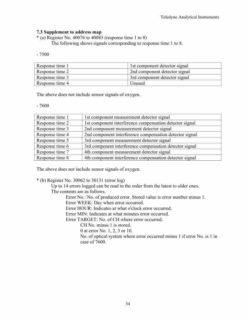
7.3 Supplement to address map * (a) Register No. 40076 to 40083 (response time 1 to 8) The following shows signals corresponding to response time 1 to 8. - 7500 Response time 1 1st component detector signal Response time 2 2nd component detector signal Response time 3 3rd component detector signal Response time 4 Unused The above does not include sensor signals of oxygen. - 7600 Response time 1 1st component measurement detector signal Response time 2 1st component interference compensation detector signal Response time 3 2nd component measurement detector signal Response time 4 2nd component interference compensation detector signal Response time 5 3rd component measurement detector signal Response time 6 3rd component interference compensation detector signal Response time 7 4th component measurement detector signal Response time 8 4th component interference compensation detector signal The above does not include sensor signals of oxygen. * (b) Register No. 30062 to 30131 (error log) Up to 14 errors logged can be read in the order from the latest to older ones. The contents are as follows. Error No.: No. of produced error. Stored value is error number minus 1. Error WEEK: Day when error occurred. Error HOUR: Indicates at what o'clock error occurred. Error MIN: Indicates at what minutes error occurred. Error TARGET: No. of CH where error occurred.
CH No. minus 1 is stored. 0 at error No. 1, 2, 3 or 10. No. of optical system where error occurred minus 1 if error No. is 1 in case of 7600.
Teledyne Analytical Instruments
35
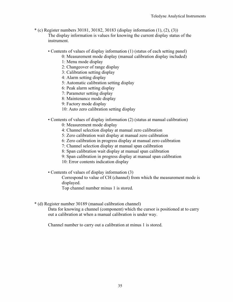
* (c) Register numbers 30181, 30182, 30183 (display information (1), (2), (3)) The display information is values for knowing the current display status of the instrument. • Contents of values of display information (1) (status of each setting panel)
0: Measurement mode display (manual calibration display included) 1: Menu mode display 2: Changeover of range display 3: Calibration setting display 4: Alarm setting display 5: Automatic calibration setting display 6: Peak alarm setting display 7: Parameter setting display 8: Maintenance mode display 9: Factory mode display 10: Auto zero calibration setting display
• Contents of values of display information (2) (status at manual calibration) 0: Measurement mode display 4: Channel selection display at manual zero calibration 5: Zero calibration wait display at manual zero calibration 6: Zero calibration in progress display at manual zero calibration 7: Channel selection display at manual span calibration 8: Span calibration wait display at manual span calibration 9: Span calibration in progress display at manual span calibration 10: Error contents indication display
• Contents of values of display information (3) Correspond to value of CH (channel) from which the measurement mode is displayed. Top channel number minus 1 is stored.
* (d) Register number 30189 (manual calibration channel)
Data for knowing a channel (component) which the cursor is positioned at to carry out a calibration at when a manual calibration is under way. Channel number to carry out a calibration at minus 1 is stored.
Teledyne Analytical Instruments
36
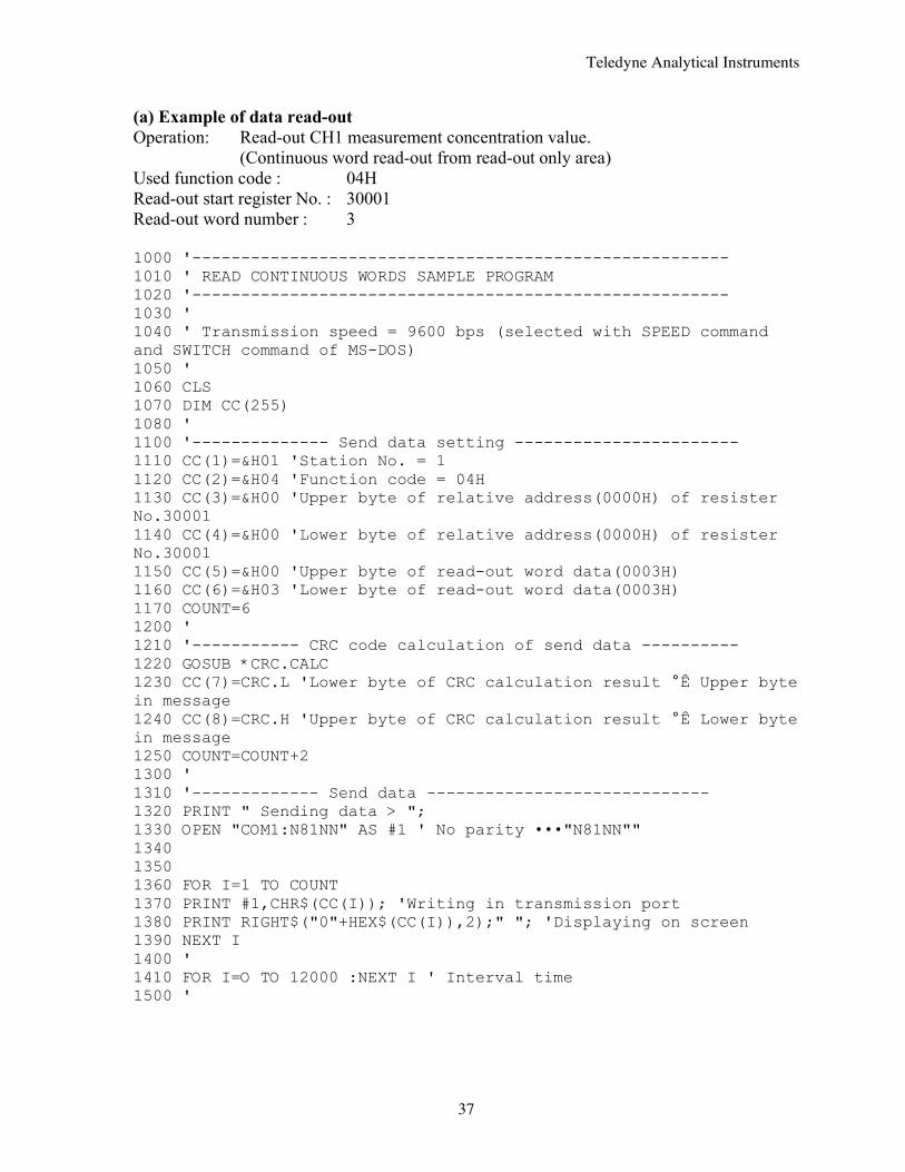
8. SAMPLE PROGRAM This chapter concerns data read-out/write-in sample program which operates on N88-Japanese BASIC (*2) for PC-9801 (*1) or compatible PCs. Note that the program shown here is for reference for you to create a program and not for guaranteeing all actions. Before executing the program, make sure of the communication conditions in the following procedure. • Communication speed (baud rate): Match the conditions with this instrument using SWITCH command and SPEED command of MS-DOS (*3). For SWITCH command and SPEED command, refer to the reference manual of MS-DOS. • Data length, stop bits and parity:
Set in this program. Match the conditions with this instrument. *1 PC-9801 series are products of NEC Corporation. *2 N88-Japanese BASIC is a registered trademark of NEC Corporation. *3 MS-DOS is a registered trade mark of Microsoft Corporation.
Teledyne Analytical Instruments
37
(a) Example of data read-out Operation: Read-out CH1 measurement concentration value. (Continuous word read-out from read-out only area) Used function code : 04H Read-out start register No. : 30001 Read-out word number : 3 1000 '------------------------------------------------------- 1010 ' READ CONTINUOUS WORDS SAMPLE PROGRAM 1020 '------------------------------------------------------- 1030 ' 1040 ' Transmission speed = 9600 bps (selected with SPEED command and SWITCH command of MS-DOS) 1050 ' 1060 CLS 1070 DIM CC(255) 1080 ' 1100 '-------------- Send data setting ----------------------- 1110 CC(1)=&H01 'Station No. = 1 1120 CC(2)=&H04 'Function code = 04H 1130 CC(3)=&H00 'Upper byte of relative address(0000H) of resister No.30001 1140 CC(4)=&H00 'Lower byte of relative address(0000H) of resister No.30001 1150 CC(5)=&H00 'Upper byte of read-out word data(0003H) 1160 CC(6)=&H03 'Lower byte of read-out word data(0003H) 1170 COUNT=6 1200 ' 1210 '----------- CRC code calculation of send data ---------- 1220 GOSUB *CRC.CALC 1230 CC(7)=CRC.L 'Lower byte of CRC calculation result °Ê Upper byte in message 1240 CC(8)=CRC.H 'Upper byte of CRC calculation result °Ê Lower byte in message 1250 COUNT=COUNT+2 1300 ' 1310 '------------- Send data ----------------------------- 1320 PRINT " Sending data > "; 1330 OPEN "COM1:N81NN" AS #1 ' No parity •••"N81NN"" 1340 1350 1360 FOR I=1 TO COUNT 1370 PRINT #1,CHR$(CC(I)); 'Writing in transmission port 1380 PRINT RIGHT$("0"+HEX$(CC(I)),2);" "; 'Displaying on screen 1390 NEXT I 1400 ' 1410 FOR I=O TO 12000 :NEXT I ' Interval time 1500 '
Teledyne Analytical Instruments
38
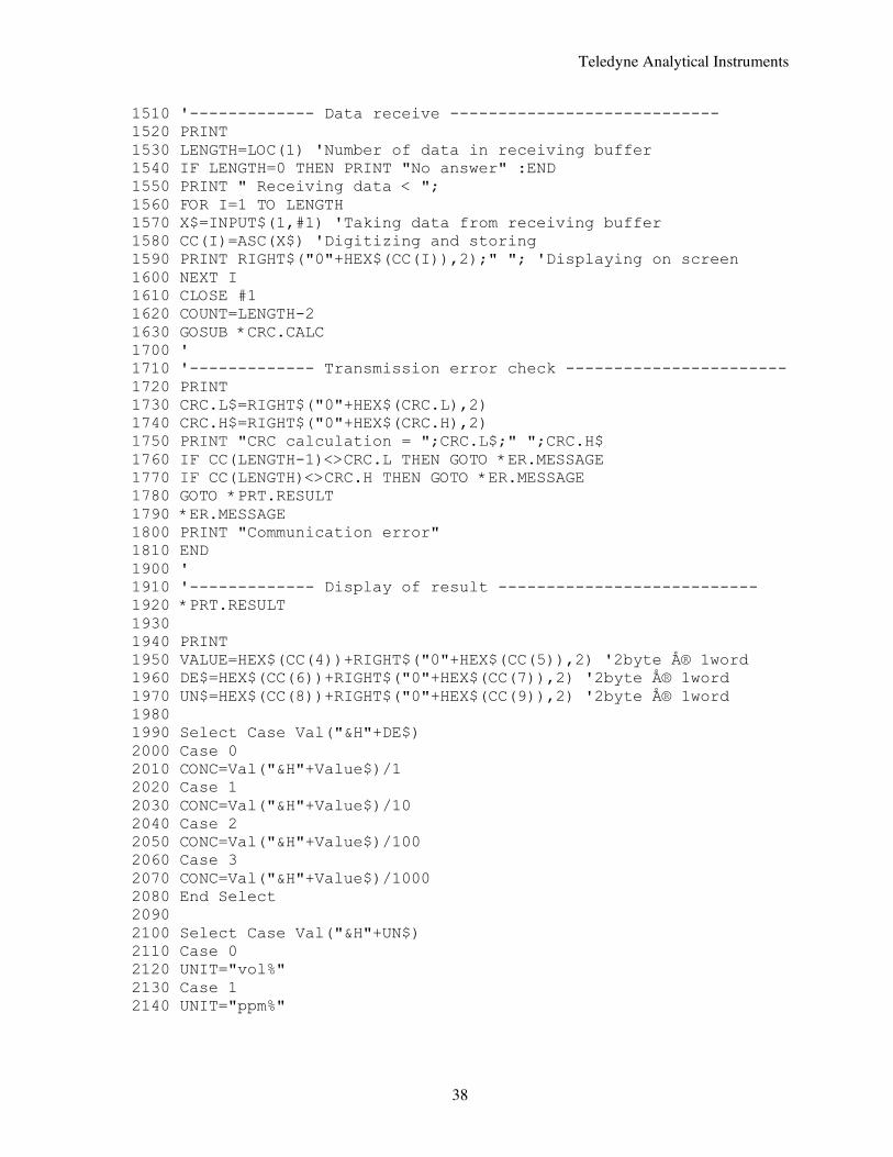
1510 '------------- Data receive ---------------------------- 1520 PRINT 1530 LENGTH=LOC(1) 'Number of data in receiving buffer 1540 IF LENGTH=0 THEN PRINT "No answer" :END 1550 PRINT " Receiving data < "; 1560 FOR I=1 TO LENGTH 1570 X$=INPUT$(1,#1) 'Taking data from receiving buffer 1580 CC(I)=ASC(X$) 'Digitizing and storing 1590 PRINT RIGHT$("0"+HEX$(CC(I)),2);" "; 'Displaying on screen 1600 NEXT I 1610 CLOSE #1 1620 COUNT=LENGTH-2 1630 GOSUB *CRC.CALC 1700 ' 1710 '------------- Transmission error check ----------------------- 1720 PRINT 1730 CRC.L$=RIGHT$("0"+HEX$(CRC.L),2) 1740 CRC.H$=RIGHT$("0"+HEX$(CRC.H),2) 1750 PRINT "CRC calculation = ";CRC.L$;" ";CRC.H$ 1760 IF CC(LENGTH-1)<>CRC.L THEN GOTO *ER.MESSAGE 1770 IF CC(LENGTH)<>CRC.H THEN GOTO *ER.MESSAGE 1780 GOTO *PRT.RESULT 1790 *ER.MESSAGE 1800 PRINT "Communication error" 1810 END 1900 ' 1910 '------------- Display of result --------------------------- 1920 *PRT.RESULT 1930 1940 PRINT 1950 VALUE=HEX$(CC(4))+RIGHT$("0"+HEX$(CC(5)),2) '2byte Å® 1word 1960 DE$=HEX$(CC(6))+RIGHT$("0"+HEX$(CC(7)),2) '2byte Å® 1word 1970 UN$=HEX$(CC(8))+RIGHT$("0"+HEX$(CC(9)),2) '2byte Å® 1word 1980 1990 Select Case Val("&H"+DE$) 2000 Case 0 2010 CONC=Val("&H"+Value$)/1 2020 Case 1 2030 CONC=Val("&H"+Value$)/10 2040 Case 2 2050 CONC=Val("&H"+Value$)/100 2060 Case 3 2070 CONC=Val("&H"+Value$)/1000 2080 End Select 2090 2100 Select Case Val("&H"+UN$) 2110 Case 0 2120 UNIT="vol%" 2130 Case 1 2140 UNIT="ppm%"
Teledyne Analytical Instruments
39
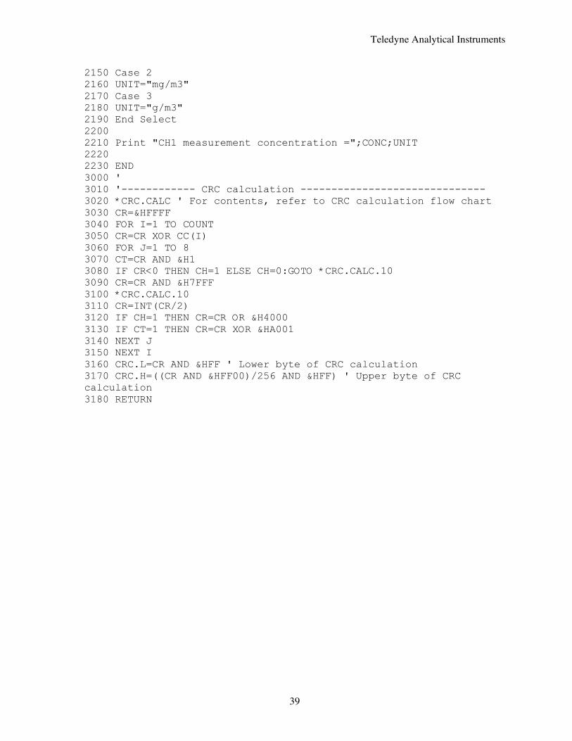
2150 Case 2 2160 UNIT="mg/m3" 2170 Case 3 2180 UNIT="g/m3" 2190 End Select 2200 2210 Print "CH1 measurement concentration =";CONC;UNIT 2220 2230 END 3000 ' 3010 '------------ CRC calculation ------------------------------ 3020 *CRC.CALC ' For contents, refer to CRC calculation flow chart 3030 CR=&HFFFF 3040 FOR I=1 TO COUNT 3050 CR=CR XOR CC(I) 3060 FOR J=1 TO 8 3070 CT=CR AND &H1 3080 IF CR<0 THEN CH=1 ELSE CH=0:GOTO *CRC.CALC.10 3090 CR=CR AND &H7FFF 3100 *CRC.CALC.10 3110 CR=INT(CR/2) 3120 IF CH=1 THEN CR=CR OR &H4000 3130 IF CT=1 THEN CR=CR XOR &HA001 3140 NEXT J 3150 NEXT I 3160 CRC.L=CR AND &HFF ' Lower byte of CRC calculation 3170 CRC.H=((CR AND &HFF00)/256 AND &HFF) ' Upper byte of CRC calculation 3180 RETURN
Teledyne Analytical Instruments
40
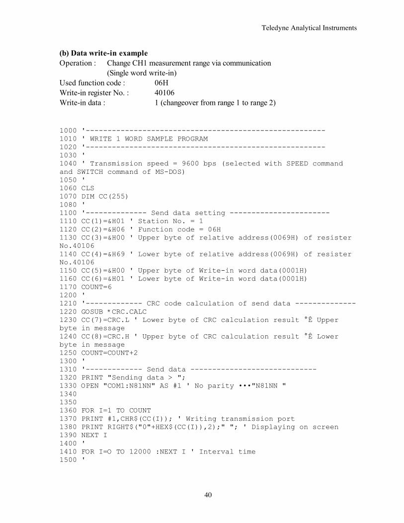
(b) Data write-in example Operation : Change CH1 measurement range via communication (Single word write-in) Used function code : 06H Write-in register No. : 40106 Write-in data : 1 (changeover from range 1 to range 2) 1000 '------------------------------------------------------- 1010 ' WRITE 1 WORD SAMPLE PROGRAM 1020 '------------------------------------------------------- 1030 ' 1040 ' Transmission speed = 9600 bps (selected with SPEED command and SWITCH command of MS-DOS) 1050 ' 1060 CLS 1070 DIM CC(255) 1080 ' 1100 '-------------- Send data setting ----------------------- 1110 CC(1)=&H01 ' Station No. = 1 1120 CC(2)=&H06 ' Function code = 06H 1130 CC(3)=&H00 ' Upper byte of relative address(0069H) of resister No.40106 1140 CC(4)=&H69 ' Lower byte of relative address(0069H) of resister No.40106 1150 CC(5)=&H00 ' Upper byte of Write-in word data(0001H) 1160 CC(6)=&H01 ' Lower byte of Write-in word data(0001H) 1170 COUNT=6 1200 ' 1210 '------------- CRC code calculation of send data -------------- 1220 GOSUB *CRC.CALC 1230 CC(7)=CRC.L ' Lower byte of CRC calculation result °Ê Upper byte in message 1240 CC(8)=CRC.H ' Upper byte of CRC calculation result °Ê Lower byte in message 1250 COUNT=COUNT+2 1300 ' 1310 '------------- Send data ----------------------------- 1320 PRINT "Sending data > "; 1330 OPEN "COM1:N81NN" AS #1 ' No parity •••"N81NN " 1340 1350 1360 FOR I=1 TO COUNT 1370 PRINT #1,CHR$(CC(I)); ' Writing transmission port 1380 PRINT RIGHT$("0"+HEX$(CC(I)),2);" "; ' Displaying on screen 1390 NEXT I 1400 ' 1410 FOR I=O TO 12000 :NEXT I ' Interval time 1500 '
Teledyne Analytical Instruments
41
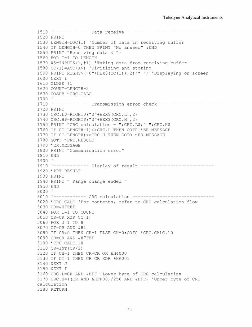
1510 '------------- Data receive ---------------------------- 1520 PRINT 1530 LENGTH=LOC(1) 'Number of data in receiving buffer 1540 IF LENGTH=0 THEN PRINT "No answer" :END 1550 PRINT "Receiving data < "; 1560 FOR I=1 TO LENGTH 1570 X$=INPUT$(1,#1) 'Taking data from receiving buffer 1580 CC(I)=ASC(X$) 'Digitizing and storing 1590 PRINT RIGHT$("0"+HEX$(CC(I)),2);" "; 'Displaying on screen 1600 NEXT I 1610 CLOSE #1 1620 COUNT=LENGTH-2 1630 GOSUB *CRC.CALC 1700 ' 1710 '------------- Transmission error check ----------------------- 1720 PRINT 1730 CRC.L$=RIGHT$("0"+HEX$(CRC.L),2) 1740 CRC.H$=RIGHT$("0"+HEX$(CRC.H),2) 1750 PRINT "CRC calculation = ";CRC.L$;" ";CRC.H$ 1760 IF CC(LENGTH-1)<>CRC.L THEN GOTO *ER.MESSAGE 1770 IF CC(LENGTH)<>CRC.H THEN GOTO *ER.MESSAGE 1780 GOTO *PRT.RESULT 1790 *ER.MESSAGE 1800 PRINT "Communication error" 1810 END 1900 ' 1910 '------------- Display of result --------------------------- 1920 *PRT.RESULT 1930 PRINT 1940 PRINT " Range change ended " 1950 END 3000 ' 3010 '------------ CRC calculation ------------------------------ 3020 *CRC.CALC 'For contents, refer to CRC calculation flow 3030 CR=&HFFFF 3040 FOR I=1 TO COUNT 3050 CR=CR XOR CC(I) 3060 FOR J=1 TO 8 3070 CT=CR AND &H1 3080 IF CR<0 THEN CH=1 ELSE CH=0:GOTO *CRC.CALC.10 3090 CR=CR AND &H7FFF 3100 *CRC.CALC.10 3110 CR=INT(CR/2) 3120 IF CH=1 THEN CR=CR OR &H4000 3130 IF CT=1 THEN CR=CR XOR &HA001 3140 NEXT J 3150 NEXT I 3160 CRC.L=CR AND &HFF 'Lower byte of CRC calculation 3170 CRC.H=((CR AND &HFF00)/256 AND &HFF) 'Upper byte of CRC calculation 3180 RETURN
Teledyne Analytical Instruments
42
9. TROUBLESHOOTING If the communication is unavailable, check the following items.
• Whether all devices related to communication are turned on.
• Whether connections are correct.
• Whether the number of connected instruments and connection distance are as
specified
• Whether communication conditions coincide between the master station (host
computer) and slave stations (instrument)
• Transmission speed : 9600bps
• Data length : 8 bits
• Stop bit : 1 bit
• Parity : None
• Whether send/receive signal timing conforms to Section 5.6 in this manual.
• Whether the station No. designated as send destination by the master station coincides
with the station No. of the connected instrument.
• Whether more than one instrument connected on the same transmission line shares
the same station No.
• Whether the station No. of instruments is set at other than 0. If it’s 0, the
communication function does not work.