Embed Size (px)
Citation preview
TELESCOPIC BOOM FOR SPACE APPLICATIONS
ENGINEERING MODEL
Lionel Bourrec (1), Lauren Bernabé (2), Victor Pires (3), Sylvain Tremolieres(4),
(1) COMAT Design engineer,
6 Chemin de Vignalis, 31130 Flourens, France. Email: [email protected] (2) COMAT Design engineer,
6 Chemin de Vignalis, 31130 Flourens, France. Email: [email protected] (3) COMAT Design department manager,
6 Chemin de Vignalis, 31130 Flourens, France. Email: [email protected] (4) CNES Mechanism engineer,
18 Avenue Edouard Belin, 31401 Toulouse cedex 01, FRANCE. Email: [email protected]
ABSTRACT
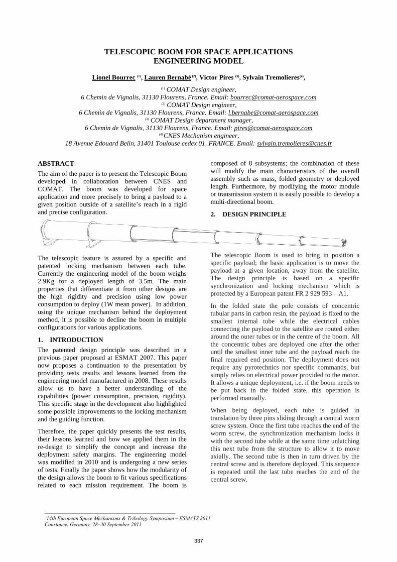
The aim of the paper is to present the Telescopic Boom
developed in collaboration between CNES and
COMAT. The boom was developed for space
application and more precisely to bring a payload to a
given position outside of a satellite’s reach in a rigid
and precise configuration.
The telescopic feature is assured by a specific and
patented locking mechanism between each tube.
Currently the engineering model of the boom weighs
2.9Kg for a deployed length of 3.5m. The main
properties that differentiate it from other designs are
the high rigidity and precision using low power
consumption to deploy (1W mean power). In addition,
using the unique mechanism behind the deployment
method, it is possible to decline the boom in multiple
configurations for various applications.
1. INTRODUCTION
The patented design principle was described in a
previous paper proposed at ESMAT 2007. This paper
now proposes a continuation to the presentation by
providing tests results and lessons learned from the
engineering model manufactured in 2008. These results
allow us to have a better understanding of the
capabilities (power consumption, precision, rigidity).
This specific stage in the development also highlighted
some possible improvements to the locking mechanism
and the guiding function.
Therefore, the paper quickly presents the test results,
their lessons learned and how we applied them in the
re-design to simplify the concept and increase the
deployment safety margins. The engineering model
was modified in 2010 and is undergoing a new series
of tests. Finally the paper shows how the modularity of
the design allows the boom to fit various specifications
related to each mission requirement. The boom is
composed of 8 subsystems; the combination of these
will modify the main characteristics of the overall
assembly such as mass, folded geometry or deployed
length. Furthermore, by modifying the motor module
or transmission system it is easily possible to develop a
multi-directional boom.
2. DESIGN PRINCIPLE
The telescopic Boom is used to bring in position a
specific payload; the basic application is to move the
payload at a given location, away from the satellite.
The design principle is based on a specific
synchronization and locking mechanism which is
protected by a European patent FR 2 929 593 – A1.
In the folded state the pole consists of concentric
tubular parts in carbon resin, the payload is fixed to the
smallest internal tube while the electrical cables
connecting the payload to the satellite are routed either
around the outer tubes or in the centre of the boom. All
the concentric tubes are deployed one after the other
until the smallest inner tube and the payload reach the
final required end position. The deployment does not
require any pyrotechnics nor specific commands, but
simply relies on electrical power provided to the motor.
It allows a unique deployment, i.e. if the boom needs to
be put back in the folded state, this operation is
performed manually.
When being deployed, each tube is guided in
translation by three pins sliding through a central worm
screw system. Once the first tube reaches the end of the
worm screw, the synchronization mechanism locks it
with the second tube while at the same time unlatching
this next tube from the structure to allow it to move
axially. The second tube is then in turn driven by the
central screw and is therefore deployed. This sequence
is repeated until the last tube reaches the end of the
central screw.
_________________________________________________ ‘14th European Space Mechanisms & Tribology Symposium – ESMATS 2011’ Constance, Germany, 28–30 September 2011
337
The basis of the accuracy and rigidity is given by the
linkage between the tube elements; this linkage is a
preloaded surface matting combined with a spherical
joint between each tube end. The specificity of the
telescopic boom is provided by the synchronization
mechanism located at the tube end that allows the
linkage between the tubes.
Each tube is actually composed of a front ring and 2
back rings. The first back ring of a tube is linked on the
front ring of the tube directly above it (e.g the front
ring of tube #1 links on the first back ring of tube #2)
this represents the linkage. Then, the patented
synchronization allows the second back ring to detach
the later tube from the structure and preload the
linkage.
3. ENGINEERING MODEL TEST RESULTS
As of today an engineering model was manufactured
and was tested at the CNES in 2008. This chapter
describes the results from the test campaign.
3.1. Engineering model design specifications
The original specifications of the engineering model
are described in table.1. This table describes two
configurations, where the 8 tube configuration simply
adds 2 inner tubes inside the 6 tube configuration.
Table 1: Telescopic Boom engineering model
specifications and measurements
Parameter Configuration Spec (measurement)
Folded
Geometry
Both
configurations Ø120 x 555mm
(measured Ø120x554)
Deployed
Length
-6 tubes
-8 tubes
3 m (measured 2.7m)
4 m
Masse:
(Does not include
payload and cables)
-6 tubes
-8 tubes
3 kg (measured 2.92kg)
3.15 kg
Rigidity
(Deployed state)
6 tubes with a
400g payload 1st Mode> 1Hz
(measured 3.25Hz)
Precision -6 tubes ±17.5mm
(measured ±1.5mm)
Modulus by
Inertia factor
(EI)
Both
configurations 7000 Nmm²
Total
Deployment
time
-6 tubes
-8 tubes T= 8 min
T= 11,4 min
Electrical power
-Nominal Voltage
-Maximum Power
Both
configurations
→24 VCC
→6,6 W (measured 3.8W)
Mechanical Sizing
- Launch vibration
levels
Both
configurations in
folded state.
400g payload + 40 g (392 ms-²)
(not tested)
Mechanical Sizing
-Extra vehicular
manipulator
Both
configurations in
deployed state.
400g payload
+ 0.1 g (0,098 ms-²)
(not tested)
3.2. Engineering model manufacturing
For the test campaign only the 6 tube configuration
boom was manufactured.
Figure 1: Engineering model is composed of 6 tubes
A mounting tool was developed for the engineering
model, to allow concentricity of 0.05mm and a
parallelism of 0.05mm on locking mechanism. The
mechanisms are indeed part of the front and back rings
glued in position on each tube end. These tight
tolerances allow the engineering model to have
sufficient rigidity and an end of boom position
precision: within Ø3mm sphere (see § 3.4 and 3.5)
Figure 2: Front and Back ring mounting tool
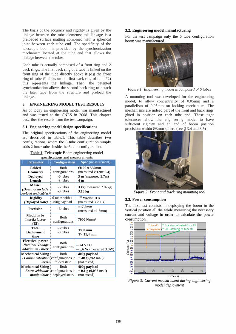
3.3. Power consumption
The first test consists in deploying the boom in the
vertical position all the while measuring the necessary
current and voltage in order to calculate the power
consumption.
Figure 3: Current measurement during engineering
model deployment
Cu
rren
t (A
)
Tube #5
deployment
* Locking of tube#6 on #5
* Un-latching of tube #6
Time (s)
338
3 A
ccel
ero
met
ers
These results show that peaks of power consumption
occur at each locking-unlatching of a new tube. On this
engineering model the current does not exceed 0.16A
for a voltage of 24V therefore the maximum peak
power consumption is 3.84W. Furthermore this test is
worst case scenario because the deployment is
performed against the gravity (upward). If we observe
the current peaks in detail we can distinguish various
steps in the locking/unlatching phase (i.e. the tubes
come in contact, the spring is pre-loaded, locking
fingers are positioned then become locked and finally
the simultaneous deployment of 2 tube segments). This
conclusion is the basis for part of the re-design that
consists in reducing the preload and the friction during
the locking phase (described in §4.1 and §4.2).
During a tube deployment the current consumption is
about 1W, therefore for a deployment in 8minutes the
total energy to deploy the 6 tubes of the engineering
model is about 480J.
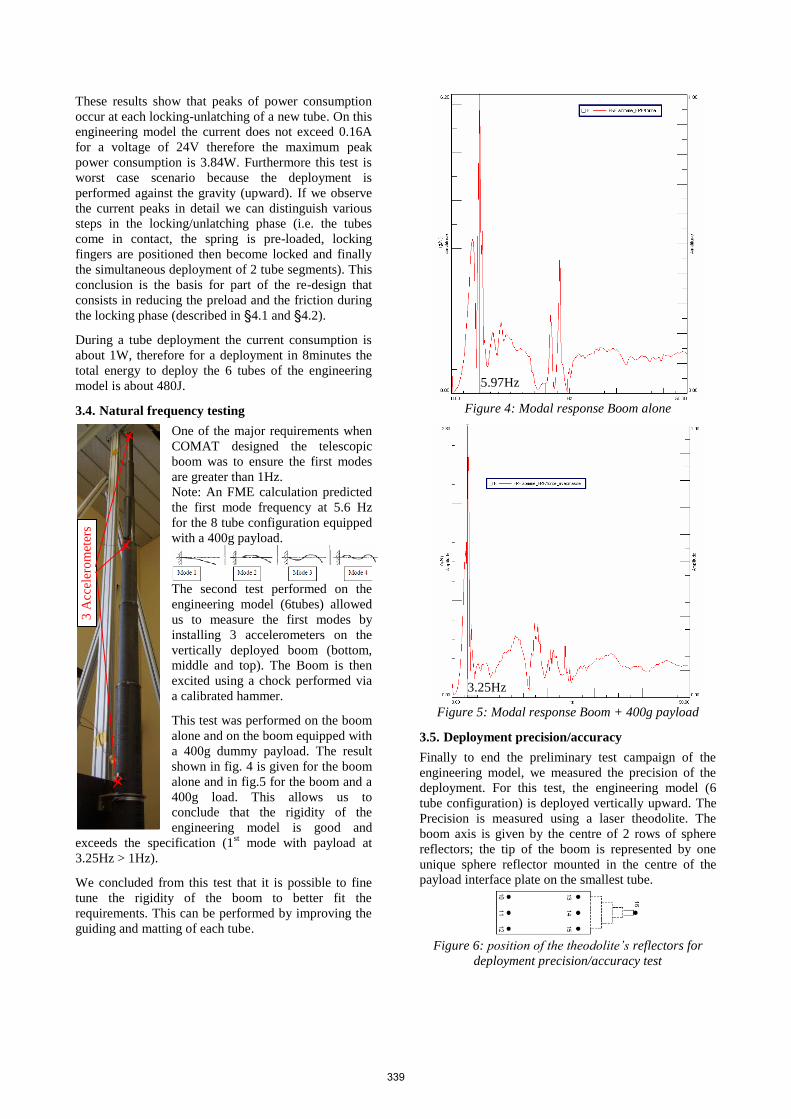
3.4. Natural frequency testing
One of the major requirements when
COMAT designed the telescopic
boom was to ensure the first modes
are greater than 1Hz.
Note: An FME calculation predicted
the first mode frequency at 5.6 Hz
for the 8 tube configuration equipped
with a 400g payload.
The second test performed on the
engineering model (6tubes) allowed
us to measure the first modes by
installing 3 accelerometers on the
vertically deployed boom (bottom,
middle and top). The Boom is then
excited using a chock performed via
a calibrated hammer.
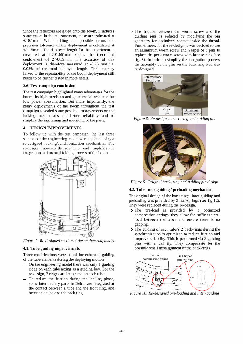
This test was performed on the boom
alone and on the boom equipped with
a 400g dummy payload. The result
shown in fig. 4 is given for the boom
alone and in fig.5 for the boom and a
400g load. This allows us to
conclude that the rigidity of the
engineering model is good and
exceeds the specification (1st mode with payload at
3.25Hz > 1Hz).
We concluded from this test that it is possible to fine
tune the rigidity of the boom to better fit the
requirements. This can be performed by improving the
guiding and matting of each tube.
Figure 4: Modal response Boom alone
Figure 5: Modal response Boom + 400g payload
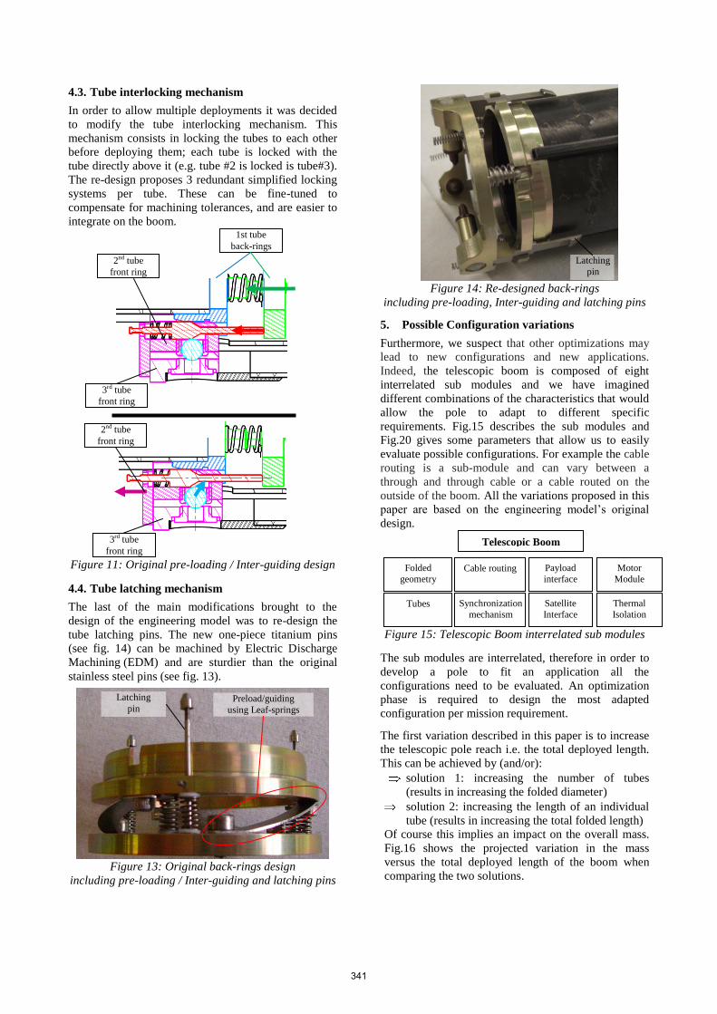
3.5. Deployment precision/accuracy
Finally to end the preliminary test campaign of the
engineering model, we measured the precision of the
deployment. For this test, the engineering model (6
tube configuration) is deployed vertically upward. The
Precision is measured using a laser theodolite. The
boom axis is given by the centre of 2 rows of sphere
reflectors; the tip of the boom is represented by one
unique sphere reflector mounted in the centre of the
payload interface plate on the smallest tube.
Figure 6: position of the theodolite’s reflectors for
deployment precision/accuracy test
5.97Hz
3.25Hz
339
Since the reflectors are glued onto the boom, it induces
some errors in the measurement, these are estimated at
+/-0.1mm. When adding the possible errors the
precision tolerance of the deployment is calculated at
+/-1.5mm. The deployed length for this experiment is
measured at 2 701.661mm versus the theoretical
deployment of 2 700.9mm. The accuracy of this
deployment is therefore measured at -0.761mm i.e.
0.03% of the total deployed length. The accuracy
linked to the repeatability of the boom deployment still
needs to be further tested in more detail.
3.6. Test campaign conclusion
The test campaign highlighted many advantages for the
boom, its high precision and good modal response for
low power consumption. But more importantly, the
many deployments of the boom throughout the test
campaign revealed some possible improvements on the
locking mechanisms for better reliability and to
simplify the machining and mounting of the parts.
4. DESIGN IMPROVEMENTS
To follow up with the test campaign, the last three
sections of the engineering model were updated using a
re-designed locking/synchronization mechanism. The
re-design improves the reliability and simplifies the
integration and manual folding process of the boom.
Figure 7: Re-designed section of the engineering model
4.1. Tube guiding improvements
Three modifications were added for enhanced guiding
of the tube elements during the deploying motion.
On the engineering model there was only 1 guiding
ridge on each tube acting as a guiding key. For the
re-design, 3 ridges are integrated on each tube.
To reduce the friction during the locking phase,
some intermediary parts in Delrin are integrated at
the contact between a tube and the front ring, and
between a tube and the back ring.
The friction between the worm screw and the
guiding pins is reduced by modifying the pin
geometry for optimized contact inside the thread.
Furthermore, for the re-design it was decided to use
an aluminium worm screw and Vespel SP3 pins to
replace the peek worm screw with bronze pins (see
fig. 8). In order to simplify the integration process
the assembly of the pins on the back ring was also
re-designed.
Figure 8: Re-designed back- ring and guiding pin
Figure 9: Original back- ring and guiding pin design
4.2. Tube Inter-guiding / preloading mechanism
The original design of the back-rings’ inter-guiding and
preloading was provided by 3 leaf-springs (see fig 12).
They were replaced during the re-design.
The pre-load is provided by 3 optimized
compression springs, they allow for sufficient pre-
load between the tubes and ensure there is no
gapping.
The guiding of each tube’s 2 back-rings during the
synchronization is optimized to reduce friction and
improve reliability. This is performed via 3 guiding
pins with a ball tip. They compensate for the
possible small misalignment of the back-rings.
Figure 10: Re-designed pre-loading and Inter-guiding
Preload
compression spring
Ball tipped
guiding pins
Intermediary Delrin part
Vespel
pin Aluminum
Worm screw
340
4.3. Tube interlocking mechanism
In order to allow multiple deployments it was decided
to modify the tube interlocking mechanism. This
mechanism consists in locking the tubes to each other
before deploying them; each tube is locked with the
tube directly above it (e.g. tube #2 is locked is tube#3).
The re-design proposes 3 redundant simplified locking
systems per tube. These can be fine-tuned to
compensate for machining tolerances, and are easier to
integrate on the boom.
Figure 11: Original pre-loading / Inter-guiding design
4.4. Tube latching mechanism
The last of the main modifications brought to the
design of the engineering model was to re-design the
tube latching pins. The new one-piece titanium pins
(see fig. 14) can be machined by Electric Discharge
Machining (EDM) and are sturdier than the original
stainless steel pins (see fig. 13).
Figure 13: Original back-rings design
including pre-loading / Inter-guiding and latching pins
Figure 14: Re-designed back-rings
including pre-loading, Inter-guiding and latching pins
5. Possible Configuration variations
Furthermore, we suspect that other optimizations may
lead to new configurations and new applications.
Indeed, the telescopic boom is composed of eight
interrelated sub modules and we have imagined
different combinations of the characteristics that would
allow the pole to adapt to different specific
requirements. Fig.15 describes the sub modules and
Fig.20 gives some parameters that allow us to easily
evaluate possible configurations. For example the cable
routing is a sub-module and can vary between a
through and through cable or a cable routed on the
outside of the boom. All the variations proposed in this
paper are based on the engineering model’s original
design.
Figure 15: Telescopic Boom interrelated sub modules
The sub modules are interrelated, therefore in order to
develop a pole to fit an application all the
configurations need to be evaluated. An optimization
phase is required to design the most adapted
configuration per mission requirement.
The first variation described in this paper is to increase
the telescopic pole reach i.e. the total deployed length.
This can be achieved by (and/or):
solution 1: increasing the number of tubes
(results in increasing the folded diameter)
solution 2: increasing the length of an individual
tube (results in increasing the total folded length)
Of course this implies an impact on the overall mass.
Fig.16 shows the projected variation in the mass
versus the total deployed length of the boom when
comparing the two solutions.
Preload/guiding
using Leaf-springs
Latching
pin
1st tube
back-rings
2nd tube
front ring
3rd tube
front ring
3rd tube
front ring
2nd tube
front ring
Telescopic Boom
Folded
geometry
Satellite
Interface
Motor
Module
Tubes
Cable routing
Thermal
Isolation
Payload
interface
Synchronization
mechanism
Latching
pin
341
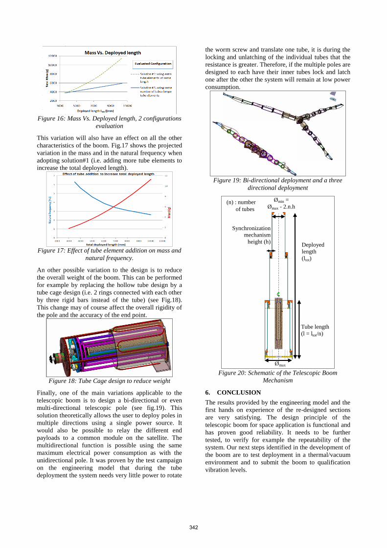
Figure 16: Mass Vs. Deployed length, 2 configurations
evaluation
This variation will also have an effect on all the other
characteristics of the boom. Fig.17 shows the projected
variation in the mass and in the natural frequency when
adopting solution#1 (i.e. adding more tube elements to
increase the total deployed length).
Figure 17: Effect of tube element addition on mass and
natural frequency.
An other possible variation to the design is to reduce
the overall weight of the boom. This can be performed
for example by replacing the hollow tube design by a
tube cage design (i.e. 2 rings connected with each other
by three rigid bars instead of the tube) (see Fig.18).
This change may of course affect the overall rigidity of
the pole and the accuracy of the end point.
Figure 18: Tube Cage design to reduce weight
Finally, one of the main variations applicable to the
telescopic boom is to design a bi-directional or even
multi-directional telescopic pole (see fig.19). This
solution theoretically allows the user to deploy poles in
multiple directions using a single power source. It
would also be possible to relay the different end
payloads to a common module on the satellite. The
multidirectional function is possible using the same
maximum electrical power consumption as with the
unidirectional pole. It was proven by the test campaign
on the engineering model that during the tube
deployment the system needs very little power to rotate
the worm screw and translate one tube, it is during the
locking and unlatching of the individual tubes that the
resistance is greater. Therefore, if the multiple poles are
designed to each have their inner tubes lock and latch
one after the other the system will remain at low power
consumption.
Figure 19: Bi-directional deployment and a three
directional deployment
Figure 20: Schematic of the Telescopic Boom
Mechanism
6. CONCLUSION
The results provided by the engineering model and the
first hands on experience of the re-designed sections
are very satisfying. The design principle of the
telescopic boom for space application is functional and
has proven good reliability. It needs to be further
tested, to verify for example the repeatability of the
system. Our next steps identified in the development of
the boom are to test deployment in a thermal/vacuum
environment and to submit the boom to qualification
vibration levels.
Deployed
length
(ltot)
Ømax
Tube length
(l = ltot/n)
(n) : number
of tubes
Ømin =
Ømax - 2.n.h
Synchronization
mechanism
height (h)
342