Embed Size (px)
Citation preview

TELES.VoIPBOX GSM and TELES.VoIPBOX CDMA
Software version 13.0

T A B L E O F C O N T E N T S
table of contents
Chapter 1 – About this Manual . . . . . . . . . . . . . . . . . . . . . . . . . . . . . . . . . . . . . . . . . . . . . . . . . . . . .1
1.1 organization . . . . . . . . . . . . . . . . . . . . . . . . . . . . . . . . . . . . . . . . . . . . . . . . . . . . . . . . . . . . . . . . . 11.2 conventions . . . . . . . . . . . . . . . . . . . . . . . . . . . . . . . . . . . . . . . . . . . . . . . . . . . . . . . . . . . . . . . . . . 21.3 Safety Symbols . . . . . . . . . . . . . . . . . . . . . . . . . . . . . . . . . . . . . . . . . . . . . . . . . . . . . . . . . . . . . . . 2
Chapter 2 – Safety and Security Precautions. . . . . . . . . . . . . . . . . . . . . . . . . . . . . . . . . . . . . . . . . . .3
2.1 Safety Measures . . . . . . . . . . . . . . . . . . . . . . . . . . . . . . . . . . . . . . . . . . . . . . . . . . . . . . . . . . . . . . 32.2 FCC / Industry Canada Notice . . . . . . . . . . . . . . . . . . . . . . . . . . . . . . . . . . . . . . . . . . . . . . . . . . . . 32.3 Power Supply. . . . . . . . . . . . . . . . . . . . . . . . . . . . . . . . . . . . . . . . . . . . . . . . . . . . . . . . . . . . . . . . . 42.3.1 Technical Data . . . . . . . . . . . . . . . . . . . . . . . . . . . . . . . . . . . . . . . . . . . . . . . . . . . . . . . . . . . . . . . . 42.3.2 Symbols . . . . . . . . . . . . . . . . . . . . . . . . . . . . . . . . . . . . . . . . . . . . . . . . . . . . . . . . . . . . . . . . . . . . . 42.3.3 Instructions for Use. . . . . . . . . . . . . . . . . . . . . . . . . . . . . . . . . . . . . . . . . . . . . . . . . . . . . . . . . . . . . 52.3.4 Safety Precautions . . . . . . . . . . . . . . . . . . . . . . . . . . . . . . . . . . . . . . . . . . . . . . . . . . . . . . . . . . . . . 52.4 Jacks . . . . . . . . . . . . . . . . . . . . . . . . . . . . . . . . . . . . . . . . . . . . . . . . . . . . . . . . . . . . . . . . . . . . . . . 62.5 Tips for EMC Protection. . . . . . . . . . . . . . . . . . . . . . . . . . . . . . . . . . . . . . . . . . . . . . . . . . . . . . . . . 62.6 System Security . . . . . . . . . . . . . . . . . . . . . . . . . . . . . . . . . . . . . . . . . . . . . . . . . . . . . . . . . . . . . . . 62.6.1 Protecting the Operating System . . . . . . . . . . . . . . . . . . . . . . . . . . . . . . . . . . . . . . . . . . . . . . . . . . . 72.7 CDR Files . . . . . . . . . . . . . . . . . . . . . . . . . . . . . . . . . . . . . . . . . . . . . . . . . . . . . . . . . . . . . . . . . . . . 72.8 Network Security . . . . . . . . . . . . . . . . . . . . . . . . . . . . . . . . . . . . . . . . . . . . . . . . . . . . . . . . . . . . . . 7
Chapter 3 – Overview . . . . . . . . . . . . . . . . . . . . . . . . . . . . . . . . . . . . . . . . . . . . . . . . . . . . . . . . . . .10
3.1 What’s New in Version 13.0 . . . . . . . . . . . . . . . . . . . . . . . . . . . . . . . . . . . . . . . . . . . . . . . . . . . . 103.2 Implementation Scenarios . . . . . . . . . . . . . . . . . . . . . . . . . . . . . . . . . . . . . . . . . . . . . . . . . . . . . . 103.3 Features. . . . . . . . . . . . . . . . . . . . . . . . . . . . . . . . . . . . . . . . . . . . . . . . . . . . . . . . . . . . . . . . . . . . 12
Chapter 4 – TELES.VoIPBOX GSM/CDMA Installation . . . . . . . . . . . . . . . . . . . . . . . . . . . . . . . . . . .14
4.1 Checklist . . . . . . . . . . . . . . . . . . . . . . . . . . . . . . . . . . . . . . . . . . . . . . . . . . . . . . . . . . . . . . . . . . . 144.2 Package Contents . . . . . . . . . . . . . . . . . . . . . . . . . . . . . . . . . . . . . . . . . . . . . . . . . . . . . . . . . . . . 144.3 TELES.VoIPBOX GSM/CDMA Hardware Description . . . . . . . . . . . . . . . . . . . . . . . . . . . . . . . . . . 144.4 Installation Requirements . . . . . . . . . . . . . . . . . . . . . . . . . . . . . . . . . . . . . . . . . . . . . . . . . . . . . . 154.4.1 Analog Wiring . . . . . . . . . . . . . . . . . . . . . . . . . . . . . . . . . . . . . . . . . . . . . . . . . . . . . . . . . . . . . . . 154.4.2 Ethernet Wiring . . . . . . . . . . . . . . . . . . . . . . . . . . . . . . . . . . . . . . . . . . . . . . . . . . . . . . . . . . . . . . 154.5 Preparing for Installation. . . . . . . . . . . . . . . . . . . . . . . . . . . . . . . . . . . . . . . . . . . . . . . . . . . . . . . 164.6 Hardware Connection . . . . . . . . . . . . . . . . . . . . . . . . . . . . . . . . . . . . . . . . . . . . . . . . . . . . . . . . . 164.7 LED Functionality. . . . . . . . . . . . . . . . . . . . . . . . . . . . . . . . . . . . . . . . . . . . . . . . . . . . . . . . . . . . . 164.8 Startup with TELES.Quickstart . . . . . . . . . . . . . . . . . . . . . . . . . . . . . . . . . . . . . . . . . . . . . . . . . . . 174.8.1 Installing TELES.Quickstart . . . . . . . . . . . . . . . . . . . . . . . . . . . . . . . . . . . . . . . . . . . . . . . . . . . . . . 184.8.2 Configuration with TELES.Quickstart . . . . . . . . . . . . . . . . . . . . . . . . . . . . . . . . . . . . . . . . . . . . . . 194.9 Startup via FTP . . . . . . . . . . . . . . . . . . . . . . . . . . . . . . . . . . . . . . . . . . . . . . . . . . . . . . . . . . . . . . 204.10 Self Provisioning with TELES.NMS. . . . . . . . . . . . . . . . . . . . . . . . . . . . . . . . . . . . . . . . . . . . . . . . 214.11 Remote Access and Access Security . . . . . . . . . . . . . . . . . . . . . . . . . . . . . . . . . . . . . . . . . . . . . . 214.11.1 TELES.GATE Manager . . . . . . . . . . . . . . . . . . . . . . . . . . . . . . . . . . . . . . . . . . . . . . . . . . . . . . . . . 21
i

T A B L E O F C O N T E N T S
4.11.2 HTTP User Interface . . . . . . . . . . . . . . . . . . . . . . . . . . . . . . . . . . . . . . . . . . . . . . . . . . . . . . . . . . 234.11.3 FTP. . . . . . . . . . . . . . . . . . . . . . . . . . . . . . . . . . . . . . . . . . . . . . . . . . . . . . . . . . . . . . . . . . . . . . . . 254.11.4 Setting a Password for Remote Access . . . . . . . . . . . . . . . . . . . . . . . . . . . . . . . . . . . . . . . . . . . . . 25
Chapter 5 – Configuration Files . . . . . . . . . . . . . . . . . . . . . . . . . . . . . . . . . . . . . . . . . . . . . . . . . . . .27
5.1 Configuration File ip.cfg . . . . . . . . . . . . . . . . . . . . . . . . . . . . . . . . . . . . . . . . . . . . . . . . . . . . . . . 285.1.1 System Section Configuration . . . . . . . . . . . . . . . . . . . . . . . . . . . . . . . . . . . . . . . . . . . . . . . . . . . . 285.1.2 Ethernet Interface Configuration . . . . . . . . . . . . . . . . . . . . . . . . . . . . . . . . . . . . . . . . . . . . . . . . . . 295.1.3 Bridge Configuration . . . . . . . . . . . . . . . . . . . . . . . . . . . . . . . . . . . . . . . . . . . . . . . . . . . . . . . . . . 295.1.4 NAT Configuration . . . . . . . . . . . . . . . . . . . . . . . . . . . . . . . . . . . . . . . . . . . . . . . . . . . . . . . . . . . . 305.1.5 PPPoE Configuration. . . . . . . . . . . . . . . . . . . . . . . . . . . . . . . . . . . . . . . . . . . . . . . . . . . . . . . . . . . 315.1.6 Firewall Settings . . . . . . . . . . . . . . . . . . . . . . . . . . . . . . . . . . . . . . . . . . . . . . . . . . . . . . . . . . . . . . 325.1.7 Bandwidth Control . . . . . . . . . . . . . . . . . . . . . . . . . . . . . . . . . . . . . . . . . . . . . . . . . . . . . . . . . . . . 345.1.8 DHCP Server Settings . . . . . . . . . . . . . . . . . . . . . . . . . . . . . . . . . . . . . . . . . . . . . . . . . . . . . . . . . . 365.1.9 PPP Configuration for CDMA Dial-Up . . . . . . . . . . . . . . . . . . . . . . . . . . . . . . . . . . . . . . . . . . . . . . 375.1.10 VLAN Configuration . . . . . . . . . . . . . . . . . . . . . . . . . . . . . . . . . . . . . . . . . . . . . . . . . . . . . . . . . . . 385.1.11 Examples . . . . . . . . . . . . . . . . . . . . . . . . . . . . . . . . . . . . . . . . . . . . . . . . . . . . . . . . . . . . . . . . . . . 39
Default Configuration . . . . . . . . . . . . . . . . . . . . . . . . . . . . . . . . . . . . . . . . . . . . . . . . . . . . . . . . . . 39Active Ethernet Bridge . . . . . . . . . . . . . . . . . . . . . . . . . . . . . . . . . . . . . . . . . . . . . . . . . . . . . . . . . 39Integrated DSL-Router Scenario for VoIP Traffic with an Active DHCP Server and Firewall . . . . . . . . 40VLAN Scenario . . . . . . . . . . . . . . . . . . . . . . . . . . . . . . . . . . . . . . . . . . . . . . . . . . . . . . . . . . . . . . . 41
5.2 Configuration File pabx.cfg . . . . . . . . . . . . . . . . . . . . . . . . . . . . . . . . . . . . . . . . . . . . . . . . . . . . . 415.2.1 System Settings . . . . . . . . . . . . . . . . . . . . . . . . . . . . . . . . . . . . . . . . . . . . . . . . . . . . . . . . . . . . . . 41
Log Files. . . . . . . . . . . . . . . . . . . . . . . . . . . . . . . . . . . . . . . . . . . . . . . . . . . . . . . . . . . . . . . . . . . 41Night Configuration . . . . . . . . . . . . . . . . . . . . . . . . . . . . . . . . . . . . . . . . . . . . . . . . . . . . . . . . . . . 43Controllers . . . . . . . . . . . . . . . . . . . . . . . . . . . . . . . . . . . . . . . . . . . . . . . . . . . . . . . . . . . . . . . . . . 44Subscribers . . . . . . . . . . . . . . . . . . . . . . . . . . . . . . . . . . . . . . . . . . . . . . . . . . . . . . . . . . . . . . . . . . 45Global Settings . . . . . . . . . . . . . . . . . . . . . . . . . . . . . . . . . . . . . . . . . . . . . . . . . . . . . . . . . . . . . . . 49
5.2.2 SMTP-Client Configuration . . . . . . . . . . . . . . . . . . . . . . . . . . . . . . . . . . . . . . . . . . . . . . . . . . . . . . 525.2.3 Number Portability Settings. . . . . . . . . . . . . . . . . . . . . . . . . . . . . . . . . . . . . . . . . . . . . . . . . . . . . . 545.2.4 SNMP Settings . . . . . . . . . . . . . . . . . . . . . . . . . . . . . . . . . . . . . . . . . . . . . . . . . . . . . . . . . . . . . . . 555.2.5 Time-Controlled Configuration Settings. . . . . . . . . . . . . . . . . . . . . . . . . . . . . . . . . . . . . . . . . . . . . 555.3 Configuration File route.cfg. . . . . . . . . . . . . . . . . . . . . . . . . . . . . . . . . . . . . . . . . . . . . . . . . . . . . 555.3.1 Entries in the Sections [System] and [Night<num>] . . . . . . . . . . . . . . . . . . . . . . . . . . . . . . . . . . . . 55
Mapping . . . . . . . . . . . . . . . . . . . . . . . . . . . . . . . . . . . . . . . . . . . . . . . . . . . . . . . . . . . . . . . . . . . 55Restrict. . . . . . . . . . . . . . . . . . . . . . . . . . . . . . . . . . . . . . . . . . . . . . . . . . . . . . . . . . . . . . . . . . . . . 56Redirect . . . . . . . . . . . . . . . . . . . . . . . . . . . . . . . . . . . . . . . . . . . . . . . . . . . . . . . . . . . . . . . . . . . . 57
5.3.2 VoIP Profiles . . . . . . . . . . . . . . . . . . . . . . . . . . . . . . . . . . . . . . . . . . . . . . . . . . . . . . . . . . . . . . . . . 595.3.3 Gatekeeper Profiles . . . . . . . . . . . . . . . . . . . . . . . . . . . . . . . . . . . . . . . . . . . . . . . . . . . . . . . . . . . 635.3.4 Registrar Profiles . . . . . . . . . . . . . . . . . . . . . . . . . . . . . . . . . . . . . . . . . . . . . . . . . . . . . . . . . . . . . 655.3.5 Radius Profiles . . . . . . . . . . . . . . . . . . . . . . . . . . . . . . . . . . . . . . . . . . . . . . . . . . . . . . . . . . . . . . . 66
ii

T A B L E O F C O N T E N T S
Chapter 6 – Routing Examples. . . . . . . . . . . . . . . . . . . . . . . . . . . . . . . . . . . . . . . . . . . . . . . . . . . . .68
6.1 Mobile Gateway in a Corporate Scenario . . . . . . . . . . . . . . . . . . . . . . . . . . . . . . . . . . . . . . . . . . 686.2 TELES.VoIPBOX GSM/CDMA Integration in a Carrier Network . . . . . . . . . . . . . . . . . . . . . . . . . . 696.3 Mobile NT . . . . . . . . . . . . . . . . . . . . . . . . . . . . . . . . . . . . . . . . . . . . . . . . . . . . . . . . . . . . . . . . . . 70
Chapter 7 – System Maintenance and Software Update. . . . . . . . . . . . . . . . . . . . . . . . . . . . . . . . .71
7.1 Configuration Errors . . . . . . . . . . . . . . . . . . . . . . . . . . . . . . . . . . . . . . . . . . . . . . . . . . . . . . . . . . 717.2 Status and Error Messages . . . . . . . . . . . . . . . . . . . . . . . . . . . . . . . . . . . . . . . . . . . . . . . . . . . . . 717.3 Software Update . . . . . . . . . . . . . . . . . . . . . . . . . . . . . . . . . . . . . . . . . . . . . . . . . . . . . . . . . . . . . 767.4 Trace . . . . . . . . . . . . . . . . . . . . . . . . . . . . . . . . . . . . . . . . . . . . . . . . . . . . . . . . . . . . . . . . . . . . . . 777.4.1 POTS Trace Output . . . . . . . . . . . . . . . . . . . . . . . . . . . . . . . . . . . . . . . . . . . . . . . . . . . . . . . . . . . . 79
Trace Types . . . . . . . . . . . . . . . . . . . . . . . . . . . . . . . . . . . . . . . . . . . . . . . . . . . . . . . . . . . . . . . . . 79sst Trace Output . . . . . . . . . . . . . . . . . . . . . . . . . . . . . . . . . . . . . . . . . . . . . . . . . . . . . . . . . . . . . . 80app Trace Output . . . . . . . . . . . . . . . . . . . . . . . . . . . . . . . . . . . . . . . . . . . . . . . . . . . . . . . . . . . . . 80mid Trace Output . . . . . . . . . . . . . . . . . . . . . . . . . . . . . . . . . . . . . . . . . . . . . . . . . . . . . . . . . . . . . 81ton Trace Output . . . . . . . . . . . . . . . . . . . . . . . . . . . . . . . . . . . . . . . . . . . . . . . . . . . . . . . . . . . . . 81
7.4.2 GSM/CDMA/UMTS Trace Output. . . . . . . . . . . . . . . . . . . . . . . . . . . . . . . . . . . . . . . . . . . . . . . . . . 817.4.3 VoIP Trace Output . . . . . . . . . . . . . . . . . . . . . . . . . . . . . . . . . . . . . . . . . . . . . . . . . . . . . . . . . . . . 83
Interface IP Network . . . . . . . . . . . . . . . . . . . . . . . . . . . . . . . . . . . . . . . . . . . . . . . . . . . . . . . . . . . 84RTP/RTCP Output . . . . . . . . . . . . . . . . . . . . . . . . . . . . . . . . . . . . . . . . . . . . . . . . . . . . . . . . . . . . . 87Internal Protocol Interface (to ISDN, POTS, Mobile) . . . . . . . . . . . . . . . . . . . . . . . . . . . . . . . . . . . . 94H.245 Messages. . . . . . . . . . . . . . . . . . . . . . . . . . . . . . . . . . . . . . . . . . . . . . . . . . . . . . . . . . . . . . 96RAS (Registration, Admission, Status) . . . . . . . . . . . . . . . . . . . . . . . . . . . . . . . . . . . . . . . . . . . . . 101ENUM Output. . . . . . . . . . . . . . . . . . . . . . . . . . . . . . . . . . . . . . . . . . . . . . . . . . . . . . . . . . . . . . . 105Examples . . . . . . . . . . . . . . . . . . . . . . . . . . . . . . . . . . . . . . . . . . . . . . . . . . . . . . . . . . . . . . . . . . 106
7.4.4 Remote Output. . . . . . . . . . . . . . . . . . . . . . . . . . . . . . . . . . . . . . . . . . . . . . . . . . . . . . . . . . . . . . 1107.4.5 SMTP Trace Output. . . . . . . . . . . . . . . . . . . . . . . . . . . . . . . . . . . . . . . . . . . . . . . . . . . . . . . . . . . 1117.4.6 Number Portability Trace Output . . . . . . . . . . . . . . . . . . . . . . . . . . . . . . . . . . . . . . . . . . . . . . . . . 1147.4.7 DTMF Tone Trace Output . . . . . . . . . . . . . . . . . . . . . . . . . . . . . . . . . . . . . . . . . . . . . . . . . . . . . . 115
Chapter 8 – Signaling and Routing Features . . . . . . . . . . . . . . . . . . . . . . . . . . . . . . . . . . . . . . . . .118
8.1 Digit Collection (Enblock/Overlap Receiving). . . . . . . . . . . . . . . . . . . . . . . . . . . . . . . . . . . . . . . 1188.2 Rejecting Data Calls and Specified Numbers . . . . . . . . . . . . . . . . . . . . . . . . . . . . . . . . . . . . . . . 1188.3 CLIP and CLIR . . . . . . . . . . . . . . . . . . . . . . . . . . . . . . . . . . . . . . . . . . . . . . . . . . . . . . . . . . . . . . 1188.3.1 Routing CLIP and CLIR Calls . . . . . . . . . . . . . . . . . . . . . . . . . . . . . . . . . . . . . . . . . . . . . . . . . . . . 1188.3.2 Routing Calls without CLIR . . . . . . . . . . . . . . . . . . . . . . . . . . . . . . . . . . . . . . . . . . . . . . . . . . . . . 1198.3.3 Setting CLIR . . . . . . . . . . . . . . . . . . . . . . . . . . . . . . . . . . . . . . . . . . . . . . . . . . . . . . . . . . . . . . . . 1198.3.4 Setting CLIP . . . . . . . . . . . . . . . . . . . . . . . . . . . . . . . . . . . . . . . . . . . . . . . . . . . . . . . . . . . . . . . . 1198.4 Conversion of Call Numbers . . . . . . . . . . . . . . . . . . . . . . . . . . . . . . . . . . . . . . . . . . . . . . . . . . . 1208.5 Setting Number Type in OAD/DAD . . . . . . . . . . . . . . . . . . . . . . . . . . . . . . . . . . . . . . . . . . . . . . 1208.6 Setting the Screening Indicator . . . . . . . . . . . . . . . . . . . . . . . . . . . . . . . . . . . . . . . . . . . . . . . . . 1228.7 Setting a Default OAD . . . . . . . . . . . . . . . . . . . . . . . . . . . . . . . . . . . . . . . . . . . . . . . . . . . . . . . . 122
iii

T A B L E O F C O N T E N T S
8.8 Setting Sending Complete Byte in Setup . . . . . . . . . . . . . . . . . . . . . . . . . . . . . . . . . . . . . . . . . . 1238.9 Miscellaneous Routing Methods . . . . . . . . . . . . . . . . . . . . . . . . . . . . . . . . . . . . . . . . . . . . . . . . 1238.9.1 Routing Calls without a Destination Number . . . . . . . . . . . . . . . . . . . . . . . . . . . . . . . . . . . . . . . . 1238.9.2 Routing Calls Based on Existence of Destination Number. . . . . . . . . . . . . . . . . . . . . . . . . . . . . . . 1248.9.3 Changing Cause Values . . . . . . . . . . . . . . . . . . . . . . . . . . . . . . . . . . . . . . . . . . . . . . . . . . . . . . . 1258.10 Caller ID . . . . . . . . . . . . . . . . . . . . . . . . . . . . . . . . . . . . . . . . . . . . . . . . . . . . . . . . . . . . . . . . . . 126
Chapter 9 – Mobile Configuration Options . . . . . . . . . . . . . . . . . . . . . . . . . . . . . . . . . . . . . . . . . .127
9.1 Connection to a TELES.vGATE . . . . . . . . . . . . . . . . . . . . . . . . . . . . . . . . . . . . . . . . . . . . . . . . . . 1279.2 Module Distribution of Various Mobile Networks . . . . . . . . . . . . . . . . . . . . . . . . . . . . . . . . . . . 1279.3 Network-Specific Mobile Routing . . . . . . . . . . . . . . . . . . . . . . . . . . . . . . . . . . . . . . . . . . . . . . . 1289.3.1 Using a Fixed Mobile Port Address . . . . . . . . . . . . . . . . . . . . . . . . . . . . . . . . . . . . . . . . . . . . . . . 1289.3.2 Using the LAIN as the Mobile Port Address . . . . . . . . . . . . . . . . . . . . . . . . . . . . . . . . . . . . . . . . . 1299.3.3 Fixed LAIN for a Mobile Port . . . . . . . . . . . . . . . . . . . . . . . . . . . . . . . . . . . . . . . . . . . . . . . . . . . . 1309.4 Incoming Voice Calls from Mobile. . . . . . . . . . . . . . . . . . . . . . . . . . . . . . . . . . . . . . . . . . . . . . . 1309.5 Blocking Ports . . . . . . . . . . . . . . . . . . . . . . . . . . . . . . . . . . . . . . . . . . . . . . . . . . . . . . . . . . . . . . 1309.6 Setting Limits. . . . . . . . . . . . . . . . . . . . . . . . . . . . . . . . . . . . . . . . . . . . . . . . . . . . . . . . . . . . . . . 1319.6.1 Count Status Information . . . . . . . . . . . . . . . . . . . . . . . . . . . . . . . . . . . . . . . . . . . . . . . . . . . . . . 1329.7 defining Time Limits for Calls . . . . . . . . . . . . . . . . . . . . . . . . . . . . . . . . . . . . . . . . . . . . . . . . . . 1329.8 Pause between Two Calls . . . . . . . . . . . . . . . . . . . . . . . . . . . . . . . . . . . . . . . . . . . . . . . . . . . . . 1339.9 Time-Controlled SIM Logoff. . . . . . . . . . . . . . . . . . . . . . . . . . . . . . . . . . . . . . . . . . . . . . . . . . . . 1339.10 Mobile-User PBX Callback. . . . . . . . . . . . . . . . . . . . . . . . . . . . . . . . . . . . . . . . . . . . . . . . . . . . . 1349.11 Optional Mobile Quality Parameters . . . . . . . . . . . . . . . . . . . . . . . . . . . . . . . . . . . . . . . . . . . . . 1349.12 Deactivating Class 2 Re-Routing . . . . . . . . . . . . . . . . . . . . . . . . . . . . . . . . . . . . . . . . . . . . . . . . 1369.13 Checking Ports/Mobile Channels. . . . . . . . . . . . . . . . . . . . . . . . . . . . . . . . . . . . . . . . . . . . . . . . 1369.14 Recharging Prepaid SIMs. . . . . . . . . . . . . . . . . . . . . . . . . . . . . . . . . . . . . . . . . . . . . . . . . . . . . . 1369.14.1 Recharge Preparation . . . . . . . . . . . . . . . . . . . . . . . . . . . . . . . . . . . . . . . . . . . . . . . . . . . . . . . . . 137
Checking the Active SIM . . . . . . . . . . . . . . . . . . . . . . . . . . . . . . . . . . . . . . . . . . . . . . . . . . . . . . . 137Addressing SIMs Using Port- and Controller-Specific Routing. . . . . . . . . . . . . . . . . . . . . . . . . . . . 138Blocking the Port Containing the Recharging SIM . . . . . . . . . . . . . . . . . . . . . . . . . . . . . . . . . . . . 139
9.14.2 Recharging Procedure. . . . . . . . . . . . . . . . . . . . . . . . . . . . . . . . . . . . . . . . . . . . . . . . . . . . . . . . . 139Direct Recharging via Call . . . . . . . . . . . . . . . . . . . . . . . . . . . . . . . . . . . . . . . . . . . . . . . . . . . . . . 139Indirect Recharging via TELES.GATE Manager . . . . . . . . . . . . . . . . . . . . . . . . . . . . . . . . . . . . . . . 139
9.14.3 Prepaid Account Status Query . . . . . . . . . . . . . . . . . . . . . . . . . . . . . . . . . . . . . . . . . . . . . . . . . . . 144Direct Account-Status Query . . . . . . . . . . . . . . . . . . . . . . . . . . . . . . . . . . . . . . . . . . . . . . . . . . . . 144Indirect Account-Status Query. . . . . . . . . . . . . . . . . . . . . . . . . . . . . . . . . . . . . . . . . . . . . . . . . . . 144Saving /Forwarding the Account Status . . . . . . . . . . . . . . . . . . . . . . . . . . . . . . . . . . . . . . . . . . . . 144
9.15 Defining Special Characters for Voice Calls . . . . . . . . . . . . . . . . . . . . . . . . . . . . . . . . . . . . . . . . 145
Chapter 10 – Least Cost Routing . . . . . . . . . . . . . . . . . . . . . . . . . . . . . . . . . . . . . . . . . . . . . . . . . .146
10.1 Carrier Selection . . . . . . . . . . . . . . . . . . . . . . . . . . . . . . . . . . . . . . . . . . . . . . . . . . . . . . . . . . . . 14610.1.1 Routing Entries . . . . . . . . . . . . . . . . . . . . . . . . . . . . . . . . . . . . . . . . . . . . . . . . . . . . . . . . . . . . . . 146
iv

T A B L E O F C O N T E N T S
10.2 Alternative Routing Settings . . . . . . . . . . . . . . . . . . . . . . . . . . . . . . . . . . . . . . . . . . . . . . . . . . . 14710.3 Charge Models . . . . . . . . . . . . . . . . . . . . . . . . . . . . . . . . . . . . . . . . . . . . . . . . . . . . . . . . . . . . . 14810.4 Generating Charges with the TELES.VoIPBOX GSM/CDMA. . . . . . . . . . . . . . . . . . . . . . . . . . . . 149
Chapter 11 – Online Traffic Monitor . . . . . . . . . . . . . . . . . . . . . . . . . . . . . . . . . . . . . . . . . . . . . . .151
11.1 ASR Calculation and Resetting Statistic Values . . . . . . . . . . . . . . . . . . . . . . . . . . . . . . . . . . . . . 15111.2 Generating and Retrieving CDRs . . . . . . . . . . . . . . . . . . . . . . . . . . . . . . . . . . . . . . . . . . . . . . . . 15211.2.1 Call Log . . . . . . . . . . . . . . . . . . . . . . . . . . . . . . . . . . . . . . . . . . . . . . . . . . . . . . . . . . . . . . . . . . . 15311.2.2 Missed Calls List . . . . . . . . . . . . . . . . . . . . . . . . . . . . . . . . . . . . . . . . . . . . . . . . . . . . . . . . . . . . . 15411.3 Generating Online CDRs . . . . . . . . . . . . . . . . . . . . . . . . . . . . . . . . . . . . . . . . . . . . . . . . . . . . . . 15511.3.1 Sending CDRs via TCP/IP. . . . . . . . . . . . . . . . . . . . . . . . . . . . . . . . . . . . . . . . . . . . . . . . . . . . . . . 155
Sending CDRs via E-Mail. . . . . . . . . . . . . . . . . . . . . . . . . . . . . . . . . . . . . . . . . . . . . . . . . . . . . . . 156
Chapter 12 – DLA/Callback Services . . . . . . . . . . . . . . . . . . . . . . . . . . . . . . . . . . . . . . . . . . . . . . .157
12.1 Call Connector and Callback Server. . . . . . . . . . . . . . . . . . . . . . . . . . . . . . . . . . . . . . . . . . . . . . 15712.1.1 Special Announcement . . . . . . . . . . . . . . . . . . . . . . . . . . . . . . . . . . . . . . . . . . . . . . . . . . . . . . . . 15812.1.2 DLA with DTMF . . . . . . . . . . . . . . . . . . . . . . . . . . . . . . . . . . . . . . . . . . . . . . . . . . . . . . . . . . . . . 15812.1.3 DLA with Fixed Destination Number . . . . . . . . . . . . . . . . . . . . . . . . . . . . . . . . . . . . . . . . . . . . . . 15912.1.4 Callback with DTMF and OAD as Callback Number . . . . . . . . . . . . . . . . . . . . . . . . . . . . . . . . . . . 15912.1.5 Callback with DTMF and Pre-Configured Callback Number . . . . . . . . . . . . . . . . . . . . . . . . . . . . . 16012.1.6 Callback to OAD and Fixed Second Leg . . . . . . . . . . . . . . . . . . . . . . . . . . . . . . . . . . . . . . . . . . . . 16012.1.7 DLA with DTMF and PIN for First Leg and Callback for Second Leg . . . . . . . . . . . . . . . . . . . . . . . 16112.1.8 Using a PIN in Front of the Call Number . . . . . . . . . . . . . . . . . . . . . . . . . . . . . . . . . . . . . . . . . . . 161
Chapter 13 – Feature Packages . . . . . . . . . . . . . . . . . . . . . . . . . . . . . . . . . . . . . . . . . . . . . . . . . . .162
13.1 SMS Gateway . . . . . . . . . . . . . . . . . . . . . . . . . . . . . . . . . . . . . . . . . . . . . . . . . . . . . . . . . . . . . . 16213.1.1 Sending SMS via E-mail . . . . . . . . . . . . . . . . . . . . . . . . . . . . . . . . . . . . . . . . . . . . . . . . . . . . . . . 16213.1.2 Receiving SMS Messages . . . . . . . . . . . . . . . . . . . . . . . . . . . . . . . . . . . . . . . . . . . . . . . . . . . . . . 163
SMS to E-Mail . . . . . . . . . . . . . . . . . . . . . . . . . . . . . . . . . . . . . . . . . . . . . . . . . . . . . . . . . . . . . . 163SMS to SMS . . . . . . . . . . . . . . . . . . . . . . . . . . . . . . . . . . . . . . . . . . . . . . . . . . . . . . . . . . . . . . . . 164SMS to File . . . . . . . . . . . . . . . . . . . . . . . . . . . . . . . . . . . . . . . . . . . . . . . . . . . . . . . . . . . . . . . . . 164
13.1.3 Setting Up Connections via E-Mail . . . . . . . . . . . . . . . . . . . . . . . . . . . . . . . . . . . . . . . . . . . . . . . 16413.1.4 Sending Anouncements via E-Mail . . . . . . . . . . . . . . . . . . . . . . . . . . . . . . . . . . . . . . . . . . . . . . . 16513.1.5 Displaying Incoming Calls . . . . . . . . . . . . . . . . . . . . . . . . . . . . . . . . . . . . . . . . . . . . . . . . . . . . . . 16513.1.6 Sending Automatic SMS for Unconnected Calls . . . . . . . . . . . . . . . . . . . . . . . . . . . . . . . . . . . . . . 16613.2 Ported Number Screening . . . . . . . . . . . . . . . . . . . . . . . . . . . . . . . . . . . . . . . . . . . . . . . . . . . . . 16713.2.1 System Requirements . . . . . . . . . . . . . . . . . . . . . . . . . . . . . . . . . . . . . . . . . . . . . . . . . . . . . . . . . 16713.2.2 Routing and Configuration . . . . . . . . . . . . . . . . . . . . . . . . . . . . . . . . . . . . . . . . . . . . . . . . . . . . . 167
Chapter 14 – Additional VoIP Parameters . . . . . . . . . . . . . . . . . . . . . . . . . . . . . . . . . . . . . . . . . . .169
14.1 Signaling Parameters . . . . . . . . . . . . . . . . . . . . . . . . . . . . . . . . . . . . . . . . . . . . . . . . . . . . . . . . 16914.2 Location Server Parameters . . . . . . . . . . . . . . . . . . . . . . . . . . . . . . . . . . . . . . . . . . . . . . . . . . . . 174
v

T A B L E O F C O N T E N T S
14.3 Routing Parameters. . . . . . . . . . . . . . . . . . . . . . . . . . . . . . . . . . . . . . . . . . . . . . . . . . . . . . . . . . 17514.4 Quality Parameters . . . . . . . . . . . . . . . . . . . . . . . . . . . . . . . . . . . . . . . . . . . . . . . . . . . . . . . . . . 17514.5 Compression Parameters. . . . . . . . . . . . . . . . . . . . . . . . . . . . . . . . . . . . . . . . . . . . . . . . . . . . . . 18314.6 Fax/Modem Parameters . . . . . . . . . . . . . . . . . . . . . . . . . . . . . . . . . . . . . . . . . . . . . . . . . . . . . . 18414.7 DTMF Parameters . . . . . . . . . . . . . . . . . . . . . . . . . . . . . . . . . . . . . . . . . . . . . . . . . . . . . . . . . . . 186
Chapter 15 – Optional Function Modules . . . . . . . . . . . . . . . . . . . . . . . . . . . . . . . . . . . . . . . . . . .187
15.1 Overview . . . . . . . . . . . . . . . . . . . . . . . . . . . . . . . . . . . . . . . . . . . . . . . . . . . . . . . . . . . . . . . . . . 18715.2 Http User Interface . . . . . . . . . . . . . . . . . . . . . . . . . . . . . . . . . . . . . . . . . . . . . . . . . . . . . . . . . . 18815.3 TELES.iPBX . . . . . . . . . . . . . . . . . . . . . . . . . . . . . . . . . . . . . . . . . . . . . . . . . . . . . . . . . . . . . . . . 18815.4 SNMP Agent . . . . . . . . . . . . . . . . . . . . . . . . . . . . . . . . . . . . . . . . . . . . . . . . . . . . . . . . . . . . . . . 18915.5 DNS Forwarder . . . . . . . . . . . . . . . . . . . . . . . . . . . . . . . . . . . . . . . . . . . . . . . . . . . . . . . . . . . . . 18915.6 ipupdate - DynDNS Client . . . . . . . . . . . . . . . . . . . . . . . . . . . . . . . . . . . . . . . . . . . . . . . . . . . . . 190
vi

O R G A N I Z A T I O N
1 A B O U T T H I S M A N U A LThis manual is set up to guide you through the step-by-step installation of your TELES.VoIPBOX GSM orTELES.VoIPBOX CDMA, so that you can follow it through from the front to the back. Unless otherwise specified,the TELES.VoIPBOX GSM and TELES.VoIPBOX CDMA will be referred to collectively as TELES.VoIPBOX GSM/CDMAthroughout this manual. Quick-installation instructions appear in Chapter 4.8, “Startup with TELES.Quickstart”.Make sure you familiarize yourself thoroughly with the safety and security precautions detailed in Chapter 2before you begin to install your TELES.VoIPBOX GSM/CDMA. TELES is not liable for any damage or injury resultingfrom a failure to follow these safety and security instructions!
1 . 1 O R G A N I Z A T I O N
This manual is organized into the following chapters.
Chapter 1, “About this Manual” introduces the TELES.VoIPBOX GSM/CDMA Systems Manual andhow it is set up.
Chapter 2, “Safety and Security Precautions” contains information about security issues relevantto connection with the IP network.
Chapter 3, “Overview” briefly describes the TELES.VoIPBOX GSM/CDMA and its implementationscenarios.
Chapter 4, “TELES.VoIPBOX GSM/CDMA Installation” contains information on how to connect andconfigure the system so that it is ready for operation.
Chapter 5, “Configuration Files” describes the TELES.VoIPBOX GSM/CDMA’s individual configurationfiles and parameters.
Chapter 6, “Routing Examples” contains useful examples and descriptions of scenario-basedconfigurations in the route.cfg.
Chapter 7, “System Maintenance and Software Update” describes system messages that aresaved in the protocol file, as well as trace options.
Chapter 8, “Signaling and Routing Features” describes configuration settings in the route.cfgused for adjusting signaling and customizing the configuration for specific scenarios.
Chapter 9, “Mobile Configuration Options” describes mobile configuration entries.
Chapter 10, “Least Cost Routing” describes configuration options for various routing processes.Chapter 11, “Online Traffic Monitor” contains the configuration for monitoring the system’s statisticsand CDRs.Chapter 12, “DLA/Callback Services” contains money-saving features that expand the functionalityof your TELES.VoIPBOX to include callback capability and DTMF services.Chapter 13, “Feature Packages” contains a description of options that expand theTELES.VoIPBOX GSM/CDMA’s functionality.Chapter 14, “Additional VoIP Parameters” contains additional configuration entries to fine-tunecommunication with the VoIP peer.Chapter 15, “Optional Function Modules” contains information on expansion modules.
1
TELES.VoIPBOX GSM/CDMA 13.0. Revised: 2007.

C O N V E N T I O N S
1 . 2 C O N V E N T I O N S
This document uses the following typographic conventions:
Bold – items from the GUI menu. Halfbold – items from the GUI and the menu.
Code – file names, variables and constants in configuration files or commands in body text.
"conventions" on page 2 – cross-references can be accessed in the PDF files by a single mouse click.
Configuration data or extracts are written in single-column tables with a gray background.
1 . 3 S A F E T Y S Y M B O L S
The following symbols are used to indicate important information and to describe levels of possible danger.
Note
Useful information with no safety implications.
Attention
Information that must be adhered to as it is necessary to ensure that the system func-tions correctly and to avoid material damage.
Warning
Danger. Could cause personal injury or damage to the system.
Dangerous voltage
Could cause injury by high voltage and/or damage the system.
Electrostatic discharge
Components at risk of discharge must be grounded before being touched.
ii
!!
!!
2
TELES.VoIPBOX GSM/CDMA 13.0. Revised: 2007.

S A F E T Y M E A S U R E S
C H A P T E R 2
2 S A F E T Y A N D S E C U R I T Y P R E C A U T I O N SPlease be sure and take time to read this section to ensure your personal safety and proper operation of yourTELES.VoIPBOX GSM/CDMA.
To avoid personal injury or damage to the system, please follow all safety instructions before you begin workingon your TELES.VoIPBOX GSM/CDMA.
TELES.VoIPBOX GSM/CDMAs are CE certified and fulfill all relevant security requirements. The manufacturer as-sumes no liability for consequential damages or for damages resulting from unauthorized changes.
2 . 1 S A F E T Y M E A S U R E S
Danger of electric shock - the power supplies run on 230 V. Do not open the TELES.VoIPBOX GSM/CDMA or itspower supply.
Make sure to install the TELES.VoIPBOX GSM/CDMA near the power source and that the power source is easilyaccessible.
Bear in mind that telephone and WAN lines are also energized and can cause electric shocks.
Be sure to respect country-specific regulations, standards or guidelines for accident prevention.
If you do not use the Ethernet cable included in the package contents, make sure you use a shielded Ethernet cable.
2 . 2 F C C / I N D U S T R Y C A N A D A N O T I C E
In accordance with the manufacturer’s specifications, the TELES.VoIPBOX GSM comes installed with modulartransmitters Q24CL001 (FCC ID: O9EQ24CL001)and Q24PL001 (FCC ID: O9EQ24PL001).
The antenna gain, including cable loss, must not exceed 3 dBi at 1900 MHz / 1.4 dBi at 850 MHz for mobile op-erating configurations and 7 dBi at 1900 MHz / 1.4 dBi at 850 MHz for fixed mounted operations, as defined in2.1091 and 1.1307 of the rules for satisfying RF exposure compliance.
The antenna(s) used for this transmitter must be installed to provide a separation distance of at least 20 cm fromall persons and must not be collocated or operating in conjunction with any other antenna or transmitter.
The TELES.VoIPBOX GSM has been tested and found to comply with the limits for a Class B digital device, pursuantto Part 15 of the FCC Rules. These limits are designed to provide reasonable protection against harmful interfer-ence in a residential installation. This equipment generates, uses and can radiate radio frequency energy and, ifnot installed and used in accordance with the instructions, may cause harmful interference to radio communica-
The following information applies for the TELES.VoIPBOX GSM only.
ii
3
TELES.VoIPBOX GSM/CDMA 13.0. Revised: 2007.

P O W E R S U P P L Y
C H A P T E R 2
tions. However, there is no guarantee that interference will not occur in a particular installation. If this equipmentdoes cause harmful interference to radio or television reception, which can be determined by turning the equipmentoff and on, the user is encouraged to try to correct the interference by one or more of the following measures:
Reorient or relocate the receiving antenna.
Increase the separation between the equipment and receiver.Connect the equipment into an outlet on a circuit different from that to which the receiver is connected.
Consult the dealer or an experienced radio/TV technician for help.
2 . 3 P O W E R S U P P L Y
The included power supply is to be used exclusively for operation of your TELES.VoIPBOX GSM/CDMA.
2 . 3 . 1 TE C H N I C A L D A T A
The following list includes technical information on the power supply:
Type: GSP-1216TLS/1 for TELES.VoIPBOX GSM/CDMA
Input voltage: 230V~ +/-15% 50-60Hz; 0.40AOutput voltage: 12V ---; 1.6A
Weight: 96g
Tested and certified as per EN60950-1
2 . 3 . 2 S Y M B O L S
The symbols on the power supply have the following meanings:
Make sure you read this chapter thoroughly and save the instructions for future ref-erence. Use only the power supply GSP-1216TLS/1 included in the package contents of your TELES.VoIPBOX GSM/CDMA.
Table 2.1 Power Supply Symbols
Symbol Meaning
Certified to conform with European norms.
Protective insulation provided.
For indoor use only.
ii
4
TELES.VoIPBOX GSM/CDMA 13.0. Revised: 2007.

P O W E R S U P P L Y
C H A P T E R 2
2 . 3 . 3 I N S T R U C T I O N S F O R U S E
Plug the power supply directly into the outlet. The power supply provides safety-low voltage with limited capacityfor your TELES.VoIPBOX GSM/CDMA.
The devices are designed for constant use in dry, indoor locations. However, we recommend that you unplug themif you do not intend to use them for an extended amount of time. Make sure the power outlet is easily accessibleat all time.
2 . 3 . 4 S A F E T Y P R E C A U T I O N S
Make sure you follow these safety precautions:
Electrical devices may not be used by individuals who are not aware of the dangers of electricity and/orincorrect use thereof.
Make sure you use only the correct input voltage.Make sure the installation site is sufficiently ventilated.
Use the device only in dry, indoor locations, and protect it from humidity.
Do not subject the device to direct sunlight.
Unplug the device if you do not intend to use it for an extended amount of time.Hold the device by its housing when you unplug it. Wall outlets can become mechanically overloaded; donot pull on the cord.The room temperature may not exceed 35°C.
Do not use the device if it is damaged or if there are signs of misfunction. In this case, send it to TELESService or dispose of it properly (not with the public trash).
Not for public disposal. Make sure you dispose of the power supply properly.
Indicates the output polarity of the power supply.
Use only the power supply GSP-1216TLS/1 included in the package contents of your TELES.VoIPBOX GSM/CDMA.
Table 2.1 Power Supply Symbols
Symbol Meaning
o - + + - o
ii
5
TELES.VoIPBOX GSM/CDMA 13.0. Revised: 2007.
J A C K S
C H A P T E R 2
2 . 4 J A C K S
The jacks on the TELES.VoIPBOX GSM/CDMA have fulfilled the requirements of the following safety standards.
ETH jacks: SELVFXS jacks: TNV3
2 . 5 T I P S F O R E M C P R O T E C T I O N
2 . 6 S Y S T E M S E C U R I T Y
This section describes all points crucial to the TELES.VoIPBOX GSM/CDMA’s system security.
The TELES.VoIPBOX GSM/CDMA’s location must support normal operation according to EN ETS 300 386. Be sureto select the location with the following conditions in mind:
Servicing the TELES.VoIPBOX GSM/CDMA
Use shielded cables.Do not remove any housing components. They provide EMC protection.
Location: Make sure you install the system in a clean, dry, dust-free location. If pos-sible, the site should be air-conditioned. The site must be free of strong electrical or magnetic fields, which cause disrupted signals and, in extreme cases, system failure.
Temperature: The site must maintain a temperature between 0 and 35°C. Be sure to guard against temperature fluctuations. Resulting condensation can cause short cir-cuiting. The humidity level may not exceed 80%. To avoid overheating the system, make sure the site provides adequate ventilation.
Power: The site must contain a central emergency switch for the entire power source.The site’s fuses must be calculated to provide adequate system security. The electri-cal facilities must comply with applicable regulations. The operating voltage and frequency may not exceed or fall below what is stated on the label.Antenna: TELES.VoIPBOX GSM contains no provision or protective device against power surges or lightning strikes.The installation of the antenna must fulfill all necessary safety requirements. Employ the services of a professional antenna installer.
!!
!!
6
TELES.VoIPBOX GSM/CDMA 13.0. Revised: 2007.

C D R F I L E S
C H A P T E R 2
Regular servicing ensures that your TELES.VoIPBOX GSM/CDMA runs trouble-free. Servicing also includes lookingafter the room in which the system is set up. Ensure that the air-conditioning and its filter system are regularlychecked and that the premises are cleaned on a regular basis.
2 . 6 . 1 P R O T E C T I N G T H E O P E R A T I N G S Y S T E M
Changing configuration data and/or SIM card positions may lead to malfunctions and/or misrouting, as well as pos-sible consequential damage. Make changes at your own risk. TELES is not liable for any possible damage resultingfrom or in relation to such changes. Please thoroughly check any changes you or a third party have made to yourconfiguration!
Make sure your hard disk or flash disk contains enough storage space. Downloading the log files and deleting themfrom the TELES.VoIPBOX GSM/CDMA on a regular basis will ensure your TELES.VoIPBOX GSM/CDMA’s reliability.
Be careful when deleting files that you do not delete any files necessary for system operation.
2 . 7 C D R F I L E S
Call Detail Records are intended for analysis of the TELES.VoIPBOX GSM/CDMA’s activity only. They are not de-signed to be used for billing purposes, as it may occur that the times they record are not exact.
2 . 8 N E T W O R K S E C U R I T Y
Every day hackers develop new ways to break into systems through the Internet. While TELES takes great care toensure the security of its systems, any system with access through the Internet is only as secure as its user makesit. Therefore, to avoid unwanted security breaches and resulting system malfunctions, you must take the followingsteps to secure your TELES.VoIPBOX GSM/CDMA if you connect it to the Internet:
Use an application gateway or a packet firewall.
To limit access to the TELES.VoIPBOX GSM/CDMA to secure remote devices, delete the default route andadd individual secure network segments.
Access to the TELES.VoIPBOX GSM/CDMA via Telnet, FTP or TELES.GATE Manager must be passwordprotected. Do not use obvious passwords (anything from sesame to your mother-in-laws maiden name).Bear in mind: the password that is easiest to remember is also likely to be easiest to crack.
TELES.vGATE Control Unit:Do not use Ctrl/Alt/Del (Task Manager) to shut down vGATEDesktop or vGATECtrl. Do not perform queries on the database. This can result in damages to the database. Do not use any MySQL tools, such as MySQL-Front to make changes in or perform tests on the database.
Inaccuracies in the generation of CDRs may occur for active connections if traffic is flowing on the system while modifications in configuration or routing files are acti-vated.
!!
ii
7
TELES.VoIPBOX GSM/CDMA 13.0. Revised: 2007.

N E T W O R K S E C U R I T Y
C H A P T E R 2
The firewall must support the following features:
Protection against IP spoofing
Logging of all attempts to access the TELES.VoIPBOX GSM/CDMA
The firewall must be able to check the following information and only allow trusted users to access theTELES.VoIPBOX GSM/CDMA:
IP source address IP destination address
Protocol (whether the packet is TCP, UDP, or ICMP)
TCP or UDP source port TCP or UDP destination port
ICMP message type
For operation and remote administration of your TELES.VoIPBOX GSM/CDMA, open only the following ports onlywhen the indicated services are used:
Table 2.2 Ports Used for Specific Services
Service Protocol Port
For TELES.VoIPBOX GSM/CDMA
FTP TCP 21 (default, can be set)
Telnet (for TELES debug access only)
TCP 23
SMTP TCP 25
DNS Forward UDP 53
HTTP TCP 80 (default, can be set)
SNTP UDP 123
SNMP UDP 161
H.225 Registration, Admission, Status
UDP 1719 (default, can be set)
H.225 Signaling TCP 1720 (default, can be set)
Radius UDP 1812 (default, can be set)
Radius Accounting UDP 1813 (default, can be set)
TELES.GATE Manager TCP 4445 (default, can be set)
SIP Signaling UDP / TCP 5060 (default, can be set)
RTP/RTCP UDP 29000-29015 (default, can be set)
For TELES.NMS
8
TELES.VoIPBOX GSM/CDMA 13.0. Revised: 2007.

N E T W O R K S E C U R I T Y
C H A P T E R 2
FTP TCP 21
Telnet TCP 23
The following ports are used for communication between the TELES.NMS Desktop and TELES.NMS:
MySQL database TCP 3306
TELES.NMS protocol TCP 5000
TELES.NMS update TCP 5001
TELES.NMS task TCP 5002
TELES.NMS task TCP 5003
Table 2.2 Ports Used for Specific Services (continued)
Service Protocol Port
9
TELES.VoIPBOX GSM/CDMA 13.0. Revised: 2007.

W H A T ’ S N E W I N V E R S I O N 1 3 . 0
C H A P T E R 3
3 O V E R V I E W TELES.VoIPBOX GSM/CDMA is a combined mobile and VoIP gateway solution for carrier networks and for corpo-rate customers wanting to connect their PBX to mobile and VoIP services. This full-featured gateway can be addedto analog and IP environments in a cost-effective and convenient manner. TELES.VoIPBOX GSM/CDMA convertsfixed-to-mobile into mobile-to-mobile calls, terminating calls to mobile networks at lower rates than possible viafixed-net interconnection.
3 . 1 W H A T ’ S N E W I N V E R S I O N 1 3 . 0
This manual includes descriptions of the following new features implemented since Version 12.0:
New kernel and file system to improve system performance
Expanded GUI (Graphical User Interface) functionality:– Unlimited configuration of VoIP, registrar and gatekeeper profiles
– Full, flexible routing configuration now supported in addition to the quick routing settings
– New statistic outputCaller ID for FXS ports
Optional automatic recognition of RTP peers’ IP address
Expanded error diagnostics especially for IP feature settingsNew VoIP functionality SIP:
– Immediate switch to t.38 possible for interconnection with a fax server
– Renegotiation of codecs in a fax if peer does not support t.38.– Refer method (RFC 3515)
– VoipP-Preferred-Identity and P-Asserted-Identity (RFC 3325)
– Additional possibilities for address type manipulations for OAD and DAD– DTMF relay with SIP INFO messages
– Automatic and fixed fallback of DTMF tone transmission from RFC 2833 to SIP Info or inband
– Possible to set SIP transaction/dialog matching to occur strictly as per RFC 3261
– Radius supportNew VoIP functionality H323
– Gatekeeper Registration: Terminal alias contains RasID plus prefixes
– Radius support– Support of STUN for gatekeeper
– DTMF relay with H.323 Info
3 . 2 I M P L E M E N T A T I O N S C E N A R I O S
These are the most commonly used implementation scenarios:
10
TELES.VoIPBOX GSM/CDMA 13.0. Revised: 2007.

I M P L E M E N T A T I O N S C E N A R I O S
C H A P T E R 3
Mobile NTThe TELES.VoIPBOX GSM/CDMAs areconnected to the customer’s PBX with upto four analog lines, and to the mobilecarrier’s network via GSM or CDMA. Themobile gateway can multiplex the avail-able mobile channels, as well as directlyconnect analog subscribers.
Corporate ScenarioThe TELES.VoIPBOX GSM/CDMA only re-ceives mobile calls from the customer’sPBX. Calls are terminated directly in themobile network. The sophisticated rout-ing algorithms allow you to route calls tospecific carriers if SIM cards from variouscarriers are used.
Mobile Gateway with VoIPThe TELES.VoIPBOX GSM/CDMAs are setup in small or medium-sized enterprises.The mobile gateway can multiplex theavailable mobile channels for an attachedPBX and/or a Soft PBX. It can also connectanalog subscribers directly. The sophisti-cated routing algorithms allow additionalVoIP communication via SIP and/orH.323. Various voice codecs ensure uni-versal connection to different VoIP desti-nations. Fax transmission occurs via T.38.The TELES.VoIPBOX GSM/CDMA recognizes calls to the mobile network and sends them through the mobile gate-way to the mobile network. All other calls are terminated via the VoIP carrier.
11
TELES.VoIPBOX GSM/CDMA 13.0. Revised: 2007.

F E A T U R E S
C H A P T E R 3
Carrier ScenarioOne or more mobile gateways are con-nected to the carrier network via VoIP.Thecarrier network routes mobile connec-tions to the individual mobile gateways,which then terminate the mobile calls.
Connection to a centralized SIMserver (TELES.vGATE): The mobile gate-ways are integrated in the TELES.vGATEthrough the IP network. All SIM cards inthe TELES.vGATE network are installed inand maintained from a central server, sothat it is no longer necessary to install SIMcards into each TELES.VoIPBOX GSM/CD-MA. The vGATEDesktop makes it possibleto assign SIMs virtually to random portsand various times without physically re-moving the SIMs from the TELES.vGATESim Unit.
3 . 3 F E A T U R E S
Mobile
4 GSM or CDMA channels
1 SIM card or R-UIM per channel1 antenna
Built-in SIM-card server support for unlimited SIMs per channel with TELES.vGATE Sim Unit
Individual timers for each SIM /call
12
TELES.VoIPBOX GSM/CDMA 13.0. Revised: 2007.

F E A T U R E S
C H A P T E R 3
VoIP
8 media channels
H.323 v.4 / SIP v.2 signaling (RFC 3261), operating in parallelVarious audio codecs: G.711, G.723.1, G.726, G.728, G.729, GSM, iLBC, Fax T.38, Data: clear channel
RTP multiplexing (reduces bandwidth required for RTP data by up to 60%)
ENUM clientEcho cancellation G.168–2000
Silence suppression, comfort noise generation, voice activity detection
Support for multiple gatekeepers and multiple registrarsSTUN client
Traffic shaping
Analog
4 analog lines (FXS)
Fax/modem detection (UDT)Charging impulse (12/16kHz)
Integrated line echo cancellation
FXS
Power feeding for FXO devices
Generates dial tone and ring tone
LCR Engine
Multiple VoIP-carrier loginsMultilevel alternative routing
Dynamic fallback to VoIP
General
User-friendly HTTP user interface with easy and advanced mode configuration settings
Ringtone generation
Configurable ToS/DivServIntegrated DSL router (PPPoE)
2nd separate 10/100 Base-T Ethernet interface
Status indication via LEDsNumber portability
13
TELES.VoIPBOX GSM/CDMA 13.0. Revised: 2007.

C H E C K L I S T
C H A P T E R 4
4 T E L E S. VO I P B OX G S M / C D M A I N S T A L L A T I O NThis section contains information on basic installation and configuration of your TELES.VoIPBOX GSM/CDMA. Fol-low the easy instructions to set up your TELES.VoIPBOX GSM/CDMA in a matter of minutes.
Implementation of individual scenarios require adjustments to the appropriate interfaces. Tips for basic settings aredescribed here. Links to relevant chapters are provided for more specific configuration changes.
4 . 1 C H E C K L I S T
The following checklist provides step-by-step installation instructions.
1. Check the package contents2. Install the device3. Connect the analog lines to the PBX 4. Check functionality (using the LEDs)5. Using TELES.Quickstart, set the configuration (IP address and VoIP configuration)6. Secure the LAN connection7. Secure connection with the configuration program
4 . 2 P A C K A G E C O N T E N T S
Your TELES.VoIPBOX GSM/CDMA package contains the following components. Check the contents to make sureeverything is complete and undamaged. Immediately report any visible transport damages to customer service. Ifdamage exists, do not attempt operation without customer-service approval:
1 TELES.VoIPBOX GSM/CDMA
1 power supply1 RJ-45 LAN cable with gray connectors
4 . 3 T E L E S . V O I P B O X G S M / C D M A H A R D W A R E D E S C R I P T I O N
The TELES.VoIPBOX GSM/CDMA handles traffic on up to 8 media channels. The following pages describe installa-tion of the TELES.VoIPBOX GSM/CDMA.
Figure 4.1 shows the front and rear view of a TELES.VoIPBOX GSM/CDMA.
Figure 4.1 TELES.VoIPBOX GSM/CDMA: Front and Rear View
14
TELES.VoIPBOX GSM/CDMA 13.0. Revised: 2007.

I N S T A L L A T I O N R E Q U I R E M E N T S
C H A P T E R 4
4 . 4 I N S T A L L A T I O N R E Q U I R E M E N T S
Before installing your TELES.VoIPBOX GSM/CDMA, make sure you have the following connections in place:
Ethernet connection
Analog connection to PBX
Power
4 . 4 . 1 A N A L O G W I R I N G
The FXS ports connect to the PBX. You can connect the TELES.VoIPBOX GSM/CDMA to a second analog outlet forthe second analog interface.
Figure 4.2 shows the standard pin assignment for each FXS analog port.
4 . 4 . 2 E T H E R N E T W I R I N G
To connect the TELES.VoIPBOX GSM/CDMA’s Ethernet port to your local network, connect the system to an Ether-net switch or hub in your network. Use the three meter cable with gray connectors.
If you want to connect the TELES.VoIPBOX GSM/CDMA directly to your computer and a connection cannot be es-tablished after you plug the cable in, use a cable with the following pin assignment:
if you do not use the included cable, make sure you use only a shielded Ethernet ca-ble!ii
123456
TipRing
Figure 4.2 Analog Wiring Scheme
12
78
3456
78
3456
12
RX+
RX-
TX+TX- TX-
TX+
RX+
RX-
Connector 1 Connector 2
Abbreviations: TX - Transmit / RX - Receive
Figure 4.3 Ethernet Wiring Scheme
15
TELES.VoIPBOX GSM/CDMA 13.0. Revised: 2007.

P R E P A R I N G F O R I N S T A L L A T I O N
C H A P T E R 4
4 . 5 P R E P A R I N G F O R I N S T A L L A T I O N
Each computer that is to communicate with the TELES.VoIPBOX GSM/CDMA requires a network connection. Pleasehave the following information for connection to your network available:
IP address in your local network for the TELES.VoIPBOX GSM/CDMA to be configured
Netmask for the TELES.VoIPBOX GSM/CDMA to be configuredDefault gateway for TELES.VoIPBOX GSM/CDMA to be configured
DNS server address
NTP server address
4 . 6 H A R D W A R E C O N N E C T I O N
Connect your computer with the local network
Connect the TELES.VoIPBOX GSM/CDMA with the local networkConnect the TELES.VoIPBOX GSM/CDMA with your PBX according to the port configuration.
Connect the TELES.VoIPBOX GSM/CDMA with the power supply.
4 . 7 L E D F U N C T I O N A L I T Y
Each TELES.VoIPBOX GSM/CDMA has the following status LEDs:
Bear in mind that the preconfigured TELES.VoIPBOX GSM/CDMA’s default IP address is 192.168.1.2. If this IP address is already being used in your local network, you must run TELES.Quickstart without a connection to your local network. This can occur us-ing a back-to-back Ethernet connection from your computer to the TELES.VoIPBOX GSM/CDMA.If the desired IP address for the TELES.VoIPBOX GSM/CDMA is not in your network, you must assign your computer a temporary IP address from this IP-address range.
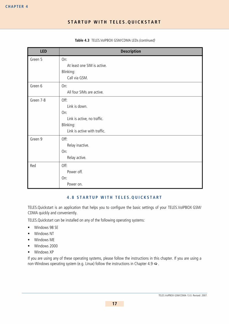
Table 4.3 TELES.VoIPBOX GSM/CDMA LEDs
LED Description
Green 1-4 Off:
Telephone on the hook.On:
Telephone off the hook.
Blinking:Call active.
ii
16
TELES.VoIPBOX GSM/CDMA 13.0. Revised: 2007.
S T A R T U P W I T H T E L E S . Q U I C K S T A R T
C H A P T E R 4
4 . 8 S T A R T U P W I T H T E L E S . Q U I C K S T A R T
TELES.Quickstart is an application that helps you to configure the basic settings of your TELES.VoIPBOX GSM/CDMA quickly and conveniently.
TELES.Quickstart can be installed on any of the following operating systems:
Windows 98 SEWindows NT
Windows ME
Windows 2000Windows XP
If you are using any of these operating systems, please follow the instructions in this chapter. If you are using anon-Windows operating system (e.g. Linux) follow the instructions in Chapter 4.9 .
Green 5 On:
At least one SIM is active.
Blinking:Call via GSM.
Green 6 On:
All four SIMs are active.
Green 7-8 Off:
Link is down.On:
Link is active, no traffic.
Blinking:Link is active with traffic.
Green 9 Off:
Relay inactive.
On:Relay active.
Red Off:
Power off.
On:Power on.
Table 4.3 TELES.VoIPBOX GSM/CDMA LEDs (continued)
LED Description
17
TELES.VoIPBOX GSM/CDMA 13.0. Revised: 2007.

S T A R T U P W I T H T E L E S . Q U I C K S T A R T
C H A P T E R 4
4 . 8 . 1 I N S T A L L I N G T E L E S . Q U I C K S T A R T
Make sure the TELES.GATE Manager isnot running on your computer. To installTELES.Quickstart on your computer, in-sert the CD and select TELES.Quickstartfrom the menu. Follow the Windows in-structions to begin installation of theTELES.Quickstart. Once installation be-gins, click Next to install TELES.Quick-start in the predefined folder. To install itin another location, click Browse and se-lect a folder from the browser that ap-pears. Then click Next.
The next dialog asks you where you wantto install the program’s icons. To installthem in the folder that appears, clickNext. If you want to install them in an-other location, select a folder from the listor enter a new folder name. Then clickNext.
To start TELES.Quickstart immediatelyfollowing installation, activate the check-box I would like to launchTELES.Quickstart. Make sure the check-box is inactive if you do not want to startthe program now. Click Finish.
Figure 4.4 TELES.Quickstart Installation
18
TELES.VoIPBOX GSM/CDMA 13.0. Revised: 2007.

S T A R T U P W I T H T E L E S . Q U I C K S T A R T
C H A P T E R 4
4 . 8 . 2 C O N F I G U R A T I O N W I T H T E L E S . Q U I C K S T A R T
Figure 4.5 TELES.Quickstart
Now you can use TELES.Quickstart to set up your TELES.VoIPBOX GSM/CDMA. Open TELES.Quickstart.exe. Theprogram will automatically search for your TELES.VoIPBOX GSM/CDMA in the local network. For TELES.Quickstart,the source UDP port is 57445. It might be necessary to change the firewall rules on your system.
Click the Search button to restart the search. When the program has found your TELES.VoIPBOX GSM/CDMA, itwill appear in the main window. As soon as it appears, you can end the search by clicking Stop. The window onthe right provides a running tally of the system’s status.
The system’s icon will appear in gray if it is unconfigured. Once it has been configured, it will appear in green. Theserial number appears as the system’s name.
To change the appearance of the window, select Large Icons, Small Icons or Details from the View menu. Inthe following description, we will use the Details View, which contains the following columns:
In the Options menu, you can suppress or activate ICMP ping to test the Internet connection.
Table 4.4 TELES.Quickstart Details View Columns
Heading Definition
Identifier This column lists the system’s serial number.
IP Address This column lists the system’s IP address.
Configured An X means the system contains the configuration files.
# of VoIP Ctrls This column lists the number of TELES.G729 Modules installed in the system. It will al-ways be 1.
VoIP Channels This column shows the number of VoIP channels per TELES.G729 Module.
Type Lists the type of system.Box An X means the system is a TELES box-based system.CF Mounted This column is not relevant for TELES box-based systems.
19
TELES.VoIPBOX GSM/CDMA 13.0. Revised: 2007.

S T A R T U P V I A F T P
C H A P T E R 4
To perform the initial configuration of the system, double-click the icon or right-click and select Configure. The IPSettings dialog will appear. If you are using a DHCP serv-er, activate the checkbox DHCP. This will deactivate thenext four lines. Your DHCP server will automatically provideall of the other necessary information. If you do not have aDHCP server, leave the DHCP checkbox empty. The defaultIP address appears in the IP Address box. Enter a new IPaddress. If the address you enter already exists in the net-work, you will be notified to choose another address at theend of the configuration process. Enter the system’s net-mask in the Mask dialog box. Enter the IP address for theDefault Gateway and the Time Server in the corre-sponding dialog boxes. Select the Time Zone for the loca-tion of the system. Click Next.
Now the system is configured; all other processes run automatically.
First the system’s IP address will be changed and then the system will start with the new IP address. When thesystem can be reached at the new IP address, all PSTN ports and routing entries will be set by sending the createdconfiguration files to the system.
If you right-click the system’s icon in the main window, you can also choose Temporarily Configure IP Address,only the IP address for the system’s first Ethernet interface and the netmask will be temporary changed. This canbe helpful if you want to set up local remote access to the system and use other IP settings on the remote devicethan the system’s IP configuration in the network. Bear in mind that the functions on the system’s first Ethernetinterface work with the new settings.
4 . 9 S T A R T U P V I A F T P
If you are using a computer that does not use a Windows operating system, you can preconfigure the system viaFTP. The system’s default IP address is 192.168.1.2. To configure the system using FTP, you must assign your com-puter an IP address from network range 192.168.1.0 Class C and then access the system via FTP.
The default user is teles and the default password is tcs-ag. To configure the system, use the default config-uration file example on the CD in the Configfiles directory and the following subdirectories:
IPconfigThis subdirectory contains the file (ip.cfg) responsible for configuration of the Ethernet interface
portconfigThis subdirectory contains the file (pabx.cfg) responsible for configuration of the analog interface
There is no internal time generation for the system when the power is interrupted. That means the default time is used when the system is restarted or rebooted! There-fore it is important to set the system time with an NTP server.
Figure 4.6 TELES.Quickstart Configuration: IP Set-tings
ii
20
TELES.VoIPBOX GSM/CDMA 13.0. Revised: 2007.

S E L F P R O V I S I O N I N G W I T H T E L E S . N M S
C H A P T E R 4
To edit the default configuration, follow the directions in Chapter 5 . Upload the configuration files into the /boot directory.
4 . 1 0 S E L F P R O V I S I O N I N G W I T H T E L E S . N M S
With a management connection to the TELES.NMS (Network Management System), the TELES.VoIPBOX GSM/CDMA can retrieve its configuration files from the configured TELES.NMS. That means that custom configurationof the device occurs automatically when the device is started. The following setting must be made in the[System] section of the pabx.cfg:
AlarmCallback=<ip address NMS server>
RemoteCallback=<ip address NMS server> <time> <days of week + holiday>
As soon as the device is started, it connects automatically with the TELES.NMS, which uses the device’s TAG num-ber to send a prepared configuration. For further information on configuration of the TELES.NMS, please refer tothe TELES.NMS Systems Manual.
4 . 1 1 R E M O T E A C C E S S A N D A C C E S S S E C U R I T Y
After the system has been configured and all cables are connected, remote administration and maintenance canoccur with the TELES.GATE Manager (Chapter 4.11.1 ), the HTTP user interface (Chapter 4.11.2 ), or via FTP(Chapter 4.11.3 ).
4 . 1 1 . 1 T E L E S . G A T E M A N A G E R
Figure 4.7 TELES.GATE Manager
The TELES.GATE Manager administration and maintenance software offers a broad range of functions. TheTELES.GATE Manager is user friendly and can be customized to suit your needs.
21
TELES.VoIPBOX GSM/CDMA 13.0. Revised: 2007.

R E M O T E A C C E S S A N D A C C E S S S E C U R I T Y
C H A P T E R 4
The following maintenance functions are possible:
Display system information and network element status.
Retrieve and display configuration files.
Restart network elements.Use of a trace option for checking functions and fault diagnosis. Option to use an external tool, e.g. todisplay and break down trace data.Update the system software (firmware) and configuration tables.
Retrieve CDRs (Call Detail Records).
Display the current connections (status).Display statistical information for network elements and interfaces.
Display the status of the interfaces.
Use the CD enclosed in your package contents to install the TELES.GATE Manager. For a detailed description ofinstallation and implementation of the TELES.GATE Manager, please refer to the TELES.GATE Manager and UtilitiesPrograms Manual.
TELES.GATE Manager remote access can occur via IP. TELES.GATE Manager access via IP uses port 4444 as orig-ination TCP port and port 4445 as destination port. The following default value (4445) is configured in thepabx.cfg file for the system’s port:
MoipPort=4445
22
TELES.VoIPBOX GSM/CDMA 13.0. Revised: 2007.

R E M O T E A C C E S S A N D A C C E S S S E C U R I T Y
C H A P T E R 4
4 . 1 1 . 2 H T T P U S E R I N T E R F A C E
Figure 4.8 HTTP User Interface
Remote access can occur via the HTTP user interface. Even users with little experience can easily configure standardsystem settings with this interface. Simply open a browser and enter the system’s IP address in the address bar.
The following administrative levels apply:
Carrier Mode (Full Access)
User: teles-carrier
Password: tcs-carrier
All configuration pages can be accessed in this mode.
Administrator Mode
User: teles-admin
Password: tcs-admin
This access level is for the user network’s administrator. All IP and routing entries, with the exception of VoIP carrierentries, can be set here.
23
TELES.VoIPBOX GSM/CDMA 13.0. Revised: 2007.

R E M O T E A C C E S S A N D A C C E S S S E C U R I T Y
C H A P T E R 4
Read-Only Mode
User: teles-user
Password: tcs-user
No configuration changes can be made at this level. Only status and statistics can be retrieved.
Of course, these configuration levels correspond with the most important scenarios. The passwords are saved inthe ip.cfg in encrypted form:
PwdCarrier=<crypt>PwdAdmin=<crypt>PwdUser=<crypt>Example:
The user interface is divided into the following main sections:
[httpd]PwdUser=k24X0sdc.uMcMPwdAdmin=k2UMj19qtovzIPwdCarrier=k2jryo6Xd5vN6
Never copy these entries from one system to another, as the encryption is unique for each system.
Table 4.5 HTTP User Interface: Sections
Section Description
User Data Here you can change the user passwords and the language for the HTTP in-terface.
System Settings IP Settings: Settings for the Ethernet interfaces and related services.
Port Settings: Settings for the TELES.VoIPBOX GSM/CDMAs ports.
VoIP Settings: VoIP settings for the SIP or H.323 carrier.Telephony Routing:Routings for telephone numbers.
POTS Settings:Settings for the TELES.VoIPBOX GSM/CDMA’s analog inter-faces.
System Overview Overview of system information and drivers.
Telephony Routing VoIP settings for the SIP or H.323 carrier and routings for telephone num-bers.
Commands Here you can activate a configuration or restart the system.
ii
24
TELES.VoIPBOX GSM/CDMA 13.0. Revised: 2007.

R E M O T E A C C E S S A N D A C C E S S S E C U R I T Y
C H A P T E R 4
All of the user interface’s pages contain Help buttons and links to the online help, which provides a detailed de-scription of all of the individual configuration settings.
4 . 1 1 . 3 F T P
Remote access can also occur via FTP. You can use FTP to transfer configuration files. You can also carry out func-tions and traces with raw commands. Use the username teles and the defined password to connect to the sys-tem with FTP.
The following entries ensure the security of your FTP access:
Once you have access to the system, you will be in the folder /home/teles. To upload or download configura-tion files change to the directory /boot. To download log files, also change to the directory /boot.
The following commands can be carried out via FTP access:
4 . 1 1 . 4 S E T T I N G A P A S S W O R D F O R R E M O T E A C C E S S
The following entry ensures the security of your remote access. Use the mkpwd.exe tool to generate the pass-word. You will find it on the enclosed CD in the directory pwd.
Table 4.6 FTP Security Entries
FTP Security
FtpdPort=<port>
Defines the FTP access port (default 21).
RemotePassword=<password>Defines the password for FTP and TELES.GATE Manager access. Please refer to Chapter 4.11.4 for instruc-tions on how to enter an encrypted password in the pabx.cfg. If you do not define a password, access to the system via TELES.GATE Manager occurs without a password, and FTP access occurs with the default pass-word tcs-ag.
Table 4.7 FTP Commands
Command Function
SITE xgboot Boots the entire system.
SITE xgact Activates the configuration.
SITE xgact 1-19 Activates the Night section corresponding with the number 1-19.
SITE xgtrace 0 Deactivates trace.
SITE xgtrace 1 Activates layer 2 trace.
SITE xgtrace 2 Activates layer 3 trace.
25
TELES.VoIPBOX GSM/CDMA 13.0. Revised: 2007.

R E M O T E A C C E S S A N D A C C E S S S E C U R I T Y
C H A P T E R 4
Start the program in a command window with the entry mkpwd <password>. The output shows the encryptedpassword. Enter the encrypted password in the configuration file pabx.cfg’s parameter line as follows:
When the file has been transferred to the system and the configuration has been activated, access to the systemcan occur only with the password. Don’t forget to memorize the password!
If you do not define a password, access to the system via TELES.GATE Manager occurs without a password, andFTP access occurs with the default password tcs-ag.
RemotePassword=<crypt>
26
TELES.VoIPBOX GSM/CDMA 13.0. Revised: 2007.
C H A P T E R 5
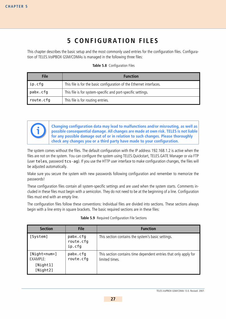
5 C O N F I G U R A T I O N F I L E SThis chapter describes the basic setup and the most commonly used entries for the configuration files. Configura-tion of TELES.VoIPBOX GSM/CDMAs is managed in the following three files:
The system comes without the files. The default configuration with the IP address 192.168.1.2 is active when thefiles are not on the system. You can configure the system using TELES.Quickstart, TELES.GATE Manager or via FTP(user teles, password tcs-ag). If you use the HTTP user interface to make configuration changes, the files willbe adjusted automatically.
Make sure you secure the system with new passwords following configuration and remember to memorize thepasswords!
These configuration files contain all system-specific settings and are used when the system starts. Comments in-cluded in these files must begin with a semicolon. They do not need to be at the beginning of a line. Configurationfiles must end with an empty line.
The configuration files follow these conventions: Individual files are divided into sections. These sections alwaysbegin with a line entry in square brackets. The basic required sections are in these files:
Table 5.8 Configuration Files
File Function
ip.cfg This file is for the basic configuration of the Ethernet interfaces.
pabx.cfg This file is for system-specific and port-specific settings.
route.cfg This file is for routing entries.
Changing configuration data may lead to malfunctions and/or misrouting, as well as possible consequential damage. All changes are made at own risk. TELES is not liable for any possible damage out of or in relation to such changes. Please thoroughly check any changes you or a third party have made to your configuration.
Table 5.9 Required Configuration File Sections
Section File Function
[System] pabx.cfgroute.cfgip.cfg
This section contains the system’s basic settings.
[Night<num>]EXAMPLE:
[Night1][Night2]
pabx.cfgroute.cfg
This section contains time dependent entries that only apply for limited times.
ii
27
TELES.VoIPBOX GSM/CDMA 13.0. Revised: 2007.

C O N F I G U R A T I O N F I L E I P . C F G
C H A P T E R 5
5 . 1 C O N F I G U R A T I O N F I L E I P . C F G
The basic settings for the two Ethernet interfaces are entered here. One interface usually suffices. The second in-terface can be used for special requirements, e.g. as a hub port, DSL router or vLAN interface. Generally, thesesettings are entered once and then left unchanged.
This file contains the following sections, which must appear in the order given:
5 . 1 . 1 S Y S T E M S E C T I O N C O N F I G U R A T I O N
The [System] section contains entries that define the default gateway and/or special routing entries.
To define the standard gateway, use the following entry to set the IP address:
[emac0] ip.cfg This section contains the IP configuration for the first Ethernet in-terface.
Table 5.10 Sections in the ip.cfg File
Section Function
[System] (required) This section contains entries that define the default gateway and/or special routing entries.
[emac0] (required)[emac1] (optional)
The Ethernet Media Access Controller section(s) define the physical Ethernet interface(s).
[nat] (optional) This section includes settings for Network Address Translation.
[bridge0] (optional) These section(s) contain settings for the second Ethernet controller in bridge mode.
[pppoe<x>] (optional) These sections contain settings for direct connection between the system and the DSLAM when the PPPoE protocol is used. <x> can be 0 or 1.
[firewall] (optional) This section contains settings for activating the system’s firewall.
[altqd] (optional) This section enables prioritization of VoIP packets in the
TELES.VoIPBOX GSM/CDMA through an IP network using bandwidth con-trol.
[dhcpd] (optional) This sections contains a list of parameters and settings for the DHCP server in the system. It is divided into global settings for the server and parameters for the DHCP subnet.
[vlan<x>] (optional) These section(s) contain settings for the virtual networks. <x> can be any-thing from 0 to 9.
Table 5.9 Required Configuration File Sections (continued)
Section File Function
28
TELES.VoIPBOX GSM/CDMA 13.0. Revised: 2007.

C O N F I G U R A T I O N F I L E I P . C F G
C H A P T E R 5
DefaultGw=<ip addr>Example:
If you must route specific net ranges to gateways other than what is defined in the default route, make the follow-ing entries in the [System] section:
Route=<target range> -netmask <ip mask> <ip gateway>Example:
If only certain routes apply, leave the line DefaultGw empty.
5 . 1 . 2 E T H E R N E T I N T E R F A C E C O N F I G U R A T I O N
The following settings are possible for the sections [emac0] and [emac1]:
IpAddress=<ip addr>/<netmask>
The IP address is entered in decimal notation, followed by a slash (/) and the netmask in bit notation.
Example:
The following entry is used to allocate an IP address via DHCP:
IpAddress=dhcpThe following entry is used in the [emac1] section if operation of the system is occurs in bridge mode.
IpAddress=up
5 . 1 . 3 B R I D G E C O N F I G U R A T I O N
A bridge can connect two networks with each other. A bridge works like a hub, forwarding traffic from one inter-face to another. Multicast and broadcast packets are always forwarded to all interfaces that are part of the bridge.This can occur on the Ethernet or VLAN level:
BrConfig=add <interface-x> add <interface-y> upActivating another Ethernet interface in this way is useful, for example, when the Ethernet switch does not haveany more ports available for connection of the system. You can simply unplug a cable and plug it into the system’ssecond Ethernet interface.
Example:
[System]DefaultGw=192.168.1.254
[System]DefaultGw=192.168.1.254Route=10.0.0.0 -netmask 255.0.0.0 192.168.1.1
IpAddress=192.168.1.2/24
[bridge0]BrConfig=add emac0 add emac1 up
29
TELES.VoIPBOX GSM/CDMA 13.0. Revised: 2007.
C O N F I G U R A T I O N F I L E I P . C F G
C H A P T E R 5
5 . 1 . 4 N A T C O N F I G U R A T I O N
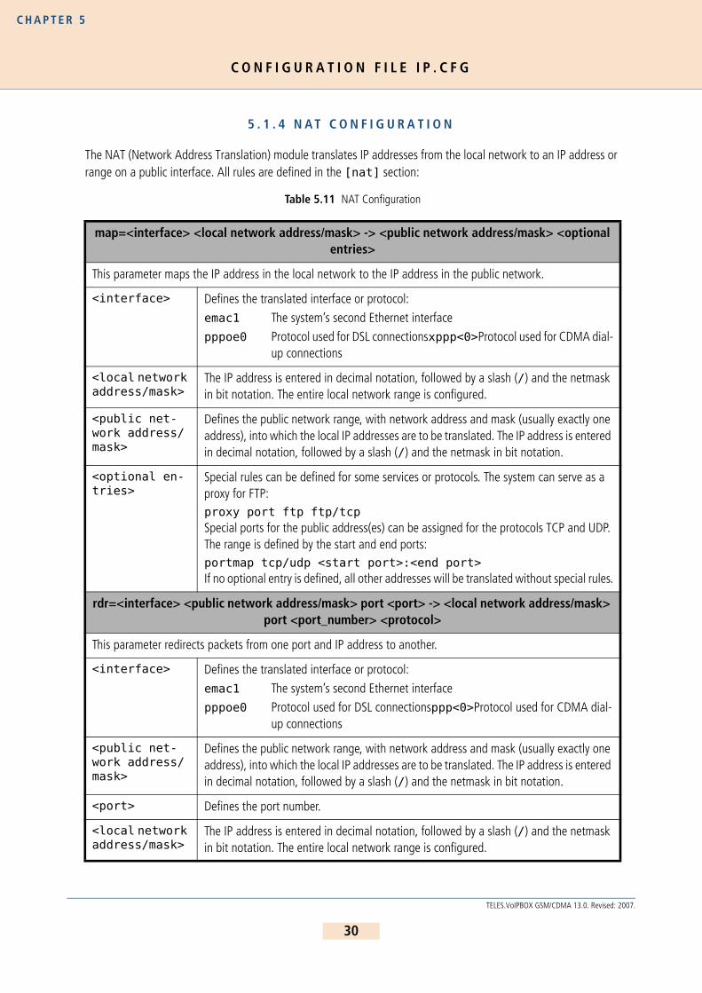
The NAT (Network Address Translation) module translates IP addresses from the local network to an IP address orrange on a public interface. All rules are defined in the [nat] section:
Table 5.11 NAT Configuration
map=<interface> <local network address/mask> -> <public network address/mask> <optional entries>
This parameter maps the IP address in the local network to the IP address in the public network.
<interface> Defines the translated interface or protocol:
emac1 The system’s second Ethernet interface
pppoe0 Protocol used for DSL connectionsxppp<0>Protocol used for CDMA dial-up connections
<local network address/mask>
The IP address is entered in decimal notation, followed by a slash (/) and the netmask in bit notation. The entire local network range is configured.
<public net-work address/mask>
Defines the public network range, with network address and mask (usually exactly one address), into which the local IP addresses are to be translated. The IP address is entered in decimal notation, followed by a slash (/) and the netmask in bit notation.
<optional en-tries>
Special rules can be defined for some services or protocols. The system can serve as a proxy for FTP: proxy port ftp ftp/tcpSpecial ports for the public address(es) can be assigned for the protocols TCP and UDP. The range is defined by the start and end ports:portmap tcp/udp <start port>:<end port>If no optional entry is defined, all other addresses will be translated without special rules.
rdr=<interface> <public network address/mask> port <port> -> <local network address/mask> port <port_number> <protocol>
This parameter redirects packets from one port and IP address to another.
<interface> Defines the translated interface or protocol:
emac1 The system’s second Ethernet interfacepppoe0 Protocol used for DSL connectionsppp<0>Protocol used for CDMA dial-
up connections
<public net-work address/mask>
Defines the public network range, with network address and mask (usually exactly one address), into which the local IP addresses are to be translated. The IP address is entered in decimal notation, followed by a slash (/) and the netmask in bit notation.
<port> Defines the port number.
<local network address/mask>
The IP address is entered in decimal notation, followed by a slash (/) and the netmask in bit notation. The entire local network range is configured.
30
TELES.VoIPBOX GSM/CDMA 13.0. Revised: 2007.

C O N F I G U R A T I O N F I L E I P . C F G
C H A P T E R 5
Example: The following NAT settings are for a system in which PPPoE (DSL) is used toward the Internet.The local network range 192.168.1.0 Class C is translated with the following rules:
– The proxy mode is used for FTP.
– All other TCP and UDP packets are mapped to the external ports 40000 to 60000.
– There are no special rules for any other services.– Incoming requests to port 80 and 443 in the public IP address 192.168.1.100 are redi-
rected to ports 80 and 443 in the local IP address 192.168.1.100.
5 . 1 . 5 P P P O E C O N F I G U R A T I O N
The protocol Point-to-Point over Ethernet is used for DSL communication with the DSLAM. That means the systemcan connect directly with the carrier network and terminate VoIP traffic directly.
All necessary information for setup of the PPPoE connection is defined in the [pppoe<x>] section. That meansusername, password and authentication protocol are set here. The Ethernet interface is emac1 and the gatewaycan also be defined. The parameter PppoeIf defines the physical Ethernet interface used (always emac1). Thesettings are entered as follows:
[pppoe<x>]PppoeIf=emac1 User=<user>Pwd=<pwd>AuthProto=<pap|chap>Route=<ip_gw> (optional)
<protocol> Defines the protocol. tcp and udp are possible.
[nat]map=emac1 192.168.1.0/24 -> 0/32 proxy port ftp ftp/tcpmap=emac1 192.168.1.0/24 -> 0/32 portmap tcp/udp 40000:60000map=emac1 192.168.1.0/24 -> 0/32rdr=emac1 0/0 port 80 -> 192.168.1.100 port 80 tcprdr=emac1 0/0 port 443 -> 192.168.1.100 port 443 tcp
Table 5.12 Settings in the [pppoe<x>] Section of the ip.cfg
[pppoe<x>]
PppoeIf=<interface>
Enter the Ethernet interface used for the DSL connection (usually emac1).
User=<username>Enter the username used for DSL access.
Table 5.11 NAT Configuration (continued)
31
TELES.VoIPBOX GSM/CDMA 13.0. Revised: 2007.

C O N F I G U R A T I O N F I L E I P . C F G
C H A P T E R 5
Bear in mind that configuration of the firewall, the NAT module and prioritization of the VoIP packets must be con-sidered when routing voice and data through the DSL line.
Example: The following entry will create the interface pppoe0, with the username user and the pass-word pwd. The PAP authentication protocol is used. The default route occurs via DSL:
5 . 1 . 6 F I R E W A L L S E T T I N G S
The firewall settings provide options for limiting or denying access to and from the system. If you do not configurethis section, the firewall is inactive and access is unlimited.
WARNING: Make sure you configure the firewall rules carefully. The rules are processed from top to bottom. Ifyou use the option quick, you will break the sequence. We recomend that you put the most restrictive rule at theend of the configuration.
Example: In the following example, only port 4445 allows incoming connections from the IP address192.168.1.10. All others will be blocked.
Pwd=<password>
Enter the password used for DSL access.
AuthProto=<protocol>
Enter chap or pap for the protocol used for authentication.
Route=<ip-addr> (optional)Enter the target IP address range, e.g. 0.0.0.0 (default route). All packets that are not defined for the local network will be sent through this interface. In this case, the parameter DefaultGW in the System section (Chapter 5.1.1 ) must remain empty. Only network ranges can be routed. The syntax in this case is Route=<target range> -netmask <ip mask>. If several different network ranges are used, you must enter the Route parameter for each range.
[pppoe0]PppoeIf=emac1 User=userPwd=pwdAuthProto=papRoute=0.0.0.0
[firewall]fw=pass in quick on emac0 proto tcp from 192.168.1.10/32 to any porteq 4445 flags S keepstate keep frags fw=block in log quick on emac0 all
Table 5.12 Settings in the [pppoe<x>] Section of the ip.cfg (continued)
[pppoe<x>]
32
TELES.VoIPBOX GSM/CDMA 13.0. Revised: 2007.

C O N F I G U R A T I O N F I L E I P . C F G
C H A P T E R 5
Table 5.13 Settings in the [firewall] Section of the ip.cfg
[firewall]fw=<mode> <direction> <list>
<mode> Two modes are possible for permitting or denying access::
pass permits accessblock denies access
<direction> Possible directions are in and out:
in external to internal
out internal to external
<list> All other entries specify the other settings for the corresponding firewall rules and are optional. The order in the line is as listed below:
log Records non-matching packets.
quickAllows short-cut rules in order to speed up the filter or override later rules. If a packet matches a filter rule that is marked as quick, this rule will be the last rule checked, allowing a short-circuit path to avoid processing later rules for this packet. If this option is missing, the rule is taken to be a "fall-through rule, meaning that the result of the match (block/pass) is saved and that processing will continue to see if there are any more matches.
on <interface>The firewall rule is used only for the defined interface (e.g. emac0, pppoe0).
from <networkaddress/mask>
to <networkaddress/mask>
from defines the source IP-address range for incoming packets. to defines the target IP-address range for outgoing packets. The IP address appears in decimal notation, followed by a slash (/) and the netmask in bit notation. any stands for all IP addresses (e.g.: to any).
NOTE: If you use the rule pass in/out in combination with the option from <ip> to <ip>, you must specify a protocol number with proto and a port number. If you not specify the port, the system may not be reachable. EXAMPLE:fw=pass in quick on pppoe0 proto tcp from any to any port eq 4445
proto <protocol>
defines the protocol, for which the rule is valid (e.g.: proto tcp, proto udp, proto icmp).
port eq <num>
<num> defines the port as number (e.g.: port eq 4445).
33
TELES.VoIPBOX GSM/CDMA 13.0. Revised: 2007.

C O N F I G U R A T I O N F I L E I P . C F G
C H A P T E R 5
Example:
5 . 1 . 7 B A N D W I D T H C O N T R O L
In many implementation scenarios, the TELES.VoIPBOX GSM/CDMA in router mode (e.g. as DSL router) sends voiceand data traffic through a connection with limited bandwidth. This can lead to lost voice packets that arrive toolate to be used in the voice stream. To avoid lost packets, this QOS setting prioritizes packet transmission. Youmust set the priority for voice signaling and for the voice packets. That means you must prioritize SIP/H.323, RTPand RTCP. You will find the ports used in Table 5.24, in the following entries:
H225PortSipPortVoipRtp PortVoipRtpPortSpacingDifferent ports can be used for RTP and RTCP, depending on the configuration.
keep stateEnsures that the firewall checks packets from the beginning to the end of a session. This is necessary, as the firewall does not know when a session begins or ends.
flags SOnly syn. packets are accepted and recorded in the state table. In conjunction with keep state, packets from sessions that have been inactive will also be routed. The advantage of this entry is that random packets will not be accepted.
keep frags
Fragmented packets are also routed.
[firewall]; loopbackfw=pass in quick on emac0 allfw=pass out quick on emac0 all
; traffic to outgoingfw=pass out quick on pppoe0 proto tcp all flags S keep state keep fragsfw=pass out quick on pppoe0 proto udp all keep state keep fragsfw=pass out quick on pppoe0 proto icmp all keep state keep frags
; incoming trafficfw=pass in quick on pppoe0 proto tcp from 10.4.0.0/16 to any port eq 21 flags S keep state keep fragsfw=pass in quick on pppoe0 proto tcp from 10.4.0.0/16 to any port eq 23 flags S keep state keep fragsfw=pass in quick on pppoe0 proto tcp from 10.4.0.0/16 to any port eq 4445 keep state
; icmp trafficfw=pass in quick on pppoe0 proto icmp all keep state
; other will be blockedfw=block in log quick on pppoe0 allfw=block out log quick on pppoe0 all
Table 5.13 Settings in the [firewall] Section of the ip.cfg (continued)
[firewall]fw=<mode> <direction> <list>
34
TELES.VoIPBOX GSM/CDMA 13.0. Revised: 2007.

C O N F I G U R A T I O N F I L E I P . C F G
C H A P T E R 5
The parameter VoipRtpPort shows the first RTP port used. The corresponding RTCP port is the next one up.The parameter VoipRtpPortSpacing shows the next RTP port (RTP port + port spacing).
Example: In the following example, prioritization is set for an eight-channel VoIP connection. The SIP sig-naling port 5060 and the RTP/RTCP ports 29000 to 29015 are prioritized at level 7. All other ser-vices are set at level 0:
Table 5.14 Settings in the [altqd] Section of the ip.cfg
interface <interface> bandwidth <bw> priq
Defines the interface for which the rule applies.
<interface> Sets the interface for which prioritization apples (e.e. pppoe0).
<bw> Sets the bandwidth that is available on the interface in Kbit/s (e.g. 256K).
priq Priority qeueing. A higher priority class is always served first.
class priq <interface> <class> root priority <prio>
Defines the priority of the filter entries.
<class> Two types can be set:
realtime_class (VoIP packets)regular_class (data packets)
<prio> Enter a value between 0 and 15. The higher the value (e.g. 15), the higher the priority.
filter <interface> <class> <values>
Defines the individual rules.
<values> The individual values are divided into the following entries. A 0 can be entered as a wild-card, in which case all values are possible:
<dest_addr> (can be followed by netmask <mask>)
<dest_port><src_addr> (can be followed by netmask <mask>)<src_port><protocol tos value>:
6 for TCP
17 for UDP
35
TELES.VoIPBOX GSM/CDMA 13.0. Revised: 2007.

C O N F I G U R A T I O N F I L E I P . C F G
C H A P T E R 5
5 . 1 . 8 D H C P S E R V E R S E T T I N G S
The DHCP (Dynamic Host Configuration Protocol) server provides a mechanism for allocation of IP addresses toclient hosts. The section [dhcpd] contains a list of parameters and settings for the DHCP server in the system. Itis divided into global settings for the server and parameters for the DHCP subnet.
[altqd]interface pppoe0 bandwidth 256K priqclass priq pppoe0 realtime_class root priority 7 filter pppoe0 realtime_class 0 5060 0 0 0 filter pppoe0 realtime_class 0 0 0 5060 0 filter pppoe0 realtime_class 0 29000 0 0 17 filter pppoe0 realtime_class 0 0 0 29000 17 filter pppoe0 realtime_class 0 29001 0 0 17 filter pppoe0 realtime_class 0 0 0 29001 17 .... filter pppoe0 realtime_class 0 29014 0 0 17 filter pppoe0 realtime_class 0 0 0 29014 17 filter pppoe0 realtime_class 0 29015 0 0 17 filter pppoe0 realtime_class 0 0 0 29015 17 class priq pppoe0 regular_class root priority 0 default
Table 5.15 Settings in the [dhcpd] Section of the ip.cfg
; Global dhcp parameters
allow unknown-clients;
All DHCP queries are accepted and the configured settings are transmitted to the clients.
ddns-update-style none;Deactivates dynamic update of the domain name system as per RFC 2136.
; Parameters for the Subnet
subnet <network address> netmask <mask for network range> {<list>}
In <list> you can enter any of the following specific network settings activated by the DHCP server. Each op-tion must begin in a new line and end with a semicolon (;).
range <start IP address> <end IP address>;The DHCP network range is defined by the first and last address in the range. Client assignment begins with the last address.
option broadcast-address <IP address>;Defines the broadcast address for the clients in the subnet..
option domain-name "<string>";
Defines the domain name used in the network.
36
TELES.VoIPBOX GSM/CDMA 13.0. Revised: 2007.

C O N F I G U R A T I O N F I L E I P . C F G
C H A P T E R 5
Example:
5 . 1 . 9 P P P C O N F I G U R A T I O N F O R C D M A D I A L - U P
The point-to-point protocol is used for dial-up connection via a mobile CDMA connection. That means the systemcan set up an Internet connection, which can be used for all local users or to transmit VoIP calls via CDMA dial-up.Bear in mind that you must configure the firewall and NAT options accordingly.
option domain-name-servers <IP address>;
Defines the DNS-server address to be assigned (as per RFC 1035)
All of the following optional entries defining server addresses are also transmitted as per RFC 1035. Separate multiple addresses per server with a comma:
… <IP address>, <IP address>; (this also applies for all other optional entries with IP addresses).
option netbios-name-servers <IP address>
Defines the WINS-server address to be assigned.
option ntp-servers <ip address>;
Defines the NTP-server address to be assigned.
option time-servers <ip address>;Defines the time-server address to be assigned (RFC 868).
option routers <IP address>;
Defines the router address to be assigned.
option subnet-mask <net mask>;
Defines the netmask to be assigned (as per RFC 950).
option tftp-server-name "<link>";Defines the TFTP server name (option 66), as per RFC 2132.
EXAMPLE: option tftp-server-name "http://192.168.0.9";
[dhcpd]; Global dhcp parametersallow unknown-clients;ddns-update-style none;
; Parameter for the Subnetsubnet 192.168.1.0 netmask 255.255.255.0 { range 192.168.1.3 192.168.1.20; option broadcast-address 192.168.1.255; option domain-name "company.de"; option domain-name-servers 192.168.1.100; option routers 192.168.1.2; option subnet-mask 255.255.255.0;}
Table 5.15 Settings in the [dhcpd] Section of the ip.cfg (continued)
; Global dhcp parameters
37
TELES.VoIPBOX GSM/CDMA 13.0. Revised: 2007.

C O N F I G U R A T I O N F I L E I P . C F G
C H A P T E R 5
All necessary information for setup of the PPP connection is defined in the section [xppp<num>].
The settings are entered as follows:
Example:
5 . 1 . 1 0 V L A N C O N F I G U R A T I O N
A VLAN (Virtual Local Area Network) is a virtual LAN within a physical network. Each VLAN is assigned a uniquenumber (VLAN ID) and defined in the [vlan<x>] section with
Tag: value between 1 and 4095
Priority: value between 0 and 7 (0 is lowest and 7 is the highest priority)
[vlan0]IfConfig=vlan <tag>,<priority> vlanif <interface>Example: The following entry will create the interface vlan1, with VLAN tag 10 and priority 7, on the Ether-
net interface emac0. Following this configuration, IP addresses (and/or other protocols) can be
Table 5.16 Settings in the [xppp] Section of the ip.cfg
[xppp<num>]
Dad=<num>
Enter the dial-up number.
User=<username>Enter a username.
Pwd=<password>
Enter a password.
Route=<ip-addr>
Enter the target IP address range, e.g. 0.0.0.0 (default route).
AuthProto=<protocol>Enter chap (default) or pap for the protocol used for authentication.
IdleTO=<sec>
Enter the number of seconds without traffic before the interface tears down the connection.
MTU=<int>
Maximum Transfer Unit. We recommend the following default values:120 for CDMA dial-up.
Rfc1662=<val>
Framing to be use:
1 for CDMA.
38
TELES.VoIPBOX GSM/CDMA 13.0. Revised: 2007.

C O N F I G U R A T I O N F I L E I P . C F G
C H A P T E R 5
assigned to the vlan1 interface:
5 . 1 . 1 1 E X A M P L E S
5 . 1 . 1 1 . 1 D E F A U L T C O N F I G U R A T I O N
In the following example, the system’s IP address is 192.168.1.1, the netmask is 255.255.255.0, and the standardgateway is 192.168.1.254:
5 . 1 . 1 1 . 2 A C T I V E E T H E R N E T B R I D G E
In the following example a two-port Ethernet bridge is configured. The system’s IP address is 192.168.1.1, the net-mask is 255.255.255.0, and the standard gateway is 192.168.1.254,
The emac1 interface is active and both Ethernet interfaces are set to bridge mode in the [bridge0] section:
[vlan1]IfConfig=vlan 10,7 vlanif emac0IpAddress=192.168.199.1
[System]DefaultGw=192.168.1.254
[emac0]IpAddress=192.168.1.1/24
[System]DefaultGw=192.168.1.254
[emac0]IpAddress=192.168.1.1/24
[emac1]IpAddress=up
[bridge0]BrConfig=add emac0 add emac1 up
39
TELES.VoIPBOX GSM/CDMA 13.0. Revised: 2007.

C O N F I G U R A T I O N F I L E I P . C F G
C H A P T E R 5
5 . 1 . 1 1 . 3 I N T E G R A T E D D S L - R O U T E R S C E N A R I O F O R V O I P TR A F F I C W I T H A N A C T I V E D H C P S E R V E R A N D F I R E W A L L
In the following example, the system is connected to the local IP network through emac0. The DSL modem is con-nected to the emac1 interface, which enables the system to connect directly to the carrier network without an ad-ditional router when the connection is used only for VoIP data. A DHCP server is used for dynamic IP-addressallocation:
[System]
[emac0]IpAddress=192.168.0.2/24
[emac1]IpAddress=up
[pppoe0]PppoeIf=emac1 User=usertelekomPwd=pwdAuthProto=chapRoute=default
[nat]map=pppoe0 192.168.0.0/24 -> 0/32 proxy port ftp ftp/tcpmap=pppoe0 192.168.0.0/24 -> 0/32 portmap tcp/udp 40000:60000map=pppoe0 192.168.0.0/24 -> 0/32
[firewall]; loopbackfw=pass in quick on emac0 allfw=pass out quick on emac0 all
; traffic to outgoingfw=pass out quick on pppoe0 proto tcp all flags S keep state keep fragsfw=pass out quick on pppoe0 proto udp all keep state keep fragsfw=pass out quick on pppoe0 proto icmp all keep state keep frags
; incoming trafficfw=pass in quick on pppoe0 proto tcp from 10.4.0.0/16 to any port eq 21 flags S keep state keep fragsfw=pass in quick on pppoe0 proto tcp from 10.4.0.0/16 to any port eq 23 flags S keep state keep fragsfw=pass in quick on pppoe0 proto tcp from 10.4.0.0/16 to any port eq 4445 keep state
; icmp trafficfw=pass in quick on pppoe0 proto icmp all keep state
; other will be blockedfw=block in log quick on pppoe0 allfw=block out log quick on pppoe0 all
[dhcpd]; Global dhcp parametersallow unknown-clients;ddns-update-style none;; Parameter for the Subnetsubnet 192.168.1.0 netmask 255.255.255.0 { range 192.168.1.3 192.168.1.20; option broadcast-address 192.168.1.255; option domain-name "company.de"; option domain-name-servers 192.168.1.100; option routers 192.168.1.2; option subnet-mask 255.255.255.0;
40
TELES.VoIPBOX GSM/CDMA 13.0. Revised: 2007.

C O N F I G U R A T I O N F I L E P A B X . C F G
C H A P T E R 5
5 . 1 . 1 1 . 4 V L A N S C E N A R I O
In the following example, the system is connected to the IP backbone through emac0. One Computer is connectedto the emac1 interface. You can separate voice and data traffic with two different VLANs (vlan0 with tag 10 forvoice, vlan1 with tag 11 for data). All traffic coming from emac1 will be sent to vlan1. Voice and data will not bemixed:
5 . 2 C O N F I G U R A T I O N F I L E P A B X . C F G
The pabx.cfg is divided into the [System] section and the optional [Night<num>], [Mail] and[Snmpd] sections.
5 . 2 . 1 S Y S T E M S E T T I N G S
The [System] section is divided into several categories to ensure clarity:
Hardware
Log filesNight configuration
Controllers
Subscribers
Global Settings
5 . 2 . 1 . 1 L O G F I L E S
CDRs, unconnected calls, system events, trace output and statistics can be saved into files.
The following entries are necessary to generate log files:
[System][emac0]IpAddress=192.168.1.12/16
[emac1]IpAddress=up
[vlan0]IfConfig=vlan 10,7 vlanif emac0IpAddress=10.0.1.2/24
[vlan1]IfConfig=vlan 11,1 vlanif emac0IpAddress=172.16.4.5/16
[bridge0]BrConfig=add vlan1 add emac1 up
Table 5.17 pabx.cfg: Log File Entries
Entry Description
ActionLog=/boot/protocol.log System events
41
TELES.VoIPBOX GSM/CDMA 13.0. Revised: 2007.

C O N F I G U R A T I O N F I L E P A B X . C F G
C H A P T E R 5
You can define how the log files are to be divided. There are two possiblities for saving entries into a new file:
In increments of time (twice-daily, daily, weekly, monthly)
Depending on the size of the fileYou can also define a maximum number of up to 7 files to be generated.
A dash (-) appears in place of information that is to be ignored.
Log=/boot/cdr.log CDR entries
RRufLog=/boot/failed.log Unconnected calls
TraceLog=/boot/trace.log System trace
The available internal memory is approximately 8 MB. Make sure you monitor the available memory.
Table 5.18 pabx.cfg: Log Parameters
Log=/boot/<file> <day> <size> <count>
<file> The name of the log file is generated as follows: [file]yymmdd[0-9|A-Z].log.
<day> Refers to the frequency with which the file is saved. The following options are possible:
halfdaily Every day at 11:59 and 23:59
daily Every day at 23:59weekly Sunday at 23:59
monthly The last day of the month at 23:59
<size> Regardless of the value entered in <day>, the file will be saved when the <size> has been reached.
NOTE: We recommend a file size of a multiple of 60kB.
<count> Refers to the number of files that will be saved in the system (between 5 and 35) before the first file is overwritten. This setting is useful not only for limited file size, but also for files that store events. Normally size can be limited for these files, e.g. 5 files of 1MB each. If the fifth file is full, the first one will automatically be overwritten.
Table 5.17 pabx.cfg: Log File Entries (continued)
Entry Description
ii
42
TELES.VoIPBOX GSM/CDMA 13.0. Revised: 2007.

C O N F I G U R A T I O N F I L E P A B X . C F G
C H A P T E R 5
Example 1 In the following entry, the file cdr.log is renamed every day. Up to 35 CDR files will be savedon the system.
Example 2 In the following entry, the file failed.log is renamed once a week. Up to 10 failed files willbe saved on the system.
Example 3 In the following entry, the file protocol.log is renamed when the file has reached 1MB. Upto five log files will be saved on the system.
5 . 2 . 1 . 2 N I G H T C O N F I G U R A T I O N
The sections for the time-dependent configuration changes and time-controlled routings are defined here.
A maximum of 19 additional daily configuration zones are possible (Night1 to Night19). The entryNightResetTime reactivates the original configuration contained in the System section.
The entry will have the following syntax:
Bear in mind that file size will be unlimited if no parameters are defined.
Log=/boot/cdr.log daily - 35
RrufLog=/boot/failed.log weekly - 10
ActionLog=/boot/protocol.log - 1000 5
Please remember to keep track of how much memory is available on the system.
Table 5.19 pabx.cfg: Night Parameters
Night<num>=<time> <day>
<num> Enter a value between 1 and 19 to define which configuration is to be loaded.
<time> If there is a time set with the format hh:mm after this entry, this configuration is loaded daily at that time on the defined day.
<day> Use a bitmask to set the weekdays on which the configuration applies here. The day-mask appears in the following order: HoSaFrThWeTuMoSu.
ii
ii
43
TELES.VoIPBOX GSM/CDMA 13.0. Revised: 2007.

C O N F I G U R A T I O N F I L E P A B X . C F G
C H A P T E R 5
Example: The configuration section is activated Fridays, Wednesdays and Mondays at noon unless the dayin question is a holiday:Night2=12:00 00101010
The configuration section switches back to the default configuration (System section) every dayat 8:00 p.m:NightResetTime=20:00 11111111
5 . 2 . 1 . 3 C O N T R O L L E R S
This category defines the parameters that apply to the ports.
The individual ports are defined with the following parameters:
Ports set to the same type can have the same bus number. In this case they will form a trunk group. If you changethis parameter in the configuration, you must restart the system.
Example:
Any defined Night sections must be set in the files pabx.cfg and route.cfg. If there are no changes in these sections, you must copy them from the System section. The complete Subscriber section must appear in the Night section of the pabx.cfg (see Chapter 5.2.5 on page 5-55). The active route(s) (MapAll, Restrict and Redirect entries) and VoIP, registrar and gatekeeper profiles must appear in the Night section of the route.cfg (see Chapter 5.3 on page 5-55).
Table 5.20 pabx.cfg: Controller Parameters
Controller<port>=<bus> <type>
<port> Defines the running (physical) port number.
<bus> Defines the configured (virtual) port number. In the default configuration, mobile ports are 20 and FXS ports are 10. VoIP ports are 40.
<type> Defines the connection type:
ANA internal (Foreign eXchange Subscriber)
CDMA CDMA portVOIP VoIP module
DTMF virtual controller for activating DTMF tone recognition
Controller00 = 30 ANAController01 = 31 ANAController02 = 32 ANAController03 = 33 ANAController04 = 20 GSMController05 = 20 GSMController06 = 20 GSMController07 = 20 GSMController08 = 40 VOIP
ii
44
TELES.VoIPBOX GSM/CDMA 13.0. Revised: 2007.

C O N F I G U R A T I O N F I L E P A B X . C F G
C H A P T E R 5
5 . 2 . 1 . 4 S U B S C R I B E R S
Features for each port can be defined using this entry. Changes become active following a restart:
Table 5.21 pabx.cfg: Subscriber Parameters
Subscriber<port>=<list>
<port> Defines the running (physical) port number.
The <list> variable may contain one or more of the following keywords:
DEFAULT The standard configuration will be used.
TRANSPARENT ROUTER Only the number is sent as caller ID (without the virtual port address).
ALARM Activates the monitoring mode for the respective port. If a relevant error oc-curs at the port, a remote call is placed to the number defined in RemoteCallBack.
SWITCH Changes internal port handling. In the default configuration, the VoIP con-troller is set to NT. You can use this parameter to change it from NT to TE.
CHMAX[x] Defines the number of VoIP channels (8) or DTMF channels. A maximum of two concurrent channels are possible for DTMF recognition if the callback platform is used.
45
TELES.VoIPBOX GSM/CDMA 13.0. Revised: 2007.

C O N F I G U R A T I O N F I L E P A B X . C F G
C H A P T E R 5
ANA[<country-code>,<charge-freq>,<cid-T5>,<cid-max-short>,<cid-min-long>,<cid-seizure-bits>,<cid-lev-el>,<cid-mode>,<au-dio-law>]
Analog FXS ports only. <country-code>
Impedance for individual analog controllers.0 = TBR21 standard (default)
0001 = USA
0049 = Germany0090 = Turkey
<charge-freq>frequency in kHz of charge impulse: 16 (default) or 12
<cid-T5>After first ring: pause (in ms) before generation of caller ID
Default: 800<cid-max-short>
Max duration of short pause (in ms) between first and second ring
Default: 250<cid-min-long>
Min duration of long pause [ms] between first and second ring
Default: 1500<cid-seizure-bits>
Length of caller ID signal: 80 (default) or 180<cid-level>
Caller ID signal level between 0 and 65535
0 = caller ID off (default)
We recommend a value of 12800<cid-mode>
Caller ID standard
1 = V.23 (default)
2 = BELL 202 (usuall used in North America)<audio-law>
1 = a-law (default)
2 = µ-law default
Table 5.21 pabx.cfg: Subscriber Parameters (continued)
Subscriber<port>=<list>
46
TELES.VoIPBOX GSM/CDMA 13.0. Revised: 2007.

C O N F I G U R A T I O N F I L E P A B X . C F G
C H A P T E R 5
Additional parameters for mobile controllers are described in Table 5.22 and Table 5.23. The parameters listed in
Table 5.22 are required for mobile controllers and those listed in Table 5.23 are optional, depending on the imple-mentation scenario.
Required Mobile Parameters
Specific settings for each mobile interface appear in square brackets behind the keywords GSM, UMTS or CDMA.These parameters are separated with a comma.
The following parameters are required:
Subscriber00 = TRANSPARENT ROUTER ALARMSubscriber01 = TRANSPARENT ROUTER ALARMSubscriber02 = TRANSPARENT ROUTER ALARMSubscriber03 = TRANSPARENT ROUTER ALARMSubscriber04 = TRANSPARENT ROUTER ANA[0049,16,800,250,1500,80,12800,2,1]Subscriber05 = TRANSPARENT ROUTER ANA[0049,16,800,250,1500,80,12800,2,1]Subscriber06 = TRANSPARENT ROUTER ANA[0049,16,800,250,1500,80,12800,2,1]Subscriber07 = TRANSPARENT ROUTER ANA[0049,16,800,250,1500,80,12800,2,1]Subscriber08 = TRANSPARENT ROUTER SWITCH CHMAX[8] ALARM
Table 5.22 Required Parameters in pabx.cfg
Subscriber<port>=<type>[<pin>,<lain>,<SMSC>,<sim>,<loudGSM>,<loudPCM>,SIM<x>,...]
<port> Defines the running (physical) port number.
<type> Defines whether a GSM, CDMA or UMTS module is used.
<pin> Defines the SIM card’s PIN. The PIN is always four digits. If no PIN is defined for a SIM card, the PIN 0000 must be used.
NOTE: An error message appears in the protocol.log file when a PIN is incorrectly configured.
<lain> Defines the LAIN (Local Area Identification Number) – the mobile network to be used. This prevents roaming into another mobile network. The LAIN is always five digits. If the LAIN is set at 00000, roaming will not be prevented. The LAIN configuration prevents accidental logon of the SIM card with another network and the use of false SIM cards.
<SMSC> Defines the SMS center’s access number. The number must always begin with + and the country code.
<SIM> Defines the SIM card to be used. Only the default value 1 is possible. Activate configu-ration suffices to activate changes.
NOTE: Please see the example following Table 5.23 for information on numbering SIM cards.
<loudGSM> Defines the volume level for the mobile line. The values 0 to 3 are possible. 0 is loudest and 3 is the least loud.
47
TELES.VoIPBOX GSM/CDMA 13.0. Revised: 2007.

C O N F I G U R A T I O N F I L E P A B X . C F G
C H A P T E R 5
Optional Mobile Parameters
In addition to the usual parameters, you can enter the following optional mobile parameters. Separate each pa-rameter with a comma.
Example: The following example uses the German impedance value and 16kHz for the FXS ports. The mo-bile controllers have two SIM groups. Different SMS center numbers are set for mobile controllers04-05 and 06-07. The SIM cards in the TELES.VoIPBOX GSM/CDMA are used. The routing pro-cess to mobile is based on the LAIN (CHADDR). VoIP is active:
<loudPCM> Defines the volume level to the fixed network. The values 0 to 7 are possible. 7 is loudest and 0 is the least loud.
SIM4 The number entered (4) refers to the number of slots read out to activate the mobile ports.
NOTE: This parameter cannot be used in combination with SIMS.
Table 5.23 Optional Parameters in pabx.cfg
Optional Mobile Parameters
<IMSI>
This keyword causes the IMSIs to be recorded in each CDR. This parameter appears after SIM<x>. Activate configuration suffices to activate changes.
SIMS
Define this keyword to connect the system to a TELES.vGATE. SIM1 must be defined in the appropriate mo-bile controller Subscriber line.
NOTE: This parameter cannot be used with the parameters SIM4. Bear in mind that no SIM-card carrier is to be inserted in the TELES.VoIPBOX GSM/CDMA.
EXAMPLE: Subscriber00=TRANSPARENT ROUTER GSM[0000,00000,<SMSC>,1,1,1,SIMS]
Subscriber00 = TRANSPARENT ROUTER ANA[0049,16]Subscriber01 = TRANSPARENT ROUTER ANA[0049,16]Subscriber02 = TRANSPARENT ROUTER ANA[0049,16]Subscriber03 = TRANSPARENT ROUTER ANA[0049,16]Subscriber04 = TRANSPARENT ROUTER GSM[0000,00000,+495555555,1,1,1,SIM4] CHADDR ALARM NEXTSubscriber05 = TRANSPARENT ROUTER GSM[0000,00000,+495555555,1,1,1,SIM4] CHADDR ALARM Subscriber06 = TRANSPARENT ROUTER GSM[0000,00000,+496666666,1,1,1,SIM4] CHADDR ALARM NEXTSubscriber07 = TRANSPARENT ROUTER GSM[0000,00000,+496666666,1,1,1,SIM4] CHADDR ALARM Subscriber08 = TRANSPARENT ROUTER SWITCH CHMAX[8] ALARM
Table 5.22 Required Parameters in pabx.cfg (continued)
Subscriber<port>=<type>[<pin>,<lain>,<SMSC>,<sim>,<loudGSM>,<loudPCM>,SIM<x>,...]
48
TELES.VoIPBOX GSM/CDMA 13.0. Revised: 2007.

C O N F I G U R A T I O N F I L E P A B X . C F G
C H A P T E R 5
5 . 2 . 1 . 5 G L O B A L S E T T I N G S
This category contains the following system parameters:
Table 5.24 pabx.cfg: IP Configuration System Parameters
System Parameters
VoipGlobalMaxChan=<count>
Max. number of channels for the entire system.
VoipRtpPort=<port>Defines the starting UDP port used to transmit RTP packets (default 29000).
VoipRtpPortSpacing=<count>
Defines the space between the ports used for individual RTP streams (default 2).
H225Port=<port>
Endpoint-to-endpoint port (default 1720).
SipPort=<port>SIP signaling port (default 5060).
VoipMaximumBandwidth=<int>
Defines an upper limit for available bandwidth for the VoIP profiles to be configured (see VoipBandwidthRestriction in Table 14.106) if traffic shaping is active for the corresponding VoIP profile. Individual codecs are assigned the following values:g711a, f711u, trp: 8g72632, t38: 4g72624 3g72616, gsm 2Other 1You must define the list of codecs to be used in the VoIP profiles, whereby the codec with the highest priority must be defined first. Calls will be set up using the codec with the highest priority as long as the sum of the values for individual calls remains lower than defined here. If the sum is greater, the next call will be set up with, and existing calls will be switched to, a higher compression rate. Bear in mind that the VoIP peer must support this feature.
VoipStrictRfc3261=<mode>
If yes is set, the SIP transaction/dialog matching will occur strictly as per RFC3261. You must disable this feature for peers that use RFC2543 (from and to name). Default is no.
StunServerAddress=<ip addr>
When this parameter is active, the TELES.VoIPBOX GSM/CDMA looks for a (NAT) firewall in the network and figures out how to bypass it without requiring changes. All ports for signaling, RTP and RTCP are checked. The parameter VoipGlobalMaxChan defines the number of ports for RTP and RTCP.
NOTE: This is not a solution for all firewall types.
49
TELES.VoIPBOX GSM/CDMA 13.0. Revised: 2007.

C O N F I G U R A T I O N F I L E P A B X . C F G
C H A P T E R 5
StunServerPollInterval=<sec>
Interval (in seconds) for the stun request at each port (default 600).
Radius=<mode>
On (default) activates the Radius service. If you change Off to On, you must restart the system.
RadiusAuthPort=<num>Port used for Radius authentication (default 1812).
RadiusAcctPort=<num>
Port used for Radius accounting (default 1813).
NameServer=<ip addr>
IP-address configuration for the DNS server. Enter your network or ISP’s DNS server. If you don’t know it, you can also enter another DNS server. If you have more than one address, enter this parameter up to three times on different lines.
Timezone=<continent/city>
Defines the time difference between the TELES.VoIPBOX GSM/CDMA’s time zone and time zone 0 (Green-wich Mean Time). Enter the continent and a large city (usually the capital) in the time zone.
NtpServer=<ip addr>
Sets the IP address at which the TELES.VoIPBOX GSM/CDMA’s SNTP server queries the standard time. The query occurs every four hours.
S2MLongHaul=<mode>This option increases the sensitivity on PRI receiving side to support Long Haul applications. The default value is No (Short Haul).
MoipPort=<port>
Defines the TELES.GATE Manager access port (default 4445).
FtpdPort=<port>Defines the FTP access port (default 21).
TelnetdPort=<port>
Defines the TELNET access port (default 23).
TftpdPort=<port>
Defines the TFTP access port (default 69).
Ftpd=<mode>Activates (on) or deactivates (off) FTP access. Default on.
Telnetd=<mode>
Activates (on) or deactivates (off) TELNET access. Default on.
Table 5.24 pabx.cfg: IP Configuration System Parameters (continued)
System Parameters
50
TELES.VoIPBOX GSM/CDMA 13.0. Revised: 2007.

C O N F I G U R A T I O N F I L E P A B X . C F G
C H A P T E R 5
Example:
Tftpd=<mode>
Activates (on) or deactivates (off) FTP access. Default off.
RemotePassword=<password>
Defines the password for FTP and TELES.GATE Manager access. Please refer to Chapter 4.11.4 for instruc-tions on how to enter an encrypted password in the pabx.cfg. If you do not define a password, access to the system via TELES.GATE Manager occurs without a password, and FTP access occurs with the default password tcs-ag.
SimCtrlUnitAddress=<ip addr>
Enter the TELES.vGATE Control Unit’s IP address. For a detailed description of TELES.VoIPBOX GSM/CDMA configuration for connection to a TELES.vGATE, see Chapter 9.1 .
DialTone=<country>If the system is used in a corporate settings and attached through a PBX to the PSTN, it may be necessary to generate the carrier’s dial tone. It depends on whether the system sends the dialed digits to the PSTN or whether it waits for a routing entry to take the call.
The following values can be entered:GE
DE
IRUK
US
FRIT
VoipGlobalMaxChan=8H225Port=1720SipPort=5060VoipRtpPort=29000VoipRtpPortSpacing=2StunServerAddress=172.16.0.1StunServerPollInterval=600NameServer=192.168.0.254Timezone=Europe/BerlinNtpServer=192.168.0.254DialTone=GE
There is no internal time generation for the system when the power is interrupted. That means the default time is used when the system is restarted or rebooted! Therefore it is important to set the system time with an NTP server.
Table 5.24 pabx.cfg: IP Configuration System Parameters (continued)
System Parameters
ii
51
TELES.VoIPBOX GSM/CDMA 13.0. Revised: 2007.

C O N F I G U R A T I O N F I L E P A B X . C F G
C H A P T E R 5
5 . 2 . 2 S M T P - C L I E N T C O N F I G U R A T I O N
The following entries in the pabx.cfg’s [Mail] section are used to send e-mail messages from theTELES.VoIPBOX GSM/CDMA. The connection to the SMTP server can be used to send CDR files or alarm messages.
The following features are possible:
Displaying incoming calls via e-mail
Setting up connections using e-mailSending announcements via e-mail
Sending CDRs via e-mail
Sending alarm messages via e-mail
You must restart the system after making changes to activate the settings.
SmtpServer=<ip addr>In <ip addr>, enter the IP address of the destination SMTP server that is to receive the e-mail messages.
MailUser=<username>
Enter a username for e-mail authentication.
MailPwd=<password>
Enter a username for e-mail authentication.
MailAuthEncr=<type>Enter an encryption method for e-mail authentication (default base64).
MailRcpt=<domain>
In <domain>, enter the destination domain, the destination address and an @ sign. If the destination ad-
dress is already complete (with an @ sign), <domain> is not added.MailFrom=<domain>
In <domain>, enter the source domain, the source address and an @ sign. If the source address is already complete (with an @ sign), <domain> is not added.
MailRcvMax=<count>
Maximum number of incoming e-mails queued for transmission via SMS or USSD.
MailRcptMax=<count>
Number of "RCPT TO" entries in e-mails that come from the LAN (a message is sent to the LCR for each "RCPT TO" entry in each incoming e-mail).
MaxMailsToHost=<count>
Maximum number of e-mail messages sent to the LCR simultaneously.
ii
52
TELES.VoIPBOX GSM/CDMA 13.0. Revised: 2007.

C O N F I G U R A T I O N F I L E P A B X . C F G
C H A P T E R 5
Example:
Sending Alarm Messages via E-mail
With the appropriate configuration, you can send e-mails containing alarm messages that are written into the logfile. The sender is given as alarm and the system’s name appears in the subject box. The text box contains thealarm message.
MailToHostDelay=<count>Milliseconds until en e-mail message is sent to the LCR (this timer runs separately for each MaxMailsToHost message).
MailToHostRetries=<count>Number of retries when SMS transmission is not successful. When the limit entered is reached, an error mes-sage is sent to the e-mail sender (default 3).
MailSendRetries=<count>Number of times an attempt is made to send an e-mail.
MailMaxIncomingClients=<count>
Defines the maximum number of clients that can access the system simultaneously. If 0 is entered, the SMTP port (25) will be blocked for incoming sessions. Default 5.
MailTcpRcvTimeout=<sec>
Defines the number of seconds after which a session will be terminated following a possible receiving error in the data stream. Default 0 (immediately).
MailTcpSndTimeout=<sec>
Defines the number of seconds after which a session will be terminated following a possible transmission error in the data stream. Default 0 (immediately).
MailAllowedPeers=<ip addr>
Defines IP addresses from which incoming SMTP connections will be accepted. Separate IP addresses with a space. If a dash (-) is entered, the SMTP port (25) will be blocked for incoming sessions. If this parameter is left empty (default), incoming connections will be accepted from all IP addresses.
MailPropPort=<num>Enter the port number for a TELES proprietary mail protocol.
[Mail]SmtpServer=172.16.0.10MailRcpt=teles.deMailFrom=172.16.0.100MailRcvMax=500MailRcptMax=100MaxMailsToHost=2MailToHostDelay=3000MailToHostRetries=10MailSendRetries=10MailAllowedPeers=172.16.0.10
53
TELES.VoIPBOX GSM/CDMA 13.0. Revised: 2007.

C O N F I G U R A T I O N F I L E P A B X . C F G
C H A P T E R 5
The following entry in the configuration file activates this function:
5 . 2 . 3 N U M B E R P O R T A B I L I T Y S E T T I N G S
The [NumberPortability] section includes the parameters necessary for communication with the databaseserver. For a description of the functionality and configuration of this feature, please see Chapter 13.2 .
...ActionLog=/data/protocol.log daily 1000 5 @<e-mail account>...
You must restart the system after making changes to activate the settings.
MNPQAddress=<ip addr>
Enter the IP address to which the number portability query is to be sent. The service comes from an external provider. It is also used as the TELES.iMNP address if the parameter MNPQSum=Yes is set.
MNPQPort=<port>
Enter the port to which the number portability query is to be sent.MNPQAddress2=<ip addr>
Enter the IP address to which the second number portability query is to be sent when ! appears in the map-ping entry. A second database will then be queried, for example if the first on is not online.
MNPQPort2=<port>
Enter the port to which the second number portability query is to be sent.MNPQSum=<mode>
This parameter must be activated (Yes) if a TELES.iMNP is used.
E2EMRSAddress=<ip addr>
Enter the IP address to which the number portability query is to be sent. The service comes from an external provider.
E2EMRSPort=<port>
Enter the port to which the number portability query is to be sent.
[NumberPortability]MNPQAddress=172.16.0.100MNPQPort=9003MNPQSum=Yes
ii
54
TELES.VoIPBOX GSM/CDMA 13.0. Revised: 2007.

C O N F I G U R A T I O N F I L E R O U T E . C F G
C H A P T E R 5
5 . 2 . 4 S N M P S E T T I N G S
The Simple Network Management Protocol facilitates network management and monitoring ofTELES.VoIPBOX GSM/CDMA network devices and their functions. For a detailed description of SNMP configura-tion, please refer to Chapter 15.4 .
5 . 2 . 5 T I M E - C O N T R O L L E D C O N F I G U R A T I O N S E T T I N G S
The [Night<num>] section is reserved for prospective time-controlled configuration changes. In thepabx.cfg file, the Night sections contain all of the system’s Subscriber entries. Simply copy allSubscriber lines into the Night Section without making any changes.
5 . 3 C O N F I G U R A T I O N F I L E R O U T E . C F G
The system’s routing information is saved in the route.cfg. The file contains the following sections:
[System][Night<num>][VoIP=<name>][GateKeeper=<name>][Registrar=<name>][Radius=<name>]
5 . 3 . 1 E N T R I E S I N T H E S E C T I O N S [ S Y S T E M ] A N D [ N I G H T < N U M > ]
The sections [System] and [Night<num>] contain the following entries.
5 . 3 . 1 . 1 M A P P I N G
Mapping entries begin with the keyword MapAll.
You must restart the system after making changes to activate the settings.
Table 5.25 route.cfg: Map Parameters
MapAll<direct>=<num> <mode>
<direct> Defines the prefix or telephone number for which the entry applies.
ii
55
TELES.VoIPBOX GSM/CDMA 13.0. Revised: 2007.

C O N F I G U R A T I O N F I L E R O U T E . C F G
C H A P T E R 5
Example: In the following example, all international calls are sent to the VoIP carrier (40) with the profilename DF. All national calls are sent to the analog controller with the number 9:
5 . 3 . 1 . 2 R E S T R I C T
This entry is for controller-specific routing entries. These entries apply only for a single controller and can be set foran OAD base number or an MSN:
<num> Defines the following in the order given:
Destination port’s controller number
Optional VoIP profile name followed by a colon if the call is terminated via VoIPOptional prefix
Part of the number on the left that is transmitted
The special symbol ? may be used as a wildcard to represent any digit.
<mode> VOICE Applies for calls with the service indicator voice (default).DATA Applies for calls with the service indicator data.
MapAll00=40DF:00MapAll0=90
Table 5.26 route.cfg: Restrict Parameters
Restrict<ns>=<num> <sin>
<ns> Defines the virtual controller number plus an optional base number or a specific calling number. The special symbol ? may be used as a wildcard to represent any digit.
<pl> Stands for a virtual placeholder used for the mapping entry that routes calls for the the Restrict command.
Table 5.25 route.cfg: Map Parameters (continued)
MapAll<direct>=<num> <mode>
56
TELES.VoIPBOX GSM/CDMA 13.0. Revised: 2007.

C O N F I G U R A T I O N F I L E R O U T E . C F G
C H A P T E R 5
Example: In the following example, all calls coming from the GSM network (controller 20) are sent to FXScontroller 10 (PBX) without regard to the routing file:
5 . 3 . 1 . 3 R E D I R E C T
This entry facilitates alternative routing when the first destination cannot be reached or is busy. A placeholder ap-pears to the right of the equal sign. The routing entry (MapAll) can be defined for the redirect using the place-holder entered:
<sin> The service indicator variable sin restricts the command to one service. Without a sin, the Restrict command is valid for all services.Possible service indicator values are:
01 Telephony
02 Analog services03 X.21-services
04 Telefax group 4
05 Videotext (64 kbps)07 Data transfer 64 kbps
08 X.25-services
09 Teletext 6410 Mixed mode
15 Videotext (new standard)
16 Video telephone
Restrict20=plMapAllpl=10
Table 5.27 route.cfg: Redirect Parameters
Redirect<type><num>=<redirect> <sin> <time>
<type> Enter 1, 2, 3 or 5 to set the following types:
1 call forwarding immediately2 call forwarding no answer
3 call forwarding when busy
5 call forwarding when busy and no answer
<num> Defines the number for which calls will be redirected. The special symbol ? may be used as a wildcard to represent any digit.
Table 5.26 route.cfg: Restrict Parameters (continued)
Restrict<ns>=<num> <sin>
57
TELES.VoIPBOX GSM/CDMA 13.0. Revised: 2007.

C O N F I G U R A T I O N F I L E R O U T E . C F G
C H A P T E R 5
Example: In the following example all international calls (beginning with 00) are sent to VoIP controller40 with the carrier profile DF. If the carrier cannot be reached or is busy, the redirect commandactivates the second target mapping with the placeholder A and the call is automatically sent toGSM controller 20.
Excluding Busy Calls or Specific Cause Values from Redirect
Defines a hexadecimal cause value according to DSS1. When connections to the destination are rejected becauseof the reason defined by the cause value, the TELES.VoIPBOX GSM/CDMA sends a busy signal to the attached PBX.Alternative routing is not carried out.
<redirect> Defines the placeholder used in the two-target routing entry and the number to which calls to <x> will be redirected.
<sin> The service indicator variable sin restricts the command to a service. Without a sin, the Redirect command is valid for all services.
Possible service indicator values are:00 All services
01 Telephony
02 Analog services03 X.21-services
04 Telefax group 4
05 Videotext (64 kbps)07 Data transfer 64 kbps
08 X.25-services
09 Teletex 6410 Mixed mode
15 Videotext (new standard)
16 Video telephone
NOTE: Fax forwarding must be set for analog and telephony services be-cause incoming fax calls from the analog network may arrive with either telephony or analog service indicators.
<time> Optional. For type 2 redirect entries, a timer (in seconds) can be defined after the service indicator entry.
NOTE: In the entry is to apply for all service indicators, the value 00 must be defined for <sin>.
MapAll00=40DF:00Redirect340DF:=AMapAllA=20
Table 5.27 route.cfg: Redirect Parameters (continued)
Redirect<type><num>=<redirect> <sin> <time>
58
TELES.VoIPBOX GSM/CDMA 13.0. Revised: 2007.

C O N F I G U R A T I O N F I L E R O U T E . C F G
C H A P T E R 5
To avoid second-choice routings when the called-party number is busy, set the following parameter in the first-choice port’s Subscriber line in the pabx.cfg:
Example: In the following example, all outgoing calls over controller 04 are rejected with the cause value91 when the called party is busy. Alternative routing is not carried out.
Subscriber04=....BUSY[91]
5 . 3 . 2 V O I P P R O F I L E S
This section includes all of the most important parameters for communication with the VoIP peer.
BUSY[<cause>] Defines a hexadecimal cause value according to DSS1. When connections to the destination are rejected because of the reason defined by the cause value, the TELES.VoIPBOX GSM/CDMA sends a busy signal to the attached PBX. Alternative routing is not carried out. You can also define a range of consecutive cause val-ues: BUSY[<cause>,<cause>]
59
TELES.VoIPBOX GSM/CDMA 13.0. Revised: 2007.

C O N F I G U R A T I O N F I L E R O U T E . C F G
C H A P T E R 5
Basic Parameters
Table 5.28 route.cfg: VoIP Basic Parameters
VoIP Basic Parameters
[Voip=<name>]Name of the routing profile. The name must begin with a letter and should be short and meaningful.
VoipDirection=<mode>
Defines the direction in which VoIP calls can be set up. Possible options: In, Out, IO, None).
VoipPeerAddress=<ip addr> or <name>
The peer’s IP address or name.
VoipIpMask=<ip mask>The subnetmask is used to determine the size of the IP address range for incoming traffic. The syntax is 0x followed by the mask in hexadecimal notation. Example of a Class C mask entry: 0xffffff00.
VoipSignalling=<int>Determines the profile’s signaling protocol for outgoing VoIP calls. In the case of incoming calls, autorecog-nition ensures that each call from the peer is accepted, regardless of the protocol: 0=H.323 (default), 1=SIP udp, 2=SIP tcp.
60
TELES.VoIPBOX GSM/CDMA 13.0. Revised: 2007.

C O N F I G U R A T I O N F I L E R O U T E . C F G
C H A P T E R 5
VoipCompression=<list>
The compression to be used, in order of preference. At least one matching codec with the peer must be de-fined.
Voice:
g729, g729a, g729b, g729abThese codecs have a bit rate of 8 kbit/s (compression ratio 1:8). A stands for Annex A and B for Annex B.
g72616, g72624, g72632These ADPCM codecs have various bit rates: g72616 = 16kBit/s (compression ratio 1:4), g72624 = 24kBit/s and g72632 = 32kBit/s (compression ratio 1:2).
NOTE: G726 32kBit/s can also be signaled as G.721 by using the entry g721.g728
The Codec has a bit rate of 16kBit/s (compression ratio 1:4).
g711a, g711uThese PCM codecs have a bit rate of 64kBit/s. No voice compression occurs. a stands for a-law and u for µ-law.
g723, g723LThese codecs work with 30ms data frames. g723.1 uses a bit rate of 6.3 kbit/s, and g723L uses a bit rate of 5.3 kbit/s to send RTP packets.
NOTE: This has no influence on the compression ratio of incoming RTP packets. Both sides must be able to receive both ratios.iLBC20, iLBC30
The Internet Low Bitrate Codec works with a frame size of 20 or 30ms. iLBC20 has a bit rate of 15,2 kbit/s and iLBC30 has a bit rate of 13,3 kbit/s.
gsmGSM-FR (full rate) has a bit rate of 13 kbit/s.
The following codecs are also possible: g721
Fax: t38T.38 (fax over IP) allows the transfer of fax documents in real time between 2 fax machines over IP. Following fax detection during a call, the voice codec will switch to T.38.
Data: trp
Transparent or clear mode (RFC 4040). Transparent relay of 64 kbit/s data streams.
gnx64: ccdClear mode (RFC3108)
Define a special profile for data call origination or destination numbers. Bear in mind that echo cancelation in this VoIP profile might be switched off (VoipECE=no).
Table 5.28 route.cfg: VoIP Basic Parameters (continued)
VoIP Basic Parameters
61
TELES.VoIPBOX GSM/CDMA 13.0. Revised: 2007.

C O N F I G U R A T I O N F I L E R O U T E . C F G
C H A P T E R 5
Please refer to Chapter 8 for information on other possible entries.
VoipMaxChan=<count>
Maximum number of channels that can be used with the profile. If this parameter is not defined (default), there will be no limit.
NOTE: For versions 13.0c or lower, we recommend that you also set the parameter VoipDelayDisc to Yes to improve the ASR.
VoipSilenceSuppression=<mode>Yes (default) activates silence suppression, CNG (comfort noise generation) and VAD (voice activity detec-tion). No deactivates silence suppression.
NOTE: In SIP signaling, silence suppression is negotiated as per RFC3555.
VoipTxM=<num> or <list> fix
The multiplication factor (1-12) for the frame size for transmission of RTP packets (default is 4). 10ms is the default frame size. A list can be defined if different frame sizes are to be used for different codecs in the VoIP profile. The list must correspond with the list in the parameter VoipCompression.Normally the peer’s frame size will be used if it is smaller than the one defined. If you enter fix, the config-ured factor will always be used.
Table 5.28 route.cfg: VoIP Basic Parameters (continued)
VoIP Basic Parameters
62
TELES.VoIPBOX GSM/CDMA 13.0. Revised: 2007.

C O N F I G U R A T I O N F I L E R O U T E . C F G
C H A P T E R 5
Management Parameters
5 . 3 . 3 G A T E K E E P E R P R O F I L E S
Gatekeeper profiles are used to connect the TELES.VoIPBOX GSM/CDMA to several systems by using a gatekeeperif the protocol is H.323. It is possible to configure different gatekeepers for different destinations and to define
Table 5.29 route.cfg: VoIP Management Parameters
VoIP Management Parameters
VoipGk=<list>Name of the assigned gatekeeper profile. You can assign a profile to several gatekeepers to define backup gatekeepers for a VoIP profile. In this case, the next gatekeeper will be used if the previous one fails.
VoipProxy=<ip addr>Enter the IP address of the SIP server.
VoipUser=<username>
Define the username for the remote device if authentication is required (SIP only).
VoipPwd=<password>
Define the password for the remote device if authentication is required (SIP only).
VoipRegistrar=<name>Enter the name of a registrar to be used for the VoIP profile.
VoipRadiusAuthenticate=<name>
Enter the name of the Radius server to activate user authentication.
VoipRadiusAccounting=<name>
Enter the name of the Radius server to activate accounting.
VoipIpLogging=<mode>Enter Yes to activate recording IP addresses in the CDRs (default is No). The first IP address is the signaling address and the second is the RTP address, followed by the the codec and the frame size used. . The IMSI appears after the IP addresses if the keyword IMSI is defined in the pabx.cfg.
Example of a CDR entry:
21.08.07-11:01:42,21.08.07-11:01:58,40,912345,192.168.0.2:192.168.0.2,G729,10,0101,16,10,0
Example of a failed log entry:
21.08.07-11:11:30,40,91234,192.168.0.2:192.168.0.2,G729,10,0101,ff,2,1
63
TELES.VoIPBOX GSM/CDMA 13.0. Revised: 2007.

C O N F I G U R A T I O N F I L E R O U T E . C F G
C H A P T E R 5
backup gatekeepers. These gatekeeper profiles are then assigned to the VoIP profiles:
Table 5.30 route.cfg: Gatekeeper Parameters
Gatekeeper Parameters
[Gatekeeper=<name>]
Name of the gatekeeper profile.
RasPort=<port>
Indicates the port the gatekeeper uses (default 1719) for registration, admission and status.
OwnRasPort=<port>Indicates the port the system uses (default 1719) for registration, admission and status.
RasPrefix=<list>
TELES.VoIPBOX GSM/CDMA’s defined prefix(es). Use a space to separate entries.
RasId=<name>
The alias used for gatekeeper registration.
GkId=<name>The gatekeeper’s alias.
GkPwd=<name>
Password to log onto the gatekeeper. If you do not use authentication, leave this entry blank.
GkAdd=<ip addr>
The gatekeeper’s IP address.
GkTtl=<sec>Gatekeeper time to live (default 0 means infinite).
GkMaxChan=<count>
Max. number of channels used for this gatekeeper. If this parameter is not defined (default), there will be no limit.
GkDynMaxChan=<mode>The static number of available channels in the gatekeeper profile (GkMaxChan=<count>) is replaced with a dynamic number of active mobile ports (up to the number entered in GkMaxChan) when Yes is entered here. Default is No.
GkUseStun=<mode>
Enter yes (default) to use the STUN values for the GK profile.
GkTerminalAliasWithPrefix=<mode>Some gatekeepers may require that prefixes are listed in the Terminal Alias section. Enter Yes to activate this function; default value is No).
64
TELES.VoIPBOX GSM/CDMA 13.0. Revised: 2007.

C O N F I G U R A T I O N F I L E R O U T E . C F G
C H A P T E R 5
5 . 3 . 4 R E G I S T R A R P R O F I L E S
Registrar profiles are used to register the TELES.VoIPBOX GSM/CDMA with a SIP registrar. It is possible to configuredifferent registrars for different destinations and to define backup registrars. These registrar profiles are then as-signed to the VoIP profiles:
GkTerminalTypeWithPrefix=<mode>
Enter no to deactivate sending the Dialed Prefix Information in the Registration Request (default yes).
Table 5.31 route.cfg: Registrar Parameters
Registrar Parameters
[Registrar=<name>]
The name of the registrar profile.
RegId=<name or ip addr>Host name or IP address used in the register’s request header. Bear in mind that the DNS service must be active if you enter the host name.
RegOwnId=<name@ip addr/domain>Typically a host name or telephone number followed by an @ sign and a domain name or IP address. The entry used in the From: field. The default setting is RegUser@RegId.
RegContact=<name or ip addr>Used in the Contact: field.
RegUser=<name>
Enter a username for authorization.
RegPwd=<password>
Enter a password for authorization.
RegProxy=<ip addr>
Enter an alternative IP address if you want the request to be sent to an address other than the one entered in RegId.
RegExpires=<sec>
Enter the number of seconds registration is to be valid. Default 0 means infinite.
RegPing=<sec>Interval (in seconds) for the registrar ping. The TELES.VoIPBOX sends an empty UDP packet to the registrar’s IP address. The packet is essentially an alive packet to avoid possible firewall problems.
Table 5.30 route.cfg: Gatekeeper Parameters (continued)
Gatekeeper Parameters
65
TELES.VoIPBOX GSM/CDMA 13.0. Revised: 2007.

C O N F I G U R A T I O N F I L E R O U T E . C F G
C H A P T E R 5
5 . 3 . 5 R A D I U S P R O F I L E S
Radius profiles are used to connect the TELES.VoIPBOX GSM/CDMA to a Radius server. You can use a Radius serverfor different destinations and for access and/or accounting. These Radius profiles are then assigned to the VoIPprofiles:
Table 5.32 route.cfg: Radius Parameters
Radius Parameters
[Radius=<name>]The name of the Radius server profile assigned to one or more VoIP profiles.
Host=<name or ip addr>
Radius server’s host name or IP address. Bear in mind that the DNS service must be active if you enter the host name.
User=<name>
Enter a username for authorization.
Pwd=<password>
Enter a password for authorization.
Secret=<secret>Enter the shared secret.
OwnId=<name or ip addr>
Host name or IP address used in the NAS identifier or NAS IP address (Cisco VSA gateway ID).
ServiceType=<num>
As defined in RFC 2865, Chapter 5.6.
RequestTimeout=<sec>Number of seconds during which the request is repeated if the Radius server does not respond.
RequestRetries=<count>Number of packet retries sent at one time.
StopOnly=<mode>
When yes is entered, only Accounting Request Messages with the status type stop are transmitted to the Radius server.
AlwaysConnected=<mode>
Enter No (default) to set the value for the field ConnectedTime to that of the field DisconnectedTime in accounting-stop messages when the call was not connected.
CallingStationId=<num>
This parameter is used to set the calling station ID. The default setting is the OAD, but you can define any calling station ID. To define a partial calling station ID, enter a ? for each digit. For example, CallingStationId=??? will consist of the first three digits of the OAD.
66
TELES.VoIPBOX GSM/CDMA 13.0. Revised: 2007.

C O N F I G U R A T I O N F I L E R O U T E . C F G
C H A P T E R 5
CallType=<int>
Enter one of the following to define the call type:
3 = VoIP and telephony2 = VoIP only
1 = Telephony only
FramedProtocol=<int>
Enter one of the following to define the framed protocol (see RFC 2865, Chapter 5.7):1 = PPP
2 = SLIP
3 = AppleTalk Remote Access Protocol (ARAP)4 = Gandalf proprietary SingleLink/MultiLink protocol
5 = Xylogics proprietary IPX/SLIP
6 = X.75 Synchronous
Table 5.32 route.cfg: Radius Parameters (continued)
Radius Parameters
67
TELES.VoIPBOX GSM/CDMA 13.0. Revised: 2007.

M O B I L E G A T E W A Y I N A C O R P O R A T E S C E N A R I O
C H A P T E R 6
6 R O U T I N G E X A M P L E SThe following examples describe possible implementation scenarios for the TELES.VoIPBOX GSM/CDMA.
6 . 1 M O B I L E G A T E W A Y I N A C O R P O R A T E S C E N A R I O
In the following example, the TELES.VoIPBOX GSM/CDMA is used in a corporate scenario for terminationof mobile calls. SIM cards from two carriers are insert-ed in the TELES.VoIPBOX GSM/CDMA. The PBXsends only calls that must be terminated directlythrough the mobile networks through the four analoglines. Calls with the mobile carrier prefixes 01555 and01556 are terminated through the mobile ports withthe LAIN 26212. Calls with the prefixes 01665 and01666 are terminated through the mobile ports withthe LAIN 26213.
Configuration in the pabx.cfg
Configuration in the route.cfg
...Subscriber04 = TRANSPARENT ROUTER GSM[0000,00000,+491555555,1,1,1,SIM4,IMSI] CHADDR ALARM NEXTSubscriber05 = TRANSPARENT ROUTER GSM[0000,00000,+491555555,1,1,1,SIM4,IMSI] CHADDR ALARM Subscriber06 = TRANSPARENT ROUTER GSM[0000,00000,+491666666,1,1,1,SIM4,IMSI] CHADDR ALARMSubscriber07 = TRANSPARENT ROUTER GSM[0000,00000,+491666666,1,1,1,SIM4,IMSI] CHADDR ALARM ...
[System]DTMFWaitDial=5
MapAll01555=|2621201555<<17MapAll01556=|2621201556<<17MapAll01666=|2621301666<<17MapAll01665=|2621301665<<17
68
TELES.VoIPBOX GSM/CDMA 13.0. Revised: 2007.

T E L E S . V O I P B O X G S M / C D M A I N T E G R A T I O N I N A C A R R I E R N E T W O R K
C H A P T E R 6
6 . 2 T E L E S . V O I P B O X G S M / C D M A I N T E G R A T I O N I N A C A R R I E R N E T W O R K
In the following example, a TELES.VoIPBOX GSM/CDMA is integrated in a carrier network via VoIP. TheVoIP traffic is accepted only from the IP address192.168.100.1. Auto-negotiation is active for VoIPsignaling, so that SIP and H.323 are both possible.The voice codecs G.729a and G.711a are used. TheTELES.VoIPBOX GSM/CDMA is connected to aTELES.vGATE and receives SIM-card information froma centralized SIM-card server. The IP address for theTELES.vGATE Control Unit is 172.16.0.100. The pa-rameter SIMS is used in SIM<x> to connect the mobile controller with the TELES.vGATE. All calls coming fromVoIP with the prefixes 01555 and 01556 are sent to the carrier’s mobile networks. Digit collection is activated, sothat incoming calls with overlap dialing are not transmitted until the number is complete or a wait timer (5 seconds)has run out. The NEXT parameter makes sure that calls are distributed evenly to the individual mobile channels inthe trunk group. The parameter CHADDR ensures that calls are not misrouted, since the controller definition chang-es to the SIM-card’s LAIN when a SIM card is mistakenly used for another mobile controller. Problems can occurwhen SMS messages are also sent, as service center numbers are definitively configured.
Configuration in the pabx.cfg
Configuration in the route.cfg
....Subscriber04 = TRANSPARENT ROUTER GSM[0000,00000,+491555555,1,1,1,SIMS,IMSI] CHADDR ALARM NEXTSubscriber05 = TRANSPARENT ROUTER GSM[0000,00000,+491555555,1,1,1,SIMS,IMSI] CHADDR ALARM Subscriber06 = TRANSPARENT ROUTER GSM[0000,00000,+491555555,1,1,1,SIMS,IMSI] CHADDR ALARMSubscriber07 = TRANSPARENT ROUTER GSM[0000,00000,+491555555,1,1,1,SIMS,IMSI] CHADDR ALARM Subscriber08 = TRANSPARENT ROUTER SWITCH CHMAX[8] ALARM
[System]DTMFWaitDial=5MapAll01555=|2621201555<<17MapAll01556=|2621201556<<17
[Voip=DF] VoipDirection=InVoipPeerAddress=192.168.100.1VoipIpMask=0xffffffffVoipSignalling=1VoipCompression=g729a G711aVoipSilenceSuppression=YesVoipMaxChan=4VoipTxM=2
69
TELES.VoIPBOX GSM/CDMA 13.0. Revised: 2007.

M O B I L E N T
C H A P T E R 6
6 . 3 M O B I L E N T
In the following example, an analog PBX is connecteddirectly with the GSM carrier in mobile NT mode. AllFXS ports are bundled together in a trunk group withthe name 30. The GSM controllers are bundled to-gether in trunk group 20. The SIM cards are insertedin the TELES.VoIPBOX GSM/CDMA (SIM4) and thecarrier uses them in a group. That means that the callis sent to another group when one SIM card is used.The routing process for the TELES.VoIPBOX GSM/CDMA is configured without changes from GSM to-ward analog and vice versa.
Configuration in the pabx.cfg
Configuration in the route.cfg
.
...Controller00 = 30 ANAController01 = 30 ANAController02 = 30 ANAController03 = 30 ANAController04 = 20 GSMController05 = 20 GSMController06 = 20 GSMController07 = 20 GSM...Subscriber00 = TRANSPARENT ROUTER ANA[0049,16]Subscriber01 = TRANSPARENT ROUTER ANA[0049,16]Subscriber02 = TRANSPARENT ROUTER ANA[0049,16]Subscriber03 = TRANSPARENT ROUTER ANA[0049,16]Subscriber04 = TRANSPARENT ROUTER GSM[0000,00000,+491555555,1,1,1,SIM4,IMSI] ALARM NEXTSubscriber05 = TRANSPARENT ROUTER GSM[0000,00000,+491555555,1,1,1,SIM4,IMSI] ALARM Subscriber06 = TRANSPARENT ROUTER GSM[0000,00000,+491555555,1,1,1,SIM4,IMSI] ALARMSubscriber07 = TRANSPARENT ROUTER GSM[0000,00000,+491555555,1,1,1,SIM4,IMSI] ALARM ...
[System]DTMFWaitDial=5
Restrict30=plMapAllpl=|20<<24
Restrict20=pbxMapAllpbx=30
70
TELES.VoIPBOX GSM/CDMA 13.0. Revised: 2007.

C O N F I G U R A T I O N E R R O R S
C H A P T E R 7
7 S Y S T E M M A I N T E N A N C E A N D S O F T W A R E U P D A T E
7 . 1 C O N F I G U R A T I O N E R R O R S
When typographical errors are made in the configuration files, an entry appears in the protocol.log when theconfiguration is activated. This entry includes the line number and its contents.
7 . 2 S T A T U S A N D E R R O R M E S S A G E S
The protocol.log file – assigned as the file for logging the protocol in the configuration file(ActionLog=file) – contains information on all activities within the system. In the example below, you can seethat all activities are recorded beginning with the date and time. If functions were activated by key combinationsfrom terminal devices you can identify these along with the service ID.
16.05.06-11:51:31,[990]Start STATUS - TELES.VoIPBOX V11.7a (007f)16.05.06-12:10:57,[01A]ERR: Layer1 16.05.06-12:10:58,[000]ERR: OK 16.05.06-12:10:58,[010]ERR: OK 16.05.06-12:12:06,Remote Control from IP 192.168.1.216.05.06-12:12:06,Remote Control: OK 16.05.06-12:12:16,Activate Configuration System 16.05.06-12:16:26,Remote Control Terminated 16.05.06-14:00:00,Activate Configuration Night2 16.05.06-14:00:00,Time Switch Operation 16.05.06-18:00:00,Activate Configuration Night3 16.05.06-18:00:00,Time Switch Operation
Table 7.33 Event Log Messages
Message NMS Definition
Status Program
[990] Start STATUS X TELES system software and status program have been started.
System Start
[999] System-Boot X System restarted by timer.
[999] Remote Control: Reboot
System restarted by remote administration command.
Configuration Changes
Activate configura-tion <num> OK
Configuration <num> successfully loaded. Initiator displayed in next line.
Activate configura-tion <num> failed [<err>]
Configuration <num> could not be loaded.
71
TELES.VoIPBOX GSM/CDMA 13.0. Revised: 2007.

S T A T U S A N D E R R O R M E S S A G E S
C H A P T E R 7
Remote Control: Date & Time changed
Date and/or time were changed via remote administration.
Time Switch Operation The configuration change was made by the timer.
Remote Administration
Remote Control from <peer>, <Remote-Code>, <service>, 0
Remote administration access from number or IP address.
Remote Control: OK Successful remote administration access.
[993]Remote Control: wrong password
X Remote administration access was denied because of a wrong pass-word.
[994]Remote Control: wrong number
X Remote administration access was denied because the call originat-ed from an unauthorized number (RemoteOrigination).
Remote Control Terminated <start time>,<end time>, <num>, <RemoteCode>, <service>, 0
Remote administration session from <num> ended. Session length is indicated by start time and end time.
Errors Reported by the Status Program
[<port><i>] ERR: Problem at Port <num>
X A Layer 1 or Layer 2 error occurred on <num>.
<i> indicates error type:
A Layer 1 error ; Layer 2 error
0 Layer 1&2 operational.
4 RSSI (for mobile only)
Should the error persist, a differentiation is possible through 'status of the ports'.
If this message appears, status inquiry connections via remote ad-ministration are accepted and NMS downloads the protocol.log file.
NOTE: If the RSSI falls below the value configured in the pabx.cfg, the port will shut down automatically.
Attention: No Call-back-Call <num> Ar-rived
Callback with DTMF: the Callback Provider <num> did not call back within approx. 20 sec.
Direct Line Access with DTMF: the call was accepted but disconnect-ed again within x sec. (as defined by MapCallBack-WaitDisc).
Table 7.33 Event Log Messages (continued)
Message NMS Definition
72
TELES.VoIPBOX GSM/CDMA 13.0. Revised: 2007.

S T A T U S A N D E R R O R M E S S A G E S
C H A P T E R 7
The following status and error messages appear in the protocol.log file when ALARM appears in the VoIPport’s subscriber line:
Write error Access to the disk drive on which the data is to be stored was not possible because it is set for read-only, full or because of faulty hard-ware or software.
[995] Msg-Memory > 75%
X This message appears when message memory is over 75% full.
If this message appears, status inquiry connections via remote ad-ministration are accepted and NMS downloads the protocol.log file.
Table 7.34 Protocol Log Status and Error Messages
Message Definition
System Configuration (a)
config: <num> duplicate profile
Specified line in pabx.cfg or route.cfg contains duplicate profile.
config: <num> invalid Specified line in pabx.cfg or route.cfg is invalid.
config: evaluation errcode <num>
Internal error.
Port-Specific Entries
[<port>]Unblock Port The <port> has been unblocked. This can occur via remote access for all controller types or automatically via TELES.vGATE for mobile channels.
[<port>]Block Port The <port> has been blocked. This can occur via remote access for all controller types or automatically via TELES.vGATE for mobile channels.
[<port>]Restart Port The <port> has been blocked. This can occur via remote access for all controller types or automatically via TELES.vGATE for mobile channels.
Ethernet Interface
[99d]ERR: emac<num><state> The Ethernet controller’s status is checked every minute and any change in status is noted.
<num> Number of the EMAC interface (0 or 1).<state> up Ethernet link is active
down Ethernet link is inactive
!resolve ip-address ARP request for specified IP address failed.
Table 7.33 Event Log Messages (continued)
Message NMS Definition
73
TELES.VoIPBOX GSM/CDMA 13.0. Revised: 2007.

S T A T U S A N D E R R O R M E S S A G E S
C H A P T E R 7
pingcheck failed Ping to configured server failed for configured amount of time; host might reboot this port.
Voice Packetizer Task (b)
[<port>]ERR: OK, <count> devices
The number (<count>) of DSPs were loaded during startup with-out errors. The first VoIP controller appears in [<port>].
[<port>]ERR: init failed A DSP could not be loaded. This DSP or the first VoIP controller is defined in [<port>].
VP: <channel> <msg> Voice-packetizer chips report fatal error on specified channel, with specified message.
VoIP (c)
GK <name> URC Successful UnRegister from specified gatekeeper.
GK <name> GRJ <num> GatekeeperRequest was rejected
GK <name> RCF Successful RegistrationRequest (RegistrationConfirm).
GK <name> RRJ <num> RegistrationRequest was rejected.
GK <name> ARJ <dad> <num> AdmissionRequest was rejected.
GK <name> !ACF dad AdmissionRequest was not answered.
GK <name> !GCF GatekeeperRequest was not answered.
no profile for ipaddress Incoming VoIP call from specified IP address was rejected due to no matching VoIP profile.
registrar <name>: registra-tion done
Successful registration at SIP registrar.
registrar <name>: wrong auth-type <num>
Registrar does not perform MD5 for authentication.
registrar <name>: gives no nonce
Nonce missing in response from registrar (possible error in registrar configuration).
registrar <name>: registra-tion forbidden
Registration with specified registrar is not allowed.
registrar <name> not an-swering
Specified registrar does not respond.
voipconn oad->dad broken Voice codec chips report broken RTP connection.
voip FdInitAll failed <cause>
Internal failure.
voip ISDNListen failed Internal failure.
Table 7.34 Protocol Log Status and Error Messages (continued)
Message Definition
74
TELES.VoIPBOX GSM/CDMA 13.0. Revised: 2007.

S T A T U S A N D E R R O R M E S S A G E S
C H A P T E R 7
voipIpSocketInit failed Internal failure.
!DNS-lookup <hostname> DNS lookup for specified host name failed (DNS not activated? Miss-ing or invalid DNS server?).
message from <ip addr> not decodable
H323, ASN1 packet cannot be decoded.
vGATE
[99]ERR: SimUnit !connect An outgoing connection to the TELES.vGATE Sim Unit could not be established.
[99]ERR: ControlUnit <ip addr> !connect
An outgoing connection to the TELES.vGATE Control Unit could not be established.
Number Portability
[99i]ERR: np !connect Connection to the TELES.iMNP could not be established.
[99i]ERR: np connect <ip ad-dr>
Connection to the TELES.iMNP reestablished.
System Kernel (e)
task <name> suspended specified task was suspended due to internal error; host might re-boot this port.
Mail (f)
cdr !connect <ip addr> sending CDR: TCP connect to specified IP address failed.
mail !connect <ip addr> sending e-mail: TCP connect to specified IP address failed.
Radius (g)
!DNS-lookup <hostname> DNS lookup for specified host name failed (DNS not activated? Miss-ing or invalid DNS server?).
timeout auth <ip addr> Authentication request to specified Radius server failed due to tim-eout.
timeout acnt <ip addr> Accounting request to specified Radius server failed due to timeout.
!rsp-auth <ip addr> Response authenticator from specified Radius server was invalid (wrong secret/password?).
!auth <ip addr> <num> Authentication denied by specified Radius server.
Configuration Errors in the ip.cfg
Error in ip.cfg line <line>: section [<section_name>] unknown
Error in ip.cfg line <line>: parameter "<parameter_name>" in [<section_name>] unknown
Table 7.34 Protocol Log Status and Error Messages (continued)
Message Definition
75
TELES.VoIPBOX GSM/CDMA 13.0. Revised: 2007.

S O F T W A R E U P D A T E
C H A P T E R 7
7 . 3 S O F T W A R E U P D A T E
You may find that you would like to implement features that are only possible with a more recent software version.To update the software on your system, follow these instructions:
Check the software version running on your system to make sure the one you want to install is newer.
The basic software consists of the following files:
startnetbsdznetbsd.gzgbox.tz1Once you have the same version number of all of these files, you can upload them via TELES.GATE Manager. Makesure there is enough available memory for the new version. This is better than uploading them vie FTP (binarymode), especially in the case of low bandwidth, because the old files will not be overwritten until the new file hasbeen completely uploaded onto the system. It may take some time to upload and verify all of the files.
Once the files have been completely transferred, check the file size and reboot the system. As soon as you can reachthe system via TELES.GATE Manager again, check the version number of the running software.
Error in ip.cfg line <line>: parameter "<parameter_name>" does not belong to any Section
There is an error in the NAT ConfigurationThe NAT was not loaded, please check the Configuration for mistakes
There is an error in the DHCPD ConfigurationThe DHCP SERVER was not loaded, please check the Configuration for mistakes
There is an error in the ALTQD ConfigurationThe ALTQD SERVER was not loaded, please check the Configuration for mistakes
There is an error in the FIREWALL ConfigurationThe FIREWALL was not loaded, please check the Configuration for mistakes
Error in <dsl_interface> Connection failed. Please, connect a cable in the <ethernet> port
Error in <dsl_interface>: Connection Failed. Please, revise your Username/Password configuration
Error in <dsl_interface>: Connection Failed. Please, revise the DSL Modem
Table 7.34 Protocol Log Status and Error Messages (continued)
Message Definition
76
TELES.VoIPBOX GSM/CDMA 13.0. Revised: 2007.

T R A C E
C H A P T E R 7
An update of the following optional function modules (see Chapter 15 ) occurs in the same way. Make sure thefile extension has the same running number as that of the file on the system:
HTTP User Interface:httpd.tz2httpd.izgTELES.iPBX:ipbx.tz2ipbx.izgDNS forwarder:dnsmasg.tz2SNMP agent:snmpd.tz0IP update:ipupdate.tz2
The only exception is that you must shut down the modules that have *.izg files before updating. To shut downthese modules, change the name of or delete the corresponding *.tz* file and restart the system.
Following transfer of the *.izg file, you must rename the *.tz.* file again and restart the system.
7 . 4 TR A C E
During operation, the trace readouts of the TELES.VoIPBOX GSM/CDMA can be saved in a file or transmitted withremote maintenance directly. The trace options must be turned on in the TELES.GATE Manager (offline or onlinetrace) or via FTP raw commands (see Chapter 4.11.3 ). Trace results presented here are for analog, mobile andVoIP interfaces, and for the following services in various levels:
Table 7.35 Trace Options
Option Definition
Mail Output for all SMTP packets.
NumberPortability Opuput of all packets for communication with the TELES.iMNP.
vGATE Ouput of all packets for communication with the TELES.vGATE.
VoiceCodecs Output of RTCP information described under VP module.
PPP Output of PPP connection information.
DTMF Output for DTMF tone recognition.
Remote Output for TELES.GATE Manager and TELES.NMS communication.
77
TELES.VoIPBOX GSM/CDMA 13.0. Revised: 2007.

T R A C E
C H A P T E R 7
Figure 7.9 TELES.GATE Manager: Offline Trace Activation Window
TELES.VoIPBOX GSM/CDMAs offer two different types of trace:
Online - trace information is immediately displayed in the TELES.GATE Manager’s trace window.
Offline - trace information is written to a file on the TELES.VoIPBOX GSM/CDMA.
TELES.VoIPBOX GSM/CDMA systems create trace files when the TraceLog=file entry is present in thepabx.cfg. Traces can be activated via remote administration (TELES.GATE Manager or FTP).
Trace Output Format
The following entries appear at the beginning and end of each trace:
DD.MM.YY-hh:mm:ss.ss, StartDD.MM.YY-hh:mm:ss.ss, End– DD = day
– hh = hour
– MM = month
– mm = minute– YY = year
– ss.ss = hundredths of seconds
Please bear in mind that the volume of trace readouts can grow quite large, so that faulty transmission of the trace data may result with remote maintenance. A trace at full capacity can cause the system to crash.
ii
78
TELES.VoIPBOX GSM/CDMA 13.0. Revised: 2007.

T R A C E
C H A P T E R 7
Traces appear in the following format:
[<hh:mm:ss>] <module>[<port>]: <trace><module> – s = send for mobile ports
– r = receive for mobile ports
– stt, app, mid and ton are described in Table 7.36– x = send to VoIP destinations
– y = receive from VoIP destinations
– i = information messages and internal trace outputs between VoIP and the other interfaces (POTS,mobile)
– a = VoIP controllers RTCP output– m = mail output
– g = remote output
<port> – port number (controller number in the pabx.cfg) or 255 if a service is used
<trace>– output in the defined syntax for the module
7 . 4 . 1 P O T S TR A C E O U T P U T
Trace output for FXS and FXO controllers is in ASCII (text notation. the <trace> part (see Chapter 7.4 ) is con-sists of <trace type>, followed directly by <trace output>.
7 . 4 . 1 . 1 TR A C E TY P E S
Possible notations for <trace type> are described in Table 7.36.
Table 7.36 POTS Trace Type
Trace Type Description
stt Output related to a status change in the POTS controller.
app Output related to the driver.
mid Output from the interface to the physical layer.
ton Information about tone recognition in the B-channel.
79
TELES.VoIPBOX GSM/CDMA 13.0. Revised: 2007.

T R A C E
C H A P T E R 7
7 . 4 . 1 . 2 S S T TR A C E O U T P U T
The most important information appears in the controller status output stt, which appears only if the controller’sstate changes. Table 7.37 contains a description of possible trace output.
Example: In the following output example, FXS controller 05 (calling party) has been in the ALERT state.This state changes to CONNECT as soon as the called party picks up the phone:
7 . 4 . 1 . 3 A P P TR A C E O U T P U T
The application output app provides important information about the connection process.
Table 7.37 sst Trace Output
Trace Output Description
IDLE Idle state.
UP A-subscriber has picked up the phone.
DIAL A-subscriber is dialing.
ALERT Alert state.
CONNECT Connecting.
AWAIT_HOOKDOWN Waiting for A-subscriber to hang up the phone.
[20:33.54] i[05]: sttALERT -> CONNECT
Table 7.38 app Trace Output
Trace Output Description
CONN_IND Connect indication
CONN_REQ Connect request
CONN_ACK Connect acknowledgment
ALRT_IND Alert indication
CONN_CNF Connect confirmation
CONN_RSP Connect response
DSC_IND Disconnect indication
DSC_REQ disconnect request
DSC_CNF Disconnect confirmation
80
TELES.VoIPBOX GSM/CDMA 13.0. Revised: 2007.

T R A C E
C H A P T E R 7
7 . 4 . 1 . 4 M I D TR A C E O U T P U T
mid traces are intended for monitoring the state of the physical layer and are described in Table 7.39.
Example: In the following example, the digit 0 has been dialed:
7 . 4 . 1 . 5 T O N TR A C E O U T P U T
The trace output ton provides information about tone recognition in the B-channel. Since they appear unabridgedand are not of importance, no description is necessary.
7 . 4 . 2 G S M / C D M A / U M T S TR A C E O U T P U T
The trace output for GSM appears in hexadecimal notation. Its format is the same as that for ISDN output. Table7.40 and Table 7.41 describe the contents of GSM trace output.
info: Dialed digit
Table 7.39 mid Trace Output
Trace Output Description
+ A-subscriber has picked up the phone.
bchan B-channel is connected.
up ’<DTMF>’ A-subscriber has entered a digit via DTMF.
dn cif <count> Number of impulses for each charge unit.
- A-subscriber has hung up the phone.
[30:23.21] i[05]: midup '0'
Table 7.40 Request Messages to the GSM Module
Hex Value Description
00 Setup
01 Connect
02 Disconnect
03 SMS
Table 7.38 app Trace Output (continued)
Trace Output Description
81
TELES.VoIPBOX GSM/CDMA 13.0. Revised: 2007.

T R A C E
C H A P T E R 7
04 DTMF
05 Set Config
06 Get Config
07 LED
08 Restart
09 Switch SIM
Table 7.41 Incoming, Indication Message from the GSM Mod-ule
Hex Value Description
0B Alert
0C Voice Indication
0D Connect
0E DTMF
0F Setup
10 Disconnect
11 SMS
12 SMS Confirmation
13 Error
16 Get Config Confirmation
18 Dial-In Call Proceeding
19 USSD
1A Restart Indication
Table 7.40 Request Messages to the GSM Module (contin-
Hex Value Description
82
TELES.VoIPBOX GSM/CDMA 13.0. Revised: 2007.

T R A C E
C H A P T E R 7
Example: The following example shows a GSM call through the fourth GSM controller:
7 . 4 . 3 V O I P TR A C E O U T P U T
As described above in Chapter 7.4 , there are four modules for VoIP traces. The groups x (send), y (receive) andi (information and internal output) appear when a Layer2 or Layer3 offline or online trace is started. Group a(RTCP output) only appears when the module Voice Codecs is active.
Particularly in the case of VoIP connections (protocols H.323 and SIP), the trace output is quite extensive and ab-breviations make it difficult to keep track of the results. The following list contains a description of H.323 output.
Output for the signaling protocol SIP is transmitted in ASCII and translated for better legibility. Since they are dis-played unabridged, no description is necessary. Information and internal output traces correspond with the H.323output and are described in the following tables. For ENUM, please refer to Chapter 7.4.3.6 .
In general, the following rules apply for this trace output:
The information is thoroughly analyzed where it is received (all rcv messages).
Status Request[14:57:51.80] s[04]: 06Status Information: [14:57:51.80] r[04]: 16 Setup Request:[14:57:52.29] s[04]: 00 4c 93 04 00 00 00 35 36 36 37 00 35 38 2c 36 34 36 2c 33 30 2c 2c 2c 30 2c 2c 2c 30 2c 32 36 32 2c 30 37 2c 00 72 64 09 75 70 20 7b 64 35 7d 20 27 2e 2e 2b 43 43 45 44 3a 20 32 36 32 2c 30 37 2c 34 Dial End:[14:57:55.47] r[04]: 18 Alert:[14:57:55.63] r[04]: 0b Connect Indication:[14:57:56.63] r[04]: 0d Disconnect Request:[14:59:54.13] s[04]: 02 4c 93 00 Disconnect Indication:[14:59:54.19] r[04]: 10
Table 7.42 H.323 Output
Packet Description
h225 H.225-protocol messages.
h245 H.245-protocol messages.
pstn Messages of the internal protocol interface that provides the interface to the other inter-faces PRI, BRI and GSM.
rcv Coming from the IP network or the internal protocol interface; appears with <dir> in the trace lines.
snd Sending to the IP network or the internal protocol interface; appears with <dir> in the trace lines.
83
TELES.VoIPBOX GSM/CDMA 13.0. Revised: 2007.

T R A C E
C H A P T E R 7
7 . 4 . 3 . 1 I N T E R F A C E I P N E T W O R K
Establish H.323 Session
Usually there is trace output that displays a new H.323 session. The direction is crucial (whether the call is goinginto or coming out of the IP network).
H.225 Signaling Output
The following trace results are for a call coming from the IP network. rcv will appear at <dir> and signifies thedirection:
h225connect to <ip address> cr <cr> s <si>h225accept from <ip address> s <si>
Table 7.43 H.323 Session
Trace Output Description
connect to Outgoing VoIP call
accept from Incoming VoIP call
<ip address> Peer's IP address
cr <cr> Call reference (corresponds with the internal protocol interface's PSTN call reference)
s <si> Session ID
h225<dir> tpkt msg 0x<mt> h225cr <cr> addr <ip address>
Table 7.44 H.225 Signaling
Trace Output Description
<mt> The ETS message type in hexadecimal; can consist of values listed in Table 7.45.
<hcr> H.225 call reference in hexadecimal (does not have to be unique when calls come from multiple peers).
<ip address> The peer's IP address.
84
TELES.VoIPBOX GSM/CDMA 13.0. Revised: 2007.

T R A C E
C H A P T E R 7
The following lines show the packet contents in detail:
Table 7.45 ETS Message Types
Hex Value Message Type
1 Alerting
2 Call Proceeding
3 Progress
5 Setup
7 Connect
D Setup Acknowledge
5A Release Complete
62 Facility
6E Notify
7B Information
7D Status
h225 decode rc 0, q931 msg 0x<mt> = 0, len <length>h225<type> <mt> voipcfg addr <ip address> rc 0 compr <codec>h225<type> <mt> h225cr <hcr> FS:<bool> (<codec>,<ip address>,<port>) TUNN:<bool> H245:<bool>(<ip address>,<port>)h225<type> <mt> h225cr <hcr> cr <cr>
Table 7.46 Incoming VoIP Calls
Trace Output Description
<mt> Message type in hexadecimal as per ETS standard (see Table 7.45) or written out as a name.
len <length> Packet length in bytes.
h225<type> H.225 rcv or send; received or sent from the IP network.
addr <ip address> Peer's IP address.
compr <codec> Peer's compression list (see Table 7.47).
FS<bool> FastStart offered in the signaling packet or not.
(<codec>, Lists codecs offered (seeTable 7.69).
85
TELES.VoIPBOX GSM/CDMA 13.0. Revised: 2007.

T R A C E
C H A P T E R 7
<ip address>, Peer's IP address for RTP data.
<port>) Peer's port for RTP Data.
Tunn<bool> Shows whether or not tunneling is offered as a signaling variant.
H245<bool> Shows an extra H.245 session.
(ip address, Peer's IP address.
port) Peer's port.
h225cr <hcr> H.225 message's call reference (does not have to be unique when calls come from multiple VoIP peers).
cr <cr> Internal call reference (always unique for the call).
ALT:<ip ad-dress>:<port>,<DAD>
Optional alternative values for IP address port or a new destination number for a facility message with the cause call forwarded.
Table 7.47 Compression Codecs Used
Synonym Codec
A G.711Alaw64k
B G.711Ulaw64k
C G.7231
D G.728
E G.729
F gsmFullRate
G T.38fax
O G.729A
P G.72616
Q G.72624
R G.72632
S G.729B
T G.729AB
U G.729E
Table 7.46 Incoming VoIP Calls (continued)
Trace Output Description
86
TELES.VoIPBOX GSM/CDMA 13.0. Revised: 2007.

T R A C E
C H A P T E R 7
When the call is sent in the direction of the IP network, the trace will include only the most important information:
Or:
7 . 4 . 3 . 2 R T P / R T C P O U T P U T
The RTP/RTCP output displays whether the signaling information corresponds with the contents of the compressionchips. The output occurs when a media channel is set up or torn down:
V G.723L
W Transparent
X G.721
Y iLBC20
Z iLBC30
h225<type> <mt1> dad <num> cr <cr>
Table 7.48 Calls to the IP Network 1
Trace Output Description
<mt> Message type written out; if a decimal number appears here, it will be translated as per Table 7.45.
<num> Called party number.
<cr> Call reference.
h225<type> callproc typ <mt> cr <cr>
Table 7.49 Calls to the IP Network 2
Trace Output Description
<mt> The ETS message type in hexadecimal.
<cr> Call reference.
Table 7.47 Compression Codecs Used (continued)
Synonym Codec
87
TELES.VoIPBOX GSM/CDMA 13.0. Revised: 2007.

T R A C E
C H A P T E R 7
VP Module
This module's output shows the controller packets for the voice connections. That means that the RTCP packetsand relevant information also appear.
The following results occur for a new RTP connection:
rtp start cr <cr> ch <ch> li <li> ri <ri> st <st> fx <fx> cp <comp> txm <factor>
Table 7.50 RTP/RTCP Output
Trace Output Description
<cr> Call reference.
<ch> The internal media channel used.
<li> 1 appears when the local RTP address (and port) has been defined.
<ri> 1 appears when the remote RTP address (and port) have been established.
<st> 0 appears if the channel's voice packetizer has not yet been started. 1 appears if the voice packetizer can receive, but not send. 2 appears when the voice packetizer can re-ceive and send.
<fx> 1 appears when T.38 (fax) is used, otherwise 0.
<comp> The codec used, as per Table 7.47.
<factor> Multiplication factor for default frame size (20ms, 30 ms for G.723).
rtp stop cr <cr>1 ch <ch>
Table 7.51 RTP Stop Message
Trace Output Description
<cr> Call reference.
<ch> The internal media channel used.
a[<controller>]: <VoIPcodecChipType> start(val) ch=<ch> local=<port> remote=<ip address:port> agg=<bool>
88
TELES.VoIPBOX GSM/CDMA 13.0. Revised: 2007.

T R A C E
C H A P T E R 7
The following output shows the channel’s state in the compression chip during a startup or change of codec:
The following output shows whether the compression chip starts sending and receiving packets:
Sent and received bytes appear with the following output results:
Table 7.52 RTP/RTCP Output (VP Module)
Trace Output Description
<controller> Running number for the VoIP controller.
<VoIPcodecChipType> Stands for the type designation for the compression chips used (e.g. Ac49x).
<val> Shows which connection is set up.
<ch> The internal media channel used.
<port> RTP port.
<ip address> Peer's IP address in hexadecimal.
agg=<bool> 1 means an RTP-multiplex connection is used (default 0).
a[<controller>]: <VoIPcodecChipType>OpenChannelConfiguration ch=<ch> rc=0a[<controller>]: <VoIPcodecChipType>T38ChannelConfiguration ch=<ch> rc=0a[<controller>]: <VoIPcodecChipType>ActivateRegularRtpChannelConfiguration ch=<ch> rc=0
a[<controller>]: <VoIPcodecChipType> ch <ch> establish
a[<controller>]: <VoIPcodecChipType> ch <ch>: in <byte> out <byte>
Table 7.53 RTP Packet Statistics
Trace Output Description
<ch> The internal media channel used.
<byte> The call's received or sent bytes.
a[<controller>]: <VoIPcodecChipType> ch <ch> rtcp<dir> <num> ji <ji> rt <rt> fl <fl> in <byte> out <byte>
89
TELES.VoIPBOX GSM/CDMA 13.0. Revised: 2007.

T R A C E
C H A P T E R 7
The following output shows the jitter buffer status:
An RTP connection has ended when the following trace output appears:
Table 7.54 RTCP Packet Statistics
Trace Output Description
<ch> The internal media channel used.
rtcp<dir> R sender report (received) is more interesting, since it comes from the peer. T sender re-port (transmitted).
<num> 0 ReceiverReport packet
1 SenderReport packet2 Packet requested by the driver
<ji> Delay jitter [msec].
<rt> Round-trip local<->remote, round-trip delay [msec].
<fl> Fraction lost: Fraction of packets lost [8lsb].
<cl> Cumulative lost: number of lost packets [24lsb].
a[<controller>]: <VoIPcodecChipType> ch <ch> jitter buffer n1 n2 n3n4 n5 n6 n7 n8
Table 7.55 Jitter Buffer Status
Trace Output Description
n1 SteadyStateDelay in milliseconds
n2 NumberOfVoiceUnderrun
n3 NumberOfVoiceOverrun
n4 NumberOfVoiceDecoderBfi (bfi = bad frame interpolation)
n5 NumberOfVoicePacketsDropped
n6 NumberOfVoiceNetPacketsLost
n7 NumberOfIbsOverrun (ibs = in band signaling)
n8 NumberOfCasOverrun
a[<controller>]: <VoIPcodecChipType> stop ch=<ch>
90
TELES.VoIPBOX GSM/CDMA 13.0. Revised: 2007.

T R A C E
C H A P T E R 7
The following output results when the codec changes for a fax connection:
Table 7.56 RTP Stop Message (VP Module)
Trace Output Description
<ch> The internal media channel used.
a[<controller>]: ac49x ch <ch> fax/data n1 n2 n3
Table 7.57 Codec Change for Fax
Trace Output Description
n1 Fax bypass flag:
0 Voice, data bypass or fax relay
1 Fax bypass
n2 Signal detected on decoder output (see Table 7.58)
n3 Signal detected on encoder input (see Table 7.58)
Table 7.58 faxordatasignalevent
Value Definition Description
0 SILENCE_OR_UNKNOWN Undefined (unknown signal or silence)
1 FAX_CNG CNG-FAX (calling fax tone, 1100 Hz)
2 ANS_TONE_2100_FAX_CED_OR_MODEM
FAX-CED or modem-ANS (answer tone, 2100 Hz)
3 ANS_TONE_WITH_REVERSALS ANS (answer tone with reversals)
4 ANS_TONE_AM ANSam (AM answer tone)
5 ANS_TONE_AM_REVERSALS ANSam (AM answer tone with reversals)
6 FAX_V21_PREAMBLE_FLAGS FAX-V.21 preamble flags
7 FAX_V8_JM_V34 FAX-V.8 JM (fax call function, V.34 fax)
8 VXX_V8_JM_VXX_DATA V.XX-V.8 JM (data call function, V-series mo-dem)
9 V32_AA V.32 AA (calling modem tone, 1800 Hz)
91
TELES.VoIPBOX GSM/CDMA 13.0. Revised: 2007.

T R A C E
C H A P T E R 7
Fax relay is activated for the corresponding channel:
The following output shows various values for fax transmission (see Table 7.59 for a description of the values):
10 V22_USB1 V.22 USB1 (V.22(bis) unscrambled binary ones)
11 V8_BIS_INITIATING_DUAL_TONE V.8bis initiating dual tone (1375 Hz and 2002 Hz)
12 V8_BIS_RESPONDING_DUAL_TONE V.8bis responding dual tone (1529 Hz and 2225 Hz)
13 VXX_DATA_SESSION V.XX data session
14 V21_CHANNEL_2 V.21 channel 2 (mark tone, 1650 Hz)
15 V23_FORWARD_CHANNEL V.23 forward channel (mark tone, 1300 Hz)
16 V21_CHANNEL_1=18 V.21 channel 1 (mark tone, 980 Hz)
17 BELL_103_ANSWER_TONE Bell 103 answer tone, 2225 Hz
18 TTY TTY
19 FAX_DCN FAX-DCN (G.3 fax disconnect signal)
a[<controller>]: Ac49xActivateFaxRelayCommand(1) ch <ch> rc <cr>
a[<controller>]: ac49x ch <ch> faxrelay: n1 n2 n3 n4 n5 n6 n7 n8 n9 n10 n11 n12 n13 n14
Table 7.59 Fax Status
Value Description
n1 UnableToRecoverFlag (0 no, 1 yes)
n2 IllegalHdlcFrameDetectedFlag (...)
n3 FaxExitWithNoMcfFrameFlag
n4 HostTransmitOverRunFlag
n5 HostTransmitUnderRunFlag
n6 InternalErrorFlag
n7 ReceivedBadCommandFlag
Table 7.58 faxordatasignalevent (continued)
Value Definition Description
92
TELES.VoIPBOX GSM/CDMA 13.0. Revised: 2007.

T R A C E
C H A P T E R 7
n8 TimeOutErrorFlag
n9 TxRxFlag (0 receive, 1 transmit)
n10 T30State
0 FAX_RELAY_T30_STATE__INITIALIZATION
1 FAX_RELAY_T30_STATE__CNG2 FAX_RELAY_T30_STATE__CED
3 FAX_RELAY_T30_STATE__V21
4 FAX_RELAY_T30_STATE__NSF5 FAX_RELAY_T30_STATE__NSC
6 FAX_RELAY_T30_STATE__CSI
7 FAX_RELAY_T30_STATE__CIG8 FAX_RELAY_T30_STATE__DIS
9 FAX_RELAY_T30_STATE__DTC
10 FAX_RELAY_T30_STATE__NSS11 FAX_RELAY_T30_STATE__TSI
12 FAX_RELAY_T30_STATE__DCS
13 FAX_RELAY_T30_STATE__CTC14 FAX_RELAY_T30_STATE__CRP
15 FAX_RELAY_T30_STATE__DCN
16 FAX_RELAY_T30_STATE__PRE_MESSAGE_RESPONSE17 FAX_RELAY_T30_STATE__POST_MESSAGE_RESPONSE
18 FAX_RELAY_T30_STATE__POST_MESSAGE_COMMAND
19 FAX_RELAY_T30_STATE__VXX20 FAX_RELAY_T30_STATE__TCF
21 FAX_RELAY_T30_STATE__IMAGE
n11 NumberOfTransferredPages
n12 BadInputPacketId
n13 BadInputPacketTotalSize
Table 7.59 Fax Status (continued)
Value Description
93
TELES.VoIPBOX GSM/CDMA 13.0. Revised: 2007.

T R A C E
C H A P T E R 7
The following output appears when the compression chip recognizes DTMF tones:
7 . 4 . 3 . 3 I N T E R N A L P R O T O C O L I N T E R F A C E ( T O I S D N , P O T S , M O B I L E )
These trace outputs always begin with the keyword pstn, followed by the direction and the message type. Themessage is then either concluded or other information follows:
n14 FaxBitRate
1 FAX_BIT_RATE__300_BPS
2 FAX_BIT_RATE__2400_BPS3 FAX_BIT_RATE__4800_BPS
4 FAX_BIT_RATE__7200_BPS
5 FAX_BIT_RATE__9600_BPS6 FAX_BIT_RATE__12000_BPS
7 FAX_BIT_RATE__14400_BPS
a[<controller]: ac49x ch <ch> ibs <dtmf> <dir> <mode> <lev> <dur>
Table 7.60 DTMF Tone Recognition
Trace Output Description
<ch> Media channel
<dtmf> Recognized DTMF tone in the stream or as per RFC2833
<dir> Direction0 Coming from BRI/analog
1 Coming from VoIP
<mode> 0 Tone has ended
1 Tone has been recognized
<lev> Signal level in -dBm
<dur> Tone duration
pstn<type> <mt1> dad <num> oad <num> cr <cr> s <si> ch <chan> isdncr<icr>
Table 7.59 Fax Status (continued)
Value Description
94
TELES.VoIPBOX GSM/CDMA 13.0. Revised: 2007.

T R A C E
C H A P T E R 7
Output also appears when a call comes from the internal protocol interface and is assigned to a VoIP profile. Thecharacters appear in front of the colon in the routing entry:
Assignment of media channel used for the internal interface and the ISDN call reference for the VoIP call's appearsas follows:
Table 7.61 Internal Protocol Interface
Trace Output Description
<type> Direction from (rcv) or to (snd) the internal protocol interface.
<mt1> Message type written out; if a decimal number appears, it will be translated as per Table 7.45.
<num> DAD<num> = called party number, OAD<num> = calling party number.
<cr> Call reference.
<si> Session ID.
<chan> Media channel used.
<icr> Call reference for the internal protocol interface (DSS1).
pstnrcv get_voipcfg <voip profile>
Table 7.62 Received from PSTN 1
Trace Output Description
<voip profile> Defines the VoIP profile to be used.
pstnrcv bchanind cr <cr> ch <chan> isdncr <icr>
Table 7.63 Received from PSTN 2
Trace Output Description
<cr> Call reference.
<chan> Media channel used for the internal protocol interface (DSS1).
<icr> Call reference for the internal protocol interface (DSS1).
95
TELES.VoIPBOX GSM/CDMA 13.0. Revised: 2007.

T R A C E
C H A P T E R 7
7 . 4 . 3 . 4 H . 2 4 5 M E S S A G E S
The following trace output is possible:
Following this trace output, either a detailed description of the message and its corresponding message type, in-cluding negotiating information, or trace output elements that are explained later appear. The most important mes-sage types that contain further information elements are as follows:
h245<dir>(<tt>) cr <cr>
Table 7.64 H.245 Messages
Trace Output Description
<dir> The message's direction; rcv (incoming from the peer) or snd (sent message).
<tt> H.245 transport type.
<cr> Internal call reference.
... TerminalCapabilitySet peer=<comp> cfg=<comp>
... TerminalCapabilitySet <comp>
Table 7.65 Codec Used
Trace Output Description
<comp> List of compression codecs offered (see Table 7.47), the list of the peer's codecs appears behind peer, and cfg shows which codecs are defined in the VoIP profile
... OpenLogicalChannel cn=<cn> cpr=<comp> sessid=<sid> ctrl=<ip address>:<rtcp port>
... OpenLogicalChannelAck cn=<cn> sessid=<sid> media=<ip address>:<rtp port>
Table 7.66 Logical Channel Parameters
Trace Output Description
<cn> H.245 channel number per H.225 connection.
<sid> Session ID.
<comp> Codec used (see Table 7.47).
96
TELES.VoIPBOX GSM/CDMA 13.0. Revised: 2007.

T R A C E
C H A P T E R 7
The trace output is as follows when the message type is not translated or is ignored:
Depending on the system control message type, one of the following message IDs appear:
<ip address> Protocol peer IP address.
<rtcp port> Port used for the protocol RTCP.
<rtp port> Port used for the protocol RTP.
h245<dir>(<tt>) cr <cr> unknown msg <hmt> <hmi>
Table 7.67 H.245 Parameters
Trace Output Description
hmt The H.245 message type (multimedia system control message type), (Table 7.68).
hmi The H.245 message ID (see Table 7.69, Table 7.70, Table 7.71, Table 7.72).
Table 7.68 Multimedia System Control Message Types
ID Message
0 (Table 7.69) Request
1 (Table 7.70) Response
2 (Table 7.71) Command
3 (Table 7.72) Indication
Table 7.69 Message IDs for Request Message
ID Message
0 NonStandard
1 MasterSlaveDetermination
2 TerminalCapabilitySet
3 OpenLogicalChannel
4 CloseLogicalChannel
Table 7.66 Logical Channel Parameters (continued)
Trace Output Description
97
TELES.VoIPBOX GSM/CDMA 13.0. Revised: 2007.

T R A C E
C H A P T E R 7
5 RequestChannelClose
6 MultiplexEntrySend
7 RequestMultiplexEntry
8 RequestMode
9 RoundTripDelayRequest
10 MaintenanceLoopRequest
11 CommunicationModeRequest
12 ConferenceRequest
13 MultilinkRequest
14 LogicalChannelRateRequest
Table 7.70 Message IDs for Response Message
ID Message
0 NonStandard
1 MasterSlaveDeterminationAck
2 MasterSlaveDeterminationReject
3 TerminalCapabilitySetAck
4 TerminalCapabilitySetReject
5 OpenLogicalChannelAck
6 OpenLogicalChannelReject
7 CloseLogicalChannelAck
8 RequestChannelCloseAck
9 RequestChannelCloseReject
10 MultiplexEntrySendAck
11 MultiplexEntrySendReject
12 RequestMultiplexEntryAck
13 RequestMultiplexEntryReject
Table 7.69 Message IDs for Request Message (continued)
ID Message
98
TELES.VoIPBOX GSM/CDMA 13.0. Revised: 2007.

T R A C E
C H A P T E R 7
14 RequestModeAck
15 RequestModeReject
16 RoundTripDelayResponse
17 MaintenanceLoopAck
18 MaintenanceLoopReject
19 CommunicationModeResponse
20 ConferenceResponse
21 MultilinkResponse
22 LogicalChannelRateAcknowledge
23 LogicalChannelRateReject
Table 7.71 Message IDs for Command Message
ID Message
0 NonStandard
1 MaintenanceLoopOffCommand
2 SendTerminalCapabilitySet
3 EncryptionCommand
4 FlowControlCommand
5 EndSessionCommand
6 MiscellaneousCommand
7 CommunicationModeCommand
8 ConferenceCommand
9 h223MultiplexReconfiguration
10 NewATMVCCommand
11 MobileMultilinkReconfigurationCommand
Table 7.70 Message IDs for Response Message (continued)
ID Message
99
TELES.VoIPBOX GSM/CDMA 13.0. Revised: 2007.

T R A C E
C H A P T E R 7
Table 7.72 Message IDs For Indication Message
ID Message
0 NonStandard
1 FunctionNotUnderstood
2 MasterSlaveDeterminationRelease
3 TerminalCapabilitySetRelease
4 OpenLogicalChannelConfirm
5 RequestChannelCloseRelease
6 MultiplexEntrySendRelease
7 RequestMultiplexEntryRelease
8 RequestModeRelease
9 MiscellaneousIndication
10 JitterIndication
11 h223SkewIndication
12 NewATMVCIndication
13 UserInput
14 h2250MaximumSkewIndication
15 McLocationIndication
16 ConferenceIndication
17 VendorIdentification
18 FunctionNotSupported
19 MultilinkIndication
20 LogicalChannelRateRelease
21 FlowControlIndication
22 MobileMultilinkReconfigurationIndication
100
TELES.VoIPBOX GSM/CDMA 13.0. Revised: 2007.

T R A C E
C H A P T E R 7
7 . 4 . 3 . 5 R A S ( R E G I S T R A T I O N , A D M I S S I O N , S T A T U S )
As a general rule, the most important terminal and gatekeeper messages appear written out with the gatekeeper'sIP address (<ip addr>):
H225 GatekeeperRequest to <ip addr> (s 131)H225 GatekeeperConfirm <ip addr>H225 GatekeeperReject <ip addr> reason <reason>
Table 7.73 RAS
Trace Output Description
<reason> Gatekeeper reject reason, see Table 7.77.
H225 GkRegistration to <ip addr>H225 RegistrationConfirm <ip addr>H225 RegistrationReject <ip addr> reason <reason>
Table 7.74 Gatekeeper 1
Trace Output Description
<reason> Registration reject reason, see Table 7.78.
H225 GkResourcesAvailableIndicate to <ip addr> (<act chan> <max chan>)H225 ResourcesAvailableConfirm <ip addr>
H225 GkAdmission cr <cr> to <ip addr>H225 AdmissionConfirm <ip addr> cr <cr>H225 AdmissionReject <ip addr> reason <reason>
Table 7.75 Gatekeeper 2
Trace Output Description
<reason> Admission reject reason, see Table 7.79.
101
TELES.VoIPBOX GSM/CDMA 13.0. Revised: 2007.

T R A C E
C H A P T E R 7
All other messages appear as follows:
H225 GkDisengage cr <cr> to <ip addr>H225 DisengageConfirm <ip addr>
H225 UnregistrationRequest <ip addr>H225 GkUnregistrationConf to <ip addr>
H225 unknown msg from Gk <ip addr>: <code>
Table 7.76 Gatekeeper 3
Trace Output Description
<code> Unknown gatekeeper message, see Table 7.80.
Table 7.77 Gatekeeper Reject Reason
ID Reject Reason
0 resourceUnavailable
1 terminalExcluded
2 invalidRevision
3 undefinedReason
4 securityDenial
5 genericDataReason
6 neededFeatureNotSupported
Table 7.78 Registration Reject Reason
ID Reject Reason
0 DiscoveryRequired
1 InvalidRevision
102
TELES.VoIPBOX GSM/CDMA 13.0. Revised: 2007.

T R A C E
C H A P T E R 7
2 InvalidCallSignalAddress
3 InvalidRASAddress
4 DuplicateAlias
5 InvalidTerminalType
6 UndefinedReason
7 TransportNotSupported
8 TransportQOSNotSupported
9 ResourceUnavailable
10 InvalidAlias
11 SecurityDenial
12 RullRegistrationRequired
13 AdditiveRegistrationNotSupported
14 InvalidTerminalAliases
15 GenericDataReason
16 NeededFeatureNotSupported
Table 7.79 Admission Reject Reason
ID Reject Reason
0 CalledPartyNotRegistered
1 InvalidPermission
2 RequestDenied
3 UndefinedReason
4 CallerNotRegistered
5 RouteCallToGatekeeper
6 InvalidEndpointIdentifier
7 ResourceUnavailable
8 SecurityDenial
Table 7.78 Registration Reject Reason (continued)
ID Reject Reason
103
TELES.VoIPBOX GSM/CDMA 13.0. Revised: 2007.

T R A C E
C H A P T E R 7
9 QosControlNotSupported
10 IncompleteAddress
11 AliasesInconsistent
12 RouteCallToSCN
13 ExceedsCallCapacity
14 CollectDestination
15 CollectPIN
16 GenericDataReason
17 NeededFeatureNotSupported
Table 7.80 Unknown Gatekeeper Messages
ID Message
0 GatekeeperRequest
1 GatekeeperConfirm
2 GatekeeperReject
3 RegistrationRequest
4 RegistrationConfirm
5 RegistrationReject
6 UnregistrationRequest
7 UnregistrationConfirm
8 UnregistrationReject
9 AdmissionRequest
10 AdmissionConfirm
11 AdmissionReject
12 BandwidthRequest
13 BandwidthConfirm
14 BandwidthReject
Table 7.79 Admission Reject Reason (continued)
ID Reject Reason
104
TELES.VoIPBOX GSM/CDMA 13.0. Revised: 2007.

T R A C E
C H A P T E R 7
7 . 4 . 3 . 6 E N U M O U T P U T
This output is assigned to group i and occurs with Layer2 and Layer3 traces:
15 DisengageRequest
16 DisengageConfirm
17 DisengageReject
18 LocationRequest
19 LocationConfirm
20 LocationReject
21 InfoRequest
22 InfoRequestResponse
23 NonStandardMessage
24 UnknownMessageResponse
25 RequestInProgress
26 ResourcesAvailableIndicate
27 ResourcesAvailableConfirm
28 InfoRequestAck
29 InfoRequestNak
30 ServiceControlIndication
31 ServiceControlResponse
i[<controller>]: enum_query cr <CR> ch <CH>: <num> -> <length> <<answer pattern>>
Table 7.81 ENUM Output
Trace Output Description
<cr> Call reference.
<ch> Media channel.
<num> Phone number converted into ENUM domain format.
Table 7.80 Unknown Gatekeeper Messages (continued)
ID Message
105
TELES.VoIPBOX GSM/CDMA 13.0. Revised: 2007.

T R A C E
C H A P T E R 7
7 . 4 . 3 . 7 E X A M P L E S
The following examples are offline traces. You can generate them using the TELES.GATE Manager or FTP com-mands. The filename is trace.log. The following cases appear in the examples:
Incoming H323 Call with FastStart (Chapter )
Outgoing H323 Call with FastStart (Chapter )
Fax Call (Chapter )
<length> Length of the answer field in the DNS response in bytes. 0 appears if the number was not found.
<answer pat-tern>
Displays the DNS response. 0 appears if the number was not found.
Table 7.81 ENUM Output (continued)
Trace Output Description
106
TELES.VoIPBOX GSM/CDMA 13.0. Revised: 2007.

T R A C E
C H A P T E R 7
Incoming H323 Call with FastStart
[15:04:09.12] i[04]: h225accept from 172.16.0.100 s 4[15:04:09.15] y[04]: h225rcv tpkt msg 5 h225cr 8006 addr 172.16.0.100 pt 0[15:04:09.16] y[04]: h225 decode rc 0, q931 msg 5 (0), len 361[15:04:09.16] y[04]: h225rcv setup voipcfg addr 172.16.0.100 rc 0 <DF> compr EABG[15:04:09.16] y[04]: h225rcv faststart <A4B4E4G0>[15:04:09.16] y[04]: h225rcv setup oad 01 00 <1111> <> dad 01 <321> rad <> bc 038090a3 0101[15:04:09.16] y[04]: h225rcv setup h225cr 8006 FS:1(E,172.16.0.100,29000) TUNN:1 H245:0(0,0)[15:04:09.16] y[04]: h225rcv setup h225cr 8006 cr 5[15:04:09.16] i[04]: pstnsnd setup dad 1 oad 1111 cr 5 s 4[15:04:09.16] s[02]: 02 ff 03 08 01 02 05 04 03 80 90 a3 18 01 89 6c 06 01 81 31 31 31 31 70 04 81 33 32 31 7d 02 91 81 [15:04:09.16] i[04]: pstnrcv connresp cr 5 acc 5 ch 1[15:04:09.16] x[04]: h225snd callproc typ d cr 5 pri 0[15:04:09.50] r[02]: 00 81 20 1a 08 01 82 01 18 01 89 [15:04:09.50] s[02]: 00 81 01 22 [15:04:09.50] i[04]: pstnrcv alert cr 5 cls ff[15:04:09.50] i[04]: rtp start cr 5 ch 1 li 1 ri 1 st 2 fx 0 cp E txm 2[15:04:09.50] x[04]: h225snd callproc typ 1 cr 5 pri 8[15:04:09.52] a[04]: ac49x start(201) ch=0 local=29000 remote=ac100064:29000 agg=0[15:04:09.52] a[04]: Ac49xOpenChannelConfiguration ch=0 rc=0[15:04:09.52] a[04]: Ac49xT38ChannelConfiguration ch=0 rc=0[15:04:09.52] a[04]: Ac49xActivateRegularRtpChannelConfiguration ch=0 rc=0[15:04:09.63] a[04]: ac49x ch 0 rtcpR 0 ji -1 rt -1 fl 65535 in 0 out -1[15:04:09.63] a[04]: ac49x ch 0 establish[15:04:09.98] a[04]: ac49x ch 0 jitter buffer 75 0 0 0 1 0 0 0[15:04:10.94] a[04]: ac49x ch 0 jitter buffer 115 5 0 5 1 0 0 0[15:04:11.79] r[02]: 00 81 22 1a 08 01 82 07 4c 03 00 80 31 [15:04:11.79] s[02]: 02 81 1a 24 08 01 02 0f [15:04:11.79] i[04]: pstnrcv connresp cr 5 acc 10 ch 255[15:04:11.79] x[04]: h225snd callproc typ 7 cr 5 pri 0[15:04:11.89] r[02]: 02 81 01 1c [15:04:12.49] a[04]: ac49x ch 0 rtcpT 1 ji 201 rt 0 fl 0 in 290 out 394[15:04:12.49] a[04]: ac49x ch 0: in 1552 out 1646[15:04:13.50] a[04]: ac49x ch 0 jitter buffer 125 1 0 1 0 0 0 0[15:04:14.50] a[04]: ac49x ch 0 jitter buffer 145 3 0 3 1 0 0 0[15:04:15.56] a[04]: ac49x ch 0 jitter buffer 145 0 0 0 1 0 0 0[15:04:16.23] a[04]: ac49x ch 0 rtcpR 1 ji 196 rt 84 fl 0 in 3236 out 3236[15:04:17.98] r[02]: 00 81 24 1c 08 01 82 45 08 02 80 90 [15:04:17.98] s[02]: 00 81 01 26 [15:04:17.98] i[04]: pstnrcv terminate connection (3201) cr 5 cau 90 err 0 state 16 ch 1 rsid 1[15:04:17.98] i[04]: rtp stop cr 5 ch 1[15:04:17.98] x[04]: h225snd relack cr 5 cau 0x90[15:04:17.98] i[04]: h225connection s 4 close[15:04:17.98] i[04]: CloseSysFd 4 (st 22)[15:04:18.03] s[02]: 02 81 1c 26 08 01 02 4d [15:04:18.03] a[04]: ac49x ch 0: in 20486 out 21288[15:04:18.03] a[04]: ac49x stop ch=0[15:04:18.06] a[04]: ac49x ch 0 rtcpR 2 ji 221 rt 84 fl 0 in 5012 out 5510[15:04:18.24] r[02]: 02 81 01 1e [15:04:18.28] r[02]: 00 81 26 1e 08 01 82 5a
107
TELES.VoIPBOX GSM/CDMA 13.0. Revised: 2007.

T R A C E
C H A P T E R 7
Outgoing H323 Call with FastStart
[15:25:13.61] r[02]: 00 81 2a 1e 08 01 48 05 04 03 80 90 a3 18 01 83 6c 05 00 80 31 31 31 70 07 81 31 32 33 34 35 36 7d 02 91 81 [15:25:13.61] s[02]: 00 81 01 2c [15:25:13.61] s[02]: 02 81 1e 2c 08 01 c8 0d 18 01 8a [15:25:13.61] i[04]: pstnrcv setup dad DF:123456 oad 111 cc 0 id dd006[15:25:13.61] i[04]: pstnrcv get_voipcfg <DF>[15:25:13.61] i[04]: h225connect to 172.16.0.100 cr 6[15:25:13.61] x[04]: h225snd setup dad 123456 cr 6[15:25:13.69] r[02]: 02 81 01 20 [15:25:13.69] y[04]: h225rcv tpkt msg d h225cr 6 addr 172.16.0.100 pt 8018c000[15:25:13.69] y[04]: h225 decode rc 0, q931 msg d (11), len 32[15:25:13.69] y[04]: h225rcv msg d (11) h225cr 6 FS:0(-,0,0) TUNN:1 H245:0(0,0)[15:25:14.36] y[04]: h225rcv tpkt msg 1 h225cr 6 addr 172.16.0.100 pt 8018c000[15:25:14.36] y[04]: h225 decode rc 0, q931 msg 1 (3), len 119[15:25:14.36] y[04]: h225rcv faststart <E4>[15:25:14.36] y[04]: h225rcv alert h225cr 6 FS:1(E,172.16.0.100,29000) TUNN:1 H245:0(0,0)[15:25:14.36] i[04]: rtp start cr 6 ch 1 li 1 ri 1 st 2 fx 0 cp E txm 2[15:25:14.36] s[02]: 02 81 20 2c 08 01 c8 01 1e 02 82 88 [15:25:14.39] a[04]: ac49x start(201) ch=0 local=29000 remote=ac100064:29000 agg=0[15:25:14.39] a[04]: Ac49xOpenChannelConfiguration ch=0 rc=0[15:25:14.39] a[04]: Ac49xT38ChannelConfiguration ch=0 rc=0[15:25:14.39] a[04]: Ac49xActivateRegularRtpChannelConfiguration ch=0 rc=0[15:25:14.41] r[02]: 02 81 01 22 [15:25:14.50] a[04]: ac49x ch 0 rtcpR 0 ji -1 rt -1 fl 65535 in 0 out -1[15:25:14.50] a[04]: ac49x ch 0 establish[15:25:14.71] a[04]: ac49x ch 0 jitter buffer 35 1 0 1 0 0 0 0[15:25:15.59] y[04]: h225rcv tpkt msg 7 h225cr 6 addr 172.16.0.100 pt 8018c000[15:25:15.59] y[04]: h225 decode rc 0, q931 msg 7 (2), len 77[15:25:15.59] y[04]: h225rcv connect h225cr 6 FS:0(-,0,0) TUNN:1 H245:0(0,0)[15:25:15.59] i[04]: pstnsnd connect cr 6[15:25:15.59] s[02]: 02 81 22 2c 08 01 c8 07 29 05 06 03 18 0f 19 [15:25:15.62] a[04]: ac49x ch 0 jitter buffer 145 15 0 17 5 2 0 0[15:25:15.65] r[02]: 02 81 01 24 [15:25:15.93] r[02]: 00 81 2c 24 08 01 48 0f [15:25:15.93] s[02]: 00 81 01 2e [15:25:16.98] a[04]: ac49x ch 0 rtcpT 1 ji 158 rt 0 fl 2 in 2316 out 1816[15:25:16.98] a[04]: ac49x ch 0: in 8836 out 7874[15:25:17.57] a[04]: ac49x ch 0 jitter buffer 145 0 0 0 1 0 0 0[15:25:18.60] a[04]: ac49x ch 0 jitter buffer 145 0 0 0 2 0 0 0[15:25:20.10] a[04]: ac49x ch 0 rtcpT 1 ji 208 rt 0 fl 0 in 5376 out 4634[15:25:20.10] a[04]: ac49x ch 0: in 20084 out 18802[15:25:20.21] a[04]: ac49x ch 0 jitter buffer 145 1 0 1 0 0 0 0[15:25:20.25] a[04]: ac49x ch 0 rtcpR 1 ji 164 rt 147 fl 0 in 5476 out 5496[15:25:21.21] a[04]: ac49x ch 0 jitter buffer 155 1 0 1 1 0 0 0[15:25:23.40] a[04]: ac49x ch 0 rtcpR 1 ji 176 rt 36 fl 0 in 8756 out 8776[15:25:24.71] r[02]: 00 81 2e 24 08 01 48 45 08 02 80 90 [15:25:24.71] s[02]: 00 81 01 30 [15:25:24.71] i[04]: pstnrcv terminate connection (3201) cr 6 cau 90 err 0 state 16 ch 1 rsid 1[15:25:24.71] i[04]: rtp stop cr 6 ch 1[15:25:24.71] x[04]: h225snd relack cr 6 cau 0x90[15:25:24.71] i[04]: h225connection s 4 close[15:25:24.71] i[04]: CloseSysFd 4 (st 22)[15:25:24.71] s[02]: 02 81 24 30 08 01 c8 4d [15:25:24.79] a[04]: ac49x ch 0: in 37858 out 34096[15:25:24.79] a[04]: ac49x stop ch=0[15:25:24.83] a[04]: ac49x ch 0 rtcpR 2 ji 194 rt 36 fl 0 in 10116 out 8426[15:25:24.92] r[02]: 02 81 01 26 [15:25:24.92] r[02]: 00 81 30 26 08 01 48 5a
108
TELES.VoIPBOX GSM/CDMA 13.0. Revised: 2007.

T R A C E
C H A P T E R 7
Fax Call
[16:00:33.87] r[02]: 00 81 54 2c 08 01 01 05 04 03 80 90 a3 18 01 83 7d 02 91 81 [16:00:33.87] s[02]: 02 81 2c 56 08 01 81 0d 18 01 89 1e 02 82 88 [16:00:36.99] r[02]: 00 81 56 2e 08 01 01 7b 70 02 81 31 [16:00:37.17] r[02]: 00 81 58 2e 08 01 01 7b 70 02 81 32 [16:00:37.33] r[02]: 00 81 5a 2e 08 01 01 7b 70 02 81 33 [16:00:37.54] r[02]: 00 81 5c 2e 08 01 01 7b 70 02 81 34 [16:00:40.46] s[02]: 02 81 2e 5e 08 01 81 02 1e 02 82 88 [16:00:40.46] i[04]: pstnrcv setup dad DF:1234 oad cc 0 id 11d007[16:00:40.46] i[04]: pstnrcv get_voipcfg <DF>[16:00:40.46] i[04]: rtp start cr 7 ch 1 li 1 ri 0 st 1 fx 0 cp E txm 1[16:00:40.46] i[04]: h225connect to 172.20.0.100 cr 7[16:00:40.46] x[04]: h225snd setup dad 1234 cr 7[16:00:40.46] y[04]: h225rcv tpkt msg d h225cr 7 addr 172.20.0.100 pt 800e7000[16:00:40.46] y[04]: h225 decode rc 0, q931 msg d (11), len 32[16:00:40.46] y[04]: h225rcv msg d (11) h225cr 7 FS:0(-,0,0) TUNN:1 H245:0(0,0)[16:00:40.54] a[04]: ac49x start(201) ch=0 local=29000 remote=0:0 agg=0[16:00:40.54] a[04]: Ac49xOpenChannelConfiguration ch=0 rc=0[16:00:40.54] a[04]: Ac49xT38ChannelConfiguration ch=0 rc=0[16:00:40.54] a[04]: Ac49xActivateRegularRtpChannelConfiguration ch=0 rc=0[16:00:40.69] y[04]: h225rcv tpkt msg 1 h225cr 7 addr 172.20.0.100 pt 800e7000[16:00:40.69] y[04]: h225 decode rc 0, q931 msg 1 (3), len 119[16:00:40.69] y[04]: h225rcv faststart <E4>[16:00:40.69] y[04]: h225rcv alert h225cr 7 FS:1(E,172.20.0.100,29000) TUNN:1 H245:0(0,0)[16:00:40.69] i[04]: rtp start cr 7 ch 1 li 1 ri 1 st 2 fx 0 cp E txm 1[16:00:40.69] s[02]: 02 81 30 5e 08 01 81 01 1e 02 82 88 [16:00:40.70] a[04]: ac49x start2 ch=0 remote=ac100064:29000 rc=0[16:00:40.77] a[04]: ac49x ch 0 rtcpR 0 ji -1 rt -1 fl 65535 in 0 out -1[16:00:40.77] a[04]: ac49x ch 0 establish[16:00:40.88] a[04]: ac49x ch 0 jitter buffer 35 1 0 1 0 0 0 0[16:00:40.91] y[04]: h225rcv tpkt msg 7 h225cr 7 addr 172.20.0.100 pt 800e7000[16:00:40.91] y[04]: h225 decode rc 0, q931 msg 7 (2), len 77[16:00:40.91] y[04]: h225rcv connect h225cr 7 FS:0(-,0,0) TUNN:1 H245:0(0,0)[16:00:40.92] i[04]: pstnsnd connect cr 7[16:00:40.92] s[02]: 02 81 32 5e 08 01 81 07 29 05 06 03 18 10 00 [16:00:41.91] a[04]: ac49x ch 0 jitter buffer 85 4 0 4 2 0 0 0[16:00:41.95] a[04]: ac49x ch 0 rtcpT 1 ji 195 rt 0 fl 0 in 272 out 1340[16:00:41.95] a[04]: ac49x ch 0: in 940 out 7926[16:00:43.15] a[04]: ac49x ch 0 fax/data 0 0 1[16:00:43.15] a[04]: ac49x ch 0 fax/data 0 0 0[16:00:43.30] a[04]: Ac49xActivateFaxRelayCommand(1) ch 0 rc 0[16:00:43.30] a[04]: ac49x ch 0 fax detected(1)[16:00:43.30] i[04]: vpinfo fax detected cr 7 ch 1[16:00:43.30] i[04]: h245snd(1) cr 7 TerminalCapabilitySet <EG>[16:00:43.30] y[04]: h225rcv tpkt msg 62 h225cr 7 addr 172.20.0.100 pt 800e7000[16:00:43.30] y[04]: h225 decode rc 0, q931 msg 62 (6), len 63[16:00:43.30] y[04]: h225rcv facility h225cr 7 FS:0(-,0,0) TUNN:1 H245:0(0,0)[16:00:43.30] i[04]: h245rcv(1) cr 7 TerminalCapabilitySetAck[16:00:43.33] a[04]: ac49x ch 0 faxrelay 0 0 0 0 0 0 0 0 1 2 0 0 0 0[16:00:43.50] y[04]: h225rcv tpkt msg 62 h225cr 7 addr 172.20.0.100 pt 800e7000[16:00:43.50] y[04]: h225 decode rc 0, q931 msg 62 (6), len 147[16:00:43.50] y[04]: h225rcv facility h225cr 7 FS:0(-,0,0) TUNN:1 H245:0(0,0)[16:00:43.50] i[04]: h245rcv(1) cr 7 TerminalCapabilitySet peer=<EG> cfg=<EG>[16:00:43.50] i[04]: h245snd(1) cr 7 TerminalCapabilitySetAck[16:00:43.50] i[04]: h245snd(1) cr 7 RequestModeT38[16:00:43.68] y[04]: h225rcv tpkt msg 62 h225cr 7 addr 172.20.0.100 pt 800e7000[16:00:43.68] y[04]: h225 decode rc 0, q931 msg 62 (6), len 64[16:00:43.68] y[04]: h225rcv facility h225cr 7 FS:0(-,0,0) TUNN:1 H245:0(0,0)[16:00:43.68] i[04]: h245rcv(1) cr 7 RequestModeAck[16:00:43.68] i[04]: h245snd(1) cr 7 CloseLogicalChannel cn=1[16:00:43.68] i[04]: h245snd(1) cr 7 OpenLogicalChannel cn=1 cpr=G sessid=1 ctrl=172.20.0.200:29001[16:00:43.69] y[04]: h225rcv tpkt msg 62 h225cr 7 addr 172.20.0.100 pt 800e7000[16:00:43.69] y[04]: h225 decode rc 0, q931 msg 62 (6), len 68[16:00:43.69] y[04]: h225rcv facility h225cr 7 FS:0(-,0,0) TUNN:1 H245:0(0,0)[16:00:43.69] i[04]: h245rcv(1) cr 7 CloseLogicalChannel cn=1 (1)[16:00:43.69] i[04]: h245snd(1) cr 7 CloseLogicalChannelAck cn=1[16:00:43.69] y[04]: h225rcv tpkt msg 62 h225cr 7 addr 172.20.0.100 pt 800e7000[16:00:43.72] y[04]: h225 decode rc 0, q931 msg 62 (6), len 92[16:00:43.72] y[04]: h225rcv facility h225cr 7 FS:0(-,0,0) TUNN:1 H245:0(0,0)[16:00:43.72] i[04]: h245rcv(1) cr 7 OpenLogicalChannel cn=1 cpr=G sessid=1 ctrl=172.20.0.100:29001[16:00:43.72] i[04]: h245snd(1) cr 7 OpenLogicalChannelAck cn=1 sessid=1 media=172.20.0.200:29000
109
TELES.VoIPBOX GSM/CDMA 13.0. Revised: 2007.

T R A C E
C H A P T E R 7
7 . 4 . 4 R E M O T E O U T P U T
This trace option provides output for communication with the TELES.GATE Manager or TELES.NMS. To activate thisoption, activate the section Remote in the TELES.GATE Manager. You can choose the depth of the trace output:Error is limited to error messages; Debug provides information; Detail provides the entire packet.
Output is defined with a g, and the port number is 99.
The following output shows an established TELES.GATE Manager connection:
[16:00:43.72] y[04]: h225rcv tpkt msg 62 h225cr 7 addr 172.20.0.100 pt 800e7000[16:00:43.72] y[04]: h225 decode rc 0, q931 msg 62 (6), len 64[16:00:43.72] y[04]: h225rcv facility h225cr 7 FS:0(-,0,0) TUNN:1 H245:0(0,0)[16:00:43.72] i[04]: h245rcv(1) cr 7 CloseLogicalChannelAck cn=1[16:00:43.72] y[04]: h225rcv tpkt msg 62 h225cr 7 addr 172.20.0.100 pt 800e7000[16:00:43.72] y[04]: h225 decode rc 0, q931 msg 62 (6), len 83[16:00:43.72] y[04]: h225rcv facility h225cr 7 FS:0(-,0,0) TUNN:1 H245:0(0,0)[16:00:43.72] i[04]: h245rcv(1) cr 7 OpenLogicalChannelAck cn=1 sessid=1 media=172.20.0.100:29000[16:00:43.72] i[04]: rtp start cr 7 ch 1 li 1 ri 1 st 3 fx 0 cp G txm 1[16:00:43.72] i[04]: rtp start cr 7 ch 1 li 1 ri 1 st 3 fx 1 cp G txm 1[16:00:43.79] a[04]: ac49x start2 ch=0 remote=ac100064:29000 rc=0[16:00:43.79] a[04]: ac49x start fax ch=0 doing fax already[16:00:46.70] a[04]: ac49x ch 0 faxrelay 0 0 0 0 0 0 0 0 1 3 0 0 0 0[16:00:48.95] a[04]: ac49x ch 0 faxrelay 0 0 0 0 0 0 0 0 1 8 0 0 0 0[16:00:49.60] a[04]: ac49x ch 0 fax/data 0 0 6[16:00:49.60] a[04]: ac49x ch 0 faxrelay 0 0 0 0 0 0 0 0 0 3 0 0 0 0[16:00:51.53] a[04]: ac49x ch 0 faxrelay 0 0 0 0 0 0 0 0 0 12 0 0 0 0[16:00:51.65] a[04]: ac49x ch 0 faxrelay 0 0 0 0 0 0 0 0 0 20 0 0 0 4[16:00:52.94] a[04]: ac49x ch 0 faxrelay 0 0 0 0 0 0 0 0 0 20 0 0 0 4[16:00:54.25] a[04]: ac49x ch 0 faxrelay 0 0 0 0 0 0 0 0 1 3 0 0 0 0[16:00:55.73] a[04]: ac49x ch 0 faxrelay 0 0 0 0 0 0 0 0 1 16 0 0 0 0[16:00:56.44] a[04]: ac49x ch 0 faxrelay 0 0 0 0 0 0 0 0 0 21 0 0 0 4...[16:01:25.93] a[04]: ac49x ch 0 faxrelay 0 0 0 0 0 0 0 0 0 21 0 0 0 4[16:01:27.13] a[04]: ac49x ch 0 faxrelay 0 0 0 0 0 0 0 0 0 3 0 0 0 0[16:01:28.26] a[04]: ac49x ch 0 faxrelay 0 0 0 0 0 0 0 0 0 18 0 0 0 0[16:01:29.05] a[04]: ac49x ch 0 faxrelay 0 0 0 0 0 0 0 0 1 3 0 0 0 0[16:01:30.56] a[04]: ac49x ch 0 faxrelay 0 0 0 0 0 0 0 0 1 17 1 0 0 0[16:01:31.62] a[04]: ac49x ch 0 faxrelay 0 0 0 0 0 0 0 0 0 3 1 0 0 0[16:01:32.72] a[04]: ac49x ch 0 faxrelay 0 0 0 0 0 0 0 0 0 15 1 0 0 0[16:01:33.13] r[02]: 00 81 5e 34 08 01 01 45 08 02 80 90 [16:01:33.13] i[04]: pstnrcv terminate connection (3201) cr 7 cau 90 err 0 state 16 ch 1 rsid 1[16:01:33.13] i[04]: rtp stop cr 7 ch 1[16:01:33.13] x[04]: h225snd relack cr 7 cau 0x90[16:01:33.13] i[04]: h225connection s 4 close[16:01:33.13] i[04]: CloseSysFd 4 (st 22)[16:01:33.16] s[02]: 02 81 34 60 08 01 81 4d [16:01:33.16] a[04]: ac49x ch 0: in 5714 out 99508[16:01:33.16] a[04]: ac49x stop ch=0[16:01:33.21] a[04]: ac49x ch 0 rtcpR 2 ji 234 rt 15139031 fl 0 in 15139047 out 2228[16:01:33.22] r[02]: 00 81 60 36 08 01 01 5a
g[99]:moip: accept rc=2 ipad=<ip address> port=<port>
Table 7.82 Remote Output
Trace Output Description
<ip address> Remote system’s IP address with TELES.GATE Manager.
<port> Origination port for the TELES.GATE Manager connection.
110
TELES.VoIPBOX GSM/CDMA 13.0. Revised: 2007.

T R A C E
C H A P T E R 7
All other trace output appears in detail mode in ASCII and are also translated.
7 . 4 . 5 S M T P TR A C E O U T P U T
This trace option provides output for communication with the mail server that occurs when status information orfiles are sent.
To activate this option, activate the section Mail in the TELES.GATE Manager. You can choose the depth of thetrace output: Error is limited to error messages; Debug provides information; Detail provides the entire packet.
Output is defined with a m, and the port number is 99.
Sending Files or Status Information
Global message output:
Detailed message output:
g[99]:moip: <direction> <length>
Table 7.83 Remote Output
Trace Output Description
<direction> recv Packets received from the remote system
send Packets sent to the remote system
write Output for communication with the internal remote interfaceread Output for communication from the internal remote interface
<length> Data length in bytes.
m[99]:mail: sendmail (<length>)
Table 7.84 SMTP Output: Sending Files or Status Info
Trace Output Description
<length> Data length in bytes.
m[99]:mail: sendmail: <Faccount> <ip address> <Taccount> <domain> <subject> <content>
111
TELES.VoIPBOX GSM/CDMA 13.0. Revised: 2007.

T R A C E
C H A P T E R 7
All other trace output appears in detail mode in ASCII and are also translated.
Receiving E-Mail Messages and Sending Them as SMS or USSD
The following output displays communication of an incoming SMTP connection:
The following output displays which packets are sent to the SMTP peer:
All other trace output appears in detail mode in ASCII and are also translated.
Table 7.85 SMTP Output: Sending Files or Status Info
Trace Output Description
<Faccount> Sender’s e-mail account (cdr, alarm, file, etc.).
<ip address> SMTP server’s IP address.
<Taccount> Recipient’s e-mail account.
<domain> Recipient’s domain.
<subject> Content of the subject field; serial number of the sender system.
<content> Content of the message’s body.
m[99]:mail: accept: ipad=<ip address> port=<port>
Table 7.86 SMTP Output: Receiving E-Mail and Sending as SMS or USSD
Trace Output Description
<ip address> The SMTP peer system’s IP address.
<port> The SMTP peer system’s origination port.
m[99]:mail: mysend <<content>>
Table 7.87 SMTP Output: Receiving E-Mail and Sending as SMS or USSD
Trace Output Description
<content> Content of the transmitted packet.
112
TELES.VoIPBOX GSM/CDMA 13.0. Revised: 2007.

T R A C E
C H A P T E R 7
The following output displays which packets are received from the SMTP peer:
All other trace output appears in detail mode in ASCII and are also translated.
The following output shows that the SMTP connection is being closed:
The mail module now converts the e-mail message to the internal format and then sent as SMS or USSD. Bulk mail(several recipient entries for the same e-mail) appear as individual messages:
The following output appears when the message has been successfully sent:
This is converted in the confirmation message, with the subject sent. The output in the subsequent communica-tion with the mail server are identical to those described above in “Sending Files or Status Information”.
The following output appears when errors occur during transmission of the SMS or USSD message:
m[99]:mail: recv (<length>)
Table 7.88 SMTP Output: Receiving E-Mail and Sending as SMS or USSD
Trace Output Description
<length> Data length in bytes.
m[99]:mail: terminate_session
m[99]:mail: newMail2Host r=<Taccount> f=<Faccount> s=<subject> d=<content>
Table 7.89 SMTP Output: Receiving E-Mail and Sending as SMS or USSD
Trace Output Description
<Faccount> One entry from the sender’s To field.
<Taccount> Content of the From field.
<subject> Content of the subject field; usually not used.
<content> Content of the message’s body; is sent as SMS or USSD.
m[99]:mail: rcvmail <Faccount> -> <Taccount>, done
113
TELES.VoIPBOX GSM/CDMA 13.0. Revised: 2007.

T R A C E
C H A P T E R 7
Message transmission was faulty and will be repeated:
Retried message transmission was also faulty, and an e-mail will be generated:
The output in the subsequent communication with the mail server are identical to those described above in “Send-ing Files or Status Information”.
Receiving SMS or USSD and Sending as E-Mail
The following output shows the internal format when an SMS or USSD message is sent to the mail module. Thisoutput is generated when transmission of the SMS or USSD message was not possible:
All other trace output appears in detail mode in ASCII and are also translated. The output in the subsequent com-munication with the mail server are identical to those described above in “Sending Files or Status Information”.
7 . 4 . 6 N U M B E R P O R T A B I L I T Y TR A C E O U T P U T
This trace option provides output for the communication with the TELES.iMNP database. To activate this option,activate the section Number Portability in the TELES.GATE Manager. Output is defined with an n, and the portnumber is 99.
The following output appears when the system sets up a TCP session with the TELES.iMNP is being set up:
m[99]:mail: rcvmail <Faccount> -> <Taccount>, failed, will retry (<num>)
Table 7.90 SMTP Output: Transmission Error
Trace Output Description
<num> Current number of retries.
m[99]:mail: rcvmail <Faccount> -> <Taccount>, failed <num> times
m[99]:mail: DATA_IND (<length>)
n[99]:np: connecting to <ip addr>
Table 7.91 Number Portability Output: Connection with TELES.iMNP
Trace Output Description
<ip address> The TELES.iMNP system’s IP address.
114
TELES.VoIPBOX GSM/CDMA 13.0. Revised: 2007.

T R A C E
C H A P T E R 7
The following output shows that the connection has been established:
The following output shows that the connection attempt failed:
The following output shows a keep alive packet from the TELES.iMNP to keep the TCP session open:
Response to a number portability request that results in the call’s routing:
7 . 4 . 7 D T M F TO N E TR A C E O U T P U T
Output about the setup of connections with the DTMF module and DTMF tone recognition are debugged. The out-put differentiates between the groups err and inf. Output is defined with a d, and the port number is that ofthe virtual DTMF controller:
The following output shows incoming call setup to the DTMF module:
n[99]:np: connect to <ip addr> ok
n[99]:np: connect to <ip addr> failed
n[99]:np: recv <>
n[99]:np: recv <N<num>>
Table 7.92 Number Portability Output: Response
Trace Output Description
<num> Ported or unported number provided by the database.
d[<ctrl>]: dtmf: msg <call state>, unknown id <id>, from 14
Table 7.93 DTMF Output: Incoming Call Setup
Trace Output Description
<ctrl> The virual controller’s running number.
<call state> 3101 Incoming setup
3201 Disconnect request
<id> Call identification number.
115
TELES.VoIPBOX GSM/CDMA 13.0. Revised: 2007.

T R A C E
C H A P T E R 7
The following output shows transmitted signaling messages depending on the call state:
The following output shows that the media channel has been designated for DTMF tone recognition:
d[<ctrl>]: dtmf <message type> <id> <call state> 0
Table 7.94 DTMF Output: Signaling Messages
Trace Output Description
<message type> Send_d_connectFor setup acknowledge and connect.
send_alert_indFor alert.
send_disconnectFor disconnect
<id> Call identification number.
<call state> 3110 Incoming setup3102 Disconnect request
3804 Alert
3202 Disconnect confirmation
d[<ctrl>]: dtmf send_alloc <b_chan id_unset> <ctrl>/<b chan>
Table 7.95 DTMF Output: Media Channel Designation
Trace Output Description
<b chan> Internal media channel used.
<b_chan id_unset>
Media channel identification (in unset state).
d[<ctrl>]: dtmf: msg <msg>, id <b_chan id>, from 1, id <id>/<b_chan id_unset>
116
TELES.VoIPBOX GSM/CDMA 13.0. Revised: 2007.
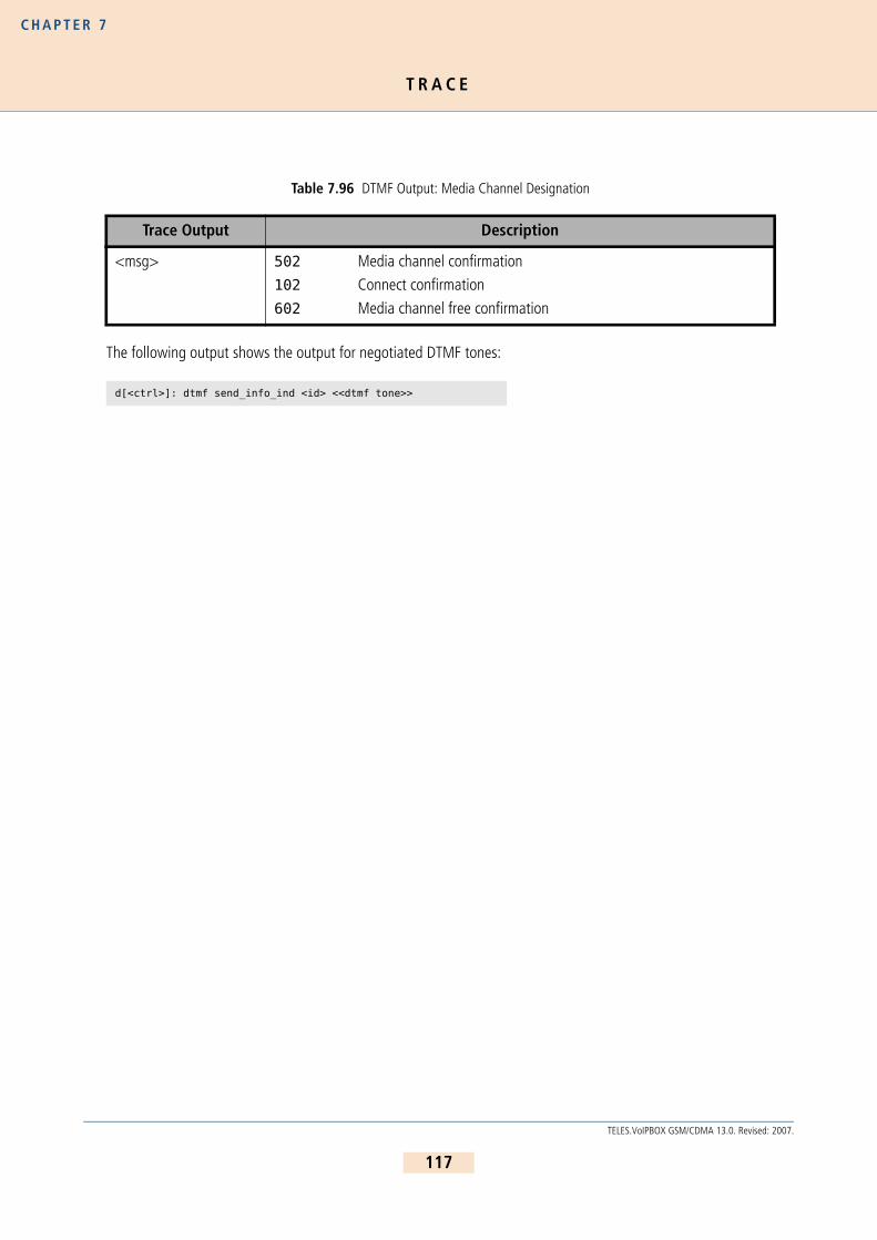
T R A C E
C H A P T E R 7
The following output shows the output for negotiated DTMF tones:
Table 7.96 DTMF Output: Media Channel Designation
Trace Output Description
<msg> 502 Media channel confirmation102 Connect confirmation
602 Media channel free confirmation
d[<ctrl>]: dtmf send_info_ind <id> <<dtmf tone>>
117
TELES.VoIPBOX GSM/CDMA 13.0. Revised: 2007.

D I G I T C O L L E C T I O N ( E N B L O C K / O V E R L A P R E C E I V I N G )
C H A P T E R 8
8 S I G N A L I N G A N D R O U T I N G F E A T U R E S
8 . 1 D I G I T C O L L E C T I O N ( E N B L O C K / O V E R L A P R E C E I V I N G )
This function makes it possible to collect digits and transmit calls when a specific number of digits has been dialed.The entire call number is required for the call to be set up with a mobile phone or the SIP gateway. Digit collectionoccurs through the following mapping command:
The example above shows a call with the prefix 01555. The | (pipe) signifies that the following digits will be col-lected before they are transmitted. The 16 at the end is the sum of the port digits, the digits of the called partynumber, and the optional VoIP profile, as (e.g. |#40iG:=5, 01555899666=11, 5+11=16). This figure must be en-tered in double digits (e.g. <<08 for 8 digits). The parameter DTMFWaitDial defines the amount of time thesystem waits between the individual digits. The system forwards the call to the VoIP profile as soon as the correctnumber of digits has been dialed. Please bear in mind that you can configure a maximum of 11 digits on the leftof the equal sign and 19 (including a #, which activates calling number suppression) on the right. The call will beforwarded as soon as the specified number of digits has been dialed or a time-out limit has been reached.
8 . 2 R E J E C T I N G D A T A C A L L S A N D S P E C I F I E D N U M B E R S
The following configuration enables you to reject calls with bearer capability data and calls that should not be di-rected to specified numbers. In both cases the cause value Switching Equipment Congestion (aa) is used:
8 . 3 C L I P A N D C L I R
8 . 3 . 1 R O U T I N G C L I P A N D C L I R C A L L S
This function allows you to route calls with Calling Line Identification Presentation (CLIP) differently from calls withCalling Line Identification Restriction (CLIR). For example, all CLIP calls can be rejected, so that only calls that donot present the calling number or calls without a calling party number (e.g. analog) are transmitted through theTELES.VoIPBOX GSM/CDMA.
...MapAll01555=|40iG:01555<<16...DTMFWaitDial=5...
... MapAll00491555=&aa DATA... MapAll004915551234=&aa VOICE
118
TELES.VoIPBOX GSM/CDMA 13.0. Revised: 2007.

C L I P A N D C L I R
C H A P T E R 8
Use the following configuration to define the various routing methods:
InsertCLIR=On activates this mode. 01 is the service indicator for telephony (analog and ISDN) and is used todifferentiate these calls from remote administration calls. Restrict9=OK 01 means that all telephony callswithout a calling number are put through. Restrict|9=OK 01 means that all CLIR telephony calls are putthrough. Restrict90=FAIL 01 means that all CLIP telephony calls are rejected with No Channel Availableas rejection cause when they are mapped to MapInFAIL=&aa.
8 . 3 . 2 R O U T I N G C A L L S W I T H O U T C L I R
This function enables you to bypass CLIR for calls through the defined mobile port. The following configuration inpabx.cfg activates this function:
8 . 3 . 3 S E T T I N G C L I R
Setting a hash (#) in front of a call number makes it possible to suppress the presentation of the origination numberof calls regardless of how the call comes into the system.
The following sytax is used: MapAll<num>=#<port><num>
Example: The following example shows an appropriate configuration. With this entry, all calls beginningwith 00491555 are sent to the port with the address 22 and the presentation of the number isrestricted:
8 . 3 . 4 S E T T I N G C L I P
Setting an exclamation point (!) in front of a call number makes it possible to force the presentation of the origi-nation number of calls regardless of how the call comes into the system.
...InsertCLIR=On...Restrict9=OK 01Restrict|9=OK 01Restrict90=FAIL 01...MapInOK00491555=2200491555MapInFAIL=&aa...
Subscriber<xx>=...GSM[...,!CLIR]...
When this function is configured, the SIM’s telephone number (and not originating telephone) is always transmitted to the B subscriber.
MapAll00491555=#2200491555
ii
119
TELES.VoIPBOX GSM/CDMA 13.0. Revised: 2007.

C O N V E R S I O N O F C A L L N U M B E R S
C H A P T E R 8
The following sytax is used: MapAll<num>=!<port><num>
Example: The following example shows an appropriate configuration. With this entry, all calls beginningwith 004930 are sent to the port with the address 9 and the presentation of the origination num-ber is allowed.:
8 . 4 C O N V E R S I O N O F C A L L N U M B E R S
The conversion of call numbers makes it possible, for example, to implement number portability or to redirect callswhen the user can be reached at another number. In the following mapping command, the call number015550123456 is changed to 015559876543 (MapAll...=9..):
Example 1
Example 2 presents an alternative, in which the routing file is searched through again after conversion of the callnumber to determine the route for the prefix 01555. Please bear in mind that you can configure a maximum of5000 mapping entries with no more than 11 digits in the first part of the command and 19 in the second.
Example 2
8 . 5 S E T T I N G N U M B E R TY P E I N O A D / D A D
In some cases it may be necessary to set a specific number type for the OAD or DAD. There are different methodsfor the various interfaces. The following number types can be set:
OAD
Use the following entry to set a specific number type in the OAD:
MapAll004930=!9004930
...MapAll015550123456=9015559876543
...MapAll015550123451=$ReceptionMapAll015550123452=$ReceptionMapAll015550123453=$ReceptionMapAllReception=015559876543
Table 8.97 Number Types
Type Definition
u Unknown
s Subscriber number
n National number
i International number
120
TELES.VoIPBOX GSM/CDMA 13.0. Revised: 2007.

S E T T I N G N U M B E R T Y P E I N O A D / D A D
C H A P T E R 8
Restrict<port><num>=<type> 15For the national and international types, remove the 0(s) at the beginning of the number:
Restrict<port>0=n 15Restrict<port>00=i 15Example: In the following example, the bit is set in the caller’s origination number for a call via analog con-
troller 01:
Example:
You can set a u (unknown type of number) in the Restrict entry to change transmission of the national/inter-national bit to 0 or 00 at the beginning of the OAD. As in a mapping entry, the national/international bit will alwaysappear left of the equal sign as 0 or 00.
Restrict<port>0=u0 15Restrict<port>00=u00 15In the following example, the area code 030 with a 0 at the beginning of the OAD of the PBX’s extension is set asa digit and transmitted along with the number:
DAD
Enter one of the four specific number types in the DAD as follows:
MapAll<num>=<port><type><num>In the case of a VoIP controller, enter the following:
MapAll<num>=<port><voip profile>:<type><num>The number type will then be defined at the port. For the national and international types, remove the 0(s) at thebeginning of the number:
Example: In the following example, the international bit is set for all calls to Italy (0039) and the numberis transmitted with 39. For the area code 012, the national bit is set and the number is trans-mitted with 12:
Restrict90=n 15Restrict900=i 15
Restrict10555=u030555 15
Restrict entries are handled from general to specific from top to bottom.
MapAll0039=40iG1:i39 VOICE MapAll012=40iG1:n12 VOICE
ii
121
TELES.VoIPBOX GSM/CDMA 13.0. Revised: 2007.

S E T T I N G T H E S C R E E N I N G I N D I C A T O R
C H A P T E R 8
8 . 6 S E T T I N G T H E S C R E E N I N G I N D I C A T O R
You can set the screening indicator to define whether the calling-party number sent is specified as userprovided verified and passed or network provided:
User provided verified and passed: v
Example: In the following Restrict example, the calling party number sent is specified as userprovided verified and passed:
Network provided: p
Example: In the following Restrict example, the calling party number sent is specified as networkprovided:
If you also want to define a number type (see Chapter 8.5 ), it must appear in front of the screening indicator:
Example: In the following Restrict example, the screening indicator is specified as networkprovided, and the number type is international:
8 . 7 S E T T I N G A D E F A U L T O A D
Use the Restrict command to set a default origination number (*<oad> 15) when the OAD is restricted(<num>):
Restrict<port><oad>=*<num> 15
Example: In the following example, 12345 replaces the original OAD. When the destination number beginswith 030, the call is sent through controller 10:
Use the entry Restrict<port><oad>=<num> 15 if digits at the beginning of the OAD are the only ones tobe restricted.
Example: In the following example, the digits 004930 are replaced with 030 followed by the remaining
Restrict10=v 15
Restrict10=p 15
Restrict10=ip 15
Please bear in mind that this entry will not work if you set a minus sign (-) behind VoipOad=<num>.
Restrict9=*12345 15MapAll030=10030
ii
122
TELES.VoIPBOX GSM/CDMA 13.0. Revised: 2007.

S E T T I N G S E N D I N G C O M P L E T E B Y T E I N S E T U P
C H A P T E R 8
digits. The destination number begins with 030 and is sent through port 10.
8 . 8 S E T T I N G S E N D I N G C O M P L E T E B Y T E I N S E T U P
In some cases the H323 peer system may require this byte for routing, or the byte may disrupt signaling.
Setting Sending Complete
The following entry ensures that the Setup includes a Sending Complete:
MapAll<direct>=)<num>The ) causes inclusion of Sending Complete in the H323 Setup.
Example: In the following example, all calls beginning with 0 are sent with a Setup Complete to controller9:
Removing Sending Complete
The following entry ensures that the Setup never includes a Sending Complete:
MapAll<direct>=(<num>The ( causes removal of Sending Complete in the ISDN Setup or in the H323 Setup.
Example: In the following example, all calls beginning with 0 are sent without a Setup Complete to VoIPcontroller 40. The VoIP profile is DF:
8 . 9 M I S C E L L A N E O U S R O U T I N G M E T H O D S
In the following scenarios it may occur that some call numbers must be routed with differing lengths or that somecall numbers may require additional number conversion:
Calls without a destination number
Connection to a PBX with an extension prefixRouting based on the length of the destination number
8 . 9 . 1 R O U T I N G C A L L S W I T H O U T A D E S T I N A T I O N N U M B E R
Enter the following configuration in the route.cfg if the TELES.VoIPBOX GSM/CDMA must route calls thatcome in without a destination number:
Restrict<port>=<pl>MapAll<pl><num>=<port><num>
Restrict9004930=030 15MapAll030=10030
MapAll0=)90
MapAll0=(40DF:0
123
TELES.VoIPBOX GSM/CDMA 13.0. Revised: 2007.

M I S C E L L A N E O U S R O U T I N G M E T H O D S
C H A P T E R 8
MapAll<pl>=<port>Incoming calls from the configured port will be assigned a placeholder and then all calls beginning with the place-holder will be routed to the placeholder’s placeholder’s mapping.
Example: In the following example, all calls from controller 9 are routed to controller 10, regardless ofwhether a destination number appears in the setup:
8 . 9 . 2 R O U T I N G C A L L S B A S E D O N E X I S T E N C E O F D E S T I N A T I O N N U M B E R
To route calls with a DAD differently from those with a DAD, you must activate the block feature in the pabx.cfgand restart the system:
Block=1Set all other parameters in the route.cfg. First define the port from which the incoming calls are to be routed.Incoming calls from the configured port will be assigned a placeholder and then digit collection will occur for allcalls beginning with the placeholder. The $ in the mapping entry, followed by the defined placeholder (MMM), caus-es a second search of the routing file when the number is complete:
DTMFWaitDial=<sec>Restrict<port>=<pl>MapAll<pl>=|$MMM<<98The second routing-file search is based on the routing entry with the leading placeholder (MMM):
MapAllMMM<digits>=<dest><digits>Example: In the following example, digit collection is activated for all calls that come into port 9. Calls with
the destination number 2222 are sent to the VoIP controller with the profile DF and the destina-tion number is replaced with the SIP account Betty. Calls with the num-ber 3333 are sent toVoIP with the SIP account Al. All other calls with a destination number are sent to controller 10.Calls without a destination number are sent to the number 12345 at port 10:
Restrict9=plMapAllpl=10
DTMFWaitDial=5Restrict9=plMapAllpl=|$MMM<<98MapAllMMM2222=40DF:BettyMapAllMMM3333=40DF:AlMapAllMMM0=100MapAllMMM1=101MapAllMMM2=102MapAllMMM3=103MapAllMMM4=104MapAllMMM5=105MapAllMMM6=106MapAllMMM7=107MapAllMMM8=108MapAllMMM9=109MapAllMMM=1012345
124
TELES.VoIPBOX GSM/CDMA 13.0. Revised: 2007.

M I S C E L L A N E O U S R O U T I N G M E T H O D S
C H A P T E R 8
8 . 9 . 3 C H A N G I N G C A U S E V A L U E S
It is possible to group cause values together into a single defined cause value so that rejected calls can be handledin a specified manner by the PBX sending the call to the TELES.VoIPBOX GSM/CDMA. The following cause valuegroups can be defined in the pabx.cfg:
Group 0 Cause Values
All connections that are rejected with a group 0 cause value (0x80-0x8f) can be mapped to a single cause valueby entering TranslateG0Cause=<cau>, whereby <cau> represents a cause value in hexadecimal form.
Group 1 Cause Values
All connections that are rejected with a group 1 cause value (0x90-0x9f) can be mapped to a single cause valueby entering TranslateG1Cause=<cau>, whereby <cau> represents a cause value in hexadecimal form.
Group 2 Cause Values
All connections that are rejected with a group 2 cause value (0xa0-0xaf) can be mapped to a single cause valueby entering TranslateG2Cause=<cau>, whereby <cau> represents a cause value in hexadecimal form.
Group 3 Cause Values
All connections that are rejected with a group 3 cause value (0xb0-0xbf) can be mapped to a single cause valueby entering TranslateG3Cause=<cau>, whereby <cau> represents a cause value in hexadecimal form.
Translating Individual Cause Values
The following parameter allows you to translate any of these cause values to any other one:Translate<cause>=<cause>. The values entered must be in hexadecimal notation between 00 and 7f.
Translating SIP Causes to ISDN and Vice Versa
You can define a specific translation from SIP responses (4xx - 6xx) to ISDN cause values and vice versa. If nothingis set, the translation occurs as described in draft-kotar-sipping-dss1-sip-iw-01.txt
Use the following parameter to translate a cause from ISDN to a specific SIP response:
SipCause<ISDN cause>=<SIP Response>Repeat the entry to initiate an additional translation.
Use the following paramter to translate a cause from SIP to ISDN:
SipEvent<SIP Response>=<ISDN Cause>The following range of values applies:
400<= <SIP Cause> <=699 (defined in RFC 3261)
0<= <ISDN Cause> <=127 (DSS1 decimal cause number)
125
TELES.VoIPBOX GSM/CDMA 13.0. Revised: 2007.
C A L L E R I D
C H A P T E R 8
8 . 1 0 C A L L E R I D
Caller ID (caller identification) is a feature that transmits the calling party number to the called party's telephonewhen it rings unless the calling party has restricted number transmission. Caller ID is generated on FXS ports ac-cording to the V.23 standard. Bear in mind that the called party must have a telephone or device that displays thecalling number in order for this feature to work.
The current firmware version supports the caller ID feature on FXS ports in the following cases:
Calls from VoIP to FXS using the SIP protocol
Calls from VoIP to FXS using the H.323 protocol
Calls from GSM to FXS
126
TELES.VoIPBOX GSM/CDMA 13.0. Revised: 2007.

C O N N E C T I O N T O A T E L E S . V G A T E
C H A P T E R 9
9 M O B I L E C O N F I G U R A T I O N O P T I O N S
9 . 1 C O N N E C T I O N T O A T E L E S . V G A T E
The TELES.vGATE is a system that enables more convenient management of a network of TELES.VoIPBOX GSM/CDMA systems. All SIM cards in the network are installed in and maintained at a central server, so that it is nolonger necessary to install SIM cards into each gateway. The TELES.VoIPBOX GSM/CDMAs connected to theTELES.vGATE do not require SIM-card carriers, as the TELES.vGATE contains SIM-card carriers for the entire net-work.
The following parameters must be configured in the pabx.cfg of each TELES.VoIPBOX GSM/CDMA connectedto the TELES.vGATE. After the parameters have been entered, you must restart the TELES.VoIPBOX GSM/CDMA toactivate the changes:
9 . 2 M O D U L E D I S T R I B U T I O N O F V A R I O U S M O B I L E N E T W O R K S
You can assign each mobile port in the TELES.VoIPBOX GSM/CDMA system either one mobile network or differentaccess groups to different mobile networks. The port numbers in the TELES.VoIPBOX GSM/CDMA must be thesame for the individual groups.
The keyword NEXT ensures equal distribution of calls.
The following configuration samples (from the pabx.cfg configuration file) show the changes:
Be sure to save a backup copy of the configuration files before making changes. Changing configuration data and/or SIM-card positions may lead to malfunctions and/or misrouting, as well as possible consequential damages. Make changes at your own risk. TELES is not liable for any damages resulting from or related to such chang-es. Therefore, please thoroughly check any configuration changes you or a third party have made.
Bear in mind that no SIM-card carriers are to be inserted in TELES.VoIPBOX GSM/CD-MAs connected to a TELES.vGATE.
SIMS
Enter this keyword in the Subscriber lines of the mobile controllers to connect the system to a TELES.vGATE.
EXAMPLE: Subscriber04=TRANSPARENT ROUTER GSM[0000,00000,+00000,1,1,1,SIMS] CHADDR ALARM
SimCtrlUnitAddress=<ip addr>Enter the TELES.vGATE Control Unit’s IP address. Set this parameter in the IP configuration section.
EXAMPLE:SimCtrlUnitAddress=192.168.0.1
!!
ii
127
TELES.VoIPBOX GSM/CDMA 13.0. Revised: 2007.

N E T W O R K - S P E C I F I C M O B I L E R O U T I N G
C H A P T E R 9
Example 1 All ports in the following example must have the same number for all mobile channels to routecalls to the same mobile network. The subscriber line of the first port must also contain thekeyword NEXT to ensure the equal distribution of calls.
Example 2 In the following example, a group of 4 mobile channels is assigned to two different mobile net-works. The subscriber line of the first port in each group must contain the keyword NEXTto ensure the equal distribution of calls.
9 . 3 N E T W O R K - S P E C I F I C M O B I L E R O U T I N G
9 . 3 . 1 U S I N G A F I X E D M O B I L E P O R T A D D R E S S
The customer’s network routes calls to the mobile network with a defined prefix. Because this code is not alwaysuniform, the TELES.VoIPBOX GSM/CDMA might have to convert it. Conversion requires the following information:
The mobile network’s access number
Destination number format (with or without prefixes, national or international)conversion occurs according to the following formula:
converted as:
Be sure to make the following entry in the pabx.cfg configuration file to configure this conversion:
The TELES.VoIPBOX GSM/CDMA system converts national into one zero and international into two zeros.
...Controller04=20 GSMController05=20 GSMController06=20 GSMController07=20 GSM...Subscriber04=TRANSPARENT ROUTER GSM[0000,00000,<SMSC>,1,1,1,SIM4] ALARM NEXTSubscriber05=TRANSPARENT ROUTER GSM[0000,00000,<SMSC>,1,1,1,SIM4] ALARMSubscriber06=TRANSPARENT ROUTER GSM[0000,00000,<SMSC>,1,1,1,SIM4] ALARMSubscriber07=TRANSPARENT ROUTER GSM[0000,00000,<SMSC>,1,1,1,SIM4] ALARM...
...Controller04=20 GSMController05=20 GSMController06=22 GSMController07=22 GSM...Subscriber04=TRANSPARENT ROUTER GSM[0000,00000,<SMSC>,1,1,1,SIM4] ALARM NEXTSubscriber05=TRANSPARENT ROUTER GSM[0000,00000,<SMSC>,1,1,1,SIM4] ALARMSubscriber06=TRANSPARENT ROUTER GSM[0000,00000,<SMSC>,1,1,1,SIM4] ALARM NEXTSubscriber07=TRANSPARENT ROUTER GSM[0000,00000,<SMSC>,1,1,1,SIM4] ALARM...
<national/international><prefix[incoming]>=<destination number>
<port><mobile network access number><destination number>
MapAll<nat./int.>prefix[incoming]>=<port><mobile network access number>
128
TELES.VoIPBOX GSM/CDMA 13.0. Revised: 2007.

N E T W O R K - S P E C I F I C M O B I L E R O U T I N G
C H A P T E R 9
The following configuration exemplifies this conversion as it might occur in Germany:
This example shows how the customer’s network provides the prefixinternational+49+1555+destination number for one mobile network, andinternational+49+1556 for the other. The configuration entries see to it that00491555+destination number is converted to 2001555+destination number and00491556+destination number is converted to 2101556+destination number. The calls to thecarrier with prefix 01555 are routed to ports with the number 20 and calls to the carrier with prefix 01556 arerouted to the ports with the number 21.
9 . 3 . 2 U S I N G T H E L A I N A S T H E M O B I L E P O R T A D D R E S S
Use the LAIN as controller with the CHADDR parameter to prevent logging onto the wrong SIM card. This will en-sure that routing is network specific. The following example is based on the German country code. One carrier’sLAIN is 26212 and the other carrier’s LAIN is 26213:
pabx.cfg
...MapAll00491555=2001555MapAll00491556=2101556...
...Controller04=20 GSMController05=20 GSMController06=20 GSMController07=20 GSM...Subscriber04=TRANSPARENT ROUTER GSM[0000,00000,+49555,1,1,1,SIM4] CHADDR ALARMSubscriber05=TRANSPARENT ROUTER GSM[0000,00000,+49555,1,1,1,SIM4] CHADDR ALARMSubscriber06=TRANSPARENT ROUTER GSM[0000,00000,+49555,1,1,1,SIM4] CHADDR ALARMSubscriber07=TRANSPARENT ROUTER GSM[0000,00000,+49555,1,1,1,SIM4] CHADDR ALARM...
If you remove the keyword CHADDR from the pabx.cfg, you must restart the system. Controllers belonging to the same trunk group must have the same address. You must delete all routing entries based on port addresses when using the LAIN as con-troller.
ii
129
TELES.VoIPBOX GSM/CDMA 13.0. Revised: 2007.

I N C O M I N G V O I C E C A L L S F R O M M O B I L E
C H A P T E R 9
route.cfg
9 . 3 . 3 F I X E D L A I N F O R A M O B I L E P O R T
Enter CHADDR[<addr>] to remove a mobile controller belonging to an LAIN group from the standard routingprocess (e.g. for specific routes or only for SMS transmission). The port address can be set to <addr>.
Example:
9 . 4 I N C O M I N G V O I C E C A L L S F R O M M O B I L E
Incoming mobile calls (service indicator 01 represents voice calls) can be routed to a specified number. This enableseach mobile controller to receive a unique identifier. It will then be mapped to an FXS port:
The mobile controllers can also have the same identifier, so that all voice calls (service indicator 01) from controller20 are sent to port 30. This number could, for example, serve a call center.
9 . 5 B L O C K I N G P O R T S
This function allows you to block a port, so that the corresponding mobile channel is omitted from the distributionof calls. The function is particularly useful when mobile channels fail or SIM cards cannot be immediately replaced.
To block a port (i.e. a mobile channel), enter the keyword CHINC[...] in the Subscriber line.
In Example 1, port 04 is blocked.
Example 1
To activate the port, remove the entry and enter Activate configuration.
...MapAll01555=2621201555...MapAll01556=2621301556...
Subscriber05=TRANSPARENT ROUTER GSM[0000,00000,+49555,1,1,1,SIM4] CHADDR[444] ALARM
MapAllSMS=444 05
Restrict20=30 01Restrict21=31 01
Restrict20=30 01
...Subscriber04=TRANSPARENT ROUTER GSM[0000,00000,<SMSC>,1,1,1,SIM4] CHADDR ALARM CHINC[01,01]...
130
TELES.VoIPBOX GSM/CDMA 13.0. Revised: 2007.

S E T T I N G L I M I T S
C H A P T E R 9
It is also possible to block an entire port with the remote administration program TELES.GATE Manager. TheCHINC[...] function is not necessary with this application. The port’s status is displayed by remote administra-tion. You can remove the block with Activate a configuration or with the Unblock option.
9 . 6 S E T T I N G L I M I T S
This function enables you to monitor time limits. A limit can be set, either to the defined time interval or in 10-second intervals (default value). When this value is reached, the current connection is torn down either immediatelyor when the call has been terminated; no more connections will be set up. An alarm also goes off and an entry isgenerated in the log file.
Setting SIM Time Limits
In the following example, the mobile channel shuts down when 6,000 intervals of 10 seconds each have passed:
Setting the Default Time Window
In the following example, the mobile channel shuts down when a calculated number of seconds has been reached.If ChargeUnitGenerate=<sec> is configured, the mobile channel will shut down when the value entered inLIMIT multiplied by the value entered here is reached. The default value for this parameter is 10 seconds. Bearin mind that the value entered in LIMIT may not exceed 65535. In the example, the mobile channel will shutdown at 60,000 seconds.
Setting Start Units
The following example shows how you can use the keyword ChargeUnitFirst=<seconds> to configure astarting unit for LIMIT. The following entries are used for SIM card tariffs where the first defined number of sec-onds are always charged (e.g. the first minute), followed by charges calculated in defined intervals (e.g. every 10seconds):
Information about the active SIM cards can be found in TELES.GATE Manager and Port Status.
...Subscriber04=TRANSPARENT ROUTER GSM[0000,00000,<SMSC>,1,1,1,SIM4] CHADDR ALARM NEXT LIMIT[6000]...
...ChargeUnitGenerate=1...Subscriber04=TRANSPARENT ROUTER GSM[0000,00000,<SMSC>,1,1,1,SIM4] CHADDR ALARM NEXT LIMIT[60000]...
...ChargeUnitFirst=60ChargeUnitGenerate=10...Subscriber04=TRANSPARENT ROUTER GSM[0000,00000,<SMSC>,1,1,1,SIM24] LIMIT[6000] ALARM NEXT......
131
TELES.VoIPBOX GSM/CDMA 13.0. Revised: 2007.

D E F I N I N G T I M E L I M I T S F O R C A L L S
C H A P T E R 9
To remove limits from the configuration, follow these steps:
Enter LIMIT[-].
Activate the configuration.
Delete the entry LIMIT[-].Activate the configuration again.
9 . 6 . 1 C O U N T S T A T U S I N F O R M A T I O N
To find information about the current counts and limits for each mobile channel, click Statistics in the TELES.GATEManager.
For mobile ports:
Count A-F For each mobile channel. Bear in mind that only one SIM card per channel is possible (CountA). Counts are the time slices (from 0 to the limit value) for the individual SIM cards. When a SIM’s settime limit is reached, the channel will disconnect and the SIM will be blocked.
Click Reset/Set Counters in the Statistics context menu in TELES.GATE Manager to reset the counters(default value is 0). You can also configure the counters to reset automatically (see Chapter 11.1 ).
9 . 7 D E F I N I N G T I M E L I M I T S F O R C A L L S
By entering the parameter CALL in the Subscriber line, you can terminate calls that reach a defined time limit. Foreach call the limit is reset at 0. You can define a value anywhere within <limit>-<random>, and you can de-fine a maximum value for <random>.
If this parameter is configured once, it will be set in each configuration file. If you prefer not to use it for all SIMs,set the limit higher than any call is likely to last (e.g. 360,000 seconds).
Example:
The following entry is required if the TELES.VoIPBOX GSM/CDMA is used in conjunction with a TELES.vGATE:
If LIMIT is configured, bear in mind that SIM 1 must be configured in the pabx.cfg for the corresponding mobile port.
ChargeUnitGenerate=1;defines the factor for the limit entry (600*1=600sec)ChargeUnitDivisor=5 ;random value that defines the maximum call duration between 595 and 600secs...Subscriber05=TRANSPARENT ROUTER GSM[0000,00000,+000000,1,1,1,SIM24] CALL[600]
Subscriber05=TRANSPARENT ROUTER GSM[0000,00000,+000000,1,1,1,SIMS] CALL[600]
ii
132
TELES.VoIPBOX GSM/CDMA 13.0. Revised: 2007.

P A U S E B E T W E E N T W O C A L L S
C H A P T E R 9
9 . 8 P A U S E B E T W E E N TW O C A L L S
If the parameter WAIT appears in the Subscriber line, the mobile controller will not be used after a successfulconnection for a random amount of time between 1 and 30 seconds
Example:
9 . 9 T I M E - C O N T R O L L E D S I M L O G O F F
You can define a time at which a mobile channel will log off. Before proceeding, please refer to Chapter 5.2.1.2for basic information.
You must define all time windows you would like to use in the [System] section of the pabx.cfg, in the sub-section night configuration.
The following entry in the configuration file pabx.cfg is necessary:
Night<num>=<time> <day>
Example: In the following example, two time windows are defined. The standard configuration is activeevery day from 6:00 a.m. to 8:00 p.m.. The time window Night1 is active from 8:00 p.m. to6:00 a.m.
To generate a NightConfiguration section for SIM logoff, copy the complete Subscriber subsectionfrom the [System] section after making the appropriate entries in the [Nightx] section.
If a dash (-) is entered in the SIM-card position, the SIM card will log off automatically. Time-controlled activationof configuration files makes it possible to shut off unneeded SIMs, for example at night.
Example: In the following example, SIM cards log off in the section [Night1]. All Subscriber linesmust be defined.
The only difference is in the active SIM card. Activate the configuration after the required files have been copiedonto the system.
Subscriber04=TRANSPARENT ROUTER GSM[0000,00000,+00000,1,1,1,SIM24,IMSI] CHADDR WAIT ALARM
;Night configuration; ---------------------Night1=20:00 11111111NightResetTime=06:00 11111111
[System]...Subscriber04=TRANSPARENT ROUTER GSM[0000,00000,+49555,1,1,1,SIM4] ALARMSubscriber05=TRANSPARENT ROUTER GSM[0000,00000,+49555,1,1,1,SIM4] ALARMSubscriber06=TRANSPARENT ROUTER GSM[0000,00000,+49555,1,1,1,SIM4] ALARMSubscriber07=TRANSPARENT ROUTER GSM[0000,00000,+49555,1,1,1,SIM4] ALARM... [Night1] ... Subscriber04=TRANSPARENT ROUTER GSM[0000,00000,+49555,-,1,1,SIM4] ALARMSubscriber05=TRANSPARENT ROUTER GSM[0000,00000,+49555,-,1,1,SIM4] ALARMSubscriber06=TRANSPARENT ROUTER GSM[0000,00000,+49555,-,1,1,SIM4] ALARMSubscriber07=TRANSPARENT ROUTER GSM[0000,00000,+49555,-,1,1,SIM4] ALARM...
133
TELES.VoIPBOX GSM/CDMA 13.0. Revised: 2007.

M O B I L E - U S E R P B X C A L L B A C K
C H A P T E R 9
Bear in mind, that you must also make the appropriate entries in the corresponding route.cfg sections. Formore information, please refer to Chapter 5.3 .
9 . 1 0 M O B I L E - U S E R P B X C A L L B A C K
When the TELES.VoIPBOX GSM/CDMA is implemented in a corporate network and connected to a PBX or betweena PBX and the outside line, the following configuration entry activates a feature, that uses a mobile caller’s OADto connect with the last PBX extension the caller unsuccessfully dialed:
DialBack=<hours>
The callback list is active for the number of hours entered.
Example: In the following example, the callback list is active for the previous five hours. The German coun-try code is used for the LAINs. All calls with the prefixes 1111 and 2222 are terminated throughthe carrier with the LAIN 26212. Calls with the prefix 3333 are terminated through the carrierwith the LAIN 26213:
9 . 1 1 O P T I O N A L M O B I L E Q U A L I T Y P A R A M E T E R S
The following table describes specific signaling and quality parameters for configuration of the mobile interface.
Callback is not possible for VoIP calls.
DialBack=5
MapAll1111=262121111MapAll2222=262122222MapAll3333=262133333
Make sure that no Restrict entries are configured for these mobile controllers.
Table 9.98 Optional Mobile Parameters
GSM=...
Enter any of the following parameters after the equal sign for the following functions. Entries may appear in any order, but all entries must appear in the same line and in double-digit notation as follows:GSM=RSSI[10] STOP[18,08] ANNOUNCE[00,08] FAX[a2] ASR[20,35]
ALERT[<sec>] Set this parameter to generate alert signal in the D channel immediately after dial-end signal. If you enter optional square brackets containing a number of seconds, the alert signal will occur when the number entered has passed.
ii
ii
134
TELES.VoIPBOX GSM/CDMA 13.0. Revised: 2007.

O P T I O N A L M O B I L E Q U A L I T Y P A R A M E T E R S
C H A P T E R 9
ANNOUNCE Set this parameter to define what happens when a recorded announcement is recog-nized:
No ANNOUNCE entry (default)
A D-channel PROGRESS message stating Inband Information Available will be generated
ANNOUNCE[<cause>]The connection will be rejected with the defined ISDN cause value.ANNOUNCE[00,<sec>]A timeout for voice recognition is defined in seconds (default value: 120 seconds). After the interval entered has passed, the connection is torn down.
ASR[<limit>,<calls>]
Allows you to change the default value (40 calls at 30% ASR). For a definition of ASR, see Chapter 11.1 .
FAX[<cause>] This entry allows you to reject fax calls with the defined cause value.
RSSI[<limit>] Configure this parameter to set a limit for the reception field strength. When the re-ception field strength falls below this limit, the mobile channel will be blocked. If the field strength is above the limit, the mobile channel will log on with the mobile carrier again. The values used are 0 to 31, which represent the following field strengths: -113dBm to -51 dBm. An error is generated in the protocol log. The result must be divided by 2.
EXAMPLE: To define a field strength of -95 dBm, subtract -95 from-113 and divide the result by 2:
- 113dB - (-95dB) = -18dB / 2 = 9
Enter RSSI[9]
STOP[<val1>,<val2>]
This entry allows you to define a maximum number of connection setups that always result in a recorded message (<val1>) without a call-connected signal or successful connection setup, or that are always accepted (<val2>). The mobile port is blocked when the defined value is reached and an entry is recorded in the log file (...Err: Voice). In this way inactive SIM cards that are forwarded to a recording (with or without a connect from the mobile carrier) can be recognized and blocked so that they are removed from the routing process. The default status of this function is off.
VOICE[1] The B-channel is immediately connected (Siemens dial tone is heard).
NOCP When this option is configured and the call is from ISDN to GSM, the Call Proceeding signaling message will be eliminated from signaling. This may be necessary if the ISDN peer does not support Call Proceeding. Bear in mind that the peer’s Setup Ack Timer is usually set at 5 seconds, which means that an Alert must be generated as follows: GSM=ALERT[5]
Table 9.98 Optional Mobile Parameters (continued)
GSM=...
135
TELES.VoIPBOX GSM/CDMA 13.0. Revised: 2007.
D E A C T I V A T I N G C L A S S 2 R E - R O U T I N G
C H A P T E R 9
9 . 1 2 D E A C T I V A T I N G C L A S S 2 R E - R O U T I N G
Configuring Class2Next=Off in the pabx.cfg file ensures that calls rejected with a class 2 cause value arenot re-routed to the next available port.
9 . 1 3 C H E C K I N G P O R T S / M O B I L E C H A N N E L S
Monitoring ASR for Mobile Ports
ASR monitoring of the last 40 calls occurs for all mobile ports. If the ASR (ASR2) is lower than 30 percent, an alarmis generated at the corresponding port and the port is blocked. The port is then restarted and a corresponding entryappears in the protocol.log file (ASR). The port is then unblocked.
The following entry in the pabx.cfg causes the mobile port to block automatically when this error occurs threetimes in a row:
ASRBlock=On
When ASRBlock=Off is used, the port will be restarted and will remain open.
The following parameter in the pabx.cfg file allows you to change the default value (30% for 40 calls): GSM=ASR[<percent>,<number of calls>]
9 . 1 4 R E C H A R G I N G P R E P A I D S I M S
Prepaid SIM cards are an alternative to mobile telephone SIMs with a contract. Instead of being billed retroactively,prepaid SIMs are paid for in advance and then recharged when they run out.
The advantages of prepaid SIMs are:
No monthly basic fee
Cost controlNo surprises resulting from unexpectedly high mobile telephone bills
When the account is empty, it can be recharged. The recharging methods for prepaid SIM cards of different carriersvary:
Recharging via SMS/USSD
Recharging via call to a defined number
Recharging via DTMFAutomatic recharging via direct debit
GSM=ASR[20,35]
136
TELES.VoIPBOX GSM/CDMA 13.0. Revised: 2007.

R E C H A R G I N G P R E P A I D S I M S
C H A P T E R 9
When prepaid SIMs that do not recharge automatically (e.g. through a credit card) are used in aTELES.VoIPBOX GSM/CDMA, it is possible to recharge them directly from the system. The following requirementsapply:
The SIM is registered and no connection is active.
Exact knowledge of the mobile carrier-specific recharging procedure exists.
One valid prepaid voucher exists for one recharge.
TELES.VoIPBOX GSM/CDMAs support of the following procedures:
USSD message to the mobile carrier's account managerThe TELES.GATE Manager sends the configured USSD message through the TELES.VoIPBOX GSM/CDMAto the account manager. USSD recharging is the recommended and most reliable procedure, as it consistsof a digital message. Unfortunately, only a few mobile carriers currently support USSD recharging. Pleaseask your mobile carrier if he supports USSD recharging.
SMS message to the mobile carrier's account managerThe TELES.GATE Manager sends the configured SMS containing the voucher number through theTELES.VoIPBOX GSM/CDMA to the account manager. Unfortunately, only a few mobile carriers currentlysupport SMS recharging. Please ask your mobile carrier if he supports SMS recharging.Connection setup to the account manager with subsequent menu selection and DTMF-tone transmissionof the voucher number– Direct recharging: Connection setup from a telephone through the TELES.VoIPBOX GSM/CDMA to the
account manager and manual DTMF-tone transmission.– Indirect recharging using the TELES.GATE Manager: The TELES.GATE Manager sets up a connections
through the TELES.VoIPBOX GSM/CDMA to the account manager and sends the configured DTMFtones automatically.
9 . 1 4 . 1 R E C H A R G E P R E P A R A T I O N
9 . 1 4 . 1 . 1 C H E C K I N G T H E A C T I V E S I M
To avoid recharging the wrong SIM card, be sure to check the mobile controller's active SIM using the TELES.GATEManager:
Transmission errors, truncated connections, incorrect or altered recharging proce-dures can prevent successful recharging. Please bear in mind that 3 incorrect re-charge attempts (per SIM) can result in blocked SIMs. Recharge SIMs at your own risk. TELES is not liable for any possible loss.
Direct recharging is the simplest procedure. Since a direct connection exists, it is pos-sible to react to commands and error messages immediately. Indirect recharging by means of USSD is the most reliable and quickest way to recharge SIMs if the config-uration in the TELES.GATE Manager and TELES.VoIPBOX GSM/CDMA is correct.
!!
ii
137
TELES.VoIPBOX GSM/CDMA 13.0. Revised: 2007.

R E C H A R G I N G P R E P A I D S I M S
C H A P T E R 9
TELES.GATE Manager
Figure 9.10 TELES.GATE Manager Port Status
Connect to the system and go to the Port Status window. The active position in the SIM-card carrier is displayedin the SIM # column. The mobile controller's active SIM is displayed in the IMSI column.
9 . 1 4 . 1 . 2 A D D R E S S I N G S I M S U S I N G P O R T - A N D C O N T R O L L E R- S P E C I F I C R O U T I N G
SIM recharging for a specific mobile controller requires configuration and activation of port- and controller-specificrouting entries in the route.cfg or pabx.cfg configuration file. Usually SIM cards are assigned to a carrier's trunkgroup and all calls through the carrier's network are evenly divided between the mobile controllers in the group.This would also apply to recharge calls.
The routing entry defined here sets up a connection to the network:
MapAll<in>=<port>*<ctrl>01:<num>
When the number <in> is dialed, a connection to <num> is set up through <port>*<ctrl>01: You can nowmanually enter DTMF tones using a telephone.
To recharge all SIMs in the TELES.VoIPBOX GSM/CDMA, configure the following mapping, whereby 4400 is an ex-ample for a number that matches the first controller and 12345 is the number for the account manager:
MapAll4400=20*0001:12345 MapAll4401=20*0101:12345 MapAll4402=20*0201:12345 MapAll4403=20*0301:12345 MapAll4404=20*0401:12345
138
TELES.VoIPBOX GSM/CDMA 13.0. Revised: 2007.

R E C H A R G I N G P R E P A I D S I M S
C H A P T E R 9
9 . 1 4 . 1 . 3 B L O C K I N G T H E P O R T C O N T A I N I N G T H E R E C H A R G I N G S I M
If a call is active on the mobile port containing the SIM to be recharged, the recharging process will not occur. Forthis reason it is better to block the port before recharging the SIM. In the Connections window, you must checkthe status No Connection on the mobile port. Block Port does not tear down a connection, it only prevents a newconnection from being set up.
9 . 1 4 . 2 R E C H A R G I N G P R O C E D U R E
9 . 1 4 . 2 . 1 D I R E C T R E C H A R G I N G V I A C A L L
This is the easiest method when it is possible to set up a telephone connection to the TELES.VoIPBOX GSM/CDMAsystem via PSTN or VoIP. This call can be connected with the carrier's account manager over a defined mobile con-troller. This means the call is set up over the controller's active SIM. Then you simply follow the account manager'srecharge instructions. After the SIM has been successfully recharged, it can be used again for a certain amount oftime.
The call can be set up using a number of methods. This is also possible if there are not enough available telephonenumbers to handle all of the system's available mobile controllers.
DLA via DTMFThe user calls a defined number in the system. The called number is connected with the DTMF platform.The digits that are transmitted via DTMF match those in the routing entries. When the connection to theaccount manager has been established, both legs will be connected (See Chapter 9.14.1.2 ).
TELES.GATE Manager (described in Chapter 9.14.2.2 below)
That means no BRI connection is necessary for a telephone that is connected directly to the system!
9 . 1 4 . 2 . 2 I N D I R E C T R E C H A R G I N G V I A T E L E S . G A T E M A N A G E R
This chapter describes automatic recharging of prepaid SIMs using the TELES.GATE Manager. It is not necessary toset up a telephone connection to the TELES.VoIPBOX GSM/CDMA. The TELES.GATE Manager can set up its ownconnection to the carrier's account manager and send the pattern of DTMF tones or a USSD message.
Recharging via Call and Transmission of Preconfigured DTMF Tones
This procedure requires exact knowledge of the when and what information the mobile carrier requests. The cor-responding pauses following the connect, for menu selection, between the DTMF tones, for correct repetition ofthe DTMF tones must be correctly configured in the TELES.GATE Manager before the call is set up.
This DTMF-tone pattern can be established by testing the recharging process on a mobile phone or by followingthe directions in Chapter 2.1 and noting the pauses and transmitted digits.
Port- and controller-specific routing has a higher priority than the Block Port com-mand. This ensures that normal calls are blocked, but recharge calls can be sent through the defined mobile port.
ii
139
TELES.VoIPBOX GSM/CDMA 13.0. Revised: 2007.

R E C H A R G I N G P R E P A I D S I M S
C H A P T E R 9
After a connection has been set up between the TELES.VoIPBOX GSM/CDMA and the TELES.GATE Manager, selectCommands | Send Call. The window must contain either General, Version or Directory.
Send Call opens a dialog to initiate calls or recharge SIMs.
To recharge SIMs, the 1st Number (e.g. 12345) is the mapping to the prepaid platform through a defined con-troller (e.g. MapAll12345=20*0101:12345).
Optional: You can set up a second connection to hear the announcement from the prepaid platform if you enteryour own number into the box 2nd Number. Both connections will be torn down when the second number dis-connects. If no number is entered in this box, the call will disconnect when the last DTMF tone has been transmittedor when the last pause interval has passed.
Activate the checkbox Advanced to open the DTMF box
Enter a series of DTMF tones in the DTMF box. Enter a p for a pause of 1 second and a P for a pause of 10 seconds.
Example: The number for the prepaid platform's account man-ager is 12345. The telephone number to listen alongto the accounting procedure is 5554321, set upthrough controller 9 (no special routing configura-tion is defined in the configuration files). Leave thisdialog box empty if the accounting process is not tobe monitored.The voucher key is: 55555555555 (a short pause canalso be defined between individual digits: for exam-ple, 5p5p5p5p5p5p5p5p5p5p5).To get to the voucher key query, the following pat-tern must be transmitted: P2ppppp1ppp. Followingtransmission of the voucher key and a 10-secondpause, the call will be torn down.
Recharging via USSD Code (Unstructured Supplementary Services Data)
Recharging prepaid SIMs using the TELES.GATE Manager and USSD is the most convenient solution if the prepaidcarrier offers this service. The USSD messages contains the prepaid voucher number.
Configure an additional controller in the last position for DTMF functionality as follows:
Example:
Bear in mind that DTMF tones are only generated with connections into the mobile network. Test calls over the PRI, BRI or VoIP interfaces do not transmit DTMF tones and no tones can be heard!
Controller36=41DTMF
Figure 9.11 Recharging with DTMF Tones
ii
140
TELES.VoIPBOX GSM/CDMA 13.0. Revised: 2007.
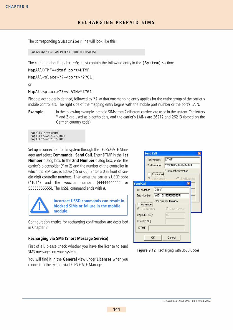
R E C H A R G I N G P R E P A I D S I M S
C H A P T E R 9
The corresponding Subscriber line will look like this:
The configuration file pabx.cfg must contain the following entry in the [System] section:
MapAllDTMF=<dtmf port>DTMF
MapAll<place>??=<port>*??01:
or
MapAll<place>??=<LAIN>*??01:
First a placeholder is defined, followed by ?? so that one mapping entry applies for the entire group of the carrier'smobile controllers. The right side of the mapping entry begins with the mobile port number or the port's LAIN.
Example: In the following example, prepaid SIMs from 2 different carriers are used in the system. The lettersY and Z are used as placeholders, and the carrier's LAINs are 26212 and 26213 (based on theGerman country code):
Set up a connection to the system through the TELES.GATE Man-ager and select Commands | Send Call. Enter DTMF in the 1stNumber dialog box. In the 2nd Number dialog box, enter thecarrier's placeholder (Y or Z) and the number of the controller inwhich the SIM card is active (15 or 05). Enter a 0 in front of sin-gle-digit controller numbers. Then enter the carrier's USSD code(*101*) and the voucher number (44444444444 or55555555555). The USSD command ends with #.
Configuration entries for recharging confirmation are describedin Chapter 3.
Recharging via SMS (Short Message Service)
First of all, please check whether you have the license to sendSMS messages on your system.
You will find it in the General view under Licenses when youconnect to the system via TELES.GATE Manager.
Subscriber36=TRANSPARENT ROUTER CHMAX[5]
MapAllDTMF=41DTMFMapAllY??=26212*??01:MapAllZ??=26213*??01:
Incorrect USSD commands can result in blocked SIMs or failure in the mobile module!
Figure 9.12 Recharging with USSD Codes
!!
141
TELES.VoIPBOX GSM/CDMA 13.0. Revised: 2007.

R E C H A R G I N G P R E P A I D S I M S
C H A P T E R 9
Figure 9.13 TELES.GATE Manager General View
The name for the license is SMS. This entry is required to send SMS.
You must configure the mail service in the [Mail] section of the file pabx.cfg if you want to send the SMSmessages with an e-mail client through a mail server or directly to the TELES.VoIPBOX GSM/CDMA:
[Mail]
SmtpServer=<server addr>
MailRcpt=<domain>
MailFrom=<own address or name>
The third entry in the mobile controller's Subscriber line is the SMS center number:
German example:
You must restart the system to activate the changes.
This entry is not necessary when using only the GateManager's Send SMS command.
Subscriber00=TRANSPARENT ROUTER GSM[0000,00000,+00000,1,1,1,SIMS,IMSI] CHADDR ALARM
Subscriber00=TRANSPARENT ROUTER GSM[0000,00000,+491721111,1,1,1,SIMS,IMSI] CHADDR ALARM
ii
142
TELES.VoIPBOX GSM/CDMA 13.0. Revised: 2007.

R E C H A R G I N G P R E P A I D S I M S
C H A P T E R 9
Then enter the port-specific SMS settings:
MapAllSMS<shortnumber>=LAIN*0001:<number>
MapAllSMS<shortnumber>=port*0001:<number>
Example: In the following German example with LAIN numbers, the short number 00 is routed to the firstcontroller. The number 12345 is sent to the SMS center.
If the SMS is sent with a normal e-mail client, the keyword SMS will appear in the To dialog box, followed by theshort number, which indicates the mobile controller. An @ sign and the TELES.VoIPBOX GSM/CDMA's IP addressor name if the system is attached to a DNS server will follow. The message box contains the recharge code in thecarrier's syntax.
SMS00@<ipaddr>
SMS00@<domain>
If the SMS is used with the Send SMS command in theTELES.GATE Manager's Commands menu, use only the shortnumber and not the keyword SMS.
To save the recharge platform's confirmation e-mail, the e-mailcan be sent to an account using the following entry in theroute.cfg:
Restrict<port>=@<addressee> 05
It can also be saved into a file using the following entry in thepabx.cfg:
MsgLog=/data/msg.log
To save it into a file, the following entry in the route.cfg isalso required:
Restrict<port>=@FILE 05
Example: In the following example for saving the SMS into a file, all incoming SMS to LAIN 26212 is savedinto the file msg.log:
If the e-mail is sent to an account, the routing entry will look like this:
Use the following entries in the pabx.cfg to connect the TELES.VoIPBOX GSM/CDMA to an e-mail server:
MapAllSMS00=26212*0001:12345MapAllSMS01=26212*0101:12345MapAllSMS02=26212*0201:12345MapAllSMS03=26212*0301:12345MapAllSMS04=26212*0401:12345MapAllSMS05=26212*0501:12345MapAllSMS06=26212*0601:12345……
Restrict26212=@FILE 05
Restrict26212=@nase 05
Figure 9.14 Send SMS
143
TELES.VoIPBOX GSM/CDMA 13.0. Revised: 2007.

R E C H A R G I N G P R E P A I D S I M S
C H A P T E R 9
[Mail]
SmtpServer=<server address>
MailRcpt=<domain>
MailFrom=<own address or name>
9 . 1 4 . 3 P R E P A I D A C C O U N T S T A T U S Q U E R Y
After a SIM card has successfully been recharged, you can query its current account status. The following variationsare possible:
Direct query via callIndirect query with the TELES.GATE Manager
Listening in on the TELES.GATE Manager connection
USSD account-status query
9 . 1 4 . 3 . 1 D I R E C T A C C O U N T - S T A T U S Q U E R Y
The same basic settings apply here as have already been described for SIM recharging.
That means routing configurations must be entered that set up a connection between the caller and the carrier'sprepaid platform. Use the same routing configuration described in Chapter 9.14.2 . The only difference is thatyou will select the account-status query instead of account recharging from the menu.
9 . 1 4 . 3 . 2 I N D I R E C T A C C O U N T - S T A T U S Q U E R Y
The indirect method with the TELES.GATE Manager and listening inon the connection requires a change in the pattern of DTMF tones.You must, of course, know what the pattern is beforehand, and thenyou must configure it in the Send Call dialog.
The indirect USSD account-status query corresponds with the USSDrecharging procedure with altered USSD account-status-query com-mand instead of the recharging command with cash code (vouchernumber).
9 . 1 4 . 3 . 3 S A V I N G / F O R W A R D I N G T H E A C C O U N T S T A T U S
Account-status information can be saved to a file in the TELES.VoIPBOX GSM/CDMA. The following entry in thepabx.cfg is required:
The USSD recharging procedure results in an immediate USSD response message, so that the TELES.VoIPBOX GSM/CDMA does not re-quire an explicit query following USSD re-charging. Figure 9.15 Status Query
ii
144
TELES.VoIPBOX GSM/CDMA 13.0. Revised: 2007.

D E F I N I N G S P E C I A L C H A R A C T E R S F O R V O I C E C A L L S
C H A P T E R 9
MsgLog=/data/msg.log
The corresponding routing entries in the route.cfg configuration file will look like this:
Restrict<port>=@FILE 06
Restrict<LAIN>=@FILE 06
Example: The following example shows incoming USSD messages for 2 carriers:
The USSD entry in the file will appear in 2 lines as follows:
Date Time [Port] IMSI
USSD Message Text
Example:
9 . 1 5 D E F I N I N G S P E C I A L C H A R A C T E R S F O R V O I C E C A L L S
In cases in which the called number includes special characters (e.g. * or #), it may be necessary to define the calltype used in the mobile network (command or voice call). Calls to GSM or CDMA that begin with * or #, are sentas command calls by default. For voice calls beginning with * or #, you must define the call type voice in the map-ping entry with a > sign.
The routing entry will look like this:
MapAll<num>=<LAIN>><num>Example:
Restrict26212=@FILE 06 Restrict26213=@FILE 06
14.02.05-17:40:06 [04] 262125555555555 Current Cash Account: 143,83 Euros
MapAll222=11111>*222
145
TELES.VoIPBOX GSM/CDMA 13.0. Revised: 2007.

C A R R I E R S E L E C T I O N
C H A P T E R 1 0
1 0 L E A S T C O S T R O U T I N GTELES.VoIPBOX GSM/CDMAs are connected between the customer’s private branch exchange (PBX) and the publictelephone network (PSTN) and/or VoIP. The customer saves connection charges and can effortlessly and automat-ically connect to the carrier as needed using the following routing method:
Carrier selectionCalls are routed transparently for the PBX and its users. TELES.VoIPBOX GSM/CDMAs can generate charges androute calls using alternate settings in case of network failures.
The following additional services are supported by this feature package:
Generation of charges
Time-controlled configurationAlternative routing
1 0 . 1 C A R R I E R S E L E C T I O N
Carrier selection is currently one of the most commonly used routing methods supported by theTELES.VoIPBOX GSM/CDMA. In the TELES.VoIPBOX GSM/CDMA, this routing process also includes calls into theGSM network or through a VoIP network. That means the system is a full-fledged second generation LCR.
1 0 . 1 . 1 R O U T I N G E N T R I E S
Use the MapAll command to route calls using Carrier Selection.
a) Use the following syntax for connections routed via the provider:MapAll<AreaCode>=9<CarrierSelection><AreaCode> where <AreaCode> is the number or number range to be routed and <CarrierSelection> is theaccess number required to reach the provider’s network.
b) For unrouted connections (placed via the public telephone network), use:MapAll<AreaCode>=9<AreaCode>
c) To block undesired carrier selection prefixes use:MapAll<CarrierSelection>=&91;(Busy signal)
In the following example, calls to international destinations are terminated through the VoIP interface. The profilenames iG1 and iG2 in the routing entries refer to different VoIP carriers. All other national long distance and localcalls are routed through an alternative carrier (01019). All calls from the PSTN or VoIP to the PBX are put throughtransparently.
146
TELES.VoIPBOX GSM/CDMA 13.0. Revised: 2007.

A L T E R N A T I V E R O U T I N G S E T T I N G S
C H A P T E R 1 0
Example:
1 0 . 2 A L T E R N A T I V E R O U T I N G S E T T I N G S
Alternative routing refers to the ability to establish connections using a different (alternative) network in case ofprovider failure (e.g. the VoIP connection has been disrupted). Alternative routing ensures uninterrupted operationof the attached PBX. In such cases, connections are often made via the public network using the Redirect com-mand:
MapAll<num>=<port><num>Redirect3<port><num>=<placeholder>
MapAll<placeholder>=<alt port><num>
Example:
In addition, the TELES.VoIPBOX GSM/CDMA can identify if the maximum number of VoIP connections has beenreached. In that case, any further requests for connections are routed over the alternative (public) network usingthe EscapeCtrl8=9 command.
MapAll001=40iG1:001MapAll0044=40iG2:0044...MapAll01=90101901MapAll02=90101902...MapAll09=90101909
MapAll1=9010191MapAll2=9010192...MapAll9=9010199
Restrict9=10Restrict40=10
Be sure to enter phone numbers in the routing file in ascending order.
MapAll001=40iG1:001Redirect40iG1:=AMapAllA=9
ii
147
TELES.VoIPBOX GSM/CDMA 13.0. Revised: 2007.

C H A R G E M O D E L S
C H A P T E R 1 0
1 0 . 3 C H A R G E M O D E L S
TELES.VoIPBOX GSM/CDMAs can generate charge information but cannot transmit received charges from the pub-lic or corporate networks to the attached PBX. Charge impulses from the PSTN can cause interferences on the es-tablished connection and must be deactivated. Charge simulation on the TELES.VoIPBOX GSM/CDMA is achievedusing variables, which ensure a great degree of flexibility for the implementation of many different charge modelsincluding:
Charge units per time unit
Flat rate (initial charge without time interval)Initial charge plus time interval
Initial charge plus time interval after delay
Time interval and/or flat rateInitial toll-free period with retroactive charge generation afterwards
In this chapter, unit means that charge information is transmitted as a whole-numbered value, and currencymeans that the charge information is sent as a currency amount (e.g. EUR 3.45). The charge impulse generationoptions can be set for each mapping by adding charge-specific arguments to the MapAll commands as shownbelow. The use of each variable is explained in Table 10.99.
MapAllsrc=dst mode time start/wait andMapCallBackOutprovsrc=dst mode time start/wait.
The maximum supported number of units per connection is 32767 units.
Additional adjustments may be made to allow for the implementation of new charge models.
When charge information is sent as Currency, values can be expressed in thousandths for greater precisionin charge calculation.
For the internal Layer 3 protocols, charges can be specified to the third decimal place (thousandth) using the/Value option (Example: /Value:1.056). In this fashion, charges can be generated for units of currencyrequiring accuracy to the third decimal place or for fractions such as tenths of a cent. This allows for greater
Table 10.99 Charge Variables
Variable Purpose
time Determines the length of each time interval (how long each unit lasts). The value is entered in seconds and hundredths or thousandths of a second (the maximum value accepted is 655.35
seconds, 65.535 if thousandths are entered). If time is set to zero or not present, no charges are generated.
start Sets the initial unit level. Enter a value between 0 and 127 whole units. If you want to use a
flat rate, set the desired number of units here and set the wait to 255 to turn off the time interval.
wait Determines the delay after which charge generation begins. Once this time has elapsed, charge
impulses are sent in the interval determined with time. Enter a value between 0 and 254 sec-
onds. 255 deactivates the charge pulse. In this case, the time variable is ignored.
148
TELES.VoIPBOX GSM/CDMA 13.0. Revised: 2007.

G E N E R A T I N G C H A R G E S W I T H T H E T E L E S . V O I P B O X G S M / C D M A
C H A P T E R 1 0
flexibility in the transmission of charges to terminal devices. In order to make use of this option, connecteddevices must support “AOC-D Currency”. A multiplication factor can be specified for received or generated charges.
During the charge generation process, each charge unit is multiplied by a preset factor. This factor appears inthe mapping entry after the time and start/wait variables (MapAllsrc=dst mode time start/wait*factor).Each unit, for example, can be converted to 12 cents. The following example illustrates the use of this feature:
In the above example, all charge units are multiplied by 12. If AOC-Currency is set on the internal port, eachunit appears as 12 cents.The multiplication factor is also used to implement two new charge models:– If the factor value exceeds 128, this marks the use of an initial toll-free phase followed by retroactive
charge generation.
– If the multiplication factor is set to 255, a “minute price” is used in place of the time variable.
These charge models are explained on page 10-149.
1 0 . 4 G E N E R A T I N G C H A R G E S W I T H T H E T E L E S . V O I P B O X G S M / C D M A
To generate charges for the attached PBX, add the charge variables described in Table 10.99 to the MapAll com-mands according to the necessities of the corporate network environment.
Example 1 MapAll0172=9123450172 1.65 131/0(time=1.65, start=131, wait=0)In the mapping example above, 3 initial tariff units (131-128) are transmitted upon connectionand a new unit is generated every 1.65 seconds and transmitted the next full second. Chargesreceived from the public network for the connection to the corporate network dial-in node areadded and transmitted (because 128 has been added to the start variable’s value).
Example 2 MapAll0172=9123450172 1.65 131/10(time=1.65, start=131, wait=10)Upon connection establishment, 3 initial tariff units (131-128) are transmitted. Then a 10-seconddelay (wait=10) elapses before charge impulses are generated according to the time variable (anew unit is generated every 1.65 seconds and transmitted the next full second). Charges receivedfrom the public network for the connection to the corporate network dial-in node are added andtransmitted (because 128 has been added to the start variable’s value).
New charge models can be implemented by taking advantage of the multiplication factor in conjunction with thetime and start/wait variables.
Retroactive charge generation after initial toll-free period
The charge generation process has been expanded to allow for the implementation of this new charge model.In this scenario, an initial period is free of charge, but after this period charges are calculated for the entire
...MapAll1=91 60 0/60*12...
149
TELES.VoIPBOX GSM/CDMA 13.0. Revised: 2007.
G E N E R A T I N G C H A R G E S W I T H T H E T E L E S . V O I P B O X G S M / C D M A
C H A P T E R 1 0
call. For example: the first minute is free, but as soon as the second minute begins, charges are incurred forthe first minute as well.The multiplication factor is set to a base value of 128. If the value exceeds this base, the remaining value rep-resents the number of units charged with each time interval. The following configuration generates one unit(129-128) per minute (time=60 seconds) retroactively after the first minute (wait=60 sec.):
...MapAll030=901019030 60 0/60*129...
150
TELES.VoIPBOX GSM/CDMA 13.0. Revised: 2007.

A S R C A L C U L A T I O N A N D R E S E T T I N G S T A T I S T I C V A L U E S
C H A P T E R 1 1
1 1 O N L I N E TR A F F I C M O N I T O RThe Online Traffic Monitor allows you to collect and monitor statistics and call detail records (CDRs). The followingfunctions are possible with this feature package:
ASR calculation
Generation of CDRs
Generation of online CDRs using TCP/IPGeneration of online CDRs using e-mail
1 1 . 1 A S R C A L C U L A T I O N A N D R E S E T T I N G S T A T I S T I C V A L U E S
When this function is configured in the pabx.cfg file, statistical values, such as the number of minutes, numberof calls, ASR, etc., are calculated for the entire system at a defined time. These statistics are then copied into aspecified file and reset at 0.
This information can also be sent to an e-mail recipient. The following syntax must be used:
StatisticTime=<file> <hh:mm> <day> @<account>
Example: In the following example, the system’s statistic values are saved daily into the file stati.logand sent to an e-mail account.
Example: If ?? appears instead of a specified hour, the ASR is written into the stati.log file once everyhour. The values are reset to zero in the twenty-third hour:
Example: The next example shows how the statistics appear in the file into which they are copied. The fol-lowing information is listed in the following order: day and time of the entry, followed by the sys-tem name. Calls: connected calls followed by the total number of calls in parentheses. The totalnumber of minutes terminated by the system, followed by the ASR1 value, the external ASR forthe traffic source (ext) and the internal ASR for the TELES.VoIPBOX GSM/CDMA (int). These val-ues can differ if a significant number of calls cannot be routed through the TELES.VoIPBOX GSM/CDMA or an insuffficient number of channels is available for a prefix. Finally, the average callduration (ACD) appears in the entry:
StatisticTimeReset=<file> <hh:mm> <day> performs the same function as the StatisticTimeparameter, but also resets the counters (A-F).
Bear in mind that the mail server must be configured in the [Mail] section of the pabx.cfg, as described in Chapter 5.2.2 .
StatisticTime=stati.log 00:00 11111111 @<account>
StatisticTimeReset=stati.log ??:00
26.10.05-00:00:00,BoIPBOX: Calls: 19351 (29716) - Minutes: 46647 - ASR1: 65.12% - ASR(ext): 65.12% - ASR(int): 65.30% - ACD: 144.63s
ii
151
TELES.VoIPBOX GSM/CDMA 13.0. Revised: 2007.

G E N E R A T I N G A N D R E T R I E V I N G C D R S
C H A P T E R 1 1
Example: In the following example, the system’s statistic values are saved on the 15th of every month intothe file reset.log.
1 1 . 2 G E N E R A T I N G A N D R E T R I E V I N G C D R S
With the Log and RrufLog commands, you save CDRs and unconnected calls in the TELES.VoIPBOX GSM/CD-MA.
For these parameters (Log and RrufLog), a folder and file name must always be specified after the equal sign.The function is not active (no data is recorded) until a file name is specified.
Example:
The service indicator listed in the call log and missed calls list describes the type of connection as a four digit hexa-decimal number. The coding is conducted according to the 1TR6 standard. A few frequently used values are listedbelow:
StatisticTimeReset=reset.log 00:00 15.
It is not possible to configure both StatisticTimeReset and StatisticTime. ASR values reset to 0 when the SIM card is changed using the TELES.GATE Manager.
Log=/boot/cdr.log RRufLog=/boot/failed.log
With recording of files, system maintenance increases. You have to be sure to down-load or delete files and ensure that there is enough disk space left on the hard drive.
Table 11.100 1TR6 Service Indicators
Service Indicator Definition
0101 ISDN-telephony 3.1 kHz
0102 analog telephony
0103 ISDN-telephony 7 kHz
0200 Fax group 2
0202 Fax group 3
0203 Data via modem
ii
ii
152
TELES.VoIPBOX GSM/CDMA 13.0. Revised: 2007.

G E N E R A T I N G A N D R E T R I E V I N G C D R S
C H A P T E R 1 1
For detailed information on how to automatically divide the files (e.g. on a daily basis), please refer to theChapter 5.2.1.1 .
1 1 . 2 . 1 C A L L L O G
The following entry in the pabx.cfg configuration file activates the capability to generate CDRs in theTELES.VoIPBOX GSM/CDMA:
Log=/boot/cdr.logThe cdr.log file is stored in the data directory. New entries are always added to the end of the file. The file isopen only during editing.
Each line represents an outgoing call:
DD.MM.YY-hh:mm:ss[Start],DD.MM.YY-hh:mm:ss[End],src,dst,service,dur,cause,charge_publine,[charge_sys]
The charge is specified in units. The service indicator listed will be one of the values shown on Table 11.100. Theexample below shows a sample log file.
0400 Telefax group 4
0500 SMS or BTX (64 kbps)
0700 Data transfer 64 kbps
07… Bit rate adaptation
1001 Video telephone – audio 3.1 kHz
1002 Video telephone – audio 7 kHz
1003 Video telephone – video
DD – Day hh – Hour src – source/extension dur – durationMM – Month mm – Minute dst – destination cause – reason for teardownYY – Year ss – Seconds service – service indicator charge_publine – from the public line
charge_sys – generated by the system
28.01.05-19:38:51,28.01.05-19:44:51,10611,9010193333333,0101,360,90,10 28.01.05-19:43:55,28.01.05-19:44:55,10610,26212015551111111,0101,60,90,3 28.01.05-19:32:54,28.01.05-19:44:55,10612,40iG2:004498989898,0101,721,90,15 28.01.05-19:41:34,28.01.05-19:45:34,10616,9010190123456,0101,240,90,4 28.01.05-19:44:19,28.01.05-19:45:49,10615,26212015553333333,0101,90,90,5 28.01.05-19:44:58,28.01.05-19:45:58,10610,26213015562222222,0101,60,90,3 28.01.05-19:46:01,28.01.05-19:47:12,10610,9010194444444,0101,71,90,5 28.01.05-19:46:18,28.01.05-19:47:48,10615,40iG1:001232323232323,0101,90,90,4 28.01.05-19:47:03,28.01.05-19:48:07,10610,9010195555555,0101,64,90,4 28.01.05-19:48:07,28.01.05-19:49:07,10610,9010190306666666,0101,60,90,3
Table 11.100 1TR6 Service Indicators (continued)
Service Indicator Definition
153
TELES.VoIPBOX GSM/CDMA 13.0. Revised: 2007.

G E N E R A T I N G A N D R E T R I E V I N G C D R S
C H A P T E R 1 1
To differentiate between ports with the same number in the CDRs, a specific node number must be defined. Youcan expand the subscriber configuration line with the keyword NODE[<no.>] for this purpose. <no.> canbe a string of between 1 and 15 characters:
Subscriber<xx>=... NODE[<num>]The following entry shows the pabx.cfg configuration file changed according to the formula:
Example: In the following CDR entry, <num> consists of a four-digit number (0000) that is included in theCDR.
To generate a VoIP-call CDR entry that includes IP addresses for the remote device’s signaling and voice data, audiocodec and frame size, the entry VoipIpLogging=Yes must be included in the VoIP profile. If the entry alsocontains the mobile controller’s IMSI, it will appear before the IP addresses.
The following entry shows the route.cfg configuration file changed according to the formula:
Example: The following CDR entry includes IP addresses for signaling and voice data , audio codec andframe size.
In the case of CDR entries for DLA/Callback calls, the beginning and ending times for the first call leg is alwaysused as the call time. The call time in seconds appears first for the first leg, followed by a slash and the connectiontime for the second leg.
Example:
1 1 . 2 . 2 M I S S E D C A L L S L I S T
All incoming calls that are not connected can be recorded in a list to facilitate return calls. Recording is activatedusing the RRufLog=<name> entry in the pabx.cfg. Specify a file name, e.g. RRufLog=failed.log. Oncethis setting is made, recording begins at once.
A new line of the following format is created for each incoming call that is not accepted:
...Subscriber00=TRANSPARENT ROUTER ALARM NODE[0000]...
29.08.05-09:45:24,29.08.05-09:46:33,923456789,[0000:01]01771111111,0101,69,0
[Voip=Default]VoipDirection=IOVoipPeerAddress=192.168.0.2VoipIpMask=0xffffffffVoipCompression=g729 t38VoipMaxChan=30VoipSilenceSuppression=Yes VoipSignalling=0VoipTxM=4VoipIPLogging=Yes
21.08.07-11:54:09,21.08.07-11:54:14,40501,[0005:01]toSIM,262032441413482,172.20.25.210:172.20.25.210,G729,20,0101,5,90,0
20.10.05-15:27:36,20.10.05-15:30:36,2621201555555555,DLA1234567890,0101,180/168,10,0
154
TELES.VoIPBOX GSM/CDMA 13.0. Revised: 2007.

G E N E R A T I N G O N L I N E C D R S
C H A P T E R 1 1
DD.MM.YY-hh:mm:ss,src,dst,cause,dur,att
The reason the connection could not be established is specified using DSS1 codes:
91 – (user busy)
ff – call not answered (disconnected by calling party)
When callback with DTMF is configured and no connection is established to the B subscriber, an entry recordingthe A subscriber’s connection time is generated in the failed.log file:
The CDR contains the IP addresses for signaling and voice data. The first IP address is the signaling address andthe second one is the RTP address.The IMSI is written behind the IP addresses if the keyword IMSI is defined inthe pabx.cfg:
Example:
In the case of missed-call entries for DLA/Callback calls, dur is the connection time for the first leg.
Example:
1 1 . 3 G E N E R A T I N G O N L I N E C D R S
1 1 . 3 . 1 S E N D I N G C D R S V I A T C P / I P
CDRs for connected calls and calls for which no connection was set up can be transmitted online to a database.The CDRs can be sent over a TCP connection from the system to the iCDR or another application. TCP port 6609is used, and the system sets up the TCP connection automatically. The following configuration entries are required:
In the file pabx.cfg:
DD – Day hh – Hour src – source/extension cause – reason for tear downMM – Month mm – Minute dst – destination dur – duration of call attemptYY – Year ss – Seconds service – service indicator att – number of attempts
16.01.05-13:58:52,9030399281679,10111,0101,ff,0,116.01.05-14:04:06,9030399281679,10111,0101,91,0,116.01.05-14:04:15,9,10111,0101,91,0,116.01.05-14:04:39,9030399281679,10111,0101,ff,0,116.01.05-14:04:50,903039904983,100,0101,ff,0,116.01.05-14:05:02,9030399281679,10111,0101,ff,0,116.01.05-14:05:03,9,100,0101,ff,0,116.01.05-14:05:14,903039904983,100,0101,91,0,120.04.05-16:21:10,[4545]981776,2->10200,0101,ff,0,120.04.05-16:21:20,[4545]981776,1->10120,0101,ff,0,1
20.02.05-10:47:52,[0004:01]00491721234567,[0005:01]DLA0307654321,0101,ff,34,1
12.05.05-10:25:51,40,991783,172.20.25.110:172.20.25.110,0101,ff,8,1
20.10.05-15:00:06,9004930555555,DLA262121111111,0101,92,24,1
155
TELES.VoIPBOX GSM/CDMA 13.0. Revised: 2007.

G E N E R A T I N G O N L I N E C D R S
C H A P T E R 1 1
Log=/boot/cdr.log @DB<ip_address>RRufLog=/boot/failed.log @DB<ip_address>...[Mail]The iCDR uses the following format for CDR entries, whereby nr represents the number of the CDR, name refersto the name of the system. Individual lines end with LF:
S(0,nr,dd.mm.yy-hh:mm:ss:lll,0.LCR,nr,name,0){A(<CDR as generated by TELES.VoIPBOX GSM/CDMA>)}
Example:
1 1 . 3 . 1 . 1 S E N D I N G C D R S V I A E - M A I L
With an appropriate configuration, you can send corresponding CDRs of outgoing and incoming calls as e-mail.Bear in mind that the mail server must be configured in the [Mail] section of the pabx.cfg, as described inChapter 5.2.2 . The sender is given as cdr and the system’s name appears in the subject box. The text box con-tains the CDR information according to the format for the entry in Log=/data/cdr.log @<account>@<domain>. A space must appear between cdr.log and @<account>; @<domain> is optional. You canalso send CDR entries via e-mail to an e-mail recipient. Each CDR entry generated is sent as e-mail. The followingentry in the configuration file activates this function:
S(0,0,04.02.05-13:44:48:000,4,0){A(04.02.05-13:42:44:000){a=20,0101,,,,siap1612345610,,si66610,;c=0,9;n=;p=255;s=edss1;}B(04.02.05-13:42:44:000){a=23,0101,,,,siap1612345610,,si66610,;c=0,11;n=;p=255;s=edss1;}C(04.02.05-13:42:44:000){a=23,0101,,,,siap1612345610,,si66610,;c=0,11;d=124000;n=;p=255;s=edss1;}D(04.02.05-13:44:48:000){f=B,CAU_NCC;t=A,CAU_NCC;a=23,0101,,,,siap1612345610,,si66610,;a=20,0101,,,,siap1612345610,,si66610,;}E(04.02.05-13:44:48:000);
...Log=/data/cdr.log @<e-mail account>@<domain>...
156
TELES.VoIPBOX GSM/CDMA 13.0. Revised: 2007.

C A L L C O N N E C T O R A N D C A L L B A C K S E R V E R
C H A P T E R 1 2
1 2 D L A / C A L L B A C K S E R V I C E SThis chapter describes money-saving features that expand the functionality of your TELES.VoIPBOX GSM/CDMA toinclude callback capability and DTMF services. It is particularly useful for companies with employees who traveloften, because it eliminates expensive roaming fees.
1 2 . 1 C A L L C O N N E C T O R A N D C A L L B A C K S E R V E R
Various intelligent solutions as a call server are possible. The most important scenarios and properties are describedhere. The scenarios can also be combined to suit your needs.
Special announcementDLA with DTMF
DLA with fixed destination number
Callback with DTMF for the second leg number (known OAD or fixed callback number)Callback with DTMF and OAD as callback number
Callback with DTMF and pre-configured callback number
Callback for a fixed second legDLA with DTMF and PIN for the first leg and callback for the second leg
Using a PIN in front of the call number
Callback via SMS Callback via HTTP
Numbers transmitted using DTMF tones can be ended by entering a # sign. Otherwise, a 5-second timer is set, afterwhich DTMF transmission will automatically end.
If the callback call is set up from the mobile network, the SIM must be available 24 hours a day. We recommendthat you reserve a SIM for this service. Otherwise, another call could block the call initiating callback, which limitsthe effectiveness of the service.
Activating DTMF Tone Recognition
The TELES.VoIPBOX GSM/CDMA can recognize DTMF tones and initiate calls with these tones. In the pabx.cfg,enter a virtual DTMF controller, as described in Table 5.20. The corresponding Subscriber entry contains theoptions:
TRANSPARENT ROUTER CHMAX[5]
This feature is available as of hardware revision 1.4 (September, 2007).
CDR entries for calls routed as Callback with DTMF include the connection times for the A and B subscribers. The times are separated by a slash (/). If no connection is established to the B subscriber, an entry recording the A subscriber’s connection time is generated in the failed.log file.
ii
ii
157
TELES.VoIPBOX GSM/CDMA 13.0. Revised: 2007.
C A L L C O N N E C T O R A N D C A L L B A C K S E R V E R
C H A P T E R 1 2
The 5 refers to the maximum number of simultaneous channels used for DTMF recognition.
Example:
1 2 . 1 . 1 S P E C I A L A N N O U N C E M E N T
An announcement can be played immediately after the connection has been established. The announcement canbe defined in the virtual DTMF controller’s Subscriber line using the following entry:
In the pabx.cfg file:DTMF[<sec>,/<dir>/<file>]
<sec> refers to the maximum number of seconds that may pass before the next DTMF tone is entered, <dir>refers to the directory, in which the announcement file is saved. boot or data are possible. The file extensionmust be 711.
Example: In this example, a maximum of 5 channels can recognize DTMF tones and change them into di-aling data. The announcement is named DTMF.711 and is saved in the boot directory:
1 2 . 1 . 2 D L A W I T H D T M F
The user dials a number in the system that is connected with the DTMF platform. She then enters the number withwhich she would like to be connected.
Make the following entries in pabx.cfg to connect a call directly:
MapAll<number>=<DTMFport>DTMFMapAllDLA=<port> Example: In the following example, the call from the number 123 is connected to the DTMF platform and
...Controller09 = 41 DTMF...Subscriber09 = TRANSPARENT ROUTER CHMAX[5]...
The TELES.VoIPBOX GSM/CDMA must be restarted to activate this configuration.
The file’s sound format must be PCM!
Subscriber09 = TRANSPARENT ROUTER DTMF[30,/boot/DTMF.711] CHMAX[5]
ii
ii
158
TELES.VoIPBOX GSM/CDMA 13.0. Revised: 2007.

C A L L C O N N E C T O R A N D C A L L B A C K S E R V E R
C H A P T E R 1 2
the call that comes in as DTMF tones is directed to the VoIP port and the VoIP profile DF:
1 2 . 1 . 3 D L A W I T H F I X E D D E S T I N A T I O N N U M B E R
The user dials a number in the system that is connected directly with a fixed external number (e.g. internationalsubsidiary number). Make the following entry in the route.cfg:
MapAll<num>=<port><fixed num>Example: In the following example, the call comes into the number 123456 and is connected to the num-
ber 004311111 at the VoIP port and the VoIP profile DF:
1 2 . 1 . 4 C A L L B A C K W I T H D T M F A N D O A D A S C A L L B A C K N U M B E R
The user calls a number that is defined so that the user will be called back based on his OAD. An alerting occurs.The user hangs up and is called back. After the user has taken the call, the destination number is entered usingDTMF tones. When he has finished dialing, the connection to the destination number is established.
The following entries in route.cfg will initiate callback to the calling party’s number:
MapAllDTMF=<DTMFport>DTMFMapAllDLA=<port>MapAll<number>=CALLBMapAllCB=<port>Example: In this example, the call with the number 123 is connected with the OAD and the number that
comes in as DTMF is directed to the VoIP port and the VoIP profile DF:
MapAll123=41DTMFMapAllDLA=40DF:
MapAll123456=40DF:004311111
Callback is not possible for VoIP calls.
MapAllDTMF=41DTMFMapAllDLA=40DF:MapAll123=CALLBMapAllCB=40DF:
ii
159
TELES.VoIPBOX GSM/CDMA 13.0. Revised: 2007.

C A L L C O N N E C T O R A N D C A L L B A C K S E R V E R
C H A P T E R 1 2
1 2 . 1 . 5 C A L L B A C K W I T H D T M F A N D P R E - C O N F I G U R E D C A L L B A C K N U M -B E R
The user calls a predefined number that is mapped to a defined callback number. An alerting occurs. The userhangs up and is called back at a fixed number. After the user has accepted the call, she must enter the destinationnumber via DTMF. The connection is set up when she finishes dialing.
Make the following entries in route.cfg to initiate callback to a fixed number:
MapAllDTMF=<DTMFport>DTMFMapAllDLA=<port>MapAll<number>=CALL<callbacknumber>Example: In the following example, the call with the number 123 is connected with the number 03012345.
The number that comes in as DTMF is directed to the VoIP port and the VoIP profile DF:
1 2 . 1 . 6 C A L L B A C K T O O A D A N D F I X E D S E C O N D L E G
The user calls a predefined number in the system. An alerting occurs. The user hangs up and is called back basedon her OAD. After the user accepts the call, she is connected to a fixed, preconfigured number (e.g. operator orcorporate central office.
Make the following entries in route.cfg:
MapAllDTMF=<port><num>MapAll<num>=CALLBMapAllCB=<port>Example: In the following example, the caller dials 123456 and her OAD is called back through the mobile
port’s LAIN 26202. She is then connected with the operator’s number 0 through port 10.
Callback is not possible for VoIP calls.
MapAllDTMF=41DTMFMAPAllDLA=40DF:MapAll123=CALL903012345
Callback is not possible for VoIP calls.
MapAllDTMF=10MAPAll123456=CALLBMapAllCB=26202
ii
ii
160
TELES.VoIPBOX GSM/CDMA 13.0. Revised: 2007.

C A L L C O N N E C T O R A N D C A L L B A C K S E R V E R
C H A P T E R 1 2
1 2 . 1 . 7 D L A W I T H D T M F A N D P I N F O R F I R S T L E G A N D C A L L B A C K F O R S E C O N D L E G
The user dials a number in the system that is connected to the DTMF platform. He then enters a predefined PINthat maps him to a predefined fixed number that is to be called back. He then hangs up. After he takes the callback,he can enter the second leg number using DTMF tones.
Make the following entries in route.cfg:
MapAllDTMF=<DTMFport>DTMFMapAll<num>=<DTMFport>DTMF VOICEMapAllDLA<num>=CALL<num> VOICEMapAllDLA=<port> VOICEExample: The number 123456 is dialed and the PIN 123# is entered. The call is then connected to the num-
ber 004930123456. The destination number can now be transmitted through the VoIP port andthe VoIP profile DF using DTMF tones:
1 2 . 1 . 8 U S I N G A P I N I N F R O N T O F T H E C A L L N U M B E R
To prevent abuse, the following entry can be made to configure a PIN in front of the actual call number:
MapAllDLA=$PINMapAllPIN<pin>=<port>Example: In the following example, the DTMF tones are analyzed, whereby the first 4 (1111) corresponds
with the PIN. The call to subscriber B is initiated when the PIN has been entered correctly. Allother DTMF tones are directed to the VoIP port and the VoIP profile DF:
MapAllDTMF=41DTMFMAPAll123456=41DTMF VOICEMapAllDLA123=CALL9004930123456 VOICEMapAllDLA=40DF: VOICE
The user must enter a # following the PIN. Otherwise the callback to the predefined number will not occur.
MapAllDLA=$PINMapAllPIN1111=40DF:
ii
161
TELES.VoIPBOX GSM/CDMA 13.0. Revised: 2007.
S M S G A T E W A Y
C H A P T E R 1 3
1 3 F E A T U R E PA C K A G E SThe TELES.VoIPBOX GSM/CDMA feature packages provide additional services. The following feature packages areincluded:
SMS Gateway (see Chapter 13.1 on page 13-162)
Ported Number Screening (see Chapter 13.2 on page 13-167)
1 3 . 1 S M S G A T E W A Y
The SMS Gateway allows you to use your TELES.VoIPBOX GSM/CDMA to send and receive SMS. The followingfunctions are possible with this feature package:
Sending SMS via e-mailReceiving SMS to e-mail, SMS or to a file
Sending and receiving USSD text messages
Setting up connections using e-mailSending announcements via e-mail
Sending automatic SMS for unconnected calls
1 3 . 1 . 1 S E N D I N G S M S V I A E - M A I L
This function makes it possible to send SMS via a TELES.VoIPBOX GSM/CDMA with an ordinary e-mail client. SMSmessages are recorded in the CDR log with the service indicator 0500. The destination address with the keywordSMS, the call number, the @ sign and the IP address or the IP name of the TELES.VoIPBOX GSM/CDMA must beentered.
In the following example, an SMS is sent to the mobile number 015553456789, whereby sms-mail.server.demust correspond with the IP address 172.172.172.172:
Example: [email protected] [email protected]
The SMS text must be entered in the text box. The subject box is not used. If the e-mail program supports sendingthe same e-mail to more than one address, the SMS messages are sent in intervals of one second. TheTELES.VoIPBOX GSM/CDMA’s algorithms evenly distribute the SMS messages to the mobile modules.
Bear in mind that the parameters for connection to the SMTP server must be config-ured in the pabx.cfg’s [Mail] section (see Chapter 5.2.2).
To use this function, you must first set the parameter <smsc> in the pabx.cfg (see Table 5.22 on page 5-47).
ii
ii
162
TELES.VoIPBOX GSM/CDMA 13.0. Revised: 2007.

S M S G A T E W A Y
C H A P T E R 1 3
If the TELES.VoIPBOX GSM/CDMA rejects the SMS, an e-mail alerting an aborted SMS will be transmitted to thesender and the attempt will be entered in the corresponding log file (RRufLog=). If transmission is successful,a positive response will be sent when the SMS is accepted by the SMS service center. sent will then appear inthe subject dialog. A corresponding CDR will be entered with a destination address beginning with SMS.
A request to set up a connection with the service ’telephony’ and the element ’user-to-user’ enables the SMS textto be sent to the TELES.VoIPBOX GSM/CDMA. All TELES.VoIPBOX GSM/CDMAs are supported that allow for SMSmessages to be sent by the process described above.
The following entry must appear in the route.cfg configuration file for SMS transmission to be possible:MapAllSMS=<port number>.
Sent SMS will also be recorded if the call log is active on the system. The formats are described in chapters 11.2.1and 11.2.2.
Example 1 In the following example, SMS-transmission to the number 01721111111 from the e-mail ac-count j.smith was successful:
Example 2 In the following example, SMS-transmission to the number 01721111111 from the e-mail ac-count j.smith was unsuccessful. the output -1 as cause value means that no routing entry wasconfigured:
1 3 . 1 . 2 R E C E I V I N G S M S M E S S A G E S
This function makes it possible to receive SMS messages via a mobile gateway with an ordinary e-mail client, toforward them to another mobile telephone, or to save them to a file.
1 3 . 1 . 2 . 1 S M S T O E - M A I L
The destination number in the TELES.VoIPBOX GSM/CDMA system must correspond with an e-mail account. Thee-mail recipient’s name contains the keyword ’sms’ and the destination number. The subject box contains the SIMcard’s IMSI and the caller’s number.
Example:
From: [email protected]
Subject: SMS 262123203500514 4915553230618
12.07.06-09:59:10,12.07.06-09:59:11,SMS01721111111,j.smith,0500,1,06,0
12.07.06-09:04:11,SMS01721111111,j.smith,0500,00,-1,0
Bear in mind that you must set the service type in all identical restrict entries.
Example: In the following example, all incoming voice calls are routed to the opera-tor incoming SMS messages are forwarded to the email account sysadmin:Restrict26202=100 01Restrict26202=@sysadmin 05
ii
163
TELES.VoIPBOX GSM/CDMA 13.0. Revised: 2007.

S M S G A T E W A Y
C H A P T E R 1 3
A mapping entry must indicate an e-mail account with a prefixed @. The following syntax is used:
Restrict<port>=@<addressee> 05As an alternative, the @ sign can be substituted with a colon (:) in the recipient’s address. If only a destinationaccount is given, the configured domain name is used.
1 3 . 1 . 2 . 2 S M S T O S M S
This configuration makes it possible to forward SMS messages via a mobile gateway to another mobile telephone.
Restrict<port>=@-><port><mobile number> 05Example:
1 3 . 1 . 2 . 3 S M S T O F I L E
Using this configuration, you can save SMS messages via a mobile gateway to a file.
Make the following entry in the pabx.cfg:
MsgLog=/boot/msg.logThe following entry in the Route.cfg is also required:
Restrict<port>=@FILE 05
1 3 . 1 . 3 S E T T I N G U P C O N N E C T I O N S V I A E - M A I L
This function sets up a connection between subscriber A and subscriber B via e-mail. Subscriber A is identified byan e-mail address and is dialed first. Subscriber B is called when the connection to subscriber A has been set up.
A connection can be set up via e-mail with the keyword ’CALL,’ the destination number, the @ sign, and the IPaddress or the TELES.VoIPBOX GSM/CDMA system’s IP name.
The following example shows a connection with the destination number 0123456789, whereby msg-mail.serv-er.de must correspond with the IP address 172.172.172.172.
Example: [email protected] [email protected]
Any text contained in the text box will be sent to subscriber A as user-to-user information. The subject box is notused.
Subscriber A is identified by an e-mail address and must be activated in the TELES.VoIPBOX GSM/CDMA system.The subscriber’s name must appear before the @ sign. This name must be assigned a corresponding MapOut com-mand.
Example: Subscriber’s e-mail address is [email protected]. Subscriber’s extension is 555. ConfigureMapAll@555=meier.
In addition to CTI capability, this function allows for callback via e-mail.
Restrict20=@->200155512345678 05
164
TELES.VoIPBOX GSM/CDMA 13.0. Revised: 2007.

S M S G A T E W A Y
C H A P T E R 1 3
1 3 . 1 . 4 S E N D I N G A N O U N C E M E N T S V I A E - M A I L
It is possible to send announcements using e-mail. An audio file with Teles G.711 A-law encoding is simply sentas an attachment. The destination address begins with the keyword play, followed by the telephone number,the @ sign and finally the TELES.System’s IP address or name.
Example: the e-mail address will look like this:
or
Make the following entry in the pabx.cfg:
MapAllplay<number>=<port><number>Example: In the following example, a connection to 123456 is set up through mobile controller’s LAIN
26202:
After the call has been successfully established, the system generates an e-mail that contains the keywordplay<num> in the from line. The keyword connected appears in the subject line.
If an error occurs, the keyword error appears in the subject line. For example, errors may occur when the callednumber is occupied. Bear in mind that the system will attempt to resend the message as often as is defined in theparameter MailToHostRetries.
To distinguish between voice calls and announcement calls in the CDRs, the keyword play appears in front ofthe DAD in the CDRs.
1 3 . 1 . 5 D I S P L A Y I N G I N C O M I N G C A L L S
With this function, you can use e-mail to signal incoming calls. Two signaling types are possible:
Display all incoming calls that receive a busy or ringing signal. Enter the keywordCTI[001.000.000.000] in the VoIP controller’s Subscriber line of theTELES.VoIPBOX GSM/CDMA system’s pabx.cfg configuration file.
Display all unsuccessful incoming calls (callback list) that receive a busy signal or remain unanswered.Enter the keyword CTI[002.000.000.000] in the VoIP controller’s subscriber line of theTELES.VoIPBOX GSM/CDMA system’s pabx.cfg configuration file.
The destination is the address of the called subscriber configured in a corresponding map entry. A callback can beinitiated when the recipient responds to the e-mail.
MapAllplay123456=26202123456
165
TELES.VoIPBOX GSM/CDMA 13.0. Revised: 2007.

S M S G A T E W A Y
C H A P T E R 1 3
1 3 . 1 . 6 S E N D I N G A U T O M A T I C S M S F O R U N C O N N E C T E D C A L L S
When the TELES.VoIPBOX GSM/CDMA is implemented in a corporate network and connected to a PBX or betweena PBX and the outside line, the following configuration entry in the pabx.cfg activates a feature, whereby thesystem automatically sends an SMS message to dialed mobile numbers that are unreachable or not answering.
A configurable text containing the callers OAD is sent in the SMS message, so that the mobile user knows whocalled him through the TELES.VoIPBOX GSM/CDMA’s interface and can return the call.
The parameter SMSInfo activates this feature. The text can be configured on an individual basis, and the caller’snumber is automatically generated when you enter %s. You must enter the text that is to be sent in quotationmarks:
SMSInfo="<text>%s<text>"
Example: In the following example, SMS messages for mobile users are generated only when calls cannotbe connected. The network prefix is 0155 and the LAIN is 26212. The company’s mobile prefixis 57777. No other mobile targets for mobile carriers with the LAIN 26212 and 26213 receive SMS, sincethe parameter VOICE has been defined in the mapping entry:
pabx.cfg:
route.cfg:
No SMS will be generated for unconnected calls if the service code VOICE or DATA appears in the mapping entry.The SMS center number must be defined (see Table 5.22), and the routing entry for sending SMS must be configured.At least two SIM cards must be activated in the TELES.VoIPBOX GSM/CDMA for this feature to work.
SMSInfo="You got a call from %s . Please call back."
MapAllSMS=26212
MapAll015557777=|26212015557777<<17MapAll01555=|2621201555<<17 VOICEMapAll01556=|2621201556<<17 VOICE
MapAll01444=|2621301444<<17 VOICEMapAll01445=|2621301445<<17 VOICE
ii
166
TELES.VoIPBOX GSM/CDMA 13.0. Revised: 2007.

P O R T E D N U M B E R S C R E E N I N G
C H A P T E R 1 3
1 3 . 2 P O R T E D N U M B E R S C R E E N I N G
Ported Number LCR Extension is a function that enables you to map defined destination call numbers to other des-tination numbers or networks (number portability). This function is used to allow telecommunications subscribersto change carriers without having to change their telephone numbers.
Number portability is used in the fixed network, as well as in the mobile network. Usually the numbers are mappedin their respective networks. Implementation of this information and the corresponding routing processes result insignificant cost savings, as tariff differences between calls to ’normal’ and ported subscribers are eliminated.
The database of ported numbers runs on the TELES.iMNP, which provides the data online for the entire network.You can also choose an external provieder.
The TELES.VoIPBOX GSM/CDMA automatically routes calls through specific ports, so that all calls through thesame carrier (including ported numbers) are routed through the port containing that carrier’s SIM card.
1 3 . 2 . 1 S Y S T E M R E Q U I R E M E N T S
Ported number screening requires the following:
An active license package for number portability.
A TELES.iMNP server or another appropriate server
1 3 . 2 . 2 R O U T I N G A N D C O N F I G U R A T I O N
To connect to the number portability database, you must set the entries described in Chapter 5.2.3 .
An appropriate routing entry in the route.cfg file is required to activate Ported Number LCR Extension. Thisincludes activation of digit collection and the following mapping configuration:
...DTMFWaitDial=<sec>MapAll<num>=|$ph<<<count>MapAllph=|D@<num><<01The routing entries for the TELES.iMNP results contain the keyword QN, followed by the query result, an equal signand the controller:
MapAllQN<query>=<controller>...
Example: The following example uses digit collection (11 digits plus $ph). Every incoming call with a lead-ing digit of 0 results in an TELES.iMNP query. The SIM-card LAINs are used instead of controllernumbers. All numbers that come back from the TELES.iMNP with the LAIN for Carrier_1 (26211)are then routed through Carrier_1’s SIM card with CLIR. The same applies for Carrier_2 (26212),Carrier_3 (26213) and Carrier_4 (26214). Numbers that the TELES.iMNP sends back as non-ex-isting (00000) are rejected. Numbers that may exist but are not found in the database (99999)are routed as they come in (normal). If the TELES.iMNP does not respond within two seconds
167
TELES.VoIPBOX GSM/CDMA 13.0. Revised: 2007.

P O R T E D N U M B E R S C R E E N I N G
C H A P T E R 1 3
(D@0), the call is routed as it comes in, whether it is ported or not:
DTMFWaitDial=5MapAll0=|$ph<<14MapAllph=|D@0<<01
MapAllQN26211=#26211MapAllQN26212=#26212MapAllQN26213=#26213MapAllQN26214=#26214MapAllQN00000=&81MapAllQN99999=$normalMapAllD@0=$normal1; not in Database ;Carrier_1MapAllnormal0151=#262110151MapAllnormal0160=#262110160MapAllnormal0170=#262110170MapAllnormal0171=#262110171MapAllnormal0175=#262110175;Carrier_2MapAllnormal0152=#262120152MapAllnormal0162=#262120162MapAllnormal0172=#262120172MapAllnormal0173=#262120173MapAllnormal0174=#262120174;Carrier_3MapAllnormal0155=#262130155MapAllnormal0163=#262130163MapAllnormal0177=#262130177MapAllnormal0178=#262130178;Carrier_4MapAllnormal0159=#262140159MapAllnormal0176=#262140176MapAllnormal0179=#262140179
168
TELES.VoIPBOX GSM/CDMA 13.0. Revised: 2007.

S I G N A L I N G P A R A M E T E R S
C H A P T E R 1 4
1 4 A D D I T I O N A L VO I P PA R A M E T E R SYou can enter the following additional parameters in the route.cfg to adjust the configuration for improvedcommunication with the VoIP peer.
1 4 . 1 S I G N A L I N G P A R A M E T E R S
Table 14.101 Customized Parameters: Protocol-Independent VoIP Signaling
Protocol-Independent VoIP Signaling Parameters
VoipDad=<num>The digits/numbers defined here will appear in front of the original DAD. If the parameter is to be valid in only one direction, you must set another profile without this parameter for the other direction.
VoipOad=<num>The digits/numbers defined here will be transmitted in front of the original OAD. If a minus (-) is entered, the original OAD will not appear. Only the digits entered in front of the minus sign will be displayed. If the pa-rameter is to be valid in only one direction, you must set another profile without this parameter for the other direction.
To limit this feature to OADs consisting of a certain number of digits, enter a !, followed by the number of digits, at the end of the entry. In the following example, the digits 567 will appear only if the OAD has at least 6 digits:EXAMPLE: VoipOad=567!6To modify the original OAD, enter randomx, whereby x represents a number of random digits that will ap-pear in the OAD.
EXAMPLE: VoipOad=567random2-
VoipProgress=<int>
For H.323: 0=progress indicator is not transmitted. 1 (default)=progress indicator is transmitted. 2=address complete message is transmitted. 3=call proceeding message type changed in alerting message type.
For SIP: 0=183 response ignored and not sent. 1=183 response changed to a progress message with inband-info-available at the ISDN interface (default). 2=183 response changed to an address complete message at the ISDN interface. 3=183 response changed to an alerting at the ISDN interface.
VoipComprMaster=<mode>This parameter defines which side the first matching codec comes from:
Yes: Default. Priority is determined by the order of the system’s parameter list.
No: Priority is determined by the peer.
169
TELES.VoIPBOX GSM/CDMA 13.0. Revised: 2007.

S I G N A L I N G P A R A M E T E R S
C H A P T E R 1 4
VoipHideOadByRemove=<mode>
If Yes is configured and call setup is to VoIP, the OAD will be removed from signaling if presentation restricted or user-provided, not screened is set in the calling party’s presentation or screen-ing indicator. No (default) means no change will occur.
NOTE: If the SIP protocol is used, Anonymous will always appear as the account in the From field. Transmission of the OAD can occur in the P-asserted header.
VoipSignalCLIR=<string>
When the configured string appears at the beginning of the OAD and the parameter VoipHideOadByRemove is set, the OAD is removed from signaling, regardless of the presentation bits in the calling party field. If the parameter VoipHideOadByRemove is not set (default), the presentation bits are set at presentation restricted (CLIR) if <string> is -. If the string matches the first digits of the OAD and it comes in with CLIP, the call will be sent to VoIP using CLIR. If the call comes in with CLIR, the string will be added to the beginning of the OAD and CLIR will be removed in the signaling.
VoipSingleTcpSession=<mode>
Enter Yes to send all outgoing VoIP connections in a single TCP session. Enter No (default) for an extra TCP session for each VoIP connection.
VoipIgnoreDADType=<mode>
Enter yes to change the DAD type to unknown, e.g. from international. The type is lost, e.g. the leading 00 bit is removed. Default no.
VoipSuppressInbandInfoAvailableIndicatorInCallProceeding=<mode>
Enter yes to send or receive the Progress Indicator in the Q.931 Call Proceeding message. Default no.
VoipG72616PayloadType=<num>
Changes the SIP payload type for G.726 16 b/s. Default is 35. A common value is 102.
VoipG72624PayloadType=<num>
Changes the SIP payload type for G.726 24 b/s. Default is 36. A common value is 99.
VoipTrpPayloadType=<num>Defines the payload type for data calls when trp (transparent/clear mode) is used as codec in VoipCompression=<list>. Default is 56. A common value is 102.
VoipDataBypassPayloadType=<num>Defines the payload type for the RTP packets when the call is sent as a data call. Default 96.
VoipMinInterDigitTime=<ms>
Defines a number of milliseconds the system waits between transmission of DTMF tones.
Table 14.101 Customized Parameters: Protocol-Independent VoIP Signaling (continued)
Protocol-Independent VoIP Signaling Parameters
170
TELES.VoIPBOX GSM/CDMA 13.0. Revised: 2007.

S I G N A L I N G P A R A M E T E R S
C H A P T E R 1 4
Table 14.102 Customized Parameters: H.323 Signaling
H.323 Signaling Parameters
VoipService=0x<service indicator>This parameter sets the barrier capability. For example, it can be used for calls coming from VoIP with the barrier capability data. You can define the service indicator as it is in the 1TR6 code:101 - ISDN 3,1kHz
102 - analog
103 - ISDN 7kHz201 - Fax 2
202 - Fax 3
203 - Fax 4 700 - Data
Normally 101 is used. You can send another value to a switch that wants to handle VoIP calls differently from PSTN calls.
EXAMPLE:VoipService=0x101
VoIPOwnIpAddress=<ip addr>
If the system is behind a NAT firewall that does not translate H.323, the NAT firewall’s public IP address is transmitted as own IP address in the H.323 protocol stack (not the private IP address). In this case, the public IP address must be defined. Bear in mind that the NAT firewall transmits the ports for signaling and voice
data to the TELES.VoIPBOX GSM/CDMA’s private IP address.
VoipMapOadType=<mode>For calls from PSTN to VoIP only. Enter yes to change the 00 at the beginning of a number to international and 0 to national.
VoipSetupAck=<int>
1=setup acknowledge is transmitted; 0= setup acknowledge is not transmitted; 2 (default) =transmitted with H.323 information.
VoipH245Transport=<int>
This option determines the H.245 offer. 0 (default)=all signaling variants are offered; 1=FastStart only; 2=H.245 tunneling only; 3=extra session.
VoipCanOverlapSend=<mode>
Enter off to deactivate overlap sending during setup (default on).
171
TELES.VoIPBOX GSM/CDMA 13.0. Revised: 2007.

S I G N A L I N G P A R A M E T E R S
C H A P T E R 1 4
Table 14.103 Customized Parameters: SIP Signaling
SIP Signaling Parameters
VoipOwnAddress=<account@domain>Used for the From field in Sip-Invite and Sip-Response messages. If only the domain is entered, the origina-tion address (e.g. from ISDN) followed by an @ sign will automatically be set at the beginning.
VoipOwnDisplay=<string>The entry is sent as Display Name in the From Field in SIP transmissions. The keyword MSN causes the calling telephone’s MSN to be transmitted as Display Name.Beispiel: From: "John" <sip:[email protected]>
VoipContact=<account@domain>
Used for the Contact field in Sip-Invite and Sip-Response messages.
VoipP-Preferred-Identity=<string>
Sets the P-Preferred-Identity field in the SIP invite message. The following settings are possible toward SIP:* The OAD coming from ISDN/POTS is transmitted.
<string> The defined string is transmitted
A combination of both is possible. Examples: 030* or tel:* or sip:[email protected]
VoipP-Asserted-Identity=<string>
Sets the P-Asserted-Identity field in the SIP invite message. The following settings are possible toward SIP:
* The OAD coming from ISDN is transmitted.<string> The defined string is transmitted
A combination of both is possible.
Examples: 030* or tel:* or sip:[email protected]
VoipOadSource=<int>
SIP only: defines the field from which field the calling party number coming from SIP is to be taken:0 = From: field (default)
1 = Remote-Party-ID
2 = P-Preferred-Identity4 = P-Asserted-Identity
NOTE: If 2 or 4 are entered, the number in the field must begin with tel:Going to SIP, the OAD is written in the following field:0 = From: field (default)
1 = Remote-Party-ID (if VoipOwnAddress is not set)
for the fields P-Preferred-Identity and P-Asserted-Identity, please check the corresponding parameters.
172
TELES.VoIPBOX GSM/CDMA 13.0. Revised: 2007.
S I G N A L I N G P A R A M E T E R S
C H A P T E R 1 4
VoipDadSource=<int>
SIP only: defines the field from which field the called party number coming from SIP is to be taken:
0 = URL1 = To: field
2 = Remote-Party-ID with party = called
VoipUseMaxPTime=<mode>
SIP only. Enter yes to set the field mptime (max packet time) with the values set in VoipTxm (ptime). Default no.
VoipUseMPTime=<int>
This parameter is used to configure packet time signaling in SDP:0 = set attribute ptime with each individual codec description (default).
1 = set attribute ptime once as the first attribute after the m- line (media type).
2 = set attribute mptime (multiple ptime) once as the first attribute with the list of the codecs’ corresponding ptimes.
3 = remove attribute ptime or mptime in SDP signaling.The parameter VoipUseMaxPTime is used when VoipUseMPTime is 0, 1 or 2.
VoipPrack=<mode>
SIP only: Enter yes to activate Provisional Response Messages in the signaling, as per RFC 3262 "Reliability of Provisional Responses in the Session Initiation Protocol (SIP)". Default is no.
VoipOverlap=<mode>
SIP only. Enter yes to activate signaling with overlap sending, as per draft-zhang-sipping-overlap-01.txt. That means digit collection is no longer necessary in the routing when the digets come from ISDN/POTS with overlap sending. When this parameter is active, VoipPrack is automatically set to yes. Default is no.
VoipInfoSamOnly=<mode>
This parameter determines the behavior in the case of overlap sending (VoipOverlap must also be set). Yes means that the contents of the SubsequentNumber field in info method will be attached to the URI’s available digits or to the invite message’s To field. No (default) means that the digit contents of the SubsequentNumber field will be used.
VoipAllow=<list>The allow header shows the supported methods and can be set here.
EXAMPLE: VoipAllow=INVITE,BYEThe default setting includes the following:INVITE,ACK,CANCEL,BYE,UPDATE,REGISTER,PRACK,INFOIt may be necessary to remove some of these entries for some peers.
Table 14.103 Customized Parameters: SIP Signaling (continued)
SIP Signaling Parameters
173
TELES.VoIPBOX GSM/CDMA 13.0. Revised: 2007.

L O C A T I O N S E R V E R P A R A M E T E R S
C H A P T E R 1 4
1 4 . 2 L O C A T I O N S E R V E R P A R A M E T E R S
The following parameters can be used in the VoIP profile when the SIP agent wants to register with theTELES.VoIPBOX GSM/CDMA.
Example: The following example creates an account for a user agent with the username 130 and passwordtest130. Authentication occurs with the procedure www:
VoipDelayDisc=<mode>
Yes (default) delays confirmation transmission during call teardown. That means the release tone is audible when the peer tears down the call.
NOTE: For versions 13.0c or lower: To improve ASR, we recommend that you set this param-eter to Yes if you use the parameter VoipMaxChan.
Table 14.104 Customized Parameters: Location Server
Location Server Parameters
VoipOwnUser=<string>
Defines the username the agent uses to register.
VoipOwnPwd=<string>Defines the password the agent uses to register.
VoipExpires=<sec>
Defines the maximum number of seconds the agent’s registration applies (default 3600).
VoipAuth=<mode>
Defines the authentication procedure www (default) or proxy.
MapAll130=40U1:130
[Voip:U1]VoipDirection=IOVoipIpMask=0x00000000VoipOwnUser=130VoipOwnPwd=test130VoipExpires=300VoipAuth=wwwVoipCompression=g711a g711u g729 g729a g729b g729ab VoipSilenceSuppression=noVoipSignalling=1VoipMaxChan=8VoipTxM=2VoipDtmfTransport=0VoipRFC2833PayloadType=101VoipMediaWaitForConnect=Tone
Table 14.103 Customized Parameters: SIP Signaling (continued)
SIP Signaling Parameters
174
TELES.VoIPBOX GSM/CDMA 13.0. Revised: 2007.

R O U T I N G P A R A M E T E R S
C H A P T E R 1 4
1 4 . 3 R O U T I N G P A R A M E T E R S
1 4 . 4 Q U A L I T Y P A R A M E T E R S
Table 14.105 Customized Parameters: VoIP Routing
VoIP Basic Parameters
VoipOadMask=<num>
VoipDadMask=<num>
It is also possible to define the profile by destination or origination number (and not only by the IP address). That means you can use different parameters not only for different IP addresses, but also for different num-bers (e.g. other codec, WaitForConnect, etc.). For example, you can define a number for the head of the company, so that her MSN always uses G.711.It is possible to configure a list of numbers for a total of up to 80 characters per line. You must define the entry again if you need more numbers. You can also use a wildcard * at the end of the number to match all calls with OADs or DADs beginning with the digits entered. Use a coma to separate the numbers. Example:VoipDadMask=123, 345*, 567, ....,VoipDadMask=912, 913*, 914, ....,....Bear in mind that you must enter numbers from specific to global (as for normal routing in the route.cfg). That means you must enter a profile with more specific numbers above a profile with more global numbers.
VoipUseIpStack=<mode>
Enter Yes to facilitate direct use of an xDSL or dial-up connection if the corresponding profile is defined. Default is No.
VoipUseEnum=<mode>
Enter yes (default no) to activate an ENUM query to the called number before the call is set up via VoIP or PSTN. Using a standard DNS query, ENUM changes telephone numbers into Internet addresses. If a number is found, the call is set up via VoIP. If not, call setup occurs via PSTN or with another VoIP profile.
NOTE: The query must include country and area codes.
VoipEnumDomain=<name>
Enter a domain name for the E.164 number query. The default domain is arpa.
VoipUseStun=<mode>
Enter yes (default yes) to use the STUN values for the VoIP profile.
Table 14.106 Customized Parameters: VoIP Quality
VoIP Quality Parameters
VoipSilenceSuppression=<mode>Activates silence suppression (see Table 5.28).
175
TELES.VoIPBOX GSM/CDMA 13.0. Revised: 2007.

Q U A L I T Y P A R A M E T E R S
C H A P T E R 1 4
VoipBandwidthRestriction=<mode>
Enter Yes to include the VoIP profile in traffic shaping. Default is No. For a description of the functionality, please refer to VoipMaximumBandwidth in Table 5.24.
VoipMediaWaitForConnect=<mode>
This parameter allows you to influence the system’s behavior in relation to voice channel negotiation (RTP stream).
The following settings are possible:
No (default): RTP data is transmitted immediately after negotiation for RTP. SIP: Early Media is activated; SDP is sent with 183 or 180.
Yes: The negotiation of RTP data is sent only after the connection has been established. SIP: SDP is sent only with 200 and ack.
Tone: The VoIP peer or the connected PBX requires generation of inband signaling tones (alert, busy, re-lease).
NOTE: If Tone is entered, the tones are not played in the direction of the PBX if RTP is already exchanged before connect (inband is switched through).Bear in mind that the parameter SWITCH in the VoIP controller’s Subscriber line must be re-moved if the tones are played for the PBX.If Tone is entered and the tones are played to VoIP, the VoIP media channel cannot be released following an ISDN call disconnect as long as the tones are being transmitted. This can result in CDR errors on the peer side.
VoipRtpTos=<num>Enter a value between 0 and 255 to set the TOS (type of service) field in the RTP packet IP header. Possible values are described in Table 14.107. If your IP network uses diferentiated services, you can also define the DSCP (differentiated services codepoint) for the RTP packets. The DSCP is the first six bits in the TOS octet.
NOTE: VoipUseIpStack must be 0 (default).
VoipRtcpTos=<num>
Enter a value between 0 and 255 to set the TOS (type of service) field in the RTCP packet IP header. Possible values are described in Table 14.107. If your IP network uses diferentiated services, you can also define the DSCP (differentiated services codepoint) for the RTCP packets. The DSCP is the first six bits in the TOS octet.
NOTE: VoipUseIpStack must be 0 (default).
VoipPCMPacketInterval=<int>
This parameter changes the default interval for PCM codecs (G.711, G.726). That means the VoipTxm fac-tor is muliplied using this interval:
0 = 10ms (default))1 = 5 ms
2 = 10 ms
3 = 20 ms
Table 14.106 Customized Parameters: VoIP Quality (continued)
VoIP Quality Parameters
176
TELES.VoIPBOX GSM/CDMA 13.0. Revised: 2007.

Q U A L I T Y P A R A M E T E R S
C H A P T E R 1 4
VoipCallGroup=<name>
All outgoing VoIP calls for VoIP profiles with the same VoipCallGroup name are distributed cyclically to these profiles.
VoipOverflow=<name>
When the value entered in VoipMaxChan is reached, all overflow calls will be sent to the profile defined here. An alternative VoIP profile can also be used if the default profile can no longer be used as a result of poor quality.
VoipDJBufMinDelay=<count>Enter a value in milliseconds (0-320) to set a minimum jitter buffer limit (default 35). For fax transmission (t.38) it is fixed to 200ms.
NOTE: VoipDJBufMaxDelay must be greater than VoipDJBufMinDelay.
VoipDJBufMaxDelay=<count>
Enter a value in milliseconds (0-320) to set a maximum jitter buffer limit (default 150). For fax transmission (t.38) it is fixed to 200ms.
NOTE: VoipDJBufMaxDelay must be greater than VoipDJBufMinDelay.
VoipDJBufOptFactor=<count>
Enter a value between 0 and 13 to set the balance between low frame erasure rates and low delay (default 7).
VoipConnBrokenTimeout=<sec>
An entry is generated in the protocol.log file and the connection is terminated after a connection bro-ken exists for the number of seconds entered (default 90). If 0 is entered, no entry will be generated and the connection will not be terminated.
VoipTcpKeepAlive=<mode>
Enter yes (default) to send the RoundTripDelayRequest message every 10 seconds (necessary for long calls with firewalls using TCP aging).
VoipIntrastar=<mode>Enter Yes to activate the IntraSTAR feature. When the IP connection results in poor quality, an ISDN call is sent to the peer and the voice data is automatically transmitted via ISDN.
VoipBrokenDetectionTimeout=<ms>When this parameter is set, the system recognizes an interruption in the transmission of RTP/RTCP data in the VoIP connection following the set number of milliseconds. This parameter is necessary to set up an IntraSTAR call immediately when the IP connection is disrupted. Bear in mind that VoipSilenceSuppression=No must appear in the VoIP profile.
Table 14.106 Customized Parameters: VoIP Quality (continued)
VoIP Quality Parameters
177
TELES.VoIPBOX GSM/CDMA 13.0. Revised: 2007.
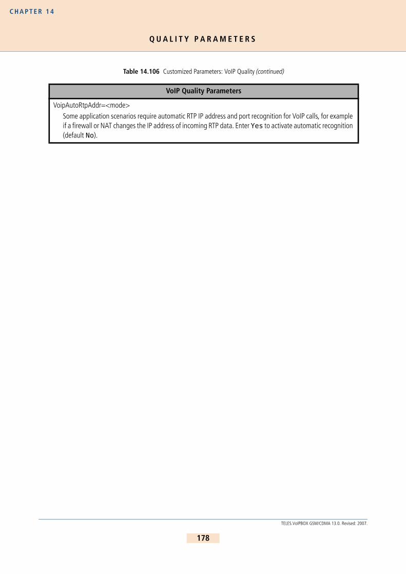
Q U A L I T Y P A R A M E T E R S
C H A P T E R 1 4
VoipAutoRtpAddr=<mode>
Some application scenarios require automatic RTP IP address and port recognition for VoIP calls, for example if a firewall or NAT changes the IP address of incoming RTP data. Enter Yes to activate automatic recognition (default No).
Table 14.106 Customized Parameters: VoIP Quality (continued)
VoIP Quality Parameters
178
TELES.VoIPBOX GSM/CDMA 13.0. Revised: 2007.

Q U A L I T Y P A R A M E T E R S
C H A P T E R 1 4
VoipAGC=<x y z>
This parameter allows automatic gain control of input signals from PSTN or IP. Enabling this feature compen-sates for near-far gain differences:x - direction (0 for signals from TDM, 1 for signals from IP)y - gain slope (controls gain changing ratio in -dBm/sec, values 0 to 31, default 0)z - target energy (determines attempted signal energy value in -dBm, values 0 to 63, default 19Gain Slope:0 - 00.25dB1 - 00.50dB2 - 00.75dB3 - 01.00dB4 - 01.25dB5 - 01.50dB6 - 01.75dB7 - 02.00dB8 - 02.50dB9 - 03.00dB10 - 03.50dB11 - 04.00dB12 - 04.50dB13 - 05.00dB14 - 05.50dB15 - 06.00dB16 - 07.00dB17 - 08.00dB18 - 09.00dB19 - 10.00dB20 - 11.00dB21 - 12.00dB22 - 13.00dB23 - 14.00dB24 - 15.00dB25 - 20.00dB26 - 25.00dB27 - 30.00dB28 - 35.00dB29 - 40.00dB30 - 50.00dB31 - 70.00dB
Table 14.106 Customized Parameters: VoIP Quality (continued)
VoIP Quality Parameters
179
TELES.VoIPBOX GSM/CDMA 13.0. Revised: 2007.

Q U A L I T Y P A R A M E T E R S
C H A P T E R 1 4
VoipVoiceVolume=<num>
The volume of VoIP calls coming from the Ethernet. The range is 0-63. The default value of 32 is 0 dB.
VoipInputGain=<num>
The volume of VoIP calls coming from ISDN,POTS or mobile. The range is 0-63. The default value of 32 is 0 dB.
Table 14.106 Customized Parameters: VoIP Quality (continued)
VoIP Quality Parameters
180
TELES.VoIPBOX GSM/CDMA 13.0. Revised: 2007.

Q U A L I T Y P A R A M E T E R S
C H A P T E R 1 4
VoipQualityCheck=<type minsamples limit recovertime>
type
Enter one of the following: ASR1, ASR2, RoundTripDelay, Jitter or FractionLostWhen type is ASR1 or ASR2:minsamples
Minimum number of calls for which ASR shall be calculated with:limit
A value between 0 and 100 recovertime
Seconds to block the profile.
When type is RoundTripDelay:minsamples
Minimum number of seconds RTD must be above:limit
The highest acceptable value for RTD (in milliseconds)recovertime
Seconds to block the profile.
When type is Jitter:minsamples
Minimum number of seconds jitter must be above:limit
The highest acceptable value for jitter (in milliseconds)recovertime
Seconds to block the profile.When type is FractionLost:minsamples
Minimum number of seconds FL must be above:limit
The highest acceptable value for FL (percentage between o and 100)recovertime
Seconds to block the profile
NOTE: If you base VoipQualityCheck on the ASR values: During setup, calls are calculated as not connected, which lowers the number of connected calls.
Example: If minsamples is set at 20, with a limit of 80%, 4 calls in the setup phase will lower the ASR of the previous 20 calls to 80% and the profile will be blocked.
VoipECE=<mode>
Enter yes (default) to set echo cancellation. Enter no to disable echo cancellation.
Table 14.106 Customized Parameters: VoIP Quality (continued)
VoIP Quality Parameters
181
TELES.VoIPBOX GSM/CDMA 13.0. Revised: 2007.

Q U A L I T Y P A R A M E T E R S
C H A P T E R 1 4
The following specifications for Quality of Service correspond with RFC791 and RFC1349.
VoipT301=<sec>
An outgoing VoIP calls will be canceled in the state of Alerting (for H323) or Ringing (for SIP) if the number of seconds entered has passed and there is no response from the IP or VoIP carrier.
VoipT303=<sec>
If this parameter is entered in a SIP profile, transmission of the INVITE is canceled after the number of seconds entered has passed. The call can then be redirected, for example to PSTN. This improves the reliability of the system when an IP or VoIP carrier’s service fails.EXAMPLE:Redirect340DF:=AMapAllA=9[Voip:DF].....VoipT303=5
VoipT304=<sec>
An outgoing VoIP calls will be canceled in the state of Setup Acknowledge (for H323) or Trying (for SIP) if the number of seconds entered has passed and there is no response from the IP or VoIP carrier.
VoipT310=<sec>
An outgoing VoIP calls will be canceled in the state of Call Proceeding (for H323) or Session Progress (for SIP) if the number of seconds entered has passed and there is no response from the IP or VoIP carrier.
Table 14.107 Quality of Service Values
Bit
Distribution
0 1 2 3 4 5 6 7
Precedence TOS MBZ
Bit Description
0-2 Precedence
3 TOS: 0=normal delay, 1=low delay
4 TOS: 0=normal throughput, 1=high throughput
5 TOS: 0=normal reliability, 1=high reliability
6 TOS: 0=normal service, 1=minimize monetary cost
7 MBZ: must be 0 (currently not used)
Precedence Description
111 Network control
110 Internetwork control
Table 14.106 Customized Parameters: VoIP Quality (continued)
VoIP Quality Parameters
182
TELES.VoIPBOX GSM/CDMA 13.0. Revised: 2007.

C O M P R E S S I O N P A R A M E T E R S
C H A P T E R 1 4
1 4 . 5 C O M P R E S S I O N P A R A M E T E R S
The following parameters are for RTP multiplexing, which aggregates RTP packets (voice user data) for individualVoIP calls into a packet. The header (for Ethernet, IP, UDP and RTP) is sent only once for all calls instead of for eachindividual call. The relationship between header and payload benefits the payload when several calls occur simul-taneously. This compression does not result in any loss in voice quality.
This feature is possible with a Teles peer and requires the following entries in the VoIP profile:
101 CRITIC/ECP
100 Flash override
011 Flash
010 Immediate
001 Priority
000 Routine
Table 14.108 Customized Parameters: VoIP Compression
VoIP Compression Parameters
VoipAggRemoteRtpPort=<port>
Enter the port for the VoIP peer that is the first RTP port. The next port is always the corresponding RTCP port. The port that is two numbers higher will be used for the next VoIP channel. Default 29000.
VoipAggRemoteDataPort=<port>VoipAggRemoteDataPort=29500Enter the port for the VoIP peer that is used for aggregated packets (compressed data). Default: 29500.
VoipAggOwnDataPort=<port>VoipAggOwnDataPort=29500Enter the own port number used for aggregated packets. Default: 29500.
VoipAggRemoteRtpPortSpacing=<count>
Defines the space between the ports used for the peer’s individual RTP streams (default 2).
Table 14.107 Quality of Service Values (continued)
183
TELES.VoIPBOX GSM/CDMA 13.0. Revised: 2007.

F A X / M O D E M P A R A M E T E R S
C H A P T E R 1 4
1 4 . 6 F A X / M O D E M P A R A M E T E R S
Table 14.109 Customized Parameters: VoIP Fax
VoIP Fax/Modem Parameters
VoipFaxTransport=<int>
Enter 2 and signaling will switch to G.711a (framesize 40ms) when the peer cannot handle fax transmission with T.38. The codec will change when the system detects a fax or modem connection on the channel. 0 = disabled (default); 1 = relay. T.38 is always used.
NOTE: Bear in mind that if T.38 is defined in the VoipCompression= line of the VoIP profile, the system will switch only when it detects a modem connection. Fax calls will still be transmit-ted using T.38.
VoipFaxBypassPayloadType=<num>Defined the payload type for a fax’s RTP packets when T.38 is not used (default 102).
VoipFaxMaxRate=<num>
If the peer does not support auto negotiation or has a fixed transmission rate, you can define the fixed rate:
0 - 2400 Bit/sec1 - 4800
2 - 7200
3 - 96004 - 12000
5 - 14400 (default)
EXAMPLE:VoipFaxMaxRate=5
VoipFaxECM=<mode>You can use this parameter to disable the error correction mode for fax transmission: yes=enabled (default), no=disabled.
VoipFaxProtocol=<int>
Defines the protocol used:0 = TCP
1 = FRF.11
2 = UDP, datarate management 13 = UDP, datarate management 2 (default)
VoipT38ErrorCorrectionMode=<int>
Sets the error-correction mode:
0 = Redundancy (default)1 = Forward error correction
184
TELES.VoIPBOX GSM/CDMA 13.0. Revised: 2007.

F A X / M O D E M P A R A M E T E R S
C H A P T E R 1 4
VoipT38CtrlDataRedundancy=<int>
Defines the redundancy level for control packets:
0 = Disable (default)1-7 = Sets level
VoipT38ImageDataRedundancy=<int>
Defines the redundancy level for fax content:
0 = Disable (default)1-3 = Sets level
The following parameters are responsible to set the modem transport method if a modem connection is detected.
VoipV21Transport=<mode>
0=disabled (must be set to 0).
VoipV22Transport=<mode>
0=disabled, 2=bypass (default).
VoipV23Transport=<mode> 0=disabled, 2=bypass (default).
VoipV32Transport=<mode>
0=disabled, 1=relay (default), 2=bypass .
VoipV34Transport=<mode>
0=disabled, 1=fallback to v32, 2= bypass (default).
Table 14.109 Customized Parameters: VoIP Fax (continued)
VoIP Fax/Modem Parameters
185
TELES.VoIPBOX GSM/CDMA 13.0. Revised: 2007.

D T M F P A R A M E T E R S
C H A P T E R 1 4
1 4 . 7 D T M F P A R A M E T E R S
Table 14.110 Customized Parameters: VoIP DTMF
VoIP DTMF Parameters
VoipIBSDetectDir=<int>
Enter 1 and DTMF tones (and all other inband signaling) will be detected from the Ethernet side. Enter 0 for DTMF tones to be detected from the PCM side (default). DTMF tones from the Ethernet side are transmitted to the host as ISDN dialing information only if 1 is entered. In this case, VoipDtmfTransport should be 1 or 3.
VoipDtmfTransport=<int> 0 (H323) = DTMF relayed with H.225 signaling information.
0 (SIP) = DTMF relayed with SIP INFO.
1 = DTMF and MF taken from audio stream and relayed to remote. 2 (default) = DTMF and MF kept in audio stream and not relayed.
3 = DTMF and MF taken from audio stream and relayed to remote as per RFC2833.
4 (SIP only) = SIP INFO messages will be relayed as DTMF and MF.
VoipDtmfFallback=<int>If VoipDtmfTransport=3 is set and the peer does not support DTMF transmission according to RFC 2833, the following settings apply:2 = automatic fallback to inband
0 = automatic fallback to signaling messages (default)
VoipRFC2833PayloadType=<num>
This parameter changes the DTMF payload type. The default value is 96, a common value is 101.
186
TELES.VoIPBOX GSM/CDMA 13.0. Revised: 2007.

O V E R V I E W
C H A P T E R 1 5
1 5 O P T I O N A L F U N C T I O N M O D U L E SThis chapter contains a description of modules that expand the functionality of the TELES.VoIPBOX GSM/CDMA,such as:
HTTP User Interface
TELES.iPBX
SNMP agentDNS forwarder
ipupdate - DynDNS client
Since these features are only required in individual cases, they are not part of the default software packet. Theycan be installed as stand-alone modules for the desired function. The description of the functionality of individualmodules appears in their respective chapters.
1 5 . 1 O V E R V I E W
The modules can be downloaded using FTP. The access data for each module is as follows:
Http User Interfaceftp://195.4.12.80user: httpdpassword: httpdTELES.iPBXftp://195.4.12.80user: ipbxpassword: ipbx
DNS Forwarderftp://195.4.12.80user: dnsmasqpassword: dnsmasq
snmp agentftp://195.4.12.80user: snmppassword: snmp
ipupdateftp://195.4.12.80user: ipupdatepassword: ipupdate
Install the respective software package on the TELES.VoIPBOX GSM/CDMA using TELES.GATE Manager. For a de-scription of how to update the software, please refer to Chapter 7.3 . Make sure the module’s file ending is cor-rect before installation. The number in the file ending shows the starting order of the modules. Do NOT changethis number if it is 0! All other modules can simply be numbered in ascending order.
187
TELES.VoIPBOX GSM/CDMA 13.0. Revised: 2007.
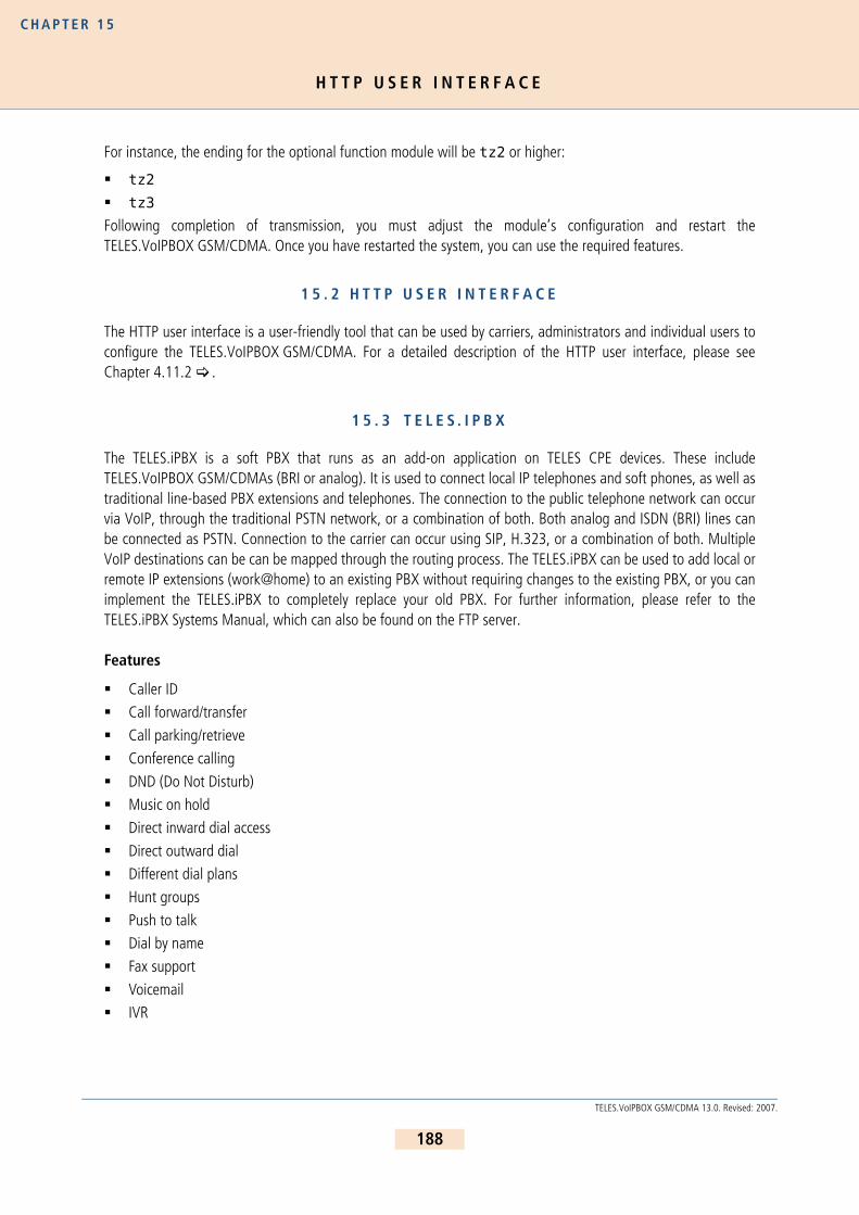
H T T P U S E R I N T E R F A C E
C H A P T E R 1 5
For instance, the ending for the optional function module will be tz2 or higher:
tz2tz3
Following completion of transmission, you must adjust the module’s configuration and restart theTELES.VoIPBOX GSM/CDMA. Once you have restarted the system, you can use the required features.
1 5 . 2 H T T P U S E R I N T E R F A C E
The HTTP user interface is a user-friendly tool that can be used by carriers, administrators and individual users toconfigure the TELES.VoIPBOX GSM/CDMA. For a detailed description of the HTTP user interface, please seeChapter 4.11.2 .
1 5 . 3 T E L E S . I P B X
The TELES.iPBX is a soft PBX that runs as an add-on application on TELES CPE devices. These includeTELES.VoIPBOX GSM/CDMAs (BRI or analog). It is used to connect local IP telephones and soft phones, as well astraditional line-based PBX extensions and telephones. The connection to the public telephone network can occurvia VoIP, through the traditional PSTN network, or a combination of both. Both analog and ISDN (BRI) lines canbe connected as PSTN. Connection to the carrier can occur using SIP, H.323, or a combination of both. MultipleVoIP destinations can be can be mapped through the routing process. The TELES.iPBX can be used to add local orremote IP extensions (work@home) to an existing PBX without requiring changes to the existing PBX, or you canimplement the TELES.iPBX to completely replace your old PBX. For further information, please refer to theTELES.iPBX Systems Manual, which can also be found on the FTP server.
Features
Caller IDCall forward/transfer
Call parking/retrieve
Conference calling
DND (Do Not Disturb)Music on hold
Direct inward dial access
Direct outward dialDifferent dial plans
Hunt groups
Push to talkDial by name
Fax support
VoicemailIVR
188
TELES.VoIPBOX GSM/CDMA 13.0. Revised: 2007.
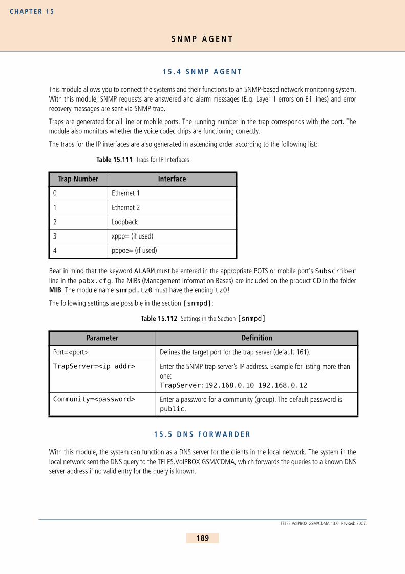
S N M P A G E N T
C H A P T E R 1 5
1 5 . 4 S N M P A G E N T
This module allows you to connect the systems and their functions to an SNMP-based network monitoring system.With this module, SNMP requests are answered and alarm messages (E.g. Layer 1 errors on E1 lines) and errorrecovery messages are sent via SNMP trap.
Traps are generated for all line or mobile ports. The running number in the trap corresponds with the port. Themodule also monitors whether the voice codec chips are functioning correctly.
The traps for the IP interfaces are also generated in ascending order according to the following list:
Bear in mind that the keyword ALARM must be entered in the appropriate POTS or mobile port’s Subscriberline in the pabx.cfg. The MIBs (Management Information Bases) are included on the product CD in the folderMIB. The module name snmpd.tz0 must have the ending tz0!
The following settings are possible in the section [snmpd]:
1 5 . 5 D N S F O R W A R D E R
With this module, the system can function as a DNS server for the clients in the local network. The system in thelocal network sent the DNS query to the TELES.VoIPBOX GSM/CDMA, which forwards the queries to a known DNSserver address if no valid entry for the query is known.
Table 15.111 Traps for IP Interfaces
Trap Number Interface
0 Ethernet 1
1 Ethernet 2
2 Loopback
3 xppp= (if used)
4 pppoe= (if used)
Table 15.112 Settings in the Section [snmpd]
Parameter Definition
Port=<port> Defines the target port for the trap server (default 161).
TrapServer=<ip addr> Enter the SNMP trap server’s IP address. Example for listing more than one: TrapServer:192.168.0.10 192.168.0.12
Community=<password> Enter a password for a community (group). The default password is public.
189
TELES.VoIPBOX GSM/CDMA 13.0. Revised: 2007.

I P U P D A T E - D Y N D N S C L I E N T
C H A P T E R 1 5
The advantage is that the clients always enter the TELES.VoIPBOX GSM/CDMA’s address as DNS server address,so that no public DNS server address is required. The TELES.VoIPBOX GSM/CDMA functions in this scenario as arouter.
Of course, the DNS server’s address can also be transmitted to the clients using the integrated DHCP server. If theTELES.VoIPBOX GSM/CDMA is used as a DSL router or if it sets up a dial-up connection, no entry is required in thepabx.cfg for the parameter NameServer. The DNS server’s address that is negotiated through this connectionwill be used.
1 5 . 6 I P U P D A T E - D Y N D N S C L I E N T
This function allows you to assign a defined hostname to an IP address that changes dynamically. That means thatyou can always reach a device or service through the public IP network, even if, for example, it is a common DSLconnection with dynamic IP address allocation. Several providers support this service.
Make the following entries in the system’s ip.cfg, in the [DynDNS] section:
Table 15.113 pabx.cfg: DynDNS
DynDNS Parameters
service=<type>
Specifies which provider is used. The following providers are supported:
dhsdyndns
dyndns-static
dynsezip
easydns
easydns-partnergnudip
heipv6tb
hn
pgpowods
tzo
zoneedit
http://www.dhs.orghttp://www.dyndns.org
http://www.dyns.cxhttp://www.ez-ip.net
http:/www.easydns.com
http://www.gnudip.cheapnet.net
http://www.hn.org
http:www.justlinux.comhttp://ods.org
http://www.tzo.com
http://zoneedit.com
user=<username:password>Defines the username and password for the DNS service provider.
host=<domain_name_of_dns_service>
Enter the domain name that is used.
190
TELES.VoIPBOX GSM/CDMA 13.0. Revised: 2007.
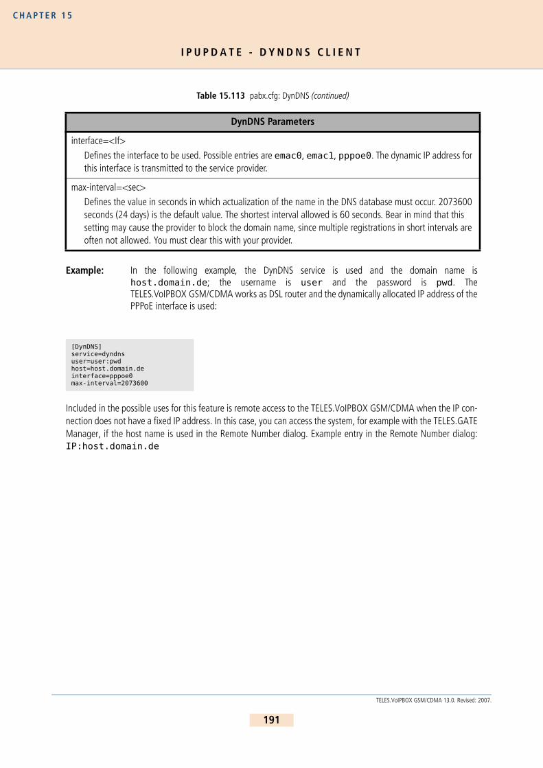
I P U P D A T E - D Y N D N S C L I E N T
C H A P T E R 1 5
Example: In the following example, the DynDNS service is used and the domain name ishost.domain.de; the username is user and the password is pwd. TheTELES.VoIPBOX GSM/CDMA works as DSL router and the dynamically allocated IP address of thePPPoE interface is used:
Included in the possible uses for this feature is remote access to the TELES.VoIPBOX GSM/CDMA when the IP con-nection does not have a fixed IP address. In this case, you can access the system, for example with the TELES.GATEManager, if the host name is used in the Remote Number dialog. Example entry in the Remote Number dialog:IP:host.domain.de
interface=<If>
Defines the interface to be used. Possible entries are emac0, emac1, pppoe0. The dynamic IP address for this interface is transmitted to the service provider.
max-interval=<sec>
Defines the value in seconds in which actualization of the name in the DNS database must occur. 2073600 seconds (24 days) is the default value. The shortest interval allowed is 60 seconds. Bear in mind that this setting may cause the provider to block the domain name, since multiple registrations in short intervals are often not allowed. You must clear this with your provider.
[DynDNS]service=dyndnsuser=user:pwdhost=host.domain.deinterface=pppoe0max-interval=2073600
Table 15.113 pabx.cfg: DynDNS (continued)
DynDNS Parameters
191
TELES.VoIPBOX GSM/CDMA 13.0. Revised: 2007.

TELES AGCommunication Systems DivisionErnst-Reuter-Platz 810587 Berlin, GermanyPhone: +49 30 399 28-00Fax: +49 30 399 28-01E-mail: [email protected]
http://www.teles.com/tcs/