Embed Size (px)
Citation preview
Furukawa Review, No. 24 2003 29
refractive index of silica-based materials. This requires temperature control by heater or thermoelectric (TE) device using the Peltier effect, an RTD or a thermistor and an electric power supply. Therefore one of the major requirements for AWGs has been to reduce power consumption, and we developed a Peltier-type AWG module and a heater-type AWG module with low power consumption 4), 5). We have now developed novel athermal AWG modules which need no electric power supply by using a unique temperature insensitive technique. It meets the need for further reduction in the power consumption of the system as a whole and is suitable to Metro networks, in which eliminating the need for electric power is a major advantage. These novel athermal AWGs almost complete temperature compensation for AWGs with a large number (32 or 42) of channels, which has been hard to realize. In this paper, we report the principle of this temperature insensitive technique and the results of fabrication of athermal AWG modules of the 100-GHz × 32-ch (Gaussian) and 100-GHz × 42-ch (semi-flat) types. We also report the results of reliability tests based on Telcordia GR-1209 and GR-1221.
2. PRINCIPLE OF TEMPERATURE-INSENSITIVITY
2.1 Principle of AWGFigure 1 shows the waveguide circuit structure of an AWG, with the input waveguides, input slab waveguide, arrayed waveguide, output slab waveguide and output waveguides formed on the substrate. Following is a description of operation as an optical demultiplexer. When a WDM signal comprising a number of optical
1. INTRODUCTIONDense wavelength division multiplexing (DWDM) systems, which had their origins in long-haul communication networks in North America, are now spreading to the entire world. They are also being used in Metro-networks and other short-range communication networks. The number of channels in DWDM systems is getting larger due to the unlimited need for transmission capacity in communication networks 1). In general, the greater the number of channels in a DWDM system, the greater the power consumption of the system as a whole. Moreover, the increase in the number of optical components as system functions increase, and the use of high-power EDFAs 2) or Raman amplifier 3) means even greater power consumption of the optical network system. For this reason, there is an urgent need to reduce power consumption or eliminate electric power for individual optical components. AWGs are playing an important role as multiplexer/demultiplexers in DWDM systems. The AWG has design flexibility with respect to the number of channels and wavelength spacing, and is superior in mass productivity and compactness. It has the further advantage that chromatic dispersion is extremely low, making it suitable to suitable to high bit-rate (40 Gbps) systems. This suggests that AWG is promising for use in future DWDM systems.
In the AWG, the center wavelength is temperature-dependent due to the temperature dependence of the
Temperature-Insensitive (Athermal) AWG Modules
by Tsunetoshi Saito *, Kazutaka Nara *, Kanji Tanaka *2, Yoshinobu Nekado *, Jun'ichi Hasegawa * and Kazuhisa Kashihara *3
High-performance temperature-insensitive (athermal) arrayed waveguide grating (AWG) modules have been developed to meet the need to reduce the
consumption of DWDM systems and eliminate electric power for optical components. Employing a unique temperature-insensitive technique that is applicable to all sorts of AWGs, we have fabricated athermal AWG modules of the 100-GHz × 32-ch (Gaussian) and 100-GHz × 42-ch (semi-flat) types. At temperatures from 0 to 70°C, center wavelength shift and insertion loss variation were less than ±0.015 nm and ±0.1dB respectively, and it was confirmed that the optical characteristics of the developed athermal AWGs showed high stability. It was also confirmed that they exhibit high reliability by reliability tests based on Telcordia GR-1209 and GR-1221.
ABSTRACT
* FITEL-Photonics Lab. *2 Development Dept., FITEL Products Div. *3 Fiber Products Dept., Optical Fiber Div.
Furukawa Review, No. 24 2003 30
Temperature-Insensitive (Athermal) AWG Modules
Furukawa Review, No. 24 2003 31
Temperature-Insensitive (Athermal) AWG Modules
material and an expansion or contraction of the substrate and waveguides, resulting in a difference in the length of the optical path. This results in a shift in the position of the focal points at the output side of the output slab waveguides, and a change in the wavelength of the signals entering the output waveguides. By taking φ in Equation (1) as 0 and differentiating an equation solved for λ by temperature T, it becomes possible to represent the magnitude of the temperature dependence of the center wavelength by
= + λαs (2)
where the first term on the right side of the equation represents the temperature dependence of the index of refraction and the second term the change in the index of refraction caused by stress on the waveguide due to the change in the length of the waveguide path accompanying expansion or contraction of the substrate. Since the temperature dependence of the index of refraction of silica glass is 8 × 10⁻⁶ /°C and the coefficient of expansion of the substrate is 3 × 10⁻⁶ /°C (in the case of silicon), we obtain a change in center wavelength of approximately 0.011 nm/°C.
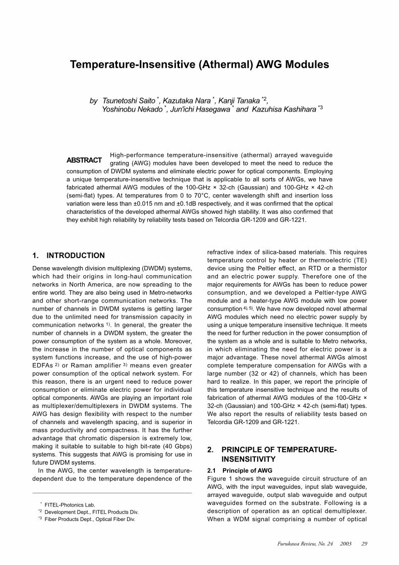
2.3 The Principle of Temperature InsensitivityIn order to compensate for this temperature dependence, we focused on the linear dispersion of the AWG. Figure 2 shows the output slab waveguide portion of the AWG. The symbol O corresponds to the position when φ=0 in equation (1) and wavelength λ0, and in this condition is represented by
λ0 = (3)
When the focus point with diffraction angle φp is defined as P and the distance between O and P is defined as x , the relation between wavelength λ and x may be represented by
= ng (4)
signals having wavelengths λ1 through λn enters the input waveguides it is diffracted and spread by the input slab waveguide and is transmitted to the arrayed waveguide, which consists of waveguides placed side-by-side in which each of the signals emitted by the input slab waveguide is propagated, and adjacent waveguides are disposed at a fixed optical path length difference ∆L. For this reason a phase difference appears in the signal propagated in each waveguide. The signals passing through the arrayed waveguide then enter the output slab waveguide and are diffracted and spread, but the signals passing though the respective waveguides interfere with each other so that in effect they are all diffracted in a direction such that their wave fronts are aligned. The in-phase conditions in which the wave fronts are aligned may be represented by
nsdsinφ+nc ∆L = mλ (1)
where: nc and ns are the effective index of refraction for the arrayed waveguide and slab waveguide, φ is the angle of diffraction, and d is the distance between arrayed waveguides, λ is the wavelength, and m is an arbitrary integer and the order of diffraction.
Since the angle of diffraction that gives the direction in which the wave fronts are aligned is dependent on wavelength, signals of differing wavelengths are each diffracted in a different direction. Accordingly the points at which signals of differing wavelength converge at the output ports of the output slab waveguides differ, and by positioning an output waveguide at each of these points, signals of differing wavelength can be sent to a different waveguide, thereby extracting signals of wavelength λ1 through λn. The above description relates to the operation of an AWG as a wavelength-division demultiplexer, but the same AWG can also be used as a multiplexer. That is to say, when a signal of each wavelength from the output waveguide (when used as a wavelength-division multiplexer) is input, the signals from the input waveguides (when used as a wavelength-division multiplexer) are all output together.
2.2 Temperature-Dependence of Center WavelengthAs has been described, an AWG can be used to multiplex and demultiplex signals of a set wavelength, but this wavelength (the center wavelength) is temperature dependent. When there is a change in temperature, there is a change in the index of refraction of the waveguide
dλdT
λnc
dncdT
nc∆Lm
Lf ∆Lnsdλ0
dxdλ
Figure 1 Light-waveguide circuit structure of AWG.
Input slab waveguide
Arrayed waveguide Output slab waveguide
Input waveguidesOutput waveguides
λ1, λ2, λ3 λn, λ1 λ2 λ3λn
Figure 2 Output slab waveguide of AWG.
x
Lf
PO
Output waveguides
Slabwaveguide φ
Arrayed waveguide
Furukawa Review, No. 24 2003 30
Temperature-Insensitive (Athermal) AWG Modules
Furukawa Review, No. 24 2003 31
Temperature-Insensitive (Athermal) AWG Modules
expansion of copper is constant and very stable.In order to compensate accurately for the temperature
dependence of the center wavelength, it is necessary to adjust the length of the copper plate, which is determined as follows. The change in positional compensating value dx may be expressed as a function of temperature change T by
dx = ng T (5)
Using as an example the circuit parameters shown in Table 1, we may derive
dx = 0.275T (6)
That is to say when the temperature changes 1°C the focal point must change 0.275 μm at the output portion of the output slab waveguide. Therefore this is the value for which the copper plate must compensate.
Since the thermal expansion coefficient of copper is 1.7 × 10⁻⁵, the length of the copper plate may be calculated to be 16.2 mm, depending on the design of the AWG, and in most case, is around 15 to 25 mm. Assuming a center wavelength compensating accurately of 0.005 nm or better (over 0~70°C) an error of 0.2 mm in copper plate length is permissible, well within manufacturing tolerances.
3. EXPERIMENTAL RESULTSUsing the principle described above, we fabricated athermal AWG modules of 100-GHz × 32-ch and 100-GHz × 42-ch, with spectra that are Gaussian and semi-flat type respectively. The semi-flat type has a configuration midway between the Gaussian type and the conventional flat type, and is recently in demand for its flatness, and lower insertion loss than the conventional flat type.
Figure 5 is a photo of the 100-GHz × 32-ch athermal AWG module. The package is very compact and slim-line measuring only 57 × 97 × 8.5 mm. The package size of the 100-GHz × 42-ch AWG module is 80 x 130 x 8.5 mm.
Figures 6 and 7 show the spectra over all channels for 100-GHz × 32-ch and 100-GHz × 42-ch athermal AWG modules. Spectrum profiles were substantially the
where: Lf is the focal length of the slab waveguide and ng is the group refractive index of the arrayed waveguide.
Equation (4) shows the linear dispersion of the AWG, showing that it is possible to take out light with a wavelength that differs from λ0 by dλ when an output waveguide is positioned at a point at a distance dx from O. Thus, if the output waveguide is shifted by a distance corresponding to wavelength change dλ caused by the temperature change, the temperature dependence of the center wavelength should be compensated.
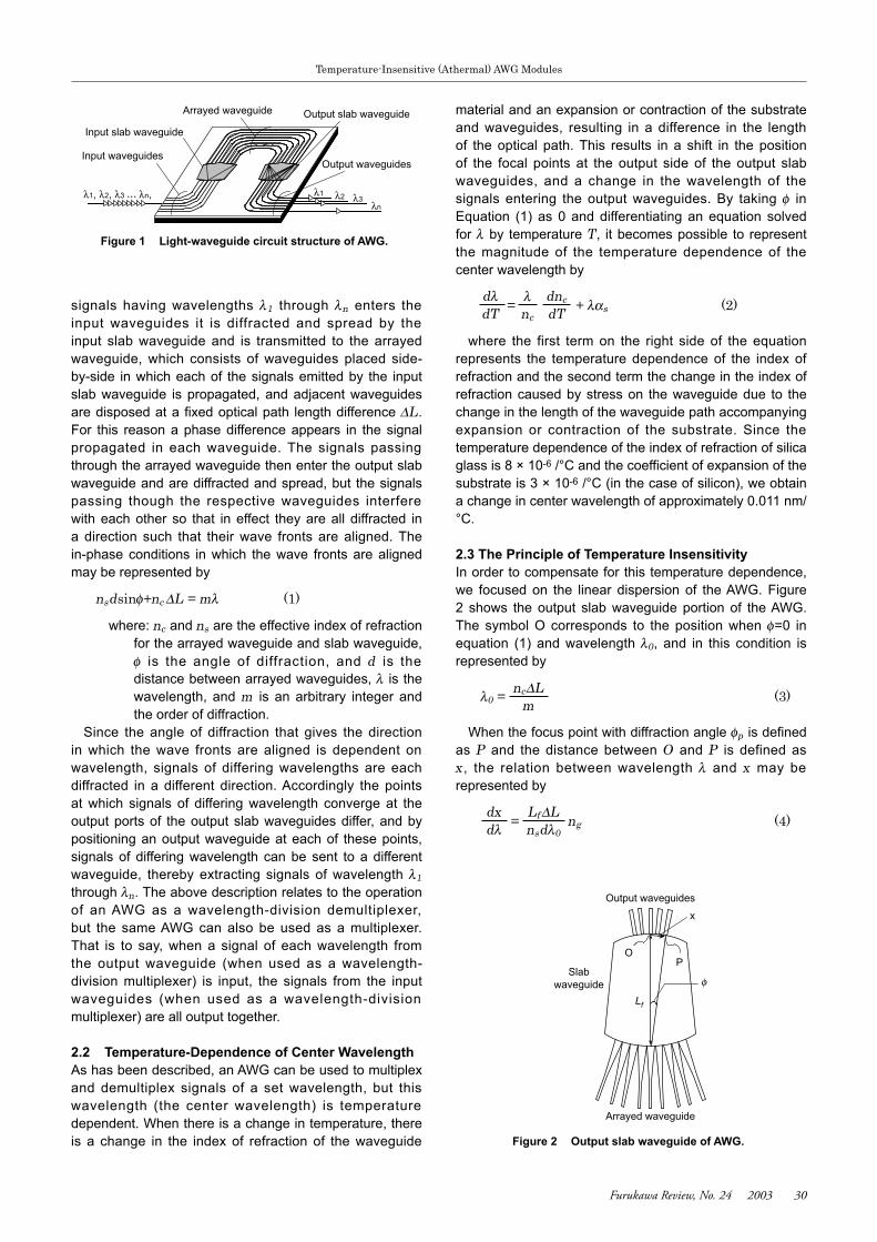
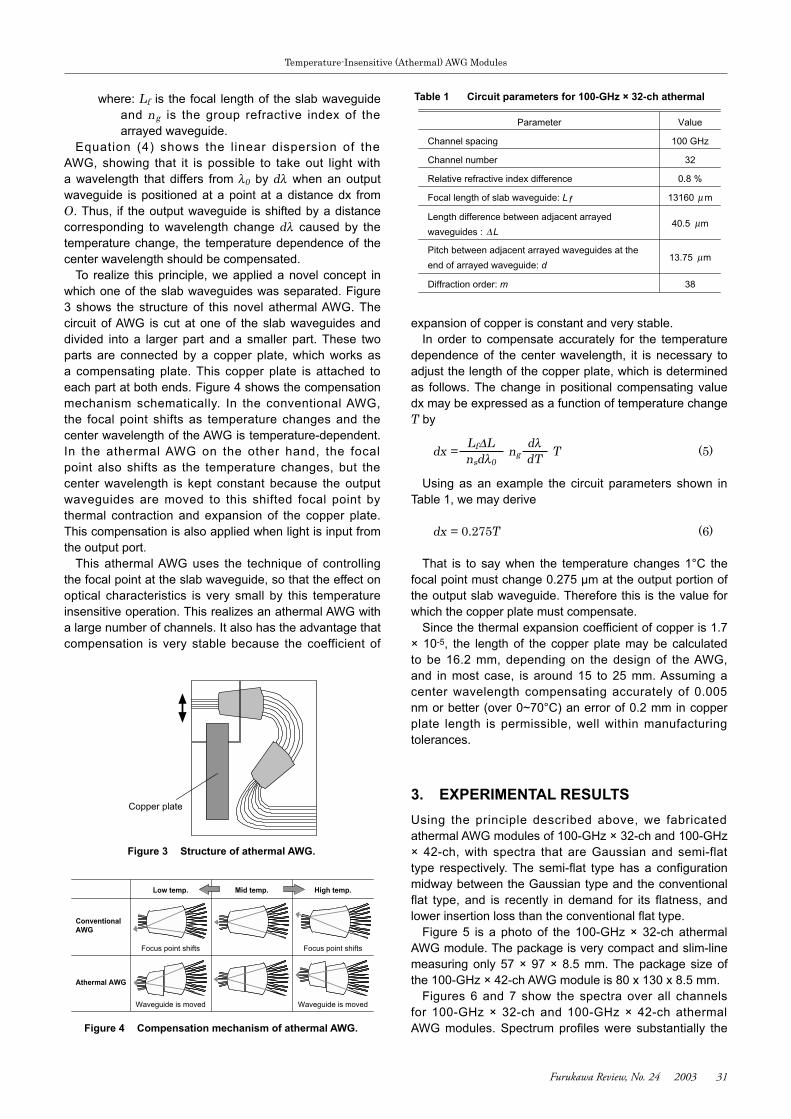
To realize this principle, we applied a novel concept in which one of the slab waveguides was separated. Figure 3 shows the structure of this novel athermal AWG. The circuit of AWG is cut at one of the slab waveguides and divided into a larger part and a smaller part. These two parts are connected by a copper plate, which works as a compensating plate. This copper plate is attached to each part at both ends. Figure 4 shows the compensation mechanism schematically. In the conventional AWG, the focal point shifts as temperature changes and the center wavelength of the AWG is temperature-dependent. In the athermal AWG on the other hand, the focal point also shifts as the temperature changes, but the center wavelength is kept constant because the output waveguides are moved to this shifted focal point by thermal contraction and expansion of the copper plate. This compensation is also applied when light is input from the output port.
This athermal AWG uses the technique of controlling the focal point at the slab waveguide, so that the effect on optical characteristics is very small by this temperature insensitive operation. This realizes an athermal AWG with a large number of channels. It also has the advantage that compensation is very stable because the coefficient of
Table 1 Circuit parameters for 100-GHz × 32-ch athermal
Parameter
Channel spacing
Channel number
Relative refractive index difference
Focal length of slab waveguide: L f
Length difference between adjacent arrayed
waveguides : L
Diffraction order: m
Pitch between adjacent arrayed waveguides at the
end of arrayed waveguide: d
Value
100 GHz
32
0.8 %
13160 m
40.5 m
13.75 m
38
∆
µ
µ
µ
dλdT
Lf∆Lnsdλ0
Figure 3 Structure of athermal AWG.
Copper plate
Figure 4 Compensation mechanism of athermal AWG.
High temp.Low temp.
ConventionalAWG
Athermal AWG
Mid temp.
Focus point shiftsFocus point shifts
Waveguide is movedWaveguide is moved
Furukawa Review, No. 24 2003 32
Temperature-Insensitive (Athermal) AWG Modules
Furukawa Review, No. 24 2003 33
Temperature-Insensitive (Athermal) AWG Modules
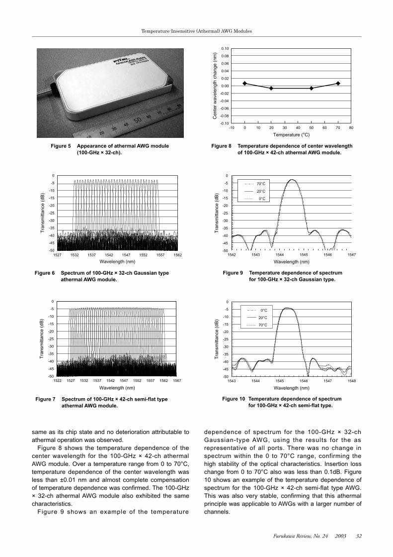
dependence of spectrum for the 100-GHz × 32-ch Gaussian-type AWG, using the results for the as representative of all ports. There was no change in spectrum within the 0 to 70°C range, confirming the high stability of the optical characteristics. Insertion loss change from 0 to 70°C also was less than 0.1dB. Figure 10 shows an example of the temperature dependence of spectrum for the 100-GHz × 42-ch semi-flat type AWG. This was also very stable, confirming that this athermal principle was applicable to AWGs with a larger number of channels.
same as its chip state and no deterioration attributable to athermal operation was observed.
Figure 8 shows the temperature dependence of the center wavelength for the 100-GHz × 42-ch athermal AWG module. Over a temperature range from 0 to 70°C, temperature dependence of the center wavelength was less than ±0.01 nm and almost complete compensation of temperature dependence was confirmed. The 100-GHz × 32-ch athermal AWG module also exhibited the same characteristics.
Figure 9 shows an example of the temperature
Figure 7 Spectrum of 100-GHz × 42-ch semi-flat type athermal AWG module.
-50
-45
-40
-35
-30
-25
-20
-15
-10
-5
0
1522 1527 1532 1537 1542 1547 1552 1557 1562 1567
Wavelength (nm)
Tra
nsm
ittan
ce (
dB)
Figure 6 Spectrum of 100-GHz × 32-ch Gaussian type athermal AWG module.
-50
-45
-40
-35
-30
-25
-20
-15
-10
-5
0
1527 1532 1537 1542 1547 1552 1557 1562
Wavelength (nm)
Tra
nsm
ittan
ce (
dB)
Figure 8 Temperature dependence of center wavelength of 100-GHz × 42-ch athermal AWG module.
-0.10
-0.08
-0.06
-0.04
-0.02
0.00
0.02
0.04
0.06
0.08
0.10
-10 0 10 20 30 40 50 60 70 80
Temperature (°C)
Cen
ter
wav
elen
gth
chan
ge (
nm)
Figure 9 Temperature dependence of spectrum for 100-GHz × 32-ch Gaussian type.
-50
-45
-40
-35
-30
-25
-20
-15
-10
-5
0
1542 1543 1544 1545 1546 1547
Wavelength (nm)
Tra
nsm
ittan
ce (
dB)
70°C
20°C
0°C
Figure 10 Temperature dependence of spectrum for 100-GHz × 42-ch semi-flat type.
-50
-45
-40
-35
-30
-25
-20
-15
-10
-5
0
1543 1544 1545 1546 1547 1548
Wavelength (nm)
Tra
nsm
ittan
ce (
dB)
0°C
20°C
70°C
Figure 5 Appearance of athermal AWG module (100-GHz × 32-ch).
Furukawa Review, No. 24 2003 32
Temperature-Insensitive (Athermal) AWG Modules
Furukawa Review, No. 24 2003 33
Temperature-Insensitive (Athermal) AWG Modules
REFERENCES
1) G. Charlet, J.-C. Antona, S. Lanne, P. Tran, W. Idler, M. Gorlier, S. Borne, A. Klekamp, C. Simonneau, L. Pierre, Y. Frignac, M. Molina, F. Beaumont, J.-P. Hamaide, S. Bigo: “6.4 Tb/s (159~42.7Gb/s) capacity over 21~100 km using bandwidth-limited phase-shaped binary transmission” Proc. European Conference on Optical Communication, (2002), PD Paper 4.1.
2) Y. Tashiro, S. Koyanagi, K. Aiso and S. Namiki, “1.5W erbium doped fiber amplifier pumped by the wavelength division multiplexed 1480 nm laser diodes with fiber Bragg grating”, Tech. Dig. OAA’98, Vail CO, July ’98, paper WC2.
3) Namiki: ECOC2001, We. M. 2. 1 4) Tsunetoshi Saito et al.; Furukawa Review, No. 19, (2000), 47 5) Junichi Hasegawa et al.; “Development of a Heater-Control
AWG Module”, Furukawa Review, No. 22, (2002)
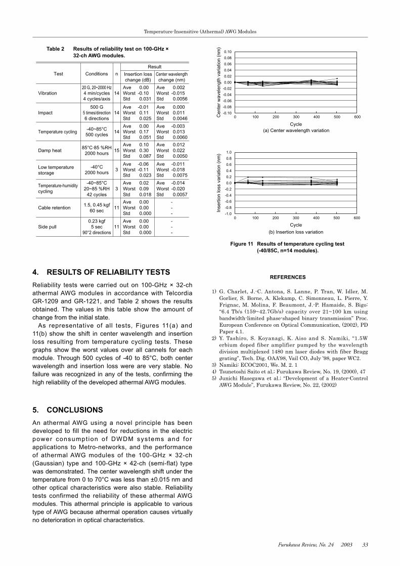
4. RESULTS OF RELIABILITY TESTSReliability tests were carried out on 100-GHz × 32-ch athermal AWG modules in accordance with Telcordia GR-1209 and GR-1221, and Table 2 shows the results obtained. The values in this table show the amount of change from the initial state.
As representative of all tests, Figures 11(a) and 11(b) show the shift in center wavelength and insertion loss resulting from temperature cycling tests. These graphs show the worst values over all cannels for each module. Through 500 cycles of -40 to 85°C, both center wavelength and insertion loss were are very stable. No failure was recognized in any of the tests, confirming the high reliability of the developed athermal AWG modules.
5. CONCLUSIONSAn athermal AWG using a novel principle has been developed to fill the need for reductions in the electric power consumpt ion o f DWDM systems and for applications to Metro-networks, and the performance of athermal AWG modules of the 100-GHz × 32-ch (Gaussian) type and 100-GHz × 42-ch (semi-flat) type was demonstrated. The center wavelength shift under the temperature from 0 to 70°C was less than ±0.015 nm and other optical characteristics were also stable. Reliability tests confirmed the reliability of these athermal AWG modules. This athermal principle is applicable to various type of AWG because athermal operation causes virtually no deterioration in optical characteristics.
Figure 11 Results of temperature cycling test (-40/85C, n=14 modules).
-0.10
-0.08
-0.06
-0.04
-0.02
0.00
0.02
0.04
0.06
0.08
0.10
0 100 200 300 400 500 600
Cycle
Cen
ter
wav
elen
gth
varia
tion
(nm
)-1.0
-0.8
-0.6
-0.4
-0.2
0.0
0.2
0.4
0.6
0.8
1.0
0 100 200 300 400 500 600
Cycle
Inse
rtio
n lo
ss v
aria
tion
(nm
)
(a) Center wavelength variation
(b) Insertion loss variation
Table 2 Results of reliability test on 100-GHz × 32-ch AWG modules.
Result
Test Conditions n Insertion loss Center wavelengthchange (dB) change (nm)
20 G, 20~2000 Hz Ave 0.00 Ave 0.002Vibration 4 min/cycles 14 Worst -0.10 Worst -0.015
4 cycles/axis Std 0.031 Std 0.0056
500 G Ave -0.01 Ave 0.000Impact 5 times/direction 14 Worst 0.11 Worst 0.011
6 directions Std 0.025 Std 0.0046
-40~85°CAve 0.00 Ave -0.003
Temperature cycling500 cycles
14 Worst 0.17 Worst 0.013Std 0.051 Std 0.0060
85°C·85 %RHAve 0.10 Ave 0.012
Damp heat2000 hours
15 Worst 0.30 Worst 0.022Std 0.087 Std 0.0050
Low temperature storage
-40°CAve -0.06 Ave -0.011
2000 hours3 Worst -0.11 Worst -0.018
Std 0.023 Std 0.0075
Temperature-humiditycycling
-40~85°C Ave 0.02 Ave -0.01420~85 %RH 3 Worst 0.09 Worst -0.020
42 cycles Std 0.018 Std 0.0057
1.5, 0.45 kgfAve 0.00 -
Cable retention60 sec
11 Worst 0.00 -Std 0.000 -
0.23 kgf Ave 0.00 -Side pull 5 sec 11 Worst 0.00 -
90°2 directions Std 0.000 -