Embed Size (px)
Citation preview

MEASUREMENTTEMPERATURE
INC 331 Industrial process measurement, 2019
AGENDA
A. Introduction
B. Thermal-expansion methods
C. Thermocouples
D. Electrical-resistance sensors
E. Junction Semi-Conductor sensors
F. Digital Thermometer
G. Pyrometers
H. Fiber optic Thermometers

A. Introduction
The zero law of thermodynamics: two bodies to
be said to have the same temperature, they
must be in thermal equilibrium.
Temperature Scale:
• Thermodynamic Kelvin scale (SI base unit)
• Celsius scale
• Farenheit scale
• Reaumur scale
• Rankine scale
• International Practical Temperature scale
Daniel Fahrenheit
(1686-1736)
Anders Celsius
(1701-1744)
William Thomson
(Lord Kelvin, 1824-1907)
Rene Antoine Ferchault
de Reaumur (1683-1757).
Temperature is a physical property of matter that quantitatively expresses the common notions of hot and cold. Thermal equilibrium is a theoretical physical
concept, used especially in theoretical texts, that means that all temperatures of interest are unchanging in time and uniform in space
Note. The International System of Units = SI

• 0°C : Water’s freezing point
• 100 °C : Water’s boiling point
• 0°K : Absolute zero temperature: the
energy of its ground state. Absolute zero, the lowest
temperature possible, is defined as being exactly 0 K and −273.15 °C
• 273.16°K : Water's triple point= 0.01 °C
A. Introduction
0°K
273.16 °K = 0 °C
K
The single combination of pressure
and temperature at which water, ice,
and water vapour can coexist in a
stable equilibrium occurs at exactly 273.16 K (0.01 °C) At that point, it is
possible to change all of the substance
to ice, water, or vapor by making
arbitrarily small changes in pressure
and temperature.


A. Introduction: Principle of temperature measurement
• Thermal expansion techniques
• Bimetallic
• Liquid-in-glass
• Filled Thermal
• Electrical Techniques
• Thermocouples
• Electrical-resistance sensors
• Junction Semi-conductor sensors
• Optical and Radiation techniques
• pyrometer
• Chemical techniques
• Crayon
• Lacker
*Contact
*Non-Contact

A. Introduction: Standard and Calibration
• International measurement system set up independent standards
for only 4 quantities: length, time, mass, and temperature. Standard
for all other quantities are basically derived from these.
• In 1927, the International Practical Temperature Scale (IPTS) was
defined (revision in 1948, 1954, 1960, 1968, and 1990)
• IPTS was set up to conform as closely as practical with the
thermodynamic scale. These primary fixed-point are listed as
follows:
• the triple point of water (0.01 C)
• the boiling point of liquid oxygen (-182.962 C)
• the boiling point of water (100 C)
• the freezing point of zinc (419.58 C)
• the freezing point of silver (961.93 C)• the freezing point of gold (1064.43 C)

A. Introduction: Standard and Calibration
• Various secondary point also established:
• A platinum resistance thermometer (-259.34 –
630.74 C)
• A platinum-10% rhodium and platinum
thermocouple (630.74-1064.43 C)
Temperature fixed-point
Temperature CalibratorNIST ITS-90 Thermocouple Database
• International Temperature Scale of 1990 (ITS-90)

A. Introduction: Standard and Calibration
Uncertainties of temperature measuring instruments

B. Thermal-expansion methods
Reference: animation pic https://en.wikipedia.org/wiki/Bimetallic_strip
B1. Bimetallic Thermometers

B. Thermal-expansion methods
B1. Bimetallic Thermometers: Applications
Household iron Thermostat

• ComponentBulb, Stem, Scale, Contraction Chamber, Expansion Chamber,
Immersion Line
B. Thermometers
B2. Liquid-in-glass Thermometers
A LiG thermometer is a glass capillary tube with a liquid-filled bulb at one end.
As the temperature of the liquid in the reservoir increases, it expands and rises
into the capillary tube. The level of the liquid in the column corresponds to a
specific temperature, which is marked on the outside of the glass. The liquid that
is contained within the thermometer may be one of many different substances, but
the most common are mercury, toluene (or a similar organic substance), and low-hazard biodegradable liquids.

B2. Liquid-in-glass Thermometers

B. Thermal-expansion methods
B2. Liquid-in-glass Thermometers

B. Thermal-expansion methods
Reference: http://www.instrumentationtoday.com/filled-system-temperature-measurement/2011/09/
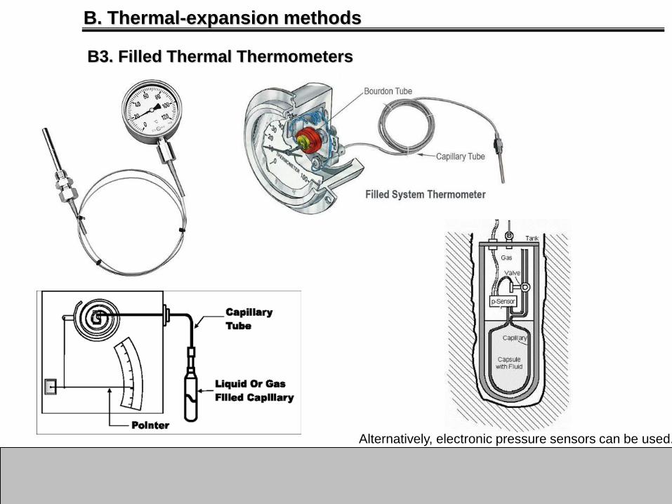
B3. Filled Thermal Thermometers
Filled system temperature measurement systems have been mostly replaced in new facilities with electronic
measurements based on thermocouples or RTD’s. A liquid will expand or contract in proportion to its
temperature and in accordance to the liquid’s coefficient of thermal/volumetric expansion. An enclosed liquid
will create a definite vapor pressure in proportion to its temperature if the liquid only partially occupies the
enclosed space. The pressure of a gas is directly proportional to its temperature in accordance with the
basic principle of the universal/perfect gas law: PV = nRT where P = absolute pressure, V = volume, T =
absolute temperature, R = universal gas constant and n = number of gas particles (moles).
1. Sensing Bulb
2. Capillary Tube
3. Pressure Sensing
4. Indicator
B. Thermal-expansion methods
B3. Filled Thermal Thermometers
Alternatively, electronic pressure sensors can be used.
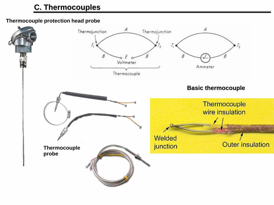
C. Thermocouples
Thermocoupleprobe
Basic thermocouple
Thermocouple protection head probe
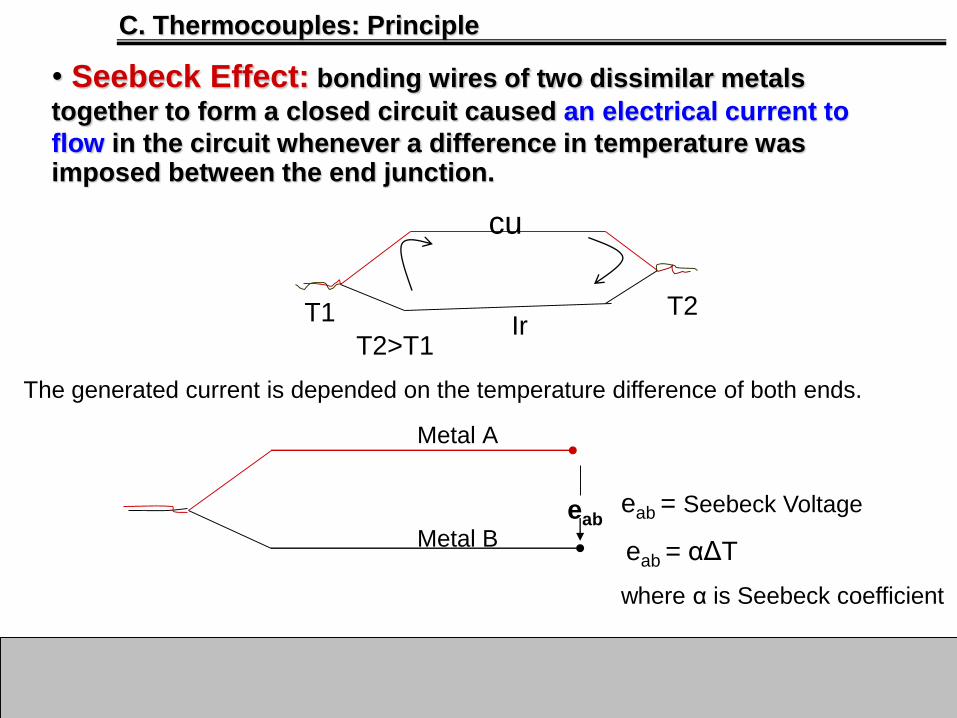
C. Thermocouples: Principle
• Seebeck Effect: bonding wires of two dissimilar metals
together to form a closed circuit caused an electrical current to
flow in the circuit whenever a difference in temperature was imposed between the end junction.
T2>T1
T1 T2
cu
Ir
The generated current is depended on the temperature difference of both ends.
Metal A
Metal Beab
eab = Seebeck Voltage
eab = αΔT
where α is Seebeck coefficient

Seebeck Series: The magnitude and direction of thermo emf in a thermocouple
depends not only on the temperature difference between the hot and cold
junctions but also on the nature of metals constituting the thermocouple.
(i) Seebeck arranged different metals in the decreasing order of their electron
density. Few metals forming the series are as below.
Sb, Fe, Cd, Zn, Ag, Au, Cr, Sn, Pb, Hg, Mn, Cu, Pt, Co, Ni, Bi
(ii) Thermo electric emf is directly proportional to the distance between the two
metals in series. Farther the metals in the series forming the thermocouple
greater is the thermo emf. Thus maximum thermo emf is obtained for Sb-Bi
thermo couple

Peltier Effect: It is reverse of Seeback effect. When the electric
current flows in the same direction as the seebeck current, heat is absorbed at the hotter junction and liberated at the colder junction. (fundamental basis for thermoelectric cooling and heating).
Example Ir – Cu Junction
Q = ¶IΔT Q = Heat , ¶ = Peltier Coefficient
I = current , ΔT = temperature difference
C. Thermocouples: Principle
Thermoelectric heat pumps exploit this phenomenon, as do thermoelectric cooling devices found in refrigerators.
Peltier element (1 V, 1 A) cooling one side, heating the other one.

C. Thermocouples: Principle

• Thomson Effect: A phenomenon discovered in 1854 by William Thomson,
later Lord Kelvin. He found that there occurs a reversible transverse heat
flow into or out of a conductor of a particular metal, the direction depending
upon whether a longitudinal electric current flows from colder to warmer
metal or from warmer to colder.
• The major difference between Thomson effect and other two is that in
Thomson effect we deal with only single metallic rod and not with thermo-
couple as in Peltier effect and Seebeck effect. According to this effect, if a
conductor has placed in varying temperature along its length and current is
passed through it then it will absorb or evolved heat. Absorbing or evolving
heat will depend on direction of current.
• It appears that the total Thomson emf along a conductor depends only
upon the temperatures of the two ends, and not in any way upon the
particular manner in which the temperature gradient varies. Thus allowing
the use of extension wires with thermocouples because no electromotive
force is added to the circuit.
C. Thermocouples: Principle

C. Thermocouples: Practical rules
• Law of the homogeneous circuit:A thermocouple current cannot be established in
circuit of a single homogeneous material.
• Law of Intermediate Material:The algebraic sum of the thermo-electromotive forces
in a circuit composed of any number of dissimilar
materials is zero if all of the circuit is at uniform
temperature. This means that a third homogeneous
material always can be added to a circuit with no effect
on the net EMF of the circuit as long as its extremities
are at the same temperature.

C. Thermocouples: Practical rules
• Law of Intermediate Temperature: Algebraic summation of EMF can be determined when the junctions are at
different temperatures (see in figure):
The law allows us to calibrate a thermocouple at one temperature interval and then to use it at
another interval. It also provides that extension wires of the same combination may be inserted
into the loop without affecting the accuracy.

Type T (copper-constantan)

Type J Iron(Fe)-constantan
Note. Add Fe for proving the theory

V3=V4Fe
Note. Extend Cu wires

Note. Original form

C. Thermocouples: Reference Junction
The end result is a measurement of the difference in temperature between the thermocouple junction and the reference junction.
Reference or Cold Junction Control
oFixed Reference Temperature
oElectronic Reference Compensate
oMechanical Reference Compensate

C. Thermocouples: Fixed Reference Temperature
1. Fixed Reference Junction Temperature with ice or fridge
2. Reference Junction with oven with temperature control at 50 OC or
isothermal block

C. Thermocouples: Principle
This practical instruments use electronic methods of cold-junction compensation
to adjust for varying temperature at the instrument terminals. Electronic
instruments can also compensate for the varying characteristics of the thermocouple, and so improve the precision and accuracy of measurements .
RTD or Thermister is used in wheatstone bridge to measure the reference
junction temperature and compensate the result voltage.
2. Electrical Reference Compensate
3. Mechanical Reference Compensate
This technique applies to the instrument with moving coil display.
The bimetallic component measured the reference junction
temperature and automatically adjust the display mechanism.

C. Thermocouples: Hardware Compensation

C. Thermocouples: Hardware Compensation
The LM94022 reference junction devices provides the function of cold end
temperature determination. Additionally, the LMP7715 operational amplifier
eliminates common mode pick-up from long thermocouple cables, another
common design challenge to thermocouples.

C. Thermocouples: Principle

C. Thermocouples: Principle
Type Material temp range (C) E (mV) Oxidizing* Reducing* Vacuum*
J Iron – Constantan1 -210 - 760 -8.096 - 42.922 y y y
K Cromel 2- Alumel 3 -270 - 1372 -6.458 - 54.875 y n n
T Copper - Constantan -270 - 400 -6.258 - 20.869 y y y
E Chromel - Constantan -270 - 1000 -9.835 - 76.358 y n n
R Platinum 13% Rhodium - Platinum -50 - 1768 -2.26 - 21.108 y n n
S Platinum 10% Rhodium - Platinum -50 - 1768 -0.236 - 18.698 y n n
Comparison between standard thermocouples
* No protection tube1 Copper(60%)-Nickel(40%)2 Nickel(90%)-Chromium(10%) 3 Nickel(95%)-Manganese(2%)-Aluminum(2%)-Silicon(1%)
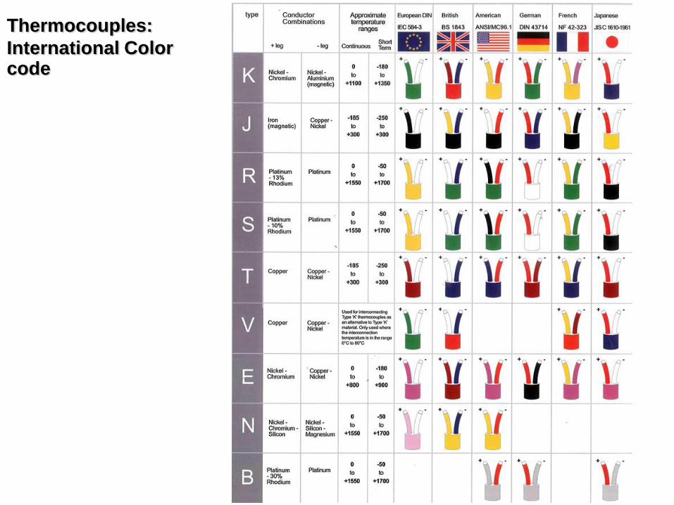
Thermocouples:
International Color code

1. Extension wires made of the same metals as a higher-
grade thermocouple are used to connect it to a
measuring instrument some distance away without
introducing additional junctions between dissimilar
materials which would generate unwanted voltages; the
connections to the extension wires, being of like metals,
do not generate a voltage. Same metals as thermocouple2. In the case of platinum thermocouples, extension wire is
a copper alloy, since it would be prohibitively expensive
to use platinum for extension wires. The extension wire
is specified to have a very similar thermal coefficient of
EMF to the thermocouple, but only over a narrow range of temperatures; this reduces the cost significantly.
C. Thermocouples: Extension Wire

Note. Thermocouple wire may be used as extension wire, but extension
grade wire may not be used in the sensing point (or probe part) of the thermocouple.
C. Thermocouples: Extension Wire

C. Thermocouples: Tips style


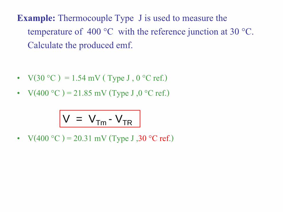
Example: Thermocouple Type J is used to measure the temperature of 400 °C with the reference junction at 30 °C. Calculate the produced emf.
• V(30 °C ) = 1.54 mV ( Type J , 0 °C ref.) • V(400 °C ) = 21.85 mV (Type J ,0 °C ref.)
• V(400 °C ) = 20.31 mV (Type J ,30 °C ref.)
V = VTm - VTR

• Transmitter: Zero 4 mA and span 20 mA• Using Oven
Oven is controlled at 50ºC for a Reference Junction control.Zero and Span Adjustment at Indicator or Transmitter
Example. The indicator with the range of 0-500ºC used with the thermocouple Type K is calibrated with Millivoltage source.
C. Thermocouples: Calibration

Cu
Cu
Oven 50ºC
Indicator
Room Temp
25ºC
Millivoltage
Source
Zero Adjustment
Consider as measure real 0ºCbut instead of using thermocouple, the voltage is generated from a millivoltagesource.
MethodsV(0 °C ) = 0 mV ( Type K , 0 °C ref.) V(50 °C ) = 2.02 mV (Type K ,0 °C ref.) V = VTm - VTR
Therefore, to adjust the zero(0ºC), users must adjust the voltage source to generate voltage = 0.0000 – 2.02 = -2.02 mVThen , adjust the zero scale of indicator to 0ºC or adjust the transmitter to source 4 mA
or Transmitter

C. Thermocouples: Calibration
In practical, zero and span adjustment must done many times by changing the generating voltage between zero and span until getting the desired values.
vs Smart Transmitter
Span Adjustment
Consider as measure 500ºC but instead of using thermocouple, the voltage is generated from a millivoltage source.
MethodsV(500 °C )= 20.65 mV ( Type K , 0 °C ref.) V(50 °C ) = 2.02 mV (Type K ,0 °C ref.)
Therefore, to adjust the span(500ºC), users must adjust the voltage source to generate voltage = 20.65 – 2.02 = 18.63 mVThen , adjust the span scale of indicator to 500ºC or adjust the transmitter to be 20 mA.

Connecting to extension wireIn some situations, the millivolt source must be connected to extension
wires. Oven 50ºC
Indicator
Room Temp
25ºC
Millivoltage
Source
Extension
wire Type
K
Type K
Cu
Cu
Ambient
Temp
30ºC
Zero Adjustment Ambient Temp 30ºC, Reference Junction Temp 50ºCExtension wire is Type K therefore it has the same properties as Type K TC.
V = VTA – VTR= 1.20 – 2.02 = -0.82 mV
V(30 °C ) = 1.20 mV ( Type K , 0 °C ref.) V(50 °C ) = 2.02 mV (Type K ,0 °C ref.)
or Transmitter
The voltage produced at the extension wire is

In the real application (measure 0ºC at Ref. Jn. 50ºC), the indicator must receive V = VTm-VTR
= 0.0 – 2.02 = -2.02 mV
V = VTA – VTR
= 1.2 – 2.02 = -0.82 mV
Thus, millivolt source must generate voltage users to extension wire
x + (-0.82) = -2.02
x = -2.02 + 0.82 = -1.2 mV
But, there is a voltage produced at the extension wire
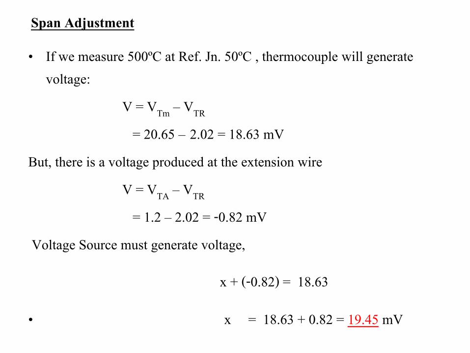
• If we measure 500ºC at Ref. Jn. 50ºC , thermocouple will generate voltage:
V = VTm – VTR
= 20.65 – 2.02 = 18.63 mVBut, there is a voltage produced at the extension wire
V = VTA – VTR
= 1.2 – 2.02 = -0.82 mVVoltage Source must generate voltage,
x + (-0.82) = 18.63
• x = 18.63 + 0.82 = 19.45 mV
Span Adjustment

Calibration of Indicator or Transmitter#Type K for Auto-compensation reference junction.
At reference junction of 25ºC , auto-compensate circuit will generate 1 mV.
Millivolt source voltage + 1 mV = 0 mV, Millivolt source voltage = -1.0 mVThe millivolt source must supply -1.0 mV to reference junction to compensate with the
voltage produced by an auto-compensation circuit.
Similary, the millivolt source must supply = 20.65 – 1 = 19.65 mV to reference junction to compensate with the voltage produced by an auto-compensation circuit.
Span Adjustment
Zero Adjustment
Auto-
Compensate
Room Temp
25ºC
Millivoltage
Source
or Transmitter
With auto-compensation circuitAt 0ºC , Indicator/Transmitter must receive 0 mV.At 500ºC, Indicator/Transmitter must receive 20.65 mV.

Example (1)From a given figure, explain the method to calibrate the transmitter with the temperature range of 0 0C to 150 0C.
Transmitter 4-20 mA
ZERO SPAN

Example (2)
From a given figure, if the measured voltage (V) is between 0 mV and 5 mV, calculate the temperature range of this thermocouple in degree Celsius
T
TypeK
25oCT1
Cu
Cu
V++
--
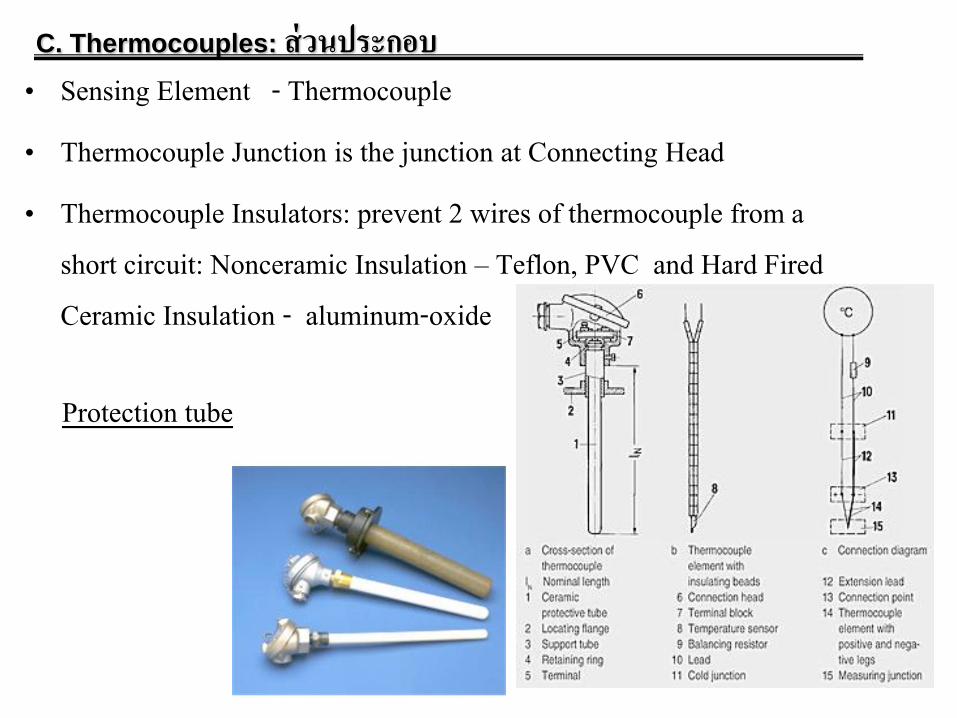
• Sensing Element - Thermocouple• Thermocouple Junction is the junction at Connecting Head• Thermocouple Insulators: prevent 2 wires of thermocouple from a
short circuit: Nonceramic Insulation – Teflon, PVC and Hard Fired Ceramic Insulation - aluminum-oxide
C. Thermocouples: ส่วนประกอบ
Protection tube

C. Thermocouples: Thermowell
For intrusive fitting, protection, easy
cleaning. But slow down the response

D. Electrical-resistance sensors
D1. Resistance thermometer (RTD)
Sir Humphrey Dery found the relation between temperature and metal resistance. In 1835, Faraday invented Resistance Thermometer based on thermoresistive principle.
Resistance temperature detectors (RTDs), are sensors used to
measure temperature by correlating the resistance of the RTD element with temperature.
t 0R R 1 t
R0 : the resistance of the sensor at 0°C
Rt : the resistance of the sensor at t°C
: temperature coefficient of resistance
2 1 0 2 1R R R t t

Thin film Wire wound
Coiled
RTD Components

D. Electrical-resistance sensors
D1. Resistance thermometer (RTD)
RTD protectionhead probe
RTD probe
....)1( 32
0 cTbTaTRRT

Platinum Resistance Thermometer• Popular type RTD, wide measuring range, the most stable resistance to temperature relationship
over the largest temperature range, hazardous environment, temperature coefficient of resistance = 0.00385/ /ºC [Commercial platinum grades] , standard for Eurepean, accurate, range : -100 to 890 ºC (PT-100),
• PT-100 : at 0 ºC =100 • PT-50 : at 0 ºC =50
• Nickel RTD: non standard , limited temperature range, very non-linear at temperatures over 572 F (300 ºC) , temperature coefficient of resistance = 0.0066 / /ºC
• Copper Resistance Thermometer: very linear resistance to temperature relationship, measurement range -200 to 150ºC (limited due to oxidizes), resistance standard 10 and 25 at 0ºC
Nickel and Copper Resistance Thermometer
Mil is a thousandth of an inch derived unit of length in an
inch-based system of units. Equal to 0.001 inches.


• Performance Characteristic
Accuracy: calibration at 6 fixed reference points
D1. Resistance thermometer (RTD)
the triple point of water (0.01 C)the boiling point of liquid oxygen (-182.962 C)the boiling point of water (100 C)the freezing point of zinc (419.58 C)the freezing point of silver (961.93 C)the freezing point of gold (1064.43 C)
• Performance Characteristic
Stability i.e. Drift Repeatability Response Time Self-Heating

Example RTD (PT-100) is used to measure the temperature of one material. If the measured resistance of RTD is 109.625 Ω, calculate the temperature of this material. Assume and Ω/ Ω/ oC
)1(0 tRRt
00385.0

1. Unbalanced Bridge: If the two voltage dividers have exactly the same ratio
(R1/R2 = R3/R4), then the bridge is said to be balanced and no current flows in either
direction through the galvanometer. Bridge is setting to be balanced at 0 oC.
2. Balanced Bridge: An unknown resistor, RX, is connected as the fourth side of the
circuit, and power is applied. R2 is adjusted until the galvanometer, G, reads zero current. At this point, RX = R2×R3/R1.
D. Electrical-resistance sensors
The Wheatstone Bridge
This method is frequently used in strain gauge and resistance thermometer
measurements, as it is usually faster to read a voltage level off a meter than to adjust a resistance to zero the voltage.

-2 Wire [Simplest]Accuracy very much depends on cable length.
Ex. For balanced bridge, R1 RTD = R2 R3
If R1 = R2, R3 = RTDThen R3 = RTD , which measuring temperature can be found from RTD table.
D. Electrical-resistance sensors
D1. Resistance thermometer (RTD) Connection
R1R2
RTD
G
R3

Ex.For balanced bridge,
R1 (RTD+r1+r2) = R2 R3
If R1 = R2, R3 = RTD + r1 + r2 Thus, R3 is not only RTD. This can
cause an error.
D. Electrical-resistance sensors
R1R2
RTD
G
R3
r1
r2
Effect of the lead resistances

D. Electrical-resistance sensors
R1
RTD
G
C
B
AR3
R2
A=B=C, R1=R2 For balanced bridge,
R2(R3+A) = R1(RTD+C)
R1 = R2, R3+A = RTD+C
and A=B=C then R3 =RTD
- 3 Wire [Most popular configuration]
Leadwire resistance error cancelation is most effective when all the lead wires have the same resistance.
Using 3 wires of the same AWG, length, and composition will typically result in leadwire resistances matched
within 5%. 3-wire construction is most commonly used in industrial applications where the third wire provides a
method for removing the average lead wire resistance from the sensor measurement. When long distances
exist between the sensor and measurement/control instrument, significant savings can be made in using a
threewire cable instead of a four-wire cable
Reference:http://instrumentationtools.com/difference-between-2-3-and-4-wire-rtds/

D. Electrical-resistance sensors
D1. Resistance thermometer (RTD)
- 4 Wires[Most accurate type: Four-terminal sensing]

D. Electrical-resistance sensors
D1. Resistance thermometer (RTD) connection with Transmitter or DAQ
4

D. Electrical-resistance sensors
D1. Resistance thermometer (RTD)
Average temperature sensing
Differential temperature sensing

Thermocouple and RTD Transmitter
A ‘Smart’ Transmitter has a digital communication protocol used for reading the transmitter’s measurement values and for configuring various settings in the transmitter. The most common digital communication protocols is HART protocol,
(Highway Addressable Remote Transducer).A HART transmitter contains both a
conventional analogue mA signal and a digital signal superimposed on top of the
analogue signal.
Reference: http://www.processindustryforum.com/article/smart-transmitter-calibration-smart-transmitters-necessary
DIN rail mount

Effects of electrical noise on thermocouple
measurements
• The signal (voltage) from a typical thermocouple is low, of order 10 mV, and the
signal-to-noise ratio may degrade rapidly in the presence of signal noise, inherently
raising the uncertainty of the temperature measurement. Capacitive coupling
between the thermocouple pair and the power line, illustrated in Figure 1, induces a
60Hz “noise” voltage in the closed thermocouple circuit. The amplitude of the noise
signal generated is directly proportional to the magnitude of the current in the
offending power line.
Reference: http://www.electronics-cooling.com/2002/08/effects-of-electrical-noise-on-thermocouple-measurements/

D. Electrical-resistance sensors
D2. Bulk Semi-conductor sensor (Thermistor)
The thermistor's resistance to temperature
relationship to temperature is given by the Steinhart & Hart equation:
T = 1 / ( a + b.ln(R) + c.ln(R)3 )
where a, b and c are constants, ln( ) the natural
logarithm, R is the thermistors resistance in ohms and T is the absolute temperature in °K. While the
Steinhart & Hart equation is a close fit to practical
devices, it does not always provide the precision required over the full temperature range.
The resistors value should equal the thermistor's resistance at
the mid-range temperature. The result is a significant reduction
in non-linearity. 2200 ohm resistor in parallel with a 2252 ohm (at 25°C) thermistor.
Accurate Equations
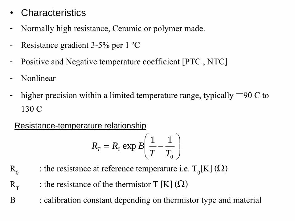
• Characteristics
- Normally high resistance, Ceramic or polymer made. - Resistance gradient 3-5% per 1 ºC- Positive and Negative temperature coefficient [PTC , NTC]- Nonlinear- higher precision within a limited temperature range, typically −90 C to
130 C
0
0
11exp
TTBRRT
R0 : the resistance at reference temperature i.e. T0[K] ()RT : the resistance of the thermistor T [K] ()B : calibration constant depending on thermistor type and material
Resistance-temperature relationship

Comparison between Temperature Sensors


D. Electrical-resistance sensors
D2. Bulk Semi-conductor sensor (Thermister)
Thermistor linearization networks

D. Electrical-resistance sensors
D2. Bulk Semi-conductor sensor (Thermister)

E. Junction Semi-Conductor sensors
A summary of available
semiconductor temperatures sensors
is presented below, followed by more
detail on some of the more popular
devices. The sensors can be grouped
into five broad categories:
• voltage output
• current output
• resistance output
• digital output
• simple diode types

E. Junction Semi-Conductor sensors
Examples of circuit implementation using AD590
AD590: Two Terminal IC Temperature Transducer
The AD590 is a two-terminal integrated circuit temperature transducer
that produces an output current proportional to absolute temperature.
Calibration
*adjust R
Apply reference temp

E. Examples of circuit implementation using AD590
AD580: High Precision 2.5V IC Reference
A rate of change of the resistance value expressed in units of parts per million (ppm) when the temperature increases by 1°C to a reference
temperature. It is generally used as a gauge to show the temperature stability of a resistive element

Comparison of Temperature Transducers

Comparison of thermocouple and RTD selection

Comparison of thermocouple and RTD selection

F. Digital Thermometer

F. Digital Thermometer
Example of a connection of sensors to transmitter

Non-contact Technologies• The uses of noncontact temperature sensors are many; the
understanding of their use is, in general, relatively poor. Part of that complication is often the need to deal with emissivity, or more precisely with spectral emissivity.
• In many industrial plants noncontact sensors are not yet standardized to the extent that thermocouples and RTDs are. In spite of this, there are numerous showcase uses of them and they more than pay their way in process plants such as steel, glass, ceramics, forging, heat treating, plastics, baby diapers and
semiconductor operations, to name just a few.
• Non-contact sensors are required because of contamination or hazardous environments where distance are great or temperature are too high for contact sensors.
Types
- Infrared Pyrometers,
- Optical (Brightness) Pyrometer
- Others:Infrared Thermal Imaging Cameras(with temperature measurement capability), Line measuring(Line-scanner) ,(two separate waveband) Ratio Pyrometer

G. Pyrometers

G. Pyrometers
Radiation pyrometers
Based on Planck's Law of the thermal emission of electromagnetic radiation , radiation
pyrometers are calibrated in units of power, such as microwatts, watts,kilowatts,
temperature measurement devices are calibrated in units of temperature.
Energy Electric Signal Temperature
A pyrometer is a type of thermometer used to measure high temperature based on a
thermal radiation process. A pyrometer has an optical system and detector. The optical
system focuses the thermal radiation onto the detector. The output signal of the
detector (Temperature T) is related to the thermal radiation of the target object through
the Stefan–Boltzmann law.The output of the detector is proportional to the amount of
energy radiated by the target object (less the amount absorbed by the optical system),
and the response of the detector to the specific radiation wavelengths. This output can
be used to infer the objects temperature.
Thermal radiation is electromagnetic radiation and it may include both visible radiation (light) and infrared radiation, which is not visible to human eyes.

G. Pyrometers
Infrared pyrometers Spot Infrared Thermometer or Infrared Pyrometer, which
measures the temperature at a spot on a surface (actually a
relatively small area). By knowing the amount of infrared
energy emitted by the object and its emissivity, the object's
temperature can often be determined. Infrared thermometers
are a subset of devices known as "thermal radiation thermometers“.
These devices can measure this radiation from a distance.
There is no need for direct contact between the radiation
thermometer and the object, as there is with thermocouples and resistance temperature detectors (RTDs).
Fixed-mounted
Handheld or Gun

G. Pyrometers
Infrared thermometer

Main factors for non-contact measurement• Field of View
• Emissivity
• Distance to Target (Spot) Ratio
• Environmental Conditions and Ambient Temperatures
• Field of view: The field of view is the angle of vision at which the instrument operates, and is determined by the optics of the unit. To obtain an accurate temperature reading, the target being measured should completely fill the field of view of the instrument.
• Emissivity: The emittivity, or emittance, (є) of the object is an important variable in converting the detector output into an accurate temperature signal. It is defined as a ratio of the energy radiated by an object at a given temperature to the energy emitted by a perfect radiator(Blackbody є=1).

• Distance to Target (Spot) Ratio: The optical system of an infrared sensor collects the infrared energy from a circular measurement spot and focuses it on the detector. Optical resolution is defined by the ratio of the distance from the instrument to the object, compared to the size of the spot being measured (D:S ratio). The larger the ratio number the better the instrument's resolution, and the smaller the spot size that can be measured from greater distance.
Optical Resolution. The optical system of an IR thermometer collects
the emitted IR energy from a circular measurement spot. The target
must completely fill this spot; otherwise the sensor will "see" other
temperature radiation from the background, making the measured value inaccurate.

• Field of view: The field of view is the angle of vision at which the instrument operates, and is determined by the optics of the unit. To obtain an accurate temperature reading, the target being measured should completely fill the field of view of the instrument.
• Emissivity: The emittivity, or emittance, (є) of the object is an important variable in converting the detector output into an accurate temperature signal. It is defined as a ratio of the energy radiated by an object at a given temperature to the energy emitted by a perfect radiator(Blackbody є=1).

G. Pyrometers
Visual IR thermometer
Others:Thermal Imaging Camera

House inspection
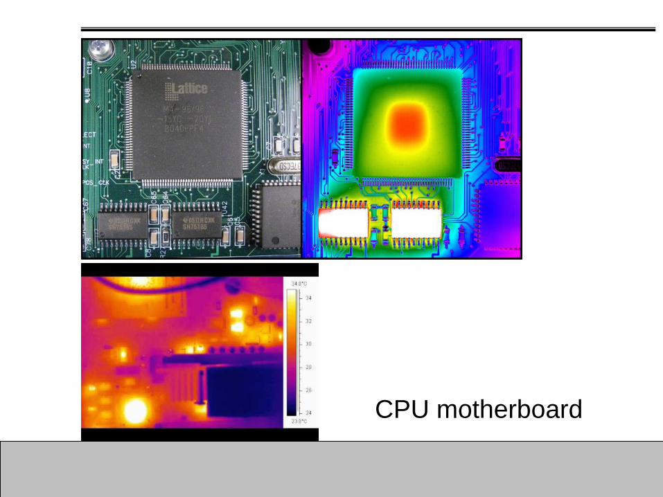
CPU motherboard

Adjustment
Since all other targets have an emissivity ranging
between 0 and 1 , practical radiation thermometers have
adjust able gains to account for both changes in target emissivity and absorption errors.

G. Pyrometers
Opitcal pyrometers
Traditional optical pyrometers measure
brightness in the visible spectrum.
Optical Pyrometers work on the basic
principle of using the human eye to
match the brightness of the hot object to
the brightness of a calibrated lamp
filament inside the instrument.

G. Pyrometers
An optical pyrometer is a device which allows contactless temperature
measuring by using the incandescense color. It is based upon the fact
that all black bodies do have the same incandescense color at a given
temperature. It is very straightforward and allows any temperature from
which a hot object emits light ( > 500 deg C). It is made from a small
magnifying optical device (like a monocular or very small telescope) in
which a small incandescent bulb is placed which image is sharp when
the user views through the eyepiece (the lens(es) on the eye end of the
optical device). The background is the hot object to be gauged. The
electrical current flowing through the filaments in the bulb is an indication
of their temperature. This current is controlled by a potentiometer which
is put between the power source (a battery) and the bulb. An ammeter is
used to display the temperature. Its range is from 500 C (== 900F lower
limit when an object incandesces) to 1600 C (3000 F), which is suitable for most applications.

G. Pyrometers
The current through a heated filament lamp is adjusted until, when viewed
through the telescope, it seems to disappear. The radiation from the lamp and
from the heat source are therefore the same. The current through the lamp is a
measure of the temperature of the heat source, and the ammeter is calibrated
in units of temperature. The absorption screen is used to absorb some of the
radiant energy from the heat source and thus extend the measuring range of
the instrument. The monochromatic filter produces single-colour, usually red, light to simplify filament radiation matching.

G. Pyrometers
Advantages of Optical Pyrometer
Flexibility
Portability
Monitor the temperature of moving object
Disadvantages of Optical Pyrometer
Cannot measure the temperatures of clean burning gases because these
gases do not radiate visible energy.
Manual optical pyrometer are unsuitable for measuring the temperature of
target object with temperature below 800 degree C because at lower
temperatures the radiation emitted is at too low a level to be recorded.
Note. The error varies from a few degrees C for target objects with high levels
of radiation to several hundred degrees C for target objects with low levels of
radiation. So most outdoor measurements are made with infrared pyrometers.

G. Pyrometers
Fiber Optic Pyrometers measure from 300 - 2,500 °C.

H. Fiber optic Thermometers
Fiber optical thermometers can be used in electromagnetically strongly
influenced environment, in microwave fields, power plants or explosion-
proof areas and wherever measurement with electrical temperature sensors
is not possible. Optical temperature sensor is specifically designed for
general use in laboratories and industrial applications. It features complete
immunity to microwaves and RF (EMI/RFI), high voltage and harsh
environments. It has a high resistance to a wide range of temperature and
meets all requirements for long term survivability to chemicals.
Fiber optic thermometers or fiber optic temperature sensors are
basically light pipes which are mainly employed for measurement of temperature in complex situations.

In a fiber-optic thermometer comprising a fiber-optic input for
applying input light, a fiber-optic output for extracting output
light, and a temperature-sensitive medium optically coupling for
transferring a proportion of the applied input light from said fiber-
optic input to said fiber-optic output, the size of said transferred
proportion being a single-valued function of the temperature of
said medium. An activated temperature measuring system
involves a sensing head containing a luminescing phosphor
attached at the tip of an optical fiber. A pulsed light source from
the instrument package excites the phosphor to luminescence
and the decay rate of the luminescence is dependent on the temperature.
H. Fiber optic Thermometers

Black body radiation sources for
calibration and testing of infrared
radiation pyrometer, LINE-SCANNER and thermal imager
Calibration radiators
Calibration

SUMMARY AND CONCLUSION