Embed Size (px)
Citation preview
International Journal of Research Available at https://edupediapublications.org/journals
p-ISSN: 2348-6848 e-ISSN: 2348-795X
Volume 03 Issue 10 June 2016
Available online: http://edupediapublications.org/journals/index.php/IJR/ P a g e | 1147
Temperature Sensor Using Microcontroller
Majed Kamil Qetheth
Master of Science in Physics (Applied Electronics)
University College of Science
Osmania University
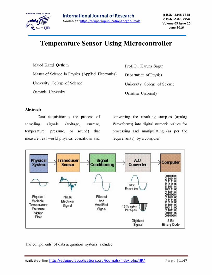
Abstract:
Data acquisition is the process of
sampling signals (voltage, current,
temperature, pressure, or sound) that
measure real world physical conditions and
converting the resulting samples (analog
Waveforms) into digital numeric values for
processing and manipulating (as per the
requirements) by a computer.
The components of data acquisition systems include:
Prof. D . Karuna Sagar
Department of Physics
University College of Science
Osmania University
International Journal of Research Available at https://edupediapublications.org/journals
p-ISSN: 2348-6848 e-ISSN: 2348-795X
Volume 03 Issue 10 June 2016
Available online: http://edupediapublications.org/journals/index.php/IJR/ P a g e | 1148
Sensors, to convert physical parameters
to electrical signals.
Signal conditioning circuitry, to convert
sensor signals into a form that can be
converted to digital values.
Analog-to-digital converters, to convert
conditioned sensor signals to digital
values.
Data acquisition applications are usually
controlled by software programs
developed using various general
purpose programming languages such
as Assembly,BASIC,C,C++,C#,Fortran,
Java,LabVIEW,Lisp, Pascal, etc.
including various Open Source Software
as well.
Stand-alone data acquisition systems are
often called data-loggers.
In our project, the Temperature data
was monitored by using the Microcontroller
& LCD. The Project has an Inbuilt Data
logger which is used to Log the Temperature
data on the LCD. A data logger is any
device that can be used to store data.
The main objectives of the Project are :
1. Real-time monitoring the ambient
temperature (in both the 0C and 0F
scales) on the LCD-Screen
2. Log the Rise and Fall of temperature
with heating and cool-down of the
LM35 Sensor.
INTRODUCTION Digital thermometer (Celsius and
Fahrenheit scale) using 8051
microcontroller (AT89S52)
Celsius and Fahrenheit scale
thermometer displays the ambient
temperature through a LCD display. It
consists of two sections. One is that which
senses the temperature. This is a temperature
sensor LM 35. The other section converts
the temperature value into a suitable number
in Celsius scale which is done by
the ADC0804. The temperature sensed in
Celsius scale is converted into the
Fahrenheit scale temperature just by using
the Celsius to Fahrenheit conversion
formulae through a little modification of the
code in the microcontroller program.
International Journal of Research Available at https://edupediapublications.org/journals
p-ISSN: 2348-6848 e-ISSN: 2348-795X
Volume 03 Issue 10 June 2016
Available online: http://edupediapublications.org/journals/index.php/IJR/ P a g e | 1149
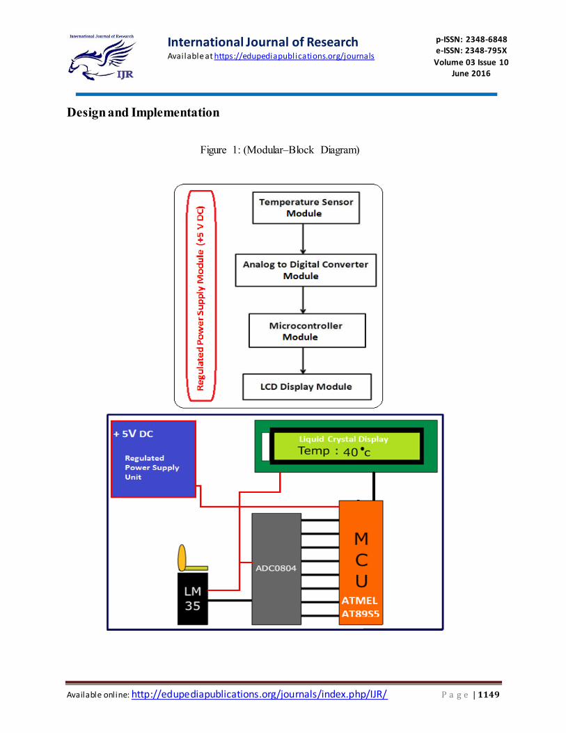
Design and Implementation
Figure 1: (Modular–Block Diagram)
International Journal of Research Available at https://edupediapublications.org/journals
p-ISSN: 2348-6848 e-ISSN: 2348-795X
Volume 03 Issue 10 June 2016
Available online: http://edupediapublications.org/journals/index.php/IJR/ P a g e | 1150
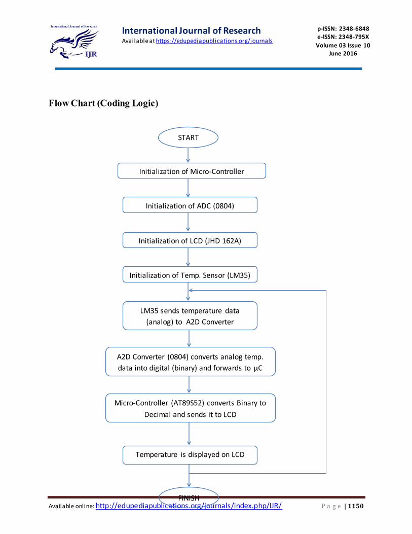
START
Initialization of Micro-Controller
(AT89S52)
Initialization of ADC (0804)
Initialization of LCD (JHD 162A)
Initialization of Temp. Sensor (LM35)
LM35 sends temperature data
(analog) to A2D Converter
A2D Converter (0804) converts analog temp.
data into digital (binary) and forwards to µC
(AT89S52)
Micro-Controller (AT89S52) converts Binary to
Decimal and sends it to LCD
Temperature is displayed on LCD
FINISH
Flow Chart (Coding Logic)
International Journal of Research Available at https://edupediapublications.org/journals
p-ISSN: 2348-6848 e-ISSN: 2348-795X
Volume 03 Issue 10 June 2016
Available online: http://edupediapublications.org/journals/index.php/IJR/ P a g e | 1151
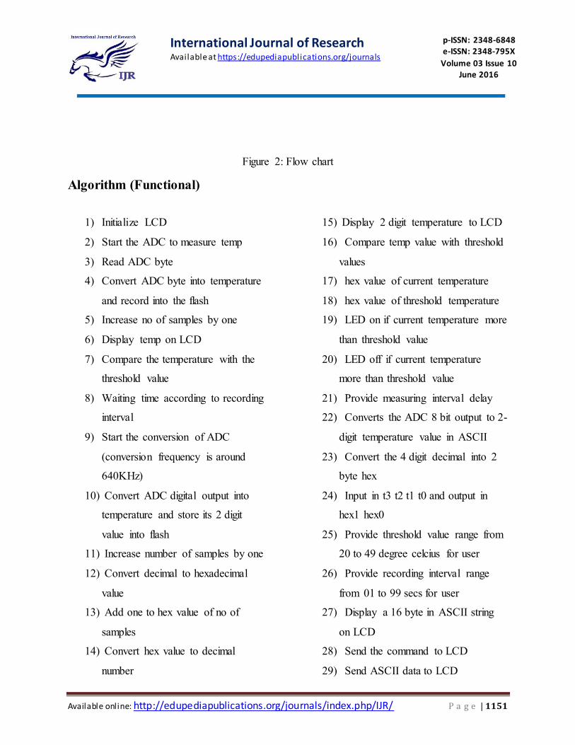
Figure 2: Flow chart
Algorithm (Functional)
1) Initialize LCD
2) Start the ADC to measure temp
3) Read ADC byte
4) Convert ADC byte into temperature
and record into the flash
5) Increase no of samples by one
6) Display temp on LCD
7) Compare the temperature with the
threshold value
8) Waiting time according to recording
interval
9) Start the conversion of ADC
(conversion frequency is around
640KHz)
10) Convert ADC digital output into
temperature and store its 2 digit
value into flash
11) Increase number of samples by one
12) Convert decimal to hexadecimal
value
13) Add one to hex value of no of
samples
14) Convert hex value to decimal
number
15) Display 2 digit temperature to LCD
16) Compare temp value with threshold
values
17) hex value of current temperature
18) hex value of threshold temperature
19) LED on if current temperature more
than threshold value
20) LED off if current temperature
more than threshold value
21) Provide measuring interval delay
22) Converts the ADC 8 bit output to 2-
digit temperature value in ASCII
23) Convert the 4 digit decimal into 2
byte hex
24) Input in t3 t2 t1 t0 and output in
hex1 hex0
25) Provide threshold value range from
20 to 49 degree celcius for user
26) Provide recording interval range
from 01 to 99 secs for user
27) Display a 16 byte in ASCII string
on LCD
28) Send the command to LCD
29) Send ASCII data to LCD
International Journal of Research Available at https://edupediapublications.org/journals
p-ISSN: 2348-6848 e-ISSN: 2348-795X
Volume 03 Issue 10 June 2016
Available online: http://edupediapublications.org/journals/index.php/IJR/ P a g e | 1152
THE SOURCE CODE
The Embedded-C Program Code which is
burnt onto the Micro-Controller is as
under :
//Program to display temperature in Celsius
and Farenheit scale.
#include<stdio.h>
#include<string.h>
#include<Regx52.h>
#define port P3
#define adc_input P1
#define dataport P0
#define sec 100
sbitrs = port^0;
sbitrw = port^1;
sbit e = port^2;
sbitwr= port^3;
sbitrd= port^4;
sbitintr= port^5;
int test_intermediate3=0,
test_final=0,test_intermediate1[10],test_intermediate
2[3]={0,0,0};
void delay(unsigned intmsec )
{
int i ,j ;
for(i=0;i<msec;i++)
for(j=0; j<1275; j++);
}
void lcd_cmd(unsigned char item) // Function to
send commands to LCD
{
dataport = item;
rs= 0;
rw=0;
e=1;
delay(1);
e=0;
return;
}
void lcd_data(unsigned char item) // Function to
send data to LCD
{
dataport = item;
rs= 1;
rw=0;
e=1;
delay(1);
e=0;
return;
}
void lcd_data_string(unsigned char *str) // Function
to string to LCD
{
int i=0;
while(str[i]!='\0')
{
lcd_data(str[i]);
i++;
delay(10);
}
return;
}
void shape() // Function to make the shape of
degree symbol
{
lcd_cmd(64);
lcd_data(2);
lcd_data(5);
lcd_data(2);
lcd_data(0);
lcd_data(0);
lcd_data(0);
lcd_data(0);
lcd_data(0);
}
void convert() // Function to convert the values of
ADC into numeric value to be sent to LCD
{
int s;
lcd_cmd(0x81);
delay(2);
lcd_data_string("TEMP:");
test_final=(((9*test_intermediate3)/5)+32);
s=test_final/100;
test_final=test_final%100;
lcd_cmd(0x88);
if(s!=0)
lcd_data(s+48);
International Journal of Research Available at https://edupediapublications.org/journals
p-ISSN: 2348-6848 e-ISSN: 2348-795X
Volume 03 Issue 10 June 2016
Available online: http://edupediapublications.org/journals/index.php/IJR/ P a g e | 1153
else
lcd_cmd(0x06);
s=test_final/10;
test_final=test_final%10;
lcd_data(s+48);
lcd_data(test_final+48);
lcd_data(0);
lcd_data('F');
lcd_data(' ');
test_final=test_intermediate3;
lcd_cmd(0xc1); //Setting cursor to first position
of first line
delay(2);
lcd_data_string("TEMP:");
s=test_final/100;
test_final=test_final%100;
lcd_cmd(0xc8);
if(s!=0)
lcd_data(s+48);
else
lcd_cmd(0x06);
s=test_final/10;
test_final=test_final%10;
lcd_data(s+48);
lcd_data(test_final+48);
lcd_data(0);
lcd_data('c');
lcd_data(' ');
delay(2);
}
void main()
{
inti,j;
adc_input=0xff;
lcd_cmd(0x38); //2 Line, 5X7 Matrix display
lcd_cmd(0x0c); //Display On, Cursor blinking
delay(2);
lcd_cmd(0x01); // clear screen
delay(2);
while(1)
{
for(j=0;j<3;j++)
{
for(i=0;i<10; i++)
{
delay(1);
rd=1;
wr=0;
delay(1);
wr=1;
while(intr==1);
rd=0;
lcd_cmd(0x88);
test_intermediate1[i]=adc_input/10;
delay(1);
intr=1;
}
for(i=0;i<10; i++)
test_intermediate2[j]=test_intermediate1[i]+test_inter
mediate2[j];
}
test_intermediate2[0]=test_intermediate2[0]/3;
test_intermediate2[1]=test_intermediate2[1]/3;
test_intermediate2[2]=test_intermediate2[2]/3;
test_intermediate3=test_intermediate2[0]+test_interm
ediate2[1]+test_intermediate2[2];
shape();
convert();
}
}
International Journal of Research Available at https://edupediapublications.org/journals
p-ISSN: 2348-6848 e-ISSN: 2348-795X
Volume 03 Issue 10 June 2016
Available online: http://edupediapublications.org/journals/index.php/IJR/ P a g e | 1154
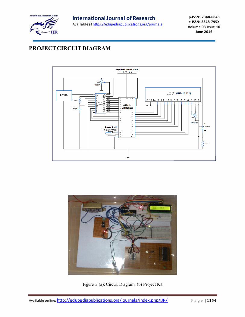
PROJECT CIRCUIT DIAGRAM
Figure 3 (a): Circuit Diagram, (b) Project Kit
International Journal of Research Available at https://edupediapublications.org/journals
p-ISSN: 2348-6848 e-ISSN: 2348-795X
Volume 03 Issue 10 June 2016
Available online: http://edupediapublications.org/journals/index.php/IJR/ P a g e | 1155
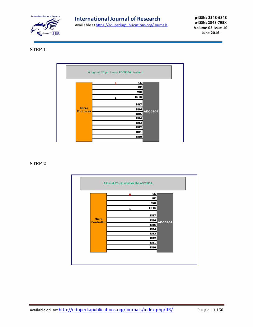
CIRCUIT FUNCTIONING
A digital thermometer can be easily
made by interfacing a temperature sensor to
the microcontroller AT89S52. The
temperature sensor used in the project
is LM35. The LM 35 IC generates a 10mV
variation to its output voltage for every
degree Celsius change in temperature. The
Output of the temperature sensor is analog
in nature so we need an analog to digital
convertor for converting the analog input to
its equivalent binary output. The ADC
0804is the analog to digital convertor IC
used in the project. 0804 is a single channel
convertor which converts the analog input
up to a range of 5V to an equivalent 8-bit
binary output.
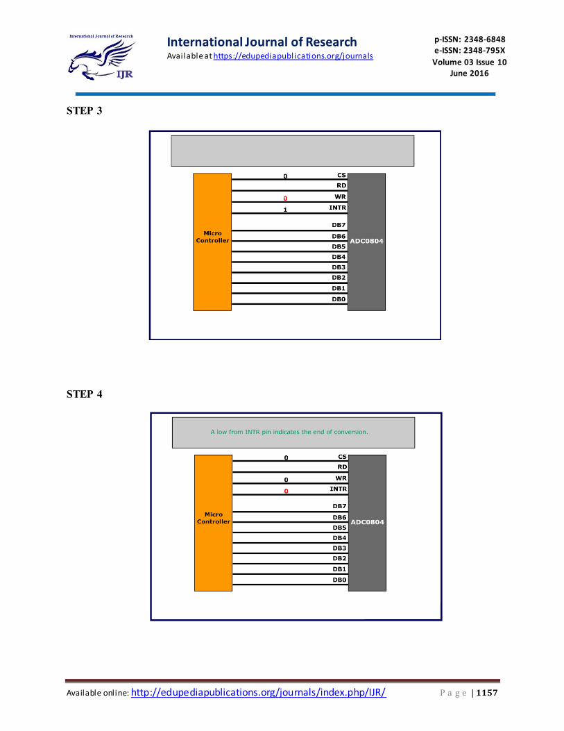
The step size is defined by the
voltage applied at the Vref/2 pin of the ADC
IC. For example, if the voltage at Vref/2 pin
is set to 1.28V then ADC has a step size of
10 mV. So if the input voltage is 1V the
equivalent binary output of ADC will be 100
or 0110 0100 in binary. The 8 bit binary
output of the ADC is incremented by one for
every 10 mV rise of input voltage. Different
step size can be selected by changing the
voltage input to the Vref/2 pin. The step size
of the ADC is calibrated using a preset to
match the actual temperature. Once the
ADC is calibrated it will give the correct
output further. The binary output of ADC is
fed parallel to a port of the microcontroller
.The microcontroller reads the input through
ADC and displays the corresponding
decimal value on LCD indicating the
temperature
.
International Journal of Research Available at https://edupediapublications.org/journals
p-ISSN: 2348-6848 e-ISSN: 2348-795X
Volume 03 Issue 10 June 2016
Available online: http://edupediapublications.org/journals/index.php/IJR/ P a g e | 1156
STEP 1
STEP 2
International Journal of Research Available at https://edupediapublications.org/journals
p-ISSN: 2348-6848 e-ISSN: 2348-795X
Volume 03 Issue 10 June 2016
Available online: http://edupediapublications.org/journals/index.php/IJR/ P a g e | 1157
STEP 3
STEP 4
International Journal of Research Available at https://edupediapublications.org/journals
p-ISSN: 2348-6848 e-ISSN: 2348-795X
Volume 03 Issue 10 June 2016
Available online: http://edupediapublications.org/journals/index.php/IJR/ P a g e | 1158
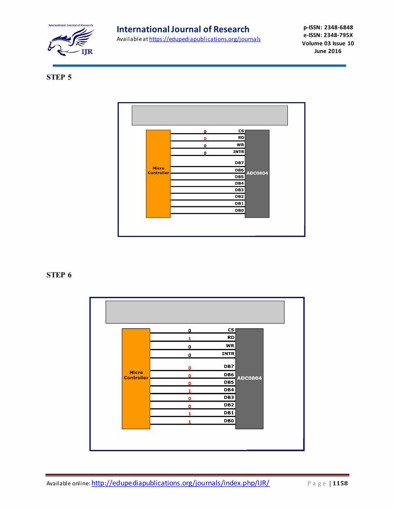
STEP 5
STEP 6
International Journal of Research Available at https://edupediapublications.org/journals
p-ISSN: 2348-6848 e-ISSN: 2348-795X
Volume 03 Issue 10 June 2016
Available online: http://edupediapublications.org/journals/index.php/IJR/ P a g e | 1159
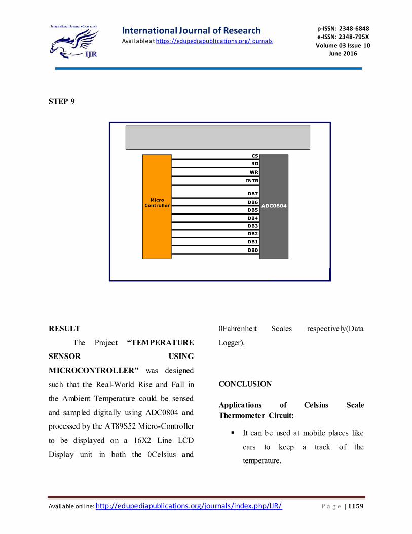
STEP 9
RESULT
The Project “TEMPERATURE
SENSOR USING
MICROCONTROLLER” was designed
such that the Real-World Rise and Fall in
the Ambient Temperature could be sensed
and sampled digitally using ADC0804 and
processed by the AT89S52 Micro-Controller
to be displayed on a 16X2 Line LCD
Display unit in both the 0Celsius and
0Fahrenheit Scales respectively(Data
Logger).
CONCLUSION
Applications of Celsius Scale
Thermometer Circuit:
It can be used at mobile places like
cars to keep a track of the
temperature.
International Journal of Research Available at https://edupediapublications.org/journals
p-ISSN: 2348-6848 e-ISSN: 2348-795X
Volume 03 Issue 10 June 2016
Available online: http://edupediapublications.org/journals/index.php/IJR/ P a g e | 1160
It can be used to control the
switching of loads like motors,
heaters based upon the temperature.
It can also be used at homes to get
the temperature reading.
Limitations of the Circuit:
It requires additional analog to
digital conversion.
The measurable Temperature range
is between -550C to +1500C
This circuit can only measure values
in +/- 10C steps.
The Fahrenheit Scale values are
obtained using the conversion
formula in Source Code
ALTERNATIVES for this Circuit:
There are a number of various other
ways in which this project task could be
accomplished. Such as:
Using the same Analog Temp. Sensor LM35
with either ATMega / ATMega32 / PIC /
Arduino or any other Micro-Controller with
a combination of Display alternatives like a
7-Segment Display / LEDs / Andriod-
SmartPhones etc.
A Few of which combinations are :
Using AT89S51, 0804 and 7-
Segment Display
Using PIC Microcontroller with 7-
Segment Display / LCD Display
Without External ADC-IC and
interfacing Using ATMega 32, 7
Segment / LCD Display
Using PIC-µC & 7 Segment / LCD
Display
Using AT89C52, DS1621 Sensor
(Digital) with 7-Segment / LCD
Display
Reference:
Bakker, A., & Huijsing, J. H. (1996).
Micropower CMOS temperature
sensor with digital output. IEEE
Journal of Solid-State Circuits,
31(7), 933-937.
Nolan, J. B., Cooper, R. E., &
Dellacroce, B. (1997). U.S. Patent
No. 5,619,430. Washington, DC:
U.S. Patent and Trademark Office.
Hill, J., Szewczyk, R., Woo, A.,
Hollar, S., Culler, D., & Pister, K.
(2000). System architecture
directions for networked sensors.
ACM SIGOPS operating systems
review, 34(5), 93-104.
International Journal of Research Available at https://edupediapublications.org/journals
p-ISSN: 2348-6848 e-ISSN: 2348-795X
Volume 03 Issue 10 June 2016
Available online: http://edupediapublications.org/journals/index.php/IJR/ P a g e | 1161
Uhrich, D. T. (1997). U.S. Patent
No. 5,611,484. Washington, DC:
U.S. Patent and Trademark Office.
Polastre, J., Szewczyk, R., & Culler,
D. (2005, April). Telos: enabling
ultra- low power wireless research. In
IPSN 2005. Fourth International
Symposium on Information
Processing in Sensor Networks,
2005. (pp. 364-369). IEEE.
Wang, N., Zhang, N., & Wang, M.
(2006). Wireless sensors in
agriculture and food industry—
Recent development and future
perspective. Computers and
electronics in agriculture, 50(1), 1-
14.
Chung, W. Y., & Oh, S. J. (2006).
Remote monitoring system with
wireless sensors module for room
environment. Sensors and Actuators
B: Chemical, 113(1), 64-70.
Potdar, V., Sharif, A., & Chang, E.
(2009, May). Wireless sensor
networks: A survey. In Advanced
Information Networking and
Applications Workshops, 2009.
WAINA'09. International Conference
on (pp. 636-641). IEEE.
Mainwaring, A., Culler, D., Polastre,
J., Szewczyk, R., & Anderson, J.
(2002, September). Wireless sensor
networks for habitat monitoring. In
Proceedings of the 1st ACM
international workshop on Wireless
sensor networks and applications
(pp. 88-97). ACM.
Meijer, G. C., Wang, G., & Fruett, F.
(2001). Temperature sensors and
voltage references implemented in
CMOS technology. IEEE Sensors
Journal, 1 (3).
Panescu, D., Fleischman, S. D.,
Whayne, J. G., & Swanson, D. K.
(1998). U.S. Patent No. 5,810,802.
Washington, DC: U.S. Patent and
Trademark Office.
Thomson, D., Blake, J., & Mac
Manus, L. (2003). U.S. Patent No.
6,554,469. Washington, DC: U.S.
Patent and Trademark Office.
Eckel, D. P., Bonasia, G., & Porter,
J. A. (2004). U.S. Patent No.
6,798,341. Washington, DC: U.S.
Patent and Trademark Office.
Pertijs, M. A., Bakker, A., &
Huijsing, J. H. (2001, May). A high-
accuracy temperature sensor with
International Journal of Research Available at https://edupediapublications.org/journals
p-ISSN: 2348-6848 e-ISSN: 2348-795X
Volume 03 Issue 10 June 2016
Available online: http://edupediapublications.org/journals/index.php/IJR/ P a g e | 1162
second-order curvature correction
and digital bus interface. In Circuits
and Systems, 2001. ISCAS 2001. The
2001 IEEE International Symposium
on (Vol. 1, pp. 368-371). IEEE.
Panescu, D. N., Whayne, J. G.,
Fleischman, S. D., & Swanson, D. K.
(1998). U.S. Patent No. 5,769,847.
Washington, DC: U.S. Patent and
Trademark Office.
Barton, D. K., Bell, F. G., Laird, J.
S., & Meyer, T. C. (2004). U.S.
Patent No. 6,814,706. Washington,
DC: U.S. Patent and Trademark
Office.