Embed Size (px)
Citation preview
temperzone Service Training
Manual
Issue 7 - October 2016
Air Cooled Packaged Units
Ducted and Under Ceiling
Water Cooled Units
Chilled Water Units

Welcome to the 7th edition temperzone Service Training Manual. The contents of this manual represent the very latest information to aid in the Installation, Commissioning, Servicing and Maintenance of the current range of temperzone products.
Included in this latest edition is the introduction of temperzone’s “new” WiFi Service Utility (WSU). This innovative temperzone designed and constructed service tool will revolutionize the servicing and trouble shooting of all temperzone air cooled and water cooled products. For more information please refer to Section 4.
For information on older temperzone products, please refer to our website www.temperzone.biz

Topics of ContentSection 1 UC6 Unit Controller Including UC6 Service
Interface Tool - UC6 Operation and Installation Air to Air - UC6 Operation and Installation Hydronic Units - UC6 Service Interface Description and Operation
pg 12 pg 30 pg 48
Section 2 UC8 Unit Controller in Air Cooled Equipment - UC8 Operation Manual - Air-to-Air units - Issue 3 - UC8 Master-Slave Connection - UC8 Troubleshooting Guide - HWP UC8 Client Wiring Schematic D - UC8 Connection Wiring
pg 63 pg 100 pg 107 pg 125 pg 126
Section 3 UC8 Unit Controller in Water Cooled Equipment - UC8 Operation Manual - Hydronic units - Issue 2 - HWP UC8 Client Wiring Schematic D
pg 127 pg 154
Section 4 WiFi Service Utility (WSU) - WiFi Service Utility User Manual
pg 155
Section 5 ECC-1260 DC Motor Controller - ECC-1260 Motor Controller Fault Diagnostics
pg 162
Section 6 IUC (Indoor Unit Controller) - IUC Operation Manual Issue 4 - IUC Quick Reference and Fault Diagnosis
pg 165 pg 174
Section 7 ALC (Analogue Level Controller) - ALC - 0-10V Level controller User Manual V1.1
pg 186
Section 8 Sat 3.1 Thermostat Controller including Six Zone Controller Kit- temperzone Thermostats- SAT-3.1 Installation Setup Guide
(Systems without zone control)- SAT-3.1 and Six Zone Controller Installation
Setup Guide
pg 189 pg 190 pg 200
Section 9 TZT-100 Thermostat Controller - Installer Manual - User Manual
pg 218 pg 240
Section 10 Plug Fans - Plug Fans - Plug Fan Fault code Update
pg 258 pg 265
Section 11 Electronic Expansion Valves pg 269
Section 12 Power+ DC Inverter Driver pg 272
Section 13 General Information- Refrigerant Volume Charts ° Refrigerant Volume Chart - May 2016 Air Cooled Units ° Refrigerant Volume Chart - May 2016 Hydronic Units - Split Systems Installation Guide (R410A Models) - The Importance of Correct System Superheat - Discharge Superheat & Sub Cooling
pg 278 pg 279 pg 280 pg 286 pg 289
Quick find guide
Air Cooled Packaged Units
Ducted and Under Ceiling
Water Cooled Units
Chilled Water Units
Page 3

That’s how long we’ve been putting our units through their paces in some of the most demanding conditions.
Sixty years on and counting.
Head OfficesAuckland (Head Office and Manufacturing)
Sydney (Australian Head Office and Manufacturing)
BranchesWellington, Christchurch, Brisbane, Melbourne, Adelaide, Singapore, Shanghai and Jakarta.
DistributorsNorth Queensland, Perth, Hobart, Newcastle, Singapore, Shanghai, Beijing, Jakarta, Hong Kong, Sri Lanka, Mauritius, Bangalore, Bangkok, Hanoi, Cambodia, South Pacific Islands and Bangladesh.
From our headquarters in New Zealand, we’ve applied our expertise and knowledge to the coolest climates, the harshest conditions in Australia and the high humidity of South East Asia.
If you’re after sales and tech support of the highest order, then you’ve got it. We have a network of experienced professionals who are always on hand to give all the help you need.
We offer unmatched:• Selection advice• Engineered solutions• Service training seminars• Product demonstrations.
What about quality? Well, every Temperzone unit is covered by a comprehensive parts and labour warranty. And if you ever need spare parts, no problem. We have a network of spare parts warehouses right around the region.
As a local manufacturer we understand local climates and conditions, so we design our products to excel in these conditions.
Temperzone designs, develops and manufactures the majority of its products from some of the world’s most modern factory complexes in the world.
Page 4

Established in 1956 by Eric Kendall
Modern manufacturing
Manufactured in Auckland and Sydney

Air Cooled Packaged Units
5.0kW – 16.0kW
5.6kW – 18.0kW
Inverter Ducted and Cassettes*
11.6kW – 193.0kW
11.0kW – 183.0kW
Screw Chillers*
It couldn’t be more comprehensive. A great range of air conditioners that are incredibly versatile. Whether it’s commercial, residential, industrial or mining, our range can adapt to any situation.
We put a lot into our range
It could be a high-rise apartment, a bank, commercial offices, a restaurant. How about a supermarket, shopping mall or auditorium? Or a factory, switch room, computer room, or an operating theatre. With the Temperzone range, the applications are virtually endless.
Putting it altogether on time and on budget is a highly experienced team that form a formidable national network of specialists who can provide you with all the right advice on the type of air conditioning that would best suit your business.
100.0kW – 1,400.0kW
100.0kW – 1,400.0kW
* Only available in Australia and New Zealand
^ Only available in New Zealand
Page 6

Inverter Multizone*
4.0kW – 215.6kW
4.4kW – 231.3kW
3.5kW – 101.6kW 2.2kW – 150.0kW
3.1kW – 98.6kW 2.5kW – 165.0kW
Chilled Water Units Water Cooled Units VRF*
Inverter Wall and Floor Mount*
1.8kW – 10.6kW
2.5kW – 13.6kW
6.5kW – 94.9kW
6.3kW – 90.1kW
2.5kW – 8.0kW
3.2kW – 9.0kW
Temperzone offers the full range of air
distribution products allowing the flexibility to formulate customised
solutions to meet all of your air distribution
requirements.
A combination of industry leading products to supplement all your
HVAC needs.
The most economical and environmentally
responsible water heating technology available.
Air Distribution^ Speciality ProductsHeat Pump Water Heaters
Ducted and Under Ceiling
15.0kW – 45.0kW
15.0kW – 45.0kW

ResourcesWhat are you looking for when you call a Technical Support Centre?
The answer’s pretty obvious – and it’s one of the reasons why Temperzone’s reputation in the industry is so strong.
When it comes to technical questions about air conditioning systems, the Temperzone team has a great depth of knowledge. And they use it to great effect to answer all sorts of questions and solve problems.
Pinpointing problems
The Temperzone Technical Support team can usually pinpoint service problems very quickly. Problems generally fall into one of two areas – refrigeration or control/electricals – and the team members understand both. With just a few simple questions, they can guide callers through the issues to identify the key problems, and help them rectify it.
Different services for different customers
In a typical day, the tech support team members have to be able to think on their feet, because the level of technical knowledge required and the types of questions asked varies greatly from phone call to phone call.
The Temperzone team has the ability to answer very different questions depending on who we’re talking to – from consumers to installers, service technicians and specialist consultants. At one end of the spectrum, end users may simply be having difficulty using an unfamiliar product. This is often the case when a householder moves into a home with an existing Temperzone air conditioning unit for which the owner’s manual has long been lost. Issues like this pose no problems for an engineer who was probably around when the unit was first installed.
Installers and service technicians approach the team with different kinds of problems. The Temperzone team appreciate that while the answer to questions such as
‘How much refrigerant should I use?’ can probably be found in the service manual or published data, an installer or technician working on-site is dealing with time pressures and needs a quick answer. The Temperzone team understand that and do their very best to help.
Our consultants build personal relationships based on trust. They will often call to confirm that a particular product is suitable for a specific application. They feel that as technical experts the Temperzone team is at arm’s length from the sales process, and they’re comfortable with that.
A solution for every problem
Most of the issues the technical support team deal with are fairly straight forward. Yet sometimes they come across a ‘curly’ one that really tests them. But there has never been a problem with a Temperzone product they haven’t been able to solve.
Hitachi support
The Temperzone team delivers the same level of support to Hitachi customers. With the Hitachi product range now part of Temperzone’s product offering, Hitachi product specialists have joined the team. This will ensure that Temperzone levels of technical support are available to Hitachi customers now and in the future.
After sales
Temperzone has a complete and comprehensive range of spare parts no matter whether your Temperzone machine is 5 years old or 25 years old. Most components are available at your doorstep in 24 hours, just another example of Temperzone exceeding your after sales expectations.
Page 8

Resources
.biz website
Temperzone News
Revit Files
CAD Drawings
Online Selection Software
Technical SupportSpare Parts
After Sales Support
Training Programs
Engineering and R&D
Teams
Page 8

Air conditioning has become such a major part of our lives that when systems break down, we demand that they be fixed immediately. But when this happens, the customer needs to make a serious decision about whether to replace their equipment or repair it, especially when older plant is involved.
Often, the first instinct is to call for a quick repair job. But is this the right decision? Repairs on an existing unit may be the least expensive short-term option.
Installing a new, energy efficient system may be a better long-term option, both in terms of performance and particularly operational cost.
There are many pitfalls in replacing an old air conditioning system; it’s not just a matter of pulling an old one out and installing a new one. If you look at a typical split ducted unit that has failed and is 10 years old, you need to be very mindful of the following: the old system probably operates on the refrigerant HCFC 22 (R22) and contains mineral oil in the system; while the system’s interconnecting refrigerant pipework is only rated for R22 - a medium pressure refrigerant.
When replacing an R22 system these days – particularly with many air conditioner manufacturers offering high-pressure refrigerant HFC410a (R410a) – the interconnecting refrigerant pipework will not be suitably rated for R410a. The minimum refrigerant tube wall thickness for R410a is 0.81mm, requiring a complete piping change. To highlight this point if you look at an R22 system, its pressure would be 1940 kPa and an R410a system would be 3045kPa at 50˚C saturation Pressure (abs). That’s a big difference in pressure that reinforces the point about using or not reusing the correct rated pipe.
With the accelerated phase out of HCFC Refrigerant towards total ban in 2020, this is having a dramatic effect on market prices of these gases. The cost of repairs can sometimes be greater than the overall replacement cost (refer to case studies for further information).
To answer the repair or replace question, several important factors need to be addressed including:
• Availability of replacement parts;
• Availability and cost of refrigerant;
• Age of the equipment;
• Condition of the equipment;
• How long will the air conditioner be down while awaiting repair?
• Labour resources;
• Energy efficiency;
• Owner’s budget; and
• Is there a replacement unit available quickly
However, more efficient equipment will actually save you money over time as it requires less fuel to cool your home or business, especially with a 10% – 30% increase in efficiency due to the MEPS requirements.
Repair Or Replace
Page 10
Instead of asking what the lifespan of the unit is from a repair or replace point of view, a better question to ask is “WHAT IS THE EER OR ENERGY EFFICIENCY LIFE SPAN OF THE UNIT?”. When does it become cheaper to replace the unit because it’s less expensive to operate?
There is also a proven link between effective maintenance and energy efficiency – properly maintained plant and equipment consume less energy, as well as being better for the environment, safer to operate and cheaper to run. The AIRAH Handbook talks about the economic life for air conditioning equipment ranging from a split unit at seven years to a large package unit at 15 years. Many air conditioner manufacturers only carry parts for units up to seven years of age and after that a generic replacement part needs to be found, and in some cases modified, to fit the system.
Temperzone is one of the few manufacturers in Australia that still carries parts for systems more than 20 years old.
One thing that is definitely required to ensure a long lifespan and an energy efficient air conditioning system is good regular maintenance. You wouldn’t drive your car for 10 years without having it serviced; and to get the best performance out of an air conditioning system, it needs to be treated with the same tender loving care.
Temperzone sales offices and our free call technical support line can assist contractors, service companies and consulting engineers to gather all the correct information needed to make a final decision when it comes to replacing or repairing your air conditioning system.
Page 11

Date: 1 November 2012Issue: 1
Unit Controller 6 (UC6)
Operation and Installation AIR-TO-AIR

Page 13
Temperzone Unit Controller 6 - Operation and installation Issue 1
Page 2 of 18
Contents 1. Introduction ..................................................................................................................................... 142. Features ........................................................................................................................................... 143. Lower board connections ................................................................................................................ 15
3.1. Power supply terminals ............................................................................................................ 163.2. Output terminals ....................................................................................................................... 163.3. Input terminals .......................................................................................................................... 17
4. Upper board connections................................................................................................................. 194.1. Digital input signals .................................................................................................................. 194.2. Digital output signals ................................................................................................................ 204.3. Analogue output signals ........................................................................................................... 204.4. Communication ports ............................................................................................................... 214.4.1. Temperzone TZT-100 thermostat connection ...................................................................... 214.5. Electronic expansion valves ..................................................................................................... 22
5. Operation ......................................................................................................................................... 225.1. Remote on/off ........................................................................................................................... 225.2. Variable duty units ................................................................................................................... 225.3. Outdoor fan control .................................................................................................................. 235.4. Indoor fan control ..................................................................................................................... 235.5. Heating mode ........................................................................................................................... 235.6. Outdoor coil de-ice control ....................................................................................................... 245.7. Crankcase heater ....................................................................................................................... 245.8. Electronic expansion valve control .......................................................................................... 255.9. Demand response management ................................................................................................ 256. Protection functions ..................................................................................................................... 256.1. Minimum compressor run time ................................................................................................ 256.2. Minimum compressor off time ................................................................................................. 256.3. Minimum compressor cycle time ............................................................................................. 256.4. Delay time between compressor 1 and compressor 2 start....................................................... 266.5. High pressure protection (HP) .................................................................................................. 266.6. Loss of refrigerant protection (LOR) ....................................................................................... 266.7. Indoor coil frost protection (FROST) ....................................................................................... 276.8. High discharge line temperature protection (HDT).................................................................. 276.9. Compressor lock-out ................................................................................................................ 276.10. Sensor alarm ......................................................................................................................... 286.11. Loss of RS485 communications alarm ................................................................................. 28
7. Test mode ........................................................................................................................................ 288. Commissioning mode ..................................................................................................................... 289. Display summary ............................................................................................................................ 29

Temperzone Unit Controller 6 - Operation and installation Issue 1
Page 3 of 18
1.Introduction The temperzone Unit Controller 6 (UC6) is the successor to the OUC4 controller. The UC6 provides increased capability and flexibility in indoor-, outdoor- and packaged units. The complete controller combines the µPC controller board from Carel plus an interface board to connect temperzone standard sensors and plugs.
The UC6 receives requests such as “Unit On/Off”, “Start 1 or 2 compressors”, “Activate HEAT (Reverse Cycle)” and transfers these requests to the outputs after enforcing safety timers. The UC6 ensures unit safety by continuously monitoring input signals such as pressures and temperatures. Beside the normal controls and unit safety the UC6 has many other functions, for example head pressure control, capacity control, superheat control, serial communications and more.
2.Features The UC6 has the following features:
Normal controls: - One controller can manage two complete refrigeration circuits - Two drivers for uni-polar electronic expansion valves (EEV) - Outdoor fan control - Outdoor coil De-ice management - Reversing valve change over management - Digital scroll compressor management - Variable speed compressor management - Crankcase heater control - BMS interface with optional board - DRED input and control
Safety functions: - Compressor minimum cycle time, minimum run time, minimum off time. - High pressure protection via HP switch or high pressure transducer - Low pressure protection via LP switch or low pressure transducer - Loss of refrigerant protection - Indoor coil frost protection - Repeat fault lock out - Error code display - Alarm logging
Commissioning functions: - Commissioning mode - Automatic test sequence

Page 15
Temperzone Unit Controller 6 - Operation and installation Issue 1
Page 4 of 18
3.Lower board connections
The paragraphs on the following pages give details how the UC6 should be connected both for packaged units and for the outdoor unit of a split system.
Care must be taken that the correct connections are made as the UC6 can be configured in various modes.
Important: The UC6 controller must be mounted inside an electrical panel.
To minimise electrical interference low power signal wires from temperature sensors, pressure transducers and low voltage control signals must be kept physically separate from wiring and cables that carry mains power.
Never run power cables and signal cables in the same conduits.
Contact temperzone if the controller has malfunctioned. Do not attempt to repair the controller.

Temperzone Unit Controller 6 - Operation and installation Issue 1
Page 5 of 18
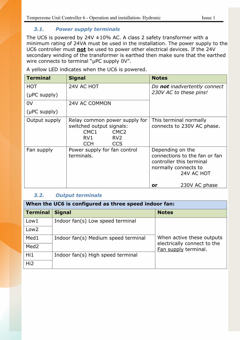
3.1. Power supply terminals
The UC6 is powered by 24V ±10% AC. A class 2 safety transformer with a minimum rating of 24VA must be used in the installation. The power supply to the UC6 controller must not be used to power other electrical devices. If the 24V secondary winding of the transformer is earthed then make sure that the earthed wire connects to terminal “µPC supply 0V”.
A yellow LED indicates when the UC6 is powered.
Terminal Signal Notes
HOT
(uPC supply)
24V AC HOT Do not inadvertently connect 230V AC to these pins!
0V
(uPC supply)
24V AC COMMON
Output supply Relay common power supply for switched output signals: CMC1 CMC2 RV1 RV2 CCH CCS
This terminal normally connects to 230V AC phase.
Fan supply Power supply for fan control terminals.
Depending on the connections to the fan or fan controller this terminal normally connects to 24V AC HOT or 230V AC phase or 10 or 12V DC
3.2. Output terminals
When the UC6 is configured to control indoor fan speed:
Terminal Signal Notes
Low1 Indoor fan(s) Low speed terminal
When active these outputs electrically connect to the Fan supply terminal.
Low2
Med1 Indoor fan(s) Medium speed terminal
Med2
Hi1 Indoor fan(s) High speed terminal
Hi2

Page 17
Temperzone Unit Controller 6 - Operation and installation Issue 1
Page 6 of 18
When the UC6 is configured NOT to control indoor fan speed:
Terminal Signal Notes
Low1 System 1 indoor fan off during an outdoor coil de-ice cycle.
When active these outputs electrically connect to the Fan supply terminal.
Low2
Med1 System 1 indoor fan off during an outdoor coil de-ice cycle. Med2
Hi1 No function.
Terminal Signal Notes
CMC1 Compressor 1 CMC1
When active these outputs electrically connect to the Output supply terminal.
CMC2 Compressor 2 CMC2
RV1 Reversing valve1
RV2 Reversing valve2
CCH Crankcase Heater
CCS Compressor capacity solenoid (compressor modulating valve)
3.3. Input terminals
Terminal Signal Notes
CS This input can have one of two functions: (1) 0 to 1V Analogue input (2) Return or supply air
temperature
For variable capacity systems For fixed capacity systems
ST1 Compressor 1 suction line temperature
NTC blue wires
ST2 Compressor 2 suction line temperature
DT1 Compressor 1 discharge line temperature
NTC red wires
DT2 Compressor 2 discharge line temperature

Temperzone Unit Controller 6 - Operation and installation Issue 1
Page 7 of 18
Terminal Signal Notes
SP1 Compressor 1 suction line pressure
0-5V transducer
OR
SP2 Compressor 2 suction line pressure
HP1 Compressor 1 discharge line pressure
HP2 Compressor 2 discharge line pressure
TS1 Compressor 1 outdoor(mid) coil temperature sensor
NTC Mid-coil: yellow wires De-ice : blue wires
TS2 Compressor2 outdoor(mid) coil temperature sensor
OAT Outdoor air temperature NTC black wires
Page 19
Temperzone Unit Controller 6 - Operation and installation Issue 1
Page 8 of 18
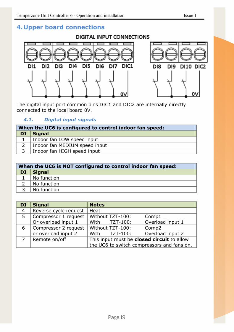
4.Upper board connections
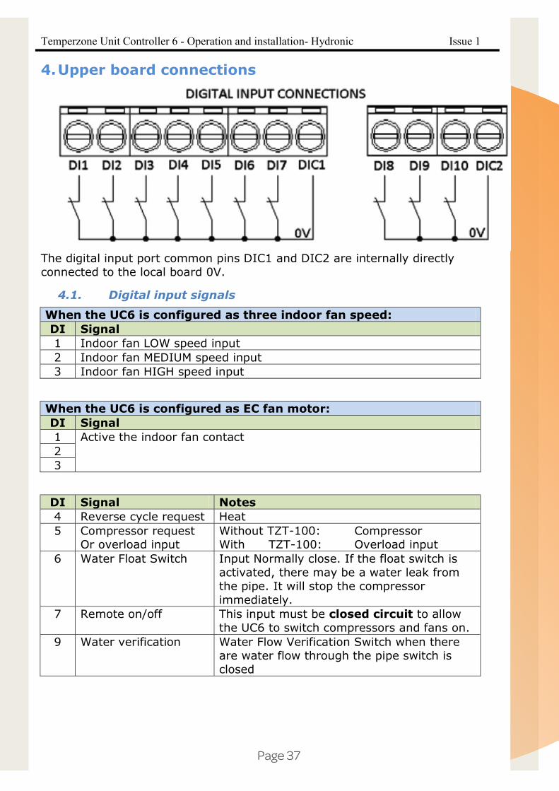
The digital input port common pins DIC1 and DIC2 are internally directly connected to the local board 0V.
4.1. Digital input signals
When the UC6 is configured to control indoor fan speed: DI Signal 1 Indoor fan LOW speed input 2 Indoor fan MEDIUM speed input 3 Indoor fan HIGH speed input
When the UC6 is NOT configured to control indoor fan speed: DI Signal 1 No function 2 No function 3 No function
DI Signal Notes 4 Reverse cycle request Heat 5 Compressor 1 request
Or overload input 1 Without TZT-100: Comp1 With TZT-100: Overload input 1
6 Compressor 2 request or overload input 2
Without TZT-100: Comp2 With TZT-100: Overload input 2
7 Remote on/off This input must be closed circuit to allow the UC6 to switch compressors and fans on.

Temperzone Unit Controller 6 - Operation and installation Issue 1
Page 9 of 18
When the UC6 is configured for DRED function: DI Signal Notes
8 DRED1 When activated the compressors will be OFF. The indoor fan is allowed to continue.
9 DRED2 or DRED3 (configurable via UC6 service interface)
DRED2 active: Total unit energy consumption will be reduced to less than 75% of rating. DRED3 active: Total unit energy consumption will be reduced to less than 50% of rating.
When the UC6 is configured for Quiet mode: DI Signal Notes
8 DRED1 When activated the compressors will be switched off. The indoor fan is allowed to continue.
9 Quiet mode Quiet mode is enabled when this input is made active.
DI Signal Notes
10 Push button
Press and hold the push button on the lower board 1 to 5 seconds to start test mode. Test mode can only be activated when both compressors are OFF. Press and hold the push button on the lower board 10 to 15 seconds to start commissioning mode.
4.2. Digital output signals
DO Signal Notes NO7 Normally open
Alarm output relay C3 Common NC7 Normally closed
4.3. Analogue output signals
AOUT Signal Notes
Y1 Indoor fan speed 0-10V (if used)
Y2 System 1 outdoor fan speed
System 1 0-10V outdoor fan speed control (if used)
Y3 System 2 outdoor fan speed
System 2 0-10V outdoor fan speed control (if used)
Y4 LED display control Controls the 1-digit LED display used to show alarm codes.

Page 21
Temperzone Unit Controller 6 - Operation and installation Issue 1
Page 10 of 18
4.4. Communication ports
Several types of communication ports are available on the UC6.
COMM PORT
Signal Notes
RS4851 MODBUS / CAREL RS485 Thermostat, Inverter pLAN UC6 service tool Programmable graphic display PLD1 Fieldbus (RS485 or TLan) Supervisory System
BMS2 RS485 MODBUS (BACnet or Ethernet optional)
Available only with additional plug-in module connected to the “BMS” connector (adjacent to the Digital Input connector).
Note 1: Connectors to the UC6 show R+/T+ for signal A, R-/T- for signal B.
Note 2: Current software supports only BMS via RS485 MODBUS. BACnet or Ethernet options can be made available on request.
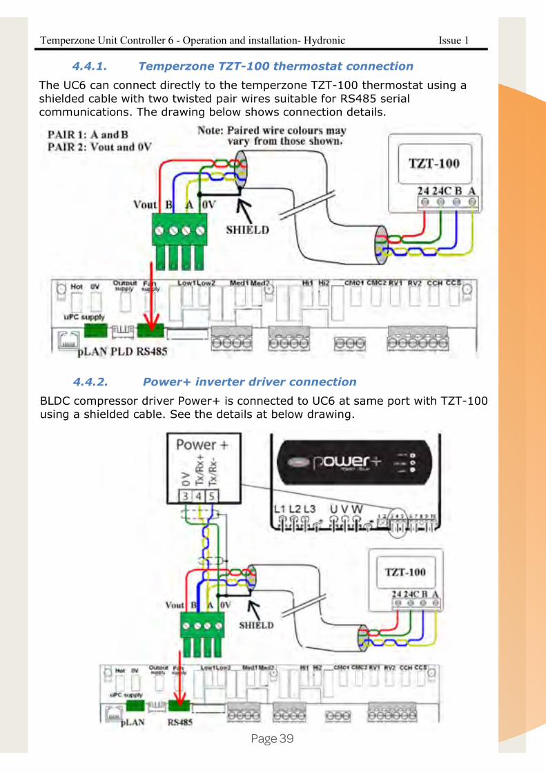
4.4.1. Temperzone TZT-100 thermostat connection
The UC6 can connect directly to the temperzone TZT-100 thermostat using a shielded cable with two twisted pair wires suitable for RS85 serial communications. The drawing below shows connection details.

Temperzone Unit Controller 6 - Operation and installation Issue 1
Page 11 of 18
4.5. Electronic expansion valves
The UC6 has two drivers to control electronic expansion valves (EEV). The EEV outputs are EEV1 and EEV2.
Note: Only one valve must be connected to each connector.
EEV type 6-wire uni-polar stepper motor Motor supply voltage 12V DC±10% Motor winding current 0.3A maximum (each winding) Motor winding resistance 40Ω minimum Maximum power each EEV 7W EEV step frequency Set by temperzone software
5.Operation
5.1. Remote on/off
The remote on/off function can be enabled or disabled by using a UC6 service tool.
When the function is enabled the remote on/off signal must connect to input DI7, signal return is DIC1. The remote on/off signal must be an external voltage free switched relay contact.
The unit is active when DI7 is connected to DIC1.
5.2. Variable duty units
The UC6 can control a unit where one of the two compressors is a variable speed compressor or a digital scroll compressor. Temperzone pre-configures the unit to the correct compressor type; a UC6 service tool is required if the compressor type configuration must be changed.
The capacity input signal must connect to input CS (0-1V, duty 10% per 0.1V).
For digital scroll compressors the capacity output signal (compressor modulating valve control signal) is on output CCS.
The minimum compressor duty is: 20 to 30% for a variable speed compressor (depends on compressor model) 16% for a digital scroll compressor
When a capacity signal is present on input CS that is lower than the minimum duty (for example 0.0V) then the compressor will continue to operate on minimum duty. Safety functions may place further restrictions on the minimum duty and may act at any operating condition.

Page 23
Temperzone Unit Controller 6 - Operation and installation Issue 1
Page 12 of 18
5.3. Outdoor fan control
When a unit is in cooling mode the UC6 can control condensing temperature by regulating the speed of multiple outdoor fans via two 0-10V signals.
When a unit is in heating mode the UC6 normally commands the outdoor fans to run at high speed.
When a unit is de-icing the outdoor coil the outdoor fans stop.
The outdoor fan speed control signals are: Y2 for system 1 outdoor fan(s) Y3 for system 2 outdoor fan(s)
The UC6 determines the condensing temperatures either by converting the high pressure readings (as reported by the high pressure transducers connected to inputs HP1 and HP2) to a condensing temperature, or by measuring the outdoor mid-coil temperatures (temperature sensors connected to TS1 and TS2).
5.4. Indoor fan control
The UC6 can be used to control the indoor fan speed. The configuration of the UC6 can be set using a UC6 service tool. If the UC6 is configured to control the indoor fan then the following applies.
Indoor fan control input signals are: If the UC6 is configured to use digital input signals then the indoor fan control signals are:
o DI1: Low o DI2: Medium o DI3: High
If the system uses a temperzone TZT-100 thermostat then the indoor fan input signals are received from the TZT-100 through the RS485 communications cable.
Two types of outputs are available for indoor fan speed control: Relays to control a three speed indoor fan motor
o Low1 and Low2 o Med1 and Med2 o Hi1 and Hi2
A 0-10V signal on analogue output Y1 for electronically controlled fans.
5.5. Heating mode
When input DI4 is made active the unit is placed in heating mode. The reversing valves are connected to outputs RV1 and RV2. If the unit was cooling when the input signal changed the compressors will be stopped first and the change-over of the reversing valves will be delayed to prevent “gas rush”. The length of the delay is adjustable by using a UC6 service tool.
If heating mode is requested but the compressors are not started within 5 minutes then the reversing valves are switched off again to save power. They will re-activate as soon as a compressor run request is received. The duration of the 5 minute timeout is adjustable by using a UC6 service tool.

Temperzone Unit Controller 6 - Operation and installation Issue 1
Page 13 of 18
5.6. Outdoor coil de-ice control
When a unit is in heating mode and the outdoor coil temperature falls below freezing point then ice may start forming on the outdoor coil. If the amount of ice continues to build up then the UC6 may start an outdoor coil de-ice cycle.
The de-ice cycle ends as soon as the outdoor coil reaches a temperature sufficiently high to ensure that all ice has melted. If operating conditions are particularly severe then it is possible that the required temperature cannot be reached. In the latter case the duration of a de-ice cycle is limited to a maximum of 10 minutes.
The UC6 will not start a new de-ice cycle until a “hold-off period” has expired since the end of the last de-ice cycle. The nominal duration of the hold-off period is half an hour. The duration of the “de-ice hold-off period” may vary automatically, for example when the UC6 detects that little ice is being formed on the outdoor coil.
At the start of a de-ice cycle the compressor is first stopped (or slowed down for a variable speed compressor). After one minute the reversing valve is changed to cooling mode and the compressor is restarted (or speed is increased). During the de-ice cycle the outdoor fan is stopped. At the end of a de-ice cycle the compressor is stopped again (or slowed down). The outdoor fan is started 90 seconds before the compressor to remove water from the outdoor coil. Normal heating mode resumes after that.
If a unit is configured to operate in “commercial” mode the compressor is not stopped at the start of a de-ice cycle.
On most two compressor units the de-ice cycle as described above applies to each individual system. The UC6 will not allow both systems to de-ice at the same time. Exceptions to this rule exist, for example for units with a common outdoor fan chamber must de-ice the two outdoor coils at the same time. Temperzone configures each unit to the correct de-ice strategy.
Display indication during a de-ice cycle number 8
5.7. Crankcase heater
Crankcase heaters are controlled by output CCH.
The crankcase heaters are activated when the following conditions are met:
Mains power has just been turned on OR:
One or both compressor(s) is (are) OFF The compressor(s) has (have) not run for at least one hour The outdoor ambient temperature is below +7°C.

Page 25
Temperzone Unit Controller 6 - Operation and installation Issue 1
Page 14 of 18
5.8. Electronic expansion valve control
On units equipped with electronic expansion valves (EEV) the EEV are used to regulate suction side superheat. The EEV connect to outputs EEV1 and EEV2.
Suction side superheat is defined by the difference between the evaporating temperature and the compressor suction line temperature. The evaporating temperature normally is calculated from the suction line pressure.
Temperzone has selected optimum EEV control parameters to guarantee best unit performance when cooling and when heating.
5.9. Demand response management
The UC6 provides 2 or 3 inputs (depends on unit configuration) for the D.R.E.D. function. D.R.E.D. stands for “Demand Response Enabling Device”. The aim of the function is to have a measure of control over the total energy that is consumed by the unit as measured over a half hour period. Refer to Australian draft standard AS4755.3.1 for detailed information.
The UC6 achieves compliance to the standard by “duty cycling” or stopping one or two compressors.
Inputs for the DRED function are: DI8 DRM1 DI9 DRM2 or DRM3 (configurable)
If the unit is configured with Quiet mode enabled then input DI9 is not available for the DRED function.
Display indication with DRM1 active letter b
Display indication with DRM2 or DRM3 active letter C
6. Protection functions
6.1. Minimum compressor run time
Minimum time that a compressor must run when started. This ensures that an adequate amount of compressor lubricating oil is returned to the compressor after start up.
Display indication when timer is active number 2
6.2. Minimum compressor off time Minimum time that a compressor must remain off after it has stopped. This time ensures that a compressor is not re-started while there still is a high pressure differential across the compressor.
Display indication when timer is active number 1
6.3. Minimum compressor cycle time A compressor is allowed a maximum of 10 starts per hour (one start per 6 minutes). This limits the amount of stress on the compressor motor.
Display indication when timer is active number 1

Temperzone Unit Controller 6 - Operation and installation Issue 1
Page 15 of 18
6.4. Delay time between compressor 1 and compressor 2 start The UC6 does not allow both compressors in the unit to start at the same time even when the compressor run request is received at the same time; a brief time delay (normally 40 seconds) is inserted. This delay reduces the unit peak inrush current.
Display indication when timer is active number 1
6.5. High pressure protection (HP) If high pressure transducers are connected to inputs HP1 and HP2 then a compressor is switched off when the discharge line pressure reading exceeds 42.0bar.
Instead of high pressure transducers some systems may be fitted with high pressure switches. These also connect to inputs HP1 and HP2. When a high pressure switch activates (electrical circuit opens) the compressor is stopped.
Similarly, if the condensing temperature reported by an outdoor coil temperature sensor (connected to TS1 and TS2) reports a coil temperature above +66°C (cooling mode) the compressor is switched off.
The UC6 will automatically reduce capacity of a digital scroll compressor before the maximum value of 42bar / 66°C is reached.
When a compressor is stopped due to high pressure it is held off for a period of 3 minutes, after which it is allowed to restart (provided pressure has fallen well below the maximum).
If three consecutive trips occur then the unit will be “locked out”. The trip counter is reset to 0 when there has been no compressor run request for longer than 60 minutes.
Display indication when protection is active number 4 (flashing)
6.6. Loss of refrigerant protection (LOR)
When a compressor is running the UC6 continuously monitors the various temperatures. The controller software applies logic that enables it to determine whether the system has an adequate amount of refrigerant. Signals used for this check are mid-coil temperatures (TS1, TS2), suction temperatures (ST1, ST2 and discharge line pressures (HP1 and HP2, if present).
The check is not made during the first 5 minutes after a compressor is started to allow pressures and temperatures to settle.
If the compressor is a variable speed type or a digital scroll type then the check is made only when the capacity is at 100%.
When a compressor is stopped due to loss of refrigerant it is held off for a period of 3 minutes, after which it is allowed to restart.
If three consecutive trips occur then the unit will be “locked out”. The trip counter is reset to 0 when there has been no compressor run request for longer than 60 minutes.
Display indication when protection is active number 3 (flashing)

Page 27
Temperzone Unit Controller 6 - Operation and installation Issue 1
Page 16 of 18
6.7. Indoor coil frost protection (FROST)
When the unit is cooling the evaporating temperature in the indoor coil must remain above -10°C (adjustable from -10°C to -2°C by using a UC6 service tool). If this temperature falls below the threshold then some amount of ice (frost) is likely to have formed on the indoor coil.
When indoor coil frost protection is activated the compressor is stopped for 15 minutes, after which it is allowed to restart.
If three consecutive trips occur then the unit will be “locked out”. The trip counter is reset to 0 when there has been no compressor run request for longer than 60 minutes.
Display indication when protection is active number 7 (flashing)
6.8. High discharge line temperature protection (HDT)
The controller monitors the discharge line temperature (inputs DT1, DT2) and should it rise above 110°C the compressor will be stopped.
When high temperature protection is activated the compressor is stopped for at least 3 minutes. The compressor is allowed to restart after 3 minutes provided that the discharge line temperature has fallen to below 100°C.
If three consecutive trips occur then the unit will be “locked out”. The trip counter is reset to 0 when there has been no compressor run request for longer than 60 minutes.
Units with a variable compressor or digital scroll compressor will automatically reduce capacity before the discharge temperature rises close to the threshold.
Display indication when protection is active number 9 (flashing)
6.9. Compressor lock-out
Certain faults (as outlined in the preceding paragraphs) can cause the unit to be “locked out” if they occur three consecutive times while the compressor-run request has remained active. When a unit is locked out the compressor is not allowed to start until the lock-out is manually reset. Lock-out protects the unit from repeatedly starting the compressor when a serious fault exists that requires the attention of a service technician.
When a unit is locked out the alarm relay output (NO7, NC7) will be active.
A unit that is locked out can be reset by either of the following two methods: 1. Remove mains power from the unit for at least 3 seconds, then restore
power. 2. Use a UC6 service tool service tool to manually reset the lock-out condition.
Display indication when protection is active letter F (flashing)

Temperzone Unit Controller 6 - Operation and installation Issue 1
Page 17 of 18
6.10. Sensor alarm If the signal of a temperature sensor or pressure transducer is out of normal operating range the UC6 will generate an alarm. The sensor may be faulty, disconnected or short circuit.
Display indication temperature sensor alarm number 5 (flashing)
Display indication pressure transducer alarm number 6 (flashing)
6.11. Loss of RS485 communications alarm
If the UC6 does not receive correct responses from a device that connects via the RS485 Modbus serial communications port then an alarm is generated. Examples of such devices are: a TZT-100 thermostat, a Carel Power+ inverter.
Display indication for communications fault letter C (flashing)
7.Test mode Test mode can only be activated when both compressors are OFF.
To start test mode press and hold down the push button on the lower board between 1 and 5 seconds.
In test mode each output is activated for 5 to 10 seconds, one output at a time. When test mode completes the unit automatically returns to normal operation.
Display indication during test mode letter A
8.Commissioning mode To start commissioning mode press and hold down the push button on the lower board between 10 and 15 seconds.
In commissioning mode all time delays are reduced to 1/10th their standard value to enable rapid diagnostic testing.
Commissioning mode automatically completes after 30 minutes and the unit will return to normal operation. Cycling mains power off and on again also ends commissioning mode.
Display indication during commissioning mode letter C

Page 29
Temperzone Unit Controller 6 - Operation and installation Issue 1
Page 18 of 18
9.Display summary Description Notes Section
0 Normal operation
1 Compressor timer active Compressor is held OFF until timer
expires 6.2 6.3 6.4
2 Compressor timer active Compressor is held ON until timer
expires 6.1
3 Loss of refrigerant alarm 6.6 4 High pressure alarm 6.5 5 Temperature sensor
signal out of range Sensor may be faulty, disconnected or short circuit.
6.10
6 Pressure transducer signal out of range
Transducer may be faulty, disconnected, short circuit, inadvertently swapped with another transducer or the wrong type is fitted.
6.10
7 Indoor coil frost alarm 6.7 8 Outdoor coil de-ice cycle
is active 5.6
9 High discharge line temperature alarm
6.8
A Test mode 7 b D.R.E.D. active (reduced
capacity operation) 5.9
C RS485 Modbus communications alarm
Check connections with TZT-100 thermostat and/or compressor inverter
6.11
d Unit is OFF by remote on/off signal OR Overload alarm
When a TZT-100 thermostat is used then inputs DI5 and DI6 are used as overload input signals
5.1
E Commissioning mode 8 F Lock out(Repetitive fault
has caused shut down) Any below events will trigger the Alarm lockout LED digit 1.Frost_lockout_comp1/2 2.HP_lockout_comp1/2 3.HT_lockout_comp1/2 4.REF_lockout_comp1/2
6
www.temperzone.co.nz

Date: 12 October 2015Issue: 1
Unit Controller 6 (UC6)
Operation and Installation HYDRONIC
Page 31
Temperzone Unit Controller 6 - Operation and installation- Hydronic Issue 1
Page 2 of 21
Contents 1. Introduction ..................................................................................................................................... 32 2. Features ........................................................................................................................................... 32 3. Lower board connections ................................................................................................................ 33
3.1. Power supply terminals ............................................................................................................ 34
3.2. Output terminals ....................................................................................................................... 34
3.3. Input terminals .......................................................................................................................... 35
4. Upper board connections................................................................................................................. 37 4.1. Digital input signals .................................................................................................................. 37
4.2. Digital output signals ................................................................................................................ 38
4.3. Analogue output signals ........................................................................................................... 38
4.4. Communication ports ............................................................................................................... 38
4.4.1. Temperzone TZT-100 thermostat connection ...................................................................... 39
4.4.2. Power+ inverter driver connection ....................................................................................... 39
4.5. Electronic expansion valves ..................................................................................................... 40
5. Operation ......................................................................................................................................... 40 5.1. Remote on/off ........................................................................................................................... 40
5.2. Variable duty units ................................................................................................................... 40
5.3. Water flow valve Y2 ................................................................................................................ 40
5.4. Indoor fan control ..................................................................................................................... 41
5.5. Heating mode ........................................................................................................................... 41
5.6. Crankcase heater ....................................................................................................................... 41
5.7. Electronic expansion valve control .......................................................................................... 41
5.8. Demand response management ................................................................................................ 42
6. Protection functions ..................................................................................................................... 42
6.1. Minimum compressor run time ................................................................................................ 42
6.2. Minimum compressor off time ................................................................................................. 42
6.3. Minimum compressor cycle time ............................................................................................. 42
6.4. High pressure protection (HP) .................................................................................................. 42
6.5. Loss of refrigerant protection (LOR) ....................................................................................... 43
6.6. High suction line temperature (HiST) ...................................................................................... 43
6.7. Indoor coil frost protection (FROST) ....................................................................................... 43
6.8. High discharge line temperature protection (HDT).................................................................. 44
6.9. No Water Flow Protection ........................................................................................................ 44
6.10. Water Float Protection .......................................................................................................... 44
6.11. Low output water temperature protection ............................................................................. 44
6.12. Compressor lock-out ............................................................................................................. 45
6.13. Sensor alarm ......................................................................................................................... 45
6.14. Loss of RS485 communications alarm ................................................................................. 45 Temperzone Unit Controller 6 - Operation and installation- Hydronic Issue 1
Page 3 of 21
7. Test mode ...................................................................................................................................... 45 8. Commissioning mode ................................................................................................................... 45 9. Display summary .......................................................................................................................... 46

Temperzone Unit Controller 6 - Operation and installation- Hydronic Issue 1
Page 4 of 21
1. Introduction The temperzone Unit Controller 6 (UC6) is the successor to the OUC4 controller. The UC6 provides increased capability and flexibility in indoor-, outdoor- and packaged units. The complete controller combines the µPC controller board from Carel plus an interface board to connect temperzone standard sensors and plugs.
The UC6 receives requests such as “Unit On/Off”, “Start compressors”, “Activate HEAT (Reverse Cycle)” and transfers these requests to the outputs after enforcing safety timers. The UC6 ensures unit safety by continuously monitoring input signals such as pressures and temperatures. Beside the normal controls and unit safety the UC6 has many other functions, for example head pressure control, capacity control, superheat control, serial communications and more.
2. Features The UC6 has the following features:
Normal controls: - One controller can manage two complete refrigeration circuits - Two drivers for uni-polar electronic expansion valves (EEV) - Outdoor fan control - Reversing valve change over management - Variable speed compressor management - Crankcase heater control - BMS interface with optional board(BACnet/IP, Ethernet, MS/TP) - DRED input and control
Safety functions: - Compressor minimum cycle time, minimum run time, minimum off time. - High pressure protection via high pressure transducer - Low pressure protection via low pressure transducer - Loss of refrigerant protection - Indoor coil frost protection - No water flow protection - Water float protection - Low water output temperature protection - Repeat fault lock out - Error code display - Alarm logging
Commissioning functions: - Commissioning mode - Automatic test sequence

Page 33
Temperzone Unit Controller 6 - Operation and installation- Hydronic Issue 1
Page 5 of 21
3. Lower board connections
The paragraphs on the following pages give details how the UC6 should be connected both for packaged units and for the outdoor unit of a split system.
Care must be taken that the correct connections are made as the UC6 can be configured in various modes.
Important:
The UC6 controller must be mounted inside an electrical panel.
To minimise electrical interference low power signal wires from temperature sensors, pressure transducers and low voltage control signals must be kept physically separate from wiring and cables that carry mains power.
Never run power cables and signal cables in the same conduits.
Contact temperzone if the controller has malfunctioned. Do not attempt to repair the controller.
Temperzone Unit Controller 6 - Operation and installation- Hydronic Issue 1
Page 6 of 21
3.1. Power supply terminals
The UC6 is powered by 24V ±10% AC. A class 2 safety transformer with a minimum rating of 24VA must be used in the installation. The power supply to the UC6 controller must not be used to power other electrical devices. If the 24V secondary winding of the transformer is earthed then make sure that the earthed wire connects to terminal “µPC supply 0V”.
A yellow LED indicates when the UC6 is powered.
Terminal Signal Notes
HOT
(µPC supply)
24V AC HOT Do not inadvertently connect 230V AC to these pins!
0V
(µPC supply)
24V AC COMMON
Output supply Relay common power supply for switched output signals: CMC1 CMC2 RV1 RV2 CCH CCS
This terminal normally connects to 230V AC phase.
Fan supply Power supply for fan control terminals.
Depending on the connections to the fan or fan controller this terminal normally connects to 24V AC HOT or 230V AC phase
3.2. Output terminals
When the UC6 is configured as three speed indoor fan:
Terminal Signal Notes
Low1 Indoor fan(s) Low speed terminal
When active these outputs electrically connect to the Fan supply terminal.
Low2
Med1 Indoor fan(s) Medium speed terminal
Med2
Hi1 Indoor fan(s) High speed terminal
Hi2

Page 35
Temperzone Unit Controller 6 - Operation and installation- Hydronic Issue 1
Page 7 of 21
When the UC6 is configured indoor fan as EC motor:
Terminal Signal Notes
Low1 No function.
Low2
Med1 No function.
Med2
Hi1/Hi2 Active to turn on the EC fan contact Terminal Signal Notes
CMC1 Compressor On/Off
When active these outputs electrically connect to the Output supply terminal.
CMC2 Circulation pump control
RV1 Reversing valve/Electric heater circuit1(if fitted)
RV2 Condensate pump
CCH Crankcase Heater/Electric heater circuit2(if fitted)
CCS Water Pump
3.3. Input terminals
Terminal Signal Notes
CS This input can have one of two functions: (1) 0 to 1V Analogue input (2) Return or supply air
temperature
For variable capacity systems For fixed capacity systems
ST1 Compressor suction line temperature
NTC blue wires
ST2 NA
DT1 Compressor discharge line temperature
NTC red wires
DT2 Electric heater temperature sensor (if used)

Temperzone Unit Controller 6 - Operation and installation- Hydronic Issue 1
Page 8 of 21
Terminal Signal Notes
SP1 Compressor suction line pressure 0-5V transducer
OR
SP2 NA
HP1 Compressor discharge line pressure
HP2 NA
TS1 Water In temperature NTC Blue wires
TS2 Water Out temperature
OAT Outdoor air temperature NTC black wires
Page 37
Temperzone Unit Controller 6 - Operation and installation- Hydronic Issue 1
Page 9 of 21
4. Upper board connections
The digital input port common pins DIC1 and DIC2 are internally directly connected to the local board 0V.
4.1. Digital input signals
When the UC6 is configured as three indoor fan speed: DI Signal 1 Indoor fan LOW speed input 2 Indoor fan MEDIUM speed input 3 Indoor fan HIGH speed input
When the UC6 is configured as EC fan motor: DI Signal 1 Active the indoor fan contact 2 3
DI Signal Notes 4 Reverse cycle request Heat 5 Compressor request
Or overload input Without TZT-100: Compressor With TZT-100: Overload input
6 Water Float Switch Input Normally close. If the float switch is activated, there may be a water leak from the pipe. It will stop the compressor immediately.
7 Remote on/off This input must be closed circuit to allow the UC6 to switch compressors and fans on.
9 Water verification Water Flow Verification Switch when there are water flow through the pipe switch is closed

Temperzone Unit Controller 6 - Operation and installation- Hydronic Issue 1
Page 10 of 21
When the UC6 is configured for DRED function: DI Signal Notes
8 DRED1 When activated the compressors will be OFF. The indoor fan is allowed to continue.
9 DRED2 or DRED3 (configurable via UC6 service interface)
DRED2 active: Total unit energy consumption will be reduced to less than 75% of rating. DRED3 active: Total unit energy consumption will be reduced to less than 50% of rating.
DI Signal Notes
10 Push button
Press and hold the push button on the lower board 1 to 5 seconds to start test mode. Test mode can only be activated when both compressors are OFF. Press and hold the push button on the lower board 10 to 15 seconds to start commissioning mode.
4.2. Digital output signals
DO Signal Notes NO7 Normally open
Alarm output relay C3 Common NC7 Normally closed
4.3. Analogue output signals
AOUT Signal Notes
Y1 Indoor fan speed 0-10V (if used)
Y2 Water flow Valve 0-10V control water flow
Y4 LED display control Controls the 1-digit LED display used to show alarm codes.
Temperzone Unit Controller 6 - Operation and installation- Hydronic Issue 1
Page 11 of 21
4.4. Communication ports
Several types of communication ports are available on the UC6.
COMM PORT Signal Notes
RS4851 MODBUS RS485 Thermostat, Inverter pLAN UC6 service tool Programmable graphic display PLD1 Fieldbus (RS485 or TLan) Supervisory System
BMS RS485 MODBUS (BACnet/IP,MS/TP or Ethernet optional)
Available only with additional plug-in module connected to the “BMS” connector (adjacent to the Digital Input connector).
Note 1: Connectors to the UC6 show R+/T+ for signal A, R-/T- for signal B.
4.4.1. Temperzone TZT-100 thermostat connection
The UC6 can connect directly to the temperzone TZT-100 thermostat using a shielded cable with two twisted pair wires suitable for RS485 serial communications. The drawing below shows connection details.
Page 39
Temperzone Unit Controller 6 - Operation and installation- Hydronic Issue 1
Page 11 of 21
4.4. Communication ports
Several types of communication ports are available on the UC6.
COMM PORT Signal Notes
RS4851 MODBUS RS485 Thermostat, Inverter pLAN UC6 service tool Programmable graphic display PLD1 Fieldbus (RS485 or TLan) Supervisory System
BMS RS485 MODBUS (BACnet/IP,MS/TP or Ethernet optional)
Available only with additional plug-in module connected to the “BMS” connector (adjacent to the Digital Input connector).
Note 1: Connectors to the UC6 show R+/T+ for signal A, R-/T- for signal B.
4.4.1. Temperzone TZT-100 thermostat connection
The UC6 can connect directly to the temperzone TZT-100 thermostat using a shielded cable with two twisted pair wires suitable for RS485 serial communications. The drawing below shows connection details.
Temperzone Unit Controller 6 - Operation and installation- Hydronic Issue 1
Page 12 of 21
4.4.2. Power+ inverter driver connection
BLDC compressor driver Power+ is connected to UC6 at same port with TZT-100 using a shielded cable. See the details at below drawing.
Temperzone Unit Controller 6 - Operation and installation- Hydronic Issue 1
Page 12 of 21
4.4.2. Power+ inverter driver connection
BLDC compressor driver Power+ is connected to UC6 at same port with TZT-100 using a shielded cable. See the details at below drawing.

Temperzone Unit Controller 6 - Operation and installation- Hydronic Issue 1
Page 13 of 21
4.5. Electronic expansion valves
The UC6 has two drivers to control electronic expansion valves (EEV). The EEV outputs are EEV1 and EEV2
Note: Only one valve must be connected to each connector.
EEV type 6-wire uni-polar stepper motor Motor supply voltage 12V DC±10% Motor winding current 0.3A maximum (each winding) Motor winding resistance 40Ω minimum Maximum power each EEV 7W EEV step frequency Set by temperzone software
5. Operation 5.1. Remote on/off
The remote on/off function can be enabled or disabled by using a UC6 service tool.
When the function is enabled the remote on/off signal must connect to input DI7, signal return is DIC1. The remote on/off signal must be an external voltage free switched relay contact.
The unit is active when DI7 is connected to DIC1.
5.2. Variable duty units
The UC6 can control a variable speed compressor or a digital scroll compressor. Temperzone pre-configures the unit to the correct compressor type; a UC6 service tool is required if the compressor type configuration must be changed.
The capacity input signal must connect to input CS (0-1V, duty 10% per 0.1V).
The minimum compressor duty is: 20 to 30% for a variable speed compressor (depends on compressor model) 16% for a digital scroll compressor
When a capacity signal is present on input CS that is lower than the minimum duty (for example 0.0V) then the compressor will continue to operate on minimum duty. Safety functions may place further restrictions on the minimum duty and may act at any operating condition.
5.3. Water flow valve Y2
When a unit is in cooling, the Water Flow Valve is used to regulate the condensing temperature via the 0-10V signals Y2.
When a unit is in heating mode the Water Flow Valve remains fully open.
The condensing temperature is converting from the high pressure reading from HP1.

Page 41
Temperzone Unit Controller 6 - Operation and installation- Hydronic Issue 1
Page 14 of 21
5.4. Indoor fan control
The UC6 can be used to control the indoor fan speed. The configuration of the UC6 can be set using a UC6 service tool. If the UC6 is configured to control the indoor fan then the following applies.
Indoor fan control input signals are: If the UC6 is configured to use digital input signals then the indoor fan
control signals are: o DI1: Low o DI2: Medium o DI3: High
If the system uses a temperzone TZT-100 thermostat then the indoor fan input signals are received from the TZT-100 through the RS485 communications cable.
Two types of outputs are available for indoor fan speed control: Relays to control a three speed indoor fan motor
o Low1 and Low2 o Med1 and Med2 o Hi1 and Hi2
A 0-10V signal on analogue output Y1 for electronically controlled fans.
5.5. Heating mode When input DI4 is made active the unit is placed in heating mode. The reversing valves are connected to outputs RV1. If the unit was cooling when the input signal changed the compressors will be stopped first and the change-over of the reversing valves will be delayed to prevent “gas rush”. The length of the delay is adjustable by using a UC6 service tool.
If heating mode is requested but the compressors are not started within 5 minutes then the reversing valves are switched off again to save power. They will re-activate as soon as a compressor run request is received. The duration of the 5 minute timeout is adjustable by using a UC6 service tool.
If the compressor is configured as cooling only and electric heater is fitted then RV1 is used to switch the electric heater on.
5.6. Crankcase heater
Crankcase heaters are controlled by output CCH.
The crankcase heaters are activated when the following conditions are met:
Mains power has just been turned on OR:
One or both compressor(s) is (are) OFF The compressor(s) has (have) not run for at least one hour The outdoor ambient temperature is below +7°C.
5.7. Electronic expansion valve control
On units equipped with electronic expansion valves (EEV) the EEV are used to regulate suction side superheat. The EEV connect to outputs EEV1 and EEV2

Temperzone Unit Controller 6 - Operation and installation- Hydronic Issue 1
Page 15 of 21
Suction side superheat is defined by the difference between the evaporating temperature and the compressor suction line temperature. The evaporating temperature normally is calculated from the suction line pressure.
HWP291 is a single compressor with two coils system unit. EEV1 and EEV2 operate synchronized by same a pair of control signal (suction temperature and pressure). Temperzone has selected optimum EEV control parameters to guarantee best unit performance when cooling and when heating.
5.8. Demand response management
The UC6 provides 2 or 3 inputs (depends on unit configuration) for the D.R.E.D. function. D.R.E.D. stands for “Demand Response Enabling Device”. The aim of the function is to have a measure of control over the total energy that is consumed by the unit as measured over a half hour period. Refer to Australian draft standard AS4755.3.1 for detailed information.
The UC6 achieves compliance to the standard by “duty cycling” or stopping one or two compressors.
Inputs for the DRED function are: DI8 DRM1 DI9 DRM2 or DRM3 (configurable)
If the unit is configured with Quiet mode enabled then input DI9 is not available for the DRED function.
Display indication with DRM1 active letter b
6. Protection functions
6.1. Minimum compressor run time
Minimum time that a compressor must run when started. This ensures that an adequate amount of compressor lubricating oil is returned to the compressor after start up.
Display indication when timer is active number 2
6.2. Minimum compressor off time Minimum time that a compressor must remain off after it has stopped. This time ensures that a compressor is not re-started while there still is a high pressure differential across the compressor.
Display indication when timer is active number 1
6.3. Minimum compressor cycle time A compressor is allowed a maximum of 10 starts per hour (one start per 6 minutes). This limits the amount of stress on the compressor motor.
Display indication when timer is active number 1
6.4. High pressure protection (HP) If high pressure transducers are connected to inputs HP1 then a compressor is switched off when the discharge line pressure reading exceeds 42.0bar.

Page 43
Temperzone Unit Controller 6 - Operation and installation- Hydronic Issue 1
Page 16 of 21
The UC6 will automatically reduce capacity of a variable compressor before the maximum value of 42bar / 66°C is reached.
When a compressor is stopped due to high pressure it is held off for a period of 3 minutes, after which it is allowed to restart (provided pressure has fallen well below the maximum).
If three consecutive trips occur then the unit will be “locked out”. The trip counter is reset to 0 when there has been no compressor run request for longer than 60 minutes.
Display indication when protection is active number 4 (flashing)
6.5. Loss of refrigerant protection (LOR) When a compressor is running the UC6 continuously monitors the various temperatures and pressures. The controller software applies logic that enables it to determine whether the system has an adequate amount of refrigerant. Signals used for this check are suction temperatures ST1 and suction line pressures SP1.
The check is not made during the first 5 minutes after a compressor is started to allow pressures and temperatures to settle.
If the compressor is a variable speed type or a digital scroll type then the check is made only when the capacity is at 100%.
When a compressor is stopped due to loss of refrigerant it is held off for a period of 3 minutes, after which it is allowed to restart.
If three consecutive trips occur then the unit will be “locked out”. The trip counter is reset to 0 when there has been no compressor run request for longer than 60 minutes.
Display indication when protection is active number 3 (flashing)
6.6. High suction line temperature (HiST)
When the suction line temperature is above 30°C and continuously for 15 minutes, stop the compressor. If the compressor is a digital scroll type then the check is made only when the capacity is at 100%.
When a compressor is stopped due to high suction temperature, it is held off for a period of 3 minutes, after which it is allowed to restart.
If three consecutive trips occur then the unit will be “locked out”
Display indication when protection is active number 4 (flashing)
6.7. Indoor coil frost protection (FROST)
When the unit is cooling the evaporating temperature in the indoor coil must remain above -4°C (adjustable from -10°C to -2°C by using a UC6 service tool).

Temperzone Unit Controller 6 - Operation and installation- Hydronic Issue 1
Page 17 of 21
If this temperature falls below the threshold then some amount of ice (frost) is likely to have formed on the indoor coil.
When indoor coil frost protection is activated the compressor is stopped for 15 minutes, after which it is allowed to restart.
If three consecutive trips occur then the unit will be “locked out”. The trip counter is reset to 0 when there has been no compressor run request for longer than 60 minutes.
Display indication when protection is active number 7 (flashing)
6.8. High discharge line temperature protection (HDT)
The controller monitors the discharge line temperature (inputs DT1) and should it rise above 110°C the compressor will be stopped.
When high temperature protection is activated the compressor is stopped for at least 3 minutes. The compressor is allowed to restart after 3 minutes provided that the discharge line temperature has fallen to below 100°C.
If three consecutive trips occur then the unit will be “locked out”. The trip counter is reset to 0 when there has been no compressor run request for longer than 60 minutes.
Units with a variable compressor or digital scroll compressor will automatically reduce capacity before the discharge temperature rises close to the threshold.
Display indication when protection is active number 9 (flashing)
6.9. No Water Flow Protection If the Water Flow Verification Switch input (Din_9) is opened during the compressor running cycle, stop the compressor immediately and report a fault. This fault will be recovered automatically after the Water Flow Verification Switch contact is closed for certain time. If the Water Flow Verification Switch input is opened 3 times within 2 hours, the compressor will be lockout.
Display indication when no water flow number 8
6.10. Water Float Protection
Normally the Float Switch (Din_6) should not ever be activated because the condensate pump is running at all the time. If the float switch is activated, there may be a water leak from the pipe then the compressor will stop immediately and the condensate pump will keep running until the float switch resets.
Display indication when Water Float number 8
Temperzone Unit Controller 6 - Operation and installation- Hydronic Issue 1
Page 18 of 21
6.11. Low output water temperature protection
If the output water temperature is blow 2°C for a contain time, stop the compressor. Minimum output water temperature and the delay time are configurable variables on UC6 service tools Service Configuration page.
Display indication when Water Float number 8
6.12. Compressor lock-out
Certain faults (as outlined in the preceding paragraphs) can cause the unit to be “locked out” if they occur three consecutive times while the compressor-run request has remained active. When a unit is locked out the compressor is not allowed to start until the lock-out is manually reset. Lock-out protects the unit from repeatedly starting the compressor when a serious fault exists that requires the attention of a service technician.
When a unit is locked out the alarm relay output (NO7, NC7) will be active.
A unit that is locked out can be reset by either of the following two methods: 1. Remove mains power from the unit for at least 3 seconds, and then restore
power. 2. Use a UC6 service tool to manually reset the lock-out condition.
Display indication when protection is active letter F (flashing)
6.13. Sensor alarm If the signal of a temperature sensor or pressure transducer is out of normal operating range the UC6 will generate an alarm. The sensor may be faulty, disconnected or short circuit.
Display indication temperature sensor alarm number 5 (flashing)
Display indication pressure transducer alarm number 6 (flashing)
6.14. Loss of RS485 communications alarm
If the UC6 does not receive correct responses from a device that connects via the RS485 Modbus serial communications port then an alarm is generated. Examples of such devices are: a TZT-100 thermostat, a Carel Power+ inverter.
Display indication for communications fault letter C (flashing)
7. Test mode Test mode can only be activated when both compressors are OFF.
To start test mode press and hold down the push button on the lower board between 1 and 5 seconds.
In test mode each output is activated for 5 to 10 seconds, one output at a time. When test mode completes the unit automatically returns to normal operation.
Display indication during test mode letter A
Temperzone Unit Controller 6 - Operation and installation- Hydronic Issue 1
Page 17 of 21
If this temperature falls below the threshold then some amount of ice (frost) is likely to have formed on the indoor coil.
When indoor coil frost protection is activated the compressor is stopped for 15 minutes, after which it is allowed to restart.
If three consecutive trips occur then the unit will be “locked out”. The trip counter is reset to 0 when there has been no compressor run request for longer than 60 minutes.
Display indication when protection is active number 7 (flashing)
6.8. High discharge line temperature protection (HDT)
The controller monitors the discharge line temperature (inputs DT1) and should it rise above 110°C the compressor will be stopped.
When high temperature protection is activated the compressor is stopped for at least 3 minutes. The compressor is allowed to restart after 3 minutes provided that the discharge line temperature has fallen to below 100°C.
If three consecutive trips occur then the unit will be “locked out”. The trip counter is reset to 0 when there has been no compressor run request for longer than 60 minutes.
Units with a variable compressor or digital scroll compressor will automatically reduce capacity before the discharge temperature rises close to the threshold.
Display indication when protection is active number 9 (flashing)
6.9. No Water Flow Protection If the Water Flow Verification Switch input (Din_9) is opened during the compressor running cycle, stop the compressor immediately and report a fault. This fault will be recovered automatically after the Water Flow Verification Switch contact is closed for certain time. If the Water Flow Verification Switch input is opened 3 times within 2 hours, the compressor will be lockout.
Display indication when no water flow number 8
6.10. Water Float Protection
Normally the Float Switch (Din_6) should not ever be activated because the condensate pump is running at all the time. If the float switch is activated, there may be a water leak from the pipe then the compressor will stop immediately and the condensate pump will keep running until the float switch resets.
Display indication when Water Float number 8
Temperzone Unit Controller 6 - Operation and installation- Hydronic Issue 1
Page 17 of 21
If this temperature falls below the threshold then some amount of ice (frost) is likely to have formed on the indoor coil.
When indoor coil frost protection is activated the compressor is stopped for 15 minutes, after which it is allowed to restart.
If three consecutive trips occur then the unit will be “locked out”. The trip counter is reset to 0 when there has been no compressor run request for longer than 60 minutes.
Display indication when protection is active number 7 (flashing)
6.8. High discharge line temperature protection (HDT)
The controller monitors the discharge line temperature (inputs DT1) and should it rise above 110°C the compressor will be stopped.
When high temperature protection is activated the compressor is stopped for at least 3 minutes. The compressor is allowed to restart after 3 minutes provided that the discharge line temperature has fallen to below 100°C.
If three consecutive trips occur then the unit will be “locked out”. The trip counter is reset to 0 when there has been no compressor run request for longer than 60 minutes.
Units with a variable compressor or digital scroll compressor will automatically reduce capacity before the discharge temperature rises close to the threshold.
Display indication when protection is active number 9 (flashing)
6.9. No Water Flow Protection If the Water Flow Verification Switch input (Din_9) is opened during the compressor running cycle, stop the compressor immediately and report a fault. This fault will be recovered automatically after the Water Flow Verification Switch contact is closed for certain time. If the Water Flow Verification Switch input is opened 3 times within 2 hours, the compressor will be lockout.
Display indication when no water flow number 8
6.10. Water Float Protection
Normally the Float Switch (Din_6) should not ever be activated because the condensate pump is running at all the time. If the float switch is activated, there may be a water leak from the pipe then the compressor will stop immediately and the condensate pump will keep running until the float switch resets.
Display indication when Water Float number 8

Page 45
Temperzone Unit Controller 6 - Operation and installation- Hydronic Issue 1
Page 18 of 21
6.11. Low output water temperature protection
If the output water temperature is blow 2°C for a contain time, stop the compressor. Minimum output water temperature and the delay time are configurable variables on UC6 service tools Service Configuration page.
Display indication when Water Float number 8
6.12. Compressor lock-out
Certain faults (as outlined in the preceding paragraphs) can cause the unit to be “locked out” if they occur three consecutive times while the compressor-run request has remained active. When a unit is locked out the compressor is not allowed to start until the lock-out is manually reset. Lock-out protects the unit from repeatedly starting the compressor when a serious fault exists that requires the attention of a service technician.
When a unit is locked out the alarm relay output (NO7, NC7) will be active.
A unit that is locked out can be reset by either of the following two methods: 1. Remove mains power from the unit for at least 3 seconds, and then restore
power. 2. Use a UC6 service tool to manually reset the lock-out condition.
Display indication when protection is active letter F (flashing)
6.13. Sensor alarm If the signal of a temperature sensor or pressure transducer is out of normal operating range the UC6 will generate an alarm. The sensor may be faulty, disconnected or short circuit.
Display indication temperature sensor alarm number 5 (flashing)
Display indication pressure transducer alarm number 6 (flashing)
6.14. Loss of RS485 communications alarm
If the UC6 does not receive correct responses from a device that connects via the RS485 Modbus serial communications port then an alarm is generated. Examples of such devices are: a TZT-100 thermostat, a Carel Power+ inverter.
Display indication for communications fault letter C (flashing)
7. Test mode Test mode can only be activated when both compressors are OFF.
To start test mode press and hold down the push button on the lower board between 1 and 5 seconds.
In test mode each output is activated for 5 to 10 seconds, one output at a time. When test mode completes the unit automatically returns to normal operation.
Display indication during test mode letter A
Temperzone Unit Controller 6 - Operation and installation- Hydronic Issue 1
Page 18 of 21
6.11. Low output water temperature protection
If the output water temperature is blow 2°C for a contain time, stop the compressor. Minimum output water temperature and the delay time are configurable variables on UC6 service tools Service Configuration page.
Display indication when Water Float number 8
6.12. Compressor lock-out
Certain faults (as outlined in the preceding paragraphs) can cause the unit to be “locked out” if they occur three consecutive times while the compressor-run request has remained active. When a unit is locked out the compressor is not allowed to start until the lock-out is manually reset. Lock-out protects the unit from repeatedly starting the compressor when a serious fault exists that requires the attention of a service technician.
When a unit is locked out the alarm relay output (NO7, NC7) will be active.
A unit that is locked out can be reset by either of the following two methods: 1. Remove mains power from the unit for at least 3 seconds, and then restore
power. 2. Use a UC6 service tool to manually reset the lock-out condition.
Display indication when protection is active letter F (flashing)
6.13. Sensor alarm If the signal of a temperature sensor or pressure transducer is out of normal operating range the UC6 will generate an alarm. The sensor may be faulty, disconnected or short circuit.
Display indication temperature sensor alarm number 5 (flashing)
Display indication pressure transducer alarm number 6 (flashing)
6.14. Loss of RS485 communications alarm
If the UC6 does not receive correct responses from a device that connects via the RS485 Modbus serial communications port then an alarm is generated. Examples of such devices are: a TZT-100 thermostat, a Carel Power+ inverter.
Display indication for communications fault letter C (flashing)
7. Test mode Test mode can only be activated when both compressors are OFF.
To start test mode press and hold down the push button on the lower board between 1 and 5 seconds.
In test mode each output is activated for 5 to 10 seconds, one output at a time. When test mode completes the unit automatically returns to normal operation.
Display indication during test mode letter A Temperzone Unit Controller 6 - Operation and installation- Hydronic Issue 1
Page 19 of 21
8. Commissioning mode To start commissioning mode press and hold down the push button on the lower board between 10 and 15 seconds.
In commissioning mode all time delays are reduced to 1/10th their standard value to enable rapid diagnostic testing.
Commissioning mode automatically completes after 30 minutes and the unit will return to normal operation. Cycling mains power off and on again also ends commissioning mode.
Display indication during commissioning mode letter
S.e.r
Temperzone Unit Controller 6 - Operation and installation- Hydronic Issue 1
Page 18 of 21
6.11. Low output water temperature protection
If the output water temperature is blow 2°C for a contain time, stop the compressor. Minimum output water temperature and the delay time are configurable variables on UC6 service tools Service Configuration page.
Display indication when Water Float number 8
6.12. Compressor lock-out
Certain faults (as outlined in the preceding paragraphs) can cause the unit to be “locked out” if they occur three consecutive times while the compressor-run request has remained active. When a unit is locked out the compressor is not allowed to start until the lock-out is manually reset. Lock-out protects the unit from repeatedly starting the compressor when a serious fault exists that requires the attention of a service technician.
When a unit is locked out the alarm relay output (NO7, NC7) will be active.
A unit that is locked out can be reset by either of the following two methods: 1. Remove mains power from the unit for at least 3 seconds, and then restore
power. 2. Use a UC6 service tool to manually reset the lock-out condition.
Display indication when protection is active letter F (flashing)
6.13. Sensor alarm If the signal of a temperature sensor or pressure transducer is out of normal operating range the UC6 will generate an alarm. The sensor may be faulty, disconnected or short circuit.
Display indication temperature sensor alarm number 5 (flashing)
Display indication pressure transducer alarm number 6 (flashing)
6.14. Loss of RS485 communications alarm
If the UC6 does not receive correct responses from a device that connects via the RS485 Modbus serial communications port then an alarm is generated. Examples of such devices are: a TZT-100 thermostat, a Carel Power+ inverter.
Display indication for communications fault letter C (flashing)
7. Test mode Test mode can only be activated when both compressors are OFF.
To start test mode press and hold down the push button on the lower board between 1 and 5 seconds.
In test mode each output is activated for 5 to 10 seconds, one output at a time. When test mode completes the unit automatically returns to normal operation.
Display indication during test mode letter A

Temperzone Unit Controller 6 - Operation and installation- Hydronic Issue 1
Page 20 of 21
9. Display summary Description Notes Section Normal operation
1 Compressor timer active Compressor is held OFF until timer expires
6.2 6.3 6.4
2 Compressor timer active Compressor is held ON until timer expires
6.1
3 Loss of refrigerant alarm 6.5 4 High pressure alarm
Or High Suction temp. alarm
Stop the compressors if HP exceeds the 42 bar threshold. Or Suction temperature is above 30°C continuously for 15 minutes.
6.4 6.6
5 Temperature sensor signal out of range
A temperature sensor may be faulty, disconnected or short circuit.
6.13
6 Pressure transducer signal out of range
A transducer may be faulty, disconnected, short circuit, inadvertently swapped with another, or the wrong type is fitted.
6.13
7 Indoor coil frost alarm In the cooling cycle, if the evaporator temperature is less than -4°C (adjustable between -2 and 10°) for a period of time, the compressor will stop for 15 mins.
6.8
8 Water Flow Verification Water Float Low water output temperature
If the Water Pump is active for a certain time, Water Flow Verification Switch is open, stop compressor. If Water Float switch is open, stop compressor If the water output temperature is below 2°C stop compressor
6.9 6.10 6.11
9 High discharge line temperature alarm
If the discharge line temperature rises above 110°C the compressor will be stopped.
6.9
A Test mode Unit is in test mode 7 b D.R.E.D. active (reduced
capacity operation) One of the 3 possible DRM modes is activated.
5.8
C RS485 Modbus communications alarm
Check connections with TZT-100 thermostat and/or any inverter compressor driver in the unit.
6.14
d Unit turned OFF by an external On/Off signal, Phase Rotation error, or an Open Circuit Overload.
When a TZT-100 thermostat is used then inputs DI5 and id used as overload input signals. Usually these monitor condenser fan overloads.
5.1

Page 47
Temperzone Unit Controller 6 - Operation and installation- Hydronic Issue 1
Page 21 of 21
S.e. r
Commissioning mode Or service mode. resets after 30 Minutes.
8
F Lock out (A repetitive fault has caused the system to shut down)
The specific repetitive fault that caused the lockout is identifiable: 1.Frost lockout 2.HP lockout 3.HT lockout 4.Loss of refrigerant lockout 5.Water flow verification switch failure lock out
6.12
www.temperzone.co.nz

Unit Controller 6 (UC6)
Service Interface Description & Operation

Page 49
Temperzone Unit Controller 6 service interface description
Page 1 of 16
Familiar with the UC6 service interface This is the first page you will see on your service interface when the unit on
Six Keys service interface function description:
1. Alarm: Press Alarm button to access alarm operation: a. View the active alarm b. Logger alarm data 2. Prg. Press program button enter to main menu 3. Esc. Return to menu’s previous level 4. ←Enter. Press the “Enter” key to confirm the operation 5. ↑↓ Press UP and DOWN key jump to Input/output page; Increase and decrease respectively
the value during the configuration.
1. Main Menu
Press Prg button on service interface1 enter to Main Menu:
Main menu A. On/Off Unit B. Set point C. Clock/Scheduler D. Input/Output E. Data logger F. Board Switch G. Service H. Manufacturer
Service menu a. Change language b. Information c. Summer/Winter d. Working hours e. BMS configuration f. Service setting g. Manual management
Manufacture menu a. Configuration b. I/O Configuration c. Factory Setting d. Initialization e. Input/output test
EVO configuration a. Configuration b. Regulation c. Custom
Service menu a. Working hour set b. Probe adjustment c. Thermoregulation d. User DEV/Chang PW1

Temperzone Unit Controller 6 service interface description
Page 2 of 16
1.1 On/Off Unit A. On/Off Unit
Turn the unit on and off by ↑↓keys b
1.2 Set point B. Temperature Set point, it’s depends on the variable term_type (type of user terminal). There
are five types user terminal. The configuration list: 0=th_tune; 1=pAD;2=Chameleon;3=contact 4=BMS/service interface 1. The default value is “3=contact”, this page will display
“Not used in the current configuration” 2. When term_type set to Chameleon, this page will show as below: 3. Terminal type =BMS/service interface 4. Terminal type=th_tune 5. pAD not available.
1.3 Clock/scheduler C. Clock/Scheduler
Use Up and Down Keys to change the time and Enter to confirm
1.4 Input/Output D. Input/Output masks
Display the input/output variables and status
Set point Ch01 TZT-100 Address: 7
Set point: 24°C Dead band: 0.0°C Temperature: 13°C
Set point BMS01 Set point: 24°C Dead Zone: 0.0°C Prop. Band: 0.0°C
Temperature now: 13°C
Set point THT 01 Set point: 24°C Dead Zone: 0.0°C Prop. Band: 0.0°C
Temperature now: 13°C

Page 51
Temperzone Unit Controller 6 service interface description
Page 3 of 16
Main: System Summary:
Input/output 01
Input/output 02
Input/output 03
Temperzone Unit Controller 6 service interface description
Page 3 of 16
Main: System Summary:
Input/output 01
Input/output 02
Input/output 03
Temperzone Unit Controller 6 service interface description
Page 3 of 16
Main: System Summary:
Input/output 01
Input/output 02
Input/output 03
Temperzone Unit Controller 6 service interface description
Page 3 of 16
Main: System Summary:
Input/output 01
Input/output 02
Input/output 03
Temperzone Unit Controller 6 service interface description
Page 3 of 16
Main: System Summary:
Input/output 01
Input/output 02
Input/output 03
Temperzone Unit Controller 6 service interface description
Page 3 of 16
Main: System Summary:
Input/output 01
Input/output 02
Input/output 03
Temperzone Unit Controller 6 service interface description
Page 3 of 16
Main: System Summary:
Input/output 01
Input/output 02
Input/output 03
Temperzone Unit Controller 6 service interface description
Page 3 of 16
Main: System Summary:
Input/output 01
Input/output 02
Input/output 03
Temperzone Unit Controller 6 service interface description
Page 3 of 16
Main: System Summary:
Input/output 01
Input/output 02
Input/output 03
Temperzone Unit Controller 6 service interface description
Page 4 of 16
Input/output 04
Input/output 05
Input/output 08
Input/output 09
Input/output 10
Temperzone Unit Controller 6 service interface description
Page 4 of 16
Input/output 04
Input/output 05
Input/output 08
Input/output 09
Input/output 10
Temperzone Unit Controller 6 service interface description
Page 4 of 16
Input/output 04
Input/output 05
Input/output 08
Input/output 09
Input/output 10
Temperzone Unit Controller 6 service interface description
Page 4 of 16
Input/output 04
Input/output 05
Input/output 08
Input/output 09
Input/output 10
Temperzone Unit Controller 6 service interface description
Page 4 of 16
Input/output 04
Input/output 05
Input/output 08
Input/output 09
Input/output 10
Temperzone Unit Controller 6 service interface description
Page 4 of 16
Input/output 04
Input/output 05
Input/output 08
Input/output 09
Input/output 10
Temperzone Unit Controller 6 service interface description
Page 4 of 16
Input/output 04
Input/output 05
Input/output 08
Input/output 09
Input/output 10
Temperzone Unit Controller 6 service interface description
Page 4 of 16
Input/output 04
Input/output 05
Input/output 08
Input/output 09
Input/output 10
Temperzone Unit Controller 6 service interface description
Page 4 of 16
Input/output 04
Input/output 05
Input/output 08
Input/output 09
Input/output 10
Temperzone Unit Controller 6 service interface description
Page 4 of 16
Input/output 04
Input/output 05
Input/output 08
Input/output 09
Input/output 10
Temperzone Unit Controller 6 service interface description
Page 5 of 16
Input/output 11
Input/output 96
1.5 Data logger E. Data logger
When the alarm is triggered, the controller logs the data to on-board memory. It record conditions leading up to the fault itself, including date, time temperatures nature of fault etc. Move the cursor (black bar) to cover the tab and press Enter key you can see the details:
When: Time the alarm was triggered What: Comp1 Ref loos Alarm Other information: Compressor discharge temperature
Compressor suction temperature Condenser coil temperature Compressor high pressure Press Enter Key again into reset page:
Use Enter Key to active the cursor and use UP and Down Key to select Yes or No
1.6 Board Switch F. Board Switch
Switch to other unit which connected in ModBus at different address
Temperzone Unit Controller 6 service interface description
Page 5 of 16
Input/output 11
Input/output 96
1.5 Data logger E. Data logger
When the alarm is triggered, the controller logs the data to on-board memory. It record conditions leading up to the fault itself, including date, time temperatures nature of fault etc. Move the cursor (black bar) to cover the tab and press Enter key you can see the details:
When: Time the alarm was triggered What: Comp1 Ref loos Alarm Other information: Compressor discharge temperature
Compressor suction temperature Condenser coil temperature Compressor high pressure Press Enter Key again into reset page:
Use Enter Key to active the cursor and use UP and Down Key to select Yes or No
1.6 Board Switch F. Board Switch
Switch to other unit which connected in ModBus at different address Temperzone Unit Controller 6 service interface description
Page 6 of 16
1.7 Service G. Service
Move the cursor (black bar) to this line and press Enter key then you are in Service menu! Service menu is password protected. Enter correct password to access it. You can change the password at service menu sub page d, change PW1. a. Information Show customer details (temperzone) software version, release time, µPC Bios, Boot version and main execution cycle (page2).
b. Working hours This is an Hour Run Meter it will tell how many hours compressor 1 and 2 already running and how many hours Fan motor runs e. BMS configuration: f. Service settings have 4 sub menus:
a. Working hour set
BMS configuration . Address: 1 Protocol: Carel/Modbus Speed: 19200 Stop bits:1 Parity: even
BMS address can be selected from 0 to 999. You can choice Protocol either Carel or Modbus Communication speeds are selectable from 19200 to 1200
Service password 01 .
Inserter service Password (PW1) 0000

Page 53
Temperzone Unit Controller 6 service interface description
Page 6 of 16
1.7 Service G. Service
Move the cursor (black bar) to this line and press Enter key then you are in Service menu! Service menu is password protected. Enter correct password to access it. You can change the password at service menu sub page d, change PW1. a. Information Show customer details (temperzone) software version, release time, µPC Bios, Boot version and main execution cycle (page2).
b. Working hours This is an Hour Run Meter it will tell how many hours compressor 1 and 2 already running and how many hours Fan motor runs e. BMS configuration: f. Service settings have 4 sub menus:
a. Working hour set
BMS configuration . Address: 1 Protocol: Carel/Modbus Speed: 19200 Stop bits:1 Parity: even
BMS address can be selected from 0 to 999. You can choice Protocol either Carel or Modbus Communication speeds are selectable from 19200 to 1200
Service password 01 .
Inserter service Password (PW1) 0000
Temperzone Unit Controller 6 service interface description
Page 7 of 16
You can set Compressor1, compressor2 and Fan motors’ running hours b. Probes adjustment
To calibrating analogue inputs, you are being able to adjust the offset of 4 probes (s1, s2, s3 and s4), temperature sensors and high pressure sensors.
c. Thermo regulation There are two more pages are used for Heating and De-ICE mode parameters setting. Thermo regulation page four is for condenser fan speed control d. User DEV/Change PW1 g. Manual management
Manual management used to control the EEV position by manual. It is useful tools for serviceman to fix the EEV position at an appropriate position to diagnostic systems
Use UP and Down Key to set the valve to an appropriate position then set Enable to Yes
Thermoregulation 01 . Cooling mode settings Setpoint SH: 5.0k LowSH thresh: 1.0K LOP thresh: -35.0°C MOP thresh: 15.0°C Swing detect time: 600s
Use up, down and enter keys to set superheat setpoint, Low superheat thresh hold setpoint, Low operation pressure threshold setpoint, Highest operation pressure threshold setpoint, And swing detect timer. The swing detect timer will reset if have no swing detected during this period.
Thermoregulation 04 . Condenser fan setpoint (fixed spd comp) 26.0°C Condenser fan setpoint (vari spd comp) 26.0°C Condenser fan Pro.band: 12.0°C
User default 01 .
Inserter new service Password (PW1) 0000
This page allowed you to change the service password
Condenser fan will start running when temperature rise above 26°C And will at its maximum speed when the coil temperature is about 38°C Analog output will be zero at 26°C and 1000 at 38°C.
Temperzone Unit Controller 6 service interface description
Page 8 of 16
1.8 Manufacturer H. Manufacturer
Manufacturer setting is password protected. Enter correct password to access.
There are 5 sub menus in Main menu list:
1.8.1. Configuration Use UP, Down and Enter key to set the following configurations:
Number of compressor fitted in the system
Package unit or Outdoor unit Condenser fan speed is fix one speed or three Speed with Low, Med and High
Manufacturer menu a. Configuration b. I/O configuration c. Factory settings d. Initialization e. Input/Output Test
Configuration 01 1. Number of compressors fitted is: One/Two 2. Compressor 1 type:
FIXED SPEED (capacity) VARI SPEED (RS485) VARI SPEED (0-10vdc) DIGITAL SCROLL
3. The Controller is: PAC/OUC 4. Number of condenser fan Speeds is: ONE/THREE
Manual mng . Valve A/B Manual Valve Position: 345stp Enable manual Valve position: Yes/No

Page 55
Temperzone Unit Controller 6 service interface description
Page 8 of 16
1.8 Manufacturer H. Manufacturer
Manufacturer setting is password protected. Enter correct password to access.
There are 5 sub menus in Main menu list:
1.8.1. Configuration Use UP, Down and Enter key to set the following configurations:
Number of compressor fitted in the system
Package unit or Outdoor unit Condenser fan speed is fix one speed or three Speed with Low, Med and High
Manufacturer menu a. Configuration b. I/O configuration c. Factory settings d. Initialization e. Input/Output Test
Configuration 01 1. Number of compressors fitted is: One/Two 2. Compressor 1 type:
FIXED SPEED (capacity) VARI SPEED (RS485) VARI SPEED (0-10vdc) DIGITAL SCROLL
3. The Controller is: PAC/OUC 4. Number of condenser fan Speeds is: ONE/THREE
Manual mng . Valve A/B Manual Valve Position: 345stp Enable manual Valve position: Yes/No
Temperzone Unit Controller 6 service interface description
Page 9 of 16
`
Configuration 03 8. Compressor 1 (C.1) C.1 discharge temperature sensor
is PRESENT/ABSENT C.1 suction temperature sensor
is PRESENT/ABSENT C.1 suction pressure sensor
is PRESENT/ABSENT
Configuration 02 5. Type of user terminal: * Dig. CONTACT * CHAMELEON * pAD * TH_TUNE * BMS OR service interface TERM 6. Electronics Expansion Valve is: * NOT FITTED * ONE EXTERNAL EVO TWIN * ONE EXTERNAL EVO * TWO ONBOARD UNI POLAR * One ONBOARD UNI POLAR 7. Enable floating HP: Yes/NO
Configuration 04 C.1 condenser temperature sensor
is PRESENT/ABSENT C.1 High pressure sensor
is PRESENT/ABSENT Outside air temperature sensor
is PRESENT/ABSENT
Configuration 04 9. Control temperature sensor is
PRESENT/ABSENT
Configuration 04 Setting for control by digital input Cool mode: Yes/No Fan mode cool DB: Auto Heat mode: YES/NO Fan mode heat DB: Auto
Temperzone Unit Controller 6 service interface description
Page 10 of 16
Compressor 2 setting (see the pressure sensor spec. ) (see the pressure sensor spec. )
Configuration 05 C.2 discharge temperature sensor
Is PRESENT/ABSENT C.2 suction temperature sensor
Is PRESENT/ABSENT C.2 suction pressure sensor Is PRESENT/ABSENT Configuration 06 C.2 condenser temperature sensor
Is PRESENT/ABSENT C.2 High Pressure sensor
Is PRESENT/ABSENT
Configuration 07 Compressor 1 Low Pressure sensor: 0-5V On/off Minimum value: 0.0Bar Maximum value: 34.5Bar
Configuration Modbus settings Baud rate: 19200 Stop bit: 2 Parity mode: NONE Timeout: 300ms
Configuration 08 Compressor 1 High Pressure sensor type: 0-5V
On/off Minimum value: 0.0Bar Maximum value: 45.0Bar
Configuration 09 Compressor 2 Low Pressure sensor: 0-5V On/off Minimum value: 0.0Bar Maximum value: 34.5Bar
Configuration 10 Compressor 2 High Pressure sensor type: 0-5V
On/off Minimum value: 0.0Bar Maximum value: 45.0Bar

Page 57
Temperzone Unit Controller 6 service interface description
Page 10 of 16
Compressor 2 setting (see the pressure sensor spec. ) (see the pressure sensor spec. )
Configuration 05 C.2 discharge temperature sensor
Is PRESENT/ABSENT C.2 suction temperature sensor
Is PRESENT/ABSENT C.2 suction pressure sensor Is PRESENT/ABSENT Configuration 06 C.2 condenser temperature sensor
Is PRESENT/ABSENT C.2 High Pressure sensor
Is PRESENT/ABSENT
Configuration 07 Compressor 1 Low Pressure sensor: 0-5V On/off Minimum value: 0.0Bar Maximum value: 34.5Bar
Configuration Modbus settings Baud rate: 19200 Stop bit: 2 Parity mode: NONE Timeout: 300ms
Configuration 08 Compressor 1 High Pressure sensor type: 0-5V
On/off Minimum value: 0.0Bar Maximum value: 45.0Bar
Configuration 09 Compressor 2 Low Pressure sensor: 0-5V On/off Minimum value: 0.0Bar Maximum value: 34.5Bar
Configuration 10 Compressor 2 High Pressure sensor type: 0-5V
On/off Minimum value: 0.0Bar Maximum value: 45.0Bar
Temperzone Unit Controller 6 service interface description
Page 11 of 16
13. EVO configuration There three sub menu in this page:
a. EVO Configuration
Page1. Page2.
Configuration Press Enter to configuration EVO OnBoard Service
EVD Configuration Valve: (there are following options type) 1. CAREL E2V 2. HUALU EPF-VPF 12V 3. HUALU SPF 12V 4. HUALU DPF 12V 5. SANHUA L SERIES 6. ALCO EXM/EXL 7. SPORLAN ESX 8. DANFOSS/SAGINOMYA TYPE KV
EVD Configuration Regulation: 1. USER DEFINED 2. AC/CHILLER WITH DIG. SCROLL 3. COMPRESSOR 4. AC/CHILLER WITH ADAPT. REGULATION 5. ANALOG POSITIONER(4-20mA) 6. TRANSCRITICAL CO2 GAS COOLER 7. HOT GAS BY-PASS BY TEMPERATURE 8. HOT GAS BY-PASS BY PRESSURE 9. EPR BACK PRESSURE 10. AC OR CHILLER PERTURBATED UNIT 11. AC OR CHILLER WITH VAR. COOLING CAPACITY 12. AC OR CHILLER WITH BATTERY COIL EVAPORATOR 13. AC OR CHILLER WITH SHELL TUBE EVAPORATOR
Manufacturer a. Configuration b. Regulation c. Custom
Temperzone Unit Controller 6 service interface description
Page 12 of 16
Page3. Probe S1 is evaporator1 pressure sensor connected to SP1 on interface board
When set the alarm enable, if the value is out of reading range, will trigger the alarm
Reading range setting Alarm range setting Page4. Probe S2 is suction temperature sensor
Alarm range setting
Page5. Probe 3 is evaporator 2pressure sensor connected to SP2 on interface board
When set the alarm enables, if the value is out of reading range, will trigger the alarm
Reading range setting Alarm range setting Page6. Probe S4 is suction temperature 2 sensor
Alarm range setting
EVD Configuration Probe S1 Alarm: EN Type: RAZ. 0-5V
40-20mA external 40-20mA remote 40-20mA
Min.: 0.0 bar Max: 34.5 bar Alarm min. 0.0 bar Alarm max. 34.5 bar
EVD Configuration Probe S2 Alarm: EN Type: 1. NTC CAREL
2. TEMP.CUSTOM 1 3. 0-10V EXT. SIGNAL 4. NTC SPKP**T0 5. CAREL NTC-HT
Alarm min: -25°C Alarm max: 70°C
EVD Configuration Probe S3 Alarm: EN Type: RAZ. 0-5V
40-20mA external 40-20mA remote 40-20mA
Min.: 0.0 bar Max: 34.5 bar Alarm min. 0.0 bar Alarm max. 34.5 bar
EVD Configuration Probe S4 Alarm: EN Type: 1. NTC CAREL
2. TEMP.CUSTOM 1 3. 0-10V EXT. SIGNAL 4. NTC SPKP**T0 5. CAREL NTC-HT
Alarm min: -25°C Alarm max: 70°C
Temperzone Unit Controller 6 service interface description
Page 11 of 16
13. EVO configuration There three sub menu in this page:
a. EVO Configuration
Page1. Page2.
Configuration Press Enter to configuration EVO OnBoard Service
EVD Configuration Valve: (there are following options type) 1. CAREL E2V 2. HUALU EPF-VPF 12V 3. HUALU SPF 12V 4. HUALU DPF 12V 5. SANHUA L SERIES 6. ALCO EXM/EXL 7. SPORLAN ESX 8. DANFOSS/SAGINOMYA TYPE KV
EVD Configuration Regulation: 1. USER DEFINED 2. AC/CHILLER WITH DIG. SCROLL 3. COMPRESSOR 4. AC/CHILLER WITH ADAPT. REGULATION 5. ANALOG POSITIONER(4-20mA) 6. TRANSCRITICAL CO2 GAS COOLER 7. HOT GAS BY-PASS BY TEMPERATURE 8. HOT GAS BY-PASS BY PRESSURE 9. EPR BACK PRESSURE 10. AC OR CHILLER PERTURBATED UNIT 11. AC OR CHILLER WITH VAR. COOLING CAPACITY 12. AC OR CHILLER WITH BATTERY COIL EVAPORATOR 13. AC OR CHILLER WITH SHELL TUBE EVAPORATOR
Manufacturer a. Configuration b. Regulation c. Custom

Page 59
Temperzone Unit Controller 6 service interface description
Page 12 of 16
Page3. Probe S1 is evaporator1 pressure sensor connected to SP1 on interface board
When set the alarm enable, if the value is out of reading range, will trigger the alarm
Reading range setting Alarm range setting Page4. Probe S2 is suction temperature sensor
Alarm range setting
Page5. Probe 3 is evaporator 2pressure sensor connected to SP2 on interface board
When set the alarm enables, if the value is out of reading range, will trigger the alarm
Reading range setting Alarm range setting Page6. Probe S4 is suction temperature 2 sensor
Alarm range setting
EVD Configuration Probe S1 Alarm: EN Type: RAZ. 0-5V
40-20mA external 40-20mA remote 40-20mA
Min.: 0.0 bar Max: 34.5 bar Alarm min. 0.0 bar Alarm max. 34.5 bar
EVD Configuration Probe S2 Alarm: EN Type: 1. NTC CAREL
2. TEMP.CUSTOM 1 3. 0-10V EXT. SIGNAL 4. NTC SPKP**T0 5. CAREL NTC-HT
Alarm min: -25°C Alarm max: 70°C
EVD Configuration Probe S3 Alarm: EN Type: RAZ. 0-5V
40-20mA external 40-20mA remote 40-20mA
Min.: 0.0 bar Max: 34.5 bar Alarm min. 0.0 bar Alarm max. 34.5 bar
EVD Configuration Probe S4 Alarm: EN Type: 1. NTC CAREL
2. TEMP.CUSTOM 1 3. 0-10V EXT. SIGNAL 4. NTC SPKP**T0 5. CAREL NTC-HT
Alarm min: -25°C Alarm max: 70°C
Temperzone Unit Controller 6 service interface description
Page 12 of 16
Page3. Probe S1 is evaporator1 pressure sensor connected to SP1 on interface board
When set the alarm enable, if the value is out of reading range, will trigger the alarm
Reading range setting Alarm range setting Page4. Probe S2 is suction temperature sensor
Alarm range setting
Page5. Probe 3 is evaporator 2pressure sensor connected to SP2 on interface board
When set the alarm enables, if the value is out of reading range, will trigger the alarm
Reading range setting Alarm range setting Page6. Probe S4 is suction temperature 2 sensor
Alarm range setting
EVD Configuration Probe S1 Alarm: EN Type: RAZ. 0-5V
40-20mA external 40-20mA remote 40-20mA
Min.: 0.0 bar Max: 34.5 bar Alarm min. 0.0 bar Alarm max. 34.5 bar
EVD Configuration Probe S2 Alarm: EN Type: 1. NTC CAREL
2. TEMP.CUSTOM 1 3. 0-10V EXT. SIGNAL 4. NTC SPKP**T0 5. CAREL NTC-HT
Alarm min: -25°C Alarm max: 70°C
EVD Configuration Probe S3 Alarm: EN Type: RAZ. 0-5V
40-20mA external 40-20mA remote 40-20mA
Min.: 0.0 bar Max: 34.5 bar Alarm min. 0.0 bar Alarm max. 34.5 bar
EVD Configuration Probe S4 Alarm: EN Type: 1. NTC CAREL
2. TEMP.CUSTOM 1 3. 0-10V EXT. SIGNAL 4. NTC SPKP**T0 5. CAREL NTC-HT
Alarm min: -25°C Alarm max: 70°C Temperzone Unit Controller 6 service interface description
Page 13 of 16
Page7. Probe S1/S3 and S2/S4 probe alarm manager When probes triggered alarm, what will be the valve position?
b. EVO Regulation (Previous cycle record EEV position)
Page1: Last cycle EEV position hold time: 300s (Last_posn_hold_time_msk) (Adjustable from 30-600seconds)
Page2: Valve opening at start-up: 75% (from0%-100%)
Page3: Valve opened in stand-by Yes/No
Page4: Delay in changing from De-Ice to heating to use PID parameters
C/O delay time: 30s (0-999) (Deice_EEV_off_delay) Page5: Cooling Mode Settings: 1. PID2 delay 100s 2. PID1 parameters a. Proportional gain: 5.0 b. Integral time: 25s c. Derivate time: 5s Page6: Cooling mode settings (continue) PID2 parameters:
a. Proportional gain: 1 b. Integral time: 50s c. Derivate time: 5.0s page7: Heating mode settings PID1 parameters a. Proportional gain: 5 b. Integral time: 25s c. Derivate time: 5s page8: Heating mode settings (continue) PID2 parameters a. Proportional gain: 1 b. Integral time: 50s c. Derivate time: 5.0s page9: De-Ice mode settings PID parameters a. Proportional gain: 5
EVD Configuration S1/S3 probe alarm manager:
1. VALVE FORCED CLOSED 2. NO ACTION 3. USE BACKUP S3 4. VALVE AT FIXED POSITION
S2/S4 probe alarm manager 1. VALVE FORCED CLOSED 2. NO ACTION 3. USE BACKUP S4 4. VALVE AT FIXED POSITION

Temperzone Unit Controller 6 service interface description
Page 13 of 16
Page7. Probe S1/S3 and S2/S4 probe alarm manager When probes triggered alarm, what will be the valve position?
b. EVO Regulation (Previous cycle record EEV position)
Page1: Last cycle EEV position hold time: 300s (Last_posn_hold_time_msk) (Adjustable from 30-600seconds)
Page2: Valve opening at start-up: 75% (from0%-100%)
Page3: Valve opened in stand-by Yes/No
Page4: Delay in changing from De-Ice to heating to use PID parameters
C/O delay time: 30s (0-999) (Deice_EEV_off_delay) Page5: Cooling Mode Settings: 1. PID2 delay 100s 2. PID1 parameters a. Proportional gain: 5.0 b. Integral time: 25s c. Derivate time: 5s Page6: Cooling mode settings (continue) PID2 parameters:
a. Proportional gain: 1 b. Integral time: 50s c. Derivate time: 5.0s page7: Heating mode settings PID1 parameters a. Proportional gain: 5 b. Integral time: 25s c. Derivate time: 5s page8: Heating mode settings (continue) PID2 parameters a. Proportional gain: 1 b. Integral time: 50s c. Derivate time: 5.0s page9: De-Ice mode settings PID parameters a. Proportional gain: 5
EVD Configuration S1/S3 probe alarm manager:
1. VALVE FORCED CLOSED 2. NO ACTION 3. USE BACKUP S3 4. VALVE AT FIXED POSITION
S2/S4 probe alarm manager 1. VALVE FORCED CLOSED 2. NO ACTION 3. USE BACKUP S4 4. VALVE AT FIXED POSITION
Temperzone Unit Controller 6 service interface description
Page 14 of 16
b. Integral time: 20s c. Derivate time: 25s page10: Cooling mode settings
Integral time LowSH protection time: 5.0s LOP protection time: 10.0s MOP protection time: 20.0s
page11: Heating mode settings Integral time
LowSH protection time: 5.0s LOP protection time: 10.0s MOP protection time: 20.0s page12: De-ICE mode settings integral time LowSH protection time: 3.0s LOP protection time: 10.0s MOP protection time: 20.0s page13: Alarm delay LowSH : 120s LOP: 240s MOP: 240s Page14: Alarm low suction temperature Threshold: -10.0°C Timeout: 15s c.EVO Customer Page1: Setting valve minimum, maximum steps and closing steps Min. steps: 50 Max. steps: 480 Closing steps: 500 Page2: Setting valve nominal speed, holding current Nom. step rate: 50Hz (EEV move rate) Holding current: 0mA Page3: Setting valve duty cycle and enabling extra opening and closing steps Duty cycle: 30% Opening synchr. Closing synchr. 1.8.2 I/O configuration
Configuration I/O 01 Min time between same comp. starts: 180s Min time a comp must run when started: 30s Min time a comp must be off: 150s
Configuration I/O 02 Min time between diff comp. starts: 40s

Page 61
Temperzone Unit Controller 6 service interface description
Page 14 of 16
b. Integral time: 20s c. Derivate time: 25s page10: Cooling mode settings
Integral time LowSH protection time: 5.0s LOP protection time: 10.0s MOP protection time: 20.0s
page11: Heating mode settings Integral time
LowSH protection time: 5.0s LOP protection time: 10.0s MOP protection time: 20.0s page12: De-ICE mode settings integral time LowSH protection time: 3.0s LOP protection time: 10.0s MOP protection time: 20.0s page13: Alarm delay LowSH : 120s LOP: 240s MOP: 240s Page14: Alarm low suction temperature Threshold: -10.0°C Timeout: 15s c.EVO Customer Page1: Setting valve minimum, maximum steps and closing steps Min. steps: 50 Max. steps: 480 Closing steps: 500 Page2: Setting valve nominal speed, holding current Nom. step rate: 50Hz (EEV move rate) Holding current: 0mA Page3: Setting valve duty cycle and enabling extra opening and closing steps Duty cycle: 30% Opening synchr. Closing synchr. 1.8.2 I/O configuration
Configuration I/O 01 Min time between same comp. starts: 180s Min time a comp must run when started: 30s Min time a comp must be off: 150s
Configuration I/O 02 Min time between diff comp. starts: 40s
Temperzone Unit Controller 6 service interface description
Page 14 of 16
b. Integral time: 20s c. Derivate time: 25s page10: Cooling mode settings
Integral time LowSH protection time: 5.0s LOP protection time: 10.0s MOP protection time: 20.0s
page11: Heating mode settings Integral time
LowSH protection time: 5.0s LOP protection time: 10.0s MOP protection time: 20.0s page12: De-ICE mode settings integral time LowSH protection time: 3.0s LOP protection time: 10.0s MOP protection time: 20.0s page13: Alarm delay LowSH : 120s LOP: 240s MOP: 240s Page14: Alarm low suction temperature Threshold: -10.0°C Timeout: 15s c.EVO Customer Page1: Setting valve minimum, maximum steps and closing steps Min. steps: 50 Max. steps: 480 Closing steps: 500 Page2: Setting valve nominal speed, holding current Nom. step rate: 50Hz (EEV move rate) Holding current: 0mA Page3: Setting valve duty cycle and enabling extra opening and closing steps Duty cycle: 30% Opening synchr. Closing synchr. 1.8.2 I/O configuration
Configuration I/O 01 Min time between same comp. starts: 180s Min time a comp must run when started: 30s Min time a comp must be off: 150s
Configuration I/O 02 Min time between diff comp. starts: 40s Temperzone Unit Controller 6 service interface description
Page 15 of 16
Configuration I/O 03 Refrigerant gas: R410A Hi Temp trip point for condenser coil: 68.0 H.P. trip point for press. Sensor 45.0Bar
Configuration I/O 04 Outside air to comp. Discharge temp diff in heat mode: 90.0°C High press. To comp. Discharge temp diff in Heat mode: 50.0°C
Configuration I/O 05 Compressor suction temperature Low limit in cool mode: -2.0°C Frost trip delay: 10s Reversing valve-change over delay: 31s Comp. idle delay: 300s
Configuration I/O 06 High press. Auto reset time delay: 60m Compressor speed p. band: 150
Configuration I/O 05 Compressor suction temperature low limit In heat mode: -10.0°C In DeIce cycle: -25°C
Configuration I/O 07 Change the input type Din 1: N/O Din 2: N/O Din 3: N/O Din 4: N/O Din 5: N/O Din 6: N/O Din 7: N/O Din 8: N/O Din 9: N/O Din10: N/O
Temperzone Unit Controller 6 service interface description
Page 14 of 16
b. Integral time: 20s c. Derivate time: 25s page10: Cooling mode settings
Integral time LowSH protection time: 5.0s LOP protection time: 10.0s MOP protection time: 20.0s
page11: Heating mode settings Integral time
LowSH protection time: 5.0s LOP protection time: 10.0s MOP protection time: 20.0s page12: De-ICE mode settings integral time LowSH protection time: 3.0s LOP protection time: 10.0s MOP protection time: 20.0s page13: Alarm delay LowSH : 120s LOP: 240s MOP: 240s Page14: Alarm low suction temperature Threshold: -10.0°C Timeout: 15s c.EVO Customer Page1: Setting valve minimum, maximum steps and closing steps Min. steps: 50 Max. steps: 480 Closing steps: 500 Page2: Setting valve nominal speed, holding current Nom. step rate: 50Hz (EEV move rate) Holding current: 0mA Page3: Setting valve duty cycle and enabling extra opening and closing steps Duty cycle: 30% Opening synchr. Closing synchr. 1.8.2 I/O configuration
Configuration I/O 01 Min time between same comp. starts: 180s Min time a comp must run when started: 30s Min time a comp must be off: 150s
Configuration I/O 02 Min time between diff comp. starts: 40s

Temperzone Unit Controller 6 service interface description
Page 16 of 16
1.8.3. Factory settings 1.8.4. Initialization Change the manufacture password. 1.8.5. Input/Output Test
Configuration I/O 08 Change the input type (digital in via Ain) ADin 1: N/O ADin 2: N/O ADin 3: N/O ADin 4: N/O
Configuration I/O 09 De ice initiates temperature: -4.0°C De ice terminate temperature: 15.0°C De ice type: DOMESTIC/COMMERICAL
Factory settings . Enable unit OnOff By digit Din_7 Yes By supervisor: No
Initialization . Default installation Erase user settings and install global default value: NO
I/O Test . Start the output test Procedure: NO ?
Initialization .
Insert new manufacture Password (PW2): 0000

Date: 4 June 2015Issue: 2Note: Information in this document applies to UC8 controllers
programmed with software version 1.5.3 and later To find the UC8 software version: Turn on mains power to the UC8 controller and observe the display. First the display will show the characters “UC8”, followed by the software version.
UNIT CONTROLLER 8
(UC8) Operation Manual AIR-TO-AIR UNITS

Temperzone UC8 Operation Manual, Air-to-Air Units, Issue 3
Page 2 of 38
Contents 1. Connections overview for air-to-air units ............................................................ 662. Mains power ....................................................................................................... 663. Input and output signals ...................................................................................... 66
3.1. Temperature sensor inputs ............................................................................................... 673.2. Pressure transducers ......................................................................................................... 673.3. Inputs HI, ME, LO, CP and HT ............................................................................................ 673.4. Switch input IN #1 ............................................................................................................. 673.5. Switch input IN #2 ............................................................................................................. 673.6. Remote On/Off .................................................................................................................. 683.7. Digitally communicating thermostats: Temperzone TZT-100 and SAT-3 ......................... 683.8. TZT-100 thermostat DIP switch settings ........................................................................... 693.9. Thermostat communication settings ................................................................................ 693.10. Electronic expansion valves .............................................................................................. 703.11. DRED inputs ....................................................................................................................... 703.12. 0-10V Analogue control input VC ...................................................................................... 713.13. 0-10V Analogue control input VF ...................................................................................... 713.14. Relay outputs CMC and R/V .............................................................................................. 723.15. Relay outputs HIGH, MED and LOW ................................................................................. 723.16. Relay outputs SSR1, SSR2 and AUX ................................................................................... 72
4. DIP switch selections ........................................................................................... 735. Test mode ........................................................................................................... 756. Commissioning mode .......................................................................................... 757. Modbus device address selection ........................................................................ 768. Compressor model selection ............................................................................... 76
8.1. Carel Power+ configuration .............................................................................................. 778.2. Emerson CSD100 configuration ........................................................................................ 77
9. Configuring the controller for a multiple compressor reverse cycle system withcommon (shared) outdoor fan chamber ................................................................... 7710. Quiet Mode ......................................................................................................... 78
10.1. Enabling quiet mode on units with TZT-100 thermostat .................................................. 7810.2. Enabling the SAT-3 thermostat for quiet mode ................................................................ 7810.3. Enabling quiet mode with a communicating BMS ............................................................ 7810.4. Enabling quiet mode with IUC input Qt ............................................................................ 7810.5. Enabling UC8 input D1 for quiet mode control ................................................................ 79
11. Dry mode (de-humidification) ............................................................................. 7911.1. Enabling the TZT-100 thermostat for dry mode ............................................................... 8011.2. Enabling the SAT-3 thermostat for dry mode ................................................................... 81

Page 65
Temperzone UC8 Operation Manual, Air-to-Air Units, Issue 3
Page 3 of 38
11.3. Enabling dry mode with a communicating BMS ............................................................... 8111.4. Enabling dry mode with IUC input Dy ............................................................................... 8111.5. Enabling UC8 input D2 for dry mode control .................................................................... 8111.6. Conventional dry mode ..................................................................................................... 8111.7. Advanced dry mode .......................................................................................................... 8211.8. Super dry mode ................................................................................................................. 82
12. Modbus communications baud rate selection ..................................................... 8313. Modbus communications parity and stop bit selection ....................................... 8314. Indoor fan control ............................................................................................... 84
14.1. Variable-speed (EC) indoor fan speed adjustment ........................................................... 8414.2. Translation from 0-10V fan control input signal VF to a fan output signal ...................... 8514.3. Translation from Modbus RTU fan control signal to fan output signal ............................ 86
15. De-icing the outdoor coil ..................................................................................... 8615.1. Outdoor coil de-ice sequence ........................................................................................... 8615.2. Outdoor coil de-icing on a multiple-compressor system .................................................. 8715.3. Forced outdoor coil de-icing ............................................................................................. 87
16. Split systems with indoor unit controller (IUC) .................................................... 8716.1. Split system with one compressor and one indoor unit ................................................... 8816.2. Split system with one compressor and two indoor units ................................................. 8816.3. Split system with multiple compressors and one indoor unit .......................................... 8816.4. Split systems with multiple compressors and two indoor units ....................................... 8816.5. Split systems with more than two indoor units ................................................................ 89
17. Multiple compressor systems with more than one UC8 ...................................... 8917.1. Control of the indoor fan in a multiple compressor system ............................................. 8917.1.1. Multiple compressor system with a 0-10V variable speed (EC) indoor fan ..................... 8917.1.2. Multiple compressor system with a single speed indoor fan ........................................... 9017.1.3. Multiple compressor system with a three speed indoor fan............................................ 9017.2. TZT-100 or SAT-3 thermostat and UC8 master-slave connection .................................... 9017.3. Switched contact type controller and individually controlled systems ............................ 9117.4. Switched contact type controller and master-slave connection ...................................... 9117.5. Communicating BMS controlling individual systems ........................................................ 9217.6. Communicating BMS controlling a master-slave system ................................................. 92
18. Display messages (normal operation) .................................................................. 9319. Troubleshooting .................................................................................................. 94
19.1. Fault codes ........................................................................................................................ 95
20. Specifications ...................................................................................................... 98
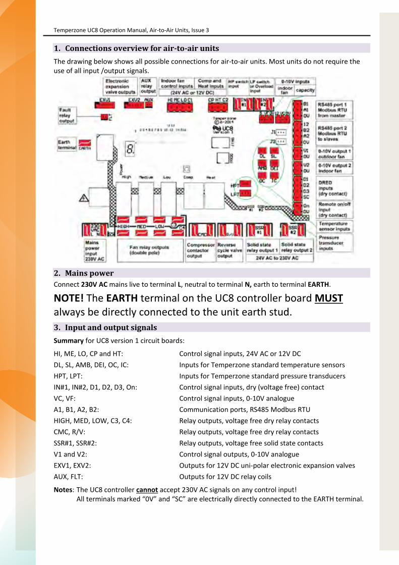
Temperzone UC8 Operation Manual, Air-to-Air Units, Issue 3
Page 4 of 38
1. Connections overview for air-to-air unitsThe drawing below shows all possible connections for air-to-air units. Most units do not require the use of all input /output signals.
2. Mains powerConnect 230V AC mains live to terminal L, neutral to terminal N, earth to terminal EARTH.
NOTE! The EARTH terminal on the UC8 controller board MUST always be directly connected to the unit earth stud. 3. Input and output signalsSummary for UC8 version 1 circuit boards:
HI, ME, LO, CP and HT: Control signal inputs, 24V AC or 12V DC DL, SL, AMB, DEI, OC, IC: Inputs for Temperzone standard temperature sensors HPT, LPT: Inputs for Temperzone standard pressure transducers IN#1, IN#2, D1, D2, D3, On: Control signal inputs, dry (voltage free) contact VC, VF: Control signal inputs, 0-10V analogue A1, B1, A2, B2: Communication ports, RS485 Modbus RTU HIGH, MED, LOW, C3, C4: Relay outputs, voltage free dry relay contacts CMC, R/V: Relay outputs, voltage free dry relay contacts SSR#1, SSR#2: Relay outputs, voltage free solid state contacts V1 and V2: Control signal outputs, 0-10V analogue EXV1, EXV2: Outputs for 12V DC uni-polar electronic expansion valves AUX, FLT: Outputs for 12V DC relay coils
Notes: The UC8 controller cannot accept 230V AC signals on any control input! All terminals marked “0V” and “SC” are electrically directly connected to the EARTH terminal.

Page 67
Temperzone UC8 Operation Manual, Air-to-Air Units, Issue 3
Page 5 of 38
3.1. Temperature sensor inputs Note: On air-to air units where pressure transducers are connected to the HPT and LPT inputs then
coil temperature sensors are not required, leave inputs OC and IC unused.
Connector Function Notes DL Compressor discharge line Red SL Compressor suction line White AMB Ambient Yellow or black (not always required) DEI De-Ice (on fins of outdoor coil) Blue (not required on cooling only units) OC Outdoor coil Yellow (not always required) IC Indoor coil Yellow (not always required)
3.2. Pressure transducers Connector Function Default pressure range Output voltage HPT High pressure 0 to 4500kPa (all models) 0.5 to 4.5V LPT Low pressure 0 to 3450kPa (all models) 0.5 to 4.5V Not all temperzone air conditioning units are equipped with pressure transducers. If no pressure transducer is present then the corresponding switch input (IN#1 and/or IN#2) is configured as an input for a pressure switch. Refer to paragraphs 3.4 and 3.5.
3.3. Inputs HI, ME, LO, CP and HT A thermostat or other controller (e.g. a BMS) that provides switched signals (dry or ‘voltage-free’ contact outputs) can use the contacts to switch 24V AC or 12V DC signals to the following inputs:
CP Compressor on/off HT Cooling / heating (leave unconnected for cooling-only installations) HI – ME – LO For a three-speed or variable speed indoor fan HI, ME or LO For a single-speed indoor fan C1 Common for inputs HI, ME and LO. C2 Common for inputs CP and HT.
Common inputs C1 and C2 would normally connect to the 24V AC Common or to 0V (when using 12V DC control signals). These inputs are electrically isolated from all other circuits.
3.4. Switch input IN #1 High pressure transducer HP switch What to do with the IN #1 terminals Yes No Leave un-connected. No Yes Connect to high pressure switch.
3.5. Switch input IN #2 Low pressure transducer
LP switch Overload switch What to do with the IN #2 terminals
Yes No No Short circuit (loop). Yes No Yes Connect to overload switch (normally closed). No Yes No Connect to low pressure switch.
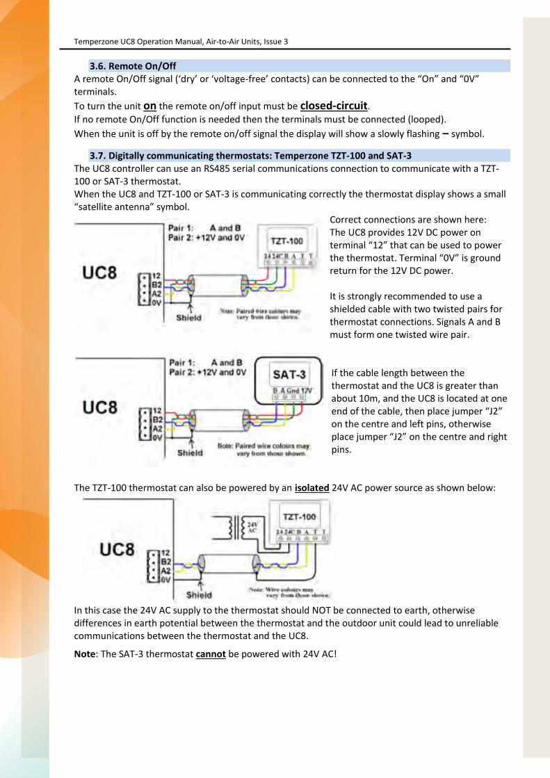
Temperzone UC8 Operation Manual, Air-to-Air Units, Issue 3
Page 6 of 38
3.6. Remote On/Off A remote On/Off signal (‘dry’ or ‘voltage-free’ contacts) can be connected to the “On” and “0V” terminals. To turn the unit on the remote on/off input must be closed-circuit. If no remote On/Off function is needed then the terminals must be connected (looped). When the unit is off by the remote on/off signal the display will show a slowly flashing – symbol.
3.7. Digitally communicating thermostats: Temperzone TZT-100 and SAT-3 The UC8 controller can use an RS485 serial communications connection to communicate with a TZT-100 or SAT-3 thermostat. When the UC8 and TZT-100 or SAT-3 is communicating correctly the thermostat display shows a small “satellite antenna” symbol.
Correct connections are shown here: The UC8 provides 12V DC power on terminal “12” that can be used to power the thermostat. Terminal “0V” is ground return for the 12V DC power. It is strongly recommended to use a shielded cable with two twisted pairs for thermostat connections. Signals A and B must form one twisted wire pair. If the cable length between the thermostat and the UC8 is greater than about 10m, and the UC8 is located at one end of the cable, then place jumper “J2” on the centre and left pins, otherwise place jumper “J2” on the centre and right pins.
The TZT-100 thermostat can also be powered by an isolated 24V AC power source as shown below:
In this case the 24V AC supply to the thermostat should NOT be connected to earth, otherwise differences in earth potential between the thermostat and the outdoor unit could lead to unreliable communications between the thermostat and the UC8.
Note: The SAT-3 thermostat cannot be powered with 24V AC!

Page 69
Temperzone UC8 Operation Manual, Air-to-Air Units, Issue 3
Page 7 of 38
3.8. TZT-100 thermostat DIP switch settings The UC8 controller requires that three DIP switches inside the TZT-100 are set in a particular way. These are:
DIP switch 2 must be ON: Equipment type = Heat Pump DIP switch 3 must be OFF: Equipment stages = One
(Note: This applies even when the unit has more than one compressor!) DIP switch 4 must be ON: Reverse cycle valve = On when Heating
All other DIP switches inside the TZT-100 thermostat can be set as required for the installation. If the UC8 controller finds that the TZT-100 DIP switches are not set as per above it will report fault code F36. To correct the situation follow this procedure:
Set TZT-100 DIP switches 2, 3 and 4 as per above. Reconnect the TZT-100. Wait until the (faint) blue backlight of the thermostat display turns off (about 15 seconds). Remove mains power from the unit, then re-apply power. Fault F36 should now be cleared.
3.9. Thermostat communication settings The communications format must be set as per recommended Modbus RTU default settings: Baud rate 19200 8 Data bits Even parity bit 1 Stop bit TZT-100 modbus device address 7 SAT-3 modbus device address 8
It is possible to change the baud rate and the parity settings of the UC8. Contact Temperzone for more information.
The procedure to check and adjust the settings in the TZT-100 thermostat is as follows: Press and hold down the O/RIDE button until the display shows the PIN code (about 15 seconds). Use the UP & DOWN buttons to select PIN code 88:21, then press O/RIDE. The thermostat is now
in installer mode. Use the O/RIDE and PROG buttons to cycle through the various installer settings. The following
settings must be selected: o Ad = 7 o bd = 19.2 o Pa = 1 (not all TZT-100 thermostats offer this setting, ignore if not available)
For the procedure to check and adjust the settings in the SAT-3 thermostat refer to the SAT-3 installer manual.

Temperzone UC8 Operation Manual, Air-to-Air Units, Issue 3
Page 8 of 38
3.10. Electronic expansion valves The UC8 can control up to two electronic expansion valves (EXV) via connectors EXV1 and EXV2. The expansion valves must be 12V unipolar types. The connectors must be compatible with JST type XH and have 6 pins. (Expansion valves with 5 pin connectors can also be used if the connectors are placed on the 5 right-most pins of EXV1 and EXV2.)
DIP switches 7 and 8 on UC8 board define how the outputs EXV1 and EXV2 are operated: 7 OFF ON OF ON
8 OFF OFF ON ON
Electronic expansion valve operating mode No electronic expansion valves (e.g. accurators, TX valve, capillary tube ...). One valve or two parallel electronic expansion valves (as required), positions always identical. If the unit is capable of advanced dry mode operation then this setting is the ‘High Efficiency Mode’. Reserved. Advanced Dry Mode. This option must only be selected on units suitably equipped. Dry mode has no influence on the unit when heating.
DIP switches 9 and 10 select the expansion valve model: 9 OFF ON OFF ON
10 OFF OFF ON ON
Electronic expansion valve type How to recognise the valve type
Dunan DPF series Zhe Jiang Sanhua DPF series Carel E2V series (& E3V series with unipolar coil) Reserved (do not select)
removable black coil non-removable metal coil removable red coil -
Below are images that can help to recognise the correct expansion valve used in the unit:
Dunan Sanhua Carel
3.11. DRED inputs
DRED stands for Demand Reduction Enabling Device. The UC8 can be connected to such a device, which is typically controlled by the electricity supplier.
When used, inputs D1, D2 and D3 should connect to a set of three ‘voltage free’ dry relay contacts in accordance with the DRED standard. The SC terminal is the common for the three inputs.
Note: Terminal SC is internally directly connected to ‘0V’ and ‘EARTH’.
Functionality is as follows:
Input D1 active: The compressor is switched off, the indoor fan is allowed to operate. Input D2 active: Average energy consumption of the unit is reduced by 50% (approximately). Input D3 active: Average energy consumption of the unit is reduced by 25% (approximately).
Inputs D1 and D2 can be given alternate functions. For more information refer to section 10: Quiet Mode, section 11: Dry Mode and section 4: DIP switch settings.

Page 71
Temperzone UC8 Operation Manual, Air-to-Air Units, Issue 3
Page 9 of 38
3.12. 0-10V Analogue control input VC Units equipped with a digital scroll- or variable speed- compressor are capable of variable capacity (duty). The required capacity can be set in four ways:
Via 0-10V analogue input VC on the UC8. Automatic in combination with the TZT-100 thermostat, SAT-3 thermostat or Zone controller. Via Modbus RTU serial communications, for example by a BMS (terminals A1, B1). Via 0-10V analogue input on the indoor unit controller (IUC, applies to split units only).
Notes: 0-10V input VC is directly referenced to unit earth, it is not electrically isolated. Terminal “0V” is the reference (return) connection for input VC. Terminal “0V” is directly connected to the controller EARTH terminal. If the 0-10V control signal source is located remotely from the unit then it may be necessary to
use a suitable 0-10V isolating amplifier.
Unit capacity is varied linearly with the control voltage applied to input VC. 0V represents 0% (no duty), 10V represents 100% (maximum duty). Note that the UC8 controller imposes a minimum capacity. In most applications the minimum capacity is limited to not less than 25% or 40%; in a close control application the minimum can be as low as 16%.
Example: If minimum capacity is set to 40% then capacity will remain at 40% (when the compressor is on) for all input voltages from 0V to 4V and vary from 40% to 100% for voltages from 4V to 10V.
For the first two minutes after a compressor is started the minimum capacity is raised to 75% (digital scroll compressor) or capacity is held fixed to 50% (variable speed compressor). After these first two minutes normal capacity control is available.
If a unit continuously operates on low capacity for longer than 1 hour and 40 minutes the controller can perform an oil flush cycle. Oil flush cycles can be necessary on some installations to return the lubricating oil to the compressor. Oil flush cycles normally last for 1 minute only and during this 1 minute the capacity is fixed to 100% (digital scroll compressor) or 65% (variable speed compressor).
3.13. 0-10V Analogue control input VF The UC8 offers several ways for control of the indoor fan speed. Available options are:
TZT-100 thermostat or SAT-3 thermostat. Inputs HI, ME and LO on the UC8 controller (24V AC / 12V DC). Analogue input VF on the UC8 controller (0-10V). Modbus RTU serial communications over RS485 (terminals A1, B1). Inputs Hi-Me-Lo on the indoor unit controller (IUC, applies to split units only).
Notes: 0-10V input VF is directly referenced to unit earth, it is not electrically isolated. Terminal “0V” id the reference (return) connection for input VF. Terminal “0V” is directly connected to the controller EARTH terminal. If the 0-10V control signal source is located remotely from the unit then it may be necessary to
use a suitable 0-10V isolating amplifier.
The above remains true regardless of the type of the indoor fan: single speed, three speed or variable speed. For more details on indoor fan speed control refer to chapter 14: Indoor fan control.

Temperzone UC8 Operation Manual, Air-to-Air Units, Issue 3
Page 10 of 38
3.14. Relay outputs CMC and R/V
The two terminals labelled CMC are one set of normally-off relay contacts, fully isolated from all other circuits and are voltage free. The same is true for the two terminals labelled R/V.
Normally the CMC output is used to control a compressor contactor while the R/V output is used to control a reverse cycle valve.
The refrigeration circuit must be designed with reverse cycle valve OFF for cooling mode, ON for heating mode.
3.15. Relay outputs HIGH, MED and LOW
Terminals labelled HIGH, MED and LOW connect to three double-pole normally-off relay contacts. Terminal C3 is the common terminal for one set of relay poles (upper row of terminals), terminal C4 does the same for the other set of poles (lower row of terminals. The two sets are voltage free and fully isolated from all other circuits.
These terminals can be assigned a number of functions. Available functions are:
Three speed induction fan control, either for the outdoor- or for the indoor fan. Single speed fan control, can be used for the outdoor- and for the indoor fan. Fan controller mains power contactor control, for the outdoor- and for the indoor- fan.
UC8 DIP switches 3 and 4 select the type of outdoor fan. DIP switches 5 and 6 select the type of indoor fan, if the indoor fan is controlled by the UC8. Refer to chapter 4: DIP switch selections.
The following table lists all available combinations:
Fan type Relay function
Outdoor Indoor HIGH MED LOW
Single speed Single speed Indoor fan on / off Outdoor fan on / off -
0-10V EC Single speed Indoor fan on / off Outdoor fan contactor
Single speed 0-10V EC Indoor fan contactor Outdoor fan on / off -
0-10V EC Three speed Indoor fan high Indoor fan medium Indoor fan low
Three speed 0-10V EC Outdoor fan high Outdoor fan medium Outdoor fan low
Three speed Three speed
These selections are not available Three speed Single speed
Single speed Three speed
3.16. Relay outputs SSR1, SSR2 and AUX Digital scroll compressor SSR1 SSR2 AUX No Crank case heater No function On status Yes Crank case heater Modulating valve On status
The “On status” output is active when one or more of the following conditions apply: The compressor is on. The indoor fan is on. The compressor and indoor fan are currently off but the thermostat is on, i.e. the unit is off in
deadband, or the compressor may be held off by an internal safety timer or by a protection function.

Page 73
Temperzone UC8 Operation Manual, Air-to-Air Units, Issue 3
Page 11 of 38
4. DIP switch selections Table 1, DIP switch functions for switches 1 to 13. Switch Function
1 OFF
ON
Indoor air flow (also refer to chapter 9: Dry mode) Variable indoor air flow:
Indoor fan performs a warm start when unit starts heating. Indoor fan stops during de-ice cycles. Indoor fan speed may vary from thermostat request.
Fixed indoor air flow: Indoor fan follows thermostat request even when heating starts. Indoor fan continues during de-ice cycles. Indoor fan speed follows thermostat request.
2 OFF ON
Compressor type Fixed capacity Digital scroll
3 OFF ON OFF ON
4 OFF OFF ON ON
Outdoor fan selection Three speed fan HIGH/MED/LOW relay outputs One speed fan MED relay output 0-10V EC fan V1 output Reserved Do not select
5 OFF ON OFF
ON
6 OFF OFF ON
ON
Indoor fan selection, when the UC8 directly controls the indoor fan Three speed fan HIGH/MED/LOW relay outputs One speed fan HIGH relay output 0-10V EC fan V2 output Select this option when the indoor fan is neither controlled by the UC8 nor by an IUC. Reserved Do not select
5
OFF ON OFF ON
6
OFF OFF ON ON
Indoor fan speed range selection, when the UC8 controls a variable speed indoor fan via the IUC
Indoor fan speed range is set by DIP switches on the IUC. Indoor fan speed range is set by the “H” and “L” fan speed setup modes on the UC8. Reserved Do not select Reserved Do not select
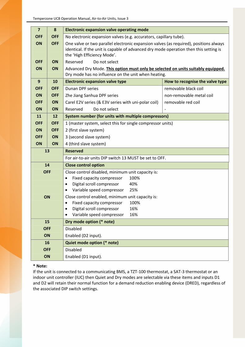
Temperzone UC8 Operation Manual, Air-to-Air Units, Issue 3
Page 12 of 38
7 OFF ON
OFF ON
8 OFF OFF
ON ON
Electronic expansion valve operating mode No electronic expansion valves (e.g. accurators, capillary tube). One valve or two parallel electronic expansion valves (as required), positions always identical. If the unit is capable of advanced dry mode operation then this setting is the ‘High Efficiency Mode’. Reserved Do not select Advanced Dry Mode. This option must only be selected on units suitably equipped. Dry mode has no influence on the unit when heating.
9 OFF ON OFF ON
10 OFF OFF ON ON
Electronic expansion valve type How to recognise the valve type Dunan DPF series Zhe Jiang Sanhua DPF series Carel E2V series (& E3V series with uni-polar coil) Reserved Do not select
removable black coil non-removable metal coil removable red coil -
11 OFF ON OFF ON
12 OFF OFF ON ON
System number (for units with multiple compressors) 1 (master system, select this for single compressor units) 2 (first slave system) 3 (second slave system) 4 (third slave system)
13
Reserved For air-to-air units DIP switch 13 MUST be set to OFF.
14 OFF
ON
Close control option Close control disabled, minimum unit capacity is: Fixed capacity compressor 100% Digital scroll compressor 40% Variable speed compressor 25% Close control enabled, minimum unit capacity is: Fixed capacity compressor 100% Digital scroll compressor 16% Variable speed compressor 16%
15 OFF ON
Dry mode option (* note) Disabled Enabled (D2 input).
16 OFF ON
Quiet mode option (* note) Disabled Enabled (D1 input).
* Note: If the unit is connected to a communicating BMS, a TZT-100 thermostat, a SAT-3 thermostat or an indoor unit controller (IUC) then Quiet and Dry modes are selectable via these items and inputs D1 and D2 will retain their normal function for a demand reduction enabling device (DRED), regardless of the associated DIP switch settings.
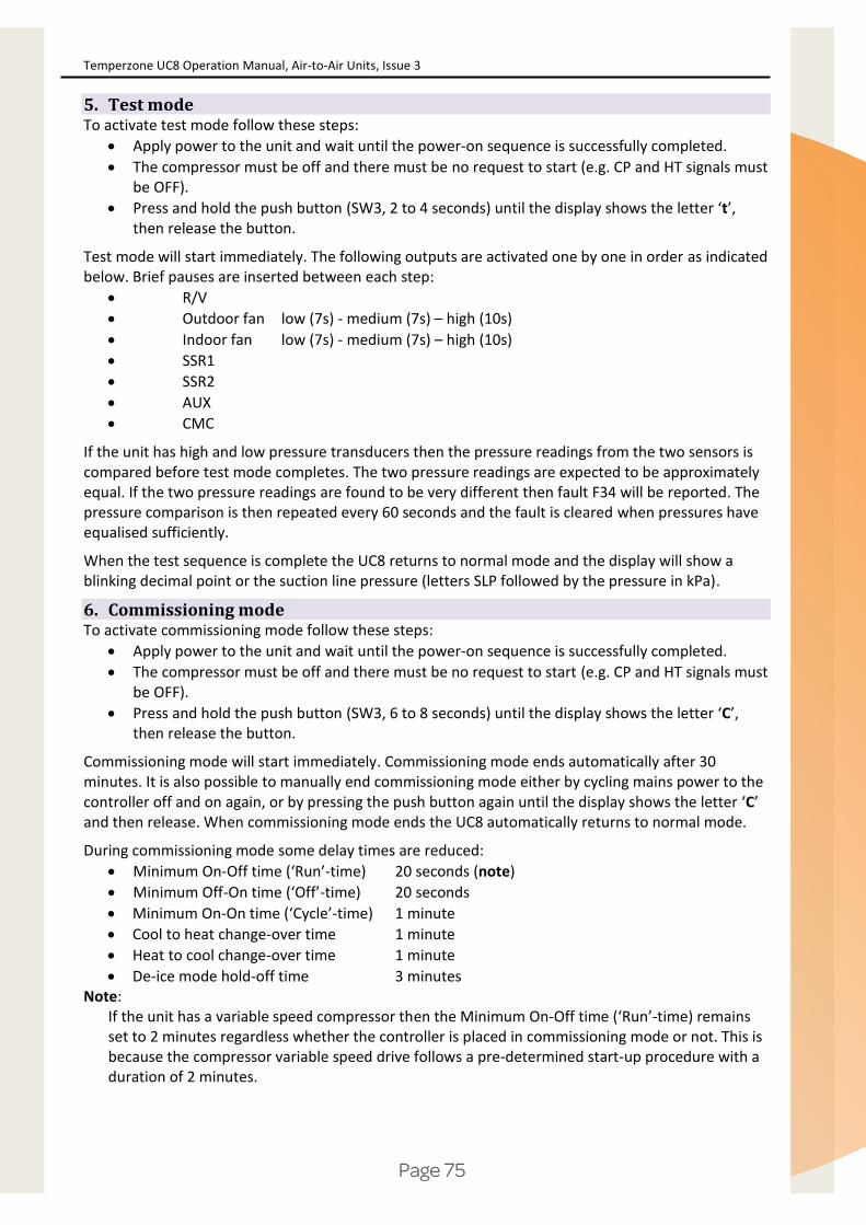
Page 75
Temperzone UC8 Operation Manual, Air-to-Air Units, Issue 3
Page 13 of 38
5. Test mode To activate test mode follow these steps:
Apply power to the unit and wait until the power-on sequence is successfully completed. The compressor must be off and there must be no request to start (e.g. CP and HT signals must
be OFF). Press and hold the push button (SW3, 2 to 4 seconds) until the display shows the letter ‘t’,
then release the button.
Test mode will start immediately. The following outputs are activated one by one in order as indicated below. Brief pauses are inserted between each step:
R/V Outdoor fan low (7s) - medium (7s) – high (10s) Indoor fan low (7s) - medium (7s) – high (10s) SSR1 SSR2 AUX CMC
If the unit has high and low pressure transducers then the pressure readings from the two sensors is compared before test mode completes. The two pressure readings are expected to be approximately equal. If the two pressure readings are found to be very different then fault F34 will be reported. The pressure comparison is then repeated every 60 seconds and the fault is cleared when pressures have equalised sufficiently.
When the test sequence is complete the UC8 returns to normal mode and the display will show a blinking decimal point or the suction line pressure (letters SLP followed by the pressure in kPa).
6. Commissioning mode To activate commissioning mode follow these steps:
Apply power to the unit and wait until the power-on sequence is successfully completed. The compressor must be off and there must be no request to start (e.g. CP and HT signals must
be OFF). Press and hold the push button (SW3, 6 to 8 seconds) until the display shows the letter ‘C’,
then release the button.
Commissioning mode will start immediately. Commissioning mode ends automatically after 30 minutes. It is also possible to manually end commissioning mode either by cycling mains power to the controller off and on again, or by pressing the push button again until the display shows the letter ‘C’ and then release. When commissioning mode ends the UC8 automatically returns to normal mode.
During commissioning mode some delay times are reduced: Minimum On-Off time (‘Run’-time) 20 seconds (note) Minimum Off-On time (‘Off’-time) 20 seconds Minimum On-On time (‘Cycle’-time) 1 minute Cool to heat change-over time 1 minute Heat to cool change-over time 1 minute De-ice mode hold-off time 3 minutes
Note: If the unit has a variable speed compressor then the Minimum On-Off time (‘Run’-time) remains set to 2 minutes regardless whether the controller is placed in commissioning mode or not. This is because the compressor variable speed drive follows a pre-determined start-up procedure with a duration of 2 minutes.

Temperzone UC8 Operation Manual, Air-to-Air Units, Issue 3
Page 14 of 38
7. Modbus device address selection The default Modbus device address of the temperzone UC8 controller is 44. To change the Modbus device address use the following procedure:
Turn mains power on. The thermostat and the compressor must be off. Press and hold the pushbutton on the controller board until the display shows the letter “A”,
then release the button. The controller is now in “Modbus address selection” mode. The display will show the Modbus device address. Subsequent button presses will increase the
address. After address 99 the address will cycle back to 1 in round-robin fashion. When the button has not been pressed for more than 30 seconds the controller will leave
setup mode and return to normal mode.
If the device address was changed then the controller will save a new address in non-volatile memory. The new address will be retained even after mains power has been switched off.
8. Compressor model selection The UC8 supports the following compressor types, models and variable speed drives:
Compressor Drive UC8 display indication DIP switch 2 setting 1. Fixed capacity Not required dF Off 2. Digital scroll Not required dF On 3. Copeland ZPV038 Carel Power+ PSD1xx 038 - 4. Toshiba DA550 Carel Power+ PSD1xx 550 - 5. Siam ANB66 Carel Power+ PSD1xx 66 - 6. Siam ANB78 Carel Power+ PSD1xx 78 - 7. Copeland ZPV063 Emerson CSD100 063 -
The factory default setting on the UC8 is for a fixed duty- or digital scroll- compressor. This is indicated on the display with the letters ‘dF’, shown twice when mains power is applied to the controller. The following procedure must be followed to correctly configure the UC8 controller for units with a different type (variable speed) compressor:
Apply power to the unit and wait until the power-on sequence is successfully completed. The compressor and the thermostat must be off (e.g. CP and HT signals must be OFF). Press and hold the UC8 push button SW3 until the display shows the letter ‘E’, then release
the button. The controller will enter ‘compressor selection mode’ and the display will show the currently
selected model. Use the pushbutton to select the correct combination of compressor and driver:
o dF Fixed capacity- or digital scroll-compressor o 038 Copeland ZPV038 Carel Power+ (PSD1xx) o 550 Toshiba DA550 Carel Power+ (PSD1xx) o 66 Siam ANB66 Carel Power+ (PSD1xx) o 78 Siam ANB78 Carel Power+ (PSD1xx) o C063 Copeland ZPV063 Emerson CSD100 (M600)
When the button has not been pressed for more than 30 seconds the controller will leave this mode and return to normal operation. If the compressor model was changed then the controller will save the new selection in non-volatile memory. The selection will be retained even after mains power has been switched off, so it needs to be done once only.

Page 77
Temperzone UC8 Operation Manual, Air-to-Air Units, Issue 3
Page 15 of 38
8.1. Carel Power+ configuration The four DIP switches on the Power+ compressor driver (inverter) must be set as follows: 1 and 4 ON, 2 and 3 OFF. These DIP switches are internal to the driver. One needs to VERY CAREFULLY remove the front cover. The Power+ must be connected to accept modbus commands on the RS485 inputs. Communication rate must be set to 19200 baud. The UC8 automatically takes care of all other driver configuration, e.g. loading of the necessary motor and compressor parameters and limits.
8.2. Emerson CSD100 configuration The Emerson CSD100 (M600) compressor driver (inverter) must be programmed to use modbus device address 1 (factory default value, CSD100 parameter 11.023). The CSD100 must be connected to accept modbus commands on the RS485 inputs. Communication rate must be set to 19200 baud (value 6 in CSD100 parameter 11.026). The UC8 automatically takes care of all other driver configuration, e.g. loading of the necessary motor and compressor parameters and limits.
9. Configuring the controller for a multiple compressor reverse cycle system with common (shared) outdoor fan chamber
UC8 controllers with software version 1.3 and later can be configured for use on reverse cycle units with multiple compressors where the outdoor fans and outdoor coils of the refrigeration circuits share one common chamber. Notes:
Re-configuration is not required for cooling-only units. In warm climates where the outdoor coil never needs de-icing re-configuration it is also not required.
Failure to correctly re-configure the UC8 master controller for multiple compressor reverse cycle units with shared outdoor fan chamber can lead to major problems in applications where outdoor coil de-icing is required!
The UC8 controllers must be configured and connected in master and slave fashion, refer to section 17.617.5 for the correct connections. DIP switches 11 and 12 must be set to designate one UC8 board as the system master and any other UC8 board(s) as slave(s) (refer to section 4).
The configuration procedure given below is necessary only on the master UC8 controller. There is no need to follow the procedure on any slave controller. In fact, the mode is automatically disabled when a UC8 is configured as a slave controller. Follow these steps to re-configure the master UC8 controller for units with shared outdoor fan chamber:
Apply power to the unit and wait until the power-on sequence is successfully completed. The compressor and the thermostat must be off (e.g. signals CP and HT must be OFF). Press and hold the UC8 push button SW3 until the display shows the letter ‘J’, then release the
button. The controller will enter ‘outdoor fan chamber configuration mode’ and the display will show
either 0 or 1. Use the pushbutton to select the correct configuration number:
o 0 : for units with individual outdoor fan chambers
o 1 : for units with shared outdoor fan chambers

Temperzone UC8 Operation Manual, Air-to-Air Units, Issue 3
Page 16 of 38
When the button has not been pressed for more than 30 seconds the controller will leave this mode and return to normal operation. If the configuration was changed then the controller will save the new configuration in non-volatile memory. The configuration will be retained even after mains power has been switched off, so it needs to be done once only.
Two last notes concerning the outdoor fan chamber:
1. If controller in a multiple compressor system are connected in master-slave fashion but the unit has individual outdoor fan chambers (NOT a shared outdoor fan chamber) then re-configuration for shared outdoor fan chamber (value 1) is possible but is NOT recommended. If configured correctly for individual chambers then each system will be able to de-ice the outdoor coil whenever it is required to do so. In contrast, if configured incorrectly for shared outdoor fan chamber then ALL systems are forced to de-ice simultaneously. Although this is not damaging it may cause reduced heating performance.
2. If controllers in a multiple compressor system are not connected in master-slave fashion then setting the outdoor fan chamber configuration to 0 or 1 has no effect.
10. Quiet Mode Quiet mode can reduce the amount of noise produced by the outdoor fan. Quiet mode has no effect on the indoor fan. Quiet mode is available both when cooling and when heating.
The effectiveness of Quiet mode depends on the outdoor ambient temperature. The limitations are: If the unit is heating while the outdoor ambient temperature is below about +10°C then
selecting Quiet mode will have no effect. If the unit is cooling while the outdoor ambient temperature is above about +35°C then
Quiet mode will also have no effect.
Quiet mode can be selected in a number of ways. These are: With a TZT-100 thermostat. With a SAT-3 thermostat. With input Qt on the indoor unit controller (IUC, applies to split units only). With a communicating BMS. With UC8 input D1 (refer to section 10.5).
10.1. Enabling quiet mode on units with TZT-100 thermostat To select Quiet mode press-and-hold down the MODE button for 3 seconds until the AUX symbol appears on the display of the thermostat. To switch Quiet mode off do the same until the AUX symbol disappears. Note: This option is available only on TZT-100 thermostats with software version 2.31 or later.
10.2. Enabling the SAT-3 thermostat for quiet mode Refer to the SAT-3 installer manual.
10.3. Enabling quiet mode with a communicating BMS Refer to document “Temperzone UC8 Modbus communications”.
10.4. Enabling quiet mode with IUC input Qt Link indoor unit controller (IUC) input Qt to 0V, e.g. with voltage free relay contacts.

Page 79
Temperzone UC8 Operation Manual, Air-to-Air Units, Issue 3
Page 17 of 38
10.5. Enabling UC8 input D1 for quiet mode control If quiet mode operation is desirable but no other control for quiet mode is available, then UC8 input D1 can be reconfigured for Quiet mode as follows:
DIP switches 13 14 15 16
OFF - - ON
The DIP switch setting shown above reserves input D1 as an enable/disable signal to start or stop operation in Quiet mode. Input D1 is then not available for the DRED function.
To start or stop Quiet mode using input D1: Input D1 open circuit: Quiet mode OFF Input D1 linked to terminal SC (same as 0V): Quiet mode ON
11. Dry mode (de-humidification) Depending on the unit model, the UC8 controller can offer several options for de-humidification while cooling the room: Mode Available on Indoor fan speed Standard cooling All units
Fixed
High-efficiency cooling All units
Variable and must be controlled via the UC8
Conventional dry cooling All units
Variable and must be controlled via the UC8
Advanced dry cooling Units with dual expansion valves and split indoor coil
Fixed
Super-dry cooling Units with dual expansion valves and split indoor coil
Variable and must be controlled via the UC8
Standard cooling mode: This is the default mode for Temperzone units with UC8 controller when no other cooling mode is activated. In this mode the unit does not actively control the indoor coil temperature. The supply air is de-humidified only when the indoor coil temperature remains below the dew point. The indoor fan speed is equal to the speed requested by the thermostat. Standard cooling mode is suitable for installations where indoor airflow must remain constant and where de-humidification is less important.
High efficiency cooling mode: The UC8 controller must be allowed to vary the indoor fan speed to obtain an indoor coil temperature for optimum unit duty and efficiency. Thus the indoor fan speed can be different from the speed as requested by the thermostat. The supply air is de-humidified only when the indoor coil temperature remains below the dew point. High efficiency cooling mode may be unsuitable for installations where indoor airflow must remain constant.

Temperzone UC8 Operation Manual, Air-to-Air Units, Issue 3
Page 18 of 38
Conventional dry cooling mode: The UC8 controller must be allowed to vary the indoor fan speed to obtain a low indoor coil temperature to provide de-humidification of the supply air. Thus the indoor fan speed can be different from the speed as requested by the thermostat. Conventional dry cooling mode may be unsuitable for installations where indoor airflow must remain constant.
Advanced dry cooling mode: Advanced dry mode provides highly effective de-humidification over a wide range of operating conditions and unit duty whilst the indoor fan speed remains unaffected. De-humidification of the supply air is achieved by operation of dual electronic expansion valves. Advanced dry cooling mode is suitable for installations where indoor airflow must remain constant.
Super dry cooling mode: Super dry cooling mode is a combination of advanced dry mode and conventional dry mode. The UC8 controller must be allowed to vary the indoor fan speed. Under most operating conditions the indoor fan speed will remain equal to the speed as requested by the thermostat. Only when the desired indoor coil temperature cannot be achieved by the dual electronic expansion valves alone then the controller will adjust the indoor fan speed to obtain maximum de-humidification. Super dry cooling mode may be unsuitable for installations where indoor airflow must remain constant.
Dry (de-humidification) mode can be selected in a number of ways. These are: With a TZT-100 thermostat. With a SAT-3 thermostat. With input Dy on the indoor unit controller (IUC, applies to split units only). With a communicating BMS. With UC8 input D2 (refer to section 11.5).
11.1. Enabling the TZT-100 thermostat for dry mode Note: This option is available only on TZT-100 thermostats with software version 2.31 or later. If the TZT-100 thermostat is programmed with an earlier software version then refer to paragraph 11.5 to enable Dry mode using input D2.
To configure the TZT-100 thermostat for dry mode: Press-and-hold the O/RIDE button for 15 seconds until the PIN code is shown (88:15). Use the Up/Down buttons to select the correct PIN code (default is 88:21), then press O/RIDE
again. The thermostat is now in installer mode. Press O/RIDE a number of times until the screen shows Fn. Press the Up/Down buttons to select the correct option. The options are:
o -- manually select heating / cooling o H heating only o C cooling only o A heating / cooling / auto o d- manually select heating / cooling / cooling with dry mode o dC cooling / cooling with dry mode o dA heating only / cooling only / cooling with dry mode / auto with dry mode
After selecting the desired option press MODE to exit from installer mode.

Page 81
Temperzone UC8 Operation Manual, Air-to-Air Units, Issue 3
Page 19 of 38
11.2. Enabling the SAT-3 thermostat for dry mode Refer to the SAT-3 installer manual.
11.3. Enabling dry mode with a communicating BMS Refer to document “Temperzone UC8 Modbus communications”.
11.4. Enabling dry mode with IUC input Dy Link indoor unit controller (IUC) input Dy to 0V, e.g. with voltage free relay contacts.
11.5. Enabling UC8 input D2 for dry mode control If no other control for dry mode is available then input D2 can be re-configured for Dry mode operation as follows:
DIP switches 13 14 15 16
OFF - ON - The DIP switches setting shown above reserve input D2 as an enable/disable signal to start or stop operation in Dry mode. Input D2 is then not available for the DRED function.
To start or stop Dry mode via input D2: D2 input open circuit: Dry mode OFF D2 input shorted to terminal SC (same as ground or G): Dry mode ON
11.6. Conventional dry mode Expansion device DIP switches
7 8
Accurators OFF OFF
One electronic expansion valve ON OFF Dual electronic expansion valves
To activate conventional dry mode (refer also to paragraphs 9.1 and 9.2): With TZT-100 thermostat: Select cool + dry or cool / heat + dry, start the unit in cooling mode.
Fan speed must show Low-Med-High.
With SAT-3 thermostat: Select cool + dry or cool / heat + dry, start the unit in cooling mode. Select fan auto-speed (the word AUTO shows on the display).
With BMS: Refer to document “Temperzone UC8 Modbus communications”. With IUC: DIP switch 1 OFF (variable indoor airflow). Activate input Dy on the IUC. With input D2: DIP switch 1 OFF (variable indoor airflow).
Activate input D2.
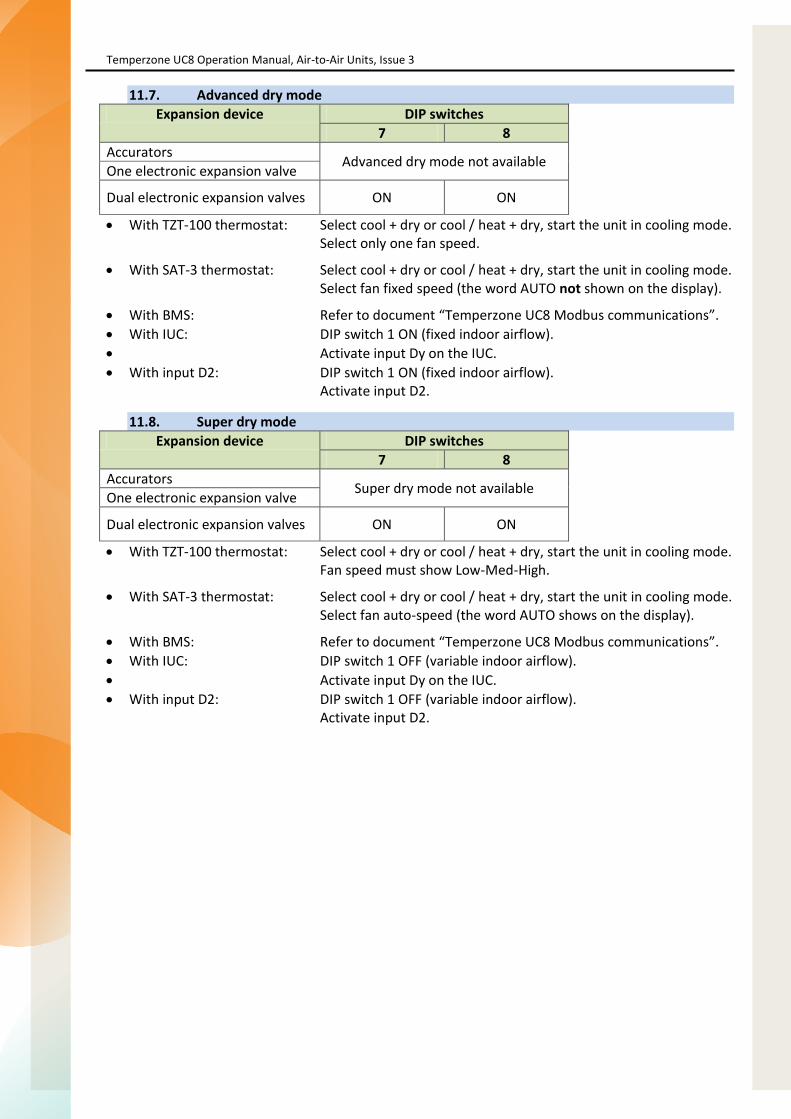
Temperzone UC8 Operation Manual, Air-to-Air Units, Issue 3
Page 20 of 38
11.7. Advanced dry mode Expansion device DIP switches
7 8 Accurators Advanced dry mode not available One electronic expansion valve
Dual electronic expansion valves ON ON
With TZT-100 thermostat: Select cool + dry or cool / heat + dry, start the unit in cooling mode. Select only one fan speed.
With SAT-3 thermostat: Select cool + dry or cool / heat + dry, start the unit in cooling mode. Select fan fixed speed (the word AUTO not shown on the display).
With BMS: Refer to document “Temperzone UC8 Modbus communications”. With IUC: DIP switch 1 ON (fixed indoor airflow). Activate input Dy on the IUC. With input D2: DIP switch 1 ON (fixed indoor airflow).
Activate input D2.
11.8. Super dry mode Expansion device DIP switches
7 8 Accurators Super dry mode not available One electronic expansion valve
Dual electronic expansion valves ON ON
With TZT-100 thermostat: Select cool + dry or cool / heat + dry, start the unit in cooling mode. Fan speed must show Low-Med-High.
With SAT-3 thermostat: Select cool + dry or cool / heat + dry, start the unit in cooling mode. Select fan auto-speed (the word AUTO shows on the display).
With BMS: Refer to document “Temperzone UC8 Modbus communications”. With IUC: DIP switch 1 OFF (variable indoor airflow). Activate input Dy on the IUC. With input D2: DIP switch 1 OFF (variable indoor airflow).
Activate input D2.

Page 83
Temperzone UC8 Operation Manual, Air-to-Air Units, Issue 3
Page 21 of 38
12. Modbus communications baud rate selection The default Modbus communication speed is 19200 baud (UC8 RS485 port 1). If a communicating BMS requires a different baud rate follow this procedure:
Apply power to the unit and wait until the power-on sequence is successfully completed. The compressor and the thermostat must be off (e.g. CP and HT signals must be OFF). Press and hold the UC8 push button SW3 until the display shows the letter ‘b’, then release
the button. The controller will enter ‘baud rate selection mode’ and the display will show a number
indicating the currently selected baud rate. Use the pushbutton to select the desired baud rate:
o 0 4800 baud o 1 9600 baud o 2 19200 baud (factory default setting) o 3 38400 baud
When the button has not been pressed for more than 30 seconds the controller will leave this mode and return to normal operation. If the baud rate was changed then the controller will save the new selection in non-volatile memory. The selection will be retained even after mains power has been switched off, so it needs to be done once only.
13. Modbus communications parity and stop bit selection The default Modbus communication parity setting is EVEN with 1 stop bit (UC8 RS485 port 1). If a communicating BMS requires different settings follow this procedure:
Apply power to the unit and wait until the power-on sequence is successfully completed. The compressor and the thermostat must be off (e.g. CP and HT signals must be OFF). Press and hold the UC8 push button SW3 until the display shows the letter ‘P’, then release
the button. The controller will enter ‘parity and stop bit selection mode’ and the display will show a
number indicating the current selection. Use the pushbutton to select the desired parity and stop bit:
o 0 no parity 2 stop bits o 1 odd parity 1 stop bit o 2 even parity 1 stop bit (factory default setting)
When the button has not been pressed for more than 30 seconds the controller will leave this mode and return to normal operation. If the setting was changed then the controller will save the new selection in non-volatile memory. The selection will be retained even after mains power has been switched off, so it needs to be done once only.

Temperzone UC8 Operation Manual, Air-to-Air Units, Issue 3
Page 22 of 38
14. Indoor fan control The UC8 controller can be configured to control a single-speed type fan (off/on), a three-speed fan (off/low/medium/high) or a variable speed fan (EC fan). Additionally the UC8 controller offers a variety of inputs to control the indoor fan. Available indoor fan control options are:
BMS using Modbus RTU over RS485 serial communication SAT-3 or TZT-100 or HL2028 thermostat or 6-Zone controller UC8 controller inputs HI-ME-LO (24V AC / 12V DC) UC8 controller input VF (0-10V) Indoor unit controller (IUC) Hi-Me-Lo inputs
- If a communicating BMS is used then all other control options are disabled. For more information refer to document “Temperzone UC8 Modbus communications”.
- Similar to control by BMS, if control is by SAT-3, TZT-100, HL2028 thermostat or 6-Zone controller the remaining input options are disabled.
- If the unit is not controlled by communicating BMS, SAT-3, TZT-100, HL028 or 6-zone controller then the UC8 automatically selects the input that requests the highest indoor fan speed.
Some installations do not permit indoor fan speed to vary from the requested speed at any time. For such installations the indoor fan can be controlled not by the UC8 or IUC but directly by an external control source (thermostat, BMS), or the fan may be simply hardwired to run at a constant fixed speed.
If the UC8 (or indoor unit controller, IUC) is not used to control the indoor fan then it is the responsibility of the system- designer and -installer to ensure proper and safe operation of the indoor fan, and the system as a whole, under all operating conditions.
14.1. Variable-speed (EC) indoor fan speed adjustment
The UC8 can control variable speed indoor fans using a 0-10V signal from output V2. Factory default settings for the output voltage provided on output V2 are:
Off 0V Low 5V Medium 6.5V High 8V
If required it is possible to adjust these voltages as follows:
To adjust the fan high speed setting: Press and hold the pushbutton until the display shows the letter “H”, then release the button. The UC8 will enter “fan high speed setup mode”. Output V2 will provide 8V and the indoor fan will run accordingly; the display will show “8.0”. Use pushbutton SW3 to change the voltage anywhere from 3.0 to 10.0V in steps of 0.5V. When the desired fan high speed has been set then wait 30 seconds, the controller will save selected setting.
To adjust the fan low speed setting: Press and hold the pushbutton until the display shows the letter “L”, then release the button. The UC8 will enter “fan low speed setup mode”. Output V2 will provide 5V and the indoor fan will run accordingly; the display will show “5.0”. Use pushbutton SW3 to change the voltage anywhere from 1.0 to 8.0V in steps of 0.5V. When the desired fan low speed has been set then wait 30 seconds, the controller will save selected setting.

Page 85
Temperzone UC8 Operation Manual, Air-to-Air Units, Issue 3
Page 23 of 38
Notes: 1. If a high speed voltage is selected that is lower than the current setting for low speed, then the
low voltage will be pushed down also and become the same as the high speed voltage. 2. A similar action happens if one selects a voltage for low speed that is higher than the current
setting for high speed: The high speed setting is increased and becomes the same as the low speed voltage.
3. It is allowed to select a low speed voltage equal to the high speed voltage. 4. In cases 1, 2 and 3 as outlined above effectively the fan will then operate as a single-speed fan
at the selected control voltage. 5. Fan medium speed voltage is always halfway between the low and high control voltages. 6. Fan off voltage is always 0V.
The default values provided by the UC8 (low 5V, medium 6.5V, high 8V) are selected to provide an adequate range of indoor airflow whilst avoiding risk of indoor coil frost, water carry-over and excessive noise. Care must be taken when changing the indoor fan speed control voltages:
Some fan controllers may not start the fan when the ‘low speed voltage’ is set as low as 1.0V. A low speed setting of 2V may be required to guarantee the indoor fan always starts.
Do not set the fan low speed so low that airflow over the indoor coil becomes so low causing the unit evaporating temperature to fall below freezing point. Otherwise there is risk of nuisance frost protection trips and unit lock-out.
Do not set the fan high speed so high that airflow over the indoor coil becomes so high that moisture that may have condensed on the fins of the indoor coil is blown into the supply air duct. Otherwise water may start leaking from the supply air vents and diffusers and corrosion of ducting may occur.
Do not set the fan high speed so high that there is excessive noise from the supply air vents and diffusers.
Do not set the fan high speed so high that, when the unit is heating, the unit may ‘over-condense’ leading to supply air that feels relatively cool and possibly also to more outdoor coil de-ice cycles than necessary (resulting in reduced duty and efficiency).
14.2. Translation from 0-10V fan control input signal VF to a fan output signal Input VF on the UC8 can be used for a 0-10V control signal for the indoor fan. This input can be used for all fan types (single-speed, three-speed and variable-speed).
If this input is used to control a variable-speed indoor fan then the UC8 does NOT simply copy the input voltage to the output voltage, but the input voltage is translated to a corresponding output voltage that obeys the settings that are programmed into the UC8. Doing so provides continued protection against the potential problems mentioned in chapter 14.1.
The translation from 0-10V input VF to a voltage on output V2 is as follows, assuming the default settings of 5V to 8V. A hysteresis zone is required between off and low speed to prevent repeated starting and stopping of the fan.
Input VF Output V2 Fan 0.0V to 0.99V 0V Off 1.0V to 1.49V 0 or 5V Off or Low (hysteresis zone, 0.5V wide) 1.5V to 9.50V 5V to 8V Low to high 9.5V to 10.0V 8V High
If above translation is undesirable then one could follow the procedure described in chapter 14.1 to change the minimum and maximum voltage settings, or one could bypass the UC8 entirely and directly control the indoor fan.

Temperzone UC8 Operation Manual, Air-to-Air Units, Issue 3
Page 24 of 38
If the indoor fan is a three-speed type then the 0-10V input signal VF is converted to Off-Low-Medium-High as per the following table. The hysteresis zones are required to reduce the chances of chattering relays.
Input VF Fan ‘Width’ 0.00V to 0.99V Off 1.0V 1.00V to 1.49V Off or Low (hysteresis zone) 0.5V 1.50V to 3.70V Low 2.2V 3.71V to 4.60V Low or Medium (hysteresis zone) 0.9V 4.61V to 6.80V Medium 2.2V 6.81V to 7.70V Medium or High (hysteresis zone) 0.9V 7.71V to 10.0V High 2.3V
If the indoor fan is a single-speed type then the 0-10V input signal VF is converted to Off-On as per the following table. The hysteresis zone is required to prevent a chattering relay.
Input VF Fan 0.0V to 0.99V Off 1.0V to 1.49V Off or On (hysteresis zone) 1.5V to 10.0V On
14.3. Translation from Modbus RTU fan control signal to fan output signal Refer to document “Temperzone UC8 Modbus communications”.
15. De-icing the outdoor coil When a unit is in heating mode and the outdoor ambient temperature is low then ice can form on the outdoor coil. In such conditions it is necessary to periodically remove the ice from the outdoor coil. The UC8 controller automatically takes care of this task.
Outdoor coil de-ice cycles are initiated when the unit is heating, the de-ice sensor reports that the temperature of the coil fins has fallen below -4°C and the previous de-ice cycle was longer than 35 minutes ago.
The 35 minute interval between de-ice cycles can become shorter when operating conditions are adverse, but the interval will never be less than 10 minutes. Such a short heating interval between de-ice cycles can be reached only in the most extreme conditions.
15.1. Outdoor coil de-ice sequence
When a de-ice cycle starts a fixed capacity compressor will stop, a digital scroll compressor or a variable speed compressor will ramp down to low capacity. Initially the outdoor fan continues at high speed.
After a brief delay the reverse cycle valve switches over and the outdoor fan is stopped. The compressor then switches back on or ramps up to high capacity. The outdoor coil will slowly warm up and cause the ice to melt.
The indoor fan may be stopped to avoid blowing very cold air into the room. Whether the indoor fan stops or not is determined by the setting of DIP switch 1 on the UC8 circuit board: OFF means the fan will stop, ON means the indoor fan continues running during the de-ice cycle. If a TZT-100 or SAT-3 thermostat is used to control the unit then the DIP switch setting can be overruled by the selection on the TZT-100 / SAT-3: AUTO-FAN allows the indoor fan to stop during de-ice, FAN-ON means the indoor fan continues during de-ice mode. A communicating BMS can also control the operation of the indoor fan during de-ice cycles.

Page 87
Temperzone UC8 Operation Manual, Air-to-Air Units, Issue 3
Page 25 of 38
A de-ice cycle normally ends when the de-ice sensor reports a temperature of +12°C. If a unit is exposed to cold winds the sensor temperature may not reach the required +12°C even though all ice may have long since melted. For such installations it is recommended that adequate shelter is provided to shield the unit from cold winds. Duration of the de-ice mode is never longer than 10 minutes.
Near the end of the de-ice cycle the compressor again stops or ramps down to low capacity. The outdoor fan restarts on high speed to remove as much water from the outdoor coil as possible. After a brief delay the unit returns to normal heating mode and the compressor duty or speed returns to normal.
15.2. Outdoor coil de-icing on a multiple-compressor system
In a system where there is more than one compressor and it is undesirable that all systems can de-ice the outdoor coils all at the same time, then the UC8 controllers may be connected as master and slave(s). When so connected a two-compressor system allows only one system to de-ice at any given time, the other system must wait until the first has completed the de-ice cycle. In the case of a three- or four-compressor system only two systems are allowed to de-ice at any given time.
If the unit has a common (shared) outdoor fan chamber then all compressor systems must de-ice at the same time. For more information refer to chapter 9.
15.3. Forced outdoor coil de-icing
It is possible to force the UC8 controller to perform an outdoor coil de-ice cycle. The procedure is as follows:
Operate the unit in heating mode as normal for longer than 2 minutes. Press and hold down UC8 push button SW3 until the LED display shows the letter ‘d’, then
release the button. A forced outdoor coil de-ice cycle will start immediately. The LED display will show ‘dE-ICE’. The de-ice cycle will proceed just like a normal de-ice cycle would. Upon completion of the de-ice cycle the unit will automatically return to normal heating
mode. Note. If a fixed duty compressor was started less than 6 minutes ago then the minimum on-on (cycle) timer may cause the de-ice cycle to be delayed until the 6 minutes have expired. If one wishes to do a quick de-ice test then first ensure the compressor is off, place the unit in commissioning mode, start the unit in heating mode, then follow the bullet points above. Temperzone UC8 Operation Manual, Air-to-Air Units, Issue 3
Page 26 of 38
16. Split systems with indoor unit controller (IUC) Split systems (separate indoor- and outdoor units) typically have one (or more) UC8 controller(s) in the outdoor unit and an indoor unit controller (IUC) in the indoor unit. The IUC simplifies wiring between the indoor- and outdoor units. For maximum flexibility connections to a thermostat or other controller can be made either to the UC8 (in the outdoor unit) or to the IUC (in the indoor unit).
For information how to correctly configure the indoor unit controller(s) refer to document “Temperzone UIC Operation manual”.
Note: To ensure reliable communications between the UC8 and the IUC the indoor unit earth must connect directly to the outdoor unit earth. Communication cables should be shielded twisted pair type. Signals A and B should always form one twisted pair. The cable shield should connect to 0V only at the UC8.
16.1. Split system with one compressor and one indoor unit
An example of the wiring between outdoor unit, indoor unit and thermostat or other type of controller is shown below.

Temperzone UC8 Operation Manual, Air-to-Air Units, Issue 3
Page 26 of 38
16. Split systems with indoor unit controller (IUC) Split systems (separate indoor- and outdoor units) typically have one (or more) UC8 controller(s) in the outdoor unit and an indoor unit controller (IUC) in the indoor unit. The IUC simplifies wiring between the indoor- and outdoor units. For maximum flexibility connections to a thermostat or other controller can be made either to the UC8 (in the outdoor unit) or to the IUC (in the indoor unit).
For information how to correctly configure the indoor unit controller(s) refer to document “Temperzone UIC Operation manual”.
Note: To ensure reliable communications between the UC8 and the IUC the indoor unit earth must connect directly to the outdoor unit earth. Communication cables should be shielded twisted pair type. Signals A and B should always form one twisted pair. The cable shield should connect to 0V only at the UC8.
16.1. Split system with one compressor and one indoor unit
An example of the wiring between outdoor unit, indoor unit and thermostat or other type of controller is shown below.
Temperzone UC8 Operation Manual, Air-to-Air Units, Issue 3
Page 27 of 38
16.2. Split system with one compressor and two indoor units
An outdoor unit with one compressor can be connected to two indoor units. Connections between the various system components must be as shown below. The two indoor units will always behave in identical fashion.
The drawing shows all possible options where a thermostat or other controller can be connected. Note that if any input on the IUC is used, this must be IUC configured as indoor unit “1”. The inputs on the IUC of indoor unit “2” are not active.
16.3. Split system with multiple compressors and one indoor unit
The UC8 controllers must be configured as a master and slave(s) (refer to sections 4 and 17.2).
The IUC must connect to the UC8 that is designated as the system master as per the diagram in chapter 16.1.
The system master UC8 will control the indoor fan on behalf of all compressors.
16.4. Split systems with multiple compressors and two indoor units
Two possibilities exist for a multiple compressor system with multiple indoor units:
Option 1: Each UC8 controller in the system connects directly to the associated indoor unit controller. The connections for this option are similar to those for single compressor systems with one UC8 and one IUC, refer to chapter 16.1.
Option 2: The master UC8 connects to two indoor unit controllers, refer to chapter 16.2. The UC8 master will control the slaved outdoor system and both indoor units.
16.5. Split systems with more than two indoor units
Software version 1.3 for the UC8 does not support connection to more than two indoor unit controllers.
However, by following the wiring shown in chapter 16.2 it is possible to create a system with two compressors (each with one UC8 controller) and connected to up to four indoor units.
Temperzone UC8 Operation Manual, Air-to-Air Units, Issue 3
Page 26 of 38
16. Split systems with indoor unit controller (IUC) Split systems (separate indoor- and outdoor units) typically have one (or more) UC8 controller(s) in the outdoor unit and an indoor unit controller (IUC) in the indoor unit. The IUC simplifies wiring between the indoor- and outdoor units. For maximum flexibility connections to a thermostat or other controller can be made either to the UC8 (in the outdoor unit) or to the IUC (in the indoor unit).
For information how to correctly configure the indoor unit controller(s) refer to document “Temperzone UIC Operation manual”.
Note: To ensure reliable communications between the UC8 and the IUC the indoor unit earth must connect directly to the outdoor unit earth. Communication cables should be shielded twisted pair type. Signals A and B should always form one twisted pair. The cable shield should connect to 0V only at the UC8.
16.1. Split system with one compressor and one indoor unit
An example of the wiring between outdoor unit, indoor unit and thermostat or other type of controller is shown below.

Page 89
Temperzone UC8 Operation Manual, Air-to-Air Units, Issue 3
Page 27 of 38
16.2. Split system with one compressor and two indoor units
An outdoor unit with one compressor can be connected to two indoor units. Connections between the various system components must be as shown below. The two indoor units will always behave in identical fashion.
The drawing shows all possible options where a thermostat or other controller can be connected. Note that if any input on the IUC is used, this must be IUC configured as indoor unit “1”. The inputs on the IUC of indoor unit “2” are not active.
16.3. Split system with multiple compressors and one indoor unit
The UC8 controllers must be configured as a master and slave(s) (refer to sections 4 and 17.2).
The IUC must connect to the UC8 that is designated as the system master as per the diagram in chapter 16.1.
The system master UC8 will control the indoor fan on behalf of all compressors.
16.4. Split systems with multiple compressors and two indoor units
Two possibilities exist for a multiple compressor system with multiple indoor units:
Option 1: Each UC8 controller in the system connects directly to the associated indoor unit controller. The connections for this option are similar to those for single compressor systems with one UC8 and one IUC, refer to chapter 16.1.
Option 2: The master UC8 connects to two indoor unit controllers, refer to chapter 16.2. The UC8 master will control the slaved outdoor system and both indoor units.
16.5. Split systems with more than two indoor units
Software version 1.3 for the UC8 does not support connection to more than two indoor unit controllers.
However, by following the wiring shown in chapter 16.2 it is possible to create a system with two compressors (each with one UC8 controller) and connected to up to four indoor units.
Temperzone UC8 Operation Manual, Air-to-Air Units, Issue 3
Page 28 of 38
17. Multiple compressor systems with more than one UC8 Several configurations are possible to control a multiple compressor system with more than one UC8 controller. The three most common configurations are described in the following chapters. Regardless of the configuration the following comments apply.
Lead-lag operation and compressor run-time sharing UC8 controllers do NOT provide any form of compressor LEAD-LAG operation. Neither do they provide compressor run-time sharing. If LEAD-LAG operation and/or compressor run-time sharing is required this must be provided by an external controller, e.g. a BMS or PLC.
Master-slave systems with one (or more) digital scroll compressor(s) If the UC8 controllers are configured as a master with one (or more than one) slaves(s) and one of the circuits has a digital scroll or variable speed compressor then this must be the master unit. If all units are equipped with digital scroll or variable speed compressors then all compressors will operate at the same time and at the same duty. This configuration is sometimes used for plant room and computer room cooling systems.
Multiple compressor units with a shared (common) outdoor fan chamber A reverse cycle system where the outdoor -coils and -fans of multiple refrigeration circuits share one common compartment must be correctly configured following the instructions given in chapter 9.
17.1. Control of the indoor fan in a multiple compressor system A multiple compressor system with only a single indoor fan, or with multiple indoor fans that must operate in unison, must run the fan when any one (or more than one) of the compressor(s) is (are) on. The following chapters explain how to achieve this with the UC8 for different types of indoor fans.
If the UC8 controllers are connected as master and slave(s), then the master UC8 can control the indoor fan on behalf of all units within the system. No other special wiring arrangements are required.
The above statement is also valid when the master-slave system is a split unit (indoor unit is separate from the outdoor unit) and the indoor fan is controlled by the indoor unit controller (IUC) via the master UC8.
It is also possible to use multiple IUC where each IUC connects to the corresponding UC8 board (a multiple compressor – multiple head system). In this case each indoor fan is controlled directly (individually) by the UC8 + IUC pair that the fan connects to.
If the UC8 controllers operate independent from one-another (i.e. they are not configured as a master and slaves(s)), then special connections must be made within the unit to ensure that the indoor fan operates correctly for all compressor systems. Refer to sections 17.1.1, 17.1.2 and 17.1.3.
17.1.1. Multiple compressor system with a 0-10V variable speed (EC) indoor fan The UC8 uses 0-10V output “V2” when it is configured for 0-10V variable speed fans. The diagram below shows how a variable speed indoor fan can be controlled by two UC8 controllers in a twin compressor system.

Temperzone UC8 Operation Manual, Air-to-Air Units, Issue 3
Page 29 of 38
17.1.2. Multiple compressor system with a single speed indoor fan The UC8 uses relay contact outputs “HIGH” when it is configured for a single speed indoor fan. The diagram below shows how a single speed indoor fan can be controlled by two UC8 controllers in a twin compressor system.
17.1.3. Multiple compressor system with a three speed indoor fan
Connecting three-speed induction fans to more than one UC8 is problematic and not recommended.
17.2. TZT-100 or SAT-3 thermostat and UC8 master-slave connection When a TZT-100 or SAT-3 thermostat is used to control a multiple compressor system with UC8 controllers then the UC8 boards must be connected using the master-slave configuration as shown below. Do NOT configure the thermostat for 2-stage operation.
In this configuration the master system compressor always is the first compressor to switch on and, normally, the last to switch off, followed by the first slave and so on. Slave compressors are switched on or off according to the required unit capacity as calculated by the master UC8 controller.
The UC8 controllers do NOT implement lead-lag operation or compressor run-time sharing.
The cable to connect the thermostat should be a shielded twisted pair type suitable for RS485 serial communications. Signals A and B must form one pair, signals 0V and 12 can form a second pair.

Page 91
Temperzone UC8 Operation Manual, Air-to-Air Units, Issue 3
Page 30 of 38
17.3. Switched contact type controller and individually controlled systems A BMS or thermostat controller with switched contact outputs (e.g. relays) can connect to two (or more) UC8 controllers as shown below.
In this configuration the DIP switches on each UC8 controller must be set as follows:
DIP switch 11 OFF DIP switch 12 OFF
If the BMS provides a 0-10V signal for capacity (unit duty) control (not shown in the diagram) then this signal can be connected to input VC on the UC8. This must be the controller with the digital scroll- or variable speed- compressor. Optionally all systems can be fitted with digital scroll- or variable speed-compressors.
17.4. Switched contact type controller and master-slave connection A BMS or thermostat controller with switched type contact outputs (e.g. relays) can connect two (or more) UC8 controllers as shown below.
For this configuration the DIP switches on the UC8 controllers must be set as follows: Switch Function 11
OFF ON OFF ON
12
OFF OFF ON ON
System number (for units with multiple compressors)
1 master system 2 first slave system 3 second slave system, if present 4 third slave system, if present
Comments in section 17.3 about a 0-10V capacity control signal apply also to this configuration.

Temperzone UC8 Operation Manual, Air-to-Air Units, Issue 3
Page 31 of 38
17.5. Communicating BMS controlling individual systems Multiple UC8 controllers can be connected to a communicating BMS. The BMS is always master and all UC8 controllers act as modbus RTU slave devices. The Modbus device address of each UC8 must be set to a unique value. For information on how to set the UC8 Modbus device address refer to chapter 7: Modbus device address selection.
This configuration is preferred over the option presented in chapter 17.6 because it can provide better system reliability.
For more details about multiple compressor control by a communicating BMS refer to document “Temperzone UC8 modbus communications”.
For this configuration the DIP switches on each UC8 controller must be set as follows:
DIP switch 11 OFF DIP switch 12 OFF
17.6. Communicating BMS controlling a master-slave system When multiple UC8 controllers are connected in master-slave fashion then a communicating BMS can be used to control and monitor all systems (the master and all connected slaves) via the single connection with the UC8 master. Please note that a communicating BMS is always master and must connect to the UC8 slave port (A1, B1).
This configuration is not preferred. It should be used only where necessary, for example in a multiple compressor reverse cycle system in a cool climate where the outdoor fans share a common compartment. In most other situations the option presented in chapter 17.5 is preferred because it can provide better system reliability.
For more details about multiple compressor control by a communicating BMS refer to document “Temperzone UC8 modbus communications”.
For this configuration the DIP switches on the UC8 controllers must be set as follows: Switch Function 11
OFF ON OFF ON
12
OFF OFF ON ON
System number (for units with multiple compressors)
1 master system 2 first slave system 3 second slave system, if present 4 third slave system, if present

Page 93
Temperzone UC8 Operation Manual, Air-to-Air Units, Issue 3
Page 32 of 38
18. Display messages (normal operation) The LED display on the UC8 circuit board can show the following messages: Display Meaning Notes UC8 1.5.3 Name and software version Shown only after power-on dELAY Random start-up delay time Up to 30s, occurs only after power-on Ready Normal operation
− Unit is OFF by Remote On/Off signal
dE-ICE De-icing the outdoor coil t Test mode c Commissioning mode H Indoor fan high speed selection Default 8.0V L Indoor fan low speed selection Default 5.0V A Modbus address selection Default 44 E Compressor model selection See table below for available models J Outdoor fan chamber selection 0 = separate, 1 = common (shared) b Modbus communications baud rate selection Default 2 = 19200 Baud P Modbus communications parity and stop bit selection Default 2 = Even d Force unit to de-ice the outdoor coil HOLd The compressor is held-on or held-off by a safety timer dr DRED energy consumption restriction is active
The following compressor model selections are available: Display Meaning dF Fixed capacity- or digital scroll-compressor 038 Copeland ZPV038 compressor and Carel Power+ PSD1xx driver 550 Toshiba DA550 compressor and Carel Power+ PSD1xx driver 66 Siam ANB66 compressor and Carel Power+ PSD1xx driver 78 Siam ANB78 compressor and Carel Power+ PSD1xx driver 063 Copeland ZPV063 compressor and Emerson CSD100 (M600) driver

Temperzone UC8 Operation Manual, Air-to-Air Units, Issue 3
Page 33 of 38
The display can be used to monitor pressures and temperatures while the unit is in normal mode or in commissioning mode. This is available regardless whether the compressor is on or off. Repeatedly press the pushbutton to cycle the display through the options (in a round robin fashion). After 2 minutes the display will automatically return to a flashing dot (or ‘c’).
Display Meaning Units or c Normal mode (default)
SLP Suction line pressure kPa Et Evaporating temperature °C SLt Suction line temperature °C SSH Suction side superheat K dLP Discharge line pressure kPa Ct Condensing temperature °C dLt Discharge line temperature °C dSH Discharge side superheat K ICEt De-ice sensor temperature (located on the outdoor coil fins) °C CAP Unit capacity (duty) % EE1 Electronic expansion valve 1 opening % EE2 Electronic expansion valve 2 opening %
or c Back to button press 0
Pressures are shown in kPa. Divide by 6.895 (roughly 7) to convert to PSI. Temperatures are shown in whole degrees Celsius. If the indicated temperature is below 0°C then a minus sign is shown before the value. If the unit has one or two pressure transducers then the condensing and/or evaporating temperatures shown are converted from pressure readings. If a reading is not available then the display shows a dash symbol (-).
19. Troubleshooting When the UC8 controller detects a problem within the system it will activate the fault relay output (FLT). The accompanying fault light will illuminate and a corresponding fault code is shown on the LED display.
Some faults will cause the unit to stop the compressor and the fans. Other faults may stop the compressor and the outdoor fans but allow the indoor fan to continue running. Yet other faults will be signalled but do not stop the unit from operating.
If a serious fault repeatedly stops the unit it may lead to unit lock-out. A locked unit will no longer run the compressor and the fans. To unlock the unit cycle mains power to the unit off and on again, alternatively a unit can be unlocked via the Modbus RTU serial connections.
Chapter 19.1 lists all possible fault codes.
Document “Temperzone UC8 troubleshooting guide” provides more detailed information on the fault codes, possible causes and remedies.

Page 95
Temperzone UC8 Operation Manual, Air-to-Air Units, Issue 3
Page 34 of 38
19.1. Fault codes Display Meaning
LP Low pressure protection is active
HP High pressure protection is active
HI-t High temperature protection is active
FROSt Indoor coil frost protection is active
HI-SL High suction line temperature protection is active
Lo-dSH Low discharge superheat protection active
Hi-dSH High discharge superheat protection active
OL Overload protection is active (‘IN #2’ input is open circuit)
Display Meaning
F10 Outdoor fan fault
F11 Indoor fan fault
F12 Low pressure transducer fault (will show as LP)
F13 High pressure transducer fault (will show as HP)
F14 Suction line temperature sensor fault
F15 Discharge line temperature sensor fault
F16 De-Ice temperature sensor fault
F17 Outdoor coil temperature sensor fault
F18 Indoor coil temperature sensor fault
F19 Ambient temperature sensor fault
F20 Superheat is unknown
F21 Thermostat fault (no serial communications)
F22 System 1 or BMS fault (no serial communications)
F23 System 2 fault (no serial communications)
F24 System 3 fault (no serial communications)
F25 System 4 fault (no serial communications)
F26 Invalid DIP switches setting
F27 Invalid fan selection
F28 Illegal operating mode requested (typically: the thermostat request heating mode but the unit lacks an outdoor coil de-ice sensor)
F29 Microcontroller temperature exceeds +100 °C
F30 Supply voltage out of bounds (+3.3V DC supply voltage on controller PCB)
F31 A slave unit reports a fault
F32 0-10V input fault
Continued on the next page.

Temperzone UC8 Operation Manual, Air-to-Air Units, Issue 3
Page 35 of 38
Fault codes, continued. Display Meaning
F33 High discharge superheat protection active
F34 Problem with pressure transducer readings or pressures not equalising
F35 Reverse cycle valve fault
F36 Invalid DIP switch setting on TZT-100 thermostat
F37 Communication with indoor unit controller (IUC) lost F38 Indoor unit controller (IUC) reports a fault F39 Variable speed compressor driver reports a fault F40 Compression ratio too high F41 Compression ratio too low F42 Evaporating temperature too high F43 Condensing temperature too low
The following sets of fault codes apply only to units with a variable speed compressor. For the Carel Power+ driver: The fault code shown is F100 plus the error code reported by the Power+ driver. For detailed information about the Power+ fault codes refer to the Carel Power+ speed drive user manual, chapter 8.3: Alarms table. A brief summary follows here: Display Meaning F100 No communications between Power+ driver and UC8 F101 Motor over-current F102 Motor overload F103 Over-voltage F104 Under-voltage F105 Drive too hot F106 Drive too cold F107 Drive over-current F108 Motor too hot F110 Drive internal error F112 Excessive drive DC bus ripple (probably: loss of mains phase) F113 Communication fault F116 Driver is disabled (input STO is open circuit) F117 Motor phase fault (possibly a motor wire has become loose) F118 Internal fan fault F119 Speed fault

Page 97
Temperzone UC8 Operation Manual, Air-to-Air Units, Issue 3
Page 36 of 38
For the Emerson CSD100 (M600) driver: The fault code shown is F100 or F200 plus a code reported by the CSD100 driver. For detailed information about the CSD100 codes refer to the Emerson CSD100 user guide. A brief summary follows here: Display Meaning F100 No communications between Power+ driver and UC8 F103 Motor current too high F105 Driver internal power supply fault F109 Driver internal 24V supply overloaded F120 Motor too hot F132 Mains power input voltage imbalance F140 Motor rotor locked F141 Motor reverse rotation F142 Compressor discharge line temperature too high (disabled by the UC8) F144 Out of safe compressor operating envelope (disabled by the UC8) F145 Loss of communications F146 Mains power input voltage too low F147 Motor soft start failure F148 Compressor discharge line temperature sensor fault (disabled by the UC8) F149 Motor too hot F150 Motor phase fault F151 Mains power input phase loss F198 Motor phase loss F205 Supply loss F209 Drive trip F215 Under voltage

Temperzone UC8 Operation Manual, Air-to-Air Units, Issue 3
Page 37 of 38
20. Specifications Notes:
Input and output signals from/to the UC8 are isolated from the mains inputs (L and N). Relay outputs HIGH, MED, LOW, C3, C4, CMC, R/V, SSR#1 and SSR#2 are isolated from all other
circuits. It is permitted to connect these relay outputs to mains live circuits. Inputs HI, ME, LO, C1, CP, HT and C2 are isolated from all other circuits. These inputs accept
24V AC or 12V DC control signals. All other input and output signals from/to the UC8 are electrically referenced to the EARTH
terminal. It is recommended that any input signal that is referenced to EARTH and that needs to connect
to a circuit external to the temperzone unit to be isolated by a suitable means, for example a relay. Typical examples of this are the remote On/Off input and the DRED inputs.
For safety, and to ensure correct operation of the unit, the EARTH terminal must directly connect to a unit earth stud located close to the controller board.
Controller environmental conditions Storage temperature range Operating temperature range Relative humidity
-20 to +75°C -10 to +65°C 20 to 95% non-condensing
Mains input L and N
230V AC 50Hz nominal
190V AC minimum
250V AC maximum
Output relays Applies to: HIGH, MED, LOW, CMC and R/V outputs
250V AC, 5A maximum, resistive load 250V AC, 2.5A maximum, inductive load
Solid state output relays Applies to: SSR1 and SSR2 outputs
12V AC minimum, 250V AC maximum (AC only!) 0.25A maximum (continuous) 2.5A maximum (peak, 0.5s)
AUX and FLT outputs Designed to operate a relay with 12V DC coil.
Open collector and +12VDC output OFF state: leakage current 0.5mA maximum ON state: 12V DC, 100mA maximum
EXV1 and EXV2 outputs Designed to operate uni-polar electronic expansion valves: 5-wire and 6-wire types.
Open collector and +12VDC output OFF state: leakage current 0.5mA maximum ON state: 12V DC, 275mA maximum per winding
Continued on the next page.

Page 99
Temperzone UC8 Operation Manual, Air-to-Air Units, Issue 3
Page 38 of 38
Isolated inputs Applies to: HI, ME, LO, CP and HT inputs Common terminals are: C1 for HI, ME and LO C2 for CP and HT
When used with 24V AC input signals: Maximum input voltage OFF state: 2V RMS AC Minimum input voltage ON state: 18V RMS AC Absolute maximum input voltage: 35V RMS AC Input impedance: 2.5kΩ When used with 12V DC input signals: Maximum input voltage OFF state: 2V DC Minimum input voltage ON state: 11V DC Absolute maximum input voltage: 35V DC Input impedance: 2.5kΩ
VC and VF 0-10V analogue inputs Referenced to terminal 0V
Absolute maximum input voltage: -2 to +15V DC Nominal input voltage: 0 to +10V DC Input impedance: 13.9kΩ
IN#1 and IN#2 DRED inputs D1, D2, D3 Remote On/Off input Referenced to terminals 0V and SC
Designed to be operated by isolated voltage free contacts. Open circuit voltage: 3.3V DC typical Closed circuit current: 3.3mA DC typical
V1 and V2 0-10V analogue outputs Referenced to terminal 0V
Maximum load: 6.5kΩ Maximum short circuit output current: 30mA
Temperature sensor inputs DL: red SL, DEI: blue AMB: yellow or black OC, IC: yellow
Designed to connect to standard Temperzone thermistor temperature sensors.
Pressure transducer inputs
Power: 5.0±0.2V DC, maximum current 50mA Signal: 0.5V at the lowest pressure 4.5V at the highest pressure Pressure ranges: LPT, all units: 0 to 3450 kPa (0-34.5 bar, 0-500 PSI) HPT, all units: 0 to 4500 kPa (0-45.0 bar, 0-653 PSI)
Modbus RS485 serial communications format
Baud rate 19200 Data bits 8 Parity even Stop bits 1
Disclaimer: Information given in this document is believed to be correct at the time of writing. Temperzone assumes no responsibility for any errors that may appear in this document. Information in this document is subject to change without notice and should not be construed as a commitment by Temperzone. In no event shall Temperzone be liable for incidental or consequential damages arising from use of this document or the software and hardware described in this document.

Date: 1 October 2015Issue: 1Note: Information in this document applies
to UC8 controllers programmed with software version 1.5
Unit Controller 8 (UC8)
Master - Slave Connection

Page 101
Temperzone UC8 – master-slave connection
Page 1 of 7
UNIT CONTROLLER 8 (UC8) Master – slave connection
Date: 1 October 2015
Issue: 1
Note: Information in this document applies to UC8 controllers programmed with software version 1.5.
Contents
1. Summary ........................................................................................................................................ 101
2. When is it necessary to connect UC8 boards as master and one or more slaves? ....................... 101
3. How to configure the UC8 as master and slave(s)? ....................................................................... 102
4. What are the limitations of master-slave connection of the UC8? ............................................... 103
5. Multiple independent UC8 controllers. ......................................................................................... 104
5.1. Connections ............................................................................................................................ 104
5.2. Implications for control of the indoor fan .............................................................................. 105
Temperzone UC8 – master-slave connection
Page 2 of 7
1. Summary The UC8 controller is designed to control a single compressor system. A unit with more than one compressor requires one UC8 controller per compressor. A few options exist for the configuration of a unit equipped with more than one UC8 controller. The various options offer different control possibilities and are subject to particular restrictions. This document presents the options, when an option should be used or not used and restrictions that may apply.
2. When is it necessary to connect UC8 boards as master and one or more slaves?
Master-slave connection of UC8 controllers is necessary when one or more of the following applies:
1. A multiple compressor unit is controlled by a single TZT-100 or SAT-3 thermostat or by the zone controller using Modbus. Only one board can communicate with the thermostat. The UC8 board that does will be the master. All other UC8 boards must be configured as slaves and connected to the master UC8.
2. A multiple compressor outdoor unit connects to an indoor unit with only one indoor unit controller (IUC), or two indoor units each with one IUC and both IUC are connected to the same UC8. As with Modbus thermostats, only one UC8 can communicate with the IUC. And again, that will be the master. The master will control the indoor fan on behalf of all compressors. The master will also pass on temperature readings taken by the IUC to the appropriate slave. Since the IUC can only handle two refrigeration circuits, such a system is limited to only two compressors. Options exist if more than two compressors are needed in a split system with IUC, these are not discussed in this document.
3. A reverse cycle unit with multiple compressors has a shared (common) outdoor fan chamber. Here all systems must de-ice all at the same time or else de-icing may be ineffective or fail altogether. The UC8 solves the problem by coordinating de-icing via the master-slave connection.
Chapter 3 gives details how to configure multiple UC8 controllers as master and slave(s).
If none of the above applies it is recommended to operate multiple UC8 controllers as independent systems. The advantages this can provide are greater control flexibility, better monitoring facility via Modbus connections, enhanced system reliability and more effective de-icing of the outdoor coils.
Chapter 5 gives details how to configure multiple UC8 controllers as independent systems.

Temperzone UC8 – master-slave connection
Page 3 of 7
3. How to configure the UC8 as master and slave(s)? The following table lists the UC8 DIP switch settings for master and slave controllers: Switch Function
11
OFF
ON
OFF
ON
12
OFF
OFF
ON
ON
# System
1 Master. This selection also applies to single compressor units.
2 First slave system.
3 Second slave system.
4 Third slave system.
The diagram below shows how to connect UC8 boards as master and slave when a TZT-100 or SAT-3 room thermostat or a zone controller is used:
The diagram below shows how to connect UC8 boards as master and slave when the unit is controlled by a communicating BMS:
The diagram below shows how to connect UC8 boards as master and slave when the unit connects to an indoor unit with one IUC:

Page 103
Temperzone UC8 – master-slave connection
Page 4 of 7
The diagram below shows how to connect UC8 boards as master and slave when the unit connects to two indoor units each with one IUC:
4. What are the limitations of master-slave connection of the UC8? The following issues may affect installations with master-slave connection:
Control and monitoring by a BMS of slave units can present issues. If the unit is controlled and/or monitored by a communicating BMS (Modbus or BACnet via a suitable converter) the BMS can connect only to the master UC8 because the BMS input of the slave board is already connected to the master UC8. Any control and monitoring of the slave unit must pass through the master. This is possible and is implemented but, due to the command passing through the master, the response to a command from the BMS is delayed by up to 2 seconds. The delay can be longer still on systems with more than two compressors. Many devices using Modbus communications cannot tolerate such long delays and are likely to indicate ‘no response’ faults.
Master-slave connection can affect system reliability. If the master UC8 controller stops operating the whole installation will stop. If the multiple compressor installation was purchased with the express intention to have backup this will be considered unacceptable. The UC8 master-slave connection thus can have a negative impact on total system reliability.
Compressor run-time sharing, lead-lag operation and user control of when a slave compressor should switch on or off may not be feasible. If the unit is controlled by a TZT-100 or SAT-3 thermostat the master UC8 decides when a slave compressor is needed and when it is not. This capacity control is by a PI closed control loop that uses the room temperature reading and the setpoint (and time elapsed) as inputs. The software does not implement compressor run-time sharing nor lead-lag logic. Furthermore, although settings for the PI closed control loop are made conservatively, they may not be appropriate for all installations and in some cases temperature control could be less than satisfactory.

Temperzone UC8 – master-slave connection
Page 5 of 7
PI closed control loops sometimes confuse customers. Some customers expect the compressors to be switched on and off purely based on distance from setpoint: essentially a form of proportional (P) control only. That method almost guarantees the room temperature never actually reaches setpoint unless the system has significant excess capacity. In contrast a PI closed control loop will (eventually) always deliver the required capacity to reach setpoint, provided the system has adequate capacity.
5. Multiple independent UC8 controllers. When possible it is recommended to operate multiple UC8 controllers as independent systems and not use master-slave connection. This can provide greater control flexibility, better monitoring facility via Modbus connections, enhanced system reliability and better de-icing of the outdoor coils.
5.1. Connections The diagram below shows how to connect multiple independent UC8 boards to a communicating BMS using Modbus over RS485:
In the configuration above each UC8 controller must be assigned a unique Modbus device address. This is most easily done using the following procedure:
Turn mains power on. The compressor and the thermostat must be off. Press and hold the pushbutton on the UC8 controller board until the display shows the letter
“A”, then release the button. The controller is now in “Modbus address setup” mode. The display will show the Modbus device address. The factory set default value is 44.
Subsequent button presses will increase the address. After address 99 the address will cycle back to 1 in round-robin fashion.
When the desired address has been selected then wait for 30 seconds. The controller will leave setup mode and return to normal mode. If the address was changed then the controller will save a new address in non-volatile memory. The new address will be retained even after mains power has been switched off.

Page 105
Temperzone UC8 – master-slave connection
Page 6 of 7
The diagram below shows an example of how one can connect multiple independent UC8 boards to a BMS or other controller with voltage-free relay contacts:
5.2. Implications for control of the indoor fan On systems with multiple independently operating UC8 controllers careful consideration must be given to the control of the indoor fan. In many cases a packaged unit has only one single compartment where all indoor coils and indoor fans are located. Many split units also have only one indoor unit with again all indoor coils and indoor fans in a common compartment. In both cases the indoor fan(s) must operate in the correct manner for all compressor circuits. Below are two examples how the indoor fan(s) can be controlled.
With continuously variable speed (0-10V) EC indoor fan(s):

Temperzone UC8 – master-slave connection
Page 7 of 7
With single speed indoor fan(s):
It is also acceptable if the indoor fan(s) is (are) controlled by means external to the UC8 controllers e.g. directly by a thermostat or BMS. In this case it is the responsibility of the system-designer and installer to ensure proper and safe operation of the indoor fan, and the system as a whole, under all operating conditions.
Disclaimer: Information given in this document is believed to be correct at the time of writing. Temperzone assumes no responsibility for any errors that may appear in this document. Information in this document is subject to change without notice and should not be construed as a commitment by Temperzone. In no event shall Temperzone be liable for incidental or consequential damages arising from use of this document or the software and hardware described in this document.

Date: 27 July 2015Issue: 2
Unit Controller 8 (UC8)
Troubleshooting Guide

Temperzone UC8 Troubleshooting Guide
Page 2 of 18
Contents 1. Cautions ..................................................................................................................................... 1092. Recommended service tool set .................................................................................................. 1093. Recommended set of spare parts ............................................................................................... 1094. Items to check first..................................................................................................................... 1105. Viewing system temperatures and pressures ............................................................................. 1106. Troubleshooting procedure........................................................................................................ 1117. Normal display messages .......................................................................................................... 1128. Fault messages ........................................................................................................................... 1139. Fault codes. ................................................................................................................................ 11510. Safety timer durations ................................................................................................................ 11711. Protection functions ................................................................................................................... 118
High pressure protection (HP).......................................................................................... 118Low pressure protection (LP)........................................................................................... 118Indoor coil frost protection ............................................................................................... 118High temperature protection............................................................................................. 118High suction line / evaporating temperature protection ................................................... 119Low discharge superheat protection................................................................................. 119High discharge superheat protection ................................................................................ 119Freeze protection .............................................................................................................. 119Reverse cycle valve failure protection ............................................................................. 120Overload protection .......................................................................................................... 120
12. Lock-out..................................................................................................................................... 12113. Unit log ...................................................................................................................................... 12214. Expansion valve types and DIP switch settings ........................................................................ 124

Page 109
Temperzone UC8 Troubleshooting Guide
Page 3 of 18
1. Cautions Turn off mains power before opening the electrical panel of a unit.
When disconnecting and connecting connectors hold them by the housing. Do not pull on the wires.
Use as little force as possible when replacing electronic circuit boards.
Never pull on individual electronic components.
2. Recommended service tool set Set of screwdrivers of various sizes: blades, pozi-drive and Phillips Socket set (metric) Allan keys (metric) Small and medium size crescent Long nose pliers Multi-meter and probe leads of good quality Refrigerant scales Mobile telephone / Smart-phone
Additional potentially useful items: Amp-meter clamp Temperature probe Length of appliance wire, mains voltage rated Wire cutting and stripping tool Roll of electrical insulation tape Quick-connect (spade) terminals (6.3mm, 0.25”) (rubber insulating boots are useful too) Quick-connect (spade) crimp tool Pressure gauges for R410a refrigerant Laptop computer with USB to RS485 converter (Hyperterm or TeraTerm program installed) Torch or other battery powered lamp (e.g. headlamp)
3. Recommended set of spare parts Bottle with R410a refrigerant Known good UC8 controller circuit board, programmed with software version 1.5.3 or later Set of Temperzone standard temperature sensors (yellow, blue, red and white leads) 34.5 bar and 45 bar pressure transducers Temperzone pressure transducer leads

Temperzone UC8 Troubleshooting Guide
Page 4 of 18
4. Items to check first Thoroughly investigate the customer complaint: What exactly is the complaint? Does the problem appear only under certain conditions? Does the unit run at all? Check mains power is properly connected and is the mains voltage correct. Check control wires between indoor and outdoor units and to the thermostat or other controller. Take careful note of any information shown on the controller board display.
Notes: 1. Hydronic units will not run the compressor until:
o The water flow switch (if used) is closed, indicating an adequate flow of water.
2. Chiller units will not run the compressor until: o The water flow switch (if used) is closed, indicating an adequate flow of water. o The supply water temperature is above +2°C.
5. Viewing system temperatures and pressures It is possible to use the display on the UC8 controller to view system pressures and temperatures. This is available with the unit in normal mode and in commissioning mode and regardless whether the compressor is on or off. It is not available when the controller is reporting a fault.
To view pressures, temperatures, superheat and expansion valve information: Repeatedly press the pushbutton to cycle the display through the options (in a round robin fashion). After 2 minutes the display will automatically return to a flashing dot (or “c”).
Display Meaning Units
or c Normal mode (default) SLP Suction line pressure kPa Et Evaporating temperature °C
SLt Suction line temperature °C SSH Suction side superheat K dLP Discharge line pressure kPa Ct Condensing temperature °C dLt Discharge line temperature °C dSH Discharge side superheat K ICEt Outdoor coil de-ice sensor temperature °C CAP Unit capacity (duty) % EE1 Expansion valve 1 opening % EE2 Expansion valve 2 opening %
Pressures are shown in kPa. Divide by 6.895 (roughly 7) to convert to PSI. Temperatures are shown in degrees Celsius (°C). If the indicated temperature is below 0°C then a minus sign is shown before the value. Note: If the unit has one or two pressure transducers then the condensing and/or evaporating temperatures shown are converted from pressure readings.

Page 111
Temperzone UC8 Troubleshooting Guide
Page 5 of 18
6. Troubleshooting procedure
Unit does not run Check: Mains power is supplied to the unit. Control circuit breaker is on. Mains wiring and connectors are OK. 230V AC mains is present across the L and N
terminals. Fuse on controller board (small brown can adjacent
to L terminal); replace board if fuse is blown.
No
Yes
No
No
Yes
Yes Remote On/Off input is open circuit: Connect input On to 0V. Also check on indoor unit controller (IUC, if used).
No Yes A safety timer is active:
Wait until the safety timer expires.
No
Yes
DRED energy restriction is active: Wait until DRED energy restriction condition ends. If DRED function is not required: Air-to-air units: Inputs D1, D2, D3 should be open
circuit (Note: Inputs D1 and D2 may be used to control Quiet and Dry modes.)
Hydronic units: Input D3 should be open circuit. Chillers : Inputs D1, D2, D3 should be open
circuit
Is power light on?
Display shows flashing dash
()?
Display shows flashing dot ()?
Display shows “HOLd”?
Display shows “dr”?
Display shows other letters
and/or numbers (not listed under
normal operation)?
The controller has detected a fault. Refer to sections “Fault messages” and “Fault codes”.
Yes
No Contact Temperzone service agent.
With TZT-100 or SAT-3 thermostat: Check the thermostat shows a small satellite dish symbol on the display.
With TZT-100 thermostat: Check thermostat shows Cooling or Heating (not flashing).
With SAT-3 thermostat: Check the thermostat flashes either the Cooling or the Heating symbol.
With communicating BMS: Refer to document “Temperzone UC8 Modbus communications”.
Check CMC output signal: Check UC8 controller Comp light is on. Check wiring from CMC contacts to the compressor
contactor. Check the compressor contactor and circuit breaker.

Temperzone UC8 Troubleshooting Guide
Page 6 of 18
7. Normal display messages The UC8 controller display may show one or more of the following during normal operation.
Table 1: Normal controller display messages
Display Meaning
UC8 1.5.3 Controller model number (UC8) and software version. (shown only after power-on)
dF Configured for fixed capacity or digital scroll compressor.
038 Configured for Copeland ZPV038 compressor & Carel Power+ inverter.
550 Configured for Toshiba DA550 compressor & Carel Power+ inverter.
66 Configured for Siam ANB66 compressor & Carel Power+ inverter.
78 Configured for Siam ANB78 compressor & Carel Power inverter.
063 Configured for Copeland ZPV063 compressor & Emerson CSD100 inverter.
dELAY The unit waits for a random start-up delay time. (up to about 30s, occurs only after power-on)
(flashing)
Normal operation.
− (slowly flashing)
Unit is OFF by Remote On/Off signal.
dE-ICE The unit is de-icing the outdoor coil. c Commissioning mode (automatically expires after 30 minutes) t Test mode (automatically expires after about 1 minute) HOLd The compressor is held-on or held-off by a safety timer dr DRED energy consumption restriction is active

Page 113
Temperzone UC8 Troubleshooting Guide
Page 7 of 18
8. Fault messages Display Meaning Possible causes Possible remedy
LP Low pressure protection
Check for refrigerant leaks. Fix leak, evacuate unit, then recharge. Expansion valve is closed. Check valve coil is properly fitted onto the valve
body. Check UC8 DIP switch settings. Repair wiring to the valve. Replace expansion valve.
Faulty transducer cable. Faulty transducer. Faulty LP switch.
Repair transducer cable. Replace transducer. Replace LP switch.
Service valve is closed. Open service valves. HP High pressure
protection Outdoor fan does not start (cooling mode).
Repair fan or fan wiring.
Indoor fan does not start (heating mode).
Repair fan or fan wiring.
Unit is overcharged. Remove excess refrigerant charge.
Expansion valve is closed. Check UC8 DIP switch settings. Repair wiring to the valve. Replace expansion valve.
Faulty transducer cable. Faulty transducer. Faulty HP switch.
Repair cable to the transducer. Replace transducer. Replace HP switch.
Service valve is closed. Open service valves.
HI-t High temperature protection
Insufficient refrigerant. Add refrigerant.
Faulty discharge line temperature sensor.
Replace sensor.
Problem with expansion valve. Check expansion valve opening.
FROSt Indoor coil frost protection
Air filter blocked. Clean or replace air filter. Indoor dampers closed. Check indoor damper and damper controls. Excess amount of cold fresh air introduced.
Check fresh air damper and damper controls.
Indoor fan speed too low. Increase indoor fan speed. Faulty indoor fan motor. Faulty indoor fan speed controller.
Replace indoor fan motor. Replace indoor fan speed controller.
Return air temperature too low.
Ensure unit is not operated in cooling mode with very low return air temperature.
Insufficient refrigerant. Add refrigerant. HI-SL High suction
line temperature protection
Insufficient refrigerant. Add refrigerant.
Very high room temperature (cooling mode).
Reduce indoor fan speed (temporarily).
Very high outdoor ambient temperature (heating mode).
Ensure unit is not operated in heating mode with very high outdoor ambient temperature.
Faulty suction line temperature sensor.
Replace sensor.

Temperzone UC8 Troubleshooting Guide
Page 8 of 18
Display Meaning Possible causes Possible remedy Lo-dSH Low discharge
superheat protection
Unit is overcharged. Remove excess refrigerant charge.
Discharge line temperature sensor not properly fitted.
Correctly fit the temperature sensor.
Faulty discharge line temperature sensor.
Replace sensor.
Incorrect expansion valve selection
Check DIP switch settings for switches 7, 8, 9 and 10
HI-dSH High discharge superheat protection
Loss of refrigerant. Find refrigerant leak and repair. Replace refrigerant with correct charge.
Faulty discharge line high pressure transducer.
Replace transducer.
Incorrect expansion valve selection
Check DIP switch settings for switches 7, 8, 9 and 10
LO-t Water freeze protection
Insufficient flow of water Check water circulating pump. Check water valves are open.
Supply water temperature too low.
Ensure supply water temperature is above +10°C.
Lack of refrigerant charge. Add refrigerant. FLOOd Sump
condensate flooding protection
Condensate drain pipe is blocked
Unblock condensate drain pipe.
Condensate drain pipe slope is insufficient
Increase pipe slope or install sump condensate pump and float switch.
No U-trap installed Install U-trap Faulty sump condensate float switch.
Replace float switch.
Faulty sump condensate pump.
Replace pump.
OL Overload protection
Indoor fan is overloaded. Check indoor fan. Check airflow is not obstructed.
Outdoor fan is overloaded. Check outdoor fan. Check airflow is not obstructed.
Compressor overheated. Wait until compressor has cooled down sufficiently. Check system has adequate refrigerant charge. System design must ensure adequate return of compressor lubricating oil.
Faulty wiring / connection to input IN#2.
Repair wiring.

Page 115
Temperzone UC8 Troubleshooting Guide
Page 9 of 18
9. Fault codes. Display Fault Possible causes Possible remedy
F10 Outdoor fan Incorrect DIP switch settings. Change DIP switch settings.
Loose wiring between UC8 board and outdoor fan speed controller board.
Repair wiring.
No power to outdoor fan speed controller.
Ensure power is present.
Faulty outdoor fan speed controller board.
Replace outdoor fan speed controller.
F11 Indoor fan Incorrect DIP switch settings. Change DIP switch settings.
Loose wiring between UC8 board and indoor fan speed controller board.
Repair wiring.
No power to indoor fan speed controller.
Ensure power is present.
Faulty indoor fan speed controller board.
Replace indoor fan speed controller.
F12 Low pressure transducer. Refer to “LP”. F13 High pressure transducer. Refer to “HP”. F14 Suction line
temperature sensor
Loose connection. Repair connections.
Faulty temperature sensor. Replace sensor.
F15 Discharge line temperature sensor
Loose connection. Repair connections.
Faulty temperature sensor. Replace sensor.
F16 De-Ice temperature sensor
Loose connection. Repair connections.
Faulty temperature sensor. Replace sensor.
F17 Outdoor coil temperature sensor
Loose connection. Repair connections.
Faulty temperature sensor. Replace sensor.
F18 Indoor coil temperature sensor
Loose connection. Repair connections.
Faulty temperature sensor. Replace sensor.
F19 Outdoor ambient temperature sensor
Loose connection. Repair connections.
Faulty temperature sensor. Replace sensor.
F20 Superheat unknown
Check: low pressure transducer, suction line temperature sensor, high pressure transducer, discharge line temperature sensor, outdoor coil temperature sensor, indoor coil temperature sensor.
F21 Thermostat serial comms lost
Loose wiring. Repair connections.
F22 System 1 or BMS serial comms lost
Loose wiring. Repair connections. Master unit or BMS controller off. Turn master unit or BMS on. Master unit or BMS communications intermittent.
Ensure BMS communicates at least once every 5 minutes.
F23 System 2 serial comms lost
Loose wiring. Repair connections. Incorrect DIP switch settings. Check DIP switch settings.
F24 System 3 serial comms lost
Loose wiring. Repair connections. Incorrect DIP switch settings. Check DIP switch settings.

Temperzone UC8 Troubleshooting Guide
Page 10 of 18
Display Fault Possible causes Possible remedy
F25 System 4 serial comms lost
Loose wiring. Repair connections.
Incorrect DIP switch settings. Correct DIP switch settings.
F26 Cannot read DIP switches
Moisture on controller circuit board. Allow controller to dry. Faulty controller. Replace controller circuit board.
F27 Invalid fan selection
Correct DIP switch settings.
F28 Missing outdoor coil de-ice temperature sensor
Control signals request heating mode on a cooling-only unit.
Remove heating mode request signal.
Loose wiring. Repair connections. Faulty outdoor coil de-ice sensor. Replace sensor.
F29 Microcontroller temperature too high
Wait until the unit has cooled down. Find cause of extremely high temperature in the electrical compartment.
F30 Supply voltage out of bounds
Check that 230V AC mains power supply voltage is stable.
F31 A slave unit reports a fault
Check slave units.
F32 Internal comms problem
Moisture on controller circuit board. Allow controller to dry. Faulty controller. Replace controller circuit board.
F33 Refer to “high discharge superheat” (shown as “HI-dSH”) F34 Problem with
readings from the pressure transducers
Transducer wires swapped. Correct transducer wiring. Transducers fitted to wrong pipe. Swap transducers. Incorrect transducer type. Fit correct transducer. Expansion valve closed. Repair EEV wires. Faulty transducer. Replace transducer.
F35 Reverse cycle valve Loose wiring. Repair wiring. Faulty reverse cycle valve. Replace reverse cycle valve.
F36 Invalid DIP switch setting on TZT-100 thermostat
The TZT-100 thermostat DIP switches must be set to: 1-stage operation heat-pump equipment type the reverse cycle valve must be on when the thermostat requests
heating mode F37 Indoor unit serial
comms lost Loose wiring. Repair connections. Indoor unit has no power. Restore power to the indoor unit. Excessive electrical interference Use shielded twisted pair wires.
Route comms cables well away from other cabling. Remove source of electrical interference.
Faulty indoor unit controller Replace indoor unit controller. F38 Indoor unit
controller reports a fault
Loose temperature sensor wiring in indoor unit.
Repair temperature sensor wiring.
F39 Problem with variable speed compressor inverter
Loose wiring. Repair connections. Inverter has no power. Restore power to the inverter. Faulty inverter. Replace inverter.

Page 117
Temperzone UC8 Troubleshooting Guide
Page 11 of 18
Display Fault Possible causes Possible remedy
F40 High compression ratio
Indoor fan speed too low. Air filter blocked. Unit is overcharged.
Increase indoor fan speed. Clean or replace air filter. Remove some refrigerant.
F41 Low compression ratio
Unit is undercharged. Add refrigerant.
F42 High evaporating temperature
Very high room temperature combined with high indoor fan speed (cooling mode).
Temporarily reduce indoor fan speed.
Excess introduction of fresh (hot outdoor) air.
Reduce amount of fresh air.
F43 Low condensing temperature
Very low room temperature combined with high indoor fan speed (heating mode).
Temporarily reduce indoor fan speed.
Excess introduction of fresh (cold outdoor) air.
Reduce amount of fresh air.
10. Safety timer durations Safety timer Compressor Off-Duration
Unit start-up delay (after mains power-on) 2 minutes Minimum compressor run-time (On-to-Off duration)
2 minutes
Minimum compressor off-time (Off-to-On duration)
3 minutes
Minimum compressor cycle-time (On-to-On duration)
6 minutes (a maximum of ten compressor starts per hour)
Hydronic unit compressor start delay (allow time for water valve to open)
45 seconds
HP protection 3 minutes LP protection 3 minutes High discharge temperature protection 3 minutes Frost protection (indoor coil) 6 minutes Freeze protection (hydronic units) 3 minutes High suction line temperature/pressure protection
3 minutes
Low discharge superheat protection 3 minutes Overload protection 3 minutes

Temperzone UC8 Troubleshooting Guide
Page 12 of 18
11. Protection functions High pressure protection (HP) Protects a unit from excessively high refrigerant pressure. Conditions: Unit with HP switch: When the switch activates (open circuit).
Unit with high pressure transducer: When compressor discharge pressure exceeds 4237 kPa (614.5 PSI, equivalent to +66°C condensing temperature). Hydronic reverse cycle units only (these units switch the high pressure transducer to the suction line when heating): When the indoor coil temperature exceeds 56°C.
Note: A faulty pressure transducer is also reported as an HP fault.
Low pressure protection (LP) Protects a unit from excessively low refrigerant pressure. Conditions: Unit with LP switch: As soon as the switch activates (open circuit).
If a low pressure transducer is connected there are two levels: Transient level: When pressure is below 114 kPa (16.5 PSI, equivalent to -35°C). Normal level: When pressure is below 228 kPa (33.0 PSI, equivalent to -25°C).
Notes: The transient level is always applied. The normal level is applied when more than 3 minutes have expired since the compressor started, or more than 3 minutes after the end of a de-ice cycle. A faulty pressure transducer is also reported as an LP fault.
Indoor coil frost protection Protects a unit from forming too much ice on the indoor coil. Applied only when a unit is cooling in normal mode, not applied when a unit is de-icing the outdoor coil.
The frost protection function activates when very cold indoor coil conditions persists for longer than the frost-protect delay time of 6 minutes. Conditions: When T(evaporating) is below -8°C for longer than the frost-protect delay time.
When the sum of T(evaporating) + T(suction line) is below -6°C for longer than the frost-protect delay time. For example: T(ev) <= -6°C and T(sl) <= 0°C. If T(evaporating) is not known to the controller: When T(suction line) is below -8°C for longer than the frost-protect delay time.
High temperature protection Protects the compressor from overheating and the compressor lubricating oil from deterioration. On a unit with electric heating protects the unit from becoming extremely hot and burn-out of the electric heating element. Conditions: When the compressor discharge line temperature exceeds:
+120°C for longer than 2 seconds or +105°C for longer than 1 hour.
Hydronic units with electric heating only: When the supply air temperature sensor (connected to input AMB) exceeds +75°C for longer than 2 seconds.

Page 119
Temperzone UC8 Troubleshooting Guide
Page 13 of 18
High suction line / evaporating temperature protection Protects the compressor motor from overheating. If the unit has a variable duty compressor (digital scroll or variable speed) then high suction line / evaporating temperature protection is applied only when capacity is at 50% of nominal duty or higher. If the unit has a fixed duty compressor this protection is always applied.
Conditions: When T(evaporating) exceeds +27.5°C (equivalent to 1665 kPa, 241.5 PSI) and/or T(suction line) exceeds +30°C
for longer than 15 minutes.
Low discharge superheat protection Protects a unit with an electronic expansion valve (EEV) from prolonged flooding of the compressor. This protection does not apply to units that use accurators.
Discharge superheat is defined as the difference between the compressor discharge line temperature and the condensing temperature.
Conditions for units with fixed duty compressor:
When discharge superheat is below 10K for longer than 20 minutes.
Conditions for units with variable duty compressor (digital scroll and variable speed types):
At nominal duty and higher: When discharge superheat is below 10K for longer than 20 minutes.
Between standard minimum and nominal duty: Minimum discharge superheat varies linearly with capacity from 0K at standard minimum duty to 10K at nominal duty.
At standard minimum duty and below: Protection not applied.
Standard minimum duty for a digital scroll compressor: 40%. Nominal duty for a digital scroll compressor: 100%. Standard minimum duty for a variable speed compressor: 25%. Nominal duty for a variable speed compressor: 65%.
High discharge superheat protection Protects a unit from prolonged running with a lack of refrigerant. Applied only when the unit operates in normal mode, not applied when a unit is de-icing the outdoor coil.
Discharge superheat is defined as the difference between the compressor discharge line temperature and the condensing temperature.
Conditions: When discharge superheat is above 45K for longer than 45 minutes.
Freeze protection This function applies only to hydronic units and chillers. Protects against freezing of the circulating water. For hydronic reverse cycle units the protection applies only to when the unit is heating the room (and thus cooling the water). For chillers the protection applies only to when the unit is cooling the water.
Conditions: When T(evaporating) is below -10°C for longer than 1 minute. When T(evaporating) is below -4°C and T(suction line) is below 0°C for longer than 1 minute.

Temperzone UC8 Troubleshooting Guide
Page 14 of 18
Reverse cycle valve failure protection Stops a unit from running in the wrong mode if the reverse cycle valve fails to assume the correct position (cooling or heating). The function is not applied to hydronic units nor to chillers.
This function comes in two versions. The first version applies only to air-to-air units which are equipped with two pressure transducers (connected to UC8 inputs HPT and LPT) and also have a temperature sensor fitted to the indoor coil (connected to UC8 input IC for packaged units, or connected to IUC input T1 for split units).
Conditions: If the unit is cooling and all of the next conditions are true: 1. The unit is cooling (not off and not de-icing the outdoor coil). 2. The compressor runs at more than 50% of nominal capacity. 3. The indoor coil temperature sensor reports a temperature that is closer to the
condensing temperature (calculated by the controller from the compressor discharge line pressure) than to the evaporating temperature (calculated by the controller from the compressor suction line pressure)
4. The difference between the condensing temperature and the evaporating temperature is greater than 20°C.
5. The above situation persists for longer than 3 minutes.
If the unit is heating the same list of conditions applies except that the indoor coil temperature sensor must give a reading closer to the condensing temperature than to the evaporating temperature.
The second version of this function applies only to air-to-air units which do not have pressure transducers (nothing is connected to UC8 inputs HPT and LPT) but have temperature sensors fitted to the indoor- and outdoor- coils (connected to inputs IC and OC respectively). It also applies to split units where the indoor unit controller (IUC) reports indoor coil temperature to the UC8.
Conditions: All of the next conditions must true: 1. The unit is cooling or heating (not off and not de-icing the outdoor coil). 2. The compressor runs at more than 50% of nominal capacity. 3. The measured condensing temperature is more than 10°C colder than the measured
evaporating temperature (i.e. temperatures are the ‘wrong way around’). 4. The above situation persists for longer than 3 minutes.
Overload protection Protects various components of the system such as the compressor, indoor and outdoor fan motors. Conditions: When the overload input signal becomes active. The UC8 controller has a number of options for the overload input signal:
Units with a LP switch connected to UC8 input IN#2: In these units any overload switches can wired in series with the COMP input signal (option). In this case when an overload signal is active the unit will not run the compressor but the controller display will not show a fault.
Units with a low pressure transducer connected to UC8 input LPT: Overload switches can be wired to input IN#2. If the input becomes inactive the display will show the “OL” message and the compressor is stopped.

Page 121
Temperzone UC8 Troubleshooting Guide
Page 15 of 18
12. Lock-out The controller counts the number of trip events for each of the safety functions. If any one of the trip counters listed below reaches the count of 3 then the unit will be placed into lock-out mode. During lock-out mode the compressor and the fans are not allowed to run. The display will show which protection caused the lock-out and the fault relay output is active.
Trip event counters are reset to zero when the thermostat calls for the compressor to be off. A trip event is also removed from the count if the event occurred longer than 12 hours ago.
Faults that can lead to lock out are:
HP LP High temperature protection Frost protection High suction line / evaporation temperature protection Low discharge superheat protection High discharge superheat protection Freeze protection Reverse cycle valve failure protection Variable speed compressor driver trip events
Lock-out mode can be cleared in a number of ways: By removing and then restoring mains power to the UC8 controller. By Modbus RTU command sequence. Refer to document UC8 Modbus communications for
details. By BACnet command sequence. Refer to document UC8 BACnet communications for details.
When a unit was locked out and the UC8 controller is reset, e.g. by removing and then restoring mains power, the display will show the previous fault message for 20 seconds (after the normal start-up sequence). After that normal operation resumes. The 20 second long message display will repeat every time mains power is removed and restored until the unit has completed at least one normal compressor-on / compressor-off cycle.

Temperzone UC8 Troubleshooting Guide
Page 16 of 18
13. Unit log The controller keeps an internal log of certain information. The log can be viewed as follows:
Connect a USB to RS485 converter to a computer and to UC8 terminals A1 and B1 respectively.
On the computer start a simple communications program such as HyperTerm or TeraTerm.
Settings of the communications parameters must be: 115200 baud, 8 data bits, no parity bit, 1 stop bit. The COM port number must be that of the USB to RS485 serial interface.
Switch power to the unit controller off.
Press the small push-button on the UC8 controller circuit board. While still holding down the push-button switch power to the unit on. Keep pressing (a few seconds) until the display on the controller shows the letter P.
The computer screen will now show a small menu as shown here: ============================= (C) COPYRIGHT 2015 Temperzone UC8 bootloader version 2.1 Please choose an option: Download new software - 1 Start normal operation - 2 View unit log record - 3 Disable write protection - 4 =============================
Choose “View unit log record” by pressing 3 on the computer keyboard.

Page 123
Temperzone UC8 Troubleshooting Guide
Page 17 of 18
The unit log will now be displayed on the computer screen. An example: ============================= Unit log record: Cooling hours : 168 Cooling minutes : 20 Heating hours : 35 Heating minutes : 46 DeIcing hours : 1 DeIcing minutes : 12 Cooling cycles : 68 Heating cycles : 51 De-ice cycles : 14 HP events : 0 LP events : 0 Frost events : 0 Freeze events : 0 High Temp events : 0 High S/L events : 0 Overload events : 0 Low DSH events : 0 High DSH events : 0 Power-on resets : 4 Watchdog resets : 0 Manual resets : 1 Other resets : 0 Indoor coil sensor faults : 0 Outdoor coil sensor faults : 0 Ambient temp sensor faults : 0 Discharge line sensor faults : 0 Suction line sensor faults : 0 De-Ice temp sensor faults : 0 High pressure sensor faults : 0 Low pressure sensor faults : 0 High board temp faults : 0 Reverse cycle valve faults : 0 IUC communication faults : 0 IUC reported faults : 0 Compressor inverter faults : 0 Compressor envelope faults : 0 Normal operation starts now...
The controller will immediately resume the normal unit power-up procedure. The information on the computer screen can be copied to any text document using normal select-
copy-paste procedures. The text document can then be saved for future reference, emailed to a service centre, etc.

Temperzone UC8 Troubleshooting Guide
Page 18 of 18
14. Expansion valve types and DIP switch settings 9
OFF
ON
OFF
ON
10
OFF
OFF
ON
ON
Electronic expansion valve type How to recognise the valve type
Dunan DPF series
Zhe Jiang Sanhua DPF series
Carel E2V series (& E3V series with unipolar coil)
Custom series
removable black coil
non-removable metal coil
removable red coil
-
Below are images that will help to recognise the correct expansion valve used in the unit:
Dunan Sanhua Carel
Disclaimer: Information given in this document is believed to be correct at the time of writing. Temperzone assumes no responsibility for any errors that may appear in this document. Information in this document is subject to change without notice and should not be construed as a commitment by Temperzone. In no event shall Temperzone be liable for incidental or consequential damages arising from use of this document or the software and hardware described in this document.

Page 125- 6 -
SPLIT DUCTED C/W UC8 & IUC CLIENT WIRING
OSA Outdoor Unit ISD Indoor Unit
E
N
L1
L2
L3
PowerSupply
(1Ø or 3Ø dependingon OSA)
E
N
L
E
N
L
ExternalProtection& Isolation
12
B
A
0V
IUCControl
- shieldedtwisted pair
2 core + screen(201-000-315)
12V
B
A
0V
SAT-3
12V
B
A
0V
UC8 24
B
A
24C
TZT-100
Room T/stat Options
Power - double insulated
2 core + E
B2
A2
0V screen
SAT-3
12V
B
A
0V
12V
B
A
0V
Zone Control
0–10V dc
E
Alternativecompatible
3 speed t/stat
orBMS
(independently powered)
CP1
RV
Hi
Me
Lo
0V
V+
V-
Zone Control: Refer to optional Wall Control and Zone Control Kit installation instruction manuals for further details.
Thermostat by Others or BMS:Refer figure 5 and separate instructions at www.temperzone.biz; model search ‘UC8’.
Power - double insulated
2 or 4 core + E
Control - shieldedtwisted pair 4 core
(201-000-399)
Zone Control & SAT-3 Option
Installed onISD electrical
box
COMP
HEAT
HIGH
MED
LOW
DRY
QUIET
Relay common
12
On
0V
Remote On/Off(optional; in which case existing link needs to be removed)
Dy
Qu
0V
Modes(optional)
OPTIONALSAT-3
ISD INDOOR UNIT
OSAOUTDOOR UNIT
ELECTRICALBOX
CONTROL LEAD
OPTIONALREMOTE
RETURN AIROR
ROOM SENSOR
POWER SUPPLY
TO ZONEDAMPERS
(VIA OPTIONAL6 ZONE
CONTROL WITH SAT-3)
OPTIONALTZT-100
POWER SUPPLY
ROOM TEMPERATURECONTROLLER
ISOLATOR

- 7 -
Figure 5. CONNECTING ALTERNATIVE THERMOSTATS(Non-communicating contact switching type)
A non-temperzone alternative thermostat can be connected to:1. IUC on the indoor unit (as shown on p.6), or2. UC8 on the outdoor unit, as shown below.
NOTE: DO NOT try to connect an alternative thermostat to both the IUC on the indoor unit and the UC8 on the outdoor unit. It is one or the other, not both.
temperzone.biz
OSA Outdoor Unit ISD Indoor Unit
UC8
IUC
(Optional. If used remove existing link)

Date: 25 June 2015Issue: 2Note: Information in this document applies to UC8 controllers
programmed with software version 1.5.3 To find the UC8 software version: Turn on mains power to the UC8 controller and observe the display. First the display will show the characters “UC8”, followed by the software version.
UNIT CONTROLLER 8
(UC8) Operation Manual HYDRONIC UNITS

Temperzone UC8 Operation, Hydronic Units, Issue 2
Page 2 of 27
Contents 1. Connections overview for hydronic units ........................................................... 1302. Mains power ...................................................................................................... 1303. Input and output signals ..................................................................................... 130
3.1. Temperature sensors ....................................................................................................... 131
3.2. Pressure transducers ........................................................................................................ 131
3.3. Water flow verification switch input IN#1 ....................................................................... 131
3.4. Low pressure switch input IN#2 ....................................................................................... 131
3.5. 24V AC / 12V DC inputs for thermostat or other controller ............................................ 131
3.6. Remote On/Off input ....................................................................................................... 132
3.7. Digitally communicating thermostats: Temperzone TZT-100 and SAT-3 ........................ 132
3.7.1. TZT-100 thermostat DIP switch settings .......................................................................... 133
3.7.2. Thermostat communication settings ............................................................................... 133
3.8. Electronic expansion valve ............................................................................................... 134
3.9. Sump condensate float switch input D1 .......................................................................... 134
3.10. DRED inputs D2 and D3 .................................................................................................... 134
3.11. Variable capacity control input VC (0-10V) ...................................................................... 135
3.12. Unit start-up capacity ....................................................................................................... 135
3.13. Variable speed indoor fan control input VF (0-10V) ........................................................ 135
3.14. Relay output CMC ............................................................................................................ 135
3.15. Relay output R/V .............................................................................................................. 135
3.16. Indoor fan and water flow valve relay outputs HIGH, MED and LOW ............................ 136
3.17. Water circulating pump relay output SSR1 ...................................................................... 136
3.18. Crank case heater relay output SSR2 ............................................................................... 136
3.19. On status relay output AUX ............................................................................................. 136
3.20. Water flow valve relay output (relay 1 on the EXV2 relay output board) ....................... 137
3.21. Sump condensate pump relay output (relay 2 on the EXV2 relay output board) ........... 137
4. Models with electric heating .............................................................................. 1375. DIP switch selections .......................................................................................... 1386. Test mode .......................................................................................................... 1397. Commissioning mode ......................................................................................... 1408. Modbus device address selection ....................................................................... 1409. Compressor model selection .............................................................................. 141
9.1. Carel Power+ configuration ............................................................................................. 141
9.2. Emerson CSD100 configuration ....................................................................................... 141
10. Cooling modes and dry mode (de-humidification) ............................................. 14210.1. Enabling the TZT-100 thermostat for dry mode .............................................................. 142
10.2. Enabling the SAT-3 thermostat for dry mode .................................................................. 143

Page 129
Temperzone UC8 Operation, Hydronic Units, Issue 2
Page 3 of 27
10.3. Enabling dry mode with a communicating BMS ............................................................. 143
10.4. Operating in dry cooling mode ....................................................................................... 143
11. Modbus communications baud rate selection ................................................... 14312. Modbus communications parity and stop bit selection ..................................... 14413. Indoor fan control ............................................................................................. 144
13.1. Variable-speed (EC) indoor fan speed adjustment ......................................................... 145
13.2. Translation from 0-10V fan control input signal VF to a fan output signal .................... 146
13.3. Translation from Modbus RTU fan control signal to fan output signal .......................... 146
14. Display messages (normal operation) ................................................................ 14715. Troubleshooting ................................................................................................ 148
15.1. Fault codes ...................................................................................................................... 149
16. Specifications .................................................................................................... 152

Temperzone UC8 Operation, Hydronic Units, Issue 2
Page 4 of 27
1. Connections overview for hydronic units The drawing below shows all possible connections for hydronic units. Most units do not require the use of all input /output signals. Also, units with electric heating are arranged slightly differently.
2. Mains power Connect 230V AC mains live to terminal L, neutral to terminal N, earth to terminal EARTH.
NOTE! The EARTH terminal on the UC8 controller board MUST always be directly connected to the unit earth stud. 3. Input and output signals Summary for UC8 version 1 circuit boards:
HI, ME, LO, CP and HT: Control signal inputs, 24V AC or 12V DC DL, SL, AMB, DEI, OC, IC: Inputs for Temperzone standard temperature sensors HPT, LPT: Inputs for Temperzone standard pressure transducers IN#1, IN#2, D1, D2, D3, On: Control signal inputs, dry (voltage free) contact VC, VF: Control signal inputs, 0-10V analogue A1, B1, A2, B2: Communication ports, RS485 Modbus RTU HIGH, MED, LOW, C3, C4: Relay outputs, voltage free dry relay contacts CMC, R/V: Relay outputs, voltage free dry relay contacts SSR#1, SSR#2: Relay outputs, voltage free solid state contacts V1 and V2: Control signal outputs, 0-10V analogue EXV1: Output for 12V DC uni-polar electronic expansion valve AUX, FLT, EXV2: Outputs for 12V DC relay coils
Notes: The UC8 controller cannot accept 230V AC signals on any control input! All terminals marked “0V” and “SC” are electrically directly connected to the EARTH terminal.

Page 131
Temperzone UC8 Operation, Hydronic Units, Issue 2
Page 5 of 27
3.1. Temperature sensors
Connector Function Notes DL Compressor discharge line Red SL Compressor suction line White (not always required) AMB Electric heating safety sensor Black (required only on units with an electric
heating element) DEI Not used - OC Water heat exchanger Yellow (optional) IC Indoor coil Yellow
3.2. Pressure transducers
Most hydronic units are fitted with a high pressure transducer that is connected to input HPT and do not have a low pressure transducer fitted. On such models the high pressure transducer connects to the compressor discharge line when cooling and to the compressor suction line when heating. A low pressure transducer is optional. On units where a low pressure transducer is used the high pressure transducer should remain connected to the compressor discharge line regardless whether the unit is cooling or heating. Connector Function Default pressure range Output voltage HPT High pressure 0 to 4500kPa (all models) 0.5 to 4.5V LPT Low pressure 0 to 3450kPa (all models, if fitted) 0.5 to 4.5V
3.3. Water flow verification switch input IN#1
Use of a water flow verification switch is recommended. The flow switch must provide voltage-free dry contacts and connect directly to the IN#1 terminals. The switch contacts must close when water flow is adequate. If no flow switch is used then the terminals of input IN#1 must be shorted (looped).
3.4. Low pressure switch input IN#2
Use of a low pressure switch is optional. Refer to the following table. Low pressure transducer
LP switch Where to connect the IN#2 terminals
No No Short circuit (loop). No Yes Connect to low pressure switch. Yes No Short circuit (loop).
3.5. 24V AC / 12V DC inputs for thermostat or other controller
A thermostat or other controller (e.g. a BMS) that provides switched signals (dry or ‘voltage-free’ contact outputs) can use the contacts to switch 24V AC or 12V DC signals to the following inputs:
CP Compressor on/off HT Cooling / heating (leave unconnected for cooling-only installations) HI – ME – LO For a three-speed or variable speed indoor fan HI, ME or LO For a single-speed indoor fan C1 Common for inputs HI, ME and LO. C2 Common for inputs CP and HT.
Common inputs C1 and C2 would normally connect to the 24V AC Common or to 0V (when using 12V DC control signals). These inputs are electrically isolated from all other circuits.

Temperzone UC8 Operation, Hydronic Units, Issue 2
Page 6 of 27
3.6. Remote On/Off input
A remote On/Off signal (‘dry’ or ‘voltage-free’ contacts) can be connected to the “On” and “0V” terminals. To turn the unit on the remote on/off input must be closed-circuit. If no remote On/Off function is needed then the terminals must be connected (looped). When the unit is off by the remote on/off signal the display will show a slowly flashing – symbol.
3.7. Digitally communicating thermostats: Temperzone TZT-100 and SAT-3
The UC8 controller can use an RS485 serial communications connection to communicate with a TZT-100 or SAT-3 thermostat. When the UC8 and TZT-100 or SAT-3 is communicating correctly the thermostat display shows a small “satellite antenna” symbol.
Correct connections are shown here: The UC8 provides 12V DC power on terminal “12” that can be used to power the thermostat. Terminal “0V” is ground return for the 12V DC power. It is strongly recommended to use a shielded cable with two twisted pairs for thermostat connections. Signals A and B must form one twisted wire pair. If the cable length between the thermostat and the UC8 is greater than about 10m, and the UC8 is located at one end of the cable, then place jumper “J2” on the centre and left pins, otherwise place jumper “J2” on the centre and right pins.
The TZT-100 thermostat can also be powered by an isolated 24V AC power source as shown below:
In this case the 24V AC supply to the thermostat should NOT be connected to earth, otherwise differences in earth potential between the thermostat and the outdoor unit could lead to unreliable communications between the thermostat and the UC8.
Note: The SAT-3 thermostat cannot be powered with 24V AC!

Page 133
Temperzone UC8 Operation, Hydronic Units, Issue 2
Page 7 of 27
3.7.1. TZT-100 thermostat DIP switch settings
The UC8 controller requires that three DIP switches inside the TZT-100 are set in a particular way. These are:
DIP switch 2 must be ON: Equipment type = Heat Pump (including units with electric heating) DIP switch 3 must be OFF: Equipment stages = One DIP switch 4 must be ON: Reverse cycle valve = On when Heating
All other DIP switches inside the TZT-100 thermostat can be set as required for the installation. If the UC8 controller finds that the TZT-100 DIP switches are not set as per above it will report fault code F36. To correct the situation follow this procedure:
Set TZT-100 DIP switches 2, 3 and 4 as per above. Reconnect the TZT-100. Wait until the (faint) blue backlight of the thermostat display turns off (about 15 seconds). Remove mains power from the unit, then re-apply power. Fault F36 should now be cleared.
3.7.2. Thermostat communication settings
The communications format must be set as per recommended Modbus RTU default settings: Baud rate 19200 8 Data bits Even parity bit 1 Stop bit TZT-100 modbus device address 7 SAT-3 modbus device address 8
The procedure to check and adjust the settings in the TZT-100 thermostat is as follows: Press and hold down the O/RIDE button until the display shows the PIN code (about 15 seconds). Use the UP & DOWN buttons to select PIN code 88:21, then press O/RIDE. The thermostat is now
in installer mode. Use the O/RIDE and PROG buttons to cycle through the various installer settings. The following
settings must be selected: o Ad = 7 o bd = 19.2 o Pa = 1 (not all TZT-100 thermostats offer this setting, ignore if not available)
For the procedure to check and adjust the settings in the SAT-3 thermostat refer to the SAT-3 installer manual.
It is also possible to change the baud rate and the parity settings of the UC8. Contact Temperzone for more information.

Temperzone UC8 Operation, Hydronic Units, Issue 2
Page 8 of 27
3.8. Electronic expansion valve
The UC8 can control one electronic expansion valve via connector EXV1. The expansion valve must be a 12V unipolar type. The connector must be compatible with JST type XH and have 6 pins. (An expansion valve with a 5 pin connector can also be used if the connector is placed on the 5 right-most pins of EXV1.)
DIP switches 7 and 8 on UC8 board define the operation of output EXV1: 7 OFF ON OF ON
8 OFF OFF ON ON
Electronic expansion valve operating mode No electronic expansion valve (e.g. accurators, capillary tube, ...). One valve electronic expansion valve. Reserved, do not select. Reserved, do not select.
DIP switches 9 and 10 select the expansion valve model: 9 OFF ON OFF ON
10 OFF OFF ON ON
Electronic expansion valve type How to recognise the valve type Dunan DPF series Zhe Jiang Sanhua DPF series Carel E2V series (& E3V series with unipolar coil) Reserved, do not select.
removable black coil non-removable metal coil removable red coil -
Below are images that can help to identify which expansion valve is used in the unit:
Dunan Zhe Jiang Sanhua Carel
3.9. Sump condensate float switch input D1
Input D1 can be used for units equipped with a sump condensate float switch and pump. The float switch must provide voltage-free dry contacts and connect directly to terminals D1 and SC. The contacts must be normally closed when the sump is dry. If no float switch is required then short circuit (loop) terminals D1 and SC. For information about the sump condensate pump refer to chapter 3.21.
3.10. DRED inputs D2 and D3
DRED stands for Demand Reduction Enabling Device. The UC8 can be connected to such a device, which typically is controlled by the electricity supplier. When used, inputs D2 and D3 should connect to a set of three ‘voltage free’ dry relay contacts in accordance with the DRED standard. Terminal SC is the common for the two inputs. When not used leave inputs D2 and D3 open circuit. Functionality is as follows:
Input D2 active: Average energy consumption of the unit is reduced by 50% (approximately). Input D3 active: Average energy consumption of the unit is reduced by 25% (approximately).
Notes: Input D1 functions as an input for a sump condensate float switch. For more information refer
to chapter 3.9. Terminal SC is internally directly connected to ‘0V’ and ‘EARTH’.

Page 135
Temperzone UC8 Operation, Hydronic Units, Issue 2
Page 9 of 27
3.11. Variable capacity control input VC (0-10V)
Units equipped with a variable speed compressor are capable of variable capacity (duty). The required capacity can be set in four ways:
Via 0-10V analogue input VC Automatic in combination with the TZT-100 thermostat, SAT-3 thermostat or Zone controller Via Modbus RTU serial communications, for example by a BMS
Notes: 0-10V input VC is directly referenced to unit earth, it is not electrically isolated. Terminal “0V” is the reference (return) connection for input VC. Terminal “0V” is directly connected to the controller EARTH terminal. If the 0-10V control signal source is located remotely from the unit then it may be necessary to
use a suitable 0-10V isolating amplifier.
Unit capacity is varied linearly with the control voltage applied to input VC. 0V represents zero duty, 10V represents maximum duty. Units with a variable speed compressor are designed to provide nominal capacity at 65% (6.5V). Note that the UC8 controller imposes a minimum capacity. In most applications minimum capacity is limited to not less than 40% of nominal capacity; in a close control application the minimum can be as low as 16% of nominal.
3.12. Unit start-up capacity
For the first two minutes after a variable speed compressor is started the minimum capacity is held fixed to 50%. After these first two minutes normal capacity control is available.
3.13. Variable speed indoor fan control input VF (0-10V)
The UC8 offers several ways for control of the indoor fan speed. Available options are: TZT-100 thermostat or SAT-3 thermostat Input HI, ME and LO (24V AC / 12V DC) Analogue input VF (0-10V) Modbus RTU serial communications over RS485
Notes: 0-10V input VF is directly referenced to unit earth, it is not electrically isolated. Terminal “0V” id the reference (return) connection for input VF. Terminal “0V” is directly connected to the controller EARTH terminal. If the 0-10V control signal source is located remotely from the unit then it may be necessary to
use a suitable 0-10V isolating amplifier.
The above remains true regardless of the type of the indoor fan: single speed, three speed or variable speed. For more details on indoor fan speed control refer to chapter 13: Indoor fan control.
3.14. Relay output CMC
The two terminals labelled CMC are one set of normally-off relay contacts, fully isolated from all other circuits and voltage-free. Normally the CMC output is used to control the compressor contactor.
3.15. Relay output R/V
The two terminals labelled R/V are one set of normally-off relay contacts, fully isolated from all other circuits and voltage-free. On reverse cycle units output R/V controls the reverse cycle valve. The refrigeration circuit must be designed with reverse cycle valve OFF for cooling mode, ON for heating mode. On units with an electric heating element output R/V controls electric heater contactor number 1 (EHC1).

Temperzone UC8 Operation, Hydronic Units, Issue 2
Page 10 of 27
3.16. Indoor fan and water flow valve relay outputs HIGH, MED and LOW
Terminals labelled HIGH, MED and LOW connect to three double-pole normally-off relay contacts. Terminal C3 is the common terminal for one set of relay poles (upper row of terminals), terminal C4 does the same for the other set of poles (lower row of terminals). The two sets are voltage free and fully isolated from all other circuits.
These terminals can be assigned a number of functions. Available functions are:
Three speed induction indoor fan control (terminals HIGH, MED, LOW) Single speed indoor fan control (terminal HIGH) Contactor for the indoor fan speed controller, for variable speed EC fans (terminal HIGH) Water flow-valve (terminal LOW, only if not used for a three-speed indoor fan)
DIP switches 5 and 6 select the type of indoor fan (if the indoor fan is controlled by the UC8). Refer also to chapter 0: DIP switch selections and chapter 3.20: Water flow valve relay output on the EXV2 relay board.
The following table lists the available fan types and relay contact functions:
Indoor fan type Relay function
HIGH MED LOW
Single speed Indoor fan on/off - Water flow valve
Three speed Indoor fan high Indoor fan medium Indoor fan low
0-10V EC Indoor fan contactor - Water flow valve
3.17. Water circulating pump relay output SSR1
Solid state relay output SSR1 can be used for control of a water circulating pump. The water circulating pump output is activated whenever the compressor is asked to run. For solid state relay contact ratings refer to chapter 16, specifications.
3.18. Crank case heater relay output SSR2
Solid state relay output SSR2 can be used for control of a compressor crank case heater. Note that DIP switch 2 MUST be set to OFF for this function: fixed duty or variable speed compressor. For the use of a digital scroll compressor in a hydronic unit contact temperzone R&D Electronics.
3.19. On status relay output AUX
Output AUX can be connected to the coil of an external relay (for output rating refer to chapter 16, specifications). The AUX output can be used as an “On status” signal. The output is active when one or more of the following conditions apply:
The compressor is on. The indoor fan is on. The compressor and indoor fan are currently off but the thermostat is on, i.e. the unit is off in
deadband, or the compressor may be held off by an internal safety timer or by a protection function.

Page 137
Temperzone UC8 Operation, Hydronic Units, Issue 2
Page 11 of 27
3.20. Water flow valve relay output (relay 1 on the EXV2 relay output board)
If a hydronic unit has an indoor fan with three-speed induction motor then the LOW relay output is not available for control of an open/close water flow valve. In this case a water flow valve can be controlled using terminals labelled “RELAY1” on the EXV2 relay output board. These relay contacts are voltage-free and fully isolated from other circuits.
3.21. Sump condensate pump relay output (relay 2 on the EXV2 relay output board)
For hydronic units that require a sump condensate pump this pump can be controlled using terminals labelled “RELAY2” on the EXV2 relay output board. These relay contacts are voltage-free and fully isolated from other circuits. The condensate pump is activated automatically whenever the sump float switch activates and/or when the unit operates in cooling mode. To remove as much water from the sump as possible the pump continues to run for some time even after the float switch de-activates and/or the unit has stopped cooling.
4. Models with electric heating Hydronic units with an electric heating element are equipped with:
Two contactors (EHC1 and EHC2) that control mains power to the heating element. Contactor EHC1 is controlled by UC8 terminals R/V. Contactor EHC2 is controlled by UC8 terminals SSR2. Two mechanical temperature safety switches that can disable EHC1 and EHC2. A fast-acting temperature sensor placed directly above the heating element and connected to
input AMB on the UC8.
These units must have DIP switch 4 set to the ON position.
If the unit is controlled by UC8 inputs CP and HT then operation is as follows:
If DIP switch 3 is OFF: Input HT controls contactor EHC2. Input CP controls either the compressor via output CMC (if input HT is OFF) or the electric heating element via contactor EHC2 (if input HT is ON).
To start cooling activate input CP only.
To start heating activate inputs HT and CP.
In effect, the unit behaves in exactly the same way as a reverse cycle unit would. This is the preferred method of operation.
If DIP switch 3 is ON: Input HT controls both contactors EHC1 and EHC2 via outputs R/V and SSR2. Input CP controls the compressor via output CMC. Note: If both inputs HT and CP are made active the unit will stay off and not heat nor cool.
To start cooling activate input CP only.
To start heating activate input HT only.
Note: If the unit is controlled by a SAT-3 or TZT-100 thermostat then the setting of DIP switch 3 is ignored. The thermostat must be set for heat-pump type operation regardless whether the unit has an electric heating element or not.

Temperzone UC8 Operation, Hydronic Units, Issue 2
Page 12 of 27
5. DIP switch selections Table 1, DIP switch functions for switches 1 to 13. Switch Function
1 OFF
ON
Indoor air flow Variable indoor air flow:
Indoor fan performs a warm start when unit starts heating. Indoor fan stops during de-ice cycles. Indoor fan speed may vary from thermostat request (to optimise unit performance.
Fixed indoor air flow: Indoor fan follows thermostat request even when heating starts (as long as the unit operates within safe limits). Indoor fan speed follows thermostat request (as long as the unit operates within safe limits).
2 OFF ON
Compressor type Fixed capacity or variable speed compressor Digital scroll (Contact temperzone for use of a digital scroll compressor in a hydronic unit)
3 OFF ON
Thermostat type Thermostat provides COMP & HEAT signals (reverse cycle heatpump type) Thermostat provides COOL & HEAT signals
4 OFF
ON
Hydronic unit type Reverse cycle or cooling-only unit. For cooling-only units: Leave input HEAT un-connected. On a controlling thermostat disable heating mode. Cooling + electric heating unit.
5 OFF ON OFF ON
6 OFF OFF ON ON
Indoor fan selection Three speed fan HIGH/MED/LOW relay outputs One speed fan HIGH relay output 0-10V EC fan V2 output (speed) and HIGH relay (contactor, use is optional) Reserved, do not select
7 OFF ON OFF ON
8 OFF OFF ON ON
Electronic expansion valve operating mode No electronic expansion valves (e.g. accurators, capillary tube). One valve electronic expansion valve. Reserved, do not select. Reserved, do not select.
9 OFF ON OFF ON
10 OFF OFF ON ON
Electronic expansion valve type How to recognise the valve type Dunan DPF series Zhe Jiang Sanhua DPF series Carel E2V series (& E3V series with uni-polar coil) Reserved, do not select
removable black coil non-removable metal coil removable red coil -

Page 139
Temperzone UC8 Operation, Hydronic Units, Issue 2
Page 13 of 27
11 OFF ON OFF ON
12 OFF OFF ON ON
Reserved Reserved Reserved, do not select Reserved, do not select Reserved, do not select
13
Reserved For hydronic units DIP switch 13 MUST be set to ON.
14 ON
15 OFF
16 OFF
Custom options Hydronic unit (water to air) All other combinations for DIP switches 14, 15 and 16 are reserved and must not be selected.
6. Test mode To activate test mode follow these steps:
Apply power to the unit and wait until the power-on sequence is successfully completed. The compressor must be off and there must be no request to start (e.g. CP and HT signals must
be OFF). Press and hold the push button (SW3, 2 to 4 seconds) until the display shows the letter ‘t’,
then release the button.
Test mode will start immediately. The following outputs are activated one by one in order as indicated below. Brief pauses are inserted between each step: Output Function Duration
R/V Reverse cycle valve or EHC1 2s Water valve 0-10V type water valve connected to output V1 total 24s LOW-MED-HIGH Indoor fan 7s + 7s + 10s SSR1 Water circulating pump 2s SSR2 Crank case heater 2s AUX Unit On status 2s CMC Compressor contactor 2s
If the unit has high and low pressure transducers then the pressure readings from the two sensors is compared before test mode completes. The two pressure readings are expected to be approximately equal. If the two pressure readings are found to be very different then fault F34 will be reported. The pressure comparison is then repeated every 60 seconds and fault F34 is cleared when pressures have equalised sufficiently.
When the test sequence is complete the UC8 returns to normal mode and the display will show the suction line pressure (letters SLP followed by the pressure in kPa), if known to the controller.

Temperzone UC8 Operation, Hydronic Units, Issue 2
Page 14 of 27
7. Commissioning mode To activate commissioning mode follow these steps:
Apply power to the unit and wait until the power-on sequence is successfully completed. The compressor must be off and there must be no request to start (e.g. CP and HT signals must
be OFF). Press and hold the push button (SW3, 6 to 8 seconds) until the display shows the letter ‘C’,
then release the button.
Commissioning mode will start immediately. Commissioning mode ends automatically after 30 minutes. It is also possible to manually end commissioning mode either by cycling mains power to the controller off and on again, or by pressing the push button again until the display shows the letter ‘C’ and then release. When commissioning mode ends the UC8 automatically returns to normal mode.
During commissioning mode some delay times are reduced: Minimum On-Off time (‘Run’-time) 20 seconds (2 minutes for variable speed compressor) Minimum Off-On time (‘Off’-time) 20 seconds Minimum On-On time (‘Cycle’-time) 1 minute (2 minutes for variable speed compressor) Cooling to heating change-over time 1 minute Heating to cooling change-over time 1 minute
8. Modbus device address selection The default Modbus device address of the temperzone UC8 controller is 44. To change the Modbus device address use the following procedure:
Turn mains power on. The thermostat and the compressor must be off. Press and hold the pushbutton on the controller board until the display shows the letter “A”,
then release the button. The controller is now in “Modbus address selection” mode. The display will show the Modbus device address. Subsequent button presses will increase the
address. After address 99 the address will cycle back to 1 in round-robin fashion. When the button has not been pressed for more than 30 seconds the controller will leave
setup mode and return to normal mode.
If the device address was changed then the controller will save a new address in non-volatile memory. The new address will be retained even after mains power has been switched off.

Page 141
Temperzone UC8 Operation, Hydronic Units, Issue 2
Page 15 of 27
9. Compressor model selection The UC8 supports the following compressor types, models and variable speed drives:
Compressor Driver UC8 display indication DIP switch 2 setting 1. Fixed capacity Not required dF Off 2. Digital scroll Not required dF On 3. Copeland ZPV038 Carel Power+ 038 - 4. Toshiba DA550 Carel Power+ 550 - 5. Siam ANB66 Carel Power+ 66 - 6. Siam ANB78 Carel Power+ 78 - 7. Copeland ZPV063 Emerson CSD100 063 -
The factory default setting on the UC8 is for a fixed duty compressor. This is indicated on the display with the letters ‘dF’, shown twice when mains power is applied to the controller. The following procedure must be followed to correctly configure the UC8 controller for units with a different type (variable speed) compressor:
Apply power to the unit and wait until the power-on sequence is successfully completed. The compressor and the thermostat must be off (e.g. CP and HT signals must be OFF). Press and hold the UC8 push button SW3 until the display shows the letter ‘E’, then release
the button. The controller will enter ‘compressor selection mode’ and the display will show the currently
selected model. Use the pushbutton to select the correct combination of compressor and driver:
o dF Fixed capacity compressor o 038 Copeland ZPV038 Carel Power+ (PSD1xx) o 550 Toshiba DA550 Carel Power+ (PSD1xx) o 66 Siam ANB66 Carel Power+ (PSD1xx) o 78 Siam ANB78 Carel Power+ (PSD1xx) o 063 Copeland ZPV063 Emerson CSD100 (M600)
When the button has not been pressed for more than 30 seconds the controller will leave this mode and return to normal operation. If the compressor model was changed then the controller will save the new selection in non-volatile memory. The selection will be retained even after mains power has been switched off, so it needs to be done once only.
9.1. Carel Power+ configuration
The four DIP switches on the Power+ compressor driver (inverter) must be set as follows: 1 and 4 ON, 2 and 3 OFF. These DIP switches are internal to the driver. One needs to VERY CAREFULLY remove the front cover. The Power+ must be connected to accept modbus commands on the RS485 inputs. Communication rate must be set to 19200 baud. The UC8 automatically takes care of all other driver configuration, e.g. loading of the necessary motor and compressor parameters and limits.
9.2. Emerson CSD100 configuration
The Emerson CSD100 (M600) compressor driver (inverter) must be programmed to use modbus device address 1 (factory default value, CSD100 parameter 11.023). The CSD100 must be connected to accept modbus commands on the RS485 inputs. Communication rate must be set to 19200 baud (value 6 in CSD100 parameter 11.026). The UC8 automatically takes care of all other driver configuration, e.g. loading of the necessary motor and compressor parameters and limits.

Temperzone UC8 Operation, Hydronic Units, Issue 2
Page 16 of 27
10. Cooling modes and dry mode (de-humidification) On hydronic units the UC8 controller offers three options for cooling mode: Mode Indoor fan speed Standard cooling Fixed
High-efficiency cooling Variable and must be controlled via the UC8
Dry cooling (de-humidification) Variable and must be controlled via the UC8
Standard cooling mode: This is the default mode. In this mode the unit does not actively control the indoor coil temperature. De-humidification occurs only when the indoor coil temperature is below the dew point. The indoor fan speed is equal to the speed requested by the thermostat. Standard cooling mode is suitable for installations where indoor airflow must remain constant and where de-humidification is less important.
High efficiency cooling mode: The UC8 controller must be allowed to vary the indoor fan speed to obtain an indoor coil temperature for optimum unit duty and efficiency. Thus actual indoor fan speed can be different from the speed as requested by the thermostat. De-humidification occurs only when the indoor coil temperature is below the dew point. High efficiency cooling mode may be unsuitable for installations where indoor airflow must remain constant.
Dry cooling mode (de-humidification): The UC8 controller must be allowed to vary the indoor fan speed to obtain an indoor coil temperature to that is below the dew point. Thus actual indoor fan speed can be different from the speed as requested by the thermostat. Dry cooling mode may be unsuitable for installations where indoor airflow must remain constant.
10.1. Enabling the TZT-100 thermostat for dry mode
Note: This option is available only on TZT-100 thermostats with software version 2.31 or later.
To configure the TZT-100 thermostat for dry mode: Press-and-hold the O/RIDE button for 15 seconds until the PIN code is shown (88:15). Use the Up/Down buttons to select the correct PIN code (default is 88:21), then press O/RIDE
again. The thermostat is now in installer mode. Press O/RIDE a number of times until the screen shows Fn. Press the Up/Down buttons to select the correct option. The options are:
o -- manually select heating / cooling o H heating only o C cooling only o A heating / cooling / auto o d- manually select heating / cooling / cooling with dry mode o dC cooling / cooling with dry mode o dA heating only / cooling only / cooling with dry mode / auto with dry mode
After selecting the desired option press MODE to exit from installer mode.

Page 143
Temperzone UC8 Operation, Hydronic Units, Issue 2
Page 17 of 27
10.2. Enabling the SAT-3 thermostat for dry mode
Refer to the SAT-3 installer manual.
10.3. Enabling dry mode with a communicating BMS
Refer to document “Temperzone UC8 Modbus communications”.
10.4. Operating in dry cooling mode
To activate dry mode: With TZT-100 thermostat: Select cool + dry or auto cool / heat + dry, start the unit in cooling mode. Select fan setting “Low-Med-High”.
With SAT-3 thermostat: Select cool + dry or auto cool / heat + dry, start the unit in cooling mode. Select fan auto-speed (the word AUTO shows on the fan display).
With communicating BMS: Refer to document “Temperzone UC8 Modbus communications”.
11. Modbus communications baud rate selection The default Modbus communication speed is 19200 baud (UC8 RS485 port 1). If a communicating BMS requires a different baud rate follow this procedure:
Apply power to the unit and wait until the power-on sequence is successfully completed. The compressor and the thermostat must be off (e.g. CP and HT signals must be OFF). Press and hold the UC8 push button SW3 until the display shows the letter ‘b’, then release
the button. The controller will enter ‘baud rate selection mode’ and the display will show a number
indicating the currently selected baud rate. Use the pushbutton to select the desired baud rate:
o 0 4800 baud o 1 9600 baud o 2 19200 baud (factory default setting) o 3 38400 baud
When the button has not been pressed for more than 30 seconds the controller will leave this mode and return to normal operation. If the baud rate was changed then the controller will save the new selection in non-volatile memory. The selection will be retained even after mains power has been switched off, so it needs to be done once only.

Temperzone UC8 Operation, Hydronic Units, Issue 2
Page 18 of 27
12. Modbus communications parity and stop bit selection The default Modbus communication parity setting is EVEN with 1 stop bit (UC8 RS485 port 1). If a communicating BMS requires different settings follow this procedure:
Apply power to the unit and wait until the power-on sequence is successfully completed. The compressor and the thermostat must be off (e.g. CP and HT signals must be OFF). Press and hold the UC8 push button SW3 until the display shows the letter ‘P’, then release
the button. The controller will enter ‘parity and stop bit selection mode’ and the display will show a
number indicating the current selection. Use the pushbutton to select the desired parity and stop bit:
o 0 no parity 2 stop bits o 1 odd parity 1 stop bit o 2 even parity 1 stop bit (factory default setting)
When the button has not been pressed for more than 30 seconds the controller will leave this mode and return to normal operation. If the setting was changed then the controller will save the new selection in non-volatile memory. The selection will be retained even after mains power has been switched off, so it needs to be done once only.
13. Indoor fan control The UC8 controller can be configured to control a single-speed type fan (off/on), a three-speed fan (off/low/medium/high) or a continuously variable speed fan (EC fan). Additionally the UC8 controller offers a variety of inputs to control the indoor fan. Available indoor fan control options are:
Inputs LO-ME-HI (24V AC / 12V DC) Input VF (0-10V) SAT-3 or TZT-100 thermostat BMS using Modbus RTU over RS485 serial communication
o If a communicating BMS is used then all other control options are disabled. For more information refer to document “Temperzone UC8 Modbus communications”.
o Similar to control by BMS, if control is by SAT-3 or TZT-100 thermostat the remaining input options are disabled.
o If the unit is not controlled by communicating BMS, SAT-3 or TZT-100 then the UC8 automatically selects the input that requests the highest indoor fan speed (LO-ME-HI or VF).
Some installations do not permit indoor fan speed to vary from the requested speed at any time. For such installations it is allowed to control the indoor fan independently from the UC8, i.e. directly by an external control source (thermostat, BMS), or the fan may be simply hardwired to run at a constant fixed speed (e.g. speed set by a potentiometer).
If the UC8 is not used to control the indoor fan then it is the responsibility of the system-designer and installer to ensure proper and safe operation of the indoor fan, and the system as a whole, under all operating conditions.

Page 145
Temperzone UC8 Operation, Hydronic Units, Issue 2
Page 19 of 27
13.1. Variable-speed (EC) indoor fan speed adjustment
The UC8 controls a variable speed indoor fan using a 0-10V signal from output V2. Factory default settings for the output voltage provided on output V2 are:
Off 0V Low 5V Medium 6.5V High 8V
It is possible to adjust these voltages. If the unit is controlled by a SAT-3 thermostat then placing the SAT-3 into fan speed setup mode will allow adjustment via the keypad on the SAT-3 thermostat. For more information on this refer to the SAT-3 installer manual. If the unit is not controlled by a SAT-3 thermostat then the fan speed adjustment procedure is as follows: To set the fan high speed:
Press and hold the pushbutton until the display shows the letter “H”, then release the button. The UC8 will enter “fan high speed setup mode”. Output V2 will provide 8V and the indoor fan will run accordingly; the display will show the current high speed voltage setting, e.g. “8.0”. Use pushbutton SW3 to change the voltage anywhere from 3.0 to 10.0V in steps of 0.5V. When the desired fan high speed has been set then wait 30 seconds, the controller will save selected setting.
To set the fan low speed: Press and hold the pushbutton until the display shows the letter “L”, then release the button. The UC8 will enter “fan low speed setup mode”. Output V2 will provide 5V and the indoor fan will run accordingly; the display will show the current low speed voltage setting, e.g. “5.0”. Use pushbutton SW3 to change the voltage anywhere from 1.0 to 8.0V in steps of 0.5V. When the desired fan low speed has been set then wait 30 seconds, the controller will save selected setting.
Notes: 1. If a high speed voltage is selected that is lower than the current setting for low speed, then the
low voltage will be pushed down also and become the same as the high speed voltage. 2. A similar action happens if one selects a voltage for low speed that is higher than the current
setting for high speed: The high speed setting is increased and becomes the same as the low speed voltage.
3. It is allowed to select a low speed voltage equal to the high speed voltage. 4. In cases 1, 2 and 3 as outlined above effectively the fan will then operate as a single-speed fan
at the selected control voltage. 5. Fan medium speed voltage is always halfway between the low and high control voltages. 6. Fan off voltage is always 0V.
The default values provided by the UC8 are selected to provide an adequate range of indoor airflow whilst avoiding risk of indoor coil frost, water carry-over and excessive noise. Care must be taken when changing the indoor fan speed control voltages:
Some fan controllers may not start the fan when the ‘low speed voltage’ is set as low as 1.0V. A low speed setting of 2V may be required to guarantee the indoor fan always starts.
Do not set the fan low speed so low that airflow over the indoor coil becomes very low and cause the unit evaporating temperature to fall below 0°C. Otherwise there is risk of nuisance frost protection trips and even of unit lock-out.

Temperzone UC8 Operation, Hydronic Units, Issue 2
Page 20 of 27
Do not set the fan high speed so high that airflow over the indoor coil becomes very high and cause moisture, that may have condensed on the fins of the indoor coil, is blown into the supply air duct. Otherwise water may start leaking from the supply air vents and diffusers and corrosion of ducting may occur.
Do not set the fan high speed so high that there is excessive noise from the supply air vents and diffusers.
Do not set the fan high speed so high that, when the unit is heating, the unit may ‘over-condense’ leading to supply air that feels relatively cool and possibly also lead to more outdoor coil de-ice cycles than necessary (resulting in reduced duty and efficiency).
13.2. Translation from 0-10V fan control input signal VF to a fan output signal
Input VF on the UC8 can be used for a 0-10V control signal for the indoor fan. This input can be used for all fan types (single-speed, three-speed and variable-speed).
If this input is used to control a variable-speed indoor fan then the UC8 does NOT simply copy the input voltage to the output voltage, but the input voltage is translated to a corresponding output voltage that obeys the settings that are programmed into the UC8. Doing so provides continued protection against the potential problems mentioned in chapter 0.
The translation from 0-10V input VF to a voltage on output V2 is as follows, assuming the default settings of 5V to 8V. A hysteresis zone is required between off and low speed to prevent repeated starting and stopping of the fan.
Input VF Output V2 Fan 0.0V to 0.99V 0V Off 1.0V to 1.49V 0 or 5V Off or Low (hysteresis zone, 0.5V wide) 1.5V to 9.50V 5V to 8V Low to high 9.5V to 10.0V 8V High
If above translation is undesirable then one could follow the procedure described in chapter 0 to change the minimum and maximum voltage settings, or one could bypass the UC8 entirely and directly control the indoor fan. If the indoor fan is a three-speed type then the 0-10V input signal VF is converted to Off-Low-Medium-High as per the following table. The hysteresis zones are required to reduce the chances of chattering relays.
Input VF Fan ‘Width’ 0.00V to 0.99V Off 1.0V 1.00V to 1.49V Off or Low (hysteresis zone) 0.5V 1.50V to 3.70V Low 2.2V 3.71V to 4.60V Low or Medium (hysteresis zone) 0.9V 4.61V to 6.80V Medium 2.2V 6.81V to 7.70V Medium or High (hysteresis zone) 0.9V 7.71V to 10.0V High 2.3V
If the indoor fan is a single-speed type then the 0-10V input signal VF is converted to Off-On as per the following table. The hysteresis zone is required to prevent a chattering relay.
Input VF Fan 0.0V to 0.99V Off 1.0V to 1.49V Off or On (hysteresis zone) 1.5V to 10.0V On
13.3. Translation from Modbus RTU fan control signal to fan output signal
Refer to document “Temperzone UC8 Modbus communications”.

Page 147
Temperzone UC8 Operation, Hydronic Units, Issue 2
Page 21 of 27
14. Display messages (normal operation) The LED display on the UC8 circuit board can show the following messages: Display Meaning Notes UC8 1.5.3 Controller name and software version Shown only after power-on dELAY Random start-up delay time Up to 30s, occurs only after power-on Ready Normal operation
− Unit is OFF by Remote On/Off signal
t Test mode c Commissioning mode H Indoor fan high speed selection Factory default value 8.0V L Indoor fan low speed selection Factory default value 5.0V A Modbus address selection Factory default value 44 E Compressor model selection Refer model list in table below b Modbus communications baud rate selection Default 19200 baud (value 2) P Modbus communications parity and stop bit selection Default even & 1 (value 2) HOLd The compressor is held-on or held-off by a safety timer dr DRED energy consumption restriction is active
The following compressor model selections are available: Display Compressor model Driver (inverter) model dF Fixed capacity None 038 Copeland ZPV038 Carel Power+ (PSD1xx) 550 Toshiba DA550 Carel Power+ (PSD1xx) 66 Siam ANB66 Carel Power+ (PSD1xx) 78 Siam ANB78 Carel Power+ (PSD1xx) 063 Copeland ZPV063 Emerson CSD100 (M600)

Temperzone UC8 Operation, Hydronic Units, Issue 2
Page 22 of 27
The display can be used to monitor pressures and temperatures while the unit is in normal mode or in commissioning mode. This is available regardless whether the compressor is on or off. Repeatedly press the pushbutton to cycle the display through the options (in a round robin fashion). After 2 minutes the display will automatically return to a flashing dot (or ‘c’).
Display Meaning Units or c Normal mode (default)
SLP Suction line pressure kPa Et Evaporating temperature °C SLt Suction line temperature °C SSH Suction side superheat K dLP Discharge line pressure kPa Ct Condensing temperature °C dLt Discharge line temperature °C dSH Discharge side superheat K ICEt De-ice sensor temperature (located on the outdoor coil fins) °C CAP Unit capacity (duty) % EE1 Electronic expansion valve 1 opening % EE2 - (no function on hydronic units) %
or c Back to button press 0
Pressures are shown in kPa. Divide by 6.895 (roughly 7) to convert to PSI. Temperatures are shown in whole degrees Celsius. If the indicated temperature is below 0°C then a minus sign is shown before the value. If the unit has one or two pressure transducers then the condensing and/or evaporating temperatures shown are converted from pressure readings. If a reading is not available then the display shows a dash symbol (-).
15. Troubleshooting When the UC8 controller detects a problem within the system it will activate the fault relay output (FLT). The accompanying fault light will illuminate and a corresponding fault code is shown on the LED display.
Some faults will cause the unit to stop the compressor and the indoor fan. Other faults may stop the compressor but allow the indoor fan to continue running. Yet other faults will be signalled but do not stop the unit from operating.
If a serious fault repeatedly stops the unit it may lead to unit lock-out. A locked unit will no longer run the compressor and the fans. To unlock the unit cycle mains power to the unit off and on again, alternatively a unit can be unlocked via the Modbus RTU serial connections.
Chapter 0 lists all possible fault codes.
Document “Temperzone UC8 troubleshooting guide” provides more detailed information on the fault codes, possible causes and remedies.

Page 149
Temperzone UC8 Operation, Hydronic Units, Issue 2
Page 23 of 27
15.1. Fault codes
Display Meaning
LP Low pressure protection is active
HP High pressure protection is active
HI-t High temperature protection is active
FROSt Indoor coil frost protection is active
HI-SL High suction line temperature protection is active
Lo-dSH Low discharge superheat protection active
Hi-dSH High discharge superheat protection active
FREEZE Water freeze protection is active
Display Meaning
F10 Outdoor fan fault
F11 Indoor fan fault
F12 Low pressure transducer fault (will show as LP)
F13 High pressure transducer fault (will show as HP)
F14 Suction line temperature sensor fault
F15 Discharge line temperature sensor fault
F16 De-Ice temperature sensor fault
F17 Outdoor coil temperature sensor fault
F18 Indoor coil temperature sensor fault
F19 Ambient temperature sensor fault
F20 Superheat is unknown
F21 Thermostat fault (no serial communications)
F22 BMS fault (no serial communications)
F26 Invalid DIP switches setting
F27 Invalid fan selection
F28 Illegal operating mode requested
F29 Microcontroller temperature exceeds +100 °C
F30 Supply voltage out of bounds (+3.3V DC supply voltage on controller PCB)
F32 0-10V input fault
F33 High discharge superheat protection active
F34 Problem with pressure transducer readings or pressures not equalising
F35 Reverse cycle valve fault
Continued on the next page.

Temperzone UC8 Operation, Hydronic Units, Issue 2
Page 24 of 27
Fault codes, continued.
Display Meaning
F36 Invalid DIP switch setting on TZT-100 thermostat
F39 Variable speed compressor driver reports a fault F40 Compression ratio too high F41 Compression ratio too low F42 Evaporating temperature too high F43 Condensing temperature too low
The following sets of fault codes apply only to units with a variable speed compressor. For the Carel Power+ driver: The fault code shown is F100 plus the error code reported by the Power+ driver. For detailed information about the Power+ fault codes refer to the Carel Power+ speed drive user manual, chapter 8.3: Alarms table. A brief summary follows here: Display Meaning F100 No communications between Power+ driver and UC8 F101 Motor over-current F102 Motor overload F103 Over-voltage F104 Under-voltage F105 Drive too hot F106 Drive too cold F107 Drive over-current F108 Motor too hot F110 Drive internal error F112 Excessive drive DC bus ripple (probably: loss of mains phase) F113 Communication fault F116 Driver is disabled (input STO is open circuit) F117 Motor phase fault (possibly a motor wire has become loose) F118 Internal fan fault F119 Speed fault

Page 151
Temperzone UC8 Operation, Hydronic Units, Issue 2
Page 25 of 27
For the Emerson CSD100 (M600) driver: The fault code shown is F100 or F200 plus a code reported by the CSD100 driver. For detailed information about the CSD100 codes refer to the Emerson CSD100 user guide. A brief summary follows here: Display Meaning F100 No communications between Power+ driver and UC8 F103 Motor current too high F105 Driver internal power supply fault F109 Driver internal 24V supply overloaded F120 Motor too hot F132 Mains power input voltage imbalance F140 Motor rotor locked F141 Motor reverse rotation F142 Compressor discharge line temperature too high (disabled by the UC8) F144 Out of safe compressor operating envelope (disabled by the UC8) F145 Loss of communications F146 Mains power input voltage too low F147 Motor soft start failure F148 Compressor discharge line temperature sensor fault (disabled by the UC8) F149 Motor too hot F150 Motor phase fault F151 Mains power input phase loss F198 Motor phase loss F205 Supply loss F209 Drive trip F215 Under voltage

Temperzone UC8 Operation, Hydronic Units, Issue 2
Page 26 of 27
16. Specifications Notes:
Input and output signals from/to the UC8 are isolated from the mains inputs (L and N). Relay outputs HIGH, MED, LOW, C3, C4, CMC, R/V, SSR#1 and SSR#2 are isolated from all other
circuits. It is permitted to connect these relay outputs to mains live circuits. Inputs HI, ME, LO, C1, CP, HT and C2 are isolated from all other circuits. These inputs accept
24V AC or 12V DC control signals. All other input and output signals from/to the UC8 are electrically referenced to the EARTH
terminal. It is recommended that any input signal that is referenced to EARTH and that needs to connect
to a circuit external to the temperzone unit to be isolated by a suitable means, for example a relay. Typical examples of this are the remote On/Off input and the DRED inputs.
For safety and to ensure correct operation of the unit the EARTH terminal must directly connect to a unit earth stud located close to the controller board.
Controller environmental conditions Storage temperature range Operating temperature range Relative humidity
-20 to +75°C -10 to +65°C 20 to 95% non-condensing
Mains input L and N
230V AC 50Hz nominal
190V AC minimum
250V AC maximum
Output relays Applies to: HIGH, MED, LOW, CMC and R/V outputs
250V AC, 5A maximum, resistive load 250V AC, 2.5A maximum, inductive load
Solid state output relays Applies to: SSR1 and SSR2 outputs
12V AC minimum, 250V AC maximum (AC only!) 0.25A maximum (continuous) 2.5A maximum (peak, 0.5s)
AUX and FLT outputs Designed to operate a relay with 12V DC coil.
Open collector and +12VDC output OFF state: leakage current 0.5mA maximum ON state: 12V DC, 100mA maximum
EXV1 output Designed to operate a uni-polar electronic expansion valve (5-wire or 6-wire type) EXV2 output For control of 12V DC relay coils.
Open collector and +12VDC output OFF state: leakage current 0.5mA maximum ON state: 12V DC, 275mA maximum per winding/coil
Continued on the next page.

Page 153
Temperzone UC8 Operation, Hydronic Units, Issue 2
Page 27 of 27
Isolated inputs Applies to: HI, ME, LO, CP and HT inputs Common terminals are: C1 for HI, ME and LO C2 for CP and HT
When used with 24V AC input signals: Maximum input voltage OFF state: 2V RMS AC Minimum input voltage ON state: 18V RMS AC Absolute maximum input voltage: 35V RMS AC Input impedance: 2.5kΩ When used with 12V DC input signals: Maximum input voltage OFF state: 2V DC Minimum input voltage ON state: 11V DC Absolute maximum input voltage: 35V DC Input impedance: 2.5kΩ
VC and VF 0-10V analogue inputs Referenced to terminal 0V
Absolute maximum input voltage: -2 to +15V DC Nominal input voltage: 0 to +10V DC Input impedance: 13.9kΩ
IN#1 and IN#2 DRED inputs D1, D2, D3 Remote On/Off input Referenced to terminals 0V and SC
Designed to be operated by isolated voltage free contacts. Open circuit voltage: 3.3V DC typical Closed circuit current: 3.3mA DC typical
V1 and V2 0-10V analogue outputs Referenced to terminal 0V
Maximum load: 6.5kΩ Maximum short circuit output current: 30mA
Temperature sensor inputs DL: red SL: white AMB: black (electric heating models only) IC: yellow OC, DEI: not used on hydronic units
Designed to connect to standard Temperzone thermistor temperature sensors.
Pressure transducer inputs
Power: 5.0±0.2V DC, maximum current draw 50mA Signal: 0.5V at the lowest pressure 4.5V at the highest pressure Pressure ranges: LPT, all units: 0 to 3450 kPa (0-34.5 bar, 0-500 PSI) HPT, all units: 0 to 4500 kPa (0-45.0 bar, 0-653 PSI)
Modbus RS485 serial communications format
Baud rate 19200 Data bits 8 Parity even Stop bits 1
Disclaimer: Information given in this document is believed to be correct at the time of writing. Temperzone assumes no responsibility for any errors that may appear in this document. Information in this document is subject to change without notice and should not be construed as a commitment by Temperzone. In no event shall Temperzone be liable for incidental or consequential damages arising from use of this document or the software and hardware described in this document.

HW
P c/
w U
C8
Clie
nt W
iring
Sch
emat
icM
AR
KE
TIN
G S
ER
VIC
ES
29.
6.16
Rev
isio
n D
HW
P U
nit
12 B A 0V
12V
B A GND
SAT
-3
UC
8
UC
8
UC
8
UC
8
24 B A 24C
TZT-
100
Ro
om
T/s
tat
Op
tio
ns
24V
AC
optio
n*
Alte
rnat
ive
com
pat
ible
3 sp
eed
th
erm
osta
tor
BM
S(in
dep
end
ently
p
ower
ed)
Hi
Me
Lo C1
E N L1 L2 L3
Pow
er S
uppl
y1Ø
(2 c
ore+
E)
or
3Ø (4
cor
e+E
)d
epen
din
g on
uni
t
Ext
erna
lP
rote
ctio
nIs
olat
or
HIG
H
ME
D
LOW
CO
MP
HE
AT
On
0V
Op
tiona
lR
emo
te O
n/O
ff(re
mov
e lin
k if
used
)
CP
HT
C2
Op
tiona
lW
ater
Flo
w V
erfic
atio
n sw
itch
(nor
mal
ly o
pen
)(re
mov
e lin
k if
used
)
WAT
ER F
LOW
1
WAT
ER F
LOW
2lin
k
WAT
ER P
UMP1
WAT
ER P
UMP2
Op
tiona
lC
ircu
lati
ng P
ump
Co
ntro
l out
put
AC
onl
y, m
ax. 0
.25A
RM
S(v
olta
ge fr
ee s
olid
sta
te r
elay
co
ntac
ts)
N/O C N/C
Rel
ay 1
Op
tiona
lO
pen
/Clo
se F
low
Val
ve o
utp
ut(v
olta
ge fr
ee d
ry r
elay
con
tact
s)
Op
tiona
lC
ond
ensa
te L
ift-P
ump
out
put
(vol
tage
free
dry
rel
ay c
onta
cts)
N/O C
Rel
ay 2
D1
SC
UC
8
link
Op
tiona
lC
ond
ensa
te D
rain
Tra
yflo
at s
wit
ch (n
orm
ally
clo
sed
)(re
mov
e lin
k if
used
)
Op
tiona
lC
om
mun
icat
ing
BM
S C
ont
rolle
r
Mod
bus
RTU
12V
DC
optio
n*
B1
A1
0V
B A REF
Con
trol
- sh
ield
edtw
iste
d p
air
2 co
re +
scr
een
(201
-000
-315
)
link
Con
trol
- sh
ield
edtw
in t
wis
ted
pai
r4
core
(201
-000
-399
)
*Use
eith
er o
ptio
n; N
OT
bot
h.

Date: 6 May 2016Issue: 2Applies to: WiFi Service Utility, version 8 prototype
The device described in this manual is subject to continual improvement, specifications and operation may change without notification.
WiFi Service Utility User’s Manual

temperzone WiFi Service Utility User’s Manual
Page 2 of 9
Contents Overview ................................................................................................................................... 156
Connection ................................................................................................................................ 157
Device Setup.............................................................................................................................. 158
WSU Use ................................................................................................................................... 158
Operation .............................................................................................................................. 158
Page Overview ....................................................................................................................... 159
System Page .......................................................................................................................... 160
Data Pages ............................................................................................................................. 160
Control Page .......................................................................................................................... 161
Help Page .............................................................................................................................. 161
Internal Battery ..................................................................................................................... 161
Appendix Supported target controllers .................................................................................. 161
temperzone WiFi Service Utility User’s Manual
Page 3 of 9
Overview The WiFi Service Utility (WSU) allows installers and service technicians to view the operating data of temperzone’s Modbus accessible electronic controls. The WSU connects to the controls Modbus slave port and reads the available data. The WSU incorporates a Wi-Fi access point. Any device connecting to the WSU’s access point may read the controller data and perform a limited amount of control using a web browser such as Chrome, Safari or Firefox.
Status information from an operating UC8 controller

Page 157
temperzone WiFi Service Utility User’s Manual
Page 4 of 9
Connection Connect the WSU Target (Modbus master) terminals A1 and B1 to the Modbus slave A and B terminals of the target controller. Any device disconnected from the targets Modbus slave A and B terminals may be re-connected to the WSU BMS A2 and B2 terminals.
The WSU requires a 12 to 30 V dc supply to operate. Connect the voltage supply to any of the WSU 0V and V+ terminals.
In the case of the temperzone UC7/8 controllers the 12 V supply output is available with the controllers Modbus master output CN8. The WSU provides pass through sockets so that any a device un-plugged from the target UC7/8 may be plugged into the WSU and the WSU connected to the UC7/8 target.
WSU connection to UC8 target
In the case of the temperzone UC6 controller a specially designed Modbus adaptor can be plugged in to the UC6 BMS socket. The adaptor provides 21 V dc and RS485 modbus slave terminals.

temperzone WiFi Service Utility User’s Manual
Page 5 of 9
WSU connection to UC6 target using UC6 Modbus Adaptor
Device Setup Power the system and WSU.
With your device (smartphone, tablet computer, laptop etc.) navigate to the Wi-Fi, WLAN or wireless network settings and connect to the access point named “TZ_AC_AP”. The password is “temperzone” without the quotation marks.
You may need to wait up to one minute for the WSU to start and the access point to appear.
Once you have connected your device to the Wi-Fi access point open your web browser and enter the address “192.168.57.1”. The system screen of the WSU web page should appear.
WSU Use
Operation Following application of power the WSU system begins to operate with the following stages:
preparing for operation starting the Wi-Fi access point searching for controllers (this stage may take up to 3 minutes) normal operation
The controllers found during the search are listed in the system page together with their communication parameters. The search is performed only once, controllers connected after the search has begun may not be detected.

Page 159
temperzone WiFi Service Utility User’s Manual
Page 6 of 9
During normal operation the Modbus parameters are read periodically from each of the connected target controllers.
Page Overview
1) System bar
The system bar displays system information.
2) Selected target device name
The selected device can be changed in the system page.
3) WSU internal clock time and date
The progress of the WSU internal clock reading is an indicator of the reliability of the Wi-Fi communication link. If the time and date display turns orange several Wi-Fi communication attempts have failed.
4) Page list
The page list is set by the device selected on the system page. Touching or clicking the page name shows the corresponding page in the page area.
5) Page area
The page area displays the selected information pages.

temperzone WiFi Service Utility User’s Manual
Page 7 of 9
System Page
1) Measured supply voltage
Indicates the supply voltage connected to the WSU.
2) Internal battery state
Displays the state of the WSU’s internal battery, refer to the Internal Battery section.
3) Available devices 4) Available devices
Identified controllers are listed with the Modbus address, communications settings and software version. Touch or click on the displayed device name to show data from that device.
5) Status bar
The status bar shows the current activity of the WSU.
6) Set time button
Touch or click the Set Time button to synchronise the WSU internal time (displayed above) with your devices time.
Data Pages Each data page displays up to 26 data items read from the controller.

Page 161
temperzone WiFi Service Utility User’s Manual
Page 8 of 9
Control Page Up to 18 controllable variables are listed on the control page. Depending on the controller there may be an enable box that must be activated before the control can be used. Action buttons are provided to adjust the control value and the current state of the control value is shown.
Following a change to a control value the value’s colour changes to pink while it is being modified. After 1 second, without a further button press, the value changes to brown to indicate that it has been transferred to the controller. After a further 2 seconds the value read back from the controller is displayed in the normal deep red colour. If the change was successful this value will be the updated value, if the change was not successful the displayed value will revert to the initial controller value.
Help Page This manual and manuals for supported temperzone controllers are accessible through the help page. These manuals may be updated and the updated versions can be found at www.temperzone.biz.
Internal Battery The WSU uses a PP3 9V Alkaline or Lithium battery. The status of the battery is displayed on the System Page. When the status is indication is “Low” the battery should be replaced. When the status indication is “Flat” the battery should be replaced immediately.
temperzone WiFi Service Utility User’s Manual
Page 9 of 9
Appendix Supported target controllers Controller Software Versions Modbus
Address range
Baud rates Parity
UC8 205, 160, 159, 158, 157, 154, 153
1-99 9600,19200,38400 even, odd, none
UC7 551, 550, 540, 530, 495
1-99 19200 even
SAT3 100 1-99 4800,9600,14400,19200 even 6ZC 100, 110, 111 64-64 4800,9600,19200,38400 even, odd, none IUC 100, 150 60-63 4800,9600,19200,38400 even, odd, none PSD1, 1 phase 10A
All 1-247 9600,19200 even, odd, none
PSD1, 1 phase 12A
All 1-247 9600,19200 even, odd, none
PSD1, 1 phase 16A
All 1-247 9600,19200 even, odd, none
PSD1, 3 phase 18A
All 1-247 9600,19200 even, odd, none
PSD1, 3 phase 24A
All 1-247 9600,19200 even, odd, none
PSD1, 3 phase 35A
All 1-247 9600,19200 even, odd, none
PSD0, 3 phase 14A
All 1-247 9600,19200 even, odd, none
PSD0, 3 phase 22A
All 1-247 9600,19200 even, odd, none
UC6 60(6.0), 62(6.2), 63(6.3), 64(6.4), 67(6.7), 68(6.8), 69(6.9), 697(6.9.7), 701(6.9.11), 702(6.9.12), 703(6.9.13), 704(6.9.14)
1-247 19200 even, odd, none
temperzone WiFi Service Utility User’s Manual
Page 8 of 9
Control Page Up to 18 controllable variables are listed on the control page. Depending on the controller there may be an enable box that must be activated before the control can be used. Action buttons are provided to adjust the control value and the current state of the control value is shown.
Following a change to a control value the value’s colour changes to pink while it is being modified. After 1 second, without a further button press, the value changes to brown to indicate that it has been transferred to the controller. After a further 2 seconds the value read back from the controller is displayed in the normal deep red colour. If the change was successful this value will be the updated value, if the change was not successful the displayed value will revert to the initial controller value.
Help Page This manual and manuals for supported temperzone controllers are accessible through the help page. These manuals may be updated and the updated versions can be found at www.temperzone.biz.
Internal Battery The WSU uses a PP3 9V Alkaline or Lithium battery. The status of the battery is displayed on the System Page. When the status is indication is “Low” the battery should be replaced. When the status indication is “Flat” the battery should be replaced immediately.
temperzone WiFi Service Utility User’s Manual
Page 8 of 9
Control Page Up to 18 controllable variables are listed on the control page. Depending on the controller there may be an enable box that must be activated before the control can be used. Action buttons are provided to adjust the control value and the current state of the control value is shown.
Following a change to a control value the value’s colour changes to pink while it is being modified. After 1 second, without a further button press, the value changes to brown to indicate that it has been transferred to the controller. After a further 2 seconds the value read back from the controller is displayed in the normal deep red colour. If the change was successful this value will be the updated value, if the change was not successful the displayed value will revert to the initial controller value.
Help Page This manual and manuals for supported temperzone controllers are accessible through the help page. These manuals may be updated and the updated versions can be found at www.temperzone.biz.
Internal Battery The WSU uses a PP3 9V Alkaline or Lithium battery. The status of the battery is displayed on the System Page. When the status is indication is “Low” the battery should be replaced. When the status indication is “Flat” the battery should be replaced immediately.

ECC-1260 Motor Controller Fault
Diagnostics

Page 163
Out
side
Con
nect
ions
Insi
de C
onne
ctio
ns
220
-240
Vac
Mai
n in
put
Com
mun
icat
ion
port
Hig
h vo
ltage
LED
Con
trol
Uni
tLE
D
Eart
h te
rmin
al
PE
0-1
0V in
put
+12V
Mot
or o
utpu
tU V W
Con
trol
por
tFR
+FR
-M
OSR
+SR
-
0-1
0V
GN
DPEAC
NAC
L
Eart
h te
rmin
al

Motor stops because of fault
When motor stops because some fault, LED will show information.
When fault disappears or target speed = 0, fault information will keep to be show for 1 minute.
Flash Mode: LED flash 12 times quickly + 6 bit fault code (bit0+bit1+bit2+bit3+bit4+bit5) + LED off 1 set
Fault code mode 1: On 1 set, Off 0.5 set, 0: On 0.25 set, Off 0.5 set,
There are two different fault indication schemes:
1) If the drive has stopped because of a fault, first the led (through the view hole) flashes very quickly 12 times (don’t bother to count it - it’s too fast). Then the fault information follows - six flashes. The length of each flash is either 0.25 or 0.5 seconds. Watch it a few times to make sure you know the sequence of long and short flashes. In the chart you attached (4.15.3); a long flash corresponds to an O, a short flsh corresponds to a star. Math the pattern to find the fault. For example the patter: Long, short, short, long, long, short = O**OO* Is fault 17, EEprom paramter fault.
2) If the motor is running but a fault is indicated then the fault display is a long flash - 2 seconds, followed by the fault code. Similarly the fault code is a series of long, 0.5 second, and short, 0.25 second, flashes. Where a long flash is present the corresponding fault from the table at the top of page 12 is present. For example, with the motor running the following sequence is observed: short, long, short, short, short, long This can be interpreted as: AC input current is too high and the motor is over temperature. The thresholds for these faults are listed elsewhere in the document along with the limitation that is applied to the motor speed when these conditions exist
No. Fault name Judgement condition6 bit fault code
HEX Control Unit LED
1 DC voltage overtop DC voltage > 430V 0x01
2 DC voltage low DC voltage < 430V 0x02
3 Phase current overtop One of three phase current > 1_phase_2 0x03
4 Loss of synchronisation BACK EMF < 15V 0x04
5 Phase-lacking Speed measure value overtops 0x05
6 Phase-lacking Phase current measure value overtops 0x06
7 IPM_FO failing edge IPM sends out a narrow FO signal 0x07
8 IPM_FO level IPM sends out a wide FO signal 0x08
9 Power overtop Power of mote > P_AC_3 0x0D
10 AC current overtop AC current > 1_AC_3 0x0E
11 AD fault AD measure anomaly 0x0F
12 Motor temperature sensor fault Temperature overtops normal range 0x12
13 Motor overheat fault Motor temperature > T_Motor_3 0x13
14 IPM temperature sensor fault Temperature overtops normal range 0x14
15 Communication fault Unit can’t communicate with another unit normal 0x16
16 Parameter fault Parameter checksum is error 0x17
17 WWprom fault EEprom fault 0x19
18 Resistance of model fault Resistance of Model Value exceeds the normal range 0x1B
19 IPM overheat fault IPM temperature > T_IPM_3 0x1C

Date: 9 June 2015Issue: 4Note: Information in this document applies to
IUC controllers programmed with software version 1.5
Indoor Unit Controller (IUC)
Operation Manual

Temperzone IUC Operation Manual, Issue 4
Page 2 of 11
Contents
1. Introduction ................................................................................................................................... 166
2. Inputs and outputs ......................................................................................................................... 167
2.1. Temperature sensor inputs T1 to T6 ...................................................................................... 167
2.2. Thermostat inputs .................................................................................................................. 167
2.3. Remote on/off input ‘On’ ....................................................................................................... 168
2.4. 0-10V capacity control input V+/V- ........................................................................................ 168
2.5. Modbus RTU serial communications port .............................................................................. 168
2.6. Relay outputs HI, ME, LO, C1, C2 ............................................................................................ 168
2.7. 0-10V analogue outputs V1 and V2 ........................................................................................ 168
2.8. Expansion valve control outputs EXV1 and EXV2 ................................................................... 169
2.9. Fault relay output FLT ............................................................................................................. 169
3. DIP switches DS1 and DS2 ............................................................................................................. 169
3.1. DIP switches DS1-1 to DS1-5: Output voltage ranges of V1 and V2 ...................................... 169
3.2. DIP switches DS1-6 and DS1-7: Relay functions ..................................................................... 170
3.3. DIP switch DS1-8 ..................................................................................................................... 170
3.4. DIP switches DS2-1 to DS2-4 .................................................................................................. 170
3.5. Re-definition of the DS1 DIP switches 1 to 5 .......................................................................... 172
4. LED status indication ...................................................................................................................... 173
1. IntroductionThe temperzone Indoor Unit Controller (IUC) is used in temperzone Ducted Split Systems. Indoor units with an IUC are identified by the 'X' at the end of the product model, e.g. ISD 164KYX.
The IUC is an integral part of the air conditioning system. Factory installed in the Indoor unit, the IUC communicates with the UC8 Controller located in the Outdoor unit. The IUC measures temperatures in the indoor unit, controls the indoor fans as directed by the outdoor unit and offers conveniently located connections for thermostats or building management controls. The IUC also can allow adjustment of the indoor fan speed settings.
A wall mounted room temperature thermostat, for example the temperzone SAT-3, can be connected to the same wiring that connects the IUC to the outdoor unit. The interconnecting cable between the indoor and the outdoor unit is a screened twisted pair cable suitable for RS485 serial communications and is available from temperzone. Temperzone IUC Operation Manual, Issue 4
Page 3 of 11
IUC Features:
Measures indoor coil-, supply air-, return air- and suction line temperatures (on cooling cycle). Allows connection of SAT-3, TZT-100 and other thermostats. Ability to connect one or two electronic expansion valves. Remote on/off switch terminals. Low/Medium/High fan speed control. 0 to 10V control of EC Motor/Fan with DIP switch selection of maximum speed and range
between highest and lowest speeds. Status/Fault LED.
2. Inputs and outputs
2.1. Temperature sensor inputs T1 to T6 The IUC can be used to report up to six temperatures using standard temperzone temperature sensors. Most indoor units do not need all six sensors, a typical small indoor unit usually has only four sensors: T1, T2, T5 and T6.
T1 indoor coil 1 temperature T2 suction line 1 temperature (cooling mode) T3 indoor coil 2 temperature T4 suction line 2 temperature (cooling mode) T5 supply air temperature T6 return air temperature
Inputs that are not used should be left open circuit.

Page 167
Temperzone IUC Operation Manual, Issue 4
Page 3 of 11
IUC Features:
Measures indoor coil-, supply air-, return air- and suction line temperatures (on cooling cycle). Allows connection of SAT-3, TZT-100 and other thermostats. Ability to connect one or two electronic expansion valves. Remote on/off switch terminals. Low/Medium/High fan speed control. 0 to 10V control of EC Motor/Fan with DIP switch selection of maximum speed and range
between highest and lowest speeds. Status/Fault LED.
2. Inputs and outputs
2.1. Temperature sensor inputs T1 to T6 The IUC can be used to report up to six temperatures using standard temperzone temperature sensors. Most indoor units do not need all six sensors, a typical small indoor unit usually has only four sensors: T1, T2, T5 and T6.
T1 indoor coil 1 temperature T2 suction line 1 temperature (cooling mode) T3 indoor coil 2 temperature T4 suction line 2 temperature (cooling mode) T5 supply air temperature T6 return air temperature
Inputs that are not used should be left open circuit.
Temperzone IUC Operation Manual, Issue 4
Page 4 of 11
2.2. Thermostat inputs The following set of inputs allows control of the unit with a thermostat or other type of controller that provides voltage-free dry relay contacts. Terminal ‘0V’ is the common for all inputs.
The inputs are directly referenced to unit earth, they are not electrically isolated.
Dy Dry mode (de-humidification) Qu Quiet mode CP1 Compressor 1 CP2 Compressor 2 RV Cooling / heating Hi Indoor fan High speed Me Indoor fan Medium speed Lo Indoor fan Low speed
Inputs that are not used should be left open circuit.
Note: If the IUC is connected to an outdoor unit with UC8 controller, then inputs CP, RV, Hi, Me and Lo work in parallel with corresponding inputs on the UC8. In other words: One is free to choose whether to control the unit from the indoor- or the outdoor- unit.
2.3. Remote on/off input ‘On’ The remote on/off input (‘On’) can be used to switch the entire unit off, e.g. by means of a time clock.
The input should be connected to a voltage-free dry relay contact. Terminal ‘0V’ is the common terminal. The input is directly referenced to unit earth, it is not electrically isolated.
In order to turn the unit ON the input must connect to 0V. If this input is not used it should be shorted (looped).
Note: If the IUC is connected to an outdoor unit with UC8 controller, then the unit can be turned off using either remote control input. For the unit to be enabled (On) both the remote on/off input on the IUC and the remote on/off input on the UC8 must be “on” (looped). One is free to choose whether to control the remote on/off signal at the indoor- or the outdoor- unit; the ‘unused’ input should remain shorted.
2.4. 0-10V capacity control input V+/V- Duty of a variable capacity unit (e.g. with digital scroll or variable speed compressor) can be controlled by an appropriate 0-10V analogue control signal connected to inputs V+ and V- on the IUC.
Terminal V- is the reference signal (usually 0V), terminal V+ should receive the 0-10V control signal.
Notes:
The 0-10V input is not electrically isolated.
If the IUC is connected to an outdoor unit with UC8 controller then unit capacity can be controlled using either inputs V+/V- on the IUC or input VC on the UC8. The input that is to remain unused should be left open-circuit.
Temperzone IUC Operation Manual, Issue 4
Page 3 of 11
IUC Features:
Measures indoor coil-, supply air-, return air- and suction line temperatures (on cooling cycle). Allows connection of SAT-3, TZT-100 and other thermostats. Ability to connect one or two electronic expansion valves. Remote on/off switch terminals. Low/Medium/High fan speed control. 0 to 10V control of EC Motor/Fan with DIP switch selection of maximum speed and range
between highest and lowest speeds. Status/Fault LED.
2. Inputs and outputs
2.1. Temperature sensor inputs T1 to T6 The IUC can be used to report up to six temperatures using standard temperzone temperature sensors. Most indoor units do not need all six sensors, a typical small indoor unit usually has only four sensors: T1, T2, T5 and T6.
T1 indoor coil 1 temperature T2 suction line 1 temperature (cooling mode) T3 indoor coil 2 temperature T4 suction line 2 temperature (cooling mode) T5 supply air temperature T6 return air temperature
Inputs that are not used should be left open circuit.
Temperzone IUC Operation Manual, Issue 4
Page 4 of 11
2.2. Thermostat inputs The following set of inputs allows control of the unit with a thermostat or other type of controller that provides voltage-free dry relay contacts. Terminal ‘0V’ is the common for all inputs.
The inputs are directly referenced to unit earth, they are not electrically isolated.
Dy Dry mode (de-humidification) Qu Quiet mode CP1 Compressor 1 CP2 Compressor 2 RV Cooling / heating Hi Indoor fan High speed Me Indoor fan Medium speed Lo Indoor fan Low speed
Inputs that are not used should be left open circuit.
Note: If the IUC is connected to an outdoor unit with UC8 controller, then inputs CP, RV, Hi, Me and Lo work in parallel with corresponding inputs on the UC8. In other words: One is free to choose whether to control the unit from the indoor- or the outdoor- unit.
2.3. Remote on/off input ‘On’ The remote on/off input (‘On’) can be used to switch the entire unit off, e.g. by means of a time clock.
The input should be connected to a voltage-free dry relay contact. Terminal ‘0V’ is the common terminal. The input is directly referenced to unit earth, it is not electrically isolated.
In order to turn the unit ON the input must connect to 0V. If this input is not used it should be shorted (looped).
Note: If the IUC is connected to an outdoor unit with UC8 controller, then the unit can be turned off using either remote control input. For the unit to be enabled (On) both the remote on/off input on the IUC and the remote on/off input on the UC8 must be “on” (looped). One is free to choose whether to control the remote on/off signal at the indoor- or the outdoor- unit; the ‘unused’ input should remain shorted.
2.4. 0-10V capacity control input V+/V- Duty of a variable capacity unit (e.g. with digital scroll or variable speed compressor) can be controlled by an appropriate 0-10V analogue control signal connected to inputs V+ and V- on the IUC.
Terminal V- is the reference signal (usually 0V), terminal V+ should receive the 0-10V control signal.
Notes:
The 0-10V input is not electrically isolated.
If the IUC is connected to an outdoor unit with UC8 controller then unit capacity can be controlled using either inputs V+/V- on the IUC or input VC on the UC8. The input that is to remain unused should be left open-circuit.
Temperzone IUC Operation Manual, Issue 4
Page 4 of 11
2.2. Thermostat inputs The following set of inputs allows control of the unit with a thermostat or other type of controller that provides voltage-free dry relay contacts. Terminal ‘0V’ is the common for all inputs.
The inputs are directly referenced to unit earth, they are not electrically isolated.
Dy Dry mode (de-humidification) Qu Quiet mode CP1 Compressor 1 CP2 Compressor 2 RV Cooling / heating Hi Indoor fan High speed Me Indoor fan Medium speed Lo Indoor fan Low speed
Inputs that are not used should be left open circuit.
Note: If the IUC is connected to an outdoor unit with UC8 controller, then inputs CP, RV, Hi, Me and Lo work in parallel with corresponding inputs on the UC8. In other words: One is free to choose whether to control the unit from the indoor- or the outdoor- unit.
2.3. Remote on/off input ‘On’ The remote on/off input (‘On’) can be used to switch the entire unit off, e.g. by means of a time clock.
The input should be connected to a voltage-free dry relay contact. Terminal ‘0V’ is the common terminal. The input is directly referenced to unit earth, it is not electrically isolated.
In order to turn the unit ON the input must connect to 0V. If this input is not used it should be shorted (looped).
Note: If the IUC is connected to an outdoor unit with UC8 controller, then the unit can be turned off using either remote control input. For the unit to be enabled (On) both the remote on/off input on the IUC and the remote on/off input on the UC8 must be “on” (looped). One is free to choose whether to control the remote on/off signal at the indoor- or the outdoor- unit; the ‘unused’ input should remain shorted.
2.4. 0-10V capacity control input V+/V- Duty of a variable capacity unit (e.g. with digital scroll or variable speed compressor) can be controlled by an appropriate 0-10V analogue control signal connected to inputs V+ and V- on the IUC.
Terminal V- is the reference signal (usually 0V), terminal V+ should receive the 0-10V control signal.
Notes:
The 0-10V input is not electrically isolated.
If the IUC is connected to an outdoor unit with UC8 controller then unit capacity can be controlled using either inputs V+/V- on the IUC or input VC on the UC8. The input that is to remain unused should be left open-circuit.
Temperzone IUC Operation Manual, Issue 4
Page 5 of 11
2.5. Modbus RTU serial communications port Terminals A and B should connect to the corresponding Modbus port on the outdoor unit. For the UC8 that is terminals A2 and B2.
The cable between the indoor and outdoor units should be a shielded twisted pair wire suitable for computer serial communications. The cable shield should connect to terminal 0V at the UC8 only and NOT connect at the IUC (to avoid creating an earth loop).
2.6. Relay outputs HI, ME, LO, C1, C2 The IUC provides two double pole relays. The relay contacts are brought out on terminals HI, ME, LO, C1 and C2. Terminal C1 is the common for the left set of terminals, C2 is common for the right set of terminals. These terminals are electrically isolated from all other circuits, and thus can be used to switch low or high voltages as required.
Typically outputs HI, ME and LO are used for control of one or two single-phase three-speed or single-speed induction motors for the indoor fan(s). For a three-speed single-phase fan one should connect terminal C1 to 230V AC mains live while terminals HI, ME and LO connect to the appropriate speed-tappings of the fan. The fan neutral wire should connect directly to mains neutral. A second three-speed fan can be connected in the same way to the other set of terminals.
The IUC can also be configured with the relays available for general purpose use. For more information on this contact Temperzone.
2.7. 0-10V analogue outputs V1 and V2 The IUC provides two 0-10V outputs on terminals V1 and V2. Terminals ‘0V’ are the reference for these outputs. The outputs are directly referenced to unit earth, they are not electrically isolated. Typical uses for these outputs are control of variable speed fans and/or proportional damper position.
2.8. Expansion valve control outputs EXV1 and EXV2 Up to two electronic expansion valves can be connected using connectors EXV1 and EXV2.
The expansion valves must be 6-wire 12V DC uni-polar types. Suitable valves are Sanhua DPF series and Carel E2V series.
2.9. Fault relay output FLT A standard temperzone fault relay board (FRB) can be connected to connector FLT. The output is normally off and becomes active when the IUC software detects a fault, such as a missing temperature sensor, lack of communications or other problem. For more information on fault status refer to chapter 4.
Temperzone IUC Operation Manual, Issue 4
Page 4 of 11
2.2. Thermostat inputs The following set of inputs allows control of the unit with a thermostat or other type of controller that provides voltage-free dry relay contacts. Terminal ‘0V’ is the common for all inputs.
The inputs are directly referenced to unit earth, they are not electrically isolated.
Dy Dry mode (de-humidification) Qu Quiet mode CP1 Compressor 1 CP2 Compressor 2 RV Cooling / heating Hi Indoor fan High speed Me Indoor fan Medium speed Lo Indoor fan Low speed
Inputs that are not used should be left open circuit.
Note: If the IUC is connected to an outdoor unit with UC8 controller, then inputs CP, RV, Hi, Me and Lo work in parallel with corresponding inputs on the UC8. In other words: One is free to choose whether to control the unit from the indoor- or the outdoor- unit.
2.3. Remote on/off input ‘On’ The remote on/off input (‘On’) can be used to switch the entire unit off, e.g. by means of a time clock.
The input should be connected to a voltage-free dry relay contact. Terminal ‘0V’ is the common terminal. The input is directly referenced to unit earth, it is not electrically isolated.
In order to turn the unit ON the input must connect to 0V. If this input is not used it should be shorted (looped).
Note: If the IUC is connected to an outdoor unit with UC8 controller, then the unit can be turned off using either remote control input. For the unit to be enabled (On) both the remote on/off input on the IUC and the remote on/off input on the UC8 must be “on” (looped). One is free to choose whether to control the remote on/off signal at the indoor- or the outdoor- unit; the ‘unused’ input should remain shorted.
2.4. 0-10V capacity control input V+/V- Duty of a variable capacity unit (e.g. with digital scroll or variable speed compressor) can be controlled by an appropriate 0-10V analogue control signal connected to inputs V+ and V- on the IUC.
Terminal V- is the reference signal (usually 0V), terminal V+ should receive the 0-10V control signal.
Notes:
The 0-10V input is not electrically isolated.
If the IUC is connected to an outdoor unit with UC8 controller then unit capacity can be controlled using either inputs V+/V- on the IUC or input VC on the UC8. The input that is to remain unused should be left open-circuit.
Temperzone IUC Operation Manual, Issue 4
Page 5 of 11
2.5. Modbus RTU serial communications port Terminals A and B should connect to the corresponding Modbus port on the outdoor unit. For the UC8 that is terminals A2 and B2.
The cable between the indoor and outdoor units should be a shielded twisted pair wire suitable for computer serial communications. The cable shield should connect to terminal 0V at the UC8 only and NOT connect at the IUC (to avoid creating an earth loop).
2.6. Relay outputs HI, ME, LO, C1, C2 The IUC provides two double pole relays. The relay contacts are brought out on terminals HI, ME, LO, C1 and C2. Terminal C1 is the common for the left set of terminals, C2 is common for the right set of terminals. These terminals are electrically isolated from all other circuits, and thus can be used to switch low or high voltages as required.
Typically outputs HI, ME and LO are used for control of one or two single-phase three-speed or single-speed induction motors for the indoor fan(s). For a three-speed single-phase fan one should connect terminal C1 to 230V AC mains live while terminals HI, ME and LO connect to the appropriate speed-tappings of the fan. The fan neutral wire should connect directly to mains neutral. A second three-speed fan can be connected in the same way to the other set of terminals.
The IUC can also be configured with the relays available for general purpose use. For more information on this contact Temperzone.
2.7. 0-10V analogue outputs V1 and V2 The IUC provides two 0-10V outputs on terminals V1 and V2. Terminals ‘0V’ are the reference for these outputs. The outputs are directly referenced to unit earth, they are not electrically isolated. Typical uses for these outputs are control of variable speed fans and/or proportional damper position.
2.8. Expansion valve control outputs EXV1 and EXV2 Up to two electronic expansion valves can be connected using connectors EXV1 and EXV2.
The expansion valves must be 6-wire 12V DC uni-polar types. Suitable valves are Sanhua DPF series and Carel E2V series.
2.9. Fault relay output FLT A standard temperzone fault relay board (FRB) can be connected to connector FLT. The output is normally off and becomes active when the IUC software detects a fault, such as a missing temperature sensor, lack of communications or other problem. For more information on fault status refer to chapter 4.
Temperzone IUC Operation Manual, Issue 4
Page 5 of 11
2.5. Modbus RTU serial communications port Terminals A and B should connect to the corresponding Modbus port on the outdoor unit. For the UC8 that is terminals A2 and B2.
The cable between the indoor and outdoor units should be a shielded twisted pair wire suitable for computer serial communications. The cable shield should connect to terminal 0V at the UC8 only and NOT connect at the IUC (to avoid creating an earth loop).
2.6. Relay outputs HI, ME, LO, C1, C2 The IUC provides two double pole relays. The relay contacts are brought out on terminals HI, ME, LO, C1 and C2. Terminal C1 is the common for the left set of terminals, C2 is common for the right set of terminals. These terminals are electrically isolated from all other circuits, and thus can be used to switch low or high voltages as required.
Typically outputs HI, ME and LO are used for control of one or two single-phase three-speed or single-speed induction motors for the indoor fan(s). For a three-speed single-phase fan one should connect terminal C1 to 230V AC mains live while terminals HI, ME and LO connect to the appropriate speed-tappings of the fan. The fan neutral wire should connect directly to mains neutral. A second three-speed fan can be connected in the same way to the other set of terminals.
The IUC can also be configured with the relays available for general purpose use. For more information on this contact Temperzone.
2.7. 0-10V analogue outputs V1 and V2 The IUC provides two 0-10V outputs on terminals V1 and V2. Terminals ‘0V’ are the reference for these outputs. The outputs are directly referenced to unit earth, they are not electrically isolated. Typical uses for these outputs are control of variable speed fans and/or proportional damper position.
2.8. Expansion valve control outputs EXV1 and EXV2 Up to two electronic expansion valves can be connected using connectors EXV1 and EXV2.
The expansion valves must be 6-wire 12V DC uni-polar types. Suitable valves are Sanhua DPF series and Carel E2V series.
2.9. Fault relay output FLT A standard temperzone fault relay board (FRB) can be connected to connector FLT. The output is normally off and becomes active when the IUC software detects a fault, such as a missing temperature sensor, lack of communications or other problem. For more information on fault status refer to chapter 4.

Page 169
Temperzone IUC Operation Manual, Issue 4
Page 5 of 11
2.5. Modbus RTU serial communications port Terminals A and B should connect to the corresponding Modbus port on the outdoor unit. For the UC8 that is terminals A2 and B2.
The cable between the indoor and outdoor units should be a shielded twisted pair wire suitable for computer serial communications. The cable shield should connect to terminal 0V at the UC8 only and NOT connect at the IUC (to avoid creating an earth loop).
2.6. Relay outputs HI, ME, LO, C1, C2 The IUC provides two double pole relays. The relay contacts are brought out on terminals HI, ME, LO, C1 and C2. Terminal C1 is the common for the left set of terminals, C2 is common for the right set of terminals. These terminals are electrically isolated from all other circuits, and thus can be used to switch low or high voltages as required.
Typically outputs HI, ME and LO are used for control of one or two single-phase three-speed or single-speed induction motors for the indoor fan(s). For a three-speed single-phase fan one should connect terminal C1 to 230V AC mains live while terminals HI, ME and LO connect to the appropriate speed-tappings of the fan. The fan neutral wire should connect directly to mains neutral. A second three-speed fan can be connected in the same way to the other set of terminals.
The IUC can also be configured with the relays available for general purpose use. For more information on this contact Temperzone.
2.7. 0-10V analogue outputs V1 and V2 The IUC provides two 0-10V outputs on terminals V1 and V2. Terminals ‘0V’ are the reference for these outputs. The outputs are directly referenced to unit earth, they are not electrically isolated. Typical uses for these outputs are control of variable speed fans and/or proportional damper position.
2.8. Expansion valve control outputs EXV1 and EXV2 Up to two electronic expansion valves can be connected using connectors EXV1 and EXV2.
The expansion valves must be 6-wire 12V DC uni-polar types. Suitable valves are Sanhua DPF series and Carel E2V series.
2.9. Fault relay output FLT A standard temperzone fault relay board (FRB) can be connected to connector FLT. The output is normally off and becomes active when the IUC software detects a fault, such as a missing temperature sensor, lack of communications or other problem. For more information on fault status refer to chapter 4.
Temperzone IUC Operation Manual, Issue 4
Page 6 of 11
3. DIP switches DS1 and DS2 The IUC circuit board has two sets of DIP switches: DS1 has 8 switches, DS2 has four switches. The DIP switches must be set correctly for the unit to operate correctly. The following sections provide information how to set the DIP switches.
3.1. DIP switches DS1-1 to DS1-5: Output voltage ranges of V1 and V2 DS1 switches 1 to 5 can control the output voltage range of analogue outputs V1 and V2.
DS1 switches 1, 2 and 3 set the HIGH-level output voltage.
DS1 switches 4 and 5 set the output voltage RANGE. (RANGE is the voltage difference between HIGH- and LOW-level).
DIP switch Output voltage HIGH
V(high)
DIP switch Output voltage RANGE V(high) – V(low) 1-1 1-2 1-3 1-4 1-5
6.5V 2V
7.0V 3V
7.5V 4.5V
8.0V 6V
8.5V
9.0V
9.5V
10V
If an output is configured not to use the range function then the setting of switches DS1-1 to DS1-5 has no effect on the output voltage. Refer to section 3.4: DIP switches DS2-1 to DS2-4.
Note:
When a combination of DIP switch settings would give a LOW output voltage of less than 2.3V then the IUC automatically limits the LOW output voltage to 2.3V. (This may be required to prevent a fan controller from stopping a fan when low speed is requested.)
Example:
DIP switches 1, 2 and3 are set for HIGH voltage 7.0V (ON, OFF and OFF). DIP switches 4 and 5 are set for output voltage RANGE 6V (ON and ON). The LOW voltage would be 7V - 6V = 1.0V but such a low level is not allowed, the IUC will provide 2.3V instead. The MEDIUM output voltage is unaffected and will be (7.0+1.0)/2=4.0V. Note: STOP is always 0V.
Temperzone IUC Operation Manual, Issue 4
Page 6 of 11
3. DIP switches DS1 and DS2 The IUC circuit board has two sets of DIP switches: DS1 has 8 switches, DS2 has four switches. The DIP switches must be set correctly for the unit to operate correctly. The following sections provide information how to set the DIP switches.
3.1. DIP switches DS1-1 to DS1-5: Output voltage ranges of V1 and V2 DS1 switches 1 to 5 can control the output voltage range of analogue outputs V1 and V2.
DS1 switches 1, 2 and 3 set the HIGH-level output voltage.
DS1 switches 4 and 5 set the output voltage RANGE. (RANGE is the voltage difference between HIGH- and LOW-level).
DIP switch Output voltage HIGH
V(high)
DIP switch Output voltage RANGE V(high) – V(low) 1-1 1-2 1-3 1-4 1-5
6.5V 2V
7.0V 3V
7.5V 4.5V
8.0V 6V
8.5V
9.0V
9.5V
10V
If an output is configured not to use the range function then the setting of switches DS1-1 to DS1-5 has no effect on the output voltage. Refer to section 3.4: DIP switches DS2-1 to DS2-4.
Note:
When a combination of DIP switch settings would give a LOW output voltage of less than 2.3V then the IUC automatically limits the LOW output voltage to 2.3V. (This may be required to prevent a fan controller from stopping a fan when low speed is requested.)
Example:
DIP switches 1, 2 and3 are set for HIGH voltage 7.0V (ON, OFF and OFF). DIP switches 4 and 5 are set for output voltage RANGE 6V (ON and ON). The LOW voltage would be 7V - 6V = 1.0V but such a low level is not allowed, the IUC will provide 2.3V instead. The MEDIUM output voltage is unaffected and will be (7.0+1.0)/2=4.0V. Note: STOP is always 0V.

Temperzone IUC Operation Manual, Issue 4
Page 7 of 11
3.2. DIP switches DS1-6 and DS1-7: Relay functions DS1 switches 6 and 7 select the functionality of the HI-ME-LO relays:
DIP switch Function
1-6 1-7
Modbus control via Hi-Me-Lo transfer function.
Intended for three-speed fan control.
Modbus direct control. This option gives full control over each individual relay via one modbus registerError! Reference source not found..
Must NOT be used for three-speed induction motor fan control! The fan motor may be damaged!
The three relays are controlled directly by the signals present at inputs Hi-Me-Lo, but only one relay will ever be on at any time (even if more than input is made active).
Intended for three speed fan control.
The three relays are controlled directly by the signals present at inputs Hi-Me-Lo. If more than one input is made active then also more than one relay will be on. Intended for general relay control.
Must NOT be used for three-speed induction motor fan control! The fan motor may be damaged!
The two direct individual control options for the relays are intended for the control of single speed fans, contactors, electric heaters, open/close dampers, etcetera.
3.3. DIP switch DS1-8 DIP switch DS1 switch 8 selects the electronic expansion valve (EXV) model:
DIP switch
DS1-8 EXV1 and EXV2 model
Sanhua DPF series, 12V DC uni-polar coil, 2000 steps
Carel E2V series, 12V DC uni-polar coil, 480 steps
Temperzone IUC Operation Manual, Issue 4
Page 8 of 11
3.4. DIP switches DS2-1 to DS2-4 DS2 switches 1, 2, 3 and 4 select configurations for 0-10V analogue voltage outputs V1 and V2. The table below shows all possible options. The meanings are as follows:
MB direct The output is directly controlled by the corresponding modbus register. In this case the register value directly sets the output voltage in a linear fashion: 0.01V per count, 0 = 0V, 1000 = 10V.
Intended for control of 0-10V dampers or valves and for continuously variable speed fans in some specific applications, such as when the unit is controlled by the temperzone six-zone controller.
MB scaled The output is controlled by the corresponding modbus register but scaling is applied according to the settings of DIP switches DS1-1 to DS1-5. Refer to section 3.1 for more information about the scaling function.
Intended for control of continuously variable speed fans.
MB stepped The output is controlled by the corresponding modbus register but stepping is applied. The stepping function can be used in applications where it is of advantage to avoid certain fan speeds that otherwise could lead to unwanted mechanical (audible) resonances.
MB scaled and stepped The output is controlled by the corresponding modbus register, scaling and stepping is applied, refer to chapter 3.1.
HML inputs scaled The output is controlled by the High-Medium-Low inputs on the IUC circuit board. The scaling function is applied.
Temperzone IUC Operation Manual, Issue 4
Page 7 of 11
3.2. DIP switches DS1-6 and DS1-7: Relay functions DS1 switches 6 and 7 select the functionality of the HI-ME-LO relays:
DIP switch Function
1-6 1-7
Modbus control via Hi-Me-Lo transfer function.
Intended for three-speed fan control.
Modbus direct control. This option gives full control over each individual relay via one modbus registerError! Reference source not found..
Must NOT be used for three-speed induction motor fan control! The fan motor may be damaged!
The three relays are controlled directly by the signals present at inputs Hi-Me-Lo, but only one relay will ever be on at any time (even if more than input is made active).
Intended for three speed fan control.
The three relays are controlled directly by the signals present at inputs Hi-Me-Lo. If more than one input is made active then also more than one relay will be on. Intended for general relay control.
Must NOT be used for three-speed induction motor fan control! The fan motor may be damaged!
The two direct individual control options for the relays are intended for the control of single speed fans, contactors, electric heaters, open/close dampers, etcetera.
3.3. DIP switch DS1-8 DIP switch DS1 switch 8 selects the electronic expansion valve (EXV) model:
DIP switch
DS1-8 EXV1 and EXV2 model
Sanhua DPF series, 12V DC uni-polar coil, 2000 steps
Carel E2V series, 12V DC uni-polar coil, 480 steps
Temperzone IUC Operation Manual, Issue 4
Page 7 of 11
3.2. DIP switches DS1-6 and DS1-7: Relay functions DS1 switches 6 and 7 select the functionality of the HI-ME-LO relays:
DIP switch Function
1-6 1-7
Modbus control via Hi-Me-Lo transfer function.
Intended for three-speed fan control.
Modbus direct control. This option gives full control over each individual relay via one modbus registerError! Reference source not found..
Must NOT be used for three-speed induction motor fan control! The fan motor may be damaged!
The three relays are controlled directly by the signals present at inputs Hi-Me-Lo, but only one relay will ever be on at any time (even if more than input is made active).
Intended for three speed fan control.
The three relays are controlled directly by the signals present at inputs Hi-Me-Lo. If more than one input is made active then also more than one relay will be on. Intended for general relay control.
Must NOT be used for three-speed induction motor fan control! The fan motor may be damaged!
The two direct individual control options for the relays are intended for the control of single speed fans, contactors, electric heaters, open/close dampers, etcetera.
3.3. DIP switch DS1-8 DIP switch DS1 switch 8 selects the electronic expansion valve (EXV) model:
DIP switch
DS1-8 EXV1 and EXV2 model
Sanhua DPF series, 12V DC uni-polar coil, 2000 steps
Carel E2V series, 12V DC uni-polar coil, 480 steps

Page 171
Temperzone IUC Operation Manual, Issue 4
Page 9 of 11
Switch V1 configuration V2 configuration Notes
2-1 2-2 2-3 2-4
MB direct MB direct
MB scaled MB direct
MB stepped MB direct
MB scaled and stepped MB direct
HML inputs scaled MB direct
MB scaled MB scaled
MB stepped MB scaled
MB scaled and stepped
MB scaled
HML inputs scaled MB scaled
MB stepped MB stepped
MB scaled and stepped
MB stepped
HML inputs scaled MB stepped
MB scaled and stepped
MB scaled and stepped
HML inputs scaled MB scaled and stepped
HML inputs scaled HML inputs scaled
MB direct MB direct
DS1-1 to DS1-5 select the IUC Modbus device address.

Temperzone IUC Operation Manual, Issue 4
Page 10 of 11
3.5. Re-definition of the DS1 DIP switches 1 to 5 With DS2-1, -2, -3 and -4 all set to the ON position the output voltage range function is not used. In this case the function of DIP switches DS1-1 to DS1-4 is changed to allow selection of the IUC Modbus device address. This enables the use of the IUC in installations with multiple indoor units.
Default device address is 60.
Switch IUC modbus device address 1-1 1-2 1-3 1-4
60
61
62
63
64
65
66
67
68
69
70
71
72
73
74
75

Page 173
Temperzone IUC Operation Manual, Issue 4
Page 11 of 11
4. LED status indication The LED on the IUC circuit board is used to indicate status of the IUC. Use the following table to determine the status. A dot (.) represents a short flash, a dash (-) represents a long flash.
LED blinking pattern IUC status
-- Slowly flashing on and off No faults
. Single short flashes Sensor T1 fault
.. Double short flashes Sensor T2 fault
... Triple short flashes Sensor T3 fault
-. One long flash followed by one short flash Sensor T4 fault
-.. One long flash followed by two short flashes Sensor T5 fault
-... One long flash followed by three short flashes Sensor T6 fault
--. Two long flashes followed by one short flash The circuit board is too hot
--.. Two long flashes followed by two short flashes Problem with the supply voltage
--... Two long flashes followed by three short flashes No Modbus communications
Any other pattern Internal problem
Disclaimer: Information given in this document is believed to be correct at the time of writing. Temperzone assumes no responsibility for any errors that may appear in this document. Information in this document is subject to change without notice and should not be construed as a commitment by Temperzone. In no event shall Temperzone be liable for incidental or consequential damages arising from use of this document or the software and hardware described in this document.

Date: 1 November 2015Issue: 1Note: IUC software version 1.5
Indoor Unit Controller (IUC)
Quick Reference & Fault Diagnosis

Page 175
1
Indoor Unit Controller (IUC) Quick Reference
and Fault Diagnosis
Date: 1 November 2015 Issue: 1 IUC software version: 1.5
Index
1. Introduction............................................................................................................................... 176
2. List of units with IUC.................................................................................................................. 176
3. Features and functions .............................................................................................................. 177
4. Inputs available.......................................................................................................................... 178
5. Outputs available....................................................................................................................... 178
6. Controller options.......................................................................................................................179
6.1. Temperzone six2 zone control system ............................................................................. 179
6.2. Communicating BMS monitoring & control....................................................................... 179
6.3. SAT2 3 and TZT2 100 Temperature controllers............................................................... 180
6.4. BMS controller with voltage-free relay contacts ............................................................... 181
7. Troubleshooting....................................................................................................................... 182
7.1. Fault codes..........................................................................................................................183
8. DIP switch settings..................................................................................................................... 183
8.1. Switches DS12 1 to DS12 5: Voltage range of outputs V1 & V2...................................... 184
8.2. Switches DS12 6 and DS12 7: Relay functions................................................................. 185
8.3. Switch DS12 8: Expansion valve model ............................................................................ 185
9. Where to find additional information ....................................................................................... 185

2
1. Introduction This is a Quick Reference document covering the features and functions of the Indoor Unit Controller (IUC) along with connectivity details and fault diagnosis troubleshooting information.
The IUC is an air conditioning unit communication and control device that provides temperature measurements to -and obeys control signals from- the controller in the outdoor unit. Introduced into temperzone air cooled split system indoor units from 2015. This is not an accessory; it is an integral part of the air conditioning system.
2. List of units with IUC Split Systems ISDL 66, 87, 116 KYX
ISD 87, 116, 141, 164, 184 KYX
ISD 194, 224, 294, 324 KYX

Page 177
3
3. Features and functions • Monitors indoor coil temperatures. • Monitors suction line temperatures (cooling mode). • Monitors return air temperature. • Monitors supply air temperature. • Easy connections: Can shares wiring with SAT-3 and TZT-100 temperature
controllers and the temperzone zone control system. • Provides 12V DC power for SAT-3 and TZT-100 temperature controllers. • Can connect to temperzone SAT-2.1 or other thermostat / controller (universal
inputs for voltage-free relay contacts). • Accepts 0 – 10V DC analogue input for system capacity (duty) control. • Reverse cycle operation. • Input for dry mode / dehumidification in cooling cycle. • Input for quiet mode. • Input for remote On/Off switching. • Relay outputs for up to two three-speed indoor fans (High/Medium/Low). • Two 0 – 10V DC outputs for variable speed indoor EC fan motors • Selection of EC fan maximum speed and speed range with DIP switches. • Two outputs for Electronic Expansion Valves (EEV). • System error / fault reporting. • Connection of external Fault Alarm signalling.

4
4. Inputs available Signal Terminals Power 230V AC L / N / EARTH
Modbus RTU serial communications (RS485)
From outdoor unit controller Shared with SAT-3 / TZT-100 temperature controllers
A / B
Thermostat / controller with voltage-free relay contacts Indoor fan speed High / Medium / Low / Common Hi / Me / Lo / 0V
Compressor1 / Compressor 2 / Heat / Common CP1 / CP2 / RV / 0V
Dry mode (Dehumidification) / Common Dy / 0V
Quiet mode / Common Qt / 0V
Remote On-Off / Common On / 0V
Temperature sensors Indoor coil, system 1 / system 2 T1 / T3
Suction line (when unit is cooling), system 1 / system 2 T2 / T4
Supply air T5
Return air T6
0-10V DC input Unit capacity (duty) V+ / V-
5. Outputs available Signal Terminals Three-speed indoor fan control (H/M/L) Fan 1 Fan 2
HI / ME / LO / C1 HI / ME / LO / C2
Variable speed EC indoor fan control Fan 1 Fan 2
V1 / 0V V2 / 0V
+12V DC power For SAT-3 and TZT-100 temperature controllers 12 / 0V
Expansion valves Expansion valve 1 Expansion valve 2
EXV1 EVX2
Solid state relays Functions to be determined S1 / S2 / C3
Fault relay Fault relay coil FLT

Page 179
5
6. Controller options Additional wiring diagrams are available on the temperzone website www.temperzone.biz
Available control signal options:
• Inputs for voltage-free relay contacts • 0-10V DC (system capacity only) • Modbus RTU over RS485 twisted pair wiring
Examples of suitable controllers:
• SAT-3 or TZT-100 wall thermostat. The SAT-3 and TZT-100 communicate directly with the controller in the outdoor unit and can make use of the same wires as the IUC, no extra wiring is needed.
• Temperzone six-zone control system • SAT-2.1 wall thermostat.
The SAT-2.1 must be wired to provide voltage-free relay contact outputs. • BMS controller with voltage-free relay contact outputs and optional 0-10V
capacity control. • BMS controller with Modbus RTU serial communications over RS485.
These must connect directly to the appropriate BMS port on the controller in the outdoor unit. They cannot use the same wiring as the IUC.
6.1. Temperzone six-zone control system Refer to documentation provided with the six-zone control system.
6.2. Communicating BMS monitoring & control A BMS system using Modbus RTU communications over RS485 must connect directly to the BMS port on the outdoor unit controller (UC6 plug-in board or UC8 terminals A1 and B1).

6
6.3. SAT-3 and TZT-100 Temperature controllers A SAT-3 or TZT-100 temperature controller can be connected directly to the RS485 Modbus RTU terminal connections on the IUC board (12 / B / A / 0V). Use shielded twisted pair wiring suitable for RS485 communications; part numbers 201-000-026 (length 10m) and 201-000-034 (length 20m).

Page 181
7
6.4. BMS controller with voltage-free relay contacts A thermostat or BMS controller with voltage-free relay contacts can connect directly to inputs provided on the IUC. It is also possible to connect to the UC8 in the outdoor unit. The following two diagrams illustrate the two options.

8
7. Troubleshooting
Unit does not run Check that:
• Mains power is supplied to the unit. • The control circuit breaker is on. • Mains wiring and connectors are OK. • The fuse (F1) on the controller board is OK. If the
fuse is blown first investigate the cause and replace the circuit board.
No Yes
No
Yes
No
Yes Refer to page 9 to find the cause and correct. No
Repair faulty connections.
Is light “PWR” on?
Does light “L1” flash in an irregular pattern?
Are connections to the
thermostat or controller OK?
Contact Temperzone customer service department.
Wait 1 minute.
Thermostat or controller
requests unit to run?
No Activate thermostat / controller.
Yes
Yes
Does the outdoor unit controller report a fault?
No
Refer to outdoor unit troubleshooting documentation to find the cause.

Page 183
9
7.1. Fault codes
Light “L1” on the IUC circuit board is used to indicate status of the controller. Use the following table to determine the status. A dot (.) represents a short flash, a dash (-) represents a long flash.
LED blinking pattern IUC status - - Regularly and slowly flashing on and off No faults . Single short flashes Sensor T1 fault
. . Double short flashes Sensor T2 fault . . . Triple short flashes Sensor T3 fault - . One long flash followed by one short flash Sensor T4 fault
- . . One long flash followed by two short flashes Sensor T5 fault - . . . One long flash followed by three short flashes Sensor T6 fault - - . Two long flashes followed by one short flash The circuit board is
too hot - - . . Two long flashes followed by two short
flashes Problem with the supply voltage
- - . . . Two long flashes followed by three short flashes
No Modbus communications
Any other pattern Internal problem
10
8. DIP switch settings The IUC circuit board has two sets of DIP switches:
• DS1 has 8 switches • DS2 has 4 switches
The switches must be set correctly for the unit to operate correctly. The switches of DS2 provide specialised functions, leave these switches set to the factory settings as indicated on the indoor unit wiring diagram. If changes to DIP switches DS2 are necessary contact Temperzone customer service. A change made to a DIP switch becomes effective only after cycling mains power off and on again. The following sections provide information how to set the DIP switches.
8.1. Switches DS1-1 to DS1-5: Voltage range of outputs V1 & V2 DS1 switches 1 to 5 control the output voltage range of analogue outputs V1 and V2: DS1 switches 1, 2 and 3 set the HIGH level output voltage. DS1 switches 4 and 5 set the output voltage RANGE. The RANGE is the voltage difference between the HIGH- and the LOW- level.
DIP switch DIP switch
1-1 1-2 1-3
Output voltage HIGH V(high)
1-4 1-5
Output voltage RANGE V(high) – V(low)
6.5V 2V
7.0V 3V
7.5V 4.5V
8.0V 6V
8.5V
9.0V
9.5V
10V
When a combination of DIP switch settings gives a LOW output voltage that is less than 2.3V then the IUC automatically limits the LOW output voltage to 2.3V. This may be required to prevent a fan controller from stopping a fan when low speed is requested. Example:
Switches 1, 2 and 3 are set for HIGH voltage 7.0V (ON, OFF, OFF). Switches 4 and 5 are set for output voltage RANGE 6V (ON, ON). LOW output voltage would be 7V - 6V = 1.0V but this level is not allowed, the controller will provide 2.3V instead. The MEDIUM output voltage is unaffected and will be (7.0 + 1.0) / 2 = 4.0V.
11
Notes: • STOP is always 0V. • The MEDIUM output voltage is always midway between HIGH and LOW
voltages without taking into account any potential limiting of the LOW voltage. • When the IUC is connected to a UC8 controller in the outdoor unit then it is
also possible to set the voltage range of outputs V1 and V2 at the outdoor unit. This may be convenient when access to the indoor unit is restricted. To use this option switch on UC8 DIP switch 5 for output V1 and/or UC8 DIP switch 6 for output V2, then cycle mains power to the outdoor unit off and on again. The voltage ranges can then be adjusted using the “H” and “L” special modes of the UC8, for more information refer to the UC8 documentation.
• If the outdoor unit has a UC8 controller and the SAT-3 thermostat is used then the voltage range of outputs V1 and V2 can be set using the fan speed setup modes available on the SAT-3 and the settings of DIP switches DS1-1 to DS1-5 are ignored. Refer to the SAT-3 installer manual for more information.
8.2. Switches DS1-6 and DS1-7: Relay functions
DS1 switches 6 and 7 select the functionality of the HI-ME-LO relays:
DIP switch 1-6 1-7
Function
Modbus control via Hi-Me-Lo transfer function. Intended for three-speed fan control.
Modbus direct control. This option gives full control over each individual relay via one modbus registerError! Reference source not found.. Intended for general purpose relay functions. Caution: Must NOT be used for three-speed induction motor fan control! The fan motor may be damaged!
The three relays are controlled directly by the signals present at inputs Hi-Me-Lo, but only one relay will ever be on at any time (even if more than input is made active). Intended for three speed fan control.
The three relays are controlled directly by the signals present at inputs Hi-Me-Lo. If more than one input is made active then also more than one relay will be on. Intended for general purpose relay functions. Caution: Must NOT be used for three-speed induction motor fan control! The fan motor may be damaged!
The two options for the general purpose relay functions are intended for control of single speed fans, contactors, electric heaters, open/close dampers, etcetera.

Page 185
11
Notes: • STOP is always 0V. • The MEDIUM output voltage is always midway between HIGH and LOW
voltages without taking into account any potential limiting of the LOW voltage. • When the IUC is connected to a UC8 controller in the outdoor unit then it is
also possible to set the voltage range of outputs V1 and V2 at the outdoor unit. This may be convenient when access to the indoor unit is restricted. To use this option switch on UC8 DIP switch 5 for output V1 and/or UC8 DIP switch 6 for output V2, then cycle mains power to the outdoor unit off and on again. The voltage ranges can then be adjusted using the “H” and “L” special modes of the UC8, for more information refer to the UC8 documentation.
• If the outdoor unit has a UC8 controller and the SAT-3 thermostat is used then the voltage range of outputs V1 and V2 can be set using the fan speed setup modes available on the SAT-3 and the settings of DIP switches DS1-1 to DS1-5 are ignored. Refer to the SAT-3 installer manual for more information.
8.2. Switches DS1-6 and DS1-7: Relay functions
DS1 switches 6 and 7 select the functionality of the HI-ME-LO relays:
DIP switch 1-6 1-7
Function
Modbus control via Hi-Me-Lo transfer function. Intended for three-speed fan control.
Modbus direct control. This option gives full control over each individual relay via one modbus registerError! Reference source not found.. Intended for general purpose relay functions. Caution: Must NOT be used for three-speed induction motor fan control! The fan motor may be damaged!
The three relays are controlled directly by the signals present at inputs Hi-Me-Lo, but only one relay will ever be on at any time (even if more than input is made active). Intended for three speed fan control.
The three relays are controlled directly by the signals present at inputs Hi-Me-Lo. If more than one input is made active then also more than one relay will be on. Intended for general purpose relay functions. Caution: Must NOT be used for three-speed induction motor fan control! The fan motor may be damaged!
The two options for the general purpose relay functions are intended for control of single speed fans, contactors, electric heaters, open/close dampers, etcetera.
12
8.3. Switch DS1-8: Expansion valve model
DIP switch DS1 switch 8 selects the electronic expansion valve (EXV) model:
DIP switch DS1-8
EXV1 and EXV2 model
Sanhua DPF series, 12V DC uni-polar coil, 2000 steps
Carel E2V series, 12V DC uni-polar coil, 480 steps
9. Where to find additional information For more detailed information regarding the IUC functionality and settings refer the documents available on our website www.temperzone.biz
Disclaimer:
Information given in this document is believed to be correct at the time of writing. Temperzone assumes no responsibility for any errors that may appear in this document. Information in this document is subject to change without notice and should not be construed as a commitment by Temperzone. In no event shall Temperzone be liable for incidental or consequential damages arising from use of this document or the software and hardware described in this document.

Date: 29 January 2014Issue: 1.1
ALC - 0-10V Level Controller
User Manual

Page 187
0-10V Level Controller User Manual V1.1 29 January 2014
Page 1 of 2
0-10V Level Controller (Referred to as “LC” – Level Controller, in temperzone Wiring Schematics)
Application To control the speed of 0-10V dc input fan controllers where speed range selection is not available. e.g. :
ECC-1260 - 600W / 900W / 1250W in development
ECC-240 – 230W in development
Others with appropriate specification checks
Function 8 maximum output voltage levels between 6.7 and 10 V selectable with 3 dip switches.
4 ranges of between 2 and 6V selectable with 2 dip switches.
Fan run-on time is selectable between 40 or 120 seconds. Run on occurrs at the listed “L” Voltage level.
Inputs Supply voltage 10 to 15V DC, 10mA.
0-10V dc level or voltage free H, M and L contacts.
Where a 0-10Vdc control is used; the Input voltages shown in the table to the right, correspond to the 3 selectable speed levels:
Outputs Output voltage is controlled by selecting a Maximum output voltage and a Range. The Minimum output voltage is determined by:
Minimum output voltage = Maximum output voltage – Range
Input voltages below 1.6V produce 0V output voltage.
Input voltages between 1.6V and 2.0V produce minimum output voltage.
If the Minimum output voltage is below 2.2V the output voltage level is limited to a minimum of 2.2V.
The example to the right shows 8V Maximum output voltage, Range 4.5V.
Run On Run on can be selected as 40 seconds (standard) and 120 seconds for electric heat applications.
0 1 2 3 4 5 6 7 8 9
10
0 1 2 3 4 5 6 7 8 9 10
Out
put v
olta
ge (V
)
Input voltage (V)
Max Vdc
Max Vdc - Range
1.6 Vdc
Input Voltage (V) Level 10 H 6 M 2 L

0-10V Level Controller User Manual V1.1 29 January 2014
Page 2 of 2
Dip Switch settings
Output voltage "Maximum" and "Range" and Fan Run on settings
DIP switch
DIP switch
DIP switch Max Speed
Setting Max Vdc
Speed Range Vdc
Fan Run on Time Application
1 2 3 Output
4 5
6 (secs) 0 0 0 6.7
0 0 2
0 40 Standard
1 0 0 7.3
1 0 3
1 120 Elec. Heat
0 1 0 8
0 1 4.5
1 1 0 8.3
1 1 6
Max Speed is achieved with 10V in
0 0 1 8.7
Max Speed also achieved with H
1 0 1 9
Note: Min "Active" Vout
Min speed achieved with 2V or L
0 1 1 9.3
= 2.2Vdc, unless OFF
Min Vout = (Max Vdc - Range Vdc)
1 1 1 10
Output responds linearly to Input V
Terminals Inputs Com Common for L, M and H voltage free
contacts L Low input – voltage free contacts M Medium input – voltage free contacts H High input – voltage free contacts +V 10 to 15 V 10 mA DC voltage supply 0V 0V reference for DC Voltage supply
and “In” terminal In 0-10V DC input terminal Outputs +V 10 to 15 V 10 mA DC voltage supply 0V 0V reference for DC Voltage supply
and “Out” terminal Out 0-10V DC output terminal N.B. Connect only one +V terminal to a 10-15Vdc supply

Over a period of many years, temperzone have used various Thermostat Controllers which have either been integrated within equipment, or offered as a field fit option complete with supportive installation instructions, wiring diagrams, trouble shooting information etc.
This particular section deals with the applicable information on the current range of Thermostat Controllers temperzone are using. Namely;
Sat 3.1 Room Temperature Controller featuring Six Zone Control Option.
TZT-100 Multi Function Thermostat Controller
For technical information on the below list of former temperzone Thermostat Controllers, click on the Technical Support Tab on www.temperzone.biz
SAT-3.0 Thermostat Controller
SAT-2.1 Thermostat Controller
SAT-2.0 Thermostat Controller
SAT-1.0 Thermostat Controller
TZT-701 Thermostat Controller
HAN-L6 Thermostat Controller
HAN-L5 Thermostat Controller
TTS-11 Thermostat Controller
TTS-10 Thermostat Controller
temperzone Thermostats
Page 189

Date: 19 August 2016Issue: 1Applies to: SAT-3.1 room temperature controller
SAT-3.1 Installation Setup Guide
(Systems without zone control)

Page 191
Temperzone SAT-3.1 Installation Setup Guide, Issue 1
Page 1 of 8
Contents 1. Quick Start Guide .................................................................................... 192
1.1. General ............................................................................................................... 1921.1.1. Installation Settings ..................................................................................... 1921.1.2. Clock Setting ................................................................................................ 192
1.2. Fan Setup ............................................................................................................ 1931.3. Air-Conditioner Commissioning.......................................................................... 193
2. Detailed SAT-3 Configuration ................................................................. 1932.1. Installation Settings ............................................................................................ 1932.2. Fan Settings ........................................................................................................ 1962.3. Commissioning Mode ......................................................................................... 1962.4. Return Air Sensor Option.................................................................................... 197
3. SAT-3 Fault Indications………………………………………………………………………..197

Temperzone SAT-3.1 Installation Setup Guide, Issue 1
Page 2 of 8
1. Quick Start Guide
1.1. General Refer to the User’s operating instruction booklet for everyday operation of the SAT-3.1. The system may include only one SAT-3.1.
To change the settings in the installer modes of the SAT-3.1 controller, press or
to scroll through the different parameters and press or to adjust a setting. The SAT-3.1 display indicates the setting value with the large digits and the selected parameter with the remainder of the display.
The system may include only one SAT-3.1
Follow all the instructions in section 1 to configure a new system installation for operation.
1.1.1. Installation Settings Apply power to the system. The SAT-3.1 is configured by default to operate with standard Temperzone air-conditioners and in most cases no adjustment is necessary. If required, refer to section 2.1 on page 3 for details of the installation settings and how they may be adjusted.
1.1.2. Clock Setting
Hold down the button until the clock and day of the week start to flash (3 seconds).
Press the and buttons to set the day.
Press the key, the hour starts to flash.
Press the and buttons to set the hour.
Press the key, the minute starts to flash.
Press the and buttons to set the minute. When the time is set press no buttons for 15 seconds until the clock stops flashing and the SAT-3.1 resumes normal operation.

Page 193
Temperzone SAT-3.1 Installation Setup Guide, Issue 1
Page 3 of 8
1.2. Fan Setup Wait until code A1 has cleared from the bottom right digits.
Switch the main SAT-3.1 on with the button
then hold down and together until the display changes as shown (3 seconds). The fan symbol flashes.
Press the and buttons to set the low level fan speed to an appropriate level. Check the airflow to confirm the set low level speed is appropriate. Note: a level around 5.0 may be appropriate.
Press the key to select high level fan speed adjustment.
Press the and buttons to set the high level fan speed. Check the airflow to confirm the set high level speed is appropriate. Note: a level of 8.0 may be appropriate.
Fan setup is complete. Press the button to save and exit the fan setup menu.
1.3.
1.3. Air-Conditioner Commissioning
Activate commissioning mode by holding down and for 3 seconds. When commissioning mode is active the “i” symbol flashes in the SAT-3.1 display. Commissioning mode allows installation testing to proceed rapidly by shortening the normal times for running the compressor and changing operating modes.
Activate the system with the button. Test the cooling cycle and heating cycle operation of the air-conditioner. When you are satisfied commissioning is complete de-activate commissioning mode by
holding down the down and buttons for 3 seconds. Commissioning mode can be de-activated at any time following activation. If you do not manually exit comissioning mode it will automatically end after 30 minutes and the system will return to normal operation.
2. Detailed SAT-3.1 Configuration
2.1. Installation Settings
To place the thermostat in installer mode hold down and together for 3
seconds. When the unit is in installer mode the symbol i will be shown. Installer mode allows adjustment of a number of settings that are not normally required by the user.

Temperzone SAT-3.1 Installation Setup Guide, Issue 1
Page 4 of 8
To confirm and save the new setting(s) press . The thermostat will return to normal operation and the new settings will apply.
To cancel changes to the settings at any time press . Any changes made will be discarded and the thermostat will return to normal operation using the old settings.
Setting Display Range Notes Enable/disable zone control i ZONE En 1:On or 0:off Default 0:off Zone 1 Size
i 1 to 5 Default 1
Zone 2 Size i 0 to 5 Default 0
Zone 3 Size i 0 to 5 Default 0
Zone 4 Size i
0 to 5 Default 0
Zone 5 Size i 0 to 5 Default 0
Zone 6 Size i 0 to 5 Default 0
Set modbus device address i Ad 1 to 99 Default 8 DO NOT ADJUST
Minimum number of zones that must be on
i ZONE nn 0, 1 or 2 Default 1
Maximum difference of zone setpoint from zone 1 SP(zone x) – SP(zone 1)
i ZONE SP 2.0 to 10.0°C Steps of 1.0°C default 2.0°C
Zone controlled auto mode dead band
i Ab 0 to 10.0°C Steps of 0.5°C default 2.0°C
12 or 24 hour clock i tC 12 or 24 hours
Default 24 hours
Programmable timer function
i tF 1 or 2 Default 1 (standard, see note 4)
Set display backlight duration i bd 0 to 59 s Default 30s Set display backlight intensity I bL 0 to 10 Default 10 Temperature differential i td 0.5 to 1.5°C Steps of 0.5°C Minimum setpoint temperature
i SET Ct 5.0°C to Ht Steps of 0.5°C
Maximum setpoint temperature
i SET Ht Ct to 50.0°C Steps of 0.5°C
Enable/disable Heating mode i
1:On or 0:off Default 1:on
Enable/disable Cooling mode i
1:On or 0:off Default 1:on
Enable/disable Cool/Heat (auto) mode i
1:On or 0:off Default 1:on (see note 1)
Enable/disable Ventilation mode i
1:On or 0:off Default 1:on

Page 195
Temperzone SAT-3.1 Installation Setup Guide, Issue 1
Page 5 of 8
Enable/disable Dry mode i
1:On or 0:off Default 0:off (see note 2)
Enable/disable Quiet mode i
1:On or 0:off Default 1:on
Enable/disable Sleep mode i
1:On or 0:off Default 1:on
Enable/disable Economy mode i
1:On or 0:off Default 1:on
Room temperature sensor i rt 1, 2, 3 or 4 Default 1 (internal, see note 3)
Zone 1 temperature sensor calibration i OF
-4.0 to +4.0°C Steps of 0.1°C, default 0 (see note 4)
Zone 2 temperature sensor calibration i OF -4.0 to +4.0°C Steps of 0.1°C, default 0
Zone 3 temperature sensor calibration i OF -4.0 to +4.0°C Steps of 0.1°C, default 0
Zone 4 temperature sensor calibration i OF
-4.0 to +4.0°C Steps of 0.1°C, default 0
Zone 5 temperature sensor calibration i OF -4.0 to +4.0°C Steps of 0.1°C, default 0
Zone 6 temperature sensor calibration i OF
-4.0 to +4.0°C Steps of 0.1°C, default 0
Set RS485 baud rate i br 1 to 4 1:4800 2: 9600 3:14400 4: 19200
Indoor fan type i Ft 1 or 3 Single- or three-speed fan Default 3-speed
Number of stages i St 1 or 2 Default 1 Notes:
1. Auto cool/heat mode can only be enabled if both cooling and heating mode are also enabled.
2. Dry mode (de-humidification) can only be enabled if cooling mode is also enabled. 3. Room temperature sensor: 1 = internal, 2 = external, 3 = average of internal and
external, 4=zone 1 temperature (from modbus – do not use with un-zoned systems). 4. Zone 1 temperature calibration is applied to the room temperature from the
selected source described above in note 3. 5. Programmable timer function: 1 = standard, 2 = advanced. 6. Not applicable to systems without zone controller.

Temperzone SAT-3.1 Installation Setup Guide, Issue 1
Page 6 of 8
2.2. Fan Settings
To activate fan setup mode hold down and together for 3 seconds. When
Fan Setup Mode is active the symbol on the display flashes on and off. Settings in Fan Setup Mode are as follows: Setting Display Range Notes
Low level fan control voltage
SET Lo 2.0 to 8.0 Default 4.0 Steps of 0.333
e.g. 2.0, 2.3, 2.7, 3.0, etc.High level fan control voltage
SET Hi 4.0 to 10.0 Default 7.0
Additional zone voltage increase
SET Ad 0 to 950 Default 300
Not applicable to systems without zone controller
Zone 1 balance bL 10 to 100% Default 100%
Zone 2 balance bL 10 to 100% Default 100%
Zone 3 balance bL 10 to 100% Default 100%
Zone 4 balance bL 10 to 100% Default 100%
Zone 5 balance bL 10 to 100% Default 100%
Zone 6 balance bL 10 to 100% Default 100%
As the settings are adjusted the unit controller adjusts its operation to allow the settings to be evaluated: Setting Unit controller operation
Low level control voltage
The indoor fan operates at the low voltage level selected
High level control voltage
The indoor fan operates at the high voltage level selected
If the key is pressed or if no key is pressed for 15 seconds the SAT-3.1 will return to normal operation using the updated settings.
If the button is pressed the SAT-3.1 will discard the updated settings and resume normal operation with the previous settings.
2.3. Commissioning Mode
To activate or de-activate commissioning mode hold down and together for
3 seconds. When commissioning mode is active the symbol i on the display flashes on andoff.

Page 197
Temperzone SAT-3.1 Installation Setup Guide, Issue 1
Page 7 of 8
Commissioning mode automatically ends after 30 minutes and the thermostat returns to
normal operation. Commissioning mode also can be terminated by again pressing
and together for 3 seconds or by removing and then re-applying power to the thermostat. Operation in commissioning mode is identical to that in normal mode except that safety timer durations are made shorter as follows: Delay Normal Commissioning Minimum compressor on-time 90 seconds 10 seconds Minimum compressor off time 90 seconds 20 seconds Minimum time from compressor-on to next compressor-on
6 minutes 30 seconds
Minimum cooling-to-heating change-over time 10 minutes 1 minute Minimum heating-to-cooling change-over time 10 minutes 1 minute Power on delay prior to starting compressor 2 minutes 2 minutes
2.4. Return Air Sensor option To use a return air sensor with the SAT-3.1 the return air sensor must be connected to the SAT-3.1. The SAT-3.1 provides a socket that accepts a 2 pin JST connector of the standard type that Temperzone uses for its optional temperature sensors. The SAT-3.1 must be configured to use the return air sensor. This is done with the Commissioning mode settings - see section 2.3 above. The options for selecting the controlling sensor are: 1 = internal, 2 = external, 3 = average of internal and external, 4=zone 1 temperature (from modbus – do not use with un-zoned systems). In this case the "external" option refers to the return air sensor plugged in to the SAT-3.1. Note: Return air sensing picks up on the air temperature in the return air duct. When the fan is off this may not be a good indication of the room temperature. For this reason we recommend using fan on mode with return air sensing. Fresh air introduced up-stream of the return air sensor will affect the temperature reading making it less representative of the room temperature. Take care with the sensor placement so that the temperature is not influenced by a fresh air intake – better to be placed prior to any any fresh air introduction.
3. SAT-3.1 Fault Indications The SAT-3.1 indicates some faults that may be useful during installation. Faults are indicated in the bottom right area of the display. Wiring changes should only be made with the power disconnected. Code displayed
Description Remedy
t1 SAT-3.1 internal temperature sensor error
The internal temperature sensor of the SAT-3.1 is damaged. Replace the SAT-3.1.
t2 SAT-3.1 external temperature sensor error
Check the external temperature sensor connected to the SAT-3.1.
Temperzone SAT-3.1 Installation Setup Guide, Issue 1
Page 8 of 8
t3 No communications between SAT-3.1 and unit controller
Check the wiring between the unit controller and the SAT-3.1. Check the SAT-3.1 baud rate is set at 19200 baud (see section 2.1).

Page 5 of 6
If setting 2 or 3 is selected but no external temperature sensor is connected to the SAT-3 code t2 will be displayed by the SAT-3 in the lower right hand digits.
Setting 3 averages the internal and external sensors and displays this value as the default temperature.
Setting 4 displays the zone 1 temperature recorded by the zone controller. If a sensor is plugged into the zone controller zone 1 input the reading from that sensor is reported, if no sensor is plugged in then the reading of the internal temperature sensor of the Main SAT-3 is reported.
A clone SAT-3 may be configured to either show the local temperature with setting 1 or the zone 1 temperature with setting 4.
Minimum number of on zones setting The SAT-3 has the provision to set the minimum number of operating zones from 0 to 2. This setting does not take zone size into account. In most systems leaving this setting at the default value of 1 is the correct option. The system’s wide variation in indoor fan and compressor capacity makes this possible.
Two SAT-3s A zone controller system may use one or two SAT-3s as the user interface. Where two SAT-3s are used they are configured as a main and a clone and connect to the same Modbus RS-485 bus. Configuration is decided by setting the Modbus address of the main SAT-3 lower than the clone SAT-3.
With the exception of configuration and timer programs, the two SAT-3s operate identically. User settings entered on one SAT-3 are transferred to the other and vice versa. Also, when the system is powered on the clock setting of the main SAT-3 is transferred to the clone SAT-3.
Timer operation may be started or stopped from either SAT-3 but timer programs may only be entered with the main SAT-3.
Where default installation settings are used and the quick start section in the “SAT-3 and Zone Controller Setup Guide” is followed there is no need to adjust the settings of the clone SAT-3.
When settings other than the defaults are set they may need to be replicated with the clone SAT-3. Please refer to the following table to determine if this is necessary.
Setting Clone SAT-3 application Minimum setpoint temperature Installer should set clone and master the same Maximum setpoint temperature Installer should set clone and master the same Temperature differential Not used in clone Indoor fan type Not used by master or clone Enable/disable Heating mode Installer should set clone and master the same Enable/disable Cooling mode Installer should set clone and master the same Enable/disable Cool/Heat (auto) mode Installer should set clone and master the same Enable/disable Fan Only mode Not used by the zone system Enable/disable Dry mode Installer should set clone and master the same

Page 199Page 6 of 6
Enable/disable Quiet mode Installer should set clone and master the same Enable/disable Sleep mode Installer should set clone and master the same Enable/disable Economy mode Installer should set clone and master the same 12 or 24 hour clock At the discretion of the installer Number of stages Not used by the zone system Room temperature sensor Refer to the Temperature sensor section Zone 1 temperature sensor calibration Not used in clone Zone 2 temperature sensor calibration Not used in clone Zone 3 temperature sensor calibration Not used in clone Zone 4 temperature sensor calibration Not used in clone Zone 5 temperature sensor calibration Not used in clone Zone 6 temperature sensor calibration Not used in clone Enable/disable zone control Set enabled by system Maximum difference of zone setpoint from zone 1 set point
Installer should set clone and master the same
Minimum number of zones that must be on
Installer should set clone and master the same
Zone 1 Size System copies this from master to clone Zone 2 Size System copies this from master to clone Zone 3 Size System copies this from master to clone Zone 4 Size System copies this from master to clone Zone 5 Size System copies this from master to clone Zone 6 Size System copies this from master to clone Programmable timer function Not used in clone Set display backlight duration At the discretion of the installer Set display backlight intensity At the discretion of the installer Set modbus device address Clone must have a higher address than master, this is
easily covered by adjusting the master address down 1 when performing the installation settup.
Set RS485 baud rate All devices must operate at the same value. The default is 4: 19200 baud
Zone controlled auto mode dead band Not used in clone
Fan control settings are not used in the clone SAT-3 and only require adjustment in the master SAT-3.

Date: 19 August 2016Issue: 1Applies to: Zone Controller Circuit board version
1, part number 201-000-150, Software version 1.0 or later and SAT-3.1 room temperature controller.
SAT-3.1 and Six Zone Controller
Installation Setup Guide

Page 201
Temperzone SAT-3.1 and Six Zone Controller Installation Setup Guide, Issue 1
Page 2 of 15
Contents 1. Quick Start Guide .................................................................................... 202
1.1. General ............................................................................................................... 2021.2. Main SAT-3.1 Setup ............................................................................................ 203
1.2.1. Installation Settings ..................................................................................... 2031.2.2. Clock Setting ................................................................................................ 2041.2.3. Configuration Complete .............................................................................. 204
1.3. Optional Clone SAT-3.1 Setup ............................................................................ 2041.4. Damper Self Calibration ...................................................................................... 2051.5. Fan Speed Setup ................................................................................................. 2051.6. Air-Conditioner Commissioning.......................................................................... 205
2. Detailed SAT-3.1 Configuration .............................................................. 2062.1. Installation Settings ............................................................................................ 2062.2. Fan Settings ........................................................................................................2082.3. Commissioning Mode ......................................................................................... 209
3. Zone controller DIP Switch Setting .........................................................2103.1. Slave Comunication Settings .............................................................................. 2103.2. Master Comunication Settings ........................................................................... 210
4. Zone Controller Status Indication And Troubleshooting ........................2105. SAT-3.1 Fault Indications ........................................................................2126. Operation Overview ................................................................................213
6.1. SAT-3.1 Controller Configuration ....................................................................... 2136.2. Temperature Sensors ........................................................................................ .2136.3. Dampers ............................................................................................................. .213

Temperzone SAT-3.1 and Six Zone Controller Installation Setup Guide, Issue 1
Page 3 of 15
1. Quick Start Guide
1.1. General
To change the settings in the installer modes of the SAT-3.1 controller, press or
to scroll through the different parameters and press or to adjust a setting. The SAT-3.1 display indicates the setting value with the large digits and the selected parameter with the remainder of the display.
The system may include one SAT-3.1 or two. If two SAT-3.1s are installed they are configured as main and clone controllers. The main SAT-3.1 is expected to be installed in zone 1 and stores the control settings of the air-conditioner.
Follow all the instructions in section 1 to configure a new zone system installation for operation.

Page 203
Temperzone SAT-3.1 and Six Zone Controller Installation Setup Guide, Issue 1
Page 4 of 15
1.2. Main SAT-3.1 Setup
1.2.1. Installation Settings Perform this setup with the SAT-3.1 controller or with the main SAT-3.1 in a system with two SAT-3.1 controllers. Apply power to the system with the main power switch.
Enter installer mode:
Press and hold the and buttons until the display changes as shown (3 seconds). NOTE: 0 or 1 may displayed with the large digits Enable zone controller functionality:
Press the button until the setting is 1 to enable the zone controller functions.
Setup installed zones:
Press the button once, is shown in the display. NOTE: the bottom right digits are blank for these settings
Press the and buttons to set the number of outlets installed in zone 1.
Press the press the and buttons to select each installed zone.
For each installed zone set the number of outlets with the and buttons. For zones not installed set 0 outlets. If the system does not include a second SAT-3.1 controller setup is complete. Press the
button to save and exit the setup menu, skip to section 1.2.2 Clock Setting. For systems with two SAT-3.1 controllers continue.

Temperzone SAT-3.1 and Six Zone Controller Installation Setup Guide, Issue 1
Page 5 of 15
Systems including a second SAT-3.1 - Set the master SAT-3.1 communications address:
Press the button repeatedly until “Ad” is shown.
Press the button to adjust the displayed number to 7.
Setup is complete. Press the button to save and exit the setup menu. NOTE: code t3 will be displayed shortly and the satelite dish symbol will disapear from the normal display. Ignore this until section 1.4. NOTE: The clone (second) SAT-3.1 does not require adjustment.
1.2.2.
1.2.2. Clock Setting
Hold down the button until the clock and day of the week start to flash (3 seconds).
Press the and buttons to set the day.
Press the key, the hour starts to flash.
Press the and buttons to set the hour.
Press the key, the minute starts to flash.
Press the and buttons to set the minute. When the time is set press no buttons for 15 seconds until the clock stops flashing and the SAT-3.1 resumes normal operation.
1.2.3. Configuration Complete
1.3. Optional Clone SAT-3.1 Setup No modification is required to the settings of the clone SAT-3.1.
If the clone SAT-3.1 is on press the clone’s button to switch the clone SAT-3.1 to the off mode as shown.
If the SAT-3.1 is on press the button to switch the SAT-3.1 to the off mode as shown.

Page 205
Temperzone SAT-3.1 and Six Zone Controller Installation Setup Guide, Issue 1
Page 6 of 15
1.4. Damper Self Calibration With the main power switch, remove power to the unit for 10 seconds and then re-apply power. After powering the system on the code A1 may take up to 1 minute to apear.
Leave the SAT-3.1 in the off mode. Wait for code A1 to disapear, indicating calibration has successfully finished. If codes other than A1 are displayed refer to section 5, SAT-3.1 Fault Indications, for troubleshooting. NOTE: Damper calibration takes approximately 7 minutes with Polyaire Zonemaster Neat dampers.
1.5. Fan Speed Setup Wait until code A1 has cleared from the bottom right digits.
Switch the main SAT-3.1 on with the button
then hold down and together until the display changes as shown (3 seconds). The fan symbol flashes.
Press the and buttons to set the low level fan speed to an appropriate level. Check the airflow in zone 1 to confirm the set low level speed is appropriate. Note: a level around 3.0 may be appropriate.
Press the key to select high level fan speed adjustment.
Press the and buttons to set the high level fan speed. Check the airflow in zone 1 to confirm the set high level speed is appropriate. Note: a level of 7.0 or lower is recommended.
Fan setup is complete. Press the button to save and exit the fan setup menu.
Temperzone SAT-3.1 and Six Zone Controller Installation Setup Guide, Issue 1
Page 7 of 15
1.6. Air-Conditioner Commissioning
Activate commissioning mode by holding down and for 3 seconds. When commissioning mode is active the “i” symbol flashes in the SAT-3.1 display. Commissioning mode allows installation testing to proceed rapidly by shortening the normal times for running the compressor and changing operating modes.
Activate the system with the button. Test the cooling cycle and heating cycle operation of the air-conditioner. When you are satisfied commissioning is complete de-activate commissioning mode by
holding down the down and buttons for 3 seconds. Commissioning mode can be de-activated at any time following activation. If you do not manually exit comissioning mode it will automatically end after 30 minutes and the system will return to normal operation.
Temperzone SAT-3.1 and Six Zone Controller Installation Setup Guide, Issue 1
Page 6 of 15
1.4. Damper Self Calibration With the main power switch, remove power to the unit for 10 seconds and then re-apply power. After powering the system on the code A1 may take up to 1 minute to apear.
Leave the SAT-3.1 in the off mode. Wait for code A1 to disapear, indicating calibration has successfully finished. If codes other than A1 are displayed refer to section 5, SAT-3.1 Fault Indications, for troubleshooting. NOTE: Damper calibration takes approximately 7 minutes with Polyaire Zonemaster Neat dampers.
1.5. Fan Speed Setup Wait until code A1 has cleared from the bottom right digits.
Switch the main SAT-3.1 on with the button
then hold down and together until the display changes as shown (3 seconds). The fan symbol flashes.
Press the and buttons to set the low level fan speed to an appropriate level. Check the airflow in zone 1 to confirm the set low level speed is appropriate. Note: a level around 3.0 may be appropriate.
Press the key to select high level fan speed adjustment.
Press the and buttons to set the high level fan speed. Check the airflow in zone 1 to confirm the set high level speed is appropriate. Note: a level of 7.0 or lower is recommended.
Fan setup is complete. Press the button to save and exit the fan setup menu.

Temperzone SAT-3.1 and Six Zone Controller Installation Setup Guide, Issue 1
Page 8 of 15
2. Detailed SAT-3.1 Configuration
2.1. Installation Settings
To place the thermostat in installer mode hold down and together for 3
seconds. When the unit is in installer mode the symbol i will be shown. Installer mode allows adjustment of a number of settings that are not normally required by the user.
To confirm and save the new setting(s) press . The thermostat will return to normal operation and the new settings will apply.
To cancel changes to the settings at any time press . Any changes made will be discarded and the thermostat will return to normal operation using the old settings.
Setting Display Range Notes Enable/disable zone control i ZONE En 1:On or 0:off Default 0:off Zone 1 Size
i 1 to 5 Default 1
Zone 2 Size i 0 to 5 Default 0
Zone 3 Size i 0 to 5 Default 0
Zone 4 Size i
0 to 5 Default 0
Zone 5 Size i 0 to 5 Default 0
Zone 6 Size i 0 to 5 Default 0
Set modbus device address i Ad 1 to 99 Default 8 Minimum number of zones that must be on
i ZONE nn 0, 1 or 2 Default 1
Maximum difference of zone setpoint from zone 1 SP(zone x) – SP(zone 1)
i ZONE SP 2.0 to 10.0°C Steps of 1.0°C default 2.0°C
Zone controlled auto mode dead band
i Ab 0 to 10.0°C Steps of 0.5°C default 2.0°C
12 or 24 hour clock i tC 12 or 24 hours
Default 24 hours
Programmable timer function
i tF 1 or 2 Default 1 (standard, see note 4)
Set display backlight duration i bd 0 to 59 s Default 30s Set display backlight intensity I bL 0 to 10 Default 10 Temperature differential i td 0.5 to 1.5°C Steps of 0.5°C Minimum setpoint temperature
i SET Ct 5.0°C to Ht Steps of 0.5°C
Maximum setpoint temperature
i SET Ht Ct to 50.0°C Steps of 0.5°C

Page 207
Temperzone SAT-3.1 and Six Zone Controller Installation Setup Guide, Issue 1
Page 9 of 15
Enable/disable Heating mode i
1:On or 0:off Default 1:on
Enable/disable Cooling mode i
1:On or 0:off Default 1:on
Enable/disable Cool/Heat (auto) mode i
1:On or 0:off Default 1:on (see note 1)
Enable/disable Ventilation mode i
1:On or 0:off Default 1:on
Enable/disable Dry mode i
1:On or 0:off Default 0:off (see note 2)
Enable/disable Quiet mode i
1:On or 0:off Default 1:on
Enable/disable Sleep mode i
1:On or 0:off Default 1:on
Enable/disable Economy mode i
1:On or 0:off Default 1:on
Room temperature sensor i rt 1, 2, 3 or 4 Default 1 (internal, see note 3)
Zone 1 temperature sensor calibration i OF
-4.0 to +4.0°C Steps of 0.1°C, default 0 (see note 4)
Zone 2 temperature sensor calibration i OF -4.0 to +4.0°C Steps of 0.1°C, default 0
Zone 3 temperature sensor calibration i OF -4.0 to +4.0°C Steps of 0.1°C, default 0
Zone 4 temperature sensor calibration i OF
-4.0 to +4.0°C Steps of 0.1°C, default 0
Zone 5 temperature sensor calibration i OF -4.0 to +4.0°C Steps of 0.1°C, default 0
Zone 6 temperature sensor calibration i OF
-4.0 to +4.0°C Steps of 0.1°C, default 0
Set RS485 baud rate i br 1 to 4 1:4800 2: 9600 3:14400 4: 19200
Indoor fan type i Ft 1 or 3 Single- or three-speed fan Default 3-speed
Number of stages i St 1 or 2 Default 1 Notes:
1. Auto cool/heat mode can only be enabled if both cooling and heating mode are also enabled. 2. Dry mode (de-humidification) can only be enabled if cooling mode is also enabled. 3. Room temperature sensor: 1 = internal, 2 = external, 3 = average of internal and external, 4=zone 1
temperature (from modbus). 4. Zone 1 temperature calibration is applied to the room temperature from the selected source
described above in note 3. 5. Programmable timer function: 1 = standard, 2 = advanced. 6. Auto mode dead band sets a difference between heating and cooling set points in auto mode.

Temperzone SAT-3.1 and Six Zone Controller Installation Setup Guide, Issue 1
Page 10 of 15
2.2. Fan Settings Fan settings should not be adjusted until the zone board has calibrated the connected dampers. This process occurs when the thermostat is off and the air-conditioner is not performing any function. Damper calibration typically takes 4 minutes with Polyaire Zonemaster Neat Dampers (15 seconds drive open/closed time) but may take up to 36 minutes with slow acting dampers (2 min drive open/closed time maximum). Code “A1” is displayed on the SAT-3.1 LCD until all the dampers indicated by the zone size configuration settings are calibrated. Where two SAT-3.1 thermostats are installed the fan settings from the lower addressed (main) SAT-3.1 are used. The zone control does not respond to fan setup mode or fan settings from the higher addressed (clone) SAT-3.1 thermostat.
To activate fan setup mode hold down and together for 3 seconds. When
Fan Setup Mode is active the symbol on the display flashes on and off. Settings in Fan Setup Mode are as follows: Setting Display Range Notes
Low level fan control voltage
SET Lo 2.0 to 8.0 Default 4.0
Steps of 0.333 e.g. 2.0, 2.3, 2.7, 3.0, etc.
High level fan control voltage
SET Hi 4.0 to 10.0 Default 7.0
Steps of 0.333 e.g. 4.0, 4.3, 4.7, 5.0, etc.
Additional zone voltage increase
SET Ad 0 to 950 Default 300
Steps of 50
Zone 1 balance
bL 10 to 100% Default 100%
Steps of 10%
Zone 2 balance bL 10 to 100%
Default 100% Steps of 10%
Zone 3 balance bL 10 to 100%
Default 100% Steps of 10%
Zone 4 balance bL 10 to 100%
Default 100% Steps of 10%
Zone 5 balance bL 10 to 100%
Default 100% Steps of 10%
Zone 6 balance bL 10 to 100%
Default 100% Steps of 10%
As the settings are adjusted the zone controller adjusts its operation to allow the settings to be evaluated: Setting Zone controller operation
Low level control voltage
Zone 1 operates with Fan Low setting
High level control voltage
Zone 1 operates with Fan High setting

Page 209
Temperzone SAT-3.1 and Six Zone Controller Installation Setup Guide, Issue 1
Page 11 of 15
Additional zone voltage increase
Operation switches between zone 1 at medium airflow setting and all enabled zones at medium airflow setting every 2 minutes. This parameter compensates the fan voltage as additional zones are opened and the airflow increases. When this parameter is set correctly the airflow into zone 1 should remain constant regardless of how many zones are operating although there will be temporary changes as the dampers open and close.
Zone 1 – 6 balance
All enabled zones are operated at medium airflow. The airflow to any zone can be reduced by decreasing the corresponding balance setting.
If the key is pressed or if no key is pressed for 15 seconds the SAT-3.1 will return to normal operation using the updated settings.
If the button is pressed the SAT-3.1 will discard the updated settings and resume normal operation with the previous settings.
2.3. Commissioning Mode
To activate or de-activate commissioning mode hold down and together for
3 seconds. When commissioning mode is active the symbol i on the display flashes on andoff. Commissioning mode automatically ends after 30 minutes and the thermostat returns to
normal operation. Commissioning mode also can be terminated by again pressing
and together for 3 seconds or by removing and then re-applying power to the thermostat. Operation in commissioning mode is identical to that in normal mode except that safety timer durations are made shorter as follows: Delay Normal Commissioning Minimum compressor on-time:
90 seconds 10 seconds
Minimum compressor off time:
90 seconds 20 seconds
Minimum time from compressor-on to next compressor-on:
6 minutes 30 seconds
Minimum cooling-to-heating change-over time:
10 minutes 1 minute
Minimum heating-to-cooling change-over time:
10 minutes 1 minute
Power on delay prior to starting compressor
2 minutes 2 minutes
Entering Commissioning mode also causes all dampers to be scheduled for re-calibration immediately. This can be used in service to test dampers have been correctly installed.

Temperzone SAT-3.1 and Six Zone Controller Installation Setup Guide, Issue 1
Page 12 of 15
3. Zone controller DIP Switch Setting The DIP switch SW1 on the zone controller controls the comunication settings for the modbus master (thermostat) and slave (outdoor unit) connections. It should not be necessary to adjust the DIP switch from its default settings.
3.1. Slave Comunication Settings Default values are bold. Parameter Setting Dip Switch Configuration Baud Rate 4800 DIP 1,2 OFF, ON
9600 DIP 1,2 ON, OFF 19200 DIP 1,2 OFF, OFF 38400 DIP 1,2 ON, ON
Parity Even (1 Stop bit) DIP 3,4 OFF, OFF Odd (1 Stop bit) DIP 3, 4 OFF, ON None (2 Stop bits) DIP 3, 4 ON, OFF
3.2. Master Comunication Settings Default values are bold. Parameter Setting Dip Switch Configuration Baud Rate 4800 DIP 5,6 OFF, ON
9600 DIP 5,6 ON, OFF 19200 DIP 5,6 OFF, OFF 38400 DIP 5,6 ON, ON
Parity Even (1 Stop bit) DIP 7,8 OFF, OFF Odd (1 Stop bit) DIP 7,8 OFF, ON None (2 Stop bits) DIP 7,8 ON, OFF
4. Zone Controller Status Indication And Troubleshooting The LED on the Zone controller printed circuit board is used to display codes indicating the status of the Zone controller. LED Pattern Boot Loader On 100ms, repeats every second Boot Loader waiting state – persists for 10
seconds following power on unless an update program is detected.
Three short flashes per second, even on/off time (167ms)
Boot Loader waiting to receive program
Ten very short flashes per second, even on/off time (50ms)
Boot Loader programming
Two short flashes 100ms each every second, 100ms off between flashes
Boot Loader complete, main program will start soon
Normal Operation On 1.5 seconds, off 1.5 seconds Normal operation, SAT-3.1 is off On 0.5 seconds, off 0.5 seconds Normal operation, SAT-3.1 is on Fault Indication LED off 2 seconds, LED on 2 seconds, followed by a number of 0.1 second flashes
Fault indication, the number of short flashes indicates the error number in the table

Page 211
Temperzone SAT-3.1 and Six Zone Controller Installation Setup Guide, Issue 1
Page 13 of 15
with 0.4 seconds between them below. Number of flashes
Software System
Fault Sources Solutions
1 Thermostat No interface Check the connections to the SAT-3.1. Check that the A and B wires have not been reversed. Check that the 12V and 0V wires are connected correctly.
Not started Slow processing
2 Modbus Slave
Bad CRC Check the connections between the Outdoor Unit Controller (UC6/UC7/UC8) and the zone controller. Check that the A and B wires have not been reversed.
Time Out No Communications
Unknown Function
These faults are not anticipated in normal operation. Check that a third party device has not been connected to the RS485 bus between the zone controller and outdoor unit controller.
Overflow
3 Modbus Master
Un-expected condition
This fault is not anticipated in normal operation and is unlikely to impair proper operation. Check that a third party device has not been connected to the RS485 bus between the thermostat and zone controller.
4 SAT-3.1 Timeout Check the connections to the SAT-3.1. Check that the A and B wires have not been reversed. Check that the 12V and 0V wires are connected correctly.
Communications error
5 Damper Continuous Current fault
A damper has continued to draw current during calibration for longer than the maximum allowed calibration time of 2 minutes. Check the damper wiring.
Not connected A damper indicated as installed by the thermostat settings recorded an operating period of less than 5 seconds during calibration. Check the damper wiring.
6 Thermistor This fault is set if a thermistor fails short or open circuit, the CPU temperature exceeds 80°C or the CPU voltage is out of specification.
Fault Indications above 6 are reserved for temperzone use and do not indicate a failure of the zone controller or system.

Temperzone SAT-3.1 and Six Zone Controller Installation Setup Guide, Issue 1
Page 14 of 15
5. SAT-3.1 Fault Indications The SAT-3.1 indicates some faults that may be useful during installation. Faults are indicated in the bottom right area of the LCD. Following each configuraton change cycle power to the unit to restart the self initialisation procedure. Wiring changes should only be made with the power disconnected. Code displayed
Description Remedy
A1 Damper calibration has not completed
Wait for calibration to complete before setting fan and damper control parameters (see section 2.2). Calibration only proceeds when the SAT-3.1 is off and the air-conditioner is not performing any operations such as fan run-on.
A2 Damper calibration failed Check damper connections and that the zone sizes set in the thermostat correspond to the physically wired damper connections. This error will occur if a zone is indicated as installed in the SAT-3.1 setup but a damper is not connected to or not properly wired to the corresponding zone board connector.
A3 No communications between zone controller and outdoor controller
Try moving jumper J1 on the Zone Controller circuit board from one pair of pins to the other pair. Check the wiring between the zone controller and IUC board and between the IUC and the outdoor unit. Check the zone controller is configured for 19200 baud even parity with the slave comunication settings (see section 3.1). Check the SAT-3.1 baud rate setting is 19200 baud (see section 2.1).
t1 SAT-3.1 internal temperature sensor error
The internal temperature sensor of the SAT-3.1 is damaged. Replace the SAT-3.1.
t2 SAT-3.1 external temperature sensor error
Check the external temperature sensor connected to the SAT-3.1.
t3 No communications between SAT-3.1 and zone controller
Try moving jumper J2 on the Zone Controller circuit board from one pair of pins to the other pair. Check the wiring between the zone controller and the SAT-3.1. Check the SAT-3.1 baud rate is set at 19200 baud (see section 2.1) and the zone controller is configured for 19200 baud even parity with the master comunication settings (see section 3.2).

Page 213
Temperzone SAT-3.1 and Six Zone Controller Installation Setup Guide, Issue 1
Page 15 of 15
6. Operation Overview
6.1. SAT-3.1 Controller Configuration When power is applied the zone controller detects the SAT-3.1 controllers connected to the modbus master RS485 bus. If two SAT-3.1s are detected they are ordered by their modbus address. The system will not function correctly if two SAT-3.1s are wired and have the same address. The following parameters are then read from the lower addressed SAT-3.1 and used to control the operation of the zone controller:
Fan low voltage setting Fan high voltage setting Fan increase setting Zone balancing settings Zone temperature sensor calibration settings Installed zone size settings Auto mode dead band setting
The following parameters are copied from the lower addressed SAT-3.1 to the higher addressed SAT-3.1:
Time settings Installed zone sizes
Additionally the zone control enabled bit of each SAT-3.1 is written on and timer programming on the higher addressed SAT-3.1 is disabled. If the address of a SAT-3.1 is changed with the installer settings, power must be removed from and re-applied to the zone controller to re-initiate the detection and configuration process. If the configuration settings of a SAT-3.1 are changed they will not be read by the zone controller until the power to the zone controller is removed and re-applied.
6.2. Temperature Sensors During operation the temperatures detected in each zone are written to the SAT-3.1(s) and can be reviewed by pressing the button of the corresponding zone. If no temperature sensor is connected to the zone 1 temperature input the temperature sensor in the lower addressed SAT-3.1 is used as the zone 1 temperature. If a temperature sensor is not present in any zone configured as installed, then the zone 1 temperature is used for control purposes in that zone.
6.3. Dampers By default the dampers are driven to the fully open state. When the unit operates the dampers controlling zones that are off or have no demand are fully closed. Dampers controlling operational zones are controlled between fully open and closed to supply the required amount of air into each zone. In cooling or heating modes air requirements for each zone are calculated by a PI control comparing the zone temperature with the zone set point. In fan only mode the supplied air volume is fixed. The actual air volume will vary with the load on other zones and the damper characteristics.

Page 1 of 6
temperzone Zone Controller Operation Overview Revision: 0 Draft 2.2 Date: 3/08/2016
Overview The temperzone Zone Controller kit is designed to transform ISD 116-324KYX air conditioners into 2 to 6 zone variable air volume (VAV) temperature controllers. Precise temperature control is achieved on a zone by zone basis with individual zone temperature sensing and optimised, continuously variable, fan, damper, and compressor capacity controls.
The continuously variable fan control supplies the right volume of air. Damper control proportions the air between zones. Compressor control maintains constant supply air temperature.
Variable Air Volume Control The temperzone Zone Controller uses variable air volume control to accurately maintain the air temperature in the controlled zones. In this system the volume of air flowing into each zone is controlled independently to maintain the temperature. The cornerstones of the system are:
Continuously variable airflow into each zone. Zone airflow unaffected by other zone airflows. Constant supply air temperature.
Over most operating conditions this VAV system achieves precise, constant temperature control instead of the temperature moving between the on and off thresholds of previously available on and off control systems.
On / Off damper control is not offered by the temperzone Zone Controller.
Airflow into each zone is controlled with a modern 32 bit ARM microcontroller using a proportional integral control loop processing the measured zone temperature. The user may select low, medium or high levels for airflow on a zone by zone basis and this level is used as the maximum air volume. The supplied air volume is controlled continuously between the user selected level and zero. The Auto airflow level is functionally no different from the high airflow level.
To maintain temperature control the system must be able to reduce the airflow into zones to zero. For this reason fan on mode is not available and the system is not suitable for introducing fresh air into commercial installations. If the system is to be used in a commercial installation a separate fresh air system should be used.
Temperature Sensing The temperzone Zone Controller is designed to use a temperature sensor in each controlled zone for the most accurate zone temperature control.

Page 215Page 2 of 6
SAT-3 temperature sensor If a temperature sensor is not fitted to the Zone 1 input of the Zone Controller, the temperature measured by the main SAT-3 Wall Control, is used as the Zone 1 temperature.
Avoid leaving the flap of the SAT-3 open as it shields the internal temperature sensor, allowing a little heat to build up, resulting in reading a warmer temperature.
If the system has two SAT-3s, the temperature sensor of the clone SAT-3 is NOT used for any control purposes.
A high quality system can be made with a temperature sensor per zone or a SAT-3 in zone 1 and individual temperature sensors in the remaining zones.
Fig 1. SAT-3 senses zone 1 temperature, individual sensors measure remaining zones
Single sensor return air sensing Return air sensing relies on airflow from the temperature controlled space. If the return air sensor is placed in the ducting in the roof space it will be influenced by the roof space temperature when the system cycles into the off state and the fan stops. This will cause the system to operate un-necessarily.
Solutions are to place the return air sensor just inside the return air intake or in a corridor common to all zones from which the return air is taken.
Where a zone is enabled but no temperature sensor is connected to the corresponding input the zone 1 temperature (from sensor or SAT-3) is used to control that zone in addition to zone 1.
A functional system can be made by connecting a return air sensor to the zone 1 input or by placing the main SAT-3 controller in the return air path. Return air sensing and direct room temperature sensing can be combined in the same system by fitting temperature sensors to the inputs for zones to be directly controlled.

Page 3 of 6
Fig 2. SAT-3 senses return air from Lounge and Bedrooms, additional sensor for Study control
With a single return air sensor the temperature control achieved on a zone by zone basis is somewhat compromised. Some manual adjustment is possible - the installer may adjust the damper balancing to reduce airflow to zones with a lower load and the user may select low, medium or high airflows on a zone by zone basis to control the supply too match the room load.
Where an individual zone set point is set higher than other zones in the system the airflow to this zone will be cut off after the return air temperature passes this temperature. As the zone no longer contributes return air to the system it will no longer be controlled. In a system reliant on a single return air temperature sensor operation will be improved if all zone set temperatures are set the same.
Where the return air is from several zones it mixes and so only the average temperature is controlled. Return air sensing with a single sensor will work best where only one zone is controlled at a time, small installations with only living and bed rooms are a good candidate for this type of installation.
Dampers Drive open / Drive closed 24V ac dampers are required by the system. The minimum actuation time allowable is 5 seconds, the maximum time allowable is 2 minutes. Typical actuation times are 15 seconds so obtaining a damper to these specifications should not be difficult.
When the zone control is powered on for the first time and the SAT-3 is in the off state each dampers actuation time is measured. This measurement is repeated every 2 weeks when the SAT-3 is in the off state. It can be repeated sooner by setting the system into commissioning mode in which case the measurement is repeated as soon as the SAT-3 is in the off state.
The code A1 is shown by the SAT-3 until the first damper actuation time measurement has been made. This is because the damper balancing setup is dependent on the measured actuation time

Page 217Page 4 of 6
and should not be set until the measurement has been completed. It also serves as a check to confirm that the dampers have been wired correctly.
Dampers are driven to the fully open state when the system does not operate.
In operation the dampers proportion the supplied air and are controlled continuously between fully open and fully closed. To improve efficiency damper control is integrated with the fan control functions.
Indoor Fan Control Base fan High and Low speeds can be set with the SAT-3. These represent the speed the fan runs at to supply the correct volume of air for the minimum sized zone. While these speeds are set the system operates the fan and zone 1 at the level of the adjusted setting so that the setting can be confirmed as it is made.
For each extra zone that is opened the indoor fan speed is increased a little to compensate the increased airflow requirement. The Additional Zone Voltage Increase parameter in combination with the Zone Size parameter defines this increase. When these are set correctly the airflow in any zone is unaffected by changes in airflow in any other zone. In most cases no adjustment to the Additional Zone Voltage Increase parameter should be necessary - the effect of the parameter is very subtle.
Where the system load is low the fan may operate below the set low speed.
In operation the indoor fan speed varies to match the airflow requirement of the system. The integration of fan and damper control maximises the indoor fan efficiency. Where the system operates at part load the damper corresponding to the highest load zone is always fully open and the fan speed is reduced to supply the right volume of air.
Damper balancing The SAT-3 provides a menu for setting the maximum opening of the dampers so that airflow may be balanced where the ducting or other factors create a variation in the airflow between zones. The balancing facility is intended to reduce the airflow in a few zones of a system only – not all zones. Where the airflow in all zones is too high the fan high and low control levels should be reduced.
SAT-3
Temperature sensor Four configurations are possible for the SAT-3 default temperature display:
1. Internal temperature sensor 2. External temperature sensor – plugged into SAT-3 board 3. Average of internal and external sensors 4. Zone 1 temperature written by zone controller
An external temperature sensor may be plugged into the SAT-3 board and this will be displayed as the default temperature display if setting 2 is selected. If an external temperature sensor is to be used it may instead be plugged in to the zone control board as the zone 1 sensor and setting 4 selected to display its value. Connecting the temperature sensor to the zone control board will improve the response time of the system to sudden temperature changes.

Issue: 1
TZT-100 Multi-function
Thermostat Installer Manual
Installer Manual TZT-100 Multi-function Thermostat
Ver 1

Page 219
2 | P a g e
This document it not typically left with the user as it contains information on setting values which, if not correctly set may damage the heating, cooling or air conditioning
system or seriously affect its performance or energy consumption.
Great effort has been taken to making the TZT-100 thermostat system intuitive, reliable and easy to install. Using a common sense approach to the installation will ensure this product is installed easily and to the customer’s satisfaction. Please read and understand this instruction manual so that installation, testing and commissioning process is undertaken in an efficient and effective manner.
This manual is to be used in conjunction with the TZT-100 “User Manual”. Throughout this manual and any associated documentation, references to “temperzone” relate to “Temperzone Ltd.” in New Zealand, and “Temperzone Australia Pty. Ltd.” in Australia. Care has been taken in the preparation of this manual. However temperzone takes no responsibility for errors or omissions in this document. It is the user’s responsibility to ensure this thermostat and the equipment connected to it, is operating to their
specifications, and in a safe manner.
Due to ongoing product improvement Smart Temp Australia Pty. Ltd., Temperzone Ltd. and Temperzone Australia Pty. Ltd. reserve the right to change the specifications of the TZT-100 thermostat (or its components) without notice.
All rights reserved. © temperzone P/L 2010
Intellectual rights apply.
3 | P a g e
Table of Contents
Installation................................................................................................................ 220Mounting the wall controller ................................................................................................ 220Setting the hardware switches ............................................................................................. 221TT Terminal Functions ............................................................................................... 222Outside Air Sensor wiring ......................................................................................................223Remote Air Temperature sensor wiring................................................................................223Averaging Temperature sensors ............................................................................................223Remote ON / OFF function.....................................................................................................223Using the “Occupancy Mode .................................................................................................223Supply Air Temperature Monitoring .....................................................................................224Typical Drawings .......................................................................................................224Attaching the thermostat ..........................................................................................226Advanced Installer Settings .......................................................................................227Commissioning..........................................................................................................233Using Remote Temperature Sensors ..........................................................................235Advanced Functions ..................................................................................................235Specifications ............................................................................................................238Sensor Resistance v Temperature Table .............................................................................238Troubleshooting ........................................................................................................238

5 | P a g e
Mounting the TZT-100 thermostat. The TZT-100 can only be as accurate as the onboard temperature sensor, or its optional remote temperature sensor(s) permit. It is therefore essential that the TZT-100 be installed in a location that is typical of the ambient room temperature. Do not install the thermostat in a draft, near a floor, behind doors or on a non-insulated external wall. Also avoid placing the thermostat in areas where the air movement is limited, affected by direct sunlight or other areas not “typical” of the temperature of the room. Further, when mounting the TZT-100 be aware that drafts may travel down the inside of cavity walls, (especially if mounted on external walls) and enter the back of the thermostat or sensor enclosure through the cable entry holes in the wall. It is important to fully seal these holes to prevent any drafts affecting the internally mounted temperature sensor. It is recommended to mount the TZT-100 or remote sensors between 1.5 & 1.7 metres from the floor where possible. Move the control wires through the large opening in the thermostat base plate then place the thermostat base on the wall and using appropriate screws, firmly attach the thermostat base to the wall. Block any holes where cables enter the back of the thermostat to prevent drafts entering through these holes affecting the sensor.
4 | P a g e
Installation As with any air conditioning project undertaken, careful installation is the key to a successful outcome. Time taken during this installation process will be rewarded with a happy customer and fewer call-backs. The steps required to install the TZT-100 thermostat are -
1. Read and understand this manual and the User manual. 2. Mount the TZT-100 back plate in a suitable location. 3. Set the 8 DIP switches to match the need of the project / user. 4. Wire the optional remote temperature sensor(s) or switches if required. 5. Power up the air conditioning system. 6. Set the installer software options (if required). 7. Program and set up the TZT-100 thermostat.
(The User Manual will assist with this). 8. Test the heating, cooling and other functions – Commissioning.
For convenience the layout of this manual is in the same order as the steps listed above.

Page 221
6 | P a g e
Setting the hardware switches
Switch Off On Sw1 – Fan Speeds 1 Speed Fan 3 Speed Fan Sw2 – Equipment Type Heat Cool Heat Pump (O/B terminals) Sw3 – Stages 1 Stage 2 Stages Sw4 – Reversing Valve If Sw 2= ON – Heat Pump
Energise in cool (O) Energise in heat (B)
Sw4 – Fan Mode If Sw 2= OFF – Heat/cool
Fan Control by Heater (HG) Fan Control by T’stat (HE)
Sw5 – Anti-Rapid Cycle Timer
Off 4 Minutes
Sw6 – Operation Manual Thermostat Programmable Thermostat Sw7 – Minimum Run 2 minutes 6 Minutes Sw8 – Program Type If Sw 6= ON – Programmable
Commercial Program Residential Program
Sw8 – Set points If Sw 6= OFF – Manual
Single Set point Two Set points
Typical drawings have been provided on page 12 of this manual that will assist with the selection of the correct positions for these function switches.
7 | P a g e
Switch 1 – Relay Assignment The TZT-100 is fitted with 5 relays capable of switching up to 24VAC @ 1Amp each. Switch 1 sets the function of these relays as either 3 fan speeds with 1 heat and 1 cool operation or single fan speed with 2 heat and 2 cool, in either HP (heat pump / reverse cycle) or HC (heat with add on cool) mode. Switch 2 – Equipment Type. Both heat with add on cool, or heat pump types of systems can be controlled by the TZT-100 thermostat. Heat Cool System uses the “W” terminal(s) only for heating and the “Y” terminal(s) only for cooling. Heat Pump systems use the “Y” terminal(s) for BOTH heating and cooling (the compressor). The “W1” terminal controls the reversing valve which determines the heating or cooling mode. Switch 3 – Equipment Stages. When it is necessary to control a single stage A/C system fitted with auxiliary heating elements, turn Sw3 OFF thereby selecting single stage mode. Heating elements controlled by the W2 output are now assigned as stage 2 heat. Switch 4 – Reversing Valve or Fan mode Regardless of the other switch positions, this switch should normally be left in the factory default ON position for all temperzone units.

9 | P a g e
Switch 8 – Thermostat Control Logic. This switch has two functions based on the position of “Switch 6”. When the TZT-100 is set as a programmable thermostat, “Switch 8” determines whether a commercial or residential program is selected. When “Switch 6” has the TZT-100 set as a non-programmable thermostat, “Switch 8” then selects between single set point mode (imitating a simple mechanical thermostats operation), or separate heating and cooling set points. “Two set point” mode also permits the user to select a separate day and night set point if desired.
TT Terminal Functions The TZT-100 is fitted with a set of terminals marked “TT”. Details of the “TT” terminals functionality is provided below. See the advanced installer setting menu on page 25 of this manual for setting the function of this set of terminals. The wiring used in the following examples are not polarity dependent and do not normally require screened cable for short runs (less than 10 metres). With longer cable runs, or where there is electrical noise present, can benefit from the use of screened cable, earthed at one.
Please Note - The TZT-100 can use multiple sensors if required. Drawings showing these various configurations are shown on page 34 of this manual.
8 | P a g e
Switch 5 – Anti-Rapid Cycle Timer temperzone recommends that this switch be left in the ON position. This means that the thermostat’s Anti-Rapid Cycle Timer is in use. The TZT-100 timer will work in parallel with the Anti-Rapid Cycle Timer in the Air Conditioner’s internal controls. Leaving “Switch 5” ON will provide the user with feedback as to the equipment status.
Note: When power is first applied to the TZT-100, it “assumes” that the compressor has just stopped and applies this Anti-Rapid Cycle delay time before starting. This may hold off the indoor fan also. Switch 6 – Thermostat Operation To suit the varying requirements of the user, the TZT-100 can be set as a “Programmable” thermostat using the time clock to automatically control the building temperature to a programmed temperature profile or to the very simple to operate, “Manual” mode where the user turns the thermostat on or off and adjusts the temperature set point manually. Switch 7 – Minimum Run Time To conserve energy and protect the A/C system, it is recommended that each time the compressor starts it runs for a minimum period of time. This ensures oil return for lubrication purposes. “Switch 7” enables you to select a minimum run time of 2 or 6 minutes. Once heat or cool cycle has started it must continue for this minimum period. The LCD will flash the word “Heating” or “Cooling” whenever this timer is holding Heating or Cooling on past set point, or when the user has changed mode etc.

Page 223
10 | P a g e
Outside Air Sensor Wiring Set “TT= OA” in the advanced installer menu. The TZT-100 can display the outside air temperature if desired. Some advanced control functions such as high and low balance points rely on this sensor to be fitted for correct operation. Using a single pair of wires connect the “TT” terminals in the TZT-100 to the two terminals in the outside air temperature sensor. (See Figure 1). If the outside air sensor fails two dashes will be shown on the LCD where the outside air temperature would normally be displayed to alert you of the problem.
Remote Room Temperature Sensor Wiring Set “TT= RS” in the advanced installer menu. (Default) When you wish to measure the temperature from a location distant from the TZT-100, simply connect a remote temperature sensor to the “TT” terminals in the TZT-100 controller. This will automatically disable the sensor fitted inside the TZT-100 and use the remote temperature sensor(s) to control the room temperature (Shown in Figure 1 above). Should you wish, you can easily switch the remote temperature sensor on and off, thereby switching temperature sensing locations between the remote sensor and the TZT-100 internal temperature sensor. Simply fit an inline switch in the sensor wiring. (See Figure 2.)
Figure 1
Figure 2
11 | P a g e
Averaging Temperature Sensors Set “TT= AV” in the advanced installer menu. If required, the TZT-100 can average the sensed temperature, between the remote temperature sensor(s) and the one fitted to the TZT-100. (See Figure 1 on the previous page for details on wiring the sensor.) The TZT-100 will auto-detect this sensor and automatically average the two sensor values to control the room temperature.
Remote ON / OFF Function Set “TT= OF” in the advanced installer menu. The TZT-100 can be connected to an external dry contact. When this contact is closed the TZT-100 will turn OFF. (See Figure 3.) When the TZT-100 has been switched OFF via the “TT” terminals the word “OFF” will flash in the LCD to indicate that this has been the shutdown method. The TZT-100 will return to the user settings when this switch is open.
Using the “Occupancy Mode” Set “TT= OC” in the advanced installer menu. The TZT-100 can alternate between the user preferred set points and an installer pre programmed set point when required. Simply wire a remote switch to the TZT-100 “TT” terminals (See Figure 3). When the switch is open the user settings will control the room temperature. When the switch is closed the Installer “Oc” (Occupied Cooling value) & “Oh” (Occupied Heating value) settings will be used to control the room temperature.
Figure 3

13 | P a g e
Switch Settings Sw1 = Off (1 speed fan) Sw2 =Off (HC System) Sw3=Off (Single Stage) Sw4= Off (HG) Sw5= Installer preference Sw6= User requirements Sw7= Installer preference Sw8= User requirements Tip Set Installer menu Fn=H
Switch Settings Sw1 = Off (1 speed fan) Sw2 =Off (HC System) Sw3=Off (Single Stage) Sw4= N/A Sw5= Installer preference Sw6= User requirements Sw7= Installer preference Sw8= User requirements Tip Set Installer menu Fn=C
Figure 4
Figure 5
12 | P a g e
Supply Air Temperature Monitoring Set “TT= DA” in the advanced installer menu. In this mode, the TZT-100 will ONLY broadcast this sensor temperature value via its ModBus communication. This value is not used by the TZT-100 nor is it displayed on the LCD. It is expected that this information is used for supervisory functions or equipment control feedback.
The TT input pair, is an analogue input designed to read a temperature dependant resistor, otherwise known as a thermistor. If a switched resistor network is connected to the TT inputs, a supervisory system can read the varying analog signal present at the TT terminals as a result of the switching of resistors. This would enable the supervisory system (BMS), to decode a number of digital states.
Typical Drawings Simplified Wiring schematics showing different Air Conditioning system configurations appear on the following pages. The DIP switch combinations corresponding to each of these systems are shown beside each schematic.

Page 225
14 | P a g e
Switch Settings Sw1 = Off (1 speed fan) Sw2 =Off (HC System) Sw3=Off (Single Stage) Sw4= Off (HG) Sw5= Installer preference Sw6= User requirements Sw7= Installer preference Sw8= User requirements
Switch Settings Sw1 = Off (1 speed fan) Sw2 =Off (HC System) Sw3=On (Two Stage) Sw4= Off (HG) Sw5= Installer preference Sw6= User requirements Sw7= Installer preference Sw8= User requirements
Figure 6
Figure 7
15 | P a g e
Switch Settings Sw1 = Off (1 speed fan) Sw2 =On (HP System) Sw3=Off (One Stage) Sw4= On Heat (B)/ Off Cool (O) Sw5= Installer preference Sw6= User requirements Sw7= Installer preference Sw8= User requirements Note – Set SW4 to suit suit the system
Switch Settings Sw1 = Off (1 speed fan) Sw2 =On (HP System) Sw3=Off (One Stage) Sw4= On Heat (B)/ Off Cool (O) Sw5= Installer preference Sw6= User requirements Sw7= Installer preference Sw8= User requirements Note – Set SW4 to suit suit the system
Figure 8
Figure 9

17 | P a g e
Attaching the thermostat Check that the position of the 8 DIP switches matches the requirements of the equipment being controlled and the specific requirements of the user. Detailed information on the 8 DIP switches can be found on page 6 of this manual. Check the wiring matches that of the equipment the TZT-100 is to control and that all wiring is tight and not likely to short between adjacent wires. Equipment wiring information can be found commencing on page 12 of this manual. If using the ModBus communication capability of the TZT-100, ensure the “A”, “B” & “T” data wires are in the correct position as an error here may affect the communication of the entire network. See page 35 for detailed wiring of the communications port of the TZT-100. Using masking tape or similar, block the hole in the wall where the wiring enters the back of the thermostat to prevent drafts that may travel down the inside of the wall cavity affecting the accuracy of the internally fitted temperature sensor. Remove and discard the plastic tab on the internally fitted backup battery so that the battery is now in circuit and operating. Be careful not to pull the battery out or damage the battery holder when doing this.
Figure 12
16 | P a g e
Switch Settings Sw1 = Off (1 speed fan) Sw2 =On (HP System) Sw3=Off (One Stage) Sw4= On Heat (B)/ Off Cool (O) Sw5= Installer preference Sw6= User requirements Sw7= Installer preference Sw8= User requirements Note – Set SW4 to suit suit the system
Switch Settings Sw1 = Off (1 speed fan) Sw2 =On (HP System) Sw3=On (Two Stage) Sw4= On Heat (B)/ Off Cool (O) Sw5= Installer preference Sw6= User requirements Sw7= Installer preference Sw8= User requirements Note: Set W3=EH in the installer menu.
Figure 10
Figure 11

Page 227
18 | P a g e
When attaching the thermostat to the base, avoid twisting the case as this may stress the LCD and cause it to crack. Avoid running wiring near the internally fitted sensor.
Take care not to damage or crush the temperature sensor between the two half’s of the case when you close the TZT-100 case. Check this sensor location.
Advanced Installer Settings The TZT-100 is fitted with many advanced functions that can be finetuned by the installer to specifically match the needs of the project of the user.
Normally these functions will not need to be altered from the factory default position however, there may be times when you wish to alter a setting or control capability so that the TZT-100 performance will perfectly match a particular application. On the next few pages there is detailed explanation of these functions and their range of control.
While in the advanced installer menu, all TZT-100 equipment control functions will be suspended. Normal equipment operation will continue when you have exited this menu (after any Anti-Rapid Cycle delays or safety delays have terminated).
19 | P a g e
Using the Installer Menu
To move forward through the Installer menu items tap the “O/RIDE” button. To move backwards through the Installer menu items tap the “PROG” button. To adjust a value, tap the (Up) or (Down) buttons. To exit the installer menu, tap the “Mode” button, the “Fan” button or wait 60 seconds. Entering the Installer Menu
To enter the Installer menu, press and hold the O/RIDE button for 15 seconds. After 15 seconds the LCD will show “88:15” (eight eight one five). Adjust this value to “88:21” – (eight eight two one) the factory default PIN (or your previously selected value) by using the (Up) or (Down) button. Tap the O/RIDE button again to enter the menu. If you have entered the correct PIN you will be given the first menu option, if you have entered an incorrect PIN you will be exited from this menu. You may retry. The Default Values are shown in bold text in heading line of the explanation for each parameter shown on the following pages:

21 | P a g e
HL = 35 (95F) Heating Limit (or High Limit The highest Heating value permitted to be set by the user. Adjustable between 5~49°C (41~120°F). CL = 16 (41F) Cooling Limit (or Low Limit The lowest Cooling value permitted to be set by the user. Adjustable between 6 ~50°C. (43~122°F). CF = C Temperature display Format Deg C or deg F display type. (effects all user and installer menu items) C1 = 0.0 Fitted Sensor Calibration Calibration Offset for the internal sensor. Adjustable range +/- 4.5°C (+/-9°F). in 0.1 steps tC = 12 Time Clock tC = 12 - 12 Hour Time Clock. tC = 24 - 24 Hour Time Clock. tC = 0 - No time clock shown (Manual mode only –SW6=off) td = 0 Temperature Display td = 00 - The TZT-100 will display both the Room & Set Temperature. td = 01 - The TZT-100 will display set temperature only. AH = 2 After Hours Override Timer Start / Stop Mode - Commercial Thermostat Mode (Sw6=on, Sw8=off) After hour run time period - Adjustable range 0 (off) to 12 hours in 0.5 hour steps. Setback (1, 2, 3, 4) mode – Residential programmable Mode (Sw6=on, Sw8=on) Temporarily program override period. Off= Override till next program change or 0.5 to 12 hours (fixed time override)
20 | P a g e
PN = 21 Keyboard Lock PIN This is the required PIN for future entry into the Installer menu. Range 00 to 99 in 01 steps. To prevent accidental PIN changes, you must press and hold the or buttons for longer than 1 second to change the PIN value.
(Caution, if you change this value and forget your new PIN, you may need to return the TZT-100 to temperzone for unlocking, there may be a fee for this service)
LC = 0 Keyboard Lock level Programmable Mode (SW6=ON) LC = 00 - Key board Lock OFF. LC = 01 - All buttons are locked except the Temperature +/- buttons*. LC = 02 - All buttons are locked except the O/Ride button & Temp +/- buttons*. LC = 03 - Fan and Program buttons are locked*. LC = 04 - Fan, Program and Override buttons are locked *. LC = 05 - All buttons locked except O/Ride. LC = 06 - All Buttons locked. Manual Mode (SW6=Off) LC = 00 - Key board Lock OFF. LC = 01 - All buttons are locked except the Mode button. LC = 02 - All buttons are locked except the Mode and temperature +/- button*. LC = 03 - Fan & O/ride buttons are locked*. Mode button can only select Auto (Heat & Cool) and off. LC = 04 - O/Ride Button is locked*. Mode button can only select Auto (Heat & Cool) and off. (*Note the temp +/- buttons range can be limited in the HL & CL menu )

Page 229
22 | P a g e
St = oFf Start Program temperature (Commercial Mode) Start/stop mode Only. (Sw6=on, Sw8=off). This sets the default temperature that will be used each time the “Start” program begins regardless of any adjustments the user may have made previously. Adjustable between OFF, 15~35°C. (59~95°F). If set to off, the user set point will not be automatically reset to a default value each day. SC = oFf Stop Cooling temperature (Commercial Mode) Start/stop mode Only. (Sw6=on, Sw8=off). Cooling temperature that will be maintained when running the “STOP” program. (Night Setback) Adjustable between 6 ~50°C. (43~122°F) + OFF. SH = oFf Stop Heating temperature (Commercial Mode) Start/stop mode Only. (Sw6=on, Sw8=off). Heating temperature that will be maintained when running the “STOP” program. (Night Setback) Adjustable between 5 ~49°C. (41~120°F) + OFF. db = 0.5 °C/1 °F Single Set Point Dead band (See page 30 for more information) Dead band between Heat and Cool cycle when in single set point mode (sw8 off). Adjustable between 0 and 5 °C (or 0 and 10 °F) in 0.5 °C (1 °F) steps.
23 | P a g e
Fo = 0 Fan Options - Advanced Fan Functions This function is only enabled when the selected fan mode is Fan On. “FAN ON” will be displayed in the LCD to confirm this mode. Fo = 0 - (Default for Residential mode – Sw6 On Sw 8 ON). The fan will run continuously, 24 hours a day 7 days a week when ever “Fan On” mode is selected. Fo = 1 - The fan will continue to run after the cooling stops to ensure the maximum fresh air ventilation and to aid in cooling. The fan will stop when the heating stops. (This is done to prevent cold drafts that may occur on cold days when the A/C system is heating). Fo = 2 - (Default in Start Stop Mode). Available only if in Programmable Mode (Sw6=on). The Fan will Run continuously from program # 1 (or Start) Program to program #4 (or Stop) program. It will then run in AUTO mode overnight to maintain the night time set points. Fo = 3 - Available only if in Programmable Mode (Sw6=on). This mode is the combination of option 1 and option 2 given above. FP = 1 Fan Purge Time Period (Fan run on) If fan mode is “Auto Fan”, the indoor fan will run for FP=X minutes after heating or cooling has stopped to extract any residual energy in the indoor coil(s). (Necessary when controlling electric element heating). Adjustable between 0 to 5 minutes in 1 minute intervals.

25 | P a g e
tt=RS TT terminal Function (See page 9 for more detail on this function) tt = oA - Connect the outside air temperature sensor to the TT terminals to display the outside Air Temperature. (Required for all outside air control functions to operate.) tt = RS - Connect the remote room temperature sensor to the TT terminals to measure the temperature at a remote location away from the TZT-100. (Note: This completely disables the temperature sensor fitted to the TZT-100) tt = AV - The TT terminals will average the temperature measured by the TZT-100 internal sensor and remote room temperature sensor(s). tt = oF - A closed contact on the TT terminals will switch the TZT-100 On or OFF. (More detail on this function provided on page 11 of this manual.) tt = oC - A closed contact on the TT terminals will switch the TZT-100 to Occupied Mode, where the oC & oH temperatures will replace the user set temperatures. (See page 11 of this manual for more detail on this function.) tt = dA - The TZT-100 will broadcast the measured temperature from the remote temperature sensor via ModBus. It will not display this value on the LCD, nor is it used for any control option. This mode is intended to provide system feedback to the ModBus master only. tt = 2P – Do not select this option – this is not required for temperzone units. AF = 0 Anti-Freeze Function AF = 0 - Antifreeze function off. AF = 1 - Room temperature will not be permitted to fall below 5°C (41°F) even if the TZT-100 mode is OFF.
24 | P a g e
Fn = A Function - Available Equipment Modes FN = A - Select if controlling a Heating & Cooling system. FN = C - Select if controlling a Cooling only system. (disables heating menus) FN = H - Select if controlling a Heating only system. (disables cooling menus) FN= -- - (Double Dash) This mode will set TZT-100 to Heat only, Cool only or OFF. (Emergency heat will also be selectable if enabled) H3 = oF W2 relay Function Only operates in single fan speed HP mode. (Sw1=off & Sw2=on). H3 = oF - W2 relay is used as 2nd (or 3rd) stage Auxiliary heat. H3 = EH - W2 relay is used to control an Emergency Heating system. H3 = AH - W2 relay is used to control a Add On Heat system. H3 = AL - Permits both Aux heat & E. Heating mode (both use W2 relay) H3 = FF - TZT-100 set up in “Fossil Fuel” Mode (Comp stops with Aux heat)

Page 231
26 | P a g e
oH = oFf Occupied Mode Heat Set (See page 11 for more information) Only operates if TT=OC. This is the heating temperature that will be used in “Occupied mode” and will temporarily replace the user heat set point while the TT terminals are shorted together. Adjustable range 0-35c (32 – 95f) oC = oFf Occupied Mode Cool Set (See page 11 for more information) Only operates if TT=OC. This is the cooling temperature that will be used in “Occupied mode” and will temporarily replace the user cool set point while the TT terminals are shorted together. Adjustable range 5-37c (41 – 98f) SP = 2 Stage 1 Span (See page 30 for an overview of this control function) Hysteresis for Stage 1. (difference between the heating and cooling turning on and off) Sp = 1 0.5c SP = 2 1.0c Sp = 3 1.5c
27 | P a g e
Sd = 2 Stage 2 Span (See page 30 for an overview of this control function) Hysteresis for Stage 2. (difference between the 2nd stage heating and cooling turning on and off) Sd = 1 0.5c Sd = 2 1.0c Sd = 3 1.5c dt = 30 Upstage delay time Time in minutes before next stage of heating or cooling is to be called. Delay only operates if stage trip temperature has not yet been reached. Adjustable between 10 ~ 90 Minutes in 5 minute steps. oS = 0 Optimised Start/stop. (Adaptive Recovery) oS = 0 - Optimised start/stop function Off. oS = 1 - Optimised start/stop function activated. (See page 39 for more information on this function) C2 = 0.0 Calibration Remote Sensor Calibration Offset for the TT terminal temperature sensor. Adjustable range +/- 4.5 deg C (+/-9 F). Co = 5 (41F) Cooling OFF temperature (See page 38 for more detail.) Only operates if tt=OA and outside temperature sensor is fitted. Outside air temperature below this value will force the cooling function OFF. Adjustable between 0 ~37c. (32~98F).

29 | P a g e
Cd = 0 Commissioning Mode (See page 38 for more detail.) Cd = 0 - Commissioning mode is OFF. Cd = 1 - All time delays are off or reduced to a very small value. SS = 0 Start Stop Mode Override (Typically used by ModBus Master) SS = 0 - User Start Stop program in use SS = 1 - Thermostat held in “Start” program typically via call from ModBus master. SS = 2 - Thermostat held in “Stop” program typically via call from ModBus master. OF Override Function (Typically used by ModBus Master)
OF=0 – The TZT-100 will control its own relays (Default) OF=1 – The 5 TZT-100 relays are being controlled via a ModBus master only. No buttons will function and all programming and control information is suppressed. The word “Override” will flash on the LCD during this mode. The TZT-100 will automatically exit this mode if no valid ModBus signals have been received for 5 mins. rS = 40 Thermostat sensor response time to room temperature changes. Adjustable from RS=10 (very fast) to RS=90 (very slow) Default is RS=40 tS = 0 Factory test mode (See page 38 for more detail.) TS = 0 - Factory test Mode OFF. TS = 1 - Display configuration code.* TS = 2 - Step cycle all relays in sequence, 1 2 3 4 5 etc. TS = 3 - Reset software to factory default. Press Fan button to initiate. (* this table is available from the download section at www.thermostat.com.au)
28 | P a g e
Ho = 35 (95F) Heating OFF temperature (See page 38 for more detail.) Only operates if tt=OA and outside temperature sensor is fitted. Outside air temperature above this value will force the heating function OFF. Adjustable between 0 ~37c. (32~98F). HB = 37 (98F) High Balance Point (See page 38 for more detail.) tt=OA, the outside temperature sensor must be fitted and Sw 1=off. 2nd (or 3rd) stage heating is locked out when the outside air is above this temperature. Adjustable between 0 ~37c. (32~98F). LB = 9.5 (15F) Low Balance point (See page 38 for more detail.) tt = OA, (the outside temperature sensor fitted), H3=EH, Sw 1=off and Sw2=on. Outside temperatures below this value will automatically select the Emergency Heat mode . Adjustable between -9.5 ~25c. (15~77F). Ft = oFf Filter warning time Return air filter cleaning warning time. Adjustable between off and 900 hours. Ad = 07 ModBus Address (See page 35 for more information.) ModBus communications address bd = 9.6 ModBus Baud Rate Bd = 4.8 - ModBus baud rate is 4,800 Baud. Bd = 9.6 - ModBus baud rate is 9,600 Baud. Bd = 19.2 - ModBus baud rate is 19,200 Baud.

Page 233
30 | P a g e
Control logic This simple diagram (right) provides a general insight into the control logic of the TZT-100 thermostat. It attempts to describe the action of the DB=XX, the SP=XX and SD=XX advanced installer control capabilities in both two set point and single set point mode. By adjusting these three values to suit the needs of the user or equipment extremely tight temperature control can be achieved, or a more energy efficient temperature control profile can be set. In single set point mode (sw8=off) the individual heating and cooling set points are replaced by a “Dead Band” where the heating and cooling differential is controlled by a installer set value. This is the simplest method of temperature control. Further, you are able to adjust how quickly the TZT-100 thermostat responds to room temperature changes by adjusting the RS=XX value in the installer menu. The lower this setting the faster the thermostat will respond to room temperature fluctuations, the larger this number the slower the thermostat will respond to changes in room temperature.
31 | P a g e
Commissioning As with any thermostat, commissioning ensures that the thermostat and the equipment connected to it are operating correctly and as expected. Although the TZT-100 is a multifunctional thermostat, commissioning is quite a simple process. Follow the steps detailed below and use the troubleshooting guide on page 41 if you encounter a problem. When the thermostat is fitted to the base plate and when 24VAC power is first applied, the LCD should briefly show all available segments (a LCD function test) then display the thermostat firmware version before showing the time and operating mode etc. The TZT-100 is fitted with a number of safety and energy saving time delays. If desired, these can be disabled for commissioning purposes by entering the installer mode and
setting the CD=00 value to read CD=01. After exiting the installer menu you will note a “Spanner” icon flashing on the LCD to remind you that commissioning mode is Active. After commissioning has been completed it is
important to disable commissioning mode by entering the installer menu once again and setting the CD=01 value back to CD=00.
Note- When in “Commissioning Mode” ALL time delays are either OFF or reduced to a extremely low value, it is therefore normal to potentially call for 3rd stage heating almost instantly 0.5°C below the heating set point.

33 | P a g e
Verify that the heating system is on and operating correctly. If stage 2 heat is being called the full stop “.” on the end of the word “MODE” will be seen to indicate 2nd stage heat. Stage 3 of heat is indicated by the full stop flashing. Using the temp + or Temp – button set the desired temperature a few degrees below the ambient temperature. After a few moments you will hear a click and the word “Cool” will change to “Cooling”. Verify that the cooling system is on and operating correctly. When stage 2 cool is being called, the full stop “.” on the end of word “MODE” mode will be seen to indicate 2nd stage cool has been called. Tap the mode button turn the TZT-100 OFF. After any necessary timers have expired all heating, cooling and fan functions should stop. Verify that the system has shut down.
Please Note - In HP mode (SW2=ON) it is normal for the reversing valve to remain energised after the compressor has stopped. This is done to prevent
de-compression “HISS” and to limit the wear on the reversing valve. The reversing valve will de-energise 120 minutes after the last heating call to conserve power. If commissioning mode has been used it is important that this function be turned OFF before handover to the user. Using the User Manual as a guide set the real time clock and the preferred user program (if applicable). Explain equipment & thermostat operation to the user. Commissioning is complete.
32 | P a g e
If you choose not to use commissioning mode you may see various words and Icons flashing in the LCD whenever a time delay is in use. For example, the word “HEAT” may flash to indicate heating is required but being held off by the 4 minute Anti-Rapid Cycle Timer. Or the word “HEATING” may be flashing to indicate set point has been achieved however heating is being held ON by the minimum run timer.
The golden rule with the TZT-100 is anything that flashes is a timer over-riding what would normally be expected to occur. Either a function is being held on or off momentarily.
Please be patient. Test fan operation. With the thermostat OFF (tap the mode button to show OFF in the LCD). Simply tap the fan button to cycle through the available fan speeds. As the LCD changes to show the fan speed or fan mode you should here faint “clicks” as the TZT-100 internal relays change, the equipment fan speed should change accordingly. Test heating and cooling (if both fitted). Turn the TZT-100 to Auto season change mode by tapping the mode button until the words “Heat” and “Cool” are shown on the LCD. Using the temp or Temp button set the desired temperature a few degrees above the ambient temperature. After a few moments you will hear a click and the word “Heat” will change to “Heating”.

Page 235
34 | P a g e
Using Remote Temperature Sensors
Single or multiple room air temperature sensors can be connected to the TZT-100 “TT” terminals if temperature averaging over a larger area is desired. 4 examples of commonly used sensor configurations are shown. Note - Either TT=RS (remote sensor) or TT=Av (Averaging sensors) value must be set in the advanced installer menu for these sensors to be used. Please note the configuration of RS-01 & RS-02 sensors in the examples provided above. Other sensor configurations are also available.
Single Sensor Twin Averaging Sensors Three Averaging Sensors
Four Averaging Sensors
Figure 13
35 | P a g e
A typical maximum of 10 metres is permitted for sensor runs with unshielded cable. If longer distances are required a larger diameter (0.3mm) shielded cable should be used.
When used in Start / Stop commercial programmable mode (SW6=on SW8=off), the afterhours run timer can be toggled on or off as required with a momentary press button on the remote sensor. See figure 17. As the TZT-100 “Auto detects” sensors connected to the “TT” terminals, temperature sensors can also be switched on and off as required by placing a switch in the sensor wiring
to open circuit the sensor loop. See figure 16.
Advanced Functions ModBus Communications The TZT-100 has integrated ModBus communications capabilities. Using a remote PC or a Direct Digital Control (DDC) system, many of the TZT-100 functions can be viewed or adjusted remotely.
It is not the scope of this manual to provide detail on the communication capability of the TZT-100. ModBus communication detail will be available for download from www.temperzone.com.au. This information will be updated as changes are made.
Figure 14 Figure 15

37 | P a g e
It is essential that the network be wired as a daisy chain as shown in fig 20. Figures 21 & 22 show examples of how NOT to wire a ModBus network. Short communication runs, 1mm (18 gauge) twisted pair unshielded wire can be used, however for longer runs or where electrical noise may be present twisted pair with shield should be used. Factory Test Mode The TZT-100 is fitted with a simple factory Test Mode where you can confirm that all relays outputs functions and the current configuration of the thermostat. Ts = 0 Factory Test Function is OFF. Ts = 1 Display DIP switch configuration code. Ts = 2 Relay test mode. All relays cycle on then off in an endless loop. Ts = 3 Factory Software reset – Press Fan button to confirm.
Figure 18
Figure 19
Figure 20
36 | P a g e
The communications port of the TZT-100 has 3 terminals used for communication. “A”, “B” & “T”. Terminals “A+” & “B-” are used for data communication, the terminal “T” ( a shared terminal from the thermostat T T input) is used as a Vss (screen ground to protect the integrity of the communication signal). A maximum of 32 TZT-100s can be connected to any single hub. Each TZT-100 on the hub must have a unique network address (factory default is 7). These settings are adjustable from the advanced installer menu. See page 18 for more detail on setting the communications address.
A typical ModBus wiring example is given below. If using a common power supply to power all thermostats on a network, it is highly recommended that all thermostats power is wired in phase, i.e. “R” to “R” and “C” to “C” and NOT crossed.
In many cases where multiple thermostats are used in a single network or on a long network run, the two DIP switches located between the “R” & “R/Com” terminals on the last thermostat on the node should be switched on to improve network reliability.
Figure 16
Figure 17

Page 237
38 | P a g e
High and Low balance points The TZT-100 is fitted with both High and Low Balance Point control capability. For these functions to operate the Installer setting must be TT=OA (outside air temperature sensor fitted), the outside air sensor must be installed and SW1 must be OFF (Single fan speed mode). High Balance point. Set the installer menu value “HB=XX”. When the outside air temperature is above this value, second or third stages of heating are held off regardless of the room and set temperature. Set this function is designed to prevent the excessive consumption of energy for heating when the outside air temperature is warm. Low Balance point SW2=on, H3 =EH (Emergency Heat Mode) Set the installer menu value “LB=XX”. When the outside air temperature is below this value the TZT-100 will automatically switch to emergency heat mode when heating is required. If the outside temperature is above this LB=XX value the emergency heat mode can be selected manually at anytime with the “MODE” button. Setting up the Heat & Cool Off functions To conserve energy, the TZT-100 can suspend the heating or cooling functions if the outside air temperature is within a prescribed installer set range.
39 | P a g e
If the outside air temperature is above the HO=XX (heating OFF) value, heating will not be called regardless of the room and set temperature. If the outside air temperature is below the CO=XX value, cooling will not be called regardless of the room and set temperature. “Heat” or “Cool” and the word “Locked” will flash on the LCD to show that these modes have been restricted. Adaptive recovery Only available in programmable mode (sw6=on). The adaptive recovery function of the TZT-100 permits the user to program a time that a desired set temperature is required, letting the thermostat calculate the most energy efficient time to turn on to achieve the desired temperature at the selected time. If the user typically returns home at 5:00pm at the end of the work day, setting program #3 (if used in residential programmable mode) to 5:00pm the TZT-100 will calculate the most energy efficient time based on the set and room temperatures as well as a history of temperature change to bring on the equipment prior to 5:00pm to meet the desired set temperature by 5:00pm. For example, when heating is required the heating may start at 4.32pm so that the set temperature is reached at 5:00pm Adaptive recovery may also prevent the TZT-100 from running for a few moments just prior to a program change occurring. “RECO” is shown in the LCD when ever Adaptive recovery is being used.

41 | P a g e
Troubleshooting
Symptom Suspected Fault Suggested remedy Temperature display seems inaccurate
Air from the wall cavity may be leaking into the rear of the thermostat / sensor enclosure.
Plug holes in wall with tape to prevent leaks
A remote sensor rather than the fitted sensor is in use.
Check the temperature at the remote sensor location for accuracy. Calibrate if necessary if long cable runs are used.
The internally fitted temperature sensor is folded back inside the enclosure and not being exposed to the room air temperature.
Carefully move the room temperature sensor bead so that it is correctly placed in the sensor cavity in the plastic case.
External heat or cool source such as lamps, televisions or drafts from open doors affecting the accuracy of sensor.
Move lamps, vents or other sources of abnormal temperature away from sensors
Sensor calibration may setting are incorrect Adjust C1=XX value in installer mode to correct perceived sensor inaccuracy. Page18
“Locked” appears on LCD and heating or cooling will not operate.
This is not a fault. Outside air temp to high to require heating Outside air temp to low to require cooling.
The Ho=XX &/or Co=XX value is inhibiting heating or cooling calls. Change these values in the installer menu, details on page 18.
Heating or cooling runs in dead band.
TZT-100 incorrectly set to HP mode. (TZT-100 keeps reversing valve energised after heating / cooling has stopped to limit decompression noise from AC system.)
Set SW2=OFF and retest heating & cooling operation.
Minimum run period has not yet expired. Words “Heating” or “Cooling flash in the LCD
Sw7 sets minimum run period from 2 or 6 minutes.
Compressor and reversing valve wiring crossed in HP mode (sw2=on)
Check W1 & Y1, Y2 for correct connections.
TZT-100 has no display Power failure or faulty TZT-100 Check for 24VAC on the 24 & 24C terminals
Reversing valve remains energised after heating or cooling has stopped.
This is not a fault The reversing valve remains energised after the heating/cooling has stopped to limit de-compression hiss. Reversing valve will de-energise within 2 hours of the last call.
Spanner Symbol flashes on LCD
This is not a fault Commissioning mode enabled.
Exit commissioning mode before handover to user. See page 20
40 | P a g e
Specifications Input Voltage 24VAC 50/60 Hz +/- 15%. Relay rating 24VAC @ 1Amp maximum per relay. Operating Temperature 0-50°C (32 to 122°F). Operating RH 0-95% (non condensing). Storage Temperature 0-65°C (32 to 150°F). Size 113 x 103 x 23mm. Display Size 74 x 55mm. Temperature Sensor(s) 10K NTC type 3. Accuracy +/- 0.3°C @ 25°C. (77°F) Stage Delays Minimum temperature change over time method. Timed upstage Delay 5~90 minutes. Anti-Rapid Cycle Delay Either “Off” or “4-minutes”. Maximum hourly cycles Unlimited, 30, 10 or 6. (Installer set) Display resolution 0.1° C (0.2°F). Control Range Off to 38°C (100°F). Outside Air temp display range -8 ~ +60°C (17 ~ 140°F). Back light Blue EL. Backlight life 3,000 hours to half brightness. Adaptive recovery method Time to Start versus Temp Differential method - updating. Communications Protocol ModBus – contact Smart Temp or temperzone for objects list. Fan speeds Based on difference between room and set temp. Approvals FCC (Part 15) (pending), C-tick.
Sensor Resistance v Temperature Table
KΩ 24.3 22.0 20.0 18.1 16.2 14.3 13.7 12.5 11.4 10.4 10.0 9.57 8.75 8.05 C 6 8 10 12 14 16 18 20 22 24 25 26 28 30 F 42.8 46.4 50 53.6 57.2 60.8 64.4 68 71.6 75.2 77 78.8 82.4 86

Page 239
42 | P a g e
Symptom Suspected Fault Suggested remedy The word OFF is flashing in the LCD. Mode button has no effect.
This is not a fault TT=Of in advanced installer menu. The thermostat is being held OFF by a remote device.
Some buttons do not appear to operate. Padlock is show on LCD.
Key board lock is on.
LC=XX value in advanced installer mode set the lock values, see page 18.
Cannot enter heat or cool modes
TZT-100 thermostat set for Heating or cooling only modes
Heating or cooling mode not available on your air conditioning system
Cannot set heating and cooling to desired value. Padlock symbol flashes
This is not a fault.
HL=XX (heating set point limit) and CL=XX (cooling set point limit) restrict control range. See page 18 for more detail.
Outside Air Temp display is showing dashes
Outside air temperature air sensor has failed. Check wiring and outside air sensor. Replace outside air sensor
No outside air sensor fitted. Change TT=AO to TT=RS in advanced installer menu.
“Heat” or “Cool” is flashing in the LCD. Heating or cooling has not started.
This is not a fault. Heating or cooling will start shortly.
Anti cycle delay in progress. This can be disabled if required for commissioning. See page 20.
The Fan runs on for some time after the heating or cooling stops, even when I turn the TZT-100 OFF.
This is not a fault.
The fan purge mode is set. FP=XX value
TZT-100 displays wrong mode (C or F).
The TZT-100 can operate in both Deg C and Deg F mode as set in installer menu.
See page 18 for changing the CF=XX value
Cannot select multiple fan speeds
SMT-700 set for single fan speed Sw=OFF Turn SW1 to ON. NOTE, 3 fan speed mode can only be used on single stage systems.
E.Heat or E.Heating is shown on LCD without manually selecting it.
This is not a fault.
LBP reached, outside air too cold for reliable HP operation. Set LBP with the LB=XX value in the installer menu, details on page 18

TZT-100 Multi-function
Thermostat User Manual
Issue: 1
Installer Manual TZT-100 Multi-function Thermostat
Ver 1

Page 241
Please take time to read and understand these instructions. Doing so will assist you to
benefit from the many features offered in this premium product. If properly installed, your temperzone Air Conditioner and thermostat will provide years of trouble-free control of the air temperature within your living or working environment. The TZT-100 thermostat has been designed and built by Smart Temp Australia P/L, to be an attractive, highly reliable and an easy to use thermostat. The TZT-100 model is a modified version of a standard Smart Temp product. It has been configured specifically to temperzone’s requirements for use on temperzone-branded Air Conditioning equipment. Throughout this manual and any associated documentation, references to “temperzone” relate to “Temperzone Ltd.” in New Zealand, and “Temperzone Australia Pty. Ltd.” in Australia. Care has been taken in the preparation of this manual. However, temperzone takes no responsibility for errors or omissions in this document. It is the responsibility of the user to ensure this thermostat and the equipment connected to it, is operating to
their specifications, and in a safe manner.
Due to ongoing product improvement Smart Temp Pty. Ltd., Temperzone Ltd. and Temperzone Australia Pty. Ltd. reserve the right to change the specifications of this thermostat (or its components) without notice. . Any such changes may impact upon the operational detail described in this manual. The user should ensure they are reading documentation which relates to the
version of thermostat they have.
All rights reserved. © 2010 by Temperzone Ltd. and Temperzone Australia Pty. Ltd. Intellectual rights apply.
3 | P a g e
Table of Contents
Introduction .............................................................................................................. 242Residential Programmable mode .............................................................................. 243
On / Off and Mode Selection ........................................................................................ 243Setting the Fan Functions .............................................................................................. 243Setting the Clock ............................................................................................................ 243Programming Your 4 Daily Events ................................................................................ 243Temperature Override...................................................................................................246To Set a Permanent Program Hold. ..............................................................................246To Review the Set Temperature. ..................................................................................246
Commercial Programmable mode .............................................................................247On /Off and Mode Selection .........................................................................................247Setting the Fan Functions. .............................................................................................247Setting the Clock ............................................................................................................247Programming Your 2 Daily Events ................................................................................247After Hours Run Timer...................................................................................................249To Review the Set Temperature. ..................................................................................249

5 | P a g e
Introduction This TZT-100 thermostat is able to be used as a residential programmable thermostat, a commercial programmable thermostat or as a simple to use manual thermostat. Your installer will have set these modes to best suit your individual needs. For clarity, this user manual is broken into the following main sections.
Residential Programmable Mode. (See page 5 of this manual). Allows programming of 4 time-related “events” per day. Manual override is possible.
Commercial Programmable Mode. (See page 14 of this manual). Allows programming of 1 “Start” and 1 “Stop” time and temperature per day.
Manual Mode. (See page 18 of this manual). Use the MODE button to switch On and Off. No time-related programming available.
Common Functions - All modes. (See page 22 of this manual for additional functions).
Please Note – The thermostat can be configured by your installer to suit a wide variety of Air Conditioning systems. It should have been set to suit your needs.
As such, this manual may describe a function or feature not active on your thermostat.
4 | P a g e
Manual mode .......................................................................................................... 249On / Off and Mode Selection .......................................................................................249Setting the Fan Function ..............................................................................................249Setting the Clock ...........................................................................................................249Setting Your Desired Temperature .............................................................................. 250Switching Between Day and Night Set Points..............................................................250To Review the Set Temperature. .................................................................................. 250
Common Functions ................................................................................................... 251The Buttons Explained – ON/Off and Mode Selection etc .........................................251Control Modes .............................................................................................................. 252Fan Functions ................................................................................................................ 253
“Auto Fan” mode .....................................................................................................253“Fan On” mode ........................................................................................................ 253
Fan Speeds ....................................................................................................................253Single Fan Speed ......................................................................................................253Three Fan Speed ......................................................................................................253
LCD Explained................................................................................................................ 254Remote Temperature Sensors. .................................................................................... 255
Troubleshooting....................................................................................................... 256Specifications............................................................................................................257
3 | P a g e
Table of Contents
Introduction .............................................................................................................. 242Residential Programmable mode .............................................................................. 243
On / Off and Mode Selection ........................................................................................ 243Setting the Fan Functions .............................................................................................. 243Setting the Clock ............................................................................................................ 243Programming Your 4 Daily Events ................................................................................ 243Temperature Override...................................................................................................246To Set a Permanent Program Hold. ..............................................................................246To Review the Set Temperature. ..................................................................................246
Commercial Programmable mode .............................................................................247On /Off and Mode Selection .........................................................................................247Setting the Fan Functions. .............................................................................................247Setting the Clock ............................................................................................................247Programming Your 2 Daily Events ................................................................................247After Hours Run Timer...................................................................................................249To Review the Set Temperature. ..................................................................................249

Page 243
6 | P a g e
Residential Programmable Mode
On / Off and Mode Selection Tap the “MODE” button to cycle the thermostat through the available modes: “Heat” only, “Cool” only, Auto-changeover (Shown by both “Heat” & “Cool” in the LCD), Emergency Heat (if fitted), and “OFF”. If the fan mode is set to “Fan On”, when you select “OFF” mode the fan mode will automatically change to “Auto Fan” to prevent the fan from running unexpectedly while the unit is OFF.
(Note – Not all modes may be active on your thermostat). Setting the Fan Functions Detail of the thermostat’s fan control functions can be found on page 26 of this manual. Setting the Clock The thermostat is fitted with a real time clock. This clock is used by the thermostat for the programming functions as described below. It is essential that the clock time and day are set accurately if you require your programmed events to start on time.
7 | P a g e
To set the clock, tap the “PROG” button. The LCD will show the hours digit flashing. Use the up () or down () button to adjust the hours to the correct time (note the AM / PM symbol). Tap the “PROG” button again and now the minutes digits will flash. Adjust this value using the up () or down () button to show the correct minute. Tap the “PROG” button again and now the weekday flashes, again use the up () or down () button to set this value to the correct day of the week. Tap the “PROG” button again to exit the clock set function. Programming Your 4 Daily Events The thermostat is a 7-day programmable type. For each day of the week you are able to have 4 timed set temperature changes or programmed events. For clarity these events are conveniently named “1”, “2”, “3” & “4”. The number “1” event may be used to set the temperature of your home that you would like to wake to. The number “2” event is typically used to set the temperature you wish your home to maintain whilst you are away at work perhaps. The number “3” event is often used to set the temperature you wish to be greeted with upon returning home at the end of the day. The number “4” event can be used to set a comfortable and energy efficient temperature while you sleep.

9 | P a g e
To enter the program mode: Press and hold the “PROG” button for 3 seconds. The display will change to show the number “1” and the Day “Monday” flashing. Using the up () or down () buttons adjust the day to the day you wish to start programming or to the day you wish to edit an existing event or program. Tap the “PROG” button to advance to the next step, the
LCD will show the digit “1” with the hour’s digit flashing. Using the up () or down () buttons adjust the hours to the time you wish the number “1” event to commence for the currently selected day. Tap the “PROG” button again, now the minute’s digits flashes. Using the up
() or down () buttons set the minute to the time you wish the number “1” event to commence. Tap the “PROG” button again, now the word “HEAT” (if enabled by the installer) and a temperature value is shown in the LCD, using the up () or down () buttons set the desired heating temperature to be maintained for the number “1” event.
8 | P a g e
You are permitted to have every event occur at a different time of the day and set a different heating and cooling temperature for each of the 4 daily events. You are also able to set a heating set point temperature between the heating turned OFF (no heating) and 49 degrees Celsius (120 F). You are able to set a cooling temperature between five degrees Celsius (41F) and the Cooling OFF (no Cooling), provided your installer has not set control limits that restrict this range of adjustment.
Remember, each of the 4 programmed event desired temperatures will hold the home temperature until the next event time arrives where the new event desired temperature will then be used. So- The “1” event set temperature will be the temperature of your home until the “2” event time arrives, then The “2” event set temperature will be the temperature of your home until the “3” event time arrives, then The “3” event set temperature will be the temperature of your home until the “4” event time arrives, then The “4” event set temperature will be the temperature of your home until the next days “1” event time arrives.
Programming your thermostat or setting these daily events is no more complicated than setting the clock as described previously. The same buttons are used in the same sequence, using the “PROG” button to advance to the next step, and the up () or down () buttons to make changes. The LCD shows only relevant information for the event being adjusted thus reducing possible errors that may be caused by having confusing information displayed on the LCD.

Page 245
10 | P a g e
Tap the “PROG” button again, now the word “Cool” (if enabled by the installer) and a temperature value is shown in the LCD, using the up () or down () buttons set the desired cooling temperature to be maintained for the number “1” event. Tap the “PROG” button again to set the heat set temperature.
Please Note – The heating set temperature must be at least 1°C (2°F) lower than the cooling set temperature. If you set the heating or cooling set
temperature closer than this minimum value, the thermostat will automatically move the other set point away to maintain this minimum value. Tap the “PROG” button again and the Day previously selected will be shown along with the digit “2”, signifying the 2nd daily event is now being programmed. The Hour digit will flash indicating that this value can now be adjusted with the up () or down () buttons. Set the hour to the time you wish the number “2” event to commence as described previously.
Continue to tap the “PROG” button to advance you through the event number “2” “Minute”, then the set temperature(s) for the number “2” event.
Continuing to tap the “PROG” button you will advance to through the number “3” program and then number “4” programs for the day you have chosen to program. Once you have completed programming the number “4” event for that day, taping the “PROG” button again the LCD will now show the word “COPY”.
11 | P a g e
You now have TWO options Option 1 – Continue programming as described previously. Simply continue to tap the “PROG” Button as you have been previously to advance to the next day, “Tuesday” in this example “1”, “2”, “3”, “4” events then Wednesday, Thursday etc, following the same simple steps previously explained….
OR Option 2 – “Copy” Program To copy the values you have just programmed for that day to other days of the week, while the word “COPY” is displayed simply tap the up () or down () buttons to “TAG” each additional day you wish to copy the currently set days program to. When you have finished “Tagging” the days you desire press the “PROG” button to initiate the copy process. The word “Copy” will flash briefly to confirm the copy process and your current days values will be copied to the days selected. Normal programming steps will resume at the next day to be programmed.

13 | P a g e
The LCD will now flash the current program indicator to remind you an override is in progress. Your new temporary temperature settings will be in use until the override time expires.
To Set a Permanent Program Hold: Tap the “O/RIDE” button to override the programmed time schedule and hold the currently set temperature. This set temperature will be maintained until released by tapping the “O/RIDE” button again. The LCD shows the word “HOLD” and hides the program event number to confirm the thermostat time schedule has been overridden and the current selected temperature is being held. If desired, while the program is held the current set temperature can be adjusted simply by pressing and holding the up () or down () buttons for 3 seconds. The thermostat display will change to show the word “SET”, and the active set point for the current mode. (Heating or Cooling) as you hold the up () or down () buttons the current set point will change. To Review the Set Temperature: Simply tap the up () or down () button to first turn the LCD backlight then again to display the currently set temperature.
12 | P a g e
Temperature Override To make your thermostat even more capable and flexible, it has been provided with a temporary program override function. This permits you to temporarily change the current event set temperatures, just for today and only for a temporary period. Your installer will have selected either a fixed timed override period from ½ to 12 hours, or an override that lasts until the next pre-programmed event change. Simply press and hold the up () or down () buttons for 3 seconds. The thermostat display will change to show the word “SET”, and the active set point for the current mode. (Heating, Cooling or Auto modes) as you hold the up () or down () buttons the current set point will change. If Auto mode is selected, after adjusting the Heat set point wait without touching a button for 3 seconds for the thermostat display to change to show “Cool” and “SET” and your current cooling set temperature. If desired change this value with the up () or down () buttons. Again wait for three seconds to exit the temporary overridden programmed mode.

Page 247
14 | P a g e
Commercial Programmable Mode
On /Off and Mode Selection Tap the “MODE” button to cycle the thermostat through the available modes: “Heat” only, “Cool” only, Auto-changeover (Shown by both “Heat” & “Cool” in the LCD), Emergency Heat (if fitted), and “OFF”. If the fan mode is set to “Fan On”, when you select “OFF” mode the fan mode will automatically change to “Auto Fan” to prevent the fan from running unexpectedly while the unit is OFF. (Note – Not all modes may be active on your thermostat).
Setting the Fan Functions. Detail of the thermostat’s fan control functions can be found on page 26 of this manual. Setting the Clock The thermostat is fitted with a real time clock. This clock is used by the thermostat for the programming functions as described below. It is essential that the clock time and day are set accurately if you require your programmed events to start on time.
15 | P a g e
To set the clock, tap the “PROG” button. The LCD will show the hours digit flashing. Use the up () or down () button to adjust the hours to the correct time (note the AM / PM symbol). Tap the “PROG” button again and now the minutes digits will flash. Adjust this value using the up () or down () button to show the correct minute. Tap the “PROG” button again and now the weekday flashes, again use the up () or down () button to set this value to the correct day of the week. Tap the “PROG” button again to exit the clock set function. Programming Your 2 Daily Events Commercial programming of the thermostat has been designed to be an extremely simple and logical process. The thermostat permits you to program a START time for the air conditioning system, then a Stop time for each day of the week. When the thermostat is displaying “START” in the LCD, it will maintain whatever set point has been chosen. When the thermostat is displaying “STOP” in the LCD it will be OFF (or it will maintain an energy efficient overnight temperature if set by the installer). To enter the program mode: Press and hold the “PROG” button for 3 seconds. The display will change to show the Day “Monday” flashing. Using the up () or down () buttons adjust the day to the day you wish to start programming an event or to the day you wish to edit an existing event.

17 | P a g e
You now have TWO options Option 1 - Continue programming as above. Simply continue to tap the “PROG” Button as you have been previously to advance to the next day, “Tuesday” in this example “START” then “STOP” times, then Wednesday, Thursday etc, following the same simple steps previously explained….
OR Option 2 – “Copy” Program To copy the values you have just set to other days of the week tap the up () or down () buttons to “TAG” each additional day you wish to copy the currently set days program to. When you have finished “Tagging” the days you desire press the “PROG” button to initiate the copy process. The word “Copy” will flash briefly to confirm the copy process and your current days values will be copied to the days selected. Normal programming will resume at the next day to be programmed.
Please Note – Your thermostat’s programs may be controlled from a Building Management System (BMS) thereby overriding any program you may have
entered, as described above. If the BMS is controlling the thermostat the word “Start” or “Stop” will flash in the LCD to indicate the thermostat program is under BMS control.
16 | P a g e
Tap the “PROG” button to advance to the next step, The LCD will show the word “START” with the hour’s digit flashes. Using the up () or down () buttons adjust the hours value to the time you wish the building Air Conditioning system to start. Tap the “PROG” button again, now the minute’s digits flashes. Using the up () or down () buttons set the minute to the time you wish the building air conditioning system to “START” for the currently selected day. Tap the “PROG” button to advance to the next step, The LCD will show the word “STOP” with the hour’s digit flashes. Using the up () or down () buttons adjust the
hours to the time you wish the building air conditioning system to “STOP” for the currently selected day. Tap the “PROG” button again, now the minute’s digits flashes. Using the up () or down () buttons set the minute to the time you wish the building air conditioning system to “STOP” for the currently selected day. The LCD will now show the word “COPY”.

Page 249
18 | P a g e
After Hours Run Timer For convenience, the installer may have set the after-hours run function. This function permits you to temporarily turn the thermostat back on for an installer pre-set period of time if the “Stop” program is running, at the conclusion of which the thermostat will automatically turn back off again. To activate the after-hours run timer, simply tap the “O/RIDE” button. (Or, the optional “After Hours” run button on the remote room temperature sensor.) The LCD will show the word “Override” flashing in the LCD. You can cancel any unexpired portion of the timer period by tapping the “O/RIDE” button again. The word “Override” will vanish from the screen. To Review the Set Temperature: Simply tap the up () or down () button to first turn the LCD backlight then again to display the currently set temperature. Your Installer may have set a default “Start” event temperature that will be used at the commencement of each day; this will override any previous day’s temperature adjustments.
19 | P a g e
Manual Mode ON / OFF and Mode Selection Tap the “MODE” button to cycle through all the available modes: “Heat”-only, “Cool”-only, Auto-changeover (Both “Heat” & “Cool” show in the LCD at the same time), Emergency Heat (if fitted), and “OFF”. If the fan mode is set to “Fan On”, when you select “OFF” mode, the fan mode will automatically change to “Auto Fan” to prevent the fan from running unexpectedly while the unit is OFF. (Note – Not all modes may be active on your thermostat).
Setting the Fan Function Detail of the thermostat’s fan control functions can be found on page 26 of this manual. Setting the Clock The thermostat has a real time clock. In Manual mode, this clock has no function other than to display the time. The clock display can be disabled by the installer if desired.
To set the clock, press and hold the “PROG” button for 3 seconds. The LCD will show the hours digit(s) flashing. Use the up () or down () button to adjust the hours to the correct time (note the AM / PM symbol). Tap the “PROG” button and now the minutes digits will flash. Adjust this value using the up () or down () button to show the correct minute.

21 | P a g e
Switching Between Day and Night Set Points If the function is set by your installer, the thermostat will keep two sets of temperatures in its memory. Typically one set is for daytime set point temperatures, and the other for the night settings.
The thermostat provides a quick and simple way to change between your day and night time set temperatures. Simply tap the “PROG” button. The display will change, showing “Day” or “Night” in the top left hand corner as you switch between modes.
Set the “Day” set temperature(s), separately from the “Night”. Each are set as described on the previous page.
To Review the Set Temperature: Simply tap the up () or down () button to first turn the LCD backlight then again to display the currently set temperature.
20 | P a g e
Tap the “PROG” button and now the week day flashes. Use the up () or down () button to set this value to the correct day of the week. Tap the “PROG” button again to exit the clock set function or simply wait 30 seconds to auto exit this screen and return to the main operating display.
Your clock is now set.
Setting Your Desired Temperature Press and hold the up () or down () buttons for 3 seconds. The thermostat display will change to show the word “SET”, and the active set point for the current mode. (Heating or Cooling) as you hold the up () or down () buttons the current set point will change accordingly. If Auto mode is selected (Indicated by both “Heat” & “Cool” showing on the display at the same time); after adjusting the “Heat” set point, wait without touching a button for 3 seconds. The thermostat display will change to show “Cool”, “SET” and your current cooling set temperature. If desired change this value with the up () or down () buttons. Wait for another 3 seconds for the thermostat to automatically exit this temperature setting screen. Your new set temperatures will be maintained.

Page 251
22 | P a g e
Common Functions The Buttons Explained – ON/Off and Mode Selection etc MODE Tap this button to cycle the thermostat through the available modes: “Heat” only, “Cool” only, Auto-changeover (Indicated by the words; “Heat” and “Cool” being visible on the display at the same time), Emergency Heat (if fitted), and “OFF”. When setting the thermostat to “OFF” mode, the fan mode will automatically change to “Auto Fan” mode so the fan does not unexpectedly continue to run. (Note – Not all modes may be active on your thermostat.) O/RIDE (Override) Commercial Programmable Mode: This button initiates the after-hours run timer. When activated, the thermostat will temporarily replace the “Stop” program temperatures with the “Start” program temperatures for an installer-defined pre set period.
Residential Programmable Mode: The “O/RIDE” button is used to override the current “event” time scheduling, and to hold the currently set temperature indefinitely. This set temperature will be maintained until released by tapping the “O/RIDE” button again. “Hold” will be displayed in the LCD to confirm this function is active.
23 | P a g e
(Up) Use this button to increase the desired room temperature for “Heating” or “Cooling” modes, or to increase a “value” in programming modes. Also used to force an override of the pre-programmed temperatures and temporarily replace them with a new higher set temperature. (Down) Use this button to decrease the desired room temperature for “Heating” or “Cooling” modes, or to decrease a “value” in programming modes. Also used to force an override of the pre-programmed temperatures and temporarily replace them with a new lower set temperature. PROG (Program) In Residential or Commercial Programmable mode: Tap the “PROG” button to begin setting the clock. Press and hold the “PROG” button for 3 seconds to begin programming your daily events.
In Manual mode: Tap the “PROG” button to switch between “Day” & “Night” modes. Press and hold the “PROG” button for 3 seconds to begin setting the clock.

25 | P a g e
E. Heat Mode - The thermostat will only use your emergency heating device to maintain your desired heating temperature. This method of heating can be quite expensive therefore Emergency Heat mode is not recommended unless it is essential. When your air conditioning system is heating using emergency heat, the word “E.Heat” in the LCD will change to the word “E.Heating”. Cool-only Mode - The thermostat will turn on the Cooling when the room temperature rises above the Cool set point. In Cool-only mode the thermostat will NOT bring on the Heating regardless of the room temperature and Heating set point temperature. In Cool-only mode, only the word “Cool” will be displayed in the LCD. When your air conditioning system is cooling, the word “Cooling” will be displayed.
If the word “Cool” is flashing, the thermostat is performing an Anti-Rapid-Cycle safety delay prior to restarting the Cooling. Auto-changeover Mode - The thermostat will turn on the Heating if the room temperature falls below the Heat Set point temperature. Likewise it will commence Cooling if the room temperature rises above the Cool Set point. This is the recommended mode as it provides automatic control of the air conditioning system to maintain the desired room temperature. Auto-changeover mode is indicated by both words “Heat” & “Cool” showing in the LCD at the same time.
If “Heat” or “Cool” is flashing; the thermostat is performing an Anti-Rapid-Cycle safety delay prior to restarting the air conditioning system.
24 | P a g e
FAN Single Speed Fan systems: Tap this button to cycle between continuous fan operation (“Fan On”), and “Auto Fan”.
Three Speed Fan systems: Tap this button to cycle between the 7 available fan modes being Low speed, Medium speed, High speed & Auto Fan speeds in “Auto Fan” mode, and then Low speed, Medium speed, High speed in “Fan On” mode.
If the thermostat is OFF, tapping the “FAN” button will turn the fan ON or OFF as desired. If your system has 3 fan speeds, these can also be selected by tapping the “FAN” button. Control Modes:
Heat-only Mode - The thermostat will turn on the Heating when the room temperature falls below the Heat set point temperature. In Heat-only mode the thermostat will NOT bring on the Cooling regardless of the room temperature and the Cooling set point temperature. In Heat-only mode, only the word “Heat” will be displayed in the LCD. When your thermostat is calling for heat, the word “Heating” will be displayed.
If the word “Heat” is flashing, the thermostat is performing an Anti-Rapid-Cycle safety delay prior to restarting the heating cycle.

Page 253 27 | P a g e
Fan Speeds:
Single Fan Speed If your air conditioning system has one fan speed, your thermostat will display the fan information shown on the picture to the left. The words “High”, “Med” or “Low” will be absent from the LCD. Tapping the “FAN” button with permit you to select either “Fan On” mode or “Auto Fan” mode as described above. Three Fan Speed If your air conditioning system is fitted with 3 fan speeds your thermostat will display the fan speeds as shown on the picture to the left. In “Auto Fan” mode (which can only be selected when the thermostat is On), tapping the “FAN” button will
step the fan speed selection through “Low”, “Med(ium)”, “High” and then “Auto Fan” (Indicated by all three fan speeds showing in the LCD at the same time). If “Auto Fan” speed has been selected the thermostat will indicate the automatically selected fan speed by flashing in appropriate word in the LCD. The thermostat selects the fan speed based on the difference between the room and set temperatures.
26 | P a g e
Fan Functions:
“Auto Fan” mode If you have selected “Auto Fan” mode with the “FAN” button, the indoor fan will turn on when the heating or cooling turns on. It will turn off again once the heating or cooling stops. To conserve energy your fan may continue to run momentarily after the heating or cooling has stopped to extract all the warm or cool air still remaining in the air condition system and bring that conditioned air into the building. “Fan On” mode Manual Thermostat Mode Your fan will run continuously until manually set back to “Auto Fan” mode again. Programmable Thermostat mode By selecting “Fan On”; or continuous fan mode, the indoor fan may operate continuously between the “Start”, or number “1” programmed event, and the “Stop”, or number “4” event. It may then turn on and off as required with heating and cooling outside of those programmed events.
Please Note – Your installer may have activated some of the many advanced indoor fan management features of the thermostat that work in partnership
with the “Fan On” Mode. This may result in the fan operating differently than described above. If you find this to be the case and undesirable, please contact your authorised temperzone service agent for advice on altering the function.
26 | P a g e
Fan Functions:
“Auto Fan” mode If you have selected “Auto Fan” mode with the “FAN” button, the indoor fan will turn on when the heating or cooling turns on. It will turn off again once the heating or cooling stops. To conserve energy your fan may continue to run momentarily after the heating or cooling has stopped to extract all the warm or cool air still remaining in the air condition system and bring that conditioned air into the building. “Fan On” mode Manual Thermostat Mode Your fan will run continuously until manually set back to “Auto Fan” mode again. Programmable Thermostat mode By selecting “Fan On”; or continuous fan mode, the indoor fan may operate continuously between the “Start”, or number “1” programmed event, and the “Stop”, or number “4” event. It may then turn on and off as required with heating and cooling outside of those programmed events.
Please Note – Your installer may have activated some of the many advanced indoor fan management features of the thermostat that work in partnership
with the “Fan On” Mode. This may result in the fan operating differently than described above. If you find this to be the case and undesirable, please contact your authorised temperzone service agent for advice on altering the function. 26 | P a g e
Fan Functions:
“Auto Fan” mode If you have selected “Auto Fan” mode with the “FAN” button, the indoor fan will turn on when the heating or cooling turns on. It will turn off again once the heating or cooling stops. To conserve energy your fan may continue to run momentarily after the heating or cooling has stopped to extract all the warm or cool air still remaining in the air condition system and bring that conditioned air into the building. “Fan On” mode Manual Thermostat Mode Your fan will run continuously until manually set back to “Auto Fan” mode again. Programmable Thermostat mode By selecting “Fan On”; or continuous fan mode, the indoor fan may operate continuously between the “Start”, or number “1” programmed event, and the “Stop”, or number “4” event. It may then turn on and off as required with heating and cooling outside of those programmed events.
Please Note – Your installer may have activated some of the many advanced indoor fan management features of the thermostat that work in partnership
with the “Fan On” Mode. This may result in the fan operating differently than described above. If you find this to be the case and undesirable, please contact your authorised temperzone service agent for advice on altering the function.
26 | P a g e
Fan Functions:
“Auto Fan” mode If you have selected “Auto Fan” mode with the “FAN” button, the indoor fan will turn on when the heating or cooling turns on. It will turn off again once the heating or cooling stops. To conserve energy your fan may continue to run momentarily after the heating or cooling has stopped to extract all the warm or cool air still remaining in the air condition system and bring that conditioned air into the building. “Fan On” mode Manual Thermostat Mode Your fan will run continuously until manually set back to “Auto Fan” mode again. Programmable Thermostat mode By selecting “Fan On”; or continuous fan mode, the indoor fan may operate continuously between the “Start”, or number “1” programmed event, and the “Stop”, or number “4” event. It may then turn on and off as required with heating and cooling outside of those programmed events.
Please Note – Your installer may have activated some of the many advanced indoor fan management features of the thermostat that work in partnership
with the “Fan On” Mode. This may result in the fan operating differently than described above. If you find this to be the case and undesirable, please contact your authorised temperzone service agent for advice on altering the function.

29 | P a g e
Padlock Symbol. Whenever this symbol is shown, a control limit has been reached, or a button, or other function has been locked out.
Spanner Symbol. If you see a spanner ICON flashing on your LCD, the installer has left your thermostat in “Commissioning mode” Although your thermostat will operate your heating and cooling system whilst in “commissioning mode”, all active safety and energy conservations delays have been disabled. It is therefore HIGHLY recommended that you contact your installer and request that the installer mode be disabled.
Satellite Symbol This indicates that your thermostat is receiving or sending information to another “communicating” controller, or a Building Management System. Information received from the building supervisory control system may change the function (mode or set temperature) of the thermostat. This is normal and no cause for concern.
The intent of this communications is to permit the centralised control of building functions which can include building climate control. To achieve this the BMS must be able to override thermostat settings made by the user. This ability is especially useful when a large building, with multiple Air Conditioning units, must be controlled.
28 | P a g e
In “Fan On” mode; “Low”, “Med(ium)” or “High” speed is selected by the user. Unlike “Auto Fan” mode, the thermostat does not vary the speed according to room temperature. However speed variations may on occasions be noticed, due to a safety feature built into your temperzone Air Conditioner over-riding the thermostat. LCD Explained
Please Note – Your thermostat has many advanced control features, designed to save energy and improve comfort levels. If any part of the display is flashing
during normal use, a safety, energy management, or program delay/override is in effect. This is normal and no cause for concern. Please be patient, these “delays” usually last only for a couple of minutes, after which normal operation will resume.

Page 255
30 | P a g e
TEXT “Locked”: The temperature of the outside air can initiate, or prevent certain functions within the thermostat from operating. If this happens, the word “LOCKED” appears. These functions automatically “unlock” once the outside air temperature becomes favourable. TEXT “Clean Filter”: This is a reminder to clean or replace your return air filter. Once you have cleaned or replaced your return air filter PRESS & HOLD both the “MODE” and “FAN” buttons together for 5 seconds. The LCD will blink and the filter counter will reset and the text “Clean Filter” will vanish. It will return again when the filter again needs cleaning. TEXT “RECO”: If the Adaptive Recovery mode is active, the thermostat will pre-warm or pre-cool your building to ensure your set temperatures are reached by your scheduled event start time. Whenever the thermostat is performing a pre-warming or cooling the word “RECO” (recovery) will be sown on the LCD. TEXT “Economy”: The thermostat can be fitted with an optional module that will analyse building temperature, outside air temperature and the building cooling demands. If the correct conditions are present, the thermostat will use outside air rather than Air Conditioner cooling (or supplement the Air Conditioner cooling) to bring the building to the set temperature in the most energy efficient manner.
31 | P a g e
TEXT “Hold”: This indicates that the residential program is held (inactive) and a permanent set temperature is enabled. This temperature can be changed manually if desired however automatic time based temperature changes are suspended. TEXT “FAULT” The TZT-100 has been “requested” to shut down the heating, cooling or Air conditioning system as a response from an external command. This request may have come from a sensor fitted to the air conditioning system, a sensor monitoring supply power or a multitude of safety interlocks that can be used. To clear this fault a service call to your air conditioning service person may be necessary. Remote Temperature Sensors: Your thermostat is fitted with an accurate and reliable temperature sensor used to measure the room temperature. There may be occasions where the thermostat cannot be placed in an ideal location for space temperature measurement; therefore the installer may have fitted “remote temperature sensor(s)”. These sensors will then report the room temperature from the remote temperature location back to the thermostat where this temperature will be displayed on the LCD.
If your thermostat is used in a commercial location, your room temperature sensor may be fitted with a button which activates the “After Hours” run function. Consult your installer if you require this feature or have questions about its use.

32 | P a g e
Troubleshooting
Symptom Suspected Fault Suggested remedy Temperature display seems inaccurate
Air from the wall cavity may be leaking into the rear of the thermostat / sensor enclosure.
Plug holes in wall with tape to prevent leaks
External heat or cool source such as lamps, televisions or drafts from open doors affecting the accuracy of sensor.
Move lamps, vents or other sources of heat (or cold) away from sensors
Sensor calibration may setting are incorrect Call your installer, Smart Temp or temperzone, for information on how to calibrate the air temperature sensor
A remote temperature sensor may be in use. The temperature is NOT being measured at the thermostat location. The remote location may have a different temperature.
“Locked” appears on LCD. Heating or Cooling will not operate.
This is not a fault. Outside air temp too high to permit heating Outside air temp too low to permit cooling.
Heating and/or cooling disabled to conserve energy. The heating or cooling function can been disabled when the outside temperature is warm or cool enough to not warrant the use of the A/C system.
Fan speed changes frequently
This may not be a fault
Your thermostat is choosing the most appropriate fan speed for the conditions. Try selecting a speed manually with the FAN button.
Wall controller has no display
Check air conditioning main fuse Reset home A/C fuse Call an approved service agent.
Faulty Wiring Call an approved service agent. Air Conditioning System seems to runs all the time
Heating and/or cooling temperatures set to an un-achievable value.
Set a lower heat temperature and/or a higher cooling temperature. Review manual on setting temperatures
Heat-Cool System set to Heat Pump Mode Installer setting Incorrect – call for service Fan set to “Fan On” mode Change to “Auto Fan” mode
Spanner Symbol in the LCD flashes all the time
Installer has left the thermostat in “Commissioning mode”
Contact your installer and request “Commissioning mode” be disabled.
33 | P a g e
Symptom Suspected Fault Suggested remedy E.Heating is shown on LCD without manually selecting it.
This is not a fault.
Your installer has set your TZT-100 to automatically use “Emergency / Auxiliary Heating” if the outside air temperature is very low.
Some buttons do not appear to operate. Padlock is show on LCD.
Key board lock is on. See page 28 for more information on this function.
This is not a fault. Buttons or functions may be locked to prevent unauthorised tampering
Cannot enter “Heat” or “Cool” modes.
Thermostat set for “Heat-only” or “Cool-only” modes
Heating or Cooling mode not available on your air conditioning system.
I cannot set my desired heating or cooling set temperature. Padlock Symbol is flashing
This is not a fault. Your installer has set control limits for the Heating and or Cooling set temperature.
Contact your installer and request these limits to be removed / adjusted.
Outside Air Temp display is showing dashes
Outside air temperature air sensor has failed. Check wiring and outside air sensor. Replace outside air sensor
No outside air sensor fitted. Installer has set “TT” terminal function incorrectly – Call for service.
“Heat” or “Cool” is flashing in the LCD. Heating or cooling has not started.
This is not a fault. Heating or cooling will start shortly.
The TZT-100 is performing an Anti Rapid Cycle delay to conserve energy and to protect the heating, cooling or A/C system.
The Fan runs on for some time after the heating or cooling stops, even when I turn the thermostat OFF.
This is not a fault. (“Fan On” will be flashing)
The is fitted with a “Fan Purge” function that keeps the fan running for a minimum amount of time after the heating or cooling has stopped. Contact the installer if you wish this function disabled (NOT recommended).
Temperature display in the wrong format – C or F.
The TZT-100 can operate in either Deg C or Deg F mode. This is set by your installer.
Contact your installer, Smart Temp or temperzone for information on changing your display type.

Page 257
34 | P a g e
Specifications Input Voltage 24VAC 50/60 Hz +/- 15%.
Relay rating 24VAC @ 1Amp maximum per relay.
Operating Temperature 0-50°C (32 to 122°F).
Operating RH 0-95% (non condensing).
Storage Temperature 0-65°C (32 to 150°F).
Size 113 x 103 x 23mm.
Display Size 74 x 55mm.
Temperature Sensor(s) 10K NTC type 3.
Memory type Non volatile – Settings do not require battery backup.
Accuracy +/- 0.3°C @ 25°C. (77°F)
Stage Delays Minimum temperature change + time method.
Maximum stages controlled 2 cool & 3 heat (Installer selectable)
Fan Speeds controlled 1 or 3 (Installer selectable)
Timed upstage Delay 5~90 minutes (installer adjustable).
Anti-Rapid Cycle Delay Installer selectable – “Off”, or “4-minutes”.
Maximum hourly cycles Unlimited, 30, 10 or 6. (Installer set)
35 | P a g e
Display resolution 0.1 deg C (0.2F).
Control Range Off to 45c (113F).
Outside Air temp display range -8 ~ +60c (17 ~ 140F).
Security Pin protected Installer menu with key lock.
Heat & Cool set control limits.
Lithium backup battery for clock functions.
Back light Blue EL.
Backlight life 3,000 hours to half brightness.
Optimised Start/Stop method Time-to-Start v Temp Differential method - updating.
Communications Protocol Modbus RTU 4.8K 9.6K 19.2K No parity 1 data 1 stop.
– Contact temperzone for Modbus objects list.
“Auto Fan” speed selection method Difference between room and set temp.
Approvals FCC (Part 15) (pending), C-tick.
Battery type CR 1220 (Backs up clock only)
Battery life > 5years (10 years Maximum)

What is a Plug Fan? Why are they called Plug Fans? What are the advantages of using Plug Fans? How to control Plug Fans Troubleshooting
Plug Fans

Page 259
What is a “Plug” fan? A “plug” fan is a high performance direct drive backward curve fan designed to operate at its optimal efficiency in an AHU without a scroll.
Unlike traditional systems, it does not require any belts, pulleys or shaft couplings. temperzone selected “plug” fans incorporate a direct drive EC (Electronically Commutated) motor. The EC motors in turn incorporate their own electronics.
Why are they called a “plug” fan? “Plug” fans are so named due to the Plug & Play nature of their installation within an AHU. “Plug” fans can mount in any plenum and the air will simply discharge in any direction where you want it to go. Connect it to the inlet and the air discharges to any outlet. Plug one outlet, the air discharges through another.
What are the advantages of using “plug” fans? Internal electronics and permanent magnets enable EC fans to convert their AC mains supply to DC – an inherently more efficient form of energy for running a fan or motor. This not only uses less electricity overall, but also reduces heat losses, helping the equipment last longer.
No belts or pulleys means no belt miss-alignment or belt slippage, thereby saving a minimum 15% in energy by removing friction losses. It also means no belt dust in your air supply which is particularly important for data centres and hospitals.
Commissioning made easy with easy speed adjustment (See next). No more adjusting pulleys and realigning belts to achieve design air quantities.
Up to 10 years maintenance-free.

How to Control Plug Fans How the “plug” fan is controlled will depend on which temperzone model you have. In some cases there are choices. Below are the options temperzone incorporate.
Using the UC6 Service Interface with UC6 equipped units
How to Control Plug Fans How the “plug” fan is controlled will depend on which temperzone model you have. In some cases there are choices. Below are the options temperzone incorporate.
Using the UC6 Service Interface with UC6 equipped units
05.
06.
07.
08.
How to Control Plug Fans How the “plug” fan is controlled will depend on which temperzone model you have. In some cases there are choices. Below are the options temperzone incorporate.
Using the UC6 Service Interface with UC6 equipped units
01.
02.
03.
04.

Page 261
Using the UC8


Page 263

Split Indoor unit using Factory Fitted Potentiometer

Page 265
7 Diagnostics / Faults
7.1 Trouble Shooting EC Blue Plug Fans
Type of error Possible cause Remedial measures
Fan does not
run (anymore)
Failure line voltage
Failure of one phase
Under - or overvoltage
Check line voltage
Earth fault Check motor connection and line voltage
Short circuit winding Replace fan
Thermal motor protection
has triggered (motor is over-
heated)
Check for free air passages; remove foreign bodies if nec-
essary
"Impeller blocked or dirty"
Check temperature of supply air
Check voltage
Impeller blocked or dirty - Switch off power to the motor and secure against switch-
ing back on
- Check safe isolation from supply
- Remove safety grille
- Remove foreign bodies or soiling
- Remount the safety grille
- Further procedure as in the chapter “Start-up”
fan will not start Temperature too low for
bearing grease
Insert bearing with cold greasing
Air stream wrong direction
(Motor turns in wrong direc-
tion at high speed)
Check air stream
( Behaviour in rotation by air current in reverse direction)
"Fan does not run"
Fan turns too
slowly
Impeller / blade scrapes /
brushes
When indicated clear foreign bodies / dirt from the fan
Active temperature manage-
ment effective
(Motor or electronics over-
heated)
Check for free air passages; remove foreign bodies if nec-
essary
"Impeller blocked or dirty"
Check temperature of supply air
Check installation space (air speed over heat sink)
Air flow to low Fan turns too slowly "Fan turns too slowly"
Airways blocked Check for free air passages (supply/exhaust air vents,
filters)
"Impeller blocked or dirty"
Pressure loss different to
planned
Check fan selection
Vibrations Imbalance Check blades for damage, soiling or ice "Impeller
blocked or dirty"
No or wrong vibration damp-
ers (only in radial)
Install correct vibration dampers
Unusual noises Bearing damaged / worn Change bearings
Assembly instructions ECblue Basic Diagnostics / Faults
L-BAL-F036-GB 1226 Index 010 Part.-No. 00295296-GB31/43

Type of error Possible cause Remedial measures
Impeller / blade scrapes /
brushes
When indicated clear foreign bodies / dirt from the fan
"Impeller blocked or dirty"
Operation beyond stall point
(for axial fans)
Check for free air passages (supply/exhaust air vents,
filters)
Wrong overlap on nozzle
(for centrifugal fans)
Observe the installation instructions
7.2 Status Out with flash code
For motor size "D" and "G" status LED integrated in cover.
22.06.2012
v_flash_expl_red_1_x.VSD
3 x
2 x
ON
OFF
4 x
5 x
6 x
1 x
LED Code Relays K1* Cause
Explanation
Reaction of Controller
Adjustment
OFFde-energized, 11
- 14 interruptedno line voltage
Line voltage available?
Unit switch OFF and automatically
ON when the voltage has been re-
stored
ONenergized, 11 - 14
bridgedNormal operation without fault
1 xenergized, 11 - 14
bridged
no enable = OFF
Terminals “D1” - “24 V / 10 V” (Digital
In 1) not bridged.
Switch OFF by external contact (
digital input).
2 xenergized, 11 - 14
bridged
Active temperature management
The device has an active tempera-
ture management to protect it from
damage due to too high inside tem-
peratures. In case of a temperature
rise above the fixed limits, the modu-
lation is reduced linearly. To prevent
the complete system being switched
off externally (in this operation per-
missible for the controller) in case of
reduced operation due to too high an
internal temperature, no fault mes-
sage is sent via the relay.
With a drop in temperature the mod-
ulation rises again llinear.
Check cooling of the controller
Assembly instructions ECblue Basic Diagnostics / Faults
L-BAL-F036-GB 1226 Index 010 Part.-No. 00295296-GB32/43

Page 267
LED Code Relays K1* Cause
Explanation
Reaction of Controller
Adjustment
3 xde-energized, 11
- 14 interrupted
HALL-IC
Incorrect signal from the Hall-ICs,
error in the commutation.
Internal plug connection faulty.
The controller switches the motor off.
Automatic restart if no faults are rec-
ognised.
Replace fan / motor
4 xde-energized, 11
- 14 interrupted
Line failure (only for 3 ~ types)
The device is provided with a built-in
phase-monitoring function for the
mains supply. In the event of a mains
interruption (failure of a fuse or
mains phase) the unit switches off
after a delay (approx. 200 ms).
Only functioning with an adequate
load for the controller.
Following a shutoff, a startup attempt
is made after approximately 15 sec-
onds, if the voltage supply is high
enough. This keeps occurring until
all 3 supply phases are available
again.
Check power supply
5 xde-energized, 11
- 14 interrupted
Motor blocked
If after 8 seconds of commutation no
speed is measured > 0, the fault
“Motor blocked” is released.
EC-Controller switches off, renewed
attempt to start after about 2.5 sec.
Final shutoff, when fourth starting
test fails.
It is then necessary to have a reset
by disconnecting the line voltage.
Check if motor is freely rotatable.
6 xde-energized, 11
- 14 interrupted
IGBT Fault
Short circuit to earth or short circuit
of the motor winding.
EC-Controller switches off, renewed
attempt to start after about 60 sec.
Code 9.
Final shutoff, if - following a second
starting test – a second fault detec-
tion is detected within a period of 60
seconds.
It is then necessary to have a reset
by disconnecting the line voltage.
7 xde-energized, 11
- 14 interrupted
DC undervoltage
If the DC-link voltage drops below a
specified limit the device will switch
off.
If the DC-link voltage rises above the
limit within 75 seconds, then the
cotroller will attempt to start.
Should the DC-link voltage stay for
more than 75 seconds below the
limit, the device will switch off with a
fault message.
8 xde-energized, 11
- 14 interrupted
DC overvoltage
If the DC-link voltage increases
above a specified limit, the motor will
switch off.
Reason for excessively high input
voltage or alternator motor operation.
If the DC-link voltage drops below
the limit within 75 seconds, then the
cotroller will attempt to start.
Should the DC-link voltage stay
above the limit for more than 75 sec-
onds, the device will switch off with a
fault message.
9 xenergized, 11 - 14
bridged
IGBT cooling down period IGBT cooling down period for approx.
60 sec.
Final shutoff after 2 cooling-off inter-
vals Code 6.
Assembly instructions ECblue Basic Diagnostics / Faults
L-BAL-F036-GB 1226 Index 010 Part.-No. 00295296-GB33/43

LED Code Relays K1* Cause
Explanation
Reaction of Controller
Adjustment
11 xde-energized, 11
- 14 interrupted
Fault motor start
If a starting command is given (ena-
ble available and Setpoint > 0) and
the motor does not start to turn in
the correct direction within 5 minutes,
then an error message will appear.
If it is possible to start the motor in
the target direction of rotation after
the error message, the error mes-
sage will disappear
Should a voltage interruption occur
in the meantime, the time taken up to
the switch off will begin again.
Check if motor is freely rotatable.
Check if the fan is driven in reverse
direction by an air stream ( Be-
haviour in rotation by air current in
reverse direction).
12 xde-energized, 11
- 14 interrupted
line voltage too low
If the DC-link voltage drops below a
specified limit the device will switch
off.
If the line voltage rises above a
specified limit within 75 seconds,
then the controller will attempt to
start.
Should the line voltage stay below
the specified limit for more than 75
seconds, the device will switch off
with an error message
13 xde-energized, 11
- 14 interrupted
Line voltage too high
Cause to high input voltage
If the line voltage increases above a
specified limit, the motor will switch
off.
If the line voltage drops below the
specified limit within 75 seconds,
then the controller will attempt to
start.
Should the line voltage stay above
the specified limit for more than 75
seconds, the device will switch off
with an error message.
14 xde-energized, 11
- 14 interrupted
Error Peak current
If the motor current increases above
the specified limit (even in a short
time-frame) the device will switch-
off.
After a switch off the controller waits
for 5 seconds then the controller at-
tempt a start.
Arises within 60 sec. in series 5 fur-
ther disconnections a final switch off
with fault indication follows.
Should no further switch off be ex-
ceeded in 60 sec. the counter will be
reset.
17 xde-energized, 11
- 14 interrupted
Temperature alarm
Excess of the max. permissible in-
side temperature.
Controller switches off motor. Auto-
matic restarting after cooling down.
Check cooling of the controller
* K1: programmed function at factory: Fault indication not inverted
Assembly instructions ECblue Basic Diagnostics / Faults
L-BAL-F036-GB 1226 Index 010 Part.-No. 00295296-GB34/43

Electronic Expansion Valves
(EEV)

Electronic Expansion Valves (EEV)
CAREL DUNAN SANHUA temperzone currently use three Brands of Electronic Expansion Valves. Carel, Dunan and Sanhua.
EE Valves driven by either the UC6, UC7 or UC8 are UNI Polar
Calibration The EE Valves automatically calibrate as soon as power is applied to a unit. On unit power up, the valves will fully open, then fully close, followed by reopening to a position of 32%. When ever a unit is in standby mode, the valves will be at 32% opening position. The calibration procedure is repeated every time power is removed then restored to a unit plus each time the compressor cycles off via thermostat.
While the above calibration procedure is taking place, if you cup your hand around the valve head, you should feel the valve pulsing as it opens, closes, then re opens. If the pulsing cannot be felt, check that the six pin plug connector is securely plugged into the UC board it is connected to. Also, check UC8 Dip Switches 7, 8, 9 & 10. Refer to UC8 manual. UC6 must be configured for EEV operation.
UC6 UC7 & UC8
To check the opening position of the EE Valve, you need to use one or more of the methods below depending on Which UC is driving the valve. For the UC6, you can use the UC6 Service Interface.

Page 271
Alternatively, you can use the WSU (Wi Fi Service Utility)
For the UC8, you can view the EE Valve opening position via the UC8 push button, or alternatively use the WSU as above.

Power+ Speed drive
Specifications and Fault Diagnosis

Page 273
ENG
Power+ / +0300050EN - rel. 2.1 - 21.06.2010
3 INSTALLATION! Important: avoid installing the drive in environments with the
following characteristics: • relative humidity higher than 90% or with condensation; • strong vibrations or knocks; • exposure to water sprays; • exposure to aggressive and polluting atmospheres (e.g.: sulphur and ammonia fumes, saline mist, smoke) to avoid corrosion and/or oxidation; • strong magnetic and/or radio frequency interference (thus avoid installation near transmitting antennae); • exposure of the drive to direct sunlight and the elements in general.
3.1 Identification Power+ is identified by a rating plate located on the top of the device, which describes the code, serial number, production date and revision number.
3.2 Structure
Ref. Description A Terminal block for power connections B Terminal block for control connections C Fastening brackets D Cooling fan E PE F Microswitches for setting the network address G Operating status LED H Terminal block for PFC coil connection or optional DC choke
3.3 Dimensions The overall dimensions of the drive vary based on the size of the heat sink (size 1 and size 2) and the type of assembly (panel or with heat sink outside of the panel, see the paragraph on “Drilling and assembly”), as the position of the fastening brackets affects the total height. The side brackets are only needed for assembly with the heat sink outside of the panel. For single-phase models, the dimensions increase because the coil for power factor control circuit (PFC) also needs to be connected. For three-phase models space may also be required for a DC choke for limiting the power factor (PFC). All the brackets have a 5.5 mm diameter hole.
80
AB
164
CD
136
75
E
7,5
240,8
DIMENSIONS (mm) Assembly Heat sink outside panel Panel
Model / size E A B C D A B PSD0*10200**/ 1a 77 299,2 289,2 192,3 202,3 279,3 269,3
PSD0*16200**/ 1a 77 299,2 289,2 192,3 202,3 279,3 269,3 PSD0*14400** / 1 77 299,2 289,2 192,3 202,3 279,3 269,3 PSD0*22400** / 2 107,9 299,2 289,2 192,3 202,3 279,3 269,3
3.4 Drilling and assembly For installation with the heat sink outside of the panel (Fig. 1), make a hole with dimensions of the dashed rectangle, where the heat sink will be fi tted, and holes for fastening the brackets. These are inserted in the slots between the heat sink and the plastic cover. For panel installation (Fig. 2), only use the top and bottom brackets, which are inserted in the slots above and below the heat sink.
8
ENG
Power+ / +0300050EN - rel. 2.1 - 21.06.2010
Installation with heat sink outside of the panel (fig.1)
80
243
138
289,
2
192,3
145,
6
Panel installation (fig.2)
.
80
269,3
! Important: in case of dismantling, do not grab the brackets, but rather the “solid“ parts such as the heat sink and the plastic cover.
3.5 Cooling All the Power+ drives are fitted with cooling fans. There must be sufficient air flow and air change inside the electrical panel. Refer to table 9.1 for maximum heat dissipation values.
200
200
Note: - on single-phase models leave space to fit the PFC coil; - on three-phase models space may be needed to fit a DC choke (see par. 3.8).
3.6 Electrical installation Important:
before carrying out any maintenance work, disconnect the drive and the external control circuits from the power supply by moving the main system switch to “off ”. Once power has been disconnected from the drive, wait at least 5 minutes before disconnecting the electrical cables;
always make sure the motor has stopped completely. Motors that are still freely rotating may produce dangerous voltages at the Power+ terminals, even when this is disconnected from the power supply. Description of the terminals
Ref. Description L1/L, L2/N, L3
earth connection (*)
Three-phase power supply input
L1/L, L2/N earth
connection (*) Single-phase power supply input
U, V, W earth
connection (*) Motor output
C1, C2 Terminals for connecting the PFC coil for single-phase drives or optional DC choke for three-phase drives
1 0V 2 RX+/TX+ 3 RX-/TX-
RS485/ModBus® connection
4 PTC Input 5 24Vdc 6 0V
Auxiliary voltage
7 STOa 8 STOb
Safety Torque Off digital input (**)
9, 10 Relay output E PE F Microswitches for setting the network address
POWER = drive powered FAULT = active alarm G Led DATA = communication active
(*) The earth connections inside the drive are electrically connected together and to PE. (**) To enable the drive for operation, apply a voltage of 24 Vac/Vdc to the Safety Torque Off digital input. The polarity is indifferent for direct current power supply.
9
ENG
Power+ / +0300050EN - rel. 2.1 - 21.06.2010
4 START-UP
! Important: Power+ can pilot various types of compressors with permanent magnetic motors (PM) brushless BLDC/BLAC sensorless or asynchronous induction motors. To set the parameters of a particular compressor, consult the values indicated by CAREL in the document “Power+: compressors parameters tables", code +0300051IE, available, also prior to purchase, on the site www.carel.com.
4.1 Configuration The configuration of the drive consists in setting the various types of parameters that regard: 1) the network communication: network address, data communication baudrate, data communication parity; 2) the selection of the type of motor control; 3) the motor plate data; 4) the motor electric data; 5) motor start-up; 6) the motor control in regenerative functioning mode (load deceleration with high inertia); 7) the proportional and integral regulation (PI) of the speed. If the motor electric data (e.g.. resistances, inductance) are not known or are believed not to reflect the effective data (for example due to the length of the motor cable), the Autotuning function can be used. See paragraph 4.5.
Note: once the communication parameters are set and the type of motor and control selected, the setting of the parameters of points 3...7 depends on the type of motor.
4.1.1 Network communication Network address The configuration and the programming of the Power+ drive, as well as the run/stop commands and the speed reference are managed by a CAREL pCO control from any BMS (Building Management System) via RS485 serial connection with ModBus® protocol. The ModBus® network address that can be set from 1 to 247. This number is made up from the base address that can be set from the parameter and the address of the 4 dip-switches present on the drive, which goes from 0 to 15. By changing the base address in steps of 16, the entire interval can be covered.
Communication baudrate/communication parity The transmission speed can be selected between 9600 and 19200 bit/s. All devices connected in the serial network must have the same communication baudrate and the same data communication parity.
4.1.2 Motor control mode Power+ allows to pilot compressors with permanent magnetic motors (PM) brushless BLDC/BLAC sensorless or asynchronous induction motors. For the latter it is possible to select between vectorial or V/f control.
Mod. add.
Description
Def
Min
Max
U.M
.
R/W
32 Base address 1 1 232 - R/W 121 Dip-switch address 0 1 15 - R 120 Network address 1 1 247 - R
! Important: the drive only reads the network address on switch on or after a reset control.
Dip-switch address Network address
Base address=1
Base address=232
1+0=1
1+15=16
...
232+0=232
232+15=247
0
15
...
0
15
The address of the dip-switches in the drive is set manually as indicated below.
POWERFAULTDATA
1234
1 2 3 4
ON
OFF
Dip-switch address
Dip-switches 1 2 3 4
Address
OFF OFF OFF OFF 0 ON OFF OFF OFF 1 OFF ON OFF OFF 2 … … … … … ON ON ON ON 15
! Important: modify the network address via the dip-switches only with drive off.
Mod.add.
Description
Def
Min
Max
U.M
.
R /W
30 Data communication baudrate 0 = 9600 bit/s 1 = 19200 bit/s
1 0 1 - R/W
31 Data communication parity 0 = none,1 = even, 2 = odd
0 0 2 - R/W
! Important: the modification of the “Communication baudrate” and “Communication parity” parameters only becomes effective on the next switch on or reset command.
Mod.add.
Description
Def
Min
Max
U.M
.
R/W
0 Motor control mode 0 = PM brushless motor 1 = asynchronous motor with vectorial control 2 = asynchronous motor with V/f control
0 0 2 - R/W
15


Page 275
ENG
Power+ / +0300050EN - rel. 2.1 - 21.06.2010
8 ALARMS
8.1 Types of alarm There are two types of alarm: • drive malfunctioning alarms; • motor malfunctioning alarms. Among the status variables it is possible to check the presence of Modbus® communication alarms. All alarms stop the motor and must be restored using the reset control:
Pr.101 = 1 followed by the command:
Pr.101 = 0 to go back to the start situation.
8.2 Alarms log The most recent 4 alarms are memorised in a FIFO type alarms queue. The last alarm memorised is visible in the Alarm 1 status variable.
8.3 Alarms table The alarm code is given in the Alarm 1...4 parameters and in the alarm code parameter (Modbus®=105)
Mod bus®
Description
Def
Min
Max
U.M
.
R /W
101 Reset (3 bit parameter) bit meaning 0 1= alarms reset and updating of
communication parameters 1 1= parameters reset at default values 2 1= reset flag check drive switch on and
switch off (see speed register, bit2)
0 0 7 - R/W
Modbus
Description
Def
Min
Max
U.M
.
R/W
137 Alarm 1 - - - - R 138 Alarm 2 - - - - R 139 Alarm 3 - - - - R 140 Alarm 4 - - - - R
Alarm code Description Relay alarm
Reset Possible cause Solutions
0 No alarm - - - - 1 Overcurrent (*) reset command The drive has detected a current supplied
that is too high due to: - sudden strong load increase; - acceleration that is too high; - inadequate motor.
Control the load, the dimension of the motor and the cables. Decrease acceleration.
2 Motor overload (*) reset command The current supplied has exceeded the rated current over the maximum time accepted
3 Overvoltage (*) reset command The DC voltage of the intermediate circuit has exceeded the limits envisioned due to: - deceleration that is too high; - high over-voltage peaks on the power supply network.
Decrease deceleration.
4 Undervoltage (*) reset command The DC voltage of the intermediate circuit is below the limits envisioned due to:
- insufficient power supply voltage; - fault inside the drive.
In the event of temporary cut-off of the power supply, reset the alarm and re-start the drive. Control the power supply voltage.
5 Drive overtemperature (*) reset command The temperature inside the drive has exceeded the maximum level allowed.
Control that the quantity and flow of cooling air are regular. Control that there is not dust in the heat sink. Control the environment temperature. Ensure that the switching frequency is not too high with respect to the environment temperature and the motor load.
6 Drive undertemperature (*) reset command The temperature inside the drive has exceeded the minimum level allowed.
7 Overcurrent HW (*) reset command The drive has detected a current supplied that is too high due to: - sudden strong load increase; - motor cables short circuit; - inadequate motor.
33

ENG
Power+ / +0300050EN - rel. 2.1 - 21.06.2010
(*) Depends on the configuration parameter
8.4 Modbus® communication error code A value is memorised in the code (Modbus® = 122) that indicates both the trend of the communication and the status of the drive. These errors are not memorised in the alarms log and do not cause the activation of the alarm relay.
8.5 Motor overtemperature The intervention of the overtemperature alarm depends on the setting of the enabling and delay parameters. It is possible to connect a PTC thermistor or a thermostat to the digital input set-up. See the Electrical installation paragraph.
8.6 Serial communication interruption The interrupted communication alarm must be enabled by setting the "Data communication fault" at a value >0. It is recommended to enable this alarm otherwise, if the data communication fault occurs with the drive/motor running, stop can no longer be commanded.
8.7 Alarms signal with relay The relay can be used by configuring it in a way that signals the status of the drive in alarm or a specific alarm. See paragraph 5.2.
Alarm code
Breakdown Alarm relay
Reset Possible cause Solutions
8 Motor overtemperature (*) reset command The temperature detected by the PTC thermistor corresponds to a resistance > 600 ohm.
Reduce the motor load. Check motor cooling.
9 RESERVED 10 CPU error (*) reset command Loss of data in memory 11 Parameter default (*) reset command 12 DCbus ripple (*) reset command Input motor phase Control the input power supply
phases to the drive 13 Data communication fault (*) reset command Check the serial connection.
Switch the drive off and back on again.
14 Drive thermistor fault (*) reset command Call for assistance 15 Autotuning fault (*) reset command 16 Drive disabled (STO input open) (*) close input 17 Motor phase fault (*) Cable disconnected Control the connections of the motor
cable 18 Internal fan fault Call for assistance 19 Speed fault (*) Switch the drive off and back on
again and check that the parameters are correct. Check the motor load.
Modbus® communication error Description Possible cause2 Address not valid Attempt to read or write a parameter that is not in the correct address 3 Data not valid Parameter value out of range 4 Drive command not valid Master command not recognised by the drive 12 Drive operation not valid - Attempt to reset parameters at the factory value while the drive is in RUN
- Drive undervoltage
Mod bus®
Description
Def
Min
Max
U.M
.
R /W
27 Motor overtemperature alarm (PTC) enable 0/1=no/yes
0 0 1 - R/W
28 Motor overtemperature alarm delay 0 0 600 s R/W
Mod bus®
Description
Def
Min
Max
U.M
.
R /W
29 Data communication fault 0 = alarm disabled
0 0 600 s R/W
! Important: the alarm is only active if the drive is in the Run status.
34

Page 277
ENG
Power+ / +0300050EN - rel. 2.1 - 21.06.2010
9 TECHNICAL SPECIFICATIONS
Storage temperature -40T60°COperating temperature -20T60°C
Humidity 95% rH non-condensing
Environmental conditions
Altitude Maximum allowed: 4000 m above sea levelUp to 1000 m a.s.l. without declassing Declassing of maximum output current: 1% /100 m
Power supply
Input voltage (depending on the model) 200 to 240 V ± 10%, 50 to 60 Hz, 1~ (model PSD0***2**) 380 to 480 V ± 10%, 50 to 60 Hz, 3~ (model PSD0***4**)
Motor output Output voltage 0…Tensione di ingresso Output frequency 0…500 Hz Maximum length 25m – shielded cable Switching frequency 4, 6, 8 kHz
Drive: short-circuit, overcurrent, earth fault, overvoltage and undervoltage, overtemperature
Motor: overtemperature and overload
Functions Protection functions
System: Safety Torque OFF input, communication failure Frequency resolution 0,1 Hz
Control unit Each drive must be connected in the network via Modbus® to a CAREL pCO controller or third party control unit that manages the drive based on Master/Slave logic.
Inputs 1 motor protector input PTC temp. probe or voltage-free contact max source current 10 mA, max. length 25 m 1 “Safety Torque Off ” digital input 1 contact at 24 Vac/Vdc ± 20%: typical input current 5 mA, maximum length 25 m Outputs 1 relay Programmable output, voltage-free contact: 240 Vac, 5 A 24Vdc auxiliary power supply Double insulation, precision 2%, 50 mA max
Serial data connection RS485, Modbus® protocol, maximum transmissionspeed 19200 bit/s. Receiver input resistance 12kohm typical (1 unit-load, that is 1/32 of total bus load)
Interface
Maximum length 100 m – shielded cable Casing index of protection
IP20 (front panel) IP44 for heat sink (installation with heat sink outside of panel)
CE conformity Low voltage directive 73/23/EEC
EN 61800-5-1: Adjustable speed electrical power drive systems. Safety requirements. Electrical, thermal and energy.
Electromagnetic compatibility directive 2004/108/EEC
EN 61800-3, 2a e.: Adjustable speed electrical power drive systems. EMC requirements and specifi c test methods. Category C2 and C3.
EN 55011: Industrial, scientific and medical (ISM) radiofrequency equipment. Electromagnetic disturbance characteristics. Limits and methods of measurement
EN61000-3-12: Electromagnetic compatibility (EMC) Part 3-12: Limits - Limits for harmonic currents produced by equipment connected to public low-voltage systems with input current > 16 A and <= 75 A per phase. For three-phase models, conformity depends on: • use of the optional DC choke specified; • public mains power supply with short-circuit power Ssc 1.9MVA at the point of connection (see table 4 of the standard with Rsce 120)
Conformity to standards
Maximum short-circuit current allowed at the drive terminals (IEC60439-1) 100kA
35
ENG
Power+ / +0300050EN - rel. 2.1 - 21.06.2010
9.1 Rated current values The table below shows the rated input and output current values, as well as the specifications for sizing the cables (cross-section, maximum length) and the fuses. The values refer to an operating temperature of 60 °C and a switching frequency of 4 kHz, unless otherwise specified.
Single-phase models, 200 to 240 Vac Model Rated input
current (A) Fuse or type B
circuit breaker (A) Power cable cross-section
(mm2)
Rated output
current (A)
Max. heat dissipation
(W)
Minimum motor cable cross-section
(mm2)
Maximum motor cable length (m)
PSD0*10200 20 32 4 10,5 - 2,5 25 PSD0*16200 30 40 6 16 - 4 25
Three-phase models, 380 to 480 Vac
Model Rated input current (A)
Fuse or type B circuit breaker (A)
Power cable cross-section
(mm2)
Rated output
current (A)
Max. heat dissipation
(W)
Minimum motor cable cross-section
(mm2)
Maximum motor cable length (m)
PSD0*14400 22 32 4 14,5 18(50°C)
250 300
4 25
PSD0*22400 28 32 6 22,5 400 6 25
36

tem
perz
one
aust
ralia
Refr
iger
ant V
olum
e Ch
art
Air C
oole
d
Mod
elNo
m C
apac
ityBa
se R
efrig
eran
t Cha
rge
Line
Char
ge**
*Po
wer
Sup
ply
Mod
elNo
m C
apac
ityRe
frig
eran
t Cha
rge
Pow
er S
uppl
yCo
olin
g kW
R 41
0A -
gram
s*gr
ams /
met
erPh
ase
Cool
ing
kWR
410A
- gr
ams
Phas
e
OSA
66
6.5
3,15
0
OSA
87
8.6
3,65
0
OSA
116
11.4
4,45
0O
PA 1
16KY
11.6
3,09
1O
SA 1
4113
.74,
500
OSA
164
16.4
5,70
0O
PA 1
61KY
16.3
4,64
5
OSA
184
18.5
5,95
0O
PA 1
86KY
18.6
5,20
0O
SA 1
9419
.26,
500
OPA
201
20.5
6,30
0
OSA
224
**21
.2 /
22.4
10,5
00 /
10,5
00O
PA 2
4223
.56,
455
OSA
294
**27
.9 /
28.4
11,9
00 /
13,0
00O
PA 2
8027
.111
,900
OPA
294
29.5
9,80
0O
PA 2
9629
.79,
000
OSA
324
**33
.3 /
32.3
12,1
00 /
11,5
00O
PA 3
4034
.011
,960
OPA
370
39.1
11,6
00O
SA 3
8038
.07,
700
/ Circ
uit
OSA
465
46.0
7,60
0 / C
ircui
tO
PA 4
6546
.717
,200
OPA
550
56.1
17,8
00O
SA 5
7056
.610
,300
/ Ci
rcui
tO
SA 6
7065
.912
,500
/ Ci
rcui
tO
PA 7
0069
.623
,636
OPA
800
78.7
23,0
00O
SA 8
4084
.712
,300
/ Ci
rcui
tO
PA 8
5085
.119
,600
OSA
950
95.0
14,4
00 /
Circ
uit
OPA
960
96.0
19,2
00
OPA
137
013
7.0
34,0
00O
PA 2
000
196.
057
,200
Notes
*Pr
e ch
arge
d fo
r 10
met
ers
**In
vert
er /
DiGi
tal
***
Addi
tiona
l ove
r 10
met
er li
ne le
ngth
50
100
/ Circ
uit
170
/ Circ
uit
Thre
e Ph
ase
Sing
le P
hase
Sing
le o
r Thr
ee P
hase
Thre
e Ph
ase
Subj
ect t
o Ch
ange
With
out N
otice
Issue
Dat
e : M
ay 2
016
Revi
sion
: HPr
epar
ed B
y : G
.Ste
war
t
temperzone australiaRefrigerant Volume Chart
Air Cooled
Model Nom Capacity Base Refrigerant Charge Line Charge*** Power Supply Model Nom Capacity Refrigerant Charge Power SupplyCooling kW R 410A - grams* grams / meter Phase Cooling kW R 410A - grams Phase
OSA 66 6.5 3,150
OSA 87 8.6 3,650
OSA 116 11.4 4,450 OPA 116KY 11.6 3,091OSA 141 13.7 4,500OSA 164 16.4 5,700
OPA 161KY 16.3 4,645
OSA 184 18.5 5,950OPA 186KY 18.6 5,200
OSA 194 19.2 6,500OPA 201 20.5 6,300
OSA 224** 21.2 / 22.4 10,500 / 10,500OPA 242 23.5 6,455
OSA 294** 27.9 / 28.4 11,900 / 13,000 OPA 280 27.1 11,900OPA 294 29.5 9,800OPA 296 29.7 9,000
OSA 324** 33.3 / 32.3 12,100 / 11,500OPA 340 34.0 11,960OPA 370 39.1 11,600
OSA 380 38.0 7,700 / CircuitOSA 465 46.0 7,600 / Circuit OPA 465 46.7 17,200
OPA 550 56.1 17,800OSA 570 56.6 10,300 / CircuitOSA 670 65.9 12,500 / Circuit
OPA 700 69.6 23,636OPA 800 78.7 23,000
OSA 840 84.7 12,300 / Circuit OPA 850 85.1 19,600OSA 950 95.0 14,400 / Circuit OPA 960 96.0 19,200
OPA 1370 137.0 34,000OPA 2000 196.0 57,200
Notes* Pre charged for 10 meters
** Inverter / DiGital*** Additional over 10 meter line length
50
100 / Circuit
170 / Circuit
Three Phase
Single Phase
Single or Three Phase
Three Phase
Subject to Change Without NoticeIssue Date : May 2016
Revision : HPrepared By : G.Stewart

Page 279
tem
perz
one
aust
ralia
Refri
gera
nt V
olum
e Ch
art
Wat
er C
oole
d
Mod
elNo
m C
apac
ityRe
frige
rant
Cha
rge
Pow
er S
uppl
yM
odel
Nom
Cap
acity
Ref
riger
ant C
harg
ePo
wer
Sup
ply
Cool
ing
kWR
410A
- gr
ams
Phas
eCo
olin
g kW
R 41
0A -
gram
sPh
ase
HWP
363.
587
0HW
P 48
4.4
770
HWP
595.
91,
050
CWP
0063
6.3
1340
HWP
798.
11,
450
CWP
0083
8.3
1750
HWP
989.
92,
100
CWP
0096
9.6
1650
HWP
118
12.2
2,00
0CW
P 01
0910
.924
00CW
P 01
3213
.224
00HW
P 14
113
.62,
100
HWP
171
15.9
2,15
0CW
P 01
7817
.829
00HW
P 19
118
.93,
200
CWP
0217
21.7
3800
HWP
225
23.1
2,70
0CW
P 02
6626
.648
00HW
P 29
028
.74,
100
HWP
370
36.6
4,80
0CW
P 03
7437
.458
00HW
P 44
544
.56,
300
CWP
0447
4490
00CW
P 05
6856
1050
0
CWP
0890
8910
200
CWP
1030
103
1810
0
Sing
le P
hase
Sing
le P
hase
Sing
le o
r Thr
ee P
hase
Thre
e Ph
ase
Thre
e Ph
ase
Subj
ect t
o ch
ange
with
out n
otice
Issue
Dat
e : M
ay 2
016
Revi
sion
:HPr
epar
ed b
y : G
.Ste
war
t
temperzone australiaRefrigerant Volume Chart
Water Cooled
Model Nom Capacity Refrigerant Charge Power Supply Model Nom Capacity Refrigerant Charge Power SupplyCooling kW R 410A - grams Phase Cooling kW R 410A - grams Phase
HWP 36 3.5 870HWP 48 4.4 770HWP 59 5.9 1,050
CWP 0063 6.3 1340
HWP 79 8.1 1,450 CWP 0083 8.3 1750HWP 98 9.9 2,100 CWP 0096 9.6 1650
HWP 118 12.2 2,000 CWP 0109 10.9 2400CWP 0132 13.2 2400
HWP 141 13.6 2,100HWP 171 15.9 2,150
CWP 0178 17.8 2900HWP 191 18.9 3,200
CWP 0217 21.7 3800HWP 225 23.1 2,700
CWP 0266 26.6 4800HWP 290 28.7 4,100HWP 370 36.6 4,800
CWP 0374 37.4 5800HWP 445 44.5 6,300 CWP 0447 44 9000
CWP 0568 56 10500
CWP 0890 89 10200CWP 1030 103 18100
Single Phase
Single Phase
Single or Three Phase
Three Phase
Three Phase
Subject to change without noticeIssue Date : May 2016
Revision :HPrepared by : G.Stewart

Date: July 2016Issue: 12
Split Systems Installation Guide
(R410A Models)

Page 281
1 Pipingi. Use clean sealed refrigeration grade piping.ii. Pipe to be cut ONLY with a pipe cutter.iii. Use long radius bends (2 x pipe dia.)iv. Insulate the suction (gas) line, seal all insulation joints and insulate the liquid
lines on all units with EEV's in outdoor unit.v. By-flowtypefilterdryersmaybefittedintheliquidline.vi. Include a process point on the interconnecting pipework.vii.Ensureallopenpipeendsaresealeduntilthefinalconnectionismade.viii. Purge pipes using Nitrogen during brazing.ix. Immediatelybeforeremovinganybrazedsealsonpipestubconnections
of outdoor units, release any residual pressure using Schraeder valves provided on the pipework after the shut-off valves. Warning: Failure to do so maycauseinjury.
2 Oil TrapsOiltrapsmustbefittedtoverticalsuctionriserswhereoutdoorunitis aboveindoorunit.Fitatrapatthebottomoftheverticalriseandthenat 8m(maximum)intervals.
INDOORUNIT
OUTDOORUNIT
slope
Oil trap insuction line
INDOORUNIT
OUTDOORUNIT
Formaximumrise referchartsoverleaf
8metresmaximum
Suctionlinerecommendationforextended line lengths
Design
2
INSTALLATION REQUIREMENTS
3
Suction Liquid
3 Piping Insulation
4 Sizing of Extra Suction AccumulationWhereextrasuctionaccumulationisstipulatedinTable2(p.9),itisbecausethetotalchargeforthesystempipelengthexceedsthecombinedcompressorshellandsuctionaccumulator(iffitted)holdingcapacity.
Therearealternativewaystoprovideextraaccumulation;
i. Ifanaccumulatorisfitted,removeandreplaceitwithanaccumulatoronesizelarger.IfthereisinsufficientroominsidetheOutdoorUnit,locatethereplacementoutsidetheunit.
ii. Addanaccumulator(inseriesorparallelwithanyexistingaccumulator)largeenoughtoaccomodatetheadditionalchargeat60%full.
Example: AnadditionalaccumulatorisrequiredforanISD/OSAcombinationwith
anintendedlinelengthofover30m,wheretheadditionalchargerateis100g/m.
Totallinelength:40m
Additionalcharge:10mx100g=1000g=1kg
SpecificvolumeofrefrigerantHFC-410A:0.87l/kg
Volumerequired: 1x0.87 =1.45litres(i.e.1450ml) 0.6(60%full)
Theextraaccumulatorisunlikelytofitinsidetheunitsoitwillneedlocatingoutside.Anaccumulatorwithconnectionsthesamesizeasthesuctionlinewillbeaddedandthiswillusuallyhavemorevolumethanisrequired.
5 Evacuation Procedure
(Pre-Charged Outdoor Units)
EvacuatetheIndoorUnitplusinterconnectingpipeworktoachieveavacuumof500micronswhichistobeheldfor15mins.Theuseofanelectronicvacuumgauge is essential for this exercise.
Insulate both lines

Page 2834
6 Pre-Charged Units Pre-chargedcondensingunitsincludetheBaseChargefortheunitsetplus
chargesufficientforthelinelengthshowninthetablesandstatedintheunit'sinstallation instructions.
7 Refrigerant Charging Refrigerantchargetobeintroducedasliquidonlyandbyweightorvolume
(notbysystempressureorsightglass).Sightglassesarenotrecommendedbecauseofflashgasinliquidline.
temperzone recommendsaccuratecharging/addingofrefrigerantusingdigitalrefrigeration scales (spring balance is not acceptable).
Forunitssuppliedpre-charged,theactuallinelengthandthefinalchargeiscrucialtocorrectoperation.Ifyoufearsomechargehasbeenlost,recoverallthe existing charge and re-charge accurately.
8 SuperheatOnunitswithoutelectronicexpansionvalves,superheatmustbecheckedattheservicevalveoncoolingcycleduringcommissioning.Ensuresuperheatisbetween3°Cto5°Cwhentheindoorairtemperatureisintherange21°Cto27°Candtheoutdoorairtemperatureisintherange24°Cto35°C.
If the conditions of the day do not allow this, use the heating cycle (on a reverse cycleunit)orotherheatsourcetoraisetheindoorairtemperaturetoabout24°C.
ForfurtherinformationonmeasuringSuperheat,visitourwebsite.
9 Refrigerant Pipe Sizes Suction/Liquidlinesizesgiveninthefollowingtablesareinterconnectingpipe
sizesandarenotnecessarilythesamesizeasthepipestubconnectionsexitingthe Indoor or Outdoor unit.
Onanyunitwithvariablecapacitycompressors,donotoversizetheinterconnectingpipingasthiswillreducetherefrigerantvelocitiessignificantlywiththeassociateddangerofnotreturningtheoiltothecompressor.
10 Oil Oil should be added on extended line lengths (refer tables overleaf).
Forcompressorswithasightglassfitted,addoiltomaintainthelevelinthesightglassafter15minutesrunningtime.
RotarycompressorsandsomeinvertercompressorsdesignedforR410Ausepolyvinyletheroil(PVE).Whileitisacceptabletotopup(max.5%)withmineraloil or polyolester oil (POE) it is best practice to use PVE oil.
MostscrollcompressorsdesignedforR410Ausepolyolesteroil(POE),typicallyEmcarate RL22CF, RL32CF or RL32-3MAFoil.Donotusemineraloil.
Pleaserefertotheunitspecificationdatasheettoensuretheuseofthecorrectoil.
11 Crankcase Heaters Crankcaseheatersarefittedtoallcompressors.Disconnectthecrankcase
heaterifthetotallinelengthislessthan8m.
12 Pipe Length Capacity Loss Maximumlinelengthsgivenrepresentactual measuredlinelengthbetween
IndoorandOutdoorunits.Theequivalent linelengthissignificantlymorethanactual line length because it includes an allowance for bends and vertical piping. Usetheequivalentlinelengthwhencalculatingpressurelossesorperformancelosses.
13 Commissioning EachoutdoorunitissuppliedwithaCommissioningSheettoassistinstallers
completingtheStartUpProcedureoutlinedintheInstallation & Maintenance pamphlet.Thesheetincludesapulleyadjustmentguideforbeltdrivenindoorunitsifapplicable.Werecommendyoucompletetheform,sendacopytotemperzone and keep the original yourself for possible future reference.
14 Manufacturer's Note Themanufacturerreservestherighttomakechangesatanytimewithoutnotice
orobligation.ShouldanyinstructioninthisguideconflictwithanyInstallation & Maintenancepamphletsuppliedwithaunit,thenthemostrecentlydatedpublication should be considered correct.
5

4
6 Pre-Charged Units Pre-chargedcondensingunitsincludetheBaseChargefortheunitsetplus
chargesufficientforthelinelengthshowninthetablesandstatedintheunit'sinstallation instructions.
7 Refrigerant Charging Refrigerantchargetobeintroducedasliquidonlyandbyweightorvolume
(notbysystempressureorsightglass).Sightglassesarenotrecommendedbecauseofflashgasinliquidline.
temperzone recommendsaccuratecharging/addingofrefrigerantusingdigitalrefrigeration scales (spring balance is not acceptable).
Forunitssuppliedpre-charged,theactuallinelengthandthefinalchargeiscrucialtocorrectoperation.Ifyoufearsomechargehasbeenlost,recoverallthe existing charge and re-charge accurately.
8 SuperheatOnunitswithoutelectronicexpansionvalves,superheatmustbecheckedattheservicevalveoncoolingcycleduringcommissioning.Ensuresuperheatisbetween3°Cto5°Cwhentheindoorairtemperatureisintherange21°Cto27°Candtheoutdoorairtemperatureisintherange24°Cto35°C.
If the conditions of the day do not allow this, use the heating cycle (on a reverse cycleunit)orotherheatsourcetoraisetheindoorairtemperaturetoabout24°C.
ForfurtherinformationonmeasuringSuperheat,visitourwebsite.
9 Refrigerant Pipe Sizes Suction/Liquidlinesizesgiveninthefollowingtablesareinterconnectingpipe
sizesandarenotnecessarilythesamesizeasthepipestubconnectionsexitingthe Indoor or Outdoor unit.
Onanyunitwithvariablecapacitycompressors,donotoversizetheinterconnectingpipingasthiswillreducetherefrigerantvelocitiessignificantlywiththeassociateddangerofnotreturningtheoiltothecompressor.
10 Oil Oil should be added on extended line lengths (refer tables overleaf).
Forcompressorswithasightglassfitted,addoiltomaintainthelevelinthesightglassafter15minutesrunningtime.
RotarycompressorsandsomeinvertercompressorsdesignedforR410Ausepolyvinyletheroil(PVE).Whileitisacceptabletotopup(max.5%)withmineraloil or polyolester oil (POE) it is best practice to use PVE oil.
MostscrollcompressorsdesignedforR410Ausepolyolesteroil(POE),typicallyEmcarate RL22CF, RL32CF or RL32-3MAFoil.Donotusemineraloil.
Pleaserefertotheunitspecificationdatasheettoensuretheuseofthecorrectoil.
11 Crankcase Heaters Crankcaseheatersarefittedtoallcompressors.Disconnectthecrankcase
heaterifthetotallinelengthislessthan8m.
12 Pipe Length Capacity Loss Maximumlinelengthsgivenrepresentactual measuredlinelengthbetween
IndoorandOutdoorunits.Theequivalent linelengthissignificantlymorethanactual line length because it includes an allowance for bends and vertical piping. Usetheequivalentlinelengthwhencalculatingpressurelossesorperformancelosses.
13 Commissioning EachoutdoorunitissuppliedwithaCommissioningSheettoassistinstallers
completingtheStartUpProcedureoutlinedintheInstallation & Maintenance pamphlet.Thesheetincludesapulleyadjustmentguideforbeltdrivenindoorunitsifapplicable.Werecommendyoucompletetheform,sendacopytotemperzone and keep the original yourself for possible future reference.
14 Manufacturer's Note Themanufacturerreservestherighttomakechangesatanytimewithoutnotice
orobligation.ShouldanyinstructioninthisguideconflictwithanyInstallation & Maintenancepamphletsuppliedwithaunit,thenthemostrecentlydatedpublication should be considered correct.
5

Page 285
Standard Unit Limitations Maximum Vertical Separation Refrigerant Charging Oil Charging
Oil Type
Model Compressor
Outdoor Unit above
Indoor Unit m
Indoor Unit above
Outdoor Unit m
Precharge for 10m Line Length
(R410A) kg
Additional Charge for Pipe Line Length g/m
(R410A)
Add Oil Beyond
mAdditional Oil
ml/mSuction Liquid
Max. Line Length
m
OSA 66RKS Scroll ZP24 KSE-PFZ 16 9.5 40 20 20 3.15 50 None up to 40 POE 32-3MAF (or equivalent)
OSA 87RKS Scroll ZP31KSE-PFZ 16 9.5 40 20 20 3.15 50 None up to 40 POE 32-3MAF (or equivalent)
OSA 116RKSG Scroll ZPD42 KSE-PFZ 16 9.5 60 20 20 4.45* 50 40 10 ml/m POE 32-3MAF (or equivalent)
OSA 116RKTG Scroll ZPD42 KSE 16 9.5 60 20 20 4.45* 50 40 10 ml/m POE 32-3MAF (or equivalent)
OSA 141RKSG Scroll ZPD51 KCE-PFZ16 9.5 20 20 20 4.50 50 None up to 20 POE 32-3MAF (or equivalent)19 9.5 60 20 20 4.50 50 40 10 ml/m POE 32-3MAF (or equivalent)
OSA 141RKTG Scroll ZPD51 KSE16 9.5 20 20 20 4.50 50 None up to 20 POE 32-3MAF (or equivalent)19 9.5 60 20 20 4.50 50 40 10 ml/m POE 32-3MAF (or equivalent)
OSA 164RKTG Scroll ZPD61 KCE 19 9.5 60 20 20 5.70 50 40 10 ml/m POE 32-3MAF (or equivalent)
OSA 184RKTF Scroll ZPV038 19 9.5 60 20 20 5.95 50 40 10 ml/m POE 32-3MAF (or equivalent)
OSA 194RKTG Scroll ZPD72 KCE 19 13 60 20 20 6.50 100 40 20 ml/m POE 32-3MAF (or equivalent)
OSA 224RKTF Scroll DA550A3F-11MD1 22 13 60 20 20 10.50 100 40 20 ml/m POE 32-3MAF (or equivalent)
OSA 224RKTG Scroll ZPD83 KCE 22 13 60 20 20 10.50 100 40 20 ml/m POE 32-3MAF (or equivalent)
OSA 294RKTF Scroll ANB66FVAMT 28 13 90 20 20 11.90 100 40 20 ml/m PVE FVC68D (or equivalent)
OSA 294RKTG Scroll ZPD104 28 13 90 20 20 13.00 100 40 20 ml/m POE 32-3MAF (or equivalent)
OSA 324RKTF Scroll ANB78FVAMT 28 13 90 20 20 13.10 100 40 20 ml/m PVE FVC68D (or equivalent)
OSA 324RKTG Scroll ZPD122KCE-TFD 28 13 90 20 20 12.50 100 40 20 ml/m POE 32-3MAF (or equivalent)
Table 1 SPLIT SYSTEM PIPING REQUIREMENTS (UnitsSuppliedPre-Charged)
76
Estimating Effective Line Length for Performance Loss Suction Line Bend Equivalent Pipe Length Standard Unit Limitations allow the unit to be installed without any extra protection other than adjustment of the refrigerantion gas and/or oil charge.When calculating performance losses for long line lengths allowances must be made for bends in the pipework.
The tabled data (right) is based on Long Radius 90° bends (2 x pipe dia.).Add this allowance for every bend to the total line length to calculate an 'effective' line length for performance loss. No allowance has been included for any effect from vertical lift.
16 mm 0.30 m19 mm 0.42 m
22 mm 0.50 m
28 mm 0.61 m35 mm 0.76 m
* For ISDL/OSA 116 combinations deduct 0.7kg for 10m or less.
Table 2 SPLIT SYSTEM PIPING REQUIREMENTS
98
Standard Unit Limitations Common to Both Standard & Extended Line Lengths Extended Line Lengths
Model Compressor
Approximate Performance
Loss(Cooling Cycle)
% per 10m
Maximum Vertical Separation Refrigerant Charging Oil Charging
Suction Liquid
Max Line Length
m
Outdoor Unit above
Indoor Unit m
Indoor Unit above
Outdoor Unit m
Precharge for 10m Line
Length (R410A) kg
Additional Charge for Pipe
Line Lengthg/m
Add Oil Beyond
mAdditional Oil
ml/m Oil Type
Maximum Line Length
when Extended m Additional Requirements
OSA 310RKTB Scroll ZP57K3E (x2) 22 (x2) 13 (x2) 60 2.10 20 20 6.6 per system 100 40 20 POE 60
OSA 310RKTBG Scroll ZP57K3EScroll ZPD67KCE
22 (x2) 13 (x2) 60 2.10 20 20 6.6 per system 100 40 20 POE 60
OSA380RKTB Scroll ZP67KCE (x2) 22 (x2) 13 (x2) 60 2.10 20 20 7.7 per system 100 40 20 POE 60
OSA380RKTBG Scroll ZP67KCEScroll ZPD67KCE
22 (x2) 13 (x2) 60 2.10 20 20 7.7 per system 100 40 20 POE 60
OSA 465RKTB
Scroll ZP83KCE (x2) 22 (x2) 13 (x2) 30 2.10 20 20 7.6 per system 100 40 20 POE 60 Extra Suction Accumulation (c/w accumulator heater) required to be fitted. Compressors and accumulators must be fitted with heaters.
OSA 465RKTBfrom serial number
800,000
Scroll ZP83KCE (x2) 22 (x2) 13 (x2) 60 2.10 20 20 7.6 per system 100 40 20 POE 6028 (x2) 13 (x2) 90 0.75 20 20 7.6 per system 100 40 20 POE 90
OSA 570RKTB Scroll ZP103KCE (x2)28 (x2) 13 (x2) 60 1.50 20 20 10.3 per system 100 40 20 POE 6035 (x2) 13 (x2) 90 0.70 20 20 10.3 per system 100 40 20 POE 90
OSA 670RKTB Scroll ZP120KCE (x2)28 (x2) 13 (x2) 60 1.50 20 20 12.5 per system 100 40 20 POE 60
35 (x2) 13 (x2) 90 0.70 20 20 12.5 per system 100 40 20 POE 90
OSA 840RKTB
ScrollSH161 (x2)
35 (x2) 16 (x2) 50 2.00 20 20 12.3 per system 170 per system 40 30 POE 90 Bi-Flow Liquid Migration Solenoid Valve interlocked with the compressor contactor to be fitted in liquid line and/or extra Suction Accumulation (c/w accumulator heater) required to be fitted. Compressors and accumulators must be fitted with heaters. For the sizing of extra suction accumulation please refer to clause 4 on page 3 of this document.
41 (x2) 16 (x2) 50 0.80 20 20 12.3 per system 170 per system 40 30 POE 90
OSA 950RKTBScroll ZP182 (x2)
orScroll ZP180 (x2)
35 (x2) 16 (x2) 50 2.00 20 20 14.4 per system 170 per system 40 30 POE 90 As per "Bi-Flow..." above.41 (x2) 16 (x2) 50 0.80 20 20 14.4 per system 170 per system 40 30 POE 90
Estimating Effective Line Length for Performance Loss Suction Line Bend
Equivalent Pipe Length Standard Unit Limitations allow the unit to be installed without any extra protection other than adjustment of the refrigerantion gas and/or oil charge.
Extended Line Lengths require adjustment to oil charge, refrigerant gas charge and the additional requirements listed above.
When calculating performance losses for long line lengths allowances must be made for bends in the pipework.The tabled data (right) is based on Long Radius 90° bends (2 x pipe dia.).Add this allowance for every bend to the total line length to calculate an 'effective' line length for performance loss. No allowance has been included for any effect from vertical lift.
28 mm 0.61 m35 mm 0.76 m41mm 0.80 m
(UnitsSuppliedPre-Charged)

The Importance of Correct System
Superheat

Page 287
The Importance of Correct System Superheat
Of all the calls received on our Technical Support Line, and also our Service Support Line, Superheat related issues are the most common.
There are varied opinions on both how to measure, and also what the ideal Superheat should be.
Basically, Superheat falls under three main categories.
1. Evaporator Superheat
2. TX Valve Superheat
3. System Superheat
System Superheat is temperzone’s preferred method of Superheat measurement. It is also the easiest method for the technician to perform.
The pages overleaf define how to measure the System Superheat on Split systems as well as package units.
The tools required are an accurate digital thermometer, and a manifold gauge rated to the applicable refrigerant.
Systems incorporating “Accurators” require the adding or removal of refrigerant charge to achieve the recommended 3K to 5K Superheat. See over.
Unfortunately, many technicians take shortcuts when it comes to performing their superheat calculations. Some technicians, under pressure to hurry to the next job, speed the process by making assumptions without taking measurements, or take quick measurements with inadequate instrumentation.
Fortunately, superheat measurement has never been made easier with the latest UC controllers. Please refer to the UC6 & UC8 manuals for details.
Instead of measuring suction line temperature, some technicians will wrap their bare hand around the Suction Line and judge by feel. The theory is that if the line is as cold as good cold beer, the system is charged. Unfortunately, that's just not accurate, and we do everything we can to discourage this kind of sloppiness.

The results of these "guesstimates" are overcharged or undercharged systems that under perform. This will then undoubtedly lead to a shortage of refrigerant fault, high suction superheat fault or high discharge temperature fault on the UC Controller.
The majority of temperzone standard units incorporate “Accurator” expansion devices. Therefore, the only available adjustment to superheat on such systems is to add or remove refrigerant until correct superheat of 3° to 5° is achieved.
When measuring superheat, as per the diagram over leaf, the system must be run on the Cooling Cycle with a minimum of 21° C air temperature onto the evaporator coil. The Outdoor Unit Controller (OUC) head pressure controller feature will maintain the condensing temperature by either increasing or decreasing the speed of the condenser fans to achieve the pre determined condensing temperature.

Discharge Superheat and
Sub Cooling

Discharge Superheat and Sub cooling Quite often the importance of correct operation on the high side of an air conditioning system can be overlooked. In the peak of summer time, there is a heavy focus on what is happening on the low side of a system, especially the temperature difference across the evaporator & Suction Superheat. That is understandable, however we can learn a lot about what is happening in an air conditioning or refrigeration system by looking at two operating conditions on the high side of the system. Discharge Superheat and Sub Cooling.
Discharge Superheat: Discharge Superheat is a simple calculation of measuring the discharge temperature minus the liquid line pressure converted to a temperature.
The ideal or target Discharge Superheat at standard cooling operating conditions should be 15-25K. With the latest temperzone UC Controllers, obtaining the Discharge Superheat is now at the touch of a button. You may come across a unit that has locked out on a Discharge Superheat fault. If so, it is a good starting point to know what the ideal Discharge Superheat should be (15-25K).
Reset and test run the system. Observe the Discharge temperature and Discharge Superheat via the units UC Controller. If you are working on an older model without a UC6, UC7 or UC8, measure the discharge temperature half way between the compressor discharge port and the entry into the reversing valve. Then, measure the liquid line pressure and convert on your PT Chart to temperature. (For R410A use the “Bubble” or “Liquid” table on your PT Chart). Discharge temperature minus the liquid line pressure converted temperature gives you the Discharge Superheat.
If the Discharge temperature is too high, say 85°C or higher, it is highly likely that the evaporator is being starved of refrigerant. The most common cause of a starving evaporator is an undercharged system.
When dealing with pre charged split systems, a typical system will be factory charged with refrigerant for a certain interconnecting pipe length. temperzone pre charge all split systems for a 10m pipe length. Unfortunately some installers guess what the actual interconnecting pipe length is and often will leave a system under charged.
Other causes of high Discharge Superheat are a kinked or restricted liquid line, a restricted filter drier, a restricted Accurator piston or Accurator strainer or an Electronic Expansion Valve (EEV) under feeding the evaporator. Restricted condenser air flow can also contribute to high Discharge Superheat. That of course will be the indoor airflow on reverse cycle.
There is also low Discharge Superheat to consider. The most common cause of low Discharge Superheat is flooding to the compressor. That condition will more than likely be associated with an Electronic Expansion Valve over feeding the evaporator. It could also point to an Accurator or check valve issue.

Page 291
Discharge Superheat above 45K will trigger a High Superheat Fault on the temperzone UC Controllers.
Discharge Superheat below 10K will trigger a low Discharge Superheat fault on the temperzone UC Controllers.
Sub Cooling: Sub Cooling is easily measured and can tell us a lot about the state of the systems refrigerant charge.
Measure the temperature of the liquid line at the outlet of the condenser coil. Then measure the pressure at the liquid line service valve. Convert the pressure reading to temperature on your PT chart. (For R410A use the “Bubble” or “Liquid” table on your PT Chart). The difference between the two temperatures is the Sub Cooling.
Ideal Sub Cooling on a temperzone system at normal operating conditions should be 8K and the system should operate +/- 2K from that. A low Sub Cooling reading means that the refrigerant did not lose the required amount of heat through the condenser coil. Not enough airflow can cause low Sub Cooling. Shortage of refrigerant will also result in low Sub Cooling.
A high Sub Cooling reading can mean the system is overcharged. It could also mean that the expansion device is under feeding.
Most temperzone air cooled split system and rooftop package units incorporate what temperzone refer to as a UC controller. The UC controller will control and regulate the condenser airflow according to the ambient of the day on the cooling cycle. The UC controller will regulate the condenser fan motor speed to achieve and maintain a 38°C condensing temperature.
Important Note! It is important that you are aware that if a system is short of refrigerant, there is every chance that the UC controller will automatically reduce the condenser fan speed in order to increase the condensing temperature. This of course in turn will artificially adjust the Sub Cooling. Therefore you can be misled into thinking the Sub Cooling is ok and therefore the refrigerant charge is ok. If the ambient temperature is 23°C or greater, temporarily bypass the condenser fan to run on high speed. Then measure the Sub Cooling.

AUSTRALIAN SERVICE CENTRE 1800 211 800
Technical Support, Spare Parts and Warranty
SPARE PARTS #1
Fax: 02 8822 5721 Email: [email protected]
• Model of Unit • Serial Number
• Component required for replacement
WARRANTY #2
Fax: 02 8822 5731 Email: [email protected]
So your warranty claim can be processed you need to ...
• Confirm that you have inspected the unit and diagnosed the fault (“Does not run” can not be accepted as a fault)
• Complete form on reverse side
Alternatively you may wish to fax this information to us
NEW ZEALAND SERVICE CENTRE 0800 692472 OR 0800TZWARRANTY
Technical Support, Spare Parts and Warranty
Option 1 for Spares
Option 2 for Tech support and Warranty queries.
Or visit our website www.temperzone.biz for further contact details.
TECHNICAL SUPPORT #3
Email: [email protected]
Additional staff now providing better technical support for all temperzone products to those in the field
Visit our website
WWW.TEMPERZONE.BIZfor online information on the following:
Detailed Product Information and Spare Parts