Embed Size (px)
Citation preview
i
Preliminary
Thank you for purchasing NTXS Series product from Omron. NTXS Series Products are versatileoperator interfaces with Microsoft Windows® based configuration Software.
This manual will help you to safely install, configure and operate NTXS Products.
All the safety warnings and precautions must be followed to ensure proper unit performance and per-sonal safety.
Warnings used in this manual:
DANGER Danger Warnings are used to indicate situations, ocationsand conditions that can cause serious injury or death.
CAUTION Caution Warnings are used to indicate situations and conditionsthat can cause operator injury and/or unit damage.
If additional information or technical assistance is needed please contact:
Omron Europe B.V.Wegalaan 67-69NL-2132 JD HoofddorpThe NetherlandsPhone :(+31)23-5681300Fax :(+31)23 5681388URL: www.omron-industrial.com
Manual Revisions:If you contact us in reference to this manual, please include the following document number:Name: NTXS ManualDocument: V03E-EN-02Document Revised on 20.12.06: Word Lamp image on Pg. 85 is updated.
IMPORTANTNTXS Series Products are intended to be operator interfaces, to work with PLCs whichactually take control actions. It is assumed that the user is well acquainted with the PLCsystem being used. Never use NTXS units to perform emergency stop applications. It is
advised that separate switches be used outside the PLC for ANY emergency stops.
Any mechanical or electrical modification to the units willvoid all warranties.
�
!
ii
ContentsINTRODUCTION 1
1.1 Purpose of this manual 21.1.1 HMI Basics 21.1.2 Hardware Requirements 31.2 NTXS Overview 41.2.1 What is NTXS series HMI? 41.3 How NTXS Works 51.3.1 Specifications of NTXS Series 8
HARDWARE 192.1 Safety Precaution 202.2 Installation Instructions 202.3 Power Requirements 222.4 Wiring Diagram 232.5 Communication Ports 23
BEFORE YOU BEGIN 303.1 Connecting the HMI to your Computer 313.2 Starting NTXS Software 323.2.1 Installing NTXS Software 323.2.2 Steps for starting NTXS Software 343.2.3 Uninstalling NTXS Software 353.3 Setting Network Configuration 353.3.1 Setting Network Configuration For NT2S Series Products 363.3.2 Setting Network Configuration For NT3S Series Products 37
USING NTXS SOFTWARE 424.1 NTXS Menu Structure 434.1.1 File Menu 454.1.2 Define Menu 464.1.3 Communicate Menu 474.1.4 Utilities Menu 474.1.5 Help Menu 484.2 Creating New Application 484.3 Creating Screens 544.3.1 Protecting Application Using Password 554.4 Data Entry Object 554.5 Display Data Object 564.6 Global And Power On Task 564.7 Global Keys 584.8 Screen Keys 59
REPRESENTING DATA BY OBJECTS AND WIZARDS 605.1 Alphanumeric Objects 615.1.1 Text Objects 615.1.2 Data Entry Objects 615.1.3 Display Data 63
iii
5.1.4 Time 665.1.5 Date 665.2 Graphic Wizards 695.2.1 Line 695.2.2 Rectangle 705.2.3 Ellipse 705.2.4 Rounded Rectangle 715.2.5 Bargraph 715.2.6 Bitmap 725.3 Wizards 735.3.1 Bit Button 745.3.2 Word Button 785.3.3 Bit Lamp 815.3.4 Word Lamp 855.3.5 Multiple Bargraph 875.3.6 Analog Meter 935.3.7 Real Time Trend 985.3.8 Numeric Keypad 103
TASK MANAGEMENT 1086.1 Application TaskList 1096.2 Screen TaskList 1116.3 Key Tasklist 1136.3.1 For Keypad Products 1136.3.2 For Touch screen Products 1156.4 Description of Tasks 116
USING LANGUAGES 1317.1 Export Functionality 1327.2 Import Functionality 1347.3 Language conversion utility 1367.3.1 File Menu 1367.3.2 Edit Menu 1397.3.3 View Menu 1397.3.4 Help Menu 1397.4 Multi-Language Text Wizard 1397.4.1 Configure Languages 1407.4.2 Displaying Multiple Languages in Unit 143
UPLOADING AND DOWNLOADING FROM UNIT 1448.1 Upload 1458.2 Download 1468.3 Error Catalog 147
ALARMS 1499.1 Define Alarm 1509.1.1 Alarm Definition 1519.1.2 Alarm Object 152
PRINTING 15410.1 Printing from NTXS unit 15510.2 Printing from NTXS Software 156
iv
MISCELLANEOUS 15811.1 Convert Application 15911.2 Memory Configuration Wizard 16011.3 Font Editor 16111.4 Image Conversion to bmp 163
DIAGNOSTICS & MAINTENANCE 16512.1 Diagnostics 16612.1.1 Erase Keys 16612.1.2 Touchscreen Calibration Loss 16712.2 Maintenance 168
APPENDIX 169A Omron Cable References and Diagrams 1701 Omron Cable References for connection to PLC’s peripheral ports ........
(CMOS) 1702 Omron Cable References for connection to PLC’s serial ports (RS232C) 1703 Omron Cable References for Programming cable (PC to NTXS) 1704 Omron Cable Diagrams for Serial cables 1714.1 NT2S-CN232-V1 / NT2S-CN235-V1 1714.2 NT2S-CN242-V1 1725 Omron Cable Disgram for NT2S / NT3S Programming cable 1735.1 NT2S-CN002 1736 Omron Cable Diagram for RS422 Communication cable XtraDrive and ........
NT3S 174B Non-Omron Cable Diagrams 1751 AB MICROLOGIX SERIES TO NTXS UNIT 1752 AB SLC DF1 PORT TO NTXS UNIT 1763 AROMAT FP0 / FPM TO NTXS UNIT 1774 AROMAT FP1 TO NTXS UNIT 1785 AROMAT FP2 TO NTXS UNIT 1796 CONTROL TECHNIQUES TO NTXS UNIT 1807 DANFOSS DRIVE TO NTXS UNIT 1818 GE90 SERIES PLC TO NTXS UNIT 1829 GE90 SERIES SNP-X PLC TO NTXS UNIT 18310 IDEC MICRO3 TO NTXS UNIT 18411 IDEC MICROSMART PLC TO NTXS UNIT 18512 KEYENCE KV PLC TO NTXS UNIT 18613 KOYO DL205 PLC TO NTXS UNIT 18714 LG MASTER K SERIES PLC TO NTXS UNIT 18815 MITSUBISHI FX SERIES PLC TO NTXS UNIT 18916 MITSUBISHI FX0 PLC TO NTXS UNIT 19017 SIEMENS STEP 7 MICRO(S7-200) PLC TO NTXS UNIT 19118 SIEMENS-S7 300 SERIES PLC TO NTXS UNIT 19219 TOSHIBA T1 PLC TO NTXS UNIT 19320 TOSHIBA T2 PLC TO NTXS UNIT 19421 TOSHIBA T1 LINK PORT TO NTXS UNIT 19522 TOSHIBA T2 LINK PORT TO NTXS UNIT 19623 TOSHIBA INVERTER S SERIES TO NTXS UNIT 197

v
24 TSX(07/37/57) PLC TO NTXS UNIT 19825 TWIDO PLC TO NTXS UNIT 199C List Of Features 200D List Of Supported Devices 203E Technical Support 204
Index .................................................... 205
Introduction
1
INTRODUCTION
In this chapter. . . .
♦ Purpose of this manualHMI BasicsHardware Configuration
♦ NTXS OverviewWhat is NTXS series HMI?How NTXS works?NTXS Series Specifications
Introduction
2
1.1 Purpose of this manual
Thank you for purchasing NTXS Series Products from Omron. NTXS Series Products are versatileoperator interfaces with Microsoft Windows based configuration Software. This manual explains theoperation of the NTXS Series and how to implement available features using the NTXS Software. Thismanual will help you to install, configure and operate NTXS product.
1.1.1 HMI Basics
Operator Interface Terminals (HMIs) provide much more versatility than traditional mechanical controlpanels. An HMI allows a plant floor operator to monitor current conditions of a control system and, ifnecessary, to initiate a change in the operation of the system. HMIs connect to programmable logiccontrollers (PLCs) typically through the serial communications port. The HMI can be programmed tomonitor and/or change current values stored in the data memory of the PLC.
HMIs can have either text-based or graphics-based displays. A text-based HMI can display printabletext characters but can not print graphics.
The NTXS Series HMIs are available in both Text display based HMI and graphics display based HMIs.
What is a Project?
A project is a user created application in NTXS Software. A project contains information such as NTXSmodel, Network Configuration, Screen information, Task information etc.
What is a Screen?
A screen is a visual representation of objects placed on the HMI screen. Any partially sized window isusually referred to as a popup screen or window. User can create his customized screen according tohis requirements. Popup windows can also appear on the HMI display by pressing buttons on thetouch screen. Maximum number of screens in an application is limited by the application memory size.A more in depth discussion on screen is covered in chapter 4.
What is an Object?
An object placed on HMI screen can perform actions such as displaying text messages, writing value toPLC register, or displaying an alarm on HMI screen etc. An object can be classified as Text object andGraphical object.For example, a Text Object is used to display text on the HMI. But objects are also used to configurethe HMI to perform some action. For example, a Display Data Object tells the HMI to continuouslymonitor a PLC register that is used by the PLC. Some objects can display a graphics shape on theHMI screen and perform some action. A Bit Button Object creates a graphic object on the HMI thatwhen pressed, activates a bit in the PLC.
Introduction
3
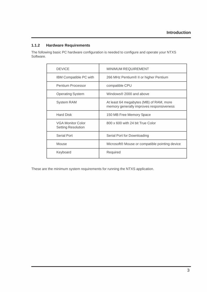
1.1.2 Hardware Requirements
The following basic PC hardware configuration is needed to configure and operate your NTXSSoftware.
DEVICE MINIMUM REQUIREMENT
IBM Compatible PC with 266 MHz Pentium® II or higher Pentium
Pentium Processor compatible CPU
Operating System Windows® 2000 and above
System RAM At least 64 megabytes (MB) of RAM, morememory generally improves responsiveness
Hard Disk 150 MB Free Memory Space
VGA Monitor Color 800 x 600 with 24 bit True ColorSetting Resolution
Serial Port Serial Port for Downloading
Mouse Microsoft® Mouse or compatible pointing device
Keyboard Required
These are the minimum system requirements for running the NTXS application.
Introduction
4
1.2 NTXS Overview
1.2.1 What is NTXS series HMI?
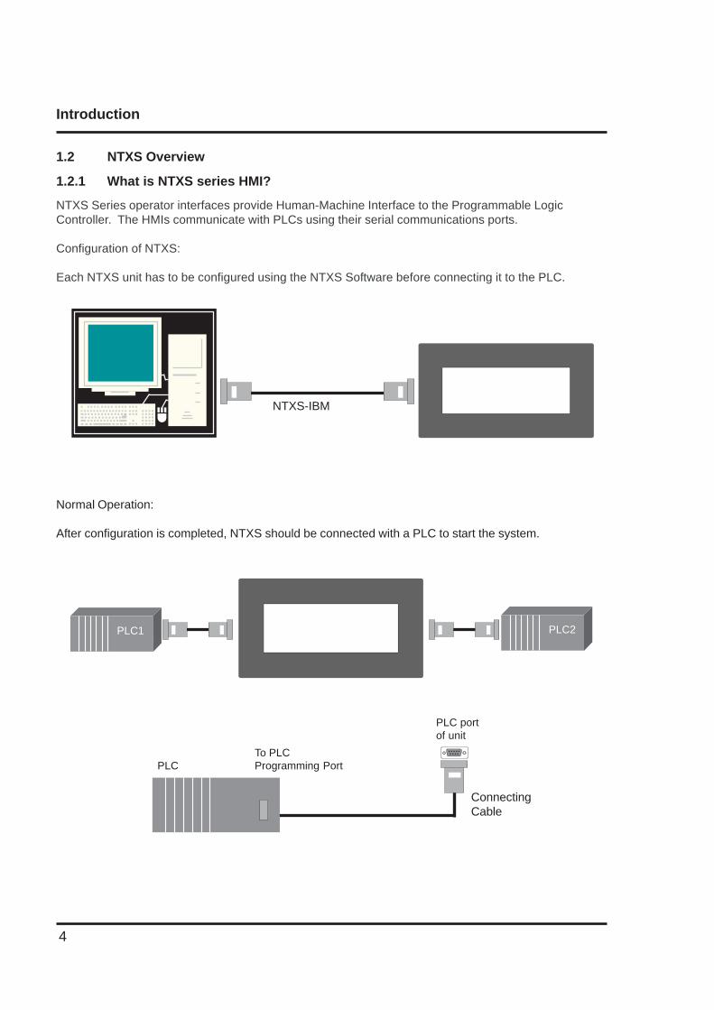
NTXS Series operator interfaces provide Human-Machine Interface to the Programmable LogicController. The HMIs communicate with PLCs using their serial communications ports.
Configuration of NTXS:
Each NTXS unit has to be configured using the NTXS Software before connecting it to the PLC.
NTXS-IBM
Normal Operation:
After configuration is completed, NTXS should be connected with a PLC to start the system.
PLCTo PLCProgramming Port
PLC portof unit
ConnectingCable
PLC1 PLC2
Introduction
5
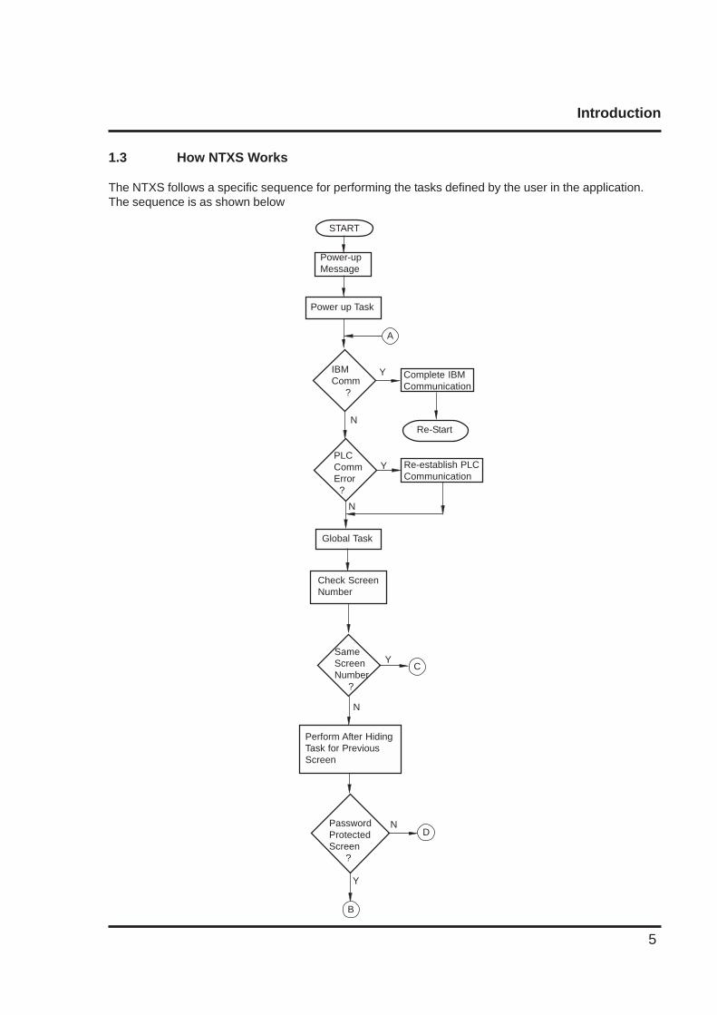
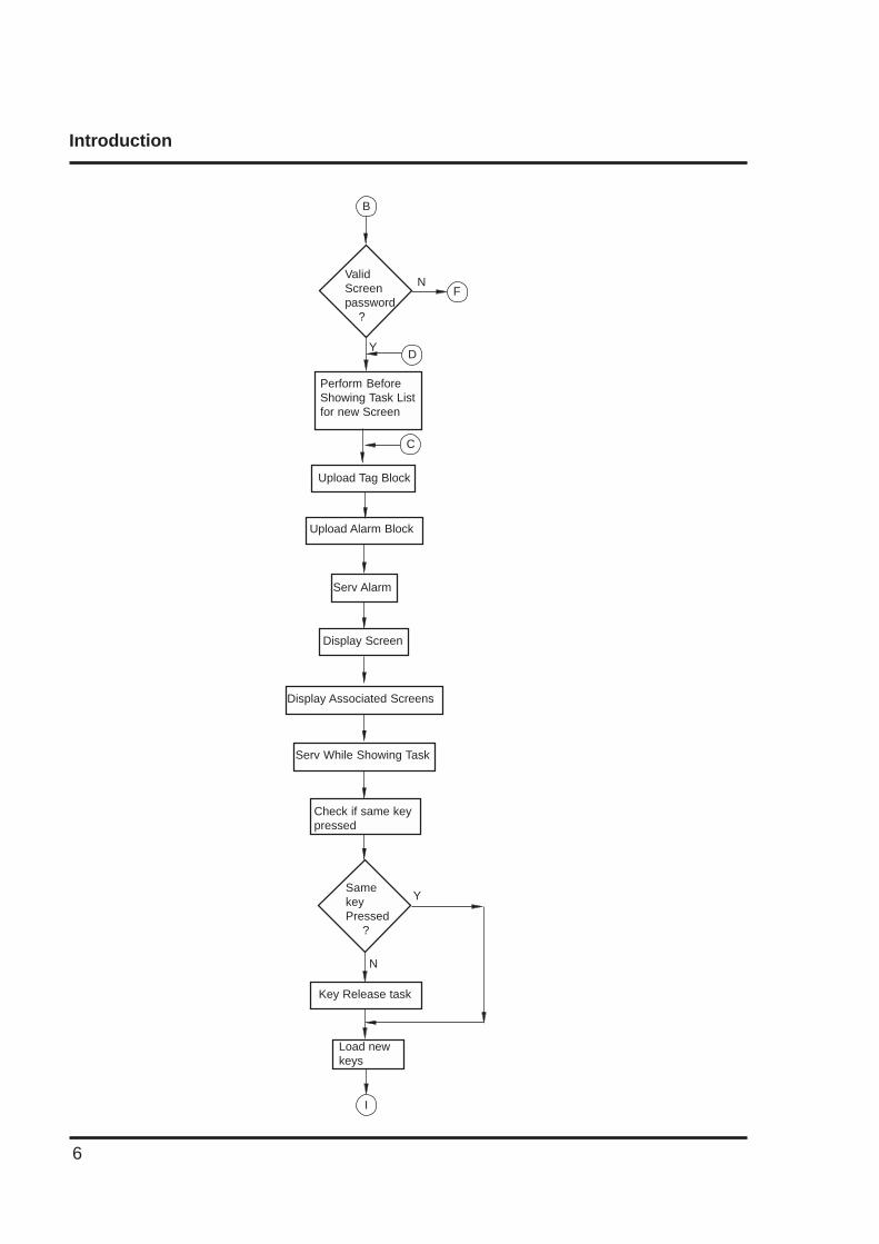
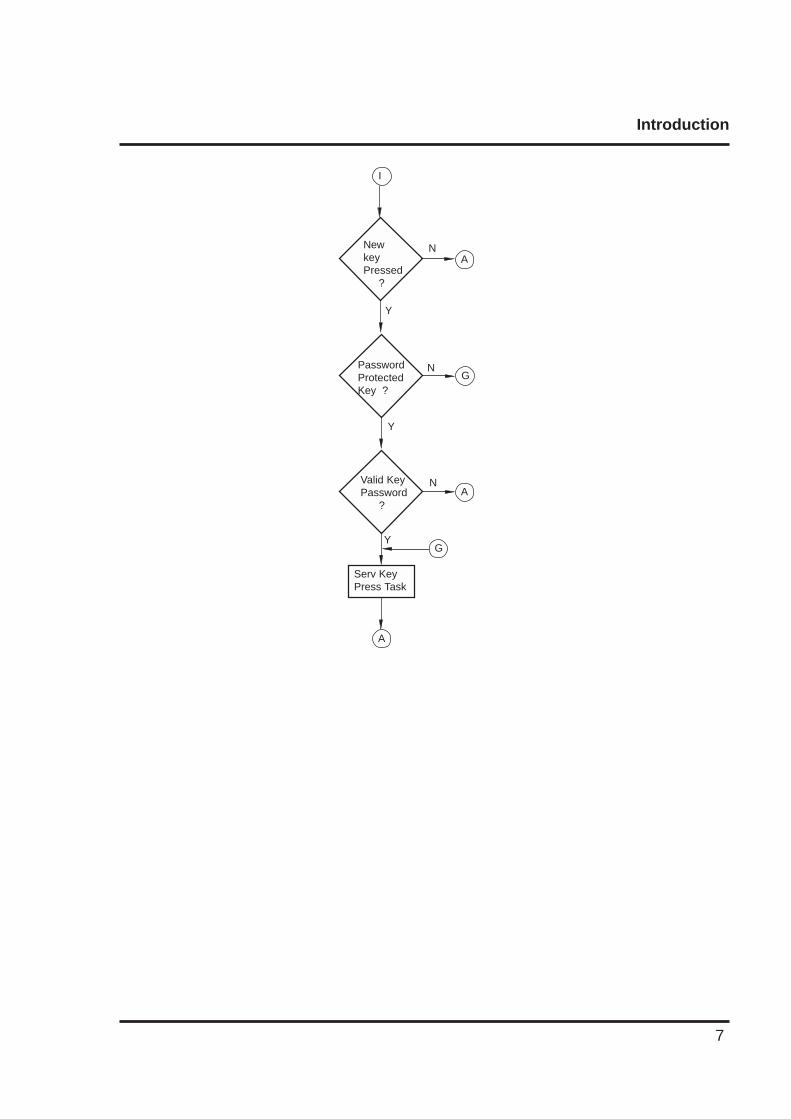
1.3 How NTXS Works
The NTXS follows a specific sequence for performing the tasks defined by the user in the application.The sequence is as shown below
Power-upMessage
Power up Task
START
IBMComm ?
A
Complete IBMCommunication
PLCCommError ?
Y
N
N
Y Re-establish PLCCommunication
Re-Start
Global Task
Check ScreenNumber
N
YSameScreenNumber ?
C
Perform After HidingTask for PreviousScreen
PasswordProtectedScreen ?
N
Y
D
B
Introduction
6
Check if same keypressed
Upload Alarm Block
Serv Alarm
Display Screen
Display Associated Screens
Serv While Showing Task
Y
N
Key Release task
SamekeyPressed ?
Load newkeys
I
ValidScreenpassword ?
N
Y
Perform BeforeShowing Task Listfor new Screen
F
D
C
Upload Tag Block
B
Introduction
7
Y
NNewkeyPressed ?
A
I
Y
NValid KeyPassword ?
A
Serv KeyPress Task
PasswordProtectedKey ?
Y
GN
G
A
Introduction
8
1.3.1 Specifications of NTXS Series
Models included in the NTXS series are as follows:
NT2S-SF121B-EV2NT2S-SF122B-EV2NT2S-SF123B-EV2
NT2S-SF125B-ENT2S-SF126B-ENT2S-SF127B-E
NT3S-ST121B-ENT3S-ST123B-ENT3S-ST124B-ENT3S-ST126B-E
Introduction
9
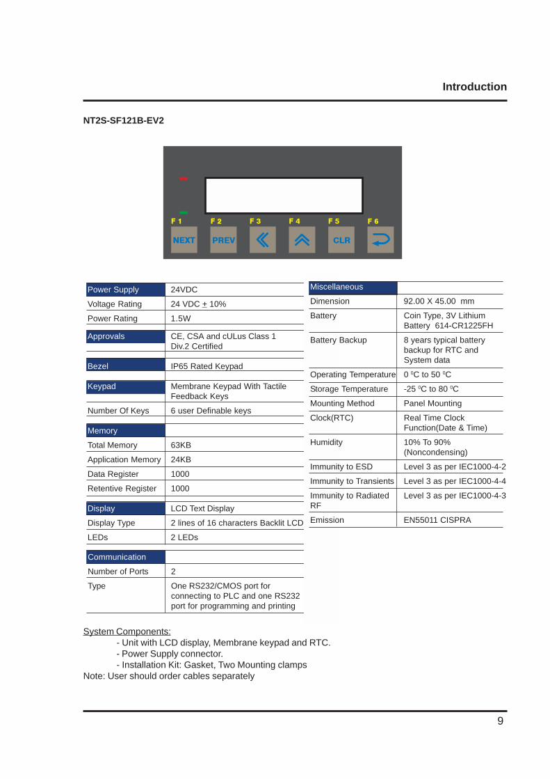
NT2S-SF121B-EV2
System Components:- Unit with LCD display, Membrane keypad and RTC.- Power Supply connector.- Installation Kit: Gasket, Two Mounting clamps
Note: User should order cables separately
Power Supply 24VDC
Voltage Rating 24 VDC + 10%
Power Rating 1.5W
Approvals CE, CSA and cULus Class 1Div.2 Certified
Bezel IP65 Rated Keypad
Keypad Membrane Keypad With TactileFeedback Keys
Number Of Keys 6 user Definable keys
Memory
Total Memory 63KB
Application Memory 24KB
Data Register 1000
Retentive Register 1000
Display LCD Text Display
Display Type 2 lines of 16 characters Backlit LCD
LEDs 2 LEDs
Communication
Number of Ports 2
Type One RS232/CMOS port forconnecting to PLC and one RS232port for programming and printing
PREV CLR
F 1 F 2 F 3 F 4 F 5 F 6
NEXT
Miscellaneous
Dimension 92.00 X 45.00 mm
Battery Coin Type, 3V LithiumBattery 614-CR1225FH
Battery Backup 8 years typical batterybackup for RTC andSystem data
Operating Temperature 0 0C to 50 0C
Storage Temperature -25 0C to 80 0C
Mounting Method Panel Mounting
Clock(RTC) Real Time ClockFunction(Date & Time)
Humidity 10% To 90%(Noncondensing)
Immunity to ESD Level 3 as per IEC1000-4-2
Immunity to Transients Level 3 as per IEC1000-4-4
Immunity to Radiated Level 3 as per IEC1000-4-3RF
Emission EN55011 CISPRA
Introduction
10
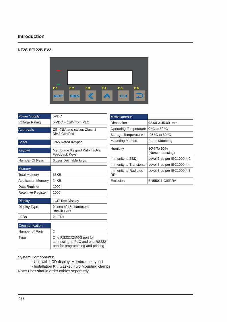
NT2S-SF122B-EV2
System Components:- Unit with LCD display, Membrane keypad- Installation Kit: Gasket, Two Mounting clamps
Note: User should order cables separately
Power Supply 5VDC
Voltage Rating 5 VDC + 10% from PLC
Approvals CE, CSA and cULus Class 1Div.2 Certified
Bezel IP65 Rated Keypad
Keypad Membrane Keypad With TactileFeedback Keys
Number Of Keys 6 user Definable keys
Memory
Total Memory 63KB
Application Memory 24KB
Data Register 1000
Retentive Register 1000
Display LCD Text Display
Display Type 2 lines of 16 charactersBacklit LCD
LEDs 2 LEDs
Communication
Number of Ports 2
Type One RS232/CMOS port forconnecting to PLC and one RS232port for programming and printing
PREV CLR
F 1 F 2 F 3 F 4 F 5 F 6
NEXT
Miscellaneous
Dimension 92.00 X 45.00 mm
Operating Temperature 0 0C to 50 0C
Storage Temperature -25 0C to 80 0C
Mounting Method Panel Mounting
Humidity 10% To 90%(Noncondensing)
Immunity to ESD Level 3 as per IEC1000-4-2
Immunity to Transients Level 3 as per IEC1000-4-4
Immunity to Radiated Level 3 as per IEC1000-4-3RF
Emission EN55011 CISPRA
Introduction
11
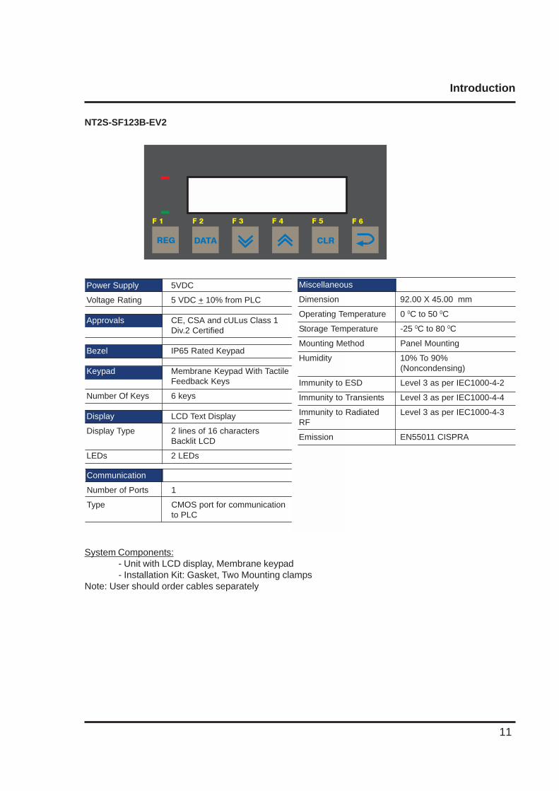
NT2S-SF123B-EV2
System Components:- Unit with LCD display, Membrane keypad- Installation Kit: Gasket, Two Mounting clamps
Note: User should order cables separately
Power Supply 5VDC
Voltage Rating 5 VDC + 10% from PLC
Approvals CE, CSA and cULus Class 1Div.2 Certified
Bezel IP65 Rated Keypad
Keypad Membrane Keypad With TactileFeedback Keys
Number Of Keys 6 keys
Display LCD Text Display
Display Type 2 lines of 16 charactersBacklit LCD
LEDs 2 LEDs
Communication
Number of Ports 1
Type CMOS port for communicationto PLC
DATA CLR
F 1 F 2 F 3 F 4 F 5 F 6
REG
Miscellaneous
Dimension 92.00 X 45.00 mm
Operating Temperature 0 0C to 50 0C
Storage Temperature -25 0C to 80 0C
Mounting Method Panel Mounting
Humidity 10% To 90%(Noncondensing)
Immunity to ESD Level 3 as per IEC1000-4-2
Immunity to Transients Level 3 as per IEC1000-4-4
Immunity to Radiated Level 3 as per IEC1000-4-3RF
Emission EN55011 CISPRA
Introduction
12
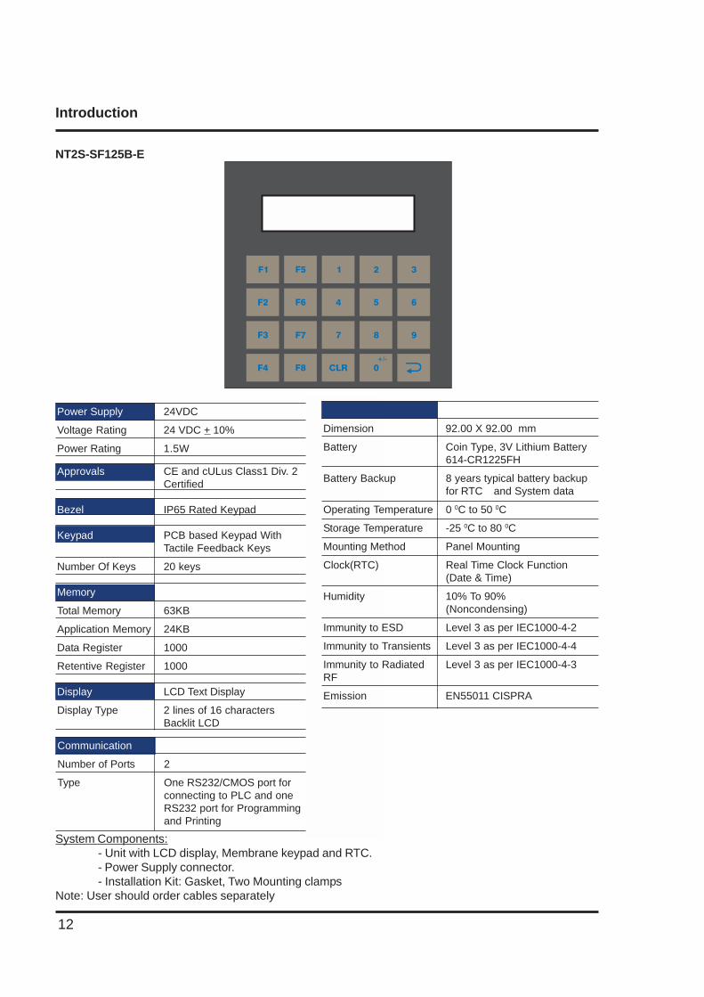
NT2S-SF125B-E
System Components:- Unit with LCD display, Membrane keypad and RTC.- Power Supply connector.- Installation Kit: Gasket, Two Mounting clamps
Note: User should order cables separately
Communication
Number of Ports 2
Type One RS232/CMOS port forconnecting to PLC and oneRS232 port for Programmingand Printing
Power Supply 24VDC
Voltage Rating 24 VDC + 10%
Power Rating 1.5W
Approvals CE and cULus Class1 Div. 2Certified
Bezel IP65 Rated Keypad
Keypad PCB based Keypad WithTactile Feedback Keys
Number Of Keys 20 keys
Memory
Total Memory 63KB
Application Memory 24KB
Data Register 1000
Retentive Register 1000
Display LCD Text Display
Display Type 2 lines of 16 charactersBacklit LCD
1
4
7
CLR
2
5
8
0
3
6
9
+/-
F1
F2
F3
F4
F5
F6
F7
F8
Miscellaneous
Dimension 92.00 X 92.00 mm
Battery Coin Type, 3V Lithium Battery614-CR1225FH
Battery Backup 8 years typical battery backupfor RTC and System data
Operating Temperature 0 0C to 50 0C
Storage Temperature -25 0C to 80 0C
Mounting Method Panel Mounting
Clock(RTC) Real Time Clock Function(Date & Time)
Humidity 10% To 90%(Noncondensing)
Immunity to ESD Level 3 as per IEC1000-4-2
Immunity to Transients Level 3 as per IEC1000-4-4
Immunity to Radiated Level 3 as per IEC1000-4-3RF
Emission EN55011 CISPRA
Introduction
13
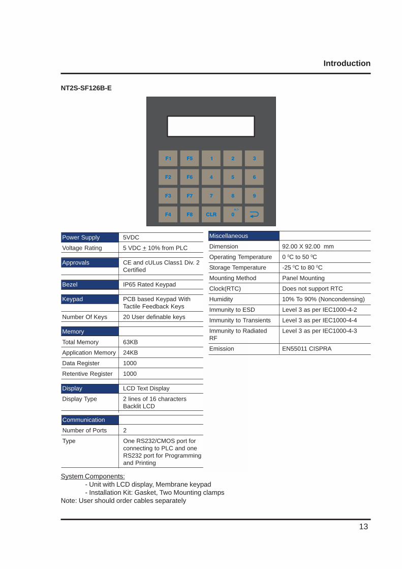
NT2S-SF126B-E
System Components:- Unit with LCD display, Membrane keypad- Installation Kit: Gasket, Two Mounting clamps
Note: User should order cables separately
Communication
Number of Ports 2
Type One RS232/CMOS port forconnecting to PLC and oneRS232 port for Programmingand Printing
Power Supply 5VDC
Voltage Rating 5 VDC + 10% from PLC
Approvals CE and cULus Class1 Div. 2Certified
Bezel IP65 Rated Keypad
Keypad PCB based Keypad WithTactile Feedback Keys
Number Of Keys 20 User definable keys
Memory
Total Memory 63KB
Application Memory 24KB
Data Register 1000
Retentive Register 1000
Display LCD Text Display
Display Type 2 lines of 16 charactersBacklit LCD
1
4
7
CLR
2
5
8
0
3
6
9
+/-
F1
F2
F3
F4
F5
F6
F7
F8
Miscellaneous
Dimension 92.00 X 92.00 mm
Operating Temperature 0 0C to 50 0C
Storage Temperature -25 0C to 80 0C
Mounting Method Panel Mounting
Clock(RTC) Does not support RTC
Humidity 10% To 90% (Noncondensing)
Immunity to ESD Level 3 as per IEC1000-4-2
Immunity to Transients Level 3 as per IEC1000-4-4
Immunity to Radiated Level 3 as per IEC1000-4-3RF
Emission EN55011 CISPRA
Introduction
14
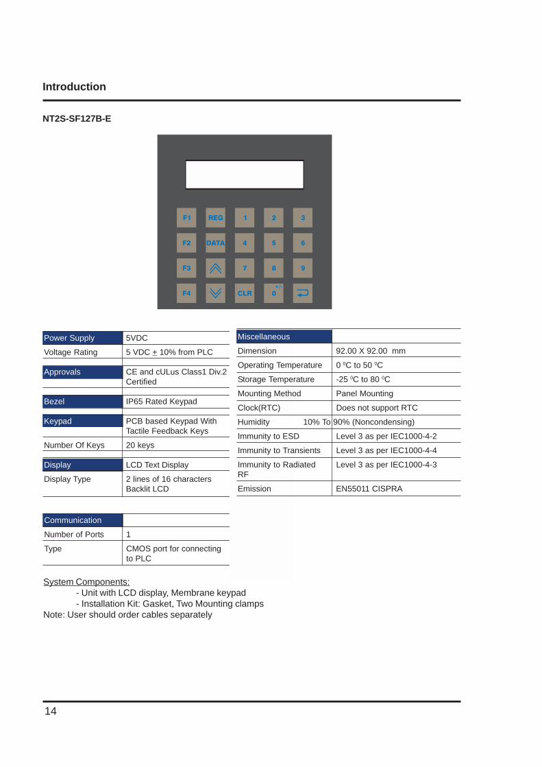
NT2S-SF127B-E
System Components:- Unit with LCD display, Membrane keypad- Installation Kit: Gasket, Two Mounting clamps
Note: User should order cables separately
Power Supply 5VDC
Voltage Rating 5 VDC + 10% from PLC
Approvals CE and cULus Class1 Div.2Certified
Bezel IP65 Rated Keypad
Keypad PCB based Keypad WithTactile Feedback Keys
Number Of Keys 20 keys
Display LCD Text Display
Display Type 2 lines of 16 charactersBacklit LCD
Communication
Number of Ports 1
Type CMOS port for connectingto PLC
1
4
7
CLR
2
5
8
0
3
6
9
+/-
F1
F2
F3
F4
REG
DATA
Miscellaneous
Dimension 92.00 X 92.00 mm
Operating Temperature 0 0C to 50 0C
Storage Temperature -25 0C to 80 0C
Mounting Method Panel Mounting
Clock(RTC) Does not support RTC
Humidity 10% To 90% (Noncondensing)
Immunity to ESD Level 3 as per IEC1000-4-2
Immunity to Transients Level 3 as per IEC1000-4-4
Immunity to Radiated Level 3 as per IEC1000-4-3RF
Emission EN55011 CISPRA
Introduction
15
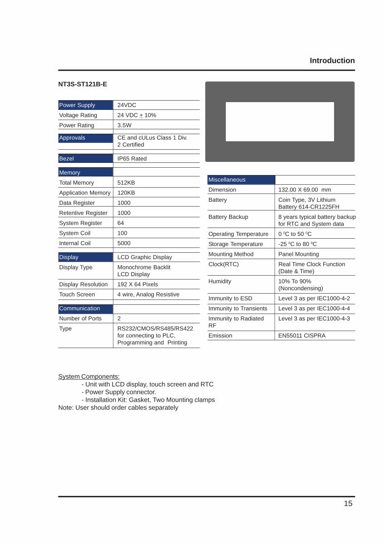
NT3S-ST121B-E
Miscellaneous
Dimension 132.00 X 69.00 mm
Battery Coin Type, 3V LithiumBattery 614-CR1225FH
Battery Backup 8 years typical battery backupfor RTC and System data
Operating Temperature 0 0C to 50 0C
Storage Temperature -25 0C to 80 0C
Mounting Method Panel Mounting
Clock(RTC) Real Time Clock Function(Date & Time)
Humidity 10% To 90%(Noncondensing)
Immunity to ESD Level 3 as per IEC1000-4-2
Immunity to Transients Level 3 as per IEC1000-4-4
Immunity to Radiated Level 3 as per IEC1000-4-3RF
Emission EN55011 CISPRA
System Components:- Unit with LCD display, touch screen and RTC- Power Supply connector.- Installation Kit: Gasket, Two Mounting clamps
Note: User should order cables separately
Power Supply 24VDC
Voltage Rating 24 VDC + 10%
Power Rating 3.5W
Approvals CE and cULus Class 1 Div.2 Certified
Bezel IP65 Rated
Memory
Total Memory 512KB
Application Memory 120KB
Data Register 1000
Retentive Register 1000
System Register 64
System Coil 100
Internal Coil 5000
Display LCD Graphic Display
Display Type Monochrome BacklitLCD Display
Display Resolution 192 X 64 Pixels
Touch Screen 4 wire, Analog Resistive
Communication
Number of Ports 2
Type RS232/CMOS/RS485/RS422for connecting to PLC,Programming and Printing
Introduction
16
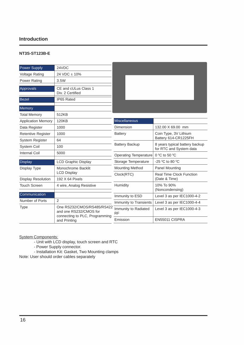
NT3S-ST123B-E
System Components:- Unit with LCD display, touch screen and RTC- Power Supply connector.- Installation Kit: Gasket, Two Mounting clamps
Note: User should order cables separately
Miscellaneous
Dimension 132.00 X 69.00 mm
Battery Coin Type, 3V LithiumBattery 614-CR1225FH
Battery Backup 8 years typical battery backupfor RTC and System data
Operating Temperature 0 0C to 50 0C
Storage Temperature -25 0C to 80 0C
Mounting Method Panel Mounting
Clock(RTC) Real Time Clock Function(Date & Time)
Humidity 10% To 90%(Noncondensing)
Immunity to ESD Level 3 as per IEC1000-4-2
Immunity to Transients Level 3 as per IEC1000-4-4
Immunity to Radiated Level 3 as per IEC1000-4-3RF
Emission EN55011 CISPRA
Power Supply 24VDC
Voltage Rating 24 VDC + 10%
Power Rating 3.5W
Approvals CE and cULus Class 1Div. 2 Certified
Bezel IP65 Rated
Memory
Total Memory 512KB
Application Memory 120KB
Data Register 1000
Retentive Register 1000
System Register 64
System Coil 100
Internal Coil 5000
Display LCD Graphic Display
Display Type Monochrome BacklitLCD Display
Display Resolution 192 X 64 Pixels
Touch Screen 4 wire, Analog Resistive
Communication
Number of Ports 2
Type One RS232/CMOS/RS485/RS422and one RS232/CMOS forconnecting to PLC, Programmingand Printing
Introduction
17
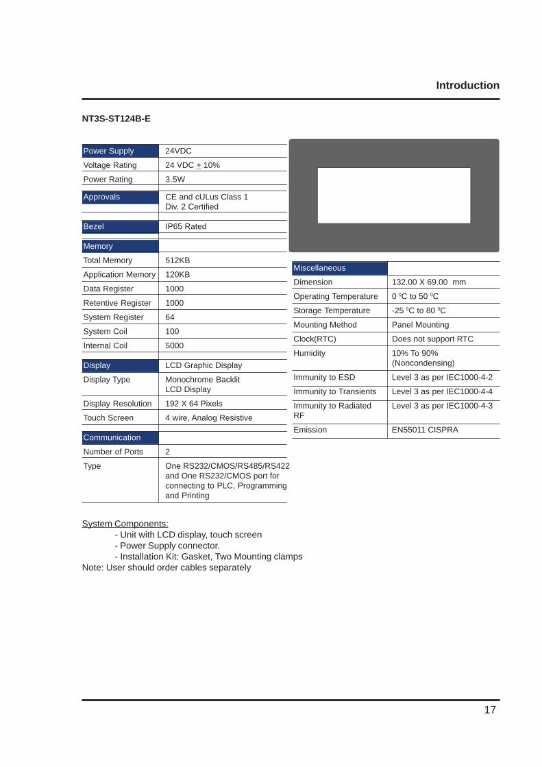
NT3S-ST124B-E
Miscellaneous
Dimension 132.00 X 69.00 mm
Operating Temperature 0 0C to 50 0C
Storage Temperature -25 0C to 80 0C
Mounting Method Panel Mounting
Clock(RTC) Does not support RTC
Humidity 10% To 90%(Noncondensing)
Immunity to ESD Level 3 as per IEC1000-4-2
Immunity to Transients Level 3 as per IEC1000-4-4
Immunity to Radiated Level 3 as per IEC1000-4-3RF
Emission EN55011 CISPRA
Power Supply 24VDC
Voltage Rating 24 VDC + 10%
Power Rating 3.5W
Approvals CE and cULus Class 1Div. 2 Certified
Bezel IP65 Rated
Memory
Total Memory 512KB
Application Memory 120KB
Data Register 1000
Retentive Register 1000
System Register 64
System Coil 100
Internal Coil 5000
Display LCD Graphic Display
Display Type Monochrome BacklitLCD Display
Display Resolution 192 X 64 Pixels
Touch Screen 4 wire, Analog Resistive
Communication
Number of Ports 2
Type One RS232/CMOS/RS485/RS422and One RS232/CMOS port forconnecting to PLC, Programmingand Printing
System Components:- Unit with LCD display, touch screen- Power Supply connector.- Installation Kit: Gasket, Two Mounting clamps
Note: User should order cables separately
Introduction
18
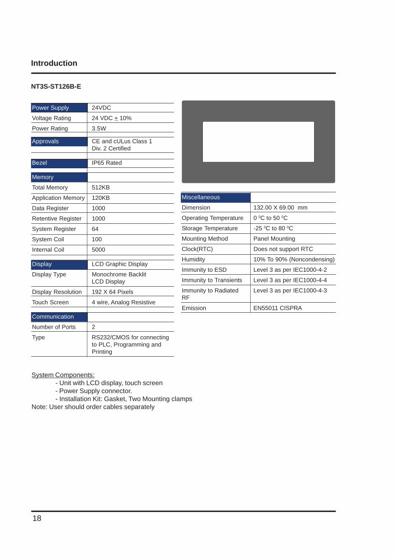
NT3S-ST126B-E
Miscellaneous
Dimension 132.00 X 69.00 mm
Operating Temperature 0 0C to 50 0C
Storage Temperature -25 0C to 80 0C
Mounting Method Panel Mounting
Clock(RTC) Does not support RTC
Humidity 10% To 90% (Noncondensing)
Immunity to ESD Level 3 as per IEC1000-4-2
Immunity to Transients Level 3 as per IEC1000-4-4
Immunity to Radiated Level 3 as per IEC1000-4-3RF
Emission EN55011 CISPRA
System Components:- Unit with LCD display, touch screen- Power Supply connector.- Installation Kit: Gasket, Two Mounting clamps
Note: User should order cables separately
Power Supply 24VDC
Voltage Rating 24 VDC + 10%
Power Rating 3.5W
Approvals CE and cULus Class 1Div. 2 Certified
Bezel IP65 Rated
Memory
Total Memory 512KB
Application Memory 120KB
Data Register 1000
Retentive Register 1000
System Register 64
System Coil 100
Internal Coil 5000
Display LCD Graphic Display
Display Type Monochrome BacklitLCD Display
Display Resolution 192 X 64 Pixels
Touch Screen 4 wire, Analog Resistive
Communication
Number of Ports 2
Type RS232/CMOS for connectingto PLC, Programming andPrinting

Hardware
19
HARDWARE
In this chapter. . . .
♦ Safety Precautions
♦ Installation Instructions
♦ Power Requirements
♦ Wiring Diagram
♦ Communication Ports
Hardware
20
2.1 Safety Precaution
Please observe the following precautions when installing the unit. Failure to comply with these restric-tions could result in loss of life, serious personal injury, or equipment damage.
Warning: Do not operate the HMI in areas subject to explosion due to flammable gases, vapors, or dusts.
Warning: Do not connect the HMI to an AC power source. You will cause permanent damage to the HMI.
Warning: Do not attempt to use a DC power supply that does not meet HMI power requirements. You may cause malfunction or permanent damage to HMI.
Warning: Do not power the HMI with a DC power supply used for inductive loads or for input circuitry to the programmable logic controller. Severe voltage spikes caused by these devices may damage the HMI.
2.2 Installation Instructions
The NTXS should be mounted on a panel. Gasket, mounting clamps are provided with each NTXS unitfor proper mounting.
Environmental Considerations:
Make sure that the unit is installed correctly and that the operating limits are followed (see Specificationsfor NTXS).Do not operate NTXS in areas subject to explosion hazards due to flammable gases, vapors or dusts.NTXS should not be installed where fast temperature variations are present. Highly humid areas arealso to be avoided. High humidity causes condensation of water in the unit.
Location Considerations:
Care should be taken when locating equipment behind the NTXS to ensure that AC power wiring, PLCoutput modules, contactors, starters, relays and any other source of electrical interference are locatedaway from NTXS. Particular care should be taken to the position of Variable speed drives and switchingpower supplies away from the NTXS.
Panel Mounting
This section presents the dimensional sketches and panel cutouts for NTXS models.(All dimensions are in mm. Not to Scale.)
!
!
!
!
Hardware
21
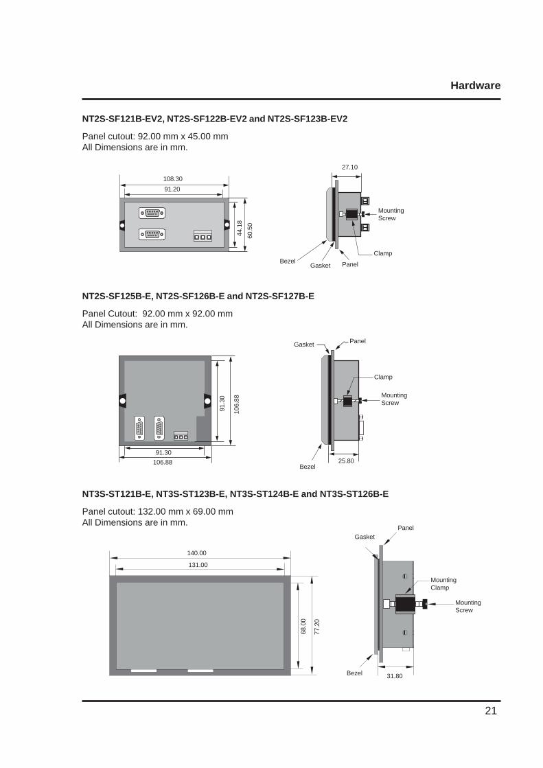
NT2S-SF121B-EV2, NT2S-SF122B-EV2 and NT2S-SF123B-EV2
Panel cutout: 92.00 mm x 45.00 mmAll Dimensions are in mm.
108.30
91.20
44.1
8
60.5
0
PanelGasketBezel
Clamp
27.10
12345671234567 Mounting
Screw
NT2S-SF125B-E, NT2S-SF126B-E and NT2S-SF127B-E
Panel Cutout: 92.00 mm x 92.00 mmAll Dimensions are in mm.
2-4
106.88
91.3
0
91.30
106.
88
Panel
25.80
Gasket
MountingScrew
Clamp
Bezel
1234512345
NT3S-ST121B-E, NT3S-ST123B-E, NT3S-ST124B-E and NT3S-ST126B-E
Panel cutout: 132.00 mm x 69.00 mmAll Dimensions are in mm.
131.00
140.00
68.0
0
77.2
0
12345678901234567890
31.80
MountingScrew
PanelGasket
MountingClamp
Bezel

Hardware
22
2.3 Power Requirements
Supply voltage requirements for NTXS series models is as follows:
NT2S-SF121B-EV2 +24VDC + 10%, 1.5W maximum on Power PortNT2S-SF122B-EV2 +5VDC + 10% on PLC portNT2S-SF123B-EV2 +5VDC + 10% on PLC port
NT2S-SF125B-E +24VDC + 10%, 1.5W maximum on Power PortNT2S-SF126B-E +5VDC + 10% on PLC portNT2S-SF127B-E +5VDC + 10% on PLC port
NT3S-ST121B-E +24VDC + 10%, 3.5W maximum on Power PortNT3S-ST123B-E +24VDC + 10%, 3.5W maximum on Power PortNT3S-ST124B-E +24VDC + 10%, 3.5W maximum on Power PortNT3S-ST126B-E +24VDC + 10%, 3.5W maximum on Power Port
Please follow the instructions given below while making power supply connections for models:
1. Follow the wiring diagram on the sticker of the unit which shows terminals.
2. To make a connection strip about 7mm of insulation of the wire, turn the connector screwcounter-clock wise until the gap is wide open. Insert the wire all the way in and turn the screwclockwise until it is tight.
3. Wire lengths should be minimum. Wires should run in pairs with a neutral or common pairedwith a live or signal wire.
4. NTXS +24VDC model is fused internally with a self resetting 60V, 400mA fuse. It is recommended that all input power lines be protected from product failure by a fuse or breaker.
5. Adequate strain relief must be provided for the power connector, to ensure that vibration doesnot cause the power connector to be pulled out.
6. All the NTXS products are housed in a moulded ABS plastic case which eliminates anyelectrical shock hazard. Hence Safety Earth is not required to be connected to the chassis ofthe unit.
7. The DC ground is not directly coupled to Earth ground internally. The unit is designed tooperate properly whether or not the DC ground is connected to the Earth ground. We do recommend, however, that if the DC ground has to be connected to the Earth ground, the Earthconnection should be made to a central star point as poor site earths can introduce noise into asystem.
8. Do not power unit and inductive loads with the same power supply even though there isenough immunity in the NTXS to withstand the transients present on these lines. Avoid usingpower supplies with large capacitive outputs which may cause problems if power is cycled withina short time period.
9. If wiring is to be exposed to lightening or surges, use appropriate surge suppression devices.
10. Keep AC, high energy and rapidly switching DC wiring separate from signal wires.
11. Connecting high voltages or AC power mains to the DC input will make unit unusable andmay create an electrical shock hazard to personnel. Such a failure or shock could result inserious personal injury, loss of life and/or equipment damage. DC voltage sources shouldprovide proper isolation from main AC power and similar hazards.
Hardware
23
2.4 Wiring Diagram
If wiring is to be exposed to lightening or surges, use appropriate surge suppression devices. Keep AC,high energy and rapidly switching DC wiring separate from signal wires.Connecting high voltages or AC power mains to the DC input will make unit unusable and may create anelectrical shock hazard to personnel. Such a failure or shock could result in serious personal injury, lossof life and/or equipment damage. DC voltage sources should provide proper isolation from main ACpower and similar hazards.
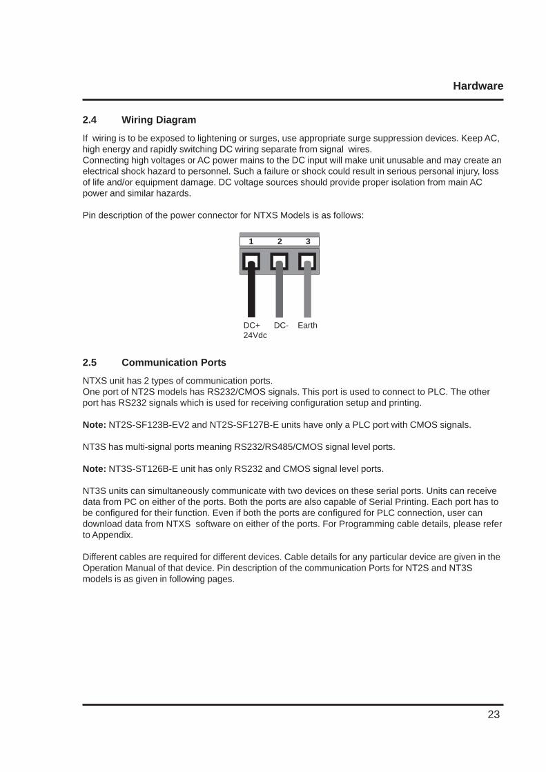
Pin description of the power connector for NTXS Models is as follows:
DC+ DC- Earth24Vdc
1 2 3
2.5 Communication Ports
NTXS unit has 2 types of communication ports.One port of NT2S models has RS232/CMOS signals. This port is used to connect to PLC. The otherport has RS232 signals which is used for receiving configuration setup and printing.
Note: NT2S-SF123B-EV2 and NT2S-SF127B-E units have only a PLC port with CMOS signals.
NT3S has multi-signal ports meaning RS232/RS485/CMOS signal level ports.
Note: NT3S-ST126B-E unit has only RS232 and CMOS signal level ports.
NT3S units can simultaneously communicate with two devices on these serial ports. Units can receivedata from PC on either of the ports. Both the ports are also capable of Serial Printing. Each port has tobe configured for their function. Even if both the ports are configured for PLC connection, user candownload data from NTXS software on either of the ports. For Programming cable details, please referto Appendix.
Different cables are required for different devices. Cable details for any particular device are given in theOperation Manual of that device. Pin description of the communication Ports for NT2S and NT3Smodels is as given in following pages.
Hardware
24
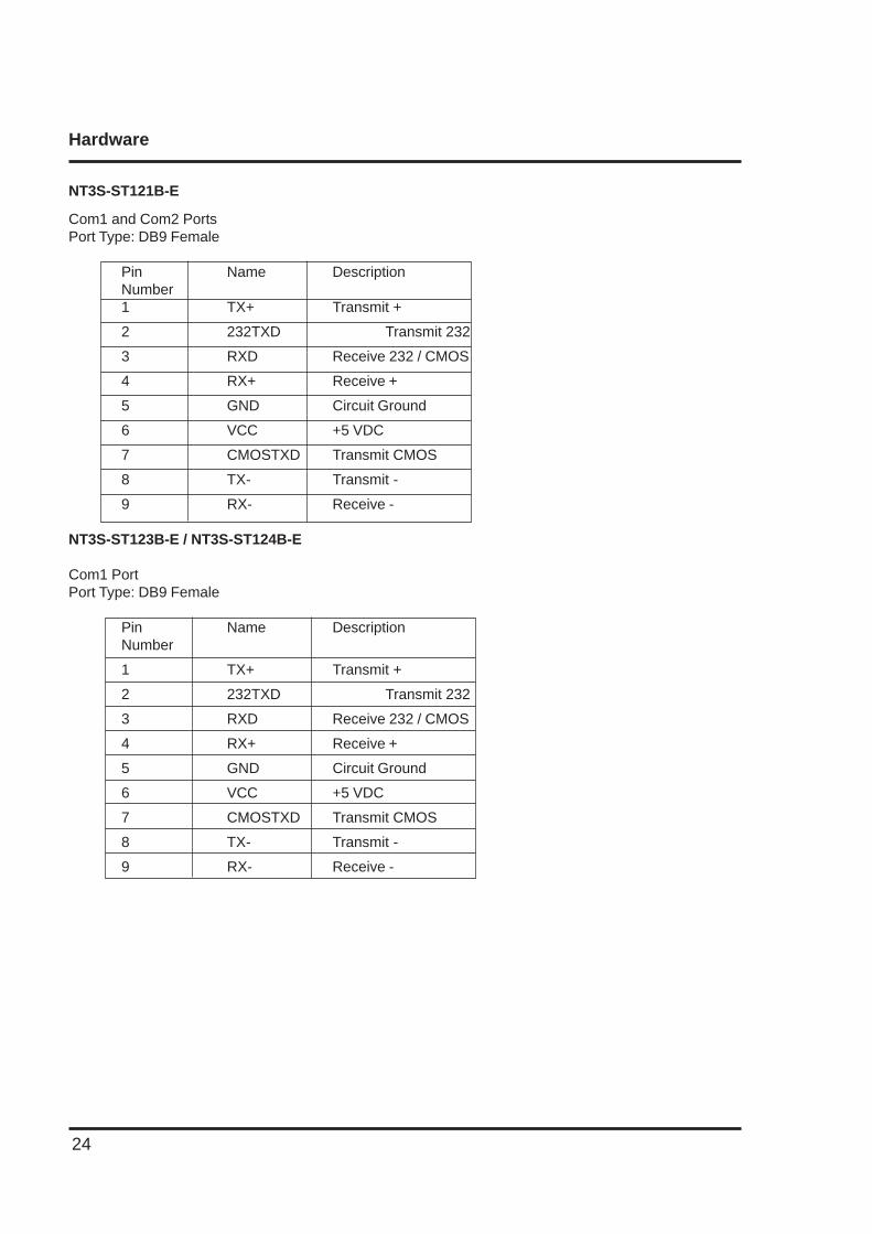
NT3S-ST121B-E
Com1 and Com2 PortsPort Type: DB9 Female
Pin Name DescriptionNumber1 TX+ Transmit +
2 232TXD Transmit 232
3 RXD Receive 232 / CMOS
4 RX+ Receive +
5 GND Circuit Ground
6 VCC +5 VDC
7 CMOSTXD Transmit CMOS
8 TX- Transmit -
9 RX- Receive -
NT3S-ST123B-E / NT3S-ST124B-E
Com1 PortPort Type: DB9 Female
Pin Name DescriptionNumber
1 TX+ Transmit +
2 232TXD Transmit 232
3 RXD Receive 232 / CMOS
4 RX+ Receive +
5 GND Circuit Ground
6 VCC +5 VDC
7 CMOSTXD Transmit CMOS
8 TX- Transmit -
9 RX- Receive -
Hardware
25
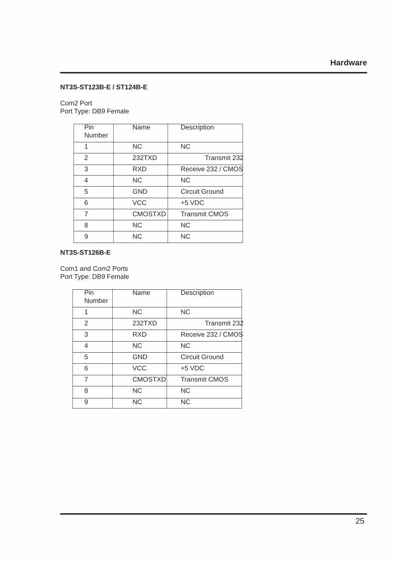
NT3S-ST123B-E / ST124B-E
Com2 PortPort Type: DB9 Female
Pin Name DescriptionNumber
1 NC NC
2 232TXD Transmit 232
3 RXD Receive 232 / CMOS
4 NC NC
5 GND Circuit Ground
6 VCC +5 VDC
7 CMOSTXD Transmit CMOS
8 NC NC
9 NC NC
NT3S-ST126B-E
Com1 and Com2 PortsPort Type: DB9 Female
Pin Name DescriptionNumber
1 NC NC
2 232TXD Transmit 232
3 RXD Receive 232 / CMOS
4 NC NC
5 GND Circuit Ground
6 VCC +5 VDC
7 CMOSTXD Transmit CMOS
8 NC NC
9 NC NC

Hardware
26
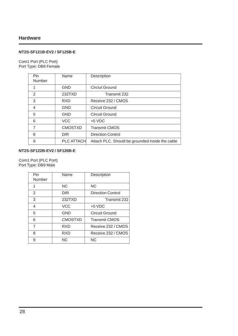
NT2S-SF121B-EV2 / SF125B-E
Com1 Port (PLC Port)Port Type: DB9 Female
Pin Name DescriptionNumber
1 GND Circiut Ground
2 232TXD Transmit 232
3 RXD Receive 232 / CMOS
4 GND Circuit Ground
5 GND Circuit Ground
6 VCC +5 VDC
7 CMOSTXD Transmit CMOS
8 DIR Direction Control
9 PLC ATTACH Attach PLC. Should be grounded inside the cable
NT2S-SF122B-EV2 / SF126B-E
Com1 Port (PLC Port)Port Type: DB9 Male
Pin Name DescriptionNumber
1 NC NC
2 DIR Direction Control
3 232TXD Transmit 232
4 VCC +5 VDC
5 GND Circuit Ground
6 CMOSTXD Transmit CMOS
7 RXD Receive 232 / CMOS
8 RXD Receive 232 / CMOS
9 NC NC

Hardware
27
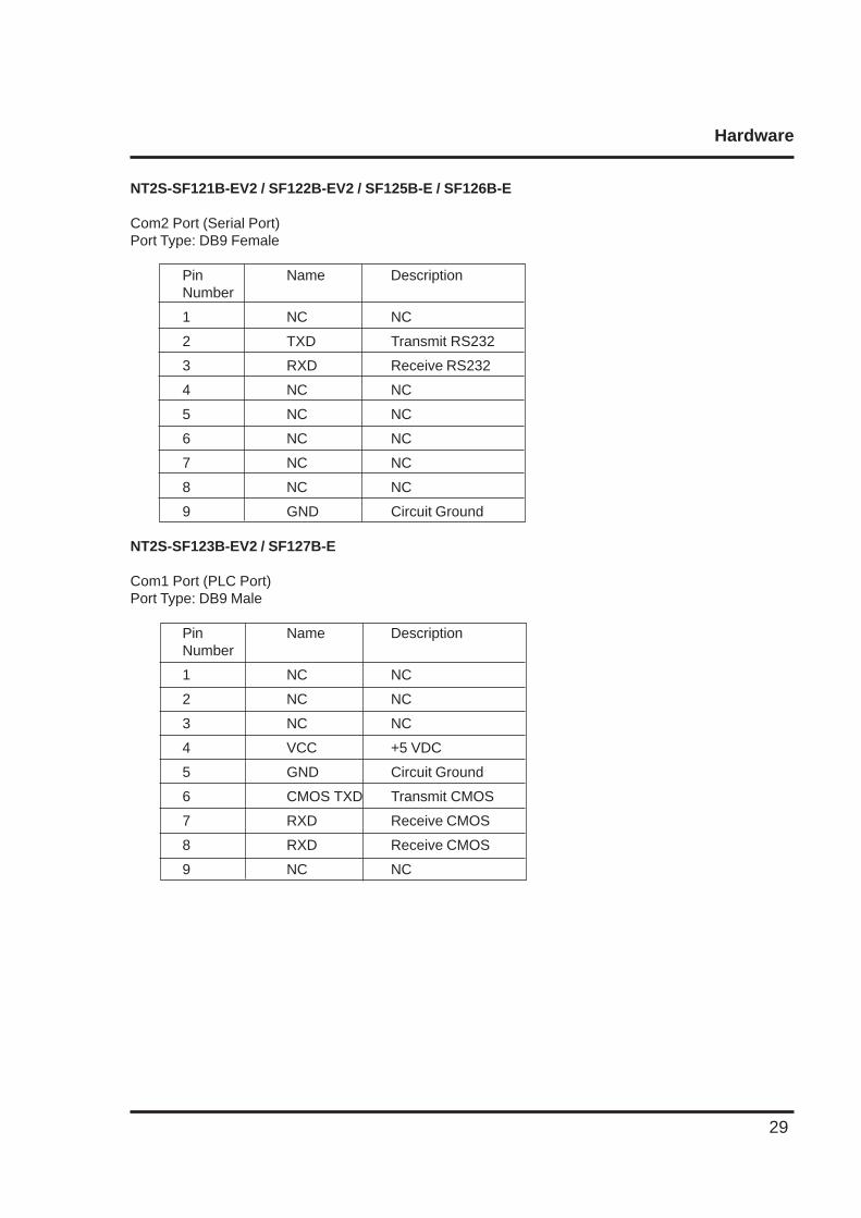
NT2S-SF121B-EV2 / SF122B-EV2 / SF125B-E / SF126B-E
Com2 Port (Serial Port)Port Type: DB9 Female
Pin Name DescriptionNumber
1 NC NC
2 TXD Transmit RS232
3 RXD Receive RS232
4 NC NC
5 NC NC
6 NC NC
7 NC NC
8 NC NC
9 GND Circuit Ground
NT2S-SF123B-EV2 / SF127B-E
Com1 Port (PLC Port)Port Type: DB9 Male
Pin Name DescriptionNumber
1 NC NC
2 NC NC
3 NC NC
4 VCC +5 VDC
5 GND Circuit Ground
6 CMOS TXD Transmit CMOS
7 RXD Receive CMOS
8 RXD Receive CMOS
9 NC NC
Hardware
28
NT2S-SF121B-EV2 / SF125B-E
Com1 Port (PLC Port)Port Type: DB9 Female
Pin Name DescriptionNumber
1 GND Circiut Ground
2 232TXD Transmit 232
3 RXD Receive 232 / CMOS
4 GND Circuit Ground
5 GND Circuit Ground
6 VCC +5 VDC
7 CMOSTXD Transmit CMOS
8 DIR Direction Control
9 PLC ATTACH Attach PLC. Should be grounded inside the cable
NT2S-SF122B-EV2 / SF126B-E
Com1 Port (PLC Port)Port Type: DB9 Male
Pin Name DescriptionNumber
1 NC NC
2 DIR Direction Control
3 232TXD Transmit 232
4 VCC +5 VDC
5 GND Circuit Ground
6 CMOSTXD Transmit CMOS
7 RXD Receive 232 / CMOS
8 RXD Receive 232 / CMOS
9 NC NC
Hardware
29
NT2S-SF121B-EV2 / SF122B-EV2 / SF125B-E / SF126B-E
Com2 Port (Serial Port)Port Type: DB9 Female
Pin Name DescriptionNumber
1 NC NC
2 TXD Transmit RS232
3 RXD Receive RS232
4 NC NC
5 NC NC
6 NC NC
7 NC NC
8 NC NC
9 GND Circuit Ground
NT2S-SF123B-EV2 / SF127B-E
Com1 Port (PLC Port)Port Type: DB9 Male
Pin Name DescriptionNumber
1 NC NC
2 NC NC
3 NC NC
4 VCC +5 VDC
5 GND Circuit Ground
6 CMOS TXD Transmit CMOS
7 RXD Receive CMOS
8 RXD Receive CMOS
9 NC NC
Before you Begin
30
BEFORE YOU BEGIN
In this chapter. . . .
♦ Connecting the HMI to a Computer
♦ Starting NTXS Software
♦ Setting Network Configuration
Before you Begin
31
3.1 Connecting the HMI to your Computer
Before you start your first project, the HMI should be connected to the computer so that the project canbe downloaded after creating it. You should also connect the PLC that you are using with the HMI so thatyou can test the operation of the HMI after you have finished creating the sample project.
• To connect your HMI to the computer
1. Connect a +24VDC power supply to the HMI.2. Connect the programming cable to the computer and HMI.
• Connect IBM cable to the communication port of NTXS.• Download Firmware i.e. driver for the PLC. The NTXS unit cannot communicate with PLC till the required driver is downloaded.
3. Apply power to the HMI.
• To connect your PLC to HMI
NTXS can communicate with any PLC without any change in the NTXS hardware. To communi-cate with a PLC, NTXS unit needs:1. Proper Communication Driver for the PLC2. NTXS - PLC communication cable
1. Communication Driver for the PLC:Each PLC has a defined protocol for communicating with any device. Communication Driver isdownloaded into NTXS unit along with the firmware. Communication driver varies from PLC toPLC. This driver enables unit to talk to a specific PLC, such as OMRON PLC.
2. NTXS: PLC Communication Cable: Proper NTXS - PLC cable is required for error free communicationwith a PLC.
Before you Begin
32
3.2 Starting NTXS Software
3.2.1 Installing NTXS Software
System requirements for installing NTXS on your PC:
Windows Version : Microsoft Windows® 2000 or higherProcessor : 266 MHz Pentium® II or higherPentium-compatible CPUHard disk Space : 150 MB free memory spaceSerial Mouse : Microsoft® mouse or compatible pointingdeviceRAM : At least 64 megabytes (MB) of RAM; more
memory generally improves responsivenessDisplay resolution : 800x600 with 24 bit true colorSerial Port : One Serial Port for Downloading Required
To install NTXS Software:
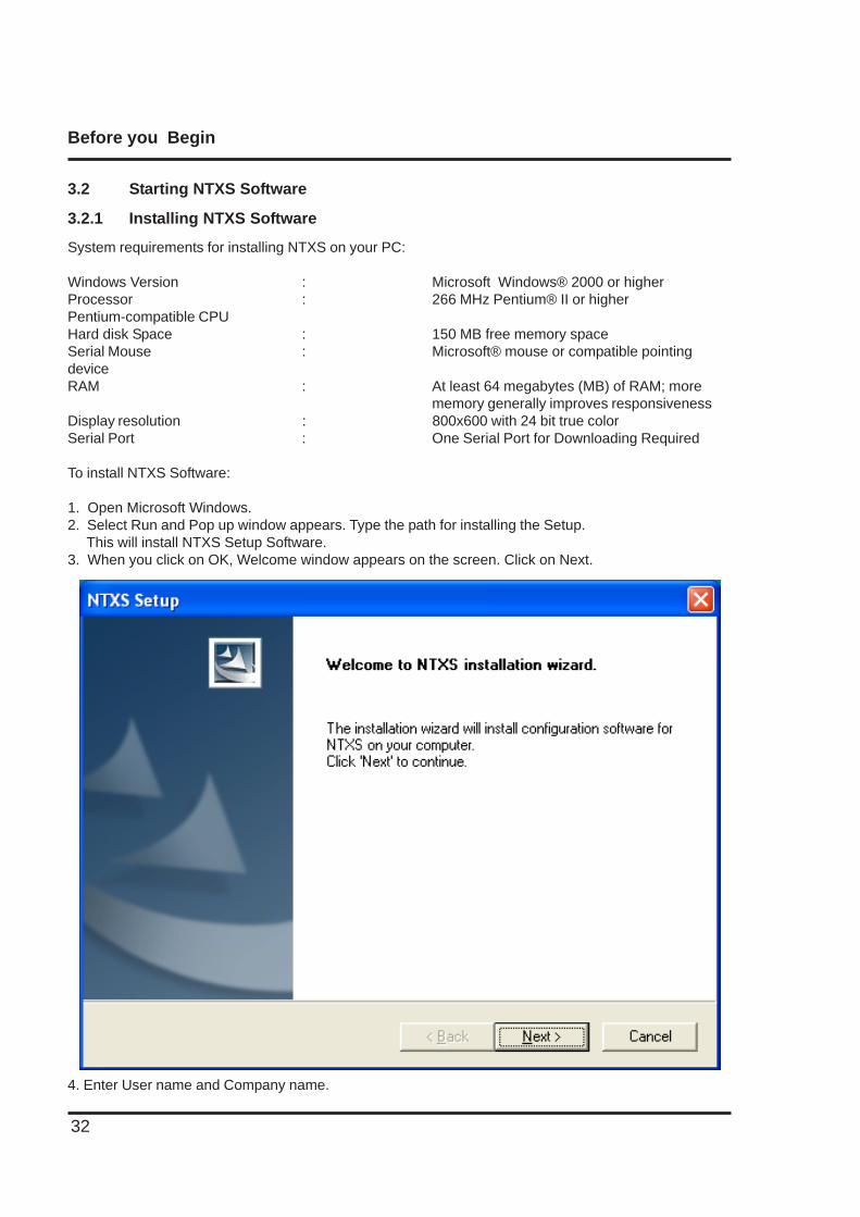
1. Open Microsoft Windows.2. Select Run and Pop up window appears. Type the path for installing the Setup. This will install NTXS Setup Software.3. When you click on OK, Welcome window appears on the screen. Click on Next.
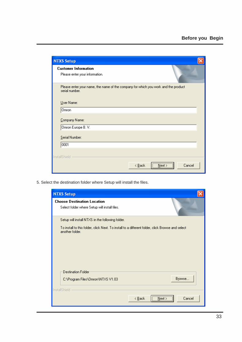
4. Enter User name and Company name.
Before you Begin
33
5. Select the destination folder where Setup will install the files.
Before you Begin
34
3.2.2 Steps for starting NTXS Software
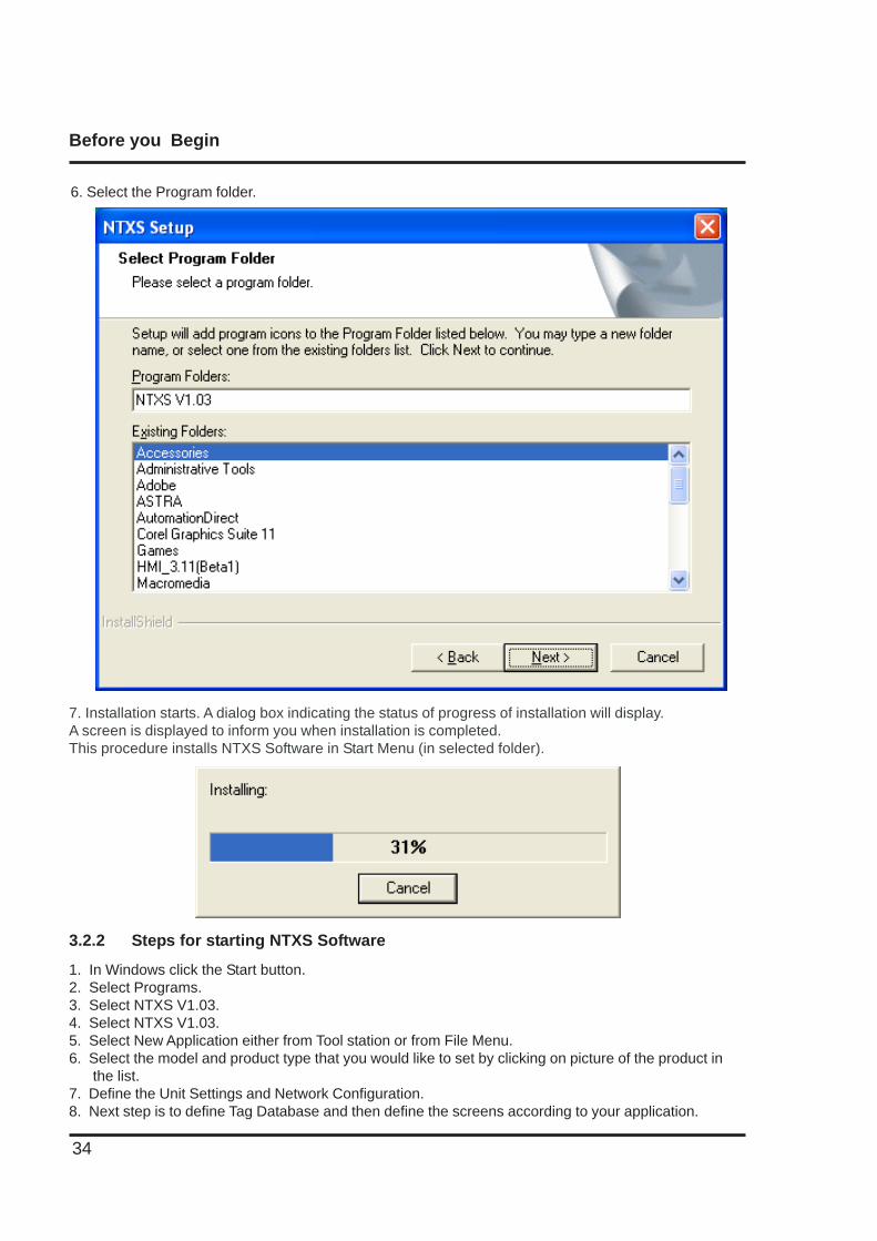
1. In Windows click the Start button.2. Select Programs.3. Select NTXS V1.03.4. Select NTXS V1.03.5. Select New Application either from Tool station or from File Menu.6. Select the model and product type that you would like to set by clicking on picture of the product in the list.7. Define the Unit Settings and Network Configuration.8. Next step is to define Tag Database and then define the screens according to your application.
7. Installation starts. A dialog box indicating the status of progress of installation will display.A screen is displayed to inform you when installation is completed.This procedure installs NTXS Software in Start Menu (in selected folder).
6. Select the Program folder.
Before you Begin
35
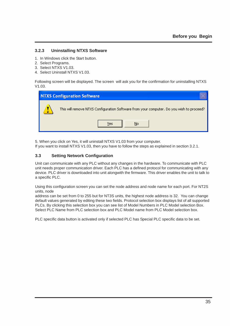
5. When you click on Yes, it will uninstall NTXS V1.03 from your computer.If you want to install NTXS V1.03, then you have to follow the steps as explained in section 3.2.1.
3.3 Setting Network Configuration
Unit can communicate with any PLC without any changes in the hardware. To communicate with PLCunit needs proper communication driver. Each PLC has a defined protocol for communicating with anydevice. PLC driver is downloaded into unit alongwith the firmware. This driver enables the unit to talk toa specific PLC.
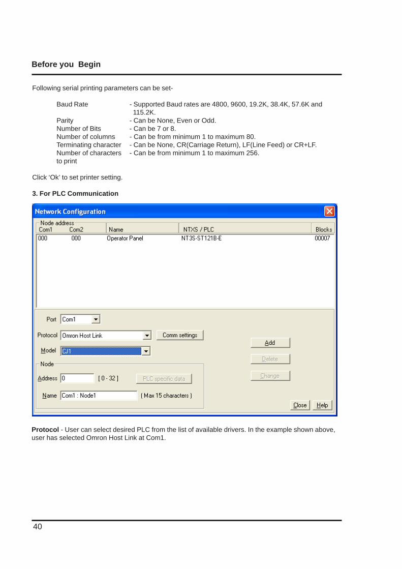
Using this configuration screen you can set the node address and node name for each port. For NT2Sunits, nodeaddress can be set from 0 to 255 but for NT3S units, the highest node address is 32. You can changedefault values generated by editing these two fields. Protocol selection box displays list of all supportedPLCs. By clicking this selection box you can see list of Model Numbers in PLC Model selection Box.Select PLC Name from PLC selection box and PLC Model name from PLC Model selection box.
PLC specific data button is activated only if selected PLC has Special PLC specific data to be set.
3.2.3 Uninstalling NTXS Software
1. In Windows click the Start button.2. Select Programs.3. Select NTXS V1.03.4. Select Uninstall NTXS V1.03.
Following screen will be displayed. The screen will ask you for the confirmation for uninstalling NTXSV1.03.
Before you Begin
36
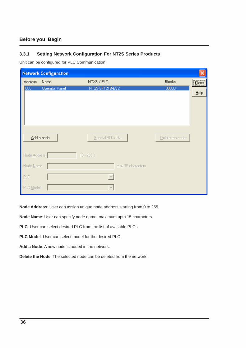
3.3.1 Setting Network Configuration For NT2S Series Products
Unit can be configured for PLC Communication.
Node Address: User can assign unique node address starting from 0 to 255.
Node Name: User can specify node name, maximum upto 15 characters.
PLC: User can select desired PLC from the list of available PLCs.
PLC Model: User can select model for the desired PLC.
Add a Node: A new node is added in the network.
Delete the Node: The selected node can be deleted from the network.
Before you Begin
37
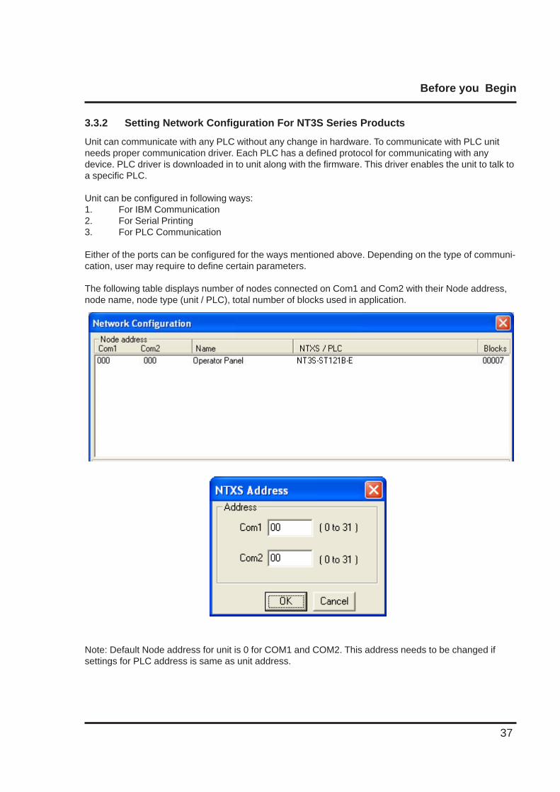
3.3.2 Setting Network Configuration For NT3S Series Products
Unit can communicate with any PLC without any change in hardware. To communicate with PLC unitneeds proper communication driver. Each PLC has a defined protocol for communicating with anydevice. PLC driver is downloaded in to unit along with the firmware. This driver enables the unit to talk toa specific PLC.
Unit can be configured in following ways:1. For IBM Communication2. For Serial Printing3. For PLC Communication
Either of the ports can be configured for the ways mentioned above. Depending on the type of communi-cation, user may require to define certain parameters.
The following table displays number of nodes connected on Com1 and Com2 with their Node address,node name, node type (unit / PLC), total number of blocks used in application.
Note: Default Node address for unit is 0 for COM1 and COM2. This address needs to be changed ifsettings for PLC address is same as unit address.
Before you Begin
38
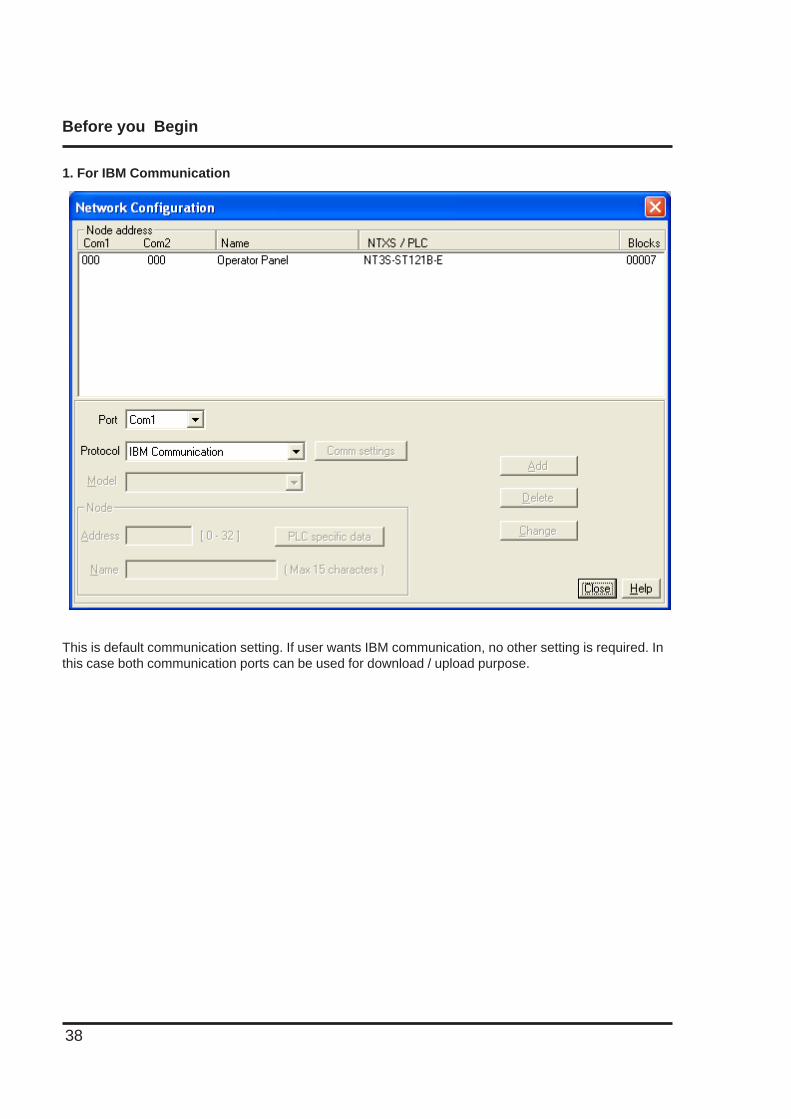
1. For IBM Communication
This is default communication setting. If user wants IBM communication, no other setting is required. Inthis case both communication ports can be used for download / upload purpose.
Before you Begin
39
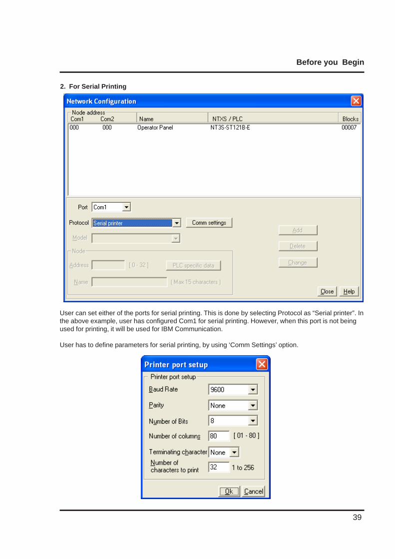
2. For Serial Printing
User can set either of the ports for serial printing. This is done by selecting Protocol as “Serial printer”. Inthe above example, user has configured Com1 for serial printing. However, when this port is not beingused for printing, it will be used for IBM Communication.
User has to define parameters for serial printing, by using ‘Comm Settings’ option.
Before you Begin
40
Following serial printing parameters can be set-
Baud Rate - Supported Baud rates are 4800, 9600, 19.2K, 38.4K, 57.6K and 115.2K.
Parity - Can be None, Even or Odd.Number of Bits - Can be 7 or 8.Number of columns - Can be from minimum 1 to maximum 80.Terminating character - Can be None, CR(Carriage Return), LF(Line Feed) or CR+LF.Number of characters - Can be from minimum 1 to maximum 256.to print
Click ‘Ok’ to set printer setting.
3. For PLC Communication
Protocol - User can select desired PLC from the list of available drivers. In the example shown above,user has selected Omron Host Link at Com1.
Before you Begin
41
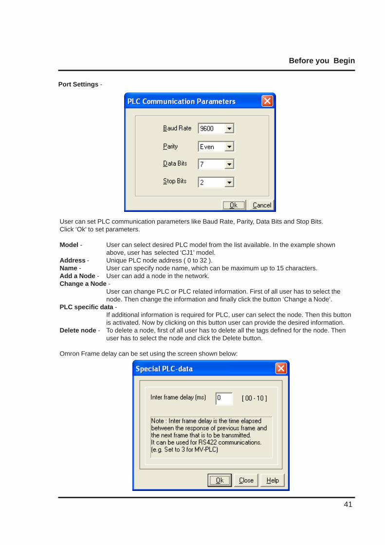
User can set PLC communication parameters like Baud Rate, Parity, Data Bits and Stop Bits.Click ‘Ok’ to set parameters.
Model - User can select desired PLC model from the list available. In the example shownabove, user has selected ‘CJ1’ model.
Address - Unique PLC node address ( 0 to 32 ).Name - User can specify node name, which can be maximum up to 15 characters.Add a Node - User can add a node in the network.Change a Node -
User can change PLC or PLC related information. First of all user has to select thenode. Then change the information and finally click the button ‘Change a Node’.
PLC specific data -If additional information is required for PLC, user can select the node. Then this buttonis activated. Now by clicking on this button user can provide the desired information.
Delete node - To delete a node, first of all user has to delete all the tags defined for the node. Thenuser has to select the node and click the Delete button.
Omron Frame delay can be set using the screen shown below:
Port Settings -
Using NTXS Software
42
USING NTXS SOFTWARE
In this chapter. . . .
♦ NTXS Menu Structure
♦ Creating New Application
♦ Creating Screens
♦ Data Entry Object
♦ Display Data Object
♦ Global And Power On Tasks
♦ Global Keys
♦ Screen Keys
Using NTXS Software
43
4.1 NTXS Menu Structure
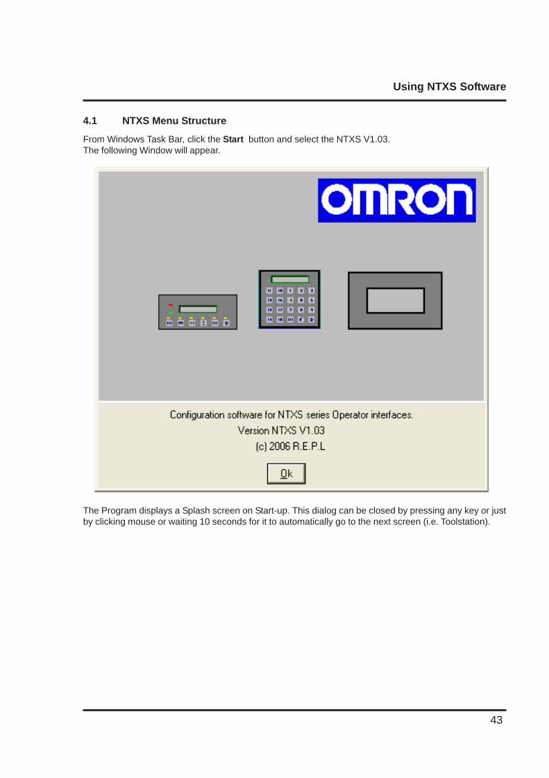
From Windows Task Bar, click the Start button and select the NTXS V1.03.The following Window will appear.
The Program displays a Splash screen on Start-up. This dialog can be closed by pressing any key or justby clicking mouse or waiting 10 seconds for it to automatically go to the next screen (i.e. Toolstation).
Using NTXS Software
44
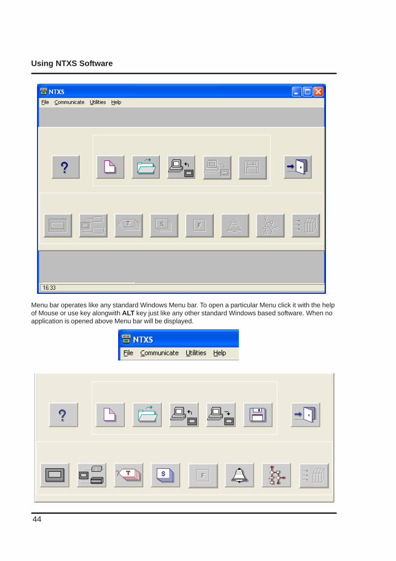
Menu bar operates like any standard Windows Menu bar. To open a particular Menu click it with the helpof Mouse or use key alongwith ALT key just like any other standard Windows based software. When noapplication is opened above Menu bar will be displayed.
Using NTXS Software
45
The Tool-Station consists of icons. When the mouse points to any icon, a tool-tip is displayed. Click onthe icon to select the particular menu.
Now we will study the different Menus in the Menu Bar.
4.1.1 File Menu
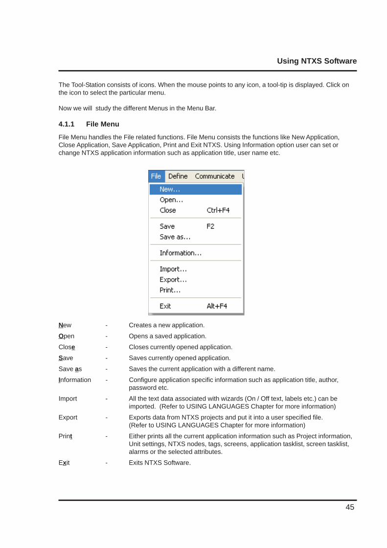
File Menu handles the File related functions. File Menu consists the functions like New Application,Close Application, Save Application, Print and Exit NTXS. Using Information option user can set orchange NTXS application information such as application title, user name etc.
New - Creates a new application.
Open - Opens a saved application.
Close - Closes currently opened application.
Save - Saves currently opened application.
Save as - Saves the current application with a different name.
Information - Configure application specific information such as application title, author,password etc.
Import - All the text data associated with wizards (On / Off text, labels etc.) can beimported. (Refer to USING LANGUAGES Chapter for more information)
Export - Exports data from NTXS projects and put it into a user specified file.(Refer to USING LANGUAGES Chapter for more information)
Print - Either prints all the current application information such as Project information,Unit settings, NTXS nodes, tags, screens, application tasklist, screen tasklist,alarms or the selected attributes.
Exit - Exits NTXS Software.
Using NTXS Software
46
4.1.2 Define Menu
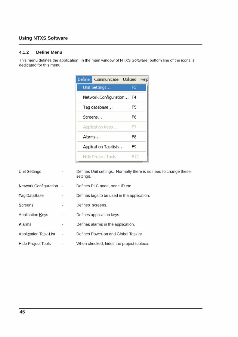
This menu defines the application. In the main window of NTXS Software, bottom line of the icons isdedicated for this menu.
Unit Settings - Defines Unit settings. Normally there is no need to change thesesettings.
Network Configuration - Defines PLC node, node ID etc.
Tag DataBase - Defines tags to be used in the application.
Screens - Defines screens.
Application Keys - Defines application keys.
Alarms - Defines alarms in the application.
Application Task-List - Defines Power-on and Global Tasklist.
Hide Project Tools - When checked, hides the project toolbox.
Using NTXS Software
47
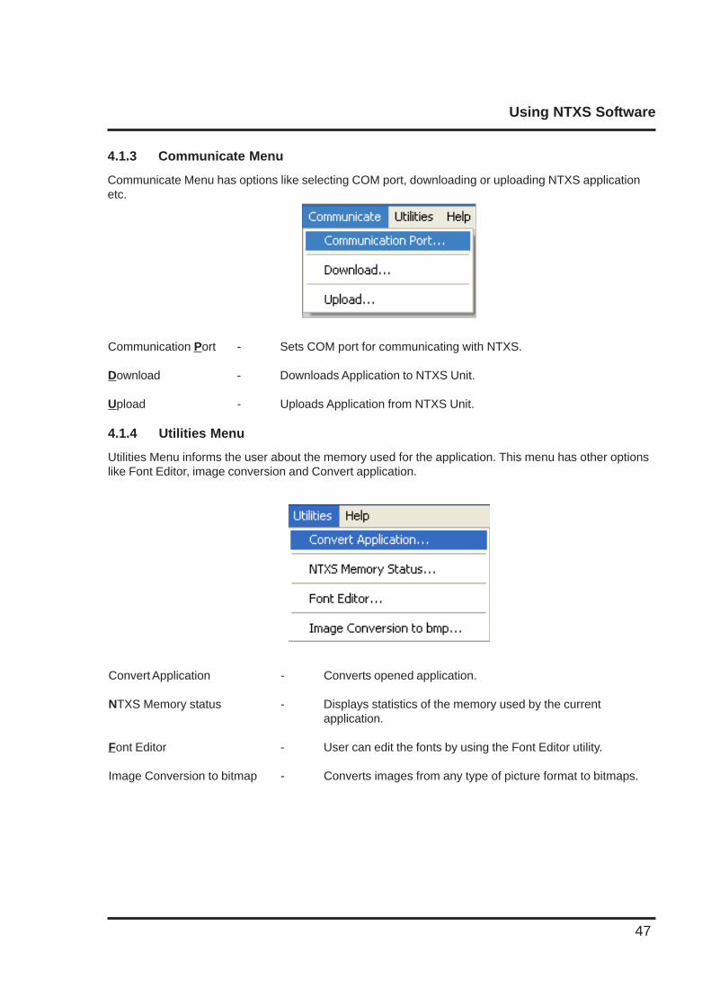
4.1.3 Communicate Menu
Communicate Menu has options like selecting COM port, downloading or uploading NTXS applicationetc.
Communication Port - Sets COM port for communicating with NTXS.
Download - Downloads Application to NTXS Unit.
Upload - Uploads Application from NTXS Unit.
4.1.4 Utilities Menu
Utilities Menu informs the user about the memory used for the application. This menu has other optionslike Font Editor, image conversion and Convert application.
Convert Application - Converts opened application.
NTXS Memory status - Displays statistics of the memory used by the currentapplication.
Font Editor - User can edit the fonts by using the Font Editor utility.
Image Conversion to bitmap - Converts images from any type of picture format to bitmaps.
Using NTXS Software
48
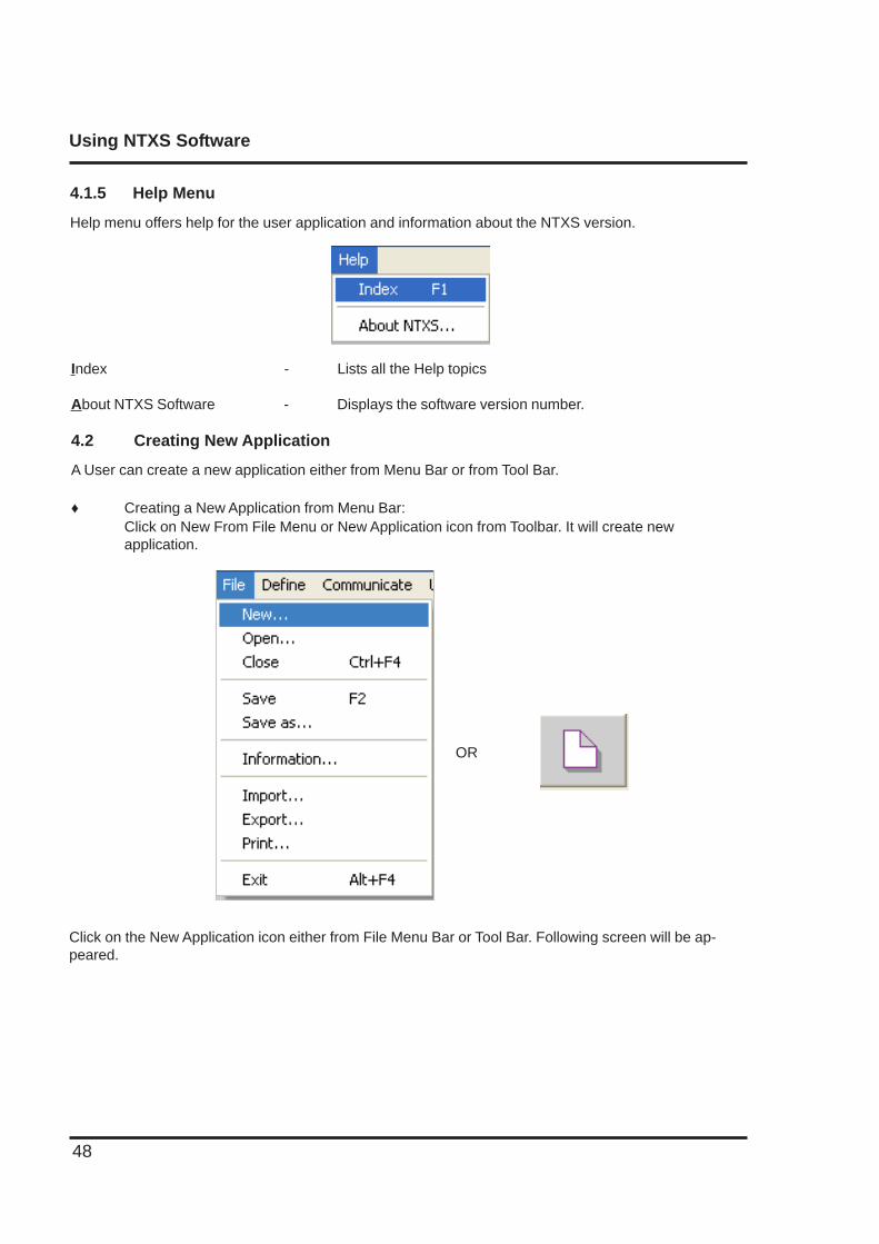
4.1.5 Help Menu
Help menu offers help for the user application and information about the NTXS version.
Index - Lists all the Help topics
About NTXS Software - Displays the software version number.
4.2 Creating New Application
A User can create a new application either from Menu Bar or from Tool Bar.
♦ Creating a New Application from Menu Bar:Click on New From File Menu or New Application icon from Toolbar. It will create newapplication.
Click on the New Application icon either from File Menu Bar or Tool Bar. Following screen will be ap-peared.
OR
Using NTXS Software
49
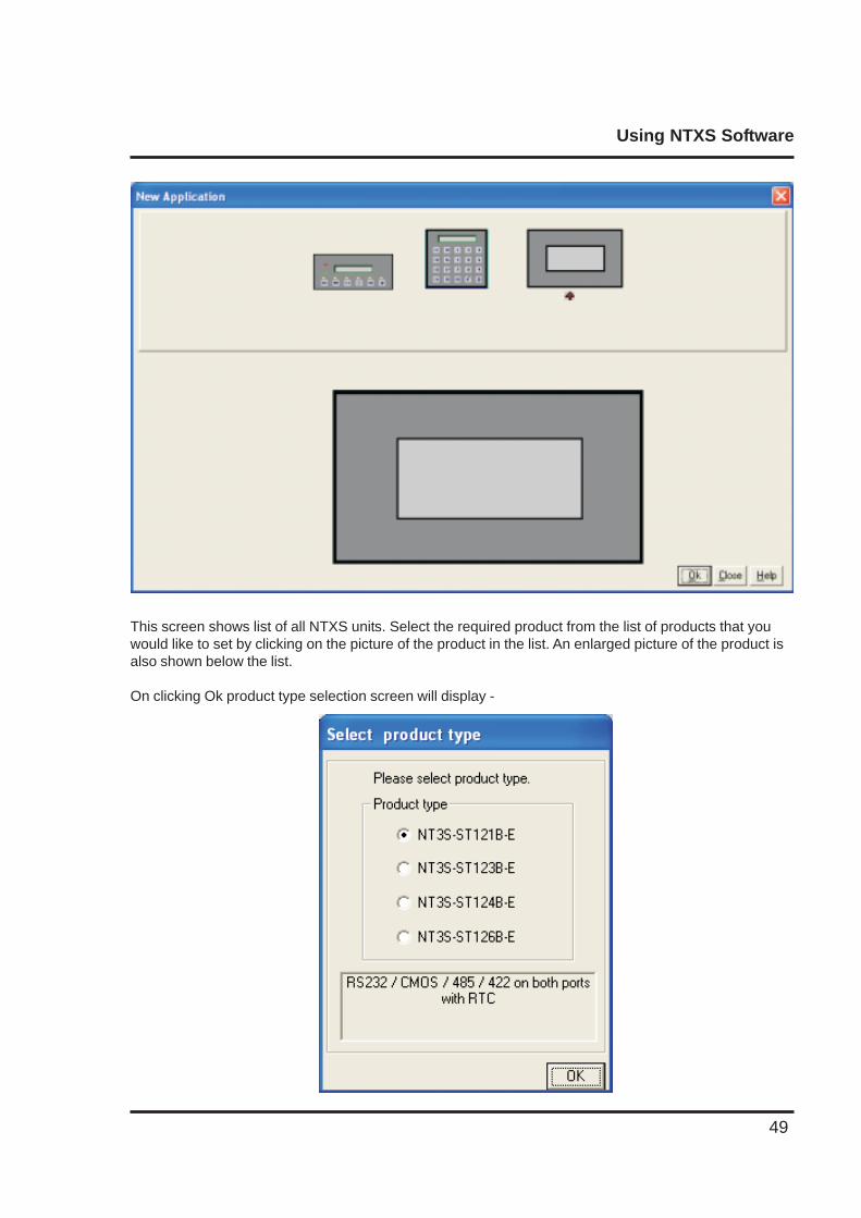
This screen shows list of all NTXS units. Select the required product from the list of products that youwould like to set by clicking on the picture of the product in the list. An enlarged picture of the product isalso shown below the list.
On clicking Ok product type selection screen will display -
Using NTXS Software
50
Select the type of Product and then click OK to start the Application.
Steps for creating a new application are as follows:
1) Start a new project using either File Menu or Tool section New command.2) Define Unit Settings.3) Define Network Configuration for selected unit and PLCs.4) Define the tags in the Tag database required for the project / application.4) Define the screens.5) Define Power-on, Global and Screen tasks.6) Save your application.7) Download firmware to the unit.8) Download your application to the unit.
Tag Database
This is the central database for the tags which need to be used in the application. Once the tags aredefined (as register or coils) and their attributes selected, the tags can be used in the application onscreens, tasks, alarms etc. This screen helps you to define Tags associated with defined Nodes. Tag isnothing but a Register or Coil or Individual bit of any register. Select type of the tag from Tag Type fieldwhich is either Register or Coil Type.
If type of tag selected is register then number of bytes to be fetched varies from 1, 2, 4, etc. For display-ing or editing float data number of bytes of tag must be 4. Tag Name field is user definable. Tag is notadded in Tag list unless you define Tag name. Once you define all these fields click on Add button foradding Tag in Tags List Box. Block field of this tag database defines Block starting address followed byBlock size.For example : Tag M0214 is within a block ( M0214 : 1 ) whose starting address is M0214 and block sizeis 1. This block size is optimized automatically depending on address of PLC Tag.Default block size is either 1 or 16. This setting varies from PLC to PLC.
Attributes of existing Tag can be changed by clicking on Change button. Note that Change button isactivated only if tag in the tag list is selected. Existing Tag can be removed from Tag list by clicking onDelete button. However, user can delete the tags only if they are not used in any screen.
Using NTXS Software
51
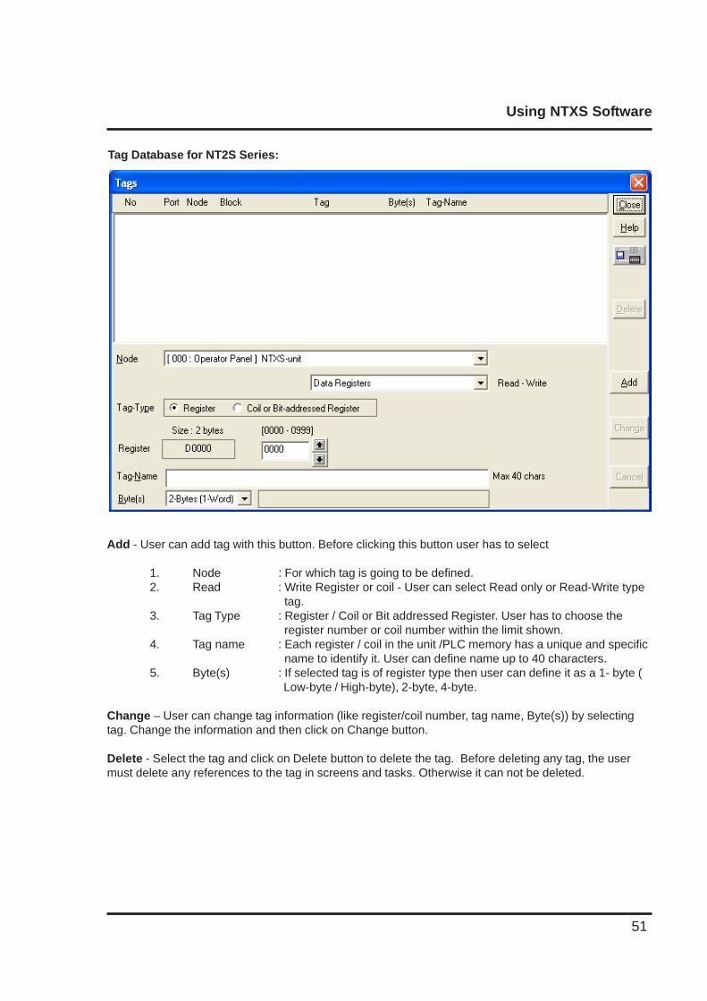
Tag Database for NT2S Series:
Add - User can add tag with this button. Before clicking this button user has to select
1. Node : For which tag is going to be defined.2. Read : Write Register or coil - User can select Read only or Read-Write type
tag.3. Tag Type : Register / Coil or Bit addressed Register. User has to choose the
register number or coil number within the limit shown.4. Tag name : Each register / coil in the unit /PLC memory has a unique and specific
name to identify it. User can define name up to 40 characters.5. Byte(s) : If selected tag is of register type then user can define it as a 1- byte (
Low-byte / High-byte), 2-byte, 4-byte.
Change – User can change tag information (like register/coil number, tag name, Byte(s)) by selectingtag. Change the information and then click on Change button.
Delete - Select the tag and click on Delete button to delete the tag. Before deleting any tag, the usermust delete any references to the tag in screens and tasks. Otherwise it can not be deleted.
Using NTXS Software
52
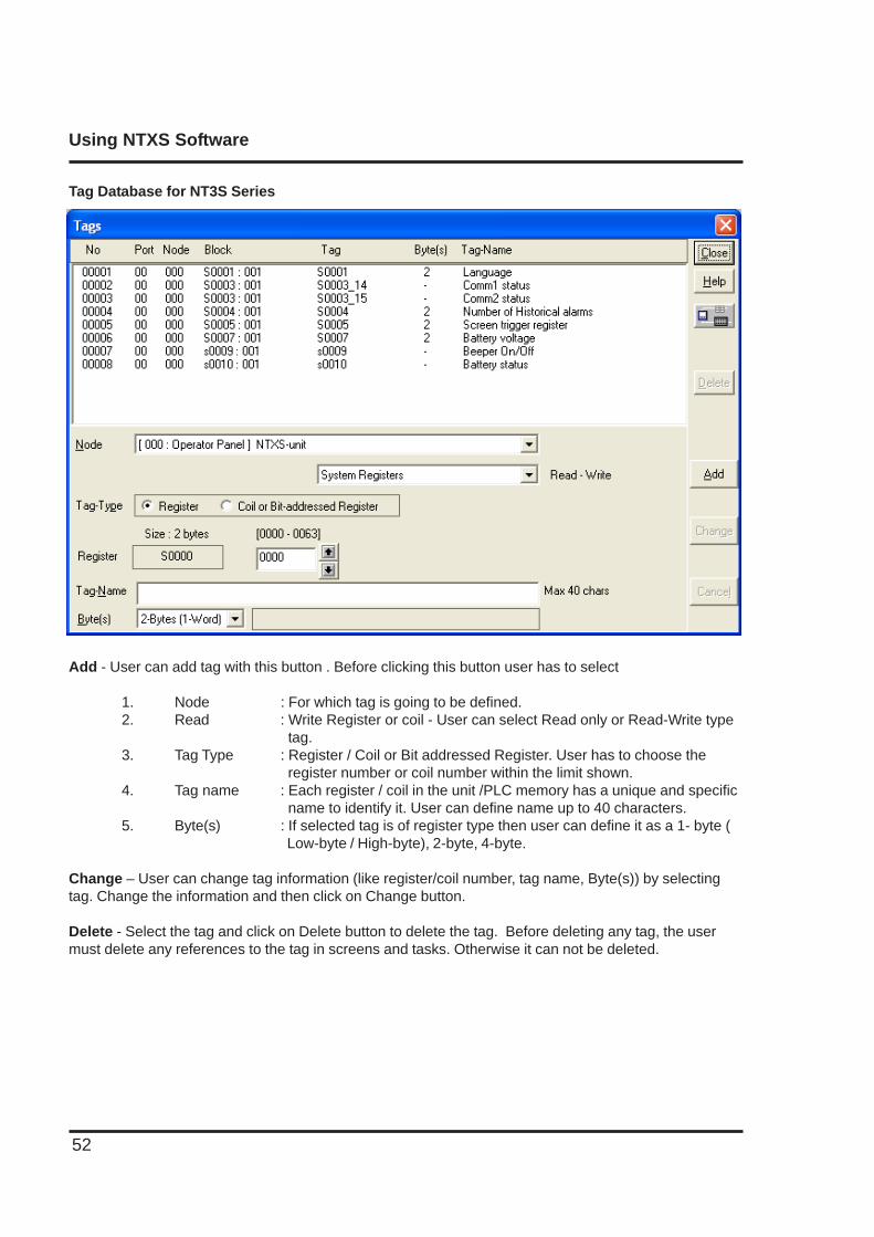
Tag Database for NT3S Series
Add - User can add tag with this button . Before clicking this button user has to select
1. Node : For which tag is going to be defined.2. Read : Write Register or coil - User can select Read only or Read-Write type
tag.3. Tag Type : Register / Coil or Bit addressed Register. User has to choose the
register number or coil number within the limit shown.4. Tag name : Each register / coil in the unit /PLC memory has a unique and specific
name to identify it. User can define name up to 40 characters.5. Byte(s) : If selected tag is of register type then user can define it as a 1- byte (
Low-byte / High-byte), 2-byte, 4-byte.
Change – User can change tag information (like register/coil number, tag name, Byte(s)) by selectingtag. Change the information and then click on Change button.
Delete - Select the tag and click on Delete button to delete the tag. Before deleting any tag, the usermust delete any references to the tag in screens and tasks. Otherwise it can not be deleted.
Using NTXS Software
53
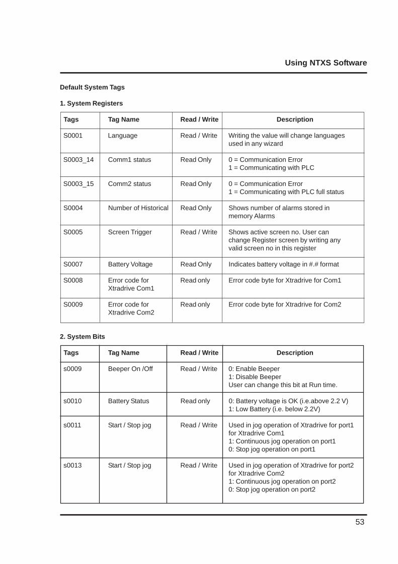
Default System Tags
1. System Registers
Tags Tag Name Read / Write Description
S0001 Language Read / Write Writing the value will change languagesused in any wizard
S0003_14 Comm1 status Read Only 0 = Communication Error1 = Communicating with PLC
S0003_15 Comm2 status Read Only 0 = Communication Error1 = Communicating with PLC full status
S0004 Number of Historical Read Only Shows number of alarms stored inmemory Alarms
S0005 Screen Trigger Read / Write Shows active screen no. User canchange Register screen by writing anyvalid screen no in this register
S0007 Battery Voltage Read Only Indicates battery voltage in #.# format
S0008 Error code for Read only Error code byte for Xtradrive for Com1Xtradrive Com1
S0009 Error code for Read only Error code byte for Xtradrive for Com2Xtradrive Com2
2. System Bits
Tags Tag Name Read / Write Description
s0009 Beeper On /Off Read / Write 0: Enable Beeper1: Disable BeeperUser can change this bit at Run time.
s0010 Battery Status Read only 0: Battery voltage is OK (i.e.above 2.2 V)1: Low Battery (i.e. below 2.2V)
s0011 Start / Stop jog Read / Write Used in jog operation of Xtradrive for port1for Xtradrive Com11: Continuous jog operation on port10: Stop jog operation on port1
s0013 Start / Stop jog Read / Write Used in jog operation of Xtradrive for port2for Xtradrive Com21: Continuous jog operation on port20: Stop jog operation on port2
Using NTXS Software
54
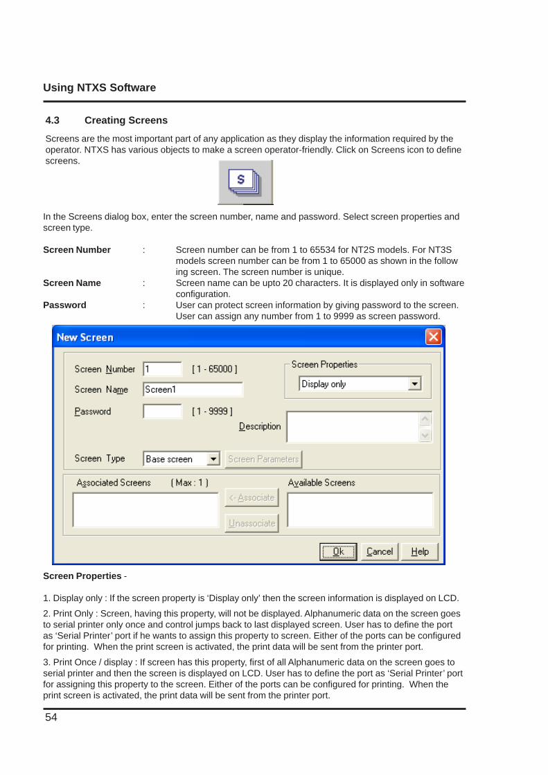
4.3 Creating Screens
Screens are the most important part of any application as they display the information required by theoperator. NTXS has various objects to make a screen operator-friendly. Click on Screens icon to definescreens.
In the Screens dialog box, enter the screen number, name and password. Select screen properties andscreen type.
Screen Number : Screen number can be from 1 to 65534 for NT2S models. For NT3Smodels screen number can be from 1 to 65000 as shown in the following screen. The screen number is unique.
Screen Name : Screen name can be upto 20 characters. It is displayed only in softwareconfiguration.
Password : User can protect screen information by giving password to the screen.User can assign any number from 1 to 9999 as screen password.
Screen Properties -
1. Display only : If the screen property is ‘Display only’ then the screen information is displayed on LCD.
2. Print Only : Screen, having this property, will not be displayed. Alphanumeric data on the screen goesto serial printer only once and control jumps back to last displayed screen. User has to define the portas ‘Serial Printer’ port if he wants to assign this property to screen. Either of the ports can be configuredfor printing. When the print screen is activated, the print data will be sent from the printer port.
3. Print Once / display : If screen has this property, first of all Alphanumeric data on the screen goes toserial printer and then the screen is displayed on LCD. User has to define the port as ‘Serial Printer’ portfor assigning this property to the screen. Either of the ports can be configured for printing. When theprint screen is activated, the print data will be sent from the printer port.
Using NTXS Software
55
Description : User can write the information about the screen for the reference. This description is onlyfor software configuration. It is not displayed on the unit.
Associated Screens : Associated screen is useful in the case where one or more objects are commonbetween different screens. The common data from all the screens is placed in a screen and this screenis associated with the other screens.
Advantage of associated screen -1. It saves application memory.2. It saves time of the application programmer.
Note : Only one screen can be associated to any screen.No data entry objects can be placed in the screen to be associated.Embedding any PLC information is not supported in associated screen.
User can ‘unassociate’ a screen.
Available Screens - List of available screens is displayed.
Click ‘Ok’ to edit the screen.
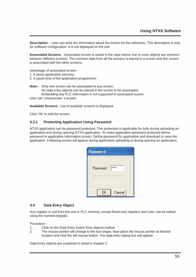
4.3.1 Protecting Application Using Password
NTXS application can be password protected. This protection is applicable for both during uploading anapplication and during opening NTXS application. To make application password protected definepassword in application information screen. Define password for application and download or save theapplication. Following screen will appear during application uploading or during opening an application.
4.4 Data Entry Object
Any register or coil from the unit or PLC memory, except Read-only registers and coils, can be editedusing the numeric keypad.
Procedure -1. Click on the Data Entry button from objects toolbar.2. The mouse pointer will change to the tool shape. Now place the mouse pointer at desired
location and click the left mouse button. The data entry dialog box will appear.
Data Entry objects are explained in detail in chapter 5.
Using NTXS Software
56
4.5 Display Data Object
This object is used to display the contents of the register or coil.Procedure-1. Click on ‘Display Data’ from objects toolbar. The mouse pointer will change to the tool shape.2. Now place the mouse pointer at desired location and click the left mouse button. The data entry dialogbox will appear.
Display data object is explained in detail in chapter 5.
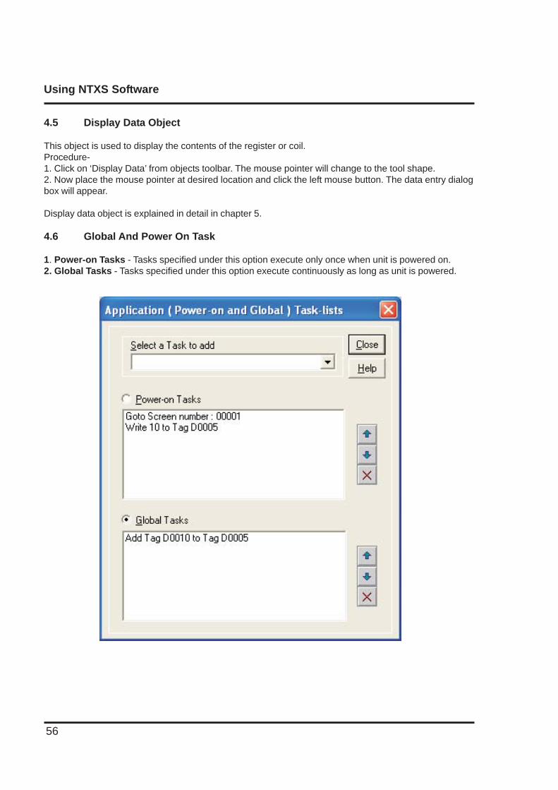
4.6 Global And Power On Task
1. Power-on Tasks - Tasks specified under this option execute only once when unit is powered on.2. Global Tasks - Tasks specified under this option execute continuously as long as unit is powered.
Using NTXS Software
57
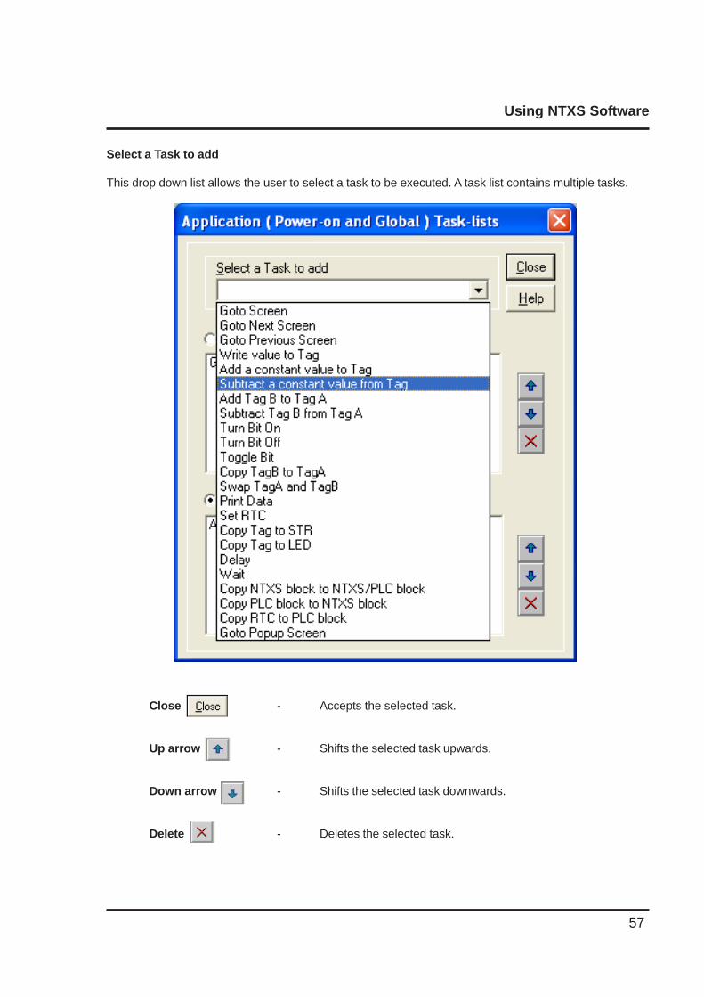
Select a Task to add
This drop down list allows the user to select a task to be executed. A task list contains multiple tasks.
Close - Accepts the selected task.
Up arrow - Shifts the selected task upwards.
Down arrow - Shifts the selected task downwards.
Delete - Deletes the selected task.
Using NTXS Software
58
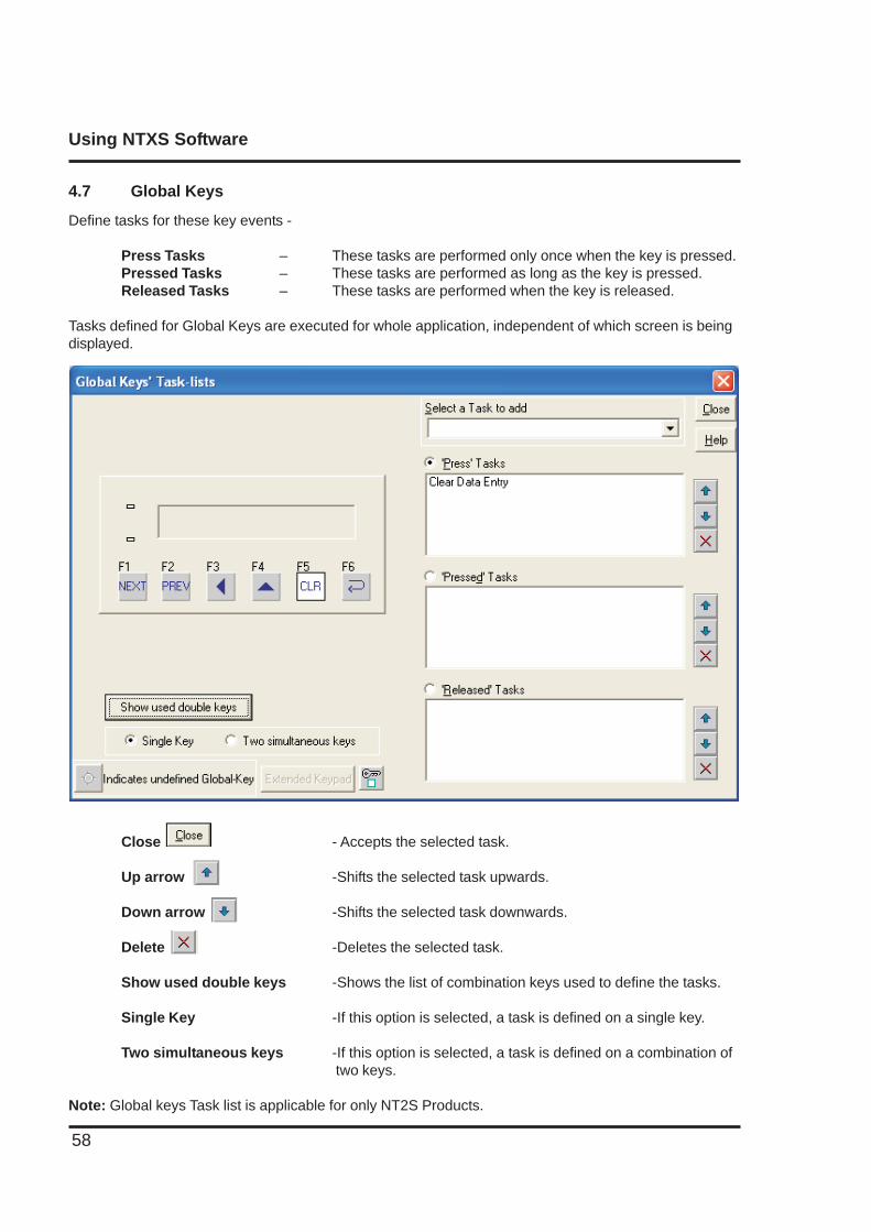
4.7 Global Keys
Define tasks for these key events -
Press Tasks – These tasks are performed only once when the key is pressed.Pressed Tasks – These tasks are performed as long as the key is pressed.Released Tasks – These tasks are performed when the key is released.
Tasks defined for Global Keys are executed for whole application, independent of which screen is beingdisplayed.
Close - Accepts the selected task.
Up arrow -Shifts the selected task upwards.
Down arrow -Shifts the selected task downwards.
Delete -Deletes the selected task.
Show used double keys -Shows the list of combination keys used to define the tasks.
Single Key -If this option is selected, a task is defined on a single key.
Two simultaneous keys -If this option is selected, a task is defined on a combination of two keys.
Note: Global keys Task list is applicable for only NT2S Products.
Using NTXS Software
59
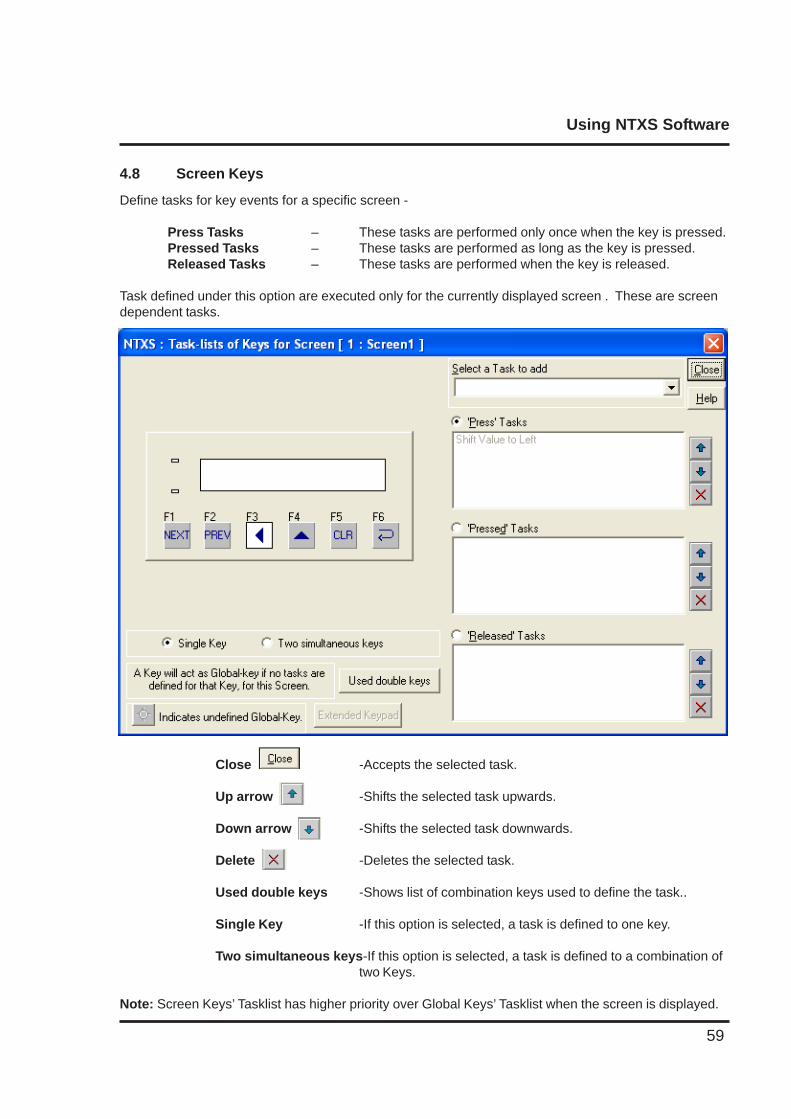
4.8 Screen Keys
Define tasks for key events for a specific screen -
Press Tasks – These tasks are performed only once when the key is pressed.Pressed Tasks – These tasks are performed as long as the key is pressed.Released Tasks – These tasks are performed when the key is released.
Task defined under this option are executed only for the currently displayed screen . These are screendependent tasks.
Close -Accepts the selected task.
Up arrow -Shifts the selected task upwards.
Down arrow -Shifts the selected task downwards.
Delete -Deletes the selected task.
Used double keys -Shows list of combination keys used to define the task..
Single Key -If this option is selected, a task is defined to one key.
Two simultaneous keys-If this option is selected, a task is defined to a combination oftwo Keys.
Note: Screen Keys’ Tasklist has higher priority over Global Keys’ Tasklist when the screen is displayed.
Representing Data
60
REPRESENTING DATA BY OBJECTS AND WIZARDS
In this chapter. . . .
♦ Alphanumeric Objects
♦ Graphics Objects
♦ Wizards
Representing Data
61
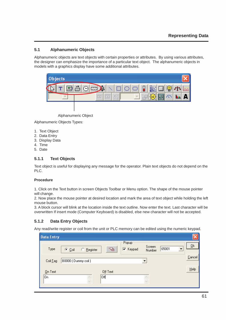
5.1 Alphanumeric Objects
Alphanumeric objects are text objects with certain properties or attributes. By using various attributes,the designer can emphasize the importance of a particular text object. The alphanumeric objects inmodels with a graphics display have some additional attributes.
Alphanumeric Object
Alphanumeric Objects Types:
1. Text Object2. Data Entry3. Display Data4. Time5. Date
5.1.1 Text Objects
Text object is useful for displaying any message for the operator. Plain text objects do not depend on thePLC.
Procedure
1. Click on the Text button in screen Objects Toolbar or Menu option. The shape of the mouse pointerwill change.2. Now place the mouse pointer at desired location and mark the area of text object while holding the leftmouse button.3. A block cursor will blink at the location inside the text outline. Now enter the text. Last character will beoverwritten If insert mode (Computer Keyboard) is disabled, else new character will not be accepted.
5.1.2 Data Entry Objects
Any read/write register or coil from the unit or PLC memory can be edited using the numeric keypad.
Representing Data
62
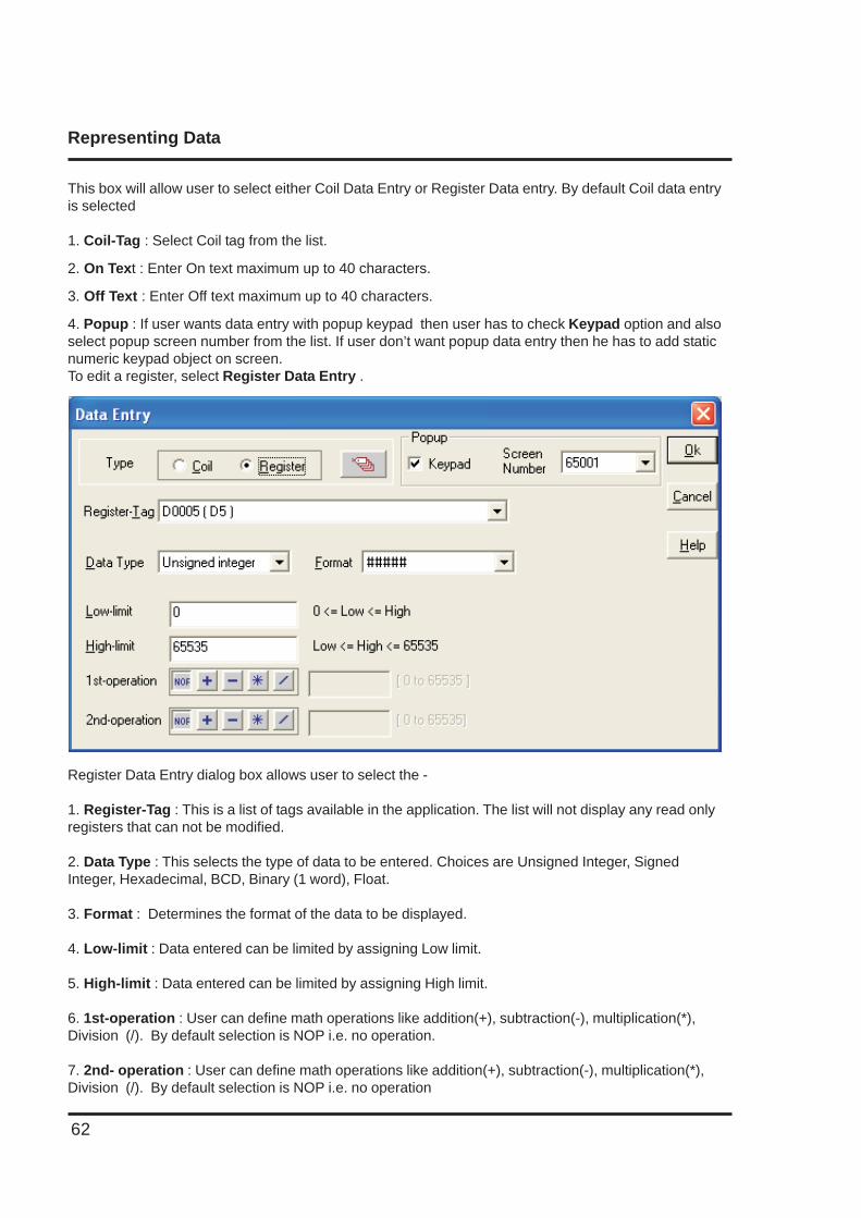
This box will allow user to select either Coil Data Entry or Register Data entry. By default Coil data entryis selected
1. Coil-Tag : Select Coil tag from the list.
2. On Text : Enter On text maximum up to 40 characters.
3. Off Text : Enter Off text maximum up to 40 characters.
4. Popup : If user wants data entry with popup keypad then user has to check Keypad option and alsoselect popup screen number from the list. If user don’t want popup data entry then he has to add staticnumeric keypad object on screen.To edit a register, select Register Data Entry .
Register Data Entry dialog box allows user to select the -
1. Register-Tag : This is a list of tags available in the application. The list will not display any read onlyregisters that can not be modified.
2. Data Type : This selects the type of data to be entered. Choices are Unsigned Integer, SignedInteger, Hexadecimal, BCD, Binary (1 word), Float.
3. Format : Determines the format of the data to be displayed.
4. Low-limit : Data entered can be limited by assigning Low limit.
5. High-limit : Data entered can be limited by assigning High limit.
6. 1st-operation : User can define math operations like addition(+), subtraction(-), multiplication(*),Division (/). By default selection is NOP i.e. no operation.
7. 2nd- operation : User can define math operations like addition(+), subtraction(-), multiplication(*),Division (/). By default selection is NOP i.e. no operation
Representing Data
63
8. Popup : If user wants to enter data with popup keypad then user has to check Keypad option andalso select popup screen number from list. If user don’t want popup data entry then he has to add staticnumeric keypad object on screen .
Note:- Math operations operate only on unsigned values and unsigned result e.g. If first operation isdivided by 100 and tag value is 25 then result will be stored as zero and not 0.25.
Click ‘Ok’ button to add the object on screen.
5.1.3 Display Data
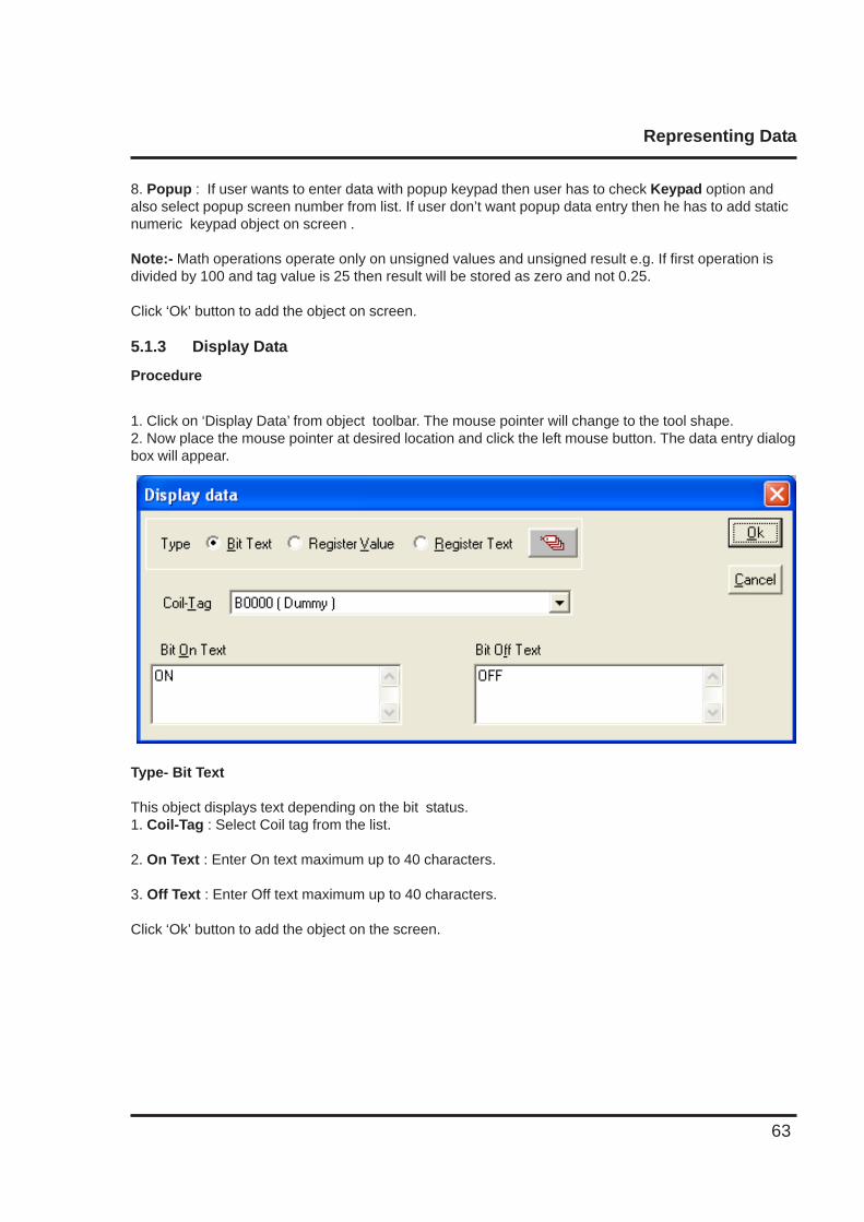
Procedure
1. Click on ‘Display Data’ from object toolbar. The mouse pointer will change to the tool shape.2. Now place the mouse pointer at desired location and click the left mouse button. The data entry dialogbox will appear.
Type- Bit Text
This object displays text depending on the bit status.1. Coil-Tag : Select Coil tag from the list.
2. On Text : Enter On text maximum up to 40 characters.
3. Off Text : Enter Off text maximum up to 40 characters.
Click ‘Ok’ button to add the object on the screen.
Representing Data
64
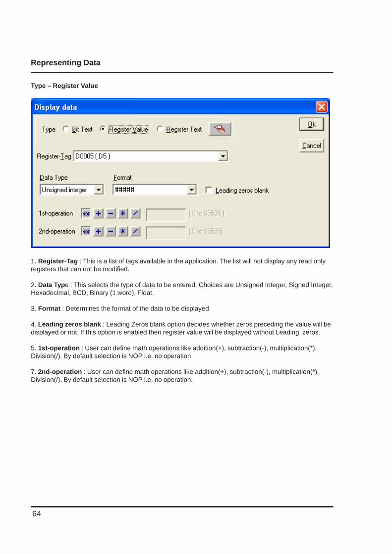
Type – Register Value
1. Register-Tag : This is a list of tags available in the application. The list will not display any read onlyregisters that can not be modified.
2. Data Type : This selects the type of data to be entered. Choices are Unsigned Integer, Signed Integer,Hexadecimal, BCD, Binary (1 word), Float.
3. Format : Determines the format of the data to be displayed.
4. Leading zeros blank : Leading Zeros blank option decides whether zeros preceding the value will bedisplayed or not. If this option is enabled then register value will be displayed without Leading zeros.
5. 1st-operation : User can define math operations like addition(+), subtraction(-), multiplication(*),Division(/). By default selection is NOP i.e. no operation
7. 2nd-operation : User can define math operations like addition(+), subtraction(-), multiplication(*),Division(/). By default selection is NOP i.e. no operation.
Representing Data
65
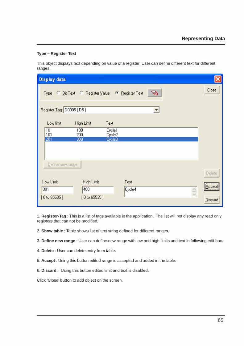
Type – Register Text
This object displays text depending on value of a register. User can define different text for differentranges.
1. Register-Tag : This is a list of tags available in the application. The list will not display any read onlyregisters that can not be modified.
2. Show table : Table shows list of text string defined for different ranges.
3. Define new range : User can define new range with low and high limits and text in following edit box.
4. Delete : User can delete entry from table.
5. Accept : Using this button edited range is accepted and added in the table.
6. Discard : Using this button edited limit and text is disabled.
Click ‘Close’ button to add object on the screen.
Representing Data
66
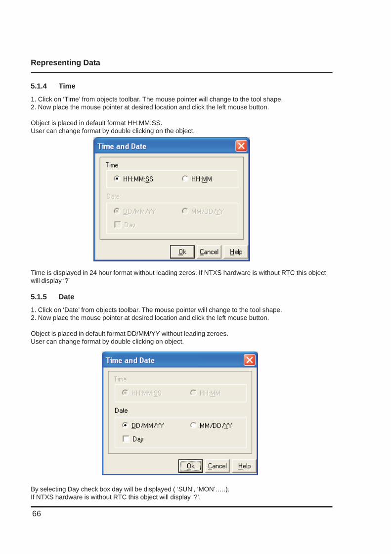
Time is displayed in 24 hour format without leading zeros. If NTXS hardware is without RTC this objectwill display ‘?’
5.1.5 Date
1. Click on ‘Date’ from objects toolbar. The mouse pointer will change to the tool shape.2. Now place the mouse pointer at desired location and click the left mouse button.
Object is placed in default format DD/MM/YY without leading zeroes.User can change format by double clicking on object.
By selecting Day check box day will be displayed ( ‘SUN’, ‘MON’…..).If NTXS hardware is without RTC this object will display ‘?’.
5.1.4 Time
1. Click on ‘Time’ from objects toolbar. The mouse pointer will change to the tool shape.2. Now place the mouse pointer at desired location and click the left mouse button.
Object is placed in default format HH:MM:SS.User can change format by double clicking on the object.
Representing Data
67
Attributes of Alphanumeric Objects
Font SizeText objects have four font sizes: 5 X 7 Dots, 7 X 14 Dots, 10 X 14 Dots and 20 X 28 Dots. Default fontsize is 5 X 7 Dots.
Text Foreground:Text foreground can be changed by user. Two options are available: black and white. Default TextForeground is Black.
Text BackgroundText Background can be changed by user. Two options are available: black and white. Default TextBackground is white.
Border -Single or DoubleAny text object can be highlighted using single or double border This enhances its importance.
Unconditional FlashUser can assign flashing attribute to any text object. An object can flash at three different speeds: Slow,Medium and Fast. By default no object is assigned the flashing attribute. If flashing is defined, slowflashing is selected by default.
Note: Data Entry objects (Coil and register) do not have flash attribute.
Following attributes are available on NTXS Models with Graphic Display.
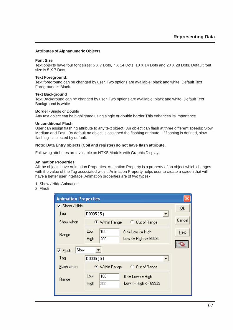
Animation Properties:All the objects have Animation Properties. Animation Property is a property of an object which changeswith the value of the Tag associated with it. Animation Property helps user to create a screen that willhave a better user interface. Animation properties are of two types-
1. Show / Hide Animation2. Flash
Representing Data
68
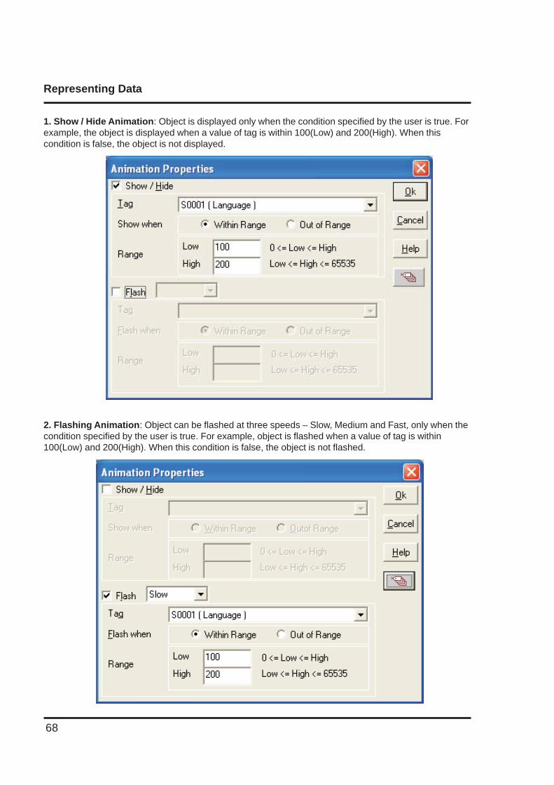
1. Show / Hide Animation: Object is displayed only when the condition specified by the user is true. Forexample, the object is displayed when a value of tag is within 100(Low) and 200(High). When thiscondition is false, the object is not displayed.
2. Flashing Animation: Object can be flashed at three speeds – Slow, Medium and Fast, only when thecondition specified by the user is true. For example, object is flashed when a value of tag is within100(Low) and 200(High). When this condition is false, the object is not flashed.
Representing Data
69
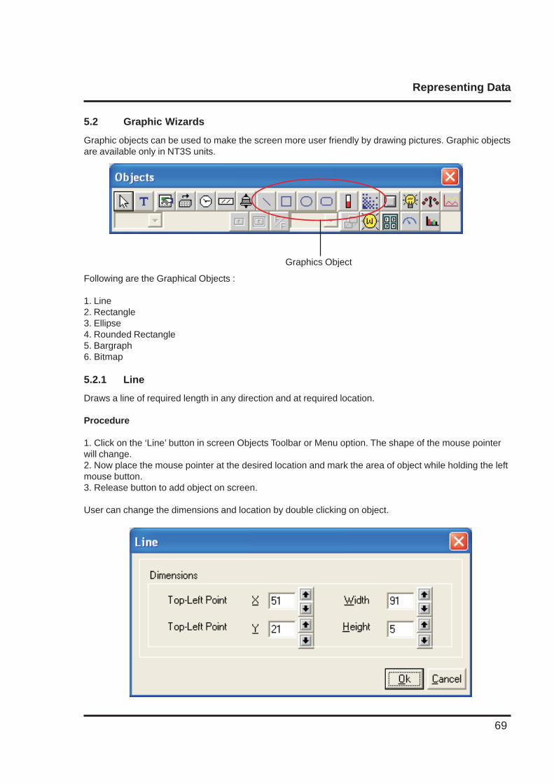
5.2 Graphic Wizards
Graphic objects can be used to make the screen more user friendly by drawing pictures. Graphic objectsare available only in NT3S units.
Graphics Object
Following are the Graphical Objects :
1. Line2. Rectangle3. Ellipse4. Rounded Rectangle5. Bargraph6. Bitmap
5.2.1 Line
Draws a line of required length in any direction and at required location.
Procedure
1. Click on the ‘Line’ button in screen Objects Toolbar or Menu option. The shape of the mouse pointerwill change.2. Now place the mouse pointer at the desired location and mark the area of object while holding the leftmouse button.3. Release button to add object on screen.
User can change the dimensions and location by double clicking on object.
Representing Data
70
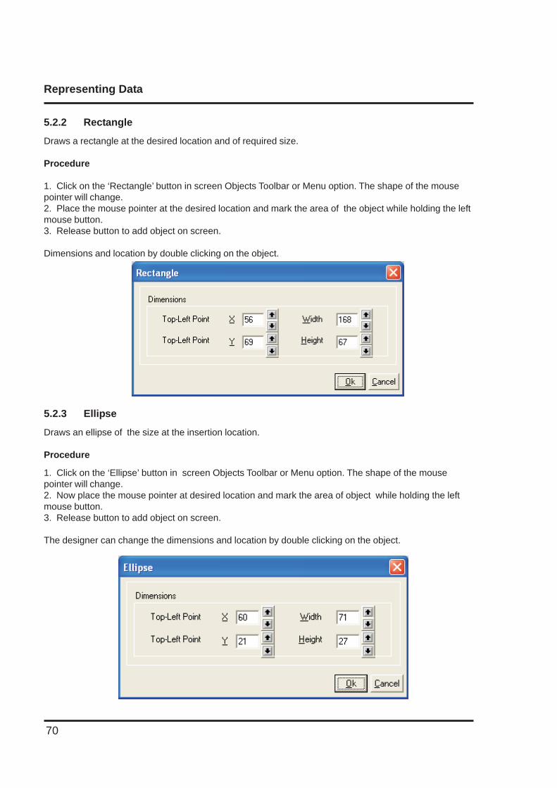
5.2.2 Rectangle
Draws a rectangle at the desired location and of required size.
Procedure
1. Click on the ‘Rectangle’ button in screen Objects Toolbar or Menu option. The shape of the mousepointer will change.2. Place the mouse pointer at the desired location and mark the area of the object while holding the leftmouse button.3. Release button to add object on screen.
Dimensions and location by double clicking on the object.
5.2.3 Ellipse
Draws an ellipse of the size at the insertion location.
Procedure
1. Click on the ‘Ellipse’ button in screen Objects Toolbar or Menu option. The shape of the mousepointer will change.2. Now place the mouse pointer at desired location and mark the area of object while holding the leftmouse button.3. Release button to add object on screen.
The designer can change the dimensions and location by double clicking on the object.
Representing Data
71
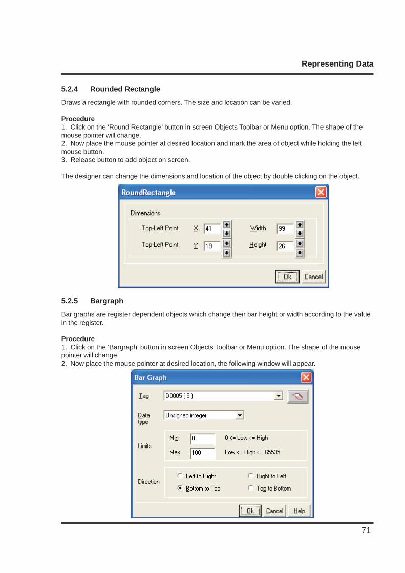
5.2.4 Rounded Rectangle
Draws a rectangle with rounded corners. The size and location can be varied.
Procedure1. Click on the ‘Round Rectangle’ button in screen Objects Toolbar or Menu option. The shape of themouse pointer will change.2. Now place the mouse pointer at desired location and mark the area of object while holding the leftmouse button.3. Release button to add object on screen.
The designer can change the dimensions and location of the object by double clicking on the object.
5.2.5 Bargraph
Bar graphs are register dependent objects which change their bar height or width according to the valuein the register.
Procedure1. Click on the ‘Bargraph’ button in screen Objects Toolbar or Menu option. The shape of the mousepointer will change.2. Now place the mouse pointer at desired location, the following window will appear.
Representing Data
72
1. Tag: This is a list of tags available in the application.
2. Data type: This selects the type of data to be entered. Choices are Unsigned Integer, Signed Integer,Hexadecimal, BCD, Binary (1 word), Float.
3. Limits: Limits of bar graph are 0 to 65535 for all data types except signed integer for which range forlimits is -32768 to 32767.
4. Direction: User can define direction of bar graph from four options.
Note: Bar graph supports only show/hide animation.Click ‘Ok’ button to add object to the screen.
5.2.6 Bitmap
A bitmap can be drawn on the NTXS display. The bitmap should not be bigger than the display size ofthe NTXS unit.
Bitmap Specifications:
Maximum size of bitmaps that can be used for NT3S is 192 pixels (W) X 64 pixels (H).Only 2 color bitmaps can be used.
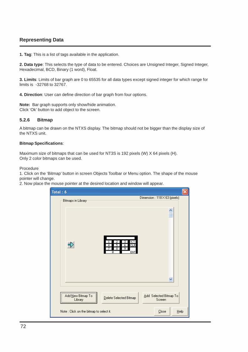
Procedure1. Click on the ‘Bitmap’ button in screen Objects Toolbar or Menu option. The shape of the mousepointer will change.2. Now place the mouse pointer at the desired location and window will appear.
Representing Data
73
This window shows a list of the currently available bitmaps in the bitmap library.
Add New Bitmap To Library : User can add his own bitmap in the library.
Delete Selected Bitmap : User can delete selected bitmap from the library.
Add Selected Bitmap To Screen : This will add selected bitmap on the screen at desired location
Graphical Objects have certain properties, referred as Attributes. Attributes are useful for suggesting theimportance of the particular object.
Basic Graphic Objects have the following attributes:
Pen Color : This attribute defines the pattern for drawing the border. For Black and White Graphicdisplay this can either be black or white.
Fill Color : This attribute defines the fill color. Any closed object can be filled by the selected color.Flash : All the basic objects can be flashed using this attribute. Flashing can be done at three
different speeds: Slow, Medium and Fast.
5.3 Wizards
Various wizards included for use in graphical NTXS products are:
1. Button object :
a. Bit Buttonb. Word Button
2. Lamp Object:
a. Bit Lampb. Word Lamp
3. Analog Meter
4. Multiple Bargraph
5. Numeric Keypad
6. Trend Display
Representing Data
74
5.3.1 Bit Button
The bit button can be used to display the status bit and perform an action based on the task defined forthe button.
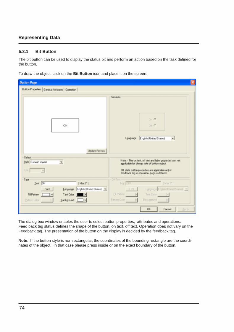
To draw the object, click on the Bit Button icon and place it on the screen.
The dialog box window enables the user to select button properties, attributes and operations.Feed back tag status defines the shape of the button, on text, off text. Operation does not vary on theFeedback tag. The presentation of the button on the display is decided by the feedback tag.
Note: If the button style is non rectangular, the coordinates of the bounding rectangle are the coordi-nates of the object. In that case please press inside or on the exact boundary of the button.
Representing Data
75
Button Properties:
Style
A button can have a number of different styles:
1. Generic square2. Generic circle3. Generic rounded rectangle4. Invisible button5. User defined image
On/Off Text
A button can also be configured with the following properties:
1. Text : On / Off text, can be up to 21 characters.2. Font : Select Windows® font, font style and font size. Any font supported in the user’s
computer is acceptable.3. Language : Display the list of languages depending upon the number of languages configured
in the unit settings.4. Fill Pattern : If the display style is a generic square, circle, or rounded rectangle; then the user
can define different types of fill patterns for that style.5. Text Color : Color of the text.6. Background : Background color of text.
Simulate
The user can simulate the ON and OFF text in various languages as configured in the wizard. Thesecan be previewed in the preview window.
General Attributes
Label selectionParameters related to the bit button label can be configured if the Label selection is ON. (Check box‘Label’ is selected).
1. Text : Label text, can be up to 21 characters.2. Font : User can select windows® Font, Font Style and Font size.3. Language : Display the list of languages depending upon number of languages configured in
the Unit settings.4. Pattern : User can select different fill patterns for label.5. Text Color : Color of the text.6. Background : Background color of text.7. Label position : If the “Top” option is selected, then the label is displayed above the button as
shown above. If the “Bottom” option is selected, then the label is shown at thebottom of the button.
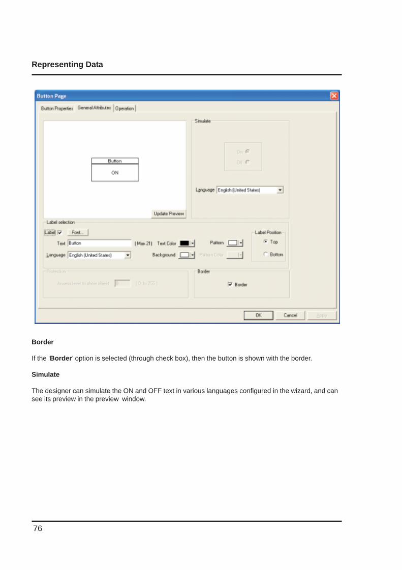
Representing Data
76
Border
If the ‘Border’ option is selected (through check box), then the button is shown with the border.
Simulate
The designer can simulate the ON and OFF text in various languages configured in the wizard, and cansee its preview in the preview window.
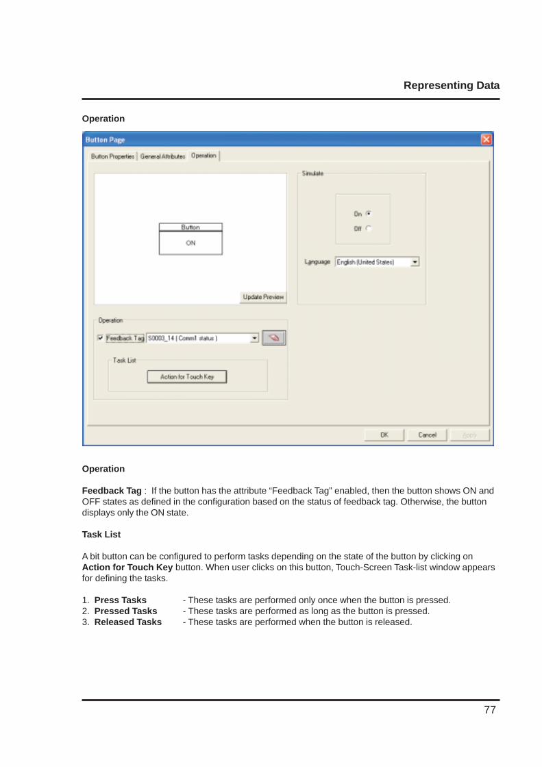
Representing Data
77
Operation
Operation
Feedback Tag : If the button has the attribute “Feedback Tag” enabled, then the button shows ON andOFF states as defined in the configuration based on the status of feedback tag. Otherwise, the buttondisplays only the ON state.
Task List
A bit button can be configured to perform tasks depending on the state of the button by clicking onAction for Touch Key button. When user clicks on this button, Touch-Screen Task-list window appearsfor defining the tasks.
1. Press Tasks - These tasks are performed only once when the button is pressed.2. Pressed Tasks - These tasks are performed as long as the button is pressed.3. Released Tasks - These tasks are performed when the button is released.
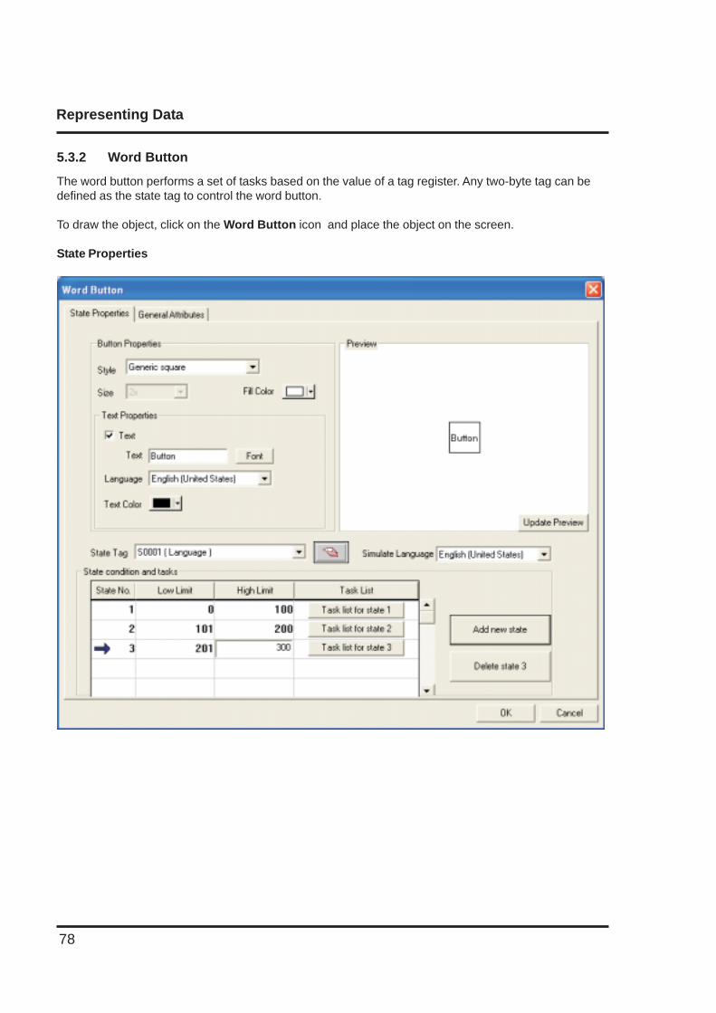
Representing Data
78
5.3.2 Word Button
The word button performs a set of tasks based on the value of a tag register. Any two-byte tag can bedefined as the state tag to control the word button.
To draw the object, click on the Word Button icon and place the object on the screen.
State Properties
Representing Data
79
Button Properties
Style
A button can have a number of different display styles:1. Generic square2. Generic circle3. Generic rounded rectangle4. Invisible button5. User defined image6. Check box7. Radio button8. Toggle switch
Fill ColorFills the color for each state of the button.
SizeIf the style is Check box, Radio button or Toggle switch then user can have button size either 1x or 2x.
Text Properties
The designer can select different text strings for each state if the text option is enabled.
1. Text : Button text.2. Font : User can select Windows® Font, Font Style and Font size.3. Language : Display the list of languages depending upon number of languages configured in theUnit settings.4. Text Color : User can select the color of the text.
State Tag
This tag is used to determine the present state of the word button. This can be either unit tag or PLCtag.
State conditions and tasks
This table gives information about the various states defined by the word button with their correspondinglow and high limits and the task list for each range. The user can assign tasks to any of the definedstates by clicking on the Task List button for the corresponding state. Up to 32 different states can bedefined.
Add new stateAdd a new state by clicking this button.
Delete stateDelete an existing state by high lighting it and pressing this button.
SimulateThe designer can simulate various languages configured in the wizard. Previews of each language canbe simulated.
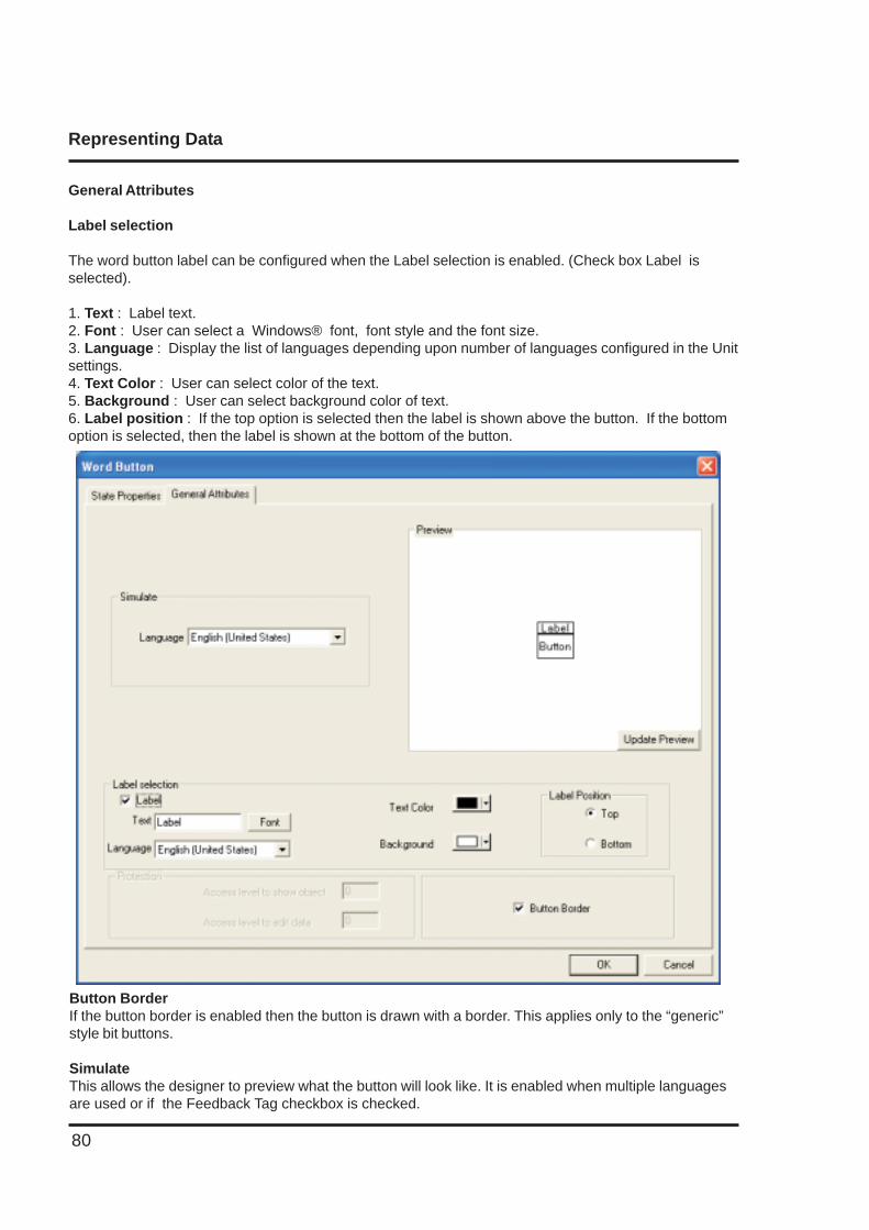
Representing Data
80
General Attributes
Label selection
The word button label can be configured when the Label selection is enabled. (Check box Label isselected).
1. Text : Label text.2. Font : User can select a Windows® font, font style and the font size.3. Language : Display the list of languages depending upon number of languages configured in the Unitsettings.4. Text Color : User can select color of the text.5. Background : User can select background color of text.6. Label position : If the top option is selected then the label is shown above the button. If the bottomoption is selected, then the label is shown at the bottom of the button.
Button BorderIf the button border is enabled then the button is drawn with a border. This applies only to the “generic”style bit buttons.
SimulateThis allows the designer to preview what the button will look like. It is enabled when multiple languagesare used or if the Feedback Tag checkbox is checked.
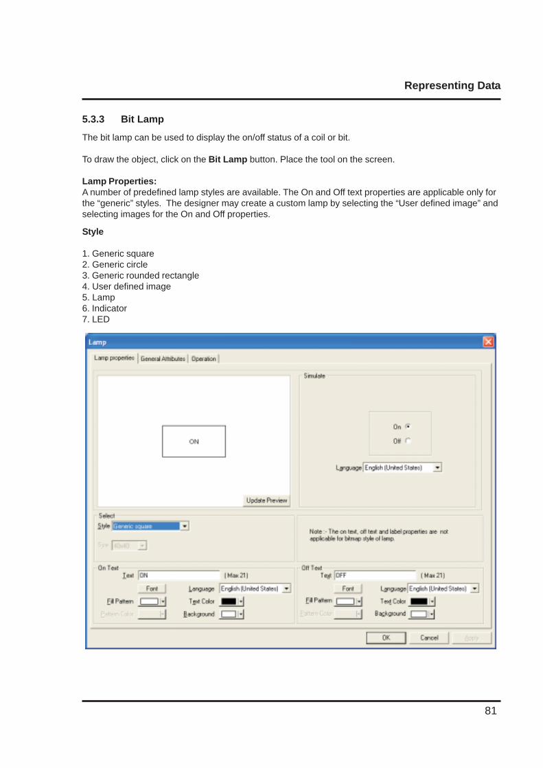
Representing Data
81
5.3.3 Bit Lamp
The bit lamp can be used to display the on/off status of a coil or bit.
To draw the object, click on the Bit Lamp button. Place the tool on the screen.
Lamp Properties:A number of predefined lamp styles are available. The On and Off text properties are applicable only forthe “generic” styles. The designer may create a custom lamp by selecting the “User defined image” andselecting images for the On and Off properties.
Style
1. Generic square2. Generic circle3. Generic rounded rectangle4. User defined image5. Lamp6. Indicator7. LED
Representing Data
82
On/Off Text
Configurable parameters:1. Text : On /Off text, can be up to 21 characters.2. Font : User can select Windows® Font , Font Style and Font size.3. Language : Displays the list of languages depending upon number of languages
configured in the Unit settings.4. Fill Pattern : If display style is Generic square; then user can have different types of fill
patterns for the style.5. Text Color : User can select color of the text.6. Background : User can select background color of text.
Simulate
User can simulate the ON and OFF text in various languages configured in the wizard, and can see itspreview in the preview window.
General Attributes
Use this page to define attributes common to all wizards. A preview of the lamp object is displayed in theupper left corner of this page.
Label selection
Bit lamp label parameters can be configured if the Label selection is enabled by selecting the “Label”checkbox.1. Text : Up to 21 characters can be entered for the label.2. Font : This is used to change the standard Windows® font, font style and font
size.3. Language : Displays the list of languages configured in the Unit Settings. When a
different language is selected, the label text is entered for that language.4. Pattern : Different fill patterns for the label can be selected.5. Text Color : Select the color for the label text. The “color index” can be used for
precise color matching.6. Background : Select the color for the text background. The “color index” can be used for
precise color matching.7. Label Position : If the “Top” option is selected, the label is shown above the lamp. If the
“Bottom” option is selected, the label is shown at the bottom of the lamp.
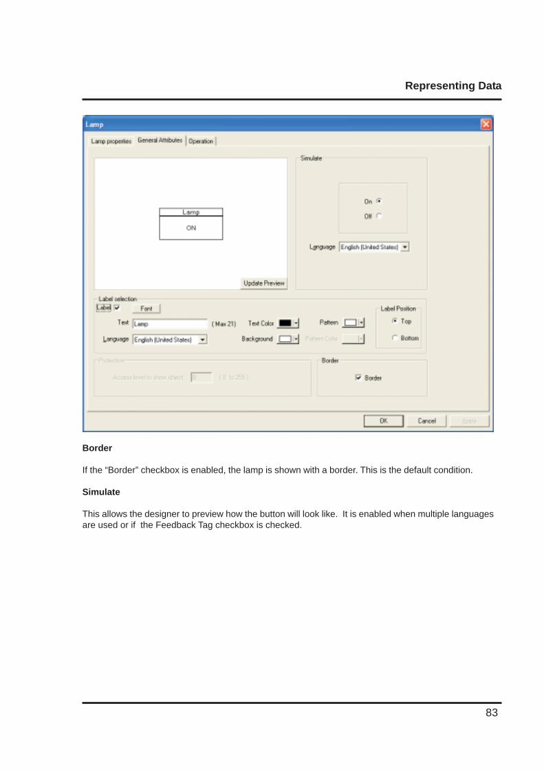
Representing Data
83
Border
If the “Border” checkbox is enabled, the lamp is shown with a border. This is the default condition.
Simulate
This allows the designer to preview how the button will look like. It is enabled when multiple languagesare used or if the Feedback Tag checkbox is checked.
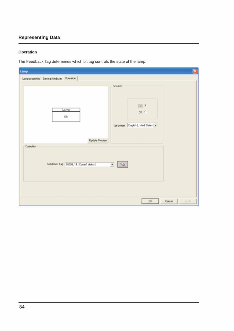
Representing Data
84
Operation
The Feedback Tag determines which bit tag controls the state of the lamp.
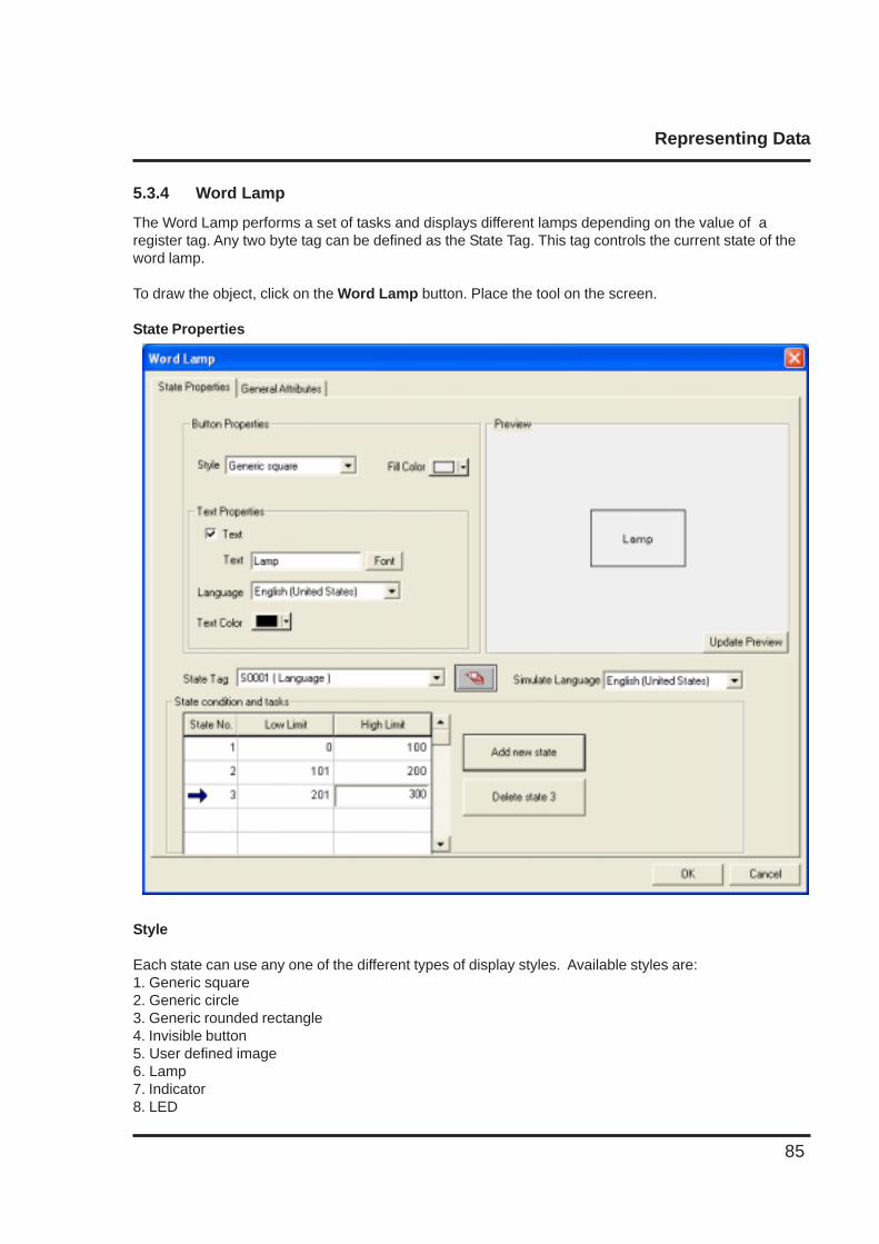
Representing Data
85
5.3.4 Word Lamp
The Word Lamp performs a set of tasks and displays different lamps depending on the value of aregister tag. Any two byte tag can be defined as the State Tag. This tag controls the current state of theword lamp.
To draw the object, click on the Word Lamp button. Place the tool on the screen.
State Properties
Style
Each state can use any one of the different types of display styles. Available styles are:1. Generic square2. Generic circle3. Generic rounded rectangle4. Invisible button5. User defined image6. Lamp7. Indicator8. LED
Representing Data
86
Fill Color
Select the lamp color for each state.
Size
If the style is ‘Lamp’, ‘Indicator’, or ‘LED’, the lamp size can be changed from 1x to 2x.
Text Properties
Different text strings can be specified for each state if the Text option is enabled.
1. Text : Up to 20 characters of text can be displayed.2. Font : Used to change the Windows® Font , Font Style and Font size.3. Language : Displays the list of languages depending upon number of languages configured in
the Unit settings.4. Text Color : Select the color of the text.
State Tag
This tag is used to determine the present state of the word lamp. This can be either a NTXS unit tag ora PLC tag.
State conditions and Tasks
This table is a list of the states defined for the word lamp with their corresponding high and low limits.Up to 32 different states can be defined.
Add new stateClicking this button adds a new state to the list.
Delete stateSelect a particular state by highlighting it, and use this button to delete it.
SimulateUser can simulate various languages configured in the wizard, and can see its preview in the previewwindow.
General Attributes
Label selectionIf the Word Lamp Style is “Generic”, then the lamp can have a label by enabling the “Label” checkbox.
1. Text : Up to 14 characters of label text can be defined.2. Font : Select the Windows® Font, Font Style and Font size.3. Language : Displays the list of languages configured in the NTXS settings.4. Text Color : Selects the color of the text.5. Background : Selects the background text color.6. Label position : If the “Top” option is selected, the label is shown above the lamp. If the
“Bottom” option is selected, the label is shown below the lamp.
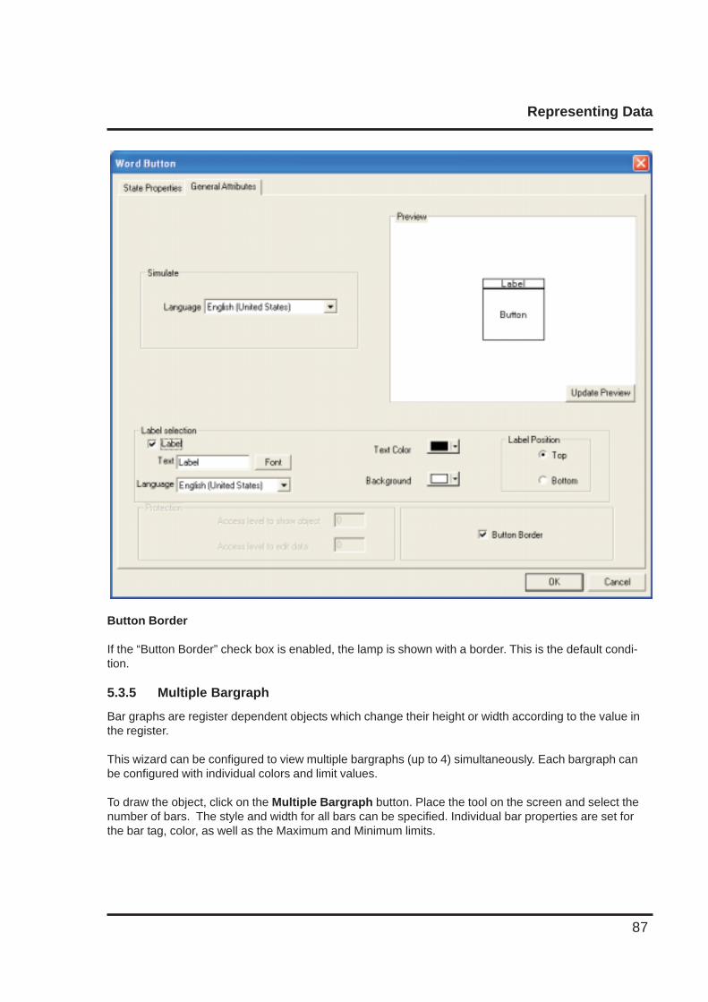
Representing Data
87
Button Border
If the “Button Border” check box is enabled, the lamp is shown with a border. This is the default condi-tion.
5.3.5 Multiple Bargraph
Bar graphs are register dependent objects which change their height or width according to the value inthe register.
This wizard can be configured to view multiple bargraphs (up to 4) simultaneously. Each bargraph canbe configured with individual colors and limit values.
To draw the object, click on the Multiple Bargraph button. Place the tool on the screen and select thenumber of bars. The style and width for all bars can be specified. Individual bar properties are set forthe bar tag, color, as well as the Maximum and Minimum limits.
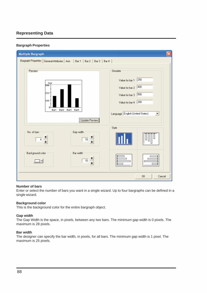
Representing Data
88
Bargraph Properties
Number of barsEnter or select the number of bars you want in a single wizard. Up to four bargraphs can be defined in asingle wizard.
Background colorThis is the background color for the entire bargraph object.
Gap widthThe Gap Width is the space, in pixels, between any two bars. The minimum gap width is 0 pixels. Themaximum is 28 pixels.
Bar widthThe designer can specify the bar width, in pixels, for all bars. The minimum gap width is 1 pixel. Themaximum is 25 pixels.
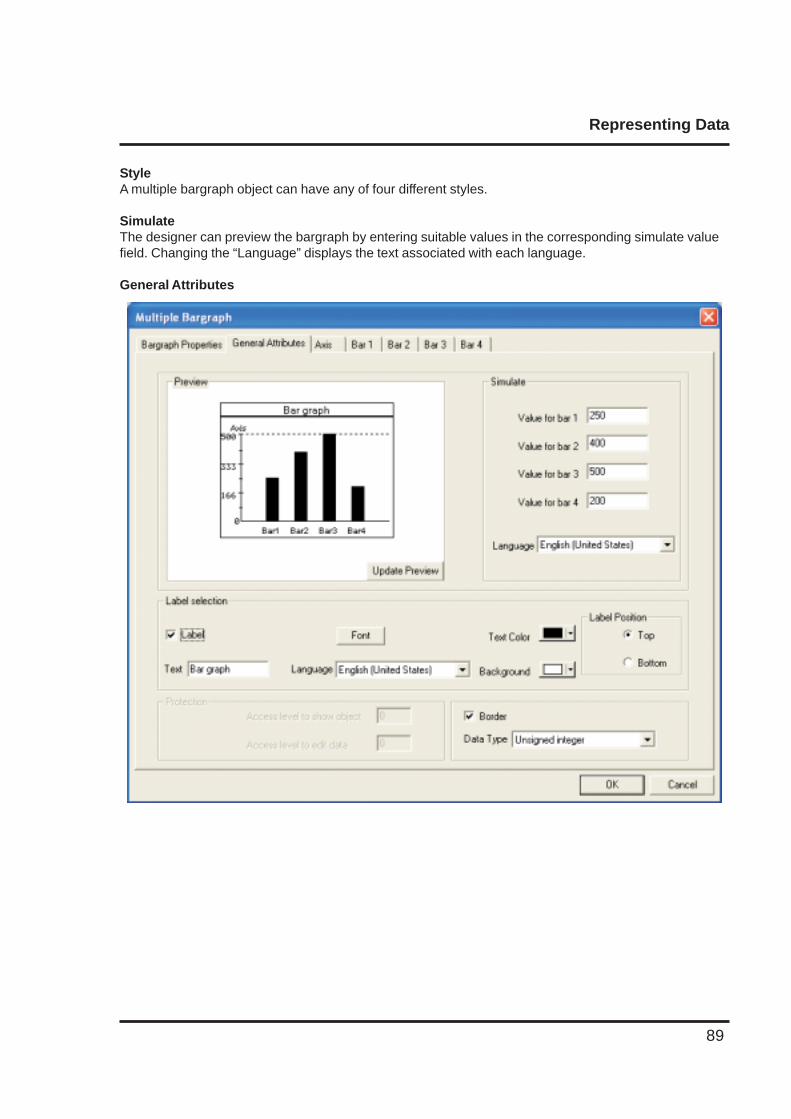
Representing Data
89
StyleA multiple bargraph object can have any of four different styles.
SimulateThe designer can preview the bargraph by entering suitable values in the corresponding simulate valuefield. Changing the “Language” displays the text associated with each language.
General Attributes
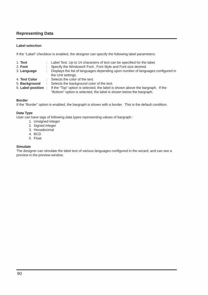
Representing Data
90
Label selection
If the “Label” checkbox is enabled, the designer can specify the following label parameters:
1. Text : Label Text. Up to 14 characters of text can be specified for the label.2. Font : Specify the Windows® Font , Font Style and Font size desired.3. Language : Displays the list of languages depending upon number of languages configured in
the Unit settings.4. Text Color : Selects the color of the text.5. Background : Selects the background color of the text.6. Label position : If the “Top” option is selected, the label is shown above the bargraph. If the
“Bottom” option is selected, the label is shown below the bargraph.
BorderIf the “Border” option is enabled, the bargraph is shown with a border. This is the default condition.
Data TypeUser can have tags of following data types representing values of bargraph :
1. Unsigned integer2. Signed integer3. Hexadecimal4. BCD5. Float
SimulateThe designer can simulate the label text of various languages configured in the wizard, and can see apreview in the preview window.
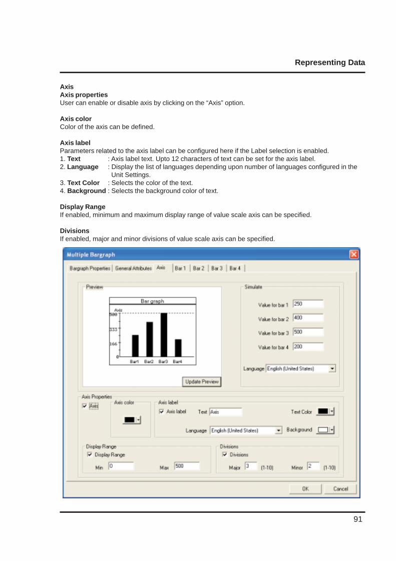
Representing Data
91
AxisAxis propertiesUser can enable or disable axis by clicking on the “Axis” option.
Axis colorColor of the axis can be defined.
Axis labelParameters related to the axis label can be configured here if the Label selection is enabled.1. Text : Axis label text. Upto 12 characters of text can be set for the axis label.2. Language : Display the list of languages depending upon number of languages configured in the
Unit Settings.3. Text Color : Selects the color of the text.4. Background : Selects the background color of text.
Display RangeIf enabled, minimum and maximum display range of value scale axis can be specified.
DivisionsIf enabled, major and minor divisions of value scale axis can be specified.
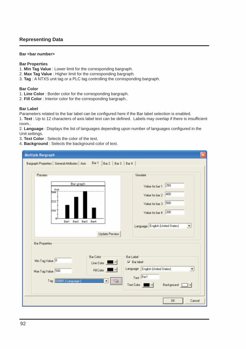
Representing Data
92
Bar <bar number>
Bar Properties1. Min Tag Value : Lower limit for the corresponding bargraph.2. Max Tag Value : Higher limit for the corresponding bargraph.3. Tag : A NTXS unit tag or a PLC tag controlling the corresponding bargraph.
Bar Color1. Line Color : Border color for the corresponding bargraph.2. Fill Color : Interior color for the corresponding bargraph..
Bar LabelParameters related to the bar label can be configured here if the Bar label selection is enabled.1. Text : Up to 12 characters of axis label text can be defined. Labels may overlap if there is insufficientroom..2. Language : Displays the list of languages depending upon number of languages configured in theUnit settings.3. Text Color : Selects the color of the text.4. Background : Selects the background color of text.
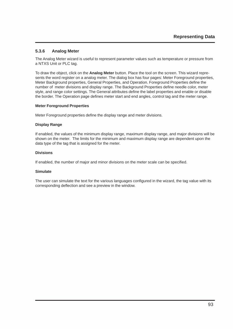
Representing Data
93
5.3.6 Analog Meter
The Analog Meter wizard is useful to represent parameter values such as temperature or pressure froma NTXS Unit or PLC tag.
To draw the object, click on the Analog Meter button. Place the tool on the screen. This wizard repre-sents the word register on a analog meter. The dialog box has four pages: Meter Foreground properties,Meter Background properties, General Properties, and Operation. Foreground Properties define thenumber of meter divisions and display range. The Background Properties define needle color, meterstyle, and range color settings. The General attributes define the label properties and enable or disablethe border. The Operation page defines meter start and end angles, control tag and the meter range.
Meter Foreground Properties
Meter Foreground properties define the display range and meter divisions.
Display Range
If enabled, the values of the minimum display range, maximum display range, and major divisions will beshown on the meter. The limits for the minimum and maximum display range are dependent upon thedata type of the tag that is assigned for the meter.
Divisions
If enabled, the number of major and minor divisions on the meter scale can be specified.
Simulate
The user can simulate the text for the various languages configured in the wizard, the tag value with itscorresponding deflection and see a preview in the window.
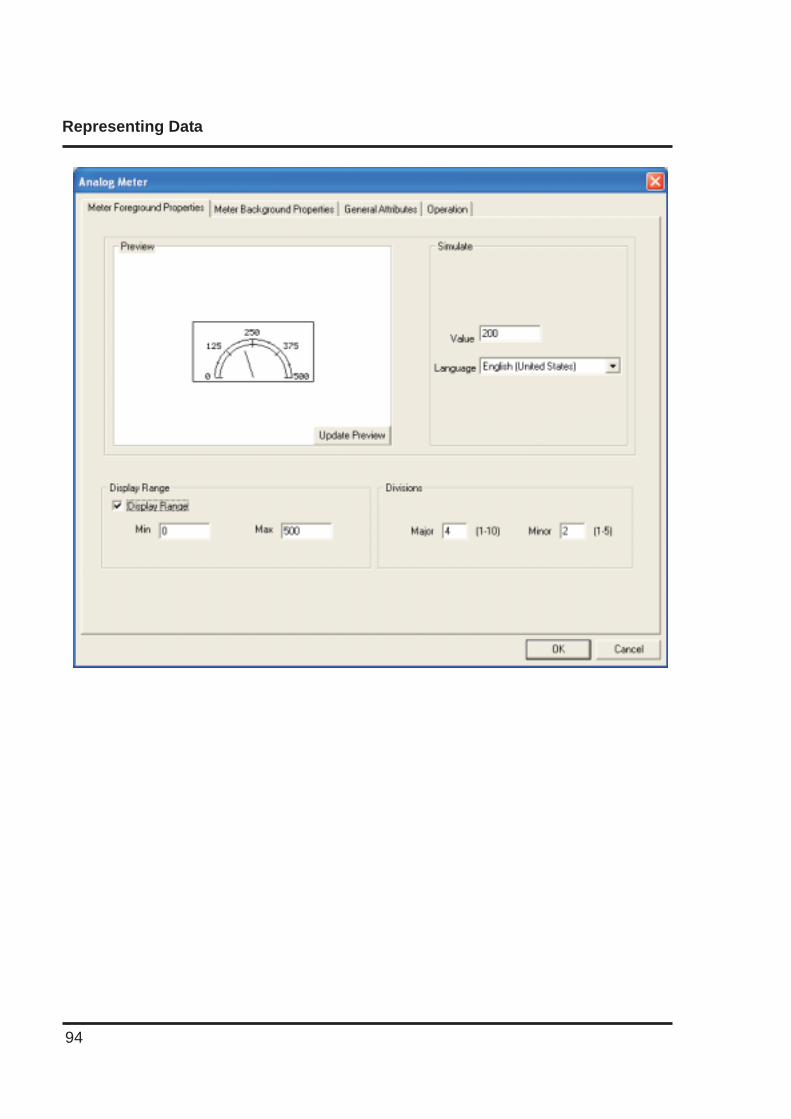
Representing Data
94
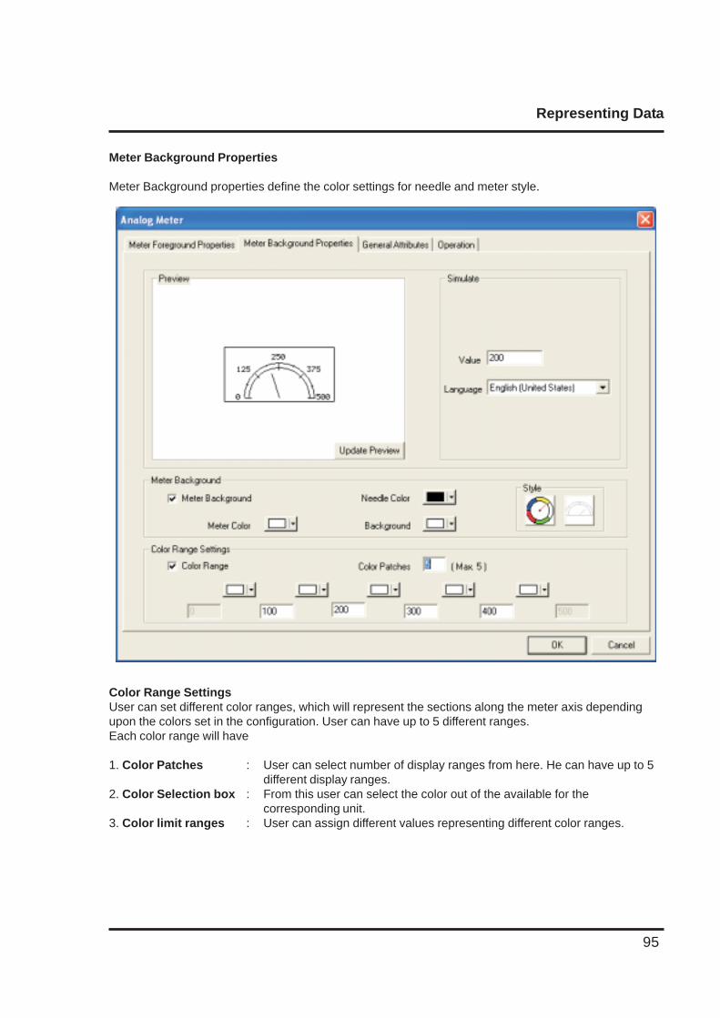
Representing Data
95
Meter Background Properties
Meter Background properties define the color settings for needle and meter style.
Color Range SettingsUser can set different color ranges, which will represent the sections along the meter axis dependingupon the colors set in the configuration. User can have up to 5 different ranges.Each color range will have
1. Color Patches : User can select number of display ranges from here. He can have up to 5different display ranges.
2. Color Selection box : From this user can select the color out of the available for thecorresponding unit.
3. Color limit ranges : User can assign different values representing different color ranges.
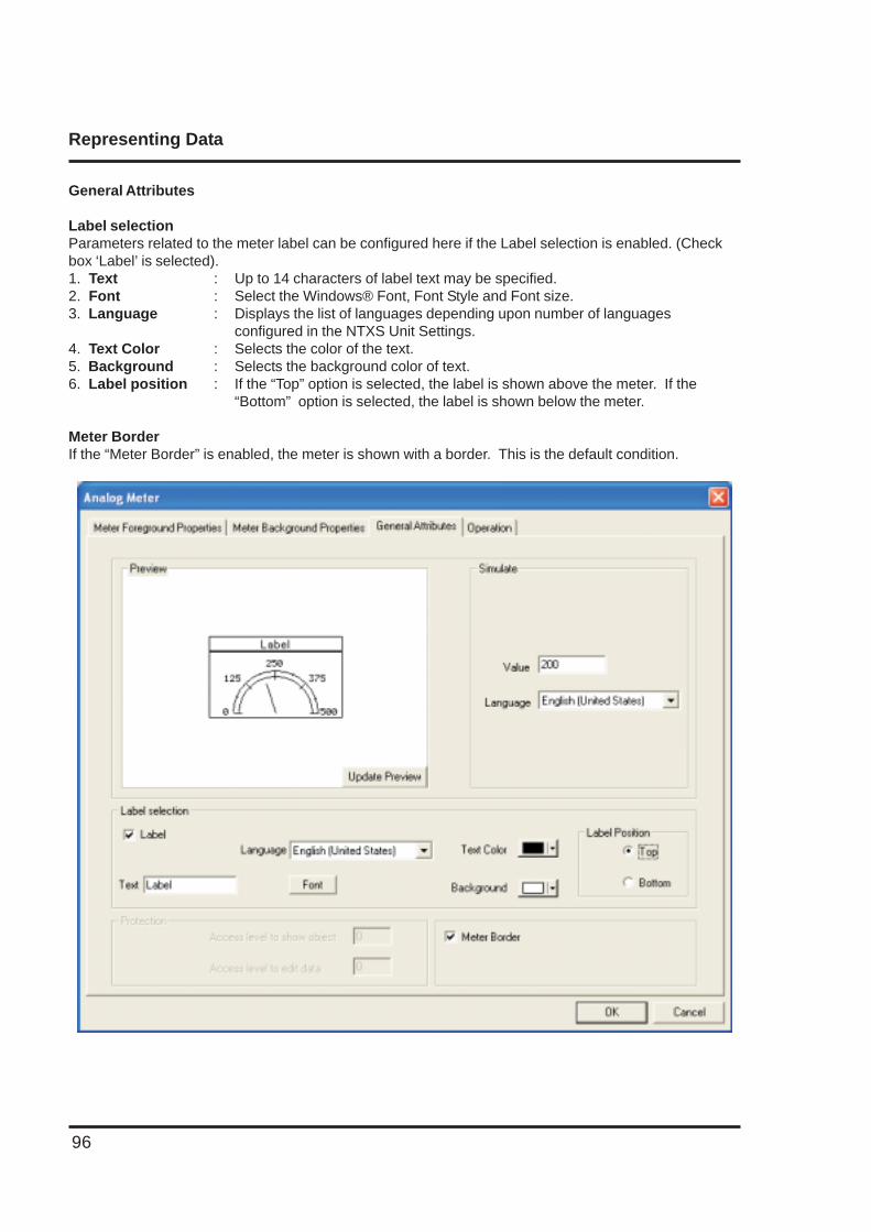
Representing Data
96
General Attributes
Label selectionParameters related to the meter label can be configured here if the Label selection is enabled. (Checkbox ‘Label’ is selected).1. Text : Up to 14 characters of label text may be specified.2. Font : Select the Windows® Font, Font Style and Font size.3. Language : Displays the list of languages depending upon number of languages
configured in the NTXS Unit Settings.4. Text Color : Selects the color of the text.5. Background : Selects the background color of text.6. Label position : If the “Top” option is selected, the label is shown above the meter. If the
“Bottom” option is selected, the label is shown below the meter.
Meter BorderIf the “Meter Border” is enabled, the meter is shown with a border. This is the default condition.
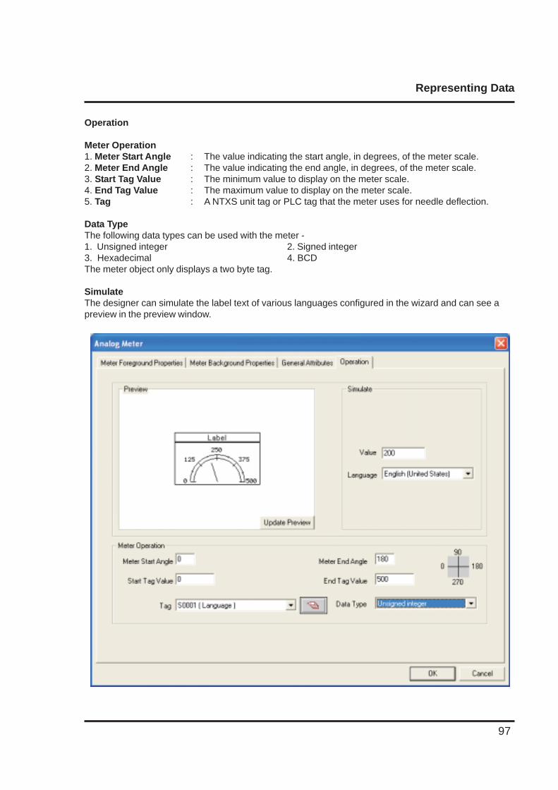
Representing Data
97
Operation
Meter Operation1. Meter Start Angle : The value indicating the start angle, in degrees, of the meter scale.2. Meter End Angle : The value indicating the end angle, in degrees, of the meter scale.3. Start Tag Value : The minimum value to display on the meter scale.4. End Tag Value : The maximum value to display on the meter scale.5. Tag : A NTXS unit tag or PLC tag that the meter uses for needle deflection.
Data TypeThe following data types can be used with the meter -1. Unsigned integer 2. Signed integer3. Hexadecimal 4. BCDThe meter object only displays a two byte tag.
SimulateThe designer can simulate the label text of various languages configured in the wizard and can see apreview in the preview window.
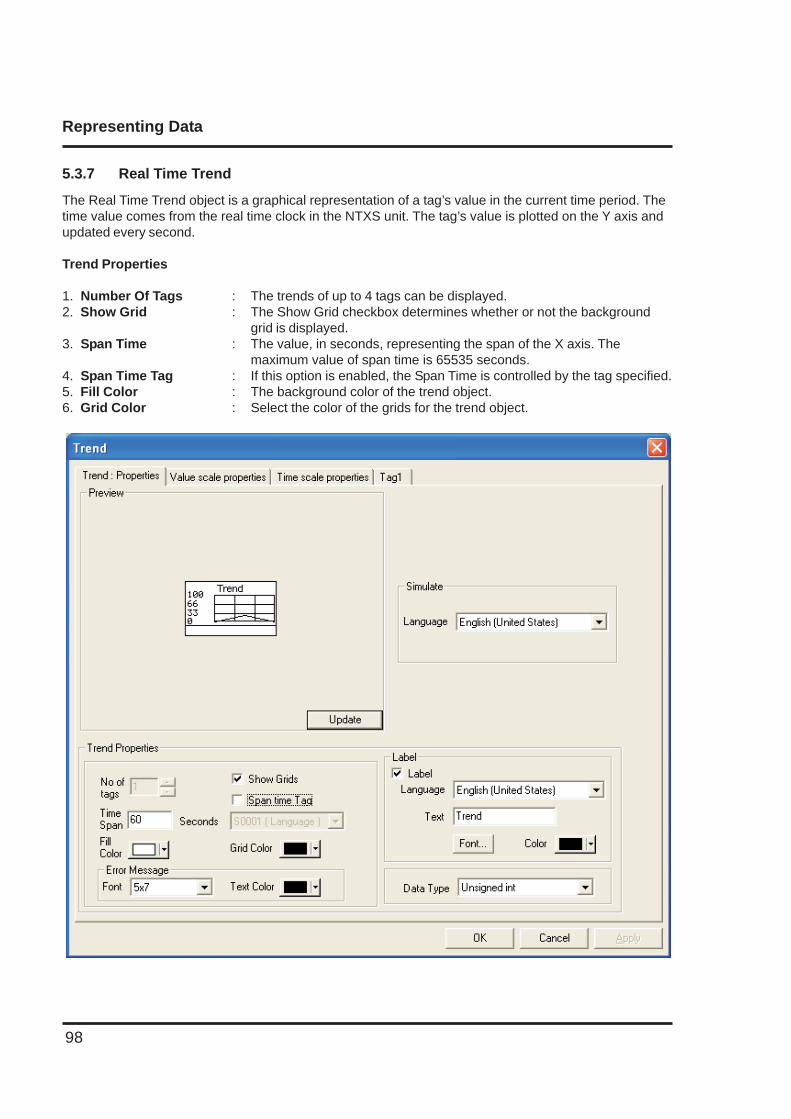
Representing Data
98
5.3.7 Real Time Trend
The Real Time Trend object is a graphical representation of a tag’s value in the current time period. Thetime value comes from the real time clock in the NTXS unit. The tag’s value is plotted on the Y axis andupdated every second.
Trend Properties
1. Number Of Tags : The trends of up to 4 tags can be displayed.2. Show Grid : The Show Grid checkbox determines whether or not the background
grid is displayed.3. Span Time : The value, in seconds, representing the span of the X axis. The
maximum value of span time is 65535 seconds.4. Span Time Tag : If this option is enabled, the Span Time is controlled by the tag specified.5. Fill Color : The background color of the trend object.6. Grid Color : Select the color of the grids for the trend object.
Representing Data
99
Error Message
Many of the trend object’s properties can be determined at run time through the use a tag. If the valueof the tag is out of the proper range for the property, an error message will be displayed. The textdisplay properties can be modified.
1. Font : Select the Font size. Font size can be either 5 X 7 or 7 X 14.2. Text Color : Color of the error message to be displayed.
Label
Parameters related to the trend label can be configured here if the Label selection is enabled. (Checkbox ‘Label’ is selected).1. Text : Label text.2. Font : Select the Windows® Font , Font Style and Font size.3. Language : Display the list of languages depending upon number of languages configured inthe Unit
settings.4. Color : Color of the text.
Data Type
The trend object can have the following data types:
1. Unsigned integer2. Signed integer3. Hexadecimal4. BCD5. Float
Only 2 byte tags are supported.
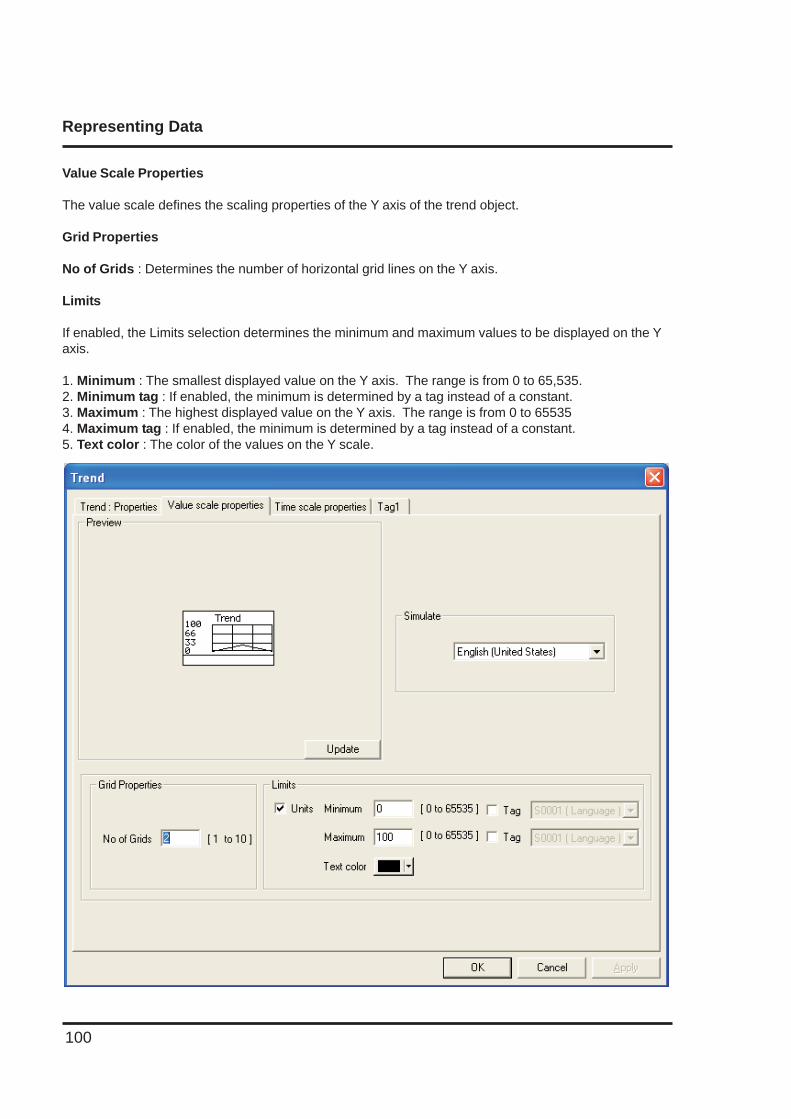
Representing Data
100
Value Scale Properties
The value scale defines the scaling properties of the Y axis of the trend object.
Grid Properties
No of Grids : Determines the number of horizontal grid lines on the Y axis.
Limits
If enabled, the Limits selection determines the minimum and maximum values to be displayed on the Yaxis.
1. Minimum : The smallest displayed value on the Y axis. The range is from 0 to 65,535.2. Minimum tag : If enabled, the minimum is determined by a tag instead of a constant.3. Maximum : The highest displayed value on the Y axis. The range is from 0 to 655354. Maximum tag : If enabled, the minimum is determined by a tag instead of a constant.5. Text color : The color of the values on the Y scale.
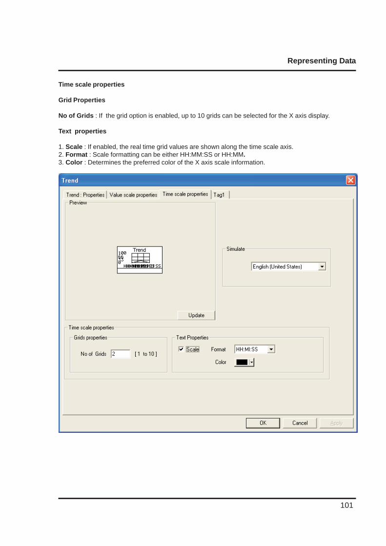
Representing Data
101
Time scale properties
Grid Properties
No of Grids : If the grid option is enabled, up to 10 grids can be selected for the X axis display.
Text properties
1. Scale : If enabled, the real time grid values are shown along the time scale axis.2. Format : Scale formatting can be either HH:MM:SS or HH:MM.3. Color : Determines the preferred color of the X axis scale information.
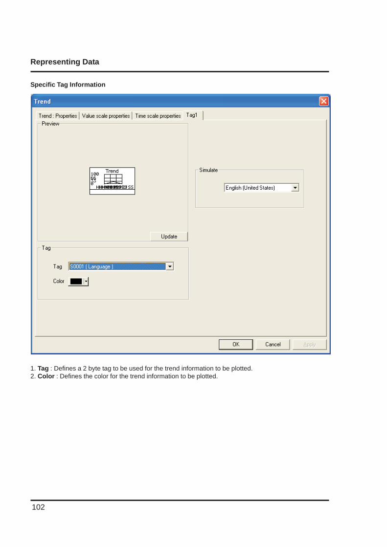
Representing Data
102
Specific Tag Information
1. Tag : Defines a 2 byte tag to be used for the trend information to be plotted.2. Color : Defines the color for the trend information to be plotted.
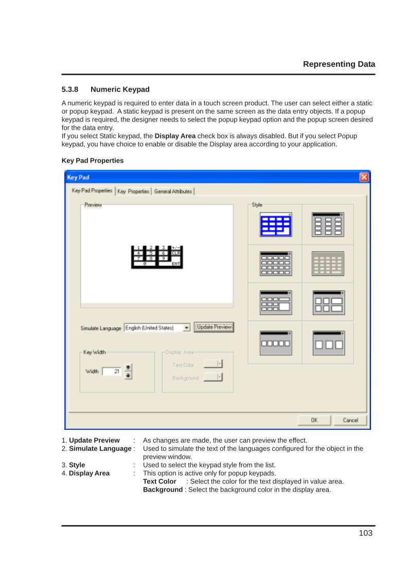
Representing Data
103
5.3.8 Numeric Keypad
A numeric keypad is required to enter data in a touch screen product. The user can select either a staticor popup keypad. A static keypad is present on the same screen as the data entry objects. If a popupkeypad is required, the designer needs to select the popup keypad option and the popup screen desiredfor the data entry.If you select Static keypad, the Display Area check box is always disabled. But if you select Popupkeypad, you have choice to enable or disable the Display area according to your application.
Key Pad Properties
1. Update Preview : As changes are made, the user can preview the effect.2. Simulate Language : Used to simulate the text of the languages configured for the object in the
preview window.3. Style : Used to select the keypad style from the list.4. Display Area : This option is active only for popup keypads.
Text Color : Select the color for the text displayed in value area.Background : Select the background color in the display area.
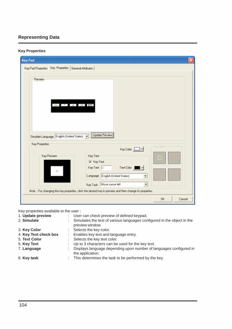
Representing Data
104
Key Properties
Key properties available to the user :1. Update preview : User can check preview of defined keypad.2. Simulate : Simulates the text of various languages configured in the object in the
preview window.3. Key Color : Selects the key color.4. Key Text check box : Enables key text and language entry.5. Text Color : Selects the key text color.6. Key Text : Up to 3 characters can be used for the key text.7. Language : Displays language depending upon number of languages configured in
the application.8. Key task : This determines the task to be performed by the key.
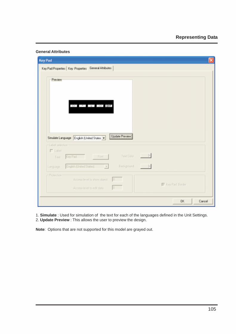
Representing Data
105
General Attributes
1. Simulate : Used for simulation of the text for each of the languages defined in the Unit Settings.2. Update Preview : This allows the user to preview the design.
Note: Options that are not supported for this model are grayed out.
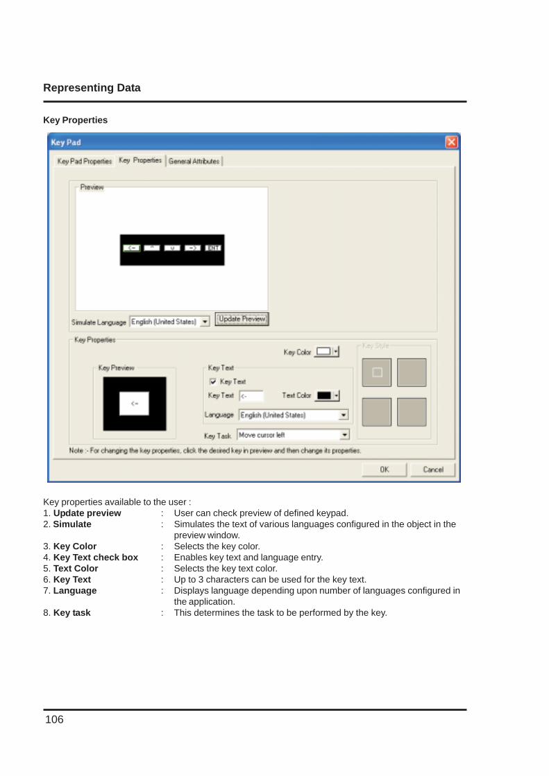
Representing Data
106
Key Properties
Key properties available to the user :1. Update preview : User can check preview of defined keypad.2. Simulate : Simulates the text of various languages configured in the object in the
preview window.3. Key Color : Selects the key color.4. Key Text check box : Enables key text and language entry.5. Text Color : Selects the key text color.6. Key Text : Up to 3 characters can be used for the key text.7. Language : Displays language depending upon number of languages configured in
the application.8. Key task : This determines the task to be performed by the key.
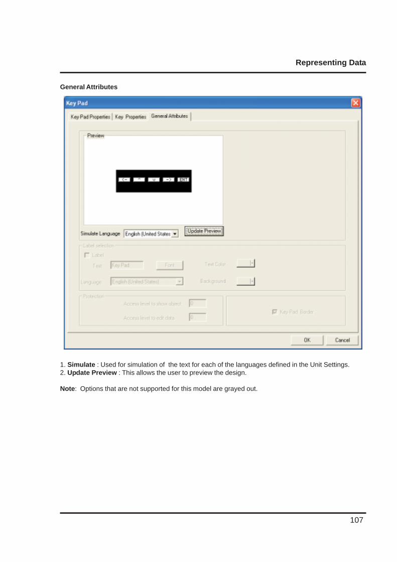
Representing Data
107
General Attributes
1. Simulate : Used for simulation of the text for each of the languages defined in the Unit Settings.2. Update Preview : This allows the user to preview the design.
Note: Options that are not supported for this model are grayed out.
Task Management
108
TASK MANAGEMENT
In this chapter. . . .
♦ Application TaskList
♦ Screen TaskList
♦ Key TaskList
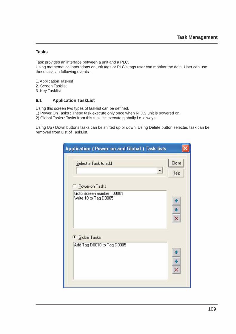
Task Management
109
Tasks
Task provides an interface between a unit and a PLC.Using mathematical operations on unit tags or PLC’s tags user can monitor the data. User can usethese tasks in following events -
1. Application Tasklist2. Screen Tasklist3. Key Tasklist
6.1 Application TaskList
Using this screen two types of tasklist can be defined.1) Power On Tasks : These task execute only once when NTXS unit is powered on.2) Global Tasks : Tasks from this task list execute globally i.e. always.
Using Up / Down buttons tasks can be shifted up or down. Using Delete button selected task can beremoved from List of TaskList.
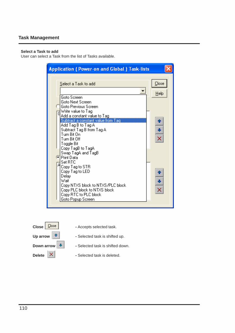
Task Management
110
Select a Task to addUser can select a Task from the list of Tasks available.
Close - Accepts selected task.
Up arrow - Selected task is shifted up.
Down arrow - Selected task is shifted down.
Delete - Selected task is deleted.
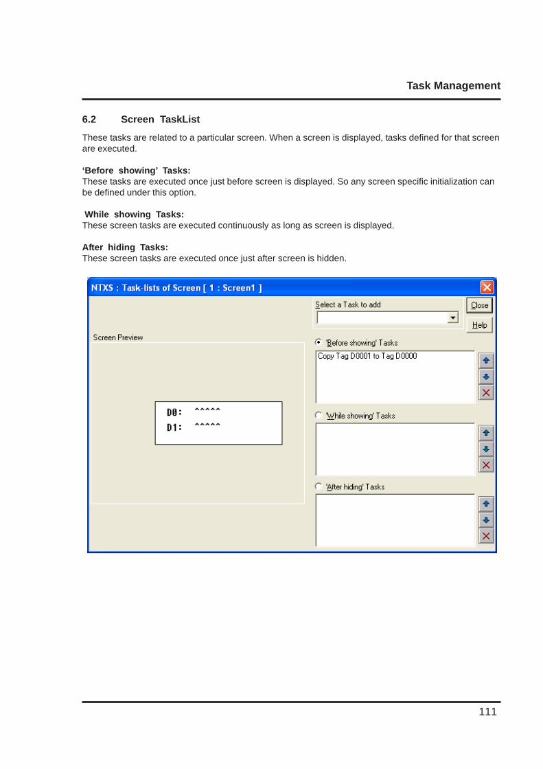
Task Management
111
6.2 Screen TaskList
These tasks are related to a particular screen. When a screen is displayed, tasks defined for that screenare executed.
‘Before showing’ Tasks:These tasks are executed once just before screen is displayed. So any screen specific initialization canbe defined under this option.
While showing Tasks:These screen tasks are executed continuously as long as screen is displayed.
After hiding Tasks:These screen tasks are executed once just after screen is hidden.
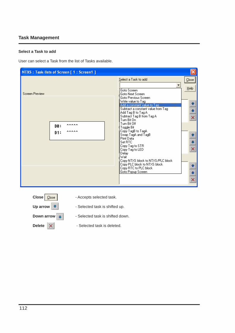
Task Management
112
Select a Task to add
User can select a Task from the list of Tasks available.
Close - Accepts selected task.
Up arrow - Selected task is shifted up.
Down arrow - Selected task is shifted down.
Delete - Selected task is deleted.
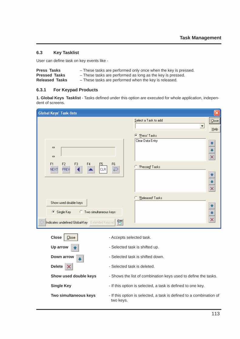
Task Management
113
Close - Accepts selected task.
Up arrow - Selected task is shifted up.
Down arrow - Selected task is shifted down.
Delete - Selected task is deleted.
Show used double keys - Shows the list of combination keys used to define the tasks.
Single Key - If this option is selected, a task is defined to one key.
Two simultaneous keys - If this option is selected, a task is defined to a combination of two keys.
6.3 Key Tasklist
User can define task on key events like -
Press Tasks – These tasks are performed only once when the key is pressed.Pressed Tasks – These tasks are performed as long as the key is pressed.Released Tasks – These tasks are performed when the key is released.
6.3.1 For Keypad Products
1. Global Keys Tasklist - Tasks defined under this option are executed for whole application, indepen-dent of screens.
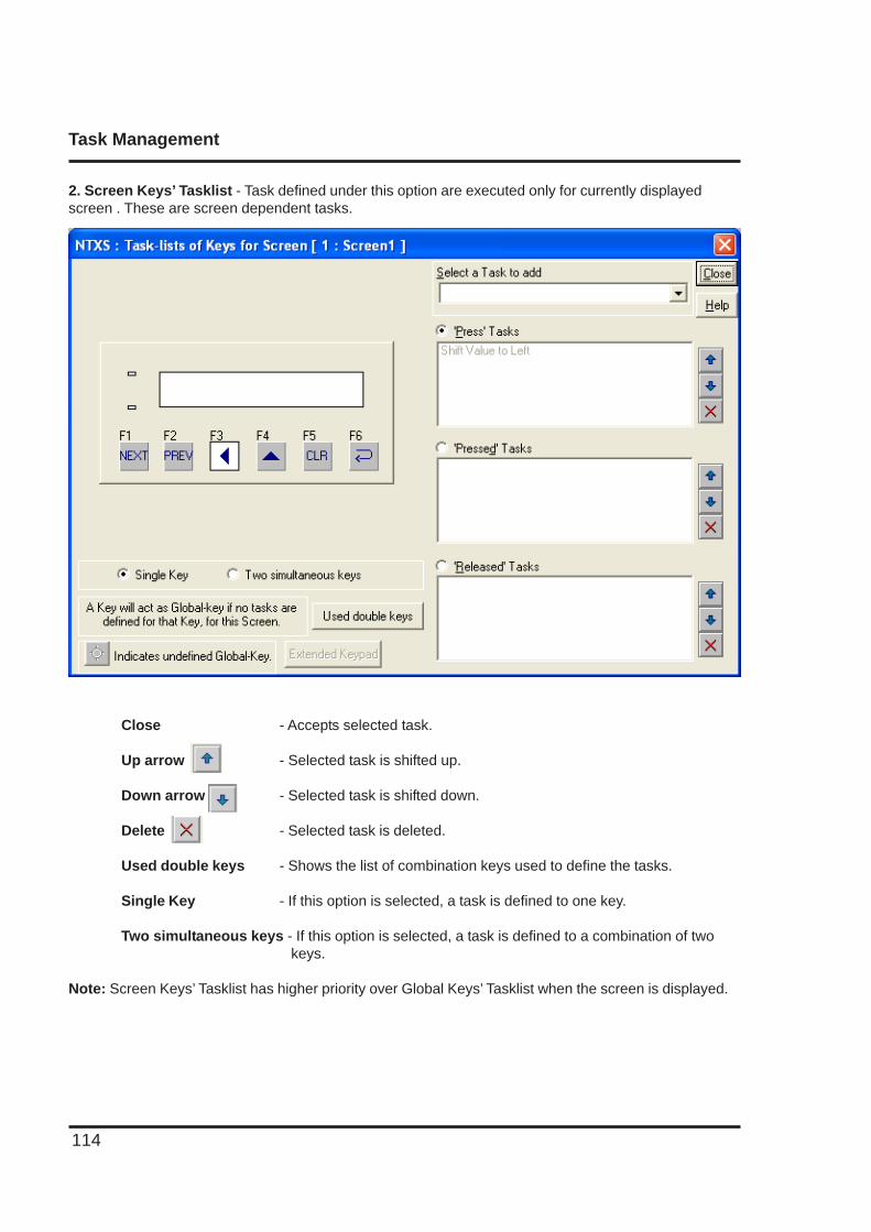
Task Management
114
Close - Accepts selected task.
Up arrow - Selected task is shifted up.
Down arrow - Selected task is shifted down.
Delete - Selected task is deleted.
Used double keys - Shows the list of combination keys used to define the tasks.
Single Key - If this option is selected, a task is defined to one key.
Two simultaneous keys - If this option is selected, a task is defined to a combination of two keys.
Note: Screen Keys’ Tasklist has higher priority over Global Keys’ Tasklist when the screen is displayed.
2. Screen Keys’ Tasklist - Task defined under this option are executed only for currently displayedscreen . These are screen dependent tasks.
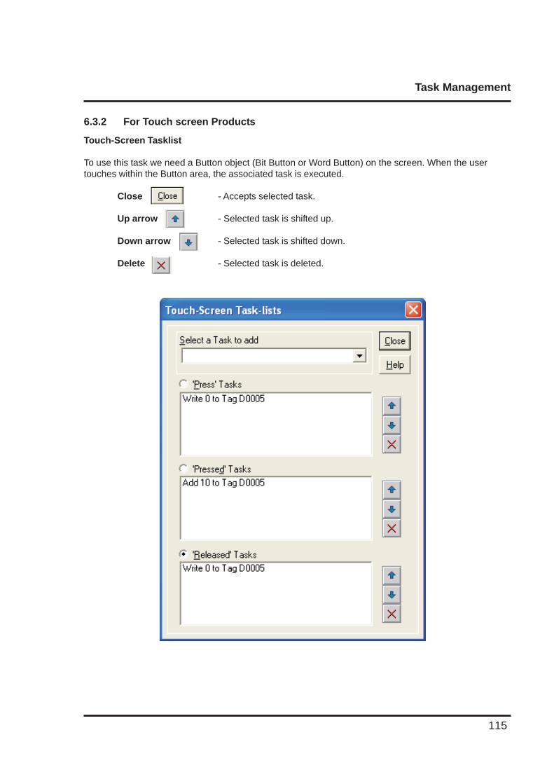
Task Management
115
6.3.2 For Touch screen Products
Touch-Screen Tasklist
To use this task we need a Button object (Bit Button or Word Button) on the screen. When the usertouches within the Button area, the associated task is executed.
Close - Accepts selected task.
Up arrow - Selected task is shifted up.
Down arrow - Selected task is shifted down.
Delete - Selected task is deleted.
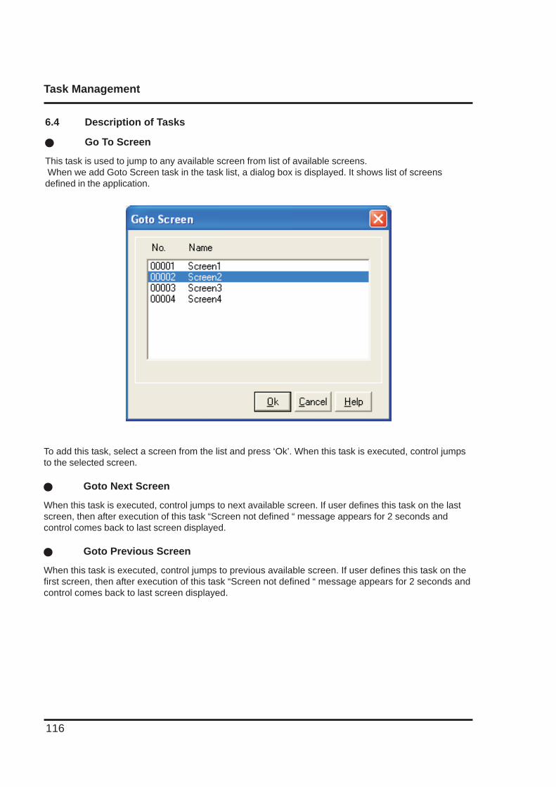
Task Management
116
6.4 Description of Tasks
� Go To Screen
This task is used to jump to any available screen from list of available screens. When we add Goto Screen task in the task list, a dialog box is displayed. It shows list of screensdefined in the application.
To add this task, select a screen from the list and press ‘Ok’. When this task is executed, control jumpsto the selected screen.
� Goto Next Screen
When this task is executed, control jumps to next available screen. If user defines this task on the lastscreen, then after execution of this task “Screen not defined “ message appears for 2 seconds andcontrol comes back to last screen displayed.
� Goto Previous Screen
When this task is executed, control jumps to previous available screen. If user defines this task on thefirst screen, then after execution of this task “Screen not defined “ message appears for 2 seconds andcontrol comes back to last screen displayed.
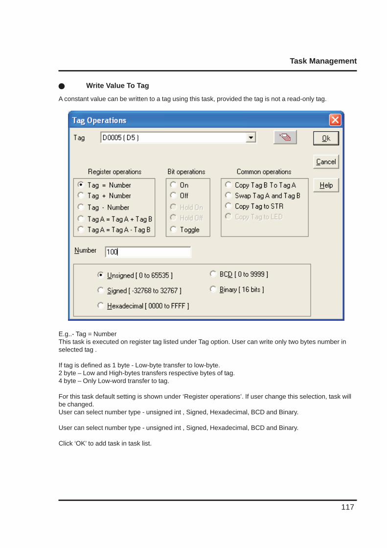
Task Management
117
� Write Value To Tag
A constant value can be written to a tag using this task, provided the tag is not a read-only tag.
E.g..- Tag = NumberThis task is executed on register tag listed under Tag option. User can write only two bytes number inselected tag .
If tag is defined as 1 byte - Low-byte transfer to low-byte.2 byte – Low and High-bytes transfers respective bytes of tag.4 byte – Only Low-word transfer to tag.
For this task default setting is shown under ‘Register operations’. If user change this selection, task willbe changed.User can select number type - unsigned int , Signed, Hexadecimal, BCD and Binary.
User can select number type - unsigned int , Signed, Hexadecimal, BCD and Binary.
Click ‘OK’ to add task in task list.
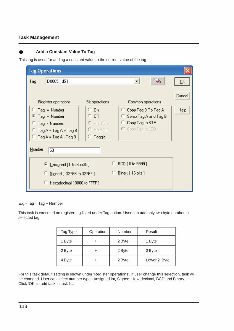
Task Management
118
� Add a Constant Value To Tag
This tag is used for adding a constant value to the current value of the tag.
E.g.- Tag = Tag + Number
This task is executed on register tag listed under Tag option. User can add only two byte number inselected tag.
Tag Type Operation Number Result
1 Byte + 2 Byte 1 Byte
2 Byte + 2 Byte 2 Byte
4 Byte + 2 Byte Lower 2 Byte
For this task default setting is shown under ‘Register operations’. If user change this selection, task willbe changed. User can select number type - unsigned int, Signed, Hexadecimal, BCD and Binary.Click ‘OK’ to add task in task list.
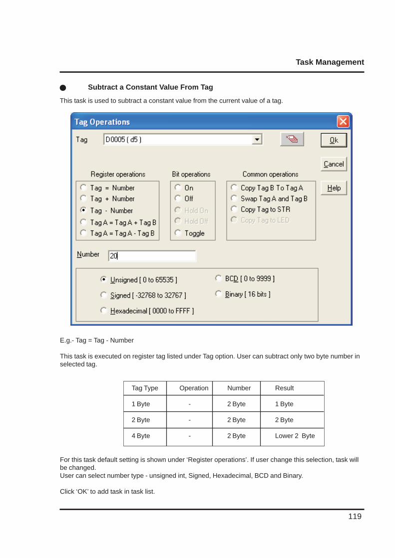
Task Management
119
� Subtract a Constant Value From Tag
This task is used to subtract a constant value from the current value of a tag.
E.g.- Tag = Tag - Number
This task is executed on register tag listed under Tag option. User can subtract only two byte number inselected tag.
Tag Type Operation Number Result
1 Byte - 2 Byte 1 Byte
2 Byte - 2 Byte 2 Byte
4 Byte - 2 Byte Lower 2 Byte
For this task default setting is shown under ‘Register operations’. If user change this selection, task willbe changed.User can select number type - unsigned int, Signed, Hexadecimal, BCD and Binary.
Click ‘OK’ to add task in task list.
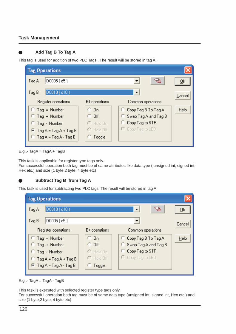
Task Management
120
� Add Tag B To Tag A
This tag is used for addition of two PLC Tags . The result will be stored in tag A.
E.g..- TagA = TagA + TagB
This task is applicable for register type tags only.For successful operation both tag must be of same attributes like data type ( unsigned int, signed int,Hex etc.) and size (1 byte,2 byte, 4 byte etc)
� Subtract Tag B from Tag A
This task is used for subtracting two PLC tags. The result will be stored in tag A.
E.g..- TagA = TagA - TagB
This task is executed with selected register type tags only.For successful operation both tag must be of same data type (unsigned int, signed int, Hex etc.) andsize (1 byte,2 byte, 4 byte etc)
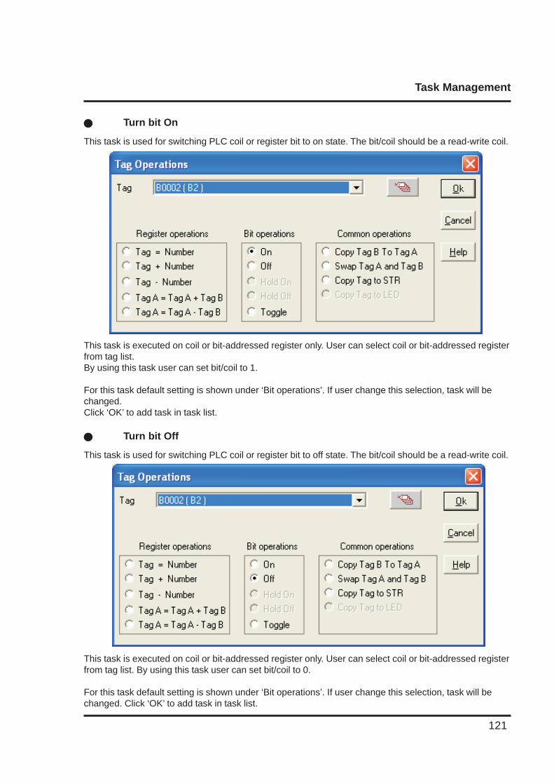
Task Management
121
� Turn bit On
This task is used for switching PLC coil or register bit to on state. The bit/coil should be a read-write coil.
This task is executed on coil or bit-addressed register only. User can select coil or bit-addressed registerfrom tag list.By using this task user can set bit/coil to 1.
For this task default setting is shown under ‘Bit operations’. If user change this selection, task will bechanged.Click ‘OK’ to add task in task list.
� Turn bit Off
This task is used for switching PLC coil or register bit to off state. The bit/coil should be a read-write coil.
This task is executed on coil or bit-addressed register only. User can select coil or bit-addressed registerfrom tag list. By using this task user can set bit/coil to 0.
For this task default setting is shown under ‘Bit operations’. If user change this selection, task will bechanged. Click ‘OK’ to add task in task list.
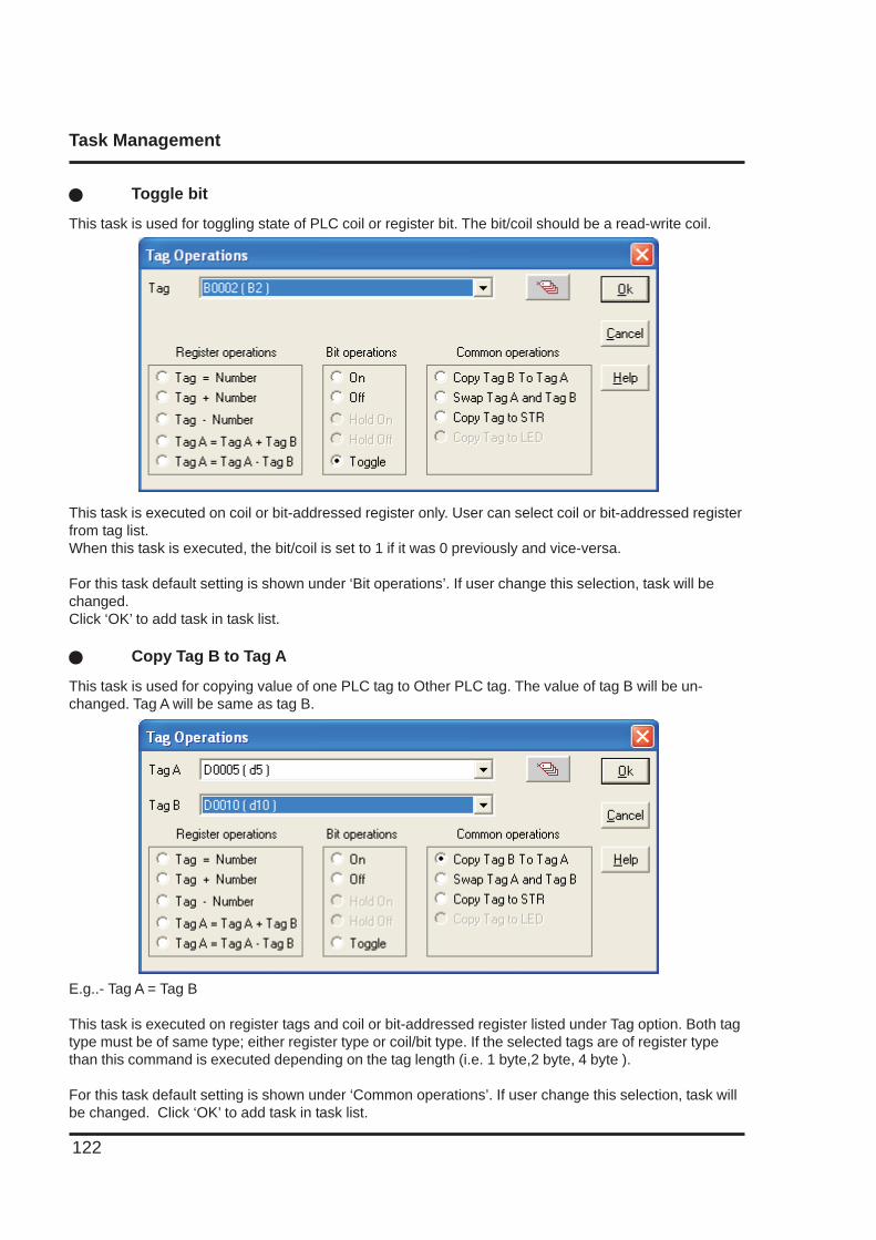
Task Management
122
This task is executed on coil or bit-addressed register only. User can select coil or bit-addressed registerfrom tag list.When this task is executed, the bit/coil is set to 1 if it was 0 previously and vice-versa.
For this task default setting is shown under ‘Bit operations’. If user change this selection, task will bechanged.Click ‘OK’ to add task in task list.
� Copy Tag B to Tag A
This task is used for copying value of one PLC tag to Other PLC tag. The value of tag B will be un-changed. Tag A will be same as tag B.
E.g..- Tag A = Tag B
This task is executed on register tags and coil or bit-addressed register listed under Tag option. Both tagtype must be of same type; either register type or coil/bit type. If the selected tags are of register typethan this command is executed depending on the tag length (i.e. 1 byte,2 byte, 4 byte ).
For this task default setting is shown under ‘Common operations’. If user change this selection, task willbe changed. Click ‘OK’ to add task in task list.
� Toggle bit
This task is used for toggling state of PLC coil or register bit. The bit/coil should be a read-write coil.
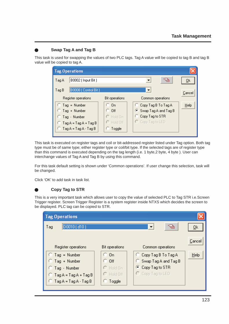
Task Management
123
This task is executed on register tags and coil or bit-addressed register listed under Tag option. Both tagtype must be of same type; either register type or coil/bit type. If the selected tags are of register typethan this command is executed depending on the tag length (i.e. 1 byte,2 byte, 4 byte ). User caninterchange values of Tag A and Tag B by using this command.
For this task default setting is shown under ‘Common operations’. If user change this selection, task willbe changed.
Click ‘OK’ to add task in task list.
� Copy Tag to STR
This is a very important task which allows user to copy the value of selected PLC to Tag STR i.e.ScreenTrigger register. Screen Trigger Register is a system register inside NTXS which decides the screen tobe displayed. PLC tag can be copied to STR.
� Swap Tag A and Tag B
This task is used for swapping the values of two PLC tags. Tag A value will be copied to tag B and tag Bvalue will be copied to tag A.
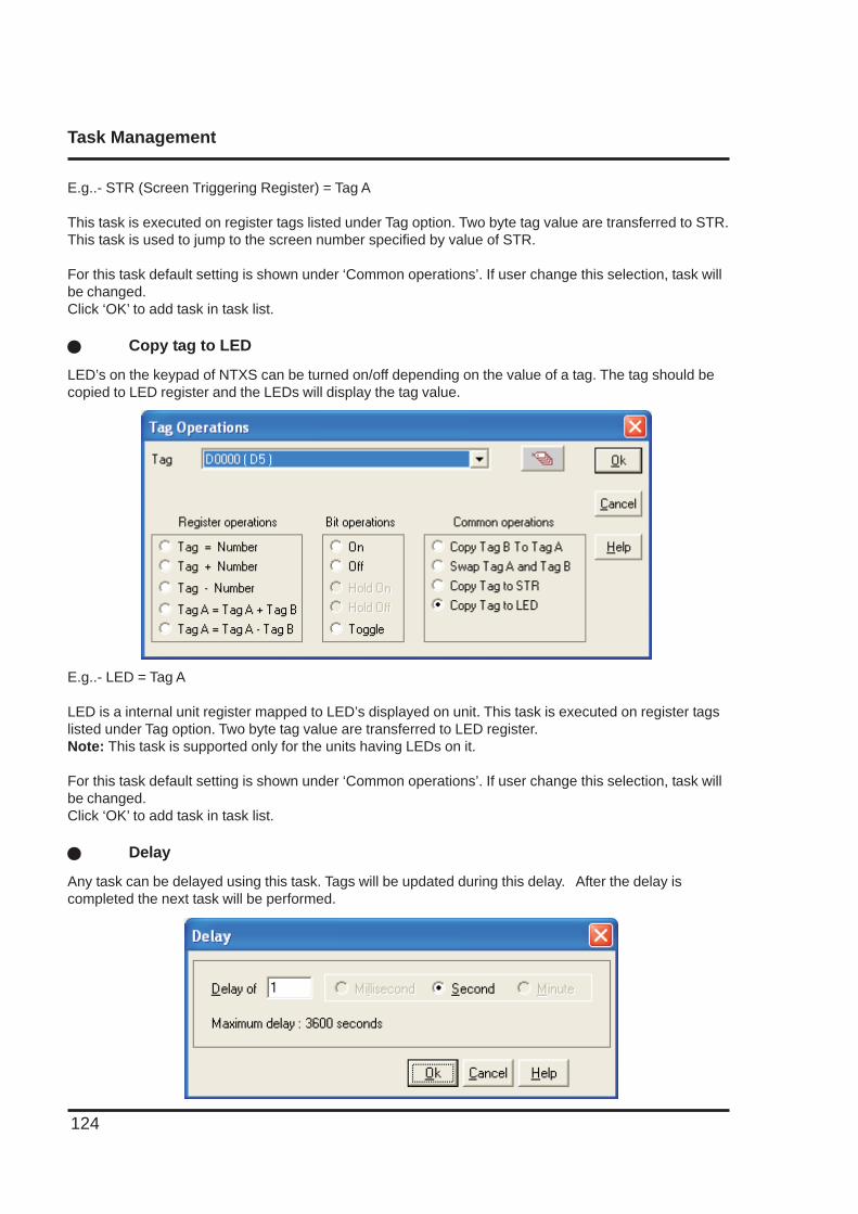
Task Management
124
E.g..- STR (Screen Triggering Register) = Tag A
This task is executed on register tags listed under Tag option. Two byte tag value are transferred to STR.This task is used to jump to the screen number specified by value of STR.
For this task default setting is shown under ‘Common operations’. If user change this selection, task willbe changed.Click ‘OK’ to add task in task list.
� Copy tag to LED
LED’s on the keypad of NTXS can be turned on/off depending on the value of a tag. The tag should becopied to LED register and the LEDs will display the tag value.
E.g..- LED = Tag A
LED is a internal unit register mapped to LED’s displayed on unit. This task is executed on register tagslisted under Tag option. Two byte tag value are transferred to LED register.Note: This task is supported only for the units having LEDs on it.
For this task default setting is shown under ‘Common operations’. If user change this selection, task willbe changed.Click ‘OK’ to add task in task list.
� Delay
Any task can be delayed using this task. Tags will be updated during this delay. After the delay iscompleted the next task will be performed.
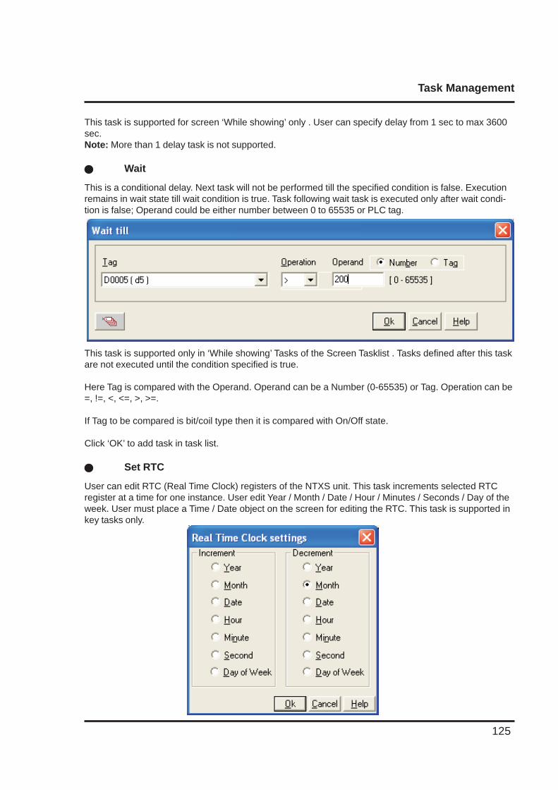
Task Management
125
This task is supported for screen ‘While showing’ only . User can specify delay from 1 sec to max 3600sec.Note: More than 1 delay task is not supported.
� Wait
This is a conditional delay. Next task will not be performed till the specified condition is false. Executionremains in wait state till wait condition is true. Task following wait task is executed only after wait condi-tion is false; Operand could be either number between 0 to 65535 or PLC tag.
This task is supported only in ‘While showing’ Tasks of the Screen Tasklist . Tasks defined after this taskare not executed until the condition specified is true.
Here Tag is compared with the Operand. Operand can be a Number (0-65535) or Tag. Operation can be=, !=, <, <=, >, >=.
If Tag to be compared is bit/coil type then it is compared with On/Off state.
Click ‘OK’ to add task in task list.
� Set RTC
User can edit RTC (Real Time Clock) registers of the NTXS unit. This task increments selected RTCregister at a time for one instance. User edit Year / Month / Date / Hour / Minutes / Seconds / Day of theweek. User must place a Time / Date object on the screen for editing the RTC. This task is supported inkey tasks only.
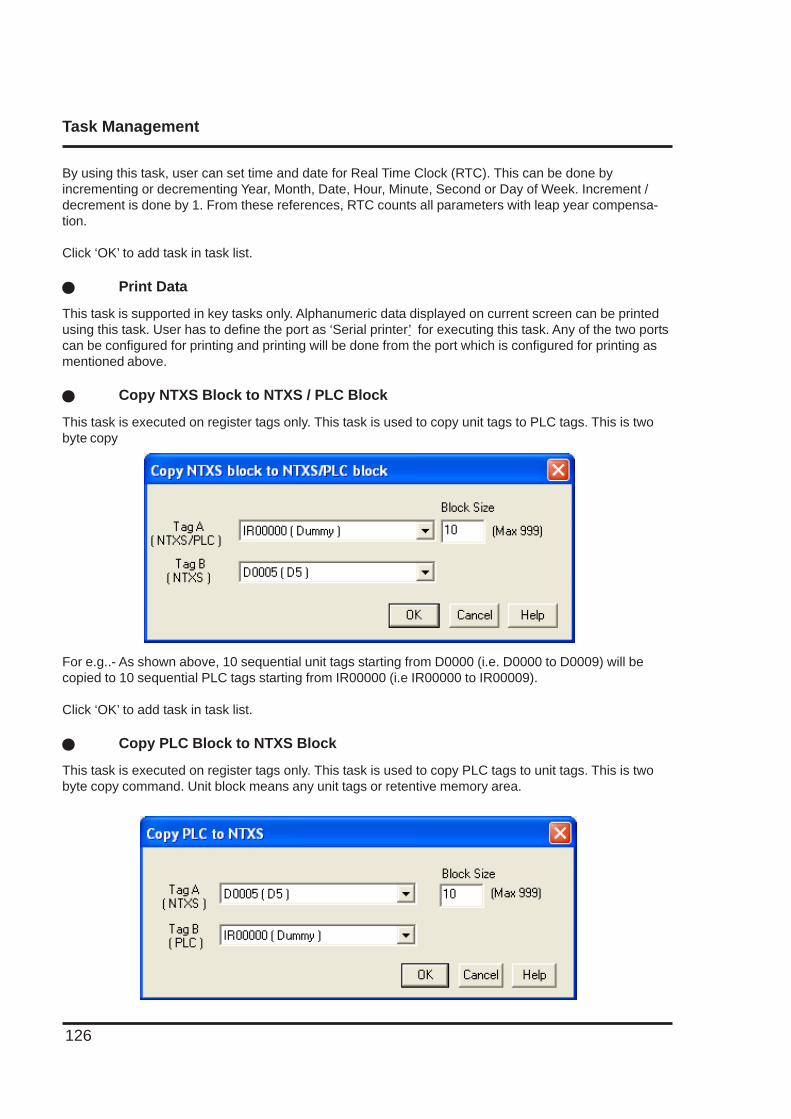
Task Management
126
By using this task, user can set time and date for Real Time Clock (RTC). This can be done byincrementing or decrementing Year, Month, Date, Hour, Minute, Second or Day of Week. Increment /decrement is done by 1. From these references, RTC counts all parameters with leap year compensa-tion.
Click ‘OK’ to add task in task list.
� Print Data
This task is supported in key tasks only. Alphanumeric data displayed on current screen can be printedusing this task. User has to define the port as ‘Serial printer’ for executing this task. Any of the two portscan be configured for printing and printing will be done from the port which is configured for printing asmentioned above.
� Copy NTXS Block to NTXS / PLC Block
This task is executed on register tags only. This task is used to copy unit tags to PLC tags. This is twobyte copy
For e.g..- As shown above, 10 sequential unit tags starting from D0000 (i.e. D0000 to D0009) will becopied to 10 sequential PLC tags starting from IR00000 (i.e IR00000 to IR00009).
Click ‘OK’ to add task in task list.
� Copy PLC Block to NTXS Block
This task is executed on register tags only. This task is used to copy PLC tags to unit tags. This is twobyte copy command. Unit block means any unit tags or retentive memory area.
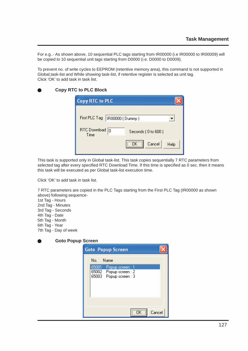
Task Management
127
For e.g..- As shown above, 10 sequential PLC tags starting from IR00000 (i.e IR00000 to IR00009) willbe copied to 10 sequential unit tags starting from D0000 (i.e. D0000 to D0009).
To prevent no. of write cycles to EEPROM (retentive memory area), this command is not supported inGlobal task-list and While showing task-list, if retentive register is selected as unit tag.Click ‘OK’ to add task in task list.
� Copy RTC to PLC Block
This task is supported only in Global task-list. This task copies sequentially 7 RTC parameters fromselected tag after every specified RTC Download Time. If this time is specified as 0 sec. then it meansthis task will be executed as per Global task-list execution time.
Click ‘OK’ to add task in task list.
7 RTC parameters are copied in the PLC Tags starting from the First PLC Tag (IR00000 as shownabove) following sequence-1st Tag - Hours2nd Tag - Minutes3rd Tag - Seconds4th Tag - Date5th Tag - Month6th Tag - Year7th Tag - Day of week
� Goto Popup Screen
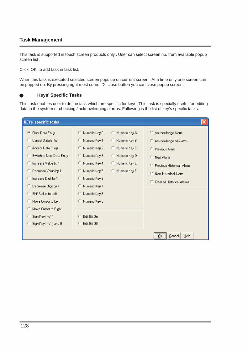
Task Management
128
This task is supported in touch screen products only . User can select screen no. from available popupscreen list .
Click ‘OK’ to add task in task list.
When this task is executed selected screen pops up on current screen . At a time only one screen canbe popped up. By pressing right most corner ‘X’ close button you can close popup screen.
� Keys’ Specific Tasks
This task enables user to define task which are specific for keys. This task is specially useful for editingdata in the system or checking / acknowledging alarms. Following is the list of key’s specific tasks:
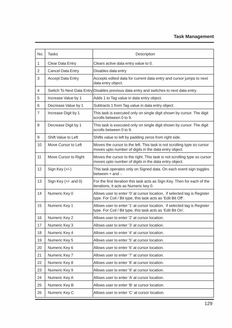
Task Management
129
No. Tasks Description
1 Clear Data Entry Clears active data entry value to 0.
2 Cancel Data Entry Disables data entry
3 Accept Data Entry Accepts edited data for current data entry and cursor jumps to nextdata entry object.
4 Switch To Next Data Entry Disables previous data entry and switches to next data entry.
5 Increase Value by 1 Adds 1 to Tag value in data entry object.
6 Decrease Value by 1 Subtracts 1 from Tag value in data entry object.
7 Increase Digit by 1 This task is executed only on single digit shown by cursor. The digitscrolls between 0 to 9.
8 Decrease Digit by 1 This task is executed only on single digit shown by cursor. The digitscrolls between 0 to 9.
9 Shift Value to Left Shifts value to left by padding zeros from right side.
10 Move Cursor to Left Moves the cursor to the left. This task is not scrolling type so cursormoves upto number of digits in the data entry object.
11 Move Cursor to Right Moves the cursor to the right. This task is not scrolling type so cursormoves upto number of digits in the data entry object.
12 Sign Key (+/-) This task operates only on Signed data. On each event sign togglesbetween + and -.
13 Sign Key (+/- and 0) For the first iteration this task acts as Sign Key. Then for each of theiterations, it acts as Numeric key 0.
14 Numeric Key 0 Allows user to enter ‘0’ at cursor location, if selected tag is Registertype. For Coil / Bit type, this task acts as ‘Edit Bit Off’.
15 Numeric Key 1 Allows user to enter ‘1’ at cursor location, if selected tag is Registertype. For Coil / Bit type, this task acts as ‘Edit Bit On’.
16 Numeric Key 2 Allows user to enter ‘2’ at cursor location.
17 Numeric Key 3 Allows user to enter ‘3’ at cursor location.
18 Numeric Key 4 Allows user to enter ‘4’ at cursor location.
19 Numeric Key 5 Allows user to enter ‘5’ at cursor location.
20 Numeric Key 6 Allows user to enter ‘6’ at cursor location.
21 Numeric Key 7 Allows user to enter ‘7’ at cursor location.
22 Numeric Key 8 Allows user to enter ‘8’ at cursor location.
23 Numeric Key 9 Allows user to enter ‘9’ at cursor location.
24 Numeric Key A Allows user to enter ‘A’ at cursor location.
25 Numeric Key B Allows user to enter ‘B’ at cursor location.
26 Numeric Key C Allows user to enter ‘C’ at cursor location.
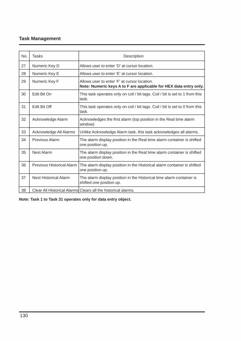
Task Management
130
Note: Task 1 to Task 31 operates only for data entry object.
No. Tasks Description
27 Numeric Key D Allows user to enter ‘D’ at cursor location.
28 Numeric Key E Allows user to enter ‘E’ at cursor location.
29 Numeric Key F Allows user to enter ‘F’ at cursor location.Note: Numeric keys A to F are applicable for HEX data entry only.
30 Edit Bit On This task operates only on coil / bit tags. Coil / bit is set to 1 from thistask.
31 Edit Bit Off This task operates only on coil / bit tags. Coil / bit is set to 0 from thistask.
32 Acknowledge Alarm Acknowledges the first alarm (top position in the Real time alarmwindow)
33 Acknowledge All Alarms Unlike Acknowledge Alarm task, this task acknowledges all alarms.
34 Previous Alarm The alarm display position in the Real time alarm container is shiftedone position up.
35 Next Alarm The alarm display position in the Real time alarm container is shiftedone position down.
36 Previous Historical Alarm The alarm display position in the Historical alarm container is shiftedone position up.
37 Next Historical Alarm The alarm display position in the Historical time alarm container isshifted one position up.
38 Clear All Historical Alarms Clears all the historical alarms.

Language Wizard
131
USING LANGUAGES
In this chapter. . . .
♦ Export Functionality
♦ Import Functionality
♦ Language Conversion Utility
♦ Language Wizard
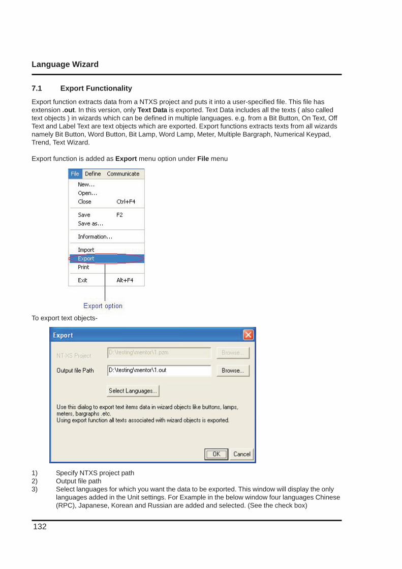
Language Wizard
132
7.1 Export Functionality
Export function extracts data from a NTXS project and puts it into a user-specified file. This file hasextension .out. In this version, only Text Data is exported. Text Data includes all the texts ( also calledtext objects ) in wizards which can be defined in multiple languages. e.g. from a Bit Button, On Text, OffText and Label Text are text objects which are exported. Export functions extracts texts from all wizardsnamely Bit Button, Word Button, Bit Lamp, Word Lamp, Meter, Multiple Bargraph, Numerical Keypad,Trend, Text Wizard.
Export function is added as Export menu option under File menu
To export text objects-
1) Specify NTXS project path2) Output file path3) Select languages for which you want the data to be exported. This window will display the only
languages added in the Unit settings. For Example in the below window four languages Chinese(RPC), Japanese, Korean and Russian are added and selected. (See the check box)
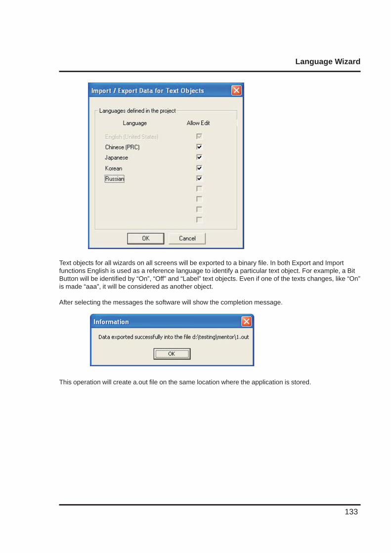
Language Wizard
133
Text objects for all wizards on all screens will be exported to a binary file. In both Export and Importfunctions English is used as a reference language to identify a particular text object. For example, a BitButton will be identified by “On”, “Off” and “Label” text objects. Even if one of the texts changes, like “On”is made “aaa”, it will be considered as another object.
After selecting the messages the software will show the completion message.
This operation will create a.out file on the same location where the application is stored.
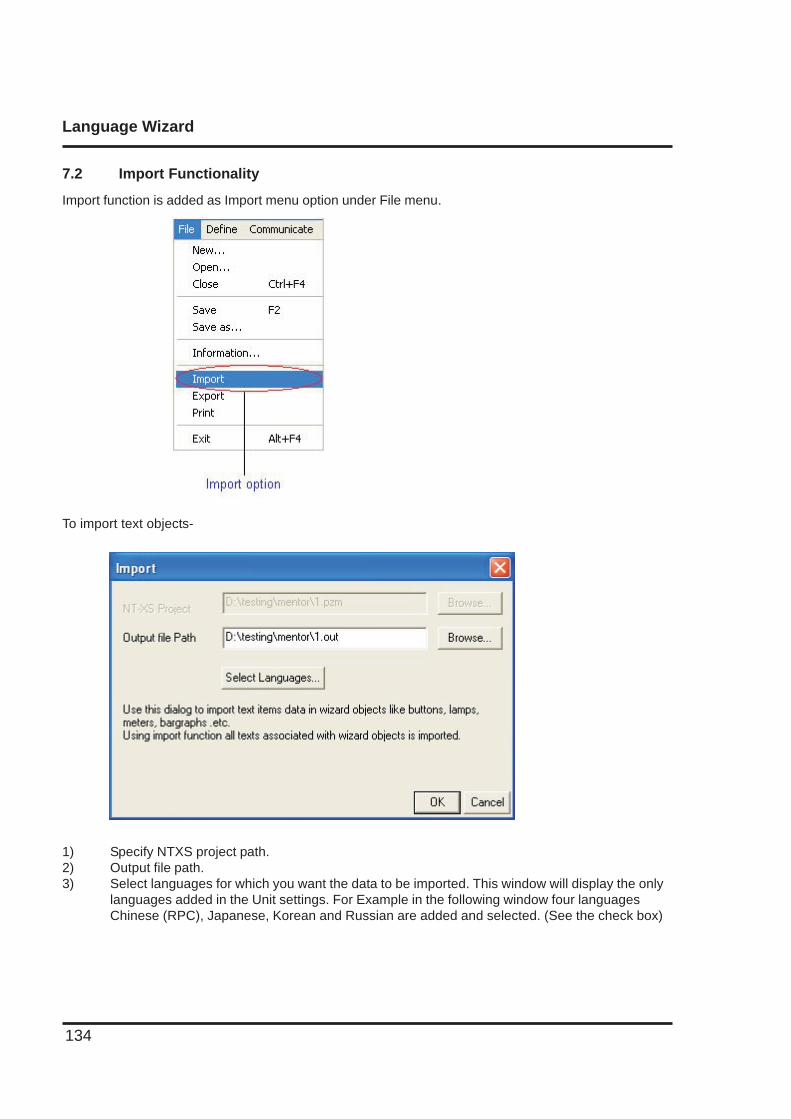
Language Wizard
134
7.2 Import Functionality
Import function is added as Import menu option under File menu.
To import text objects-
1) Specify NTXS project path.2) Output file path.3) Select languages for which you want the data to be imported. This window will display the only
languages added in the Unit settings. For Example in the following window four languagesChinese (RPC), Japanese, Korean and Russian are added and selected. (See the check box)
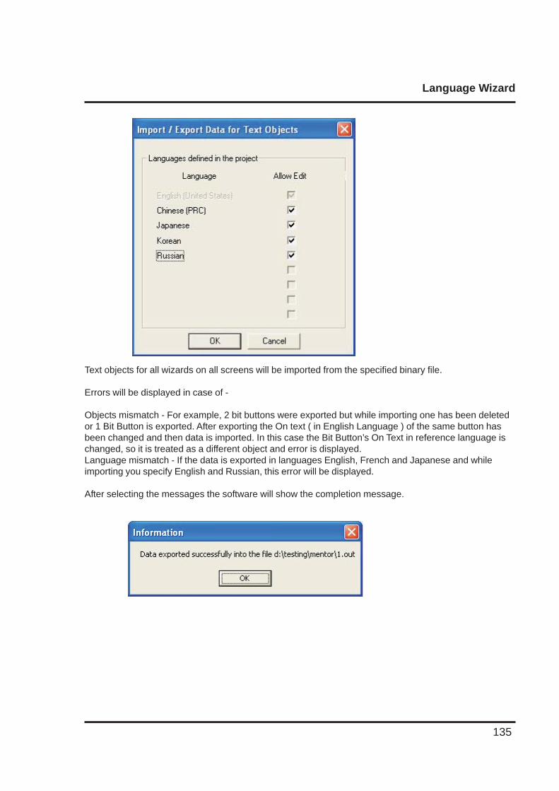
Language Wizard
135
Text objects for all wizards on all screens will be imported from the specified binary file.
Errors will be displayed in case of -
Objects mismatch - For example, 2 bit buttons were exported but while importing one has been deletedor 1 Bit Button is exported. After exporting the On text ( in English Language ) of the same button hasbeen changed and then data is imported. In this case the Bit Button’s On Text in reference language ischanged, so it is treated as a different object and error is displayed.Language mismatch - If the data is exported in languages English, French and Japanese and whileimporting you specify English and Russian, this error will be displayed.
After selecting the messages the software will show the completion message.
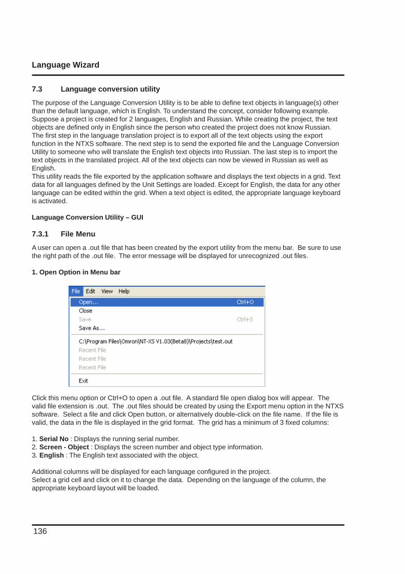
Language Wizard
136
7.3 Language conversion utility
The purpose of the Language Conversion Utility is to be able to define text objects in language(s) otherthan the default language, which is English. To understand the concept, consider following example.Suppose a project is created for 2 languages, English and Russian. While creating the project, the textobjects are defined only in English since the person who created the project does not know Russian.The first step in the language translation project is to export all of the text objects using the exportfunction in the NTXS software. The next step is to send the exported file and the Language ConversionUtility to someone who will translate the English text objects into Russian. The last step is to import thetext objects in the translated project. All of the text objects can now be viewed in Russian as well asEnglish.This utility reads the file exported by the application software and displays the text objects in a grid. Textdata for all languages defined by the Unit Settings are loaded. Except for English, the data for any otherlanguage can be edited within the grid. When a text object is edited, the appropriate language keyboardis activated.
Language Conversion Utility – GUI
7.3.1 File Menu
A user can open a .out file that has been created by the export utility from the menu bar. Be sure to usethe right path of the .out file. The error message will be displayed for unrecognized .out files.
1. Open Option in Menu bar
Click this menu option or Ctrl+O to open a .out file. A standard file open dialog box will appear. Thevalid file extension is .out. The .out files should be created by using the Export menu option in the NTXSsoftware. Select a file and click Open button, or alternatively double-click on the file name. If the file isvalid, the data in the file is displayed in the grid format. The grid has a minimum of 3 fixed columns:
1. Serial No : Displays the running serial number.2. Screen - Object : Displays the screen number and object type information.3. English : The English text associated with the object.
Additional columns will be displayed for each language configured in the project.Select a grid cell and click on it to change the data. Depending on the language of the column, theappropriate keyboard layout will be loaded.
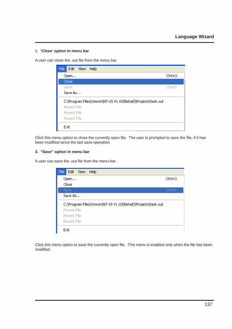
Language Wizard
137
2. ‘Close’ option in menu bar
A user can close the .out file from the menu bar.
Click this menu option to close the currently open file. The user is prompted to save the file, if it hasbeen modified since the last save operation.
3. “Save” option in menu bar
A user can save the .out file from the menu bar.
Click this menu option to save the currently open file. This menu is enabled only when the file has beenmodified.
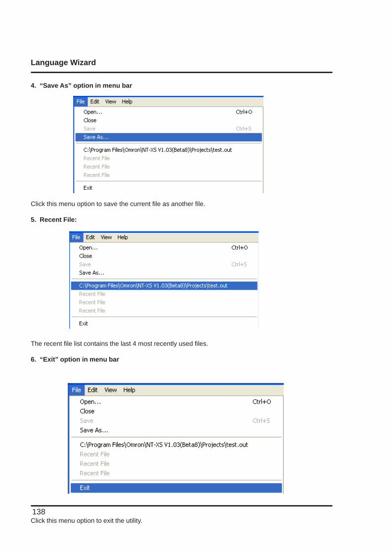
Language Wizard
138
4. “Save As” option in menu bar
Click this menu option to save the current file as another file.
5. Recent File:
The recent file list contains the last 4 most recently used files.
6. “Exit” option in menu bar
Click this menu option to exit the utility.
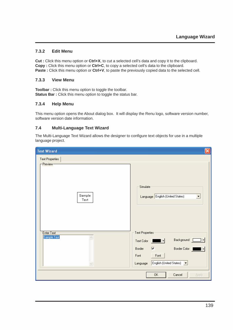
Language Wizard
139
7.3.2 Edit Menu
Cut : Click this menu option or Ctrl+X, to cut a selected cell’s data and copy it to the clipboard.Copy : Click this menu option or Ctrl+C, to copy a selected cell’s data to the clipboard.Paste : Click this menu option or Ctrl+V, to paste the previously copied data to the selected cell.
7.3.3 View Menu
Toolbar : Click this menu option to toggle the toolbar.Status Bar : Click this menu option to toggle the status bar.
7.3.4 Help Menu
This menu option opens the About dialog box. It will display the Renu logo, software version number,software version date information.
7.4 Multi-Language Text Wizard
The Multi-Language Text Wizard allows the designer to configure text objects for use in a multiplelanguage project.
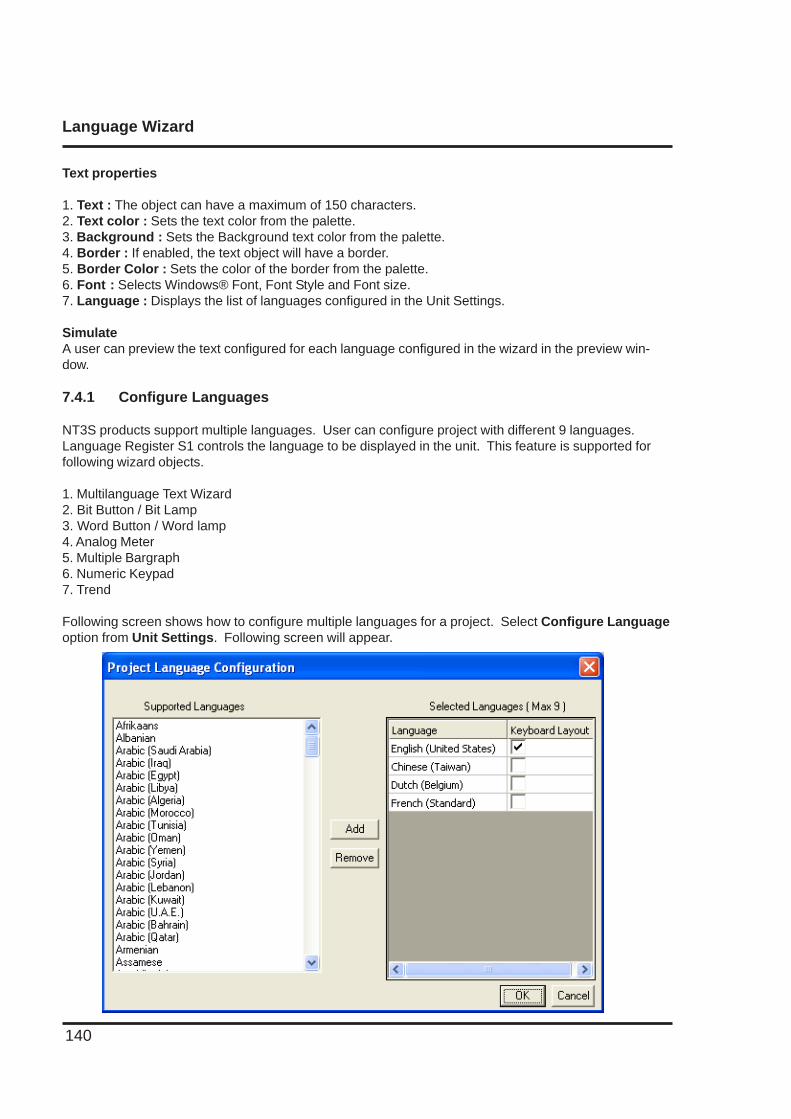
Language Wizard
140
Text properties
1. Text : The object can have a maximum of 150 characters.2. Text color : Sets the text color from the palette.3. Background : Sets the Background text color from the palette.4. Border : If enabled, the text object will have a border.5. Border Color : Sets the color of the border from the palette.6. Font : Selects Windows® Font, Font Style and Font size.7. Language : Displays the list of languages configured in the Unit Settings.
SimulateA user can preview the text configured for each language configured in the wizard in the preview win-dow.
7.4.1 Configure Languages
NT3S products support multiple languages. User can configure project with different 9 languages.Language Register S1 controls the language to be displayed in the unit. This feature is supported forfollowing wizard objects.
1. Multilanguage Text Wizard2. Bit Button / Bit Lamp3. Word Button / Word lamp4. Analog Meter5. Multiple Bargraph6. Numeric Keypad7. Trend
Following screen shows how to configure multiple languages for a project. Select Configure Languageoption from Unit Settings. Following screen will appear.
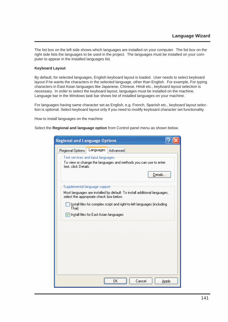
Language Wizard
141
The list box on the left side shows which languages are installed on your computer. The list box on theright side lists the languages to be used in the project. The languages must be installed on your com-puter to appear in the installed languages list.
Keyboard Layout
By default, for selected languages, English keyboard layout is loaded. User needs to select keyboardlayout if he wants the characters in the selected language, other than English. For example, For typingcharacters in East Asian languages like Japanese, Chinese, Hindi etc., keyboard layout selection isnecessary. In order to select the keyboard layout, languages must be installed on the machine.Language bar in the Windows task bar shows list of installed languages on your machine.
For languages having same character set as English, e.g. French, Spanish etc., keyboard layout selec-tion is optional. Select keyboard layout only if you need to modify keyboard character set functionality.
How to install languages on the machine
Select the Regional and language option from Control panel menu as shown below.
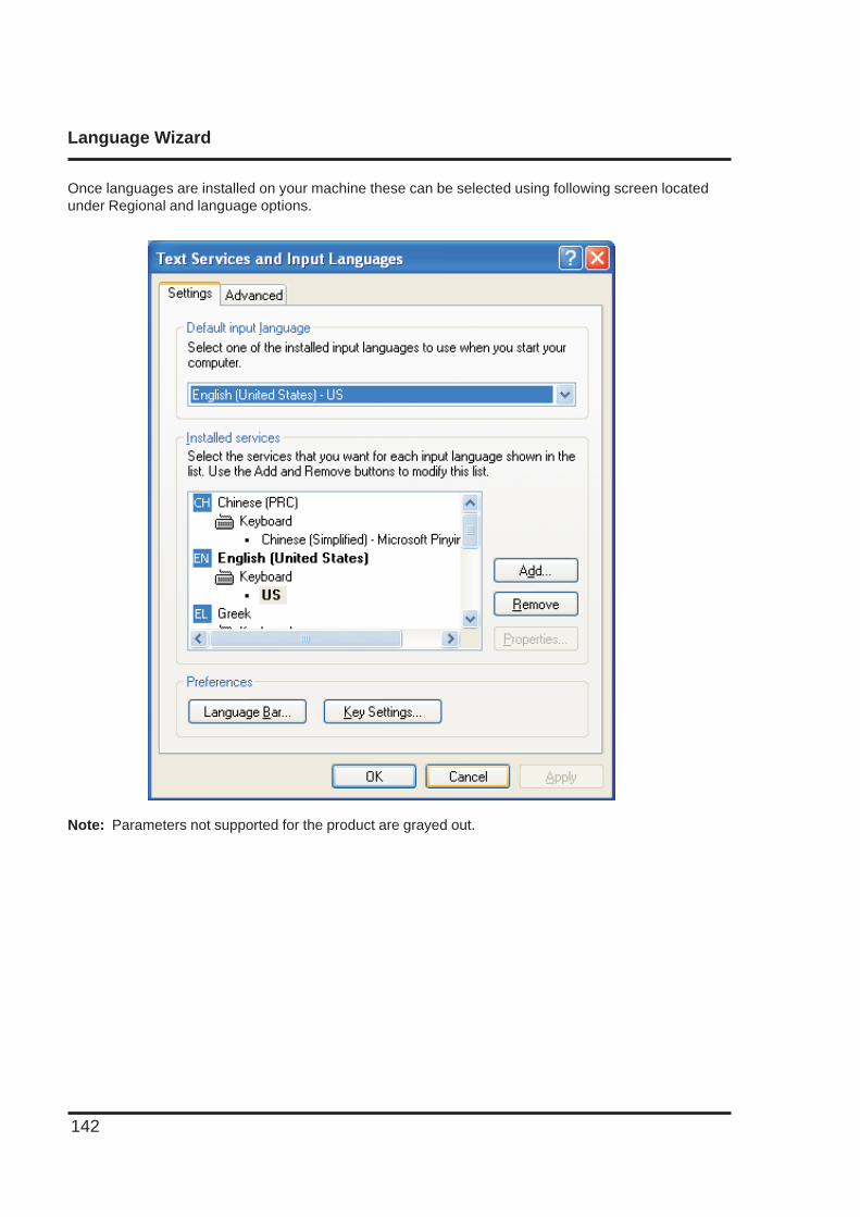
Language Wizard
142
Once languages are installed on your machine these can be selected using following screen locatedunder Regional and language options.
Note: Parameters not supported for the product are grayed out.

Language Wizard
143
7.4.2 Displaying Multiple Languages in Unit
System Register S0001 controls the language to be displayed at run time. User can use ‘Write value totag’ task for changing value in system register.
Note : If S0001 has value other than 1 to 9 then English language is displayed.
Example:If user has configured project for 3 different languages namely English, Korean, Japanese then followingtasks can be used to change language at run time.
English - Write value to Tag S0001 with value 1
Korean - Write value to Tag S0001 with value 2
Japanese - Write value to Tag S0001 with value 3
In this way 9 different languages can be displayed in unit at run time.Following table shows the value of System Register S0001.
Language Tag Value Description
0 Default Value : English
1 English
2 Configurable Language
3 Configurable Language
4 Configurable Language
5 Configurable Language
6 Configurable Language
7 Configurable Language
8 Configurable Language
9 Configurable Language
Uploading and Downloading from unit
144
UPLOADING AND DOWNLOADING FROM UNIT
In this chapter. . . .
♦ Upload an Application
♦ Download an Application
♦ Error Catalog
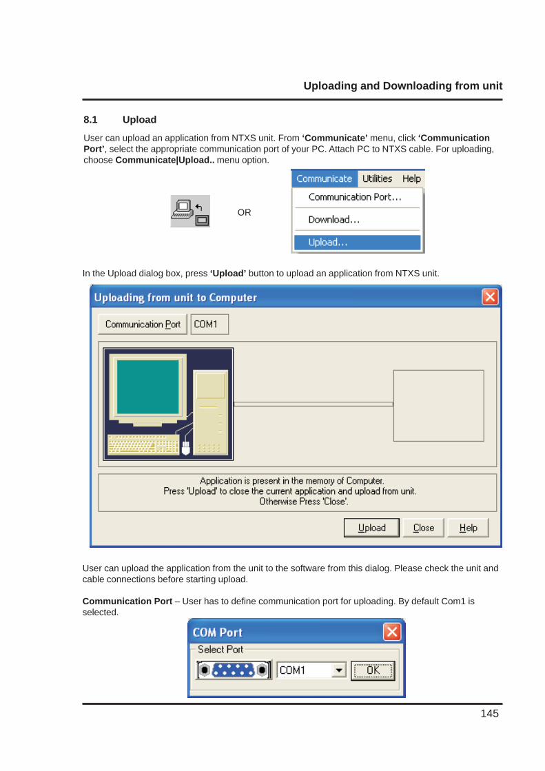
Uploading and Downloading from unit
145
8.1 Upload
User can upload an application from NTXS unit. From ‘Communicate’ menu, click ‘CommunicationPort’, select the appropriate communication port of your PC. Attach PC to NTXS cable. For uploading,choose Communicate|Upload.. menu option.
In the Upload dialog box, press ‘Upload’ button to upload an application from NTXS unit.
OR
User can upload the application from the unit to the software from this dialog. Please check the unit andcable connections before starting upload.
Communication Port – User has to define communication port for uploading. By default Com1 isselected.
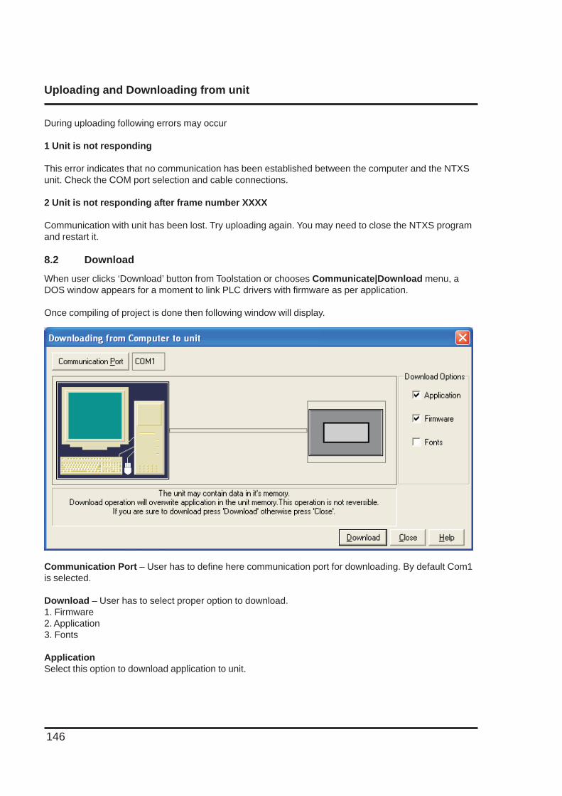
Uploading and Downloading from unit
146
During uploading following errors may occur
1 Unit is not responding
This error indicates that no communication has been established between the computer and the NTXSunit. Check the COM port selection and cable connections.
2 Unit is not responding after frame number XXXX
Communication with unit has been lost. Try uploading again. You may need to close the NTXS programand restart it.
8.2 Download
When user clicks ‘Download’ button from Toolstation or chooses Communicate|Download menu, aDOS window appears for a moment to link PLC drivers with firmware as per application.
Once compiling of project is done then following window will display.
Communication Port – User has to define here communication port for downloading. By default Com1is selected.
Download – User has to select proper option to download.1. Firmware2. Application3. Fonts
ApplicationSelect this option to download application to unit.
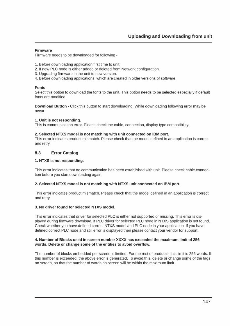
Uploading and Downloading from unit
147
FirmwareFirmware needs to be downloaded for following -
1. Before downloading application first time to unit.2. If new PLC node is either added or deleted from Network configuration.3. Upgrading firmware in the unit to new version.4. Before downloading applications, which are created in older versions of software.
FontsSelect this option to download the fonts to the unit. This option needs to be selected especially if defaultfonts are modified.
Download Button - Click this button to start downloading. While downloading following error may beoccur -
1. Unit is not responding.This is communication error. Please check the cable, connection, display type compatibility.
2. Selected NTXS model is not matching with unit connected on IBM port.This error indicates product mismatch. Please check that the model defined in an application is correctand retry.
8.3 Error Catalog
1. NTXS is not responding.
This error indicates that no communication has been established with unit. Please check cable connec-tion before you start downloading again.
2. Selected NTXS model is not matching with NTXS unit connected on IBM port.
This error indicates product mismatch. Please check that the model defined in an application is correctand retry.
3. No driver found for selected NTXS model.
This error indicates that driver for selected PLC is either not supported or missing. This error is dis-played during firmware download, if PLC driver for selected PLC node in NTXS application is not found.Check whether you have defined correct NTXS model and PLC node in your application. If you havedefined correct PLC node and still error is displayed then please contact your vendor for support.
4. Number of Blocks used in screen number XXXX has exceeded the maximum limit of 256words. Delete or change some of the entities to avoid overflow.
The number of blocks embedded per screen is limited. For the rest of products, this limit is 256 words. Ifthis number is exceeded, the above error is generated. To avoid this, delete or change some of the tagson screen, so that the number of words on screen will be within the maximum limit.
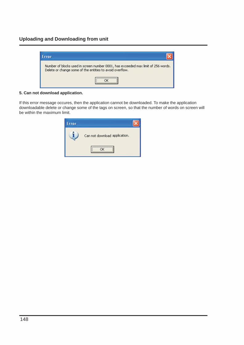
Uploading and Downloading from unit
148
5. Can not download application.
If this error message occures, then the application cannot be downloaded. To make the applicationdownloadable delete or change some of the tags on screen, so that the number of words on screen willbe within the maximum limit.
Alarm
149
ALARMS
In this chapter. . . .
♦ Define Alarm
♦ Using Alarm Window
♦ Difference between Real Time & Historical Alarm
Alarm
150
9.1 Define Alarm
Alarm will be displayed in the alarm window only if it is defined from the ‘Define Alarm’ menu.
There are two categories of alarm
1. Real time alarms: Stored & displayed as long as unit power is ON.2. Historical alarms: Stores alarms in memory with battery back up.
Note: Historical alarms are only supported for the units with RTC / Battery backup.
In case of historical alarms the alarms defined with “Historical attribute” are logged till the unit is ON.Then even though you turn the unit OFF & then back ON after few days you can still view the alarms thatwere present when the unit was ON earlier.
The alarm object displays the alarm text when the alarm occurs. First triggered alarm is on top. Alarmcondition for alarm should be cleared. Each alarm has to be acknowledged. ‘Acknowledge Alarm’ keyacknowledges the alarm. The alarm text is cleared when the alarm condition is cleared and the alarm isacknowledged. Alarm text for unacknowledged or uncleared alarm will not be cleared. Any tag can becontinuously monitored by defining alarms for each bit of that tag. To display an alarm on the screen assoon as it is triggered, alarm object has to be placed on the screen. An alarm is triggered for each bit ina tag. If the value of the particular tag becomes nonzero, corresponding alarm is displayed in the alarmobject.
An alarm is a bit in a particular 2-byte tag. This two-byte tag is defined as a particular group in the alarmdefinition table. Since a two-byte tag contains 16 bits one such tag can generate 16 alarms. So to define64 alarms we need to create 4 groups with 4 different two byte tags & define one alarm per bit in that. Intotal you can define up to 256 real time & 30 historical alarms.
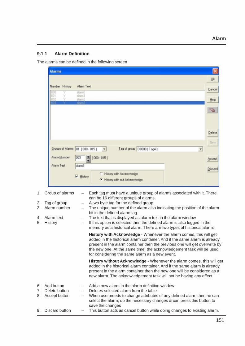
Alarm
151
9.1.1 Alarm Definition
The alarms can be defined in the following screen
1. Group of alarms – Each tag must have a unique group of alarms associated with it. Therecan be 16 different groups of alarms.
2. Tag of group – A two byte tag for the defined group3. Alarm number – The unique number of the alarm also indicating the position of the alarm
bit in the defined alarm tag4. Alarm text – The text that is displayed as alarm text in the alarm window5. History – If this option is selected then the defined alarm is also logged in the
memory as a historical alarm. There are two types of historical alarm:
History with Acknowledge - Whenever the alarm comes, this will getadded in the historical alarm container. And if the same alarm is alreadypresent in the alarm container then the previous one will get overwrite bythe new one. At the same time, the acknowledgement task will be usedfor considering the same alarm as a new event.
History without Acknowledge - Whenever the alarm comes, this will getadded in the historical alarm container. And if the same alarm is alreadypresent in the alarm container then the new one will be considered as anew alarm. The acknowledgement task will not be having any effect
6. Add button – Add a new alarm in the alarm definition window7. Delete button – Deletes selected alarm from the table8. Accept button – When user needs to change attributes of any defined alarm then he can
select the alarm, do the necessary changes & can press this button tosave the changes
9. Discard button – This button acts as cancel button while doing changes to existing alarm.
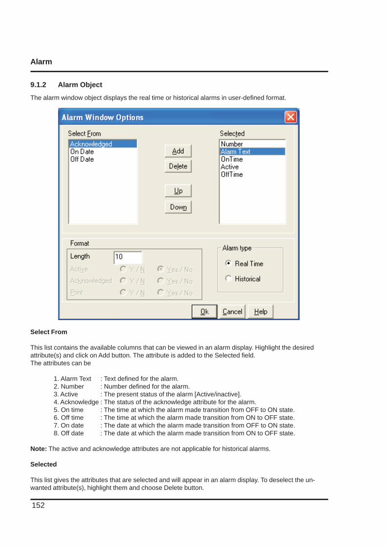
Alarm
152
9.1.2 Alarm Object
The alarm window object displays the real time or historical alarms in user-defined format.
Select From
This list contains the available columns that can be viewed in an alarm display. Highlight the desiredattribute(s) and click on Add button. The attribute is added to the Selected field.The attributes can be
1. Alarm Text : Text defined for the alarm.2. Number : Number defined for the alarm.3. Active : The present status of the alarm [Active/inactive].4. Acknowledge : The status of the acknowledge attribute for the alarm.5. On time : The time at which the alarm made transition from OFF to ON state.6. Off time : The time at which the alarm made transition from ON to OFF state.7. On date : The date at which the alarm made transition from OFF to ON state.8. Off date : The date at which the alarm made transition from ON to OFF state.
Note: The active and acknowledge attributes are not applicable for historical alarms.
Selected
This list gives the attributes that are selected and will appear in an alarm display. To deselect the un-wanted attribute(s), highlight them and choose Delete button.
Alarm
153
Alarm type
This selection specifies whether the current alarm window represents the real time or historical alarms.
Note: Historical alarms are Product dependent.
Format
Enter the format for the highlighted attribute from Selected field.For Alarm Text attribute, user can enter the length in ‘Length’ field.
For Time attribute, user can select the format as either HH:MM:SS or MM:SS from the combo box.
For Active and Acknowledged attributes, user can check the desired radio button.
Printing
154
PRINTING
In this chapter. . . .
♦ Printing from NTXS unit
♦ Printing from NTXS Software
♦ Printer Port Setup
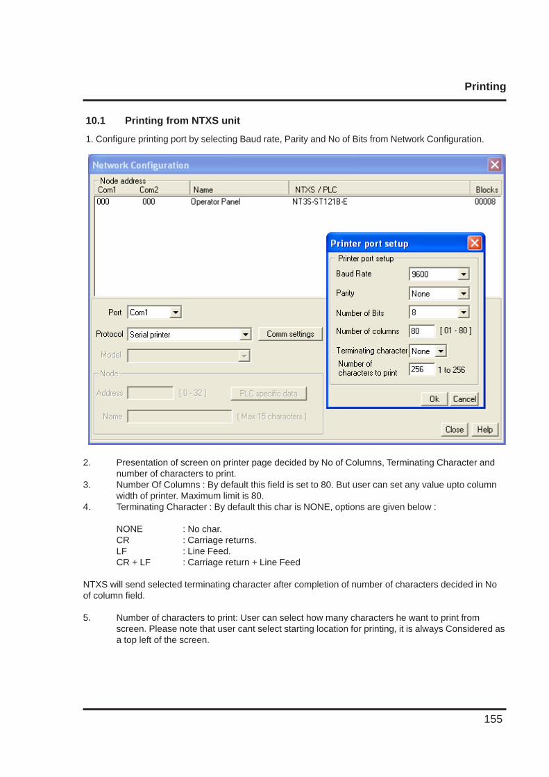
Printing
155
10.1 Printing from NTXS unit
1. Configure printing port by selecting Baud rate, Parity and No of Bits from Network Configuration.
2. Presentation of screen on printer page decided by No of Columns, Terminating Character andnumber of characters to print.
3. Number Of Columns : By default this field is set to 80. But user can set any value upto columnwidth of printer. Maximum limit is 80.
4. Terminating Character : By default this char is NONE, options are given below :
NONE : No char.CR : Carriage returns.LF : Line Feed.CR + LF : Carriage return + Line Feed
NTXS will send selected terminating character after completion of number of characters decided in Noof column field.
5. Number of characters to print: User can select how many characters he want to print fromscreen. Please note that user cant select starting location for printing, it is always Considered asa top left of the screen.
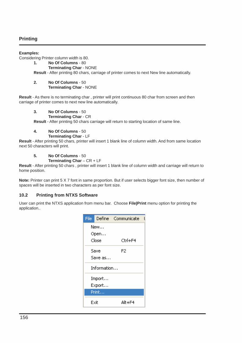
Printing
156
Examples:Considering Printer column width is 80.
1. No Of Columns - 80Terminating Char - NONE
Result - After printing 80 chars, carriage of printer comes to next New line automatically.
2. No Of Columns - 50Terminating Char - NONE
Result - As there is no terminating char , printer will print continuous 80 char from screen and thencarriage of printer comes to next new line automatically.
3. No Of Columns - 50Terminating Char - CR
Result - After printing 50 chars carriage will return to starting location of same line.
4. No Of Columns - 50Terminating Char - LF
Result - After printing 50 chars, printer will insert 1 blank line of column width. And from same locationnext 50 characters will print.
5. No Of Columns - 50Terminating Char – CR + LF
Result - After printing 50 chars , printer will insert 1 blank line of column width and carriage will return tohome position.
Note: Printer can print 5 X 7 font in same proportion. But if user selects bigger font size, then number ofspaces will be inserted in two characters as per font size.
10.2 Printing from NTXS Software
User can print the NTXS application from menu bar. Choose File|Print menu option for printing theapplication..
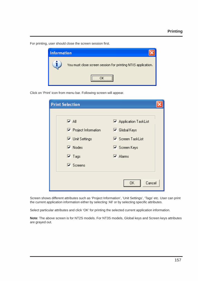
Printing
157
For printing, user should close the screen session first.
Click on ‘Print’ icon from menu bar. Following screen will appear.
Screen shows different attributes such as ‘Project Information’, ’Unit Settings’, ‘Tags’ etc. User can printthe current application information either by selecting ‘All’ or by selecting specific attributes.
Select particular attributes and click ‘OK’ for printing the selected current application information.
Note: The above screen is for NT2S models. For NT3S models, Global keys and Screen keys attributesare grayed out.
Miscellaneous
158
MISCELLANEOUS
In this chapter. . . .
♦ Convert Application
♦ NTXS Memory Status
♦ Font Editor
♦ Image conversion to bmp
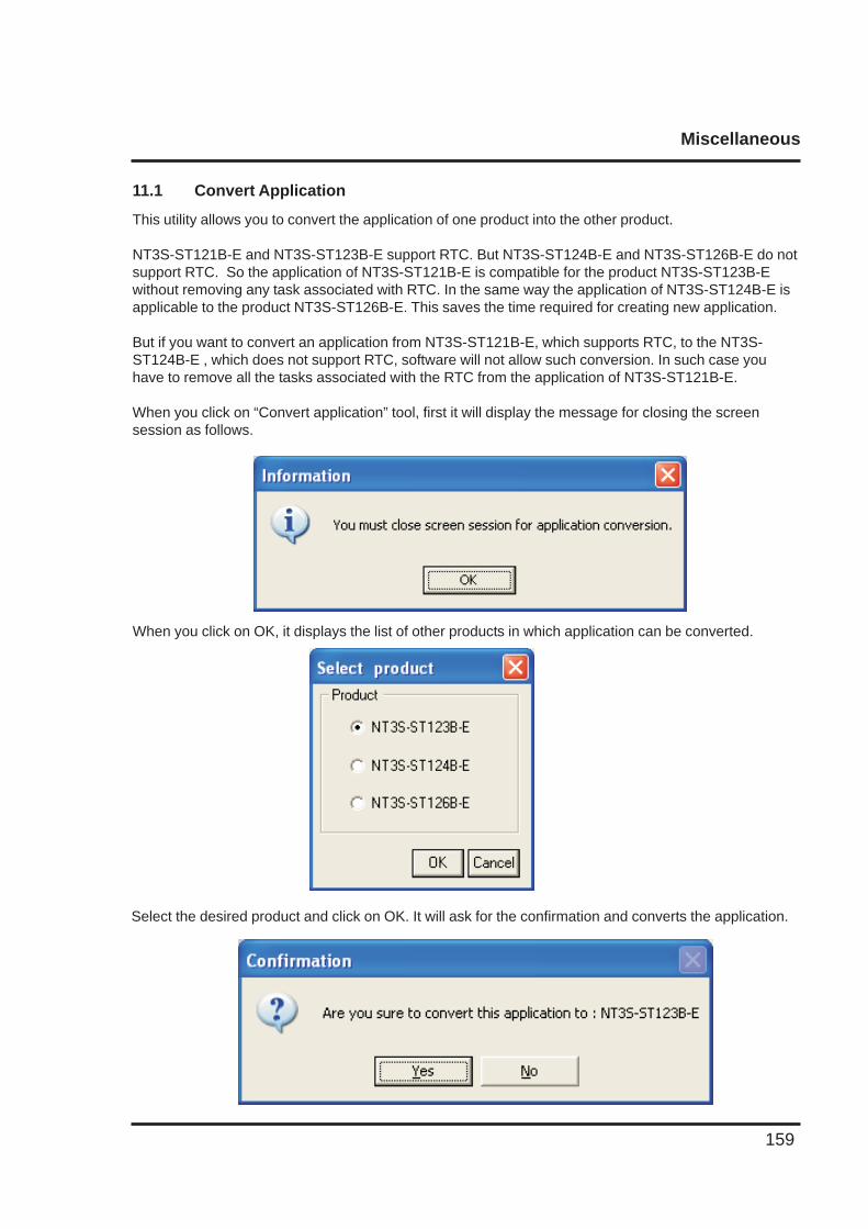
Miscellaneous
159
11.1 Convert Application
This utility allows you to convert the application of one product into the other product.
NT3S-ST121B-E and NT3S-ST123B-E support RTC. But NT3S-ST124B-E and NT3S-ST126B-E do notsupport RTC. So the application of NT3S-ST121B-E is compatible for the product NT3S-ST123B-Ewithout removing any task associated with RTC. In the same way the application of NT3S-ST124B-E isapplicable to the product NT3S-ST126B-E. This saves the time required for creating new application.
But if you want to convert an application from NT3S-ST121B-E, which supports RTC, to the NT3S-ST124B-E , which does not support RTC, software will not allow such conversion. In such case youhave to remove all the tasks associated with the RTC from the application of NT3S-ST121B-E.
When you click on “Convert application” tool, first it will display the message for closing the screensession as follows.
When you click on OK, it displays the list of other products in which application can be converted.
Select the desired product and click on OK. It will ask for the confirmation and converts the application.
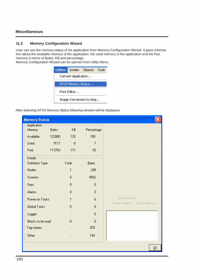
Miscellaneous
160
11.2 Memory Configuration Wizard
User can see the memory status of his application from Memory Configuration Wizard. It gives informa-tion about the available memory of the application, the used memory in the application and the freememory in terms of Bytes, KB and percentage.Memory Configuration Wizard can be opened from Utility Menu.
After selecting NTXS Memory Status following window will be displayed.
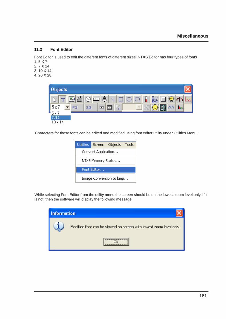
Miscellaneous
161
11.3 Font Editor
Font Editor is used to edit the different fonts of different sizes. NTXS Editor has four types of fonts1. 5 X 72. 7 X 143. 10 X 144. 20 X 28
Characters for these fonts can be edited and modified using font editor utility under Utilities Menu.
While selecting Font Editor from the utility menu the screen should be on the lowest zoom level only. If itis not, then the software will display the following message.
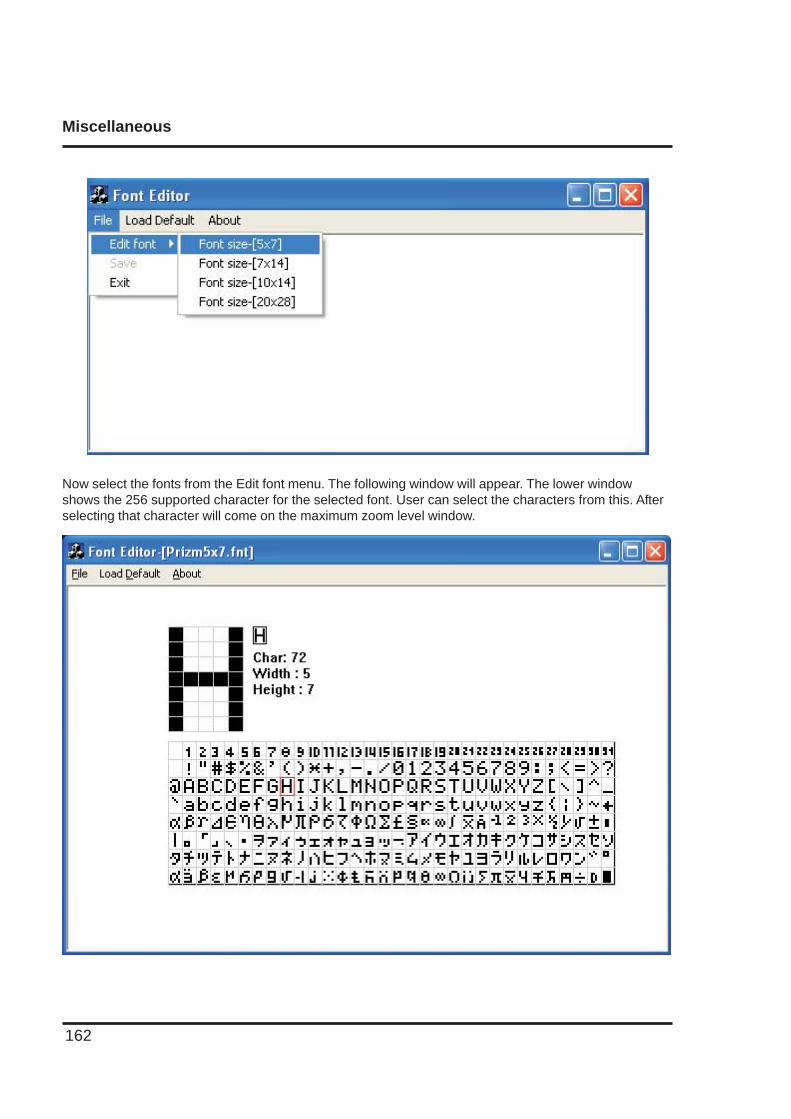
Miscellaneous
162
Now select the fonts from the Edit font menu. The following window will appear. The lower windowshows the 256 supported character for the selected font. User can select the characters from this. Afterselecting that character will come on the maximum zoom level window.
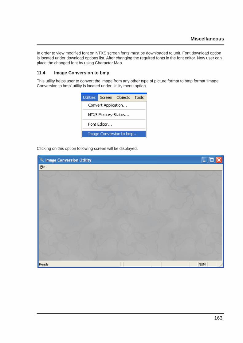
Miscellaneous
163
Clicking on this option following screen will be displayed.
In order to view modified font on NTXS screen fonts must be downloaded to unit. Font download optionis located under download options list. After changing the required fonts in the font editor. Now user canplace the changed font by using Character Map.
11.4 Image Conversion to bmp
This utility helps user to convert the image from any other type of picture format to bmp format ‘ImageConversion to bmp’ utility is located under Utility menu option.
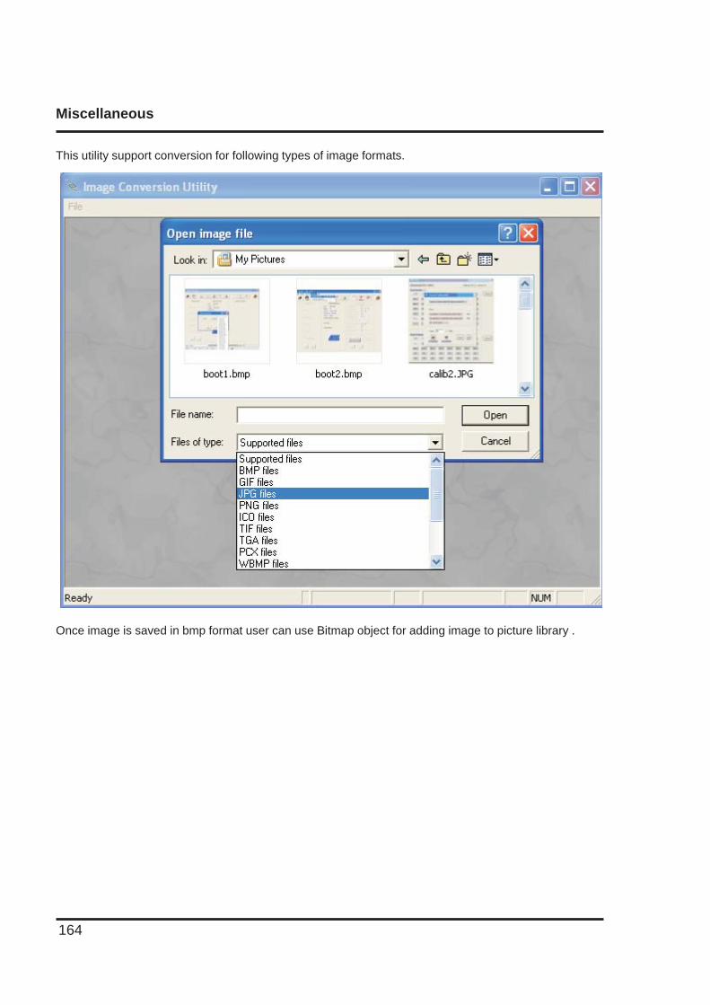
Miscellaneous
164
Once image is saved in bmp format user can use Bitmap object for adding image to picture library .
This utility support conversion for following types of image formats.
Diagnostic and Maintainance
165
DIAGNOSTICS & MAINTENANCE
In this chapter. . . .
♦ Diagnostics
♦ Maintenance
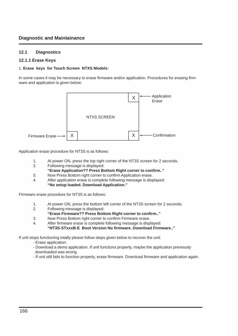
Diagnostic and Maintainance
166
12.1 Diagnostics
12.1.1 Erase Keys
1. Erase keys for Touch Screen NTXS Models:
In some cases it may be necessary to erase firmware and/or application. Procedures for erasing firm-ware and application is given below:
Application erase procedure for NT3S is as follows:
1. At power ON, press the top right corner of the NT3S screen for 2 seconds.2. Following message is displayed:
“Erase Application?? Press Bottom Right corner to confirm..”3. Now Press Bottom right corner to confirm Application erase.4. After application erase is complete following message is displayed:
“No setup loaded. Download Application.”
Firmware erase procedure for NT3S is as follows:
1. At power ON, press the bottom left corner of the NT3S screen for 2 seconds.2. Following message is displayed:
“Erase Firmware?? Press Bottom Right corner to confirm..”3. Now Press Bottom right corner to confirm Firmware erase.4. After firmware erase is complete following message is displayed:
“NT3S-STxxxB-E Boot Version No firmware. Download Firmware..”
If unit stops functioning totally please follow steps given below to recover the unit:- Erase application.- Download a demo application. If unit functions properly, maybe the application previously downloaded was wrong.- If unit still fails to function properly, erase firmware. Download firmware and application again.
ConfirmationX
X
X
ApplicationErase
Firmware Erase
NTXS SCREEN
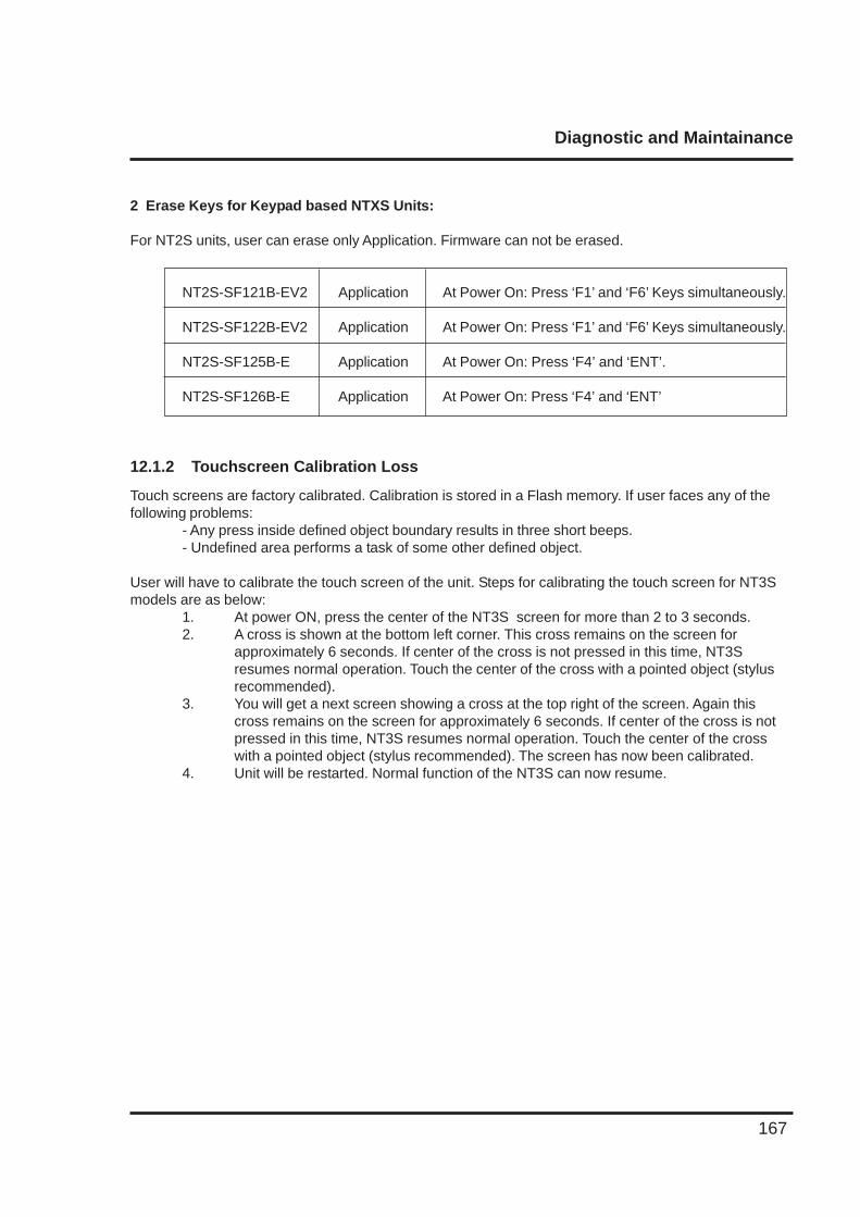
Diagnostic and Maintainance
167
2 Erase Keys for Keypad based NTXS Units:
For NT2S units, user can erase only Application. Firmware can not be erased.
NT2S-SF121B-EV2 Application At Power On: Press ‘F1’ and ‘F6’ Keys simultaneously.
NT2S-SF122B-EV2 Application At Power On: Press ‘F1’ and ‘F6’ Keys simultaneously.
NT2S-SF125B-E Application At Power On: Press ‘F4’ and ‘ENT’.
NT2S-SF126B-E Application At Power On: Press ‘F4’ and ‘ENT’
12.1.2 Touchscreen Calibration Loss
Touch screens are factory calibrated. Calibration is stored in a Flash memory. If user faces any of thefollowing problems:
- Any press inside defined object boundary results in three short beeps.- Undefined area performs a task of some other defined object.
User will have to calibrate the touch screen of the unit. Steps for calibrating the touch screen for NT3Smodels are as below:
1. At power ON, press the center of the NT3S screen for more than 2 to 3 seconds.2. A cross is shown at the bottom left corner. This cross remains on the screen for
approximately 6 seconds. If center of the cross is not pressed in this time, NT3Sresumes normal operation. Touch the center of the cross with a pointed object (stylusrecommended).
3. You will get a next screen showing a cross at the top right of the screen. Again thiscross remains on the screen for approximately 6 seconds. If center of the cross is notpressed in this time, NT3S resumes normal operation. Touch the center of the crosswith a pointed object (stylus recommended). The screen has now been calibrated.
4. Unit will be restarted. Normal function of the NT3S can now resume.
Diagnostic and Maintainance
168
12.2 Maintenance
12.2.1 Clean all sides of the unit using a isopropyl alcohol solution. Use a clean, soft piece of cloth. Donot use a rough cloth as it may produce scratches on the unit. Take proper care while cleaningthe keypad of the unit, especially the LCD window. Also take care that the LCD windowdoes not come in contact with the material that has an abrasive surface.
12.2.2. Do not use benzene, paint thinner or other volatile solvents. Do not use any chemically treatedcloth, wipes, or rags.
12.2.3. Tighten the mounting brackets evenly. Make sure the panel is not dirty or warped and that it isstrong enough to hold the unit.
12.2.4. Please note keys on the keypad are only for finger operation. They should not be pressed withpointed tools or any other such items. This will cause key failure or other malfunctioning mayoccur. Do not apply a force any greater that 30 Newton’s to the keys.
12.2.5. Always tighten the connector screws after connecting the communication cables.
12.2.6. The maximum pull load for cables is 30 Newton’s. Do not apply loads greater than this.
12.2.7 Do not use sharp objects for pressing any touch screen key.
Appendix
169
APPENDIX
In this chapter. . . .
♦ Omron Cable References and Diagrams
♦ Non-Omron Cable Diagrams
♦ List of features
♦ List of Supported Devices
♦ Technical Support
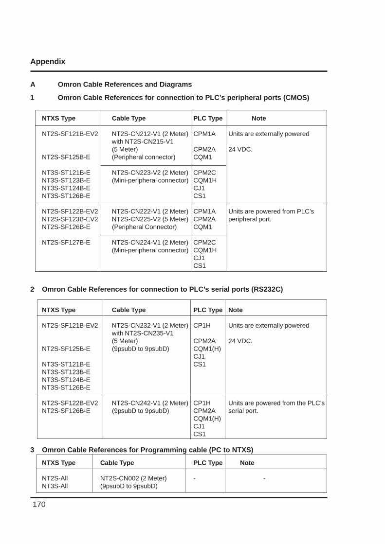
Appendix
170
A Omron Cable References and Diagrams
1 Omron Cable References for connection to PLC’s peripheral ports (CMOS)
NTXS Type Cable Type PLC Type Note
NT2S-SF121B-EV2 NT2S-CN212-V1 (2 Meter) CPM1A Units are externally poweredwith NT2S-CN215-V1(5 Meter) CPM2A 24 VDC.
NT2S-SF125B-E (Peripheral connector) CQM1
NT3S-ST121B-E NT2S-CN223-V2 (2 Meter) CPM2CNT3S-ST123B-E (Mini-peripheral connector) CQM1HNT3S-ST124B-E CJ1NT3S-ST126B-E CS1
NT2S-SF122B-EV2 NT2S-CN222-V1 (2 Meter) CPM1A Units are powered from PLC’sNT2S-SF123B-EV2 NT2S-CN225-V2 (5 Meter) CPM2A peripheral port.NT2S-SF126B-E (Peripheral Connector) CQM1
NT2S-SF127B-E NT2S-CN224-V1 (2 Meter) CPM2C(Mini-peripheral connector) CQM1H
CJ1CS1
2 Omron Cable References for connection to PLC’s serial ports (RS232C)
NTXS Type Cable Type PLC Type Note
NT2S-SF121B-EV2 NT2S-CN232-V1 (2 Meter) CP1H Units are externally poweredwith NT2S-CN235-V1(5 Meter) CPM2A 24 VDC.
NT2S-SF125B-E (9psubD to 9psubD) CQM1(H)CJ1
NT3S-ST121B-E CS1NT3S-ST123B-ENT3S-ST124B-ENT3S-ST126B-E
NT2S-SF122B-EV2 NT2S-CN242-V1 (2 Meter) CP1H Units are powered from the PLC’sNT2S-SF126B-E (9psubD to 9psubD) CPM2A serial port.
CQM1(H)CJ1CS1
3 Omron Cable References for Programming cable (PC to NTXS)
NTXS Type Cable Type PLC Type Note
NT2S-All NT2S-CN002 (2 Meter) - -NT3S-All (9psubD to 9psubD)
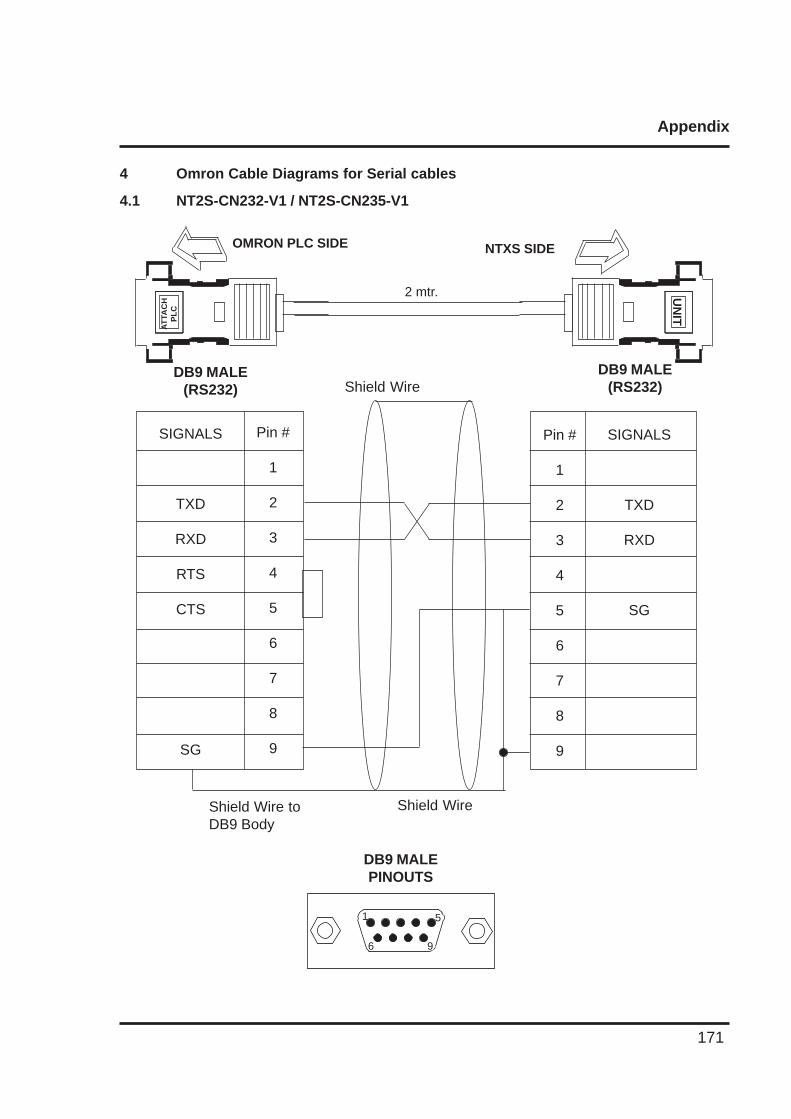
Appendix
171
4 Omron Cable Diagrams for Serial cables
4.1 NT2S-CN232-V1 / NT2S-CN235-V1
DB9 MALEPINOUTS
UN
IT
NTXS SIDEOMRON PLC SIDE
2 mtr.
AT
TAC
HP
LC
SIGNALS
TXD
RXD
SG
Shield Wire
Pin #
1
2
3
4
5
6
7
8
9
SIGNALS
TXD
RXD
RTS
CTS
SG
Pin #
1
2
3
4
5
6
7
8
9
Shield Wire toDB9 Body
DB9 MALE(RS232)
DB9 MALE(RS232) Shield Wire
6 9
1 5
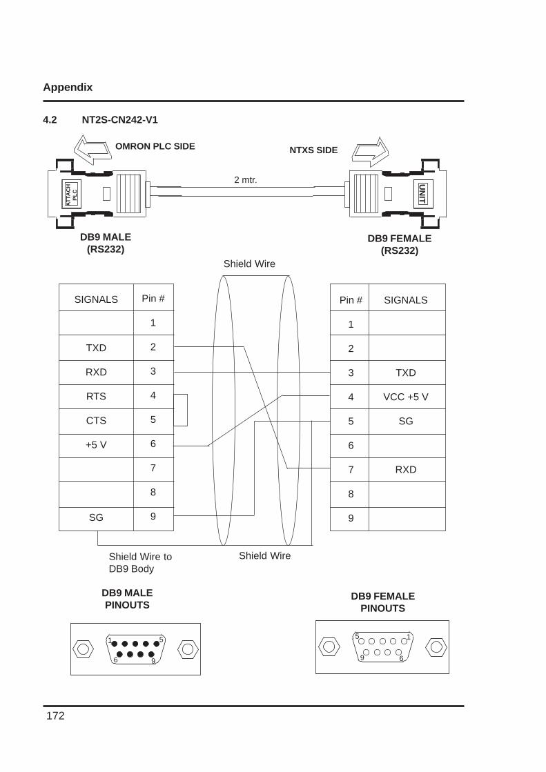
Appendix
172
4.2 NT2S-CN242-V1
SIGNALS
TXD
VCC +5 V
SG
RXD
Shield Wire
Shield Wire
Pin #
1
2
3
4
5
6
7
8
9
SIGNALS
TXD
RXD
RTS
CTS
+5 V
SG
Pin #
1
2
3
4
5
6
7
8
9
Shield Wire toDB9 Body
DB9 MALEPINOUTS
DB9 FEMALEPINOUTS
UN
IT
NTXS SIDEOMRON PLC SIDE
2 mtr.
DB9 FEMALE(RS232)
DB9 MALE(RS232)
AT
TAC
HP
LC
6 9
1 5
9 6
5 1
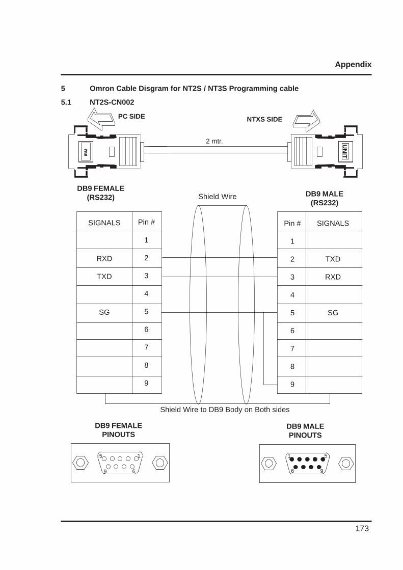
Appendix
173
5 Omron Cable Disgram for NT2S / NT3S Programming cable
5.1 NT2S-CN002
DB9 MALE(RS232)
DB9 FEMALE(RS232)
SIGNALS
TXD
RXD
SG
Shield Wire
Pin #
1
2
3
4
5
6
7
8
9
SIGNALS
RXD
TXD
SG
Pin #
1
2
3
4
5
6
7
8
9
Shield Wire to DB9 Body on Both sides
DB9 MALEPINOUTS
DB9 FEMALEPINOUTS
UN
IT
NTXS SIDEPC SIDE
2 mtr.
IBM
9 6
5 1
6 9
1 5
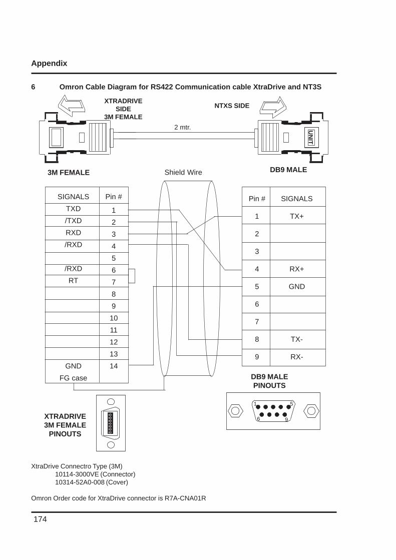
Appendix
174
6 Omron Cable Diagram for RS422 Communication cable XtraDrive and NT3S
XtraDrive Connectro Type (3M)10114-3000VE (Connector)10314-52A0-008 (Cover)
Omron Order code for XtraDrive connector is R7A-CNA01R
DB9 MALEPINOUTS
DB9 MALE3M FEMALE
SIGNALS
TX+
RX+
GND
TX-
RX-
Shield Wire
Pin #
1
2
3
4
5
6
7
8
9
SIGNALS
TXD
/TXD
RXD
/RXD
/RXD
RT
GND
FG case
Pin #
1
2
3
4
5
6
7
8
9
10
11
12
13
14
UN
IT
NTXS SIDE
2 mtr.
XTRADRIVESIDE
3M FEMALE
XTRADRIVE3M FEMALE
PINOUTS
6 9
1 5
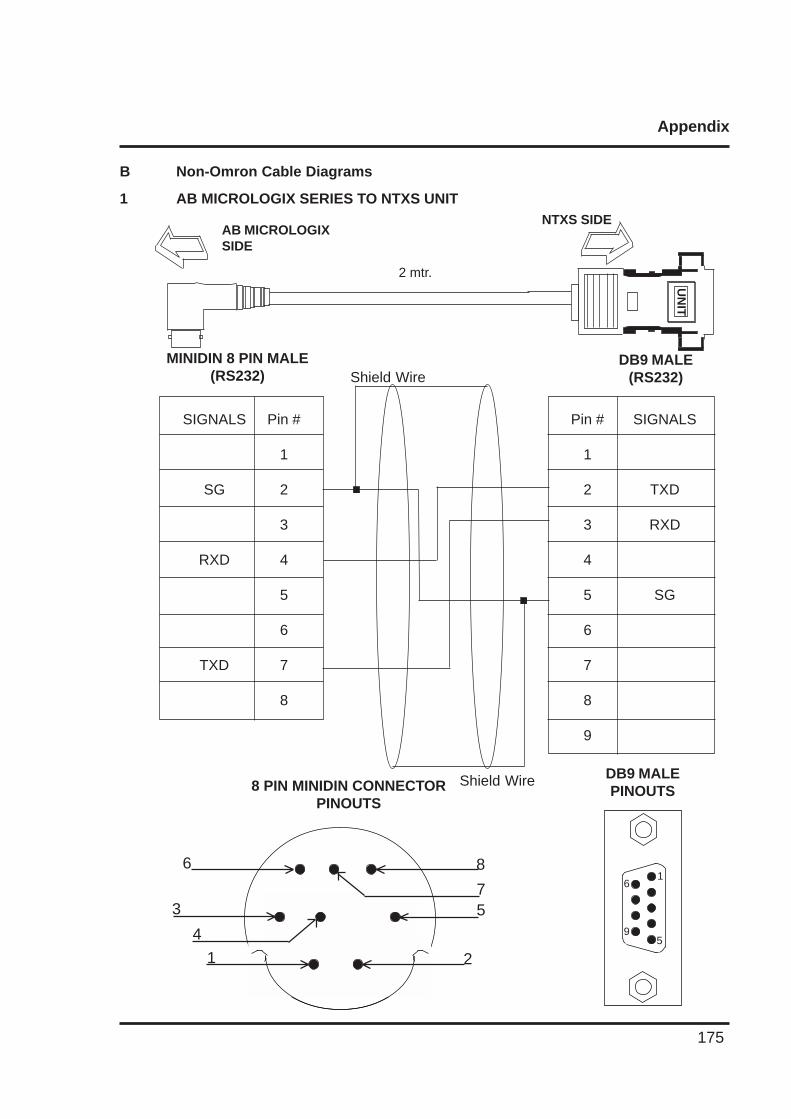
Appendix
175
B Non-Omron Cable Diagrams
1 AB MICROLOGIX SERIES TO NTXS UNIT
UN
IT
NTXS SIDEAB MICROLOGIXSIDE
2 mtr.
Pin #
1
2
3
4
5
6
7
8
9
SIGNALS
TXD
RXD
SG
DB9 MALE(RS232)
Pin #
1
2
3
4
5
6
7
8
SIGNALS
SG
RXD
TXD
MINIDIN 8 PIN MALE(RS232)
DB9 MALEPINOUTS8 PIN MINIDIN CONNECTOR
PINOUTS
Shield Wire
Shield Wire
6
9
1
5
6
3
4
1
8
75
2
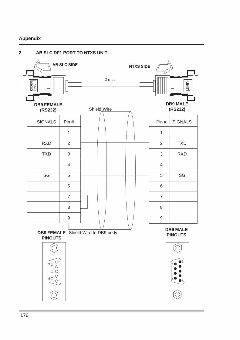
Appendix
176
2 AB SLC DF1 PORT TO NTXS UNIT
SIGNALS
TXD
RXD
SG
DB9 MALEPINOUTSDB9 FEMALE
PINOUTS
6
9
1
5
Shield Wire to DB9 body
9
6
5
1
Pin #
1
2
3
4
5
6
7
8
9
Pin #
1
2
3
4
5
6
7
8
9
SIGNALS
RXD
TXD
SG
UN
IT
NTXS SIDEAB SLC SIDE
2 mtr.
DB9 MALE(RS232)
DB9 FEMALE(RS232) Shield Wire
AT
TAC
HP
LC
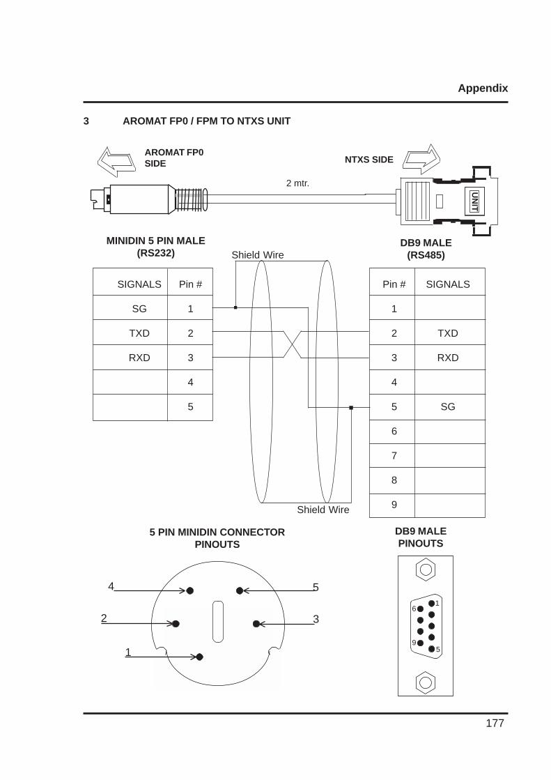
Appendix
177
3 AROMAT FP0 / FPM TO NTXS UNIT
UN
IT
NTXS SIDEAROMAT FP0SIDE
2 mtr.
Pin #
1
2
3
4
5
6
7
8
9
SIGNALS
TXD
RXD
SG
DB9 MALE(RS485)
Pin #
1
2
3
4
5
SIGNALS
SG
TXD
RXD
MINIDIN 5 PIN MALE(RS232)
DB9 MALEPINOUTS
5 PIN MINIDIN CONNECTORPINOUTS
Shield Wire
Shield Wire
6
9
1
5
4
2
1
5
3
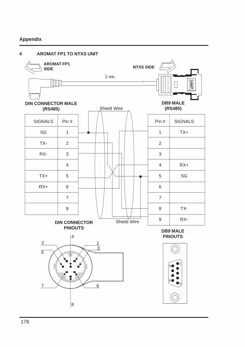
Appendix
178
4 AROMAT FP1 TO NTXS UNITU
NIT
NTXS SIDEAROMAT FP1SIDE
2 mtr.
Pin #
1
2
3
4
5
6
7
8
9
SIGNALS
TX+
RX+
SG
TX-
RX-
DB9 MALE(RS485)
Pin #
1
2
3
4
5
6
7
8
SIGNALS
SG
TX-
RX-
TX+
RX+
DIN CONNECTOR MALE(RS485)
DB9 MALEPINOUTS
DIN CONNECTORPINOUTS
6
9
1
5
Shield Wire
Shield Wire
42
5
7
8
6
13
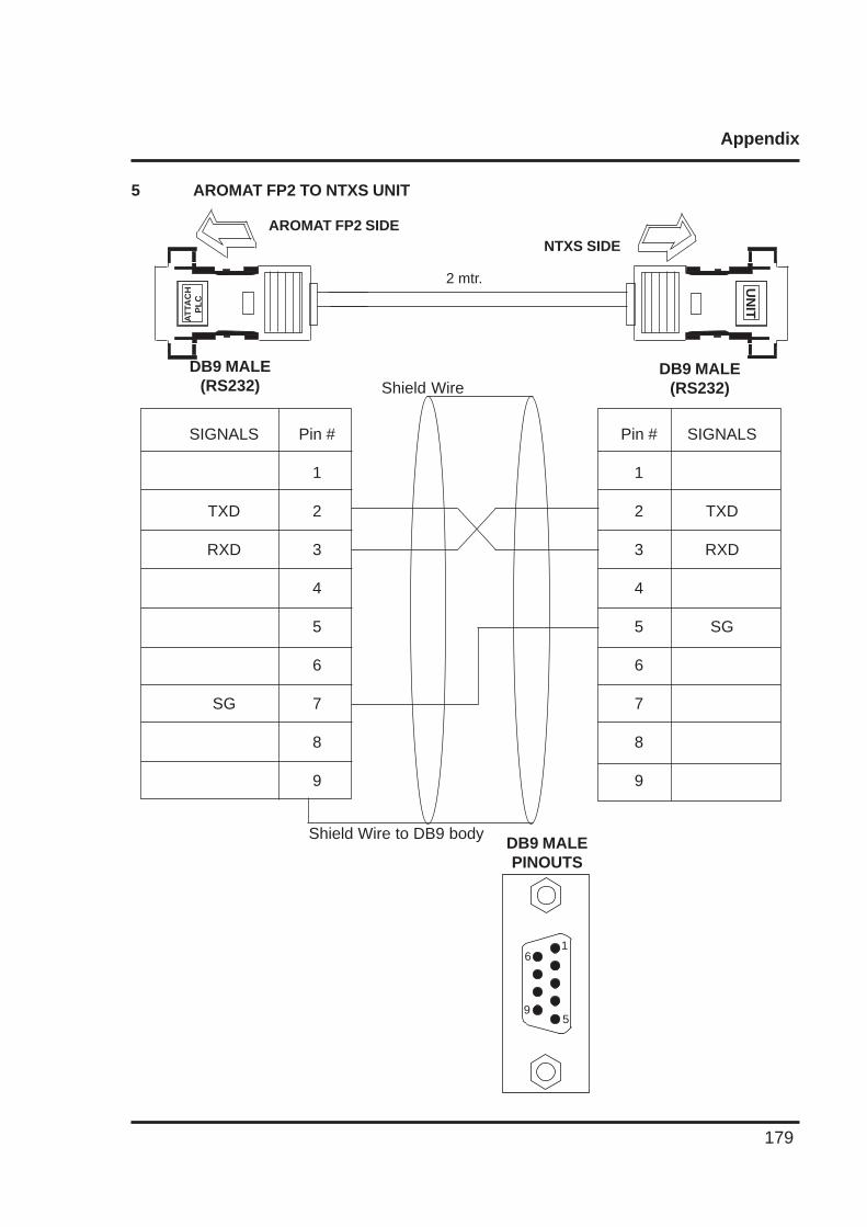
Appendix
179
5 AROMAT FP2 TO NTXS UNIT
UN
IT
NTXS SIDEAROMAT FP2 SIDE
2 mtr.
SIGNALS
TXD
RXD
SG
DB9 MALE(RS232)
DB9 MALE(RS232)
DB9 MALEPINOUTS
6
9
1
5
Shield Wire
Shield Wire to DB9 body
AT
TAC
HP
LC
Pin #
1
2
3
4
5
6
7
8
9
Pin #
1
2
3
4
5
6
7
8
9
SIGNALS
TXD
RXD
SG
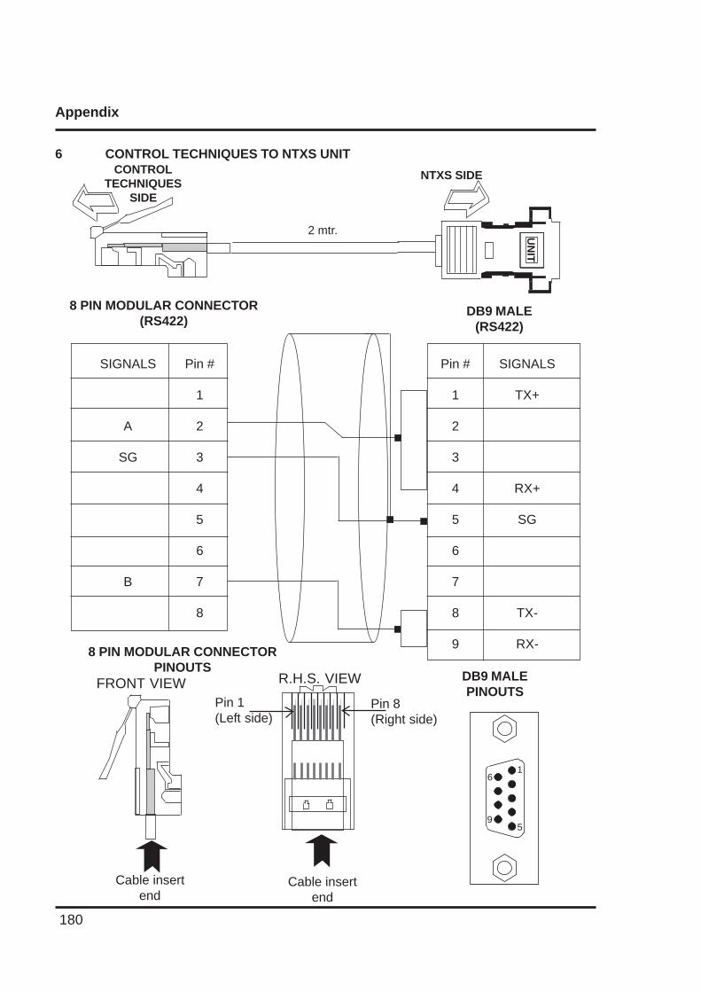
Appendix
180
6 CONTROL TECHNIQUES TO NTXS UNITCONTROL
TECHNIQUESSIDE
UN
ITNTXS SIDE
2 mtr.
Pin #
1
2
3
4
5
6
7
8
9
SIGNALS
TX+
RX+
SG
TX-
RX-
DB9 MALE(RS422)
Pin #
1
2
3
4
5
6
7
8
SIGNALS
A
SG
B
8 PIN MODULAR CONNECTOR(RS422)
DB9 MALEPINOUTS
8 PIN MODULAR CONNECTORPINOUTS
6
9
1
5
Cable insertend
Cable insertend
Pin 1(Left side)
Pin 8(Right side)
FRONT VIEW R.H.S. VIEW
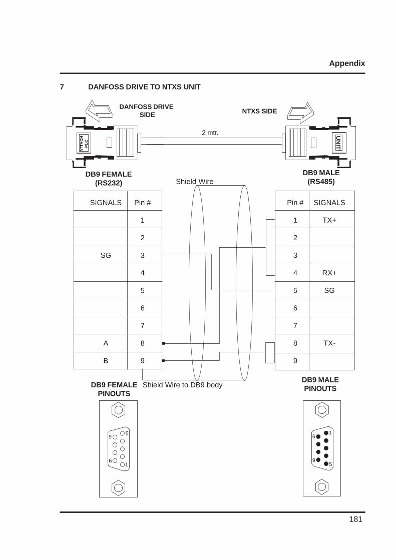
Appendix
181
7 DANFOSS DRIVE TO NTXS UNIT
UN
IT
NTXS SIDEDANFOSS DRIVE
SIDE
2 mtr.
SIGNALS
TX+
RX+
SG
TX-
DB9 MALE(RS485)
DB9 FEMALE(RS232)
DB9 MALEPINOUTSDB9 FEMALE
PINOUTS
6
9
1
5
Shield Wire
Shield Wire to DB9 body
AT
TAC
HP
LC
9
6
5
1
Pin #
1
2
3
4
5
6
7
8
9
Pin #
1
2
3
4
5
6
7
8
9
SIGNALS
SG
A
B
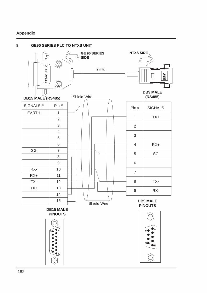
Appendix
182
8 GE90 SERIES PLC TO NTXS UNITU
NIT
NTXS SIDEGE 90 SERIESSIDE
2 mtr.
SIGNALS
TX+
RX+
SG
TX-
RX-
DB9 MALE(RS485)DB15 MALE (RS485)
DB9 MALEPINOUTS
6
9
1
5
Shield Wire
Shield Wire
Pin #
1
2
3
4
5
6
7
8
9
Pin #
1
2
3
4
5
6
7
8
9
10
11
12
13
14
15
SIGNALS #
EARTH
SG
RX-
RX+
TX-
TX+
DB15 MALEPINOUTS
15
9 1
8
AT
TAC
H P
LC
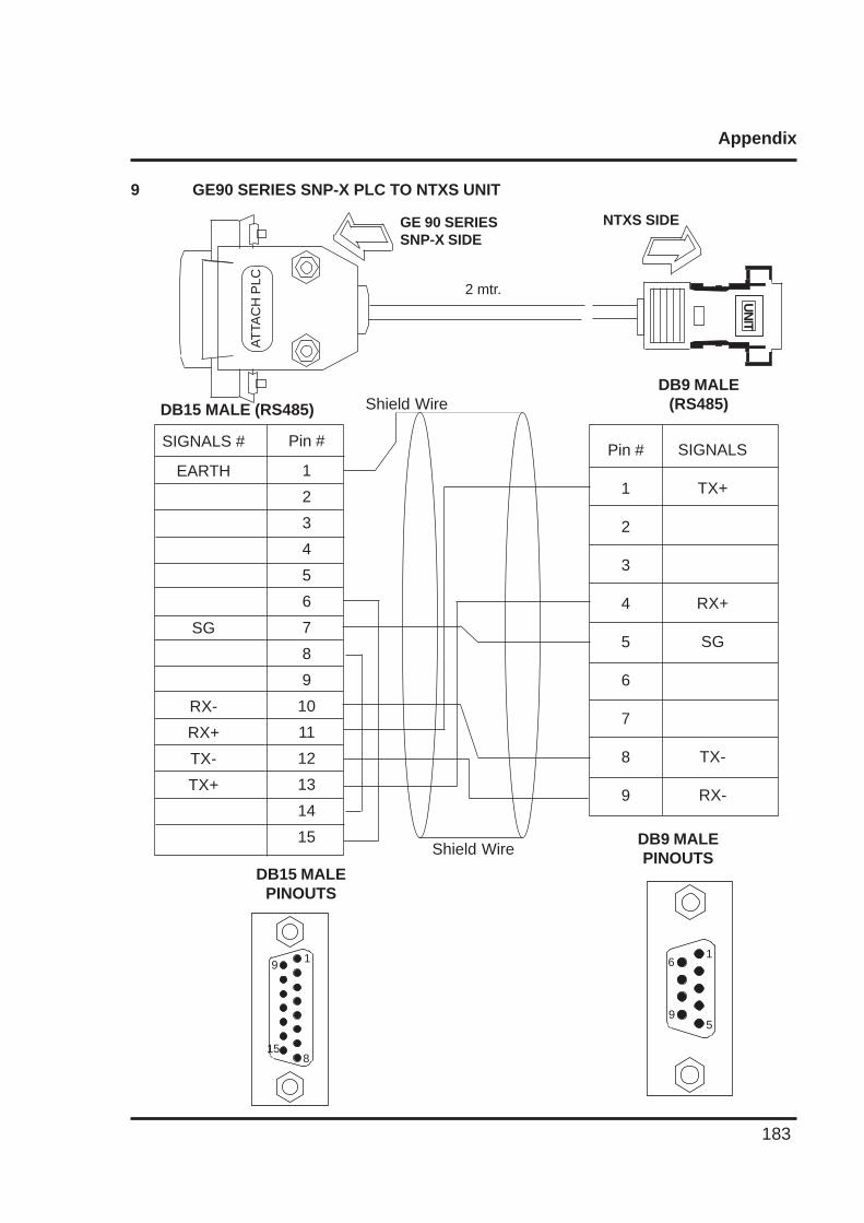
Appendix
183
9 GE90 SERIES SNP-X PLC TO NTXS UNIT
UN
IT
NTXS SIDEGE 90 SERIESSNP-X SIDE
2 mtr.
SIGNALS
TX+
RX+
SG
TX-
RX-
DB9 MALE(RS485)DB15 MALE (RS485)
DB9 MALEPINOUTS
6
9
1
5
Shield Wire
Shield Wire
Pin #
1
2
3
4
5
6
7
8
9
Pin #
1
2
3
4
5
6
7
8
9
10
11
12
13
14
15
SIGNALS #
EARTH
SG
RX-
RX+
TX-
TX+
DB15 MALEPINOUTS
15
9 1
8
AT
TAC
H P
LC
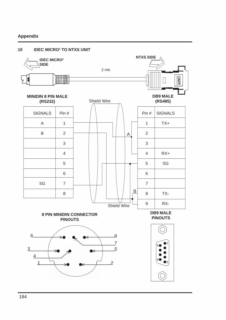
Appendix
184
10 IDEC MICRO3 TO NTXS UNITU
NIT
NTXS SIDEIDEC MICRO3
SIDE2 mtr.
Pin #
1
2
3
4
5
6
7
8
9
SIGNALS
TX+
RX+
SG
TX-
RX-
DB9 MALE(RS485)
Pin #
1
2
3
4
5
6
7
8
SIGNALS
A
B
SG
MINIDIN 8 PIN MALE(RS232)
DB9 MALEPINOUTS
8 PIN MINIDIN CONNECTORPINOUTS
6
9
1
5
Shield Wire
Shield Wire
A
B
6
3
4
1
8
75
2
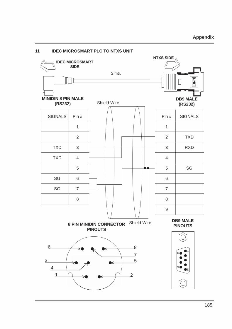
Appendix
185
11 IDEC MICROSMART PLC TO NTXS UNIT
UN
IT
NTXS SIDEIDEC MICROSMART
SIDE
2 mtr.
Pin #
1
2
3
4
5
6
7
8
9
SIGNALS
TXD
RXD
SG
DB9 MALE(RS232)
Pin #
1
2
3
4
5
6
7
8
SIGNALS
TXD
TXD
SG
SG
MINIDIN 8 PIN MALE(RS232)
DB9 MALEPINOUTS8 PIN MINIDIN CONNECTOR
PINOUTS
Shield Wire
Shield Wire
6
9
1
5
6
3
4
1
8
75
2
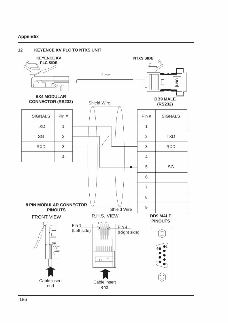
Appendix
186
12 KEYENCE KV PLC TO NTXS UNITU
NIT
NTXS SIDEKEYENCE KVPLC SIDE
2 mtr.
Pin #
1
2
3
4
5
6
7
8
9
SIGNALS
TXD
RXD
SG
DB9 MALE(RS232)
Pin #
1
2
3
4
SIGNALS
TXD
SG
RXD
6X4 MODULARCONNECTOR (RS232)
DB9 MALEPINOUTS
8 PIN MODULAR CONNECTORPINOUTS
6
9
1
5
Cable insertend
Cable insertend
Pin 1(Left side)
Pin 4(Right side)
FRONT VIEW R.H.S. VIEW
Shield Wire
Shield Wire
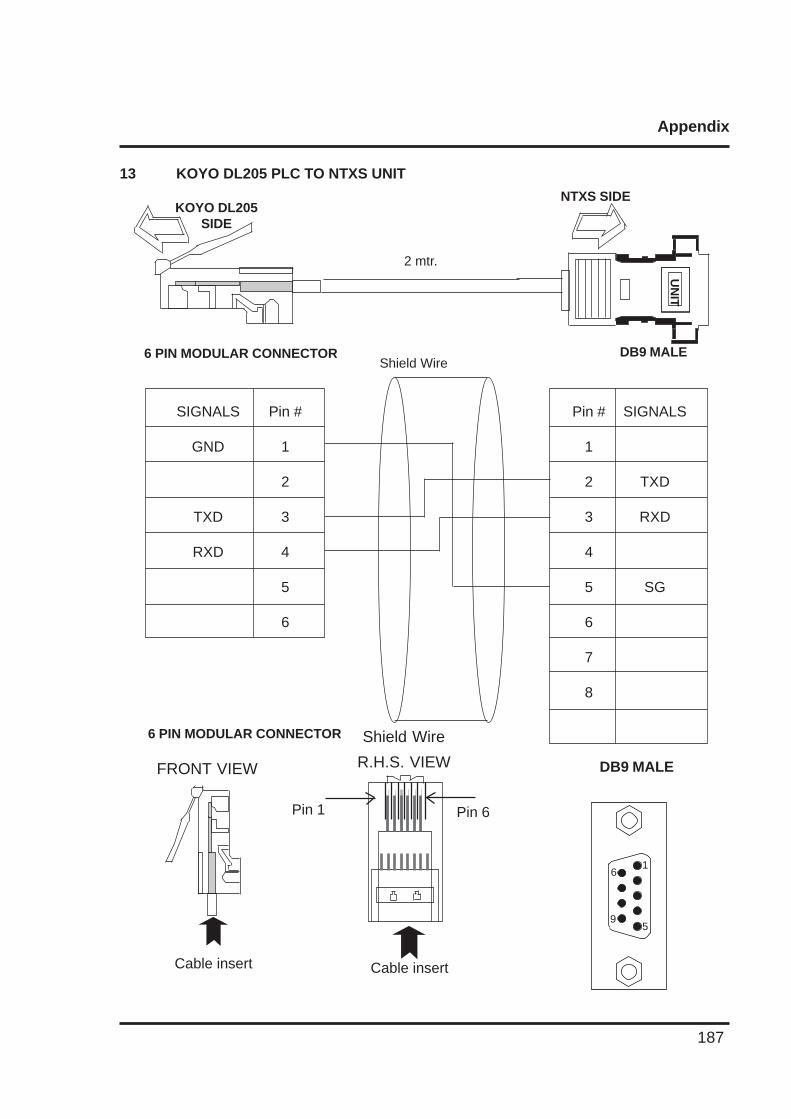
Appendix
187
13 KOYO DL205 PLC TO NTXS UNIT
UN
IT
NTXS SIDEKOYO DL205
SIDE
2 mtr.
Pin #
1
2
3
4
5
6
7
8
SIGNALS
TXD
RXD
SG
DB9 MALE
Pin #
1
2
3
4
5
6
SIGNALS
GND
TXD
RXD
6 PIN MODULAR CONNECTOR
DB9 MALE
6 PIN MODULAR CONNECTOR
Cable insert Cable insert
Pin 1 Pin 6
FRONT VIEW R.H.S. VIEW
Shield Wire
Shield Wire
6
9
1
5
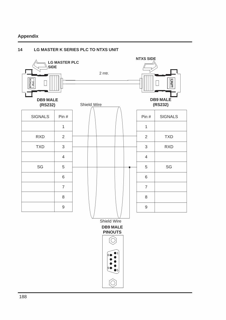
Appendix
188
14 LG MASTER K SERIES PLC TO NTXS UNITU
NIT
NTXS SIDELG MASTER PLCSIDE
2 mtr.
SIGNALS
TXD
RXD
SG
DB9 MALE(RS232)
DB9 MALE(RS232)
DB9 MALEPINOUTS
6
9
1
5
Shield Wire
Shield Wire
AT
TAC
HP
LC
Pin #
1
2
3
4
5
6
7
8
9
Pin #
1
2
3
4
5
6
7
8
9
SIGNALS
RXD
TXD
SG
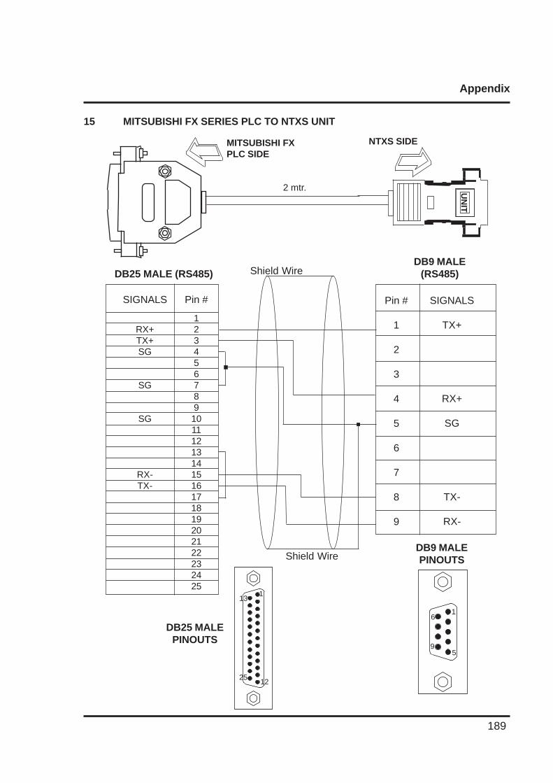
Appendix
189
15 MITSUBISHI FX SERIES PLC TO NTXS UNIT
UN
IT
NTXS SIDEMITSUBISHI FXPLC SIDE
2 mtr.
SIGNALS
TX+
RX+
SG
TX-
RX-
DB9 MALE(RS485)DB25 MALE (RS485)
DB9 MALEPINOUTS
Shield Wire
Shield Wire
Pin #
1
2
3
4
5
6
7
8
9
Pin #
12345678910111213141516171819202122232425
SIGNALS
RX+TX+SG
SG
SG
RX-TX-
DB25 MALEPINOUTS
6
9
1
5
1
12
13
25
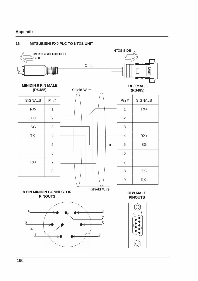
Appendix
190
16 MITSUBISHI FX0 PLC TO NTXS UNITU
NIT
NTXS SIDEMITSIBISHI FX0 PLCSIDE
2 mtr.
Pin #
1
2
3
4
5
6
7
8
9
SIGNALS
TX+
RX+
SG
TX-
RX-
DB9 MALE(RS485)
Pin #
1
2
3
4
5
6
7
8
SIGNALS
RX-
RX+
SG
TX-
TX+
MINIDIN 8 PIN MALE(RS485)
DB9 MALEPINOUTS
8 PIN MINIDIN CONNECTORPINOUTS
6
9
1
5
Shield Wire
Shield Wire
6
3
4
1
8
75
2
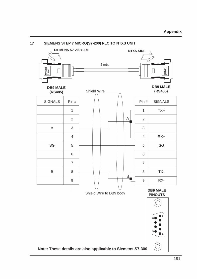
Appendix
191
17 SIEMENS STEP 7 MICRO(S7-200) PLC TO NTXS UNIT
UN
IT
NTXS SIDESIEMENS S7-200 SIDE
2 mtr.
SIGNALS
TX+
RX+
SG
TX-
RX-
DB9 MALE(RS485)
DB9 MALE(RS485)
DB9 MALEPINOUTS
Shield Wire
Shield Wire to DB9 body
AT
TAC
HP
LC
Pin #
1
2
3
4
5
6
7
8
9
Pin #
1
2
3
4
5
6
7
8
9
SIGNALS
A
SG
B
A
B
Note: These details are also applicable to Siemens S7-300
6
9
1
5
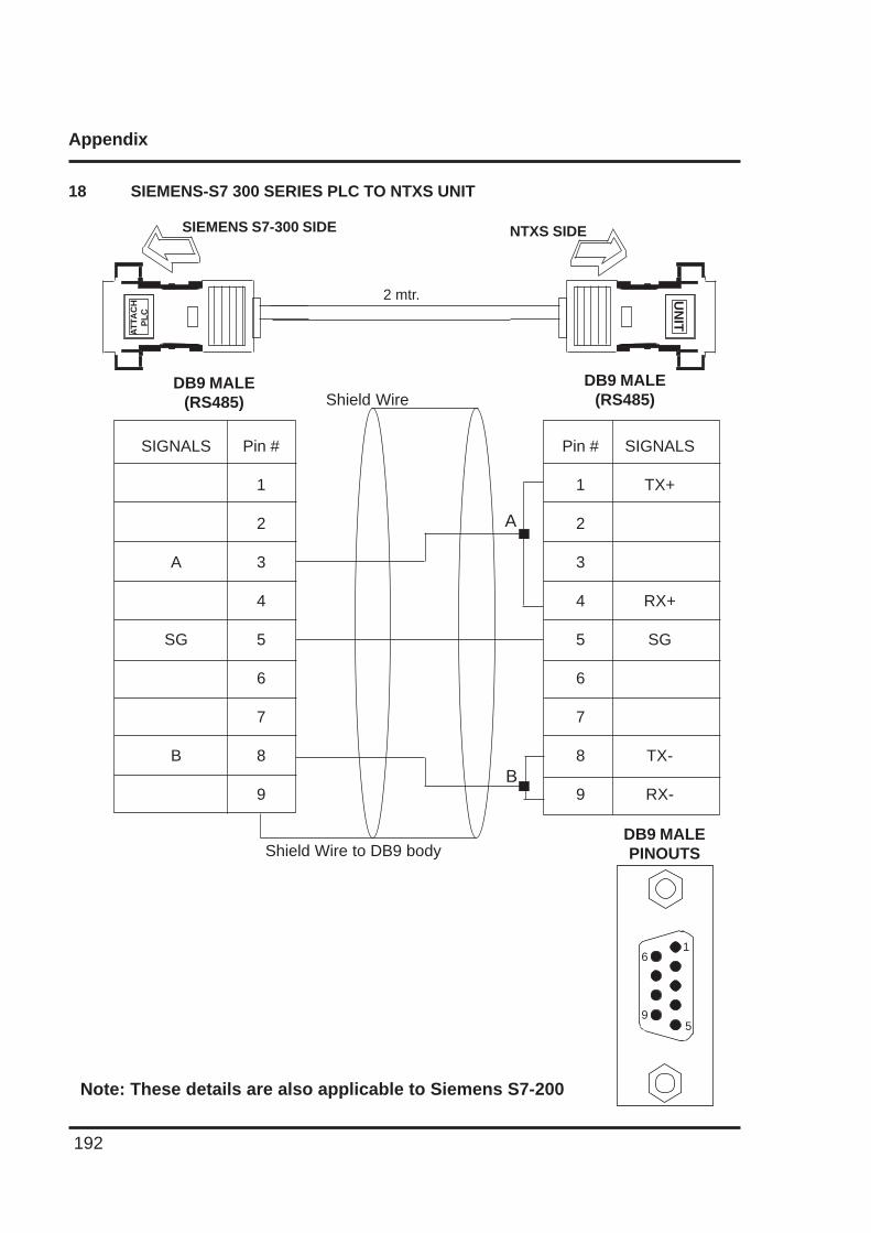
Appendix
192
18 SIEMENS-S7 300 SERIES PLC TO NTXS UNITU
NIT
NTXS SIDESIEMENS S7-300 SIDE
2 mtr.
SIGNALS
TX+
RX+
SG
TX-
RX-
DB9 MALE(RS485)
DB9 MALE(RS485)
DB9 MALEPINOUTS
Shield Wire
Shield Wire to DB9 body
AT
TAC
HP
LC
Pin #
1
2
3
4
5
6
7
8
9
Pin #
1
2
3
4
5
6
7
8
9
SIGNALS
A
SG
B
A
B
Note: These details are also applicable to Siemens S7-200
6
9
1
5
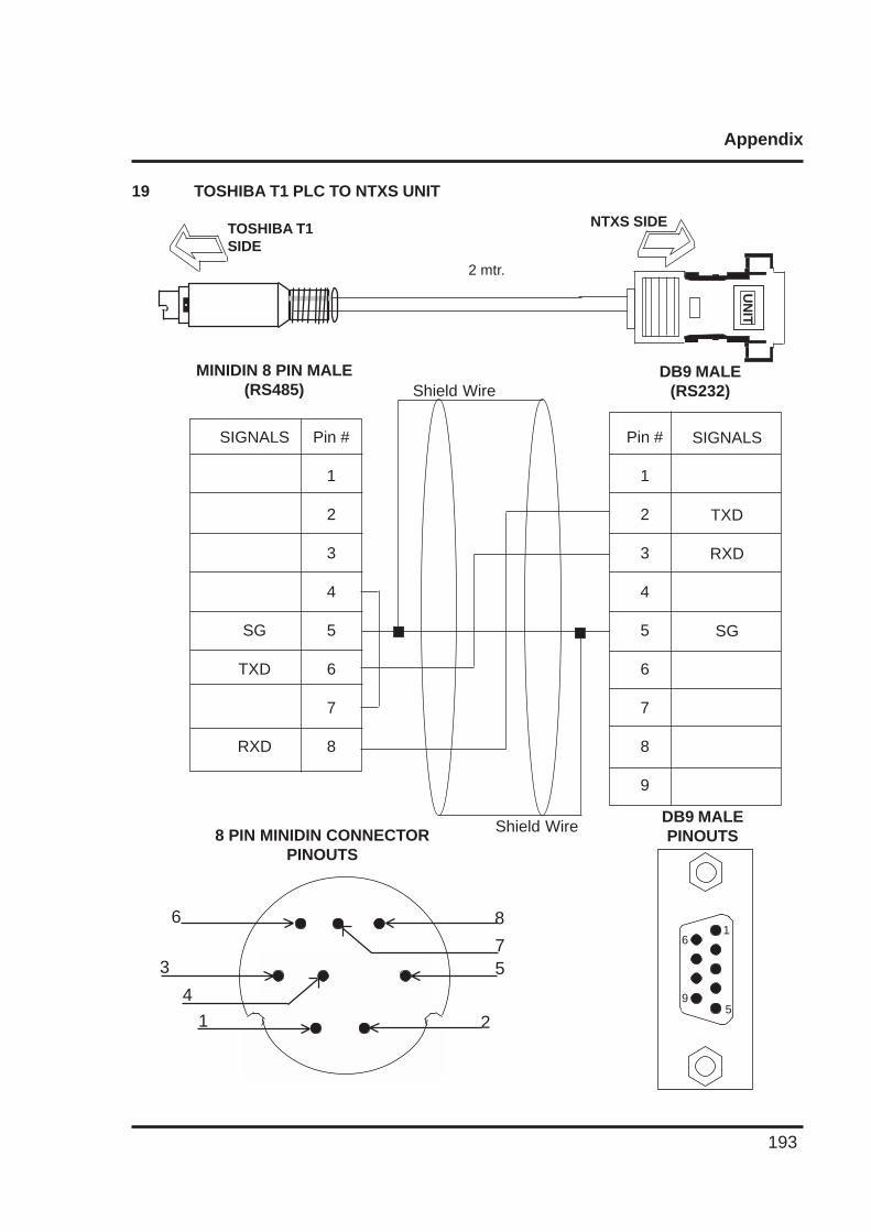
Appendix
193
19 TOSHIBA T1 PLC TO NTXS UNIT
UN
IT
NTXS SIDETOSHIBA T1SIDE
2 mtr.
Pin #
1
2
3
4
5
6
7
8
9
SIGNALS
TXD
RXD
SG
DB9 MALE(RS232)
Pin #
1
2
3
4
5
6
7
8
SIGNALS
SG
TXD
RXD
MINIDIN 8 PIN MALE(RS485)
DB9 MALEPINOUTS
Shield Wire
Shield Wire8 PIN MINIDIN CONNECTORPINOUTS
6
3
4
1
8
75
2
6
9
1
5
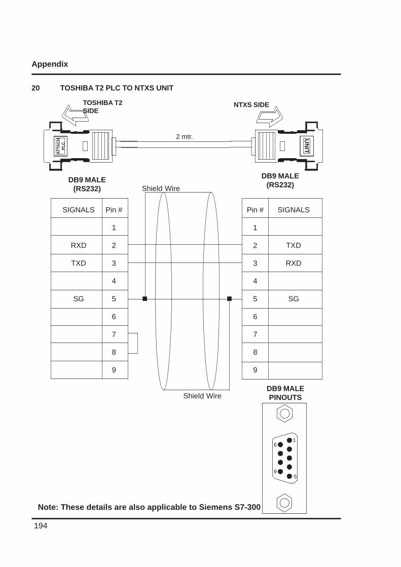
Appendix
194
20 TOSHIBA T2 PLC TO NTXS UNIT
NTXS SIDETOSHIBA T2SIDE
2 mtr.
SIGNALS
TXD
RXD
SG
DB9 MALE(RS232)
DB9 MALE(RS232)
DB9 MALEPINOUTS
Shield Wire
Shield Wire
Pin #
1
2
3
4
5
6
7
8
9
Pin #
1
2
3
4
5
6
7
8
9
SIGNALS
RXD
TXD
SG
Note: These details are also applicable to Siemens S7-300
UN
IT
AT
TAC
HP
LC
6
9
1
5
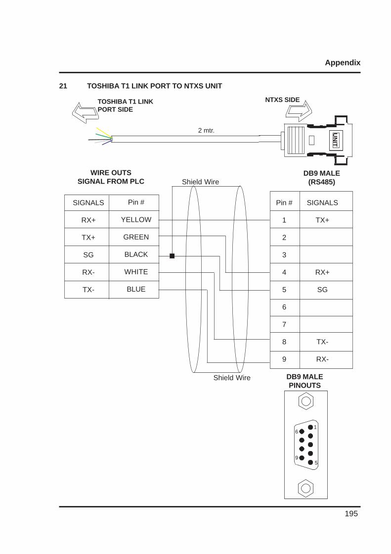
Appendix
195
21 TOSHIBA T1 LINK PORT TO NTXS UNIT
UN
IT
NTXS SIDETOSHIBA T1 LINKPORT SIDE
2 mtr.
Pin #
1
2
3
4
5
6
7
8
9
SIGNALS
TX+
RX+
SG
TX-
RX-
DB9 MALE(RS485)
Pin #
YELLOW
GREEN
BLACK
WHITE
BLUE
SIGNALS
RX+
TX+
SG
RX-
TX-
WIRE OUTSSIGNAL FROM PLC
DB9 MALEPINOUTS
Shield Wire
Shield Wire
6
9
1
5
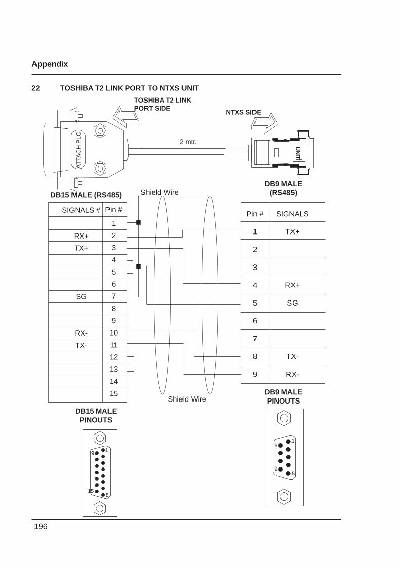
Appendix
196
22 TOSHIBA T2 LINK PORT TO NTXS UNIT
UN
IT
NTXS SIDE
TOSHIBA T2 LINKPORT SIDE
2 mtr.
SIGNALS
TX+
RX+
SG
TX-
RX-
DB9 MALE(RS485)DB15 MALE (RS485)
DB9 MALEPINOUTS
6
9
1
5
Shield Wire
Shield Wire
Pin #
1
2
3
4
5
6
7
8
9
AT
TAC
H P
LC
Pin #
1
2
3
4
5
6
7
8
9
10
11
12
13
14
15
SIGNALS #
RX+
TX+
SG
RX-
TX-
DB15 MALEPINOUTS
15
91
8
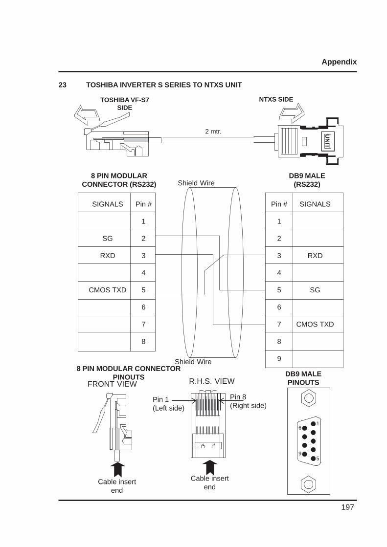
Appendix
197
23 TOSHIBA INVERTER S SERIES TO NTXS UNIT
UN
IT
NTXS SIDETOSHIBA VF-S7SIDE
2 mtr.
Pin #
1
2
3
4
5
6
7
8
9
SIGNALS
RXD
SG
CMOS TXD
DB9 MALE(RS232)
Pin #
1
2
3
4
5
6
7
8
SIGNALS
SG
RXD
CMOS TXD
8 PIN MODULARCONNECTOR (RS232)
DB9 MALEPINOUTS
8 PIN MODULAR CONNECTORPINOUTS
6
9
1
5
Cable insertend
Cable insertend
Pin 1(Left side)
Pin 8(Right side)
FRONT VIEW R.H.S. VIEW
Shield Wire
Shield Wire
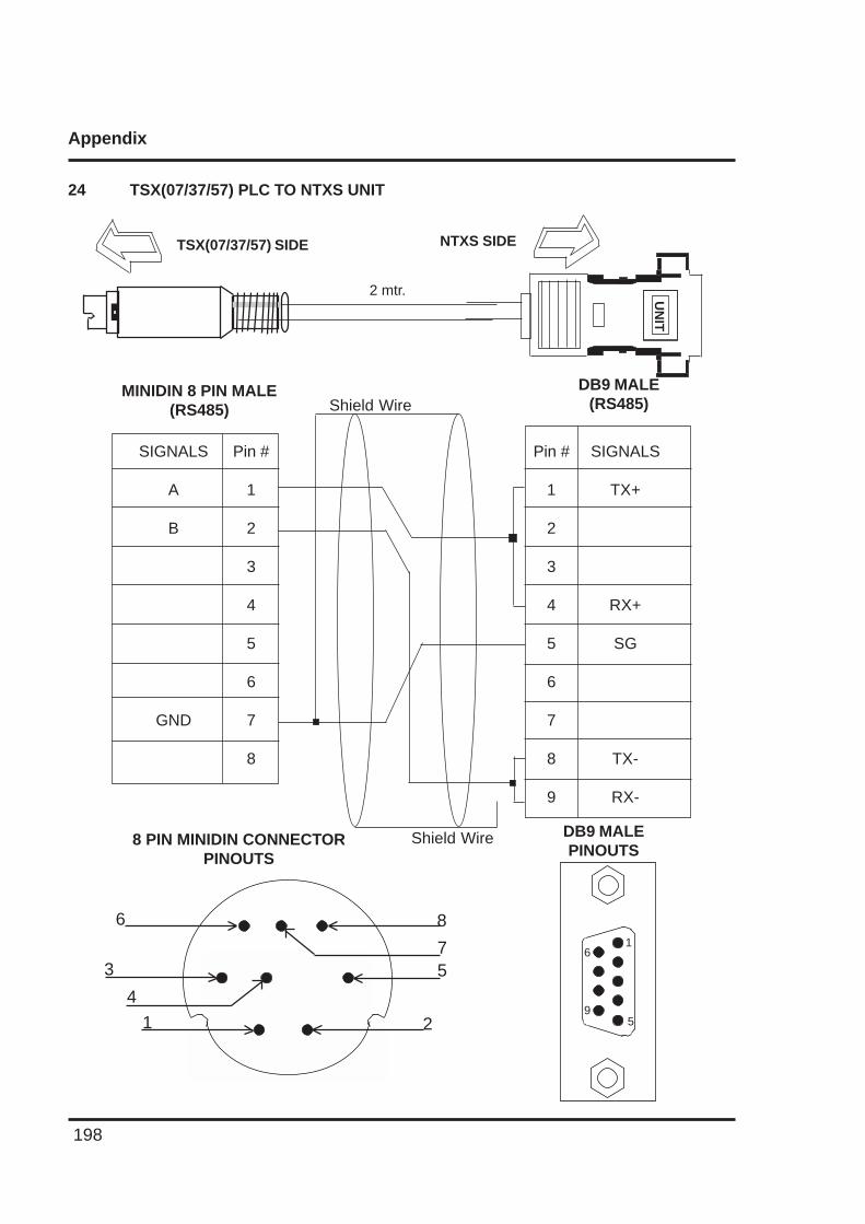
Appendix
198
24 TSX(07/37/57) PLC TO NTXS UNITU
NIT
NTXS SIDETSX(07/37/57) SIDE
2 mtr.
Pin #
1
2
3
4
5
6
7
8
9
SIGNALS
TX+
RX+
SG
TX-
RX-
DB9 MALE(RS485)
Pin #
1
2
3
4
5
6
7
8
SIGNALS
A
B
GND
MINIDIN 8 PIN MALE(RS485)
DB9 MALEPINOUTS
8 PIN MINIDIN CONNECTORPINOUTS
Shield Wire
Shield Wire
6
3
4
1
8
75
2
6
9
1
5
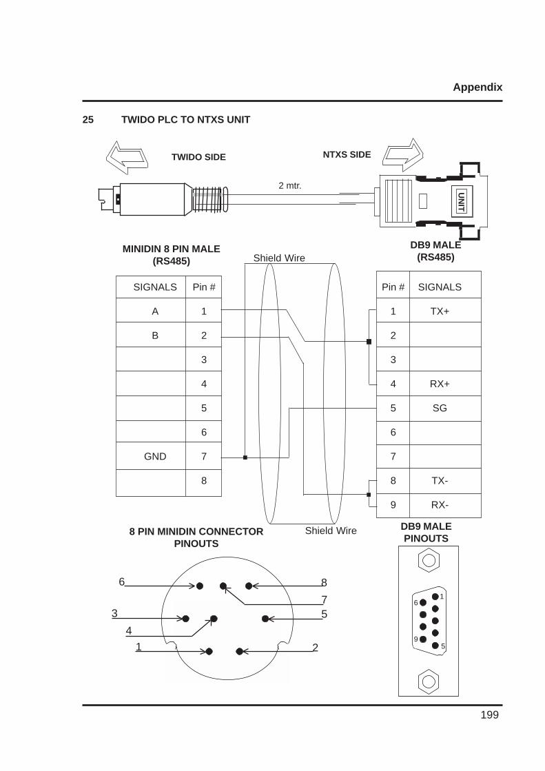
Appendix
199
25 TWIDO PLC TO NTXS UNIT
UN
IT
NTXS SIDETWIDO SIDE
2 mtr.
Pin #
1
2
3
4
5
6
7
8
9
SIGNALS
TX+
RX+
SG
TX-
RX-
DB9 MALE(RS485)
Pin #
1
2
3
4
5
6
7
8
SIGNALS
A
B
GND
MINIDIN 8 PIN MALE(RS485)
DB9 MALEPINOUTS
8 PIN MINIDIN CONNECTORPINOUTS
Shield Wire
Shield Wire
6
3
4
1
8
75
2
6
9
1
5
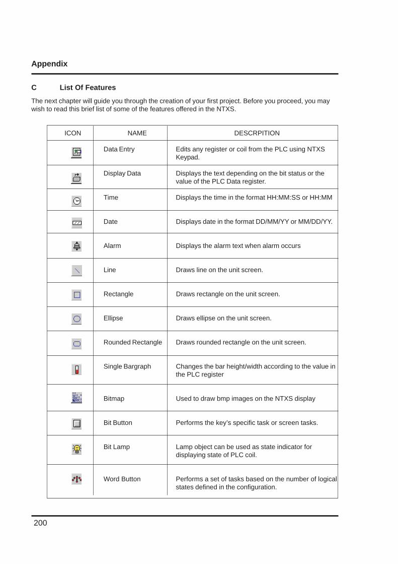
Appendix
200
C List Of Features
The next chapter will guide you through the creation of your first project. Before you proceed, you maywish to read this brief list of some of the features offered in the NTXS.
ICON NAME DESCRPITION
Data Entry Edits any register or coil from the PLC using NTXSKeypad.
Display Data Displays the text depending on the bit status or thevalue of the PLC Data register.
Time Displays the time in the format HH:MM:SS or HH:MM
Date Displays date in the format DD/MM/YY or MM/DD/YY.
Alarm Displays the alarm text when alarm occurs
Line Draws line on the unit screen.
Rectangle Draws rectangle on the unit screen.
Ellipse Draws ellipse on the unit screen.
Rounded Rectangle Draws rounded rectangle on the unit screen.
Single Bargraph Changes the bar height/width according to the value inthe PLC register
Bitmap Used to draw bmp images on the NTXS display
Bit Button Performs the key’s specific task or screen tasks.
Bit Lamp Lamp object can be used as state indicator fordisplaying state of PLC coil.
Word Button Performs a set of tasks based on the number of logicalstates defined in the configuration.
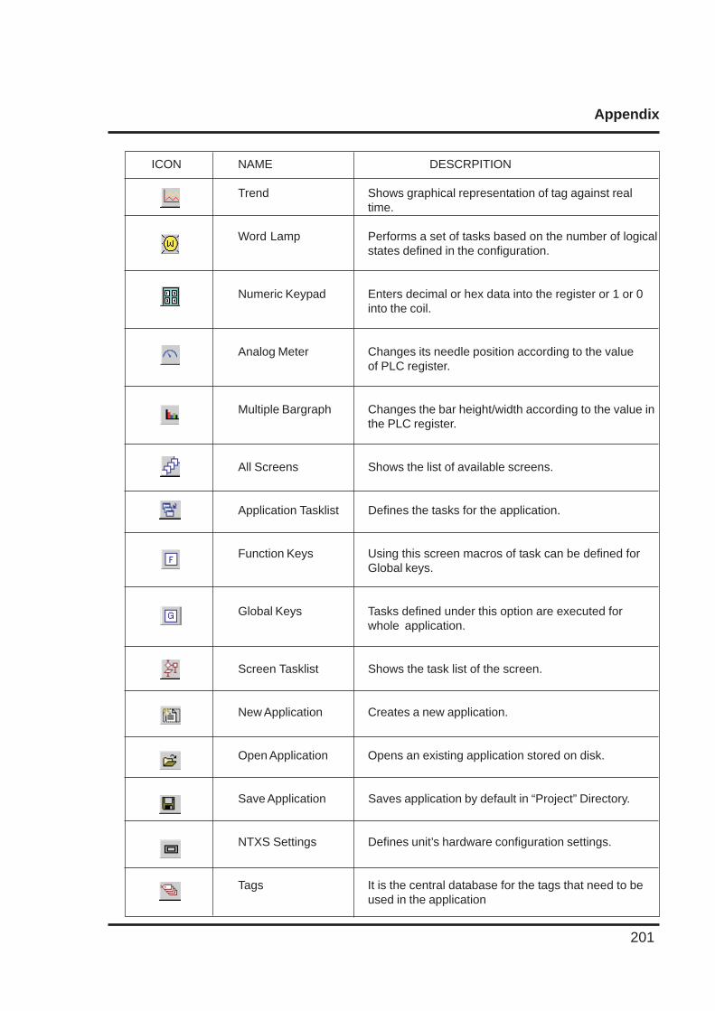
Appendix
201
ICON NAME DESCRPITION
Trend Shows graphical representation of tag against realtime.
Word Lamp Performs a set of tasks based on the number of logicalstates defined in the configuration.
Numeric Keypad Enters decimal or hex data into the register or 1 or 0into the coil.
Analog Meter Changes its needle position according to the valueof PLC register.
Multiple Bargraph Changes the bar height/width according to the value inthe PLC register.
All Screens Shows the list of available screens.
Application Tasklist Defines the tasks for the application.
Function Keys Using this screen macros of task can be defined forGlobal keys.
Global Keys Tasks defined under this option are executed forwhole application.
Screen Tasklist Shows the task list of the screen.
New Application Creates a new application.
Open Application Opens an existing application stored on disk.
Save Application Saves application by default in “Project” Directory.
NTXS Settings Defines unit’s hardware configuration settings.
Tags It is the central database for the tags that need to beused in the application

Appendix
202
ICON NAME DESCRPITION
Download Application Downloads the application & firmware in the NTXS unit
Upload Application Uploads application from the NTXS memory
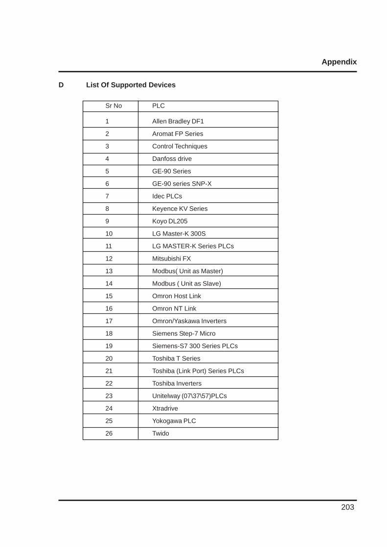
Appendix
203
D List Of Supported Devices
Sr No PLC
1 Allen Bradley DF1
2 Aromat FP Series
3 Control Techniques
4 Danfoss drive
5 GE-90 Series
6 GE-90 series SNP-X
7 Idec PLCs
8 Keyence KV Series
9 Koyo DL205
10 LG Master-K 300S
11 LG MASTER-K Series PLCs
12 Mitsubishi FX
13 Modbus( Unit as Master)
14 Modbus ( Unit as Slave)
15 Omron Host Link
16 Omron NT Link
17 Omron/Yaskawa Inverters
18 Siemens Step-7 Micro
19 Siemens-S7 300 Series PLCs
20 Toshiba T Series
21 Toshiba (Link Port) Series PLCs
22 Toshiba Inverters
23 Unitelway (07\37\57)PLCs
24 Xtradrive
25 Yokogawa PLC
26 Twido
Appendix
204
E Technical Support
Omron Europe B.V.Wegalaan 67-69NL-2132 JD HoofddorpThe Netherlands
:(+31)23-5681300
Fax :(+31)23 5681388
Website: www.omron-industrial.com
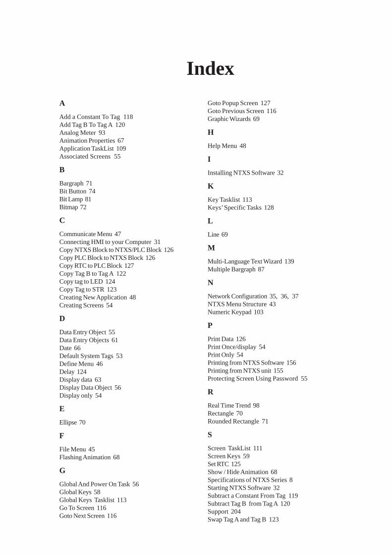
Index
A
Add a Constant To Tag 118Add Tag B To Tag A 120Analog Meter 93Animation Properties 67Application TaskList 109Associated Screens 55
B
Bargraph 71Bit Button 74Bit Lamp 81Bitmap 72
C
Communicate Menu 47Connecting HMI to your Computer 31Copy NTXS Block to NTXS/PLC Block 126Copy PLC Block to NTXS Block 126Copy RTC to PLC Block 127Copy Tag B to Tag A 122Copy tag to LED 124Copy Tag to STR 123Creating New Application 48Creating Screens 54
D
Data Entry Object 55Data Entry Objects 61Date 66Default System Tags 53Define Menu 46Delay 124Display data 63Display Data Object 56Display only 54
E
Ellipse 70
F
File Menu 45Flashing Animation 68
G
Global And Power On Task 56Global Keys 58Global Keys Tasklist 113Go To Screen 116Goto Next Screen 116
Goto Popup Screen 127Goto Previous Screen 116Graphic Wizards 69
H
Help Menu 48
I
Installing NTXS Software 32
K
Key Tasklist 113Keys’ Specific Tasks 128
L
Line 69
M
Multi-Language Text Wizard 139Multiple Bargraph 87
N
Network Configuration 35, 36, 37NTXS Menu Structure 43Numeric Keypad 103
P
Print Data 126Print Once/display 54Print Only 54Printing from NTXS Software 156Printing from NTXS unit 155Protecting Screen Using Password 55
R
Real Time Trend 98Rectangle 70Rounded Rectangle 71
S
Screen TaskList 111Screen Keys 59Set RTC 125Show / Hide Animation 68Specifications of NTXS Series 8Starting NTXS Software 32Subtract a Constant From Tag 119Subtract Tag B from Tag A 120Support 204Swap Tag A and Tag B 123

T
Tag Database 50Tasks 109Text Object 63Time 66Toggle bit 122Touch-Screen Tasklist 115Turn bit Off 121Turn bit On 121
U
Utilities Menu 47
W
Wait 125Wizards 73Word Button 78Word Lamp 85Write Value To Tag 117