Embed Size (px)
Citation preview

Temporary ProtectiveGround Cable ImpedanceK-Factors for PredictingWorker Touch Voltage
U.S. Department of the InteriorBureau of Reclamation March 2016
Temporary Protective G
round Cable Im
pedance K
-Factors for Predicting Worker Touch Voltage
IEEE_cover.indd 1 6/6/2016 9:34:40 AM
Preface
The Institute of Electrical and Electronics Engineers Standard
No. 1246-2011™, IEEE Guide for Temporary Protective Grounding
Systems Used in Substations (IEEE 1246) provides a method to predict
worker touch voltage at grounded worksites in high voltage,
alternating current substations using impedance correction K-factors
for temporary protective grounds (TPG). This book provides
supportive information for the grounding models and derivations of
TPG impedance equations presented in IEEE 1246. Chapter 1
introduces the reactive voltage drop principle that occurs on TPG.
Chapter 2 develops the ground loop induction formulas for a basic
single-phase TPG grounding scenario. Chapter 3 expands the use of
the K-factor to practical single- and three-phase substation bus
examples. Chapter 4 develops the K-factor for bracket TPG grounding
scenarios and Chapter 5 expands the use of K-factors referenced in the
standard to power line TPG grounding scenarios.
This book’s development is based on years of research performed by
the Hydropower Diagnostics and SCADA Group and onsite testing
performed at various Bureau of Reclamation and Western Area Power
Administration facilities. Support and funding was provided through
the Bureau of Reclamation Science and Technology Program.
The authors gratefully acknowledge the assistance of all who
contributed to this research work.
Philip Atwater and James DeHaan

i
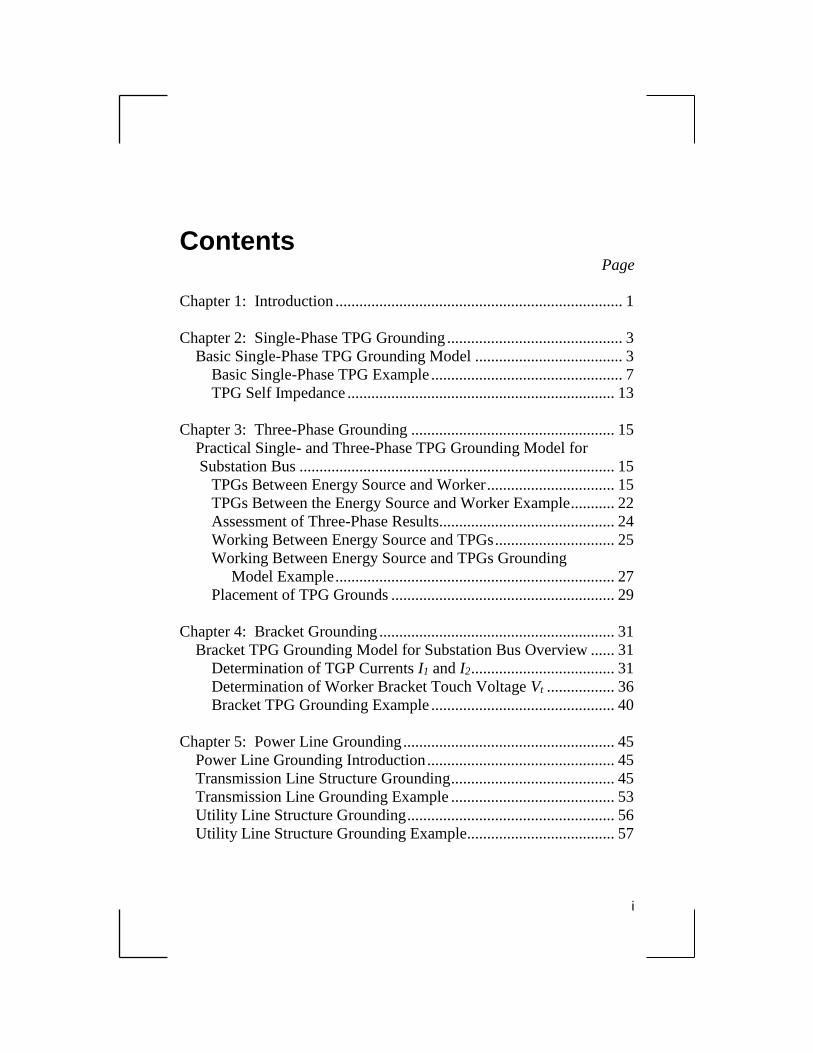
Contents Page
Chapter 1: Introduction ........................................................................ 1
Chapter 2: Single-Phase TPG Grounding ............................................ 3 Basic Single-Phase TPG Grounding Model ..................................... 3
Basic Single-Phase TPG Example ................................................ 7
TPG Self Impedance ................................................................... 13
Chapter 3: Three-Phase Grounding ................................................... 15
Practical Single- and Three-Phase TPG Grounding Model for
Substation Bus ............................................................................... 15
TPGs Between Energy Source and Worker ................................ 15 TPGs Between the Energy Source and Worker Example ........... 22 Assessment of Three-Phase Results............................................ 24
Working Between Energy Source and TPGs .............................. 25
Working Between Energy Source and TPGs Grounding
Model Example ...................................................................... 27 Placement of TPG Grounds ........................................................ 29
Chapter 4: Bracket Grounding ........................................................... 31
Bracket TPG Grounding Model for Substation Bus Overview ...... 31 Determination of TGP Currents I1 and I2 .................................... 31
Determination of Worker Bracket Touch Voltage Vt ................. 36 Bracket TPG Grounding Example .............................................. 40
Chapter 5: Power Line Grounding ..................................................... 45
Power Line Grounding Introduction ............................................... 45 Transmission Line Structure Grounding ......................................... 45 Transmission Line Grounding Example ......................................... 53
Utility Line Structure Grounding .................................................... 56 Utility Line Structure Grounding Example..................................... 57
ii
Contents (continued) Page
Chapter 6: Conclusion........................................................................ 61
References ........................................................................................... 63
Biography ............................................................................................ 65
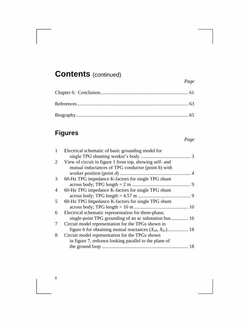
Figures Page
1 Electrical schematic of basic grounding model for
single TPG shunting worker’s body ......................................... 3 2 View of circuit in figure 1 from top, showing self- and
mutual inductances of TPG conductor (point b) with
worker position (point d) .......................................................... 4
3 60-Hz TPG impedance K-factors for single TPG shunt
across body; TPG length = 2 m ................................................ 9 4 60-Hz TPG impedance K-factors for single TPG shunt
across body; TPG length = 4.57 m ........................................... 9 5 60-Hz TPG Impedance K-factors for single TPG shunt
across body; TPG length = 10 m ............................................ 10 6 Electrical schematic representation for three-phase,
single-point TPG grounding of an ac substation bus .............. 16 7 Circuit model representation for the TPGs shown in
figure 6 for obtaining mutual reactances (Xab, Xac) ................. 18
8 Circuit model representation for the TPGs shown
in figure 7, redrawn looking parallel to the plane of
the ground loop ....................................................................... 18
iii
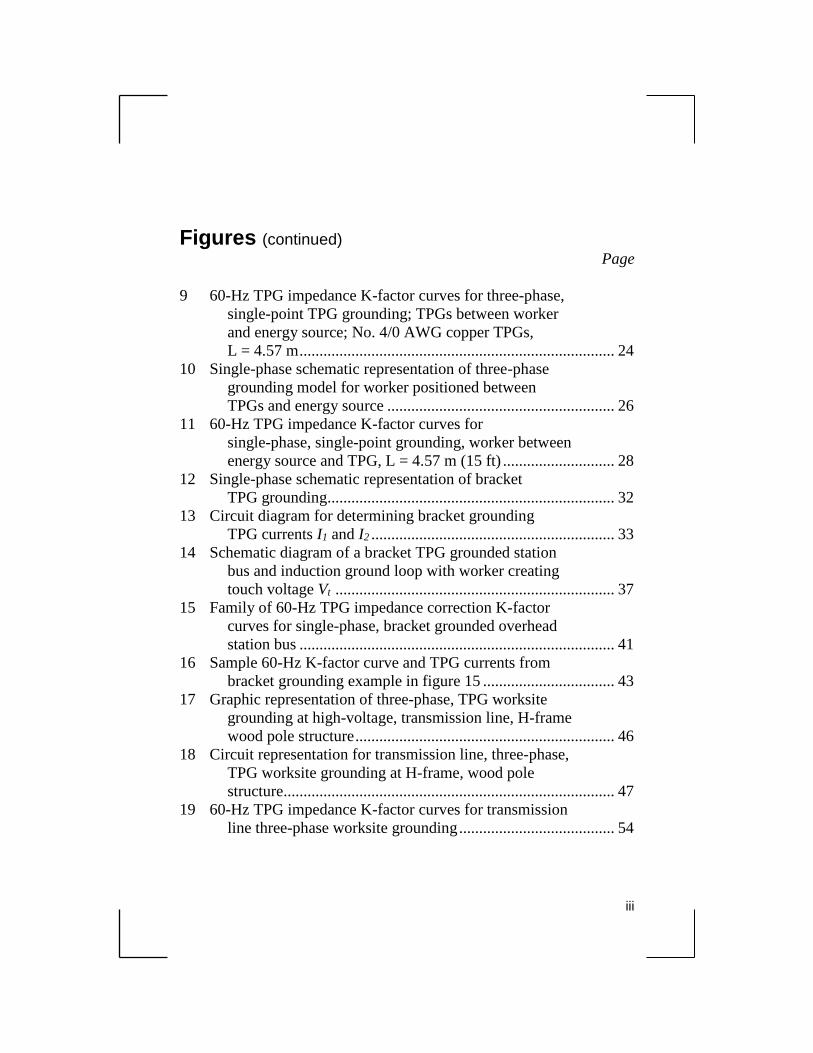
Figures (continued)
Page
9 60-Hz TPG impedance K-factor curves for three-phase,
single-point TPG grounding; TPGs between worker
and energy source; No. 4/0 AWG copper TPGs,
L = 4.57 m ............................................................................... 24
10 Single-phase schematic representation of three-phase
grounding model for worker positioned between
TPGs and energy source ......................................................... 26
11 60-Hz TPG impedance K-factor curves for
single-phase, single-point grounding, worker between
energy source and TPG, L = 4.57 m (15 ft) ............................ 28 12 Single-phase schematic representation of bracket
TPG grounding........................................................................ 32
13 Circuit diagram for determining bracket grounding
TPG currents I1 and I2 ............................................................. 33
14 Schematic diagram of a bracket TPG grounded station
bus and induction ground loop with worker creating
touch voltage Vt ...................................................................... 37 15 Family of 60-Hz TPG impedance correction K-factor
curves for single-phase, bracket grounded overhead
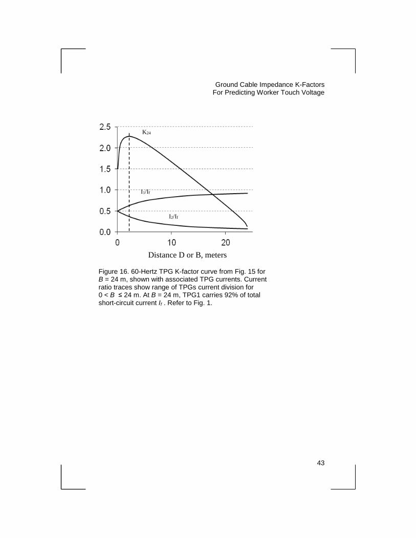
station bus ............................................................................... 41 16 Sample 60-Hz K-factor curve and TPG currents from
bracket grounding example in figure 15 ................................. 43 17 Graphic representation of three-phase, TPG worksite
grounding at high-voltage, transmission line, H-frame
wood pole structure ................................................................. 46
18 Circuit representation for transmission line, three-phase,
TPG worksite grounding at H-frame, wood pole
structure................................................................................... 47 19 60-Hz TPG impedance K-factor curves for transmission
line three-phase worksite grounding ....................................... 54
iv
Figures (continued)
Page
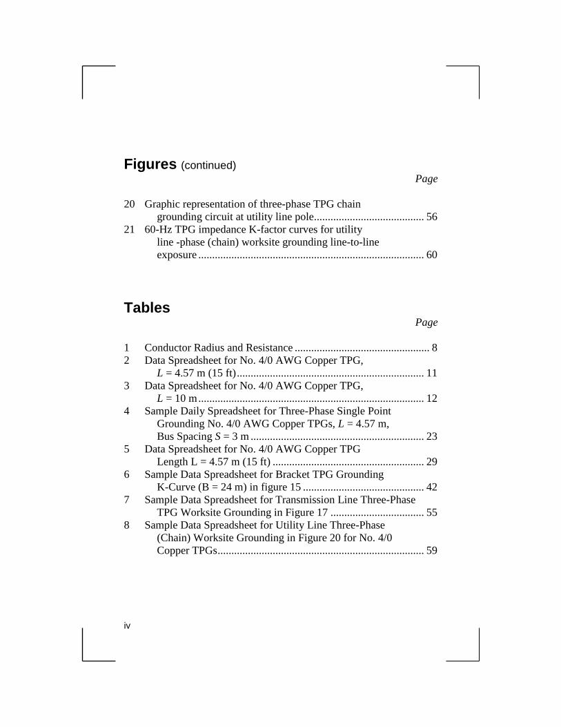
20 Graphic representation of three-phase TPG chain
grounding circuit at utility line pole........................................ 56
21 60-Hz TPG impedance K-factor curves for utility
line -phase (chain) worksite grounding line-to-line
exposure .................................................................................. 60
Tables Page
1 Conductor Radius and Resistance ................................................. 8
2 Data Spreadsheet for No. 4/0 AWG Copper TPG,
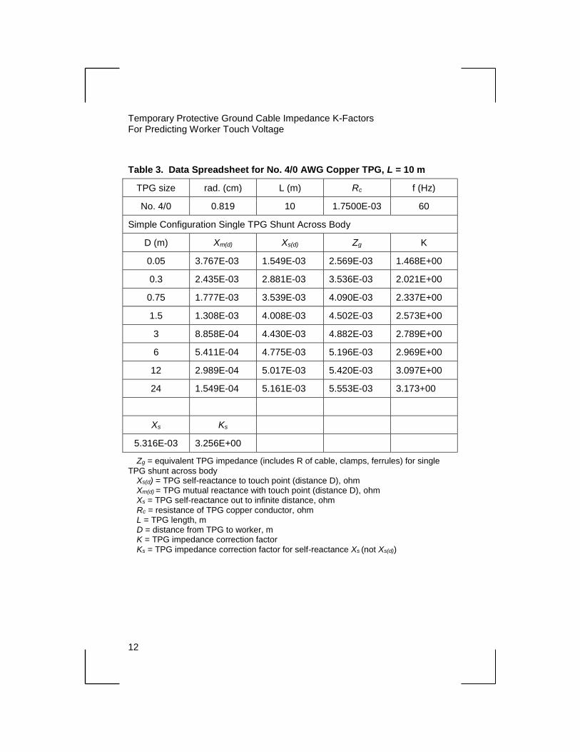
L = 4.57 m (15 ft) .................................................................... 11 3 Data Spreadsheet for No. 4/0 AWG Copper TPG,
L = 10 m .................................................................................. 12
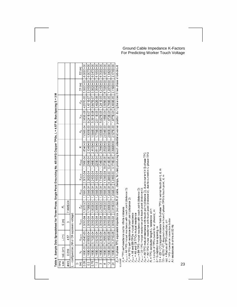
4 Sample Daily Spreadsheet for Three-Phase Single Point
Grounding No. 4/0 AWG Copper TPGs, L = 4.57 m,
Bus Spacing S = 3 m ............................................................... 23
5 Data Spreadsheet for No. 4/0 AWG Copper TPG
Length L = 4.57 m (15 ft) ....................................................... 29
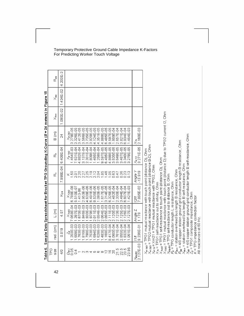
6 Sample Data Spreadsheet for Bracket TPG Grounding
K-Curve (B = 24 m) in figure 15 ............................................ 42
7 Sample Data Spreadsheet for Transmission Line Three-Phase
TPG Worksite Grounding in Figure 17 .................................. 55
8 Sample Data Spreadsheet for Utility Line Three-Phase
(Chain) Worksite Grounding in Figure 20 for No. 4/0
Copper TPGs ........................................................................... 59
1
Chapter 1
Introduction
The electric power industry has, for a long time, recognized the need
for grounding deenergized, high voltage power lines and equipment
for bare-hand contact during maintenance or construction activities.
Grounding of the line or equipment conductors is typically
accomplished by applying temporary protective grounds (TPG)
according to the utility’s procedure to create an equipotential safe
work zone. However, in practice, the various conductive parts of the
work zone are rarely at the same potential when an accidental
reenergization occurs. This is due to voltage drops in the fault current
carrying conductors, both TPG and the grounded equipment, which
cannot be avoided.
As stated in the Institute of Electric and Electronic Engineers Standard
No. 1246-2011 [1] (IEEE 1246), historically, the TPG cable resistance
was placed in parallel with the worker’s body to calculate current
through the body during an accidental energization of a grounded
worksite. The TPG cable resistive (IR) voltage drop resulting from the
alternating current (ac) power system available short-circuit current
was the key factor in determining worker touch voltage and body
current. Recent modeling of grounded worksites, and laboratory and
field testing (see IEEE 1246, Section 7, “Model Comparison With
Field Test Data”), demonstrated that the TPG cable reactive (IX)
voltage drop often is a significant component of the worker touch
voltage and body current.
Grounded worksites inherently produce a reactive voltage drop (touch
potential) when TPGs conduct ac short circuit current. Induction
ground loops are typically formed by the TPGs, grounded line or
equipment conductors, and a current return path between TPG and
worker. The worker completes the ground loop circuit by touching a
Temporary Protective Ground Cable Impedance K-Factors For Predicting Worker Touch Voltage
2
grounded conductor (intentionally grounded by TPG) and another
grounded object at the worksite. The induction ground loop creates
the reactive IX voltage drop exposure to the worker. The combined
resistive and reactive voltage drops of a TPG cable can be several
times higher than the resistive voltage drop alone.
Therefore, the TPG effective ac impedance (not only resistance)
should be considered for realistic worker exposure evaluation. This
situation led to the development of TPG composite impedance, which
accounts for the physical layout of the TPGs at the grounded worksite.
To simplify the calculation of the TPG impedance, the TPG
impedance K-factors were introduced. The use of the K-factor to
predict worker touch voltage modifies the historic method of
calculating TPG resistive (IR) voltage drop by including the additional
effects of reactive voltage drop of the TPG cable. Worker touch
voltage may be approximated using the following equation:
Vt = If × Rc × K (0)
where
Vt is the touch voltage, Vrms
If is the available short-circuit current, kA rms sym.
Rc is the TPG cable resistance (excluding clamps and
ferrules), milliohm
K is the TPG impedance multiplier
Application of K-factors for the worker touch voltage calculation
procedure is covered in IEEE 1246. However, explanation of
magnetic induction concepts and derivation of equations is limited,
and additional explanation is provided in this book.

3
Chapter 2
Single-Phase TPG Grounding
Basic Single-Phase TPG Grounding Model
In the simplest grounding form, a single TPG conductor is shunted
across a worker’s body, as shown schematically in figure 1. The
worker’s body is represented by resistance Rw. The TPG conductor
has resistance Rc. Induction ground loop a,b,c,d is formed with the
TPG and worker and is assumed rectangular in shape in this example
with TPG conductor length L and depth of ground loop D (distance
from TPG to worker).
Current I through the TPG (side b) creates magnetic flux ψ. Sides a
and c connect the worker to either end of the TPG. Voltage Vx is
Figure 1. Electrical schematic of basic grounding model for single TPG shunting worker’s body. The portion of magnetic flux ψ
internal to closed loop a,b,c,d (defined ψs(d)) induces voltage VX in contact with the worker.
D
ψ
Worker TPG
I
Rw Rc
a
d
c
b L
+ Vx
-
Temporary Protective Ground Cable Impedance K-Factors For Predicting Worker Touch Voltage
4
induced in the loop from flux linkages ψs(d), which penetrate (link
with) the enclosed loop area. No current is assumed through the body
(side d) because Rw>>Rc. This assumption is justified because the
body core resistance is approximately six orders of magnitude greater
than the resistance of a typical TPG cable (1 kΩ versus 1 mΩ).
Therefore, current through the worker side of the ground loop has a
negligible effect in determining voltage induced in the loop.
Induced voltage VX in figure 1 is equivalent to the IX reactive voltage
drop of the TPG where X is the self-reactance of the TPG conductor
out to distance D; defined Xs(d). Self-reactance Xs(d) can be found by
treating the TPG and worker’s body current paths as two parallel
conductors of equal length L separated by distance D.
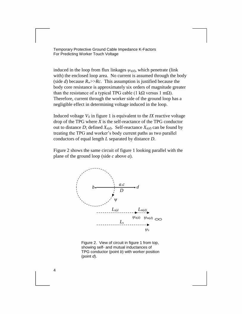
Figure 2 shows the same circuit of figure 1 looking parallel with the
plane of the ground loop (side c above a).
Figure 2. View of circuit in figure 1 from top, showing self- and mutual inductances of TPG conductor (point b) with worker position (point d).
a,c
D • • b d
ψs(d)
Lm(d)
ψm(d)
ψs
Ls
Ls(d
ψ
Temporary Protective Ground Cable Impedance K-Factors
For Predicting Worker Touch Voltage
5
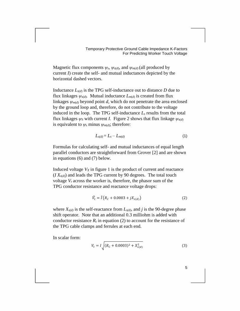
Magnetic flux components ψs, ψs(d), and ψm(d) (all produced by
current I) create the self- and mutual inductances depicted by the
horizontal dashed vectors.
Inductance Ls(d) is the TPG self-inductance out to distance D due to
flux linkages ψs(d). Mutual inductance Lm(d) is created from flux
linkages ψm(d) beyond point d, which do not penetrate the area enclosed
by the ground loop and, therefore, do not contribute to the voltage
induced in the loop. The TPG self-inductance Ls results from the total
flux linkages ψS with current I. Figure 2 shows that flux linkage ψs(d)
is equivalent to ψs minus ψm(d); therefore:
Ls(d) = Ls – Lm(d) (1)
Formulas for calculating self- and mutual inductances of equal length
parallel conductors are straightforward from Grover [2] and are shown
in equations (6) and (7) below.
Induced voltage VX in figure 1 is the product of current and reactance
(I Xs(d)) and leads the TPG current by 90 degrees. The total touch
voltage Vt across the worker is, therefore, the phasor sum of the
TPG conductor resistance and reactance voltage drops:
𝑉�̂� = 𝐼 ̂(𝑅𝐶 + 0.0003 + 𝑗𝑋𝑠(𝑑)) (2)
where Xs(d) is the self-reactance from Ls(d), and j is the 90-degree phase
shift operator. Note that an additional 0.3 milliohm is added with
conductor resistance Rc in equation (2) to account for the resistance of
the TPG cable clamps and ferrules at each end.
In scalar form:
𝑉𝑡 = 𝐼√(𝑅𝐶 + 0.0003)2 + 𝑋𝑠(𝑑)2 (3)

Temporary Protective Ground Cable Impedance K-Factors For Predicting Worker Touch Voltage
6
where all values of resistance and reactance are in ohms, and current
I is in amps.
Dividing both sides of equation (3) by current magnitude I gives an
expression for the TPG composite impedance magnitude:
𝑍𝑔 =𝑉𝑡
𝐼⁄ = √(𝑅𝐶 + 0.0003)2 + 𝑋𝑠(𝑑)2 (4)
Finally, TPG composite impedance Zg is normalized to the TPG
conductor resistance by dividing by Rc. This is the defined TPG
impedance correction K-factor, a dimensionless quantity. Therefore,
for the TPG grounding configuration in figure 1, the expression for the
TPG impedance correction K-factor is:
𝐾 =𝑍𝑔
𝑅𝐶=
√(𝑅𝐶+0.0003)2+𝑋𝑠(𝑑)2
𝑅𝐶 (5)
Formulas for the self-inductance of a single straight conductor and
mutual inductance of two equal length parallel straight conductors are
reprinted from Grover [2] in inductance unit of Henry.
𝐿𝑠 = 2𝐿 [𝑙𝑛 (2𝐿
𝑟) − 0.75] 𝑥10−9 H (6)
𝐿𝑚(𝑑) = 2𝐿 [𝑙𝑛 (𝐿
𝑑+ √1 + (
𝐿
𝑑)
2
) − √1 + (𝑑
𝐿)
2
+𝑑
𝐿] 𝑥10−9 H (7)
where
Ls = self-inductance of single conductor out to infinite
distance
Lm(d) = mutual inductance of parallel conductors separated by d
L = conductor length, centimeters (cm)
Temporary Protective Ground Cable Impedance K-Factors
For Predicting Worker Touch Voltage
7
r = conductor radius, cm
d = distance between center of conductors, cm
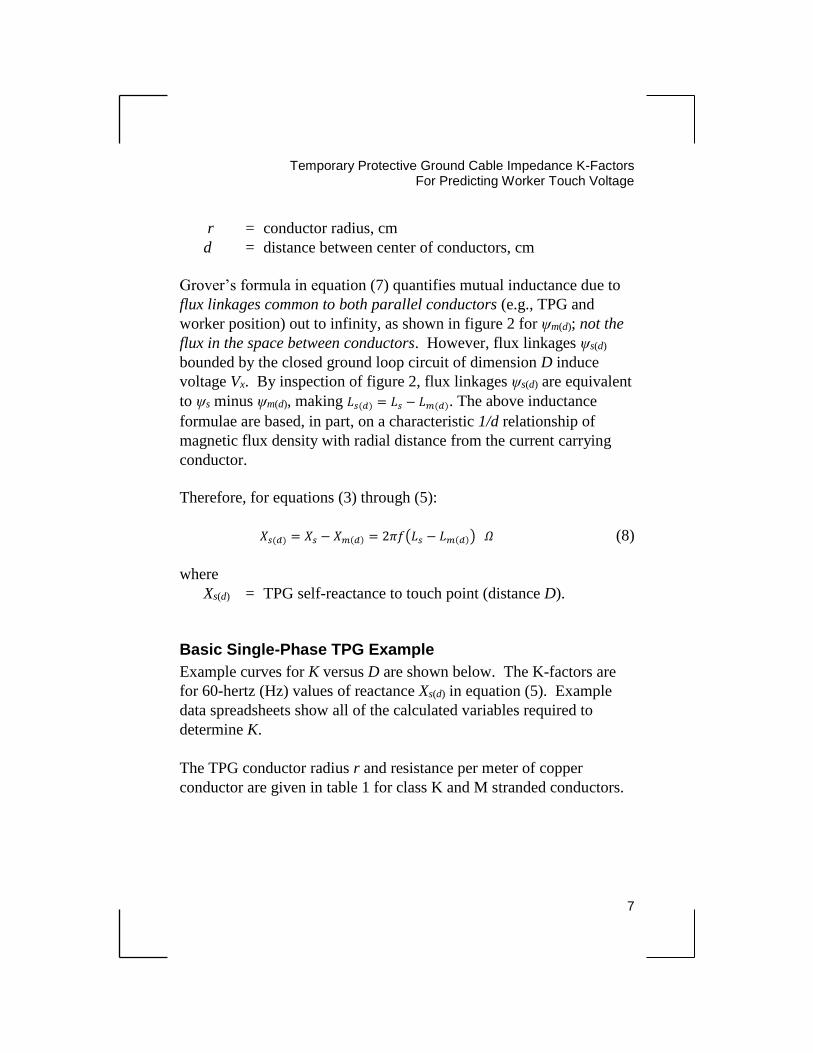
Grover’s formula in equation (7) quantifies mutual inductance due to
flux linkages common to both parallel conductors (e.g., TPG and
worker position) out to infinity, as shown in figure 2 for ψm(d); not the
flux in the space between conductors. However, flux linkages ψs(d)
bounded by the closed ground loop circuit of dimension D induce
voltage Vx. By inspection of figure 2, flux linkages ψs(d) are equivalent
to ψs minus ψm(d), making 𝐿𝑠(𝑑) = 𝐿𝑠 − 𝐿𝑚(𝑑). The above inductance
formulae are based, in part, on a characteristic 1/d relationship of
magnetic flux density with radial distance from the current carrying
conductor.
Therefore, for equations (3) through (5):
𝑋𝑠(𝑑) = 𝑋𝑠 − 𝑋𝑚(𝑑) = 2𝜋𝑓(𝐿𝑠 − 𝐿𝑚(𝑑)) 𝛺 (8)
where
Xs(d) = TPG self-reactance to touch point (distance D).
Basic Single-Phase TPG Example
Example curves for K versus D are shown below. The K-factors are
for 60-hertz (Hz) values of reactance Xs(d) in equation (5). Example
data spreadsheets show all of the calculated variables required to
determine K.
The TPG conductor radius r and resistance per meter of copper
conductor are given in table 1 for class K and M stranded conductors.
Temporary Protective Ground Cable Impedance K-Factors For Predicting Worker Touch Voltage
8
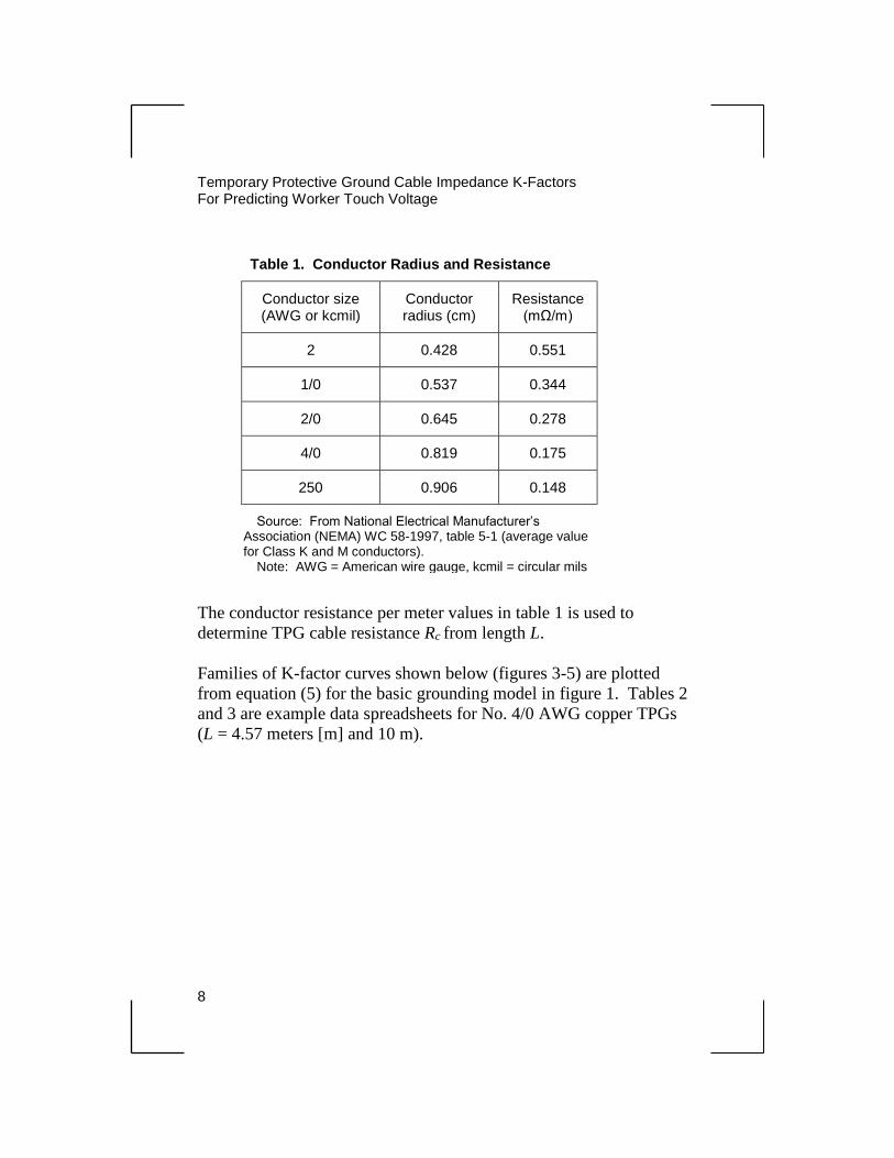
Table 1. Conductor Radius and Resistance
Conductor size (AWG or kcmil)
Conductor radius (cm)
Resistance (mΩ/m)
2 0.428 0.551
1/0 0.537 0.344
2/0 0.645 0.278
4/0 0.819 0.175
250 0.906 0.148
Source: From National Electrical Manufacturer’s Association (NEMA) WC 58-1997, table 5-1 (average value for Class K and M conductors).
Note: AWG = American wire gauge, kcmil = circular mils
The conductor resistance per meter values in table 1 is used to
determine TPG cable resistance Rc from length L.
Families of K-factor curves shown below (figures 3-5) are plotted
from equation (5) for the basic grounding model in figure 1. Tables 2
and 3 are example data spreadsheets for No. 4/0 AWG copper TPGs
(L = 4.57 meters [m] and 10 m).

Temporary Protective Ground Cable Impedance K-Factors
For Predicting Worker Touch Voltage
9
Figure 3. 60-Hz TPG impedance K-factors for single TPG shunt across body; TPG length = 2 m.
Figure 4. 60-Hz TPG impedance K-factors for single TPG shunt across body; TPG length = 4.57 m.

Temporary Protective Ground Cable Impedance K-Factors For Predicting Worker Touch Voltage
10
Worker touch voltage Vt is determined in figure 1 (Vx becomes Vt) for
the worksite available short-circuit current I, resistance of the TPG,
and the above-derived K-factor as follows:
𝑉𝑡 = 𝐼 • 𝑅𝐶 • 𝐾 (9)
In summary, the TPG impedance correction K-factor in equation (5)
adjusts conductor resistance RC to the effective impedance of the TPG
in shunt with the worker from a distance. The K-factor is a function of
the specific TPG grounding layout with the worker (simple rectangular
geometry of figure 1 in this example).
Figure 5. 60-Hz TPG Impedance K-factors for single TPG shunt across body; TPG length = 10 m.
Temporary Protective Ground Cable Impedance K-Factors
For Predicting Worker Touch Voltage
11
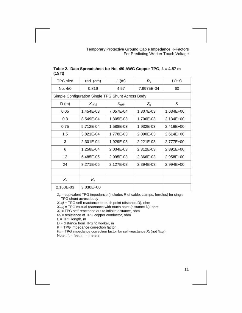
Table 2. Data Spreadsheet for No. 4/0 AWG Copper TPG, L = 4.57 m (15 ft)
TPG size rad. (cm) L (m) Rc f (Hz)
No. 4/0 0.819 4.57 7.9975E-04 60
Simple Configuration Single TPG Shunt Across Body
D (m) Xm(d) Xs(d) Zg K
0.05 1.454E-03 7.057E-04 1.307E-03 1.634E+00
0.3 8.549E-04 1.305E-03 1.706E-03 2.134E+00
0.75 5.712E-04 1.588E-03 1.932E-03 2.416E+00
1.5 3.821E-04 1.778E-03 2.090E-03 2.614E+00
3 2.301E-04 1.929E-03 2.221E-03 2.777E+00
6 1.258E-04 2.034E-03 2.312E-03 2.891E+00
12 6.485E-05 2.095E-03 2.366E-03 2.958E+00
24 3.271E-05 2.127E-03 2.394E-03 2.994E+00
Xs Ks
2.160E-03 3.030E+00
Zg = equivalent TPG impedance (includes R of cable, clamps, ferrules) for single TPG shunt across body Xs(d) = TPG self-reactance to touch point (distance D), ohm Xm(d) = TPG mutual reactance with touch point (distance D), ohm Xs = TPG self-reactance out to infinite distance, ohm Rc = resistance of TPG copper conductor, ohm L = TPG length, m D = distance from TPG to worker, m K = TPG impedance correction factor Ks = TPG impedance correction factor for self-reactance Xs (not Xs(d)) Note: ft = feet, m = meters
Temporary Protective Ground Cable Impedance K-Factors For Predicting Worker Touch Voltage
12
Table 3. Data Spreadsheet for No. 4/0 AWG Copper TPG, L = 10 m
TPG size rad. (cm) L (m) Rc f (Hz)
No. 4/0 0.819 10 1.7500E-03 60
Simple Configuration Single TPG Shunt Across Body
D (m) Xm(d) Xs(d) Zg K
0.05 3.767E-03 1.549E-03 2.569E-03 1.468E+00
0.3 2.435E-03 2.881E-03 3.536E-03 2.021E+00
0.75 1.777E-03 3.539E-03 4.090E-03 2.337E+00
1.5 1.308E-03 4.008E-03 4.502E-03 2.573E+00
3 8.858E-04 4.430E-03 4.882E-03 2.789E+00
6 5.411E-04 4.775E-03 5.196E-03 2.969E+00
12 2.989E-04 5.017E-03 5.420E-03 3.097E+00
24 1.549E-04 5.161E-03 5.553E-03 3.173+00
Xs Ks
5.316E-03 3.256E+00
Zg = equivalent TPG impedance (includes R of cable, clamps, ferrules) for single
TPG shunt across body Xs(d) = TPG self-reactance to touch point (distance D), ohm Xm(d) = TPG mutual reactance with touch point (distance D), ohm Xs = TPG self-reactance out to infinite distance, ohm Rc = resistance of TPG copper conductor, ohm L = TPG length, m D = distance from TPG to worker, m K = TPG impedance correction factor Ks = TPG impedance correction factor for self-reactance Xs (not Xs(d))
Temporary Protective Ground Cable Impedance K-Factors
For Predicting Worker Touch Voltage
13
TPG Self Impedance
The K-curves tend to flatten for values of D greater than about 5 m.
This occurs because as D increases, the value of Xs(d) quickly
approaches the TPG self-reactance Xs, due to the rapid decrease in
mutual reactance Xm(d). This suggests that for practical applications, a
representative worst-case, single-value K-factor could be chosen,
letting Xs(d) = Xs in equation (5) for a given TPG conductor size and
length (identified as Ks in tables 2 and 3). The value of Ks for the
10-m TPG (rounded to two decimal places) is included in table C.1 of
IEEE 1246.

15
Chapter 3
Three-Phase Grounding
Practical Single- and Three-Phase TPG Grounding Model for Substation Bus
In this chapter, the basic TPG model is expanded to represent more
practical single- and three-phase grounding methods implemented in
ac substations. The three-phase grounding method is depicted on the
book cover.
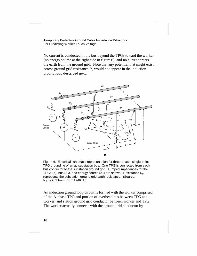
Figure 6 depicts an electrical circuit model of three-phase, single-point
worksite grounding in an ac substation. Temporary protective grounds
connect the station bus to the ground grid between the worker touch
point (represented by RW) and energy source. A worker could also be
located between the TPGs and energy source (not shown). The
objective is to express Vt (Vexp in figure) in terms of the substation
available three-phase, short-circuit current magnitude If, taking into
account the effects of magnetic coupling from the three TPG currents
Ia , Ib , and Ic.
TPGs Between Energy Source and Worker
During an accidental energization of the grounded worksite, balanced
three-phase currents are assumed in the overhead bus and TPGs from
the energy source. Therefore:
𝐼�̂� = If (1 + j0)
𝐼�̂� = If (-0.5 - j0.866)
𝐼�̂� = If (-0.5 + j0.866)
If = worksite available short-circuit current magnitude,
A and 𝐼�̂� + 𝐼�̂� + 𝐼�̂� = 0
Temporary Protective Ground Cable Impedance K-Factors For Predicting Worker Touch Voltage
16
No current is conducted in the bus beyond the TPGs toward the worker
(no energy source at the right side in figure 6), and no current enters
the earth from the ground grid. Note that any potential that might exist
across ground grid resistance Rg would not appear in the induction
ground loop described next.
An induction ground loop circuit is formed with the worker comprised
of the A-phase TPG and portion of overhead bus between TPG and
worker, and station ground grid conductor between worker and TPG.
The worker actually connects with the ground grid conductor by
Va
Vb
Vc
ØA
ØB
ØC
L
Rw
Vexp
S
S
Ia
Ib
Ic
ZTa
ZTb
ZTc
Flux
Ground Grid
ZBc
ZBb
ZBa
D
ZSa
ZSb
ZSc
Energy Source
Rg
TPGs
Ground Loop
Figure 6. Electrical schematic representation for three-phase, single-point TPG grounding of an ac substation bus. One TPG is connected from each bus conductor to the substation ground grid. Lumped impedances for the TPGs (Z), bus (ZB), and energy source (ZS) are shown. Resistance Rg
represents the substation ground grid earth resistance. (Source: figure C.3 from IEEE 1246 [1])
Ground Cable Impedance K-Factors
For Predicting Worker Touch Voltage
17
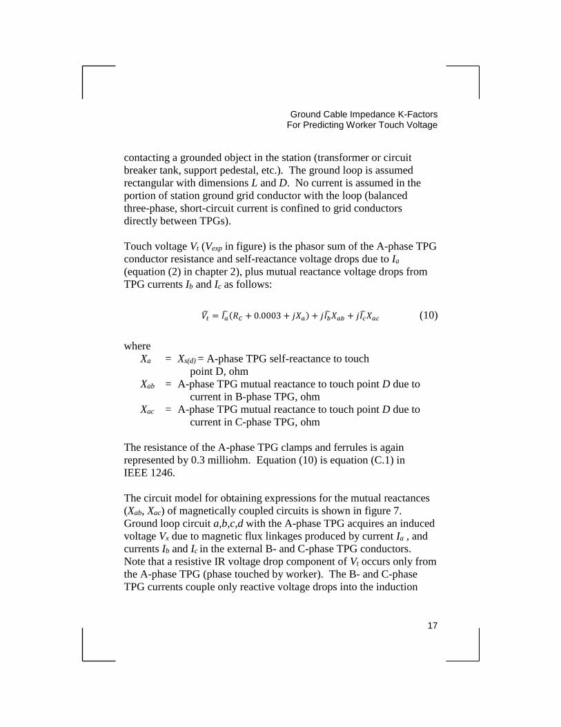
contacting a grounded object in the station (transformer or circuit
breaker tank, support pedestal, etc.). The ground loop is assumed
rectangular with dimensions L and D. No current is assumed in the
portion of station ground grid conductor with the loop (balanced
three-phase, short-circuit current is confined to grid conductors
directly between TPGs).
Touch voltage Vt (Vexp in figure) is the phasor sum of the A-phase TPG
conductor resistance and self-reactance voltage drops due to Ia
(equation (2) in chapter 2), plus mutual reactance voltage drops from
TPG currents Ib and Ic as follows:
𝑉�̂� = 𝐼�̂�(𝑅𝐶 + 0.0003 + 𝑗𝑋𝑎) + 𝑗𝐼�̂�𝑋𝑎𝑏 + 𝑗𝐼�̂�𝑋𝑎𝑐 (10)
where
Xa = Xs(d) = A-phase TPG self-reactance to touch
point D, ohm
Xab = A-phase TPG mutual reactance to touch point D due to
current in B-phase TPG, ohm
Xac = A-phase TPG mutual reactance to touch point D due to
current in C-phase TPG, ohm
The resistance of the A-phase TPG clamps and ferrules is again
represented by 0.3 milliohm. Equation (10) is equation (C.1) in
IEEE 1246.
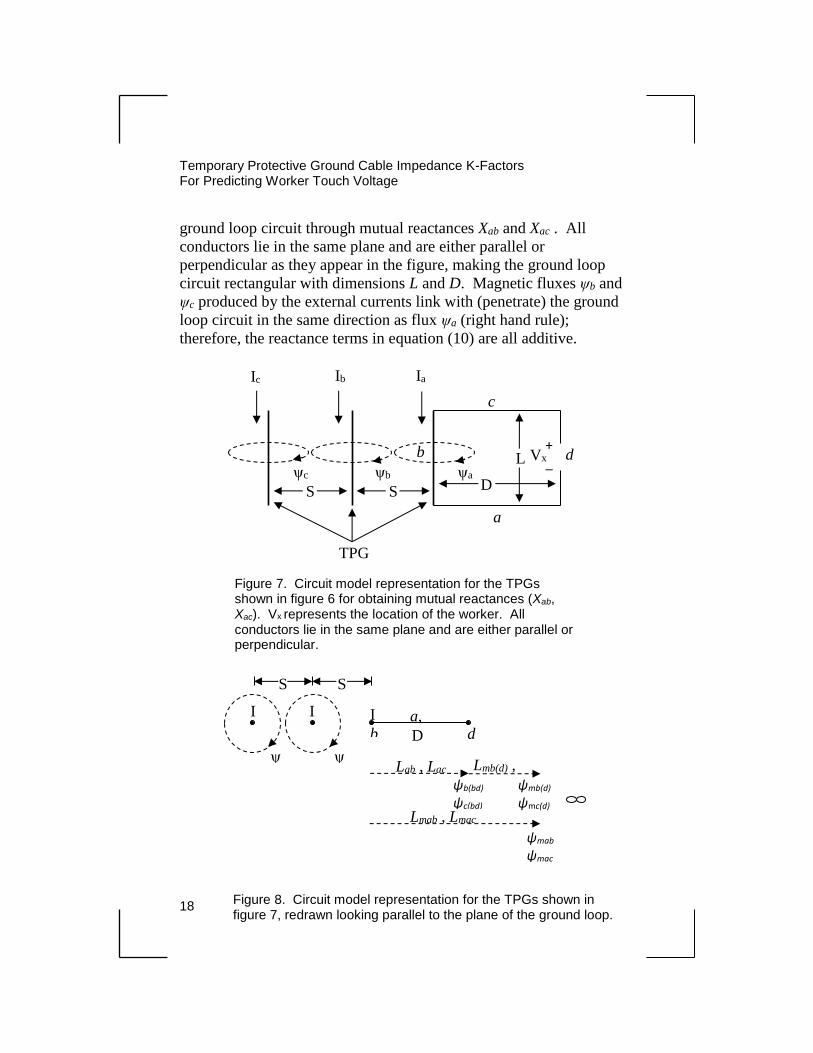
The circuit model for obtaining expressions for the mutual reactances
(Xab, Xac) of magnetically coupled circuits is shown in figure 7.
Ground loop circuit a,b,c,d with the A-phase TPG acquires an induced
voltage Vx due to magnetic flux linkages produced by current Ia , and
currents Ib and Ic in the external B- and C-phase TPG conductors.
Note that a resistive IR voltage drop component of Vt occurs only from
the A-phase TPG (phase touched by worker). The B- and C-phase
TPG currents couple only reactive voltage drops into the induction
Temporary Protective Ground Cable Impedance K-Factors For Predicting Worker Touch Voltage
18
ground loop circuit through mutual reactances Xab and Xac . All
conductors lie in the same plane and are either parallel or
perpendicular as they appear in the figure, making the ground loop
circuit rectangular with dimensions L and D. Magnetic fluxes ψb and
ψc produced by the external currents link with (penetrate) the ground
loop circuit in the same direction as flux ψa (right hand rule);
therefore, the reactance terms in equation (10) are all additive.
ψb ψc ψa
Vx + _
Ia Ib Ic
S S D
L
TPG
b
c
d
a
Figure 7. Circuit model representation for the TPGs shown in figure 6 for obtaining mutual reactances (Xab, Xac). Vx represents the location of the worker. All conductors lie in the same plane and are either parallel or perpendicular.
Lmab , Lmac
ψmab ψmac
ψ
I
ψ
I
b d
I a,
c D
S S
Lab , Lac Lmb(d) ,
Lmc(d) ψb(bd)
ψc(bd)
ψmb(d)
ψmc(d)
Figure 8. Circuit model representation for the TPGs shown in figure 7, redrawn looking parallel to the plane of the ground loop.

Ground Cable Impedance K-Factors
For Predicting Worker Touch Voltage
19
The circuit of figure 7 is redrawn in figure 8, looking parallel to the
plane of the ground loop. Fluxes ψb and ψc, produced by currents Ib
and Ic, link ground loop a,b,c,d, creating mutual inductances Lab and
Lac, depicted by the horizontal dashed vectors. Other magnetic flux
components of the Ib and Ic currents and associated inductances are
shown, which are necessary to determine mutual inductances Lab and
Lac:
where
ψb(bd) = flux produced by Ib linking area bounded by ground loop
a,b,c,d
ψc(bd) = flux produced by Ic linking area bounded by ground loop
a,b,c,d
ψmb(d) = mutual flux produced by Ib linking touch point d (distance
S+D) out to infinite distance
ψmc(d) = mutual flux produced by Ic linking touch point d (distance
2S+D) out to infinite distance
ψmab = mutual flux produced by Ia or Ib linking both A- and
B-phase TPGs out to infinite distance
ψmac = mutual flux produced by Ia or Ic linking both A- and
C-phase TPGs out to infinite distance
Lab = A-phase TPG mutual (coupled) inductance with touch
point d (distance D), due to current in B-phase TPG (due
to ψb(bd)), H
Lac = A-phase TPG mutual (coupled) inductance with touch
point d (distance D), due to current in C-phase TPG (due
to ψc(bd)), H
Lmab = A- and B-phase TPGs mutual inductance (due to ψmab), H
Lmac = A- and C-phase TPGs mutual inductance (due to ψmac), H
Lmb(d) = B-phase TPG mutual inductance with touch point d
(distance S+D) (due to ψmb(d)) , H
Lmc(d) = C-phase TPG mutual inductance with touch point d
(distance 2S+D) (due to ψmc(d)) , H
Temporary Protective Ground Cable Impedance K-Factors For Predicting Worker Touch Voltage
20
The word "coupled" distinguishes mutual inductances Lab and Lac from
the other defined mutual inductances. These coupled inductances
occur from magnetic fluxes that are bounded by the ground loop area,
whereas all other mutual inductances arise from magnetic fluxes that
are unbounded to infinite distance from two parallel conductors.
By inspection of figure 8, mutual inductances Lab and Lac can be
determined, noting that the flux linkages creating them (ψb(bd) and
ψc(bd)) are equivalent to the difference in the mutual flux linkages of
TPG-to-TPG and TPG-to-worker, or:
𝜓𝑏(𝑏𝑑) = 𝜓𝑚𝑎𝑏 − 𝜓𝑚𝑏(𝑑) (11)
𝜓𝑐(𝑏𝑑) = 𝜓𝑚𝑎𝑐 − 𝜓𝑚𝑐(𝑑) (12)
Stated in terms of the associated inductances:
𝐿𝑎𝑏 = 𝐿𝑚𝑎𝑏 − 𝐿𝑚𝑏(𝑑) (13)
𝐿𝑎𝑐 = 𝐿𝑚𝑎𝑐 − 𝐿𝑚𝑐(𝑑) (14)
Ground loop induced voltage Vx related to the self- and mutual
inductances associated with current Ia is similar to figure 2 in
chapter 2. Using variable subscripts suitable for this three-phase
circuit model, the A-phase TPG inductances become:
𝐿𝑠(𝑑) → 𝐿𝑎 (15)
𝐿𝑚(𝑑) → 𝐿𝑚𝑎(𝑑) (16)
where:
La = A-phase TPG self-inductance out to touch point d
(distance D), H
Ground Cable Impedance K-Factors
For Predicting Worker Touch Voltage
21
Lma(d) = A-phase TPG mutual inductance with touch point d
(distance D), H
and self-inductance Ls is unchanged (A-phase self -inductance out to
infinite distance). The desired reactances for equation (10) are then:
𝑋𝑎 = 2𝜋𝑓(𝐿𝑠 − 𝐿𝑚𝑎(𝑑)) 𝛺 (17)
𝑋𝑎𝑏 = 2𝜋𝑓(𝐿𝑚𝑎𝑏 − 𝐿𝑚𝑏(𝑑)) 𝛺 (18)
𝑋𝑎𝑐 = 2𝜋𝑓(𝐿𝑚𝑎𝑐 − 𝐿𝑚𝑐(𝑑)) 𝛺 (19)
Equations (17), (18), and (19) are IEEE 1246 equations (C.5), (C.6),
and (C.7), respectively.
The self- and mutual inductances in equations (17) through (19) are
determined from equations (6) and (7) in chapter 2. However, the
circuit depicted in figures 7 and 8 is planar, while the circuit geometry
of figure 6 is L-shaped with the worker position normal to the plane of
the three TPGs. In this case, distances from the B- and C-phase TPGs
to worker position point d are found using the right-triangle rule:
𝑑 = √(𝑛𝑆)2 + 𝐷2 (20)
with n = 1 or 2 for mutual inductance Lmb(d) or Lmc(d), respectively.
The A-phase TPG composite impedance magnitude Zg3, due to
balanced three-phase currents in the TPGs, is found by substituting the
rectangular form of short-circuit currents into equation (10), collecting
real and imaginary terms and converting to magnitude, then dividing
by If:
Zg3 =
√[𝑅𝐶 + 0.0003 + 0.866(𝑋𝑎𝑏 − 𝑋𝑎𝑐)]2 + [𝑋𝑎 − 0.5(𝑋𝑎𝑏 + 𝑋𝑎𝑐)]2 (21)
Temporary Protective Ground Cable Impedance K-Factors For Predicting Worker Touch Voltage
22
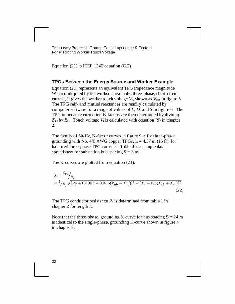
Equation (21) is IEEE 1246 equation (C.2)
TPGs Between the Energy Source and Worker Example
Equation (21) represents an equivalent TPG impedance magnitude.
When multiplied by the worksite available, three-phase, short-circuit
current, it gives the worker touch voltage Vt, shown as Vexp in figure 6.
The TPG self- and mutual reactances are readily calculated by
computer software for a range of values of L, D, and S in figure 6. The
TPG impedance correction K-factors are then determined by dividing
Zg3 by RC. Touch voltage Vt is calculated with equation (9) in chapter
2.
The family of 60-Hz, K-factor curves in figure 9 is for three-phase
grounding with No. 4/0 AWG copper TPGs, L = 4.57 m (15 ft), for
balanced three-phase TPG currents. Table 4 is a sample data
spreadsheet for substation bus spacing S = 3 m.
The K-curves are plotted from equation (21):
𝐾 =𝑍𝑔3
𝑅𝑐⁄
= 1𝑅𝑐
⁄ √[𝑅𝐶 + 0.0003 + 0.866(𝑋𝑎𝑏 − 𝑋𝑎𝑐)]2 + [𝑋𝑎 − 0.5(𝑋𝑎𝑏 + 𝑋𝑎𝑐)]2
(22)
The TPG conductor resistance Rc is determined from table 1 in
chapter 2 for length L.
Note that the three-phase, grounding K-curve for bus spacing S = 24 m
is identical to the single-phase, grounding K-curve shown in figure 4
in chapter 2.
Ground Cable Impedance K-Factors
For Predicting Worker Touch Voltage
23

Temporary Protective Ground Cable Impedance K-Factors For Predicting Worker Touch Voltage
24
Assessment of Three-Phase Results
Comparison of K-factor curves in chapter 2, as well as the above
example, reveals that the three-phase K-values approach an upper limit
of the corresponding single-phase values as bus spacing S increases.
This is to be expected because mutual reactances Xab and Xac become
small relative to self-reactance Xa, and equation (21) reduces to
equation (4) in chapter 2, making Zg3 ≈ Zg. It implies that, for
conservative results, the single-phase grounding model (figure 1 in
chapter 2) can be used for three-phase grounding (figure 6). The error
is less than about 10 percent if bus spacing S > 1.5 m.
Figure 9. 60-Hz TPG impedance K-factor curves for three-phase, single-point TPG grounding; TPGs between worker and energy source; No. 4/0 AWG copper TPGs, L = 4.57 m
Ground Cable Impedance K-Factors
For Predicting Worker Touch Voltage
25
A second degree of conservancy may be applied if the single-phase
K-factors are based only on TPG conductor self-inductance Ls
(Lm(d) = 0 in equation (1) and Xs(d) = Xs in equations (3) through (5) in
chapter 2); defined Ks. This is the basis for the K-factors given in table
C.1 of IEEE 1246.
Working Between Energy Source and TPGs
For this scenario, the worker touch point (RW) in figure 6 with the
A-phase overhead bus is to the left of the TPG at distance D (not
shown). The induction ground loop circuit comprises the A-phase
TPG and portions of the overhead bus and station ground grid
conductor between TPG and the worker. The ground loop is again
assumed rectangular with dimensions L and D, and there is no current
in the station ground grid conductor forming the loop with the worker.
In the previous three-phase grounding example, it was shown that the
B- and C-phase TPG currents had minor influence on the touch
voltage in the A-phase TPG ground loop circuit. Therefore, this
three-phase grounding example can be modeled in the single-phase
representation of figure 10 for simplicity of calculation.
Sides b and c of the induction ground loop in figure 10 represent
the A-phase TPG and overhead bus, respectively. The A-phase,
short-circuit current enters the upper left corner of the loop and
exits the lower right corner into the plane of the page (toward B- and
C-phase TPGs). There is no current in sides a and d of the ground
loop and essentially no magnetic flux produced by the exit current
links the loop.
Flux produced by the A-phase current links the ground loop in
figure 10 from the bus (ψbus) in addition to the TPG (ψs(d)). Therefore,
touch voltage Vt includes an additional reactive voltage component
from the bus current compared to figure 1 in chapter 2.
Temporary Protective Ground Cable Impedance K-Factors For Predicting Worker Touch Voltage
26
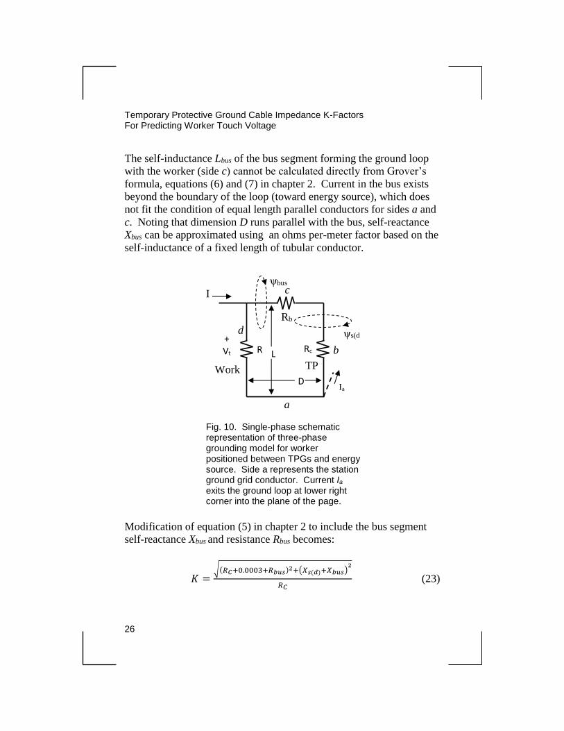
The self-inductance Lbus of the bus segment forming the ground loop
with the worker (side c) cannot be calculated directly from Grover’s
formula, equations (6) and (7) in chapter 2. Current in the bus exists
beyond the boundary of the loop (toward energy source), which does
not fit the condition of equal length parallel conductors for sides a and
c. Noting that dimension D runs parallel with the bus, self-reactance
Xbus can be approximated using an ohms per-meter factor based on the
self-inductance of a fixed length of tubular conductor.
Modification of equation (5) in chapter 2 to include the bus segment
self-reactance Xbus and resistance Rbus becomes:
𝐾 =√(𝑅𝐶+0.0003+𝑅𝑏𝑢𝑠)2+(𝑋𝑠(𝑑)+𝑋𝑏𝑢𝑠)
2
𝑅𝐶 (23)
Fig. 10. Single-phase schematic representation of three-phase grounding model for worker positioned between TPGs and energy source. Side a represents the station ground grid conductor. Current Ia exits the ground loop at lower right corner into the plane of the page.
R
w
Rc
I c
a
d
b
ψbus
Work
er
TP
G D
L
Rb
Ia
+ Vt
-
ψs(d
Ground Cable Impedance K-Factors
For Predicting Worker Touch Voltage
27
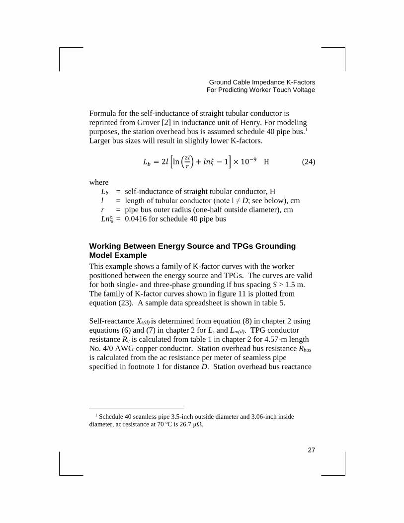
Formula for the self-inductance of straight tubular conductor is
reprinted from Grover [2] in inductance unit of Henry. For modeling
purposes, the station overhead bus is assumed schedule 40 pipe bus.1
Larger bus sizes will result in slightly lower K-factors.
𝐿𝑏 = 2𝑙 [ln (2𝑙
𝑟) + 𝑙𝑛𝜉 − 1] × 10−9 H (24)
where
Lb = self-inductance of straight tubular conductor, H
l = length of tubular conductor (note l ≠ D; see below), cm
r = pipe bus outer radius (one-half outside diameter), cm
Lnξ = 0.0416 for schedule 40 pipe bus
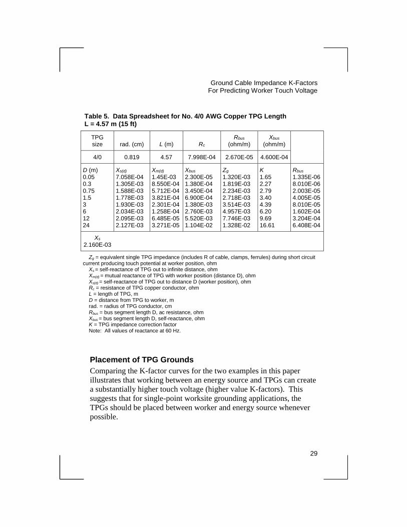
Working Between Energy Source and TPGs Grounding Model Example
This example shows a family of K-factor curves with the worker
positioned between the energy source and TPGs. The curves are valid
for both single- and three-phase grounding if bus spacing S > 1.5 m.
The family of K-factor curves shown in figure 11 is plotted from
equation (23). A sample data spreadsheet is shown in table 5.
Self-reactance Xs(d) is determined from equation (8) in chapter 2 using
equations (6) and (7) in chapter 2 for Ls and Lm(d). TPG conductor
resistance Rc is calculated from table 1 in chapter 2 for 4.57-m length
No. 4/0 AWG copper conductor. Station overhead bus resistance Rbus
is calculated from the ac resistance per meter of seamless pipe
specified in footnote 1 for distance D. Station overhead bus reactance
1 Schedule 40 seamless pipe 3.5-inch outside diameter and 3.06-inch inside
diameter, ac resistance at 70 ºC is 26.7 µΩ.
Temporary Protective Ground Cable Impedance K-Factors For Predicting Worker Touch Voltage
28
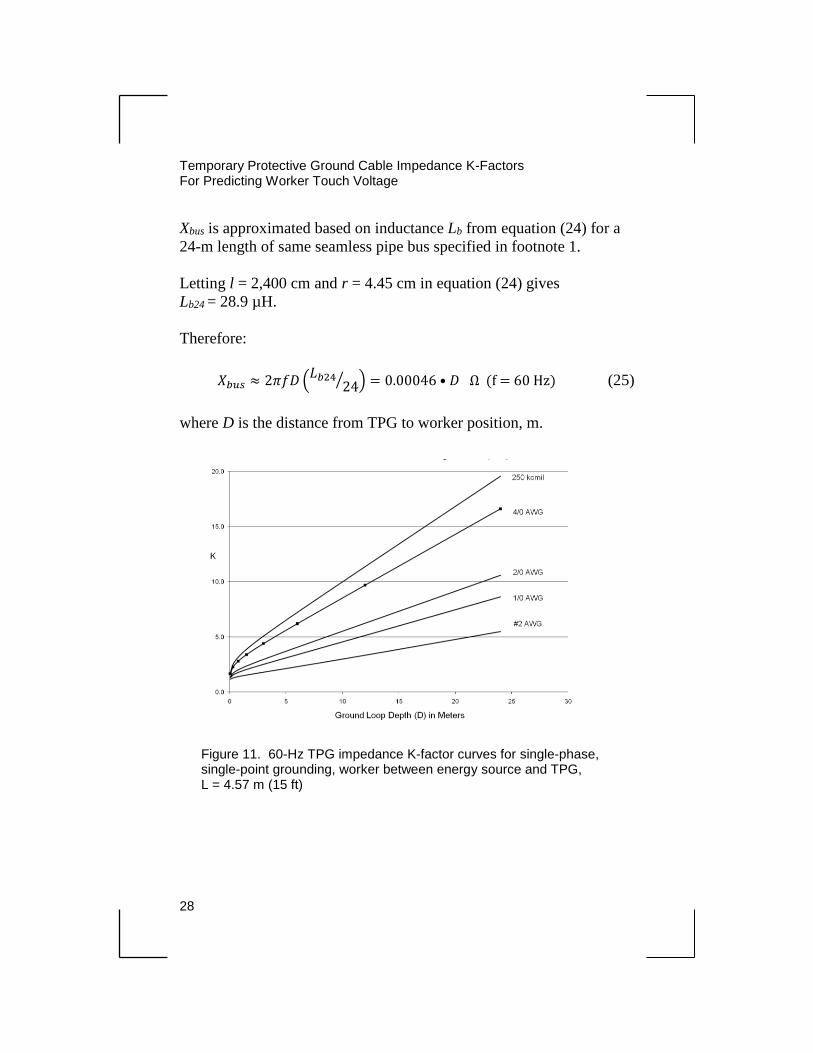
Xbus is approximated based on inductance Lb from equation (24) for a
24-m length of same seamless pipe bus specified in footnote 1.
Letting l = 2,400 cm and r = 4.45 cm in equation (24) gives
Lb24 = 28.9 µH.
Therefore:
𝑋𝑏𝑢𝑠 ≈ 2𝜋𝑓𝐷 (𝐿𝑏24
24⁄ ) = 0.00046 • 𝐷 Ω (f = 60 Hz) (25)
where D is the distance from TPG to worker position, m.
Figure 11. 60-Hz TPG impedance K-factor curves for single-phase, single-point grounding, worker between energy source and TPG, L = 4.57 m (15 ft)
Ground Cable Impedance K-Factors
For Predicting Worker Touch Voltage
29
Table 5. Data Spreadsheet for No. 4/0 AWG Copper TPG Length L = 4.57 m (15 ft)
TPG size rad. (cm) L (m) Rc
Rbus
(ohm/m) Xbus
(ohm/m)
4/0 0.819 4.57 7.998E-04 2.670E-05 4.600E-04
D (m) 0.05 0.3 0.75 1.5 3 6 12 24
Xs(d)
7.058E-04 1.305E-03 1.588E-03 1.778E-03 1.930E-03 2.034E-03 2.095E-03 2.127E-03
Xm(d)
1.45E-03 8.550E-04 5.712E-04 3.821E-04 2.301E-04 1.258E-04 6.485E-05 3.271E-05
Xbus
2.300E-05 1.380E-04 3.450E-04 6.900E-04 1.380E-03 2.760E-03 5.520E-03 1.104E-02
Zg 1.320E-03 1.819E-03 2.234E-03 2.718E-03 3.514E-03 4.957E-03 7.746E-03 1.328E-02
K 1.65 2.27 2.79 3.40 4.39 6.20 9.69 16.61
Rbus
1.335E-06 8.010E-06 2.003E-05 4.005E-05 8.010E-05 1.602E-04 3.204E-04 6.408E-04
Xs 2.160E-03
Zg = equivalent single TPG impedance (includes R of cable, clamps, ferrules) during short circuit current producing touch potential at worker position, ohm
Xs = self-reactance of TPG out to infinite distance, ohm Xm(d) = mutual reactance of TPG with worker position (distance D), ohm Xs(d) = self-reactance of TPG out to distance D (worker position), ohm Rc = resistance of TPG copper conductor, ohm L = length of TPG, m D = distance from TPG to worker, m rad. = radius of TPG conductor, cm Rbus = bus segment length D, ac resistance, ohm Xbus = bus segment length D, self-reactance, ohm K = TPG impedance correction factor Note: All values of reactance at 60 Hz.
Placement of TPG Grounds
Comparing the K-factor curves for the two examples in this paper
illustrates that working between an energy source and TPGs can create
a substantially higher touch voltage (higher value K-factors). This
suggests that for single-point worksite grounding applications, the
TPGs should be placed between worker and energy source whenever
possible.
Temporary Protective Ground Cable Impedance K-Factors For Predicting Worker Touch Voltage
30
The K-factor values in the previous section will increase if the
substation ground grid conductor (side a in figure 10) conducts a
portion or all of the A-phase, short-circuit return current. The latter
case is represented by the K-factor curves given in IEEE 1246,
figures C.18, C.19, and C.20. For those K-factor curves, equation (23)
was modified to include the resistance and self-reactance of the station
ground grid conductor segment in a method similar to that described
above for the overhead bus.
31
Chapter 4
Bracket Grounding
Bracket TPG Grounding Model for Substation Bus Overview
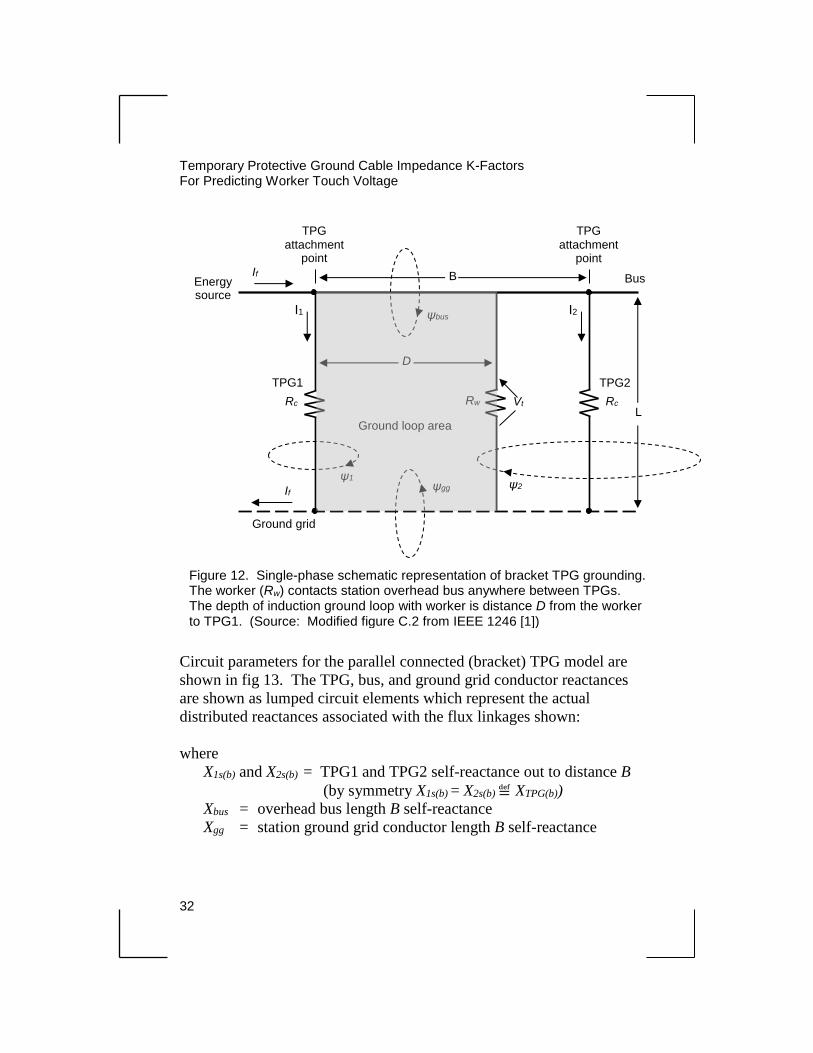
In addition to single- and three-phase grounding, bracket grounding is
another option implemented in grounding ac substations. It uses a set
of grounds on each side of the work area. Figure 12 depicts a form of
bracket grounding. Only one phase is shown because single-phase
modeling has been proven sufficiently accurate for three-phase
grounding (see chapter 3). The station overhead bus is grounded with
two identical TPGs separated by distance B. The worker (Rw) contacts
the station bus and ground grid anywhere between the TPGs. An
energy source is located to the left of TPG1, and there is no energy
source to the right of TPG2. The sum of TPG currents I1 and I2 equals
the station available, short-circuit current If from the source. Touch
voltage Vt is to be determined for worker-to-TPG1 distance D < B.
For conservative analysis (highest touch voltage), current I2, carried by
TPG2, is modeled returning to the source in a single station ground
grid conductor directly below the overhead bus. As shown in
figure 12, magnetic flux produced by currents in the TPGs, overhead
bus, and ground grid conductor links (penetrates) the shaded area,
forming an induction ground loop with the worker.
Determination of TGP Currents I1 and I2
The bus If current division in the TPGs is first solved for I1 and I2.
Current division in the TPGs is dependent on the TPGs’ self- and
mutual inductances associated with fluxes ψ1 and ψ2, and the bus and
ground grid conductor impedances between the TPGs.
Temporary Protective Ground Cable Impedance K-Factors For Predicting Worker Touch Voltage
32
Circuit parameters for the parallel connected (bracket) TPG model are
shown in fig 13. The TPG, bus, and ground grid conductor reactances
are shown as lumped circuit elements which represent the actual
distributed reactances associated with the flux linkages shown:
where
X1s(b) and X2s(b) = TPG1 and TPG2 self-reactance out to distance B
(by symmetry X1s(b) = X2s(b) ≝ XTPG(b))
Xbus = overhead bus length B self-reactance
Xgg = station ground grid conductor length B self-reactance
Figure 12. Single-phase schematic representation of bracket TPG grounding. The worker (Rw) contacts station overhead bus anywhere between TPGs. The depth of induction ground loop with worker is distance D from the worker to TPG1. (Source: Modified figure C.2 from IEEE 1246 [1])
ψbus
ψ1
ψgg ψ2
Bus
L
TPG2
Rc
Energy source
If
I1 I2
Ground grid
If
Ground loop area
B
TPG attachment
point
TPG attachment
point
Vt Rw
TPG1
Rc
D

Ground Cable Impedance K-Factors
For Predicting Worker Touch Voltage
33
Rc = TPG conductor length L resistance
Rbus = overhead bus length B resistance
Rgg = station ground grid conductor length B resistance
For a given conductor length L, self-reactance XTPG(b) is a nonlinear
function of B in the radial dimension to the TPG, due mainly to a
1/B relation in magnetic flux density for linkages ψ1 or ψ2. Therefore,
self-inductance LTPG(b) is determined in a way similar to that described
in chapter 2, “Basic Single-Phase TPG Example” section, as well as
TPG2
X2s(b)
RC
Rgg
Ground grid
conductor
TPG1
RC
Bus
I2 I1
ψbus
ψ2 ψ1
ψg
If
B
L
Rbus Xbus
Xgg
X1s(b)
Figure 13. Circuit diagram for determining bracket grounding TPG currents I1 and I2. TPGs are constructed of conductors identical in size and length. Magnetic flux ψ1 is produced by current I1. All other fluxes shown are produced by current I2.

Temporary Protective Ground Cable Impedance K-Factors For Predicting Worker Touch Voltage
34
from equations (6) and (7) of chapter 2, noting that mutual inductance
from equation (7) in chapter 2 is determined for d = B as follows:
𝐿1𝑠 = 2𝐿 [𝑙𝑛 (2𝐿
𝑟) − 0.75] 𝑥10−9 H (26)
𝐿𝑚12 = 2𝐿 [𝑙𝑛 (𝐿
𝐵+ √1 + (
𝐿
𝐵)
2
) − √1 + (𝐵
𝐿)
2
+𝐵
𝐿] 𝑥10−9 H (27)
with all dimensions in centimeters, and:
𝑋𝑇𝑃𝐺(𝑏) = 2𝜋𝑓(𝐿1𝑠 − 𝐿𝑚12) 𝛺 (28)
where
L1s = TPG1 self-inductance out to infinite distance
Lm12 = TPG1 mutual inductance with TPG2
Conversely, the bus and station ground grid conductor self-reactances
approximate a linear function of B because their respective magnetic
flux density patterns are approximately constant in the axial direction
with those conductors. Therefore, the bus and ground grid conductor
self-inductances are obtained from equations (24) in chapter 3 and (15)
and (6) in chapters 3 and 2, respectively, setting l = B as follows:
𝐿𝑏𝑢𝑠 = 2𝐵 [𝑙𝑛 (2𝐵
𝑟𝑏) + 𝑙𝑛𝜉 − 1] × 10−9 𝐻 (29)
where
Lbus = self-inductance of straight tubular conductor, H
𝐵 = length of tubular conductor
rb = pipe bus outer radius (one-half outside diameter)
Lnξ = 0.0416 for schedule 40 pipe bus
Ground Cable Impedance K-Factors
For Predicting Worker Touch Voltage
35
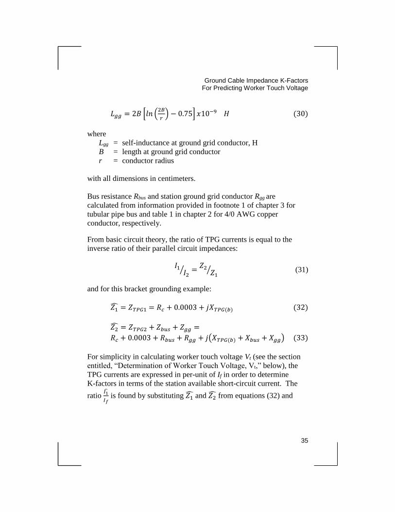
𝐿𝑔𝑔 = 2𝐵 [𝑙𝑛 (2𝐵
𝑟) − 0.75] 𝑥10−9 𝐻 (30)
where
Lgg = self-inductance at ground grid conductor, H
B = length at ground grid conductor
r = conductor radius
with all dimensions in centimeters.
Bus resistance Rbus and station ground grid conductor Rgg are
calculated from information provided in footnote 1 of chapter 3 for
tubular pipe bus and table 1 in chapter 2 for 4/0 AWG copper
conductor, respectively.
From basic circuit theory, the ratio of TPG currents is equal to the
inverse ratio of their parallel circuit impedances:
𝐼1
𝐼2⁄ =
𝑍2𝑍1
⁄ (31)
and for this bracket grounding example:
𝑍1̂ = 𝑍𝑇𝑃𝐺1 = 𝑅𝑐 + 0.0003 + 𝑗𝑋𝑇𝑃𝐺(𝑏) (32)
𝑍2̂ = 𝑍𝑇𝑃𝐺2 + 𝑍𝑏𝑢𝑠 + 𝑍𝑔𝑔 =
𝑅𝑐 + 0.0003 + 𝑅𝑏𝑢𝑠 + 𝑅𝑔𝑔 + 𝑗(𝑋𝑇𝑃𝐺(𝑏) + 𝑋𝑏𝑢𝑠 + 𝑋𝑔𝑔) (33)
For simplicity in calculating worker touch voltage Vt (see the section
entitled, “Determination of Worker Touch Voltage, Vt,” below), the
TPG currents are expressed in per-unit of If in order to determine
K-factors in terms of the station available short-circuit current. The
ratio 𝐼1̂
𝐼𝑓 is found by substituting 𝑍1̂ and 𝑍2̂ from equations (32) and
Temporary Protective Ground Cable Impedance K-Factors For Predicting Worker Touch Voltage
36
(33) into (31) and replacing 𝐼2 with 𝐼𝑓 − 𝐼1 in the left side
denominator:
𝐼1̂𝐼𝑓
⁄ = 𝑅𝑐 + 𝑅𝑏𝑢𝑠 + 𝑅𝑔𝑔 + 𝑗(𝑋𝑇𝑃𝐺(𝑏) + 𝑋𝑏𝑢𝑠 + 𝑋𝑔𝑔)
2𝑅𝑐 + 𝑅𝑏𝑢𝑠 + 𝑅𝑔𝑔 + 𝑗(2𝑋𝑇𝑃𝐺(𝑏) + 𝑋𝑏𝑢𝑠 + 𝑋𝑔𝑔) (34)
Although equation (34) is not reduced to simplest form, it is readily
manipulated in software and displayed in polar form as the ratio |𝐼1
𝐼𝑓| ∠𝑍.
Ratio |𝐼2
𝐼𝑓| ∠𝑌 is determined from the relation
𝐼2
𝐼𝑓= 1 −
𝐼1
𝐼𝑓 since the I1
and I2 complex current ratios must sum to one per unit of If .
Determination of Worker Bracket Touch Voltage Vt
Touch potential Vt is found by summing the resistive and reactive
voltage drops around the loop circuit enclosing the shaded area in
figure 12. This again implies that all the loop voltage appears across
worker resistance RW. A reactive IX voltage drop is calculated for
each of the reactances associated with the fluxes (ψ1, ψ2, ψbus, ψgg),
which links only the shaded ground loop area shown in the figure.
The electrical schematic for determining touch voltage Vt is shown in
figure 14. The worker contacts the station bus and ground grid
conductor at distance D from TPG1, completing an induction ground
loop circuit with shaded area in the figure. Touch voltage Vt is found
by summing the voltage drops around this loop circuit to the contact
points with worker. For this purpose, the sectional impedances of
station bus and station ground grid conductor included in the shaded
loop are approximated by multiplying Rbus, Rgg, Xbus, and Xgg by the
ratio D/B.

Ground Cable Impedance K-Factors
For Predicting Worker Touch Voltage
37
Vt
ψ2(d)
L1
D
D/B(Rbus + jXbus)
D/B(Rgg + jXgg)
If
I2
ψ1
I
B
TPG2
X12(d)
L
ψ1s
L1s(d)
ψ1(d)
Lm1
ψm1(d)
ψm2
Lm2(d) ψm
Lm
Bus
Gnd. Grid Conductor
L
RC
X1s(d)1d
TPG1
ψ2
Figure 14. Schematic diagram of a bracket TPG grounded station bus and induction ground loop with worker creating touch voltage Vt. The TPG self- and mutual inductances required to determine Vt are depicted by vectors representing the associated flux linkages with TPGs and worker. TPG2 resistance Rc does not appear in the I2 branch because it is not involved in calculation of Vt by summation of voltage drops around the shaded portion of the loop.
Temporary Protective Ground Cable Impedance K-Factors For Predicting Worker Touch Voltage
38
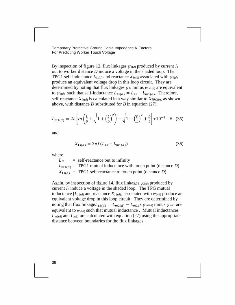
By inspection of figure 12, flux linkages ψ1(d) produced by current I1
out to worker distance D induce a voltage in the shaded loop. The
TPG1 self-inductance L1s(d) and reactance X1s(d) associated with ψ1(d)
produce an equivalent voltage drop in this loop circuit. They are
determined by noting that flux linkages ψ1s minus ψm1(d) are equivalent
to ψ1(d) such that self-inductance 𝐿1𝑠(𝑑) = 𝐿1𝑠 − 𝐿𝑚1(𝑑). Therefore,
self-reactance X1s(d) is calculated in a way similar to XTPG(b), as shown
above, with distance D substituted for B in equation (27):
𝐿𝑚1(𝑑) = 2𝐿 [𝑙𝑛 (𝐿
𝐷+ √1 + (
𝐿
𝐷)
2
) − √1 + (𝐷
𝐿)
2
+𝐷
𝐿] 𝑥10−9 H (35)
and
𝑋1𝑠(𝑑) = 2𝜋𝑓(𝐿1𝑠 − 𝐿𝑚1(𝑑)) (36)
where
L1s = self-reactance out to infinity
𝐿𝑚1(𝑑) = TPG1 mutual inductance with touch point (distance D)
𝑋1𝑠(𝑑) = TPG1 self-reactance to touch point (distance D)
Again, by inspection of figure 14, flux linkages ψ2(d) produced by
current I2 induce a voltage in the shaded loop. The TPG mutual
inductance [L12(d) and reactance X12(d)] associated with ψ2(d) produce an
equivalent voltage drop in this loop circuit. They are determined by
noting that flux linkage𝐿12(𝑑) = 𝐿𝑚2(𝑑) − 𝐿𝑚21s ψm2(d) minus ψm21 are
equivalent to ψ2(d) such that mutual inductance . Mutual inductances
Lm2(d) and Lm21 are calculated with equation (27) using the appropriate
distance between boundaries for the flux linkages:
Ground Cable Impedance K-Factors
For Predicting Worker Touch Voltage
39
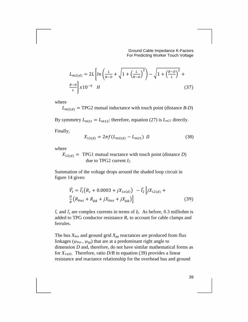
𝐿𝑚2(𝑑) = 2𝐿 [𝑙𝑛 (𝐿
𝐵−𝐷+ √1 + (
𝐿
𝐵−𝐷)
2
) − √1 + (𝐵−𝐷
𝐿)
2
+
𝐵−𝐷
𝐿] 𝑥10−9 𝐻 (37)
where
𝐿𝑚2(𝑑) = TPG2 mutual inductance with touch point (distance B-D)
By symmetry 𝐿𝑚21 = 𝐿𝑚12; therefore, equation (27) is Lm21 directly.
Finally,
𝑋12(𝑑) = 2𝜋𝑓(𝐿𝑚2(𝑑) − 𝐿𝑚21) 𝛺 (38)
where
𝑋12(𝑑) = TPG1 mutual reactance with touch point (distance D)
due to TPG2 current I2.
Summation of the voltage drops around the shaded loop circuit in
figure 14 gives:
𝑉�̂� = 𝐼1̂(𝑅𝑐 + 0.0003 + 𝑗𝑋1𝑠(𝑑)) − 𝐼2̂ [𝑗𝑋12(𝑑) +𝐷
𝐵(𝑅𝑏𝑢𝑠 + 𝑅𝑔𝑔 + 𝑗𝑋𝑏𝑢𝑠 + 𝑗𝑋𝑔𝑔)] (39)
𝐼1̂ and 𝐼2̂ are complex currents in terms of If. As before, 0.3 milliohm is
added to TPG conductor resistance Rc to account for cable clamps and
ferrules.
The bus Xbus and ground grid Xgg reactances are produced from flux
linkages (ψbus , ψgg) that are at a predominant right angle to
dimension D and, therefore, do not have similar mathematical forms as
for X1s(d). Therefore, ratio D/B in equation (39) provides a linear
resistance and reactance relationship for the overhead bus and ground
Temporary Protective Ground Cable Impedance K-Factors For Predicting Worker Touch Voltage
40
grid conductor segments versus dimension D of the ground loop with
TPG1 and worker.
Determination of K-factor results from dividing both sides of
equation (39) by 𝐼𝑓, giving the TPG1 composite complex impedance
𝑍�̂� = 𝑉�̂�/𝐼𝑓. Division by 𝐼𝑓 on the right side of the equation is
accomplished by substituting per-unit quantities |𝐼1
𝐼𝑓| ∠𝑍 and |
𝐼2
𝐼𝑓| ∠𝑌 for
currents 𝐼1̂ and 𝐼2̂, respectively. Currents 𝐼1̂ and 𝐼2̂ are solved in per
unit of If and converted to rectangular form for computation of
composite impedance 𝑍�̂�. The magnitude of 𝑍𝑔 is then readily
determined after collecting real and imaginary terms. This magnitude
represents the effective composite impedance of TPG1 in terms of the
station-available, short-circuit current and worker position between
TPGs. The K-factors are then found, as before, by dividing the
composite impedance magnitude Zg by TPG conductor resistance Rc.
Note that the choice of determining K-factors for TPG1 is arbitrary
(closest to source); K-factors for TPG2 would produce the same touch
voltage at a given location on the bus.
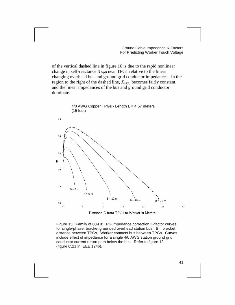
Bracket TPG Grounding Example
A family of bracket grounding TPG impedance correction K-factor
curves for various bracket spacing B is shown in figure 15.
Values for magnitude 𝑍𝑔 and TPG impedance correction K-factor
𝐾 = 𝑍𝑔/𝑅𝑐 are given in table 6 for one bracket distance 𝐵 = 24
meters in figure 15.
The associated K-curve from Table 6 is replotted in figure 16, along
with TPG per-unit currents 𝐼1
𝐼𝑓 and
𝐼2
𝐼𝑓 versus TPG bracket separation
distance B for comparison. The steep portion of the K-curve to the left
Ground Cable Impedance K-Factors
For Predicting Worker Touch Voltage
41
of the vertical dashed line in figure 16 is due to the rapid nonlinear
change in self-reactance X1s(d) near TPG1 relative to the linear
changing overhead bus and ground grid conductor impedances. In the
region to the right of the dashed line, X1s(d) becomes fairly constant,
and the linear impedances of the bus and ground grid conductor
dominate.
4/0 AWG Copper TPGs - Length L = 4.57 meters (15 feet)
Figure 15. Family of 60-Hz TPG impedance correction K-factor curves for single-phase, bracket grounded overhead station bus. B = bracket distance between TPGs. Worker contacts bus between TPGs. Curves include effect of impedance for a single 4/0 AWG station ground grid conductor current return path below the bus. Refer to figure 12 (figure C.21 in IEEE 1246).
Temporary Protective Ground Cable Impedance K-Factors For Predicting Worker Touch Voltage
42
Ground Cable Impedance K-Factors
For Predicting Worker Touch Voltage
43
Figure 16. 60-Hertz TPG K-factor curve from Fig. 15 for B = 24 m, shown with associated TPG currents. Current ratio traces show range of TPGs current division for 0 < B ≤ 24 m. At B = 24 m, TPG1 carries 92% of total short-circuit current If . Refer to Fig. 1.
Distance D or B, meters
I1/If
I2/If
K24

45
Chapter 5
Power Line Grounding
Power Line Grounding Introduction
A method to predict worker touch voltage in substations using TPGs
impedance correction K-factors has been developed in the previous
chapters. Similar analysis of touch potential can be applied to workers
aloft in contact with power line conductors at a support structure.
Ground potential rise at the structure footings, guy wire anchors, etc.,
are not addressed in this analysis. Two examples for single-point
protective grounding at a high-voltage transmission and utility line
structure are presented. These examples are simple in layout: TPGs
lie in the same plane as the structure, and the source of short-circuit
current is from either side of the structure.
Transmission Line Structure Grounding
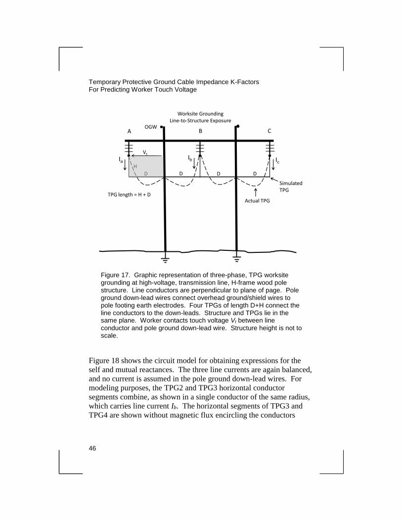
Figure 17 shows a simple TPG worksite grounding application for a
H-frame, wood pole, transmission line structure. The structure and
TPGs lie in the same plane (i.e., the TPGs are connected to the line
conductors near the insulators). A worker contacts the line conductor
and pole ground down-lead wire at the elevation of the line conductor,
forming a rectangular induction ground loop (shaded area) with the
A-phase TPG and ground down-lead of dimensions D and H. This
model lends itself to analysis of touch voltage Vt using mutual
induction formulas that are similar to those for the substation models
in the previous chapters. Other, more complicated structure grounding
configurations (e.g., worksite bracket grounding) are beyond the scope
of this chapter.
Temporary Protective Ground Cable Impedance K-Factors For Predicting Worker Touch Voltage
46
Figure 18 shows the circuit model for obtaining expressions for the
self and mutual reactances. The three line currents are again balanced,
and no current is assumed in the pole ground down-lead wires. For
modeling purposes, the TPG2 and TPG3 horizontal conductor
segments combine, as shown in a single conductor of the same radius,
which carries line current Ib. The horizontal segments of TPG3 and
TPG4 are shown without magnetic flux encircling the conductors
A B C
Vt
H
D D D D
TPG length = H + D
Worksite GroundingLine-to-Structure Exposure
Actual TPG
Simulated TPG
OGW
IaIb Ic
Figure 17. Graphic representation of three-phase, TPG worksite grounding at high-voltage, transmission line, H-frame wood pole structure. Line conductors are perpendicular to plane of page. Pole ground down-lead wires connect overhead ground/shield wires to pole footing earth electrodes. Four TPGs of length D+H connect the line conductors to the down-leads. Structure and TPGs lie in the same plane. Worker contacts touch voltage Vt between line conductor and pole ground down-lead wire. Structure height is not to scale.
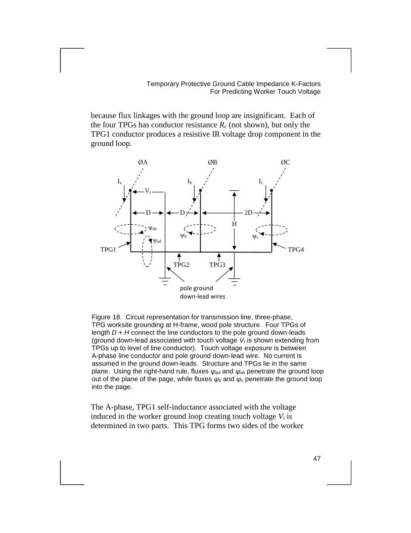
Temporary Protective Ground Cable Impedance K-Factors
For Predicting Worker Touch Voltage
47
because flux linkages with the ground loop are insignificant. Each of
the four TPGs has conductor resistance Rc (not shown), but only the
TPG1 conductor produces a resistive IR voltage drop component in the
ground loop.
The A-phase, TPG1 self-inductance associated with the voltage
induced in the worker ground loop creating touch voltage Vt is
determined in two parts. This TPG forms two sides of the worker
Figure 18. Circuit representation for transmission line, three-phase, TPG worksite grounding at H-frame, wood pole structure. Four TPGs of length D + H connect the line conductors to the pole ground down-leads (ground down-lead associated with touch voltage Vt is shown extending from TPGs up to level of line conductor). Touch voltage exposure is between A-phase line conductor and pole ground down-lead wire. No current is assumed in the ground down-leads. Structure and TPGs lie in the same plane. Using the right-hand rule, fluxes ψad and ψah penetrate the ground loop out of the plane of the page, while fluxes ψb and ψc penetrate the ground loop into the page.
TPG1
TPG2 TPG3
TPG4
Ia Ib Ic
Vt
D D 2D
H ψah
ψad
ψb ψc
. . .
ØA ØB ØC
pole ground down-lead wires

Temporary Protective Ground Cable Impedance K-Factors For Predicting Worker Touch Voltage
48
ground loop; therefore, flux linkages ψad and ψah must be accounted
for when determining the self-inductance. These fluxes are at a
predominant right angle to each other; therefore, they can be evaluated
separately, and their associated self-inductances can be combined by
superposition. The TPG1 self-inductance associated with flux
linkages ψah (flux produced by Ia in length H of TPG1) is determined
in a similar way to that described in the “Basic Single-Phase TPG
Grounding Model” section in chapter 2, as well as from equations (6)
and (7) in chapter 2. As described in that section, the method of
determining self-inductance for a specified radial distance from a
conductor involves finding the mutual inductance of two equal length
parallel conductors; in this case, the vertical segments of TPG1 and
pole ground down-lead of length H, separated by distance D.
Therefore:
𝐿1𝑠𝐻 = 2𝐻 [𝑙𝑛 (2𝐻
𝑟) − 0.75] 𝑥10−9 H (40)
𝐿1𝑚𝐻(𝑑) = 2𝐻 [𝑙𝑛 (𝐻
𝐷+ √1 + (
𝐻
𝐷)
2
) − √1 + (𝐷
𝐻)
2
+𝐷
𝐻] 𝑥10−9 H (41)
where
r = the conductor radius and all dimensions in centimeters
Then:
𝑋1𝑠𝐻(𝑑) = 𝑋1𝑠𝐻 − 𝑋1𝑚𝐻(𝑑) = 2𝜋𝑓(𝐿1𝑠𝐻 − 𝐿1𝑚𝐻(𝑑)) 𝛺 (42)
where
𝑋1𝑠𝐻(𝑑) = A-phase TPG1 length H self-reactance to pole ground
down-lead (distance D)
𝐿1𝑠𝐻 , 𝑋1𝑠𝐻 = A-phase TPG1 length H self-inductance (reactance) out
to infinite distance
Temporary Protective Ground Cable Impedance K-Factors
For Predicting Worker Touch Voltage
49
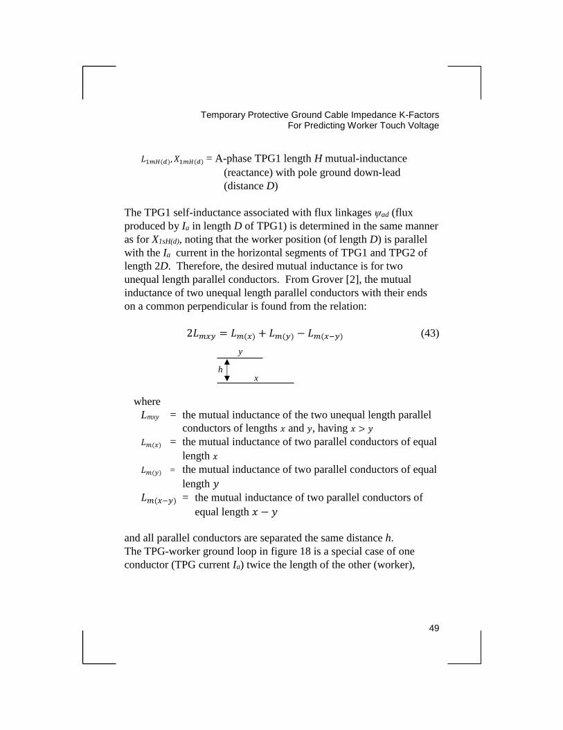
𝐿1𝑚𝐻(𝑑), 𝑋1𝑚𝐻(𝑑) = A-phase TPG1 length H mutual-inductance
(reactance) with pole ground down-lead
(distance D)
The TPG1 self-inductance associated with flux linkages ψad (flux
produced by Ia in length D of TPG1) is determined in the same manner
as for X1sH(d), noting that the worker position (of length D) is parallel
with the Ia current in the horizontal segments of TPG1 and TPG2 of
length 2D. Therefore, the desired mutual inductance is for two
unequal length parallel conductors. From Grover [2], the mutual
inductance of two unequal length parallel conductors with their ends
on a common perpendicular is found from the relation:
2𝐿𝑚𝑥𝑦 = 𝐿𝑚(𝑥) + 𝐿𝑚(𝑦) − 𝐿𝑚(𝑥−𝑦) (43)
where
Lmxy = the mutual inductance of the two unequal length parallel
conductors of lengths 𝑥 and 𝑦, having 𝑥 > 𝑦
𝐿𝑚(𝑥) = the mutual inductance of two parallel conductors of equal
length 𝑥
𝐿𝑚(𝑦) = the mutual inductance of two parallel conductors of equal
length 𝑦
𝐿𝑚(𝑥−𝑦) = the mutual inductance of two parallel conductors of
equal length 𝑥 − 𝑦
and all parallel conductors are separated the same distance h.
The TPG-worker ground loop in figure 18 is a special case of one
conductor (TPG current Ia) twice the length of the other (worker),
y
x h
Temporary Protective Ground Cable Impedance K-Factors For Predicting Worker Touch Voltage
50
making 𝐿𝑚(𝑦) = 𝐿𝑚(𝑥−𝑦) and, therefore, 𝐿𝑚𝑥𝑦 =1
2𝐿𝑚(𝑥). The required
mutual inductance is then:
𝐿1𝑚𝐷(ℎ) = 2𝐷 [𝑙𝑛 (2𝐷
𝐻+ √1 + (
2𝐷
𝐻)
2
) − √1 + (𝐻
2𝐷)
2
+𝐻
2𝐷] 𝑥10−9 H (44)
where the 1/2 factor for Lm(x) results in the 2D term (rather than 4D) in
front of the bracket.
The TPG1 approximate self-inductance2 of length D is:
𝐿1𝑠𝐷 = 2𝐷 [𝑙𝑛 (2𝐷
𝑟) − 0.75] 𝑥10−9 H (45)
Finally:
𝑋1𝑠𝐷(ℎ) = 𝑋1𝑠𝐷 − 𝑋1𝑚𝐷(ℎ) = 2𝜋𝑓(𝐿1𝑠𝐷 − 𝐿1𝑚𝐷(ℎ)) 𝛺 (46)
where
𝑋1𝑠𝐷(ℎ) = A-phase TPG1 length D self-reactance to worker
position (distance H)
𝐿1𝑠𝐷 , 𝑋1𝑠𝐷 = A-phase TPG1 length D self-inductance (reactance)
out to infinite distance
𝐿1𝑚𝐷(ℎ), 𝑋1𝑚𝐷(ℎ) = A-phase TPG1 andTPG2 segments length
2D mutual-inductance (reactance) with
worker position (distance H)
The total self-reactance Xa of the A-phase TPG1 associated with the
area enclosed by the worker ground loop is:
2 Approximate self-inductance of horizontal segment of TPG1 based on
self-inductance formula for Ia current-carrying conductor of length D, which ignores
influence of flux linkages due to the same current in adjacent horizontal segment of
TPG2. This results in slightly lower K-factor values.
Temporary Protective Ground Cable Impedance K-Factors
For Predicting Worker Touch Voltage
51
𝑋𝑎 = 𝑋1𝑠𝐻(𝑑) + 𝑋1𝑠𝐷(ℎ) 𝛺 (47)
Flux linkages ψb and ψc, and their associated mutual reactances Xab
and Xac, influence touch voltage Vt to a much lesser extent than Xa.
This is due to the distant locations of the vertical portions of the Ib and
Ic TPG conductors with the worker induction ground loop (Ic has the
least effect). Calculated values for mutual reactance Xac will show it
insignificant and, therefore, will be ignored when determining
composite TPG impedance Zg1 below.
The ψb flux linkages with the A-phase TPG1-worker ground loop are
similar in physical arrangement to those for linkages ψ2d in figure 14
in chapter 4, where TPG1 in that figure becomes the vertical portion
A-phase TPG1, and TPG2 becomes the common vertical portion of the
B-phase TPG. Thus, the mutual reactance term Xab is of similar form
as X12(d) from equation (38) in chapter 4. Due to symmetry (pole
ground down-lead centered between TPGs), mutual reactance Lm2(d) in
equation (38) in chapter 4 is equivalent to L1mH(d) in equation (41);
therefore:
𝑋𝑎𝑏 = 𝑋1𝑚𝐻(𝑑) − 𝑋𝑚𝑎𝑏 = 2𝜋𝑓(𝐿1𝑚𝐻(𝑑) − 𝐿𝑚𝑎𝑏) Ω (48)
where
Xab = mutual reactance of the vertical portion of TPG1 with the
pole ground down-lead due to current Ib in the common
vertical portion B-phase TPG
From modified equation (27) in chapter 4:
𝐿𝑚𝑎𝑏 = 2𝐻 [𝑙𝑛 (𝐻
2𝐷+ √1 + (
𝐻
2𝐷)
2
) − √1 + (2𝐷
𝐻)
2
+2𝐷
𝐻] 𝑥10−9 H (49)
with all dimensions in centimeters.
Temporary Protective Ground Cable Impedance K-Factors For Predicting Worker Touch Voltage
52
Derivation of mutual reactance Xac, if it were to be evaluated, would
follow a similar process as for Xab in determining the mutual reactances
of the vertical portions of the C- and A-phase TPGs, and of the C-phase
TPG with the pole ground down-lead. A single value of Xac is given in
the sample data spreadsheet below for comparison with Xab.
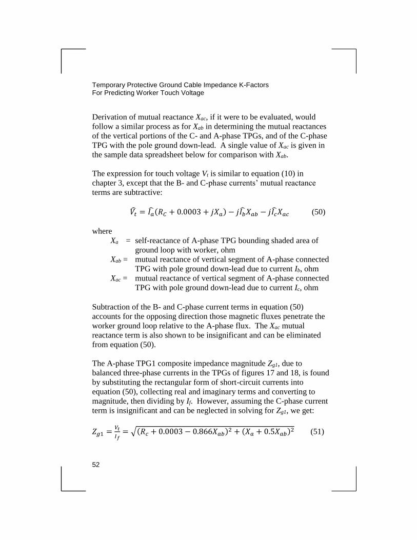
The expression for touch voltage Vt is similar to equation (10) in
chapter 3, except that the B- and C-phase currents’ mutual reactance
terms are subtractive:
𝑉�̂� = 𝐼�̂�(𝑅𝐶 + 0.0003 + 𝑗𝑋𝑎) − 𝑗𝐼�̂�𝑋𝑎𝑏 − 𝑗𝐼�̂�𝑋𝑎𝑐 (50)
where
Xa = self-reactance of A-phase TPG bounding shaded area of
ground loop with worker, ohm
Xab = mutual reactance of vertical segment of A-phase connected
TPG with pole ground down-lead due to current Ib, ohm
Xac = mutual reactance of vertical segment of A-phase connected
TPG with pole ground down-lead due to current Ic, ohm
Subtraction of the B- and C-phase current terms in equation (50)
accounts for the opposing direction those magnetic fluxes penetrate the
worker ground loop relative to the A-phase flux. The Xac mutual
reactance term is also shown to be insignificant and can be eliminated
from equation (50).
The A-phase TPG1 composite impedance magnitude Zg1, due to
balanced three-phase currents in the TPGs of figures 17 and 18, is found
by substituting the rectangular form of short-circuit currents into
equation (50), collecting real and imaginary terms and converting to
magnitude, then dividing by If. However, assuming the C-phase current
term is insignificant and can be neglected in solving for Zg1, we get:
𝑍𝑔1 =𝑉𝑡
𝐼𝑓= √(𝑅𝑐 + 0.0003 − 0.866𝑋𝑎𝑏)2 + (𝑋𝑎 + 0.5𝑋𝑎𝑏)2 (51)
Temporary Protective Ground Cable Impedance K-Factors
For Predicting Worker Touch Voltage
53
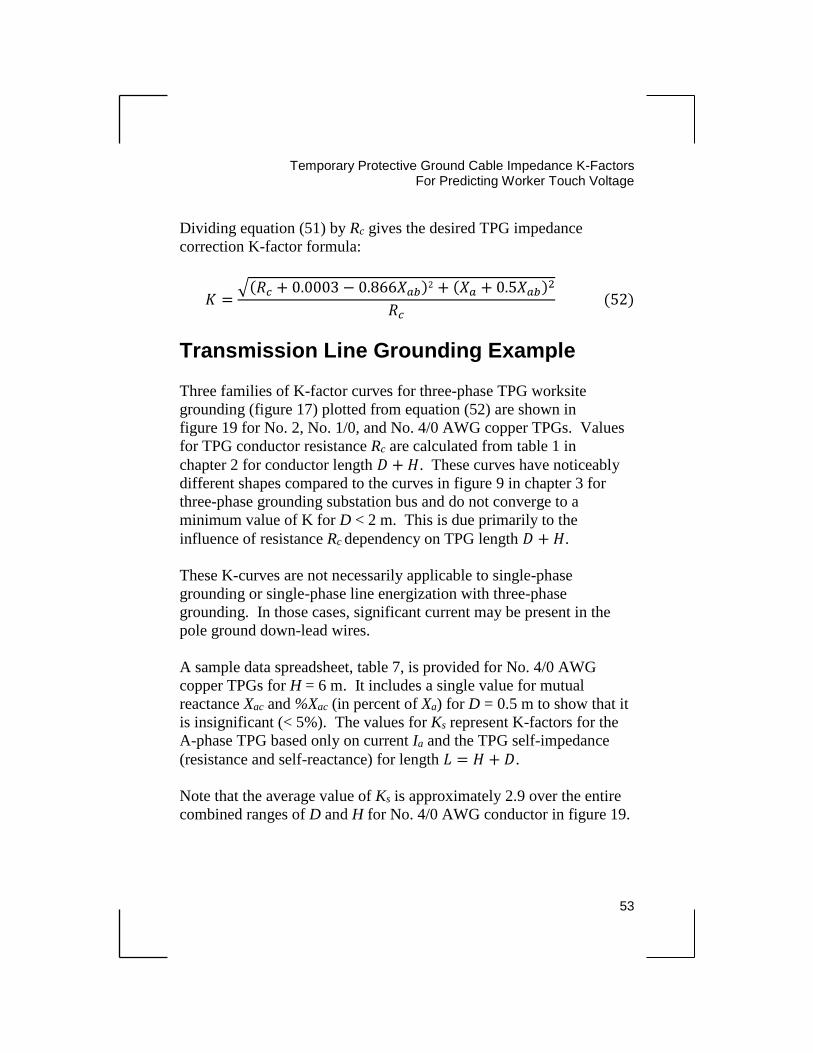
Dividing equation (51) by Rc gives the desired TPG impedance
correction K-factor formula:
𝐾 =√(𝑅𝑐 + 0.0003 − 0.866𝑋𝑎𝑏)2 + (𝑋𝑎 + 0.5𝑋𝑎𝑏)2
𝑅𝑐 (52)
Transmission Line Grounding Example
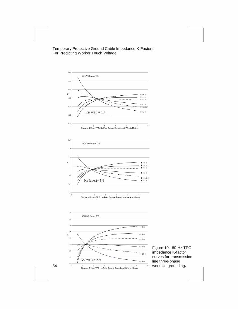
Three families of K-factor curves for three-phase TPG worksite
grounding (figure 17) plotted from equation (52) are shown in
figure 19 for No. 2, No. 1/0, and No. 4/0 AWG copper TPGs. Values
for TPG conductor resistance Rc are calculated from table 1 in
chapter 2 for conductor length 𝐷 + 𝐻. These curves have noticeably
different shapes compared to the curves in figure 9 in chapter 3 for
three-phase grounding substation bus and do not converge to a
minimum value of K for D < 2 m. This is due primarily to the
influence of resistance Rc dependency on TPG length 𝐷 + 𝐻.
These K-curves are not necessarily applicable to single-phase
grounding or single-phase line energization with three-phase
grounding. In those cases, significant current may be present in the
pole ground down-lead wires.
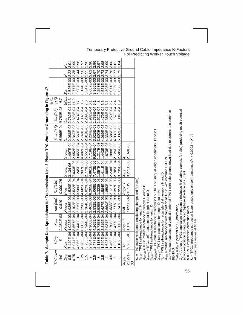
A sample data spreadsheet, table 7, is provided for No. 4/0 AWG
copper TPGs for H = 6 m. It includes a single value for mutual
reactance Xac and %Xac (in percent of Xa) for D = 0.5 m to show that it
is insignificant (< 5%). The values for Ks represent K-factors for the
A-phase TPG based only on current Ia and the TPG self-impedance
(resistance and self-reactance) for length 𝐿 = 𝐻 + 𝐷.
Note that the average value of Ks is approximately 2.9 over the entire
combined ranges of D and H for No. 4/0 AWG conductor in figure 19.
Temporary Protective Ground Cable Impedance K-Factors For Predicting Worker Touch Voltage
54
Ks(ave.) = 2.9
Ks (ave.)= 1.8
Ks(ave.) = 1.4
Figure 19. 60-Hz TPG impedance K-factor curves for transmission line three-phase
worksite grounding.
Temporary Protective Ground Cable Impedance K-Factors
For Predicting Worker Touch Voltage
55
Ta
ble
7.
Sam
ple
Da
ta S
pre
ad
sh
ee
t fo
r T
ran
sm
issio
n L
ine
3-P
ha
se
TP
G W
ork
sit
e G
rou
nd
ing
in
Fig
ure
17
TP
G s
ize
H
(m)
X1
sH
rad
(cm
) R
c (Ω/m
)
X
ma
c (
0.5
) X
ac (0
.5)
%X
ac
(0.5
)
4/0
6
2
.95
9E
-03
0.8
19
0.0
001
75
4.9
66
E-0
4 9
.78
3E
-05
4.7
D(m
)
0.5
0
.75
1
1.2
5
1.5
2
2
.5
3
3.5
4
4
.5
5
6
Xm
ab
7.4
40
E-0
4
5.9
44
E-0
4
4.9
66
E-0
4
4.2
65
E-0
4
3.7
35
E-0
4
2.9
84
E-0
4
2.4
77
E-0
4
2.1
13
E-0
4
1.8
40
E-0
4
1.6
28
E-0
4
1.4
58
E-0
4
1.3
20
E-0
4
1.1
09
E-0
4 X
1m
H(d
)
1.0
22
E-0
3
8.5
67
E-0
4
7.4
40
E-0
4
6.6
02
E-0
4
5.9
44
E-0
4
4.9
66
E-0
4
4.2
65
E-0
4
3.7
35
E-0
4
3.3
19
E-0
4
2.9
84
E-0
4
2.7
08
E-0
4
2.4
77
E-0
4
2.1
13
E-0
4 X
1sH
(d)
1.9
36
E-0
3
2.1
02
E-0
3
2.2
15
E-0
3
2.2
98
E-0
3
2.3
64
E-0
3
2.4
62
E-0
3
2.5
32
E-0
3
2.5
85
E-0
3
2.6
27
E-0
3
2.6
60
E-0
3
2.6
88
E-0
3
2.7
11
E-0
3
2.7
47
E-0
3 K
1sD
1.5
29
E-0
4
2.5
22
E-0
4
3.5
80
E-0
4
4.6
85
E-0
4
5.8
29
E-0
4
8.2
05
E-0
4
1.0
68
E-0
3
1.3
23
E-0
3
1.5
84
E-0
3
1.8
50
E-0
3
2.1
21
E-0
3
2.3
97
E-0
3
2.9
59
E-0
3 X
1m
D(h
)
3.1
34
-06
7
.03
3E
-06
1
.24
5E
-05
1
.93
7E
-05
2
.77
3E
-05
4
.86
1E
-05
7
.47
3E
-05
1
.05
7E
-04
1
.41
1E
-04
1
.80
5E
-04
2
.23
8E
-04
2
.70
5E
-04
3
.73
5E
-04 X
1sD
(h)
1.4
97
E-0
4
2.4
52
E-0
4
3.4
55
E-0
4
4.4
92
E-0
4
5.5
51
E-0
4
7.7
19
E-0
4
9.9
30
E-0
4
1.2
17
E-0
3
1.4
43
E-0
3
1.6
70
E-0
3
1.8
98
E-0
3
2.1
26
E-0
3
2.5
85
E-0
3 X
a
2.0
86
E-0
3
2.3
47
E-0
3
2.5
60
E-0
3
2.7
48
E-0
3
2.9
19
E-0
3
3.2
34
E-0
3
3.5
25
E-0
3
3.8
02
E-0
3
4.0
69
E-0
3
4.3
30
E-0
3
4.5
85
E-0
3
4.8
37
E-0
3
5.3
32
E-0
3 X
ab
2.7
82
E-0
4
2.6
23
E-0
4
2.4
74
E-0
4
2.3
37
E-0
4
2.2
09
E-0
4
1.9
82
E-0
4
1.7
88
E-0
4
1.6
22
E-0
4
1.4
79
E-0
4
1.3
56
E-0
4
1.2
50
E-0
4
1.1
57
E-0
4
1.0
04
E-0
4 %
Xa
b
13
.3
11
.2
9.7
8
.5
7.6
6
.1
5.1
4
.3
3.6
3
.1
2.7
2
.4
1.9
Zg
1
2.5
26
E-0
3
2.7
77
E-0
3
2.9
87
E-0
3
3.1
74
E-0
3
3.3
47
E-0
3
3.6
67
E-0
3
3.9
66
E-0
3
4.2
53
E-0
3
4.5
31
E-0
3
4.8
03
E-0
3
5.0
71
E-0
3
5.3
36
E-0
3
5.8
58
E-0
3 K
2
.22
2
.35
2
.44
2
.50
2
.55
2
.62
2
.67
2
.70
2
.73
2
.74
2
.76
2
.77
2
.79
Ks
3.0
1
2.9
9
2.9
8
2.9
7
2.9
6
2.9
6
2.9
6
2.9
7
2.9
8
2.9
9
3.0
0
3.0
1
3.0
4
Xtp
g(b
)
2.1
27
E-
03
I1/f
9
.23
6E
-01 A
ng
le Z
1
.17
8
I2/lf
7.8
95
E-0
2 A
ng
le Y
-1
3.9
19
Xm
12
3.2
71
E-0
5 X
1s
2.1
60
E-0
3
Rc =
TP
G c
able
resis
tance (
exclu
din
g c
lam
ps a
nd ferr
ule
s)
X1sH
= T
PG
1 s
elf-r
eacta
nce for
length
H
X1m
H(d
) =
TP
G1 m
utu
al re
acta
nce for
length
H o
ut to
D
X1sH
(d) =
TP
G1 s
elf-r
eacta
nce f
or
length
H o
ut to
D
X1sD
= T
PG
1 s
elf-r
eacta
nce for
length
D
X1m
D(h
) =
TP
G m
utu
al re
acta
nce for
length
2D
out to
H o
f unequal le
ngth
conducto
rs D
and 2
D
X1sd(h
) =
TP
G1 s
elf-r
eacta
nce for
length
D o
ut to
H
Xa =
TP
G1 s
elf-r
eacta
nce for
recta
ngle
of
dim
ensio
ns H
and D
X
mab =
mu
tual re
acta
nce o
f vert
ical port
ion o
f T
PG
1 w
ith c
om
mon B
Ø T
PG
X
ab =
mu
tual re
acta
nce o
f vert
ical port
ion o
f T
PG
1 w
ith p
ole
gro
und d
ow
n-le
ad d
ue t
o c
urr
en
t I b
in
com
mon
BØ
TP
G
%X
ab =
Xab in
perc
ent
of
Xa (
info
rmatio
n)
Zg1 =
A-p
hase T
PG
1 e
quiv
ale
nt im
pedance (
inclu
des R
of cable
, cla
mps,
ferr
ule
s)
pro
ducin
g t
ouch p
ote
ntia
l at
work
er
positio
n d
urin
g b
ala
nced 3
-phase s
hort
-circuit c
urr
ent
K =
TP
G1 im
pedance c
orr
ectio
n facto
r K
s =
TP
G1 im
pedance c
orr
ectio
n facto
r based o
nly
on s
elf-r
eacta
nce (
Rc +
0.0
003 +
jX
1sD)
All
reacta
nce v
alu
es a
t 60 H
z
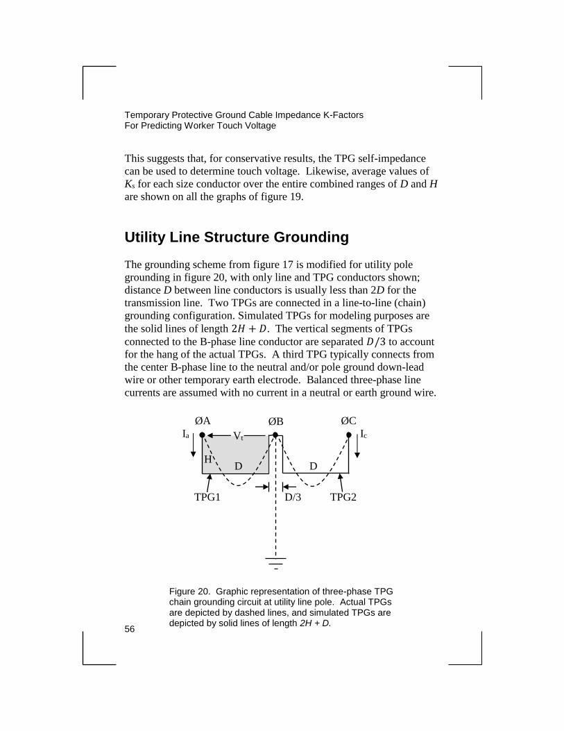
Temporary Protective Ground Cable Impedance K-Factors For Predicting Worker Touch Voltage
56
This suggests that, for conservative results, the TPG self-impedance
can be used to determine touch voltage. Likewise, average values of
Ks for each size conductor over the entire combined ranges of D and H
are shown on all the graphs of figure 19.
Utility Line Structure Grounding
The grounding scheme from figure 17 is modified for utility pole
grounding in figure 20, with only line and TPG conductors shown;
distance D between line conductors is usually less than 2D for the
transmission line. Two TPGs are connected in a line-to-line (chain)
grounding configuration. Simulated TPGs for modeling purposes are
the solid lines of length 2𝐻 + 𝐷. The vertical segments of TPGs
connected to the B-phase line conductor are separated 𝐷/3 to account
for the hang of the actual TPGs. A third TPG typically connects from
the center B-phase line to the neutral and/or pole ground down-lead
wire or other temporary earth electrode. Balanced three-phase line
currents are assumed with no current in a neutral or earth ground wire.
Ks (ave.)=
2.9
TPG1 TPG2
D D
ØA ØB ØC
H
Ia Ic Vt
D/3
Figure 20. Graphic representation of three-phase TPG chain grounding circuit at utility line pole. Actual TPGs are depicted by dashed lines, and simulated TPGs are depicted by solid lines of length 2H + D.
Temporary Protective Ground Cable Impedance K-Factors
For Predicting Worker Touch Voltage
57
Worker touch voltage Vt in figure 20 is found using a similar calculation
procedure as for the transmission line model, except induced touch
voltage components are calculated for each current (Ia and Ic) in the
vertical segments of the TPG connections to the B-phase line conductor.
This is necessary for adequate modeling of the magnetic coupling with
the ground loop bounded by the current-carrying conductor at B-phase.
In the transmission line case, the ground loop was bounded by the
noncurrent-carrying ground down-lead wire, making the model less
sensitive to the conductor shape chosen to carry current Ib.
The derivation of the K-factor expression for the AB-phase connected
TPG1 (or BC-phase connected TPG2 due to symmetry) is left to the
reader. It has the same form as equation (52) for the transmission line
case:
𝐾 = √(𝑅𝑐 + 0.0003 − 0.866𝑋12−𝑏)2 + (𝑋ℎ𝑑 + 0.5𝑋12−𝑏)2
𝑅𝑐 (53)
where
X12-b = mutual reactance of TPG1, due to current Ic in adjacent (ØB)
vertical segment of TPG2, ohm
Xhd = TPG self-reactance of shaded rectangle sides 2H+D, ohm
and, again, noting that the contribution to induced voltage Vt, due to
current Ic in the vertical segment of TPG2 connected to the C-phase
line conductor, is neglected.
Utility Line Structure Grounding Example
Three families of K-factor curves for three-phase TPG worksite chain
grounding (figure 20) plotted from equation (53) are shown in
figure 21 for No. 2, No. 1/0, and No. 4/0 AWG copper TPGs.
Temporary Protective Ground Cable Impedance K-Factors For Predicting Worker Touch Voltage
58
A sample data spreadsheet, table 8, is provided for No. 4/0 AWG
copper TPGs for H = 3 m. The values for Ks represent K-factors for
the A-phase TPG based only on current Ia and the TPG self-impedance
(resistance and self-reactance) for length 𝐿 = 𝐻 + 𝐷. Values for Ks
are also shown for each size conductor in figure 21, and they apply to
all curves in a family. The range of K for each family of curves is
relatively small; an average value K-factor could be chosen to
adequately represent each TPG conductor size.
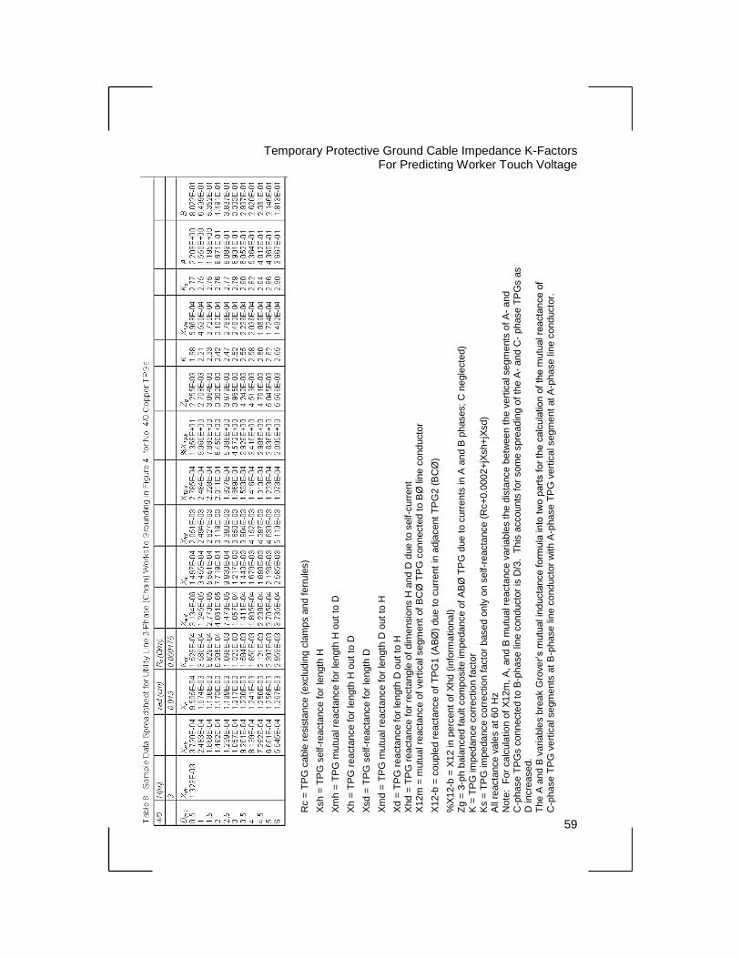
Temporary Protective Ground Cable Impedance K-Factors
For Predicting Worker Touch Voltage
59
Rc =
TP
G c
able
resis
tance (
exclu
din
g c
lam
ps a
nd f
err
ule
s)
Xsh =
TP
G s
elf-r
eacta
nce for
length
H
Xm
h =
TP
G m
utu
al re
acta
nce for
length
H o
ut
to D
Xh =
TP
G r
eacta
nce f
or
length
H o
ut
to D
Xsd =
TP
G s
elf-r
eacta
nce for
length
D
Xm
d =
TP
G m
utu
al re
acta
nce for
length
D o
ut to
H
Xd =
TP
G r
eacta
nce f
or
length
D o
ut
to H
X
hd =
TP
G r
eacta
nce
for
recta
ngle
of
dim
ensio
ns H
and
D d
ue t
o s
elf-c
urr
ent
X12m
= m
utu
al re
acta
nce o
f vert
ical segm
ent
of B
CØ
TP
G c
onnecte
d t
o B
Ø lin
e c
onducto
r
X12-b
= c
ouple
d r
eacta
nce o
f T
PG
1 (
AB
Ø)
due to c
urr
ent
in a
dja
cent
TP
G2 (
BC
Ø)
%X
12-b
= X
12 in
perc
ent
of
Xhd
(in
form
atio
nal)
Zg
= 3
-ph b
ala
nced fault c
om
posite im
pedance o
f A
BØ
TP
G d
ue t
o c
urr
ents
in
A a
nd B
phases;
C n
egle
cte
d)
K =
TP
G im
pedance c
orr
ectio
n facto
r K
s =
TP
G im
pedance c
orr
ectio
n f
acto
r based o
nly
on s
elf-r
eacta
nce (
Rc+
0.0
002
+jX
sh+
jXsd)
All
reacta
nce v
ale
s a
t 60
Hz
Note
: F
or
calc
ula
tio
n o
f X
12m
, A
, and B
mu
tual re
acta
nce v
aria
ble
s the d
ista
nce b
etw
een t
he v
ert
ical segm
ents
of A
- and
C-p
hase T
PG
s c
onnecte
d to B
-phase lin
e c
onducto
r is
D/3
. T
his
accounts
for
som
e s
pre
adin
g o
f th
e A
- and C
- phase T
PG
s a
s
D in
cre
ased.
Th
e A
and B
varia
ble
s b
reak G
rove
r’s m
utu
al in
ducta
nce form
ula
in
to t
wo p
art
s for
the c
alc
ula
tio
n o
f th
e m
utu
al re
acta
nce o
f
C-p
hase T
PG
vert
ical segm
ents
at B
-phase lin
e c
onducto
r w
ith A
-phase T
PG
vert
ical segm
ent
at A
-phase lin
e c
onducto
r.

Temporary Protective Ground Cable Impedance K-Factors For Predicting Worker Touch Voltage
60
Figure 21. 60-Hz TPG impedance K-factor curves for utility line -phase (chain) worksite grounding line-to-line exposure.
No. 1/0 AWG Copper TPG length = 2H + D
Ks (ave.)= 1.8
No. 2 AWG Copper TPG length = 2H +
D
Ks(ave.)=1.4
No. 4/0 AWG Copper TPG length = 2H
+ D
Ks(ave.)=2.8
61
Chapter 6
Conclusion
Electrical grounding models for six temporary protective grounding
scenarios covered in this book illustrate the effect magnetic induction
has on worker touch voltage when a worksite is accidentally
energized. The underlying induction principles are presented and
developed into touch voltage equations in terms of the self- and mutual
reactances for the TPGs. These grounding models are the basis for
applying TPG impedance correction K-factors that appear in
IEEE 1246.
Temporary protective grounding staged-fault field tests [3] [4] confirm
the model predictions of higher value touch voltages due to TPG
induction ground loops formed with the worker.
The induction ground loop effect is demonstrated in [3] for the case of
a grounded generator bus with TPGs between worker and energy
source. The measured touch voltage remote from the point of
attachment of the TPGs to the bus is two or more times the fault
voltage drop measured directly across the TPGs (refer to figures 1 and
3, as well as table 1, in [3]). For the transmission line grounding tests
[3] [4], the measured touch voltages from line conductor to structure
are approximately three times the fault voltage drop directly across the
TPG forming the ground loop with the worker (refer to figures 9
and 10 in [3] and Test 6, figure 3, and table 2 in [4]). The
above-referenced field test examples do not precisely fit the
grounding models presented in this paper; however, the test data
generally confirm the model predictions and are useful for study.
In the previous chapters, impedance correction K-factors are described
which adjust the resistance of the TPG conductor to an equivalent
shunt impedance across the worker’s body. This equivalent
Temporary Protective Ground Cable Impedance K-Factors For Predicting Worker Touch Voltage
62
impedance, multiplied by the worksite available short-circuit current,
approximates the actual touch voltage due to the physical layout of the
TPGs, creating an induction ground loop with the worker. In some
cases, touch voltage calculation can be further simplified by using the
TPG conductor self-impedance (resistance and self-reactance) to
determine K-factors, making it independent of the physical layout at
the worksite.
Touch (exposure) voltage is shown to be approximately three times
higher, depending on the physical arrangement of TPGs with the
worker, if the reactive IX voltage drop of the cable is included with the
resistive IR voltage drop; however, for the case of working between an
energy source and TPGs, the touch voltage (and K-factors) continues
to rise with worker distance from the TPGs.
63
References
[1] The Institute of Electrical and Electronics Engineers,
IEEE Standard No. 1246-2011, IEEE Guide for Temporary
Protective Grounding Systems Used in Substations, 2011.
[2] Grover, Frederick W., Inductance Calculations, Dover
Publications, Inc., Mineola, New York, 2004.
[3] Atwater, P.L., and J.M. DeHaan, “Staged Fault Test Evaluation of
Safety Grounding For High-Voltage Equipment and
Transmission Lines,” Proceedings of 2000 T&D World Expo,
p. 317-338, 2000.
[4] Atwater, P.L., J.M. DeHaan, and A. Roman, “Evaluation of
Safety Grounding Practices for Maintenance Work on
De-Energized Transmission Lines,” Proceedings of 2001
IEEE/PES Transmission and Distribution Conference,
Distribution System Maintenance and Operation Session,
2001.

65
Biography
Philip L. Atwater received a B.S. degree in electrical engineering
from Michigan State University, East Lansing, Michigan in 1977, and
is a registered Professional Engineer.
He is retired from the Bureau of Reclamation and is currently a
consultant with over 37 years of experience in the electric power
fields of plant controls design, power system equipment diagnostics,
research, and field testing. Philip has performed several
research-related, staged fault protective grounding tests on
high-voltage transmission lines and equipment. In addition, he served
on the IEEE Substations Safety Working Group for the 1246-2011
Standard [1] revision.
James M. DeHaan received a B.S. degree in electrical engineering
from Dordt College, Sioux Center, Iowa in 1989, and M.S. degree in
electric power engineering from Iowa State University, Ames, Iowa in
1991. He is a registered Professional Engineer.
James works at the Bureau of Reclamation and has over 24 years of
experience in the electric power fields of operation and maintenance,
equipment diagnostics, research, and field testing. He has performed
several research-related, staged fault protective grounding tests on
high-voltage transmission lines and equipment.