Embed Size (px)
Citation preview
Temposonics®
Magnetostrictive Linear Position Sensors
ER AnalogData Sheet
– Compact sensor model– Operating temperature up to +75 °C (+167 °F)– Ideal for flexible mounting
I 2 I
Temposonics® ER AnalogData Sheet
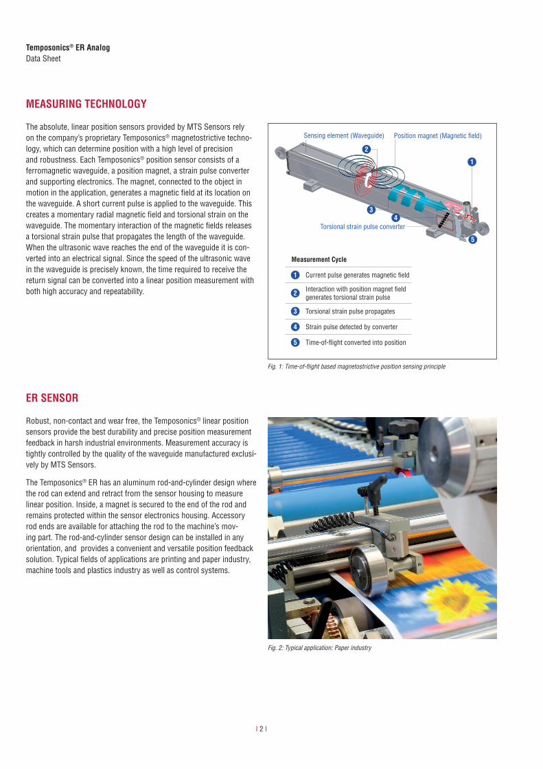
Fig. 2: Typical application: Paper industry
MEASURING TECHNOLOGY
The absolute, linear position sensors provided by MTS Sensors rely on the company’s proprietary Temposonics® magnetostrictive techno-logy, which can determine position with a high level of precision and robustness. Each Temposonics® position sensor consists of a ferromagnetic waveguide, a position magnet, a strain pulse converter and supporting electronics. The magnet, connected to the object in motion in the application, generates a magnetic field at its location on the waveguide. A short current pulse is applied to the waveguide. This creates a momentary radial magnetic field and torsional strain on the waveguide. The momentary interaction of the magnetic fields releases a torsional strain pulse that propagates the length of the waveguide. When the ultrasonic wave reaches the end of the waveguide it is con-verted into an electrical signal. Since the speed of the ultrasonic wave in the waveguide is precisely known, the time required to receive the return signal can be converted into a linear position measurement with both high accuracy and repeatability.
Fig. 1: Time-of-flight based magnetostrictive position sensing principle
4
5
3
1
Measurement Cycle
1 Current pulse generates magnetic fi eld
2 Interaction with position magnet fi eld generates torsional strain pulse
3 Torsional strain pulse propagates
4 Strain pulse detected by converter
5 Time-of-fl ight converted into position
Sensing element (Waveguide) Position magnet (Magnetic fi eld)
Torsional strain pulse converter
2
ER SENSOR
Robust, non-contact and wear free, the Temposonics® linear position sensors provide the best durability and precise position measurement feedback in harsh industrial environments. Measurement accuracy is tightly controlled by the quality of the waveguide manufactured exclusi-vely by MTS Sensors.
The Temposonics® ER has an aluminum rod-and-cylinder design where the rod can extend and retract from the sensor housing to measure linear position. Inside, a magnet is secured to the end of the rod and remains protected within the sensor electronics housing. Accessory rod ends are available for attaching the rod to the machine’s mov-ing part. The rod-and-cylinder sensor design can be installed in any orientation, and provides a convenient and versatile position feedback solution. Typical fields of applications are printing and paper industry, machine tools and plastics industry as well as control systems.
I 3 I
Temposonics® ER AnalogData Sheet
TECHNICAL DATA
Output
Voltage 0…10 VDC or 10…0 VDC, 0…10 VDC and 10…0 VDC (controller input resistance RL > 5 kΩ)
Current 4…20 mA or 20…4 mA (minimum / maximum load: 0 / 500 Ω)
Measured value Position
Measurement parameters
Resolution Infinite
Cycle time Typ. 0.3 ms < t < 2 ms (depending on stroke lengths)
Linearity ≤ ±0.02 % F.S. (minimum ±60 μm)
Repeatability ≤ ±0.005 % F.S. (minimum ±20 μm)
Operating conditions
Operating temperature −40…+75 °C (−40…+167 °F)
Humidity 90 % rel. humidity, no condensation
Ingress protection 1,2 IP67 (if mating connectors are correctly fitted)
Shock test 100 g (single shock) IEC standard 60068-2-27
Vibration test 5 g / 10…2000 Hz IEC standard 60068-2-6 (resonance frequencies excluded)
EMC test Electromagnetic emission according to EN 61000-6-3 Electromagnetic immunity according to EN 61000-6-2The sensor meets the requirements of the EC directives and is marked with .
Magnet movement velocity ≤ 5 m/s
Design / Material
Sensor electronics housing Aluminum
Guided driving rod Aluminum
Stroke length 50…1500 mm (2…60 in.)
Mechanical mounting
Mounting position Any
Mounting instruction Please consult the technical drawings and the brief instructions (document number: 551684)
Electrical connection
Connection type M12 (5 pin) male connector
Operating voltage +24 VDC (−15 / +20 %); UL recognition requires an approved power supply with energy limitation (UL 61010-1), or Class 2 rating according to the National Electrical Code (USA) / Canadian Electrical Code.
Ripple ≤ 0.28 Vpp
Current consumption 50…140 mA
Dielectric strength 500 VDC (DC ground to machine ground)
Polarity protection Up to −30 VDC
Overvoltage protection Up to 36 VDC
1/ The IP rating is not part of the UL recognition2/ The IP rating IP67 is only valid for the sensor electronics housing, as water and dust can get inside the profile
I 4 I
Temposonics® ER AnalogData Sheet
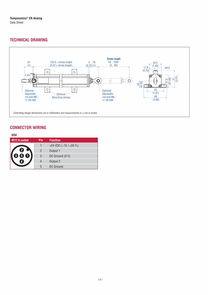
TECHNICAL DRAWING
50 (1.97)
51(2
.01)
Stroke length50…1500
(2…60)M12
37.8
(01.
49)
68 (2.68)
17.8(0.70)
20(0
.79)
25(1)
25 (1)
Optional:Adjustable rod end M6 / ¼"-28 UNF
Optional:Adjustable rod end M6 / ¼"-28 UNF
5 pin
Optional:Mounting clamps
132.5 + stroke length(5.22 + stroke length)
35.5(1.40)
3(0.12)
CONNECTOR WIRING
D34
M12 A-coded Pin Function
1
2
3
4
5
1 +24 VDC (−15 / +20 %)
2 Output 1
3 DC Ground (0 V)
4 Output 2
5 DC Ground
Controlling design dimensions are in millimeters and measurements in ( ) are in inches
I 5 I
Temposonics® ER AnalogData Sheet
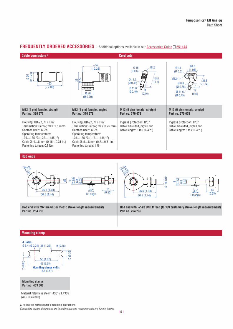
FREQUENTLY ORDERED ACCESSORIES – Additional options available in our Accessories Guide 551444
Cable connectors 3 Cord sets
~53(~ 2.09)
Ø 20
(Ø 0
.79)
38 (1.5
)
Ø 20(Ø 0.79)
~ 57(~2.25)
45.5(1.8)
M12Ø 15(Ø 0.6)
Ø 12.2(Ø 0.48)
Ø 11.6(Ø 0.46) 4
(0.16)
Ø 15(Ø 0.6)
Ø 8.8(Ø 0.35)
Ø 11.6(Ø 0.45)
12(0.5)
26.5(1.04)
31.5(1.24)
M12×1
M12 (5 pin) female, straightPart no. 370 677
M12 (5 pin) female, angledPart no. 370 678
M12 (5 pin) female, straightPart no. 370 673
M12 (5 pin) female, angledPart no. 370 675
Housing: GD-Zn, Ni / IP67Termination: Screw; max. 1.5 mm²Contact insert: CuZnOperating temperature: −30…+85 °C (−22…+185 °F)Cable Ø: 4…8 mm (0.16…0.31 in.)Fastening torque: 0.6 Nm
Housing: GD-Zn, Ni / IP67Termination: Screw; max. 0.75 mm2
Contact insert: CuZnOperating temperature: −25…+85 °C (−13…+185 °F)Cable Ø: 5…8 mm (0.2…0.31 in.)Fastening torque: 1 Nm
Ingress protection: IP67Cable: Shielded, pigtail endCable length: 5 m (16.4 ft.)
Ingress protection: IP67Cable: Shielded, pigtail endCable length: 5 m (16.4 ft.)
Rod ends
Tilt angle26.5 (1.04)
M6
30°36.5 (1.44)
9(0
.35)
6.8
0.03
14(0.55)
Ø 6
(Ø 0.24)
Tilt angle26.5 (1.04)
¼"-2
8 UN
F
30°36.5 (1.44)
9(0
.35)
6.8
0.03
14(0.55)
Ø 6.35
(Ø 0.25)
Rod end with M6 thread (for metric stroke length measurement)Part no. 254 210
Rod end with ¼"-28 UNF thread (for US customary stroke length measurement)Part no. 254 235
Mounting clamp
4 HolesØ 5.4 (Ø 0.21) 31 (1.22) 9 (0.35)
50 (1.97)
2 (0
.08) 68 (2.68)
10 (0
.39)
Mounting clamp width: 14.6 (0.57)
Mounting clampPart no. 403 508
Material: Stainless steel 1.4301 / 1.4305 (AISI 304 / 303)
3/ Follow the manufacturer‘s mounting instructionsControlling design dimensions are in millimeters and measurements in ( ) are in inches
I 6 I
Temposonics® ER AnalogData Sheet
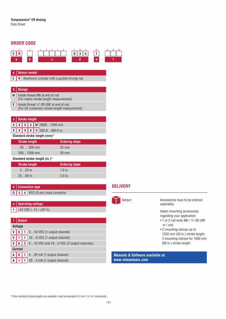
ORDER CODE
f Output
Voltage
V 0 1 0…10 VDC (1 output channel)
V 1 1 10…0 VDC (1 output channel)
V 0 3 0…10 VDC and 10…0 VDC (2 output channels)
Current
A 0 1 4…20 mA (1 output channel)
A 1 1 20…4 mA (1 output channel)
a Sensor model
E R Aluminum cylinder with a guided driving rod
d Connection type
D 3 4 M12 (5 pin) male connector
e Operating voltage
1 +24 VDC (−15 / +20 %)
c Stroke length
X X X X M 0050…1500 mm
X X X X U 002.0…060.0 in..
*/ Non standard stroke lengths are available; must be encoded in 5 mm / 0.1 in. increments
DELIVERY
Sensor Accessories have to be ordered separately.
Select mounting accessories regarding your application:• 1 or 2 rod ends M6 / ¼"-28 UNF or / and• 2 mounting clamps up to 1250 mm (50 in.) stroke length, 3 mounting clamps for 1500 mm (60 in.) stroke length
b Design
M Inside thread M6 at end of rod(For metric stroke length measurement)
S Inside thread ¼"-28 UNF at end of rod(For US customary stroke length measurement)
Standard stroke length (mm)*
Stroke length Ordering steps
50 … 500 mm 25 mm
500…1500 mm 50 mm
Standard stroke length (in.)*
Stroke length Ordering steps
2…22 in. 1.0 in.
22…60 in. 2.0 in.
E R D 3 4 1
a b c d e f
1 2 3 4 5 6 7 8 9 10 11 12 13 14 15
Manuals & Software available at: www.mtssensors.com
MTS, Temposonics and Level Plus are registered trademarks of MTS Systems Corporation in the United States; MTS SENSORS and the MTS SENSORS logo are trademarks of MTS Systems Corporation within the United States. These trademarks may be protected in other countries. All other trademarks are the property of their respective owners. Copyright © 2016 MTS Systems Corporation. No license of any intellectual property rights is granted. MTS reserves the right to change the information within this document, change product designs, or withdraw products from availability for purchase without notice. Typographic and graphics errors or omissions are unintentional and subject to correction. Visit www.mtssensors.com for the latest product information. LO
CATI
ONS
LEGA
L NO
TICE
SUSA MTS Systems CorporationSensors Division3001 Sheldon DriveCary, N.C. 27513, USATel. +1 919 677-0100Fax +1 919 [email protected]
JAPANMTS Sensors Technology Corp.737 Aihara-machi, Machida-shi, Tokyo 194-0211, JapanTel. + 81 42 775-3838Fax + 81 42 775- [email protected]
FRANCEMTS Systems SASZone EUROPARC Bâtiment EXA 1616/18, rue Eugène Dupuis94046 Creteil, FranceTel. + 33 1 58 4390-28Fax + 33 1 58 [email protected]
GERMANYMTS Sensor TechnologieGmbH & Co. KGAuf dem Schüffel 958513 Lüdenscheid, GermanyTel. + 49 2351 9587-0Fax + 49 2351 [email protected]
CHINAMTS Sensors Room 504, Huajing Commercial Center, No. 188, North Qinzhou Road200233 Shanghai, ChinaTel. +86 21 6485 5800 Fax +86 21 6495 [email protected]
ITALYMTS Systems SrlSensor DivisionVia Camillo Golgi, 5/725064 Gussago (BS), ItalyTel. + 39 030 988 3819Fax + 39 030 982 [email protected]
Reg.-No. 003095-QM08
Document Part number: 551246 Revision G (EN) 12/2016
Image reference:Fig. 2: © Alterfalter - Fotolia.com