Embed Size (px)
Citation preview
TENDER DOCUMENT
REQUEST FOR PROPOSALS
TENDER NO: 16 of 2018/19
SUPPLY AND INSTALLATION OF 2 x 40 MVA 132/66
kV, 3 x 10 MVA 66/11 kV, 4 x 20 MVA 66/11 kV POWER
TRANSFORMERS
July 2018
Tender No.16 of 2018/19– Supply and Installation of 2x40MVA
132/66kV, 3x10MVA 66/11 kV and 4 x 20 MVA 66/11 kV power transformers
Page 2 of 28
SECTION 1 INVITATION FOR TENDER
1.0 Background
The Swaziland Electricity Company Limited (SEC) intends to implement network
strengthening projects in the south eastern region of Swaziland in order to improve network
performance. This initiative is also intended to meet to growing demand for electrical energy
as a result of farming activity in this area.
Further, some transformers at Lobamba and Stonehenge substations will be uprated.
2.0 Required Power Transformers
There required transformers are as follows:
1. 2 x 40 MVA 132/66 kV transformer
2. 3 x 10 MVA 66/11 kV transformers
3. 4 x 20 MVA 66/11 kV transformers
3.0 Objective
The objective of the tender is to procure a supplier for the above mentioned transformers.
4.0 Scope of Work
The scope of work for the transformer supplier is as follows:
1. Supply 2 x 40 MVA 132/66 kV transformer
4. Supply 3 x 10 MVA 66/11 kV transformers
5. Supply 4 x 20 MVA 66/11 kV transformers
2. Deliver the transformers to Swaziland at the following sites:
a. 2 x 40 MVA 132/66 kV transformer to Ncandweni substation
b. 2 x 10 MVA 66/11 kV transformers at Ncandweni substation
c. 1 x 10 MVA 66/11 kV transformer at Ndzevane substation
d. 2 x 20 MVA 66/11 kV transformer at Lobamba substation
Tender No.16 of 2018/19– Supply and Installation of 2x40MVA
132/66kV, 3x10MVA 66/11 kV and 4 x 20 MVA 66/11 kV power transformers
Page 3 of 28
e. 2 x 20 MVA 66/11 kV transformer at Stonehenge substation
3. Install the transformer
4. Provide as built drawings and relevant documentation
5. Carry out the following pre-commissioning tests
a. Insulation resistance tests
b. Winding resistance tests
c. Voltage ratio tests
d. Vector group tests
e. Magnetic balance
f. Bushing and winding Tan Delta
g. On load tap changer tests
h. Transformer oil tests
i. Sweep frequency response analysis (to be done before loading and after
offloading)
j. Continuity tests
6. The following tests can be carried out in the manufacturing plant where SEC
engineers would witness the tests:
a. Short circuit impedance and load loss
b. Zero sequence impedance tests
c. Harmonics on no load current
d. Dielectric type tests
5.0 Methodology
The supplier should provide the following information:
1. Methodology on how the manufacturing, installation and testing will be done.
2. State applicable standards used as per the attached specification
Tender No.16 of 2018/19– Supply and Installation of 2x40MVA
132/66kV, 3x10MVA 66/11 kV and 4 x 20 MVA 66/11 kV power transformers
Page 4 of 28
6.0 Company profile and statutory documents
The tender bid should have the following documents:
Company profile(s)
List of similar projects
Consortium agreements where applicable
Three reference letters from previous and / or current clients
Composition of the team. It is necessary that the team leader be identified as well as the
role to be played by any of the support team members.
Curriculum vitae for personnel that will conduct the transformer tests
The following statutory documents should be submitted together with those highlighted
in the datasheet:
o Certified copy of Company registration Document that reflect Company
name, registration number, date of registration and active directors or
members
o Tax clearance
o Certified 2018 trading licence
o Last three years audited/reviewed financial statements
o Tender guarantee of E 100,000
7.0 Information to be provided by SEC
The Swaziland Electricity Company will provide any information requested by the supplier
either during manufacturing or installation or testing.
The engaged team is expected:
To provide all the necessary expertise to deliver the activities highlighted in the scope
Deliver the project in accordance to the agreed project timelines
Tender No.16 of 2018/19– Supply and Installation of 2x40MVA
132/66kV, 3x10MVA 66/11 kV and 4 x 20 MVA 66/11 kV power transformers
Page 5 of 28
To ensure that a cost efficient approach is adopted to the completion of the project
8.0 Timelines
The transformers should be delivered within 11 months from the date of signing a contract.
9.0 Evaluation Methodology
The evaluation will be separated into two parts. First will be the technical evaluation after which
the financial evaluation will be done for those consultants that surpass the minimum accepted
score for technical proposals
The weights to be used for the evaluation are as follows:
Technical – 70%
Financial – 30%
9.1 Technical Evaluation
Technical Description Maximum Points %
Approach and Methodology
Understanding of the project and scope of work (100% filled in schedule)
20
Overall methodology adopted to meet the scope of work requirements
10
Detailed work plan with timeframes for the overall project (manufacturing, installation upto testing done within 12 months)
20
Maximum Points 50
Relevant Experience of Service Provider
Experience in the manufacture of power transformers similar to the ones required in the tender
20
Experience in the installation and testing of power transformers similar to those stated in the tender (past 10 years)
10
Quality certfication by a recognised body (ISO etc) 10
Maximum Points 40
Tender No.16 of 2018/19– Supply and Installation of 2x40MVA
132/66kV, 3x10MVA 66/11 kV and 4 x 20 MVA 66/11 kV power transformers
Page 6 of 28
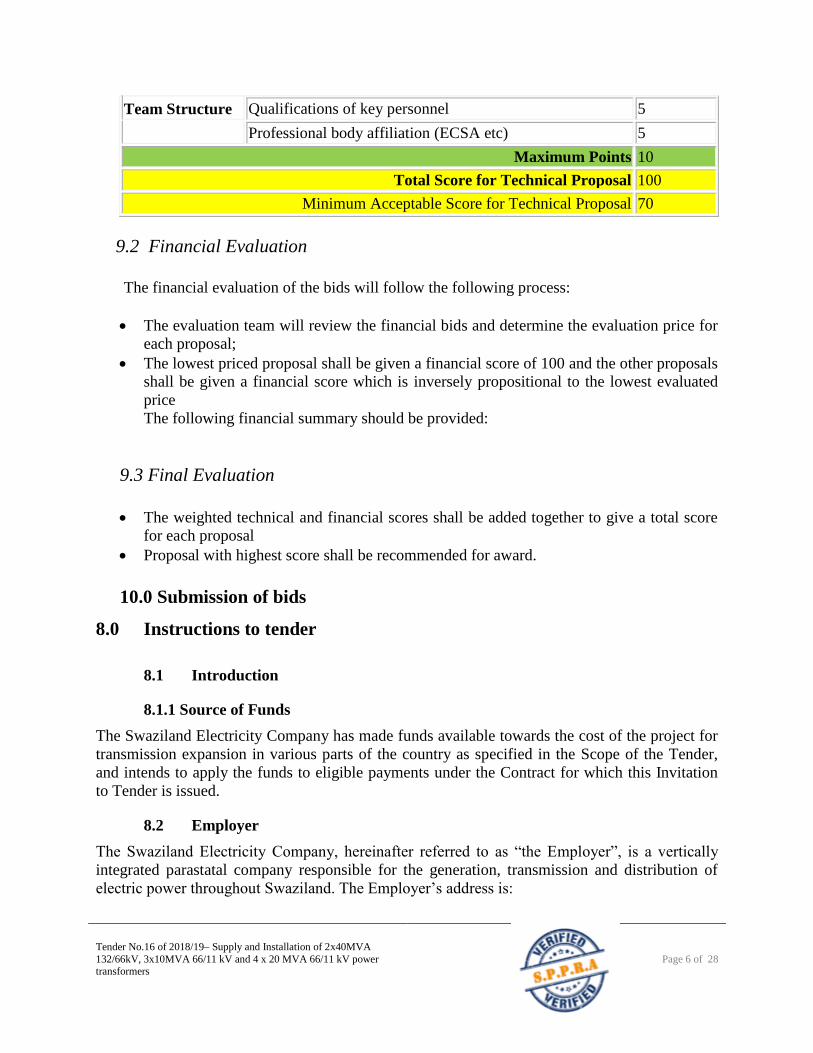
Team Structure Qualifications of key personnel 5
Professional body affiliation (ECSA etc) 5
Maximum Points 10
Total Score for Technical Proposal 100
Minimum Acceptable Score for Technical Proposal 70
9.2 Financial Evaluation
The financial evaluation of the bids will follow the following process:
The evaluation team will review the financial bids and determine the evaluation price for
each proposal;
The lowest priced proposal shall be given a financial score of 100 and the other proposals
shall be given a financial score which is inversely propositional to the lowest evaluated
price
The following financial summary should be provided:
9.3 Final Evaluation
The weighted technical and financial scores shall be added together to give a total score
for each proposal
Proposal with highest score shall be recommended for award.
10.0 Submission of bids
8.0 Instructions to tender
8.1 Introduction
8.1.1 Source of Funds
The Swaziland Electricity Company has made funds available towards the cost of the project for
transmission expansion in various parts of the country as specified in the Scope of the Tender,
and intends to apply the funds to eligible payments under the Contract for which this Invitation
to Tender is issued.
8.2 Employer
The Swaziland Electricity Company, hereinafter referred to as “the Employer”, is a vertically
integrated parastatal company responsible for the generation, transmission and distribution of
electric power throughout Swaziland. The Employer’s address is:
Tender No.16 of 2018/19– Supply and Installation of 2x40MVA
132/66kV, 3x10MVA 66/11 kV and 4 x 20 MVA 66/11 kV power transformers
Page 7 of 28
Swaziland Electricity Company
P.O. Box 258
Mbabane
H100
Swaziland
Eluvatsini House
Mhlambanyatsi Road
Mbabane
Swaziland
Telephone: +268 409 4000
Facsimile: +268 409 4001
8.3 Engineer
The Engineer appointed by the Employer for the purpose of the project is:
The Swaziland Electricity Company’ Project Manager
Address is the same as above.
8.4 Scope of Tender
Eligible Tenders are invited to submit Tenders for the Project. The Project covers the
construction of 36km of 132kV line from Sinceni-Ndzevane on a combination of steel
monopoles and towers, and a 12km of 66kV line on steel monopoles from Ncandweni –
Ndzevane.
8.5 Eligible Tenderers
The invitation to Tender is open to suitably qualified and capable contractors with a track record
and financial backing to deliver a turnkey project.
8.6 Subcontractors
It is a requirement that non specialised work be subcontracted to suitably qualified local
Subcontractors.
8.7 Cost of Tendering
The Tenderer shall bear all costs associated with preparation and submission of its Tender, and
the Employer will in no case be responsible or liable for those costs, regardless of the outcome of
the tendering process.
8.8 Tender Documents
8.8.1 Modifications
Tenderers shall not make any modifications to the Tender Document. Should a Tenderer notice
any clause or item which he considers necessary to be changed, he shall notify the Engineer in
writing, and the Engineer will in turn investigate and reply in writing.
8.8.2 Checking of Tender Documents
Tender No.16 of 2018/19– Supply and Installation of 2x40MVA
132/66kV, 3x10MVA 66/11 kV and 4 x 20 MVA 66/11 kV power transformers
Page 8 of 28
On receipt of the Tender Documents, the Tenderer must prior to submitting his Tender, check all
the Tender Documents and should any difference or discrepancy between or in the Drawings and
Specification be detected by the Tenderer, he shall seek in writing a decision also in writing of
the Engineer on the true intent and meaning of the Tender documents as the Employer cannot be
held liable for the additional cost of extra work that may be caused as a result thereof.
8.8.3 Clarification of Tender Document
A prospective Tender requiring any clarification of the Tender Documents may notify the
Engineer in writing. The Engineer will respond in writing to any request for clarification of the
Tender Documents, which it receives no later than seven days prior to the deadline for
submission of Tenders prescribed by the Employer. Written copies of the Engineer’s response
(including an explanation of the query but without identifying the source of the inquiry will be
sent to all prospective Tenderers who have received the Tender Document.
8.8.4 Amendment of Tender Document
At any time prior to the deadline for submission of Tenders, the Employer may, for any reason,
whether at its own initiative or in response to a clarification requested by a prospective Tenderer,
modify the Tender Documents by amendment. If this modification occurs later than one week
before the deadline for the submission Tenders, the Employer has the right of extending the
deadline for the submission in order to give other Tenderers the necessary time for considering
the modifications in the preparation of their Tenders.
The amendment will be notified in writing or by cable (hereinafter, term cable is deemed to
include Electronic Data Interchange (EDI), telex or facsimile) to all prospective Tenderers,
which have received the Tender Document and will be binding to them.
8.8.5 Tender Documents and Ownership
The Tender Documents which have been made available to Tenderers are the property of the
Employer and shall be returned to the Engineer whether or not a Tender is submitted.
8.8.6 Documents Confidential
Tenderers shall treat the details of the Tender Documents as confidential, whether they submit a
Tender or not.
8.9 Preparation of Tenders
8.9.1 Language of Tender
The Tender prepared by the Tenderer and all correspondences and documents relating to the
Tender exchanged by the Tenderer, the Engineer and the Employer, shall be written in the
English language, provided that any printed literature furnished by the Tenderer may be written
in another language on condition that it is accompanied by an English translation in which case,
for purposes of interpretation of the Tender, the English translation shall govern.
8.9.2 Tender Site Meeting
Tender No.16 of 2018/19– Supply and Installation of 2x40MVA
132/66kV, 3x10MVA 66/11 kV and 4 x 20 MVA 66/11 kV power transformers
Page 9 of 28
It is required that all prospective Tenderers attend a pre-tender site meeting and site visit as
indicated in the Invitation for Tender. Failure to attend will result in disqualification of the
Tender. The cost of attending the meeting shall be at the Tenderer’s own expense.
8.9.3 Tender Prices
Tenders shall quote for the facilities on a “single responsibility” basis such that the total Tender
Price covers all the Contractor’s obligations mentioned in or to be reasonably inferred from the
Tender Documents in respect to the design, manufacture, including procurement and
subcontracting if any, delivery, construction, installation and completion of the facilities. This
includes all requirements under the Contractor’s responsibility for testing, pre-commissioning
and commissioning of the facilities and, where so required by the Tender Documents, the
acquisition of all permits, approvals and licenses, etc, training services and such other items and
services as may be specified in the Tender Document, all in accordance with the requirements of
the General Conditions of the Contract. Items against which no price is entered by the Tenderer
will not be paid for by the Employer when executed and shall be deemed to be covered by the
prices for other items.
Tenderers are required to quote the price for commercial, contractual and technical obligations
outlined in the Tender Documents. If a Tenderer wishes to make a deviation, such deviation shall
be listed in Attachment 6 of its Tender. The Tenderer shall also provide the additional price, if
any, for withdrawal of the deviations. Deviations without an additional price for its withdrawal
will be accepted at no cost.
Tenderers shall give a breakdown of the prices in a format similar to the one provided.
Plant and equipment to be supplied from abroad shall be quoted on CIP to site basis. The term
CIP is described in the current edition of Incoterms.
Installation Services shall include rates or prices for all labour, contractor’s equipment,
temporary works, materials, consumables and all matters and things of whatsoever nature,
including operations and maintenance services, the provisions of operations and maintenance
manuals, training etc, where identified in the Tender Documents, as necessary for proper
execution of Installation Services, including all taxes, duties, levies and charges payable in the
Employer’s country as of 28 (twenty-eight ) days prior to the deadline of submission of Tenders.
Recommended spare parts shall be quoted separately and not included in the Grand Summary.
Prices quoted by the Tender shall be FIXED for the duration of the Contract and will not be
subject to the adjustments for change in cost. A Tender submitted with an adjustable price
quotation will be treated as non-responsive and rejected.
Applicable rates of exchange as determined by the Central Bank of Swaziland on the date of the
Tender closure will be applicable for the duration of the Contract. Tenderers will be responsible
for acquiring forward cover against the exchange rates fluctuations. NO adjustments for the
changes in cost will be accepted for the duration of the Contract. The Contractor shall submit
proof of forward cover on the relevant portions of the Contract within 28 days after award of
Contract.
All taxes including VAT, levies and custom duties etc, as applicable to the Works and
Tender No.16 of 2018/19– Supply and Installation of 2x40MVA
132/66kV, 3x10MVA 66/11 kV and 4 x 20 MVA 66/11 kV power transformers
Page 10 of 28
determined 28 (twenty-eight) days prior to Tender submission, shall be deemed included in the
Tender Prices. If there are or may be exemptions from levies, customs duties, tax, etc applicable
to any aspect of the works, the Tenderer must make his own arrangements thereof, as the tender
price shall be regarded as comprehensive.
The Tenderer, if registered in Swaziland, is liable for income tax or other national or local taxes
applicable in the country in connection with the execution of the Contract. The Tenderer, if not
registered in Swaziland, is liable only to 15 (fifteen) percent Withholding Tax in line with the
Income Tax Act Directive on non-resident Contractors/Suppliers.
8.9.4 Tender Currencies
Tender prices shall be quoted in Emalangeni (SZL) or South African Rand (ZAR).
The point of payment will be Swaziland.
8.9.5 Tender Security
The Tenderer shall furnish as part of its Tender, a Tender Security in the amount of E 1,000,000
in the Tender Currency.
The Tender Security shall, at the Tenderers’ option be in the form of a certified cheque or bank
guarantee from an internationally reputable bank selected by the Tenderer. The format of the
bank guarantee shall be in accordance with the Tender Security Form included in the Tender
Documents, other formats may be permitted, subject to the prior approval of the Employer.
The Tender Security shall remain valid for a period of 28 (twenty-eight) days beyond the original
Tender validity period, and beyond any extension subsequently requested.
Any Tender not accompanied by an acceptable Tender Security shall be rejected by the employer
as being non-responsive.
The Tender Security of a joint venture must be in the name of the all the partners in the joint
venture submitting the Tender.
The Tender Security of unsuccessful Tenderers will be returned as promptly as possible, but not
later than 28 (twenty-eight) days after the expiry of the Tender validity period.
The Tender Security of the successful Tenderer will be returned when the Tenderer has signed
the Contract Agreement and has furnished the required Performance Security.
The Tender Security may be forfeited:
If the Tenderer withdraws its Tender during the period of Tender validity specified by the
Tender in the Letter of Tender,
In the case of a successful Tender, if the Tenderer fails within a specified time limit to
sign the Contract Agreement or to furnish the required Performance Security, or
For participating in Corrupt and Fraudulent Practices.
Tender No.16 of 2018/19– Supply and Installation of 2x40MVA
132/66kV, 3x10MVA 66/11 kV and 4 x 20 MVA 66/11 kV power transformers
Page 11 of 28
8.9.6 Period of Validity
The Tender shall remain valid for 90 (ninety) days after the Tender closing date. A Tender valid
for a shorter period shall be rejected by the Employer as being non-responsive.
In exceptional circumstances the Employer may solicit the Tenderer’s consent to an extension of
the Tender validity period. The request and responses thereto shall be made in writing or by
cable. If a Tenderer accepts to extend the period of validity, the Tender Security shall also be
suitably extended. A Tenderer may refuse the request without forfeiting its Tender Security. A
Tenderer granting the request will not be required or permitted to modify its Tender.
8.9.7 Format and Signing of Tender
The Tender shall prepare one original and two complete copies of the Tender and clearly
marking each one respectively as “Original Tender”, “Copy No. 1” and “Copy No. 2.” In the
Event of any discrepancy between them, the original shall govern.
The original and all copies of the Tender, each consisting of the documents listed above shall be
typed or written in indelible ink and shall be signed by the Tenderer or person or persons duly
authorised to bind the Tenderer to the Contract. The latter authorisation shall be indicated by
written power of the attorney accompanying the Tender and submitted as Attachment 2 to the
Tender. All pages of the Tender except for un-amended printed literature shall be initialled by
the person or persons signing the Tender.
The Tender shall contain not alterations, omissions or additions, unless such corrections are
initialled by the person or persons signing the Tender.
8.10 Submission of Tenders
8.10.1 Sealing and Marking
The Tenderer shall Seal The Original and each Copy of the Tender in separate envelopes, duly
marking the envelopes as “Original Tender”, “Copy No.1” and “Copy No.2.” The envelopes
shall then be sealed in an outer envelope. This should be done for the technical proposal and
financial proposal, ie the technical and financial should be in separate envelopes.
The inner and outer envelopes shall:
Be addressed to the Employer at the address given, and
Bear the Tender Number and the statement “DO NOT OPEN BEFORE” and the closing date for
Tendering, excluding any notice allowing identification of the Tenderer.
If the outer envelope is not sealed and marked as requested, then the Employer will assume no
responsibility for the Tender’s misplacement or premature opening. If the outer envelope
discloses the identity of the Tenderer, the Employer will not guarantee the anonymity of the
Tender submission, but this disclosure will not constitute grounds for Tender rejection.
8.10.2 Deadline for Submission of Tenders
Tenders must be received by the Employer at the address no later than the time and date stated in
Tender No.16 of 2018/19– Supply and Installation of 2x40MVA
132/66kV, 3x10MVA 66/11 kV and 4 x 20 MVA 66/11 kV power transformers
Page 12 of 28
the Invitation for Tender.
The Employer may, at its discretion, extend this deadline for submission of Tenders by amending
the Tender Documents in which case all rights and obligations of the Employer and Tenderers
will thereafter be subject to the deadline as extended.
8.10.3 Late Tenders
Any Tender received after by the Employer after the Tender submission deadline prescribed by
the Employer will be rejected and returned unopened to the Tenderer.
8.10.4 Modification and Withdrawal from Tenders
The Tenderer may modify or withdraw its Tender after submission, provided that written notice
of the modification or withdrawal is received by the Employer prior to the deadline prescribed
for Tender submission.
The Tenderer’s modifications shall be prepared, sealed, marked and dispatched as follows:
The Tender shall provide an original an the number of copies specified of any modifications to
its Tender, clearly identified as such, in two inner envelopes duly marked “Tender Modification
– Original” and “Tender Modification – Copies.” The inner envelopes shall be sealed in an outer
envelope, which shall be duly marked “Tender Modifications.”
A Tenderer wishing to withdraw its Tender shall notify the Employer in writing prior to the
deadline prescribed for Tender submission.
The notice of withdrawal shall:
Be addressed to the Employer at the address specified, and
Bear the Tender Number and the words “Tender Withdrawal Notice.” Tender withdrawal
notices received after the Tender submission deadline will be ignored, and the submitted
Tender will be deemed to be a validly submitted Tender.
No Tender may be withdrawn in the interval between the Tender submission deadline
and the expiry of the Tender validity period specified. Withdrawal of a Tender during this
interval may result in the Tenderer’s forfeiture of its Tender Security.
8.11 Tender Opening and Evaluation
8.11.1 Opening of Tender by Employer
The Employer will open the Tenders, including withdrawals and the modifications made in the
presence of Tenderer’s designated representatives who choose to attend, at the time, date and
location specified. The Tenderers’ representatives who are present shall sign a register to provide
evidence of their presence.
Envelopes marked “Withdrawal” shall be opened first and the name of the Tenderer shall be read
out. Tenders for which an acceptable notice of withdrawal has been submitted pursuant shall not
be opened.
Tender No.16 of 2018/19– Supply and Installation of 2x40MVA
132/66kV, 3x10MVA 66/11 kV and 4 x 20 MVA 66/11 kV power transformers
Page 13 of 28
The Tenderer’s names, the Tender Prices including any alternative Tender Price or deviation any
discounts, Tender modifications and withdrawals, the presence or absence of Tender Security
and any such other details as the Employer may consider appropriate, will be announced by the
Employer at the opening.
Subsequently, all envelopes marked “Modification” shall be opened and the submissions therein
read out in appropriate detail.
No Tender shall be rejected at Tender opening except for late Tenders
The Employer shall prepare minutes of the Tender opening, including the information disclosed
to those present.
Tenders not opened and read out at the Tender opening shall not be considered further for
evaluation, irrespective of the circumstances.
8.11.2 Clarification of Tenders
During the Tender evaluation, the Employer may, at its discretion, ask the Tenderer for
clarification of its Tender.
The request for clarification and the response shall be in writing and no change in the price or
substance of the Tender shall be sought, offered or permitted.
8.11.3 Preliminary Examination of Tenders
The Employer will examine the Tenders to determine whether they are complete, whether any
computational errors have been made, whether required sureties have been furnished, whether
the documents have been properly signed, and whether the Tenders are generally in order.
Arithmetic errors will be rectified on the following basis. If there is a discrepancy between the
unit price and the total price, which is obtained by multiplying the unit price and quantity, or
between subtotals and the total price, the unit or subtotal price shall prevail, and the total price
shall be corrected. If there is a discrepancy between words and figures the amount in words will
prevail. If the Tenderer does not accept the correction of errors its Tender will be rejected.
Prior to the detailed evaluation, the Employer will determine whether each Tender is of
acceptable quality, is complete and substantially responsive to the Tender Documents. For
purposes of this determination, a substantially responsive Tender is one that conforms to all
terms, conditions and specifications of the bidding documents without material deviations and
objections, conditionalities or reservations. A material deviation, objection, conditionality or
reservation is one (i) that affects in any substantial way the scope, quality or performance of the
contract; (ii) that limits in any substantial way, inconsistent with the Tender Documents, the
Employer’s rights or successful Tenderer’s obligations under the contract; or (iii) whose
rectification would unfairly affect the competitive position of other Tenderers who are presenting
substantially responsive.
If a Tender is not substantially responsive, it will be rejected by the Employer, and may not
subsequently be made responsive by the Tenderer by correction of the non-conformity. The
Employer’s determination of a Tender’s responsiveness is based on the contents of the Tender
Tender No.16 of 2018/19– Supply and Installation of 2x40MVA
132/66kV, 3x10MVA 66/11 kV and 4 x 20 MVA 66/11 kV power transformers
Page 14 of 28
itself without recourse to extrinsic evidence.
8.11.4 Contacting the Employer
From the time of the tender opening to the time of Contract award, if any Tenderer wishes to
contact the employer on any matter related to its Tender, it should do so in writing.
Any effort by a Tenderer to influence the Employer in the Employer’s Tender evaluation, Tender
comparison or Contract award decisions may result in rejection of the Tenderer’s Tender.
8.12 Award of Contract
8.12.1 Award Criteria
The Employer may award the contract to the Tenderer whose Tender has been determined to be
substantially responsive and provided that the Tenderer is determined to be qualified to perform
the Contract satisfactorily. The Employer is not bound to accept the lowest Tender or any at all
and no reasons will be given for non-acceptance of Tender.
8.12.2 Employer’s Right to Accept Any Tender and to Reject Any or All
Tenders
The Employer reserves the right to accept or reject any Tender, and to annul the Tendering
process and reject all Tenders at any time prior to award of Contract, without thereby incurring
any liability to the affected Tenderer or Tenderers or any obligation to inform the affected
Tenderer or Tenderers of the grounds for the Employer’s action.
8.12.3 Employer’s Right to Vary Quantities at Time of Award
The Employer reserves the right at the time of award of Contract to increase or decrease the
quantities of goods and services up to 25% of the Total Tender Price without any change in unit
prices, Preliminary and General cost, or other terms and conditions.
8.12.4 Pre-Award Negotiations
Prior to the expiry of the period of Tender Validity, the Employer will invite the successful
Tenderer to his office for Contract negotiations.
The successful conclusion of the Contract Negotiations will constitute the formation of the
Contract.
The Employer shall prepare the Minutes of Contract Negotiations which shall form part of the
Contract.
Upon the successful Tenderer’s furnishing of a Performance Security the Employer will
promptly notify each unsuccessful Tenderer and will discharge its Tender Security.
8.12.5 Signing the Contract Agreement
The Employer will send the Tenderer the Contract Agreement provided in the Tender
Documents, incorporating all agreements between parties.

Tender No.16 of 2018/19– Supply and Installation of 2x40MVA
132/66kV, 3x10MVA 66/11 kV and 4 x 20 MVA 66/11 kV power transformers
Page 15 of 28
Within 28 (twenty-eight) days of receipt of the Contract Agreement, the successful Tenderer
shall sign and date the Contract Agreement and return it to the Employer.
8.12.6 Performance Security
Within 28 (twenty-eight ) days after successfully concluding the Contact negotiation, the
successful Tenderer shall furnish the Performance Security in the amount of 10% (ten percent)
of the accepted Contract Amount and in the form provided in the Tender Documents or in
another form acceptable to the Employer.
Failure of the successful Tenderer to comply shall constitute sufficient grounds for the
annulment of the award and forfeiture of the Tender Security, in which event the Employer may
make the award to the next most advantageous evaluated Tenderer or call for new Tenders.
8.12.7 Corrupt or Fraudulent Practices
Any Tenderer that is found to be, or who attempts to be involved in any corrupt or
fraudulent activity or practice involving any party concerned in the Tender process, shall
be disqualified. The Tenderer may forfeit the Tender Security.
9. APPENDIX TO TENDER
The Appendix to refers to the Conditions of Contract for Plant and Design Build for Electrical
and Mechanical Works and for Building and Engineering Works, Designed by the Contractor,
Tender No.16 of 2018/19– Supply and Installation of 2x40MVA
132/66kV, 3x10MVA 66/11 kV and 4 x 20 MVA 66/11 kV power transformers
Page 16 of 28
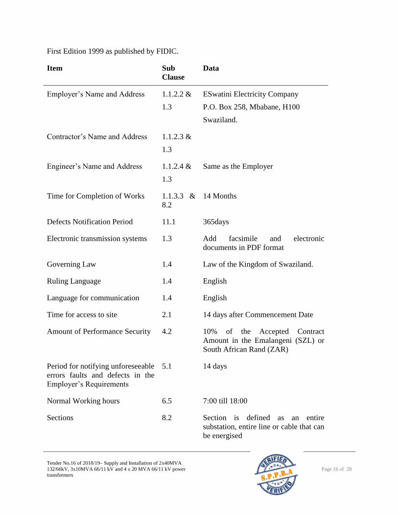
First Edition 1999 as published by FIDIC.
Item Sub
Clause
Data
Employer’s Name and Address 1.1.2.2 &
1.3
ESwatini Electricity Company
P.O. Box 258, Mbabane, H100
Swaziland.
Contractor’s Name and Address 1.1.2.3 &
1.3
Engineer’s Name and Address 1.1.2.4 &
1.3
Same as the Employer
Time for Completion of Works 1.1.3.3 &
8.2
14 Months
Defects Notification Period 11.1 365days
Electronic transmission systems 1.3 Add facsimile and electronic
documents in PDF format
Governing Law 1.4 Law of the Kingdom of Swaziland.
Ruling Language 1.4 English
Language for communication 1.4 English
Time for access to site 2.1 14 days after Commencement Date
Amount of Performance Security 4.2 10% of the Accepted Contract
Amount in the Emalangeni (SZL) or
South African Rand (ZAR)
Period for notifying unforeseeable
errors faults and defects in the
Employer’s Requirements
5.1 14 days
Normal Working hours 6.5 7:00 till 18:00
Sections 8.2 Section is defined as an entire
substation, entire line or cable that can
be energised
Tender No.16 of 2018/19– Supply and Installation of 2x40MVA
132/66kV, 3x10MVA 66/11 kV and 4 x 20 MVA 66/11 kV power transformers
Page 17 of 28
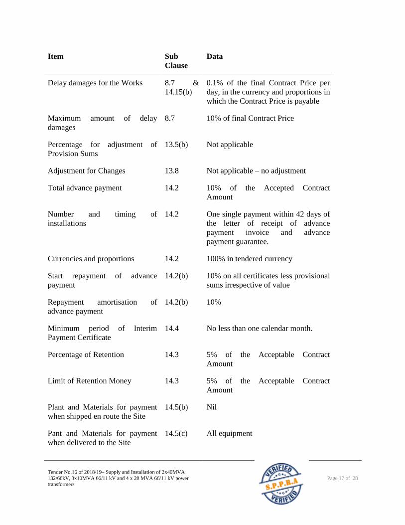
Item Sub
Clause
Data
Delay damages for the Works 8.7 &
14.15(b)
0.1% of the final Contract Price per
day, in the currency and proportions in
which the Contract Price is payable
Maximum amount of delay
damages
8.7 10% of final Contract Price
Percentage for adjustment of
Provision Sums
13.5(b) Not applicable
Adjustment for Changes 13.8 Not applicable – no adjustment
Total advance payment 14.2 10% of the Accepted Contract
Amount
Number and timing of
installations
14.2 One single payment within 42 days of
the letter of receipt of advance
payment invoice and advance
payment guarantee.
Currencies and proportions 14.2 100% in tendered currency
Start repayment of advance
payment
14.2(b) 10% on all certificates less provisional
sums irrespective of value
Repayment amortisation of
advance payment
14.2(b) 10%
Minimum period of Interim
Payment Certificate
14.4 No less than one calendar month.
Percentage of Retention 14.3 5% of the Acceptable Contract
Amount
Limit of Retention Money 14.3 5% of the Acceptable Contract
Amount
Plant and Materials for payment
when shipped en route the Site
14.5(b) Nil
Pant and Materials for payment
when delivered to the Site
14.5(c) All equipment
Tender No.16 of 2018/19– Supply and Installation of 2x40MVA
132/66kV, 3x10MVA 66/11 kV and 4 x 20 MVA 66/11 kV power transformers
Page 18 of 28
Item Sub
Clause
Data
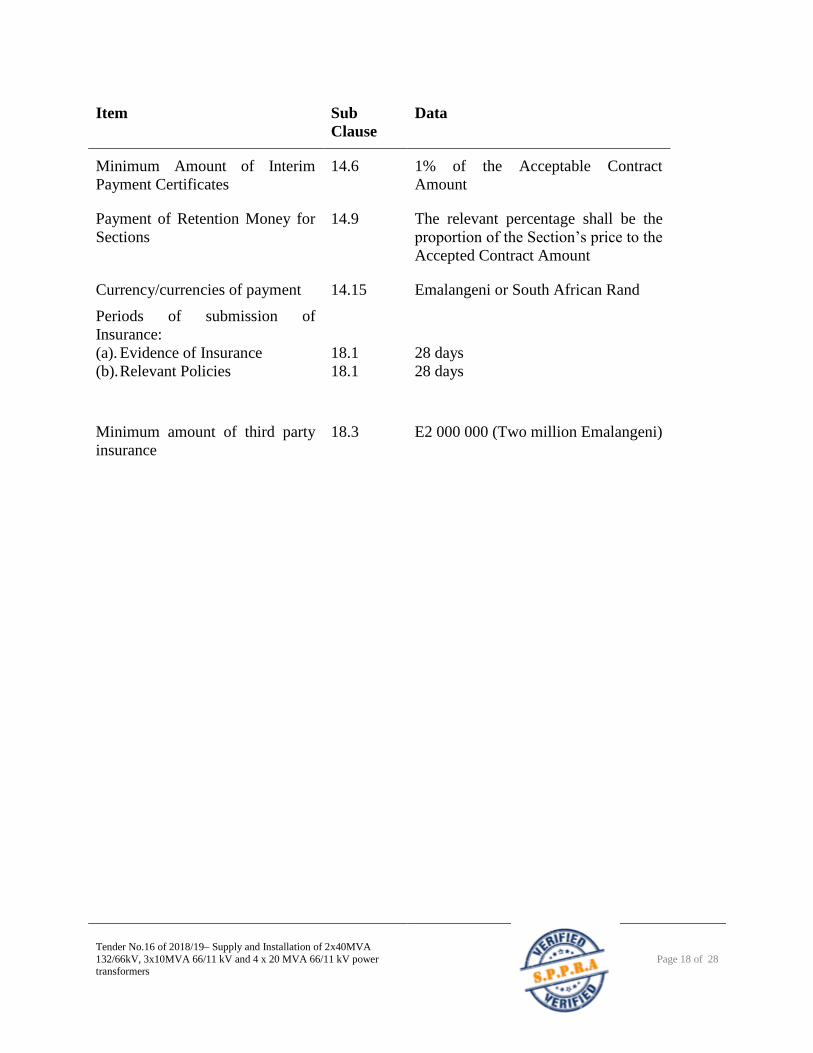
Minimum Amount of Interim
Payment Certificates
14.6 1% of the Acceptable Contract
Amount
Payment of Retention Money for
Sections
14.9 The relevant percentage shall be the
proportion of the Section’s price to the
Accepted Contract Amount
Currency/currencies of payment 14.15 Emalangeni or South African Rand
Periods of submission of
Insurance:
(a). Evidence of Insurance
(b). Relevant Policies
18.1
18.1
28 days
28 days
Minimum amount of third party
insurance
18.3 E2 000 000 (Two million Emalangeni)
Tender No.16 of 2018/19– Supply and Installation of 2x40MVA
132/66kV, 3x10MVA 66/11 kV and 4 x 20 MVA 66/11 kV power transformers
Page 19 of 28
10. GENERAL CONDITIONS OF CONTRACT
The Conditions of Contract applicable to this contract shall be:
FIDIC (International Federation of Consulting Engineers)
Condition of Contract for Plant and Design Build for Electrical and Mechanical Works and for
Building and Engineering Works, Designed by the Contractor. First Edition. 1999. (Yellow
Book).
The Conditions consists of three parts, namely
1. General Conditions of Contract.
2. Appendix to Tender.
2. Particular Conditions of Contract.
The Tenderer must obtain a copy of this document from the Federation, at their own cost. The
document will not be made available by the Employer or the Engineer.
The Tenderers must familiarise themselves with the conditions and stipulations contained
therein. No arguments, disagreement or complaint, based on ignorance of the contents of the
mentioned document, will be considered as a base for a claim against the Employer.
Copies of the FIDIC Conditions of Contract may also be obtained from:
The South African Association of Consulting Engineers,
St James House
Hampton Park North
20 Georgian Crescent
Bryanston
P.O. Box 68482
Bryanston
2021
Telephone Number: +27 11 463 2022
Tender No.16 of 2018/19– Supply and Installation of 2x40MVA
132/66kV, 3x10MVA 66/11 kV and 4 x 20 MVA 66/11 kV power transformers
Page 20 of 28
11. PARTICULAR CONDITIONS OF CONTRACT
This Particular Conditions of Contract is in reference to the General Conditions of Contract as
contained in the FIDIC’s Conditions of Contract for Plant and Design, Build for Electrical and
Mechanical Works and for Building and Engineering Works, Designed by the Contractor. First
Edition. 1999. (Yellow Book)
Clause 1 General Provisions
Sub-Clause 1.1 Definitions
1.1.1.1 Add “Minutes of Negotiation” after “Contract Agreement.”
1.1.1.5 The Employer’s Requirements are detailed in Part II of the Tender Document
1.1.4.6 The Foreign Currency is South African Rand
1.1.6.2 “Country” shall mean Swaziland.
Sub-Clause 1.2 Priority of Documents
Replace the list of documents with the following list
(a) Contract Agreement
(b) Minutes of Contract Negotiations
(c) Letter of Acceptance
(d) Letter of Tender
(e) Particular Conditions of Contract
(f) General Conditions of Contract
(g) Employer’s Requirements
(h) Schedules, and
(i) Contractor’s Proposal and any other documents forming part of the Contract.
Sub-Clause 1.14 Joint Several Liability
Insert after Sub-Clause 1.14(c):
(d) Each member shall produce parent member guarantee.
Sub Clause 1.15 Details to be Confidential
The Contractor shall treat the details of the Contract as private and confidential, except to the
extent necessary to carry out obligations under it or to comply with applicable Laws. The
Contractor shall not publish, permit to be published, or disclose any particulars of the Works in
Tender No.16 of 2018/19– Supply and Installation of 2x40MVA
132/66kV, 3x10MVA 66/11 kV and 4 x 20 MVA 66/11 kV power transformers
Page 21 of 28
any trade or technical paper elsewhere without the previous agreement of the Employer.
The obligations of confidentiality herein shall be imposed mutatis mutandis upon such sub-
consultants, sub-contractors or suppliers in their respective contracts.
Clause 2 The Employer
Sub-Clause 2.4 Employer’s Financial Arrangements
Delete this Sub-Clause.
Clause 3 The Engineer
Sub-Clause 3.6 Management Meetings
The Engineer or the Contractor’s Representative may require the other to attend a management
meeting in order to review the arrangements for future work. The Engineer shall record the
business of management meetings and supply copies of the record to those attending the meeting
and to the Employer. In the record, responsibilities for any actions to be taken shall be in
accordance with the Contract.
Clause 4 The Contractor
Sub-Clause 4.4 Sub-Contractors
Delete Sub-Clause 4.4(b) and insert:
(b) Prior consent shall not be required where the accumulative total value of the subcontracts
of a particular subcontractor is less than 0.01% of the Accepted Contract Amount.
Sub-Clause 4.16 Transport of Goods
Insert at the end of Sub-Clause 4.16:
(d) The Contractor shall notify the Engineer 14 (fourteen) days in advance of its requirement
for permission to deliver any equipment to the site. The failure of the Contractor to give such
notice to the Engineer within the required time shall not relieve the Contractor of its obligations
under this Contract.
Sub-Clause 4.19 Electricity, Water and Gas
The Contractor shall be responsible for providing on the Site such supplies of electricity and
water as are necessary for the proper execution and security of Works.
In the case of water supplies the Contractor shall make all necessary arrangements for metering,
temporary storage and distribution of water on the Site and shall alter, adapt, and maintain the
temporary work as necessary.
In the case of electricity supplies the Contractor shall make all necessary arrangements in
accordance with the regulations and good practice for the distribution of lighting and power
Tender No.16 of 2018/19– Supply and Installation of 2x40MVA
132/66kV, 3x10MVA 66/11 kV and 4 x 20 MVA 66/11 kV power transformers
Page 22 of 28
including all meters, temporary wiring and fittings on Site and shall adapt temporary work as
necessary all the time maintaining strict safety rules.
The electrical supply shall be of such adequate capacity for all testing on Site prior to final
energising.
The Contractor shall at its own cost pay all charges in connection with or arising out of the
provision of electricity and water including, without limitation, the provision of any apparatus
necessary for such use and the removal and making good on completion of the Works.
Clause 13 Variations and Adjustments
Sub-Clause 13.1 Right to Vary
Insert after the first paragraph of Sub-Clause 13.1:
During the Time for Completion the Works may be increased or reduced by up to 25% of the
Accepted Contract Amount without adjustment to the rates tendered, Preliminary and General
cost, or other terms and conditions.
Clause 14 Contract Price and Payment
Sub-Clause 14.4 Schedule of Payment
Insert at the end of Sub-Clause 14.4
The contractor will be paid after 30 days from receipt of the invoice, and payments at ESwatini
Electricity Company are made on the 15th and 30th of each month. The payments will be
according to the contractor’s payment schedule.
Clause 17 Risks and Responsibility
Sub-Clause 17.7 Use of Employer’s Facilities
The Contractor shall take full responsibility for the care of items detailed below, from the
respective dates of use or occupation by the Contractor, up to the respective dates of hand-over
or cessation of the occupation (where hand-over or cessation of occupation may take place after
the date stated in the Taking-Over Certificate for the Works):
The Employer’s existing Works and Plant
If any loss or damage happens to any of the above items while the Contractor is responsible for
their care, arising from any cause whatsoever other than those for which the Employer is liable,
the Contractor shall, at his own cost, rectify the loss or damage to the satisfaction of the
Engineer.
Clause 20 Claims, Disputes and Arbitration
Sub-Clause 20.2 Appointment of the Dispute Adjudication Board
Tender No.16 of 2018/19– Supply and Installation of 2x40MVA
132/66kV, 3x10MVA 66/11 kV and 4 x 20 MVA 66/11 kV power transformers
Page 23 of 28
Delete this Sub-Clause.
Sub-Clause 20.3 Failure to Agree Dispute Adjudication Board
Delete this Sub-Clause.
Sub-Clause 20.4 Obtaining Dispute Adjudication Board’s Decision
Delete this Sub-Clause.
Sub-Clause 20.5 Amicable Settlement
Delete this Sub-Clause.
Sub-Clause 20.6 Arbitration
Delete this Sub-Clause and replace it with:
Unless settled amicably, any disputes shall be settled by international arbitration. Unless
otherwise agreed by both parties:
1.3 the dispute shall be finally settled under the Rules of the Conduct of Arbitrations
(5th Edition 2005) of the Association of Arbitrators (Southern Africa) within the
context of the Law defined in Sub-Clause 1.4
1.4 The dispute shall be settled by the arbitrator(s) appointed in accordance with the
Rules and
1.5 The arbitration shall be conducted in the language for communications defined in
Sub-Clause 1.4
The arbitrator(s) shall have full power to open up, review and revise any certificate,
determination, instruction, opinion or valuation of the Engineer relevant to the dispute. Nothing
shall disqualify the Engineer from being called as witness and giving evidence before
arbitrator(s) on any matter relevant to the dispute.
Neither party shall be limited to the reasons for dissatisfaction given in its notice of
dissatisfaction.
Arbitration may be commenced prior to or after completion of the Works. The obligations of the
Parties shall not be altered by reason of any arbitration being conducted during the progress of
the Works.
Sub-Clause 20.7 Failure to Comply with Dispute Adjudication Board’s Decision
Delete this Sub-Clause
Sub-Clause 20.8 Expiry of Dispute Adjudication Board’s Appointment
Delete this Sub-Clause
Tender No.16 of 2018/19– Supply and Installation of 2x40MVA
132/66kV, 3x10MVA 66/11 kV and 4 x 20 MVA 66/11 kV power transformers
Page 24 of 28
12. Tender Form
Tenderers must complete one tender form for each Lot they are offering services for
Date …………………..
Tender No. ___________________________
To:
ESwatini Electricity Company Eluvatsini House
Mhlambanyatsi Road
Mbabane
Kingdom of ESwatini
Having examined the tendering documents the receipt of which is hereby duly acknowledged,
we, the undersigned, offer to undertake the maintenance and service of [State the particular
tender that you are bidding for] at [State Locations] in conformity with the said tendering
documents for the sum of [total tender amount in words and figures] and at the rates indicated
in the Pricing Form and made part of this Tender. We undertake, if our Tender is accepted, to deliver the services in accordance with the
requirements of the specifications forming part of this contract. We agree to abide by this Tender for a period of 90 days from the date fixed for Tender opening,
and it shall remain binding upon us and may be accepted at any time before the expiration of that
period. Until a formal Contract is prepared and executed, this Tender, together with your written
acceptance thereof and your notification of award, shall constitute a binding Contract between
us. We understand that you are not bound to accept the lowest or any tender you may receive.
_________________________ _____________________________
[signature] [in the capacity of]
Duly authorized to sign Tender for and on behalf of___________________________
13. Declaration of Eligibility
All Tenderers must meet the following criteria, to be eligible to participate in public procurement
Tenderers must provide a signed declaration on their company letterhead in the following
format. If the tender is being presented by a joint venture or consortium all members must
Tender No.16 of 2018/19– Supply and Installation of 2x40MVA
132/66kV, 3x10MVA 66/11 kV and 4 x 20 MVA 66/11 kV power transformers
Page 25 of 28
sign the declaration
Dear Sirs,
Re Tender Reference ……………………………….
In accordance with the eligibility requirements of the Procurement Regulations and the tender
documents we hereby declare that:- (a) We, including any joint venture partners or consortium partners are a legal entity and
have the legal capacity to enter into the contract;
(b) We further declare that we are not insolvent, in receivership, bankrupt or being wound up,
our affairs are not being administered by a court or a judicial officer, our business activities
have not been suspended and we are not the subject of legal proceedings for any of the
foregoing;
(c) We declare that we have fulfilled our obligations to pay taxes and social security
contributions;
(d) We have not, and our directors or officers have not, been convicted of any criminal
offence related to our/their professional conduct or the making of false statements or
misrepresentations as to their qualifications to enter into a contract within a period of five
years preceding the commencement of the procurement proceedings; and
(e) We do not have a conflict of interest in relation to the procurement requirement.
Signed ……………………………………..
Date………………………………….
14. Submission of bids
The technical and financial proposals should be separated and clearly marked
“TECHNICAL” and “FINANCIAL”.
Tender No.16 of 2018/19– Supply and Installation of 2x40MVA
132/66kV, 3x10MVA 66/11 kV and 4 x 20 MVA 66/11 kV power transformers
Page 26 of 28
The separate, sealed envelopes of both the financial and technical proposals should then
be sent to SEC in a sealed envelope clearly marked “Tender No.16 of 2018/19 – Supply
and Installation of 2 x 40 MVA 132/66 KV, 3 x 10 MVA 66/11 kV, and 4 x 20 MVA
66/11 kV power transformers” and addressed to the “Secretary to the Tender
Committee”, Swaziland Electricity Company, Eluvatsini House, Head Office,
Mhlambanyatsi Road, Mbabane, Swaziland no later than 1200 hours on 27 August
2018.
Document should be submitted with proof of payment of E400.00 for tender
documentation.
SECTION 2 TRANSFORMER SPECIFICATION
1.0 Definitions and Terminology
Wherever the term standard is used in this specification, this shall mean the latest international /
national standard in the following order of priority:
Tender No.16 of 2018/19– Supply and Installation of 2x40MVA
132/66kV, 3x10MVA 66/11 kV and 4 x 20 MVA 66/11 kV power transformers
Page 27 of 28
1. SABS (South African Bureau of Standards).
2. IEC (International Electro-technical Commission)
3. BS (British Standard)
4. DIN (German Institute of Standards)
2.0 Scope of Facilities
The Contractor will provide the following:
1. All designs required for the manufacture of 66/11kV 10 MVA, 132/66 kV 40 MVA,
66/11 kV 20 MVA transformers according to the specification below
2. All material, transport and labour required for the construction and commissioning of
the works.
3. Updated as-built drawings as per specification.
4. Operating Manuals and Training as specified.
The principal features of the works to be performed shall include but not be limited to the
following:
1. Design, manufacture, supply and assembling of transformers (highlighted in 3 below)
for Ncandweni, Ndzevane, Lobamba and Stonehenge substations.
2. Design, manufacture, supply and install all accessories for the transformers
(highlighted in 3 below)
3. 132/66 kV 40 MVA, 66/11 kV 20 MVA, 66/11 kV 10 MVA
2.1 Power Transformers
2.1.1 General
This specification provides for the manufacture, supply, testing before shipment, delivery
installation and commissioning of the transformers detailed. The transformers shall be supplied
together with all auxiliary equipment necessary for a complete installation.
Transformers shall comply with the requirements of IEC 60076 and BS 171.
Transformers of the same rating shall have matched impedances to allow parallel operation with
others.
A copy of the transformer manufacturer's certificate of quality assurance, issued by an
acknowledged institution, shall accompany the Tender.
All new transformers will be supplied with neutral current transformers as per specification.
2.1.2 Site Handling, Off-Loading and Erection
2.1.2.1 Access to Lifting Lugs and Jacking Pads
The provisions made for transporting the transformers shall in all cases leave the lifting lugs and
Tender No.16 of 2018/19– Supply and Installation of 2x40MVA
132/66kV, 3x10MVA 66/11 kV and 4 x 20 MVA 66/11 kV power transformers
Page 28 of 28
jacking pads clear of obstructions so that their function may be fulfilled whilst the transformers
are in position on the transporting vehicle.
2.1.2.2 Costs
Where specified, a price shall be quoted for off-loading and erecting the transformers on their
foundations. Unless otherwise specified, this price shall include for filling the transformers with
oil to the oil correct temperature level, and it shall include for the undertaking of any drying-out
process, which may be necessary to ensure that the transformers are ready for operation before
handing over.
2.1.2.3 Erection
Erection shall include off-loading, lifting, handling, positioning on foundations, oil filling and
installation of the transformer(s) together with all materials and auxiliary equipment supplied on
the contract for a complete installation, including levelling, grouting and any provision deemed
necessary to prevent movement of the transformer on its base in service, and also the provision
of all necessary staging, sleepers, lifting tackle and appliances.
Erection shall further include filtering of oil and drying out and testing and checking processes
which may be necessary to ensure that the transformers are ready for operating before handing
over, together with the provision of the necessary materials, apparatus and instruments for these
processes.
All items provided for erection shall be removed from site when erection is completed.
2.1.3 Design Details
2.1.3.1 Rating
The transformers shall be capable of operating continuously and without permanent damage
under the stated service conditions on any tapping, with the primary winding carrying the MVA
stated at the no-load voltage corresponding to the tapping in use. With the principle tapping in
use and other conditions as above, the temperature rises specified in BS 171 shall not be
exceeded.
2.1.3.2 Tapping
All tapings shall be designed for constant MVA output.
2.1.3.3 Interchangeability
All transformers of any one type shall be identical and interchangeable with one another at short
notice. No alteration to control circuits shall be permissible for this purpose except by means of
built-in terminal boards fitted with links for effecting the alteration.
All parts are to be made accurately to dimensions so that any corresponding parts will be
interchangeable, any spare parts will fit into place without need of adjustments. Where similar
equipment has previously been supplied, components shall interchange with those on previous
contracts, unless otherwise approved.
2.1.3.4 Internal Connections
All internal connections shall be supported to maintain clearances to each other and to earthed
Tender No.16 of 2018/19– Supply and Installation of 2x40MVA
132/66kV, 3x10MVA 66/11 kV and 4 x 20 MVA 66/11 kV power transformers
Page 29 of 28
metal during transport and under short-circuit conditions and shall not vibrate in normal service.
2.1.3.5 Electrical Clearances
Adequate electrical clearance shall be provided and care shall be taken to ensure that no fittings
are located so as to interfere with the external connections to the bushings.
2.1.4 Insulation
2.1.4.1 Test Levels
Transformer windings shall be designed to withstand the minimum values of impulse and
dielectric tests specified.
2.1.4.2 Bushings
All bushings shall be the outdoor type and designed to withstand the minimum values of impulse
and dielectric tests specified.
Minimum acceptable creepage distances are in the Detailed Technical Specification.
2.1.4.3 Arc Gaps
Bushings arc gaps, where provided, shall be set at, or adjustable to, the impulse flashover
settings specified in the Detailed Technical Specification, unless protection is afforded by
lightning arrestors in which case arc gaps are not required.
2.1.4.4 Cable End Boxes
A cable end box shall be fitted to the LT side of the transformer suitable for either XLPE or
paper insulated cable.
2.1.5 Constructional Details
2.1.5.1 Cores
Where the core laminations are divided into sections by insulating barriers or cooling ducts
parallel to the plane of the laminations, tinned-copper bridging strips shall be inserted to
maintain electrical continuity between sections.
The magnetic circuit shall be earthed to the core clamping structure at one point only through a
removable link placed in an accessible position beneath an inspection cover and on the same side
of the core as the main connection between the core structure and tank.
Core-bolt nuts shall be effectively locked.
Lifting lugs or other means shall be provided for conveniently lifting the core, and when lifting
no stress shall be imposed on any core bolt or its insulation. Unless otherwise approved vertical
tie rods shall be provided between top and bottom clamping structures.
2.1.5.2 Windings
All winding insulation shall be treated to ensure that there will be no appreciable shrinkage after
assembly.
Coil stacks are to be provided with clamping arrangements, which will distribute the clamping

Tender No.16 of 2018/19– Supply and Installation of 2x40MVA
132/66kV, 3x10MVA 66/11 kV and 4 x 20 MVA 66/11 kV power transformers
Page 30 of 28
force over a large portion of the ends of the coil stacks and will permit adjustment of the pressure
and the taking-up of shrinkage that may occur in service.
Driven wedges, except those bearing on clamping rings under the yoke, will not be acceptable.
These yoke wedges shall be locked in position.
Varnish impregnation of windings will not be acceptable, except for transformers having
windings made up of individual cross-over coils, in which case it shall be possible to remove
coils separately without damage by virtue of adhesion due to the varnish impregnation. In no
case shall linseed oil impregnation be used.
2.1.5.3 Tanks and Radiators
Corrugated tanks are not acceptable.
Tanks and fittings shall be of such a shape that water cannot collect at any point on the outside
surfaces.
Guides shall be provided inside each tank for locating the core and windings centrally. Suitable
proportioned manhole covers shall be provided in the tank cover to afford easy access to the
lower ends of bushings and upper portions of the core and winding assembly.
Detachable radiators shall have lifting eyes and shall be provided with drain plugs or valves at
their lowest points and vent plugs in the headers. Isolating valves shall be provided immediately
adjacent to the main tank or headers to enable the radiators to be removed without handling the
oil in the transformer tank or cooler bank.
All oil-pipe connections above 12mm bore shall have flanged joints.
The tank and cooling equipment shall be designed to permit vacuum treatment on site.
The maximum safe permissible vacuum (mmHg), which may be applied above oil level, to the
tank, cooling equipment and to the conservator, without causing permanent distortion, shall be
stated.
2.1.5.4 Gaskets
Oil resisting synthetic rubber gaskets are not acceptable, except where synthetic rubber is used as
a bonding medium for cork or similar material, or alternatively, where steel stops are provided to
prevent over-compression of the gaskets. The Contractor shall submit details of gasket material
for approval.
2.1.5.5 Main Terminals
Bushings shall be fitted to the equipment as specified.
All terminals shall be marked to correspond with the markings on the diagram plate. Compound
filled bushings are not acceptable.
Bushings insulators having small radius grooves under each skirt, and commonly known as anti-
fog type, will not be acceptable.
Characters shall be marked in relief adjacent to their appropriate terminals. The characters may
be of brass, steel or other acceptable metal and shall be permanently fixed to the tank, by means
Tender No.16 of 2018/19– Supply and Installation of 2x40MVA
132/66kV, 3x10MVA 66/11 kV and 4 x 20 MVA 66/11 kV power transformers
Page 31 of 28
of brazing or welding.
2.1.5.6 Painting and Galvanizing
All interior and exterior metal surfaces, subject to corrosion, shall be thoroughly cleaned by
means of sand-blasting, shot-blasting, or other approved methods before painting. All exterior
surfaces shall be given a priming coat of anti-corrosion and oil-resisting paint, followed by two
coats of weather and oil-resisting paint of good quality to the colour specified.
The interior surfaces of the conservators above cold oil-level shall be finished with a coat of
light-coloured oil-resisting paint or varnish and care shall be taken to protect the interior surfaces
below oil-level after cleaning.
All cabinet interiors shall have at least one priming coat and one finishing coat of glosswhite
paint or enamel.
The exteriors of all indoor control panels shall be finished in Light Grey finish, colour no. 632 to
BS 381/c unless otherwise specified. The exterior finish of outdoor control cabinets shall be in
the same colour as that specified for the transformers.
Should any paintwork be damaged during transit or erection, this shall be rectified on site.
Galvanising should be done to SANS 121.
2.1.6 Fittings
The transformers shall be supplied with the fittings specified hereafter.
2.1.6.1 Conservator Tank
Where conservators are not mounted on the main transformer tank or as part of a cooler bank, a
separate floor mounted supporting structure shall be provided by the Contractor. The conservator
tank shall be fitted with a removable end on which the oil gauge shall be mounted. The
conservator tank shall be mounted to slope slightly downwards towards the drain valve, which
shall be adjacent to the removable end.
The pipe connecting the conservator to the tank shall extend at least 50mm into the conservator
and shall be brought out from the highest point of the main tank cover. A valve shall be provided
immediately adjacent to the conservator. All pockets and bushing turrets of the main tank and
tap-changer selector switch chamber, where this is separate from the main tank, shall be
connected into this pipe between the transformer and the Buchholz relay.
The capacity of the conservator shall be such that the oil will not overflow or fall below the
Buchholz relay floats for oil temperatures from –10°C to 100°C.
2.1.6.2 Plain Oil Gauges
Plain oil gauges shall be flush mounted with the gauge glass (of glass or plastic material)
securely attached to the tank throughout its length by means of a metal shroud. The oil in the
gauge shall not be in contact with the air outside the tank. Unprotected glass tubes are not
acceptable.
2.1.6.3 Breathers
Silica-gel breathers shall have a window for inspection of the condition of the silica-gel and oil
Tender No.16 of 2018/19– Supply and Installation of 2x40MVA
132/66kV, 3x10MVA 66/11 kV and 4 x 20 MVA 66/11 kV power transformers
Page 32 of 28
cup or other device to prevent continuous contact of the silica-gel with the air outside the
transformer.
2.1.6.4 Pressure Relief Device
Where a pressure relief valve(s) is provided, it shall be fitted to the transformer tank wall in the
vertical plane and arranged to be self-resealing and provided with contacts to indicate the
"normal" and "operated" conditions, and also a mechanically operated, manually reset operation
indicator.
2.1.6.5 Buchholz Relays
Buchholz relays shall be of the double-float or bucket type and shall be of approved
manufacture. The gas-release cock for the relay shall be placed within easy reach from ground
level and connected to the relay by small-bore non-ferrous tubing. The sight window of the relay
shall be readily visible from ground level.
2.1.6.6 Winding-Temperature Indicators
Winding-temperature indicators shall be of the dial type, preferably compensated for changes in
ambient temperature, and shall have a load-temperature characteristic approximately the same as
the hottest part of the windings. The current transformer for operating the indicator shall be built
into the main transformer tank and shall be located so as to reflect the maximum hot-spot
temperature of the transformer. The alarm contact circuits of these indicators shall be paralleled
and the trip contact circuits paralleled and each brought out to a pair of terminals.
The indicators are to be provided with a dial indicating the temperature in °C and fitted with a
resettable maximum temperature indicator. A pair of adjustable alarm contacts which can be set
to close at a predetermined temperature are to be provided and, in addition, a pair of contacts for
tripping purposes.
The instrument shall be mounted in a separate control cabinet where this is provided, otherwise
as follows:
2.1.6.7 Dial-type Thermometers
Dial-type thermometers shall be graduated in °C for registering "top-oil" temperatures. The
instrument shall be provided with a resettable maximum temperature indicator and a pair of
adjustable alarm contacts, which can be set to close at a predetermined temperature. An
additional set of adjustable contacts shall be provided for tripping purposes.
The mounting arrangements shall be the same as for the winding- temperature indicators.
2.1.6.8 Thermometer Pockets
Thermometer pockets shall be fitted with a captive screw cap.
2.1.6.9 Alarm and Trip Contacts
All alarm contacts shall be suitable for making or breaking up to 20 watts D.C., inductive, at the
specified alarm and tripping voltage.
All trip contacts shall be suitable for making and carrying for half a second a current
Tender No.16 of 2018/19– Supply and Installation of 2x40MVA
132/66kV, 3x10MVA 66/11 kV and 4 x 20 MVA 66/11 kV power transformers
Page 33 of 28
corresponding to 150 watts at the specified alarm and tripping voltage.
Any auxiliary relays associated with trip circuits shall be D.C. operated and suitable for the
specified alarm and tripping voltage.
Alarm and trip contacts shall be provided with electrically independent and ungrounded circuits.
2.1.6.10 Drain, Filter and Sampling Valves
All valves shall be attached by bolted-on flanges and shall not be screwed or welded to the tank.
Valves of 50mm and smaller shall be of gunmetal or similar material. Drain valves or isolating
valves larger than 50mm and of the flanged gate-type construction may have bodies of cast iron
or cast steel.
Drain valves shall be of suitable dimensions in relation to the volume of oil in the transformer
tank and coolers.
Oil sampling valves shall be 12mm screwed glove, angle or gate valves located so as to permit
sampling of oil from the extreme bottom of the tank.
Filtration connections, which shall have flanges drilled to BS 10, Table D for 25mm valves, or
screwed 25mm B.S.P. female whichever is specified shall be as follows:
1. A valve at the top and bottom of the main tank. The drain valve of the main tank may be
used for this purpose.
2. A valve at the top and bottom of each separately mounted cooler bank.
3. The oil conservator drain valve located within easy reach of the ground, by means of a
pipe extension if necessary, shall be suitable for a filter connection.
All valve entries shall be blanked-off with gasketed bolted-on blank plates or plugs.
2.1.6.11 Rating and Diagram Plate
Rating and diagram plates shall be to BS 171 and shall be engraved, stamped or embossed on
brass, or stainless steel.
2.1.6.12 Earthing Terminal
A suitably rated earthing terminal or clamp shall be provided on the tank base to suit the size of
earthing conductor specified.
2.1.6.13 Lifting Lugs
Lifting lugs shall be designed to lift the completely assembled transformer with oil.
2.1.6.14 Jacking Pads
Not less than four suitably and symmetrically placed jacking pads shall be provided in positions,
which will not be impeded when the transformer is loaded on to the transport vehicle.
Each jacking pad shall be designated to support at least half of the total weight of the transformer
base and complete with oil the unimpeded working surface of the jacking pads shall be as
follows:
Tender No.16 of 2018/19– Supply and Installation of 2x40MVA
132/66kV, 3x10MVA 66/11 kV and 4 x 20 MVA 66/11 kV power transformers
Page 34 of 28
1. Minimum/maximum height of jacking pad above base in mm: 460/530.
2. Unimpeded working surface mm: 230 x 230.
2.1.6.15 Skid Under-base
Skid under-base shall be reinforced to permit moving the transformer in the direction(s)
specified. Hauling eyes shall be provided on the under-base.
2.1.7 Tap Changer
2.1.7.1 Tap-transfer Equipment
The tap-transfer equipment shall be designed such that it will not be possible for either a portion
of the main transformer windings to be short circuited, except through a current limiting
impedance, or for the main transformer winding to be open circuited.
In the event of the apparatus not being continuously rated, protective devices shall be fitted to
protect the equipment from overheating.
2.1.7.2 Driving Mechanism
The supply for the driving mechanism will be as stated.
The driving motor shall be controlled by a contactor fitted with thermal overload protection.
The driving mechanism shall be designed such that once a tap changing operation has been
initiated the tap changer contacts will not remain in an intermediate position should the power
supply for the driving unit fail.
The design shall include means to ensure that tap changers fitted to three single-phase units or
units operating in parallel, operate in step. Stops are to be provided to prevent the mechanism
from over-running its end position.
For emergency operation of the tap changing equipment, a readily detachable handle shall be
provided for manual operation. Adequate provision shall be made to prevent the tap-changer
contacts from being left in an intermediate position when operated manually, and to prevent
power operation with the handle in position. A mechanical tap position indicator and operation
counter shall be provided on the driving mechanism both of which shall be externally visible. A
dial type tap indicator is preferred complete with maximum and minimum drag pointers.
The driving mechanism shall be enclosed in a dustproof, weatherproof and vermin proof cabinet
provided with a separately fused heater and switch.
2.1.7.3 Control Equipment
All manual electrical controls, and preferably automatic controls, shall be arranged for step-by-
step operation.
Where an over-current protection scheme is provided for the tap-changer, this shall be arranged
to:
1. Prevent initiation of a tap change during over-current condition
2. Stop progress of tap change for duration of an over-current if this condition occurs after
Tender No.16 of 2018/19– Supply and Installation of 2x40MVA
132/66kV, 3x10MVA 66/11 kV and 4 x 20 MVA 66/11 kV power transformers
Page 35 of 28
tap change initiation.
The following type of tap changer control shall be provided where specified:
2.1.7.3.1 Local Electrical control
This shall comprise of interlocked push buttons or control switch with spring return to neutral,
engraved "Raise Voltage/Lower Voltage".
"Local/Remote" changeover switch is required.
2.1.7.3.2 Remote Electrical Control
Equipment shall comprise of:
1. An isolating switch, which shall be arranged to isolate the panel from the tap-changer
control supply and voltage transformer (if any).
2. Interlocked push buttons or control switch with spring return to neutral, engraved "Raise
Voltage/Lower Voltage".
3. Tap changer "Supply Failure" indicating lamp.
4. "Tap change in Progress" indicating lamp.
5. Tap position indicator with facilities for accurate lead burden calibration. The instrument
face shall indicate tap positions and corresponding voltages. Alternatively a separate label
shall be mounted on the panel adjacent to the tap position indicator on which shall be
engraved no-load voltages and corresponding tap positions.
6. Fuses, links, etc, to make a complete assembly.
2.1.7.3.3 Remote Automatic Control
In addition to that specified above the equipment shall comprise of:
1. "Auto/Manual/Off" selector switch.
2. Voltage regulating relay, adjustable 95 to 110 percent of specified control voltage.
3. Time-delay relay with user defined curves and times delays.
4. Under voltage relay to immobilize tap-changer in event of loss of regulating relay control
voltage.
2.1.7.4 Line Drop Compensation
Equipment shall be suitable for resistance and reactance volt drop compensation and shall be
designed to give an accurate reflection of the volt drop in circuit to be compensated.
Compensation shall be by means of tappings on the H.V. side to correct voltage fluctuation on
the L.V. side.
The range of compensation at full load shall be not less than:
1. Resistance - 0 to 7.5% of rated voltage.
2. Reactance - 0 to 7.5% of rated voltage.
Tender No.16 of 2018/19– Supply and Installation of 2x40MVA
132/66kV, 3x10MVA 66/11 kV and 4 x 20 MVA 66/11 kV power transformers
Page 36 of 28
The setting dial shall be marked in percentage steps.
2.1.7.5 Parallel Operation Control
All parallel control schemes shall incorporate the following features:
1. "Auto/Manual/Off" control selection (where applicable)
2. Master/Follower (or Simultaneous) control with master selection. Only the regulating
relay of the unit selected as master shall be capable of effecting tap changer
operations.
3. "Individual/Parallel" control selection for each transformer.
4. Where an interlock scheme is provided to prevent paralleling of transformers on
different tap positions a "Paralleling Interlock" rotary switch shall be provided for
selecting this interlock "Out of Service" or "In Service", as required, and a suitable
lamp on the tap-changer control panel to indicate the "Interlock in Service" position.
Where an interlock scheme is not provided, a label engrave in red shall be provided
on each panel adjacent to the "Individual/parallel" control switch stating, "Check tap
changers in step before paralleling".
5. "Out-op-Step" indication on the tap-changer control panel(s) and lock-out of the
control scheme. This Out-of-Step indication and lock-out shall be in no way
dependant on the position of the disconnects and circuit-breakers.
2.1.7.6 Mounting of Control Equipment
All items of control equipment shall be arranged similar to the equipment as described under the
heading for general protection equipment.
Remote control equipment shall be supplied for mounting by the following method:
1. Equipment completely mounted and wired in the transformer control panel suitable for
indoor mounting.
2. Where parallel operation control is provided the equipment shall be mounted in
accordance with the proposed scheme.
3. Each transformer shall be provided with a separate control panel on which shall be
mounted and wired all items of control equipment to enable the transformer to operate
satisfactorily as an individual unit on automatic control.
2.1.8 Secondary Circuits
2.1.8.1 Secondary Wiring and Terminal Boxes
All secondary wiring used on the transformers or on auxiliary equipment attached to the
transformers, shall be stranded conductor (minimum 7 strands) to avoid fracture due to vibration.
The wiring shall be of not less than 2.5 mm2 section. Wiring insulation shall be oil and damp
proof and shall have thermal characteristics at least equal to Class A in BS 2757 and/or BS EN
60687.
All wiring from alarm and tripping contacts or any other equipment on the transformer requiring

Tender No.16 of 2018/19– Supply and Installation of 2x40MVA
132/66kV, 3x10MVA 66/11 kV and 4 x 20 MVA 66/11 kV power transformers
Page 37 of 28
connection to external circuits shall be either armoured, in conduit, or in metal protective
channel, and brought to terminal box situated at a convenient height on the transformer. The
terminal box shall be provided with a removable gland plate.
Manufacturer's standard wiring, whether solid or stranded conductor, is acceptable on separately
mounted panels or cubicles but all wiring shall be suitably braced, clipped and/or laced to
prevent vibration.
2.1.8.2 Secondary Cables
Where a separately mounted control cabinet is provided, the Contractor shall provide all cabling
between this control cabinet, the transformer terminal box and auxiliary apparatus, together with
all necessary cable boxes and/or glands. The cables shall be oil resisting and of an approved type.
All secondary and panel wiring shall withstand a test voltage of 2kV to earth for 1 minute.
2.1.8.3 Terminal Boards
Terminal boards shall be made of moulded insulating material and suitable barriers shall be
provided between adjacent terminals.
Terminals shall be suitable to take a stranded or solid conductor of not less than 4.8mm diameter.
Terminals of the type where clamping screws are in direct contact with the wire are not
acceptable.
2.1.8.4 Terminal Studs
Where stud type terminals are used these shall be of the double stud type consisting of two
screws or studs, each equipped with two nuts and either Ross-Courtney washers or crimped or
sweated lugs to enable the internal equipment to be connected to one side and the external
equipment to the other side. The screws or studs shall be not less than 19mm long and not less
than O.B.A. in diameter, and of brass.
2.1.8.5 Spare Terminals
Each terminal board shall be provided with not less than 10% spare terminals with a minimum
number of 12, unless otherwise approved. Terminal boards shall not be covered by compound.
2.1.8.6 Cable Entry
The arrangement of the terminal boards in the boxes or panels shall be such as to facilitate the
entry of the incoming control, or other cables.
2.1.8.7 Marking of Wires
The internal wiring connected to one side of the terminal boards or the terminals themselves
shall be marked by means of numbered ferrules, or other approved means.
2.1.9 Inspection and Tests
2.1.9.1 Witnessing of Tests
The Engineer reserves the right to appoint a representative to inspect the transformers at any
stage of manufacture or to be present at any of the tests specified. Such inspection shall not
relieve the Contractor of his responsibility for meeting all the requirements of the specification,
Tender No.16 of 2018/19– Supply and Installation of 2x40MVA
132/66kV, 3x10MVA 66/11 kV and 4 x 20 MVA 66/11 kV power transformers
Page 38 of 28
and it shall not prevent subsequent rejection if such material or equipment is later found to be
defective.
2.1.9.2 Tests
Group III tests shall be performed on each transformer.
The test conditions shall correspond to those laid down by SABS 780 and/or IEC 60076. Four
copies of test certificates shall be supplied.
Unless certified records of previous tests performed on identical transformers in the same works
are available, the following additional tests will be required:
Group I, Tests
1. Temperature rise test
2. Full and chopped impulse voltage withstand test
3. Vacuum test
2.1.9.2.1 Note
The cost of the temperature rise and impulse tests shall be given as separate items in the price
schedule. (It is assumed that, where applicable, the cost of the vacuum test is included in the
price of the transformers).
2.1.9.3 Tests at Site
On completion of erection at site the Contractor shall perform such tests as may be required to
ensure that the transformers are ready for handing over and putting into regular and commercial
use.
High voltage tests at site will not be required unless specifically called for.
2.1.10 Miscellaneous
2.1.10.1 Contract Drawings
Drawings for approval shall be submitted in duplicate as soon as possible, but not later than 6
months after the contract has been placed (unless a shorter period is stated). The Contractor shall
guarantee to supply the drawings within the specified time. After these drawings have been
approved an original copy of each drawing shall be supplied.
Drawings shall be of a convenient size to permit clear interpretation and the minimum size of
condensed drawings will be subject to individual approval.
The following drawings shall be supplied:
1. Outline and general arrangement;
2. Internal arrangement of the core and windings, showing lead supports and winding
clamping arrangements;
3. Details of core and core clamping;
4. Sectional arrangement drawing of the windings showing sufficient details of the

Tender No.16 of 2018/19– Supply and Installation of 2x40MVA
132/66kV, 3x10MVA 66/11 kV and 4 x 20 MVA 66/11 kV power transformers
Page 39 of 28
conductors and insulation for local maintenance purposes;
5. Rating and diagram plates;
6. Tap-changer switch;
7. Wiring diagram, outline and drilling details of each item of loose control equipment;
8. Wiring diagram and dimensioned outline drawing of control panels or cubicles, which
shall show base fixing arrangements.
All drawings shall have titles in English.
The approval of drawings by the Swaziland Electricity Company (SEC) shall not relieve the
Contractor of responsibility for correctness thereof, or from the consequences of error or
omission on the Contractor's behalf.
2.1.10.2 Instruction Manuals
Four copies of instruction manuals in English shall be supplied before the transformers are
delivered to site. The manuals shall be complete with all relevant drawings to enable the
equipment to be assembled, checked and overhauled.
Information shall be included on the following:
1. Mechanical operation of tap changers;
2. Setting and testing of winding temperature, oil temperature indicators and Buchholz
relay.
2.1.10.3 Spares
The Contractor is required to specify the recommended spares.
Spares shall be packed in separate cases, clearly labelled "spares" and consigned directly to the
site. Each item of spares in a case shall be suitably identified by means of a metal label.
2.1.10.4 Oil
Where oil is provided with the transformers, it shall comply with SANS 555 - 4: 2017 and shall
be clean and free from any trace of moisture. The Contractor shall carry out all the necessary
tests on site to ensure the condition of the oil.
2.1.10.5 Transport
All shafts, bearings and machined surfaces exposed for transport to site shall be given a
temporary protective coating to prevent corrosion.
If it is necessary to remove bushings or radiators for transport, blanking-off plates and a spare set
of gaskets shall be provided.
Where the supply of oil is included in the contract, the transformers shall preferably be
transported with sufficient oil to cover the core and windings. The tank shall be sealed for
transport to prevent all breathing. Should the transformers not be filled with oil it should be
transported filled with nitrogen.
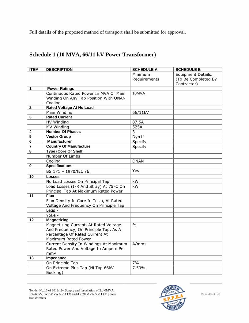
Tender No.16 of 2018/19– Supply and Installation of 2x40MVA
132/66kV, 3x10MVA 66/11 kV and 4 x 20 MVA 66/11 kV power transformers
Page 40 of 28
Full details of the proposed method of transport shall be submitted for approval.
Schedule 1 (10 MVA, 66/11 kV Power Transformer)
ITEM DESCRIPTION SCHEDULE A SCHEDULE B
Minimum
Requirements
Equipment Details.
(To Be Completed By
Contractor) 1 Power Ratings
Continuous Rated Power In MVA Of Main
Winding On Any Tap Position With ONAN
Cooling
10MVA
2 Rated Voltage At No Load
Main Winding 66/11kV 3 Rated Current
HV Winding 87.5A
MV Winding 525A 4 Number Of Phases 3 5 Vector Group Dyn11 6 Manufacturer Specify 7 Country Of Manufacture Specify 8 Type (Core Or Shell)
Number Of Limbs
Cooling ONAN 9 Specifications
BS 171 – 1970/IEC 76 Yes
10 Losses
No Load Losses On Principal Tap kW
Load Losses (I²R And Stray) At 75°C On
Principal Tap At Maximum Rated Power
kW
11 Flux
Flux Density In Core In Tesla, At Rated
Voltage And Frequency On Principle Tap
Legs -
Yoke - 12 Magnetizing
Magnetizing Current, At Rated Voltage
And Frequency, On Principle Tap, As A
Percentage Of Rated Current At
Maximum Rated Power
%
Current Density In Windings At Maximum
Rated Power And Voltage In Ampere Per
mm²
A/mm2
13 Impedance
On Principle Tap 7%
On Extreme Plus Tap (Hi Tap 66kV
Bucking)
7.50%
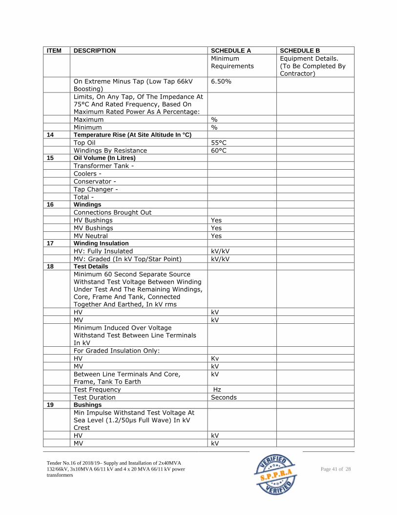
Tender No.16 of 2018/19– Supply and Installation of 2x40MVA
132/66kV, 3x10MVA 66/11 kV and 4 x 20 MVA 66/11 kV power transformers
Page 41 of 28
ITEM DESCRIPTION SCHEDULE A SCHEDULE B
Minimum
Requirements
Equipment Details.
(To Be Completed By
Contractor)
On Extreme Minus Tap (Low Tap 66kV
Boosting)
6.50%
Limits, On Any Tap, Of The Impedance At
75°C And Rated Frequency, Based On
Maximum Rated Power As A Percentage:
Maximum %
Minimum % 14 Temperature Rise (At Site Altitude In °C)
Top Oil 55°C
Windings By Resistance 60°C 15 Oil Volume (In Litres)
Transformer Tank -
Coolers -
Conservator -
Tap Changer -
Total - 16 Windings
Connections Brought Out
HV Bushings Yes
MV Bushings Yes
MV Neutral Yes 17 Winding Insulation
HV: Fully Insulated kV/kV
MV: Graded (In kV Top/Star Point) kV/kV 18 Test Details
Minimum 60 Second Separate Source
Withstand Test Voltage Between Winding
Under Test And The Remaining Windings,
Core, Frame And Tank, Connected
Together And Earthed, In kV rms
HV kV
MV kV
Minimum Induced Over Voltage
Withstand Test Between Line Terminals
In kV
For Graded Insulation Only:
HV Kv
MV kV
Between Line Terminals And Core,
Frame, Tank To Earth
kV
Test Frequency Hz
Test Duration Seconds 19 Bushings
Min Impulse Withstand Test Voltage At
Sea Level (1.2/50μs Full Wave) In kV
Crest
HV kV
MV kV
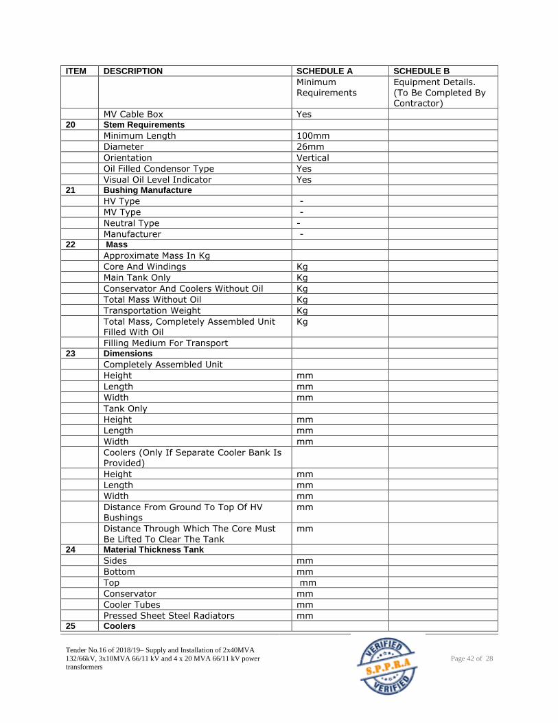
Tender No.16 of 2018/19– Supply and Installation of 2x40MVA
132/66kV, 3x10MVA 66/11 kV and 4 x 20 MVA 66/11 kV power transformers
Page 42 of 28
ITEM DESCRIPTION SCHEDULE A SCHEDULE B
Minimum
Requirements
Equipment Details.
(To Be Completed By
Contractor)
MV Cable Box Yes 20 Stem Requirements
Minimum Length 100mm
Diameter 26mm
Orientation Vertical
Oil Filled Condensor Type Yes
Visual Oil Level Indicator Yes 21 Bushing Manufacture
HV Type -
MV Type -
Neutral Type -
Manufacturer - 22 Mass
Approximate Mass In Kg
Core And Windings Kg
Main Tank Only Kg
Conservator And Coolers Without Oil Kg
Total Mass Without Oil Kg
Transportation Weight Kg
Total Mass, Completely Assembled Unit
Filled With Oil
Kg
Filling Medium For Transport 23 Dimensions
Completely Assembled Unit
Height mm
Length mm
Width mm
Tank Only
Height mm
Length mm
Width mm
Coolers (Only If Separate Cooler Bank Is
Provided)
Height mm
Length mm
Width mm
Distance From Ground To Top Of HV
Bushings
mm
Distance Through Which The Core Must
Be Lifted To Clear The Tank
mm
24 Material Thickness Tank
Sides mm
Bottom mm
Top mm
Conservator mm
Cooler Tubes mm
Pressed Sheet Steel Radiators mm 25 Coolers
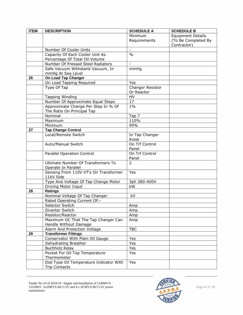
Tender No.16 of 2018/19– Supply and Installation of 2x40MVA
132/66kV, 3x10MVA 66/11 kV and 4 x 20 MVA 66/11 kV power transformers
Page 43 of 28
ITEM DESCRIPTION SCHEDULE A SCHEDULE B
Minimum
Requirements
Equipment Details.
(To Be Completed By
Contractor)
Number Of Cooler Units -
Capacity Of Each Cooler Unit As
Percentage Of Total Oil Volume
%
Number Of Pressed Steel Radiators -
Safe Vacuum Withstand Vacuum, In
mmHg At Sea Level
mmHg
26 On Load Tap Changer
On Load Tapping Required Yes
Type Of Tap Changer Resistor
Or Reactor
Tapping Winding HV
Number Of Approximate Equal Steps 17
Approximate Change Per Step In % Of
The Ratio On Principal Tap
1%
Nominal Tap 7
Maximum 110%
Minimum 95% 27 Tap Change Control
Local/Remote Switch In Tap Changer
Kiosk
Auto/Manual Switch On Trf Control
Panel
Parallel Operation Control On Trf Control
Panel
Ultimate Number Of Transformers To
Operate In Parallel
2
Sensing From 110V VT's On Transformer
11kV Side
Yes
Type And Voltage Of Tap Change Motor 3ph 380-400V
Driving Motor Input kW 28 Ratings
Nominal Voltage Of Tap Changer kV
Rated Operating Current Of:-
Selector Switch Amp
Diverter Switch Amp
Resistor/Reactor Amp
Maximum OC That The Tap Changer Can
Handle Without Damage
Amp
Alarm And Protection Voltage TBC 29 Transformer Fittings
Conservator With Plain Oil Gauge Yes
Dehydrating Breather Yes
Buchholz Relay Yes
Pocket For Oil Top Temperature
Thermometer
Yes
Dial Type Oil Temperature Indicator With
Trip Contacts
Yes
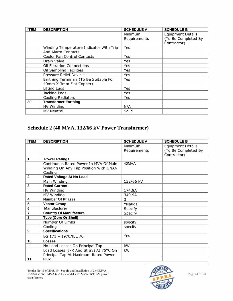
Tender No.16 of 2018/19– Supply and Installation of 2x40MVA
132/66kV, 3x10MVA 66/11 kV and 4 x 20 MVA 66/11 kV power transformers
Page 44 of 28
ITEM DESCRIPTION SCHEDULE A SCHEDULE B
Minimum
Requirements
Equipment Details.
(To Be Completed By
Contractor)
Winding Temperature Indicator With Trip
And Alarm Contacts
Yes
Cooler Fan Control Contacts Yes
Drain Valve Yes
Oil Filtration Connections Yes
Oil Sampling Facilities Yes
Pressure Relief Device Yes
Earthing Terminals (To Be Suitable For
40mm X 3mm Flat Copper)
Yes
Lifting Lugs Yes
Jacking Pads Yes
Cooling Radiators Yes 30 Transformer Earthing
HV Winding N/A
MV Neutral Solid
Schedule 2 (40 MVA, 132/66 kV Power Transformer)
ITEM DESCRIPTION SCHEDULE A SCHEDULE B
Minimum
Requirements
Equipment Details.
(To Be Completed By
Contractor) 1 Power Ratings
Continuous Rated Power In MVA Of Main
Winding On Any Tap Position With ONAN
Cooling
40MVA
2 Rated Voltage At No Load
Main Winding 132/66 kV 3 Rated Current
HV Winding 174.9A
MV Winding 349.9A 4 Number Of Phases 3 5 Vector Group YNa0d1 6 Manufacturer Specify 7 Country Of Manufacture Specify 8 Type (Core Or Shell)
Number Of Limbs specify
Cooling specify 9 Specifications
BS 171 – 1970/IEC 76 Yes
10 Losses
No Load Losses On Principal Tap kW
Load Losses (I²R And Stray) At 75°C On
Principal Tap At Maximum Rated Power
kW
11 Flux
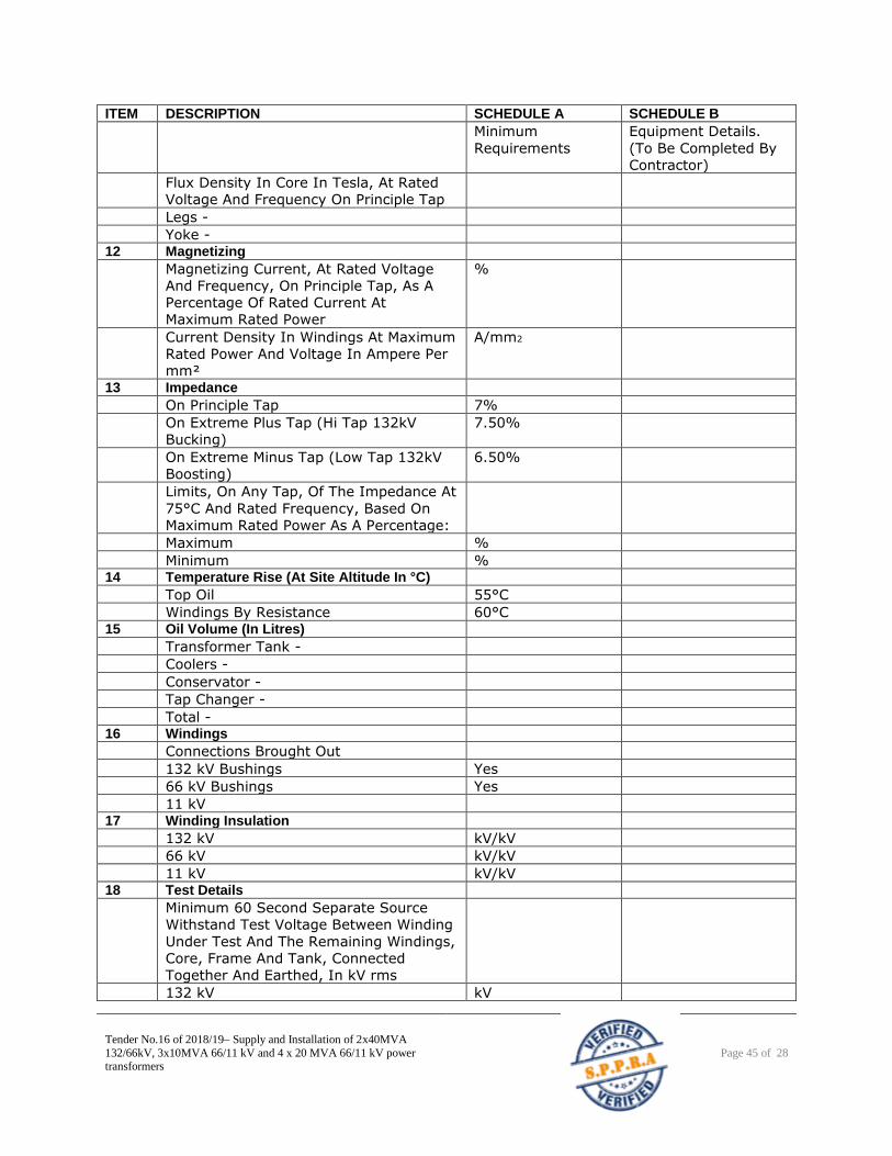
Tender No.16 of 2018/19– Supply and Installation of 2x40MVA
132/66kV, 3x10MVA 66/11 kV and 4 x 20 MVA 66/11 kV power transformers
Page 45 of 28
ITEM DESCRIPTION SCHEDULE A SCHEDULE B
Minimum
Requirements
Equipment Details.
(To Be Completed By
Contractor)
Flux Density In Core In Tesla, At Rated
Voltage And Frequency On Principle Tap
Legs -
Yoke - 12 Magnetizing
Magnetizing Current, At Rated Voltage
And Frequency, On Principle Tap, As A
Percentage Of Rated Current At
Maximum Rated Power
%
Current Density In Windings At Maximum
Rated Power And Voltage In Ampere Per
mm²
A/mm2
13 Impedance
On Principle Tap 7%
On Extreme Plus Tap (Hi Tap 132kV
Bucking)
7.50%
On Extreme Minus Tap (Low Tap 132kV
Boosting)
6.50%
Limits, On Any Tap, Of The Impedance At
75°C And Rated Frequency, Based On
Maximum Rated Power As A Percentage:
Maximum %
Minimum % 14 Temperature Rise (At Site Altitude In °C)
Top Oil 55°C
Windings By Resistance 60°C 15 Oil Volume (In Litres)
Transformer Tank -
Coolers -
Conservator -
Tap Changer -
Total - 16 Windings
Connections Brought Out
132 kV Bushings Yes
66 kV Bushings Yes
11 kV 17 Winding Insulation
132 kV kV/kV
66 kV kV/kV
11 kV kV/kV 18 Test Details
Minimum 60 Second Separate Source
Withstand Test Voltage Between Winding
Under Test And The Remaining Windings,
Core, Frame And Tank, Connected
Together And Earthed, In kV rms
132 kV kV
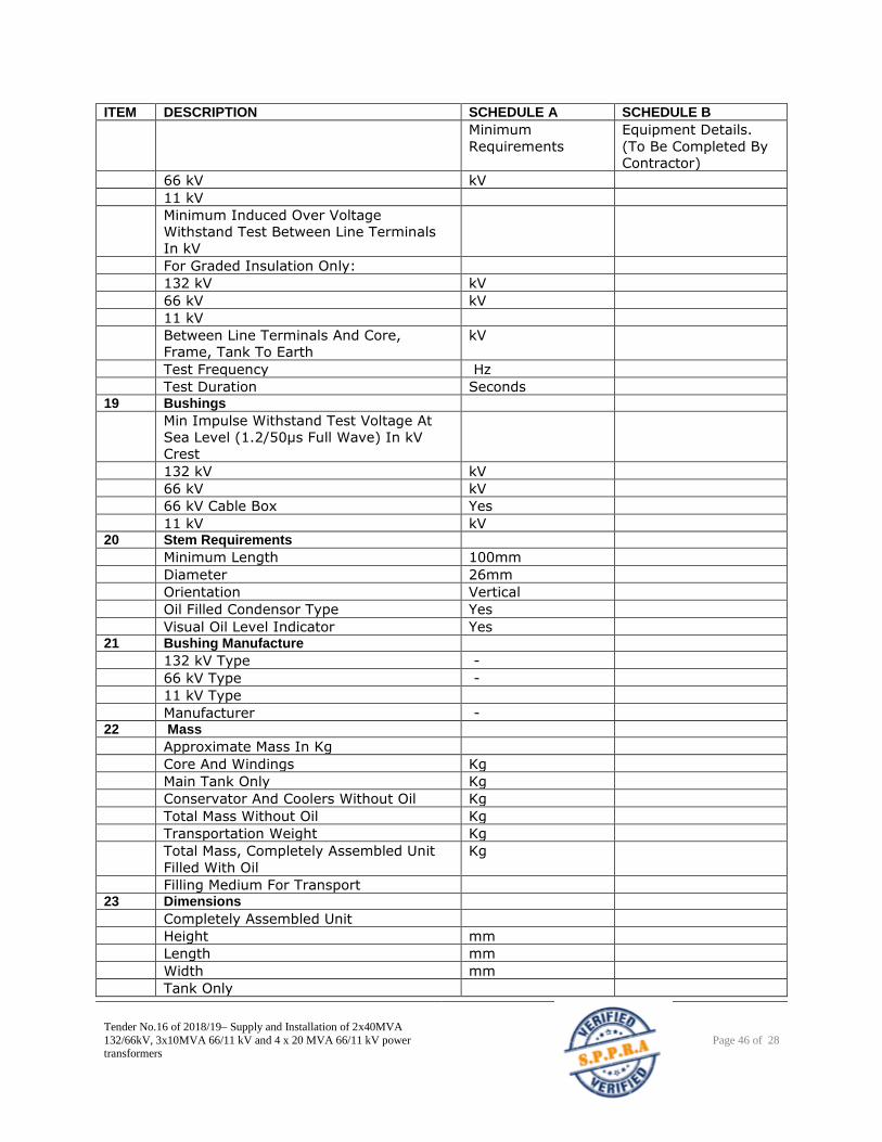
Tender No.16 of 2018/19– Supply and Installation of 2x40MVA
132/66kV, 3x10MVA 66/11 kV and 4 x 20 MVA 66/11 kV power transformers
Page 46 of 28
ITEM DESCRIPTION SCHEDULE A SCHEDULE B
Minimum
Requirements
Equipment Details.
(To Be Completed By
Contractor)
66 kV kV
11 kV
Minimum Induced Over Voltage
Withstand Test Between Line Terminals
In kV
For Graded Insulation Only:
132 kV kV
66 kV kV
11 kV
Between Line Terminals And Core,
Frame, Tank To Earth
kV
Test Frequency Hz
Test Duration Seconds 19 Bushings
Min Impulse Withstand Test Voltage At
Sea Level (1.2/50μs Full Wave) In kV
Crest
132 kV kV
66 kV kV
66 kV Cable Box Yes
11 kV kV 20 Stem Requirements
Minimum Length 100mm
Diameter 26mm
Orientation Vertical
Oil Filled Condensor Type Yes
Visual Oil Level Indicator Yes 21 Bushing Manufacture
132 kV Type -
66 kV Type -
11 kV Type
Manufacturer - 22 Mass
Approximate Mass In Kg
Core And Windings Kg
Main Tank Only Kg
Conservator And Coolers Without Oil Kg
Total Mass Without Oil Kg
Transportation Weight Kg
Total Mass, Completely Assembled Unit
Filled With Oil
Kg
Filling Medium For Transport 23 Dimensions
Completely Assembled Unit
Height mm
Length mm
Width mm
Tank Only
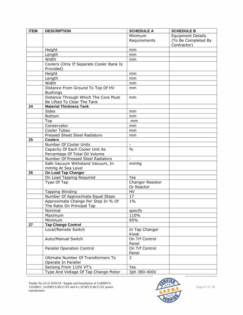
Tender No.16 of 2018/19– Supply and Installation of 2x40MVA
132/66kV, 3x10MVA 66/11 kV and 4 x 20 MVA 66/11 kV power transformers
Page 47 of 28
ITEM DESCRIPTION SCHEDULE A SCHEDULE B
Minimum
Requirements
Equipment Details.
(To Be Completed By
Contractor)
Height mm
Length mm
Width mm
Coolers (Only If Separate Cooler Bank Is
Provided)
Height mm
Length mm
Width mm
Distance From Ground To Top Of HV
Bushings
mm
Distance Through Which The Core Must
Be Lifted To Clear The Tank
mm
24 Material Thickness Tank
Sides mm
Bottom mm
Top mm
Conservator mm
Cooler Tubes mm
Pressed Sheet Steel Radiators mm 25 Coolers
Number Of Cooler Units -
Capacity Of Each Cooler Unit As
Percentage Of Total Oil Volume
%
Number Of Pressed Steel Radiators -
Safe Vacuum Withstand Vacuum, In
mmHg At Sea Level
mmHg
26 On Load Tap Changer
On Load Tapping Required Yes
Type Of Tap Changer Resistor
Or Reactor
Tapping Winding HV
Number Of Approximate Equal Steps 17
Approximate Change Per Step In % Of
The Ratio On Principal Tap
1%
Nominal specify
Maximum 110%
Minimum 95% 27 Tap Change Control
Local/Remote Switch In Tap Changer
Kiosk
Auto/Manual Switch On Trf Control
Panel
Parallel Operation Control On Trf Control
Panel
Ultimate Number Of Transformers To
Operate In Parallel
2
Sensing From 110V VT's Yes
Type And Voltage Of Tap Change Motor 3ph 380-400V
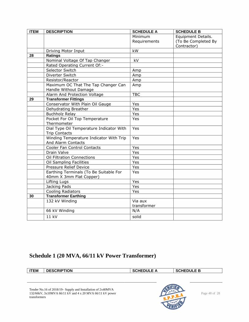
Tender No.16 of 2018/19– Supply and Installation of 2x40MVA
132/66kV, 3x10MVA 66/11 kV and 4 x 20 MVA 66/11 kV power transformers
Page 48 of 28
ITEM DESCRIPTION SCHEDULE A SCHEDULE B
Minimum
Requirements
Equipment Details.
(To Be Completed By
Contractor)
Driving Motor Input kW 28 Ratings
Nominal Voltage Of Tap Changer kV
Rated Operating Current Of:-
Selector Switch Amp
Diverter Switch Amp
Resistor/Reactor Amp
Maximum OC That The Tap Changer Can
Handle Without Damage
Amp
Alarm And Protection Voltage TBC 29 Transformer Fittings
Conservator With Plain Oil Gauge Yes
Dehydrating Breather Yes
Buchholz Relay Yes
Pocket For Oil Top Temperature
Thermometer
Yes
Dial Type Oil Temperature Indicator With
Trip Contacts
Yes
Winding Temperature Indicator With Trip
And Alarm Contacts
Yes
Cooler Fan Control Contacts Yes
Drain Valve Yes
Oil Filtration Connections Yes
Oil Sampling Facilities Yes
Pressure Relief Device Yes
Earthing Terminals (To Be Suitable For
40mm X 3mm Flat Copper)
Yes
Lifting Lugs Yes
Jacking Pads Yes
Cooling Radiators Yes 30 Transformer Earthing
132 kV Winding Via aux
transformer
66 kV Winding N/A 11 kV solid
Schedule 1 (20 MVA, 66/11 kV Power Transformer)
ITEM DESCRIPTION SCHEDULE A SCHEDULE B
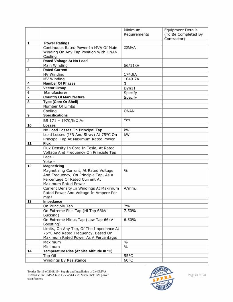
Tender No.16 of 2018/19– Supply and Installation of 2x40MVA
132/66kV, 3x10MVA 66/11 kV and 4 x 20 MVA 66/11 kV power transformers
Page 49 of 28
Minimum
Requirements
Equipment Details.
(To Be Completed By
Contractor) 1 Power Ratings
Continuous Rated Power In MVA Of Main
Winding On Any Tap Position With ONAN
Cooling
20MVA
2 Rated Voltage At No Load
Main Winding 66/11kV 3 Rated Current
HV Winding 174.9A
MV Winding 1049.7A 4 Number Of Phases 3 5 Vector Group Dyn11 6 Manufacturer Specify 7 Country Of Manufacture Specify 8 Type (Core Or Shell)
Number Of Limbs
Cooling ONAN 9 Specifications
BS 171 – 1970/IEC 76 Yes
10 Losses
No Load Losses On Principal Tap kW
Load Losses (I²R And Stray) At 75°C On
Principal Tap At Maximum Rated Power
kW
11 Flux
Flux Density In Core In Tesla, At Rated
Voltage And Frequency On Principle Tap
Legs -
Yoke - 12 Magnetizing
Magnetizing Current, At Rated Voltage
And Frequency, On Principle Tap, As A
Percentage Of Rated Current At
Maximum Rated Power
%
Current Density In Windings At Maximum
Rated Power And Voltage In Ampere Per
mm²
A/mm2
13 Impedance
On Principle Tap 7%
On Extreme Plus Tap (Hi Tap 66kV
Bucking)
7.50%
On Extreme Minus Tap (Low Tap 66kV
Boosting)
6.50%
Limits, On Any Tap, Of The Impedance At
75°C And Rated Frequency, Based On
Maximum Rated Power As A Percentage:
Maximum %
Minimum % 14 Temperature Rise (At Site Altitude In °C)
Top Oil 55°C
Windings By Resistance 60°C
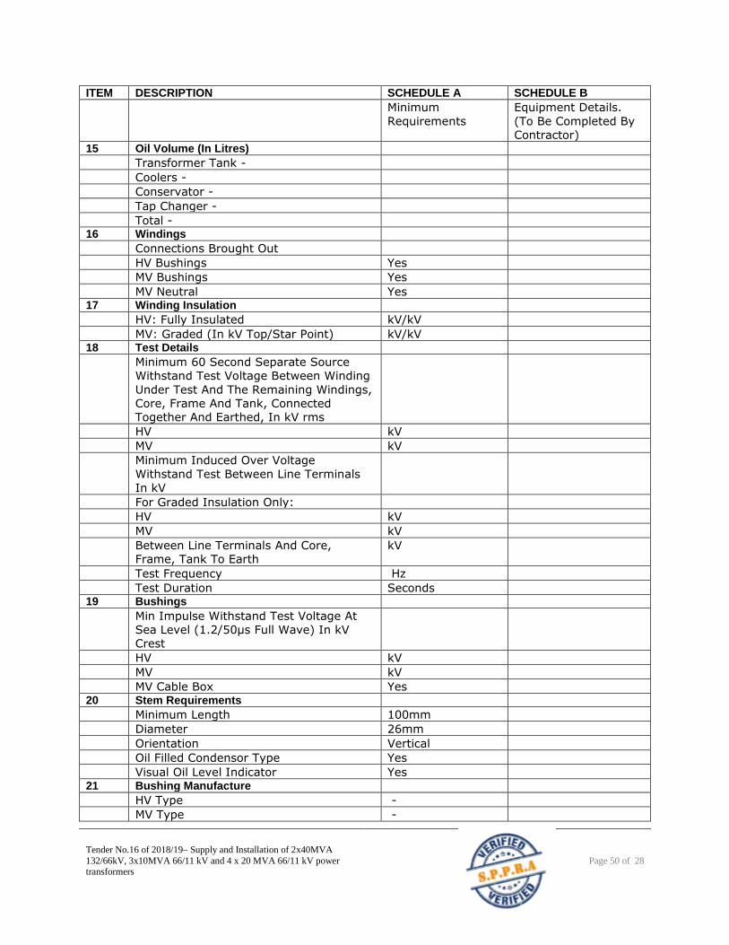
Tender No.16 of 2018/19– Supply and Installation of 2x40MVA
132/66kV, 3x10MVA 66/11 kV and 4 x 20 MVA 66/11 kV power transformers
Page 50 of 28
ITEM DESCRIPTION SCHEDULE A SCHEDULE B
Minimum
Requirements
Equipment Details.
(To Be Completed By
Contractor) 15 Oil Volume (In Litres)
Transformer Tank -
Coolers -
Conservator -
Tap Changer -
Total - 16 Windings
Connections Brought Out
HV Bushings Yes
MV Bushings Yes
MV Neutral Yes 17 Winding Insulation
HV: Fully Insulated kV/kV
MV: Graded (In kV Top/Star Point) kV/kV 18 Test Details
Minimum 60 Second Separate Source
Withstand Test Voltage Between Winding
Under Test And The Remaining Windings,
Core, Frame And Tank, Connected
Together And Earthed, In kV rms
HV kV
MV kV
Minimum Induced Over Voltage
Withstand Test Between Line Terminals
In kV
For Graded Insulation Only:
HV kV
MV kV
Between Line Terminals And Core,
Frame, Tank To Earth
kV
Test Frequency Hz
Test Duration Seconds 19 Bushings
Min Impulse Withstand Test Voltage At
Sea Level (1.2/50μs Full Wave) In kV
Crest
HV kV
MV kV
MV Cable Box Yes 20 Stem Requirements
Minimum Length 100mm
Diameter 26mm
Orientation Vertical
Oil Filled Condensor Type Yes
Visual Oil Level Indicator Yes 21 Bushing Manufacture
HV Type -
MV Type -
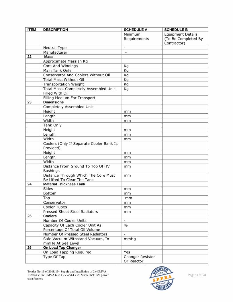
Tender No.16 of 2018/19– Supply and Installation of 2x40MVA
132/66kV, 3x10MVA 66/11 kV and 4 x 20 MVA 66/11 kV power transformers
Page 51 of 28
ITEM DESCRIPTION SCHEDULE A SCHEDULE B
Minimum
Requirements
Equipment Details.
(To Be Completed By
Contractor)
Neutral Type -
Manufacturer - 22 Mass
Approximate Mass In Kg
Core And Windings Kg
Main Tank Only Kg
Conservator And Coolers Without Oil Kg
Total Mass Without Oil Kg
Transportation Weight Kg
Total Mass, Completely Assembled Unit
Filled With Oil
Kg
Filling Medium For Transport 23 Dimensions
Completely Assembled Unit
Height mm
Length mm
Width mm
Tank Only
Height mm
Length mm
Width mm
Coolers (Only If Separate Cooler Bank Is
Provided)
Height mm
Length mm
Width mm
Distance From Ground To Top Of HV
Bushings
mm
Distance Through Which The Core Must
Be Lifted To Clear The Tank
mm
24 Material Thickness Tank
Sides mm
Bottom mm
Top mm
Conservator mm
Cooler Tubes mm
Pressed Sheet Steel Radiators mm 25 Coolers
Number Of Cooler Units -
Capacity Of Each Cooler Unit As
Percentage Of Total Oil Volume
%
Number Of Pressed Steel Radiators -
Safe Vacuum Withstand Vacuum, In
mmHg At Sea Level
mmHg
26 On Load Tap Changer
On Load Tapping Required Yes
Type Of Tap Changer Resistor
Or Reactor
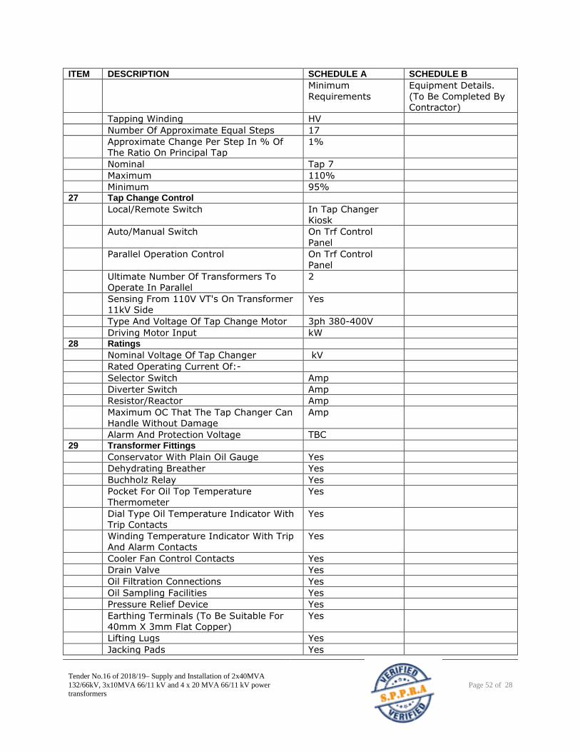
Tender No.16 of 2018/19– Supply and Installation of 2x40MVA
132/66kV, 3x10MVA 66/11 kV and 4 x 20 MVA 66/11 kV power transformers
Page 52 of 28
ITEM DESCRIPTION SCHEDULE A SCHEDULE B
Minimum
Requirements
Equipment Details.
(To Be Completed By
Contractor)
Tapping Winding HV
Number Of Approximate Equal Steps 17
Approximate Change Per Step In % Of
The Ratio On Principal Tap
1%
Nominal Tap 7
Maximum 110%
Minimum 95% 27 Tap Change Control
Local/Remote Switch In Tap Changer
Kiosk
Auto/Manual Switch On Trf Control
Panel
Parallel Operation Control On Trf Control
Panel
Ultimate Number Of Transformers To
Operate In Parallel
2
Sensing From 110V VT's On Transformer
11kV Side
Yes
Type And Voltage Of Tap Change Motor 3ph 380-400V
Driving Motor Input kW 28 Ratings
Nominal Voltage Of Tap Changer kV
Rated Operating Current Of:-
Selector Switch Amp
Diverter Switch Amp
Resistor/Reactor Amp
Maximum OC That The Tap Changer Can
Handle Without Damage
Amp
Alarm And Protection Voltage TBC 29 Transformer Fittings
Conservator With Plain Oil Gauge Yes
Dehydrating Breather Yes
Buchholz Relay Yes
Pocket For Oil Top Temperature
Thermometer
Yes
Dial Type Oil Temperature Indicator With
Trip Contacts
Yes
Winding Temperature Indicator With Trip
And Alarm Contacts
Yes
Cooler Fan Control Contacts Yes
Drain Valve Yes
Oil Filtration Connections Yes
Oil Sampling Facilities Yes
Pressure Relief Device Yes
Earthing Terminals (To Be Suitable For
40mm X 3mm Flat Copper)
Yes
Lifting Lugs Yes
Jacking Pads Yes
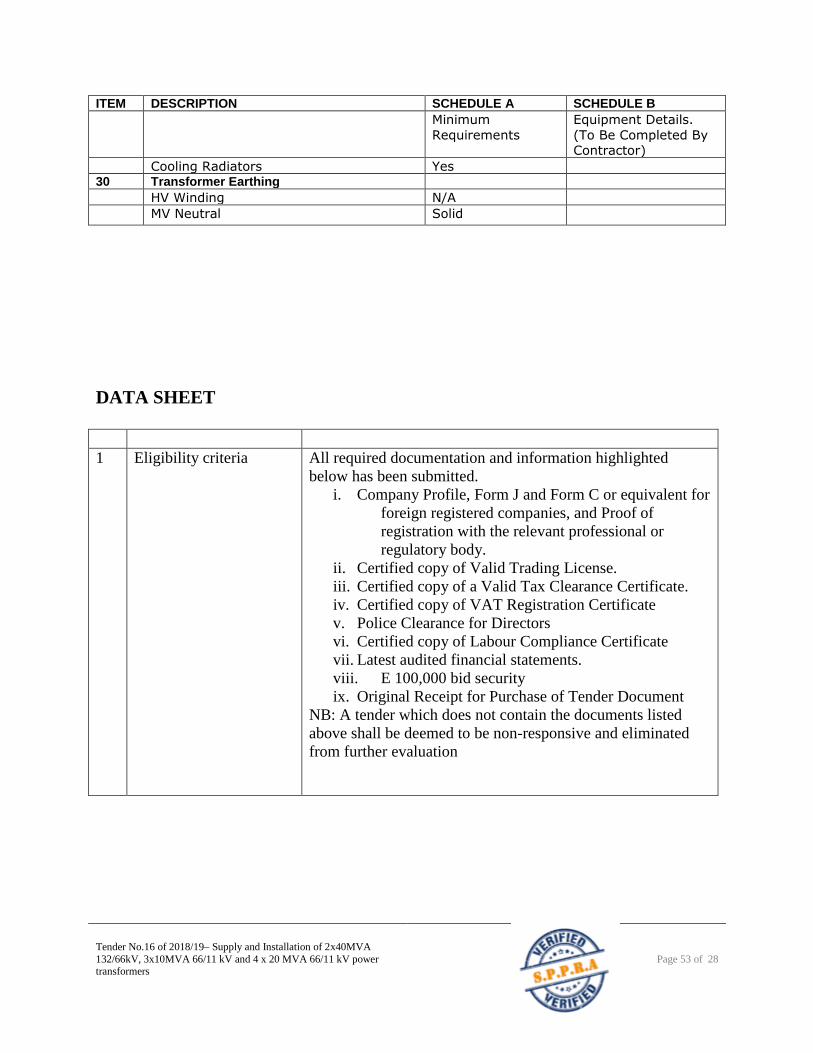
Tender No.16 of 2018/19– Supply and Installation of 2x40MVA
132/66kV, 3x10MVA 66/11 kV and 4 x 20 MVA 66/11 kV power transformers
Page 53 of 28
ITEM DESCRIPTION SCHEDULE A SCHEDULE B
Minimum
Requirements
Equipment Details.
(To Be Completed By
Contractor)
Cooling Radiators Yes 30 Transformer Earthing
HV Winding N/A
MV Neutral Solid
DATA SHEET
1 Eligibility criteria All required documentation and information highlighted
below has been submitted.
i. Company Profile, Form J and Form C or equivalent for
foreign registered companies, and Proof of
registration with the relevant professional or
regulatory body.
ii. Certified copy of Valid Trading License.
iii. Certified copy of a Valid Tax Clearance Certificate.
iv. Certified copy of VAT Registration Certificate
v. Police Clearance for Directors
vi. Certified copy of Labour Compliance Certificate
vii. Latest audited financial statements.
viii. E 100,000 bid security
ix. Original Receipt for Purchase of Tender Document
NB: A tender which does not contain the documents listed
above shall be deemed to be non-responsive and eliminated
from further evaluation
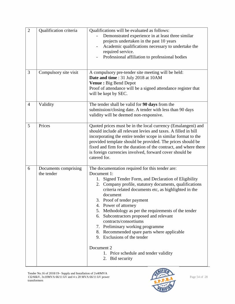
Tender No.16 of 2018/19– Supply and Installation of 2x40MVA
132/66kV, 3x10MVA 66/11 kV and 4 x 20 MVA 66/11 kV power transformers
Page 54 of 28
2 Qualification criteria Qualifications will be evaluated as follows:
- Demonstrated experience in at least three similar
projects undertaken in the past 10 years
- Academic qualifications necessary to undertake the
required service.
- Professional affiliation to professional bodies
3 Compulsory site visit A compulsory pre-tender site meeting will be held:
Date and time : 31 July 2018 at 10AM
Venue : Big Bend Depot
Proof of attendance will be a signed attendance register that
will be kept by SEC.
4 Validity The tender shall be valid for 90 days from the
submission/closing date. A tender with less than 90 days
validity will be deemed non-responsive.
5 Prices Quoted prices must be in the local currency (Emalangeni) and
should include all relevant levies and taxes. A filled in bill
incorporating the entire tender scope in similar format to the
provided template should be provided. The prices should be
fixed and firm for the duration of the contract, and where there
is foreign currencies involved, forward cover should be
catered for.
6 Documents comprising
the tender
The documentation required for this tender are:
Document 1:
1. Signed Tender Form, and Declaration of Eligibility
2. Company profile, statutory documents, qualifications
criteria related documents etc, as highlighted in the
document
3. Proof of tender payment
4. Power of attorney
5. Methodology as per the requirements of the tender
6. Subcontractors proposed and relevant
contracts/consortiums
7. Preliminary working programme
8. Recommended spare parts where applicable
9. Exclusions of the tender
Document 2
1. Price schedule and tender validity
2. Bid security
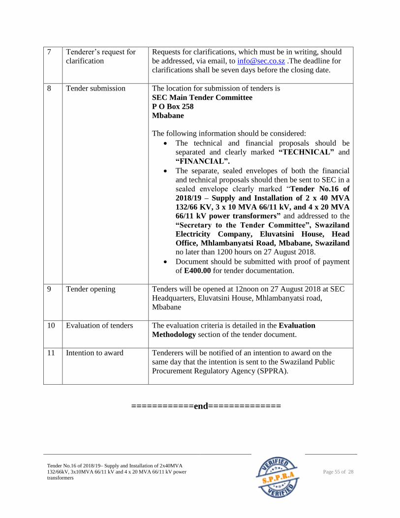
Tender No.16 of 2018/19– Supply and Installation of 2x40MVA
132/66kV, 3x10MVA 66/11 kV and 4 x 20 MVA 66/11 kV power transformers
Page 55 of 28
7 Tenderer’s request for
clarification
Requests for clarifications, which must be in writing, should
be addressed, via email, to [email protected] .The deadline for
clarifications shall be seven days before the closing date.
8 Tender submission The location for submission of tenders is
SEC Main Tender Committee
P O Box 258
Mbabane
The following information should be considered:
The technical and financial proposals should be
separated and clearly marked “TECHNICAL” and
“FINANCIAL”.
The separate, sealed envelopes of both the financial
and technical proposals should then be sent to SEC in a
sealed envelope clearly marked “Tender No.16 of
2018/19 – Supply and Installation of 2 x 40 MVA
132/66 KV, 3 x 10 MVA 66/11 kV, and 4 x 20 MVA
66/11 kV power transformers” and addressed to the
“Secretary to the Tender Committee”, Swaziland
Electricity Company, Eluvatsini House, Head
Office, Mhlambanyatsi Road, Mbabane, Swaziland no later than 1200 hours on 27 August 2018.
Document should be submitted with proof of payment
of E400.00 for tender documentation.
9 Tender opening Tenders will be opened at 12noon on 27 August 2018 at SEC
Headquarters, Eluvatsini House, Mhlambanyatsi road,
Mbabane
10 Evaluation of tenders The evaluation criteria is detailed in the Evaluation
Methodology section of the tender document.
11 Intention to award Tenderers will be notified of an intention to award on the
same day that the intention is sent to the Swaziland Public
Procurement Regulatory Agency (SPPRA).
============end==============