Embed Size (px)
Citation preview
PILE FOUNDATION FOR WATER TANKS AT PARADEEP
Page 1 of 1
HINDUSTAN PETROLEUM CORPORATION LIMITED
ENGINEERING & PROJECTS
GRESHAM ASSURANCE HOUSE, 2ND
FLOOR,
A-1595(3) 1-A, SIR P M ROAD, FORT
MUMBAI-400 001
TENDER DOCUMENT
FOR
PILE FOUNDATION FOR WATER TANKS
AT
PARADEEP POL TERMINAL
ORISSA
PILE FOUNDATION FOR WATER TANKS AT PARADEEP
Page 1 of 1
INDEX
Sr.
No.
DESCRIPTION PAGES
FROM TO
1
TENDER COVER PAGE
1
1
2
INDEX
1
1
3
PROJECT DESCRIPTION, SCOPE OF WORK & SCHEDULE OF
QUANTITIES
1 11
4 UNPRICED BID 1 2
5
TIME SCHEDULE
1
2
6
SPECIAL CONDITIONS OF CONTRACT
1
23
7
TENDER TECHNICAL SPECIFICATIONS
7.1 TECHNICAL SPECIFICATION FOR SAND/MURRUM FILLING WORKS 1 21
7.2 TECHNICAL SPECIFICATION FOR PILING WORKS 1 47
8
SAFETY, HEALTH & ENVIRONMENT(SHE) POLICY
1 8
9
PARADEEP TERMINAL LAYOUT
1
1

PILE FOUNDATION FOR WATER TANKS AT PARADEEP
Page 1 of 11
PROJECT DESCRIPTION,
SCOPE OF WORK &
SCHEDULE OF QUANTITIES
PILE FOUNDATION FOR WATER TANKS AT PARADEEP
Page 2 of 11
PROJECT DESCRIPTION/ SITE INFORMATION
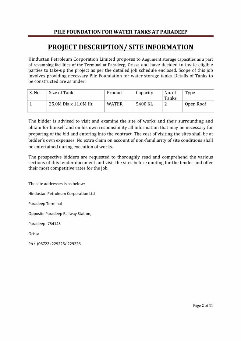
Hindustan Petroleum Corporation Limited proposes to Augument storage capacities as a part
of revamping facilities of the Terminal at Paradeep, Orissa and have decided to invite eligible
parties to take-up the project as per the detailed job schedule enclosed. Scope of this job
involves providing necessary Pile Foundation for water storage tanks. Details of Tanks to
be constructed are as under:
S. No. Size of Tank Product Capacity No. of
Tanks
Type
1 25.0M Dia x 11.0M Ht
WATER 5400 KL 2 Open Roof
The bidder is advised to visit and examine the site of works and their surrounding and
obtain for himself and on his own responsibility all information that may be necessary for
preparing of the bid and entering into the contract. The cost of visiting the sites shall be at
bidder’s own expenses. No extra claim on account of non-familiarity of site conditions shall
be entertained during execution of works.
The prospective bidders are requested to thoroughly read and comprehend the various
sections of this tender document and visit the sites before quoting for the tender and offer
their most competitive rates for the job.
The site addresses is as below:
Hindustan Petroleum Corporation Ltd
Paradeep Terminal
Opposite Paradeep Railway Station,
Paradeep- 754145
Orissa
Ph : (06722) 229225/ 229226
PILE FOUNDATION FOR WATER TANKS AT PARADEEP
Page 3 of 11
SCOPE OF WORK
Scope of the job involves but not limited to the following:
1. Scope of the job includes Design, Construction & Testing of Pile Foundation (including Pile Cap)
for water storage Tanks.
2. Conducting Routine Load tests on designated working piles namely Vertical, Lateral load tests.
IMPORTANT NOTES
1. The successful bidder will be given the copy of “Soil Investigation Report” to enable the bidder
to carryout design of the Pile foundation (including Pile Cap etc) of water storage tanks as per
relevant codal provisions based on the Soil investigation report/ recommendations of the soil
investigation agency and get the design vetted by a reputed institute like IIT, Kharagpur or any
other reputed Engineering Institutes/ Consultant duly approved by HPCL. The vetted design
shall be submitted to HPCL for approval before commencement of the job. Rate to include the
same in respective items and No separate payment shall be made to the party on this account.
2. The testing of the piles shall also be carried out by the party in line with IS 2911-Part IV and
relevant specification of this tender document within the quoted rates. No separate payment
shall be made to the party on this account.
3. Entire Cement concrete job need to be carried out thru Ready mix concrete only. The scope of
mix design is included in the scope of bidder and the same to be vetted by reputed
engineering institute like IIT, Kharagpur or any other reputed Engineering Institutes/
Consultant duly approved by HPCL. Party has to submit vetted design calculations to EIC and
obtain approval of the same before commencement of the job. RMC plants shall be of repute
like ACC, L&T etc. Alternatively, party can also set up a batching plant at the site and make
design mix as per provision including vetting by the reputed engineering institute like IIT,
Kharagpur or any other reputed Engineering Institutes/ Consultant duly approved by HPCL.
Party has to submit vetted design calculations to EIC and obtain approval of the HPCL before
commencement of the job. The batching plant need to be certified by third party for
robustness of performance and equipments associated with it.
4. Scope also includes shifting of all types of materials including scrap materials, if any lying at
the constructional area to the designated place inside the depot premises at no extra cost. Job
also includes site clearing from any debris, vegetation, bushes and trees, etc and make the site
free for construction at no extra cost.
5. Any cables / piping encountered during excavation and other construction activities, the same
shall be separated using Sand Bed and Tiles or to be re-routed, if necessary as directed by the
Engineer in charge at no extra cost to HPCL.
6. The complete requirements shall be executed comprehensively with single point
responsibility. The prospective bidders are requested to thoroughly read and comprehend the
various sections of this tender document and visit the sites before quoting for the tender.
PILE FOUNDATION FOR WATER TANKS AT PARADEEP
Page 4 of 11
7. If any deviation is found during execution between the specification and the drawings, it is to be
explicitly noted that the specification will hold good and supersede the drawings.
8. The bidder is required to peruse carefully all parts of tender documents and drawings and if any
difference / inconsistency is noticed, he shall bring it to attention of HPCL before submission of
tender and shall get the clarification(s) required. Failure to do so will not entitle the successful
bidder for any extra claims on account of such discrepancies/inconsistencies.
9. All jobs shall be executed as per technical specifications, relevant codal provisions, sound
engineering practices and as directed by EIC.
Drawings required to be submitted by the Party:
1. Drawing of Pile Foundations along with pile cap for water storage tanks and any other design
and drawing required and directed by Engineer In Charge.
2. Preparation of all detailed and working drawing and obtaining approval of HPCL.
3. Submission of 4 copies of all the above drawings (As built) shall be submitted along with CD
containing soft copy in AutoCAD latest version after job completion.
The prospective bidders are requested to thoroughly read and comprehend the various sections of this
tender document and visit the sites before quoting for the tender.
SITE INFORMATION
The job needs to be carried out in the working Terminal premises. Works to be commenced only after
having obtained necessary work permit on a daily basis & all safety precautions to be taken by the
party for carrying out the above jobs as directed by Engineer In Charge/ Terminal Manager. The party
will also have to arrange for all necessary safety and fire fighting equipments like fire extinguishers,
foam trolley, localised fire screen etc at no extra cost. The party will have to abide by all instructions
and directions by Engineer In Charge/ Terminal Manager while working inside the premises.
All conditions of work permit to be followed religiously by the party. The explosive meter readings and
check for presence of flammable vapour shall be checked by contractor’s supervisor along with HPCL’s
representative before undertaking hot work. Full time supervisor to be provided at work spot and job
shall be carried out only after complying with all safety norms of the depot. A full Time Qualified
Engineer who is technically competent and having sufficient Site experience to be available at site for
supervising and carrying out all the Jobs as per the Scope.
All the safety precautions including supplying & providing localised fire screens etc shall be arranged by
the Contractors as per the directions of Engineer in charge at no extra cost to HPCL. The contractor has
to take necessary precaution for the safe transportation of the material. Before quoting for the said job
the contractor is required to visit the site and make himself acquainted with the scope of the job and
quote accordingly.
PILE FOUNDATION FOR WATER TANKS AT PARADEEP
Page 5 of 11
The tenderers are required to go through the tender document thoroughly and carefully and offer their
most competitive rates for the job. All sets of this tender document are to be read in conjunction with
each other and accordingly quote in the priced bid.
In case of any clarifications contractor may contact Shri B. S. GOPALA KRISHNA, Senior Manager-E&P,
Engg & Projects Dept., Gresham Assurance House, 2ND
Floor, A-1595 (3), 1-A, Sir P M Road, 132, Shahid B
Singh Road, Fort, Mumbai- 400 001 on 022-22608507 regarding any queries. Party may also contact Shri
R. C. Panna, Senior Manager on 06722-229225 or 09437573955 regarding any queries.
SITE VISIT
1. The bidder is advised to visit and examine the site of works at all locations and their surrounding
and obtain for himself on his own responsibility all information that may be necessary for preparing
of the bid and entering into the contract. The cost of visiting the sites shall be at bidder’s own
expenses. No extra claim on account of non-familiarity of site conditions shall be entertained during
execution of works.
2. The bidder and any of his personnel or agents will be granted permission by the Owner to enter
upon his premises and lands for the purpose of such inspection, but only upon the explicit condition
that the bidder, his personnel or agents will release and indemnify the Owner and his personnel and
agents from and against all liability in respect thereof and will be responsible for personnel injury
(whether fatal or otherwise), loss of or damage and expenses incurred as a result hereof.
The prospective bidders are requested to thoroughly read and comprehend the various sections of this
tender document and visit the sites before quoting for the tender.

PILE FOUNDATION FOR WATER TANKS AT PARADEEP
Page 6 of 11
SCHEDULE
OF
QUANTITIES
PILE FOUNDATION FOR WATER TANKS AT PARADEEP
Page 7 of 11
IMPORTANT NOTES TO SCHEDULE OF QUANTITIES
1. These notes to be read in conjunction with the schedule of quantities and is integral part of the same.
2. Scope of Work , Supply of Material, Technical Specifications, QAP, ITP( Inspection Test Plan)
Requirement of relevant Codes , SCC( Special Conditions to Contract), GTC (General Terms &
Conditions) , Schedule of Rates ,Statutory Rules & Guide Lines as applicable, Minimum Equipment /
Machineries Deployment and any other requirement to complete the Job / Work as per this Tender
Document shall be deemed to be included in SOR items.
3. For all Items preparation of Design and Construction Drawing as per relevant code & Tech.
Specifications of this Tender & vetting after review by HPCL through Third Party approved by HPCL,
Quality Control , Inspection & Job procedure, Project Scheduling & Monitoring Document as per SCC ,
Submission of all these documents to HPCL for approval deemed to be included in quoted rates.
4. Scope of the job also includes design of pile foundations including pile cap based on soil
investigation report provided by HPCL by reputed institute like IIT, Kharagpur or any other reputed
Engineering Institutes/ Consultant duly approved by HPCL and submit the same to HPCL before
commencement of the job. Rate to include the same in respective items and No separate payment shall
be made to the party on this account.
5. The Water and Electrical power required for constructional activity shall be in the Scope of Contractor
& shall be deemed to be included in SOR Items.
6. All the Testing and Third Party Charges for Items as per tender documents elicited in various sections
shall be borne by contractor and deemed to be included in quoted rates.
7. All Tools & Tackles, Equipments, and items brought to site by contractor will be permitted to be taken
out only after completion of work & fulfillment of necessary formalities.
8. Rate for all items to include deployment of qualified Quality Control & Safety Engineer at site from the
date of LOI till completion of job as per PO. QC Engineer & Safety Engineer deployed as per above will
report to HPCL site-in-charge on daily basis for complying all the QC/safety jobs mentioned in the PO.
9. The Drawings/QAP/ITP /Job procedures attached along with tender document are for guidance/
tender purpose only. The successful bidder to submit the above for HPCL approval as per the job
requirements during the execution of the job.
PILE FOUNDATION FOR WATER TANKS AT PARADEEP
Page 8 of 11
ITEM
NO
DESCRIPTION OF ITEM UNIT QTY
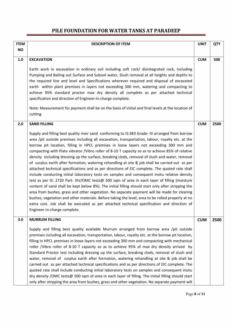
1.0 EXCAVATION
Earth work in excavation in ordinary soil including soft rock/ disintegrated rock, including
Pumping and Bailing out Surface and Subsoil water, Slush removal at all heights and depths to
the required line and level and Specifications wherever required and disposal of excavated
earth within plant premises in layers not exceeding 300 mm, watering and compacting to
achieve 95% standard proctor max dry density all complete as per attached technical
specification and direction of Engineer-in-charge complete.
Note: Measurement for payment shall be on the basis of initial and final levels at the location of
cutting.
CUM 500
2.0 SAND FILLING
Supply and filling best quality river sand conforming to IS:383 Grade- III arranged from borrow
area /pit outside premises including all excavation, transportation, labour, royalty etc. at the
borrow pit location, filling in HPCL premises in loose layers not exceeding 300 mm and
compacting with Plate vibrator /Vibro roller of 8-10 T capacity so as to achieve 85% of relative
density including dressing up the surface, breaking clods, removal of slush and water, removal
of surplus earth after formation, watering rehandling at site & job shall be carried out as per
attached technical specifications and as per directions of EIC complete. The quoted rate shall
include conducting initial laboratory tests on samples and consequent insitu relative density
test as per IS: 2720 Part- XIV/OMC tests@ 500 sqm of area in each layer of filling (moisture
content of sand shall be kept below 8%). The initial filling should start only after stripping the
area from bushes, grass and other vegetation. No separate payment will be made for clearing
bushes, vegetation and other materials. Before taking the level, area to be rolled properly at no
extra cost. Job shall be executed as per attached technical specification and direction of
Engineer-in-charge complete.
CUM 2500
3.0 MURRUM FILLING
Supply and filling best quality available Murrum arranged from borrow area /pit outside
premises including all excavation, transportation, labour, royalty etc. at the borrow pit location,
filling in HPCL premises in loose layers not exceeding 300 mm and compacting with mechanical
roller /Vibro roller of 8-10 T capacity so as to achieve 95% of max dry density arrived by
Standard Proctor test including dressing up the surface, breaking clods, removal of slush and
water, removal of surplus earth after formation, watering rehandling at site & job shall be
carried out as per attached technical specifications and as per directions of EIC complete. The
quoted rate shall include conducting initial laboratory tests on samples and consequent insitu
dry density /OMC tests@ 500 sqm of area in each layer of filling. The initial filling should start
only after stripping the area from bushes, grass and other vegetation. No separate payment will
CUM 2500
PILE FOUNDATION FOR WATER TANKS AT PARADEEP
Page 9 of 11
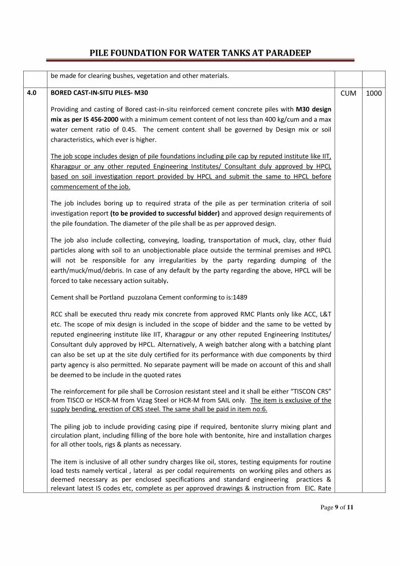
be made for clearing bushes, vegetation and other materials.
4.0 BORED CAST-IN-SITU PILES- M30
Providing and casting of Bored cast-in-situ reinforced cement concrete piles with M30 design
mix as per IS 456-2000 with a minimum cement content of not less than 400 kg/cum and a max
water cement ratio of 0.45. The cement content shall be governed by Design mix or soil
characteristics, which ever is higher.
The job scope includes design of pile foundations including pile cap by reputed institute like IIT,
Kharagpur or any other reputed Engineering Institutes/ Consultant duly approved by HPCL
based on soil investigation report provided by HPCL and submit the same to HPCL before
commencement of the job.
The job includes boring up to required strata of the pile as per termination criteria of soil
investigation report (to be provided to successful bidder) and approved design requirements of
the pile foundation. The diameter of the pile shall be as per approved design.
The job also include collecting, conveying, loading, transportation of muck, clay, other fluid
particles along with soil to an unobjectionable place outside the terminal premises and HPCL
will not be responsible for any irregularities by the party regarding dumping of the
earth/muck/mud/debris. In case of any default by the party regarding the above, HPCL will be
forced to take necessary action suitably.
CUM 1000
Cement shall be Portland puzzolana Cement conforming to is:1489
RCC shall be executed thru ready mix concrete from approved RMC Plants only like ACC, L&T
etc. The scope of mix design is included in the scope of bidder and the same to be vetted by
reputed engineering institute like IIT, Kharagpur or any other reputed Engineering Institutes/
Consultant duly approved by HPCL. Alternatively, A weigh batcher along with a batching plant
can also be set up at the site duly certified for its performance with due components by third
party agency is also permitted. No separate payment will be made on account of this and shall
be deemed to be include in the quoted rates
The reinforcement for pile shall be Corrosion resistant steel and it shall be either “TISCON CRS”
from TISCO or HSCR-M from Vizag Steel or HCR-M from SAIL only. The item is exclusive of the
supply bending, erection of CRS steel. The same shall be paid in item no:6.
The piling job to include providing casing pipe if required, bentonite slurry mixing plant and
circulation plant, including filling of the bore hole with bentonite, hire and installation charges
for all other tools, rigs & plants as necessary.
The item is inclusive of all other sundry charges like oil, stores, testing equipments for routine
load tests namely vertical , lateral as per codal requirements on working piles and others as
deemed necessary as per enclosed specifications and standard engineering practices &
relevant latest IS codes etc, complete as per approved drawings & instruction from EIC. Rate
PILE FOUNDATION FOR WATER TANKS AT PARADEEP
Page 10 of 11
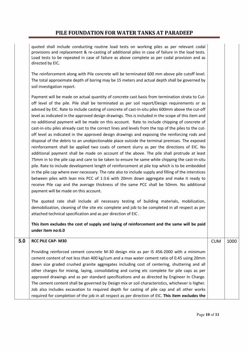
quoted shall include conducting routine load tests on working piles as per relevant codal
provisions and replacement & re-casting of additional piles in case of failure in the load tests.
Load tests to be repeated in case of failure as above complete as per codal provision and as
directed by EIC.
The reinforcement along with Pile concrete will be terminated 600 mm above pile cutoff level.
The total approximate depth of boring may be 15 meters and actual depth shall be governed by
soil investigation report.
Payment will be made on actual quantity of concrete cast basis from termination strata to Cut-
off level of the pile. Pile shall be terminated as per soil report/Design requirements or as
advised by EIC. Rate to include casting of concrete of cast-in-situ piles 600mm above the cut-off
level as indicated in the approved design drawings. This is included in the scope of this item and
no additional payment will be made on this account. Rate to include chipping of concrete of
cast-in-situ piles already cast to the correct lines and levels from the top of the piles to the cut-
off level as indicated in the approved design drawings and exposing the reinforcing rods and
disposal of the debris to an unobjectionable place outside the terminal premises. The exposed
reinforcement shall be applied two coats of cement slurry as per the directions of EIC. No
additional payment shall be made on account of the above. The pile shall protrude at least
75mm in to the pile cap and care to be taken to ensure he same while chipping the cast-in-situ
pile. Rate to include development length of reinforcement at pile top which is to be embedded
in the pile cap where ever necessary. The rate also to include supply and filling of the interstices
between piles with lean mix PCC of 1:3:6 with 20mm down aggregate and make it ready to
receive Pile cap and the average thickness of the same PCC shall be 50mm. No additional
payment will be made on this account.
The quoted rate shall include all necessary testing of building materials, mobilization,
demobilization, cleaning of the site etc complete and job to be completed in all respect as per
attached technical specification and as per direction of EIC .
This item excludes the cost of supply and laying of reinforcement and the same will be paid
under item no:6.0
5.0 RCC PILE CAP- M30 CUM 1000
Providing reinforced cement concrete M-30 design mix as per IS 456-2000 with a minimum
cement content of not less than 400 kg/cum and a max water cement ratio of 0.45 using 20mm
down size graded crushed granite aggregates including cost of centering, shuttering and all
other charges for mixing, laying, consolidating and curing etc complete for pile caps as per
approved drawings and as per standard specifications and as directed by Engineer In Charge.
The cement content shall be governed by Design mix or soil characteristics, whichever is higher.
Job also includes excavation to required depth for casting of pile cap and all other works
required for completion of the job in all respect as per direction of EIC. This item excludes the
PILE FOUNDATION FOR WATER TANKS AT PARADEEP
Page 11 of 11
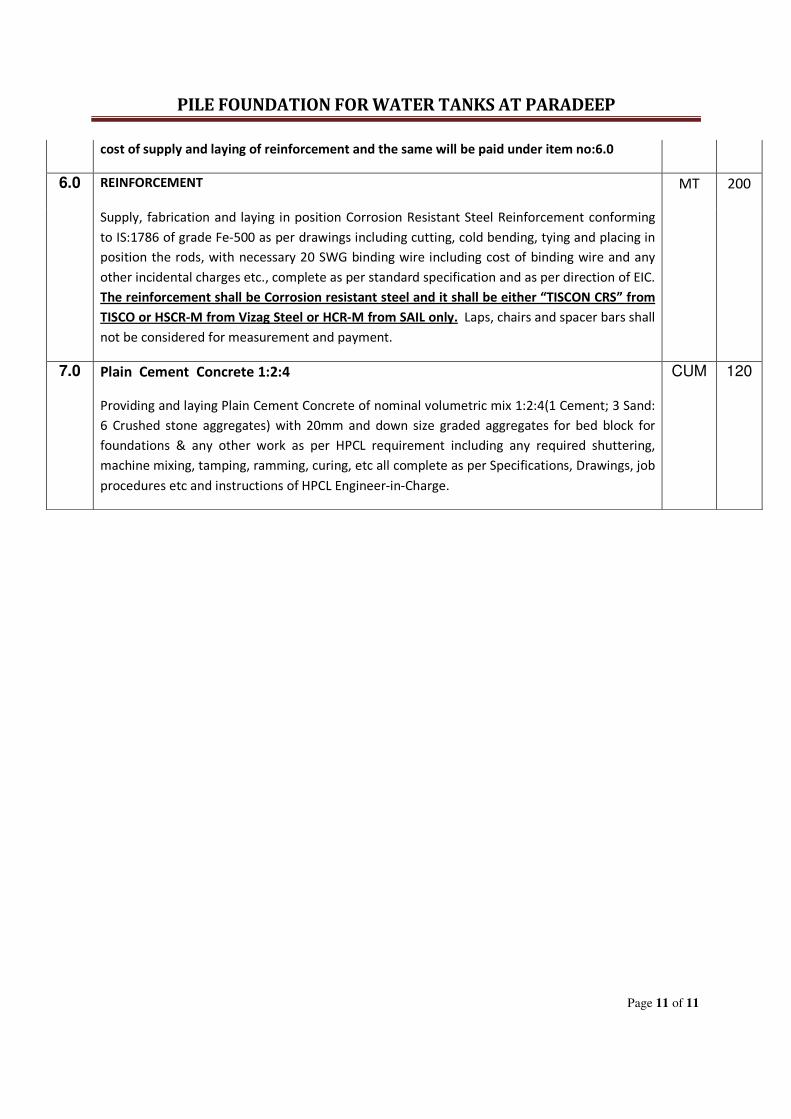
cost of supply and laying of reinforcement and the same will be paid under item no:6.0
6.0 REINFORCEMENT MT 200
Supply, fabrication and laying in position Corrosion Resistant Steel Reinforcement conforming
to IS:1786 of grade Fe-500 as per drawings including cutting, cold bending, tying and placing in
position the rods, with necessary 20 SWG binding wire including cost of binding wire and any
other incidental charges etc., complete as per standard specification and as per direction of EIC.
The reinforcement shall be Corrosion resistant steel and it shall be either “TISCON CRS” from
TISCO or HSCR-M from Vizag Steel or HCR-M from SAIL only. Laps, chairs and spacer bars shall
not be considered for measurement and payment.
7.0 Plain Cement Concrete 1:2:4
Providing and laying Plain Cement Concrete of nominal volumetric mix 1:2:4(1 Cement; 3 Sand:
6 Crushed stone aggregates) with 20mm and down size graded aggregates for bed block for
foundations & any other work as per HPCL requirement including any required shuttering,
machine mixing, tamping, ramming, curing, etc all complete as per Specifications, Drawings, job
procedures etc and instructions of HPCL Engineer-in-Charge.
CUM 120

PILE FOUNDATION FOR WATER TANKS AT PARADEEP
Page 1 of 2
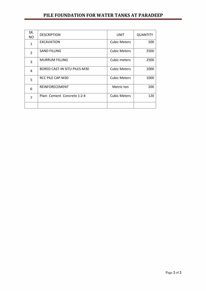
UNPRICED BID
PILE FOUNDATION FOR WATER TANKS AT PARADEEP
Page 2 of 2
SR.
NO DESCRIPTION UNIT QUANTITY
1 EXCAVATION Cubic Meters 500
2 SAND FILLING Cubic Meters 2500
3 MURRUM FILLING Cubic meters 2500
4 BORED CAST-IN SITU PILES-M30 Cubic Meters 1000
5 RCC PILE CAP-M30 Cubic Meters 1000
6 REINFORECEMENT Metric ton 200
7 Plain Cement Concrete 1:2:4 Cubic Meters 120

PILE FOUNDATION FOR WATER TANKS AT PARADEEP
Page 1 of 2
TIME SCHEDULE
PILE FOUNDATION FOR WATER TANKS AT PARADEEP
Page 2 of 2
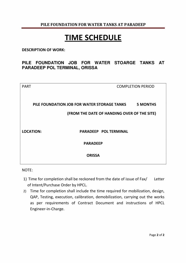
TIME SCHEDULE
DESCRIPTION OF WORK:
PILE FOUNDATION JOB FOR WATER STOARGE TANKS AT
PARADEEP POL TERMINAL, ORISSA
PART COMPLETION PERIOD
PILE FOUNDATION JOB FOR WATER STORAGE TANKS 5 MONTHS
(FROM THE DATE OF HANDING OVER OF THE SITE)
LOCATION: PARADEEP POL TERMINAL
PARADEEP
ORISSA
NOTE:
1) Time for completion shall be reckoned from the date of issue of Fax/ Letter
of Intent/Purchase Order by HPCL.
2) Time for completion shall include the time required for mobilization, design,
QAP, Testing, execution, calibration, demobilization, carrying out the works
as per requirements of Contract Document and instructions of HPCL
Engineer-in-Charge.

PILE FOUNDATION FOR WATER TANKS AT PARADEEP
Page 1 of 23
SPECIAL CONDITIONS
OF
CONTRACT
PILE FOUNDATION FOR WATER TANKS AT PARADEEP
Page 2 of 23
1.0 GENERAL
1.1 Special Conditions of Contract (SCC) shall be read in conjunction with the
General Conditions of Contract (GCC) also referred to as General Terms &
Conditions of Works Contract, Schedule of Quantities, specifications of
work, drawings and any other document forming part of this Contract
wherever the context so requires.
1.2 Notwithstanding the sub-division of the document into these separate
sections and volumes, every part of each shall be deemed to be
supplementary of every other part and shall be read with and into the
Contract so far as it may be practicable to do so.
1.3 Where any portion of the GCC is repugnant to or at variance with any
provisions of the Special Conditions of Contract, then unless a different
intention appears, the provision(s) of the Special Conditions of Contract
shall be deemed to override the provision(s) of GCC only to the extent
that such repugnancy or variations in the Special Conditions of Contract
are not possible of being reconciled with the provisions of GCC.
1.4 Wherever it is stated in this Bidding Document that such and such a
supply is to be affected or such and such a work is to be carried out, it
shall be understood that the same shall be affected and /or carried out by
the Contractor at his own cost, unless a different intention is specifically
and expressly stated herein or otherwise explicit from the context.
Contract Price shall be deemed to have included such cost.
1.5 The materials, design & workmanship shall satisfy the applicable relevant
Indian Standards, the job specifications contained herein & codes referred
to. Where the job specifications stipulate requirements in addition to those
contained in the standard codes and specifications, these additional
requirements shall also be satisfied. In the absence of any Standard /
Specifications / Codes of practice for detailed specifications covering any
part of the work covered in this bidding document, the instructions /
directions of Engineer-in-Charge will be binding upon the Contractor.
PILE FOUNDATION FOR WATER TANKS AT PARADEEP
Page 3 of 23
1.6 In case of contradiction between relevant Indian standards, GCC, Special
Conditions of Contract, Specifications, Drawings and Schedule of Rates, the
following shall prevail in order of precedence.
i) Detailed Purchase Order along with Statement of Agreed Variations, if any,
and its enclosures .
ii) Fax of Intent (FOI)/Letter of Intent(LOI)
iii) Schedule of Quantities AND Technical specifications
iv) Special Conditions of Contract
v) Drawings/data sheets/job procedures
vi) Instructions to Bidders
vii) General Conditions of Contract
viii) Relevant Indian Standards.
1.7 SAFETY, FIRE FIGHTING AND SPECIFIC REQUIREMENTS OF HPCL
1.7.1 Contractor shall provide adequate number of standard lengths of IS Stamped Fire
hoses, IS Stamped DCP Fire extinguishers, fire buckets with sand and nozzles.
These items can be taken back by the Contractor after completion of work. Sand
shall also be maintained dry by the Contractor with fresh supply, whenever
required. Work permit may not be issued by HPCL in the absence of above items.
1.7.2 Safety Helmets shall be provided to all the employees of Contractor including
that of his labour contractors.
1.7.3 Safety Belts and Harnesses shall be provided by the Contractor in adequate
number for the workers working at heights.
1.7.4 Proper earthing shall be provided for all equipments and generators.
2.0 THE WORK
2.1 Scope of Work & Scope of Supply
2.1.1 The scope of work and Scope of Supply covered in this Contract
will be as described in Scope of work provided in the Instructions
to bidders, Schedule of Quantities, Technical Specifications,
Drawings, etc.
PILE FOUNDATION FOR WATER TANKS AT PARADEEP
Page 4 of 23
2.2 Time Schedule
The Completion period for pile foundation jobs including pile cap for water tanks
shall be 5 (FIVE) Months from the date of handing over the site.
2.2.1 Time is the essence of this Contract. The period of completion given includes
the time required for mobilization as well as testing, rectifications, if any,
retesting, demobilization and completion in all respects to the satisfaction
of the Engineer-in-Charge.
2.2.2 A joint program of execution of work will be prepared by the Engineer-in-
Charge and Contractor. This program will take into account the time of
completion period of the Contract.
2.2.3 Monthly execution program will be drawn up by the Engineer-in-Charge
jointly with the Contractor based on availability of materials, work fronts
and the joint program of execution as referred to above. The Contractor
shall scrupulously adhere to the Targets / Program by deploying adequate
personnel, Construction Equipment, Tools and Tackles and also by Timely
Supply of required materials coming within his scope of supply as per
Contract. In all matters concerning the extent of target set out in the
monthly program and the degree of achievement, the decision of the
Engineer-in-Charge will be final and binding upon the Contractor.
2.2.4 Contractor shall give every day category-wise labour and equipment
deployment report along with the progress of work done on previous day
in the proforma prescribed by the Engineer-in-Charge.
2.3 Measurement of Works
2.3.1 Mode of measurement will be as specified in Specifications or SOR.
2.4 Payment Terms
2.4.1 Payment will be released within 15 days of submission of duly certified Running
Account Bills at Disbursement section at Mumbai after deduction of
WCST(Works Contract Sales Tax) or VAT whichever is applicable, IT(Income Tax)
and any other statutory deduction as applicable from time to time, Any
MRR(Materials Received Report- An internal document forwarded by HPCL Site –
in-Charge/ Engineer to Disbursement Section along with Contractor’s Bill and
PILE FOUNDATION FOR WATER TANKS AT PARADEEP
Page 5 of 23
duly certified measurement sheets for release of payment) Deductions, LD, etc.
In case of Final Bill, Payment will be released within 45 days of submission of
duly certified Final Bill along with all requisite documents, drawings, etc.
Payment break up for various items covered in SOR/PRICED BID is as indicated as
Appendix 1 to SCC. No further alteration is permitted in approved payment
break up.
2.5 Temporary Works
2.5.1 All temporary works, enabling works, including dewatering of surface and
subsoil water, preparation and maintenance of temporary drains at the
work site, preparation and maintenance of approaches to working areas,
adequate lighting, wherever required, for execution of the work, shall be
the responsibility of the Contractor and all costs towards the same shall be
deemed to have been included in the quoted prices.
2.6 Quality Assurance
2.6.1 Detailed quality assurance programme to be followed for the execution of
Contract under various divisions of works will be mutually discussed and
agreed to.
2.6.2 The Contractor shall establish, document and maintain an effective
quality assurance system as outlined in the specifications and various codes
and standards.
2.6.4 The Owner/Consultant or their representative shall reserve the right to
inspect/witness, review any or all stages of work at shop/site as deemed
necessary for quality assurance and / or timely completion of the work.
2.6.5 In case Contractor fails to follow the instructions of Engineer-in-Charge
with respect to above clauses, next payment due to him shall not be
released unless and until he complies with the instructions to the full
satisfaction of Engineer-in-Charge
2.7 Leads
2.7.1 For the various works, in case of contradiction, leads mentioned in the
Schedule of Quantities shall prevail over those indicated in the Technical
specifications.
PILE FOUNDATION FOR WATER TANKS AT PARADEEP
Page 6 of 23
3.0 ROYALTY, INCOME TAX, SERVICE TAX AND PRICES
3.1 Royalty
3.1.1 All royalties etc., as may be required for any Borrow Areas, including right
of way etc., to be arranged by Contractor shall be deemed to have been
included in the quoted prices.
3.1.2 Contractor’s quoted rates should include the royalty on different applicable
items as per the prevailing State Government rates. In case, Owner is able
to obtain the exemption of royalty from the State Government the
Contractor shall pass on the same to Owner for all the items involving
royalty. Any increase in prevailing rate of royalty shall be borne by the
Contractor at no extra cost to the Owner.
3.2 Income Tax
3.2.1 Income Tax at the prevailing rate as applicable from time to time shall be deducted
from Contractor’s Bills as per Income Tax Act and quoted rates shall be inclusive
of this. Owner will issue the TDS (Tax Deduction at Source) Certificate.
3.3 Firm Prices
3.3.1 The contract price shall remain firm and fixed till the completion of work in
all respects and no escalation in prices on any account shall be admissible
to the Contractor except for statutory variations as per General Terms and
Conditions (GTC).
4 PROVIDENT FUND,LABOUR, LABOUR LAWS AND SITE REQUIREMENTS
4.1 Provident Fund
4.1.1 The Contractor shall strictly comply with the provisions of Employees
Provident Fund Act and register himself with Regional Provident Fund
Commissioner (RPFC) before commencing work. The Contractor shall deposit
Employees and Employers contributions to the RPFC every month. The
Contractor shall furnish along with each Running bill, the challan / receipt
for the payment made to the RPFC for the preceding month. The
PILE FOUNDATION FOR WATER TANKS AT PARADEEP
Page 7 of 23
Contractor shall furnish the code number allotted by the RPFC Authority to
the Engineer-in-Charge before commencing the work.
4.1.2 In case the RPFC challan / receipt, as above, is not furnished, Owner shall
deduct 16% (sixteen percent) of the payable amount from Contractor’s
running bill and retain the same as a deposit. Such retained amounts shall
be refunded to Contractor on production of RPFC Challan / receipt for the
period covered by the related running bill.
4.2 Labour License
4.2.1 Before starting of work, Contractor shall obtain a license from concerned
authorities under the Contract Labour (Abolition and Regulation) Act 1970,
and furnish copy of the same to Owner.
4.3 Labour Relations
4.3.1 In case of labour unrest/labour dispute arising out of non-implementation
of any law, the responsibility shall solely lie with the Contractor and they
shall remove/resolve the same satisfactorily at his cost and risk.
4.3.2 The Contractor shall at all times take all reasonable precautions to prevent
any unlawful, riotous or disorderly conduct by or amongst his staff and
labour and to preserve peace and protection of persons and property in
the neighbourhoods of the Works against such conduct.
4.4 Employment of Local Labour
4.4.1 The Contractor shall ensure that local labour skilled and / or unskilled, to
the extent available shall be employed in this work. In case of non –
availability of suitable labour in any category out of the above persons,
labour from outside may be employed.
4.4.2 The Contractor shall not recruit personnel of any category from among
those who are already employed by other agencies working at site but
shall make maximum use of local labour available.
4.5 Site Cleaning
4.5.1 The Contractor shall clean and keep clean the work site from time to time
to the satisfaction of the Engineer-in-Charge for easy access to work site
and to ensure safe passage, movement and working.
PILE FOUNDATION FOR WATER TANKS AT PARADEEP
Page 8 of 23
4.5.2 The Contractor shall dispose off the unserviceable materials, debris etc., to
the earmarked area within the premises or any other location outside the
premises as decided by the Engineer-in-Charge. No extra payment shall be paid
on this account.
4.5.3 Review/Approval of Drawings, Design and other documents submitted by
Contractor
4.5.3.1 HPCL/consultant will normally require and utilize a maximum time frame of seven
(07) working days from the date of Receipt for Review/Approval of Drawings,
Design and other documents submitted by Contractor. Upon Review of the
submitted documents, HPCL may give their comments and ask for redesign/
resubmission after necessary rectifications/ modifications and the time frame of
7 working days will be applicable for same.
4.6 Protection of Existing Facilities
4.6.1 Contractor shall obtain all clearance (work permit) from the Owner, as may
be required from time to time, prior to start of work. Work without
permit shall not be carried out within the existing premises.
4.6.2 Contractor shall obtain plans and full details of all existing and planned
facilities/services/utilities from the Owner and shall follow these plans
closely at all times during the performance of work. Contractor shall be
responsible for location and protection of all facilities/utilities and
structures at his own cost.
4.6.3 Despite all precautions, should any damage to any structure / utility etc. occur,
the Contractor shall contact the Owner / authority concerned and
Contractor shall forthwith carry out repair at his expenses under the
direction and to the satisfaction of Engineer-in-Charge and the
Owner/concerned authority.
4.6.4 Contractor shall take all precautions to ensure that no damage is caused
to the existing facilities etc., during construction. Existing
structures/facilities/utilities damaged / disturbed during construction shall be
repaired and restored to their original condition by Contractor after
completion of construction to the complete satisfaction of Owner.
PILE FOUNDATION FOR WATER TANKS AT PARADEEP
Page 9 of 23
4.7 Work Front
4.7.1 The work involved under this Contract may include such works as
have to be taken up and completed after other agencies have completed
their jobs. The Contractor will be required and bound to take up as and
when the fronts are available for the same and no claim of any sort
whatsoever shall be admissible to the Contractor on this account. Only
extension of time limit shall be admissible, if the availabilities of work
fronts to the Contractor are delayed due to any reason not attributable to
the Contractor and the same is clearly recorded.
4.8 Site Facilities
4.8.1 The Contractor shall arrange for the following facilities at site, for workmen
deployed/engaged by him / his sub-contractor, at his own cost:
i) Arrangement for First Aid.
ii) Arrangement for clean & potable drinking water.
iii) A crèche where 10 or more women workers are having children below
the age of 6 years.
iv) Any other facility/utility as may be required under the Contract as per the
existing legislation/regulations.
4.9 Contractor’s Site Office and Stores
4.9.1 Owner shall provide land only for contractor’s site office and stores and
fabrication yard, if any at site. However, same shall be dismantled prior to
submission of Final Bill.
4.9.2 The Contractor shall remove all temporary buildings / facilities etc., before
leaving the site after completion of works in all respect.
4.10 Construction Power and Water
4.10.1 Owner shall not provide power and the Contractor shall be exclusively
responsible to make his own arrangements for supply of power, without
any extra cost to the Owner.
PILE FOUNDATION FOR WATER TANKS AT PARADEEP
Page 10 of 23
4.10.2 Water required for the works shall be arranged by the Contractor. The
contractor has to make all necessary arrangement for drawing water
including making temporary storage, pumping etc.
4.10.3 CEMENT:
Cement required for execution of the job under the entire scope of work (other
than for Ready Mix Concrete where the cement is from the RMC manufacturer
scope) contained in this tender shall be supplied at provided at site by the
contractor at his own cost. Contractor to include the cost of cement required
for execution of various items included in this tender in their quoted rates.
Cement shall be of 43 / 53 Grade OPC as specified in the technical specifications
of Ultra Tech Cement/ Gujarat Ambuja / ACC / Birla / Lafarge Makes only and
shall conform to IS relevant standards of latest edition. Contractor to produce
Invoice Copy of every batch of cement procured at site to EIC. However, HPCL’s
decision with regard to the specific brand of cement to be procured for the
execution of the work shall be final and binding on the contractor.
Cement shall be procured and brought to site at least 15 days in advance.
Sample from every batch of cement brought to site shall be tested for standard
test as per the specification of relevant IS standards in approved Laboratory and
Test Certificate shall be submitted to EIC for verification. Only after obtaining
approval of EIC, cement shall be put into use. Manufacturer’s Batch Test
Certificates backed by Factory’s Invoice for the batch will also be acceptable for
approval of cement. Contractor shall bring cement well in advance before full
consumption of previous lot. No claims for extension of completion period for
stoppage of work on account of non-availability of cement / delays is testing
procedures will be entertained/accepted by HPCL.
For all computation purposes, the theoretical cement consumption shall be
considered as per CPWD standards. Cement cost shall be recovered for under-
consumption at the penal rate of Rs.7000/- per MT. Empty cement bag shall be
the property of the contractor. Theoretical weight of cement in a bag will be
considered as 50 Kgs. Bags weighing upto 4% less shall be accepted by HPCL.
Any shortage in weight of any cement bag by more than 4% will be to
contractor’s account. Contractor shall maintain necessary weighing scale at site
for the purpose of random checking of the weight of cement bags by
representative of HPCL.
The contractor will be required to maintain a stock register for receipt, issuance
and daily consumption of cement at site. Cement shall be regulated on the basis
of 1st receipt to go as 1st issue. Cement not consumed within 3 months after
PILE FOUNDATION FOR WATER TANKS AT PARADEEP
Page 11 of 23
bringing to site shall not be used and shall be removed from site with prior
written permission of EIC.
All RA bills including the final bills will be accompanied by Cement Consumption
Statements giving the detailed working of cement used.
Contractor shall construct suitable temporary godown at site for storage of
cement under his lock and key. The contractor will be fully responsible for safe
custody of cement.
HPCL will not entertain any claims by the Contractor for theft, loss or damages to
cement. Contractor shall not remove from the site any cement bags at any time.
Permissible wastage shall be total 3% of the theoretical consumption. However,
these wastage shall be considered in excess of the theoretical quantity required
for the various items of work. No extra payment will be made towards this
wastage and the same will be in the contractor’s account. The contractor shall
be penalised for any under-consumption of cement at the rate of Rs7000/- per
MT.
4.10.4 STEEL:
Entire quantity of corrosion resistant reinforcement required for the project
shall be supplied and provided at site by the contractor at his own cost.
Contractor to include the cost of steel reinforcement / structural steel required
to be used against various items of this scope of work in their quoted rates.
HPCL shall not supply any reinforcement / structural steel. The contractor shall
make necessary arrangement at his own cost for unloading, storage of steel in
the open duly fenced under locking arrangement. The reinforcement steel shall
be procured from Tata/SAIL/Vizag Steel and will produce invoice for the same to
EIC for every batch of procurement along with Manufacturer’s Test Certificate.
In the case of steel reinforcement or structural steel the theoretical quantity of
steel shall be taken as the quantity required as per design or as authorised by
Architect/Consultant /HPCL’s Engineer including authorised lap lengths/chairs
etc. No further claim towards additional wastage due to lap length / full length
bars or other consideration including rolling margin will be entertained. No
payment will be made or measurement recorded for binding wires which shall
be of 18 SWG gauge and shall be provided by the contractor.
For the purpose of dealing and accounting, only linear measurements will be
taken and any difference in weight based on linear measurement and actual
weight shall be to contractor’s account. Quoted rate shall be deemed to include
PILE FOUNDATION FOR WATER TANKS AT PARADEEP
Page 12 of 23
the above and the wastage mentioned below. No claim whatsoever shall be
entertained on account of wastage and difference in weight as referred to
above.
All binding wires required for tying the reinforcement in position etc. will be
supplied by the contractor. Cost of this binding wire and labour will be included
in the item for binding and placing reinforcement in position.
It will be necessary that the contractor get the steel tested at his own cost at a
Govt. approved laboratory as per the testing schedule or as per the EIC’s advise,
for strength and other properties specified in IS – 1786 latest editioin before
using it in the work.
The contractor will be required to maintain a register for recording details of
steel receipt, steel utilised and balance at site.
Final bill will be accompanied by steel consumption statement.
In every case, it shall be the contractor’s responsibility to ensure the standard of
quality and the correctness of quantity of steel procured at site by him.
The permissible wastage (wastage defined as bars having less than 3 mt. Length)
shall be of 3% of theoretical consumption. Recovery for less consumption as per
theoretical consumption will be recovered at Rs.50,000/- per MT. All scrap
(scrap defined as pieces of steel bars measuring less than 3 mt. in length) shall be
the property of the contractor. The wastage quantity shall not be considered to
be included within the theoretical quantity and no extra shall be payable on
account of wastage.
4.11 Construction
4.11.1 Rules and Regulations
4.11.2 Contractor shall observe in addition to Codes specified in respective
specification, all national and local laws, ordinances, rules and regulations
and requirements pertaining to the work and shall be responsible for extra
costs arising from violations of the same.
PILE FOUNDATION FOR WATER TANKS AT PARADEEP
Page 13 of 23
5.0 Procedures
5.1 Various procedures and method statements to be adopted by Contractor
during the construction as required as per the respective specifications
shall be submitted to Engineer-in-Charge in due time for approval.
5.2 Security
5.2.1 As the premises will be protected area, entry into the area shall be
restricted and may be governed by issue of photo gate passes. The
Contractor shall arrange to obtain through the Engineer-in-Charge, well in
advance, all necessary entry permits/gate passes for his staffs and labourers
and entry and exit of his men and materials shall be subject to vigorous
checking by the security staff. The Contractor shall not be eligible for any
claim or extension of time whatsoever on this account.
5.2.2 It shall be the responsibility of the contractor to safeguard all his
materials/owned from theft, damage etc. For this purpose the contractor shall
be allowed to keep his own security inside HPCL premises
5.3 Drawings and Documents
5.3.1 Drawings accompanying the Bidding Document are indicative of scope of
work and issued for bidding purpose only. Purpose of these drawings is to
enable the bidder to make an offer in line with the requirements of the
owner.
5.3.2 The contractor as per ‘scope of work’ shall carry out preparation of detailed
and working drawings. Detailed construction layout drawings as needed
shall be prepared by contractor and got reviewed/approved by Engineer-in-
Charge/Architect before taking up the work.
5.4 Rounding off
5.4.1 All payments to and recoveries from the Contractor shall be rounded off to
the nearest rupee. Wherever the amount to be paid / recovered consists of
a fraction of a rupee (paise), the amount shall be rounded off to the next
PILE FOUNDATION FOR WATER TANKS AT PARADEEP
Page 14 of 23
higher rupee if the fraction consists of 50 (fifty) paise or more and if the
faction of a rupee is less than 50 (fifty) paise, the same shall be ignored.
5.5 Contractor’s Billing System
5.5.1 HPCL will provide an approved format for Measurement sheets, Bill Summary and
Bill Abstract. Contractor has to ensure that these data are updated for each
subsequent RA and Final Bill.
5.5.1 HPCL will utilize these data for processing and verification of the
Contractor’s bill.
5.6 Site Organization
5.6.1 The Contractor shall without prejudice to his overall responsibility to
execute and complete the works as per specifications and time schedule
progressively deploy adequate qualified and experienced personnel together
with skilled / unskilled manpower and augment the same as decided by
Engineer-in-Charge depending on the exigencies of work to suit the
construction schedule without any additional cost to Owner.
5.6.2 The Contractor shall provide all necessary superintendence during the
execution of the Works and as long thereafter as the Engineer-in-Charge
may consider necessary for the proper fulfilling of the Contractor’s
obligations under the Contract Such superintendence shall be given by
sufficient persons having adequate knowledge of the operations to be
carried out (including the methods and techniques required, the hazards
likely to be encountered and methods of preventing accidents) for the
satisfactory and safe execution of the Work. The workmen deployed by
the Contractor should also possess the necessary license etc., if required
under the existing laws, rules and regulations.
5.7 Additional / Extra Works
Owner reserves the right to execute any additional works / extra works,
during the execution of work, either by themselves or by appointing any other
agency, even though such works are incidental to and necessary for the
completion of works awarded to the Contractor.
PILE FOUNDATION FOR WATER TANKS AT PARADEEP
Page 15 of 23
5.8 Responsibility of Contractor
5.8.1 It shall be the responsibility of the contractor to obtain the approval for
any revision and/or modifications decided by the contractor from the
Owner / Engineer-in-Charge before implementation. Also such revisions and /
or modifications if accepted / approved by the Owner / Engineer-in-Charge
shall be carried out at no extra cost to the owner. Any change required
during functional requirements or for efficient running of system, keeping
the basic parameters unchanged and which has not been indicated by the
contractor in the data / drawings furnished along with the offer shall be
carried out by the contractor at no extra cost to the owner.
5.8.2 All expenses towards mobilization at site and demobilization including
bringing in equipment, work force, materials, dismantling the equipment,
clearing the site etc. shall be deemed to be included in the prices quoted
and no separate payments on account of such expenses shall be
entertained.
5.8.3 It shall be entirely the contractor’s responsibility to provide, operate and
maintain all necessary construction equipment, steel scaffoldings and safety
gadgets, cranes and other lifting tackles, tools and appliances to perform
the work in a workman like and efficient manner and complete all the
jobs as per time schedule.
5.8.4 Preparing approaches and working area for the movement of his men and
machinery.
5.8.5 The procurement and supply in sequences and at the appropriate time of
all materials, and consumables shall be entirely the contractor’s
responsibility and his rates for execution of work will be inclusive of
supply of all these items.
5.9 Coordination with other agencies
5.9.1 Contractor shall be responsible for proper coordination with other agencies
operating at the site of work so that work may be carried out
concurrently, without any hindrance to others. The Engineer – in – Charge
shall resolve disputes, if any, in this regard, and his decision shall be final
and binding on the Contractor.
PILE FOUNDATION FOR WATER TANKS AT PARADEEP
Page 16 of 23
5.10 Underground and overhead structures
5.10.1 The Contractor will familiarize himself with and obtain information and
details from the Owner in respect of all existing structures, and utilities
existing at the job site before commencing work. The Contractor shall
execute the work in such a manner that the said structures, utilities, etc.
are not disturbed or damaged, and shall indemnify and keep indemnified the
Owner from and against any destruction thereof or damages thereto.
5.11 Documents required with final bill
5.11.1 Statement of final bills – issue of No Claim/ No Due Certificate
5.11.2 The Contractor shall furnish a No-Claim/No-Due declaration indicating that there
are no balance dues to his sub-vendor/sub-contractors/labour contractors along
with the Final Bill.
5.12 Working hours
5.12.1 Depending upon the requirement, time schedule / drawing/ programme
and the target set to complete the job in time, the works may also have
to continue beyond normal working hours/night hours / holidays or during
such periods with out causing any inconvenience to the neighbours/others with
due permission from EIC, for which no extra claim shall be entertained.
However for all such working contractor’s responsible representative shall be
available at site to receive the work permit to be issued by HPCL. With out
responsible representative of the contractor, no work shall be allowed inside the
premises.
6.0 TESTS, INSPECTION AND COMPLETION
6.1 Tests and Inspection
6.1.1 The Contractor shall carry out the various tests as enumerated in the
technical specifications of this Bidding Document and technical documents
that will be furnished to him during the performance of the work at no
extra cost to the Owner.
PILE FOUNDATION FOR WATER TANKS AT PARADEEP
Page 17 of 23
6.1.2 All the tests either on the field or at outside laboratories concerning the
execution of the work and supply of materials by the Contractor shall be
carried out by Contractor at his cost.
6.1.3 The work is subject to inspection at all times by the Engineer-in-Charge.
The Contractor shall carry out all instructions given during inspection and
shall ensure that the work is being carried out according to the technical
specifications of this bidding document, the technical documents that will
be furnished to him during performance of work and the relevant codes of
practice.
6.1.4 Compressed air for carrying out works ,if required shall be arranged by the
Contractor at his own cost.
6.1.5 For material supplied by Owner, Contractor shall carry out the tests, if
required by the Engineer-in-Charge, and the cost of such tests shall be
reimbursed by the Owner at actual to the Contractor on production of
documentary evidence.
6.1.6 All results of inspection and tests will be recorded in the inspection
reports, proforma of which will be approved by the Engineer-in-Charge.
These reports shall form part of the completion documents. Any work not
conforming to execution drawings, specifications or codes shall be rejected
and the Contractor shall carry out the rectifications at his own cost.
6.2 Final Inspection
After completion of all tests as per specification the whole work w ill be
subject to a final inspection to ensure that job has been completed as per
requirement. If any defect is noticed, the Contractor will be notified by
the Engineer-in-Charge and he shall make good the defects with utmost
speed. If however, the Contractor fails to attend to these defects within a
reasonable time (time period shall be fixed by the Engineer-in-Charge) then
Engineer-in-Charge may have defects rectified at Contractor’s cost.
6.3 Inspection of Supply Items
6.3.1 All inspection and tests on bought out items shall be made as required by
specifications forming part of this contract. Various stages of inspection
PILE FOUNDATION FOR WATER TANKS AT PARADEEP
Page 18 of 23
and testing shall be identified after receipt of Quality Assurance
Programme from the contractor / manufacturer.
6.3.2 Inspection calls shall be given for association of Owner , as per
mutually agreed programme in prescribed proforma , giving details of
equipment and attaching relevant test certificates and internal inspection
report of the contractor. All drawings, general arrangement and other
contract drawings, specifications, catalogues etc. pertaining to equipment
offered for inspection shall be got approved by Owner and copies shall be
made available to Owner before hand for undertaking inspection.
6.3.3 The contractor shall ensure full and free access to the inspection
engineer of Owner at the contractor’s or their sub-contractor’s premises at
any time during contract period to facilitate him to carry out inspection
and testing assignments.
6.3.4 The contractor / sub – contractor shall provide all instruments, tools,
necessary testing and other inspection facilities to inspection engineer of
Owner free of cost for carrying out inspection.
6.3.5 Where facilities for testing do not exist in the contractor’s / sub-
contractor’s laboratories, samples and test pieces shall be drawn by the
contractor / sub-contractor in presence of Inspection Engineer of Owner and
duly sealed by the later and sent for tests in Government approved test
house or any other testing laboratories approved by the Inspection
Engineer at the contractor’s cost.
6.3.6 The contractor shall comply with the instructions of the Inspection
Engineer fully and with promptitude.
6.3.7 The contractor shall ensure that the equipment / assemblies /
component of the plant and equipment required to be inspected are not
assembled or dispatched before inspection.
6.3.8 The contractor shall not offer equipment for inspection in painted
conditions unless otherwise agreed in writing with the Owner .
6.3.9 The contractor shall ensure that the parts once rejected by the
inspection engineer are not used in the manufacture of the plant and
equipment. Where parts rejected by the inspection engineer have been
PILE FOUNDATION FOR WATER TANKS AT PARADEEP
Page 19 of 23
rectified or altered, such parts shall be segregated for separate inspection
and approval, before being used in the work.
6.3.10 On satisfactory completion of final inspection and testing, all accepted
part of the work and equipment shall be stamped suitably and inspection
certificate shall be stamped suitably and inspection certificate shall be
issued in requisite copies for all accepted items. For stage inspection and
for rejected items, only inspection memo shall be issued indicating therein
the details of observations and remarks.
6.3.11 All inspections and tests shall be made as required by the
specifications forming part of this contract. Contractor shall advise HPCL in
writing at least fifteen days in advance of the date of final inspection /
tests. Manufacturers inspection or testing certificate for equipment and
materials supplied may be considered for acceptance, at the discretion of
Engineer-in-Charge. All costs towards testing etc. shall be borne by the
contractor within their quoted rates.
6.4 Documentation
6.4.1 Completion Documents
The following documents shall also be submitted by the Contractor in
triplicate as part of completion documents :
a) Test certificate for materials supplied by the Contractor.
b) Certified records of field tests on materials / equipment, as applicable.
c) Material appropriation statement as required.
d) Six sets of drawings showing therein the as built conditions of the
work duly approved by the Engineer-in-Charge along with one set of
reproducible on polyester film (drawings prepared by Contractor)
along with soft form of the same.
e) Other documents as mentioned in Technical Specification.
6.4.2 “AS BUILT” Drawings
Upon completion of work, the Contractor shall complete all drawings to
“As built” status (including all vendor / Sub – vendor’s drawings for
bought out items) and provide the Owner, the following :
PILE FOUNDATION FOR WATER TANKS AT PARADEEP
Page 20 of 23
a. One complete set of all original tracings / reproducible along with the
soft form of the same.
b. Six complete sets of prints.
7.0 OTHERS
7.1 Dispute Settlement between Govt. Dept. / PSU & PSE
7.1.1 In the event of any disputes or differences between the Contractor and the
Owner, if the Contractor is a Government department, a Government
company or an undertaking in the public sector, then such disputes or
differences shall be resolved amicably by mutual consultation or through
the good offices or empowered agencies of the Government. If such
resolution is not possible, then the unresolved disputes or differences shall
be referred to arbitration of an arbitrator to be nominated by the
Secretary. Department of legal affairs (Law Secretary) in terms of the
Office Memorandum No. 55 / 1 / 75 – CF dated 19th
December 1975 issued
by the Cabinet Secretariat (Dept. of Cabinet Affairs) as modified from time
to time. The Arbitration Conciliation Act 1996 shall not be applicable to
the arbitrator under this clause. The award of the arbitrator shall be
binding upon parties to the dispute, provided, however any party aggrieved
by such award may make a further reference for setting aside or revision
of the award to Law Secretary whose decision shall bind the parties finally
and conclusively.
7.2 Project Scheduling and Monitoring
7.2.1 The following schedules / documents / reports shall be prepared and
submitted by the CONTRACTOR for review / approval at various stages of
the contract.
7.2.3 After placement of Purchase Order
Upon placement of Purchase Order, Contractor has to furnish a detailed bar
chart within 15 days of issue of FOI/LOI.
PILE FOUNDATION FOR WATER TANKS AT PARADEEP
Page 21 of 23
7.2.4 Project Review Meetings
7.2.4.1 The CONTRACTOR shall present the programme and status at various review
meetings as required.
Monthly Review Meeting
Level of Participation: Senior Officers of Owner & Contractor.
Agenda a)Progress Status/ statistics. .
b) Completion Outlook
c) Major hold ups / slippages.
d) Assistance required.
e) Critical issues.
f) Client query / approval.
Venue : Site
7.2.5 Progress Reports
I) Monthly Progress Report
This report shall be submitted in three copies on a monthly basis
within Ten calendar days from cut-off date as agreed upon, covering
overall scenario of the work. The report shall include but not be
limited to the following :
a) Brief introduction of the work.
b) Activities executed / achievements during the month.
c) Scheduled vs actual percentage progress and progress curves for
sub-ordering, manufacturing / delivery, sub-contracting, construction
activities and overall quantum wise status of purchase orders against
scheduled.
d) Areas of concern / problems / hold ups, impact and action plans.
e) Resource deployment status.
f) Annexure giving status summary for Material Requisitions and
deliveries, sub-contracting and construction
PILE FOUNDATION FOR WATER TANKS AT PARADEEP
Page 22 of 23
Distribution: OWNER Two copies & One at Site.
II) Daily Report:
Daily report in duplicate as out lined in 2.2.4 of SCC and any other additional
information/data/guideline/job procedure sought by Engineer-in-Charge shall be
submitted without fail to HPCL at site by contractor.
7.3 General Environment Requirement
The contractor has to ensure efficient use of natural resources like water,
fuel oil and lubricants. The contractor should ensure proper awareness to
workers to maintain a green and clean environment inside / outside the
building premises. The contractor must collect and dispose of all the waste
and scrap materials at the designated place only as directed by Engineer – in
– Charge.
7.4 DEFECT LIABILITY PERIOD/Warranty Period
As per clause No. 5n of GTC.
7.5 Form C/D etc will not be issued by M/s HPCL
PILE FOUNDATION FOR WATER TANKS AT PARADEEP
Page 23 of 23
APPENDIX -1 TO SCC
TERMS OF PAYMENTS
1.1 The basis and terms of payment without prejudice to any other mode of
recovery available to Owner, shall be as given below :
1.2 The Contractor shall be paid monthly running account bills at stages of
completion of individual item / work, based on the joint measurement, in the
following manner after deductions of necessary dues payable by Contractor to
the Owner such as Retention money, Taxes, Duties etc. in accordance with
various provisions made elsewhere in this document.
1.3 SPECIAL PAYMENT TERMS
Following payment shall be made to the contractor against the running bills subject to
the rate awarded to him and the clause regarding retention money as per general
terms and conditions.
1. Item nos 4, 5 and 6
90% on completion
10% on completion and acceptance of all jobs as per schedule of Quantities/ Rates
against submission of Performance Bank Guarantee for an equivalent amount valid for
a period of two (2) years from date of completion of job along with guarantee (in the
form of indemnity bond) for additional eight years period. In case, the settlement of
pile foundations are more than the limit (in ten years period) as mentioned in the
relevant IS Codes, Party has to rectify the same at their cost and risk, failure to do so
will result in invoking the bank guarantee. This is in addition to retention money clause
no.-7.c of General Terms & Conditions of Works Contract. (GTC)
2. For all the remaining items
95% after completion of the job
5% after completion and acceptance by HPCL as per SOR NOTES :
1. For Each stage, necessary testing shall be completed prior to claiming the percentage
break-up as given above.
2. Partial bill will be processed only after submission of duly certified copy of proof of
payment towards royalty.
3. Final bill will be processed only after submission of “No objection certificate” from relevant
statutory authorities towards payment of royalty.
PILE FOUNDATION FOR WATER TANKS AT PARADEEP
Page 1 of 21
TECHNICAL
SPECIFICATION
FOR
SAND/MURRUM
FILLING WORKS
PILE FOUNDATION FOR WATER TANKS AT PARADEEP
Page 2 of 21
1.0 SCOPE
1.1 This Specification covers classification of soil for earth work in excavation and filling for site grading work.
2.0 ORDINARY SOIL
2.1 Soft Soil/loose Soil Generally any soil which yields to the ordinary application of pick and showel, or to phawara, rake or other ordinary digging implements such as :
• Sand, gravel, loam, clay, mud, black cotton soil.
• Vegetation or organic soil, turf, peats, soft shale or loose murrum.
• Mud concrete below ground level.
• Any mixture of soil below ground level.
2.2 Hard / Dense Soil
Generally any soil which requires the close application of picks or Jumpers or scarifier and rippers to loosen the same. Such as:
• Stiff heavy clay, hard shale or compact murrum requiring grafting tool and/ or pick and shovel.
• Shingle and river or nallah bed boulders.
• Soling or roads, paths, etc and hard core.
• Macadam surface of any description(water bound, grouted tarmac , etc)
• Lime concrete, stone masonry in lime or cement mortar below ground level.
• Soft conglomerate.
3.0 SOFT ROCK This is fissured / disintegrated rocky strata, boulders (volume less than 0.4 Cu.M and more than 0.028 Cu.M) and also which cannot be quarried/excavated by using above manual Tools but can be quarried /excavated manually by using crow bars is classified as soft rock. Soft rock shall include all kinds of stiff and stratified rock such as shales, laterite, hard conglomerate, lime stone, sand stone, and unreinforced cement concrete below ground level. Soft rock may be quarried or split with crow bar or picks and can also be excavated by rippers, dozers and other mechanical equipment but without the aid of blasting.
PILE FOUNDATION FOR WATER TANKS AT PARADEEP
Page 3 of 21
4.0 EXCAVATION
4.1 This specification covers in general the scope of excavation for this tender only which is to be carried out as per drawings and as directed by EIC.
4.2 The excavation mainly has to be carried out in soft soil / top soil i.e. to
the required line level and as directed by EIC
4.3 The site will be handed over to contractor with Vegetation/ bushes/ shrubs/ trees etc. Contractor shall visit the site to ascertain the nature of ground prior to bidding to accept all the responsibilities. The removal of the above is included in the scope of excavation and no additional payment will be made on this account.
4.4 HPCL shall hand over the Bench Marks at site only . The proceeding
activities for setting out of work like plotting grid points with Brick Pedestals on the land, fixing the center point for tanks as per drawing with physical verification with existing structures/land marks for distances measurement purpose, setting out the two permanent centre lines for each tank along with RL of main B.M. on brick pedestals etc to the satisfaction of EIC after stripping / clearing the ground complete in all respect . All the survey equipment like total station/theodolite etc, skilled & qualified surveying manpower, recording & maintaining the measurement book, tools & tackles etc completely at contractor’s cost to the best satisfaction of HPCL.
4.5 The contractor shall provide at his own cost all the assistance which
EIC may require for checking the setting out of works. The contractor shall be solely responsible for the horizontal & vertical alignment, correctness of level, and correctness of every part of work and shall rectify any errors or imperfection therein on instruction of EIC.
4.6 Prior to commencing the excavation, requisite block ground levels of
entire plot grid co-ordinate wise shall be taken by contractor at 5 meter intervals in consultation & presence of EIC. The proper duly signed record for the same shall be maintained.
4.7 Excavation shall be carried out once setting out of work by Contractor
is approved by HPCL. Contractor shall excavate the soil as per approved drawings which enumerate the levels to be achieved. The carting away and leveling of excavated earth shall be carried out as per specifications and as directed by EIC with in the premises. To minimize / avoid side sloughing and collapse sufficient side slope has to be maintained by Contractor. The excavation for side slope to avoid sloughing and collapse will not be entertained for payment. Royalty
PILE FOUNDATION FOR WATER TANKS AT PARADEEP
Page 4 of 21
payment, if any to be made towards excavation shall be made by the Contractor as quoted rates are deemed to include the same.
4.8 Soil strata received as above shall be rolled thoroughly by 10T roller till
95% standard proctor maximum laboratory dry density is attained as directed by EIC. Thereupon at corresponding co-ordinates at 5m interval, level shall be taken to ascertain the excavated height as instructed by EIC.
Contractor shall maintain adequate drainage facilities at site at all times during the execution of work. Additional ditches, drains & such other temporary means to achieve this, over and above what is shown in drawings, will be provided and maintained by Contractor at his own cost. Adequate dewatering facilities like dewatering pumps, piping etc will also be provided by the Contractor for this work and also for dewatering during excavation etc. at his own cost.
5.0 : DELETED
6.0 CLEARING AND STRIPPING
• The areas including depressions, where filling or cutting is to be carried out shall be cleared and stripped completely of bushes, roots, vegetation, plantation trees, shrubs, trees, organic and other objectionable materials. All these shall be completely uprooted and virgin soil exposed not merely scrapped at the surface. The roots of trees shall be removed to a minimum depth of 1 m below existing ground level and holes, hollows filled up with selected approved available earth within all leads and lifts and compacted to obtain 90% of laboratory dry density of soil and levelled as directed by Engineer-in-charge. All soft patches must be worked out to remove soft soil and selected approved earth must be filled back and the areas (areas coming under filling ) compacted to obtain 90% of maximum laboratory dry density of soil, as per IS:2720 part vii. The depth of stripping shall be generally 50 to 150 mm as decided by Engineer-in-charge.
• Material obtained from clearing shall be disposed off as directed by Engineer-in-charge and in line with local bye laws/ statutory requirements.
• Payment
No separate payment shall be made for clearing, stripping and disposal of materials obtained from clearing .This shall be considered as part of cutting work in areas of cutting and filling work in areas of filling and the rates quoted under the respective items of:
PILE FOUNDATION FOR WATER TANKS AT PARADEEP
Page 5 of 21
i. Earthwork in Excavation/cutting. ii. Earthwork in filling (Both with available earth & earth obtained
from approved borrow areas ), shall be inclusive of clearing and stripping with all operations described above in clause no.5 in respective areas of cutting and filling.
No separate payment shall be made for cleaning, stripping and disposal of materials obtained from clearing of borrow areas for earth as directed by Engineer-in-charge.This shall be considered a part of filling work in area of filling and the rate quoted under the respective items.
7.0 EARTHWORK IN EXCAVATION / CUTTING
After clearing, stripping of areas as specified above, spot levels at intervals and pattern as decided by Engineer in charge shall be taken jointly with the Contractor and Engineer in charge, and Excavation / cutting shall commence only after the levels are signed by the contractor as token of acceptance.
Excavation/ cutting for this work shall be carried out strictly as per the instructions of Engineer in charge
If the contractor excavates / cuts beyond the required level, additional quantity of earthwork shall not be paid for .The excavation taken below the specified level shall be made good by filling with approved material to the required compaction at contractor’s cost.
The final bed and sides of excavation must be levelled, dressed and compacted. In case of areas under excavation for Site Grading, the final surface shall be levelled, dressed and consolidated by means of sheep foot/ power driven rollers to obtain maximum compaction. However, no test control is required in such areas.
Provision for dewatering shall be governed by relevant clauses.
Payment
Payment for excavation shall be on the basis of volume of excavation Calculated on the basis of joint level taken for initial and the final finished grade levels, the volume being calculated by the trapezoidal rule.
8.0 SPECIFICATION FOR SAND FILLING
PILE FOUNDATION FOR WATER TANKS AT PARADEEP
Page 6 of 21
• Contractor shall submit the sample of Sand to be used for filling to HPCL. This sand sample shall be tested in HPCL approved soil laboratory by contractor for following characteristics:- Mechanical analysis, specific gravity, grain size distribution, soil test data sheet etc to calculate minimum and maximum density as per clause no. 3.6 IS 2720. The sample test report of earlier job is attached for reference. Material - SAND
• Sand Shall be clean, dry, coarse, hard, angular river sand free from coatings of clay, dust and mix of vegetable and organic matters and shall conform to IS:383 Grade-III.
• Use of dust like sand and sea sand for this job is prohibited. It is recommended to wash the sand prior to use.
• After the excavation i.e. reduced level of virgin soil shall be taken on a grid of 5Mx5M, co-ordinate wise w.r.t benchmark, job includes setting out of work like fixing of B.M. for 0 deg, 90 deg, 180 deg and 270 deg for area desgnated. The same shall be plotted on construction drawing, to be prepared by contractor for HPCL’s approval on AUTOCAD.
• QAP/ITP for the job shall be drawn by contractor for HPCL’s approval.
• Sand Layer shall be laid in 300mm loose layer thoroughly compacted to achieve 85% Relative density as per IS : 2720 Part XIV. Principle method for compaction using vibratory table as explained vide clause no. 3 of IS:2720 part XIV will be used for ascertaining the compaction i.e. 85% relative density as per clause 3.6.4 of IS:2720 part XIV. For compaction purpose plate vibrator/ vibro roller shall be deployed. Each layer one test has to be done @500 sqm of area and top layer has to be tested by any HPCL approved third party.
• After clearing, stripping and consolidation of areas as specified in clause 6, spot levels at intervals and pattern as decided by Engineer-in-charge shall be taken jointly with the Contractor and Engineer-in-charge and filling shall commence only after the levels are signed by the Contractor as the token of his acceptance .Approved fill material shall be spread in uniform layers not exceeding 30 cms in loose depth. The contractor has to make his own approach and access roads from the borrow area to the demarcated filling areas. While the contractor may make use of such short cuts as may be available to him for earth movement from borrow areas to the filling areas, the Owner does not guarantee any pass way or the right of way for the Contractor work other than available at site. No claim shall also be admissible to the Contractor on the account of his having taken longer leads or routes for earth movement, than envisaged by him, either due to any road cuttings, non-availability of routes, or any other grounds whatsoever.
PILE FOUNDATION FOR WATER TANKS AT PARADEEP
Page 7 of 21
• All clods, lumps etc , shall be broken before compaction.
• Successive layers of filling shall not be placed until the layer below has been thoroughly compacted to satisfy the requirements laid down in the specification.
• After adjusting the moisture content as described ,the layers shall be thoroughly compacted by either sheep foot roller or power driven roller or vibratory roller or plate vibrator or EIC as approved by Engineer-in-charge till the specified maximum laboratory dry density is obtained.
• Each layer shall be tested in field for density and accepted by Engineer-in-charge subject to achieving the required density before laying the next layer. A minimum of one test per 500m2 for each layer shall be conducted.
• If the layer fails to meet the required density, it shall be reworked or the material shall be replaced and method of construction altered as directed by Engineer-in-charge to obtain the required density.
• The filling shall be finished in conformity with the alignment, levels, cross section and dimensions as shown in the drawing. Earthen embankment shall be filled 300mm on both sides, where height is more than 1m, and this extra filling shall be dressed, after compaction , in conformity with alignment, level, cross section and dimensions as shown in drawing to achieve proper compaction in the slope. No extra payment shall be made in this regards.
• All the royalty payments etc. as deemed admissible to statutory / govt. authorities will be paid by contractor for all the earth brought for HPCL works. It shall be the responsibility for the contractor to produce all such payments, documents to Engineer-in-Charge during submission of running bill. At the end of work no objection certificate from relevant authorities will be submitted to ensure that HPCL is kept free from all encumbrances
• Extra material shall be removed and disposed off as directed by Engineer-in-charge .
• Tolerances General site grading including cutting and filling in depressions shall be carried out to within up down tolerance of+/- 2 cms of final lines grades and slopes.
PROCEDURE FOR SAND COMPACTION /CALCULATIONS
PILE FOUNDATION FOR WATER TANKS AT PARADEEP
Page 8 of 21
PROCEDURE FOR FIELD COMPACTION OF SAND LAYER.
Equipment type: vibrating base plate contactor/ vibro roller
Application: for coarse grained sand/soil
• Procedure: loose filling of sand layer is spread on the filling area of max.
300 mm thick. Moisture content of the sand is maintained below 5%.the
compaction should be carried out with single pads or plates of min. 90 kg
may be used tender where working plate available. Vibratory frequency
shall be greater than 1600 cycles per minute. Minimum no. of passes or
coverages shall be 3. Relative density of the sand layer is measured in
field /lot and no. of passes or coverages are executed to obtain 85%
relative density. The next layer is filled on compacted layer and above
procedure is repeated until it reaches the desired level.
1. Procedure for the determination of minimum density
The pouring device and mould should be selected according to the maximum size of particle as indicated in Table 1 of IS:2720 Part XIV.The mould should be weighed and the mass recorded .Ovendry soils should be used. Soil containing particles smaller than 4.75mm should be placed as loosely as possible in the mould by pouring the soil through the spout in a steady stream.The spout should be adjusted so that the height of free fall of the soil is always 25mm.While pouring the soil the pouring device should be moved in a spiral motion from the outside towards centre to form soil layer of uniform without segregation.The mould should be filled approximately 25mm above the top and leveled by making one continous pass with the steel straight edge .If all excess matter is not removed,an additional continous pass should be made.Great care shall be exercised to avoid jarring the mould during the entire pouring and trimming operation.The mould and the soil should be weighed and the mass recorded. Soil containing particles larger than 4.75mm should be placed by means of a large scoop(or shovel) held as close as possible to and just above the soil surface to cause the material to slide rather than fall into the previously placed soil.If necessary ,large particles may be held by hand to prevent them from rolling off the scoop.The mould should be filled to overflowing but not more than 25mm above the top .The surface of the soil should be leveled with the top of the mould using the steel straightedge(and the fingers ,if necessary) in such a way that any slight projection of the larger particles above the top of mould shall approximately balance the larger voids in the surface below the top of the mould.The mould and the soil should be weighed and the mass recorded.
2. PROCEDURE FOR DETERMINATION OF MAXIMUM DENSITY.
PILE FOUNDATION FOR WATER TANKS AT PARADEEP
Page 9 of 21
The maximum density may be determined by dry method. The guide sleeve should be assembled on top of the mould and clamp assemblies tightened so that the inner surfaces of the walls of the mould and the sleeve are in the line. The lock nuts on the two set screws equipped with them should be tightened. The third clamp should be loosened, the guide sleeve removed, the empty mould weighed and its mass recorded. The mould should be then filled the thoroughly mixed oven dry sand by the procedure explained as above. The mould filled for the determination of minimum density can also be used for this test. The guide sleeves should attached to the mould and surcharge base plate should placed on the soil surface. The surcharge weight then should be lowered on the base plate using the hoist in the case of the 15000 cm3 mould. The mould should be fixed to the vibrator deck assembly. The vibrator control should be set at max. Amplitude and the loaded specimen should be vibrated for 8 minutes. Calculations: Minimum density- the minimum density, Y min, in g/cm3 should be calculated as follows: Y min = W gm/Vc Where, Wgm = mass of dry soil in the minimum density test in gram ; and Vc = caliberated volume in the mould in cm3. Maximum density- The maximum density calculated as follows: Y max = Ws/Vs Where: Ws= mass of dry soil in the maximum density test in grams. Vs=volume of soil in maximum density test in cm3 = Vc-(Di-Df)A; Di = initial dial guage reading in cm Df= final dial guage reading on the surcharge plate. Density index (relative density): The density index expressed as a percentage should be calculated as follows: Id (or Dr) = Y max (Y d - Y min)/ Y d ( Y max- Y min) In terms of void ratio Id= ( [ emax-e]/[emax-emin])*100 emax=void ratio of the soil in loosest state e=void ratio of the soil in the field emin=void ration of the soil in the densest state
• Payment
PILE FOUNDATION FOR WATER TANKS AT PARADEEP
Page 10 of 21
Payment for filling shall be made on cubic metre of volume calculated on the basis of cross-section plotted from the levels of ground, where filling is to be carried out and the levels reached after filling is duly consolidated, volume being calculated by trapezoidal method. Partial bill will be processed only after submission of duly certified copy of proof of payment towards royalty. Final bill will be processed only after submission of “No objection certificate” from relevant statutory authorities towards payment of royalty.
No extra payment shall be made towards testing charges.
9.0 MISCELLANEOUS & ENABLING WORKS
The sand filling work shall be commenced in following sequence.
a. Taking spot levels and marking grid pillars and clearing bushes & vegetation.
b. Identifying Borrow areas and obtaining laboratory results regarding nature of soil, Optimum moisture content (OMC) and max dry density.
c. Submission of sand/murrum filling and excavation procedure. d. Earthwork in excavation and filling. The filling shall be done in layers not
exceeding 300mm (loose) and compacted with 8-10T roller/ vibro roller so as to achieve 95% dry density or 85% relative density as applicable. The field testing shall be done for every layer per 500sqm.
e. The borrow area sand/murrum brought from outside should also be commenced simultaneously (only after it is ensured that the excavated earth within premises shall be utilized in filling fully). Whenever there is a change in source of sand/ murrum, fresh laboratory test shall be carried out and submitted.
f. Proper watering should be ensured during filling and compaction operation so that moisture content is near OMC.
g. Party should ensure that all royalty and other cess are paid before earth is brought to site for filling operation.
h. The trees cut within premises should be uprooted up to 1m below ground level and the branches to be chopped to small sizes and stacked at designated place within premises.
i. Coordination with other contractors, creating front for others for execution of job.
10.0 SPECIFICATION FOR MURRUM FILLING
PILE FOUNDATION FOR WATER TANKS AT PARADEEP
Page 11 of 21
1.0 This covers the specification for external borrowed earth material i.e. MURRUM for land filling purposes..
2.0 Only Material considered suitable by HPCL shall be employed for the
construction and that consider unsuitable shall be disposed of, as directed by Engineer-in-Charge, at contractors cost and no claim for compensation will be entertained.
3.0 The contractor shall give 4 to 5 samples minimum to cover the best
material available in around the vicinity to Engineer-in-Charge / HPCL prior to collection and use for approval The test for following characteristic for all the samples shall be done in a laboratory / test house as guided by Engineer-in-Charge:
i ) Mechanical analysis are grain size distribution as per IS:2720 part IV.
ii ) Liquid limit as per IS:2720 part V iii ) Plastic limit as per IS: 2720 part V iv) Moisture density relationship as per IS: 2720 part VII 4.0 The murrum used for filling shall be free from boulders, lumps, tree
roots, rubbish or any organic deleterious materials. 5.0 Murrum approved by HPCL shall only be used for filling purpose. Non
plastic material will not be permitted 6.0 Murrum having standard proctor laboratory maximum dry density of
less than 1.8 gms/cc shall not be used. The murrum shall have a Plasticity Index of 7-17(medium Plastic) and not more than 20%Fines,i.e., Clay. Particle size grading shall be 20mm and down size.
7.0 Care shall be taken to see that waste material from murrum is disposed
of in such a manner that there is no likely hood of its getting mixed with the material proposed to be used for filling.
8.0 The contractor has to make own approach and access roads in the
borrow areas(Outside Plant Premises) and to the demarcated filling area(Inside Plant Premises).
9.0 All the royalty payments etc. as deemed admissible to statutory / govt.
authorities will be paid by contractor for all the murrum brought for HPCL works. It shall be the responsibility for the contractor to produce all such payments, documents to Engineer-in-Charge during submission of running bill. At the end of work no objection certificate from relevant authorities will be submitted to ensure that HPCL is kept free from all encumbrances.
PILE FOUNDATION FOR WATER TANKS AT PARADEEP
Page 12 of 21
10.0 Approved murrum material shall be spread in uniform layers not exceeding 30 cm in loose thickness and watered as per OMC.
11.0 After checking the moisture through moisture tester by calcium carbide
method in field for OMC, the layers shall be thoroughly compacted by vibratory roller as approved by Engineer-in-Charge till 95% of Standard proctor maximum laboratory dry density is achieved. Each layer shall be tested in field for density and accepted by HPCL subject to 95% of Standard proctor maximum laboratory dry density being achieved. A minimum of 1 test per 500 sq. mt. of compacted area in field shall be conducted for dry density. Required equipments like Moisture Tester, Oven, Electronic weighing machine, proctor apparatus shall be supplied by Contractor.
12.0 Successive layers of filling and watering will not be permitted until the
layer below has been compacted thoroughly to satisfy the requirements of the specifications. If the layer fails to meet the required density, it shall be reworked till the required density is achieved.
13.0 The filling shall be finished in conformity with alignment levels, cross
section and dimension as shown in the drawing. Earthen embankment shall be filled suitably on both sides to achieve the required compaction and this extra filling shall be dressed after compaction, in conformity with alignment, levels, cross section and dimensions as shown in the drawing. No extra payment shall be made in this regard.
11.0 The excavated soil and / or unusable debris from excavation shall be
loaded, transported safely and unloaded at designated spots as specified/ as per local bye laws. In case of disposal within the premises, the soil/debris after unloading shall be levelled and dozed keeping a distance of at least 5m from the Compound wall to give a uniform appearance. No extra payment shall be made in this regard.
Payment
Payment for filling shall be made on cubic metre of volume calculated on the basis of cross-section plotted from the levels of ground, where filling is to be carried out and the levels reached after filling is duly consolidated, volume being calculated by trapezoidal method. Partial bill will be processed only after submission of duly certified copy of proof of payment towards royalty. Final bill will be processed only after submission of “No objection certificate” from relevant statutory authorities towards payment of royalty.
PILE FOUNDATION FOR WATER TANKS AT PARADEEP
Page 13 of 21
No extra payment shall be made towards testing charges. SAFETY REQUIREMENT FOR CONSTRUCTION WORKS
1.0 GENERAL
1.1 This specification deals with the subject matter of safety and protection to be observed in the Civil Construction. This shall be followed along with all related statutory requirements/obligation including Governmental byelaws, codes, ordinance of local or central authorities related to the construction work.
1.2. In case of complicated work like deep excavation, intricate shuttering and formwork, excavation in loose soil and below water table, stacking of excavated earth etc., work plan with necessary drawings and documents have to be prepared by the Contractor and got approved by the Engineer.
1.3 Necessary reference shall be made to the following Indian Standard Codes on safety requirements for various type of work :
2.0 INDIAN STANDARD
4130 – 1991 Demolition of Buildings
3764 – 1992 Excavation Work
4014 – (P-II) – 1967 Scaffolding, Steel Tubular
3696 – (P-I & P-II) Scaffolds and Ladders 1987 to 1991
4138 – 1977 Working in Compressed Air
7293 – 1974 Working with Construction Machinery
8989 – 1978 Erection of Concrete Framed Structures
3.0 EXCAVATIONS
3.1. No excavation or earth work below the foundation level of an adjoining building shall be taken up unless adequate steps are taken to prevent damage to the existing structure or fall of any part.
3.2 Every accessible part of an excavation, pit or opening in the ground into which there is a danger of persons falling shall be suitably
PILE FOUNDATION FOR WATER TANKS AT PARADEEP
Page 14 of 21
fenced with a barrier upto a height of one metre suitably placed from the edge of the excavation as far as practicable.
3.3. No material or load shall be placed or stacked near the edge of the excavation or opening in the ground. The excavated material shall not be placed within 1.5 m of the trench or half of the depth of the trench whichever is more.
3.4 Cutting shall be done from top to bottom. No undercutting of sides of excavation shall be allowed.
3.5 Materials shall not be dumped against existing walls or partition to a height that may endanger the stability of the walls.
3.6 While withdrawing piled materials like loose earth, crushed stone, sand, etc. from the stock piles, no over hanging shall be allowed to be formed in the existing dump.
3.7 No material on any of the sites of work shall be so stacked or placed as to cause danger or inconvenience to any person or public or any other agency at work.
4.0 SCAFFOLDING, LADDERS & SHUTTERING
4.1 For all work that cannot be done from the ground level or from part of any permanent structure or from other available means of support, soundly constructed scaffoldings of adequate strength shall be used as a safe means of access to places of work.
4.2 All scaffolding shall be securely supported or suspended and wherever necessary be properly braced to ensure stability.
4.3 All working platform and stages from which workers are liable to fall shall be of adequate width depending on the type of work done and closely boarded and planked.
4.4 Every ladder shall be securely fixed at top and bottom. A ladder more than 5 m long shall have a prop.
4.5 No portable single ladder shall be over 8 m in length.
4.6 Unfinished scaffolding which is under construction shall be prominently marked as unsafe and any access points shall be closed.
PILE FOUNDATION FOR WATER TANKS AT PARADEEP
Page 15 of 21
4.7. Shuttering
The above remarks shall be applicable for this also. Shuttering, particularly for slabs, should be treated as a scaffold. Unfinished shuttering should be marked as dangerous similarly the finished form work should be adequately supported, care being taken to avoid trap door effects.
5.0 SAFETY APPLIANCE
5.1 Those engaged in white washing and mixing or stacking of cement bags or any materials which is injurious to the eyes, shall be provided with protective goggles.
5.2. The Contractor shall not employ men below the age of 18 and women on the work of painting with products containing lead in any form. Whenever men above the age of 18 are employed on the work of lead painting the following precautions shall be taken :
5.3. All necessary personnel safety equipment such as safety helmets, safety boots, safety belts, leather gloves for welders, clear glass safety goggles etc., as considered adequate by the Engineer have to be kept available for the use of persons employed at the site of work and maintained in condition suitable for immediate use and Contractor shall take steps to ensure proper use of equipment by the workers.
5.4 Sign boards 1 x 1.5 m in size with the following wording shall be erected at the access to these areas. “CONSTRUCTION AREA, HELMET REQUIRED BEYOND THIS POINT”.
5.5 Arrangement for rendering prompt and adequate first aid to the injured persons shall be maintained at every work site under the guidance of a medical officer-in-charge of the project. Depending upon the magnitude of the work the availability of an ambulance at a very short notice (a telephone call) shall be ensured.
First-aid arrangements commensurate with the degree of hazard and with the number of workers employed shall be maintained in a readily accessible place throughout the working hours. At least one
PILE FOUNDATION FOR WATER TANKS AT PARADEEP
Page 16 of 21
experienced first-air attendant with his distinguishing badge shall be available on each shift to take care of injured persons. Arrangements shall be made for calling the medical officer, when such a need may arise. It is recommended that foreman/assistant foreman /supervisor /permanent workmen who are normally present at each working phase in each shift are given adequate training on first-aid methods to avoid employment of a separate attendant.
6.0 MISCELLANEOUS
6.1 The Contractor shall provide necessary fencing and lights to protect the public from accident.
6.2 To ensure effective enforcement of the rules and regulations relating to safety precautions, the arrangements made by the Contractor shall be open to inspection by the Engineer and Owner.
6.3. All sources of ignition shall be prohibited in areas where flammable liquids are stored, handled and processed. Suitable warning and ‘NO SMOKING’ signs shall be posted in all such places. Receptacles containing flammable liquids shall be stacked in such a manner as to permit free passage of air between them.
6.4 All combustible materials shall be continuously removed from such areas where flammable liquids are stored, handled and processed. All spills of flammable liquids shall be cleared up immediately. Containers of flammable liquids shall be tightly capped.
7.0 REPORTING OF ACCIDENT
7.1 All accidents, major or minor must be reported immediately. The Contractor, will provide first aid to the injured person immediately and the injured person shall report to the first aid station along with the ‘INJURED ON WORK’ form duly filled in quintuplicate and submit to the Medical Officer of the First Aid Station”.
7.2. Serious Injury
PILE FOUNDATION FOR WATER TANKS AT PARADEEP
Page 17 of 21
In case of serious injury, the following procedure shall be adopted by the Contractor:
a) Provide First Aid at his own First Aid Station.
b) Take the injured person to the Hospital along with the “INJURED ON WORK” form duly filled in.
c) Reporting the accident to the Owner/Engineer by the Contractor.
7.3 Fatal Accident
Fatal accident must be reported immediately to the Engineer/Owner as well as to the Police.
8.0 PENALTY
Failure to observe the Safety Rules will make the Contractor liable to penalty by way of suspension of work, fine and termination of contract.
PILE FOUNDATION FOR WATER TANKS AT PARADEEP
Page 18 of 21
STANDARD
INSPECTION & TEST PLAN
(I T P )
FOR
SAND/MURRUM FILLING
PILE FOUNDATION FOR WATER TANKS AT PARADEEP
Page 19 of 21
STANDARD INSPECTION & TEST PLAN (I T P ) FOR SAND & MURRUM FILLING WORKS
1.0 GENERAL NOTES:
Inspection and Test Plan(ITP) given herein is indicative only. The Contractor shall prepare and submit ITP for all activities The provisions indicated herein for stage wise inspection are minimum and the Engineer-in-Charge may decide to increase the Hold Point / Witness Point. Contractor has to prepare ITPs for any of the activities not covered herein, submit the same to HPCL and obtain their approval. Contractor to prepare required reporting formats and job procedures for
each activity i.e. Setting out of work, levels at 5x5m grid co-ordinate wise and as per technical specifications, submission of min. 5 nos. Sand / Murrum samples meeting tender specifications along with soil lab. test report, watering, OMC, Rolling , carting away earth etc to HPCL for approval well in advance prior to commencement of activity. Any deviation to ITP shall be subjected to HPCL’s written approval. Contractor to carry out 100% examination of all activities and proper records shall be maintained and made available to HPCL Officer’s requirement at any time of inspection during the contract period.
2.0 LEGEND :
2.1 HP: HOLD POINT
A point which requires inspection/verification and acceptance by HPCL before any further processing is permitted. The contractor shall not process the activity/item beyond the Hold Point without written approval from Engineer-in-Charge.
2.2 W : Witness Point
An Activity which requires witness by HPCL when activity is performed.
2.3 RW : Review of Contractor’s Documentation 2.4 S : Surveillance Inspection by HPCL
Monitoring of observations to verify whether or not materials/items/services confirms to specified requirement. Surveillance activities may include audit, inspection, witness of testing, review of quality documentation & records, personnel qualifications, etc.
2.5 WC: 100% examination by Contractor. 3.0 The Indicative Inspection and Test Plan(ITP) is as given below:
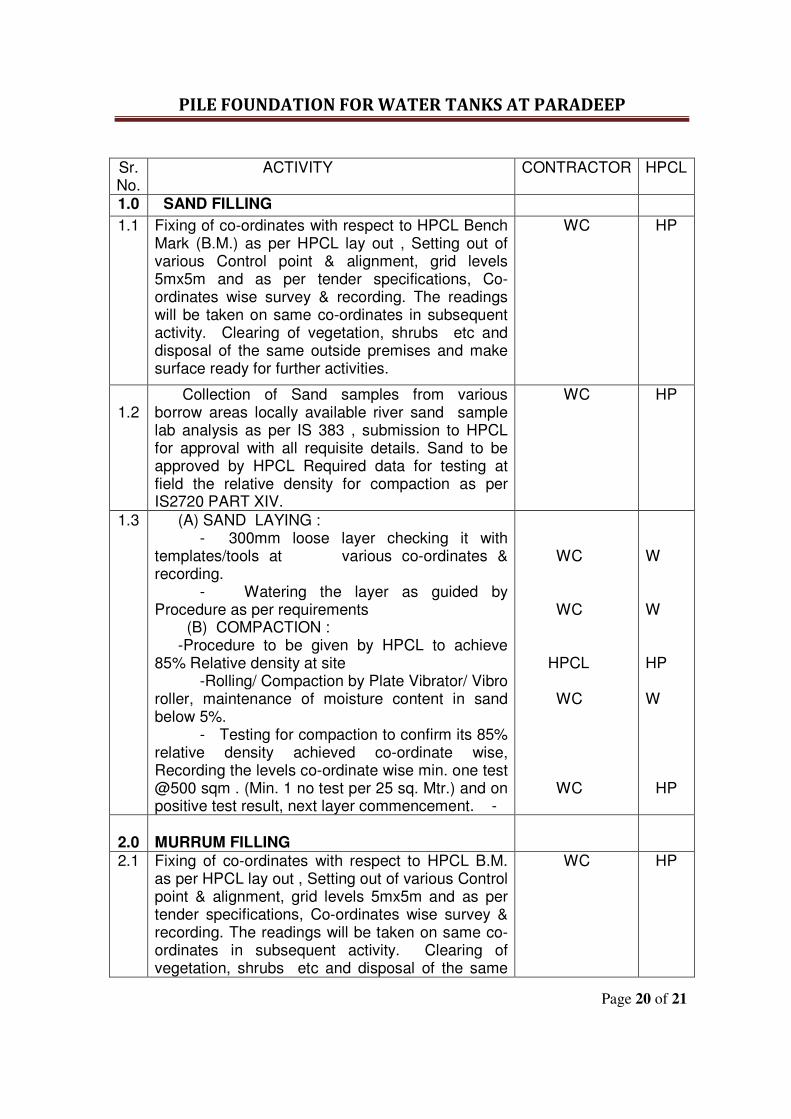
PILE FOUNDATION FOR WATER TANKS AT PARADEEP
Page 20 of 21
Sr. No.
ACTIVITY CONTRACTOR HPCL
1.0 SAND FILLING
1.1 Fixing of co-ordinates with respect to HPCL Bench Mark (B.M.) as per HPCL lay out , Setting out of various Control point & alignment, grid levels 5mx5m and as per tender specifications, Co-ordinates wise survey & recording. The readings will be taken on same co-ordinates in subsequent activity. Clearing of vegetation, shrubs etc and disposal of the same outside premises and make surface ready for further activities.
WC
HP
1.2
Collection of Sand samples from various borrow areas locally available river sand sample lab analysis as per IS 383 , submission to HPCL for approval with all requisite details. Sand to be approved by HPCL Required data for testing at field the relative density for compaction as per IS2720 PART XIV.
WC HP
1.3 (A) SAND LAYING : - 300mm loose layer checking it with templates/tools at various co-ordinates & recording. - Watering the layer as guided by Procedure as per requirements (B) COMPACTION : -Procedure to be given by HPCL to achieve 85% Relative density at site -Rolling/ Compaction by Plate Vibrator/ Vibro roller, maintenance of moisture content in sand below 5%. - Testing for compaction to confirm its 85% relative density achieved co-ordinate wise, Recording the levels co-ordinate wise min. one test @500 sqm . (Min. 1 no test per 25 sq. Mtr.) and on positive test result, next layer commencement. -
WC WC HPCL WC WC
W W HP W
HP
2.0
MURRUM FILLING
2.1 Fixing of co-ordinates with respect to HPCL B.M. as per HPCL lay out , Setting out of various Control point & alignment, grid levels 5mx5m and as per tender specifications, Co-ordinates wise survey & recording. The readings will be taken on same co-ordinates in subsequent activity. Clearing of vegetation, shrubs etc and disposal of the same
WC HP
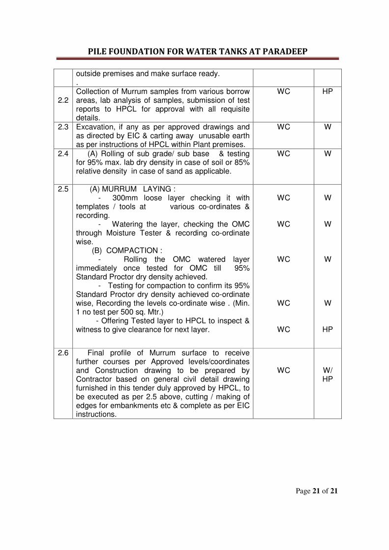
PILE FOUNDATION FOR WATER TANKS AT PARADEEP
Page 21 of 21
outside premises and make surface ready. .
2.2
Collection of Murrum samples from various borrow areas, lab analysis of samples, submission of test reports to HPCL for approval with all requisite details.
WC HP
2.3 Excavation, if any as per approved drawings and as directed by EIC & carting away unusable earth as per instructions of HPCL within Plant premises.
WC W
2.4 (A) Rolling of sub grade/ sub base & testing for 95% max. lab dry density in case of soil or 85% relative density in case of sand as applicable.
WC
W
2.5
(A) MURRUM LAYING : - 300mm loose layer checking it with templates / tools at various co-ordinates & recording. - Watering the layer, checking the OMC through Moisture Tester & recording co-ordinate wise. (B) COMPACTION : - Rolling the OMC watered layer immediately once tested for OMC till 95% Standard Proctor dry density achieved. - Testing for compaction to confirm its 95% Standard Proctor dry density achieved co-ordinate wise, Recording the levels co-ordinate wise . (Min. 1 no test per 500 sq. Mtr.) - Offering Tested layer to HPCL to inspect & witness to give clearance for next layer.
WC
WC
WC
WC
WC
W
W
W
W
HP
2.6 Final profile of Murrum surface to receive further courses per Approved levels/coordinates and Construction drawing to be prepared by Contractor based on general civil detail drawing furnished in this tender duly approved by HPCL, to be executed as per 2.5 above, cutting / making of edges for embankments etc & complete as per EIC instructions.
WC
W/ HP

PILE FOUNDATION FOR WATER TANKS AT PARADEEP
Page 1 of 47
TECHNICAL
SPECIFICATION
PILE FOUNDATION FOR WATER TANKS AT PARADEEP
Page 2 of 47
TECHNICAL SPECIFICATION
&
SCOPE OF WORK
FOR
PILING JOB
PILE FOUNDATION FOR WATER TANKS AT PARADEEP
Page 3 of 47
1.0 PURPOSE This document defines the scope of works for RCC bored cast-in- situ piles and its specific requirements including pile foundation system for the proposed Petroleum Product storage Tanks at Paradeep Terminal, Orissa. 2.0 CODES, STANDARDS & SPECIFICATION a. IS: 2911 (All Parts) b. Specification for materials for Reinforcement concrete piles c. Specification for construction and installation for bored cast in situ piles d. Specification for testing of concrete piles 3.0 SCOPE 3.1 General Providing RC bored cast in situ piles and R.C. pile caps as per design carried out by the bidder, vetted by reputed engineering institute like IIT, Kharagpur or any other reputed Engineering Institutes/ Consultant duly approved by HPCL and submitting to HPCL for review before commencement of piling work. All jobs to be completed within the specified time period mentioned in the tender. Supply of all materials is also included in contractor’s scope. The scope in general consists of designing the RCC pile foundation basis the soil investigation report/ recommendation, which shall be provided to the successful bidder. The party has to carry out the design of the pile foundation basis the soil report after the award of the contract and get the design vetted by reputed engineering institute like IIT, Kharagpur or any other reputed Engineering Institutes/ Consultant duly approved by HPCL within the quoted rates. For the purpose facilitating the bidders to provide their techno commercial offer the diameter of piles have been assumed ranging from 500 mm dia to 800 mm dia and depth of termination approximately 15 meters The quantities mentioned in the schedule of rates are approximate and actual payment shall be made basis the actual executed quantities based on the approved design. The testing of piles shall also be carried out by the contractor in line with IS 2911– (Part IV) and relevant specifications of this tender document within the quoted rates. No extra payment shall be made to the Bidders on this account. However the contractor is expected to quote for this tender based on the information provided herein and other sections of this tender document including the Schedule of Quantities. The work involves but not limited to the following:
(i) Design & Construction of Pile foundation for construction of Petroleum storage tanks ( 2 nos of 28 mt dia X 10 mt ht (5000 KL capacity) & 2 nos of 30 mt dia X 10 mt height(6700 KL capacity)
(ii) Conducting Routine Load tests on designated working piles namely Vertical, Lateral & Pullout load tests.
PILE FOUNDATION FOR WATER TANKS AT PARADEEP
Page 4 of 47
3.2 Minimum Requirement of Piling Equipment Sufficient no of hydraulic self propelled or manual rotary piling rig complete with casing Adaptor and Casing Oscillator to complete the entire job as per the time schedule provided in this tender document.. The Contractor shall mobilize sufficient spares; cutting tools (e.g. flat teeth bits, round shank bits, holders, etc) to avoid any stoppage of work.
3.3 Surveying and Staking It is the express responsibility of the contractor to bring to site all surveying instruments necessary for the marking out, fixation of levels, etc. and conduct these survey operations himself with utmost accuracy. The contractor shall put-up stable bench marks etc. as necessary for the work. HPCL will be present when this work is being carried out and will inspect all these operations with the Contractor’s assistance. The contractor shall be entirely responsible for accurate setting out of the work and he shall at his own expense make good any defects arising from errors in line and levels. 3.4. Dewatering Dewatering of accumulated water in all locations on job site from whatever source or cause untill the virtual completion of the entire work shall be done by the contractor at his own expense and shall not be separately paid for. The rates quoted by the contractor shall be deemed to be inclusive of this. 3.5 Tenderer’s shall submit the following information as part of their technical bid: i) Numbers of the piling rig proposed to be deployed. ii) Full Technical details of piling rigs and accessories in the form of catalogues, data sheets, etc. iii) Piling procedure, piling programme and accessories to be mobilized by the contractor at no extra cost to the client. 3.6 The contractor shall use only Ready mixed concrete for the proposed piling and pile caps works. Contractor shall indicate the resources available in this regards including number of batching plants to be mobilized considering the time frame and nature of works. As a specific requirement, only Portland puzzolana cement conforming to IS 1489 shall be used for all concrete works. All rebars shall be Corrosion resistant steel (Tiscon CRS/SAIL-HCR- /RINL-HSCR) and shall conform to IS 1786 grade Fe 500 for mechanical properties. 3.7 The work involves but not limited to the following: a) Construction of straight shaft RCC bored cast-in-situ piles of approved diameter and depth of termination (basis approved design carried out by the bidder based on soil investigation report to be handed over the bidder after award of work order) and approximate number of piles b) Carrying out routine load tests as specified on randomly selected job piles selected by Engineer-in-Charge and as per codal provisions.
PILE FOUNDATION FOR WATER TANKS AT PARADEEP
Page 5 of 47
4.0 AVAILABLE INFORMATION 4.1 The proposed pile top need to be terminated at 600mm above Pile cutoff level..The same will be chipped off at the time of commencement of pile cap job to progress the job further. The soil profile and design requirements shall dictate length of temporary casing pipe required for construction purposes which shall be immediately withdrawn after casting of the pile Free boring, if any will not be considered for measurement & payment. 5.0 REQUIREMENTS All work shall be carried out in accordance with the specifications enclosed herewith and contractor shall ensure minimum requirements as laid down hereunder: 5.1 Termination of Piles Piles shall be terminated with a minimum embedment of 2.40m inside the soft /disintegrated strata having SPTN Value more than 100 or as per soil investigation report or as per design requirements. After encountering the soft /disintegrated medium dense layer, the beginning of the layer shall be established by conducting SPT. In case SPT is observed more than 100, the pile shall be terminated with an embedment of minimum 2.4m inside the strata. For confirmation of the similar strata two more SPT shall be conducted thereafter with an interval of 1.0m, conducting of SPT shall be done at least one in five (1 in 5) pile location. In case medium hard or hard strata encountered before minimum embedment depth in the above specified strata the pile shall be terminated in this layer with a minimum embedment of 500mm in medium hard strata or 200mm in hard strata. Piling in soft / disintegrated strata shall be done preferably with chisel as per discretion of Engineer-in-Charge and in the case of medium hard / hard rock strata pile boring shall be proceed with chisel of weight 2.5t or more. The level of encountering the particular strata and termination depth in all cases shall be certified by Engineer-in-Charge and shall be binding on the tenderer. 5.2 Safe Load Carrying Capacity For Vertical Compression/Lateral/Uplift The tenderer shall guarantee minimum safe load of 1.5 times the design capacity for the piles provided. The safe load may be increased by 25% in the case of wind and seismic. 5.3 MATERIALS Materials shall conform to specifications for materials for Reinforcement concrete pile which is enclosed elsewhere in this tender document and forming a part of the tender. 5.3.1 CONCRETE The concrete shall have a minimum strength of 30 N/sq. mm at 28 days. The cement for concrete shall be Portland puzzolana cement having minimum cement content not to be less than 400 kg/cum and a max water cement ratio of 0.45. The cement content shall be governed by Design mix or soil characteristics, which ever is higher. The allowable slump shall be as per relevant latest revision of IS codes (IS 2911 Part 1/Sec 2). The Engineer-in-charge
PILE FOUNDATION FOR WATER TANKS AT PARADEEP
Page 6 of 47
may allow marginal adjustment in water/cement ratio to obtain concrete of good workability. The other concrete specifications shall be as per relevant clauses of “Design, Construction & Installation of Bored cast-in-situ piles forming part of this tender. 5.3.2 REINFORCEMENT Reinforcement shall conform to IS: 1786 (latest version) grade Fe-500 for mechanical properties and shall be Corrosion resistant steel and it shall be either “TISCON CRS” from TISCO or HSCR-M from Vizag Steel or HCR-M from SAIL only. The reinforcement in the pile shall consist of the following: a) Longitudinal/Ties/Spacer bar Reinforcement Reinforcement provided shall be as per approved design with respect to diameter, numbers and should run through the entire length of the pile. d) Cover Clear cover to reinforcement shall be as per approved design (min 75mm). 5.4 INSTALLATION 5.4.1 Installation of piles shall be carried out in accordance with the pile lay out drawings as prepared/vetted/approved which are prepared by the contractor at the time of execution of work. 5.4.2 Cut-off level of the piles shall correspond to those given in the working drawings. 5.4.3 To ensure dense and sound concrete upto cut-off level, concreting shall extend minimum 600 mm above cut-off level. However, no extra payment shall be made for this and quoted rates shall be inclusive of this. 5.4.4 In case the reinforcement cage is made up of more than one segment, the same shall be assembled by welding only, before lowering, as per IS: 456-2000 by providing necessary laps. 5.4.5 The vertical reinforcement shall project 50 times its diameter above the cut-off level. 5.4.6 Pile shall be constructed by using temporary casing upto minimum 1.5m to 3.0m inside the stiff to very stiff clay exists below very soft / marine clay as per site conditions or design requirements. Adequate bentonite mud shall be used as full depth temporary casing not been used during the boring below temporary casing. Concrete shall be placed by tremie. All precautions for obtaining clean and sound pile shaft shall be strictly observed. 5.4.7 For Tremie concreted piles, a sample of drilling fluid shall be taken from the base of the borehole by means of an approved sampling device in the first few piles and at suitable interval of piles thereafter. Concreting shall not proceed if density of fluid exceeds 1250 kg/cu.m. The sand content in the fluid shall not exceed 7 percent. 5.5 MEASUREMENT OF PILES 5.5.1 The piles shall be measured and paid for the actual pile length from pile tip to the cut off level, as per the approved working drawings submitted by the contractor based on the approved design or as indicated by the Engineer-in-Charge. No extra payment shall be made for empty boring, if any. 5.5.2 Payment for routine load tests which shows unsatisfactory results shall not be made.
PILE FOUNDATION FOR WATER TANKS AT PARADEEP
Page 7 of 47
5.5.3 Piles showing unsatisfactory results shall be treated as defective piles. Defective piles shall be removed or left in place and replaced by additional piles as directed by engineer-in-Charge at no additional cost to the owner. 5.5.4 Reaction piles, if required for the purpose of conducting load tests on piles shall not be paid extra. Quoted rate for tests shall be inclusive of this. However, for routine lateral and uplift tests, if required, job piles may be used as reaction piles. 5.5.5 The quoted rate for bored cast in situ piles shall be exclusive of reinforcement conforming to IS 1786 – Fe 500 corrosion resistant bars of TISCON – CRS, HSCR-M from Vizag steel or HCR-M from SAIL. However, measurement/payment for reinforcement used shall be made through a separate item available in the schedule of rates. 5.6 PILE TESTING 5.6.1 Initial Load Test : DELETED 5.6.2 Routine Load Test Routine load tests shall be carried out up to one and half times the design load. The piles for the test shall be randomly selected by the Engineer-in-Charge 5.6.3 Pile Load Test Details i) For pile load tests, the test set up shall be as per IS 2911 Part IV and specifications for testing of concrete piles. ii) All testing shall be done by Direct method of loading in successive increments as per the relevant clauses of IS: 2911 Part IV & Standard Specifications for testing concrete piles forming a part of this tender iii) Each stage of loading shall be maintained till the rate of movement is less than 0.2 mm per hour. Test shall be carried out at the cut-off level. 5.6.4 Maximum test loads shall be as follows: i) Initial pile load tests: Deleted ii) Routine vertical load test: Load corresponding to 12 mm settlement or one and half times the safe load whichever occurs earlier. 5.6.5 Number of Tests Required The number of tests required shall be as per relevant clause of IS 2911 Part IV. 5.6.6 Payment for testing of Piles No additional payment shall be made for testing of piles. The rates quoted in the schedule of rates shall deem to be inclusive of the pile testing required to be carried out under clause 5.6. NOTE: Kentledge load shall be at least 25% higher than the maximum test loads. 5.6.5 Criteria for Assessment of Safe Loads 5.6.5.1 Safe vertical load on single pile shall be the least of the following: i) Two thirds of the final load at which the total settlement attains a value of 12 mm. ii) 50% of the final load at which the total settlement equals to 10% of the piles dia. iii) Safe lateral load on single pile shall be least on the following: iv) 50% of the final load at which the total lateral displacement equals to 12 mm. v) Final load corresponding to the total displacement of 5 mm.
PILE FOUNDATION FOR WATER TANKS AT PARADEEP
Page 8 of 47
5.6.5.2 A full record of pile load test results shall be submitted in triplicate to the Engineer-in-Charge immediately on completion of each test. The record shall also include the plots of load-settlement (for various stages of loads) characteristics of pile and also the interpretation of the pile load test curve as per criteria for safe loads mentioned in the specifications for testing concrete piles forming a part of this tender. Any special observations shall be duly explained by the contractor.
5.6.5.3 Replacement of Rejected Piles Piles/boring/casing that are defective or exceed the tolerances specified above shall be left in place or pulled out as directed by Engineer In Charge without adversely affecting the performance of the adjacent piles. In case the piles/casing cannot be removed they shall be cut out as directed by Engineer In Charge. Voids resulting from rejected borings or extraction of the piles or casings shall be filled with gravel or sand unless other piles are installed in such voids at the cost of contractor . 6.0. General Pumping and bailing out of water, shoring, strutting, etc., if found necessary for successful and speedy operation of work shall be carried out by the contractor and cost of such works shall be included in his rates. No extra claims whatsoever on all subsidiary works pertaining to pilling work will be entertained. All the excavated materials including debris, Loose earth, muck etc shall be carted away and disposed off by the contractor out of the premises to any suitable place as per local statutory authorities. The Contractor shall provide all the equipments, tools and plants required for the work and rates shall include the cost of bringing the equipment etc, to site, proper maintenance and removal of the same after completion of work. Control of Piling Installation shall be as per the relevant IS Code (IS 2911 (part 1 section2). Piles that are defective shall be left in places as judged by Engineer In Charge and additional piles shall be driven to replace them at no extra cost. Adequate length of bars to be left over the cut-off level of the pile to develop anchorage in the pile caps and also dowels to be kept of adequate lengths. Sample of the hard strata shall be taken appropriately marked and preserved by the contractor and finally handed over to HPCL. The level on the container should specify the date of piling, pile marked and depth of strata from which the sample has been obtained.
PILE FOUNDATION FOR WATER TANKS AT PARADEEP
Page 9 of 47
Rig register and weekly report as per the format, approved by HPCL shall be submitted to In-charge of the project. During the period of establishing mix- design at site, nominal mix 1:1:2 for piling work only can be followed but the cement consumption for entire volume of piling work under reference will be reconciled based on approved design mix. For the purpose of measurements and payments, the length of pile shall be measured from the tip of the pile to the bottom of the pile cap. The 8 cm. length of the pile projecting into the cap shall not be measured for the payment and also shall not be deducted from the quantity of Pile cap concrete. Reinforcement placed in the pile shall be paid for separately for the actual quantity of reinforcement placed in the pile exclusive of couplings, welded joints, spacer bars and binding wire as stipulated in the relevant specifications for reinforcements. All piles shall be concreted to a level 600 mm above the specified pile cut off elevation which shall be 7.5 cm. above the bottom of the Pile cap. For piles cast by tremie method, in bentonite established bore holes, this level of concreting above pile cut of level shall not less than 600mm. Before casting the pile cap, this excess concrete shall be cut off up to pile cut off elevation. In case sound concrete is not met with at such elevation the piles shall be cut to such elevation where sound concrete is met. Piles shall be cut off at level and true to elevation shown or specified on the Drawings. Care shall be taken not to damage the reinforcement or the concrete below cut off elevation during such stripping operations. Where stripping to be done to a level lower than the specified cut off elevation to obtain dense and sound concrete, the Piling Contractor shall built up the pile up to cut off elevation at his own cost. Upon completion of the piling work, all casing equipments, construction tools, protective covering and debris resulting from the piling operations shall be removed from the works site with the permission of the HPCL. A minimum length of 2-3 metres of temporary casing shall be provided for each bored piles unless otherwise specifically desired. Additional length of temporary casing shall be used depending on the condition of the strata, ground water level etc. 7.0 Recording of Data
Daily site records shall be maintained by the Contractor for the installation of piles against each Rig and shall contain the number and dimension of the pile, depth bored ( including depth in soft / hard rock ), time taken for boring, concreting and empty boring ( cut-off level) , chiselling and where the pile is wet or dry.
PILE FOUNDATION FOR WATER TANKS AT PARADEEP
Page 10 of 47
Sample bore log in the initial stage or when major variation occur should be shown. When drilling mud is used, amount of bentonite needed for stabilization of bore, specific gravity of the fresh supply and contaminated mud in the bore hole before concreting shall be checked and recorded regularly. Concrete volume actually cast per pile against required volume and actual cement consumption. Detail of any obstruction encountered, its nature, depth and obstruction time. Any deviation from the designated location alignment or load capacity of any pile shall be noted. Typical data sheet in triplicate for facility of recording piling data to be prepared by the Contractor before starting of actual piling operation at site and information to be recorded against each pile in the data sheet shall be signed by the contractor and countersigned by HPCL. One copy of the data sheet shall be retained by the Contractor and the other two copies to be submitted to HPCL for records & future reference. At least six photographs are to be taken by the party depicting progress of the job in every week and a set of same to be separately submitted for review and record to HPCL.

PILE FOUNDATION FOR WATER TANKS AT PARADEEP
Page 11 of 47
STANDARD SPECIFICATION
FOR MATERIALS FOR
REINFORCED CONCRETE
PILES
PILE FOUNDATION FOR WATER TANKS AT PARADEEP
Page 12 of 47
CONTENTS
1. GENERAL
2. MATERIALS FOR CONCRETE
3. ADMIXTURES
4. REINFORCEMENT
PILE FOUNDATION FOR WATER TANKS AT PARADEEP
Page 13 of 47
1.0 GENERAL 1.1 Scope 1.1.1 This specification establishes the material specification of reinforced cement concrete to be used in pile foundation. Any special requirements as shown or noted on the drawings shall govern over the provisions of these specifications. 1.1.2 For specific work requirements concerning design and construction or otherwise modifying or supplementing the provision of this specification, refer to the specific requirements. In case of conflict between specific requirements and provision of this specification, former shall govern. 1.2 Definitions 1.2.1 Reference to Indian Standard Codes shall always mean reference to the latest issue of the relevant standards including all its amendments up to date. 1.3 Codes All design and construction shall be performed in accordance with the Indian Standard Code of Practice for Plain and Reinforced Concrete I S: 456 & IS: 2911 2.0 MATERIALS FOR CONCRETE All materials which may be used in the Plain or Reinforced Cement Concrete work shall be of Standard quality conforming to IS or equivalent and shall have IS certification mark as far as possible unless otherwise approved by the Engineer-in-Charge. The contractor shall get all materials approved by Engineer-in-Charge prior to its procurement and before actual use. The Engineer-in-Charge shall have the right to determine whether all or any of the materials offered or delivered for use in the works are acceptable. Any material brought to site and not conforming to specification and instruction of Engineer-in-Charge shall be rejected and the contractor shall have to remove the same immediately from site at his own expense. 2.1 Cement 2.1.1 General The cement used shall be Portland puzzolona cement conforming to IS: 1489 latest version and the make of the same shall be approved by HPCL. 2.1.2 Tests after Delivery Each consignment of cement may, after delivery on the site at the discretion of the Engineer-in-Charge, be subjected to any or all of tests and analysis required by the relevant Indian Standard Specifications. Facilities for testing shall be provided by contractor at his own cost. 2.1.3 Storage on the Site The cement shall be stored in a suitable weather-tight building and in such a manner as to permit easy access for proper inspection to prevent deterioration due to moisture and to minimize warehouse deterioration. Cement of different type and brands shall be kept in
PILE FOUNDATION FOR WATER TANKS AT PARADEEP
Page 14 of 47
separate storage. All accepted cement stored on the site shall be arranged in batches, and used in the same order as received from the manufacturer. The contractor shall maintain a cement register, in which all entries shall be completed day to day showing the quantities received, date of receipt, source of dispatch, type of cement, etc. and also the daily cement consumption on site. The register shall be accessible to the Engineer-in- Charge for his verification. 2.1.4 Rejection of Cement The Engineer-in-Charge may reject any cement as a result of any tests thereof, notwithstanding the manufacturer’s certificate. He may also reject cement which has deteriorated owing to inadequate protection from moisture or due to intrusion of foreign matter or other causes. Any cement which is considered defective by the Engineer-in-Charge shall not be promptly removed from the site of the work by the contractor at his own expense. 2.2 Aggregates for Concrete 2.2.1 General Coarse and fine aggregates for concrete shall conform in all respect to IS: 383, “Specification for Coarse and Fine Aggregates from Natural Sources for Concrete”. Aggregates shall be obtained from a source known to produce those satisfactory for concrete. Aggregates shall consist of naturally occurring sand and granite/basalt trap stone, crushed or uncrushed, or a combination thereof. They shall be chemically inert, hard, strong, dense, durable, clean and free from veins, adherent coatings and shall be of limited porosity. Flaky and elongated pieces shall not be used. The source of aggregates shall be approved by the Engineer-in-Charge and shall not be changed during the course of the job without his approval. Rejected aggregates shall be removed from the work site by the contractor at his own expense. 2.2.2 Deleterious Materials Aggregates shall not contain any harmful materials such as iron pyrites, coal, mica, shale or similar laminated materials, clay, alkali, soft fragments, sea shells, organic impurities etc. in such quantities as to affect the strength or durability of the concrete. In addition to the above, for reinforced concrete, any material which might cause corrosion of the reinforcement and aggregates which are chemically reactive with the alkalis of cement shall not be used. The maximum quantities of deleterious materials in the aggregates, as determined in accordance with IS: 2386 (Part-II) “Methods of Test for Aggregates for Concrete”, shall not exceed the limits given in Table-I of IS: 383. The sum of the percentages of all deleterious materials shall not exceed five. Deleterious materials also include material passing 75 micron IS sieve. 2.2.3 Coarse Aggregates Coarse aggregate is aggregate most of which is retained on 4.75 mm IS sieve. These may be obtained from crushed or uncrushed granite/basalt trap stone as per Cl. 2.3.1 and may be supplied as single sized or graded aggregates given in Table-II of IS: 383. The Engineer-in-Charge may allow all-in-Aggregate to be used provided they satisfy the requirements of clause 4.4 and T able-IV of IS 383.
PILE FOUNDATION FOR WATER TANKS AT PARADEEP
Page 15 of 47
2.2.4 Fine Aggregates Fine aggregate is aggregate most of which passes 4.75 mm IS Sieve but not more than 10% pass through 150 microns IS Sieve. These shall comply with the requirements of grading zones I, II and III and given in Table-III of IS: 383. Fine aggregate conforming to grading zone IV shall not be normally used in reinforced concrete unless tests have been made by the contractor to ascertain the suitability of the proposed mix proportion and approved by the Engineer-in-Charge. Fine aggregate shall consist of natural sand resulting from natural disintegration of rock and which has been deposited by streams or glacial agencies, or crushed stone sand or crushed gravel sand. 2.2.5 Sampling and Testing In case of doubt the Engineer-in-Charge may require the contractor to carry out tests, at the contractor’s expense in accordance with – IS: 516 – Method of Tests for Strengths of Concrete; and IS: 2386- Method of Tests for Aggregates for Concrete. 2.2.6 Storage of Aggregates T he contractor shall at all times maintain at the site of work such quantities of aggregate as are considered by the Engineer-in-Charge to be sufficient to ensure continuity of work. Each type and grade of aggregate shall be stored separately on hard firm ground having sufficient slope to provide adequate drainage to rain water. Any aggregate delivered to site in a wet condition or becoming wet at site due to rain shall be kept in storage for at least 24 hrs. to obtain adequate drainage, before it is used for concreting, or the water content of mix must be suitably adjusted as directed by Engineer-in-Charge. 2.3 Water Water used for concrete shall be clear and free from injurious amounts of Oil, Acid Alkali, Organic matters or other harmful substances in such amount that may impair the strength or durability of structure. Potable water shall generally be considered satisfactory for mixing and curing concrete. The Engineer-in-Charge may require the contractor to prove at latter’s expense, that the concrete mixed with water proposed to be used should not have a compressive strength, lower than 90% of the strength of concrete mixed with distilled water. The Engineer-in-Charge may require the contractor to get the water tested from an approved laboratory at his own expenses and in case the water contains any sugar or an excess of acid, alkali, any injurious salts, etc. the Engineer-in-Charge may refuse to permit its use. 3.0 Admixtures 3.1 Admixtures such as CICO grade I or KIM (KRYTON make) or equivalent may be used in concrete only with the approval of Engineer-in-Charge. 4.0 Reinforcement 4.1 Corrosion resistant Steel reinforcement 4.1.1 The reinforcement shall confirm to IS: 1786, Fe-500 grade. The reinforcement shall be Corrosion resistant steel and it shall be either “TISCON CRS” from TISCO or HSCR-M from Vizag Steel or HCR from SAIL-M normally be mild steel in the form of round bars, conforming to IS: 432-Grade 1 unless specified otherwise.
PILE FOUNDATION FOR WATER TANKS AT PARADEEP
Page 16 of 47
4.1.2 Hard-Drawn Steel wire Fabric When specified in the drawings, hard drawn steel wire fabric shall be used conforming to IS: 1566, It shall be of approved type and of the weights and dimensions shown in the drawings. 4.2 Welding 4.2.1 Field welding of reinforcing bars will not be permitted without the written consent of the Engineer-in-Charge. Where welding is permitted it must be at staggered locations. Tests shall be made to provide that the joints are of the full strength of bars connected. Welding of reinforcement shall be done in accordance with the recommendation of IS: 2751. 4.3 Storage 4.3.1. The steel reinforcement shall be stored in such a way as to avoid distortion and to prevent deterioration and corrosion. 4.4 Other Specifications 4.4.1 General construction details and workmanship relative to reinforcement including bar bonds, lap splices and installation shall be in accordance with I S:2502- Code of Practice for Bonding and Fixing of Bars for concrete reinforcement, as well as the detailing of reinforcement given in I S:456. 4.4.2 Hot bending of bars shall not be allowed. 4.4.3 The number of sizes, shape and position of all the reinforcement shall, unless otherwise directed or authorized by the Engineer-in-Charge, be strictly in accordance with the drawings. The reinforcement shall be adequately secured and held in position by metal chairs and spacers. Ties of inter-sections shall be made with 16 SWG soft black annealed binding wire. 4.4.4 The contractor must obtain the approval of the Engineer-in-Charge for the reinforcement placed, before any concrete is placed in the forms. The reinforcement of this time shall be free from loose rust or scale or other coating that will destroy or reduce bond. 4.7.5 Concrete spacer blocks of the same strength as parent concrete shall be used to ensure correct cover to the reinforcement. This clear cover shall be as shown on the drawings or as per instructions of the Engineer-in-Charge. 4.7.6 All the reinforcing bars shall be so tied as to form a rigid cage to prevent displacement before or during concreting.

PILE FOUNDATION FOR WATER TANKS AT PARADEEP
Page 17 of 47
STANDARD SPECIFICATION
FOR
CONSTRUCTION AND
INSTALLATION OF
RCC BORED
CAST-IN-SITU PILES
PILE FOUNDATION FOR WATER TANKS AT PARADEEP
Page 18 of 47
CONTENTS 1. SCOPE 2. CODES 3. MATERIALS 4. DESIGN CONSIDERATIONS 5. EQUIPMENTS AND ACCESSORIES 6. PILE INSTALLATION 7. DEFECTIVE PILES 8. RECORDING OF DATA
PILE FOUNDATION FOR WATER TANKS AT PARADEEP
Page 19 of 47
1.0 SCOPE 1.1 This standard specification covers the construction and installation of load bearing reinforced concrete bored cast-in-situ piles. 1.2 For specific work requirements concerning construction or otherwise modifying or supplementing the provisions of this specification, reference may be made to ‘Specific Requirements’. In case of any conflict between requirements set forth in ‘Specific Requirement’ and the provisions of this specification, the ‘Specific Requirements’ shall govern. 2 CODES 2.1 IS: 2911 (Part I /Sec.2) – Indian Standard Code of Practice for Design and Construction of pile foundations for Bored Cast-in-Situ Piles shall be referred to in conjunction with these specifications during the entire design, construction and installation work. 2.2 Reference to any code shall always mean reference to the latest revised edition of the code including all its amendments up to date, unless otherwise specified. In the event of any conflict between the requirements of this specification and those of the referred codes, the former shall govern. 3 MATERIALS 3.1 All materials, viz. cement, steel, aggregates, water, etc. which are to be used in the construction work, shall conform to Standard Specification for construction and installation of RCC bored cast-in-situ piles. 3.2 Concrete 3.2.1 Methods of the manufacture of cement concrete shall in general, be in accordance with IS: 2911 (Part I /Sec.2) and as per following clauses: 3.2.2 The grade of concrete shall be M-30 with a minimum cement content of 400 kg/cum and a max water cement ratio of 0.45. The cement content shall be governed by Design mix or soil characteristics, which ever is higher. 3.2.3 Slump of Concrete Slump of concrete shall range between 100 to 180 mm depending on the manner of concreting. The table below gives the general guidance. PILI NG SLUMP (In MM) TYPICAL CONDITIONS OF USE Min. Max. A 100 180 Pouring into water-free unlined bore having widely
spaced reinforcement. Where reinforcement is not spaced widely enough, cut-off level of pile is within the casting and diameter of pile less than or equal to
PILE FOUNDATION FOR WATER TANKS AT PARADEEP
Page 20 of 47
600mm, higher order of slump within this range may be used.
B 150 180 Where concrete is to be placed under water or
drilling mud by tremie or by placer 4 DESIGN CONSIDERATIONS 4.1 Structural Design: The piles shall have necessary structural strength to transmit the load imposed on it, to soil. Relevant part of IS: 2911 (Part I/ Sec.2) and specific requirements shall be considered to apply for assessing the structural capacity of piles. 4.2 Reinforcement 4.2.1 The minimum longitudinal reinforcement shall be 0.4% of the cross sectional area of the pile. 4.2.2 Clear cover to the main reinforcement shall be 50 mm. This shall be increased to 75 mm in case of aggressive soils and ground water conditions. 4.2.3 The vertical reinforcement shall project 50 times its diameter above the cut-off level. 4.2.4 The minimum clear distance between the two adjacent main reinforcement bars should normally be 100 mm for the full depth of cage. The bars shall be so placed as not to impede the placing of concrete. 4.2.5 The lateral ties in the reinforcing cage shall be preferably spaced not closer than 150 mm centre to centre. 4.2.6 The minimum diameter of the lateral ties shall be 6 mm. 5 EQUIPMENT AND ACCESSORIES 5.1 The equipment and accessories for installation of bored case-in-situ piles shall be selected giving due consideration to the subsoil conditions and the method of installation, etc. These shall of standard type and shall have the approval of the Engineer-in-Charge. 5.2 The capacity of the rig shall be adequate so as to reach the desired depth. 5.3 Provision shall be kept for chiseling within the borehole in case of any underground obstruction/hard strata. However, chiseling shall be carried out only with the approval of Engineer-in-Charge. 5.4 In case pile is required to be socketted in medium or good quality rock strata, the equipment mobilized shall have adequate capability to do so up to the required socket length. For the purpose of classification of rock for the determination of length of socketting, pilot drill holes shall be carried out in the areas to be piled.
PILE FOUNDATION FOR WATER TANKS AT PARADEEP
Page 21 of 47
5.5 Pilot drill hole shall be of Nx or Bx size as per specific requirements. Rock drilling shall be carried out using double tube core barrel. Drilling and storing of rock cores shall conform to relevant IS codes. Rock quality shall be classified as under depending upon the RQD. RQD (%) ROCK QUALITY <25 Poor 25 to 75 Medium >75 Good 6 PILING INSTALLATION 6.1 Control of Alignment 6.1.1 The piles shall be installed as accurately as possible as per the designs and drawings. The permissible positional deviations shall be governed by IS: 2911 (Part I /Sec.2). In case of piles deviating beyond such permissible limits, the piles shall be replaced or supplemented by additional piles, as directed by Engineer-in-Charge. 6.2 Boring 6.2.1 The boring shall be done by one of the following methods: (a) Direct mud circulation (b) Reverse mud circulation (c) Bailer bentonite The actual method of construction to be followed shall be as per specific requirements. 6.2.2 In very soft soil a permanent liner shall be installed to ensure stability of borehole. A liner shall be used to protect the green concrete where a high hydrostatic pressure exists in the subsoil or where an underground flow of water exists and which is likely to damage the concrete on withdrawal of casing. 6.2.3 Use of temporary liner only in lieu of bentonite to stabilize sides of boreholes shall not be permitted. 6.2.4 Properties of bentonite used and quality control shall be as per IS: 2911 (Part I /Sec.2). 6.3 Concreting of Piles 6.3.1 Reinforcement 6.3.1.1 The reinforcements shall be made into cages sufficiently rigid to withstand handling without damage. In case the reinforcement cage is made up more than one segment, the same shall be assembled by providing necessary laps preferably by welding. 6.3.1.2 Stirrups to the main bars shall be tack welded. 6.3.1.3 Care shall be taken to ensure that the reinforcement bars do not come closer while the cage is lowered down the hole.
PILE FOUNDATION FOR WATER TANKS AT PARADEEP
Page 22 of 47
6.3.1.4 Proper cover and central placement of the reinforcement shall be ensured by use of suitable concrete spacers or rollers, case specifically for the purpose. 6.3.2 Concreting 6.3.2.1 Concreting shall not be commenced until the Engineer-in-Charge satisfies himself that at final borehole depth the soil is not weaker than that taken as the basis for pile design. If necessary, SPT or similar test shall be conducted to ensure the above. 6.3.2.2 Borehole bottom shall be thoroughly cleaned to make it free from sludge or any foreign matter before lowering the reinforcement cage. The full length of reinforcement cage shall be in position before start of concreting. 6.3.2.3 Concreting shall be done by tremie method. The operation of tremie concreting shall be governed by IS: 2911 (Part I / Sec.2). 6.3.2.4 The concrete placing shall not proceed if specific gravity of fluid near about the bottom of borehole exceeds 1.2. Determination of the specific gravity of the drilling mud from the base of the borehole shall be carried out by taking samples of fluid by suitable slurry sampler approved by the Engineer-in-Charge, in first few piles and at a suitable interval of piles thereafter and the results recorded. Control of consistency of drilling mud shall be carried out throughout boring as well as concreting operations. 6.3.2.5 Care shall be exercised to preserve correct cover and alignment of reinforcement and avoid any damage to it throughout the complete operation of placing the concrete. 6.3.2.6 The top of the pile shall be brought up above the cut off level minimum by 0.75 m so as to permit removal of all laitance and weak concrete before capping and to ensure good and sound concrete at the cut off level for proper embedment into the pile cap. Any defective concrete in the head of the completed piles shall be cut-away and made good with new concrete. 7 DEFECTIVE PILES 7.1 Defective piles shall be removed or left in place, as judged convenient by the Engineer-in-Charge, without affecting the performance of adjacent piles of capping above and additional piles shall be provided to replace them. 8 RECORDING OF DATA 8.1 A competent supervisor shall be present to record the necessary information during the installation of piles. The data to be recorded shall include: a) The dimensions of the piles, including the reinforcement detail and the mark of the pile. b) The boring method employed. c) The type of soil in which pile is terminated. d) The depth bored.
PILE FOUNDATION FOR WATER TANKS AT PARADEEP
Page 23 of 47
e) The depth of water table. f) When drilling mud is used, the specific gravity of the fresh supply and contaminated mud in the borehole before concreting is taken up, in case of first few piles and subsequently at suitable interval of piles. g) The time taken for concreting. h) The cut-off level/working level, and i) The consumption of cement. j) Any other important observations. 8.2 Typical data sheets of recording piling data shall be as given in Appendix-D of IS: 2911 (Part I/ Sec.2). 8.3 Any deviation from the designed location, alignment or load carrying capacity of any pile shall be noted and promptly reported to the Engineer-in-Charge.

PILE FOUNDATION FOR WATER TANKS AT PARADEEP
Page 24 of 47
STANDARD
SPECIFICATION
FOR
TESTING OF
CONCRETE PILES
PILE FOUNDATION FOR WATER TANKS AT PARADEEP
Page 25 of 47
CONTENTS
1. GENERAL 2. VERTICAL LOADING TEST 3. LATERAL LOADING TEST 4. PULL OUT CAPACITY OF PILES 5. COMBINED VERTICAL AND LATERAL LOADING TEST 6. SPECIAL TYPE OF LOADING
APPENDIX 1 – PILE LOAD TEST RECORD
PILE FOUNDATION FOR WATER TANKS AT PARADEEP
Page 26 of 47
1.0 GENERAL 1.1 Scope 1.1.1 This Specification covers the requirement and methods of testing of a single pile for evaluating its safe capacity in: a) Vertical Loading (Compression) b) Lateral Loading c) Pull Out d) Combined Vertical and Lateral Loading e) Special type of loading such as vibratory loadings 1.1.2 These specifications shall be applicable for all types of piles in general excepting sheet piles. 1.1.3 For specific work requirements or otherwise modifying or supplementing the provision of this specification, refer to specific requirement. In case of conflict between requirements set forth in the specific requirements and the provisions of this specification, the specific requirements shall govern. 1.2 Definitions 1.2.1 Reference to Indian Standard Codes shall always mean reference to the latest issue of the relevant standards, including all the amendments up to date. 1.3 Codes 1.3.1 All testing shall be performed in accordance with the following codes and the provision of these specifications IS: 2911-(Part IV) – Code of Practice for design and construction of pile foundations – Load Test on Piles. 1.4 Requirements 1.4.1 The load test shall be required to provide data regarding the load deformation characteristics of the pile up to failure or otherwise specified and the safe design capacity. 1.4.2 Full details of the equipment proposed to be used and the test set up shall be submitted to the Engineer-in-Charge with detailed sketches for approval. Approval of the Engineer-in-Charge shall also be obtained after the test set up is complete, prior to commencement of loading. 1.4.3 All measuring devices shall be tested for satisfactory performance and accuracy at an approved institution and a certificate to that effect obtained and submitted to the Engineer-in-Charge prior to use. 1.4.4 The test pile shall be constructed using same equipment and technique as for the job piles.
PILE FOUNDATION FOR WATER TANKS AT PARADEEP
Page 27 of 47
1.4.5 A minimum time period of one week shall be allowed between the time of installation and testing in case of a precast pile and not less than four weeks from the time of casting in case of a cast-in-situ pile. 1.4.6 Records A full record giving all details of the test in the proforma shown in Appendix-I shall be submitted in triplicate to the Engineer-in-Charge immediately on completion of each test. The record shall also include the plot of load time settlement characteristics of piles. 2.0 VERTICAL LOADING TESTS 2.1 Equipment and Test Set -up 2.1.1 Test Pile 2.1.1.1 The test pile shall be decided by the Engineer-in-Charge. It may be one of the working piles or a separate test pile. 2.1.1.2 The head of the test pile shall be brought to the proper level and provided with a pile cap with a level and plane surface and with adequate space for proper seating of a jack and dial gauges. 2.1.1.3 Test pile surface shall be prepared for testing purposes on the expiry of one week after casting the pile. 2.1.2 Loading Systems 2.1.2.1 Loading shall be applied by the reaction method consisting of an hydraulic jack centrally against a loaded platform. Supports of the platforms shall be adequately designed. Special anchor piles or any other suitable type of anchorage systems may be used. However, use of the uplift capacity of neighboring piles for providing the reaction shall normally not be permitted. 2.1.2.2 The loading system shall be adequate to ensure that the test can be carried up to the specified limit. The reaction to be made available for the test shall be at least 25% greater than the maximum jacking force required. 2.1.3 Measuring System 2.1.3.1 Loading on Piles The load applied on the pile shall be recorded on a calibrated pressure gauge mounted on the jack. 2.1.3.2 Settlement of Pile a) Settlement of the pile shall be recorded by dial gauges suspended from datum bars. Four dial gauges of 0.01 mm sensitivity shall be positioned on four corners around the pile. b) The datum bars shall have rigid supports preferably of concrete pillars or steel sections, embedded well into the ground. The supports shall be located more than three times the pile
PILE FOUNDATION FOR WATER TANKS AT PARADEEP
Page 28 of 47
diameter, subject to a minimum of 1.5 m, clear away from the pile face and also sufficiently away from the supports of the loaded platform to avoid any disturbance on these accounts. Movements near the supports of the datum bar shall be avoided while the test is in progress. 2.2 Method of Conducting Test The test shall be carried out by the direct method of loading in successive increments or by the cyclic loading method as specified and as described by the Engineer-in-Charge. 2.2.1 Direct Method of Loading in Successive Increments The test shall be carried out as per the procedure outlined. a) The load shall be applied to the pile top in increments of about of fifth of the rated capacity of the pile or as specified. Settlement readings shall be taken before and after the application of each new load increment and at 2, 4, 8, 15, 30, 60 minutes and at every two hours until application of the next load increment. b) Each stage of loading shall be maintained till the rate of movement of the pile top is not more than 0.2 mm per hour or until two hours have elapsed, whichever is later. c) Further loading shall then be continued as in (a) above till one of the following occurs:
i) Yield of soil-pile system occur causing progressive settlement of the pile exceeding a value of one tenth of the pile diameter. ii) The loading on the pile top equals twice the rated capacity or as specified in the case of a separate test pile and 1.5 times the rated capacity of the pile in case of a working pile.
d) Where yielding of the soil does not occur, the full test load shall be maintained on the pile head for 24 hours or more if necessary and settlement readings shall be taken at 6 hours interval during the period. e) Unloading shall be carried out in the same steps as loading. A minimum of half hour shall be allowed to elapse between two successive stages of load decrement. The final rebound shall be recorded 6 hours after the entire test load has been removed. f) If so directed by the Engineer-in-Charge, loading and unloading cycles shall be carried out for all load stages within the assumed working load. g) Assessment of Safe Load The safe capacity of the pile shall be the least of the following values
i) Load corresponding to settlement specified in specific requirements which is based on the nature and type of structure. ii) 50 percent of the final load at which the total displacement equals 10 percent of the pile diameter in case of uniform diameter piles and 7.5 percent of bulb diameter in case of under-reamed piles.
2.2.2 Cyclic Loading Test The test shall be carried out as per procedure outlined by IS: 2911-(Part-IV) and as described below: a) The load shall be applied to the pile top in increments of about one fifth the estimated safe capacity of the pile or as specified. Settlement readings shall be taken before and after the application of each new load increment at 2, 4, 8, 15, 30, 60 minutes and at every two hours until application of the next load increment.
PILE FOUNDATION FOR WATER TANKS AT PARADEEP
Page 29 of 47
b) Alternate loading and unloading shall be carried out at each stage and the total and net settlements recorded as specified. If so directed by the Engineer-in-Charge, more than one cycle of loading and unloading shall be carried out at any or all of the stages. c) Each stage of loading or unloading shall be maintained till the rate of movement of the pile top is not more than 0.2 mm per hour provided that the minimum period if two hours for loading and one hour for unloading. T he following load stages shall however be maintained for longer periods as given below:
i) At load of 1.5 time assumed safe capacity (for routine test only) – 24 hours. ii) At load of twice assumed safe capacity (for initial test only) – 24 hrs.
The loading shall be continued till one of the following occurs: i) Yield of the soil pile system occur causing progressive settlement exceeding one tenth of the pile diameter. ii) The loading on the pile top equals twice the estimated safe load in case of a separate test pile and 1.5 times the rated capacity of the pile in case of a working pile.
d) Assessment of Safe Load The safe capacity of the pile shall be the least of the following:
i) Load corresponding to settlement specified in specific requirements which is based on the nature and type of structure. ii) Half of the final load at which the total settlement equals one tenth of the pile diameter.
3.0 LATERAL LOADING TEST 3.1 Equipment and Test Set -up 3.1.1 Test Pile The test pile shall be decided by the Engineer-in-Charge. It may be one of the working piles or a separate test pile. The test pile shall be cut off at the proper level and provided with a cap with vertical plane sides having an adequate area for proper seating of the jack and dial gauges. 3.1.2 Loading System, 3.1.2.1 Loading shall be applied by an hydraulic jack of adequate capacity, abutting the pile horizontally and reacting against the suitable system. The reaction may be provided by the wall of the excavated pit when the test is being conducted below ground level or by a neighbouring pile in which case thrust pieces shall be inserted on either end of the jack to make up the gap. 3.1.3 Measuring System 3.1.3.1 Lateral load applied on the pile shall be measured by a calibrated pressure gauge mounted on the jack, having a least count of 500 kg. 3.1.3.2 Deflection of the pile head shall be measured by dial gauges, fixed to datum bars and having a least count of 0.01 mm. The datum bars shall be provided with rigid supports as described in Clause 2.1.3.2 (b) above. 3.2 Method of Conducting Tests The test shall be carried out in accordance with the provisions of I S: 2911-(Part-IV) and as detailed below: 3.2.1 Loading shall be applied in increments of 500 kgs or as specified.
PILE FOUNDATION FOR WATER TANKS AT PARADEEP
Page 30 of 47
3.2.2 Each stage shall be maintained for a period till the rate of movement of the pile head is not more 0.2 mm/hr or 1 hr whichever is greater. 3.2.3 Loading shall be continued till one of the following occurs: a) Deflection of the pile head exceeds 12 mm. b) T he applied load on the pile is twice the assumed lateral load capacity of the pile in case of a separate test pile and 1.5 times the rated capacity in the case of a working pile. 3.2.4 Assessment of Safe Load The safe load shall be the smaller of the following:
i) Half of the final load for which the total deflection is 12 mm. ii) Load corresponding to 5 mm total deflection.
Note: The deflection is at the cut off level of the pile. 4.0 PULLOUT CAPACITY OF PILES 4.1 Equipment and Test Set up 4.1.1 Test Pile 4.1.1.1 The test pile shall be decided by the Engineer-in-Charge. The test shall be conducted on separate pile installed specifically for this purpose. 4.1.1.2 The test pile shall be built up to the proper length and the head provided with suitable arrangements for anchoring the load applying system. 4.1.2 Loading System 4.1.2.1 Load shall be applied using an approved reaction system. Uplift force on the pile may be applied directly to the test pile or through a level system. T he reaction may be provided by neighboring piles or blocks may be constructed for the purpose. A hydraulic jack shall be used for load application. 4.1.3 Measuring System 4.1.3.1 Load applied by jack shall be measured by a calibrated pressure gauge with a least count of 1000 kgs. 4.1.3.2 Movement of the pile shall be measured by dial gauges, fixed to datum bar and having a least count of 0.01 mm. A minimum of two dial gauges, placed diametrically opposite shall be used. Datum bars shall be provided with rigid supports as described in 2.1.3.2 (b) above. 4.2 Method of Conducting Test T he test shall be conducted as outlined below: 4.2.1 Loading shall be applied to the pile top in increments of one fifth the rated capacity of pile. 4.2.2 Each stage shall be maintained for a period till the rate of movement of the pile head is not more than 0.2 mm/hr or one hour, whichever is greater.
PILE FOUNDATION FOR WATER TANKS AT PARADEEP
Page 31 of 47
4.2.3 Loading shall be continued till one of the following occurs: a) Yield of soil pile system occurs causing progressive movement of he pile exceeding 12 mm. b) T he loading on the pile top equals twice the estimated safe load or as specified. 4.3 Assessment of Safe Load The safe capacity of the pile shall be the least of the following: a) Two-thirds of load at which the total displacement is 12 mm or the load corresponding to a specified permissible uplift, and b) Half of the load at which the load displacement curve shows a clear break (downward trend). 5.0 COMBINED VERTICAL AND LATERAL LOADING 5.1 Equipment and Test set -up 5.1.1 The equipment and test set up shall be same as described in Clause 3. In addition, a platform shall be constructed on the pile top, and loaded to 1.0 times the pile capacity in vertical loading. The pile shall be first subjected to the full vertical load. The lateral load shall commence after all settlements due to the vertical load have ceased and while the full vertical load is in position. 5.1.2 The loading system, measuring system and recording of the results shall be the same as described in clause-3. 5.2 Method of Conducting Test and Assessment of Safe Load This shall be in accordance with the provision of clause 3.2 above. 6.0 SPECIAL TYPE OF LOADING This shall include evaluating the pile response to vibratory loads, both horizontal and vertical in nature. The test set up and method of conducting the test shall be covered under specific requirements.
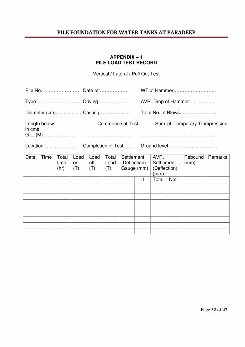
PILE FOUNDATION FOR WATER TANKS AT PARADEEP
Page 32 of 47
APPENDIX – 1
PILE LOAD TEST RECORD
Vertical / Lateral / Pull Out Test
Pile No…………………… Date of ……………… WT of Hammer …………………….. Type……………………… Driving……………….. AVR. Drop of Hammer……………. Diameter (cm)……………. Casting……………….. Total No. of Blows………………….. Length below Commence of Test Sum of Temporary Compression in cms G.L. (M)………………… ………………………… ………………………………………. Location………………… Completion of Test…… Ground level …………………………
Date Time Total time (hr)
Load on (T)
Load off (T)
Total Load (T)
Settlement (Deflection) Gauge (mm)
AVR. Settlement (Deflection) (mm)
Rebound (mm)
Remarks
I II Total Net
PILE FOUNDATION FOR WATER TANKS AT PARADEEP
Page 33 of 47
TECHNICAL
SPECIFICATIONS
FOR
CONCRETE AND
REINFORCEMENT
WORKS
PILE FOUNDATION FOR WATER TANKS AT PARADEEP
Page 34 of 47
1. CONCRETE AND STEEL REINFORCEMENT 1.1 GENERAL: This section describes and specifies work required for plain and reinforced cement
concrete including reinforcement and form work. Unless otherwise specified or agreed in writing by the EIC, all materials and methods used in the production, testing and handling of concrete shall comply with the latest editions or amendments of the relevant Indian Standards.
1.2 MATERIALS: All materials shall be obtained from sources approved by the EIC. The agreed source or
quality of any material shall not be changed during the course of the contract except with the approval of the EIC.
Whenever requested by the EIC, the Contractor shall provide a certificate from the
manufacturer, for each and every delivery of material, showing the source, quantity delivered and confirming that the material has been tested and conforms to the required Indian Standard.
1.3 TESTING OF CONCRETE MATERIALS : Prior to the commencement of concrete work, the contractor shall get all cement
aggregates and water tested in the laboratories approved by the EIC and shall keep the approved samples in the site office for inspection at any time of the concreting operation. The test certificates shall be submitted to EIC for review & approval before concreting. During construction also, the materials shall be sampled and tested as often as deemed necessary and also as per the “Periodicity of Testing” by the EIC. Samples shall be taken and tested in accordance with the latest revision of relevant Indian Standard Specifications and the cost thereto shall be borne by the Contractor.
1.4 CEMENT : The cement used throughout the work shall be to the approval of the EIC. A certificate
shall be obtained from the manufacturers and produced to EIC for each delivery of cement and it shall comply with the requirements of as mentioned in the “Technical Specification – Materials” . The Contractor shall store the cement in storage sheds to be provided by him for this purpose at site. The cement shall be delivered to the site in bags sealed with the manufacturer's seal and different types of cement shall be stored separately. The storage sheds with watertight walls and roof, shall be maintained in a perfectly dry and wall ventilated condition, 12" above ground level and the cement shall be stored a per instructions issued by EIC. It shall be turned over from the bottom as and when required by the EIC. Any cement which has been deteriorated caked or which has been damaged due to any reason whatsoever shall not be used. No cement shall be used for the works that has been stored at site for more than three months. Test samples of cement may be drawn from each consignment as delivered and tested by the EIC. Should the results of such test show that any samples does not comply with the specified requirement, the whole consignment from which the sample was taken,
PILE FOUNDATION FOR WATER TANKS AT PARADEEP
Page 35 of 47
shall be rejected and forthwith removed entirely from the site and replaced with cement of satisfactory quality.
1.5 SAND :
Sand to be used for concrete shall be well graded mixture from coarse to fine grains, complying with the requirements of IS 383 Latest edition. It shall be clean, hard and free from salt, earth, clay and other impurities. Fine sand confirming to Zone – iv shall not be used. It will comply with sieve analysis in accordance with IS 2386 Part I & II.
Unless initially clean, all sand shall be thoroughly and carefully cleaned by screening and washing in fresh and clean water. The screened and washed sand shall not contain more than 8% by volume of clay, dust and silt immediately after allowing it to settle for 3 hours in water.
Field tests shall be carried out regularly to ensure the suitability of sand. Sample loads shall be available at site for inspection of the EIC and if approved by him
all sand in the work shall be of quality at least equal thereto. In case of sand containing moisture the proportions of concrete materials shall be
adjusted to give the correct mixture. 1.6 COARSE AGGREGATE : The coarse aggregate for the reinforced concrete work shall consist of crushed black
trap, granite/basalt or other stone to the approval of the EIC and shall be free from dust confirming to IS – 383 latest edition. If considered necessary by the EIC, the aggregate shall be washed specially until an approved cleanliness is obtained. The use of laminated stone, flat or flaky material will not be permitted. The combined coarse aggregate shall in all respects be so graded as to allow 95% to 100% by weight to pass a 20mm I.S. sieve 25% to 55% by weight to pass a 5mm I.S. sieve and 0% by weight to pass a 5mm I.S. sieve. The aggregates of different sizes shall be stored in separate stacks in clean state and free from all dirt.
The coarse aggregate where absorption of water after 24 hours immersion is more than
5% by weight shall not be used. When required by the EIC the tests indicated in I.S. 383 or IS-2386 (all parts) shall be
got carried out by the Contractor at his cost to show the acceptability of the materials. Stowage piles of aggregate shall have good drainage, preclude inclusion of foreign
matter and preserve the gradation. 1.7 WATER : Water used for all purpose in this contract shall be free from oil, acid, vegetable matter,
salts or dirt of any kind which will have adverse effect on cement or steel in the case of reinforced concrete. Whenever called for, the Contractor shall produce test results for water being used on work. The water quality shall confirm to IS-456-2000.
PILE FOUNDATION FOR WATER TANKS AT PARADEEP
Page 36 of 47
1.8 ADMIXTURES: Admixtures or Cement containing additives (such as accelerators, retarders, water
proofing agents etc.) shall not be used unless specified or otherwise directed or approved by the EICs). The Admixtures shall confirm to IS-9103 latest edition.
1.9 FORM WORK : The form work shall be designed and constructed in such a manner that all concrete
work shall be true to line, level and size, and free from honeycombing, pinholes, surface irregularities and every other defect whatsoever.
All form work shall be adequately propped, braced and framed to prevent deformation under weight and pressure of wet concrete, constructional loads, wind, vibrations and other forces. All joints in shuttering shall be close fitting to prevent the loss of cement paste or mortar from the concrete.
All form work shall be carefully cleaned and coated with an approved proprietary mould
oil before use, care being taken to keep all reinforcement away from contact with such oil. All moulds shall be free from sawdust, shavings, dirt, mud or other debris by hosing with water or oil free compressed air.
The shuttering for beams and slabs shall be erected so that the shuttering on the sides
of the beams and of the soffits of the slabs can be removed without disturbing the beam bottoms. For beams having spans greater than 6 meters and for cantilevers, the form work shall be given adequate upward camber as directed by the EIC.
Details of all temporary work (timbering, staging etc.) are to be submitted for the
approval of the EIC and the form work shall be inspected and approved by the EIC before concrete is placed within it. Notwithstanding such approval, any damage or consequences arising there from shall be the Contractor's entire responsibility.
1.10 PROPORTIONS FOR CONCRETE: The contractor shall design concrete mixes (by Ready Mix Concrete Plants) to produce
concrete of the required strengths. The contractor must submit full designs done from RMC plants of the mixes and shall get it vetted by Reputed Engineering institutesand submit the same for approval of EIC. Site trial mixes will be prepared by the contractor in the presence of the EIC, having workability, strength, minimum cement content and surface finish as criteria. Notwithstanding the acceptance by the EIC of any mix design and series of trial mixes, variations may be made to the proportions when considered necessary by the EIC. Such variations may be made also to normal mixes if used, but variations of this nature will not be allowed to affect the unit price of concrete.
For both Nominal as well as Design mix concrete, the quantity of cement shall be
determined by weight. Where standard bags of cement are used, their weight shall be checked at frequent intervals and any loss in weight due to leakage etc. shall be made good.
PILE FOUNDATION FOR WATER TANKS AT PARADEEP
Page 37 of 47
In the case of Nominal Mix concrete, aggregates shall be measured by volume, cement by weight and mixing water in graduated cans. In the case of controlled concrete all aggregates and cement shall be measured by weight in approved weigh batching equipment. Mixing water shall be measured in graduated cans.
While calculating the amount of mixing water, the moisture content of the aggregates
shall be taken into account. READY MIX CONCRETE:
• The provision in this section shall apply to all concrete grades and is to be considered as a supplementary to general provisions for Plain Cement Concrete & Reinforced Cement Concrete works.
1. Ready mix concrete (RMC) may be manufactured in a central automatic weigh batching
plant and transported to the job by agitating Transit mixers. The RMC is to be sourced from reputed & approved batching plants as mentioned in the approved list of manufacturers or suppliers only. The design mix has to be submitted to HPCL before concreting and the same has to be approved by HPCL before concreting is done. Alternatively, a batching plant can also be set up at the site and make design mix as per codal provision including vetting by the reputed Engineering Institutes/ Consultant duly approved by HPCL. Party has to submit vetted design calculations to EIC and obtain approval of the HPCL before commencement of the job. The batching plant need to be certified by third party for robustness of performance and equipments associated with it.
• The design mix is to be carried out as per IS-10262/ as per approved methods by EIC
• The standard deviation for concrete mix design will be considered as per Table 8 of IS-456-2000.
• The proportion of fine aggregates to coarse aggregates should be adjusted so as to keep them within the specified limits as mentioned in IS-383.
• The Bidders have to submit the Quality Assurance Plan of theirs as well as the RMC plant for approval and shall strictly adhere to the same.
• The admixtures used shall confirm to IS-9103.
PILE FOUNDATION FOR WATER TANKS AT PARADEEP
Page 38 of 47
APPLICABLE CODES AND SPECIFICATIONS; The following specifications, standards and codes are made a part of this specification. All standards, tentative specifications, codes of practice referred to herein shall be the latest editions including all applicable official amendments and revisions. In case of discrepancy between this specification and those referred to herein, this specification shall govern. APPLICABLE IS SPECIFICATIONS AND CODES OF PRACTICE: IS 269:- Specification for ordinary, rapid hardening and low heat portland cement. IS-10262: Recommended guidelines for concrete mix design. IS 8112:- Specification for high strength ordinary, portland cement. IS 1489 - Specification for portland - pozzolona cement. IS 383:- Specification for coarse and find aggregates from natural source for concrete. IS 455: - Specification for Portland Slag Cement IS 2386:- Methods of test for aggregates for concrete. (Part I to VIII) IS 516:- Method of test for strength of concrete. IS 1199:- Method of sampling and analysis of concrete. IS 3025:- Methods of sampling and test (Physical and chemical) water used in industry. IS 432:- Specification for mild steel and medium tensile steel (parts I & II) bars and hard drawn steel wire for concrete reinforcement. IS 1139:- Specification for hot rolled mild steel and medium tensile steel deformed bars for concrete reinforcement. IS 4926: Ready Mix Concrete – Code Of Practice IS 1566:- Specification for plain hard drawn steel wire fabric (Part I) for concrete reinforcement. IS 1786:- Specification for cold twisted steel bars for concrete reinforcement. IS 2645:- Specification for integral cement waterproofing compound.
PILE FOUNDATION FOR WATER TANKS AT PARADEEP
Page 39 of 47
IS 456:- Code of practice for plain and reinforced concrete. IS 3370:- Code of practice for concrete structures for storage of liquids (Part I to IV) IS 2502:- Code of practice for bending and fixing of bars for concrete reinforcement. IS 2571:- Code of practice for laying in situ cement concrete flooring. IS 3596:- Safety code for scaffolds and ladders. (Part I & II) IS 1200:- Method of measurement of building works. In the event that state, city or other Government bodies have requirements, more stringent than those set forth in this specification, such requirements shall be considered part of this specification and shall supersede this specification where applicable. The quality of materials , method and control of manufacture and transportation of all concrete works irrespective of the mix , whether reinforced or otherwise, shall conform to the applicable portion of this specification. Engineer shall have the right to inspect the source/s of material/s , the layout of operations of procurement and storage of materials, the concrete batching and mixing equipment and quality control system. Such an inspection shall be arranged and approval of Engineer-In-Charge shall be obtained prior to starting of concrete work. Concrete shall be mixed by mechanical mixer only and no hand mixing shall be allowed for RCC works. GENERAL: The quality of materials and method and control of manufacture and transportation of all concrete work irrespective of mix, whether reinforced or otherwise, shall conform to the applicable portions of this specification. Engineer shall have the right to inspect the source/s of material/s, the layout and operation of procurement and storage of materials, the concrete batching and mixing equipment, and the quality control system. Such an inspection shall be arranged and Engineer’s approval obtained, prior to starting of concrete work. MATERIALS FOR STANDARD CONCRETE: The ingredients to be used in the manufacture of standard concrete shall consist solely of a standard type portland cement, clean sand, natural coarse aggregate, clean water and admixtures, if specially called for on drawings or specifications. CONSISTENCY: The consistency of the concrete shall be such that it flows sluggish during pumping of concrete into the forms and around the reinforcement without any segregation coarse aggregate from
PILE FOUNDATION FOR WATER TANKS AT PARADEEP
Page 40 of 47
mortar. The slump tests are mandatory and shall be carried out at regular intervals so that the consistency concrete can be monitored. PLACING OF CONCRETE: Concreting shall commence only after inspection and written approval by EIC. Shuttering shall be clean and free from deposits of foreign materials and proper deshuttering agent shall be applied to the surface. Proper arrangements shall be provided for conveying the concrete the place of deposition without disturbing the reinforcement. COMPACTION: Concrete shall be compacted immediately after placing by means of mechanical vibrators. All RCC works shall be cured for a minimum period of 14 days or more as advised by EIC. INSPECTION AND RECTIFICATION OF DEFECTS: Immediately on removal of forms, the RCC works shall be examined by the Engg. -in-Charge /
Architects before any defects are made good.
The work that has sagged or contains honey combing to an extent detrimental to the structural
safety or architectural concept shall be rejected.
Surface defects on a minor nature may be accepted and the same shall be rectified as follows:
a) Bulges due to movement of forms, ridges at forms, ridges at form joints shall be carefully
chipped and then rubbed with a grinding stone.
b) Honeycombed and other defective areas must be chipped out, the edges being out as
straight as possible and perpendicular to the surface. Shallow patches are first treated with
a coat of thin grout (1 cement : 1 sand) and then filled with mortar similar to that used in
concrete. Large and deep patches shall be filled up with concrete held in place by forms
and shall be reinforced.
c) Holes left by bolts shall be filled carefully with mortar. Holes extending right through the
concrete shall be filled with mortar with a pressure gun.
d) The same amount of care to cure the material in patches should be taken as with the whole
structure.
POST TREATMENT OF SURFACE :
The surface which has to receive plaster or where it has to be joined with brick masonry walls
shall be properly roughened immediately after the shuttering is removed.
PILE FOUNDATION FOR WATER TANKS AT PARADEEP
Page 41 of 47
ACCEPTANCE CRITERIA OF CONCRETE WORK : will be as per clause 16 of IS-456-
2000.
MEASUREMENT
All measurements shall be as per IS 1200
1.11 MIXING OF CONCRETE:
Mixing of concrete shall continue until there is a uniform distribution of material and the concrete is uniform in colour and consistency and for at least two minutes.
Mixes and weigh batches shall be maintained in good condition throughout the contract
and any mixer or plant which is faulty shall not be used. The drums on all mixers shall revolve at the speed recommended by the maker. A mixer of any type which has been out of use for more than 20 minutes shall be thoroughly cleaned out before any fresh concrete is mixed. All equipment shall be maintained in a clean serviceable condition and their accuracy periodically checked.
1.12 SLUMP TEST :
The Contractor shall keep at the site of the works for the EIC’s use or his representative
a standard slump test mould and shall provide facilities throughout the construction for tests to be made as and when the EIC may require.
1.13 COMPRESSIVE STRENGTH : Concrete shall confirm to IS-456-2000. The Contractor shall keep on site minimum 12 nos. standard 15 cm test cube moulds
and ancillary equipment for preparing test cubes. Before the Contractor commences any concrete construction they shall make six cubes of mix concrete with the cement sand, aggregate and water which he proposes using on the contract and shall have them tested at a Laboratory approved by the EIC/EIC. Three cubes shall be tested at 7 days and three cubes at 28 days after casting and curing. In all cases the cubes shall give the minimum compressive strength. No concrete construction shall be commenced until Preliminary Tests on the six cubes referred above have been completed and results show the concrete to have the minimum compressive strength. As construction proceeds samples from fresh concrete shall be taken as per IS 1199 - 1959 and cubes shall be made, cured and tested in accordance with IS 516 1959.
Three test specimens shall be made from each sample for testing at 28 days. Additional
cubes may be required for various purposes as to determine the strength of concrete at 7 days or at the time of striking form work, or to determine the duration of curing, or to check the testing error.
The test strength of the sample shall be the average of the strength of three specimens.
The individual variation should not be more than 15 percent of the average.
PILE FOUNDATION FOR WATER TANKS AT PARADEEP
Page 42 of 47
Any part of the work from which the cubes fail to give the required minimum compressive strength shall be dealt with by the Contractor as directed by the EIC and at the expenses of the Contractor.
The concrete is also liable to be rejected or repaired as per the instructions of the
EIC/EIC if it is porous or honeycombed, its placing has been interrupted without providing a construction joint or the reinforcement has been disproportionately displaced. The rejected concrete has to be demolished and redone to the satisfaction of the EIC free of cost.
The Contractor shall keep a daily record (Concrete Pour Card) showing the date when
each portion of concrete is poured in slab, beam, column etc., curing, removal of form work and test cube results at 7 days and 28 days period. They shall be sent immediately to the EIC/EIC.
1.14 TRANSPORTING, PLACING AND COMPACTING OF CONCRETE : The concrete shall be transported maintaining required workability in a manner such as
to avoid the segregation of the constituent materials, and loss of any of the ingredients. It shall be deposited as nearly as practicable in its final position to avoid re handling. It shall be placed and compacted before setting commences and should not be subsequently disturbed. Methods of pouring should be such as to preclude segregation, and to avoid displacement of reinforcement and movement of form work. Concrete Pumping needs to be arranged for conveying the concrete from transit mixers to work spot.
The concrete should be thoroughly compacted and fully worked around the
reinforcement, around embedded fixtures and into the corner of the form work without formation of honeycombing, pinholes or surface irregularities and any other defects whatsoever.
The use of mechanical vibrators having capacity of producing vibrations at a rate not
less than 5000 cycles per minute is recommended. Over vibration or vibration of very wet concrete is harmful. In addition to mechanical vibration, sufficient hand tools must be used to assure full consolidation around reinforcement and at edges and corners.
The deposition of concrete shall be carried out as continuously as possible to reduce to
minimum joints between new concrete and concrete which has set. Where construction joints are necessary they shall be formed at right angles to the axis of the member concerned by the insertion of rigid stopping off forms, against which concrete can be properly rammed or as per the advise of Structural EIC.
No unset concrete shall be brought into contact with unset concrete containing cement
of different type. Special permission and instructions shall be obtained when concrete has to be deposited under water.
PILE FOUNDATION FOR WATER TANKS AT PARADEEP
Page 43 of 47
Accumulation of set concrete on the reinforcement shall be avoided. Before fresh concrete is deposited upon or against any concrete which has already hardened, the surface of hardened concrete shall be well roughened if necessary by chipping and laitance remove. The surface shall then be swept clean with wire brushes, thoroughly wetted and covered with a thin layer of cement mortar.
1.15 PROTECTION OF CONCRETE : Newly placed concrete shall be protected by approved means from rain, sun and drying
winds. Concrete placed below the ground shall be protected from falling earth during and after placing. Approved means shall be taken to protect immature concrete from damage by debris, excessive loading, vibration, abrasion, deleterious ground-water, mixing with earth or other materials that may impair the strength and durability of concrete.
1.16 CONSTRUCTION JOINTS : Before construction commences the Contractor shall submit to the EIC, for his approval,
sketches showing proposed positions of construction joints. Each section of concrete shall be poured continuously between construction joints.
Shuttering to all construction joints should be so made that it produces on the face of joints a suitable grooved or indented surface to act as a sheer key or bond for the subsequent concrete. Inclined joints shall not be permitted.
If the concrete has been allowed to harden excessively, the surface shall be chipped
over its whole surface to a depth of at least 3/8"and thereafter thoroughly washed. If the concrete has not fully hardened, all laitance shall be removed by scrubbing the wet surface with wire brushes to avoid dislodgement of particles of aggregate. Before fresh concrete is added to the other site of a construction joint the surface of the old concrete will be thoroughly wetted and then covered with a thin layer of cement mortar of the same quality as that in the concrete.
No distortion or displacement of reinforcement from the positions shown on the
drawings shall be permitted at construction joints. Water stoppers shall be provided to the construction joints of terrace slabs, kitchen and
bathroom slabs, and water retaining structures where water leakage poses serious problems.
1.17 STRUCTURAL JOINTS : Expansion joints or other permanent structural joints shall be provided in the positions
and of the form described in the drawings or elsewhere. In no case shall the reinforcement, corner protecting angles or other fixed metal items, embedded or bonded into concrete run continuously through as expansion joint. The placing of concrete on
PILE FOUNDATION FOR WATER TANKS AT PARADEEP
Page 44 of 47
either side of the expansion joint shall be done separately after an interval of at least 7 days.
1.18 CUTTING INTO CONCRETE : No concrete shall be cut into, nor shall it be interfered with in any way, without the prior
approval in writing of the EIC. Necessary holes shall be provided as required for plumbing work and for electrical pipes etc. at the time of execution.
1.19 CURING OF CONCRETE : Exposed surfaces of concrete shall be kept continuously in a damp or wet condition for
at least seven days from the date of placing of concrete. Approved curing compounds may be used in lieu of moist curing with the permission of
the EIC. Such compounds shall be applied to all exposed surfaces of the concrete as soon as possible after the concrete has set.
1.20 SUPERVISION : Constant and strict supervision of all the items of the construction is necessary during
the progress of the work, including the proportioning and mixing of the concrete. Supervision is also of extreme importance to check the reinforcement and its placing before being covered.
Before any important operation, such as concreting or striking off the form work is
started, adequate notice shall be given to the EIC.
1.21 CONTRACTOR'S RATES TO INCLUDE : The rates of contractor for providing and laying cement concrete in various grades or
proportions in the Schedule of Quantities shall, apart from any other factors specified elsewhere in the tender documents, include for the following:
(a) For all factors and method of work described in these specifications. (b) For all materials, labour, tools and plants, scaffolding, etc. mixing, conveying and
placing concrete in position, ramming, vibrating, trawling, curing, providing necessary scaffolding and removing the same after the work is complete.
(c) Unless otherwise specified in the Schedule of Quantities the cost for concrete items
shall include for providing and fixing form work as described inclusive of erecting, propping to required heights, bracing, providing stays, struts, bolts, nuts and everything necessary to keep the forms rigid, smoothening the surface to receive concrete as per detailed drawing, striking and stripping form work after the concrete is cured, hacking the concrete surface required to receive plaster etc.
PILE FOUNDATION FOR WATER TANKS AT PARADEEP
Page 45 of 47
(d) The reinforcement in case of Reinforced Concrete work will be paid for separately unless otherwise stated in the particular items, but rate shall include for pouring concrete and packing around reinforcement.
(e) The measurement of concrete will be as per detailed drawings, shapes and size based
on net structural sizes as per drawings i.e. exclusive of plaster. (f) Rates for concrete items shall cover for any shape of structural members like columns,
beams, facias, fins, louvers etc. and for cantilevered beams slabs etc. (g) Formation and treatment of contraction and expansion joints (where water bars like
copper strips or joint fillers like 'Shalitex' are specified, such materials shall be paid for separately.
(h) Design of mixes where so required by specification in an approved Laboratory and on
tests of materials and work required in the opinion of the EIC and described in these specifications.
(i) Fixing all inserts like pipes, plugs, forming holes etc. as described. (j) Weigh-batching using a Mechanical weigh-batcher or a batching plant or where so
specified for volumetric batching. (k) For taking out dowel bars, fan hooks etc. through shuttering. (l) In case where at the junctions of beams, columns, slabs, the composition of concrete
mix or specified strength be different for columns, beams and slabs, then in such cases only the richer concrete among those specified for in all these members shall be used at the junctions and rate quoted for columns, beams and slabs or any member entering such junctions shall allow for the same. Rate shall also cover for spill over of richer concrete in beams to natural angle of repose of wet concrete required from practical considerations, while concreting the junctions.
(m) For forming drip moulds in Chajjas, sills, etc. and where shown in the drawings or as
directed. (n) For work at all levels. 2 STEEL REINFORCEMENT : 2.1 CORROSION RESISTANT STEEL BARS
The reinforcement shall confirm to IS: 1786, Fe-500 grade. The reinforcement shall be Corrosion resistant steel and it shall be either “TISCON CRS” from TISCO or HSCR-M from Vizag Steel or HCR from SAIL-M.
PILE FOUNDATION FOR WATER TANKS AT PARADEEP
Page 46 of 47
2.2 CLEANING OF REINFORCEMENT : Before steel reinforcement is placed in position, the surface of the reinforcement shall
be cleaned of rust, dust, grease and other objectionable substances. 2.3 CUTTING OF REINFORCEMENT : Before the reinforcement bars are cut, the contractor shall study the lengths of bars
required as per drawings and shall carry out cutting only to suit the sizes required as per drawings.
2.4 PLACING AND SECURING : Reinforcement bars shall be accurately placed and secured in position and firmly
supported or wedged by precast concrete blocks of suitable thickness, at sufficiently close intervals, so that they will not sag between the supports or get displaced during the placing of concrete or any other operation of the work. It is most important to maintain reinforcement in its correct position without displacement and to maintain the correct specified cover. Contractor shall be responsible for all costs for rectification required in case the bars are displaced out of their correct position.
2.5 BINDING WIRE : The reinforcement shall be securely bound wherever bars cross or wherever required
with 18 gauge soft annealed steel wire. 2.6 WELDING : Welding of bars shall not be carried out unless specially authorised in writing by
Structural EIC. 2.7 BENDS ETC : Bends, cranks etc. on steel reinforcement shall be carefully formed, care being taken to
keep bends out of winding. Otherwise, all rods shall be truly straight. If any bend shows signs of brittleness or cracking, the rod shall be removed immediately from the site. Minimum radius of 9 times diameter of the bar shall be used unless otherwise specified in the drawings. However, in respect of standard hooks the radius of bend shall be 2 times of diameter of bar. Heating of reinforcement of bar to facilitate bending will not be permitted. The bars shall always be bent cold.
In case of mild steel reinforcement bars of larger sizes, where cold bending is not
possible, they may be bent by heating with written permission of the Project Engineer. Bars when bent hot shall not be heated beyond cherry red colour and after bending, shall be allowed to cool slowly without quenching. The bars damaged or weakened in any way in bending shall not be used on the work. High strength deformed bars shall in no case be heated to facilitate bending or cranking.
2.8 INSPECTION OF REINFORCEMENT : No concreting shall be commenced until the Structural EIC has inspected the
reinforcement in position and until his approval has been obtained.
PILE FOUNDATION FOR WATER TANKS AT PARADEEP
Page 47 of 47
A notice of at least 24 hours shall be given to the Project Engineer by the Contractor for
inspection of reinforcement. If in the opinion of the Project Engineer any material is not in accordance with the
specification or the reinforcement is incorrectly spaced, bent or otherwise defective, the contractor shall immediately remove such materials from the site and replace the same and rectify any other defects in accordance with the instruction of the Project Engineer to his entire satisfaction.
2.9 NET MEASUREMENTS : Reinforcement shall be placed as shown on the structural drawings and payment will be
made on the net measurements from drawings. No laps, dowels, chairs and pins in reinforcement shall be paid for. The Contractor shall allow in his quoted rate for all wastage which will not be paid for.
2.10 RATES QUOTED FOR REINFORCEMENT SHALL IN ADDITION TO ANY FACTORS
MENTIONED ELSEWHERE SHALL ALSO INCLUDE FOR : (a) All cutting to lengths, labour in bending and cranking, forming hooked ends, handling,
hoisting and everything necessary to fix reinforcement in work as per drawings. (b) Cost of binding wire required as described. (c) Cost of PVC blocks to maintain cover and holding reinforcement in position. (d) For fabricating and fixing reinforcement in any structural member irrespective of its
location, dimensions and level. (e) Removal of rust and every other undesirable substances, using wire brush etc. as
described. (f) Stock piling of reinforcement as described. (g) Work at all levels.

SAFETY, HEALTH
AND
ENVIRONMENT
REQUIREMENTS
(SHE POLICY)
SAFETY , HEALTH & ENVIRONMENT POLICY
SPECIFICATION FOR SAFETY HEALTH AND ENVIRONMENT (SHE)
MANAGEMENT
CONTENTS
________________________________________________________________________
CLAUSE NO. TITLE
________________________________________________________________________
1.0 SCOPE
2.0 REFERENCES
3.0 REQUIREMENT OF SAFETY, HEALTH AND
ENVIRONMENT (SHE)
3.1 MANAGEMENT RESPONSIBILITY
3.2 HOUSE KEEPING
3.3 SAFETY, HEALTH & ENVIRONMENT
4.0 DETAILS OF SHE MANAGEMENT SYSTEM
BY CONTRACTOR
4.1 ON AWARD OF CONTRACT
4.2 DURING JOB EXECUTION
1.0 SCOPE
This specification establishes the Safety Health and Environment (SHE)
management requirement to be complied with by the Contractors during
construction.
Requirements stipulated in this specification shall supplement the requirements of
SHE Management given in relevant Act (s) / legislations. General Conditions of
Contract (GCC), Special Conditions of Contract (SCC) and Job Specifications.
Where different documents stipulate different requirements, the most stringent shall
be adopted.
2.0 REFERENCES
This document should be read in conjunction with following:
- General Conditions of Contract (GCC)
- Special Conditions of Contract (SCC)
- Job Specifications
3.0 REQUIREMENTS OF SAFETY HEALTH & ENVIRONMENT (SHE)
MANAGEMENT SYSTEM TO BE COMPLIED BY BIDDERS
3.1 MANAGEMENT RESPONSIBILITY
3.1.1 The Contractor should have a documented SHE policy to cover commitment of
their organization to ensure health, safety and environment aspects in their line of
operations.
3.1.2 The SHE management system of the Contractor shall cover the SHE requirements
including but not limited to what is specified under Para 1.0 and para 2.0 above.
3.1.3 Contractor shall be fully responsible for planning and implementing SHE
requirements. Contractor as a minimum requirement shall designate / deploy the
following to co-ordinate the above :
No. of workers deployed
Up to 250 - Designate one safety supervisor
Above 250 & up to 500 - Deploy one qualified and experienced safety
Engineer / officer
Above 500 - One additional safety (for every 500 or less)
engineer/officer as above.
Contractor shall indemnify & hold harmless Owner / HPCL & either representatives
free from any and all liabilities arising out of non – fulfillments of SHE
requirements.
3.1.4 The Contractor shall ensure that the Safety, Health and Environment (SHE)
requirements are clearly understood & faithfully implemented at all levels at site.
3.1.5 The Contractor shall promote and develop consciousness for Safety , Health and
Environment among all personnel working for the Contractor. Regular awareness,
program site meetings shall be arranged on SHE activities to cover hazards
involved in various operations during construction.
3.1.6 Arrange suitable first aid measures such as First Aid Box, trained personnel to
give First Aid, Stand by Ambulance or Vehicle and install fire protection
measures such as : adequate number of steel buckets with sand and adequate fire
extinguishers to the satisfaction of HPCL/Owner.
3.1.7 The Contractor shall evolve a comprehensive planned and documented system for
implementation and monitoring of the SHE requirements. This shall be submitted to
HPCL/Owner for approval. The monitoring for implementation shall be done by
regular inspections and compliance to the observations thereof. The Contractor
shall get similar SHE requirements implemented at his sub-contractor(s) work
site/office. However, compliance of SHE requirements shall be the sole
responsibility of the Contractor. Any review / approval by HPCL/Owner shall not
absolve contractor of his responsibility / liability in relation to all HSE
requirements.
3.1.8 Non-Conformance on SHE by Contractor (including his Sub-contractors) as brought out
during review/audit by HPCL/Owner representatives shall be resolved forthwith by
Contractor. Compliance report shall be provided to HPCL/Owner.
3.1.9 The Contractor shall ensure participation of his Resident Engineer / Site-in-Charge in the
Safety Committee / SHE Committees meetings arranged by HPCL/Owner. The compliance
of any observations shall be arranged urgently. He shall assist HPCL/Owner to achieve the
targets set by them on SHE during the project implementation.
3.1.10 The Contractor shall adhere consistently to all provisions of SHE requirements. In case
of non-compliance or continuous failure in implementation of any of SHE provisions;
HPCL/Owner may impose stoppage of work without any Cost & Time implication to
Owner and/or impose a suitable penalty for non-compliance with a notice of suitable
period, up to a cumulative limit of 1.0% (one percent) of Contract Value with a
maximum limit of Rs. 10 lakhs. This penalty shall be in addition to all other penalties
specified else where in the contract. The decision of imposing stoppage work, its extent
& monitory penalty shall rest with HPCL/Owner & binding on the Contractor.
3.1.11 All fatal accidents and other personnel accidents shall be investigated by a team of
Contractor’s senior personnel for root cause & recommend corrective and preventive
actions. Findings shall be documented and suitable actions taken to avoid recurrences
shall be communicated to HPCL/Owner. Owner / HPCL shall have the liberty to
independently investigate such occurrences and Contractor shall extend all necessary help
and co-operation in this regard.
3.2 HOUSE KEEPING
3.2.1 Contractor shall ensure that a high degree of house keeping is maintained and
shall ensure inter alia the followings wherever applicable:
a. All surplus earth and debris are removed/disposed off from the
working areas to identified location(s).
b. Unused/Surplus Cables, Steel items and steel scrap lying scattered at
different places within the working areas are removed to identified
location(s).
c. All wooden scrap, empty wooden cable drums and other combustible
packing materials, shall be removed from work place to identified
location(s).
d. Roads shall be kept clear and materials like: pipes, steel, sand
boulders, concrete, chips and bricks etc. shall not be allowed on the
roads to obstruct free movement of men & machineries.
e. Fabricated steel structural, pipes & piping materials shall be stacked
properly for erection.
f. Water logging on roads shall not be allowed.
g. No parking of trucks / trolleys, cranes and trailers etc. shall be
allowed on roads which may obstruct the traffic movement.
h. Utmost care shall be taken to ensure over all cleanliness and proper
upkeep of the working areas.
i. Trucks carrying sand, earth and pulverised materials etc. shall be covered
while moving within the premises.
j Only properly designed steel scaffolding materials to be used for working
at heights more than 3.0M . Double scaffolding using wooden ballis may
be allowed for working at height less than 3.0M
3.3 SAFETY, HEALTH AND ENVIRONMENT
3.3.1 The Contractor shall provide safe means of access to any working place
including provisions of suitable and sufficient scaffolding at various stages
during all operations of the work for the safety of his workmen, and,
HPCL/Owner. Contractor shall ensure deployment of appropriate equipment
and appliances for adequate safety and health of the workmen and
protection of surrounding areas.
3.3.2 The Contractor shall ensure that all their staff and workers including their
sub-contractor(s) shall wear Safety Helmet and Safety shoes. Contractor shall
also ensure use of safety belt, protective goggles, gloves etc. by the
personnel as per job requirements. All these gadgets shall conform to relevant
IS specifications or equivalent.
3.3.3 Contractor shall ensure that a proper Safety Net System shall be used at
appropriate locations. The safety net shall be located not more than 30 feet
(9.0 metres) below the working surface at site to arrest or to reduce the
consequences of a possible fall of persons working at different heights.
3.3.4 Contractor shall ensure that flash back arrester shall be used while using
Gas Cylinders at site. Cylinders shall be mounted on trolleys.
3.3.5 The Contractor shall assign to his workmen, tasks commensurate with their
qualification, experience and state of health for driving of vehicles,
handling and erection of materials and equipments. All lifting equipments
shall be tested certified for its capacity before use. Adequate and suitable
lighting at every work place and approach there to, shall be provided by
the Contractor before starting the actual operations at night.
3.3.6 Hazardous and/or toxic materials such as solvent coating, or thinners shall
be stored in appropriate containers.
3.3.7 All hazardous materials shall be labelled with the name of the materials,
the hazards associated with its use and necessary precautions to be taken.
3.3.8 Contractor shall ensure that during the performance of the work, all
hazards to be health of personnel, have been identified, assessed and
eliminated.
3.3.9 Chemical spills shall be contained & cleaned up immediately to prevent
further contamination.
3.3.10 All personnel exposed to physical agents such as ionizing radiation,
ultraviolet rays or similar other physical agents shall be provided with
adequate shielding or protection commensurate with the type of exposure
involved.
3.3.11 Where contact or exposure of hazardous materials could exceed limits or
could otherwise have harmful affects, appropriate personal protective
equipments such as gloves, goggles, aprons, chemical resistant clothing and
respirator shall be used.
- A Crèche where 10 or more female workers are having children
below the age of 6 years.
- Reasonable Canteen facilities are made available at appropriate
location depending upon site conditions.
3.3.13 Suitable facilities for toilet, drinking water, proper lighting shall be
provided at site and labour camps, commensurate with applicable Laws /
Legislation.
3.3.14 Contractor shall ensure storage and utilization methodology of materials that
are not detrimental to the environment. Where required Contractor shall
ensure that only the environment friendly materials are selected.
3.3.15 All persons deployed at site shall be knowledgeable of and comply with
the environmental laws, rules & regulations relating to the hazardous
materials substances and wastes. Contractor shall not dump, release or
otherwise discharge or dispose off any such materials without the express
authorization of HPCL/Owner.
4.0 DETAILS OF SHE MANAGEMENT SYSTEM BY CONTRACTOR
4.1 On Award of Contract
The Contractor shall prior to start of work submit his Safety Health and
Environment Manual or procedure and SHE Plans for approval by HPCL/Owner.
The Contractor shall participate in the pre-start meeting with HPCL/Owner to
finalise SHE Plans including the following :
- Job procedure to be followed by Contractor for activities covering.
Handling of equipment, Scaffolding, Electric Installation, describing the
risks involved, actions to be taken and methodology for monitoring each
activity.
- HPCL/Owner review / audit requirement.
- Organization structure along with responsibility and authority records / reports
etc. on SHE activities.
4.2 During job execution
4.2.1 Implement approved Safety Health, and Environment management procedure including but
not limited to as brought out under para 3.0. Contractor shall also ensure to:
- arrange workmen compensation insurance, registration under ESI Act,
third party liability insurance etc., as applicable.
- arrange all HSE permits before start of activities (as applicable) like
hot work, confined space, work at heights, storage of chemical / explosive
materials and its use and implement all precautions mentioned therein.
- submit timely the completed checklist on SHE activities, Monthly SHE
report, accident reports, investigation reports etc. as per HPCL/Owner
requirements. Compliance of instructions on SHE shall be done by
Contractor and informed urgently to HPCL/Owner.
- ensure that Resident Engineer / Site-in-Charge of the Contractor
shall attend all the Safety Committee / SHE meetings arranged by
HPCL/Owner. Only in case of his absence from site that a second
senior most person shall be nominated by him in advance and
communicated to HPCL/Owner.
- display at site office and work locations caution boards, list of hospitals,
emergency services available.
- provide posters, banners for safe working to promote safety consciousness.
- carryout audits / inspection at sub contractor works as per approved SHE
document and submit the reports for HPCL/Owner review.
- assist in SHE audits by HPCL/Owner, and submit compliance report.
- generate & submit HSE records / report as per SHE Plan.
- appraise HPCL/Owner on SHE activities at site.
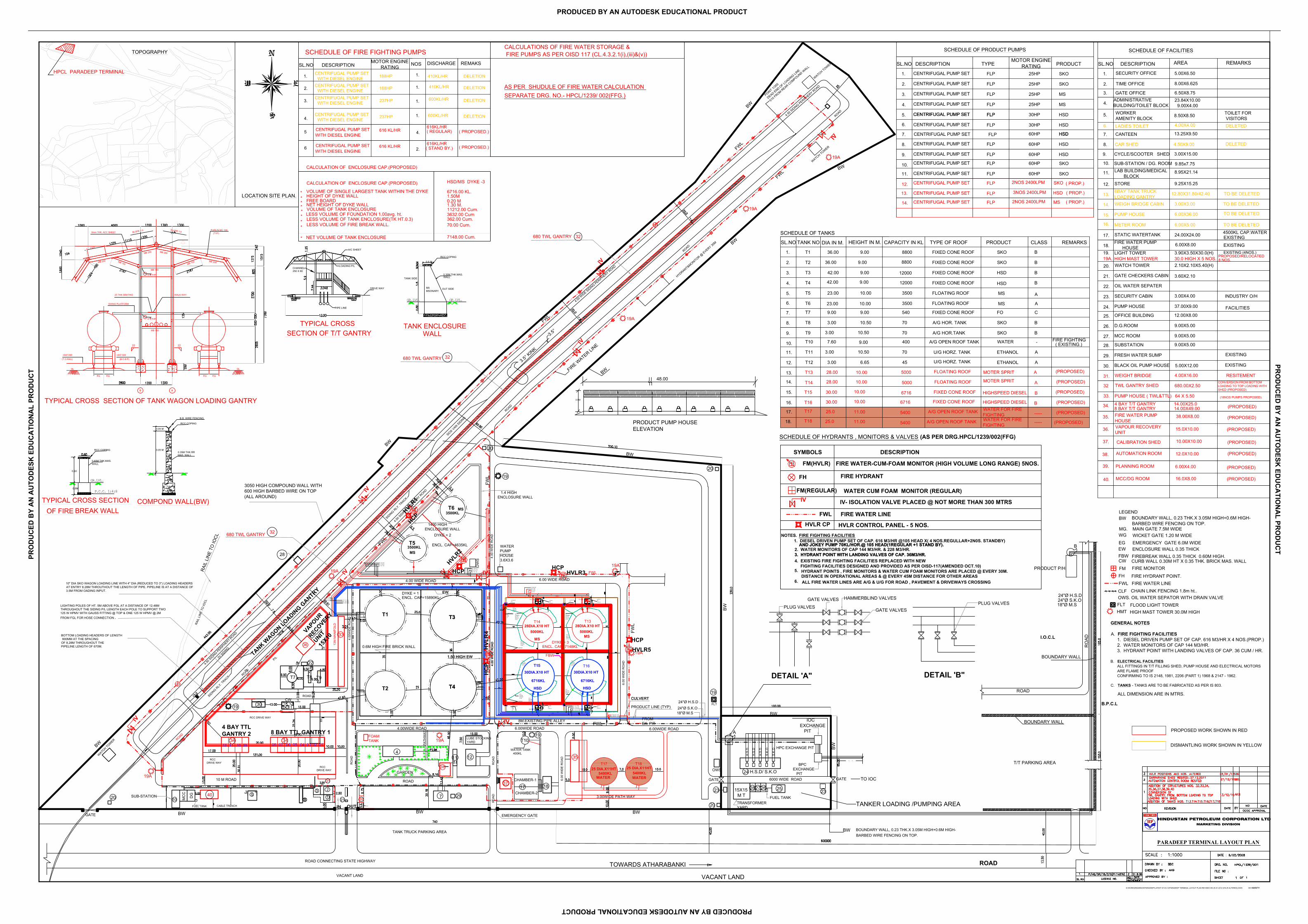
HINDUSTAN PETROLEUM CORPORATION LTD MARKETING DIVISION
FLPCENTRIFUGAL PUMP SET
14.
13.
12.
SCHEDULE OF PRODUCT PUMPS
1.
SL.NO
2.
6.
7.
8.
4.
5.
3.
DESCRIPTION
9.
10.
11.
TYPEMOTOR ENGINE RATING PRODUCT
CENTRIFUGAL PUMP SET FLP 25HP SKO
CENTRIFUGAL PUMP SET FLP 25HP SKO
CENTRIFUGAL PUMP SET FLP 25HP MS
CENTRIFUGAL PUMP SET FLP 25HP
CENTRIFUGAL PUMP SET FLPCENTRIFUGAL PUMP SET FLP 30HP HSD
CENTRIFUGAL PUMP SET FLP
CENTRIFUGAL PUMP SET FLP
CENTRIFUGAL PUMP SET FLP
CENTRIFUGAL PUMP SET FLP
CENTRIFUGAL PUMP SET FLP SKO
CENTRIFUGAL PUMP SET FLP SKO
30HP
60HP
60HP
60HP
60HP
60HP
MS
HSD
HSDHSD
HSD
HSD
4.00X16.00WEIGHT BRIDGE31.
INDUSTRY O/H
30. BLACK OIL PUMP HOUSE
29. FRESH WATER SUMP
9.00X5.0028. SUBSTATION
9.00X5.0027. MCC ROOM
9.00X5.0026. D.G.ROOM
12.00X8.0025. OFFICE BUILDING
5.00X12.00
24. PUMP HOUSE
3.00X4.0023. SECURITY CABIN
22. OIL WATER SEPATER
3.60X2.1021. GATE CHECKERS CABIN
2.10X2.10X5.40(H)20. WATCH TOWER
3.90X3.50X30.0(H)19. LIGHT TOWER
6.00X8.0018.FIRE WATER PUMP HOUSE
TO BE DELETED
24.00X24.0017. STATIC WATERTANK
6.00X5.0016. METER ROOM
6.00X36.0015. PUMP HOUSE
3.00X3.0014. WEIGH BRIDGE CABIN
12.80X31.80/42.4013.6BAY TANK TRUCKLOADING GANTRY
9.25X15.2512. STORE
8.95X21.1411. LAB BUILDING/MEDICAL BLOCK
9.85x7.7510. SUB-STATION / DG. ROOM
3.00X15.009. CYCLE/SCOOTER SHED
TOILET FOR VISITORS
REMARKS AREA
TIME OFFICE
1.
SL.NO
2.
SECURITY OFFICE
DESCRIPTION
6.50X8.75
SCHEDULE OF FACILITIES
5.00X6.50
8.00X6.625
6.
7.
8.
4.
5.
LADIES TOILET
CANTEEN
CAR SHED
ADMINISTRATIVEBUILDING/TOILET BLOCKWORKERAMENITY BLOCK
4.00X4.00
13.25X9.50
4.50X9.00
23.84X10.00 9.00X4.00
8.50X8.50
3. GATE OFFICE
8 BAY T/T GANTRY 14.00X49.00
32
(PROPOSED)
(18NOS PUMPS PROPOSED)33. PUMP HOUSE ( TWL&TTL) 64 X 5.50
TOPOGRAPHY
LIGHTING POLES OF HT. 5M ABOVE FGL AT A DISTANCE OF 12.48MTHROUGHOUT THE SIDING P/L LENGTH EACH POLE TO SUPPORT TWO125 W HPMV WITH GAUSS FITTING @ TOP & ONE 125 W HPMV @ 2MFROM FGL FOR HOSE CONNECTION .
LESS VOLUME OF FIRE BREAK WALL.
HEIGHT OF DYKE WALLFREE BOARDNET HEIGHT OF DYKE WALL
LESS VOLUME OF TANK ENCLOSURE(TK HT.0.3)
VOLUME OF TANK ENCLOSURE
VOLUME OF SINGLE LARGEST TANK WITHIN THE DYKE
NET VOLUME OF TANK ENCLOSURE
LESS VOLUME OF FOUNDATION 1.00avg. ht.
*
*
*
**
*
**
*
CALCULATION OF ENCLOSURE CAP.(PROPOSED) HSD/MS DYKE -3
6716.00 KL.
1.30 M.11212.00 Cum.
0.20 M
3632.00 Cum362.00 Cum.70.00 Cum.
1.50M
7148.00 Cum.
HPCL PARADEEP TERMINAL
LOCATION SITE PLAN.
PARADEEP TERMINAL LAYOUT PLAN
WATER TANK 400KL
10.0030.00
10.00
28.00 10.00
10.503.00
9.00
10.503.00
23.00 10.00
42.00 9.00
12000
8800
TO IOCGATE
BW BOUNDARY WALL, 0.23 THK.X 3.05M HIGH+0.6M HIGH- BARBED WIRE FENCING ON TOP.
DISMANTLING WORK SHOWN IN YELLOW
PROPOSED WORK SHOWN IN RED
4.50 S
IDIN
G PERIP
HERY ROAD
4.50 S
IDIN
G PERIP
HERY ROAD
36.00 9.00
ALL DIMENSION ARE IN MTRS.
FIXED CONE ROOF
FIXED CONE ROOF
ENCL. CAP=4635KL
671616. T16
T15 30.00
B
B
(PROPOSED)
(PROPOSED)HIGHSPEED DIESEL6716
BWBARBED WIRE FENCING ON TOP.
EG
WG WICKET GATE 1.20 M WIDE EMERGENCY GATE 6.0M WIDE
MAIN GATE 7.5M WIDE MG.
LEGEND
FBW
FMFH
FIRE MONITOR
FIRE HYDRANT POINT.
CW
FWL
OWS.CLF
FIRE WATER LINECHAIN LINK FENCING 1.8m ht..
FLOOD LIGHT TOWERFLT
EW
GENERAL NOTES
A. FIRE FIGHTING FACILITIES 1. DIESEL DRIVEN PUMP SET OF CAP. 616 M3/HR X 4 NOS.(PROP.) 2. WATER MONITORS OF CAP 144 M3/HR. 3. HYDRANT POINT WITH LANDING VALVES OF CAP. 36 CUM / HR.
B. ELECTRICAL FACILITIES ALL FITTINGS IN T/T FILLING SHED, PUMP HOUSE AND ELECTRICAL MOTORS ARE FLAME PROOF CONFIRMING TO IS 2148, 1981, 2206 (PART 1) 1968 & 2147 - 1962.
C. TANKS - TANKS ARE TO BE FABRICATED AS PER IS 803.
ENCLOSURE WALL 0.35 THICK
OIL WATER SEPATOR WITH DRAIN VALVE
FIREBREAK WALL 0.35 THICK 0.60M HIGH.
BOUNDARY WALL, 0.23 THK.X 3.05M HIGH+0.6M HIGH-
CURB WALL 0.30M HT X 0.35 THK. BRICK MAS. WALL
RAI
L LI
NE
TO IO
CL
680 TWL GANTRYAETHANOL456.653.00T12
AETHANOL70T11
WATERA/G OPEN ROOF TANK4007.60T10
BSKOA/G HOR.TANK70T9
BSKOA/G HOR. TANK7010.503.00T8
CFO5409.009.00T7
A3500T6
A350010.0023.00T5
BHSDFIXED CONE ROOF12000T4
BHSDFIXED CONE ROOF9.0042.00T3
BSKOFIXED CONE ROOFT2
BSKOFIXED CONE ROOF88009.0036.00T1
REMARKSCLASSPRODUCTTYPE OF ROOFCAPACITY IN KLHEIGHT IN M.DIA IN M.
12.
11.
10.
9.
TANK NO
3.
5.
4.
8.
7.
6.
2.
SL.NO
1.
FLOATING ROOF
FLOATING ROOF
FIXED CONE ROOF
MS
MS
SCHEDULE OF TANKS
13.
14.
15.
U/G HORZ. TANK
U/G HORZ. TANK
28.00 10.00 5000
5000
FLOATING ROOF
FLOATING ROOF
MOTER SPRIT (PROPOSED)
(PROPOSED)
A
A
T13
T14
B
DETAIL 'B"DETAIL 'A"
A
4.00
WID
E R
OA
D
3500KLMS
1
235
CABLE TRENCHFUEL TANK
DG
MC
C
1020 SUB-STATION
IN OUT21
RO
AD
GARDEN
411 12
RO
AD
RO
AD
EMERGENCY GATE
CHAMBER-1
CHAMBER-217 18
20
23
OWS
HPC EXCHANGE PIT
24 H.S.D/ S.K.O
H.S
.D
H.S
.D
S.K
.O
S.K
.O
H.S
.D
6000 WIDE ROAD
15X15 M T
262728 25
TRANSFORMERYARD
23
BPCEXCHANGE PIT
IOCEXCHANGE PIT
24"Ø H.S.D24"Ø S.K.O18"Ø M.S
1.50 HIGH EW
4.00
WID
E R
OA
D
WATERPUMPHOUSE3.6X3.6
4.00WIDE ROAD
T2
T1 T3
T4
T5
T6
0.6M HIGH FIRE BRICK WALL
ENCL. CAP=15890KL
4.00 WIDE ROAD
4.00
WID
E R
OA
D
ROAD
TK 1230
T7 T8 T9
ROAD
3V S
IDIN
G
RAI
L LI
NE
TO IO
CL
28
3050 HIGH COMPOUND WALL WITH600 HIGH BARBED WIRE ON TOP(ALL AROUND)
SICK V
AN SID
ING
10" DIA SKO WAGON LOADING LINE WITH 4" DIA (REDUCED TO 3") LOADING HEADERSAT ENTRY 8.28M THROUTHOUT THE LENGTH OF PIPE. PIPELINE IS AT A DISTANCE OF3.5M FROM OADING INPUT.
BOTTOM LOADING HEADERS OF LENGTH 900MM AT THE SPACINGOF 8,28M THROUGHOUT THEPIPELINE LENGTH OF 670M.
T/T PARKING AREA
BOUNDARY WALL
ROAD
RO
ADI.O.C.L
PRODUCT P/H
18"Ø M.S24"Ø S.K.O24"Ø H.S.D
BOUNDARY WALL
B.P.C.L
GATE VALVES
HAMMERBLIND VALVESGATE VALVES
PLUG VALVESPLUG VALVES
ROADTOWARDS ATHARABANKIROAD CONNECTING STATE HIGHWAY
VACANT LAND VACANT LAND
22
7 29 FUEL TANK
3500KLMS
SIDIN
G RLY
. TRACK
SIDIN
G RLY
. TRACK
MB 150
EQ EQ EQEQ
SLOPE 1:5
8
WALK WAY25 THK GRATING
MB 150
GL GL
6mm THK. ACC SHEETSLOPE 1:5
PURLIN MC 100(TYP)
+947.049
(T.O.RAIL)
+947.049
(B.O.B.P)
8
(TYP)
(TYP)
SWING PLATFORM
1325
MB 200
MB 150 MB 200
MB 200
MB 150 MB 200
22 22
B A
TYPICAL CROSS SECTION OF TANK WAGON LOADING GANTRY
BW
BW
BWBW
BW
BW
BW
BW
RCC COPING
RCC COPING
MSONARY
0.6 M
WALL
OUT SIDE
GR.LVL.GR.LVL.
TANK SIDE
DRIVE WAY
A/C SHEET
PIPE LINE
TYPICAL CROSS
LOADING P/L
250 X 80
3.05 M
MAS. WALL
3.05 M
COMPOND WALL(BW)
0.60
WALL
GR.LVL.
P.C.C. 1:4:80.8M
BREAK WALL
WALL
RR
0.35M THK.MAS.
CHANNEL
0.35M THK.RR
0.40M THK.MAS.
OF FIRE
TANK ENCLOSURE
TYPICAL CROSS SECTION
RCC COPING
B.B. WIRE FENCING
1400 HIGH ENCLOSURE WALL
TWL GANTRY SHED 680.00X2.50CONVERSION FROM BOTTOMLOADING TO TOP LOADING WITHSHED (PROPOSED)
34.
FWL
FWL
FWL
FWL
FWL
FWL
T10
TK 11
CW
-
EW
( PROP.)SKO2NOS 2400LPM
6.00WIDE ROAD
37.00X9.00 FACILITIES
4500KL CAP.WATEREXISTING
( PROP.)HSD
FLPCENTRIFUGAL PUMP SET
FLPCENTRIFUGAL PUMP SET
( PROP.)MS
3NOS 2400LPM
2NOS 2400LPM
( EXISTING.)FIRE FIGHTING
TANK TRUCK PARKING AREA
TANKER LOADING /PUMPING AREA
680 TWL GANTRY
680 TWL GANTRY
38.00X8.00 (PROPOSED)35. FIRE WATER PUMPHOUSE
EXISTING
WATCH TOW
ER
20
19
LUBE STOCKINGYARD
20
3.5° KINK
4.50 W
IDE SIDING PERIPHERY ROAD
FIRE WATER LI
NE
HYDRANT&MONITOR @ EVERY 30
M
WATCH TOWER
WATCH TOWER
POINT 1/35
5
DEAD END OF LO
ADING LINE
510 F
ROM REAR COMPOUND WALL
BW
FWL
4.50 S
IDING PERIPHERY ROAD
BW
BW
3.5°
BW
DYKE = 1
GATE
DYKE = 2
SECTION OF T/T GANTRY
1.4 HIGH ENCLOSURE WALL
35
CULVERT
36.
PLANNING ROOM 6.00X4.00
(PROPOSED)
(PROPOSED)37.
19A
19A
HIGH MAST TOWER 30.0M HIGHHMT
30.0 HIGH X 5 NOS.19A. HIGH MAST TOWER PROPOSED/RELOCATED
32
32
32
16.0X8.00MCC/DG ROOM
99
31
DELETED
RESITEMENT
RCCDRIVE WAY
3434
10 M ROAD
4 BAY T/T GANTRY 14.00X25.0
19A
EXISTING
TO BE DELETED
TO BE DELETED
PRODUCT PUMP HOUSEELEVATION
3.5M
48.00
ROAD
10.00X10.00CALIBRATION SHED
EXISTING (4NOS.)
GATE
TO BE DELETED
EXISTING
BW
39
38.
39.
40.
AUTOMATION ROOM 12.0X10.00 (PROPOSED)
(PROPOSED)
RCCDRIVE WAY
FLT
ROAD
ROAD
ROAD
ROAD
37
33
13M
MA
NIF
OLD
MOTER SPRIT
HIGHSPEED DIESEL
11.00 ----- (PROPOSED)T1717. A/G OPEN ROOF TANK
11.00 (PROPOSED)T1818. -----A/G OPEN ROOF TANK
RCC DRIVE WAY
40
P/L
FBW
T13T14
T15 T16
PRODUCT LINE (TYP)
6.00
WID
E R
OA
D
ENCL. CAP=7148KL
30DIA.X10 HT
6716KL
HSD
5000KL28DIA.X10 HT
1.50 HIGH EW
4.00
WID
E R
OA
D
T3
T4
30DIA.X10 HT
6716KL
HSD
28DIA.X10 HT
MS
5000KL
FWL
FWL
EW
6.00WIDE ROAD
DYKE = 3
CULVERT
CATCHPIT5.5X4.6
U/GWATERDROUGH(TYP)
CATCHPIT5.5X4.6
T15U/GWATERDROUGH(TYP)
U/GWATERDROUGH(TYP)
CATCHPIT5.5X4.6
U/GWATERDROUGH(TYP)
CATCHPIT5.5X4.6
U/GWATERDROUGH(TYP)
MS
SWDRAIN
SWDRAIN
1x1CHEMBERWATERDROUGH(TYP)
1x1CHEMBERWATERDROUGH(TYP)
U/GWATERDROUGH(TYP)
U/GWATERDROUGH(TYP)
U/GWATERDROUGH(TYP)
FROMEX. PIT
10"DBBV
20"
TOBV
18"10"
18"RECEIP
TOBVTOBV
10" TOBV
DBBV
DBBVDBBV
TWLRTNTLF
20"
18"10"
TWLRTNTLF
16"18"10"24"RECEIP
TWLRTN
TLF
TOBVTOBV
TOBV10"
24"RECEIPT HSD24"RECEIPT SKO
18"RECEIPT MS
SANDPIT-1.5X2.75
3-VOLVEPIT-1.8X2.5
CONCEALEDMSPIPE6"
CONCEALEDMSPIPE6"
10"DBBV 10"
10"
10" 10"
8M.EXISTING PIPE ALLEY
3-VOLVEPIT-1.8X2.5
18" RECEIPT
16"18"10"
TWLRTN
TLF20"
18"10"
TWLRTNTLF
20"
18"10"
TWLRTNTLF
MSMSMS
MSMSMSMS
MSMSMS HSD
HSDHSD
HSDHSDHSD
HSD
6.00 WIDE ROAD
6.00
WID
E R
OA
D
FIRE WATER-CUM-FOAM MONITOR (HIGH VOLUME LONG RANGE) 5NOS.
3. HYDRANT POINT WITH LANDING VALVES OF CAP. 36M3/HR.
AND JOKEY PUMP 70KL/HOR.@ 105 HEAD(1REGULAR +1 STAND BY).
FM(HVLR)
FIRE WATER LINEFWL
FIRE HYDRANT FH
FM(REGULAR) WATER CUM FOAM MONITOR (REGULAR)
NOTES. FIRE FIGHTING FACILITIES 1. DIESEL DRIVEN PUMP SET OF CAP. 616 M3/HR @105 HEAD X( 4 NOS.REGULLAR+2N0S. STANDBY)
2. WATER MONITORS OF CAP 144 M3/HR. & 228 M3/HR. 3. HYDRANT POINT WITH LANDING VALVES OF CAP. 36M3/HR.
FIGHTING FACILITIES DESIGNED AND PROVIDED AS PER OISD-117(AMENDED OCT.10)
AND JOKEY PUMP 70KL/HOR.@ 105 HEAD(1REGULAR +1 STAND BY).
HYDRANT POINTS , FIRE MONITORS & WATER CUM FOAM MONITORS ARE PLACED @ EVERY 30M.5. DISTANCE IN OPERATIONAL AREAS & @ EVERY 45M DISTANCE FOR OTHER AREAS
SYMBOLS DESCRIPTION
SCHEDULE OF HYDRANTS , MONITORS & VALVES
ALL FIRE WATER LINES ARE A/G & U/G FOR ROAD , PAVEMENT & DRIVEWAYS CROSSING6.
IV- ISOLATION VALVE PLACED @ NOT MORE THAN 300 MTRS
4. EXISTING FIRE FIGHTING FACILITIES REPLACED WITH NEW
HVLR CONTROL PANEL - 5 NOS.HVLR CP
600KL/HR
600KL/HR
410KL/HR
237HP
188HP
CENTRIFUGAL PUMP SET WITH DIESEL ENGINE
CENTRIFUGAL PUMP SET WITH DIESEL ENGINE
CENTRIFUGAL PUMP SET WITH DIESEL ENGINE
1.
SL.NO
2.
4.
3.
DESCRIPTIONMOTOR ENGINE RATING
DISCHARGE
CENTRIFUGAL PUMP SET WITH DIESEL ENGINE 188HP 410KL/HR
237HP
SCHEDULE OF FIRE FIGHTING PUMPS
CENTRIFUGAL PUMP SET 616KL/HR
WITH DIESEL ENGINE616 KL/HR5 ( PROPOSED.)
CENTRIFUGAL PUMP SETWITH DIESEL ENGINE
616 KL/HR6616KL/HR
( REGULAR)
( STAND BY.)
1.
1.
1.
1.
4.
2.
NOS
DELETION
REMAKS
( PROPOSED.)
DELETION
DELETION
DELETION
AS PER SHUDULE OF FIRE WATER CALCULATION SEPARATE DRG. NO.- HPCL/1239/ 002(FFG.)
CALCULATIONS OF FIRE WATER STORAGE & FIRE PUMPS AS PER OISD 117 (CL.4.3.2.1(i),(iii)&(v))
(AS PER DRG.HPCL/1239/002(FFG)
19A
CALCULATION OF ENCLOSURE CAP.(PROPOSED)
38
PA
THW
AY
010203040506070809101112
DELETED
FOAMTANK
19A
19A19
19
19
19A
19A
8 NOS.
WALL
19A
HMT(PROPOSED)
OW
S
HVLR3HCP
HVLR1
HCP
HVLR5HCP
HVL
R4
HC
P
HVLR2
HCP
4 BAY TTLGANTRY 2 8 BAY TTL GANTRY 1
(PROPOSED)15.0X10.00VAPOUR RECOVERYUNIT
36
VAPOURRECOVERY
UNIT15
X10
TANK WAGON LOADIN
G GANTRY
D:\WORK\DRAWINGS\PARADEEP\LATEST 07-03-12\PARADEEP TERMINAL LAYOUT PLAN REVISED ON 25-01-2012 (HVLR ALTERED).DWG 09/10/201212:32 PM
540025.0
25.0
25 DIA.X11HT5400KL
WATER
T17
3.00WIDE PATH WAY
5400
25 DIA.X11HT5400KLWATER
T18
WATER FOR FIREFIGHTING
WATER FOR FIREFIGHTING
PRO
DU
CED
BY
AN
AU
TOD
ESK
ED
UC
ATI
ON
AL
PRO
DU
CT
PRODUCED BY AN AUTODESK EDUCATIONAL PRODUCT
PRO
DU
CED
BY A
N A
UTO
DESK
EDU
CA
TION
AL PR
OD
UC
T
PRODUCED BY AN AUTODESK EDUCATIONAL PRODUCT


![Index [tenders.hpcl.co.in]tenders.hpcl.co.in/tenders/tender_prog/tenderfiles/5786/Tender... · hindustan petroleum tital corporation limited chkd drwn dsgn name sign date drawing](https://img.pdfslide.net/doc/110x75/5aa1a4447f8b9ada698be578/index-petroleum-tital-corporation-limited-chkd-drwn-dsgn-name-sign-date-drawing.jpg)