Embed Size (px)
Citation preview
Tender-RELAYS – 65/ 2014-15 Technical Specification Page 1 of 49
ODISHA POWER TRANSMISSION CORPORATION LTD. OFFICE OF THE SENIOR GENERAL MANAGER,
CENTRAL PROCUREMENT CELL, JANPATH, BHUBANESWAR - 751022
TENDER SPECIFICATION NO.
SR.G.M-CPC -TENDER– RELAYS – 65/ 2014-15 2015-16
E-TENDER NOTICE NO. 65 / 2014-15 & 2015-16
TENDER SPECIFICATION
NO. SR.G.M.CPC-TENDER– RELAYS -65/2014-15
FOR PROCUREMENT OF DIFFERENT TYPES OF RELAYS (DIFF,
DISTANCE PROTN,BACK UP,MASTER TRIPPING RELAYS,REF POLE DISCRIPENCY RELAY AND OVER-
FLUXING RELAYS)
Tender-RELAYS – 65/ 2014-15 Technical Specification Page 2 of 49
TECHNICAL SPECIFICATION RELAYS
TECHNICAL SPECIFICATION FOR RELAYS. 1) NUMERICAL DISTANCE PROTECTION RELAYS
FOR TRANSMISSION LINES ,
2) NUMERICAL DIFFERENTIAL PROTECTION
RELAYS FOR TWO WINDING AND THREE
WINDING TRANSFORMERS ,
3) NUMERICAL BACK UP OVER CURRENT AND
EARTH FAULT RELAY
4) ELECTROMECHANICAL AUXILIARY RELAYS
(ALSTOM / EQUIVALENT MAKE ) TO SUIT OPTCL
SYSTEM.
5) REF RELY(Electromechanical CAG-14 type)
6) Pole- discrepancy relay.
7) Over-fluxing relay.
Tender-RELAYS – 65/ 2014-15 Technical Specification Page 3 of 49
GENERAL DESCRIPTION Specification of the Relay for this part covers the general protection schemes for 400 KV, 220 KV, 132 KV and 33 KV system (For feeders, transformers and Bus coupler/Bus transfer Bays) in OPTCL system. Bidders are intimated to supply the relays, which shall be suitable to OPTCL. Proper care to be taken while quoting the latest version of Numerical relays. Since these relays shall be used for replacement in different sub-station, the Bidder shall render all helps for replacement, installation and Testing free of cost to OPTCL. 1. All relays shall confirm to the requirements of IS: 3231/IEC-60255 and IEC-61850 protocol compliance. Relay shall be suitable for flush or semi-flush mounting on the front with connections from the rear. 2. Shall be provided with proper testing facilities. Necessary test plugs/test handles shall be supplied, which is in the scope of this contract. 3. The protective relay shall be suitable for efficient and reliable operation of the protection scheme as indicated in the specification. Necessary auxiliary relays etc for interlocking scheme, for multiplying contacts suiting for the scheme and monitoring of control supplies and circuits, lockout relay monitoring circuits etc. Auxiliary relays and timers shall have pairs of contacts as required to complete the scheme; contacts shall be silver faced with spring action. It shall have adequate numbers of terminals for making potential free external connection to the relay coils and contacts, including spare contacts. All the contacts of the auxiliary relays and timers except lock out type relays shall have self-reset type contacts 4. No control relay which shall trip the power circuit breaker when the relay is de-energized shall be employed in the circuit. 5. Provision shall be made for easy isolation of trip circuits of each relay for the purpose of testing and maintenance. 6. All protective relays and alarm relays shall be provided with extra isolated pair of contacts wired to terminals of the relay exclusively for future use. 7. The Bidder shall include in his bid a list of installations where the relays quoted have been in satisfactory operation. 8. The numerical relays shall include the followings:
i) Necessary software and hardware to up/down load the data to/from the relay from/to the personal computer.
ii) The relay shall have suitable communication facilities for future connectivity to SCADA. The relay shall be capable of supporting IEC61850 protocol. Neither the interface hardware nor the software for connectivity to SCADA will form part of the scope of this specification.
iii) In the numerical relays the features like disturbance recorder and event logging
function as available in these relays shall be supplied. 9. Relays shall be suitable for flush mounting on the panel board. All the relays shall be neck connected, Protected from dust with tight cases for tropical use and superbly finished container. The adjusting devices shall be accessible with the relays mounted on the panel board. Flag type operating indicators and flag indicator reset devices shall be provided. The latter shall be suitable for operation from the front of the relay without opening the cover. The relays shall comply in all respects with the requirement of IS: 3231/1965, equivalent IEC standards and shall be suitable for operation under the climate conditions specified. The relays shall be suitable for operation with a temperature range of 0 deg. to 50 deg. C. The current coils shall be rated for a continuous current of 1 Amps as specified against each. And the voltage coil for 110 volts normal PT voltage and 220V±10% for the DC system voltage. The contacts of the relays shall be silvered and precaution shall be taken to prevent or minimize damage due to arcs which have to be successfully broken against 240 V D.C. when open, the contacts shall withstand a voltage of 115% of the normal circuit voltage. The relays shall preferably be provided with suitable seal in devices.
Tender-RELAYS – 65/ 2014-15 Technical Specification Page 4 of 49
9.1. The offered Protection relays shall be completely numerical with protection functions using software algorithm. Hard ware based measurement shall not be acceptable. 9.2. Any proprietary protocol externally converted to IEC 61850 with the help of a protocol converter to be used for communication with an outside network shall not be acceptable. No internal protocol converter can be used for the numerical relays proposed to procure.
9.3. The relays should have high immunity to electrical and electromagnetic interference and the circuit boards of the relays should be applied with harsh environmental conformal coating 9.4. The relays should confirm to following mandatory type tests for safe operation of the relay; High frequency disturbance test as per IEC 61000-4-1 Fast transient disturbance test as per IEC 61000-4-4 Electrostatic discharge as per IEC 61000-4-2 Radio frequency interference as per ANSI C 37.90.2 Impulse test as per IEC 61000-4-3 9.5. The same relay shall be provided with 1A CT input. 9.6. It shall be possible to energise the relay from either AC or DC auxiliary supply. 9.7. The offered relay shall have a comprehensive local HMI for interface. It shall have the following minimum elements so that the features of the relay can be accessed and setting changes can be done locally.
a) At least a minimum of 32 characters alphanumeric backlit LCD display unit. b) Fixed LEDs ( for trip, Alarm, Relay available/run & Relay out of service/faulty ) and
minimum eight programmable LEDs which can be assigned to any protection function for local annunciation shall be available. The device shall allow the option of latching the LED indication after a trip command so that the LEDs always indicate the operation for the last trip signal.
c) Tactile keypad / or key pad with arrow keys for browsing and setting the relay menu. 9.8. The relays should have communication ports viz. Front RS 232/USB port for local communication for relay settings, modifications, extraction and analysis of fault/event/ disturbance records from a laptop and Rear redundant port for remote communication to SCADA system on IEC61850 protocol. 9.9. It shall be possible to daisy chain/multi dropped all the numerical relays on RS 485 rear port or some advanced network, for remote communication facility. The remote communication protocol of the numerical relays shall be an open protocol like most advances IEC61850. All refer have line synchronise facility with IRIG-B PORT. 9.10. The relays shall have the following tools for fault diagnostics.
a) Fault record – The relay shall have the facility to store at least 5 last fault records with information on cause of trip, date, time, trip values of electrical parameters.
b) Event record – The relay shall have the facility to store at least 75 to 200 time stamped event records with 1 ms resolution. c) Disturbance record – The relay shall have capacity of disturbance record waveforms.
d) The relay settings shall be provided with adequate password protection. The password of the relay Should be of a minimum 4 characters upper case text to provide security to setting parameter. e) It shall be possible to change the relay setting from the front panel using the keypads. f) The relay shall have comprehensive self-diagnostic feature. This feature shall continuously monitor the healthiness of all the hardware and software elements of the relay. Any failure detected shall be Annunciation through an output watchdog contact. The fault diagnosis information shall be displayed on the LCD and also through the communication port. g) The numerical Relays shall be provided with common support software compatible with WINDOW-XP/ WINDOW-7/ WINDOW-8 which will allow easy settings of relays in addition to uploading of event, fault, disturbance records, and measurements.
Tender-RELAYS – 65/ 2014-15 Technical Specification Page 5 of 49
h) The relay setting shall also be changed from local or remote using the same software. i) Additional functions can be added to relay by software up gradation and downloading this upgraded software to the relays by simple communication through P.C. j) Different group setting (at least two) should be available.
All Main relays are of numerical relays shall include the followings: i) Necessary software and hardware to up/down load the data’s to/from the relay from/to the personal computer ( supply is in the scope of this contract.). ii) The relay shall have suitable communication facilities for future connectivity to SCADA. The relay shall be capable of supporting IEC 870-5-103 protocol. Neither the interface hardware nor the software for connectivity to SCADA will form part of the scope of this specification. iii) In the numerical relays the features like disturbance recorder and event logging function as available in these relays shall be supplied.
10. TEST REQUIREMENTS:- General requirements:
The manufacturer shall supply test results and/or in service operating evidence to confirm compliance with the general and performance requirements as detailed in this Specification.
a) Pre-commissioning and energisation tests:-
The Bidder shall submit details of all pre-commissioning and energisation tests to OPTCL for approval prior to the inspection of the equipment.
b) Testing, inspection and test certificates:-
The Bidder shall enclose with his bid the reports of type and routine tests conducted on similar equipment earlier as a proof of designing and developing similar equipment. Bid documents, furnished without these test reports shall be considered as incomplete and shall be liable for rejection. All equipment furnished shall conform to the type tests and shall be subject to routine tests in accordance with the requirements stipulated for Protection IEC 61850 protocol Relays. OPTCL will have the right to call for any other tests of reasonable nature to be carried out at the Bidder's premises or at site or in any other place, in addition to the aforesaid type and routine tests, to satisfy that the materials comply with the Specification. The Bidder shall give one months notice of routine tests and inspection to be carried out on the finished equipment. A programme for conducting the tests shall be furnished and the Bidder shall proceed to test the equipment after approval of OPTCL. The tests shall be witnessed by OPTCL. All inspections, type tests and routine tests shall be carried out after approval of all the relevant drawings required under the contract. None of the equipment to be furnished or used in connection with this contract shall be despatched until factory tests are satisfactorily completed. Such factory tests on the equipment shall not however relieve the Bidder from full responsibility for furnishing equipment conforming to the requirements of this contract, nor prejudice any claim right or privilege which the Employer may have because of the use of defective or unsatisfactory equipment. Should the OPTCL waive the rights to inspect and test any equipment, such a waiver shall not relieve the Contractor, in any way, of his obligations under this contract. Three (3) copies of test reports of successful tests shall be submitted by the Bidder to the OPTCL for approval before shipment of equipment. For equipment tests for which IEC recommendations or Indian Standards are available, test reports confirming that the equipment has passed the specified type and routine tests shall be furnished for the approval of the OPTCL by the Bidder before shipment of the equipment.
Tender-RELAYS – 65/ 2014-15 Technical Specification Page 6 of 49
For equipment/tests for which IEC/IS specifications do not exist, the Bidder shall propose a test procedure for the approval of the OPTCL before conducting tests. Test certificates for tests carried out shall be submitted for approval of the OPTCL before shipment of the equipment. Failure of any equipment to meet the requirements of tests carried out at works or at site shall be sufficient cause for rejection of the equipment. Rejection of any equipment will not be held as a valid reason for delay in the completion of the works in accordance with the agreed programme. The Employer reserves the right to call for field tests on the completely assembled equipment at site. Three (3) copies of all test reports shall be supplied for approval before shipment of equipment. The reports shall indicate clearly the standard values specified for each test, to facilitate checking of the test reports. c) Soak test: All solid state equipment/system shall be subject to the Hot Soak Test as a routine test in accordance with the procedure detailed in the following paragraph. All solid state equipment shall be burn-in tested for minimum of 120 hours continuously under operational conditions. During the last 48 hours of testing, the ambient temperature of the test chamber shall be 50C. The temperature of the interior shall not exceed 65C. d) Type tests: 1. Impulse voltage withstand test as per Clause 6.1 of IS 8686 (for a test voltage appropriate to Class III as per Clause 3.2 of IS-8686) 2. High Frequency Disturbance test as per Clause 5.2 of IS 8686 (for a test voltage appropriate to Class III as per Clause 3.2 of IS 8686).Type tests listed under IEC-Technical Committees recommendation `TEC-57' and functional type tests listed under CIGRE Study Committee 34 (Protection) Report on simulator, Network analyser or PTL as applicable. e) Routine tests:Contact insulation resistance test as per Clause 10.5 of IS-3231. Insulation withstand capability as per Clause 10.5 of IS-3231 on all AC/DC relays.
STATIC RELAY a) The printed circuit cards shall be of fiberglass type and the contact shall be gold plated. All connections with the connector pegs shall be through wire wrapping. Harsh environment conformal coating to be provided on the PCB for the long life of the PCB to avoid failure of the device during storing of the relay. b) The components shall be loaded by less than half of their rated values . The resistors shall be of carbon composition or metal oxide type and the capacitors shall be of plastic film or tantalum type . Stringent measures including shielding of long internal wiring should be taken to make relays immune to voltage spikes . As per IEC , the relays must withstand 5KV, 1.2 x 50 micro-second , 0.5joule energy impulse test or 1.5 Mhz damped oscillations with initial Value (Zero to peak ) of 2.5 KV decaying to half the initial value in 6 microsecond s with internal s ource impedance of 150ohms . Insulation barriers shall be provided to ensure that transients present in CT & VT connections due to extraneous sources do not cause damage to static circuits. c) All relay shall be designed for satisfactory performance under tropical and humid conditions specified. Special mention , shall be mad e in the technical deviation schedule of the bid for those relays , if any, that Bidder proposes to use, which differ from specified requirements. d) All devices required for correct operation of each relay shall be provided by contractor without any extra cost. e) The contractor shall ensure that the terminals of the contacts of the relays are readily brought out for connections as required in the final approved scheme . The type of relay case offered shall not create any restrictions of the availability of the contact terminals for wiring connections.
Tender-RELAYS – 65/ 2014-15 Technical Specification Page 7 of 49
f ) AC/ DC convertor shall be provided as stable auxiliary supply for relay operation Provision of D.C cell in the protective relays as reliable stand by power supplies will however not be acceptable. g) The solid state relays shall be stab le and suitably protected against transient /induced over voltages and noise signals. The Bidder shall state clearly in his bid special requirement, if any, for DC input arrangement or cabling, considered necessary of satisfactory operation of solid state relays quoted by him . h) The Bidder shall include in his bid a list of installations where the relays quoted have been in satisfactory operation Each relay shall be provided with dust-tight removable front cover with full glass window. The relays operation of relays shall be practically free from errors due to nominal variations of frequency and ambient temperatures given in general requirement of specification. All relay coils shall be vacuum impregnated with suitable insulation compound which shall be moisture resistant . The design shall be such that the settings and calibration will not get out of adjustment unless intended to. i) All contacts shall be made of pure silver or palladium and shall be readily renewable , self-cleaning and self-aligning type . The contact rating shall, be liberal so that they may give satisfactory service without much attention Time delay features like dash or other devices which are appreciably affected by variations in temperatures and humidity shall not be acceptable . Permanent magnet shall be of non-ageing type. j) All the relays shall be provided with operation indicators which shall be secured against unwanted operation . The indicators shall show all types of faults and the phase or phases on which fault had occurred . All indicators and hand resetting relays must be capable of being reset without opening the relays case. All measuring, starting and tripping relays shall be provide with operation indicator. k) The relays should be flush mounted and of draw out or plugging type. l) For testing the relay while it is in service , every relay scheme namely distance protection , differential. protection etc shall be provided with rotary switch with position test / service . One of them. shall be sued in the circuit of main protection and the other with back up protection . When the relay is in service , both these switches shall be kept in service position. During testing , one of the switches in turn shall be rotated to test position to short the main CT , isolate main VT , isolate tripping command to breaker, block auto-reclosing circuits etc and simultaneously initiate alarm Protection under testing .Relay terminals for connecting CT,VT, I.C. tripping loads of testing kits shall be Provided on panel. These shall not be live when test switch is in service is in service position. testing kit shall be provided on the panel . These terminal shall not be live when test switch. 1. All relays shall be enclosed in flush or semi flush, dust tight, dull black enamel painted, back connected cases , All protective and auxiliary relays , except the lockout relays shall be self reset type . The relays shall have silver to silver contacts with wiping action, shall be capable of making carrying and breaking currents o f the associated circuits. The D.C control supply voltage shall be as specified in section -III . The current and voltage coils of all relays shall be rated for secondary rating of associated instrument transformers . All relays shall comply with the latest issue of I.S 3231 or IEC publication no. 255-1-155-2. 2. All necessary provision for easy testing of relays shall be incorporated and specifically brought 'out in the tender. Suitable devices for indication of operation of each protection including time delayed protection shall be provided along with resetting devices on front of the panel All protections which do not have built in hand reset operation indicator flag , shall have additional auxiliary relays for this purpose . Similar indicating device shall also be provided in the trip circuits of protections located outside the boards such as Buchholz relays, temperature protection, fire protection etc. For STATIC relays, the following should be necessary. i) 5 KV test ii) High Frequency burst test
Tender-RELAYS – 65/ 2014-15 Technical Specification Page 8 of 49
3. Provision shall be made for easy isolation of trip circuits of each relays so that circuits are not disturbed during testing and maintenance of individual relays . Current and voltage relays in all protections with time delayed operation shall have a reset ratio of not less than 9.85 and not more than 1.20 respectively and shall have adequate thermal rating the relays shall give guaranteed performance for the climatic conditions prevailing at site. 4. All protective relays shall be draw out type with provision of removing the mechanism for inspection, maintenance and replacement , self-contained facilities for secondary injection testing shall be incorporated in all protective relays. In case this facility is not available in any relay separate suitable test blocks shall be provided on the panel for this purpose . 5. The relays shall be suitable for efficient and reliable operation of the protective scheme to be supplied as per section -III of this specification. The Bidder shall submit along with the tender complete sets of detailed operational sequence, relay characteristics, circuit diagram and descriptive literature for all relays . 6. a) All AC relays shall be suitable for operation at 50Hz AC Voltage operated relays shall be suitable for 110 volts VI; con dares and current operated relays for I Amp C T. secondary’s as specified in this specification. DC auxiliary relays and timers shall be designed for 250 V DC voltage and shall operate satisfactorily between 70% and 1 10% of rated voltage. Voltage operated relays shall have adequate thermal capacity for continuous operation. b) The protective relay's shall he suitable for efficient and reliable operation o f the protection scheme described in the specification. Necessary auxiliary relays and timers required for interlocking schemes for multiplying of contacts/suiting contact duties of protective relays and monitoring of control supplies and circuits, lockout relay monitoring of circuits etc., and also required f or the complete protection schemes described in the specification shall be provided. All protective relays shall be provided with at least two pairs of potential free isolated output contacts. Auxiliary relays and timers shall have pairs of contacts as required to complete the scheme. Contacts shall be silver faced with spring action Relay cases shall have adequate number of terminals for making potential free external connections to the relay coils and contacts including spar e contacts. Relay case size shall be-so chosen as not to introduce an y limitations on the use of available contacts on the relay due to in-adequacy of terminals. Paralleling of contacts, if any shall be done at the terminals on the casing of the relay. c) All protective relays, auxiliary relays and timers except the lock out relays and interlocking relays specified shall be provided with sell-reset type contacts. All protective relays and timers shall be provided with externally hand reset positive action operation indicators, provided with inscription , subject to purchaser's approval. All protective relays which do not have built in hand reset o per action indicators shall have additional auxiliary relays with operating indicators shall this purpose. Similar separate operating indicator (auxiliary relays) shall also he provided in the trip circuits of protections located outside the board such as buchholtz temperature protection. fire protection etc. d) Timers shall be of the electromagnetic or solid state type. Pneumatic timers are not acceptable: Short tint; delays in terms of milliseconds may be obtained, using copper slugs en auxiliary radius : In such case it shall be ensured that the Continuous rating of the relay is not of affected. Time delay in terms of milliseconds obtained by the external capacitor resistor combination is not acceptable. e) No control relay which shall trip the power circuit breaker when the relay is reenergized shall be employed in the circuits. f) Pro vision shall be made f or easy isolation of trip circuits of each relay fo r the purpose of testing and maintenance g) All relays shall withstand a test voltage 2.5 KV, 50 HZ. RMS voltage for one second.
Tender-RELAYS – 65/ 2014-15 Technical Specification Page 9 of 49
h) Auxiliary seal-in-units provided on the protective relays shall preferably be of shunt reinforcement type. If series relays are used the following shall be strictly ensured: i) The operating time of the series seal-in-unit shall be sufficiently shorter than that of the trip coil or trip relay in series with which it operates to ensure definite operation of the flag indicator of the relay. j) Seal-in -unit shall obtain adequate current for operation when one or more relays operate simultaneously. k) Impedance of the seal-in-unit shall be small enough to permit satisfactory operation of the trip coil on trip relays when the DC supply voltage :is minimum. l) protective relays an d alarm relays shall be provided with one extra isolated pair of contacts wired to terminals exclusively for Purchaser's use.
Protection discrimination On the occurrence of a fault on the power system network the high speed discriminating protection systems (main protection) shall rapidly detect the fault and initiate the opening of only those circuit breakers which are necessary to disconnect the faulted electrical element from the network. Protection equipment associated with adjacent electrical elements may detect the fault, but must be able to discriminate between an external fault and a fault on the electrical element which it is designed to protect. Sequential time delayed tripping is not permitted except in the following specific circumstances:
Protection for short connections between post current transformer housings and circuit breakers when the technical advantages of complete overlapping of the protection are outweighed by economic considerations, (i.e. short-zone protection)
Operation of time graded back-up protection takes place as a result of either the complete failure of the communication links associated with the main protection systems, or the fault resistance is substantially greater than a value which can be detected by main protection systems.
Operation of line back-up protection to disconnect primary system faults in the case of a circuit breaker failing to operate, (i.e. circuit breaker failure protection)
All back-up protection systems shall be able to discriminate with main protection systems, circuit breaker fail protection and with other back-up protection systems installed elsewhere on the transmission system.
Protection settings A list of the settings to be applied to all protection systems together with all associated calculations, shall be provided for review and approval not less than three months prior to the first programmed date for commissioning. The settings for line protection shall be such as to permit correct operation of the protection for earth faults with up to 100 ohms fault resistance. Any limitations imposed on the power system as a result of the settings proposed shall be explicitly stated. In the absence of system data required for calculation purposes, assumptions may be made providing these are clearly identified as such in the relevant calculations.
Fault clearing time The protection equipment shall be capable of achieving the following discriminative fault clearing times, inclusive of circuit breaker and signaling times:
One millisecond for all electrical elements whose boundary connections are defined by circuit breakers located within a given substation.
For interconnecting tie lines in which the boundary connections of the electrical element being protected are defined by circuit breakers located in adjacent switching stations, an additional 20 ms fault clearance time is allowed at the substation remote from the fault point. This additional fault clearance time is permitted subject to the requirement
Tender-RELAYS – 65/ 2014-15 Technical Specification Page 10 of 49
that the positive sequence impedance of the primary circuit from the switching terminal to the point of fault shall not be less than ten ohms. The Contractor shall supply the Project Manager with details of the operating times under defined conditions of all protection equipment proposed. Any limitation in operating time performance shall be declared by the Contractor, e.g. end of zone faults where distance protection is applied, high resistance faults, faults at high X/R with significant DC component and time constant, faults coincident with communication channel noise. The Contractor shall specify the increase in operating time which could occur under such conditions.
Signalling equipment operating times: For design purposes the operating times of signalling equipment to provide a contact signal for use with associated distance protection shall be assumed to be as follows:
Intertripping (transfer trip) not greater than: 20 milliseconds
Permissive transfer trip: 15 to 20 milliseconds
Blocking signal operate time: 10 milliseconds
Blocking signal reset time: 10 milliseconds
Protection Schemes Line protection General requirement for line protection relays
The line protection relays shall protect the line and clear faults on line in the shortest possible time with reliability, selectivity and full sensitivity to all types of line fault. The general concept for 400kV and 220kV levels is to have primary and back-up protection systems having equal performance requirement especially in respect of time as would be provided by two Main protections called Main-I and Main-II. It is desirable that Main-I and Main-II protection should work on two different principles of operation and one back up dir O/C & E/F protn is envisaged. For 132 kV level the concept of one main distance protection and one backup directional O/C and E/F protection is envisaged. For 33 kV level, the requirement is that of modular directional O/C and E/F protection. The protection requirements are summarised below, and illustrated in the single line diagrams in the schedules.
400kV and 220kV lines
Main I Numerical non switched distance protection meeting performance levels.
Main II Numerical non switched phase comparison, carrier aided or of numerical distance using a different principle of operation
Phase segregated teleprotection facility
Power swing detection blocking and tripping
Synchronising.
Line overvoltage ( Only for 400kV and 220kV line 200kM long )
Autoreclosure
Numerical directional overcurrent and earth fault
Three phase to ground
Numerical local breaker back up
Tender-RELAYS – 65/ 2014-15 Technical Specification Page 11 of 49
Pole discrepancy protection
4.5.1 Distance Protection Relay (Numerical IEC-61850 Protocol compliance)
The relay shall:
1. Be static and modular in construction
2. Have high speed phase segregated non switched distance relays for three phase systems to clear all type of line faults within the set reach of the relay.
3. Cover at least two line sections with 15% in hand margin.
4. Measure all type of faults without the need to switch the measuring elements to the faulty phase or phases. Zone switching to extend the reach of the measuring elements is not allowed. The reach of each zone shall be independently and individually adjustable and shall have settings in steps of 1%. Memory circuits with defined characteristics shall be provided in all three phases to ensure correct operation during close-up 3 phase faults and other adverse conditions. Independent zero sequence compensation shall be provided for each zone.
5. Have reverse reaching zone operating times as given in Table. The Carrier transmission time has been considered as 20 ms.
6. Have stepped time-distance characteristics and at least two directional and one non-directional independently variable time graded distance protection zones to cover two adjacent line sections.
7. Have a maximum Zone 1 operating time from fault initiation to trip impulse from relay (complete protection time excluding applicable carrier time) under source to line impedance ratios and under all possible combinations of fault with CVT being used on the line (with all filters included) and at 50% of Zone I reach as follows:
For S.I.R. 0.01 to 4: 30 ms at the nearest end and 50 ms at far end.
For S.I.R. 4 to 15: 30 ms at the nearest end and 50 ms at far end. Carrier transmission time is considered as 20 ms. Any reduction in carrier transmission
time shall be reflected in the reduction of maximum operating time. The trip times should not be affected by DC offset and under frequency up to 47Hz.
8. Have a reach for Zones 1,2 and 3 to cover line length as per 3 above. The relay shall have an adjustable characteristic angle setting range of 30 to 75 degree, preferably adjustable dynamically following the load conditions of the power system. It should be ensured that this long coverage is consistent with limitations imposed by heavy loading and sound phase component of fault current. If so characterised by system requirements, it shall be possible to have circular characteristics of offset Mho type & Quadrilateral shaped. If the characteristics of starting relays are such that it cannot pick-up because of very low infeed, under voltage relays may also be used as supplementary relays.
9. Have two independent continuously variable time setting range of 0-3 seconds for Zone 2 and 0-5 seconds for Zone 3.
10. Have a maximum resetting time of less than 35 milliseconds.
11. Have facilities for offset features with adjustment of at least 20% of Zone 3 setting.
12. Have automatic residual compensation capabilities variable from 30-150%.
13. Be such that the setting / reach should not be affected by mutual coupling effect of double circuit line or nearby paralleled circuits. The proof of compensation should be given if provided.
14. Operate instantaneously when circuit breaker is closed to zero volt 3 phase fault.
15. Be suitable for single and three phase tripping.
Tender-RELAYS – 65/ 2014-15 Technical Specification Page 12 of 49
16. Have a continuous current rating of twice rated current. The voltage circuit shall be capable of continuous operation at 1.2 times rated voltage. The relay shall also be capable of carrying a high short time current of 70 times rated current without damage for a period of one second.
17. Be selective between internal and external faults.
18. Incorporate three separate high speed trip relays for single phase faults and a fourth high speed trip relay for multi phase faults. Each of these shall have adequate contacts to meet the complete scheme requirements. The relay shall conform to the requirements for tripping relays specified in this specification.
19. Include power swing blocking protection which shall:
be of triple pole type
have suitable setting rage to encircle the distance protection described above.
have a continuously adjustable time delay on pick up of setting range 0-2 seconds.
block tripping during power swing conditions.
20. Include fuse failure protection which shall:
monitor all the three fuses of CVT and associated cable against open circuit.
inhibit trip circuits on operation and initiate annunciation.
have an operating time less than seven milliseconds.
remain inoperative for system earth faults.
21. Have integrated two stage over voltage protection facilities.
22. Shall have comprehensive self test feature including diagnostics at power up.
23. Broken conductor detection facility.
24. Distance to fault locator
4.5.2 Distance to fault locator
General
Distance to fault locators shall be the inbuilt features of the distance relay for both Main I and Main II, shall be capable of locating phase to phase and phase to earth faults. They shall also preferably be capable of locating open circuit faults.
a) Have built-in display feature.
b) Display directly in percent of line length or kilometres without the requirement for further calculation.
c) Have an accuracy of 3% or better for all types of faults and fault levels. This level of accuracy should not be impaired under the following conditions:
presence of remote end infeed
predominant DC component in fault current
high fault arc resistance
severe CVT transients
d) Have facility for remote data transmission
e) Meet IEC 255 Part IV or other equivalent internationally recognised standard.
Tender-RELAYS – 65/ 2014-15 Technical Specification Page 13 of 49
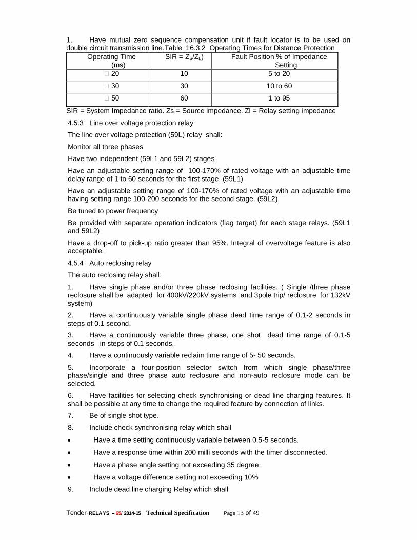
1. Have mutual zero sequence compensation unit if fault locator is to be used on double circuit transmission line.Table 16.3.2 Operating Times for Distance Protection
Operating Time (ms)
SIR = ZS/ZL) Fault Position % of Impedance Setting
20 10 5 to 20
30 30 10 to 60
50 60 1 to 95
SIR = System Impedance ratio. Zs = Source impedance. Zl = Relay setting impedance
4.5.3 Line over voltage protection relay
The line over voltage protection (59L) relay shall:
Monitor all three phases
Have two independent (59L1 and 59L2) stages
Have an adjustable setting range of 100-170% of rated voltage with an adjustable time delay range of 1 to 60 seconds for the first stage. (59L1)
Have an adjustable setting range of 100-170% of rated voltage with an adjustable time having setting range 100-200 seconds for the second stage. (59L2)
Be tuned to power frequency
Be provided with separate operation indicators (flag target) for each stage relays. (59L1 and 59L2)
Have a drop-off to pick-up ratio greater than 95%. Integral of overvoltage feature is also acceptable.
4.5.4 Auto reclosing relay
The auto reclosing relay shall:
1. Have single phase and/or three phase reclosing facilities. ( Single /three phase reclosure shall be adapted for 400kV/220kV systems and 3pole trip/ reclosure for 132kV system)
2. Have a continuously variable single phase dead time range of 0.1-2 seconds in steps of 0.1 second.
3. Have a continuously variable three phase, one shot dead time range of 0.1-5 seconds in steps of 0.1 seconds.
4. Have a continuously variable reclaim time range of 5- 50 seconds.
5. Incorporate a four-position selector switch from which single phase/three phase/single and three phase auto reclosure and non-auto reclosure mode can be selected.
6. Have facilities for selecting check synchronising or dead line charging features. It shall be possible at any time to change the required feature by connection of links.
7. Be of single shot type.
8. Include check synchronising relay which shall
Have a time setting continuously variable between 0.5-5 seconds.
Have a response time within 200 milli seconds with the timer disconnected.
Have a phase angle setting not exceeding 35 degree.
Have a voltage difference setting not exceeding 10%
9. Include dead line charging Relay which shall
Tender-RELAYS – 65/ 2014-15 Technical Specification Page 14 of 49
Have two sets of relays and each set shall be able to monitor the three phase voltage.
Have one set connected to the line CVT’s with a fixed setting of 20% of rated voltage.
Incorporate necessary auxiliary relays and timers to give comprehensive scheme. The scheme shall be such as to have Main I and Main II fully segregated such that shutdown and testing on one main protection should not affect the other main protection. The auto reclosure should then be connected to one protection. Integrated auto-reclosure feature as part of both Main I and Main II is also acceptable. The scheme shall have check synchronous and voltage check interlocks (25, 27). These interlocks are supplementary to all other decision interlocks that may be required or specified in order to ensure correct operation of the scheme.
Local Breaker Back-up protection relay (50 LBB) for circuit breakers The local breaker backup protection relay shall:
1. Be of triple pole type
2. Have an operating time of less than 15 milliseconds.
3. Have a resetting time of less than 15 milliseconds.
4. Have three over current elements. Each element shall be arranged to get individual initiation from the corresponding phase of line protection.
5. Be of solid-state type having a setting range of 5-80% of rated current
6. Have a continuous thermal withstand twice the rated current irrespective of the setting.
7. Have three separate timers, one for each phase with continuously adjustable setting range of 0.1-1 seconds.
8. Have necessary auxiliary relays to make a comprehensive scheme.
Protective system
Unit and backup protection Power system elements and the network shall be provided with independent high speed discriminative protection systems. Duplicate schemes (Main I and Main II) shall be provided for all 400kV and 220kV systems. For all other systems up to 132kV, the protection equipment shall be divided into ‘Main’ and ‘Backup’ systems. Protection schemes of different philosophy (Main I and Main II or Main and Back-up) shall preferably be fed from different DC supplies when available in the substation. This shall include energisation of trip coil circuits in case of 400 kV and 220 kV breakers. However in case of 132kV system where a duplicate DC source is available, the two trip coils shall be energised from the different sources. Protection equipment shall not initiate a trip signal following the normal and correct discharge operation of one or more surge arresters. Measurement functions relays must be achieved through electronic circuits. Auxiliary relays, repeat relays, trip relays and any other simple auxiliary or contact multiplication function may be based on standard attracted armature or other electromechanical techniques. Relays based on numerical design technique shall constitute all primary protections. The Employers intends to avail the improved benefits in the functionality, design, reliability and cost effectiveness of integrated substation control systems in future for which relays with numeric design only shall be required. It is the responsibility of the Contractor to demonstrate that all relay equipment offered has a reasonable level of in-service experience. For numerical relays, the following conditions apply :
Tender-RELAYS – 65/ 2014-15 Technical Specification Page 15 of 49
a) The Bidder must be able to demonstrate that a minimum of 10 relays of each type offered have been in full service without relay failures for a minimum of three years in two different countries, one of which may be the country of manufacture. Experience involving trial installations is not acceptable.
b) The Bidder must include a statement of the number of years of guaranteed manufacturing and parts support which will be provided for the relays offered.
c) The Bidder is be required to state the full firmware version together with the version of relays for which experience records are offered. For relays which are provided with communication facilities, the communications facility should allow all information which is available locally at the relay front panel to be accessed remotely. It should also be possible to carry out bulk transfer of settings and fault record information using the appropriate PC based software.
Protection discrimination On the occurrence of a fault on the power system network the high speed discriminating protection systems (main protection) shall rapidly detect the fault and initiate the opening of only those circuit breakers which are necessary to disconnect the faulted electrical element from the network. Protection equipment associated with adjacent electrical elements may detect the fault, but must be able to discriminate between an external fault and a fault on the electrical element which it is designed to protect. Sequential time delayed tripping is not permitted except in the following specific circumstances:
Protection for short connections between post current transformer housings and circuit breakers when the technical advantages of complete overlapping of the protection are outweighed by economic considerations, (i.e. short-zone protection)
Operation of time graded back-up protection takes place as a result of either the complete failure of the communication links associated with the main protection systems, or the fault resistance is substantially greater than a value which can be detected by main protection systems.
Operation of line back-up protection to disconnect primary system faults in the case of a circuit breaker failing to operate, (i.e. circuit breaker failure protection)
All back-up protection systems shall be able to discriminate with main protection systems, circuit breaker fail protection and with other back-up protection systems installed elsewhere on the transmission system.
Codes and Standards The equipment supplied shall generally comply with the codes and standards indicated in relevant sections of this specification. Additionally the equipment shall also conform the requirements of this specification. Environmental requirement The protection, control and metering equipment shall operate satisfactorily under the various atmospheric, mechanical, electrical and environmental conditions as stipulated in the relevant sections of this Specification. The equipment shall conform to EMC Class III. Future network scada system At some time in the future the Employer intends to introduce a network SCADA system. All equipment to be installed under this Specification shall be suitable for future remote operation and remote data acquisition. The limit of responsibility with regard to this contract shall be to provide equipment suitable for future connection to and communication with a SCADA system, either by means of RTU or modem. Neither the RTU nor the modems form part of the scope of this Specification.
Tender-RELAYS – 65/ 2014-15 Technical Specification Page 16 of 49
The proposed protocol for the SCADA system is IEC 61850 compliance. Equipment necessary to interface the Integrated Substation Control System with the SCADA system are part of the scope of this Specification.
Control and monitoring levels The substation control and monitoring system shall allow for three levels of man machine interface. The number of levels initially employed will be limited to one i.e. substation levels. Provision shall be made for the future implementation of the second and third level of network control and monitoring from a system control centre via SCADA. Selection of substation control shall be from the individual equipment basis i.e., from the control panels. At the station level, control panels should be located in the main control room. A mimic diagram representing the substation lay-out in single line diagram form should be provided. The mimic board is intended to give operating personnel an overall view of the switchgear state. It shall be made up from the individual circuit control panels mounted side by side. The arrangement should correspond to the primary equipment layout. Alarm annunciation equipment should be mounted adjacent to the mimic diagram, or form an integral part of the control panel. Operation of an alarm should cause the appropriate window to flash and sound an audible warning. Operation of an accept button will silence the audible warning, steady the flashing window and prepare the annunciation to respond to subsequent initiation. A reset button should be provided to extinguish alarms which have reset. A lamp test button shall be provided which will initiate steady state illumination of all alarm windows. Trip or protection initiated alarms should have windows distinct from others (e.g. red display instead of white). Control and selector switches should be of approved types complying with accepted standards such as IEC 337. Control switches shall have two independent motions or two handed operation to effect operation. Indicating instruments should be of approved types complying with accepted standards such as IEC 5 1.
Enclosures Protection systems shall preferably be accommodated in rack or hinged rack cubicles and be of modular construction with factory assembled and tested wiring. Conventional analogue relays may be mounted on conventional relay panels which must be mounted to allow access to the front and rear of the panel. Relays mounted on such panels shall be flush mounted. The construction method shall offer the benefits of minimum site construction times and circuit outage requirements. Interconnections shall be identified in accordance with the requirements for dependent local end marking as specified in IEC Publication 391 Sections 3.4.1.a.1 and The interconnections shall be recorded on an appropriate schedule or diagram. For modular protection systems, means shall be provided to lock positively each withdrawable module or unit in the “service” position. It shall not be possible to remove any module without first short-circuiting all associated current transformer circuits.
Operator interface:
General
All numerical protection systems shall be provided with an integral local operator interface facility to enable communication with the relay without the use of external equipment. Any facilities provided for connection to an external computer shall be an additional feature to the local operator interface. No exceptions to this requirement shall be accepted.
Tender-RELAYS – 65/ 2014-15 Technical Specification Page 17 of 49
Identification Each protection system shall have a unique identifier which is clearly visible. If the protection system is software operated the software reference and issue level shall be identified.
Settings Each protection system shall provide a means by which the user can easily access the protection system to apply the required settings. This facility shall be secure from inadvertent operation. A display of the selected settings shall be provided on the protection system.
Indications Each relay or protection scheme shall be provided with an adequate number of indications to ensure that the appropriate faulted phase, zone, etc. can be easily identified after a fault condition. Each indicator shall be visible and capable of being reset without removing the relay cover. For relays based upon numerical techniques, indication shall be provided for failures detected in the protection relay or communications equipment. The indications provided shall be designed to allow the defective item to be quickly identified. The status of the DC power supplies shall be permanently indicated. Details of the indication required for specific types of relay are provided in the individual parts of this section of the specification covering particular types of relay.
Protection system output contacts All protection systems shall be provided with an adequate number of contacts of suitable rating to carry out the required tripping functions, alarm indications, fault recorder functions and such supplementary signalling functions as may be necessary for initiation of automatic switching control, inter tripping etc. In all cases contacts intended for tripping duty shall be designed such that they cannot inadvertently interrupt trip coil current.
Testing and isolating facilities Each functional protection system shall be so arranged that operational and calibration checks can be carried out with the associated primary circuit(s) in service. Adequate test facilities shall be provided within the protection system to enable the protection and auto-reclosing equipment to be tested from the front of the protection equipment panel with the primary circuit(s) in service. The test points shall be clearly identified and labelled. Relays based on digital and numerical design techniques shall include supervision facilities which provide a periodic self check of the key elements within the relay and also provide continuous self monitoring of all internal power supplies and microprocessor operation. A defect in any of the self supervision facilities shall not cause maloperation of the protection relay internal self-test facilities and shall give an alarm should an internal fault occur. Adequate facilities shall be provided, preferably at the front of each protection equipment panel, to isolate all DC and AC incoming and outgoing circuits so that work may be carried out on the equipment with complete safety for personnel and without loss of security in the operation of the switching station. The isolation points shall be clearly identified and labelled. The labels on the isolation points shall either describe the function or be uniquely numbered. The Contractor shall provide a list of all of the protection and auto-reclose equipment being offered under the contract. The Contractor shall also provide a list of all of the test and ancillary equipment required for commissioning and routine testing of all protection and auto-reclose equipment.
Tender-RELAYS – 65/ 2014-15 Technical Specification Page 18 of 49
Service life and support The protection systems shall be designed for a service life of at least 15 years, and preferably 20 years, given that normal maintenance in accordance with manufacturers recommendations is carried out during the lifetime of the protection system. The Contractor shall state the service life of the protection system equipment in relation to that of the main HV plant and apparatus so that Employer can assess the cost of any replacement during the life of the substation. The Contractor shall state the period for which lifetime support will be provided for the protection system equipment and shall make recommendations for the provision of spare parts. The Contractor shall supply circuit diagrams for each protection system and the associated tripping system(s). The diagrams shall provide sufficient information to enable fault finding and maintenance to be carried out and shall not consist solely of information used for equipment manufacture. When the Contractor has been notified of incorrect operation, or failure to operate when required, of any protection system supplied under the contract, the Contractor shall investigate the incident and inform Employer of any such incidents if they result in the necessity to modify the equipment. The Contractor shall also inform Employer of the details of the modifications required to prevent such incidents re-occurring. The Contractor shall offer a service to enable any faulty item of protection equipment to be rectified or replaced within a stated period of the fault being reported. The Contractor shall state the repair/replacement period. The Contractor shall, when requested, offer the Employer a maintenance contract for the protection equipment supplied under the contract. The Contractor shall supply details of the cost of the maintenance contract and information on test procedures and test frequencies that would be supplied under the maintenance contract. The Contractor shall offer training for Employer’s personnel in the operation and maintenance of the protection equipment.
Thermal rating of equipment Relay equipment intended to perform a current measurement function shall be capable of continuous operation at a current of not less than 2.4 times the nominal rating or twice the setting value, whichever is the more onerous. Relay equipment intended for use in a normally quiescent mode and having a short time rating - for example, high impedance differential protection - shall be rated in accordance with the intended function and taking account of such inherent protective devices as may be incorporated in the design. The short time rating for all protection relaying schemes shall be 100 times the nominal relay rating for a duration of one second. Voltage sensitive equipment intended for use on effectively earthed networks shall have a continuous withstand of not less than 1.2 times nominal voltage and a short duration withstand of not less than 1.5 times nominal phase-to-ground voltage for 30 s.
Insulation The rated insulation voltage of circuits connected to current transformers of high impedance relays shall be 1000 V. All other circuits shall have an insulation voltage of 2500V. All open contacts of the protection system shall withstand a voltage of 1000V. The protection system shall comply with the dielectric test requirements of IEC 255-5. The test voltage shall be selected according to the rated insulation voltage of the circuits being tested form SeriesC of Table1 of IEC 255-5. The protection system shall comply with the impulse test requirements of IEC 255-5 with test voltage of 5kV.
Tender-RELAYS – 65/ 2014-15 Technical Specification Page 19 of 49
Test requirements
General requirements The Contractor shall supply test results and/or in service operating evidence to confirm compliance with the general and performance requirements as detailed in this Specification.
Pre-commissioning and energisation tests The Contractor shall submit details of all pre-commissioning and energisation tests to the Project Manager for approval prior to the tests, and shall provide the Project Manager with the opportunity to witness the commissioning tests.
Testing, inspection and test certificates The Bidder shall enclose with his bid the reports of type and routine tests conducted on similar equipment earlier as a proof of designing and developing similar equipment. Bid documents, furnished without these test reports shall be considered as incomplete and shall be liable for rejection. All equipment furnished shall conform to the type tests and shall be subject to routine tests in accordance with the requirements stipulated for control and relay panel equipment. The Project Manager reserves the option to call for any or all the type tests to be repeated on the equipment. The Project Manager further reserves the option to intimate the type tests to be carried out on the equipment up to six months after the award of contract. Payments would be made for the type tests actually carried out in accordance with the rates given in the Bid Price Schedule. OPTCL will have the right to call for any other tests of reasonable nature to be carried out at the Contractor's premises or at site or in any other place, in addition to the aforesaid type and routine tests, to satisfy that the materials comply with the Specification. The Contractor shall advise the Project Manager three months in advance of the type tests to be conducted on the finished equipment giving a programme for conducting the tests and shall proceed to test the equipment only after approval of the Project Manager. All type tests shall be performed in presence of Project Manager should he so desire. The Contractor shall give one months notice of routine tests and inspection to be carried out on the finished equipment. A programme for conducting the tests shall be furnished and the Contractor shall proceed to test the equipment after approval of the Project Manager. The tests shall be witnessed by the Project Manager should he so desire. All inspections, type tests and routine tests shall be carried out after approval of all the relevant drawings required under the contract. None of the equipment to be furnished or used in connection with this contract shall be despatched until factory tests are satisfactorily completed. Such factory tests on the equipment shall not however relieve the Contractor from full responsibility for furnishing equipment conforming to the requirements of this contract, nor prejudice any claim right or privilege which the Employer may have because of the use of defective or unsatisfactory equipment. Should the Project Manager waive the rights to inspect and test any equipment, such a waiver shall not relieve the Contractor, in any way, of his obligations under this contract. One copy of test reports of successful tests shall be submitted to OPTCL for approval before shipment of equipment. For equipment tests for which IEC recommendations or Indian Standards are available, test reports confirming that the equipment has passed the specified type and routine tests shall be furnished for the approval of the OPTCL by the Contractor before shipment of the equipment. For equipment/tests for which IEC/IS specifications do not exist, the Contractor shall propose a test procedure for the approval of the Project Manager before conducting tests. Test certificates for tests carried out shall be submitted for approval of the OPTCL before shipment of the equipment. Failure of any equipment to meet the requirements of tests carried out at works or at site shall be sufficient cause for rejection of the equipment. Rejection of any equipment
Tender-RELAYS – 65/ 2014-15 Technical Specification Page 20 of 49
will not be held as a valid reason for delay in the completion of the works in accordance with the agreed programme. The Employer reserves the right to call for field tests on the completely assembled equipment at site. The price for conducting all the type tests in accordance with relevant standards and specifications shall be indicated in Bid Price Schedule and these would be considered for bid evaluation. The break-up price of type tests shall be given in the relevant price schedule for payment purpose only. In case Bidder does not indicate charges for any of the type tests or does not specifically identify any test in the price schedules, it will be assumed that the particular test has been offered free of charge. Further, in case any Bidder indicates that he shall not carry out a particular test, his offer shall be considered incomplete and shall be liable to rejection.
Soak test All solid state equipment/system panels shall be subject to the Hot Soak Test as a routine test in accordance with the procedure detailed in the following paragraph. All solid state equipment shall be burn-in tested for minimum of 120 hours continuously under operational conditions. During the last 48 hours of testing, the ambient temperature of the test chamber shall be 50C. Each panel shall be complete with all associated sub-systems and the same shall be in operation during the above test. During the last 48 hours of the above test, the temperature inside the panel shall be monitored with all the doors closed. The temperature of the panel interior shall not exceed 65C.
Type tests Impulse voltage withstand test as per Clause 6.1 of IS 8686 (for a test voltage appropriate to Class III as per Clause 3.2 of IS-8686) High Frequency Disturbance test as per Clause 5.2 of IS 8686 (for a test voltage appropriate to Class III as per Clause 3.2 of IS 8686) Type tests listed under IEC-Technical Committees recommendation `TEC-57' and functional type tests listed under CIGRE Study Committee 34 (Protection) Report on simulator, Network analyser or PTL as applicable.
Routine tests Contact insulation resistance test as per Clause 10.5 of IS-3231. Insulation withstand capability as per Clause 10.5 of IS-3231 on all AC/DC relays. Protection Schemes
General The following sections of this specification identify the protection requirements for specific schemes. Drawings showing single line diagrams for each type of circuit are included in this Specification. The arrangements shown on these drawings represent the minimum requirements. Other protection arrangements may be provided but the Bidder must clearly state the reasons for offering supplementary protection schemes.
Technical requirements Technical requirements of the protection and auxiliary relays, recorders and meters to be provided as part of the scope are detailed I the following sub clauses. The setting ranges of the equipment offered, if different from that specified shall be acceptable if they meet the functional requirements. The Bidder shall quote for protection equipment meeting the requirements given in these sub clauses. The Bidder may also quote alternative or additional protections or relays considered necessary by him for providing an effective and reliable protection scheme. These equipments shall be quoted separately as an alternative or addition to the main offer. The Employer reserves the right to accept or otherwise such equipment.
Tender-RELAYS – 65/ 2014-15 Technical Specification Page 21 of 49
400kV Reactor protection Protection requirement The 400 kV reactors provided with the lines shall have the following protections.
Differential protection.
Restricted earth fault protection.
Backup impedance protection.
Differential protection relay (87R) This relay shall :
Be triple pole type
Have operation time less than 25 milliseconds at five times setting.
Be tuned to system frequency.
Have three instantaneous high set units to ensure rapid clearance of heavy faults with saturated CT’s.
Have current setting range of 10 to 40% of 1 Amp.
Be Low impedance type.
Be stable for all external faults.
Be provided with suitable non-linear resistors to limit the peak voltage to 1000 volts.
Restricted earth fault protection relay (64 R) This relay shall:
Be single pole type
Be of current/voltage operated high impedance type
Have a current setting of 10-40% of 1A and a suitable voltage setting range.
Be tuned to system frequency.
Be fitted with suitable non-linear resistors to limit the peak voltage to 1000 volts.
Back up impedance protection relay (21 R) This relay shall:
2. Be triple pole type
3. Be single step polarised `mho' distance relay or impedance relay suitable for measuring phase to ground and phase to phase faults.
4. Have an ohmic setting range of 20-320 ohms and shall be continuously variable.
5. Have an adjustable characteristic angle of 30 to 80 degree.
6. Have a definite time delay with a continuously adjustable setting range of 0.2 - 2.0 seconds. Shall initiate three phase tripping
Transformer protection The following protection shall be provided for all 315MVA 400/220kV and 220/132/33 KV,160 or 100MVA autotransformers(33 kv side is delta winding and is a loaded winding), and 220/33kV and 132/33kV double wound transformers: All the relay shall be latest numerical version having IEC 61850 protocol compliance
Transformer differential protection (87AT)
Over fluxing protection (99AT)
Restricted earth fault protection (64AT)
Back-up directional over current protection (67/51/50) on HV side
Tender-RELAYS – 65/ 2014-15 Technical Specification Page 22 of 49
Back-up directional earth fault protection (67N/51N/50N) on HV side
Back-up directional over current protection (67/51/50) on LV side
Back-up directional earth fault protection (67N/51N/50N) on LV side
Restricted earth fault protection (64R)
Transformer over load protection (51OL)
1. LBB for 400kV, 220kV and 132kV sides.
Transformer differential protection relay (87AT) This relay shall :
ii) Be triple pole type, with faulty phase identification/indication
iii) Have an operating time not greater than 30 milliseconds at five times setting.
iv) Have three instantaneous high set units to ensure rapid clearance of heavy faults with saturated CT’s.
v) Have an adjustable dual slope bias setting range of 10%-50%.
vi) Be suitable for rated current of 1A.
vii) Have second harmonic and fifth harmonic restraint feature and also be stable under normal over fluxing conditions and inrush of current during charging.
viii) Have at least three bias winding per phase.
ix) Have an operating current setting adjustable between 10% and 50%
x) Should not require interposing transformers and the relay should correct the vector group difference and CT primary/load current difference.
Over fluxing protection relay (99AT) This relay shall :
a) Operate on the principle of voltage to frequency ratio and have two settings - for alarm and trip.
b) Have inverse time characteristics, matching with transformer over fluxing withstand capability curve.
c) Provide an independent `alarm' with the time delay continuously adjustable between 0.1 to 6.0 seconds at values of “v/f”' between 100% to 130% of rated values.
d) Have a set of characteristics of various time multiplier settings. The maximum operating time of the relay shall not exceed 3 seconds and 1.5 seconds at “v/f”' values of 1.4 and 1. 5 times, the rated values, respectively.
e) Have a tripping time governed by “v/f”' Vs. time characteristics of the relay.
f) Have an accuracy of operating time better than ± 10%.
g) Have a resetting ratio of 98% or better.
Restricted earth fault protection relay (64AT) This relay shall:
i) Be single pole type.
ii) Be of current/voltage operated high/low impedance type.
iii) Have a current setting range of 10-40% of 1A and a suitable voltage setting range.
iv) Be tuned to the system frequency
v) Have suitable non-linear resistor in case required to limit the peak voltage to 1000 Volts.
Tender-RELAYS – 65/ 2014-15 Technical Specification Page 23 of 49
Transformer overload protection feature The transformer overload protection shall:
Be a single pole type
Be a definite time overcurrent type
Have two separate sets of overcurrent relay elements, each with continuously adjustable setting range of 50-200% of rated current independently.
Have two separately adjustable time delay relays, one for alarm having setting range of 1 to 10.0 seconds, continuously. The second time delay relay should have continuously adjustable setting range of 1.0 to 10.0 minutes for tripping.
Have a drop-off/pick-up ratio greater than 95%.
HV /LV side back-up directional over current protection This relay shall:
(a) Be single pole type.
(b) Have IDMT characteristics with a definite minimum of three seconds at ten times the setting.
(c) Have a variable setting range of 50% to 200% of rated current.
(d) Have a characteristic angle of 45 degrees, a directional controlled, low transient over reach, high set instantaneous unit of continuously variable setting range of 500- 2000% of rated current.
(e) Provision of highest setting in two stages.
HV/LV side back-up directional earth fault protection This shall also have identical specification as at clause above excepting that the adjustable setting range shall be 20-80%.
TEE protection differential relays (87 TT1,87TT2) (applicable for 5 CT scheme)
Where a Tee Protection for a five CT system is provided the following shall be applicable.
First set of differential relays One set of differential protection relays (87 TT1) shall
b) Be triple pole type.
c) Have an operating time less than 30 milliseconds at five times setting
d) Have three instantaneous high set over current units.
e) Have an adjustable bias setting range of 20% to 50%
f) Be suitable for rated current of 1A.
g) Have three bias windings.
h) Have an operating current setting of 15% or less.
Second set of differential relays. The second set of Differential relay (87 TT2) shall:
1. Be triple pole type.
2. Have operating time less than 25 milliseconds at five times setting.
3. Be tuned to system frequency
4. Have current setting range of 20 to 80% of 1A.
5. Be voltage operated, high impedance type
6. Be stable for all external faults.
Tender-RELAYS – 65/ 2014-15 Technical Specification Page 24 of 49
Be provided with suitable non linear resistors across the relay to limit the peak voltage to 1000 volts.
BUS BAR PROTECTION: Bus bar protection schemes shall be provided for each main and transfer bus of 400 KV and 200 KV provided in the switch yard. This shall constitute main and check features. The overall scheme shall be engineered such that operation of both main and check features connected to the faulty bus shall result in tripping of the same. The scheme shall be provided with necessary expansion capacity and interfaces for adding features when the switch yard is extended in future to its ultimate capacity. The bus bar relay shall be of latest numerical relay having IEC protocol 61850 compliance.
Busbar protection (Latest version numerical having IEC-61850 protocol compliance)
Bus bar protection schemes shall be provided for each main bus of 400kV and 220kV switchyard. The overall scheme shall be engineered so as to ensure that operation of any one out of two schemes connected to main faulty bus shall result in tripping of the same. However in case of transfer bus, where provided, only one busbar protection scheme shall be required. Each busbar protection scheme shall
i. Be of modular construction and have features of self monitoring facility to ensure maximum availability of scheme. The scheme shall be static/ microprocessor/ Numerical based.
ii. Have maximum operating time up to trip impulse to trip relay for all types of faults of 15 milli seconds at 5 times setting value.
iii. Operate selectively for each busbar.
iv. Give hundred percent security up to 40kA fault level.
v. Incorporate a check feature.
vi. Incorporate continuous supervision for CT secondaries against any possible open circuit and if it occurs, shall render the relevant zone of protection inoperative and initiate alarm.
vii. Not give false operation during normal load flow in busbars.
viii. Incorporate clear zone indication.
ix. Be of phase segregated and triple pole type and provide independent zones of protection for each bus (including transfer bus if any). If a bus section is provided then each side of the bus section shall have separate busbar protection scheme.
x. Include individual high speed hand reset tripping relays for each feeder, including future ones.
xi. Be of low/medium impedance biased differential type and have operate and restraint characteristics.
xii. Be transient free in operation
xiii. Include continuous DC supplies supervision.
xiv. Shall include multitap auxiliary CT's for each bay including future bays as per SLD and also include necessary CT switching relays wherever CT switching is involved.
xv. Include protection 'in/out' switch for each zone with at least six contacts for each switch.
xvi. Shall have CT selection incomplete alarm wherever CT switching is involved.
xvii. Have necessary auxiliary relays to make a comprehensive scheme.
Tender-RELAYS – 65/ 2014-15 Technical Specification Page 25 of 49
At existing substations busbar scheme with independent zones for each bus will be available. All necessary co-ordination for 'CT' and 'DC' interconnections between existing schemes (panels) and the bays proposed under the scope of this contract shall be fully covered by the bidder. Any auxiliary relays, trip relays, flag relays required to facilitate the operation of bays covered under this contract shall be fully covered in the scope of the bidder. The Contractor shall offer all equipment to meet the requirements as above to make the scheme full and comprehensive.
Tripping relay (86)
High speed tripping relay shall:
Be instantaneous (operating time not to exceed 10 milliseconds).
Reset within 20 milliseconds. Not self resetting.
Be DC operated
Have adequate contacts to meet the requirement of scheme, other functions such as auto-reclose relay, LBB relay as well as cater to associated equipment such as event logger, disturbance recorder, fault locator, etc.
Be provided with operation indicators for each element/coil.
Flag relays
These shall have:
Hand reset flag indication
Two elements
Four contacts (NO or NC or combination as required), for each element/coil.
Trip circuit supervision relay
The relay shall be capable of monitoring the healthiness of each `phase' trip coil and associated trip circuit of circuit breaker during `ON' and `OFF' conditions. The relay shall have adequate contacts for providing connections to alarm and event logger. The relay shall have time delay on drop-off of not less than 200 milliseconds and be provided with operation indications for each phase.
Supply supervision relay
The relay shall be capable of monitoring the DC supply to which it is connected and indicating failure. It shall have adequate potential free contacts to meet the scheme requirement. The relay shall have a `time delay on drop-off' of not less than 100 milliseconds and be provided with operation indicator/flag.
Bus coupler / transfer bus coupler protection
The protection scheme for the above are to be provided with directional numerical over current and earth fault protection scheme . The relay shall be latest version numerical and IEC 61850 compliant for future SCADA purpose.The details as indicated under unit back up protection relay. All 220 kV substations shall be of Double Main (DM) or Double Main and Transfer (DMT) busbar configuration and shall be provided with a single bus coupler circuit breaker. In addition 220 kV DMT busbar configurations shall be provided with a transfer bus coupler circuit breaker. The required protection equipment for these breakers comprises overcurrent and earth fault relays. These relays shall comply with the requirements for backup over current and earth fault protection as described elsewhere in this section,
Tender-RELAYS – 65/ 2014-15 Technical Specification Page 26 of 49
except that the relays shall not be directional. The earth fault element shall have a current setting range of at least 20 – 80 percent in six equal steps. All 132 and 33 kV substations shall be of Single Main and Transfer (SMT) busbar configuration and a bus section isolator. Overcurrent and earth fault protection, complying with the requirements as given elsewhere in this section but without directional feature, shall be provided. In DMT/SMT configurations, whenever the main breaker of a feeder or transformer is substituted by the bus coupler or transfer bus coupler breaker, a facility for switching over of the trip function of the feeder or transformer relays from the main breaker to the bus coupler or transfer bus coupler breaker, shall be provided through provision of a lockable protection transfer switch. The provision of a key interlock on the above switch is to be so arranged that at one time only one feeder or transformer can be taken to transfer mode.
Circuit breaker monitoring auxiliary relays All circuit breakers shall be provided with several relay contacts for annunciation of circuit breaker conditions such as :
Low air/hydraulic oil/gas pressure.
Lockout conditions due to abnormally low air/hydraulic oil/gas pressure.
Pole discrepancy trip.
Compressor/hydraulic pump trouble. The exact requirements for this shall be available in the circuit breaker drawings to be provided by the manufacturer. The programmable Inputs/Outputs of the numeric relays shall be used as much as possible for providing annunciation in the control room for such cases. In case this is found inadequate, suitable auxiliary flag relays may be provided in the relay panels to provide annunciation.
Tender-RELAYS – 65/ 2014-15 Technical Specification Page 27 of 49
1) DISTANCE PROTECTION RELAY Specification for Numerical distance Protection:- A. The line protection relays are required to protect the line and clear the faults on line
within shortest possible time with reliability, selectivity and full sensitivity to all type of faults on lines.
B. The general concept is to have one main protection for 400KV ,220 KV or 132 KV transmission lines.
1) The maximum fault current could be as high as 40 KA/63 KA but the minimum fault current could be as low as 20% of rated current of CT secondary. The starting & measuring relays characteristics should be satisfactory under these extremely varying conditions. 2) The protective relays shall be suitable for use with capacitor voltage transformers having non-electronic damping and transient response as per IEC 3) Disturbance Recorder function shall be offered as an integral part of line protection relay. 4) The NUMERICAL DISTANCE PROTECTION RELAYS SHALL BE USED FOR:- MAIN PROTN: Numerical, distance protection scheme with back up IDMT earth fault protection with having dual algorithm for protection. The detailed description of the above line protections is given hereunder:- Numerical distance protection scheme: (for main-1 protection in 220 KV&132 KV) shall: a) Be fully numerical and be based on a non-switched scheme. b) Provide protection for the transmission line from all types of faults-phase to earth faults as well as multiphase fault. The protection algorithm may have dual redundant distance protection algorithms to detect all types of power system faults so as to arrive at a secure trip decision with correct phase selection and proper direction discrimination in the shortest possible time. c) Have non-switched measurement, which implies processing of more than six possible fault loops measurement. d) Have polygonal and Circular characteristics for both phase to phase & phase to ground with independently adjustable reactive and resistive reaches for maximum selectivity and maximum fault resistance coverage. The zones shall have independent settable earth fault compensation factors to cater to adjacent lines with different zero sequence to positive sequence ratios Alternatively, the Zone settings for Polygons (R and X) shall be adjustable between 0.05 and 250 ohm secondary. For MHO Circles the range shall be 0.05 to 200 ohm secondary these ranges apply to 1A nominal current. e) Have adequate number of forward zones (minimum three) and reverse zone. The zone reach setting ranges shall be sufficient to cover line lengths appropriate to each zone. Carrier aided scheme options such as permissive under reach, over reach, & blocking and non-carrier aided schemes of zone-1 extension and loss of load accelerated tripping schemes shall be available as standard. Weak in feed logic and current reversal guard also shall be provided.
f) In case the carrier channels fails, one out of the non-carrier based schemes cited above should come into operation automatically to ensure high speed and simultaneous opening of breakers at both ends of the line. g) In addition to the conventional impedance measuring algorithm the distance protection relay should have a separate measuring technique in the same hardware completely different to the conventional impedance measuring principal. Both the algorithms should run in parallel and should take trip decisions independently h) Have a maximum operating time up to trip impulse to circuit breaker (complete protection time including applicable carrier and trip relay time) with CVT being used on the line.
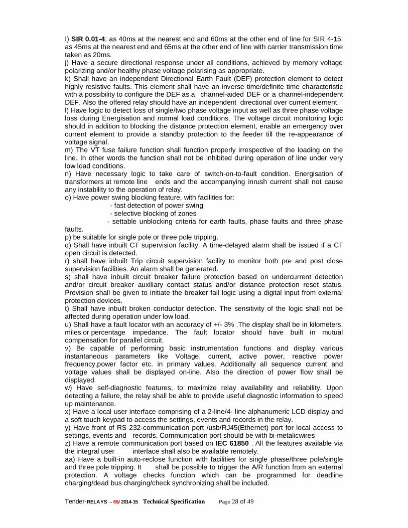
Tender-RELAYS – 65/ 2014-15 Technical Specification Page 28 of 49
I) SIR 0.01-4: as 40ms at the nearest end and 60ms at the other end of line for SIR 4-15: as 45ms at the nearest end and 65ms at the other end of line with carrier transmission time taken as 20ms. j) Have a secure directional response under all conditions, achieved by memory voltage polarizing and/or healthy phase voltage polarising as appropriate. k) Shall have an independent Directional Earth Fault (DEF) protection element to detect highly resistive faults. This element shall have an inverse time/definite time characteristic with a possibility to configure the DEF as a channel-aided DEF or a channel-independent DEF. Also the offered relay should have an independent directional over current element. l) Have logic to detect loss of single/two phase voltage input as well as three phase voltage loss during Energisation and normal load conditions. The voltage circuit monitoring logic should in addition to blocking the distance protection element, enable an emergency over current element to provide a standby protection to the feeder till the re-appearance of voltage signal. m) The VT fuse failure function shall function properly irrespective of the loading on the line. In other words the function shall not be inhibited during operation of line under very low load conditions. n) Have necessary logic to take care of switch-on-to-fault condition. Energisation of transformers at remote line ends and the accompanying inrush current shall not cause any instability to the operation of relay. o) Have power swing blocking feature, with facilities for:
- fast detection of power swing - selective blocking of zones
- settable unblocking criteria for earth faults, phase faults and three phase faults. p) be suitable for single pole or three pole tripping. q) Shall have inbuilt CT supervision facility. A time-delayed alarm shall be issued if a CT open circuit is detected. r) shall have inbuilt Trip circuit supervision facility to monitor both pre and post close supervision facilities. An alarm shall be generated. s) shall have inbuilt circuit breaker failure protection based on undercurrent detection and/or circuit breaker auxiliary contact status and/or distance protection reset status. Provision shall be given to initiate the breaker fail logic using a digital input from external protection devices. t) Shall have inbuilt broken conductor detection. The sensitivity of the logic shall not be affected during operation under low load. u) Shall have a fault locator with an accuracy of +/- 3% .The display shall be in kilometers, miles or percentage impedance. The fault locator should have built in mutual compensation for parallel circuit. v) Be capable of performing basic instrumentation functions and display various instantaneous parameters like Voltage, current, active power, reactive power frequency,power factor etc. in primary values. Additionally all sequence current and voltage values shall be displayed on-line. Also the direction of power flow shall be displayed. w) Have self-diagnostic features, to maximize relay availability and reliability. Upon detecting a failure, the relay shall be able to provide useful diagnostic information to speed up maintenance. x) Have a local user interface comprising of a 2-line/4- line alphanumeric LCD display and a soft touch keypad to access the settings, events and records in the relay. y) Have front of RS 232-communication port /usb/RJ45(Ethernet) port for local access to settings, events and records. Communication port should be with bi-metalicwires z) Have a remote communication port based on IEC 61850 . All the features available via the integral user interface shall also be available remotely. aa) Have a built-in auto-reclose function with facilities for single phase/three pole/single and three pole tripping. It shall be possible to trigger the A/R function from an external protection. A voltage checks function which can be programmed for deadline charging/dead bus charging/check synchronizing shall be included.
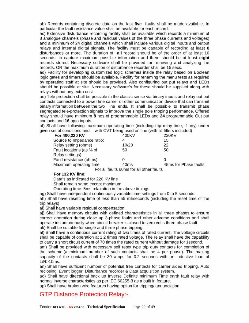
Tender-RELAYS – 65/ 2014-15 Technical Specification Page 29 of 49
ab) Records containing discrete data on the last five faults shall be made available. In particular the fault resistance value shall be available for each record. ac) Extensive disturbance recording facility shall be available which records a minimum of 8 analogue channels (phase and residual values of the three phase currents and voltages) and a minimum of 24 digital channels which shall include various digital inputs and output relays and internal digital signals. The facility must be capable of recording at least 8 disturbances or more. The duration of all record should be of the order of at least 10 seconds, to capture maximum possible information and there should be at least eight records stored. Necessary software shall be provided for retrieving and analyzing the records. OR the maximum duration of disturbance recorder shall be 15 secs. ad) Facility for developing customized logic schemes inside the relay based on Boolean logic gates and timers should be available. Facility for renaming the menu tests as required by operating staff at site should be provided. Also configuring out put relays and LEDs should be possible at site. Necessary software’s for these should be supplied along with relays without any extra cost. ae) Tele protection shall be possible in the classic sense via binary inputs and relay out put contacts connected to a power line carrier or other communication device that can transmit binary information between the two line ends. It shall be possible to transmit phase segregated tele-protection signals to improve the single pole tripping performance. Offered relay should have minimum 8 nos of programmable LEDs and 24 programmable Out put contacts and 16 opto inputs. af) Shall have following maximum operating time (including trip relay time, if any) under given set of conditions and with CVT being used on line (with all filters included) For 400,220 KV 400KV 220KV
Source to Impedance ratio: 4 15 Relay setting (ohms) 10/20 22 Fault locations (as % of 50 50 Relay settings) Fault resistance (ohms) 0 0 Maximum operating time 40ms 45ms for Phase faults For all faults 60ms for all other faults
For 132 KV line: Data’s as indicated for 220 KV line Shall remain same except maximum Operating time: 5ms relaxation in the above timings
ag) Shall have independent continuously variable time settings from 0 to 5 seconds. ah) Shall have resetting time of less than 55 miliseconds (including the reset time of the trip relays) ai) Shall have variable residual compensation. aj) Shall have memory circuits with defined characteristics in all three phases to ensure correct operation during close up 3-phase faults and other adverse conditions and shall operate instantaneously when circuit breaker is closed to zero volts three phase fault. ak) Shall be suitable for single and three phase tripping. al) Shall have a continuous current rating of two times of rated current. The voltage circuits shall be capable of operation at 1.2 times rated voltage. The relay shall have the capability to carry a short circuit current of 70 times the rated current without damage for 1second. am) Shall be provided with necessary self reset type trip duty contacts for completion of the scheme.(a minimum number of such contacts shall be 4 per phase). The making capacity of the contacts shall be 30 amps for 0.2 seconds with an inductive load of L/R>10ms. an) Shall have sufficient number of potential free contacts for carrier aided tripping, Auto reclosing, Event logger, Disturbance recorder & Data acquisition system. ao) Shall have directional back up Inverse Definite minimum Time earth fault relay with normal inverse characteristics as per IEC 60255-3 as a built in feature. ap) Shall have broken wire features having option for tripping/ annunciation.
GTP Distance Protection Relay:-
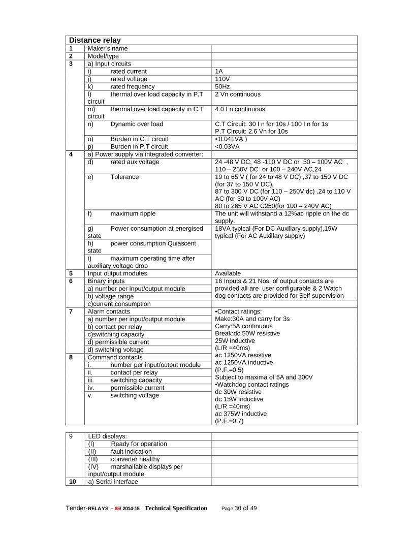
Tender-RELAYS – 65/ 2014-15 Technical Specification Page 30 of 49
Distance relay 1 Maker’s name 2 Model/type 3 a) Input circuits
i) rated current 1A j) rated voltage 110V k) rated frequency 50Hz l) thermal over load capacity in P.T circuit
2 Vn continuous
m) thermal over load capacity in C.T circuit
4.0 I n continuous
n) Dynamic over load C.T Circuit: 30 I n for 10s / 100 I n for 1s P.T Circuit: 2.6 Vn for 10s
o) Burden in C.T circuit <0.041VA ) p) Burden in P.T circuit <0.03VA
4 a) Power supply via integrated converter: d) rated aux voltage 24 -48 V DC, 48 -110 V DC or 30 – 100V AC ,
110 – 250V DC or 100 – 240V AC,24 e) Tolerance 19 to 65 V ( for 24 to 48 V DC) ,37 to 150 V DC
(for 37 to 150 V DC), 87 to 300 V DC (for 110 – 250V dc) ,24 to 110 V AC (for 30 to 100V AC) 80 to 265 V AC C250(for 100 – 240V AC)
f) maximum ripple The unit will withstand a 12%ac ripple on the dc supply.
g) Power consumption at energised state
18VA typical (For DC Auxillary supply),19W typical (For AC Auxillary supply) h) power consumption Quiascent
state i) maximum operating time after auxiliary voltage drop
5 Input output modules Available 6 Binary inputs 16 Inputs & 21 Nos. of output contacts are
provided all are user configurable & 2 Watch dog contacts are provided for Self supervision
a) number per input/output module b) voltage range c)current consumption
7 Alarm contacts •Contact ratings: Make:30A and carry for 3s Carry:5A continuous Break:dc 50W resistive 25W inductive (L/R =40ms) ac 1250VA resistive ac 1250VA inductive (P.F.=0.5) Subject to maxima of 5A and 300V •Watchdog contact ratings dc 30W resistive dc 15W inductive (L/R =40ms) ac 375W inductive (P.F.=0.7)
a) number per input/output module b) contact per relay c)switching capacity d) permissible current d) switching voltage
8 Command contacts i. number per input/output module ii. contact per relay iii. switching capacity iv. permissible current v. switching voltage
9 LED displays:
(I) Ready for operation (II) fault indication (III) converter healthy (IV) marshallable displays per input/output module
10 a) Serial interface
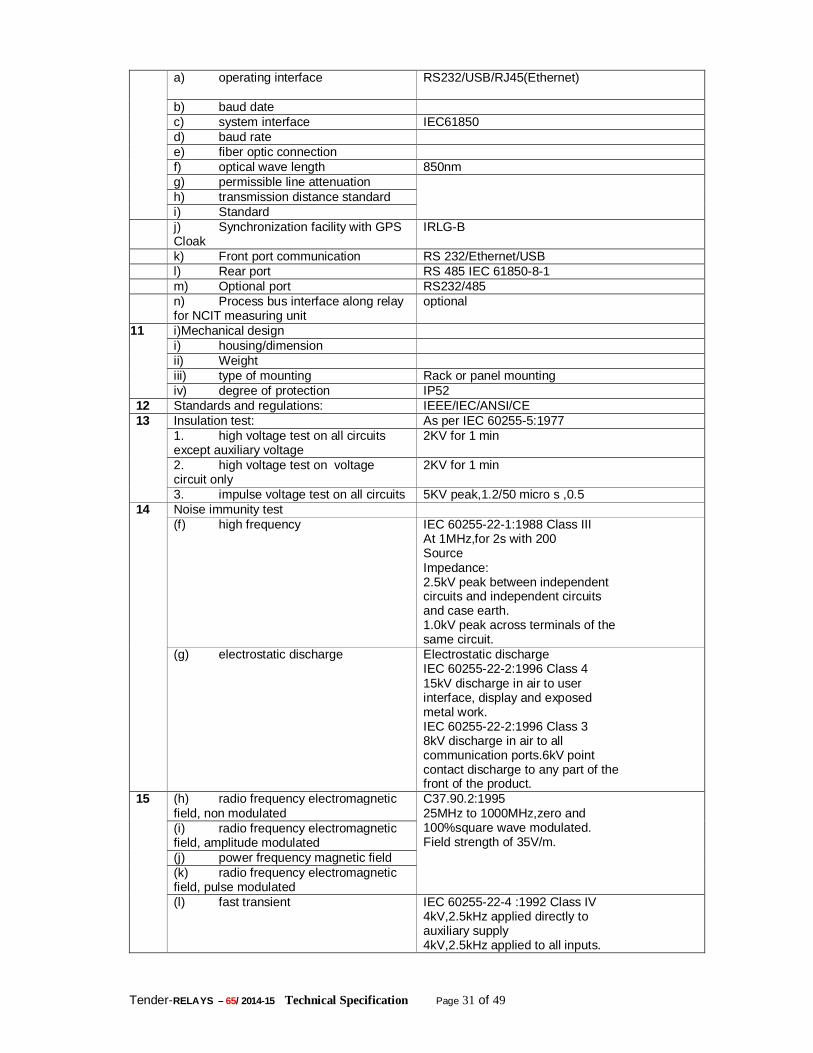
Tender-RELAYS – 65/ 2014-15 Technical Specification Page 31 of 49
a) operating interface RS232/USB/RJ45(Ethernet)
b) baud date c) system interface IEC61850 d) baud rate e) fiber optic connection f) optical wave length 850nm g) permissible line attenuation h) transmission distance standard i) Standard
j) Synchronization facility with GPS Cloak
IRLG-B
k) Front port communication RS 232/Ethernet/USB l) Rear port RS 485 IEC 61850-8-1 m) Optional port RS232/485 n) Process bus interface along relay
for NCIT measuring unit optional
11 i)Mechanical design i) housing/dimension ii) Weight iii) type of mounting Rack or panel mounting iv) degree of protection IP52
12 Standards and regulations: IEEE/IEC/ANSI/CE 13 Insulation test: As per IEC 60255-5:1977
1. high voltage test on all circuits except auxiliary voltage
2KV for 1 min
2. high voltage test on voltage circuit only
2KV for 1 min
3. impulse voltage test on all circuits 5KV peak,1.2/50 micro s ,0.5 14 Noise immunity test
(f) high frequency IEC 60255-22-1:1988 Class III At 1MHz,for 2s with 200 Source Impedance: 2.5kV peak between independent circuits and independent circuits and case earth. 1.0kV peak across terminals of the same circuit.
(g) electrostatic discharge Electrostatic discharge IEC 60255-22-2:1996 Class 4 15kV discharge in air to user interface, display and exposed metal work. IEC 60255-22-2:1996 Class 3 8kV discharge in air to all communication ports.6kV point contact discharge to any part of the front of the product.
15 (h) radio frequency electromagnetic field, non modulated
C37.90.2:1995 25MHz to 1000MHz,zero and 100%square wave modulated. Field strength of 35V/m.
(i) radio frequency electromagnetic field, amplitude modulated (j) power frequency magnetic field (k) radio frequency electromagnetic field, pulse modulated (l) fast transient IEC 60255-22-4 :1992 Class IV
4kV,2.5kHz applied directly to auxiliary supply 4kV,2.5kHz applied to all inputs.
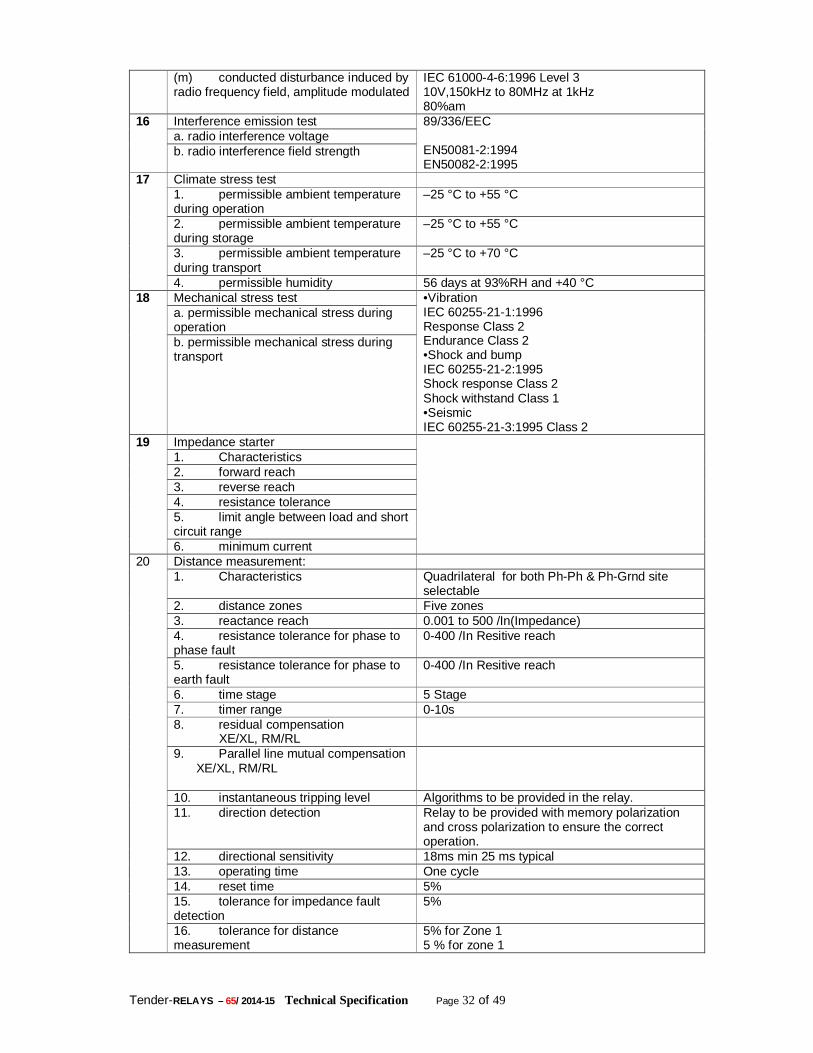
Tender-RELAYS – 65/ 2014-15 Technical Specification Page 32 of 49
(m) conducted disturbance induced by radio frequency field, amplitude modulated
IEC 61000-4-6:1996 Level 3 10V,150kHz to 80MHz at 1kHz 80%am
16 Interference emission test 89/336/EEC EN50081-2:1994 EN50082-2:1995
a. radio interference voltage b. radio interference field strength
17 Climate stress test 1. permissible ambient temperature during operation
–25 °C to +55 °C
2. permissible ambient temperature during storage
–25 °C to +55 °C
3. permissible ambient temperature during transport
–25 °C to +70 °C
4. permissible humidity 56 days at 93%RH and +40 °C 18 Mechanical stress test •Vibration
IEC 60255-21-1:1996 Response Class 2 Endurance Class 2 •Shock and bump IEC 60255-21-2:1995 Shock response Class 2 Shock withstand Class 1 •Seismic IEC 60255-21-3:1995 Class 2
a. permissible mechanical stress during operation b. permissible mechanical stress during transport
19 Impedance starter 1. Characteristics 2. forward reach 3. reverse reach 4. resistance tolerance 5. limit angle between load and short circuit range 6. minimum current
20 Distance measurement: 1. Characteristics Quadrilateral for both Ph-Ph & Ph-Grnd site
selectable 2. distance zones Five zones 3. reactance reach 0.001 to 500 /In(Impedance) 4. resistance tolerance for phase to phase fault
0-400 /In Resitive reach
5. resistance tolerance for phase to earth fault
0-400 /In Resitive reach
6. time stage 5 Stage 7. timer range 0-10s 8. residual compensation XE/XL, RM/RL
9. Parallel line mutual compensation XE/XL, RM/RL
10. instantaneous tripping level Algorithms to be provided in the relay. 11. direction detection Relay to be provided with memory polarization
and cross polarization to ensure the correct operation.
12. directional sensitivity 18ms min 25 ms typical 13. operating time One cycle 14. reset time 5% 15. tolerance for impedance fault detection
5%
16. tolerance for distance measurement
5% for Zone 1 5 % for zone 1
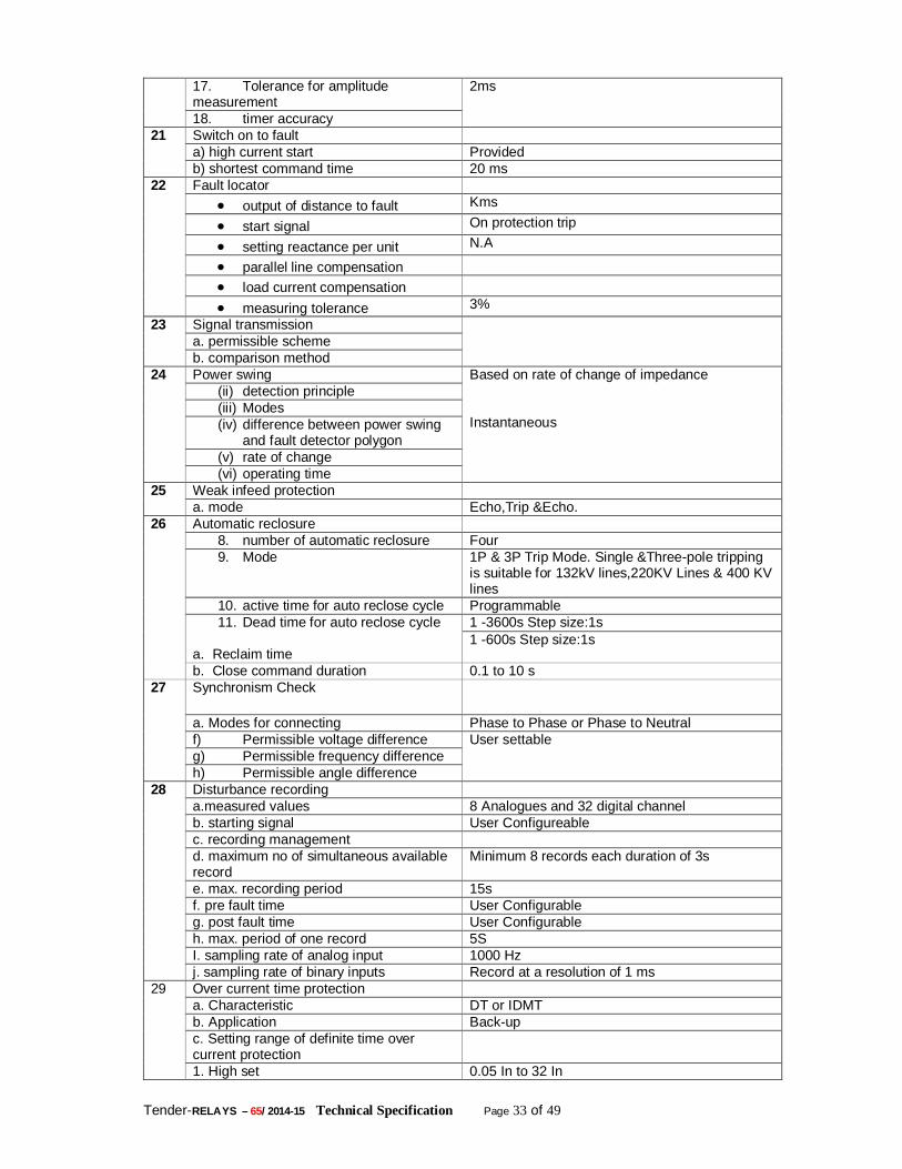
Tender-RELAYS – 65/ 2014-15 Technical Specification Page 33 of 49
17. Tolerance for amplitude measurement
2ms
18. timer accuracy 21 Switch on to fault
a) high current start Provided b) shortest command time 20 ms
22 Fault locator output of distance to fault Kms
start signal On protection trip
setting reactance per unit N.A
parallel line compensation
load current compensation
measuring tolerance 3% 23 Signal transmission
a. permissible scheme b. comparison method
24 Power swing Based on rate of change of impedance Instantaneous
(ii) detection principle (iii) Modes (iv) difference between power swing
and fault detector polygon (v) rate of change (vi) operating time
25 Weak infeed protection a. mode Echo,Trip &Echo.
26 Automatic reclosure 8. number of automatic reclosure Four 9. Mode 1P & 3P Trip Mode. Single &Three-pole tripping
is suitable for 132kV lines,220KV Lines & 400 KV lines
10. active time for auto reclose cycle Programmable 11. Dead time for auto reclose cycle
a. Reclaim time
1 -3600s Step size:1s 1 -600s Step size:1s
b. Close command duration 0.1 to 10 s 27 Synchronism Check
a. Modes for connecting Phase to Phase or Phase to Neutral f) Permissible voltage difference User settable g) Permissible frequency difference h) Permissible angle difference
28 Disturbance recording a.measured values 8 Analogues and 32 digital channel b. starting signal User Configureable c. recording management d. maximum no of simultaneous available record
Minimum 8 records each duration of 3s
e. max. recording period 15s f. pre fault time User Configurable g. post fault time User Configurable h. max. period of one record 5S I. sampling rate of analog input 1000 Hz j. sampling rate of binary inputs Record at a resolution of 1 ms
29 Over current time protection a. Characteristic DT or IDMT b. Application Back-up c. Setting range of definite time over current protection
1. High set 0.05 In to 32 In
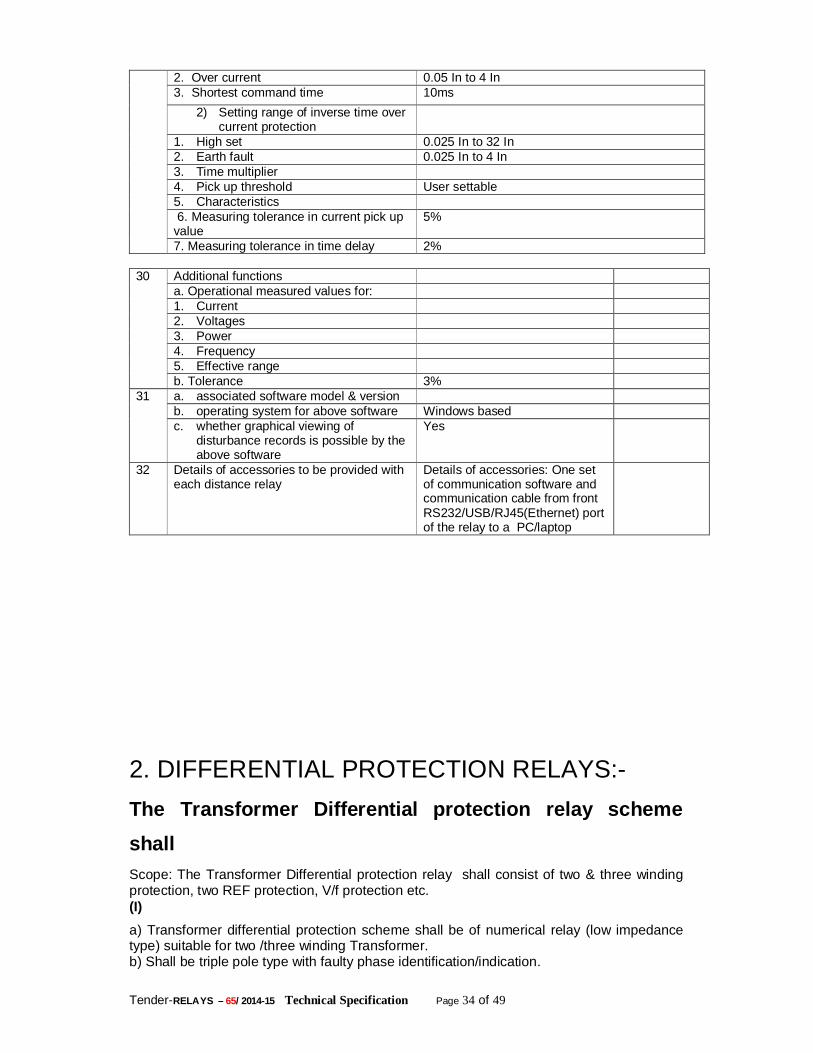
Tender-RELAYS – 65/ 2014-15 Technical Specification Page 34 of 49
2. Over current 0.05 In to 4 In 3. Shortest command time 10ms
2) Setting range of inverse time over current protection
1. High set 0.025 In to 32 In 2. Earth fault 0.025 In to 4 In 3. Time multiplier 4. Pick up threshold User settable 5. Characteristics 6. Measuring tolerance in current pick up value
5%
7. Measuring tolerance in time delay 2% 30 Additional functions
a. Operational measured values for: 1. Current 2. Voltages 3. Power 4. Frequency 5. Effective range b. Tolerance 3%
31 a. associated software model & version b. operating system for above software Windows based c. whether graphical viewing of
disturbance records is possible by the above software
Yes
32 Details of accessories to be provided with each distance relay
Details of accessories: One set of communication software and communication cable from front RS232/USB/RJ45(Ethernet) port of the relay to a PC/laptop
2. DIFFERENTIAL PROTECTION RELAYS:- The Transformer Differential protection relay scheme shall Scope: The Transformer Differential protection relay shall consist of two & three winding protection, two REF protection, V/f protection etc. (I) a) Transformer differential protection scheme shall be of numerical relay (low impedance type) suitable for two /three winding Transformer. b) Shall be triple pole type with faulty phase identification/indication.
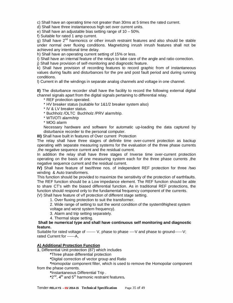
Tender-RELAYS – 65/ 2014-15 Technical Specification Page 35 of 49
c) Shall have an operating time not greater than 30ms at 5 times the rated current. d) Shall have three instantaneous high set over current units. e) Shall have an adjustable bias setting range of 10 – 50%. f) Suitable for rated 1 amp current. g) Shall have 2nd harmonics or other inrush restraint features and also should be stable under normal over fluxing conditions. Magnetizing inrush inrush features shall not be achieved any intentional time delay. h) Shall have an operating current setting of 15% or less. I) Shall have an internal feature of the relays to take care of the angle and ratio correction. j) Shall have provision of self-monitoring and diagnostic feature. k) Shall have provision of recording features to record graphic from of instantaneous values during faults and disturbances for the pre and post fault period and during running conditions. l) Current in all the windings in separate analog channels and voltage in one channel. II) The disturbance recorder shall have the facility to record the following external digital channel signals apart from the digital signals pertaining to differential relay. * REF protection operated. * HV breaker status (suitable for 1&1/2 breaker system also) * IV & LV breaker status. * Buchholz /OLTC Buchholz /PRV alarm/trip. * WTI/OTI alarm/trip * MOG alarm
Necessary hardware and software for automatic up-loading the data captured by disturbance recorder to the personal computer.
III) Shall have built in features of Over current Protection The relay shall have three stages of definite time over-current protection as backup operating with separate measuring systems for the evaluation of the three phase currents ,the negative sequence current and the residual current. In addition the relay shall have three stages of Inverse time over-current protection operating on the basis of one measuring system each for the three phase currents ,the negative sequence current and the residual current. IV) Shall have feature of two/three nos. of independent REF protection for three /two winding & Auto transformers. This function should be provided to maximize the sensitivity of the protection of earthfaults. The REF function should be a Low impedance element. The REF function should be able to share CT’s with the biased differential function. As in traditional REF protections, the function should respond only to the fundamental frequency component of the currents. (V) Shall have feature of v/f protection of different stage setting. 1. Over fluxing protection to suit the transformer. 2. Wide range of setting to suit the worst condition of the system9highest system voltage and worst system frequency). 3. Alarm and trip setting separately. 4. Thermal slope setting. Shall be numerical type and shall have continuous self monitoring and diagnostic feature. Suitable for rated voltage of ------- V, phase to phase ----V and phase to ground------V; rated Current for ------A, A) Additional Protection Function 1, Differential Unit protection (87) which includes *Three phase differential protection *Digital correction of vector group and Ratio *Homopolar component filter, which is used to remove the Homopolar component from the phase currents. *Instantaneous Differential Trip . *2nd, 4th and 5th harmonic restraint features.
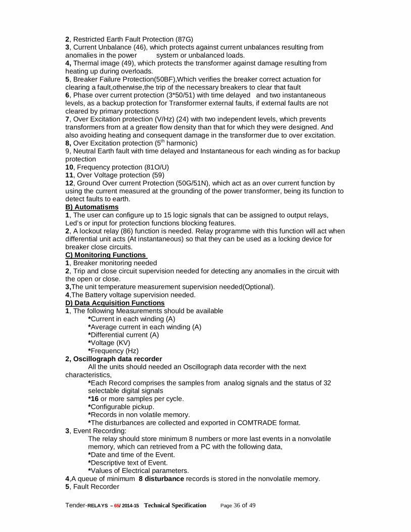
Tender-RELAYS – 65/ 2014-15 Technical Specification Page 36 of 49
2, Restricted Earth Fault Protection (87G) 3, Current Unbalance (46), which protects against current unbalances resulting from anomalies in the power system or unbalanced loads. 4, Thermal image (49), which protects the transformer against damage resulting from heating up during overloads. 5, Breaker Failure Protection(50BF),Which verifies the breaker correct actuation for clearing a fault,otherwise,the trip of the necessary breakers to clear that fault 6, Phase over current protection (3*50/51) with time delayed and two instantaneous levels, as a backup protection for Transformer external faults, if external faults are not cleared by primary protections 7, Over Excitation protection (V/Hz) (24) with two independent levels, which prevents transformers from at a greater flow density than that for which they were designed. And also avoiding heating and consequent damage in the transformer due to over excitation. 8, Over Excitation protection (5th harmonic) 9, Neutral Earth fault with time delayed and Instantaneous for each winding as for backup protection 10, Frequency protection (81O/U) 11, Over Voltage protection (59) 12, Ground Over current Protection (50G/51N), which act as an over current function by using the current measured at the grounding of the power transformer, being its function to detect faults to earth. B) Automatisms 1, The user can configure up to 15 logic signals that can be assigned to output relays, Led’s or input for protection functions blocking features. 2, A lockout relay (86) function is needed. Relay programme with this function will act when differential unit acts (At instantaneous) so that they can be used as a locking device for breaker close circuits. C) Monitoring Functions 1, Breaker monitoring needed 2, Trip and close circuit supervision needed for detecting any anomalies in the circuit with the open or close. 3,The unit temperature measurement supervision needed(Optional). 4,The Battery voltage supervision needed. D) Data Acquisition Functions 1, The following Measurements should be available *Current in each winding (A) *Average current in each winding (A) *Differential current (A) *Voltage (KV) *Frequency (Hz) 2, Oscillograph data recorder All the units should needed an Oscillograph data recorder with the next characteristics, *Each Record comprises the samples from analog signals and the status of 32 selectable digital signals *16 or more samples per cycle. *Configurable pickup. *Records in non volatile memory. *The disturbances are collected and exported in COMTRADE format. 3, Event Recording: The relay should store minimum 8 numbers or more last events in a nonvolatile memory, which can retrieved from a PC with the following data, *Date and time of the Event. *Descriptive text of Event. *Values of Electrical parameters. 4,A queue of minimum 8 disturbance records is stored in the nonvolatile memory. 5, Fault Recorder
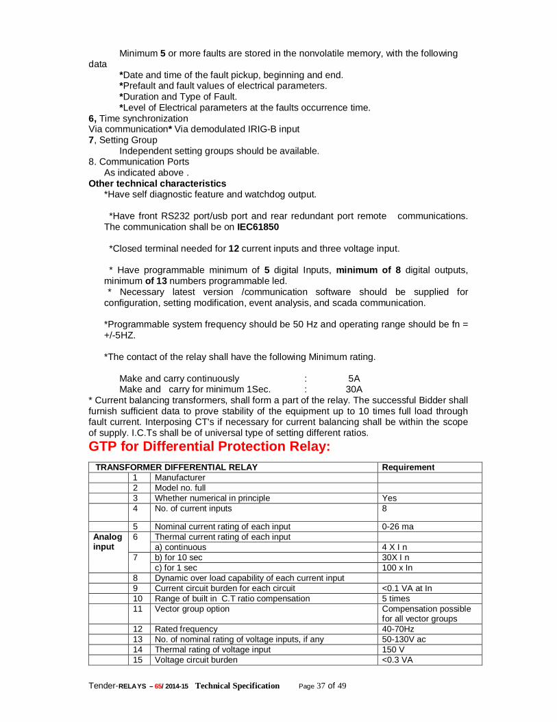
Tender-RELAYS – 65/ 2014-15 Technical Specification Page 37 of 49
Minimum 5 or more faults are stored in the nonvolatile memory, with the following data *Date and time of the fault pickup, beginning and end. *Prefault and fault values of electrical parameters. *Duration and Type of Fault. *Level of Electrical parameters at the faults occurrence time. 6, Time synchronization Via communication* Via demodulated IRIG-B input 7, Setting Group Independent setting groups should be available. 8. Communication Ports
As indicated above . Other technical characteristics
*Have self diagnostic feature and watchdog output.
*Have front RS232 port/usb port and rear redundant port remote communications. The communication shall be on IEC61850 *Closed terminal needed for 12 current inputs and three voltage input. * Have programmable minimum of 5 digital Inputs, minimum of 8 digital outputs,
minimum of 13 numbers programmable led. * Necessary latest version /communication software should be supplied for
configuration, setting modification, event analysis, and scada communication.
*Programmable system frequency should be 50 Hz and operating range should be fn = +/-5HZ.
*The contact of the relay shall have the following Minimum rating.
Make and carry continuously : 5A Make and carry for minimum 1Sec. : 30A * Current balancing transformers, shall form a part of the relay. The successful Bidder shall furnish sufficient data to prove stability of the equipment up to 10 times full load through fault current. Interposing CT's if necessary for current balancing shall be within the scope of supply. I.C.Ts shall be of universal type of setting different ratios. GTP for Differential Protection Relay: TRANSFORMER DIFFERENTIAL RELAY Requirement 1 Manufacturer 2 Model no. full 3 Whether numerical in principle Yes
4 No. of current inputs 8
5 Nominal current rating of each input 0-26 ma Analog input
6 Thermal current rating of each input a) continuous 4 X I n
7 b) for 10 sec 30X I n c) for 1 sec 100 x In
8 Dynamic over load capability of each current input 9 Current circuit burden for each circuit <0.1 VA at In 10 Range of built in C.T ratio compensation 5 times 11 Vector group option Compensation possible
for all vector groups 12 Rated frequency 40-70Hz 13 No. of nominal rating of voltage inputs, if any 50-130V ac 14 Thermal rating of voltage input 150 V 15 Voltage circuit burden <0.3 VA
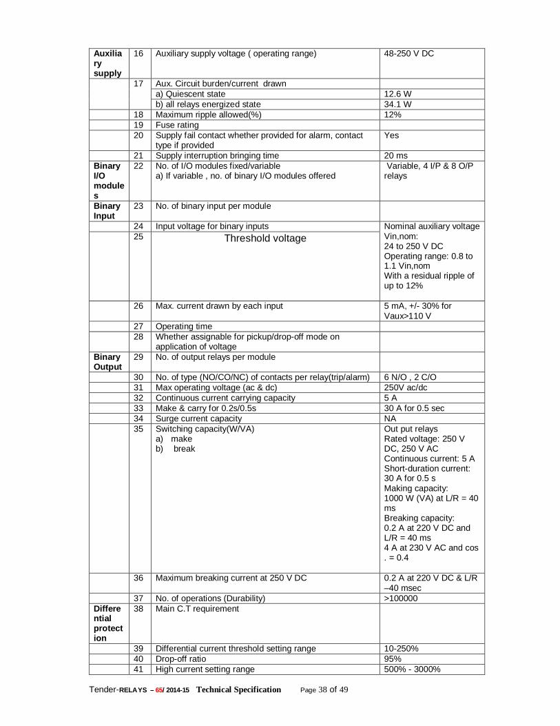
Tender-RELAYS – 65/ 2014-15 Technical Specification Page 38 of 49
Auxiliary supply
16 Auxiliary supply voltage ( operating range) 48-250 V DC
17 Aux. Circuit burden/current drawn a) Quiescent state 12.6 W b) all relays energized state 34.1 W
18 Maximum ripple allowed(%) 12% 19 Fuse rating 20 Supply fail contact whether provided for alarm, contact
type if provided Yes
21 Supply interruption bringing time 20 ms Binary I/O modules
22 No. of I/O modules fixed/variable a) If variable , no. of binary I/O modules offered
Variable, 4 I/P & 8 O/P relays
Binary Input
23 No. of binary input per module
24 Input voltage for binary inputs Nominal auxiliary voltage Vin,nom: 24 to 250 V DC Operating range: 0.8 to 1.1 Vin,nom With a residual ripple of up to 12%
25 Threshold voltage
26 Max. current drawn by each input 5 mA, +/- 30% for Vaux>110 V
27 Operating time 28 Whether assignable for pickup/drop-off mode on
application of voltage
Binary Output
29 No. of output relays per module
30 No. of type (NO/CO/NC) of contacts per relay(trip/alarm) 6 N/O , 2 C/O 31 Max operating voltage (ac & dc) 250V ac/dc 32 Continuous current carrying capacity 5 A 33 Make & carry for 0.2s/0.5s 30 A for 0.5 sec 34 Surge current capacity NA 35 Switching capacity(W/VA)
a) make b) break
Out put relays Rated voltage: 250 V DC, 250 V AC Continuous current: 5 A Short-duration current: 30 A for 0.5 s Making capacity: 1000 W (VA) at L/R = 40 ms Breaking capacity: 0.2 A at 220 V DC and L/R = 40 ms 4 A at 230 V AC and cos . = 0.4
36 Maximum breaking current at 250 V DC 0.2 A at 220 V DC & L/R –40 msec
37 No. of operations (Durability) >100000 Differential protection
38 Main C.T requirement
39 Differential current threshold setting range 10-250% 40 Drop-off ratio 95% 41 High current setting range 500% - 3000%
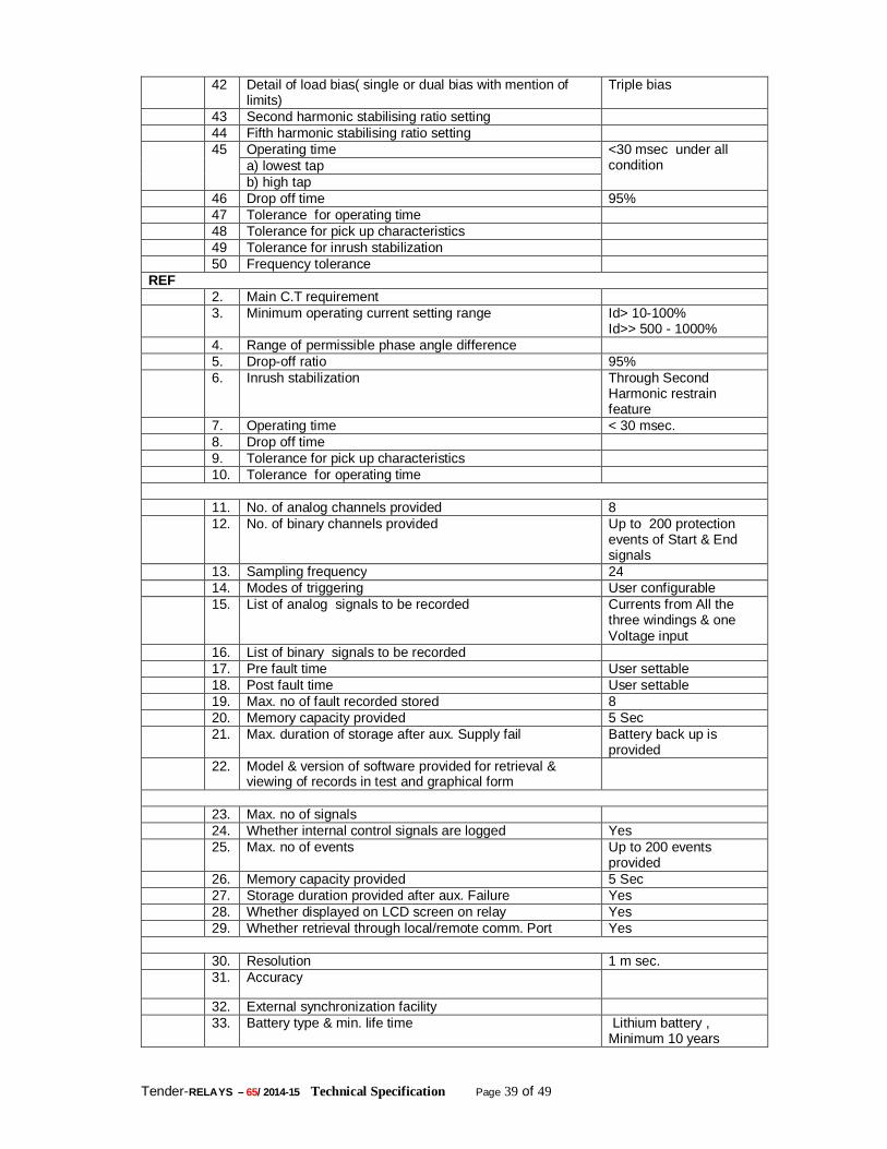
Tender-RELAYS – 65/ 2014-15 Technical Specification Page 39 of 49
42 Detail of load bias( single or dual bias with mention of limits)
Triple bias
43 Second harmonic stabilising ratio setting 44 Fifth harmonic stabilising ratio setting 45 Operating time <30 msec under all
condition a) lowest tap b) high tap
46 Drop off time 95% 47 Tolerance for operating time 48 Tolerance for pick up characteristics 49 Tolerance for inrush stabilization 50 Frequency tolerance REF 2. Main C.T requirement 3. Minimum operating current setting range Id> 10-100%
Id>> 500 - 1000% 4. Range of permissible phase angle difference 5. Drop-off ratio 95% 6. Inrush stabilization Through Second
Harmonic restrain feature
7. Operating time < 30 msec. 8. Drop off time 9. Tolerance for pick up characteristics 10. Tolerance for operating time 11. No. of analog channels provided 8 12. No. of binary channels provided Up to 200 protection
events of Start & End signals
13. Sampling frequency 24 14. Modes of triggering User configurable 15. List of analog signals to be recorded Currents from All the
three windings & one Voltage input
16. List of binary signals to be recorded 17. Pre fault time User settable 18. Post fault time User settable 19. Max. no of fault recorded stored 8 20. Memory capacity provided 5 Sec 21. Max. duration of storage after aux. Supply fail Battery back up is
provided 22. Model & version of software provided for retrieval &
viewing of records in test and graphical form
23. Max. no of signals 24. Whether internal control signals are logged Yes 25. Max. no of events Up to 200 events
provided 26. Memory capacity provided 5 Sec 27. Storage duration provided after aux. Failure Yes 28. Whether displayed on LCD screen on relay Yes 29. Whether retrieval through local/remote comm. Port Yes
30. Resolution 1 m sec. 31. Accuracy 32. External synchronization facility 33. Battery type & min. life time Lithium battery ,
Minimum 10 years
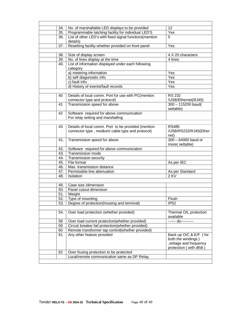
Tender-RELAYS – 65/ 2014-15 Technical Specification Page 40 of 49
34. No. of marshallable LED displays to be provided 12 35. Programmable latching facility for individual LED’S Yes 36. List of other LED’s with fixed signal functions(mention
details) 5
37. Resetting facility whether provided on front panel Yes
38. Size of display screen 4 X 20 characters 39. No. of lines display at the time 4 lines 40. List of information displayed under each following
category
a) metering information Yes b) self diagonostic info Yes c) fault info. Yes d) History of events/fault records Yes
40 Details of local comm. Port for use with PC(mention
connector type and protocol) RS 232 /USB/Ethernet(RJ45)
41 Transmission speed for above 300 – 115200 baud( settable)
42 Software required for above communication For relay setting and marshalling
43 Details of local comm. Port to be provided (mention
connector type , medium/ cable type and protocol) RS485 /USB/RS232/RJ45(Ethernet)
41. Transmission speed for above 300 – 64000 baud or more( settable)
42. Software required for above communication 43. Transmission mode 44. Transmission security 45. File format As per IEC 46. Max. transmission distance 47. Permissible line attenuation As per Standard 48. Isolation 2 KV
49. Case size /dimension 50. Panel cutout dimension 51. Weight 52. Type of mounting Flush 53. Degree of protection(housing and terminal) IP52
54. Over load protection (whether provided) Thermal O/L protection
available 58 Over load current protection(whether provided) ------ do---------- 59 Circuit breaker fail protection(whether provided) 60 Remote transformer tap control(whether provided) 61 Any other feature provided Back up O/C & E/F ( for
both the windings ) ,voltage and frequency protection ( with df/dt )
62 Over fiuxing protection to be protected Local/remote communication same as DP Relay.
Tender-RELAYS – 65/ 2014-15 Technical Specification Page 41 of 49
3) BACK-UP OVER CURRENT AND EARTH FAULT PROTECTION SCHEME WITH HIGH SET FEATURE:-
Specification for Numerical Directional - Non-Directional Over Current and Earth Fault Protection. A. General A comprehensive communicable numerical protection should be offered by the relay. High level of security should be built-in the relay to avoid any mal operation causing over protection of the system or any non operation of the relay causing under protection. Should have flexibility to customize the relay for intended applications as may be desired at site, in other words the relay should not have very limited features rendering it equipment specific. The relay should have high immunity to electrical and electromagnetic interference and also continuous supervision of hardware and software should be done to ensure enhanced system reliability and availability, the relay should have auto diagnostic fault indication to facilitate fault location and repair after detection of internal relay fault. The compulsory features required by the relay to be fulfilled are listed as below B. Application The relay will be required for applications where time graded Directional & or Non-Directional (site selectable) o/c and e/f protection is required. The Directional & or Non-Directional (site selectable) earth fault protection should provide suitable sensitivity for most systems where the earth fault current is limited. Typically the relay should be applied for all incoming transformers, capacitors and feeders for any application. The relay should be designed in such a way that it operates for a wide range of ac and dc auxiliary power supplies. C. General requirements The relay in addition to protection and control should display and store all parameters necessary for post fault analysis. The relay shall record all the events affecting and effecting the relay performance. All the time stamped data should be available via a RS232 serial communication port for access locally and/or remotely via a computer. All the events, faults and disturbance records shall be extracted via a RS485 serial port. D. Operating Principle The sampling frequency of the digital/analogue converter should be synchronised to power frequency by suitable frequency tracking methods to improve both accuracy of measurement and harmonic rejection. The relay should necessarily have a software filtering to prevent induced ac signals in the external wiring causing operation of logic inputs. E. Functional Description (a) O/C protection: The relay should have 4 independent time delayed stages which can be selectable either as directional or non-directional. MTA shall be adjustable anywhere within -180 degrees to + 179 degrees. The first and second stages shall be programmable to have either a DT characteristics or IDMT characteristics( as per IEEE/IEC Standards) described as follows. 1. The low set phase current should start when the current of any phase exceeds the set value.

Tender-RELAYS – 65/ 2014-15 Technical Specification Page 42 of 49
The first and the second current stage shall have a current setting range of 0.10 - 4.00 In and time setting range of 0.06 sec to 100 sec. 2. The Third, fourth stage of protection shall be with instantaneous operation or DT having a current setting range as 0.1 to 20 In and a time delay of 0.06 sec to 100 sec for stage III and IV. These stages may have the flexibility to be configured for a bus bar protection scheme using blocking logic at a later date. Facility available in the relays for this flexibility may be highlighted. (b) Earth fault protection: The relay should have at least 2 independent time delayed Directional & or Non –Directional E/F stages suitable for networks with different earthling types( solidly earthed, resistive earthed, Petersen coil earthed systems).The relay shall also be suitable where ever a selective and sensitive earth fault protection is needed. It shall also be possible to detect Intermittent earth faults. MTA shall be adjustable anywhere within -180 degrees to + 179 degrees. The first and second stage shall be programmable to have either a DT characteristics or IDMT characteristics described as follows, The low set phase current should start when the current of any phase exceeds the set value. Both the stages Shall have a current setting range of 0.05 to 4 IN and time setting range of 0.1 sec to 200 sec. The lower setting is critical to take care of systems which have low earth fault currents. Additionally there shall be four non-directional earth fault stages where the first stage can be programmed either to IDMT or DT and the rest 3 stages shall be of definite time type. (c) Sensitive Earth Fault/Restricted Earth Fault. The relay shall take care of transformers applications where Restricted Earth fault and standby earth fault is required. It shall be possible to either measure the value of neutral current through available C.T I/P's or derive it internally within the relay and use the same for applications as described above. The Relay shall be able to accept input from Core balance current transformer to detect earth faults of very low amplitude. The setting range shall be settable to a minimum of 0.005 Amps. The relay shall have Restricted earth fault protection feature of high Impedance type. (d) Over Voltage /Under Voltage. If the system goes for very high under and over voltages in case of Supply or Load unbalance it shall be possible to grade the system for Voltage protections. Relay shall have 3 under voltage stages and 3 over voltage stages respectively. (e) Residual voltage protection: The relay shall have at least 2 residual voltage stages in order to give an unselected backup for existing earth fault protection. The stages shall have a setting range of 1 – 60 %U0N with a time delay settable from 0.3 – 100.0s ( in steps of 0.1 s). (f) Under frequency/Over Frequency /ROCOF: The relay shall have four frequency stages out of which it shall be possible to program at least 2 of them to under or over frequency to be suitable for various load sharing applications. The under frequency stages shall be settable any where within a frequency range of 45 - 55.0 Hz. With the flexibility to block any mal operation on event on under voltage. All stages shall be of definite time type with a setting range of 0.10) – 100.0 s ( in steps of 0.02 s). The relay shall also have the facility to detect a rate of change of frequency for load shedding applications , to speed up operation time in over- and under-frequency situations and to detect loss of grid. Pick up setting shall be settable from 0.2 – 10.0 Hz/s (step 0.1 Hz/s). (g) The relay in addition to the above basic function should also provide the following functions, 1. The relay should have the protection feature which allows the relay to trip the upstream circuit breaker when a local breaker failure condition is detected and should be energised both from operation of the relay or by an external trip.
Tender-RELAYS – 65/ 2014-15 Technical Specification Page 43 of 49
2.The relay should measure the following standard quantities, Phase current(Positive, negative and zero sequence currents) Phase Voltage(Positive, negative and zero sequence voltages) Neutral current Frequency Active and Reactive Power Power factor
3. The relay shall have at least two independent setting groups . The relay shall automatically switch from one setting group to another depending on system conditions ( such as failure of incomer supply, which causes fault level to decrease etc.,) 4. The relay shall have the facility of communication on industry standard open protocols such as Modbus or IEC 60870-5-103 which shall be selectable through software. There shall have a facility to have IEC61850 protocol inbuilt without use of any external converter. Further, the test levels of EMI as indicated in IEC 61850 shall be applicable to these. The relays shall support copper and fiber optic medium which shall be selectable at site for SAS connectivity. The relay shall support peer to peer communication. 19. The relays shall generate GOOSE messages of class 1 as per IEC 61850 standards for interlocking/tripping and also to ensure interoperability with third party relays. 20. Necessary user friendly configuration tool shall be provided to configure the relays. It should be compatible with SCL/SCD files generated by a third party system. 21. Goose signals shall be freely configurable for any kind of signals using graphic tool/user friendly software. Bidder shall also ensure adequate hardware. 5. The Relay shall have facility for Time synchronization on IRIG B/SNTP/RS 485 and through digital input. F. Relay hardware: The relay should be modular type, suitable for either rack or panel mounting. Standard terminal blocks should be located at the rear of the relay providing connections for all input and output circuits. G. Output relays: The relay should have up to 5-CT inputs. They should provide at least 6 optically isolated inputs and at least 7 programmable outputs. They should be arranged in response to any or all of the available functions by suitably setting the output relays. The protection and control function to which these relays respond should be selectable via the menu system of the relay. One output relay shall be permanently assigned for self-supervision. H. The Relay shall also have the following functionality/Features..
Thermal overload protection. Negative sequence over current. Permanent Self-Test. Circuit breaker maintenance information. Broken conductor detection by measuring I2/I1 . Cold load pickup function to change the settings when the protected object is connected to a network i.e., at starting allowing the set value being lower than the connected inrush current. The relay shall also have the feature of Inrush blocking through 2nd harmonic detection. Disturbance recorder & Event recorder facilities.8 fault records shall be possible in each protection stage. Front RS232 port for communication to LAPTOP (at a later date). The relay shall have a facility for C.T. Supervision, P.T. Supervision and Trip Circuit Supervision.
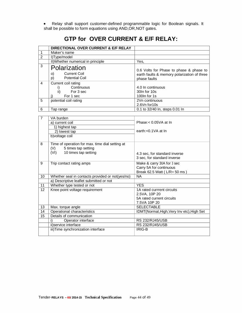
Tender-RELAYS – 65/ 2014-15 Technical Specification Page 44 of 49
Relay shall support customer-defined programmable logic for Boolean signals. It shall be possible to form equations using AND,OR,NOT gates.
GTP for OVER CURRENT & E/F RELAY:
DIRECTIONAL OVER CURRENT & E/F RELAY 1 Maker’s name 2 I)Type/model II)Whether numerical in principle Yes, 3 Polarization
o) Current Coil p) Potential Coil
0.6 Volts for Phase to phase & phase to earth faults & memory polarization of three phase faults
4 Current coil rating i) Continuous ii) For 3 sec
j) For 1 sec
4.0 In continuous 30In for 10s 100In for 1s
5 potential coil rating 2Vn continuous 2.6Vn for10s
6 Tap range 0.1 to 32/40 In, steps 0.01 In 7 VA burden
Phase:< 0.05VA at In earth:<0.1VA at In
a) current coil 1) highest tap 2) lowest tap b)voltage coil
8 Time of operation for max. time dial setting at (V) 5 times tap setting (VI) 10 times tap setting
4.3 sec, for standard inverse 3 sec, for standard inverse
9 Trip contact rating amps Make & carry 30A for 3 sec Carry 5A for continuous Break 62.5 Watt ( L/R= 50 ms )
10 Whether seal in contacts provided or not(yes/no) NA a) Descriptive leaflet submitted or not 11 Whether type tested or not YES 12 Knee point voltage requirement 1A rated currrent circuits
2.5VA, 10P 20 5A rated current circuits 7.5VA 10P 20
13 Max. torque angle SELECTABLE 14 Operational characteristics IDMT(Normal,High,Very Inv etc),High Set 15 Details of communication i) Operator interface RS 232/RJ45/USB ii)service interface RS 232/RJ45/USB iii)Time synchronization interface IRIG-B
Tender-RELAYS – 65/ 2014-15 Technical Specification Page 45 of 49
4. ELECTROMECHANICAL AUXILIARY RELAYS:- Relays shall be suitable for semi flush mounting on the panel board. All the relays shall be back connected, protected with dust tight cases for tropical use and finished with dull black enamel paint. The adjusting devices, shall be accessible with the relay mounted on the panel board. Flag type operating indicators and flag indicator reset devices shall be provided. The latter shall be suitable for operation from the front of the relay case, without opening the cover. The relays shall comply in all respects with the requirements of IS: 3231 (latest edition) or equivalent standards and shall be suitable for operation under the climatic condition specified. The relays shall be suitable for operation within a temperature range of 0 deg. to50 deg. C. The current coils shall be rated for a continuous current of 1 ampere and the voltage coils for 110 V normal. The contacts of the relays shall be silvered and precautions shall be taken to prevent or minimize damage due to arc which have to be successfully broken against 240 V D.C. When open, the contacts shall withstand a voltage of 115% of the normal circuit voltage. The relays shall preferably be provided with suitable seal-in-devices. OTHER PARTICULARS OF AUXILIARY RELAYS:- 1. The auxiliary relays shall be, designed for continuous operation at 250 V. D.C. and shall withstand 11 0% rated voltage continuo usually. This shall also be suitable for Satisfactory operation at 85% rated Voltage. 2. All protective relays, auxiliary relays an d timer s except the lock out relays and interlocking relays specified shall be provided with self reset type contacts. All protective relays and timers shall be provided with externally hand reset positive action operation indicators with inscription subject to Purchaser's approval. All protective relays which do not have built-in hand-reset operation indicators shall have additional auxiliary relays with operating indicators (Flag relays) for this purpose. Similar separate operating indicator (auxiliary relays) shall also be provided in the trip circuits of protections located outside the board such as buchholtz relays, oil and winding temperature protection, sudden pressure devices, fire protection etc. 3. Self reset auxiliary voltage relays rated for specified D.C voltage shall be provided for use in the interlocking schemes for multiplication of contacts suiting contact duties of protective relays and for monitoring of control supplies and circuits . Monitoring relays for lockout relay circuits shall be connected in series with lockout relays coils . The Bidder shall be responsible to ensure that the monitoring relay ratings are such that they shall positively pick-up through the breaker coils / lockout relays coils monitored, but the breakers / lockout relays shall not operate with such a connection. 4. The supply and circuit monitoring relay shall be connected to initiate an alarm upto failure of respective supply / circuit . They shall preferably have reverse flags, which drop when relay is de-energised . Otherwise, an indicating lamp shall be provided with each monitoring relay for indication of its operation. 5. Close positions relays of main supply circuit beakers initiating automatic closure of stand by supply breakers shall have adequate time delay on drop out so that complete closure of stand by supply breaker is ensured . This feature will be used for obtaining limitation of duration of impulse for automatic closure of stand by supply breakers. In case the close position relays with such time delay are not available, additional slugged D.C auxiliary with adequate time delay on drop out may be supplied for automatic reverse closure . The exact arrangement will depend on the actual control schemes and shall be subject to the approval of purchaser.
Tender-RELAYS – 65/ 2014-15 Technical Specification Page 46 of 49
6. The lockout trip relays shall be multi contact, hand reset type . The latching mechanism shall be positive and insensitive to vibration and shock. The reset devices on the front of the relay panel shall not permit manual tripping . Each lock-out relay shall be furnished with a panel mounted isolating arrangement to permit opening of trip circuits for testing . TRIP CIRCUIT SUPERVISION RELAYS: If required by the purchaser, the trip circuits shall be supervised by means of relays . The scheme shall continuously monitor the trip circuit before closing and after closing of the breaker . The scheme shall detect (i) failure of trip supply (ii) open circuit of trip coil or trip circuit wiring and (iii) failure of mechanism to complete the tripping operation . The relays shall have necessary contacts to be connected to the Annunciator available in the annunciation panel for visual and audible indication of the failure of trip circuit . 1. HIGH SPEED TRIPPING RELAY Two nos high burden tripping relay shall be provided for simultaneous tripping of H.V. and L.V. breakers in case of transformers faults with necessary lockout feature. (a) High Speed tripping Relay Electro-mechanical relay. (b) Shall be instantaneous (Operating time not exceeding 10 milli-seconds). (c) Shall reset within 20 milli seconds. (d) Shall be DC operated (220 V±10% DC). (e) Shall have adequate contacts to meet the requirement of the scheme, other functions like Auto –reclose, LBB relay as well as cater to associated equipment like event logger, Disturbance Recorder, Fault Locators etc. (f) Shall be provided with operation indicators for each element/coil. 2. FLAG RELAY: (a)These shall have hand reset flag indication. (b) Have minimum two contacts (NO or NC or combination as required). (c) Shall be DC operated(220 V±10% DC). 3. TRIP CIRCUIT SUPERVISION RELAY: (a) The relay shall be capable of monitoring the healthiness of each ‘phase” trip coil and associated circuit of circuit breaker during “ON” and “OFF” conditions. Both Pre and Post close supervision. (b) The relay shall have adequate contacts for providing connection to the alarm and event logger. (c) The relay shall have time delay on drop- off of not less than 200 milliseconds and be provided with operation indications for each phase. 4. DC SUPPLY SUPERVISION RELAY: (a) The relay shall be capable of monitoring the failure of DC supply to which, it is
connected
(b) It shall have adequate potential free contacts to meet the scheme requirement. (c) The relay shall have a “time delay on drop off” of not less than100 milliseconds and be provided with operation indicator/flag. 5. AUX. Relay Type- VAA-33(ALARM ANNUNCIATION) 250 V DC Case Size-3 element
20 Terminal
Flag -Required
Mounting -Flush
Aux. Contacts-2 N/O,SR+1 NO and 1 NC H/R for each element
Tender-RELAYS – 65/ 2014-15 Technical Specification Page 47 of 49
THREE POLE VOLTAGE OPERATED AUXILIARY RELAY. Technical specification
Relay type VAA 33
Aux.current or voltage 220 - 230V dc Contacts - unit L.H 3 N/O 1 N/C H/R Contacts - unit CTR 3 N/O 1 N/C H/R Contacts - unit R.H 3 N/O 1 N/C H/R Flag Yes Mounting Flush COIL RATING D.C.75%-120% of rated voltage AC.80%-115% of rated voltage Operating voltage- not greater than 70% of voltage rating. Operating time-15-20ms typical minimum at nominal voltage. Burden- 2watts for 30,125v 6watts for 50,250v. Operation indicator Hand reset operation indicator provided
6) MASTER TRIP RELAY TYPE-VAJH/VAJHM Single pole High Speed trip relay
Case Size-1 Vertical
Mounting –Flush
Burden –Low
Aux. Voltage-250 V DC Contacts-2 NO+2 NC/3NO+1NC
Flag- Required
Coil rating-24,30,48 & 110or 220v DC & 110 or 220V AC
Operating voltage-50 to 120% of rated voltage.
Operating time-10ms nominal, at rated voltage
Operation indicator Hand reset operation indicator provided
5) RESTRICTED EARTH FAULT RELAY (ATTRACTED TYPE ELECTR MECHANICAL): TYPE:
Electro-mechanical The REF relay (attracted armature type) to be used along with a stabilising resistor & Metrosil, which is designed for applications where sensitive settings with stability on heavy through faults are required. It is recommended for balanced and restricted earth fault, bus-zone and certain forms of differential protection for auto-transformers, Power Transformers
Tender-RELAYS – 65/ 2014-15 Technical Specification Page 48 of 49
etc. The relay shall operate as a high impedance unit protection scheme & to be connected in the system accordingly. The relay shall be attracted armature unit of simple and robust construction. The operating coil shall be provided with the accessories like series resonant circuit. Current tapping should be provided for different current setting by making suitable arrangement. The construction of the relay should be simple & electromechanical construction, detection element, and the output contacts should be in the same device, which will make the Operation fast and highly reliable. The relay circuit, connected & tuned to the supply frequency must rejects the harmonics produced by current transformer saturation & due to system disturbances. The current transformers may develop voltages during maximum internal faults and the relay may be damaged. Therefore total impedance of the relay to be decided by using external series stabilising resistor (non-linear resistor) to prevent over voltage developed. The relay shall be single pole operated. Features: • High stability on external faults • Tuned to rated frequency • 25ms operating time at 5 times current setting • Simple and robust construction. • High stability on external faults. • Sensitive high speed protection on internal faults. • Tuned to rated frequency. Application • Differential/REF protection of Power Transformers, auto-transformers and busbars. • Balanced and restricted earth fault protection of transformer windings. • Transverse differential protection of generators and parallel feeders. General description In circulating current protection schemes, the sudden and often asymmetrical growth of the system current during external fault conditions can cause the protective current transformers to go into saturation, resulting in a high unbalance current. To ensure stability under these conditions the relay should be designed to take care, may be by using a voltage operated, high impedance relay, set to operate at a voltage slightly higher than that developed by the current transformers under maximum external fault conditions. The stabilising resistor to be designed for such applications where sensitive settings with stability on heavy through faults are required. A slight time delay on operation of relay helps to provide stability on heavy external faults and is to be taken care. This limits the current supplied, and the output unit operates only on the slower part of its time/current curve. The external stabilising resistor to be supplied separately with the relay allows continuous adjustment of the relay voltage setting over a wide range. y spaced current settings. The relay circuit, tuned to the supply frequency, rejects the harmonics produced by CT saturation. A slight time delay on operation helps to provide stability on heavy external faults and is obtain TECHNICAL DATA Current rating 1A Frequency 50 Hz Hz Settings 10 - 40% in seven equal steps as standard. Continuously variable external stabilising resistors of 200 ohms or any suitable value for 1A. Operating time
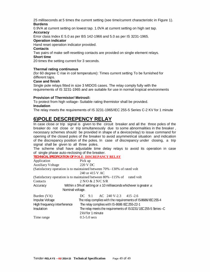
Tender-RELAYS – 65/ 2014-15 Technical Specification Page 49 of 49
25 milliseconds at 5 times the current setting (see time/current characteristic in Figure 1). Burdens 0.9VA at current setting on lowest tap. 1.0VA at current setting on high set tap. Accuracy Error class Index E 5.0 as per BS 142-1966 and 5.0 as per IS 3231-1965. Operation indicator Hand reset operation indicator provided. Contacts Two pairs of make self-resetting contacts are provided on single element relays. Short time 20 times the setting current for 3 seconds. Thermal rating continuous (for 60 degree C rise in coil temperature): Times current setting To be furnished for different taps. Case and finish Single pole relays fitted in size 3 MIDOS cases. The relay comply fully with the requirements of IS 3231-1965 and are suitable for use in normal tropical environments Provision of Thermistor/ Metrosil: To protect from high voltage- Suitable rating thermistor shall be provided. Insulation The relay meets the requirements of IS 3231-1965/IEC 255-5 Series C-2 KV for 1 minute 6)POLE DESCREPENCY RELAY In case close or trip signal is given to the circuit breaker and all the three poles of the breaker do not close or trip simultaneously due to some abnormalities in the breaker , necessary schemes should be provided in shape of a device(relay) to issue command for opening of the closed poles of the breaker to avoid asymmetrical situation and indication of the discrepancy position of the poles. In case of discrepancy under closing, a trip signal shall be given to all three poles. The scheme shall have adjustable time delay relays to avoid its operation in case of single phase auto-reclosing of the breaker. TECHNICAL SPECIFICATION OF POLE- DISCREPANCY RELAY Application Pick up Auxiliary Voltage 220 V DC (Satisfactory operation is to maintained between 70% -130% of rated volt 240 or 415 V AC (Satisfactory operation is to maintained between 80% -115% of rated volt Contacts 2 N/O & 2 N/C S/R Accuracy Within ± 5% of setting or ± 10 milliseconds whichever is greater at Nominal voltage.
Burden (VA) DC 9.1 AC 240 V-2.3 415 -2.6 Impulse Voltage The relay complies with the requirements of IS-8686/IEC 255-4 High frequency interference The relay complies with IS -8686 IEC 255-22-1 Insulation The relay meets the requirements of IS-3231/1EC 255-5 Series –C
2 kV for 1 minute Time range 0.5-5.0 secs