Embed Size (px)
Citation preview
US 20030124019A1
(12) Patent Application Publication (10) Pub. No.: US 2003/0124019 A1 (19) United States
Grubb
(54) FERRITIC STAINLESS STEEL HAVING HIGH TEMPERATURE CREEP RESISTANCE
(76) Inventor: John F. Grubb, Lower Burrell, PA (Us)
Correspondence Address: Patrick J. Viccaro, Esq. Allegheny Technologies Incorporated 1000 Six PPG Place Pittsburgh, PA 15222-5479 (US)
(21) Appl. No.: 09/998,487
(22) Filed: Nov. 30, 2001
Publication Classi?cation
(51) Int. Cl.7 ................................................... .. C22C 38/22
(52) US. Cl. ............................. .. 420/68; 420/69; 148/605
(57) ABSTRACT
A ferritic stainless steel having improved high temperature mechanical properties includes greater than 25 Weight per
i
Yield Strength, 0.2% Offset (psi) 2 i %
(43) Pub. Date: Jul. 3, 2003
cent chromium, 0.75 up to 1.5 Weight percent molybdenum, up to 0.05 Weight percent carbon, and at least one of niobium, titanium, and tantalum, Wherein the sum of the Weight percentages of niobium, titanium, and tantalum sat is?es the following equation:
The coefficient of thermal expansion of the ferritic stainless steel is Within 25 percent of the CTE of stabilized Zirconia betWeen 20° C. (68° and 1000° C. (1832° F.), and the steel exhibits at least one creep property selected from creep
rupture strength of at least 1000 psi at 900° C. (1652° F.), time to 1% creep strain of at least 100 hours at 900° C.
(1652° under load of 1000 psi, and time to 2% creep strain of at least 200 hours at 900° C. (1652° under load of 1000 psi. The steel is particularly suited for high tem perature applications including, but not limited to, current collecting interconnects in solid oxide fuel cells, furnace hardWare, equipment for the chemical process, petrochemi cal, electrical poWer generation, and pollution control indus tries, and equipment for handling molten copper and other molten metals.
1 1S60“F (800°C) 0 1650'? (850°C) 1 1740‘? (900%)
1 1560°F (800°C) 12000 a 16S0°F (850°C)
l 1740°F (900%)
9000
Tens?e Strength (psi) O %
wcm W01
100
h/i Elongattnn
a 1S60°F (800°C) Cl 16S0°F (850%) l 1740“? (900%?)
wen W675
Patent Application Publication Jul. 3, 2003 Sheet 1 0f 9 US 2003/0124019 A1
a‘ mix ‘n..x+ IA. X+ X +
X + +
X+ X
My“ 0M m m. mm 8 7 6 S 4 3 2
2100°F 2000°F 1800°F 19000;:
Annealing Tempefature (0F)
FIGUQE 1
Jul. 3, 2003 Sheet 3 0f 9 US 2003/0124019 A1
m 133E $2 22a 33% 83 82 82 82 82 8: 8m 02. 08
> . \J r: \_J _ 0
fl! l 4 4 I I ) u )
o 4 o 0 i
- 02 w
m 8“ m m
x 8m .m.
S n... 00w) o m“
8m
83 39am U252 23V 226 U233
83 83 8% 88 82 83 8: 8Q 82 88 83 88 8E 82
. _ . I V . _ l. . : _ l O
I >- ) I 0 d U I 4
I “ 4 _ u .- IX 4 X l
I 4 4
. x w . . ._ 02 m
83 . < 4 09. w
% %
w mg m
._ m 08 a
0 - 08. J a
H who?‘ £03. 8m H
o N - W ?ux; 803x 08 82
Patent Application Publication
Patent Application Publication
2500
o I
I
X
‘I
% X 1500 2000 Applied Stress (psi)
1000
500
1000 0 r—' 0
(b)
3400
A
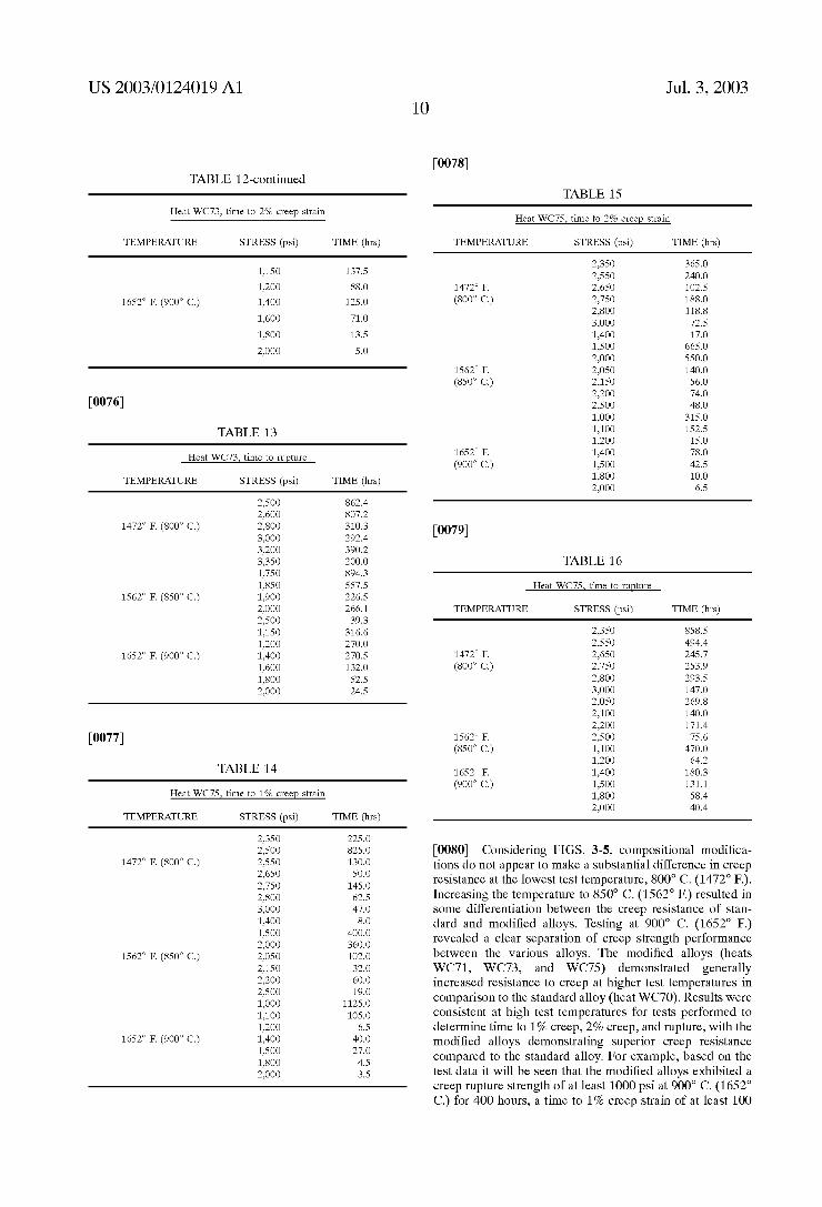
2400 2900
Applied Stress (ps1)
1900 O O O o o o o O O o O O O N 0 on ‘o 1- N H 1-4
Jul. 3, 2003 Sheet 4 0f 9
2500
2000
A 5 1500 Apptlad Stress (psi)
0 I 1000
US 2003/0124019 A1
FMDUREH~
Patent Application Publication
In A U 3 I
m n U 3 O
1000 1 ° ° 8 8 8 8 v N
(u) $299 12 wrudnu o: QWLL
/'\ ,9 \J
.4 g\ u 3 <
:2 U X Z x O
Q X
X
X o n
G X I
I O
I 1K 4
4
I 4
4
O o o o 0 g o o o o o N o 00 o Q N F‘ _4
(q) JQZLH 1e mrudnu 01 will
1500 2000
Applled Stress (psi)
0
O 0 O n
2500
i000
3900
3400
2400 2900
Applied Stress (psi)
1.900
Jul. 3, 2003 Sheet 5 0f 9 US 2003/0124019 A1
5
FIQMLE
Patent Application Publication Jul. 3, 2003 Sheet 6 0f 9 US 2003/0124019 A1
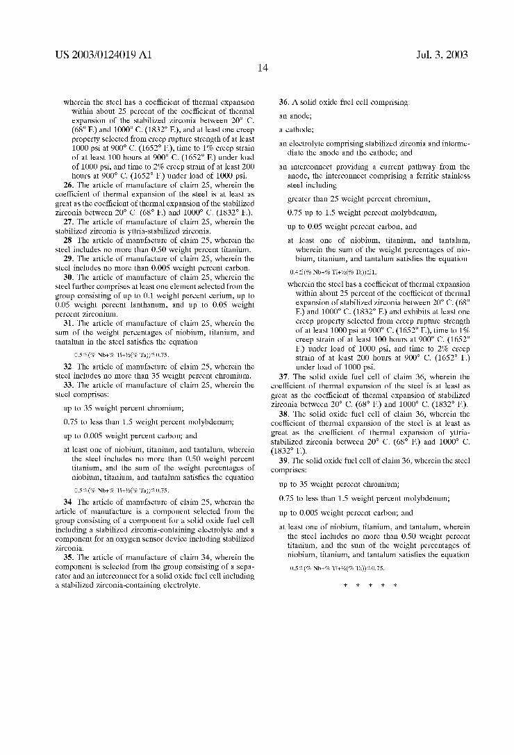
FIGURE 6
0.30 1 XWCIO ‘wc71 +wc72 X
‘g 0'25 _ .wc73 AWC74 iwcvs X Q A g 0.20 - AL I! 5
8~ 15 5 + * ‘é 0' ‘ 4. t + ‘I ‘ g X 3 O 10 -
.15 i 3 + ‘U
3 0.05 +
0.00 l l l .
O 125 250 375 500
Time at 1472°F (h)
Patent Application Publication Jul. 3, 2003 Sheet 7 0f 9 US 2003/0124019 A1
FKGURE 7
0.30 -
-20 -
m m.
0. n“ 0
ANEUBEV @220 29g 0.10 ~ 3
0.00 —
500 hours 168 houts
Patent Application Publication Jul. 3, 2003 Sheet 8 0f 9 US 2003/0124019 Al
O
A oAu+ ‘m AI+
S 7 3
L a
00
Al.
M m
G .2
I F
mm ww ‘ .:+
+1
14 CL
@. 1
LA
03 ‘2+ WW 2:.
X. ‘Al.
_ . Logo
nwl O_ O G 0 m m m. Mm m m w o. a 0 $8035 @955 292$
Time at 1652°F (h)
Patent Application Publication Jul. 3, 2003 Sheet 9 0f 9 US 2003/0124019 A1
FIGURE 9
200 1 +
150 -
x
100 X
+
so - i X A .
A
0 . . . . l ‘
2050 2100 2150 2200 2250 2300 2350
Cycle Temperature ("Fl
US 2003/0124019 A1
FERRITIC STAINLESS STEEL HAVING HIGH TEMPERATURE CREEP RESISTANCE
CROSS REFERENCE TO RELATED APPLICATIONS
[0001] Not applicable.
STATEMENT REGARDING FEDERALLY SPONSORED RESEARCH OR DEVELOPMENT
[0002] Not applicable.
TECHNICAL FIELD AND INDUSTRIAL APPLICABILITY OF THE INVENTION
[0003] The present invention is directed to a ferritic stain less steel alloy. More particularly, the present invention is directed to a ferritic stainless steel alloy having microstruc tural stability and mechanical properties making it particu larly suited for high temperature applications. Such appli cations include, but are not limited to, current collecting interconnects in solid oxide fuel cells, furnace hardWare, equipment for the chemical process, petrochemical, electri cal poWer generation, and pollution control industries, and equipment for handling molten copper and other molten metals.
DESCRIPTION OF THE INVENTION BACKGROUND
[0004] Fuel cells are highly ef?cient, environmentally friendly means for generating electric poWer. The basic principle behind the operation of fuel cells is the generation of electricity by the combustion of fuel. The fuel is separated from an oxidiZer by a permeable barrier knoWn as an
electrolyte. Hydrogen atoms on the fuel side of the electro lyte are ioniZed. The resulting protons pass through the electrolyte, While the liberated electrons travel through an external circuit. On the air side of the electrolyte, opposite the fuel side, tWo protons combine With an oxygen atom and tWo electrons to create a Water molecule, liberating heat and completing the electric circuit. Energy is extracted from the process by using the electrons in the external circuit to do Work. For fuel cells Which run at higher temperatures, heat liberated from the reaction on the air side can also be used
for fuel reformation or heating applications, increasing the efficiency of the cell’s overall operation.
[0005] A type of fuel cell currently attracting much inter est is the solid oxide fuel cell (SOFC). SOFC’s operate at high temperatures (1450-1800° F. (788-982° C.)), Which means that they can internally reform common hydrocarbon fuels such as natural gas, diesel fuel, gasoline, alcohol, and coal gas into hydrogen and carbon monoxide. Internal reformation recycles thermal energy and eliminates the need for expensive platinum group metal catalysts. Hydrogen and carbon monoxide are both used as fuel in the SOFC.
Hydrogen combines With oxygen in a modi?cation of the generic fuel cell reaction detailed previously. The electrolyte is an oxide ceramic, Which is permeable to oxygen ions (02'), rather than to protons. Thus, the SOFC runs in a reverse direction relative to certain other fuel cell types. In
Jul. 3, 2003
addition to combusting hydrogen, carbon monoxide is oxi diZed to carbon dioxide at the anode, releasing heat. This is an advantage because carbon monoxide is present in unre ?ned fuels and can poison loW temperature fuel cells, reduce operating efficiency. Small SOFC’s operate at up to about 50% efficiency. To achieve even greater efficiency, medium siZed and larger SOFC’s can be combined With gas turbines. The resulting efficiency of a combined SOFC-gas turbine set can reach 70%.
[0006] Several variants on the basic SOFC design exist. The electrolyte is typically a form of Zirconia that has been stabiliZed by the addition of oxides to inhibit lattice changes and provide high ionic conductivity When heated to high temperatures. Such oxide-stabiliZed materials are generally knoWn, and are referred to herein, as “stabiliZed Zirconia”. SOFC’s commonly include yttria-stabiliZed Zirconia (YSZ) as the stabiliZed Zirconia electrolyte. A reported coefficient
of thermal expansion (CTE) of YSZ, betWeen 20° C. (68° and 1000° (1832° C.), is about 11x10“6 per ° C.
[0007] A tubular SOFC, of relatively simple construction, Which operates at extremely high temperatures (1800° F. (982° and is large in siZe, has been developed. Atubular SOFC may be scaled up in siZe by increasing the siZe and number of individual SOFC tubes in the device. More recently, the “planar” SOFC (PSOFC) has been developed. PSOFC’s are relatively compact and are constructed of stacks of ?at cells. The anode and cathode plates are typically ceramic materials. Permeable nickel-Zirconia cer mets have also been used for the anode.
[0008] Interconnects are needed to collect the electrons generated by a fuel cell. Interconnects also function as a physical separator for the oxidiZing and reducing gas streams. Accordingly, the material used to form fuel cell interconnects should be electrically conductive, oxidation resistant, and mechanically stable, and should have thermal expansion properties substantially matching those of the ceramic components of the cell, Which may be physically disposed adjacent to the interconnects. Until recently, SOFC interconnects Were commonly fabricated from ceramic material that is electrically conductive at high temperatures, commonly LaCrO3 doped With either CaO or SrO. Although ceramics typically are stable When subjected to high tem peratures for prolonged periods, ceramics also are brittle and relatively expensive, and are poor conductors of electricity relative to metals. Certain metallic interconnects have been fabricated from a chromium-based alloy developed for that purpose. The alloy provides adequate oxidation resistance and a good thermal expansion match With stabiliZed Zirco nia. HoWever, the poWder metallurgical route used to pro duce the alloy makes it very expensive, Which adds sub stantial cost to SOFC’s produced from the alloy.
[0009] Fabricating SOFC interconnects from stainless steels may provide advantages over ceramics because the steels Would have greater electrical conductivity and may be in a form less brittle than ceramics. HoWever, problems associated With the use of stainless steels in SOFC inter connect applications include oxidation, thermal expansion, and creep problems. Oxidation can reduce the capacity of a stainless steel to conduct current, thereby reducing cell output over time. Standard austenitic stainless steels do not
US 2003/0124019 A1
provide a good thermal expansion match With conventional SOFC electrolyte ceramics. Ferritic stainless steels that may provide a good thermal expansion match With the ceramic electrolytes typically exhibit loW creep resistance. For example, tests conducted by the present inventor on several commercially available stainless steels, including E-BRITE® (UNS S44627), AL 29-4-2® (UNS S44800) and ALFA-IV® (Alloy Digest SS-677, ASM International) alloys, have demonstrated that E-BRITE® alloy has accept able thermal expansion for SOFC use, good thermal stabil ity, and forms the desirable Cr2O3 oxide. The creep resis tance of E-BRITE® alloy, hoWever, is less than desirable for SOFC applications.
[0010] Thus, there exists a need for an improved stainless steel alloy having high temperature creep resistance, good thermal stability, and other characteristics that make it suitable for use as current collecting interconnects in SOFC’s and for use in other high temperature applications, such as in equipment for the chemical process, petrochemi cal, electrical poWer generation, and pollution control indus tries, as Well as in furnace hardWare and equipment for handling molten metals.
SUMMARY OF THE INVENTION
[0011] The present invention addresses the above-de scribed need by providing a ferritic stainless steel including greater than 25 Weight percent chromium, 0.75 up to 1.5 Weight percent molybdenum, up to 0.05 Weight percent carbon, and at least one of niobium, titanium, and tantalum, Wherein the sum of the Weight percentages of niobium, titanium, and tantalum satis?es the equation 0.4§(% Nb+% Ti+1/z(% Ta))§ 1. The steel of the present invention has a CTE Within about 25% of the CTE of stabiliZed Zirconia betWeen 20° C. (68° and 1000° C. (1832° The steel of the present invention also exhibits at least one creep property selected from creep rupture strength of at least 1000 psi at 900° C. (1652° F.), time to 1% creep strain of at least 100 hours at 900° C. (1652° under load of 1000 psi, and time to 2% creep strain of at least 200 hours at 900° C. (1652° under load of 1000 psi.
[0012] The present invention also provides a method for making a ferritic stainless steel alloy Wherein the method includes forming a steel comprising greater than 25 Weight percent chromium, 0.75 up to 1.5 Weight percent molybde num, up to 0.05 Weight percent carbon, and at least one of niobium, titanium, and tantalum, Wherein the sum of the Weight percentages of niobium, titanium, and tantalum sat is?es the equation 0.4§(% Nb+% Ti+1/z(% Ta))§1. The steel has a CTE Within about 25% of the CTE of stabiliZed Zirconia, and preferably has a CTE that is greater than and Within 25% of the CTE of stabiliZed Zirconia, betWeen 20° C. (68° and 1000° C. (1832° The steel also has at least one creep property selected from creep rupture strength of at least 1000 psi at 900° C. (1652° F.), time to 1% creep strain of at least 100 hours at 900° C. (1652° under load of 1000 psi, and time to 2% creep strain of at least 200 hours at 900° C. (1652° under load of 1000 psi. In a subsequent step, the steel is solution annealed and then cooled from the annealing temperature. Solution annealing preferably is per formed at a temperature that is at least the greater of the intended service temperature of the alloy and 1600° F. (871° C.). If desired, the solution annealed stainless steel is pre cipitation heat treated to harden the steel.
Jul. 3, 2003
[0013] The present invention also provides for the fabri cation of articles of manufacture from the stainless steel of the present invention. The articles may be fabricated using conventional techniques.
[0014] The stainless steel of the present invention exhibits improved high temperature mechanical properties, including improved high temperature creep resistance, relative to other ferritic stainless steels. The steel also should exhibit a good thermal expansion match With YSZ, the stabiliZed Zirconia commonly used as electrolyte in SOFC’s. Thus, the steel is suitable for use in SOFC’s as current carrying interconnects and How separators and may be used in place of ceramics. The steel also may be suitable for use in high stress, high temperature applications including, for example, oxygen sensor devices, certain chemical process, petrochemical, electrical poWer generation, and pollution control equip ment, high temperature furnace hardWare, and molten metal handling equipment.
[0015] The reader Will appreciate the foregoing details and advantages of the present invention, as Well as others, upon consideration of the folloWing detailed description of embodiments of the invention. The reader also may com prehend additional details and advantages of the present invention upon making and/or using the stainless steel of the present invention.
BRIEF DESCRIPTION OF THE FIGURES
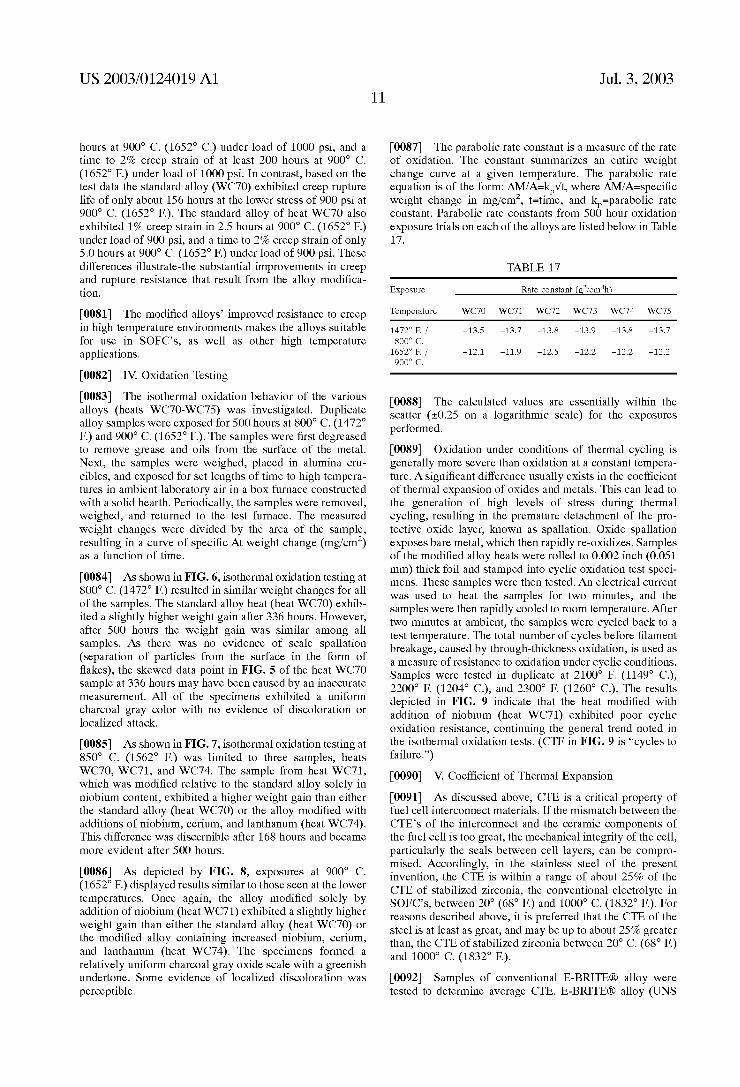
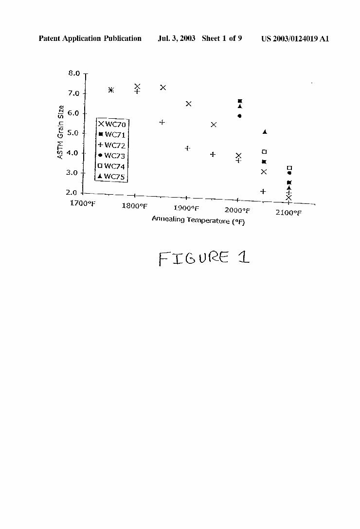
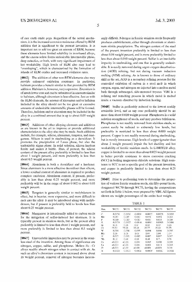
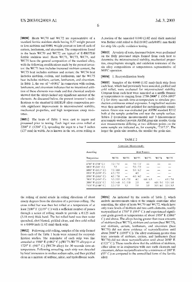
[0016] FIG. 1 is a graph of ASTM grain siZe as a function of annealing temperature for several ferritic stainless steels;
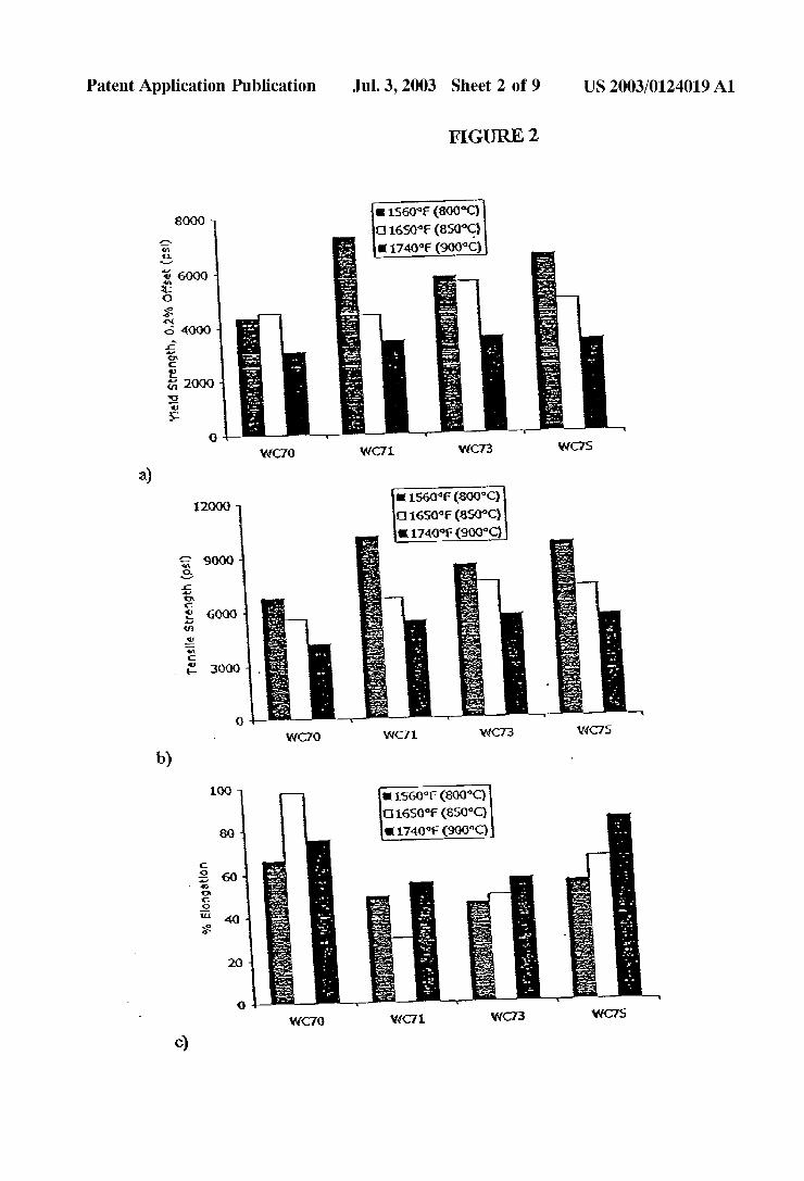
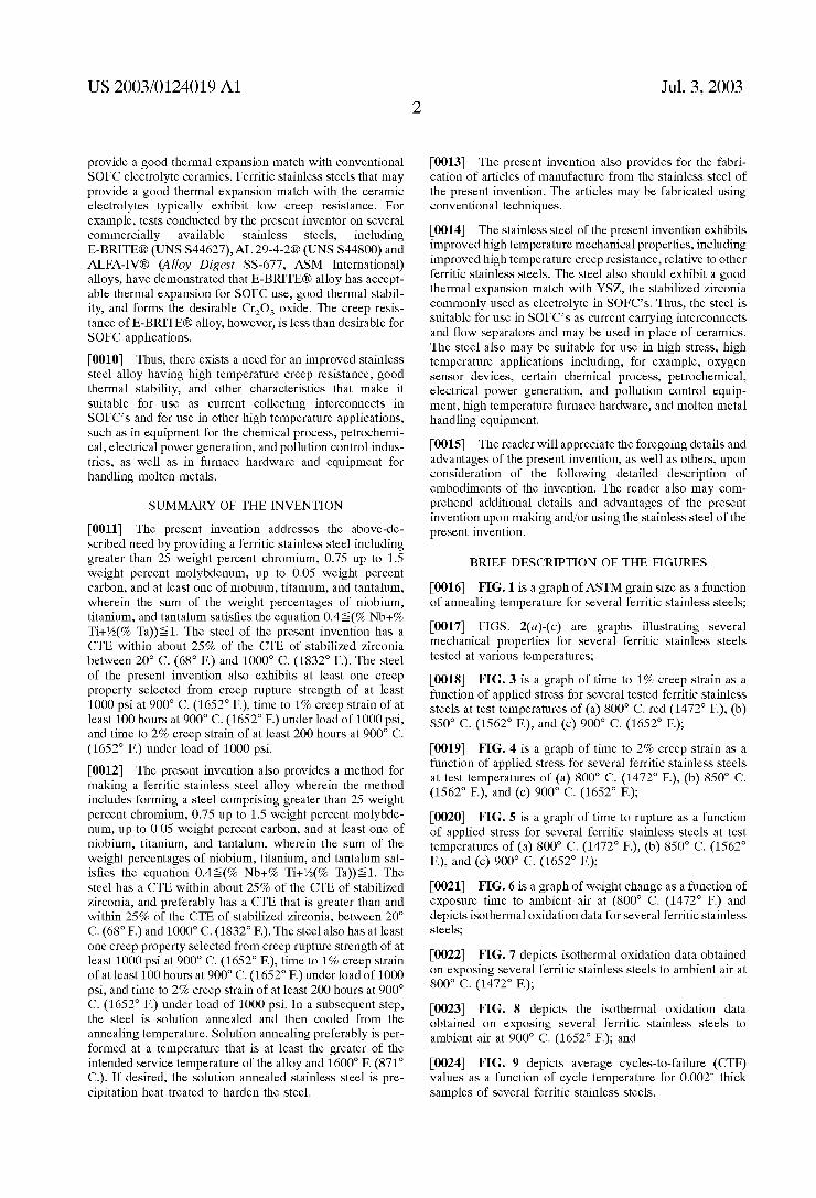
[0017] FIGS. 2(a)-(c) are graphs illustrating several mechanical properties for several ferritic stainless steels tested at various temperatures;
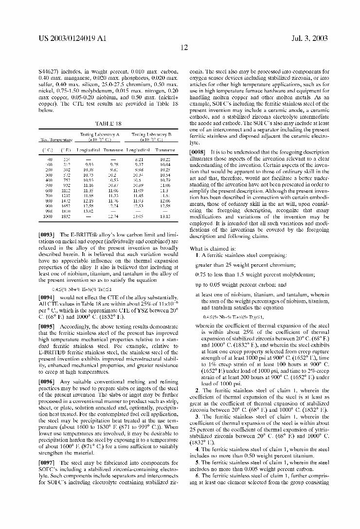
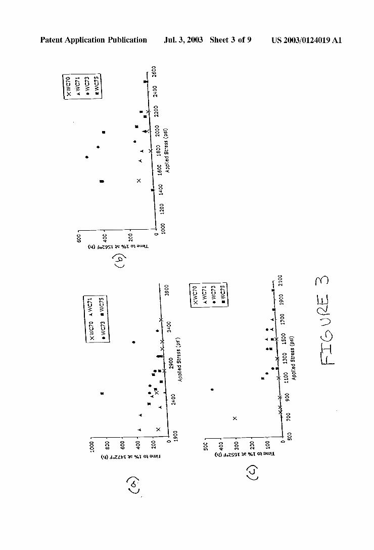
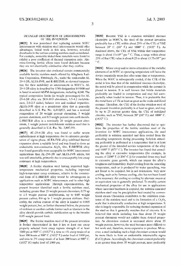
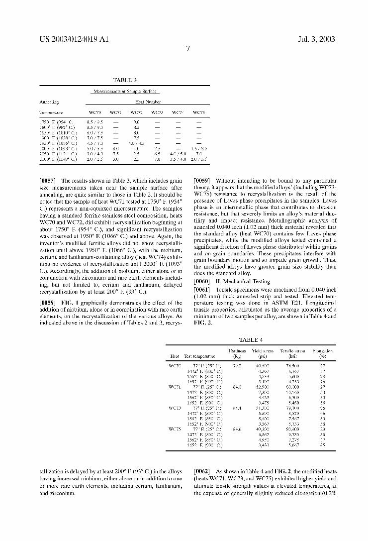
[0018] FIG. 3 is a graph of time to 1% creep strain as a function of applied stress for several tested ferritic stainless steels at test temperatures of (a) 800° C. red (1472° F.), (b) 850° C. (1562° F.), and (c) 900° C. (1652° F.);
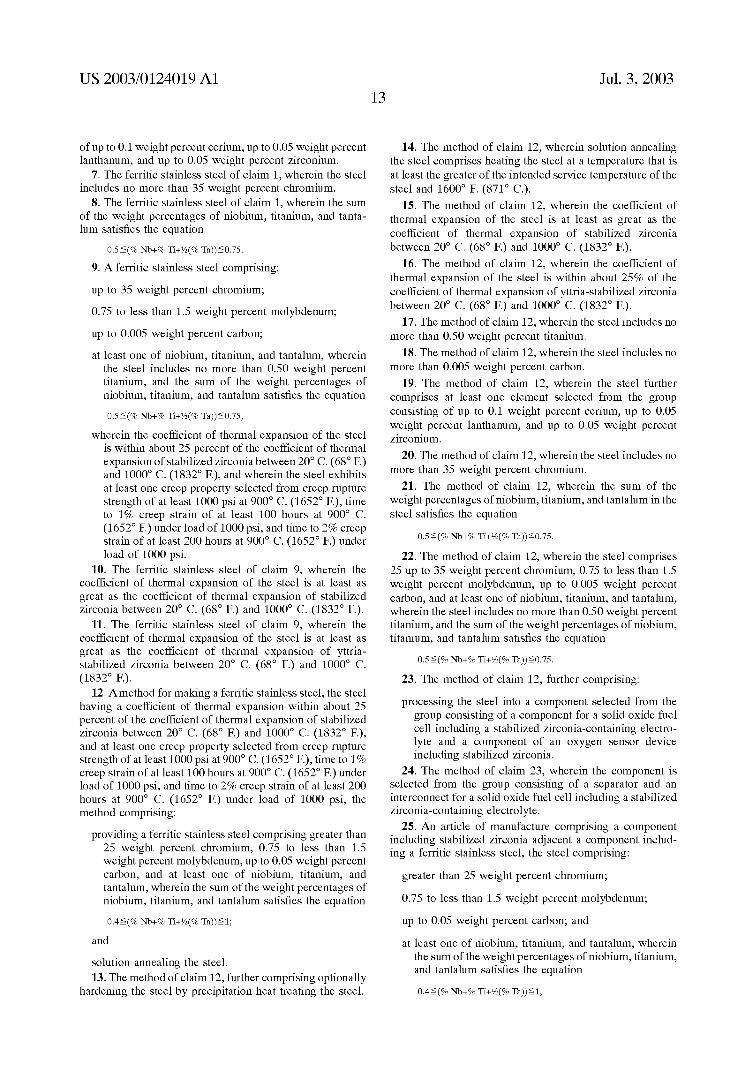
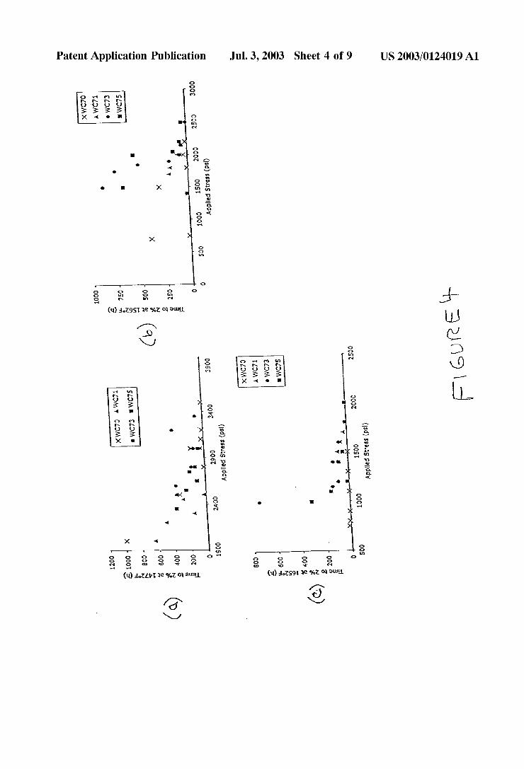
[0019] FIG. 4 is a graph of time to 2% creep strain as a function of applied stress for several ferritic stainless steels at test temperatures of (a) 800° C. (1472° F.), (b) 850° C. (1562° F.), and (c) 900° C. (1652° F.);
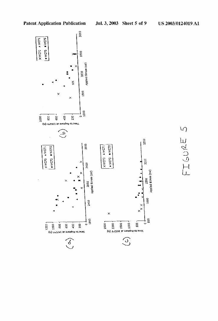
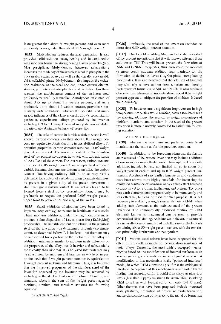
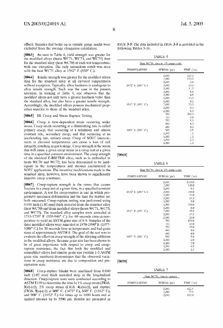
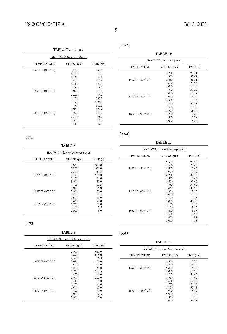
[0020] FIG. 5 is a graph of time to rupture as a function of applied stress for several ferritic stainless steels at test temperatures of (a) 800° C. (1472° F.), (b) 850° C. (1562° F.), and (c) 900° C. (1652° F.);
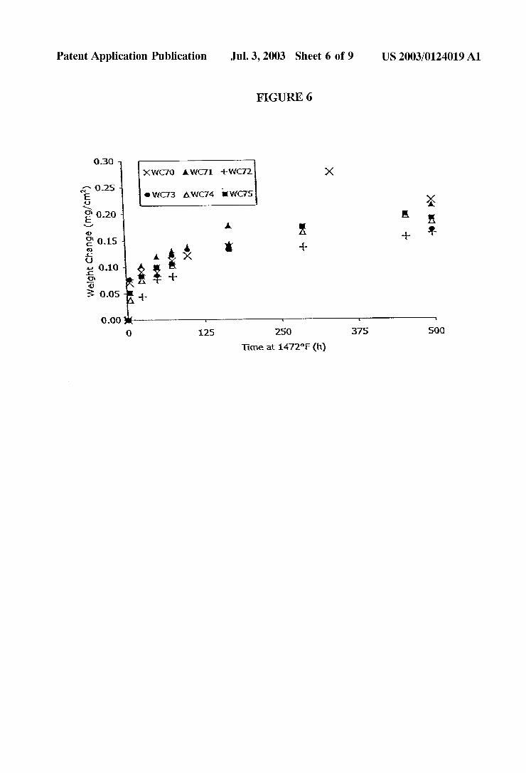
[0021] FIG. 6 is a graph of Weight change as a function of exposure time to ambient air at (800° C. (1472° and depicts isothermal oxidation data for several ferritic stainless steels;
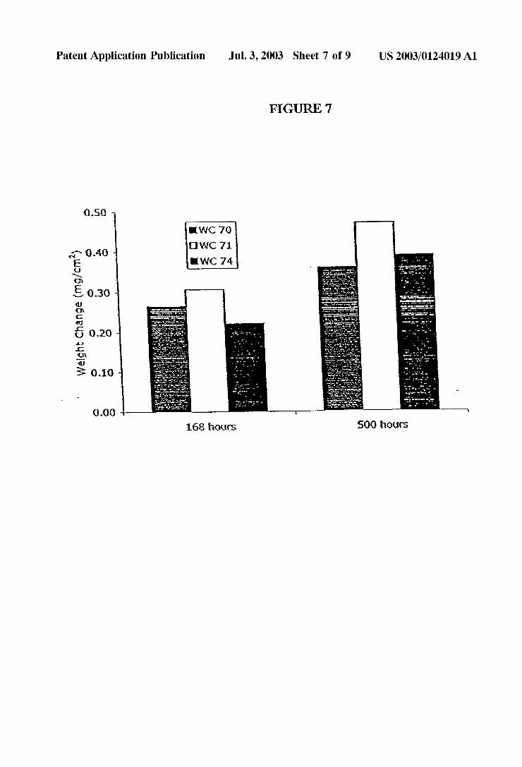
[0022] FIG. 7 depicts isothermal oxidation data obtained on exposing several ferritic stainless steels to ambient air at 800° C. (1472° F.);
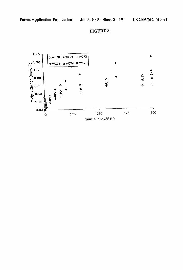
[0023] FIG. 8 depicts the isothermal oxidation data obtained on exposing several ferritic stainless steels to ambient air at 900° C. (1652° F.); and
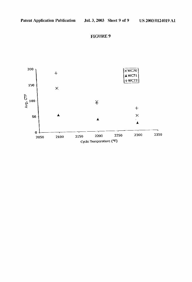
[0024] FIG. 9 depicts average cycles-to-failure (CTF) values as a function of cycle temperature for 0.002“ thick samples of several ferritic stainless steels.
US 2003/0124019 A1
DETAILED DESCRIPTION OF EMBODIMENTS OF THE INVENTION
[0025] It Was postulated that replacing ceramic SOFC interconnects With stainless steel interconnects Would offer advantages. Initial Work in this area, however, revealed drawbacks in the various existing stainless steels considered. For example, austenitic nickel-base materials Were found to exhibit a poor coefficient of thermal expansion ratio. Alu mina-forming ferritic alloys Were found de?cient because they are not electrically conductive after they oxidiZe.
[0026] The inventor also evaluated certain commercially available ferritic stainless steels offered by Allegheny Lud lum Corporation, Pittsburgh, Pa., under the trademarks AL 29-4-2®, ALFA-IV®, and E-BRITE®, at elevated tempera ture for their suitability as interconnects in SOFC’s. AL 29-4-2® alloy is described by UNS designation S44800 and is listed in several ASTM designations, including A240. The typical composition limits (in Weight percentages) for AL 29-4-2® alloy are 28.0-30.0 chromium, 3.5-4.2 molybde num, 2.0-2.5 nickel, balance iron and residual impurities. ALFA-IV® alloy is a proprietary alloy that is generally described in US. Pat. No. 4,414,023, and has a nominal composition of 20 Weight percent chromium, 5 Weight percent aluminum, and 0.3 Weight percent rare earth metals. E-BRITE® alloy is a nominally 26 Weight percent chro mium, 1 Weight percent molybdenum stainless steel that is generally described in US. Pat. No. 3,807,991.
[0027] AL-29-4-2® alloy Was found to suffer severe embrittlement at high temperature due to extensive precipi tation of sigma phase. ALFA-IV® alloy exhibited thermal expansion above a suitable level and Was found to form an
undesirable non-conductive Al2O3 ?lm. E-BRITE® alloy Was found generally more acceptable for SOFC interconnect applications than AL-294-2® and ALFA-IV® alloys, but Was still unsuitable, primarily due to unacceptably loW creep resistance at high temperatures.
[0028] A ferritic stainless steel having improved high temperature mechanical properties, including improved high-temperature creep resistance, relative to the commer cial form of E-BRITE® alloy Would be advantageous in applications such as SOFC interconnects and in other high temperature applications. Through experimentation, the present inventor identi?ed such a ferritic stainless steel, including greater than 25 Weight percent chromium, 0.75 up to 1.5 Weight percent molybdenum, up to 0.05 Weight percent carbon, 0.4 up to 1 Weight percent niobium. Pref erably, the carbon content of the alloy is limited to 0.005 Weight percent, but, as further discussed beloW, the presence of niobium or another carbide former such as titanium in the alloy should provide carbide stabiliZation up to the broader 0.05 Weight percent limit.
[0029] The ferritic stainless steel of the present invention is further characteriZed in that it has at least one creep
property selected from creep rupture strength of at least 1000 psi at 900° C. (1652° F), time to 1% creep strain of at least 100 hours at 900° C. (1652° under load of 1000 psi, and time to 2% creep strain of at least 200 hours at 900° C.
(1652° under load of 1000 psi.
Jul. 3, 2003
[0030] Because YSZ is a common stabiliZed Zirconia
electrolyte in SOFC’s, the steel of the present invention preferably has a CTE Within about 25% of the CTE of YSZ
betWeen 20° C. (68° and 1000° C. (1832° As disclosed above, the CTE of YSZ Within that temperature range is about 11><10_6 per ° C. Thus, a range Within about 25% of that CTE value is about 8.25 to about 13.75><10_6 per ° C.
[0031] Minor creep and/or stress relaxation of the metallic elements of an SOFC at operating temperature Will leave the device essentially stress free after some time at temperature.
When the SOFC is subsequently cooled, if the CTE of the metal is less than that of the stabiliZed Zirconia electrolyte, the metal Will be placed in compression While the ceramic is placed in tension. It is Well knoWn that brittle materials preferably are loaded in compression and may fail unex pectedly When loaded in tension. Thus, it is preferable that the metal have a CTE as least as great as the oxide-stabiliZed
ceramic. Therefore, the CTE of the ferritic stainless steel of the present invention preferably is at least as great, and may be up to 25 percent greater than, the CTE of stabiliZed Zirconia, such as YSZ, betWeen 20° (68° and 1000° C.
(1832° [0032] The inventor has further discovered that to opti miZe the properties of the ferritic stainless steel of the invention for SOFC interconnect applications, the steel preferably is solution annealed and then cooled from the annealing temperature during processing. Solution anneal ing preferably is performed at a temperature that is at least the greater of the intended service temperature of the alloy and 1600° F. (871° C.). The inventor has found that anneal ing the alloy at excessive temperatures (for example, in excess of 2200° F. (1204° for extended times may lead to excessive grain groWth, Which can impair the alloy’s toughness and formability. Rapid cooling from the annealing temperature, such as is produced by Water quenching, Was not found to be required, but is not deleterious. Very sloW cooling, such as by furnace cooling, also has not been found to be necessary. Air cooling or cooling by alternate means at an equivalent rate is generally preferred. To modify certain mechanical properties of the alloy for use in applications Where increased hardness is required, the solution annealed stainless steel may be precipitation heat treated by conven tional means Chromium contributes to the oxidation resis
tance of the stainless steel and to its formation of a Cr2O3 scale that is electrically conductive at high temperatures. It also is largely responsible for reducing thermal expansion of the steel so that it generally matches that of Zirconia. It is believed that steels including less than about 25 Weight percent chromium Would not exhibit these desired proper ties. As chromium content is increased above about 35 Weight percent, hoWever, the steel becomes more dif?cult to hot Work and, therefore, more expensive to produce. More over, a steel including such a high chromium content Would be more likely to from an undesirable intermetallic sigma (FeCr) phase. Accordingly, the chromium content preferably is no greater than about 35 Weight percent, more preferably
US 2003/0124019 A1
is no greater than about 30 Weight percent, and even more preferably is no greater than about 27.5 Weight percent.
[0033] Molybdenum reduces thermal expansion. It also provides solid solution strengthening and in conjunction With niobium forms the strengthening Laves phase Fe2(Nb, Mo) precipitate. Molybdenum, hoWever, substantially increases the tendency of the stainless steel to precipitate the undesirable sigma phase, as Well as the equally undesirable chi (Fe,Cr,Mo) phase. Molybdenum also impairs the oxida tion resistance of the steel and can, under certain circum stances, promote a catastrophic form of oxidation. For these reasons, the molybdenum content of the stainless steel preferably is carefully controlled. A molybdenum content of about 0.75 up to about 1.5 Weight percent, and more preferably up to about 1.2 Weight percent, provides a par ticularly suitable balance betWeen the desirable and unde sirable in?uences of the element on the alloy’s properties. In particular, experimental alloys produced by the inventor including 0.9 to 1.1 Weight percent molybdenum exhibited a particularly desirable balance of properties.
[0034] The role of carbon in ferritic stainless steels is Well knoWn. Carbon contents less than about 0.010 Weight per cent are required to obtain ductility in unstabiliZed alloys. To optimiZe properties, carbon contents less than 0.005 Weight percent are needed. The niobium content of the stainless
steel of the present invention, hoWever, Will mitigate many of the effects of the carbon. For this reason, carbon contents up to about 0.05 Weight percent are acceptable if suf?cient carbide forming elements are present to stabiliZe the carbon content. One having ordinary skill in the art may readily determine the content of carbide forming elements that must be present in a given alloy of the present invention to stabiliZe a given carbon content. If Welded articles are to be
formed from a steel of the present invention, it may be preferable to respect the preferred 0.005 Weight percent upper limit to prevent hot cracking of the Welds.
[0035] Small additions of niobium have been found to improve creep or “sag” resistance in ferritic stainless steels. These niobium additions, under the right circumstances, produce a ?ne dispersion of Laves phase (Fe2(Ta,Nb,Mo)) precipitates. The suitable content of niobium in the stainless steel of the invention Was determined through experimen tation, as described beloW. It is believed that titanium may be substituted for a portion of the niobium in the alloy. In addition, tantalum is similar to niobium in its in?uence on the properties of the alloy, but is heavier and substantially more costly than niobium. It is believed that tantalum may be substituted for niobium and titanium in Whole or in part on the basis that 2 Weight percent tantalum is equivalent to 1 Weight percent niobium and titanium. Thus, it is believed that the improved properties of the stainless steel of the invention observed by the inventor may be achieved by including in the steel at least one of niobium, titanium, and tantalum, Wherein the sum of the Weight percentages of niobium, titanium, and tantalum satis?es the folloWing equation:
Jul. 3, 2003
[0036] Preferably, the steel of the invention includes no more than 0.50 Weight percent titanium.
[0037] One bene?t of adding titanium to the stainless steel of the present invention is that it Will remove nitrogen from solution as TiN. This Will better prevent the formation of NbN and CrNbN precipitates, thus preserving the niobium (a more costly alloying addition than titanium) for the formation of desirable Laves (FeZNb) phase strengthening precipitates. It is also believed that the addition of titanium may similarly remove carbon from solution and thereby better prevent formation of NbC and NbCN. It also has been observed that titanium in amounts above about 0.07 Weight percent appears to mitigate the problem of niobium-induced Weld cracking.
[0038] To better ensure a signi?cant improvement in high temperature properties While limiting costs associated With the alloying additions, the sum of the Weight percentages of niobium, titanium, and tantalum in the steel of the present invention is more narroWly controlled to satisfy the folloW ing equation:
[0039] Wherein the maximum and preferred contents of titanium are the same as for the previous equation.
[0040] In addition, to the foregoing elements, the ferritic stainless steel of the present invention may include additions of one or more rare earth elements. These optional rare earth
additions include, but are not limited to, up to about 0.1 Weight percent cerium and up to 0.05 Weight percent lan thanum. Additions of rare earth elements as alloy additions have been shoWn to be highly bene?cial for increasing the oxidation resistance of iron-base alloys. Such effect has been demonstrated for yttrium, lanthanum, and cerium. The other rare earth elements tend progressively to be more costly and less effective, but can be used for that purpose. It is not necessary to add only a single rare earth metal (REM) When adding such elements to the stainless steel of the present invention. The commercially produced mixture of REM elements knoWn as mischmetal can be used to provide economical REM doping. As is knoWn in the art, mischmetal is a naturally derived mixture of metallic rare earth elements
containing about 50 Weight percent cerium, With the remain der principally lanthanum and neodymium.
[0041] Various mechanisms have been proposed for the effect of rare earth elements on the oxidation resistance of
metal alloys. Currently, the most Widely accepted mecha nism is based on the modi?cation of internal surfaces, such as oxide/oxide grain boundaries and oxide/metal interface. A modi?cation to this mechanism is the “poisoned interface” model, in Which REM atoms tie up sulfur at the oxide/metal interface. Acceptance of this mechanism is supported by the ?nding that reducing sulfur in REM-free alloys to ultra-loW levels (less than 1 ppm) has much the same effect as adding REM to alloys With typical sulfur contents (3-100 ppm). Other theories that have been proposed include increased scale plasticity, promotion of protective oxide formation, and mechanical keying of the scale to the metal by formation
US 2003/0124019 A1
of rare earth oxide pegs. Regardless of the actual mecha nism, it is the increased corrosion resistance offered by REM addition that is signi?cant to the present invention. It is important not to add too great an amount of REM, because these elements have limited solubility in iron-based alloys, and the excess solute forms undesirable intermetallic phase, deep eutectics, or both, With very signi?cant impairment of hot Workability. High levels of REM also may lead to “overdoping”, Which is characteriZed by the formation of islands of REM oxides and increased oxidation rates.
[0042] The addition of other non-REM elements also may provide enhanced oxidation resistance. In particular, hafnium provides a bene?t similar to that provided by REM addition. Hafnium is, hoWever, very expensive. Zirconium is of much loWer cost and can be substituted in amounts similar
to hafnium, although Zirconium is less effective. Just as With the REM elements, the amount of Zirconium and/or hafnium included in the alloy should not be too great or excessive amounts of undesirable intermetallic phases Will be formed. Therefore, hafnium and/or Zirconium may be included in the alloy in a combined amount that is up to about 0.05 Weight percent.
[0043] Additions of other alloying elements and additives as are knoWn in the art to improve or provide additional characteristics to the alloy also may be made. Such additions include, for example, silicon, aluminum, tungsten, and man ganese. Silicon is used in steelmaking as a deoxidiZer. It promotes the precipitation of Laves phase, but also the undesirable sigma phase. In solid solution, silicon hardens ferrite and makes it brittle. Thus, if present, the silicon content of the present alloy preferably is limited to less than about 1 Weight percent, and more preferably is less than about 0.5 Weight percent.
[0044] Aluminum is both a deoxidiZer and a hardener. Since aluminum is a more effective deoxidiZer than silicon, a loWer residual content of aluminum is required to produce complete oxidation. Aluminum content, if present, prefer ably is less than about 0.25 Weight percent, and more preferably Will be in the range of about 0.002 to about 0.05 Weight percent.
[0045] Tungsten is generally similar to molybdenum in effect, but is heavier, more expensive, and more dif?cult to melt into the alloy. It may be introduced along With molyb denum, but if present is preferably held to levels less than about 0.25 Weight percent.
[0046] Manganese is intentionally added to carbon steels for the mitigation of sulfur-induced hot shortness. It is typically present in stainless steels, but in the present alloy preferably is limited to less than about 1 Weight percent, and more preferably is limited to less than about 0.5 Weight percent.
[0047] Unavoidable impurities may be present in the stain less steel of the invention. Among those of signi?cance are nitrogen, copper, sulfur, and phosphorus. Molten Fe—Cr alloys readily absorb nitrogen When in contact With air. As such an alloy’s chromium content is increased above about 18 Weight percent, removal of nitrogen becomes increas
Jul. 3, 2003
ingly dif?cult. Nitrogen in ferritic stainless steels frequently produces embrittlement, either through chromium or alumi num nitride precipitation. The nitrogen content of the steel
of the present invention preferably is limited to less than about 0.04 Weight percent, and is more preferably limited to less than about 0.010 Weight percent. Sulfur is an inevitable
impurity in steelmaking, and one that is generally undesir able. It is easily removed during argon oxygen decarburiZa tion (AOD) re?ning, but not during vacuum induction melting (VIM) re?ning. As is knoWn to those of ordinary skill in the art, AOD is a secondary re?ning process for the controlled oxidation of carbon in a steel melt in Which
oxygen, argon, and nitrogen are injected into a molten metal
bath through submerged, side-mounted tuyeres. VIM is a re?ning and remelting process in Which metal is melted inside a vacuum chamber by induction heating.
[0048] Sulfur is preferably reduced to the loWest readily attainable level, and in any case preferably should be no
more than about 0.010 Weight percent. Phosphorus is a solid
solution strengthener of steels, and may produce brittleness. Phosphorus is not readily removed from stainless steels, so cannot easily be reduced to extremely loW levels, but preferably is restricted to less than about 0.050 Weight percent. Copper is not readily removed during steelmaking, but is mostly innocuous. High levels of copper (greater than about 2 Weight percent) impair the hot ductility and hot Workability of ferritic stainless steels. In E-BRITE® alloy, copper is limited to no more than about 0.025 Weight percent
to better provide resistance to stress corrosion cracking
(SCC) in boiling magnesium chloride solutions. High resis tance to SCC is not a speci?c goal of the present invention, and copper is preferably limited to less than about 0.25
Weight percent.
[0049] Prior to performing tests to determine the proper
ties of various ferritic stainless steels, six ?fty-pound heats, designated WC70 through WC75, having the compositions set forth in Table 1 beloW, Were prepared by VIM. All ?gures shoWn are Weight percentages of the entire heat Weight.
TABLE 1
Heat W070 W071 W072 W073 W074 W075
0 0.0026 0.0026 0.0038 0.0022 0.0023 0.0033 Mn 0.054 0.055 0.060 0.049 0.052 0.053 P 0.010 0.010 0.010 0.010 0.010 0.010 8 0.0029 0.0027 0.0014 0.0011 0.0003 0.0006 Si 0.16 0.15 0.14 0.15 0.15 0.15 Cr 25.52 25.98 25.63 25.77 25.69 25.79 Ni 0.096 0.094 0.095 0.094 0.094 0.095 MO 1.05 1.05 1.03 1.04 1.04 1.04 Al 0.002 0.002 0.002 0.002 0.002 0.002 Nb 0.12 0.68 0.13 0.68 0.71 0.71 Ce <0.001 <0.001 0.001 0.003 0.042 0.009 La <0.001 <0.001 0.001 0.001 0.016 0.003 Zr <0.001 <0.001 <0.001 <0.001 <0.001 0.011
N 0.0010 0.0010 0.0008 0.0009 0.0011 0.0011
US 2003/0124019 A1
[0050] Heats WC70 and WC72 are representative of a standard ferritic stainless steels having 0.37 Weight percent or less niobium and 0.001 Weight percent or less of each of cerium, lanthanum, and Zirconium. The compositions found in the heats WC70 and WC72 are typical of E-BRITE® ferritic stainless steel. Heats WC71, WC73, WC74, and WC75 have the general composition of the standard alloy, With the following modi?cations made by the present inven tor: the WC71 heat includes increased niobium content; the WC73 heat includes niobium and cerium; the WC74 heat includes niobium, cerium, and lanthanum; and the WC75 heat includes niobium, cerium, lanthanum, and Zirconium. In Table 1, the use of “<0.001” in connection With cerium, lanthanum, and Zirconium indicates that no intentional addi tion of these elements Was made and that chemical analysis shoWed that the alloys lacked any signi?cant amount of the elements. As discussed beloW, the present inventor’s modi ?cations to the standard E-BRITE® alloy composition pro vide signi?cant improvement in microstructural stability, mechanical properties, and high temperature creep resis tance.
[0051] The heats of Table 1 Were cast to ingots and processed prior to testing. Each ingot Was cross rolled at 2200° F. (1204° C.), spreading the ingot to a bar 5 inches (127 mm) in Width. As is knoWn in the art, cross rolling is
Jul. 3, 2003
A portion of the annealed 0.040 (1.02 mm) thick material Was further cold rolled to foil (0.002 inch/0.051 mm thick) for strip life cyclic oxidation testing.
[0053] Avariety of tests, discussed beloW, Were performed on the fully processed strips formed from each heat to determine the microstructural stability, mechanical proper ties, creep/rupture strength, and oxidation resistance of the six alloy compositions at temperatures representative of SOFC operation.
[0054] I. Recrystallization Study
[0055] Samples of the 0.040 (1.02 mm) thick strip from each heat, Which had previously been annealed, pickled and cold rolled, Were evaluated for microstructural stability. Coupons from each heat Were annealed in a muffle furnace at temperatures to ranging from 1750-2000° F. (954-1093° C.) for thirty seconds time-at-temperature to simulate pro duction continuous anneal exposures. Longitudinal sections Were then mounted and polished for metallographic exami nation. Grain siZe Was evaluated per ASTM standard E112 both at the sample centerline and near the sample surface. Tables 2 (centerline measurements) and 3 (measurement near sample surface) provide ASTM grain siZe results. Grain siZe measurements differing at tWo different points on the same sample are indicated as, for example, “7.0/7.5”. The larger the grain siZe number, the smaller the grain siZe.
TABLE 2
Centerline Measurements
Annealing Heat Number
Temperature WC70 WC71 WC72 WC73 WC74 WC75
1750° F. (954° C.) 7.0 / 7.5 — 7.0 / 7.5 — — —
1800° F. (982° C.) 7.5 — 7.0 / 7.5 — — —
1850° F. (1010° C.) 7.0 / 8.0 — 5.0 / 6.5 — — —
1900° F. (1038° C.) 6.0 / 7.5 — 4.5 — — —
1950° F. (1066° C.) 4.5 / 7.0 — 4.0 / 4.5 — — —
2000° F. (1093° C.) 3.0 / 5.5 6.5 / 7.5 4.0 6.0 / 6.5 — 6.5 / 7.0
2050° F. (1121° C.) 3.0 / 4.0 3.0 / 5.0 2.5 4.0 4.0 / 5.0 5.0 / 6.0 2100° F. (1148° C.) 2.0 / 2.5 3.0 2.5 3.5 3.5 / 4.0 2.0 / 3.5
the rolling of metal article in rolling directions of about ninety degrees from the direction of a previous rolling. The cross rolled bar Was then hot rolled at a temperature of at
least 2100° F. (1149° C.) With a suf?cient number of passes through a series of rolling stands to provide a 0.125 inch (3.18 mm) thick band. The hot rolled band Was then Water quenched, shot blasted, pickled clean, and then cold rolled to a 0.040 inch (1.02 mm) thick strip.
[0052] FolloWing cold rolling, samples of the strip formed from each of the Table 1 heats Were retained for recrystal liZation studies. The remainder of each strip Was line
annealed at 1980° F. (1082° C.) (WC71-WC75 alloys) or at 1725° F. (9410 C.) (WC70 alloy) for 30 seconds time-at temperature. FolloWing annealing, each strip Was descaled by brief immersion in molten sodium salts, and then pickled clean in a mixture of sulfuric, nitric, and hydro?uoric acids.
[0056] As indicated by the results of Table 2, Which include measurements taken at the sample centerline after annealing, the alloy of heats WC70 and WC72, Which have only trace levels of niobium and rare earth elements, readily recrystalliZed at 1750° F. (954° C.) and experienced signi? cant grain groWth at temperatures of about 1950° F. (1066° C.) and above. The alloys having greater than trace amounts of niobium (heat WC71), niobium and cerium (heat WC73), and niobium, cerium, lanthanum, and Zirconium (heat WC75) did not shoW evidence of recrystalliZation until about 2000° F. (1093° C.). The alloy containing greater than trace amounts of niobium, cerium, and lanthanum (heat WC74) did not shoW recrystalliZation until about 2050° F. (1121° C.). These results shoW that the addition of niobium, either alone or in conjunction With rare earth elements and Zirconium, delays recrystalliZation by a minimum of 200° F. (93° C.) as compared to the unmodi?ed form of the ferritic alloy.
US 2003/0124019 A1
TABLE 3
Jul. 3, 2003
Measurements at Sample Surface
Annealing Heat Number
Temperature WC70 WC71 WC72 WC73 WC74 WC75
1750° F. (954° C. 8.5/9.5 — 9.0 — — —
1800° F. (982° C.) 8.5/9.0 — 8.5 — — —
1850° F. (1010° C.) 6.0/7.5 — 8.0 — — —
1900° F (1038° C.) 7.0 / 7.5 — 7.5 — — —
1950° F (1066° C.) 4.5 / 7.0 — 4 0 / 4 5 — — —
2000° F (1093° C.) 5.0 / 5.5 8.0 4.0 7.5 — 7.5 / 8.0 2050° F (1121° C.) 3.0/4.0 7.5 2.5 6.5 4.0 / 5.0 7.0 2100° F (1148° C.) 2.0 / 2.5 3.0 2.5 7.0 3.5 / 4.0 2.0 / 3.5
[0057] The results shown in Table 3, Which includes grain size measurements taken near the sample surface after annealing, are quite similar to those in Table 2. It should be noted that the sample of heat WC71 tested at 1750° F. (954° C.) represents a non-equiaxed microstructure. The samples having a standard ferritic stainless steel composition, heats WC70 and WC72, did exhibit recrystallization beginning at about 1750° F. (954° C.), and signi?cant recrystallization Was observed at 1950° F. (1066° C.) and above. Again, the inventor’s modi?ed ferritic alloys did not shoW recrystalli zation until above 1950° F. (1066° C.), With the niobium, cerium, and lanthanum-containing alloy (heat WC74) exhib iting no evidence of recrystallization until 2000° F. (1093° C.). Accordingly, the addition of niobium, either alone or in conjunction With zirconium and rare earth elements includ ing, but not limited to, cerium and lanthanum, delayed recrystallization by at least 200° F. (93° C.).
[0058] FIG. 1 graphically demonstrates the effect of the addition of niobium, alone or in combination With rare earth elements, on the recrystallization of the various alloys. As indicated above in the discussion of Tables 2 and 3, recrys
[0059] Without intending to be bound to any particular theory, it appears that the modi?ed alloys’ (including WC73 WC75) resistance to recrystallization is the result of the presence of Laves phase precipitates in the samples. Laves phase is an intermetallic phase that contributes to abrasion resistance, but that severely limits an alloy’s material duc tility and impact resistance. Metallographic analysis of annealed 0.040 inch (1.02 mm) thick material revealed that the standard alloy (heat WC70) contains feW Laves phase precipitates, While the modi?ed alloys tested contained a signi?cant fraction of Laves phase distributed Within grains and on grain boundaries. These precipitates interfere With grain boundary motion and so impede grain groWth. Thus, the modi?ed alloys have greater grain size stability than does the standard alloy.
[0060] II. Mechanical Testing [0061] Tensile specimens Were machined from 0.040 inch (1.02 mm) thick annealed strip and tested. Elevated tem perature testing Was done in ASTM E21. Longitudinal tensile properties, calculated as the average properties of a minimum of tWo samples per alloy, are shoWn in Table 4 and FIG. 2.
TABLE 4
Hardness Yield stress Tensile stress Elongation Heat Test temperature (Rb) (psi) (%)
WC70 77° F. (25° C.) 79.0 49,600 76,500 27 1472° F. (800° C.) 4,367 6,767 67 1562° F. (850° C.) 4,533 5,600 98 1652° F. (900° C.) 3,100 4,233 76
WC71 77° F. (25° C.) 84.0 52,900 80,000 27 1472° F. (800° C.) 7,300 10,160 50 1562° F. (850° C.) 4,433 6,700 30 1652° F. (900° C.) 3,475 5,450 56
WC73 77° F. (25° C.) 84.4 51,300 79,700 26 1472° F. (800° C.) 5,800 8,520 46 1562° F. (850° C.) 5,600 7,567 50 1652° F. (900° C.) 3,567 5,733 58
WC75 77° F. (25° C.) 84.6 49,300 80,900 23 1472° F. (800° C.) 6,567 9,733 56 1562° F. (850° C.) 4,950 7,275 67 1652° F. (900° C.) 3,433 5,667 85
tallization is delayed by at least 200° F. (93° C.) in the alloys having increased niobium, either alone or in addition to one
or more rare earth elements, including cerium, lanthanum, and zirconium.
[0062] As shoWn in Table 4 and FIG. 2, the modi?ed heats (heats WC71, WC73, and WC75) exhibited higher yield and ultimate tensile strength values at elevated temperatures, at the expense of generally slightly reduced elongation (0.2%
US 2003/0124019 A1
offset). Samples that broke on or outside gauge marks Were excluded from the average elongation calculation.
[0063] As seen in Table 4, yield strength Was greater for the modi?ed alloys (heats WC71, WC73, and WC75) than for the standard alloy (heat WC70) at each test temperature, With one exception. The only anomalous result Was seen With the heat WC71 alloy at 1562° F. (850° C.).
[0064] Tensile strength Was greater for the modi?ed alloys than for the standard alloy at all elevated temperatures Without exception. Typically, alloy hardness is analogous to alloy tensile strength. Such Was the case in the present situation. In looking at Table 4, one observes that the modi?ed alloys not only have a greater hardness value than the standard alloy, but also have a greater tensile strength. Accordingly, the modi?ed alloys possess mechanical prop erties superior to those of the standard alloy.
[0065] III. Creep and Stress Rupture Testing
[0066] Creep is time-dependent strain occurring under stress. Creep strain occurring at a diminishing rate is called primary creep; that occurring at a minimum and almost constant rate, secondary creep; and that occurring at an accelerating rate, tertiary creep. Creep of SOFC intercon nects at elevated temperatures can cause a loss of cell integrity, resulting in gas leakage. Creep strength is the stress that Will cause a given creep strain in a creep test at a given time in a speci?ed constant environment. The creep strength of the standard E-BRITE® alloy, such as is embodied in heats WC70 and WC72, has been determined to be inad equate in the temperatures and stresses encountered in SOFC applications. The inventive modi?cations made to the standard alloy, hoWever, have been shoWn to signi?cantly improve creep resistance.
[0067] Creep-rupture strength is the stress that causes fracture in a creep test at a given time, in a speci?ed constant environment. A test for creep-rupture is one in Which pro gressive specimen deformation and the time for rupture are both measured. Creep-rupture testing Was performed using 0.040 inch (1.02 mm) thick material from the standard alloy (heat WC70) and from modi?ed alloys (heats WC71, WC73, and WC75). The standard alloy samples Were annealed at 1715-1735° F. (935-946° C.) for 60 seconds time-at-tem perature to yield an ASTM grain siZe of 8-9. Samples of the three modi?ed alloys Were annealed at 1970-1990° F. (1077 1088° C.) for 30 seconds time-at-temperature and had grain siZes of approximately ASTM 8. The goal of the test Was to evaluate the effect on creep strength of the alloying additions in the modi?ed alloys. Because grain siZe has been shoWn to be of great importance With respect to creep and creep rupture resistance, the fact that both the modi?ed and unmodi?ed alloys had similar grain siZe (Within 1-2 ASTM grain siZe numbers) demonstrates that the observed varia tions in creep resistance are due to composition and pre cipitation state.
[0068] Creep-rupture blanks Were machined from 0.040 inch (1.02 mm) thick annealed strip in the longitudinal direction. Creep-rupture tests Were conducted according to ASTM E139 to determine the time to 1% creep strain (FIGS. 3(a)-(c)), 2% creep strain (FIGS. 4(a)-(c)), and rupture (FIGS. 5(a)-(c)) at 800° C. (1472° F.), 850° C. (1562° F.), and 900° C. (1652° for times up to 1000 hours and at applied stresses up to 3500 psi. Results are presented in
Jul. 3, 2003
FIGS. 3-5. The data included in FIGS. 3-5 is provided in the folloWing Tables 5-16.
TABLE 5
Heat WC70, time to 1% creep strain
TEMPERATURE STRESS (psi) TIME (hrs)
2,000 125.0 2,500 120.0 2,800 3.8
1472’ F. (800° c.) 3,000 50.0 3,100 11.0 3,200 6.8 3,500 4.8 1,500 110.0 1,800 4.0
1562° F. (850° c.) 2,000 23.0 2,200 8.0 2,500 6.0 700 300.0 750 3.8 750 5.0 800 4.0 800 4.0
1652° F. (900° c.) 900 2.5 1,100 1.0 1,100 1.0 1,300 2.3 1,500 1.0
[0069]
TABLE 6
Heat WC70, time to 2% creep strain
TEMPERATURE STRESS (psi) TIME (hrs)
2,000 1000.0 2,500 320.0 2,800 9.5
1472° F. (800° C.) 3,000 160.0 3,100 31.0 3,200 15.5 3,500 9.8 1,500 300.0 1,800 8.8
1562° F. (850° C.) 2,000 39.5 2,200 17.5 2,500 23.0 700 400.0 750 15.0 750 15.0 800 8.0 800 8.0
1652° F. (900° C.) 900 5.0 1,100 2.0 1,100 2.0 1,300 4.5 1,500 1.5
[0070]
TABLE 7
Heat WC70, time to rupture
TEMPERATURE STRESS (psi) TIME (hrs)
2,500 822.5 2,800 77.5 3,000 537.4
US 2003/0124019 A1 Jul. 3, 2003 9
[0073] TABLE 7-c0ntinued
TABLE 10 Heat WC70, time to rupture
Heat WC71, time to rupture TEMPERATURE STRESS (psi) TIME (hrS)
TEMPERATURE STRESS (psi) TIME (hrS) 1472° F. (800° C.) 3,100 160.1
3,200 725 2,200 954.4 3,500 582 2,300 379.8 1,400 2295 1472’ F. (800° c.) 2,450 662.4 1,500 520.3 2,500 239.8 1,750 143.7 3900 131-0
1562° F. (850° c.) 1,800 145.9 £88 2,200 48.3 o o > '
2,500 106.5 1562 F. (850 C.) 700 2205.0 1,500 203-4
750 3265 1,600 175.0 800 177-4 1,600 188.9
1652° F. (900° C.) 900 156.1 16529 E (9009 C) 1,700 830 1,100 61.2 1,800 378 1,300 25.1 2,000 562 1,500 37.8
[0074] [0071]
TABLE 11 TABLE 8
Heat WC73, time to 1% creep strain Heat WC71, time to 1% creep strain
TEMPERATURE STRESS (psi) TIME (hrS) TEMPERATURE STRESS (psi) TIME (h)
2,500 210.0 2,000 370.0 2,600 200.0 2,200 350.0 1472° F. (800° C.) 2,800 120.0 2,300 87.5 3,000 75.0
1472° F. (800° C.) 2,450 185.0 3,200 375.0 2,500 14.0 3,350 60.0 3,000 30.0 1,500 390.0 1,700 92.5 1,750 500.0 1,800 75.0 1,850 410.0
1562° F. (850° C.) 2,000 53.0 1562° F. (850° C.) 1,900 122.0 2,500 11.3 2,000 36.0 1,500 66.0 2,500 2.3 1,600 28.0 1,000 435.0
1652° F. (900° C.) 1,700 22.0 1,150 75.0 1,800 7.5 1,200 35.0 2,000 5.0 1652° F. (900° C.) 1,400 62.5
1,600 57.0 1,800 6.8 2,000 2.3
[0072]
TABLE 9 [0075]
Heat WC71, time to 2% creep stain TABLE 12
TEMPERATURE STRESS (psi) TIME (hrS) Heat WC73, time to 2% creep strain
2,000 650.0 2,200 505-0 TEMPERATURE STRESS (psi) TIME (hrS) 2,300 156.3
1472° F. (800° C.) 2,450 285.0 2,500 355.0 2,500 29.0 2,600 365.0 3,000 48.0 1472° F. (800° C.) 2,800 161.3 1,700 192.5 3,000 127.5 1,800 180.0 3,200 380.0
1562° F. (850° C.) 2,000 101.0 3,350 90.0 2,500 21.0 1,500 870.0 1,500 86.0 1,750 745.0 1,600 60.0 1,850 503.8
1652° F. (900° C.) 1,700 33.0 1562° F. (850° C.) 1,900 185.0 1,800 12.5 2,000 77.0 2,000 10.0 2,500 5 1
1,000 742.5
US 2003/0124019 A1 Jul. 3, 2003
[0078] TABLE 12-continued
TABLE 15 Heat WC73, time to 2% creep strain _ _ — Heat WC75, time to 2% creep strain
TEMPERATURE STRESS (psi) TIME (hrs) TEMPERATURE STRESS (psi) TIME (hrs)
2,350 365.0 1,150 137.5 2,550 2400 1,200 88.0 1472° F. 2,650 102.5
1652° F. (900° C.) 1,400 125.0 (800° C) 2,750 188-0 2,800 118.8
1,600 71.0 3,000 725 1,800 13.5 1,400 17.0 2 000 5 0 1,500 665.0
’ ' 2,000 550.0
1562° F. 2,050 140.0 (850° C.) 2,150 56.0
2,200 74.0 [0076] 2,500 48.0
1,000 315.0 1,100 152.5 1,200 15.0
Heat WC73, time to rupture 16520 F‘ L400 780 (900 C.) 1,500 42.5
TEMPERATURE STRESS (psi) TIME (hrS) L800 100 2,000 6.5
2,500 862.4 2,600 807.2
1472° F. (800° C.) 2,800 310.3 [0079] 3,000 292.4 3,200 390.2 3,350 200.0 TABLE 16 1,750 894.3 1,850 557.5 Heat WC75z time to rupture
1562° F. (850° C.) 1,900 226.5 2,000 266.1 TEMPERATURE STRESS (psi) TIME (hrs) 2,500 39.3 1,150 316.6 2,350 858.5 1,200 270.0 2,550 494.4
1652° F. (900° C.) 1,400 270.5 1472° F- 2,650 245.7 1,600 1321) (800° C.) 2,750 253.9 1,800 52.5 2,800 293-5 2,000 24.5 3,000 147.0
2,050 269.8 2,100 140.0 2,200 171.4
[0077] 1562° F. 2,500 75.6 (850° C.) 1,100 470.0
1,200 64.2 TABLE 14 1652° F. 1,400 180.3
(900° C.) 1,500 131.1 Heat WC75 time to 1% cree strain 1,800 584
2,000 40.4 TEMPERATURE STRESS (psi) TIME (hrs)
2,350 225.0 _ _ _ _ _
2,500 825.0 [0080] Considering FIGS. 3-5, compositional modi?ca 14720 F- (8000 0) £28 128-8 tions do not appear to make a substantial difference in creep
i750 145'O resistance at the lowest test temperature, 800° C. (1472° 2:800 625 Increasing the temperature to 850° C. (1562° resulted in
3,000 47.0 some differentiation between the creep resistance of stan
L‘sloo 8-O dard and modi?ed alloys. Testing at 900° C. (1652° i’ogg 328g revealed a clear separation of creep strength performance
15620 p_ (8500 C_) 2:050 1020 between the various alloys. The modi?ed alloys (heats 2,150 32.0 WC71, WC73, and WC75) demonstrated generally 5%88 38 increased resistance to creep at higher test temperatures in {000 11256 comparison to the standard alloy (heat WC70). Results were 1:100 1050 consistent at high test temperatures for tests performed to 1,200 6.5 determine time to 1% creep, 2% creep, and rupture, with the
1652° F- (900° (1) 1,400 400 modi?ed alloys demonstrating superior creep resistance 1500 m d h d d 11 1 b d h 1800 45 compare to t e Stan ar a oy. For eXamp e, ase on t e
2,000 35 test data it will be seen that the modi?ed alloys exhibited a creep rupture strength of at least 1000 psi at 900° C. (1652° C.) for 400 hours, a time to 1% creep strain of at least 100