Embed Size (px)
Citation preview

Available online at www.sciencedirect.com
www.elsevier.com/locate/actamat
Acta Materialia 61 (2013) 1432–1443
Tensile behavior of Al1�xMox crystalline and amorphous thin films
D.S. Gianola a,⇑, Z. Lee b,c, C. Ophus b,d, E.J. Luber d, D. Mitlin d, U. Dahmen b,K.J. Hemker e, V.R. Radmilovic b,f,⇑
a Department of Materials Science and Engineering, University of Pennsylvania, Philadelphia, PA, USAb National Center for Electron Microscopy, Lawrence Berkeley National Laboratory, University of California, Berkeley, CA, USA
c School of Mechanical and Advanced Materials Engineering, Ulsan National Institute of Science and Technology, Ulsan, Republic of Koread Department of Materials and Chemical Engineering, University of Alberta, Edmonton, Alberta, Canada
e Department of Mechanical Engineering and Materials Science and Engineering Johns Hopkins University, Baltimore, MD, USAf University of Belgrade, Faculty of Technology and Metallurgy, Nanotechnology and Functional Materials Center, Belgrade, Serbia
Received 29 September 2012; received in revised form 12 November 2012; accepted 12 November 2012Available online 13 December 2012
Abstract
The exceptional strength and distinct deformation physics exhibited by pure ultrafine-grained and nanocrystalline metals in compar-ison to their microcrystalline counterparts have been ascribed to the dominant influence of grain boundaries in accommodating plasticflow. Such grain-boundary-mediated mechanisms can be augmented by additional strengthening in nanocrystalline alloys via solute andprecipitate interactions with dislocations, although its potency is a function of the changes in the elastic properties of the alloyed mate-rial. In this study, we investigate the elastic and plastic properties of Al1�xMox alloys (0 6 x 6 0.32) by tensile testing of sputter-depos-ited freestanding thin films. Isotropic elastic constants and strength are measured over the composition range for which threemicrostructural regimes are identified, including solid solutions, face-centered cubic and amorphous phase mixtures and body-centeredcubic (bcc)/amorphous mixtures. Whereas the bulk modulus is measured to follow the rule of mixtures over the Mo composition range,the Young’s and shear moduli do not. Poisson’s ratio is non-monotonic with increasing Mo content, showing a discontinuous change atthe onset of the bcc/amorphous two-phase region. The strengthening measured in alloyed thin films can be adequately predicted in thesolid solution regime only by combining solute strengthening with a grain boundary pinning model. The single-step co-sputtering pro-cedure presented here results in diversity of alloy compositions and microstructures, offering a promising avenue for tailoring themechanical behavior of thin films.� 2012 Acta Materialia Inc. Published by Elsevier Ltd. All rights reserved.
Keywords: Thin films; MEMS/NEMS; Amorphous metals; Nanocrystalline metals; Elastic properties
1. Introduction
Polycrystalline metals consisting of grains with sizes lessthan 500 nm (ultrafine-grained) and smaller (less than100 nm, nanocrystalline) have received considerable
1359-6454/$36.00 � 2012 Acta Materialia Inc. Published by Elsevier Ltd. All
http://dx.doi.org/10.1016/j.actamat.2012.11.020
⇑ Corresponding authors. Addresses: Department of Materials Scienceand Engineering, University of Pennsylvania, Philadelphia, USA. Tel.: +1215 898 7974 (D.S. Gianola), University of Belgrade, Faculty ofTechnology and Metallurgy, Belgrade, Serbia. Tel.: +381 11 3370 469(V.R. Radmilovic).
E-mail addresses: [email protected] (D.S. Gianola),[email protected], [email protected] (V.R. Radmilovic).
research and industrial attention in recent years, owing totheir impressive strengths in comparison to their coarse-grained counterparts. Central to the mechanical propertyenhancements that have piqued interest in these materialsfor structural applications, including yield strength [1–4],fatigue resistance [5–8] and wear resistance [9–11], are tran-sitions in the underlying deformation mechanisms thataccommodate plastic flow as the grain size enters the sub-micron regime and approaches the nanometer scale [12–29]. Following extensive fundamental investigations intothese novel plasticity mechanisms over the last decade orso (e.g. see thorough reviews on this topic in Refs.[3,4,30]), the emerging picture is that the strength- and
rights reserved.

D.S. Gianola et al. / Acta Materialia 61 (2013) 1432–1443 1433
rate-limiting processes occur at, and are controlled by, thelarge volume fraction of interfacial material residing atgrain boundaries (GBs). As the mean free path requiredfor conventional dislocation–dislocation interactions andsubsequent plasticity mechanisms such as dislocation forest(i.e. Taylor) hardening becomes large relative to the grainsize and new mechanisms become energetically favorable,including partial dislocation emission and absorption[17,31,32], deformation twinning [13,33,34], GB sliding[20,35,36] and GB migration [37–40]. Much of the evolu-tion in the understanding of the active mechanisms hasbeen the result of experimental studies of nominally purenanocrystalline metals and informed via atomistic simula-tions of pure materials.
However, truly pure nanocrystalline metals are knownto be thermodynamically unstable [41], and thus the ther-mal stability displayed by most of these materials suggeststhat some amount of impurities is present to energeticallystabilize GBs [42–45] or kinetically hinder microstructuralevolution [46–48]. Indeed, solute atoms within a nanocrys-talline solvent have been shown to segregate to GBs andincrease stability. Additional driving forces such as stresshave also been shown to catalyze grain growth or refine-ment [27,39,49–54], and recent studies have identified min-ute concentrations of impurities at GBs as potentstabilizers against such evolution [55–58]. The need tounderstand the role of additional elements incorporatedinto nanocrystalline metals is underscored by the addi-tional enhancements that can be achieved in multi-compo-nent systems where alloying effects augment the newdeformation mechanisms. Despite the promise of alloying,relatively little attention has been given to studying suchnanocrystalline metals, in part due to the difficulty ofdeconvoluting the effects of grain size and chemistry [59].As alloying can cause changes to both elastic and plasticproperties, an experimental approach capable of indepen-dently measuring the full suite of mechanical properties isrequisite to predictive capability.
In parallel to these fundamental studies, metallic thinfilms employed in applications such as integrated circuits,micro- and nanoelectromechanical systems (MEMS/NEMS) energy storage and energy conversion, where goodelectrical conductivity is demanded in dimensionally con-strained systems, are often deposited or grown in nano-structured forms using far-from-equilibrium approaches(e.g. vapor deposition, electrodeposition, etc.). As thedimensions of features comprising these devices arereduced to nanometer scales, the appropriate geometricand surface roughness requirements become harder toachieve using standard film synthesis and microfabricationmethods. This is primarily because the size of the internalmicrostructure of these thin film materials is of the orderof the feature itself; the nature of crystalline growth duringthin film synthesis can preclude having smooth, conformal-ly coating material [60]. Recently, Lee and colleagues fab-ricated NEMS cantilever structures fashioned from Al–Mo sputtered thin films, which were compositionally opti-
mized for mechanical properties and roughness [61,62].These authors found the optimum composition for theuse as NEMS resonators to be Al–32 at.% Mo, whichexhibited a composite structure consisting of an amor-phous Al matrix and dispersed Mo nanocrystallites. Thismaterial displayed low roughness (rrms < 5 nm), high hard-ness (H > 5 GPa) and high stiffness as deduced from nano-indentation (reduced modulus, Er � 150 GPa). Theseresults are promising for NEMS applications, but the fullconstitutive behavior of this material is still unknown, pre-cluding rational design and device lifetime prediction.
In this paper, we report on the uniaxial tensile responseof Al–Mo submicron freestanding thin films across a widecompositional range resulting in both crystalline and amor-phous phases to elucidate the role of alloying on elastic andfracture behavior in ultrafine grained and nanocrystallinemetals. We chose the Al–Mo binary system [63] as a modelmaterial to gain fundamental insight into the role of alloy-ing additions on mechanical behavior of thin films; more-over, Al–Mo alloys and multilayers [64–67] have alsobeen proposed as a good candidate material for corro-sion-resistant coatings [68–71].
2. Materials and methods
Al1�xMox films of compositions ranging from pure Alto Al–32 at.% Mo (0, 2, 4, 8, 16, 24 and 32 at.% Mo) weredeposited onto laboratory-grade naturally oxidized 4 inchsilicon h100i wafers by DC magnetron co-sputtering frompure Mo and pure Al targets. Wafers were either cleanedwith a 3:1 mixture of 51% H2SO4 and 30% H2O2 or etchedwith HF prior to deposition. The argon sputtering pressurewas 7.0 mTorr following evacuation to a vacuum basepressure of 1 � 10�6 Torr. Film depositions were per-formed with substrate rotation during deposition to ensurefilm uniformity. The Al sputtering rate was kept constantat 10.5 nm min�1 (300 W power) while the Mo sputteringrate was adjusted to create the desired composition. Allfilms had a thickness of �200 nm. X-ray photoelectronspectroscopy was used to verify the global thin film compo-sition as well as to determine the contamination levels. Theonly detectable impurity was oxygen, which was present ata maximum value of 4 at.%. Microstructural characteriza-tion was performed using transmission electron microscopy(TEM) of freestanding films, which are electron-transpar-ent in the as-deposited state. Cross-sectional TEM sampleswere prepared according to the procedure outlined in Refs.[61,62]. Lattice parameters were determined using X-raydiffraction (XRD) operated in standard powder diffractiongeometry. XRD profiles indicated strong h111i and h110ifilm textures for the face-centered cubic (fcc) and body cen-tered cubic (bcc) phases, respectively, beyond film compo-sitions of 4 at.% Mo. Atomic force microscope (AFM)operated in tapping mode was employed to characterizesurface roughness and measure surface grain sizes.
Pre-fabricated Si-based testing frames (1 � 1 cm) wereintroduced in the vacuum chamber during deposition to

1434 D.S. Gianola et al. / Acta Materialia 61 (2013) 1432–1443
create thin film tensile specimens. Thin film mechanicalbehavior was determined using a custom-built microtensilespecimen testing apparatus. Details regarding the mechan-ical testing setup and microfabrication of the specimentesting frames can be found in Refs. [27,54,72,73]. Localtwo-dimensional full-field strains were calculated using anin-house digital image correlation (DIC) code [73–76],which, combined with force measurement, allowed forthe evaluation of a full suite of material properties includ-ing strength, ductility, elastic moduli and Poisson’s ratio(defined as the absolute value of the ratio of transverse toaxial strains in the elastic regime). In brief, intensity profilesof hundreds of fine silica particles deposited on the surfaceof the films are fit with a nonlinear least squares routineand tracked during deformation. Subsequent calculationof displacements and strain quantities is performed fromthe particle positions. This strain measurement approachoffers sufficient resolution (�30 and 50 le in the longitudi-nal and transverse directions, respectively) to measuresmall elastic strains. All tensile experiments were conductedat a constant strain rate of �10�5 s�1. Mechanical proper-ties extracted from tensile measurements were compared tonanoindentation results from nominally identical filmsacross the composition range, as reported in Ref. [61].Nanoindentation was performed using a commerciallyavailable load–depth sensing instrument (Hysitron Tribo-Indenter), equipped with an AFM. A Berkovich indentertip was used, with a target indentation depth of 150 nm.The presented hardness and modulus values are each calcu-lated as the average from 25 individual indentations, eachseparated by �25 lm.
3. Structural and chemical characterization
The morphology of the Al–Mo films was examinedusing TEM. Fig. 1 shows representative bright field TEMimages of four different Al–Mo compositions in plan view.The pure Al film in Fig. 1a has large crystalline grains, withthe largest having diameters on the order of several timesthe film thickness. A grain size distribution for the pureAl films was calculated from over 400 measurements fromplan view TEM images and is given in Fig. 2, which showsa mean grain size of 370 ± 199 nm. Gaps between a portionof the grains can be seen, demonstrating significant poros-ity present in the film. Addition of 8 at.% Mo shows amicrostructure with finer Al fcc grains (150 ± 42 nm).The microstructure also is somewhat porous, though witha much finer pore structure than that of the pure Al.Fig. 1c shows the structure of the thin film with 16 at.%Mo. This composition’s morphology is further refined,consisting of a mixture of nanoscale crystalline and amor-phous regions with no evident porosity. Further alloyingadditions are shown for the 32 at.% Mo composition inFig. 1d. This alloy is primarily composed of amorphousmaterial, with a fine network of O-rich and Mo-depletedbands a few nanometers thick (determined by nano-probeelectron energy loss spectroscopy). To determine the effect
of Mo content on mean grain size over the entire composi-tion range, AFM was used to characterize the surface ofthicker films (t = 1.5 lm) and surface grain diameters weremeasured. Fig. 3 shows that the mean grain size decreaseswith increasing Mo content, consistent with other reportsof grain size stabilization in Al thin films [55,58]. Despitethe difference in film thickness for the AFM data plottedin Fig. 3 in comparison to the films employed for tensiletesting, the mean grain sizes for the pure (370 and387 nm for thin and thick films, respectively) and 8 at.%Mo (150 and 164 nm for thin and thick films, respectively)films show good agreement, suggesting that the Mo contentis the predominant factor in controlling the microstructurerather than the film geometry.
To further elucidate the morphology of the Al–Mo com-positions exhibiting very fine microstructure, we performedhigh-resolution transmission electron microscopy(HRTEM) of selected thin films. Fig. 4a shows a HRTEMmicrograph of the Al84Mo16 film in cross-section. Thestructure is composed of nanoscale fcc crystallites embed-ded in a continuous amorphous matrix. Fourier transformsof the HRTEM images confirm such a two-phase micro-structure via evidence of both discrete crystalline spotsand a diffuse halo characteristic of amorphous materials.The microstructure of the Al68Mo32 film is shown inFig. 4b, which is primarily amorphous with small amountsof ordered bcc domains. We note that XRD patterns forthe compositional range of �20 and 45 at.% Mo showedno visible crystalline peaks, suggesting a completely amor-phous compositional regime. However, the ordereddomains evident in HRTEM images obtained from filmswithin this compositional regime would be expected to con-tribute very weakly to the scattered X-ray intensity. Thus,we hereafter refer to this regime as two-phase. Taken as awhole, we can roughly identify three regimes over the com-position range studied here: (i) fcc solid solution, (ii) fccand amorphous two-phase material and (iii) bcc and amor-phous two-phase material. To determine the compositionallimit of the fcc solid solution regime, we performed XRDof thin films and calculated lattice parameters based onthe measured Bragg peak positions of the fcc Al phase.Fig. 5 shows the lattice parameter a as a function of Mocomposition, with the error bars representing the standarddeviation of a from the fitted peaks. At the pure Alextreme, the lattice parameter was measured to be veryclose to the known aAl = 4.048 A. The data up to�10 at.% Mo shows a linear decrease in a, illustratingVegard’s law and the accommodation of Mo solute atomsin Al. In this regime, we can describe the lattice parameterchanges with composition as a = aAl + kc, where c is theMo atomic fraction and k is a proportionality constantequal to �0.36 A for our alloyed thin films. However, atcompositions above 10 at.% Mo, the fcc lattice parametersaturates with increasing alloying content, suggesting thatadditional Mo is incorporated into the amorphous phase.As the lattice parameters measured in XRD correspondto the grain interiors where diffraction occurs [77,78], it is

Fig. 1. Plan view bright field TEM micrographs of (a) pure Al, (b) Al0.92Mo0.08, (c) Al0.84Mo0.16 and (d) Al0.68Mo0.32 thin films. Note different scale bars.
Fig. 2. Histogram of grain size in as-deposited pure Al film.
Fig. 3. Surface grain diameter obtained by AFM of thicker films(t = 1.5 lm).
D.S. Gianola et al. / Acta Materialia 61 (2013) 1432–1443 1435
possible that Mo segregates to grain boundaries as well.Nevertheless, the fcc phase in our thin films is capable ofdissolving large solute quantities, well in excess of the equi-librium solubility of Mo in Al [79]. Since the amorphousphase is evident in films with compositions larger than 10at.% Mo, and the fcc phase disappears above �20 at.%Mo (interpolating between measured compositions), wecan assume that 20 at.% Mo is roughly the compositionof the amorphous phase at this limit. This allows us to esti-mate the volume fraction of the amorphous phase (assum-ing a linear rule of mixtures) to be �2/3 at a composition of16 at.% Mo, as shown in Fig. 4a.
4. Mechanical behavior of thin films
4.1. Elastic response
Representative tensile stress–strain curves illustratingthe mechanical behavior of Al–Mo thin films as a functionof Mo content are shown in Fig. 6. The alloyed films allexhibited strong and brittle response, in contrast to thebehavior of the pure Al films, which exhibited plasticstrains in excess of 15%. Differences in the Young’s modu-lus appear to systematically correlate with the compositionof the film, with larger Mo content showing higher moduli.The Young’s moduli of all alloyed films were markedlyhigher than the pure Al film, which was measured fromunloads to avoid contributions from microplasticity.Beginning with the pure film, Young’s modulus was mea-sured to be lower than that of bulk Al, likely due to thepresence of some porosity in the thin films at levels lowenough (estimated to be between 1–2% as measured byTEM and SEM images) to afford the material with

Fig. 4. HRTEM micrographs of (A) Al0.84Mo0.16 and (B) Al0.68Mo0.32 thin films in cross-section. Insets give FFTs, confirming presence of nanocrystalliteswithin an amorphous matrix in Al0.84Mo0.16 and a fully amorphous Al0.68Mo0.32. It should be noted that small amounts of ordered bcc domains werefound in the Al0.68Mo0.32 sample.
Fig. 5. fcc Lattice parameter as a function of Mo content. The error barsshow the standard deviation of the measured lattice parameters from thefitted peaks.
Fig. 6. Representative tensile response for films with varying Mo content.The stress–strain curves are plotted for both the longitudinal (exx) andtransverse (eyy) directions, which allowed for the measurement ofPoisson’s ratio. The full curve for a pure Al film has been truncated tohighlight the differences between alloy films.
Fig. 7. Measured elastic constants as a function of at.% Mo and tensiletesting of freestanding thin films: (a) Young’s modulus, (b) Poisson’s ratioand (c) bulk and shear moduli calculated assuming elastic isotropy. Thereduced modulus of the films on Si substrates as measured by nanoin-dentation [61] are also shown for comparison.
1436 D.S. Gianola et al. / Acta Materialia 61 (2013) 1432–1443
substantial ductility. The relatively large width of the thinfilm tensile samples (600 lm specimen widths) coupled withthe use of DIC methods enabled direct measurement oftransverse strains (eyy) during tensile loading, which arealso plotted in Fig. 6 and have negative values owing to
Poisson contraction. The negative ratio of the transverseto axial strains gives the Poisson’s ratio (m = �eyy/exx),which was computed for all alloy compositions.
The isotropic elastic constants (Young’s modulus andPoisson’s ratio) of the Al–Mo films are shown as a functionof Mo content in Fig. 7a and b, respectively. The standardisotropic elastic relations:

Fig. 8. Ultimate strength (obtained from tensile testing) and hardness(obtained from nanoindentation) as a function of Mo composition. Theinset shows a linear relationship between tensile strength and hardness,with a slope below that of the Tabor relationship r = H3.
D.S. Gianola et al. / Acta Materialia 61 (2013) 1432–1443 1437
G ¼ E2ð1þ mÞ ; B ¼ E
3ð1� 2mÞ ð1Þ
were used to calculate the bulk (B) and shear (G) moduli asplotted in Fig. 7c. Young’s, bulk and shear moduli are seento increase with increasing addition of the stiffer Mo atom.However, the trends with increasing alloying content arenonlinear with the exception of the bulk modulus, in con-trast to the prediction of a simple rule of mixtures relation-ship based on the moduli of pure Al (70 GPa) and Mo(329 GPa). Both the Young’s and shear moduli appear tosaturate above �20 at.% Mo at values of �150 and50 GPa, respectively.
Interestingly, Poisson’s ratio was measured to be non-monotonic over the studied compositional range, decreas-ing with increasing Mo content to values as low as 0.23.However, films with concentrations higher than 20 at.%Mo show an apparent discontinuous jump to values similarto those of pure Al (0.35) and Mo (0.38). Whereas the onsetof the amorphous phase does not measurably change thetrend in Poisson’s ratio with increasing Mo content, thesharp increase in Poisson’s ratio of the film correlates withthe presence of small ordered bcc domains.
4.2. Fracture strength
Fracture strengths of these films also were measured tostrongly depend on the alloy composition with the generaltrend of higher strength with increasing addition of Mo.The stress–strain behavior and ultimate tensile strengthof the pure Al thin films were found to agree very well withother reports of sputter-deposited Al films synthesizedunder similar conditions [27,28,39,55]. The relatively largeductility measured in similar pure Al nanocrystalline filmstested in tension was shown to be a result of stress-drivengrain growth. This phenomenon was reported [27,29] tohave a dramatic and dynamic effect on the mechanicalresponse, in particular the ductility of these films. In addi-tion, the impurity content at grain boundaries was shownto control the propensity for stress-driven microstructuralevolution [55,58], suggesting that that the pure films stud-ied here possessed low impurity concentrations.
The addition of Mo in the alloyed thin films clearlystrengthens the material, as demonstrated in Fig. 8. Thefcc solid solution compositional range demonstrates themost potent strengthening, while the strength appears tosaturate at compositions higher than 18 at.% Mo. To inves-tigate the influence of stress state, our tensile data are com-pared to hardness values obtained from nanoindenation ofthicker films (1.5 lm) with the same nominal composition[61]. The strengthening and hardening trends were mea-sured to correlate linearly, as shown in the inset ofFig. 8, suggesting a similar mechanism responsible forstrengthening over this compositional range. However,the slope of tensile strength vs. hardness gives a value muchlarger than the standard Tabor relation of H = 3r. Propor-tionality constants different from 3 have been previously
measured in nanocrystalline metals [21], ceramics [80] andmetallic glasses [81–83] and have been attributed to thepressure dependence of plastic yielding in materials thatundergo shear-induced dilations or transformation plastic-ity. Such mechanisms in our two-phase amorphous regimescould be active, but the large ratio between hardness andtensile strength values could also be enhanced by filmporosity, leading to premature fracture in tension.
In summary, both the elastic constants and tensilestrength depend strongly on the Mo content and generallydo not follow a simple rule-of-mixtures relationship. In thesubsequent discussion, we analyze these results in the con-text of the different microstructures that develop over ourstudied compositional range and propose mechanisticinsight to our measured trends.
5. Discussion
5.1. Elastic properties
Our results show the following trends in elastic con-stants with increasing Mo content: (i) Young’s modulus(E) increases in a nonlinear manner with the largestchanges occurring in dilute solutions, followed by anapparent saturation (�150 GPa, nearly 2� higher thanthe pure Al thin films) at the highest concentrations stud-ied, (ii) bulk modulus (B) shows a linear increase that iswell captured by a rule of mixtures model, (iii) shear mod-ulus (G) shows a similar trend to that of Young’s modulus,and increases by a factor of 3 over that of the pure Al thinfilms and (iv) Poisson’s ratio decreases nonlinearly in thesolid solution and two-phase fcc/amorphous regimes, fol-lowed by a discontinuous increase at Mo content largerthan 20 at.%. The large changes in E in the solid solutionregime amount to 10% per 1% of Mo added, larger thanwhat has been reported for bulk Al–Mo alloys (3% increasefor every 1% of Mo) [84].

1438 D.S. Gianola et al. / Acta Materialia 61 (2013) 1432–1443
Given the thin film geometry and corresponding micro-structure that evolves as a result of the sputtering process,it is worth considering the role of elastic anisotropy in ourtensile measurements. The direct measurements of Young’smodulus and Poisson’s ratio are based on in-plane quanti-ties, which for a h111i textured film with cubic symmetryare isotropic. Use of Eq. (1) to calculate shear and bulkmoduli assume full isotropy of the film, which could beinfluenced by the measured texture in the thin films. How-ever, the elastic anisotropy ratios of both Al and Mo,defined as AR = 2C44/(C11 � C12) where Cij represent thecomponents of the elastic stiffness tensor, are 1.22 and0.91, respectively, representing low elastic anisotropy(AR = 1 for a perfectly isotropic material). Thus, we con-clude that our assumption of isotropy for calculation ofthe shear and bulk moduli is reasonable and would notsubstantially influence accurate measurement of the fullsuite of elastic properties.
Comparison of our experimental results with trends inelastic constants of other Al–M alloys serves as a usefulguide for understanding the origins of our measuredchanges. Table 1 gives properties and corresponding elas-ticity trends for several different solute elements added toan Al solvent, as obtained via experimental measurementsand ab initio calculations [85–87]. One general trend thatemerges is the strong correlation that exists betweenincreases in bulk and Young’s moduli and decreasing lat-tice parameter upon incorporation of solute atoms, sug-
Table 1Elastic properties and trends in binary Al–M solid solution alloys
Quantities highlighted in blue and red indicate a property that isa Ref. [110].b Ref. [85].c Ref. [86].d Ref. [87].e Current study of Al–Mo thin films.�Does not follow rule of mixtures.��Follows rule of mixtures.���Anisotropy ratio defined as ð2C44 þ C12Þ=ðC11 � 1Þ and C33/(C1
perfectly isotropic.
gesting that bond stiffening occurs when the solutereduces the atomic volume of the alloy [88]. This is alsotrue of our Al–Mo thin film alloys, despite the atomic sizeof Mo being larger than that of Al. Such a phenomenonhas also been observed in Al–Cu alloys, which (like Mo)introduces monovalent solute into a trivalent Al matrix,has a larger atomic radius, is a stiffer element (Ecu = 120GPa, BCu = 140 GPa), and results in decreases in the latticeparameter of the alloy relative to pure Al. That Cu addi-tions to Al only cause subtle increases to elastic constants[86,89], while Mo additions produce substantial increasesas we have measured (�3 GPa per at.% Mo), suggests thatthe drastic stiffness contrast between pure Mo (EMo = 329 -GPa, BMo = 230 GPa) and Al controls the magnitude ofstiffening. The correlation between elastic constants andlattice parameter leads to a linear increase of the bulk mod-ulus with increasing solute content (Fig. 7c), which can bereconciled by the adherence of our lattice parameter datato Vegard’s law (Fig. 5) and considering that bulk modulusrepresents the elastic stiffness in a hydrostatic stress state[90].
While the Young’s and shear moduli also show increaseswith increasing Mo content, we have measured their rela-tionships to be nonlinear (Fig. 7). This behavior is likelya result of changes in the local atomic environment uponincorporation of Mo solute atoms, changing the electronicstructure and thus the elastic constants that represent non-hydrostatic stress states. Indeed, classic Zener theory [91]
, including current study of Al1�xMox thin films.
lower or higher than that of the pure Al solvent, respectively.
1 � 1) in cubic and hcp crystals, respectively, with A = 0 being

D.S. Gianola et al. / Acta Materialia 61 (2013) 1432–1443 1439
predicts changes to the shear modulus to be predominatelya result of the internal strain ea in a solid solution, asexpressed by
1
G@G@c
� �¼ 4e2
a
kBN@G@T
� �ð2Þ
where ea = (1/a)(oa/oc), N is the number density of atoms,and oG/oT gives the temperature dependence of the shearmodulus of pure Al. Our measurements of a in the solidsolution regime give ea as constant (Fig. 5), and oG/oT
can be represented as constant near room temperature[87]. Eq. (2) would consequently predict a linear depen-dence of G with increasing Mo solute content, in contrastto our measurements of G. Thus, it is reasonable to con-clude that additional factors other than internal strain,such as charge transfer and changes to the electronic struc-ture, must be considered to account for changes in G in ourAl–Mo alloys. Changes to the Poisson’s ratio upon alloy-ing with Mo (Fig. 7b) are also likely affected by such fac-tors. Beyond the solid solution regime, the suddenincrease in Poisson’s ratio is presumed to be a result ofthe accommodation of multi-axial strain by the amor-phous/glassy composite or the emergence of ordered bccdomains in the two-phase material.
Our results showing substantial changes to all isotropicelastic constants also highlight the importance of the test-ing approach used for measuring thin film alloy properties.For instance, calculation of the Young’s modulus fromnanoindentation measurements requires either the assump-tion that the Poisson’s ratio of the sample does not changewith alloying [86] or independent measurement via alter-nate approaches. This interdependence of elastic constantsis a result of the multiaxial stress state beneath the indentertip and is demonstrated through the reduced modulus Er
measured in nanoindentation as given by:
1
Er¼ 1� m2
i
Eiþ 1� m2
s
Esð3Þ
where the subscripts i and s denote the indenter and spec-imen, respectively [92]. Measurements of the full isotropicelastic constants of Al–Mo alloy thin films via tensile test-ing allow us to more accurately determine properties ex-tracted from nanoindentation results. Using ourmeasured Poisson’s ratio values (Fig. 7b) and Er measuredin a previous study of similar Al–Mo films [61], we calcu-lated Es to compare with Young’s modulus measured fromtensile tests, as shown in Fig. 7a. The trend of increasingmodulus with increasing Mo content is identical, althoughthe nanoindentation results were consistently higher thanthose from tensile testing. This result could be explainedby several factors. First, the film thicknesses of the speci-mens used for nanoindentation were 1.5 lm [61], signifi-cantly thicker than those deposited for tensile testing(�200 nm), which likely results in distinct mean grain sizesand grain size distributions (evidenced by different surfacemorphologies and roughness). As the elastic properties aregenerally considered to be microstructure-independent (for
the grain sizes obtained in this study), we hypothesize thatlevels and through-thickness variations in porosity couldbe different between the two batches of films, resulting inchanges in apparent moduli. Nevertheless, determinationof the compositional dependence of m is needed to accu-rately measure Es in these alloy thin films.
5.2. Strengthening mechanisms
Several strength-controlling mechanisms could governthe behavior of our Al–Mo alloys depending on the com-position of the thin film. Below �10 at.% Mo, the micro-structure consists of an fcc solid solution with ultrafinegrains, leading to solution-based and grain boundarystrengthening. Above 10 at.% Mo, two-phase microstruc-tures emerge with a significant amorphous content, inwhich distinct mechanisms are expected to control thestrength of the material. We will treat these regimes sepa-rately to model the measured tensile strengths.
At low Mo compositions, classical solid solutionstrengthening theories that treat the interaction of disloca-tions with solute atoms that distort the lattice can beapplied. One such theory is the well-known Fleischer modelthat readily applies to substitutional solutes in a cubicmetal solvent [93,94]. According to Fleischer, the magni-tude of strengthening DsSS that occurs on the dislocationslip plane is proportional to the square root of compositionc, as given by:
DsSS ¼ bGoe3=2SS c1=2 ð4Þ
where b is a proportionality constant related to obstaclestrength, Go is the shear modulus of the solvent, and eSS
is an interaction parameter that describes the changes tothe lattice parameter and shear modulus of the solvent ow-ing to the presence of the solute atoms. The interactionterm expands as:
eSS ¼1
Go
@G@c
1þ 12j 1
Go
@G@c j� 3
bo
@b@c
���������� ð5Þ
where bo is the Burgers vector of the solvent. The first andsecond terms in the brackets represent the influence ofchanges in stiffness and volume with alloying, respectively.We can directly estimate the predicted strengthening incre-ment due to a solid solution since we have experimentalmeasurements of shear moduli and lattice parameters asa function of composition. Fitting of the data in Fig. 5 inthe solid solution regime yields ob/oc = �0.36 A, whilethe shear modulus variation o G/o c = 286 GPa is givenby the data in Fig. 7c. Using measurements for the pureAl solvent and a value of b = 1/120 (representative of bulkAl alloys [88]), we can calculate DsSS to compare with ourmeasured data as shown in Fig. 9. It is evident that solidsolution strengthening alone describes the lower range ofour data relatively well in the single-phase regime.
This model of strengthening alone, however, does notincorporate the effects of grain boundaries as obstacles to
1440 D.S. Gianola et al. / Acta Materialia 61 (2013) 1432–1443
dislocation motion. Rupert and colleagues recently devel-oped a model for an additional strengthening term thataccounts for the effects of solute in a nanocrystalline alloythat is governed by distinct deformation mechanisms fromits microcrystalline counterpart [59]. Based on a compari-son of nanocrystalline Ni–W sputtered and electrodepos-ited alloys, they were able to deconvolute the combinedeffects of mean grain size d and solute content and showedthat their data could only be described by considering theadditional role that solutes play when grain boundariesserve as pinning points for dislocation motion. This modelassumes a scenario where a dislocation is nucleated at grainboundaries and bows across the grain whilst being pinnedat either end by the grain boundaries, as has been suggestedby several researchers [22,31,32,95,96]. This strengtheningmechanism is thus grain size dependent, with the strength-ening modeled as s = Gb/d [31]. These authors argue thatthe effect of solutes in such a scenario can be incorporatedvia changes in G and b with atomic fraction of solute, anal-ogous to the Fleischer model. Accordingly, they predict theshear strength of a nanocrystalline alloy as [59]:
s ¼ DsSS þGobo
d1þ 1
Go
@G@cþ 1
bo
@b@c
� �� �ð6Þ
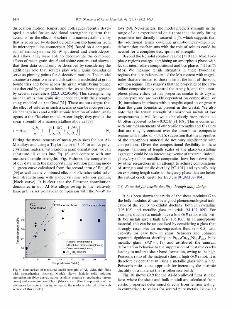
Fitting the measurements of mean grain sizes for our Al–Mo alloys and using a Taylor factor of 3.06 for an fcc poly-crystalline material with random grain orientations, we cansubstitute all values into Eq. (6) and compare with ourmeasured tensile strengths. Fig. 9 shows the comparisonof our data with the nanocrystalline solution pinning mod-el (green curve calculated from the second term of Eq. (6))[59] as well as the combined effects of Fleischer solid solu-tion strengthening with nanocrystalline solution pinning(black curve). It is clear that the Fleischer contributiondominates in our Al–Mo alloys owing to the relativelylarge grain sizes we have in comparison with the Ni–W al-
Fig. 9. Comparison of measured tensile strengths of Al1�xMox thin filmswith strengthening theories. Models shown include solid solutionstrengthening (blue curve), nanocrystalline pinning strengthening (greencurve) and a combination of both (black curve). (For interpretation of thereferences to colour in this figure legend, the reader is referred to the webversion of this article.)
loys [59]. Nevertheless, the model predicts strength in therange of our experimental data (note that the only fittingparameter not directly measured is b), which suggests thatthe additional terms coupling grain-boundary-mediateddeformation mechanisms with the role of solutes could beneeded for a complete description of strength.
Beyond the fcc solid solution regime (>10 at.% Mo), two-phase regions emerge, combining an amorphous phase withfcc (at intermediate compositions) and bcc phases (>25 at.%Mo). We measure tensile strengths in these two-phaseregimes that are independent of the Mo content with magni-tudes that are similar to those films at the limit of the solidsolution regime. This suggests that the properties of the crys-talline composite may control the strength, and the amor-phous phase either: (a) has properties similar to its crystalcounterpart and are weakly dependent on composition, or(b) introduces interfaces with strengths equal to or greaterthan the grain boundaries present in the crystal. We alsonote that the tensile strength of amorphous metals at lowtemperatures is well known to be closely proportional toG; often reported to be �0.025G [81,108]. This is consistentwith our measurements of our tensile strengths and G valuesthat are roughly constant over the amorphous compositeregime with a ratio of �0.02G, suggesting that the propertiesof the amorphous material do not vary significantly withcomposition. Given the compositional flexibility in theseregions, tailoring of length scales of the glassy/crystallineaggregate could be an interesting avenue of research. Indeed,glassy/crystalline metallic composites have been developedby other researchers in an attempt to achieve combinationsof strength and tensile ductility [97–101], and typically relyon exploiting length scales in the glassy phase that are belowthe critical crack length for fracture [81,99,102–104].
5.3. Potential for tensile ductility through alloy design
It has been shown that ratio of the shear modulus G tothe bulk modulus B, can be a good phenomenological indi-cator of the ability to exhibit ductility, both in crystalline[105,106] and metallic glass materials [81,107–109]. Forexample, ductile fcc metals have a low G/B ratio, while brit-tle bcc metals give a high G/B [105,106]. In an amorphousmaterial, this can be rationalized by considering a glass thatstrongly resembles an incompressible fluid (m = 0.5) withcapacity for easy flow in shear. Schroers and Johnsonreported significant ductility in Pt57.5Cu14.7Ni5.3P22.5 bulkmetallic glass (G/B = 0.17) and attributed the unusualdeformation behavior to the suppression of unstable cracksleading to multiple shear band formation, owing to the highPoisson’s ratio of the material (thus, a high G/B ratio). It istherefore evident that utilizing a metallic glass with a highPoisson’s ratio is one approach for increasing the intrinsicductility of a material that is otherwise brittle.
Fig. 10 shows G/B for the Al–Mo alloyed films studiedhere, where the shear and bulk moduli are calculated fromelastic properties determined directly from tension testing,in comparison to values for several pure metals. Below 10

D.S. Gianola et al. / Acta Materialia 61 (2013) 1432–1443 1441
at.% Mo, where the material remains fully crystalline, G/Bincreases from �0.38 to 0.57, suggesting that solid solu-tioning may impart intrinsically brittle behavior. In thetwo-phase fcc/amorphous region, G/B maintains its highvalue. However, the presence of the bcc ordered domainsat higher Mo concentrations drastically reduces G/B to val-ues close to that of Mo and for ductile pure metals (e.g.Cu). This framework suggests that the higher Mo compo-sitions that include bcc crystallites may have the potentialfor combining high strength with tensile ductility. The brit-tle response that we measured for all alloyed thin films islikely due to extrinsic factors such as the presence of poros-ity. Nevertheless, measurements of the full suite of mechan-ical response over a large composition range are promisingstrategies to guide design of new materials with superiorcombinations of properties.
Fig. 10. Ratio of shear to bulk moduli (G/B) for Al–Mo thin filmsobtained from tensile testing. G/B ratios are also shown for several puremetals for comparison.
6. Conclusions
In summary, we have performed systematic tensile test-ing of submicron freestanding Al–Mo alloy sputtered thinfilms. The full mechanical behavior as a function of Mocontent was measured, providing both elastic and plasticproperties for a range of microstructures including solidsolution and two-phase amorphous/crystalline mixtures.Full-field strain measurements during testing enabled directdetermination of both Young’s modulus and Poisson’sratio, allowing for calculation of all isotropic elastic con-stants. In addition, fracture strength was measured for allMo compositions, providing insight to influence of Moon thin film plasticity.
Based on the results and their interpretation presentedherein, we draw the following conclusions:
� Our Al–Mo thin films synthesized via co-sputtering canconsist of supersaturated solid solutions out to �10 at.%Mo, followed by a two-phase fcc/amorphous mixture atlarger Mo content. Beyond �20 at.% Mo, ordered bccdomains within an amorphous matrix are observed.
� The isotropic elastic constants are very sensitive to theMo content, particularly in the solid solution regime,with E, G and B increasing with the addition of Mo.Whereas B showsB shows a linear relationshipwith Mo composition, indicative of adherence toVegard’s law, the elastic constants not mediated byhydrostatic stress states (E, G, and m) increase nonlinear-ly, suggesting the influence of changes to the electronicstructure and the local atomic environment aroundMo solutes in addition to internal strain. Poisson’s ratioshows particular sensitivity to the amorphous or bccphases as evidenced by a discontinuous change at �20at.% Mo.� Incorporation of Mo into Al thin films results in sub-
stantial strengthening, with the most potent effect result-ing from solid solution strengthening (up to 5� higherfracture strength over that of pure Al thin films). Flei-scher solid solution theory predicts the lower range ofour measured strengths, whereas the combination ofsolid solution effects with a recently developed nano-crystalline solution pinning theory [59] better describeour experimental data. Calculation of the G/Bratio for our Al–Mo thin films implies the potentialfor tensile ductility at high Mo content, althoughthe measured brittle behavior highlights the roleof porosity in precluding large amounts of plasticflow.
Taken as a whole, our single step physical vapor deposi-tion approach for synthesizing Al1�xMox thin films pro-duces a diverse set of microstructures over the Mocomposition range studied, resulting in a large propertyspace. Tailoring the elastic and plastic properties of suchthin films could be used in dimensionally constrained appli-cations such as MEMS/NEMS, energy storage and conver-sion, and corrosion-resistant and hard coatings.
Acknowledgements
We gratefully acknowledge partial financial supportfrom the National Science Foundation through a MaterialsNetwork Program (DMR-1008222 and DMR-1008156)and the Penn MRSEC (DMR11-20901). DSG acknowl-edges additional support through start-up funding fromthe University of Pennsylvania. KJH acknowledges finan-cial support from the U.S. Department of Energy undergrant number DE-FG02-07ER46437. The authorsacknowledge the support of the staff and facilities at theNational Center for Electron Microscopy at LawrenceBerkeley National Laboratory, funded by the US Depart-ment of Energy under Contract DE-AC02-05CH11231.VRR acknowledges support of Nanotechnology and Func-tional Materials Center, funded by the European FP7 Pro-ject No. 245916, and support from the Ministry OfEducation and Science of the Republic of Serbia, underProject No. 172054.

1442 D.S. Gianola et al. / Acta Materialia 61 (2013) 1432–1443
References
[1] Weertman JR, Farkas D, Hemker K, Kung H, Mayo M, Mitra R,et al. MRS Bull 1999;24:44–50.
[2] Dao M, Lu L, Asaro R, Dehosson J, Ma E. Acta Mater2007;55:4041–65.
[3] Kumar K, Van Swygenhoven H, Suresh S. Acta Mater2003;51:5743–74.
[4] Koch CC. J Mater Sci 2007;42:1403–14.[5] Hanlon T, Tabachnikova E, Suresh S. Int J Fatigue
2005;27:1147–58.[6] Hanlon T. Scripta Mater 2003;49:675–80.[7] Moser B, Hanlon T, Kumar KS, Suresh S. Scripta Mater
2006;54:1151–5.[8] Padilla Ha, Boyce BL. Exp Mech 2009;50:5–23.[9] Farhat ZN, Ding Y, Northwood DO, Alpas aT. Mater Sci Eng, A
1996;206:302–13.[10] Jeong D, Gonzalez F, Palumbo G, Aust K, Erb U. Scripta Mater
2001;44:493–9.[11] Rupert TJ, Schuh Ca. Acta Mater 2010;58:4137–48.[12] Shen Y, Lu L, Dao M, Suresh S. Scripta Mater 2006;55:
319–22.[13] Chen M, Ma E, Hemker KJ, Sheng H, Wang Y, Cheng X. Science
2003;300:1275–7.[14] Sanders PG, Rittner M, Kiedaisch E, Weertman JR, Kung H, Lu
YC. Nanostruct Mater 1997;9:433–40.[15] Hugo RC, Kung H, Weertman JR, Mitra R, Knapp jA, Follstaedt
DM. Acta Mater 2003;51:1937–43.[16] Kumar KS, Suresh S, Chisholm MF, Horton jA, Wang P. Acta
Mater 2003;51:387–405.[17] Budrovic Z, Van Swygenhoven H, Derlet PM, Van Petegem S,
Schmitt B. Science 2004;304:273–6.[18] Haslam aJ, Moldovan D, Yamakov V, Wolf D, Phillpot SR, Gleiter
H. Acta Mater 2003;51:2097–112.[19] Li L, Anderson PM, Lee M, Bitzek E, Derlet P, Van Swygenhoven
H. Acta Mater 2009;57:812.[20] Van Swygenhoven H, Derlet P. Phys Rev B 2001;64:1–9.[21] Dalla Torre F, Van Swygenhoven H, Victoria M. Acta Mater
2002;50:3957–70.[22] Van Swygenhoven H, Derlet PM, Frøseth aG. Acta Mater
2006;54:1975–83.[23] Van Swygenhoven H, Derlet PM, Frøseth aG. Nat Mater
2004;3:399–403.[24] Hasnaoui A, Van Swygenhoven H, Derlet P. Phys Rev B
2002;66:1–8.[25] Huang X, Hansen N, Tsuji N. Science 2006;312:249–51.[26] Koch CC. Nanostruct Mater 1997;9:13–22.[27] Gianola DS, Van Petegem S, Legros M, Brandstetter S, Van
Swygenhoven H, Hemker KJ. Acta Mater 2006;54:2253–63.[28] Gianola DS, Warner DH, Molinari JF, Hemker KJ. Scripta Mater
2006;55:649–52.[29] Rupert TJ, Gianola DS, Gan Y, Hemker KJ. Science
2009;326:1686–90.[30] Meyers MA, Mishra A, Benson DJ. Prog Mater Sci
2006;51:427–556.[31] Asaro RJ, Suresh S. Acta Mater 2005;53:3369–82.[32] Van Petegem S, Brandstetter S, Van Swygenhoven H, Martin J-L.
Appl Phys Lett 2006;89:073102.[33] Yamakov V, Wolf D, Phillpot SR, Mukherjee AK, Gleiter H. Nat
Mater 2002;1:45–8.[34] Wolf D, Yamakov V, Phillpot SR, Mukherjee a, Gleiter H. Acta
Mater 2005;53:1–40.[35] Schiøtz J, Tolla FDD, Jacobsen KW. Nature 1998;391:561–3.[36] Schiøtz J, Jacobsen KW. Science 2003;301:1357–9.[37] Cahn JW, Taylor JE. Acta Mater 2004;52:4887–98.[38] Cahn JW, Mishin Y, Suzuki A. Acta Mater 2006;54:4953–75.
[39] Legros M, Gianola DS, Hemker KJ. Acta Mater 2008;56:3380–93.
[40] Mompiou F, Legros M, Radetic T, Dahmen U, Gianola DS,Hemker KJ. Acta Mater 2012;60:2209–18.
[41] Gleiter H. Nanostruct Mater 1995;6:3–14.[42] Weissmuller J. Nanostruct Mater 1993;3:261–72.[43] Kirchheim R. Acta Mater 2002;50:413–9.[44] Millett P, Selvam R, Saxena A. Acta Mater 2007;55:2329–36.[45] Trelewicz J, Schuh C. Phys Rev B 2009;79:1–13.[46] Cahn JW. Acta Metall 1962;10:789–98.[47] Malow T, Koch C. Acta Mater 1997;45:2177–86.[48] Michels A, Krill CE, Ehrhardt H, Birringer R, Wu DT. Acta Mater
1999;47:2143–52.[49] Jin M, Minor AM, Stach EA, Morris JW. Acta Mater
2004;52:5381–7.[50] Zhang K, Weertman JR, Eastman JA. Appl Phys Lett
2005;87:061921.[51] Fan G, Fu L, Qiao D, Choo H, Liaw P, Browning N. Scripta Mater
2006;54:2137–41.[52] Pan D, Kuwano S, Fujita T, Chen MW. Nano Lett 2007;7:2108–11.[53] Brandstetter S, Zhang K, Escuadro A, Weertman JR, Van
Swygenhoven H. Scripta Mater 2008;58:61–4.[54] Gianola DS, Eberl C, Cheng XM, Hemker KJ. Adv Mater
2008;20:303–8.[55] Gianola DS, Mendis BG, Cheng X, Hemker KJ. Mater Sci Eng, A
2008;483–484:637–40.[56] Elsener A, Politano O, Derlet PM, Van Swygenhoven H. Acta Mater
2009;57:1988–2001.[57] Schafer J, Albe K. Scripta Mater 2011:10–2.[58] Tang F, Gianola DS, Moody MP, Hemker KJ, Cairney JM. Acta
Mater 2012;60:1038–47.[59] Rupert TJ, Trenkle JC, Schuh CA. Acta Mater 2011;59:1619–31.[60] Thompson C. Annu Rev Mater Sci 2000;30:159–90.[61] Lee Z, Ophus C, Fischer LM, Nelson-Fitzpatrick N, Westra KL,
Evoy S, et al. Nanotechnology 2006;17:3063–70.[62] Ophus C, Luber EJ, Edelen M, Lee Z, Fischer LM, Evoy S, et al.
Acta Mater 2009;57:4296–303.[63] Almeida A, Carvalho F, Carvalho PA, Vilar R. Surf Coat Technol
2006;200:4782–90.[64] Nii H, Miyagawa M, Matsuo Y, Sugie Y, Niibe M, Kinoshita H.
Jpn J Appl Phys 2002;41:5338–41.[65] Lin K, Ho Y, Ho J. Thin Solid Films 1995;263:85–91.[66] Hoffmann H, Kucher P. Thin Solid Films 1987;146:155–64.[67] Chow GM, Pattnaik a, Schlesinger TE, Cammarata RC, Twigg ME,
Edelstein AS. J Mater Res 2011;6:737–43.[68] Janik-Czachor M, Jaskiewicz A, Kedzierzawski P, Werner Z. Mater
Sci Eng, A 2003;358:171–7.[69] Wolowik A, Janikczachor M. Mater Sci Eng, A 1999;267:301–6.[70] Principe EL, Shaw BA, Davis GD. Corrosion 2003;59:295–313.[71] Crossland AC, Thompson GE, Wang J, Habazaki H, Shimizu K,
Skeldon P, et al. J Electrochem Soc 1997;144:847.[72] Gianola DS, Hemker KJ, Legros M, Sharpe WN. TMS Letters
2004;1:8–9.[73] Gianola DS, Eberl C. JOM 2009;61:24–35.[74] Sharpe WN, Pulskamp J, Gianola DS, Eberl C, Polcawich RG,
Thompson RJ. Exp Mech 2007;47:649–58.[75] Gianola DS, Sedlmayr A, Monig R, Volkert Ca, Major RC,
Cyrankowski E, Asif SAS, Warren OL, Kraft O. Rev Sci Instrum2011;82:063901.
[76] Eberl C, Gianola DS, Thompson RJ, Sharpe WN, Hemker KJ.Matlab File Exchange 2006.
[77] Markmann J, Yamakov V, Weissmuller J. Scripta Mater2008;59:15–8.
[78] Stukowski A, Markmann J, Weissmuller J, Albe K. Acta Mater2009;57:1648–54.
[79] Walford LK. Phil Mag 1964;9:513–6.[80] Chen I-W. J Am Ceram Soc 1986;4:189–94.

D.S. Gianola et al. / Acta Materialia 61 (2013) 1432–1443 1443
[81] Schuh C, Hufnagel T, Ramamurty U. Acta Mater 2007;55:4067–109.
[82] Schuh CA, Nieh TG. J Mater Res 2011;19:46–57.[83] Schuh CA, Nieh TG, Iwasaki H. Acta Mater 2003;51:431–43.[84] Dudzinski N. J Inst Metals 1952;81:49–55.[85] Taga A, Vitos L, Johansson B, Grimvall G. Phys Rev B 2005;71:1–9.[86] Masuda-Jindo K, Terakura K. Phys Rev B 1989;39:7509–16.[87] Matsumuro A, Murata K. J Mater Sci 1993;28.[88] Hatch JE. Aluminum: properties and physical metallurgy. Materials
Park, OH: ASM International; 1984.[89] Van Horn K. Aluminum: properties, physical metallurgy and phase
diagrams. Metals Park, OH: American Society for Metals; 1967.[90] Haasen P. Physical metallurgy. Cambridge: Cambridge University
Press; 1996.[91] Zener C. Acta Crystallogr A 1949;2:163–6.[92] Oliver WC, Pharr GM. J Mater Res 1992;7:1564–83.[93] Fleischer RL. J Appl Phys 1962;33:3504.[94] Scattergood R, Koch C, Murty K, Brenner D. Mater Sci Eng A
2008;493:3–11.[95] Arzt E. Acta Mater 1998;46:5611–26.[96] Cheng S, Spencer JA, Milligan WW. Acta Mater 2003;51
:4505–18.
[97] Donohue A, Spaepen F, Hoagland RG, Misra A. Appl Phys Lett2007;91:241905.
[98] Wang Y, Li J, Hamza AV, Barbee TW. Proc Nat Acad Sci USA2007;104:11155–60.
[99] Hofmann DC, Suh J-Y, Wiest A, Duan G, Lind M-L, DemetriouMD, et al. Nature 2008;451:1085–9.
[100] Greer JR, De Hosson JTM. Prog Mater Sci 2011;56:654–724.[101] Kim J-Y, Jang D, Greer JR. Adv Funct Mater 2011;21:4550–4.[102] Liu YH, Wang G, Wang RJ, Zhao DQ, Pan MX, Wang WH.
Science 2007;315:1385–8.[103] Conner RD, Johnson WL, Paton NE, Nix WD. J Appl Phys
2003;94:904.[104] Conner RD, Li Y, Nix WD, Johnson WL. Acta Mater
2004;52:2429–34.[105] Pugh SF. Phil Mag 1954;45:823–43.[106] Hecker SS, Rohr DL, Stein DF. Metall Mater Trans 1978;9:481–8.[107] Schroers J, Johnson W. Phys Rev Lett 2004;93:20–3.[108] Chen M. Annu Rev Mater Res 2008;38:445–69.[109] Lewandowski JJ, Wang WH, Greer AL. Philos Mag Lett
2005;85:77–87.[110] Davis JR, editor. ASM specialty handbook: aluminum and alumi-
num alloys. Metals Park, OH: ASM International; 1993.