Embed Size (px)
Citation preview
1
Terahertz Linear to Circular Polarization Converter Based on
Reflective Metasurface
Mahsa Barkabian 1, Narges Dalvand 2, Hesam Zandi 3, * and Nosrat
Granpayeh 1
1. Centre of Excellence in Electromagnetics, Optical Communication Lab, Faculty
of Electrical Engineering, K. N. Toosi University of Technology, Tehran, Iran
2. Faculty of Electrical Engineering, K. N. Toosi University of Technology,
Tehran, Iran
3. * Electronic Materials Laboratory, Faculty of Electrical Engineering, K. N.
Toosi University of Technology, Tehran, Iran, [email protected]
2
THz Linear to Circular Polarization Converter Based on Reflective
Metasurface
Metasurfaces are two-dimensional artificial structures which have extraordinary
electromagnetic properties. They have been used in myriad of devices such as
nano-antennas, cloaking coatings, imaging devices, flat lenses, and polarization
converters over a wide range of frequency. Due to high dependency of many
devices on incident wave polarization, manipulating the polarization of
electromagnetic waves would be useful, especially in the THz regime. In this study,
we propose a linear to circular polarization converter (LTC-PC) based on a THz
reflective metasurface. For a TE linear polarization incident wave, this structure
has two distinct bands; the first one lays in a wideband frequency range of 0.5-1.41
THz, in which the reflected wave would be a left-handed circular polarization
(LHCP) with minimum efficiency of 89% and maximum efficiency of more than
95% in 80% of the bandwidth. The second band lays in the narrowband frequency
range of 1.45-1.55 THz, resulting a right-handed circular polarization (RHCP)
wave with a minimum efficiency of 82%. The proposed polarization converter can
be used in optical communication and electronic devices.
Keywords: Metasurface, Circular polarization, Polarization Conversion, Linear to
circular polarization conversion (LTC-PC), THz devices.
1. Introduction
Metamaterials are composed of periodic subwavelength structures that some of their
properties have not been found in natural materials [1, 2]. A metasurface is a two-
dimensional form of metamaterial with thin thickness and much less fabrication
complexity. Despite having the lower thickness, they have acceptable optical responses
in comparison with conventional metamaterials, and therefore they are a good
replacement for bulky metamaterials [1, 3, 4, 5]. Nowadays, metasurfaces are so attractive
because of their applications in sensors [6], imaging devices [7], absorption devices [8],
and beam manipulation devices [9], such as holograms, cloaking devices, and
polarization converters in the microwave, terahertz (THz), and optical regimes. Due to
3
the small volume, low absorption, and tunable optical responses of metasurfaces, they
have been extensively used to linear to circular polarization converters (LTC-PC) [10,
11]. For example, in [11] a linear polarization converter which operates within a wide
frequency range of 0.6 to 1.41 THz and an efficiency higher than 88% was proposed. Gao
et al. also proposed a wideband LTC-PC based on graphene metasurface. This device is
tunable by changing the Fermi energy of graphene [12]. A cross-polarization convertor
using metasurface was introduced in three distinct frequency bands for the 9.8–12.2,
19.0–22.6, and, 24.9–29.5 GHz. The polarization conversion ratio is more than 90% [13].
Chen and Chang reported a structure composed of two cascading arrays of
complementary resonators. In this LTC-PC, the bandwidth has reached 2 octaves in the
range of 0.4-2.4 THz [14]. An LTC-PC aperture-coupled antenna with an ultrathin single-
layer metasurface has been proposed in [15] to achieve boresight radiation gain around
10 dBic over 9.5 GHz to 11.5 GHz. The axial ratio bandwidth of the proposed antenna is
also 19.23%. In 2020, Lin et al. proposed an ultra-wideband circular polarized
maintaining reflector based on metasurface. The reflections of both right-handed circular
polarization (RHCP) and left-handed circular polarization (LHCP) were attained between
8.79 and 27.09 GHz [16]. Another polarization convertor which is explained in [17] can
convert linear polarized wave to its orthogonal polarization, in two distinct frequency
bands, i.e., 7.1–8 GHz and 13.3–25.8 GHz. The proposed metasurface consists of metal
patches laid diagonally on the FR4 substrate, and both of them are placed on the reflective
metal sheet that enhances the linear polatization convertor’s (LPC) performance to more
than 95% polarization conversion ratio (PCR).
In this work, we propose a broad band high-efficiency LTC-PC. The output wave
of the structure has an axial ratio of less than 3dB and high efficiency of 95% in 80% of
the bandwidth. If a linearly polarized plane wave illuminates the proposed metasurface,
4
reflected wave will have a wideband LHCP in the 0.5-1.41 THz range and a narrowband
RHCP in the 1.45-1.55 THz range. The remaining of this paper is organized as follows:
In Section 2 the structure design and the analysis method are described. The results are
presented and discussed in Section 3. Finally, the paper is concluded in Section 4.
2. Design and Analysis Method
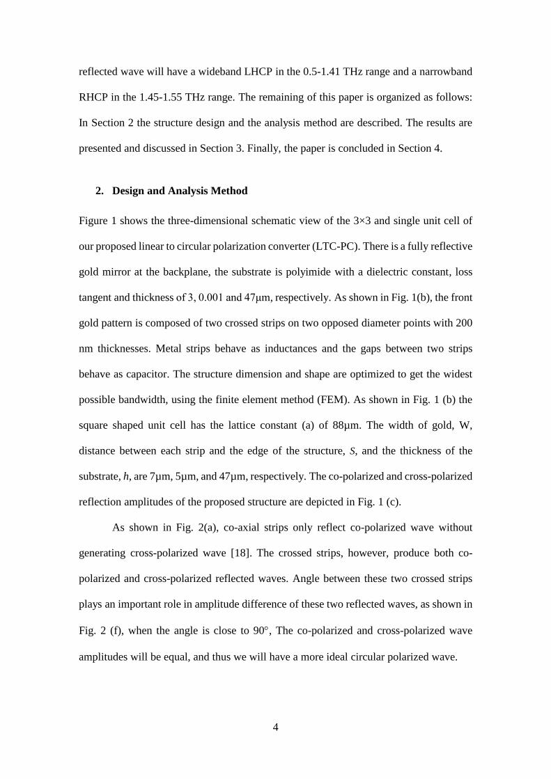
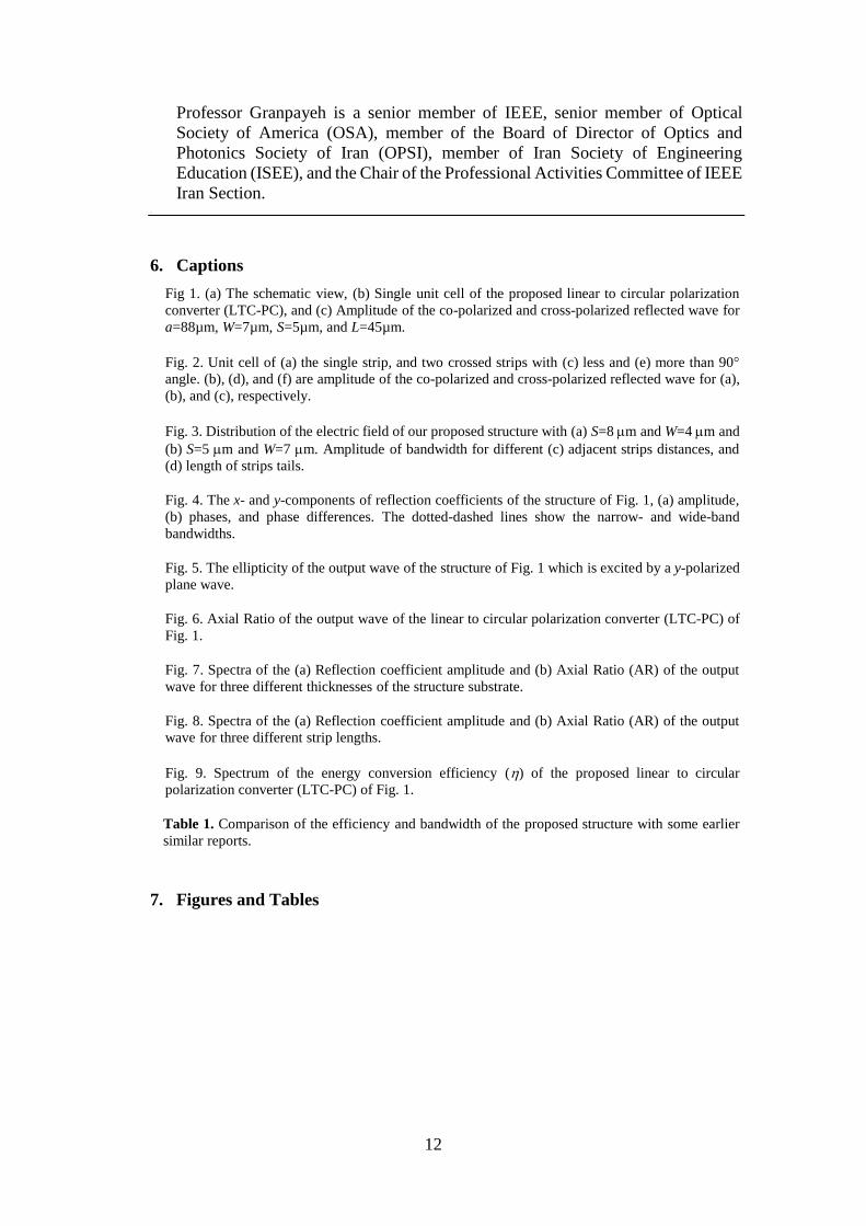
Figure 1 shows the three-dimensional schematic view of the 3×3 and single unit cell of
our proposed linear to circular polarization converter (LTC-PC). There is a fully reflective
gold mirror at the backplane, the substrate is polyimide with a dielectric constant, loss
tangent and thickness of 3, 0.001 and 47μm, respectively. As shown in Fig. 1(b), the front
gold pattern is composed of two crossed strips on two opposed diameter points with 200
nm thicknesses. Metal strips behave as inductances and the gaps between two strips
behave as capacitor. The structure dimension and shape are optimized to get the widest
possible bandwidth, using the finite element method (FEM). As shown in Fig. 1 (b) the
square shaped unit cell has the lattice constant (a) of 88µm. The width of gold, W,
distance between each strip and the edge of the structure, S, and the thickness of the
substrate, h, are 7µm, 5µm, and 47µm, respectively. The co-polarized and cross-polarized
reflection amplitudes of the proposed structure are depicted in Fig. 1 (c).
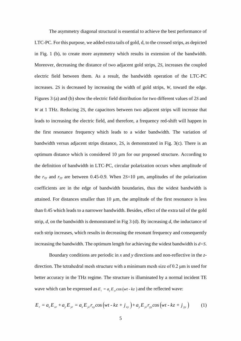
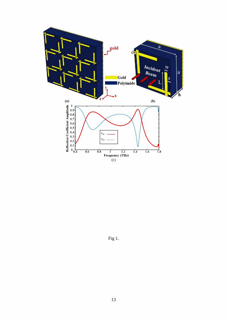
As shown in Fig. 2(a), co-axial strips only reflect co-polarized wave without
generating cross-polarized wave [18]. The crossed strips, however, produce both co-
polarized and cross-polarized reflected waves. Angle between these two crossed strips
plays an important role in amplitude difference of these two reflected waves, as shown in
Fig. 2 (f), when the angle is close to 90, The co-polarized and cross-polarized wave
amplitudes will be equal, and thus we will have a more ideal circular polarized wave.
5
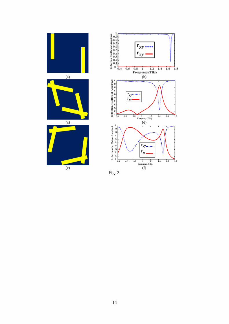
The asymmetry diagonal structural is essential to achieve the best performance of
LTC-PC. For this purpose, we added extra tails of gold, d, to the crossed strips, as depicted
in Fig. 1 (b), to create more asymmetry which results in extension of the bandwidth.
Moreover, decreasing the distance of two adjacent gold strips, 2S, increases the coupled
electric field between them. As a result, the bandwidth operation of the LTC-PC
increases. 2S is decreased by increasing the width of gold strips, W, toward the edge.
Figures 3 (a) and (b) show the electric field distribution for two different values of 2S and
W at 1 THz. Reducing 2S, the capacitors between two adjacent strips will increase that
leads to increasing the electric field, and therefore, a frequency red-shift will happen in
the first resonance frequency which leads to a wider bandwidth. The variation of
bandwidth versus adjacent strips distance, 2S, is demonstrated in Fig. 3(c). There is an
optimum distance which is considered 10 µm for our proposed structure. According to
the definition of bandwidth in LTC-PC, circular polarization occurs when amplitude of
the rxy and ryy are between 0.45-0.9. When 2S=10 µm, amplitudes of the polarization
coefficients are in the edge of bandwidth boundaries, thus the widest bandwidth is
attained. For distances smaller than 10 µm, the amplitude of the first resonance is less
than 0.45 which leads to a narrower bandwidth. Besides, effect of the extra tail of the gold
strip, d, on the bandwidth is demonstrated in Fig 3 (d). By increasing d, the inductance of
each strip increases, which results in decreasing the resonant frequency and consequently
increasing the bandwidth. The optimum length for achieving the widest bandwidth is d=S.
Boundary conditions are periodic in x and y directions and non-reflective in the z-
direction. The tetrahedral mesh structure with a minimum mesh size of 0.2 μm is used for
better accuracy in the THz regime. The structure is illuminated by a normal incident TE
wave which can be expressed as i y yiE = a E cos wt - kz and the reflected wave:
r x xr y yr x yi xy xy y yi yy yyE = a E +a E = a E r cos wt - kz + j +a E r cos wt - kz + j (1)
6
wherexr yixy Er E , yr yiyy Er E , xy , and yy represent the reflection coefficient
magnitudes for y-to-x, y-to-y polarization conversion, and their corresponding angles,
respectively. Circular polarization occurs when xy yyr r and 2 1 2yy xy n
for an integer value of n. The positive and negative signs represent right-handed circular
polarization (RHCP) and left-handed circular polarization (LHCP), respectively [11, 19].
By illuminating an incident TM wave, this behavior is inverted. Elliptically polarized
wave is approximately considered as a circularly polarized wave because a perfect
circular polarization is not achievable practically. By using Stokes parameters in free
space, the normalized Stokes parameters of the reflected wave can be expressed as [11,
20]:
2 2
n xy yyI = r + r (2)
2 2
n yy xyQ = r - r (3)
n xy yyU = 2 r r cos (4)
n xy yyV = 2 r r sin (5)
2 2 2 2
n n n nI = Q +U +V (6)
where In, Qn, Un, and Vn are , total reflection, horizental or vertical linear polarization,
linear +45 or -45 polarization, and circular polarization of the reflected wave,
respectively. These four Stokes parameters describe the wide-band waves and their
polarization. For a perfect circular polarization, Qn and Un, which are linearly polarized
waves, should be equal to zero [20].
According to definitions of the Stokes parameters, the mathematical equation of
ellipticity can be defined as the ratio of Vn/In. In special cases, where n nV I = -1 , the
reflected wave is RHCP. On the other hand, where n nV I = +1 , the reflected wave is
LHCP [18]. The axial ratio (AR) is used for evaluating the circular polarization
7
characteristic which can be defined as AR = 10log(tanb) , where is the ellipticity angle,
representing the shape of the ellipse which can be calculated by -1
n n= 1 2 .sin V I .
Where the value of AR is less than 3dB, the reflected wave is approximately considered
as a circularly polarized wave [21].
3. Results and Discussion
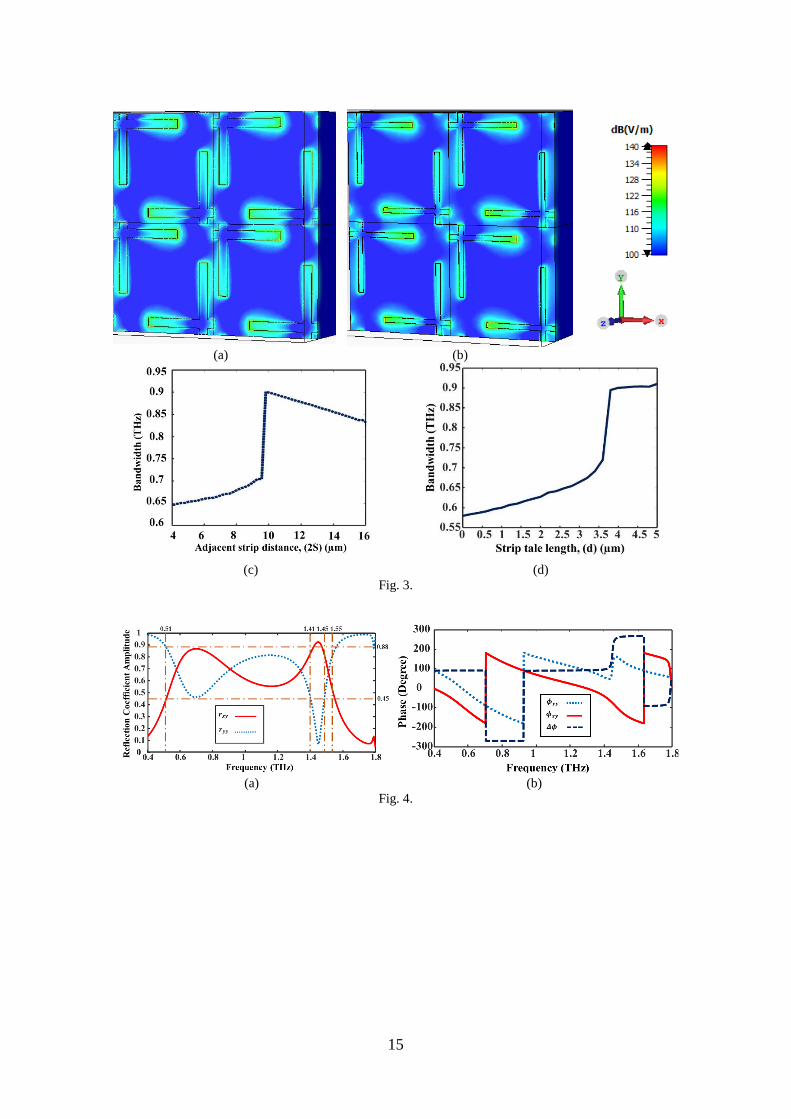
As shown in Fig. 4, in the bandwidth of 0.5-1.41 THz and 1.45-1.55 THz, the magnitudes
of xyr and yyr are approximately the same and the difference of xy and yy is 90˚or -270˚
in the first frequency band and -90˚or 270˚ in the second one. The equal amplitudes and
±90˚ phase differences show that the reflected wave is a circularly polarized wave.
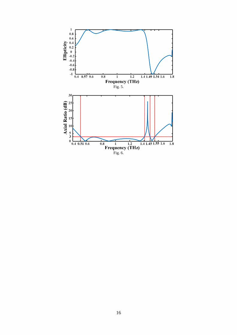
According to Fig. 5, and Stokes parameters, in the range of 0.5 to 1.41 THz, the ellipticity
is close to +1, and the reflected wave is LHCP. In the range of 1.45-1.55 THz, there is
also an approximate ellipticity of -1 and an RHCP reflected wave. Also, performance of
the LTC-PC remains good even when illuminated by an oblique incident wave. It is also
interesting that for less than 15 degrees of deviation from normal incident wave, the
bandwidth of PC is approximately the same and hence the structure has a very low
sensitivity with respect to the incident wave angle, but for farther angles, the bandwidth
decreases.
The axial ratio spectrum of the output wave of the optimized structure of Fig. 1 is
depicted in Fig. 6. The proposed LTC-PC operates satisfying and converts the
polarization from linear to circular in the range of 0.5 to 1.41 THz and 1.45 to 1.55 THz,
because of the axial ratio value of less than 3dB. LHCP works in a wide range of
frequency and RHCP works in the narrower range. The bandwidths of LHCP and RHCP
have been increased up to 15% and 66% in comparison with, respectively [11].
8
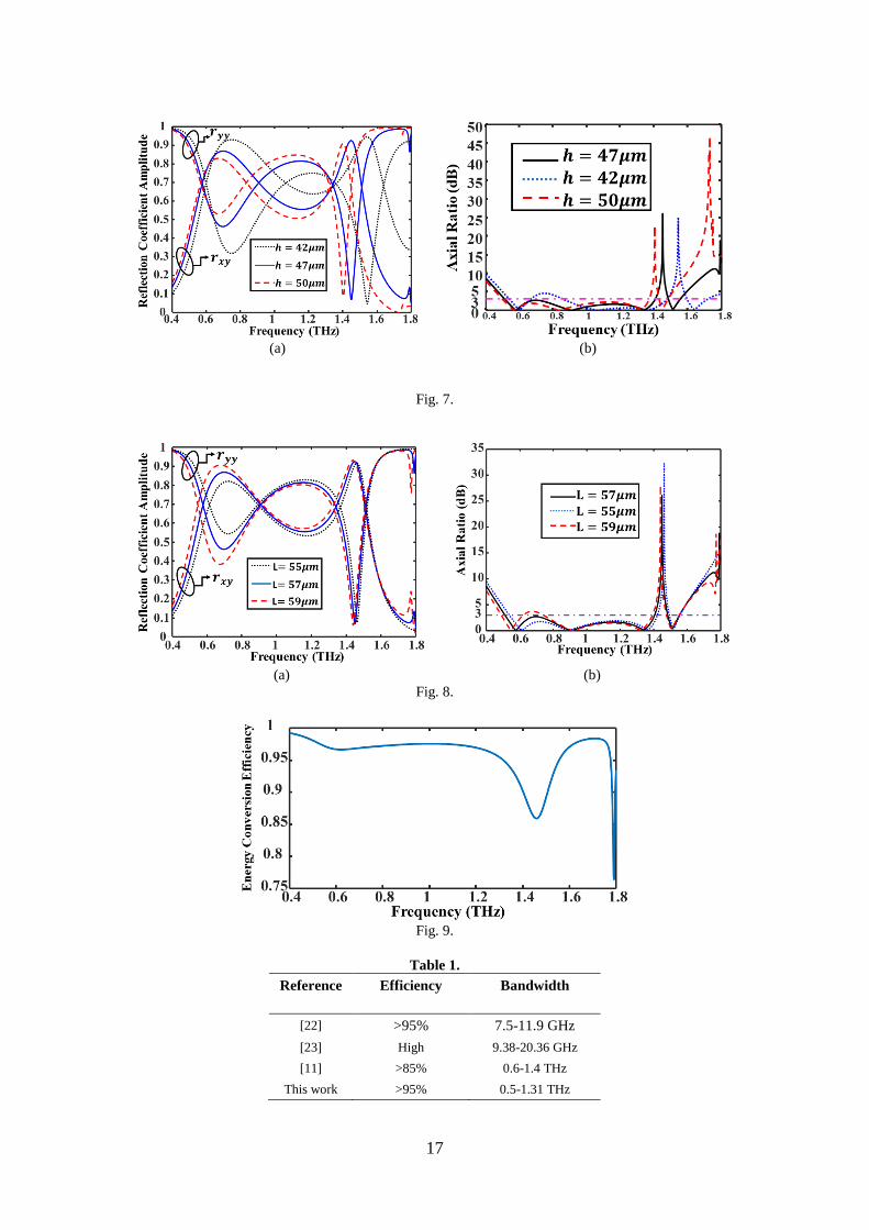
The thickness of the substrate and the length of the arm have significant effects
on the results. The spectra of the magnitude of the reflection coefficients and the axial
ratios for three different values of the thicknesses of the structure substrate, h, and the
length of the arm, L, are respectively illustrated in Figs 7(a), 7(b) and 8(a), 8(b). The
optimum value of h and Lis 47µm and 55µm, respectively.
The energy conversion efficiency () is also calculated by the ratio of output wave
energy to the incident wave energy. According to normalization of the Stokes parameters,
values of In and are equal. The spectrum of the energy conversion efficiency of the
proposed device is illustrated in Fig. 9. is more than 89% for LHCP and more than 85%
for RHCP. The efficiency of the LHCP wave is more than 95% in 80% of the bandwidth.
The results indicate the high efficiency of our proposed structure. The efficiency and
bandwidth of our proposed LTC-PC are compared with three other similar works in Table
1.
4. Conclusion
In this study, a high efficiency metasurface-based wideband linear-to-circular (LTC)
polarization converter (PC) is proposed in the terahertz frequency range. It is shown that
when the angle between two crossed strips is close to 90, the reflection wave is closer to
circularly polarized. Furthermore, Different parameters of the structure, such as thickness
of the substrate (h), gold strips length (L), distance between two adjacent gold strips (2S),
and length of extra tails (d) are optimized to gain highest efficiency and widest bandwidth.
Efficiency of the proposed structure is more than 89% within an ultra-wideband
frequency range of 0.5-1.41 THz and reflected wave is left-handed circularly polarized if
a linear TE polarization input wave was applied. The efficiency of the conversion is more
than 95% in 80% of this bandwidth. Within the frequency range of 1.45-1.55 THz, the
9
efficiency is more than 85% and the reflected wave is right-handed circularly polarized.
The LTC converter has potential applications in electromagnetic measurement, antenna
design, and cloaking technology.
5. References
1. Chen, H.T., Taylor, A.J. and Yu, N. “A review of metasurfaces: physics and
applications”. Reports on progress in physics, 79(7), p. 076401 (2016).
2. Mendhe, S.E. and Kosta, Y.P. “Metamaterial properties and
applications”. International Journal of Information Technology and Knowledge
Management, 4(1), pp. 85-89 (2011).
3. Achouri, K. and Caloz, C. “Design, concepts, and applications of electromagnetic
metasurfaces”. Nanophotonics, 7(6), pp. 1095-1116 (2018).
4. Glybovski, S.B., Tretyakov, S.A., Belov, P.A., et al. “Metasurfaces: From
microwaves to visible”. Physics reports, 634, pp. 1-72 (2016).
5. Achouri, K., Khan, B.A., Gupta, S., et al. “Synthesis of electromagnetic
metasurfaces: principles and illustrations” . arXiv preprint arXiv:1510.05997
(2015).
6. Sarychev, A.K., Lagarkov, A.N., Ivanov, A.V., et al. “Metal-dielectric resonances
in tip silicon metasurface and SERS based nanosensors”. In Plasmonics: Design,
Materials, Fabrication, Characterization, and Applications XV (Vol. 10346, p.
103460C) (2017).
7. Sleasman, T., Imani, M.F., Boyarsky, M., et al. “Reconfigurable metasurface
aperture for security screening and microwave imaging”. In Passive and Active
Millimeter-Wave Imaging XX (Vol. 10189, p. 101890G) (2017).
8. Liu, Z. and Bai, B. Ultra-thin and high-efficiency graphene metasurface for
tunable terahertz wave manipulation. Optics express, 25(8), pp.8584-8592
(2017).
9. Yachmenev, A.E., Lavrukhin, D.V., Glinskiy, I.A., et al. “Metallic and dielectric
metasurfaces in photoconductive terahertz devices” : a review. Optical
Engineering, 59(6), p. 061608 (2019).
10
10. Gao, X., Han, X., Cao, W.P., et al., “Ultrawideband and high-efficiency linear
polarization converter based on double V-shaped metasurface,” IEEE
Transactions on Antennas and Propagation, 63(8), pp. 3522-3530 (2015).
11. Jiang, Y., Wang, L., Wang, J., et al. Ultra-wideband high-efficiency reflective
linear-to-circular polarization converter based on metasurface at terahertz
frequencies. Optics express, 25(22), pp. 27616-27623 (2017).
12. Gao, X., Yang, W., Cao, W., et al. “Bandwidth broadening of a graphene-based
circular polarization converter by phase compensation”. Optics express, 25(20),
pp. 23945-23954 (2017).
13. Yang, Z., Yu, S., Kou, N., et al. “Ultrathin tri-band reflective cross-polarization
artificial electromagnetic metasurface”. Journal of Electromagnetic Waves and
Applications, pp. 1-11 (2020).
14. Chen, H.T. and Chang, C.C. “Broadband terahertz polarization conversion using
metasurfaces” (Conference Presentation). In Terahertz Emitters, Receivers, and
Applications IX (Vol. 10756, p. 107560C) (2018).
15. Swain, R., Chatterjee, A., Nanda, S. et al. “A Linear-to-Circular Polarization
Conversion Metasurface Based Wideband Aperture Coupled Antenna”. Journal
of Electrical Engineering & Technology, pp. 1-7 (2020).
16. Lin, B.Q., Lv, L., Guo, J., et al. Ultra-wideband circular polarization-maintaining
reflection realized by an anisotropic metasurface. Journal of Electromagnetic
Waves and Applications, pp. 1-10 (2020).
17. Khan, B., Kamal, B., Ullah, S., et al. “Design and experimental analysis of dual-
band polarization converting metasurface for microwave applications”. Scientific
Reports, 10(1), pp. 1-13 (2020).
18. Zhang, L., Zhou, P., Lu, H., et al. “Realization of broadband reflective
polarization converter using asymmetric cross-shaped resonator”. Optical
Materials Express, 6(4), pp. 1393-1404 (2016).
19. Cong, L., Cao, W., Zhang, X., et al. “A perfect metamaterial polarization rotator,”
Applied Physics Letters, 103(17), p. 171107 (2013).
20. Goldstein, Dennis H., December 16, Polarized light, Pages 59-61, CRC press,
2016, p 59-61.
11
21. Li, Y., Zhang, J., Qu, S., et al. “Achieving wide-band linear-to-circular
polarization conversion using ultra-thin bi-layered metasurfaces”. Journal of
Applied Physics, 117(4), p. 044501 (2015).
22. Khan, M.I., Khalid, Z. and Tahir, F.A. Linear and circular-polarization conversion
in X-band using anisotropic metasurface. Scientific reports, 9(1), pp. 1-11 (2019).
23. Fu, C., Sun, Z., Han, L., et al. High-Efficiency “Dual-Frequency Reflective Linear
Polarization Converter Based on Metasurface for Microwave Bands,” Applied
Sciences, 9(9), p. 1910 (2019).
Mahsa Barkabian received her B.Sc in Electrical Engineering-Telecommunications
in 2017 from Zanjan University, Zanjan, Iran. In 2017, she started her M.Sc of
Telecommunications- Fields and Waves in K. N. Toosi University of Technology,
Tehran, Iran. She worked in Optical Communication Lab Under supervision of Prof.
Granpayeh in the field of 2D Materials, Metasurfaces, Graphene, Terahertz
Technology, and Polarization Conversion.
Narges Dalvand in 2016 received her B.Sc degree in Electronics Engineering from
Shahid Chamran University, Khousestan, Ahvaz, Iran. In 2017, she joined in
Electrical Department of K. N. Toosi University of technology, Tehran, Iran as an
M.Sc student under the supervision of Dr. Zandi. Her research interests include
terahertz sources, graphene and complex materials, nonlinear photonics and optical
communication.
Hesam Zandi received B.Sc., M.Sc. and PhD degrees in electrical engineering from
Sharif University of Technology, in 2005, 2007, and 2012 respectively. He conducted
research in development of a quantum bit device, which lead to double entangled
qubits having high fidelity reading process at SERL. He got a post-doc research
fellowship in SUT, in which he was developing a RSFQL structure for ultra-high
speed digital circuits. In 2016, he joined K. N. Toosi University of Technology, where
he is currently an assistant professor in electrical engineering. His research interests
are mainly focused on the design, modeling, and fabrication of THz devices and
systems, metal-oxide sensors, and also superconducting devices. He is recently been
chosen as the head of EML laboratory which is one the well-known establishments in
KNTU.
Corresponding author’s email: [email protected]
Nosrat Granpayeh has received his BSc, MSc, and PhD degrees in
Telecommunication Engineering from Telecommunication College, Radio and
Television College, Tehran, Iran, and University of NSW, Sydney Australia, in
1975, 1980, and 1996, respectively.In 1975, as an honor graduate of the Faculty
of Electrical Engineering of K.N. Toosi University of Technology, Tehran, Iran,
he was employed as an instructor. He was promoted to Lecturer, Assistant
Professor, Associate Professor, and Professor, respectively in 1980, 1996, 2007,
and 2016. His research interests are in optical devices, equipment, and materials,
optical fibers, and optical fiber effects. He is the author and co-author of 100 peer
reviewed journal and 100 conference papers.
12
Professor Granpayeh is a senior member of IEEE, senior member of Optical
Society of America (OSA), member of the Board of Director of Optics and
Photonics Society of Iran (OPSI), member of Iran Society of Engineering
Education (ISEE), and the Chair of the Professional Activities Committee of IEEE
Iran Section. 24.
6. Captions
Fig 1. (a) The schematic view, (b) Single unit cell of the proposed linear to circular polarization
converter (LTC-PC), and (c) Amplitude of the co-polarized and cross-polarized reflected wave for
a=88µm, W=7µm, S=5µm, and L=45µm.
Fig. 2. Unit cell of (a) the single strip, and two crossed strips with (c) less and (e) more than 90
angle. (b), (d), and (f) are amplitude of the co-polarized and cross-polarized reflected wave for (a),
(b), and (c), respectively.
Fig. 3. Distribution of the electric field of our proposed structure with (a) S=8 m and W=4 m and
(b) S=5 m and W=7 m. Amplitude of bandwidth for different (c) adjacent strips distances, and
(d) length of strips tails.
Fig. 4. The x- and y-components of reflection coefficients of the structure of Fig. 1, (a) amplitude,
(b) phases, and phase differences. The dotted-dashed lines show the narrow- and wide-band
bandwidths.
Fig. 5. The ellipticity of the output wave of the structure of Fig. 1 which is excited by a y-polarized
plane wave.
Fig. 6. Axial Ratio of the output wave of the linear to circular polarization converter (LTC-PC) of
Fig. 1.
Fig. 7. Spectra of the (a) Reflection coefficient amplitude and (b) Axial Ratio (AR) of the output
wave for three different thicknesses of the structure substrate.
Fig. 8. Spectra of the (a) Reflection coefficient amplitude and (b) Axial Ratio (AR) of the output
wave for three different strip lengths.
Fig. 9. Spectrum of the energy conversion efficiency () of the proposed linear to circular
polarization converter (LTC-PC) of Fig. 1.
Table 1. Comparison of the efficiency and bandwidth of the proposed structure with some earlier
similar reports.
7. Figures and Tables
13
(c)
Fig 1.
14
(a) (b)
(c) (d)
(e) (f)
Fig. 2.
15
(a) (b)
(c) (d)
Fig. 3.
(a) (b)
Fig. 4.
16
Fig. 5.
Fig. 6.
17
(a) (b)
Fig. 7.
(a) (b)
Fig. 8.
Fig. 9.
Table 1.
Reference Efficiency Bandwidth
[22] >95% 7.5-11.9 GHz
[23] High 9.38-20.36 GHz
[11] >85% 0.6-1.4 THz
This work >95% 0.5-1.31 THz