Embed Size (px)
Citation preview
ME 5643: MECHATRONICS
TERM PROJECT
September 2009 – December 2009
Mihai Pruna, Pavel Khazron, Jennifer S. Haghpanah
GROUP 1 PRESENTS: THE SMART TRASH CANS
ABSTRACT
This project proposes a smart system for sorting common beverage containers, controlled by the Basic Stamp microcontroller. The system is to differentiate between three common types of trash: crumpled paper, paper cups, plastic bottles, and aluminum cans. Based on the type of article, the system is to use actuators to deposit trash to the appropriate trash bin for recycling purposes. The decision on the type of material is to be made via a capacitive sensor. Specifically, the sensor is to consist of air-filled capacitance plates in parallel. The capacitance will change based on the dielectric constant of the material presented for sorting. Since the dielectric constants for the three materials are different, the system can make an informed decision. The Basic Stamp will determine the type of trash based on capacitance readings. Standard servos will then be used to deposit the trash into an appropriate bin. An additional capacitor sensor may then be used to further refine the decision. The trashcan also uses capacitance sensors to determine when it is full, and then conveys the information to the user by means of lighting an LED for the appropriate bin. Another method for sorting trash has been investigated as well. Light will interact differently with the three materials specified above. Plastic used in bottles and cups is generally transparent. aluminum can focus reflected light, while paper scatters it. Using two photoresistors and a light source, the type of material can be inferred using the Basic Stamp microcontroller and the RCTime command.
INTRODUCTION
Today, an average American will produce over 1000 pounds of trash each year. In our society, recycling has become a major issue due to dwindling resources and pollution. Unfortunately, households are not recycling as much as they say they do because recycling is not a consistent habit for most people. Also, recyclables are not always sorted properly. The motivation for this project comes from people not having the ability or will to sort their trash properly. Thus, we have designed two trashcans that have the ability to properly sort common beverage containers. (Figure 1).
Before we proceed to detailing the functionality of our approaches, we need to review existing recycling and disposal technologies. Currently, RFID-based recycling technology makes Philadelphia a greener community. Their approach uses a radio frequency identification chip to identify how much trash each household is recycling. Based on this amount, they are able to get money back for all the items that can be recycled.
Meanwhile, there is a large plant that has been developed to sort trash with a variety of devices such as screens, magnets, ultraviolet optical scanners that activate blasts of air and star-shaped plastic devices. There is talk of how a plant maybe a complete waste of money because it focuses on speed for a vast quantity of recyclables. Thus, there is contamination among recyclables. It is important to get more people involved with recycling by making the process easy for them. If a plant is having difficulty separating trash with multiple sensors, then it is best to use a smart trashcan in the home with only one inexpensive sensor.
Another type of smart trashcan that has been developed is the touch-less trashcan, which has a sensor in the lid that can detect objects in front of it. This type of trashcan will open when the user’s hand or object is detected above the lid. This trashcan prevents the spread of other people’s germs, and helps maintain hygiene in the home.
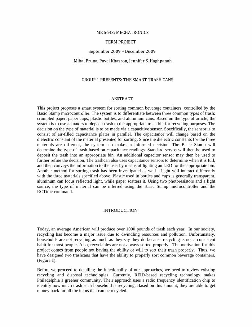
We believe that the next step for smart trashcans would be one that can properly analyze an object’s material and decide which recycling bin to place it in. In many cases, state and city laws require that paper be separated from plastic and aluminum. In order to develop a system that properly sorts trash, we looked into the idea of using a capacitance sensor, which can sort trash based on the dielectric constant of a material. Another idea we tried to explore is sorting trash based on the way different materials conduct and reflect light. (See Figure 1 below)
a) b)
Figure 1: a) Trash can which sorts trash based on their dielectric constant with capacitance sensors, b) Trash can which sorts trash based on light interaction.
The two sorting approaches developed by Team 1 are outlined in detail below.
CAPACITANCE METHOD
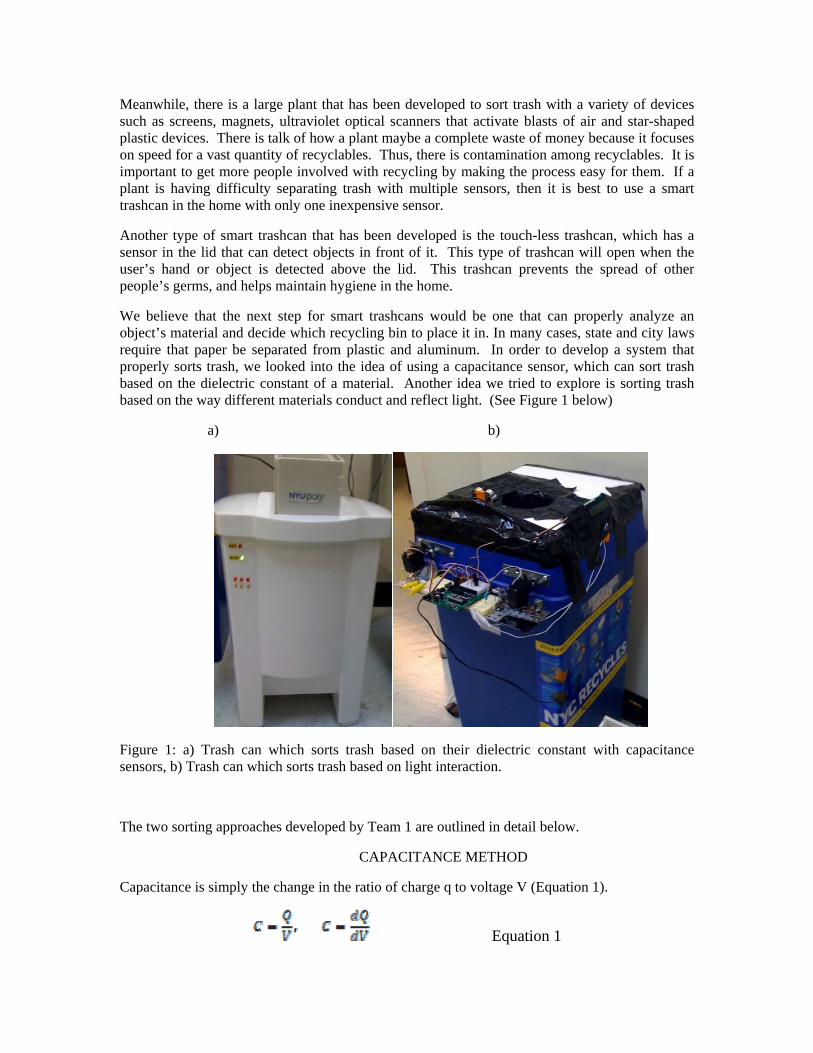
Capacitance is simply the change in the ratio of charge q to voltage V (Equation 1).
Equation 1
Some of the other factors that play a role in the capacitance of a material are the area and distance of the material between the plates. We begin with two conductive plates, which have a space between them, which respond differently when a voltage is applied to them. When we apply a voltage to the conductors, an electric field is between the positive and negative charges. Materials such as plastic, aluminum, paper cups will all have dielectric constants that are different from air. When a non-conducting/ conducting material is inserted between the plates, we obtain a capacitance. Capacitance of a material will also depend on the thickness and density of a material as well. Capacitance sensors can be sensitive in such a way that whey can detect a variety of things such as motion, chemical composition, and electric field, which can be converted into a dielectric constant. Capacitor sensors can be built with conductive sensing electrodes in a dielectric with five volts and detection circuits, which will translate capacitance into voltage, frequency, or pulse width variation. Capacitor sensors can be used for flow, pressure, liquid levels, spacing, thickness measurement, accelerometers, ice detector, keyswitch, and limit switch. The spacing of the two parallel plates is very important because the spacing is inversely related to the capacitance. At a small spacing, we get a large capacitance, and at a large spacing we get a small capacitance (equation 2). Area is another factor that will alter the capacitance of a material (equation 2). One of the main drawbacks to a capacitive sensor is their sensitivity to condensation and pollution, which may not be so reliable. For example, the dielectric constant of air will have a change of 170 ppm depending on he pressure, temperature, and humidity.
Equation 2
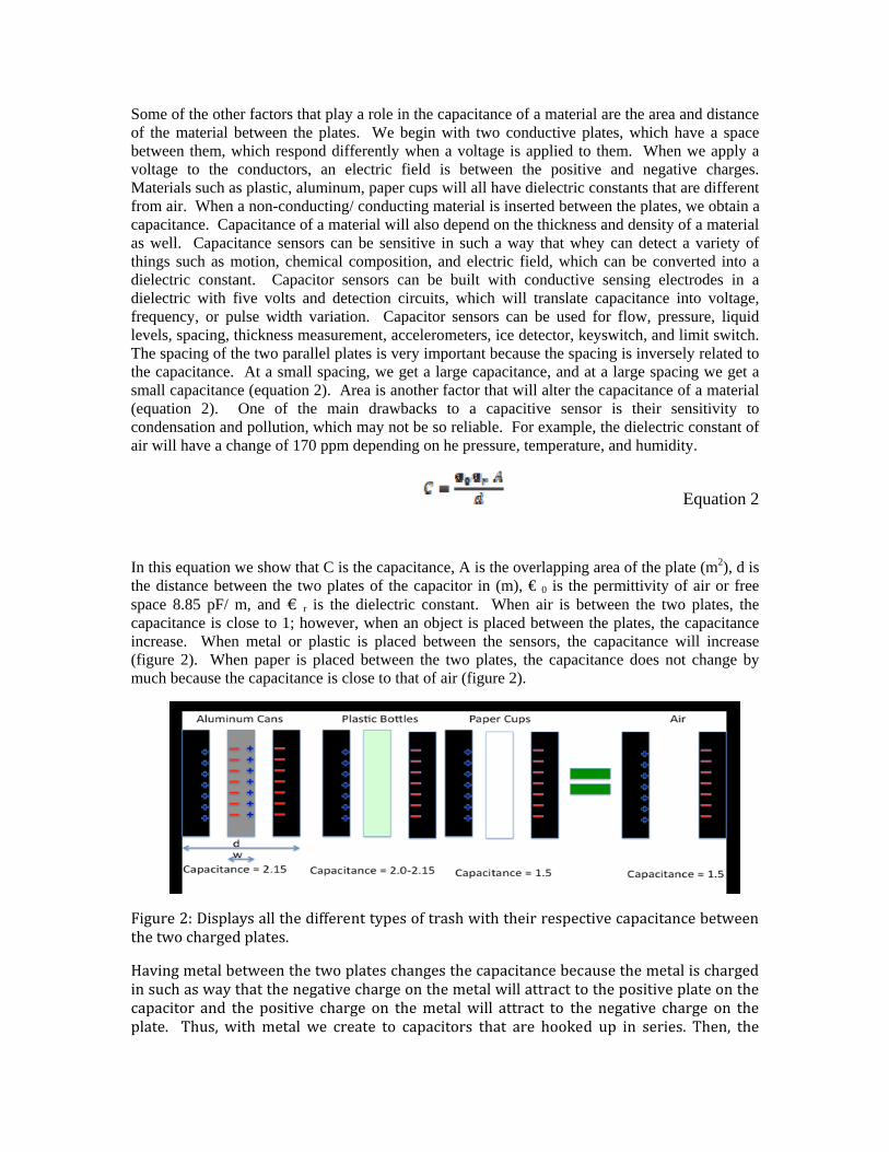
In this equation we show that C is the capacitance, A is the overlapping area of the plate (m2), d is the distance between the two plates of the capacitor in (m), € 0 is the permittivity of air or free space 8.85 pF/ m, and € r is the dielectric constant. When air is between the two plates, the capacitance is close to 1; however, when an object is placed between the plates, the capacitance increase. When metal or plastic is placed between the sensors, the capacitance will increase (figure 2). When paper is placed between the two plates, the capacitance does not change by much because the capacitance is close to that of air (figure 2).
Figure 2: Displays all the different types of trash with their respective capacitance between the two charged plates.
Having metal between the two plates changes the capacitance because the metal is charged in such as way that the negative charge on the metal will attract to the positive plate on the capacitor and the positive charge on the metal will attract to the negative charge on the plate. Thus, with metal we create to capacitors that are hooked up in series. Then, the
formula that we use follows the equation below (equation 3). The formula that would be used for non‐conductive materials such as paper or plastic would be equation because in this case there would only one capacitor and not two hooked up in series.
Equation 3
PHOTORESISTORS/ RC TIME METHOD
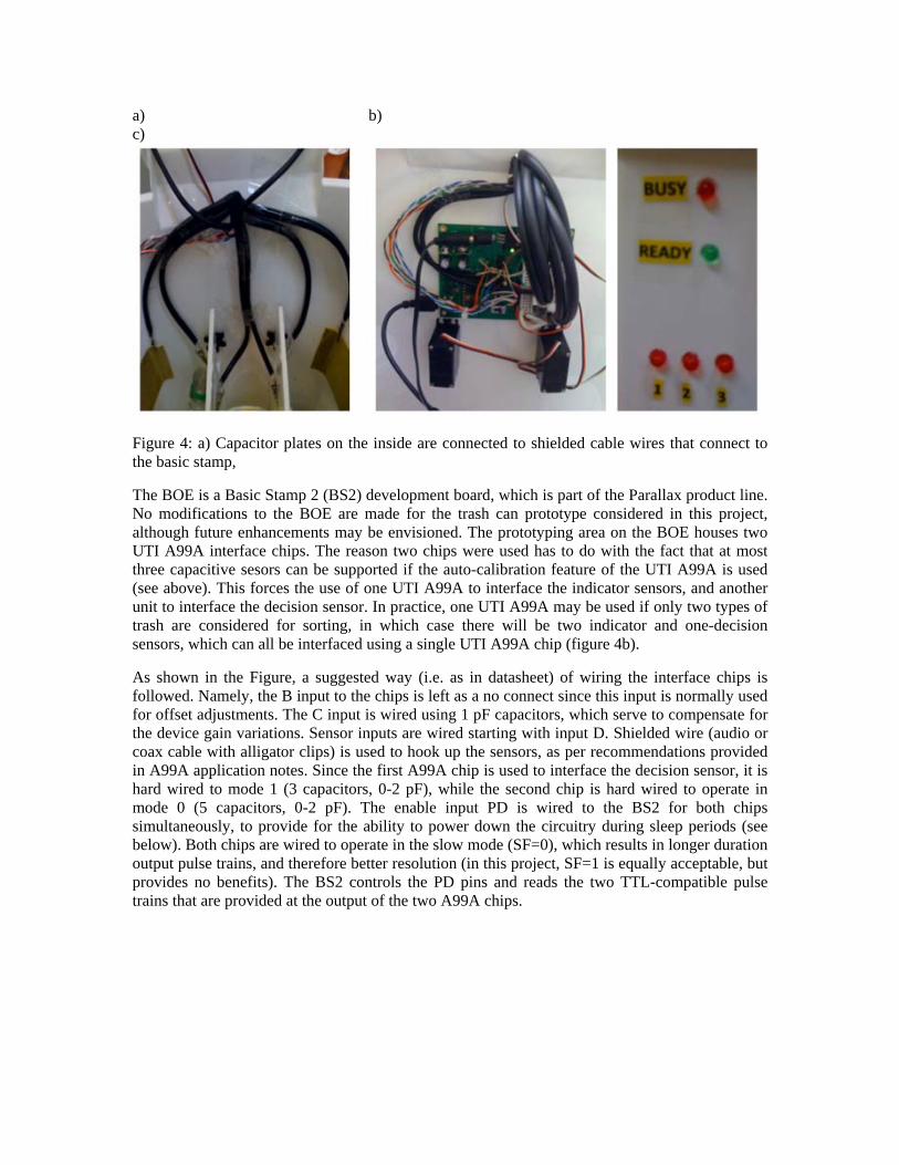
Photoresistors are made using cadmium sulfide, indium antimonide and lead sulfide resistors that respond differently to light., Under dark conditions, the resistance is quite high, and under light conditions, the resistance is quite low. These photoresistors will respond to light in a certain range of wavelengths depending on what compounds were used to in their manufacturing process. One of the disadvantages of photoresistors is the fact that it may take a couple of seconds to detect a variation in resistance under varying light conditions (Figure 3).
The RCtime command is used to bring analog data into BASIC Stamp with the aid of a resistor and a capacitor. The output time is proportional to the amount of time that it takes to charge/ discharge a capacitor with a photoresistor of interest connected in parallel.
Figure 3: a) Photoresistor that is used to detect reflected light from the paper, plastic cup, or aluminum can.
MECHANICAL/ ELECTRICAL DESIGN FOR CAPACTIANCE
The main components in the automatic sorting trashcan are the Board of Education (BOE), two UTI03 chips, servos, and capacitive sensors. The capacitive sensors are made of rectangular metal sheets and attached to the can walls by means of cable wires and clear packing tape (figure 4a). The decision sensor is responsible for the main function of sorting the incoming articles according to type, while the three indicator sensors are responsible for making the binary decisions – “bin full” and “bin not full”. Servos are programmed to ensure the accurate placement of an article in one of three bins – “plastic (1)”, “paper (2)”, and “metal (3)” (figure 4c). This is achieved by rotation of the main door, which opens the compartment housing the decision sensor, and two valves, which deflect to easily guide the article to the right bin.
a) b) c)
Figure 4: a) Capacitor plates on the inside are connected to shielded cable wires that connect to the basic stamp,
The BOE is a Basic Stamp 2 (BS2) development board, which is part of the Parallax product line. No modifications to the BOE are made for the trash can prototype considered in this project, although future enhancements may be envisioned. The prototyping area on the BOE houses two UTI A99A interface chips. The reason two chips were used has to do with the fact that at most three capacitive sesors can be supported if the auto-calibration feature of the UTI A99A is used (see above). This forces the use of one UTI A99A to interface the indicator sensors, and another unit to interface the decision sensor. In practice, one UTI A99A may be used if only two types of trash are considered for sorting, in which case there will be two indicator and one-decision sensors, which can all be interfaced using a single UTI A99A chip (figure 4b).
As shown in the Figure, a suggested way (i.e. as in datasheet) of wiring the interface chips is followed. Namely, the B input to the chips is left as a no connect since this input is normally used for offset adjustments. The C input is wired using 1 pF capacitors, which serve to compensate for the device gain variations. Sensor inputs are wired starting with input D. Shielded wire (audio or coax cable with alligator clips) is used to hook up the sensors, as per recommendations provided in A99A application notes. Since the first A99A chip is used to interface the decision sensor, it is hard wired to mode 1 (3 capacitors, 0-2 pF), while the second chip is hard wired to operate in mode 0 (5 capacitors, 0-2 pF). The enable input PD is wired to the BS2 for both chips simultaneously, to provide for the ability to power down the circuitry during sleep periods (see below). Both chips are wired to operate in the slow mode (SF=0), which results in longer duration output pulse trains, and therefore better resolution (in this project, SF=1 is equally acceptable, but provides no benefits). The BS2 controls the PD pins and reads the two TTL-compatible pulse trains that are provided at the output of the two A99A chips.
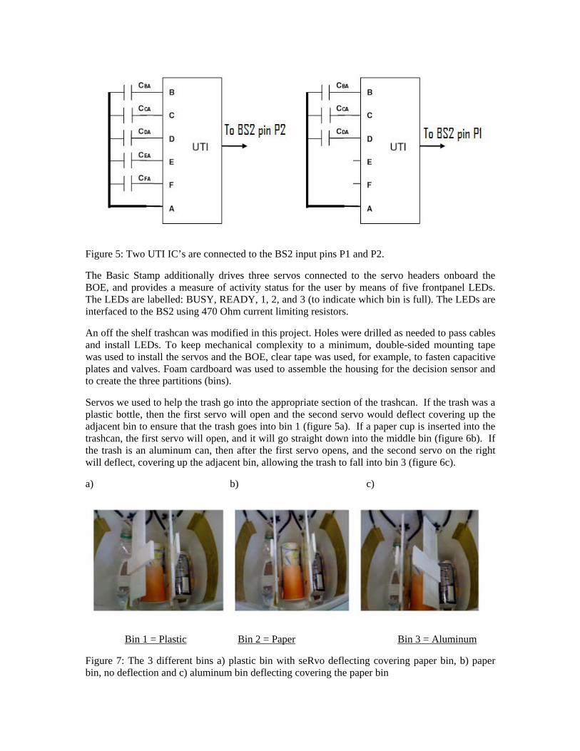
Figure 5: Two UTI IC’s are connected to the BS2 input pins P1 and P2.
The Basic Stamp additionally drives three servos connected to the servo headers onboard the BOE, and provides a measure of activity status for the user by means of five frontpanel LEDs. The LEDs are labelled: BUSY, READY, 1, 2, and 3 (to indicate which bin is full). The LEDs are interfaced to the BS2 using 470 Ohm current limiting resistors.
An off the shelf trashcan was modified in this project. Holes were drilled as needed to pass cables and install LEDs. To keep mechanical complexity to a minimum, double-sided mounting tape was used to install the servos and the BOE, clear tape was used, for example, to fasten capacitive plates and valves. Foam cardboard was used to assemble the housing for the decision sensor and to create the three partitions (bins).
Servos we used to help the trash go into the appropriate section of the trashcan. If the trash was a plastic bottle, then the first servo will open and the second servo would deflect covering up the adjacent bin to ensure that the trash goes into bin 1 (figure 5a). If a paper cup is inserted into the trashcan, the first servo will open, and it will go straight down into the middle bin (figure 6b). If the trash is an aluminum can, then after the first servo opens, and the second servo on the right will deflect, covering up the adjacent bin, allowing the trash to fall into bin 3 (figure 6c).
a) b) c)
Bin 1 = Plastic Bin 2 = Paper Bin 3 = Aluminum
Figure 7: The 3 different bins a) plastic bin with seRvo deflecting covering paper bin, b) paper bin, no deflection and c) aluminum bin deflecting covering the paper bin
UTI03 A99A – Universal Transducer Interface
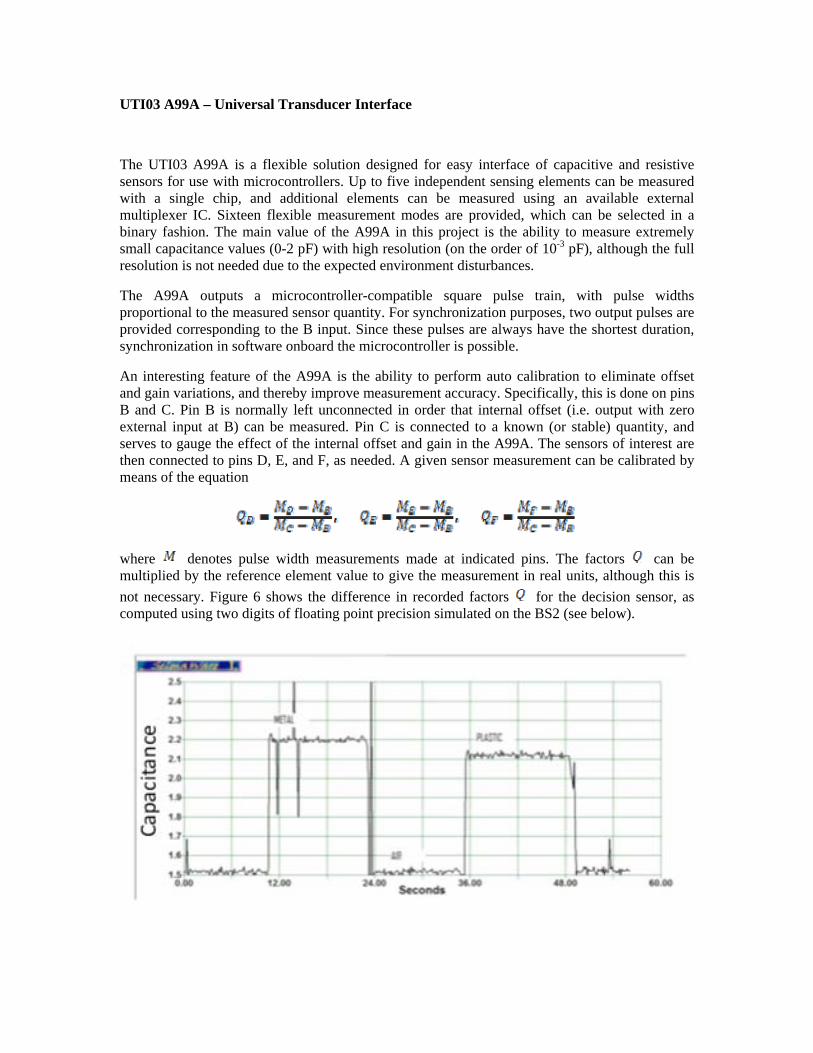
The UTI03 A99A is a flexible solution designed for easy interface of capacitive and resistive sensors for use with microcontrollers. Up to five independent sensing elements can be measured with a single chip, and additional elements can be measured using an available external multiplexer IC. Sixteen flexible measurement modes are provided, which can be selected in a binary fashion. The main value of the A99A in this project is the ability to measure extremely small capacitance values (0-2 pF) with high resolution (on the order of 10-3 pF), although the full resolution is not needed due to the expected environment disturbances.
The A99A outputs a microcontroller-compatible square pulse train, with pulse widths proportional to the measured sensor quantity. For synchronization purposes, two output pulses are provided corresponding to the B input. Since these pulses are always have the shortest duration, synchronization in software onboard the microcontroller is possible.
An interesting feature of the A99A is the ability to perform auto calibration to eliminate offset and gain variations, and thereby improve measurement accuracy. Specifically, this is done on pins B and C. Pin B is normally left unconnected in order that internal offset (i.e. output with zero external input at B) can be measured. Pin C is connected to a known (or stable) quantity, and serves to gauge the effect of the internal offset and gain in the A99A. The sensors of interest are then connected to pins D, E, and F, as needed. A given sensor measurement can be calibrated by means of the equation
where denotes pulse width measurements made at indicated pins. The factors can be multiplied by the reference element value to give the measurement in real units, although this is not necessary. Figure 6 shows the difference in recorded factors for the decision sensor, as computed using two digits of floating point precision simulated on the BS2 (see below).
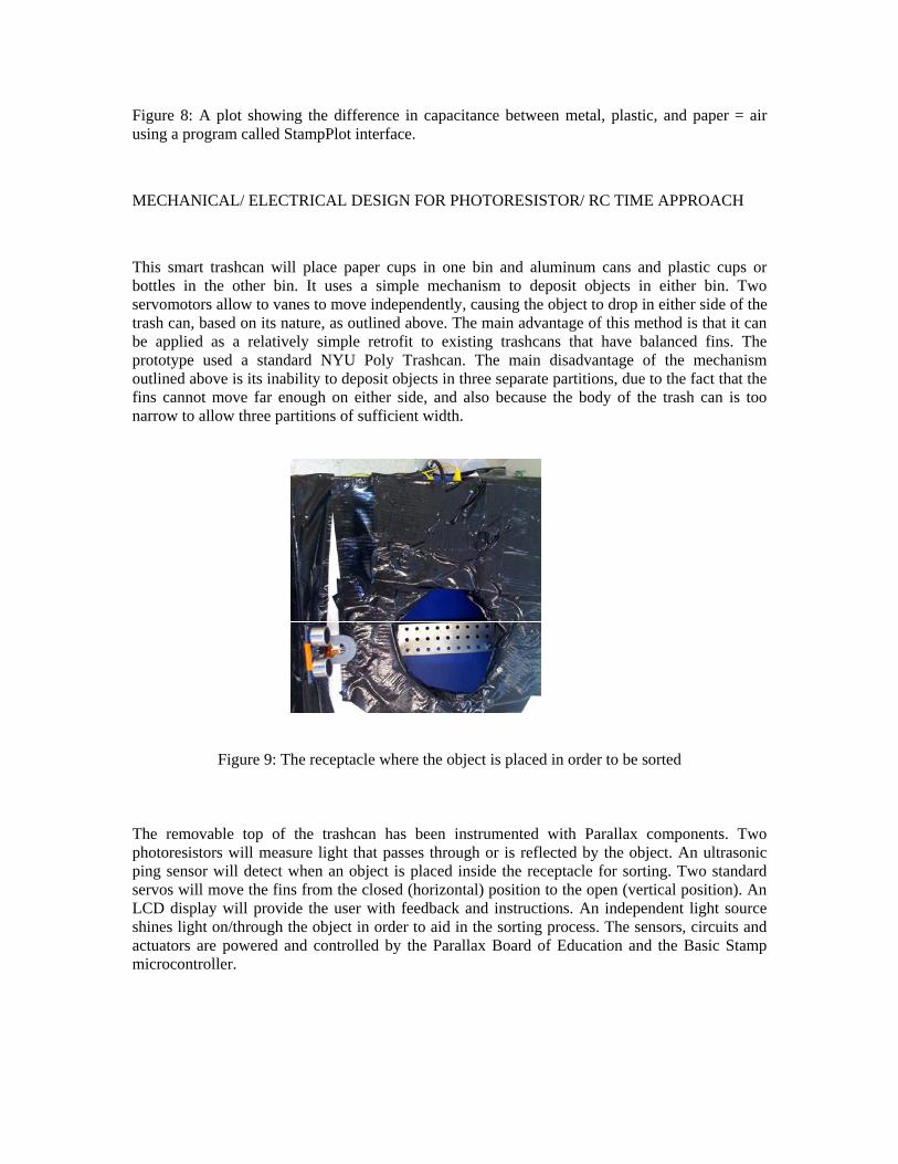
Figure 8: A plot showing the difference in capacitance between metal, plastic, and paper = air using a program called StampPlot interface.
MECHANICAL/ ELECTRICAL DESIGN FOR PHOTORESISTOR/ RC TIME APPROACH
This smart trashcan will place paper cups in one bin and aluminum cans and plastic cups or bottles in the other bin. It uses a simple mechanism to deposit objects in either bin. Two servomotors allow to vanes to move independently, causing the object to drop in either side of the trash can, based on its nature, as outlined above. The main advantage of this method is that it can be applied as a relatively simple retrofit to existing trashcans that have balanced fins. The prototype used a standard NYU Poly Trashcan. The main disadvantage of the mechanism outlined above is its inability to deposit objects in three separate partitions, due to the fact that the fins cannot move far enough on either side, and also because the body of the trash can is too narrow to allow three partitions of sufficient width.
Figure 9: The receptacle where the object is placed in order to be sorted The removable top of the trashcan has been instrumented with Parallax components. Two photoresistors will measure light that passes through or is reflected by the object. An ultrasonic ping sensor will detect when an object is placed inside the receptacle for sorting. Two standard servos will move the fins from the closed (horizontal) position to the open (vertical position). An LCD display will provide the user with feedback and instructions. An independent light source shines light on/through the object in order to aid in the sorting process. The sensors, circuits and actuators are powered and controlled by the Parallax Board of Education and the Basic Stamp microcontroller.
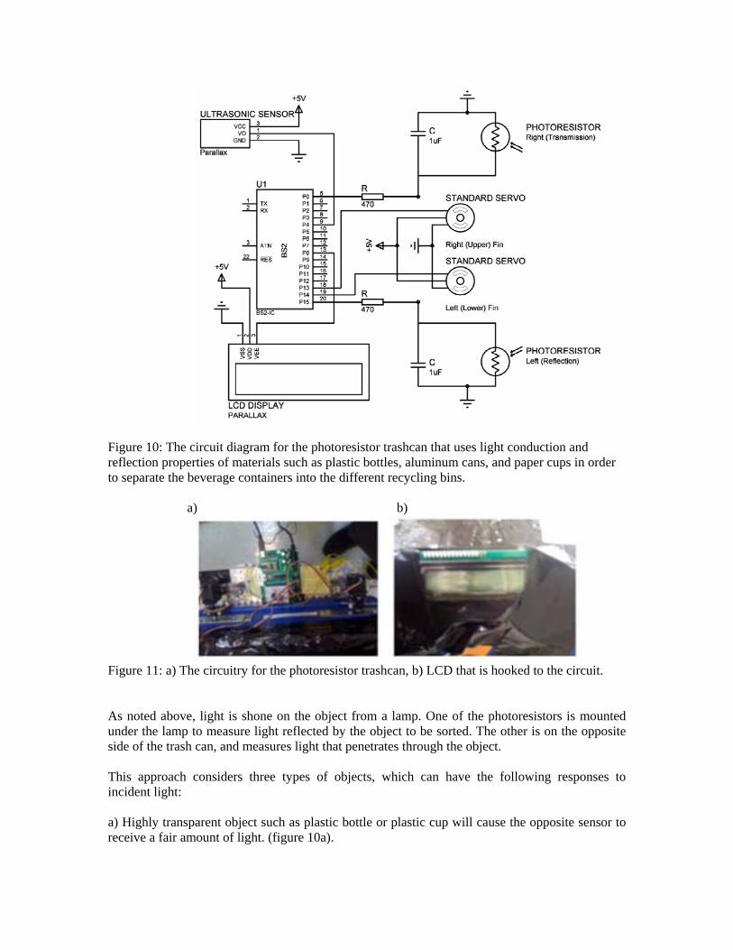
Figure 10: The circuit diagram for the photoresistor trashcan that uses light conduction and reflection properties of materials such as plastic bottles, aluminum cans, and paper cups in order to separate the beverage containers into the different recycling bins. a) b)
Figure 11: a) The circuitry for the photoresistor trashcan, b) LCD that is hooked to the circuit. As noted above, light is shone on the object from a lamp. One of the photoresistors is mounted under the lamp to measure light reflected by the object to be sorted. The other is on the opposite side of the trash can, and measures light that penetrates through the object. This approach considers three types of objects, which can have the following responses to incident light: a) Highly transparent object such as plastic bottle or plastic cup will cause the opposite sensor to receive a fair amount of light. (figure 10a).
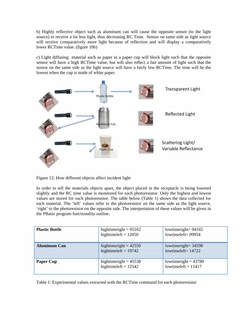
b) Highly reflective object such as aluminum can will cause the opposite sensor (to the light source) to receive a lot less light, thus decreasing RC Time. Sensor on same side as light source will receive comparatively more light because of reflection and will display a comparatively lower RCTime value. (figure 10b) c) Light diffusing material such as paper in a paper cup will block light such that the opposite sensor will have a high RCTime value, but will also reflect a fair amount of light such that the sensor on the same side as the light source will have a fairly low RCTime. The time will be the lowest when the cup is made of white paper.
Figure 12: How different objects affect incident light In order to tell the materials objects apart, the object placed in the receptacle is being lowered slightly and the RC time value is monitored for each photoresistor. Only the highest and lowest values are stored for each photoresistor. The table below (Table 1) shows the data collected for each material. The ‘left’ values refer to the photoresistor on the same side as the light source, ‘right’ to the photoresistor on the opposite side. The interpretation of these values will be given in the PBasic program functionality outline. Plastic Bottle hightimeright = 05162
hightimeleft = 12050
lowtimeright= 04165 lowtimeleft= 09954
Aluminum Can hightimeright = 42550 hightimeleft = 19742
lowtimeright= 34598 lowtimeleft= 14722
Paper Cup hightimeright = 45538 hightimeleft = 12542
lowtimeright = 43780 lowtimeleft = 11417
Table 1: Experimental values extracted with the RCTime command for each photoresistor
CAPACITIVE APPROACH - PROGRAM LOGIC/IMPLEMENTED CODE
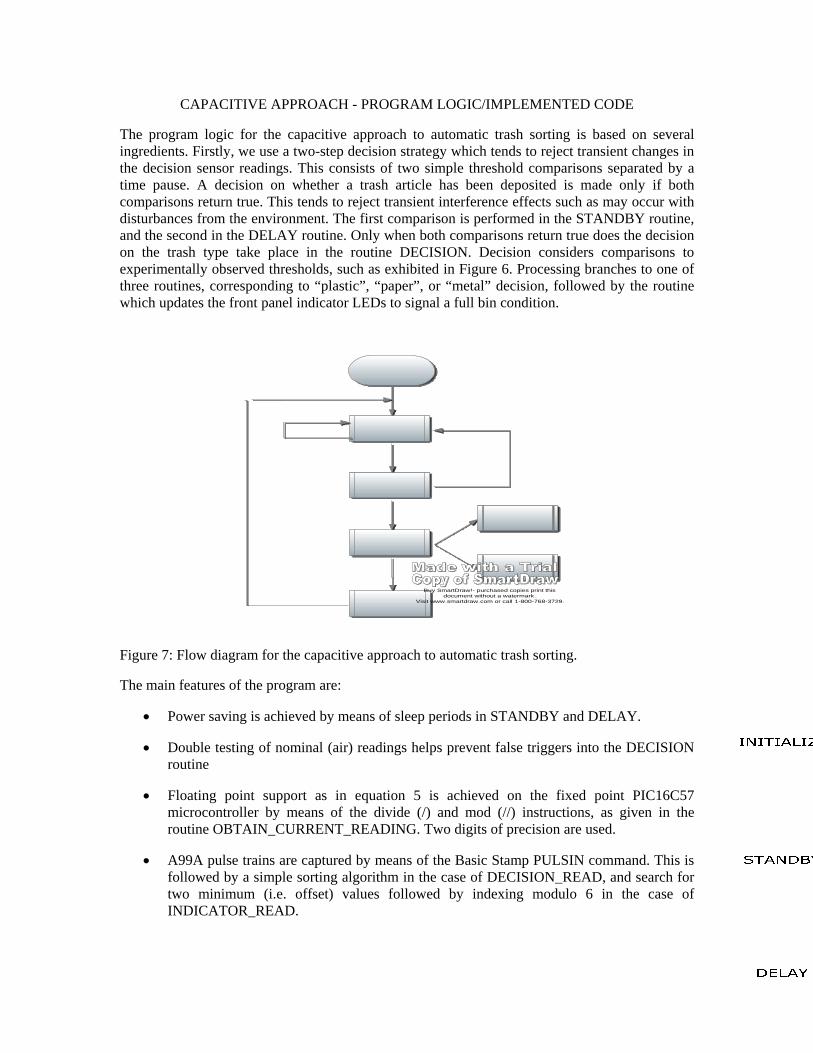
The program logic for the capacitive approach to automatic trash sorting is based on several ingredients. Firstly, we use a two-step decision strategy which tends to reject transient changes in the decision sensor readings. This consists of two simple threshold comparisons separated by a time pause. A decision on whether a trash article has been deposited is made only if both comparisons return true. This tends to reject transient interference effects such as may occur with disturbances from the environment. The first comparison is performed in the STANDBY routine, and the second in the DELAY routine. Only when both comparisons return true does the decision on the trash type take place in the routine DECISION. Decision considers comparisons to experimentally observed thresholds, such as exhibited in Figure 6. Processing branches to one of three routines, corresponding to “plastic”, “paper”, or “metal” decision, followed by the routine which updates the front panel indicator LEDs to signal a full bin condition.
Buy SmartDraw!- purchased copies print this document without a watermark .
Visit www.smartdraw.com or call 1-800-768-3729.
Figure 7: Flow diagram for the capacitive approach to automatic trash sorting.
The main features of the program are:
• Power saving is achieved by means of sleep periods in STANDBY and DELAY.
• Double testing of nominal (air) readings helps prevent false triggers into the DECISION routine
• Floating point support as in equation 5 is achieved on the fixed point PIC16C57 microcontroller by means of the divide (/) and mod (//) instructions, as given in the routine OBTAIN_CURRENT_READING. Two digits of precision are used.
• A99A pulse trains are captured by means of the Basic Stamp PULSIN command. This is followed by a simple sorting algorithm in the case of DECISION_READ, and search for two minimum (i.e. offset) values followed by indexing modulo 6 in the case of INDICATOR_READ.
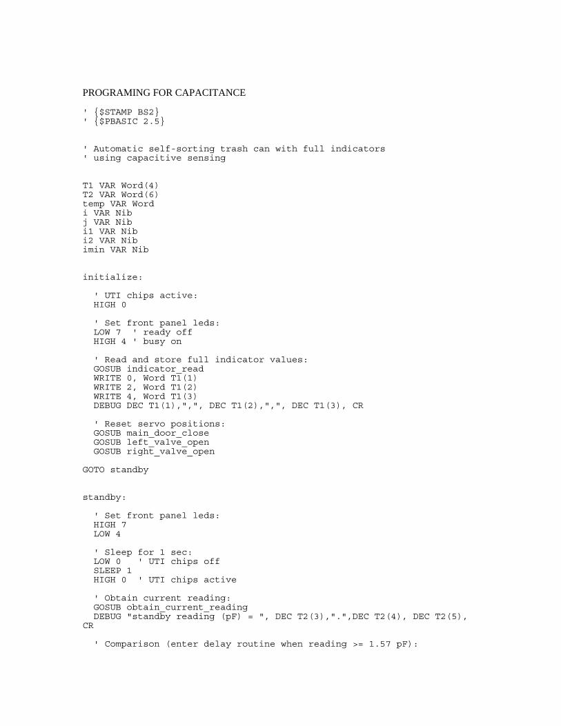
PROGRAMING FOR CAPACITANCE
' {$STAMP BS2} ' {$PBASIC 2.5} ' Automatic self-sorting trash can with full indicators ' using capacitive sensing T1 VAR Word(4) T2 VAR Word(6) temp VAR Word i VAR Nib j VAR Nib i1 VAR Nib i2 VAR Nib imin VAR Nib initialize: ' UTI chips active: HIGH 0 ' Set front panel leds: LOW 7 ' ready off HIGH 4 ' busy on ' Read and store full indicator values: GOSUB indicator_read WRITE 0, Word T1(1) WRITE 2, Word T1(2) WRITE 4, Word T1(3) DEBUG DEC T1(1),",", DEC T1(2),",", DEC T1(3), CR ' Reset servo positions: GOSUB main_door_close GOSUB left_valve_open GOSUB right_valve_open GOTO standby standby: ' Set front panel leds: HIGH 7 LOW 4 ' Sleep for 1 sec: LOW 0 ' UTI chips off SLEEP 1 HIGH 0 ' UTI chips active ' Obtain current reading: GOSUB obtain_current_reading DEBUG "standby reading (pF) = ", DEC T2(3),".",DEC T2(4), DEC T2(5), CR ' Comparison (enter delay routine when reading >= 1.57 pF):
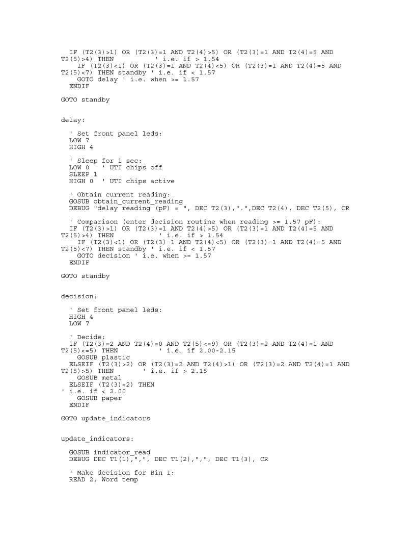
IF (T2(3)>1) OR (T2(3)=1 AND T2(4)>5) OR (T2(3)=1 AND T2(4)=5 AND T2(5)>4) THEN ' i.e. if > 1.54 IF (T2(3)<1) OR (T2(3)=1 AND T2(4)<5) OR (T2(3)=1 AND T2(4)=5 AND T2(5)<7) THEN standby ' i.e. if < 1.57 GOTO delay ' i.e. when >= 1.57 ENDIF GOTO standby delay: ' Set front panel leds: LOW 7 HIGH 4 ' Sleep for 1 sec: LOW 0 ' UTI chips off SLEEP 1 HIGH 0 ' UTI chips active ' Obtain current reading: GOSUB obtain_current_reading DEBUG "delay reading (pF) = ", DEC T2(3),".",DEC T2(4), DEC T2(5), CR ' Comparison (enter decision routine when reading >= 1.57 pF): IF (T2(3)>1) OR (T2(3)=1 AND T2(4)>5) OR (T2(3)=1 AND T2(4)=5 AND T2(5)>4) THEN ' i.e. if > 1.54 IF (T2(3)<1) OR (T2(3)=1 AND T2(4)<5) OR (T2(3)=1 AND T2(4)=5 AND T2(5)<7) THEN standby ' i.e. if < 1.57 GOTO decision ' i.e. when >= 1.57 ENDIF GOTO standby decision: ' Set front panel leds: HIGH 4 LOW 7 ' Decide: IF (T2(3)=2 AND T2(4)=0 AND T2(5)<=9) OR (T2(3)=2 AND T2(4)=1 AND T2(5)<=5) THEN ' i.e. if 2.00-2.15 GOSUB plastic ELSEIF (T2(3)>2) OR (T2(3)=2 AND T2(4)>1) OR (T2(3)=2 AND T2(4)=1 AND T2(5)>5) THEN ' i.e. if > 2.15 GOSUB metal ELSEIF (T2(3)<2) THEN ' i.e. if < 2.00 GOSUB paper ENDIF GOTO update_indicators update_indicators: GOSUB indicator_read DEBUG DEC T1(1),",", DEC T1(2),",", DEC T1(3), CR ' Make decision for Bin 1: READ 2, Word temp
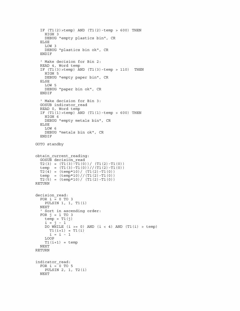
IF (T1(2)>temp) AND (T1(2)-temp > 600) THEN HIGH 3 DEBUG "empty plastics bin", CR ELSE LOW 3 DEBUG "plastics bin ok", CR ENDIF ' Make decision for Bin 2: READ 4, Word temp IF (T1(3)>temp) AND (T1(3)-temp > 110) THEN HIGH 5 DEBUG "empty paper bin", CR ELSE LOW 5 DEBUG "paper bin ok", CR ENDIF ' Make decision for Bin 3: GOSUB indicator_read READ 0, Word temp IF (T1(1)>temp) AND (T1(1)-temp > 600) THEN HIGH 6 DEBUG "empty metals bin", CR ELSE LOW 6 DEBUG "metals bin ok", CR ENDIF GOTO standby obtain_current_reading: GOSUB decision_read T2(3) = (T1(3)-T1(0))/ (T1(2)-T1(0)) temp = (T1(3)-T1(0))//(T1(2)-T1(0)) T2(4) = (temp*10)/ (T1(2)-T1(0)) temp = (temp*10)//(T1(2)-T1(0)) T2(5) = (temp*10)/ (T1(2)-T1(0)) RETURN decision_read: FOR i = 0 TO 3 PULSIN 1, 1, T1(i) NEXT ' Sort in ascending order: FOR j = 1 TO 3 temp = T1(j) i = j - 1 DO WHILE (i >= 0) AND (i < 4) AND (T1(i) > temp) T1(i+1) = T1(i) i = i - 1 LOOP T1(i+1) = temp NEXT RETURN indicator_read: FOR i = 0 TO 5 PULSIN 2, 1, T2(i) NEXT

' Find minimum value and its index: temp = T2(0) FOR j = 0 TO 4 temp = temp MAX T2(j+1) NEXT FOR j = 0 TO 5 IF (T2(j)=temp) THEN i1 = j ENDIF NEXT ' Find the next minimum value and its index: IF (i1=0) THEN temp = T2(1) FOR j = 0 TO 4 temp = temp MAX T2(j+1) NEXT ELSEIF (i1=5) THEN temp = T2(0) FOR j = 0 TO 3 temp = temp MAX T2(j+1) NEXT ELSE temp = T2(0) FOR j = 0 TO 4 IF (i1=j+1) THEN temp = temp MAX T2(j+2) ELSE temp = temp MAX T2(j+1) ENDIF NEXT ENDIF FOR j = 0 TO 5 IF (T2(j)=temp) THEN i2 = j ENDIF NEXT imin = i1 MAX i2 ' Use T1(1), T1(2), T1(3) to store indicator values: IF (i1-i2=1) OR (i2-i1=1) THEN T1(1) = T2((imin+1+2)//6) T1(2) = T2((imin+1+3)//6) T1(3) = T2((imin+1+4)//6) ELSE T1(1) = T2(imin+2) T1(2) = T2(imin+3) T1(3) = T2(imin+4) ENDIF RETURN plastic: GOSUB left_valve_close GOSUB main_door_open PAUSE 500 GOSUB left_valve_open GOSUB main_door_close RETURN metal:
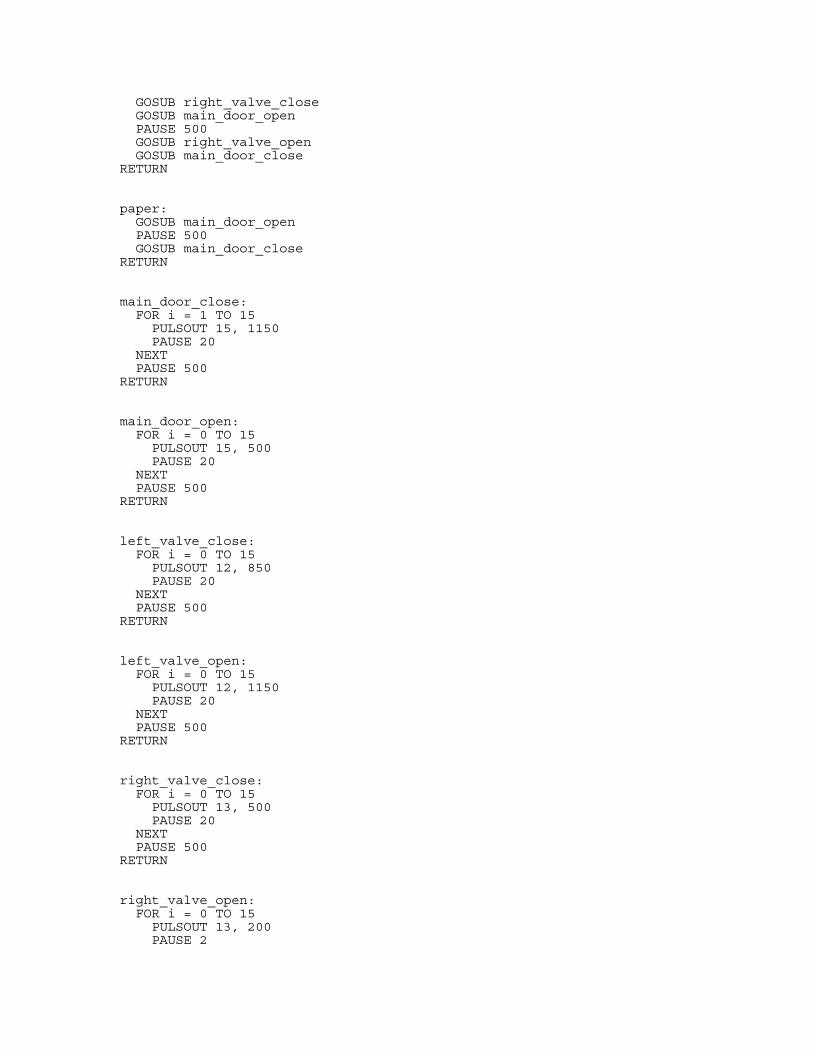
GOSUB right_valve_close GOSUB main_door_open PAUSE 500 GOSUB right_valve_open GOSUB main_door_close RETURN paper: GOSUB main_door_open PAUSE 500 GOSUB main_door_close RETURN main_door_close: FOR i = 1 TO 15 PULSOUT 15, 1150 PAUSE 20 NEXT PAUSE 500 RETURN main_door_open: FOR i = 0 TO 15 PULSOUT 15, 500 PAUSE 20 NEXT PAUSE 500 RETURN left_valve_close: FOR i = 0 TO 15 PULSOUT 12, 850 PAUSE 20 NEXT PAUSE 500 RETURN left_valve_open: FOR i = 0 TO 15 PULSOUT 12, 1150 PAUSE 20 NEXT PAUSE 500 RETURN right_valve_close: FOR i = 0 TO 15 PULSOUT 13, 500 PAUSE 20 NEXT PAUSE 500 RETURN right_valve_open: FOR i = 0 TO 15 PULSOUT 13, 200 PAUSE 2
NEXT PAUSE 500 RETURN
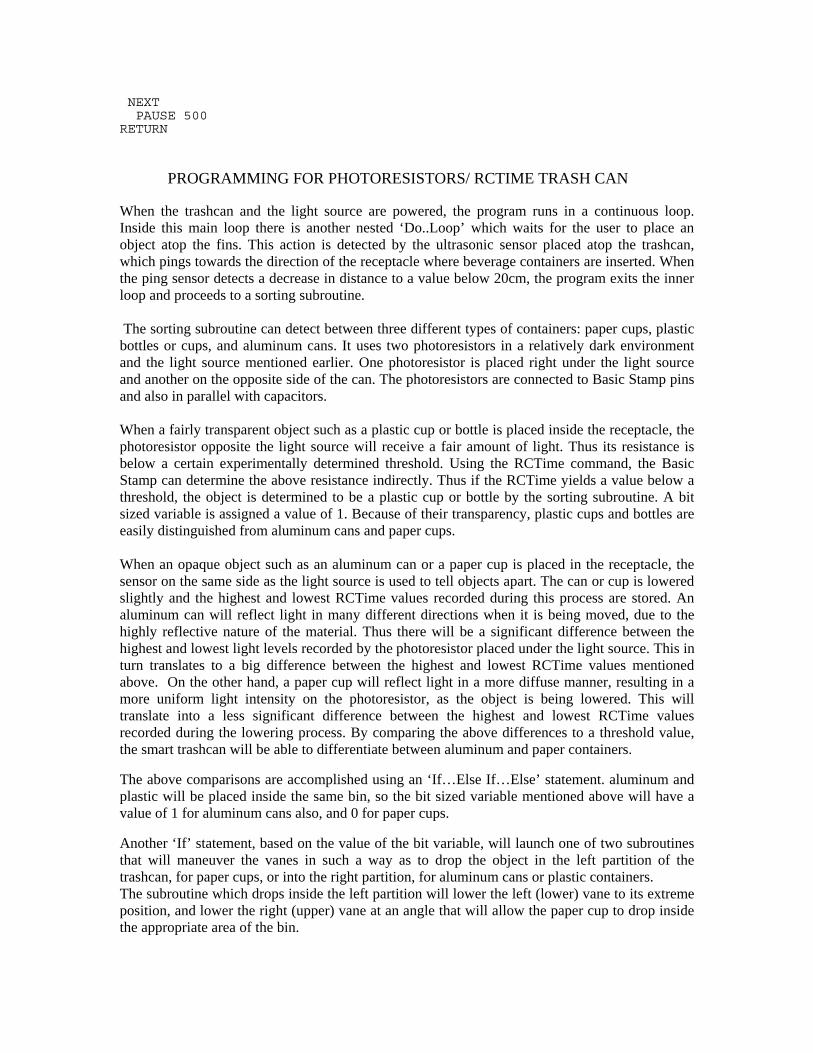
PROGRAMMING FOR PHOTORESISTORS/ RCTIME TRASH CAN When the trashcan and the light source are powered, the program runs in a continuous loop. Inside this main loop there is another nested ‘Do..Loop’ which waits for the user to place an object atop the fins. This action is detected by the ultrasonic sensor placed atop the trashcan, which pings towards the direction of the receptacle where beverage containers are inserted. When the ping sensor detects a decrease in distance to a value below 20cm, the program exits the inner loop and proceeds to a sorting subroutine. The sorting subroutine can detect between three different types of containers: paper cups, plastic bottles or cups, and aluminum cans. It uses two photoresistors in a relatively dark environment and the light source mentioned earlier. One photoresistor is placed right under the light source and another on the opposite side of the can. The photoresistors are connected to Basic Stamp pins and also in parallel with capacitors. When a fairly transparent object such as a plastic cup or bottle is placed inside the receptacle, the photoresistor opposite the light source will receive a fair amount of light. Thus its resistance is below a certain experimentally determined threshold. Using the RCTime command, the Basic Stamp can determine the above resistance indirectly. Thus if the RCTime yields a value below a threshold, the object is determined to be a plastic cup or bottle by the sorting subroutine. A bit sized variable is assigned a value of 1. Because of their transparency, plastic cups and bottles are easily distinguished from aluminum cans and paper cups. When an opaque object such as an aluminum can or a paper cup is placed in the receptacle, the sensor on the same side as the light source is used to tell objects apart. The can or cup is lowered slightly and the highest and lowest RCTime values recorded during this process are stored. An aluminum can will reflect light in many different directions when it is being moved, due to the highly reflective nature of the material. Thus there will be a significant difference between the highest and lowest light levels recorded by the photoresistor placed under the light source. This in turn translates to a big difference between the highest and lowest RCTime values mentioned above. On the other hand, a paper cup will reflect light in a more diffuse manner, resulting in a more uniform light intensity on the photoresistor, as the object is being lowered. This will translate into a less significant difference between the highest and lowest RCTime values recorded during the lowering process. By comparing the above differences to a threshold value, the smart trashcan will be able to differentiate between aluminum and paper containers.
The above comparisons are accomplished using an ‘If…Else If…Else’ statement. aluminum and plastic will be placed inside the same bin, so the bit sized variable mentioned above will have a value of 1 for aluminum cans also, and 0 for paper cups.
Another ‘If’ statement, based on the value of the bit variable, will launch one of two subroutines that will maneuver the vanes in such a way as to drop the object in the left partition of the trashcan, for paper cups, or into the right partition, for aluminum cans or plastic containers. The subroutine which drops inside the left partition will lower the left (lower) vane to its extreme position, and lower the right (upper) vane at an angle that will allow the paper cup to drop inside the appropriate area of the bin.
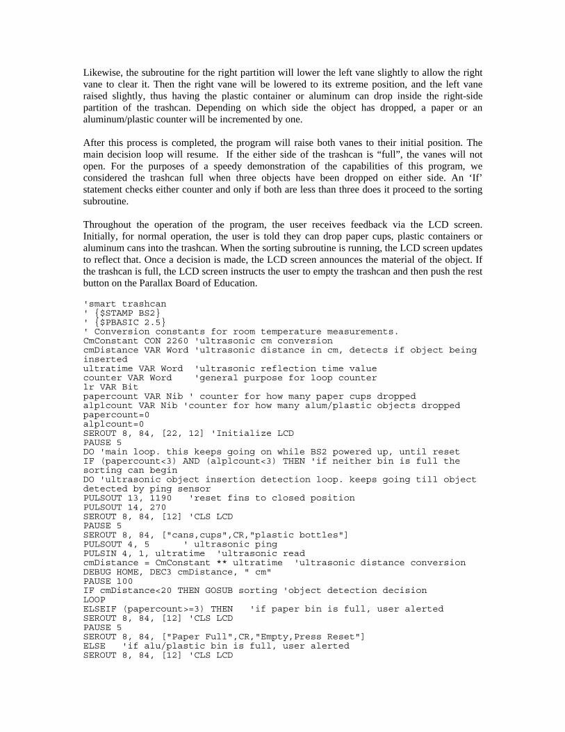
Likewise, the subroutine for the right partition will lower the left vane slightly to allow the right vane to clear it. Then the right vane will be lowered to its extreme position, and the left vane raised slightly, thus having the plastic container or aluminum can drop inside the right-side partition of the trashcan. Depending on which side the object has dropped, a paper or an aluminum/plastic counter will be incremented by one. After this process is completed, the program will raise both vanes to their initial position. The main decision loop will resume. If the either side of the trashcan is “full”, the vanes will not open. For the purposes of a speedy demonstration of the capabilities of this program, we considered the trashcan full when three objects have been dropped on either side. An ‘If’ statement checks either counter and only if both are less than three does it proceed to the sorting subroutine. Throughout the operation of the program, the user receives feedback via the LCD screen. Initially, for normal operation, the user is told they can drop paper cups, plastic containers or aluminum cans into the trashcan. When the sorting subroutine is running, the LCD screen updates to reflect that. Once a decision is made, the LCD screen announces the material of the object. If the trashcan is full, the LCD screen instructs the user to empty the trashcan and then push the rest button on the Parallax Board of Education. 'smart trashcan ' {$STAMP BS2} ' {$PBASIC 2.5} ' Conversion constants for room temperature measurements. CmConstant CON 2260 'ultrasonic cm conversion cmDistance VAR Word 'ultrasonic distance in cm, detects if object being inserted ultratime VAR Word 'ultrasonic reflection time value counter VAR Word 'general purpose for loop counter lr VAR Bit papercount VAR Nib ' counter for how many paper cups dropped alplcount VAR Nib 'counter for how many alum/plastic objects dropped papercount=0 alplcount=0 SEROUT 8, 84, [22, 12] 'Initialize LCD PAUSE 5 DO 'main loop. this keeps going on while BS2 powered up, until reset IF (papercount<3) AND (alplcount<3) THEN 'if neither bin is full the sorting can begin DO 'ultrasonic object insertion detection loop. keeps going till object detected by ping sensor PULSOUT 13, 1190 'reset fins to closed position PULSOUT 14, 270 SEROUT 8, 84, [12] 'CLS LCD PAUSE 5 SEROUT 8, 84, ["cans,cups",CR,"plastic bottles"] PULSOUT 4, 5 ' ultrasonic ping PULSIN 4, 1, ultratime 'ultrasonic read cmDistance = CmConstant ** ultratime 'ultrasonic distance conversion DEBUG HOME, DEC3 cmDistance, " cm" PAUSE 100 IF cmDistance<20 THEN GOSUB sorting 'object detection decision LOOP ELSEIF (papercount>=3) THEN 'if paper bin is full, user alerted SEROUT 8, 84, [12] 'CLS LCD PAUSE 5 SEROUT 8, 84, ["Paper Full",CR,"Empty,Press Reset"] ELSE 'if alu/plastic bin is full, user alerted SEROUT 8, 84, [12] 'CLS LCD
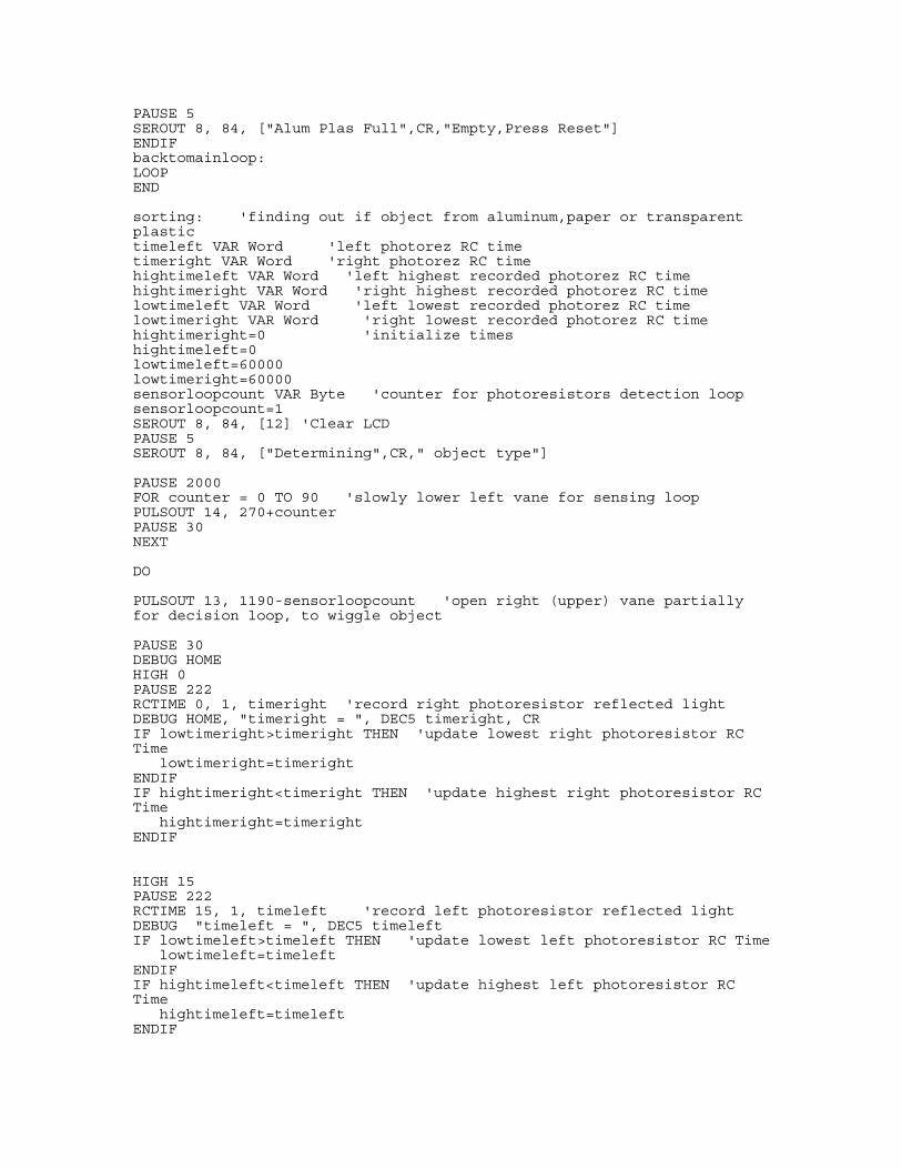
PAUSE 5 SEROUT 8, 84, ["Alum Plas Full",CR,"Empty,Press Reset"] ENDIF backtomainloop: LOOP END sorting: 'finding out if object from aluminum,paper or transparent plastic timeleft VAR Word 'left photorez RC time timeright VAR Word 'right photorez RC time hightimeleft VAR Word 'left highest recorded photorez RC time hightimeright VAR Word 'right highest recorded photorez RC time lowtimeleft VAR Word 'left lowest recorded photorez RC time lowtimeright VAR Word 'right lowest recorded photorez RC time hightimeright=0 'initialize times hightimeleft=0 lowtimeleft=60000 lowtimeright=60000 sensorloopcount VAR Byte 'counter for photoresistors detection loop sensorloopcount=1 SEROUT 8, 84, [12] 'Clear LCD PAUSE 5 SEROUT 8, 84, ["Determining",CR," object type"] PAUSE 2000 FOR counter = 0 TO 90 'slowly lower left vane for sensing loop PULSOUT 14, 270+counter PAUSE 30 NEXT DO PULSOUT 13, 1190-sensorloopcount 'open right (upper) vane partially for decision loop, to wiggle object PAUSE 30 DEBUG HOME HIGH 0 PAUSE 222 RCTIME 0, 1, timeright 'record right photoresistor reflected light DEBUG HOME, "timeright = ", DEC5 timeright, CR IF lowtimeright>timeright THEN 'update lowest right photoresistor RC Time lowtimeright=timeright ENDIF IF hightimeright<timeright THEN 'update highest right photoresistor RC Time hightimeright=timeright ENDIF HIGH 15 PAUSE 222 RCTIME 15, 1, timeleft 'record left photoresistor reflected light DEBUG "timeleft = ", DEC5 timeleft IF lowtimeleft>timeleft THEN 'update lowest left photoresistor RC Time lowtimeleft=timeleft ENDIF IF hightimeleft<timeleft THEN 'update highest left photoresistor RC Time hightimeleft=timeleft ENDIF
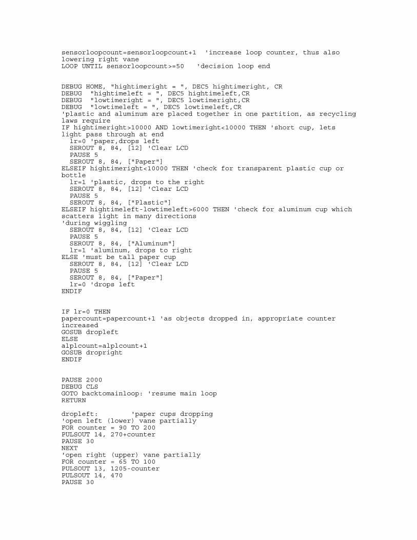
sensorloopcount=sensorloopcount+1 'increase loop counter, thus also lowering right vane LOOP UNTIL sensorloopcount>=50 'decision loop end DEBUG HOME, "hightimeright = ", DEC5 hightimeright, CR DEBUG "hightimeleft = ", DEC5 hightimeleft,CR DEBUG "lowtimeright = ", DEC5 lowtimeright,CR DEBUG "lowtimeleft = ", DEC5 lowtimeleft,CR 'plastic and aluminum are placed together in one partition, as recycling laws require IF hightimeright>10000 AND lowtimeright<10000 THEN 'short cup, lets light pass through at end lr=0 'paper,drops left SEROUT 8, 84, [12] 'Clear LCD PAUSE 5 SEROUT 8, 84, ["Paper"] ELSEIF hightimeright<10000 THEN 'check for transparent plastic cup or bottle lr=1 'plastic, drops to the right SEROUT 8, 84, [12] 'Clear LCD PAUSE 5 SEROUT 8, 84, ["Plastic"] ELSEIF hightimeleft-lowtimeleft>6000 THEN 'check for aluminum cup which scatters light in many directions 'during wiggling SEROUT 8, 84, [12] 'Clear LCD PAUSE 5 SEROUT 8, 84, ["Aluminum"] lr=1 'aluminum, drops to right ELSE 'must be tall paper cup SEROUT 8, 84, [12] 'Clear LCD PAUSE 5 SEROUT 8, 84, ["Paper"] lr=0 'drops left ENDIF IF lr=0 THEN papercount=papercount+1 'as objects dropped in, appropriate counter increased GOSUB dropleft ELSE alplcount=alplcount+1 GOSUB dropright ENDIF PAUSE 2000 DEBUG CLS GOTO backtomainloop: 'resume main loop RETURN dropleft: 'paper cups dropping 'open left (lower) vane partially FOR counter = 90 TO 200 PULSOUT 14, 270+counter PAUSE 30 NEXT 'open right (upper) vane partially FOR counter = 65 TO 100 PULSOUT 13, 1205-counter PULSOUT 14, 470 PAUSE 30
NEXT 'open left (lower) vane fully FOR counter = 200 TO 300 PULSOUT 14, 270+counter PAUSE 30 NEXT FOR counter = 100 TO 220 PULSOUT 13, 1205-counter PAUSE 30 NEXT 'close right (upper) vane FOR counter = 0 TO 220 PULSOUT 13, 1205-220+counter PAUSE 30 NEXT 'close left (lower) vane FOR counter = 0 TO 300 PULSOUT 14, 570-counter PAUSE 30 NEXT RETURN dropright: 'aluminum plastic dropping 'close left (lower) vane partially FOR counter = 0 TO 10 PULSOUT 14, 360-counter PAUSE 30 NEXT 'open right (upper) vane fully FOR counter = 0 TO 295 PULSOUT 13, 1140-counter PAUSE 30 NEXT 'close right (upper) vane FOR counter = 0 TO 360 PULSOUT 13, 1205-360+counter PAUSE 30 NEXT 'close left (lower) vane FOR counter = 10 TO 90 PULSOUT 14, 360-counter PAUSE 30 NEXT RETURN
REFERENCES Baxter, Larry K., “Capacitive Sensors,” IEEE Press, Piscataway NJ., 1997 Lion Precision, “Capacitive Sensor Operation and Optimization,” St. Paul, MN., 2009 Heerens, Willem Chr., “Application of capacitance techniques in sensor design,” J .Phys. E: Sci. Instrum. 19, 1986, pp. 897-906 Puers, Robert, “Capacitive sensors: when and how to use them,” Sensors and Actuators, A37-A38, 1993, pp. 93-105 Von Hippel, A., “Dielectric Materials and Applications,” Technology Press of MIT, Cambridge, 1954 Dr. Vikram Kapila. Polytechnic Institute of New York University, 6 MetroTech Center, Brooklyn NY,11201, 2009. Mechatronics class, topics 4 and 6 Lindsay, A., “What’s a micro-controller? BASIC Stamp Manual”, Version 2.0c, Parallax Inc., 2000 Halliday, D., Rensnick, R., Walker, J., “Fundamentals of Physics,” John Wiley & Sons, 2001
We would like to acknowledge professor Kapila, the GK-12 fellowship, Carlo Yuvienco, Parth Kumar, Peter James Baker, Nicole Abaid, student offices on the basement floor, and eighth floor bathroom trashcan.
Bill of Materials/ Capacitance
• BS2 $240
• Cables $ 2.00
• Labor $200
• Trash Can $ 30.00
• Label Maker $ 25.00
• White Cardboard $ 15.00
• Trash $ 8.00
• Capacitance plates $ 10.00
• Tape $ 15.00
Bill of Materials/ Photoresistor
• BS2 $240
• Cables $ 2.00
• Labor $200
• Light source with battery $ 30.00
• Trash Can $ 100.00
• Vex dirty parts kit $ 20.00 on ebay
• Duck tape $ 2.00
• Styrofoam $ 2.00
• White Cardboard $15.00
• Tape $ 5.00