Embed Size (px)
Citation preview
Terminals and Splices
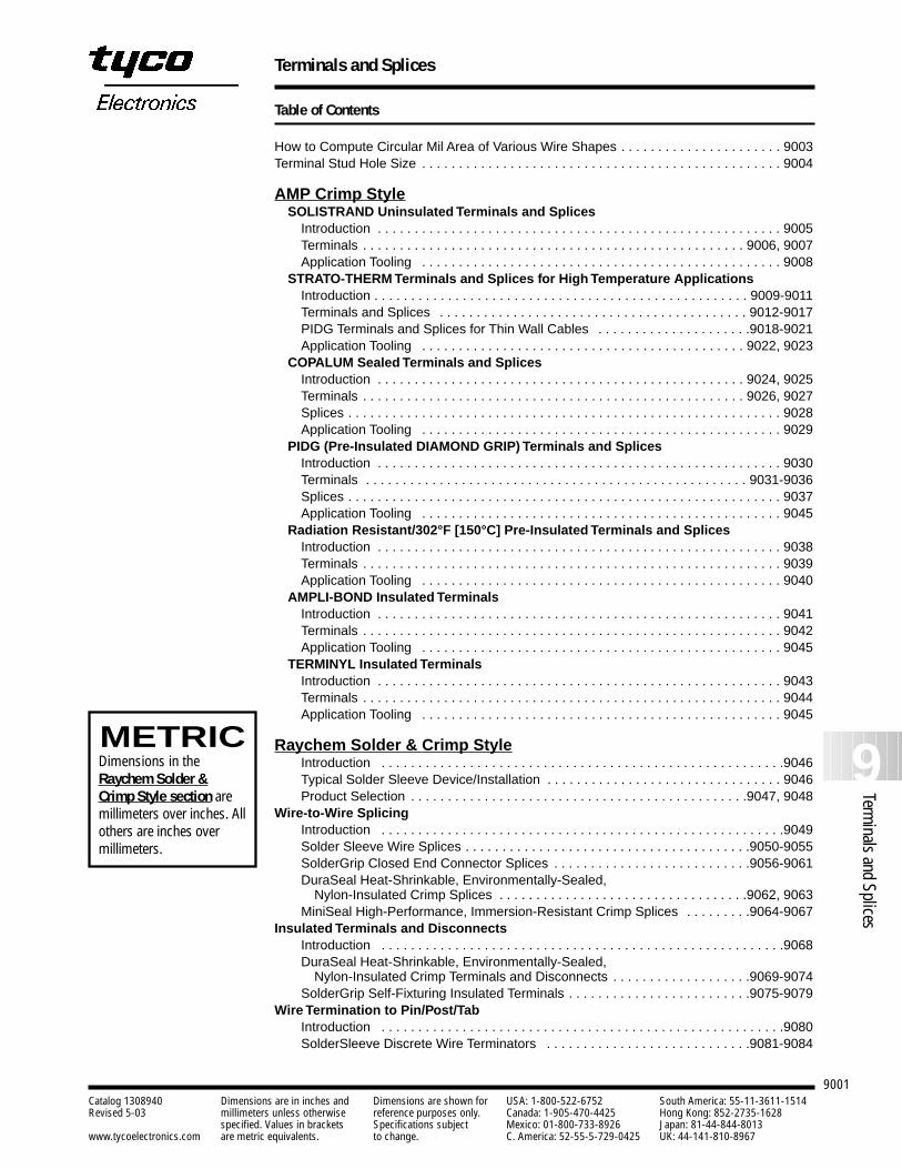
Table of Contents
9001
How to Compute Circular Mil Area of Various Wire Shapes . . . . . . . . . . . . . . . . . . . . . . 9003Terminal Stud Hole Size . . . . . . . . . . . . . . . . . . . . . . . . . . . . . . . . . . . . . . . . . . . . . . . . . 9004
AMP Crimp StyleSOLISTRAND Uninsulated Terminals and Splices
Introduction . . . . . . . . . . . . . . . . . . . . . . . . . . . . . . . . . . . . . . . . . . . . . . . . . . . . . . . 9005Terminals . . . . . . . . . . . . . . . . . . . . . . . . . . . . . . . . . . . . . . . . . . . . . . . . . . . . 9006, 9007Application Tooling . . . . . . . . . . . . . . . . . . . . . . . . . . . . . . . . . . . . . . . . . . . . . . . . . 9008
STRATO-THERM Terminals and Splices for High Temperature ApplicationsIntroduction . . . . . . . . . . . . . . . . . . . . . . . . . . . . . . . . . . . . . . . . . . . . . . . . . . . 9009-9011Terminals and Splices . . . . . . . . . . . . . . . . . . . . . . . . . . . . . . . . . . . . . . . . . . 9012-9017PIDG Terminals and Splices for Thin Wall Cables . . . . . . . . . . . . . . . . . . . . .9018-9021Application Tooling . . . . . . . . . . . . . . . . . . . . . . . . . . . . . . . . . . . . . . . . . . . . 9022, 9023
COPALUM Sealed Terminals and SplicesIntroduction . . . . . . . . . . . . . . . . . . . . . . . . . . . . . . . . . . . . . . . . . . . . . . . . . . 9024, 9025Terminals . . . . . . . . . . . . . . . . . . . . . . . . . . . . . . . . . . . . . . . . . . . . . . . . . . . . 9026, 9027Splices . . . . . . . . . . . . . . . . . . . . . . . . . . . . . . . . . . . . . . . . . . . . . . . . . . . . . . . . . . . 9028Application Tooling . . . . . . . . . . . . . . . . . . . . . . . . . . . . . . . . . . . . . . . . . . . . . . . . . 9029
PIDG (Pre-Insulated DIAMOND GRIP) Terminals and SplicesIntroduction . . . . . . . . . . . . . . . . . . . . . . . . . . . . . . . . . . . . . . . . . . . . . . . . . . . . . . . 9030Terminals . . . . . . . . . . . . . . . . . . . . . . . . . . . . . . . . . . . . . . . . . . . . . . . . . . . . 9031-9036Splices . . . . . . . . . . . . . . . . . . . . . . . . . . . . . . . . . . . . . . . . . . . . . . . . . . . . . . . . . . . 9037Application Tooling . . . . . . . . . . . . . . . . . . . . . . . . . . . . . . . . . . . . . . . . . . . . . . . . . 9045
Radiation Resistant/302°F [150°C] Pre-Insulated Terminals and SplicesIntroduction . . . . . . . . . . . . . . . . . . . . . . . . . . . . . . . . . . . . . . . . . . . . . . . . . . . . . . . 9038Terminals . . . . . . . . . . . . . . . . . . . . . . . . . . . . . . . . . . . . . . . . . . . . . . . . . . . . . . . . . 9039Application Tooling . . . . . . . . . . . . . . . . . . . . . . . . . . . . . . . . . . . . . . . . . . . . . . . . . 9040
AMPLI-BOND Insulated TerminalsIntroduction . . . . . . . . . . . . . . . . . . . . . . . . . . . . . . . . . . . . . . . . . . . . . . . . . . . . . . . 9041Terminals . . . . . . . . . . . . . . . . . . . . . . . . . . . . . . . . . . . . . . . . . . . . . . . . . . . . . . . . . 9042Application Tooling . . . . . . . . . . . . . . . . . . . . . . . . . . . . . . . . . . . . . . . . . . . . . . . . . 9045
TERMINYL Insulated TerminalsIntroduction . . . . . . . . . . . . . . . . . . . . . . . . . . . . . . . . . . . . . . . . . . . . . . . . . . . . . . . 9043Terminals . . . . . . . . . . . . . . . . . . . . . . . . . . . . . . . . . . . . . . . . . . . . . . . . . . . . . . . . . 9044Application Tooling . . . . . . . . . . . . . . . . . . . . . . . . . . . . . . . . . . . . . . . . . . . . . . . . . 9045
Raychem Solder & Crimp StyleIntroduction . . . . . . . . . . . . . . . . . . . . . . . . . . . . . . . . . . . . . . . . . . . . . . . . . . . . . . .9046Typical Solder Sleeve Device/Installation . . . . . . . . . . . . . . . . . . . . . . . . . . . . . . . . 9046Product Selection . . . . . . . . . . . . . . . . . . . . . . . . . . . . . . . . . . . . . . . . . . . . . .9047, 9048
Wire-to-Wire SplicingIntroduction . . . . . . . . . . . . . . . . . . . . . . . . . . . . . . . . . . . . . . . . . . . . . . . . . . . . . . .9049Solder Sleeve Wire Splices . . . . . . . . . . . . . . . . . . . . . . . . . . . . . . . . . . . . . . .9050-9055SolderGrip Closed End Connector Splices . . . . . . . . . . . . . . . . . . . . . . . . . . .9056-9061DuraSeal Heat-Shrinkable, Environmentally-Sealed,
Nylon-Insulated Crimp Splices . . . . . . . . . . . . . . . . . . . . . . . . . . . . . . . . . .9062, 9063MiniSeal High-Performance, Immersion-Resistant Crimp Splices . . . . . . . . .9064-9067
Insulated Terminals and DisconnectsIntroduction . . . . . . . . . . . . . . . . . . . . . . . . . . . . . . . . . . . . . . . . . . . . . . . . . . . . . . .9068DuraSeal Heat-Shrinkable, Environmentally-Sealed,
Nylon-Insulated Crimp Terminals and Disconnects . . . . . . . . . . . . . . . . . . .9069-9074SolderGrip Self-Fixturing Insulated Terminals . . . . . . . . . . . . . . . . . . . . . . . . .9075-9079
Wire Termination to Pin/Post/TabIntroduction . . . . . . . . . . . . . . . . . . . . . . . . . . . . . . . . . . . . . . . . . . . . . . . . . . . . . . .9080SolderSleeve Discrete Wire Terminators . . . . . . . . . . . . . . . . . . . . . . . . . . . .9081-9084
9Terminals and Splices
Catalog 1308940 Dimensions are in inches and Dimensions are shown for USA: 1-800-522-6752 South America: 55-11-3611-1514Revised 5-03 millimeters unless otherwise reference purposes only. Canada: 1-905-470-4425 Hong Kong: 852-2735-1628
specified. Values in brackets Specifications subject Mexico: 01-800-733-8926 Japan: 81-44-844-8013www.tycoelectronics.com are metric equivalents. to change. C. America: 52-55-5-729-0425 UK: 44-141-810-8967
METRICDimensions in the Raychem Solder &Crimp Style section aremillimeters over inches. Allothers are inches over millimeters.
Terminals and Splices
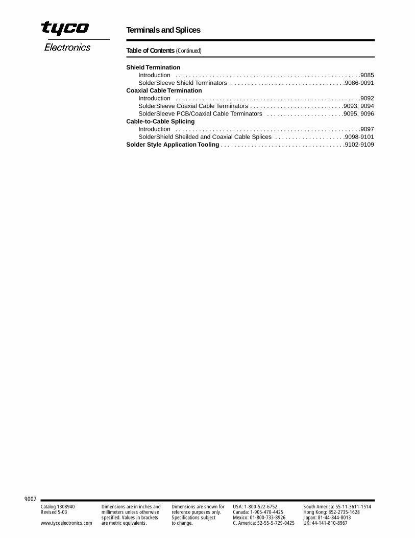
Table of Contents (Continued)
9002
Shield TerminationIntroduction . . . . . . . . . . . . . . . . . . . . . . . . . . . . . . . . . . . . . . . . . . . . . . . . . . . . . . .9085SolderSleeve Shield Terminators . . . . . . . . . . . . . . . . . . . . . . . . . . . . . . . . . .9086-9091
Coaxial Cable TerminationIntroduction . . . . . . . . . . . . . . . . . . . . . . . . . . . . . . . . . . . . . . . . . . . . . . . . . . . . . . .9092SolderSleeve Coaxial Cable Terminators . . . . . . . . . . . . . . . . . . . . . . . . . . . .9093, 9094SolderSleeve PCB/Coaxial Cable Terminators . . . . . . . . . . . . . . . . . . . . . . .9095, 9096
Cable-to-Cable SplicingIntroduction . . . . . . . . . . . . . . . . . . . . . . . . . . . . . . . . . . . . . . . . . . . . . . . . . . . . . . .9097SolderShield Sheilded and Coaxial Cable Splices . . . . . . . . . . . . . . . . . . . . .9098-9101
Solder Style Application Tooling . . . . . . . . . . . . . . . . . . . . . . . . . . . . . . . . . . . . .9102-9109
Catalog 1308940 Dimensions are in inches and Dimensions are shown for USA: 1-800-522-6752 South America: 55-11-3611-1514Revised 5-03 millimeters unless otherwise reference purposes only. Canada: 1-905-470-4425 Hong Kong: 852-2735-1628
specified. Values in brackets Specifications subject Mexico: 01-800-733-8926 Japan: 81-44-844-8013www.tycoelectronics.com are metric equivalents. to change. C. America: 52-55-5-729-0425 UK: 44-141-810-8967
Terminals and Splices
9003
9Terminals and Splices
Catalog 1308940 Dimensions are in inches and Dimensions are shown for USA: 1-800-522-6752 South America: 55-11-3611-1514Revised 5-03 millimeters unless otherwise reference purposes only. Canada: 1-905-470-4425 Hong Kong: 852-2735-1628
specified. Values in brackets Specifications subject Mexico: 01-800-733-8926 Japan: 81-44-844-8013www.tycoelectronics.com are metric equivalents. to change. C. America: 52-55-5-729-0425 UK: 44-141-810-8967
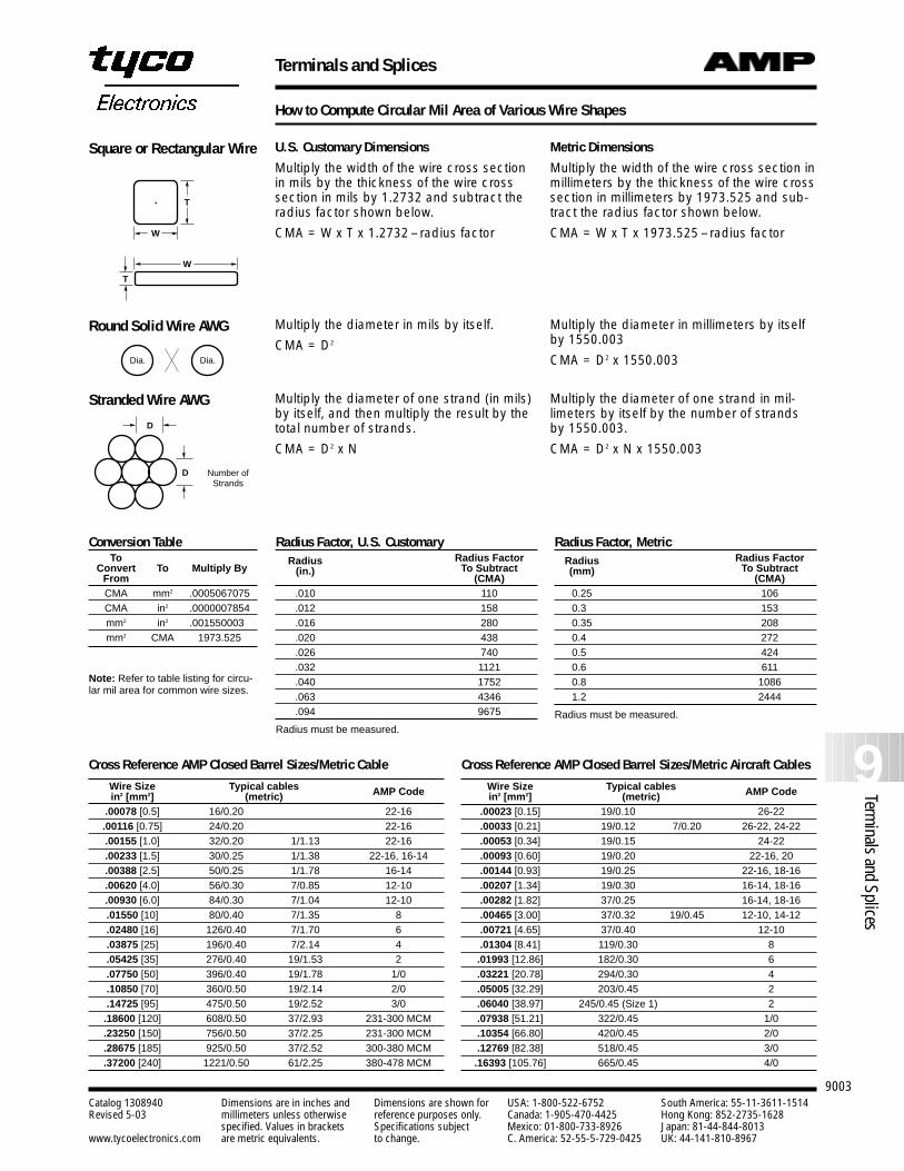
How to Compute Circular Mil Area of Various Wire Shapes
Square or Rectangular Wire
Round Solid Wire AWG
Stranded Wire AWG
U.S. Customary Dimensions
Multiply the width of the wire cross section in mils by the thickness of the wire crosssection in mils by 1.2732 and subtract theradius factor shown below.
CMA = W x T x 1.2732 – radius factor
Multiply the diameter in mils by itself.
CMA = D2
Multiply the diameter of one strand (in mils)by itself, and then multiply the result by thetotal number of strands.
CMA = D2 x N
Metric Dimensions
Multiply the width of the wire cross section inmillimeters by the thickness of the wire crosssection in millimeters by 1973.525 and sub-tract the radius factor shown below.
CMA = W x T x 1973.525 – radius factor
Multiply the diameter in millimeters by itselfby 1550.003
CMA = D2 x 1550.003
Multiply the diameter of one strand in mil-limeters by itself by the number of strandsby 1550.003.
CMA = D2 x N x 1550.003
W
T
T
W
Dia. Dia.
D
D Number ofStrands
Radius Factor, U.S. CustomaryRadius Radius Factor
(in.) To Subtract(CMA)
.010 110
.012 158
.016 280
.020 438
.026 740
.032 1121
.040 1752
.063 4346
.094 9675
Radius must be measured.
Conversion TableTo
Convert To Multiply ByFromCMA mm2 .0005067075CMA in2 .0000007854mm2 in2 .0015500030mm2 CMA 1973.525
Note: Refer to table listing for circu-lar mil area for common wire sizes.
Radius Factor, MetricRadius Radius Factor(mm) To Subtract
(CMA)0.25 1060.30 1530.35 2080.40 2720.50 4240.60 6110.80 10861.20 2444
Radius must be measured.
Cross Reference AMP Closed Barrel Sizes/Metric Cable
Wire Size Typical cables AMP Codein2 [mm2] (metric).00078 [0.5] 16/0.20 22-16.00116 [0.75] 24/0.20 22-16.00155 [1.0] 32/0.20 1/1.13 22-16.00233 [1.5] 30/0.25 1/1.38 22-16, 16-14.00388 [2.5] 50/0.25 1/1.78 16-14.00620 [4.0] 56/0.30 7/0.85 12-10.00930 [6.0] 84/0.30 7/1.04 12-10.01550 [10] 80/0.40 7/1.35 8.02480 [16] 126/0.40 7/1.70 6.03875 [25] 196/0.40 7/2.14 4.05425 [35] 276/0.40 19/1.53 2.07750 [50] 396/0.40 19/1.78 1/0.10850 [70] 360/0.50 19/2.14 2/0.14725 [95] 475/0.50 19/2.52 3/0.18600 [120] 608/0.50 37/2.93 231-300 MCM.23250 [150] 756/0.50 37/2.25 231-300 MCM.28675 [185] 925/0.50 37/2.52 300-380 MCM.37200 [240] 1221/0.50 61/2.25 380-478 MCM
Cross Reference AMP Closed Barrel Sizes/Metric Aircraft Cables
Wire Size Typical cables AMP Codein2 [mm2] (metric).00023 [0.15] 19/0.10 26-22.00033 [0.21] 19/0.12 7/0.20 26-22, 24-22.00053 [0.34] 19/0.15 24-22.00093 [0.60] 19/0.20 22-16, 20.00144 [0.93] 19/0.25 22-16, 18-16.00207 [1.34] 19/0.30 16-14, 18-16.00282 [1.82] 37/0.25 16-14, 18-16.00465 [3.00] 37/0.32 19/0.45 12-10, 14-12.00721 [4.65] 37/0.40 12-10.01304 [8.41] 119/0.30 8.01993 [12.86] 182/0.30 6.03221 [20.78] 294/0.30 4.05005 [32.29] 203/0.45 2.06040 [38.97] 245/0.45 (Size 1) 2.07938 [51.21] 322/0.45 1/0.10354 [66.80] 420/0.45 2/0.12769 [82.38] 518/0.45 3/0.16393 [105.76] 665/0.45 4/0
Terminals and Splices
9004Catalog 1308940 Dimensions are in inches and Dimensions are shown for USA: 1-800-522-6752 South America: 55-11-3611-1514Revised 5-03 millimeters unless otherwise reference purposes only. Canada: 1-905-470-4425 Hong Kong: 852-2735-1628
specified. Values in brackets Specifications subject Mexico: 01-800-733-8926 Japan: 81-44-844-8013www.tycoelectronics.com are metric equivalents. to change. C. America: 52-55-5-729-0425 UK: 44-141-810-8967
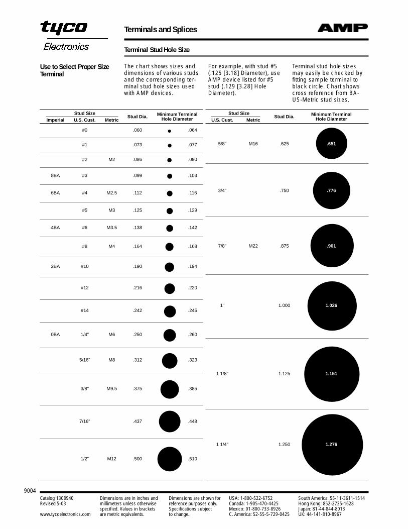
Terminal Stud Hole Size
The chart shows sizes anddimensions of various studsand the corresponding ter-minal stud hole sizes usedwith AMP devices.
For example, with stud #5(.125 [3.18] Diameter), useAMP device listed for #5stud (.129 [3.28] HoleDiameter).
Terminal stud hole sizesmay easily be checked byfitting sample terminal toblack circle. Chart showscross reference from BA-US-Metric stud sizes.
Stud Size Minimum TerminalU.S. Cust. Metric
Stud Dia. Hole Diameter
5/8" M16 .625 .651
3/4" .750 .776
7/8" M22 .875 .901
1" 1.000 1.026
1 1/8" 1.125 1.151
1 1/4" 1.250 1.276
Stud SizeStud Dia. Minimum Terminal
Imperial U.S. Cust. Metric Hole Diameter
#0 .060 .064
#1 .073 .077
#2 M2 .086 .090
8BA #3 .099 .103
6BA #4 M2.5 .112 .116
#5 M3 .125 .129
4BA #6 M3.5 .138 .142
#8 M4 .164 .168
2BA #10 .190 .194
#12 .216 .220
#14 .242 .245
0BA 1/4" M6 .250 .260
5/16" M8 .312 .323
3/8" M9.5 .375 .385
7/16" .437 .448
1/2" M12 .500 .510
Use to Select Proper SizeTerminal
SOLISTRAND, Uninsulated Terminals and Splices
9005
9Terminals and Splices
Catalog 1308940 Dimensions are in inches and Dimensions are shown for USA: 1-800-522-6752 South America: 55-11-3611-1514Revised 5-03 millimeters unless otherwise reference purposes only. Canada: 1-905-470-4425 Hong Kong: 852-2735-1628
specified. Values in brackets Specifications subject Mexico: 01-800-733-8926 Japan: 81-44-844-8013www.tycoelectronics.com are metric equivalents. to change. C. America: 52-55-5-729-0425 UK: 44-141-810-8967
Introduction
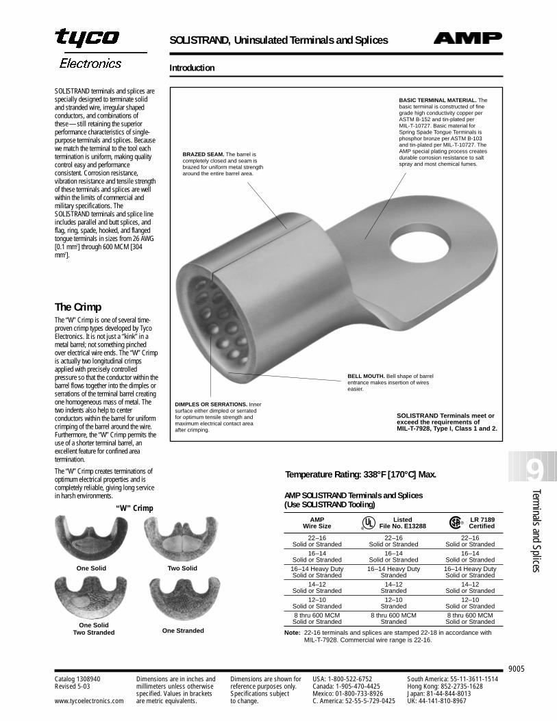
SOLISTRAND terminals and splices arespecially designed to terminate solid and stranded wire, irregular shapedconductors, and combinations ofthese —still retaining the superiorperformance characteristics of single-purpose terminals and splices. Becausewe match the terminal to the tool eachtermination is uniform, making qualitycontrol easy and performanceconsistent. Corrosion resistance,vibration resistance and tensile strengthof these terminals and splices are wellwithin the limits of commercial andmilitary specifications. TheSOLISTRAND terminals and splice lineincludes parallel and butt splices, andflag, ring, spade, hooked, and flangedtongue terminals in sizes from 26 AWG[0.1 mm2] through 600 MCM [304mm2].
The CrimpThe “W” Crimp is one of several time-proven crimp types developed by TycoElectronics. It is not just a “kink” in ametal barrel; not something pinchedover electrical wire ends. The “W” Crimpis actually two longitudinal crimpsapplied with precisely controlledpressure so that the conductor within thebarrel flows together into the dimples orserrations of the terminal barrel creatingone homogeneous mass of metal. Thetwo indents also help to centerconductors within the barrel for uniformcrimping of the barrel around the wire.Furthermore, the “W” Crimp permits theuse of a shorter terminal barrel, anexcellent feature for confined areatermination.
The “W” Crimp creates terminations ofoptimum electrical properties and iscompletely reliable, giving long servicein harsh environments.
BASIC TERMINAL MATERIAL. Thebasic terminal is constructed of finegrade high conductivity copper perASTM B-152 and tin-plated perMIL-T-10727. Basic material forSpring Spade Tongue Terminals isphosphor bronze per ASTM B-103and tin-plated per MIL-T-10727. TheAMP special plating process createsdurable corrosion resistance to saltspray and most chemical fumes.
DIMPLES OR SERRATIONS. Innersurface either dimpled or serratedfor optimum tensile strength andmaximum electrical contact areaafter crimping.
BELL MOUTH. Bell shape of barrelentrance makes insertion of wireseasier.
SOLISTRAND Terminals meet orexceed the requirements ofMIL-T-7928, Type I, Class 1 and 2.
Temperature Rating: 338°F [170°C] Max.
AMP SOLISTRAND Terminals and Splices (Use SOLISTRAND Tooling)
AMP Listed LR 7189Wire Size File No. E13288 Certified
22–16 22–16 22–16Solid or Stranded Solid or Stranded Solid or Stranded
16–14 16–14 16–14Solid or Stranded Solid or Stranded Solid or Stranded
16–14 Heavy Duty 16–14 Heavy Duty 16–14 Heavy DutySolid or Stranded Stranded Solid or Stranded
14–12 14–12 14–12Solid or Stranded Stranded Solid or Stranded
12–10 12–10 12–10Solid or Stranded Stranded Solid or Stranded8 thru 600 MCM 8 thru 600 MCM 8 thru 600 MCM
Solid or Stranded Stranded Solid or Stranded
Note: 22-16 terminals and splices are stamped 22-18 in accordance withMIL-T-7928. Commercial wire range is 22-16.
R
R
“W” Crimp
One Solid Two Solid
One StrandedOne Solid
Two Stranded
BRAZED SEAM. The barrel iscompletely closed and seam isbrazed for uniform metal strengtharound the entire barrel area.
SOLISTRAND, Uninsulated Terminals and Splices
9006Catalog 1308940 Dimensions are in inches and Dimensions are shown for USA: 1-800-522-6752 South America: 55-11-3611-1514Revised 5-03 millimeters unless otherwise reference purposes only. Canada: 1-905-470-4425 Hong Kong: 852-2735-1628
specified. Values in brackets Specifications subject Mexico: 01-800-733-8926 Japan: 81-44-844-8013www.tycoelectronics.com are metric equivalents. to change. C. America: 52-55-5-729-0425 UK: 44-141-810-8967
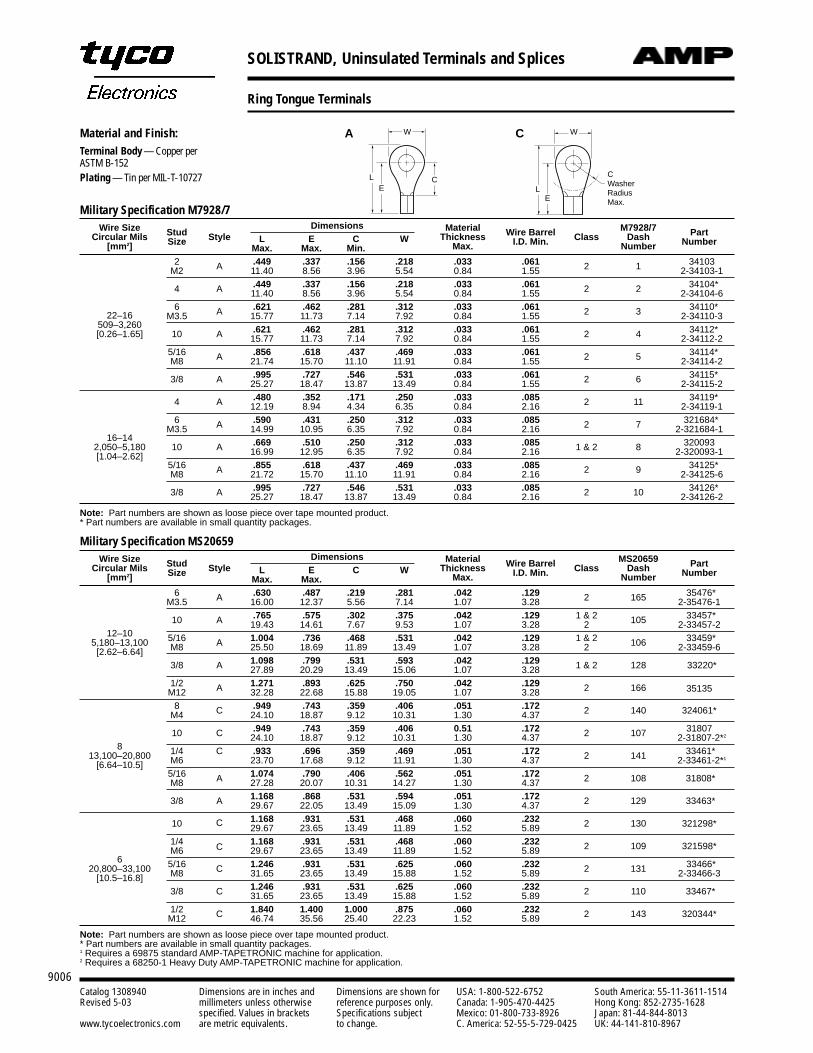
Military Specification M7928/7Wire Size Dimensions Material M7928/7
Circular Mils Stud Style L E C W Thickness Wire Barrel Class Dash Part
[mm2] SizeMax. Max. Min. Max. I.D. Min. Number Number
2 A .449 .337 .156 .218 .033 .061 2 1 34103M2 11.40 8.56 3.96 5.54 0.84 1.55 2-34103-1
4 A .449 .337 .156 .218 .033 .061 2 2 34104*11.40 8.56 3.96 5.54 0.84 1.55 2-34104-6
6 A .621 .462 .281 .312 .033 .061 2 3 34110*22–16 M3.5 15.77 11.73 7.14 7.92 0.84 1.55 2-34110-3
509–3,26010 A .621 .462 .281 .312 .033 .061 2 4 34112*[0.26–1.65] 15.77 11.73 7.14 7.92 0.84 1.55 2-34112-2
5/16 A .856 .618 .437 .469 .033 .061 2 5 34114*M8 21.74 15.70 11.10 11.91 0.84 1.55 2-34114-2
3/8 A .995 .727 .546 .531 .033 .061 2 6 34115*25.27 18.47 13.87 13.49 0.84 1.55 2-34115-2
4 A .480 .352 .171 .250 .033 .085 2 11 34119*12.19 8.94 4.34 6.35 0.84 2.16 2-34119-1
6 A .590 .431 .250 .312 .033 .085 2 7 321684*
16–14M3.5 14.99 10.95 6.35 7.92 0.84 2.16 2-321684-1
2,050–5,180 10 A .669 .510 .250 .312 .033 .085 1 & 2 8 320093
[1.04–2.62] 16.99 12.95 6.35 7.92 0.84 2.16 2-320093-15/16 A .855 .618 .437 .469 .033 .085 2 9 34125*M8 21.72 15.70 11.10 11.91 0.84 2.16 2-34125-6
3/8 A .995 .727 .546 .531 .033 .085 2 10 34126*25.27 18.47 13.87 13.49 0.84 2.16 2-34126-2
Note: Part numbers are shown as loose piece over tape mounted product.* Part numbers are available in small quantity packages.
Ring Tongue Terminals
Material and Finish:Terminal Body — Copper per ASTM B-152Plating — Tin per MIL-T-10727 C
E
L
WA
Military Specification MS20659Wire Size Dimensions Material MS20659
Circular Mils Stud Style L E C W Thickness Wire Barrel Class Dash Part
[mm2] SizeMax. Max. Max. I.D. Min. Number Number
6 A .630 .487 .219 .281 .042 .129 2 165 35476*M3.5 16.00 12.37 5.56 7.14 1.07 3.28 2-35476-1
A .765 .575 .302 .375 .042 .129 1 & 2 105 33457*
12–1010 19.43 14.61 7.67 9.53 1.07 3.28 2 2-33457-2
5,180–13,100 5/16 A 1.004 .736 .468 .531 .042 .129 1 & 2 106 33459*
[2.62–6.64] M8 25.50 18.69 11.89 13.49 1.07 3.28 2 2-33459-6
A 1.098 .799 .531 .593 .042 .129 1 & 2 128 33220*3/8 27.89 20.29 13.49 15.06 1.07 3.281/2 A 1.271 .893 .625 .750 .042 .129 2 166 35135M12 32.28 22.68 15.88 19.05 1.07 3.288 C .949 .743 .359 .406 .051 .172 2 140 324061*M4 24.10 18.87 9.12 10.31 1.30 4.37
10 C .949 .743 .359 .406 0.51 .172 2 107 31807
824.10 18.87 9.12 10.31 1.30 4.37 2-31807-2*2
13,100–20,800 1/4 C .933 .696 .359 .469 .051 .172 2 141 33461*
[6.64–10.5] M6 23.70 17.68 9.12 11.91 1.30 4.37 2-33461-2*1
5/16 A 1.074 .790 .406 .562 .051 .172 2 108 31808*M8 27.28 20.07 10.31 14.27 1.30 4.37
3/8 A 1.168 .868 .531 .594 .051 .172 2 129 33463*29.67 22.05 13.49 15.09 1.30 4.37
10 1.168 .931 .531 .468 .060 .232 2 130 321298*C 29.67 23.65 13.49 11.89 1.52 5.891/4 1.168 .931 .531 .468 .060 .232 2 109 321598*
6M6 C 29.67 23.65 13.49 11.89 1.52 5.89
20,800–33,100 5/16 C 1.246 .931 .531 .625 .060 .232 2 131 33466*
[10.5–16.8] M8 31.65 23.65 13.49 15.88 1.52 5.89 2-33466-3
3/8 C 1.246 .931 .531 .625 .060 .232 2 110 33467*31.65 23.65 13.49 15.88 1.52 5.891/2 C 1.840 1.400 1.000 .875 .060 .232 2 143 320344*M12 46.74 35.56 25.40 22.23 1.52 5.89
Note: Part numbers are shown as loose piece over tape mounted product.* Part numbers are available in small quantity packages.1 Requires a 69875 standard AMP-TAPETRONIC machine for application.2 Requires a 68250-1 Heavy Duty AMP-TAPETRONIC machine for application.
W
CE
L
E
L
WC
LE
W
CWasherRadiusMax.
SOLISTRAND, Uninsulated Terminals and Splices
9007
9Terminals and Splices
Catalog 1308940 Dimensions are in inches and Dimensions are shown for USA: 1-800-522-6752 South America: 55-11-3611-1514Revised 5-03 millimeters unless otherwise reference purposes only. Canada: 1-905-470-4425 Hong Kong: 852-2735-1628
specified. Values in brackets Specifications subject Mexico: 01-800-733-8926 Japan: 81-44-844-8013www.tycoelectronics.com are metric equivalents. to change. C. America: 52-55-5-729-0425 UK: 44-141-810-8967
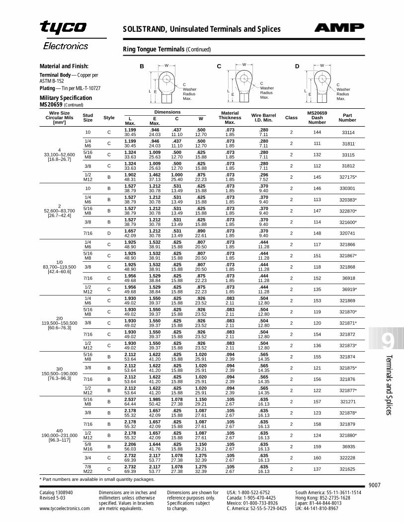
Wire Size Dimensions Material MS20659Circular Mils Stud Style L E C W Thickness Wire Barrel Class Dash Part
[mm2] SizeMax. Max. Max. I.D. Min. Number Number
10 C 1.199 .946 .437 .500 .073 .280 2 144 3311430.45 24.03 11.10 12.70 1.85 7.111/4 C 1.199 .946 .437 .500 .073 .280 2 111 31811†
M6 30.45 24.03 11.10 12.70 1.85 7.114 5/16 C 1.324 1.009 .500 .625 .073 .280 2 132 3311533,100–52,600 M8 33.63 25.63 12.70 15.88 1.85 7.11[16.8–26.7]
C 1.324 1.009 .500 .625 .073 .280 2 112 318123/8 33.63 25.63 12.70 15.88 1.85 7.111/2 B 1.902 1.462 1.000 .875 .073 .296 2 145 327175*M12 48.31 37.13 25.40 22.23 1.85 7.52
10 B 1.527 1.212 .531 .625 .073 .370 2 146 33030138.79 30.78 13.49 15.88 1.85 9.401/4 B 1.527 1.212 .531 .625 .073 .370 2 113 320383*M6 38.79 30.78 13.49 15.88 1.85 9.40
2 5/16 B 1.527 1.212 .531 .625 .073 .370 2 147 322870*52,600–83,700 M8 38.79 30.78 13.49 15.88 1.85 9.40[26.7–42.4]3/8 B 1.527 1.212 .531 .625 .073 .370 2 114 321600*38.79 30.78 13.49 15.88 1.85 9.40
7/16 D 1.657 1.212 .531 .890 .073 .370 2 148 32074142.09 30.78 13.49 22.61 1.85 9.401/4 C 1.925 1.532 .625 .807 .073 .444 2 117 321866M6 48.90 38.91 15.88 20.50 1.85 11.285/16 C 1.925 1.532 .625 .807 .073 .444 2 151 321867*
1/0M8 48.90 38.91 15.88 20.50 1.85 11.28
83,700–119,500 3/8 C 1.925 1.532 .625 .807 .073 .444 2 118 321868[42.4–60.6] 48.90 38.91 15.88 20.50 1.85 11.28
7/16 C 1.956 1.529 .625 .875 .073 .444 2 152 3691849.68 38.84 15.88 22.23 1.85 11.281/2 C 1.956 1.529 .625 .875 .073 .444 2 135 36919*M12 49.68 38.84 15.88 22.23 1.85 11.281/4 C 1.930 1.550 .625 .926 .083 .504 2 153 321869M6 49.02 39.37 15.88 23.52 2.11 12.805/16 C 1.930 1.550 .625 .926 .083 .504 2 119 321870*M8 49.02 39.37 15.88 23.52 2.11 12.80
2/0C 1.930 1.550 .625 .926 .083 .504 2 120 321871*119,500–150,500 3/8 49.02 39.37 15.88 23.52 2.11 12.80[60.6–76.3]
7/16 C 1.930 1.550 .625 .926 .083 .504 2 154 32187249.02 39.37 15.88 23.52 2.11 12.801/2 C 1.930 1.550 .625 .926 .083 .504 2 136 321873*M12 49.02 39.37 15.88 23.52 2.11 12.805/16 B 2.112 1.622 .625 1.020 .094 .565 2 155 321874M8 53.64 41.20 15.88 25.91 2.39 14.35
3/0 B 2.112 1.622 .625 1.020 .094 .565 2 121 321875*150,500–190,000
3/8 53.64 41.20 15.88 25.91 2.39 14.35
[76.3–96.3] 7/16 B 2.112 1.622 .625 1.020 .094 .565 2 156 32187653.64 41.20 15.88 25.91 2.39 14.351/2 B 2.112 1.622 .625 1.020 .094 .565 2 122 321877*M12 53.64 41.20 15.88 25.91 2.39 14.355/16 B 2.537 1.985 1.078 1.150 .105 .635 2 157 321271M8 64.44 50.42 27.38 29.21 2.67 16.13
3/8 B 2.178 1.657 .625 1.087 .105 .635 2 123 321878*55.32 42.09 15.88 27.61 2.67 16.13
7/16 B 2.178 1.657 .625 1.087 .105 .635 2 158 3218794/0
55.32 42.09 15.88 27.61 2.67 16.13
190,000–231,000 1/2 B 2.178 1.657 .625 1.087 .105 .635 2 124 321880*[96.3–117] M12 55.32 42.09 15.88 27.61 2.67 16.13
5/8 B 2.206 1.644 .625 1.150 .105 .635 2 159 36935M16 56.03 41.76 15.88 29.21 2.67 16.13
3/4 C 2.732 2.117 1.078 1.275 .105 .635 2 160 32222869.39 53.77 27.38 32.39 2.67 16.137/8 C 2.732 2.117 1.078 1.275 .105 .635 2 137 321625M22 69.39 53.77 27.38 32.39 2.67 16.13
* Part numbers are available in small quantity packages.
Ring Tongue Terminals (Continued)
Material and Finish:Terminal Body — Copper per ASTM B-152Plating — Tin per MIL-T-10727
CWRM
E
L
W
E
L
WC D
EL
WB W
EL
CWasherRadiusMax.
EL
W
CWasherRadiusMax.
W
EL
CWasherRadiusMax.Military Specification
MS20659 (Continued)
SOLISTRAND, Uninsulated Terminals and Splices
9008Catalog 1308940 Dimensions are in inches and Dimensions are shown for USA: 1-800-522-6752 South America: 55-11-3611-1514Revised 5-03 millimeters unless otherwise reference purposes only. Canada: 1-905-470-4425 Hong Kong: 852-2735-1628
specified. Values in brackets Specifications subject Mexico: 01-800-733-8926 Japan: 81-44-844-8013www.tycoelectronics.com are metric equivalents. to change. C. America: 52-55-5-729-0425 UK: 44-141-810-8967
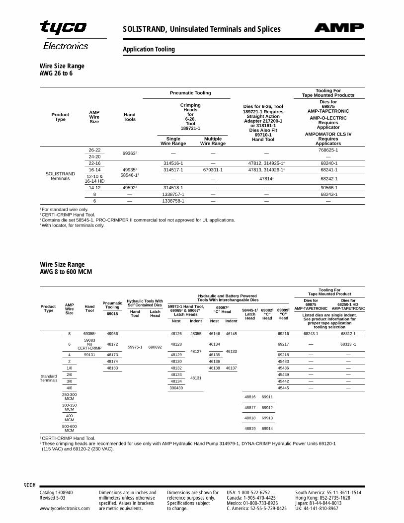
Application Tooling
Wire Size RangeAWG 26 to 6
Pneumatic Tooling Tooling ForTape Mounted Products
Dies for 6-26, ToolDies for
Crimping189721-1 Requires
69875AMP Heads
Straight ActionAMP-TAPETRONIC
Product Wire Hand forAdapter 217200-1
AMP-O-LECTRICType Size Tools 6-26,or 318161-1
RequiresToolDies Also Fit
Applicator189721-169710-1
Hand ToolAMPOMATOR CLS IV
Single Multiple RequiresWire Range Wire Range Applicators
26-22693632 — — —
768625-124-20 —22-16 314516-1 — 47812, 314925-14 *68240-1
SOLISTRAND16-14 499352 314517-1 679301-1 47813, 314926-14 *68241-1
terminals 12-10 & 58546-13
— — 478141 *68242-116-14 HD14-12 495922 314518-1 — — *90566-1
8 — 1338757-1 — — *68243-16 — 1338758-1 — — —
1 For standard wire only.2 CERTI-CRIMP Hand Tool.3 Contains die set 58545-1. PRO-CRIMPER II commercial tool not approved for UL applications.4 With locator, for terminals only.
Wire Size RangeAWG 8 to 600 MCM
Tooling ForTape Mounted Product
HandTool
LatchHead
Product Type
Hydraulic Tools WithSelf Contained Dies
Hydraulic and Battery Powered Tools With Interchangeable Dies
59973-1 Hand Tool,690652 & 690672
Latch Heads
690972
“C” Head
Dies for68250-1 HD
AMP-TAPETRONIC
Listed dies are single indent.See product information for
proper tape applicationtooling selection
68312-1
68313 -1
Dies for69875
AMP-TAPETRONIC
68243-1
—
——————
——————
59975-1 690692
PneumaticTooling
69015
49956
48172
48173
48174
48183
Nest
46146
46134
46135
46136
46138
Indent
46145
46133
46137
Indent
48355
48127
48131
Nest
48126
48128
48129
48130
48132
48133
48134
300430
690992
“C”Head
69216
69217
69218
45433
45436
45439
45442
45445
StandardTerminals
58445-12
LatchHead
48816
48817
48818
48819
690822
“C”Head
69911
69912
69913
69914
AMPWireSize
8
6
4
2
1/0
2/0
3/0
4/0
250-300MCM
300-350MCM
400MCM
500-600MCM
HandTool
693551
59083No
CERTI-CRIMP
59131
1 CERTI-CRIMP Hand Tool.2 These crimping heads are recommended for use only with AMP Hydraulic Hand Pump 314979-1, DYNA-CRIMP Hydraulic Power Units 69120-1 (115 VAC) and 69120-2 (230 VAC).
STRATO-THERM Terminals and Splices for High Temperature Applications
9009
9Terminals and Splices
Catalog 1308940 Dimensions are in inches and Dimensions are shown for USA: 1-800-522-6752 South America: 55-11-3611-1514Revised 5-03 millimeters unless otherwise reference purposes only. Canada: 1-905-470-4425 Hong Kong: 852-2735-1628
specified. Values in brackets Specifications subject Mexico: 01-800-733-8926 Japan: 81-44-844-8013www.tycoelectronics.com are metric equivalents. to change. C. America: 52-55-5-729-0425 UK: 44-141-810-8967
Introduction
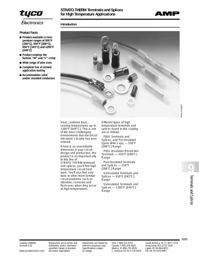
Heat…extreme heat…searing temperatures up to1200°F [649°C]. This is oneof the most challengingenvironments that electrical/electronic circuitry has everentered.
If heat is an unavoidabledimension in your circuitdesign and production, thisproduct is an important ally.In this line of STRATO-THERM terminalsand splices, you’ll find hightemperature circuit hard-ware. You’ll also find solu-tions to other more familiarcircuit problems such asvibration, corrosion andflash-over, when they occurat high temperatures.
Different types of hightemperature terminals andsplices found in this catalogare as follows:
PIDG Terminals andSplices, and Pre-InsulatedSpare Wire Caps — 550°F[288°C] Range
PIDG Insulation RestrictionTerminals — 550°F [288°C]Range
Post-Insulated Terminalsand Splices — 550°F[288°C] Range
Uninsulated Terminals andSplices — 650°F [343°C]Range
Uninsulated Terminals andSplices — 1200°F [649°C]Range
Product Facts Product available in tem-
perature ranges of 500°F[260°C], 550°F [288°C],650°F [343°C] and 1200°F[649°C]
Product employs the famous “W” and “C” crimp
Wide range of wire sizes
Complete line of relatedapplication tooling
Accommodates solid and/or stranded conductors
Pho
to #
1030
97
STRATO-THERM Terminals and Splices for High Temperature Applications
9010Catalog 1308940 Dimensions are in inches and Dimensions are shown for USA: 1-800-522-6752 South America: 55-11-3611-1514Revised 5-03 millimeters unless otherwise reference purposes only. Canada: 1-905-470-4425 Hong Kong: 852-2735-1628
specified. Values in brackets Specifications subject Mexico: 01-800-733-8926 Japan: 81-44-844-8013www.tycoelectronics.com are metric equivalents. to change. C. America: 52-55-5-729-0425 UK: 44-141-810-8967
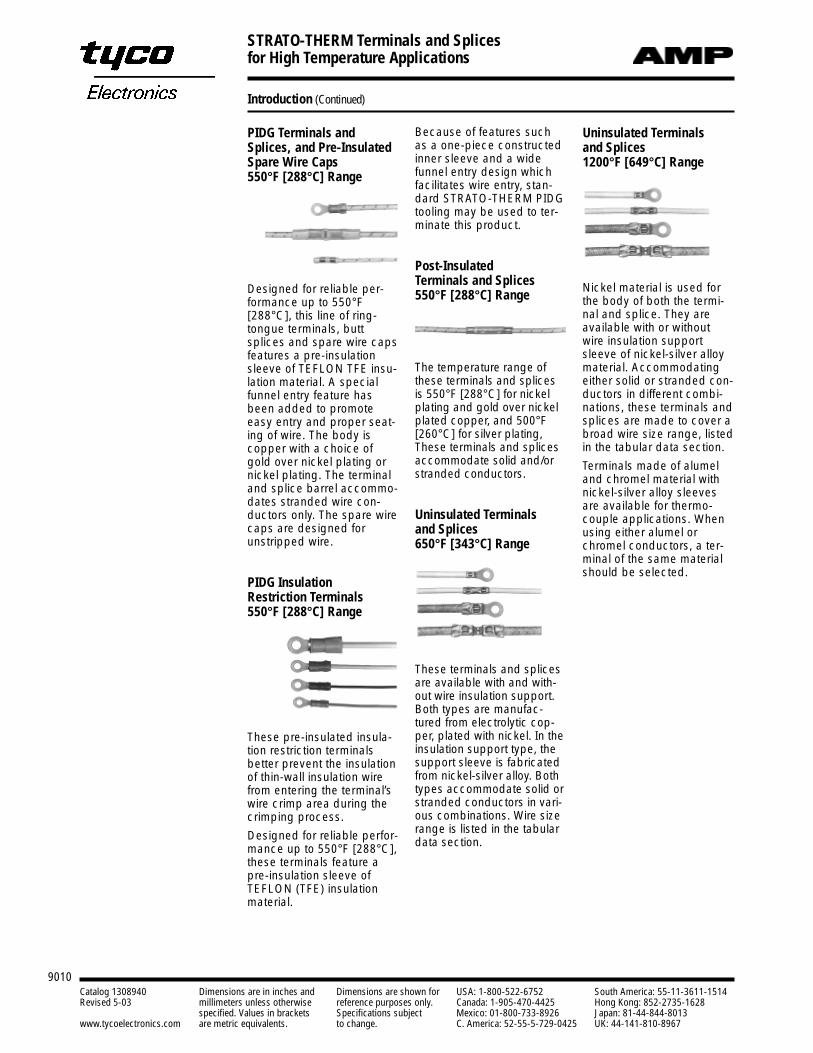
PIDG Terminals andSplices, and Pre-InsulatedSpare Wire Caps 550°F [288°C] Range
Designed for reliable per-formance up to 550°F[288°C], this line of ring-tongue terminals, buttsplices and spare wire capsfeatures a pre-insulationsleeve of TEFLON TFE insu-lation material. A specialfunnel entry feature hasbeen added to promoteeasy entry and proper seat-ing of wire. The body iscopper with a choice ofgold over nickel plating ornickel plating. The terminaland splice barrel accommo-dates stranded wire con-ductors only. The spare wirecaps are designed forunstripped wire.
PIDG Insulation Restriction Terminals550°F [288°C] Range
These pre-insulated insula-tion restriction terminals better prevent the insulationof thin-wall insulation wirefrom entering the terminal’swire crimp area during thecrimping process.
Designed for reliable perfor-mance up to 550°F [288°C],these terminals feature apre-insulation sleeve ofTEFLON (TFE) insulationmaterial.
Uninsulated Terminals and Splices 1200°F [649°C] Range
Nickel material is used forthe body of both the termi-nal and splice. They areavailable with or withoutwire insulation supportsleeve of nickel-silver alloymaterial. Accommodatingeither solid or stranded con-ductors in different combi-nations, these terminals andsplices are made to cover abroad wire size range, listedin the tabular data section.
Terminals made of alumeland chromel material withnickel-silver alloy sleevesare available for thermo-couple applications. Whenusing either alumel orchromel conductors, a ter-minal of the same materialshould be selected.
Because of features suchas a one-piece constructedinner sleeve and a wide funnel entry design whichfacilitates wire entry, stan-dard STRATO-THERM PIDGtooling may be used to ter-minate this product.
Post-InsulatedTerminals and Splices550°F [288°C] Range
The temperature range ofthese terminals and splicesis 550°F [288°C] for nickelplating and gold over nickelplated copper, and 500°F[260°C] for silver plating,These terminals and splicesaccommodate solid and/orstranded conductors.
Uninsulated Terminals and Splices 650°F [343°C] Range
These terminals and splicesare available with and with-out wire insulation support.Both types are manufac-tured from electrolytic cop-per, plated with nickel. In theinsulation support type, thesupport sleeve is fabricatedfrom nickel-silver alloy. Bothtypes accommodate solid orstranded conductors in vari-ous combinations. Wire sizerange is listed in the tabulardata section.
Introduction (Continued)
STRATO-THERM Terminals and Splices for High Temperature Applications
9011
9Terminals and Splices
Catalog 1308940 Dimensions are in inches and Dimensions are shown for USA: 1-800-522-6752 South America: 55-11-3611-1514Revised 5-03 millimeters unless otherwise reference purposes only. Canada: 1-905-470-4425 Hong Kong: 852-2735-1628
specified. Values in brackets Specifications subject Mexico: 01-800-733-8926 Japan: 81-44-844-8013www.tycoelectronics.com are metric equivalents. to change. C. America: 52-55-5-729-0425 UK: 44-141-810-8967
Introduction (Continued)
Ordering Information All terminals and splices arelisted according to wire sizeand type of terminal orsplice. If the part number ofthe terminal or splice isknown, refer to theNumerical Index, at theback of this catalog, forpage location of tabulardata.
In the Tabular Data Section,part numbers are availablein either loose piece or tapemounted form.
When ordering tapemounted part numbers,specify the terminal orsplice part number, the totalquantity of parts desired (ifapplicable). The chart to theright lists by wire size thetype of packaging availableand the quantity perpackage.
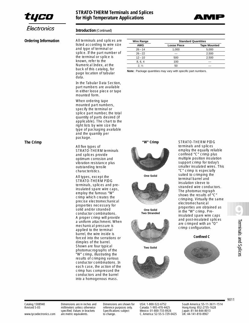
All five types of STRATO-THERM terminalsand splices provideoptimum corrosion andvibration resistance plusoutstanding tensilecharacteristics.
All types, except the STRATO-THERM PIDGterminals, splices and pre-insulated spare wire caps,employ the famous “W”crimp which creates theprecise electromechanicalproperties necessary forsolid and/or strandedconductor combinations. A proper crimp will providea uniform attachment. Whenmechanical pressure isapplied to the terminalbarrel, the wire inside isforced into the serrations ordimples of the barrel.Shown are four typicalphotomacrographs of the“W” crimp, illustrating theresults of crimping variousconductor combinations. Ineach case, the action of thecrimp has compressed theconductors and the barrelinto a homogenous mass.
The Crimp STRATO-THERM PIDG terminals and splicesemploy the equally reliableconfined “C” crimp plusmultiple position insulationsupport crimp for today’ssmaller insulated wires. This“C” crimp is especiallysuited to crimping theterminal barrel andinsulation sleeve tostranded wire conductors.The photomacrographshows the results of “C”crimping. Virtually the sameelectromechanicalproperties are obtained asin the “W” crimp. Pre-insulated spare wire capsand post-insulated splicesare crimped with an “O”crimp configuration.
Wire Range Standard QuantitiesAWG Loose Piece Tape Mounted
26 – 14 1,000 5,00026 – 22 — 2,50012 – 10 500 2,5008, 6, 4 100 —2, 1⁄0 50 —
Note: Package quantities may vary with specific part numbers.
Confined C
Two Solid
One SolidTwo Stranded
One Solid
“W” Crimp
STRATO-THERM Terminals and Splices for High Temperature Applications
9012Catalog 1308940 Dimensions are in inches and Dimensions are shown for USA: 1-800-522-6752 South America: 55-11-3611-1514Revised 5-03 millimeters unless otherwise reference purposes only. Canada: 1-905-470-4425 Hong Kong: 852-2735-1628
specified. Values in brackets Specifications subject Mexico: 01-800-733-8926 Japan: 81-44-844-8013www.tycoelectronics.com are metric equivalents. to change. C. America: 52-55-5-729-0425 UK: 44-141-810-8967
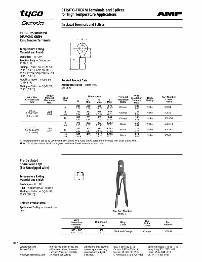
Tongue Dimensions Wire Part NumberWire Size Material Stud Terminal Insulation BodyCircular Mils Thickness Size W C E L Insulation Diameter Plating1 Loose
[mm2] Max. Min. Max. Max. Color Max. Piece
.218 .156 .560 .672 .1354 5.54 3.96 14.22 17.07 Orange 3.43 Nickel 50834
18-16 .033 8 .312 .281 .685 .844 .1351,600-2,800 0.84 M4 7.92 7.14 17.40 21.44 Orange 3.43 Nickel 50836[0.81-1.42] .312 .281 .685 .844 .13510
7.92 7.14 17.40 21.44 Orange 3.43 Nickel 50836-1
8 .375 .302 .893 1.083 .214M4 9.53 7.67 22.68 27.51 Black 5.44 Nickel 50845-1
12-10 .042 .375 .302 .893 1.083 .2145,180-13,100 1.07 10 9.53 7.67 22.68 27.51 Black 5.44 Nickel 50845-2[2.62-6.64]
1/4 .531 .437 1.012 1.280 .214M6 13.49 11.10 25.70 32.51 Black 5.44 Nickel 50846
1 Nickel plated parts are to be used with nickel plated wire. Gold plated parts are to be used with silver plated wire.Note: “C” dimension applies from edge of metal wire barrel to center of stud hole.
C
W
E
L
PIDG (Pre-InsulatedDIAMOND GRIP)Ring Tongue Terminals
Temperature Rating, Material and FinishInsulation — TEFLONTerminal Body — Copper per ASTM B152Plating — Nickel per QQ-N-290,550°F [288°C]. Gold per MIL-G-45204 over Nickel per QQ-N-290500°F [260°C]Metallic Sleeve — Copper perASTM B152Plating — Nickel per QQ-N-290,550°F [288°C]
Wire ToolInsulation Dimension Ring Color PartDiameter Color Guide Number
Range L Max.
.075 – .087 .5001.91 – 2.21 12.70 Black and Orange Orange 328859
L
Pre-InsulatedSpare Wire Caps(For Unstripped Wire)
Temperature Rating, Material and FinishInsulation — TEFLONRing — Copper per ASTM B152Plating — Nickel per QQ-N-290,550°F [288°C]
Related Product DataApplication Tooling — shown to theright Tool Part Number
69272-1
Related Product DataApplication Tooling — pages 9022and 9023
Insulated Terminals and Splices
STRATO-THERM Terminals and Splices for High Temperature Applications
9013
9Terminals and Splices
Catalog 1308940 Dimensions are in inches and Dimensions are shown for USA: 1-800-522-6752 South America: 55-11-3611-1514Revised 5-03 millimeters unless otherwise reference purposes only. Canada: 1-905-470-4425 Hong Kong: 852-2735-1628
specified. Values in brackets Specifications subject Mexico: 01-800-733-8926 Japan: 81-44-844-8013www.tycoelectronics.com are metric equivalents. to change. C. America: 52-55-5-729-0425 UK: 44-141-810-8967
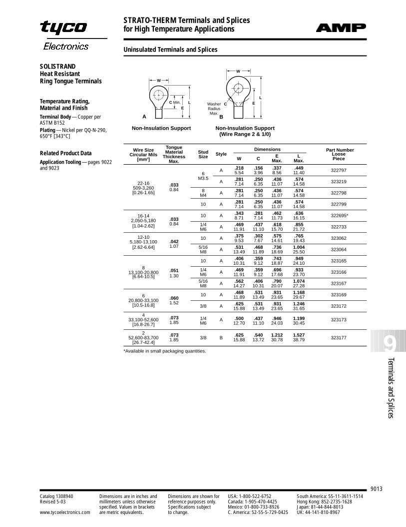
Uninsulated Terminals and Splices
SOLISTRANDHeat ResistantRing Tongue Terminals
Temperature Rating, Material and FinishTerminal Body — Copper per ASTM B152Plating — Nickel per QQ-N-290,650°F [343°C]
Related Product DataApplication Tooling — pages 9022and 9023
Non-Insulation Support Non-Insulation Support(Wire Range 2 & 1/0)
EL
W
C C Min.E
L
W
B
WasherRadiusMax.
A
Tongue Dimensions Part NumberWire Size Material Stud StyleCircular Mils Thickness Size W C E L Loose[mm2] Max. Max. Max. Piece
.218 .156 .337 .4496
A 5.54 3.96 8.56 11.40 322797
M3.5 .281 .250 .436 .57422-16 .033
A 7.14 6.35 11.07 14.58 323219509-3,260 0.84 8 .281 .250 .436 .574[0.26-1.65] M4 A 7.14 6.35 11.07 14.58 322798
.281 .250 .436 .57410 A 7.14 6.35 11.07 14.58 322799
16-14 .343 .281 .462 .636
2,050-5,180 .03310 A 8.71 7.14 11.73 16.15 322695*
[1.04-2.62] 0.84 1/4 .469 .437 .618 .855M6 A 11.91 11.10 15.70 21.72 322733
12-10 .375 .302 .575 .7655,180-13,100 .042
10 A 9.53 7.67 14.61 19.43 323062
[2.62-6.64] 1.07 5/16 .531 .468 .736 1.004M8 A 13.49 11.89 18.69 25.50 323064
.406 .359 .743 .94910 A 10.31 9.12 18.87 24.10 323165
8 .051 1/4 .469 .359 .696 .93313,100-20,8001.30 M6 A 11.91 9.12 17.68 23.70 323166
[6.64-10.5]5/16 .562 .406 .790 1.074M8 A 14.27 10.31 20.07 27.28 323167
.468 .531 .931 1.1686 .060
10 A 11.89 13.49 23.65 29.67 32316920,800-33,100 1.52 .625 .531 .931 1.246[10.5-16.8] 3/8 A 15.88 13.49 23.65 31.65 323172
4 .073 1/4 .500 .437 .946 1.19933,100-52,600 1.85 M6A
12.70 11.10 24.03 30.45323173
[16.8-26.7]
2 .073 .625 .540 1.212 1.52752,600-83,700 1.85 3/8 B 15.88 13.72 30.78 38.79 323177[26.7-42.4]
*Available in small packaging quantities.
STRATO-THERM Terminals and Splices for High Temperature Applications
9014Catalog 1308940 Dimensions are in inches and Dimensions are shown for USA: 1-800-522-6752 South America: 55-11-3611-1514Revised 5-03 millimeters unless otherwise reference purposes only. Canada: 1-905-470-4425 Hong Kong: 852-2735-1628
specified. Values in brackets Specifications subject Mexico: 01-800-733-8926 Japan: 81-44-844-8013www.tycoelectronics.com are metric equivalents. to change. C. America: 52-55-5-729-0425 UK: 44-141-810-8967
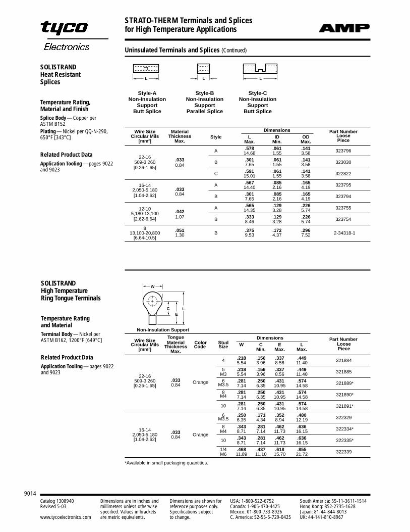
SOLISTRANDHeat ResistantSplices
Temperature Rating, Material and FinishSplice Body — Copper per ASTM B152Plating — Nickel per QQ-N-290,650°F [343°C]
Related Product DataApplication Tooling — pages 9022and 9023
L L L
Style-ANon-Insulation
SupportButt Splice
Style-BNon-Insulation
SupportParallel Splice
Style-CNon-Insulation
SupportButt Splice
Wire Size Material Dimensions Part NumberCircular Mils Thickness Style L ID OD Loose
[mm2] Max. Max. Min. Max. Piece
.578 .061 .141A 14.68 1.55 3.58 32379622-16 .033 .301 .061 .141509-3,260
0.84B 7.65 1.55 3.58 323030
[0.26-1.65].591 .061 .141C 15.01 1.55 3.58 322822
.567 .085 .16516-14.033
A 14.40 2.16 4.19 3237952,050-5,180
0.84 .301 .085 .165[1.04-2.62] B 7.65 2.16 4.19 323794
.565 .129 .22612-10 .042
A 14.35 3.28 5.74 3237555,180-13,100
1.07 .333 .129 .226[2.62-6.64] B 8.46 3.28 5.74 323754
8 .051 .375 .172 .29613,100-20,800 1.30 B 9.53 4.37 7.52 2-34318-1[6.64-10.5]
CE
L
WSOLISTRANDHigh TemperatureRing Tongue Terminals
Temperature Rating and MaterialTerminal Body — Nickel per ASTM B162, 1200°F [649°C]
Related Product DataApplication Tooling — pages 9022and 9023
Tongue Dimensions Part NumberWire Size Material Color StudCircular Mils Thickness Code Size W C E L Loose[mm2] Max. Min. Max. Max. Piece
.218 .156 .337 .4494 5.54 3.96 8.56 11.40 321884
5 .218 .156 .337 .44922-16 M3 5.54 3.96 8.56 11.40 321885
509-3,260 .033 6 .281 .250 .431 .574[0.26-1.65] 0.84 Orange M3.5 7.14 6.35 10.95 14.58 321889*
8 .281 .250 .431 .574M4 7.14 6.35 10.95 14.58 321890*
.281 .250 .431 .57410 7.14 6.35 10.95 14.58 321891*
6 .250 .171 .352 .480M3.5 6.35 4.34 8.94 12.19 322329
8 .343 .281 .462 .63616-14 .033 M4 8.71 7.14 11.73 16.15 322334*
2,050-5,180 0.84 Orange.343 .281 .462 .636[1.04-2.62] 10 8.71 7.14 11.73 16.15 322335*
1/4 .468 .437 .618 .855M6 11.89 11.10 15.70 21.72 322339
*Available in small packaging quantities.
Non-Insulation Support
Uninsulated Terminals and Splices (Continued)
STRATO-THERM Terminals and Splices for High Temperature Applications
9015
9Terminals and Splices
Catalog 1308940 Dimensions are in inches and Dimensions are shown for USA: 1-800-522-6752 South America: 55-11-3611-1514Revised 5-03 millimeters unless otherwise reference purposes only. Canada: 1-905-470-4425 Hong Kong: 852-2735-1628
specified. Values in brackets Specifications subject Mexico: 01-800-733-8926 Japan: 81-44-844-8013www.tycoelectronics.com are metric equivalents. to change. C. America: 52-55-5-729-0425 UK: 44-141-810-8967
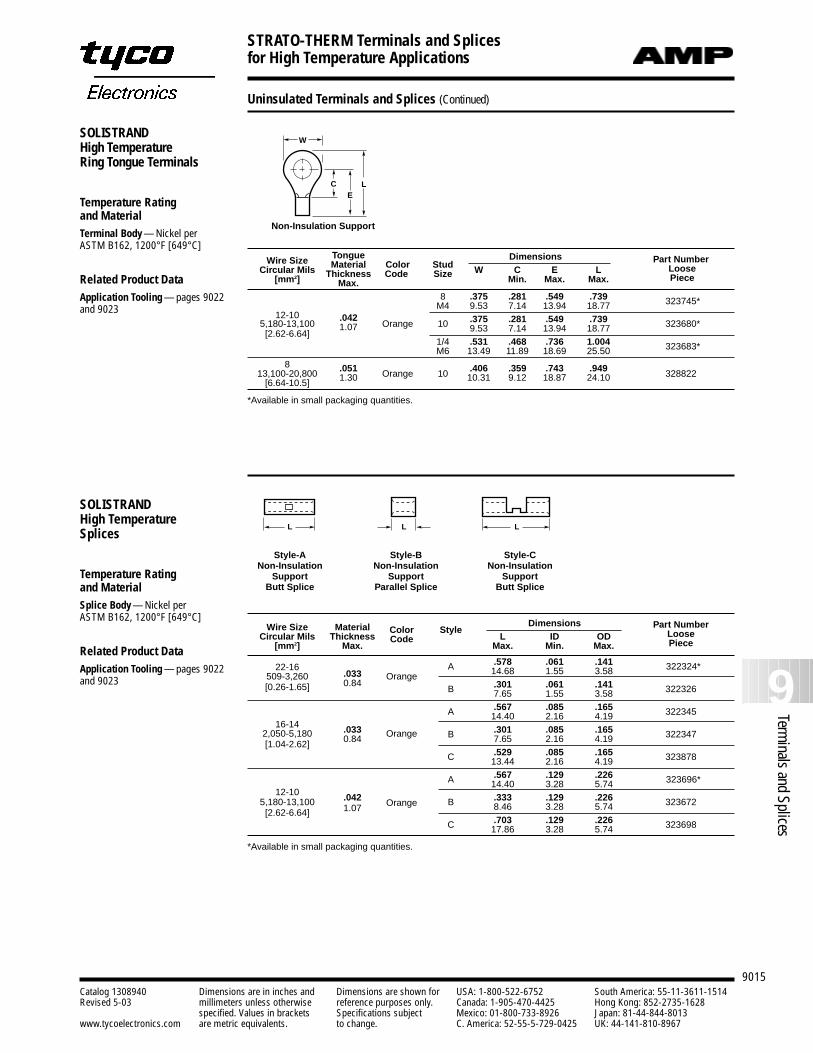
Uninsulated Terminals and Splices (Continued)
CE
L
WSOLISTRANDHigh TemperatureRing Tongue Terminals
Temperature Rating and MaterialTerminal Body — Nickel per ASTM B162, 1200°F [649°C]
Related Product DataApplication Tooling — pages 9022and 9023
Tongue Dimensions Part NumberWire Size Material Color StudCircular Mils Thickness Code Size W C E L Loose[mm2] Max. Min. Max. Max. Piece
8 .375 .281 .549 .739M4 9.53 7.14 13.94 18.77 323745*
12-10 .042 .375 .281 .549 .7395,180-13,100 1.07 Orange 10 9.53 7.14 13.94 18.77 323680*[2.62-6.64]
1/4 .531 .468 .736 1.004M6 13.49 11.89 18.69 25.50 323683*
8 .051 .406 .359 .743 .94913,100-20,800 1.30 Orange 10 10.31 9.12 18.87 24.10 328822[6.64-10.5]
*Available in small packaging quantities.
Non-Insulation Support
SOLISTRANDHigh TemperatureSplices
Temperature Rating and MaterialSplice Body — Nickel per ASTM B162, 1200°F [649°C]
Related Product DataApplication Tooling — pages 9022and 9023
L L L
Style-ANon-Insulation
SupportButt Splice
Style-BNon-Insulation
SupportParallel Splice
Style-CNon-Insulation
SupportButt Splice
Dimensions Part NumberWire Size Material Color StyleCircular Mils Thickness Code L ID OD Loose
[mm2] Max. Max. Min. Max. Piece
.578 .061 .14122-16.033
A 14.68 1.55 3.58 322324*509-3,260
0.84Orange
.301 .061 .141[0.26-1.65] B 7.65 1.55 3.58 322326
.567 .085 .165
16-14A 14.40 2.16 4.19 322345
2,050-5,180 .033 .301 .085 .165
[1.04-2.62] 0.84 Orange B 7.65 2.16 4.19 322347
.529 .085 .165C 13.44 2.16 4.19 323878
.567 .129 .226A 14.40 3.28 5.74 323696*12-10 .042 .333 .129 .2265,180-13,100
1.07 Orange B 8.46 3.28 5.74 323672[2.62-6.64]
.703 .129 .226C 17.86 3.28 5.74 323698
*Available in small packaging quantities.
STRATO-THERM Terminals and Splices for High Temperature Applications
9016Catalog 1308940 Dimensions are in inches and Dimensions are shown for USA: 1-800-522-6752 South America: 55-11-3611-1514Revised 5-03 millimeters unless otherwise reference purposes only. Canada: 1-905-470-4425 Hong Kong: 852-2735-1628
specified. Values in brackets Specifications subject Mexico: 01-800-733-8926 Japan: 81-44-844-8013www.tycoelectronics.com are metric equivalents. to change. C. America: 52-55-5-729-0425 UK: 44-141-810-8967
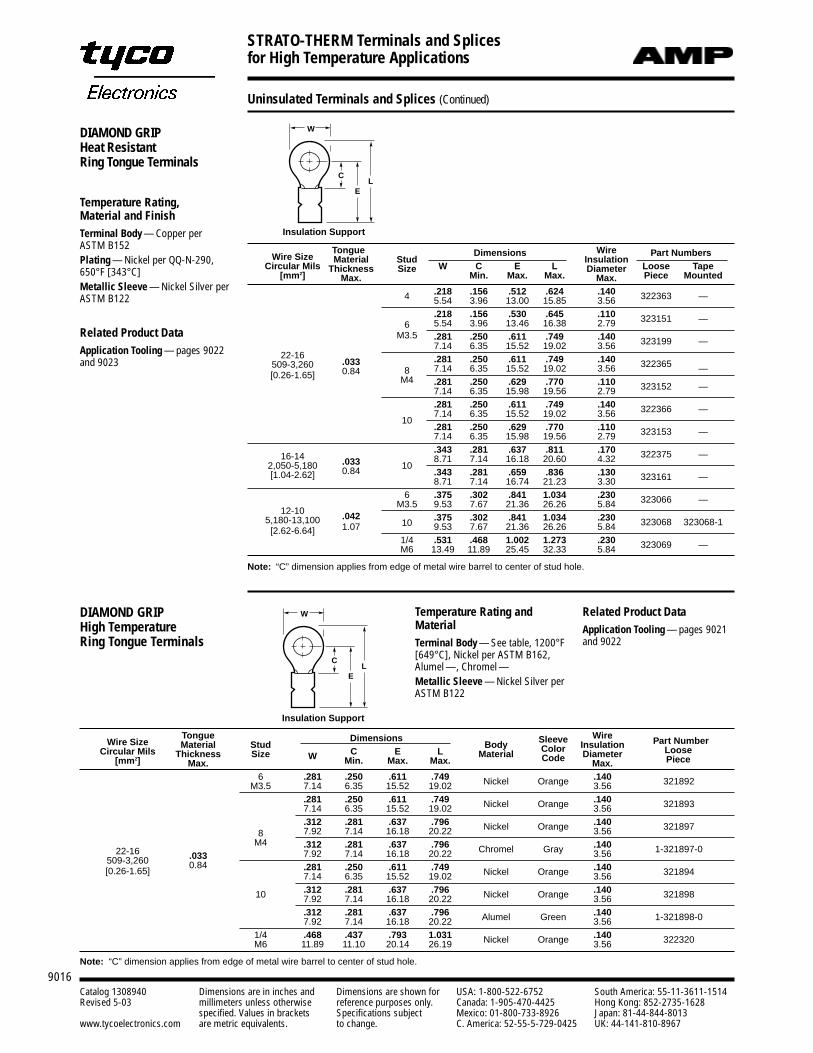
Tongue Dimensions Wire Part NumbersWire Size Material Stud InsulationCircular Mils Thickness Size W C E L Diameter Loose Tape
[mm2] Max. Min. Max. Max. Max. Piece Mounted
.218 .156 .512 .624 .1404 5.54 3.96 13.00 15.85 3.56 322363 —
.218 .156 .530 .645 .1106 5.54 3.96 13.46 16.38 2.79 323151 —
M3.5 .281 .250 .611 .749 .1407.14 6.35 15.52 19.02 3.56 323199 —
22-16 .281 .250 .611 .749 .140509-3,260 .0338 7.14 6.35 15.52 19.02 3.56 322365 —
[0.26-1.65] 0.84M4 .281 .250 .629 .770 .110
7.14 6.35 15.98 19.56 2.79 323152 —
.281 .250 .611 .749 .140
107.14 6.35 15.52 19.02 3.56 322366 —
.281 .250 .629 .770 .1107.14 6.35 15.98 19.56 2.79 323153 —
16-14.343 .281 .637 .811 .170
2,050-5,180 .033 108.71 7.14 16.18 20.60 4.32 322375 —
[1.04-2.62] 0.84 .343 .281 .659 .836 .1308.71 7.14 16.74 21.23 3.30 323161 —
6 .375 .302 .841 1.034 .230
12-10M3.5 9.53 7.67 21.36 26.26 5.84 323066 —
5,180-13,100 .042 .375 .302 .841 1.034 .230[2.62-6.64] 1.07 10 9.53 7.67 21.36 26.26 5.84 323068 323068-1
1/4 .531 .468 1.002 1.273 .230M6 13.49 11.89 25.45 32.33 5.84 323069 —
Note: “C” dimension applies from edge of metal wire barrel to center of stud hole.
Insulation Support
EL
W
C
DIAMOND GRIPHeat ResistantRing Tongue Terminals
Temperature Rating, Material and FinishTerminal Body — Copper per ASTM B152Plating — Nickel per QQ-N-290,650°F [343°C]Metallic Sleeve — Nickel Silver perASTM B122
Related Product DataApplication Tooling — pages 9022and 9023
Tongue Dimensions Wire Part NumberWire Size Material Stud Body Sleeve InsulationCircular Mils Thickness Size W C E L Material Color Diameter Loose
[mm2] Max. Min. Max. Max. Code Max. Piece
6 .281 .250 .611 .749 .140M3.5 7.14 6.35 15.52 19.02 Nickel Orange 3.56 321892
.281 .250 .611 .749 .1407.14 6.35 15.52 19.02 Nickel Orange 3.56 321893
.312 .281 .637 .796 .1408 7.92 7.14 16.18 20.22 Nickel Orange 3.56 321897
22-16M4 .312 .281 .637 .796 .140
509-3,260 .033 7.92 7.14 16.18 20.22 Chromel Gray 3.56 1-321897-0
0.84 .281 .250 .611 .749 .140[0.26-1.65] 7.14 6.35 15.52 19.02 Nickel Orange 3.56 321894
.312 .281 .637 .796 .14010 7.92 7.14 16.18 20.22 Nickel Orange 3.56 321898
.312 .281 .637 .796 .1407.92 7.14 16.18 20.22 Alumel Green 3.56 1-321898-0
1/4 .468 .437 .793 1.031 .140M6 11.89 11.10 20.14 26.19 Nickel Orange 3.56 322320
Note: “C” dimension applies from edge of metal wire barrel to center of stud hole.
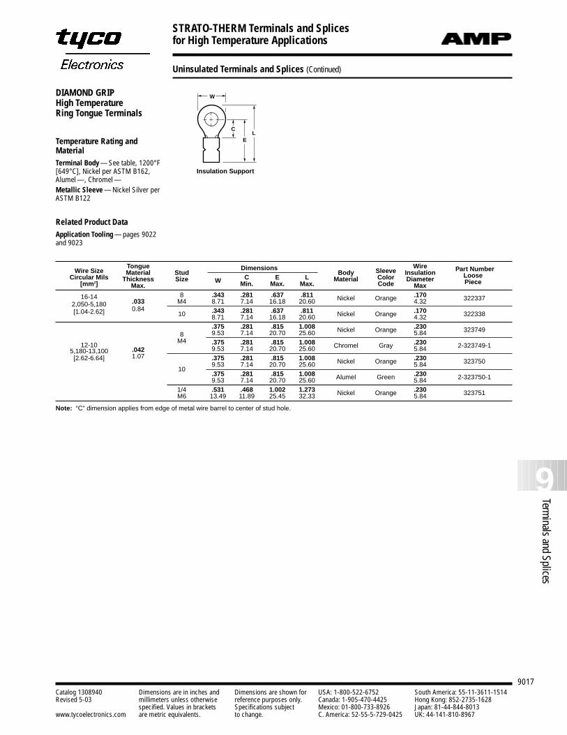
Temperature Rating andMaterialTerminal Body — See table, 1200°F[649°C], Nickel per ASTM B162,Alumel —, Chromel —Metallic Sleeve — Nickel Silver perASTM B122
Insulation Support
EL
W
C
DIAMOND GRIPHigh TemperatureRing Tongue Terminals
Related Product DataApplication Tooling — pages 9021and 9022
Uninsulated Terminals and Splices (Continued)
STRATO-THERM Terminals and Splices for High Temperature Applications
9017
9Terminals and Splices
Catalog 1308940 Dimensions are in inches and Dimensions are shown for USA: 1-800-522-6752 South America: 55-11-3611-1514Revised 5-03 millimeters unless otherwise reference purposes only. Canada: 1-905-470-4425 Hong Kong: 852-2735-1628
specified. Values in brackets Specifications subject Mexico: 01-800-733-8926 Japan: 81-44-844-8013www.tycoelectronics.com are metric equivalents. to change. C. America: 52-55-5-729-0425 UK: 44-141-810-8967
Uninsulated Terminals and Splices (Continued)
Insulation Support
EL
W
C
DIAMOND GRIPHigh TemperatureRing Tongue Terminals
Temperature Rating andMaterialTerminal Body — See table, 1200°F[649°C], Nickel per ASTM B162,Alumel —, Chromel —Metallic Sleeve — Nickel Silver perASTM B122
Related Product DataApplication Tooling — pages 9022and 9023
Tongue Dimensions Wire Part NumberWire Size Material Stud Body Sleeve InsulationCircular Mils Thickness Size W C E L Material Color Diameter Loose
[mm2] Max. Min. Max. Max. Code Max Piece
16-14 8 .343 .281 .637 .811 .1702,050-5,180 .033 M4 8.71 7.14 16.18 20.60 Nickel Orange 4.32 322337
0.84 .343 .281 .637 .811 .170[1.04-2.62] 10 8.71 7.14 16.18 20.60 Nickel Orange 4.32 322338
.375 .281 .815 1.008 .2308 9.53 7.14 20.70 25.60 Nickel Orange 5.84 323749
12-10M4 .375 .281 .815 1.008 .230
5,180-13,100 .042 9.53 7.14 20.70 25.60 Chromel Gray 5.84 2-323749-1
[2.62-6.64] 1.07 .375 .281 .815 1.008 .230
109.53 7.14 20.70 25.60 Nickel Orange 5.84 323750
.375 .281 .815 1.008 .2309.53 7.14 20.70 25.60 Alumel Green 5.84 2-323750-1
1/4 .531 .468 1.002 1.273 .230M6 13.49 11.89 25.45 32.33 Nickel Orange 5.84 323751
Note: “C” dimension applies from edge of metal wire barrel to center of stud hole.
STRATO-THERM Terminals and Splices for High Temperature Applications
9018Catalog 1308940 Dimensions are in inches and Dimensions are shown for USA: 1-800-522-6752 South America: 55-11-3611-1514Revised 5-03 millimeters unless otherwise reference purposes only. Canada: 1-905-470-4425 Hong Kong: 852-2735-1628
specified. Values in brackets Specifications subject Mexico: 01-800-733-8926 Japan: 81-44-844-8013www.tycoelectronics.com are metric equivalents. to change. C. America: 52-55-5-729-0425 UK: 44-141-810-8967
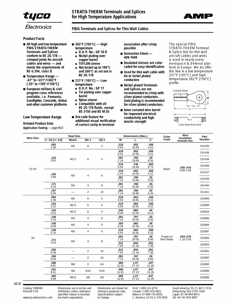
PIDG Terminals and Splices for Thin Wall Cables
Product Facts All high and low temperature
PIDG STRATO-THERMTerminals and Splicesconform to BS 2G 178 —crimped joints for aircraftcables and wires — andmeets the requirements ofBS G 204, class II
Temperature Range — -67° to +221°/+302°F[-55° to +105°/+150°C]
European military & civilprogram cross referencesavailable, i.e. Pannavia,Eurofighter, Concorde, Airbusand other customer platforms
302°F [150°C] — Hightemperature D.D.P. No.: GP 10 D Nickel plating over
copper barrel TEFLON sleeve Not tested up to 190°C
and 260°C as set out inBS 2G 178
221°F [105°C] — Lowtemperature D.D.P. No.: GP 17 Tin plating over copper
barrel Nylon sleeve Compatible with all
BS 2G 178 fluids, exceptBS 3150 and BS M 26
Dot code feature foradditional visual verificationof correct cavity to terminal
association after crimppossible
Instruction Sheet — 408-1049
Insulated sleeves are colorcoded for easy identification
Used for thin wall cable withtin or nickel platedconductors
Nickel plated Terminals and Splices are notrecommended to crimp withsilver plated conductors.Gold plating is recommendedfor silver plated conductors.
Inner serrated wire barrelfor improved electricalconductivity and hightensile strength
Color Band Each End
L
L
C
Colored Stripe
W
Low Temperature Range
Related Product DataApplication Tooling — page 9023
The special PIDGSTRATO-THERM Terminal & Splice line for thin wall aircraft cables and wires is used in nearly everyAerospace & Defense plat-form in Europe. We do offerthis line in a low temperature221°F [105°C] and hightemperature 302°F [150°C]profile.
Stud Size Dimensions (Max.) Color Wire PartWire Size Code Insulation Number+/- .03 [+/- 0.8] Metric BA # UN # W L C Outside Dia..093 M2 8 2 .218 .652 .166 1514352.36 5.54 16.56 4.22
.218 .652 .166 1514365.54 16.56 4.22.119 M2.5 6 4 .281 .780 .25 1514383.02 7.14 19.80 6.35
.218 .746 .265 15145822-24
5.54 18.94 6.73Black .035-.075
.218 .652 .166 0.90-1.90151437
.145 M3 4 65.54 16.56 4.22
3.68 .281 .780 .25 1514397.14 19.80 6.35.171 M4 3 8 .281 .780 .25 1514404.34 7.14 19.80 6.35.197 — 2 10 .281 .780 .25 1514415.00 7.14 19.80 6.35.093 M2 8 2 .218 .662 .166 1528992.36 5.54 16.81 4.22.122 M2.5 6 4 .218 .662 .166 1528983.10 5.54 16.81 4.22.119 M2.5 6 4 .240 .882 .36 1549243.02 6.09 22.40 9.14.148 M3 4 6 .281 .787 .25 1528953.76 7.14 20.00 6.35.145 M3 4 6 .250 .882 .36 1528963.68 6.35 22.40 9.14.148 M3 4 6 .218 .662 .166 1528973.76 5.54 16.81 4.22
20 .281 .787 .26 Purple w/ .043-.079 152894.171 M4 3 8
7.14 20.00 6.60 Red Stripe 1.10-2.004.34 .312 .834 .291 1528937.92 21.18 7.39.200 — 2 10 .312 .834 .291 1528915.08 7.92 21.18 7.39.199 — 2 10 .281 .787 .26 1528925.06 7.14 20.00 6.60.268 M6 0 1/4 .469 1.07 .447 1528906.81 11.91 27.13 11.35.331 M8 5/15 5/16 .469 1.07 .447 1528898.41 11.91 27.13 11.35.393 M9.5 3/8 3/8 .469 1.07 .447 1528889.98 11.91 27.13 11.35
STRATO-THERM Terminals and Splices for High Temperature Applications
9019
9Terminals and Splices
Catalog 1308940 Dimensions are in inches and Dimensions are shown for USA: 1-800-522-6752 South America: 55-11-3611-1514Revised 5-03 millimeters unless otherwise reference purposes only. Canada: 1-905-470-4425 Hong Kong: 852-2735-1628
specified. Values in brackets Specifications subject Mexico: 01-800-733-8926 Japan: 81-44-844-8013www.tycoelectronics.com are metric equivalents. to change. C. America: 52-55-5-729-0425 UK: 44-141-810-8967
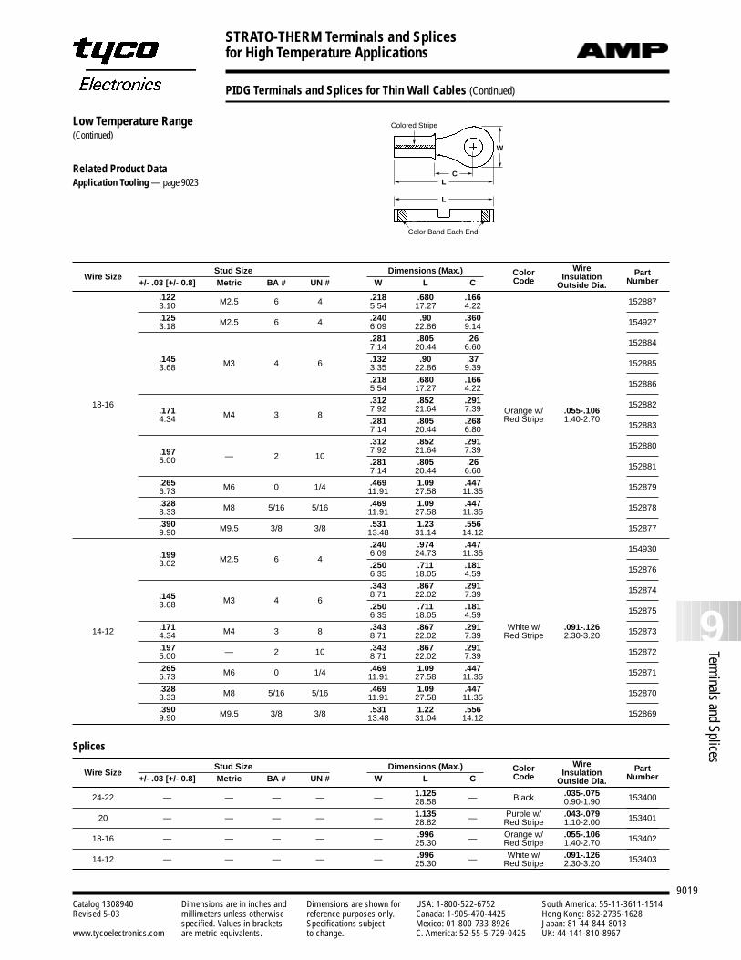
PIDG Terminals and Splices for Thin Wall Cables (Continued)
Stud Size Dimensions (Max.) Color Wire PartWire Size Code Insulation Number+/- .03 [+/- 0.8] Metric BA # UN # W L C Outside Dia..122 M2.5 6 4 .218 .680 .166 1528873.10 5.54 17.27 4.22.125 M2.5 6 4 .240 .90 .360 1549273.18 6.09 22.86 9.14
.281 .805 .26 1528847.14 20.44 6.60.145 M3 4 6 .132 .90 .37 1528853.68 3.35 22.86 9.39
.218 .680 .166 1528865.54 17.27 4.22
.312 .852 .291 15288218-16.171 M4 3 8
7.92 21.64 7.39 Orange w/ .055-.1064.34 .281 .805 .268 Red Stripe 1.40-2.70
1528837.14 20.44 6.80.312 .852 .291 152880
.197 — 2 107.92 21.64 7.39
5.00 .281 .805 .26 1528817.14 20.44 6.60.265 M6 0 1/4 .469 1.09 .447 1528796.73 11.91 27.58 11.35.328 M8 5/16 5/16 .469 1.09 .447 1528788.33 11.91 27.58 11.35.390 M9.5 3/8 3/8 .531 1.23 .556 1528779.90 13.48 31.14 14.12
.240 .974 .447 154930.199 M2.5 6 4
6.09 24.73 11.353.02 .250 .711 .181 1528766.35 18.05 4.59
.343 .867 .291 152874.145 M3 4 6
8.71 22.02 7.393.68 .250 .711 .181 1528756.35 18.05 4.59
14-12 .171 M4 3 8 .343 .867 .291 White w/ .091-.126 1528734.34 8.71 22.02 7.39 Red Stripe 2.30-3.20.197 — 2 10 .343 .867 .291 1528725.00 8.71 22.02 7.39.265 M6 0 1/4 .469 1.09 .447 1528716.73 11.91 27.58 11.35.328 M8 5/16 5/16 .469 1.09 .447 1528708.33 11.91 27.58 11.35.390 M9.5 3/8 3/8 .531 1.22 .556 1528699.90 13.48 31.04 14.12
Splices
Stud Size Dimensions (Max.) Color Wire PartWire Size Code Insulation Number+/- .03 [+/- 0.8] Metric BA # UN # W L C Outside Dia.
24-22 — — — — — 1.125 — Black .035-.075 15340028.58 0.90-1.90
20 — — — — — 1.135 — Purple w/ .043-.079 15340128.82 Red Stripe 1.10-2.00
— — — — — .996 — Orange w/ .055-.106 15340218-16 25.30 Red Stripe 1.40-2.70
14-12 — — — — — .996 — White w/ .091-.126 15340325.30 Red Stripe 2.30-3.20
Color Band Each End
L
L
C
Colored Stripe
W
Low Temperature Range(Continued)
Related Product DataApplication Tooling — page 9023
STRATO-THERM Terminals and Splices for High Temperature Applications
9020Catalog 1308940 Dimensions are in inches and Dimensions are shown for USA: 1-800-522-6752 South America: 55-11-3611-1514Revised 5-03 millimeters unless otherwise reference purposes only. Canada: 1-905-470-4425 Hong Kong: 852-2735-1628
specified. Values in brackets Specifications subject Mexico: 01-800-733-8926 Japan: 81-44-844-8013www.tycoelectronics.com are metric equivalents. to change. C. America: 52-55-5-729-0425 UK: 44-141-810-8967
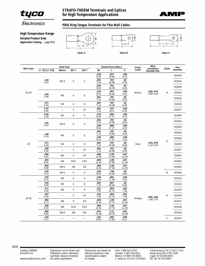
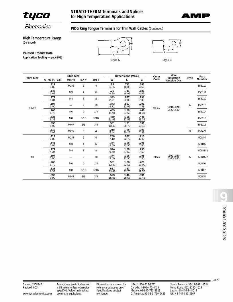
PIDG Ring Tongue Terminals for Thin Wall Cables
Stud Size Dimensions (Max.) Color Wire PartWire Size Code Insulation Style Number+/- .03 [+/- 0.8] Metric BA # UN # W L C Outside Dia..218 .657 .166 1526425.54 16.68 4.22
.119 M2.5 6 4 .281 .787 .25 1526443.02 7.14 19.98 6.35.218 .751 .25 1526485.54 19.08 6.35
22-24 .218 .657 .166 Brown .035-.075 A 152643.145 M3 4 6
5.54 16.68 4.22 0.90-1.903.68 .281 .787 .25 1526457.14 19.98 6.35.171 M4 3 8 .281 .787 .25 1526464.34 7.14 19.98 6.351.97 — 2 10 .281 .787 .244 1526475.00 7.14 20.0 6.200.93 M2 8 2 .218 .680 .166 1526602.36 5.54 17.27 4.22
.281 .787 .26 152654.122 M2.5 6 4
7.14 19.98 6.603.10 .218 .680 .166 1526595.54 17.27 4.22
.281 .787 .25 152655.148 M3 4 6
7.14 19.98 6.353.76 .218 .680 .166 1526585.54 17.27 4.22
A20 .171 M4 3 8 .281 .787 .26 Grey .043-.079 1526564.34 7.14 19.98 6.60 1.10-2.00
.199 — 2 10 .281 .787 .26 1526575.06 7.14 19.98 6.60
.268 M6 0 1/4 .469 1.08 .447 1526616.81 11.91 27.58 11.35
.331 M8 5/16 5/16 .469 1.08 .447 1526628.41 11.91 27.58 11.35
.393 M9.5 3/8 3/8 .469 1.08 .447 1526639.98 11.91 27.58 11.35
.122 M2.5 6 4 .218 .746 .26 B 1534933.10 5.54 18.94 6.60
.122 M3 6 4 .218 .681 .166 1531033.10 5.54 17.30 4.22
.145 M3 6 .281 .807 .26 1531043.68 4 7.10 20.50 6.60
.171 M4 3 8 .312 .854 .291 1531054.34 7.92 21.70 7.39
.197 — 2 10 .312 .854 .291 A 15310618-16
5.00 7.92 21.70 7.39Orange .055-.106
.265 M6 0 1/4 .469 1.09 .447 1.40-2.701531076.73 11.91 27.70 11.35
.328 M8 5/16 5/16 .469 1.09 .447 1531088.33 11.91 27.70 11.35
.390 M9.5 3/8 3/8 .531 1.21 .531 1531099.90 13.48 30.79 13.48
.125 — — — .223 .902 .359 C 1534753.17 5.66 22.90 9.11
LC
W
Style B
LC
W
Style A
LC
W
Style C
High Temperature Range Related Product DataApplication Tooling — page 9023
STRATO-THERM Terminals and Splices for High Temperature Applications
9021
9Terminals and Splices
Catalog 1308940 Dimensions are in inches and Dimensions are shown for USA: 1-800-522-6752 South America: 55-11-3611-1514Revised 5-03 millimeters unless otherwise reference purposes only. Canada: 1-905-470-4425 Hong Kong: 852-2735-1628
specified. Values in brackets Specifications subject Mexico: 01-800-733-8926 Japan: 81-44-844-8013www.tycoelectronics.com are metric equivalents. to change. C. America: 52-55-5-729-0425 UK: 44-141-810-8967
PIDG Ring Tongue Terminals for Thin Wall Cables (Continued)
Stud Size Dimensions (Max.) Color Wire PartWire Size Code Insulation Style Number+/- .03 [+/- 0.8] Metric BA # UN # W L C Outside Dia..119 M2.5 6 4 .25 .711 .181 1531103.02 6.35 18.06 4.59.145 M3 4 6 .25 .711 .181 1531113.68 6.35 18.06 4.59.171 M4 3 8 .343 .867 .291 1531124.34 8.71 22.02 7.39.197 — 2 10 .343 .867 .291 A 153113
14-125.00 8.71 22.02 7.39
White .091-.126.265 M6 0 1/4 .469 1.08 .448 2.30-3.20
1531146.73 11.91 27.58 11.39.328 M8 5/16 5/16 .469 1.08 .448 1531158.33 11.91 27.58 11.39.390 M9.5 3/8 3/8 .531 1.21 .531 1531169.90 13.48 30.76 13.48.119 M2.5 6 4 .218 .798 .291 D 1534763.02 5.44 20.26 7.39.119 M2.5 6 4 .280 .937 .213 508443.02 7.10 23.79 5.40.145 M3 6 .374 1.08 .295 508453.68 4 9.50 27.50 7.50.171 M4 3 8 .374 1.08 .295 50845-14.34 9.50 27.50 7.50
10 .197 — 2 10 .374 1.08 .295 Black .102-.150 A 50845-25.00 9.50 27.50 7.50 2.60-3.80.265 M6 0 1/4 .531 1.28 .429 508466.73 13.48 32.51 10.90.328 M8 5/16 5/16 .531 1.33 .461 508478.33 13.48 33.70 11.70.390 M9.5 3/8 3/8 .593 1.40 .531 508489.90 15.06 35.68 13.48
LC
W
Style D
LC
W
Style A
High Temperature Range(Continued)
Related Product DataApplication Tooling — page 9023
STRATO-THERM Terminals and Splices for High Temperature Applications
9022Catalog 1308940 Dimensions are in inches and Dimensions are shown for USA: 1-800-522-6752 South America: 55-11-3611-1514Revised 5-03 millimeters unless otherwise reference purposes only. Canada: 1-905-470-4425 Hong Kong: 852-2735-1628
specified. Values in brackets Specifications subject Mexico: 01-800-733-8926 Japan: 81-44-844-8013www.tycoelectronics.com are metric equivalents. to change. C. America: 52-55-5-729-0425 UK: 44-141-810-8967
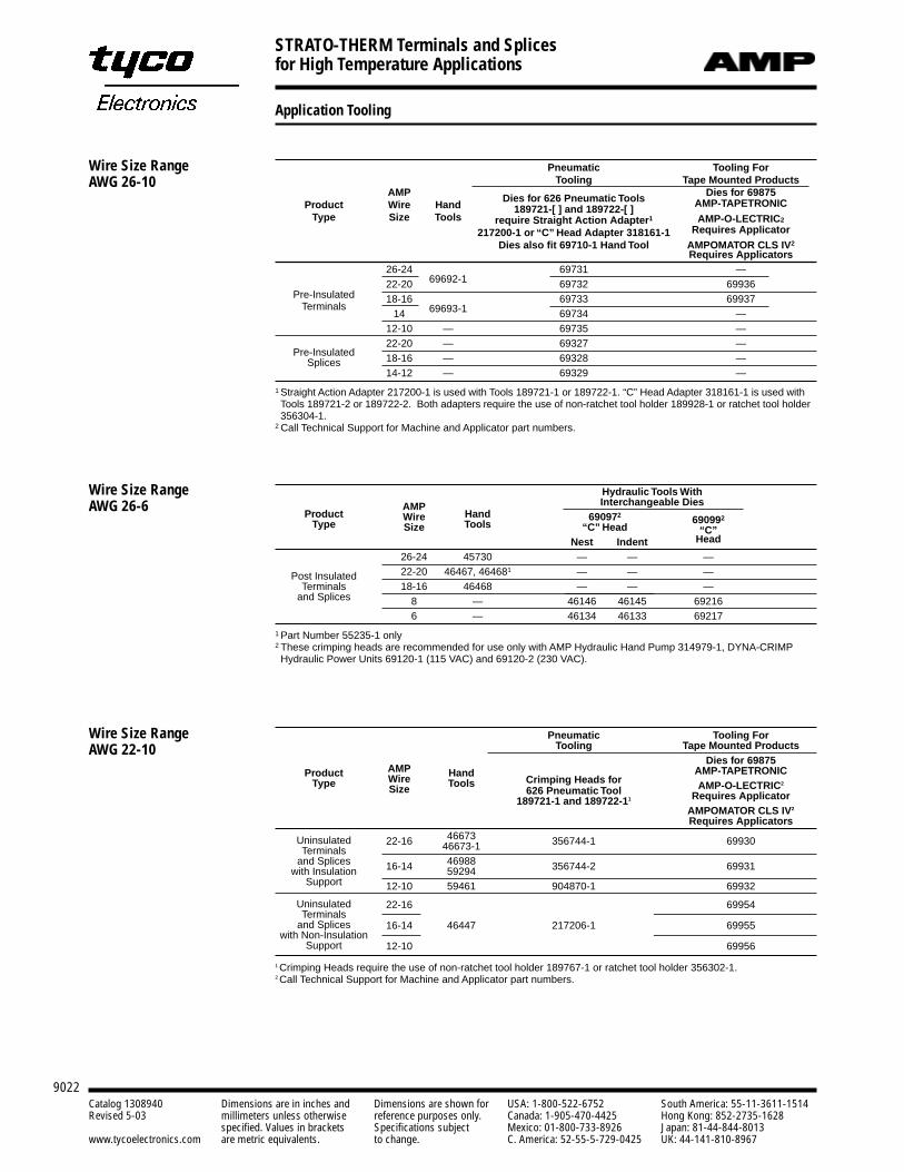
Application Tooling
Pneumatic Tooling ForTooling Tape Mounted Products
AMP Dies for 626 Pneumatic Tools Dies for 69875Product Wire Hand 189721-[ ] and 189722-[ ] AMP-TAPETRONIC
Type Size Tools require Straight Action Adapter1 AMP-O-LECTRIC2
217200-1 or “C” Head Adapter 318161-1 Requires ApplicatorDies also fit 69710-1 Hand Tool AMPOMATOR CLS IV2
Requires Applicators26-24 69731 —
Pre-Insulated22-20 69692-1 69732 69936
Terminals18-16 69733 69937
14 69693-1 69734 —12-10 — 69735 —
Pre-Insulated22-20 — 69327 —
Splices 18-16 — 69328 —14-12 — 69329 —
1 Straight Action Adapter 217200-1 is used with Tools 189721-1 or 189722-1. “C” Head Adapter 318161-1 is used withTools 189721-2 or 189722-2. Both adapters require the use of non-ratchet tool holder 189928-1 or ratchet tool holder356304-1.
2 Call Technical Support for Machine and Applicator part numbers.
Wire Size Range AWG 26-10
Hydraulic Tools WithAMP Interchangeable Dies
Product Wire Hand 690972 690992Type Size Tools “C” Head “C”
Nest Indent Head
26-24 45730 — — —
Post Insulated 22-20 46467, 464681 — — —Terminals 18-16 46468 — — —
and Splices 8 — 46146 46145 692166 — 46134 46133 69217
1 Part Number 55235-1 only2 These crimping heads are recommended for use only with AMP Hydraulic Hand Pump 314979-1, DYNA-CRIMPHydraulic Power Units 69120-1 (115 VAC) and 69120-2 (230 VAC).
Wire Size Range AWG 26-6
Pneumatic Tooling ForTooling Tape Mounted Products
Dies for 69875Product AMP Hand
Crimping Heads forAMP-TAPETRONIC
Type Wire Tools626 Pneumatic Tool AMP-O-LECTRIC2
Size189721-1 and 189722-11 Requires Applicator
AMPOMATOR CLS IV2
Requires Applicators
Uninsulated 46673Terminals
22-16 46673-1 356744-1 69930
and Splices 46988with Insulation 16-14 59294 356744-2 69931
Support 12-10 59461 904870-1 69932
Uninsulated 22-16 69954Terminals
and Splices 16-14 46447 217206-1 69955with Non-Insulation
Support 12-10 69956
1 Crimping Heads require the use of non-ratchet tool holder 189767-1 or ratchet tool holder 356302-1.2 Call Technical Support for Machine and Applicator part numbers.
Wire Size RangeAWG 22-10
STRATO-THERM Terminals and Splices for High Temperature Applications
9023
9Terminals and Splices
Catalog 1308940 Dimensions are in inches and Dimensions are shown for USA: 1-800-522-6752 South America: 55-11-3611-1514Revised 5-03 millimeters unless otherwise reference purposes only. Canada: 1-905-470-4425 Hong Kong: 852-2735-1628
specified. Values in brackets Specifications subject Mexico: 01-800-733-8926 Japan: 81-44-844-8013www.tycoelectronics.com are metric equivalents. to change. C. America: 52-55-5-729-0425 UK: 44-141-810-8967
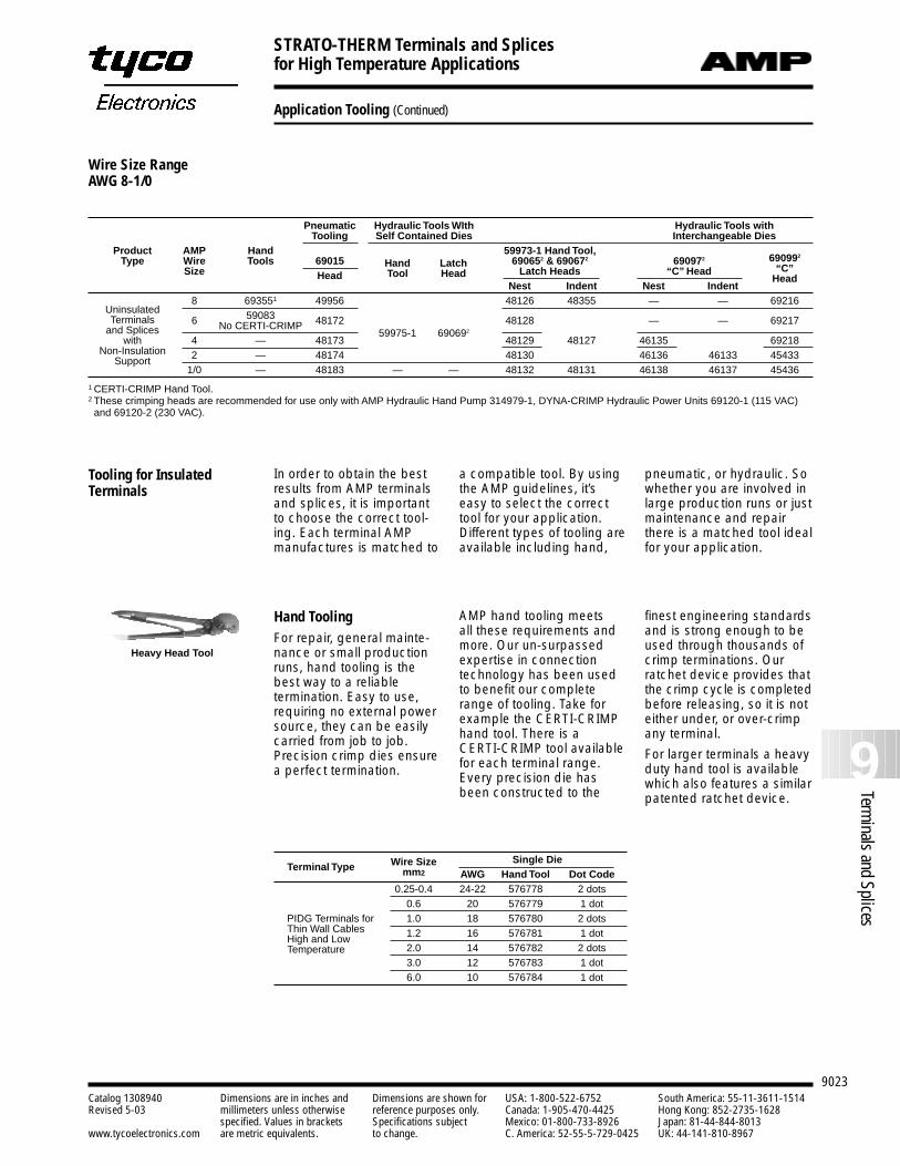
Application Tooling (Continued)
Pneumatic Hydraulic Tools WIth Hydraulic Tools with Tooling Self Contained Dies Interchangeable Dies
Product AMP Hand 59973-1 Hand Tool,Type Wire Tools 69015 Hand Latch 690652 & 690672 690972 690992
Size Head Tool Head Latch Heads “C” Head “C”
Nest Indent Nest IndentHead
Uninsulated8 693551 49956 48126 48355 — — 69216
Terminals 6 59083 48172 48128 — — 69217and Splices No CERTI-CRIMP
with 4 — 4817359975-1 690692
48129 48127 46135 69218Non-Insulation 2 — 48174 48130 46136 46133 45433Support
1/0 — 48183 — — 48132 48131 46138 46137 45436
1 CERTI-CRIMP Hand Tool.2 These crimping heads are recommended for use only with AMP Hydraulic Hand Pump 314979-1, DYNA-CRIMP Hydraulic Power Units 69120-1 (115 VAC)and 69120-2 (230 VAC).
Wire Size RangeAWG 8-1/0
Tooling for InsulatedTerminals
In order to obtain the bestresults from AMP terminalsand splices, it is importantto choose the correct tool-ing. Each terminal AMPmanufactures is matched to
a compatible tool. By usingthe AMP guidelines, it’seasy to select the correcttool for your application.Different types of tooling areavailable including hand,
pneumatic, or hydraulic. Sowhether you are involved inlarge production runs or justmaintenance and repairthere is a matched tool idealfor your application.
Hand ToolingFor repair, general mainte-nance or small productionruns, hand tooling is thebest way to a reliable termination. Easy to use,requiring no external powersource, they can be easilycarried from job to job.Precision crimp dies ensurea perfect termination.
AMP hand tooling meets all these requirements andmore. Our un-surpassedexpertise in connectiontechnology has been usedto benefit our completerange of tooling. Take forexample the CERTI-CRIMPhand tool. There is a CERTI-CRIMP tool availablefor each terminal range.Every precision die hasbeen constructed to the
finest engineering standardsand is strong enough to beused through thousands ofcrimp terminations. Ourratchet device provides thatthe crimp cycle is completedbefore releasing, so it is noteither under, or over-crimpany terminal.
For larger terminals a heavyduty hand tool is availablewhich also features a similarpatented ratchet device.
Heavy Head Tool
Terminal Type Wire Size Single Diemm2 AWG Hand Tool Dot Code
0.25-0.4 24-22 576778 2 dots0.6 20 576779 1 dot
PIDG Terminals for 1.0 18 576780 2 dotsThin Wall Cables 1.2 16 576781 1 dotHigh and Low
2.0 14 576782 2 dotsTemperature3.0 12 576783 1 dot6.0 10 576784 1 dot
COPALUM Sealed Terminals and Splices
9024Catalog 1308940 Dimensions are in inches and Dimensions are shown for USA: 1-800-522-6752 South America: 55-11-3611-1514Revised 5-03 millimeters unless otherwise reference purposes only. Canada: 1-905-470-4425 Hong Kong: 852-2735-1628
specified. Values in brackets Specifications subject Mexico: 01-800-733-8926 Japan: 81-44-844-8013www.tycoelectronics.com are metric equivalents. to change. C. America: 52-55-5-729-0425 UK: 44-141-810-8967
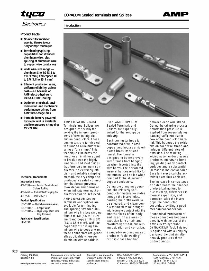
Introduction
AMP COPALUM SealedTerminals and Splices aredesigned especially forsolving the inherent prob-lems of terminating alu-minum conductors. Theseconnectors are terminatedto stranded aluminum wireusing a “dry crimp.” Thistechnique eliminates theneed for an inhibitor agentto break down the highlytenacious and inert oxidesthat form on aluminum con-ductors. An extremely effi-cient and reliable crimpingmethod, the dry crimp alsoproduces a sealed connec-tion that better prevents re-oxidation and corrosionwhen intimate terminal/con-ductor contact is achieved.
AMP COPALUM SealedTerminals and Splices areavailable for terminatingand splicing stranded alu-minum wire in sizes rangingfrom 8 to 4/0 [8.6 to 110.9mm2] and copper 10 to 3/0[4.8 to 85.9 mm2]. With thecapability of splicing alu-minum wire to copper wire,these connectors are gener-ally applicable wherever aluminum wire or cable is
used. AMP COPALUMSealed Terminals andSplices are especially suited for the aerospaceindustry.
Each connector body isconstructed of tin-platedcopper and houses a nickel-plated brass insert and funnel. The funnel isdesigned to better preventwire strands from hangingup when inserted into thewire barrel. The perforatedinsert enhances reliability forthe terminal and splice whencrimped to the aluminum/copper conductors.
During the crimping opera-tion, the relatively soft conductor material extrudesthrough the insert holes,causing the brittle oxide tobe sheared, and clean con-ductor metal to be broughtinto intimate contact with theinner surfaces of the bodyand insert. These areas ofextrusion form an air- andmoisture-tight seal, minimiz-ing oxidation and corrosion.
Stranded-wire crimping alsoproduces “cold welding”or solid-phase bonding
between each wire strand.During the crimping process,deformation pressure isapplied from several planes,causing sufficient plasticflow of the conductor mate-rial. This fractures the oxidefilm on each wire strand andinduces different rates ofextrusion. The resulting wiping action under pressureproduces interstrand bond-ing, yielding many contactsurfaces and a substantialincrease in the contact area.Excellent electrical charac-teristics are thus achieved.
The increase in contact areaalso decreases the chancesof electrical malfunction due to creep, differences inthermal expansion, and corrosion. Also the insertgrips the conductor securely, providing a goodmechanical connection.
Economical termination ofthese connectors becomesa reality with the use of theAMP electro-hydraulicDYNA-CRIMP Tool. This toolis equipped with a uniquelydesigned die that simulta-neously produces three distinct crimps.
Product Facts No need for inhibitor
agents, thanks to our “dry crimp” technique
Terminating/splicing capabilities for strandedaluminum wire, plus splicing of aluminum wireto copper wire conductors
Wide wire-size range —aluminum 8 to 4/0 [8.6 to110.9 mm2] and copper 10to 3/0 [4.8 to 85.9 mm2]
Efficient production rates,uniform reliability, at lowcost — all because of AMP electro-hydraulicDYNA-CRIMP Tooling
Optimum electrical, envi-ronmental, and mechanicalperformance crimps fromAMP three-stage dies
Portable battery poweredhydraulic unit is availableand low pressure crimp diesfor 2/0 size
Technical DocumentsInstruction Sheets408-2281— Application Terminals and
Splices Tooling408-2453 — Tool 69066/Crimping Die408-9535 — Tool 58422-1
Product Specifications108-11011 — Overall Aluminum Wires108-11011-1 — Copper Wires108-11011-2 — High Temp. Wires with
Flag Terminals
Application Specifications114-2134
COPALUM Sealed Terminals and Splices
9025
9Terminals and Splices
Catalog 1308940 Dimensions are in inches and Dimensions are shown for USA: 1-800-522-6752 South America: 55-11-3611-1514Revised 5-03 millimeters unless otherwise reference purposes only. Canada: 1-905-470-4425 Hong Kong: 852-2735-1628
specified. Values in brackets Specifications subject Mexico: 01-800-733-8926 Japan: 81-44-844-8013www.tycoelectronics.com are metric equivalents. to change. C. America: 52-55-5-729-0425 UK: 44-141-810-8967
Introduction (Continued)
The AMP Sealed COPALUM terminal and splice product line was established in the 50’s.Originally it had two separate product lines, one for aluminum wire and one for copper wire.Each line had butt connectors and terminals.The Aluminum wire connector bodies were made of stamped and formed aluminum stripstock and COPALUM terminal connector bodies were made of stamped and formed copperstrip stock.Both products contained a closed cup (cartridge) installed within each wire barrel. This cartridge contained an oxide inhibiting compound with abrasive particles that flowed duringcrimping into the strand voids (interstices) and mechanically abraded the wire and barreloxide surfaces. The oxide inhibitor protected the contact surfaces from further oxidation andformed a temporary partial seal between the conductor and the crimped insulation support.The crimp dies were the two stage type and of the confined crescent design. The first stagecrimped the wire barrel and cartridge, while the second stage crimped only the flared cartridgeend. This second stage crimp produced the insulation support which was designed as astrain relief.In the 60’s, all copper bodies and perforated inserts were introduced. The industry wanted adry crimp with a fully sealed body. Some important advantages of the copper design are:
1. Almost all buss contacts are copper. The plated terminal tongue needs no special contactsurface treatment against the bolted copper buss. This is the (dynamic), disconnectablepart of the connection.
2. The copper wire barrel allows for a natural two step down capacity from an equivalentaluminum wire to copper wire.Example—#4 aluminum down to #6 copper.
3. The more dense copper has 100% electrical conductivity compared to aluminum at 61%maximum. Copper compared to aluminum has hardly any mechanical creep; therefore,with the proper crimp, it provides a much more stable crimped (static), permanentlysealed connection.
4. Within the circuit design there is always a need to change from high temperaturecopper wires to lower temperature aluminum wires. With the copper connector, we havethe choices of “optional” (4 AL-6 CU) or “primary” (4 AL-4 AL) or “secondary”(6 CU-6CU) all within the same wire barrel and crimp die envelope.
5. During crimping, the hard nickel plated perforated insert digs into and intimately connectsthe wire and copper body while at the same time increasing the fresh surface contactareas via the holes and extrusion. With this feature, we now have a preferred “dry” con-nection with the copper to aluminum transition occurring inside the connector bodywhere it is protected and controlled.
6. The barrier walls of the terminal and splice body provide the blind hole required for anenvironmentally sealed crimp.
7. The product has a three stage simultaneous crimp design which allows for a very secureelectrical crimp, a smooth transition crimp which goes up to the full round sealing crimp.It also has an identification feature and maintains maximum connector wall thicknessafter crimp.
We made several changes to the product line in the 80’s and also changed the part numbersas listed below.
1. The perforated insert was modified without causing a change in connector performance.2. The internal components were oriented and permanently locked in place during manufacture.3. Clearer, more permanent marking was introduced with the straight knurl stripes replacing
the blue ink stripe guides used to show crimp location.
Tyco Electronics continually monitors incoming material for material conformance.Consolidation of production facilities and improved equipment produce more accurate com-ponent parts which, after heat treatment and plating, yield an overall higher quality assembly.All customer drawings are now on new formats and are on CAD. Catalog and instructionalmaterials are regularly updated.In April 1993, a new application sheet 114-2134 was completed. Also in 1993, we released awhole line of two stud hole terminals, silver plated with high temperature terminals, two 4/0 ALstyle terminals, a new crimp die, and various sheared tongue styles.Using engineering tools like CAE/CAD/CAM, thermography, and computer driven imageanalysis on crimp cross-sections, we are able to arrive at and maintain optimum productintegrity and reliability.
As with all AMP products, we have a continuing program of product and process improvementsto promote maximum performance to meet customer’s needs.
Product Evolution
COPALUM Sealed Terminals and Splices
9026Catalog 1308940 Dimensions are in inches and Dimensions are shown for USA: 1-800-522-6752 South America: 55-11-3611-1514Revised 5-03 millimeters unless otherwise reference purposes only. Canada: 1-905-470-4425 Hong Kong: 852-2735-1628
specified. Values in brackets Specifications subject Mexico: 01-800-733-8926 Japan: 81-44-844-8013www.tycoelectronics.com are metric equivalents. to change. C. America: 52-55-5-729-0425 UK: 44-141-810-8967
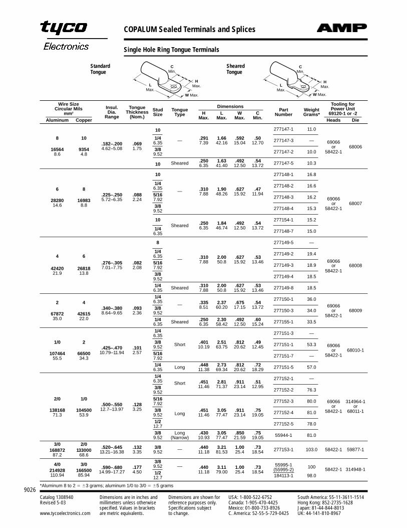
Single Hole Ring Tongue Terminals
LMax.
W Max.
CMin.
HMax. L
Max.
CMin.
HMax.
W Max.
Wire SizeInsul. Tongue Dimensions Tooling for
Circular MilsDia. Thickness Stud Tongue
H L W CPart Weight Power Unit
mm2
Range (Nom.) Size TypeMax. Max. Max. Min.
Number Grams* 69120-1 or -2Aluminum Copper Heads Die
10 277147-1 11.0
8 10 1/4 — .291 1.66 .592 .50 277147-3 —.182–.200 .069 6.35 7.39 42.16 15.04 12.70 69066
6800616564 9354 4.62–5.08 1.75 3/8 277147-2 10.0or
8.6 4.8 9.52 58422-1
10 Sheared .250 1.63 .492 .54 277147-5 10.36.35 41.40 12.50 13.72
10 277148-1 16.8
1/4 277148-2 16.66 8 6.35
— .310 1.90 .627 .47.225–.250 .088 5/16 7.88 48.26 15.92 11.94
277148-3 16.2 6906628280 16983 5.72–6.35 2.24 7.92or 6800714.6 8.8 3/8 277148-4 15.3 58422-19.52
10Sheared .250 1.84 .492 .54
277154-1 15.2
1/4 6.35 46.74 12.50 13.72277148-7 15.06.35
8 277149-5 —
1/4 277149-2 19.44 6 6.35— .310 2.00 .627 .53
.276–.305 .082 5/16 7.88 50.8 15.92 13.46277149-3 18.9
6906668008
42420 26818 7.01–7.75 2.08 7.92 or
21.9 13.8 3/8 277149-4 18.558422-1
9.521/4 Sheared .310 2.00 .627 .53 277149-8 18.56.35 7.88 50.8 15.92 13.461/4 277150-1 36.0
2 4 6.35— .335 2.37 .675 .54
69066.340–.380 .093 3/8 8.51 60.20 17.15 13.72277150-3 34.0 or 68009
67872 42615 8.64–9.65 2.36 9.5235.0 22.0 1/4 Sheared .250 2.30 .492 .60 277155-1 33.5
58422-1
6.35 6.35 58.42 12.50 15.241/4 277151-3 —6.35
1/0 2 3/8 Short .401 2.51 .812 .49 277151-1 53.3 69066.425–.470 .101 9.52 10.19 63.75 20.62 12.45or 68010-1
107464 66500 10.79–11.94 2.57 5/16 277151-7 —55.5 34.3 7.9258422-1
1/4 Long .448 2.73 .812 .72 277151-5 57.06.35 11.38 69.34 20.62 18.291/4 277152-1 —6.35 Short .451 2.81 .911 .513/8 11.46 71.37 23.14 12.95
277152-2 76.39.522/0 1/0 5/16 277152-3 80.0 69066 314964-1
.500–.550 .128 7.92 or or138168 104500 12.7–13.97 3.25 3/8
Long.451 3.05 .911 .75 277152-4 81.0 58422-1 68011-1
71.3 53.9 9.52 11.46 77.47 23.14 19.051/2 277152-5 78.012.73/8 Long .430 3.05 .850 .75 55944-1 81.09.52 (Narrow) 10.93 77.47 21.59 19.05
3/0 2/0.520–.645 .132 3/8 .440 3.21 1.00 .73
168872 133000 13.21–16.38 3.35 9.52 — 11.18 81.53 25.4 18.54 277153-1 103.0 58422-1 59877-187.2 68.6
4/0 3/03/8
55995-1 100.590–.680 .177 9.52 –– .440 3.11 1.00 .73 (55995-2) 58422-1 314948-1214928 166500 14.99–17.27 4.50 1/2 11.18 79.00 25.4 18.54110.94 85.94 12.7 184113-1 98.0
*Aluminum 8 to 2 3 grams; aluminum 1/0 to 3/0 5 grams
StandardTongue
ShearedTongue
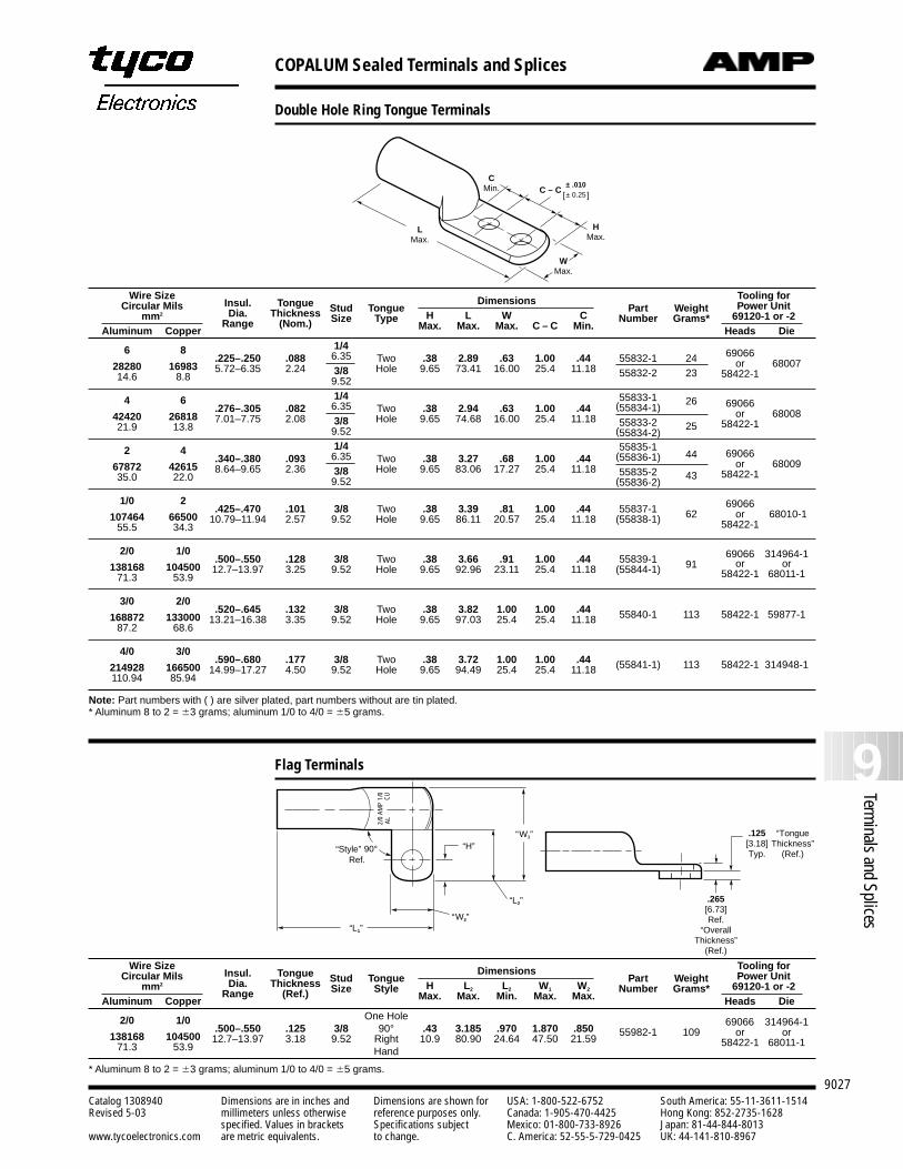
COPALUM Sealed Terminals and Splices
9027
9Terminals and Splices
Catalog 1308940 Dimensions are in inches and Dimensions are shown for USA: 1-800-522-6752 South America: 55-11-3611-1514Revised 5-03 millimeters unless otherwise reference purposes only. Canada: 1-905-470-4425 Hong Kong: 852-2735-1628
specified. Values in brackets Specifications subject Mexico: 01-800-733-8926 Japan: 81-44-844-8013www.tycoelectronics.com are metric equivalents. to change. C. America: 52-55-5-729-0425 UK: 44-141-810-8967
Double Hole Ring Tongue Terminals
Wire SizeInsul. Tongue Dimensions Tooling for
Circular MilsDia. Thickness Stud Tongue Part Weight Power Unit
mm2
Range (Nom.) Size Type H L W C Number Grams* 69120-1 or -2Aluminum Copper Max. Max. Max. C – C Min. Heads Die
6 8 1/4.225–.250 .088 6.35 Two .38 2.89 .63 1.00 .44 55832-1 24 69066
6800728280 16983 5.72–6.35 2.24 3/8 Hole 9.65 73.41 16.00 25.4 11.18 55832-2 23or
14.6 8.8 9.5258422-1
4 6 1/4 55833-1.276–.305 .082 6.35 Two .38 2.94 .63 1.00 .44 (55834-1)
26 690666800842420 26818 7.01–7.75 2.08 3/8 Hole 9.65 74.68 16.00 25.4 11.18 55833-2 25
or21.9 13.8 9.52 (55834-2)
58422-1
2 4 1/4 55835-1.340–.380 .093 6.35 Two .38 3.27 .68 1.00 .44 (55836-1) 44 69066
6800967872 42615 8.64–9.65 2.36 3/8 Hole 9.65 83.06 17.27 25.4 11.18 55835-2 43or
35.0 22.0 9.52 (55836-2)58422-1
1/0 2.425–.470 .101 3/8 Two .38 3.39 .81 1.00 .44 55837-1 62
6906668010-1107464 66500 10.79–11.94 2.57 9.52 Hole 9.65 86.11 20.57 25.4 11.18 (55838-1) or
55.5 34.3 58422-1
2/0 1/0.500–.550 .128 3/8 Two .38 3.66 .91 1.00 .44 55839-1 91
69066 314964-1138168 104500 12.7–13.97 3.25 9.52 Hole 9.65 92.96 23.11 25.4 11.18 (55844-1) or or
71.3 53.9 58422-1 68011-1
3/0 2/0.520–.645 .132 3/8 Two .38 3.82 1.00 1.00 .44 58422-1 59877-1168872 133000 13.21–16.38 3.35 9.52 Hole 9.65 97.03 25.4 25.4 11.18 55840-1 113
87.2 68.6
4/0 3/0.590–.680 .177 3/8 Two .38 3.72 1.00 1.00 .44
214928 166500 14.99–17.27 4.50 9.52 Hole 9.65 94.49 25.4 25.4 11.18 (55841-1) 113 58422-1 314948-1110.94 85.94
Note: Part numbers with ( ) are silver plated, part numbers without are tin plated.* Aluminum 8 to 2 = 3 grams; aluminum 1/0 to 4/0 = 5 grams.
LMax.
WMax.
CMin.
HMax.
C – C[ ]± .010± 0.25
“H”“W1”
“W2”“L1”
“L2”
90°“Style”
2/0
AM
P 1/
0AL
CU
Ref.
.125[3.18]Typ.
.265[6.73]Ref.
“Overall Thickness”
(Ref.)
“TongueThickness”
(Ref.)
Wire SizeInsul. Tongue Dimensions Tooling for
Circular MilsDia. Thickness Stud Tongue Part Weight Power Unit
mm2
Range (Ref.) Size Style H L2 L2 W1 W2 Number Grams* 69120-1 or -2Aluminum Copper Max. Max. Min. Max. Max. Heads Die
2/0 1/0 One Hole.500–.550 .125 3/8 90° .43 3.185 .970 1.870 .850
69066 314964-1138168 104500 12.7–13.97 3.18 9.52 Right 10.9 80.90 24.64 47.50 21.59
55982-1 109 or or71.3 53.9 Hand
58422-1 68011-1
* Aluminum 8 to 2 = 3 grams; aluminum 1/0 to 4/0 = 5 grams.
Flag Terminals
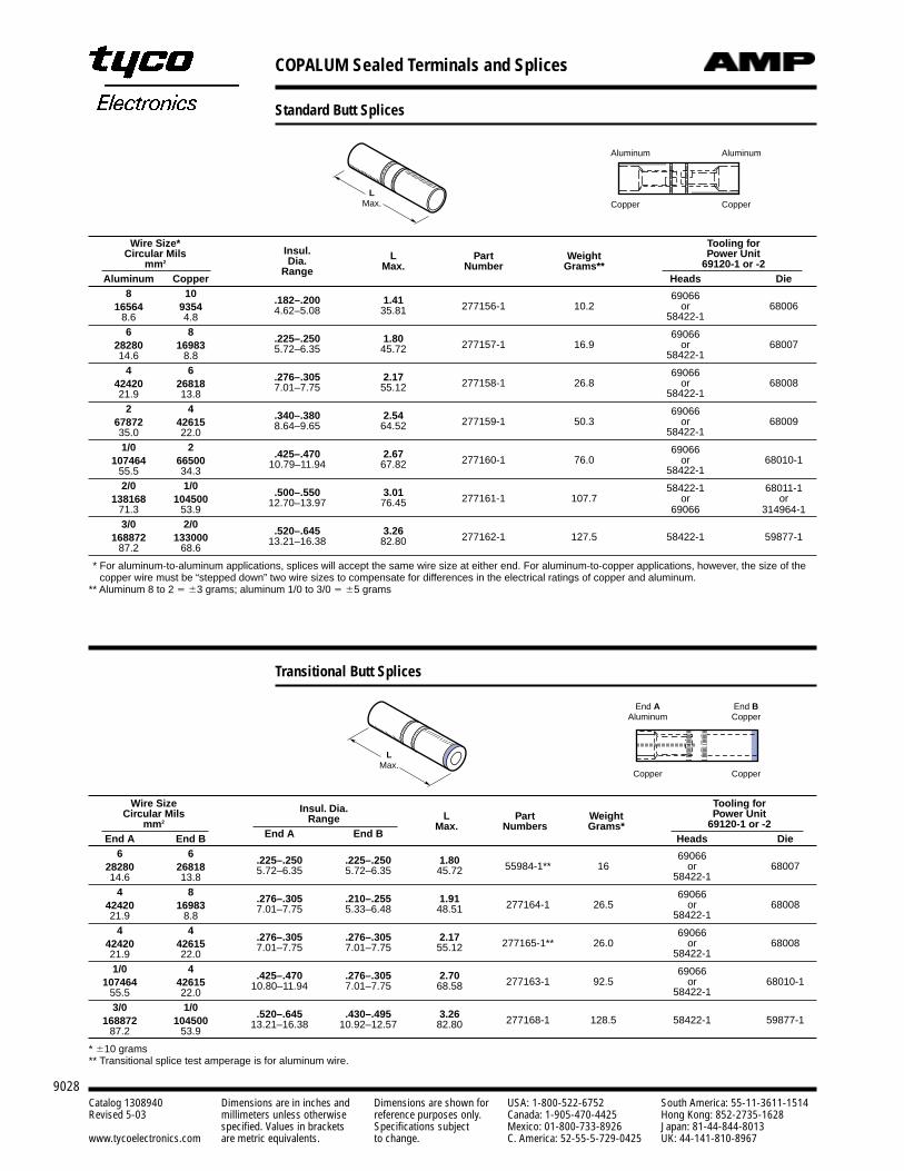
COPALUM Sealed Terminals and Splices
9028Catalog 1308940 Dimensions are in inches and Dimensions are shown for USA: 1-800-522-6752 South America: 55-11-3611-1514Revised 5-03 millimeters unless otherwise reference purposes only. Canada: 1-905-470-4425 Hong Kong: 852-2735-1628
specified. Values in brackets Specifications subject Mexico: 01-800-733-8926 Japan: 81-44-844-8013www.tycoelectronics.com are metric equivalents. to change. C. America: 52-55-5-729-0425 UK: 44-141-810-8967
Standard Butt Splices
LMax.
Wire Size*Insul. L Part Weight
Tooling forCircular Mils
Dia. Max. Number Grams**Power Unit
mm2
Range69120-1 or -2
Aluminum Copper Heads Die8 10
.182–.200 1.41 6906616564 9354 4.62–5.08 35.81 277156-1 10.2 or 68006
8.6 4.8 58422-1
6 8.225–.250 1.80 69066
28280 16983 5.72–6.35 45.72 277157-1 16.9 or 6800714.6 8.8 58422-1
4 6.276–.305 2.17 69066
42420 26818 7.01–7.75 55.12 277158-1 26.8 or 6800821.9 13.8 58422-1
2 4.340–.380 2.54 69066
67872 42615 8.64–9.65 64.52 277159-1 50.3 or 6800935.0 22.0 58422-1
1/0 2.425–.470 2.67 69066
107464 66500 10.79–11.94 67.82 277160-1 76.0 or 68010-155.5 34.3 58422-1
2/0 1/0.500–.550 3.01 58422-1 68011-1
138168 104500 12.70–13.97 76.45 277161-1 107.7 or or71.3 53.9 69066 314964-13/0 2/0
.520–.645 3.26168872 133000 13.21–16.38 82.80 277162-1 127.5 58422-1 59877-1
87.2 68.6
** For aluminum-to-aluminum applications, splices will accept the same wire size at either end. For aluminum-to-copper applications, however, the size of thecopper wire must be “stepped down” two wire sizes to compensate for differences in the electrical ratings of copper and aluminum.
** Aluminum 8 to 2 3 grams; aluminum 1/0 to 3/0 5 grams
Wire Size Insul. Dia.L Part Weight
Tooling forCircular Mils Range
Max. Numbers Grams*Power Unit
mm2 69120-1 or -2End A End B End A End B Heads Die
6 6.225–.250 .225–.250 1.80 69066
28280 26818 5.72–6.35 5.72–6.35 45.72 55984-1** 16 or 6800714.6 13.8 58422-1
4 8.276–.305 .210–.255 1.91 69066
42420 16983 7.01–7.75 5.33–6.48 48.51 277164-1 26.5 or 6800821.9 8.8 58422-1
4 4.276–.305 .276–.305 2.17 69066
42420 42615 7.01–7.75 7.01–7.75 55.12 277165-1** 26.0 or 6800821.9 22.0 58422-1
1/0 4.425–.470 .276–.305 2.70 69066
107464 42615 10.80–11.94 7.01–7.75 68.58 277163-1 92.5 or 68010-155.5 22.0 58422-1
3/0 1/0.520–.645 .430–.495 3.26
168872 104500 13.21–16.38 10.92–12.57 82.80 277168-1 128.5 58422-1 59877-187.2 53.9
* 10 grams** Transitional splice test amperage is for aluminum wire.
End AAluminum
End BCopper
Copper Copper
LMax.
Aluminum Aluminum
Copper Copper
Transitional Butt Splices
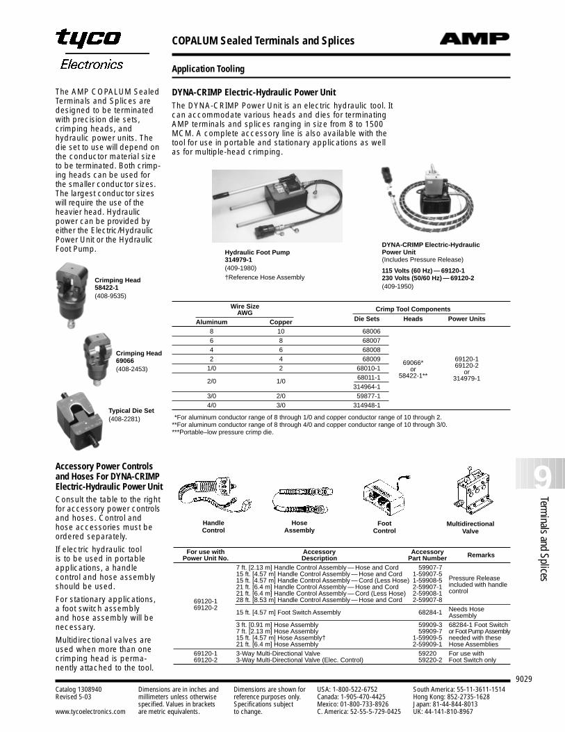
COPALUM Sealed Terminals and Splices
9029
9Terminals and Splices
Catalog 1308940 Dimensions are in inches and Dimensions are shown for USA: 1-800-522-6752 South America: 55-11-3611-1514Revised 5-03 millimeters unless otherwise reference purposes only. Canada: 1-905-470-4425 Hong Kong: 852-2735-1628
specified. Values in brackets Specifications subject Mexico: 01-800-733-8926 Japan: 81-44-844-8013www.tycoelectronics.com are metric equivalents. to change. C. America: 52-55-5-729-0425 UK: 44-141-810-8967
Application Tooling
DYNA-CRIMP Electric-Hydraulic Power UnitThe DYNA-CRIMP Power Unit is an electric hydraulic tool. Itcan accommodate various heads and dies for terminatingAMP terminals and splices ranging in size from 8 to 1500MCM. A complete accessory line is also available with thetool for use in portable and stationary applications as wellas for multiple-head crimping.
Consult the table to the rightfor accessory power controlsand hoses. Control andhose accessories must beordered separately.
If electric hydraulic tool is to be used in portableapplications, a handle control and hose assemblyshould be used.
For stationary applications,a foot switch assembly and hose assembly will benecessary.
Multidirectional valves areused when more than onecrimping head is perma-nently attached to the tool.
Accessory Power Controlsand Hoses For DYNA-CRIMPElectric-Hydraulic Power Unit
For use with Accessory Accessory RemarksPower Unit No. Description Part Number7 ft. [2.13 m] Handle Control Assembly — Hose and Cord 1-59907-715 ft. [4.57 m] Handle Control Assembly — Hose and Cord 1-59907-515 ft. [4.57 m] Handle Control Assembly — Cord (Less Hose) 1-59908-5 Pressure Release21 ft. [6.4 m] Handle Control Assembly — Hose and Cord 2-59907-1 included with handle21 ft. [6.4 m] Handle Control Assembly — Cord (Less Hose) 2-59908-1 control
69120-1 28 ft. [8.53 m] Handle Control Assembly — Hose and Cord 2-59907-869120-2
15 ft. [4.57 m] Foot Switch Assembly 1-68284-1 Needs Hose Assembly
3 ft. [0.91 m] Hose Assembly 1-59909-3 68284-1 Foot Switch7 ft. [2.13 m] Hose Assembly 1-59909-7 or Foot Pump Assembly15 ft. [4.57 m] Hose Assembly† 1-59909-5 needed with these 21 ft. [6.4 m] Hose Assembly 2-59909-1 Hose Assemblies
69120-1 3-Way Multi-Directional Valve 59220 For use with69120-2 3-Way Multi-Directional Valve (Elec. Control) 1-59220-2 Foot Switch only
HandleControl
HoseAssembly
Foot Control
MultidirectionalValve
DYNA-CRIMP Electric-HydraulicPower Unit(Includes Pressure Release)
115 Volts (60 Hz) — 69120-1230 Volts (50/60 Hz) — 69120-2(409-1950)
Wire Size Crimp Tool ComponentsAWGAluminum Copper Die Sets Heads Power Units
8 10 680066 8 680074 6 68008
69066* 69120-12 4 68009
or 69120-21/0 2 68010-158422-1** or
2/0 1/0 68011-1 314979-1314964-1
3/0 2/0 59877-14/0 3/0 314948-1
**For aluminum conductor range of 8 through 1/0 and copper conductor range of 10 through 2.**For aluminum conductor range of 8 through 4/0 and copper conductor range of 10 through 3/0.***Portable–low pressure crimp die.
Typical Die Set(408-2281)
Hydraulic Foot Pump314979-1(409-1980)†Reference Hose Assembly
The AMP COPALUM SealedTerminals and Splices aredesigned to be terminatedwith precision die sets,crimping heads, andhydraulic power units. Thedie set to use will depend onthe conductor material sizeto be terminated. Both crimp-ing heads can be used forthe smaller conductor sizes.The largest conductor sizeswill require the use of theheavier head. Hydraulicpower can be provided byeither the Electric/HydraulicPower Unit or the HydraulicFoot Pump.
Crimping Head58422-1(408-9535)
Crimping Head69066(408-2453)
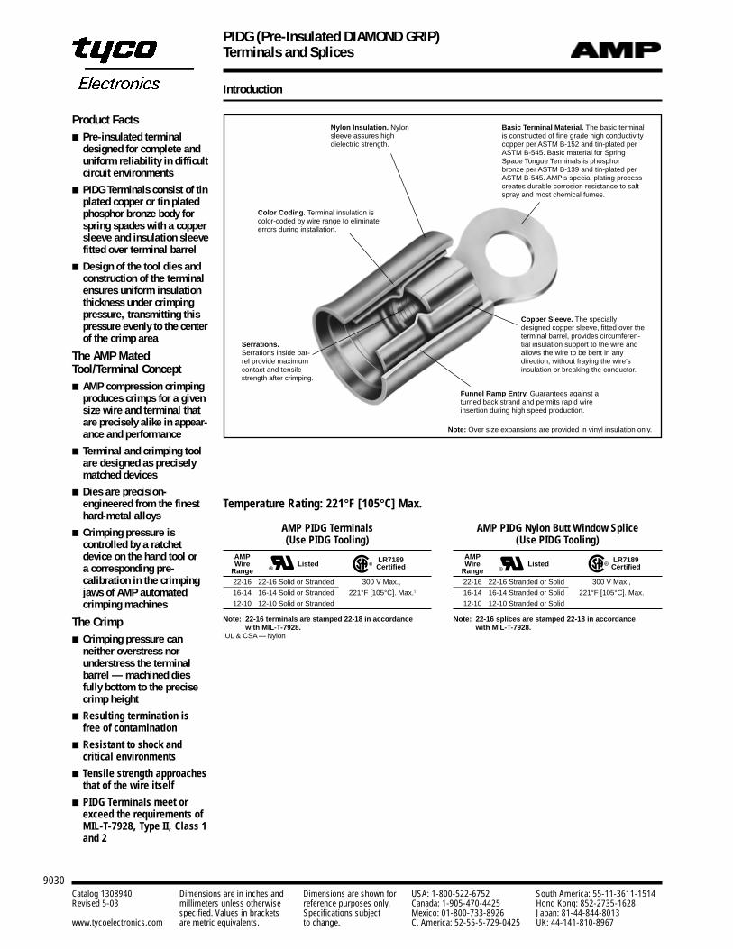
PIDG (Pre-Insulated DIAMOND GRIP)Terminals and Splices
9030Catalog 1308940 Dimensions are in inches and Dimensions are shown for USA: 1-800-522-6752 South America: 55-11-3611-1514Revised 5-03 millimeters unless otherwise reference purposes only. Canada: 1-905-470-4425 Hong Kong: 852-2735-1628
specified. Values in brackets Specifications subject Mexico: 01-800-733-8926 Japan: 81-44-844-8013www.tycoelectronics.com are metric equivalents. to change. C. America: 52-55-5-729-0425 UK: 44-141-810-8967
Introduction
Product Facts Pre-insulated terminal
designed for complete anduniform reliability in difficultcircuit environments
PIDG Terminals consist of tinplated copper or tin platedphosphor bronze body forspring spades with a coppersleeve and insulation sleevefitted over terminal barrel
Design of the tool dies andconstruction of the terminalensures uniform insulationthickness under crimpingpressure, transmitting thispressure evenly to the centerof the crimp area
The AMP MatedTool/Terminal Concept AMP compression crimping
produces crimps for a givensize wire and terminal thatare precisely alike in appear-ance and performance
Terminal and crimping toolare designed as preciselymatched devices
Dies are precision-engineered from the finesthard-metal alloys
Crimping pressure is controlled by a ratchetdevice on the hand tool or a corresponding pre-calibration in the crimpingjaws of AMP automatedcrimping machines
The Crimp Crimping pressure can
neither overstress norunderstress the terminalbarrel — machined diesfully bottom to the precisecrimp height
Resulting termination isfree of contamination
Resistant to shock and critical environments
Tensile strength approachesthat of the wire itself
PIDG Terminals meet orexceed the requirements ofMIL-T-7928, Type II, Class 1and 2
Basic Terminal Material. The basic terminalis constructed of fine grade high conductivitycopper per ASTM B-152 and tin-plated perASTM B-545. Basic material for SpringSpade Tongue Terminals is phosphorbronze per ASTM B-139 and tin-plated perASTM B-545. AMP’s special plating processcreates durable corrosion resistance to saltspray and most chemical fumes.
Color Coding. Terminal insulation iscolor-coded by wire range to eliminateerrors during installation.
Serrations.Serrations inside bar-rel provide maximumcontact and tensilestrength after crimping.
Funnel Ramp Entry. Guarantees against aturned back strand and permits rapid wireinsertion during high speed production.
Copper Sleeve. The speciallydesigned copper sleeve, fitted over theterminal barrel, provides circumferen-tial insulation support to the wire andallows the wire to be bent in any direction, without fraying the wire’sinsulation or breaking the conductor.
Temperature Rating: 221°F [105°C] Max.
AMP PIDG Terminals(Use PIDG Tooling)
AMPWire Listed LR7189
Range Certified
22-16 22-16 Solid or Stranded 300 V Max.,
16-14 16-14 Solid or Stranded 221°F [105°C]. Max.1
12-10 12-10 Solid or Stranded
Note: 22-16 terminals are stamped 22-18 in accordancewith MIL-T-7928.
1UL & CSA — Nylon
R
R
Nylon Insulation. Nylonsleeve assures high dielectric strength.
AMP PIDG Nylon Butt Window Splice(Use PIDG Tooling)
AMPWire Listed LR7189
Range Certified
22-16 22-16 Stranded or Solid 300 V Max.,
16-14 16-14 Stranded or Solid 221°F [105°C]. Max.
12-10 12-10 Stranded or Solid
Note: 22-16 splices are stamped 22-18 in accordancewith MIL-T-7928.
R
R
Note: Over size expansions are provided in vinyl insulation only.
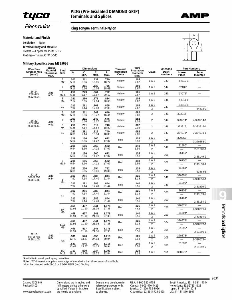
PIDG (Pre-Insulated DIAMOND GRIP)Terminals and Splices
9031
9Terminals and Splices
Catalog 1308940 Dimensions are in inches and Dimensions are shown for USA: 1-800-522-6752 South America: 55-11-3611-1514Revised 5-03 millimeters unless otherwise reference purposes only. Canada: 1-905-470-4425 Hong Kong: 852-2735-1628
specified. Values in brackets Specifications subject Mexico: 01-800-733-8926 Japan: 81-44-844-8013www.tycoelectronics.com are metric equivalents. to change. C. America: 52-55-5-729-0425 UK: 44-141-810-8967
Ring Tongue Terminals-Nylon
Material and FinishInsulation — NylonTerminal Body and MetallicSleeve — Copper per ASTM B-152Plating — Tin per ASTM B-545
L
E
C
W
Military Specifications MS25036
Wire Size Tongue Dimensions Wire Part NumbersCircular Mils Material Stud Terminal Insulation MS25036
[mm2] Thickness Size W C E L Insulation Diameter Class Dash Loose TapeMax. Min. Max. Max. Color Max. Numbers Piece Mounted
2 .203 .211 .632 .739 Yellow .105 1 & 2 143 54310-1† —M2 5.16 5.36 16.05 18.77 2.67
4 .203 .211 .632 .736 Yellow .105 1 & 2 144 52189† —5.16 5.36 16.05 18.69 2.6726-24 .029 6 .250 .243 .664 .792 Yellow .105 1 & 2 145 53073† —238-475 0.74 M3.5 6.35 6.17 16.87 20.12 2.67
[0.12-0.24]8 .281 .250 .671 .814 Yellow .105 1 & 2 146 54311-1† —M4 7.14 6.35 17.04 20.68 2.67
.312 .281 .702 .868 Yellow .105 1 & 2147
54312-1† —10 7.92 7.14 17.83 22.05 2.67 2 — 54312-2†
2 .203 .211 .542 .646 Yellow .082 2 143 323913 —M2 5.16 5.36 13.77 16.41 2.08
26-22 4 .203 .211 .542 .646 Yellow .082 2 144 323914* 2-323914-1202-810 .020 5.16 5.36 13.77 16.41 2.08
[0.10-0.41] 0.51 8 .250 .281 .612 .740 Yellow .082 2 146 323916 2-323916-1M4 6.35 7.14 15.54 18.80 2.08
10 .250 .281 .612 .740 Yellow .082 2 147 324075* 2-324075-16.35 7.14 15.54 18.80 2.08
.218 .156 .560 .672 Red .125 1 & 2148
320553 —
45.54 3.96 14.22 17.07 3.18 2 — 2-320553-2
.218 .156 .560 .672 Red .140 1 & 2148
31880* —5.54 3.96 14.22 17.07 3.56 2 — 2-31880-1
.218 .156 .560 .672 Red .125 1 & 2101
36149* —5.54 3.96 14.22 17.07 3.18 2 — 2-36149-2
6 .218 .156 .560 .672 Red .140 1 & 2101
36150* —M3.5 5.54 3.96 14.22 17.07 3.56 2 — 2-36150-1
.250 .250 .654 .782 Red .125 1 & 2102
51863* —6.35 6.35 16.61 19.86 3.18 2 — 51863-1
22-16 .033 .312 .281 .685 .844 Red .125 1 & 2149
320551* —509-3,260 0.84 8 7.92 7.14 17.40 21.44 3.18 2 — 2-320551-1[0.26-1.65]
M4 .312 .281 .685 .844 Red .140 1 & 2149
31890* —7.92 7.14 17.40 21.44 3.56 2 — 2-31890-2
.312 .281 .685 .844 Red .125 1 & 2103
36153* —
107.92 7.14 17.40 21.44 3.18 2 — 2-36153-2
.312 .281 .685 .844 Red .140 1 & 2103
36154* —7.92 7.14 17.40 21.44 3.56 2 — 2-36154-2
.469 .437 .841 1.078 Red .125 1 & 2150
320571* —
1/4 11.91 11.10 21.36 27.38 3.18 2 — 2-320571-2M6 .469 .437 .841 1.078 Red .140 1 & 2
15031894* —
11.91 11.10 21.36 27.38 3.56 2 — 2-31894-2
.469 .437 .841 1.078 Red .125 1 & 2104
320572* —
5/16 11.91 11.10 21.36 27.38 3.18 2 — 2-320572-1M8 .469 .437 .841 1.078 Red .140 1 & 2
10431895* —
22-1611.91 11.10 21.36 27.38 3.56 2 — 2-31895-1
509-3,260 .033 .531 .546 .950 1.218 Red .125 1 & 2105
320573* —[0.26-1.65] 0.84
3/813.49 13.87 24.13 30.94 3.18 2 — 2-320573-4
.531 .546 .950 1.218 Red .140 1 & 2105
31897* —13.49 13.87 24.13 30.94 3.56 2 — 2-31897-2
1/2 .713 .530 .934 1.293 Red .125 1 & 2 151 328975* —M12 18.11 13.46 23.72 32.84 3.18
*Available in small packaging quantities.Note: “C” dimension applies from edge of metal wire barrel to center of stud hole.†Must be crimped with 22-18 or 22-16 PIDG (red) Tooling.
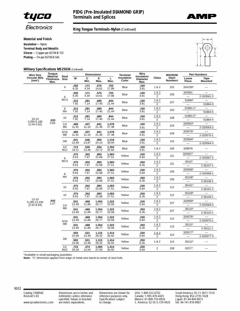
PIDG (Pre-Insulated DIAMOND GRIP)Terminals and Splices
9032Catalog 1308940 Dimensions are in inches and Dimensions are shown for USA: 1-800-522-6752 South America: 55-11-3611-1514Revised 5-03 millimeters unless otherwise reference purposes only. Canada: 1-905-470-4425 Hong Kong: 852-2735-1628
specified. Values in brackets Specifications subject Mexico: 01-800-733-8926 Japan: 81-44-844-8013www.tycoelectronics.com are metric equivalents. to change. C. America: 52-55-5-729-0425 UK: 44-141-810-8967
Ring Tongue Terminals-Nylon (Continued)
Military Specifications MS25036 (Continued)
Wire Size Tongue Dimensions Wire Part NumbersCircular Mils Material Stud Terminal Insulation MS25036
[mm2] Thickness Size W C E L Insulation Diameter Class Dash Loose TapeMax. Min. Max. Max. Color Max. Numbers Piece Mounted
4 .250 .171 .575 .703 Blue .150 1 & 2 152 324159* —6.35 4.34 14.61 17.86 3.81
.250 .171 .575 .703 Blue .150 1 & 2106
320561 —
6 6.35 4.34 14.61 17.86 3.81 2 — 2-320561-2M3.5 .312 .281 .685 .844 Blue .150 1 & 2
10751864* —
7.92 7.14 17.40 21.44 3.81 2 — 51864-3
8 .312 .281 .685 .844 Blue .150 1 & 2153
51864-1* —M4 7.92 7.14 17.40 21.44 3.81 2 — 51864-5
10 .312 .281 .685 .844 Blue .150 1 & 2108
51864-2* —16-14 .033 7.92 7.14 17.40 21.44 3.81 2 — 51864-4
2,050-5,180 0.84 1/4 .469 .437 .841 1.078 Blue .150 1 & 2154
320563* —[1.04-2.62]M6 11.91 11.10 21.36 27.38 3.81 2 — 2-320563-2
5/16 .469 .437 .841 1.078 Blue .150 1 & 2109
320575* —M8 11.91 11.10 21.36 27.38 3.81 2 — 2-320575-1
.531 .546 .950 1.218 Blue .150 1 & 2110
320564* —3/8 13.49 13.87 24.13 30.94 3.81 2 — 2-320564-31/2 .713 .530 .934 1.293 Blue .150 1 & 2 155 328976 —M12 18.11 13.46 23.72 32.84 3.81
.375 .302 .893 1.083 Yellow .230 1 & 2111
320567* —
6 9.53 7.67 22.68 27.51 5.84 2 — 2-320567-2M3.5 .375 .302 .893 1.083 Yellow .250 1 & 2
11135107 —
9.53 7.67 22.68 27.51 6.35 2 — 2-35107-1
.375 .302 .893 1.083 Yellow .230 1 & 2156
320568* —
8 9.53 7.67 22.68 27.51 5.84 2 — 2-320568-1M4 .375 .302 .893 1.083 Yellow .250 1 & 2
15635108* —
9.53 7.67 22.68 27.51 6.35 2 — 2-35108-1
10 .375 .302 .893 1.083 Yellow .230 1 & 2112
36161* —9.53 7.67 22.68 27.51 5.84 2 — 2-36161-2
10 .375 .302 .893 1.083 Yellow .250 1 & 2112
35109* —
12-109.53 7.67 22.68 27.51 6.35 2 — 2-35109-1
5,180-13,100 .042 .531 .468 1.054 1.322 Yellow .230 1 & 2157
320569* —[2.62-6.64] 1.07
1/4 13.49 11.89 26.77 33.58 5.84 2 — 2-320569-3M6 .531 .468 1.054 1.322 Yellow .250 1 & 2
15735110* —
13.49 11.89 26.77 33.58 6.35 2 — 2-35110-1
.531 .468 1.054 1.322 Yellow .230 1 & 2113
320576* —
5/16 13.49 11.89 26.77 33.58 5.84 2 — 2-320576-1M8 .531 .468 1.054 1.322 Yellow .250 1 & 2
11335111* —
13.49 11.89 26.77 33.58 6.35 2 — 2-35111-1
.593 .531 1.115 1.414 Yellow .230 1 & 2114
320577* —15.06 13.49 28.32 35.92 5.84 2 — 2-320577-3
3/8 .593 .531 1.115 1.414 Yellow .250 1 & 2 114 35112* —15.06 13.49 28.32 35.92 6.351/2 .715 .474 1.065 1.414 Yellow .230 2 158 52077 —M12 18.16 12.04 27.05 35.92 5.84
*Available in small packaging quantities.Note: “C” dimension applies from edge of metal wire barrel to center of stud hole.
L
E
C
WMaterial and FinishInsulation — NylonTerminal Body and MetallicSleeve — Copper per ASTM B-152Plating — Tin per ASTM B-545
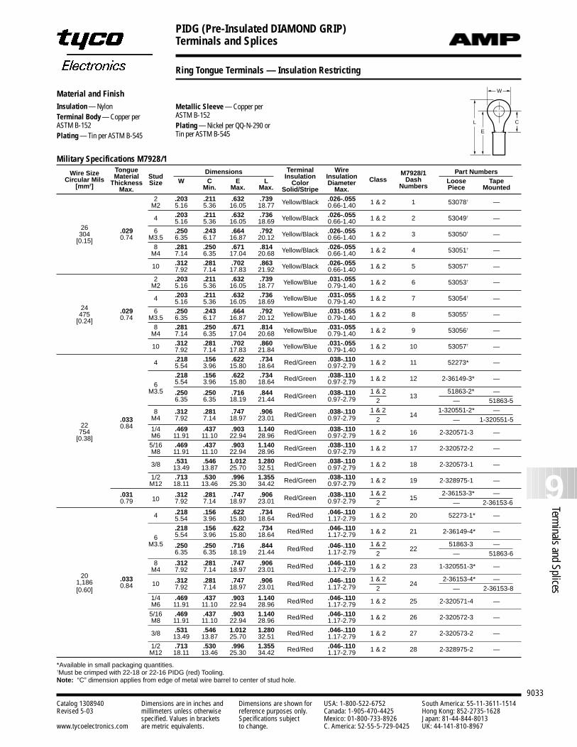
PIDG (Pre-Insulated DIAMOND GRIP)Terminals and Splices
9033
9Terminals and Splices
Catalog 1308940 Dimensions are in inches and Dimensions are shown for USA: 1-800-522-6752 South America: 55-11-3611-1514Revised 5-03 millimeters unless otherwise reference purposes only. Canada: 1-905-470-4425 Hong Kong: 852-2735-1628
specified. Values in brackets Specifications subject Mexico: 01-800-733-8926 Japan: 81-44-844-8013www.tycoelectronics.com are metric equivalents. to change. C. America: 52-55-5-729-0425 UK: 44-141-810-8967
Ring Tongue Terminals –– Insulation Restricting
Material and FinishInsulation — NylonTerminal Body — Copper perASTM B-152Plating — Tin per ASTM B-545
Metallic Sleeve — Copper per ASTM B-152Plating — Nickel per QQ-N-290 orTin per ASTM B-545
L
E
C
W
Military Specifications M7928/1
Wire Size Tongue Dimensions Terminal Wire Part NumbersCircular Mils Material Stud Insulation Insulation M7928/1
[mm2] Thickness Size W C E L Color Diameter Class Dash Loose TapeMax. Min. Max. Max. Solid/Stripe Max. Numbers Piece Mounted
2 .203 .211 .632 .739 Yellow/Black .026-.055 1 & 2 1 53078† —M2 5.16 5.36 16.05 18.77 0.66-1.40
4 .203 .211 .632 .736 Yellow/Black .026-.055 1 & 2 2 53049† —26
5.16 5.36 16.05 18.69 0.66-1.40
304 .029 6 .250 .243 .664 .792 Yellow/Black .026-.055 1 & 2 3 53050† —[0.15] 0.74 M3.5 6.35 6.17 16.87 20.12 0.66-1.40
8 .281 .250 .671 .814 Yellow/Black .026-.055 1 & 2 4 53051† —M4 7.14 6.35 17.04 20.68 0.66-1.40
10 .312 .281 .702 .863 Yellow/Black .026-.055 1 & 2 5 53057† —7.92 7.14 17.83 21.92 0.66-1.402 .203 .211 .632 .739 Yellow/Blue .031-.055 1 & 2 6 53053† —M2 5.16 5.36 16.05 18.77 0.79-1.40
4 .203 .211 .632 .736 Yellow/Blue .031-.055 1 & 2 7 53054† —24
5.16 5.36 16.05 18.69 0.79-1.40
475 .029 6 .250 .243 .664 .792 Yellow/Blue .031-.055 1 & 2 8 53055† —[0.24] 0.74 M3.5 6.35 6.17 16.87 20.12 0.79-1.40
8 .281 .250 .671 .814 Yellow/Blue .031-.055 1 & 2 9 53056† —M4 7.14 6.35 17.04 20.68 0.79-1.40
10 .312 .281 .702 .860 Yellow/Blue .031-.055 1 & 2 10 53057† —7.92 7.14 17.83 21.84 0.79-1.40
4 .218 .156 .622 .734 Red/Green .038-.110 1 & 2 11 52273* —5.54 3.96 15.80 18.64 0.97-2.79.218 .156 .622 .734 Red/Green .038-.110 1 & 2 12 2-36149-3* —
6 5.54 3.96 15.80 18.64 0.97-2.79M3.5 .250 .250 .716 .844 Red/Green .038-.110 1 & 2
1351863-2* —
6.35 6.35 18.19 21.44 0.97-2.79 2 — 51863-5
8 .312 .281 .747 .906 Red/Green .038-.110 1 & 214
1-320551-2* —
22.033 M4 7.92 7.14 18.97 23.01 0.97-2.79 2 — 1-320551-5
7540.84 1/4 .469 .437 .903 1.140 Red/Green .038-.110 1 & 2 16 2-320571-3 —
[0.38] M6 11.91 11.10 22.94 28.96 0.97-2.795/16 .469 .437 .903 1.140 Red/Green .038-.110 1 & 2 17 2-320572-2 —M8 11.91 11.10 22.94 28.96 0.97-2.79
3/8 .531 .546 1.012 1.280 Red/Green .038-.110 1 & 2 18 2-320573-1 —13.49 13.87 25.70 32.51 0.97-2.791/2 .713 .530 .996 1.355 Red/Green .038-.110 1 & 2 19 2-328975-1 —M12 18.11 13.46 25.30 34.42 0.97-2.79
.03110
.312 .281 .747 .906 Red/Green .038-.110 1 & 215
2-36153-3* —0.79 7.92 7.14 18.97 23.01 0.97-2.79 2 — 2-36153-6
4 .218 .156 .622 .734 Red/Red .046-.110 1 & 2 20 52273-1* —5.54 3.96 15.80 18.64 1.17-2.79.218 .156 .622 .734 Red/Red .046-.110 1 & 2 21 2-36149-4* —
6 5.54 3.96 15.80 18.64 1.17-2.79M3.5 .250 .250 .716 .844 Red/Red .046-.110 1 & 2
2251863-3 —
6.35 6.35 18.19 21.44 1.17-2.79 2 — 51863-68 .312 .281 .747 .906 Red/Red .046-.110 1 & 2 23 1-320551-3* —
20M4 7.92 7.14 18.97 23.01 1.17-2.79
1,186 .03310 .312 .281 .747 .906 Red/Red .046-.110 1 & 2
242-36153-4* —
[0.60]0.84 7.92 7.14 18.97 23.01 1.17-2.79 2 — 2-36153-8
1/4 .469 .437 .903 1.140 Red/Red .046-.110 1 & 2 25 2-320571-4 —M6 11.91 11.10 22.94 28.96 1.17-2.795/16 .469 .437 .903 1.140 Red/Red .046-.110 1 & 2 26 2-320572-3 —M8 11.91 11.10 22.94 28.96 1.17-2.79
3/8 .531 .546 1.012 1.280 Red/Red .046-.110 1 & 2 27 2-320573-2 —13.49 13.87 25.70 32.51 1.17-2.791/2 .713 .530 .996 1.355 Red/Red .046-.110 1 & 2 28 2-328975-2 —M12 18.11 13.46 25.30 34.42 1.17-2.79
*Available in small packaging quantities.†Must be crimped with 22-18 or 22-16 PIDG (red) Tooling.Note: “C” dimension applies from edge of metal wire barrel to center of stud hole.
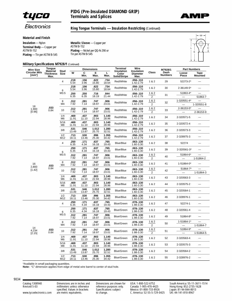
PIDG (Pre-Insulated DIAMOND GRIP)Terminals and Splices
9034Catalog 1308940 Dimensions are in inches and Dimensions are shown for USA: 1-800-522-6752 South America: 55-11-3611-1514Revised 5-03 millimeters unless otherwise reference purposes only. Canada: 1-905-470-4425 Hong Kong: 852-2735-1628
specified. Values in brackets Specifications subject Mexico: 01-800-733-8926 Japan: 81-44-844-8013www.tycoelectronics.com are metric equivalents. to change. C. America: 52-55-5-729-0425 UK: 44-141-810-8967
Ring Tongue Terminals –– Insulation Restricting (Continued)
Material and FinishInsulation — NylonTerminal Body — Copper perASTM B-152Plating — Tin per ASTM B-545
L
E
C
W
Military Specifications M7928/1 (Continued)
Wire Size Tongue Dimensions Terminal Wire Part NumbersCircular Mils Material Stud Insulation Insulation M7928/1
[mm2] Thickness Size W C E L Color Diameter Class Dash Loose TapeMax. Min. Max. Max. Solid/Stripe Max. Numbers Piece Mounted
4 .218 .156 .622 .734 Red/White .056-.110 1 & 2 29 52273-2* —5.54 3.96 15.80 18.64 1.42-2.79.218 .156 .622 .734 Red/White .056-.110 1 & 2 30 2-36149-5* —
6 5.54 3.96 15.80 18.64 1.42-2.79M3.5 .250 .250 .716 .844 Red/White .056-.110 1 & 2
3151863-4* —
6.35 6.35 18.19 21.44 1.42-2.79 2 — 51863-7
8 .312 .281 .747 .906 Red/White .056-.110 1 & 232
1-320551-4* —
18M4 7.92 7.14 18.97 23.01 1.42-2.79 2 — 1-320551-8
1,900 .03310 .312 .281 .747 .906 Red/White .056-.110 1 & 2
332-36153-5* —
[0.96] 0.84 7.92 7.14 18.97 23.01 1.42-2.79 2 — 2-36153-91/4 .469 .437 .903 1.140 Red/White .056-.110 1 & 2 34 2-320571-5 —M6 11.91 11.10 22.94 28.96 1.42-2.795/16 .469 .437 .903 1.140 Red/White .056-.110 1 & 2 35 2-320572-4 —M8 11.91 11.10 22.94 28.96 1.42-2.79
3/8 .531 .546 1.012 1.280 Red/White .056-.110 1 & 2 36 2-320573-3 —13.49 13.87 25.70 32.51 1.42-2.791/2 .713 .530 .996 1.355 Red/White .056-.110 1 & 2 37 2-328975-3 —M12 18.11 13.46 25.30 34.42 1.42-2.79
4 .250 .171 .637 .765 Blue/Blue .063-.130 1 & 2 38 52274 —6.35 4.34 16.18 19.43 1.60-3.30.250 .171 .637 .765 Blue/Blue .063-.130 1 & 2 39 2-320561-3* —
6 6.35 4.34 16.18 19.43 1.60-3.30M3.5 .312 .281 .747 .906 Blue/Blue .063-.130 1 & 2
4051864-6* —
7.92 7.14 18.97 23.01 1.60-3.30 2 — 1-51864-2
16 8 .312 .281 .747 .906 Blue/Blue .063-.130 1 & 2 41 1-51864-0* —2,800 .033 M4 7.92 7.14 18.97 23.01 1.60-3.30
[1.42] 0.8410 .312 .281 .747 .906 Blue/Blue .063-.130 1 & 2
4251864-7* —
7.92 7.14 18.97 23.01 1.60-3.30 2 — 1-51864-31/4 .469 .437 .903 1.140 Blue/Blue .063-.130 1 & 2 43 2-320563-3 —M6 11.91 11.10 22.94 28.96 1.60-3.305/16 .469 .437 .903 1.140 Blue/Blue .063-.130 1 & 2 44 2-320575-2 —M8 11.91 11.10 22.94 28.96 1.60-3.30
3/8 .531 .546 1.012 1.280 Blue/Blue .063-.130 1 & 2 45 2-320564-1 —13.49 13.87 25.70 32.51 1.60-3.301/2 .713 .530 .996 1.355 Blue/Blue .063-.130 1 & 2 46 2-328976-1 —M12 18.11 13.46 25.30 34.42 1.60-3.30
4 .250 .171 .637 .765 Blue/Green .078-.130 1 & 2 47 52274-1 —6.35 4.34 16.18 19.43 1.98-3.30.250 .171 .637 .765 Blue/Green .078-.130 1 & 2 48 2-320561-4 —
6 6.35 4.34 16.18 19.43 1.98-3.30M3.5 .312 .281 .747 .906 Blue/Green .078-.130 1 & 2 49 51864-8* —7.92 7.14 18.97 23.01 1.98-3.30
8 .312 .281 .747 .906 Blue/Green .078-.130 1 & 250
1-51864-1* —
14M4 7.92 7.14 18.97 23.01 1.98-3.30 2 — 1-51864-7
4,234 .033 10 .312 .281 .747 .906 Blue/Green .078-.130 1 & 251
51864-9* —
[2.15] 0.84 7.92 7.14 18.97 23.01 1.98-3.30 2 — 1-51864-51/4 .469 .437 .903 1.140 Blue/Green .078-.130 1 & 2 52 2-320563-4 —M6 11.91 11.10 22.94 28.96 1.98-3.30
5/16 .469 .437 .903 1.140 Blue/Green .078-.130 1 & 2 53 2-320575-3 —M8 11.91 11.10 22.94 28.96 1.98-3.30
3/8 .531 .546 1.012 1.280 Blue/Green .078-.130 1 & 2 54 2-320564-2 —13.49 13.87 25.70 32.51 1.98-3.301/2 .713 .530 .996 1.355 Blue/Green .078-.130 1 & 2 55 2-328976-2 —M12 18.11 13.46 25.30 34.42 1.98-3.30
*Available in small packaging quantities.Note: “C” dimension applies from edge of metal wire barrel to center of stud hole.
Metallic Sleeve — Copper per ASTM B-152Plating — Nickel per QQ-N-290 orTin per ASTM B-545
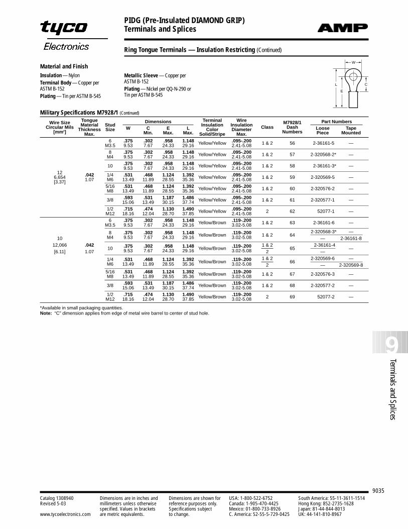
PIDG (Pre-Insulated DIAMOND GRIP)Terminals and Splices
9035
9Terminals and Splices
Catalog 1308940 Dimensions are in inches and Dimensions are shown for USA: 1-800-522-6752 South America: 55-11-3611-1514Revised 5-03 millimeters unless otherwise reference purposes only. Canada: 1-905-470-4425 Hong Kong: 852-2735-1628
specified. Values in brackets Specifications subject Mexico: 01-800-733-8926 Japan: 81-44-844-8013www.tycoelectronics.com are metric equivalents. to change. C. America: 52-55-5-729-0425 UK: 44-141-810-8967
Ring Tongue Terminals –– Insulation Restricting (Continued)
Material and FinishInsulation — NylonTerminal Body — Copper perASTM B-152Plating — Tin per ASTM B-545
L
E
C
W
Military Specifications M7928/1 (Continued)
Wire Size Tongue Dimensions Terminal Wire Part NumbersCircular Mils Material Stud Insulation Insulation M7928/1
[mm2] Thickness Size W C E L Color Diameter Class Dash Loose TapeMax. Min. Max. Max. Solid/Stripe Max. Numbers Piece Mounted
6 .375 .302 .958 1.148 Yellow/Yellow .095-.200 1 & 2 56 2-36161-5 —M3.5 9.53 7.67 24.33 29.16 2.41-5.088 .375 .302 .958 1.148 Yellow/Yellow .095-.200 1 & 2 57 2-320568-2* —M4 9.53 7.67 24.33 29.16 2.41-5.08
10 .375 .302 .958 1.148 Yellow/Yellow .095-.200 1 & 2 58 2-36161-3* —12
9.53 7.67 24.33 29.16 2.41-5.08
6,654 .042 1/4 .531 .468 1.124 1.392 Yellow/Yellow .095-.200 1 & 2 59 2-320569-5 —[3.37] 1.07 M6 13.49 11.89 28.55 35.36 2.41-5.08
5/16 .531 .468 1.124 1.392 Yellow/Yellow .095-.200 1 & 2 60 2-320576-2 —M8 13.49 11.89 28.55 35.36 2.41-5.08
3/8 .593 .531 1.187 1.486 Yellow/Yellow .095-.200 1 & 2 61 2-320577-1 —15.06 13.49 30.15 37.74 2.41-5.081/2 .715 .474 1.130 1.490 Yellow/Yellow .095-.200 2 62 52077-1 —M12 18.16 12.04 28.70 37.85 2.41-5.086 .375 .302 .958 1.148 Yellow/Brown .119-.200 1 & 2 63 2-36161-6 —M3.5 9.53 7.67 24.33 29.16 3.02-5.08
8 .375 .302 .958 1.148 Yellow/Brown .119-.200 1 & 2 642-320568-3* —
10 M4 9.53 7.67 24.33 29.16 3.02-5.08 — 2-36161-812,066 .042
10 .375 .302 .958 1.148 Yellow/Brown .119-.200 1 & 265
2-36161-4—
[6.11] 1.07 9.53 7.67 24.33 29.16 3.02-5.08 2 —
1/4 .531 .468 1.124 1.392 Yellow/Brown .119-.200 1 & 266
2-320569-6 —M6 13.49 11.89 28.55 35.36 3.02-5.08 2 — 2-320569-8
5/16 .531 .468 1.124 1.392 Yellow/Brown .119-.200 1 & 2 67 2-320576-3 —M8 13.49 11.89 28.55 35.36 3.02-5.08
3/8 .593 .531 1.187 1.486 Yellow/Brown .119-.200 1 & 2 68 2-320577-2 —15.06 13.49 30.15 37.74 3.02-5.081/2 .715 .474 1.130 1.490 Yellow/Brown .119-.200 2 69 52077-2 —M12 18.16 12.04 28.70 37.85 3.02-5.08
*Available in small packaging quantities.Note: “C” dimension applies from edge of metal wire barrel to center of stud hole.
Metallic Sleeve — Copper per ASTM B-152Plating — Nickel per QQ-N-290 orTin per ASTM B-545
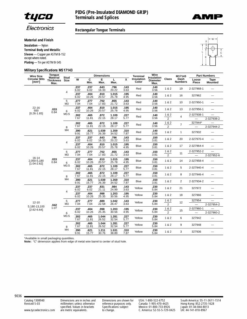
PIDG (Pre-Insulated DIAMOND GRIP)Terminals and Splices
9036Catalog 1308940 Dimensions are in inches and Dimensions are shown for USA: 1-800-522-6752 South America: 55-11-3611-1514Revised 5-03 millimeters unless otherwise reference purposes only. Canada: 1-905-470-4425 Hong Kong: 852-2735-1628
specified. Values in brackets Specifications subject Mexico: 01-800-733-8926 Japan: 81-44-844-8013www.tycoelectronics.com are metric equivalents. to change. C. America: 52-55-5-729-0425 UK: 44-141-810-8967
Rectangular Tongue Terminals
Military Specifications MS17143
Wire Size Tongue Dimensions Wire Part NumbersCircular Mils Material Stud Terminal Insulation M17143
[mm2] Thickness Size W C E L X Insulation Diameter Class Dash Loose TapeMax. Min. Max. Max. Color Max. Numbers Piece Mounted
.237 .237 .643 .796 .143 Red .140 1 & 2 19 2-327968-1 —4
6.02 6.02 16.33 20.22 3.63 3.56.237 .404 .810 1.015 .195 Red .140 1 & 2 16 327962 —6.02 10.26 20.57 25.78 4.95 3.56
5 .277 .277 .702 .855 .143 Red .140 1 & 2 10 2-327950-1 —M3 7.04 7.04 17.83 21.72 3.63 3.5622-16 .237 .404 .810 1.015 .195 Red .140 1 & 2 13 2-327956-1 —500 .033
6 6.02 10.26 20.57 25.78 4.95 3.56[0.26-1.65] 0.84
M3.5 .302 .465 .872 1.109 .227 Red .140 1 & 24
2-327938-1 —7.67 11.81 22.15 28.17 5.77 3.56 2 — 2-327938-2
.302 .465 .872 1.109 .227 Red .140 1 & 27
327944* —
8 7.67 11.81 22.15 28.17 5.77 3.56 2 — 2-327944-2M4 .390 .621 1.039 1.359 .310 Red .140 1 & 2 1 327932 —9.91 15.77 26.39 34.52 7.87 3.56
.237 .237 .643 .796 .143 Blue .150 1 & 2 20 2-327970-4 —4
6.02 6.02 16.33 20.22 3.63 3.81.237 .404 .810 1.015 .195 Blue .150 1 & 2 17 2-327964-4 —6.02 10.26 20.57 25.78 4.95 3.81
5 .277 .277 .702 .855 .143 Blue .150 1 & 211
2-327952-2 —
16-14M3 7.04 7.04 17.83 21.72 3.63 3.81 2 — 2-327952-6
2,050-5,180 .033 .237 .404 .810 1.015 .195 Blue .150 1 & 2 14 2-327958-4 —[1.04-2.62] 0.84 6 6.02 10.26 20.57 25.78 4.95 3.81
M3.5 .302 .465 .872 1.109 .227 Blue .150 1 & 2 5 2-327940-4 —7.67 11.81 22.15 28.17 5.77 3.81.302 .465 .872 1.109 .227 Blue .150 1 & 2 8 2-327946-4 —
8 7.67 11.81 22.15 28.17 5.77 3.81M4 .390 .621 1.039 1.359 .310 Blue .150 1 & 2 2 2-327934-2 —9.91 15.77 26.39 34.52 7.87 3.81
.237 .237 .831 .984 .143 Yellow .230 1 & 2 21 327972 —4
6.02 6.02 21.11 24.99 3.63 5.84.237 .404 .998 1.203 .195 Yellow .230 1 & 2 18 327966 —6.02 10.26 25.35 30.56 4.95 5.84
12-10 5 .277 .277 .889 1.042 .143 Yellow .230 1 & 212
327954 —
5,180-13,100 .042 M3 7.04 7.04 22.58 26.47 3.63 5.84 2 — 2-327954-2
[2.62-6.64]1.07 .237 .404 .998 1.203 .195 Yellow .230 1 & 2
152-327960-1 —
6 6.02 10.26 25.35 30.56 4.95 5.84 2 — 2-327960-2M3.5 .302 .465 1.044 1.281 .227 Yellow .230 1 & 2 6 327942 —7.67 11.81 26.52 32.54 5.77 5.84
.302 .465 1.044 1.281 .227 Yellow .230 1 & 2 9 327948 —8 7.67 11.81 26.52 32.54 5.77 5.84
M4 .390 .621 1.211 1.531 .310 Yellow .230 1 & 2 3 327936 —9.91 15.77 30.76 38.89 7.87 5.84
*Available in small packaging quantities.Note: “C” dimension applies from edge of metal wire barrel to center of stud hole.
Material and FinishInsulation — NylonTerminal Body and MetallicSleeve — Copper per ASTM B-152except where noted.Plating — Tin per ASTM B-545
L
E
W
C
X
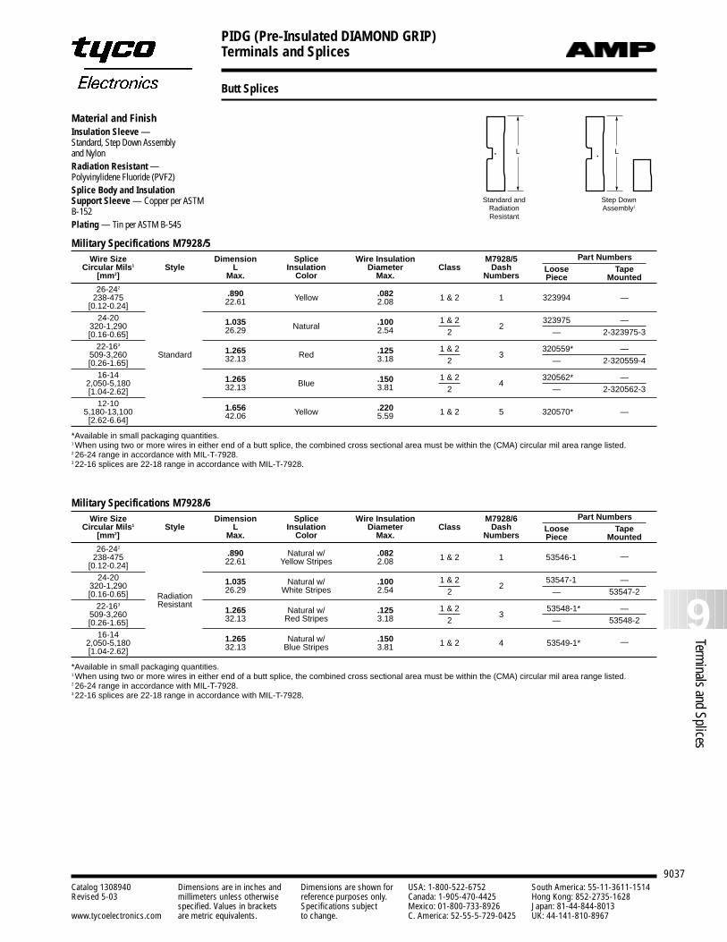
PIDG (Pre-Insulated DIAMOND GRIP)Terminals and Splices
9037
9Terminals and Splices
Catalog 1308940 Dimensions are in inches and Dimensions are shown for USA: 1-800-522-6752 South America: 55-11-3611-1514Revised 5-03 millimeters unless otherwise reference purposes only. Canada: 1-905-470-4425 Hong Kong: 852-2735-1628
specified. Values in brackets Specifications subject Mexico: 01-800-733-8926 Japan: 81-44-844-8013www.tycoelectronics.com are metric equivalents. to change. C. America: 52-55-5-729-0425 UK: 44-141-810-8967
Butt Splices
Material and FinishInsulation Sleeve —Standard, Step Down Assembly and NylonRadiation Resistant — Polyvinylidene Fluoride (PVF2)Splice Body and InsulationSupport Sleeve — Copper per ASTMB-152Plating — Tin per ASTM B-545
L L
Step DownAssembly1
Standard andRadiationResistant
PIDG Butt Spices
Military Specifications M7928/6Wire Size Dimension Splice Wire Insulation M7928/6 Part Numbers
Circular Mils1 Style L Insulation Diameter Class Dash Loose Tape[mm2] Max. Color Max. Numbers Piece Mounted26-242
.890 Natural w/ .082238-475 1 & 2 1 53546-1 —[0.12-0.24] 22.61 Yellow Stripes 2.08
24-20320-1,290 1.035 Natural w/ .100 1 & 2
253547-1 —
[0.16-0.65] Radiation26.29 White Stripes 2.54 2 — 53547-2
22-163 Resistant509-3,260 1.265 Natural w/ .125 1 & 2
353548-1* —
[0.26-1.65] 32.13 Red Stripes 3.18 2 — 53548-2
16-14 1.265 Natural w/ .1502,050-5,180 1 & 2 4 53549-1* —[1.04-2.62] 32.13 Blue Stripes 3.81
*Available in small packaging quantities.1 When using two or more wires in either end of a butt splice, the combined cross sectional area must be within the (CMA) circular mil area range listed.2 26-24 range in accordance with MIL-T-7928.3 22-16 splices are 22-18 range in accordance with MIL-T-7928.
Military Specifications M7928/5Wire Size Dimension Splice Wire Insulation M7928/5 Part Numbers
Circular Mils1 Style L Insulation Diameter Class Dash Loose Tape[mm2] Max. Color Max. Numbers Piece Mounted26-242
.890 .082238-475 Yellow 1 & 2 1 323994 —[0.12-0.24] 22.61 2.08
24-20320-1,290 1.035 Natural .100 1 & 2
2323975 —
[0.16-0.65] 26.29 2.54 2 — 2-323975-3
22-163
509-3,260 Standard 1.265 Red .125 1 & 23
320559* —
[0.26-1.65] 32.13 3.18 2 — 2-320559-4
16-142,050-5,180 1.265 Blue .150 1 & 2
4320562* —
[1.04-2.62] 32.13 3.81 2 — 2-320562-3
12-10 1.656 .2205,180-13,100 Yellow 1 & 2 5 320570* —[2.62-6.64] 42.06 5.59
*Available in small packaging quantities.1 When using two or more wires in either end of a butt splice, the combined cross sectional area must be within the (CMA) circular mil area range listed.2 26-24 range in accordance with MIL-T-7928.3 22-16 splices are 22-18 range in accordance with MIL-T-7928.
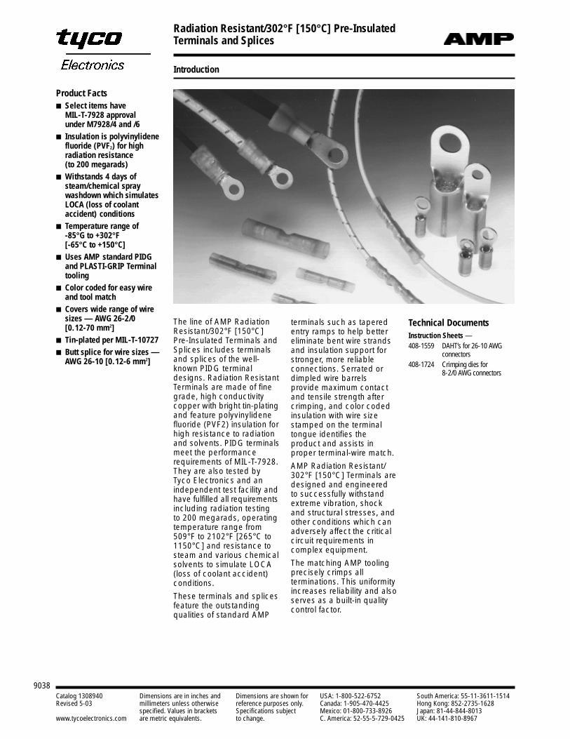
9038Catalog 1308940 Dimensions are in inches and Dimensions are shown for USA: 1-800-522-6752 South America: 55-11-3611-1514Revised 5-03 millimeters unless otherwise reference purposes only. Canada: 1-905-470-4425 Hong Kong: 852-2735-1628
specified. Values in brackets Specifications subject Mexico: 01-800-733-8926 Japan: 81-44-844-8013www.tycoelectronics.com are metric equivalents. to change. C. America: 52-55-5-729-0425 UK: 44-141-810-8967
Radiation Resistant/302°F [150°C] Pre-InsulatedTerminals and Splices
Introduction
The line of AMP RadiationResistant/302°F [150°C]Pre-Insulated Terminals andSplices includes terminalsand splices of the well-known PIDG terminaldesigns. Radiation ResistantTerminals are made of finegrade, high conductivitycopper with bright tin-platingand feature polyvinylidenefluoride (PVF2) insulation forhigh resistance to radiationand solvents. PIDG terminalsmeet the performancerequirements of MIL-T-7928.They are also tested byTyco Electronics and anindependent test facility andhave fulfilled all requirementsincluding radiation testingto 200 megarads, operatingtemperature range from509°F to 2102°F [265°C to1150°C] and resistance tosteam and various chemicalsolvents to simulate LOCA(loss of coolant accident)conditions.
These terminals and splicesfeature the outstandingqualities of standard AMP
terminals such as taperedentry ramps to help bettereliminate bent wire strandsand insulation support forstronger, more reliableconnections. Serrated ordimpled wire barrelsprovide maximum contactand tensile strength aftercrimping, and color codedinsulation with wire sizestamped on the terminaltongue identifies theproduct and assists inproper terminal-wire match.
AMP Radiation Resistant/302°F [150°C] Terminals aredesigned and engineeredto successfully withstandextreme vibration, shockand structural stresses, andother conditions which canadversely affect the criticalcircuit requirements incomplex equipment.
The matching AMP toolingprecisely crimps allterminations. This uniformityincreases reliability and alsoserves as a built-in qualitycontrol factor.
Technical DocumentsInstruction Sheets — 408-1559 DAHT’s for 26-10 AWG
connectors408-1724 Crimping dies for
8-2/0 AWG connectors
Product Facts Select items have
MIL-T-7928 approval under M7928/4 and /6
Insulation is polyvinylidenefluoride (PVF2) for high radiation resistance (to 200 megarads)
Withstands 4 days ofsteam/chemical spraywashdown which simulatesLOCA (loss of coolantaccident) conditions
Temperature range of -85°G to +302°F[-65°C to +150°C]
Uses AMP standard PIDGand PLASTI-GRIP Terminaltooling
Color coded for easy wireand tool match
Covers wide range of wiresizes — AWG 26-2/0 [0.12-70 mm2]
Tin-plated per MIL-T-10727 Butt splice for wire sizes —
AWG 26-10 [0.12-6 mm2]
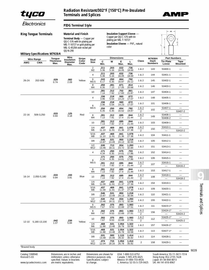
9039
9Terminals and Splices
Catalog 1308940 Dimensions are in inches and Dimensions are shown for USA: 1-800-522-6752 South America: 55-11-3611-1514Revised 5-03 millimeters unless otherwise reference purposes only. Canada: 1-905-470-4425 Hong Kong: 852-2735-1628
specified. Values in brackets Specifications subject Mexico: 01-800-733-8926 Japan: 81-44-844-8013www.tycoelectronics.com are metric equivalents. to change. C. America: 52-55-5-729-0425 UK: 44-141-810-8967
Radiation Resistant/302°F [150°C] Pre-InsulatedTerminals and Splices
PIDG Terminal Style
Material and FinishTerminal Body — Copper per QQ-C-576 with tin plating perMIL-T-10727 or gold plating per MIL-G-45204 over nickel per QQ-N-290
C
W
E
L
Military Specifications M7928/4Wire Dimensions Part NumbersWire Range Tongue Insulation Stripe Stud M7928/4
AWG CMAThickness Diameter Color Size C W E L Class Dash Tin Plate Tape
Max. Max. Code Min. Max. Max. Numbers Loose Mounted
2 .211 .203 .632 .736 1 & 2 143 53400-1 —M2 5.36 5.16 16.05 18.69
4 .211 .203 .632 .736 1 & 2 144 53401-1 —5.36 5.16 16.05 18.69
26-24 202-509 .029 .082 Yellow 6 .243 .250 .664 .792 1 & 2 145 53402-1 —0.74 2.09 M3.5 6.17 6.35 16.87 20.12
8 .250 .281 .671 .814 1 & 2 146 53403-1 —M4 6.35 7.13 17.05 20.68
10 .281 .312 .702 .861 1 & 2 147 53404-1 —7.14 7.92 17.83 21.87
4 .156 .218 .560 .672 1 & 2 148 53405-1 —3.96 5.54 14.23 17.07.156 .218 .560 .672 1 & 2 101 53406-1 —
6 3.96 5.54 14.23 17.07M3.5 .250 .250 .654 .782 1 & 2
10253407-1 —
.033 .1256.35 6.35 16.62 19.87 2 — 53407-2
22-16 509-3,250 0.84 3.18 Red 8 .281 .312 .685 .844 1 & 2149
53408-1 —M4 7.13 7.91 17.4 21.44 2 53408-2 —
10 .281 .312 .685 .844 1 & 2 103 53409-1 —7.13 7.92 17.4 21.44
1/4 .437 .469 .841 1.078 1 & 2150
53410-1 —M6 11.10 11.91 21.36 27.38 2 — 53410-2
5/16 .437 .469 .841 1.078 1 & 2 104 53411-1 —M8 11.10 11.91 21.36 27.38
3/8 .546 .531 .950 1.218 1 & 2 105 53412-1 —13.87 13.49 24.13 30.941/2 .530 .713 .934 1.293 1 & 2 151 53413-1 —M12 13.46 18.11 23.72 32.84
4 .171 .250 .575 .703 1 & 2 152 53414-1 —4.34 6.35 14.61 17.86.171 .250 .575 .703 1 & 2 106 53415-1 —
6 4.34 6.35 14.61 17.86M3.5 .281 .312 .685 .844 1 & 2
10753416-1 —
7.13 7.92 17.4 21.44 2 — 53416-28 .281 .312 .685 .844 1 & 2 153 53417-1 —M4 7.13 7.92 17.4 21.44
.033 .150 Blue 10 .281 .312 .685 .844 1 & 2108
53418-1 —16-14 2,050-5,180 0.84 3.81 7.13 7.92 17.4 21.44 2 — 53418-2
1/4 .437 .469 .841 1.078 1 & 2 154 53419-1 —M6 11.09 11.91 21.37 27.395/16 .437 .469 .841 1.078 1 & 2 109 53420-1 —M8 11.09 11.91 21.37 27.39
3/8 .546 .531 .950 1.218 1 & 2 110 53421-1 —13.87 13.49 24.13 30.941/2 .530 .713 .934 1.293 1 & 2 155 53422-1 —M12 13.46 18.11 23.72 32.846 .302 .375 .893 1.083 1 & 2 111 53423-1* —M3.5 7.67 9.53 22.69 27.51
8 .302 .375 .893 1.083 1 & 2156
53424-1* —M4 7.67 9.53 22.69 27.51 2 — 53424-2
10 .302 .375 .893 1.083 1 & 2112
53425-1* —
12-10 5,180-13,100 .042 .230 Yellow7.67 9.53 22.69 27.51 2 — 53425-2
1.07 5.84 1/4 .468 .531 1.054 1.322 1 & 2 157 53426-1* —M6 11.88 13.48 26.78 33.585/16 .468 .531 1.054 1.322 1 & 2 113 53427-1* —M8 11.88 13.48 26.78 33.58
3/8 .531 .593 1.115 1.414 1 & 2 114 53428-1 —13.48 15.06 28.32 35.921/2 .474 .715 1.054 1.414 2 158 53429-1 —M12 12.04 18.16 26.78 35.92
*Brazed body
Insulation Support Sleeve —Copper per QQ-C-576 with tin plating per MIL-T-10727Insulation Sleeve — PVF2, naturalcolor
Ring Tongue Terminals
CL
E
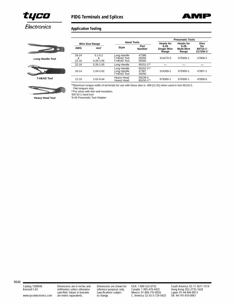
PIDG Terminals and Splices
9040Catalog 1308940 Dimensions are in inches and Dimensions are shown for USA: 1-800-522-6752 South America: 55-11-3611-1514Revised 5-03 millimeters unless otherwise reference purposes only. Canada: 1-905-470-4425 Hong Kong: 852-2735-1628
specified. Values in brackets Specifications subject Mexico: 01-800-733-8926 Japan: 81-44-844-8013www.tycoelectronics.com are metric equivalents. to change. C. America: 52-55-5-729-0425 UK: 44-141-810-8967
Application Tooling
Wire Size Range Hand ToolsPneumatic Tools
Heads for Heads for Dies
AWG mm2 Style Part 6-26 6-26 forNumber Single Wire Multi-Wire 69710-11
Range Range 217200-12
26-24 0.1-0.2 Long Handle 47386 -1& & T-HEAD Tool 59250 314270-3 679305-1 47806-2
22-16 0.26-1.65 T-HEAD Tool 5930022-16 0.26-1.65 Long Handle -1**69151-1** — — —
Long Handle -1**69152-1** -116-14 1.04-2.62 Long Handle 47387 314269-1 679305-1 47807-1
T-HEAD Tool 59250Heavy Head -159239-412-10 2.62-6.64 Heavy Head -1**69150-1** 679300-1 679305-1 47808-6
**Maximum tongue width of terminals for use with these dies is .469 [11.91] when used in tool 46110-2. Flat tongues only.
**For wires with thin wall insulation.169710-1 hand tool26-26 Pneumatic Tool Adapter
Long Handle Tool
Heavy Head Tool
T-HEAD Tool
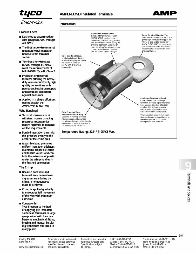
AMPLI-BOND Insulated Terminals
9041
9Terminals and Splices
Catalog 1308940 Dimensions are in inches and Dimensions are shown for USA: 1-800-522-6752 South America: 55-11-3611-1514Revised 5-03 millimeters unless otherwise reference purposes only. Canada: 1-905-470-4425 Hong Kong: 852-2735-1628
specified. Values in brackets Specifications subject Mexico: 01-800-733-8926 Japan: 81-44-844-8013www.tycoelectronics.com are metric equivalents. to change. C. America: 52-55-5-729-0425 UK: 44-141-810-8967
Introduction
Product Facts Designed to accommodate
wire gauges 8 AWG through4/0 AWG
The first large wire terminalto feature vinyl insulationbonded to the terminalsleeve
Terminals for wire sizes 8 AWG through 4/0 AWGmeet the requirements ofMIL-T-7928, Type II, Class 2
Precision-engineered terminal offering the heavy-duty wire user uniformly highquality connections withpermanent insulation supportand complete protectionagainst flash over
Applied in a single effortlessoperation with the AMP DYNA-CRIMP tool
Why Bonding? Terminal insulators must
withstand intense crimpingpressures necessary fortoday’s high wire-to-terminalcontact requirements
Bonded insulation transmitsthis pressure evenly to thecenter of the crimp area
A positive bond promotesuniform insulation thickness,maintains proper dielectricand tensile values and con-trols the extrusion of plasticunder the crimping dies inthe finished connection
The Crimp Because both wire and
terminal are confined over a greater area during thecrimp, a homogeneousmass is achieved
Crimp is applied graduallyto encourage full movementof the wire with minimumextrusion
Compare this Tyco Electronics method of applying pre-insulated solderless terminals to largegauge wires with the cum-bersome mechanical fitting,brazing and manual insulat-ing techniques still used inmany plants
Basic Terminal Material. Thebasic terminal is constructed of finegrade high conductivity copper per ASTM B-152 and tin-plated perASTM B-545. AMP’s special platingprocess creates durable corrosionresistance to salt spray and mostchemical fumes.
Inner Bonding Sleeve.Insulation is bonded to this(ASTM B-152) copper sleeve…the secret of superior AMPLI-BOND terminal construction.
Fully Protected RearInsulation Support Ring.Separate metal ring providesinsulation support to dampenvibration and prevent sharp bendson conductor. Steel (ASTM A-109,Tin plated per ASTM B-545).
Insulation Proofmarked andColor Coded. Color coding ofterminals provides rapid indentifica-tion, assures selection of properterminal. For additional qualitycontrol, crimping die embosseswire size number on insulation.
Vinyl insulation extends minimumdistance beyond terminal barrel toprevent exposure of conductorduring stress and vibration.
Barrel with Brazed Seam,Dimpled Inner Surface. EachAMPLI-BOND terminal body isindividually brazed for ruggednessand deformation control during thecrimping operation. Dimpling oninner barrel surface provides morecontact area of wire to terminaland additional tensile strength.
Temperature Rating: 221°F [105°C] Max.
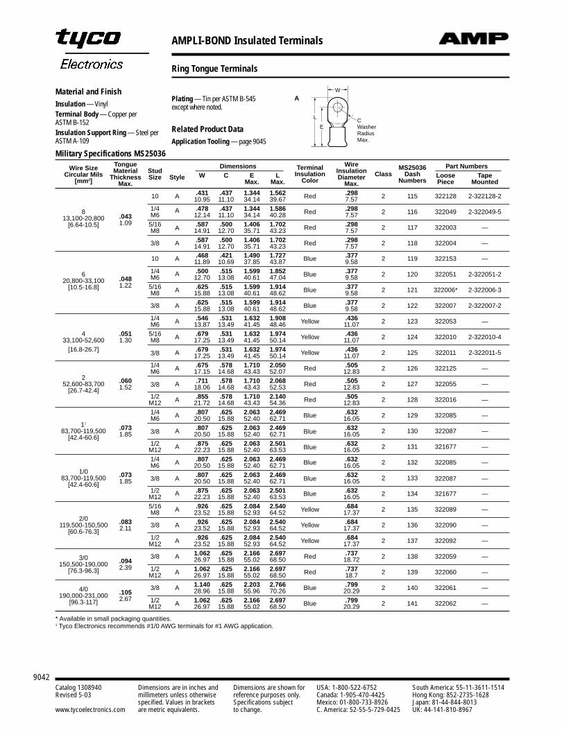
AMPLI-BOND Insulated Terminals
9042Catalog 1308940 Dimensions are in inches and Dimensions are shown for USA: 1-800-522-6752 South America: 55-11-3611-1514Revised 5-03 millimeters unless otherwise reference purposes only. Canada: 1-905-470-4425 Hong Kong: 852-2735-1628
specified. Values in brackets Specifications subject Mexico: 01-800-733-8926 Japan: 81-44-844-8013www.tycoelectronics.com are metric equivalents. to change. C. America: 52-55-5-729-0425 UK: 44-141-810-8967
Military Specifications MS25036
Wire Size Tongue Dimensions Wire Part NumbersCircular Mils Material Stud Terminal Insulation MS25036
[mm2] Thickness Size Style W C E L Insulation Diameter Class Dash Loose TapeMax. Max. Max. Color Max. Numbers Piece Mounted
A .431 .437 1.344 1.562 Red .298 2 115 322128 2-322128-210 10.95 11.10 34.14 39.67 7.57
8 1/4 .478 .437 1.344 1.586 Red .298 2 116 322049 2-322049-513,100-20,800 .043 M6
A12.14 11.10 34.14 40.28 7.57
[6.64-10.5] 1.09 5/16 .587 .500 1.406 1.702 Red .298 2 117 322003 —M8 A 14.91 12.70 35.71 43.23 7.57
3/8 A .587 .500 1.406 1.702 Red .298 2 118 322004 —14.91 12.70 35.71 43.23 7.57.468 .421 1.490 1.727 Blue .377 2 119 322153 —10 A 11.89 10.69 37.85 43.87 9.58
6 1/4 .500 .515 1.599 1.852 Blue .377 2 120 322051 2-322051-220,800-33,100 .048 M6 A 12.70 13.08 40.61 47.04 9.58
[10.5-16.8] 1.22 5/16 A .625 .515 1.599 1.914 Blue .377 2 121 322006* 2-322006-3M8 15.88 13.08 40.61 48.62 9.58
3/8 A .625 .515 1.599 1.914 Blue .377 2 122 322007 2-322007-215.88 13.08 40.61 48.62 9.581/4 .546 .531 1.632 1.908 Yellow .436 2 123 322053 —M6 A 13.87 13.49 41.45 48.46 11.07
4 .051 5/16 A .679 .531 1.632 1.974 Yellow .436 2 124 322010 2-322010-433,100-52,600 1.30 M8 17.25 13.49 41.45 50.14 11.07[16.8-26.7] A .679 .531 1.632 1.974 Yellow .436 2 125 322011 2-322011-53/8 17.25 13.49 41.45 50.14 11.07
1/4 A .675 .578 1.710 2.050 Red .505 2 126 322125 —2
M6 17.15 14.68 43.43 52.07 12.83
52,600-83,700 .060 3/8 A .711 .578 1.710 2.068 Red .505 2 127 322055 —[26.7-42.4] 1.52 18.06 14.68 43.43 52.53 12.83
1/2 A .855 .578 1.710 2.140 Red .505 2 128 322016 —M12 21.72 14.68 43.43 54.36 12.831/4 A .807 .625 2.063 2.469 Blue .632 2 129 322085 —
11M6 20.50 15.88 52.40 62.71 16.05
83,700-119,500 .073 3/8 A .807 .625 2.063 2.469 Blue .632 2 130 322087 —[42.4-60.6] 1.85 20.50 15.88 52.40 62.71 16.05
1/2 A .875 .625 2.063 2.501 Blue .632 2 131 321677 —M12 22.23 15.88 52.40 63.53 16.051/4 .807 .625 2.063 2.469 Blue .632 2 132 322085 —
1/0M6 A 20.50 15.88 52.40 62.71 16.05
83,700-119,500 .073 3/8 A .807 .625 2.063 2.469 Blue .632 2 133 322087 —[42.4-60.6] 1.85 20.50 15.88 52.40 62.71 16.05
1/2 A .875 .625 2.063 2.501 Blue .632 2 134 321677 —M12 22.23 15.88 52.40 63.53 16.055/16 A .926 .625 2.084 2.540 Yellow .684 2 135 322089 —
2/0M8 23.52 15.88 52.93 64.52 17.37
119,500-150,500 .083 3/8 A .926 .625 2.084 2.540 Yellow .684 2 136 322090 —[60.6-76.3] 2.11 23.52 15.88 52.93 64.52 17.37
1/2 A .926 .625 2.084 2.540 Yellow .684 2 137 322092 —M12 23.52 15.88 52.93 64.52 17.37
3/8 A 1.062 .625 2.166 2.697 Red .737 2 138 322059 —3/0 .094 26.97 15.88 55.02 68.50 18.72150,500-190,000 2.39 1/2 A 1.062 .625 2.166 2.697 Red .737 2 139 322060 —[76.3-96.3]
M12 26.97 15.88 55.02 68.50 18.7
3/8 A 1.140 .625 2.203 2.766 Blue .799 2 140 322061 —4/0 .105 28.96 15.88 55.96 70.26 20.29190,000-231,000 2.67 1/2 A 1.062 .625 2.166 2.697 Blue .799 2 141 322062 —[96.3-117]
M12 26.97 15.88 55.02 68.50 20.29
* Available in small packaging quantities.1 Tyco Electronics recommends #1/0 AWG terminals for #1 AWG application.
Material and FinishInsulation — VinylTerminal Body — Copper perASTM B-152Insulation Support Ring — Steel perASTM A-109
L
ECWRM
W
Plating — Tin per ASTM B-545except where noted.
Related Product DataApplication Tooling — page 9045
AW
L
ECWasherRadiusMax.
Ring Tongue Terminals
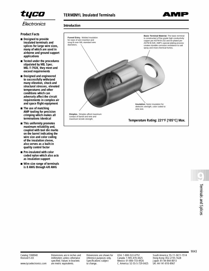
TERMINYL Insulated Terminals
9043
9Terminals and Splices
Catalog 1308940 Dimensions are in inches and Dimensions are shown for USA: 1-800-522-6752 South America: 55-11-3611-1514Revised 5-03 millimeters unless otherwise reference purposes only. Canada: 1-905-470-4425 Hong Kong: 852-2735-1628
specified. Values in brackets Specifications subject Mexico: 01-800-733-8926 Japan: 81-44-844-8013www.tycoelectronics.com are metric equivalents. to change. C. America: 52-55-5-729-0425 UK: 44-141-810-8967
Introduction
Product Facts Designed to provide
insulated terminals andsplices for large wire sizes,many of which are used inairborne and ground supportapplications
Tested under the proceduresstipulated by MIL Spec.MIL-T-7928, they meet andexceed requirements
Designed and engineered to successfully withstandmany vibration, shock andstructural stresses, elevatedtemperatures and other conditions which canadversely affect the circuitrequirements in complex airand space flight equipment
The use of matching AMP tooling for precisioncrimping which makes allterminations identical
This uniformity promotesmaximum reliability and,coupled with tool die markson the barrel indicating thewire size and color codingof the insulation sleeve,also serves as a built-inquality control factor
Pre-insulated with colorcoded nylon which also actsas insulation support
Wire size range of terminalsis 8 AWG through 4/0 AWG
Basic Terminal Material. The basic terminalis constructed of fine grade high conductivitycopper per ASTM B-152 and tin-plated perASTM B-545. AMP’s special plating processcreates durable corrosion resistance to saltspray and most chemical fumes.
Funnel Entry. Molded insulationfor ease of wire insertion andsnug fit over MIL-standard wirediameters.
Dimples. Dimples afford maximumcontact of barrel and wire andmaximum tensile strength.
Insulation. Nylon insulation fordielectric strength, color coded towire size.
Temperature Rating: 221°F [105°C] Max.
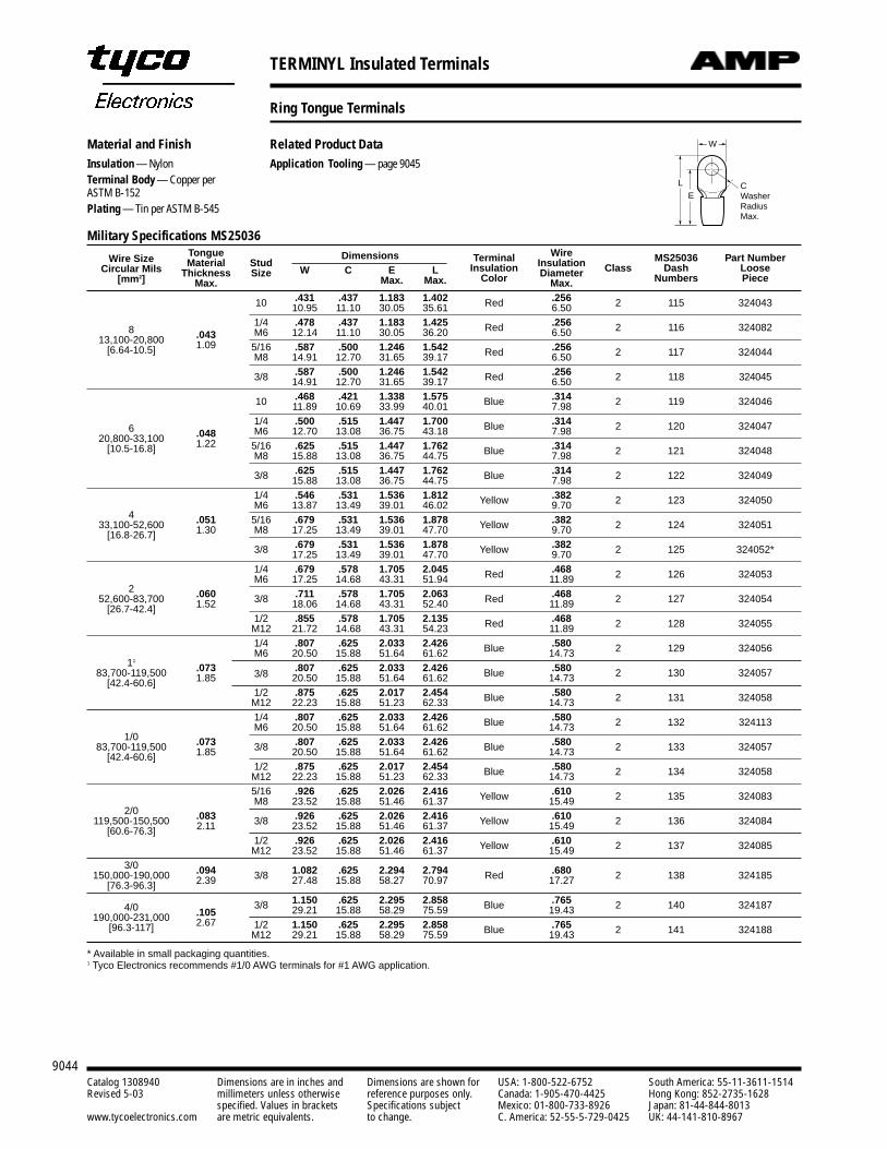
TERMINYL Insulated Terminals
9044Catalog 1308940 Dimensions are in inches and Dimensions are shown for USA: 1-800-522-6752 South America: 55-11-3611-1514Revised 5-03 millimeters unless otherwise reference purposes only. Canada: 1-905-470-4425 Hong Kong: 852-2735-1628
specified. Values in brackets Specifications subject Mexico: 01-800-733-8926 Japan: 81-44-844-8013www.tycoelectronics.com are metric equivalents. to change. C. America: 52-55-5-729-0425 UK: 44-141-810-8967
Military Specifications MS25036
Wire Size Tongue Dimensions Wire Part NumberCircular Mils Material Stud Terminal Insulation MS25036
[mm2] Thickness Size W C E L Insulation Diameter Class Dash Loose
Max. Max. Max. Color Max. Numbers Piece
10 .431 .437 1.183 1.402 Red .256 2 115 32404310.95 11.10 30.05 35.61 6.50
81/4 .478 .437 1.183 1.425 Red .256 2 116 324082
13,100-20,800 .043 M6 12.14 11.10 30.05 36.20 6.50
[6.64-10.5] 1.09 5/16 .587 .500 1.246 1.542 Red .256 2 117 324044M8 14.91 12.70 31.65 39.17 6.50
3/8 .587 .500 1.246 1.542 Red .256 2 118 32404514.91 12.70 31.65 39.17 6.50
10 .468 .421 1.338 1.575 Blue .314 2 119 32404611.89 10.69 33.99 40.01 7.98
61/4 .500 .515 1.447 1.700 Blue .314 2 120 324047
20,800-33,100 .048 M6 12.70 13.08 36.75 43.18 7.98
[10.5-16.8] 1.22 5/16 .625 .515 1.447 1.762 Blue .314 2 121 324048M8 15.88 13.08 36.75 44.75 7.98
3/8 .625 .515 1.447 1.762 Blue .314 2 122 32404915.88 13.08 36.75 44.75 7.981/4 .546 .531 1.536 1.812 Yellow .382 2 123 324050
4M6 13.87 13.49 39.01 46.02 9.70
33,100-52,600 .051 5/16 .679 .531 1.536 1.878 Yellow .382 2 124 324051[16.8-26.7] 1.30 M8 17.25 13.49 39.01 47.70 9.70
3/8 .679 .531 1.536 1.878 Yellow .382 2 125 324052*17.25 13.49 39.01 47.70 9.701/4 .679 .578 1.705 2.045 Red .468 2 126 324053
2M6 17.25 14.68 43.31 51.94 11.89
52,600-83,700 .060 3/8 .711 .578 1.705 2.063 Red .468 2 127 324054[26.7-42.4] 1.52 18.06 14.68 43.31 52.40 11.89
1/2 .855 .578 1.705 2.135 Red .468 2 128 324055M12 21.72 14.68 43.31 54.23 11.891/4 .807 .625 2.033 2.426 Blue .580 2 129 324056
11M6 20.50 15.88 51.64 61.62 14.73
83,700-119,500 .073 3/8 .807 .625 2.033 2.426 Blue .580 2 130 324057[42.4-60.6] 1.85 20.50 15.88 51.64 61.62 14.73
1/2 .875 .625 2.017 2.454 Blue .580 2 131 324058M12 22.23 15.88 51.23 62.33 14.731/4 .807 .625 2.033 2.426 Blue .580 2 132 324113
1/0M6 20.50 15.88 51.64 61.62 14.73
83,700-119,500 .073 3/8 .807 .625 2.033 2.426 Blue .580 2 133 324057[42.4-60.6] 1.85 20.50 15.88 51.64 61.62 14.73
1/2 .875 .625 2.017 2.454 Blue .580 2 134 324058M12 22.23 15.88 51.23 62.33 14.735/16 .926 .625 2.026 2.416 Yellow .610 2 135 324083M8 23.52 15.88 51.46 61.37 15.49
2/0 .083 3/8 .926 .625 2.026 2.416 Yellow .610 2 136 324084119,500-150,500 2.11 23.52 15.88 51.46 61.37 15.49[60.6-76.3]1/2 .926 .625 2.026 2.416 Yellow .610 2 137 324085M12 23.52 15.88 51.46 61.37 15.49
3/0 .094 1.082 .625 2.294 2.794 .680150,000-190,000 2.39 3/8 27.48 15.88 58.27 70.97 Red 17.27 2 138 324185[76.3-96.3]
4/0 3/8 1.150 .625 2.295 2.858 Blue .765 2 140 324187190,000-231,000 .105 29.21 15.88 58.29 75.59 19.43
[96.3-117] 2.67 1/2 1.150 .625 2.295 2.858 Blue .765 2 141 324188M12 29.21 15.88 58.29 75.59 19.43
* Available in small packaging quantities.1 Tyco Electronics recommends #1/0 AWG terminals for #1 AWG application.
Material and FinishInsulation — NylonTerminal Body — Copper perASTM B-152Plating — Tin per ASTM B-545
L
ECWasherRadiusMax.
WRelated Product DataApplication Tooling — page 9045
W
L
ECWasherRadiusMax.
Ring Tongue Terminals
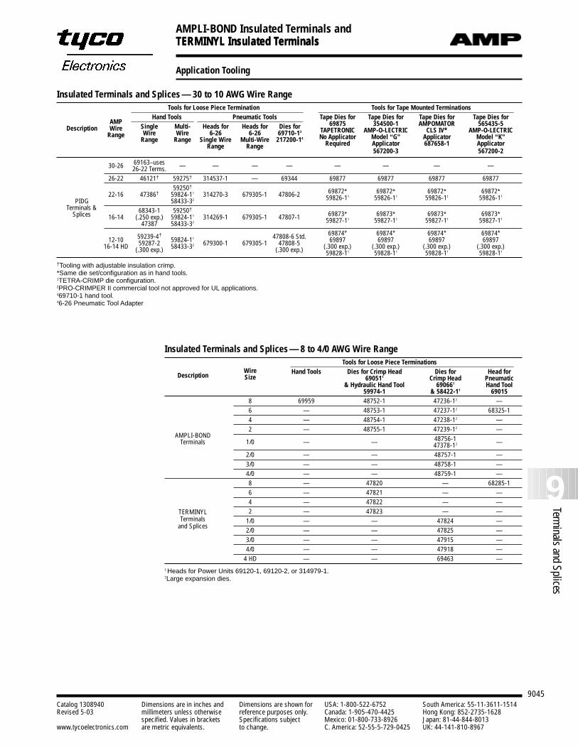
TERMINYL Insulated Terminals
9045
9Terminals and Splices
Catalog 1308940 Dimensions are in inches and Dimensions are shown for USA: 1-800-522-6752 South America: 55-11-3611-1514Revised 5-03 millimeters unless otherwise reference purposes only. Canada: 1-905-470-4425 Hong Kong: 852-2735-1628
specified. Values in brackets Specifications subject Mexico: 01-800-733-8926 Japan: 81-44-844-8013www.tycoelectronics.com are metric equivalents. to change. C. America: 52-55-5-729-0425 UK: 44-141-810-8967
Application Tooling
AMPLI-BOND Insulated Terminals andTERMINYL Insulated Terminals
Insulated Terminals and Splices — 30 to 10 AWG Wire RangeTools for Loose Piece Termination Tools for Tape Mounted Terminations
Hand Tools Pneumatic Tools Tape Dies for Tape Dies for Tape Dies for Tape Dies for
DescriptionAMP
Single Multi- Heads for Heads for Dies for 69875 354500-1 AMPOMATOR 565435-5Wire
Wire Wire 6-26 6-26 69710-13 TAPETRONIC AMP-O-LECTRIC CLS IV* AMP-O-LECTRICRange
Range Range Single Wire Multi-Wire 217200-14 No Applicator Model “G” Applicator Model “K”Range Range Required Applicator 687658-1 Applicator
567200-3 567200-2
30-26 69163–uses — — — — — — — —26-22 Terms.26-22 46121† 59275† 314537-1 — 69344 69877 69877 69877 69877
59250†69872* 69872* 69872* 69872*22-16 47386† 59824-11 314270-3 679305-1 47806-2 59826-11 59826-11 59826-11 59826-11
PIDG 58433-32
Terminals & 68343-1 59250†69873* 69873* 69873* 69873*Splices 16-14 (.250 exp.) 59824-11 314269-1 679305-1 47807-1 59827-11 59827-11 59827-11 59827-11
47387 58433-32
59239-4† 47808-6 Std. 69874* 69874* 69874* 69874*12-10 59287-2 59824-11
679300-1 679305-1 47808-5 69897 69897 69897 6989716-14 HD (.300 exp.) 58433-32
(.300 exp.) (.300 exp.) (.300 exp.) (.300 exp.) (.300 exp.)59828-11 59828-11 59828-11 59828-11
†Tooling with adjustable insulation crimp.*Same die set/configuration as in hand tools.1TETRA-CRIMP die configuration.2PRO-CRIMPER II commercial tool not approved for UL applications.369710-1 hand tool.46-26 Pneumatic Tool Adapter
Insulated Terminals and Splices — 8 to 4/0 AWG Wire RangeTools for Loose Piece Terminations
DescriptionWire Hand Tools Dies for Crimp Head Dies for Head forSize 690511 Crimp Head Pneumatic
& Hydraulic Hand Tool 690661 Hand Tool59974-1 & 58422-11 69015
8 69959 48752-1 47236-12 —6 — 48753-1 47237-12 68325-14 — 48754-1 47238-12 —2 — 48755-1 47239-12 —
AMPLI-BOND1/0 — — 48756-1 —Terminals 47378-12
2/0 — — 48757-1 —3/0 — — 48758-1 —4/0 — — 48759-1 —8 — 47820 — 68285-16 — 47821 — —4 — 47822 — —
TERMINYL 2 — 47823 — —Terminals 1/0 — — 47824 —
and Splices2/0 — — 47825 —3/0 — — 47915 —4/0 — — 47918 —
4 HD — — 69463 —1 Heads for Power Units 69120-1, 69120-2, or 314979-1.2Large expansion dies.
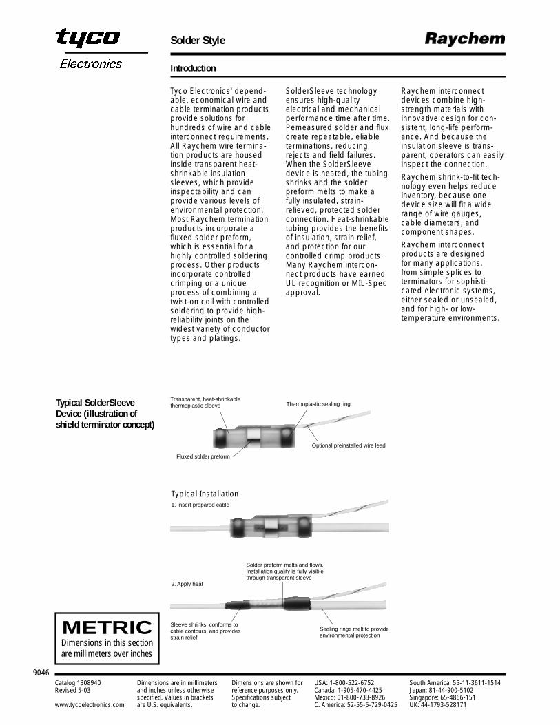
Solder Style
9046Catalog 1308940 Dimensions are in millimeters Dimensions are shown for USA: 1-800-522-6752 South America: 55-11-3611-1514Revised 5-03 and inches unless otherwise reference purposes only. Canada: 1-905-470-4425 Japan: 81-44-900-5102
specified. Values in brackets Specifications subject Mexico: 01-800-733-8926 Singapore: 65-4866-151www.tycoelectronics.com are U.S. equivalents. to change. C. America: 52-55-5-729-0425 UK: 44-1793-528171
Introduction
METRICDimensions in this sectionare millimeters over inches
Typical SolderSleeveDevice (illustration ofshield terminator concept)
Transparent, heat-shrinkablethermoplastic sleeve Thermoplastic sealing ring
Optional preinstalled wire lead
Fluxed solder preform
Sleeve shrinks, conforms tocable contours, and providesstrain relief
Solder preform melts and flows,Installation quality is fully visiblethrough transparent sleeve
Sealing rings melt to provideenvironmental protection
Typical Installation1. Insert prepared cable
2. Apply heat
Tyco Electronics' depend-able, economical wire andcable termination productsprovide solutions for hundreds of wire and cableinterconnect requirements.All Raychem wire termina-tion products are housedinside transparent heat-shrinkable insulationsleeves, which provideinspectability and can provide various levels ofenvironmental protection.Most Raychem terminationproducts incorporate afluxed solder preform,which is essential for ahighly controlled solderingprocess. Other productsincorporate controlledcrimping or a uniqueprocess of combining atwist-on coil with controlledsoldering to provide high-reliability joints on thewidest variety of conductortypes and platings.
SolderSleeve technologyensures high-quality electrical and mechanicalperformance time after time.Pemeasured solder and fluxcreate repeatable, eliableterminations, reducingrejects and field failures.When the SolderSleevedevice is heated, the tubingshrinks and the solder preform melts to make afully insulated, strain-relieved, protected solderconnection. Heat-shrinkabletubing provides the benefitsof insulation, strain relief,and protection for our controlled crimp products.Many Raychem intercon-nect products have earnedUL recognition or MIL-Specapproval.
Raychem interconnectdevices combine high-strength materials with innovative design for con-sistent, long-life perform-ance. And because theinsulation sleeve is trans-parent, operators can easilyinspect the connection.
Raychem shrink-to-fit tech-nology even helps reduceinventory, because onedevice size will fit a widerange of wire gauges, cable diameters, and component shapes.
Raychem interconnectproducts are designed for many applications, from simple splices to terminators for sophisti-cated electronic systems,either sealed or unsealed,and for high- or low-temperature environments.
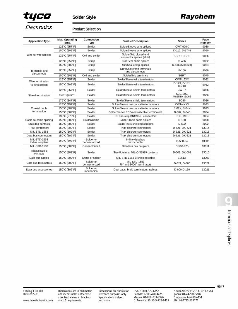
Solder Style
9047
9Terminals and Splices
Catalog 1308940 Dimensions are in millimeters Dimensions are shown for USA: 1-800-522-6752 South America: 55-11-3611-1514Revised 5-03 and inches unless otherwise reference purposes only. Canada: 1-905-470-4425 Japan: 81-44-900-5102
specified. Values in brackets Specifications subject Mexico: 01-800-733-8926 Singapore: 65-4866-151www.tycoelectronics.com are U.S. equivalents. to change. C. America: 52-55-5-729-0425 UK: 44-1793-528171
Product Selection
Application Type Max. Operating Connection Page Temp. Type Product Description Series Number
Wire-to-wire splicing
125°C [257°F] Solder SolderSleeve wire splices CWT-900X 9050150°C [302°F] Solder SolderSleeve wire splices D-110, D-1744 9050
125°C [257°F] Coil and solder SolderGrip closed end connector splices (stub) SGRP, SGRS 9056
125°C [257°F] Crimp DuraSeal crimp splices D-406 9062150°C [302°F] Crimp MiniSeal crimp splices D-436 (M81824) 9064
Terminals and 125°C [257°F] Crimp DuraSeal crimp terminals
disconnectsand disconnects B-106 9069
150°C [302°F] Coil and solder SolderGrip terminals SGRT 9075
Wire termination125°C [257°F] Solder SolderSleeve wire terminators CWT-15XX 9082
to pin/post/tab 150°C [302°F] Solder SolderSleeve wire terminators D-129, D-141, D-71X 9082
Shield termination
125°C [257°F] Solder SolderSleeve shield terminators CWT-X 9086
150°C [302°F Solder SolderSleeve shield terminators S01, S02,M83519, SO63 9086
175°C [347°F] Solder SolderSleeve shield terminators SO96 9086
Coaxial cable 125°C [257°F] Solder SolderSleeve coaxial cable terminators CWT-4XXX 9093
termination150°C [302°F] Solder SolderSleeve coaxial cable terminators B-02X, B-04X 9093150°C [302°F] Solder SolderSleeve PCB/coaxial cable terminators D-607, B-046 9094135°C [275°F] Solder RF one-step BNC/TNC connectors RBD, RTD 7034
Cable-to-cable splicing 150°C [302°F] Solder/Crimp SolderShield cable splices D-150 9098Shielded contacts 150°C [302°F] Solder SolderTacts shielded contacts D-602 2002Triax connectors 150°C [302°F] Solder Triax discrete connectors D-621, DK-621 13015MIL-STD-1553 150°C [302°F] Solder Triax discrete connectors D-621, DK-621 13015
Data bus connectors 150°C [302°F] Solder Triax discrete connectors D-621, DK-621 13015MIL-STD-1553 150°C [302°F] Solder or In-line data busIn-line couplers connectorized microcoupler D-500-04 13005
MIL-STD-1533 150°C [302°F] Connectorized Data bus box couplers D-500-025 13011
Triaxial size 8contacts 150°C [302°F] Solder Size 8, triaxial MIL-C-38999 contacts D-602, DK-602 13015
Data bus cables 150°C [302°F] Crimp or solder MIL-STD-1553 B shielded cable 1061X 13003
Data bus terminators 150°C [302°F] Solder or MIL-STD-1553connectorized 78° and 3000° terminators D-621, D-500 13021
Data bus accessories 150°C [302°F] Solder or Dust caps, braid terminators, splices D-600,D-150 13021mechanical
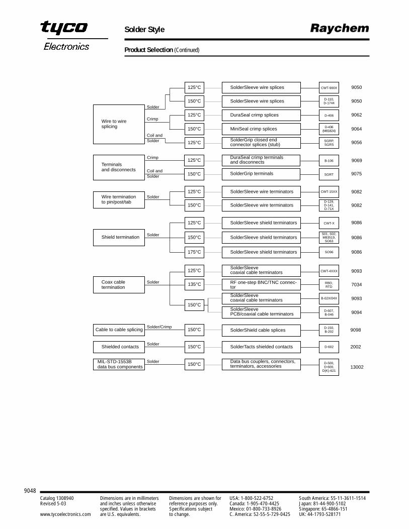
Solder Style
9048Catalog 1308940 Dimensions are in millimeters Dimensions are shown for USA: 1-800-522-6752 South America: 55-11-3611-1514Revised 5-03 and inches unless otherwise reference purposes only. Canada: 1-905-470-4425 Japan: 81-44-900-5102
specified. Values in brackets Specifications subject Mexico: 01-800-733-8926 Singapore: 65-4866-151www.tycoelectronics.com are U.S. equivalents. to change. C. America: 52-55-5-729-0425 UK: 44-1793-528171
Product Selection (Continued)
SolderSleeve wire splices
Application Type Connection Max. Product Description Series PageType Operating Number
Temp.
Wire to wire splicing
Terminals and disconnects
Wire termination to pin/post/tab
Shield termination
Coax cable termination
Cable to cable splicing
Shielded contacts
125°C CWT-900X
Solder
Crimp
Coil andSolder
Coil andSolder
Crimp
Solder
Solder
Solder
Solder/Crimp
Solder
9050
9050
9062
9064
9056
9069
9082
9082
9086
9086
9086
9093
7034
9093
9094
9098
2002
13002
SolderSleeve wire splices150°C D-110,D-1744
DuraSeal crimp splices125°C D-406
MiniSeal crimp splices150°C D-436(M81824)
SolderGrip closed end connector splices (stub)125°C SGRP,
SGRS
DuraSeal crimp terminals and disconnects125°C B-106
9075SolderGrip terminals150°C SGRT
SolderSleeve wire terminators125°C CWT-15XX
SolderSleeve wire terminators150°CD-129, D-141, D-71X
SolderSleeve shield terminators125°C CWT-X
SolderSleeve shield terminators150°CS01, S02, M83519,
SO63
SolderSleeve shield terminators175°C SO96
SolderSleeve coaxial cable terminators125°C CWT-4XXX
SolderTacts shielded contacts150°C D-602
SolderShield cable splices150°C D-150, B-202
SolderSleeve coaxial cable terminators
150°C
B-02X/04X
SolderSleeve PCB/coaxial cable terminators
D-607, B-046
RF one-step BNC/TNC connec-tor
135°C RBD, RTD
MIL-STD-1553B data bus components
Solder Data bus couplers, connectors, terminators, accessories150°C D-500,
D-600,D(K)-621
9049
9Terminals and Splices
Catalog 1308940 Dimensions are in millimeters Dimensions are shown for USA: 1-800-522-6752 South America: 55-11-3611-1514Revised 5-03 and inches unless otherwise reference purposes only. Canada: 1-905-470-4425 Japan: 81-44-900-5102
specified. Values in brackets Specifications subject Mexico: 01-800-733-8926 Singapore: 65-4866-151www.tycoelectronics.com are U.S. equivalents. to change. C. America: 52-55-5-729-0425 UK: 44-1793-528171
Wire-to-Wire Splicing
Introduction
Tyco Electronics offersmany products for wire-to-wire splicing:Raychem SolderSleevesplicing devices; SolderGripsplices; and DuraSeal andMiniSeal crimp splices. Like all Raychem intercon-nect products, the wire-to-wire splicing devices arerugged and reliable, yeteasy to install.
Designed for applicationswith temperatures up to150°C [302°F], products in this section include:
SolderSleeve splicingdevices, which can beused to make sealed orunsealed splices. In a single step, they solder,insulate, encapsulate, andstrain-relieve a widerange of wire sizes.
DuraSeal heat-shrinkablenylon crimp splices areeasy to use in factory orrepair applications.DuraSeal crimp splicesprovide watertight sealingand superior protectionagainst corrosion, abrasion, and vibration.
Small, lightweight, and low-profile MiniSeal high-performance crimpsplices, which substantiallyreduce wire bundle sizeand weight, are QPL-listedto the MIL-S-81824 specification, and arerequired by the MIL-W-5088 specification.
SolderGrip splices, whichare closed-end connec-tors utilizing a spiral copper coil that grips and compresses the conductors and allows aprefluxed solder ring to flow to the center of thesplicing area, resulting in a high-reliability, repeatable solder joint.
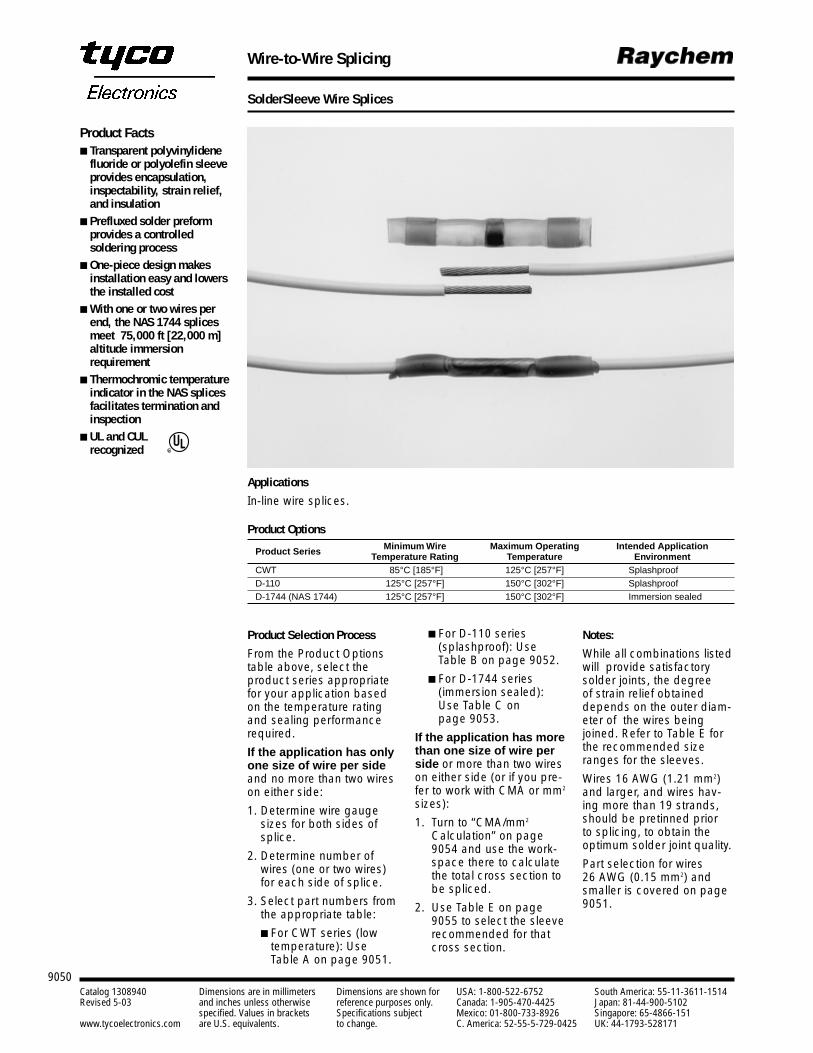
9050Catalog 1308940 Dimensions are in millimeters Dimensions are shown for USA: 1-800-522-6752 South America: 55-11-3611-1514Revised 5-03 and inches unless otherwise reference purposes only. Canada: 1-905-470-4425 Japan: 81-44-900-5102
specified. Values in brackets Specifications subject Mexico: 01-800-733-8926 Singapore: 65-4866-151www.tycoelectronics.com are U.S. equivalents. to change. C. America: 52-55-5-729-0425 UK: 44-1793-528171
Wire-to-Wire Splicing
SolderSleeve Wire Splices
Product Options
Product Series Minimum Wire Maximum Operating Intended Application Temperature Rating Temperature Environment
CWT 85°C [185°F] 125°C [257°F] SplashproofD-110 125°C [257°F] 150°C [302°F] SplashproofD-1744 (NAS 1744) 125°C [257°F] 150°C [302°F] Immersion sealed
Product Facts Transparent polyvinylidene
fluoride or polyolefin sleeveprovides encapsulation,inspectability, strain relief,and insulation
Prefluxed solder preformprovides a controlledsoldering process
One-piece design makesinstallation easy and lowersthe installed cost
With one or two wires perend, the NAS 1744 splicesmeet 75,000 ft [22,000 m]altitude immersionrequirement
Thermochromic temperatureindicator in the NAS splicesfacilitates termination andinspection
UL and CULrecognized R
Product Selection Process
From the Product Optionstable above, select theproduct series appropriatefor your application basedon the temperature ratingand sealing performancerequired.
If the application has onlyone size of wire per sideand no more than two wireson either side:
1. Determine wire gaugesizes for both sides ofsplice.
2. Determine number ofwires (one or two wires)for each side of splice.
3. Select part numbers fromthe appropriate table:
For CWT series (lowtemperature): UseTable A on page 9051.
For D-110 series(splashproof): UseTable B on page 9052.
For D-1744 series(immersion sealed):Use Table C on page 9053.
If the application has morethan one size of wire perside or more than two wireson either side (or if you pre-fer to work with CMA or mm2
sizes):
1. Turn to “CMA/mm2
Calculation” on page 9054 and use the work-space there to calculatethe total cross section tobe spliced.
2. Use Table E on page 9055 to select the sleeverecommended for thatcross section.
Notes:
While all combinations listedwill provide satisfactory solder joints, the degree of strain relief obtaineddepends on the outer diam-eter of the wires beingjoined. Refer to Table E forthe recommended sizeranges for the sleeves.
Wires 16 AWG (1.21 mm2)and larger, and wires hav-ing more than 19 strands,should be pretinned prior to splicing, to obtain theoptimum solder joint quality.
Part selection for wires 26 AWG (0.15 mm2) andsmaller is covered on page9051.
Applications
In-line wire splices.
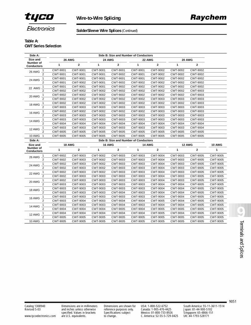
9051
9Terminals and Splices
Catalog 1308940 Dimensions are in millimeters Dimensions are shown for USA: 1-800-522-6752 South America: 55-11-3611-1514Revised 5-03 and inches unless otherwise reference purposes only. Canada: 1-905-470-4425 Japan: 81-44-900-5102
specified. Values in brackets Specifications subject Mexico: 01-800-733-8926 Singapore: 65-4866-151www.tycoelectronics.com are U.S. equivalents. to change. C. America: 52-55-5-729-0425 UK: 44-1793-528171
Wire-to-Wire Splicing
SolderSleeve Wire Splices (Continued)
Side A: Side B: Size and Number of ConductorsSize and 26 AWG 24 AWG 22 AWG 20 AWG
Number of1 2 1 2 1 2 1 2Conductors
26 AWG 1 CWT-9001 CWT-9001 CWT-9001 CWT-9001 CWT-9001 CWT-9002 CWT-9002 CWT-90022 CWT-9001 CWT-9001 CWT-9001 CWT-9002 CWT-9001 CWT-9002 CWT-9002 CWT-9002
24 AWG 1 CWT-9001 CWT-9001 CWT-9001 CWT-9001 CWT-9001 CWT-9002 CWT-9002 CWT-90022 CWT-9001 CWT-9002 CWT-9001 CWT-9002 CWT-9002 CWT-9002 CWT-9002 CWT-9002
22 AWG 1 CWT-9001 CWT-9001 CWT-9001 CWT-9002 CWT-9002 CWT-9002 CWT-9002 CWT-90022 CWT-9002 CWT-9002 CWT-9002 CWT-9002 CWT-9002 CWT-9002 CWT-9002 CWT-9003
20 AWG 1 CWT-9002 CWT-9002 CWT-9002 CWT-9002 CWT-9002 CWT-9002 CWT-9002 CWT-90032 CWT-9002 CWT-9002 CWT-9002 CWT-9002 CWT-9002 CWT-9003 CWT-9003 CWT-9003
18 AWG 1 CWT-9002 CWT-9002 CWT-9002 CWT-9002 CWT-9002 CWT-9002 CWT-9002 CWT-90032 CWT-9003 CWT-9003 CWT-9003 CWT-9003 CWT-9003 CWT-9003 CWT-9003 CWT-9003
16 AWG 1 CWT-9002 CWT-9002 CWT-9002 CWT-9002 CWT-9002 CWT-9003 CWT-9003 CWT-90032 CWT-9003 CWT-9003 CWT-9003 CWT-9003 CWT-9003 CWT-9003 CWT-9003 CWT-9003
14 AWG 1 CWT-9003 CWT-9003 CWT-9003 CWT-9003 CWT-9003 CWT-9003 CWT-9003 CWT-90032 CWT-9004 CWT-9004 CWT-9004 CWT-9004 CWT-9004 CWT-9004 CWT-9004 CWT-9004
12 AWG 1 CWT-9003 CWT-9003 CWT-9003 CWT-9003 CWT-9003 CWT-9003 CWT-9003 CWT-90042 CWT-9005 CWT-9005 CWT-9005 CWT-9005 CWT-9005 CWT-9005 CWT-9005 CWT-9005
10 AWG 1 CWT-9005 CWT-9005 CWT-9005 CWT-9005 CWT-9005 CWT-9005 CWT-9005 CWT-9005
Side A: Side B: Size and Number of Conductors
Size and 18 AWG 16 AWG 14 AWG 12 AWG 10 AWGNumber of
1 2 1 2 1 2 1 2 1Conductors
26 AWG 1 CWT-9002 CWT-9003 CWT-9002 CWT-9003 CWT-9003 CWT-9004 CWT-9003 CWT-9005 CWT-90052 CWT-9002 CWT-9003 CWT-9002 CWT-9003 CWT-9003 CWT-9004 CWT-9003 CWT-9005 CWT-9005
24 AWG 1 CWT-9002 CWT-9003 CWT-9002 CWT-9003 CWT-9003 CWT-9004 CWT-9003 CWT-9005 CWT-90052 CWT-9002 CWT-9003 CWT-9002 CWT-9003 CWT-9003 CWT-9004 CWT-9003 CWT-9005 CWT-9005
22 AWG 1 CWT-9002 CWT-9003 CWT-9002 CWT-9003 CWT-9003 CWT-9004 CWT-9003 CWT-9005 CWT-90052 CWT-9002 CWT-9003 CWT-9003 CWT-9003 CWT-9003 CWT-9004 CWT-9003 CWT-9005 CWT-9005
20 AWG 1 CWT-9002 CWT-9003 CWT-9003 CWT-9003 CWT-9003 CWT-9004 CWT-9003 CWT-9005 CWT-90052 CWT-9003 CWT-9003 CWT-9003 CWT-9003 CWT-9003 CWT-9004 CWT-9004 CWT-9005 CWT-9005
18 AWG 1 CWT-9003 CWT-9003 CWT-9003 CWT-9003 CWT-9003 CWT-9004 CWT-9004 CWT-9005 CWT-90052 CWT-9003 CWT-9003 CWT-9003 CWT-9004 CWT-9003 CWT-9004 CWT-9004 CWT-9005 CWT-9005
16 AWG 1 CWT-9003 CWT-9003 CWT-9003 CWT-9003 CWT-9003 CWT-9004 CWT-9004 CWT-9005 CWT-90052 CWT-9003 CWT-9004 CWT-9003 CWT-9004 CWT-9004 CWT-9005 CWT-9004 CWT-9005 CWT-9005
14 AWG 1 CWT-9003 CWT-9003 CWT-9003 CWT-9004 CWT-9003 CWT-9004 CWT-9004 CWT-9005 CWT-90052 CWT-9004 CWT-9004 CWT-9004 CWT-9005 CWT-9004 CWT-9005 CWT-9005 CWT-9005 CWT-9005
12 AWG 1 CWT-9004 CWT-9004 CWT-9004 CWT-9004 CWT-9004 CWT-9005 CWT-9004 CWT-9005 CWT-90052 CWT-9005 CWT-9005 CWT-9005 CWT-9005 CWT-9005 CWT-9005 CWT-9005 CWT-9005 CWT-9005
10 AWG 1 CWT-9005 CWT-9005 CWT-9005 CWT-9005 CWT-9005 CWT-9005 CWT-9005 CWT-9005 CWT-9005
Table A:CWT Series Selection
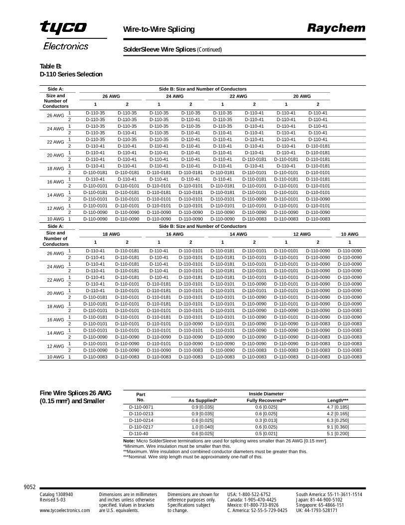
9052Catalog 1308940 Dimensions are in millimeters Dimensions are shown for USA: 1-800-522-6752 South America: 55-11-3611-1514Revised 5-03 and inches unless otherwise reference purposes only. Canada: 1-905-470-4425 Japan: 81-44-900-5102
specified. Values in brackets Specifications subject Mexico: 01-800-733-8926 Singapore: 65-4866-151www.tycoelectronics.com are U.S. equivalents. to change. C. America: 52-55-5-729-0425 UK: 44-1793-528171
Wire-to-Wire Splicing
SolderSleeve Wire Splices (Continued)
Side A: Side B: Size and Number of ConductorsSize and 26 AWG 24 AWG 22 AWG 20 AWG
Number of1 2 1 2 1 2 1 2Conductors
26 AWG 1 D-110-35 D-110-35 D-110-35 D-110-35 D-110-35 D-110-41 D-110-41 D-110-412 D-110-35 D-110-35 D-110-35 D-110-41 D-110-35 D-110-41 D-110-41 D-110-41
24 AWG 1 D-110-35 D-110-35 D-110-35 D-110-35 D-110-35 D-110-41 D-110-41 D-110-412 D-110-35 D-110-41 D-110-35 D-110-41 D-110-41 D-110-41 D-110-41 D-110-41
22 AWG 1 D-110-35 D-110-35 D-110-35 D-110-41 D-110-41 D-110-41 D-110-41 D-110-412 D-110-41 D-110-41 D-110-41 D-110-41 D-110-41 D-110-41 D-110-41 D-110-0181
20 AWG 1 D-110-41 D-110-41 D-110-41 D-110-41 D-110-41 D-110-41 D-110-41 D-110-01812 D-110-41 D-110-41 D-110-41 D-110-41 D-110-41 D-110-0181 D-110-0181 D-110-0181
18 AWG 1 D-110-41 D-110-41 D-110-41 D-110-41 D-110-41 D-110-41 D-110-41 D-110-01812 D-110-0181 D-110-0181 D-110-0181 D-110-0181 D-110-0181 D-110-0101 D-110-0101 D-110-0101
16 AWG 1 D-110-41 D-110-41 D-110-41 D-110-41 D-110-41 D-110-0181 D-110-0181 D-110-01812 D-110-0101 D-110-0101 D-110-0101 D-110-0101 D-110-0181 D-110-0101 D-110-0101 D-110-0101
14 AWG 1 D-110-0181 D-110-0181 D-110-0181 D-110-0181 D-110-0181 D-110-0101 D-110-0101 D-110-01012 D-110-0101 D-110-0101 D-110-0101 D-110-0101 D-110-0101 D-110-0090 D-110-0101 D-110-0090
12 AWG 1 D-110-0101 D-110-0101 D-110-0101 D-110-0101 D-110-0101 D-110-0101 D-110-0101 D-110-01012 D-110-0090 D-110-0090 D-110-0090 D-110-0090 D-110-0090 D-110-0090 D-110-0090 D-110-0090
10 AWG 1 D-110-0090 D-110-0090 D-110-0090 D-110-0090 D-110-0090 D-110-0083 D-110-0083 D-110-0083
Side A: Side B: Size and Number of ConductorsSize and 18 AWG 16 AWG 14 AWG 12 AWG 10 AWG
Number of1 2 1 2 1 2 1 2 1Conductors
26 AWG 1 D-110-41 D-110-0181 D-110-41 D-110-0101 D-110-0181 D-110-0101 D-110-0101 D-110-0090 D-110-00902 D-110-41 D-110-0181 D-110-41 D-110-0101 D-110-0181 D-110-0101 D-110-0101 D-110-0090 D-110-0090
24 AWG 1 D-110-41 D-110-0181 D-110-41 D-110-0101 D-110-0181 D-110-0101 D-110-0101 D-110-0090 D-110-00902 D-110-41 D-110-0181 D-110-41 D-110-0101 D-110-0181 D-110-0101 D-110-0101 D-110-0090 D-110-0090
22 AWG 1 D-110-41 D-110-0181 D-110-41 D-110-0181 D-110-0181 D-110-0101 D-110-0101 D-110-0090 D-110-00902 D-110-41 D-110-0101 D-110-0181 D-110-0101 D-110-0101 D-110-0090 D-110-0101 D-110-0090 D-110-0090
20 AWG 1 D-110-41 D-110-0101 D-110-0181 D-110-0101 D-110-0101 D-110-0101 D-110-0101 D-110-0090 D-110-00902 D-110-0181 D-110-0101 D-110-0181 D-110-0101 D-110-0101 D-110-0090 D-110-0101 D-110-0090 D-110-0090
18 AWG 1 D-110-0181 D-110-0101 D-110-0181 D-110-0101 D-110-0101 D-110-0090 D-110-0101 D-110-0090 D-110-00902 D-110-0101 D-110-0101 D-110-0101 D-110-0101 D-110-0101 D-110-0090 D-110-0090 D-110-0090 D-110-0083
16 AWG 1 D-110-0181 D-110-0101 D-110-0181 D-110-0101 D-110-0101 D-110-0090 D-110-0101 D-110-0090 D-110-00902 D-110-0101 D-110-0101 D-110-0101 D-110-0090 D-110-0101 D-110-0090 D-110-0090 D-110-0083 D-110-0083
14 AWG 1 D-110-0101 D-110-0101 D-110-0101 D-110-0101 D-110-0101 D-110-0090 D-110-0090 D-110-0090 D-110-00832 D-110-0090 D-110-0090 D-110-0090 D-110-0090 D-110-0090 D-110-0090 D-110-0090 D-110-0083 D-110-0083
12 AWG 1 D-110-0101 D-110-0090 D-110-0101 D-110-0090 D-110-0090 D-110-0090 D-110-0090 D-110-0083 D-110-00832 D-110-0090 D-110-0090 D-110-0090 D-110-0083 D-110-0090 D-110-0083 D-110-0083 D-110-0083 D-110-0083
10 AWG 1 D-110-0083 D-110-0083 D-110-0083 D-110-0083 D-110-0083 D-110-0083 D-110-0083 D-110-0083 D-110-0083
Table B:D-110 Series Selection
Part Inside DiameterNo. As Supplied* Fully Recovered** Length***
D-110-0071 0.9 [0.035] 0.6 [0.025] 4.7 [0.185]D-110-0213 0.9 [0.035] 0.6 [0.025] 4.2 [0.165]D-110-0214 0.6 [0.025] 0.3 [0.013] 6.3 [0.250]D-110-0217 1.0 [0.040] 0.6 [0.025) 9.1 [0.360]D-110-40 0.6 [0.025] 0.5 [0.021] 5.1 [0.200]
Note: Micro SolderSleeve terminations are used for splicing wires smaller than 26 AWG [0.15 mm2].*Minimum. Wire insulation must be smaller than this.**Maximum. Wire insulation and combined conductor diameters must be greater than this.***Nominal. Wire strip length must be approximately one-half of this.
Fine Wire Splices 26 AWG(0.15 mm2) and Smaller
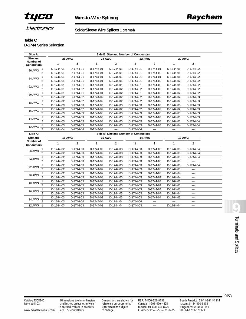
9053
9Terminals and Splices
Catalog 1308940 Dimensions are in millimeters Dimensions are shown for USA: 1-800-522-6752 South America: 55-11-3611-1514Revised 5-03 and inches unless otherwise reference purposes only. Canada: 1-905-470-4425 Japan: 81-44-900-5102
specified. Values in brackets Specifications subject Mexico: 01-800-733-8926 Singapore: 65-4866-151www.tycoelectronics.com are U.S. equivalents. to change. C. America: 52-55-5-729-0425 UK: 44-1793-528171
Wire-to-Wire Splicing
SolderSleeve Wire Splices (Continued)
Side A: Side B: Size and Number of ConductorsSize and 26 AWG 24 AWG 22 AWG 20 AWG
Number of1 2 1 2 1 2 1 2Conductors
26 AWG 1 D-1744-01 D-1744-01 D-1744-01 D-1744-01 D-1744-01 D-1744-01 D-1744-01 D-1744-022 D-1744-01 D-1744-01 D-1744-01 D-1744-01 D-1744-01 D-1744-02 D-1744-01 D-1744-02
24 AWG 1 D-1744-01 D-1744-01 D-1744-01 D-1744-01 D-1744-01 D-1744-01 D-1744-01 D-1744-022 D-1744-01 D-1744-01 D-1744-01 D-1744-01 D-1744-01 D-1744-02 D-1744-02 D-1744-02
22 AWG 1 D-1744-01 D-1744-01 D-1744-01 D-1744-01 D-1744-01 D-1744-02 D-1744-01 D-1744-022 D-1744-01 D-1744-02 D-1744-01 D-1744-02 D-1744-02 D-1744-02 D-1744-02 D-1744-02
20 AWG 1 D-1744-01 D-1744-01 D-1744-01 D-1744-02 D-1744-01 D-1744-02 D-1744-02 D-1744-022 D-1744-02 D-1744-02 D-1744-02 D-1744-02 D-1744-02 D-1744-02 D-1744-02 D-1744-03
18 AWG 1 D-1744-02 D-1744-02 D-1744-02 D-1744-02 D-1744-02 D-1744-02 D-1744-02 D-1744-032 D-1744-03 D-1744-03 D-1744-03 D-1744-03 D-1744-03 D-1744-03 D-1744-03 D-1744-03
16 AWG 1 D-1744-02 D-1744-02 D-1744-02 D-1744-02 D-1744-02 D-1744-02 D-1744-02 D-1744-032 D-1744-03 D-1744-03 D-1744-03 D-1744-03 D-1744-03 D-1744-03 D-1744-03 D-1744-03
14 AWG 1 D-1744-03 D-1744-03 D-1744-03 D-1744-03 D-1744-03 D-1744-03 D-1744-03 D-1744-032 D-1744-03 D-1744-03 D-1744-03 D-1744-03 D-1744-03 D-1744-03 D-1744-03 D-1744-04
12 AWG 1 D-1744-03 D-1744-03 D-1744-03 D-1744-03 D-1744-03 D-1744-03 D-1744-04 D-1744-042 D-1744-04 D-1744-04 D-1744-04 — D-1744-04 — — —
Side A: Side B: Size and Number of ConductorsSize and 18 AWG 16 AWG 14 AWG 12 AWG
Number of1 2 1 2 1 2 1 2Conductors
26 AWG1 D-1744-02 D-1744-03 D-1744-02 D-1744-03 D-1744-03 D-1744-03 D-1744-03 D-1744-042 D-1744-02 D-1744-03 D-1744-02 D-1744-03 D-1744-03 D-1744-03 D-1744-03 D-1744-04
24 AWG1 D-1744-02 D-1744-03 D-1744-02 D-1744-03 D-1744-03 D-1744-03 D-1744-03 D-1744-042 D-1744-02 D-1744-03 D-1744-02 D-1744-03 D-1744-03 D-1744-03 D-1744-03 —
22 AWG1 D-1744-02 D-1744-03 D-1744-02 D-1744-03 D-1744-03 D-1744-03 D-1744-03 D-1744-042 D-1744-02 D-1744-03 D-1744-02 D-1744-03 D-1744-03 D-1744-03 D-1744-03 —
20 AWG1 D-1744-02 D-1744-03 D-1744-02 D-1744-03 D-1744-03 D-1744-03 D-1744-04 —2 D-1744-03 D-1744-03 D-1744-03 D-1744-03 D-1744-03 D-1744-04 D-1744-04 —
18 AWG1 D-1744-02 D-1744-03 D-1744-03 D-1744-03 D-1744-03 D-1744-03 D-1744-03 —2 D-1744-03 D-1744-03 D-1744-03 D-1744-03 D-1744-03 D-1744-04 D-1744-03 —
16 AWG1 D-1744-03 D-1744-03 D-1744-03 D-1744-03 D-1744-03 D-1744-04 D-1744-03 —2 D-1744-03 D-1744-03 D-1744-03 D-1744-03 D-1744-03 D-1744-04 D-1744-04 —
14 AWG1 D-1744-03 D-1744-03 D-1744-03 D-1744-03 D-1744-03 D-1744-04 D-1744-03 —2 D-1744-03 D-1744-04 D-1744-04 D-1744-04 D-1744-04 — — —
12 AWG 1 D-1744-03 D-1744-03 D-1744-03 D-1744-04 D-1744-03 — D-1744-04 —
Table C:D-1744 Series Selection
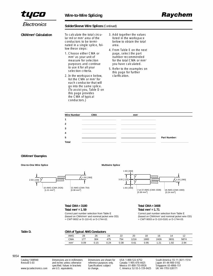
9054Catalog 1308940 Dimensions are in millimeters Dimensions are shown for USA: 1-800-522-6752 South America: 55-11-3611-1514Revised 5-03 and inches unless otherwise reference purposes only. Canada: 1-905-470-4425 Japan: 81-44-900-5102
specified. Values in brackets Specifications subject Mexico: 01-800-733-8926 Singapore: 65-4866-151www.tycoelectronics.com are U.S. equivalents. to change. C. America: 52-55-5-729-0425 UK: 44-1793-528171
Wire-to-Wire Splicing
SolderSleeve Wire Splices (Continued)
To calculate the total circu-lar mil or mm2 area of theconductors to be termi-nated in a single splice, fol-low these steps:
1. Choose either CMA ormm2 as your unit of measure for selectionpurposes and continue to use it for all your selection criteria.
2. In the workspace below,list the CMA or mm2 foreach conductor that willgo into the same splice.(To assist you, Table D onthis page provides the CMA of typical conductors.)
3. Add together the valueslisted in the workspacebelow to obtain the totalarea.
4. From Table E on the nextpage, select the partnumber recommendedfor the total CMA or mm2
you have calculated.
5. Refer to the examples onthis page for further clarification.
Total CMA = 3180 Total CMA = 3408Total mm2 = 1.59 Total mm2 = 1.71Correct part number selection from Table E Correct part number selection from Table E (based on CMA/mm2 and nominal jacket wire OD) (based on CMA/mm2 and nominal jacket wire OD)= CWT-9002 or D-110-41 or D-1744-02. = CWT-9003 or D-110-0181 or D-1744-03.
CMA/mm2 Examples
One-to-One Wire Splice Multiwire Splice
Wire Number CMA mm2
1
2
3
4
5 Part Number:
Total
16 AWG (CMA 2426) [1.21 mm2]
2.50 [.100]1.50 [.060]
22 AWG (CMA 754)[0.38 mm2] 2 at 22 AWG (CMA 1508)
[0.38 mm2]
1.50 [.060]
1.50 [.060]
3.00 [.120] 2.25 [.090]
18 AWG (CMA 1900) [0.24 mm2]
CMA of Typical AWG ConductorsAWG 28 26 24 22 20 18 16 14 12CMA 177 304 475 754 1216 1900 2426 3831 5874mm2 0.09 0.15 0.24 0.38 0.61 0.95 1.21 1.92 2.94
CMA/mm2 Calculation
Table D.
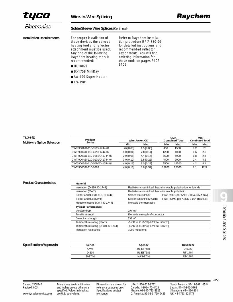
9055
9Terminals and Splices
Catalog 1308940 Dimensions are in millimeters Dimensions are shown for USA: 1-800-522-6752 South America: 55-11-3611-1514Revised 5-03 and inches unless otherwise reference purposes only. Canada: 1-905-470-4425 Japan: 81-44-900-5102
specified. Values in brackets Specifications subject Mexico: 01-800-733-8926 Singapore: 65-4866-151www.tycoelectronics.com are U.S. equivalents. to change. C. America: 52-55-5-729-0425 UK: 44-1793-528171
Wire-to-Wire Splicing
SolderSleeve Wire Splices (Continued)
CMA mm2
Product Wire Jacket OD Combined Total Combined TotalSeries
Min. Max. Min. Max. Min. Max.CWT-9001/D-110-35/D-1744-01 .76 [0.03] 1.5 [0.06] 450 1500 0.2 .75CWT-9002/D-110-41/D-1744-02 1.0 [0.04] 2.8 [0.11] 1250 4000 0.6 2.0CWT-9003/D-110-0181/D-1744-03 2.0 [0.08] 4.4 [0.17] 3600 5000 1.8 2.5CWT-9004/D-110-0101/D-1744-04 3.0 [0.12] 5.8 [0.22] 4800 9000 2.4 4.5CWT-9005/D-110-0090/D-1744-04 4.0 [0.16] 7.0 [0.27] 8500 16200 4.2 8.1CWT-9005/D-110-0083 4.0 [0.16] 8.6 [0.34] 16200 25000 8.1 12.5
Series Agency RaychemCWT UL E87681 D-5023D-110 UL E87681 RT-1404
D-1744 NAS-1744 RT-1404
MaterialInsulation (D-110, D-1744) Radiation-crosslinked, heat-shrinkable polyvinylidene fluoride Insulation (CWT) Radiation-crosslinked, heat-shrinkable polyolefinSolder and flux (D-110, D-1744) Solder: Sn63 Pb37 Flux: ROL1 per ANSI-J-004 (RMA flux)Solder and flux (CWT) Solder: Sn50 Pb32 Cd18 Flux: ROM1 per ASNS-J-004 (RA flux)Meltable inserts (CWT, D-1744) Meltable thermoplastic
Typical PerformanceVoltage drop 2.0 mVTensile strength Exceeds strength of conductorDielectric strength 2.0 kVTemperature rating (CWT) -55°C to +125°C [-67°F to +257°F]Temperature rating (D-110, D-1744) -55°C to +150°C [-67°F to +302°F]Insulation resistance 1000 megohms
Installation Requirements
Table E:Multiwire Splice Selection
Product Characteristics
Specifications/Approvals
For proper installation ofthese devices the correctheating tool and reflectorattachment must be used.Any one of the followingRaychem heating tools isrecommended:
HL1802E
IR-1759 MiniRay
AA-400 Super Heater
CV-1981
Refer to Raychem installa-tion procedure RPIP 850-00for detailed instructions andrecommended reflectorattachments. You will findordering information forthese tools on pages 9102-9109.
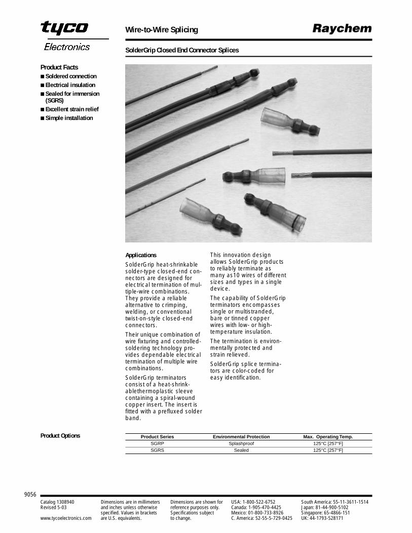
9056Catalog 1308940 Dimensions are in millimeters Dimensions are shown for USA: 1-800-522-6752 South America: 55-11-3611-1514Revised 5-03 and inches unless otherwise reference purposes only. Canada: 1-905-470-4425 Japan: 81-44-900-5102
specified. Values in brackets Specifications subject Mexico: 01-800-733-8926 Singapore: 65-4866-151www.tycoelectronics.com are U.S. equivalents. to change. C. America: 52-55-5-729-0425 UK: 44-1793-528171
Wire-to-Wire Splicing
SolderGrip Closed End Connector Splices
Applications
SolderGrip heat-shrinkablesolder-type closed-end con-nectors are designed forelectrical termination of mul-tiple-wire combinations.They provide a reliablealternative to crimping,welding, or conventionaltwist-on-style closed-endconnectors.
Their unique combination ofwire fixturing and controlled-soldering technology pro-vides dependable electricaltermination of multiple wirecombinations.
SolderGrip terminators consist of a heat-shrink-ablethermoplastic sleevecontaining a spiral-woundcopper insert. The insert isfitted with a prefluxed solderband.
This innovation designallows SolderGrip productsto reliably terminate asmany as10 wires of differentsizes and types in a singledevice.
The capability of SolderGripterminators encompassessingle or multistranded,bare or tinned copper wires with low- or high-temperature insulation.
The termination is environ-mentally protected andstrain relieved.
SolderGrip splice termina-tors are color-coded foreasy identification.
Product Series Environmental Protection Max. Operating Temp.SGRP Splashproof 125°C [257°F]SGRS Sealed 125°C [257°F]
Product Facts Soldered connection Electrical insulation Sealed for immersion
(SGRS) Excellent strain relief Simple installation
Product Options
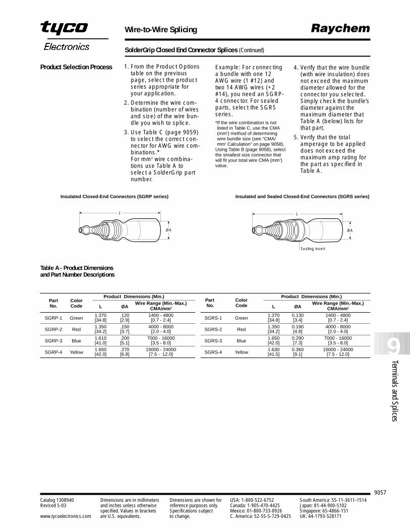
9057
9Terminals and Splices
Catalog 1308940 Dimensions are in millimeters Dimensions are shown for USA: 1-800-522-6752 South America: 55-11-3611-1514Revised 5-03 and inches unless otherwise reference purposes only. Canada: 1-905-470-4425 Japan: 81-44-900-5102
specified. Values in brackets Specifications subject Mexico: 01-800-733-8926 Singapore: 65-4866-151www.tycoelectronics.com are U.S. equivalents. to change. C. America: 52-55-5-729-0425 UK: 44-1793-528171
Wire-to-Wire Splicing
SolderGrip Closed End Connector Splices (Continued)
Product Dimensions (Min.) Product Dimensions (Min.)Part Color
L ØAWire Range (Min.-Max.)
L ØAWire Range (Min.-Max.)No. Code CMA/mm2 CMA/mm2
SGRP-1 Green 1.370 .120 1400 - 4800 SGRS-1 Green 1.370 0.130 1400 - 4800[34.8] [2.9] [0.7 - 2.4] [34.8] [3.4] [0.7 - 2.4]
SGRP-2 Red 1.350 .150 4000 - 8000 SGRS-2 Red 1.350 0.190 4000 - 8000[34.2] [3.7] [2.0 - 4.0] [34.2] [4.8] [2.0 - 4.0]
SGRP-3 Blue 1.610 .200 7000 - 16000 SGRS-3 Blue 1.650 0.290 7000 - 16000[41.0] [5.1] [3.5 - 8.0] [42.0] [7.3] [3.5 - 8.0]
SGRP-4 Yellow 1.650 .270 15000 - 24000 SGRS-4 Yellow 1.630 0.360 15000 - 24000[42.0] [6.8] [7.5 - 12.0] [41.5] [9.1] [7.5 - 12.0]
L
Sealing insert
ØA
L
ØA
1. From the Product Optionstable on the previouspage, select the productseries appropriate foryour application.
2. Determine the wire com-bination (number of wiresand size) of the wire bun-dle you wish to splice.
3. Use Table C (page 9059)to select the correct con-nector for AWG wire com-binations.* For mm2 wire combina-tions use Table A toselect a SolderGrip partnumber.
Example: For connectinga bundle with one 12AWG wire (1 #12) andtwo 14 AWG wires (+2#14), you need an SGRP-4 connector. For sealedparts, select the SGRSseries.*If the wire combination is notlisted in Table C, use the CMA(mm2) method of determiningwire bundle size (see “CMA/mm2 Calculation” on page 9058).
Using Table B (page 9058), selectthe smallest size connector thatwill fit your total wire CMA (mm2)value.
4. Verify that the wire bundle(with wire insulation) doesnot exceed the maximumdiameter allowed for theconnector you selected.Simply check the bundle’sdiameter against the maximum diameter that Table A (below) lists forthat part.
5. Verify that the totalamperage to be applieddoes not exceed themaximum amp rating forthe part as specified inTable A.
Product Selection Process
Insulated Closed-End Connectors (SGRP series) Insulated and Sealed Closed-End Connectors (SGRS series)
Part ColorNo. Code
Table A - Product Dimensionsand Part Number Descriptions
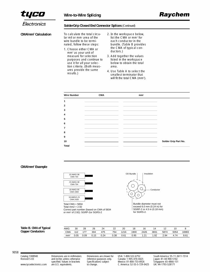
9058Catalog 1308940 Dimensions are in millimeters Dimensions are shown for USA: 1-800-522-6752 South America: 55-11-3611-1514Revised 5-03 and inches unless otherwise reference purposes only. Canada: 1-905-470-4425 Japan: 81-44-900-5102
specified. Values in brackets Specifications subject Mexico: 01-800-733-8926 Singapore: 65-4866-151www.tycoelectronics.com are U.S. equivalents. to change. C. America: 52-55-5-729-0425 UK: 44-1793-528171
Wire-to-Wire Splicing
SolderGrip Closed End Connector Splices (Continued)
CMA/mm2 Example
22 AWG/.38CMA 754
OD Bundle Insulation
Conductor
Bundle diameter must notexceed 6.0 mm (0.24 in) forSGRP-2 or 4.5 in (0.18 mm)for SGRS-2.
Total CMA = 5834Total mm2 = 2.92Correct part number (based on CMA of 5834 or mm2 of 2.92): SGRP-2or SGRS-2
22 AWG/.38CMA 754
18 AWG/.95CMA 1900
16 AWG/1.21CMA 2426
AWG 30 28 26 24 22 20 18 16 14 12 10 8CMA 112 177 304 475 754 1216 1900 2426 3831 5874 9354 16983mm2 0.05 0.09 0.15 0.24 0.38 0.61 0.95 1.21 1.92 2.94 4.74 8.61
To calculate the total circu-lar mil or mm2 area of thewire bundle to be termi-nated, follow these steps:
1. Choose either CMA ormm2 as your unit ofmeasure for selectionpurposes and continue touse it for all your selec-tion criteria. (Both meas-ures provide the sameresults.)
Wire Number CMA mm2
1
2
3
4
5
6
7
8
9
10 Solder Grip Part No.
Total
CMA/mm2 Calculation 2. In the workspace below,list the CMA or mm2 foreach conductor in thebundle. (Table B providesthe CMA of typical con-ductors.)
3. Add together the valueslisted in the workspacebelow to obtain the totalarea.
4. Use Table A to select thesmallest terminator thatwill fit the total CMA (mm2).
Table B. CMA of TypicalCopper Conductors
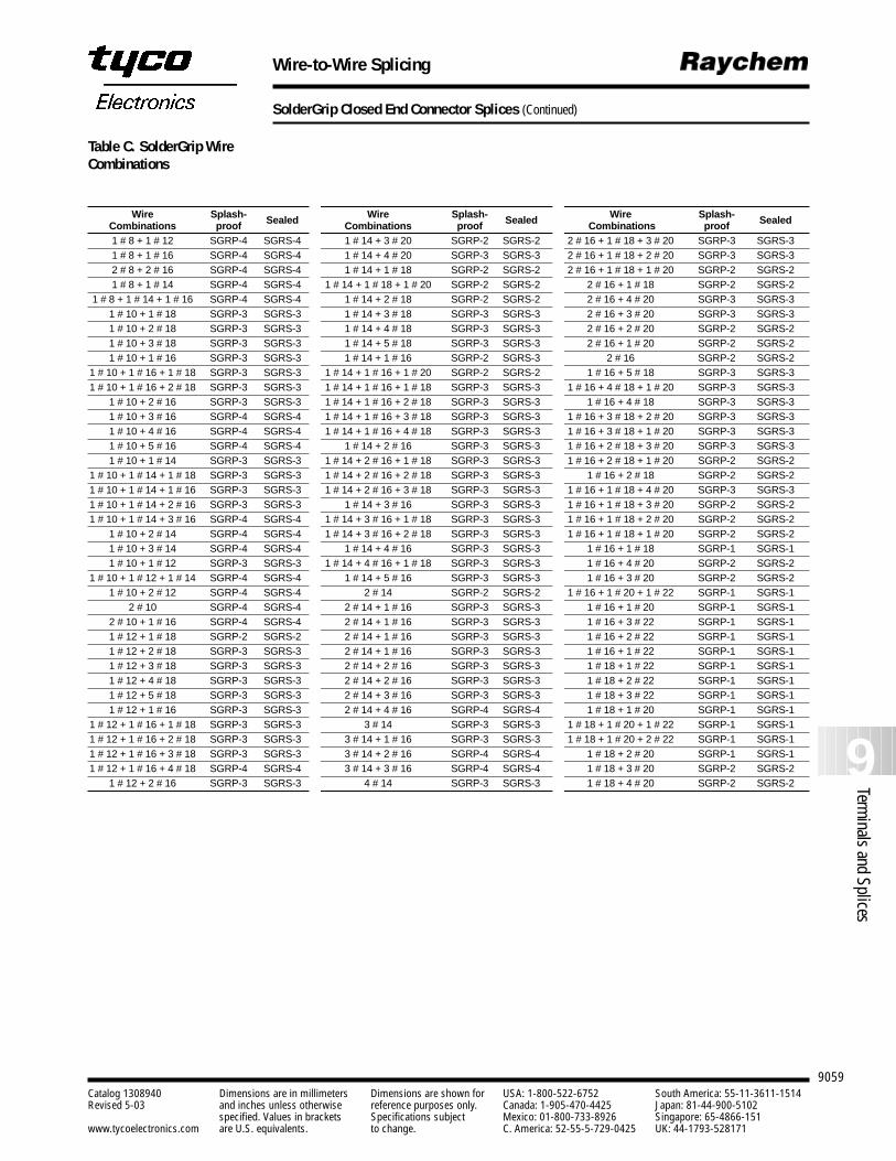
9059
9Terminals and Splices
Catalog 1308940 Dimensions are in millimeters Dimensions are shown for USA: 1-800-522-6752 South America: 55-11-3611-1514Revised 5-03 and inches unless otherwise reference purposes only. Canada: 1-905-470-4425 Japan: 81-44-900-5102
specified. Values in brackets Specifications subject Mexico: 01-800-733-8926 Singapore: 65-4866-151www.tycoelectronics.com are U.S. equivalents. to change. C. America: 52-55-5-729-0425 UK: 44-1793-528171
Wire-to-Wire Splicing
SolderGrip Closed End Connector Splices (Continued)
Wire Splash- Wire Splash- Wire Splash-Combinations proof Sealed Combinations proof Sealed Combinations proof Sealed
1 # 8 + 1 # 12 SGRP-4 SGRS-4 1 # 14 + 3 # 20 SGRP-2 SGRS-2 2 # 16 + 1 # 18 + 3 # 20 SGRP-3 SGRS-31 # 8 + 1 # 16 SGRP-4 SGRS-4 1 # 14 + 4 # 20 SGRP-3 SGRS-3 2 # 16 + 1 # 18 + 2 # 20 SGRP-3 SGRS-32 # 8 + 2 # 16 SGRP-4 SGRS-4 1 # 14 + 1 # 18 SGRP-2 SGRS-2 2 # 16 + 1 # 18 + 1 # 20 SGRP-2 SGRS-21 # 8 + 1 # 14 SGRP-4 SGRS-4 1 # 14 + 1 # 18 + 1 # 20 SGRP-2 SGRS-2 2 # 16 + 1 # 18 SGRP-2 SGRS-2
1 # 8 + 1 # 14 + 1 # 16 SGRP-4 SGRS-4 1 # 14 + 2 # 18 SGRP-2 SGRS-2 2 # 16 + 4 # 20 SGRP-3 SGRS-31 # 10 + 1 # 18 SGRP-3 SGRS-3 1 # 14 + 3 # 18 SGRP-3 SGRS-3 2 # 16 + 3 # 20 SGRP-3 SGRS-31 # 10 + 2 # 18 SGRP-3 SGRS-3 1 # 14 + 4 # 18 SGRP-3 SGRS-3 2 # 16 + 2 # 20 SGRP-2 SGRS-21 # 10 + 3 # 18 SGRP-3 SGRS-3 1 # 14 + 5 # 18 SGRP-3 SGRS-3 2 # 16 + 1 # 20 SGRP-2 SGRS-21 # 10 + 1 # 16 SGRP-3 SGRS-3 1 # 14 + 1 # 16 SGRP-2 SGRS-3 2 # 16 SGRP-2 SGRS-2
1 # 10 + 1 # 16 + 1 # 18 SGRP-3 SGRS-3 1 # 14 + 1 # 16 + 1 # 20 SGRP-2 SGRS-2 1 # 16 + 5 # 18 SGRP-3 SGRS-31 # 10 + 1 # 16 + 2 # 18 SGRP-3 SGRS-3 1 # 14 + 1 # 16 + 1 # 18 SGRP-3 SGRS-3 1 # 16 + 4 # 18 + 1 # 20 SGRP-3 SGRS-3
1 # 10 + 2 # 16 SGRP-3 SGRS-3 1 # 14 + 1 # 16 + 2 # 18 SGRP-3 SGRS-3 1 # 16 + 4 # 18 SGRP-3 SGRS-31 # 10 + 3 # 16 SGRP-4 SGRS-4 1 # 14 + 1 # 16 + 3 # 18 SGRP-3 SGRS-3 1 # 16 + 3 # 18 + 2 # 20 SGRP-3 SGRS-31 # 10 + 4 # 16 SGRP-4 SGRS-4 1 # 14 + 1 # 16 + 4 # 18 SGRP-3 SGRS-3 1 # 16 + 3 # 18 + 1 # 20 SGRP-3 SGRS-31 # 10 + 5 # 16 SGRP-4 SGRS-4 1 # 14 + 2 # 16 SGRP-3 SGRS-3 1 # 16 + 2 # 18 + 3 # 20 SGRP-3 SGRS-31 # 10 + 1 # 14 SGRP-3 SGRS-3 1 # 14 + 2 # 16 + 1 # 18 SGRP-3 SGRS-3 1 # 16 + 2 # 18 + 1 # 20 SGRP-2 SGRS-2
1 # 10 + 1 # 14 + 1 # 18 SGRP-3 SGRS-3 1 # 14 + 2 # 16 + 2 # 18 SGRP-3 SGRS-3 1 # 16 + 2 # 18 SGRP-2 SGRS-21 # 10 + 1 # 14 + 1 # 16 SGRP-3 SGRS-3 1 # 14 + 2 # 16 + 3 # 18 SGRP-3 SGRS-3 1 # 16 + 1 # 18 + 4 # 20 SGRP-3 SGRS-31 # 10 + 1 # 14 + 2 # 16 SGRP-3 SGRS-3 1 # 14 + 3 # 16 SGRP-3 SGRS-3 1 # 16 + 1 # 18 + 3 # 20 SGRP-2 SGRS-21 # 10 + 1 # 14 + 3 # 16 SGRP-4 SGRS-4 1 # 14 + 3 # 16 + 1 # 18 SGRP-3 SGRS-3 1 # 16 + 1 # 18 + 2 # 20 SGRP-2 SGRS-2
1 # 10 + 2 # 14 SGRP-4 SGRS-4 1 # 14 + 3 # 16 + 2 # 18 SGRP-3 SGRS-3 1 # 16 + 1 # 18 + 1 # 20 SGRP-2 SGRS-21 # 10 + 3 # 14 SGRP-4 SGRS-4 1 # 14 + 4 # 16 SGRP-3 SGRS-3 1 # 16 + 1 # 18 SGRP-1 SGRS-11 # 10 + 1 # 12 SGRP-3 SGRS-3 1 # 14 + 4 # 16 + 1 # 18 SGRP-3 SGRS-3 1 # 16 + 4 # 20 SGRP-2 SGRS-2
1 # 10 + 1 # 12 + 1 # 14 SGRP-4 SGRS-4 1 # 14 + 5 # 16 SGRP-3 SGRS-3 1 # 16 + 3 # 20 SGRP-2 SGRS-21 # 10 + 2 # 12 SGRP-4 SGRS-4 2 # 14 SGRP-2 SGRS-2 1 # 16 + 1 # 20 + 1 # 22 SGRP-1 SGRS-1
2 # 10 SGRP-4 SGRS-4 2 # 14 + 1 # 16 SGRP-3 SGRS-3 1 # 16 + 1 # 20 SGRP-1 SGRS-12 # 10 + 1 # 16 SGRP-4 SGRS-4 2 # 14 + 1 # 16 SGRP-3 SGRS-3 1 # 16 + 3 # 22 SGRP-1 SGRS-11 # 12 + 1 # 18 SGRP-2 SGRS-2 2 # 14 + 1 # 16 SGRP-3 SGRS-3 1 # 16 + 2 # 22 SGRP-1 SGRS-11 # 12 + 2 # 18 SGRP-3 SGRS-3 2 # 14 + 1 # 16 SGRP-3 SGRS-3 1 # 16 + 1 # 22 SGRP-1 SGRS-11 # 12 + 3 # 18 SGRP-3 SGRS-3 2 # 14 + 2 # 16 SGRP-3 SGRS-3 1 # 18 + 1 # 22 SGRP-1 SGRS-11 # 12 + 4 # 18 SGRP-3 SGRS-3 2 # 14 + 2 # 16 SGRP-3 SGRS-3 1 # 18 + 2 # 22 SGRP-1 SGRS-11 # 12 + 5 # 18 SGRP-3 SGRS-3 2 # 14 + 3 # 16 SGRP-3 SGRS-3 1 # 18 + 3 # 22 SGRP-1 SGRS-11 # 12 + 1 # 16 SGRP-3 SGRS-3 2 # 14 + 4 # 16 SGRP-4 SGRS-4 1 # 18 + 1 # 20 SGRP-1 SGRS-1
1 # 12 + 1 # 16 + 1 # 18 SGRP-3 SGRS-3 3 # 14 SGRP-3 SGRS-3 1 # 18 + 1 # 20 + 1 # 22 SGRP-1 SGRS-11 # 12 + 1 # 16 + 2 # 18 SGRP-3 SGRS-3 3 # 14 + 1 # 16 SGRP-3 SGRS-3 1 # 18 + 1 # 20 + 2 # 22 SGRP-1 SGRS-11 # 12 + 1 # 16 + 3 # 18 SGRP-3 SGRS-3 3 # 14 + 2 # 16 SGRP-4 SGRS-4 1 # 18 + 2 # 20 SGRP-1 SGRS-11 # 12 + 1 # 16 + 4 # 18 SGRP-4 SGRS-4 3 # 14 + 3 # 16 SGRP-4 SGRS-4 1 # 18 + 3 # 20 SGRP-2 SGRS-2
1 # 12 + 2 # 16 SGRP-3 SGRS-3 4 # 14 SGRP-3 SGRS-3 1 # 18 + 4 # 20 SGRP-2 SGRS-2
Table C. SolderGrip WireCombinations
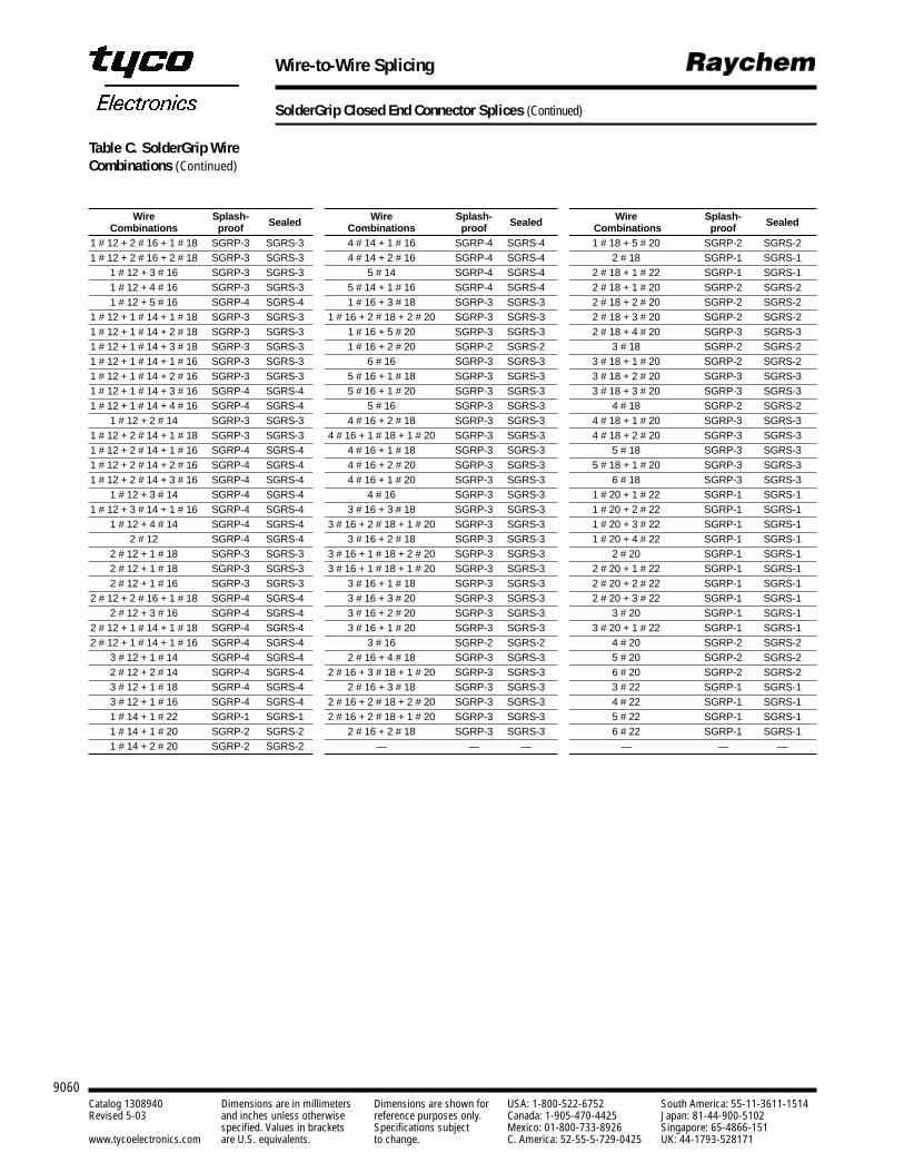
9060Catalog 1308940 Dimensions are in millimeters Dimensions are shown for USA: 1-800-522-6752 South America: 55-11-3611-1514Revised 5-03 and inches unless otherwise reference purposes only. Canada: 1-905-470-4425 Japan: 81-44-900-5102
specified. Values in brackets Specifications subject Mexico: 01-800-733-8926 Singapore: 65-4866-151www.tycoelectronics.com are U.S. equivalents. to change. C. America: 52-55-5-729-0425 UK: 44-1793-528171
Wire-to-Wire Splicing
SolderGrip Closed End Connector Splices (Continued)
Wire Splash- Wire Splash- Wire Splash-Combinations proof Sealed Combinations proof Sealed Combinations proof Sealed
1 # 12 + 2 # 16 + 1 # 18 SGRP-3 SGRS-3 4 # 14 + 1 # 16 SGRP-4 SGRS-4 1 # 18 + 5 # 20 SGRP-2 SGRS-21 # 12 + 2 # 16 + 2 # 18 SGRP-3 SGRS-3 4 # 14 + 2 # 16 SGRP-4 SGRS-4 2 # 18 SGRP-1 SGRS-1
1 # 12 + 3 # 16 SGRP-3 SGRS-3 5 # 14 SGRP-4 SGRS-4 2 # 18 + 1 # 22 SGRP-1 SGRS-11 # 12 + 4 # 16 SGRP-3 SGRS-3 5 # 14 + 1 # 16 SGRP-4 SGRS-4 2 # 18 + 1 # 20 SGRP-2 SGRS-21 # 12 + 5 # 16 SGRP-4 SGRS-4 1 # 16 + 3 # 18 SGRP-3 SGRS-3 2 # 18 + 2 # 20 SGRP-2 SGRS-2
1 # 12 + 1 # 14 + 1 # 18 SGRP-3 SGRS-3 1 # 16 + 2 # 18 + 2 # 20 SGRP-3 SGRS-3 2 # 18 + 3 # 20 SGRP-2 SGRS-21 # 12 + 1 # 14 + 2 # 18 SGRP-3 SGRS-3 1 # 16 + 5 # 20 SGRP-3 SGRS-3 2 # 18 + 4 # 20 SGRP-3 SGRS-31 # 12 + 1 # 14 + 3 # 18 SGRP-3 SGRS-3 1 # 16 + 2 # 20 SGRP-2 SGRS-2 3 # 18 SGRP-2 SGRS-21 # 12 + 1 # 14 + 1 # 16 SGRP-3 SGRS-3 6 # 16 SGRP-3 SGRS-3 3 # 18 + 1 # 20 SGRP-2 SGRS-21 # 12 + 1 # 14 + 2 # 16 SGRP-3 SGRS-3 5 # 16 + 1 # 18 SGRP-3 SGRS-3 3 # 18 + 2 # 20 SGRP-3 SGRS-31 # 12 + 1 # 14 + 3 # 16 SGRP-4 SGRS-4 5 # 16 + 1 # 20 SGRP-3 SGRS-3 3 # 18 + 3 # 20 SGRP-3 SGRS-31 # 12 + 1 # 14 + 4 # 16 SGRP-4 SGRS-4 5 # 16 SGRP-3 SGRS-3 4 # 18 SGRP-2 SGRS-2
1 # 12 + 2 # 14 SGRP-3 SGRS-3 4 # 16 + 2 # 18 SGRP-3 SGRS-3 4 # 18 + 1 # 20 SGRP-3 SGRS-31 # 12 + 2 # 14 + 1 # 18 SGRP-3 SGRS-3 4 # 16 + 1 # 18 + 1 # 20 SGRP-3 SGRS-3 4 # 18 + 2 # 20 SGRP-3 SGRS-31 # 12 + 2 # 14 + 1 # 16 SGRP-4 SGRS-4 4 # 16 + 1 # 18 SGRP-3 SGRS-3 5 # 18 SGRP-3 SGRS-31 # 12 + 2 # 14 + 2 # 16 SGRP-4 SGRS-4 4 # 16 + 2 # 20 SGRP-3 SGRS-3 5 # 18 + 1 # 20 SGRP-3 SGRS-31 # 12 + 2 # 14 + 3 # 16 SGRP-4 SGRS-4 4 # 16 + 1 # 20 SGRP-3 SGRS-3 6 # 18 SGRP-3 SGRS-3
1 # 12 + 3 # 14 SGRP-4 SGRS-4 4 # 16 SGRP-3 SGRS-3 1 # 20 + 1 # 22 SGRP-1 SGRS-11 # 12 + 3 # 14 + 1 # 16 SGRP-4 SGRS-4 3 # 16 + 3 # 18 SGRP-3 SGRS-3 1 # 20 + 2 # 22 SGRP-1 SGRS-1
1 # 12 + 4 # 14 SGRP-4 SGRS-4 3 # 16 + 2 # 18 + 1 # 20 SGRP-3 SGRS-3 1 # 20 + 3 # 22 SGRP-1 SGRS-12 # 12 SGRP-4 SGRS-4 3 # 16 + 2 # 18 SGRP-3 SGRS-3 1 # 20 + 4 # 22 SGRP-1 SGRS-1
2 # 12 + 1 # 18 SGRP-3 SGRS-3 3 # 16 + 1 # 18 + 2 # 20 SGRP-3 SGRS-3 2 # 20 SGRP-1 SGRS-12 # 12 + 1 # 18 SGRP-3 SGRS-3 3 # 16 + 1 # 18 + 1 # 20 SGRP-3 SGRS-3 2 # 20 + 1 # 22 SGRP-1 SGRS-12 # 12 + 1 # 16 SGRP-3 SGRS-3 3 # 16 + 1 # 18 SGRP-3 SGRS-3 2 # 20 + 2 # 22 SGRP-1 SGRS-1
2 # 12 + 2 # 16 + 1 # 18 SGRP-4 SGRS-4 3 # 16 + 3 # 20 SGRP-3 SGRS-3 2 # 20 + 3 # 22 SGRP-1 SGRS-12 # 12 + 3 # 16 SGRP-4 SGRS-4 3 # 16 + 2 # 20 SGRP-3 SGRS-3 3 # 20 SGRP-1 SGRS-1
2 # 12 + 1 # 14 + 1 # 18 SGRP-4 SGRS-4 3 # 16 + 1 # 20 SGRP-3 SGRS-3 3 # 20 + 1 # 22 SGRP-1 SGRS-12 # 12 + 1 # 14 + 1 # 16 SGRP-4 SGRS-4 3 # 16 SGRP-2 SGRS-2 4 # 20 SGRP-2 SGRS-2
3 # 12 + 1 # 14 SGRP-4 SGRS-4 2 # 16 + 4 # 18 SGRP-3 SGRS-3 5 # 20 SGRP-2 SGRS-22 # 12 + 2 # 14 SGRP-4 SGRS-4 2 # 16 + 3 # 18 + 1 # 20 SGRP-3 SGRS-3 6 # 20 SGRP-2 SGRS-23 # 12 + 1 # 18 SGRP-4 SGRS-4 2 # 16 + 3 # 18 SGRP-3 SGRS-3 3 # 22 SGRP-1 SGRS-13 # 12 + 1 # 16 SGRP-4 SGRS-4 2 # 16 + 2 # 18 + 2 # 20 SGRP-3 SGRS-3 4 # 22 SGRP-1 SGRS-11 # 14 + 1 # 22 SGRP-1 SGRS-1 2 # 16 + 2 # 18 + 1 # 20 SGRP-3 SGRS-3 5 # 22 SGRP-1 SGRS-11 # 14 + 1 # 20 SGRP-2 SGRS-2 2 # 16 + 2 # 18 SGRP-3 SGRS-3 6 # 22 SGRP-1 SGRS-11 # 14 + 2 # 20 SGRP-2 SGRS-2 — — — — — —
Table C. SolderGrip WireCombinations (Continued)

9061
9Terminals and Splices
Catalog 1308940 Dimensions are in millimeters Dimensions are shown for USA: 1-800-522-6752 South America: 55-11-3611-1514Revised 5-03 and inches unless otherwise reference purposes only. Canada: 1-905-470-4425 Japan: 81-44-900-5102
specified. Values in brackets Specifications subject Mexico: 01-800-733-8926 Singapore: 65-4866-151www.tycoelectronics.com are U.S. equivalents. to change. C. America: 52-55-5-729-0425 UK: 44-1793-528171
Wire-to-Wire Splicing
SolderGrip Closed End Connector Splices (Continued)
Approvals and ReferenceDocuments
Installation
Agency Approvals UL, CUL E87681Reference documents Raychem Specification RB-109 for splices
SolderGrip Terminators Selection Guide (H54640),SolderGrip Terminators Installation Procedure (H54636)Specification Control DrawingsSplices—Non Sealed (SGRP-X), Splices—Sealed (SGRS-X)
The SolderGrip product ispushed onto the conductorswith a twisting motion. Withthe product in place, instal-lation can be completedwith the proper selectionand use of heating toolsand reflectors. Either of thefollowing Raychem heatingtools is recommended:
HL1802E
CV-1981
MaterialInsulation Radiation-crosslinked, transparent heat-shrinkable polyvinylidene fluorideSolder preform with flux Sn 60, Pb 40, ROM 1 flux per ANSI-J-STD-004 (RA flux).Sealing insert (SGRS) Hot melt adhesiveSpiral wound insert Copper alloy
Physical Unit Method of test RequirementDimensions inches RB-109 See product dimensions.
Electromechanical Unit Method of test Typical valuesDielectric withstand voltage kilovolts RB-109 2.0Static heating degrees RB-109 Less than 50°C rise
Environmental* Unit Method of test RequirementInsulation resistance after water immersion (SGRS only) megohms RB-109 100Contact resistance after exposure milliohms RB-109 Less than 6 milliohms
Operating condition Unit Method of test ValueTemperature rating — — -55°C to 125°C [-67°F to 257°F]Voltage rating volts — 600
*Immersion resistance sealing is dependent on the wire combinations used. The user should test specific wire combinations. Refer to RB-109 Raychem specification for procedures.
Product Characteristics
Refer to Raychem installa-tion procedure RPIP 820-00for detailed instructions andrecommended reflectorattachments.
You will find ordering information for these toolson pages 9102-9109.
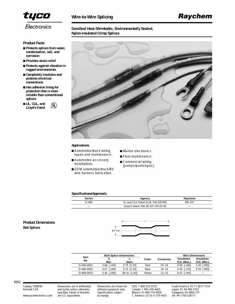
9062Catalog 1308940 Dimensions are in millimeters Dimensions are shown for USA: 1-800-522-6752 South America: 55-11-3611-1514Revised 5-03 and inches unless otherwise reference purposes only. Canada: 1-905-470-4425 Japan: 81-44-900-5102
specified. Values in brackets Specifications subject Mexico: 01-800-733-8926 Singapore: 65-4866-151www.tycoelectronics.com are U.S. equivalents. to change. C. America: 52-55-5-729-0425 UK: 44-1793-528171
Wire-to-Wire Splicing
DuraSeal Heat-Shrinkable, Environmentally Sealed, Nylon-Insulated Crimp Splices
Applications
Automotive/truck wiringrepair and maintenance.
Automotive accessoryinstallations.
OEM automotive/truck/RVwire harness fabrication.
Specifications/ApprovalsSeries Agency RaychemD-406 UL and CUL listed 91J4, File E87681 RB-107
— Lloyd’s listed, File 65 247 HH 02-93 —
Butt Splice Dimensions Wire DimensionsPart A L Insulation InsulationNo. Min. Nom.
Color ConductorO.D. (Max.) O.D. (Min.)
D-406-0001 3.68 [.145] 3.75 [1.25] Red 22–18 3.56 [.140] 1.40 [.055]D-406-0002 4.57 [.180] 3.75 [1.25] Blue 16–14 4.45 [.175] 2.03 [.080]D-406-0003 6.35 [.250] 38.10 [1.50] Yellow 12–10 6.22 [.245] —
ØA min.
L
Product Facts Protects splices from water,
condensation, salt, andcorrosion
Provides strain relief Protects against vibration in
rugged environments Completely insulates and
protects electricalconnections
Has adhesive lining forprotection that is morereliable than conventionalsplices
UL, CUL, andLloyd’s listed R
Product DimensionsButt Splices
Marine electronics.
Fleet maintenance.
Commercial wiring(pumps/pools/spas).
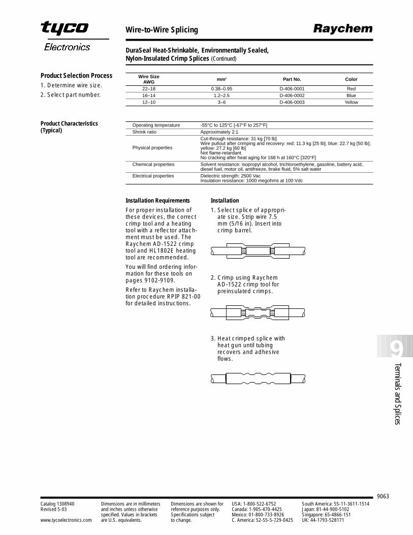
9063
9Terminals and Splices
Catalog 1308940 Dimensions are in millimeters Dimensions are shown for USA: 1-800-522-6752 South America: 55-11-3611-1514Revised 5-03 and inches unless otherwise reference purposes only. Canada: 1-905-470-4425 Japan: 81-44-900-5102
specified. Values in brackets Specifications subject Mexico: 01-800-733-8926 Singapore: 65-4866-151www.tycoelectronics.com are U.S. equivalents. to change. C. America: 52-55-5-729-0425 UK: 44-1793-528171
Wire-to-Wire Splicing
DuraSeal Heat-Shrinkable, Environmentally Sealed, Nylon-Insulated Crimp Splices (Continued)
Wire Size mm2 Part No. ColorAWG22–18 0.38–0.95 D-406-0001 Red16–14 1.2–2.5 D-406-0002 Blue12–10 3–6 D-406-0003 Yellow
Operating temperature -55°C to 125°C [-67°F to 257°F]Shrink ratio Approximately 2:1
Cut-through resistance: 31 kg [70 lb]Wire pullout after crimping and recovery: red: 11.3 kg [25 lb]; blue: 22.7 kg [50 lb]; yellow: 27.2 kg [60 lb]Not flame-retardantNo cracking after heat aging for 168 h at 160°C [320°F]
Chemical properties Solvent resistance: isopropyl alcohol, trichloroethylene, gasoline, battery acid, diesel fuel, motor oil, antifreeze, brake fluid, 5% salt water
Electrical properties Dielectric strength: 2500 VacInsulation resistance: 1000 megohms at 100 Vdc
Installation
1. Select splice of appropri-ate size. Strip wire 7.5mm (5/16 in). Insert intocrimp barrel.
2. Crimp using RaychemAD-1522 crimp tool forpreinsulated crimps.
3. Heat crimped splice withheat gun until tubingrecovers and adhesiveflows.
Installation Requirements
For proper installation ofthese devices, the correctcrimp tool and a heatingtool with a reflector attach-ment must be used. TheRaychem AD-1522 crimptool and HL1802E heatingtool are recommended.
You will find ordering infor-mation for these tools onpages 9102-9109.
Refer to Raychem installa-tion procedure RPIP 821-00for detailed instructions.
Product Selection Process1. Determine wire size.
2. Select part number.
Product Characteristics(Typical)
Physical properties
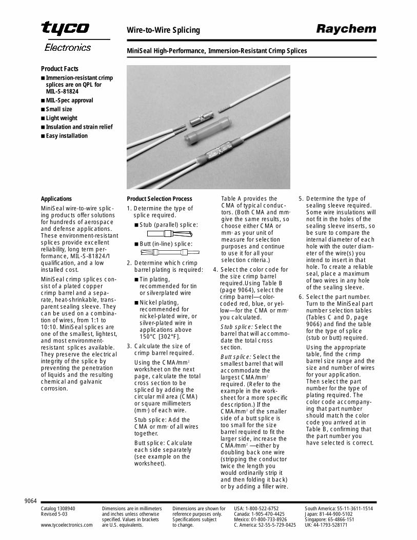
9064Catalog 1308940 Dimensions are in millimeters Dimensions are shown for USA: 1-800-522-6752 South America: 55-11-3611-1514Revised 5-03 and inches unless otherwise reference purposes only. Canada: 1-905-470-4425 Japan: 81-44-900-5102
specified. Values in brackets Specifications subject Mexico: 01-800-733-8926 Singapore: 65-4866-151www.tycoelectronics.com are U.S. equivalents. to change. C. America: 52-55-5-729-0425 UK: 44-1793-528171
Wire-to-Wire Splicing
MiniSeal High-Performance, Immersion-Resistant Crimp Splices
Applications
MiniSeal wire-to-wire splic-ing products offer solutionsfor hundreds of aerospaceand defense applications.These environment-resistantsplices provide excellentreliability, long term per-formance, MIL-S-81824/1qualification, and a lowinstalled cost.
MiniSeal crimp splices con-sist of a plated coppercrimp barrel and a sepa-rate, heat-shrinkable, trans-parent sealing sleeve. Theycan be used on a combina-tion of wires, from 1:1 to10:10. MiniSeal splices areone of the smallest, lightest,and most environment-resistant splices available.They preserve the electricalintegrity of the splice bypreventing the penetrationof liquids and the resultingchemical and galvanic corrosion.
Product Selection Process
1. Determine the type ofsplice required.
Stub (parallel) splice:
Butt (in-line) splice:
2. Determine which crimpbarrel plating is required:
Tin plating, recommended for tin or silverplated wire
Nickel plating, recommended for nickel-plated wire, orsilver-plated wire inapplications above150°C [302°F].
3. Calculate the size ofcrimp barrel required.
Using the CMA/mm2
worksheet on the nextpage, calculate the totalcross section to bespliced by adding thecircular mil area (CMA)or square millimeters(mm2) of each wire.
Stub splice: Add theCMA or mm2 of all wirestogether.
Butt splice: Calculateeach side separately(see example on theworksheet).
Table A provides theCMA of typical conduc-tors. (Both CMA and mm2
give the same results, sochoose either CMA ormm2 as your unit ofmeasure for selectionpurposes and continueto use it for all yourselection criteria.)
4. Select the color code forthe size crimp barrelrequired.Using Table B(page 9064), select thecrimp barrel—color-coded red, blue, or yel-low—for the CMA or mm2
you calculated.
Stub splice: Select thebarrel that will accommo-date the total cross section.
Butt splice: Select thesmallest barrel that willaccommodate thelargest CMA/mm2
required. (Refer to theexample in the work-sheet for a more specificdescription.) If theCMA/mm2 of the smallerside of a butt splice istoo small for the size barrel required to fit thelarger side, increase theCMA/mm2 —either bydoubling back one wire(stripping the conductortwice the length youwould ordinarily strip itand then folding it back)or by adding a filler wire.
5. Determine the type ofsealing sleeve required.Some wire insulations willnot fit in the holes of thesealing sleeve inserts, sobe sure to compare theinternal diameter of eachhole with the outer diam-eter of the wire(s) youintend to insert in thathole. To create a reliableseal, place a maximumof two wires in any holeof the sealing sleeve.
6. Select the part number.Turn to the MiniSeal partnumber selection tables(Tables C and D, page9066) and find the tablefor the type of splice(stub or butt) required.
Using the appropriatetable, find the crimp barrel size range and thesize and number of wiresfor your application.Then select the partnumber for the type ofplating required. Thecolor code accompany-ing that part numbershould match the colorcode you arrived at inTable B, confirming thatthe part number youhave selected is correct.
Product Facts Immersion-resistant crimp
splices are on QPL for MIL-S-81824
MIL-Spec approval Small size Light weight Insulation and strain relief Easy installation
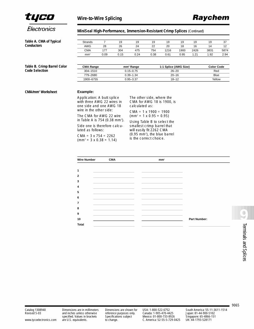
9065
9Terminals and Splices
Catalog 1308940 Dimensions are in millimeters Dimensions are shown for USA: 1-800-522-6752 South America: 55-11-3611-1514Revised 5-03 and inches unless otherwise reference purposes only. Canada: 1-905-470-4425 Japan: 81-44-900-5102
specified. Values in brackets Specifications subject Mexico: 01-800-733-8926 Singapore: 65-4866-151www.tycoelectronics.com are U.S. equivalents. to change. C. America: 52-55-5-729-0425 UK: 44-1793-528171
Wire-to-Wire Splicing
MiniSeal High-Performance, Immersion-Resistant Crimp Splices (Continued)
Strands 7 19 19 19 19 19 19 19 37AWG 28 26 24 22 20 18 16 14 12CMA 177 304 475 754 1216 1900 2426 3831 5874mm2 0.09 0.15 0.24 0.38 0.61 0.95 1.21 1.92 2.94
CMA Range mm2 Range 1:1 Splice (AWG Size) Color Code304–1510 0.15–0.75 26–20 Red779–2680 0.39–1.34 20–16 Blue1900–6755 0.95–3.37 18–12 Yellow
Example:
Application: A butt splicewith three AWG 22 wires inone side and one AWG 18wire in the other side:
The CMA for AWG 22 wirein Table A is 754 (0.38 mm2).
Side one is therefore calcu-lated as follows:
CMA = 3 x 754 = 2262(mm2 = 3 x 0.38 = 1.14)
The other side, where theCMA for AWG 18 is 1900, iscalculated as:
CMA = 1 x 1900 = 1900(mm2 = 1 x 0.95 = 0.95)
Using Table B to select thesmallest crimp barrel thatwill easily fit 2262 CMA(0.95 mm2), the blue barrelis the correct choice.
Wire Number CMA mm2
1
2
3
4
5
6
7
8
9
10 Part Number:
Total
Table A. CMA of TypicalConductors
Table B. Crimp Barrel ColorCode Selection
CMA/mm2 Worksheet
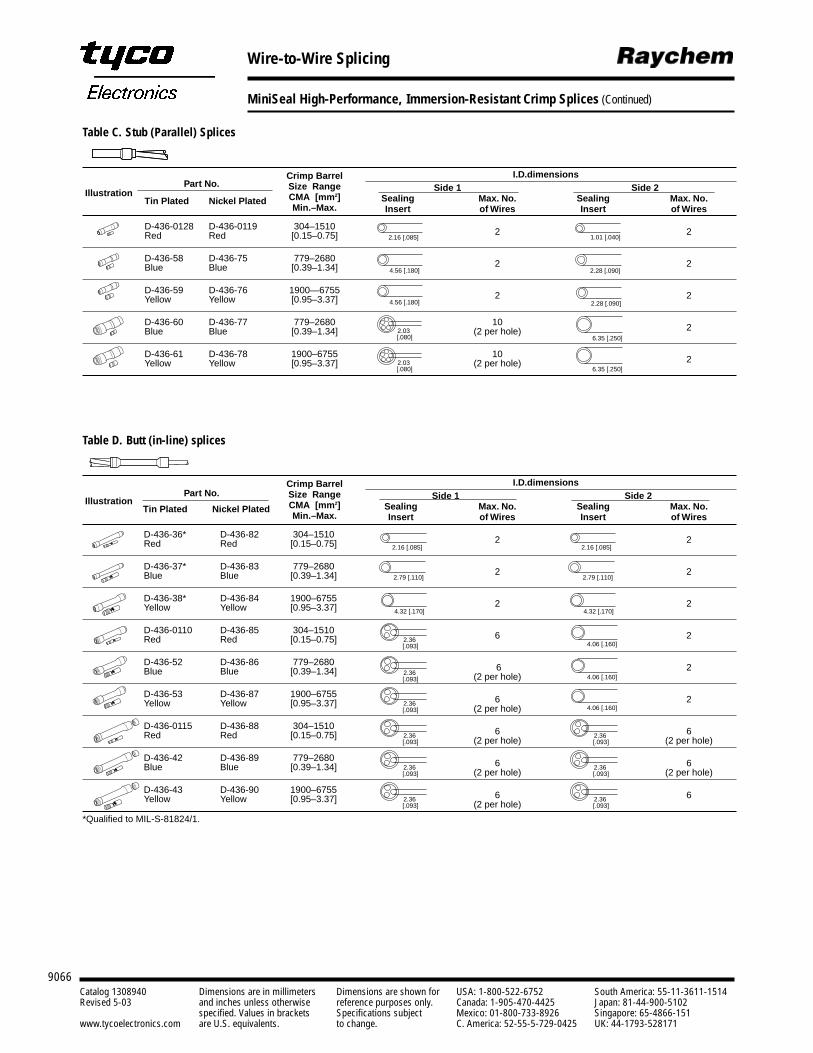
9066Catalog 1308940 Dimensions are in millimeters Dimensions are shown for USA: 1-800-522-6752 South America: 55-11-3611-1514Revised 5-03 and inches unless otherwise reference purposes only. Canada: 1-905-470-4425 Japan: 81-44-900-5102
specified. Values in brackets Specifications subject Mexico: 01-800-733-8926 Singapore: 65-4866-151www.tycoelectronics.com are U.S. equivalents. to change. C. America: 52-55-5-729-0425 UK: 44-1793-528171
Wire-to-Wire Splicing
MiniSeal High-Performance, Immersion-Resistant Crimp Splices (Continued)
Table D. Butt (in-line) splices
Crimp Barrel I.D.dimensions
IllustrationPart No. Size Range Side 1 Side 2
CMA [mm2] Sealing Max. No. Sealing Max. No.Tin Plated Nickel PlatedMin.–Max. Insert of Wires Insert of Wires
D-436-36* D-436-82 304–1510 2 2Red Red [0.15–0.75]
D-436-37* D-436-83 779–2680 2 2Blue Blue [0.39–1.34]
D-436-38* D-436-84 1900–6755 2 2Yellow Yellow [0.95–3.37]
D-436-0110 D-436-85 304–1510 6 2Red Red [0.15–0.75]
D-436-52 D-436-86 779–2680 6 2Blue Blue [0.39–1.34] (2 per hole)
D-436-53 D-436-87 1900–6755 6 2Yellow Yellow [0.95–3.37] (2 per hole)
D-436-0115 D-436-88 304–1510 6 6Red Red [0.15–0.75] (2 per hole) (2 per hole)
D-436-42 D-436-89 779–2680 6 6Blue Blue [0.39–1.34] (2 per hole) (2 per hole)
D-436-43 D-436-90 1900–6755 6 6Yellow Yellow [0.95–3.37] (2 per hole)
*Qualified to MIL-S-81824/1.
Table C. Stub (Parallel) Splices
Crimp Barrel I.D.dimensions
IllustrationPart No. Size Range Side 1 Side 2
CMA [mm2] Sealing Max. No. Sealing Max. No.Tin Plated Nickel PlatedMin.–Max. Insert of Wires Insert of Wires
D-436-0128 D-436-0119 304–1510 2 2Red Red [0.15–0.75]
D-436-58 D-436-75 779–2680 2 2Blue Blue [0.39–1.34]
D-436-59 D-436-76 1900—6755 2 2Yellow Yellow [0.95–3.37]
D-436-60 D-436-77 779–2680 10 2Blue Blue [0.39–1.34] (2 per hole)
D-436-61 D-436-78 1900–6755 10 2Yellow Yellow [0.95–3.37] (2 per hole)
2.16 [.085]
4.56 [.180]
4.56 [.180]
2.03 [.080]
2.03 [.080]
1.01 [.040]
2.28 [.090]
2.28 [.090]
6.35 [.250]
6.35 [.250]
2.16 [.085]
2.79 [.110]
4.32 [.170]
2.16 [.085]
2.79 [.110]
4.32 [.170]
2.36 [.093]
2.36 [.093]
4.06 [.160]
4.06 [.160]
2.36 [.093] 4.06 [.160]
2.36 [.093]
2.36 [.093]
2.36 [.093]
2.36 [.093]
2.36 [.093]
2.36 [.093]
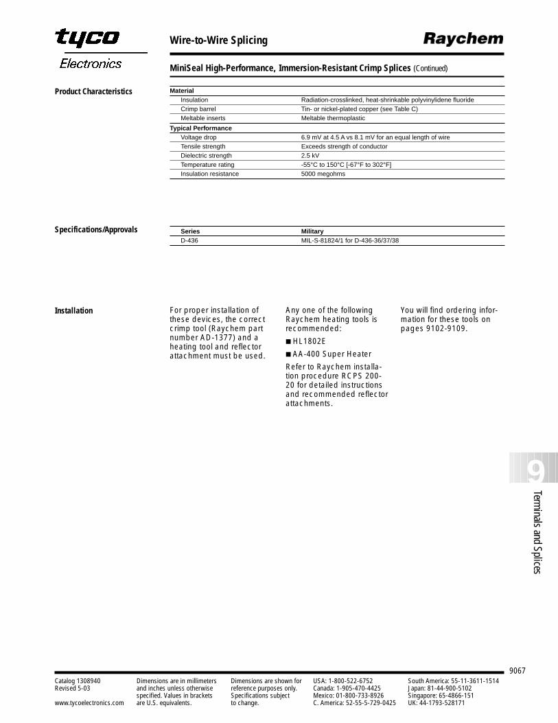
9067
9Terminals and Splices
Catalog 1308940 Dimensions are in millimeters Dimensions are shown for USA: 1-800-522-6752 South America: 55-11-3611-1514Revised 5-03 and inches unless otherwise reference purposes only. Canada: 1-905-470-4425 Japan: 81-44-900-5102
specified. Values in brackets Specifications subject Mexico: 01-800-733-8926 Singapore: 65-4866-151www.tycoelectronics.com are U.S. equivalents. to change. C. America: 52-55-5-729-0425 UK: 44-1793-528171
Wire-to-Wire Splicing
MiniSeal High-Performance, Immersion-Resistant Crimp Splices (Continued)
MaterialInsulation Radiation-crosslinked, heat-shrinkable polyvinylidene fluoride Crimp barrel Tin- or nickel-plated copper (see Table C)Meltable inserts Meltable thermoplastic
Typical PerformanceVoltage drop 6.9 mV at 4.5 A vs 8.1 mV for an equal length of wireTensile strength Exceeds strength of conductorDielectric strength 2.5 kVTemperature rating -55°C to 150°C [-67°F to 302°F]Insulation resistance 5000 megohms
Series MilitaryD-436 MIL-S-81824/1 for D-436-36/37/38
For proper installation ofthese devices, the correctcrimp tool (Raychem partnumber AD-1377) and aheating tool and reflectorattachment must be used.
Any one of the followingRaychem heating tools isrecommended:
HL1802E
AA-400 Super Heater
Refer to Raychem installa-tion procedure RCPS 200-20 for detailed instructionsand recommended reflectorattachments.
You will find ordering infor-mation for these tools onpages 9102-9109.
Product Characteristics
Specifications/Approvals
Installation
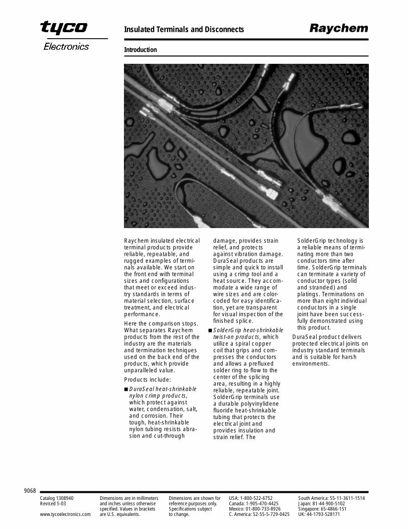
9068Catalog 1308940 Dimensions are in millimeters Dimensions are shown for USA: 1-800-522-6752 South America: 55-11-3611-1514Revised 5-03 and inches unless otherwise reference purposes only. Canada: 1-905-470-4425 Japan: 81-44-900-5102
specified. Values in brackets Specifications subject Mexico: 01-800-733-8926 Singapore: 65-4866-151www.tycoelectronics.com are U.S. equivalents. to change. C. America: 52-55-5-729-0425 UK: 44-1793-528171
Insulated Terminals and Disconnects
Introduction
Raychem insulated electricalterminal products providereliable, repeatable, andrugged examples of termi-nals available. We start onthe front end with terminalsizes and configurationsthat meet or exceed indus-try standards in terms ofmaterial selection, surfacetreatment, and electricalperformance.
Here the comparison stops.What separates Raychemproducts from the rest of theindustry are the materialsand termination techniquesused on the back end of theproducts, which provideunparalleled value.
Products include:
DuraSeal heat-shrinkablenylon crimp products,which protect againstwater, condensation, salt,and corrosion. Theirtough, heat-shrinkablenylon tubing resists abra-sion and cut-through
SolderGrip technology isa reliable means of termi-nating more than two conductors time aftertime. SolderGrip terminalscan terminate a variety ofconductor types (solidand stranded) and platings. Terminations onmore than eight individualconductors in a singlejoint have been success-fully demonstrated usingthis product.
DuraSeal product deliversprotected electrical joints onindustry standard terminalsand is suitable for harshenvironments.
damage, provides strainrelief, and protectsagainst vibration damage.DuraSeal products aresimple and quick to installusing a crimp tool and aheat source. They accom-modate a wide range ofwire sizes and are color-coded for easy identifica-tion, yet are transparentfor visual inspection of thefinished splice.
SolderGrip heat-shrinkabletwist-on products, whichutilize a spiral copper coil that grips and com-presses the conductorsand allows a prefluxedsolder ring to flow to thecenter of the splicingarea, resulting in a highlyreliable, repeatable joint.SolderGrip terminals usea durable polyvinylidenefluoride heat-shrinkabletubing that protects theelectrical joint and provides insulation andstrain relief. The
9069
9Terminals and Splices
Catalog 1308940 Dimensions are in millimeters Dimensions are shown for USA: 1-800-522-6752 South America: 55-11-3611-1514Revised 5-03 and inches unless otherwise reference purposes only. Canada: 1-905-470-4425 Japan: 81-44-900-5102
specified. Values in brackets Specifications subject Mexico: 01-800-733-8926 Singapore: 65-4866-151www.tycoelectronics.com are U.S. equivalents. to change. C. America: 52-55-5-729-0425 UK: 44-1793-528171
Insulated Terminals and Disconnects
DuraSeal Heat-Shrinkable EnvironmentallySealed, Nylon Insulated Crimp Terminals and Disconnects
ApplicationsDuraSeal products insulateand protect electrical con-nections from mechanicalabuse, wire pull-out, andabrasion while resistingwater, salt, and othercontaminants.
DuraSeal devices provide atough, environmentallysealed wire connection.Their crimp barrel or termi-nal, encased in rugged,heat-shrinkable nylon tubing lined with a specialhot-melt adhesive, resistsdamage from abrasions and cuts.
DuraSeal devices retainflexibility and impact-resistance long after similarproducts have become brittle.
DuraSeal devices accomodate wire gaugesizes 22 to 10. They arecolor-coded for easy identification of gaugesizes, yet transparent forinspection of the finishedsplice.
Agency approvals UL listed component, file E87681, terminals except quick connect terminals;file E157833, quick connect terminals
Reference documentsRaychem specifications RB-108, Specification DuraSeal crimp terminalsDuraSeal selection guide (H54153)DuraSeal installation guidelines (H54154)
Product Facts Resistance to moisture and
abrasion Strain relief Protection from wire pull-out Easy installation UL and CUL
listed R
Approvals and ReferenceDocuments
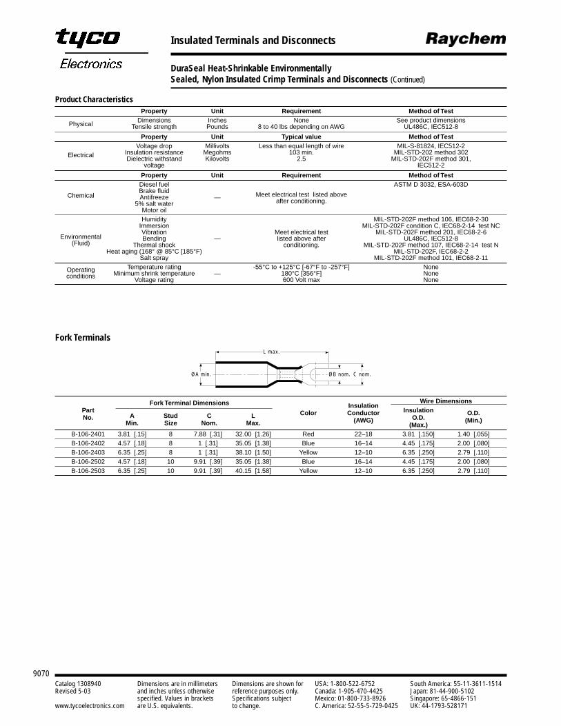
9070Catalog 1308940 Dimensions are in millimeters Dimensions are shown for USA: 1-800-522-6752 South America: 55-11-3611-1514Revised 5-03 and inches unless otherwise reference purposes only. Canada: 1-905-470-4425 Japan: 81-44-900-5102
specified. Values in brackets Specifications subject Mexico: 01-800-733-8926 Singapore: 65-4866-151www.tycoelectronics.com are U.S. equivalents. to change. C. America: 52-55-5-729-0425 UK: 44-1793-528171
Insulated Terminals and Disconnects
DuraSeal Heat-Shrinkable EnvironmentallySealed, Nylon Insulated Crimp Terminals and Disconnects (Continued)
Product CharacteristicsProperty Unit Requirement Method of Test
Physical Dimensions Inches None See product dimensionsTensile strength Pounds 8 to 40 lbs depending on AWG UL486C, IEC512-8
Property Unit Typical value Method of Test
ElectricalVoltage drop Millivolts Less than equal length of wire MIL-S-81824, IEC512-2
Insulation resistance Megohms 103 min. MIL-STD-202 method 302Dielectric withstand Kilovolts 2.5 MIL-STD-202F method 301,
voltage IEC512-2
Property Unit Requirement Method of Test
Chemical
Diesel fuel ASTM D 3032, ESA-603DBrake fluidAntifreeze — Meet electrical test listed above
5% salt water after conditioning.Motor oil
Environmental
Humidity MIL-STD-202F method 106, IEC68-2-30
(Fluid)
Immersion MIL-STD-202F condition C, IEC68-2-14 test NCVibration Meet electrical test MIL-STD-202F method 201, IEC68-2-6Bending — listed above after UL486C, IEC512-8
Thermal shock conditioning. MIL-STD-202F method 107, IEC68-2-14 test NHeat aging (168° @ 85°C [185°F) MIL-STD-202F, IEC68-2-2
Salt spray MIL-STD-202F method 101, IEC68-2-11
Operating Temperature rating -55°C to +125°C [-67°F to -257°F] Noneconditions Minimum shrink temperature — 180°C [356°F] None
Voltage rating 600 Volt max None
Fork Terminals
Fork Terminal Dimensions Wire DimensionsPart
InsulationInsulation
No. A Stud C L Color ConductorO.D.
O.D.
Min. Size Nom. Max. (AWG)(Max.)
(Min.)
B-106-2401 3.81 [.15] 8 7.88 [.31] 32.00 [1.26] Red 22–18 3.81 [.150] 1.40 [.055]B-106-2402 4.57 [.18] 8 1 [.31] 35.05 [1.38] Blue 16–14 4.45 [.175] 2.00 [.080]B-106-2403 6.35 [.25] 8 1 [.31] 38.10 [1.50] Yellow 12–10 6.35 [.250] 2.79 [.110]B-106-2502 4.57 [.18] 10 9.91 [.39] 35.05 [1.38] Blue 16–14 4.45 [.175] 2.00 [.080]B-106-2503 6.35 [.25] 10 9.91 [.39] 40.15 [1.58] Yellow 12–10 6.35 [.250] 2.79 [.110]
ØA min.
L max.
ØB nom. C nom.

9071
9Terminals and Splices
Catalog 1308940 Dimensions are in millimeters Dimensions are shown for USA: 1-800-522-6752 South America: 55-11-3611-1514Revised 5-03 and inches unless otherwise reference purposes only. Canada: 1-905-470-4425 Japan: 81-44-900-5102
specified. Values in brackets Specifications subject Mexico: 01-800-733-8926 Singapore: 65-4866-151www.tycoelectronics.com are U.S. equivalents. to change. C. America: 52-55-5-729-0425 UK: 44-1793-528171
Insulated Terminals and Disconnects
DuraSeal Heat-Shrinkable EnvironmentallySealed, Nylon Insulated Crimp Terminals and Disconnects (Continued)
Fork Terminal Dimensions Wire DimensionsPart Insulation InsulationNo. A Stud C L Color Conductor O.D. O.D.
Min. Size Nom. Max. (AWG) (Max.) (Min.)
B-106-1401 3.81 [.15] 8 7.88 [.31] 32.00 [1.26] Red 22–18 3.81 [.150] 1.40 [.055]B-106-1501 3.81 [.15] 10 9.91 [.39] 34.04 [1.34] Red 22–18 3.81 [.150] 1.40 [.055]B-106-1601 3.81 [.15] 1/4 11.94 [.47] 36.07 [1.42] Red 22–18 3.81 [.150] 1.40 [.055]B-106-1801 3.81 [.15] 5/16 13.97 [.55] 39.12 [1.54] Red 22–18 3.81 [.150] 1.40 [.055]B-106-1991 3.81 [.15] 3/8 17.78 [.70] 43.18 [1.70] Red 22–18 3.81 [.150] 1.40 [.055]B-106-1402 4.57 [.18] 8 7.88 [.31] 33.02 [1.30] Blue 16–14 4.45 [.175] 2.00 [.080]B-106-1502 4.57 [.18] 10 9.91 [.39] 35.05 [1.38] Blue 16–14 4.45 [.175] 2.00 [.080]B-106-1602 4.57 [.18] 1/4 11.94 [.47] 36.58 [1.44] Blue 16–14 4.45 [.175] 2.00 [.080]B-106-1802 4.57 [.18] 5/16 13.97 [.55] 40.13 [1.58] Blue 16–14 4.45 [.175] 2.00 [.080]B-106-1992 4.57 [.18] 3/8 17.78 [.70] 43.94 [1.73] Blue 16–14 4.45 [.175] 2.00 [.080]B-106-1403 6.35 [.25] 8 7.88 [.31] 38.10 [1.50] Yellow 12–10 6.35 [.250] 2.79 [.110]B-106-1503 6.35 [.25] 10 9.91 [.39] 40.13 [1.58] Yellow 12–10 6.35 [.250] 2.79 [.110]B-106-1603 6.35 [.25] 1/4 11.94 [.47] 41.66 [1.64] Yellow 12–10 6.35 [.250] 2.79 [.110]B-106-1803 6.35 [.25] 5/16 13.97 [.55] 45.21 [1.78] Yellow 12–10 6.35 [.250] 2.79 [.110]B-106-1993 6.35 [.25] 3/8 17.78 [.70] 46.99 [1.85] Yellow 12–10 6.35 [.250] 2.79 [.110]
ØA min.
L max.
B nom. ØC nom.
Ring Terminals
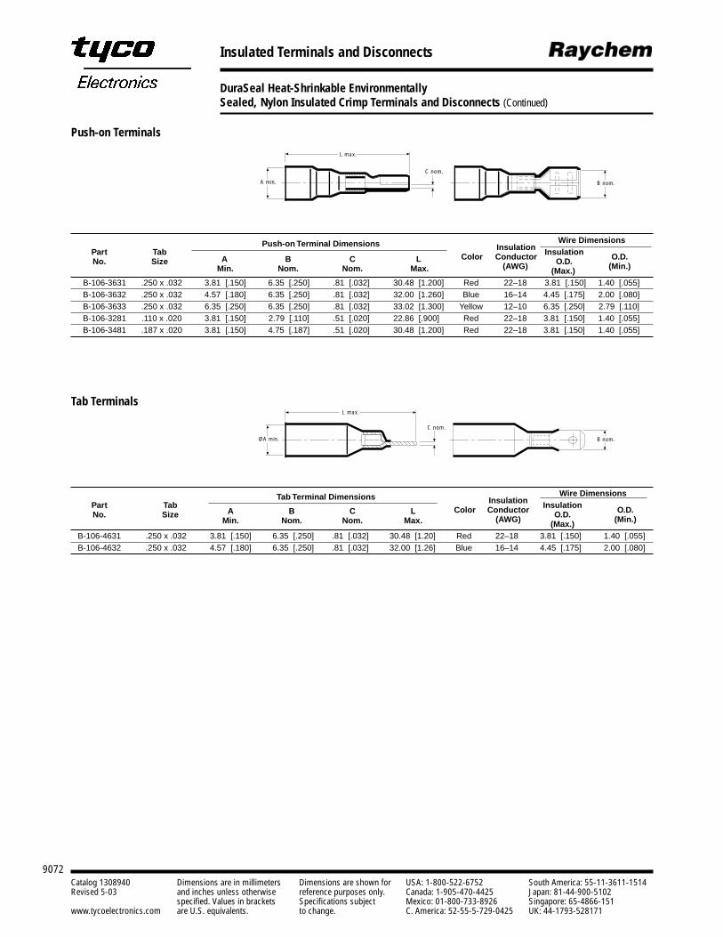
9072Catalog 1308940 Dimensions are in millimeters Dimensions are shown for USA: 1-800-522-6752 South America: 55-11-3611-1514Revised 5-03 and inches unless otherwise reference purposes only. Canada: 1-905-470-4425 Japan: 81-44-900-5102
specified. Values in brackets Specifications subject Mexico: 01-800-733-8926 Singapore: 65-4866-151www.tycoelectronics.com are U.S. equivalents. to change. C. America: 52-55-5-729-0425 UK: 44-1793-528171
Insulated Terminals and Disconnects
DuraSeal Heat-Shrinkable EnvironmentallySealed, Nylon Insulated Crimp Terminals and Disconnects (Continued)
B nom.
C nom.
L max.
A min.
L max.
ØA min.
C nom.
B nom.
Push-on Terminal Dimensions Wire DimensionsPart Tab Color
Insulation InsulationNo. Size A B C L Conductor O.D. O.D.
Min. Nom. Nom. Max. (AWG) (Max.) (Min.)
B-106-3631 .250 x .032 3.81 [.150] 6.35 [.250] .81 [.032] 30.48 [1.200] Red 22–18 3.81 [.150] 1.40 [.055]B-106-3632 .250 x .032 4.57 [.180] 6.35 [.250] .81 [.032] 32.00 [1.260] Blue 16–14 4.45 [.175] 2.00 [.080]B-106-3633 .250 x .032 6.35 [.250] 6.35 [.250] .81 [.032] 33.02 [1.300] Yellow 12–10 6.35 [.250] 2.79 [.110]B-106-3281 .110 x .020 3.81 [.150] 2.79 [.110] .51 [.020] 22.86 [.900] Red 22–18 3.81 [.150] 1.40 [.055]B-106-3481 .187 x .020 3.81 [.150] 4.75 [.187] .51 [.020] 30.48 [1.200] Red 22–18 3.81 [.150] 1.40 [.055]
Tab Terminal Dimensions Wire DimensionsPart Tab Color
Insulation InsulationNo. Size A B C L Conductor O.D. O.D.
Min. Nom. Nom. Max. (AWG) (Max.) (Min.)
B-106-4631 .250 x .032 3.81 [.150] 6.35 [.250] .81 [.032] 30.48 [1.20] Red 22–18 3.81 [.150] 1.40 [.055]B-106-4632 .250 x .032 4.57 [.180] 6.35 [.250] .81 [.032] 32.00 [1.26] Blue 16–14 4.45 [.175] 2.00 [.080]
Push-on Terminals
Tab Terminals
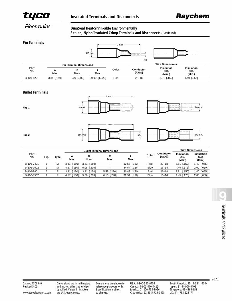
9073
9Terminals and Splices
Catalog 1308940 Dimensions are in millimeters Dimensions are shown for USA: 1-800-522-6752 South America: 55-11-3611-1514Revised 5-03 and inches unless otherwise reference purposes only. Canada: 1-905-470-4425 Japan: 81-44-900-5102
specified. Values in brackets Specifications subject Mexico: 01-800-733-8926 Singapore: 65-4866-151www.tycoelectronics.com are U.S. equivalents. to change. C. America: 52-55-5-729-0425 UK: 44-1793-528171
Insulated Terminals and Disconnects
DuraSeal Heat-Shrinkable EnvironmentallySealed, Nylon Insulated Crimp Terminals and Disconnects (Continued)
Pin Terminal Dimensions Wire DimensionsPart Color Insulation InsulationNo. A B L Conductor O.D. O.D.
Min. Nom. Max. (AWG) (Max.) (Min.)B-106-6201 3.81 [.150] 2.00 [.080] 30.99 [1.220] Red 22–18 3.81 [.150] 1.40 [.055]
Fig. 1
Fig. 2
Bullet Terminal Dimensions Wire DimensionsPart Color
Conductor Insulation InsulationNo. Fig. Type A B C L (AWG) O.D. O.D.
Min. Nom. Min. Max. (Max.) (Min.)B-106-7401 1 M 3.81 [.150] 3.81 [.150] — 33.53 [1.32] Red 22–18 3.81 [.150] 1.40 [.055]B-106-7502 1 M 4.57 [.180] 5.08 [.200] — 34.54 [1.36] Blue 16–14 4.45 [.175] 2.00 [.080]B-106-8401 2 F 3.81 [.150] 3.81 [.150] 5.59 [.220] 30.48 [1.20] Red 22–18 3.81 [.150] 1.40 [.055]B-106-8502 2 F 4.57 [.180] 5.08 [.200] 6.10 [.240] 32.51 [1.28] Blue 16–14 4.45 [.175] 2.00 [.080]
ØA min.
ØB
L max.
ØA min. B nom.
ØA min. ØB ØC min.
L max.
L max.
Pin Terminals
Bullet Terminals
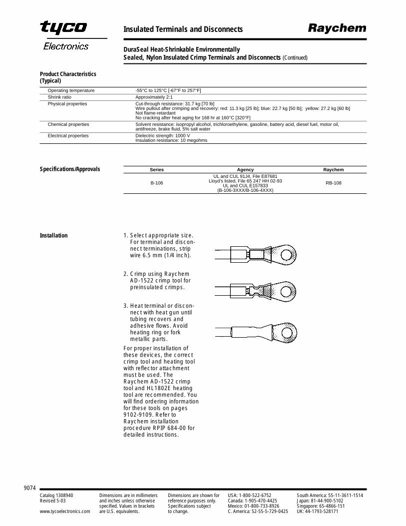
9074Catalog 1308940 Dimensions are in millimeters Dimensions are shown for USA: 1-800-522-6752 South America: 55-11-3611-1514Revised 5-03 and inches unless otherwise reference purposes only. Canada: 1-905-470-4425 Japan: 81-44-900-5102
specified. Values in brackets Specifications subject Mexico: 01-800-733-8926 Singapore: 65-4866-151www.tycoelectronics.com are U.S. equivalents. to change. C. America: 52-55-5-729-0425 UK: 44-1793-528171
Insulated Terminals and Disconnects
DuraSeal Heat-Shrinkable EnvironmentallySealed, Nylon Insulated Crimp Terminals and Disconnects (Continued)
Operating temperature -55°C to 125°C [-67°F to 257°F]Shrink ratio Approximately 2:1Physical properties Cut-through resistance: 31.7 kg [70 lb]
Wire pullout after crimping and recovery: red: 11.3 kg [25 lb]; blue: 22.7 kg [50 lb]; yellow: 27.2 kg [60 lb]Not flame-retardantNo cracking after heat aging for 168 hr at 160°C [320°F]
Chemical properties Solvent resistance: isopropyl alcohol, trichloroethylene, gasoline, battery acid, diesel fuel, motor oil, antifreeze, brake fluid, 5% salt water
Electrical properties Dielectric strength: 1000 VInsulation resistance: 10 megohms
Series Agency Raychem
B-106UL and CUL 91J4, File E87681
RB-108Lloyd’s listed, File 65 247 HH 02-93UL and CUL E157833
(B-106-3XXX/B-106-4XXX)
1. Select appropriate size.For terminal and discon-nect terminations, stripwire 6.5 mm (1/4 inch).
2. Crimp using RaychemAD-1522 crimp tool forpreinsulated crimps.
3. Heat terminal or discon-nect with heat gun untiltubing recovers andadhesive flows. Avoidheating ring or fork metallic parts.
For proper installation ofthese devices, the correctcrimp tool and heating toolwith reflector attachmentmust be used. TheRaychem AD-1522 crimptool and HL1802E heatingtool are recommended. Youwill find ordering informationfor these tools on pages9102-9109. Refer toRaychem installation procedure RPIP 684-00 fordetailed instructions.
Product Characteristics(Typical)
Specifications/Approvals
Installation
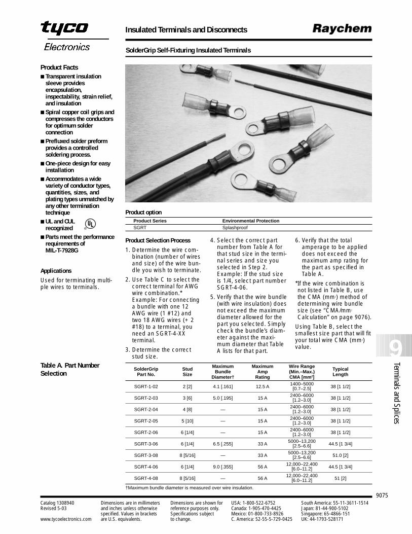
9075
9Terminals and Splices
Catalog 1308940 Dimensions are in millimeters Dimensions are shown for USA: 1-800-522-6752 South America: 55-11-3611-1514Revised 5-03 and inches unless otherwise reference purposes only. Canada: 1-905-470-4425 Japan: 81-44-900-5102
specified. Values in brackets Specifications subject Mexico: 01-800-733-8926 Singapore: 65-4866-151www.tycoelectronics.com are U.S. equivalents. to change. C. America: 52-55-5-729-0425 UK: 44-1793-528171
Insulated Terminals and Disconnects
SolderGrip Self-Fixturing Insulated Terminals
Product Facts Transparent insulation
sleeve providesencapsulation,inspectability, strain relief,and insulation
Spiral copper coil grips andcompresses the conductorsfor optimum solderconnection
Prefluxed solder preformprovides a controlledsoldering process.
One-piece design for easyinstallation
Accommodates a widevariety of conductor types,quantities, sizes, andplating types unmatched byany other terminationtechnique
UL and CULrecognized
Parts meet the performancerequirements of MIL-T-7928G
Product optionProduct Series Environmental ProtectionSGRT Splashproof
Applications
Used for terminating multi-ple wires to terminals.
R
Maximum Maximum Wire Range TypicalSolderGrip Stud Bundle Amp (Min.–Max.) LengthPart No. Size Diameter† Rating CMA [mm2]
SGRT-1-02 2 [2] 4.1 [.161] 12.5 A 1400–5000 38 [1 1/2][0.7–2.5]
SGRT-2-03 3 [6] 5.0 [.195] 15 A 2400–6000 38 [1 1/2][1.2–3.0]
SGRT-2-04 4 [8] — 15 A 2400–6000 38 [1 1/2][1.2–3.0]
SGRT-2-05 5 [10] — 15 A 2400–6000 38 [1 1/2][1.2–3.0]
SGRT-2-06 6 [1/4] — 15 A 2400–6000 38 [1 1/2][1.2–3.0]
SGRT-3-06 6 [1/4] 6.5 [.255] 33 A 5000–13,200 44.5 [1 3/4][2.5–6.6]
SGRT-3-08 8 [5/16] — 33 A 5000–13,200 51.0 [2][2.5–6.6]
SGRT-4-06 6 [1/4] 9.0 [.355] 56 A 12,000–22,400 44.5 [1 3/4][6.0–11.2]
SGRT-4-08 8 [5/16] — 56 A 12,000–22,400 51 [2][6.0–11.2]
†Maximum bundle diameter is measured over wire insulation.
Table A. Part NumberSelection
Product Selection Process
1. Determine the wire com-bination (number of wiresand size) of the wire bun-dle you wish to terminate.
2. Use Table C to select thecorrect terminal for AWGwire combination.*Example: For connectinga bundle with one 12AWG wire (1 #12) andtwo 18 AWG wires (+ 2#18) to a terminal, youneed an SGRT-4-XX terminal.
3. Determine the correctstud size.
4. Select the correct partnumber from Table A forthat stud size in the termi-nal series and size youselected in Step 2.Example: If the stud sizeis 1/4, select part numberSGRT-4-06.
5. Verify that the wire bundle(with wire insulation) doesnot exceed the maximumdiameter allowed for thepart you selected. Simplycheck the bundle’s diam-eter against the maxi-mum diameter that TableA lists for that part.
6. Verify that the totalamperage to be applieddoes not exceed themaximum amp rating forthe part as specified inTable A.
*If the wire combination isnot listed in Table B, usethe CMA (mm2) method ofdetermining wire bundlesize (see “CMA/mm2
Calculation” on page 9076).
Using Table B, select thesmallest size part that will fityour total wire CMA (mm2)value.
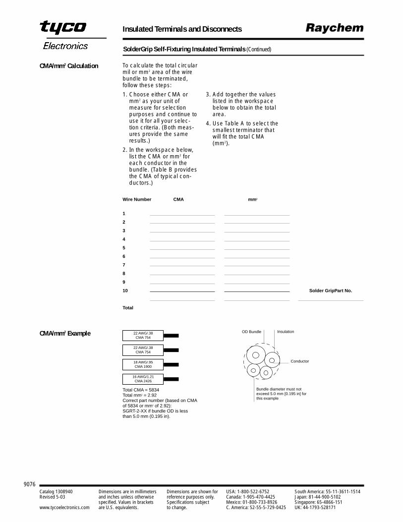
9076Catalog 1308940 Dimensions are in millimeters Dimensions are shown for USA: 1-800-522-6752 South America: 55-11-3611-1514Revised 5-03 and inches unless otherwise reference purposes only. Canada: 1-905-470-4425 Japan: 81-44-900-5102
specified. Values in brackets Specifications subject Mexico: 01-800-733-8926 Singapore: 65-4866-151www.tycoelectronics.com are U.S. equivalents. to change. C. America: 52-55-5-729-0425 UK: 44-1793-528171
Insulated Terminals and Disconnects
SolderGrip Self-Fixturing Insulated Terminals (Continued)
3. Add together the valueslisted in the workspacebelow to obtain the totalarea.
4. Use Table A to select thesmallest terminator thatwill fit the total CMA(mm2).
To calculate the total circularmil or mm2 area of the wirebundle to be terminated,follow these steps:
1. Choose either CMA ormm2 as your unit ofmeasure for selectionpurposes and continue touse it for all your selec-tion criteria. (Both meas-ures provide the sameresults.)
2. In the workspace below,list the CMA or mm2 foreach conductor in thebundle. (Table B providesthe CMA of typical con-ductors.)
Wire Number CMA mm2
1
2
3
4
5
6
7
8
9
10 Solder GripPart No.
Total
CMA/mm2 Example 22 AWG/.38CMA 754
Total CMA = 5834Total mm2 = 2.92Correct part number (based on CMAof 5834 or mm2 of 2.92): SGRT-2-XX if bundle OD is lessthan 5.0 mm (0.195 in).
OD Bundle Insulation
Conductor
Bundle diameter must not exceed 5.0 mm [0.195 in] for this example
22 AWG/.38CMA 754
18 AWG/.95CMA 1900
16 AWG/1.21CMA 2426
CMA/mm2 Calculation
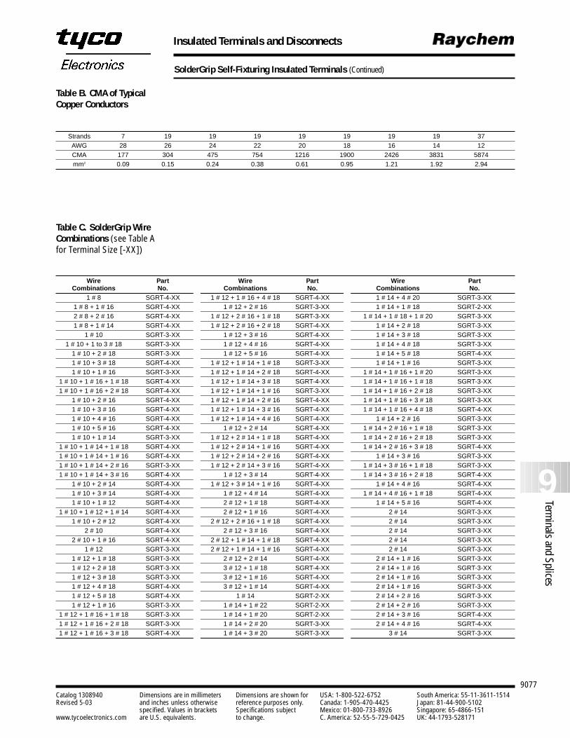
9077
9Terminals and Splices
Catalog 1308940 Dimensions are in millimeters Dimensions are shown for USA: 1-800-522-6752 South America: 55-11-3611-1514Revised 5-03 and inches unless otherwise reference purposes only. Canada: 1-905-470-4425 Japan: 81-44-900-5102
specified. Values in brackets Specifications subject Mexico: 01-800-733-8926 Singapore: 65-4866-151www.tycoelectronics.com are U.S. equivalents. to change. C. America: 52-55-5-729-0425 UK: 44-1793-528171
Insulated Terminals and Disconnects
SolderGrip Self-Fixturing Insulated Terminals (Continued)
Strands 7 19 19 19 19 19 19 19 37AWG 28 26 24 22 20 18 16 14 12CMA 177 304 475 754 1216 1900 2426 3831 5874mm2 0.09 0.15 0.24 0.38 0.61 0.95 1.21 1.92 2.94
Wire Part Wire Part Wire PartCombinations No. Combinations No. Combinations No.
1 # 8 SGRT-4-XX 1 # 12 + 1 # 16 + 4 # 18 SGRT-4-XX 1 # 14 + 4 # 20 SGRT-3-XX1 # 8 + 1 # 16 SGRT-4-XX 1 # 12 + 2 # 16 SGRT-3-XX 1 # 14 + 1 # 18 SGRT-2-XX2 # 8 + 2 # 16 SGRT-4-XX 1 # 12 + 2 # 16 + 1 # 18 SGRT-3-XX 1 # 14 + 1 # 18 + 1 # 20 SGRT-3-XX1 # 8 + 1 # 14 SGRT-4-XX 1 # 12 + 2 # 16 + 2 # 18 SGRT-4-XX 1 # 14 + 2 # 18 SGRT-3-XX
1 # 10 SGRT-3-XX 1 # 12 + 3 # 16 SGRT-4-XX 1 # 14 + 3 # 18 SGRT-3-XX1 # 10 + 1 to 3 # 18 SGRT-3-XX 1 # 12 + 4 # 16 SGRT-4-XX 1 # 14 + 4 # 18 SGRT-3-XX
1 # 10 + 2 # 18 SGRT-3-XX 1 # 12 + 5 # 16 SGRT-4-XX 1 # 14 + 5 # 18 SGRT-4-XX1 # 10 + 3 # 18 SGRT-4-XX 1 # 12 + 1 # 14 + 1 # 18 SGRT-3-XX 1 # 14 + 1 # 16 SGRT-3-XX1 # 10 + 1 # 16 SGRT-3-XX 1 # 12 + 1 # 14 + 2 # 18 SGRT-4-XX 1 # 14 + 1 # 16 + 1 # 20 SGRT-3-XX
1 # 10 + 1 # 16 + 1 # 18 SGRT-4-XX 1 # 12 + 1 # 14 + 3 # 18 SGRT-4-XX 1 # 14 + 1 # 16 + 1 # 18 SGRT-3-XX1 # 10 + 1 # 16 + 2 # 18 SGRT-4-XX 1 # 12 + 1 # 14 + 1 # 16 SGRT-3-XX 1 # 14 + 1 # 16 + 2 # 18 SGRT-3-XX
1 # 10 + 2 # 16 SGRT-4-XX 1 # 12 + 1 # 14 + 2 # 16 SGRT-4-XX 1 # 14 + 1 # 16 + 3 # 18 SGRT-3-XX1 # 10 + 3 # 16 SGRT-4-XX 1 # 12 + 1 # 14 + 3 # 16 SGRT-4-XX 1 # 14 + 1 # 16 + 4 # 18 SGRT-4-XX1 # 10 + 4 # 16 SGRT-4-XX 1 # 12 + 1 # 14 + 4 # 16 SGRT-4-XX 1 # 14 + 2 # 16 SGRT-3-XX1 # 10 + 5 # 16 SGRT-4-XX 1 # 12 + 2 # 14 SGRT-4-XX 1 # 14 + 2 # 16 + 1 # 18 SGRT-3-XX1 # 10 + 1 # 14 SGRT-3-XX 1 # 12 + 2 # 14 + 1 # 18 SGRT-4-XX 1 # 14 + 2 # 16 + 2 # 18 SGRT-3-XX
1 # 10 + 1 # 14 + 1 # 18 SGRT-4-XX 1 # 12 + 2 # 14 + 1 # 16 SGRT-4-XX 1 # 14 + 2 # 16 + 3 # 18 SGRT-4-XX1 # 10 + 1 # 14 + 1 # 16 SGRT-4-XX 1 # 12 + 2 # 14 + 2 # 16 SGRT-4-XX 1 # 14 + 3 # 16 SGRT-3-XX1 # 10 + 1 # 14 + 2 # 16 SGRT-3-XX 1 # 12 + 2 # 14 + 3 # 16 SGRT-4-XX 1 # 14 + 3 # 16 + 1 # 18 SGRT-3-XX1 # 10 + 1 # 14 + 3 # 16 SGRT-4-XX 1 # 12 + 3 # 14 SGRT-4-XX 1 # 14 + 3 # 16 + 2 # 18 SGRT-4-XX
1 # 10 + 2 # 14 SGRT-4-XX 1 # 12 + 3 # 14 + 1 # 16 SGRT-4-XX 1 # 14 + 4 # 16 SGRT-4-XX1 # 10 + 3 # 14 SGRT-4-XX 1 # 12 + 4 # 14 SGRT-4-XX 1 # 14 + 4 # 16 + 1 # 18 SGRT-4-XX1 # 10 + 1 # 12 SGRT-4-XX 2 # 12 + 1 # 18 SGRT-4-XX 1 # 14 + 5 # 16 SGRT-4-XX
1 # 10 + 1 # 12 + 1 # 14 SGRT-4-XX 2 # 12 + 1 # 16 SGRT-4-XX 2 # 14 SGRT-3-XX1 # 10 + 2 # 12 SGRT-4-XX 2 # 12 + 2 # 16 + 1 # 18 SGRT-4-XX 2 # 14 SGRT-3-XX
2 # 10 SGRT-4-XX 2 # 12 + 3 # 16 SGRT-4-XX 2 # 14 SGRT-3-XX2 # 10 + 1 # 16 SGRT-4-XX 2 # 12 + 1 # 14 + 1 # 18 SGRT-4-XX 2 # 14 SGRT-3-XX
1 # 12 SGRT-3-XX 2 # 12 + 1 # 14 + 1 # 16 SGRT-4-XX 2 # 14 SGRT-3-XX1 # 12 + 1 # 18 SGRT-3-XX 2 # 12 + 2 # 14 SGRT-4-XX 2 # 14 + 1 # 16 SGRT-3-XX1 # 12 + 2 # 18 SGRT-3-XX 3 # 12 + 1 # 18 SGRT-4-XX 2 # 14 + 1 # 16 SGRT-3-XX1 # 12 + 3 # 18 SGRT-3-XX 3 # 12 + 1 # 16 SGRT-4-XX 2 # 14 + 1 # 16 SGRT-3-XX1 # 12 + 4 # 18 SGRT-4-XX 3 # 12 + 1 # 14 SGRT-4-XX 2 # 14 + 1 # 16 SGRT-3-XX1 # 12 + 5 # 18 SGRT-4-XX 1 # 14 SGRT-2-XX 2 # 14 + 2 # 16 SGRT-3-XX1 # 12 + 1 # 16 SGRT-3-XX 1 # 14 + 1 # 22 SGRT-2-XX 2 # 14 + 2 # 16 SGRT-3-XX
1 # 12 + 1 # 16 + 1 # 18 SGRT-3-XX 1 # 14 + 1 # 20 SGRT-2-XX 2 # 14 + 3 # 16 SGRT-4-XX1 # 12 + 1 # 16 + 2 # 18 SGRT-3-XX 1 # 14 + 2 # 20 SGRT-3-XX 2 # 14 + 4 # 16 SGRT-4-XX1 # 12 + 1 # 16 + 3 # 18 SGRT-4-XX 1 # 14 + 3 # 20 SGRT-3-XX 3 # 14 SGRT-3-XX
Table B. CMA of TypicalCopper Conductors
Table C. SolderGrip WireCombinations (see Table Afor Terminal Size [-XX])
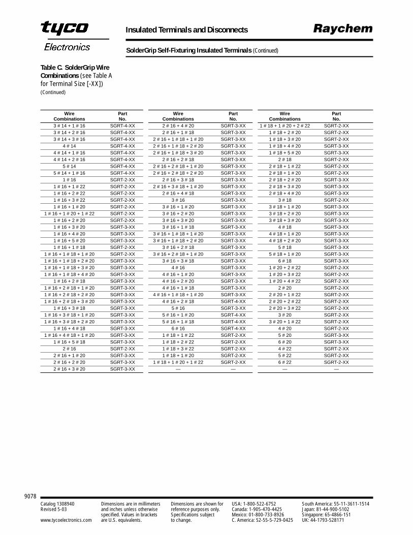
9078Catalog 1308940 Dimensions are in millimeters Dimensions are shown for USA: 1-800-522-6752 South America: 55-11-3611-1514Revised 5-03 and inches unless otherwise reference purposes only. Canada: 1-905-470-4425 Japan: 81-44-900-5102
specified. Values in brackets Specifications subject Mexico: 01-800-733-8926 Singapore: 65-4866-151www.tycoelectronics.com are U.S. equivalents. to change. C. America: 52-55-5-729-0425 UK: 44-1793-528171
Insulated Terminals and Disconnects
SolderGrip Self-Fixturing Insulated Terminals (Continued)
Wire Part Wire Part Wire PartCombinations No. Combinations No. Combinations No.3 # 14 + 1 # 16 SGRT-4-XX 2 # 16 + 4 # 20 SGRT-3-XX 1 # 18 + 1 # 20 + 2 # 22 SGRT-2-XX3 # 14 + 2 # 16 SGRT-4-XX 2 # 16 + 1 # 18 SGRT-3-XX 1 # 18 + 2 # 20 SGRT-2-XX3 # 14 + 3 # 16 SGRT-4-XX 2 # 16 + 1 # 18 + 1 # 20 SGRT-3-XX 1 # 18 + 3 # 20 SGRT-2-XX
4 # 14 SGRT-4-XX 2 # 16 + 1 # 18 + 2 # 20 SGRT-3-XX 1 # 18 + 4 # 20 SGRT-3-XX4 # 14 + 1 # 16 SGRT-4-XX 2 # 16 + 1 # 18 + 3 # 20 SGRT-3-XX 1 # 18 + 5 # 20 SGRT-3-XX4 # 14 + 2 # 16 SGRT-4-XX 2 # 16 + 2 # 18 SGRT-3-XX 2 # 18 SGRT-2-XX
5 # 14 SGRT-4-XX 2 # 16 + 2 # 18 + 1 # 20 SGRT-3-XX 2 # 18 + 1 # 22 SGRT-2-XX5 # 14 + 1 # 16 SGRT-4-XX 2 # 16 + 2 # 18 + 2 # 20 SGRT-3-XX 2 # 18 + 1 # 20 SGRT-2-XX
1 # 16 SGRT-2-XX 2 # 16 + 3 # 18 SGRT-3-XX 2 # 18 + 2 # 20 SGRT-3-XX1 # 16 + 1 # 22 SGRT-2-XX 2 # 16 + 3 # 18 + 1 # 20 SGRT-3-XX 2 # 18 + 3 # 20 SGRT-3-XX1 # 16 + 2 # 22 SGRT-2-XX 2 # 16 + 4 # 18 SGRT-3-XX 2 # 18 + 4 # 20 SGRT-3-XX1 # 16 + 3 # 22 SGRT-2-XX 3 # 16 SGRT-3-XX 3 # 18 SGRT-2-XX1 # 16 + 1 # 20 SGRT-2-XX 3 # 16 + 1 # 20 SGRT-3-XX 3 # 18 + 1 # 20 SGRT-3-XX
1 # 16 + 1 # 20 + 1 # 22 SGRT-2-XX 3 # 16 + 2 # 20 SGRT-3-XX 3 # 18 + 2 # 20 SGRT-3-XX1 # 16 + 2 # 20 SGRT-2-XX 3 # 16 + 3 # 20 SGRT-3-XX 3 # 18 + 3 # 20 SGRT-3-XX1 # 16 + 3 # 20 SGRT-3-XX 3 # 16 + 1 # 18 SGRT-3-XX 4 # 18 SGRT-3-XX1 # 16 + 4 # 20 SGRT-3-XX 3 # 16 + 1 # 18 + 1 # 20 SGRT-3-XX 4 # 18 + 1 # 20 SGRT-3-XX1 # 16 + 5 # 20 SGRT-3-XX 3 # 16 + 1 # 18 + 2 # 20 SGRT-3-XX 4 # 18 + 2 # 20 SGRT-3-XX1 # 16 + 1 # 18 SGRT-2-XX 3 # 16 + 2 # 18 SGRT-3-XX 5 # 18 SGRT-3-XX
1 # 16 + 1 # 18 + 1 # 20 SGRT-2-XX 3 # 16 + 2 # 18 + 1 # 20 SGRT-3-XX 5 # 18 + 1 # 20 SGRT-3-XX1 # 16 + 1 # 18 + 2 # 20 SGRT-3-XX 3 # 16 + 3 # 18 SGRT-3-XX 6 # 18 SGRT-3-XX1 # 16 + 1 # 18 + 3 # 20 SGRT-3-XX 4 # 16 SGRT-3-XX 1 # 20 + 2 # 22 SGRT-2-XX1 # 16 + 1 # 18 + 4 # 20 SGRT-3-XX 4 # 16 + 1 # 20 SGRT-3-XX 1 # 20 + 3 # 22 SGRT-2-XX
1 # 16 + 2 # 18 SGRT-3-XX 4 # 16 + 2 # 20 SGRT-3-XX 1 # 20 + 4 # 22 SGRT-2-XX1 # 16 + 2 # 18 + 1 # 20 SGRT-3-XX 4 # 16 + 1 # 18 SGRT-3-XX 2 # 20 SGRT-2-XX1 # 16 + 2 # 18 + 2 # 20 SGRT-3-XX 4 # 16 + 1 # 18 + 1 # 20 SGRT-3-XX 2 # 20 + 1 # 22 SGRT-2-XX1 # 16 + 2 # 18 + 3 # 20 SGRT-3-XX 4 # 16 + 2 # 18 SGRT-4-XX 2 # 20 + 2 # 22 SGRT-2-XX
1 # 16 + 3 # 18 SGRT-3-XX 5 # 16 SGRT-3-XX 2 # 20 + 3 # 22 SGRT-2-XX1 # 16 + 3 # 18 + 1 # 20 SGRT-3-XX 5 # 16 + 1 # 20 SGRT-4-XX 3 # 20 SGRT-2-XX1 # 16 + 3 # 18 + 2 # 20 SGRT-3-XX 5 # 16 + 1 # 18 SGRT-4-XX 3 # 20 + 1 # 22 SGRT-2-XX
1 # 16 + 4 # 18 SGRT-3-XX 6 # 16 SGRT-4-XX 4 # 20 SGRT-2-XX1 # 16 + 4 # 18 + 1 # 20 SGRT-3-XX 1 # 18 + 1 # 22 SGRT-2-XX 5 # 20 SGRT-3-XX
1 # 16 + 5 # 18 SGRT-3-XX 1 # 18 + 2 # 22 SGRT-2-XX 6 # 20 SGRT-3-XX2 # 16 SGRT-2-XX 1 # 18 + 3 # 22 SGRT-2-XX 4 # 22 SGRT-2-XX
2 # 16 + 1 # 20 SGRT-3-XX 1 # 18 + 1 # 20 SGRT-2-XX 5 # 22 SGRT-2-XX2 # 16 + 2 # 20 SGRT-3-XX 1 # 18 + 1 # 20 + 1 # 22 SGRT-2-XX 6 # 22 SGRT-2-XX2 # 16 + 3 # 20 SGRT-3-XX — — — —
Table C. SolderGrip WireCombinations (see Table Afor Terminal Size [-XX])(Continued)
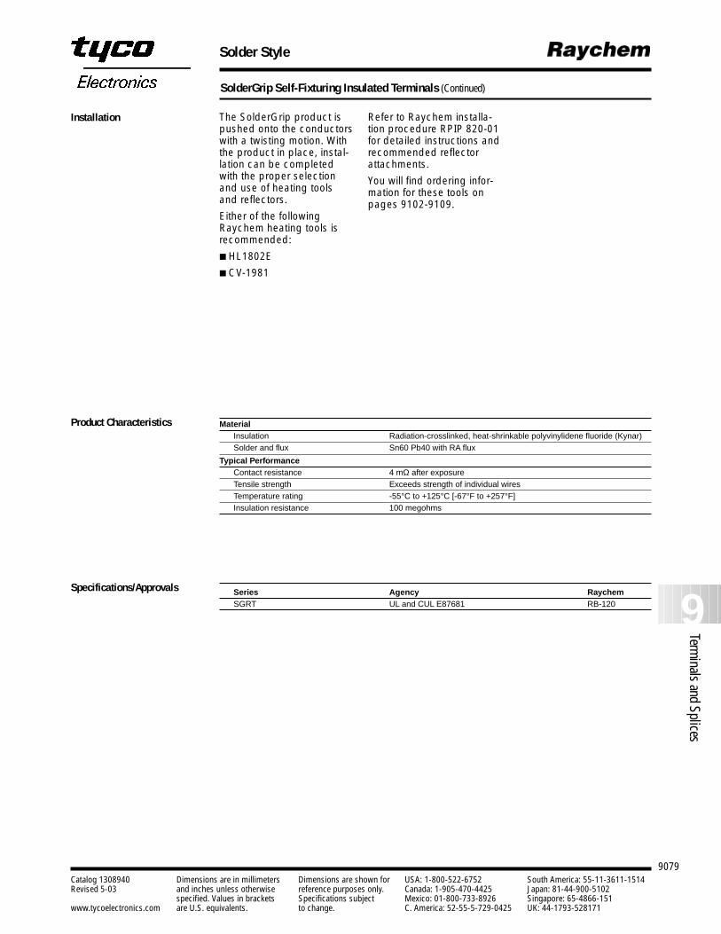
Solder Style
9079
9Terminals and Splices
Catalog 1308940 Dimensions are in millimeters Dimensions are shown for USA: 1-800-522-6752 South America: 55-11-3611-1514Revised 5-03 and inches unless otherwise reference purposes only. Canada: 1-905-470-4425 Japan: 81-44-900-5102
specified. Values in brackets Specifications subject Mexico: 01-800-733-8926 Singapore: 65-4866-151www.tycoelectronics.com are U.S. equivalents. to change. C. America: 52-55-5-729-0425 UK: 44-1793-528171
SolderGrip Self-Fixturing Insulated Terminals (Continued)
MaterialInsulation Radiation-crosslinked, heat-shrinkable polyvinylidene fluoride (Kynar)Solder and flux Sn60 Pb40 with RA flux
Typical PerformanceContact resistance 4 mΩ after exposureTensile strength Exceeds strength of individual wiresTemperature rating -55°C to +125°C [-67°F to +257°F]Insulation resistance 100 megohms
Series Agency Raychem SGRT UL and CUL E87681 RB-120
The SolderGrip product ispushed onto the conductorswith a twisting motion. Withthe product in place, instal-lation can be completedwith the proper selectionand use of heating toolsand reflectors.
Either of the followingRaychem heating tools isrecommended:
HL1802E
CV-1981
Product Characteristics
Installation
Specifications/Approvals
Refer to Raychem installa-tion procedure RPIP 820-01for detailed instructions andrecommended reflectorattachments.
You will find ordering infor-mation for these tools onpages 9102-9109.
9080Catalog 1308940 Dimensions are in millimeters Dimensions are shown for USA: 1-800-522-6752 South America: 55-11-3611-1514Revised 5-03 and inches unless otherwise reference purposes only. Canada: 1-905-470-4425 Japan: 81-44-900-5102
specified. Values in brackets Specifications subject Mexico: 01-800-733-8926 Singapore: 65-4866-151www.tycoelectronics.com are U.S. equivalents. to change. C. America: 52-55-5-729-0425 UK: 44-1793-528171
Wire Termination to Pin/Post/Tab
Introduction
Raychem SolderSleeve ter-minators offer easy, one-stepsolutions for wire connectionsto pins, posts, and tabs andfor mass wire terminations.
Designed for applicationswith temperatures up to150°C [302°F], the productsin this section includeSolderSleeve discrete wireterminators, which are heat-shrinkable thermoplas-tic sleeves containing a precisely engineered fluxedsolder preform.
SolderSleeve terminatorsare also available on carriertape, spaced precisely tomatch connector terminalspacing, enabling termina-tion of an entire row of wiresat one time.
SolderSleeve wire-to-pin,wire-to-post, and wire-to-tabterminators, like all Raychemtermination products, pro-vide reliability and economi-cal installation for greaterproductivity. They can besupplied either in bulk or oncarrier tape.
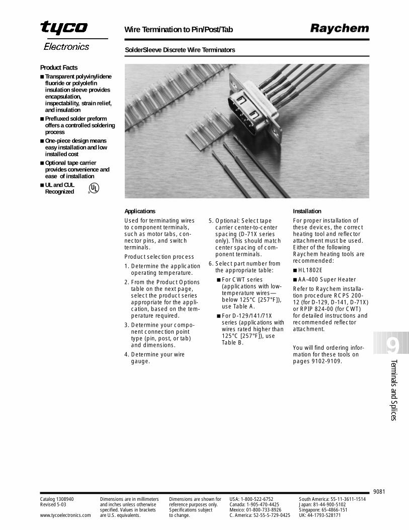
9081
9Terminals and Splices
Catalog 1308940 Dimensions are in millimeters Dimensions are shown for USA: 1-800-522-6752 South America: 55-11-3611-1514Revised 5-03 and inches unless otherwise reference purposes only. Canada: 1-905-470-4425 Japan: 81-44-900-5102
specified. Values in brackets Specifications subject Mexico: 01-800-733-8926 Singapore: 65-4866-151www.tycoelectronics.com are U.S. equivalents. to change. C. America: 52-55-5-729-0425 UK: 44-1793-528171
Wire Termination to Pin/Post/Tab
SolderSleeve Discrete Wire Terminators
Applications
Used for terminating wiresto component terminals,such as motor tabs, con-nector pins, and switch terminals.
Product selection process
1. Determine the applicationoperating temperature.
2. From the Product Optionstable on the next page,select the product seriesappropriate for the appli-cation, based on the tem-perature required.
3. Determine your compo-nent connection pointtype (pin, post, or tab)and dimensions.
4. Determine your wiregauge.
5. Optional: Select tape carrier center-to-centerspacing (D-71X seriesonly). This should matchcenter spacing of com-ponent terminals.
6. Select part number fromthe appropriate table:
For CWT series (applications with low-temperature wires—below 125°C [257°F]),use Table A.
For D-129/141/71Xseries (applications withwires rated higher than125°C [257°F]), useTable B.
Installation
For proper installation ofthese devices, the correctheating tool and reflectorattachment must be used.Either of the followingRaychem heating tools arerecommended:
HL1802E
AA-400 Super Heater
Refer to Raychem installa-tion procedure RCPS 200-12 (for D-129, D-141, D-71X)or RPIP 824-00 (for CWT)for detailed instructions andrecommended reflectorattachment.
You will find ordering infor-mation for these tools onpages 9102-9109.
Product Facts Transparent polyvinylidene
fluoride or polyolefininsulation sleeve providesencapsulation,inspectability, strain relief,and insulation
Prefluxed solder preformoffers a controlled solderingprocess
One-piece design meanseasy installation and lowinstalled cost
Optional tape carrierprovides convenience andease of installation
UL and CULRecognized R
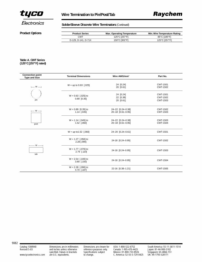
9082Catalog 1308940 Dimensions are in millimeters Dimensions are shown for USA: 1-800-522-6752 South America: 55-11-3611-1514Revised 5-03 and inches unless otherwise reference purposes only. Canada: 1-905-470-4425 Japan: 81-44-900-5102
specified. Values in brackets Specifications subject Mexico: 01-800-733-8926 Singapore: 65-4866-151www.tycoelectronics.com are U.S. equivalents. to change. C. America: 52-55-5-729-0425 UK: 44-1793-528171
Wire Termination to Pin/Post/Tab
SolderSleeve Discrete Wire Terminators (Continued)
Connection-point Type and Size Terminal Dimensions Wire AWG/mm2 Part No.
W = up to 0.63 [.025] 24 [0.24] CWT-150120 [0.61] CWT-1502
W = 0.63 [.025] to 24 [0.24] CWT-1501
0.89 [0.35] 22 [0.38] CWT-150220 [0.61] CWT-1503
W = 0.89 [0.35] to 24–22 [0.24–0.38] CWT-15021.14 [.045] 20–18 [0.61–0.95] CWT-1503
W = 1.14 [.045] to 24–22 [0.24–0.38] CWT-15031.52 [.060] 20–18 [0.61–0.95] CWT-1504
W = up to1.52 [.060] 24–20 [0.24–0.61] CWT-1501
W = 1.27 [.050] to 24-18 [0.24–0.95] CWT-15022.28 [.090]
W = 1.77 [.070] to 24-18 [0.24–0.95] CWT-15032.79 [.110]
W = 2.54 [.100] to 24-18 [0.24–0.95] CWT-15043.80 [.150]
W = 2.28 [.090] to 22-16 [0.38–1.21] CWT-15054.70 [.187]
Product Series Max. Operating Temperature Min. Wire Temperature RatingCWT 125°C [257°F] 85°C [185°F]
D-129, D-141, D-71X 150°C [302°F] 125°C [257°F]
Product Options
Table A. CWT Series (125°C [257°F] rated)
pin
W
post
W
tab
W
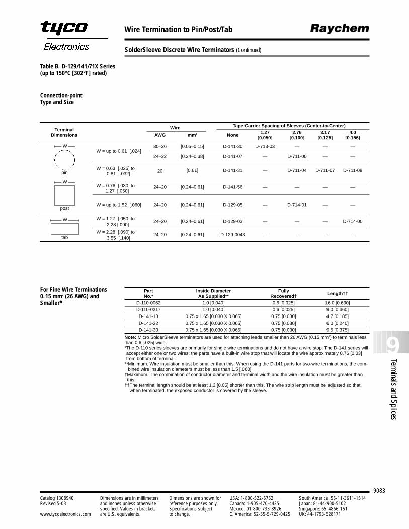
9083
9Terminals and Splices
Catalog 1308940 Dimensions are in millimeters Dimensions are shown for USA: 1-800-522-6752 South America: 55-11-3611-1514Revised 5-03 and inches unless otherwise reference purposes only. Canada: 1-905-470-4425 Japan: 81-44-900-5102
specified. Values in brackets Specifications subject Mexico: 01-800-733-8926 Singapore: 65-4866-151www.tycoelectronics.com are U.S. equivalents. to change. C. America: 52-55-5-729-0425 UK: 44-1793-528171
Wire Termination to Pin/Post/Tab
SolderSleeve Discrete Wire Terminators (Continued)
Wire Tape Carrier Spacing of Sleeves (Center-to-Center)Terminal 1.27 2.76 3.17 4.0Dimensions AWG mm2 None [0.050] [0.100] [0.125] [0.156]
W = up to 0.61 [.024]30–26 [0.05–0.15] D-141-30 D-713-03 — — —
24–22 [0.24–0.38] D-141-07 — D-711-00 — —
W = 0.63 [.025] to 20 [0.61] D-141-31 — D-711-04 D-711-07 D-711-080.81 [.032]
W = 0.76 [.030] to 24–20 [0.24–0.61] D-141-56 — — — —1.27 [.050]
W = up to 1.52 [.060] 24–20 [0.24–0.61] D-129-05 — D-714-01 — —
W = 1.27 [.050] to 24–20 [0.24–0.61] D-129-03 — — — D-714-002.28 [.090]
W = 2.28 [.090] to 24–20 [0.24–0.61] D-129-0043 — — — —3.55 [.140]
Part Inside Diameter FullyNo.* As Supplied** Recovered† Length††
D-110-0062 1.0 [0.040] 0.6 [0.025] 16.0 [0.630]D-110-0217 1.0 [0.040] 0.6 [0.025] 9.0 [0.360]D-141-13 0.75 x 1.65 [0.030 X 0.065] 0.75 [0.030] 4.7 [0.185]D-141-22 0.75 x 1.65 [0.030 X 0.065] 0.75 [0.030] 6.0 [0.240]D-141-30 0.75 x 1.65 [0.030 X 0.065] 0.75 [0.030] 9.5 [0.375]
Note: Micro SolderSleeve terminators are used for attaching leads smaller than 26 AWG (0.15 mm2) to terminals lessthan 0.6 [.025] wide.*The D-110 series sleeves are primarily for single wire terminations and do not have a wire stop. The D-141 series willaccept either one or two wires; the parts have a built-in wire stop that will locate the wire approximately 0.76 [0.03]from bottom of terminal.
**Minimum. Wire insulation must be smaller than this. When using the D-141 parts for two-wire terminations, the com-bined wire insulation diameters must be less than 1.5 [.060].
†Maximum. The combination of conductor diameter and terminal width and the wire insulation must be greater thanthis.
††The terminal length should be at least 1.2 [0.05] shorter than this. The wire strip length must be adjusted so that,when terminated, the exposed conductor is covered by the sleeve.
pin
W
post
W
tab
W
For Fine Wire Terminations0.15 mm2 (26 AWG) andSmaller*
Table B. D-129/141/71X Series(up to 150°C [302°F] rated)
Connection-point Type and Size
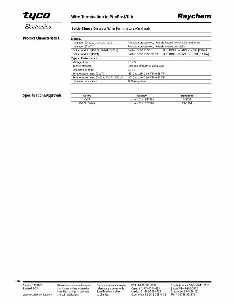
9084Catalog 1308940 Dimensions are in millimeters Dimensions are shown for USA: 1-800-522-6752 South America: 55-11-3611-1514Revised 5-03 and inches unless otherwise reference purposes only. Canada: 1-905-470-4425 Japan: 81-44-900-5102
specified. Values in brackets Specifications subject Mexico: 01-800-733-8926 Singapore: 65-4866-151www.tycoelectronics.com are U.S. equivalents. to change. C. America: 52-55-5-729-0425 UK: 44-1793-528171
Wire Termination to Pin/Post/Tab
SolderSleeve Discrete Wire Terminators (Continued)
MaterialInsulation [D-129, D-141, D-71X] Radiation-crosslinked, heat-shrinkable polyvinylidene fluorideInsulation [CWT] Radiation-crosslinked, heat-shrinkable polyolefinSolder and flux [D-129, D-141, D-71X] Solder: Sn63 Pb37 Flux: ROL1 per ANSI -J - 004 [RMA flux]Solder and flux [CWT] Solder: Sn50 Pb32 Cd 18 Flux: ROM1 per ANSI -J - 004 [RA flux]
Typical PerformanceVoltage drop 2.0 mVTensile strength Exceeds strength of conductorDielectric strength 2.0 kVTemperature rating [CWT] -55°C to 125°C [-67°F to 257°F]Temperature rating [D-129, D-141, D-71X] -55°C to 150°C [-67°F to 302°F]Insulation resistance 1000 megohms
Series Agency Raychem CWT UL and CUL E87681 D-5023
D-129, D-141 UL and CUL E87681 RT-1404
Product Characteristics
Specifications/Approvals
9085
9Terminals and Splices
Catalog 1308940 Dimensions are in millimeters Dimensions are shown for USA: 1-800-522-6752 South America: 55-11-3611-1514Revised 5-03 and inches unless otherwise reference purposes only. Canada: 1-905-470-4425 Japan: 81-44-900-5102
specified. Values in brackets Specifications subject Mexico: 01-800-733-8926 Singapore: 65-4866-151www.tycoelectronics.com are U.S. equivalents. to change. C. America: 52-55-5-729-0425 UK: 44-1793-528171
Shield Termination
Introduction
Raychem SolderSleeveshield grounding termina-tors provide an environmen-tally sealed, insulated, andencapsulated solder con-nection for a variety ofapplications. SolderSleeveterminators are available inmany styles.
Designed for a wide varietyof temperature applicationsranging from -65°C to200°C [-85°F to 392°F], theproducts in this sectioninclude:
CWT-X SolderSleeveterminators, designed forlow-temperature cableswith operatingtemperatures up to 125°C[257°F] and suitable formost commercialenvironments.
MIL-S-83519SolderSleeve terminators,which are immersionresistant and availablewith or without apreinstalled ground lead.
SO Seies SolderSleeveterminators, which alsoare immersion resistantand feature the RaychemBiAlloy temperatureindication system.
All SolderSleeve productsare reliable, versatile, andeasy to install, resulting inlower installed costs.
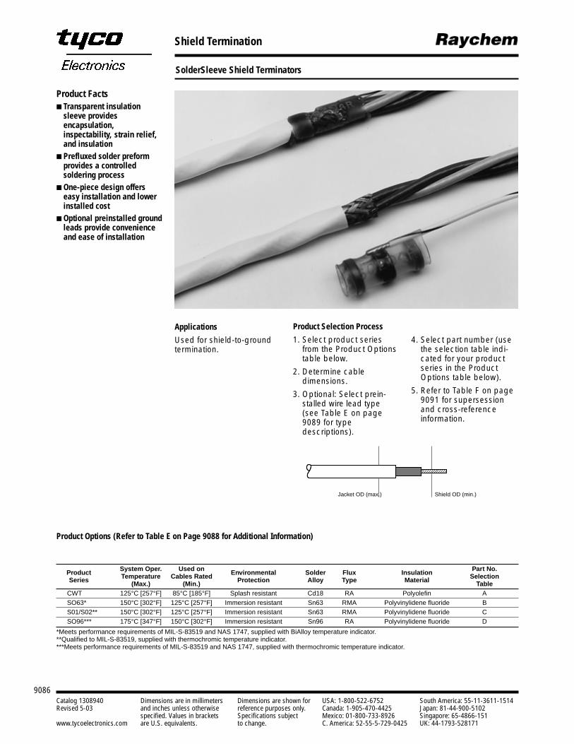
9086Catalog 1308940 Dimensions are in millimeters Dimensions are shown for USA: 1-800-522-6752 South America: 55-11-3611-1514Revised 5-03 and inches unless otherwise reference purposes only. Canada: 1-905-470-4425 Japan: 81-44-900-5102
specified. Values in brackets Specifications subject Mexico: 01-800-733-8926 Singapore: 65-4866-151www.tycoelectronics.com are U.S. equivalents. to change. C. America: 52-55-5-729-0425 UK: 44-1793-528171
Shield Termination
SolderSleeve Shield Terminators
Product Selection Process
1. Select product seriesfrom the Product Optionstable below.
2. Determine cable dimensions.
3. Optional: Select prein-stalled wire lead type(see Table E on page 9089 for type descriptions).
4. Select part number (usethe selection table indi-cated for your productseries in the ProductOptions table below).
5. Refer to Table F on page9091 for supersessionand cross-referenceinformation.
Product Options (Refer to Table E on Page 9088 for Additional Information)
System Oper. Used on Part No.Product Temperature Cables Rated Environmental Solder Flux Insulation SelectionSeries (Max.) (Min.) Protection Alloy Type Material TableCWT 125°C [257°F] 85°C [185°F] Splash resistant Cd18 RA Polyolefin ASO63* 150°C [302°F] 125°C [257°F] Immersion resistant Sn63 RMA Polyvinylidene fluoride BS01/S02** 150°C [302°F] 125°C [257°F] Immersion resistant Sn63 RMA Polyvinylidene fluoride CSO96*** 175°C [347°F] 150°C [302°F] Immersion resistant Sn96 RA Polyvinylidene fluoride D
*Meets performance requirements of MIL-S-83519 and NAS 1747, supplied with BiAlloy temperature indicator.**Qualified to MIL-S-83519, supplied with thermochromic temperature indicator.***Meets performance requirements of MIL-S-83519 and NAS 1747, supplied with thermochromic temperature indicator.
Jacket OD (max.) Shield OD (min.)
Product Facts Transparent insulation
sleeve providesencapsulation,inspectability, strain relief,and insulation
Prefluxed solder preformprovides a controlledsoldering process
One-piece design offerseasy installation and lowerinstalled cost
Optional preinstalled groundleads provide convenienceand ease of installation
Applications
Used for shield-to-groundtermination.
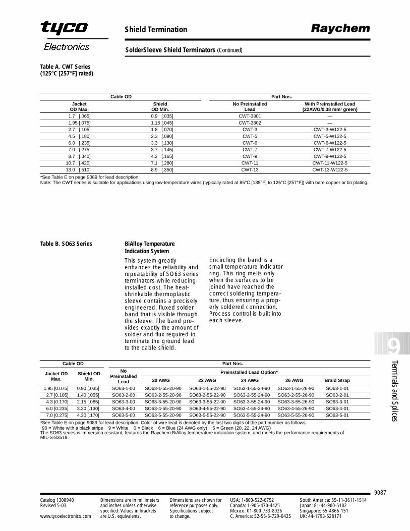
9087
9Terminals and Splices
Catalog 1308940 Dimensions are in millimeters Dimensions are shown for USA: 1-800-522-6752 South America: 55-11-3611-1514Revised 5-03 and inches unless otherwise reference purposes only. Canada: 1-905-470-4425 Japan: 81-44-900-5102
specified. Values in brackets Specifications subject Mexico: 01-800-733-8926 Singapore: 65-4866-151www.tycoelectronics.com are U.S. equivalents. to change. C. America: 52-55-5-729-0425 UK: 44-1793-528171
Shield Termination
SolderSleeve Shield Terminators (Continued)
Table A. CWT Series (125°C [257°F] rated)
Cable OD Part Nos.
Jacket Shield No Preinstalled With Preinstalled LeadOD Max. OD Min. Lead (22AWG/0.38 mm2 green)
1.7 [.065] 0.9 [.035] CWT-3801 —1.95 [.075] 1.15 [.045] CWT-3802 —2.7 [.105] 1.8 [.070] CWT-3 CWT-3-W122-54.5 [.180] 2.3 [.090] CWT-5 CWT-5-W122-56.0 [.235] 3.3 [.130] CWT-6 CWT-6-W122-57.0 [.275] 3.7 [.145] CWT-7 CWT-7-W122-58.7 [.340] 4.2 [.165] CWT-9 CWT-9-W122-5
10.7 [.420] 7.1 [.280] CWT-11 CWT-11-W122-513.0 [.510] 8.9 [.350] CWT-13 CWT-13-W122-5
*See Table E on page 9089 for lead description.Note: The CWT series is suitable for applications using low-temperature wires (typically rated at 85°C [185°F] to 125°C [257°F]) with bare copper or tin plating.
Cable OD Part Nos.
No Preinstalled Lead Option*Jacket OD Shield OD PreinstalledMax. Min. Lead 20 AWG 22 AWG 24 AWG 26 AWG Braid Strap
1.95 [0.075] 0.90 [.035] SO63-1-00 SO63-1-55-20-90 SO63-1-55-22-90 SO63-1-55-24-90 SO63-1-55-26-90 SO63-1-012.7 [0.105] 1.40 [.055] SO63-2-00 SO63-2-55-20-90 SO63-2-55-22-90 SO63-2-55-24-90 SO63-2-55-26-90 SO63-2-014.3 [0.170] 2.15 [.085] SO63-3-00 SO63-3-55-20-90 SO63-3-55-22-90 SO63-3-55-24-90 SO63-3-55-26-90 SO63-3-016.0 [0.235] 3.30 [.130] SO63-4-00 SO63-4-55-20-90 SO63-4-55-22-90 SO63-4-55-24-90 SO63-4-55-26-90 SO63-4-017.0 [0.275] 4.30 [.170] SO63-5-00 SO63-5-55-20-90 SO63-5-55-22-90 SO63-5-55-24-90 SO63-5-55-26-90 SO63-5-01
*See Table E on page 9089 for lead description. Color of wire lead is denoted by the last two digits of the part number as follows:90 = White with a black stripe 9 = White 0 = Black 6 = Blue (24 AWG only) 5 = Green (20, 22, 24 AWG)
The SO63 series is immersion resistant, features the Raychem BiAlloy temperature indication system, and meets the performance requirements of MIL-S-83519.
BiAlloy Temperature Indication System
This system greatlyenhances the reliability andrepeatability of SO63 seriesterminators while reducinginstalled cost. The heat-shrinkable thermoplasticsleeve contains a preciselyengineered, fluxed solderband that is visible throughthe sleeve. The band pro-vides exactly the amount ofsolder and flux required toterminate the ground leadto the cable shield.
Encircling the band is asmall temperature indicatorring. This ring melts onlywhen the surfaces to bejoined have reached thecorrect soldering tempera-ture, thus ensuring a prop-erly soldered connection.Process control is built intoeach sleeve.
Table B. SO63 Series
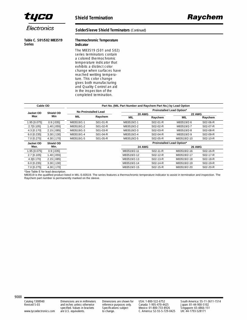
9088Catalog 1308940 Dimensions are in millimeters Dimensions are shown for USA: 1-800-522-6752 South America: 55-11-3611-1514Revised 5-03 and inches unless otherwise reference purposes only. Canada: 1-905-470-4425 Japan: 81-44-900-5102
specified. Values in brackets Specifications subject Mexico: 01-800-733-8926 Singapore: 65-4866-151www.tycoelectronics.com are U.S. equivalents. to change. C. America: 52-55-5-729-0425 UK: 44-1793-528171
Shield Termination
SolderSleeve Shield Terminators (Continued)
Cable OD Part No. (MIL Part Number and Raychem Part No.) by Lead Option
Preinstalled Lead Option*Jacket OD Shield OD No Preinstalled Lead
20 AWG 22 AWGMax Min MIL Raychem MIL Raychem MIL Raychem
1.95 [0.075] 0.9 [.035] M83519/1-1 S01-01-R M83519/2-1 S02-01-R M83519/2-6 S02-06-R2.7[0.105] 1.40 [.055] M83519/1-2 S01-02-R M83519/2-2 S02-02-R M83519/2-7 S02-07-R4.3 [0.170] 2.15 [.085] M83519/1-3 S01-03-R M83519/2-3 S02-03-R M83519/2-8 S02-08-R6.0 [0.235] 3.30 [.130] M83519/1-4 S01-04-R M83519/2-4 S02-04-R M83519/2-9 S02-09-R7.0 [0.275] 4.30 [.170] M83519/1-5 S01-05-R M83519/2-5 S02-05-R M83519/2-10 S02-10-R
Jacket OD Shield OD Preinstalled Lead Option*Max. Min. 24 AWG 26 AWG
1.95 [0.075] 0.9 [.035] M83519/2-11 S02-11-R M83519/2-16 S02-16-R2.7 [0.105] 1.40 [.055] M83519/2-12 S02-12-R M83519/2-17 S02-17-R4.3[0.170] 2.15 [.085] M83519/2-13 S02-13-R M83519/2-18 S02-18-R6.0 [0.235] 3.30 [.130] M83519/2-14 S02-14-R M83519/2-19 S02-19-R7.0 [0.275] 4.30 [.170] M83519/2-15 S02-15-R M83519/2-20 S02-20-R
*See Table E for lead description.M83519 is the qualified product listed in MIL-S-83519. The series features a thermochromic temperature indicator to assist in termination and inspection. TheRaychem part number is permanently marked on the sleeve.
Thermochromic TemperatureIndicator
The M83519 (S01 and S02)series terminators contain a colored thermochromictemperature indicator thatexhibits a distinct colorchange when surfaces havereached wetting tempera-ture. This color changegives both manufacturingand Quality Control an aidin the inspection of thecompleted termination.
Table C. S01/S02 M83519Series
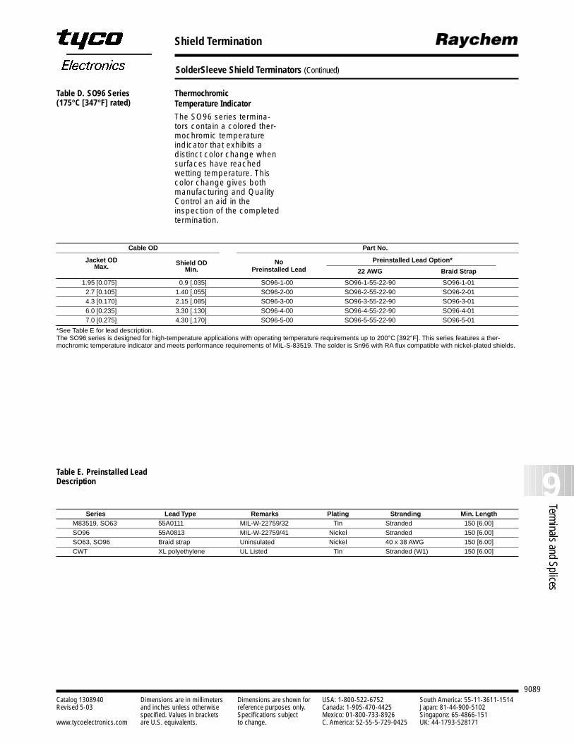
9089
9Terminals and Splices
Catalog 1308940 Dimensions are in millimeters Dimensions are shown for USA: 1-800-522-6752 South America: 55-11-3611-1514Revised 5-03 and inches unless otherwise reference purposes only. Canada: 1-905-470-4425 Japan: 81-44-900-5102
specified. Values in brackets Specifications subject Mexico: 01-800-733-8926 Singapore: 65-4866-151www.tycoelectronics.com are U.S. equivalents. to change. C. America: 52-55-5-729-0425 UK: 44-1793-528171
Shield Termination
SolderSleeve Shield Terminators (Continued)
Cable OD Part No.
Preinstalled Lead Option*Jacket OD Shield OD NoMax. Min. Preinstalled Lead 22 AWG Braid Strap
1.95 [0.075] 0.9 [.035] SO96-1-00 SO96-1-55-22-90 SO96-1-012.7 [0.105] 1.40 [.055] SO96-2-00 SO96-2-55-22-90 SO96-2-014.3 [0.170] 2.15 [.085] SO96-3-00 SO96-3-55-22-90 SO96-3-016.0 [0.235] 3.30 [.130] SO96-4-00 SO96-4-55-22-90 SO96-4-017.0 [0.275] 4.30 [.170] SO96-5-00 SO96-5-55-22-90 SO96-5-01
*See Table E for lead description.The SO96 series is designed for high-temperature applications with operating temperature requirements up to 200°C [392°F]. This series features a ther-mochromic temperature indicator and meets performance requirements of MIL-S-83519. The solder is Sn96 with RA flux compatible with nickel-plated shields.
Table E. Preinstalled Lead Description
Series Lead Type Remarks Plating Stranding Min. LengthM83519, SO63 55A0111 MIL-W-22759/32 Tin Stranded 150 [6.00]SO96 55A0813 MIL-W-22759/41 Nickel Stranded 150 [6.00]SO63, SO96 Braid strap Uninsulated Nickel 40 x 38 AWG 150 [6.00]CWT XL polyethylene UL Listed Tin Stranded (W1) 150 [6.00]
Thermochromic Temperature Indicator
The SO96 series termina-tors contain a colored ther-mochromic temperatureindicator that exhibits a distinct color change whensurfaces have reached wetting temperature. Thiscolor change gives bothmanufacturing and QualityControl an aid in the inspection of the completedtermination.
Table D. SO96 Series(175°C [347°F] rated)
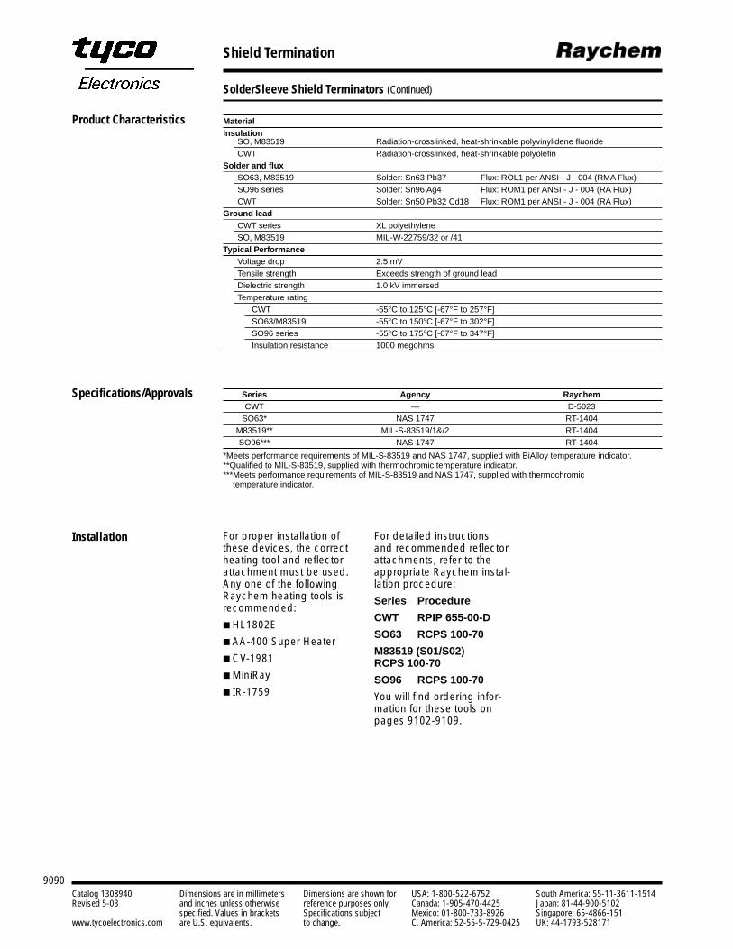
9090Catalog 1308940 Dimensions are in millimeters Dimensions are shown for USA: 1-800-522-6752 South America: 55-11-3611-1514Revised 5-03 and inches unless otherwise reference purposes only. Canada: 1-905-470-4425 Japan: 81-44-900-5102
specified. Values in brackets Specifications subject Mexico: 01-800-733-8926 Singapore: 65-4866-151www.tycoelectronics.com are U.S. equivalents. to change. C. America: 52-55-5-729-0425 UK: 44-1793-528171
MaterialInsulation
SO, M83519 Radiation-crosslinked, heat-shrinkable polyvinylidene fluorideCWT Radiation-crosslinked, heat-shrinkable polyolefin
Solder and flux SO63, M83519 Solder: Sn63 Pb37 Flux: ROL1 per ANSI - J - 004 (RMA Flux)SO96 series Solder: Sn96 Ag4 Flux: ROM1 per ANSI - J - 004 (RA Flux)CWT Solder: Sn50 Pb32 Cd18 Flux: ROM1 per ANSI - J - 004 (RA Flux)
Ground lead CWT series XL polyethyleneSO, M83519 MIL-W-22759/32 or /41
Typical PerformanceVoltage drop 2.5 mVTensile strength Exceeds strength of ground leadDielectric strength 1.0 kV immersedTemperature rating
CWT -55°C to 125°C [-67°F to 257°F]SO63/M83519 -55°C to 150°C [-67°F to 302°F]SO96 series -55°C to 175°C [-67°F to 347°F]Insulation resistance 1000 megohms
Series Agency RaychemCWT — D-5023
SO63* NAS 1747 RT-1404M83519** MIL-S-83519/1&/2 RT-1404SO96*** NAS 1747 RT-1404
*Meets performance requirements of MIL-S-83519 and NAS 1747, supplied with BiAlloy temperature indicator.**Qualified to MIL-S-83519, supplied with thermochromic temperature indicator.***Meets performance requirements of MIL-S-83519 and NAS 1747, supplied with thermochromic
temperature indicator.
Shield Termination
SolderSleeve Shield Terminators (Continued)
For proper installation ofthese devices, the correctheating tool and reflectorattachment must be used.Any one of the followingRaychem heating tools isrecommended:
HL1802E
AA-400 Super Heater
CV-1981
MiniRay
IR-1759
Product Characteristics
Specifications/Approvals
Installation For detailed instructionsand recommended reflectorattachments, refer to theappropriate Raychem instal-lation procedure:
Series Procedure
CWT RPIP 655-00-D
SO63 RCPS 100-70
M83519 (S01/S02)RCPS 100-70
SO96 RCPS 100-70
You will find ordering infor-mation for these tools onpages 9102-9109.
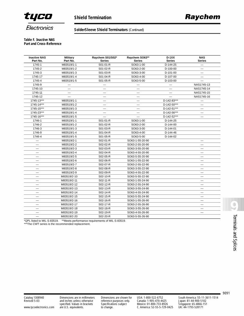
9091
9Terminals and Splices
Catalog 1308940 Dimensions are in millimeters Dimensions are shown for USA: 1-800-522-6752 South America: 55-11-3611-1514Revised 5-03 and inches unless otherwise reference purposes only. Canada: 1-905-470-4425 Japan: 81-44-900-5102
specified. Values in brackets Specifications subject Mexico: 01-800-733-8926 Singapore: 65-4866-151www.tycoelectronics.com are U.S. equivalents. to change. C. America: 52-55-5-729-0425 UK: 44-1793-528171
Shield Termination
SolderSleeve Shield Terminators (Continued)
Table F. Inactive NAS Part and Cross-Reference
Inactive NAS Military Raychem S01/S02* Raychem SO63** D-1XX NASPart No. Part No. Series Series Series Series1745-1 M83519/1-1 S01-01-R SO63-1-00 D-144-25 —1745-2 M83519/1-2 S01-02-R SO63-2-00 D-100-00 —1745-3 M83519/1-3 S01-03-R SO63-3-00 D-101-00 —1745-17 M83519/1-4 S01-04-R SO63-4-00 D-107-00 —1745-4 M83519/1-5 S01-05-R SO63-5-00 D-103-00 —1745-9 — — — — NAS1745-131745-10 — — — — NAS1745-141745-11 — — — — NAS1745-151745-12 — — — — NAS1745-16
1745-13*** M83519/1-1 — — D-142-83*** —1745-14*** M83519/1-2 — — D-142-50*** —1745-15*** M83519/1-3 — — D-142-51*** —1745-23*** M83519/1-4 — — D-142-56*** —1745-16*** M83519/1-5 — — D-142-52*** —
1746-1 M83519/1-1 S01-01-R SO63-1-00 D-144-251746-2 M83519/1-2 S01-02-R SO63-2-00 D-144-001746-3 M83519/1-3 S01-03-R SO63-3-00 D-144-011746-9 M83519/1-4 S01-04-R SO63-4-00 D-144-461746-4 M83519/1-5 S01-05-R SO63-5-00 D-144-02
— M83519/2-1 S02-01-R SO63-1-55-20-90 —— M83519/2-2 S02-02-R SO63-2-55-20-90 —— M83519/2-3 S02-03-R SO63-3-55-20-90 —— M83519/2-4 S02-04-R SO63-4-55-20-90 —— M83519/2-5 S02-05-R SO63-5-55-20-90 —— M83519/2-6 S02-06-R SO63-1-55-22-90 —— M83519/2-7 S02-07-R SO63-2-55-22-90 —— M83519/2-8 S02-08-R SO63-3-55-22-90 —— M83519/2-9 S02-09-R SO63-4-55-22-90 —— M83519/2-10 S02-10-R SO63-5-55-22-90 —— M83519/2-11 S02-11-R SO63-1-55-24-90 —— M83519/2-12 S02-12-R SO63-2-55-24-90 —— M83519/2-13 S02-13-R SO63-3-55-24-90 —— M83519/2-14 S02-14-R SO63-4-55-24-90 —— M83519/2-15 S02-15-R SO63-5-55-24-90 —— M83519/2-16 S02-16-R SO63-1-55-26-90 —— M83519/2-17 S02-17-R SO63-2-55-26-90 —— M83519/2-18 S02-18-R SO63-3-55-26-90 —— M83519/2-19 S02-19-R SO63-4-55-26-90 —— M83519/2-20 S02-20-R SO63-5-55-26-90
*QPL listed to MIL-S-83519. **Meets performance requirements of MIL-S-83519.***The CWT series is the recommended replacement.
9092Catalog 1308940 Dimensions are in millimeters Dimensions are shown for USA: 1-800-522-6752 South America: 55-11-3611-1514Revised 5-03 and inches unless otherwise reference purposes only. Canada: 1-905-470-4425 Japan: 81-44-900-5102
specified. Values in brackets Specifications subject Mexico: 01-800-733-8926 Singapore: 65-4866-151www.tycoelectronics.com are U.S. equivalents. to change. C. America: 52-55-5-729-0425 UK: 44-1793-528171
Coaxial Cable Termination
Introduction
Raychem SolderSleevecoaxial cable terminatorsallow reliable, easy termina-tions in a variety of coaxialcable applications, includ-ing printed circuit boards(PCBs). The insulating andstrain-relieving capabilitiesof SolderSleeve terminatorsprovide the ideal solution tocenter-conductor breakageproblems.
Designed for applicationswith temperatures up to150°C [302°F], the productsin this section include:
SolderSleeve coaxialcable terminators, whichallow reliable, economicalattachment of coaxialcable to connector terminals, printed wiringassemblies, or solderlesswrap terminals.
One-piece SolderSleevePCB coaxial cable termi-nators, which permitquick, easy, and cost-effective terminations ofcoaxial cable to printedcircuit boards.
RF one-step BNC/TNCconnectors, which are sin-gle-piece assemblies forterminating the centerconductor and the braidof a broad range of coax-ial cables. They are fullyintermateable with MIL-C-39012C connectors andare available in 50-ohmand 75-ohm versions(refer to pages 7034-7039in Section 7 for productinformation).
With precisely measuredsolder and flux, SolderSleeveproducts provide exactprocess control of termina-tions. The SolderSleevemethod means strong connections with the lowestpossible voltage drop. Small,lightweight SolderSleeveterminators are also the idealsolution for high-densitypackaging problems.
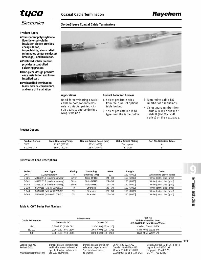
9093
9Terminals and Splices
Catalog 1308940 Dimensions are in millimeters Dimensions are shown for USA: 1-800-522-6752 South America: 55-11-3611-1514Revised 5-03 and inches unless otherwise reference purposes only. Canada: 1-905-470-4425 Japan: 81-44-900-5102
specified. Values in brackets Specifications subject Mexico: 01-800-733-8926 Singapore: 65-4866-151www.tycoelectronics.com are U.S. equivalents. to change. C. America: 52-55-5-729-0425 UK: 44-1793-528171
Coaxial Cable Termination
SolderSleeve Coaxial Cable Terminators
Product Facts Transparent polyvinylidene
fluoride or polyolefininsulation sleeve providesencapsulation,inspectability, strain relief(eliminates center conductorbreakage), and insulation.
Prefluxed solder preformprovides a controlledsoldering process
One-piece design provideseasy installation and lowerinstalled cost
Preinstalled terminationleads provide convenienceand ease of installation
Product Options
Product Series Max. Operating Temp. Use on Cables Rated (Min) Cable Shield Plating Part No. Selection TableCWT 125°C [257°F] 85°C [185°F] Tin, copper AB-02X/B-04X 150°C [302°F] 125°C [257°F] Tin, silver B
Preinstalled Lead Descriptions
Series Lead Type Plating Stranding AWG Length ColorCWT XL polyethelene Tin Stranded (W1) 22 150 [6.000] White (cntr), green (grnd)B-021 M81822/13 (solderless wrap) Silver Solid-OFHC 24—30 150 [6.000] White (cntr), blue (grnd) B-041 M81822/13 (solderless wrap) Silver Solid-OFHC 24—30 150 [6.000] White (cntr), blue (grnd) B-043 M81822/13 (solderless wrap) Silver Solid-OFHC 24—30 150 [6.000] White (cntr), blue (grnd) B-020 55A0111 (MIL-W-22759/32) Tin Stranded 20—30 150 [6.000] White (cntr), blue (grnd) B-040 55A0111 (MIL-W-22759/32) Tin Stranded 20—30 150 [6.000] White (cntr), blue (grnd) B-044 55A0111 (MIL-W-22759/32) Tin Stranded 20—30 150 [6.000] White (cntr), blue (grnd)
Table A. CWT Series Part Numbers
Dimensions Part No.Cable RG Number
Dielectric OD Jacket ODWith Preinstalled Lead
(22 AWG/0.38 mm2 Green/White)174 0.80–2.30 [.032–.091] 1.30–2.80 [.051–.110] CWT-4174-W122-5/9
58, 122 2.00–2.80 [.079–.110] 2.50–4.40 [.100–.173] CWT-4058-W122-5/959 2.80–3.30 [.110–.130] 3.20–6.00 [.125–.235] CWT-4059-W122-5/9
Applications
Used for terminating coaxialcable to component termi-nals, contacts, printed cir-cuit boards, and solderlesswrap terminals.
Product Selection Process
1. Select product seriesfrom the product optionstable below.
2. Select preinstalled leadtype from the table below.
3. Determine cable RGnumber or dimensions.
4. Select part number fromTable A (CWT series) orTable B (B-02X/B-04Xseries) on the next page.
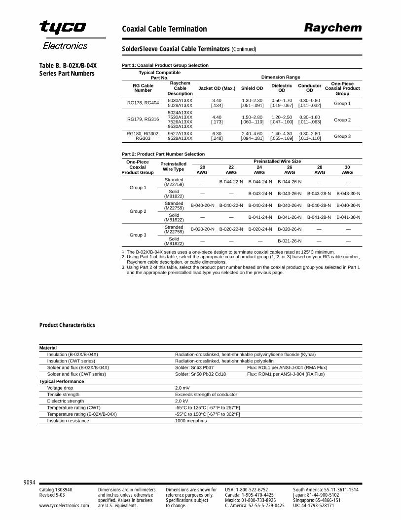
9094Catalog 1308940 Dimensions are in millimeters Dimensions are shown for USA: 1-800-522-6752 South America: 55-11-3611-1514Revised 5-03 and inches unless otherwise reference purposes only. Canada: 1-905-470-4425 Japan: 81-44-900-5102
specified. Values in brackets Specifications subject Mexico: 01-800-733-8926 Singapore: 65-4866-151www.tycoelectronics.com are U.S. equivalents. to change. C. America: 52-55-5-729-0425 UK: 44-1793-528171
Coaxial Cable Termination
SolderSleeve Coaxial Cable Terminators (Continued)
Product Characteristics
MaterialInsulation (B-02X/B-04X) Radiation-crosslinked, heat-shrinkable polyvinylidene fluoride (Kynar)Insulation (CWT series) Radiation-crosslinked, heat-shrinkable polyolefinSolder and flux (B-02X/B-04X) Solder: Sn63 Pb37 Flux: ROL1 per ANSI-J-004 (RMA Flux)Solder and flux (CWT series) Solder: Sn50 Pb32 Cd18 Flux: ROM1 per ANSI-J-004 (RA Flux)
Typical PerformanceVoltage drop 2.0 mVTensile strength Exceeds strength of conductorDielectric strength 2.0 kVTemperature rating (CWT) -55°C to 125°C [-67°F to 257°F]Temperature rating (B-02X/B-04X) -55°C to 150°C [-67°F to 302°F]Insulation resistance 1000 megohms
Part 1: Coaxial Product Group Selection
Typical Compatible Part No. Dimension Range
Raychem One-PieceRG Cable Cable Jacket OD (Max.) Shield OD Dielectric Conductor Coaxial ProductNumberDescription
OD ODGroup
RG178, RG404 5030A13XX 3.40 1.30–2.30 0.50–1.70 0.30–0.80 Group 15028A13XX [.134] [.051–.091] [.019–.067] [.011–.032]
5024A13XXRG179, RG316 7530A13XX 4.40 1.50–2.80 1.20–2.50 0.30–1.60 Group 27526A13XX [.173] [.060–.110] [.047–.100] [.011–.063]
9530A13XX
RG180, RG302, 9527A13XX 6.30 2.40–4.60 1.40–4.30 0.30–2.80 Group 3RG303 9528A13XX [.248] [.094–.181] [.055–.169] [.011–.110]
Part 2: Product Part Number Selection
One-Piece Preinstalled Wire SizeCoaxial
Preinstalled 20 22 24 26 28 30
Product Group Wire Type
AWG AWG AWG AWG AWG AWG
Stranded — B-044-22-N B-044-24-N B-044-26-N — —Group 1
(M22759)
Solid — — B-043-24-N B-043-26-N B-043-28-N B-043-30-N(M81822)
Stranded B-040-20-N B-040-22-N B-040-24-N B-040-26-N B-040-28-N B-040-30-NGroup 2
(M22759)
Solid — — B-041-24-N B-041-26-N B-041-28-N B-041-30-N(M81822)
Stranded B-020-20-N B-020-22-N B-020-24-N B-020-26-N — —Group 3
(M22759)
Solid — — — B-021-26-N — —(M81822)
1. The B-02X/B-04X series uses a one-piece design to terminate coaxial cables rated at 125°C minimum.2. Using Part 1 of this table, select the appropriate coaxial product group (1, 2, or 3) based on your RG cable number,
Raychem cable description, or cable dimensions. 3. Using Part 2 of this table, select the product part number based on the coaxial product group you selected in Part 1
and the appropriate preinstalled lead type you selected on the previous page.
Table B. B-02X/B-04XSeries Part Numbers
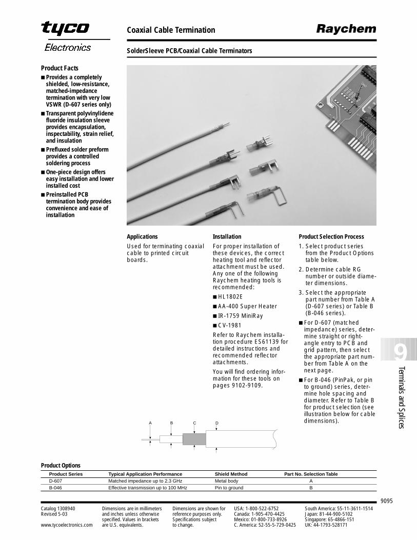
9095
9Terminals and Splices
Catalog 1308940 Dimensions are in millimeters Dimensions are shown for USA: 1-800-522-6752 South America: 55-11-3611-1514Revised 5-03 and inches unless otherwise reference purposes only. Canada: 1-905-470-4425 Japan: 81-44-900-5102
specified. Values in brackets Specifications subject Mexico: 01-800-733-8926 Singapore: 65-4866-151www.tycoelectronics.com are U.S. equivalents. to change. C. America: 52-55-5-729-0425 UK: 44-1793-528171
Coaxial Cable Termination
SolderSleeve PCB/Coaxial Cable Terminators
Product OptionsProduct Series Typical Application Performance Shield Method Part No. Selection TableD-607 Matched impedance up to 2.3 GHz Metal body AB-046 Effective transmission up to 100 MHz Pin to ground B
Product Selection Process
1. Select product seriesfrom the Product Optionstable below.
2. Determine cable RGnumber or outside diame-ter dimensions.
3. Select the appropriatepart number from Table A(D-607 series) or Table B(B-046 series).
For D-607 (matchedimpedance) series, deter-mine straight or right-angle entry to PCB andgrid pattern, then selectthe appropriate part num-ber from Table A on thenext page.
For B-046 (PinPak, or pinto ground) series, deter-mine hole spacing anddiameter. Refer to Table Bfor product selection (seeillustration below for cabledimensions).
Installation
For proper installation ofthese devices, the correctheating tool and reflectorattachment must be used.Any one of the followingRaychem heating tools isrecommended:
HL1802E
AA-400 Super Heater
IR-1759 MiniRay
CV-1981
Refer to Raychem installa-tion procedure ES61139 fordetailed instructions andrecommended reflectorattachments.
You will find ordering infor-mation for these tools onpages 9102-9109.
A B C D
Product Facts Provides a completely
shielded, low-resistance,matched-impedancetermination with very lowVSWR (D-607 series only)
Transparent polyvinylidenefluoride insulation sleeveprovides encapsulation,inspectability, strain relief,and insulation
Prefluxed solder preformprovides a controlledsoldering process
One-piece design offerseasy installation and lowerinstalled cost
Preinstalled PCBtermination body providesconvenience and ease ofinstallation
Applications
Used for terminating coaxialcable to printed circuitboards.
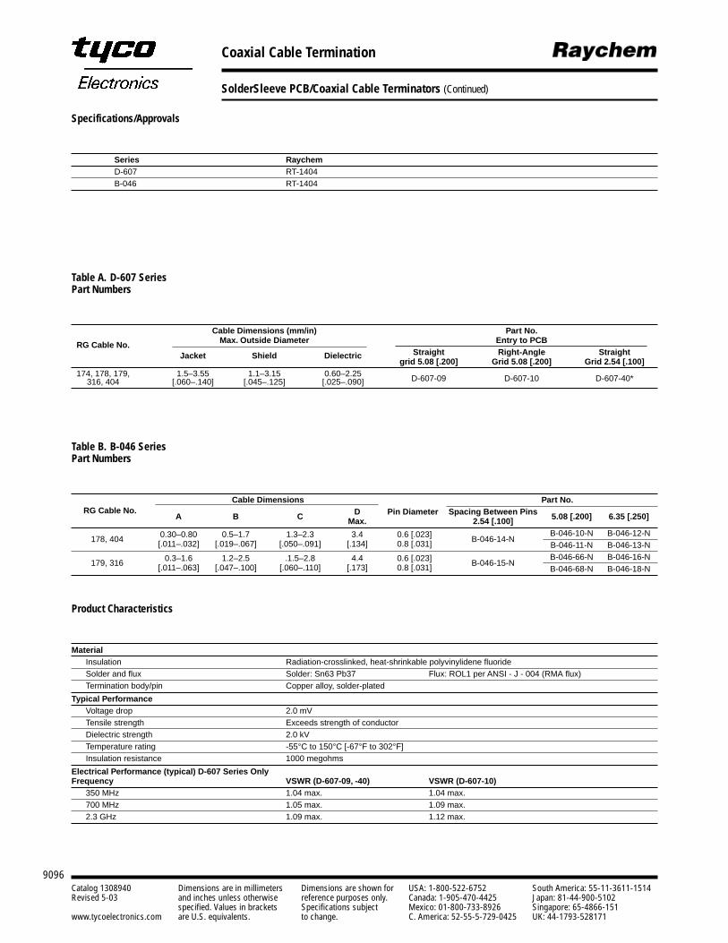
9096Catalog 1308940 Dimensions are in millimeters Dimensions are shown for USA: 1-800-522-6752 South America: 55-11-3611-1514Revised 5-03 and inches unless otherwise reference purposes only. Canada: 1-905-470-4425 Japan: 81-44-900-5102
specified. Values in brackets Specifications subject Mexico: 01-800-733-8926 Singapore: 65-4866-151www.tycoelectronics.com are U.S. equivalents. to change. C. America: 52-55-5-729-0425 UK: 44-1793-528171
Coaxial Cable Termination
SolderSleeve PCB/Coaxial Cable Terminators (Continued)
Table A. D-607 Series Part Numbers
Cable Dimensions (mm/in) Part No.
RG Cable No. Max. Outside Diameter Entry to PCBStraight Right-Angle StraightJacket Shield Dielectric
grid 5.08 [.200] Grid 5.08 [.200] Grid 2.54 [.100] 174, 178, 179, 1.5–3.55 1.1–3.15 0.60–2.25 D-607-09 D-607-10 D-607-40*316, 404 [.060–.140] [.045–.125] [.025–.090]
Table B. B-046 Series Part Numbers
Cable Dimensions Part No.RG Cable No.
A B C D Pin Diameter Spacing Between Pins Max. 2.54 [.100] 5.08 [.200] 6.35 [.250]
178, 404 0.30–0.80 0.5–1.7 1.3–2.3 3.4 0.6 [.023] B-046-14-NB-046-10-N B-046-12-N
[.011–.032] [.019–.067] [.050–.091] [.134] 0.8 [.031] B-046-11-N B-046-13-N
179, 316 0.3–1.6 1.2–2.5 .1.5–2.8 4.4 0.6 [.023] B-046-15-NB-046-66-N B-046-16-N
[.011–.063] [.047–.100] [.060–.110] [.173] 0.8 [.031] B-046-68-N B-046-18-N
Product Characteristics
MaterialInsulation Radiation-crosslinked, heat-shrinkable polyvinylidene fluoride Solder and flux Solder: Sn63 Pb37 Flux: ROL1 per ANSI - J - 004 (RMA flux)Termination body/pin Copper alloy, solder-plated
Typical PerformanceVoltage drop 2.0 mVTensile strength Exceeds strength of conductorDielectric strength 2.0 kVTemperature rating -55°C to 150°C [-67°F to 302°F]Insulation resistance 1000 megohms
Electrical Performance (typical) D-607 Series OnlyFrequency VSWR (D-607-09, -40) VSWR (D-607-10)
350 MHz 1.04 max. 1.04 max.700 MHz 1.05 max. 1.09 max.2.3 GHz 1.09 max. 1.12 max.
Specifications/Approvals
Series RaychemD-607 RT-1404B-046 RT-1404
9097
9Terminals and Splices
Catalog 1308940 Dimensions are in millimeters Dimensions are shown for USA: 1-800-522-6752 South America: 55-11-3611-1514Revised 5-03 and inches unless otherwise reference purposes only. Canada: 1-905-470-4425 Japan: 81-44-900-5102
specified. Values in brackets Specifications subject Mexico: 01-800-733-8926 Singapore: 65-4866-151www.tycoelectronics.com are U.S. equivalents. to change. C. America: 52-55-5-729-0425 UK: 44-1793-528171
Cable-to-Cable Splicing
Introduction
The question is, how tomeet growing performancerequirements for shieldedcable system fabricationand maintenance while min-imizing electromagneticinterference (EMI). Theanswer is RaychemSolderShield cable splices.SolderShield devices areone-piece products consist-ing of a flux-coated, solder-impregnated copper shieldbraid encased in a heat-shrinkable insulation sleeve.
SolderShield cable-to-cablesplice kits, designed for single-conductor or multi-conductor shielded cables,are ideal for fabrication/repair/rework while restoringthe electrical integrity of the cable.
SolderShield devices per-form even in demandingenvironments. They are reliable, versatile, and easyto install.
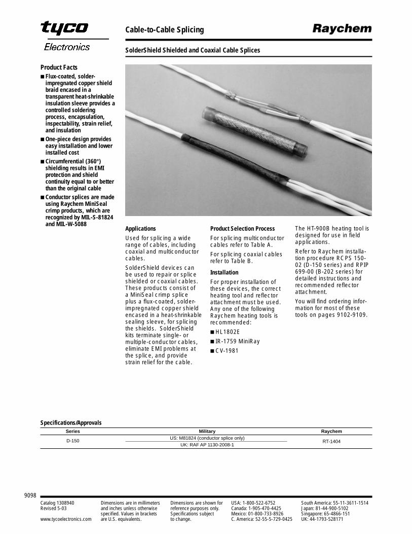
9098Catalog 1308940 Dimensions are in millimeters Dimensions are shown for USA: 1-800-522-6752 South America: 55-11-3611-1514Revised 5-03 and inches unless otherwise reference purposes only. Canada: 1-905-470-4425 Japan: 81-44-900-5102
specified. Values in brackets Specifications subject Mexico: 01-800-733-8926 Singapore: 65-4866-151www.tycoelectronics.com are U.S. equivalents. to change. C. America: 52-55-5-729-0425 UK: 44-1793-528171
Cable-to-Cable Splicing
SolderShield Shielded and Coaxial Cable Splices
Applications
Used for splicing a widerange of cables, includingcoaxial and multiconductorcables.
SolderShield devices canbe used to repair or spliceshielded or coaxial cables.These products consist of a MiniSeal crimp splice plus a flux-coated, solder-impregnated copper shieldencased in a heat-shrinkablesealing sleeve, for splicingthe shields. SolderShieldkits terminate single- or multiple-conductor cables,eliminate EMI problems atthe splice, and providestrain relief for the cable.
Product Selection Process
For splicing multiconductorcables refer to Table A.
For splicing coaxial cablesrefer to Table B.
Installation
For proper installation ofthese devices, the correctheating tool and reflectorattachment must be used.Any one of the followingRaychem heating tools isrecommended:
HL1802E
IR-1759 MiniRay
CV-1981
Specifications/ApprovalsSeries Military Raychem
D-150 US: M81824 (conductor splice only)RT-1404
UK: RAF AP 1130-2008-1
Product Facts Flux-coated, solder-
impregnated copper shieldbraid encased in atransparent heat-shrinkableinsulation sleeve provides acontrolled solderingprocess, encapsulation,inspectability, strain relief,and insulation
One-piece design provideseasy installation and lowerinstalled cost
Circumferential (360°)shielding results in EMIprotection and shieldcontinuity equal to or betterthan the original cable
Conductor splices are madeusing Raychem MiniSealcrimp products, which arerecognized by MIL-S-81824and MIL-W-5088
The HT-900B heating tool isdesigned for use in fieldapplications.
Refer to Raychem installa-tion procedure RCPS 150-02 (D-150 series) and RPIP699-00 (B-202 series) fordetailed instructions andrecommended reflectorattachment.
You will find ordering infor-mation for most of thesetools on pages 9102-9109.
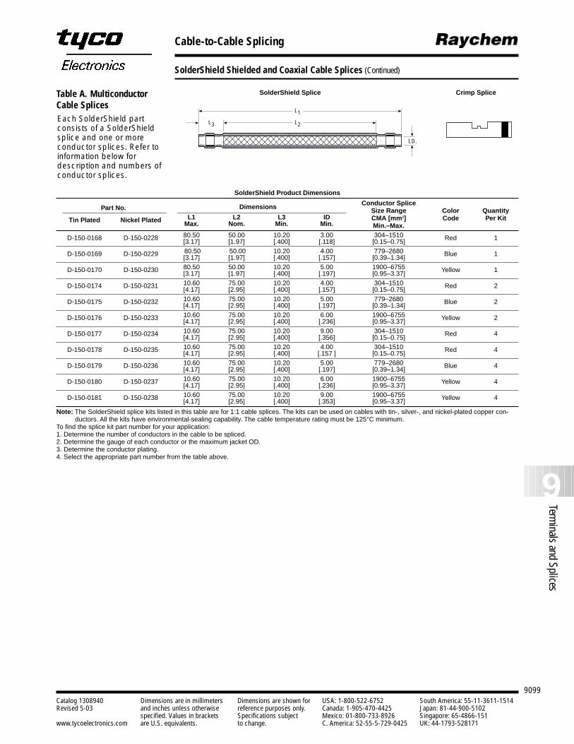
9099
9Terminals and Splices
Catalog 1308940 Dimensions are in millimeters Dimensions are shown for USA: 1-800-522-6752 South America: 55-11-3611-1514Revised 5-03 and inches unless otherwise reference purposes only. Canada: 1-905-470-4425 Japan: 81-44-900-5102
specified. Values in brackets Specifications subject Mexico: 01-800-733-8926 Singapore: 65-4866-151www.tycoelectronics.com are U.S. equivalents. to change. C. America: 52-55-5-729-0425 UK: 44-1793-528171
Cable-to-Cable Splicing
SolderShield Shielded and Coaxial Cable Splices (Continued)
SolderShield Product Dimensions
Conductor SplicePart No. Dimensions Size Range Color Quantity
L1 L2 L3 ID CMA [mm2] Code Per KitTin Plated Nickel Plated Max. Nom. Min. Min. Min.–Max.
D-150-0168 D-150-0228 80.50 50.00 10.20 3.00 304–1510 Red 1[3.17] [1.97] [.400] [.118] [0.15–0.75]
D-150-0169 D-150-0229 80.50 50.00 10.20 4.00 779–2680 Blue 1[3.17] [1.97] [.400] [.157] [0.39–1.34]
D-150-0170 D-150-0230 80.50 50.00 10.20 5.00 1900–6755 Yellow 1[3.17] [1.97] [.400] [.197] [0.95–3.37]
D-150-0174 D-150-0231 10.60 75.00 10.20 4.00 304–1510 Red 2[4.17] [2.95] [.400] [.157] [0.15–0.75]
D-150-0175 D-150-0232 10.60 75.00 10.20 5.00 779–2680 Blue 2[4.17] [2.95] [.400] [.197] [0.39–1.34]
D-150-0176 D-150-0233 10.60 75.00 10.20 6.00 1900–6755 Yellow 2[4.17] [2.95] [.400] [.236] [0.95–3.37]
D-150-0177 D-150-0234 10.60 75.00 10.20 9.00 304–1510 Red 4[4.17] [2.95] [.400] [.356] [0.15–0.75]
D-150-0178 D-150-0235 10.60 75.00 10.20 4.00 304–1510 Red 4[4.17] [2.95] [.400] [.157 ] [0.15–0.75]
D-150-0179 D-150-0236 10.60 75.00 10.20 5.00 779–2680 Blue 4[4.17] [2.95] [.400] [.197] [0.39–1.34]
D-150-0180 D-150-0237 10.60 75.00 10.20 6.00 1900–6755 Yellow 4[4.17] [2.95] [.400] [.236] [0.95–3.37]
D-150-0181 D-150-0238 10.60 75.00 10.20 9.00 1900–6755 Yellow 4[4.17] [2.95] [.400] [.353] [0.95–3.37]
Note: The SolderShield splice kits listed in this table are for 1:1 cable splices. The kits can be used on cables with tin-, silver-, and nickel-plated copper con-ductors. All the kits have environmental-sealing capability. The cable temperature rating must be 125°C minimum.
To find the splice kit part number for your application:1. Determine the number of conductors in the cable to be spliced.2. Determine the gauge of each conductor or the maximum jacket OD.3. Determine the conductor plating. 4. Select the appropriate part number from the table above.
L1
I.D.
L2L3Each SolderShield partconsists of a SolderShieldsplice and one or moreconductor splices. Refer toinformation below fordescription and numbers ofconductor splices.
SolderShield Splice Crimp SpliceTable A. MulticonductorCable Splices
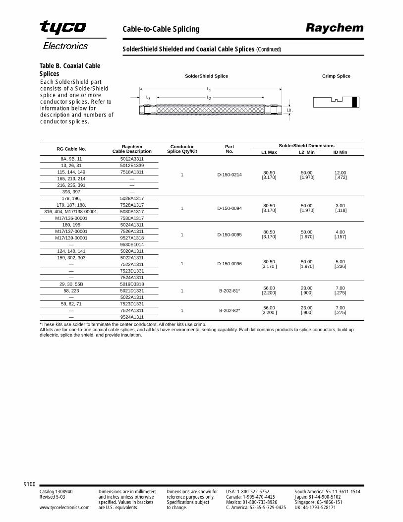
9100Catalog 1308940 Dimensions are in millimeters Dimensions are shown for USA: 1-800-522-6752 South America: 55-11-3611-1514Revised 5-03 and inches unless otherwise reference purposes only. Canada: 1-905-470-4425 Japan: 81-44-900-5102
specified. Values in brackets Specifications subject Mexico: 01-800-733-8926 Singapore: 65-4866-151www.tycoelectronics.com are U.S. equivalents. to change. C. America: 52-55-5-729-0425 UK: 44-1793-528171
Cable-to-Cable Splicing
SolderShield Shielded and Coaxial Cable Splices (Continued)
RG Cable No. Raychem Conductor Part SolderShield DimensionsCable Description Splice Qty/Kit No. L1 Max L2 Min ID Min
8A, 9B, 11 5012A331113, 26, 31 5012E1339
115, 144, 149 7518A1311 1 D-150-0214 80.50 50.00 12.00165, 213, 214 — [3.170] [1.970] [.472]
216, 235, 391 —393, 397 —178, 196, 5028A1317
179, 187, 188, 7528A13171 D-150-0094 80.50 50.00 3.00
316, 404, M17/138-00001, 5030A1317 [3.170] [1.970] [.118]
M17/136-00001 7530A1317180, 195 5024A1311
M17/137-00001 7526A13111 D-150-0095 80.50 50.00 4.00
M17/139-00001 9527A1318 [3.170] [1.970] [.157]
— 9530E1014124, 140, 141 5020A1311159, 302, 303 5022A1311
1 D-150-0096 80.50 50.00 5.00— 7522A1311 [3.170 ] [1.970] [.236]— 7523D1331— 7524A1311
29, 30, 55B 5019D33181 B-202-81* 56.00 23.00 7.0058, 223 5021D1331 [2.200] [.900] [.275]
— 5022A131159, 62, 71 7523D1331
1 B-202-82* 56.00 23.00 7.00— 7524A1311 [2.200 ] [.900] [.275]— 9524A1311
*These kits use solder to terminate the center conductors. All other kits use crimp.All kits are for one-to-one coaxial cable splices, and all kits have environmental sealing capability. Each kit contains products to splice conductors, build updielectric, splice the shield, and provide insulation.
Each SolderShield partconsists of a SolderShieldsplice and one or moreconductor splices. Refer toinformation below fordescription and numbers ofconductor splices.
L1
I.D.
L2L3
SolderShield Splice Crimp Splice
Table B. Coaxial CableSplices
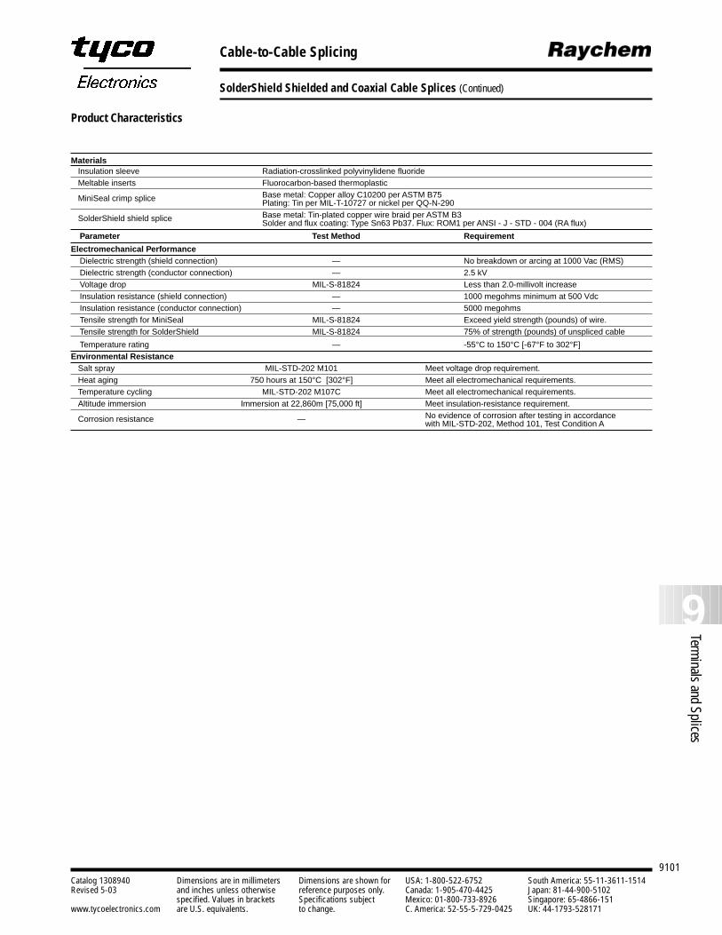
9101
9Terminals and Splices
Catalog 1308940 Dimensions are in millimeters Dimensions are shown for USA: 1-800-522-6752 South America: 55-11-3611-1514Revised 5-03 and inches unless otherwise reference purposes only. Canada: 1-905-470-4425 Japan: 81-44-900-5102
specified. Values in brackets Specifications subject Mexico: 01-800-733-8926 Singapore: 65-4866-151www.tycoelectronics.com are U.S. equivalents. to change. C. America: 52-55-5-729-0425 UK: 44-1793-528171
Cable-to-Cable Splicing
SolderShield Shielded and Coaxial Cable Splices (Continued)
Product Characteristics
MaterialsInsulation sleeve Radiation-crosslinked polyvinylidene fluorideMeltable inserts Fluorocarbon-based thermoplastic
MiniSeal crimp splice Base metal: Copper alloy C10200 per ASTM B75Plating: Tin per MIL-T-10727 or nickel per QQ-N-290
SolderShield shield splice Base metal: Tin-plated copper wire braid per ASTM B3Solder and flux coating: Type Sn63 Pb37. Flux: ROM1 per ANSI - J - STD - 004 (RA flux)
Parameter Test Method Requirement
Electromechanical PerformanceDielectric strength (shield connection) — No breakdown or arcing at 1000 Vac (RMS)Dielectric strength (conductor connection) — 2.5 kVVoltage drop MIL-S-81824 Less than 2.0-millivolt increaseInsulation resistance (shield connection) — 1000 megohms minimum at 500 VdcInsulation resistance (conductor connection) — 5000 megohmsTensile strength for MiniSeal MIL-S-81824 Exceed yield strength (pounds) of wire.Tensile strength for SolderShield MIL-S-81824 75% of strength (pounds) of unspliced cable
Temperature rating — -55°C to 150°C [-67°F to 302°F]Environmental Resistance
Salt spray MIL-STD-202 M101 Meet voltage drop requirement.Heat aging 750 hours at 150°C [302°F] Meet all electromechanical requirements.Temperature cycling MIL-STD-202 M107C Meet all electromechanical requirements.Altitude immersion Immersion at 22,860m [75,000 ft] Meet insulation-resistance requirement.
Corrosion resistance — No evidence of corrosion after testing in accordance with MIL-STD-202, Method 101, Test Condition A
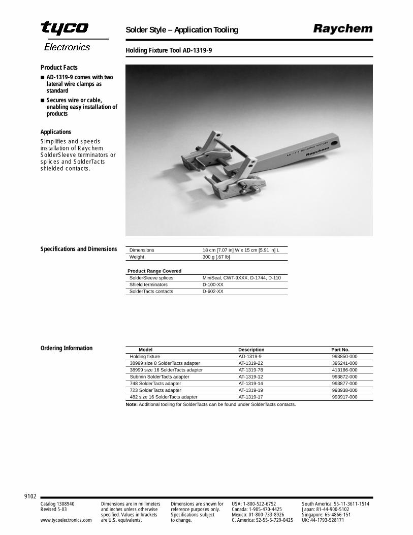
Solder Style – Application Tooling
9102Catalog 1308940 Dimensions are in millimeters Dimensions are shown for USA: 1-800-522-6752 South America: 55-11-3611-1514Revised 5-03 and inches unless otherwise reference purposes only. Canada: 1-905-470-4425 Japan: 81-44-900-5102
specified. Values in brackets Specifications subject Mexico: 01-800-733-8926 Singapore: 65-4866-151www.tycoelectronics.com are U.S. equivalents. to change. C. America: 52-55-5-729-0425 UK: 44-1793-528171
Holding Fixture Tool AD-1319-9
Model Description Part No.Holding fixture AD-1319-9 993850-00038999 size 8 SolderTacts adapter AT-1319-22 395241-00038999 size 16 SolderTacts adapter AT-1319-78 413186-000Submin SolderTacts adapter AT-1319-12 993872-000748 SolderTacts adapter AT-1319-14 993877-000723 SolderTacts adapter AT-1319-19 993938-000482 size 16 SolderTacts adapter AT-1319-17 993917-000
Note: Additional tooling for SolderTacts can be found under SolderTacts contacts.
Ordering Information
Dimensions 18 cm [7.07 in] W x 15 cm [5.91 in] LWeight 300 g [.67 lb]
Product Range CoveredSolderSleeve splices MiniSeal, CWT-9XXX, D-1744, D-110Shield terminators D-100-XXSolderTacts contacts D-602-XX
Product Facts AD-1319-9 comes with two
lateral wire clamps asstandard
Secures wire or cable,enabling easy installation ofproducts
Applications
Simplifies and speedsinstallation of RaychemSolderSleeve terminators orsplices and SolderTactsshielded contacts.
Specifications and Dimensions
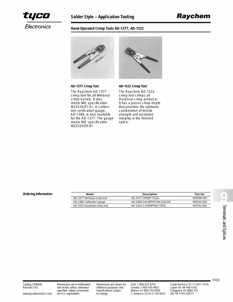
Solder Style – Application Tooling
Hand-Operated Crimp Tools AD-1377, AD-1522
9103
9Terminals and Splices
Catalog 1308940 Dimensions are in millimeters Dimensions are shown for USA: 1-800-522-6752 South America: 55-11-3611-1514Revised 5-03 and inches unless otherwise reference purposes only. Canada: 1-905-470-4425 Japan: 81-44-900-5102
specified. Values in brackets Specifications subject Mexico: 01-800-733-8926 Singapore: 65-4866-151www.tycoelectronics.com are U.S. equivalents. to change. C. America: 52-55-5-729-0425 UK: 44-1793-528171
Model Description Part No.AD-1377 MiniSeal crimp tool AD-1377-CRIMP-TOOL 992008-000AD-1386 Calibration gauge AD-1386-CALIBRATION-GAUGE 992013-000AD-1522 DuraSeal crimp tool AD-1522-1-CRIMPING TOOL 047011-000
Ordering Information
AD-1377 Crimp Tool
The Raychem AD-1377crimp tool fits all MiniSealcrimp barrels. It also meets MIL specificationM22520/37-01. A calibra-tion verification gauge, AD-1386, is also availablefor the AD-1377. The gaugemeets MIL specificationM22520/39-01
AD-1522 Crimp Tool
The Raychem AD-1522crimp tool crimps allDuraSeal crimp products. It has a preset crimp depththat provides the optimumcombination of tensilestrength and insulationintegrity in the finishedsplice.
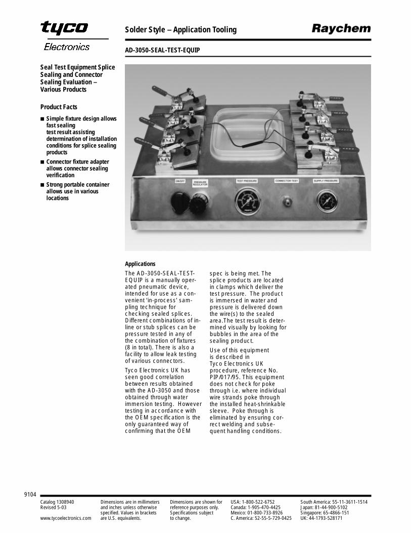
Solder Style – Application Tooling
AD-3050-SEAL-TEST-EQUIP
9104Catalog 1308940 Dimensions are in millimeters Dimensions are shown for USA: 1-800-522-6752 South America: 55-11-3611-1514Revised 5-03 and inches unless otherwise reference purposes only. Canada: 1-905-470-4425 Japan: 81-44-900-5102
specified. Values in brackets Specifications subject Mexico: 01-800-733-8926 Singapore: 65-4866-151www.tycoelectronics.com are U.S. equivalents. to change. C. America: 52-55-5-729-0425 UK: 44-1793-528171
Seal Test Equipment SpliceSealing and ConnectorSealing Evaluation –Various Products
Product Facts
Simple fixture design allowsfast sealing test result assistingdetermination of installationconditions for splice sealingproducts
Connector fixture adapterallows connector sealingverification
Strong portable containerallows use in variouslocations
Applications
The AD-3050-SEAL-TEST-EQUIP is a manually oper-ated pneumatic device,intended for use as a con-venient ‘in-process’ sam-pling technique forchecking sealed splices.Different combinations of in-line or stub splices can bepressure tested in any ofthe combination of fixtures(8 in total). There is also afacility to allow leak testingof various connectors.
Tyco Electronics UK hasseen good correlationbetween results obtainedwith the AD-3050 and thoseobtained through waterimmersion testing. Howevertesting in accordance withthe OEM specification is theonly guaranteed way ofconfirming that the OEM
spec is being met. Thesplice products are locatedin clamps which deliver thetest pressure. The productis immersed in water andpressure is delivered downthe wire(s) to the sealedarea.The test result is deter-mined visually by looking forbubbles in the area of thesealing product.
Use of this equipment is described in Tyco Electronics UK procedure, reference No.PIP/017/95. This equipmentdoes not check for pokethrough i.e. where individualwire strands poke throughthe installed heat-shrinkablesleeve. Poke through iseliminated by ensuring cor-rect welding and subse-quent handling conditions.
Solder Style – Application Tooling
AD-3050-SEAL-TEST-EQUIP (Continued)
9105
9Terminals and Splices
Catalog 1308940 Dimensions are in millimeters Dimensions are shown for USA: 1-800-522-6752 South America: 55-11-3611-1514Revised 5-03 and inches unless otherwise reference purposes only. Canada: 1-905-470-4425 Japan: 81-44-900-5102
specified. Values in brackets Specifications subject Mexico: 01-800-733-8926 Singapore: 65-4866-151www.tycoelectronics.com are U.S. equivalents. to change. C. America: 52-55-5-729-0425 UK: 44-1793-528171
6 bar maximum, filtered supply.Pneumatic Supply 2 bar test pressure maximum.
(Test pressure typically 0.5 bar)Machine Cycle Times for seal testing: Typically 1 minute.Total System Noise: Negligible noise from air test
Dimensions: 550 x 350 x 215 [22 x 14 x 8](Excludes packing case)
Weight:
4 Kg (8.80 lb)(Excludes packing case)9.6 Kg (21.20 lb)(Includes packing case)
Technical Specification
Description Part No.Seal Test Equipment AD-3050-SEAL-TEST-EQUIP 102119-000
Ordering Information
Description Part No.Tool Assembly AD-3050-SEAL-TEST-EQUIP 102119-000Set of 8 Seals** AD-3050-SEAL-8-KIT 299155-000Clamp assembly including seals AD-3050-SEAL-CLAMP-ASSY 168927-000
Sealing tape EPDM foam, 6 mm x 9 mm, —with acrylic adhesive backing.
** Full set of seals
Recommended Spares
Seal Test Equipment SpliceSealing and ConnectorSealing Evaluation –Various Products(Continued)
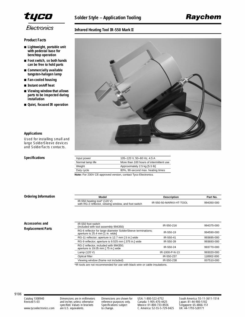
Solder Style – Application Tooling
Infrared Heating Tool IR-550 Mark II
9106Catalog 1308940 Dimensions are in millimeters Dimensions are shown for USA: 1-800-522-6752 South America: 55-11-3611-1514Revised 5-03 and inches unless otherwise reference purposes only. Canada: 1-905-470-4425 Japan: 81-44-900-5102
specified. Values in brackets Specifications subject Mexico: 01-800-733-8926 Singapore: 65-4866-151www.tycoelectronics.com are U.S. equivalents. to change. C. America: 52-55-5-729-0425 UK: 44-1793-528171
Product Facts
Lightweight, portable unitwith pedestal base forbenchtop operation
Foot switch, so both handscan be free to hold parts
Commercially availabletungsten-halogen lamp
Fan-cooled housing
Instant on/off heat
Viewing window that allowsparts to be inspected duringinstallation
Quiet, focused IR operation
Input power 105–120 V, 50–60 Hz, 4.5 ANormal lamp life More than 100 hours of intermittent useWeight Approximately 2.5 kg [5.5 lb]Duty cycle 80%, 90-second max. heating times
Note: For 230V CE-approved version, contact Tyco Electronics.
Specifications
Applications
Used for installing small andlarge SolderSleeve devicesand SolderTacts contacts.
Model Description Part No.IR-550 heating tool* (120 V) IR-550-50-MARKII-HT-TOOL 994350-000with RG-2 reflector, viewing window, and foot switch
IR-550 foot switch IR-550-216 994375-000(included with tool assembly 994350)RG-6 reflector for large-diameter SolderSleeve terminations; IR-550-19 994590-000aperture is 25.4 mm [1 in. wide]RG-11 reflector; aperture is 12.7 mm [.5 in.] wide IR-550-41 993695-000RG-9 reflector; aperture is 9.525 mm [.375 in.] wide IR-550-39 993693-000RG-2 reflector, included with 994350; IR-550-24 993770-000aperture is 19.05 mm [.75 in.] wideLamp (120 V) IR-1000-P-N-13 993020-000Optical filter IR-550-237 118902-000Viewing window (frame not included) IR-550-238 007510-000
*IR tools are not recommended for use with black wire or cable insulations.
Ordering Information
Accessories and Replacement Parts
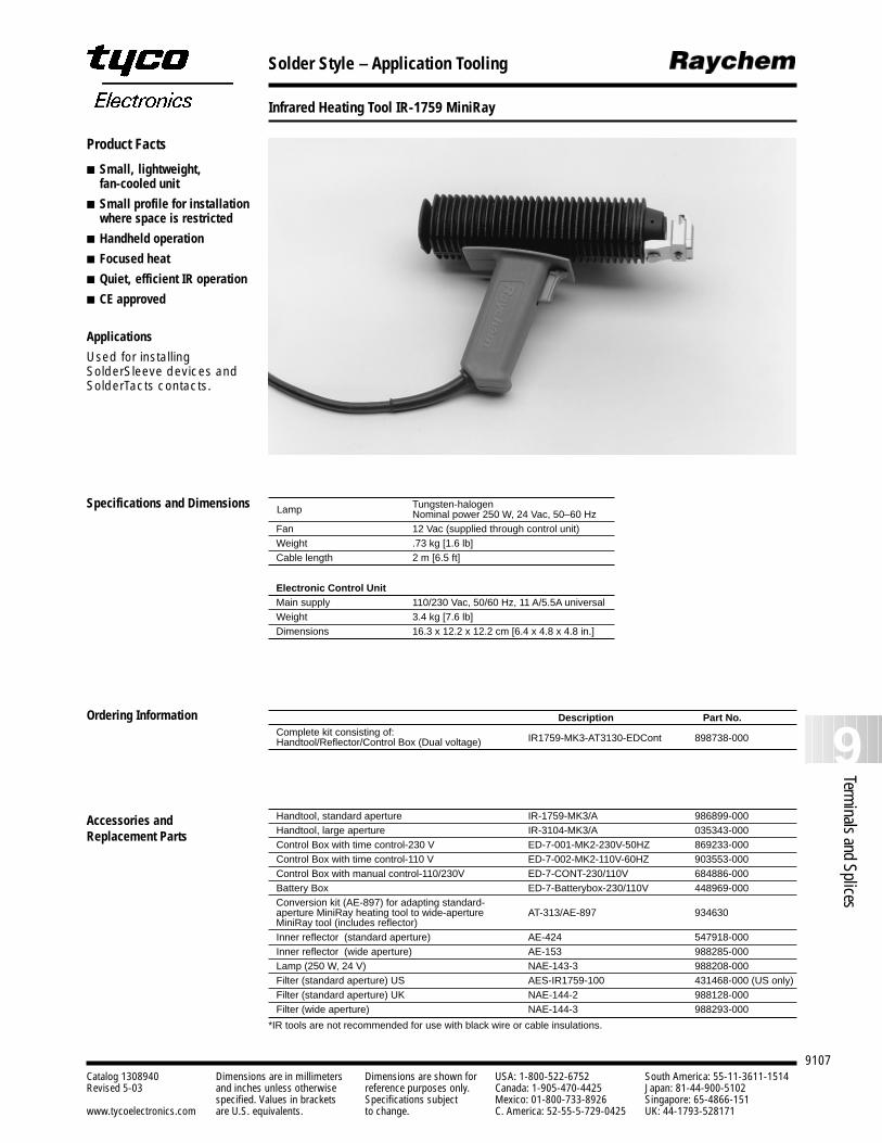
Solder Style – Application Tooling
Infrared Heating Tool IR-1759 MiniRay
9107
9Terminals and Splices
Catalog 1308940 Dimensions are in millimeters Dimensions are shown for USA: 1-800-522-6752 South America: 55-11-3611-1514Revised 5-03 and inches unless otherwise reference purposes only. Canada: 1-905-470-4425 Japan: 81-44-900-5102
specified. Values in brackets Specifications subject Mexico: 01-800-733-8926 Singapore: 65-4866-151www.tycoelectronics.com are U.S. equivalents. to change. C. America: 52-55-5-729-0425 UK: 44-1793-528171
Product Facts
Small, lightweight, fan-cooled unit
Small profile for installationwhere space is restricted
Handheld operation
Focused heat
Quiet, efficient IR operation
CE approved
Applications
Used for installingSolderSleeve devices andSolderTacts contacts.
Tungsten-halogenNominal power 250 W, 24 Vac, 50–60 Hz
Fan 12 Vac (supplied through control unit)Weight .73 kg [1.6 lb]Cable length 2 m [6.5 ft]
Electronic Control Unit Main supply 110/230 Vac, 50/60 Hz, 11 A/5.5A universalWeight 3.4 kg [7.6 lb]Dimensions 16.3 x 12.2 x 12.2 cm [6.4 x 4.8 x 4.8 in.]
Specifications and Dimensions Lamp
Description Part No.Complete kit consisting of:Handtool/Reflector/Control Box (Dual voltage) IR1759-MK3-AT3130-EDCont 898738-000
Handtool, standard aperture IR-1759-MK3/A 986899-000Handtool, large aperture IR-3104-MK3/A 035343-000Control Box with time control-230 V ED-7-001-MK2-230V-50HZ 869233-000Control Box with time control-110 V ED-7-002-MK2-110V-60HZ 903553-000Control Box with manual control-110/230V ED-7-CONT-230/110V 684886-000Battery Box ED-7-Batterybox-230/110V 448969-000Conversion kit (AE-897) for adapting standard-
AT-313/AE-897 934630aperture MiniRay heating tool to wide-aperture MiniRay tool (includes reflector) Inner reflector (standard aperture) AE-424 547918-000Inner reflector (wide aperture) AE-153 988285-000Lamp (250 W, 24 V) NAE-143-3 988208-000Filter (standard aperture) US AES-IR1759-100 431468-000 (US only)Filter (standard aperture) UK NAE-144-2 988128-000Filter (wide aperture) NAE-144-3 988293-000
*IR tools are not recommended for use with black wire or cable insulations.
Ordering Information
Accessories and Replacement Parts
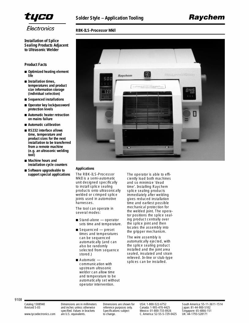
Solder Style – Application Tooling
RBK-ILS-Processor Mkll
9108Catalog 1308940 Dimensions are in millimeters Dimensions are shown for USA: 1-800-522-6752 South America: 55-11-3611-1514Revised 5-03 and inches unless otherwise reference purposes only. Canada: 1-905-470-4425 Japan: 81-44-900-5102
specified. Values in brackets Specifications subject Mexico: 01-800-733-8926 Singapore: 65-4866-151www.tycoelectronics.com are U.S. equivalents. to change. C. America: 52-55-5-729-0425 UK: 44-1793-528171
Installation of SpliceSealing Products Adjacentto Ultrasonic Welder
Applications
The RBK-ILS-ProcessorMkII is a semi-automaticunit designed specifically to install splice sealingproducts onto ultrasonicallywelded or crimped splicejoints used in automotiveharnesses.
The tool can operate in several modes:
Stand-alone — operatorsets time and temperature.
Sequenced — presettimes and temperaturescan be sequencedautomatically (and canalso be randomlyselected from sequencestored.)
Automatic —communication withupstream ultrasonicwelder can allow timeand temperature to beautomatically set withoutoperator intervention.
The operator is able to effi-ciently load both machinesand so minimize ‘deadtime’. Installing Raychemsplice sealing productsimmediately after weldinggives reduced installationtime and earliest possiblemechanical protection forthe welded joint. The opera-tor positions the splice seal-ing product centrally overthe splice joint and thenlocates the assembly intothe gripper mechanism.
The wire assembly is automatically ejected, withthe splice sealing productinstalled and the joint areasealed, insulated and strainrelieved. In-line or stub-typesplices can be installed.
Product Facts
Optimized heating elementlife
Installation times,temperatures and productsize information storage(individual selection)
Sequenced installations
Operator key lock/passwordprotection levels
Automatic heater retractionon mains failure
Automatic calibration
RS232 interface allowstime, temperature andproduct sizes for the nextinstallation to be transferredfrom a remote machine(e.g. an ultrasonic weldingtool)
Machine hours andinstallation cycle counters
Software upgradeable tosupport special applications
Solder Style – Application Tooling
RBK-ILS-Processor Mkll (Continued)
9109
9Terminals and Splices
Catalog 1308940 Dimensions are in millimeters Dimensions are shown for USA: 1-800-522-6752 South America: 55-11-3611-1514Revised 5-03 and inches unless otherwise reference purposes only. Canada: 1-905-470-4425 Japan: 81-44-900-5102
specified. Values in brackets Specifications subject Mexico: 01-800-733-8926 Singapore: 65-4866-151www.tycoelectronics.com are U.S. equivalents. to change. C. America: 52-55-5-729-0425 UK: 44-1793-528171
Installation of SpliceSealing Products Adjacentto Ultrasonic Welder(Continued)
Electrical Supply 220V-240V-50HzPower Consumption 1.7 Amps (Max)Operating Temperature 550°C [1022°F] (Max)
(500°C [932°F] recommended) Machine Cycle Times for splice sealing products 6 to 20 seconds depending on wire size used on typical range of automotive splices and the number or wires usedTotal System Noise <80dB Dimensions 390 mm x 365 mm x 225 mm [15 x 14 x 9 in.]Weight 18Kg [40 lb]
Technical Specification
RBK-ILS-125 Products Sizes 1 to 3ARBK-ILS-85 Products Sizes 6/1 to 12/3For Other Raychem Products (eg RBK-VWS, RBK-ESS….) Contact Tyco Electronics
Product Range
Description Part No.Equipment RBK-Proc-Mk2-Processor 740331-000
Stub splice fixture - RBK-ILS-Proc-Stub-Sp-Fix 981721-000Accessories Air cooled stub splice fixture - RBK-ILS-Proc-Air-Cool-Kit 843800-000
8 mm ring terminal fixture - RBK-ILS-Proc-Termfix-08mm 049857-000
Ordering Information
Terminals and Splices
Engineering Notes
9110Catalog 1308940 Dimensions are in inches and Dimensions are shown for USA: 1-800-522-6752 South America: 55-11-3611-1514Revised 5-03 millimeters unless otherwise reference purposes only. Canada: 1-905-470-4425 Hong Kong: 852-2735-1628
specified. Values in brackets Specifications subject Mexico: 01-800-733-8926 Japan: 81-44-844-8013www.tycoelectronics.com are metric equivalents. to change. C. America: 52-55-5-729-0425 UK: 44-141-810-8967