Embed Size (px)
Citation preview

2
TABLE OF CONTENTS
OVERVIEW .............................................................................................................................................................................3
TERRABUILDER TERRAINBUILDER.......................................................................................................................................4
INTRODUCTION ......................................................................................................................................................................4
PRODUCT MAIN FEATURES......................................................................................................................................................5
TERRAIN DATABASE................................................................................................................................................................6
RASTER LAYERS ......................................................................................................................................................................6
TOOLS ............................................................................................................................................................................... 13
TERRACATALOG .................................................................................................................................................................. 15
SYSTEM REQUIREMENTS ...................................................................................................................................................... 16
TERRABUILDER CITYBUILDER ........................................................................................................................................... 17
INTRODUCTION ................................................................................................................................................................... 17
PRODUCT MAIN FEATURES................................................................................................................................................... 18
LAYERS .............................................................................................................................................................................. 18
TERRAIN OBJECTS AND LAYERS.............................................................................................................................................. 19
ANALYSIS TOOLS ................................................................................................................................................................. 19
ADVANCED VIEWING OPTIONS.............................................................................................................................................. 20
CREATING 3DML DATABASES .............................................................................................................................................. 20
UPLOADING 3DML’S .......................................................................................................................................................... 21
TERRACATALOG .................................................................................................................................................................. 21
SYSTEM REQUIREMENTS ...................................................................................................................................................... 21
TERRABUILDER PHOTOMESH ........................................................................................................................................... 22
INTRODUCTION ................................................................................................................................................................... 22
PHOTOMESH COMPONENTS................................................................................................................................................. 22
PRODUCT MAIN FEATURES................................................................................................................................................... 23
PHOTO MANAGEMENT ........................................................................................................................................................ 24
PHOTO POSITIONING ........................................................................................................................................................... 24
PREPARING AND PREVIEWING THE BUILD PROJECT .................................................................................................................. 24
CONTROL POINTS................................................................................................................................................................ 25
BUILD PROCESS................................................................................................................................................................... 25
MONITORING A BUILD ......................................................................................................................................................... 26
REBUILDING ....................................................................................................................................................................... 27
VIEWING A BUILD REPORT.................................................................................................................................................... 27
PHOTOMESH FUSERS .......................................................................................................................................................... 28
SYSTEM REQUIREMENTS ...................................................................................................................................................... 29
PHOTOMESH PACKAGES ...................................................................................................................................................... 29

3
OVERVIEW The TerraBuilder family of tools generates terrain and urban model databases from a wide variety of data
types. TerraBuilder TerrainBuilder provides professional-grade tools for manipulating and merging
imagery and elevation data of different sizes and resolutions into a geographically accurate terrain
database. TerraBuilder PhotoMesh fully automates the generation of high-resolution, textured, 3D mesh
models from standard 2D photographs. These models can be outputted directly in PhotoMesh as stream
optimized urban model databases (3DML) or they can be merged in CityBuilder with classification
information to transform PhotoMesh mesh models into powerful geospatial data.
The TerraBuilder family includes the following products:
TerrainBuilder –Merges aerial photos, satellite images, and digital elevation models of different
sizes and resolutions into a photo-realistic, geographically accurate terrain database.
CityBuilder – Merges layers of 3D mesh models together with classification layers, and BIM or
model layers into a multi-resolution and stream-optimized 3D Mesh Layer database (3DML).
PhotoMesh – Fully automates the generation of high-resolution, textured, 3D mesh models from
standard 2D photographs.

4
TERRABUILDER TERRAINBUILDER
Introduction
TerraBuilder TerrainBuilder is a 3D terrain database creator with professional-grade tools for manipulating
and merging aerial photos, satellite images, and digital elevation models of different sizes and
resolutions. The resulting photo-realistic, geographically accurate terrain database can be made available
to local TerraExplorer clients or published to remote clients (using the TerraGate Terrain service).
TerraBuilder supports a wide-range of layer types and automatically reprojects layers that use different
coordinate systems. TerraBuilder provides a range of editing tools with which to manipulate the imported
raster files, enabling maximum precision in the 3D terrain database result. Possible manipulations include
cropping, resizing, moving, feathering, adjustment of geographic coordinates using tie points, and
modification of color and elevation parameters.
TerraBuilder can run its efficient algorithms fluidly on standard, low-cost GPUs, or exploit computer
clusters and cloud computing to accelerate database creation. TerraBuilder’s Preview mode saves time
by letting you preview and correct potentially problematic areas before MPT creation.
The completed TerraBuilder project can be processed into a single stream-optimized file (MPT) and then
loaded directly in TerraExplorer, or it can be published to remote TerraExplorer clients using the
TerraGate Terrain service. Alternatively, the project (TBP) can be directly published for streaming, without
pre-processing, from Skyline’s TerraGate server. The published project, built from optimized and native
source data, is streamed using the DirectConnect component, which employs advanced mechanisms to
build data on-demand, and leverage cache technology for performance and scalability optimizations.
Terrain databases (MPT and TBP) can also be served to WMS/WMTS clients with TerraGate SFS
WMS/WMTS service.
Figure 1: TerraBuilder Interface

5
Product Main Features
TerraBuilder has the following features:
Efficient handling of massive databases. No size limitation.
Multi-processor, multi-computer local network workload distribution.
Highly realistic, detailed scenes.
Data compression for minimizing disk storage and network bandwidth.
Supports most standard data formats for source data.
Additional support for new data source formats via a plug-in interface.
64-bit file pointers allow quick access to databases exceeding terabyte file sizes.
Automatic merging (mosaic) of source data of different spatial resolutions.
Advanced user interface for automatic or manual database customization.
Powerful preview options and features.
Numerous editing tools allow the expansion of user-defined layers.
Import of server-based raster files.
Interface with TerraCatalog, a catalog database of geographic data.
Complete localization support.
Figure 2: TerraBuilder Data Flow

6
Terrain Database
Terrain Database File (MPT)
The terrain database (MPT) is a compressed, multi-resolution, stream-optimized file that includes all
source information and applied manipulations in the TerraBuilder project. The terrain database is used
locally or published by TerraGate to Internet or Intranet users.
MPT v3 offers improved imagery and elevation quality, while reducing file size and optimizing bandwidth
capacity.
TerraBuilder allows you to share the workload of massive 3D database creation simultaneously between
several computers and multi-CPU platforms. Using TerraBuilder fusers, every computer on the network
stands-by for MPT creation, adding its computing power to the 3D terrain generation process.
A TerraBuilder fuser is an application that allows TerraBuilder on another computer to utilize the
resources of the fuser computer for the generation of an MPT file. The fuser operates as a copy of
TerraBuilder on the client machine, adding its resources to the MPT generation process. The fuser
remains idle until activated by the Master computer on the network.
Direct Connect Project
TerraBuilder DirectConnect, together with TerraGate, allows you to fly directly over a TerraBuilder Project
(TBP), saving the time and resources needed to create a 3D terrain database (MPT). You can add your
raster MPT files to a TerraBuilder project, perform all the required manipulations, and make the project
immediately accessible through TerraGate to clients over the network. Later, existing MPT files can be
updated or removed and new layer MPT’s added, to show variations of the original information.
DirectConnect can stream any TerraBuilder supported raster source that either has an internal resolution
pyramid (e.g., MrSid, ECW) or for which a resolution pyramid (MPT or MPU) was created by TerraBuilder.
If a source does not have a resolution pyramid, DirectConnect can still stream it, if its maximum visible
UPP is set to its UPP in the project.
TerraBuilder DirectConnect can manipulate and combine multiple source files, of various formats and
projections as well as unlimited size and resolution. TerraBuilder DirectConnect uses TerraBuilder fusers
to exploit the combined computing power of any available server-side computers. This provides scalability
for the resources needed to handle the performance-demanding workload of on-the-fly 3D terrain
database creation.
Raster Layers
Imagery Layers
In TerraBuilder, you can load aerial, satellite or other raster data of different formats, coordinate systems
and spatial resolutions to generate the 3D terrain texture. TerraBuilder fuses all imagery sources into a
seamless mosaic that is draped over the respective elevation model.
Supported Imagery Data:
MrSID (.sid)
Tiff Format (.tif, .itiff)
TiLe Text file (.tlt)
Triangle elevation as color (.tri)

7
Projection Text file (.prj)
Erds Imagine (.img)
Mip Terrain (.mpt)
Gdal Gif (.gif)
Gdal Nitf (.ntf)
Gdal Jpeg (jpg)
Gdal Jpeg2000 (.jp2, .j2k, jpc)
Gdal Tiff (.tif)
Gdal Img (.img)
Gdal Cib
ER-Mapper JPEG2000 (.jp2, .j2k, .jpc)
Windows Bitmap (.bmp)
No Stream Bitmap (.bmp)
No Stream Jpeg (.jpg)
No Stream Gif (.gif)
Undefined Raw
Multi Channel (.mcn)
ERDAS IMAGINE (.img)
ER-Mapper (.ecw)
ER-Mapper Server (.ecwp)
NGA CIB (a.toc)
NGA CADRG (a.toc)
NGA ADRG (a.toc)
Oracle Spatial Database
ECW Image Web Server
TerraGate Server (.tgate)
Image MPU (.li.mpu)
ArcSDE Raster Server (.sde)
Web Catalog Service (CSW)
Web Map Server (.wms)

8
Figure 3: High Quality Imagery Source
Elevation Layers
In TerraBuilder, you can load raster or irregular-grid elevation data of different formats, coordinate
systems and spatial resolutions to generate the 3D terrain model. TerraBuilder fuses all elevation sources
into a seamless surface that is merged together with the respective imagery data.
Supported Elevation Data:
Window Bitmap (.bmp)
ER-Mapper (.ecw)
ER-Mapper Server (.ecwp)
Gdal Dted (.dt?)
Gdl USGS Ascii Dem (.dem)
Gdal USGS SDTS Dem (.ddf)
Gdal Arc/Info Binary rid (.adf)
Gdal Img (.img)
Gdal Tiff (.tif)

9
Erdas Imagine (.img)
Mip Terrain (.mpt)
Elevation MPU (.Ei.mpu)
NGA DTED (DMED)
No Stream Bitmap (.bmp)
No Stream Jpeg (.jpg)
No Stream Gif (.gif)
Geo Raw (.grw)
Undefined Raw
Tiff Format (.tif)
TiLe Text file (.tlt)
Triangle Elevation (.tri)
Projection Text file (.prj)
Web Map Server (.wms)
TerraGate Server (.tgate)
ArcSDE Raster Server (.sde)
ECW Image Web Server
Oracle Spatial Database
Web Catalog Service (CSW)

10
Figure 4: Elevation Source
Coordinate Systems
The coordinate system describes the method by which the data locates positions in the world. Each
coordinate system is associated with its Well Known Text (WKT) description, a simple structured, text-
based format that is easy to store and share between systems (See:
http://www.geoapi.org/2.0/javadoc/org/opengis/referencing/doc-files/WKT.html). The coordinate system
continues to be defined also by four standard parameters, Group, System, Datum and Units, in order to
provide backward compatibility. Usually, the data supplier provides the information about the coordinate
system used for each source.
All project layers must use the same coordinate system. If you add a layer to a project that uses a
different coordinate system than the one you set when you started the project, TerraBuilder reprojects
(converts) the layer's data, so that the same location is described, but in the project’s coordinate system.
If a layer does not include coordinate system information or TerraBuilder is unable to read this
information, you must supply the coordinate system information so that TerraBuilder can reproject the
layer.

11
Figure 5: Select Coordinate System
Layer Manipulation
You can manipulate the sources you have imported to your project, clipping, resizing, moving and
recoloring layers, as required, to create a photo-realistic, geographically accurate database. Some layer
information is modified in the Properties Sheet, while other information is changed in the layer windows.
The following techniques are used to manipulate layers:
Polygon Operations
Draw polygons and rectangles in the Working Window to clip layers, erase a selected color or elevation
value, or fill a particular area with a color or elevation value. A polygon/rectangle can be applied to any
number of layers simultaneously.
TerraBuilder supports four types of polygon operations:
Clip - The clip polygon/rectangle is used mainly to mark the areas of the layer you wish to include
in the final project. All areas outside the clip polygons will automatically fill with a lower resolution
layer covering the same area.
Exclusion - The exclusion polygon/rectangle is used mainly to cut away areas of the layer you do
not wish to include in the final project. All areas within the exclusion polygons will automatically fill
with a lower resolution layer covering the same area.

12
Fill Color/Elevation - The Fill Color polygon/rectangle is used mainly to cover elements that you
do not want to show in the final output, such as: military facilities or private land. The Fill Elevation
is mainly used to crop elevation (e.g. elevation values below a high tide mark) or replace
elevation values (e.g., cover an area with a flat elevation to hide secure information).
Remove Null Value - The Remove Null Value polygon/rectangle is used to remove unwanted
values that represent non existing values or transparency. If there are several layers of sources,
removing a value from a top layer exposes the layers below it according to the UPP levels and
the order in the Ordered Source List. The Tolerance margin is used to define the permissible
deviation from the specified value when the color or elevation values are irregular.
Figure 6: Insert Polygon Group on TerraBuilder Ribbon
Adjustment of Color and Elevation Parameters
Modify the RGB levels of an image layer in the layer’s Properties Sheet. You can either enter precise
luminosity, gamma and saturation values or adjust the RGB histogram. Elevation values can be scaled in
the layer’s Properties Sheet in order to adjust elevation layers that are defined with reference to a
baseline other than sea level, or in units other than meters.
Figure 7: Color Adjustment Dialog
Modification of Layer Dimensions and Resolution
In a layer’s Properties Sheet, you can modify a layer’s coordinates and resolution level (UPP).

13
Clipping and Moving Layers
A layer boundary frame and layer extent frame are automatically created in the Working Window when
you add a new source to the project. By moving the layer boundary frame, you move the layer and define
its boundaries. The layer extent frame acts like a clip rectangle that is specific to that layer.
Manual Source Positioning
You can define the geographical coordinates of a layer with respect to the coordinates of other reference
layers. This allows you to view a layer whose coordinates are unknown, and set its coordinates by
inserting a number of tie points in both this layer and the layers with known coordinates. Each tie point
appears in both layers, and represents identical physical features.
Tools
Measurement Tools
TerraBuilder provides two measurement tools for use in the layer windows:
Measure Distance
Measure Area
Convert Z ASCII Elevation
The Convert Z ASCII Elevation tool converts an ASCII file of Elevations to a GRW (binary Geo Raw) file
for use as an elevation source for TerraBuilder Projects. The file must contain a list of numbers, where
each number is the elevation of a point. The points form a uniform grid (the geographical space between
every two points must be equal in X-axis and Y-axis). The file cannot have any header.
Convert XYZ ASCII Elevation
The Convert XYZ ASCII Elevation tool converts XYZ ASCII files to GRW (binary Geo Raw) files for use as
elevation sources for TerraBuilder Projects. The XYZ file must contain a uniform grid of points (the
geographical space between every two points must be equal in X-axis and Y-axis).
Triangulate Irregular Elevation Grid
The Triangulate Irregular Elevation Grid tool converts XYZ, DXF and other vector files to TRI
(Triangulated) files for use as elevation sources for TerraBuilder Projects. The Triangulate Irregular
Elevation Grid tool creates a multi resolution elevation file. This file can be divided into tiles that can be
used individually for calculations. Since it is difficult to triangulate with large datasets, breaking a large file
into tiles is recommended. An additional benefit is that using tiles uses fewer resources and saves time.
This tool can automatically calculate an optimal tile division.
The file formats that can be triangulated using the Triangulate Irregular Elevation Grid tool are:
XYZ – Converts the .xyz ASCII points’ format to TRI format.
DXF –Converts the .dxf points’ format, points’ and break lines’ format or Tin (triangulated) format
into a TRI format.
QUE – Converts the .que format to the TRI format.
001 – Converts the .001 format to the TRI format.

14
REG – Converts the .reg format to the TRI format.
GD – Converts .lf and .pf formats to the TRI format.
Gather Tiled Files
The Gather Tiled Files tool gathers several files into a custom number of Tile Text File (TLT) source files
for TerraBuilder. This allows you to load several files into TerraBuilder as one file, or as a specified
number of custom-tiled source files.
These files must all have the same Units Per Pixel, and must be located in the same folder.
Figure 8: Gather Tiled Files Tool
Split and Merge MPU-MPT Files
The Split and Merge MPU-MPT Files Tool splits MPU and MPT files that were created using older
TerraBuilder versions, into a more efficient Split format. It also merges Split MPU and MPT files into one
MPU or MPT file.
The Split size is determined by the value entered in the System Preferences property page (Default value
is 2 GB). You can select 640 MB, 700 MB, 2 GB, 4 GB, 4.7 GB or no split.
Secure Terrain Databases and TerraGate Servers
The Security tool enables you to increase the security of terrain databases (MPT) and local or remote
TerraGate servers by adding User/Password protection. You can set permissions restricting viewing,
editing, and extraction of the terrain database. You can also limit access to your resource for a specific
time interval.
15
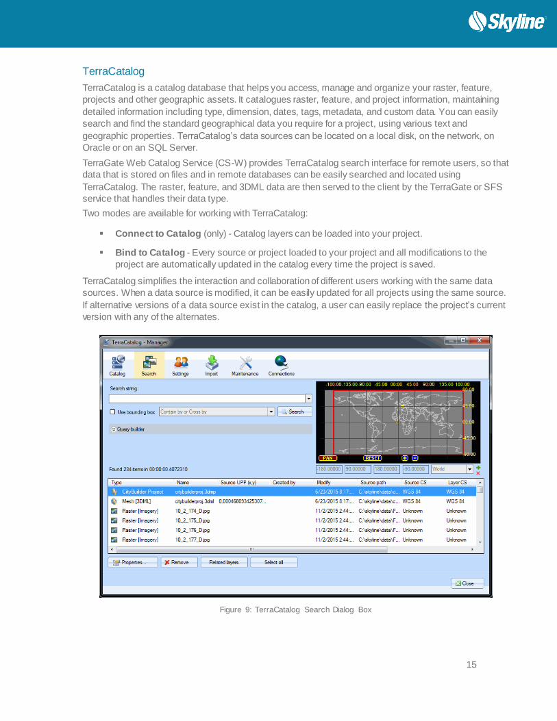
TerraCatalog
TerraCatalog is a catalog database that helps you access, manage and organize your raster, feature,
projects and other geographic assets. It catalogues raster, feature, and project information, maintaining
detailed information including type, dimension, dates, tags, metadata, and custom data. You can easily
search and find the standard geographical data you require for a project, using various text and
geographic properties. TerraCatalog’s data sources can be located on a local disk, on the network, on
Oracle or on an SQL Server.
TerraGate Web Catalog Service (CS-W) provides TerraCatalog search interface for remote users, so that
data that is stored on files and in remote databases can be easily searched and located using
TerraCatalog. The raster, feature, and 3DML data are then served to the client by the TerraGate or SFS
service that handles their data type.
Two modes are available for working with TerraCatalog:
Connect to Catalog (only) - Catalog layers can be loaded into your project.
Bind to Catalog - Every source or project loaded to your project and all modifications to the
project are automatically updated in the catalog every time the project is saved.
TerraCatalog simplifies the interaction and collaboration of different users working with the same data
sources. When a data source is modified, it can be easily updated for all projects using the same source.
If alternative versions of a data source exist in the catalog, a user can easily replace the project’s current
version with any of the alternates.
Figure 9: TerraCatalog Search Dialog Box

16
System Requirements
Operating System Windows® 7 / 8 / Server 2003 / Server 2008.
Processor Dual-Core (4 or 8 cores recommended). TerraBuilder works best
in a multi-core environment and can utilize multiple CPU’s and
hyper-threaded processors.
System Memory (RAM) 2 GB of RAM (8 GB or more recommended).
Video Card 256 MB of video memory (1024 MB or more recommended). Pixel
and vertex shader v3.0. Required only for viewing in 3D.
User Privileges Administrator privileges required for installation.

17
TERRABUILDER CITYBUILDER
Introduction
CityBuilder, a TerraBuilder application, merges 3D PhotoMesh city models together with classification
layers, individually modeled layers, and BIM datasets, into a stream-optimized, fully textured, and
geospatially-enabled mesh layer (3DML). Generated 3DMLs can be made available to local
TerraExplorer clients or published to remote clients (using the TerraGate SFS 3DML service).
CityBuilder integrates point feature layers that reference individual models of complete cities, and stream-
optimizes model layers for viewing and streaming on desktop and mobile applications. CityBuilder fully
enables spatial operations and attribute queries by merging PhotoMesh-generated mesh models with
classification information such as building footprints. Generated 3DML layers are integrated seamlessly in
TerraExplorer's terrain, and can be measured, analyzed, and queried using TerraExplorer’s advanced
capabilities.
CityBuilder converts BIM from FBX (the industry standard for BIM data) to the 3DML format, preserving all
geometry and attribute data, so that the data can be viewed and analyzed in its geographical context
using TerraExplorer.
Figure 10: CityBuilder Interface

18
Product Main Features
CityBuilder has the following features:
Creates unified and efficient 3D mesh layer.
Merges any number of mesh models with BIM and other model data sets.
Reprojects layers that use different coordinate systems.
Fully enables spatial operations and attribute queries on mesh models by merging PhotoMesh-
generated mesh models with classification information such as building footprints.
Optimizes model layers for viewing and streaming on desktop and mobile applications.
Reads BIM data in FBX format.
Converts BIM from FBX to 3DML format that can be viewed in TerraExplorer with all geometry
and attribute data preserved.
Stream-optimizes BIM data.
Supports multi-threading for full utilization of computer resources.
Enables preview of created 3DMLs.
Uploading of 3DMLs to TerraGate 3DML service directly from Citybuilder
Layers
CityBuilder can merge the following layers into a unified 3D mesh layer:
Model Layers
Mesh Layers
o Classification Layers
BIM Layers
Model Layers
Model layers are point feature layers that reference individual models. A layer attribute field is used to
associate each model with a particular point.
Mesh Layers
Mesh layers are 3D mesh models which are either generated by TerraBuilder PhotoMesh or created in an
external application as OSGB layers.
Mesh layers can be added to a project in either of the following ways:
Load - A native mesh layer generated by PhotoMesh
Import - An OSGB mesh layer (the native format of the open source - OpenSceneGraph library
http://www.openscenegraph.org/). In this case, the OSGB layer is converted to a CityBuilder mesh layer
in LODTreeExport.xml format and then added to the project.

19
Classification Layers
Polygon feature layers are used to classify areas of the mesh model by associating different areas of the
mesh model with the respective polygon features. This enables you to access attribute data and perform
feature layer operations on the mesh layer, including spatial and attribute queries.
BIM Layers
Building Information Modeling (BIM) layers store the geographic location and attribute data of models.
CityBuilder supports Autodesk’s FBX format for BIM layers .
Terrain Objects and Layers
Terrain objects and layers can be added to a CityBuilder project to enable you to visualize how the model
will appear in TerraExplorer’s 3D World:
Locations
Imagery and Elevation Layers
3D Mesh Layers
Terrain Objects (Modify Terrain and Hole on Terrain)
Analysis Tools
Figure 11: Analysis Tools
CityBuilder provides a set of tools for measurement and terrain analysis.
Distance Measures the aerial distance between points in the 3D Window.
Area Measures either of the following:
Area of the horizontal projection (2D measurement) - The area
measured is the horizontal projection of the area you have outlined, even
if some or all of your selected area encompasses mountainous terrain.
Surface area (3D measurement) - The area measured takes into
account terrain contours.
Query Provides data about any point or object in the 3D World. For a point on the
terrain, location and elevation information is provided, while for an object, the
query also displays the object’s perimeter and area. If the object selected
was loaded from a layer with attribute information, the object’s attributes are
also displayed.

20
Advanced Viewing Options
Sun - Use the sun as a light source.
Time Slider – Adjust the current time to view
each terrain region in the required date/time
range.
Underground Mode -
Explore the subsurface of the
terrain.
Project Tree
The Project Tree lists all of the
project’s layers, organized by
layer type, providing quick access
to CityBuilder elements.
Properties Sheet
Layer data for the selected layer is
concentrated in the Properties sheet.
Creating 3DML Databases
In the final stage of a project, CityBuilder merges mesh layers generated by TerraBuilder PhotoMesh,
together with classification layers, and other model layers (e.g. point layers with individually referenced
3D models) into a multi-resolution and stream-optimized 3D Mesh Layer database (3DML). Support for
multi-threading allows full utilization of computer resources. Databases can be published to remote
TerraExplorer clients using the TerraGate SFS 3DML service.

21
Uploading 3DML’s
CityBuilder provides a tool to connect to a supported database to upload and manage 3DML
files for distribution via TerraGate SFS 3DML service.
Figure 12: Upload 3DML to Database
TerraCatalog
TerraCatalog is a catalog database that helps you access, manage and organize your raster, feature, and
3DML layers and projects. TerraCatalog maintains detailed information about its layers including type,
dimension, dates, tags, metadata, and custom data, enabling clients to easily query the catalog for the
specific layer required for a TerraBuilder or TerraExplorer project. TerraCatalog’s data sources can be
located on a local disk, on the network, on Oracle or on an SQL Server. You can publish selective parts of
your catalog to Web Catalog Service (CS-W), providing TerraCatalog search interface for remote users.
Two modes are available for working with TerraCatalog:
Connect to Catalog (only) - Catalog layers can be loaded into your project.
Bind to Catalog - Every source or project loaded to your project and all modifications to the
project are automatically updated in the catalog every time the project is saved.
System Requirements
Operating System Windows® 7 / 8 - 64 bit required.
System Memory 8 GB of RAM (16 GB or more recommended).
Video Card 256 MB of video memory (1024 MB or more recommended). Pixel
and vertex shader v3.0. Required only for viewing in 3D.
Processor Dual-Core (4 or 8 cores recommended). CityBuilder works best in a
multi-core environment and can utilize multiple CPU’s and hyper-
threaded processors.

22
TERRABUILDER PHOTOMESH
Introduction
TerraBuilder PhotoMesh fully automates
the generation of high-resolution, textured,
3D mesh models from standard 2D
photographs that can be viewed using
TerraExplorer or other 3D and GIS
products.
This breakthrough application combines
unlimited scalability with superior precision
to produce consistent and accurate 3D
models that enhance the realism of any 3D
visualization.
PhotoMesh’s powerful engines and elaborate tiling mechanisms enable efficient handling of projects with
massive quantities of input imagery. PhotoMesh can also exploit computer clusters and cloud computing
to dramatically accelerate processing time by enabling multiple computers to share the processing load.
PhotoMesh Components
The PhotoMesh application is composed of three components:
PhotoMesh Editor – GUI from which the user can prepare and edit a build, submit it for
processing, and then review build results. .
PhotoMesh Fuser – Worker component of PhotoMesh which allows you to share the workload
between several computers and multi-CPU platforms on the same network. The Master
computer, equipped with PhotoMesh fuser, utilizes the computing power of the network’s client
computers by connecting to PhotoMesh fusers on the client machines.
PhotoMesh Build Manager – Manager application that is responsible for managing the build
process and PhotoMesh fusers. In PhotoMesh Build Manager, the user selects the build steps
that should be performed and the fusers to use for processing the build. PhotoMesh Build
Manager then assigns the steps to the different fusers and the build process begins. During the
build process, PhotoMesh Build Manager monitors the build and provides the user with detailed
information about the build progress.
23
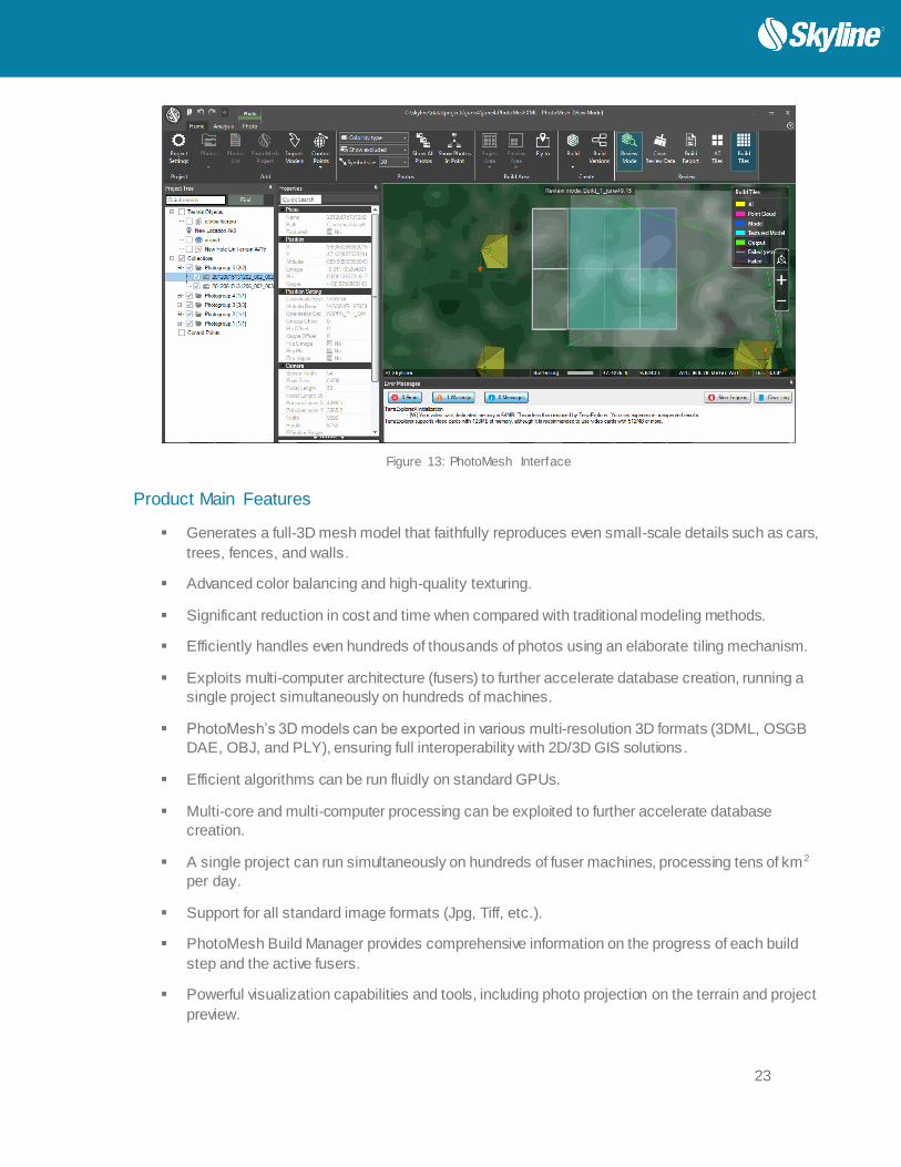
Figure 13: PhotoMesh Interface
Product Main Features
Generates a full-3D mesh model that faithfully reproduces even small-scale details such as cars,
trees, fences, and walls.
Advanced color balancing and high-quality texturing.
Significant reduction in cost and time when compared with traditional modeling methods.
Efficiently handles even hundreds of thousands of photos using an elaborate tiling mechanism.
Exploits multi-computer architecture (fusers) to further accelerate database creation, running a
single project simultaneously on hundreds of machines.
PhotoMesh’s 3D models can be exported in various multi-resolution 3D formats (3DML, OSGB
DAE, OBJ, and PLY), ensuring full interoperability with 2D/3D GIS solutions.
Efficient algorithms can be run fluidly on standard GPUs.
Multi-core and multi-computer processing can be exploited to further accelerate database
creation.
A single project can run simultaneously on hundreds of fuser machines, processing tens of km2
per day.
Support for all standard image formats (Jpg, Tiff, etc.).
PhotoMesh Build Manager provides comprehensive information on the progress of each build
step and the active fusers.
Powerful visualization capabilities and tools, including photo projection on the terrain and project
preview.

24
Photo Management
Photos can be added to a project using any of the following methods:
Import photo files from disk.
Import an Excel/XML file with a list of photos, their file paths, and all photo and photo collection
information. This eliminates the need to manually enter all this information.
Import a PhotoMesh project. When a PhotoMesh project (.PhotoXML or .xls) is imported into a
second project, only the project’s photos and photo and collection parameters are imported.
Other project information (e.g. terrain objects, control points, and other project parameters) is not
imported.
Photo Format
PhotoMesh supports standard image formats (Jpg, Tiff).
Directionality
Since PhotoMesh models can be viewed from any angle, it is important to capture nearly all visible
surfaces, including walls and facades. Any object in the area of interest should be photographed multiple
times from the top and at least four other directions
Overlap
To create an accurate 3D model, each point in the area of interest should be visible in multiple images. A
>66% overlap between consecutive photos is recommended. Each point in the area of interest should be
visible by, at least, 3 cameras (min 10° offset). PhotoMesh can combine photos with different ground
resolutions.
For structured aerial photography
Overlap in direction of flight (forward overlap) - 80%
Overlap between neighboring rows (side overlap) - 50%
Photo Positioning
Photo data (e.g., build tile coordinate system, sensor width, focal length, photo position information) is
concentrated in the photo and photo collection property sheets. This information is generally read from an
imported Excel or XML file. These parameters can then be adjusted in the photo and collection properties
sheets.
Preparing and Previewing the Build Project
Setting a Project Area / Preview Area
Designating the “project area” determines what area of the project all PhotoMesh operations (tile calculation,
build process, etc.) are performed on when building the “project area”. All the project’s photos can be
automatically included or the “project area” can be set to include only the photos within a specific area on
the terrain. This enables you to build a subset of the project for any area of interest, generally for the
purpose of validating camera parameters and project settings. You can also build a subset of the project for
an area of interest by setting a “preview area”, and then setting the preview area as the current build area.
Projecting Photos on the Terrain

25
A photo can be projected on the terrain to see if it fits the terrain imagery or to better understand the position
of the photo. This option is only available for photos that have positioning (XY coordinates and altitude) and
orientation (Omega, Phi, and Kappa) information.
Figure 14: Projecting Photos on the Terrain
Control Points
Control points help you accurately georeference PhotoMesh output by linking easily identifiable locations
in photos (e.g., a survey point representing a known point in the physical world, such as a geodetic
survey marker) with their corresponding locations on the terrain. The survey point is used to correctly
orient the photo’s geometry in the project’s coordinate system.
The process involves identifying a series of control points on the terrain—known x,y coordinates— and
then marking the positions of these control points in the project’s photos.
Control points can be created/added using any of the following methods:
Create a control point with no initial position and then set its position in its property sheet
Create a control point on a specific position on the terrain
Import a tab delimited .txt file with control point information
Build Process
After all photos are added to the project and all properties are set as required, you can begin the build
process. The build process provides flexibility with regard to the section of the project being built (entire
project or only a selected preview area), build stages that are to be completed, and output formats.
The required build stages: photo preparation, aerotriangulation, point cloud creation, model creation,
model texturing, and final output production are selected in PhotoMesh Build Manager. The final output
can be created in any of the following formats: 3DML (for import into TerraExplorer), DAE, OBJ, OSG,
PLY, CityBuilder, Orthophoto, or DSM.
26
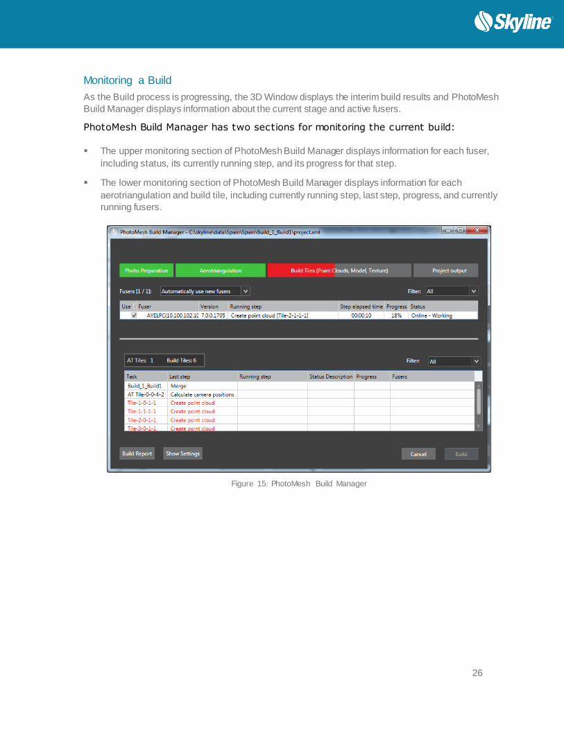
Monitoring a Build
As the Build process is progressing, the 3D Window displays the interim build results and PhotoMesh
Build Manager displays information about the current stage and active fusers.
PhotoMesh Build Manager has two sections for monitoring the current build:
The upper monitoring section of PhotoMesh Build Manager displays information for each fuser,
including status, its currently running step, and its progress for that step.
The lower monitoring section of PhotoMesh Build Manager displays information for each
aerotriangulation and build tile, including currently running step, last step, progress, and currently
running fusers.
Figure 15: PhotoMesh Build Manager

27
Rebuilding
If a previously built project requires modification, you can build the entire project again from the first step,
or you can “rebuild”, incorporating some of a previous build’s results. Rebuilding provides flexibility both
with regard to the project section (entire project, only error tiles or selected tiles) and project stages that
are to be rebuilt. Alternative build parameters can also be set.
Viewing a Build Report
The Build report displays statistical and graphical information about the build process. The first section of
the report displays summary information:
Basic project information including: project area, number of photos, number of AT,
Reconstruction, and failed tiles, and processing time.
Basic aerotriangulation information including: calculated photos average, number of control
points, and median control point error.
Performance information, i.e., average time for each of the build stages.
This summary section is followed by detailed information and graphs relating to one of the following,
based on user selection:
Build process stages - Details about each build stage: steps involved, tiles produced,
processing time, and active fusers.
Fusers - Statistics for each fuser regarding processing time for each build stage and each tile in
each stage.
Aerotriangulation - AT details per photogroup (e.g. mean median error, focal length, and
principal X/Y).
The detailed information and graph data can be filtered to display information only about tiles with
warnings or errors or about specific build process stages, fusers, or aerotriangulation tiles.

28
Figure 16: PhotoMesh Build Report
PhotoMesh Fusers
PhotoMesh can exploit computer clusters to accelerate database creation. Fusers allow you to share the
demanding processing entailed for the different build stages (image preparation, AT, point cloud, mesh
model, texture, 3DML/other outputs) between several computers on the same network. The Master
computer utilizes the computing power of the network’s client computers by connecting to PhotoMesh
fusers on the client machines. The fuser operates as a copy of PhotoMesh on the client machine, adding
its resources to the build process. A single PhotoMesh fuser can serve several different PhotoMesh
Master computers.
The fuser remains idle until activated by the Master computer on the network. Once activated, the fuser
operates on the client machines, with only an icon in the system tray that opens a status log and a dialog
to stop or suspend fusers. You can install the PhotoMesh Fuser on the same computer with the
PhotoMesh Build Manager and/or other computers.
When beginning the build process the PhotoMesh Build Manager application determines what build steps
are required and assigns them to the different fusers. PhotoMesh Build Manager continuously monitors
the fusers’ progress and assigns new processing tasks based on fuser availability.
PhotoMesh Build Manager and the PhotoMesh fusers must both have read-write access to the working
and project folders.

29
System Requirements
Operating System Windows® 7 / 8 - 64 bit required
System Memory 8 GB RAM (16 GB recommended)
Video Card 1GB of video memory (2GB or more recommended). Pixel and vertex
shader v3.0.
Processor 4 cores (8 cores recommended). PhotoMesh works best in a multi-
core environment and can utilize multiple CPU’s and hyper-threaded
processors.
PhotoMesh Packages
TerraBuilder PhotoMesh is available in three packages.
Option # of Managers/
Fusers
Max. Images/ Project Recommended
Use
PhotoMesh
Basic
1 manager/ 1
fuser
500 UAV projects
(facility / mine /
neighborhood)
PhotoMesh
Plus
1 manager/ 3
fusers
1500 Village / downtown
PhotoMesh
Enterprise
Unlimited
managers/
unlimited fusers
License includes a bank of Giga-
Pixel to be used in one or more
projects
Giga-Pixel (GP) is the number of
pixels in all images used in the
project
Pay per use.
Commercial

Office: (703) 378 3780
Fax: (703) 378 3760
www.skylinesoft.com
Technical Support:
Linkedin:
Skyline Software Systems, Inc.
General Information:
Youtube:
skylinesoft
Copyright © 2015 Skyline Software Systems Inc. All rights reserved.
Skyline, It’s your world, the Skyline logo, TerraExplorer, TerraExplorer Pro, TerraExplorer Plus, TerraDeveloper, TerraBuilder, CityBuilder, PhotoMesh, TerraGate, SFS, and the TerraExplorer logo are trademarks of Skyline Software
Systems Inc. All other trademarks are the property of their respective holders. Trademark names are used editorially, to the benefit of the trademark owner, with no intent to infringe on the trademark. Protected by U. S. Patents 6111583,
6433792, 6496189, 6704017, 7551172. Other patents pending.