Embed Size (px)
Citation preview

D U N I W A Y S T O C K R O O M C O R P .
Instruction Manual
Terranova Model 741Ion Pump Power Supply
Copyright © 2003 by Duniway Stockroom Corp.
rev062503sr
1305 SPACE PARK WAY MOUNTAIN VIEW, CALIFORNIA 94043TELEPHONE: 1-650-969-8811 TOLL-FREE: 1-800-446-8811 FAX: 1-650-965-0764
INTERNET: WWW.DUNIWAY.COM
1 of 34

D U N I W A Y S T O C K R O O M C O R P .
Table of Contents
I Technical Specifications page 4
A. DescriptionB. SpecificationsC. Connector Pin Listing
II Installation page 9
A. General ConsiderationsB. Front Panel Description and Preliminary Set UpC. Initial Set Up & Set Point OperationD. Safety ConsiderationsE. Rear Panel DescriptionF. Safety Interlock OperationG. Connection to the Ion Pump
III Operation page 19
A. Start Mode OperationB. Normal Mode OperationC. Communications Functions: RS-232, 422 ad 485 CommandsD. Power/Voltage Characteristics
IV Maintenance page 25
A. 741 Block DiagramB. Trouble ShootingC. High Voltage Output Polarity Change ProcedureD. Internal DIP Switch SettingsE. FusesF. High Voltage Cables
V Warranty & CE Declaration page 33
1305 SPACE PARK WAY MOUNTAIN VIEW, CALIFORNIA 94043TELEPHONE: 1-650-969-8811 TOLL-FREE: 1-800-446-8811 FAX: 1-650-965-0764
INTERNET: WWW.DUNIWAY.COM
2 of 34

D U N I W A Y S T O C K R O O M C O R P .
List of Figures
Figure 1: Serial Interface Connector Pins page 7
Figure 2 Serial I/O Connector-Rear Panel page 7
Figure 3 Miscellaneous I/O Connector Pins page 8
Figure 4 Miscellaneous I/O Connector page 8
Figure 5 Ion Pump Operating Pressures page 9
Figure 6 Front Panel page 10
Figure 7 Rear Panel page 15
Figure 8 Ground-Sense Conditions page 17
Figure 9 Serial Interface Format page 22
Figure 10 Serial Interface Parameter Set page 23
Figure 11 Power vs. Current Curve page 23
Figure 12 Voltage vs. Current Curve page 23
Figure 13 Block Diagram page 24
Figure 14 Top View, Cover Removed page 28
Figure 15 DIP Switch - S1 - Settings page 30
Figure 16 DIP Switch S2 Settings page 31
1305 SPACE PARK WAY MOUNTAIN VIEW, CALIFORNIA 94043TELEPHONE: 1-650-969-8811 TOLL-FREE: 1-800-446-8811 FAX: 1-650-965-0764
INTERNET: WWW.DUNIWAY.COM
3 of 34

D U N I W A Y S T O C K R O O M C O R P .
I Technical Specifications
A. Description
The Terranova Model 741 Ion Pump Control Unit is designed to supply operating power to a sputter ion pumps and to display the voltage, current and pressure. It is designed to start
and operate pumps of 20 l/s and smaller and to operate larger pumps of any size at lower pressures.
The Terranova Model 741 is a programmable, microprocessor controlled unit, which givesit great versatility in operation, display, control and data communication. Some major features include:
- Programmable High Voltage Output
- Programmable Maximum Current
- Programmable Pump Size for Pressure Display
- Choice of Pressure Units
- Programmable Process Control Set Point Relay
- Display for voltage, current and pressure
- RS 232, 422, 485 Serial I/O for Data Collection and Computer Control
- Analog Outputs for Monitoring Voltage and Current
- Ground Sensing Circuit for Operator Safety
- Power Interlock Micro-Switch on Top Cover
- CE Conformance for EMI, EMC and Safety
1305 SPACE PARK WAY MOUNTAIN VIEW, CALIFORNIA 94043TELEPHONE: 1-650-969-8811 TOLL-FREE: 1-800-446-8811 FAX: 1-650-965-0764
INTERNET: WWW.DUNIWAY.COM
4 of 34
D U N I W A Y S T O C K R O O M C O R P .
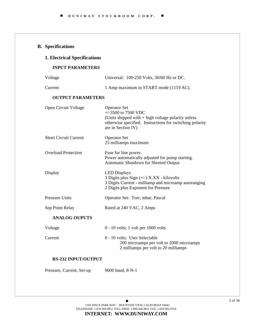
B. Specifications
1. Electrical Specifications
INPUT PARAMETERS
Voltage Universal: 100-250 Volts, 50/60 Hz or DC.
Current 1 Amp maximum in START mode (115VAC).
OUTPUT PARAMETERS
Open Circuit Voltage Operator Set+/-3500 to 7500 VDC (Units shipped with + high voltage polarity unless otherwise specified. Instructions for switching polarity are in Section IV)
Short Circuit Current Operator Set25 milliamps maximum
Overload Protection Fuse for line power. Power automatically adjusted for pump starting.Automatic Shutdown for Shorted Output
Display LED Displays 3 Digits plus Sign (+/-) X.XX - kilovolts3 Digits Current - milliamp and microamp autoranging2 Digits plus Exponent for Pressure
Pressure Units Operator Set: Torr, mbar, Pascal
Sep Point Relay Rated at 240 VAC, 2 Amps
ANALOG OUPUTS
Voltage 0 - 10 volts; 1 volt per 1000 volts
Current 0 - 10 volts; User Selectable 200 microamps per volt to 2000 microamps2 milliamps per volt to 20 milliamps
RS-232 INPUT/OUTPUT
Pressure, Current, Set-up 9600 baud, 8-N-1
1305 SPACE PARK WAY MOUNTAIN VIEW, CALIFORNIA 94043TELEPHONE: 1-650-969-8811 TOLL-FREE: 1-800-446-8811 FAX: 1-650-965-0764
INTERNET: WWW.DUNIWAY.COM
5 of 34

D U N I W A Y S T O C K R O O M C O R P .
2. Physical Specifications
CONNECTORS/CABLES
Line Power 6.7 foot (2 meter) length Belden Type 17250 orequivalent NEMA 5-15P grounding plugPH-290B
High Voltage Output Kings Type Connector, Rated at 10KVFor High Voltage Cables, See Accessory List in Section IV
Serial I/O 9-Pin D-sub type Connector, Female Pins
Miscellaneous I/O 15-Pin D-sub type Connector, Female Pins
Ground Sense Isolated 8/32 Threaded Stud
DIMENSIONS
Panel 9.5 in (24.1 cm) W x 3.5 in (9.0 cm) H
Cabinet Depth 16 in (40.6 cm) deep (Allow 4 in (10.2 cm) extra for cable clearance)
WEIGHT
Installed Weight 6 lb (2.7 kg)
Shipping Weight 10 lb (4.5kg)
OPERATING ENVIRONMENT
Temperature 32oF to 105oF(0oC to 40oC)
Humidity 0 - 80% Relative Humidity, Non- condensing
Altitude Sea Level to 10,000 feet (3100 meters)
1305 SPACE PARK WAY MOUNTAIN VIEW, CALIFORNIA 94043TELEPHONE: 1-650-969-8811 TOLL-FREE: 1-800-446-8811 FAX: 1-650-965-0764
INTERNET: WWW.DUNIWAY.COM
6 of 34

D U N I W A Y S T O C K R O O M C O R P .
C. Connector Pin Configuration
1. Serial RS-232 Multi-Drop RS-422/485Rear Panel, 9-pin D-sub type connector
PIN RS-232 SIGNAL RS-422/485 SIGNAL
Pin 1 DCD ---Pin 2 RxD +TxPin 3 TxD +RxPin 4 DTR ---Pin 5 SIGNAL GROUND SIGNAL GROUNDPin 6 DSR ---Pin 7 RTS -RxPin 8 CTS -TxPin 9 RI ---
Figure 1: Serial Interface Connector Pin Connections
Figure 2: Serial I/O Connector-Rear Panel
(The 9 pin D-sub connector on the control unit has female pins, the cable connector must have male pins. An unterminated 9 pin D-sub connector with male pins is included in theaccessory kit shipped with the unit. If you have difficulty finding a connector for use withthis unit, please call Duniway Stockroom Corp.)
NOTE: INTERNAL JUMPER AND DIP SWITCH SETTINGS:
Changing from RS-232 configuration to RS-485 configuration requires changes to internal jumpers and internal DIP switches. For RS-232, internal jumper JP1-5 requires a jumper from pin 1 to pin 2. For RS-422 and RS-485, internal jumper JP1-5 requires a jumper from pin 2 to pin 3. See Section IV-D for the DIP switch settings.
Factory default set-up is for RS-232 format 9600 baud, 8-N-1.
1305 SPACE PARK WAY MOUNTAIN VIEW, CALIFORNIA 94043TELEPHONE: 1-650-969-8811 TOLL-FREE: 1-800-446-8811 FAX: 1-650-965-0764
INTERNET: WWW.DUNIWAY.COM
7 of 34

D U N I W A Y S T O C K R O O M C O R P .
2. Miscellaneous I/O Rear panel, 15-pin D-sub connector
PIN SIGNAL
Pin1 SETPOINT COMMONPin 2 SETPOINT NORMALLY CLOSED (NC)Pin 3 DIGITAL COMMONPin 4 ANALOG COMMONPin 5 -15 VOLTS, 0.2 APin 6 +15 VOLTS, 0.2 APin 7 + 5 VOLTS, 0.2 APin 8 HV PULSE CONTROL INPUT, TTL LEVELPin 9 SETPOINT NORMALLY OPEN (NO)Pin 10 + 12 VOLTS, 0.2 APin 11 + 5 VOLTS WHEN SETPOINT ‘ON’ Pin 12 CURRENT MONITOR - ANALOG OUTPin 13 + 12 VOLTS WHEN HV ‘ON’ NEGATIVEPin 14 VOLTAGE MONITOR - ANALOG OUTPin 15 + 12 VOLTS WHEN HV ‘ON’ POSITIVE
Figure 3: Miscellaneous I/O Connector Pin Connections
Figure 4: Miscellaneous I/O Connector - Rear Panel
(The 15 pin D-sub connector on the control unit has female pins, the cable connector must have male pins. An unterminated 15 pin D-sub connector with male pins is included in theaccessory kit shipped with the unit. If you have difficulty finding a connector for use withthis unit, please call Duniway Stockroom Corp.)
1305 SPACE PARK WAY MOUNTAIN VIEW, CALIFORNIA 94043TELEPHONE: 1-650-969-8811 TOLL-FREE: 1-800-446-8811 FAX: 1-650-965-0764
INTERNET: WWW.DUNIWAY.COM
8 of 34
D U N I W A Y S T O C K R O O M C O R P .
II InstallationA. General Considerations
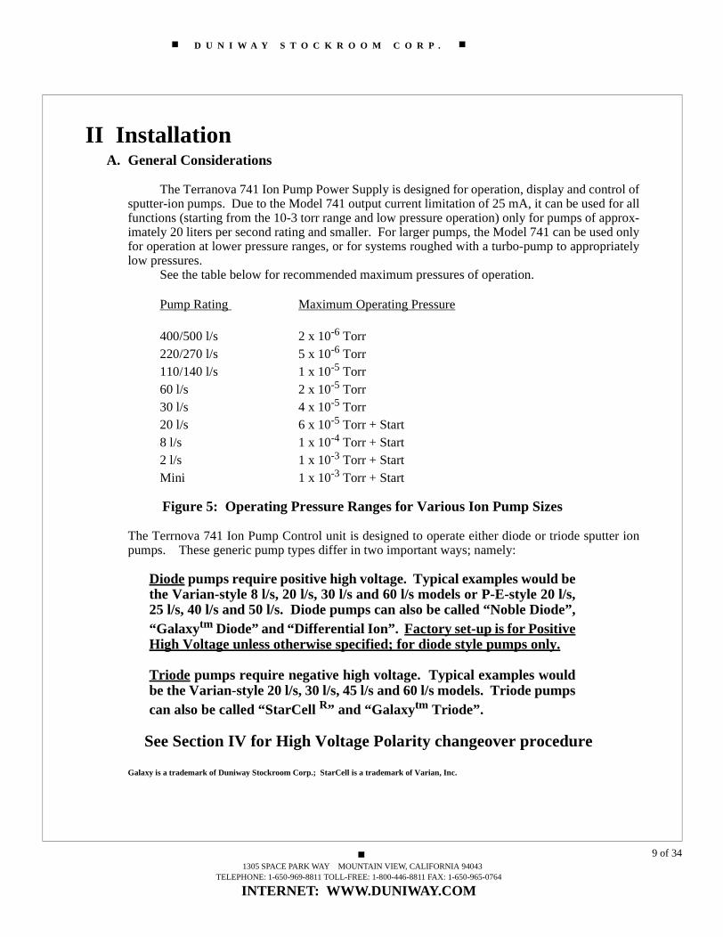
The Terranova 741 Ion Pump Power Supply is designed for operation, display and control ofsputter-ion pumps. Due to the Model 741 output current limitation of 25 mA, it can be used for allfunctions (starting from the 10-3 torr range and low pressure operation) only for pumps of approx-imately 20 liters per second rating and smaller. For larger pumps, the Model 741 can be used onlyfor operation at lower pressure ranges, or for systems roughed with a turbo-pump to appropriatelylow pressures.
See the table below for recommended maximum pressures of operation.
Pump Rating Maximum Operating Pressure
400/500 l/s 2 x 10⁻⁶ Torr220/270 l/s 5 x 10⁻⁶ Torr110/140 l/s 1 x 10⁻⁵ Torr 60 l/s 2 x 10⁻⁵ Torr30 l/s 4 x 10⁻⁵ Torr20 l/s 6 x 10⁻⁵ Torr + Start8 l/s 1 x 10⁻⁴ Torr + Start2 l/s 1 x 10⁻³ Torr + StartMini 1 x 10⁻³ Torr + Start
Figure 5: Operating Pressure Ranges for Various Ion Pump Sizes
The Terrnova 741 Ion Pump Control unit is designed to operate either diode or triode sputter ionpumps. These generic pump types differ in two important ways; namely:
Diode pumps require positive high voltage. Typical examples would bethe Varian-style 8 l/s, 20 l/s, 30 l/s and 60 l/s models or P-E-style 20 l/s,25 l/s, 40 l/s and 50 l/s. Diode pumps can also be called “Noble Diode”,“Galaxytm Diode” and “Differential Ion”. Factory set-up is for PositiveHigh Voltage unless otherwise specified; for diode style pumps only.
Triode pumps require negative high voltage. Typical examples wouldbe the Varian-style 20 l/s, 30 l/s, 45 l/s and 60 l/s models. Triode pumpscan also be called “StarCell R” and “Galaxytm Triode”.
See Section IV for High Voltage Polarity changeover procedure
Galaxy is a trademark of Duniway Stockroom Corp.; StarCell is a trademark of Varian, Inc.
1305 SPACE PARK WAY MOUNTAIN VIEW, CALIFORNIA 94043TELEPHONE: 1-650-969-8811 TOLL-FREE: 1-800-446-8811 FAX: 1-650-965-0764
INTERNET: WWW.DUNIWAY.COM
9 of 34
D U N I W A Y S T O C K R O O M C O R P .
A typical sputter ion pump is generally very tolerant of a wide range of power supply operat-ing characteristics in the NORMAL mode of operation. This mode exists at pressures less than thecritical transition pressure, usually around 10-4 torr. This pressure depends upon the design of thepump in relation to such parameters as anode cell geometry and magnetic field. For more informa-tion on this topic, please contact your Duniway Stockroom Corporation customer support represen-tative.
In the START mode of operation, sputter ion pumps are generally very intolerant of impropermatching of the pump requirements to the electrical characteristics of the power supply.
1305 SPACE PARK WAY MOUNTAIN VIEW, CALIFORNIA 94043TELEPHONE: 1-650-969-8811 TOLL-FREE: 1-800-446-8811 FAX: 1-650-965-0764
INTERNET: WWW.DUNIWAY.COM
10 of 34
D U N I W A Y S T O C K R O O M C O R P .
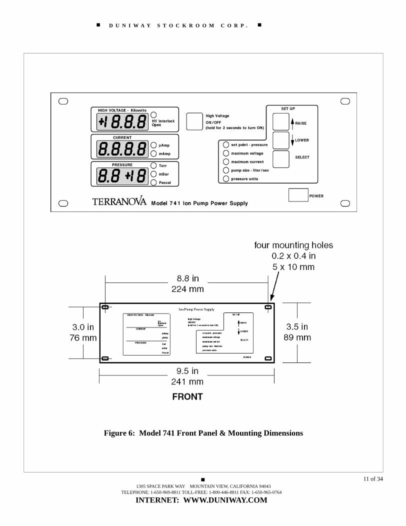
Figure 6: Model 741 Front Panel & Mounting Dimensions
1305 SPACE PARK WAY MOUNTAIN VIEW, CALIFORNIA 94043TELEPHONE: 1-650-969-8811 TOLL-FREE: 1-800-446-8811 FAX: 1-650-965-0764
INTERNET: WWW.DUNIWAY.COM
11 of 34

D U N I W A Y S T O C K R O O M C O R P .
B. Front Panel Description and Preliminary Set Up
1. Displays:
There are three alphanumeric displays:
High Voltage: Polarity sign (+ or -) and 3 digits with decimal.Current: 3 digits with decimalPressure: 2 digits with decimal plus exponent with sign
There are 12 LED indicators.HV InterlockHV OnCurrent (2): milliamp or microamp rangePressure Units (3): torr or mbar or PascalSet Point Set Up or ActivatedMaximum Voltage Set UpMaximum Current Set UpPump Size Set UpPressure Units Set Up
2. Set-Up Keys
There are three Set Up keys provided
SELECT places the unit into Set Up Mode and activates the other two keysRAISE ▲ increases the value of the selected parameterLOWER ▼ decreases the value of the selected parameter
3. Power Switch
A rocker-type power switch is provided on the front panel. It is labelled with the interna-tional binary 0/1 notation: Binary zero (circle) depressed is OFF and binary 1 (bar) de-pressed is ON.
4. High Voltage Switch
A push button is provided to turn high voltage on and off. Turning high voltage on requiresthe operator to depress the button for 2 seconds (for safety reasons), while turning high volt-age off is instantaneous.
1305 SPACE PARK WAY MOUNTAIN VIEW, CALIFORNIA 94043TELEPHONE: 1-650-969-8811 TOLL-FREE: 1-800-446-8811 FAX: 1-650-965-0764
INTERNET: WWW.DUNIWAY.COM
12 of 34

D U N I W A Y S T O C K R O O M C O R P .
C. Initial Set Up1. Turn on: When the power is initially turned on by depressing the bar side of the rocker typepower switch, the Model 741 will cycle through a diagnostic exercise in the following sequence:
a. All display segments will momentarily activate.b. All LED indicators will momentarily activate.c. The model number “741” will appear on the VOLTAGE display.d. The internal DIP switch setup will be displayed in the CURRENT display (see IV-C). e. The release version of the unit “N.NN” (e.g. 1.02) will appear on the pressure display.f. “OFF” will be displayed on the High Voltage display.
(Holding down the SELECT button during power-up will retain display of model #, DIP switch set-tings and release version until the SELECT button is released. This is for ease of interpretation.)
2. Set Up: After the turn on cycle described above, the parameter set up process is accomplishedby 6 operations of the “SELECT” switch.
a. The first press of the “SELECT” button will allow the adjustment of the set point pressure,which is shown on the “Pressure” display. The default set point pressure is OFF and the range is0.1X 10-9 to 1X10⁻⁵ in the chosen units of pressure. Press the ▲ button to raise the set point pres-sure and press the ▼ button to lower the set point pressure.
SET POINT OPERATIONIn operation, as the pressure falls in the ion pump, the set point relay goes to the ‘ON’ condition when the pressure is less than or equal to entered setting. Pressure Falling: (Set Point Relay ‘ON’ if P = or < Setting).
As the pressure rises, the set point relay goes to the ‘OFF’ position when the pressure is equal to or greater than 1.20 times the entered setting. This 20% hysteresis range is provided to avoid “chatter” in the set point relay at or verynear the entered setting. Pressure Rising: (Set Point Relay ‘OFF’ if P = or > 1.2 x Setting)
Both Normally Open (NO, pin 9) and Normally Closed (NC, pin 2) terminals are provided on the Miscellaneous I/O Connector, see Section C2)
b. The second press of the “SELECT” button will allow the adjustment of the maximum volt-
age supplied by the Model 741, which is displayed on the “High Voltage” display. The default max-imum high voltage is 7500 volts (displayed as +7.50 KV) and the range is 3500 volts to 7000 volts.Press the ▲ button to raise the maximum high voltage and press the ▼ button to lower the maxi-mum high voltage.
c. The third press of the “SELECT” button will allow the adjustment of the maximum currentsupplied by the Model 741, which is displayed on the “Current” display. The default maximum cur-rent is 25 milliamps, and the range is 1 milliamp to 25 milliamps. Press the ▲ button to raise themaximum current and press the ▼ button to lower the maximum current.
1305 SPACE PARK WAY MOUNTAIN VIEW, CALIFORNIA 94043TELEPHONE: 1-650-969-8811 TOLL-FREE: 1-800-446-8811 FAX: 1-650-965-0764
INTERNET: WWW.DUNIWAY.COM
13 of 34

D U N I W A Y S T O C K R O O M C O R P .
d. The fourth press of the “SELECT” button will allow the choice of the pump size, (used inthe calculation of pressure from the pump current), which is displayed on the “Current” display.The default pump size is 20 liters per second and the range is 0.1 liter per second to 999 liters persecond. Press the ▲ button to raise the pump size and press the ▼ button to lower the pump size
e. The fifth press of the “SELECT” button will allow the choice of pressure units displayedby the Model 741, which is displayed on the “Pressure” display. The default pressure units are torr(displayed as tor) and the alternate choices are millibar (displayed as bar) and Pascal (displayed aspas). Press the ▲ button or the ▼ button to change the choice of pressure units.
f. The sixth press of the “SELECT” button will return the Model 741 to the “Operate” mode,in the transition, all display segments will momentarily be illuminated.
3. Re-setting Parameters to Default Values: The unit can be returned to default settings of param-eters by turning the power switch OFF, then simultaneously depressing the raise (▲) and lower (▼)buttons on the front panel while turning the power switch ON. The unit will cycle through its nor-mal turn-on diagnostic process (see C.1, above) and then the display will show “rst” and the unitwill emit short ‘beeps’ until the reset is complete.
D. Safety Considerations
The primary safety hazard when operating high voltage power supplies such as theModel 741 is electrical shock. Electrical shock can result from contact with the AC linevoltage, internal potentials in the control unit or the high voltage output of the unit itself.The high voltage output hazard can exist either from direct contact with the high voltagelead or as a result of loss of proper grounding of the unit or the pump.
WARNING!Always wait at least 15 seconds after turning OFF high voltage beforeworking on either the Model 741 or the sputter-ion pump. NOTE: In a properly operating Model 741, the absence of hazardouspotentials on the high voltage output may be verified by reading thehigh voltage meter on the front panel.
1305 SPACE PARK WAY MOUNTAIN VIEW, CALIFORNIA 94043TELEPHONE: 1-650-969-8811 TOLL-FREE: 1-800-446-8811 FAX: 1-650-965-0764
INTERNET: WWW.DUNIWAY.COM
14 of 34

D U N I W A Y S T O C K R O O M C O R P .
E. Rear Panel
Figure 7: Model 741 Rear Panel
Power Input/Fuse Module
The Power Input socket is a standard IEC 320 instrument power in-put receptacle. Replacement fuses are 2 amp type S slow Blow fuses. TheModel 741 has a universal power supply which accepts 100 - 240 Volts, 50-60 Hz or DC.
High Voltage Connector
The High Voltage output connector is a Kings-type 10 KV co-axialconnector. See Section IV-F, below for high voltage cable descriptions.
Ground Sense Circuit Terminal
A Ground Sense Circuit Terminal is provided on the rear panel ofthe Terranova 741. It is an isolated 8/32 screw-lug. If the Ground Senseterminal and High Voltage cable shield are not properly connected to thevacuum system ground, the high voltage can not be turned on. See addition-al explanation immediately below in Section II-F.
1305 SPACE PARK WAY MOUNTAIN VIEW, CALIFORNIA 94043TELEPHONE: 1-650-969-8811 TOLL-FREE: 1-800-446-8811 FAX: 1-650-965-0764
INTERNET: WWW.DUNIWAY.COM
15 of 34

D U N I W A Y S T O C K R O O M C O R P .
Ground Lug
A separate Safety Ground (Earth Ground) 8/32 screw-lug is alsoprovided. This lug is permanently attached to the Model 741 chassis. Seethe explanation above before using this terminal.
Serial RS-232 D-9 Connector
A D-9 connector is provided for the serial I/O signals. See sectionI-C for the pin-signal configuration.
Miscellaneous I/O D-15 Connector
A D-15 connector is provided for the miscellaneous I/O signals. Seesection I-C for the pin-signal configuration.
F. Safety Interlock - Ground Sense Circuit Description and Procedure
A Safety Interlock circuit has been incorporated into the Model 741 to reduce the riskof electrical shock in the case that proper grounding is lost. The required Groundreturn path is provided through shielding on the high voltage cable. See the discussion below.
PROCEDURE: GROUND SENSE SAFETY WIRE
1. Ensure that continuity exists between the high voltage output connector shell andthe sputter-ion pump body.
2. Make a connection between the ground sense lug connector on the rear panel ofthe Model 741 (See Figure 2 - Photograph of Rear Panel) and any convenient fastener on the sputter ion pump body.
3. If there is a ground fault (open circuit), The High Voltage will be turned OFF and the Ground Sensing Circuit LED “HV Interlock Open” lamp on the front panel will be illuminated. To restore High Voltage,correct the grounding problem and press the High Voltage ON button on the front panel.
WARNING!Under no circumstances should the ground sense strap be connected di-rectly to the case of the Model 741. That would defeat the protectionprovided by this safety feature and may result in serious electricalshock hazard to personnel.
1305 SPACE PARK WAY MOUNTAIN VIEW, CALIFORNIA 94043TELEPHONE: 1-650-969-8811 TOLL-FREE: 1-800-446-8811 FAX: 1-650-965-0764
INTERNET: WWW.DUNIWAY.COM
16 of 34

D U N I W A Y S T O C K R O O M C O R P .
Discussion of the Ground-Sense Safety Circuit Operation
The Terranova Ground-Sense Circuit is provided to assure that thehigh voltage will be turned off if either the Ground-Sense connection or theHigh Voltage connection to the ion pump is broken or lost.
The Ground-Sense safety feature operates to allow the HV to oper-ate when the Ground-Sense wire is connected between the Terranova 741Ground-Sense terminal on the rear of the unit and the ion pump body; ANDthe high voltage cable ground shield is properly terminated both through theHV ion pump connector to the ion pump body and through the controllerconnector to the Terranova 741 chassis.
If either Ground-Sense or Ground Shield connections are interruptedat either end, the HV will automatically be shut off.
NOTE: *A redundant ground connection, either intentional through a sep-arate grounding wire or unintentional, through chassis contact with pump/system ground (as in mounting pump and control on the same conductingrack or cart), will defeat the HV turn-off portion of the Ground Sense safetycircuit*. See the table below for state conditions for all these alternatives.
Use of cables other than those approved by Duniway StockroomCorp. could lead to operation problems of safety hazards.
Figure 8 - Terranova 741 Ground-Sense Conditions
Case Ground HV Redundant 741Sense Cable 741-Pump HV
Line Ground Ground
1 N N N OFF2 Y Y N ON3 Y N N OFF4 N Y N OFF5 N N Y OFF6 Y N Y ON*7 N Y Y OFF8 Y Y Y ON*
741 Ground Sense Conditions
1305 SPACE PARK WAY MOUNTAIN VIEW, CALIFORNIA 94043TELEPHONE: 1-650-969-8811 TOLL-FREE: 1-800-446-8811 FAX: 1-650-965-0764
INTERNET: WWW.DUNIWAY.COM
17 of 34

D U N I W A Y S T O C K R O O M C O R P .
G. Connection to PumpThe Model 741 is connected to a sputter-ion pump by means of a coaxial cable assembly. To see a list of cables, go to Section IV-E, or for more details, photographs, prices or special length cables, please call Duniway Stockroom Corp. or go to our web page at www.duniway.com.
PROCEDURE: CONNECTION TO THE PUMP
1. Turn OFF the POWER switch on the front panel of the Model 741. (See Figure 6 - Front Panel Photograph)
2. Make or confirm the required ground connections to the Model 741 as described above in Section II-D.
3. Verify that (or set) the pump selection is set to the correct value for thesputter ion pump in use.
4. Verify that the high voltage polarity is correct for the pump in use. Positive (+)polarity is used for diode, noble diode and DI pumps while negative (-) polarity is used for triode and StarCell R pumps. If you have any questions about the type of pump you are planning to use, contact Duniway Stockroom Corp. immediately.
5. Attach the high voltage connector to the ion pump.
6. Connect the Kings-type, 10KV connector (control unit end of high voltage cable)to the high voltage output connector on the rear of the control unit.
WARNING!NEVER apply power to the Model 741 until proper grounding has been
checked and verified.
Now, rough pump the system to a pressure of 10-3 torr or below. Turbo roughing is strongly recommended, however a cryosorption pumps or two stage oil sealed rotary pump or other roughing pump can be used with careful attention to technique and appropriate trapping of pump oils.
CAUTIONAt pressures below about 1.5 X 10⁻¹ torr for most systems and pumps,the backstreaming of mechanical pump oil is a significant problem.High quality oil traps MUST be used.
1305 SPACE PARK WAY MOUNTAIN VIEW, CALIFORNIA 94043TELEPHONE: 1-650-969-8811 TOLL-FREE: 1-800-446-8811 FAX: 1-650-965-0764
INTERNET: WWW.DUNIWAY.COM
18 of 34

D U N I W A Y S T O C K R O O M C O R P .
III Operation
A. Start-Mode Operation
1. Turn the POWER switch on the front panel to ON. No warm-up period is required.
2. When it is suspected or observed that the roughing system has reached its basepressure, the ion pump starting cycle can be started. Note the maximumrecommended operating pressures for various pump sizes listed is section II-A,above.
3. Push the High Voltage switch and hold for two seconds. The High Voltage ON LEDwill be activated and the High Voltage display will show the voltage. The voltagewill ramp up to the Maximum Voltage designated in the set-up procedure (or to somelower value determined by the load represented by higher pressure in the ion pump.)The Current and Pressure displays will remain off until several seconds have elapsed(to avoid displaying erroneous transient start up values).
4. When the initial voltage (at maximum or rising), current (falling) and pressure(falling) are observed to be improving, close the roughing valve.
If the voltage falls (meaning that current and therefore pressure is rising), reopen the rough-ing valve.
If the voltage increases or remains constant (pressure is decreasing or “holding”), leave theroughing valve closed.
NOTEWith a sputter ion pump, a modest rise in pressure is normal during the ini-tial START. This is caused by heating of the pump components and is ben-eficial in outgassing the elements for later operation in the NORMAL mode.
5. Maximum Current (Imax) Operation: During Initial Set Up (Section II-C), the operator chooses a value for the maximum current (Imax) which the ion pump should be exposed
to. This function is provided to limit the power input, especially to small pumps. In operation, if the pump current rises to Imax, the Terranova 741 automatically begins limiting power by incrementally reducing the high voltage applied to the ion pump. Thisincremental voltage reduction continues until the ion pump current stays below the Imax setting. If the ion pump current remains at or near the Imax setting for extended periods, the 741 goes into a cool-down mode (below).
1305 SPACE PARK WAY MOUNTAIN VIEW, CALIFORNIA 94043TELEPHONE: 1-650-969-8811 TOLL-FREE: 1-800-446-8811 FAX: 1-650-965-0764
INTERNET: WWW.DUNIWAY.COM
19 of 34

D U N I W A Y S T O C K R O O M C O R P .
6. Cool-Down Mode: If the ion pump current remains at or near the maximum current(Imax) setting for a period of 10 minutes, the 741 automatically shuts OFF the high voltageto allow the ion pump to cool down. The high voltage stays off for 5 minutes and thencomes back on. This cyclical process continues (10 minutes ON - 5 minutes OFF) for 5 cycles if the ion pump current stays at or near Imax. If the ion pump current goes significantly below Imax at any time during this process, the Imax/Cool-Down Mode willbe re-started at the beginning. If the full 5 cycles are completed without significant ionpump current reduction, the 741 automatically goes into shut-down mode (below). A seriesof ‘beeps’ is emitted when the cool-down mode or shut-down mode is commenced.
The display shows “cdX” when the voltage goes off, where X is the cool-down cycle number, between 1 and 5. The unit emits X beeps when entering a cool-down cycle.
7. Shut-Down Mode: If the 741 goes through the full cool-down cycle, it goes into shut-down mode. The high voltage is turned OFF, a 5 second ‘beep’ is emitted and thedisplay shows “sd”.
In addition, if the high voltage output is shorted to ground, due to malfunction of the ionpump, cable or connector, the 741 will enter shut-down mode after 30 seconds haveelapsed. The high voltage turns OFF, a 5 second ‘beep’ is emitted and “sd” is displayed.
To recover normal operation from shut-down, resolve the situation that led to shut-downand press the HV button on the front panel for 2 seconds.
8. Defeating Cool-Down/Shut-Down Modes: Operation of the Cool-Down and Shut-Down Modes can be accomplished by changing the internal DIP switch settings. See Section IV-D.
B. Normal Mode Operation
Operation in the NORMAL mode is simple and automatic. As the pressure and cur-rent fall, the operating voltage approaches the open circuit value for the control unit; andthe current is approximately proportional to pressure over a wide range of pressures.
Pressure at the pump inlet flange may be read directly on the “pressure” display of thefront panel. (This assumes that the pump size in the selection mode has been made properlyduring set up.)
Alternately, if the current vs. Pressure relationship is known for the pump in use, cur-rent may be read directly and converted into a pressure reading.
1305 SPACE PARK WAY MOUNTAIN VIEW, CALIFORNIA 94043TELEPHONE: 1-650-969-8811 TOLL-FREE: 1-800-446-8811 FAX: 1-650-965-0764
INTERNET: WWW.DUNIWAY.COM
20 of 34

D U N I W A Y S T O C K R O O M C O R P .
DISCUSSION OF THE TECHNIQUE
The current drawn in a sputter-ion pump is nearly proportional to pressure. For theTerranova 741 unit, the equation used for calculating pressure from current is:
P = (K x I)/ (S x V),
where P is the pressure in Torr, K is a constant equal to 369.6, I is the current in amps,S is the Pumping Speed as entered during Set-Up in liters per second and V is the Voltagein volts as entered during Set-Up.
While it is true that the current drawn in a sputter-ion pump is nearly proportional topressure over a wide range, there are limitations to the technique. Specifically:
1. The proportionality is only approximate.
2. At pressures less than 1 x 10⁻⁸ Torr, the current to the Penning discharge is multiplevalued, displaying significant hysteresis. Thus the current drawn depends onwhether the pressure is rising or falling.
3. Sharp points and edges, or flakes which may form with prolonged pump use,particularly in triode pumps, can add significant current, due to field emission,which is independent of the pressure. (These field emission points can be removedby “hi-potting” the pump, that is, by applying AC or DC voltages to the pump of atleast twice the operating voltage, preferably with the pump magnets removed.)
For these reasons, the accuracy of the pressure as indicated by the ion pump currentis no better than +/-20%, and that accuracy is only achieved in the pressure range between1 x 10-7 Torr and 1 x 10⁻⁵ Torr.
For pressures below 1 x 10⁻⁸Torr, a Bayard-Alpert ionization gauge is strongly rec-ommended. The pressure indication on the Model 741 is semi-quantitative.
Note that for sputter ion pumps, it is possible to extrapolate the current value to ex-tremely low pressures and obtain a “reading” for the pressure. This is subject to the samefundamental limitations indicated above, and is therefore not a reliable indication of pres-sure.
Note that these effects, while significant to the measurement of pressure, have only minoreffects on the pumping efficiency, and for that purpose may be generally neglected.
1305 SPACE PARK WAY MOUNTAIN VIEW, CALIFORNIA 94043TELEPHONE: 1-650-969-8811 TOLL-FREE: 1-800-446-8811 FAX: 1-650-965-0764
INTERNET: WWW.DUNIWAY.COM
21 of 34

D U N I W A Y S T O C K R O O M C O R P .
C. Communications Functions RS-232, 422 and 485 Commands
General format for Queries
The serial port (see page 7 for pin/signal configuration) allows the user to remotely Query (read)the Terranova 741 for the parameter values shown below on this page and to remotely Set the pa-rameters shown on the next page.
FORMAT: [start character][two byte address][two byte query mnemonic][?][,][chksum][cr](The start character for the 741 is ‘*’, asterisk.)
The address field is used only when the unit is configured for the RS-485 communications mode(DIP switch S1-1 On), and is a two byte value in hexadecimal. The address value is set up by usingDIP switch S2. See Section IV-D for more information on DIP switch settings.
The checksum is only used when the unit is configured with dip switch S1-7 ON. Even if the switchis on, sending a value of 00 for the checksum will cause it to be ignored. Regardless of the settingof this switch, the 741 will always calculate and send a checksum.
Examples of query/response in the RS-232/422 mode, checksum disabled:
To get the voltage value: *VO?<cr>Response for 4300 volts: OK:4.3e+3,cc<cr>
Examples of query/response in the RS-485 mode, checksum enabled:
To get the voltage value: *05VO?,00<cr>Response for 4300 volts: 05,OK:4.3e+3,cc<cr>
Query Function Response
MO Read Model Number 741VE Read Firmware VersionN.NNCU Read Current N.NN e +/-X (amps)PR Read Pressure N.NN e -X (in selected pressure units)VO Read Voltage N.NN e +/-X (Volts)ST Read Supply Status XX (Status Code: 00, Off; 10, Running;
02, Cooling; 03, Shutdown; 04, Interlock) UN Read Selected Units Torr, mBar, PascalPS Read Pump Size NNN.N (liters per second, 0.1-999)PO Read HV Polarity Pos, NegHV Read HV ON or OFF On, OffMC Read Maximum CurrentN.NN e +/-X (amps)SP Read Set Point N.N e -X (selected pressure units)MV Read Max Volts NN00 (Volts)
Figure 9: Serial Interface Query-Response Format
1305 SPACE PARK WAY MOUNTAIN VIEW, CALIFORNIA 94043TELEPHONE: 1-650-969-8811 TOLL-FREE: 1-800-446-8811 FAX: 1-650-965-0764
INTERNET: WWW.DUNIWAY.COM
22 of 34
D U N I W A Y S T O C K R O O M C O R P .
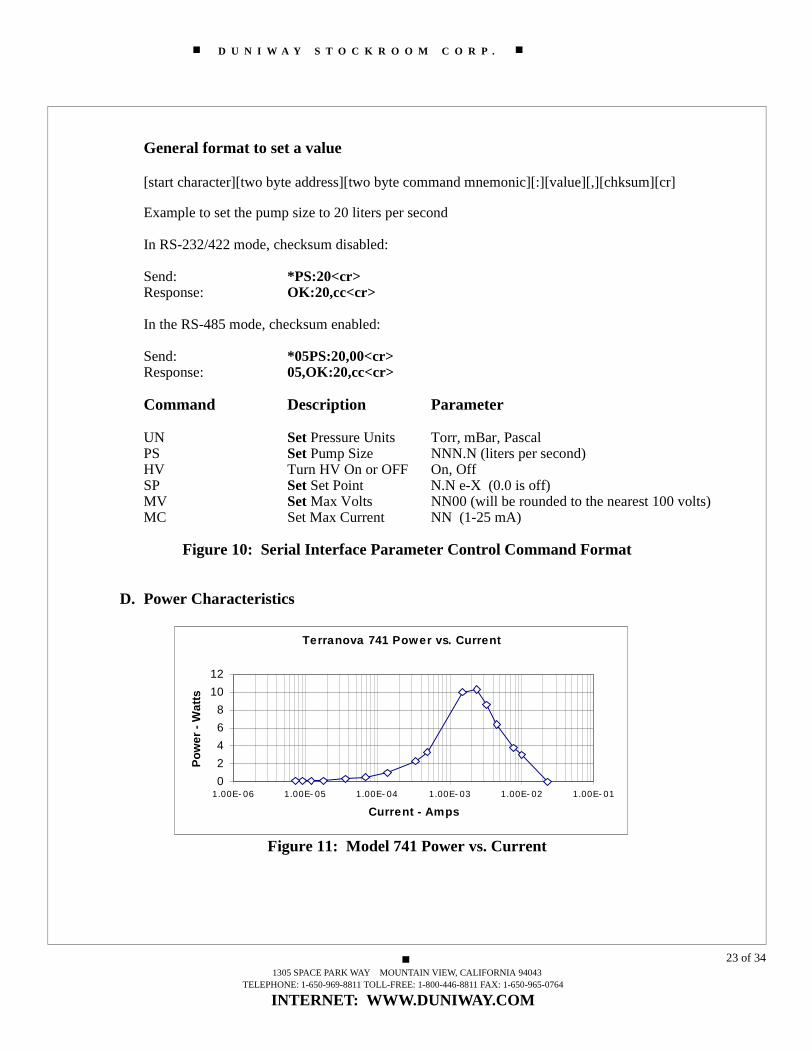
General format to set a value
[start character][two byte address][two byte command mnemonic][:][value][,][chksum][cr]
Example to set the pump size to 20 liters per second
In RS-232/422 mode, checksum disabled:
Send: *PS:20<cr>Response: OK:20,cc<cr>
In the RS-485 mode, checksum enabled:
Send: *05PS:20,00<cr>Response: 05,OK:20,cc<cr>
Command Description Parameter
UN Set Pressure Units Torr, mBar, PascalPS Set Pump Size NNN.N (liters per second)HV Turn HV On or OFF On, OffSP Set Set Point N.N e-X (0.0 is off)MV Set Max Volts NN00 (will be rounded to the nearest 100 volts)MC Set Max Current NN (1-25 mA)
Figure 10: Serial Interface Parameter Control Command Format
D. Power Characteristics
Figure 11: Model 741 Power vs. Current
Terranova 741 Power vs. Current
0
2
4
6
8
10
12
1.00E- 06 1.00E- 05 1.00E- 04 1.00E- 03 1.00E- 02 1.00E- 01
Current - Amps
Po
wer
- W
atts
1305 SPACE PARK WAY MOUNTAIN VIEW, CALIFORNIA 94043TELEPHONE: 1-650-969-8811 TOLL-FREE: 1-800-446-8811 FAX: 1-650-965-0764
INTERNET: WWW.DUNIWAY.COM
23 of 34

D U N I W A Y S T O C K R O O M C O R P .
Figure 12 Model 741 Voltage vs. Current
Terranova 741 Voltage vs. Current
0
1000
2000
3000
4000
5000
6000
7000
8000
1.00E- 06 1.00E- 05 1.00E-04 1.00E- 03 1.00E- 02 1.00E- 01
Current - Amps
Vo
ltag
e -
Vo
lts
1305 SPACE PARK WAY MOUNTAIN VIEW, CALIFORNIA 94043TELEPHONE: 1-650-969-8811 TOLL-FREE: 1-800-446-8811 FAX: 1-650-965-0764
INTERNET: WWW.DUNIWAY.COM
24 of 34

D U N I W A Y S T O C K R O O M C O R P .
IV Maintenance
A. 741 Block Diagram
Figure 13: Model 741 Block Diagram
1305 SPACE PARK WAY MOUNTAIN VIEW, CALIFORNIA 94043TELEPHONE: 1-650-969-8811 TOLL-FREE: 1-800-446-8811 FAX: 1-650-965-0764
INTERNET: WWW.DUNIWAY.COM
25 of 34

D U N I W A Y S T O C K R O O M C O R P .
B. Trouble Shooting
Problem Possible Cause Remedy/Diagnostic
Unit will not turn on Input fuses are open Check fuses at AC input connector; missing, blown?
Unit will not turn on Internal connector to power switch is not in place
Disconnect AC power cord, remove cover and verify that J10 is connected; J10 is located near rear-left side
Unit will not turn on AC outlet has no power Verify AC outlet power; 100 to 240 VAC, 47-63 Hz
Unit will not turn on AC line cord is defective Check continuity of AC line cord
Unit ‘beeps’ at turn-on, but display is dark
Internal connector to front panel is not con-nected
Disconnect AC power cord, remove cover and check rib-bon-cable connector to dis-play
Unit turns on, but dis-play has random LED segments lit and doesn’t respond
Microprocessor is not operating
Disconnect AC power cord, remove cover and verify that U1 and U2 are properly seated/socketed
Some LEDs or display segments don’t light
LED component is defective
Return unit to Duniway Stockroom Corp. or request replacement display board
No beeps or response when any front panel buttons are pushed
Internal connector to front panel is not con-nected
Disconnect AC power cord, remove cover and check rib-bon-cable connector to dis-play
1305 SPACE PARK WAY MOUNTAIN VIEW, CALIFORNIA 94043TELEPHONE: 1-650-969-8811 TOLL-FREE: 1-800-446-8811 FAX: 1-650-965-0764
INTERNET: WWW.DUNIWAY.COM
26 of 34

D U N I W A Y S T O C K R O O M C O R P .
No beeps or response when one front panel button is pushed, others OK
Defective button/switch Return unit to Duniway Stockroom Corp. or request replacement display board
High voltage doesn’t turn on when HV button is pushed
Ground-Sense Safety interlock is open, or High Voltage Ground Shield is open or unit is in Remote HV Control Mode
Check isolated Ground Sense connector on rear of unit for proper connection to ground. Check HV cable shield connections. Check DIP switch settings for proper configuration.
High voltage LED turns on, but voltage shows zero, pump connected
HV output is shorted Remove HV connector from ion pump, try again
High voltage LED turns on, but voltage shows zero, pump not con-nected
Internal HV power sup-ply not connected
Disconnect AC cord, remove cover and verify connection of J4 and J1 on HV board
High voltage LED turns on, but voltage stays near zero, pump con-nected/not connected
Plus/Minus 15 volt sup-plies are defective
Disconnect AC cord, remove cover and verify +/- 15 volts on E1 and E2, front-left. If defective, return unit to Duniway Stockroom Corp. for repair
High voltage LED turns on, but current stays near zero, pump connected
Pressure below detect-able level.
No action required
High voltage LED turns on, but current stays near zero, pump connected
Cable to ion pump is open or not connected
Turn 741 off, disconnect HV cable, check continuity of both center conductor and shield.
Problem Possible Cause Remedy/Diagnostic
1305 SPACE PARK WAY MOUNTAIN VIEW, CALIFORNIA 94043TELEPHONE: 1-650-969-8811 TOLL-FREE: 1-800-446-8811 FAX: 1-650-965-0764
INTERNET: WWW.DUNIWAY.COM
27 of 34
D U N I W A Y S T O C K R O O M C O R P .
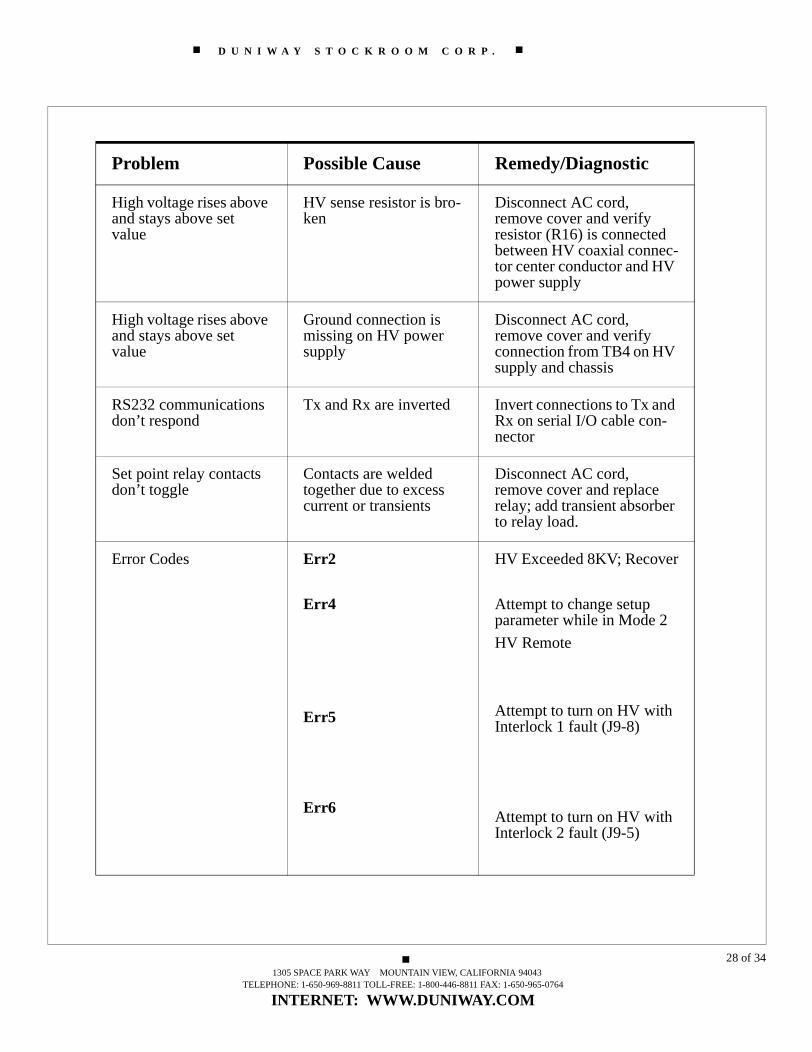
High voltage rises above and stays above set value
HV sense resistor is bro-ken
Disconnect AC cord, remove cover and verify resistor (R16) is connected between HV coaxial connec-tor center conductor and HV power supply
High voltage rises above and stays above set value
Ground connection is missing on HV power supply
Disconnect AC cord, remove cover and verify connection from TB4 on HV supply and chassis
RS232 communications don’t respond
Tx and Rx are inverted Invert connections to Tx and Rx on serial I/O cable con-nector
Set point relay contacts don’t toggle
Contacts are welded together due to excess current or transients
Disconnect AC cord, remove cover and replace relay; add transient absorber to relay load.
Error Codes Err2
Err4
Err5
Err6
HV Exceeded 8KV; Recover
Attempt to change setup parameter while in Mode 2
HV Remote
Attempt to turn on HV with Interlock 1 fault (J9-8)
Attempt to turn on HV with Interlock 2 fault (J9-5)
Problem Possible Cause Remedy/Diagnostic
1305 SPACE PARK WAY MOUNTAIN VIEW, CALIFORNIA 94043TELEPHONE: 1-650-969-8811 TOLL-FREE: 1-800-446-8811 FAX: 1-650-965-0764
INTERNET: WWW.DUNIWAY.COM
28 of 34

D U N I W A Y S T O C K R O O M C O R P .
Figure 14: Model 741 Top View, Cover Removed (Front:Left -- Rear:Right)
(Note Power Interlock Micro-Switch at Top of Photo)
C. High Voltage Output Polarity Change Procedure
1. Remove the AC Power Cord
2. Remove the top cover (6 Phillips Head screws)
3: Make the 4 Step Polarity Change (See Figure 14 for reference letters)
A. High Voltage Diode: Locate the High Voltage Diode mounted with screws through lugson the top of two ceramic stand-offs (Figure 14, Rectangle A, marked with cross-mark). The diodehas a narrow stripe on one end, which marks the Positive (+) polarity.. When the diode is mountedwith this stripe positioned as shown in Figure 14, the unit is configured for positive (+) high voltageoutput. When the diode is mounted with the stripe in the opposite direction, the unit is configuredfor negative (-) high voltage output.
Remove the two screws from the high voltage diode lugs, being sure to retain the screws and/or washers from dropping into the interior of the unit. Flip the High Voltage Diode over to obtainthe direction for the desired high voltage polarity Replace and tighten the screws through the lugand into the top of the stand-off.
1305 SPACE PARK WAY MOUNTAIN VIEW, CALIFORNIA 94043TELEPHONE: 1-650-969-8811 TOLL-FREE: 1-800-446-8811 FAX: 1-650-965-0764
INTERNET: WWW.DUNIWAY.COM
29 of 34

D U N I W A Y S T O C K R O O M C O R P .
B. Polarity Jumpers: Locate the High Voltage Polarity jumpers (Figure 14, Rectangle B).Note the label on the printed circuit board beneath the two jumpers. “Select Output Polarity”.There are two jumper positions: J3 NEGATIVE for negative (-) high voltage output polarity andJ-2 POSITIVE for positive (+) high voltage output polarity. Place/verify that the 4-pin jumper is inthe correct position to correspond with the placement of the High Voltage diode in step A, above.
C. DIP Switch Settings: Locate the DIP switch S1 (Figure 14, Rectangle C) Switch S1 is theswitch toward the back of the unit labelled “S1”. The individual switches on Switch S1 are labelled1-8. Locate switch S1-8. For Positive High Voltage Output, switch S1-8 should be in the OFF po-sition. For Negative High Voltage Output, switch S1-8 should be in the ON position. Switch S1-8 controls the + and - sign on the high voltage display.
D. Miscellaneous I/O Jumpers: Locate jumper JP-8 inside the rear panel near the Miscella-neous I/O plug. For Positive High Voltage Polarity, connect pins 1 and 2 of JP-8. For NegativeHigh Voltage Polarity, connect pins 2 and 3 of JP-8.
See Section IV-D below for other DIP switch settings.
Finally, verify that all four components (High Voltage Diode, Polarity Jumper, Dip Switchand Misc. I/O jumper) are set consistently to the voltage polarity required for ion pump operation.See Section II-A for ion pump voltage polarity requirements.
D. Internal DIP Switch Settings
There are two internal DIP switches located near the front of the main printed circuit boardinside the unit. (See Figure 14, rectangle marked C.)
DIP Switch S1 NOTE: Remove the power cord before opening the unit.
The following shows the functions and default values for DIP Switch S-1. The factory de-fault settings are all OFF for this switch. The settings of this switch are displayed in hexa-decimal format on the right two digits of the CURRENT display during start-up.
S1-1 Communications Protocol; Default OFF=RS-232/422; ON=RS-485. S1-2 Power Loss Restart; Default OFF=Disabled; ON=Enabled. S1-3 * Remote HV Control Mode Set-Up; Default OFF=Disabled; ON=Enabled. S1-4 * Remote HV Control Mode Set-Up, Default OFF=Disabled; ON=Enabled.S1-5 Factory Diagnostic; Default OFF=Disabled; ON=Enabled. S1-6 Defeat Cool-Down/Shut-Down; Default OFF=Disabled; ON=Enabled S1-7 Communications Checksum; Default OFF=Disabled; ON=EnabledS1-8 High Voltage Polarity Display; Default OFF=Positive (+), ON=Negative (-)(Note: For Remote HV Control Mode Set-Up and Operation, call Technical Support)
Figure 15: DIP Switch - S1 - Settings
1305 SPACE PARK WAY MOUNTAIN VIEW, CALIFORNIA 94043TELEPHONE: 1-650-969-8811 TOLL-FREE: 1-800-446-8811 FAX: 1-650-965-0764
INTERNET: WWW.DUNIWAY.COM
30 of 34

D U N I W A Y S T O C K R O O M C O R P .
DIP Switch S2
The switches on DIP switch S2 are used to set up the Offset for residual current and the RS-485 address in 5-bit binary format. The following table shows the functions and defaultvalues for DIP Switch S2. The settings of this switch are displayed in 5-bit binary formaton the three digits of the CURRENT display during start-up.
S2-1 Residual Current Offset=0.1 microamp; Default=OFF* S2-2 Residual Current Offset=0.2 microamp; Default=OFF*S2-3 Residual Current Offset=0.4 microamp; Default=OFF* S2-4, LSB of RS-485 address in 5-bit binary; Default=ONS2-5, Second bit of RS-485 address in 5-bit binary; Default=OFFS2-6, Third bit of RS-485 address in 5-bit binary; Default=ONS2-7, Fourth bit of RS-485 address in 5-bit binary; Default=OFFS2-8, MSB of RS-485 address in 5-bit binary; Default=OFF
Figure 16: DIP Switch S2 Settings
[NOTE: The default address for RS-485 is 5 (Right-Shifted 5-bit binary = 00101); thisgives a range of 32 possible RS-485 addresses from 0 to 31. Also, DIP switch S1-1 mustalso be ON to enable RS-485 communications.] (*Residual Current Offset function is pro-vided to mask residual current which may build up due to aging and dust accumulation ofthe unit. The three switches are additive and provide up to 0.7 microamps of residual cur-rent offset (all three switches ‘ON’). For further details, please call Duniway StockroomCorp.)
E. Fuses: The fuses are located in the power input module on the back panel.
There are two fuses: 2 amp, type S, Slow Blow. Replacement types are:Bussman GDC-2A or Littlefuse 218 002
1305 SPACE PARK WAY MOUNTAIN VIEW, CALIFORNIA 94043TELEPHONE: 1-650-969-8811 TOLL-FREE: 1-800-446-8811 FAX: 1-650-965-0764
INTERNET: WWW.DUNIWAY.COM
31 of 34

D U N I W A Y S T O C K R O O M C O R P .
F. High Voltage Cables -- From: Model 741 - Kings Type - 10KV to: Ion Pump
Pump End Connector Cable Part Number
Standard Varian Standard A-110-10Standard Varian Bakeable A-210-10Varian StarCell R Standard S-110-10Varian StarCell R Bakeable S-210-10Varian Mini Standard M-110-10Varian Interlock Bakeable FS-210-10P-E/Ultek Standard P-110-10P-E/Ultek Bakeable P-210-10
Duniway Stockroom Corp. has the parts and knowledge to build a large variety of cables:
Hybrid Vendor CablesVirtually Any LengthBakeable - Non- BakeableCustom Coax WireCustom Shielding
Duniway Stockroom Corp. also supplies High Voltage Feedthroughs for all the commonion pumps; as well as rebuilding services and parts
For more details, prices or special cables, please call Duniway Stockroom Corp. or go to our web page at www.duniway.com.
1305 SPACE PARK WAY MOUNTAIN VIEW, CALIFORNIA 94043TELEPHONE: 1-650-969-8811 TOLL-FREE: 1-800-446-8811 FAX: 1-650-965-0764
INTERNET: WWW.DUNIWAY.COM
32 of 34

D U N I W A Y S T O C K R O O M C O R P .
V Warranty & CE DeclarationTerranova products of Duniway Stockroom Corp. are warranted to be free of defects in material and workmanship for a period of one year from the date of shipment. At our option, we will repair or replace products which prove to be defective during the war-ranty period. Liability under this warranty is limited to repair or replacement of the defective items. Shipping damage is excluded from the scope of this warranty. Gauge tubes of all types are excluded from this warranty.
Terranova products are warranted not to fail to execute programming instructions due to defects in materials and workmanship. If Duniway Stockroom receives notice of such defects during the warranty period. Duniway Stockroom will repair or replace firmware that does not execute its programming instruction due to such defects. Duniway Stock-room does not warrant that the operation of the firmware or hardware will be uninter-rupted or error-free.
If this product is returned to Duniway Stockroom for warranty service, Buyer will pre-pay shipping charges and will pay all duties and taxes for products returned to Duniway Stockroom. Duniway Stockroom will pay for return of products to Buyer, except for products returned to a Buyer from a country other than the United States.
LIMITATION OF WARRANTY: The foregoing warranty does not apply to the defects resulting from:
1. Improper or inadequate maintenance by Buyer;2. Buyer-supplied interfacing;3. Unauthorized modification or misuse;4. Operation outside of the environmental specifications of the product; or5. Improper site preparation and maintenance.
THE WARRANTY SET FORTH ABOVE IS EXCLUSIVE AND NO OTHER WARRANTY, WHETHER WRITTEN OR ORAL, IS EXPRESSED OR IMPLIED. DUNIWAY STOCK-ROOM DISCLAIMS ANY IMPLIED WARRANTIES OF MERCHANTABILITY AND FITNESS FOR A PARTICULAR PURPOSE.
EXCLUSIVE REMEDIES: The remedies provided herein are Buyer’s sole and exclusive remedies. In no event will Duniway Stockroom be liable for direct, indirect, special, incidental, or consequential damages, including loss of profits, whether based on con-tract, tort, or any other legal theory.
1305 SPACE PARK WAY MOUNTAIN VIEW, CALIFORNIA 94043TELEPHONE: 1-650-969-8811 TOLL-FREE: 1-800-446-8811 FAX: 1-650-965-0764
INTERNET: WWW.DUNIWAY.COM
33 of 34

D U N I W A Y S T O C K R O O M C O R P .
DECLARATION OF CONFORMITY
We, Duniway Stockroom Corp., declare under our sole responsibility,that the following products, displaying the CE mark on the rear panel:
Model 908A Dual Capacitance Diaphragm Gauge ControllerModel 926A Dual Convection Gauge Controller
Model 741 Ion Pump Control Unit
to which this declaration relates, are in conformity with the followingstandards or normal documents
EMC Directive (89/336/EEC//93/68/EEC)Electromagnetic Compatibility
Standards: EN 50081-1: 1992, EN 50082-1: 1993
Low Voltage Directive (73/23/EEC//93/68/EEC)Electrical/Technical Safety
Standard: EN 61010-1: 1993/A2: 1995
following the provisions of the EMC directive (89/336/EEC)
-------------------------------------------------------------------------------------------------
UL and CSA Listing
Safety of Electrical Equipment for Laboratory Use UL61010A-1, Issued 2002/01/30 CAN/CSA C22.2 No. 1010.1-92, 97
August 2002 by: Sherman RutherfordCompliance Manager
Duniway Stockroom Corp.1305 Space Park WayMountain View, California 94043
rev062503sr
1305 SPACE PARK WAY MOUNTAIN VIEW, CALIFORNIA 94043TELEPHONE: 1-650-969-8811 TOLL-FREE: 1-800-446-8811 FAX: 1-650-965-0764
INTERNET: WWW.DUNIWAY.COM
34 of 34