Embed Size (px)
Citation preview

TERROCK
This is the html version of the file http://www.readymix.com.au/mtshamrock/docs/tsvolume2/06BlastingVibration.pdf. G o o g l e automatically generates html versions of documents as we crawl the web.
Google is neither affiliated with the authors of this page nor responsible for its content.
These search terms have been highlighted: effects blasting bats
Page 1
TERROCK Consulting Engineers
A.B.N. 99 005 784 841
P O Box 829
Eltham Vic 3095
Phone: (03) 9431 0033 Fax: (03) 9431 1810 Email: [email protected]
Alan B. RichardsB.Sc.(Tech), F.I.E.Aust., F.Aust.I.M.M.,F.I.Q.
Adrian J. MooreDip.C.E.,B.E.(Min.), M.Eng.Sc., M.I.E.Aust.
READYMIX – MT SHAMROCK QUARRY (PAKENHAM) PROPOSED EXTENSION
REPORT ON THE EFFECTS OF BLASTING
PREPARED FOR THE ENVIRONMENT EFFECTS
STATEMENT
http://scholar.google.com/scholar?hl=en&lr=&q=cache:mO6mu90wYxUJ:www.readym...shamrock/docs/tsvolume2/06BlastingVibration.pdf+effects+of+blasting+on+bats (1 of 86)11/22/2006 2:11:37 PM

TERROCK
Adrian J. Moore
22 nd February 2005
Page 2
READYMIX – MT SHAMROCK QUARRY (PAKENHAM) PROPOSED EXTENSION
REPORT ON THE EFFECTS OF BLASTING
PREPARED FOR THE ENVIRONMENT EFFECTS STATEMENT
TABLE OF CONTENTS
http://scholar.google.com/scholar?hl=en&lr=&q=cache:mO6mu90wYxUJ:www.readym...shamrock/docs/tsvolume2/06BlastingVibration.pdf+effects+of+blasting+on+bats (2 of 86)11/22/2006 2:11:37 PM

TERROCK
RVP-0421-030904-final.doc Table of Contents TERROCK
1. EXECUTIVE SUMMARY..................................................................................................1
2. INTRODUCTION................................................................................................................2
3. CURRENT OPERATIONS ................................................................................................3
4. VIBRATION LIMITS.........................................................................................................5
5. DETERMINATION OF BLAST VIBRATION LEVELS...............................................5
5.1 B ASIS FOR BLAST VIBRATION LEVEL ASSESSMENT .......................................................5 5.2 B LASTING SPECIFICATIONS ............................................................................................7 5.3 G ROUND VIBRATION .....................................................................................................7 5.4 A IR VIBRATION .............................................................................................................9
6. EFFECTIVE CONTROL OF BLASTS...........................................................................11
6.1 G ENERAL .....................................................................................................................11 6.2 F LYROCK AND BLAST EXCLUSION ZONE .....................................................................11 6.3 E NVIRONMENTAL M ANAGEMENT PLAN ......................................................................13
7. OTHER BLASTING EFFECTS.......................................................................................13
7.1 T HE EFFECTS OF BLASTING ON DOMESTIC AND W ILD FAUNA .....................................13 7.2 T HE EFFECTS OF BLASTING ON STREAM ECOLOGY .....................................................14
8. CONCLUSIONS ................................................................................................................14
APPENDICES..............................................................................................................................16
REFERENCES ............................................................................................................................61
http://scholar.google.com/scholar?hl=en&lr=&q=cache:mO6mu90wYxUJ:www.readym...shamrock/docs/tsvolume2/06BlastingVibration.pdf+effects+of+blasting+on+bats (3 of 86)11/22/2006 2:11:37 PM

TERROCK
Page 3 TERROCK
Consulting Engineers
A.B.N. 99 005 784 841
P O Box 829
Eltham Vic 3095
Phone: (03) 9431 0033 Fax: (03) 9431 1810 Email: [email protected]
Alan B. RichardsB.Sc.(Tech), F.I.E.Aust., F.Aust.I.M.M.,F.I.Q.
Adrian J. MooreDip.C.E.,B.E.(Min.), M.Eng.Sc., M.I.E.Aust.
READYMIX – MT SHAMROCK QUARRY (PAKENHAM) PROPOSED EXTENSION
REPORT ON THE EFFECTS OF BLASTING
PREPARED FOR THE ENVIRONMENT EFFECTS STATEMENT
1. EXECUTIVE SUMMARY
Blasting operations are currently conducted within the extraction limits of the existing Work Authority, No. 174. Current blasting operations are conducted safely and vibration is controlled
to comply with the Department of Primary Industries (DPI) environmental guideline limits for
existing operations, ie. peak particle velocity (PPV) of 10 mm/s and 120 dBL peak air vibration
at any sensitive site (ie. within 10 metres of any residence). The DPI environmental guideline
limits for blasting at new sites are 5 mm/s for 95% of blasts, with an absolute limit of 10 mm/s,
and a 115 dBL peak air vibration for 95% of blasts, with an absolute limit of 120 dBL. The
vibration levels from blasting in the existing Work Authority also comply with the DPI
environmental guideline for new operations.
It is recommended that the DPI environmental guideline limits for new sites becomes a licence
condition for the existing extraction area as well as the extension as a common sense approach to
managing vibration control.
Blasting operations will extend into the extension area to the south and west of the current Work
Authority boundary, if approval is granted. The effect of blasting in the extension area on rural
residential amenity will be to lower peak vibration levels at some sensitive sites, to marginally
increase peak blast vibration levels at other sensitive sites, while at other sites the levels will
remain the same. The maximum blast vibration will be less than the DPI environmental guideline
limits at any sensitive site. Blasting is conducted at approximately weekly intervals (32 blasts
were conducted in 2003 and 47 in 2004) and the vibration from each blast, when felt, is felt for
about 2-4 seconds.
Blasting operations in the current Work Authority and extension area do not and will not cause a
danger to life when conducted by licensed and experienced shotfirers acting under the
http://scholar.google.com/scholar?hl=en&lr=&q=cache:mO6mu90wYxUJ:www.readym...shamrock/docs/tsvolume2/06BlastingVibration.pdf+effects+of+blasting+on+bats (4 of 86)11/22/2006 2:11:37 PM

TERROCK
RVP-0421-030904-final.doc 1 TERROCK
requirements of the Extractive Industry Development Regulations (1996) and the Dangerous Goods (Explosives) Regulations (2000), as the relevant regulatory framework and other pertinent
Standards and Codes under which the Quarry operates.
The instrument of control of blasting vibration is compliance with the regulatory vibration limits
at any sensitive site, irrespective of predictions made from analysis of past events. Compliance to
the satisfaction of the regulatory authorities can be demonstrated by the current monitoring
regime adopted by the quarry management or a similar regime to allow for blasting operations to
move over the life of the quarry.
Page 4
2. INTRODUCTION
This report is prepared as part of the Environment Effects Statement for the proposed extension to the Readymix Mt Shamrock Quarry (Pakenham). It gives an assessment of the effects of
blasting in the proposed extension to the existing hard rock quarry at the Mt Shamrock Quarry;
Work Authority No. 174, and answers the specific questions raised in the scoping document,
namely:
• What impact (if any) will blasting in relation to the proposed use and development of
the quarry extension have on the rural residential amenity?
• Will blasting, in relation to the proposed use and development of the quarry extension,
cause a danger to life?
The report addresses the following issues in particular:
• Air vibration and peak ground vibration measurements.
• Optimisation of blast hole design and initiation systems.
• Analysis of historical information gathered at the site.
• Prediction of future blasting contours and measurements at sensitive sites.
http://scholar.google.com/scholar?hl=en&lr=&q=cache:mO6mu90wYxUJ:www.readym...shamrock/docs/tsvolume2/06BlastingVibration.pdf+effects+of+blasting+on+bats (5 of 86)11/22/2006 2:11:37 PM

TERROCK
RVP-0421-030904-final.doc 2 TERROCK
• Assessment of blasting in the context of DPI ‘Environmental Guidelines – Ground Vibration and Air Vibration Limits for Blasting in Mines and Quarries 2001’.
• Comparison of predicted blast vibration levels and environmental limits, structural damage
and human response standards.
For the information of those reading this report, the DPI Environmental Guidelines 2001 are
included as Appendix 6.
The quarry is located at Mt Shamrock Road, Pakenham. The relative locations of the proposed
extension and existing development are shown in the attached site photograph (Appendix 1).
Blasting within the existing Work Authority boundary is authorised by the Work Authority
document and is subject to Work Authority and Planning Permit conditions. The effects of
blasting within the current Work Authority area are analysed in detail and the findings
extrapolated into the proposed extension to show the impact on the rural residential amenity of
the surrounding area.
A basic description of quarry blasting practice has been included as Appendix 5 to assist those
who are unfamiliar with the subject, together with a section covering the nature and
measurement of blast vibration and a description of the methodology used for future predictions.
This report also gives details of predicted worst-case blast vibration levels in the area
surrounding the quarry, together with applicable control procedures to minimise vibration levels
over the life of the extraction.
Page 5
3. CURRENT OPERATIONS
Blasting operations are currently conducted within the approved extraction limits of the existing http://scholar.google.com/scholar?hl=en&lr=&q=cache:mO6mu90wYxUJ:www.readym...shamrock/docs/tsvolume2/06BlastingVibration.pdf+effects+of+blasting+on+bats (6 of 86)11/22/2006 2:11:37 PM

TERROCK
Work Authority boundary. The areas available for extraction are shown in Appendix 2b. The
blasting operations are regulated by the Work Authority and Planning Permit conditions; the
Extractive Industries Development Act (1995), the Extractive Industries Development
Regulations (1996), the Extractive Industries Regulations (1989), the Dangerous Goods
(Explosives) Regulations (2000), with reference to Australian Standard (AS) 2187.2-1993 and
the Australian Explosives Code.
The steps involved in the blasting procedure are summarised in Appendix 4b, for the benefit of
those unfamiliar with the blasting process.
The blast vibration limits applicable to the existing operations measured at sensitive sites (ie.
within 10 metres of houses, etc.) are as follows:
• Ground vibration: <10 mm/s • Air vibration: <120 dBL
To ensure compliance with Work Authority conditions, the vibrations from blasting are routinely
measured at three locations; monitoring stations A, F and Z. Monitoring station A is located near
the quarry office, monitoring station F is located on the north-east quarry boundary and
monitoring station Z is located north of the quarry in Toomuc Valley Road, as shown on
Appendix 1. The vibration levels at any sensitive site can be reliably estimated from the levels
recorded at these locations. A summary of the vibration measured, consisting of the range of
peak vibration measured and the arithmetic mean, from 2001 to 30 thJune 2004, is listed in Table
1.
The vibration from all blasting operations has complied with the Work Authority limit
conditions, which are the DPI guideline limits for existing quarries, and has also complied with
the more stringent DPI guideline limits for new sites.
The vibration levels at any particular site vary considerably because the locations of blasts move
and areas within the quarry become worked out. The 2001 measurements are highest at most
monitored locations because it was during this period that blasting was conducted in the northern
section of the quarry, closest to monitoring stations Z and F, with blasts facing monitoring
station A. In 2002 and early 2003, the blasting was confined mainly to the western section,
advancing to the south-west, ie. further away from monitoring stations F and Z. During late 2003
and early 2004, the blasting returned to the northern section and the ground vibration levels at
monitoring station Z increased, as did the air vibration levels at monitoring station A; the
blasting was closer to monitoring station Z and faced monitoring station A. Also, blasting
practise and specifications have been modified over the period, as an evolutionary process
following an analysis and review procedure designed to minimise vibration levels.
http://scholar.google.com/scholar?hl=en&lr=&q=cache:mO6mu90wYxUJ:www.readym...shamrock/docs/tsvolume2/06BlastingVibration.pdf+effects+of+blasting+on+bats (7 of 86)11/22/2006 2:11:37 PM

TERROCK
RVP-0421-030904-final.doc 3 TERROCK
Page 6
RVP-0421-030904-final.doc 4 TERROCK
Table 1 – Blast vibration summary – monitoring stations A, F and Z
2001 2002 2003 2004 (to 30 th June)
PPV (mms)
PAV (dBL)
PPV (mms)
PAV (dBL)
PPV (mms)
PAV (dBL)
PPV (mms)
PAV (dBL)
Stn
Range Mean Range Mean Range Mean Range Mean Range Mean Range Mean Range Mean Range Mean
A 0.5-8.2 1.58 10.3-118.4 109.37 0.4-4.9 1.14 101.9-113.7 109.2 0.3-4.2 1.25 101.5-115.5 109.0 0.3-1.2 0.58 107.0-118.4 112.5
F* 0.3-14.7 3.45 104.8-117.3 112.49 0.2-1.5 0.54 102.2-114.5 109.81 0.2-3.5 1.07 102.6-119.8 109.3 1.2-4.4 2.65 105.0-115.9 110.8
Z* 0.1-0.8 0.39 91.9-109.6 103.26 0.1-0.5 0.22 91.8-109.3 101.51 0.1-1.1 0.40 96.1-107.9 100.2 0.2-1.2 0.47 86.9-104.4 98.9
* enable sensitive site assessment
http://scholar.google.com/scholar?hl=en&lr=&q=cache:mO6mu90wYxUJ:www.readym...shamrock/docs/tsvolume2/06BlastingVibration.pdf+effects+of+blasting+on+bats (8 of 86)11/22/2006 2:11:37 PM

TERROCK
Page 7
4. VIBRATION LIMITS
The vibration from blasting in the current Work Authority must comply with the Work Authority and Planning Permit conditions, which are the DPI environmental guideline limits for existing
operations, ie. peak particle velocity ground vibration <10 mm/s and peak air vibration <120
dBL at any sensitive site.
If the extension is approved, the vibration limits from blasting in the current Work Authority will
be brought in line with the DPI environmental guideline limits for new sites, which are the limits
applicable to blasting in the extension.
The environmental guideline limits at any sensitive sites are:
• Ground vibration: <5 mm/s for 95% of blasts in a 12 month period
<10 mm/s for all blasts
• Air vibration: <115 dBL for 95% of blasts in a 12 month period
<120 dBL for all blasts
The instrument of control of blast vibration is compliance with the regulatory limits at any
sensitive site. Compliance to the satisfaction of the DPI can be demonstrated by the monitoring
regime adopted by quarry management plus additional monitoring, as required, by a Quarry
Inspector. The vibration from current blasting operations is monitored at the quarry office
(Station A), the north-east corner (Station F) and Toomuc Valley Road, north of the quarry
(Station Z). The vibration levels at other locations can be reliably predicted by extrapolation
from measurements at these locations.
5. DETERMINATION OF BLAST VIBRATION LEVELS
5.1 Basis for Blast Vibration Level Assessment
The evaluations made in this report are based primarily on the blast vibration measurements taken by Terrock Consulting Engineers at the routine monitoring stations A, F & Z, since 2001,
with reference to earlier monitoring and more recent monitoring at other locations. The vibration
http://scholar.google.com/scholar?hl=en&lr=&q=cache:mO6mu90wYxUJ:www.readym...shamrock/docs/tsvolume2/06BlastingVibration.pdf+effects+of+blasting+on+bats (9 of 86)11/22/2006 2:11:37 PM

TERROCK
RVP-0421-030904-final.doc 5 TERROCK
levels of all blasts at the quarry have been monitored at the locations shown in Appendix 1 since October 1997. The blasting practice has changed as an evolutionary process over the 6 years,
which has resulted in a reduction of air and ground vibration, by optimising the blasthole design,
initiation systems and survey and loading practice. Also, blast locations have moved around the
quarry as sections have been worked out to the extraction limit and other areas have had the
overburden stripped.
The peak ground and air vibration measurements from our data base are listed by station and
year in Table 2. The peak air vibration measurements at distant monitors must be treated
circumspectly because they are invariably affected by the wind (see Appendix 5, Section
A5.3.2). The peak measurements were not analysed in enough detail at the time of monitoring to
separate air vibration from wind effects and because they were below the regulatory limit were
reported in an unadjusted form.
Page 8
Table 2 – Summary of peak blast vibration recorded 1998-2004 (peak vibration recorded at the monitoring station from any blast)
1998 1999 2000 2001 2002 2003 2004 (to 30 th June) Station
PPV (1)
(mm/s) PAV (2)
(dBL) PPV
(mm/s) PAV (dBL)
PPV (mm/s)
PAV (dBL)
PPV (mm/s)
PAV (dBL)
PPV (mm/s)
PAV (dBL)
PPV (mm/s)
PAV (dBL)
PPV (mm/s)
PAV (dBL)
A* (Office) 6.7 127 8.7 125.5 7.7 119.8 8.2 118.4 4.9 113.7 4.2 115.5 1.2 118.4 C (Pony Club) - - - - - - - - 0.5 123.1 - - - - F* (north-east corner of quarry) 2.5 129.4 2.4 127.4 7.7 125.2 14.7 117.3 1.5 114.5 3.5 119.8 4.4 115.9 H* (125 Huxtable Rd) - - - - - - - - 0.3 111.4 - - - - L* (Leppitt Road) - - - - - - 0.1 106.7 - - - - - - M* (Miller residence site) - - - - - - - - 1.8 105.9 - - - - N* (Petty, new house) - - - - - - 0.6 99.5 - - - - 1.6 108.5 O* (485 Toomuc Valley Road) - - - - - - - - - - 0.2 92.9 - - P* (580 Toomuc Valley Road) 0.9 114.1 - - - - - - - - - - - -
http://scholar.google.com/scholar?hl=en&lr=&q=cache:mO6mu90wYxUJ:www.ready...hamrock/docs/tsvolume2/06BlastingVibration.pdf+effects+of+blasting+on+bats (10 of 86)11/22/2006 2:11:37 PM

TERROCK
RVP-0421-030904-final.doc 6 TERROCK
T* (280 Toomuc Valley Road) - - - - - - - - - - - - 0.03 94.4 U (west corner of quarry) 5.3 114.9 - - - - - - - - - - - - W* (Whitley’s shed) 0.8 110.1 0.5 106.8 - - - - - - - - - - X* (Whitley’s south) 0.9 117.6 1.0 119.2 - - - - - - - - - - Y* (580 Toomuc Valley Road) 1.8 110.5 1.1 117.8 - - - - - - - - - - Z* (650 Toomuc Valley Road) 1.0 115.9 0.8 109.6 0.7 111.1 0.8 109.6 0.5 109.3 1.1 107.9 1.2 104.4
* sensitive site or enables sensitive site assessment (1)
peak particle velocity (millimetres per second)(2)
peak air vibration (Decibels)
Page 9
5.2 Blasting Specifications
The blast vibration assessment is based on the following standard blasting specifications (see Table 3), which will carry into the extension:
Table 3 – Standard blast specifications
Maximum face height: varies up to 15 metres maximumHole diameter: 89 mmBurden: 3.8 metres Spacing: 4.1 metres Hole angle: 10
o
Sub-grade 1 metre Hole length: 16.2 metres (maximum) Stemming height: 3.8 metres Explosives column: 12.4 metres (maximum) Explosives charge: 96.8 kg (say 100 kg) (maximum) Explosives type: Emulsion (density 1.3 g/cc)
Included in the blast vibration data for previous operations is vibration resulting from faces to 25 metres high and charge masses to 150 kg per hole, which resulted after overburden stripping in
http://scholar.google.com/scholar?hl=en&lr=&q=cache:mO6mu90wYxUJ:www.ready...hamrock/docs/tsvolume2/06BlastingVibration.pdf+effects+of+blasting+on+bats (11 of 86)11/22/2006 2:11:37 PM
TERROCK
RVP-0421-030904-final.doc 7 TERROCK
the north-western corner of the existing Work Authority.
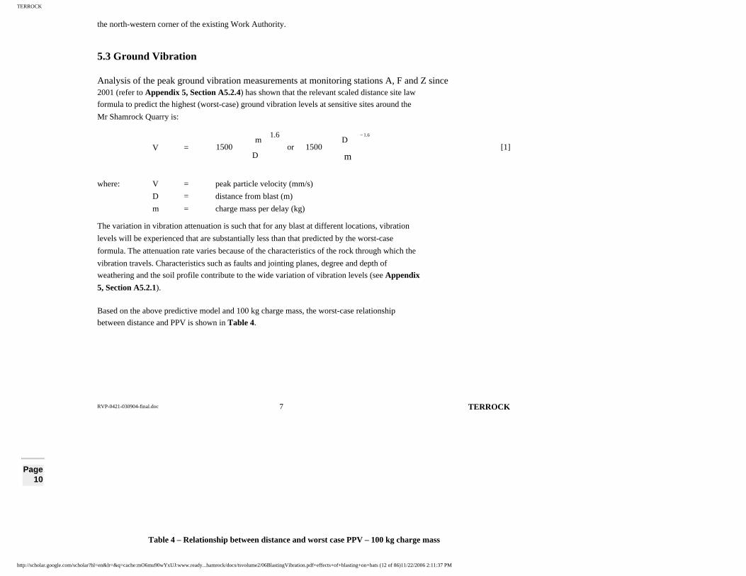
5.3 Ground Vibration
Analysis of the peak ground vibration measurements at monitoring stations A, F and Z since 2001 (refer to Appendix 5, Section A5.2.4) has shown that the relevant scaled distance site law
formula to predict the highest (worst-case) ground vibration levels at sensitive sites around the
Mr Shamrock Quarry is:
V =
1.61.6
m
D1500or
D
m1500
−
[1]
where: V = peak particle velocity (mm/s)
D = distance from blast (m)
m = charge mass per delay (kg)
The variation in vibration attenuation is such that for any blast at different locations, vibration
levels will be experienced that are substantially less than that predicted by the worst-case
formula. The attenuation rate varies because of the characteristics of the rock through which the
vibration travels. Characteristics such as faults and jointing planes, degree and depth of
weathering and the soil profile contribute to the wide variation of vibration levels (see Appendix
5, Section A5.2.1).
Based on the above predictive model and 100 kg charge mass, the worst-case relationship
between distance and PPV is shown in Table 4.
Page 10
Table 4 – Relationship between distance and worst case PPV – 100 kg charge mass
http://scholar.google.com/scholar?hl=en&lr=&q=cache:mO6mu90wYxUJ:www.ready...hamrock/docs/tsvolume2/06BlastingVibration.pdf+effects+of+blasting+on+bats (12 of 86)11/22/2006 2:11:37 PM

TERROCK
PPV (mm/s) Distance (m) 10 229 5 353 2 626 1 966
0.5 1550
The idealised worst-case ground vibration levels for a single blast are represented as circular contours in Figure 1. These idealised contours have been used to produce the ground vibration
assessment shown in Appendix 2a by moving the single blast contours around the limit of
extraction of rock reserves remaining within the existing Work Authority and recording the
maximum extent of any contour interval. Appendix 2a shows the maximum vibration levels that
will be experienced anywhere from any blast within the existing quarry. The 10 mm/s contours
from individual blasts are also shown. The vibration levels for blasts other than at the closest
limit of extraction will be less than the maximum value shown by this assessment.
The contour assessment for ground vibration from blasting of rock reserves that will become
available if the extension is approved are shown in Appendix 2b. The effect of blasting in the
extension area on the surrounding area can be compared to the effect of blasting in the current
Work Authority and can be seen by comparing the two contour assessments.
http://scholar.google.com/scholar?hl=en&lr=&q=cache:mO6mu90wYxUJ:www.ready...hamrock/docs/tsvolume2/06BlastingVibration.pdf+effects+of+blasting+on+bats (13 of 86)11/22/2006 2:11:37 PM

TERROCK
RVP-0421-030904-final.doc 8 TERROCK
Figure 1 – Maximum (worst case) ground vibration contours for a standard specification blast
Page 11
The maximum ground vibration levels at any sensitive site from blasting anywhere within the current Work Authority or the extension area from standard specification blasts will be less than
5 mm/s, except perhaps for an area in the south-east corner of the current Work Authority, as
shown in Appendix 2a. However, when monitoring indicates the 5 mm/s limit may be exceeded,
blast specifications can be changed to ensure compliance, as required.
The effects of ground vibration from blasting operations permitted if the proposed extension is
approved were quantified by selecting 22 of the houses nearest the quarry and comparing the
estimated peak ground vibration from any blast within this area from the estimated peak ground
vibration from any blast within the current Work Authority. For comparison, the peak ground
vibration levels are listed in Table 5. The ground vibration is estimated to increase marginally at
some houses, particularly house Nos. 1, 3 and 16-22, and to reduce at the other houses.
Table 5 – Summary of peak air and ground vibration
Peak Air Vibration (dBL) Peak Ground Vibration (mm/s) House
No. Current Work
Authority Extension Difference
Current Work Authority
Extension Difference
1 110 110 - 2.4 3.0 +0.6 2 107 107 - 1.9 1.9 - 3 104 104 - 1.3 1.5 +0.2 4 105 100 -5 1.0 0.8 -0.2 5 107 102 -5 1.4 0.9 -0.5 6 111 103 -8 1.8 0.8 -1.0 7 108 100 -8 1.0 0.8 -0.2 8 110 105 -5 1.0 0.8 -0.2 9 108 107 -1 1.2 0.9 -0.3
10 103 105 +2 1.2 0.8 -0.4 11 104 105 +1 1.2 0.9 -0.3 12 104 106 +2 1.4 1.0 -0.4 13 114 114 - 4.0 3.0 -1.0 14 107 107 - 1.9 1.7 -0.2 15 110 109 -1 2.3 2.1 -0.2
http://scholar.google.com/scholar?hl=en&lr=&q=cache:mO6mu90wYxUJ:www.ready...hamrock/docs/tsvolume2/06BlastingVibration.pdf+effects+of+blasting+on+bats (14 of 86)11/22/2006 2:11:37 PM

TERROCK
RVP-0421-030904-final.doc 9 TERROCK
16 108 111 +3 1.4 2.0 +0.4 17 108 111 +3 1.6 2.1 +0.5 18 107 110 +3 1.6 2.1 +0.5 19 108 109 +1 1.9 2.2 +0.3 20 108 109 +1 2.0 2.3 +0.3 21 108 111 +3 2.1 3.2 +1.1 22 107 110 +3 1.9 3.0 +1.1
varies: -8 to +3 dBL varies: -1.0 to +1.1 mm/s
5.4 Air Vibration
The air vibration levels for a standard specification blast can be estimated by the basic Terrock air vibration emission model demonstrated in Appendix 5, Section A5.2.5.
The basic air vibration emission is determined:
D 120 = 32.5
mB
d250⋅
×[2]
= 35.2
1003800
89250⋅
×= 385 metres
Page 12
where: D 120 = the distance to 120 dBL in front of the blast
d = hole diameter (mm) (89 mm)
B = burden (m) (3.8 metres)
m = charge mass/hole or charge mass/delay (kg) (100 kg)
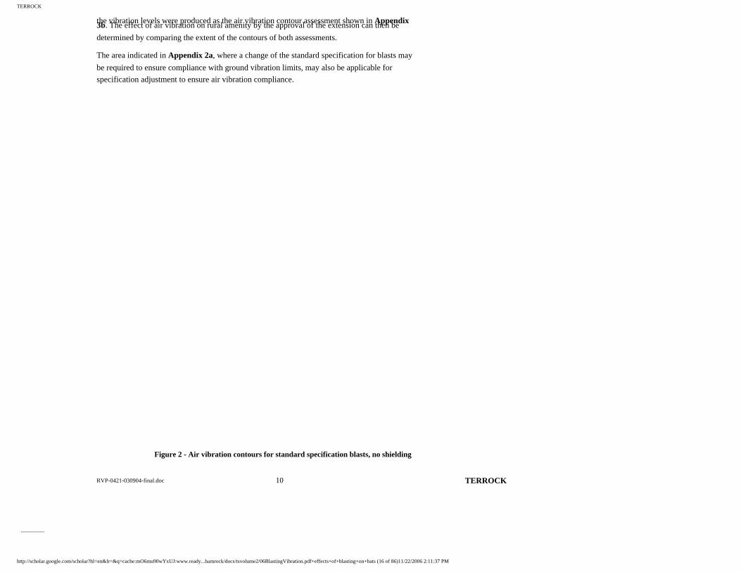
The basic emission for a blast at the top bench with no topographical shielding is shown in
contour form in Figure 2. When these basic emission contours are moved around the limit of
extraction and oriented in the most likely direction of firing the highest air vibration levels from
blasting anywhere within the Work Authority area can be established. The air vibration contour
assessment is shown in Appendix 3a.
The basic air vibration emission contours were then moved around the extraction area permitted
by approval of the extension, observing the face orientations shown, and the maximum extent of
http://scholar.google.com/scholar?hl=en&lr=&q=cache:mO6mu90wYxUJ:www.ready...hamrock/docs/tsvolume2/06BlastingVibration.pdf+effects+of+blasting+on+bats (15 of 86)11/22/2006 2:11:37 PM
TERROCK
RVP-0421-030904-final.doc 10 TERROCK
the vibration levels were produced as the air vibration contour assessment shown in Appendix 3b. The effect of air vibration on rural amenity by the approval of the extension can then be
determined by comparing the extent of the contours of both assessments.
The area indicated in Appendix 2a, where a change of the standard specification for blasts may
be required to ensure compliance with ground vibration limits, may also be applicable for
specification adjustment to ensure air vibration compliance.
Figure 2 - Air vibration contours for standard specification blasts, no shielding
http://scholar.google.com/scholar?hl=en&lr=&q=cache:mO6mu90wYxUJ:www.ready...hamrock/docs/tsvolume2/06BlastingVibration.pdf+effects+of+blasting+on+bats (16 of 86)11/22/2006 2:11:37 PM

TERROCK
Page 13
Blasting at locations within the extraction limits at lower benches will result in less air vibration than shown in the model because of topographical shielding (see Appendix 5, Section A5.4.2).
The air vibration at sensitive sites from blasting in the current Work Authority area and in the
extension area will be less than the DPI environmental guideline limits.
The effects of air vibration from blasting operations permitted by the approval of the extension
were quantified by selecting 22 of the houses nearest the quarry and comparing the estimated
peak air vibration from any blast within this area from the estimated peak air vibration from any
blast within the current Work Authority. For comparison, the peak air vibration levels are listed
in Table 5.
The peak air vibration, as estimated, will remain constant or reduce by up to 8 dBL for houses to
the north and east of the quarry (house Nos. 1-9). The peak air vibration is estimated to remain
constant or increase by up to 3 dBL for houses to the south-east and west of the quarry (house
Nos. 10-22).
6. EFFECTIVE CONTROL OF BLASTS
6.1 General
Blasting in Victorian quarries is regulated by the Extractive Industries Development Act (1995), the Extractive Industries Development Regulations (1996) and the Extractive Industries
Regulations (1989) and the Dangerous Goods (Explosives) Regulations (2000), with reference to
Australian Standard 2187.2-1993 (Explosives Storage, Transport and Use) and the Australian
Explosives Code.
All quarries in Victoria are required by law to record details of every blast in an official report
book, and these reports are available for official inspection by the authorities. The report book
includes a stocktaking section for controlling the explosives’ inventory, which can be checked
against official records, which explosives’ suppliers are required to keep. Quarry Managers and
shotfirers are also required to hold statutory certificates and licences, which are issued only after
passing satisfactory experience and examination criteria, and are liable to have these suspended
or cancelled if they do not comply with the regulations.
6.2 Flyrock and Blast Exclusion Zone
Efficient blasting practice results in broken rock being left in a pile next to the blasting face, but the possibility of flyrock and it’s effective control must always be considered. The public, quarry
personnel and quarry infrastructure must be adequately protected from possible flyrock from
quarry blasting operations. The distinction must be made between 'flyrock' being the normal
movement of broken rock from a blast and 'wild flyrock', the unplanned and unexpected violent
http://scholar.google.com/scholar?hl=en&lr=&q=cache:mO6mu90wYxUJ:www.ready...hamrock/docs/tsvolume2/06BlastingVibration.pdf+effects+of+blasting+on+bats (17 of 86)11/22/2006 2:11:37 PM

TERROCK
RVP-0421-030904-final.doc 11 TERROCK
projection of rock fragments at a great velocity from a blast.
Flyrock occurs when the explosive in the blasthole is poorly confined and energy in the form of
high pressure gas is available to throw broken rock fragments into the air, accompanied by
excessive air vibration. If there is insufficient stemming height or poor quality stemming
material is used (eg. drill cuttings), material may be projected from the collar region of the
blasthole at a high trajectory into the air around the blast site. If the blasthole has insufficient
burden in front of the blasthole, flyrock may be projected at a somewhat flatter trajectory in front
of the face.
Page 14
Potential flyrock in front of the face is controlled by having a design burden appropriate for the hole diameter, face height and charge mass used and proper survey and loading procedures to
identify and treat underburdened zones, such as outlined in Appendix 4a and practiced by the
shotfiring staff at this quarry. Potential flyrock behind the face is controlled by having an
appropriate stemming height, the use of good quality stemming material and proper procedures
to check on the explosive column rise during loading, as outlined in Appendix 4a and practiced
by the quarry shotfiring staff.
The possibility of flyrock is reduced to an insignificant level by proper blasting practice. There
have been hundreds of blasts conducted at this quarry by Readymix and CSR personnel without
flyrock incidents. There have also been hundred of blasts conducted at other quarries in Victoria,
within 50 metres of houses and heavily trafficked roads, without flyrock incidents because of the
conscientious application of the principles outlined in Appendix 4a. Flyrock can be an emotive
subject and there is the possibility that flyrock can be projected large distances with ineffective
control procedures. The opportunity has been taken to quantify the conditions under which
flyrock may result in detail in Section A5.5 of Appendix 5.
The performance of the shotfiring staff at this quarry over many years has demonstrated that
blasting can be conducted to within 100 metres of a boundary without increased risk to the
public behind a blast. The area around the blast site, including the adjoining private land and the
Pony Club, must be checked for the presence of people as part of the pit clearance procedure and
again immediately prior to the blast being initiated, according to the ‘exclusion zone’ discussed
in Section A5.5 of Appendix 5.
http://scholar.google.com/scholar?hl=en&lr=&q=cache:mO6mu90wYxUJ:www.ready...hamrock/docs/tsvolume2/06BlastingVibration.pdf+effects+of+blasting+on+bats (18 of 86)11/22/2006 2:11:37 PM

TERROCK
RVP-0421-030904-final.doc 12 TERROCK
The critical dimensions of the zone are 400 metres in front of the blast and 150 metres behind the
blast and are applied regardless of variation in the surface level; a conservative approach.
The exclusion zone is demonstrated in Figure 3. This is reproduced as a scaled overlay and used
by the shotfirer in planning the evacuation of the quarry at firing time (see Appendix 4c).
Figure 3 – Exclusion zone
Page 15
6.3 Environmental Management Plan
To control the environmental effects of blasting, blasting must continue to be carried out in compliance with the applicable regulations and the recommended blasting practice specified in
this report (see Appendix 4).
Air and ground vibration resulting from all blasts should continue to be measured at the nearest
sensitive site to the extraction area, or some other convenient location that will permit the
http://scholar.google.com/scholar?hl=en&lr=&q=cache:mO6mu90wYxUJ:www.ready...hamrock/docs/tsvolume2/06BlastingVibration.pdf+effects+of+blasting+on+bats (19 of 86)11/22/2006 2:11:37 PM

TERROCK
vibration at the nearest sensitive site to be reliably estimated. At present, the vibration from all blasts are measured at the quarry office (monitoring station A), the north-west corner
(monitoring station F) and Toomuc Valley Road (monitoring station Z). The monitoring
locations should be reviewed if the extension is approved and the blasting operations move to the
west and southern extraction areas. Sites in Toomuc Valley Road and Mt Shamrock Road may
become more appropriate in the future. Vibration may be monitored at the nearest sensitive
location only with the permission of the residents, and may be resented as an intrusion and the
ground vibration must be sufficient to reliably trigger the instruments. Compliance with blast
vibration limits at the nearest sensitive site will ensure that air and ground vibration levels stay
below regulatory limits at more distant sensitive sites.
In the event that the vibration measurements indicate that the 95% DPI regulatory guideline
limits may be exceeded in future blasts, the blasting specification and shotfiring practice must be
reviewed and modifications made, as appropriate, to ensure continuing compliance.
7. OTHER BLASTING EFFECTS
7.1 The Effects of Blasting on Domestic and Wild Fauna
The effects of blasting in the quarry and the proposed extension on domestic and wild fauna is negligible. Some animals have been known to react adversely to loud noise and strong
vibrations. Thunder and lightning are sufficient to cause many dogs to become anxious and seek
a place to hide to feel safe. As a general rule, most animals, whether domestic or wild, soon learn
to pay little attention to human activity, including blasting, unless it is truly threatening.
Within the Work Authority boundaries in many Victorian quarries, such as the Readymix
Oaklands Junction Quarry, are resident kangaroo populations. Peregrine Falcons nest on rock
ledges within 100 metres of working faces at Readymix Colac Quarry, unconcerned about
blasting operations. Many quarries control grass growth in the unworked areas by grazing cattle
and sheep, upon which the nearby blasting has no effect.
Detailed observations were made of the response of 200 animals, birds and fish, including owls,
snow leopards, bats and trout, as well as cattle and sheep, to a shaft and tunnel project beneath
the Oregon Zoo (Oriard 2002), when subjected to ground vibrations ranging from 1.3 mm/s to 17
mm/s. At first, some animals looked nervous for a few seconds, but by the eighth blast they paid
little or no attention.
This is consistent with our experience. Animals near blasting at a new site or new animals
brought to a blast site, may show some initial nervousness but soon become habitualised.
A new open cut coal mine near Muswellbrook, as part of its operating conditions, was required
to observe the behaviour of horses in a nearby thoroughbred stud for the first blasts.
http://scholar.google.com/scholar?hl=en&lr=&q=cache:mO6mu90wYxUJ:www.ready...hamrock/docs/tsvolume2/06BlastingVibration.pdf+effects+of+blasting+on+bats (20 of 86)11/22/2006 2:11:37 PM

TERROCK
RVP-0421-030904-final.doc 13 TERROCK
Page 16
At vibration levels of 1 mm/s to 3 mm/s and 110 dBL to 115 dBL, the horses were unconcerned. Throughout the Hunter Valley in New South Wales other thoroughbred studs are located near
large open cut coal mines without incident.
The effects of blast vibration on animals and birds, whether domestic or wild, is less than the
effects of natural events, such as thunder and lightning, and once habitualised most animals show
no response. Some dogs show more response to the high frequency warning sirens than to the
blast itself. Animals that show adverse reactions to current blasting will show similar reactions to
blasting within the quarry extension.
7.2 The Effects of Blasting on Stream Ecology
The effects of blasting in the quarry and the proposed extension on the stream ecology of Toomuc Creek and its minor tributaries is negligible.
The pressure created from an explosive charge placed and fired within the water can be sufficient
to kill or injure mammals, birds, fish and invertebrates, if sufficiently high. Fish and marine
mammals with lungs or swim bladders are the creatures most sensitive to pressure changes in the
water.
Blasting on land near water can also generate water pressure. The Canadian Department of
Fisheries and Oceans (CDFO) require that the pressure generated from blasting on or in the
water does not exceed a guideline level of 100 kPa for the protection of fish and aquatic
mammals; D.G. Wright et al (1998). The effect of blast pressure on invertebrates and crustaceans
is less; Oriard (2002) quotes a U.S. Navy test in 1975 at Chesapeake Bay which found that
oysters could survive 23,905 kPa.
Using the published CDFO criteria, a charge mass of 100 kg (a typical quarry charge) could be
fired from 29 metres to 50.3 metres from Toomuc Creek, depending on whether the substrate is
unsaturated soil or rock, to limit pressure to the 100 kPa safe guideline pressure level. At the
closest distance from the quarry extension to the Toomuc Creek, the water pressure levels will be
less than 0.1 kPa.
The effect on the stream ecology from air vibration will also be negligible. The change of
pressure associated with an air vibration of 115 dBL, the regulatory limit at houses, is the
equivalent to the change of pressure associated with a wind speed of about 4.5 m/s. It may,
therefore, be reasonably concluded that wind will have more effect on stream ecology than air http://scholar.google.com/scholar?hl=en&lr=&q=cache:mO6mu90wYxUJ:www.ready...hamrock/docs/tsvolume2/06BlastingVibration.pdf+effects+of+blasting+on+bats (21 of 86)11/22/2006 2:11:37 PM

TERROCK
RVP-0421-030904-final.doc 14 TERROCK
vibration because the maximum air vibration at the stream is estimated to be 107 dBL.
8. CONCLUSIONS
This report addressed the following issues:
• Air vibration and peak ground vibration measurements. • Optimisation of blast hole design and initiation systems.
• Analysis of historical information gathered at the site. • Prediction of future blasting contours and measurements at sensitive sites. • Assessment of blasting in the context of DPI ‘Environmental Guidelines – Ground
Vibration and Air Vibration Limits for Blasting in Mines and Quarries 2001’.
• Comparison of predicted blast vibration levels and environmental limits, structural damage
and human response standards.
Page 17
The following conclusions were made in answering the specific questions raised in the scoping document:
• What impact (if any) will blasting in the proposed use and development of the quarry
extension have on rural residential amenity?
The effect of blasting in the extension area, when compared to blasting in the current Work
Authority, on the sensitive sites surrounding the quarry will be a reduction of the peak vibration
levels at some sites, a marginal increase in the peak vibration levels at some sites and the peak
vibration levels at other sites will remain about the same.
The peak ground vibration, as estimated, will be reduced at sites in an arc from the north-east to
the south of the quarry. The peak ground vibration, as estimated, will increase at the sensitive
sites ranging from south-west to north of the quarry. The peak ground vibration from any blast
fired anywhere in the quarry or extension area will not exceed the guideline ground vibration
limits of the DPI environmental guidelines for new sites.
The peak air vibration levels will reduce or remain constant at sensitive sites, ranging from north
http://scholar.google.com/scholar?hl=en&lr=&q=cache:mO6mu90wYxUJ:www.ready...hamrock/docs/tsvolume2/06BlastingVibration.pdf+effects+of+blasting+on+bats (22 of 86)11/22/2006 2:11:37 PM
TERROCK
RVP-0421-030904-final.doc 15 TERROCK
to east of the quarry. The peak air vibration will increase or remain constant at sensitive sites ranging from south-east to north-west of the quarry. The peak air vibration from any blast fired
anywhere in the quarry or extension area will not exceed the guideline air vibration limits of the
DPI environmental guidelines for new sites.
Blasting is conducted at approximately weekly intervals (32 in 2003) and on occasions where
blasting is ‘felt’ at sensitive sites, the vibration has a 2-4 seconds duration.
• Will blasting in relation to the proposed use and development of the quarry extension
cause a danger to life?
Blasting operations in the current Work Authority and the extension area do not and will not
cause a danger to life when conducted by licensed and experienced shotfirers acting under the
requirements of the regulatory framework of the responsible authorities, the Work Authority and
Planning Permit conditions and the recommended blasting practice and procedure contained in
Appendix 4 of this report.
The shotfirer(s) at the quarry exercise(s) rigorous control procedures during all phases of blast
design, drilling, loading and firing to ensure adequate explosives' confinement. The observance
of a conservative exclusion zone and a pit evacuation procedure to ensure the absence of people
with the potential flyrock zone within and adjacent to the quarry at the time of firing prevents
danger to life.
To ensure continuing compliance of blast vibration levels to DPI guideline limits, the vibration
should continue to be monitored at locations where there is sufficient ground vibration to ensure
reliable triggering and the vibration levels at sensitive sites can be reliably determined. Vibration
levels can only be monitored at sensitive sites with the permission of the resident. The vibration
levels should continue to be reviewed immediately after each blast so that blasting specifications
or loading practice can be modified, if necessary, to ensure continuing compliance with the DPI
environmental guideline limits.
Adrian J. Moore
22 nd February 2005
Page 18
http://scholar.google.com/scholar?hl=en&lr=&q=cache:mO6mu90wYxUJ:www.ready...hamrock/docs/tsvolume2/06BlastingVibration.pdf+effects+of+blasting+on+bats (23 of 86)11/22/2006 2:11:37 PM

TERROCK
APPENDICES
http://scholar.google.com/scholar?hl=en&lr=&q=cache:mO6mu90wYxUJ:www.ready...hamrock/docs/tsvolume2/06BlastingVibration.pdf+effects+of+blasting+on+bats (24 of 86)11/22/2006 2:11:37 PM

TERROCK
Page 19
http://scholar.google.com/scholar?hl=en&lr=&q=cache:mO6mu90wYxUJ:www.ready...hamrock/docs/tsvolume2/06BlastingVibration.pdf+effects+of+blasting+on+bats (25 of 86)11/22/2006 2:11:37 PM

TERROCK
Page 20
http://scholar.google.com/scholar?hl=en&lr=&q=cache:mO6mu90wYxUJ:www.ready...hamrock/docs/tsvolume2/06BlastingVibration.pdf+effects+of+blasting+on+bats (26 of 86)11/22/2006 2:11:37 PM

TERROCK
http://scholar.google.com/scholar?hl=en&lr=&q=cache:mO6mu90wYxUJ:www.ready...hamrock/docs/tsvolume2/06BlastingVibration.pdf+effects+of+blasting+on+bats (27 of 86)11/22/2006 2:11:37 PM

TERROCK
Page 21
http://scholar.google.com/scholar?hl=en&lr=&q=cache:mO6mu90wYxUJ:www.ready...hamrock/docs/tsvolume2/06BlastingVibration.pdf+effects+of+blasting+on+bats (28 of 86)11/22/2006 2:11:37 PM

TERROCK
Page 22
http://scholar.google.com/scholar?hl=en&lr=&q=cache:mO6mu90wYxUJ:www.ready...hamrock/docs/tsvolume2/06BlastingVibration.pdf+effects+of+blasting+on+bats (29 of 86)11/22/2006 2:11:37 PM

TERROCK
Page 23
http://scholar.google.com/scholar?hl=en&lr=&q=cache:mO6mu90wYxUJ:www.ready...hamrock/docs/tsvolume2/06BlastingVibration.pdf+effects+of+blasting+on+bats (30 of 86)11/22/2006 2:11:37 PM

TERROCK
http://scholar.google.com/scholar?hl=en&lr=&q=cache:mO6mu90wYxUJ:www.ready...hamrock/docs/tsvolume2/06BlastingVibration.pdf+effects+of+blasting+on+bats (31 of 86)11/22/2006 2:11:37 PM

TERROCK
Page 24
APPENDIX 4A - GENERAL RECOMMENDED BLASTING PRACTICE
READYMIX – MT SHAMROCK QUARRY (PAKENHAM)
GENERAL RECOMMENDED BLASTING PRACTICE
A4.1 Determine the area to be blasted. Examine the face and area of the blast. Use appropriate survey methods to measure the face conditions, design hole positions and
lay out the drilling pattern. Drill blastholes.
A4.2 Use laser theodolite and bore tracking survey techniques or other techniques, as
appropriate, to measure the blastholes to the following specified accuracies:
• Face Height: (± 150 mm) • Blasthole angle from vertical: (± 1 degree) • Profiled burden of blastholes: (± 150 mm) • Blasthole depth: (± 150 mm) • Subgrade: (± 150 mm) • Blasthole Spacing: (± 150 mm)
A4.3 From face and borehole survey, design loading pattern in detail.
A4.4 Before commencing to load blastholes or bringing explosives to the blasting site, check
that all persons in the area are aware that blasting will take place, and that warning
signals and signs are in place as required.
A4.5 When loading blastholes be careful and methodical. Monitor the position of the
explosive charge with the loading hose, a tape or loading pole as it rises in the blasthole.
A4.6 Light-load any blast hole as necessary to achieve safe blasting, by such means as
decking with stemming or using smaller diameter packaged explosives.
http://scholar.google.com/scholar?hl=en&lr=&q=cache:mO6mu90wYxUJ:www.ready...hamrock/docs/tsvolume2/06BlastingVibration.pdf+effects+of+blasting+on+bats (32 of 86)11/22/2006 2:11:37 PM
TERROCK
RVP-0421-030904-final.doc 22 TERROCK
A4.7 Use sufficient stemming length of appropriate material. A general guideline is for stemming height to equal burden, but greater stemming heights may be necessary in
some cases. Drill cuttings are generally not appropriate for containing explosives gases
in the blast hole. Crushed aggregate approximately 1/10 of the blast hole diameter is the
most suitable stemming material.
A4.8 When all holes are loaded, complete the surface firing circuit connections and connect
the firing cable or Nonel load in line.
A4.9 Clear the area, check the adjoining private land and Pony Club for the presence of
people, place vibration monitors and set to record.
A4.10 Give warning signals, conduct a final clearance check and fire the shot from a safe
location.
A4.11 Inspect the blast site and sound the all clear.
A4.12 Collect the vibration monitors, download and record measurements.
Page 25
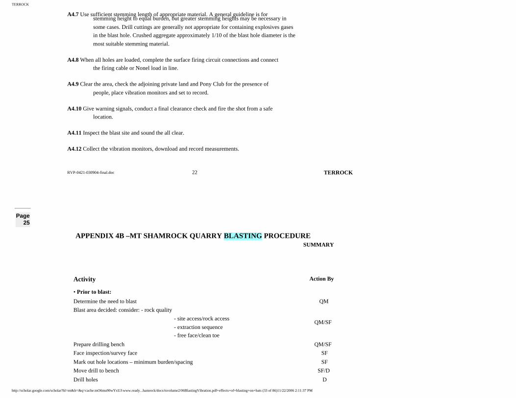
APPENDIX 4B –MT SHAMROCK QUARRY BLASTING PROCEDURE SUMMARY
Activity Action By
• Prior to blast:
Determine the need to blast QM
Blast area decided: consider: - rock quality
- site access/rock access
- extraction sequence
- free face/clean toe
QM/SF
Prepare drilling bench QM/SF
Face inspection/survey face SF
Mark out hole locations – minimum burden/spacing SF
Move drill to bench SF/D
Drill holes D
http://scholar.google.com/scholar?hl=en&lr=&q=cache:mO6mu90wYxUJ:www.ready...hamrock/docs/tsvolume2/06BlastingVibration.pdf+effects+of+blasting+on+bats (33 of 86)11/22/2006 2:11:37 PM

TERROCK
RVP-0421-030904-final.doc 23 TERROCK
Survey holes for depth and minimum burden SF Redrill blockages/defective holes D
Decision to fire – select date QM/SF
Design blast and initiation sequence, calculate explosives quantities QM/SF
Order explosives – adjust firing date for availability SF
Notify vibration monitoring consultant SF/VM
• Day prior to blast:
Recheck drillholes SF
Delivery of stemming material SF
• Day of blast:
Notify neighbours as required SF
Clear unnecessary personnel and machinery from blast site SF
Determine evacuation area QM/SF
Post blast warning/advisory signs SF
Move primers/detonators from magazine to blast SF
Prime blastholes SF
Move explosives bulk tanker to blast site after weigh in on entering quarry ES
Progressively load blastholes, checking explosives column rise and stop at
correct stemming height SF/ES
Allow for explosive gassing (if appropriate) SF
Progressively add stemming to blastholes – check quantity SF
Load and stem all blastholes SF
Bulk tanker leaves site and quarry after weigh out ES
Modify initiation sequence (if necessary) SF
Tie in echelon row delays - back row forward SF
Tie in control row - last to first SF
Finalise blast time QM/SF
VM to site to set out monitors at sites as instructed VM/SF
Return detonators and primers to magazine SF
Execute evacuation check sheet (attached) SF
Page 26
APPENDIX 4B –MT SHAMROCK QUARRY BLASTING PROCEDURE
http://scholar.google.com/scholar?hl=en&lr=&q=cache:mO6mu90wYxUJ:www.ready...hamrock/docs/tsvolume2/06BlastingVibration.pdf+effects+of+blasting+on+bats (34 of 86)11/22/2006 2:11:37 PM
TERROCK
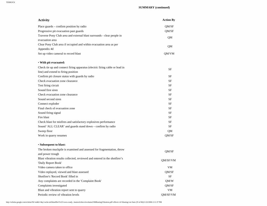
SUMMARY (continued)
Activity Action By
Place guards – confirm position by radio QM/SF
Progressive pit evacuation past guards QM/SF
Traverse Pony Club area and external blast surrounds - clear people in
evacuation area QM
Clear Pony Club area if occupied and within evacuation area as per
Appendix 4d QM
Set up video cameral to record blast QM/VM
• With pit evacuated:
Check tie up and connect firing apparatus (electric firing cable or lead in
line) and extend to firing position SF
Confirm pit closure status with guards by radio SF
Check evacuation zone clearance SF
Test firing circuit SF
Sound first siren SF
Check evacuation zone clearance SF
Sound second siren SF
Connect exploder SF
Final check of evacuation zone SF
Sound firing signal SF
Fire blast SF
Check blast for misfires and satisfactory explosives performance SF
Sound ‘ALL CLEAR’ and guards stand down – confirm by radio SF
Sweep floor QM
Work in quarry resumes QM/SF
• Subsequent to blast:
The broken muckpile is examined and assessed for fragmentation, throw
and power trough QM/SF
Blast vibration results collected, reviewed and entered in the shotfirer’s
'Daily Report Book' QM/SF/VM
Video camera taken to office VM
Video replayed, viewed and blast assessed QM/SF
Shotfirer's 'Record Book' filled in SF
Any complaints are recorded in the 'Complaint Book' QM/W
Complaints investigated QM/SF
Blast and vibration report sent to quarry VM
Periodic review of vibration levels QM/SF/VM
http://scholar.google.com/scholar?hl=en&lr=&q=cache:mO6mu90wYxUJ:www.ready...hamrock/docs/tsvolume2/06BlastingVibration.pdf+effects+of+blasting+on+bats (35 of 86)11/22/2006 2:11:37 PM

TERROCK
RVP-0421-030904-final.doc 24 TERROCK
Periodic reporting of monitoring to planning authority (Work Authority condition)
QM/SF
QM: Quarry Manager SF: Shotfirer D: Driller/contractorES: Explosives' supplier VM: Vibration monitoring consultantW: Weighbridge operator
Page 27
APPENDIX 4C - MT SHAMROCK QUARRY - BLAST EVACUATION CHECK SHEET
http://scholar.google.com/scholar?hl=en&lr=&q=cache:mO6mu90wYxUJ:www.ready...hamrock/docs/tsvolume2/06BlastingVibration.pdf+effects+of+blasting+on+bats (36 of 86)11/22/2006 2:11:37 PM

TERROCK
RVP-0421-030904-final.doc 25 TERROCK
Page 28
APPENDIX 4D - MT SHAMROCK QUARRY – INFORMATION ON BLASTING
http://scholar.google.com/scholar?hl=en&lr=&q=cache:mO6mu90wYxUJ:www.ready...hamrock/docs/tsvolume2/06BlastingVibration.pdf+effects+of+blasting+on+bats (37 of 86)11/22/2006 2:11:37 PM

TERROCK
RVP-0421-030904-final.doc 26 TERROCK
http://scholar.google.com/scholar?hl=en&lr=&q=cache:mO6mu90wYxUJ:www.ready...hamrock/docs/tsvolume2/06BlastingVibration.pdf+effects+of+blasting+on+bats (38 of 86)11/22/2006 2:11:37 PM

TERROCK
Page 29
APPENDIX 5 – BLASTING PRACTICE, THE NATURE OF VIBRATIONS AND ITS MEASUREMENT AND CONTROL
EXPLANATORY NOTES
A5.1 QUARRY BLASTING PRACTICE
These notes were written to explain, in simple terms, the nature of blast vibration, how it is measured, acceptable community standards for blast vibration and how it is controlled.
To extract rock economically in quarries it is necessary to blast the rock with explosives. It is
necessary to place the explosives within the rock mass by drilling blastholes downward into
the rock. A quantity of explosives is then placed in each blasthole, which is then topped up
with crushed aggregate to effectively confine the explosives charge. Current blasting practice
at the quarry is described below, which will carry on into the planned extension, subject to a
continual improvement review procedure.
Before the blastholes are drilled, the face is surveyed by appropriate methods and the position
and inclination of the holes are designed to optimise minimum and maximum burden and
spacing criteria.
A typical quarry blast is described as follows:
Blastholes, 89 mm diameter are drilled in rows 3.8 metres distance from the edge of the
quarry bench and 3.8 metres between rows (burden). Blastholes are spaced 4.1 metres apart,
as shown in Figure A5.1.
http://scholar.google.com/scholar?hl=en&lr=&q=cache:mO6mu90wYxUJ:www.ready...hamrock/docs/tsvolume2/06BlastingVibration.pdf+effects+of+blasting+on+bats (39 of 86)11/22/2006 2:11:37 PM

TERROCK
RVP-0421-030904-final.doc 27 TERROCK
Figure A5.1 – Typical quarry drilling pattern
The burden and spacing are varied to match the characteristics of the rock being blasted.
The actual face height over the past five years varied from 10 metres to 25 metres and the drill
depths were adjusted accordingly. In the proposed extension, the maximum face heights will
be limited to 15 metres and this has been used as the basis of this assessment.
Holes are drilled at an angle to the vertical to match the inclination of the face. The holes are
drilled to floor level, plus an extra distance known as the sub-grade, to ensure a smooth floor
results after blasting. For a 15 metre face height, at an angle of 10 o with one metre sub-drill, the hole depth is 16.2 metres.
Page 30
Explosives are then loaded into the blasthole until the top of the explosive charge is no closer than 3.8 metres from the top of the blasthole. The weight of explosives that can be placed in
the blasthole depends on the density of the explosive used because the volume of the blasthole
is fixed by the diameter and charge length. A bulk emulsion explosive is generally used with a
maximum density of 1.3 g/cc. The charge mass in the 16.2 metre deep hole is approximately
100 kg. The hole is then topped up with at least 3.8 metres of aggregate to effectively confine
the explosives charge, as shown in Figure A5.2. If an explosive with a lower density is used
the maximum charge will reduce. The denser explosives have more energy available and their
use is matched to the fracturing characteristics of the rock. They are also water resistant and
can be used in blastholes containing water.
http://scholar.google.com/scholar?hl=en&lr=&q=cache:mO6mu90wYxUJ:www.ready...hamrock/docs/tsvolume2/06BlastingVibration.pdf+effects+of+blasting+on+bats (40 of 86)11/22/2006 2:11:37 PM

TERROCK
RVP-0421-030904-final.doc 28 TERROCK
Figure A5.2 - Blasthole design for Readymix – Mt Shamrock Quarry (Pakenham)
It is common quarry practice for the number of blastholes loaded and fired in any one blast to vary between 60 and 140 holes. The explosives in each blasthole are initiated by signal tube
delay detonators.
The signal tube leads from each blasthole are joined together by surface signal tube delay
detonators to form a blasting circuit. At the approved firing time, after warning signals have
been given, the blasting circuit is connected to an exploder and fired.
All blastholes do not, however, explode at the same instant of time. Reduced blast vibration
and improved fragmentation result because the blastholes detonate in sequence, with a small
time delay of several milliseconds between each explosion. This small time delay is provided
by the surface signal tube delay detonators and an unlimited number of delay intervals are
possible. It is usual for only one blasthole to be exploded at any instant of time. In the case of
20 blastholes being fired in the one blast, a possible delay sequence is shown in Figure A5.3.
42 67 92 117 142 167 192 217 242 267
2252001751501251007550250
note: the above numbers refer to the
detonation times in milliseconds
Figure A5.3 - Typical delay sequence
Page 31
The blastholes at one end of the blast explode first, and are followed by the succeeding blastholes in the sequence shown. The total time for the 20 blastholes to be exploded would
be approximately a quarter of a second. The total time for 100 blastholes in this delay pattern
would be one and a quarter seconds. The number of holes fired in a blast does not directly
http://scholar.google.com/scholar?hl=en&lr=&q=cache:mO6mu90wYxUJ:www.ready...hamrock/docs/tsvolume2/06BlastingVibration.pdf+effects+of+blasting+on+bats (41 of 86)11/22/2006 2:11:37 PM

TERROCK
effect the resulting vibration levels, although the time between the first and lost holes firing determines the blast duration.
After the blast, the broken rock is left lying against the wall of the quarry excavation, as
shown in Figure A5.4. The broken rock is then loaded into trucks and taken to the crusher.
Figure A5.4 - Rock left after a typical quarry blast
A5.2 THE NATURE AND MEASUREMENT OF BLAST VIBRATION
Explosive energy produces the following effects:
• Rock shattering and displacement.
• Ground vibration.
• Air vibration.
The energy contained in explosives used in quarry blastholes is designed to break and
displace rock, and the more of the energy available which can be utilised for that purpose the
more efficient the blast. However, some of the energy cannot be utilised in breaking rock and
creates vibration in the surrounding rock and air.
http://scholar.google.com/scholar?hl=en&lr=&q=cache:mO6mu90wYxUJ:www.ready...hamrock/docs/tsvolume2/06BlastingVibration.pdf+effects+of+blasting+on+bats (42 of 86)11/22/2006 2:11:37 PM

TERROCK
RVP-0421-030904-final.doc 29 TERROCK
As a general principle, both air and ground vibration increase with increasing charge mass
and reduce with increasing distance.
Page 32
A5.2.1 Ground Vibration
Ground vibration radiates outwards from the blast site and gradually reduces in magnitude, in the same manner as ripples behave when a stone is thrown into a pool of water, schematically
shown in Figure A5.5. The motion of the wave can be defined by taking measurements of a
float on the surface of the water. With suitable instruments we can measure the displacement
or amplitude, the velocity, the acceleration of the float and the wave length of the waves.
Figure A5.5 – Schematic diagram of vibration terminology
With ground vibration, the motion of the surface of the ground can be measured by coupling a suitable instrument directly to the surface.
http://scholar.google.com/scholar?hl=en&lr=&q=cache:mO6mu90wYxUJ:www.ready...hamrock/docs/tsvolume2/06BlastingVibration.pdf+effects+of+blasting+on+bats (43 of 86)11/22/2006 2:11:37 PM

TERROCK
RVP-0421-030904-final.doc 30 TERROCK
Early researchers into ground vibration discovered a closer relationship between velocity of
the ground surface and the response of structures than either displacement or acceleration.
Measurement of velocity of the motion of the surface of the ground near where it enters a
building has become the standard by which ground vibration is measured and regulated.
Ground vibration is measured with a blasting seismograph and is commonly expressed in
terms of Peak Particle Velocity and measured in terms of millimetres per second (mm/s). To
define the motion in three dimensions, it is necessary to use three transducers to measure the
vibration in three mutually perpendicular directions and then determine a Peak Particle
Velocity or Peak Vector Sum, which is the instantaneous maximum vector of the three
individual measurements:
2
v2
l2
tvvv(PVS)PPVie. ++=
Rather than being the simple wave type in the pond illustration, the ground vibrations are
more complicated seismic events. The blast vibration consists of the different waves from
each hole in the blast with propagation controlled by the physical and structural properties of
the ground through which it travels.
Page 33
The ground vibration wave motion consists of different kinds of waves:
• Compressional (or P) waves.
• Shear (or S or secondary) waves.
• Rayleigh (or R) waves.
The Compressional or ‘P’ wave is the fastest wave through the ground. The simplest
illustration of the motion of the particles within the ‘P’ wave is to consider a long steel rod
struck on the end. The particles of the rod move to and fro as the compressive pulse travels
along the rod, ie. the particles in the wave move in the same direction as the propagation of
the wave.
The ‘P’ wave moves radially from the blasthole in all directions at velocities characteristic of
the material being travelled through (approximately 2200 m/s). The wave motion of ‘P’ waves
is illustrated in Figures A5.6 and A5.7.
http://scholar.google.com/scholar?hl=en&lr=&q=cache:mO6mu90wYxUJ:www.ready...hamrock/docs/tsvolume2/06BlastingVibration.pdf+effects+of+blasting+on+bats (44 of 86)11/22/2006 2:11:37 PM
TERROCK
RVP-0421-030904-final.doc 31 TERROCK
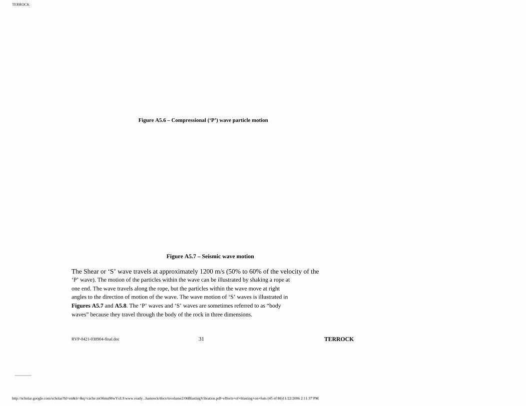
Figure A5.6 – Compressional (‘P’) wave particle motion
Figure A5.7 – Seismic wave motion
The Shear or ‘S’ wave travels at approximately 1200 m/s (50% to 60% of the velocity of the ‘P’ wave). The motion of the particles within the wave can be illustrated by shaking a rope at
one end. The wave travels along the rope, but the particles within the wave move at right
angles to the direction of motion of the wave. The wave motion of ‘S’ waves is illustrated in
Figures A5.7 and A5.8. The ‘P’ waves and ‘S’ waves are sometimes referred to as “body
waves” because they travel through the body of the rock in three dimensions.
http://scholar.google.com/scholar?hl=en&lr=&q=cache:mO6mu90wYxUJ:www.ready...hamrock/docs/tsvolume2/06BlastingVibration.pdf+effects+of+blasting+on+bats (45 of 86)11/22/2006 2:11:37 PM

TERROCK
Page 34
Figure A5.8 – Shear (‘S’) wave particle motion
Figure A5.9 – Rayleigh (‘R’) wave particle motion
The Raleigh or ‘R’ wave is a surface wave, which fades rapidly with depth and propagates more slowly (750 m/s) than the other two waves. The particles within the wave move
elliptically in a vertical plane in the same direction as the direction of propagation. At the
surface the motion is retrograde to the movement of the wave, similar to waves on the ocean.
The wave motion of the ‘R’ waves is illustrated in Figures A5.7 and A5.9.
The essential features of the ground vibration arriving at a remote point can be illustrated in
Figure A5.10. This is a wavetrace recorded in Toomuc Valley Road from a Mt Shamrock
Quarry blast on 8 th November 2001 at a distance of 1140 metres. The individual peaks of the wavetrace are a reflection of the firing of the individual blastholes with a time delay between
them. There is no direct correlation between the number of individual blastholes in a blast and
the resulting peak velocity because of the delay period between the holes firing. If the holes
were fired without the delay period, there would be a significant increase in vibration levels.
the increase can be quantified by substituting the combined charge mass in Formula [2] in http://scholar.google.com/scholar?hl=en&lr=&q=cache:mO6mu90wYxUJ:www.ready...hamrock/docs/tsvolume2/06BlastingVibration.pdf+effects+of+blasting+on+bats (46 of 86)11/22/2006 2:11:37 PM

TERROCK
RVP-0421-030904-final.doc 32 TERROCK
Section A5.4.1.1.
Page 35
Figure A5.10 – Typical ground vibration wavetrace showing ‘P’, ‘S’ and ‘R’ wave arrivals
http://scholar.google.com/scholar?hl=en&lr=&q=cache:mO6mu90wYxUJ:www.ready...hamrock/docs/tsvolume2/06BlastingVibration.pdf+effects+of+blasting+on+bats (47 of 86)11/22/2006 2:11:37 PM

TERROCK
RVP-0421-030904-final.doc 33 TERROCK
Figure A5.11 – The relationship between charge mass, distance and PPV
Page 36
The manner in which ground vibration reduces with distance is demonstrated in Figure A5.11. This shows typical maximum vibration levels that results from a large blast (many
holes) with a maximum charge mass of 50 kg and 100 kg/hole and an attenuation rate
determined for the Mt Shamrock Quarry.
The vibration measured at many locations for the same blast may show a considerable
variation from the maximum lines shown in Figure A5.11. Variations in vibration levels
ranging from one fifth of the maximum to the maximum are common. An example of the
http://scholar.google.com/scholar?hl=en&lr=&q=cache:mO6mu90wYxUJ:www.ready...hamrock/docs/tsvolume2/06BlastingVibration.pdf+effects+of+blasting+on+bats (48 of 86)11/22/2006 2:11:37 PM

TERROCK
variation in ground vibration in different directions around a blast is shown in Figure A5.12a.The vibration measurements at locations are shown plotted against scaled distance for the
blast of 22 nd June 2004 located at the north-western corner of the quarry.
Figure A5.12a - Variation in ground vibration in different directions around a blast
Monitoring station F is located on fill material above the basalt; monitoring station Z is located on weathered granite material near Toomuc Valley Road and monitoring station A is
located on fill material near the office. Such variation is frequently observed.
In general terms, ground vibration increases with increased charge mass and reduces with
distance. The relationships between charge mass distance and vibration can be analysed and
then used in a predictive formula to limit the ground vibration.
A5.3.2 Air Vibration
When air vibration is within the range of hearing it is called sound. When its frequency is below the range of hearing, it is generally referred to as concussion or air vibration. Air
vibration from blasting is measured with an air vibration meter, which meets the requirements
of AS2187.2-1993 and is expressed in terms of decibels (linear) or dBL.
Air vibration radiates outwards from the blast site in a similar manner to ground vibration, but
at a slower rate (see Figure A5.12b). This is the wavetrace of the same blast shown in Figure A5.10, but includes the air vibration channel. The time between the arrival of the ground
vibration and air vibration depends on the distance from the blast. At one kilometre, the air
vibration arrives approximately 2.5 seconds after the ground vibration. People may
experience the blast as two separate events, ie. separate air and ground vibrations.
http://scholar.google.com/scholar?hl=en&lr=&q=cache:mO6mu90wYxUJ:www.ready...hamrock/docs/tsvolume2/06BlastingVibration.pdf+effects+of+blasting+on+bats (49 of 86)11/22/2006 2:11:37 PM
TERROCK
RVP-0421-030904-final.doc 34 TERROCK
Page 37
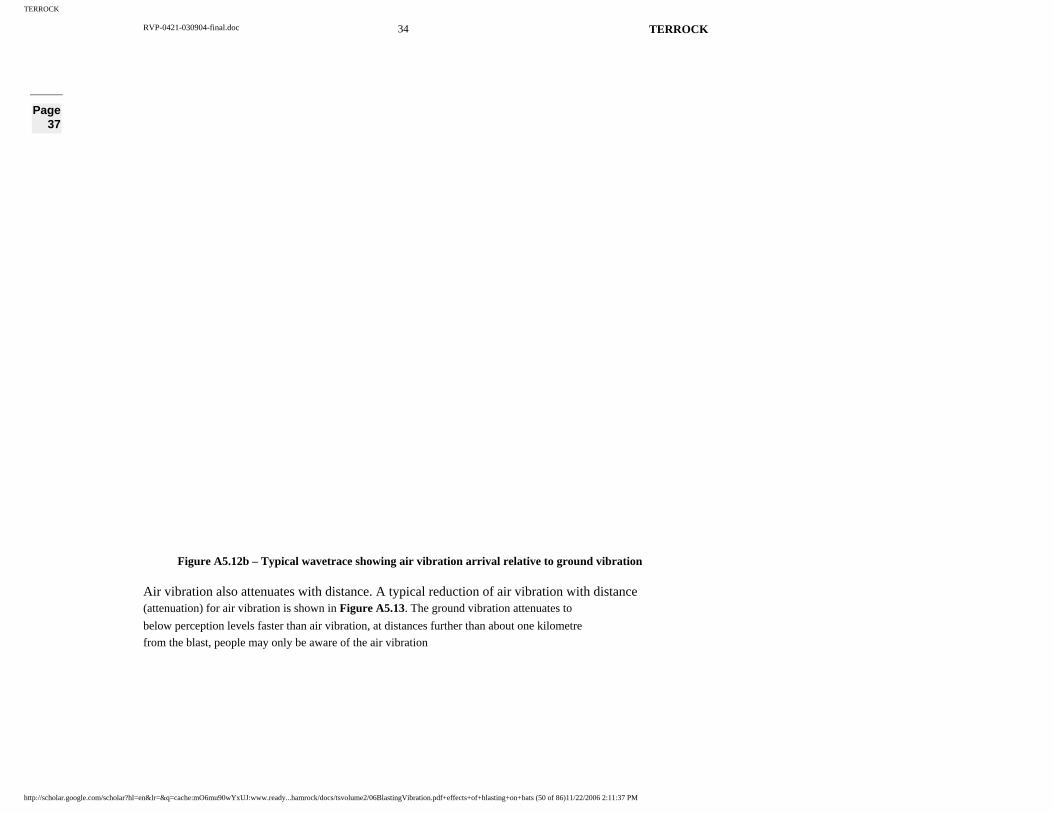
Figure A5.12b – Typical wavetrace showing air vibration arrival relative to ground vibration
Air vibration also attenuates with distance. A typical reduction of air vibration with distance (attenuation) for air vibration is shown in Figure A5.13. The ground vibration attenuates to
below perception levels faster than air vibration, at distances further than about one kilometre
from the blast, people may only be aware of the air vibration
http://scholar.google.com/scholar?hl=en&lr=&q=cache:mO6mu90wYxUJ:www.ready...hamrock/docs/tsvolume2/06BlastingVibration.pdf+effects+of+blasting+on+bats (50 of 86)11/22/2006 2:11:37 PM

TERROCK
RVP-0421-030904-final.doc 35 TERROCK
Figure A5.13 – Basic air vibration emission showing face effect and attenuation
Page 38
Surface wind speed in isolation does not have a significant effect on air vibration levels. However, atmospheric conditions (meteorological reinforcement) and the degree of shielding
(topographical shielding) can influence the level of air vibration resulting in the area
surrounding a blast. Atmospheric conditions can, on occasions, concentrate or focus air
vibration in certain directions and distances from the blast. Weather conditions that include an
'inversion' or a layer of warm air between colder air layers, such as exists on smog pollution
days, can cause an increase of up to 10 or more decibels at distances from 2 km to 5 km from
the blast. The reinforcing mechanism is demonstrated in Figure A5.14.
http://scholar.google.com/scholar?hl=en&lr=&q=cache:mO6mu90wYxUJ:www.ready...hamrock/docs/tsvolume2/06BlastingVibration.pdf+effects+of+blasting+on+bats (51 of 86)11/22/2006 2:11:37 PM

TERROCK
RVP-0421-030904-final.doc 36 TERROCK
Figure A5.14 – Combined effect of wind and temperature inversion on sound rays causing surface reinforcement
Similar effects may be caused by increasing wind speed with altitude, especially when accompanied with a change of wind direction or wind shear. For meteorology to have a
significant influence on air vibration levels at properties surrounding the Mt Shamrock
Quarry, the inversion layer or wind shear must be at levels less than about 200 metres to 250
metres above the blast. The prediction meteorological conditions require accurate local data
that is not freely available for use in adjusting blasting times to avoid reinforcements
occurring. The practical effect of meteorological reinforcement is that, on occasions, blasts
may be noticed in locations distant from the quarry where they are normally imperceptible.
Elevated air vibration levels due to meteorology are usually below regulatory limits because
at the distance from the blast at which they characteristically occur (>2 km), the basic
emission levels are low following natural attenuation. In the inversion season between late
autumn and early winter, firing blasts in the mid-afternoon is the only practical means
available for reducing the possible effects of meteorology.
The wind also plays a significant part in air vibration measurement and interpretation. The air
vibration meter contains a precision microphone with a low frequency response. The air
vibration is measured by electrical signals generated by the response of the diaphragm of the
microphone to changes of pressured caused by the compressional wave. Wind also results in
changes of pressure on the diaphragm of the microphone.
Page 39
The change of pressure due to wind velocity can be determined from:
http://scholar.google.com/scholar?hl=en&lr=&q=cache:mO6mu90wYxUJ:www.ready...hamrock/docs/tsvolume2/06BlastingVibration.pdf+effects+of+blasting+on+bats (52 of 86)11/22/2006 2:11:37 PM

TERROCK
P = 0.6V 2
where: V = gust wind velocity (m/s)
P = dynamic wind pressure (Pa)
A comparison of the pressure due to wind velocity expressed in Pa (AS1170.2-1989, SAA
Loading Code Part 2: Windloads) and the decibel equivalent are listed in Table A5.1.
Table A5.1 - A comparison of the pressure due to wind velocity expressed in Pa and decibel equivalent
Wind Velocity Pressure m/s km/hr
Beaufort Description of Wind and Observed Effects Pa dBL
1 2.6 Light air; direction shown by smoke drift 0.6 89.5 1.7-3.0 6-11 Light breeze; wind felt on face 1.73-5.4 99-109
4.3 15.6 11.2 115 5 18
Gentle breeze; leaves, small twigs in constant motion 15 117.5
5.8 20.8 Moderate breeze; raises dust and loose paper 20 120 10 36 Fresh breeze; leafy trees sway 60 129.5
Wind described as a light breeze can cause a pressure change equivalent to air vibration of 109 dBL. A gentle breeze can cause a pressure change equivalent the 95% environmental
guideline limit of 115 dBL. The pressure changes equivalent to the environmental guideline
limit of 120 dBL are caused by a moderate breeze that begins to raise dust and loose paper.
The slightest breeze can cause pressure changes that are recorded on the signal trace. The
signals due to wind may overwhelm the signals from the blast, so specialist techniques have
been developed to distinguish between the two events. The masking effect of wind on air
vibration on a wavetrace is demonstrated in Figure A5.15. The peak air vibration
measurement is from a wind gust and the air vibration arrival period is also during a gusty
period. The peak air vibration at this monitoring station is 104.5 dBL (3.4 Pa), based on
extrapolation from a closer monitor.
http://scholar.google.com/scholar?hl=en&lr=&q=cache:mO6mu90wYxUJ:www.ready...hamrock/docs/tsvolume2/06BlastingVibration.pdf+effects+of+blasting+on+bats (53 of 86)11/22/2006 2:11:37 PM

TERROCK
RVP-0421-030904-final.doc 37 TERROCK
Figure A5.15 – Masking effect of wind on air vibration on a wavetrace
Page 40
For those who are unfamiliar with sound measurement, it is hoped that the following explanation will be of assistance. The difference in air pressure between sound pressure
levels, which are barely noticeable and those that will damage buildings, is very large. For
this reason, sound and air vibration levels are measured on a decibel scale, which is
logarithmic. On this scale, an increase of 6 decibels represents a doubling of the sound
pressure levels, expressed as Pascals.
Air vibration measurement is further complicated by the use of the decibel A (dBA) scale for
audible community noise level measurement and the use of the decibel (Linear Peak) or dBL
(Peak) scale for measurement of air vibration from blasting. It is necessary to measure the air
vibration from blasting on the dBL (Peak) scale because it has a considerable sub-audible
component, which can affect houses and other buildings.
As a comparison between the two systems, if a Precision Sound Level Meter which was set to
measure air vibration from blasting measured 115 dBL (Peak), an identical Precision Sound
Level Meter set to measure community noise on the dBA scale could measure approximately
90 dBA for the same blast.
A5.4 BLAST VIBRATION ASSESSMENT
A5.4.1 Ground Vibration Assessment
The ground vibration arriving at a location remote from a blast is a function of many factors, including:
• Charge mass of explosive fired in each hole.
• Distance from the blast.
• Explosives properties and coupling to the rock.
• Ground transmission characteristics.
http://scholar.google.com/scholar?hl=en&lr=&q=cache:mO6mu90wYxUJ:www.ready...hamrock/docs/tsvolume2/06BlastingVibration.pdf+effects+of+blasting+on+bats (54 of 86)11/22/2006 2:11:37 PM

TERROCK
RVP-0421-030904-final.doc 38 TERROCK
• Origin of the rock, ie. igneous or sedimentary. • Presence of structures within the rock, such as bedding, faults and joints.
• Degree and depth of weathering at the surface.
• Soil profile.
• Initiation sequence and direction of firing.
Generally, all other factors being equal, the ground vibration increases with increasing charge
mass and reduces with distance.
A5.4.1.1 Evaluation of Maximum Ground Levels
The model commonly used for analysing and predicting ground vibration from blasting is the scaled distance site law formula:
V =
b
m
Dk [1]
where: V = ground vibration as PPV (mm/s)
D = distance from blast (m)
m = charge mass per delay (kg)
k = a site constant
b = a site exponent
Page 41
The function m
Dis known as the square root scaled distance.
Analysis of the peak ground vibration measurements of blasts at this quarry has shown that
the peak ground vibration at any sensitive site can be determined from:
V =
6.11.6-
1500m
D1500
D
mor [2]
The range of k factors estimated for the peak vibration at sensitive sites is 275 to 1500, which
means that at some locations vibration levels may be recorded that are one fifth of those
predicted using Formula [2].
http://scholar.google.com/scholar?hl=en&lr=&q=cache:mO6mu90wYxUJ:www.ready...hamrock/docs/tsvolume2/06BlastingVibration.pdf+effects+of+blasting+on+bats (55 of 86)11/22/2006 2:11:37 PM

TERROCK
RVP-0421-030904-final.doc 39 TERROCK
The manner in which the PPV from 100 kg charge mass is effected by distance is
demonstrated in Table A5.2.
Table A5.2 – The relationship between PPV and distance for 100 kg charge mass
PPV (mm/s)
Distance (m)
10 229 5 353 2 626 1 966
0.5 1550
A conservative representation of this model is the circular contours shown in Figure A5.16, which represent the worst-case ground vibration predictions for a single blast.
Figure A5.16 - Worst-case ground vibration predictions for a single blast
http://scholar.google.com/scholar?hl=en&lr=&q=cache:mO6mu90wYxUJ:www.ready...hamrock/docs/tsvolume2/06BlastingVibration.pdf+effects+of+blasting+on+bats (56 of 86)11/22/2006 2:11:37 PM

TERROCK
Page 42
The actual ground vibration contours of a blast are not circular but are an irregular shape influenced by the number of monitoring points and the directional variation in attenuation
rate. The circular shape represents the highest vibration levels that will result around a blast.
The effects of blasting in the area surrounding the quarry can be demonstrated by placing the
contour template at the blast location. The worst-case effects of blasting anywhere within the
extraction area can be determined by placing the contour template on the extraction limit and
moving it around the limit and recording the maximum extent of the contour intervals.
A5.4.2 Air Vibration Assessment
The air vibration levels resulting at a location remote from a blast are a function of many factors, including:
• Charge mass of explosives fired.
• Distance from the blast.
• Direction of the receptor relative to the free face.
• Confinement of the explosion by burden and stemming (height and stemming material).
• Topographic shielding.
• Burden, spacing and initiation timing sequence,
• The performance of the shotfiring crew during loading.
• Meteorological conditions at the time of the blast.
Generally, all other factors being equal, air vibration increases with increasing charge mass
and reduces with distance.
The classical model for the prediction of air vibration is a cube root scaled distance site law,
whereby:
P =
b3
D
mA
where: P = peak pressure (kPa)
m = charge mass (kg)
D = distance from blast (m)
A = site constant
b = site exponent
From the ICI ‘Handbook of Blasting Tables’, A = 185 for unconfined charges and 3.3 for
fully confined charges. The confinement conditions of quarry charges lies between the two
http://scholar.google.com/scholar?hl=en&lr=&q=cache:mO6mu90wYxUJ:www.ready...hamrock/docs/tsvolume2/06BlastingVibration.pdf+effects+of+blasting+on+bats (57 of 86)11/22/2006 2:11:37 PM

TERROCK
RVP-0421-030904-final.doc 40 TERROCK
extremes. The value ‘b’ is given as –1.2, which corresponds to a 7 dBL reduction with the doubling of distance.
The pressure is then converted to decibels by the formula: db = 20 log 0.00002
P
Our research has shown that the –1.2 exponent may be suitable for audible noise from an
unconfined charge but –1.5 is more suitable for low frequency air vibration emanating from a
confined charge. This is the equivalent to a 9 dBL reduction with the doubling of distance.
The cube root model is very limiting for practical use because directional effects and
confinement conditions cannot be considered.
Page 43
From our research into air vibration, we have developed our own assessment model, which permits confinement conditions and face direction to be considered (Moore et al 1993 and
Richards et al 2002). The model is incorporated in our ENVIB software, which has been
accepted by the regulatory authorities in Victoria, New South Wales and Queensland.
The ENVIB model is that the basic emission from a quarry blast can be determined from the
formula:
D 120 = 32.5
mB
d250⋅
×[3]
where: D = distance in front of the blast to the 120 dBL vibration level
d = hole diameter (mm)
B = burden (mm)
m = charge mass per hole (kg)
The basic emission must then be modified for face conditions and topographical shielding.
Wind has not been found to significantly effect the basic air vibration emission and its effects
are not considered in the model.
For single bench quarry in flat topography, higher levels of blast vibration are recorded in
front of the face than at the same distance behind the face. For the blast specifications used in
this evaluation, measurements of 6-8 dBL higher are common in front of the face due to a
“face shielding” effect. This is illustrated in Figure A5.17.
http://scholar.google.com/scholar?hl=en&lr=&q=cache:mO6mu90wYxUJ:www.ready...hamrock/docs/tsvolume2/06BlastingVibration.pdf+effects+of+blasting+on+bats (58 of 86)11/22/2006 2:11:37 PM

TERROCK
RVP-0421-030904-final.doc 41 TERROCK
Figure A5.17 – The effect of the face on air vibration levels
Basic emission contours for a worst-case Mt Shamrock blast, with no topographical shielding, are shown in Figure A5.18.
0200400 200 400 600
0
200
200
12 5dBL
120dBL
115 dBL
Figure A5.18 - Basic emission contours for a worst-case Mt Shamrock blast, with no topographical
shielding (8 dBL increase in front of blast)
A
BBLA
STAir vibration at B is
higher than at A
EQUAL DISTANCES
Page 44
In hilly topography and deep quarries, such as the Mt Shamrock Quarry, the contours are modified by shielding. The amount of shielding depends on the factors illustrated below in
Figure A5.19.
http://scholar.google.com/scholar?hl=en&lr=&q=cache:mO6mu90wYxUJ:www.ready...hamrock/docs/tsvolume2/06BlastingVibration.pdf+effects+of+blasting+on+bats (59 of 86)11/22/2006 2:11:38 PM

TERROCK
Figure A5.19 – The topographic effects on air vibration levels in more complex situations
Shielding is a function of the effective barrier height and the incident angle to the measuring point. The terms are illustrated in Figure A5.19. Our research has shown the amount of
shielding afforded by the topography can be estimated from Figure A5.20. The amount of
shielding estimated to apply at Mt Shamrock Quarry is shown in Table A5.3. The effect of
shielding on the basic emission is shown in Figure A5.21.
Figure A5.20 – Air vibration contours for current specification blasts, no shielding
http://scholar.google.com/scholar?hl=en&lr=&q=cache:mO6mu90wYxUJ:www.ready...hamrock/docs/tsvolume2/06BlastingVibration.pdf+effects+of+blasting+on+bats (60 of 86)11/22/2006 2:11:38 PM
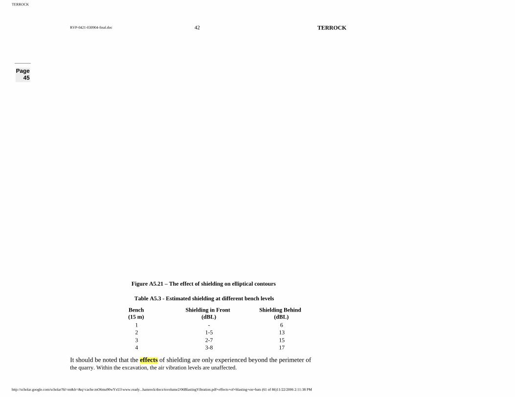
TERROCK
RVP-0421-030904-final.doc 42 TERROCK
Page 45
Figure A5.21 – The effect of shielding on elliptical contours
Table A5.3 - Estimated shielding at different bench levels
Bench (15 m)
Shielding in Front (dBL)
Shielding Behind (dBL)
1 - 6 2 1-5 13 3 2-7 15 4 3-8 17
It should be noted that the effects of shielding are only experienced beyond the perimeter of the quarry. Within the excavation, the air vibration levels are unaffected.
http://scholar.google.com/scholar?hl=en&lr=&q=cache:mO6mu90wYxUJ:www.ready...hamrock/docs/tsvolume2/06BlastingVibration.pdf+effects+of+blasting+on+bats (61 of 86)11/22/2006 2:11:38 PM

TERROCK
RVP-0421-030904-final.doc 43 TERROCK
An air vibration assessment is made by moving the basic emission contours around the limit of extraction and, while observing blast orientation, record the maximum extent of each
contour interval.
A5.6 FLYROCK
Flyrock occurs when the explosive in a blasthole is poorly confined by the stemming or rock mass and the high pressure gas breaks out of confinement and launches rock fragments into
the air, accompanied by excessive air vibration. Three potential flyrock cases are:
• Underburdening: Lack of confinement by the rock mass in front of the blasthole
results in flyrock in front of the face.
• Cratering: Insufficient stemming height or weakened collar rock results in
a crater being formed around the hole collar with rock projected
in any direction. Does not occur if the stemming height is
greater than 10-15 hole diameters.
Page 46
• Stemming Ejection: Poor stemming practice can result in a high angle throw of the
stemming material and loose rocks in the blasthole wall and
collar.
The relationship between confinement conditions and the distance that flyrock may be
projected has been quantified and may be used as the basis for determining blast exclusion
zones, with the application of appropriate safety factors.
The investigations of Lundborg (1981) yielded semi-empirical formulae for the prediction of
the maximum throw (defined as 'the distance beyond which the probability of being struck by
flyrock is less than the probability of being struck by lightning in a 10 year period', ie. ‘safe’)
based on hole diameter and powder factor (kilogram of explosive/cubic metre of rock).
The maximum throw is given by the formula:
L max = 260 x d0.67
[3]
where: L = maximum throw (m)http://scholar.google.com/scholar?hl=en&lr=&q=cache:mO6mu90wYxUJ:www.ready...hamrock/docs/tsvolume2/06BlastingVibration.pdf+effects+of+blasting+on+bats (62 of 86)11/22/2006 2:11:38 PM
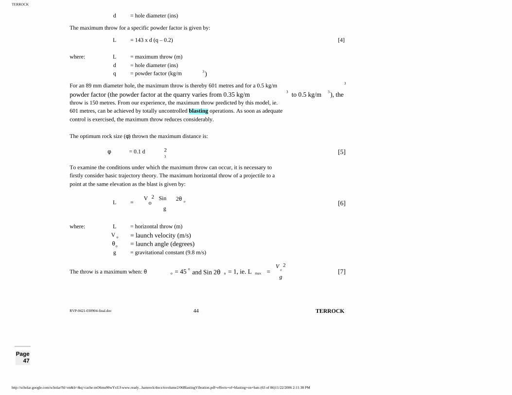
TERROCK
RVP-0421-030904-final.doc 44 TERROCK
d = hole diameter (ins)
The maximum throw for a specific powder factor is given by:
L = 143 x d (q – 0.2) [4]
where: L = maximum throw (m)
d = hole diameter (ins)
q = powder factor (kg/m 3)
For an 89 mm diameter hole, the maximum throw is thereby 601 metres and for a 0.5 kg/m 3
powder factor (the powder factor at the quarry varies from 0.35 kg/m3
to 0.5 kg/m3), the
throw is 150 metres. From our experience, the maximum throw predicted by this model, ie.
601 metres, can be achieved by totally uncontrolled blasting operations. As soon as adequate
control is exercised, the maximum throw reduces considerably.
The optimum rock size (φ) thrown the maximum distance is:
φ = 0.1 d 3
2 [5]
To examine the conditions under which the maximum throw can occur, it is necessary to
firstly consider basic trajectory theory. The maximum horizontal throw of a projectile to a
point at the same elevation as the blast is given by:
L = g
2θSinVo
2o [6]
where: L = horizontal throw (m)
V o = launch velocity (m/s) θ o = launch angle (degrees) g = gravitational constant (9.8 m/s)
The throw is a maximum when: θ o = 45o
and Sin 2θ o = 1, ie. L max = g
Vo
2[7]
Page 47
http://scholar.google.com/scholar?hl=en&lr=&q=cache:mO6mu90wYxUJ:www.ready...hamrock/docs/tsvolume2/06BlastingVibration.pdf+effects+of+blasting+on+bats (63 of 86)11/22/2006 2:11:38 PM

TERROCK
By substitution in the formula, the maximum launch velocities for throw of 601 metres and 150 metres are 76.7 m/s and 38 m/s, respectively.
If the ground rises above the launch site, the throw will be less. If the ground drops below the
launch site, the throw will be greater, as illustrated in Figure A5.22.
Figure A5.22 – Projectile path for V o = 38 m/s (after Workman et al, 1994)
The complex formulae for determining the throw to points of different elevation is:
L max = ( ) ±+
g
HgSinVSinVCosV oo
o
22θθ
θ [8]
where: H = the difference in elevation
The general trajectory theory ignores factors such as rock dimension and shape, density, air
resistance and wind, but is accurate enough for this methodology at distances up to
Lundborg’s ‘safe’ distance. As the work of Lundborg demonstrates, at distances beyond 200-
300 metres, the rock size and shape becomes increasingly important to the maximum throw as
momentum and air resistance becomes more significant in how far a rock will travel.
The investigations of Workman et al (1994) gave the relationship between launch velocity
and scaled burden (burden divided by the square root of the charge mass per metre) for a 45 o
launch angle is of the form:
V o = 1.3
B
mk [9]
where: V o = launch velocity (m/s) m = charge mass per metre
http://scholar.google.com/scholar?hl=en&lr=&q=cache:mO6mu90wYxUJ:www.ready...hamrock/docs/tsvolume2/06BlastingVibration.pdf+effects+of+blasting+on+bats (64 of 86)11/22/2006 2:11:38 PM

TERROCK
RVP-0421-030904-final.doc 45 TERROCK
B = burden (m) k = a constant which varies from 13.5 (mean) to 27 (maximum)
Formulae [7] and [9] can be combined to give:
L max = 2.6
2
B
m
9.8
k[10]
Page 48
The standard blasting practice at the Mt Shamrock Quarry is:
burden = 3.8 metres; stemming height = 3.8 metres; hole angle = 80 o.
The maximum throw distance for the burden condition is:
L max = metres34.53.8
8
9.8
272.6
2=
The 400 metres exclusion zone in front of the face gives a factor of safety of 11 to a point at
the same elevation. In case of underburdening, by substitution in the above equation, the 400
metres exclusion zone will permit the inadvertent reduction of the burden to 1.5 metres. The
400 metres exclusion zone is thereby conservative to a point at the same elevation and
extremely conservative to points at a higher elevation.
The maximum throw distance for the stemming condition, assuming rock can be projected at
an angle of 5 o flatter than the hole angle, ie. 75 o , is:
L max = ( )metres17.5752Sin
3.8
8
9.8
27o
2.62=×
The 150 metres exclusion zone behind the face gives a factor of safety of 8.5 to a point at the
same elevation and permits the inadvertent reduction of the stemming height to 1.65 metres.
Stemming height is more readily measured and controlled than burden and a reduced
exclusion distance is considered to be appropriate.
The exclusion zone shape overlay is placed over an aerial photograph of the quarry, centred
on the blast with correct face orientation to determine the minimum area that must be cleared
during the quarry excavation and the placement of the guards to prevent unauthorised access.
http://scholar.google.com/scholar?hl=en&lr=&q=cache:mO6mu90wYxUJ:www.ready...hamrock/docs/tsvolume2/06BlastingVibration.pdf+effects+of+blasting+on+bats (65 of 86)11/22/2006 2:11:38 PM

TERROCK
RVP-0421-030904-final.doc 46 TERROCK
The areas beyond the quarry boundary, including the Pony Club are also included in
determining the evacuation procedure.
The regulations clearly place the responsibility to protect people and property from danger on
the shotfirer. Dangerous Goods (Explosives) Regulations (2000) states that ‘The shotfirer and
every person in charge of a blasting operation or the use of blasting explosives must take all
due precautions to prevent any danger to people or damage to property’. Protecting the
public by the implementation of proper blasting practices are part of the accepted
responsibilities of the shotfirer’s job.
A5.7 BLAST VIBRATION LIMITS
People feel vibration at very low levels and can become concerned at vibration levels well below those that can cause damage to their property. Vibration limits, therefore, have two
aspects:
(i) An environmental or acceptable human response limit.
(ii) A limit to prevent structural damage (which should be considered separately).
Page 49
A5.7.1 Environmental Limits
A5.7.1.1 Ground Vibration
Guidance on human response levels can be obtained from the Australian and New Zealand Environment Council (ANZEC), “Technical Basis for Guidelines to Minimise Annoyance due
to Blasting Overpressure and Ground Vibration”, which are used by authorities in some
Australian states to regulate blast vibration. For blasting between the hours of 9:00 am to 5:00
pm, Monday to Saturday, the ANZEC guidelines recommend a maximum level for ground
http://scholar.google.com/scholar?hl=en&lr=&q=cache:mO6mu90wYxUJ:www.ready...hamrock/docs/tsvolume2/06BlastingVibration.pdf+effects+of+blasting+on+bats (66 of 86)11/22/2006 2:11:38 PM
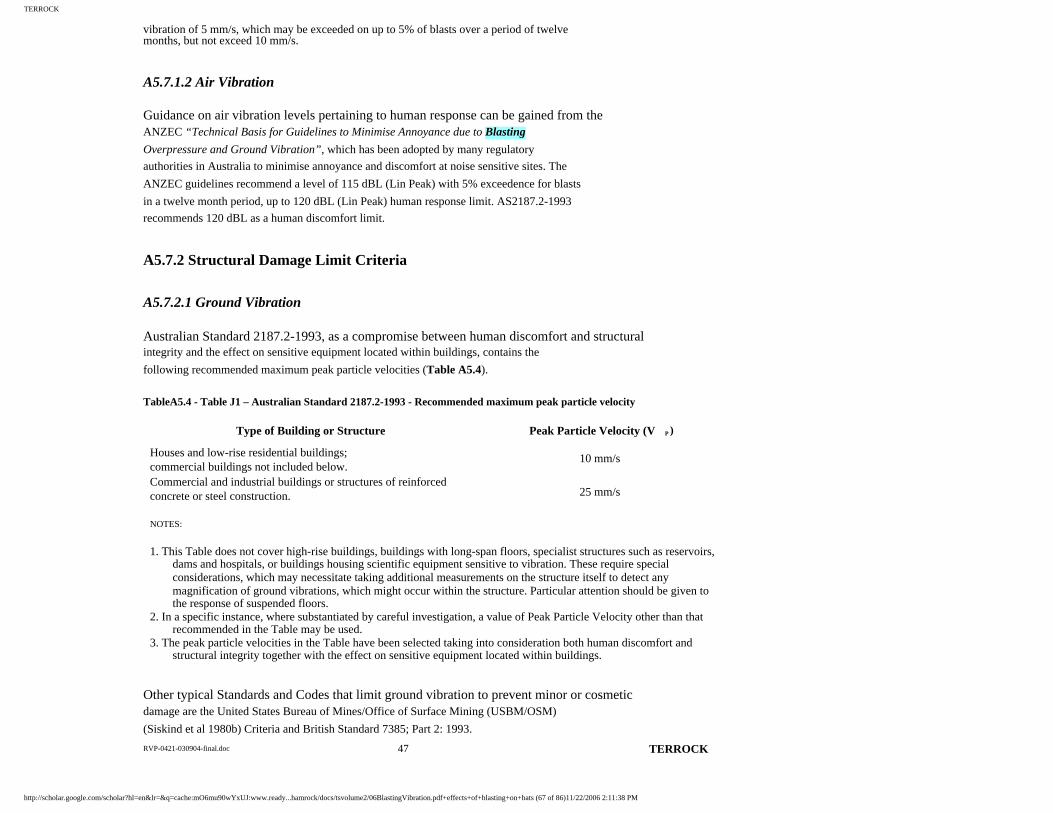
TERROCK
RVP-0421-030904-final.doc 47 TERROCK
vibration of 5 mm/s, which may be exceeded on up to 5% of blasts over a period of twelve months, but not exceed 10 mm/s.
A5.7.1.2 Air Vibration
Guidance on air vibration levels pertaining to human response can be gained from the ANZEC “Technical Basis for Guidelines to Minimise Annoyance due to Blasting
Overpressure and Ground Vibration”, which has been adopted by many regulatory
authorities in Australia to minimise annoyance and discomfort at noise sensitive sites. The
ANZEC guidelines recommend a level of 115 dBL (Lin Peak) with 5% exceedence for blasts
in a twelve month period, up to 120 dBL (Lin Peak) human response limit. AS2187.2-1993
recommends 120 dBL as a human discomfort limit.
A5.7.2 Structural Damage Limit Criteria
A5.7.2.1 Ground Vibration
Australian Standard 2187.2-1993, as a compromise between human discomfort and structural integrity and the effect on sensitive equipment located within buildings, contains the
following recommended maximum peak particle velocities (Table A5.4).
TableA5.4 - Table J1 – Australian Standard 2187.2-1993 - Recommended maximum peak particle velocity
Type of Building or Structure Peak Particle Velocity (V P )
Houses and low-rise residential buildings;commercial buildings not included below.
10 mm/s
Commercial and industrial buildings or structures of reinforced concrete or steel construction. 25 mm/s
NOTES:
1. This Table does not cover high-rise buildings, buildings with long-span floors, specialist structures such as reservoirs, dams and hospitals, or buildings housing scientific equipment sensitive to vibration. These require special considerations, which may necessitate taking additional measurements on the structure itself to detect anymagnification of ground vibrations, which might occur within the structure. Particular attention should be given to the response of suspended floors.
2. In a specific instance, where substantiated by careful investigation, a value of Peak Particle Velocity other than that recommended in the Table may be used.
3. The peak particle velocities in the Table have been selected taking into consideration both human discomfort and structural integrity together with the effect on sensitive equipment located within buildings.
Other typical Standards and Codes that limit ground vibration to prevent minor or cosmetic damage are the United States Bureau of Mines/Office of Surface Mining (USBM/OSM)
(Siskind et al 1980b) Criteria and British Standard 7385; Part 2: 1993.
http://scholar.google.com/scholar?hl=en&lr=&q=cache:mO6mu90wYxUJ:www.ready...hamrock/docs/tsvolume2/06BlastingVibration.pdf+effects+of+blasting+on+bats (67 of 86)11/22/2006 2:11:38 PM

TERROCK
Page 50
In both these documents the vibration levels are dependent on the dominant frequency in the vibration. Because the natural frequency of houses is usually in the range of 5 Hz to 10 Hz,
the recommended vibration levels are reduced at lower frequencies in recognition that the
vibration from the ground may be magnified through a structure if a resonance situation
occurs. High frequency vibration passes through a structure without it responding. The USBM
‘safe’ blasting vibration level criteria is shown in Figure A5.23.
Figure A5.23 - USBM ‘safe’ blasting vibration level criteria
The USBM ‘safe’ limits were determined from a comprehensive study involving over 150 houses over a number of years. The ‘safe’ vibration limits will prevent threshold damage in
structures, as defined in Table A5.5.
Table A5.5 - USBM damage classification
Uniform Classification Description of Damage
Threshold: Loosening of paint; small plaster crack at joints between construction elements; lengthening of old cracks.
http://scholar.google.com/scholar?hl=en&lr=&q=cache:mO6mu90wYxUJ:www.ready...hamrock/docs/tsvolume2/06BlastingVibration.pdf+effects+of+blasting+on+bats (68 of 86)11/22/2006 2:11:38 PM

TERROCK
RVP-0421-030904-final.doc 48 TERROCK
Minor: Loosening and falling of plaster; cracks in masonry around openings near partitions; hairline to 3 mm cracks (0 to 1/8 in); fall of loose mortar.
Major: Cracks of several mm in walls; rupture of opening vaults; structuralweakening; fall of masonry, eg. chimneys; load support ability effected.
The British Standard (BS) 7385; Part 2: 1993 “Guide Values for Transient Vibration Relating to Cosmetic Damage” are listed in Table A5.7 and Figure A5.23. The guide values represent
limits for transient vibration above which cosmetic damage could occur. Minor damage is
possible at vibration levels which are greater than twice those given in the table, and major
damage above four times the guide values given.
Page 51
Table A5.6 - Transient vibration guide values for cosmetic damage (BS7385: 1993)
Peak component particle velocity in frequency range of predominant pulse Line Type of Building4 Hz to 15 Hz 15 Hz and above
1 Reinforced or framed structures. Industrial and heavy commercial buildings. 50 mm/s at 4 Hz and above.
2 Unreinforced or light framed structure. Residential or light commercial typebuildings.
15 mm/s at 4 Hz increasing to 20 mm/s
at 15 Hz.
20 mm/s at 15 Hz increasing to 50 mm/s at 40 Hz and above.
NOTE 1: Values referred to are at the base of the building.
NOTE 2: For line 2, at frequencies below 4 Hz, a maximum displacement of 0.6 mm (zero to peak) should not be exceeded.
http://scholar.google.com/scholar?hl=en&lr=&q=cache:mO6mu90wYxUJ:www.ready...hamrock/docs/tsvolume2/06BlastingVibration.pdf+effects+of+blasting+on+bats (69 of 86)11/22/2006 2:11:38 PM

TERROCK
RVP-0421-030904-final.doc 49 TERROCK
Figure A5.24 - Transient vibration guide values for cosmetic damage (BS7386: 1993)
Table A5.7 – BS7385; Part 1: 1990 damage classification
Damage Classification Description
Cosmetic:
.....the formation of hairline cracks on drywall surfaces or the growth of existing cracks in plaster or drywall surfaces; in addition, the formation of hairline cracks in the mortar joints of brick/concrete block construction
Minor: .....the formation of cracks or loosening and falling of plaster or drywall surfaces, or cracks through bricks/concrete blocks
Major: ......damage to structural elements of the building, cracks in support columns, loosening of joints, splaying of masonry cracks etc.
The British Standard guide values are peak component particle velocity, whereas the USBM/OSM values are peak vector particle velocity. Peak vector particle velocity varies
from 1.0 to 1.7 times the peak component velocity with 1.2 being an average determined in
practice.
Page 52
A5.7.2.2 Air vibration
Australian Standard 2187.2-1993 recommends a maximum air vibration level of 133 dBL to
http://scholar.google.com/scholar?hl=en&lr=&q=cache:mO6mu90wYxUJ:www.ready...hamrock/docs/tsvolume2/06BlastingVibration.pdf+effects+of+blasting+on+bats (70 of 86)11/22/2006 2:11:38 PM
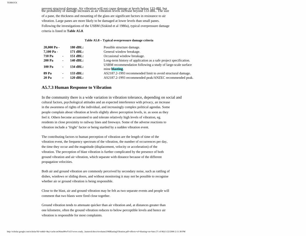
TERROCK
prevent structural damage. Air vibration will not cause damage at levels below 133 dBL but the probability of damage increases as air vibration levels increase beyond 133 dBL. The size
of a pane, the thickness and mounting of the glass are significant factors in resistance to air
vibration. Large panes are more likely to be damaged at lower levels than small panes.
Following the investigations of the USBM (Siskind et al 1980a), typical overpressure damage
criteria is listed in Table A5.8.
Table A5.8 – Typical overpressure damage criteria
20,000 Pa - 180 dBL: Possible structure damage. 7,100 Pa - 171 dBL: General window breakage. 710 Pa - 151 dBL: Occasional window breakage. 200 Pa - 140 dBL: Long-term history of application as a safe project specification.
100 Pa - 134 dBL: USBM recommendation following a study of large-scale surface mine blasting.
89 Pa - 133 dBL: AS2187.2-1993 recommended limit to avoid structural damage. 20 Pa - 120 dBL: AS2187.2-1993 recommended peak/ANZEC recommended peak.
A5.7.3 Human Response to Vibration
In the community there is a wide variation in vibration tolerance, depending on social and cultural factors, psychological attitudes and an expected interference with privacy, an increase
in the awareness of rights of the individual, and increasingly complex political agendas. Some
people complain about vibration at levels slightly above perception levels, ie. as soon as they
feel it. Others become accustomed to and tolerate relatively high levels of vibration, eg.
residents in close proximity to railway lines and freeways. Some of the adverse reactions to
vibration include a ‘fright’ factor or being startled by a sudden vibration event.
The contributing factors to human perception of vibration are the length of time of the
vibration event, the frequency spectrum of the vibration, the number of occurrences per day,
the time they occur and the magnitude (displacement, velocity or acceleration) of the
vibration. The perception of blast vibration is further complicated by the presence of both
ground vibration and air vibration, which separate with distance because of the different
propagation velocities.
Both air and ground vibration are commonly perceived by secondary noise, such as rattling of
dishes, windows or sliding doors, and without monitoring it may not be possible to recognise
whether air or ground vibration is being responsible.
Close to the blast, air and ground vibration may be felt as two separate events and people will
comment that two blasts were fired close together.
Ground vibration tends to attenuate quicker than air vibration and, at distances greater than
one kilometre, often the ground vibration reduces to below perceptible levels and hence air
vibration is responsible for most complaints.
http://scholar.google.com/scholar?hl=en&lr=&q=cache:mO6mu90wYxUJ:www.ready...hamrock/docs/tsvolume2/06BlastingVibration.pdf+effects+of+blasting+on+bats (71 of 86)11/22/2006 2:11:38 PM

TERROCK
RVP-0421-030904-final.doc 50 TERROCK
Page 53
Attempts have been made to quantify human sensitivity to vibration and a typical human response graphs are shown in Figures A5.24a and A5.24b. The graphs are based on the
studies listed in Figure A5.24b. The shortest vibration duration is 5 seconds, which is a
longer period than most blasting events.
Figure A5.24a – Human response to steady-state and transient vibrations
http://scholar.google.com/scholar?hl=en&lr=&q=cache:mO6mu90wYxUJ:www.ready...hamrock/docs/tsvolume2/06BlastingVibration.pdf+effects+of+blasting+on+bats (72 of 86)11/22/2006 2:11:38 PM

TERROCK
RVP-0421-030904-final.doc 51 TERROCK
Figure A5.24b – Studies of human response to vibration
Page 54
In our experience, vibration is perceptible at between 0.2 mm/s and 0.5 mm/s, depending on the activities of the receiver at the time, whether indoors or outside, and the frequency and
duration of the vibration.
A number of Standards have attempted to address the issue of whole body response to
vibration in buildings. The vibration is measured at the entry of the vibration to the body,
which is usually the floor. A typical set of guide vibration levels tolerated by humans in
building is given in Table A5.9 from the American National Standards Institution (ANSI)
S3.18-1979.
Table A5.9 – Peak vibration levels tolerated by humans in buildings (ANSI S3.18-1979)
Number of Events Per Day 1 12 26
PVL (mm/s) PVL (mm/s) PVL (mm/s) Critical Structure (eg. hospital): 0.13 0.07 0.05
http://scholar.google.com/scholar?hl=en&lr=&q=cache:mO6mu90wYxUJ:www.ready...hamrock/docs/tsvolume2/06BlastingVibration.pdf+effects+of+blasting+on+bats (73 of 86)11/22/2006 2:11:38 PM

TERROCK
RVP-0421-030904-final.doc 52 TERROCK
Residence (night): 0.20 0.10 0.7 Residence (day): 12.5 6.3 4.3 Office or Workshop: 18.0 9.0 6.0
The guidance vibration levels are for 8 Hz to 80 Hz (vertical plus horizontal motions) for events lasting up to one second. For longer events, the values listed are reduced. The guide
vibration levels on the floor of the structure can be approximately related to ground vibration
by an allowance for magnification by structural response.
The ANZEC guidelines are another example of vibration limits based on human response
criteria. For blasts between 9:00 am and 5:00 pm Monday to Saturday, the guidelines
recommend a maximum ground vibration level of 5 mm/s (which may be exceeded on 5% of
occasions in a twelve month period to a maximum of 10 mm/s) and a maximum air vibration
level of 115 dBL (which may be exceeded on 5% of occasions in a twelve month period to a
maximum of 120 dBL).
The ANZEC ground vibration limit of 5 mm/s would approximate to the 12.5 mm/s ANSI day
time residential limit, allowing for a 2.5 times structural magnification, which is within the
range of magnifications measured on the floor of houses.
A5.7.4 Statutory Vibration Limits at the Mt Shamrock Quarry
The vibration from blasting of rock remaining within the quarry and in the extension will not exceed the environmental guideline vibration limits of the DPI for quarry extensions at
sensitive sites.
The guideline vibration limits sensitive sites (including residences) are:
• Ground vibration: <5 mm/s for 95% of blasts in a 12 month period
<10 mm/s at all times
• Air vibration overpressure: <115 dBL for 95% of blasts in a 12 month period
<120 dBL at all times
When comparing these guideline limits with the preceding sections, it can be seen that the
DPI regulatory limits are based on the environmental limit criteria of the ANZEC guidelines.
Page 55
http://scholar.google.com/scholar?hl=en&lr=&q=cache:mO6mu90wYxUJ:www.ready...hamrock/docs/tsvolume2/06BlastingVibration.pdf+effects+of+blasting+on+bats (74 of 86)11/22/2006 2:11:38 PM

TERROCK
Slight exceedence of the regulatory vibration limits will not automatically result in structural damage. Because of the bias towards human comfort criteria, there is considerable
conservatism in the environmental guideline limits regarding possible structural damage.
Structural damage may begin to occur above the USBM damage limit criteria shown in
Figure A5.25. A comparison of environmental ground vibration limits to structural damage
criteria is also shown graphically in Figure A5.25.
Figure A5.25 – Comparison of USBM ‘safe’ blasting vibration level criteria with AS2187.2 and DPI guideline limits
http://scholar.google.com/scholar?hl=en&lr=&q=cache:mO6mu90wYxUJ:www.ready...hamrock/docs/tsvolume2/06BlastingVibration.pdf+effects+of+blasting+on+bats (75 of 86)11/22/2006 2:11:38 PM

TERROCK
RVP-0421-030904-final.doc 53 TERROCK
Page 56
APPENDIX 6
DEPARTMENT OF PRIMARY INDUSTIES
ENVIRONMENTAL GUIDELINEShttp://scholar.google.com/scholar?hl=en&lr=&q=cache:mO6mu90wYxUJ:www.ready...hamrock/docs/tsvolume2/06BlastingVibration.pdf+effects+of+blasting+on+bats (76 of 86)11/22/2006 2:11:38 PM

TERROCK
GROUND VIBRATION AND AIR VIBRATION LIMITS FOR
BLASTING IN MINES AND QUARRIES
Page 57
Ground Vibration and Air vibration Limits for Blasting in Mines and Quarries
1. PURPOSE
This document describes the policy of the Department of Natural Resources and Environment with respect to the limits on blasting impacts at residential premises and other Sensitive Sites. This guideline does not apply to control of impacts at commercial or industrial premises where less stringent standards may be
Blasting usually results in both ground and airborne vibration. The latter commonly includes both audible noise and vibration known as air vibration, which can cause objects to rattle and make noise. At the levels experienced fromblasting associated with mining, structural damage to adjoining properties is unlikely to occur. In addition, the noise levels experienced from blasting at a mine site are unlikely to cause
http://scholar.google.com/scholar?hl=en&lr=&q=cache:mO6mu90wYxUJ:www.ready...hamrock/docs/tsvolume2/06BlastingVibration.pdf+effects+of+blasting+on+bats (77 of 86)11/22/2006 2:11:38 PM

TERROCK
RVP-0421-030904-final.doc 55 TERROCK
appropriate.
The ground vibration and air vibration limits recommended by this guideline have been set to minimise annoyance to people as a result of blasting on mine and quarry sites.
They are therefore considerably lower than the levels that could give rise to damage to competent structures. More stringent limits maybe required, however, in cases where the objective is protection of fragile structures such as historic buildings.
This guideline is based on the Australian and New Zealand Environment and Conservation Council’s Technical Basis for Guidelines to Minimise Annoyance Due to Blasting Overpressure and Ground Vibration, September 1990.
This guideline applies to new and existing mine and quarry sites (as defined in section 3). For new sites, limits are as specified in this guideline For existing sites, limits for ground vibration and air vibration are as specified in this guideline, unless otherwise specified in existing licence conditions.
2. INTRODUCTION
Blasting is necessary for the recovery of ore or stone in most underground mines, and manyopen cut mines and quarries. However, blasting can cause noise and vibration, which can have an impact upon neighbouring premises. Proper control of blasting practices is therefore necessary to ensure both the safety of employees and the protection of the community fromadverse effects.
any hearing damage to anyone outside the work site.
Annoyance and discomfort from blasting can occur when noise startles individuals or when air vibration or ground vibration causes vibration of windows or other items at a Sensitive Site. The degree of annoyance will therefore be influenced by the level of air vibration and vibration as well as factors such as the time of day, the frequencyof occurrence and the sensitivity of individuals.
In most cases, a competent operator can reasonably predict the level of air vibration and ground vibration. However the generation and transmission of air vibration and ground vibration is affected by a number of factors including blast design, meteorology (particularlywind speed and direction and temperature inversions), topography, geology and soil water content. It is therefore possible that on someoccasions the level of air vibration and/or ground vibration will exceed the predicted levels.
The guideline also recognises that for new mine and quarry sites a greater degree of control will be expected and can be designed into the work program.
The guideline does not address the control of flyrock and dust from blasting. Operators are required to satisfy the Department as to the safety of blasting practices and rigorous control of flyrock is an important consideration. The control of dust from blasting must be considered in Ground Vibration and Air vibration Limits for Blasting in Mines and Quarries Blasting Limit Guidelines v1.2 3 conjunction with other sources of dust emission at the site. Operators should ensure that both these issues are addressed adequately.
http://scholar.google.com/scholar?hl=en&lr=&q=cache:mO6mu90wYxUJ:www.ready...hamrock/docs/tsvolume2/06BlastingVibration.pdf+effects+of+blasting+on+bats (78 of 86)11/22/2006 2:11:38 PM

TERROCK
Page 58
Ground Vibration and Air vibration Limits for Blasting in Mines and Quarries
3. IMPLEMENTATION OF LIMITS
Separate limits apply depending upon whether the site was in operation prior to the introduction of this guideline. Existing operations are defined as those where mining or extractive operations have been undertaken or where planning approvals for those operations existed prior to 1 July 2001 and where the existing Work Authority or Licence allows blasting.
In some cases the limits recommended by this guideline may not be consistent with current Mining Licence or Work Authority conditions. In such cases the applicable limits are those set down in the Licence or Authority.
Ground vibration and air vibration levels are generally measured at the nearest Sensitive Site.
3.1 Existing Sites
At most existing sites, Work Authority or Licence conditions set limits for air vibration and ground vibration measured at Sensitive Sites.
For existing sites the limits are as follows:
• Ground vibration at Sensitive Sites
should be below 10 mm/s (PPV) at all times, and
• Air vibration at Sensitive Sites should be
below 120 dB (Lin Peak) at all times.
3.2 New Sites
At new sites, criteria at the site boundary or at other defined points may be set in Work Authority or Licence conditions to ensure vibration and air vibration are below appropriate limits at the most affected
• Air vibration at Sensitive Sites should
be below 115 dB (Lin Peak) for 95% of all blasts.
Note: In situations where the location or the nature of the operations mean that this is not achievable, these standards may be varied, subject to the Department being satisfied that all effected people have given informed consent).
3.3 Evening and Night Operations
3.3.1 Open Cuts and Surface Mines
Blasting at open cut or surface mines and quarries should only occur during the hours of 9.00am to 5.00pm Monday to Saturday(the “day period”). However, blasting outside these hours may in some cases be required either because of the practical constraints on an operation or where a blast planned for the day period could not be fired due to unforeseen circumstances. The Department may approve blasting outside the day period where the proponent can demonstrate that such approval is required for sound operational reasons and that anypotential impacts will be subject to rigorous control. Where the blasting is required due to unforeseen circumstances, Department approvals are likely to require the operator to give adequate warning to occupants of Sensitive Sites. Surface blasting between 10:00pm and 7:00am would not normallybe approved. Ground Vibration and Air vibration Limits for Blasting in Mines and Quarries Blasting Limit Guidelines v1.2 4.
3.3.2 Underground Mines
Many of the risks that are of particular
http://scholar.google.com/scholar?hl=en&lr=&q=cache:mO6mu90wYxUJ:www.ready...hamrock/docs/tsvolume2/06BlastingVibration.pdf+effects+of+blasting+on+bats (79 of 86)11/22/2006 2:11:38 PM

TERROCK
RVP-0421-030904-final.doc 56 TERROCK
Sensitive Sites.
New sites should meet the requirements of part 3.1 as well as the following:
• Ground vibration at Sensitive Sites
should be below 5 mm/s (PPV) for 95% of all blasts.
concern for surface blasting outside the dayperiod are reduced for blasting in underground mines. The risks of flyrock or excess air vibration are essentiallyeliminated for underground blasts and there is usually no risk of unauthorised public entry to the blast site.
Page 59
Ground Vibration and Air vibration Limits for Blasting in Mines and Quarries
Blasting times at underground mines are often limited to shift changes or other times when personnel can be safely removed fromthe blast area. Blasting outside the dayperiod is therefore often necessary. Where the Department approves night time blasting in underground mines it is considered appropriate to apply more stringent limits to ground vibration during the hours usually devoted to sleep. In these circumstances, the ground vibration level at Sensitive Sites should not exceed 3 mm/s and air vibration should not exceed 115 dB (Lin Peak) between the hours 10:00pm and 7:00am.
4. APPROACH TO CHANGED CONDITIONS
A significant factor in determining the impact of blasting on Sensitive Sites is the separation distance between the blast site and the Sensitive Sites. This distance can be reduced by expansion of the operation or by the development of sensitive land uses closer to the operation. Different policies apply to these two situations.
4.1 Operator Initiated Change
Where a change to a Work Authority or Work Plan results in the area of operations moving closer to Sensitive Sites, the Department may set new limits at a level typical of the levels occurring at Sensitive Sites prior to the change. However, the new limits will not be lower than those set out in section 3.2 for new sites.
4.2 Surrounding Land Use Change
In cases where the separation distance is reduced as new Sensitive Sites are developed closer to an existing mine or quarry, the existing vibration and air vibration criteria will be applied to the new properties. This means that the encroachment of legally approved housing or other Sensitive Sites will impose restrictions on operating mines and quarries. Mining and quarrying operators should therefore ensure that they are aware of proposed new development.
5. MEASUREMENT & MONITORING
Blast vibration and air vibration monitoring should be carried out at all sites where blasting
http://scholar.google.com/scholar?hl=en&lr=&q=cache:mO6mu90wYxUJ:www.ready...hamrock/docs/tsvolume2/06BlastingVibration.pdf+effects+of+blasting+on+bats (80 of 86)11/22/2006 2:11:38 PM

TERROCK
RVP-0421-030904-final.doc 57 TERROCK
It is not proposed that this guideline will apply retrospectively to mine or extractive sites where a Work Authority or Licence has been issued. However where an operator proposes changes to an existing operation, and this requires:
(i) changing the area to which a Work Authority applies; or
(ii) a significant change to the area to which a mining Work Plan applies, the air vibration and ground vibration criteria will be reviewed.
Where the proposed change does not result in operations occurring closer to the nearest Sensitive Site (ie operations extend in other directions, and not towards the Sensitive Site), the existing limits should continue to apply. This will mean that the maximum air vibration and ground vibration levels received at the Sensitive Sites will be unchanged.
occurs and where there are Sensitive Sites that may be affected. The extent of monitoring and locations will be Ground Vibration and Air vibration Limits for Blasting in Mines and Quarries Blasting Limit Guidelines v1.2 5 considered prior to approval of the Work Plan for the operation. Applicants for a Work Plan should determine the proximity and directions of all Sensitive Sites around the proposed mine or quarry. These sites should include all sites that may be affected by blasting during the foreseeable future of the operation.
In addition to vibration and air vibration monitoring, it is often useful to record video or photographic images of surface blasts. These records can be of significant assistance in analysis of blast impact problems.
The approved use of blasting will be set down in the Work Authority or Licence and monitoring requirements will usually be set out in the Environmental Monitoring Program.
Page 60
Ground Vibration and Air vibration Limits for Blasting in Mines and Quarries
5.1 Monitoring
Monitoring should generally be in two parts, the initial monitoring and ongoing monitoring.
5.1.1 Initial Monitoring
Initial monitoring should be conducted where it is possible that one or more Sensitive Sites may be exposed to air vibration or ground vibration to ensure that the blasting program is able to comply with the prescribed criteria.
Where initial monitoring shows that all blasts are below 3 mm/s and below 115 dB (Lin Peak) ongoing monitoring may not be required. However, any change in the methods of blasting or other factors such as the direction of a rock face, or proximity to Sensitive Sites, should be monitored as for an initial monitoring program.
5.2 Monitoring Data
Data from a number of approved monitoring sites may be aggregated for the purpose of assessing compliance with
http://scholar.google.com/scholar?hl=en&lr=&q=cache:mO6mu90wYxUJ:www.ready...hamrock/docs/tsvolume2/06BlastingVibration.pdf+effects+of+blasting+on+bats (81 of 86)11/22/2006 2:11:38 PM

TERROCK
RVP-0421-030904-final.doc 58 TERROCK
This will enable changes to be made to the blasting methods if it is found that the levels do not comply with the criteria. Initial monitoring should be done over a sufficient number of blasts to show consistent results, usually a minimum of five. These tests should be done at the most affected Sensitive Sites in two or more directions (unless there are Sensitive Sites only in one direction).
Initial monitoring should be undertaken directly at or adjacent to Sensitive Sites or where this is not practical may be at defined locations. Where monitoring cannot be done at Sensitive Sites initial monitoring may be done at sites such as at site boundaries, depending upon the requirements of the Work Authority or Licence and the specifications of the approved Environmental Monitoring Plan.
5.1.2 Ongoing Monitoring
On-going monitoring should generally be conducted around each mine and quarry to confirm that the air vibration and ground vibration levels do not exceed the criteria specified. The monitoring program will generally be included in the approved Environmental Monitoring Plan. Blasts should be randomly selected or monitored on a fixed schedule (eg five continuous blasts.
percentile limits. However, data records should identify specific measurement sites so that individual site results can be reviewed if necessary.
For comparison with the percentile limits applying to new sites, a rolling 12 month data set should be used. However, if there are too few blasts in a 12 month period to establish an adequate basis for assessment, a longer Ground Vibration and Air vibration Limits for Blasting in Mines and Quarries Blasting Limit Guidelines v1.2 6 period may be used. Statistical outcomes should be recalculated on a monthly basis so that the percentage exceedence of the lower limits is known for the immediate past twelve month (or longer) period.
Records of initial monitoring data should be reported to DNRE within four weeks of being completed. In the event of complaints, or suspected non-compliance with blasting limits, the Department mayrequest submission of on-going monitoring data by the proponent.
Blast monitoring results should be stored and maintained in a systematic manner. Data should be available for perusal by the Department when and if necessary. Data may be stored in electronic or hard copyform. However, operators should ensure themselves that whatever storage medium is used is secure and that data is retained for an appropriate length of time.
Page 61
Ground Vibration and Air vibration Limits for Blasting in Mines and Quarries
http://scholar.google.com/scholar?hl=en&lr=&q=cache:mO6mu90wYxUJ:www.ready...hamrock/docs/tsvolume2/06BlastingVibration.pdf+effects+of+blasting+on+bats (82 of 86)11/22/2006 2:11:38 PM

TERROCK
5.3 Measurement
Measurements should be conducted bysuitably trained personnel using appropriate equipment. Equipment used for blast monitoring should meet or exceed the relevant Australian Standards or equivalent overseas standards for field equipment. Equipment should be calibrated on a regular basis in accordance with the manufacturers’recommendations or other appropriate standards. Measurement Procedures should be in accordance with the equipment manufacturers’ recommendations. In particular, the use of the ground vibration transducer should be consistent with achieving optimum coupling with the ground. Ground Vibration and Air vibration Limits for Blasting in Mines and Quarries Blasting Limit Guidelines v1.2 7.
http://scholar.google.com/scholar?hl=en&lr=&q=cache:mO6mu90wYxUJ:www.ready...hamrock/docs/tsvolume2/06BlastingVibration.pdf+effects+of+blasting+on+bats (83 of 86)11/22/2006 2:11:38 PM
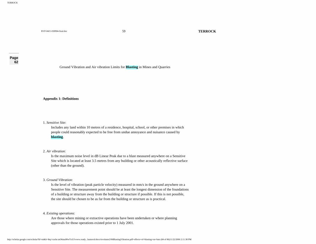
TERROCK
RVP-0421-030904-final.doc 59 TERROCK
Page 62
Ground Vibration and Air vibration Limits for Blasting in Mines and Quarries
Appendix 1: Definitions
1. Sensitive Site: Includes any land within 10 metres of a residence, hospital, school, or other premises in which people could reasonably expected to be free from undue annoyance and nuisance caused byblasting.
2. Air vibration: Is the maximum noise level in dB Linear Peak due to a blast measured anywhere on a Sensitive Site which is located at least 3.5 metres from any building or other acoustically reflective surface (other than the ground).
3. Ground Vibration: Is the level of vibration (peak particle velocity) measured in mm/s in the ground anywhere on a Sensitive Site. The measurement point should be at least the longest dimension of the foundations of a building or structure away from the building or structure if possible. If this is not possible, the site should be chosen to be as far from the building or structure as is practical.
4. Existing operations: Are those where mining or extractive operations have been undertaken or where planning approvals for those operations existed prior to 1 July 2001.
http://scholar.google.com/scholar?hl=en&lr=&q=cache:mO6mu90wYxUJ:www.ready...hamrock/docs/tsvolume2/06BlastingVibration.pdf+effects+of+blasting+on+bats (84 of 86)11/22/2006 2:11:38 PM

TERROCK
RVP-0421-030904-final.doc 60 TERROCK
5. PPV Peak Particle Velocity – the instantaneous sum of the velocity vectors (measured in millimetres per second) of the ground movement caused by the passage of vibration from blasting.
6. Lin Peak Linear Peak – the maximum level of air pressure fluctuation measured in deciBels without frequency weighting. (NB frequency weightings are often applied to sound measurements to ensure the measured parameter is indicative of the level experienced by the human auditorysystem. Weighting is not applied to air vibration measurements as much of the sound from an air vibration is at inaudible frequencies and would therefore be excluded).
Page 63
REFERENCES
Australian and New Zealand Environment Council (ANZEC) (1990): Technical Basis for Guidelines to Minimise Annoyance due to Blasting Overpressure and Ground Vibration.
Australian Standard 2187.2-1993 Part 2: Use of Explosives.
British Standard BS7385 Part 2; 1993: Guide to Damage Levels from Ground Bourne Vibration.
Dangerous Goods (Explosives) Regulations, 2000.
Department of Natural Resources and Environment (now Department of Primary Industries) (2001):
Environmental Guidelines for Ground Vibration and Air vibration Limits for Blasting in Mines and
http://scholar.google.com/scholar?hl=en&lr=&q=cache:mO6mu90wYxUJ:www.ready...hamrock/docs/tsvolume2/06BlastingVibration.pdf+effects+of+blasting+on+bats (85 of 86)11/22/2006 2:11:38 PM

TERROCK
RVP-0421-030904-final.doc 61 TERROCK
Quarries, attached as Appendix 6.
Extractive Industry Development Act (1995).
Extractive Industry Development Regulations (1996).
Extractive Industry Regulations (1989).
Lundborg, N., (1981): The Probability of Flyrock – Swedish Detonic Research Foundation.
Moore, A J, Evans, R, and Richards, A B (1993). An Elliptical Air vibration Attenuation Model, in
Proceedings of The Fourth International Symposium on Rock Fragmentation by Blasting -
Fragblast – 4, pp 247-252 (Vienna, Austria).
Oriard, L.L., (2002): Explosives Engineering, Construction Vibrations and Geotechnology.
Richards, A B and Moore, A J (2002). Air vibration Design Concepts in Open Pit Mines, presented
at The 7 thInternational Symposium on Rock Fragmentation by Blasting (FRAGBLAST 7), (China
Society of Engineering Blasting and Chinese Society of Mechanics: Beijing, China).
Workman, J.L. and Calder, P.N., (1984): Flyrock Prediction and Control in Surface Mine Blasting,
Proceedings of 20 thConference ISEE, Austin Texas.
Wright, D.G. and Hopky, G.E., (1998): Guidlelines for the Use of Explosives in or near Canadian
Fisheries’ Waters, Canadian Technical Report of Fisheries and Aquatic Sciences.
http://scholar.google.com/scholar?hl=en&lr=&q=cache:mO6mu90wYxUJ:www.ready...hamrock/docs/tsvolume2/06BlastingVibration.pdf+effects+of+blasting+on+bats (86 of 86)11/22/2006 2:11:38 PM


![Tramites rvp 02_registro[1]](https://img.pdfslide.net/doc/110x75/58ef6a4a1a28ab80278b4617/tramites-rvp-02registro1.jpg)