Embed Size (px)
Citation preview
8/7/2019 Test Adjust and Balancing (See 233)
http://slidepdf.com/reader/full/test-adjust-and-balancing-see-233 1/247
TESTING AND COMMISSIONING PROCEDURE
FOR
AIR-CONDITIONING, REFRIGERATION, VENTILATION
AND
CENTRAL MONITORING & CONTROL SYSTEM
INSTALLATION
IN
GOVERNMENT BUILDINGS
OF
THE HONG KONG SPECIAL ADMINISTRATIVE REGION
2007 EDITION
(INCORPORATING CORRIGENDUM NO. GSAC01)
ARCHITECTURAL SERVICES DEPARTMENTTHE GOVERNMENT OF THE HONG KONG SPECIAL ADMINISTRATIVE REGION

8/7/2019 Test Adjust and Balancing (See 233)
http://slidepdf.com/reader/full/test-adjust-and-balancing-see-233 2/247
PREFACE
This Testing and Commissioning (T & C) Procedure aims to lay down the minimum
testing and commissioning requirements to be carried out on air-conditioning, refrigeration,
ventilation and central monitoring and control system installation in Government Buildingsof the Hong Kong Special Administrative Region (HKSAR). Such requirements are
applicable to both new installations upon completion and existing ones after major
alteration.
The present edition was developed based on its 2007 edition by the Air-conditioning
Specialist Support Group that was established under the Building Services Branch Technical
Information and Research & Development Committee. This T&C Procedure had
incorporated latest changes in corrigendum no. GSAC01 for the 2007 edition of the General
Specification. With the benefit of information technology, electronic version of this new
edition is to be viewed on and free for download from the Architectural Services Department
(ArchSD) Internet homepage. As part of the Government‟s efforts to limit paper consumption, hard copies of this T & C Procedure will not be put up for sale.
The Architectural Services Department welcomes comments on its contents at
anytime since the updating of this T & C Procedure is a continuous process to tie in with
technological advances.
8/7/2019 Test Adjust and Balancing (See 233)
http://slidepdf.com/reader/full/test-adjust-and-balancing-see-233 3/247
DISCLAIMER
This T & C Procedure is solely compiled for use on air-conditioning, refrigeration,
ventilation and central monitoring and control system installation carried out for or on behalf
of the ArchSD in Government buildings of the HKSAR.
There are no representations, either expressed or implied, as to the suitability of this
T & C Procedure for purposes other than that stated above. The material contained in this
T & C Procedure may not be pertinent or fully cover the extent of the installation in
non-government buildings. Users who choose to adopt this T & C Procedure for their works
are responsible for making their own assessments and judgement of all information
contained here. The Architectural Services Department does not accept any liability and
responsibility for any special, indirect or consequential loss or damage whatsoever arising
out of or in connection with the use of this T & C Procedure or reliance placed on it.
8/7/2019 Test Adjust and Balancing (See 233)
http://slidepdf.com/reader/full/test-adjust-and-balancing-see-233 4/247
Table of Contents
Page 1 of 6
AC_TCP
2007 Edition (Corr.2010)
TABLE OF CONTENTS Page
1 Introduction 1
2 Objectives of the T & C Works 1
3 Scope of the T & C Works 2
3.1 Tests and Inspections during Construction 2
3.2 Functional Performance Tests 2
3.3 Commissioning and Statutory Inspections 3
3.4 Documentation and Deliverables 3
3.5 General Commissioning Requirements 3
3.6 General Testing Requirements 7
4 T & C Procedures 9
4.1 Tests and Inspections during Construction 9
4.1.1 Work Tests 9
4.1.2 Weld in Piped Services 9
4.1.3 Pressure Testing of Piped Services 10
4.1.4 Air Leakage Test of Ductwork 11
4.1.5 Pre-commissioning Checks of WaterDistribution System 12
4.1.6 Pre-commissioning Checks of Air Distribution
System
19
4.1.7 Calibrated Equipment 27
4.1.8 Balancing Air Flow Circuits 28
8/7/2019 Test Adjust and Balancing (See 233)
http://slidepdf.com/reader/full/test-adjust-and-balancing-see-233 5/247
Table of Contents
Page 2 of 6
AC_TCP
2007 Edition (Corr.2010)
TABLE OF CONTENTS Page
4.2 Functional Performance Tests 29
4.2.1 Water Distribution System 29
4.2.2 Air Distribution System 36
4.2.3 Refrigeration Systems 57
4.2.4 Acoustic Tests 98
4.2.5 IAQ Equipment and System Testing 100
4.3 Commissioning and Statutory Inspections 102
4.3.1 Indoor Air Quality (IAQ) 102
4.3.2 Energy Efficient Equipment & Systems 105
4.3.3 Control Systems 107
4.3.4 Noise and Sound Tests 127
4.3.5 Vibration Tests 129
4.3.6 Electrical Tests 130
4.3.7 Final Air Conditioning System Performance
Tests
131
Annex
Annex I Testing and Commissioning Progress Chart
"Air-conditioning, Refrigeration, Ventilation and Central
Monitoring &Control System Installation"
I_1
Annex II Testing and Commissioning Certificate on
Air-conditioning, Refrigeration, Ventilation and Central
Monitoring &Control System Installation
II_1
8/7/2019 Test Adjust and Balancing (See 233)
http://slidepdf.com/reader/full/test-adjust-and-balancing-see-233 6/247
Table of Contents
Page 3 of 6
AC_TCP
2007 Edition (Corr.2010)
TABLE OF CONTENTS Page
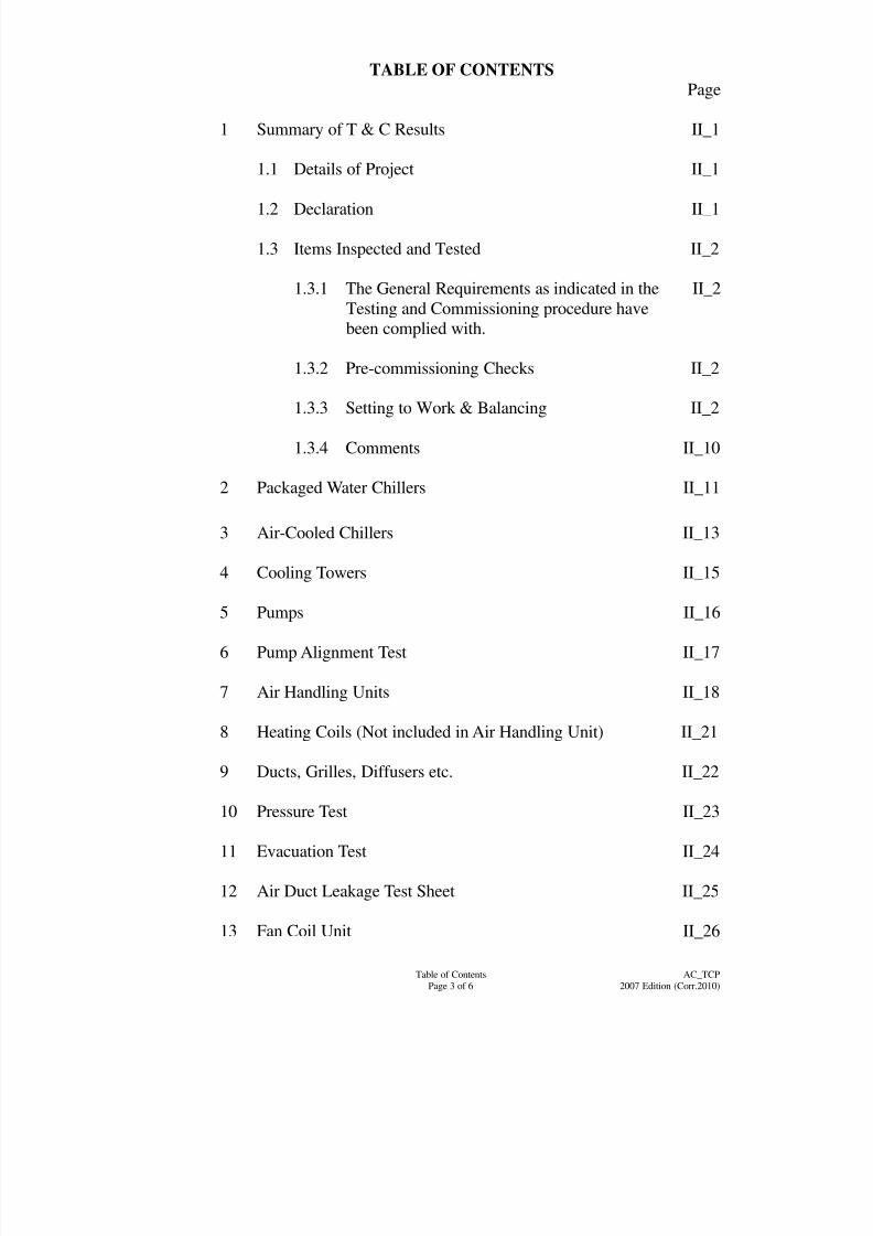
1 Summary of T & C Results II_1
1.1 Details of Project II_1
1.2 Declaration II_1
1.3 Items Inspected and Tested II_2
1.3.1 The General Requirements as indicated in the
Testing and Commissioning procedure have
been complied with.
II_2
1.3.2 Pre-commissioning Checks II_2
1.3.3 Setting to Work & Balancing II_2
1.3.4 Comments II_10
2 Packaged Water Chillers II_11
3 Air-Cooled Chillers II_13
4 Cooling Towers II_15
5 Pumps II_16
6 Pump Alignment Test II_17
7 Air Handling Units II_18
8 Heating Coils (Not included in Air Handling Unit) II_21
9 Ducts, Grilles, Diffusers etc. II_22
10 Pressure Test II_23
11 Evacuation Test II_24
12 Air Duct Leakage Test Sheet II_25
13 Fan Coil Unit II_26
8/7/2019 Test Adjust and Balancing (See 233)
http://slidepdf.com/reader/full/test-adjust-and-balancing-see-233 7/247
Table of Contents
Page 4 of 6
AC_TCP
2007 Edition (Corr.2010)
TABLE OF CONTENTS Page
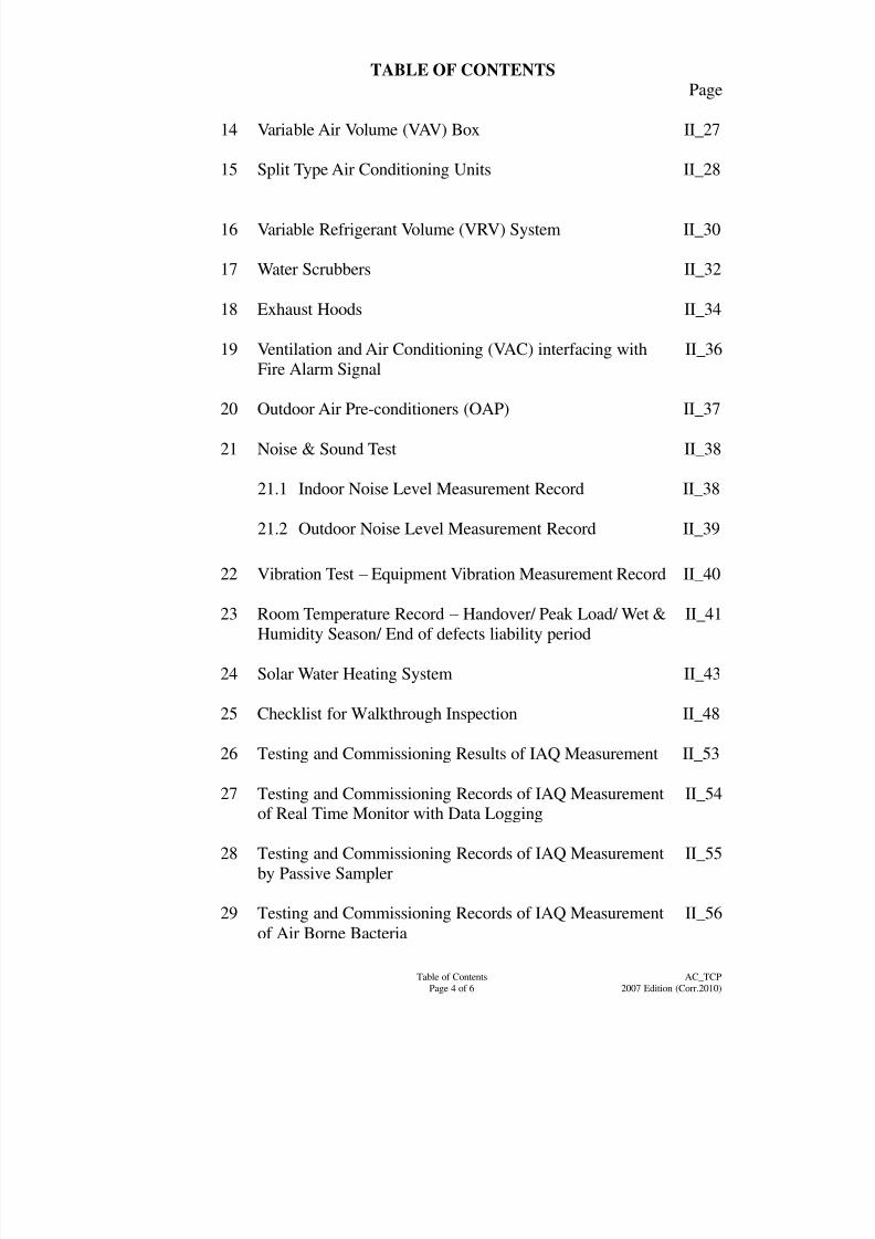
14 Variable Air Volume (VAV) Box II_27
15 Split Type Air Conditioning Units II_28
16 Variable Refrigerant Volume (VRV) System II_30
17 Water Scrubbers II_32
18 Exhaust Hoods II_34
19 Ventilation and Air Conditioning (VAC) interfacing with
Fire Alarm Signal
II_36
20 Outdoor Air Pre-conditioners (OAP) II_37
21 Noise & Sound Test II_38
21.1 Indoor Noise Level Measurement Record II_38
21.2 Outdoor Noise Level Measurement Record II_39
22 Vibration Test – Equipment Vibration Measurement Record II_40
23 Room Temperature Record – Handover/ Peak Load/ Wet &
Humidity Season/ End of defects liability period
II_41
24 Solar Water Heating System II_43
25 Checklist for Walkthrough Inspection II_48
26 Testing and Commissioning Results of IAQ Measurement II_53
27 Testing and Commissioning Records of IAQ Measurementof Real Time Monitor with Data Logging
II_54
28 Testing and Commissioning Records of IAQ Measurement
by Passive Sampler
II_55
29 Testing and Commissioning Records of IAQ Measurementof Air Borne Bacteria II_56
8/7/2019 Test Adjust and Balancing (See 233)
http://slidepdf.com/reader/full/test-adjust-and-balancing-see-233 8/247
Table of Contents
Page 5 of 6
AC_TCP
2007 Edition (Corr.2010)
TABLE OF CONTENTS Page
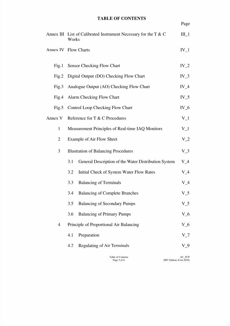
Annex III List of Calibrated Instrument Necessary for the T & C
Works
III_1
Annex IV Flow Charts IV_1
Fig.1 Sensor Checking Flow Chart IV_2
Fig.2 Digital Output (DO) Checking Flow Chart IV_3
Fig.3 Analogue Output (AO) Checking Flow Chart IV_4
Fig.4 Alarm Checking Flow Chart IV_5
Fig.5 Control Loop Checking Flow Chart IV_6
Annex V Reference for T & C Procedures V_1
1 Measurement Principles of Real-time IAQ Monitors V_1
2 Example of Air Flow Sheet V_2
3 Illustration of Balancing Procedures V_3
3.1 General Description of the Water Distribution System V_4
3.2 Initial Check of System Water Flow Rates V_4
3.3 Balancing of Terminals V_4
3.4 Balancing of Complete Branches V_5
3.5 Balancing of Secondary Pumps V_5
3.6 Balancing of Primary Pumps V_6
4 Principle of Proportional Air Balancing V_6
4.1 Preparation V_7
4.2 Regulating of Air Terminals V_9
8/7/2019 Test Adjust and Balancing (See 233)
http://slidepdf.com/reader/full/test-adjust-and-balancing-see-233 9/247
Table of Contents
Page 6 of 6
AC_TCP
2007 Edition (Corr.2010)
TABLE OF CONTENTS Page
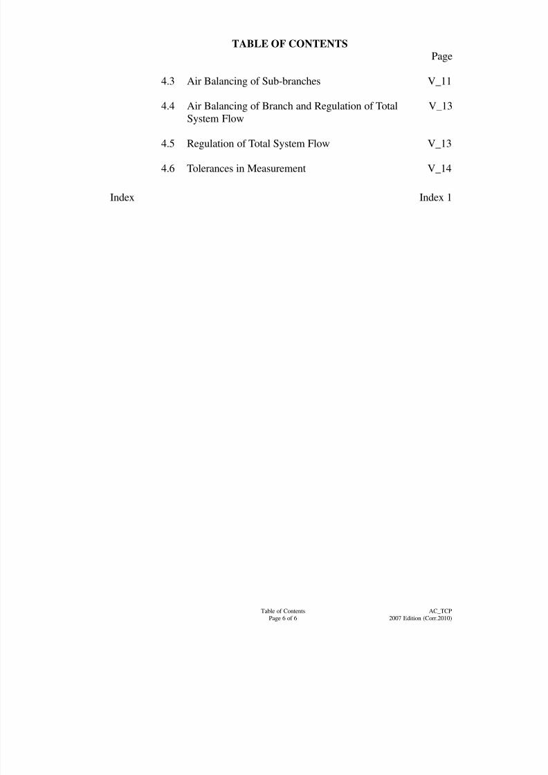
4.3 Air Balancing of Sub-branches V_11
4.4 Air Balancing of Branch and Regulation of Total
System Flow
V_13
4.5 Regulation of Total System Flow V_13
4.6 Tolerances in Measurement V_14
Index Index 1

8/7/2019 Test Adjust and Balancing (See 233)
http://slidepdf.com/reader/full/test-adjust-and-balancing-see-233 10/247
Page 1 of 133
AC_TCP
2007 Edition (Corr.2010)
Testing & Commissioning Procedure
Air-conditioning, Refrigeration, Ventilation and Central Monitoring &
Control System Installation
1 Introduction
The procedures stated in this document cover the activities in preliminary tests andinspections, functional performance tests and the commissioning of newly completed
installations and existing ones after major alteration. They are so compiled to facilitate
the work of Project Building Services Engineer (PBSE) and Project Building Services
Inspector (PBSI) in the following aspects with respect to testing and commissioning (T &
C):
(a) To vet and approve the T & C procedures proposed and submitted by the
Contractor;
(b) To witness those T & C procedures as specified; and
(c) To accept the T & C certificates and other supporting data.
The Contractor shall carry out the T & C works as detailed in this document.
Supplementary T & C plans may be proposed by the Contractor as appropriate and
agreed by PBSE, e.g. for special equipment supplied and/or installed by the Contractor.
The administrative requirements for T & C works are in general as specified in the
General Specification for Air-conditioning, Refrigeration, Ventilation and Central
Monitoring & Control System Installation (the AC General Specification) issued by the
Architectural Services Department. If there is any discrepancy between this procedureand the AC General Specification, the AC General Specification shall take precedence.
2 Objectives of the T & C works
The objectives of the T & C works are:
(a) to verify proper functioning of the equipment/system after installation;
(b) to verify that the performance of the installed equipment/systems meet with the
specified design intent through a series of tests and adjustments; and
(c) to capture and record performance data of the whole installation as the baseline
for future operation and maintenance.
For the avoidance of doubt, depending on the specific demands of individual installation,
the PBSE may require additional or substitute T & C works in regard to any elements in
the installation other than those indicated in this Procedure.

8/7/2019 Test Adjust and Balancing (See 233)
http://slidepdf.com/reader/full/test-adjust-and-balancing-see-233 11/247
Page 2 of 133
AC_TCP
2007 Edition (Corr.2010)
3 Scope of the T & C Works
3.1 Tests and Inspections during Construction
The purpose of these tests is to ensure that all components and systems are in a
satisfactory and safe condition before start up. Preliminary adjustment and setting
of equipment at this stage shall also be carried out at the same time to pave way for
the coming functional performance tests.
Before carrying out any test, the Contractor shall ensure that the installation
complies with all relevant statutory requirements and regulations. The T & C
works shall also comply with all site safety regulatory requirements currently in
force namely:
(a) Electricity Ordinance, Chapter 406, and other subsidiary legislations;
(b) The Code of Practice for the Electricity (Wiring) Regulations;
(c) IEC 60364-4-44 [2006] “Electrical Installations of Building – Part 4 - 44”;
and
(d) Electricity supply rules of the relevant power supply companies.
3.2 Functional Performance Tests
The purpose of functional performance tests is to demonstrate that the
equipment/installation can meet the functional and performance requirements as
specified in the General/Particular Specifications. Functional performance test
should proceed from the testing of individual components to the testing of differentsystems in the installation.
The Contractor may have to make temporary modifications as the test proceeds.
The specific tests required and the order of tests will vary depending on the type
and size of systems, number of systems, sequence of construction, interface with
other installations, relationship with the building elements and other specific
requirements as indicated in the General/Particular Specifications. The testing of
systems may have to be carried out in stages depending on the progress of work or
as proposed by the Contractor.
Part of the tests may be required to be carried out in suppliers‟ premises inaccordance with the provisions in the General/Particular Specification.
Any performance deficiencies revealed during the functional performance tests
must be evaluated to determine the cause and whether they are part of the
contractual obligations. After completion of the necessary corrective measures,
the Contractor shall repeat the tests.
If any test cannot be completed because of circumstances that are beyond the
control of the Contractor, it shall be properly documented and reported to the
PBSE, who shall then liaise with the relevant parties to resolve the situation. The
Contractor shall resume his testing work immediately upon the attainment of asuitable testing environment.
8/7/2019 Test Adjust and Balancing (See 233)
http://slidepdf.com/reader/full/test-adjust-and-balancing-see-233 12/247
Page 3 of 133
AC_TCP
2007 Edition (Corr.2010)
3.3 Commissioning and Statutory Inspections
Commissioning is the advancement of an installation from the stage of static
completion to full working conditions and to meet the performance requirements
as specified in the General/Particular Specification. This will include setting into
operation and regulation of the installation. It is expected that fine-tuning of the
commissioned system shall be done by the Contractor to match system
performance to the actual needs of the building occupier more closely.
Where necessary, after the proper testing and commissioning of the
Air-conditioning, Refrigeration, Ventilation and Central Monitoring & Control
System Installation, the Contractor shall notify the appropriate authority, through
the PBSE of the completion of the installation and its readiness for final inspection.
3.4 Documentation and Deliverables
The Contractor shall submit his proposed T & C procedures together with the
Testing and Commissioning Progress Chart shown in Annex I to PBSE for
approval.
All inspection and T & C results shall be recorded by the Contractor in the
appropriate test record forms, the reference of which is shown against each
individual test. A complete set of these forms can be found in Annex II.
Data recorded in other formats may also acceptable subject to agreement between
the PBSE and the Contractor. Upon completion of all the required T & C works,
the Contractor‟s project engineer shall complete and sign a testing and
commissioning certificate as shown in Annex II Section 1.1 & 1.2 to the effect that
the agreed T & C works have been duly carried out.
A functional performance test report covering all measured data, data sheets, and a
comprehensive summary describing the operation of the system at the time of the
functional performance tests shall be prepared and submitted to the PBSE.
Deviations in performance from the General/Particular Specifications or the design
intent should be recorded, with a description and analysis included.
Where required in the General Specification, the Contractor shall conduct a final
evaluation of the performance of the Air-conditioning, Refrigeration, Ventilation
and Central Monitoring & Control System Installation, the results of which shall
be included in the commissioning report.
3.5 General Commissioning Requirements
3.5.1 Systems shall be properly commissioned to demonstrate that all the
equipment deliver the designed capacities and that air and water flow rates
are balanced in accordance with the design.
Since the air systems are usually completed ahead of the hydraulic systems,
commissioning of the air systems will commence earlier than the water
systems.
Prior to any commissioning works, the Contractor shall check the
completion of the air condition and ventilation associated builder‟s work and
8/7/2019 Test Adjust and Balancing (See 233)
http://slidepdf.com/reader/full/test-adjust-and-balancing-see-233 13/247
Page 4 of 133
AC_TCP
2007 Edition (Corr.2010)
the building services installations, to ensure that commissioning can be
proceeded without obstruction.
(a) Checking Procedures on builder‟s work:
(i) Plantrooms are completed and free of construction debris;
(ii) All plant room doors are fitted and lockable;
(iii) Permanent power supply of sufficient capacity is available and
the building contractor is operating a security access procedure
to all plant areas to prevent unauthorised switching of plant.
(The normal security access system is one of "Permit to Work"
arrangement and procedure proposed by the Contractor in
accordance with the guidelines on "Permit to Work" issued by
the Labour Department.);
(iv) All builder‟s work and building services installations in
association with air conditioning systems are satisfactorily
completed;
(v) All glazing works are completed and all windows closed;
(vi) All curtain walls and the building fabric are completed and
reasonably water-tight;
(vii) All external doors, all stairs and lobbies, and toilet doors are
completed and securable;
(viii) All ceiling works are completed, unless specifically agreed,
with the exception of those access areas required to be left open
for final adjustment and testing of high level building services
equipment during the commissioning period.
All dust generating activities by other trades are finished and all
areas are thoroughly cleaned and sealed to prevent ingress dust
from getting into the ventilation and air conditioning systems
during operation; and
(ix) All builder‟s work in association with pressurised and
depressurised areas are completed.
(b) Checking procedures on Building Services Installation
The Contractor should ensure that:
(i) Air intake screens and louvres are unobstructed and clean;
(ii) Fan and other equipment chambers are clean and free of
construction debris;
(iii) Floor gulleys and drainage traps are clear;
8/7/2019 Test Adjust and Balancing (See 233)
http://slidepdf.com/reader/full/test-adjust-and-balancing-see-233 14/247
Page 5 of 133
AC_TCP
2007 Edition (Corr.2010)
(iv) Fans are checked for impeller housing clearance and free of
foreign objects;
(v) Heater batteries and cooler batteries are clean and fins combed;
(vi) Cooling coil condensate trays and humidifier drains are
unblocked;
(vii) Dampers are clean;
(viii) Ducting and other airways are clean;
(ix) All electrical wiring circuits (power, lighting and controls) are
completed, or will be completed at the correct stage during the
commissioning period;
(x) All electrical panels are commissioned and clean;
(xi) Lighting systems are switched on;
(xii) Permanent power supply is available at the electrical panels,
and all the connected equipment can be switched on;
(xiii) All equipment are checked for:
- Equipment rotation (fan kicked only);
- Lubrication;
- Belt tension;- Motor fixings;
- Duct flexible connector correctly aligned;
- Keyway and setscrew tightness;
- Clean condition;
- Vibration isolation adjustment;
- Correct operation of VAV control gear;
- Correct overloads and amperages;
- Investigate and locate all stop-start, disconnect and circuit
interruption devices; and
- Inspect fan inlet and outlet to ensure satisfactory
performance conditions are provided.
(xiv) All outside air, return air and spill air dampers are operative;
(xv) All fire and volume control dampers are fitted and left in the
fully open position;
(xvi) The supply air systems are blown through;
(xvii) All VAV and CAV terminals are installed, together with grilles
and diffusers;
(xviii) All manual control valves are open or pre-set, as required;
8/7/2019 Test Adjust and Balancing (See 233)
http://slidepdf.com/reader/full/test-adjust-and-balancing-see-233 15/247
Page 6 of 133
AC_TCP
2007 Edition (Corr.2010)
(xix) All strainers are cleaned;
(xx) All water systems are flushed, vented and filled and chemical
cleaning process is completed;
(xxi) Water treatment is completed;
(xxii) All filter media are installed;
(xxiii) Plantroom access is restricted to authorised personnel only; and
(xxiv) All functional and safety devices are installed and operational.
3.5.2 All aspects of the commissioning procedure shall follow the
recommendations in the relevant CIBSE Commissioning Codes, including
but not limited to:-
(a) Preliminary checks to ensure that all systems and system components
are in a satisfactory and safe condition before start up;
(b) Preliminary adjustment and setting of all plant and equipment
consistent with eventual design performance;
(c) Energising and setting to work on all plants; and
(d) Final regulation and demonstration that the installation delivers the
correct rate of flow of fluids and air at the conditions specified in the
Contract Documents.
3.5.3 Progressive Commissioning
The Contractor shall not wait for completion of every part of the work but
shall arrange for a progressive commissioning programme to achieve
practical overall completion and have the whole work ready
to be handed over by a date to suit the Building Contract completion date or
any other agreed programme date.
3.5.4 Specialist Commissioning
The Contractor shall be responsible for initially setting the plants to work and shall arrange for any Specialist Plant or Equipment such as CCMS to be
commissioned and tested by the Specialist Equipment Manufacturer‟s
skilled Commissioning Engineer and/or technician.
8/7/2019 Test Adjust and Balancing (See 233)
http://slidepdf.com/reader/full/test-adjust-and-balancing-see-233 16/247
Page 7 of 133
AC_TCP
2007 Edition (Corr.2010)
3.6 General Testing Requirements
3.6.1 Cleaning
Before any installation is subjected to commissioning and site testing, it shall
be thoroughly cleaned both internally and externally.
(a) Water System
(i) The system (new or old) shall be flushed using an appropriate
chemical dispersant of a type and strength recommended by a
reputable chemical water treatment manufacturer and
guaranteed in writing by that company as suitable in every
respect for the application in question.
(ii) The quality of cleaning water discharged shall comply with
EPD requirement or treated if needed as stated in clauses
F.5.1(e) and F.10 of the General Specification.
(iii) The chemicals shall remain in the system for 48 hours including
a minimum of 12 hours with the pumped circulation in
operation, unless otherwise recommended by the supplier with
free technical support accepted by the Architect.
(iv) After chemical cleaning, the system shall be flushed and
drained immediately. The Contractor or the chemical water
treatment Specialist shall continue to take water samples at all
system low points until the water samples indicate iron and
chemical residues below the level of 1 ppm.
(v) The success or failure of the above operation will depend on a
high speed rate of draining down which is entirely related to the
size of the drain points and ability of air to enter the system from
the top.
(vi) For high speed draining down purposes the Contractor shall
provide temporary 50 mm valved drain outlets on all points
where the main pipework is 50 mm dia. or over.
(vii) The Contractor shall ascertain that there is adequate drainagenearby to discharge by large hose in order to ensure flooding of
low level areas will not occur.
(viii) Subsequent to the flushing operations, the large drain down
points shall be reduced to 15 mm valves or cocks or the sizes as
indicated in the Contract Drawings.
8/7/2019 Test Adjust and Balancing (See 233)
http://slidepdf.com/reader/full/test-adjust-and-balancing-see-233 17/247
Page 8 of 133
AC_TCP
2007 Edition (Corr.2010)
(b) Air System
(i) Ductwork systems shall be cleaned by purging using the supply
air fan, or robot duct cleaning as recommended by the ductwork
system cleaning Specialist. No fan shall be started until
cleaning is commenced.
(ii) All submitted proposals for arrangements to ensure cleanlinessof air and water systems shall follow the recommendations in
the relevant CIBSE Commissioning Codes.
(c) Refrigerant system
The piping system shall be cleaned by purging using nitrogen before
pressure test and evacuation test
3.6.2 Contractor to Inform Architect
The Architect shall be informed in good time of all site tests for plant,
ducting and piping.
3.6.3 Witness by Architect
The final tests shall be carried out in the presence of the Architect, or the
Contractor representative, in accordance with the requirements of witness
testing and commissioning as stipulated in the Building Services Branch
Instructions. The Contractor shall give at least 72 hours notice, in writing,
when any part or parts of the installation will be tested.
3.6.4 Test Equipment and Labour
The Contractor shall allow for providing all skilled labour, testing gear
(including pumps, tools, air and water flow instruments and thermometers,
etc.) and attendants for all tests including those by Specialist employed under
the Sub-contractor. The Contractor shall be solely responsible for the proper
filling, emptying and flushing of the plants and pipes to be tested and shall
make good any defects emerging from the tests, or made manifest under
testing or re-testing, until the whole of the plant is free from defect and is in
complete working order to the satisfaction of the Architect.
3.6.5 Tests under Operating Conditions
The Contractor shall include the hydraulic and functional performance tests
under operating conditions, on the whole installation to the entire satisfaction
of the Architect.

8/7/2019 Test Adjust and Balancing (See 233)
http://slidepdf.com/reader/full/test-adjust-and-balancing-see-233 18/247
Page 9 of 133
AC_TCP
2007 Edition (Corr.2010)
4 T & C Procedures
4.1 Tests and Inspections during Construction
Certain tests will be carried out on different systems of the installation during
construction to ensure their suitability for operating at the design conditions.
Certificates of such tests have to be issued together with certificates of any work
tests.
4.1.1 Work Tests
(a) Work tests shall be carried out in accordance with the type normally
associated with the specified item of equipment and to the standards as
laid down in the Specification and the Contract.
(b) Work static pressure tests shall be carried out on such items of plant and
equipment as pressure vessels, water coils, heat exchangers and plate
exchanger, radiator and convector elements, and all items of plant orequipment, as laid down in the Specification and the Contract.
(c) Dynamic rotation tests shall be carried out on such items as fan
impellers and drives, compressor, pump impellers and drives. Tests
shall be conducted through the entire rotational speed range up to a
maximum of 150% design operating speed if such provisions have been
made in the Contract. When items of plant are purchased ex-stock,
manufacturer‟s test certificate will suffice.
(d) Rotational test on electric motors will not be carried out if the
equipment is constructed to the related content of IEC standard, or anyother approved standards.
4.1.2 Weld in Piped Services
(a) The PBSE reserves the right to inspect at random 2% of the welded
joints. Should any of the above welds prove faulty in materials or
workmanship, further removal of welds may be ordered up to a total of
4% of the welded joints. If any of the welds fail the tests, it is sufficient
to conclude that an operative is not consistent in standard. The PBSE
may order any number of the operative‟s welds to be removed. The
Contractor shall be responsible for cutting out and repair of all suchwelds for inspection.
(b) At least 2 welds per operative shall be inspected. Each welder
employed on the works shall be allocated an identification number and
each site weld shall be stamped with the appropriate identification
number to identify the operative.
(c) In addition to the above, each weld made on pipes and fittings having a
nominal diameter of 350 mm and larger, and a 5% sample of all welds
on pipes and fittings 300 mm diameter and below shall be inspected
using an approved non destructive inspection process, e.g. radiographicor ultrasonic methods. The Contractor‟s attention is drawn to the
magnitude of this task, the constraints of the water mains, and the time
8/7/2019 Test Adjust and Balancing (See 233)
http://slidepdf.com/reader/full/test-adjust-and-balancing-see-233 19/247
Page 10 of 133
AC_TCP
2007 Edition (Corr.2010)
frame within which testing must be carried out. Such non-destructive
testing should be carried out by specialized laboratories that both
perform the tests and analyse the results.
4.1.3 Pressure Testing of Piped Services
4.1.3.1 Before carrying out pressure test, spotted open-up inspection for
joints shall be required to inspect the internal finishing after brazingto ensure the quality of the workmanship.
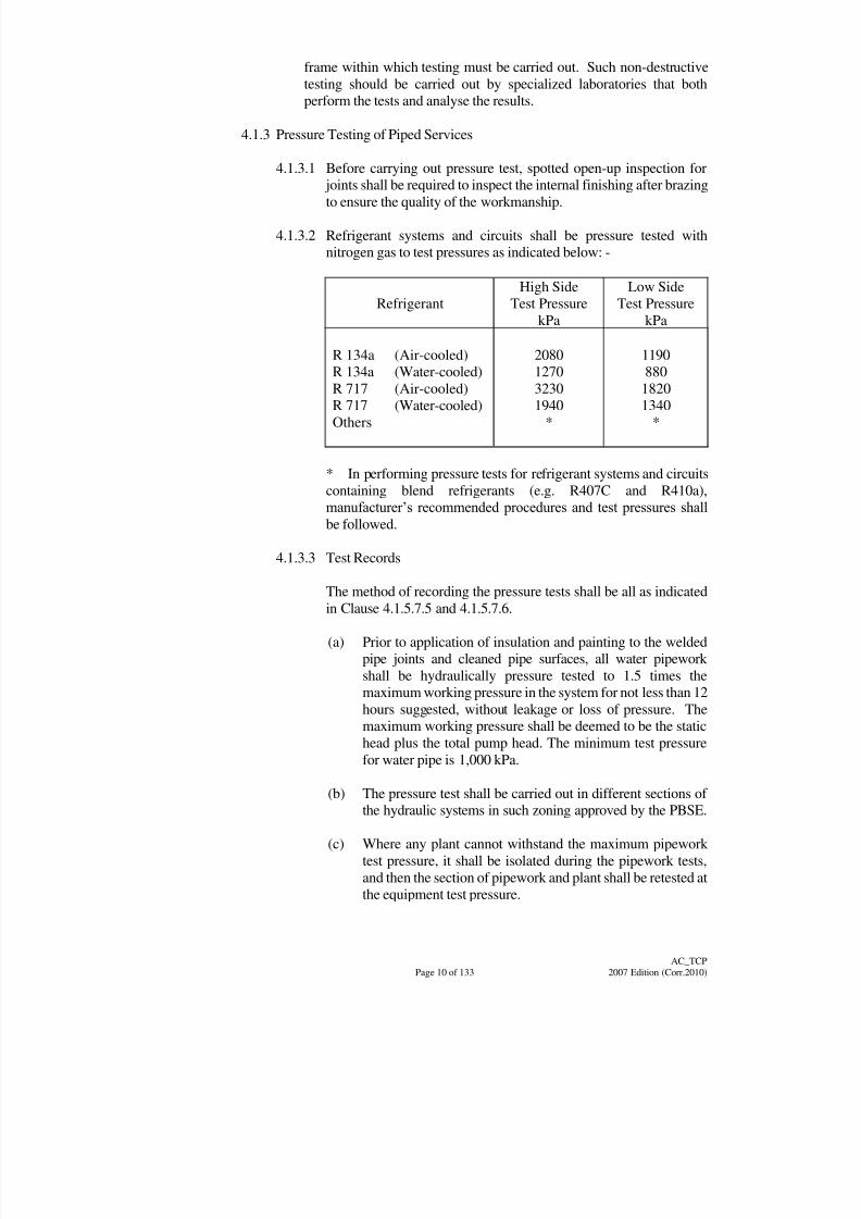
4.1.3.2 Refrigerant systems and circuits shall be pressure tested with
nitrogen gas to test pressures as indicated below: -
Refrigerant
High Side
Test Pressure
kPa
Low Side
Test Pressure
kPa
R 134a (Air-cooled)R 134a (Water-cooled)
R 717 (Air-cooled)
R 717 (Water-cooled)
Others
20801270
3230
1940
*
1190880
1820
1340
*
* In performing pressure tests for refrigerant systems and circuits
containing blend refrigerants (e.g. R407C and R410a),
manufacturer‟s recommended procedures and test pressures shall
be followed.
4.1.3.3 Test Records
The method of recording the pressure tests shall be all as indicated
in Clause 4.1.5.7.5 and 4.1.5.7.6.
(a) Prior to application of insulation and painting to the welded
pipe joints and cleaned pipe surfaces, all water pipework
shall be hydraulically pressure tested to 1.5 times the
maximum working pressure in the system for not less than 12
hours suggested, without leakage or loss of pressure. The
maximum working pressure shall be deemed to be the statichead plus the total pump head. The minimum test pressure
for water pipe is 1,000 kPa.
(b) The pressure test shall be carried out in different sections of
the hydraulic systems in such zoning approved by the PBSE.
(c) Where any plant cannot withstand the maximum pipework
test pressure, it shall be isolated during the pipework tests,
and then the section of pipework and plant shall be retested at
the equipment test pressure.

8/7/2019 Test Adjust and Balancing (See 233)
http://slidepdf.com/reader/full/test-adjust-and-balancing-see-233 20/247
Page 11 of 133
AC_TCP
2007 Edition (Corr.2010)
(d) The Contractor shall ensure that all plugs, caps, tees and
drain fittings are provided to enable the pressure tests to be
carried out.
(e) Before hydraulic pressure tests are carried out, all safety
valves, gauges, etc., shall be effectively isolated or removed.
For all safety equipment, these shall be effectively tested at
their design working pressure during commissioning of theinstallation.
(f) Tests on lengths of pipe or portions of systems shall be
applied by filling the section to be tested with water up to its
testing pressure.
(g) The section shall then be left fully isolated without further
strokes of the pump and all joints must remain watertight for
a period of at least 12 hours. As to whether or not the section
is sound shall be governed by the rate at which the pressure
falls. The Contractor shall agree with the PBSE on the
acceptable percentage of pressure falls.
(h) Any fault discovered during such tests shall be at once
remedied and the test reapplied until the section under test is
considered sound. Remedial work shall conform to all the
requirements of the General and Particular Specification for
material and standards of workmanship.
(i) Upon completion of the test, the water shall be released and
drained away as rapidly as possible, the section being thenthoroughly sluiced through to ensure the removal of as much
dirt and dross as possible before being refilled and put into
service.
4.1.4 Air Leakage Test for Ductwork
4.1.4.1 All ductwork shall be tested for air leakage in accordance with
Sub-section B2.10 of the General Specification.
4.1.4.2 The joints on ductwork shall be tested by using chemical 'white'
smoke generators. All openings such as fan outlets, grilles, accesspanels, test holes, etc. shall be sealed before the smoke is introduced.
If smoke leaks from any joint, that joint shall be made good. The
smoke test shall be repeated until all joints are tested and to be
properly sealed.
(a) Prior to application of insulation and painting, all installed
ductwork, including exhaust, smoke extraction,
air-conditioning, ventilation, etc., shall be tested to the
requirements of the General Specification. The method of air
leakage test shall follow the HVCA standard DW/series or the
“Low Pressure Duct Construction Standards” and “HighPressure Duct Construction Standards” issued by the
SMACNA of U.S.A. as directed by the PBSE. Air ducts shall
8/7/2019 Test Adjust and Balancing (See 233)
http://slidepdf.com/reader/full/test-adjust-and-balancing-see-233 21/247
Page 12 of 133
AC_TCP
2007 Edition (Corr.2010)
be leakage tested and any defects shall be rectified before
applying insulation and commissioning.
(b) For preliminary and visual test, the method will include using
chemical “white” smoke generator. All openings in the
ductwork shall be properly sealed followed by the introduction
of smoke.
4.1.5 Pre-commissioning Checks of Water Distribution System
4.1.5.1 System Cleanliness
Irrespective of the precautions taken during the construction stage
to keep the internal surfaces of pipework clean, the following
procedures shall be used to clean the system.
4.1.5.1.1 Flushing
(a) divide the pipework system into self-draining
sections so that the maximum possible flushing rate
is achieved;
(b) isolate or bypass items which are particularly
sensitive to dirt such as pumps, chillers, small bore
coils and tubes, including induction and other room
unit coils and spray nozzles. Washers, cooling
tower basins, feed and other tanks which may have
accumulated with deposits during manufacturing or
installation should also be isolated and flushedindependently; and
(c) where make-up or feed tanks are used for flushing,
ensure that the maximum possible pressure is
sustained on the system during the flushing process.
This may necessitate the provision of a temporary
parallel feed of mains water into the tank where the
ball valve has limited capacity. This procedure
assumes that the connection of the section from the
tank is at a high point in the section being flushed.
The flushing water wherever appropriate, shall berecirculated with suitable filtration to reduce the
water demand and wastewater discharge.
(d) Ensure:
(i) that flushing is carried out from the upper to
the lower sections of a multi-section system,
flushing with the lowest point; initial flushing
should always be from small bore to large bore
pipe. Particular care is required on reverse
return systems and systems with roof-topchiller or boiler plant;
8/7/2019 Test Adjust and Balancing (See 233)
http://slidepdf.com/reader/full/test-adjust-and-balancing-see-233 22/247
Page 13 of 133
AC_TCP
2007 Edition (Corr.2010)
(ii) that the large bore outlet is not opened until the
section being flushed is fully primed;
(iii) that the maximum possible flow rates are used;
and
(iv) that flushing continues until the outflow runs
clear.
4.1.5.1.2 Cleaning by Forced Circulation
Where facilities exist, cleaning of systems can be
achieved by circulation of the medium in order to
collect dirt at filters or other selected points in the
system. Where circulation is achieved by the use of a
pump, this action shall be deferred until the pump has
been set to work in accordance with para. 4.2.1.4. The
circulating velocity shall be 1.5 times of normal water
velocity in pipe.
4.1.5.1.3 Chemical Cleaning & Corrosion Inhibiting
Chemical Cleaning, if required, shall be carried out as
specified by the specialist. Corrosion inhibiting, where
specified, should be carried out after flushing.
4.1.5.2 State of System
Check:
(a) that where special valve packing is required, e.g. grease in
medium or high temperature system, this shall be in
accordance with manufacturer‟s instructions;
(b) that pressure tests have been completed throughout;
(c) that the system has been cleaned in accordance with para.
4.1.5.1;
(d) that permanent water connections have been made; and
(e) that water treatment is available if specified.
4.1.5.3 Check of System before Filling
Check:
(a) that probes, pockets, pressure gauges, siphons, orifice plates
and taps, and air vents are installed;
(b) that drains and overflows are connected and free fromblockage;
8/7/2019 Test Adjust and Balancing (See 233)
http://slidepdf.com/reader/full/test-adjust-and-balancing-see-233 23/247
Page 14 of 133
AC_TCP
2007 Edition (Corr.2010)
(c) that connections to heating and cooling coils and all other
heat exchangers are correct in relation to the design water
flow direction;
(d) that control and non-return valves are installed the right way
round;
(e) that relief valves are installed as specified and are free tooperate;
(f) that relief valve outlets are piped away to suitable drain
points;
(g) the expansion devices for alignment and freedom from
obstruction;
(h) the presence of special pump priming devices where
specified;
(i) that the strainer meshes are of the correct grade and material;
(j) that the changeover devices for duplex strainers are operative
and that there are means of isolation for single strainers;
(k) that washers, tanks, nozzles and filters are clean;
(l) that tank covers are provided where specified;
(m) that drain cocks are closed and other valves are left open orclosed according to the plan for filling;
(n) that the feed connection is in its correct location; and
(o) that all pipework and fittings are adequately supported,
guided and/or anchored where applicable.
4.1.5.4 Mechanical Checks
4.1.5.4.1 Pumps
Check:
(a) the external cleanliness of the pumps, remove and
clean and replace all strainers;
(b) that the flow direction is correct;
(c) that all components, bolts, fixings, tie bars etc., are
secured;
(d) that the impellers are free to rotate;
8/7/2019 Test Adjust and Balancing (See 233)
http://slidepdf.com/reader/full/test-adjust-and-balancing-see-233 24/247
Page 15 of 133
AC_TCP
2007 Edition (Corr.2010)
(e) the level and plumb of pump and motor shaft and
slide rails; (direct drive pumps require particular
attention in this respect);
(f) the anti-vibration mountings for correct deflection;
(g) that the correct drivers are fitted;
(h) that the pipework imposes no strain at the pump
connections;
(i) the securing and alignment of pulleys and
couplings;
(j) the belt tension and match;
(k) the cleanliness of the bearings;
(l) that the lubricant is fresh and of the correct grade;
(m) that the coolant is available at the bearings when
specified.
(n) that glands are correctly packed and the gland nuts
are finger-tight only, pending adjustment to correct
drip rate after start-up; and
(o) that drive guards are fitted and the access for speed
measurement is provided.
4.1.5.4.2 Motorized Valves and Float Switches
Check :
(a) that the valves are installed the correct way round;
(b) that the valve spindles are free to move;
(c) for freedom from excessive looseness;
(d) the fit of pins;
(e) the rigidity of the mountings;
(f) the stiffness of the linkage members;
(g) the tightness of locking devices; and
(h) the bearing lubrication.
4.1.5.4.3 Cooling Towers
Check:
8/7/2019 Test Adjust and Balancing (See 233)
http://slidepdf.com/reader/full/test-adjust-and-balancing-see-233 25/247
Page 16 of 133
AC_TCP
2007 Edition (Corr.2010)
(a) that the water-circulating system serving the tower
is thoroughly cleaned of all direct and foreign
matters;
(b) that interior filling of cooling tower is clean and
free of foreign materials such as scale, algae, or tar;
(c) that the cooling tower fans are free to rotate and the
tower basin is clean; and
(d) that the water-circulating pumps are ready for test.
4.1.5.5 System Filling
4.1.5.5.1 All water tanks shall, after erection, be filled with water
and shall remain filled for at least 24 hours during which
all joints shall be carefully examined. Any defect shall
be rectified immediately and the test repeated.
4.1.5.5.2 Before finally charging, the water systems shall be
thoroughly flushed and all strainers, filters, etc. cleaned
or replaced.
4.1.5.5.3 Charge the system with water by filling from the bottom
upwards forcing the air to high points – for venting to
atmosphere. Careful consideration should be given to
the stage of valves and automatic air vents before and
during filling to avoid air-locks and excessive spillage.Take care not to exceed the working pressure of the
system when filling from a high pressure source. When
the whole system is filled, disconnect the filling source,
open the permanent supply and adjust the tank levels.
4.1.5.6 Electrical Checks
Prior to the initial running of any electrically driven pump, valve or
electric water heater, the following procedures should be adopted.
4.1.5.6.1 With all electrical supplies isolated, check:
(a) the local isolation of motor and control circuits;
(b) that there are no unshrouded live components
within the panels;
(c) that the panels and switchgears are clean;
(d) that the motor and surrounding areas are clean and
dry;
(e) that the transit packing has been removed from
contactors and other equipment;
8/7/2019 Test Adjust and Balancing (See 233)
http://slidepdf.com/reader/full/test-adjust-and-balancing-see-233 26/247
Page 17 of 133
AC_TCP
2007 Edition (Corr.2010)
(f) that there is no mechanical damage to switchgears
and that thermostats are of a suitable range to
operate at ambient temperature, see para. 4.2.1.2;
(g) that all mechanical checks on the pump and motor
or valve are completed, see para. 4.1.5.4;
(h) that all connections are tight on busbars and
wirings;
(i) that the internal links on the starter are correct;
(j) that all power and control wirings have been
completed in detail to the circuit diagram, paying
special attention to circuit for star-delta connected
or specially wound motors;
(k) that the fuse ratings are correct;
(l) that the starter overloads are set correctly in
relation to the motor name-plate full load current;
(m) that the dashpots are charged with the correct fluid
and the time adjustments and levels are identical;
(n) that insulation tests on the motor have been
performed satisfactorily;
(o) that the adjustable thermal cut-outs are set
correctly (check manufacturers‟ test certificates);
and
(p) that all cover plates are fitted.
4.1.5.6.2 With the electrical supply available, check:
(a) check that the declared voltage range is available
on all supply phases;
(b) where motor powers are substantial or reduced
voltage starting or complex interlocks are involved,
the control circuit logic and the starter operation
should be tested before the motor is rotated. The
supply should first be isolated by the withdrawal of
the 2 power fuses not associated with the control
circuit or the disconnection of cables. The “red”
phase shall be used for control circuit normally.
The control circuit fuse must be checked to ensure
that it is rated to give the correct discriminatory
protection to the control circuit cables. The controlcircuit should be activated and the starter operation
observed. Adjust the timers. Check for positive
8/7/2019 Test Adjust and Balancing (See 233)
http://slidepdf.com/reader/full/test-adjust-and-balancing-see-233 27/247
Page 18 of 133
AC_TCP
2007 Edition (Corr.2010)
operation of all contactors, relays and interlocks.
Finally, open the isolators, reinstate the power
connections and close the isolators;
(c) where small motors have direct-on-line starting
and simple control circuits, the starter operation,
etc., should be checked when first starting the
motor; and
(d) never energise electronic valve motors until the
checks in para. 4.1.5.4.2 have been completed.
4.1.5.7 Hydraulic testing for water distribution pipe work systems
4.1.5.7.1 General
All water distribution pipework systems shall be
hydraulically tested in sections as installation work
progresses and before thermal insulation is applied.
4.1.5.7.2 Test Pressure
The hydraulic test pressure shall be one and a half times
the total working pressure.
4.1.5.7.3 Precautions
Before hydraulic tests are carried out, all safety valves,
gauges, etc. shall be effectively isolated or removed.These safety equipment shall be effectively tested at
their design working pressure during commissioning of
the installation.
4.1.5.7.4 Method of Testing
For a satisfactory and acceptable test, the pressure shall
be maintained for a period of 24 hours or as otherwise
stated in the Particular Specification, without loss of
pressure after all weak joints, defective fittings and
pipes disclosed by the initial application of the test arerectified. During the final testing period the Architect or
the representative shall be invited to witness the tests.
All sections of the work under test shall be accessible
for inspection and selected welds shall be hammer
tested.
4.1.5.7.5 Hydraulic Test Certificates
Certificates of all hydraulic tests made on site shall be
forwarded to the Architect for approval and such
approval shall be obtained before any thermal insulationis applied. A separate and duplicated set of the
Contractor‟s installation/shop drawings shall be
8/7/2019 Test Adjust and Balancing (See 233)
http://slidepdf.com/reader/full/test-adjust-and-balancing-see-233 28/247
Page 19 of 133
AC_TCP
2007 Edition (Corr.2010)
provided for the purpose of keeping accurate records of
site tests. 1 copy will be kept by the Architect‟s
representative on site and the other retained by the
Contractor.
4.1.5.7.6 Details on Test Certificate
All test certificates shall be signed by the Contractor‟sauthorized site representative and by the Architect or the
representative who has witnessed the test. All test
certificates shall contain the following particulars :-
- Date of test
- Apparatus or section under test
- Makers number (if any)
- Nature, duration and conditions of test
- Result of test
- Name of Contractor‟s representative (in block
letter) in charge of test
- Name of Employer‟s representative at witness
the test
A blank test certificate form shall be submitted by
Contractor for Architect‟s approval prior to carrying out
the actual test on site.
4.1.6 Pre-commissioning Checks of Air distribution System
4.1.6.1 System Cleanliness
4.1.6.1.1 During Construction
Dust and debris should be prevented from entering the
duct system as far as possible and the system inspected
and cleaned as part of pre-commissioning steps.
4.1.6.1.2 During T & C, the following procedures should be
adopted:-
(a) ductwork systems shall be cleaned by purgingusing the supply air fan, or robot duct cleaning as
recommended by the ductwork system cleaning
Specialist if employed;
(b) temporary filter media shall be used where
building work is still in progress during T & C, and
replaced with clean filters for final measurements
of flow rates;
(c) computer room plants, in particular where under
floor air distribution systems are used, should notbe run before the rooms have been properly
cleaned;
8/7/2019 Test Adjust and Balancing (See 233)
http://slidepdf.com/reader/full/test-adjust-and-balancing-see-233 29/247
Page 20 of 133
AC_TCP
2007 Edition (Corr.2010)
(d) extraction systems should not be run whilst
building work is in progress and dirt is present; and
(e) where a specialist ductwork cleaning company is
employed, system commissioning should not
commence until cleanliness has been inspected
and certified.
4.1.6.1.3 Prior to the fitting of air cleaning equipment, ensure that
the environment is clean and then proceed to check the
following for cleanliness:
(a) air intake screens and louvres;
(b) fan and other equipment chambers;
(c) f1oor galley and all drainage traps;
(d) fan internals;
(e) heater and cooler batteries;
(f) cooling coil condensate trays;
(g) washer tanks;
(h) humidifiers;
(i) eliminators;
(j) dampers and linkages;
(k) ducting and other airways;
(l) sensing elements; and
(m) terminal units.
4.1.6.2 Air Regulating Devices and Other Components within Airways
Check:
(a) that turning vanes, thermal insulation, acoustic linings,
heating/cooling battery fins and sensing elements have been
fitted and are undamaged;
(b) that heater and cooler batteries, humidifiers, filters, silencers,
fire dampers, sail switches, volume control dampers etc., are
installed correctly in relation to air flow;
8/7/2019 Test Adjust and Balancing (See 233)
http://slidepdf.com/reader/full/test-adjust-and-balancing-see-233 30/247
Page 21 of 133
AC_TCP
2007 Edition (Corr.2010)
(c) the damper free-movement, clearances seating pinning to
damper spindles, position of blades with respect to quadrant
indication, relative positions of blades in multi-leaf dampers;
(d) the control linkages on motorized dampers for alignment,
rigidity, lubrication and free movement without slackness;
(e) that dampers throughout the system are secured in open/closeposition, as desired, with damper actuators locked;
(f) the free movement of fire dampers together with the location
of, access to and fitting of fusible link assembly; all fire
dampers are finally secured in open position;
(g) that all adjustable louvers are set without deflection, i.e.
normal to face of grille. Adjustable cones on diffusers are set
either all in the fully up or all in the fully down position; and
(h) that test holes are provided at strategic points for the
measurement of branch and total air volume flow.
4.1.6.3 Visual Checks for Air tightness
Check:
(a) the builder's work for ducts and shafts are sealed;
(b) access doors to plant equipment are sealed around the whole
periphery;
(c) ductwork joints, including flexible couplings are air tight;
(d) inspection covers are fitted;
(e) drainage water seals are intact; and
(f) plugs or covers for test holes are fitted.
4.1.6.4 Mechanical Checks
4.1.6.4.1 Fans
The following should be checked:
(a) internal and external cleanliness of fans;
(b) all components, bolts, fixing, etc. are secured;
(c) impeller secured, free to rotate, of correct handing
and correct clearances;

8/7/2019 Test Adjust and Balancing (See 233)
http://slidepdf.com/reader/full/test-adjust-and-balancing-see-233 31/247
Page 22 of 133
AC_TCP
2007 Edition (Corr.2010)
(d) axial-flow-type fans installed for correct air flow
direction and, where compounded, in correct
order;
(e) level and plumb of fan and motor shaft and slide
rails;
(f) anti-vibration mountings for correct deflection andthe removal of transit bolts and packing materials;
(g) the static balance;
(h) correct drive is fitted;
(i) securing and alignment of pulleys and couplings;
(j) belt tension and match;
(k) cleanliness of the bearings;
(l) lubricant is fresh and of the correct grade;
(m) coolant is available at bearings when specified;
(n) drive guards fitted and access for speed
measurement provided;
(o) satisfactory operation of inlet guide vanes over full
range of movement; and
(p) fan casings to be earthed are correctly and soundly
bonded.
4.1.6.4.2 Automatic Fabric Roll Filter
(a) Check level mounting;
(b) Check alignment, clearances and free movement
of spools, drives and limit switches; and
(c) Check lubrication of spool drive motor, gearbox
and spool bearings.
4.1.6.5 Electrical Checks
Prior to the initial running of any electrically driven fan, electric air
heater or automatically advancing filter, the following procedures
shall be adopted:
4.1.6.5.1 With all Electrical Supplies Isolated, check:
(a) local isolation of motor and control circuits;
8/7/2019 Test Adjust and Balancing (See 233)
http://slidepdf.com/reader/full/test-adjust-and-balancing-see-233 32/247
Page 23 of 133
AC_TCP
2007 Edition (Corr.2010)
(b) no unshrouded live components within the panels;
(c) panels and switchgears are clean;
(d) motor and surrounding areas are clean; air heaters
are clean;
(e) transit packing is removed from contactors andother equipment;
(f) no mechanical damage to switchgears or air
heaters;
(g) all mechanical checks on fan, motor and automatic
filter are complete (see para.4.1.6.4);
(h) all connections are tight on busbars and wirings;
(i) internal links on starter are correct;
(j) all power and control wirings are completed in
detail to the circuit diagram (paying special
attention to circuits for star-delta connected or
specially wounded motors);
(k) fuse ratings are correct;
(l) starter overloads are set correctly in relation to
motor name-plate full load current;
(m) dashpots charged with the correct fluid and the
time adjustments and levels identical;
(n) insulation tests on motor are satisfactory;
(o) adjustable thermal cut-outs are set correctly; and
(p) all cover plates are fitted.
4.1.6.5.2 With Electrical Supply Available, check:
(a) that the declared voltage is available on all supply
phases;
(b) where motor powers are substantial or reduced
voltage starting or complex interlocks are involved,
the control circuit logic and the starter operation
should be tested before the motor is rotated. The
supply should first be isolated; then by the
withdrawal of 2 power fuses or the disconnection
of cables followed by the reinstatement of supplyto the control circuit alone, the control circuit shall
be activated and starter operation observed. Adjust
8/7/2019 Test Adjust and Balancing (See 233)
http://slidepdf.com/reader/full/test-adjust-and-balancing-see-233 33/247
Page 24 of 133
AC_TCP
2007 Edition (Corr.2010)
the timers. Check for proper operation of all
contactors, relays and interlocks. Finally open the
isolators, reinstate power connections and close
the isolators; and
(c) where small motors have direct-on-line starting
and simple control circuits, the starter operation,
etc., should be checked when first starting motor.
4.1.6.6 Automatic Recleanable High Voltage Electrostatic Filter
4.1.6.6.1 Before approaching the filter, establish:
(a) what isolators must be opened and fuses
withdrawn to completely disconnect the filter plant
from the low voltage supply. Beware of
interlocking circuits which are energized from
elsewhere and cannot be isolated locally to the
filter;
(b) the arrangements for preventing access to any high
voltage component until it is earthed; and
(c) adequate labels for instructions /precautions
/warnings to be displayed at the entrance access to
the filter.
4.1.6.6.2 With all low voltage supplies isolated, check:
(a) the local isolation of all low voltage circuits;
(b) that switchgears are clean and undamaged;
(c) that the transit packing has been removed from
contactors and other equipment;
(d) that all wiring connections are tight;
(e) that all wirings have been completed according to
circuit diagram; and
(f) that all cover plates are fitted.
4.1.6.6.3 High Voltage Electrical System
Only Registered Electrical Worker(s) with recognized
training from the filtersupplier on maintenance of high
tension portion of the equipment should be allowed to
enter the filter casing; the responsible person/team
should have the interlock key which controls the
opening of the access door to the section of filter whichhe is entering or a fuse link or other item to prevent the
filter being energized; a second person should be
8/7/2019 Test Adjust and Balancing (See 233)
http://slidepdf.com/reader/full/test-adjust-and-balancing-see-233 34/247
Page 25 of 133
AC_TCP
2007 Edition (Corr.2010)
stationed outside the door as an observer and he will
normally also be in control of the operation of the power
pack from this position. Before working on any filter
system, any residual High Tension (H.T.) charge must
be discharged using an earthing tool with insulated
handle. Where the power pack is remote from the filter,
a shorting bar should be securely fixed between earth
and each H.T. feed to the filter.
The inbuilt features which prevent access to high
voltage components shall, without fail, shall be checked
as follows:
(a) no access to filter section via inlet or outlet
ductwork connections. Where equipment is being
used as a barrier, beware of items which are
demountable without tools such as pre-filter cells.
Such items should always be supplemented by
safety screens as should dampers with blade width
exceeding 100 mm;
(b) any mechanical interlock correctly links H.T.
circuits to earth before access door can be opened
and simultaneously de-energizes the H.T. primary
circuit to prevent overload caused by the earth
link;
(c) no duplicate keys on site for the mechanical
interlock system;
(d) any safety switches fitted to access doors break the
Low Tension (L.T.) interlock circuit and
destroy.
H.T. potential before the door is open wide enough
to allow an arm or leg to reach a H.T. component
within the filter casing; also check that switches
are held positively open to prevent manual closure
or closure by spring failure whilst access door is
open;
(e) check that H.T. potentials are reduced to a safe
level within the time it takes to open the door and
reaches any H.T. component. This will be of
particular importance when door safety switches
do not merely augment a mechanical interlock
earthing system but are also the sole safety
interlock, the value of bleed resistors connected
across each capacitor holding H.T. charge will be
critical; and
8/7/2019 Test Adjust and Balancing (See 233)
http://slidepdf.com/reader/full/test-adjust-and-balancing-see-233 35/247
Page 26 of 133
AC_TCP
2007 Edition (Corr.2010)
(f) a solid copper or aluminium bond connects the
H.T. power pack and filter frame to the building‟s
main earthing system.
4.1.6.6.4 Cleanliness and Mechanical Condition
With all electrical supplies isolated, H.T. circuits
earthed and precautions for staff adopted in accordancewith para.4.1.6.6.3. Check:
(a) for unsafe ladders, walkways or dangerous
projections;
(b) the internal cleanliness of casing, components,
including insulators and ductwork connections;
(c) that all components are in place and correctly
connected; no damage or distortion to ionizer and
collector sections; no obvious foreign items in the
filter cells; ionizer wires of the correct diameter
and type to be provided and to be correctly
tensioned; displacement of these wires from the
centres between neutral electrodes should not
exceed 5% of the distance between the neutral
electrodes; no distortion of collector plates and
gaps between plates shall not vary by more than
10%;
(d) that the wash water and f1uid coating systems arecompleted; reservoir is charged with correct f1uid
and drainage systems are completed and free from
blockage; connection is provided for manual wash;
and
(e) that fabric alter sections are loaded with media; if
automatic advancing then checks listed in
para.4.1.6.4.2 shall be carried out.
4.1.6.6.5 Interlock Sequence and Alarm Systems
With electrical supply available check:
(a) that the filter interlock sequence is correct; and
(b) that all safety and failure alarm systems and
function correctly.
8/7/2019 Test Adjust and Balancing (See 233)
http://slidepdf.com/reader/full/test-adjust-and-balancing-see-233 36/247
Page 27 of 133
AC_TCP
2007 Edition (Corr.2010)
4.1.7 Calibrated Equipment
4.1.7.1 The Contractor shall supply the calibrated equipment relevant for
T & C of the installation works as stipulated in the particular
specification of the contract or the current air-conditioning general
specification whichever appropriate. The equipment shall be
calibrated by the recognisd laboratories accredited with the Hong
Kong Laboratory Accreditation Scheme (HOKLAS) or otherworldwide-recognised laboratories during the active period of the
contract.
4.1.7.2 A list of equipment proposed by the Contractor to be used for T & C
must be agreed with the PBSE prior to commissioning the work.
All equipment requiring periodic calibration shall have this carried
out before the work commences. Data sheets of such testing
instrument showing manufacturer‟s name, model number, latest
date of calibration and correction factors shall be submitted to the
PBSE for record. If any item requires re-checking the accuracy
because of the time that has elapsed since the previous calibration,
this shall be carried out prior to commencing the work.
4.1.7.3 Calibrated instruments (within 1 year validity) shall as and where
necessary be provided and used by the Contractor for the balancing
of the air conditioning and ventilation air flow systems.
Alternatively the Contractor may propose the use of equivalent
modern electronic test equipment, the suitability of which shall be
approved by the Architect for the purpose. The suggested items of
instruments & accessories necessary to comply with the T & C
objectives are:
(a) sound level meter to BS EN 61672-1 [2003] and BS EN
61672-2 [2003] with built-in octave filter and sound level
calibrator, Microphone Sensitivity: 2dB, Resolution: 0.1dB;
(b) vibration meter to ISO 2954 [1975] for vibratory velocity in
mm/s measurement, completed with vibration transducer
(accelerometer), Accelerometer Sensitivity: 1pC/ms-22%,
Resolution: 6%;
(c) inclined manometer in not less than 0.1 Pa (0.0005 in. of water) divisions;
(d) combined inclined and vertical manometer 0-2000 Pa (0-10
in. of water);
(e) pitot tubes (size 450 mm (18-in.) and 1200 mm (48-in.) long
tube);
(f) a tachometer, which should be the high quality, direct contact,
self-timing type;
(g) clamp-on ampere meter with voltage scales;
8/7/2019 Test Adjust and Balancing (See 233)
http://slidepdf.com/reader/full/test-adjust-and-balancing-see-233 37/247
Page 28 of 133
AC_TCP
2007 Edition (Corr.2010)
(h) deflecting vane anemometer;
(i) rotating vane anemometer;
(j) thermal-type (hot-wire) anemometer;
(k) dial and glass stem thermometers;
(l) pressure gauges (Manifold & Single);
(m) dial push/pull pressure gauge;
(n) pressure tapings; and
(o) coupling alignment dial gauge.
4.1.8 Balancing Air Flow Circuits
4.1.8.1 General
Airflow tests shall commence as soon as a ducting system and fan
are installed and wired up. In some instances, temporary electrical
supplies to fans may be necessary in order to test ductwork under
working conditions.
4.1.8.2 Method of Balancing
4.1.8.2.1 The Contractor shall balance all air diffusers and grilles
by regulating the dampers provided. Each system of ductwork shall be balanced so that every branch duct,
diffuser, grille and pressure relief valve shall carry the
required quantity of air.
4.1.8.2.2 Generally, the test procedure shall comply with that set
out in the current edition of the Chartered Institution of
Building Services Engineers Commissioning Code "A"
- Air Distribution Systems.
4.1.8.3 Demonstration on Completion
After completion of the balancing, all dampers, grilles, diffusers, etc.
shall be locked in position with permanent marking and the
Contractor shall demonstrate to the Architect that the installation
complies with the Particular Specification and that the air
distribution is balanced in accordance with the air flow details
shown in the original Contract Drawings or as later instructed.
8/7/2019 Test Adjust and Balancing (See 233)
http://slidepdf.com/reader/full/test-adjust-and-balancing-see-233 38/247
Page 29 of 133
AC_TCP
2007 Edition (Corr.2010)
4.2 Functional Performance Tests
4.2.1 Water Distribution System
4.2.1.1 General
The system as detailed in Annex V Fig.V includes only those plant
items necessary for clarification of the regulation method described.The procedure given here may have to be adapted to suit the
particular arrangement.
The method of manual regulation detailed below is applicable to the
following systems :
(a) constant volume, variable temperature primary circuits;
(b) constant volume, variable temperature secondary circuits; and
(c) the maximum flow situation in a variable volume system
designed without diversity.
4.2.1.2 Procedures
This section defines the procedures to be carried out in order to
achieve a water distribution system, which works satisfactorily and
is regulated appropriately. These works should normally be carried
out with the medium at ambient temperature and therefore there is
no need for heated or chilled water to be available. It is unwise, in
any event, to conduct the commissioning of heating or refrigerationplant (particular if of low thermal capacity) before design primary
circulation flow rates have been established and any likelihood of
primary flow rate variations due to modulation of unbalanced
secondary systems have been eliminated.
4.2.1.3 Checks Prior to Pump Start-Up
(a) check that all normally open isolating and regulating valves
are fully open and that all normally close valves are closed. In
the case of thermostatic valves it is essential that provision for
fully opening of the valves is available. Most electricmotorised valves have either provision for manual override of
normal control using a switch on the main control box or a
facility to position the valves seat mechanically;
(b) check that the direction sign of all non-return valves is along
the same discharge direction of associated pumps;
(c) check that the horizontal or vertical alignment of all flexible
joints is within the tolerances recommended by manufacturers‟
installation guideline;
(d) open all control valves to full flow to heat exchangers of
branch circuits; and
8/7/2019 Test Adjust and Balancing (See 233)
http://slidepdf.com/reader/full/test-adjust-and-balancing-see-233 39/247
Page 30 of 133
AC_TCP
2007 Edition (Corr.2010)
(e) fully open the return and close the flow valve on the pump,
close valves on standby pump. Closing the flow valve on the
duty pump will limit the initial starting current, which is
usually excessive at the first time a pump is running due to
bearing stiffness.
4.2.1.4 Initial Running of Electrically Driven Centrifugal Pump Set
4.2.1.4.1 Initial start
On activating the motor starter at initial start, check that:
(a) the direction and speed of rotation of the motor
shaft are correct;
(b) the motor, pump and drive are free from vibration
and undue noise;
(c) the sequence timing adjustment of star-delta
starters, auto-transformer starters, etc. is set in light
of motor starting current;
(d) the motor running current on all phases are
balanced and do not exceed motor nameplate
rating The flow valve can be opened at this point
to raise the running current to say 50 per cent of the
name-plate full load current;
(e) there is no sparking at the commutator or slip rings
for d.c. or slip ring motors;
(f) there is no overheating of the motor (see BS EN
60947-4-1 [2004] and BS EN 60034-3 [2005]);
(g) there is no seepage of lubricant from the housing;
(h) the water flow to water-cooled bearings is
sufficient;
(i) the ventilation systems of air-cooled motors are
operating correctly; and
(j) the motor running current are correctly matchingwith the speed as specified by manufacturer‟s
pump data sheet on multi-speed motors.
4.2.1.4.2 Initial run
(a) ensure that a light load should be sustained until
the commissioning engineer is satisfied from thechecks listed in para. 4.2.1.4.1 and from motor
insulation test readings that further load may be

8/7/2019 Test Adjust and Balancing (See 233)
http://slidepdf.com/reader/full/test-adjust-and-balancing-see-233 40/247
Page 31 of 133
AC_TCP
2007 Edition (Corr.2010)
applied. Repetitive starting of the motor should be
avoided to prevent over-stressing of the fuses,
switchgear and motor;
(b) gradually open the discharge valve from closed
position until the motor current reaches either the
design value or the motor full load current,
whichever is the lower;
(c) check the pump pressure developed by means of
the pump altitude gauges against the design
pressure. If excessive pressure is developed at this
stage, the cause should be investigated and
rectified; and
(d) adjust the discharge valve so that the flow as
determined roughly from the pump characteristic
is between 100 and 110 per cent of the design
value.
Note that the motor full load current is not
exceeded.
4.2.1.4.3 Running-in period
(a) the pump should be run in accordance with the
manufacturer‟s recommendations and should be
under fairly continuous observation. It should not
be left running outside normal working hoursunless attended;
(b) ensure that a means of temporarily bypassing the
terminal units liable to choking be completed in
advance as a parallel circuit of each coil for
AHUs/Chillers;
(c) check that the bearings and motor temperature
remain steady, that no noise or vibration develops
and that no bolts or fixing works is loose;
(d) close the valves to the AHUs/Chillers and other
vulnerable units to avoid blockage at the coils of
terminal units;
(e) vent all high points from time to time. When
possible the medium should be heated to
maximum permissible levels to assist in removing
air from the heating system;
(f) adjust the gland nuts of the pump glands to give the
correct drip rate; (not applicable to mechanicalseals.) and
8/7/2019 Test Adjust and Balancing (See 233)
http://slidepdf.com/reader/full/test-adjust-and-balancing-see-233 41/247
Page 32 of 133
AC_TCP
2007 Edition (Corr.2010)
(g) after 8 hours of running, check all strainers. If
these are clean, regulation can commence.
Otherwise, clean the strainers and run again for at
least 8 hours and then re-check.
(Remark: Observations afterwards may then
become less frequent, but it is advisable, while
commissioning other parts of the system later, tocheck the pump from time to time.)
4.2.1.4.4 Standby Pump
(a) on installations with a standby pump, this standby
pump should also be commissioned;
(b) this pump can be checked against the other duty
pump. In the unlikely event of failure of the duty
pump, commissioning can continue using standby
pump; and
(c) carry out a full diagnosis of the reasons for the
failure of the duty pump before energizing the
standby pump to ensure that any contributory
causes are remedied.
4.2.1.4.5 Secondary Pump
(a) in systems with primary and secondary pumps,
starting procedures for the primary pumps shouldbe dealt with first;
(b) isolate the secondary system during this period to
prevent any accumulated deposits not removed
during the flushing process being carried over into
the secondary services;
(c) after the final check of strainers referred to in para.
4.2.1.4.3, the secondary system can be opened up
and the starting procedure for the secondary pumps
initiated; and
(d) only after a final check of both primary and
secondary strainers should actual regulation
commence.
4.2.1.5 Regulation of Water Flow
4.2.1.5.1 Principles of water flow rate measurement &
registration
(a) the installation location of the devices have tofollow the manufacturers‟ recommendation in
order to obtain accurate flow measurement results.
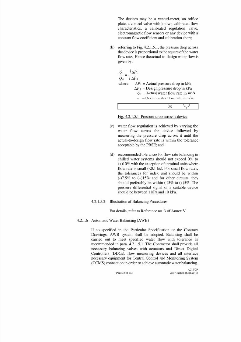
8/7/2019 Test Adjust and Balancing (See 233)
http://slidepdf.com/reader/full/test-adjust-and-balancing-see-233 42/247
Page 33 of 133
AC_TCP
2007 Edition (Corr.2010)
The devices may be a venturi-meter, an orifice
plate, a control valve with known calibrated flow
characteristics, a calibrated regulation valve,
electromagnetic flow sensors or any device with a
constant flow coefficient and calibration chart;
(b) referring to Fig. 4.2.1.5.1, the pressure drop across
the device is proportional to the square of the waterflow rate. Hence the actual-to-design water flow is
given by;
2
1
2
1
P
P
Q
Q
where 1P = Actual pressure drop in kPa
2P = Design pressure drop in kPa
1Q = Actual water flow rate in m3/s
= 3
(a)
Fig. 4.2.1.5.1 Pressure drop across a device
(c) water flow regulation is achieved by varying the
water flow across the device followed by
measuring the pressure drop across it until the
actual-to-design flow rate is within the tolerance
acceptable by the PBSE; and
(d) recommended tolerances for flow rate balancing inchilled water systems should not exceed 0% to
(+)10% with the exception of terminal units where
flow rate is small (<0.1 l/s). For small flow rates,
the tolerances for index unit should be within
(-)7.5% to (+)15% and for other circuits, they
should preferably be within (-)5% to (+)5%. The
pressure differential signal of a suitable device
should be between 1 kPa and 10 kPa.
4.2.1.5.2 Illustration of Balancing Procedures
For details, refer to Reference no. 3 of Annex V.
4.2.1.6 Automatic Water Balancing (AWB)
If so specified in the Particular Specification or the Contract
Drawings, AWB system shall be adopted. Balancing shall be
carried out to meet specified water flow with tolerance as
recommended in para. 4.2.1.5.1. The Contractor shall provide all
necessary balancing valves with actuators and Direct Digital
Controllers (DDCs), flow measuring devices and all interfacenecessary equipment for Central Control and Monitoring System
(CCMS) connection in order to achieve automatic water balancing.
8/7/2019 Test Adjust and Balancing (See 233)
http://slidepdf.com/reader/full/test-adjust-and-balancing-see-233 43/247
Page 34 of 133
AC_TCP
2007 Edition (Corr.2010)
The AWB system shall perform 3 main functions, namely, (1)
water balancing for system commissioning, (2) monitoring of the
flow rates and (3) re-balancing of water due to change of load
profile. The AWB shall be so designed to achieve a fully automatic
control in performing the water balancing. No on-field adjustment,
measurement and testing during the water balancing shall be
required. The only step is to input the design flow rates to theCCMS and observe the change from the monitor and revise input
data if any.
4.2.1.6.1 Method of Balancing
(a) The Contractor shall provide a computer
programme with a compact algorithm for water
system balancing. Such algorithm completed with
water circuit diagram and location of balancing
valves shall be submitted within 3 months after the
commencement of the Contract for approval.
(b) The algorithm shall be designed to achieve the
water balancing using the logic of the procedure as
outlined in the General Specification and para.
4.2.1.5. After completion of the pre-water
balancing procedure as specified in para. 4.1.5, the
AWB system shall balance all water circuits by
operating the motorized balancing valves through
the CCMS.
4.2.1.6.2 Hardware and software
Any necessary hardware and software such as DDC
controllers, sensing devices, operating software and
self-diagnostic devices of the AWB are deemed to be
included in the Contract. The AWB is an integral part of
the CCMS and any standards or requirement not
specified in this section shall refer to the relevant
sections and clauses or CCMS specified in the Contract.
The communication protocol shall comply with the
ASHRAE‟s BACnet standards, or relevant internationalstandards as stated in clause C5.3 of the General
Specification.
4.2.1.6.3 Pre-commissioning Consideration
The Contractor shall select the motorized modulating
control valve and design the algorithm in achieving a
stable AWB system. The Contractor shall supply and
install any additional items and/or modification works
required for achieving a stable system at no additional
cost.
8/7/2019 Test Adjust and Balancing (See 233)
http://slidepdf.com/reader/full/test-adjust-and-balancing-see-233 44/247
Page 35 of 133
AC_TCP
2007 Edition (Corr.2010)
The AWB system shall balance all water circuit as
specified in the Particular Specification or the Contract
Drawings to a steady balanced state. The CCMS system
shall coordinate with the control of all other system such
as chiller plant to complete the balancing. The input
design flow data and balancing point of each motorized
balancing valve shall be logged and password protected
in the CCMS. Power shall not be required to maintainmotorized modulating control valves at the balancing
point.
Only the person with authority shall change the flow
rates and re-balance the water circuit. The password
shall be at least 64-bit encrypted and stored in the
CCMS. The flow rate and temperature at each
motorized balancing valve shall be displayed with
colour graphic layout diagram on the computer monitor
and updated at intervals agreed by PBSE.
The colour graphic layout diagram shall show the
location and number of motorized balancing valves on
the background of the schematic water flow diagram
with floor level and room name. The CCMS shall
generate and print out, if requested, tables showing the
actual flow rates, design flow rates and the
corresponding percentage difference of the water
passing through motorized modulating control valves
against their location and floor level. The difference
between the input design flow rates and actual flowrates shall be in accordance with para. 4.2.1.5.1.
The algorithm and corresponding colour graphic layout
diagram shall be easily updated for any modification of
water circuit.
4.2.1.6.4 Demonstration
The Contractor shall perform dummy testing by
inputting at least 20 sets of water flow rates or as
specified in the Particular Specification to test thestability of the AWB system and the timing required for
adjusting. The values of the dummy testing water flow
rates shall be submitted for approval at least 2 weeks
before T & C. Any electronic measuring equipment for
use with automatic water balancing shall be provided by
the Contractor and permanently installed at designated
location at no additional cost.
8/7/2019 Test Adjust and Balancing (See 233)
http://slidepdf.com/reader/full/test-adjust-and-balancing-see-233 45/247
Page 36 of 133
AC_TCP
2007 Edition (Corr.2010)
4.2.1.7 Balancing Water Circuits
4.2.1.7.1 Method of Balancing
The Contractor shall balance all circuits by operating
the regulation valves provided. Fluid flow through the
cooling and heating coils shall be adjusted to provide
the design air temperature drop or rise.
4.2.1.7.2 CIBSE Commissioning Code 'W'
In general, the system shall be balanced using the
procedure as outlined in the current edition of the
CIBSE Commissioning Code "W" - Water Distribution
Systems.
4.2.2 Air Distribution System
4.2.2.1 Precautions Against Airborne Dirt
The system should have been cleaned internally in accordance with
para. 4.1.6.1 but further precautions shall be taken before starting
the fans for the first time:
(a) disconnect final flexible connections to terminal units such as
induction units and blender boxes;
(b) preferably remove all high efficiency terminal filters;
(c) check that suitable temporary protection has been provided for
anything within the spaces served by the system which could
be damaged by initial discharge of dust from supply outlets at
first starting;
(d) install main inlet filter cells, properly coated as necessary, to
avoid introducing additional dirt into the ductwork system
after start-up;
(e) check seating of cells for air tightness; and
(f) commission automatic fabric and electrostatic filters in
accordance with para. 4.2.2.2 and 4.2.2.3.
4.2.2.2 Automatic Fabric Roll Filter
The scope of the test is to verify effective performance of the
automatic fabric roll filter in accordance with the manufacturer‟s
technical information and/or the stated requirements in the
Particular Specification. The general test procedures for the unit is:
(a) preliminary checks in accordance with para. 4.1.6.4.2 and4.1.6.5 shall have been completed;
8/7/2019 Test Adjust and Balancing (See 233)
http://slidepdf.com/reader/full/test-adjust-and-balancing-see-233 46/247
Page 37 of 133
AC_TCP
2007 Edition (Corr.2010)
(b) install filter media in accordance with manuf acturer‟s
instructions;
(c) energize the filter without air flow;
(d) with the differential pressure control device looped out, close
the isolator controlling supply to filter and test operation by the
manual advance switch;
(e) leave the filter on manual advance until the correct total air
flow through the filter is established;
(f) the correct total air flow through the filter shall be established
as part of the procedure for regulation of air flow (see para.
4.2.2.5 below);
(g) commission the differential pressure controller after
establishment of correct air flow as described in (see
Reference no. 4 of Annex V) for which the clean filter
condition will normally have been manually selected;
(h) an inclined manometer with pressure sampling points adjacent
to the filter fabric will be used to measure the prevailing static
pressure drop across the clean filter and this will be recorded;
(i) the filter may then be progressively blanked off (e.g. with
cardboard) until the manometer indicates the design „dirty
filter‟ pressure drop;
(j) the differential pressure control will be adjusted to start
advancing the filter at this „dirty filter‟ pressure drop and to
stop advancing the filter at the design clean filter pressure drop;
and
(k) Filter performance shall be tested according to
ANSI/ASHRAE Standard 52.2-1999 – Method of Testing
General Ventilation Air-Cleaning Devices for Removal
Efficiency by Particle Size.
4.2.2.3 Automatic Recleanable High Voltage Electrostatic Filter
The scope of the test is to verify effective performance of the
automatic recleanable high voltage electrostatic filter in accordance
with the manufacturer‟s technical information and/or the stated
requirements in the Particular Specification. The general test
procedures for the unit is:
(a) only Registered Electrical Worker(s) with recognised
training from the filter supplier on maintenance of high
tension portion of the equipment should be allowed to enter
the filter casing;
8/7/2019 Test Adjust and Balancing (See 233)
http://slidepdf.com/reader/full/test-adjust-and-balancing-see-233 47/247
Page 38 of 133
AC_TCP
2007 Edition (Corr.2010)
(b) the responsible person/team should have the interlock key
which controls the opening of the access door to the section
of filter which he is entering or a fuse link or other item to
prevent the filter being energized;
(c) a second person should be stationed outside the door as an
observer and he will normally also be in control of the
operation of the power pack from this position;
(d) before working on any filter system, any residual H.T. charge
must be removed using an earthing tool with insulated handle;
and
(e) where the power pack is remote from the filter a shorting bar
should be securely fixed between earth and each H.T. feed to
the filter.
4.2.2.3.1 Preliminary Checks
Under no circumstance shall commissioning proceed
until all checks listed in para. 4.1.6.6 have been
completed.
4.2.2.3.2 Water Wash and Fluid Coating Systems
(a) commission the wash and coating systems in
accordance with para. 4.1.5 and 4.2.1;
(b) adjust sequence timers; and
(c) the filter should be washed prior to initial energizing
and if specified coated with fluid, allowing correct
drainage period to elapse. (Note : This may be a
matter of hours.)
4.2.2.3.3 Automatic Fabric Filter Sections
Commission any automatic fabric filter sections in
accordance with para. 4.1.6.4.2, 4.1.6.5 and 4.2.2.2.
4.2.2.3.4 Initial Energizing of Filter Without Air Flow
(a) check that no one is inside filter casing, that access
doors are closed and that no entry can otherwise be
made to the filter interior;
(b) cancel and lock out any remote control system for
filter;
(c) switch on filter;
8/7/2019 Test Adjust and Balancing (See 233)
http://slidepdf.com/reader/full/test-adjust-and-balancing-see-233 48/247
Page 39 of 133
AC_TCP
2007 Edition (Corr.2010)
(d) check that there is no flash-over problem and that
indications from meters and lamps on filter control
panel are normal;
(e) all safety measures listed in para. 4.1.6.6.3 must be
implemented before entry to the filter casing; and
(f) restore full automatic control sequence and make itready for the establishment of air flow through the
filter.
4.2.2.3.5 Application of Air Flow to Filter
When air flow is established through the filter (see para.
4.2.2.4.5):
(a) check that there is no excessive flash-over (say, an
average of over 5 per minute per square metre of the
face area);
(b) an inspection should be made on the de-energized
filter after a few hours operation with air flow
established (see para. 4.2.2.4.5);
(c) the H.T. voltage shall be checked at ionizer and
collector sections. Unless otherwise specified the
H.T. voltage should be within +3% of the nominal
figure specified at the mean declared L.T. voltage;
(d) polarity should normally be arranged with positive
voltage on the ionizer section to limit ozone
generation;
(e) measurement of H.T. voltage shall be by means of
an instrument comprising high stability resistance
chain with high sensitivity millimetre in series, or
electrostatic voltmeter across 1 section of the chain;
(f) only a skilled and experienced operator should
attempt measurement of H.T. voltage. Great care isnecessary to avoid contact with live parts of the
meter and no part of the meter or its connections
should be touched when it is connected to H.T.
components; any such connections should normally
be special H.T. cables to avoid current leakage;
(g) readings should normally be made with the meter
placed within the filter casing and observed from
the outside through the observation window;
(h) the correct total air flow through the filter shall beestablished as part of the procedure for regulation of
total air flow (see Reference no. 4 of Annex V);
8/7/2019 Test Adjust and Balancing (See 233)
http://slidepdf.com/reader/full/test-adjust-and-balancing-see-233 49/247
Page 40 of 133
AC_TCP
2007 Edition (Corr.2010)
(i) the uniformity of air velocity distribution across the
face of the de-energized filter bank should be
checked using an anemometer after the regulation of
total air flow (see Reference no. 4 of Annex V). To
do this, it will be necessary to override the interlock
with the supply fan;
(j) single point measurements of indicated velocity
should be made at the centre of each 300 mm square
of the face area, and where appropriate instrument
correction factors shall be applied to each of the
readings;
(k) the mean indicated velocity is then calculated and
each of the point readings is expressed as a
percentage of this mean. The percentage variations
of velocity must be within the tolerances specified;
and
(l) upper limits will always be critical and a failure to
meet the specified tolerances must be rectified.
4.2.2.3.6 Filter Performance
Filter performance shall be tested according to
ANSI/ASHRAE Standard 52.2 – 1999 – Method of
Testing General Ventilation Air-Cleaning Devices for
Removal Efficiency by Particle Size and equipmentshall be tested to meet Underwriters Laboratories UL
Standard 867 [2000] - Electrostatic Air Cleaners.
For kitchen application, oil mist and odour removal
performance shall be verified by recognized testing
laboratory and equipment shall be tested to meet
Underwriters Laboratories UL Standard 710 [1995] -
Exhaust Hoods for Commercial Cooking Equipment
(for Fire and Burnout Test only).
4.2.2.4 Initial Running of Electrically Driven Fan Set
4.2.2.4.1 Limit the Load
(a) wherever possible the first start of any motor should
be on light load;
(b) with centrifugal fan sets this will normally be
achieved by limiting the mass flow by operation of
the main damper. The fan characteristics must be
available so that excessive suction or delivery
pressure is not applied to the ductwork system.
8/7/2019 Test Adjust and Balancing (See 233)
http://slidepdf.com/reader/full/test-adjust-and-balancing-see-233 50/247
Page 41 of 133
AC_TCP
2007 Edition (Corr.2010)
4.2.2.4.2 Initial Start
On activating the motor starter, check :
(a) that the direction and speed of rotation of motor
shaft are correct;
(b) that the motor, drive and fan are free from vibrationor undue noise;
(c) the motor starting current for sequence timing
adjustment;
(d) the motor running current on all phases;
(e) that there is no sparking at commutator or slip rings;
(f) that there is no overheating of motor (see BS EN
60470 [2001]);
(g) that there is no seepage of lubricant from the
housing;
(h) that there is no overheating of the bearings;
(i) that oil rings are running freely;
(j) note the reduced speed rev/s and the motor running
current on multi-speed motors;
(k) the rev/s of fan and motor; and
(l) visually / audibly check the performance of fan belts
in case of abnormal vibration.
4.2.2.4.3 Initial Run
(a) a light load run shall be sustained until the
PBSE/PBSI is satisfied from the checks listed in
para. 4.2.2.4.2 above; and
(b) repetitive starting of the motor should be avoided to
prevent over-stressing of fuses, switchgear and
motor.
4.2.2.4.4 Start at Normal Load
(a) after the initial light load run, the machine shall be
stopped and restarted at normal starting load, and
the checks listed in para. 4.2.2.4.2 repeated; and
(b) avoid repetitive starting.

8/7/2019 Test Adjust and Balancing (See 233)
http://slidepdf.com/reader/full/test-adjust-and-balancing-see-233 51/247
Page 42 of 133
AC_TCP
2007 Edition (Corr.2010)
4.2.2.4.5 Running-in Period
(a) after a short run at normal load (a few minutes‟ run
will normally suffice) flexible connections to
terminal units, etc., and terminal filters (which were
removed in para. 4.2.2.1) shall be restored to
position;
(b) subsequently a running-in period shall be sustained
until the fan set is in a reliable continuous running
condition; and
(c) the regulation of the air distribution system shall be
delayed until the running-in period (which may last
for a few days) is completed satisfactorily.
During the running-in period the following work shall
be conducted:
(d) the dynamic balance of the fan and motor shall be
investigated and corrected if necessary; and
(e) the performance of electrostatic filter shall be
checked (see para. 4.2.2.3).
4.2.2.5 Regulation of Airflow
Adopt the proportional air balancing method. (Reference: CIBSE
Commissioning Code A:1996, Air Distribution Systems)
4.2.2.5.1 State of the System and Building
Before starting the regulation of airflow, check that the
following conditions are fulfilled:
(a) relevant building features are completed and
consistent with their normal state. Windows and
doors are opened or shut as appropriate;
(b) should (a) be impractical, make appropriateprovisions (temporary blanking-off or opening etc.)
to simulate the normal state of the spaces under test;
(c) in exercising (a) & (b) above, maintain flexibility
with reference to requirements in (g) below;
(d) the duct system is completed and practically
leakage-free and in the case of a high velocity
system, pressure testing is satisfactory;
(e) the requirements of checks listed in para 4.1.6 havebeen met;
8/7/2019 Test Adjust and Balancing (See 233)
http://slidepdf.com/reader/full/test-adjust-and-balancing-see-233 52/247
Page 43 of 133
AC_TCP
2007 Edition (Corr.2010)
(f) the corresponding cooling and heating systems
(including duct heaters) shall normally be shut off,
except for fresh air systems, some cooling or
heating may be applied to the main duct only for air
tempering purpose; and
(g) the associated air supply or extract system that has
not been regulated should normally be shut downand the duct system under regulation shall be
balanced against atmosphere i.e. with doors or
windows open (or purpose-made provisions) to
maintain the relevant spaces under atmospheric
pressure.
4.2.2.5.2 Principle of Proportional Air Balancing
For details, refer to Reference no. 4 of Annex V.
4.2.2.6 Variable Air Volume System
(a) the self-balancing system characteristic requires little actual air
balancing work. The exercise is targeting on verifying the
performances of the VAV boxes and fan airflow discharge in
response to changes in controlling parameters;
(b) check that the system is clean, to avoid damage to VAV box
components. Check that site conditions in para. 4.2.2.5.1 are
met, unless otherwise stipulated below;
(c) fully review the recommendation from supplier in the setting to
work and commissioning of both VAV box and variable airflow
device. Adhere to these recommendations to avoid damages due
to improper handling;
(d) obtain fan curves and surge characteristics;
(e) for a variable speed drive operating on variable frequency
control, obtain data pertaining to the change of fan motor speed
and corresponding airflow with the change of frequency. For a
vortex damper control, obtain similar data against the change of damper setting. Determine the maximum and minimum fan
speed or damper settings;
(f) construct a theoretical system curve with approximate surge
area. The system curve initiates at the minimum inlet static of
the boxes, plus system loss at minimum flow and terminates at
design maximum flow;
(g) for variable speed control, the operating range is between “the
minimum speed that can produce the necessary minimum box
static at lowest flow while still remaining in the fan‟s stablerange” and “the highest speed necessary to obtain maximum
design flow”;
8/7/2019 Test Adjust and Balancing (See 233)
http://slidepdf.com/reader/full/test-adjust-and-balancing-see-233 53/247
Page 44 of 133
AC_TCP
2007 Edition (Corr.2010)
(h) for inlet vane damper control, the operating range is between
“the surge line intersection with the system curve” and “the
maximum design flow”;
(i) set the fresh/exhaust/recirculation dampers in either full fresh
air or full recirculation positions;
(j) set the supply and extract fans systems to their minimum speed
conditions. Start the fans, and gradually increase the airflows.
Motor running current checks should be made at various
increments, to prevent overloading. Check that the fans are
operating within the extreme conditions identified from (e);
(k) check system static pressures at or close to the positions
specified for the pressure sensor for automatic regulation of fan
speed, and at VAV boxes near to the fan. This is to prevent
over-pressurisation of system components;
(l) should abnormal excessive current or pressure are detected in (j)
or (k) above, check for any improper settings. Refer to the
designer for unresolved problem;
(m) with fan motor current and system pressure not being exceeded,
increase the airflow to the maximum design condition;
(n) verify the VAV box factory settings on maximum and
minimum flows with change in controlling parameter (e.g.
actuator responses to voltage fluctuation according totemperature change). Also check intermediate settings. This
must be done according to the VAV manufacturer‟s
recommendations;
(o) in conducting the exercise in (n) for a particular box, it may be
necessary to throttle airflow to other boxes/branches in order to
bring the one at test with sufficient pressure and flow;
(p) in conducting (n), a sufficient number of boxes should be
checked to be representative of the system. If a wide variation
occurs, it may be necessary to check all the boxes;
(q) check that the least favoured VAV box is also operating at the
system‟s minimum design airflow;
(r) for VAV box delivering air to a number of secondary terminals,
air balancing of these terminals should be carried out according
to Reference no. 4 of Annex V;
(s) repeat (h) to (n) for different design conditions dictating the
flows of fresh air and recirculation;
8/7/2019 Test Adjust and Balancing (See 233)
http://slidepdf.com/reader/full/test-adjust-and-balancing-see-233 54/247
Page 45 of 133
AC_TCP
2007 Edition (Corr.2010)
(t) in the above processes, the fan drive mechanism will have to be
repeatedly adjusted. Do this in accordance with the fan drive
manufacturer‟s recommendations;
(u) take readings of all above measurements and settings;
(v) review the data and work in conjunction with the control
specialist to arrive at the desired fan drive settings and VAVbox settings; and
(w) it is important to ensure that pressure sensors for fan airflow
control are so located that they offer responsive, stable and
reliable regulation across the full range of fan operation. Should
the pre-determined positions not be appropriate, reflect this to
the PBSE.
4.2.2.7 Pressure Differential Between Spaces
There are systems designed to achieve a pressure differential
between spaces served, for purpose of isolation or containment.
Airflow in hospital from clean area to less clean area is one of the
applications. The following actions shall be taken:
(a) check that site conditions in para. 4.2.2.5.1 are met, unless
otherwise stipulated below;
(b) check that suitable paths for make-up or spill air are provided.
Open all doors and hatches between the pressurised spaces;
(c) run the supply or extract fan;
(d) balance the air terminals in accordance with Reference no. 4 of
Annex V;
(e) set the fan airflow rate to design requirement;
(f) close all doors and hatches so that the space is in its normal
operating condition;
(g) run the other extract or supply fan previously not in operation;
(h) balance the system previously not balanced;
(i) set up and commission pressure control devices in accordance
with manufacturer‟s recommendations;
(j) set the fan airflow rate to design requirement;
(k) re-check airflow rates of previous system;
(l) if the flow rates are within specified tolerance, the balancingwork is completed;

8/7/2019 Test Adjust and Balancing (See 233)
http://slidepdf.com/reader/full/test-adjust-and-balancing-see-233 55/247
Page 46 of 133
AC_TCP
2007 Edition (Corr.2010)
(m) if the readings are not within tolerance, re-check the system
balance described in (d) & (e) above and, where necessary,
make adjustments to reinstate the balance of the previously set
total volume flow rate. Reiterate this step until no further
adjustment is required; and
(n) measure and record the pressure differentials between all
adjacent spaces and compare the measurements with thespecified design requirements.
4.2.2.8 Dual Duct System
(a) dual duct system comprises a cold duct and a hot duct,
respective air to be mixed in a mixing box before discharging to
air-conditioned space at the appropriate dry and wet bulb
temperatures. The cold duct usually can handle 85% to 100% of
system flow, and the hot duct 40% to 80% flow;
(b) check that site conditions in para. 4.2.2.5.1 are met, unless
otherwise stipulated below;
(c) start balancing by setting all room control thermostats for
maximum cooling, fully opening the cold air valves;
(d) proceed to the extreme end of the system (longest duct run) and
check the static pressure drop across the box. The reading
should exceed or equal the minimum static pressure
recommended by the manufacturer of the box (about 185 Pa
static pressure is common for the mechanical regulator);
(e) for mixing boxes that are not factory preset, set the mechanical
volume regulator in accordance with manufacturer‟s
recommendation. Refer to calibration curve wherever
appropriate;
(f) measure airflow of all air terminals;
(g) for mixing box delivering air to a number of secondary
terminals, air-balance them according to Reference no. 4 of
Annex V;
(h) air-balance the flow from boxes to Reference no. 4 of Annex V
should relevant dampers be available and the readings in (f)
indicate unacceptable tolerances. Make adjustment to box airvalve if necessary in accordance with manufacturer‟s
recommendation;
(i) change the control settings to full heating and make certain that
the controls and dual-duct boxes function properly; and
(j) measure airflow from all air terminals and check against design.For out-of range mixing box, make adjustment to the air valve if
8/7/2019 Test Adjust and Balancing (See 233)
http://slidepdf.com/reader/full/test-adjust-and-balancing-see-233 56/247
Page 47 of 133
AC_TCP
2007 Edition (Corr.2010)
necessary in accordance with manufacturer‟s
recommendations.
4.2.2.9 Automatic Air Balancing (AAB)
If so specified in the Particular Specification or the Contract
Drawings, AAB system shall be adopted. Balancing shall be carried
out to meet the specified airflow with tolerance level asrecommended in Reference no. 4 of Annex V. The Contractor shall
provide all necessary motorized volume control dampers, airflow
measuring devices and all interface equipment necessary for CCMS
connection in order to achieve AAB.
The AAB system shall perform 3 main functions, namely, (1) air
balancing for system commissioning, (2) monitoring of the airflow
rates and (3) re-balancing of air due to change of load profile. The
AAB shall be so designed to achieve a fully automatic control in
performing the air balancing. No on-field adjustment, measurement
and testing during the air balancing shall be required. The only step
is to input the design airflow rates to the CCMS and observe the
change from the monitor and revise input data if any.
4.2.2.9.1 Method of Balancing
The Contractor shall provide a computer program with a
compact algorithm for system balancing. Such
algorithm completed with air side schematic diagram
and location of motorized volume control dampers shall
be submitted within 3 months after the commencementof the Contract for approval.
The logic of the algorithm shall be designed to achieve
the air balancing using the procedure as outlined in the
General Specification and para. 4.2.2. After the
completion of the pre-air balancing procedure as
specified in para. 4.1.6 and para. 4.2.2.5, the AAB
system shall balance all air circuits by operating the
motorized volume control dampers through the CCMS.
4.2.2.9.2 Hardware and Software
Any necessary hardware and software such as DDC
controllers, sensing devices, operating software and
self-diagnostic devices of the AAB are deemed to be
included in the Contract. The AAB is an integral part of
the CCMS, any standards or requirement not specified
in this section shall refer to relevant sections and clauses
or CCMS specified in the Contract.
4.2.2.9.3 Pre-commissioning Consideration
(a) The Contractor shall select the motorized volume
control dampers and design the algorithm in
8/7/2019 Test Adjust and Balancing (See 233)
http://slidepdf.com/reader/full/test-adjust-and-balancing-see-233 57/247
Page 48 of 133
AC_TCP
2007 Edition (Corr.2010)
achieving a stable AAB system. The Contractor
shall supply and install any additional items and/or
modification works required for achieving a stable
system at no additional cost.
(b) The AAB system shall balance all air circuit as
specified in the Particular Specification or the
Contract Drawings to a steady balanced state. TheCCMS system shall coordinate with the control of
all other systems such as AHUs and FCUs to
complete the balancing. The input design flow data
and balancing point of each motorized volume
control damper shall be logged and password
protected in the CCMS. Only the person with
authority shall be able to change the flow rates and
re-balance the air circuit. The flow rate and
temperature at each motorized volume control
damper shall be displayed with colour graphic
layout diagram on the computer monitor and
updated at intervals agreed by PBSE.
(c) The colour graphic layout diagram shall show the
location and number of each motorized volume
control damper on the background of the airflow
schematic diagram with floor level and room name.
The CCMS shall generate and print out if requested
tables showing the actual flow rates and design flow
rates of the air passing through motorized volume
control dampers against their locations and floorlevel. The Contractor shall select suitable hardware
and software such as flow meter, actuators, DDC
and the operating system to achieve overall
performance of the AAB in accordance with
Reference no. 4 of Annex V.
(d) The algorithm and corresponding colour graphic
layout diagram shall be easily updated for any
modification of air circuit.
4.2.2.9.4 Demonstration
The Contractor shall perform dummy testing by
inputting at least 20 sets of airflow rates or as specified
in the Particular Specification to test the stability of the
AAB system and the timing required for adjusting. The
values of the dummy testing air flow rates shall be
submitted for approval and at least 2 weeks before T &
C. Any electronic measuring equipment for use with
automatic air balancing shall be provided by the
Contractor and permanently installed at their location at
no additional cost.
8/7/2019 Test Adjust and Balancing (See 233)
http://slidepdf.com/reader/full/test-adjust-and-balancing-see-233 58/247
Page 49 of 133
AC_TCP
2007 Edition (Corr.2010)
4.2.2.9.5 Motorized Volume Control Dampers
Motorized volume control dampers shall be tested in
accordance with the recommendation of the
manufacturer to assure automatic air balancing. All
dampers provided shall also comply with the relevant
Section of the General Specification.
4.2.2.10 Air Handling Units (AHUs)
The T & C of air handling units should be carried out in line with
the current General Specification and the items as specified below.
4.2.2.10.1 Operation
(a) AHU systems must be in operation before the test
and balance procedures are started; and
(b) all controls must be installed, calibrated and fully
operational.
4.2.2.10.2 Inspection
(a) inspect the system to determine if it is complete and
operable; check on the condensate drains, etc.;
(b) verify that the drives are installed properly and are
of the correct size and type. Verify that the inlet
vanes are working;
(c) refer to the pre-requisites for balancing;
(d) verify that the fan wheels are on a single shaft. If
they are on a split shaft, then verify that the shafts
are properly connected to the drive end; and
(e) verify that the filters are clean and of correct size
and type.
4.2.2.10.3 Procedures
(a) check the fan for proper operating condition and the
fan motor shall be below the full-load current rating;
(b) measure and proportionally balance the air
distribution if the total discrepancy is within 20% of
esign. If not, investigate and make adjustments as
required;
(c) locate a traverse position in a straight section of duct.
Refer to the „Pitot Tube Traverse‟ procedures;
8/7/2019 Test Adjust and Balancing (See 233)
http://slidepdf.com/reader/full/test-adjust-and-balancing-see-233 59/247
Page 50 of 133
AC_TCP
2007 Edition (Corr.2010)
(d) traverse to determine fan airflow. Flow should be
100 to 110% of design assuming 0% air leakage;
(e) adjust fan speed to obtain 100 to 110% of design
airflow (m3/s) ;
(f) measure power requirements before and after
adjustments; and
(g) after completing the balancing procedure, record the
following minimum data on the report form as
indicated in Annex II, whichever appropriate. They
are:
(i) unit design data;
(ii) airflow (m3/s) from duct or coil traverse;
(iii) electrical power measurement procedure;
(iv) test the power in kW, if applicable;
(v) all nameplate data must be identified and
verified;
(vi) test the motor rpm and fan rpm;
(vii) drive sizes, belt type, size and number;
(viii) centre-to-centre distance of the motor-base
travel;
(ix) static pressure profile according to the static
pressure profile procedure; and
(x) temperatures across coils according to the
coil capacity testing procedures.
4.2.2.10.4 Compliance
(a) to comply with this procedure, complete all of the
above steps and record all data on the report forms;
and
(b) all deficiencies that affect the above T & C works
should be resolved by the installing contractor(s)
and well include the deficiencies into the report.
4.2.2.11 Pretreated Air-handling Units (PAUs)
All the procedures are similar to clause 4.2.2.10 for AHUs exceptthe testing is for constant outside air coming directly into contact
with the units.
8/7/2019 Test Adjust and Balancing (See 233)
http://slidepdf.com/reader/full/test-adjust-and-balancing-see-233 60/247
Page 51 of 133
AC_TCP
2007 Edition (Corr.2010)
4.2.2.11.1 Operation
(a) the systems must be put in operation by the
Contractor; and
(b) access must be provided by the Contractor.
4.2.2.11.2 Inspection
(a) inspect the system to determine if it is complete and
operable; check on the condensate drains, etc.;
(b) verify that the drives are installed properly and are
of correct size and type;
(c) refer to pre-requisite for balancing;
(d) verify that the fan wheels are on a single shaft. If
they are on a split shaft, then verify that the shafts
are properly connected to the drive end;
(e) verify that the filters for the outdoor air are clean
and of correct size and type; and
(f) verify that the coils are piped correctly.
4.2.2.11.3 Procedures
(a) set and test the outside air quantity that could meet
the minimum requirement as specified;
(b) balance the systems that distribute outdoor air
directly to the space to the quantities specified;
(c) on systems that distribute air directly to other
air-handling units, verify that the outside air is
properly mixed with the return air so the mixed-air
temperature is uniformly entering the coil. If the air
temperature is not uniform, treat it as a deficiency;
(d) verify that the outside air quality remains constant
under all modes of operation;
(e) test and set the outside air and verify that the
minimum airflow rate (m3/s) stays constant. Verify
that the outside system air operates when occupied
and when the exhaust system is on; and
(f) measuring and setting outside air.
8/7/2019 Test Adjust and Balancing (See 233)
http://slidepdf.com/reader/full/test-adjust-and-balancing-see-233 61/247
Page 52 of 133
AC_TCP
2007 Edition (Corr.2010)
(i) the preferred method of measuring outside air
is by duct traverse. Use Pitot Tube Traverse
method to test;
(ii) an air capture hood is an acceptable method
for measuring small outside air requirements,
such as a unit ventilator or fan coil unit; and
(iii) velocities at intakes are acceptable when an
appropriate factor can be field determined by
Pitot Tube Traverse.
4.2.2.11.4 Compliance
(a) to comply with this procedure, complete all of the
above steps and record all data on the report forms;
and
(b) outside air which makes up with the return air is also
a consideration required in balancing the outside air,
and should be reported if not included in the
minimum outside air requirement.
4.2.2.12 Fan Coil Units (FCUs)
This procedure applies to all chilled water fan coil units including
the high static equipment.
4.2.2.12.1 Operation
(a) the system must be put in medium speed operation
unless otherwise specified; and
(b) proper access must be provided.
4.2.2.12.2 Inspection
Inspect the system to determine if it is complete and
operable; check the condensate drains, etc.
4.2.2.12.3 Procedures
Use the following procedures for chilled-water fan coil
units:
(a) use manufacturer‟s rated airflow unless ducted, then
use a duct traverse to determine airflow. If duct
traverse is impossible, then use summation of the
outlet readings;
(b) set outside airflow to design specifications;
8/7/2019 Test Adjust and Balancing (See 233)
http://slidepdf.com/reader/full/test-adjust-and-balancing-see-233 62/247
Page 53 of 133
AC_TCP
2007 Edition (Corr.2010)
(c) measure entering and leaving air dry and wet bulb
temperatures;
(d) measure entering and leaving water temperatures;
(e) use the room conditions to determine the cooling
load;
(f) if a flow station is installed, then measure and record
the flowrates (l/s) and compare to the heat-balance
flowrate;
(g) measure and record the water pressure drop across
the coil and compare to the design. Only rely upon
pressure drop for flow determination if other means
noted are impossible to obtain;
(h) measure and record all unit data;
(i) measure and record motor operating amperage
/voltage and compare against full-load nameplate;
and
(j) verify that controls operate properly and are in
correct sequence. Note any deficiencies and record.
4.2.2.12.4 Compliance
Compliance with this procedure is met when the aboveare completed and the units are balanced to within the
limits of the system.
4.2.2.13 Test on Water Scrubber / Kitchen Exhaust Hood
The scope of the test is to verify effective performance of the water
scrubber / kitchen exhaust hood and its associated facilities in
accordance with the manufacturer‟s technical information and the
stated requirements in the Particular Specification. The general test
procedures are:
(a) the mechanical and electrical installations shall be visually
inspected, tested in conformance with manufacturer‟s
technical installation guide and information;
(b) re-sealing test holes shall be provided at the main discharge
duct for total air flow and static pressure measurements. The
test hole position shall be determined on site. Test holes
usually shall not be drilled on the bottom side of air duct;
(c) the exhaust air fan shall be generally tested in accordance with
relevant sections for fan, and noise measurement shall be inaccordance with relevant section;
8/7/2019 Test Adjust and Balancing (See 233)
http://slidepdf.com/reader/full/test-adjust-and-balancing-see-233 63/247
8/7/2019 Test Adjust and Balancing (See 233)
http://slidepdf.com/reader/full/test-adjust-and-balancing-see-233 64/247
Page 55 of 133
AC_TCP
2007 Edition (Corr.2010)
(a) verify that all seals are properly installed and
adjusted;
(b) measure and record the flow rate of air entering the
exhaust section;
(c) measure and record the flow rate of air leaving the
outside air section;
(d) measure and record the dry and wet bulb
temperature of air entering and leaving the exhaust
side;
(e) measure and record the dry and wet bulb
temperature of air entering and leaving the outside
air side;
(f) calculate and record the sensible and total capacity
of each airstream;
(g) measure and record the pressure drop on each side
of the heat exchange section;
(h) measure and record the starting and running current
of the equipment; and
(i) measure and record the noise level where
applicable.
4.2.2.15 Split Units and Variable Refrigerant Volume (VRV) System
4.2.2.15.1 Preliminary checks
The Contractor shall carry out all visual checks and
preliminary checks as recommended by the
supplier/manufacturer before start up of the equipment.
In addition, electrical checks shall be carried out as per
para. 4.1.6.5.
4.2.2.15.2 Commissioning tests
(a) The following tests shall be carried out where
applicable: static pressure test, dynamic rotation
tests and inspection of welds in piped services;
(b) Pressure and leak tests of refrigerating piping
systems are normally carried out on completion of
the system, before pipework is insulated; and
(c) System evacuation, dehydration and charging with
refrigerant shall be carried out by skills andexperienced personnel.
8/7/2019 Test Adjust and Balancing (See 233)
http://slidepdf.com/reader/full/test-adjust-and-balancing-see-233 65/247
Page 56 of 133
AC_TCP
2007 Edition (Corr.2010)
4.2.2.15.3 The following are general procedures to be adopted.
(a) check that the indoor and outdoor units are installed
according to supplier‟s instructions and
recommendations including maximum pipe run,
etc;
(b) check that the safety devices and necessaryoperational control are provided as per requirements
of the General Specification;
(c) check that pipeworks of correct pipe sizes are
installed and insulation is completed;
(d) check that the units are correctly wired up;
(e) ensure that the connection nuts are tightened;
(f) ensure that the system has been properly evacuated
and leak-tested;
(g) open all isolating valves where appropriate;
(h) trial run the units after water drainage test;
(i) measure the following and note down in the record
sheet:
(i) starting and running current;
(ii) high and low pressure cut-out;
(iii) compressor suction and discharge pressure;
(iv) evaporator entering and leaving coil
temperature, both WB and DB;
(v) condenser entering and leaving coil
temperature, both WB and DB;
(vi) air flow rate;
(vii) noise level measurement as necessary;
(viii) other measurements as necessary for VRV
systems; and
(j) test the control system according to design where
applicable.
8/7/2019 Test Adjust and Balancing (See 233)
http://slidepdf.com/reader/full/test-adjust-and-balancing-see-233 66/247
Page 57 of 133
AC_TCP
2007 Edition (Corr.2010)
4.2.3 Refrigeration Systems
4.2.3.1 General
T & C of refrigeration system shall be carried out by the skilled and
experienced persons preferably assigned by the original
manufacturer.
Normally the refrigeration systems are categorized by of the
following species (not exhaustive).
(a) Reciprocating Compressor Systems (See para. 4.2.3.2) ;
(b) Centrifugal Compressor Systems (Including Oil Free
Compressor) (See para. 4.2.3.3);
(c) Absorption Systems (See para. 4.2.3.4);
(d) Screw Compressor Systems (See para. 4.2.3.5);
(e) Scroll Compressor Systems (Details should be referred to
Manufacturer‟s recommendation.); and
(f) Split Units and VRV System (See para. 4.2.2.15).
The following points are common to all systems and require careful
handling:
4.2.3.1.1 System Cleanliness
(a) The chilled water and condenser water systems
should be flushed thoroughly by following the
procedures as described in para. 4.1.5.1 and the
precautions below:
(i) isolate or bypass items which are particularly
sensitive to dirts, including the shell and tube
evaporators, condensers, pumps, spray nozzles
and automatic water valves, and so on; and
(ii) where appropriate, remove the strainer screens,
cooling tower basins, tanks and other
equipment which may have accumulated
deposits during manufacturing or installation,
and shall also be isolated and flushed
independently.
(b) check the following items for cleanliness:
(i) air intake screens;
(ii) fan chambers of condensers and cooling
towers;
8/7/2019 Test Adjust and Balancing (See 233)
http://slidepdf.com/reader/full/test-adjust-and-balancing-see-233 67/247
Page 58 of 133
AC_TCP
2007 Edition (Corr.2010)
(iii) fan internals;
(iv) external heat exchanger surfaces of air-cooled
condensers, evaporative condensers and
cooling towers;
(v) sensing elements;
(vi) cooling tower basins, evaporative condenser
tanks and chilled water tanks;
(vii) compressor, motor and drive;
(viii) safety and control devices; and
(ix) drains and overflows.
4.2.3.1.2 State of the Systems
(a) Water System
For chilled water and condenser water systems,
carry out the T & C procedures as listed in para.
4.1.5 and 4.2.1 in addition to the following.
Check :
(i) that the cooling tower fill is complete andsecured;
(ii) that where chilled water tank is provided the
tank lid is fitted and secured;
(iii) the valve connection (where specified) for
blow-down from cooling towers and
evaporative condensers; and
(iv) that any splash guards for cooling towers and
evaporative condensers are fitted properly.
(b) Air System
For air handling systems and any airways associated
with the air-cooled condensers, evaporative
condensers and cooling towers, carry out the
following checks.
Check :
(i) that the airways are clear;
8/7/2019 Test Adjust and Balancing (See 233)
http://slidepdf.com/reader/full/test-adjust-and-balancing-see-233 68/247
Page 59 of 133
AC_TCP
2007 Edition (Corr.2010)
(ii) that the condenser heat exchangers are
installed correctly in relation to air flow;
(iii) where applicable, the damper free movement,
clearances, seating, pinning to damper spindles,
relative positions of blades in multi-leaf
dampers;
(iv) that dampers are secured in open position with,
where motorized, the actuator disconnected;
and
(v) the airways including builder‟s ductwork for
air-tightness, noting particular seals at
equipment, access doors, flexible connections,
and junctions of all ductworks.
(c) Refrigerant System
Check :
(i) that the pipework is complete and secured;
(ii) that the thermostatic expansion valve (or float
level device) is fitted : thermal bulb is correctly
fitted and secured, external equalizer (where
appropriate) is fitted;
(iii) that the safety and control devices are fitted :such as the low pressure and high pressure
cut-out, oil pressure cut-out (where fitted),
chilled water low temperature thermostat, low
water flow safety device and any protective
solenoid valves being specified;
(iv) that the liquid line strainer, isolating valves as
specified, sight glass with moisture indicator
and drier are fitted;
(v) that the suction, discharge and oil pressuregauges with isolating valves are fitted and
isolated from the system;
(vi) that purging and charging connections are
fitted; and
(vii) if liquid receiver is provided, the capacity,
associated works and the surveyor‟s certificate
(if specified) are to be checked before
commissioning.
(d) Checking of Water System before Filling
8/7/2019 Test Adjust and Balancing (See 233)
http://slidepdf.com/reader/full/test-adjust-and-balancing-see-233 69/247
Page 60 of 133
AC_TCP
2007 Edition (Corr.2010)
4.2.3.1.3 Carry out all checks where appropriate as described
in para. 4.1.5.3.
4.2.3.1.4 Mechanical Checks
(a) Fans
Carry out checks as described in para. 4.1.6.4.1.
(b) Compressors
Check :
(i) external cleanliness;
(ii) that all components, bolts, fixings, etc., are
properly secured;
(iii) that the compressor shaft is free to rotate
(applicable to open type compressor only);
(iv) level and plumb of compressor and motor shaft
and slide rails (applicable to open type
compressor only);
(v) anti-vibration mountings for correct
deflection;
(vi) to secure and align the pulleys and couplings(if applicable);
(vii) belt tension and match of pulleys (if
applicable);
(viii) that drive guards are fitted, the access for speed
measurement is provided and nipple extension
for motor lubrication is provided (if
applicable);
(ix) correct oil level in compressor;
(x) that the compressor unloading gear is fitted (if
specified);
(xi) any special arrangements for motor cooling;
oil cooling where appropriate; and
(xii) that vibration eliminator and muffler are fitted.
(c) Drives

8/7/2019 Test Adjust and Balancing (See 233)
http://slidepdf.com/reader/full/test-adjust-and-balancing-see-233 70/247
Page 61 of 133
AC_TCP
2007 Edition (Corr.2010)
For gear boxes and special mechanical drives
pulley/belt, direct or flexible couplings for
compressor or large cooling tower fans.
Check :
(i) that the lubrication and pre-lubrication are in
order before starting;
(ii) that drive mountings are secured;
(iii) that all shafts are correctly aligned; and
(iv) for free rotation.
4.2.3.1.5 Electrical Checks
(a) With all electrical supplies isolated
Check :
(i) local isolation of motors and control circuits;
(ii) that there are no unshrouded live components
within the panels;
(iii) that panels and switchgear are clean;
(iv) that motors and surrounding areas are cleanand dry;
(v) that transit packing has been removed from
contactors and other equipment;
(vi) that there is no mechanical damage to
switchgear, anti-condensation heaters and
that their thermostats are of a suitable range to
operate at ambient temperature;
(vii) that all connections are tight on busbars andwirings;
(viii) that internal links on the starter are correct;
(ix) that all power and control wirings have been
completed in accordance with the approved
circuit diagrams;
(x) that all fuse/circuit breaker ratings are
correct;
8/7/2019 Test Adjust and Balancing (See 233)
http://slidepdf.com/reader/full/test-adjust-and-balancing-see-233 71/247
Page 62 of 133
AC_TCP
2007 Edition (Corr.2010)
(xi) that all starter overloads are set correctly in
relation to the motor name-plate full load
current;
(xii) that dashpots are charged with the correct
fluid and the time adjustments and levels are
identical;
(xiii) that insulation tests on the motor have been
performed satisfactorily;
(xiv) that adjustable thermal cut-outs are set
correctly (check manufacturers‟ test
certificates);
(xv) that all the cover plates are fitted;
(xvi) that wirings from all safety devices and liquid
line solenoid valve are completed; and
(xvii) that compressor crankcase heater(s) is/are
fitted and the wiring is completed.
(b) With electrical supplies connected
Check :
(i) the declared voltage range is correct on all
supply phases;
(ii) where motor powers are substantial or
reduced voltage starting or complex
interlocks are involved:
- the control circuit logic and the starter
operation shall be tested before the
motor is rotated;
- the supply should first be isolated; then
by the withdrawal of 2 power fuses ordisconnection of cables followed by
reinstatement of supply to the control
circuit alone, the control circuit shall be
activated and starter operation observed;
and
- check for satisfactory operation of any
electrical controls associated with
compressor starter operation such as
liquid line solenoid valve, electrical
timing heater on the oil failure control(in this case, check for satisfactory
operation and then temporarily
8/7/2019 Test Adjust and Balancing (See 233)
http://slidepdf.com/reader/full/test-adjust-and-balancing-see-233 72/247
Page 63 of 133
AC_TCP
2007 Edition (Corr.2010)
disconnect it), and capacity unloading if
initiated electrically;
(iii) where automatic sequencing starting for the
whole refrigeration plant and associated
chilled water and condenser water pumps is
specified:
- check that the sequence is correct in
order and timing;
- adjust timers, check for clean operation
of all contactors, relays and interlocks;
and
- finally open the isolators, reset or
reconnect any device as appropriate,
reinstate power connections and close
isolators;
(iv) where small motors are of direct on-line
starting and simple control circuits, the starter
operation, etc., should be checked when first
starting the motor.
4.2.3.2 Reciprocating Compressor System
4.2.3.2.1 Pressure and Leakage testing
Refrigeration system working and test pressures shall
comply with the requirements stipulated in the Contract
Specifications.
(a) Factory Assembled Packaged Units
(i) pressure & leak test, evacuation and
dehydration & charging, either as a small
holding charge or the full amount, should
have been carried out at the factory;
(ii) observe pressure gauge readings and
- if the gauge readings are unsatisfactory,
the whole programme of pressure testing,
evacuation and charging must be carried
out again;
- if the gauge readings are in order, then
pressure testing and evacuation are not
required; and
- where the system has a holding charge,
additional charging is necessary.
8/7/2019 Test Adjust and Balancing (See 233)
http://slidepdf.com/reader/full/test-adjust-and-balancing-see-233 73/247
Page 64 of 133
AC_TCP
2007 Edition (Corr.2010)
(b) Built-up Systems
Pressure and leakage testing shall be carried out on
completion of the system, before pipework is
insulated and condenser is filled up with water:-
(i) charge the system with a small amount of therefrigerant. The refrigerant acts as a tracer for
leak detection purpose;
(ii) charge the entire system to the desired test
gauge pressure in accordance with
manufacturer‟s instructions using dry
nitrogen;
(iii) pressure should be applied to compressor to
test the vulnerable oil lines, etc. Precautions
to be made on applied pressure to avoid
damages to the shaft seal (applicable to open
drive system only) and
- checked all joints for leakage by
electronic leak detector, then follow by
using a soap solution “bubble” test;
- pay attention to the gasket joints, bolt
heads and nuts, sight glasses, welded
joints, parting lines on castings, gaugesand gauge connections, relief valves,
evaporator and condenser water boxes;
and
- on hermetic units, pay attention to the
motor terminals; on open machines,
check the shaft seals;
(iv) if leaks are identified, the gas and refrigerant
in the system must be evacuated for fixing
leakage area, and the system shall berecharged and tested again;
(v) repair any leaks found in the system. Leaks
must not be repaired while the system is
under pressure;
(vi) when the system is found to be free from
leakage, allow it to stand for a minimum of 24
hours under pressure. If no pressure drop
occurs (allowing for effect due to changes of
ambient temperature) the system is ready forevacuation; and
8/7/2019 Test Adjust and Balancing (See 233)
http://slidepdf.com/reader/full/test-adjust-and-balancing-see-233 74/247
Page 65 of 133
AC_TCP
2007 Edition (Corr.2010)
(vii) relieve test pressure to atmosphere, reconnect
all lines and reinstate all items removed or
isolated.
4.2.3.2.2 Evacuation and Dehydration
This shall be carried out by specialists assigned by the
equipment manufacturer/ supplier.
4.2.3.2.3 Associated Air Systems
(a) setting to work and adjusting air handling plant shall
be carried out in accordance with para. 4.1.6 and
4.2.2; and
(b) for systems employing direct expansion air coolers,
check that commissioning of the main air
distribution plant has progressed sufficiently
through para. 4.2.2 so as
(i) to enable some measure of heat exchange to
take place at the cooler;
(ii) to allow limited running of the refrigeration
plant for initial commissioning purposes; and
(iii) to carry out the relevant parts of para. 4.1.6
and all of para. 4.2.2.4 for equipment on the
condenser side of the refrigeration plant.
4.2.3.2.4 Charging
This shall be carried out by specialists assigned by the
equipment manufacturer/ supplier.
4.2.3.2.5 Setting to Work and Adjusting
(a) Procedures
All procedures as outlined in para. 4.2.3.1, and4.2.3.2.1 to 4.2.3.2.4 shall be completed before
commencing this section. Chilled water and
condenser water systems shall be checked in
accordance with para. 4.1.5 and the setting to work
procedures in para. 4.2.1 shall be proceeded at least
to a point where sufficient water flow is available to
enable full capacity conditions of the refrigeration
plant to be checked.
(b) System Checks
Before operating the compressor continuously for
the first time, a further visual check shall be carried
8/7/2019 Test Adjust and Balancing (See 233)
http://slidepdf.com/reader/full/test-adjust-and-balancing-see-233 75/247
Page 66 of 133
AC_TCP
2007 Edition (Corr.2010)
out on the complete system, and in particular all
refrigeration safety controls shall be put through
their complete cycle of operation, including:-
(i) set refrigeration pressure controls in
accordance with manufacturer‟s instructions
or ensure that all factory settings are in the
right positions:
- adjust compressor low pressure switch to
cut-in whenever suction pressure rises
above the desired gauge setting, with the
differential set as wide as possible to
prevent short-cycling in accordance with
the manufacturer‟s recommendation;
- adjust high pressure switch to the
recommended gauge settings; and
- adjust oil pressure switch to the
recommended setting;
(ii) ensure all sequence and safety interlocks are
operating correctly;
(iii) in case the electronic expansion valve is
employed:
- take refrigerant temperature at a point asclose as possible to the remote bulb of
thethermostatic expansion valve at the
evaporator suction outlet, to enable
proper superheat measurement to be
made;
- the suction pressure shall be read at a
gauge installed in the back-set port of the
compressor suction valve and converted
to temperature reading using the
refrigerant table; and
- the difference between the thermometer
reading at evaporator suction outlet and
the temperature calculated from suction
pressure is the superheat (usually about
5oC to 6
oC);
(iv) if abnormal pressure drop is suspected
(suction lines are normally designed for 0.07
bar maximum pressure drop), steps shall be
taken to reveal the reason;
8/7/2019 Test Adjust and Balancing (See 233)
http://slidepdf.com/reader/full/test-adjust-and-balancing-see-233 76/247
Page 67 of 133
AC_TCP
2007 Edition (Corr.2010)
(v) check that the condenser water valves are
open and the pressure or temperature actuated
valves (where fitted) are operative;
(vi) check the condensing system to ensure design
air (if appropriate) and/or water quantities at
required temperatures are available to enable
the desired high side pressure to bemaintained;
(vii) check the associated thermostatic control
system as described in para. 4.3.1. Set the
controlling devices (e.g. chilled water, room
air, or return air thermostat, or pressure
switch, or humidistat) to the desired settings;
(viii) check, immediately prior to commencing a
continuous running test of the refrigeration
system:
- that all refrigerant circuit shut-off valves
are in open position, except for the bypass
valves; especially ensure that the
condenser liquid line valve is open;
- that all chilled water and condenser water
circuit valves are in the correct positions;
- that compressor suction and dischargevalves are open. Oil, suction and
discharge pressure gauge throttling
valves are open;
- that solenoid stop valves of evaporator
are working on magnetic coil control
- that lubricating oil is visible (at centre, or
above) in sight glass on compressor sump;
and
- that electrical supply is available to the
crankcase heater and the heater is all right.
In case of a cold plant, at least 1 hour of
operation shall elapse prior to running to
enable the heater to boil off any
refrigerant; and
- press the reset buttons on refrigerant
pressure control(s), oil pressure control
and freeze protection thermostat and/or
freeze protection pressure switch.
(c) Start-Up
8/7/2019 Test Adjust and Balancing (See 233)
http://slidepdf.com/reader/full/test-adjust-and-balancing-see-233 77/247
Page 68 of 133
AC_TCP
2007 Edition (Corr.2010)
(i) test and ensure free movement of all rotating
parts of each compressor. Disconnect drive
coupling or vee-belt. Check the correct
direction of motor (applicable to open type
compressor only);
(ii) start on „manual‟ control of the chilled water pump (or relevant fan) and condenser water
pump and condenser fan (or relevant pump).
If controls are arranged for sequenced „auto‟
start only, proceed straightly to the automatic
start; and
(iii) start the compressor and observe for plant
with both „manual‟ and „auto‟ selection, after
2 or 3 successful „manual‟ operations change
over to automatic control and check:
- direction of rotation of compressor;
- that motor, drive, and compressor are free
from vibration or undue noise;
- motor starting current; and
- oil and refrigerant pressure gauges.
(d) Shut-Down
(i) if the plant has „auto‟ controls, operate an
automatic shut down. Check that all
sequencing and any special shut down
requirements are operated satisfactorily;
(ii) if the plant is arranged for manual control,
proceed through the correct relevant
sequence to shut the complete plant down;
observe whether all automatic or safety
features are operated satisfactorily; and
(iii) in either case above note whether anything
abnormal occurs during the shut down cycle
(such as noise, vibration, or unexpected
pressure variation).
(e) Running-In
When all of para 4.2.3.2.5 (b)(i) to 4.2.3.2.5 (b)(iv)
have been satisfactorily completed, the complete
system shall be placed in operation and allowed torun for at least 72 hours. It is recommended that the
installation be continuously supervised by a
8/7/2019 Test Adjust and Balancing (See 233)
http://slidepdf.com/reader/full/test-adjust-and-balancing-see-233 78/247
Page 69 of 133
AC_TCP
2007 Edition (Corr.2010)
competent person. Check and observe the
following features, and adjust if necessary. All
operation information shall be recorded hourly in a
log book.
(i) The oil level in the compressor shall be
monitored closely during the entire period.
The compressor must not be allowed to runshort of oil.
(ii) Maintain sufficient load to keep the plant
running during the whole period. This may
mean the provision of an artificial load.
(iii) Superheat setting of the thermostatic
expansion valve using the method given in
para. 4.2.3.2.5 (b)(iii).
(iv) Checks must be carried out under conditions
approximating to design conditions (i.e.
average or maximum load, but not light load)
and with satisfactory condensing pressure.
(v) Do not alter superheat setting until it is certain
that the reset of the system is operating
satisfactorily. If incorrect values of superheat
are found, gradual adjustment of the control
setting ( as given in the manufacturer‟s
instructions) and rechecking of the superheatvalue shall be made.
(vi) All operating temperatures and pressures (in
refrigerant cycle and chilled water and
condenser water circuits) are under normal
running conditions. Refrigerant flows at
sight glasses. Bubbles indicate refrigerant
shortage and possible leak.
(vii) Amperage and voltage readings of all motors
and any sparking at commutator or slip ringsshould be recorded.
(viii) Check the system for refrigerant leakage.
This shall be done at least twice during the
running-in period.
(ix) When these checks have been made and the
plant is running satisfactorily and steadily,
check the operation and calibration of control
and protection devices.
(x) The operation and control of the refrigeration
plant by the primary control device
8/7/2019 Test Adjust and Balancing (See 233)
http://slidepdf.com/reader/full/test-adjust-and-balancing-see-233 79/247
Page 70 of 133
AC_TCP
2007 Edition (Corr.2010)
(thermostat, etc.). The actual control of the
condition (temperature, etc.) by the device
will be checked as given in para. 4.2.3. and
the following procedures should be followed:
- this operation shall be achieved by a
gradual reduction of the cooling load;
- this shall be done solely so that there is
ample time to note any extended
sequence of events; and
- when the refrigeration plant has stopped,
load can be gradually increased, so as to
observe the automatic starting up
sequence.
(xi) During the load changing procedure, the
satisfactory operation of the liquid line
solenoid valve, compressor capacity control
system, unloaded compressor start-up, and
automatic pump down, where these facilities
are specified, shall be observed.
(xii) Low pressure cut-out: Close the liquid line
shut off valve (isolating valve on liquid
receiver or cause the liquid line solenoid
valve to close). Isolating valves shall be
opened and closed as slowly as possible andthen
- the compressor shall reduce pressure in
the evaporator;
- check that the low pressure cut-out
operates at the suction pressure
recommended;
- watch the suction gauge carefully, do not
allow the suction pressure (particularlywith water chillers) to fall more than 0.1
bar below the recommended setting; and
- open the valve and check the pressure at
which compressor cuts in.
(xiii) High pressure cut-out: Gradually reduce the
flow of the condensing medium (by
bypassing the condensing water or restricting
the air flow to or from the air-cooled
condenser). The condenser pressure will rise.Then
8/7/2019 Test Adjust and Balancing (See 233)
http://slidepdf.com/reader/full/test-adjust-and-balancing-see-233 80/247
Page 71 of 133
AC_TCP
2007 Edition (Corr.2010)
- check that the high pressure cut-out
operates at the condenser pressure as
recommended and set;
- watch the pressure gauge carefully, do
not allow the condenser pressure to rise
appreciably above the recommended
setting; and
- slowly restore flow of condensing
medium and check the pressure at which
compressor cuts in (with manual rest it
will be necessary to depress reset button).
(xiv) Condenser pressure control, where fitted.
During this period, if possible, note the
operation of condenser pressure control under
either naturally occurring low external
temperature conditions or where possible
simulate the conditions on a
multi-compressor plant feeding the whole of
the condensing capacity to one machine.
(xv) If evaporator pressure regulating valve is
fitted,
- reduce the cooling load, so that suction
pressure tends to drop; and
- observe the evaporator pressure (if a
special gauge has not been fitted, fit one
temporarily at the evaporator on the
evaporator side of the valve); this shall
not fall below the required value, even
though the suction pressure drops to
cut-out level.
(xvi) With the assistance of manufacturer‟s
recommendation, check the operation of any
other special control or operating devicessuch as low water temperature control, low
water flow control, or hot-gas by-pass circuit
controls. Where any device is installed for
protection of the plant, care must be exercised
when checking so that should the protective
device fail to operate, the plant shall stop
immediately.
(xvii) Condenser pressure against condenser
temperature: If pressure is excessive, this
indicates presence of air or othernon-condensable gases. Stop the plant, allow
8/7/2019 Test Adjust and Balancing (See 233)
http://slidepdf.com/reader/full/test-adjust-and-balancing-see-233 81/247
Page 72 of 133
AC_TCP
2007 Edition (Corr.2010)
the condenser to cool, then purge. Restart the
plant, recheck, and re-purge if necessary.
(xviii) All mechanical equipment shall be checked
for excess heat, noise and vibration.
(f) First Inspection after Running-In
This cannot be carried out until the plant has been in
operation for at least 72 hours. By the end of the
running-in period any improper adjustments or
sources of potential troubles shall become apparent.
(i) Recheck the compressor oil level, If low, wait
further 3 or 4 hours to see that returning oil
does not restore to the proper level. If level
remains low, further lubricating oil should be
added to maintain correct level;
(ii) Ensure that the compressor crankcase heater
is working so that oil level is not high due to
refrigerant distilling into the oil;
(iii) Remove test gauges and plug tapings;
(iv) With compressor stopped, check the
compressor shaft seal for refrigerant leakage;
(v) Check the alignment and lubrication of compressor motor. Check and tighten as
necessary the holding-down bolts;
(vi) Check the drive belts for proper tension and
alignment; and
(vii) Check the sight glass. If there is presence of
appreciable moisture, change the dryer.
(g) Final Inspection after Running-In
This shall be carried out after the system has been in
operation for not less then 1 week:
(i) drain the compressor crankcase and clean the
interior with approved cleaner;
(ii) recharge the compressor with new clean
compressor oil of the exact type and grade
specified by the manufacturer;
(iii) tighten bolts in coupling between compressormotor (or adjust belt drive as necessary); and
8/7/2019 Test Adjust and Balancing (See 233)
http://slidepdf.com/reader/full/test-adjust-and-balancing-see-233 82/247
Page 73 of 133
AC_TCP
2007 Edition (Corr.2010)
(iv) change the dryer element.
4.2.3.3 Centrifugal Compressor System (Including Oil Free Compressor)
The complete plant must have been pressure and leak tested,
evacuated and dehydrated, and the system charged with refrigerant
and lubricating oil by the specialists from the supplier prior torunning. The charging operation is normally carried out by the
specialists from equipment supplier on site. In addition, cleanliness,
stage of system, mechanical and electrical components must be
checked.
On open type centrifugal machine, ensure transmission is lined up
in accordance with manufacturer‟s instructions.
Check that:
(a) the evaporator and condenser shells are correctly levelled;
(b) all flanged connections are correctly aligned and tightened, with
proper gaskets in place;
(c) the liquid line and float valve assembly are completed;
(d) vibration isolation to compressor is provided in accordance with
manufacturers‟ recommendations;
(e) motor cooling connections are completed;
(f) the purge unit for negative pressure refrigerant systems, and
small-bore accessory piping are completed, including cooling
water connections where specified;
(g) oil pump accessories and connections are installed;
(h) control gauges and tubing are completed; and
(i) temperature control bulbs/sensors are correctly located, space
between bulb and well is filled and suitable heat conductingfluid, and capillary tubes are free from damage or distortion.
4.2.3.3.1 Pressure and Leakage testing
Refrigeration system working and testing pressures are
defined in the manual of the manufacturer.
(a) Factory Assembled Units
These are factory pressure and leak tested, often
insulated, and delivered to site with a holdingcharge of refrigerant /nitrogen.
8/7/2019 Test Adjust and Balancing (See 233)
http://slidepdf.com/reader/full/test-adjust-and-balancing-see-233 83/247
Page 74 of 133
AC_TCP
2007 Edition (Corr.2010)
(i) Observe pressure gauge readings. If gauges
register zero unit may have been damaged in
transit and holding charge lost, in that case
the whole programme of pressure and
leakage testing must be carried out again;
(ii) If gauge readings are in order then a leak test
shall be carried out around all joints.Alternatively, units may be despatched under
vacuum and in this case the manufacturer‟s
recommended procedures should be
followed.
(b) Site-assembled Units
Pressure and leakage testing should be carried out
on completion of the installation, before the unit and
the immediately adjacent pipework connections are
insulated, and before condenser or evaporator is
finally filled up with water. The following actions
shall be taken:
(i) a cylinder of dry nitrogen and a small amount
of refrigerant of a type recommended by the
manufacturer shall be used to pressure test the
system;
(ii) the refrigerant recommended by the
equipment manufacturer/supplier shall beused for this purpose and also serves as a
tracer for leak detection;
(iii) where the required test pressures exceed the
allowable pressures on certain items, remove
or isolate these components. Ensure the
system is suitably sealed to enable the
pressure testing to be carried out;
(iv) where the purge unit is subjected to a higher
operating pressure than the remainder of unit,it shall be isolated and tested separately at a
higher pressure;
(v) charge the purge unit to the desired test
pressure with proper type of refrigerant in
accordance with the manufacturer‟s
instructions;
(vi) check the entire purge unit for leaks using a
halide torch or electronic leak detector. Tap
all joints with a mallet and remove any fluxthat may be adhering to them;

8/7/2019 Test Adjust and Balancing (See 233)
http://slidepdf.com/reader/full/test-adjust-and-balancing-see-233 84/247
Page 75 of 133
AC_TCP
2007 Edition (Corr.2010)
(vii) repair any leaks and retest the unit. Leaks
must not be repaired while the system is
under pressure;
(viii) on satisfactory completion of test, relieve test
pressure (by opening valves in connecting
pipework to main unit) and remove charging
apparatus;
(ix) reinstate any items previously removed or
isolated and
- to charge and leak test the entire unit, first
connect a cylinder of refrigerant as
recommended by the manufacturer to the
charging valve; and
- to charge enough refrigerant into the
system to produce a pressure as
recommended by the manufacturer for
leak test purposes;
(x) close the charging valve and remove the
refrigerant charging apparatus;
(xi) connect a cylinder of dry nitrogen to the
charging valve on the unit and charge to the
desired test gauge pressure. Suitable nitrogen
injection pressure reducing valve is fitted;
(xii) close the charging valve and remove the
charging equipment;
(xiii) check all joints for leaks by electronic leak
detector, then followed by using a soap
solution “bubble” test and
- pay attention to all gasket joints, bolt
heads and nuts, sight glasses, welded
joints, parting lines on castings, gaugesand gauge connections, relief valves,
evaporator and condenser water boxes;
and
- pay attention to the motor terminals of
hermetic units; or check the shaft seals
on open machines.
(xiv) repair any leaks found in the system. Leaks
must not be repaired while the system is
under pressure;
8/7/2019 Test Adjust and Balancing (See 233)
http://slidepdf.com/reader/full/test-adjust-and-balancing-see-233 85/247
Page 76 of 133
AC_TCP
2007 Edition (Corr.2010)
(xv) when the system is found to be free from
leakage, allow it to stand for a minimum of 24
hours under pressure. If no pressure drop
occurs (allowing for effect due to changes in
ambient temperature) the system is ready for
evacuation; and
(xvi) relieve test pressure to atmosphere, reconnectall lines and reinstate all items removed or
isolated prior to pressure testing.
4.2.3.3.2 Evacuation and Dehydration
This shall be carried out by specialists assigned by the
equipment manufacturer/ supplier.
4.2.3.3.3 Associated Air Systems
Check in accordance with para. 4.2.3.2.3
4.2.3.3.4 Charging
The procedure to be adopted shall vary according to the
make of unit and type of refrigerant and shall be carried
out by specialists.
4.2.3.3.5 Setting to Work and Adjusting
(a) Procedures
After satisfactory completion of procedures in para.
4.2.3.1 and 4.2.3.3.1 to 4.2.3.3.4, and before
operating the centrifugal compressor for the first
time, a further visual check shall be carried out on
the complete system.
The chilled water and condenser water systems
must have been thoroughly checked in accordance
with para. 4.1.5 and 4.2.1, and be ready for
operation. For this section to be carried outcompletely, some load on the chilled water plant
(probably at least 50 %) is necessary.
(b) System Check
(i) Controls
The procedures below shall be followed:
- with all electrical supplies isolated, check
wire connections for tightness and fusesfor correct size;
8/7/2019 Test Adjust and Balancing (See 233)
http://slidepdf.com/reader/full/test-adjust-and-balancing-see-233 86/247
Page 77 of 133
AC_TCP
2007 Edition (Corr.2010)
- with centrifugal compressor motor
electrically isolated, check that chilled
water pumps, condenser water pumps,
cooling tower fans, and centrifugal
refrigerant plant oil pump operate in the
sequence required, rotate in the proper
direction, and that flow rates and
pressures are set to the required levels;
- ensure that centrifugal compressor motor
will be “locked-out” if other equipment
essential to its operation stops for any
reason;
- set each control and safety device in
accordance with manufacturer‟s
instructions, or ensure that factory
settings are correct and have not been
disturbed. The complete control system
shall be checked out generally in
accordance with para. 4.2.3;
- check for satisfactory operation of pilot
lights and reset buttons;
- check the settings and the functional
operation of the following items as
appropriate to system under
consideration:
pneumatic/electric switches;
oil temperature control (this mayrequire check on operation of sump
cooling water solenoid valve and
sump heater);
oil pressure relief valve;
oil filter pressure cut-out switch;
low pressure oil cut-out switch;
high pressure oil cut-out switch;
chilled water low temperature
cut-out;
refrigerant low temperature cut-out;
and
8/7/2019 Test Adjust and Balancing (See 233)
http://slidepdf.com/reader/full/test-adjust-and-balancing-see-233 87/247
Page 78 of 133
AC_TCP
2007 Edition (Corr.2010)
cooling tower thermostat and
condensing water controls.
may also be fitted with :
time delay relay on inlet vaneoperator;
vane closed switch;
time delay relay on oil pump (to
prolong running on shut down
cycle);
timers in main motor starter;
thrust bearing and transmission
bearing high temperature cut-outthermostat (on compressor);
timer (to limit number of starts per
hour) and recycling device;
motor winding high temperature
cut-out switch; and
flow switches (chilled and/or
condenser water).
(ii) Purge Unit (for negative pressure refrigerant
i.e. R123)
The procedures below shall be followed:
Compressor purge system
Check :
- oil levels in compressor sump and oil
separator sections;
- operation of high pressure control;
- operation of temperature control and
purge heater;
- alignment of the motor and compressor
shafts, drive belt adjustment, and
lubrication of compressor motor bearings
in accordance with manufacturer‟sinstructions; and
8/7/2019 Test Adjust and Balancing (See 233)
http://slidepdf.com/reader/full/test-adjust-and-balancing-see-233 88/247
Page 79 of 133
AC_TCP
2007 Edition (Corr.2010)
- that the system isolating valves are in
correct positions (open/closed).
Thermal purge system
Check :
- in accordance with manufacturer‟sinstructions and ensure all valves are in
correct position (open/closed).
(c) Start-Up
The procedures below shall be followed :
(i) ensure all electrical switches and starters are
in “off” position and supplies are isolated.
Replace any fuses or leads removed during
para. 4.2.3.3.5 (b)(i);
(ii) ensure all water valves are in proper position;
(iii) place chilled water pump, condenser water
pump, cooling tower fan, refrigeration
machine oil pump and purge system starters
in “auto” position and close isolators;
(iv) start the chilled water and condenser water
pumps and cooling tower fans;
(v) energize the control circuits;
(vi) start the oil pump and allow the main
compressor to run;
(vii) check the compressor impeller rotation. If
incorrect, stop immediately, electrically
isolate, and reverse any two of the three phase
connections. Recheck;
(viii) start the purge system as follows:
compressor type
Energize the purge heater and after 30
minutes, start purge compressor, or in
accordance with manufacturer‟s instructions.
The longer in time is better;
thermal type
Start in accordance with manufacturer‟s
instructions;

8/7/2019 Test Adjust and Balancing (See 233)
http://slidepdf.com/reader/full/test-adjust-and-balancing-see-233 89/247
Page 80 of 133
AC_TCP
2007 Edition (Corr.2010)
(d) Shut-Down
The procedures below shall be followed:
(i) stop the compressor and then the chilled
water pumps, condenser water pumps andcooling tower fans in sequence;
(ii) listen for any unusual sound from compressor
or transmission housing during “closed-down”
period;
(iii) check that the operation of oil pump
continues until the time delay relay causes it
to stop;
(e) Running-In
The procedures below shall be followed:
(i) restart the plant in accordance with the above
paragraph;
(ii) check the oil pressure and temperature;
(iii) check the operation of refrigerant agitator
solenoid valves (where fitted) in relation tovane motor crank angle;
(iv) adjust the motor overload trip mechanism in
accordance with the instructions of the
compressor by the manufacturers;
(Caution: Do not allow motor to operate in
overloaded condition beyond the time
permitted by the manufacturer, typically 60
minutes at 105 per cent of full load
amperage).
(v) adjust low limit relay to manufacturer‟s
instructions;
(vi) check for satisfactory operation of low
temperature control;
(vii) check for satisfactory operation of refrigerant
low temperature cut-out;
(viii) check operation of high pressure cut-out (if necessary isolated switch and use metered air
supply);
8/7/2019 Test Adjust and Balancing (See 233)
http://slidepdf.com/reader/full/test-adjust-and-balancing-see-233 90/247
Page 81 of 133
AC_TCP
2007 Edition (Corr.2010)
(ix) take the gauge and other readings and
compare them with design figures, typically;
- evaporator pressure;
- condenser pressure (measure water
temperature if necessary);
- purge drum pressure;
- oil sump temperature;
- oil level; and
- chilled water and condenser water
temperatures.
4.2.3.4 Absorption System
The absorption refrigeration machine shall be factory assembled,
though, certain necessary items may be installed on site. Prior to
running, the unit must be pressure and leak tested, evacuated and
charged with primary refrigerant (usually lithium bromide solution)
and chemicals.
The charging operations are usually carried out on site. In addition,
cleanliness, stage of system and mechanical and electrical
components must be checked.
Check:
(a) that the unit is correctly installed and levelled;
(b) that the chilled water and condenser water circuits are complete
and are ready to operate. Water treatment is available if
specified;
(c) that the steam and condensate, or hot water piping system are
completed with adequate pressure gauges, thermometers, andtest points;
(d) for steam piping system: pressure relief valve and safety valve
are correctly set; trapping arrangements are satisfactory; control
valve is correctly installed;
(e) for hot water piping system: control valve is correctly installed;
(f) that steam, or hot water, is available at rated
pressure/temperature;
(g) that auxiliary water piping and drains are completed (as may be
required for pump motor and cooling during start-up periods);
8/7/2019 Test Adjust and Balancing (See 233)
http://slidepdf.com/reader/full/test-adjust-and-balancing-see-233 91/247
Page 82 of 133
AC_TCP
2007 Edition (Corr.2010)
(h) that all electrical wiring, starters, motors, and controls are
completed;
(i) that pneumatic controls (where used) are installed, pneumatic
piping is completed and tested, air pressure is available;
(j) that all gauges and thermometers (or test points) are installed onwater inlets and outlets to evaporator, absorber and condenser;
(k) that dry nitrogen and refrigerant are available for pressure and
leakage testing (when carried out on site);
(l) that lithium bromide solution and chemical oils are available for
charging, together with necessary equipment;
(m) that for the system to be operated and properly commissioned. It
is usually necessary to have at least 75 % of the cooling load
available;
(n) in conjunction with the manufacturer‟s representative, ensure
that phase sequence of power supply is checked and that
connections are properly made before hermetic pumps are
operated (for some types of machines).
4.2.3.4.1 Site Leakage testing
(a) Absorption Unit Shell
(i) isolate the purge unit (manual valve between
purge drum and purge pump);
(ii) charge a small amount of the recommended
refrigerant into the unit through the access
valve on concentrator sump;
(iii) raise the gauge pressure within the unit to test
figure (typically 0.75 bar) with dry nitrogen;
(iv) check for leakage with halide torch orelectronic leak detector. In particular, check
all welds, joints, float valves and around the
hermetic pumps; and
(v) correct or repair any leaks, and retest as
necessary.
(b) Purge System
(i) ensure gauge unit is isolated;
(ii) close the gas ballast valve on the purge pump;
8/7/2019 Test Adjust and Balancing (See 233)
http://slidepdf.com/reader/full/test-adjust-and-balancing-see-233 92/247
Page 83 of 133
AC_TCP
2007 Edition (Corr.2010)
(iii) connect vacuum hose to the purge pump
exhaust fitting, place open end of hose in
glass container of water and start the pump;
(iv) purge system is leak free if no bubbles appear
in water after about 10 minutes operation.
Pay attention to the power supply interruption,
otherwise water may be sucked into thesystem;
(v) if the result is satisfactory, slightly open the
gas ballast valve until bubbles appear in water;
and
(vi) remove test equipment. Purge system is now
ready for service.
4.2.3.4.2 Evacuation
This will be carried out by specialists assigned by the
equipment manufacturer/supplier.
4.2.3.4.3 Associated Air Systems
Check in accordance with para. 4.2.3.2.3
4.2.3.4.4 Charging
This will be carried out by specialists assigned by theequipment manufacturer/supplier.
4.2.3.4.5 Setting to Work and Adjusting
(a) Procedures
(i) after satisfactory completion of procedures in
para. 4.2.3.1 and 4.2.3.4.1 to 4.2.3.4.4 and
before operating the absorption machine for
the first time, a further visual check should be
carried out on the complete system; and
(ii) the chilled water and condenser water
systems must have been thoroughly checked
in accordance with para. 4.1.5 and 4.2.1 and
be ready for operation. The heating fluid
(steam or hot water) circuit must have been
similarly checked and be ready for operation.
(b) System Checks
The procedures below should be followed:
8/7/2019 Test Adjust and Balancing (See 233)
http://slidepdf.com/reader/full/test-adjust-and-balancing-see-233 93/247
Page 84 of 133
AC_TCP
2007 Edition (Corr.2010)
(i) with absorption machine solution pumps
electrically isolated;
(ii) check that chilled water pumps, condenser
water pumps and cooling tower fans operate
in the sequence required, rotate in the proper
direction, and that flow rates and pressures
are of the required settings;
(iii) ensure that solution pumps will be
“locked-out” if other equipment essential to
their operation stops for any reasons;
(iv) set each control and safety device in
accordance with manufacturer‟s instructions
or ensure that factory settings are correct and
have not been disturbed. The complete
control system should be checked out
generally in accordance with para. 4.3.3;
(v) check the settings and the functional
operation (by raising and lowering the
temperature of water at sensing element if
necessary) of the following items as
appropriate to the system under
consideration;
load controller, usually chilled water
thermostat;
operation of automatic control valve onheating medium. Ensure medium is at
the desired temperature and pressure;
pneumatic/electric switches (on
pneumatic systems) and set in
accordance with manufacturer‟s
instructions;
high temperature control, where fitted;(Typically factory set to cut out at 24
oC
and cut-in at 18oC refrigerant water
temperature.);
time delay relay for high temperaturecontrol;
low temperature control; (Typicallyfactory set to cut-out at 2
oC and cut-in at
6oC refrigerant water temperature.);
chilled water flow switch (where fitted);
8/7/2019 Test Adjust and Balancing (See 233)
http://slidepdf.com/reader/full/test-adjust-and-balancing-see-233 94/247
Page 85 of 133
AC_TCP
2007 Edition (Corr.2010)
condenser water flow switch (where
fitted);
cooling tower thermostat. Ensure
raising and lowering of set point can
start and stop of the tower fans;
condensing water thermostat;
operation of condensing water control
valve;
setting of motor temperature control
protectors;
some types of machine require
refrigerant water for lubrication of refrigerant and solution pumps. On these
machines the refrigerant sump is dry at
start-up and must be filled with distilled
water in accordance with the
manufacturer‟s instructions. Air must
not be allowed to enter the system; and
check operation of float switch
controlling minimum operating level of
refrigerant (after filling of sump where
applicable).
(c) Start-Up
(i) ensure all electrical switches and starters are
in „off‟ position and supplies are isolated.
Replace any fuses removed;
(ii) place chilled water pump, condenser water
pump and cooling tower fan starters in „auto‟
position and then close the isolators;
(iii) ensure all water valves are in proper position;
(iv) open the heating fluid isolating valve;
(v) start the chilled water and condenser water
pumps, and cooling tower fans; and
(vi) start the absorption refrigeration machine and
place solution pumps in operation (i.e.
evaporator, concentrator and absorberpumps).
8/7/2019 Test Adjust and Balancing (See 233)
http://slidepdf.com/reader/full/test-adjust-and-balancing-see-233 95/247
Page 86 of 133
AC_TCP
2007 Edition (Corr.2010)
(d) Shut-Down
The sequence of operation of the „dilution‟ or
shut-down cycle must be checked. This dilution
cycle normally allows the unit pumps to operate
under the control of a time delay relay:
(i) stop the absorption refrigeration machine.The condenser pumps and the cooling tower
fans should stop immediately and the heating
control valve should close; and
(ii) check that the time delay relay permits the
chilled water pumps and the solution pumps
to continue operation for the period of time
specified by the manufacturer (typically
about 7 minutes).
(e) Running-in
(i) with purge unit operating allow the system to
operate for approximately 8 hours and at the
same time observe the performance and make
any necessary adjustments. Ensure purge unit
operates satisfactorily;
(ii) after approximately 8 hours, stop the unit,
then isolate, clean and replace all strainers.
Return isolating valves to normal position;and
(iii) if unit operation is satisfactory, arrange for
final insulation of those parts normally left
incomplete until system has been
commissioned.
4.2.3.5 Screw Compressor System
The procedure described is for a factory assembled screw
compressor water chiller, which has been pressure and leak tested,evacuated and dehydrated at the manufacturer‟s works, and
transported to site as a complete assembly, with operating chargers
of refrigerant and lubricating oil.
Commissioning should be carried out in accordance with the
manufacturer‟s instructions.
(a) Check:
(i) that the unit refrigerant and oil charges are intact. If
unsatisfactory, arrange for checks and repair leaks;pressure test, dehydrate and recharge by the
manufacturer;

8/7/2019 Test Adjust and Balancing (See 233)
http://slidepdf.com/reader/full/test-adjust-and-balancing-see-233 96/247
Page 87 of 133
AC_TCP
2007 Edition (Corr.2010)
(ii) that the unit is installed in accordance with
manufacturer‟s recommendations and designer‟s
specification;
(iii) that the unit is correctly levelled;
(iv) that vibration isolators (where specified) are provided inaccordance with designer‟s instructions;
4.2.3.5.1 Pressure and Leakage Testing
(a) pressure and leakage testing should be carried out
on completion of the installation, before the unit and
the immediately adjacent pipework connections are
insulated, and before the condenser or evaporator is
finally filled with water.
(b) a cylinder of dry nitrogen and a small amount of
refrigerant (recommended by the manufacturer)
should be used to pressure test the system and the
refrigerant also serves as a tracer for leak detection
purpose:
(i) charge a small amount of refrigerant into the
low side of the system, using convenient
valve to achieve a gauge pressure of about 2.0
bar. (It is essential to use low side charging
where compressor discharge line is fittedwith check valve.);
(ii) close the charging valve and remove the
charging apparatus;
(iii) carry out preliminary leak test using halide
torch or electronic leak detector;
(iv) connect a cylinder of dry nitrogen to the
charging valve and charge to the desired test
gauge pressure recommended by themanufacturer/supplier;
(v) close the charging valve and remove the
charging apparatus;
(vi) thoroughly re-check the entire system for
leaks;
(vii) repair any leaks and retest the system. Leaks
must not be repaired while the system is
under pressure;
8/7/2019 Test Adjust and Balancing (See 233)
http://slidepdf.com/reader/full/test-adjust-and-balancing-see-233 97/247
Page 88 of 133
AC_TCP
2007 Edition (Corr.2010)
(viii) when the system is found to be leak-free,
allow to stand for a minimum of 24 hours
under pressure. If no pressure drop occurs
(allowing for effects due to changes in
ambient temperature), the system is ready for
evacuation; and
(ix) depressurize the system to atmosphericpressure (where discharge check valve is
fitted, the high side after the check valve must
be separately depressurized).
4.2.3.5.2 Evacuation and Dehydration
This will be carried out by specialists assigned by the
equipment manufacturer/supplier.
4.2.3.5.3 Associated Air Systems
Check in accordance with para. 4.2.3.2.3.
4.2.3.5.4 Charging of Refrigerant
This will be carried out by specialists assigned by the
equipment manufacturer/supplier.
4.2.3.5.5 Setting to Work and Adjusting
(a) Procedure
After satisfactory completion of procedures in para.
4.2.3.1 and 4.2.3.5.1 to 4.2.3.5.4, and before
operating the compressor continuously for the first
time, a further visual check should be carried out on
the complete system.
(b) System Checks
(i) with compressor motor power circuit
electrically isolated, set all refrigerationcontrols in accordance with PBSE‟s
instructions, or ensure that factory settings are
correct and have not been disturbed. All
safety controls should be put through their
complete cycle of operation;
(ii) as a guide, typical controls are listed below.
Control settings should be in accordance with
the design specifications; safety settings
should be based on manufacturers‟
recommendations;
- pressure switches;
8/7/2019 Test Adjust and Balancing (See 233)
http://slidepdf.com/reader/full/test-adjust-and-balancing-see-233 98/247
Page 89 of 133
AC_TCP
2007 Edition (Corr.2010)
- high pressure cut-out;
- low pressure pump down;
- low pressure cut-out;
- low pressure unload;
- high pressure oil cut-out;
- oil failure switch;
- temperature switches;
- freeze-up;
- low water temperature;
- oil sump temperature heater control;
- low oil sump temperature heater control;
- timing relays;
- oil failure relay;
- oil pump coast-down relay;
- compressor loading time delay;
- oil circulating time delay;
- anti-recycling relay;
- flow switches;
- set to cut-in and cut-out at flow rates
recommended by manufacturer;
- set temperature/load controller in
accordance with manufacturer‟s
recommendation and para. 4.3.3
(preliminary settings only);
- other adjustments;
- certain types and sizes of screw machine
may have adjustments relating to
hydraulic unloader cams, which should
be set by manufacturer‟s representative;
8/7/2019 Test Adjust and Balancing (See 233)
http://slidepdf.com/reader/full/test-adjust-and-balancing-see-233 99/247
Page 90 of 133
AC_TCP
2007 Edition (Corr.2010)
- the hydraulic unloader level time should
be set by manufacturer‟s representative;
and
- this includes:
Fast unload maximum to minimum load;
Minimum load to maximum load; andMaximum load to minimum load.
(iii) with compressor power circuit energized,
check :
- the oil pump for correct rotation;
- the compressor for correct rotation
(momentary start). Do not let the
compressor attain the full running speed,
since if running backwards, high speed
operation may cause damage; and
- checks should be carried out strictly in
accordance with manufacturer‟s
recommendations.
(c) Start-Up
Manual sequence
(i) switch on heater in oil sump and wait until
recommended oil temperature (typically
43oC) is attained;
Note: Manufacturer may recommend
warm-up period of 24 hours with compressor
power circuit isolated
(ii) energize compressor control circuits;
(iii) start those items of equipment required tooperate by sequence interlock before
compressor is started. Ensure compressor
will “lock -out” if items essential to its
operation stop for any reasons. Check all
safety controls and reset;
(iv) restore power to compressor power circuits,
and start the compressor in accordance with
manufacturer‟s instructions, ensuring oil
pump operative, compressor unloading slide
valve moves to fully unloaded position, andother items working correctly by observation
of pilot lights;
8/7/2019 Test Adjust and Balancing (See 233)
http://slidepdf.com/reader/full/test-adjust-and-balancing-see-233 100/247
Page 91 of 133
AC_TCP
2007 Edition (Corr.2010)
(v) if oil pressure does not reach the required
pressure the system will automatically shut
down (in approximately 5 seconds). Controls
must be reset and/or fault rectified before
proceeding;
(vi) with oil pump operating and correct pressureavailable, the compressor will be fully
unloaded after the oil circulating time delay;
(vii) check for satisfactory operation of all pilot
lights. Ensure items such as hot gas injection
solenoid valve (when fitted), small (or single)
expansion valve and side oil injection
solenoids are operating correctly;
(viii) on completion of warm-up cycle (2 minutes
loading time delay) check that the main oil
injection solenoid valve and the
temperature/load controller are activated, and
fast unload solenoid valve is de-energized;
(ix) check the compressor loads as required and
pilot light is operating when loading. Based
on the unit with dual expansion valves,
ensure the large expansion valve operates as
loading exceeds 33 per cent;
(x) check and adjust superheat settings to design
requirements (typically within range 10 to
14oC);
(xi) check the oil gauge pressure and level at 100
per cent capacity (typical 2.0 bar with level to
bottom of upper sight glass in sump); and
(xii) set the temperature/load controller in
accordance with designer‟s brief (final
settings).
(d) Shut-Down
Automatic Sequence
(i) check that the large expansion valve (if
provided) closes at approximately 26 %
capacity (may be activated by cam switch in
relation to unloader slide valve travel);
(ii) when the temperature of chilled waterreaches the setting of low temperature switch
8/7/2019 Test Adjust and Balancing (See 233)
http://slidepdf.com/reader/full/test-adjust-and-balancing-see-233 101/247
Page 92 of 133
AC_TCP
2007 Edition (Corr.2010)
check that shut-down (which normally takes
place below 10 % load) occurs as follows :
- small expansion valve (if provided) is
de-energized;
- compressor shuts down at required
suction pressure (typically a gaugepressure of 5.4 bar);
- main and side oil injection valves are
de-energized; and
- temperature/load controller is locked out
and all appropriate pilot lights go out;
- oil re-circulating pump stops after 10
seconds (held in by oil pump coast down
relay) to complete automatic shut-down;
and
- ensure that the anti-recycle relay prevents
compressor from restarting until preset
time (15 minutes minimum) after low
water temperature switch cuts back in.
(e) Running-in
Note: These checks should be carried out afterapproximately 1000 hours of operation:
(i) change the refrigerant filter dryer(s) if
moisture shows “wet” or if the desired
pressure differential exceeds typically a
gauge pressure of 0.27 bar;
(ii) take oil sample and submit to compressor
manufacturer for analysis; and
(iii) check cam settings, superheat, sub-coolingtemperature and the unloader speed.
4.2.3.6 Cooling Tower
General criteria for setting up the ground rules for proper T & C of
cooling towers are as described below.
4.2.3.6.1 Conditions for T & C
There are certain conditions that require to be fulfilled
before T & C can commence. Ensure that:
8/7/2019 Test Adjust and Balancing (See 233)
http://slidepdf.com/reader/full/test-adjust-and-balancing-see-233 102/247
Page 93 of 133
AC_TCP
2007 Edition (Corr.2010)
(a) the water system serving the tower has been
thoroughly cleaned, preliminary checks and setting
to work and balancing have been carried out in
accordance with para. 4.1.5 and 4.2.1;
(b) the fan serving the cooling tower has been set to
work in accordance with para. 4.1.6 and 4.2.2 noting
any permanent obstruction and removing all foreignobstructions;
(c) the interior fills of the tower are properly cleaned
and free from foreign materials such as scale, algae
or fur;
(d) the water level in the tower basin is maintained at
the proper level, making sure by visual check of the
basin sump that the centrifugal action during full
flow does not cause any entrainment of air which
may cause pump cavitation;
(e) all valves except balancing valves in the water
system are in full open position; and
(f) provisions for facilities to determine make-up and
blowdown water flow rates are available.
4.2.3.6.2 Test Method
The actual test method consists of the following steps :-
(a) determine volume of water in the tower, volume of
make-up water and volume of blowdown water;
(b) record temperature of make-up water;
(c) measure the volume and temperature of make-up
water at the point of entry to the system;
(d) measure the volume and temperature of blowdown
water at the point of discharge from system;
(e) measure inlet and outlet dry and wet bulb
temperatures;
(f) use entering & leaving wet bulb temperatures to
determine the tower performance against design;
(g) use entering and leaving dry and wet bulb
temperatures to determine the rate of evaporation
involved;
(h) measure wet and dry bulb temperatures between 1
and 1.5 metre from the tower on all sides. These
8/7/2019 Test Adjust and Balancing (See 233)
http://slidepdf.com/reader/full/test-adjust-and-balancing-see-233 103/247
Page 94 of 133
AC_TCP
2007 Edition (Corr.2010)
readings should be taken half-way between the base
and the top of the inlet louver at not more than 1.5
metre spacing horizontally and averaged out;
(i) note any unusual inlet conditions, wind velocity and
wind direction at the time of test;
(j) take readings continually with a minimum of timelapse between readings; and
(k) if the first test indicates a tower deficiency, perform
2 additional tests to verify the original readings.
4.2.3.7 Automatic T & C
Automatic T & C procedures of refrigeration plants described in
this section are only applicable to a refrigeration system with
CCMS or otherwise specified in the Particular Specification and are
mainly on conditional and performance basis as follows:
(a) the recommended procedures state the ways to undertake
automatic testing, monitoring and commissioning of the
refrigeration system in achieving the designed functions and
performance specified;
(b) these procedures shall not be treated as the starting-up T & C for
individual refrigeration machines such as chillers, pumps,
cooling towers, etc., which require to be closely monitored,
aligned, adjusted, tuned and balanced by skilled and experiencetechnicians in accordance with the manufacturer‟s/supplier‟s
recommendations for smooth operation without any initial
damages; and
(c) the chiller & CCMS shall have a high level integration.
4.2.3.7.1 Automatic Scanning and Logging of Status and
Conditions of Refrigeration Plants
Below is a list of the recommended output signals to be
linked to the CCMS so that the conditions of therefrigeration plants can be closely monitored. Exact
details and point schedules shall refer to the Particular
Specification and Contract Drawings.
(a) entering and leaving chilled water temperatures of
each chiller;
(b) entering and leaving condenser water temperatures
of each chiller;
(c) condenser refrigerant temperature and pressure of each chiller;
8/7/2019 Test Adjust and Balancing (See 233)
http://slidepdf.com/reader/full/test-adjust-and-balancing-see-233 104/247
Page 95 of 133
AC_TCP
2007 Edition (Corr.2010)
(d) evaporator refrigerant temperature and pressure of
each chiller;
(e) oil supply temperature and pressure of each chiller;
(f) entering and leaving condensing water temperature
of each cooling tower (for water cooled system
only);
(g) entering and leaving hot water temperature of each
heat recovery unit (for refrigeration plant with heat
reclaim unit);
(h) on /off / fault status of each chiller water /
condensing water / chemical dosing pumps;
(i) on / off status of each chilled water / condensing
water / refrigerant motorized on / off valves;
(j) fault signal(s) from each chiller, cooling tower,
variable speed controller and other refrigeration
machines;
(k) electrical operating voltage and current of each
chiller / chilled water pump / condensing water
pump / cooling tower fan; and
(l) other signals stipulated in the Particular
Specification, Contract Drawings or recommendedby the manufacturer / supplier of that particular
refrigeration machine.
4.2.3.7.2 Automatic Configuration of Optimum Sequencing of
Chillers
For a refrigeration system requesting automatic
optimum sequencing control of chillers, an energy
programme developed in the CCMS shall be able to
carry out the following automatic procedures in
working out the optimum chiller-sequencingconfigurations. The full load and partial load energy
performance of each chiller (provided by the
following automatic testing of chiller‟s performance)
shall be input to the CCMS and the energy programme
shall then work out the most energy efficient chiller
combination under different load demand conditions.
Automatic testing of chiller‟ s performance
(a) for constant condenser air (air-cooled chiller)/water
(water-cooled chiller) entering temperature, % fullload (input) against % full load capacity table/chart
shall be provided by the manufacturer or supplier.
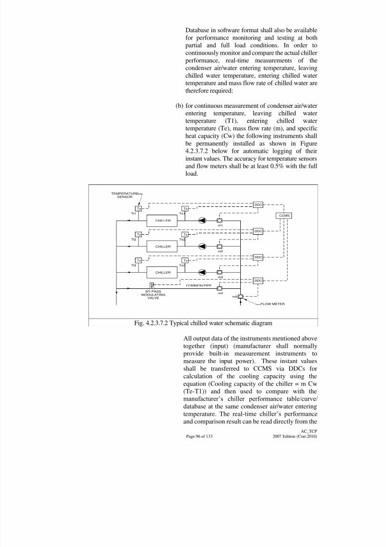
8/7/2019 Test Adjust and Balancing (See 233)
http://slidepdf.com/reader/full/test-adjust-and-balancing-see-233 105/247
Page 96 of 133
AC_TCP
2007 Edition (Corr.2010)
Database in software format shall also be available
for performance monitoring and testing at both
partial and full load conditions. In order to
continuously monitor and compare the actual chiller
performance, real-time measurements of the
condenser air/water entering temperature, leaving
chilled water temperature, entering chilled water
temperature and mass flow rate of chilled water aretherefore required;
(b) for continuous measurement of condenser air/water
entering temperature, leaving chilled water
temperature (T1), entering chilled water
temperature (Te), mass flow rate (m), and specific
heat capacity (Cw) the following instruments shall
be permanently installed as shown in Figure
4.2.3.7.2 below for automatic logging of their
instant values. The accuracy for temperature sensors
and flow meters shall be at least 0.5% with the full
load.
CCMS
DDC
Ts Ts
CHILLER
Te1Tl1
m1
DDC
Ts Ts
CHILLER
Te2Tl2
m2
DDC
Ts Ts
CHILLER
Te3Tl3
m3
m4
m5
M
DDC
COMMON PIPE
BY-PASS
MODULATING
VALVE
FLOW METER
TEMPERATURE
SENSOR
Fig. 4.2.3.7.2 Typical chilled water schematic diagram
All output data of the instruments mentioned above
together (input) (manufacturer shall normally
provide built-in measurement instruments to
measure the input power). These instant values
shall be transferred to CCMS via DDCs for
calculation of the cooling capacity using the
equation (Cooling capacity of the chiller = m Cw
(Te-T1)) and then used to compare with the
manufacturer‟s chiller performance table/curve/
database at the same condenser air/water enteringtemperature. The real-time chiller‟s performance
and comparison result can be read directly from the
8/7/2019 Test Adjust and Balancing (See 233)
http://slidepdf.com/reader/full/test-adjust-and-balancing-see-233 106/247
Page 97 of 133
AC_TCP
2007 Edition (Corr.2010)
monitor or printed-outs. For chillers without
built-in % full load (input) against % full load
capacity database, separate instrument for
measurement of % full load (input) shall be
provided;
(c) for full load performance test, the following
procedures are used:
(i) for parallel chillers as shown in Fig.4.2.3.7.2,
except the branch containing the chiller to be
tested, all other chillers should be decoupled
and isolated from the chiller system by
shutting down the chillers and closing the
corresponding motorized valves at the
common pipe i.e. the (by-pass de-coupler)
under the control of the CCMS;
(ii) at the same time, the testing chiller will sense
the substantial temperature difference
between the entering and leaving chilled
water. The compressors of the testing chiller
will cut-in one by one until the testing chiller
reaches the full load condition; and
(iii) from the data obtained from the instruments
mentioned above via DDC, the full load
cooling capacity of the chiller will be
calculated by the CCMS using the equation(Cooling capacity of the chiller = m Cw (Te -
T1)) at that condenser air/water entering
temperature. Those results are then compared
with the database (supplied by the chiller
manufacturer) for full load cooling capacity
of the chiller at the same condenser air/water
entering temperature. The real-time chiller‟s
full load performance and comparison result
can be read directly from the monitor or
print-outs.
4.2.3.7.3 Automatic Performance Data Logging
If so specified in the Particular Specification or Contract
Drawings, an energy programme shall be so designed in
the CCMS that a continuous performance monitoring of
the refrigeration plants can be undertaken automatically
by the CCMS.
(a) for the implementation of this test, energy meters
shall be installed to measure the actual chilled water
energy output and the actual power consumption of each chiller and its associated chilled water pump
and condenser water pump;
8/7/2019 Test Adjust and Balancing (See 233)
http://slidepdf.com/reader/full/test-adjust-and-balancing-see-233 107/247
Page 98 of 133
AC_TCP
2007 Edition (Corr.2010)
(b) the chilled water energy output will then be plotted
against the actual power consumption under
different load profile in order to work out
performance curves for each chiller;
(c) for a full range of performance data, the test should
be carried out for a sufficient long period of time(say 12 months or within the whole Defect Liability
Period) such that data can be obtained from each
chiller from its full load condition to the lowest
partial load condition; and
(d) the information obtained in the test will form an
important database in the CCMS to monitor the
conditions of the refrigeration plants and hence the
arrangement and scheduling of maintenance works
after the Defect Liability Period.
4.2.3.7.4 Testing of Safety Devices for Refrigeration Plants
For testing of safety devices in chillers such as high
pressure cut, low pressure cut, no flow trip, high oil
temperature / pressure cut, etc., the T & C works can be
carried out manually or if specified by using a simulator
provided by the manufacturer / supplier and undertaken
by a skilled and experience personnel assigned by the
manufacturer / supplier. Every necessary step shall be
taken to prevent the refrigeration machines from beingdamaged accidentally during the tests.
4.2.4 Acoustic Tests
4.2.4.1 Site ambient noise levels shall be recorded prior to the
commencement of tests. In order to minimise background noise,
external noise levels shall be taken at night or at an agreed time.
4.2.4.2 Checking Procedures
Before noise level checks are undertaken, the following checksshall be carried out:-
(a) All ACMV systems are dynamically tested and balanced in
accordance with the relevant sections of this document;
(b) All building works are completed and areas under test are
vacated or under control for carrying out the noise test;
(c) All other noise generating activities and equipment are stopped.
Where circumstances require certain equipment to be keptoperational, then this shall be clearly indicated on the final test
data sheets; and
8/7/2019 Test Adjust and Balancing (See 233)
http://slidepdf.com/reader/full/test-adjust-and-balancing-see-233 108/247
Page 99 of 133
AC_TCP
2007 Edition (Corr.2010)
(d) All areas under test are provided with safe access.
4.2.4.3 Noise Screening Test
The Contractor shall carry out screening test on all noise emitting
plant and machineries during the pre-commissioning phase of the
installation work to identify potential problems that mightinfringe the current Noise Control Ordinance.
The Contractor shall submit to the Architect the test results and to
notify the Architect on any likely problematic areas so that
prompt action could be followed up.
4.2.4.3 Noise Level Test
Prior to measuring noise levels, the Contractor shall check that all
the plants in the air system and the water system are running.
If any item of plant is not running during the test, it shall be
clearly identified on the test sheets.
Noise levels shall be measured by using an approved noise level
meter capable of measuring noise levels in the frequency range of
63 Hz to 8 kHz.
Sound meter tests of the system shall include sound pressure
readings relating to the NC levels in each room where stated in the
Contract Drawings or in the Particular Specification.
In each selected area, noise levels shall be measured 1.5 metres
above the finished floor level and at a distance of 1.5 metres from
a wall.
In large areas, the floor area shall be divided into equal areas and
readings carried out in each area.
The Contractor shall carry out external noise level tests in
locations at agreed boundary positions.
In order to minimise background noise, external noise levels shall
be taken at night or at an agreed time.
Upon completion of the noise level tests, the Contractor shall
carry out a further set of noise level reading with all plant off, so
as to determine the level of background noise.
In cases where measured noise levels are in excess of the
specified criteria, additional checks shall be carried out to identify
the sources of excessive noise generation.
All noise level readings are to be recorded and plotted on octave
wave band frequency charts.
8/7/2019 Test Adjust and Balancing (See 233)
http://slidepdf.com/reader/full/test-adjust-and-balancing-see-233 109/247
Page 100 of 133
AC_TCP
2007 Edition (Corr.2010)
The date and time of test are also to be recorded together with any
relative comments.
4.2.5 IAQ Equipment And System Testing
Before completion of ACMV installation, the Contractor shall carry out
testing and commissioning of IAQ equipment and system to thesatisfaction of the Architect or to meet the requirements as stated in the
Particular Specification.
Testing and commissioning of IAQ installation shall be undertaken by the
Contractor‟s own competent specialist staff or by a competent Independent
Commissioning Specialist nominated by and acting for the Contractor and
approved by the Architect. The option chosen shall be declared by the
Contractor in the Tender Document.
4.2.5.1 IAQ Parameters
Detailed requirement relating to IAQ shall be under Part D of the
General Specification. The level of control for each IAQ
parameters shall be as specified under the Particular Specification.
The Contractor shall check and obtain endorsement from the
Architect for level of all control parameters.
4.2.5.2 General Commissioning Requirements
Systems shall be properly adjusted and commissioned to ensure
that the equipment achieve the designed airflow rates. Thefollowing general requirements shall be met before actual testing
and commissioning of IAQ installation are carried out.
(a) Plant rooms are free of construction waste and debris;
(b) Access doors to plant rooms are fitted and lockable;
(c) All builder‟s works associated with the IAQ systems must be
completed and painted with dust preventing compound;
(d) All ceiling works are completed;
(e) All dust generating activities by other trades are completed and
all areas thoroughly cleaned to prevent ingress of building dust
and debris into the return air or fresh air intake systems;
(f) Air intake screens and louvres are unobstructed and clean;
(g) Fan and other equipment chambers are clean and free of
construction debris;
(h) Fans are checked for proper operation;
(i) Floor gullies and drainage traps are clear and operational;
8/7/2019 Test Adjust and Balancing (See 233)
http://slidepdf.com/reader/full/test-adjust-and-balancing-see-233 110/247
Page 101 of 133
AC_TCP
2007 Edition (Corr.2010)
(j) All condensate drains and trays are clear and water can be
drained away satisfactorily;
(k) Dampers are clean;
(l) Ducting and other air passage ways are clean;
(m) All outside air, return air and spill air dampers are operative;
(n) All volume control dampers are fitted and are at appropriate
opening positions;
(o) Ductwork systems are cleaned by purging of the supply air fan,
or by robot duct cleaning recommended by the ductwork
cleaning specialist;
(p) All VAV and CAV terminals are installed, together with grilles
and diffusers;
(q) All filter media are installed; and
(r) Air conditioning systems and the building indoor area are
purged to the standard acceptable by the Architect.
4.2.5.3 Testing and Commissioning Requirements
After the general commissioning requirements have been verified
by inspection, testing and commissioning of the following IAQequipment and systems shall then be carried out in accordance with
the relevant BSB Testing & Commissioning Procedures.
(a) All air handling
equipment
: Fans, AHUs, FCUs, water scrubbers,
Terminal Air Control devices, grilles
and diffusers.
(b) Air cleaning
equipment
: All pre-filters, main filters, high
efficiency filters and chemical filters,
UV lighting and activated oxygen air
purifier
(c) All ductwork and accessories
: All ductwork, hoods and dampers.
Testing and commissioning procedures shall be carried out by
licensed personnel as shown in Sub-section D.10 of the General
Specification to adjust and regulate the system and equipment so
as to achieve the IAQ parameters as shown in Sub-section D.3 of
the General Specification.
4.2.5.4 IAQ Assessment and Methodologies
IAQ assessment shall be performed as the last part of the testing andcommissioning process upon completion of the ACMV installation.
Further assessments shall also be done 6 months after the building
8/7/2019 Test Adjust and Balancing (See 233)
http://slidepdf.com/reader/full/test-adjust-and-balancing-see-233 111/247
Page 102 of 133
AC_TCP
2007 Edition (Corr.2010)
has been occupied and at 2 months before the end of the
Maintenance Period is certified, i.e.,
(a) First
Assessment
- After testing & commissioning
(b) Second
Assessment
- 6 months after occupation of building or
substantial completion
(c) Third
Assessment
- End of Maintenance Period
IAQ compliance shall be proved by results of measurements. In
addition, an end user satisfaction survey shall be conducted before
end of the Maintenance Period.
4.2.5.5 IAQ Measurement
For measuring IAQ compliance, assessment shall be carried out
by either the real-time monitoring method or the integrated
sampling method. Real-time monitoring shall be used for
detection of pollutant sources and provide information on
variation of pollutant levels throughout the day. The integrated
sampling method shall be carried out by taking samples of a
particular pollutant over an 8-hour basis to obtain the total
exposure level data. If it is not practicable to have 8-hour samples,
short-term sampling to cover the worst scenarios shall be
considered subject to approval of the Architect. All measurements
shall be conducted with the use of calibrated instruments andequipment, standards and reference materials with traceability to
international or national standards.
(a) IAQ Measurement using Real-time Monitors;
(see Reference no. 25, 27 of Annex II & 1 of Annex V )
(b) IAQ Measurement using Passive Samplers; and
(see Reference no. 25 & 28 of Annex II)
(c) IAQ Measurement using Air-borne Bacteria.
(see Reference no. 25 and 29 of Annex II)
4.2.5.6 Sampling Method
The sample method, location of measuring & monitoring IAQ
parameters and measurement method of IAQ parameters shall refer
to Part D and as detailed in the Particular Specification requirement.
4.3 Commissioning and Statutory Inspections
4.3.1 Indoor Air Quality (IAQ)
4.3.1.1 IAQ parameters and their level of control are specified in the
Particular Specification. The 12 parameters are specified, i.e. 3
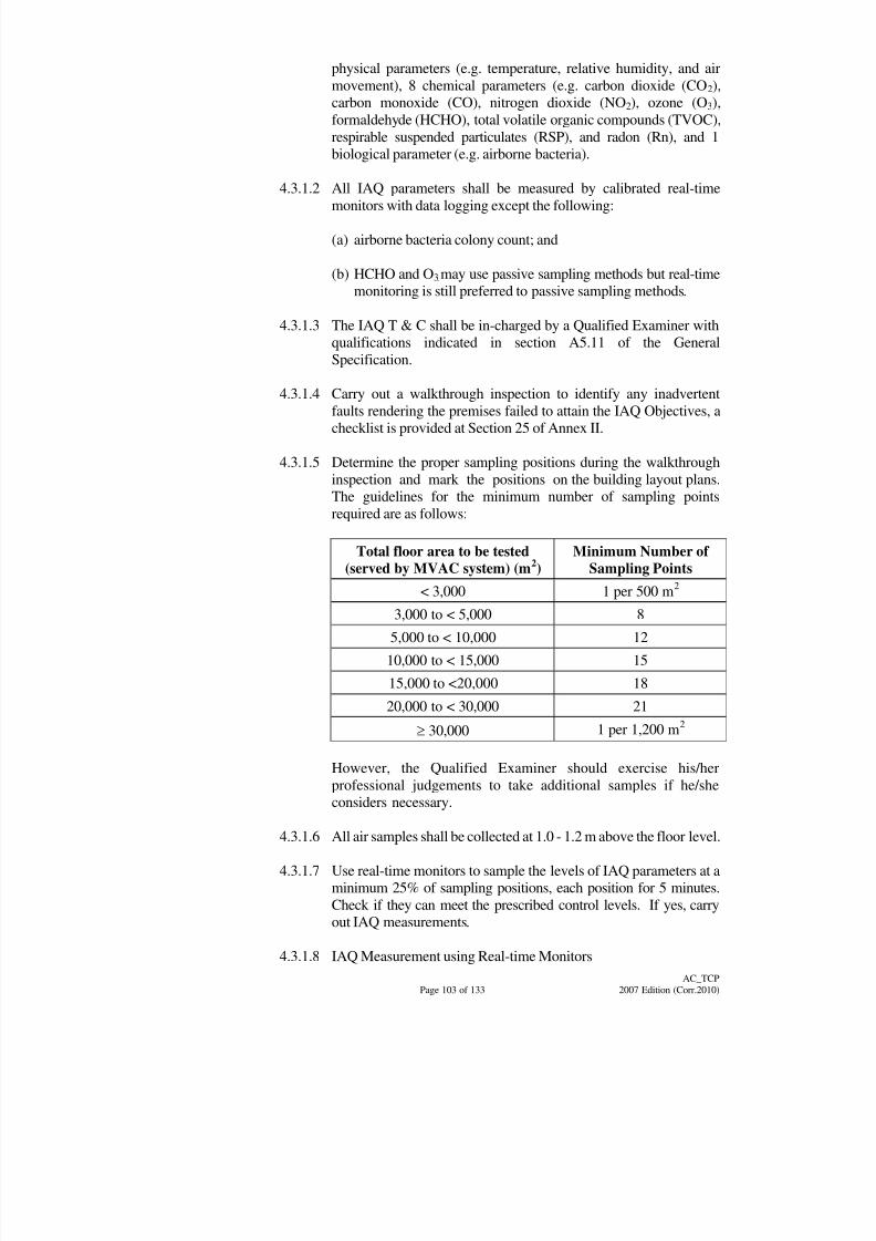
8/7/2019 Test Adjust and Balancing (See 233)
http://slidepdf.com/reader/full/test-adjust-and-balancing-see-233 112/247
Page 103 of 133
AC_TCP
2007 Edition (Corr.2010)
physical parameters (e.g. temperature, relative humidity, and air
movement), 8 chemical parameters (e.g. carbon dioxide (CO2),
carbon monoxide (CO), nitrogen dioxide (NO2), ozone (O3),
formaldehyde (HCHO), total volatile organic compounds (TVOC),
respirable suspended particulates (RSP), and radon (Rn), and 1
biological parameter (e.g. airborne bacteria).
4.3.1.2 All IAQ parameters shall be measured by calibrated real-timemonitors with data logging except the following:
(a) airborne bacteria colony count; and
(b) HCHO and O3 may use passive sampling methods but real-time
monitoring is still preferred to passive sampling methods.
4.3.1.3 The IAQ T & C shall be in-charged by a Qualified Examiner with
qualifications indicated in section A5.11 of the General
Specification.
4.3.1.4 Carry out a walkthrough inspection to identify any inadvertent
faults rendering the premises failed to attain the IAQ Objectives, a
checklist is provided at Section 25 of Annex II.
4.3.1.5 Determine the proper sampling positions during the walkthrough
inspection and mark the positions on the building layout plans.
The guidelines for the minimum number of sampling points
required are as follows:
Total floor area to be tested(served by MVAC system) (m
2)
Minimum Number of Sampling Points
< 3,000 1 per 500 m2
3,000 to < 5,000 8
5,000 to < 10,000 12
10,000 to < 15,000 15
15,000 to <20,000 18
20,000 to < 30,000 21
30,0001 per 1,200 m
2
However, the Qualified Examiner should exercise his/her
professional judgements to take additional samples if he/she
considers necessary.
4.3.1.6 All air samples shall be collected at 1.0 - 1.2 m above the floor level.
4.3.1.7 Use real-time monitors to sample the levels of IAQ parameters at a
minimum 25% of sampling positions, each position for 5 minutes.
Check if they can meet the prescribed control levels. If yes, carry
out IAQ measurements.
4.3.1.8 IAQ Measurement using Real-time Monitors
8/7/2019 Test Adjust and Balancing (See 233)
http://slidepdf.com/reader/full/test-adjust-and-balancing-see-233 113/247
Page 104 of 133
AC_TCP
2007 Edition (Corr.2010)
(a) real time monitors shall be incorporated with data logging
facilities. The logged data shall be stored in memory of the
monitors and then downloadable to a personal computer for
data handling and calculation of time average. The
measurement principles of the monitors are provided at
Reference no. 1 of Annex V. Alternative measurement
principles shall be allowed subjected to the approval of thePBSE;
(b) except air velocity, the measurement time at each sampling
position shall be of minimum 8 hours and covering the whole
normal operation hour of the building, at least one reading
should be taken every 5 minutes. Shorter sampling time shall be
allowed subject to the approval of the PBSE;
(c) before sampling, a unique identification code should be
assigned to each sample collected. These identification codes
will indicate the IAQ parameter, the sampling location, and
whether the sample is a primary or duplicate sample. In
addition to labelling, documentation of sampling equipment,
pump airflow rates, start/stop times, sampling conditions,
names of technicians, and other appropriate sampling collection
information are also necessary;
(d) turn on the real-time monitor, check correctness of operation
parameters (e.g. mode, logging interval, etc.), and then allow
the monitor to log data;
(e) after logging data for the required sampling period, download
the data to computer. Ignore the readings of the initial 10
minutes, and then obtain the highest value of 8-hour average;
(f) sample the outdoor air condition in parallel with the sampling of
the indoor condition, the minimum sample of outdoor shall be 4
number 5-minutes samples taken at 4 time slots distributed
within an 8-hour sampling period;
(g) report and record the results, a record form is provided at
Section 3 of Annex II; and
(h) since the air velocity usually will not fluctuate with time,
therefore a short sampling time shall be allowed and to be
determined by the Qualified Examiner.
4.3.1.9 IAQ Measurement using Passive Samplers
(a) before sampling, a unique identification code should be
assigned to each sample collected. These identification codes
shall indicate the IAQ parameter, the sampling location, and
whether the sample is a primary or duplicate sample. In additionto labelling, documentation of sampling equipment, pump
airflow rates, start/stop times, sampling conditions, names of
8/7/2019 Test Adjust and Balancing (See 233)
http://slidepdf.com/reader/full/test-adjust-and-balancing-see-233 114/247
Page 105 of 133
AC_TCP
2007 Edition (Corr.2010)
technicians, and other appropriate sample collection
information are also necessary;
(b) the sampling time at each sampling position shall be of
minimum 24 hours and covering a normal operation day of the
building;
(c) take a 24-hour sample of the outdoor condition in parallel withthe sampling of the indoor condition;
(d) send the samples to the laboratory for analysis within 5 days.
Before analysis, the sampling tubes / filters / bags / canister
should be treated and stored as per manufacturers'
recommendations. The laboratory results should be signed by
an approved signatory; and
(e) report and record the results, a record form is provided at
Section 4 of Annex II.
4.3.1.10 IAQ measurement of Air-borne Bacteria
(a) before sampling, a unique identification code should be
assigned to each sample collected. These identification codes
shall indicate the sampling location, and whether the sample is a
primary or duplicate sample. In addition to labelling, pump
airflow rates, start/stop times, sampling conditions, names of
technician, and other appropriate sample collection information
are also necessary;
(b) at each sampling position collect 5-minute samples using
Andersen multi-hole impactor samplers with Tryptic soy agar
plates at 4 time-slot evenly distributed within an 8-hour
sampling period covering periods of highest number of
occupancy of a normal operation day;
(c) collect 5-minute samples of outdoor air at 4 time-slots in
parallel with sampling of indoor air;
(d) send the plates for incubation in less than 24 hours. Incubate the
plates at 30C for 48 hours, and then perform bacterial count.Standard aseptic techniques should be practised throughout the
whole process; and
(e) report and record the results, a record form is provided at
Section 5 of Annex II.
4.3.1.11 10% of the integrated samples shall be performed for quality
control including duplicate samples, and field blanks.
4.3.1.12 Report the T & C Result of IAQ measurement. A report form is
provided at Section 2 of Annex II.
4.3.2 Energy Efficiency Equipment & System
8/7/2019 Test Adjust and Balancing (See 233)
http://slidepdf.com/reader/full/test-adjust-and-balancing-see-233 115/247
Page 106 of 133
AC_TCP
2007 Edition (Corr.2010)
The Contractor shall demonstrate by carrying out T & C that the installed air
conditioning and ventilation equipment and system can satisfactorily
perform to the requirements on energy efficiency and energy conservation as
stipulated in section A6 of the General Specifications and the Code of
Practice for Energy Efficiency of Air Conditioning Installations and for
Electrical Installations issued by the Electrical and Mechanical Services
Department.
T & C should be properly carried out before the handover of projects in order
to verify that the energy efficiency performance of the following equipment
and system, but not limited to, based on technical documents and
calculations submitted by the Contractor, can be adequately achieved.
(a) minimum coefficient of performance of major air conditioning chiller
plants;
(b) minimum working efficiency of fans, pumps and motors;
(c) maximum amount of system energy reclaimed; and
(d) optimum working performance of dehumidifiers, outdoor air
pre-conditioners, motion detecting sensing device and enthalpy control
device of free cooling.
Tests for evaluating the energy efficiency performance of equipment would
be classified into factory test and field test.
(a) factory test on equipment should be conducted according to therecognized testing standards such as ARI, ISO, EN and so on.
Certificates should be issued in order to demonstrate that the technical
requirements on energy efficiency as laid down in the Particular
Specification are being complied with satisfactorily;
(b) field test should only be conducted before a set of working details agreed
between the Contractor and PBSE. Full set of calibrated instruments
should be provided for taking record on design temperature, volumetric
and mass flowrate and pressure of air and water at relevant locations, air
relative humidity, equipment operating current and voltage and overall
power input to the HVAC system;
(c) before the commencement of actual T & C works, those standard forms
set out in the Schedule of the Code of Practice for Energy Efficiency of
Air Conditioning Installations should be updated and submitted;
(d) factory endorsed T & C guidelines for illustrating the compliance of
energy efficiency performance requirement should be submitted for
checking and agreement;
(e) calibration certificates of instruments to be used in T & C should be
submitted for checking;
8/7/2019 Test Adjust and Balancing (See 233)
http://slidepdf.com/reader/full/test-adjust-and-balancing-see-233 116/247
Page 107 of 133
AC_TCP
2007 Edition (Corr.2010)
(f) initial visual inspection of the installed air conditioning and ventilation
equipment and system shall be carried out;
(g) if the actual site condition could not allow full load for system testing, a
simulated load shall be agreed and generated for testing;
(h) run in the installed air conditioning and ventilation equipment and
system for a short period of time before it becomes steady;
(i) monitor the steady state system performance;
(j) measure relevant system performance parameters such as air and water
temperature, flowrate, pressure, relative humidity, on/off position of
dampers and valves and so on. Based on those measured data and valid
scientific equations to verify if the attained energy efficiency
performance of the equipment and system is acceptable according to the
Particular Specification;
(k) results of T & C works should be properly documented and certified by
the Contractor and PBSE; and
(l) post-occupation energy efficiency and consumption audit has to be held
before the issuance of Maintenance Certificate for deciding on whether
there is any adjustment and correction to the system operation logic to be
made in order to maximize the working efficiency of the system.
4.3.3 Control Systems
The T & C of Central Control and Monitoring System (CCMS) and BuildingAutomation System (BAS) should be carried out by specialists. Control
systems as defined herein relate to „on the plant‟ control systems, including
pressure/temperature sensing points, motorized valves, dampers, etc. with
which the CCMS/BAS may interface.
It is essential that all wirings within the control panel should be checked to
avoid any loose connections and to ensure correct terminations in
compliance with wiring diagrams. In addition, it is also assured that
functional checks to ensure that all interlocking and sequencing have been
carried out in accordance with the requirements and specifications. It is
also critical that the procedures described elsewhere relating to theregulation of air, water, refrigeration systems and any other connected
equipment/systems have been carried out prior to commissioning the
control system.
Generally, the commissioning procedure shall comply with that set out in the
current edition of the CIBSE Commissioning Code "C" - Automatic Control.
4.3.3.1 Automatic Control System
4.3.3.1.1 Off Site Preparatory Work
Positions for all space thermostats are provisionally
shown on the Contract Drawings. The exact final
8/7/2019 Test Adjust and Balancing (See 233)
http://slidepdf.com/reader/full/test-adjust-and-balancing-see-233 117/247
Page 108 of 133
AC_TCP
2007 Edition (Corr.2010)
locations shall be selected to give maximum coverage
of each space by the control system. The location shall
be proposed by the Contractor in the installation
drawings and shall be approved by the Architect before
installation of the conduit/box and thermostat.
The Contractor shall prepare and submit the following
document and drawing to the PBSE for approval beforecarrying out T & C work for the Automatic Control
System. The document and drawing shall include but
not limit to the followings:
(a) list of systems, plants and equipment to be carried
out T & C;
(b) list of systems, plants and equipment to be
interfaced with the CCMS and BAS if any;
(c) schematic and control wiring diagrams of
Automatic Control System;
(d) location and quantity of sensing, monitoring and
control equipment;
(e) detailed system description for Automatic Control
System;
(f) logic diagrams for Automatic Control System;
(g) list of tools and equipment for on site T & C;
(h) calibration certificates of tools and equipment for on
site T & C; and
(i) form of T & C checklist (refer to Annex II).
4.3.3.1.2 On Site T & C Works
(a) Preliminary Checks
This section is common to all types of system.
Before attempting to set up automatic controls, it
should be ascertained that the following
requirements are satisfied;
(i) all electrical supplies are isolated;
(ii) all control components are installed in
accordance with specified requirements and
manufacturers‟ instructions, e.g., that control
valves are correctly positioned and portedand that temperature and humidity elements
suit the temperature ranges so involved;

8/7/2019 Test Adjust and Balancing (See 233)
http://slidepdf.com/reader/full/test-adjust-and-balancing-see-233 118/247
Page 109 of 133
AC_TCP
2007 Edition (Corr.2010)
(iii) all safety devices including circuit interlocks
and cut-out shall be correctly inserted into the
overall operational plan and will effectively
carry out the purpose intended;
(iv) all sensing elements are located in a position
which will give good representation of thecontrolled variable and are not subject to
extraneous influence;
(v) measuring instruments have been calibrated
against certified standards;
(vi) After installation of all the instruments and
connecting leads and sampling points, the
Commissioning Engineers shall check the
installation and adjustment of the instruments
to ensure they are in proper working order.
Calibration charts shall be provided together
with the test certificates. The Contractor shall
provide records of settings / pressure-levels /
positions of actuators, limits, etc.;
(vii) As far as practical, the Contractor shall
demonstrate by simulation of fault conditions,
the adequacy of the interlocking alarm
circuits' and
(viii) Functional tests shall be carried out for
equipment inter-related with fire services and
CCMS control.
(b) Operating Checks
Check:
(i) that at full rated flow of the controlled media,
the pump and fan pressures are within design
tolerances immediately prior to setting-up;
(ii) that the input temperature of the controlled
media and the pressure at the input of the
controlled device at full design flow
condition are each within specified design
limits and that the pressure difference across
the device comply to design requirements;
Note : In the case of variable fluid flow the
pressure available at any particular
controlled device will tend to vary inrelation to demands at other points of
regulation within the system. There will also
8/7/2019 Test Adjust and Balancing (See 233)
http://slidepdf.com/reader/full/test-adjust-and-balancing-see-233 119/247
Page 110 of 133
AC_TCP
2007 Edition (Corr.2010)
be some variations of the temperature of
fluid available at the inlet of the device
particularly at low-flow condition; and
Checks must be made to ensure that at any
point in the system the fluid to be controlled
is not only available within the specified
limits of temperature and pressure but that thecontrolled device continues to provide the
degree of control required throughout the
range of variations in flow and pressure to
which the system may be subjected;
(iii) that the movement of the controlled device
matches with the travel of the actuator. For
example, examine the damper-actuator
assemblies.
(c) Electricity Supply and Wirings
The following checks are to be made before
switching on the electricity supply:
(i) that the wiring has been installed to the
required standards and regulations and is in
accordance with manufacturers‟
requirements. Special care should be taken to
ensure that the cable possesses suitable
physical and electrical characteristics and thatearthing suits the regulations of the
equipment;
(ii) that all connections are in accordance with
the relevant wiring diagrams supplied; and
(iii) that the electrical supply at the point of
distribution for the control system is correct
and that suitably rated fuse is available.
(d) Connection to Electrical Supply
Switches for the electrical supply is provided.
4.3.3.1.3 Electrical and Electronic Control Systems
(a) Check-out, Calibration and Setting-up Procedures
The procedure applies main component parts of the
system as follows:
(i) valves, dampers and other actuators; and
(ii) controllers and detectors.

8/7/2019 Test Adjust and Balancing (See 233)
http://slidepdf.com/reader/full/test-adjust-and-balancing-see-233 120/247
8/7/2019 Test Adjust and Balancing (See 233)
http://slidepdf.com/reader/full/test-adjust-and-balancing-see-233 121/247
Page 112 of 133
AC_TCP
2007 Edition (Corr.2010)
device in the required direction. Check that the
total movement of the set-point to give full
movement of the control device corresponding to
the proportional band setting;
(v) in the case of two-position control check that the
switching action is correct and any internal
heaters are disconnected during calibration;
(vi) adjust the set-point to the specified desired value;
make „Dead Zone‟ adjustment where applicable;
(vii) cancel any measures that may have been taken to
stabilize the conditions at the detector thus
returning the plant ready for normal working;
and
(viii) adjust proportional bands of controllers to attain
the minimum deviation consistent with stable
control. In the case of timed two-position and
floating control systems, set the design
differential and where applicable, the time
interval which is consistent with stable control
and the minimum deviation.
(d) DDC Controller
(i) use an engineering tool e.g. portable computer;
(ii) verify whether the control program is
downloaded or not;
(iii) verify the time and date of the real time clock;
(iv) set correctly the data transmission rate of the
controller; and
(v) verify the proper communication in the network
by checking the network indication;
(vi) check the performance of the controller and
calibrate the input and output points as follows:
1. Analogue input
• take the reading of the sensor connected
to the controller;
• compare the reading with gauge reading
or instrument reading; and

8/7/2019 Test Adjust and Balancing (See 233)
http://slidepdf.com/reader/full/test-adjust-and-balancing-see-233 122/247
Page 113 of 133
AC_TCP
2007 Edition (Corr.2010)
• calibrate the sensor if necessary.
(calibration certificates should be
submitted).
2. Digital input
• read the initial status of the point;
• manually start the equipment or simulate
an alarm condition;
• verify the change of the status or
appearance of alarm;
• resume the condition back to initial state;
and
• verify the resumed condition.
3. Analogue output
• force the controller to give 0% output
signal;
• verify the position of the actuator by sight
or the running condition of the
equipment by gauge reading;
• repeat the verification for 33%, 66% and100% output signals; and
• calibrate the actuator if necessary.
(calibration certificates should be
submitted).
4. Digital output
• read the initial state of the point;
• force the controller to send ON or OPENsignal
• verify the proper action of the actuator or
equipment by sight;
• force the controller to send OFF or
CLOSE signal; and
• verify the resumed signal of the actuator
or equipment by sight.
(e) Sequence Control
8/7/2019 Test Adjust and Balancing (See 233)
http://slidepdf.com/reader/full/test-adjust-and-balancing-see-233 123/247
Page 114 of 133
AC_TCP
2007 Edition (Corr.2010)
any interlocking or overriding devices should be
checked to ensure that the overall sequence of control
is achieved.
(f) Plant Operation
following the T & C procedures, the design conditions
should be achieved and maintained for a suitableperiod of observation with a minimum of one operation.
If the conditions cannot be achieved or maintained,
then a check on the final control devices should be
carried out to ascertain that maximum correction has
been applied. If this is not satisfied, investigation
beyond the control system is needed.
4.3.3.1.4 Completion of T & C
The Contractor shall submit the record document and
drawings after the completion of T & C.
The final T & C report shall be kept in the Operating and
Maintenance Manual for permanent reference and easy
access.
4.3.3.2 Central Control Monitoring System (CCMS)
4.3.3.2.1 Off Site Preparatory Work
The Contractor shall prepare and submit the documentand drawing as specified in General Specification to the
PBSE for approval before carrying out the CCMS T & C
work.
4.3.3.2.2 On Site T & C Works
Pre-commissioning
Pre-commissioning shall include the checking of the
installed software and hardware (e.g. wiring, sensors and
actuators) and any items of plant with integral controllers;
The test equipment and instruments shall have been
calibrated within the specified period according to the
manufacturer‟s recommendations. The calibration
certificates shall be submitted to PBSE for record;
All physical adjustments to the CCMS field devices shall
be marked. Volt free and control terminals shall be
checked such that they are separated from mains voltage.
(a) Checking and Set-up
(i) Level of CCMS Performance Checking

8/7/2019 Test Adjust and Balancing (See 233)
http://slidepdf.com/reader/full/test-adjust-and-balancing-see-233 124/247
Page 115 of 133
AC_TCP
2007 Edition (Corr.2010)
Level 3 – Building/Zone
Level 2 – Sub-system and
equipment
Level 1 – Component
Test:
Zones
Building
Test:
Chillers
Air handling units
Any systems/equipment
specified in the Contract
Test:
Analogue inputs
Temperature sensors
Humidity sensors
Pressure sensors
Voltage
Current
Flowrate
Digital inputs
Relays
Switches
Analogue outputs
Actuators
Digital outputs Relays
Test for:
Temperature
Humidity
Light
Carbon dioxide
Ventilation rate Energy consumption
Test for:
System response to
inputs
Control loops
Sequencing
Test for:
Accuracy
Operation
Alarms
Address
Checking the performance of a CCMS shall be
conducted at several different levels:
- Level 1 : Component level
e.g. sensors, actuators, controllers / routers
/gateways, terminal workstations, field
devices;
- Level 2 : Sub-system performance
e.g. individual chillers, air handing units and
equipment, etc.; and
- Level 3 : Building and zone performance
e.g. environmental control in zone or
building.
The checking can be performed from the
workstations (in a remote control room) or in
the plant room itself. Level of CCMS
performance testing is as shown in Figure
4.3.3.2.2 below.
Fig. 4.3.3.2.2 – Levels of CCMS performance Testing
8/7/2019 Test Adjust and Balancing (See 233)
http://slidepdf.com/reader/full/test-adjust-and-balancing-see-233 125/247
Page 116 of 133
AC_TCP
2007 Edition (Corr.2010)
(ii) Preliminary check
All major components are installed in
accordance with the drawings.
(iii) Electrical Supply & Batteries
To check for correct power supply to theCCMS
(iv) Visual/Physical inspection
The Contractor shall submit a checklist but
not limited to the following for visual
checking: -
1. CCMS wiring;
2. Field devices;
3. Controller /Router /Gateway /Interfacing
Unit; and
4. CCMS Workstation/Server;
Visual inspection shall be carried out to
check for any physical damage and
assess the readiness for
pre-commissioning. Defect list shall beraised to initiate the remedial work
before commissioning;
5. Wiring
• correct type of cables according to the
specification;
• identification of cables;
• security of fixing/protection of cables,etc.;
• secure termination of wires; and
• in accordance with current edition of
Electricity (Wiring) Regulations;
6. Sensors and actuators
• correct location/orientation;
• type as specified;
8/7/2019 Test Adjust and Balancing (See 233)
http://slidepdf.com/reader/full/test-adjust-and-balancing-see-233 126/247
Page 117 of 133
AC_TCP
2007 Edition (Corr.2010)
• actuator linkage connected and adjusted;
and
• identification correct;
7. Digital inputs/outputs
• location as specified; and;
• identification correct
8. Controller/Router/Gateway/Interfacing
Unit
• type as specified;
• mechanical fixing for Controller /
Router / Gateway / Interfacing Unit
firmly located;
• identification by correct;
• all cables terminated and identified;
• power available, i.e. correct and healthy
electrical power supply;
• hardware configuration in line with
design;
• all electronic devices in place; and
• wiring diagram;
9. CCMS workstation/server
• type as specified;
• sufficient power outlets available;
• cleanliness for operation; and
• data ports for modem and phone, if any;
10. Control wiring connection
• cable type as specified;
• cable identified at both ends;
• correct input/output;
• correct and secure termination;
8/7/2019 Test Adjust and Balancing (See 233)
http://slidepdf.com/reader/full/test-adjust-and-balancing-see-233 127/247
Page 118 of 133
AC_TCP
2007 Edition (Corr.2010)
• separation of mains and signals cables;
and
• no short circuits (line to line and line to
earth).
(b) Component and System Checking
(i) Control Strategy/Software
The logic diagrams for CCMS can be used
to check the software of CCMS
1. Set Points
• check that realistic numbers and ranges
have been entered for all set points;
2. Time Control
• Check that suitable on/off times are
entered for all timed routines, and that
they operate the relevant plant as
required;
3. Interlocks
• Check that all interlocks are in place andwork-test by individually switching
interlocked items of plant;
4. Control Loops
• Check that each control loop is in place
and that the necessary default values
have been added to enable testing to
proceed;
• Test the operation of control loop.
5. Sequencing
• Check that sequence control is provided
and it sequences plant in the specified
manner;
6. Start-up & Shut down
• Check the start-up routine for the correct
sequence of operations for the plantcontrols;
8/7/2019 Test Adjust and Balancing (See 233)
http://slidepdf.com/reader/full/test-adjust-and-balancing-see-233 128/247
Page 119 of 133
AC_TCP
2007 Edition (Corr.2010)
• Check that the defined restart routine is
effective when power is reinstated after
failure; and
• Run a similar check on the shut-down
routine and check status of dampers,
valves etc. after shut-down;
7. Plant Change Over
• The automatic change over of plant on
plant failure or when a specified number
of hours run has been reached should be
checked by failing plant or “manually”
increasing the hours run;
8. Alarm Function
• Check the operation of each alarm
function; and
• Check the level or category of alarm, its
destination and how it is reported;
9. Graphics
• Check the text display and graphics to
avoid inconsistencies.
(ii) Controller/Router/Gateway/Interfacing Unit
1. Check that the “as built” drawings
incorporate the latest modifications;
2. Check metalwork; hinges on doors,
flush doors, opening and closing of
doors, no sagging or drooping of doors
when open, interlocking of doors;
3. Check secure operation of door locks;
4. Check for location and labelling of
switches and indicators (including
colour). Check that plastic rivets or
screws are used to mount labels;
5. Check the scale of analogue/devices;
6. Check that: -
• access for incoming/outgoing cables;
• all doors/gland plates to be earthed;
8/7/2019 Test Adjust and Balancing (See 233)
http://slidepdf.com/reader/full/test-adjust-and-balancing-see-233 129/247
Page 120 of 133
AC_TCP
2007 Edition (Corr.2010)
• tightness of all connections;
• colour coding and numbering of all
cables as specified;
• numbering of all terminals;
• segregation of power cabling and
switchgear from control cabling and
electronic equipment.;
• connections between panel sections are
numbered as specified, accessible and
physically simple to connect /
disconnect.;
• link type terminals for CCMS cables.;
• spare space is provided as specified.;
• labelling of equipment in
Controller/Router/ Gateway/Interfacing
Unit; and
• screen and earth connections cabling
associated with CCMS equipment in
compliance with manufacturer‟s
installation requirements.
7. Sensors (See Annex IV Fig. 1)
• Check that the sensor output is within
the expected range. The sensor output
shall be compared with the reading on
the test instrument;
• If a sensor is not linear over its working
range, check the sensor at the upper,
middle and lower points of its normalworking range; and
• Check for offsets in the software.
8. Digital Signal (See Annex IV Fig. 2 )
• Check that the signal is sensed correctly
by the CCMS;
• Check that each contact is correctly at
open or closed state and that it canchange in response to the relevant item
of plant being switched;
8/7/2019 Test Adjust and Balancing (See 233)
http://slidepdf.com/reader/full/test-adjust-and-balancing-see-233 130/247
Page 121 of 133
AC_TCP
2007 Edition (Corr.2010)
• If available, feedback signals from the
digital output (DO) should be checked
against the controlling digital output;
• Check the status lights on the digital
output boards in the Controller/Router/
Gateway/Interfacing Unit;
• If a device is switched on or off, the
effect can usually be monitored by
another CCMS input; and
• Check that no unexpected / additional /
temporary software override or
interlock have been enabled.
9. Analogue Signal (See Annex IV Fig. 3)
• Check the position indication signal that
agrees with the AO signal to the
actuator;
• Check the direction of movement and
accuracy of position;
• Check that the relevant actuator is
functioning correctly;
• With the valve or damper actuator in the
closed position, check that there is no
temperature changes across the heater/
cooler;
• Check that the actuator has the correct
movement to give the required travel of
the final control device;
• Ensure that any linkage adjustment for
rotation, lift or close off have beensuitably set;
• Check that in the case of spring return
motor being fitted, the position assumed
upon interruption of the power supply is
correct; and
• Check that there is a smooth and regular
movement of the actuating motor and
regulator throughout this procedure.
8/7/2019 Test Adjust and Balancing (See 233)
http://slidepdf.com/reader/full/test-adjust-and-balancing-see-233 131/247
Page 122 of 133
AC_TCP
2007 Edition (Corr.2010)
10. Alarm Signal (See Annex IV Fig. 4)
• Adjust the alarm level to cause an alarm.
Check that the address, alarm message
and destination are correct; and
• Alarms can also apply to digital inputs,
e.g. an overheat thermostat or a switchfor a pump or fan;
11. Response to Sensor Failures
• Inspect the control strategy software;
and
• Should there be a sensor failure where
the output is used in a control loop, then
the action of the loop should be
checked;
12. Interlocks
• Check interlocks through written logic
diagrams and read the text;
• Check when one particular activity
happens, all related and interlocked
activities also occur (positive checks);
and
• Check that interlocked and related
activities cannot occur in isolation
(negative checks);
13. Control Loops (See Annex IV Fig. 5)
• Determine if loop is open (without
feedback) or closed (with feedback);
and
• Before checking the loops, verify the
correct operation of the valve or
dampers. Damper linkages may be
disconnected, dampers jammed, valve
jammed or passing etc.;
14. Open Loop Test (See Annex IV Fig. 5)
• Set up trend logs for the input and output
of the loop;
• Switch the control loop to manual mode;
8/7/2019 Test Adjust and Balancing (See 233)
http://slidepdf.com/reader/full/test-adjust-and-balancing-see-233 132/247
Page 123 of 133
AC_TCP
2007 Edition (Corr.2010)
• Vary the signal to the actuator in a
predefined test sequence covering the
span from fully closed to fully open and
log the output;
• Note that some control loops allow
limits to be applied to an output signal,
so an output range of 0-100% may notbe achievable;
• Examine the profiles of the output and
input; and
• Reset the controller to the required set
point and to automatic mode;
15. Close Loop Test (See Annex IV Fig. 5)
• Trend-log the input and output to the
control loop;
• Set the control to achieve the desired
test conditions;
• Select the controls to achieve the desired
test conditions;
• Select 2 set point values (they should be
within 10% of each other) and set thecontroller to the first value;
• Check that the controller can maintain
the set point;
• Monitor (trend-log) the transient
behaviour and check if it is acceptable
(i.e. the initial time taken for the
response to settle to a steady level);
• Change the control to the second setpoint and check the transient behaviour
and output level;
• If the set point cannot be achieved or
maintained, or the system does not
stabilize, the control loop should be
returned and retested; and
• Reset the controller to the required set
point and the automatic mode;

8/7/2019 Test Adjust and Balancing (See 233)
http://slidepdf.com/reader/full/test-adjust-and-balancing-see-233 133/247
Page 124 of 133
AC_TCP
2007 Edition (Corr.2010)
16. Field Device Location
• Check that the correct type of device is
located in the correct position; and
• The identification or reference number
of the device should be checked;
17. Field Device Wiring
• Visual check the wiring to the device,
see if it is of the correct type,
termination etc.; and
• At the Controller / Router / Gateway /
Interfacing Unit and automatic control
panel, check that the wiring is
terminated and the manual/off/auto
switches are set to automatic.
Commissioning
(a) commissioning involves completing all the checks
and the settings of control values to ensure the
correct operational state of the installation;
(b) the CCMS Workstation shall be used to evaluate the
performance of the completed system;
(c) all variable parameters and switches shall be set to
appropriate values and settings to ensure
compliance with the Particular Specification;
(d) check that the Controller/Router/Gateway/
Interfacing Unit continues to function
independently and in real time irrespective of any
failure of the remainder of the CCMS;
(e) CCMS workstation/server shall be used to check the
communication networks, such as graphic functions,CCMS software, etc; and
(f) a mains failure shall be simulated to check if the
CCMS operation meets the Particular Specification
when the electrical supply is interrupted;
Functional Test of System Performance
(a) Functional Test of Workstation/Server
(i) Hardware Installation
8/7/2019 Test Adjust and Balancing (See 233)
http://slidepdf.com/reader/full/test-adjust-and-balancing-see-233 134/247
Page 125 of 133
AC_TCP
2007 Edition (Corr.2010)
1. Check ambient environment i.e.
temperature and relative humidity;
2. Check the electrical power supply cable
connected to UPS and eventually all
workstation equipment power cables
well terminated at UPS;
3. Check the cable connected to Controller
/ Router / Gateway / Interfacing Unit
and ensure the wiring is correct;
4. Check the LAN cable connected from
Controller / Router / Gateway /
Interfacing Unit to workstation.; and
5. Check the display panel by pressing
different keypads;
(ii) Software Installation
1. Check correct type of software to be
installed for the workstation;
2. Ensure the above software have been
installed at workstation and check the
set up of control system;
3. Test and execute the control task; and
4. Demonstrate that all relevant
information can be monitored and
controlled through the Workstation;
(b) Functional Test of Controller / Router / Gateway /
Interfacing Unit
(i) Installation
1. Check the Controller / Router / Gateway/ Interfacing Unit and accessories are
properly set;
2. Check the sensors, transducers, valves,
actuators, AHU, PAU, FCU, VAV,
ventilation fans, frequency inverters are
properly installed according to drawings,
etc.;
3. Check the installations and services
interfacing with CCMS; and
8/7/2019 Test Adjust and Balancing (See 233)
http://slidepdf.com/reader/full/test-adjust-and-balancing-see-233 135/247
Page 126 of 133
AC_TCP
2007 Edition (Corr.2010)
4. Check the gateway/interfacing Unit for
relevant systems and equipment;
(ii) Testing Procedures for Controller
1. Put controller into operation (on-line);
2. Check the controller is functioning;
3. Check the data communication among
workstation when controller start
operating;
4. Check the input and output of controller
as well as the field points and ensure the
system can transmit a correct signal;
5. Check whether the field points can be
assigned through workstation;
6. Test I/O points with controllers and
Building Services Installations which
monitor and control through CCMS to
ensure whole system is installed
correctly;
7. Put the system into an auto mode and
test if the program can run properly; and
8. Use the workstation or Portable
Operator Terminal to carry out the
modification;
(c) Interface between CCMS and Other Connected
Equipment/ Systems
The Contractor shall carry out the T & C with
other contractors to ensure the success of signal
input/output between the CCMS and any other
connected equipment/systems; and
(d) Commissioning Data and Storage
A copy of all commissioning data of each
system/equipment shall be submitted to the PBSE
for approval. The commissioning data shall be
included in Operating and Maintenance Manuals
at handover. The commissioning data shall
include sensor accuracy, alarm delays, actuator
movement, control loop settings plus input and
outputs.
8/7/2019 Test Adjust and Balancing (See 233)
http://slidepdf.com/reader/full/test-adjust-and-balancing-see-233 136/247
Page 127 of 133
AC_TCP
2007 Edition (Corr.2010)
4.3.3.2.3 Completion of T & C
The Contractor shall submit the following record
documents and drawings after the completion of
commissioning and testing:
(a) Backup copy of CCMS software
the back-up copies of the latest version of all the
software shall be made. After changes have been
made in the software following the performance
tests, a new back-up copy of the software shall be
made, while still retaining a copy of the previous
version shall problems arise;
(b) O&M manual
since the control strategies, set points, alarm levels
etc. are software based, an up-to-date hard copy
needs to be kept in the Operating and Maintenance
Manual for permanent reference and easy access.
4.3.4 Noise and Sound Tests
4.3.4.1 Indoor Noise Level Measurement
All the effort in designing the indoor HVAC system with care and
thought might be wasted if installation and commissioning of the
equipment is not proper. The following check points shall befollowed to determine if the total noise level in occupied areas
within the building exceed the limits as specified in the General
Specification or the Particular Specification.
(a) the sound level meter shall comply with BS EN 61672-1 [2003 ]
and BS EN 61672-2 [2003] with built-in octave filter;
(b) calibrate the sound level meter with sound level calibrator
supplied with the meter according to the procedures specified in
the operation manual of the meter;
(c) switch on the MVAC equipment or plant serving the area in
which noise is to be assessed. The corresponding fan coil units,
ventilation fans and other sound source(s) affecting the area
shall also be turned on;
(d) measure Sound Pressure Levels (SPLs) in dB. Measurement
shall be made as close to the diffuser as possible and the
position of the sound level meter shall be at a height of 1.5m
above floor level is considered appropriate for general
situations;
(e) indicate clearly the locations of measurement on a floor layout
plan for the area(s) concerned;
8/7/2019 Test Adjust and Balancing (See 233)
http://slidepdf.com/reader/full/test-adjust-and-balancing-see-233 137/247
Page 128 of 133
AC_TCP
2007 Edition (Corr.2010)
(f) record the SPLs measured from the 63 Hz octave band through
the 8000 Hz octave frequency band in Certificate no. 21.1 of
Annex II;
(g) plot the SPLs on typical Noise Criteria (NC) curves to
determine the measured NC level in each area;
(h) also indicate other relevant information including date and time
of measurement; type, model and calibration date of the meter
used as well as other observations during the measurement
process in Certificate no. 21.1 of Annex II;
(i) re-calibrate the meter with the calibrator after the noise
measurement; and
(j) measure background noise level only if the ambient noise level
in the area, with the MVAC equipment not operating, exceeds
the NC limits as specified in the General Specification or the
Particular Specification.
4.3.4.2 Outdoor Noise Level Measurement
The noise measurement is performed to assess the noise generated
from MVAC equipment like chillers, ventilation fans, etc., which
may cause noise annoyance to receivers outside the building in
which the equipment is placed.
The procedures below are generally in compliance with those setin the requirements in the Noise Control Ordinance:
(a) the sound level meter shall comply with BS EN 61672-1 [2003 ]
and BS EN 61672-2 [2003] with built-in octave filter;
(b) calibrate the meter with sound level calibrator supplied with the
meter according to the procedures specified in the operation
manual of the meter;
(c) measure noise levels at the location/point to be assessed. The
location/point to be assessed could be the potential „noisesensitive receiver‟ according to the „Technical Memorandum
for the Assessment of Noise from Places other than Domestic
Premises, Public Places or Construction Sites‟ (TM) issued by
the Environmental Protection Department (EPD);
(d) indicate clearly the locations of the noise source and measuring
point(s) on a site plan.
(e) where a measurement is to be carried out at a building, the
assessment point shall be at a position 1m from the exterior of
the building façade but may be at any other point considered tobe appropriate by the EPD. Where a measurement is to be made
of noise being received at a place other than a building, the
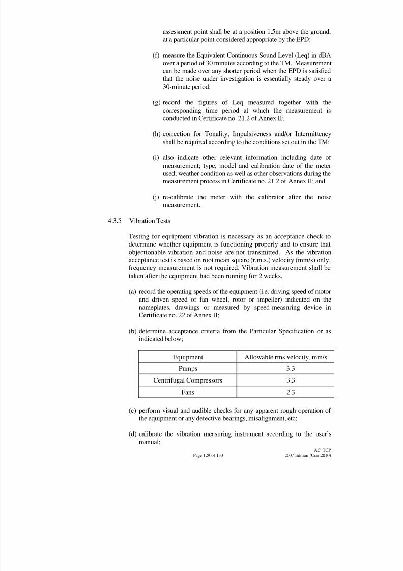
8/7/2019 Test Adjust and Balancing (See 233)
http://slidepdf.com/reader/full/test-adjust-and-balancing-see-233 138/247
Page 129 of 133
AC_TCP
2007 Edition (Corr.2010)
assessment point shall be at a position 1.5m above the ground,
at a particular point considered appropriate by the EPD;
(f) measure the Equivalent Continuous Sound Level (Leq) in dBA
over a period of 30 minutes according to the TM. Measurement
can be made over any shorter period when the EPD is satisfied
that the noise under investigation is essentially steady over a
30-minute period;
(g) record the figures of Leq measured together with the
corresponding time period at which the measurement is
conducted in Certificate no. 21.2 of Annex II;
(h) correction for Tonality, Impulsiveness and/or Intermittency
shall be required according to the conditions set out in the TM;
(i) also indicate other relevant information including date of
measurement; type, model and calibration date of the meter
used; weather condition as well as other observations during the
measurement process in Certificate no. 21.2 of Annex II; and
(j) re-calibrate the meter with the calibrator after the noise
measurement.
4.3.5 Vibration Tests
Testing for equipment vibration is necessary as an acceptance check to
determine whether equipment is functioning properly and to ensure that
objectionable vibration and noise are not transmitted. As the vibrationacceptance test is based on root mean square (r.m.s.) velocity (mm/s) only,
frequency measurement is not required. Vibration measurement shall be
taken after the equipment had been running for 2 weeks.
(a) record the operating speeds of the equipment (i.e. driving speed of motor
and driven speed of fan wheel, rotor or impeller) indicated on the
nameplates, drawings or measured by speed-measuring device in
Certificate no. 22 of Annex II;
(b) determine acceptance criteria from the Particular Specification or as
indicated below;
Equipment Allowable rms velocity, mm/s
Pumps 3.3
Centrifugal Compressors 3.3
Fans 2.3
(c) perform visual and audible checks for any apparent rough operation of
the equipment or any defective bearings, misalignment, etc;
(d) calibrate the vibration measuring instrument according to the user‟s
manual;

8/7/2019 Test Adjust and Balancing (See 233)
http://slidepdf.com/reader/full/test-adjust-and-balancing-see-233 139/247
Page 130 of 133
AC_TCP
2007 Edition (Corr.2010)
(e) measure and record in Certificate no. 22 of Annex II vibration at bearings
of driving and driven components in horizontal, vertical and, if possible,
axial directions. There should be at least one axial measurement for each
rotating component (fan motor, pump motor);
(f) indicate other relevant information including date of measurement, type,
model and calibration date of the instrument used as well as otherobservations in the measurement process in Certificate no. 22 of Annex
II; and
(g) re-calibrate the instrument after the measurement.
4.3.6 Electrical Tests
4.3.6.1 Electrical Tests on Motor Control Switchboard
(a) The tests shall be carried out before and after connection of
power supply. The tests shall follow the requirements as
stipulated in the General Specification for Electrical Installation
in Government Buildings of The Hong Kong Special
Administrative Region issued by Building Services Branch of
Architectural Services Department for L.V. Cubicle
Switchboard; and
(b) The tests to be carried out for the high voltage motor control
switchboard shall strictly follow the tests as recommended by
the equipment manufacturer.
4.3.6.2 Electrical Tests on Motor
(a) Required Tests
The Contractor shall carry out the following tests on all
electrical motors and provide test certificates in duplicate :-
(i) Check motor nameplate characteristic such as voltage
and frequency & etc.;
(ii) Check motor rotation and speed, prior to connection of the driven equipment;
(iii) Ascertain maximum kW absorbed by fan at the most
demanding point of the pressure/volume characteristic
curve at the specified fan speed;
(iv) Check the earth continuity loop resistance for every
motor starter;
(v) Check the insulation to earth resistance for every motor
starter taken with 500 V "Meggar" tester;
8/7/2019 Test Adjust and Balancing (See 233)
http://slidepdf.com/reader/full/test-adjust-and-balancing-see-233 140/247
Page 131 of 133
AC_TCP
2007 Edition (Corr.2010)
(vi) Test the full load current taken by all motors on each
phase;
(vii) Test the tripping time of starter overloads set to 10%
above the motor nameplate rating;
(viii) Test the function of each control unit in accordance with
the specification (e.g. selector switches correctly wired,high or low circuit cut-out operates, level switches
correctly operating);
(ix) Check motor temperature; and
(x) Check starting current of each motor.
(b) Type Tests
Type tests and abbreviated tests shall meet the requirements
of IEC 60072-1 [1991], IEC 60072-2 [1990] and IEC 60072-3
[1994]. The Architect has the discretion to agree or accept
type-test results for performance in place of individual unit
tests but these will not be accepted in place of practical on site,
pressure, insulation, resistance tests which shall still be
carried out on individual units.
(c) Contractor‟s Responsibility
Approval of test certificates shall not absolve the Contractor
from providing motors capable of driving the various items of plant under the conditions of loading stated in the tender
documents.
4.3.7 Final Air Conditioning System Performance Tests
4.3.7.1 General
On completion of all inspections and tests, a final overall
performance test shall be carried out on the air conditioning
installation.
4.3.7.2 Instruments
The Contractor shall provide the following calibrated instruments
for this test:-
(a) All necessary wet and dry bulb mercury-in-glass thermometers;
(b) A wet and dry bulb weekly recorder;
(c) Where specified, multi-point recorders with Service Devices for
monitoring temperature, humidity, current, voltage, etc.;
(d) Surface contact dial indicating pyrometer;
8/7/2019 Test Adjust and Balancing (See 233)
http://slidepdf.com/reader/full/test-adjust-and-balancing-see-233 141/247
Page 132 of 133
AC_TCP
2007 Edition (Corr.2010)
(e) A sound meter capable of reading the noise level at 62.5, 125,
250, 500, 1000, 2000, 4000 and 8000 Hertz; and
(f) Other equipment as found necessary or instructed.
4.3.7.3 Method of Testing
During this test, the air conditioning systems shall be operated for
a period of 5 days minimum. During which time, the following
shall be noted and the results compared with the design criteria:-
(a) Note occupation rates, internal heat and humidity loads, and
external conditions at time of test;
(b) Obtain temperature and humidity levels throughout all spaces;
(c) Obtain sound levels for all critical areas;
(d) Record exhaust and outdoor air extract system ventilation rates;
(e) Check efficiency of individual direct expansion
refrigeration/cooling systems in accordance with CIBSE
Commissioning Code 'R' - Refrigerating Systems;
(f) Check capability of chilled water system to maintain chilled
water flow and return temperature under full load conditions;
and
(g) Check electrical loadings of all plants when operating under
both full load and part load conditions.
4.3.7.4 Full Load Requirement
When full load conditions cannot be achieved during the
commissioning tests, the Contractor shall allow for returning to
site to carry out a full load test when the desirable external and
internal design conditions occur at the first opportunity during the
maintenance period.
For particularly sensitive areas such as computer rooms,
simulated full load tests shall be carried out at the time of
commissioning using electric heaters to simulate the sensible load
and electric steam pan humidifiers to simulate the latent load.
4.3.7.5 When calculating the required simulated load, the following shall
be taken into account.
(a) the anticipated heat gain from plant and machinery;
(b) the extra heat gain through the structural fabric due to thedifference between the design external air temperature and the
external air temperature at the time of the tests;
8/7/2019 Test Adjust and Balancing (See 233)
http://slidepdf.com/reader/full/test-adjust-and-balancing-see-233 142/247
Page 133 of 133
AC_TCP
2007 Edition (Corr.2010)
(c) the extra solar heat gain at maximum design conditions over
that experienced at the time of the tests;
(d) the extra heat gain from the fresh air quantity due to the
difference between the design external air temperature and the
external air temperature at the time of the tests;
(e) the extra sensible and latent (if significant) heat gains due to the
increase in the number of occupants normally present (i.e.
allowed for in the design) over the number present at the time of
the tests; and
(f) NOTE: The areas where simulated load tests are to be carried
out shall be clearly indicated in the Particular Specification.
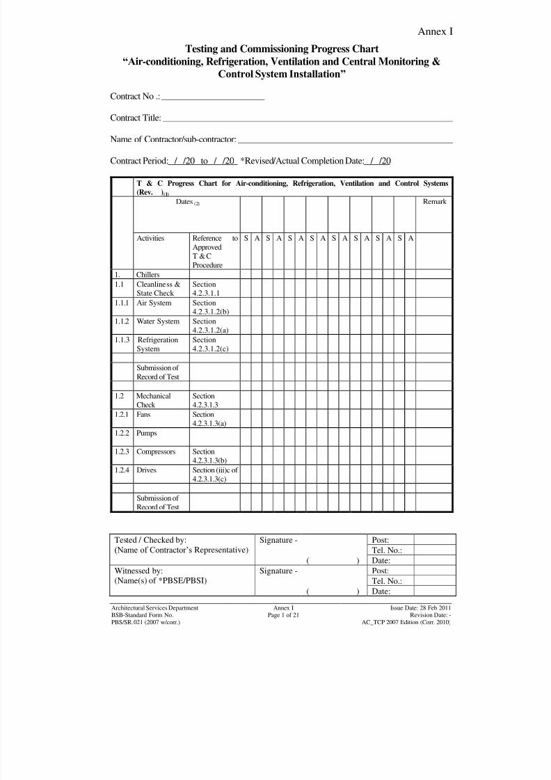
8/7/2019 Test Adjust and Balancing (See 233)
http://slidepdf.com/reader/full/test-adjust-and-balancing-see-233 143/247
Annex I
Tested / Checked by:
(Name of Contractor‟s Representative)
Signature - Post:
Tel. No.:
( ) Date:
Witnessed by:
(Name(s) of *PBSE/PBSI)
Signature - Post:
Tel. No.:( ) Date:
Architectural Services DepartmentBSB-Standard Form No.
Annex IPage 1 of 21
Issue Date: 28 Feb 2011Revision Date: -
PBS/SR.021 (2007 w/corr.) AC_TCP 2007 Edition (Corr. 2010)
Testing and Commissioning Progress Chart
“Air-conditioning, Refrigeration, Ventilation and Central Monitoring &
Control System Installation”
Contract No .:
Contract Title:
Name of Contractor/sub-contractor:
Contract Period: / /20 to / /20 *Revised/Actual Completion Date: / /20
T & C Progress Chart for Air-conditioning, Refrigeration, Ventilation and Control Systems
(Rev. )(1)
Dates (2) Remark
Activities Reference to
Approved
T & C
Procedure
S A S A S A S A S A S A S A S A
1. Chillers
1.1 Cleanliness &State Check
Section4.2.3.1.1
1.1.1 Air System Section4.2.3.1.2(b)
1.1.2 Water System Section
4.2.3.1.2(a) 1.1.3 Refrigeration
System
Section
4.2.3.1.2(c)
Submission of
Record of Test
1.2 Mechanical
Check
Section
4.2.3.1.3
1.2.1 Fans Section
4.2.3.1.3(a)
1.2.2 Pumps
1.2.3 Compressors Section
4.2.3.1.3(b)1.2.4 Drives Section (iii)c of
4.2.3.1.3(c)
Submission of
Record of Test
8/7/2019 Test Adjust and Balancing (See 233)
http://slidepdf.com/reader/full/test-adjust-and-balancing-see-233 144/247
Annex I
Tested / Checked by:
(Name of Contractor‟s Representative)
Signature - Post:
Tel. No.:
( ) Date:
Witnessed by:
(Name(s) of *PBSE/PBSI)
Signature - Post:
Tel. No.:( ) Date:
Architectural Services DepartmentBSB-Standard Form No.
Annex IPage 2 of 21
Issue Date: 28 Feb 2011Revision Date: -
PBS/SR.021 (2007 w/corr.) AC_TCP 2007 Edition (Corr. 2010)
Testing and Commissioning Progress Chart
“Air-conditioning, Refrigeration, Ventilation and Central Monitoring &
Control System Installation”
T & C Progress Chart for Air-conditioning, Refrigeration, Ventilation and Central Monitoring &
Control Systems (Rev. )(1)
Dates (2) Remark
Activities Reference to
Approved
T & C
Procedure
S A S A S A S A S A S A S A S A
1.3 Electrical Check Section
4.2.3.1.4
1.3.1 Electrical Supplies
Isolated
Section
4.2.3.1.4(a)
1.3.2 Electrical SuppliesConnected
Section4.2.3.1.4(b)
Submission of Recordof Test
1.4 Test of ReciprocatingCompressor System
Section4.2.3.2
1.4.1 Pressure & LeakageTest
Section4.2.3.2.1
1.4.2 Evacuation &
Dehydration
Section
4.2.3.2.2
1.4.3 Charging of
Refrigerant
Section
4.2.3.2.4
1.4.4 Setting to Work &
Adjusting
Section
4.2.3.2.5
Submission of Record
of Test
1.5 Test of Centrifugal
Compressor System
(Including Oil Free
Compressor)
Section
4.2.3.3
1.5.1 Pressure & Leakage
Test
Section
4.2.3.3.1
1.5.2 Evacuation &
Dehydration
Section
4.2.3.3.2
1.5.3 Charging of Refrigerant
Section4.2.3.3.4
1.5.4 Setting to Work &
Adjusting
Section
4.2.3.3.5
Submission of Record
of Test

8/7/2019 Test Adjust and Balancing (See 233)
http://slidepdf.com/reader/full/test-adjust-and-balancing-see-233 145/247
Annex I
Tested / Checked by:
(Name of Contractor‟s Representative)
Signature - Post:
Tel. No.:
( ) Date:
Witnessed by:
(Name(s) of *PBSE/PBSI)
Signature - Post:
Tel. No.:( ) Date:
Architectural Services DepartmentBSB-Standard Form No.
Annex IPage 3 of 21
Issue Date: 28 Feb 2011Revision Date: -
PBS/SR.021 (2007 w/corr.) AC_TCP 2007 Edition (Corr. 2010)
Testing and Commissioning Progress Chart
“Air-conditioning, Refrigeration, Ventilation and Central Monitoring &
Control System Installation”
T & C Progress Chart for Air-conditioning, Refrigeration, Ventilation and Central Monitoring &
Control Systems (Rev. )(1) Dates (2) Remark
Activities Reference to
ApprovedT & C
Procedure
S A S A S A S A S A S A S A S A
1.6 Test of Screw
Compressor System
Section
4.2.3.5
1.6.1 Pressure & LeakageTest Section4.2.3.5.1
1.6.2 Evacuation &
Dehydration
Section
4.2.3.5.2
1.6.3 Charging of
Refrigerant
Section
4.2.3.5.4
1.6.4 Setting to Work &
Adjusting
Section
4.2.3.5.5
Submission of
Record of Test
1.7 Testing of
Absorption Chillers
Section
4.2.3.41.7.1 General Check of
System Components
Section
4.2.3.4
1.7.2 Leak Test of
Absorption Shell and
Purge Unit
Section
4.2.3.4.1
1.7.3 Evacuation of
Absorption System
Section
4.2.3.4.2
1.7.4 Charging of
Refrigerant
Section
4.2.3.4.4
1.7.5 Setting to Work &
Adjusting
Section
4.2.3.4.5
Submission of
Record of Test
1.8 Functional Test for
Air & Water Cooled
Chillers
Section 4.2.3
&
Annex II
Setting to
work &
record

8/7/2019 Test Adjust and Balancing (See 233)
http://slidepdf.com/reader/full/test-adjust-and-balancing-see-233 146/247
Annex I
Tested / Checked by:
(Name of Contractor‟s Representative)
Signature - Post:
Tel. No.:
( ) Date:
Witnessed by:
(Name(s) of *PBSE/PBSI)
Signature - Post:
Tel. No.:( ) Date:
Architectural Services DepartmentBSB-Standard Form No.
Annex IPage 4 of 21
Issue Date: 28 Feb 2011Revision Date: -
PBS/SR.021 (2007 w/corr.) AC_TCP 2007 Edition (Corr. 2010)
Testing and Commissioning Progress Chart
“Air-conditioning, Refrigeration, Ventilation and Central Monitoring &
Control System Installation”
T & C Progress Chart for Air-conditioning, Refrigeration, Ventilation and Central Monitoring &
Control Systems (Rev. )(1)
Dates (2) Remark
Activities Reference to
Approved
T & C
Procedure
S A S A S A S A S A S A S A S A
1.8.1 Chilled Water Leaving
Temperature
1.8.2 Chilled Water
Entering Temperature
1.8.3 Chilled Water Flow
Rate
1.8.4 Condenser Entering
Temperature (Water
Cooled Chillers)
1.8.5 Condenser Leaving
Temperature (Water
Cooled Chillers)
1.8.6 Compressor Motor
Speed
1.8.7 Compressor Running
Current
1.8.8 Air Flow Rate (Air
Cooled Chillers)1.8.9 Fan Speed (Air
Cooled Chillers)1.8.10 Fan Motor Speed (Air
Cooled Chillers)1.8.11 Fan Motor Running
Current1.8.12 Supply Voltage
Submission of Record
of Test
1.9 Functional Test for Air
Absorption Chillers
Section 4.2.3
&
Annex II
Setting
to work
& record
8/7/2019 Test Adjust and Balancing (See 233)
http://slidepdf.com/reader/full/test-adjust-and-balancing-see-233 147/247
Annex I
Tested / Checked by:
(Name of Contractor‟s Representative)
Signature - Post:
Tel. No.:
( ) Date:
Witnessed by:
(Name(s) of *PBSE/PBSI)
Signature - Post:
Tel. No.:( ) Date:
Architectural Services DepartmentBSB-Standard Form No.
Annex IPage 5 of 21
Issue Date: 28 Feb 2011Revision Date: -
PBS/SR.021 (2007 w/corr.) AC_TCP 2007 Edition (Corr. 2010)
Testing and Commissioning Progress Chart
"Air-conditioning, Refrigeration, Ventilation and Central Monitoring &
Control System Installation”
T & C Progress Chart for Air-conditioning, Refrigeration, Ventilation and Central Monitoring &
Control Systems (Rev. )(1)
Dates (2) Remark
Activities Reference to
Approved
T & C
Procedure
S A S A S A S A S A S A S A S A
Submission of Record
of Test
2. Chilled Water System
2.1 Cleanliness & State
Check
Section
4.1.5.1
G/F
1/F
2/F
3/F
4/F
Submission of Record
of Test
2.2 Mechanical Check Section
4.1.5.4G/F
1/F
2/F
3/F
4/F
Submission of Record
of Test
2.3 General Checking Section
4.1.5.3
G/F1/F
2/F
3/F
4/F
8/7/2019 Test Adjust and Balancing (See 233)
http://slidepdf.com/reader/full/test-adjust-and-balancing-see-233 148/247
Annex I
Tested / Checked by:
(Name of Contractor‟s Representative)
Signature - Post:
Tel. No.:
( ) Date:
Witnessed by:
(Name(s) of *PBSE/PBSI)
Signature - Post:
Tel. No.:( ) Date:
Architectural Services DepartmentBSB-Standard Form No.
Annex IPage 6 of 21
Issue Date: 28 Feb 2011Revision Date: -
PBS/SR.021 (2007 w/corr.) AC_TCP 2007 Edition (Corr. 2010)
Testing and Commissioning Progress Chart
“Air-conditioning, Refrigeration, Ventilation and Central Monitoring &
Control System Installation”
T & C Progress Chart for Air-conditioning, Refrigeration, Ventilation and Central Monitoring &
Control Systems (Rev. )(1)
Dates (2) Remark
Activities Reference to
Approved
T & C
Procedure
S A S A S A S A S A S A S A S A
Submission of Record
of Test
2.4 Electrical Check
(Pumps)
Section
4.1.5.6
2.4.1 Electrical SupplyIsolated
Section4.1.5.6.1
Pri.
Sec.
Submission of Record
of Test
2.4.2 Electrical Supply
Available
Section
4.1.5.6.2
Pri.
Sec.
Submission of Record
of Test
2.5 Initial Running of
Pump Sets
Section
4.2.1.4
2.5.1 Pump Discharge Rate Section
4.2.1.4
Pri.
Sec.
Submission of Recordof Test
2.5.2 Pump Suction
Pressure
Section
4.2.1.4
Pri.
Sec.
8/7/2019 Test Adjust and Balancing (See 233)
http://slidepdf.com/reader/full/test-adjust-and-balancing-see-233 149/247
Annex I
Tested / Checked by:
(Name of Contractor‟s Representative)
Signature - Post:
Tel. No.:
( ) Date:
Witnessed by:
(Name(s) of *PBSE/PBSI)
Signature - Post:
Tel. No.:( ) Date:
Architectural Services DepartmentBSB-Standard Form No.
Annex IPage 7 of 21
Issue Date: 28 Feb 2011Revision Date: -
PBS/SR.021 (2007 w/corr.) AC_TCP 2007 Edition (Corr. 2010)
Testing and Commissioning Progress Chart
“Air-conditioning, Refrigeration, Ventilation and Central Monitoring &
Control System Installation”
T & C Progress Chart for Air-conditioning, Refrigeration, Ventilation and Central Monitoring &
Control Systems (Rev. )(1)
Dates (2) Remark
Activities Reference to
Approved
T & C
Procedure
S A S A S A S A S A S A S A S A
Submission of
Record of Test
2.5.3 Pump discharge
Pressure
Section
4.2.1.4
Pri.
Sec.
Submission of
Record of Test
2.5.4 Pump Motor Speed Section
4.2.1.4
Pri.
Sec.
Submission of Record of Test
2.5.5 Pump Motor
Current
Section
4.2.1.4
Pri.
Sec.
Submission of
Record of Test
2.5.6 Supply Voltage Section
4.2.1.4Pri.
Sec.
Submission of
Record of Test
8/7/2019 Test Adjust and Balancing (See 233)
http://slidepdf.com/reader/full/test-adjust-and-balancing-see-233 150/247
Annex I
Tested / Checked by:
(Name of Contractor‟s Representative)
Signature - Post:
Tel. No.:
( ) Date:
Witnessed by:
(Name(s) of *PBSE/PBSI)
Signature - Post:
Tel. No.:( ) Date:
Architectural Services DepartmentBSB-Standard Form No.
Annex IPage 8 of 21
Issue Date: 28 Feb 2011Revision Date: -
PBS/SR.021 (2007 w/corr.) AC_TCP 2007 Edition (Corr. 2010)
Testing and Commissioning Progress Chart
“Air-conditioning, Refrigeration, Ventilation and Central Monitoring &
Control System Installation”
T & C Progress Chart for Air-conditioning, Refrigeration, Ventilation and Central Monitoring &
Control Systems (Rev. )(1)
Dates (2) Remark
Activities Reference to
Approved
T & CProcedure
S A S A S A S A S A S A S A S A
2.5.7 Non-return Valve
Operation
Section 4.2.1
Pri.
Sec.
Submission of
Record of Test
2.5.8 Isolation Valve
Operation
Section 4.2.1
Pri.
Sec.
Submission of
Record of Test
2.5.9 Flexible Joint Section 4.2.1
Pri.Sec.
Submission of
Record of Test
2.6 Chemical Treatment Section 4.2
2.6.1 Cleanliness & State
Check
2.6.2 Mechanical Check
2.6.3 Electrical Check
2.6.4 General Check
2.6.5 Initial Running of
Chemical Dosing
Pump
Submission of
Record of Test
8/7/2019 Test Adjust and Balancing (See 233)
http://slidepdf.com/reader/full/test-adjust-and-balancing-see-233 151/247
Annex I
Tested / Checked by:
(Name of Contractor‟s Representative)
Signature - Post:
Tel. No.:
( ) Date:
Witnessed by:
(Name(s) of *PBSE/PBSI)
Signature - Post:
Tel. No.:( ) Date:
Architectural Services DepartmentBSB-Standard Form No.
Annex IPage 9 of 21
Issue Date: 28 Feb 2011Revision Date: -
PBS/SR.021 (2007 w/corr.) AC_TCP 2007 Edition (Corr. 2010)
Testing and Commissioning Progress Chart
“Air-conditioning, Refrigeration, Ventilation and Central Monitoring &
Control System Installation”
T & C Progress Chart for Air-conditioning, Refrigeration, Ventilation and Central Monitoring &
Control Systems (Rev. )(1)
Dates (2) Remark
Activities Reference to
Approved
T & C
Procedure
S A S A S A S A S A S A S A S A
3. Air Distribution
System
3.1 Cleanliness & State
Check
Section
4.1.6.1
G/F
1/F
2/F
3/F
4/F
Submission of
Record of Test
3.2 Fire & Smoke
System Check
3.2.1 Regulating Device Section
4.1.6.2
G/F1/F
2/F
3/F
4/F
Submission of
Record of Test
3.2.2 Visual Check on Air
Tightness
Section
4.1.6.3
G/F
1/F2/F
3/F
4/F
Submission of
Record of Test
8/7/2019 Test Adjust and Balancing (See 233)
http://slidepdf.com/reader/full/test-adjust-and-balancing-see-233 152/247
Annex I
Tested / Checked by:
(Name of Contractor‟s Representative)
Signature - Post:
Tel. No.:
( ) Date:
Witnessed by:
(Name(s) of *PBSE/PBSI)
Signature - Post:
Tel. No.:( ) Date:
Architectural Services DepartmentBSB-Standard Form No.
Annex IPage 10 of 21
Issue Date: 28 Feb 2011Revision Date: -
PBS/SR.021 (2007 w/corr.) AC_TCP 2007 Edition (Corr. 2010)
Testing and Commissioning Progress Chart
“Air-conditioning, Refrigeration, Ventilation and Central Monitoring &
Control System Installation”
T & C Progress Chart for Air-conditioning, Refrigeration, Ventilation and Central Monitoring &
Control Systems (Rev. )(1)
Dates (2) Remark
Activities Reference to
Approved
T & C
Procedure
S A S A S A S A S A S A S A S A
3.2.3 Leakage Test
G/F
1/F
2/F
3/F
4/F
Submission of
Record of Test
3.2.4 Mechanical Check
on Fans & Dampers
Section
4.1.6.4
G/F
1/F
2/F
3/F
4/F
Submission of
Record of Test
3.2.5 Initial Running of
Fans & Dampers
G/F
1/F
2/F
3/F
4/F
Submission of Record of Test
3.2.6 Regulating of Air
Flow
G/F
8/7/2019 Test Adjust and Balancing (See 233)
http://slidepdf.com/reader/full/test-adjust-and-balancing-see-233 153/247
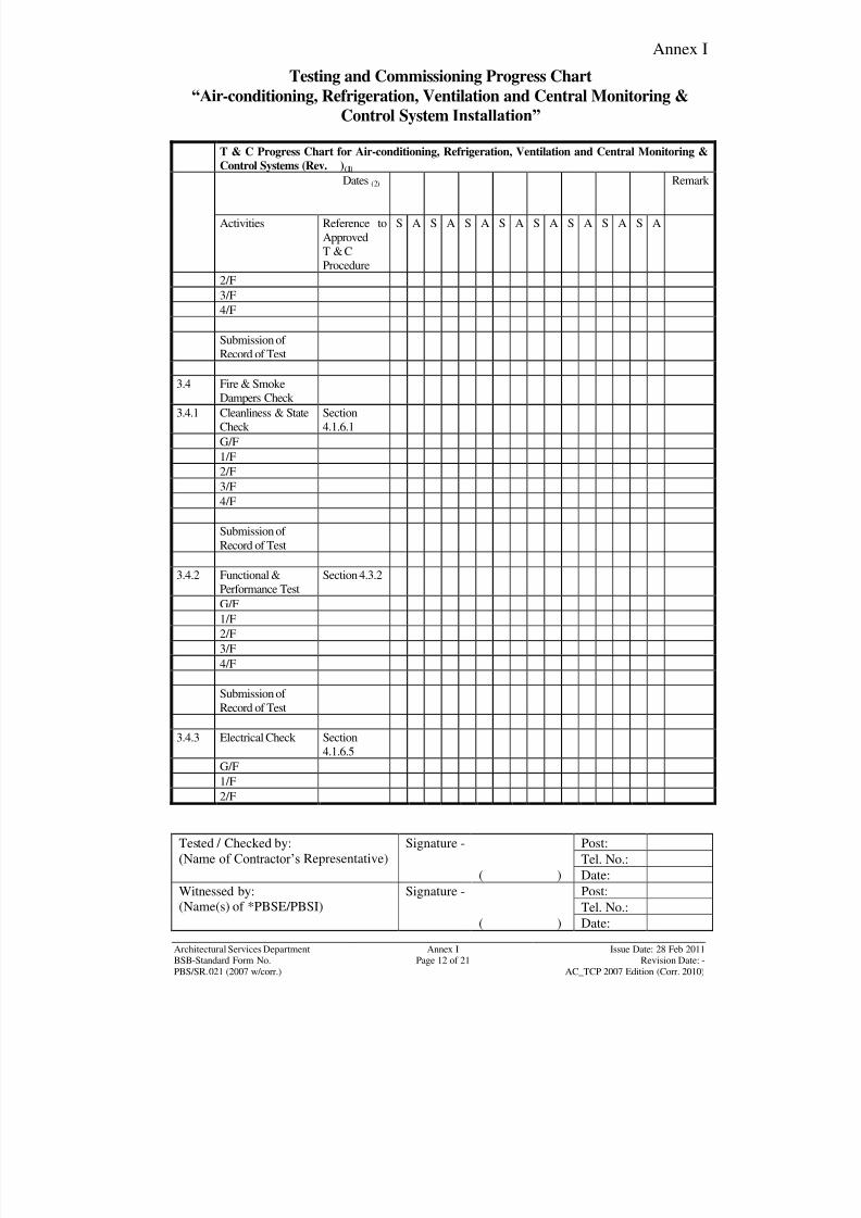
8/7/2019 Test Adjust and Balancing (See 233)
http://slidepdf.com/reader/full/test-adjust-and-balancing-see-233 154/247
Annex I
Tested / Checked by:
(Name of Contractor‟s Representative)
Signature - Post:
Tel. No.:
( ) Date:
Witnessed by:
(Name(s) of *PBSE/PBSI)
Signature - Post:
Tel. No.:( ) Date:
Architectural Services DepartmentBSB-Standard Form No.
Annex IPage 12 of 21
Issue Date: 28 Feb 2011Revision Date: -
PBS/SR.021 (2007 w/corr.) AC_TCP 2007 Edition (Corr. 2010)
Testing and Commissioning Progress Chart
“Air-conditioning, Refrigeration, Ventilation and Central Monitoring &
Control System Installation”
T & C Progress Chart for Air-conditioning, Refrigeration, Ventilation and Central Monitoring &
Control Systems (Rev. )(1)
Dates (2) Remark
Activities Reference to
Approved
T & C
Procedure
S A S A S A S A S A S A S A S A
2/F
3/F
4/F
Submission of
Record of Test
3.4 Fire & Smoke
Dampers Check
3.4.1 Cleanliness & State
Check
Section
4.1.6.1
G/F
1/F
2/F
3/F
4/F
Submission of
Record of Test
3.4.2 Functional &
Performance Test
Section 4.3.2
G/F
1/F
2/F
3/F
4/F
Submission of
Record of Test
3.4.3 Electrical Check Section
4.1.6.5
G/F
1/F
2/F
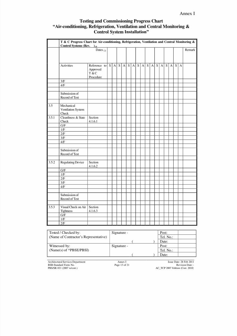
8/7/2019 Test Adjust and Balancing (See 233)
http://slidepdf.com/reader/full/test-adjust-and-balancing-see-233 155/247
Annex I
Tested / Checked by:
(Name of Contractor‟s Representative)
Signature - Post:
Tel. No.:
( ) Date:
Witnessed by:
(Name(s) of *PBSE/PBSI)
Signature - Post:
Tel. No.:( ) Date:
Architectural Services DepartmentBSB-Standard Form No.
Annex IPage 13 of 21
Issue Date: 28 Feb 2011Revision Date: -
PBS/SR.021 (2007 w/corr.) AC_TCP 2007 Edition (Corr. 2010)
Testing and Commissioning Progress Chart
“Air-conditioning, Refrigeration, Ventilation and Central Monitoring &
Control System Installation”
T & C Progress Chart for Air-conditioning, Refrigeration, Ventilation and Central Monitoring &
Control Systems (Rev. )(1)
Dates (2) Remark
Activities Reference to
Approved
T & C
Procedure
S A S A S A S A S A S A S A S A
3/F
4/F
Submission of
Record of Test
3.5 Mechanical
Ventilation System
Check
3.5.1 Cleanliness & StateCheck
Section4.1.6.1
G/F
1/F
2/F
3/F
4/F
Submission of Record of Test
3.5.2 Regulating Device Section
4.1.6.2
G/F
1/F
2/F
3/F
4/F
Submission of
Record of Test
3.5.3 Visual Check on Air
Tightness
Section
4.1.6.3
G/F
1/F
2/F
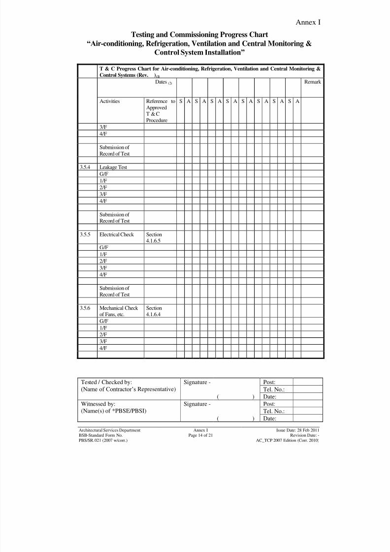
8/7/2019 Test Adjust and Balancing (See 233)
http://slidepdf.com/reader/full/test-adjust-and-balancing-see-233 156/247
Annex I
Tested / Checked by:
(Name of Contractor‟s Representative)
Signature - Post:
Tel. No.:
( ) Date:
Witnessed by:
(Name(s) of *PBSE/PBSI)
Signature - Post:
Tel. No.:( ) Date:
Architectural Services DepartmentBSB-Standard Form No.
Annex IPage 14 of 21
Issue Date: 28 Feb 2011Revision Date: -
PBS/SR.021 (2007 w/corr.) AC_TCP 2007 Edition (Corr. 2010)
Testing and Commissioning Progress Chart
“Air-conditioning, Refrigeration, Ventilation and Central Monitoring &
Control System Installation”
T & C Progress Chart for Air-conditioning, Refrigeration, Ventilation and Central Monitoring &
Control Systems (Rev. )(1)
Dates (2) Remark
Activities Reference to
Approved
T & C
Procedure
S A S A S A S A S A S A S A S A
3/F
4/F
Submission of
Record of Test
3.5.4 Leakage Test
G/F
1/F
2/F
3/F
4/F
Submission of Record of Test
3.5.5 Electrical Check Section4.1.6.5
G/F1/F
2/F
3/F
4/F
Submission of
Record of Test
3.5.6 Mechanical Check
of Fans, etc.
Section
4.1.6.4
G/F
1/F2/F
3/F
4/F

8/7/2019 Test Adjust and Balancing (See 233)
http://slidepdf.com/reader/full/test-adjust-and-balancing-see-233 157/247
Annex I
Tested / Checked by:
(Name of Contractor‟s Representative)
Signature - Post:
Tel. No.:
( ) Date:
Witnessed by:
(Name(s) of *PBSE/PBSI)
Signature - Post:
Tel. No.:( ) Date:
Architectural Services DepartmentBSB-Standard Form No.
Annex IPage 15 of 21
Issue Date: 28 Feb 2011Revision Date: -
PBS/SR.021 (2007 w/corr.) AC_TCP 2007 Edition (Corr. 2010)
Testing and Commissioning Progress Chart
“Air-conditioning, Refrigeration, Ventilation and Central Monitoring &
Control System Installation”
T & C Progress Chart for Air-conditioning, Refrigeration, Ventilation and Central Monitoring &
Control Systems (Rev. )(1)
Dates (2) Remark
Activities Reference to
Approved
T & C
Procedure
S A S A S A S A S A S A S A S A
Submission of
Record of Test
3.5.7 Initial Running of
Fans
Section
4.2.2.4
G/F
1/F
2/F
3/F
4/F
Submission of
Record of Test
3.5.8 Regulating of Flow Section
4.2.2.5
G/F1/F
2/F
3/F
4/F
Submission of
Record of Test
3.5.9 Function &
Performance Test
Section 4.3.2
G/F
1/F2/F
3/F
4/F
Submission of
Record of Test
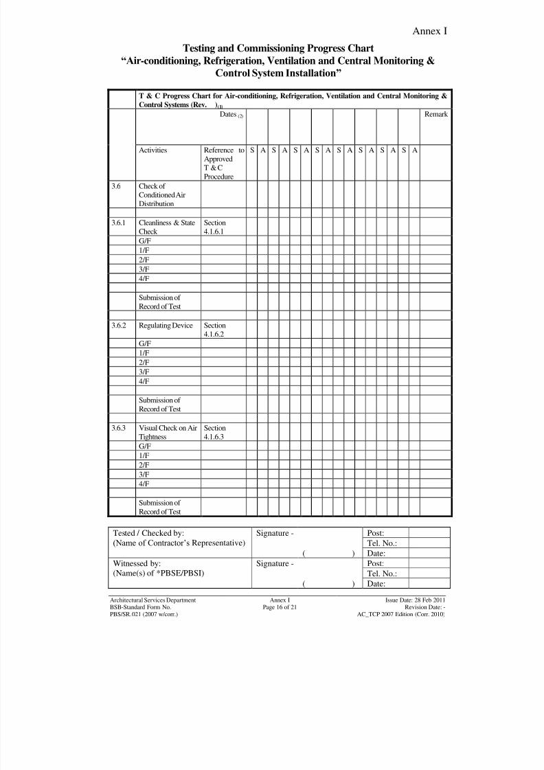
8/7/2019 Test Adjust and Balancing (See 233)
http://slidepdf.com/reader/full/test-adjust-and-balancing-see-233 158/247
Annex I
Tested / Checked by:
(Name of Contractor‟s Representative)
Signature - Post:
Tel. No.:
( ) Date:
Witnessed by:
(Name(s) of *PBSE/PBSI)
Signature - Post:
Tel. No.:( ) Date:
Architectural Services DepartmentBSB-Standard Form No.
Annex IPage 16 of 21
Issue Date: 28 Feb 2011Revision Date: -
PBS/SR.021 (2007 w/corr.) AC_TCP 2007 Edition (Corr. 2010)
Testing and Commissioning Progress Chart
“Air-conditioning, Refrigeration, Ventilation and Central Monitoring &
Control System Installation”
T & C Progress Chart for Air-conditioning, Refrigeration, Ventilation and Central Monitoring &
Control Systems (Rev. )(1)
Dates (2) Remark
Activities Reference to
Approved
T & C
Procedure
S A S A S A S A S A S A S A S A
3.6 Check of
Conditioned Air
Distribution
3.6.1 Cleanliness & State
Check
Section
4.1.6.1
G/F
1/F
2/F
3/F
4/F
Submission of
Record of Test
3.6.2 Regulating Device Section
4.1.6.2
G/F1/F
2/F
3/F
4/F
Submission of
Record of Test
3.6.3 Visual Check on Air
Tightness
Section
4.1.6.3
G/F
1/F2/F
3/F
4/F
Submission of
Record of Test
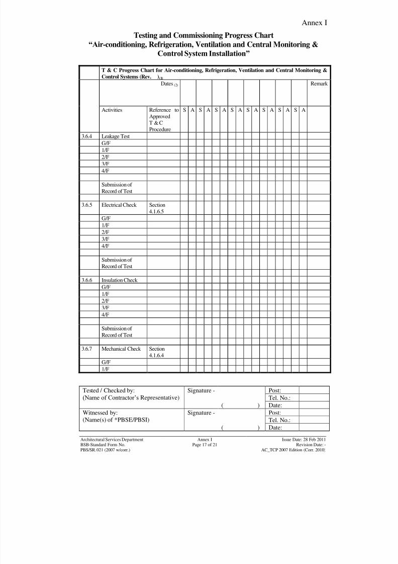
8/7/2019 Test Adjust and Balancing (See 233)
http://slidepdf.com/reader/full/test-adjust-and-balancing-see-233 159/247
Annex I
Tested / Checked by:
(Name of Contractor‟s Representative)
Signature - Post:
Tel. No.:
( ) Date:
Witnessed by:
(Name(s) of *PBSE/PBSI)
Signature - Post:
Tel. No.:( ) Date:
Architectural Services DepartmentBSB-Standard Form No.
Annex IPage 17 of 21
Issue Date: 28 Feb 2011Revision Date: -
PBS/SR.021 (2007 w/corr.) AC_TCP 2007 Edition (Corr. 2010)
Testing and Commissioning Progress Chart
“Air-conditioning, Refrigeration, Ventilation and Central Monitoring &
Control System Installation”
T & C Progress Chart for Air-conditioning, Refrigeration, Ventilation and Central Monitoring &
Control Systems (Rev. )(1)
Dates (2) Remark
Activities Reference to
Approved
T & C
Procedure
S A S A S A S A S A S A S A S A
3.6.4 Leakage Test
G/F
1/F
2/F
3/F
4/F
Submission of
Record of Test
3.6.5 Electrical Check Section
4.1.6.5
G/F
1/F
2/F
3/F
4/F
Submission of Record of Test
3.6.6 Insulation Check
G/F
1/F
2/F
3/F
4/F
Submission of
Record of Test
3.6.7 Mechanical Check Section
4.1.6.4
G/F
1/F
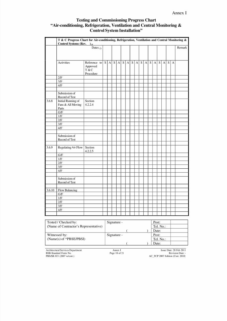
8/7/2019 Test Adjust and Balancing (See 233)
http://slidepdf.com/reader/full/test-adjust-and-balancing-see-233 160/247
Annex I
Tested / Checked by:
(Name of Contractor‟s Representative)
Signature - Post:
Tel. No.:
( ) Date:
Witnessed by:
(Name(s) of *PBSE/PBSI)
Signature - Post:
Tel. No.:( ) Date:
Architectural Services DepartmentBSB-Standard Form No.
Annex IPage 18 of 21
Issue Date: 28 Feb 2011Revision Date: -
PBS/SR.021 (2007 w/corr.) AC_TCP 2007 Edition (Corr. 2010)
Testing and Commissioning Progress Chart
“Air-conditioning, Refrigeration, Ventilation and Central Monitoring &
Control System Installation”
T & C Progress Chart for Air-conditioning, Refrigeration, Ventilation and Central Monitoring &
Control Systems (Rev. )(1)
Dates (2) Remark
Activities Reference to
Approved
T & C
Procedure
S A S A S A S A S A S A S A S A
2/F
3/F
4/F
Submission of
Record of Test
3.6.8 Initial Running of
Fans & All Moving
Parts
Section
4.2.2.4
G/F
1/F
2/F
3/F
4/F
Submission of
Record of Test
3.6.9 Regulating Air Flow Section
4.2.2.5
G/F
1/F
2/F
3/F
4/F
Submission of
Record of Test
3.6.10 Flow BalancingG/F
1/F
2/F
3/F
4/F
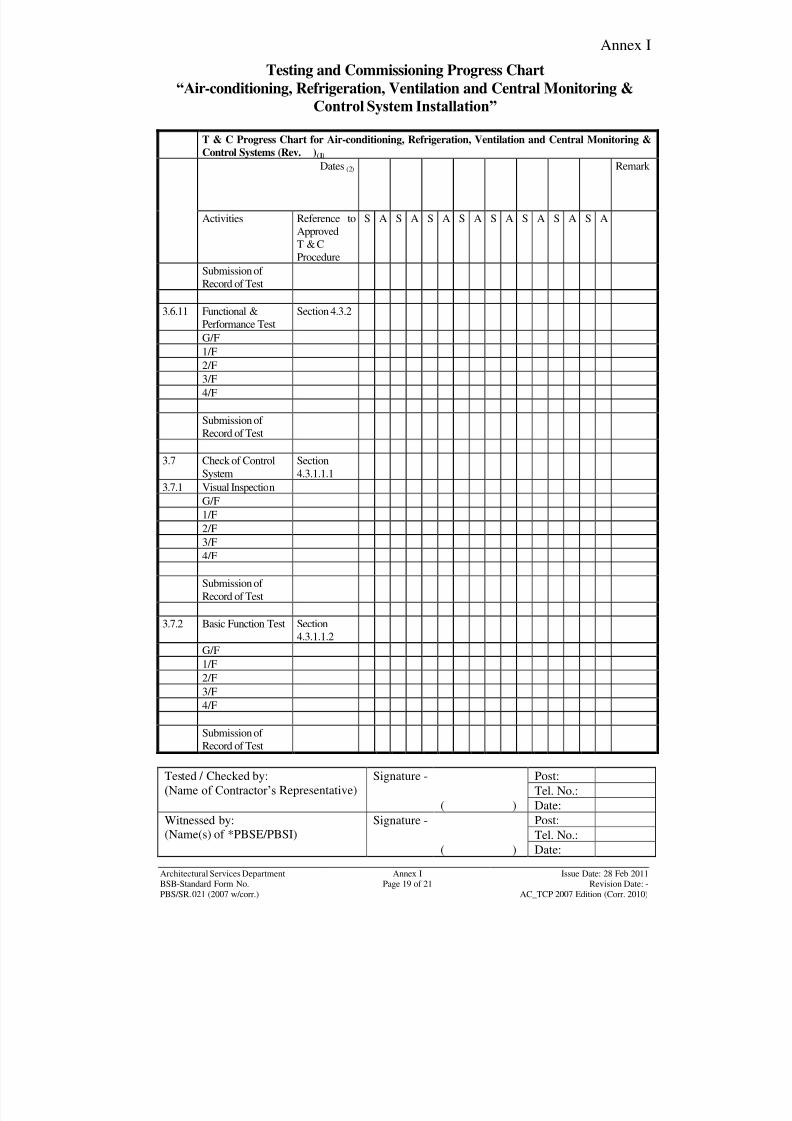
8/7/2019 Test Adjust and Balancing (See 233)
http://slidepdf.com/reader/full/test-adjust-and-balancing-see-233 161/247
Annex I
Tested / Checked by:
(Name of Contractor‟s Representative)
Signature - Post:
Tel. No.:
( ) Date:
Witnessed by:
(Name(s) of *PBSE/PBSI)
Signature - Post:
Tel. No.:( ) Date:
Architectural Services DepartmentBSB-Standard Form No.
Annex IPage 19 of 21
Issue Date: 28 Feb 2011Revision Date: -
PBS/SR.021 (2007 w/corr.) AC_TCP 2007 Edition (Corr. 2010)
Testing and Commissioning Progress Chart
“Air-conditioning, Refrigeration, Ventilation and Central Monitoring &
Control System Installation”
T & C Progress Chart for Air-conditioning, Refrigeration, Ventilation and Central Monitoring &
Control Systems (Rev. )(1)
Dates (2) Remark
Activities Reference to
Approved
T & C
Procedure
S A S A S A S A S A S A S A S A
Submission of
Record of Test
3.6.11 Functional &
Performance Test
Section 4.3.2
G/F
1/F
2/F
3/F
4/F
Submission of
Record of Test
3.7 Check of Control
System
Section
4.3.1.1.1
3.7.1 Visual Inspection
G/F1/F
2/F
3/F
4/F
Submission of
Record of Test
3.7.2 Basic Function Test Section
4.3.1.1.2
G/F
1/F2/F
3/F
4/F
Submission of
Record of Test
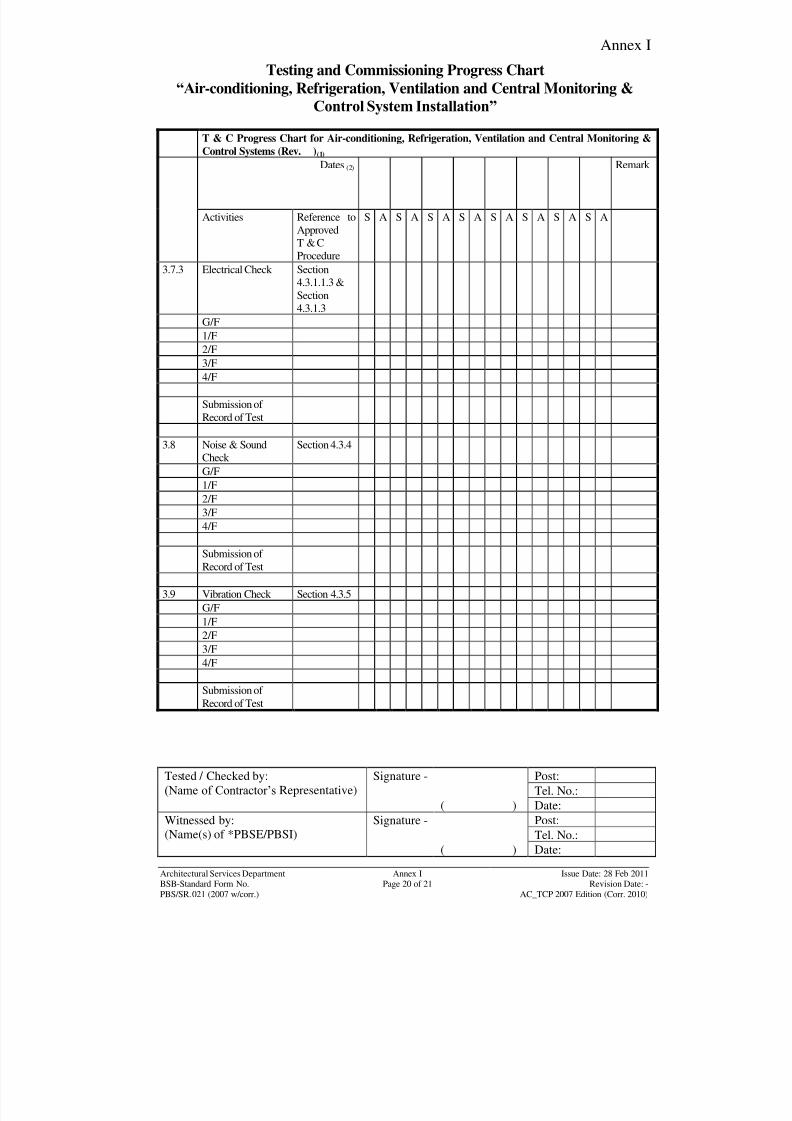
8/7/2019 Test Adjust and Balancing (See 233)
http://slidepdf.com/reader/full/test-adjust-and-balancing-see-233 162/247
Annex I
Tested / Checked by:
(Name of Contractor‟s Representative)
Signature - Post:
Tel. No.:
( ) Date:
Witnessed by:
(Name(s) of *PBSE/PBSI)
Signature - Post:
Tel. No.:( ) Date:
Architectural Services DepartmentBSB-Standard Form No.
Annex IPage 20 of 21
Issue Date: 28 Feb 2011Revision Date: -
PBS/SR.021 (2007 w/corr.) AC_TCP 2007 Edition (Corr. 2010)
Testing and Commissioning Progress Chart
“Air-conditioning, Refrigeration, Ventilation and Central Monitoring &
Control System Installation”
T & C Progress Chart for Air-conditioning, Refrigeration, Ventilation and Central Monitoring &
Control Systems (Rev. )(1)
Dates (2) Remark
Activities Reference to
Approved
T & C
Procedure
S A S A S A S A S A S A S A S A
3.7.3 Electrical Check Section
4.3.1.1.3 &
Section
4.3.1.3
G/F
1/F2/F
3/F
4/F
Submission of
Record of Test
3.8 Noise & Sound
Check
Section 4.3.4
G/F
1/F
2/F3/F
4/F
Submission of
Record of Test
3.9 Vibration Check Section 4.3.5
G/F
1/F
2/F
3/F
4/F
Submission of
Record of Test
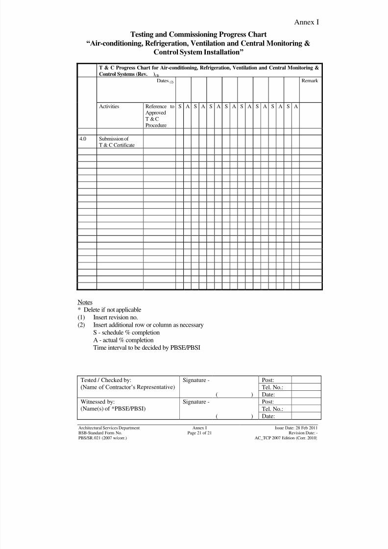
8/7/2019 Test Adjust and Balancing (See 233)
http://slidepdf.com/reader/full/test-adjust-and-balancing-see-233 163/247
Annex I
Tested / Checked by:
(Name of Contractor‟s Representative)
Signature - Post:
Tel. No.:
( ) Date:
Witnessed by:
(Name(s) of *PBSE/PBSI)
Signature - Post:
Tel. No.:( ) Date:
Architectural Services DepartmentBSB-Standard Form No.
Annex IPage 21 of 21
Issue Date: 28 Feb 2011Revision Date: -
PBS/SR.021 (2007 w/corr.) AC_TCP 2007 Edition (Corr. 2010)
Testing and Commissioning Progress Chart
“Air-conditioning, Refrigeration, Ventilation and Central Monitoring &
Control System Installation”
T & C Progress Chart for Air-conditioning, Refrigeration, Ventilation and Central Monitoring &
Control Systems (Rev. )(1)
Dates (2) Remark
Activities Reference to
Approved
T & C
Procedure
S A S A S A S A S A S A S A S A
4.0 Submission of
T & C Certificate
Notes
* Delete if not applicable
(1) Insert revision no.
(2) Insert additional row or column as necessaryS - schedule % completion
A - actual % completion
Time interval to be decided by PBSE/PBSI
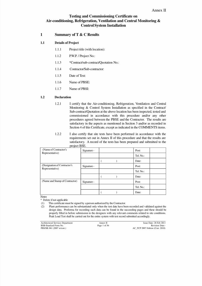
8/7/2019 Test Adjust and Balancing (See 233)
http://slidepdf.com/reader/full/test-adjust-and-balancing-see-233 164/247
Annex II
Architectural Services Department Annex II Issue Date: 28 Feb 2011BSB-Standard Form No. Page 1 of 56 Revision Date:-
PBS/SR.061 (2007 w/corr.) AC_TCP 2007 Edition (Corr. 2010)
Testing and Commissioning Certificate on
Air-conditioning, Refrigeration, Ventilation and Central Monitoring &
Control System Installation
1 Summary of T & C Results
1.1 Details of Project
1.1.1 Project title (with location):
1.1.2 P.W.P. / Project No.:
1.1.3 *Contract/sub-contract/Quotation No.:
1.1.4 Contractor/Sub-contractor:
1.1.5 Date of Test:
1.1.6 Name of PBSE:
1.1.7 Name of PBSI:
1.2 Declaration
1.2.1 I certify that the Air-conditioning, Refrigeration, Ventilation and Central
Monitoring & Control System Installation as specified in the Contract/
Sub-contract/Quotation at the above location has been inspected, tested and
commissioned in accordance with this procedure and/or any other
procedures agreed between the PBSE and the Contractor. The results are
satisfactory in the aspects as mentioned in Section 3 and/or as recorded in
Section 4 of this Certificate, except as indicated in the COMMENTS items.
1.2.2 I also certify that site tests have been performed in accordance with the
requirements set out in Annex II of this procedure and that the results are
satisfactory. A record of the tests has been prepared and submitted to the
project BSE.(Name of Contractor‟s
Representative)Signature - Post:
Tel. No.:
( ) Date:
(Designation of Contractor‟s
Representative)
Signature - Post:
Tel. No.:
( ) Date:
(Name and Stamp of Contractor) Signature - Post:
Tel. No.:
( ) Date:
Notes
* Delete if not applicable(1) This certificate must be signed by a person authorized by the Contractor.
(2) Plant performance can be substantiated only when the test data have been recorded and validated against the
design data. Proforma for recording such data can be found in the succeeding pages and these should be
properly filled in before submission to the designers with any relevant comments related to site conditions.Peak Load Test shall be carried out for the entire system with test record submitted accordingly.
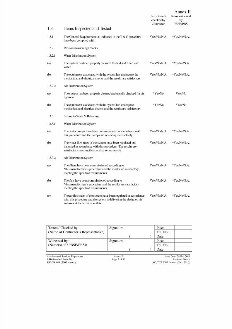
8/7/2019 Test Adjust and Balancing (See 233)
http://slidepdf.com/reader/full/test-adjust-and-balancing-see-233 165/247
Annex II
Tested / Checked by:
(Name of Contractor‟s Representative) Signature - Post:
Tel. No.:
( ) Date:
Witnessed by:
(Name(s) of *PBSE/PBSI)
Signature - Post:
Tel. No.:( ) Date:
Architectural Services Department Annex II Issue Date: 28 Feb 2011BSB-Standard Form No. Page 2 of 56 Revision Date: -
PBS/SR.061 (2007 w/corr.) AC_TCP 2007 Edition (Corr. 2010)
Items tested/
checked by
Contractor
Items witnessed
by
PBSE/PBSI
1.3 Items Inspected and Tested
1.3.1 The General Requirements as indicated in the T & C procedurehave been complied with.
*Yes/No/N.A. *Yes/No/N.A.
1.3.2 Pre-commissioning Checks
1.3.2.1 Water Distribution System
(a) The system has been properly cleaned, flushed and filled with
water.
*Yes/No/N.A. *Yes/No/N.A.
(b) The equipment associated with the system has undergone the
mechanical and electrical checks and the results are satisfactory.
*Yes/No/N.A. *Yes/No/N.A.
1.3.2.2 Air Distribution System
(a) The system has been properly cleaned and usually checked for air
tightness.
*Yes/No *Yes/No
(b) The equipment associated with the system has undergone
mechanical and electrical checks and the results are satisfactory.
*Yes/No *Yes/No
1.3.3 Setting to Work & Balancing
1.3.3.1 Water Distribution System
(a) The water pumps have been commissioned in accordance with
this procedure and the pumps are operating satisfactorily.
*Yes/No/N.A. *Yes/No/N.A.
(b) The water flow rates of the system have been regulated and
balanced in accordance with this procedure. The results aresatisfactory meeting the specified requirements.
*Yes/No/N.A. *Yes/No/N.A.
1.3.3.2 Air Distribution System
(a) The filters have been commissioned according to
*this/manufacturer‟s procedure and the results are satisfactory,
meeting the specified requirements.
*Yes/No/N.A. *Yes/No/N.A.
(b) The fans have been commissioned according to
*this/manufacturer‟s procedure and the results are satisfactory
meeting the specified requirements.
*Yes/No/N.A. *Yes/No/N.A.
(c) The air flow rates of the system have been regulated in accordancewith this procedure and the system is delivering the designed air
volumes at the terminal outlets.
*Yes/No/N.A. *Yes/No/N.A.
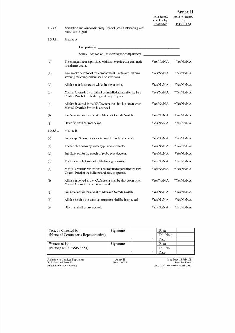
8/7/2019 Test Adjust and Balancing (See 233)
http://slidepdf.com/reader/full/test-adjust-and-balancing-see-233 166/247
Annex II
Tested / Checked by:
(Name of Contractor‟s Representative) Signature - Post:
Tel. No.:
( ) Date:
Witnessed by:
(Name(s) of *PBSE/PBSI)
Signature - Post:
Tel. No.:( ) Date:
Architectural Services Department Annex II Issue Date: 28 Feb 2011BSB-Standard Form No. Page 3 of 56 Revision Date: -
PBS/SR.061 (2007 w/corr.) AC_TCP 2007 Edition (Corr. 2010)
Items tested/
checked by
Contractor
Items witnessed
by
PBSE/PBSI
1.3.3.3 Ventilation and Air-conditioning Control (VAC) interfacing with
Fire Alarm Signal
1.3.3.3.1 Method A
Compartment: ____________________________________________________
Serial/ Code No. of Fans serving the compartment : _______________________
(a) The compartment is provided with a smoke detector automatic
fire alarm system.
*Yes/No/N.A. *Yes/No/N.A.
(b) Any smoke detector of the compartment is activated; all fans
severing the compartment shall be shut down.
*Yes/No/N.A. *Yes/No/N.A.
(c) All fans unable to restart while fire signal exist. *Yes/No/N.A. *Yes/No/N.A.
(d) Manual Override Switch shall be installed adjacent to the Fire
Control Panel of the building and easy to operate.
*Yes/No/N.A. *Yes/No/N.A.
(e) All fans involved in the VAC system shall be shut down when
Manual Override Switch is activated.
*Yes/No/N.A. *Yes/No/N.A.
(f) Fail Safe test for the circuit of Manual Override Switch. *Yes/No/N.A. *Yes/No/N.A.
(g) Other fan shall be interlocked. *Yes/No/N.A. *Yes/No/N.A.
1.3.3.3.2 Method B
(a) Probe-type Smoke Detector is provided in the ductwork. *Yes/No/N.A. *Yes/No/N.A.
(b) The fan shut down by probe-type smoke detector. *Yes/No/N.A. *Yes/No/N.A.
(c) Fail Safe test for the circuit of probe-type detector. *Yes/No/N.A. *Yes/No/N.A.
(d) The fans unable to restart while fire signal exists. *Yes/No/N.A. *Yes/No/N.A.
(e) Manual Override Switch shall be installed adjacent to the Fire
Control Panel of the building and easy to operate.
*Yes/No/N.A. *Yes/No/N.A.
(f) All fans involved in the VAC system shall be shut down when
Manual Override Switch is activated.
*Yes/No/N.A. *Yes/No/N.A.
(g) Fail Safe test for the circuit of Manual Override Switch. *Yes/No/N.A. *Yes/No/N.A.
(h) All fans serving the same compartment shall be interlocked *Yes/No/N.A. *Yes/No/N.A.
(i) Other fan shall be interlocked. *Yes/No/N.A. *Yes/No/N.A.
8/7/2019 Test Adjust and Balancing (See 233)
http://slidepdf.com/reader/full/test-adjust-and-balancing-see-233 167/247
Annex II
Tested / Checked by:
(Name of Contractor‟s Representative) Signature - Post:
Tel. No.:
( ) Date:
Witnessed by:
(Name(s) of *PBSE/PBSI)
Signature - Post:
Tel. No.:( ) Date:
Architectural Services Department Annex II Issue Date: 28 Feb 2011BSB-Standard Form No. Page 4 of 56 Revision Date: -
PBS/SR.061 (2007 w/corr.) AC_TCP 2007 Edition (Corr. 2010)
Items tested/
checked by
Contractor
Items witnessed
by
PBSE/PBSI
1.3.3.3.3 Method C
(a) All fans involved in the VAC System shall be shut down when
building fire alarm system is achieved.
*Yes/No/N.A. *Yes/No/N.A.
(b) All fans unable to restart while fire signal exists. *Yes/No/N.A. *Yes/No/N.A.
(c) Manual Override Switch shall be installed adjacent to the Fire
Control Panel of the building and easy to operate.
*Yes/No/N.A. *Yes/No/N.A.
(d) All fans involved in the VAC System shall be shut down when
Manual Override Switch is activated.
*Yes/No/N.A. *Yes/No/N.A.
(e) Fail Safe test for the circuit of Manual Override Switch. *Yes/No/N.A. *Yes/No/N.A.
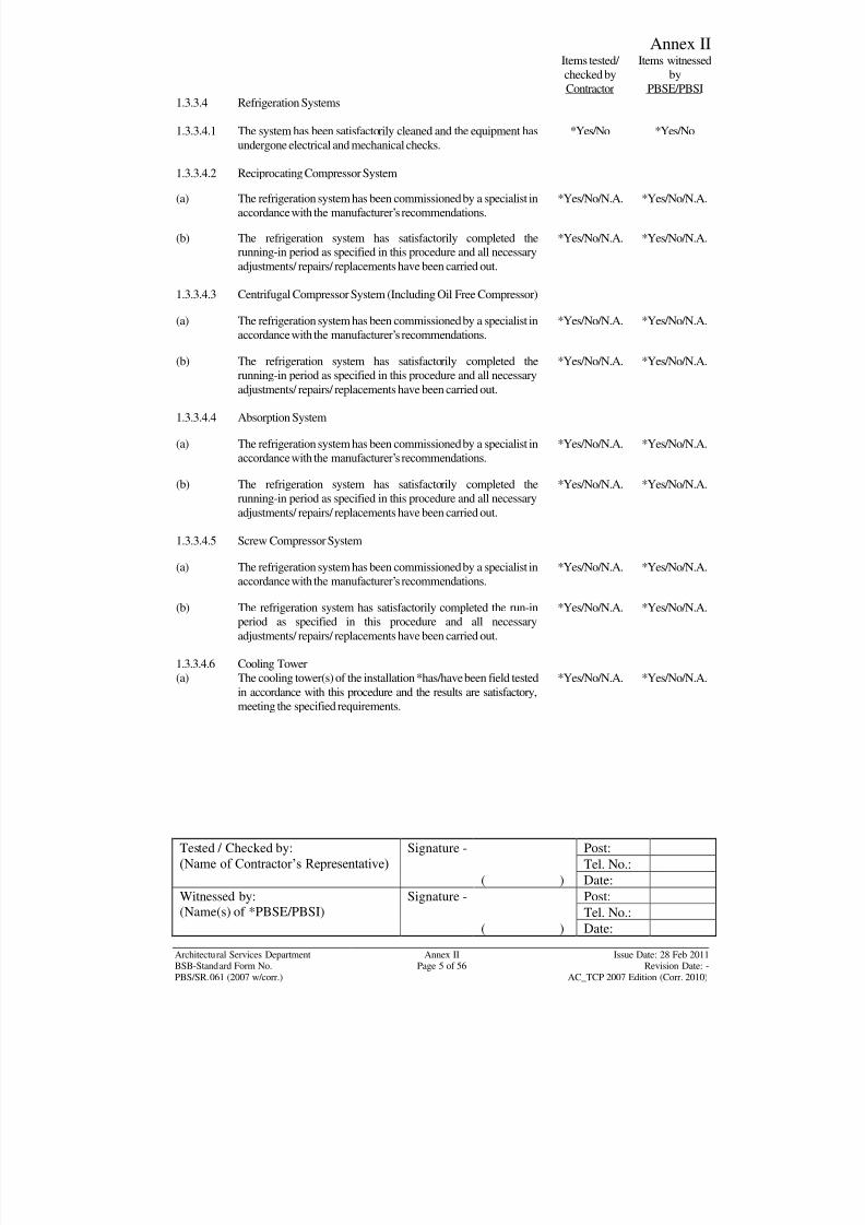
8/7/2019 Test Adjust and Balancing (See 233)
http://slidepdf.com/reader/full/test-adjust-and-balancing-see-233 168/247
Annex II
Tested / Checked by:
(Name of Contractor‟s Representative) Signature - Post:
Tel. No.:
( ) Date:
Witnessed by:
(Name(s) of *PBSE/PBSI)
Signature - Post:
Tel. No.:( ) Date:
Architectural Services Department Annex II Issue Date: 28 Feb 2011BSB-Standard Form No. Page 5 of 56 Revision Date: -
PBS/SR.061 (2007 w/corr.) AC_TCP 2007 Edition (Corr. 2010)
Items tested/
checked by
Contractor
Items witnessed
by
PBSE/PBSI
1.3.3.4 Refrigeration Systems
1.3.3.4.1 The system has been satisfactorily cleaned and the equipment has
undergone electrical and mechanical checks.
*Yes/No *Yes/No
1.3.3.4.2 Reciprocating Compressor System
(a) The refrigeration system has been commissioned by a specialist in
accordance with the manufacturer‟s recommendations.
*Yes/No/N.A. *Yes/No/N.A.
(b) The refrigeration system has satisfactorily completed therunning-in period as specified in this procedure and all necessary
adjustments/ repairs/ replacements have been carried out.
*Yes/No/N.A. *Yes/No/N.A.
1.3.3.4.3 Centrifugal Compressor System (Including Oil Free Compressor)
(a) The refrigeration system has been commissioned by a specialist in
accordance with the manufacturer‟s recommendations.
*Yes/No/N.A. *Yes/No/N.A.
(b) The refrigeration system has satisfactorily completed therunning-in period as specified in this procedure and all necessary
adjustments/ repairs/ replacements have been carried out.
*Yes/No/N.A. *Yes/No/N.A.
1.3.3.4.4 Absorption System
(a) The refrigeration system has been commissioned by a specialist in
accordance with the manufacturer‟s recommendations.
*Yes/No/N.A. *Yes/No/N.A.
(b) The refrigeration system has satisfactorily completed the
running-in period as specified in this procedure and all necessary
adjustments/ repairs/ replacements have been carried out.
*Yes/No/N.A. *Yes/No/N.A.
1.3.3.4.5 Screw Compressor System
(a) The refrigeration system has been commissioned by a specialist in
accordance with the manufacturer‟s recommendations.
*Yes/No/N.A. *Yes/No/N.A.
(b) The refrigeration system has satisfactorily completed the run-in
period as specified in this procedure and all necessary
adjustments/ repairs/ replacements have been carried out.
*Yes/No/N.A. *Yes/No/N.A.
1.3.3.4.6 Cooling Tower
(a) The cooling tower(s) of the installation *has/have been field tested
in accordance with this procedure and the results are satisfactory,
meeting the specified requirements.
*Yes/No/N.A. *Yes/No/N.A.
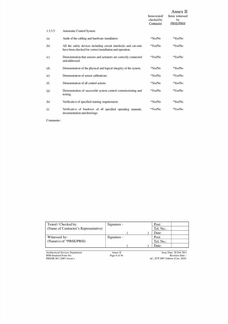
8/7/2019 Test Adjust and Balancing (See 233)
http://slidepdf.com/reader/full/test-adjust-and-balancing-see-233 169/247
Annex II
Tested / Checked by:
(Name of Contractor‟s Representative) Signature - Post:
Tel. No.:
( ) Date:
Witnessed by:
(Name(s) of *PBSE/PBSI)
Signature - Post:
Tel. No.:( ) Date:
Architectural Services Department Annex II Issue Date: 28 Feb 2011BSB-Standard Form No. Page 6 of 56 Revision Date: -
PBS/SR.061 (2007 w/corr.) AC_TCP 2007 Edition (Corr. 2010)
Items tested/
checked by
Contractor
Items witnessed
by
PBSE/PBSI
1.3.3.5 Automatic Control System
(a) Audit of the cabling and hardware installation *Yes/No *Yes/No
(b) All the safety devices including circuit interlocks and cut-outs
have been checked for correct installation and operation.
*Yes/No *Yes/No
(c) Demonstration that sensors and actuators are correctly connected
and addressed.
*Yes/No *Yes/No
(d) Demonstration of the physical and logical integrity of the system. *Yes/No *Yes/No
(e) Demonstration of sensor calibrations *Yes/No *Yes/No
(f) Demonstration of all control actions *Yes/No *Yes/No
(g) Demonstration of successful system control commissioning andtesting.
*Yes/No *Yes/No
(h) Verification of specified training requirements *Yes/No *Yes/No
(i) Verification of handover of all specified operating manuals,
documentation and drawings
*Yes/No *Yes/No
Comments :
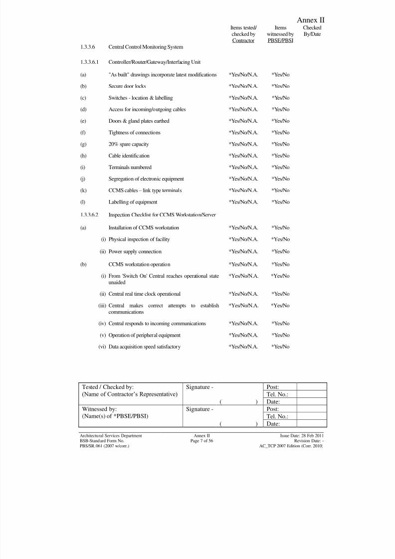
8/7/2019 Test Adjust and Balancing (See 233)
http://slidepdf.com/reader/full/test-adjust-and-balancing-see-233 170/247
Annex II
Tested / Checked by:
(Name of Contractor‟s Representative) Signature - Post:
Tel. No.:
( ) Date:
Witnessed by:
(Name(s) of *PBSE/PBSI)
Signature - Post:
Tel. No.:( ) Date:
Architectural Services Department Annex II Issue Date: 28 Feb 2011BSB-Standard Form No. Page 7 of 56 Revision Date: -
PBS/SR.061 (2007 w/corr.) AC_TCP 2007 Edition (Corr. 2010)
Items tested/
checked by
Contractor
Items
witnessed by
PBSE/PBSI
Checked
By/Date
1.3.3.6 Central Control Monitoring System
1.3.3.6.1 Controller/Router/Gateway/Interfacing Unit
(a) "As built" drawings incorporate latest modifications *Yes/No/N.A. *Yes/No
(b) Secure door locks *Yes/No/N.A. *Yes/No
(c) Switches - location & labelling *Yes/No/N.A. *Yes/No
(d) Access for incoming/outgoing cables *Yes/No/N.A. *Yes/No
(e) Doors & gland plates earthed *Yes/No/N.A. *Yes/No
(f) Tightness of connections *Yes/No/N.A. *Yes/No
(g) 20% spare capacity *Yes/No/N.A. *Yes/No
(h) Cable identification *Yes/No/N.A. *Yes/No
(i) Terminals numbered *Yes/No/N.A. *Yes/No
(j) Segregation of electronic equipment *Yes/No/N.A. *Yes/No
(k) CCMS cables – link type terminals *Yes/No/N.A. *Yes/No
(l) Labelling of equipment *Yes/No/N.A. *Yes/No
1.3.3.6.2 Inspection Checklist for CCMS Workstation/Server
(a) Installation of CCMS workstation *Yes/No/N.A. *Yes/No
(i) Physical inspection of facility *Yes/No/N.A. *Yes/No
(ii) Power supply connection *Yes/No/N.A. *Yes/No
(b) CCMS workstation operation *Yes/No/N.A. *Yes/No
(i) From 'Switch On' Central reaches operational state
unaided
*Yes/No/N.A. *Yes/No
(ii) Central real time clock operational *Yes/No/N.A. *Yes/No
(iii) Central makes correct attempts to establish
communications
*Yes/No/N.A. *Yes/No
(iv) Central responds to incoming communications *Yes/No/N.A. *Yes/No
(v) Operation of peripheral equipment *Yes/No/N.A. *Yes/No
(vi) Data acquisition speed satisfactory *Yes/No/N.A. *Yes/No
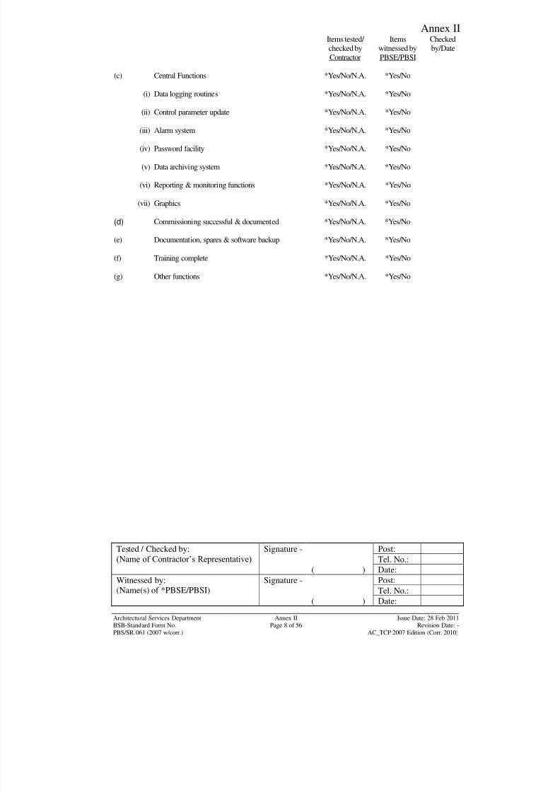
8/7/2019 Test Adjust and Balancing (See 233)
http://slidepdf.com/reader/full/test-adjust-and-balancing-see-233 171/247
Annex II
Tested / Checked by:
(Name of Contractor‟s Representative) Signature - Post:
Tel. No.:
( ) Date:
Witnessed by:
(Name(s) of *PBSE/PBSI)
Signature - Post:
Tel. No.:( ) Date:
Architectural Services Department Annex II Issue Date: 28 Feb 2011BSB-Standard Form No. Page 8 of 56 Revision Date: -
PBS/SR.061 (2007 w/corr.) AC_TCP 2007 Edition (Corr. 2010)
Items tested/
checked by
Contractor
Items
witnessed by
PBSE/PBSI
Checked
by/Date
(c) Central Functions *Yes/No/N.A. *Yes/No
(i) Data logging routines *Yes/No/N.A. *Yes/No
(ii) Control parameter update *Yes/No/N.A. *Yes/No
(iii) Alarm system *Yes/No/N.A. *Yes/No
(iv) Password facility *Yes/No/N.A. *Yes/No
(v) Data archiving system *Yes/No/N.A. *Yes/No
(vi) Reporting & monitoring functions *Yes/No/N.A. *Yes/No
(vii) Graphics *Yes/No/N.A. *Yes/No
(d) Commissioning successful & documented *Yes/No/N.A. *Yes/No
(e) Documentation, spares & software backup *Yes/No/N.A. *Yes/No
(f) Training complete *Yes/No/N.A. *Yes/No
(g) Other functions *Yes/No/N.A. *Yes/No
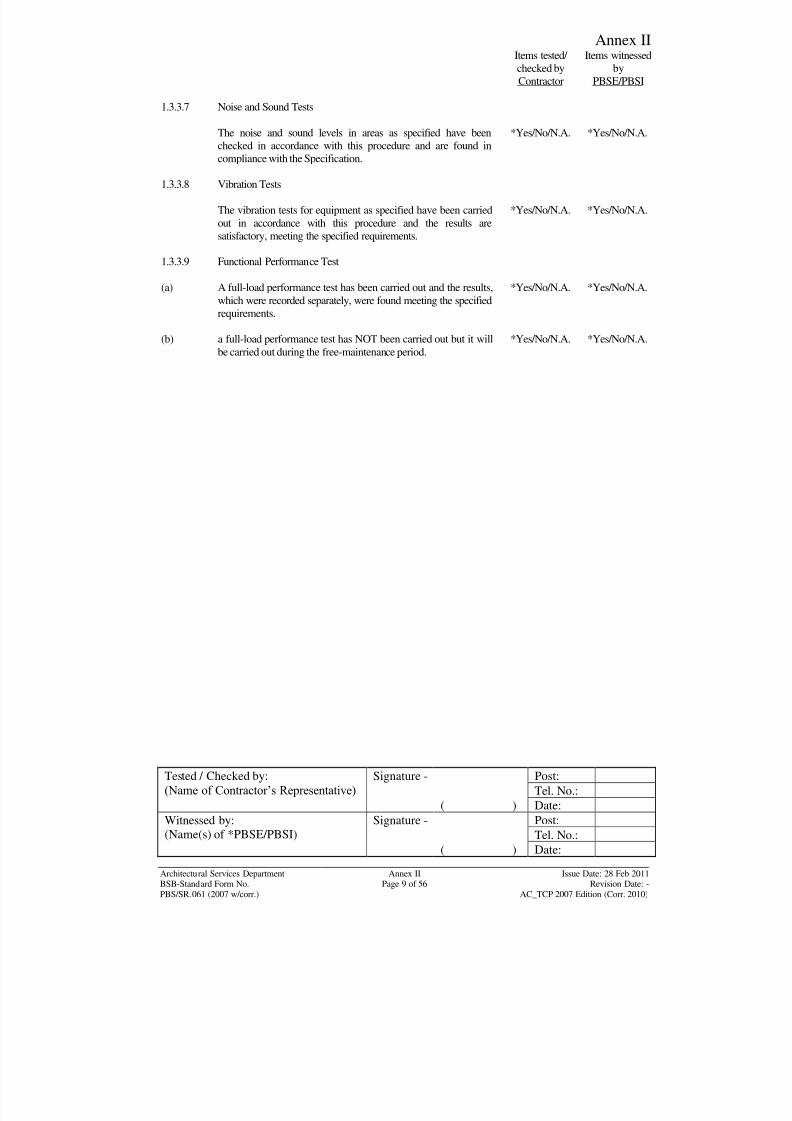
8/7/2019 Test Adjust and Balancing (See 233)
http://slidepdf.com/reader/full/test-adjust-and-balancing-see-233 172/247
Annex II
Tested / Checked by:
(Name of Contractor‟s Representative) Signature - Post:
Tel. No.:
( ) Date:
Witnessed by:
(Name(s) of *PBSE/PBSI)
Signature - Post:
Tel. No.:( ) Date:
Architectural Services Department Annex II Issue Date: 28 Feb 2011BSB-Standard Form No. Page 9 of 56 Revision Date: -
PBS/SR.061 (2007 w/corr.) AC_TCP 2007 Edition (Corr. 2010)
Items tested/
checked by
Contractor
Items witnessed
by
PBSE/PBSI
1.3.3.7 Noise and Sound Tests
The noise and sound levels in areas as specified have been
checked in accordance with this procedure and are found in
compliance with the Specification.
*Yes/No/N.A. *Yes/No/N.A.
1.3.3.8 Vibration Tests
The vibration tests for equipment as specified have been carried
out in accordance with this procedure and the results are
satisfactory, meeting the specified requirements.
*Yes/No/N.A. *Yes/No/N.A.
1.3.3.9 Functional Performance Test
(a) A full-load performance test has been carried out and the results,
which were recorded separately, were found meeting the specified
requirements.
*Yes/No/N.A. *Yes/No/N.A.
(b) a full-load performance test has NOT been carried out but it will
be carried out during the free-maintenance period.
*Yes/No/N.A. *Yes/No/N.A.
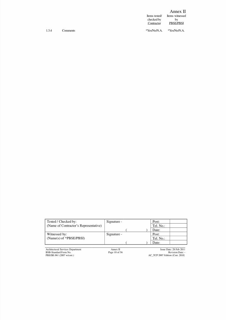
8/7/2019 Test Adjust and Balancing (See 233)
http://slidepdf.com/reader/full/test-adjust-and-balancing-see-233 173/247
Annex II
Tested / Checked by:
(Name of Contractor‟s Representative) Signature - Post:
Tel. No.:
( ) Date:
Witnessed by:
(Name(s) of *PBSE/PBSI)
Signature - Post:
Tel. No.:( ) Date:
Architectural Services Department Annex II Issue Date: 28 Feb 2011BSB-Standard Form No. Page 10 of 56 Revision Date: -
PBS/SR.061 (2007 w/corr.) AC_TCP 2007 Edition (Corr. 2010)
Items tested/
checked by
Contractor
Items witnessed
by
PBSE/PBSI
1.3.4 Comments *Yes/No/N.A. *Yes/No/N.A.
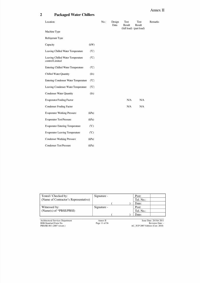
8/7/2019 Test Adjust and Balancing (See 233)
http://slidepdf.com/reader/full/test-adjust-and-balancing-see-233 174/247
Annex II
Tested / Checked by:
(Name of Contractor‟s Representative) Signature - Post:
Tel. No.:
( ) Date:
Witnessed by:
(Name(s) of *PBSE/PBSI)
Signature - Post:
Tel. No.:( ) Date:
Architectural Services Department Annex II Issue Date: 28 Feb 2011BSB-Standard Form No. Page 11 of 56 Revision Date: -
PBS/SR.061 (2007 w/corr.) AC_TCP 2007 Edition (Corr. 2010)
2 Packaged Water Chillers
Location: No.: Design Test Test Remarks
Data Result Result
(full load) (part load)
Machine Type
Refrigerant Type
Capacity (kW)
Leaving Chilled Water Temperature (oC)
Leaving Chilled Water Temperature (oC)
control Limited
Entering Chilled Water Temperature (oC)
Chilled Water Quantity (l/s)
Entering Condenser Water Temperature (oC)
Leaving Condenser Water Temperature (oC)
Condenser Water Quantity (l/s)
Evaporator Fouling Factor N/A N/A
Condenser Fouling Factor N/A N/A
Evaporator Working Pressure (kPa)
Evaporator Test Pressure (kPa)
Evaporator Entering Temperature (o
C)
Evaporator Leaving Temperature (oC)
Condenser Working Pressure (kPa)
Condenser Test Pressure (kPa)
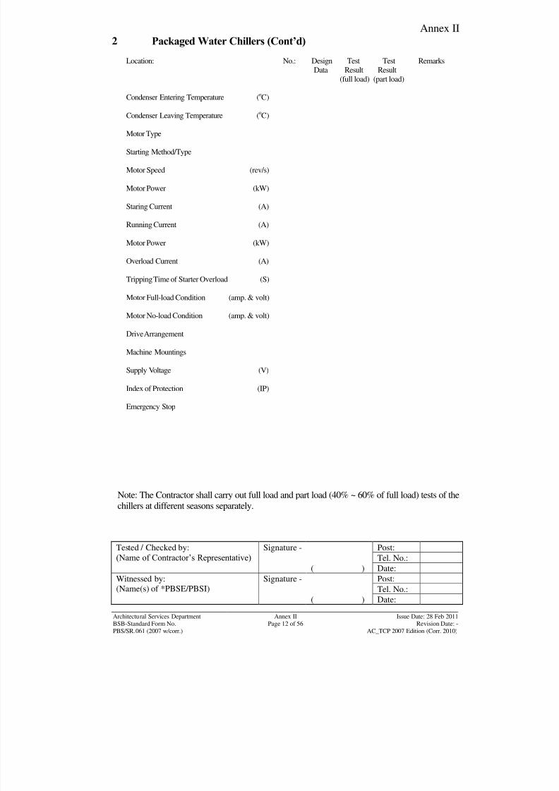
8/7/2019 Test Adjust and Balancing (See 233)
http://slidepdf.com/reader/full/test-adjust-and-balancing-see-233 175/247
Annex II
Tested / Checked by:
(Name of Contractor‟s Representative) Signature - Post:
Tel. No.:
( ) Date:
Witnessed by:
(Name(s) of *PBSE/PBSI)
Signature - Post:
Tel. No.:( ) Date:
Architectural Services Department Annex II Issue Date: 28 Feb 2011BSB-Standard Form No. Page 12 of 56 Revision Date: -
PBS/SR.061 (2007 w/corr.) AC_TCP 2007 Edition (Corr. 2010)
2 Packaged Water Chillers (Cont’d)
Location: No.: Design Test Test Remarks
Data Result Result
(full load) (part load)
Condenser Entering Temperature (oC)
Condenser Leaving Temperature (o
C)
Motor Type
Starting Method/Type
Motor Speed (rev/s)
Motor Power (kW)
Staring Current (A)
Running Current (A)
Motor Power (kW)
Overload Current (A)
Tripping Time of Starter Overload (S)
Motor Full-load Condition (amp. & volt)
Motor No-load Condition (amp. & volt)
Drive Arrangement
Machine Mountings
Supply Voltage (V)
Index of Protection (IP)
Emergency Stop
Note: The Contractor shall carry out full load and part load (40% ~ 60% of full load) tests of the
chillers at different seasons separately.
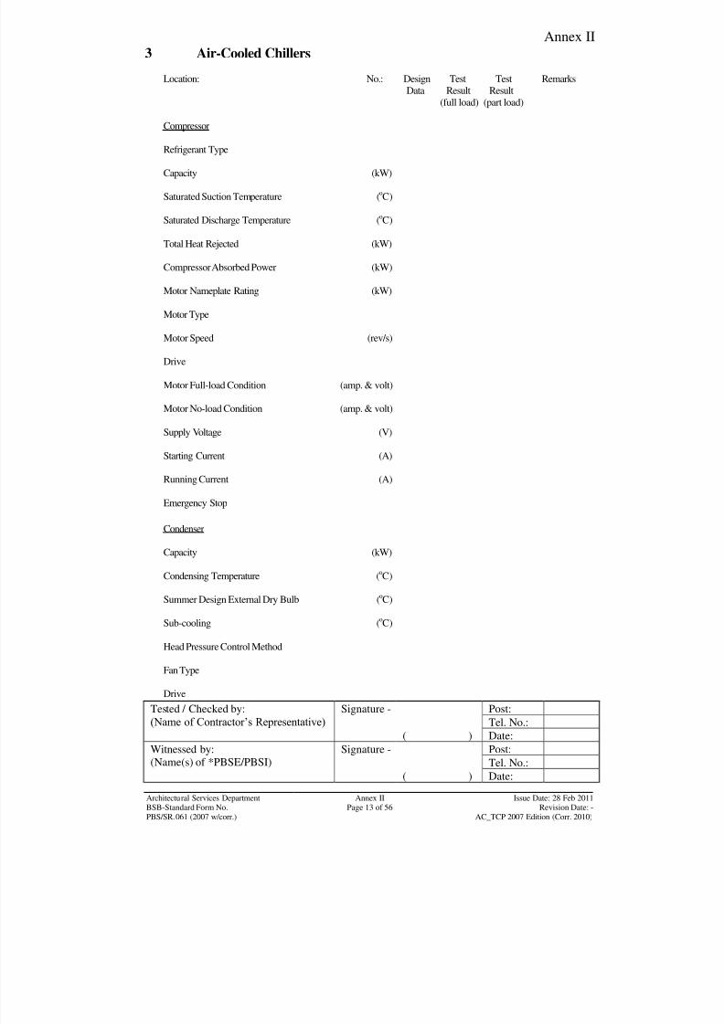
8/7/2019 Test Adjust and Balancing (See 233)
http://slidepdf.com/reader/full/test-adjust-and-balancing-see-233 176/247
Annex II
Tested / Checked by:
(Name of Contractor‟s Representative) Signature - Post:
Tel. No.:
( ) Date:
Witnessed by:
(Name(s) of *PBSE/PBSI)
Signature - Post:
Tel. No.:( ) Date:
Architectural Services Department Annex II Issue Date: 28 Feb 2011BSB-Standard Form No. Page 13 of 56 Revision Date: -
PBS/SR.061 (2007 w/corr.) AC_TCP 2007 Edition (Corr. 2010)
3 Air-Cooled Chillers
Location: No.: Design Test Test Remarks
Data Result Result
(full load) (part load)
Compressor
Refrigerant Type
Capacity (kW)
Saturated Suction Temperature (oC)
Saturated Discharge Temperature (oC)
Total Heat Rejected (kW)
Compressor Absorbed Power (kW)
Motor Nameplate Rating (kW)
Motor Type
Motor Speed (rev/s)
Drive
Motor Full-load Condition (amp. & volt)
Motor No-load Condition (amp. & volt)
Supply Voltage (V)
Starting Current (A)
Running Current (A)
Emergency Stop
Condenser
Capacity (kW)
Condensing Temperature (oC)
Summer Design External Dry Bulb (oC)
Sub-cooling (oC)
Head Pressure Control Method
Fan Type
Drive
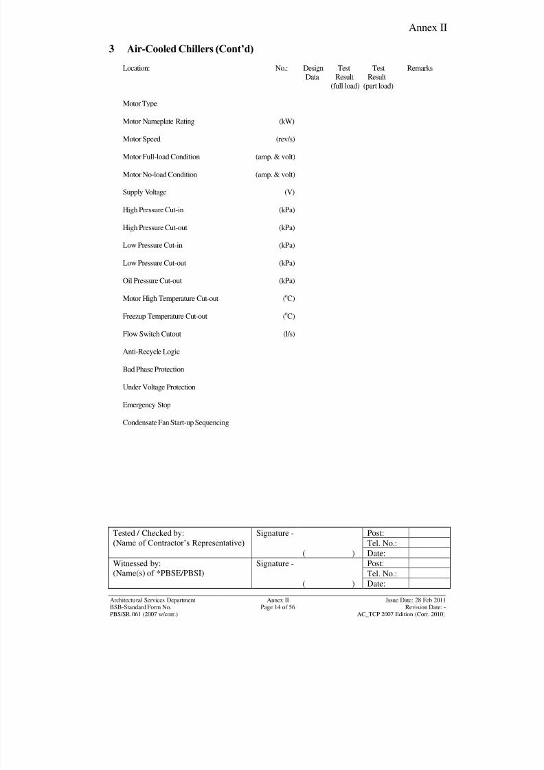
8/7/2019 Test Adjust and Balancing (See 233)
http://slidepdf.com/reader/full/test-adjust-and-balancing-see-233 177/247
Annex II
Tested / Checked by:
(Name of Contractor‟s Representative) Signature - Post:
Tel. No.:
( ) Date:
Witnessed by:
(Name(s) of *PBSE/PBSI)
Signature - Post:
Tel. No.:( ) Date:
Architectural Services Department Annex II Issue Date: 28 Feb 2011BSB-Standard Form No. Page 14 of 56 Revision Date: -
PBS/SR.061 (2007 w/corr.) AC_TCP 2007 Edition (Corr. 2010)
3 Air-Cooled Chillers (Cont’d)
Location: No.: Design Test Test Remarks
Data Result Result
(full load) (part load)
Motor Type
Motor Nameplate Rating (kW)
Motor Speed (rev/s)
Motor Full-load Condition (amp. & volt)
Motor No-load Condition (amp. & volt)
Supply Voltage (V)
High Pressure Cut-in (kPa)
High Pressure Cut-out (kPa)
Low Pressure Cut-in (kPa)
Low Pressure Cut-out (kPa)
Oil Pressure Cut-out (kPa)
Motor High Temperature Cut-out (oC)
Freezup Temperature Cut-out (oC)
Flow Switch Cutout (l/s)
Anti-Recycle Logic
Bad Phase Protection
Under Voltage Protection
Emergency Stop
Condensate Fan Start-up Sequencing
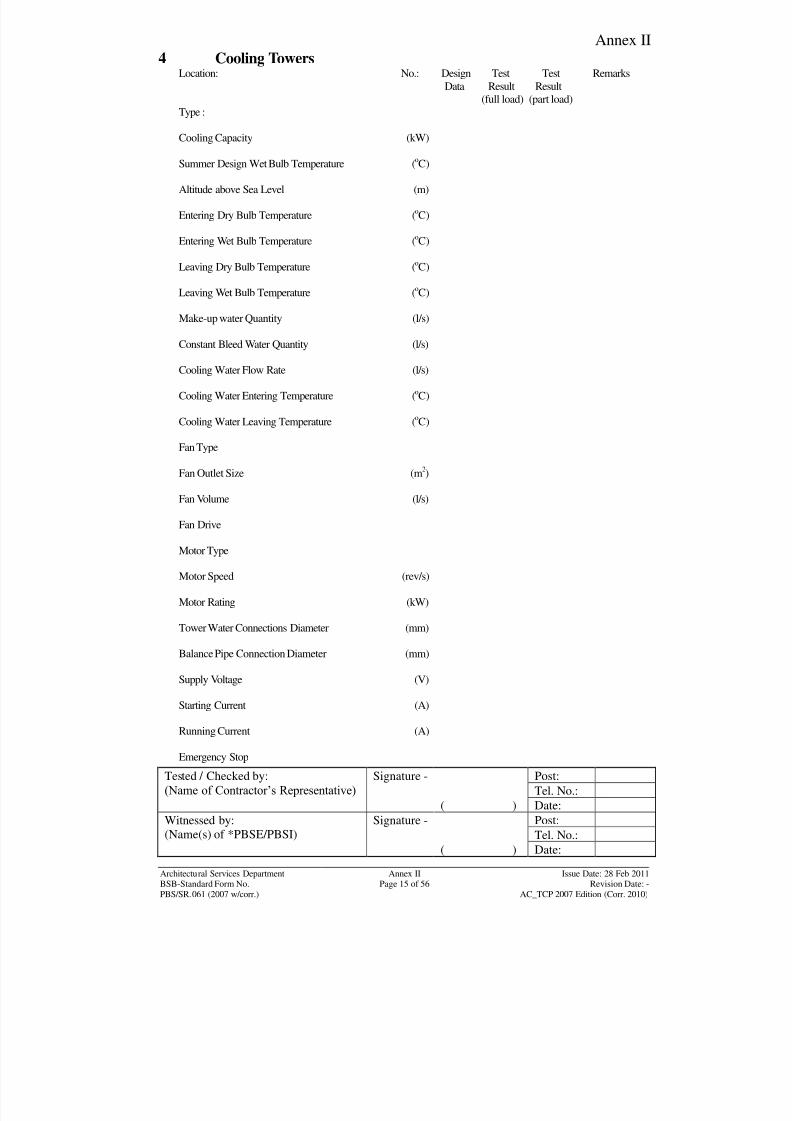
8/7/2019 Test Adjust and Balancing (See 233)
http://slidepdf.com/reader/full/test-adjust-and-balancing-see-233 178/247
Annex II
Tested / Checked by:
(Name of Contractor‟s Representative) Signature - Post:
Tel. No.:
( ) Date:
Witnessed by:
(Name(s) of *PBSE/PBSI)
Signature - Post:
Tel. No.:( ) Date:
Architectural Services Department Annex II Issue Date: 28 Feb 2011BSB-Standard Form No. Page 15 of 56 Revision Date: -
PBS/SR.061 (2007 w/corr.) AC_TCP 2007 Edition (Corr. 2010)
4 Cooling TowersLocation: No.: Design Test Test Remarks
Data Result Result
(full load) (part load)
Type :
Cooling Capacity (kW)
Summer Design Wet Bulb Temperature (o
C)
Altitude above Sea Level (m)
Entering Dry Bulb Temperature (oC)
Entering Wet Bulb Temperature (oC)
Leaving Dry Bulb Temperature (oC)
Leaving Wet Bulb Temperature (oC)
Make-up water Quantity (l/s)
Constant Bleed Water Quantity (l/s)
Cooling Water Flow Rate (l/s)
Cooling Water Entering Temperature (oC)
Cooling Water Leaving Temperature (oC)
Fan Type
Fan Outlet Size (m2)
Fan Volume (l/s)
Fan Drive
Motor Type
Motor Speed (rev/s)
Motor Rating (kW)
Tower Water Connections Diameter (mm)
Balance Pipe Connection Diameter (mm)
Supply Voltage (V)
Starting Current (A)
Running Current (A)
Emergency Stop
8/7/2019 Test Adjust and Balancing (See 233)
http://slidepdf.com/reader/full/test-adjust-and-balancing-see-233 179/247
Annex II
Tested / Checked by:
(Name of Contractor‟s Representative) Signature - Post:
Tel. No.:
( ) Date:
Witnessed by:
(Name(s) of *PBSE/PBSI)
Signature - Post:
Tel. No.:( ) Date:
Architectural Services Department Annex II Issue Date: 28 Feb 2011BSB-Standard Form No. Page 16 of 56 Revision Date: -
PBS/SR.061 (2007 w/corr.) AC_TCP 2007 Edition (Corr. 2010)
5 Pumps
Location: No.: Design Test Test Remarks
Data Result Result
(full load) (part load)
Volume Flow Rate (l/s)
No Flow Head (kPa)
Full Flow Discharge Head (kPa)
Full Suction Pressure (kPa)
Full Flow Differential (kPa)
Impeller Diameter (mm)
Motor Type
Motor Speed (rev/s)
Rated Power (kW)
Motor Full-load Condition (amp. & volt)
Supply Voltage (V)
Starting Current (A)
Running Current (A)
Overload Setting (A)
Tripping Time of Starter Overload (S)
Auto-changeover *Yes/No/N.A. *Yes/No/N.A.
Emergency Stop *Yes/No/N.A. *Yes/No/N.A.
Low Level Cut-in *Yes/No/N.A. *Yes/No/N.A.
Low Level Cut-out *Yes/No/N.A. *Yes/No/N.A.
High Level Cut-out *Yes/No/N.A. *Yes/No/N.A.
Horn Buzzer *Yes/No/N.A. *Yes/No/N.A.
Lamp Test Button *Yes/No/N.A. *Yes/No/N.A.
Degree of Protection of Enclosures (IP) *Yes/No/N.A. *Yes/No/N.A.
8/7/2019 Test Adjust and Balancing (See 233)
http://slidepdf.com/reader/full/test-adjust-and-balancing-see-233 180/247
Annex II
Tested / Checked by:
(Name of Contractor‟s Representative) Signature - Post:
Tel. No.:
( ) Date:
Witnessed by:
(Name(s) of *PBSE/PBSI)
Signature - Post:
Tel. No.:( ) Date:
Architectural Services Department Annex II Issue Date: 28 Feb 2011BSB-Standard Form No. Page 17 of 56 Revision Date: -
PBS/SR.061 (2007 w/corr.) AC_TCP 2007 Edition (Corr. 2010)
6 Pump Alignment Test
Location: _____________________________
Ref. No.: _____________________________
Rim Check Reading Face Check ReadingT B L R T B L R
Pump No.
Pump No.
Pump No.
Pump No.
Remarks:
T : Top ReadingB : Bottom Reading
L : Left Hand Side Reading
R : Right Hand Side Reading
Maximum allowable misalignments refer to the recommendation by
General Specification or Manufacture‟s Recommendation.

8/7/2019 Test Adjust and Balancing (See 233)
http://slidepdf.com/reader/full/test-adjust-and-balancing-see-233 181/247
Annex II
Tested / Checked by:
(Name of Contractor‟s Representative) Signature - Post:
Tel. No.:
( ) Date:
Witnessed by:
(Name(s) of *PBSE/PBSI)
Signature - Post:
Tel. No.:( ) Date:
Architectural Services Department Annex II Issue Date: 28 Feb 2011BSB-Standard Form No. Page 18 of 56 Revision Date: -
PBS/SR.061 (2007 w/corr.) AC_TCP 2007 Edition (Corr. 2010)
7 Air Handling Units
Location: No.: Design Test Test Remarks
Data Result Result
(full load) (part load)
Outdoor Air Condition
Dry Bulb Temperature (o
C)
Wet Bulb Temperature (oC)
Time of Day (Hrs)
Condition (Cloudy/Sunny)
Total Air Quantity (l/s)
Fresh Air Quantity (Minimum) (l/s)
Fresh Air Quantity (Maximum) (l/s)
Smoke Detector *Yes/No/N.A. *Yes/No/N.A.
Fan
Type
Speed (r/s)
Drive
Driven Belt (Type/No.)
Inlet pressure (kPa)
Discharge pressure (kPa)
Fan Static Pressure (kPa)
(Discharge - Inlet)
Supply Voltage (V)
Overload Setting (A)
Tripping Time of Overload (S)
Starting Current (A)
Running Current (A)
Rated Power (kW)
Emergency Stop

8/7/2019 Test Adjust and Balancing (See 233)
http://slidepdf.com/reader/full/test-adjust-and-balancing-see-233 182/247
Annex II
Tested / Checked by:
(Name of Contractor‟s Representative) Signature - Post:
Tel. No.:
( ) Date:
Witnessed by:
(Name(s) of *PBSE/PBSI)
Signature - Post:
Tel. No.:( ) Date:
Architectural Services Department Annex II Issue Date: 28 Feb 2011BSB-Standard Form No. Page 19 of 56 Revision Date: -
PBS/SR.061 (2007 w/corr.) AC_TCP 2007 Edition (Corr. 2010)
7 Air Handling Units (Cont’d)
Location: No.: Design Test Test Remarks
Data Result Result
(full load) (part load)
Filter
Type :
Inlet Pressure (kPa)
Outlet Pressure (kPa)
Effective Area (m2)
Velocity (m/s)
Cleanliness
Alarm Buzzer
Filter Clogged Light
Cooling Coil
Entering Air Dry Bulb Temperature (oC)
Entering Air Wet Bulb Temperature (oC)
Leaving Air Dry Bulb Temperature (oC)
Leaving Air Wet Bulb Temperature (oC)
Entering Water Temperature (o
C)
Leaving Water Temperature (oC)
Entering Water Pressure (kPa)
Leaving Water Pressure (kPa)
Water Quantity (l/s)
Evaporator Suction Pressure (kPa)
Evaporator Suction Temperature (oC)
Evaporator Discharge Pressure (kPa)
Evaporator Discharge Temperature (oC)
Effective Area (m2)
Velocity (m/s)
8/7/2019 Test Adjust and Balancing (See 233)
http://slidepdf.com/reader/full/test-adjust-and-balancing-see-233 183/247
Annex II
Tested / Checked by:
(Name of Contractor‟s Representative) Signature - Post:
Tel. No.:
( ) Date:
Witnessed by:
(Name(s) of *PBSE/PBSI)
Signature - Post:
Tel. No.:( ) Date:
Architectural Services Department Annex II Issue Date: 28 Feb 2011BSB-Standard Form No. Page 20 of 56 Revision Date: -
PBS/SR.061 (2007 w/corr.) AC_TCP 2007 Edition (Corr. 2010)
7 Air Handling Units (Cont’d)
Location: No.: Design Test Test Remarks
Data Result Result
(full load) (part load)
Heating Coil (Medium)
Entering Air Dry Bulb Temperature (o
C)
Leaving Air Dry Bulb Temperature (oC)
Effective Area (m2)
Velocity (m/s)
Entering Water Temperature (oC)
Leaving Water Temperature (oC)
Entering Water Pressure (kPa)
Leaving Water Pressure (kPa)
Water Quantity (l/s)
No. of steps
Capacity of Each Steps (kW)
Air Quantity (l/s)
8/7/2019 Test Adjust and Balancing (See 233)
http://slidepdf.com/reader/full/test-adjust-and-balancing-see-233 184/247
Annex II
Tested / Checked by:
(Name of Contractor‟s Representative) Signature - Post:
Tel. No.:
( ) Date:
Witnessed by:
(Name(s) of *PBSE/PBSI)
Signature - Post:
Tel. No.:( ) Date:
Architectural Services Department Annex II Issue Date: 28 Feb 2011BSB-Standard Form No. Page 21 of 56 Revision Date: -
PBS/SR.061 (2007 w/corr.) AC_TCP 2007 Edition (Corr. 2010)
8 Heating Coils (Not included in Air Handling Unit)
Location: No.: Design Test Test Remarks
Data Result Result
(full load) (part load)
Medium
Entering Air Dry Bulb Temperature (o
C)
Leaving Air Dry Bulb Temperature (oC)
Effective Area (m2)
Velocity (m/s)
Air Quantity (l/s)
Entering Water Pressure (kPa)
Leaving Water Pressure (kPa)
Water Quantity (l/s)
Capacity of Coil (kW)
No. of Steps
Capacity of Each Step (kW)
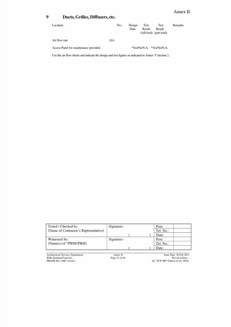
8/7/2019 Test Adjust and Balancing (See 233)
http://slidepdf.com/reader/full/test-adjust-and-balancing-see-233 185/247
Annex II
Tested / Checked by:
(Name of Contractor‟s Representative) Signature - Post:
Tel. No.:
( ) Date:
Witnessed by:
(Name(s) of *PBSE/PBSI)
Signature - Post:
Tel. No.:( ) Date:
Architectural Services Department Annex II Issue Date: 28 Feb 2011BSB-Standard Form No. Page 22 of 56 Revision Date: -
PBS/SR.061 (2007 w/corr.) AC_TCP 2007 Edition (Corr. 2010)
9 Ducts, Grilles, Diffusers, etc.
Location: No.: Design Test Test Remarks
Data Result Result
(full load) (part load)
Air flow rate (l/s)
Access Panel for maintenance provided *Yes/No/N.A. *Yes/No/N.A.
Use the air flow sheets and indicate the design and test figures as indicated in Annex V Section 2.
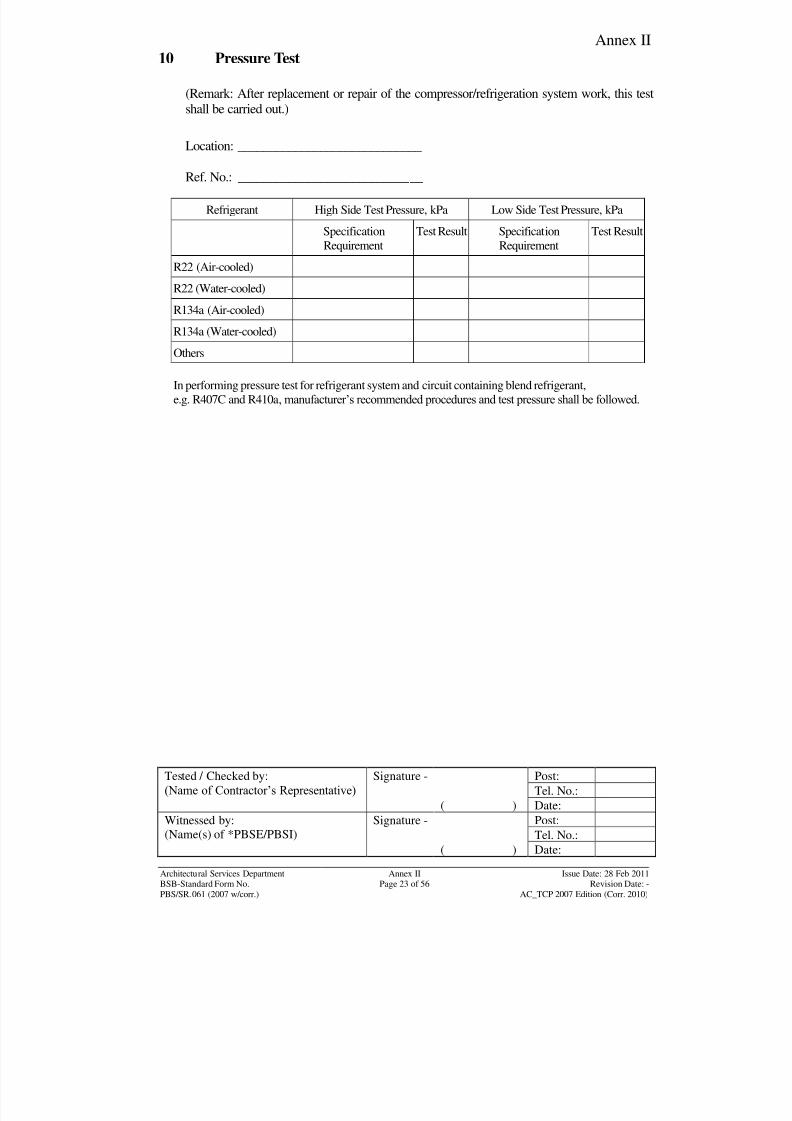
8/7/2019 Test Adjust and Balancing (See 233)
http://slidepdf.com/reader/full/test-adjust-and-balancing-see-233 186/247
Annex II
Tested / Checked by:
(Name of Contractor‟s Representative) Signature - Post:
Tel. No.:
( ) Date:
Witnessed by:
(Name(s) of *PBSE/PBSI)
Signature - Post:
Tel. No.:( ) Date:
Architectural Services Department Annex II Issue Date: 28 Feb 2011BSB-Standard Form No. Page 23 of 56 Revision Date: -
PBS/SR.061 (2007 w/corr.) AC_TCP 2007 Edition (Corr. 2010)
10 Pressure Test
(Remark: After replacement or repair of the compressor/refrigeration system work, this test
shall be carried out.)
Location: _____________________________
Ref. No.: _____________________________
Refrigerant High Side Test Pressure, kPa Low Side Test Pressure, kPa
Specification
Requirement
Test Result Specification
Requirement
Test Result
R22 (Air-cooled)
R22 (Water-cooled)
R134a (Air-cooled)
R134a (Water-cooled)
Others
In performing pressure test for refrigerant system and circuit containing blend refrigerant,
e.g. R407C and R410a, manufacturer‟s recommended procedures and test pressure shall be followed.
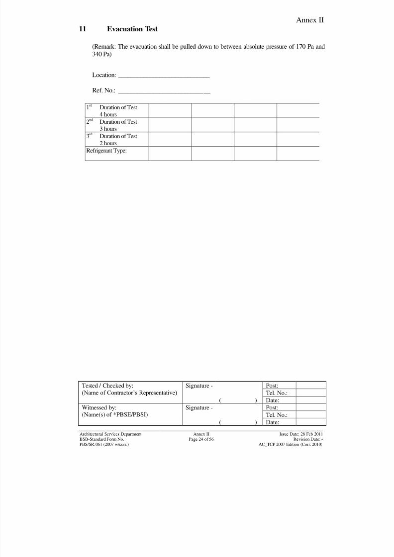
8/7/2019 Test Adjust and Balancing (See 233)
http://slidepdf.com/reader/full/test-adjust-and-balancing-see-233 187/247
Annex II
Tested / Checked by:
(Name of Contractor‟s Representative) Signature - Post:
Tel. No.:
( ) Date:
Witnessed by:
(Name(s) of *PBSE/PBSI)
Signature - Post:
Tel. No.:( ) Date:
Architectural Services Department Annex II Issue Date: 28 Feb 2011BSB-Standard Form No. Page 24 of 56 Revision Date: -
PBS/SR.061 (2007 w/corr.) AC_TCP 2007 Edition (Corr. 2010)
11 Evacuation Test
(Remark: The evacuation shall be pulled down to between absolute pressure of 170 Pa and
340 Pa)
Location: _____________________________
Ref. No.: _____________________________
1st
Duration of Test
4 hours
2nd
Duration of Test
3 hours
3rd
Duration of Test
2 hours
Refrigerant Type:
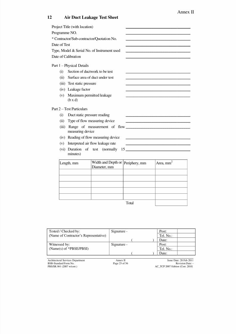
8/7/2019 Test Adjust and Balancing (See 233)
http://slidepdf.com/reader/full/test-adjust-and-balancing-see-233 188/247
Annex II
Tested / Checked by:
(Name of Contractor‟s Representative) Signature - Post:
Tel. No.:
( ) Date:
Witnessed by:
(Name(s) of *PBSE/PBSI)
Signature - Post:
Tel. No.:( ) Date:
Architectural Services Department Annex II Issue Date: 28 Feb 2011BSB-Standard Form No. Page 25 of 56 Revision Date: -
PBS/SR.061 (2007 w/corr.) AC_TCP 2007 Edition (Corr. 2010)
12 Air Duct Leakage Test Sheet
Project Title (with location) __________________________________
Programme NO. __________________________________
* Contractor/Sub-contractor/Quotation No. __________________________________
Date of Test __________________________________
Type, Model & Serial No. of Instrument used __________________________________
Date of Calibration __________________________________
Part 1 – Physical Details
(i) Section of ductwork to be test __________________________________
(ii) Surface area of duct under test __________________________________
(iii) Test static pressure __________________________________
(iv) Leakage factor __________________________________
(v) Maximum permitted leakage
(b x d)
__________________________________
Part 2 – Test Particulars
(i) Duct static pressure reading __________________________________
(ii) Type of flow measuring device __________________________________
(iii) Range of measurement of flow
measuring device
__________________________________
(iv) Reading of flow measuring device __________________________________
(v) Interpreted air flow leakage rate __________________________________
(vi) Duration of test (normally 15minutes)
__________________________________
Length, mm Width and Depth or
Diameter, mmPeriphery, mm Area, mm
2
Total
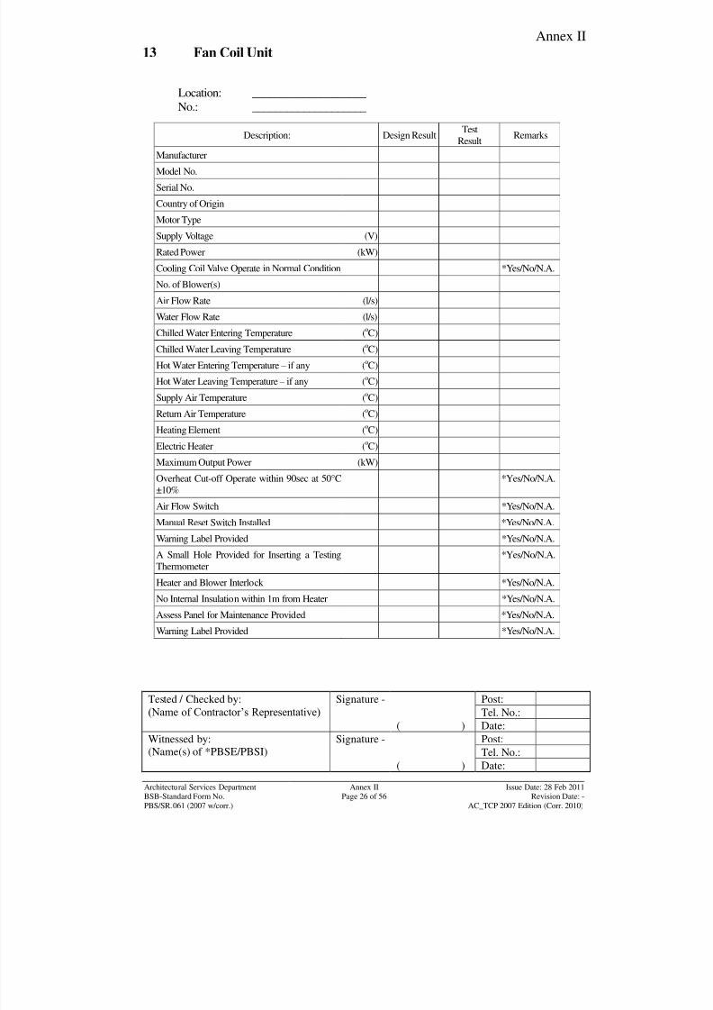
8/7/2019 Test Adjust and Balancing (See 233)
http://slidepdf.com/reader/full/test-adjust-and-balancing-see-233 189/247
Annex II
Tested / Checked by:
(Name of Contractor‟s Representative) Signature - Post:
Tel. No.:
( ) Date:
Witnessed by:
(Name(s) of *PBSE/PBSI)
Signature - Post:
Tel. No.:( ) Date:
Architectural Services Department Annex II Issue Date: 28 Feb 2011BSB-Standard Form No. Page 26 of 56 Revision Date: -
PBS/SR.061 (2007 w/corr.) AC_TCP 2007 Edition (Corr. 2010)
13 Fan Coil Unit
Location: ____________________
No.: ____________________
Description: Design ResultTest
ResultRemarks
Manufacturer
Model No.
Serial No.
Country of Origin
Motor Type
Supply Voltage (V)
Rated Power (kW)
Cooling Coil Valve Operate in Normal Condition *Yes/No/N.A.
No. of Blower(s)
Air Flow Rate (l/s)
Water Flow Rate (l/s)
Chilled Water Entering Temperature (oC)
Chilled Water Leaving Temperature (oC)
Hot Water Entering Temperature – if any (oC)
Hot Water Leaving Temperature – if any (oC)
Supply Air Temperature (oC)
Return Air Temperature (oC)
Heating Element (oC)
Electric Heater (
o
C)Maximum Output Power (kW)
Overheat Cut-off Operate within 90sec at 50°C
±10%
*Yes/No/N.A.
Air Flow Switch *Yes/No/N.A.
Manual Reset Switch Installed *Yes/No/N.A.
Warning Label Provided *Yes/No/N.A.
A Small Hole Provided for Inserting a Testing
Thermometer
*Yes/No/N.A.
Heater and Blower Interlock *Yes/No/N.A.
No Internal Insulation within 1m from Heater *Yes/No/N.A.Assess Panel for Maintenance Provided *Yes/No/N.A.
Warning Label Provided *Yes/No/N.A.
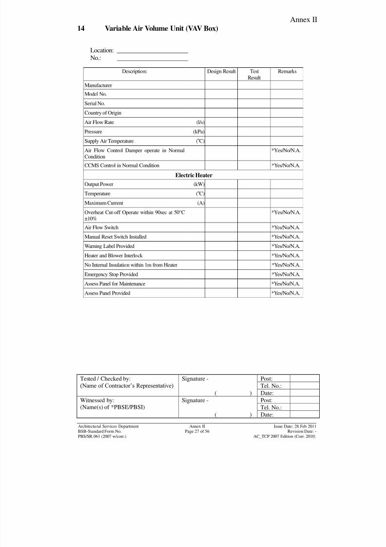
8/7/2019 Test Adjust and Balancing (See 233)
http://slidepdf.com/reader/full/test-adjust-and-balancing-see-233 190/247
Annex II
Tested / Checked by:
(Name of Contractor‟s Representative) Signature - Post:
Tel. No.:
( ) Date:
Witnessed by:
(Name(s) of *PBSE/PBSI)
Signature - Post:
Tel. No.:( ) Date:
Architectural Services Department Annex II Issue Date: 28 Feb 2011BSB-Standard Form No. Page 27 of 56 Revision Date: -
PBS/SR.061 (2007 w/corr.) AC_TCP 2007 Edition (Corr. 2010)
14 Variable Air Volume Unit (VAV Box)
Location: _______________________
No.: _______________________
Description: Design Result Test
Result
Remarks
Manufacturer
Model No.
Serial No.
Country of Origin
Air Flow Rate (l/s)
Pressure (kPa)
Supply Air Temperature (oC)
Air Flow Control Damper operate in Normal
Condition
*Yes/No/N.A.
CCMS Control in Normal Condition *Yes/No/N.A.
Electric Heater
Output Power (kW)
Temperature (oC)
Maximum Current (A)
Overheat Cut-off Operate within 90sec at 50°C
±10%
*Yes/No/N.A.
Air Flow Switch *Yes/No/N.A.
Manual Reset Switch Installed *Yes/No/N.A.
Warning Label Provided *Yes/No/N.A.
Heater and Blower Interlock *Yes/No/N.A.
No Internal Insulation within 1m from Heater *Yes/No/N.A.
Emergency Stop Provided *Yes/No/N.A.
Assess Panel for Maintenance *Yes/No/N.A.
Assess Panel Provided *Yes/No/N.A.
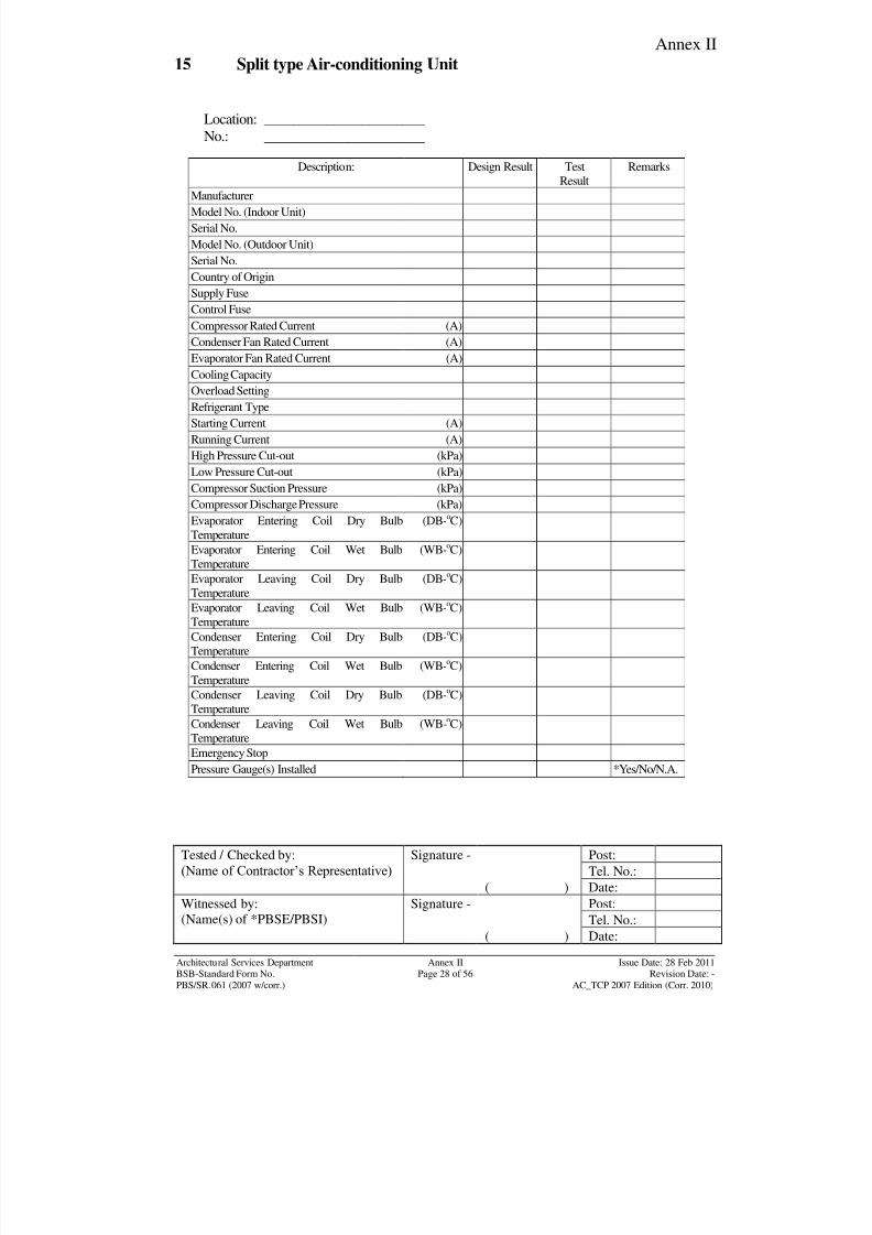
8/7/2019 Test Adjust and Balancing (See 233)
http://slidepdf.com/reader/full/test-adjust-and-balancing-see-233 191/247
Annex II
Tested / Checked by:
(Name of Contractor‟s Representative) Signature - Post:
Tel. No.:
( ) Date:
Witnessed by:
(Name(s) of *PBSE/PBSI)
Signature - Post:
Tel. No.:( ) Date:
Architectural Services Department Annex II Issue Date: 28 Feb 2011BSB-Standard Form No. Page 28 of 56 Revision Date: -
PBS/SR.061 (2007 w/corr.) AC_TCP 2007 Edition (Corr. 2010)
15 Split type Air-conditioning Unit
Location: _______________________
No.: _______________________
Description: Design Result Test
Result
Remarks
Manufacturer
Model No. (Indoor Unit)
Serial No.
Model No. (Outdoor Unit)
Serial No.
Country of Origin
Supply Fuse
Control Fuse
Compressor Rated Current (A)
Condenser Fan Rated Current (A)
Evaporator Fan Rated Current (A)
Cooling Capacity
Overload Setting
Refrigerant Type
Starting Current (A)
Running Current (A)
High Pressure Cut-out (kPa)
Low Pressure Cut-out (kPa)
Compressor Suction Pressure (kPa)
Compressor Discharge Pressure (kPa)
Evaporator Entering Coil Dry Bulb
Temperature
(DB-oC)
Evaporator Entering Coil Wet BulbTemperature
(WB-o
C)
Evaporator Leaving Coil Dry Bulb
Temperature
(DB-oC)
Evaporator Leaving Coil Wet Bulb
Temperature
(WB-oC)
Condenser Entering Coil Dry Bulb
Temperature
(DB-oC)
Condenser Entering Coil Wet Bulb
Temperature
(WB-oC)
Condenser Leaving Coil Dry Bulb
Temperature
(DB-oC)
Condenser Leaving Coil Wet Bulb
Temperature
(WB-oC)
Emergency Stop
Pressure Gauge(s) Installed *Yes/No/N.A.
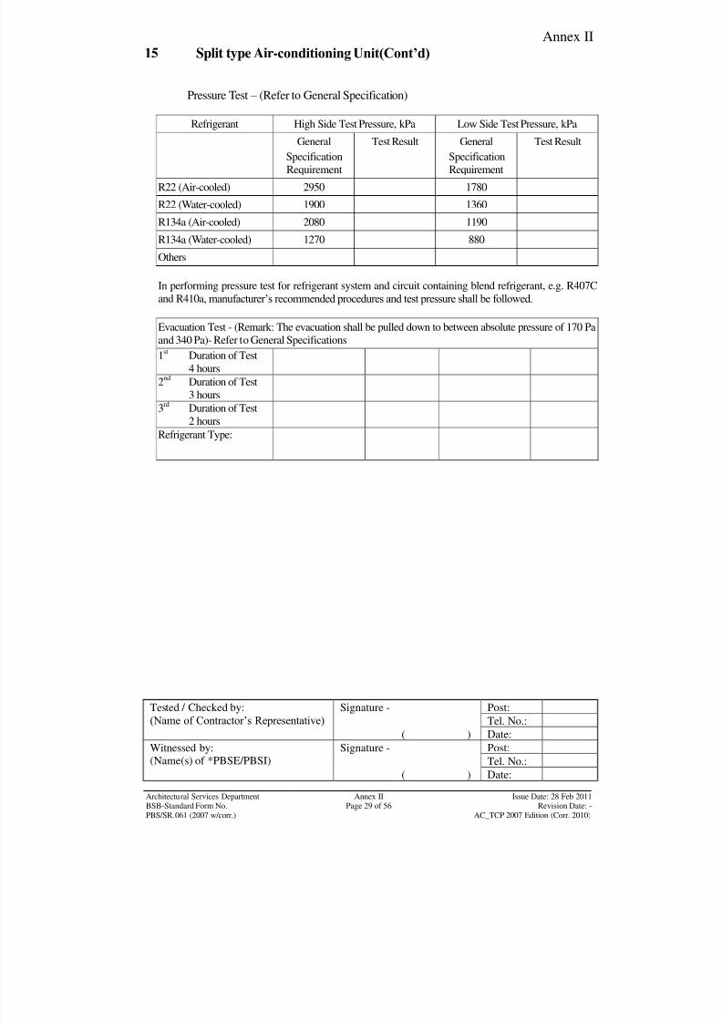
8/7/2019 Test Adjust and Balancing (See 233)
http://slidepdf.com/reader/full/test-adjust-and-balancing-see-233 192/247
Annex II
Tested / Checked by:
(Name of Contractor‟s Representative) Signature - Post:
Tel. No.:
( ) Date:
Witnessed by:
(Name(s) of *PBSE/PBSI)
Signature - Post:
Tel. No.:( ) Date:
Architectural Services Department Annex II Issue Date: 28 Feb 2011BSB-Standard Form No. Page 29 of 56 Revision Date: -
PBS/SR.061 (2007 w/corr.) AC_TCP 2007 Edition (Corr. 2010)
15 Split type Air-conditioning Unit(Cont’d)
Pressure Test – (Refer to General Specification)
Refrigerant High Side Test Pressure, kPa Low Side Test Pressure, kPa
General
Specification
Requirement
Test Result General
Specification
Requirement
Test Result
R22 (Air-cooled) 2950 1780
R22 (Water-cooled) 1900 1360
R134a (Air-cooled) 2080 1190
R134a (Water-cooled) 1270 880
Others
In performing pressure test for refrigerant system and circuit containing blend refrigerant, e.g. R407C
and R410a, manufacturer‟s recommended procedures and test pressure shall be followed.
Evacuation Test - (Remark: The evacuation shall be pulled down to between absolute pressure of 170 Pa
and 340 Pa)- Refer to General Specifications
1st
Duration of Test
4 hours
2nd
Duration of Test
3 hours
3rd
Duration of Test
2 hours
Refrigerant Type:

8/7/2019 Test Adjust and Balancing (See 233)
http://slidepdf.com/reader/full/test-adjust-and-balancing-see-233 193/247
Annex II
Tested / Checked by:
(Name of Contractor‟s Representative) Signature - Post:
Tel. No.:
( ) Date:
Witnessed by:
(Name(s) of *PBSE/PBSI)
Signature - Post:
Tel. No.:( ) Date:
Architectural Services Department Annex II Issue Date: 28 Feb 2011BSB-Standard Form No. Page 30 of 56 Revision Date: -
PBS/SR.061 (2007 w/corr.) AC_TCP 2007 Edition (Corr. 2010)
16 Variable Refrigerant Volume System (VRV)
Manufacturer: Location
Air Distribution System:
Pressure testing of pipe servicing system or any section of a
completed system, shall be completed prior to the application of
any thermal insulation to the cleaned pipe surfaces. The pressuretest for this system is recommended by the Manufacturer‟s.
*Yes/No/N.A *Yes/No/N.A
The system is required to vacuum by a vacuum pump. *Yes/No/N.A *Yes/No/N.A
Add the refrigerant to the indoor unit through the refrigerant pipe. *Yes/No/N.A *Yes/No/N.A
The refrigerant is extracted by the new vacuum pump. *Yes/No/N.A *Yes/No/N.A
Refrigerant High Side Test Pressure, kPa Low Side Test Pressure, kPa
General
Specification
Requirement
Test Result General
Specification
Requirement
Test Result
R22 (Air-cooled) 2950 1780
R22 (Water-cooled) 1900 1360
R134a (Air-cooled) 2080 1190
R134a (Water-cooled) 1270 880
Others
In performing pressure test for refrigerant system and circuit containing blend refrigerant, e.g. R407C
and R410a, manufacturer‟s recommended procedures and test pressure shall be followed.
Evacuation Test - (Remark: The evacuation shall be pulled down to between 170 Pa absolute and 340 Pa
absolute)- Refer to General Specifications
1st
Duration of Test
4 hours
2nd
Duration of Test3 hours
3rd
Duration of Test
2 hours
Refrigerant Type:
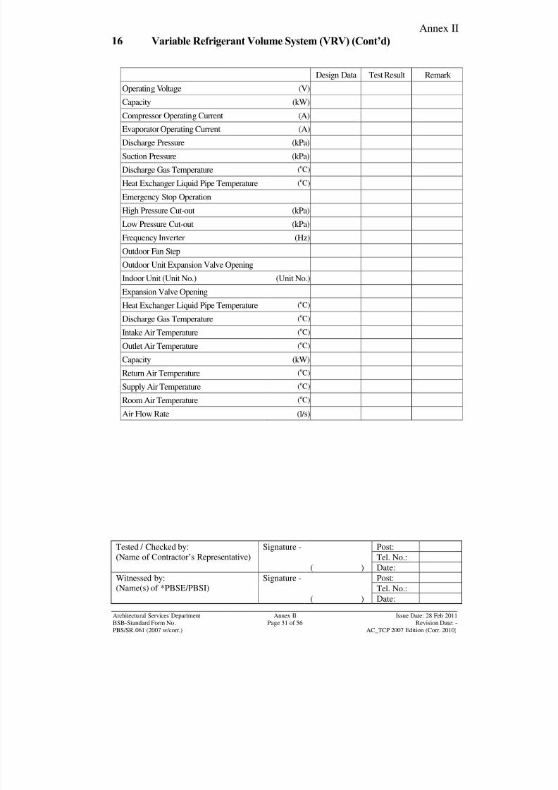
8/7/2019 Test Adjust and Balancing (See 233)
http://slidepdf.com/reader/full/test-adjust-and-balancing-see-233 194/247
Annex II
Tested / Checked by:
(Name of Contractor‟s Representative) Signature - Post:
Tel. No.:
( ) Date:
Witnessed by:
(Name(s) of *PBSE/PBSI)
Signature - Post:
Tel. No.:( ) Date:
Architectural Services Department Annex II Issue Date: 28 Feb 2011BSB-Standard Form No. Page 31 of 56 Revision Date: -
PBS/SR.061 (2007 w/corr.) AC_TCP 2007 Edition (Corr. 2010)
16 Variable Refrigerant Volume System (VRV) (Cont’d)
Design Data Test Result Remark
Operating Voltage (V)
Capacity (kW)
Compressor Operating Current (A)Evaporator Operating Current (A)
Discharge Pressure (kPa)
Suction Pressure (kPa)
Discharge Gas Temperature (oC)
Heat Exchanger Liquid Pipe Temperature (oC)
Emergency Stop Operation
High Pressure Cut-out (kPa)
Low Pressure Cut-out (kPa)
Frequency Inverter (Hz)
Outdoor Fan Step
Outdoor Unit Expansion Valve Opening
Indoor Unit (Unit No.) (Unit No.)
Expansion Valve Opening
Heat Exchanger Liquid Pipe Temperature (oC)
Discharge Gas Temperature (oC)
Intake Air Temperature (oC)
Outlet Air Temperature (oC)
Capacity (kW)
Return Air Temperature (oC)
Supply Air Temperature (oC)
Room Air Temperature (oC)
Air Flow Rate (l/s)
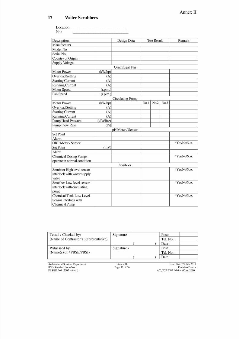
8/7/2019 Test Adjust and Balancing (See 233)
http://slidepdf.com/reader/full/test-adjust-and-balancing-see-233 195/247
Annex II
Tested / Checked by:
(Name of Contractor‟s Representative) Signature - Post:
Tel. No.:
( ) Date:
Witnessed by:
(Name(s) of *PBSE/PBSI)
Signature - Post:
Tel. No.:( ) Date:
Architectural Services Department Annex II Issue Date: 28 Feb 2011BSB-Standard Form No. Page 32 of 56 Revision Date: -
PBS/SR.061 (2007 w/corr.) AC_TCP 2007 Edition (Corr. 2010)
17 Water Scrubbers
Location: _____________________________
No.: ________________________________
Description: Design Data Test Result Remark
Manufacturer
Model No.Serial No.
Country of Origin
Supply Voltage
Centrifugal Fan
Motor Power (kW/hp)
Overload Setting (A)
Starting Current (A)
Running Current (A)
Motor Speed (r.p.m.)
Fan Speed (r.p.m.)
Circulating Pump
Motor Power (kW/hp) No.1 No.2 No.3
Overload Setting (A)
Starting Current (A)
Running Current (A)
Pump Head Pressure (kPa/Bar)
Pump Flow Rate (l/s)
pH Meter / Sensor
Set Point
Alarm
ORP Meter / Sensor *Yes/No/N.A.
Set Point (mV)
AlarmChemical Dosing Pumps
operate in normal condition
*Yes/No/N.A.
Scrubber
Scrubber High level sensor
interlock with water supply
valve
*Yes/No/N.A.
Scrubber Low level sensor
interlock with circulating
pump
*Yes/No/N.A.
Chemical Tank Low Level
Sensor interlock withChemical Pump
*Yes/No/N.A.
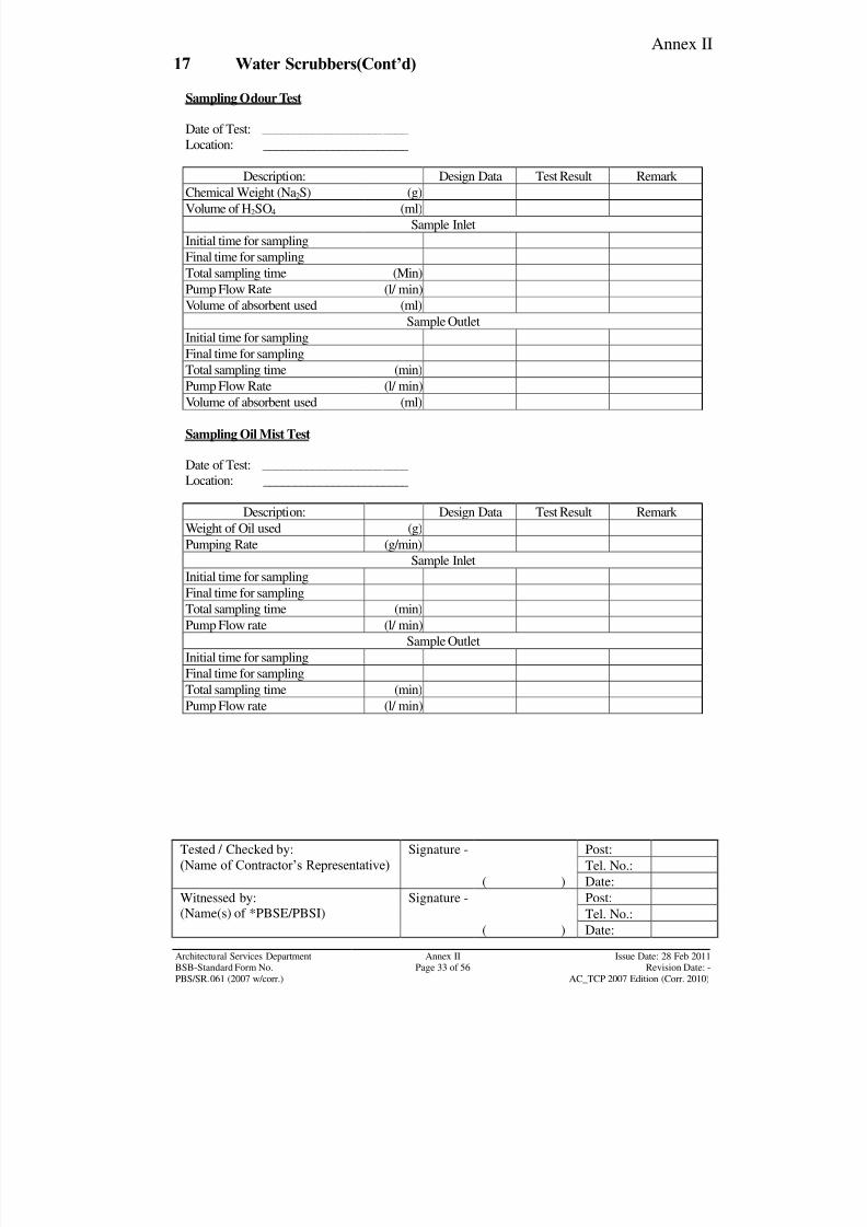
8/7/2019 Test Adjust and Balancing (See 233)
http://slidepdf.com/reader/full/test-adjust-and-balancing-see-233 196/247
Annex II
Tested / Checked by:
(Name of Contractor‟s Representative) Signature - Post:
Tel. No.:
( ) Date:
Witnessed by:
(Name(s) of *PBSE/PBSI)
Signature - Post:
Tel. No.:( ) Date:
Architectural Services Department Annex II Issue Date: 28 Feb 2011BSB-Standard Form No. Page 33 of 56 Revision Date: -
PBS/SR.061 (2007 w/corr.) AC_TCP 2007 Edition (Corr. 2010)
17 Water Scrubbers(Cont’d)
Sampling Odour Test
Date of Test: _______________________
Location: _______________________
Description: Design Data Test Result Remark Chemical Weight (Na2S) (g)
Volume of H2SO4 (ml)
Sample Inlet
Initial time for sampling
Final time for sampling
Total sampling time (Min)
Pump Flow Rate (l/ min)
Volume of absorbent used (ml)
Sample Outlet
Initial time for sampling
Final time for sampling
Total sampling time (min)
Pump Flow Rate (l/ min)
Volume of absorbent used (ml)
Sampling Oil Mist Test
Date of Test: _______________________
Location: _______________________
Description: Design Data Test Result Remark
Weight of Oil used (g)
Pumping Rate (g/min)Sample Inlet
Initial time for sampling
Final time for sampling
Total sampling time (min)
Pump Flow rate (l/ min)
Sample Outlet
Initial time for sampling
Final time for sampling
Total sampling time (min)
Pump Flow rate (l/ min)
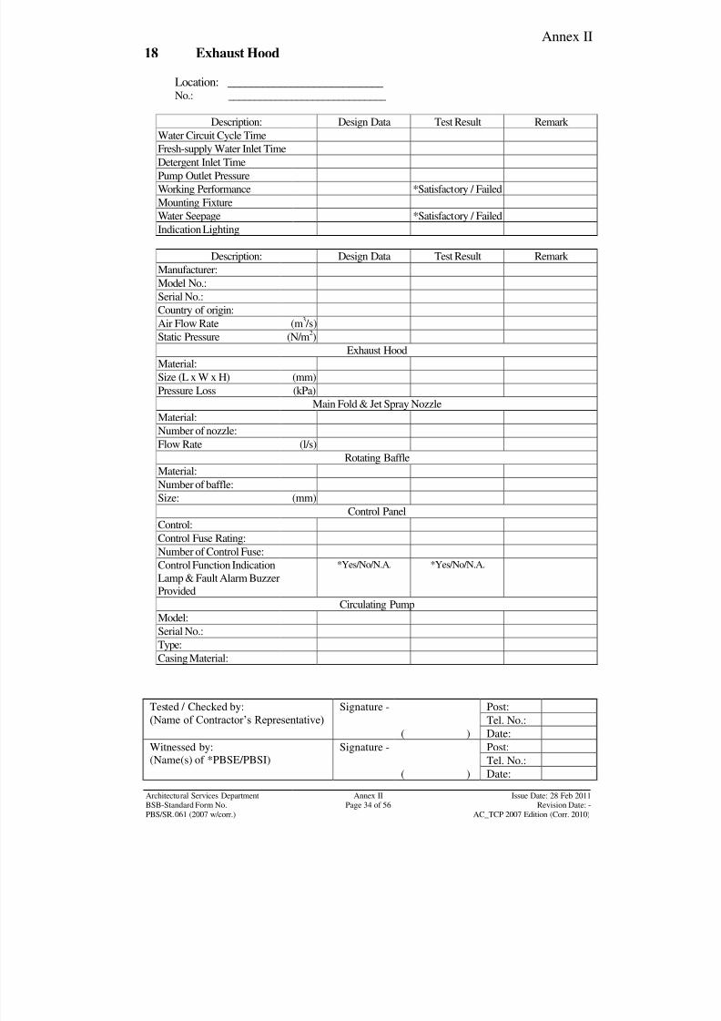
8/7/2019 Test Adjust and Balancing (See 233)
http://slidepdf.com/reader/full/test-adjust-and-balancing-see-233 197/247
Annex II
Tested / Checked by:
(Name of Contractor‟s Representative) Signature - Post:
Tel. No.:
( ) Date:
Witnessed by:
(Name(s) of *PBSE/PBSI)
Signature - Post:
Tel. No.:( ) Date:
Architectural Services Department Annex II Issue Date: 28 Feb 2011BSB-Standard Form No. Page 34 of 56 Revision Date: -
PBS/SR.061 (2007 w/corr.) AC_TCP 2007 Edition (Corr. 2010)
18 Exhaust Hood
Location: ___________________________
No.: ______________________________
Description: Design Data Test Result Remark
Water Circuit Cycle Time
Fresh-supply Water Inlet TimeDetergent Inlet Time
Pump Outlet Pressure
Working Performance *Satisfactory / Failed
Mounting Fixture
Water Seepage *Satisfactory / Failed
Indication Lighting
Description: Design Data Test Result Remark
Manufacturer:
Model No.:
Serial No.:
Country of origin:
Air Flow Rate (m3/s)
Static Pressure (N/m2)
Exhaust Hood
Material:
Size (L x W x H) (mm)
Pressure Loss (kPa)
Main Fold & Jet Spray Nozzle
Material:
Number of nozzle:
Flow Rate (l/s)
Rotating BaffleMaterial:
Number of baffle:
Size: (mm)
Control Panel
Control:
Control Fuse Rating:
Number of Control Fuse:
Control Function Indication
Lamp & Fault Alarm Buzzer
Provided
*Yes/No/N.A. *Yes/No/N.A.
Circulating PumpModel:
Serial No.:
Type:
Casing Material:
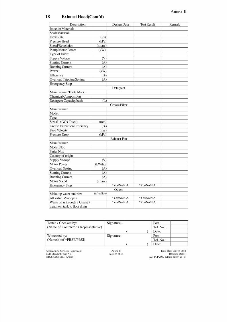
8/7/2019 Test Adjust and Balancing (See 233)
http://slidepdf.com/reader/full/test-adjust-and-balancing-see-233 198/247
Annex II
Tested / Checked by:
(Name of Contractor‟s Representative) Signature - Post:
Tel. No.:
( ) Date:
Witnessed by:
(Name(s) of *PBSE/PBSI)
Signature - Post:
Tel. No.:( ) Date:
Architectural Services Department Annex II Issue Date: 28 Feb 2011BSB-Standard Form No. Page 35 of 56 Revision Date: -
PBS/SR.061 (2007 w/corr.) AC_TCP 2007 Edition (Corr. 2010)
18 Exhaust Hood(Cont’d)
Description: Design Data Test Result Remark
Impeller Material:
Shaft Material:
Flow Rate (l/s):
Pressure Head (kPa)
Speed/Revolution (r.p.m.)
Pump Motor Power (kW):
Type of Drive:
Supply Voltage (V)
Starting Current (A)
Running Current (A)
Power (kW)
Efficiency (%)
Overload Tripping Setting (A)
Emergency Stop
Detergent
Manufacturer/Trade Mark:
Chemical Composition:Detergent Capacity/each (L)
Grease Filter
Manufacturer
Model:
Type:
Size (L x W x Thick) (mm)
Grease Extraction Efficiency (%)
Face Velocity (m/s)
Pressure Drop (kPa)
Exhaust Fan
Manufacturer:Model No.:
Serial No.:
Country of origin:
Supply Voltage (V)
Motor Power (kW/hp)
Overload Setting (A)
Starting Current (A)
Running Current (A)
Motor Speed (r.p.m.)
Emergency Stop *Yes/No/N.A. *Yes/No/N.A.
OthersMake-up water tank size (m3 or litre)
All valve is/are open *Yes/No/N.A. *Yes/No/N.A.
Waste oil is through a Grease /
treatment tank to floor drain
*Yes/No/N.A. *Yes/No/N.A.
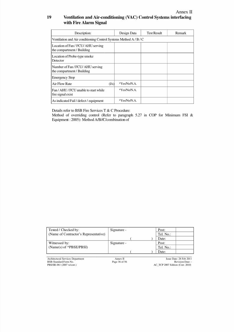
8/7/2019 Test Adjust and Balancing (See 233)
http://slidepdf.com/reader/full/test-adjust-and-balancing-see-233 199/247
Annex II
Tested / Checked by:
(Name of Contractor‟s Representative) Signature - Post:
Tel. No.:
( ) Date:
Witnessed by:
(Name(s) of *PBSE/PBSI)
Signature - Post:
Tel. No.:( ) Date:
Architectural Services Department Annex II Issue Date: 28 Feb 2011BSB-Standard Form No. Page 36 of 56 Revision Date: -
PBS/SR.061 (2007 w/corr.) AC_TCP 2007 Edition (Corr. 2010)
19 Ventilation and Air-conditioning (VAC) Control Systems interfacing
with Fire Alarm Signal
Description: Design Data Test Result Remark
Ventilation and Air conditioning Control Systems Method A / B / C
Location of Fan / FCU/ AHU serving
the compartment / Building
Location of Probe-type smoke
Detector
Number of Fan / FCU/ AHU serving
the compartment / Building
Emergency Stop
Air Flow Rate (l/s) *Yes/No/N.A.
Fan / AHU / FCU unable to start while
fire signal exist
*Yes/No/N.A.
As indicated Fail / defect / equipment *Yes/No/N.A.
Details refer to BSB Fire Services T & C Procedure:
Method of overriding control (Refer to paragraph 5.27 in COP for Minimum FSI &
Equipment : 2005): Method A/B//C/combination of
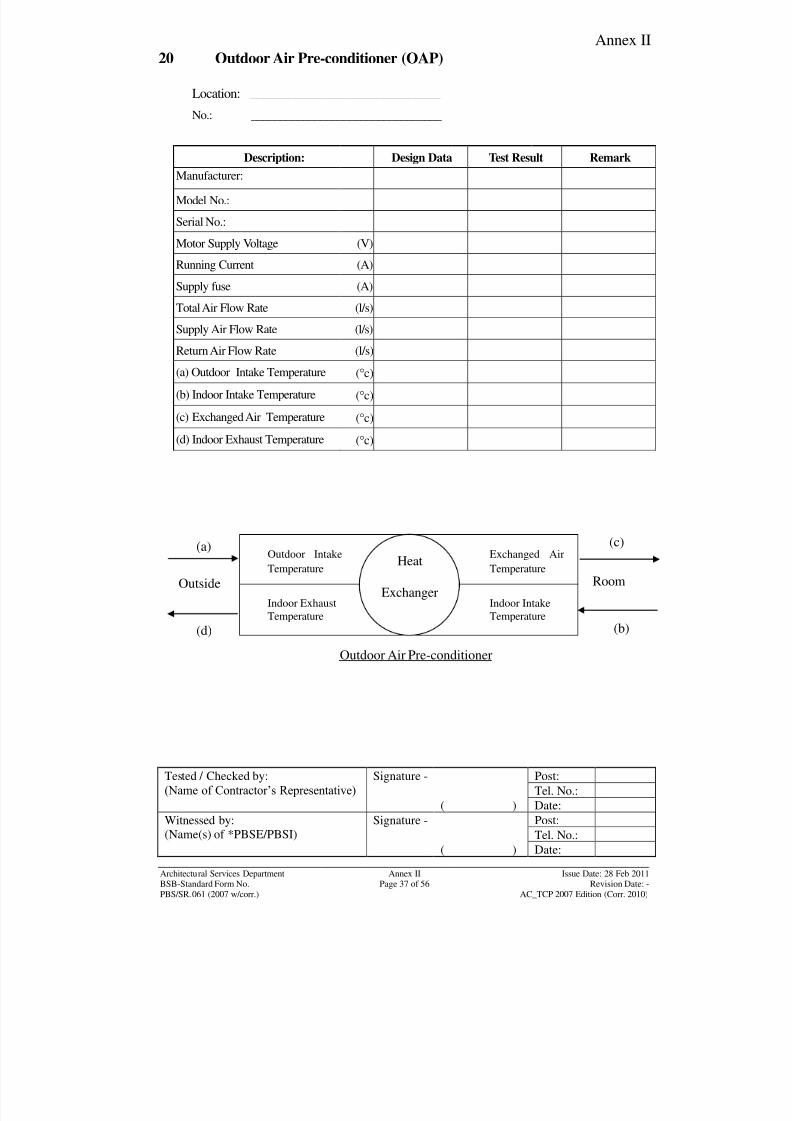
8/7/2019 Test Adjust and Balancing (See 233)
http://slidepdf.com/reader/full/test-adjust-and-balancing-see-233 200/247
Annex II
Tested / Checked by:
(Name of Contractor‟s Representative) Signature - Post:
Tel. No.:
( ) Date:
Witnessed by:
(Name(s) of *PBSE/PBSI)
Signature - Post:
Tel. No.:( ) Date:
Architectural Services Department Annex II Issue Date: 28 Feb 2011BSB-Standard Form No. Page 37 of 56 Revision Date: -
PBS/SR.061 (2007 w/corr.) AC_TCP 2007 Edition (Corr. 2010)
20 Outdoor Air Pre-conditioner (OAP)
Location: ______________________________
No.: _________________________________
Description: Design Data Test Result Remark
Manufacturer:
Model No.:
Serial No.:
Motor Supply Voltage (V)
Running Current (A)
Supply fuse (A)
Total Air Flow Rate (l/s)
Supply Air Flow Rate (l/s)Return Air Flow Rate (l/s)
(a) Outdoor Intake Temperature (c)
(b) Indoor Intake Temperature (c)
(c) Exchanged Air Temperature (c)
(d) Indoor Exhaust Temperature (c)
(a)Heat
Exchanger
(d)
(c)
(b)
Outside Room
Outdoor Air Pre-conditioner
Outdoor Intake
Temperature
Exchanged Air
Temperature
Indoor Exhaust
Temperature
Indoor Intake
Temperature
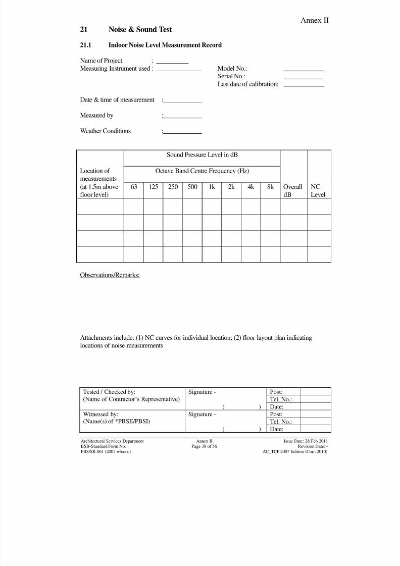
8/7/2019 Test Adjust and Balancing (See 233)
http://slidepdf.com/reader/full/test-adjust-and-balancing-see-233 201/247
Annex II
Tested / Checked by:
(Name of Contractor‟s Representative) Signature - Post:
Tel. No.:
( ) Date:
Witnessed by:
(Name(s) of *PBSE/PBSI)
Signature - Post:
Tel. No.:( ) Date:
Architectural Services Department Annex II Issue Date: 28 Feb 2011BSB-Standard Form No. Page 38 of 56 Revision Date: -
PBS/SR.061 (2007 w/corr.) AC_TCP 2007 Edition (Corr. 2010)
21 Noise & Sound Test
21.1 Indoor Noise Level Measurement Record
Name of Project :
Measuring Instrument used : Model No.:
Serial No.:
Last date of calibration:
Date & time of measurement :
Measured by :
Weather Conditions :
Sound Pressure Level in dB
Location of
measurements
Octave Band Centre Frequency (Hz)
(at 1.5m above
floor level)
63 125 250 500 1k 2k 4k 8k Overall
dB
NC
Level
Observations/Remarks:
Attachments include: (1) NC curves for individual location; (2) floor layout plan indicatinglocations of noise measurements
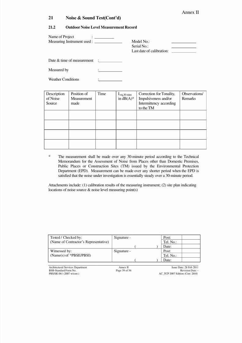
8/7/2019 Test Adjust and Balancing (See 233)
http://slidepdf.com/reader/full/test-adjust-and-balancing-see-233 202/247
Annex II
Tested / Checked by:
(Name of Contractor‟s Representative) Signature - Post:
Tel. No.:
( ) Date:
Witnessed by:
(Name(s) of *PBSE/PBSI)
Signature - Post:
Tel. No.:( ) Date:
Architectural Services Department Annex II Issue Date: 28 Feb 2011BSB-Standard Form No. Page 39 of 56 Revision Date: -
PBS/SR.061 (2007 w/corr.) AC_TCP 2007 Edition (Corr. 2010)
21 Noise & Sound Test(Cont’d)
21.2 Outdoor Noise Level Measurement Record
Name of Project :
Measuring Instrument used : Model No.:
Serial No.:
Last date of calibration:
Date & time of measurement :
Measured by :
Weather Conditions :
Description
of Noise
Source
Position of
Measurement
made
Time Leq,30 mins
in dB(A)*
Correction for Tonality,
Impulsiveness and/or
Intermittency accordingto the TM
Observations/
Remarks
* The measurement shall be made over any 30-minute period according to the Technical
Memorandum for the Assessment of Noise from Places other than Domestic Premises,
Public Places or Construction Sites (TM) issued by the Environmental Protection
Department (EPD). Measurement can be made over any shorter period when the EPD is
satisfied that the noise under investigation is essentially steady over a 30-minute period.
Attachments include: (1) calibration results of the measuring instrument; (2) site plan indicating
locations of noise source & noise level measuring point(s)
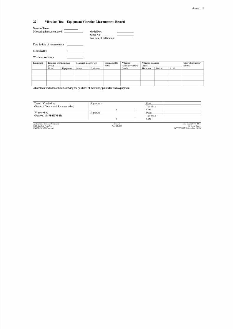
8/7/2019 Test Adjust and Balancing (See 233)
http://slidepdf.com/reader/full/test-adjust-and-balancing-see-233 203/247
Annex II
Tested / Checked by :
(Name of Contractor‟s Representative)
Signature - Post :
Tel. No. :
( ) Date :
Witnessed by :
(Name(s) of *PBSE/PBSI)
Signature - Post :
Tel. No. :
( ) Date :
Architectural Services Department Annex II Issue Date: 28 Feb 2011
BSB-Standard Form No. Page 40 of 56 Revision Date: -PBS/SR.061 (2007 w/corr.) AC_TCP 2007 Edition (Corr. 2010)
22 Vibration Test – Equipment Vibration Measurement Record
Name of Project :
Measuring Instrument used : Model No.:
Serial No.:
Last date of calibration:
Date & time of measurement :
Measured by :
Weather Conditions :
Equipment Indicated operation speed
(rev/s)
Measured speed (rev/s) Visual/ audible
check
Vibration
acceptance criteria(mm/s)
Vibration measured
(mm/s)
Other observations/
remarks
Motor Equipment Motor Equipment Horizontal Vertical Axial
Attachment includes a sketch showing the positions of measuring points for each equipment.
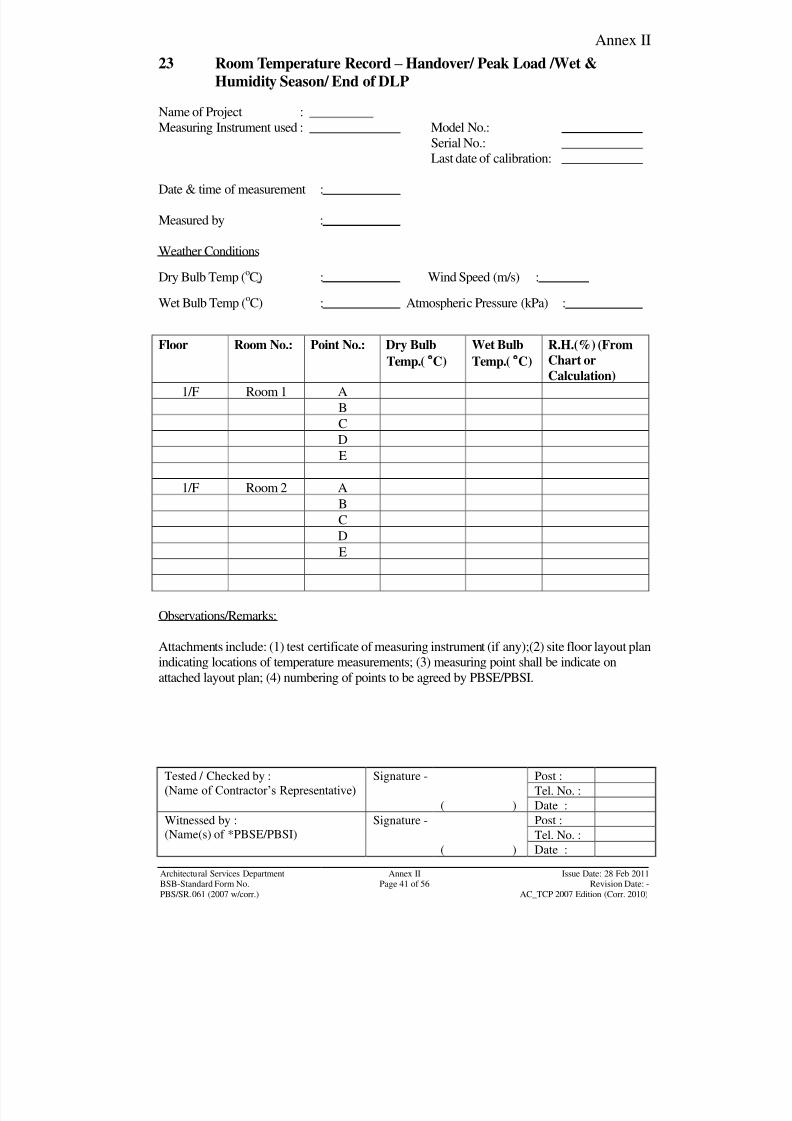
8/7/2019 Test Adjust and Balancing (See 233)
http://slidepdf.com/reader/full/test-adjust-and-balancing-see-233 204/247
Annex II
Tested / Checked by :
(Name of Contractor‟s Representative) Signature - Post :
Tel. No. :
( ) Date :
Witnessed by :
(Name(s) of *PBSE/PBSI)
Signature - Post :
Tel. No. :( ) Date :
Architectural Services Department Annex II Issue Date: 28 Feb 2011BSB-Standard Form No. Page 41 of 56 Revision Date: -
PBS/SR.061 (2007 w/corr.) AC_TCP 2007 Edition (Corr. 2010)
23 Room Temperature Record – Handover/ Peak Load /Wet &
Humidity Season/ End of DLP
Name of Project :
Measuring Instrument used : Model No.:
Serial No.:
Last date of calibration:
Date & time of measurement :
Measured by :
Weather Conditions
Dry Bulb Temp (oC) : Wind Speed (m/s) :
Wet Bulb Temp (oC) : Atmospheric Pressure (kPa) :
Floor Room No.: Point No.: Dry Bulb
Temp.(C)
Wet Bulb
Temp.(C)
R.H.(%) (From
Chart or
Calculation)
1/F Room 1 A
B
C
D
E
1/F Room 2 A
BC
D
E
Observations/Remarks:
Attachments include: (1) test certificate of measuring instrument (if any);(2) site floor layout plan
indicating locations of temperature measurements; (3) measuring point shall be indicate onattached layout plan; (4) numbering of points to be agreed by PBSE/PBSI.

8/7/2019 Test Adjust and Balancing (See 233)
http://slidepdf.com/reader/full/test-adjust-and-balancing-see-233 205/247
Annex II
Tested / Checked by :
(Name of Contractor‟s Representative) Signature - Post :
Tel. No. :
( ) Date :
Witnessed by :
(Name(s) of *PBSE/PBSI)
Signature - Post :
Tel. No. :( ) Date :
Architectural Services Department Annex II Issue Date: 28 Feb 2011BSB-Standard Form No. Page 42 of 56 Revision Date: -
PBS/SR.061 (2007 w/corr.) AC_TCP 2007 Edition (Corr. 2010)
23 Room Temperature Record – Handover/ Peak Load /Wet &
Humidity Season/ End of DLP(Cont’d)
Example :1/F Layout Plan
A B
C D
Room 1
E
A B
C D
Room 2
E
Open Area Office
Lift 1 Lift 2
Lift Lobby
N
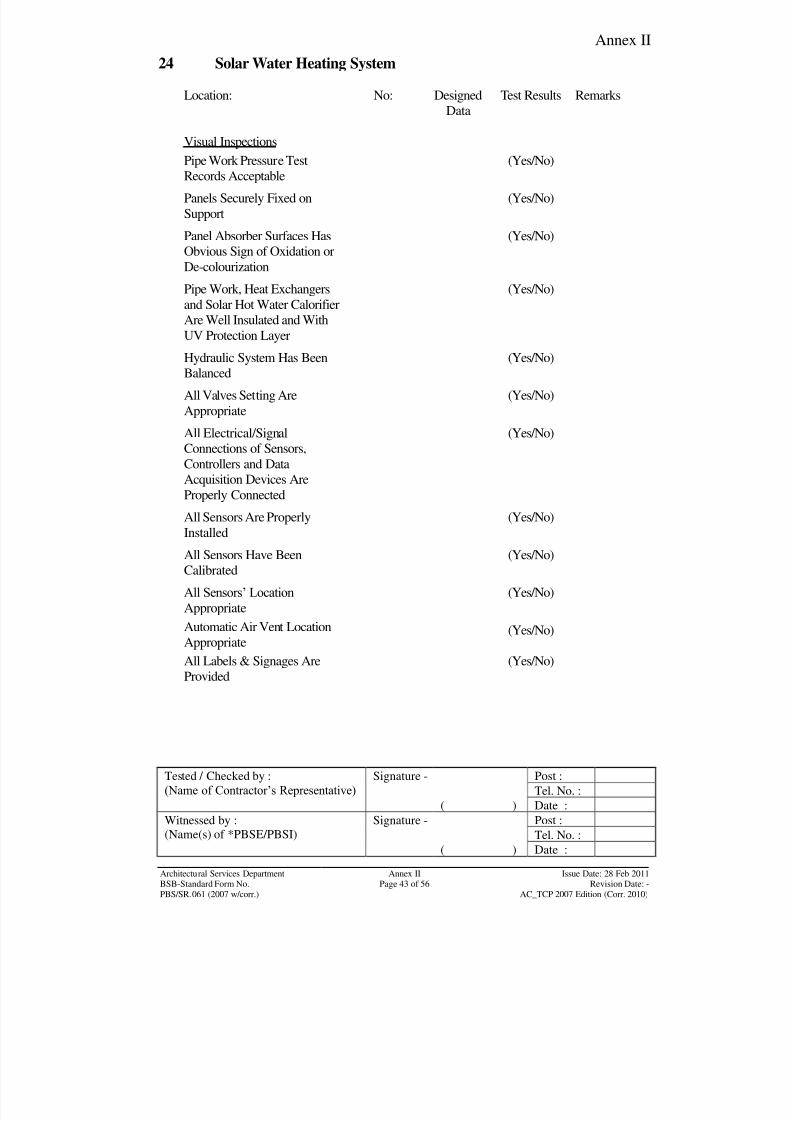
8/7/2019 Test Adjust and Balancing (See 233)
http://slidepdf.com/reader/full/test-adjust-and-balancing-see-233 206/247
Annex II
Tested / Checked by :
(Name of Contractor‟s Representative) Signature - Post :
Tel. No. :
( ) Date :
Witnessed by :
(Name(s) of *PBSE/PBSI)
Signature - Post :
Tel. No. :( ) Date :
Architectural Services Department Annex II Issue Date: 28 Feb 2011BSB-Standard Form No. Page 43 of 56 Revision Date: -
PBS/SR.061 (2007 w/corr.) AC_TCP 2007 Edition (Corr. 2010)
24 Solar Water Heating System
Location: No: Designed
Data
Test Results Remarks
Visual Inspections
Pipe Work Pressure TestRecords Acceptable (Yes/No)
Panels Securely Fixed on
Support
(Yes/No)
Panel Absorber Surfaces Has
Obvious Sign of Oxidation or
De-colourization
(Yes/No)
Pipe Work, Heat Exchangers
and Solar Hot Water Calorifier
Are Well Insulated and With
UV Protection Layer
(Yes/No)
Hydraulic System Has Been
Balanced
(Yes/No)
All Valves Setting Are
Appropriate
(Yes/No)
All Electrical/Signal
Connections of Sensors,
Controllers and Data
Acquisition Devices Are
Properly Connected
(Yes/No)
All Sensors Are Properly
Installed
(Yes/No)
All Sensors Have Been
Calibrated
(Yes/No)
All Sensors‟ Location
Appropriate
(Yes/No)
Automatic Air Vent Location
Appropriate(Yes/No)
All Labels & Signages AreProvided (Yes/No)
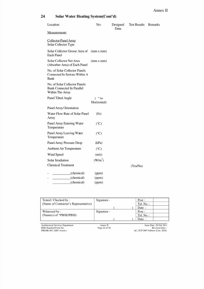
8/7/2019 Test Adjust and Balancing (See 233)
http://slidepdf.com/reader/full/test-adjust-and-balancing-see-233 207/247
Annex II
Tested / Checked by :
(Name of Contractor‟s Representative) Signature - Post :
Tel. No. :
( ) Date :
Witnessed by :
(Name(s) of *PBSE/PBSI)
Signature - Post :
Tel. No. :( ) Date :
Architectural Services Department Annex II Issue Date: 28 Feb 2011BSB-Standard Form No. Page 44 of 56 Revision Date: -
PBS/SR.061 (2007 w/corr.) AC_TCP 2007 Edition (Corr. 2010)
24 Solar Water Heating System(Cont’d)
Location: No: Designed
Data
Test Results Remarks
Measurements
Collector Panel Array
Solar Collector Type
Solar Collector Grosse Area of
Each Panel
(mm x mm)
Solar Collector Net Area
(Absorber Area) of Each Panel
(mm x mm)
No. of Solar Collector Panels
Connected In Serious Within A
Bank
No. of Solar Collector PanelsBank Connected In Parallel
Within The Array
Panel Tilted Angle ( to
Horizontal)
Panel Array Orientation
Water Flow Rate of Solar Panel
Array
(l/s)
Panel Array Entering Water
Temperature
(C)
Panel Array Leaving Water
Temperature(C)
Panel Array Pressure Drop (kPa)
Ambient Air Temperature (C)
Wind Speed (m/s)
Solar Irradiation (W/m2)
Chemical Treatment
- ___________(chemical)
- ___________(chemical)
- ___________(chemical)
(ppm)
(ppm)
(ppm)
(Yes/No)
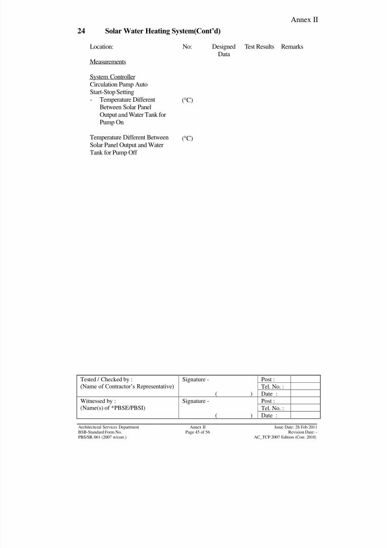
8/7/2019 Test Adjust and Balancing (See 233)
http://slidepdf.com/reader/full/test-adjust-and-balancing-see-233 208/247
Annex II
Tested / Checked by :
(Name of Contractor‟s Representative) Signature - Post :
Tel. No. :
( ) Date :
Witnessed by :
(Name(s) of *PBSE/PBSI)
Signature - Post :
Tel. No. :( ) Date :
Architectural Services Department Annex II Issue Date: 28 Feb 2011BSB-Standard Form No. Page 45 of 56 Revision Date: -
PBS/SR.061 (2007 w/corr.) AC_TCP 2007 Edition (Corr. 2010)
24 Solar Water Heating System(Cont’d)
Location: No: Designed
Data
Test Results Remarks
Measurements
System Controller
Circulation Pump Auto
Start-Stop Setting
- Temperature Different
Between Solar Panel
Output and Water Tank for
Pump On
Temperature Different Between
Solar Panel Output and Water
Tank for Pump Off
(C)
(C)
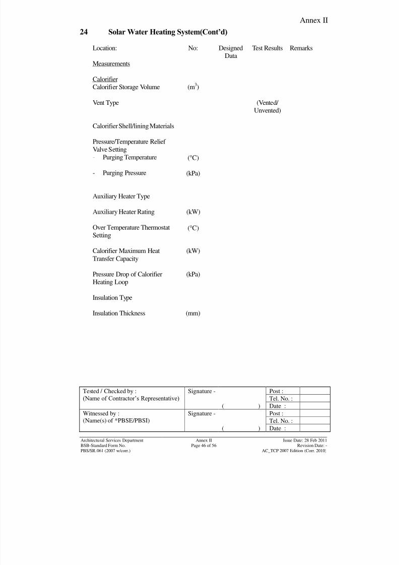
8/7/2019 Test Adjust and Balancing (See 233)
http://slidepdf.com/reader/full/test-adjust-and-balancing-see-233 209/247
Annex II
Tested / Checked by :
(Name of Contractor‟s Representative) Signature - Post :
Tel. No. :
( ) Date :
Witnessed by :
(Name(s) of *PBSE/PBSI)
Signature - Post :
Tel. No. :( ) Date :
Architectural Services Department Annex II Issue Date: 28 Feb 2011BSB-Standard Form No. Page 46 of 56 Revision Date: -
PBS/SR.061 (2007 w/corr.) AC_TCP 2007 Edition (Corr. 2010)
24 Solar Water Heating System(Cont’d)
Location: No: Designed
Data
Test Results Remarks
Measurements
Calorifier
Calorifier Storage Volume (m3)
Vent Type (Vented/
Unvented)
Calorifier Shell/lining Materials
Pressure/Temperature Relief
Valve Setting
- Purging Temperature
- Purging Pressure
(C)
(kPa)
Auxiliary Heater Type
Auxiliary Heater Rating (kW)
Over Temperature Thermostat
Setting(C)
Calorifier Maximum HeatTransfer Capacity
(kW)
Pressure Drop of Calorifier
Heating Loop
(kPa)
Insulation Type
Insulation Thickness (mm)

8/7/2019 Test Adjust and Balancing (See 233)
http://slidepdf.com/reader/full/test-adjust-and-balancing-see-233 210/247
Annex II
Tested / Checked by :
(Name of Contractor‟s Representative) Signature - Post :
Tel. No. :
( ) Date :
Witnessed by :
(Name(s) of *PBSE/PBSI)
Signature - Post :
Tel. No. :( ) Date :
Architectural Services Department Annex II Issue Date: 28 Feb 2011BSB-Standard Form No. Page 47 of 56 Revision Date: -
PBS/SR.061 (2007 w/corr.) AC_TCP 2007 Edition (Corr. 2010)
24 Solar Water Heating System(Cont’d)
Location: No: Designed
Data
Test Results Remarks
Measurements
Circulation Pumps
Voltage (V)
Current (A)
Power (W)
Flow Rate (l/s)
Pump Head (kPa)
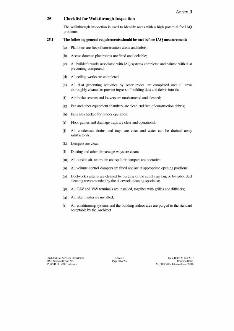
8/7/2019 Test Adjust and Balancing (See 233)
http://slidepdf.com/reader/full/test-adjust-and-balancing-see-233 211/247
Annex II
Architectural Services Department Annex II Issue Date: 28 Feb 2011BSB-Standard Form No. Page 48 of 56 Revision Date:-
PBS/SR.061 (2007 w/corr.) AC_TCP 2007 Edition (Corr. 2010)
25 Checklist for Walkthrough Inspection
The walkthrough inspection is used to identify areas with a high potential for IAQ
problems.
25.1 The following general requirements should be met before IAQ measurement:
(a) Platforms are free of construction waste and debris;
(b) Access doors to plantrooms are fitted and lockable;
(c) All builder‟s works associated with IAQ systems completed and painted with dust
preventing compound;
(d) All ceiling works are completed;
(e) All dust generating activities by other trades are completed and all areas
thoroughly cleaned to prevent ingress of building dust and debris into the
(f) Air intake screens and louvers are unobstructed and cleaned;
(g) Fan and other equipment chambers are clean and free of construction debris;
(h) Fans are checked for proper operation;
(i) Floor gullies and drainage traps are clear and operational;
(j) All condensate drains and trays are clear and water can be drained away
satisfactorily;
(k) Dampers are clean;
(l) Ducting and other air passage ways are clean;
(m) All outside air, return air, and spill air dampers are operative;
(n) All volume control dampers are fitted and are at appropriate opening positions;
(o) Ductwork systems are cleaned by purging of the supply air fan, or by robot duct
cleaning recommended by the ductwork cleaning specialist;
(p) All CAV and VAV terminals are installed, together with grilles and diffusers;
(q) All filter media are installed;
(r) Air conditioning systems and the building indoor area are purged to the standard
acceptable by the Architect
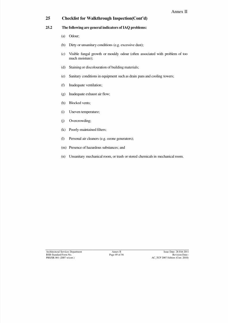
8/7/2019 Test Adjust and Balancing (See 233)
http://slidepdf.com/reader/full/test-adjust-and-balancing-see-233 212/247
Annex II
Architectural Services Department Annex II Issue Date: 28 Feb 2011BSB-Standard Form No. Page 49 of 56 Revision Date:-
PBS/SR.061 (2007 w/corr.) AC_TCP 2007 Edition (Corr. 2010)
25 Checklist for Walkthrough Inspection(Cont’d)
25.2 The following are general indicators of IAQ problems:
(a) Odour;
(b) Dirty or unsanitary conditions (e.g. excessive dust);
(c) Visible fungal growth or mouldy odour (often associated with problem of too
much moisture);
(d) Staining or discolouration of building materials;
(e) Sanitary conditions in equipment such as drain pans and cooling towers;
(f) Inadequate ventilation;
(g) Inadequate exhaust air flow;
(h) Blocked vents;
(i) Uneven temperature;
(j) Overcrowding;
(k) Poorly-maintained filters;
(l) Personal air cleaners (e.g. ozone generators);
(m) Presence of hazardous substances; and
(n) Unsanitary mechanical room, or trash or stored chemicals in mechanical room.
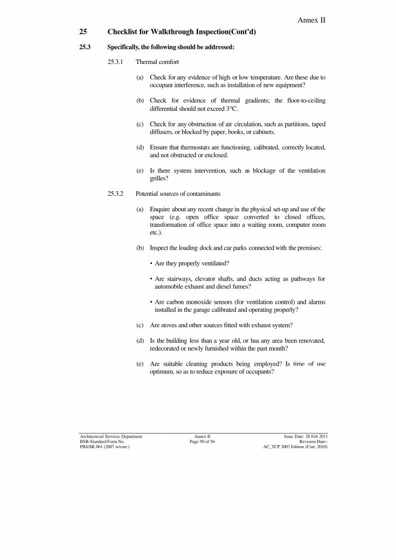
8/7/2019 Test Adjust and Balancing (See 233)
http://slidepdf.com/reader/full/test-adjust-and-balancing-see-233 213/247
Annex II
Architectural Services Department Annex II Issue Date: 28 Feb 2011BSB-Standard Form No. Page 50 of 56 Revision Date:-
PBS/SR.061 (2007 w/corr.) AC_TCP 2007 Edition (Corr. 2010)
25 Checklist for Walkthrough Inspection(Cont’d)
25.3 Specifically, the following should be addressed:
25.3.1 Thermal comfort
(a) Check for any evidence of high or low temperature. Are these due to
occupant interference, such as installation of new equipment?
(b) Check for evidence of thermal gradients; the floor-to-ceiling
differential should not exceed 3C.
(c) Check for any obstruction of air circulation, such as partitions, taped
diffusers, or blocked by paper, books, or cabinets.
(d) Ensure that thermostats are functioning, calibrated, correctly located,
and not obstructed or enclosed.
(e) Is there system intervention, such as blockage of the ventilation
grilles?
25.3.2 Potential sources of contaminants
(a) Enquire about any recent change in the physical set-up and use of the
space (e.g. open office space converted to closed offices,
transformation of office space into a waiting room, computer room
etc.).
(b) Inspect the loading dock and car parks connected with the premises:
• Are they properly ventilated?
• Are stairways, elevator shafts, and ducts acting as pathways for
automobile exhaust and diesel fumes?
• Are carbon monoxide sensors (for ventilation control) and alarms
installed in the garage calibrated and operating properly?
(c) Are stoves and other sources fitted with exhaust system?
(d) Is the building less than a year old, or has any area been renovated,
redecorated or newly furnished within the past month?
(e) Are suitable cleaning products being employed? Is time of use
optimum, so as to reduce exposure of occupants?
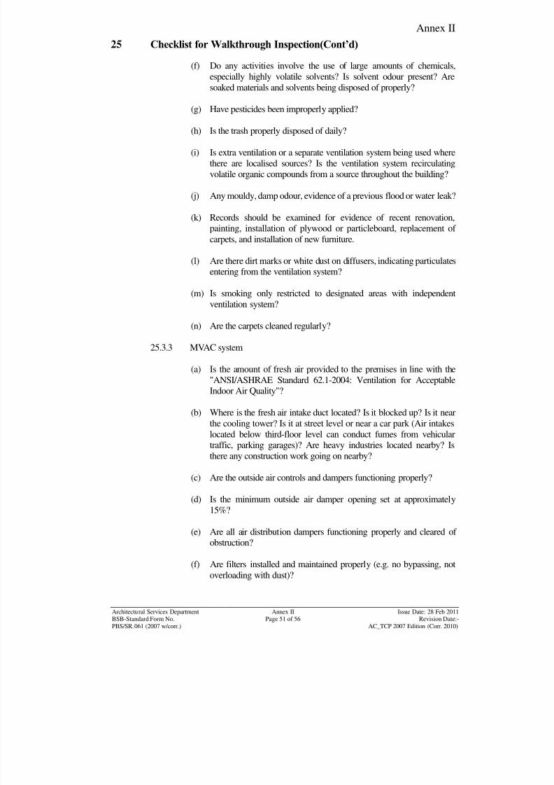
8/7/2019 Test Adjust and Balancing (See 233)
http://slidepdf.com/reader/full/test-adjust-and-balancing-see-233 214/247
Annex II
Architectural Services Department Annex II Issue Date: 28 Feb 2011BSB-Standard Form No. Page 51 of 56 Revision Date:-
PBS/SR.061 (2007 w/corr.) AC_TCP 2007 Edition (Corr. 2010)
25 Checklist for Walkthrough Inspection(Cont’d)
(f) Do any activities involve the use of large amounts of chemicals,
especially highly volatile solvents? Is solvent odour present? Are
soaked materials and solvents being disposed of properly?
(g) Have pesticides been improperly applied?
(h) Is the trash properly disposed of daily?
(i) Is extra ventilation or a separate ventilation system being used where
there are localised sources? Is the ventilation system recirculating
volatile organic compounds from a source throughout the building?
(j) Any mouldy, damp odour, evidence of a previous flood or water leak?
(k) Records should be examined for evidence of recent renovation,
painting, installation of plywood or particleboard, replacement of carpets, and installation of new furniture.
(l) Are there dirt marks or white dust on diffusers, indicating particulates
entering from the ventilation system?
(m) Is smoking only restricted to designated areas with independent
ventilation system?
(n) Are the carpets cleaned regularly?
25.3.3 MVAC system
(a) Is the amount of fresh air provided to the premises in line with the
"ANSI/ASHRAE Standard 62.1-2004: Ventilation for Acceptable
Indoor Air Quality"?
(b) Where is the fresh air intake duct located? Is it blocked up? Is it near
the cooling tower? Is it at street level or near a car park (Air intakes
located below third-floor level can conduct fumes from vehicular
traffic, parking garages)? Are heavy industries located nearby? Is
there any construction work going on nearby?
(c) Are the outside air controls and dampers functioning properly?
(d) Is the minimum outside air damper opening set at approximately
15%?
(e) Are all air distribution dampers functioning properly and cleared of
obstruction?
(f) Are filters installed and maintained properly (e.g. no bypassing, not
overloading with dust)?
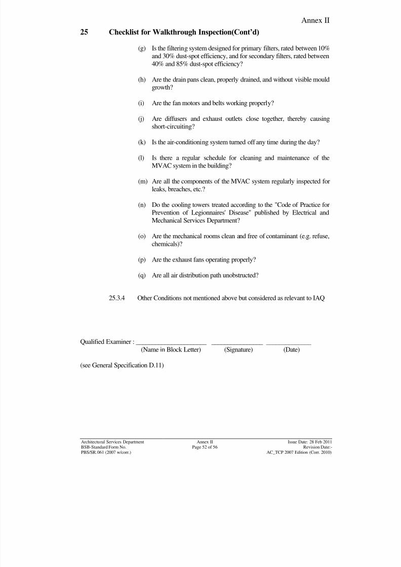
8/7/2019 Test Adjust and Balancing (See 233)
http://slidepdf.com/reader/full/test-adjust-and-balancing-see-233 215/247
Annex II
Architectural Services Department Annex II Issue Date: 28 Feb 2011BSB-Standard Form No. Page 52 of 56 Revision Date:-
PBS/SR.061 (2007 w/corr.) AC_TCP 2007 Edition (Corr. 2010)
25 Checklist for Walkthrough Inspection(Cont’d)
(g) Is the filtering system designed for primary filters, rated between 10%
and 30% dust-spot efficiency, and for secondary filters, rated between
40% and 85% dust-spot efficiency?
(h) Are the drain pans clean, properly drained, and without visible mould
growth?
(i) Are the fan motors and belts working properly?
(j) Are diffusers and exhaust outlets close together, thereby causing
short-circuiting?
(k) Is the air-conditioning system turned off any time during the day?
(l) Is there a regular schedule for cleaning and maintenance of the
MVAC system in the building?
(m) Are all the components of the MVAC system regularly inspected for
leaks, breaches, etc.?
(n) Do the cooling towers treated according to the "Code of Practice for
Prevention of Legionnaires' Disease" published by Electrical and
Mechanical Services Department?
(o) Are the mechanical rooms clean and free of contaminant (e.g. refuse,
chemicals)?
(p) Are the exhaust fans operating properly?
(q) Are all air distribution path unobstructed?
25.3.4 Other Conditions not mentioned above but considered as relevant to IAQ
Qualified Examiner : ______________________ ________________ ______________
(Name in Block Letter) (Signature) (Date)
(see General Specification D.11)
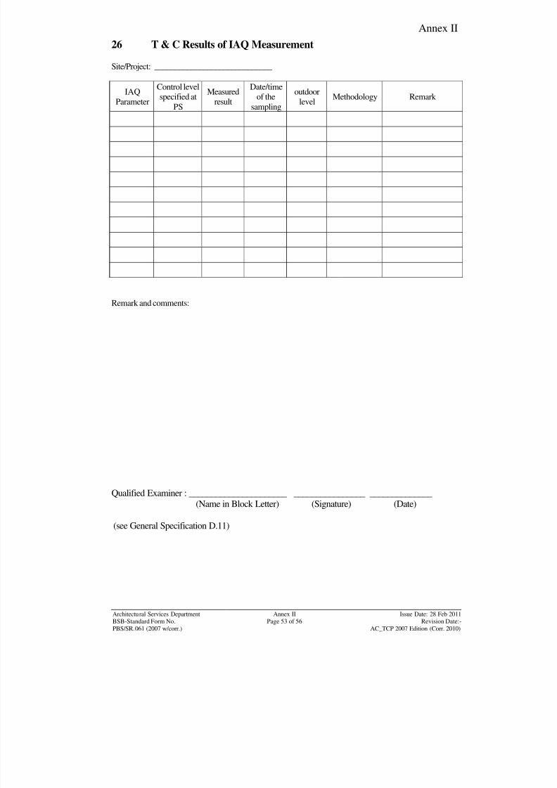
8/7/2019 Test Adjust and Balancing (See 233)
http://slidepdf.com/reader/full/test-adjust-and-balancing-see-233 216/247
Annex II
Architectural Services Department Annex II Issue Date: 28 Feb 2011BSB-Standard Form No. Page 53 of 56 Revision Date:-
PBS/SR.061 (2007 w/corr.) AC_TCP 2007 Edition (Corr. 2010)
26 T & C Results of IAQ Measurement
Site/Project: _____________________________
IAQ
Parameter
Control level
specified at
PS
Measured
result
Date/time
of the
sampling
outdoor
levelMethodology Remark
Remark and comments:
Qualified Examiner : ______________________ ________________ ______________
(Name in Block Letter) (Signature) (Date)
(see General Specification D.11)
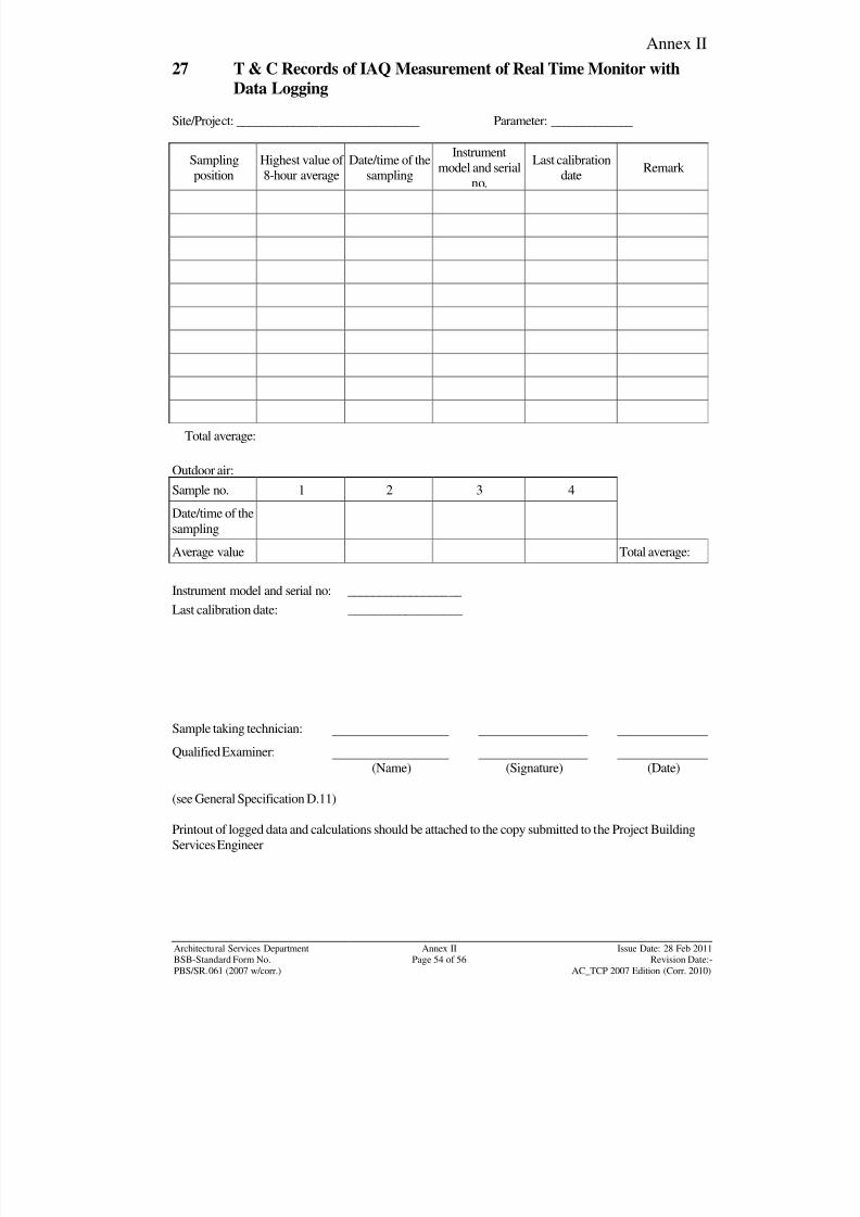
8/7/2019 Test Adjust and Balancing (See 233)
http://slidepdf.com/reader/full/test-adjust-and-balancing-see-233 217/247
Annex II
Architectural Services Department Annex II Issue Date: 28 Feb 2011BSB-Standard Form No. Page 54 of 56 Revision Date:-
PBS/SR.061 (2007 w/corr.) AC_TCP 2007 Edition (Corr. 2010)
27 T & C Records of IAQ Measurement of Real Time Monitor with
Data Logging
Site/Project: _____________________________ Parameter: _____________
Sampling
position
Highest value of
8-hour average
Date/time of the
sampling
Instrument
model and serial
no.
Last calibration
date
Remark
Total average:
Outdoor air:
Sample no. 1 2 3 4
Date/time of the
sampling
Average value Total average:
Instrument model and serial no: __________________
Last calibration date: __________________
Sample taking technician:
Qualified Examiner:
(Name) (Signature) (Date)
(see General Specification D.11)
Printout of logged data and calculations should be attached to the copy submitted to the Project Building
Services Engineer
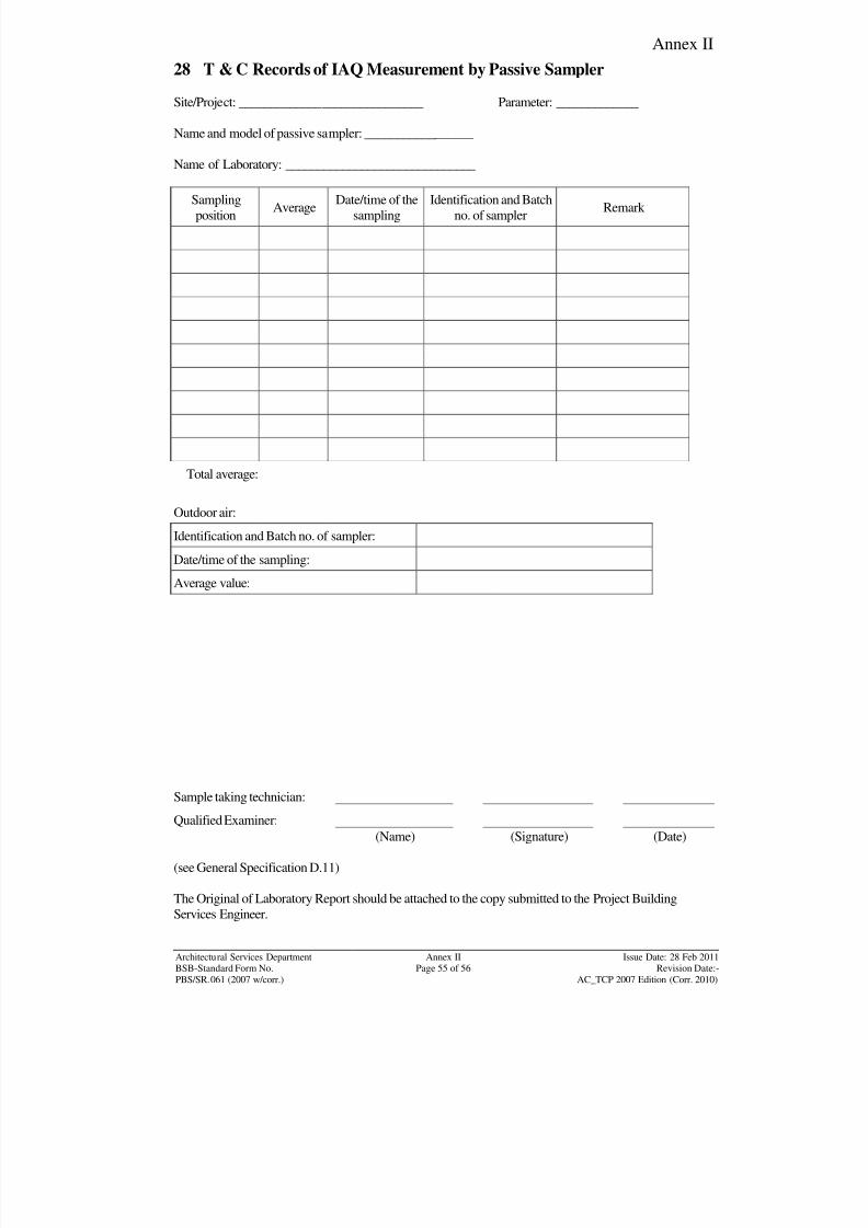
8/7/2019 Test Adjust and Balancing (See 233)
http://slidepdf.com/reader/full/test-adjust-and-balancing-see-233 218/247
Annex II
Architectural Services Department Annex II Issue Date: 28 Feb 2011BSB-Standard Form No. Page 55 of 56 Revision Date:-
PBS/SR.061 (2007 w/corr.) AC_TCP 2007 Edition (Corr. 2010)
28 T & C Records of IAQ Measurement by Passive Sampler
Site/Project: _____________________________ Parameter: _____________
Name and model of passive sampler: _________________
Name of Laboratory: ______________________________
Sampling
positionAverage
Date/time of the
sampling
Identification and Batch
no. of samplerRemark
Total average:
Outdoor air:
Identification and Batch no. of sampler:
Date/time of the sampling:
Average value:
Sample taking technician:
Qualified Examiner:
(Name) (Signature) (Date)
(see General Specification D.11)
The Original of Laboratory Report should be attached to the copy submitted to the Project Building
Services Engineer.
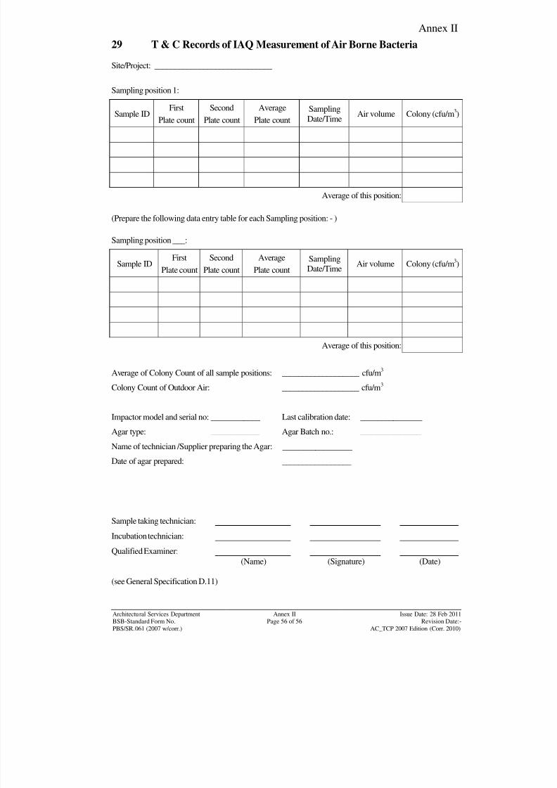
8/7/2019 Test Adjust and Balancing (See 233)
http://slidepdf.com/reader/full/test-adjust-and-balancing-see-233 219/247
Annex II
Architectural Services Department Annex II Issue Date: 28 Feb 2011BSB-Standard Form No. Page 56 of 56 Revision Date:-
PBS/SR.061 (2007 w/corr.) AC_TCP 2007 Edition (Corr. 2010)
29 T & C Records of IAQ Measurement of Air Borne Bacteria
Site/Project: _____________________________
Sampling position 1:
Sample ID
First
Plate count
Second
Plate count
Average
Plate count
Sampling
Date/Time Air volume Colony (cfu/m
3
)
Average of this position:
(Prepare the following data entry table for each Sampling position: - )
Sampling position ___:
Sample IDFirst
Plate count
Second
Plate count
Average
Plate count
Sampling
Date/TimeAir volume Colony (cfu/m
3)
Average of this position:
Average of Colony Count of all sample positions: ___________________ cfu/m3
Colony Count of Outdoor Air: ___________________ cfu/m3
Impactor model and serial no: ____________ Last calibration date: _______________
Agar type: ____________ Agar Batch no.: _______________
Name of technician /Supplier preparing the Agar: _________________
Date of agar prepared: _________________
Sample taking technician:
Incubation technician:
Qualified Examiner:
(Name) (Signature) (Date)
(see General Specification D.11)
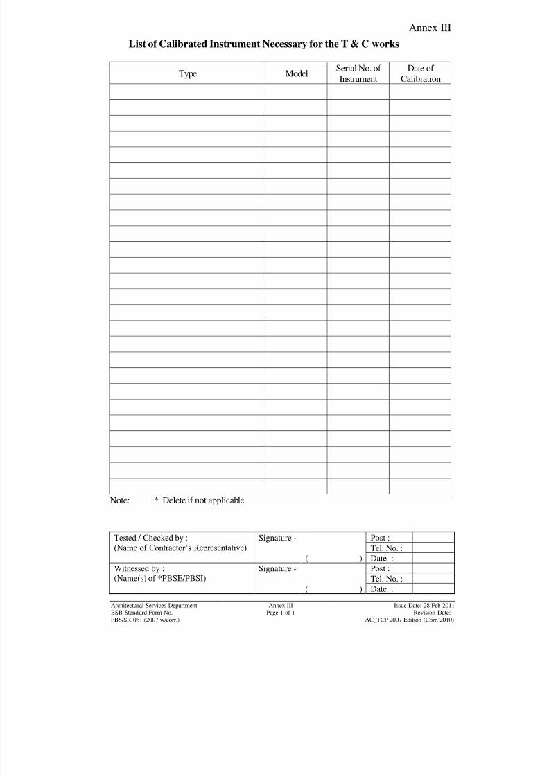
8/7/2019 Test Adjust and Balancing (See 233)
http://slidepdf.com/reader/full/test-adjust-and-balancing-see-233 220/247
Annex III
Tested / Checked by :
(Name of Contractor‟s Representative) Signature - Post :
Tel. No. :
( ) Date :
Witnessed by :
(Name(s) of *PBSE/PBSI)
Signature - Post :
Tel. No. :( ) Date :
Architectural Services Department Annex III Issue Date: 28 Feb 2011BSB-Standard Form No. Page 1 of 1 Revision Date: -
PBS/SR.061 (2007 w/corr.) AC_TCP 2007 Edition (Corr. 2010)
List of Calibrated Instrument Necessary for the T & C works
Type ModelSerial No. of
Instrument
Date of
Calibration
Note: * Delete if not applicable
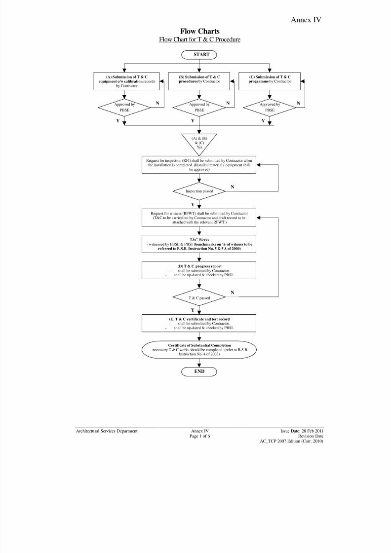
8/7/2019 Test Adjust and Balancing (See 233)
http://slidepdf.com/reader/full/test-adjust-and-balancing-see-233 221/247
Annex IV
Architectural Services Department Annex IV Issue Date: 28 Feb 2011Page 1 of 6 Revision Date
AC_TCP 2007 Edition (Corr. 2010)
Flow ChartsFlow Chart for T & C Procedure
Y
Y YY
Y
N N N
(A) & (B)& (C)Yes
Approved by
PBSE
Approved by
PBSE
Approved by
PBSE
START
(A) Submission of T & C
equipment c/w calibration recordsby Contractor
(B) Submission of T & C
procedures by Contractor
(C) Submission of T & C
programme by Contractor
Request for inspection (RFI) shall be submitted by Contractor when
the installation is completed. (Installed material / equipment shallbe approved)
Inspection passed
Request for witness (RFWT) shall be submitted by Contractor(T&C to be carried out by Contractor and draft record to be
attached with the relevant RFWT.)
T&C Works- witnessed by PBSE & PBSI (benchmarks on % of witness to be
referred to B.S.B. Instruction No. 5 & 5A of 2000)
(D) T & C progress report- shall be submitted by Contractor.
- shall be up-dated & checked by PBSI.
T & C passed
(E) T & C certificate and test record- shall be submitted by Contractor.
- shall be up-dated & checked by PBSI.
Certificate of Substantial Completion- necessary T & C works should be completed. (refer to B.S.B.
Instruction No. 4 of 2003)
END
N
N
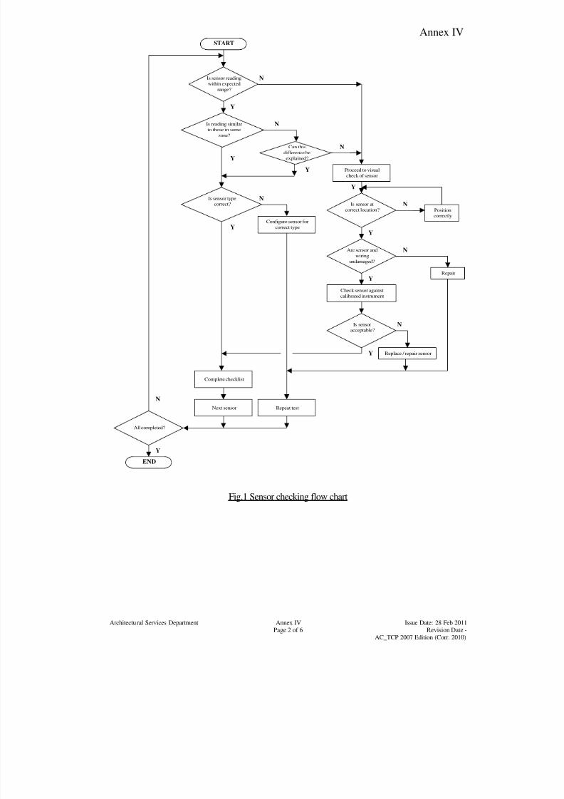
8/7/2019 Test Adjust and Balancing (See 233)
http://slidepdf.com/reader/full/test-adjust-and-balancing-see-233 222/247
Annex IV
Architectural Services Department Annex IV Issue Date: 28 Feb 2011Page 2 of 6 Revision Date -
AC_TCP 2007 Edition (Corr. 2010)
Y
N
Y
Y
Y
Y
Y
Y
N
N
N
Is sensor reading
within expected
range?
Can this
difference be
explained?
Check sensor against
calibrated instrument
Proceed to visual
check of sensor
Configure sensor for
correct type
Is sensor at
correct location?
Complete checklist
Are sensor and
wiring
undamaged?
Replace / repair sensor
N
N
START
Is reading similar
to those in same
zone?
Is sensor type
correct?
Next sensor Repeat test
All completed?
END
Is sensor
acceptable?
Repair
Position
correctly
N
N
Y
Y
Fig.1 Sensor checking flow chart
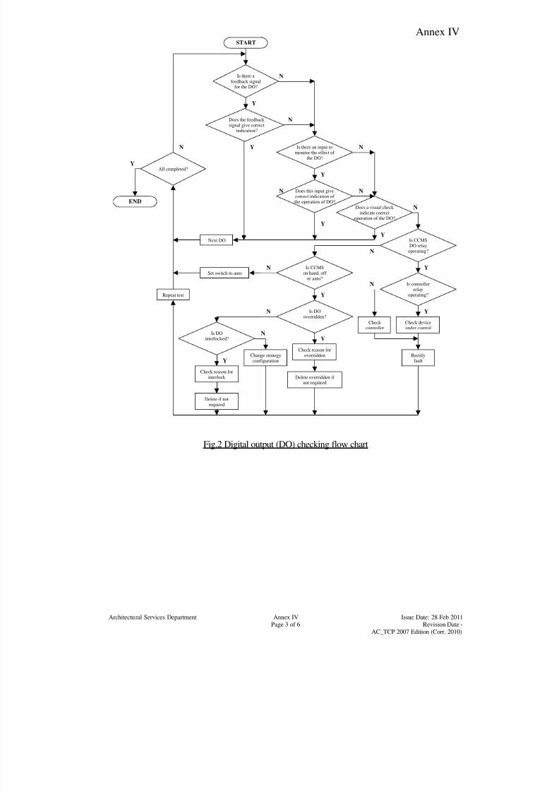
8/7/2019 Test Adjust and Balancing (See 233)
http://slidepdf.com/reader/full/test-adjust-and-balancing-see-233 223/247
Annex IV
Architectural Services Department Annex IV Issue Date: 28 Feb 2011Page 3 of 6 Revision Date -
AC_TCP 2007 Edition (Corr. 2010)
Y
Y
Y
Y
N
Y
N
Y
Y
Y
Y
Y
Y
N
N
N
Is there afeedback signal
for the DO?
Is there an input tomonitor the effect of
the DO?
Check controller
Does a visual check indicate correct
operation of the DO?
Is CCMSDO relay
operating?
Check deviceunder control
N N
START
Does the feedback signal give correct
indication?
Does this input givecorrect indication of the operation of DO?
Repeat test
All completed?
END
Is controllerrelay
operating?
Next DO
N
Is CCMSon hand, off
or auto?
Is DOoverridden?
Is DOinterlocked?
Rectifyfault
Check reason foroverridden
Check reason forinterlock Delete overridden if
not required
Delete if notrequired
Change strategyconfiguration
Set switch to autoN
N
N
N
Fig.2 Digital output (DO) checking flow chart
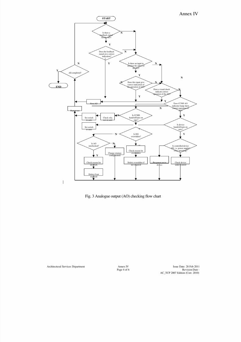
8/7/2019 Test Adjust and Balancing (See 233)
http://slidepdf.com/reader/full/test-adjust-and-balancing-see-233 224/247
Annex IV
Architectural Services Department Annex IV Issue Date: 28 Feb 2011Page 4 of 6 Revision Date -
AC_TCP 2007 Edition (Corr. 2010)
N
Y
Y
Y
Y
N
Y
N
Y
Y
Y
Y
Y
Y
N
N
N
Is there afeedback signal
for the AO?
Is there an input tomonitor the effect of
the AO?
Put power on todevice
Does a visual check indicate correct
operation of the AO?
Does CCMS AOindicator lamp showcorrect operation of
AO?
Check deviceunder control
N N
START
Does the feedback signal give correct
indication?
Does this input givecorrect indication of the operation of AO?
Repeat test
All completed?
END
Is devicehand/off/auto on
auto?
Next AO
N
Is CCMShand/off/auto on
auto?
Is DOoverridden?
Is AOinterlocked?
Check reason for
overridden
Check reason forinterlock
Delete overridden if not required
Delete if notrequired
Change strategyconfiguration
Set switchto auto
N
N
N
Check whynot on auto
Set switchto auto
Is controlled deviceON, i.e. power supply?
relay operating?
Fig. 3 Analogue output (AO) checking flow chart
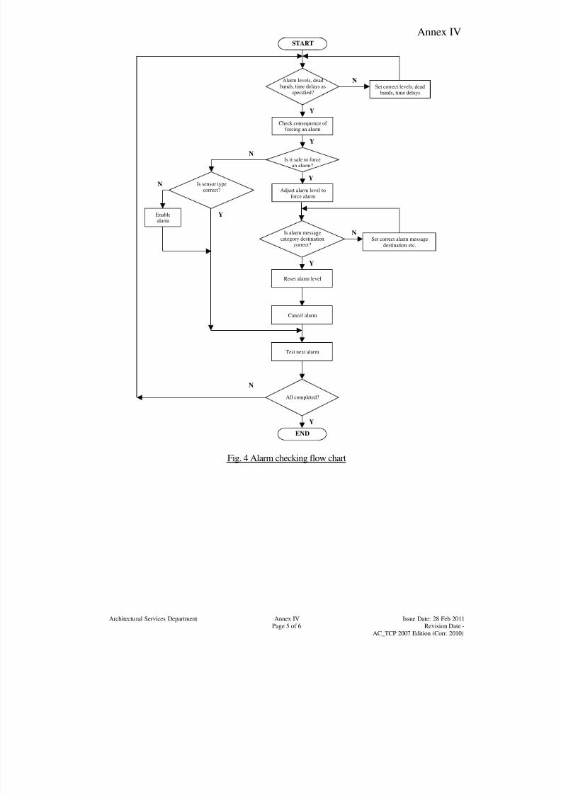
8/7/2019 Test Adjust and Balancing (See 233)
http://slidepdf.com/reader/full/test-adjust-and-balancing-see-233 225/247
Annex IV
Architectural Services Department Annex IV Issue Date: 28 Feb 2011Page 5 of 6 Revision Date -
AC_TCP 2007 Edition (Corr. 2010)
Y
N
Y
Y
N
Y
Y
Y
N
N
Alarm levels, deadbands, time delays as
specified?
Is it safe to forcean alarm?
Adjust alarm level toforce alarm
Set correct levels, deadbands, time delays
Check consequence of forcing an alarm
Reset alarm level
N
START
Is alarm messagecategory destination
correct?
Is sensor typecorrect?
Cancel alarm
Test next alarm
All completed?
END
Enablealarm
Set correct alarm messagedestination etc.
Fig. 4 Alarm checking flow chart
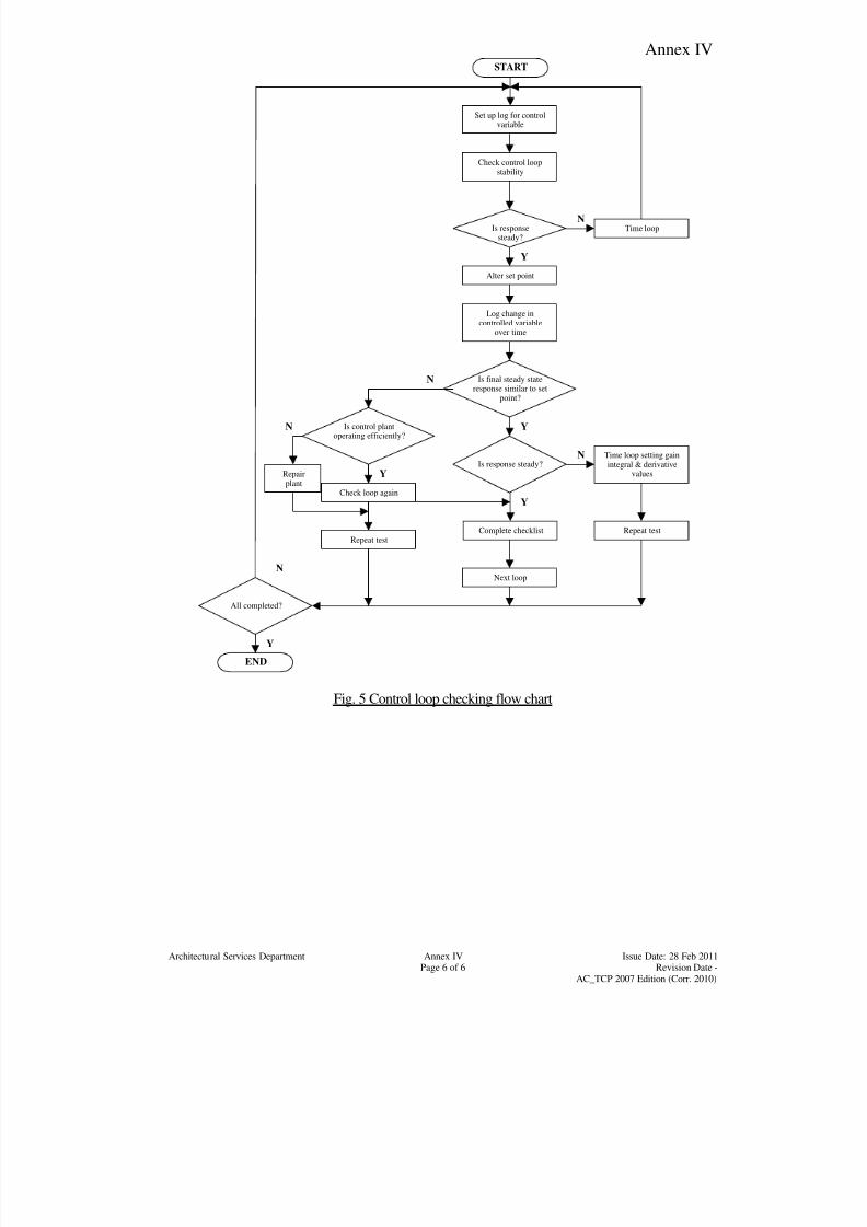
8/7/2019 Test Adjust and Balancing (See 233)
http://slidepdf.com/reader/full/test-adjust-and-balancing-see-233 226/247
Annex IV
Architectural Services Department Annex IV Issue Date: 28 Feb 2011Page 6 of 6 Revision Date -
AC_TCP 2007 Edition (Corr. 2010)
N
Y
Y
N
Y
Y
Y
N
N
Is response steady?
Is responsesteady?
Alter set point
Set up log for controlvariable
Check control loopstability
Time loop setting gainintegral & derivative
values
N
START
Is final steady stateresponse similar to set
point?
Is control plantoperating efficiently?
Next loop
Complete checklist
All completed?
END
Repairplant
Log change incontrolled variable
over time
Repeat test
Check loop again
Repeat test
Time loop
Fig. 5 Control loop checking flow chart
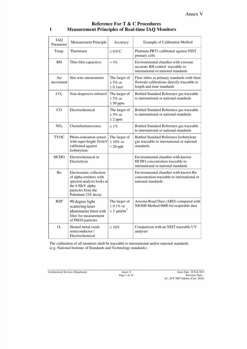
8/7/2019 Test Adjust and Balancing (See 233)
http://slidepdf.com/reader/full/test-adjust-and-balancing-see-233 227/247
Annex V
Architectural Services Department Annex V Issue Date: 28 Feb 2011Page 1 of 14 Revision Date: -
AC_TCP 2007 Edition (Corr. 2010)
Reference For T & C Procedures
1 Measurement Principles of Real-time IAQ Monitors
IAQ
ParameterMeasurement Principle Accuracy Example of Calibration Method
Temp. Thermistor 0.6C Platinum PRT's calibrated against NISTprimary cells
RH Thin-film capacitive 5% Environmental chamber with extreme
accurate RH control traceable to
international or national standards
Air
movement
Hot-wire anemometer The larger of
5% or
0.1m/s
Flow tubes as primary standards with their
flowrate calibrations directly traceable to
length and time standards
CO2 Non-dispersive infrared The larger of
5% or
50 ppm
Bottled Standard Reference gas traceable
to international or national standards
CO Electrochemical The larger of
5% or
2 ppm
Bottled Standard Reference gas traceable
to international or national standards
NO2 Chemiluminescence 1% Bottled Standard Reference gas traceable
to international or national standards
TVOC Photo-ionisation sensor
with super bright 10.6eV
calibrated against
Isobutylene
The larger of
10% or
20 ppb
Bottled Standard Reference Isobutylene
gas traceable to international or national
standards
HCHO Electrochemical orElectrolysis
Environmental chamber with knownHCHO concentration traceable to
international or national standards
Rn Electrostatic collection
of alpha-emitters with
spectral analysis looks at
the 6 MeV alpha
particles from the
Polonium-218 decay.
Environmental chamber with known Rn
concentration traceable to international or
national standards
RSP 90 degree light
scattering laserphotometer fitted with
filter for measurement
of PM10 particles
The larger of
0.1% or 1 m/m
3
Arizona Road Dust (ARD) compared with
NIOSH Method 0600 for respirable dust
O3 Heated metal oxide
semiconductor /
Electrochemical
10% Comparison with an NIST traceable UV
analyser
The calibration of all monitors shall be traceable to international and/or national standards
(e.g. National Institute of Standards and Technology standards).

8/7/2019 Test Adjust and Balancing (See 233)
http://slidepdf.com/reader/full/test-adjust-and-balancing-see-233 228/247
Annex V
Architectural Services Department Annex V Issue Date: 28 Feb 2011Page 2 of 14 Revision Date: -
AC_TCP 2007 Edition (Corr. 2010)
2 Example of Air Flow Sheet
Design vol.
Test
v = velocitya = area
vol. = volume
Design
Test vol.
vol.
v a
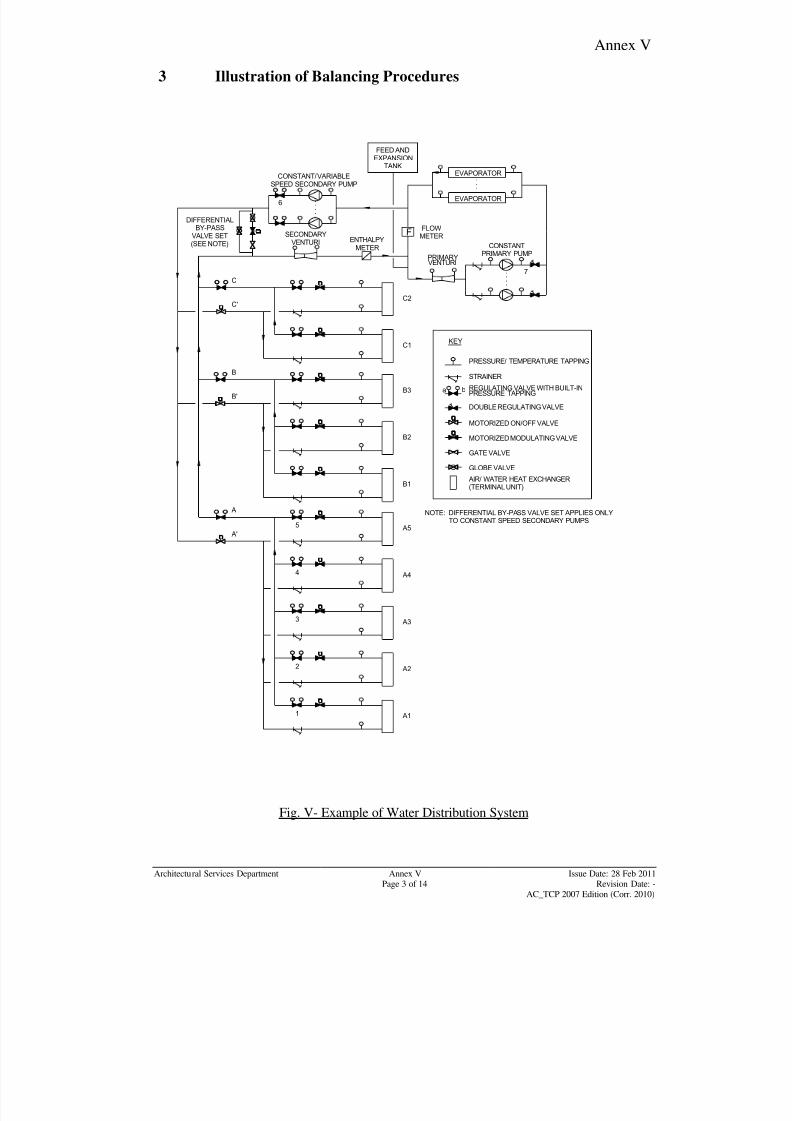
8/7/2019 Test Adjust and Balancing (See 233)
http://slidepdf.com/reader/full/test-adjust-and-balancing-see-233 229/247
Annex V
Architectural Services Department Annex V Issue Date: 28 Feb 2011Page 3 of 14 Revision Date: -
AC_TCP 2007 Edition (Corr. 2010)
3 Illustration of Balancing Procedures
PRESSURE/ TEMPERATURE TAPPING
STRAINER
REGULATING VALVE WITH BUILT-INPRESSURE TAPPING
a b
DOUBLE REGULATING VALVE
AIR/ WATER HEAT EXCHANGER(TERMINAL UNIT)
KEY
PRIMARYVENTURI
CONSTANTPRIMARY PUMP
EVAPORATOR
FLOWMETER
CONSTANT/ VARIABLESPEED SECONDARY PUMP
DIFFERENTIALBY-PASS
VALVE SET(SEE NOTE)
C2
C
C'
C1
B
B'
B2
B3
B1
A'
A
A5
A1
EVAPORATOR
FENTHALPY
METER
SECONDARYVENTURI
A2
A3
A4
MOTORIZED ON/OFF VALVE
GATE VALVE
GLOBE VALVE
MOTORIZED MODULATING VALVE
NOTE: DIFFERENTIAL BY-PASS VALVE SET APPLIES ONLYTO CONSTANT SPEED SECONDARY PUMPS
FEED ANDEXPANSION
TANK
1
2
3
4
5
6
7
Fig. V- Example of Water Distribution System
8/7/2019 Test Adjust and Balancing (See 233)
http://slidepdf.com/reader/full/test-adjust-and-balancing-see-233 230/247
Annex V
Architectural Services Department Annex V Issue Date: 28 Feb 2011Page 4 of 14 Revision Date: -
AC_TCP 2007 Edition (Corr. 2010)
3.1 General Description of the Water Distribution System
(a) chilled water system as shown in Fig. V will be used to illustrate the
balancing procedures. The procedures for chilled water circuitry are equally
applicable to heating and condensing water circuitry;
(b) the performance of terminal plant in chilled water systems is considerablymore sensitive to any deviations from the design water flow rate. Hence, the
T & C procedure for chilled water systems requires more exacting tolerances
than heating system when balancing;
(c) the flow to each branch circuit is controlled by a two-way motorized on/off
control valve;
(d) the return line from each terminal unit is fitted with a motorized modulating
valve. Downstream in series is a regulating valve which has built-in pressure
tapings. This valve is used for both the water flow regulations and
measurement. This valve is locked in position after the balancing procedure
is completed.
3.2 Initial Check of System Water Flow Rates
(a) check the pressure drop across the associated flow regulating valve of each
terminal unit and branch by connecting a manometer between points a and b
of the regulating valve with built-in pressure tapping. (Refer to Fig. V);
(b) compute the square root of the ratio of the actual-to-design pressure drop for
each branch and terminal;
(c) determine which is the least favoured (index) branch and which is the most
favoured branch. The branch with the highest ratio is taken as the most
favoured branch, whereas the branch with the smallest ratio is the least
favoured branch, i.e. the index branch.
3.3 Balancing of Terminals
(a) start by balancing the most favoured branch first;
(b) balance the water flow rate of each terminal unit to the water flow rate of theindex terminal unit in that branch;
(c) balance the water flow rate of each branch independently. (The main branch
valves A, A‟, B, B‟, C, C‟ regulating valves with built in pressure tappings
and motorized modulating valves of terminal units in Fig. V are all fully open
at this stage);
8/7/2019 Test Adjust and Balancing (See 233)
http://slidepdf.com/reader/full/test-adjust-and-balancing-see-233 231/247
Annex V
Architectural Services Department Annex V Issue Date: 28 Feb 2011Page 5 of 14 Revision Date: -
AC_TCP 2007 Edition (Corr. 2010)
(d) assume branch A-A‟ has the highest ratio (i.e. the most favoured) and unit A1
(remote in hydraulic terms relative to the circulating pump) is the least
favoured. If it is not, connect 1 manometer across valve No. 1 and a second
manometer across the regulating valve at the least favoured terminal unit;
(take regulative valve No. 2 in this case for illustration)
(e) regulate valve No. 2 until the percentage of design water flow rate across the2 valves is equal (or within the designer‟s tolerances);
(f) leave the first manometer connected across valve No. 1 (a and b) while the
rest of the branch A-A‟ is balanced;
(g) connect the second manometer across valve No. 3. Regulate valve No. 3
until the percentage of design water flow rate is the same (or within the
designer‟s tolerances) as valve No. 1;
(h) repeat this procedure for all valves on branch A-A‟;
(i) remove both manometers and start on the next most favoured branch;
(j) repeat until the water flow rates of all terminal units on all branches are
balanced within each branch.
3.4 Balancing of Complete Branches
(a) for this stage, the branch regulation valves (A, B and C) will be the measuring
stations;
(b) check the percentage of design water flow rate across each branch regulating
valve and determine which is the index branch (say B-B‟);
(c) set the first manometer across valve No. B‟ and the second manometer across
valve A‟ until the percentage of design water flow rates across the valves A
and B are equal (or within the designer‟s tolerances for branch balance);
(d) leave the first manometer connected across valve B. Repeat this procedure
for all branches (in this example for branch C-C‟) working back from the
most remote branch to the branch nearest the pump. (Where, at the start of
branch balancing, if the most remote branch is not the index or least favouredbranch, it should be made so, in the manner described for terminal balance.)
3.5 Balancing of Secondary Pumps
(a) set the pump speed at designed maximum flow conditions for variable speed
pump;
(b) measure the water flow by connecting a manometer across the regulating
valve No.6. Adjust the regulating valve until the pressure drop across the
valve equals the design pressure drop;
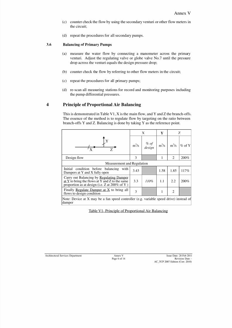
8/7/2019 Test Adjust and Balancing (See 233)
http://slidepdf.com/reader/full/test-adjust-and-balancing-see-233 232/247
Annex V
Architectural Services Department Annex V Issue Date: 28 Feb 2011Page 6 of 14 Revision Date: -
AC_TCP 2007 Edition (Corr. 2010)
Y
X Z
(c) counter check the flow by using the secondary venturi or other flow meters in
the circuit;
(d) repeat the procedures for all secondary pumps.
3.6 Balancing of Primary Pumps
(a) measure the water flow by connecting a manometer across the primary
venturi. Adjust the regulating valve or globe valve No.7 until the pressure
drop across the venturi equals the design pressure drop;
(b) counter check the flow by referring to other flow meters in the circuit;
(c) repeat the procedures for all primary pumps;
(d) re-scan all measuring stations for record and monitoring purposes including
the pump differential pressures.
4 Principle of Proportional Air Balancing
This is demonstrated in Table V1, X is the main flow, and Y and Z the branch-offs.
The essence of the method is to regulate flow by targeting on the ratio between
branch-offs Y and Z. Balancing is done by taking Y as the reference point.
X Y Z
m3
/s
% of
design m3
/s m3
/s % of Y
Design flow 3 1 2 200%
Measurement and Regulation
Initial condition before balancing withDampers at Y and X fully open
3.43 1.58 1.85 117%
Carry out Balancing by Regulating Damperat Y to bring the flows at Y and Z to the sameproportion as at design (i.e. Z at 200% of Y )
3.3 110% 1.1 2.2 200%
Finally Regulate Damper at X to bring all
flows to design condition
3 1 2
Note: Device at X may be a fan speed controller (e.g. variable speed drive) instead of damper
Table V1- Principle of Proportional Air Balancing
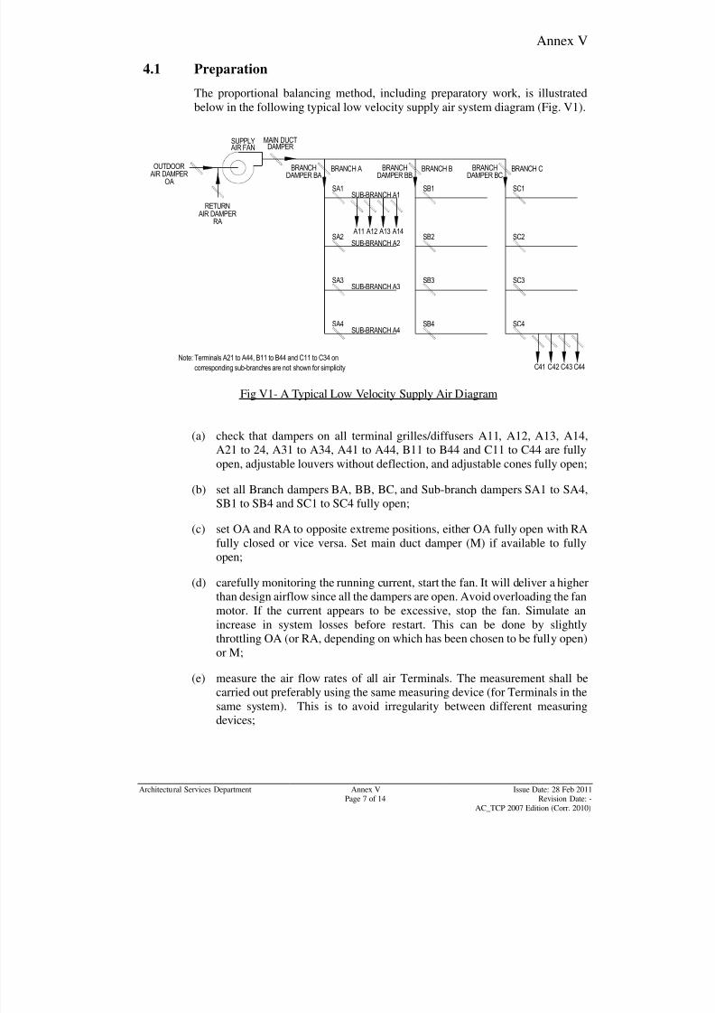
8/7/2019 Test Adjust and Balancing (See 233)
http://slidepdf.com/reader/full/test-adjust-and-balancing-see-233 233/247
Annex V
Architectural Services Department Annex V Issue Date: 28 Feb 2011Page 7 of 14 Revision Date: -
AC_TCP 2007 Edition (Corr. 2010)
4.1 Preparation
The proportional balancing method, including preparatory work, is illustrated
below in the following typical low velocity supply air system diagram (Fig. V1).
SUPPLY
AIR FAN
MAIN DUCT
DAMPER
BRANCHDAMPER BA
BRANCH A BRANCH B BRANCH C
SA1 SB1 SC1
A11 A12 A13 A14
C41 C44C43C42
SUB-BRANCH A1
BRANCHDAMPER BB
BRANCHDAMPER BC
SA2 SB2 SC2
SA3 SB3 SC3
SA4 SB4 SC4
SUB-BRANCH A2
SUB-BRANCH A3
SUB-BRANCH A4
OUTDOORAIR DAMPER
OA
RETURNAIR DAMPER
RA
Note: Terminals A21 to A44, B11 to B44 and C11 to C34 on
corresponding sub-branches are not shown for simplicity
Fig V1- A Typical Low Velocity Supply Air Diagram
(a) check that dampers on all terminal grilles/diffusers A11, A12, A13, A14,
A21 to 24, A31 to A34, A41 to A44, B11 to B44 and C11 to C44 are fullyopen, adjustable louvers without deflection, and adjustable cones fully open;
(b) set all Branch dampers BA, BB, BC, and Sub-branch dampers SA1 to SA4,
SB1 to SB4 and SC1 to SC4 fully open;
(c) set OA and RA to opposite extreme positions, either OA fully open with RA
fully closed or vice versa. Set main duct damper (M) if available to fully
open;
(d) carefully monitoring the running current, start the fan. It will deliver a higher
than design airflow since all the dampers are open. Avoid overloading the fanmotor. If the current appears to be excessive, stop the fan. Simulate an
increase in system losses before restart. This can be done by slightly
throttling OA (or RA, depending on which has been chosen to be fully open)
or M;
(e) measure the air flow rates of all air Terminals. The measurement shall be
carried out preferably using the same measuring device (for Terminals in the
same system). This is to avoid irregularity between different measuring
devices;
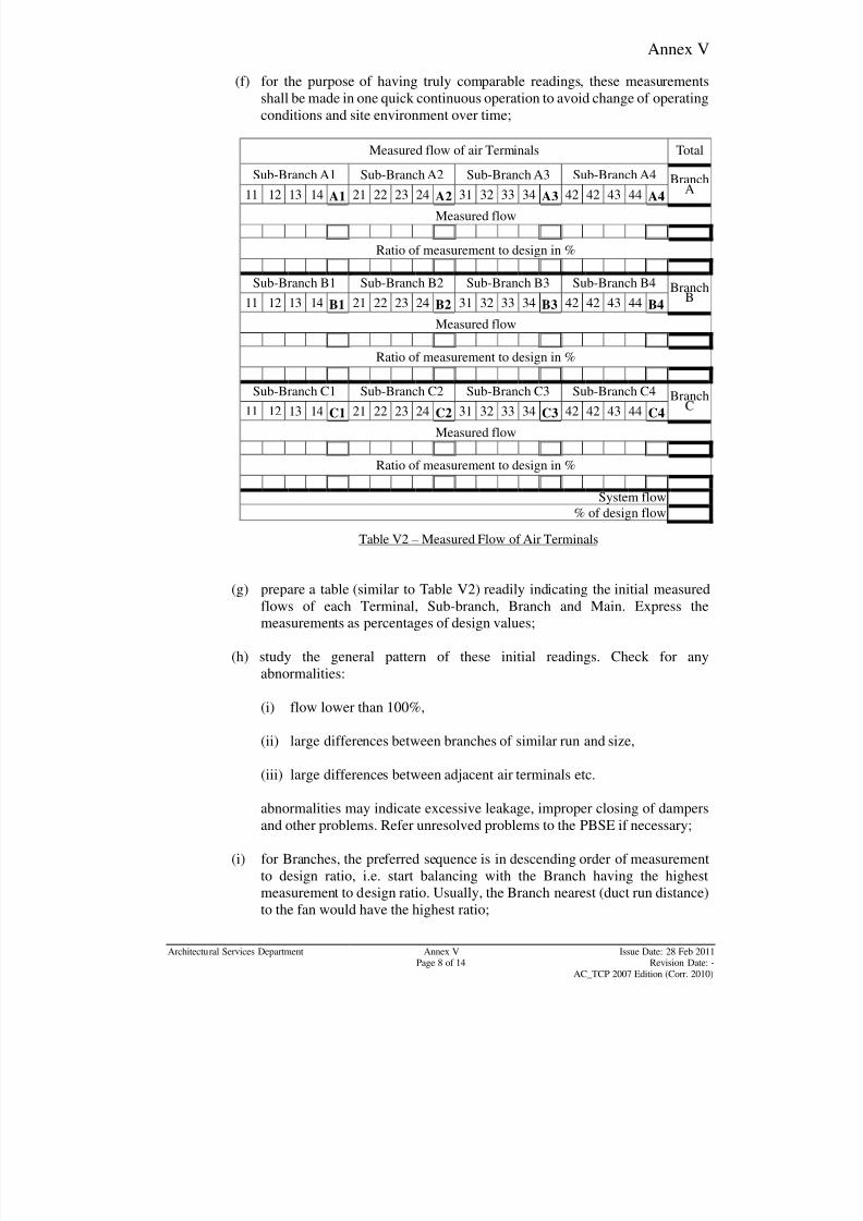
8/7/2019 Test Adjust and Balancing (See 233)
http://slidepdf.com/reader/full/test-adjust-and-balancing-see-233 234/247
Annex V
Architectural Services Department Annex V Issue Date: 28 Feb 2011Page 8 of 14 Revision Date: -
AC_TCP 2007 Edition (Corr. 2010)
(f) for the purpose of having truly comparable readings, these measurements
shall be made in one quick continuous operation to avoid change of operating
conditions and site environment over time;
Measured flow of air Terminals Total
Sub-Branch A1 Sub-Branch A2 Sub-Branch A3 Sub-Branch A4 BranchA11 12 13 14 A1 21 22 23 24 A2 31 32 33 34 A3 42 42 43 44 A4
Measured flow
Ratio of measurement to design in %
Sub-Branch B1 Sub-Branch B2 Sub-Branch B3 Sub-Branch B4 BranchB11 12 13 14 B1 21 22 23 24 B2 31 32 33 34 B3 42 42 43 44 B4
Measured flow
Ratio of measurement to design in %
Sub-Branch C1 Sub-Branch C2 Sub-Branch C3 Sub-Branch C4 BranchC11 12 13 14 C1 21 22 23 24 C2 31 32 33 34 C3 42 42 43 44 C4
Measured flow
Ratio of measurement to design in %
System flow
% of design flow
Table V2 – Measured Flow of Air Terminals
(g) prepare a table (similar to Table V2) readily indicating the initial measured
flows of each Terminal, Sub-branch, Branch and Main. Express the
measurements as percentages of design values;
(h) study the general pattern of these initial readings. Check for any
abnormalities:
(i) flow lower than 100%,
(ii) large differences between branches of similar run and size,
(iii) large differences between adjacent air terminals etc.
abnormalities may indicate excessive leakage, improper closing of dampers
and other problems. Refer unresolved problems to the PBSE if necessary;
(i) for Branches, the preferred sequence is in descending order of measurement
to design ratio, i.e. start balancing with the Branch having the highest
measurement to design ratio. Usually, the Branch nearest (duct run distance)
to the fan would have the highest ratio;
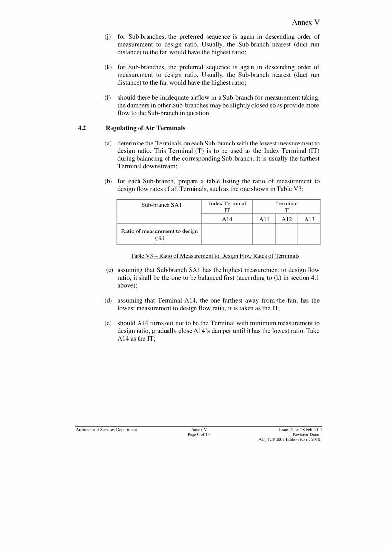
8/7/2019 Test Adjust and Balancing (See 233)
http://slidepdf.com/reader/full/test-adjust-and-balancing-see-233 235/247
Annex V
Architectural Services Department Annex V Issue Date: 28 Feb 2011Page 9 of 14 Revision Date: -
AC_TCP 2007 Edition (Corr. 2010)
(j) for Sub-branches, the preferred sequence is again in descending order of
measurement to design ratio. Usually, the Sub-branch nearest (duct run
distance) to the fan would have the highest ratio;
(k) for Sub-branches, the preferred sequence is again in descending order of
measurement to design ratio. Usually, the Sub-branch nearest (duct run
distance) to the fan would have the highest ratio;
(l) should there be inadequate airflow in a Sub-branch for measurement taking,
the dampers in other Sub-branches may be slightly closed so as provide more
flow to the Sub-branch in question.
4.2 Regulating of Air Terminals
(a) determine the Terminals on each Sub-branch with the lowest measurement to
design ratio. This Terminal (T) is to be used as the Index Terminal (IT)
during balancing of the corresponding Sub-branch. It is usually the farthest
Terminal downstream;
(b) for each Sub-branch, prepare a table listing the ratio of measurement to
design flow rates of all Terminals, such as the one shown in Table V3;
Sub-branch SA1 Index Terminal
IT
Terminal
T
A14 A11 A12 A13
Ratio of measurement to design
(%)
Table V3 – Ratio of Measurement to Design Flow Rates of Terminals
(c) assuming that Sub-branch SA1 has the highest measurement to design flow
ratio, it shall be the one to be balanced first (according to (k) in section 4.1
above);
(d) assuming that Terminal A14, the one farthest away from the fan, has the
lowest measurement to design flow ratio, it is taken as the IT;
(e) should A14 turns out not to be the Terminal with minimum measurement to
design ratio, gradually close A14‟s damper until it has the lowest ratio. Take
A14 as the IT;
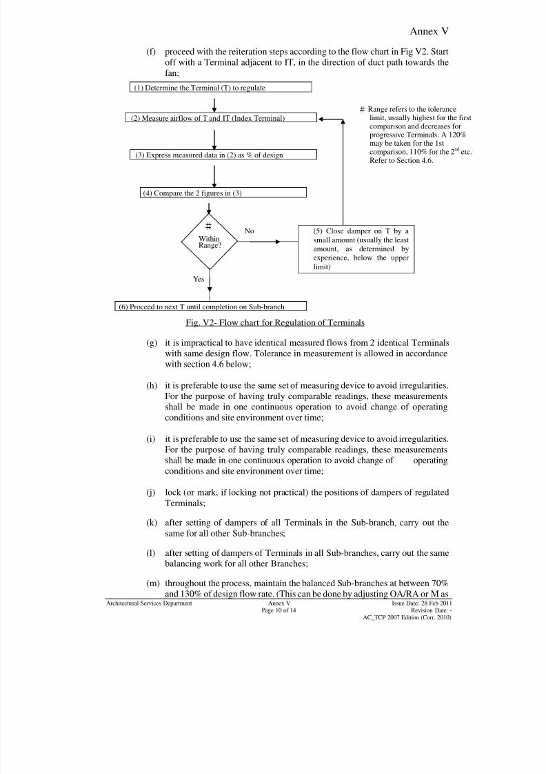
8/7/2019 Test Adjust and Balancing (See 233)
http://slidepdf.com/reader/full/test-adjust-and-balancing-see-233 236/247
Annex V
Architectural Services Department Annex V Issue Date: 28 Feb 2011Page 10 of 14 Revision Date: -
AC_TCP 2007 Edition (Corr. 2010)
(f) proceed with the reiteration steps according to the flow chart in Fig V2. Start
off with a Terminal adjacent to IT, in the direction of duct path towards the
fan;
Fig. V2- Flow chart for Regulation of Terminals
(g) it is impractical to have identical measured flows from 2 identical Terminalswith same design flow. Tolerance in measurement is allowed in accordance
with section 4.6 below;
(h) it is preferable to use the same set of measuring device to avoid irregularities.
For the purpose of having truly comparable readings, these measurements
shall be made in one continuous operation to avoid change of operating
conditions and site environment over time;
(i) it is preferable to use the same set of measuring device to avoid irregularities.
For the purpose of having truly comparable readings, these measurements
shall be made in one continuous operation to avoid change of operatingconditions and site environment over time;
(j) lock (or mark, if locking not practical) the positions of dampers of regulated
Terminals;
(k) after setting of dampers of all Terminals in the Sub-branch, carry out the
same for all other Sub-branches;
(l) after setting of dampers of Terminals in all Sub-branches, carry out the same
balancing work for all other Branches;
(m) throughout the process, maintain the balanced Sub-branches at between 70%
and 130% of design flow rate. (This can be done by adjusting OA/RA or M as
# Range refers to the tolerancelimit, usually highest for the firstcomparison and decreases forprogressive Terminals. A 120%may be taken for the 1stcomparison, 110% for the 2
ndetc.
Refer to Section 4.6.
(5) Close damper on T by asmall amount (usually the leastamount, as determined by
experience, below the upper
limit)
No
(1) Determine the Terminal (T) to regulate
(3) Express measured data in (2) as % of design
(4) Compare the 2 figures in (3)
(6) Proceed to next T until completion on Sub-branch
(2) Measure airflow of T and IT (Index Terminal)
WithinRange?
Yes
#
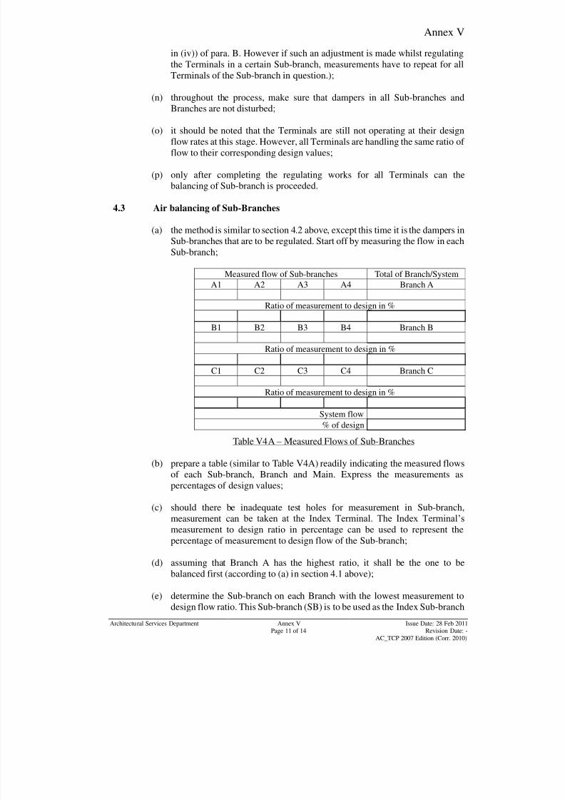
8/7/2019 Test Adjust and Balancing (See 233)
http://slidepdf.com/reader/full/test-adjust-and-balancing-see-233 237/247
Annex V
Architectural Services Department Annex V Issue Date: 28 Feb 2011Page 11 of 14 Revision Date: -
AC_TCP 2007 Edition (Corr. 2010)
in (iv)) of para. B. However if such an adjustment is made whilst regulating
the Terminals in a certain Sub-branch, measurements have to repeat for all
Terminals of the Sub-branch in question.);
(n) throughout the process, make sure that dampers in all Sub-branches and
Branches are not disturbed;
(o) it should be noted that the Terminals are still not operating at their design
flow rates at this stage. However, all Terminals are handling the same ratio of
flow to their corresponding design values;
(p) only after completing the regulating works for all Terminals can the
balancing of Sub-branch is proceeded.
4.3 Air balancing of Sub-Branches
(a) the method is similar to section 4.2 above, except this time it is the dampers in
Sub-branches that are to be regulated. Start off by measuring the flow in eachSub-branch;
Measured flow of Sub-branches Total of Branch/System
A1 A2 A3 A4 Branch A
Ratio of measurement to design in %
B1 B2 B3 B4 Branch B
Ratio of measurement to design in %
C1 C2 C3 C4 Branch C
Ratio of measurement to design in %
System flow
% of design
Table V4A – Measured Flows of Sub-Branches
(b) prepare a table (similar to Table V4A) readily indicating the measured flows
of each Sub-branch, Branch and Main. Express the measurements aspercentages of design values;
(c) should there be inadequate test holes for measurement in Sub-branch,
measurement can be taken at the Index Terminal. The Index Terminal‟s
measurement to design ratio in percentage can be used to represent the
percentage of measurement to design flow of the Sub-branch;
(d) assuming that Branch A has the highest ratio, it shall be the one to be
balanced first (according to (a) in section 4.1 above);
(e) determine the Sub-branch on each Branch with the lowest measurement todesign flow ratio. This Sub-branch (SB) is to be used as the Index Sub-branch

8/7/2019 Test Adjust and Balancing (See 233)
http://slidepdf.com/reader/full/test-adjust-and-balancing-see-233 238/247
Annex V
Architectural Services Department Annex V Issue Date: 28 Feb 2011Page 12 of 14 Revision Date: -
AC_TCP 2007 Edition (Corr. 2010)
(IS) during balancing. Assuming SA4 has the lowest measurement to design
ratio, it is taken as the IS;
(f) for each Branch, prepare a table listing the ratio of measured flow rates of all
Sub-branch to their corresponding design flow rates, such as the one shown
on Table V4B;
Branch A Index Sub-branch
IS
Sub-branch
SB
SA4 SA1 SA2 SA3
Ratio of measurement to design
(%)
Table V4B – Ratio of Measured Flow Rate of Sub-Branches
(g) proceed with the reiterative steps of balancing according to the flowchart in
Fig. V3 Start off with an adjacent Sub-branch.
Fig. V3- Flow chart for Air-balancing of Sub-Branches
#Range refers to the tolerancelimit, usually highest for the firstcomparison and decreases forprogressive Sub-branches.120% may be taken for the 1stcomparison, 110% for the 2
nd
etc. Refer to Section 4.6
(5) Close damper on SB by a
small amount (usually the
least amount, as determinedby experience, below the
upper limit)
No
(1) Determine the Sub-branch (SB) to regulate
(3) Express measured data in (2) as % of design
(4) Compare the 2 figures in (3)
(6) Proceed to next SB until completion of the Branch
(2) Measure air flows of SB and IS (Index Sub-branch)
t nRange?
Yes
#
8/7/2019 Test Adjust and Balancing (See 233)
http://slidepdf.com/reader/full/test-adjust-and-balancing-see-233 239/247
Annex V
Architectural Services Department Annex V Issue Date: 28 Feb 2011Page 13 of 14 Revision Date: -
AC_TCP 2007 Edition (Corr. 2010)
(h) it is preferable to use the same set of measuring device to avoid irregularities.
For purpose of having truly comparable readings, these measurements shall
be made in one continuous operation to avoid change of operating conditions
and site environment over time;
(i) tolerance in measurement is allowed in accordance with section 4.6 below;
(j) lock the positions of dampers of balanced Sub-branches;
(k) after setting of Dampers on all Sub-branches in the same Branch, carry out
the same for all other Branches;
(l) throughout the process, maintain the balanced Sub-branches at between 70%
and 130% of design flow rate;
(m) throughout the process, make sure that dampers in all Branches are not
disturbed;
(n) it should be noted that the Sub-branches are still not operating at their design
flow rates at this stage. However, all are handling the same ratio of flow to
their corresponding design values;
(o) only after completing the air balancing works for all Sub-branches can the
balancing of Branch is proceeded.
4.4 Air balancing of Branch and regulation of total system flow
(a) branch Dampers BA, BB & BC are to be regulated. The method is same as for
balancing for Sub-branches;
(b) determine the Branch with the lowest measurement to design flow ratio. This
Branch is to be used as the Index Branch (IB) during balancing. Assuming
BC has the lowest measurement to design ratio, it is taken as the IB;
(c) carry out similar exercise as described in (g) in section 4.3 above, and take
note of the pre-cautions and remarks in (h) to (o).
4.5 Regulation of total system flow
(a) after completing air balancing of all Branches, it is time to regulate the total
system flow;
(b) measure the total airflow in the main duct. Where it is not practical to do so,
Branch flow rates can be added together to establish the total flow;
(c) wherever practical, filters if any in the system should be cleaned;
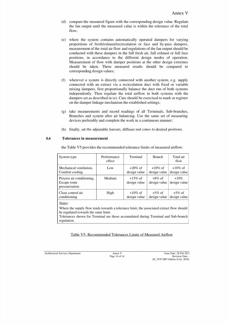
8/7/2019 Test Adjust and Balancing (See 233)
http://slidepdf.com/reader/full/test-adjust-and-balancing-see-233 240/247
Annex V
Architectural Services Department Annex V Issue Date: 28 Feb 2011Page 14 of 14 Revision Date: -
AC_TCP 2007 Edition (Corr. 2010)
(d) compare the measured figure with the corresponding design value. Regulate
the fan output until the measured value is within the tolerance of the total
flow;
(e) where the system contains automatically operated dampers for varying
proportions of fresh/exhaust/recirculation or face and by-pass dampers,
measurement of the total air flow and regulations of the fan output should beconducted with these dampers in the full fresh air, full exhaust or full face
positions, in accordance to the different design modes of operation.
Measurement of flow with damper positions at the other design extremes
should be taken. These measured results should be compared to
corresponding design values;
(f) wherever a system is directly connected with another system, e.g. supply
connected with an extract via a recirculation duct with fixed or variable
mixing dampers, first proportionally balance the duct run of both systems
independently. Then regulate the total airflow in both systems with the
dampers set as described in (e). Care should be exercised to mark or registeron the damper linkage mechanism the established settings;
(g) take measurements and record readings of all Terminals, Sub-branches,
Branches and system after air balancing. Use the same set of measuring
devices preferably and complete the work in a continuous manner;
(h) finally, set the adjustable louvers, diffuser and cones to desired positions.
4.6 Tolerances in measurement
the Table V5 provides the recommended tolerance limits of measured airflow:
System type Performance
effect
Terminal Branch Total air
flow
Mechanical ventilation,
Comfort cooling
Low +20% of
design value
+10% of
design value
+10% of
design value
Process air conditioning,
Escape route
pressurization
Medium +15% of
design value
+8% of
design value
+10%
design value
Close control airconditioning
High +10% of design value
+5% of design value
+5% of design value
Notes:
Where the supply flow tends towards a tolerance limit, the associated extract flow should
be regulated towards the same limit.
Tolerances shown for Terminal are those accumulated during Terminal and Sub-branch
regulation.
Table V5- Recommended Tolerances Limits of Measured Airflow
8/7/2019 Test Adjust and Balancing (See 233)
http://slidepdf.com/reader/full/test-adjust-and-balancing-see-233 241/247
Index
Index
Page 1 of 7
AC_TCP
2007 Edition (Corr.2010)
A Abnormal vibration 41
Absorption machine solution pumps 84
Absorption refrigeration machine 81
Absorption Unit Shell 82
Access doors 21
Acoustic linings 20
Actual-to-design water flow 33
Additional tests 94
Air balancing 43
Air Borne Bacteria 56
Air flow sheets 22
Air intake screens 20
Air Leakage Test 11
Air vent 13
Airborne bacteria colony count 103
Air-cooled Condenser 58
Air-cooled motors 30
Air-locks 16
Algae 16
Ambient temperature 17
Ampere meter 27
Analogue input 112
Analogue output 113
Andersen multi-hole impactor samplers 105
Anemometer 40
Anti-condensation Heater 61
Anti-recycle relay 92
Anti-vibration mounting 15
Architectural 1
Artificial load 69
ASHRAE 34
Authority 35
Automatic pump down 70
Auxiliary water piping 81
B Background noise level 128
BACnet 34
Bearing lubrication 15
Belt tension and match 60
Biological parameter 103
Blade 25
Blockage 13
Boiler plant 12
Bolt 64
Bore coil 12
Building Automation System (BAS) 107
Building Services Installations 126
Bypass 67
Bypass valve 67
C Calibration chart 33
Carbon dioxide (CO2) 103
Carbon monoxide (CO) 103
Cavitation 93
CCMS Workstation/Server 7
Central Control and Monitoring System (CCMS)
107
Centrifugal Compressor System 73
Changeover devices 14
Checklist for Walkthrough Inspection 48
Chemical Cleaning 13
Chemical parameters 103
Chilled water 29
Chiller 12
CIBSE Commissioning Code A
1996, Air Distribution Systems 42
Circulating pump 54
Close Loop Test 123
Codes of Practice for Energy Efficiency of Air
Conditioning Installations 106
Cold plant 67
Colour graphic layout diagram 35
Commissioning report 3
Common pipe (by-pass de-coupler) 97
8/7/2019 Test Adjust and Balancing (See 233)
http://slidepdf.com/reader/full/test-adjust-and-balancing-see-233 242/247
Index
Index
Page 2 of 7
AC_TCP
2007 Edition (Corr.2010)
Commutator 30
Complex interlocks 17
Compressor 73
Compressor capacity control system 70
Compressor Crankcase Heater 62
Compressor discharge line 87
Compressor oil 72
Compressor shaft 60
Compressor unloading gear 60
Condenser air/water entering temperature 96
Condenser liquid line valve 67
Condenser water pumps 63
Condenser water systems 58
Condensing water thermostat 85
Constant flow coefficient 33
Continuous running test 67
Contractor 1
Control circuit logic 17
Control circuits 16
Control equipment 108
Control linkages 21
Control Strategy 118
Coolant 15
Cooling coil condensate trays 20
Cooling tower basin 12
Cooling tower thermostat 78
Correct grade 14
Corrective measures 2
Cover plates 17
Crankcase heater 67
D Damper 21
Damper linkage mechanism 14
Dampers - Motorized volume control 49
Dampers - Multi-leaf 21
Dampers and linkages 20
Dangerous projections 26
Dashpots 17
Data Logging 104
Data sheets 3
Data transmission rate 112
Database 96
Deflection 15
Dehydration 55
Design operating speed 9
Design water flow direction 14
Design water flow rate 4
Differential pressure 37
Digital Input 117
Digital output 113
Digital Signal 120
Dilution 86
Direct Digital Controllers (DDC) 33
Direct drive pumps 15
Direct expansion air cooler 65
Direct-on-line starting 18
Discharge pressure gauge throttling valve 67
Disconnection of cables 23
Discriminatory protection 17
Drain cocks 14
Drain point 14
Drainage traps 48
Drainage water 21
Drive guards 15
Drives 9
Dry nitrogen 64
Dual duct system 46
Dual-duct boxes 46
Duct path 10
Dummy testing 35
Duplex strainers 14
Dynamic balance 42
Dynamic Rotation Tests 55
E Electric motors 9
Electronic expansion valve 66
8/7/2019 Test Adjust and Balancing (See 233)
http://slidepdf.com/reader/full/test-adjust-and-balancing-see-233 243/247
Index
Index
Page 3 of 7
AC_TCP
2007 Edition (Corr.2010)
Electronic leak detector 64
Electronic measuring equipment 35
Eliminator 60
Encrypt 35
Energy meters 97
Entering chilled water temperature (Te) 96
Enthalpy control device 106
Environmental control 115
Environmental Protection Department (EPD) 128
Equalizer 59
Equipment chambers 20
Evacuation 55
Evaporator 56
Evaporator pressure regulating valve 71
Excessive spillage 16
Exhaust 11
Expansion devices 14
External cleanliness 14
Extract systems 20
F Fabric Filter 38
Fan coil units (FCU) 127
Fan curves and surge characteristics 43
Fan drive settings 45
Fan impellers and drives, 9
Fan internals 20
Fan speed controller 6
Fan wheels 49, 51
Feed connection 14
Feed tank 12
Filling source 16
Filter bank 40
Filter control panel 39
Filtration 12
Final evaluation 3
Fire suppression installations 54
Flash-over 39
Float valve 73, 82
Flow characteristics 33
Flushing process 12
Flushing water 12
Formaldehyde (HCHO) 103
Free cooling 106
Freeze protection thermostat 67
Fresh air systems 43
Full load capacity database 97
Full load capacity table/chart 95
Functional performance test report 3
Fuse ratings 17
Fusible link 21
G Gas ballast valve 82
General Specification 1
Gland 15
Gland nuts 15
Graphics 119
H H.T. primary circuit 25
Halide torch 74
HCHO 103
Heat exchanger 9
Heat reclaim unit 95
Heat recovery unit 95
Heat-balance flowrate 53
Heater and cooler batteries 20
Hermetic pump 82
Hermetic unit 64
High efficiency terminal filters 36
High Pressure Duct 11
High pressure oil cut-out 77
High pressure oil cut-out switch 77
High voltage components 25
Hong Kong Laboratory Accreditation Scheme
(HOKLAS) 27Hospital 45

8/7/2019 Test Adjust and Balancing (See 233)
http://slidepdf.com/reader/full/test-adjust-and-balancing-see-233 244/247
Index
Index
Page 4 of 7
AC_TCP
2007 Edition (Corr.2010)
Hot water piping system 81
HVCA standard 11
Hydraulic systems 10
Hydraulic unloader cams 89
Hydraulically pressure test 10
Exhaust Hood 34
I I/O points 126
IAQ Objectives 103
IAQ parameter 102
IEC standard 9
Impeller 14
Inclined and vertical manometer 27
Incoming/outgoing cables 119
Index branch 4
Index Sub-branch (IS) 12
Index Terminal (I.T.) 9
Inlet guide vanes 22
Interface 33
Interlock key 38
Ionizer 26
Isolating and regulating valves 29
Isolators 18
K Kitchen ventilation systems 54
L Laboratories 10
LAN cable 125
Least favoured branch 4
Least favoured terminal unit 5
Light load 30
Liquid line solenoid valve 62
Liquid line strainer 59
Liquid receiver 59
Lithium bromide solution 81
Live parts 39
Louver 94
Low oil sump temperature heater control 89
Low Pressure Duct Construction Standards 11
Low pressure oil cut-out switch 77
Low pressure pump down 89
Low pressure unload 89
Low Tension (LT.) 25
Low velocity supply air system diagram 7
Low Water Flow Safety Device 59
Lubricant 15
Lubricating oil 67
M Main damper 40
Main earthing system 26
Main inlet filter cells 36
Make-up or spill air 45
Manifold 28
Manometer 37
Manual override 29
Maximum design flow 43
Maximum pipework test pressure 10
Mechanical damage 17
Minimum test pressure 10
Mixed-air temperature 51
Momentary start 90
Most favoured branch 4
Motor full load current 31
Motor name-plate 17
Motor shaft 15
Motorized balancing valve 34
Muffler 60
Multi-section system 12
Multi-speed motors 30
MVAC equipment 128
N Nitrogen dioxide (NO2) 103
Nitrogen injection pressure reducing valve 75Noise 30
8/7/2019 Test Adjust and Balancing (See 233)
http://slidepdf.com/reader/full/test-adjust-and-balancing-see-233 245/247
Index
Index
Page 5 of 7
AC_TCP
2007 Edition (Corr.2010)
Noise Control Ordinance 128
Noise Criteria (NC) 128
Nominal diameter 9
Non destructive inspection process 9
Non-destructive testing 10
Normal water velocity 13
Nozzle 57
O Octave filter 127
Oil circulating time delay 89
Oil failure relay 89
Oil failure switch 89
Oil filter pressure cut-out switch 77
Oil Free Compressor 73
Oil Pressure Cut-out 14
Oil pressure relief valve 77
Oil pump coast-down relay 89
Oil ring 41
Oil sump temperature heater control 89
Open/close position 21
Operating and Maintenance (O&M) 114
Orifice plate 13
Outdoor Air Pre-conditioner (OAP) 37
Outside air quantity 51
Overflows 13
Ozone 39
P Packaged Water Chillers 11
Parallel feed 12
Particular Specification 2
Passive sampling methods 103
Pipes and fittings 9
Pipework system 12
Pipework tests 10
Pitot Tube Traverse method 52
Plant Change Over 119Plate exchanger 9
Plumb of pump 15
Pneumatic systems 84
Portable Operator Terminal 126
Pre-commissioning 12
Pre-filter cells 25
Preliminary and visual test 12
Preliminary checks 6
Pressure differential signal 33
Pressure drop 33
Pressure gauge 13
Pressure sensor 44
Pressure switches 88
Pressure vessels 9
Primary circulation 29
Primary pump 32
Primary refrigerant 81
Project Building Services Engineer (PBSE) 1
Project Building Services Inspector (PBSI) 1
Proportional band 111
Proportional controllers 111
Pump Alignment Test 17
Pump altitude gauges 31
Pump characteristic 31
Pump impellers 9
Pump priming devices 14
Purge drum pressure 81
Purge heater 78
Purge system 79
Purge unit 73
Q Quadrant indication 21
R Radiator 9
Radiographic 9
Radon (Rn) 103
Real-time monitors 103Reciprocating Compressor Systems 57
8/7/2019 Test Adjust and Balancing (See 233)
http://slidepdf.com/reader/full/test-adjust-and-balancing-see-233 246/247
Index
Index
Page 6 of 7
AC_TCP
2007 Edition (Corr.2010)
Refrigerant agitator solenoid valve 80
Refrigerant charging apparatus 75
Reiteration steps 10
Relative humidity 103
Relay 78
Relief valve 14
Remote control system 38
Removal of welds 9
Respirable suspended particulates (RSP) 103
Room unit coil 12
Rotational speed 9
Running-in 31
S Safety and failure alarm systems 26
Safety valves 11
Sail switches 20
Sampling tubes 105
Screw Compressor Systems 57
Seepage of lubricant 41
Self-diagnostic devices 34
Self-draining sections 12
Sensing elements 20
Simulator 98
Skilled and experienced person 57
Slip ring 30
Small-bore accessory piping 73
Smoke extraction 11
Soap solution 64
Solenoid valve 59
Sound level meter 127
Sound Pressure Levels (SPLs) 127
Speed measurement 15
Spindles 21
Split type Air-conditioning Unit 28
Spool bearings 22
Spray nozzles 12
Star-delta 17
Start-up 118
Static head 10
Statutory requirements and regulations 2
Steady state system performance 107
Steam piping system 81
Stiffness 15
Strainer 14
Strainer mesh 14
Sub-cooling temperature 92
Surge line 44
T T & C Certificate 21
T & C procedures 1
T & C report 114
Tachometer 27
Temperature switches 89
Temporary filter media 19
Temporary modifications 2
Terminal unit 20
Terminal workstations 115
Test Equipment 8
Test holes 21
Testing of individual components 2
Tests and Inspections 2
Theoretical system curve 43
Thermal cut-outs 62
Thermal insulation 20
Thermostatic expansion valve 59
Thermostatic valve 29
Thermostats 61
Tolerance 33
Total volatile organic compounds (TVOC) 103
Tower basin 16
Transit bolts 22
Trend log 122
Tryptic soy agar plates 105
Two-position control 112
8/7/2019 Test Adjust and Balancing (See 233)
http://slidepdf.com/reader/full/test-adjust-and-balancing-see-233 247/247
Index
U Ultrasonic methods 9
Unloaded compressor start-up 70
Unsafe ladders, 26Unshrouded live components 16
V
Vortex damper control 43
Vulnerable oil line 64
W Walkthrough inspection 103
Walkways 26
Washer tanks 20