Embed Size (px)
Citation preview

SMK20Test Coupling with Port Connection
SMK20 Type GTest Coupling complete with Straight Fitting
SMK20 Type K Test Coupling for 24° Cone Fittings
SMK20-JICTest Coupling SMK-JIC Connection (to SAE J514)
SSK20Bulkhead
Fast Coupling for
� Monitoring and control of pressure � Venting � Sampling in high- and low-pressure systems
Advantages
� Test system at working pressure � Leak proof connection before ball check is open � Simple connection to measurement, control and switching devices � Self locking metal protective cap
Working Pressure
� Max. working pressure 630 bar / 9137 PSIFor SMK Type G and K the recommended working pressure of fi tting manufacturer should be noted.
� Connection under pressure up to 400 bar / 5801 PSI max.
Materials
� Metal Parts: Standard material: Steel, zinc/nickel-plated = C6F (CrVI-free) Optional: Stainless Steel V2A (1.4305 / AISI 303) on request Stainless Steel V4A (1.4571 / AISI 316Ti) on request
For ordering "V2A" or "V4A" please replace "C6F" with "V2A" or "V4A".
� Ball: Stainless Steel
� Sealings: P = NBR (Buna-N®) (Temperature range -20 °C ... +100 °C / -4 °F ... +212 °F)Note: Internal sealings made of FPM, even for standard NBR-type.
V = FPM (Viton®)* (Temperature range -20 °C ... +200 °C / -4 °F ... +392 °F) * Standard option for North America is FPM (Viton®)
E = EPDM Ethylene Propylene Diene Monomer Rubber (for Brake fl uid, Temperature range -40 °C ... +150 °C / -40 °F ... +302 °F)
For ordering NBR or EPDM sealings please replace "V" with "P" or "E".
Vibration safety O-ring made of NBR (Buna-N®) (standard).
Media
� Suitable for hydraulic oils and other Mineral oil based fl uids(Check compatibility of sealing material)
� For use with other liquid media please consult STAUFF
Protection Cap
� The complete STAUFF-Test-20-type-SMK range is also available with a hexagonalprotection cap made of steel or plastic protection cap.
For ordering the hexagonal protection cap version please add "-SK" to the order code. (e.g. SMK20-M10x1-VA-SK-C6F)For ordering the plastic protection cap version please add "-KK" to the order code.(e.g. SMK20-M10x1-VA-KK-C6F)
Test Coupling with Ball Check
Test 20 Connection Thread M16 x 2 Introduction SMK20
Test CouplingSMK20
Internal Sealings
Ball
Vibration Safety O-ring
Spring
Sealing at Port Connection
Port Connection
B4 www.stauff.com
NoAm Version TEST.indd 4 10.11.2011 09:07:47

STAU
FFTe
stB
www.stauff.com B5
Dimensions / Order Codes Connection Thread M16 x 2 Test 20
Test Coupling with Port ConnectionSMK20
Sealing Details
O-ring Type A
Metal Joint Type B
Elastomeric Sealing Type C
Taper Type D (suitable sealant required)
O-ring Type E
Hex
M 16 h1
h2
G
17 10
(.39)(.67)
Metal Parts
Standard material: Steel, zinc/nickel-plated = C6F (CrVI-free)For ordering V2A (1.4305 / AISI 303) replace "C6F" with "V2A".For ordering V4A (1.4571 / AISI 316Ti) replace "C6F" with "V4A".
Sealings
For ordering NBR sealings replace "V" with "P".For ordering EPDM sealings replace "V" with "E".
* Standard option for North America is FPM (Viton®).
Protection Cap
Standard material: SteelFor ordering the hexagonal protection cap version please add "-SK" to the order code. (e.g. SMK20-M10x1-VA-SK-C6F)For ordering the plastic protection cap version please add "-KK" to the order code. (e.g. SMK20-M10x1-VA-KK-C6F)
For further information on materials, sealings or protection caps, please see page B4.
Other port connections and sealings on request. Please consult STAUFF for further information.
Thread Sealing Working Dimensions Order CodesPressure (mm/in) NBR FPM*
G (bar/PSI) h1 h2 Hex (Standard Option-North America)
M8 x 1Type A
250 38 8,5 17SMK20-M8x1-PA-C6F SMK20-M8x1-VA-C6F
3625 1.50 .33 .67
M10 x 1630 38 9,8 17
SMK20-M10x1-PA-C6F SMK20-M10x1-VA-C6F9137 1.50 .39 .67
M10 x 1
Type B
400 37 8 17SMK20-M10x1-PB-C6F SMK20-M10x1-VB-C6F
5801 1.46 .31 .67
M12 x 1,5630 37 12 17
SMK20-M12x1,5-PB-C6F SMK20-M12x1,5-VB-C6F9137 1.46 .47 .67
M14 x 1,5630 37 12 19
SMK20-M14x1,5-PB-C6F SMK20-M14x1,5-VB-C6F9137 1.46 .47 .75
M16 x 1,5630 37 12 22
SMK20-M16x1,5-PB-C6F SMK20-M16x1,5-VB-C6F9137 1.46 .47 .87
G1/8400 39 8 17
SMK20-G1/8-PB-C6F SMK20-G1/8-VB-C6F5801 1.54 .31 .67
G1/4630 37 12 19
SMK20-G1/4-PB-C6F SMK20-G1/4-VB-C6F9137 1.46 .47 .75
G3/8630 37 12 22
SMK20-G3/8-PB-C6F SMK20-G3/8-VB-C6F9137 1.46 .47 .87
M10 x 1
Type C
400 39 8 17SMK20-M10x1-PC-C6F SMK20-M10x1-VC-C6F
5801 1.54 .31 .67
M12 x 1,5630 37 12 17
SMK20-M12x1,5-PC-C6F SMK20-M12x1,5-VC-C6F9137 1.46 .47 .67
M14 x 1,5630 37 12 19
SMK20-M14x1,5-PC-C6F SMK20-M14x1,5-VC-C6F9137 1.46 .47 .75
M16 x 1,5630 37 12 22
SMK20-M16x1,5-PC-C6F SMK20-M16x1,5-VC-C6F9137 1.46 .47 .87
G1/8400 39 8 17
SMK20-G1/8-PC-C6F SMK20-G1/8-VC-C6F5801 1.54 .31 .67
G1/4630 37 12 19
SMK20-G1/4-PC-C6F SMK20-G1/4-VC-C6F9137 1.46 .47 .75
G3/8630 37 12 22
SMK20-G3/8-PC-C6F SMK20-G3/8-VC-C6F9137 1.46 .47 .87
G1/2630 39 14 27
SMK20-G1/2-PC-C6F SMK20-G1/2-VC-C6F9137 1.54 .55 1.06
R1/8 K
Type D
400 37 8 17SMK20-R1/8K-PD-C6F SMK20-R1/8K-VD-C6F
5801 1.46 .31 .67
R1/4 K630 35 12 17
SMK20-R1/4K-PD-C6F SMK20-R1/4K-VD-C6F9137 1.38 .47 .67
1/8 NPT400 36 10 17
SMK20-1/8NPT-PD-C6F SMK20-1/8NPT-VD-C6F5801 1.42 .39 .67
1/4 NPT630 35 15 17
SMK20-1/4NPT-PD-C6F SMK20-1/4NPT-VD-C6F9137 1.38 .59 .67
5/16–24 UNF
Type E
400 38 7,5 17SMK20-5/16UNF-PE-C6F SMK20-5/16UNF-VE-C6F
5.801 1.50 .30 .67
7/16–20 UNF630 38 9,1 17
SMK20-7/16UNF-PE-C6F SMK20-7/16UNF-VE-C6F9137 1.50 .36 .67
1/2–20 UNF630 38 9,2 17
SMK20-1/2UNF-PE-C6F SMK20-1/2UNF-VE-C6F9137 1.50 .36 .67
9/16–18 UNF630 37 10 19
SMK20-9/16UNF-PE-C6F SMK20-9/16UNF-VE-C6F9137 1.46 .39 .75
3/4–16 UNF630 37 11.1 19
SMK20-3/4UNF-PE-C6F SMK20-3/4UNF-VE-C6F9137 1.46 .44 .75
M10 x 1630 38 9,5 17
SMK20-M10x1-PE-C6F SMK20-M10x1-VE-C6F9137 1.50 .37 .67
M12 x1,5630 37 11 17
SMK20-M12x1,5-PE-C6F SMK20-M12x1,5-VE-C6F9137 1.46 .43 .67
M14 x 1,5630 38 11 19
SMK20-M14x1,5-PE-C6F SMK20-M14x1,5-VE-C6F9137 1.50 .43 .75
M16
17(.67)
10(.39)
G
h2h1
Dimensional drawings: All dimensions in mm (in).
NoAm Version TEST.indd 5 10.11.2011 09:07:50

Test 20 Connection Thread M16 x 2 Dimensions / Order Codes
B6 www.stauff.com
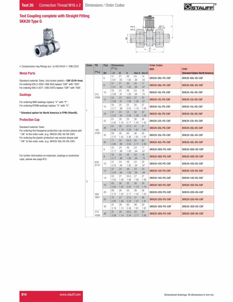
� Compression ring fittings acc. to ISO 8434-1 / DIN 2353
Metal Parts
Standard material: Steel, zinc/nickel-plated = C6F (CrVI-free)For ordering V2A (1.4305 / AISI 303) replace "C6F" with "V2A".For ordering V4A (1.4571 / AISI 316Ti) replace "C6F" with "V4A".
Sealings
For ordering NBR sealings replace "V" with "P".For ordering EPDM sealings replace "V" with "E".
* Standard option for North America is FPM (Viton®).
Protection Cap
Standard material: SteelFor ordering the hexagonal protection cap version please add "-SK" to the order code. (e.g. SMK20-08L-VG-SK-C6F)For ordering the plastic protection cap version please add "-KK" to the order code. (e.g. SMK20-08L-VG-KK-C6F)
For further information on materials, sealings or protection caps, please see page B4.
Series PN Pipe Dimensions Order Codes(mm/in) NBR FPM*
(bar/PSI) Ø d ~l1 l2 h Hex A Hex B (Standard Option-North America)
L
315
651 21 49 24 14
SMK20-06L-PG-C6F SMK20-06L-VG-C6F2.01 .83 1.93 .94 .55
851 21 49 24 17
SMK20-08L-PG-C6F SMK20-08L-VG-C6F2.01 .83 1.93 .94 .67
1053 23 49 24 19
SMK20-10L-PG-C6F SMK20-10L-VG-C6F2.09 .91 1.93 .94 .75
456812
53 23 50,5 27 22SMK20-12L-PG-C6F SMK20-12L-VG-C6F
2.09 .91 1.99 1.06 .87
1555 25 52 30 27
SMK20-15L-PG-C6F SMK20-15L-VG-C6F2.17 .98 2.05 1.18 1.06
1857 24 53 32 32
SMK20-18L-PG-C6F SMK20-18L-VG-C6F2.24 .94 2.09 1.26 1.26
160
2261 28 55 36 36
SMK20-22L-PG-C6F SMK20-22L-VG-C6F2.40 1.10 2.17 1.42 1.42
2861 28 57,5 41 41
SMK20-28L-PG-C6F SMK20-28L-VG-C6F2.40 1.10 2.26 1.61 1.61
232035
69 26 60 46 50SMK20-35L-PG-C6F SMK20-35L-VG-C6F
2.72 1.02 2.36 1.81 1.97
4271 25 64,5 55 60
SMK20-42L-PG-C6F SMK20-42L-VG-C6F2.80 .98 2.54 2.17 2.36
S
630
655 25 49 24 17
SMK20-06S-PG-C6F SMK20-06S-VG-C6F2.17 .98 1.93 .94 .67
855 25 49 24 19
SMK20-08S-PG-C6F SMK20-08S-VG-C6F2.17 .98 1.93 .94 .75
1057 24 49 24 22
SMK20-10S-PG-C6F SMK20-10S-VG-C6F9137 2.24 .94 1.93 .94 .87
1257 24 49 24 24
SMK20-12S-PG-C6F SMK20-12S-VG-C6F2.24 .94 1.93 .94 .94
1463 27 50,5 27 27
SMK20-14S-PG-C6F SMK20-14S-VG-C6F2.50 1.06 1.99 1.06 1.06
400
1663 26 52 30 30
SMK20-16S-PG-C6F SMK20-16S-VG-C6F2.50 1.02 2.05 1.18 1.18
2069 26 55 36 36
SMK20-20S-PG-C6F SMK20-20S-VG-C6F2.72 1.02 2.17 1.42 1.42
580125
75 27 57,5 41 46SMK20-25S-PG-C6F SMK20-25S-VG-C6F
2.95 1.06 2.26 1.61 1.81
3081 28 60 46 50
SMK20-30S-PG-C6F SMK20-30S-VG-C6F3.19 1.10 2.36 1.81 1.97
31538
91 29 64,5 55 60SMK20-38S-PG-C6F SMK20-38S-VG-C6F
4568 3.58 1.14 2.54 2.17 2.36
Test Coupling complete with Straight FittingSMK20 Type G
h
Ød
Hex B
Hex ASW 17
l1
l2
(Hex .67)
l1l2
Dimensional drawings: All dimensions in mm (in).
NoAm Version TEST.indd 6 10.11.2011 09:07:52

STAU
FFTe
stB
www.stauff.com B7
Dimensions / Order Codes Connection Thread M16 x 2 Test 20
Dimensional drawings: All dimensions in mm (in).
Hex A
SW
(Hex .67)
(1.4
6)
Hex A
(Hex .67)
SW 17
(1.4
6)
37
Ød
G
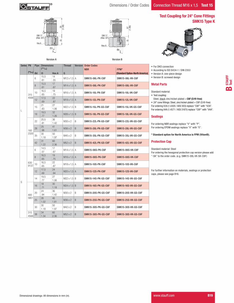
Test Coupling for 24° Cone FittingsSMK20 Type K
Version A Version Bl3
(1.3
8)35 35 (1.4
6)l3
Series PN Pipe Dimensions Thread Version Order Codes(mm/in) NBR FPM*
(bar/PSI) Ø d l3 Hex A G (Standard Option-North America)
L
315
615,5 14
M12 x 1,5 A SMK20-06L-PK-C6F SMK20-06L-VK-C6F.61 .55
815,5 17
M14 x 1,5 A SMK20-08L-PK-C6F SMK20-08L-VK-C6F.61 .67
1016,5 19
M16 x 1,5 A SMK20-10L-PK-C6F SMK20-10L-VK-C6F.65 .75
456812
17,5 22M18 x 1,5 A SMK20-12L-PK-C6F SMK20-12L-VK-C6F
.69 .87
1521 27
M22 x 1,5 B SMK20-15L-PK-GS-C6F SMK20-15L-VK-GS-C6F.83 1.06
1819,5 32
M26 x 1,5 B SMK20-18L-PK-GS-C6F SMK20-18L-VK-GS-C6F.77 1.26
160
2220,5 36
M30 x 2 B SMK20-22L-PK-GS-C6F SMK20-22L-VK-GS-C6F.81 1.42
2825 41
M36 x 2 B SMK20-28L-PK-GS-C6F SMK20-28L-VK-GS-C6F.98 1.61
232035
30 50M45 x 2 B SMK20-35L-PK-GS-C6F SMK20-35L-VK-GS-C6F
1.18 1.97
4231 60
M52 x 2 B SMK20-42L-PK-GS-C6F SMK20-42L-VK-GS-C6F1.22 2.36
S
630
614,5 17
M14 x 1,5 A SMK20-06S-PK-C6F SMK20-06S-VK-C6F.57 .67
816,5 19
M16 x 1,5 A SMK20-08S-PK-C6F SMK20-08S-VK-C6F.65 .75
1016,5 22
M18 x 1,5 A SMK20-10S-PK-C6F SMK20-10S-VK-C6F9137 .65 .87
1217,5 24
M20 x 1,5 A SMK20-12S-PK-C6F SMK20-12S-VK-C6F.69 .94
1419,5 27
M22 x 1,5 B SMK20-14S-PK-GS-C6F SMK20-14S-VK-GS-C6F.77 1.06
400
1618 30
M24 x 1,5 B SMK20-16S-PK-GS-C6F SMK20-16S-VK-GS-C6F.71 1.18
2024 36
M30 x 2 B SMK20-20S-PK-GS-C6F SMK20-20S-VK-GS-C6F.94 1.42
580125
26 46M36 x 2 B SMK20-25S-PK-GS-C6F SMK20-25S-VK-GS-C6F
1.02 1.81
3030 50
M42 x 2 B SMK20-30S-PK-GS-C6F SMK20-30S-VK-GS-C6F1.18 1.97
31538
34 60M52 x 2 B SMK20-38S-PK-GS-C6F SMK20-38S-VK-GS-C6F
4568 1.34 2.36
� For DKO connection � According to ISO 8434-1 / DIN 2353 � Version A: one-piece design � Version B: screwed design
Metal Parts
Standard material: Steel, zinc/nickel-plated = C6F (CrVI-free)For ordering V2A (1.4305 / AISI 303) replace "C6F" with "V2A".For ordering V4A (1.4571 / AISI 316Ti) replace "C6F" with "V4A".
Sealings
For ordering NBR sealings replace "V" with "P".For ordering EPDM sealings replace "V" with "E".
* Standard option for North America is FPM (Viton®).
Protection Cap
Standard material: SteelFor ordering the hexagonal protection cap version please add "-SK" to the order code. (e.g. SMK20-08L-VK-SK-C6F)For ordering the plastic protection cap version please add "-KK" to the order code. (e.g. SMK20-08L-VK-KK-C6F)
For further information on materials, sealings or protection caps, please see page B4.
NoAm Version TEST.indd 7 10.11.2011 09:07:55

Test 20 Connection Thread M16 x 2
B8 www.stauff.com Dimensional drawings: All dimensions in mm (in).
Dimensions / Order Codes
� 37° JIC fittings acc. to SAE J514 � Version A: one-piece design � Version B: screwed design
Metal Parts
Standard material: Steel, zinc/nickel-plated = C6F (CrVI-free)For ordering V2A (1.4305 / AISI 303) replace "C6F" with "V2A".For ordering V4A (1.4571 / AISI 316Ti) replace "C6F" with "V4A".
Sealings
For ordering NBR sealings replace "V" with "P".For ordering EPDM sealings replace "V" with "E".
* Standard option for North America is FPM (Viton®).
Protection Cap
Standard material: SteelFor ordering the hexagonal protection cap version please add "-SK" to the order code. (e.g. SMK20-JIC5/16-VK-SK-C6F)For ordering the plastic protection cap version please add "-KK" to the order code. (e.g. SMK20-JIC5/16-VK-KK-C6F)
A
B
(Hex .67)
Hex A
SW 17
Pipe JIC Dimensions Thread Version Order CodesØ d Size (mm/in) NBR FPM*inch h Hex A Hex B G (Standard Option-North America)
1/4 -453 17 17
7/16–20 UNF A SMK20-JIC1/4-PK-C6F SMK20-JIC1/4-VK-C6F2.09 .67 .67
5/16 -553,5 17 17
1/2–20 UNF A SMK20-JIC5/16-PK-C6F SMK20-JIC5/16-VK-C6F2.11 .67 .67
3/8 -655,5 19 17
9/16–18 UNF A SMK20-JIC3/8-PK-C6F SMK20-JIC3/8-VK-C6F2.19 .75 .67
1/2 -856,5 22 19
3/4–16 UNF A SMK20-JIC1/2-PK-C6F SMK20-JIC1/2-VK-C6F2.22 .87 .75
5/8 -1060 27 22
7/8–14 UNF A SMK20-JIC5/8-PK-C6F SMK20-JIC5/8-VK-C6F2.36 1.06 .87
3/4 -1270,5 32
- 1-1/16–12 UN B SMK20-JIC3/4-PK-GS-C6F SMK20-JIC3/4-VK-GS-C6F2.78 1.26
1 -1669 38
- 1-5/16–12 UN B SMK20-JIC1-PK-GS-C6F SMK20-JIC1-VK-GS-C6F2.72 1.50
1-1/4 -2073,5 50
- 1-5/8–12 UN B SMK20-JIC1-1/4-PK-GS-C6F SMK20-JIC1-1/4-VK-GS-C6F2.89 1.97
1-1/2 -2476 60
- 1-7/8–12 UN B SMK20-JIC1-1/2-PK-GS-C6F SMK20-JIC1-1/2-VK-GS-C6F2.99 2.36
� 37° JIC fittings acc. to SAE J514
Metal Parts
Standard material: Steel, zinc/nickel-plated = C6F (CrVI-free)For ordering V2A (1.4305 / AISI 303) replace "C6F" with "V2A".For ordering V4A (1.4571 / AISI 316Ti) replace "C6F" with "V4A".
Sealings
For ordering NBR sealings replace "V" with "P".For ordering EPDM sealings replace "V" with "E".
* Standard option for North America is FPM (Viton®).
Protection Cap
Standard material: SteelFor ordering the hexagonal protection cap version please add "-SK" to the order code. (e.g. SMK20-JIC5/16-VG-SK-C6F)For ordering the plastic protection cap version please add "-KK" to the order code. (e.g. SMK20-JIC5/16-VG-KK-C6F)
Pipe JIC Dimensions Thread Order CodesØ d Size (mm/in) NBR FPM*inch l1 l2 h Hex A G (Standard Option-North America)
1/4 -443 14 61 24
7/16–20 UNF SMK20-JIC1/4-PG-C6F SMK20-JIC1/4-VG-C6F1.69 .55 2.40 .94
5/16 -543 14 61 24
1/2–20 UNF SMK20-JIC5/16-PG-C6F SMK20-JIC5/16-VG-C6F1.69 .55 2.40 .94
3/8 -643 14 61 24
9/16–18 UNF SMK20-JIC3/8-PG-C6F SMK20-JIC3/8-VG-C6F1.69 .55 2.40 .94
1/2 -848,5 16,5 67 30
3/4–16 UNF SMK20-JIC1/2-PG-C6F SMK20-JIC1/2-VG-C6F1.91 .65 2.64 1.18
5/8 -1053,5 19,5 67 30
7/8–14 UNF SMK20-JIC5/8-PG-C6F SMK20-JIC5/8-VG-C6F2.11 .77 2.64 1.18
3/4 -1259 22 73 36
1-1/16–12 UN SMK20-JIC3/4-PG-C6F SMK20-JIC3/4-VG-C6F2.32 .87 2.87 1.42
1 -1661 23 78 41
1-5/16–12 UN SMK20-JIC1-PG-C6F SMK20-JIC1-VG-C6F2.40 .91 3.07 1.61
1-1/4 -2065,5 24,5 83 46
1-5/8–12 UN SMK20-JIC1-1/4-PG-C6F SMK20-JIC1-1/4-VG-C6F2.58 .96 3.26 1.81
1-1/2 -2472 27,5 92 55
1-7/8–12 UN SMK20-JIC1-1/2-PG-C6F SMK20-JIC1-1/2-VG-C6F2.83 1.08 3.62 2.17
A
SW 17(Hex .67)
For further information on materials, sealings or protection caps, please see page B4.
For further information on materials, sealings or protection caps, please see page B4.
Test Coupling SMK-JIC Connection (to SAE-J514) SMK20-JIC Type K
Test Coupling SMK-JIC Connection (to SAE-J514)SMK20-JIC Type G
Version A Version B
Hex A
Hex B
G
h
Hex A
SW 17(Hex .67)
G
hl2
l1l2
NoAm Version TEST.indd 8 10.11.2011 09:07:58

STAU
FFTe
stB
www.stauff.com B9
Dimensions / Order Codes Connection Thread M16 x 2 Test 20
Dimensional drawings: All dimensions in mm (in).
Swivel Run Tee with JIC ConnectionSGV-JIC Type F/M
Metal Parts
Standard material: Steel, zinc/nickel-plated = C6F (CrVI-free)For ordering V2A (1.4305 / AISI 303) replace "C6F" with "V2A".For ordering V4A (1.4571 / AISI 316Ti) replace "C6F" with "V4A".
For further information please consult STAUFF.
Thread Dimensions Order Codes(mm/in)
inch Ø d1 Ø d2 l1 l2 l3 l4 Hex A Hex B
7/16–20 UNF7,49 4,9 9 14 37 8 27 17
SGV-7/16UNF-04-JIC1/4-F/M-C6F.29 .19 .35 .55 1.46 .31 1.06 .67
9/16–18 UNF11,05 8,1 10,5 14 37,5 8,5 27 19
SGV-7/16UNF-06-JIC3/8-F/M-C6F.44 .32 .41 .55 1.48 .33 1.06 .75
3/4–16 UNF15,9 10,8 10,5 16,7 43,7 12 30 22
SGV-7/16UNF-08-JIC1/2-F/M-C6F.63 .43 .41 .66 1.72 .47 1.18 .87
1-1/16–12 UNF21,6 16,9 15,4 21,9 50,4 13,5 36 32
SGV-7/16UNF-12-JIC3/4-F/M-C6F.85 .66 .61 .86 1.98 .53 1.42 1.26
1-5/16–12 UNF27,9 23,2 17,3 23,1 53,1 15 41 41
SGV-7/16UNF-16-JIC1-F/M-C6F1.10 .91 .68 .91 2.09 .59 1.61 1.61
l2
7/16-20 UNF
Hex AHex B
l1 l4 15(.59)
l3Th
read
d1 d2
Thre
ad
37°
37°
Metal Parts
Standard material: Steel, zinc/nickel-plated = C6F (CrVI-free)For ordering V2A (1.4305 / AISI 303) replace "C6F" with "V2A".For ordering V4A (1.4571 / AISI 316Ti) replace "C6F" with "V4A".
Sealings
For ordering NBR sealings replace "V" with "P".For ordering EPDM sealings replace "V" with "E".
* Standard option for North America is FPM (Viton®).
Protection Cap
Standard material: SteelFor ordering the hexagonal protection cap version please add "-SK" to the order code. (e.g. SMK20-04-ORFS-V-SK-C6F)For ordering the plastic protection cap version please add "-KK" to the order code. (e.g. SMK20-04-ORFS-V-KK-C6F)
l
h
Hex A
Hex B
G
M16
Thread Dimensions Order Codes(mm/in) NBR FPM*
G h l Hex A Hex B (Standard Option-North America)
9/16–18 UNF54 19 17 17
SMK20-04-ORFS-P-C6F SMK20-04-ORFS-V-C6F2.1 .75 .67 .67
11/16–16 UNF54 19 19 21
SMK20-06-ORFS-P-C6F SMK20-06-ORFS-V-C6F2.1 .75 .75 .80
13/16–16 UNF54 19 22 24
SMK20-08-ORFS-P-C6F SMK20-08-ORFS-V-C6F2.1 .75 .87 .87
For further information on materials, sealings or protection caps, please see page B4.
Test Coupling with ORFS ConnectionSMK20 Type ORFS
Hex A
Hex B
h
G
l
NoAm Version TEST.indd 9 10.11.2011 09:07:59
Test 20 Connection Thread M16 x 2
B10 www.stauff.com
Dimensions / Order Codes
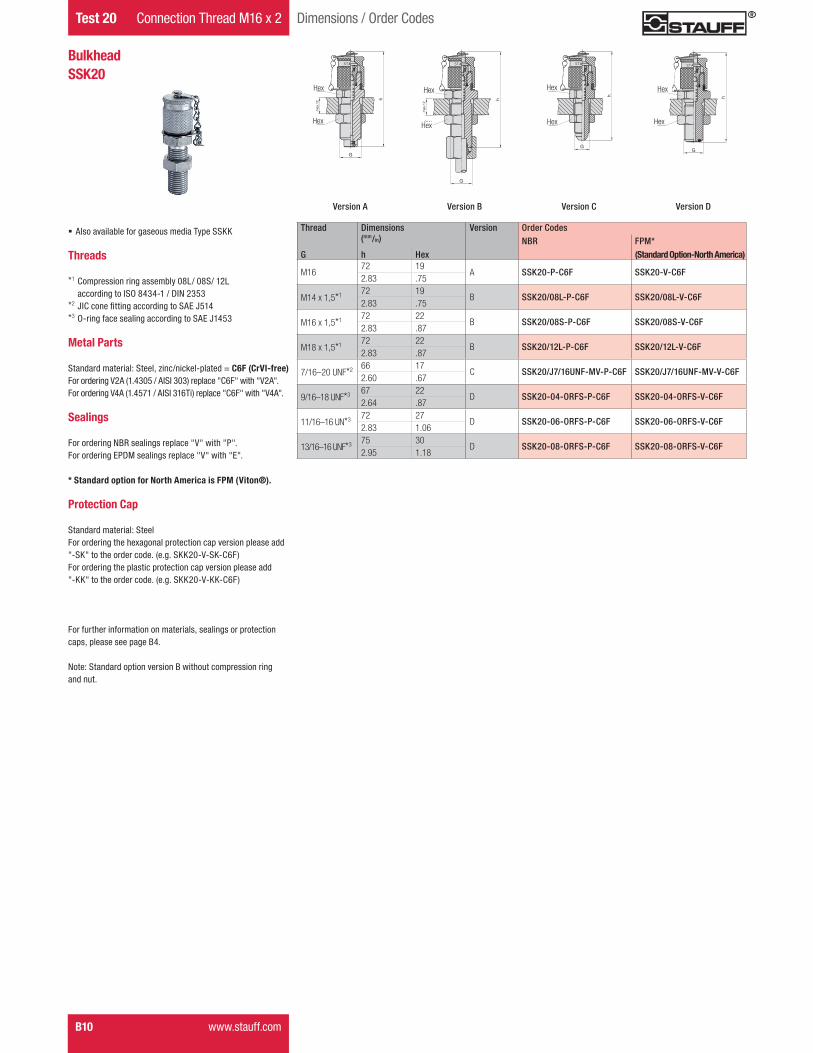
� Also available for gaseous media Type SSKK
Threads
*1 Compression ring assembly 08L/ 08S/ 12L according to ISO 8434-1 / DIN 2353 *2 JIC cone fitting according to SAE J514 *3 O-ring face sealing according to SAE J1453
Metal Parts
Standard material: Steel, zinc/nickel-plated = C6F (CrVI-free)For ordering V2A (1.4305 / AISI 303) replace "C6F" with "V2A".For ordering V4A (1.4571 / AISI 316Ti) replace "C6F" with "V4A".
Sealings
For ordering NBR sealings replace "V" with "P".For ordering EPDM sealings replace "V" with "E".
* Standard option for North America is FPM (Viton®).
Protection Cap
Standard material: SteelFor ordering the hexagonal protection cap version please add "-SK" to the order code. (e.g. SKK20-V-SK-C6F)For ordering the plastic protection cap version please add "-KK" to the order code. (e.g. SKK20-V-KK-C6F)
For further information on materials, sealings or protection caps, please see page B4.
Note: Standard option version B without compression ring and nut.
Thread Dimensions Version Order Codes(mm/in) NBR FPM*
G h Hex (Standard Option-North America)
M1672 19
A SSK20-P-C6F SSK20-V-C6F2.83 .75
M14 x 1,5*1 72 19B SSK20/08L-P-C6F SSK20/08L-V-C6F
2.83 .75
M16 x 1,5*1 72 22B SSK20/08S-P-C6F SSK20/08S-V-C6F
2.83 .87
M18 x 1,5*1 72 22B SSK20/12L-P-C6F SSK20/12L-V-C6F
2.83 .87
7/16–20 UNF*2 66 17C SSK20/J7/16UNF-MV-P-C6F SSK20/J7/16UNF-MV-V-C6F
2.60 .67
9/16–18 UNF*3 67 22D SSK20-04-ORFS-P-C6F SSK20-04-ORFS-V-C6F
2.64 .87
11/16–16 UN*3 72 27D SSK20-06-ORFS-P-C6F SSK20-06-ORFS-V-C6F
2.83 1.06
13/16–16 UNF*3 75 30D SSK20-08-ORFS-P-C6F SSK20-08-ORFS-V-C6F
2.95 1.18
SW
h
G
max
.12
SW
SW
max
.12
SW
G
h
SW
SW
G
h
SW
SW
h
G
Hex
Hex Hex
Hex Hex
Hex
Hex
Hex
BulkheadSSK20
Version A Version B Version C Version D
NoAm Version TEST.indd 10 10.11.2011 09:08:01

STAU
FFTe
stB
www.stauff.com B11
Dimensions / Order Codes Connection Thread M16 x 2 Test 20
Dimensional drawings: All dimensions in mm (in).
Threads
*1 Special thread: buttress thread S12,65 x1,5
Metal Parts
Standard material: Steel, zinc/nickel-plated = C6F (CrVI-free)For ordering V2A (1.4305 / AISI 303) replace "C6F" with "V2A".For ordering V4A (1.4571 / AISI 316Ti) replace "C6F" with "V4A".
Sealings
For ordering NBR sealings replace "V" with "P".For ordering EPDM sealings replace "V" with "E".
* Standard option for North America is FPM (Viton®).
Thread Dimensions Version Order Codes(mm/in) NBR FPM*
G h (Standard Option-North America)
M16 x 1,539
A SAD20/15-P-C6F SAD20/15-V-C6F1.54
S12*1 39A SAD20/12-P-C6F SAD20/12-V-C6F
1.54
Plug in37
B SAD20/10-P-C6F SAD20/10-V-C6F1.46
h
M 16
G
M 16
h
Adaptor SAD20
Version A Version B
Metal Parts
Standard material: Steel, zinc/nickel-plated = C6F (CrVI-free)For ordering V2A (1.4305 / AISI 303) replace "C6F" with "V2A".For ordering V4A (1.4571 / AISI 316Ti) replace "C6F" with "V4A".
Sealings
For ordering NBR sealings replace "V" with "P".For ordering EPDM sealings replace "V" with "E".
* Standard option for North America is FPM (Viton®).
Snubber on request.
max
.12
M 16
G
Hex A
h
SW 19(Hex .75)
(max
.47)
M 16
G
Hex A
h
Thread Dimensions Order Codes(mm/in) NBR FPM*
G h Hex A (Standard Option-North America)
G1/454 19
SMA20-G1/4-P-OR-C6F SMA20-G1/4-V-OR-C6F2.13 .75
G1/264 27
SMA20-G1/2-P-OR-C6F SMA20-G1/2-V-OR-C6F2.52 1.06
1/4 NPT54 19
SMA20-1/4NPT-P-C6F SMA20-1/4NPT-V-C6F2.13 .75
1/2 NPT64 27
SMA20-1/2NPT-P-C6F SMA20-1/2NPT-V-C6F2.52 1.06
9/16–18 UNF57 19
SMA20-9/16UNF-P-C6F SMA20-9/16UNF-V-C6F2.24 .75
G1/441 19
SMD20-G1/4-P-OR-C6F SMD20-G1/4-V-OR-C6F1.61 .75
G1/251 27
SMD20-G1/2-P-OR-C6F SMD20-G1/2-V-OR-C6F2.01 1.06
1/4 NPT41 19
SMD20-1/4NPT-P-C6F SMD20-1/4NPT-V-C6F1.61 .75
1/2 NPT51 27
SMD20-1/2NPT-P-C6F SMD20-1/2NPT-V-C6F2.01 1.06
7/16–20 UNF41 19
SMD20-7/16UNF-P-C6F SMD20-7/16UNF-V-C6F1.61 .75
Through hole Ø 18 (.71)
Gauge AdaptorSMA20
Direct Gauge AdaptorSMD20
Gauge Adaptor SMA20 Direct Gauge Adaptor SMD20
M16M16
G
NoAm Version TEST.indd 11 10.11.2011 09:08:06

B46 www.stauff.com Dimensional drawings: All dimensions in mm (in).
STAUFF Test General Technical Information
Type A Type A - Threaded port according to factory standardSealing: O-ring Type AThread Dimensions
G
(mm/in)
d1 +0,1 t1 min. t2 min
M8 x 19,5 11 15,5.37 .43 .61
M10 x 111,5 12 16,5.45 .47 .64G
d1
t2
t1
2,5
0,5
30°
Port Connections and Sealing Details
t2t1a0,1 A
A
Gd1
Type D Type D - Parallel threaded port type Z according to DIN 3852 Part 2 (inch)Sealing: Taper Type D suitable sealant requiredThread Dimensions
(mm/in)
G t1 min. t2 min.
Rp1/85,5 9,5.22 .37
Rp1/48,5 13,5.33 .53
Rp3/88,5 13,5.33 .53
Rp1/210,5 16,5.41 .65
t2
t1
G
90°
Type B Type C
Type B and C Type B and C - Threaded port type X acc. to DIN 3852 Part 1 and 2; ISO 9974-1 (metric); ISO 1179-1 (inch)Sealing: Metal joint Type B / Elastomeric sealing Type CThread Dimensions
(mm/in)
G d1 min. t1 min. t2 min. a max.
M10 x 115 8 10 1.59 .31 .39 .04
M12 x 1,518 12 15 1,5.71 .47 .59 .06
M14 x 1,520 12 15 1,5.79 .47 .59 .06
M16 x 1,523 12 15 1,5.91 .47 .59 .06
M18 x 1,525 12 15 2.98 .47 .59 .08
M20 x 1,527 14 17 21.06 .55 .67 .08
M22 x 1,528 14 17 2,51.10 .55 .67 .10
G1/815 8,5 10,5 1.59 .33 .41 .04
G1/420 12,5 15,5 1,5.79 .49 .61 .06
G3/823 12,5 15,5 2.91 .49 .61 .08
G1/228 14,5 18,5 2,51.10 .57 .73 .10
NoAm Version TEST.indd 46 10.11.2011 09:10:29

STAU
FFTe
stB
www.stauff.com B47Dimensional drawings: All dimensions in mm (in).
General Technical Information STAUFF Test
Type D Type D - Taper threaded port according to ANSI/ASME B1.20.1-1983 (NPT)Sealing: Taper Type D suitable sealant requiredThread Dimensions
(mm/in)
G t1 min. t2 min.
1/8–27 NPT6,9 11,6.27 .46
1/4–18 NPT10 16,4.39 .65
1/2–14 NPT13,6 22,6.54 .89
G
90°
t2
t1
Port Connections and Sealing Details
Gd1
t2t1ab
z°
A
0,1 A
0,2 A
d2
Type E Type E - Threaded port according to ISO 6149-1 (metric); ISO 11926-1 (UNF)Sealing: O-ring Type EThread Dimensions
(mm/in)
G d1 +0,1 d2 min. t1 min. t2 min. a +0,4 b max. z° ±1°
M10 x 111,1 16 10 11,5 1,6 1
12°.44 .63 .39 .45 .06 .04
M12 x 1,513,8 19 11,5 14 2,4 1,5
15°.54 .75 .45 .55 .09 .06
M14 x 1,515,8 21 11,5 14 2,4 1,5
15°.62 .83 .45 .55 .09 .06
M16 x 1,517,8 24 13 15,5 2,4 1,5
15°.70 .94 .51 .61 .09 .06
M22 x 1,523,8 29 15,5 18 2,4 2
15°.94 1.14 .61 .71 .09 .08
M27 x 229,4 34 19 22 3,1 2
15°1.16 1.34 .75 .87 .91 .08
5/16–24 UNF9,1 17 10 12 1,9 1,6
12°.36 .67 .39 .47 .07 .06
7/16–24 UNF12,4 21 11,5 14 2,4 1,6
12°.49 .83 .45 .55 .09 .06
1/2–20 UNF14 23 11,5 14 2,4 1,6
12°.55 .91 .45 .55 .09 .06
9/16–18 UNF15,65 25 12,7 15,5 2,5 1,6
12°.62 .98 .50 .61 .10 .06
7/8–14 UNF23,95 34 16,7 20 2,5 2,4
15°.94 1.34 .66 .79 .10 .09
NoAm Version TEST.indd 47 10.11.2011 09:10:30

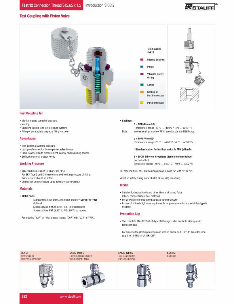
Test Coupling with Piston Valve
Fast coupling for
� Monitoring and control of pressure � Venting � Sampling in high- and low-pressure systems � Filling of accumulators (special fi lling-version)
Advantages
� Test system at working pressure � Leakproof connection before piston valve is open � Simple connection to measurement, control and switching devices � Self locking metal protective cap
Working Pressure
� Max. working pressure 630 bar / 9137 PSIFor SKK Type G and K the recommended working pressure of fi tting manufacturer should be noted.
� Connection under pressure up to 400 bar / 5801 PSI max.
DVGW
� DVGW registration as test coupling for gas pressure control systems with the Deutsche Vereinigung des Gas- und Wasserfaches e.V.
� The DVGW approval relates solely to the following test couplings: - SKK20-M8x1-VA-DVGW-C6F - SKK20-M10x1-VA-DVGW-C6F - SKK20-1/8NPT-VD-DVGW-C6F - SKK20-1/4NPT-VD-DVGW-C6F
Media
� Suitable for hydraulic oils and other Mineral oil based fl uids(Check compatibility of sealing material)
� For use with other liquid media please consult STAUFF � In case of ultimate tightness requirements for gaseous media, a special Gas-type is available
Materials
� Metal Parts: Standard material: Steel, zinc/nickel-plated = C6F (CrVI-free) Optional: Stainless Steel V2A (1.4305 / AISI 303) on request Stainless Steel V4A (1.4571 / AISI 316Ti) on request
For ordering "V2A" or "V4A" please replace "C6F" with "V2A" or "V4A".
� Sealings: P = NBR (Buna-N®) (Temperature range -20 °C ... +100 °C / -4 °F ... +212 °F)Note: Internal sealings made of FPM, even for standard NBR-type.
V = FPM (Viton®)* (Temperature range -20 °C ... +200 °C / -4 °F ... +392 °F)
* Standard option for North America is FPM (Viton®)
E = EPDM Ethylene Propylene Diene Monomer Rubber (for Brake fl uid, Temperature range -40 °C ... +150 °C / -40 °F ... +302 °F)
For ordering NBR or EPDM sealings please replace "V" with "P" or "E".
Vibration safety O-ring made of NBR (Buna-N®) (standard).
Protection Cap
� The complete STAUFF-Test-20-Type-SKK range is also available with a hexagonal protection cap made of steel or plastic protection cap.
For ordering the hexagonal protection cap version please add "-SK" to the order code. (e.g. SKK20-M10x1-VA-SK-C6F)For ordering the plastic protection cap version please add "-KK" to the order code.(e.g. SKK20-M10x1-VA-KK-C6F)
SKK20Test Coupling with Port Connection
SKK20 Type GTest Coupling complete with Straight Fitting
SKK20 Type K Test Coupling for 24° Cone Fittings
Test CouplingSKK20
Internal Sealings
Piston
Vibration Safety O-ring
Spring
Sealing at Port Connection
Port Connection
Test 20 Connection Thread M16 x 2 Introduction SKK20
B12 www.stauff.com
NoAm Version TEST.indd 12 10.11.2011 09:08:11

STAU
FFTe
stB
Dimensions / Order Codes Connection Thread M16 x 2 Test 20
Dimensional drawings: All dimensions in mm (in). www.stauff.com B13
Hex
M 16 h1
h2
G
17 10
(.39)(.67)
Test Coupling with Port Connection SKK20
Thread Sealing Working Dimensions Order CodesPressure (mm/in) NBR FPM*
G (bar/PSI) h1 h2 Hex (Standard Option-North America)
M8 x 1Type A
250 38 8,5 17SKK20-M8x1-PA-C6F SKK20-M8x1-VA-C6F
3625 1.50 .33 .67
M10 x 1630 38 9,8 17
SKK20-M10x1-PA-C6F SKK20-M10x1-VA-C6F9137 1.50 .39 .67
M12 x 1,5
Type B
630 37 12 17SKK20-M12x1,5-PB-C6F SKK20-M12x1,5-VB-C6F
9137 1.46 .47 .67
M14 x 1,5630 37 12 19
SKK20-M14x1,5-PB-C6F SKK20-M14x1,5-VB-C6F9137 1.46 .47 .75
M16 x 1,5630 37 12 22
SKK20-M16x1,5-PB-C6F SKK20-M16x1,5-VB-C6F9137 1.46 .47 .87
G1/4630 37 12 19
SKK20-G1/4-PB-C6F SKK20-G1/4-VB-C6F9137 1.46 .47 .75
G3/8630 37 12 22
SKK20-G3/8-PB-C6F SKK20-G3/8-VB-C6F9137 1.46 .47 .87
M10 x 1
Type C
400 39 8 17SKK20-M10x1-PC-C6F SKK20-M10x1-VC-C6F
5801 1.54 .31 .67
M12 x 1,5630 37 12 17
SKK20-M12x1,5-PC-C6F SKK20-M12x1,5-VC-C6F9137 1.46 .47 .67
M14 x 1,5630 37 12 19
SKK20-M14x1,5-PC-C6F SKK20-M14x1,5-VC-C6F9137 1.46 .47 .75
M16 x 1,5630 37 12 22
SKK20-M16x1,5-PC-C6F SKK20-M16x1,5-VC-C6F9137 1.46 .47 .87
G1/8400 39 8 17
SKK20-G1/8-PC-C6F SKK20-G1/8-VC-C6F5801 1.54 .31 .67
G1/4630 37 12 19
SKK20-G1/4-PC-C6F SKK20-G1/4-VC-C6F9137 1.46 .47 .75
G3/8630 37 12 22
SKK20-G3/8-PC-C6F SKK20-G3/8-VC-C6F9137 1.46 .47 .87
G1/2630 39 14 27
SKK20-G1/2-PC-C6F SKK20-G1/2-VC-C6F9137 1.54 .55 1.06
R1/8 K
Type D
400 37 8 17SKK20-R1/8K-PD-C6F SKK20-R1/8K-VD-C6F
5801 1.46 .31 .67
R1/4 K630 35 12 17
SKK20-R1/4K-PD-C6F SKK20-R1/4K-VD-C6F9137 1.38 .47 .67
1/8 NPT400 36 10 17
SKK20-1/8NPT-PD-C6F SKK20-1/8NPT-VD-C6F5801 1.42 .39 .67
1/4 NPT630 35 15 17
SKK20-1/4NPT-PD-C6F SKK20-1/4NPT-VD-C6F9137 1.38 .59 .67
5/16–24 UNF
Type E
400 38 7,5 17SKK20-5/16UNF-PE-C6F SKK20-5/16UNF-VE-C6F
5801 1.50 .30 .67
7/16–20 UNF630 38 9,1 17
SKK20-7/16UNF-PE-C6F SKK20-7/16UNF-VE-C6F9137 1.50 .36 .67
1/2–20 UNF630 38 9,2 17
SKK20-1/2UNF-PE-C6F SKK20-1/2UNF-VE-C6F9137 1.50 .36 .67
9/16–18 UNF630 37 10 19
SKK20-9/16UNF-PE-C6F SKK20-9/16UNF-VE-C6F9137 1.46 .39 .75
M12 x1,5630 37 11 17
SKK20-M12x1,5-PE-C6F SKK20-M12x1,5-VE-C6F9137 1.46 .43 .67
M14 x 1,5630 38 11 19
SKK20-M14x1,5-PE-C6F SKK20-M14x1,5-VE-C6F9137 1.50 .43 .75
Metal Parts
Standard material: Steel, zinc/nickel-plated = C6F (CrVI-free)For ordering V2A (1.4305 / AISI 303) replace "C6F" with "V2A".For ordering V4A (1.4571 / AISI 316Ti) replace "C6F" with "V4A".
Sealings
For ordering NBR sealings replace "V" with "P".For ordering EPDM sealings replace "V" with "E".
* Standard option for North America is FPM (Viton®).
Sealing Details
O-ring Type A
Metal Joint Type B
Elastomeric Sealing Type C
Taper Type D (suitable sealant required)
O-ring Type E
Protection Cap
Standard material: SteelFor ordering the hexagonal protection cap version please add "-SK" to the order code. (e.g. SKK20-M10x1-VA-SK-C6F)For ordering the plastic protection cap version please add "-KK" to the order code. (e.g. SKK20-M10x1-VA-KK-C6F)
For further information on materials, sealings or protection caps, please see page B12.
Other port connections and sealings on request. Please consult STAUFF for further information.
NoAm Version TEST.indd 13 10.11.2011 09:08:13
Test 20 Connection Thread M16 x 2 Dimensions / Order Codes
h
Ø d
Hex B
Hex A SW 17
l1
l2
(Hex .67)
Test Coupling complete with Straight FittingSKK20 Type G
l2l1
Ød
� Compression ring fittings acc. to ISO 8434-1 / DIN 2353
Metal Parts
Standard material: Steel, zinc/nickel-plated = C6F (CrVI-free)For ordering V2A (1.4305 / AISI 303) replace "C6F" with "V2A".For ordering V4A (1.4571 / AISI 316Ti) replace "C6F" with "V4A".
Sealings
For ordering NBR sealings replace "V" with "P".For ordering EPDM sealings replace "V" with "E".
* Standard option for North America is FPM (Viton®).
Protection Cap
Standard material: SteelFor ordering the hexagonal protection cap version please add "-SK" to the order code. (e.g. SKK20-08L-VG-SK-C6F)For ordering the plastic protection cap version please add "-KK" to the order code. (e.g. SKK20-08L-VG-KK-C6F)
For further information on materials, sealings or protection caps, please see page B12.
Series PN Pipe Dimensions Order Codes(mm/in) NBR FPM*
(bar/PSI) Ød ~l1 l2 h Hex A Hex B (Standard Option-North America)
L
315
651 21 49 24 14
SKK20-06L-PG-C6F SKK20-06L-VG-C6F2.01 .83 1.93 .94 .55
851 21 49 24 17
SKK20-08L-PG-C6F SKK20-08L-VG-C6F2.01 .83 1.93 .94 .67
1053 23 49 24 19
SKK20-10L-PG-C6F SKK20-10L-VG-C6F2.09 .91 1.93 .94 .75
456812
53 23 50,5 27 22SKK20-12L-PG-C6F SKK20-12L-VG-C6F
2.09 .91 1.99 1.06 .87
1555 25 52 30 27
SKK20-15L-PG-C6F SKK20-15L-VG-C6F2.17 .98 2.05 1.18 1.06
1857 24 53 32 32
SKK20-18L-PG-C6F SKK20-18L-VG-C6F2.24 .94 2.09 1.26 1.26
160
2261 28 55 36 36
SKK20-22L-PG-C6F SKK20-22L-VG-C6F2.40 1.10 2.17 1.42 1.42
2861 28 57,5 41 41
SKK20-28L-PG-C6F SKK20-28L-VG-C6F2.40 1.10 2.26 1.61 1.61
232035
69 26 60 46 50SKK20-35L-PG-C6F SKK20-35L-VG-C6F
2.72 1.02 2.36 1.81 1.97
4271 25 64,5 55 60
SKK20-42L-PG-C6F SKK20-42L-VG-C6F2.80 .98 2.54 2.17 2.36
S
630
655 25 49 24 17
SKK20-06S-PG-C6F SKK20-06S-VG-C6F2.17 .98 1.93 .94 .67
855 25 49 24 19
SKK20-08S-PG-C6F SKK20-08S-VG-C6F2.17 .98 1.93 .94 .75
1057 24 49 24 22
SKK20-10S-PG-C6F SKK20-10S-VG-C6F9137 2.24 .94 1.93 .94 .87
1257 24 49 24 24
SKK20-12S-PG-C6F SKK20-12S-VG-C6F2.24 .94 1.93 .94 .94
1463 27 50,5 27 27
SKK20-14S-PG-C6F SKK20-14S-VG-C6F2.50 1.06 1.99 1.06 1.06
400
1663 26 52 30 30
SKK20-16S-PG-C6F SKK20-16S-VG-C6F2.50 1.02 2.05 1.18 1.18
2069 26 55 36 36
SKK20-20S-PG-C6F SKK20-20S-VG-C6F2.72 1.02 2.17 1.42 1.42
580125
75 27 57,5 41 46SKK20-25S-PG-C6F SKK20-25S-VG-C6F
2.95 1.06 2.26 1.61 1.81
3081 28 60 46 50
SKK20-30S-PG-C6F SKK20-30S-VG-C6F3.19 1.10 2.36 1.81 1.97
31538
91 29 64,5 55 60SKK20-38S-PG-C6F SKK20-38S-VG-C6F
4568 3.58 1.14 2.54 2.17 2.36
Dimensional drawings: All dimensions in mm (in).B14 www.stauff.com
NoAm Version TEST.indd 14 10.11.2011 09:08:15

STAU
FFTe
stB
Dimensions / Order Codes Connection Thread M16 x 2 Test 20
Hex A
SW
(Hex .67)
(1.4
6)
Hex A
(Hex .67)
SW 17
(1.4
6)
37
Ød
G
Test Coupling for 24° Cone FittingsSKK20 Type K
SW 17(Hex .67)
ØdG
l335
(1.3
8)
Hex A
SW 17(Hex .67)
ØdG
l337
(1.4
6)
Hex A
Version BVersion A
Series PN Pipe Dimensions Thread Version Order Codes(mm/in) NBR FPM*
(bar/PSI) Ød l3 Hex A G (Standard Option-North America)
L
315
615,5 14
M12 x 1,5 A SKK20-06L-PK-C6F SKK20-06L-VK-C6F.61 .55
815,5 17
M14 x 1,5 A SKK20-08L-PK-C6F SKK20-08L-VK-C6F.61 .67
1016,5 19
M16 x 1,5 A SKK20-10L-PK-C6F SKK20-10L-VK-C6F.65 .75
456812
17,5 22M18 x 1,5 A SKK20-12L-PK-C6F SKK20-12L-VK-C6F
.69 .87
1521 27
M22 x 1,5 B SKK20-15L-PK-GS-C6F SKK20-15L-VK-GS-C6F.83 1.06
1819,5 32
M26 x 1,5 B SKK20-18L-PK-GS-C6F SKK20-18L-VK-GS-C6F.77 1.26
160
2220,5 36
M30 x 2 B SKK20-22L-PK-GS-C6F SKK20-22L-VK-GS-C6F.81 1.42
2825 41
M36 x 2 B SKK20-28L-PK-GS-C6F SKK20-28L-VK-GS-C6F.98 1.61
232035
30 50M45 x 2 B SKK20-35L-PK-GS-C6F SKK20-35L-VK-GS-C6F
1.18 1.97
4231 60
M52 x 2 B SKK20-42L-PK-GS-C6F SKK20-42L-VK-GS-C6F1.22 2.36
S
630
614,5 17
M14 x 1,5 A SKK20-06S-PK-C6F SKK20-06S-VK-C6F.57 .67
816,5 19
M16 x 1,5 A SKK20-08S-PK-C6F SKK20-08S-VK-C6F.65 .75
1016,5 22
M18 x 1,5 A SKK20-10S-PK-C6F SKK20-10S-VK-C6F9137 .65 .87
1217,5 24
M20 x 1,5 A SKK20-12S-PK-C6F SKK20-12S-VK-C6F.69 .94
1419,5 27
M22 x 1,5 B SKK20-14S-PK-GS-C6F SKK20-14S-VK-GS-C6F.77 1.06
400
1618 30
M24 x 1,5 B SKK20-16S-PK-GS-C6F SKK20-16S-VK-GS-C6F.71 1.18
2024 36
M30 x 2 B SKK20-20S-PK-GS-C6F SKK20-20S-VK-GS-C6F.94 1.42
580125
26 46M36 x 2 B SKK20-25S-PK-GS-C6F SKK20-25S-VK-GS-C6F
1.02 1.81
3030 50
M42 x 2 B SKK20-30S-PK-GS-C6F SKK20-30S-VK-GS-C6F1.18 1.97
31538
34 60M52 x 2 B SKK20-38S-PK-GS-C6F SKK20-38S-VK-GS-C6F
4568 1.34 2.36
� For DKO connection � According to ISO 8434-1 / DIN 2353 � Version A: one-piece design � Version B: screwed design
Metal Parts
Standard material: Steel, zinc/nickel-plated = C6F (CrVI-free)For ordering V2A (1.4305 / AISI 303) replace "C6F" with "V2A".For ordering V4A (1.4571 / AISI 316Ti) replace "C6F" with "V4A".
Sealings
For ordering NBR sealings replace "V" with "P".For ordering EPDM sealings replace "V" with "E".
* Standard option for North America is FPM (Viton®).
Protection Cap
Standard material: SteelFor ordering the hexagonal protection cap version please add "-SK" to the order code. (e.g. SKK20-08L-VK-SK-C6F)For ordering the plastic protection cap version please add "-KK" to the order code. (e.g. SKK20-08L-VK-KK-C6F)
For further information on materials, sealings or protection caps, please see page B12.
Dimensional drawings: All dimensions in mm (in). www.stauff.com B15
NoAm Version TEST.indd 15 10.11.2011 09:08:17

B46 www.stauff.com Dimensional drawings: All dimensions in mm (in).
STAUFF Test General Technical Information
Type A Type A - Threaded port according to factory standardSealing: O-ring Type AThread Dimensions
G
(mm/in)
d1 +0,1 t1 min. t2 min
M8 x 19,5 11 15,5.37 .43 .61
M10 x 111,5 12 16,5.45 .47 .64G
d1
t2
t1
2,5
0,5
30°
Port Connections and Sealing Details
t2t1a0,1 A
A
Gd1
Type D Type D - Parallel threaded port type Z according to DIN 3852 Part 2 (inch)Sealing: Taper Type D suitable sealant requiredThread Dimensions
(mm/in)
G t1 min. t2 min.
Rp1/85,5 9,5.22 .37
Rp1/48,5 13,5.33 .53
Rp3/88,5 13,5.33 .53
Rp1/210,5 16,5.41 .65
t2
t1
G
90°
Type B Type C
Type B and C Type B and C - Threaded port type X acc. to DIN 3852 Part 1 and 2; ISO 9974-1 (metric); ISO 1179-1 (inch)Sealing: Metal joint Type B / Elastomeric sealing Type CThread Dimensions
(mm/in)
G d1 min. t1 min. t2 min. a max.
M10 x 115 8 10 1.59 .31 .39 .04
M12 x 1,518 12 15 1,5.71 .47 .59 .06
M14 x 1,520 12 15 1,5.79 .47 .59 .06
M16 x 1,523 12 15 1,5.91 .47 .59 .06
M18 x 1,525 12 15 2.98 .47 .59 .08
M20 x 1,527 14 17 21.06 .55 .67 .08
M22 x 1,528 14 17 2,51.10 .55 .67 .10
G1/815 8,5 10,5 1.59 .33 .41 .04
G1/420 12,5 15,5 1,5.79 .49 .61 .06
G3/823 12,5 15,5 2.91 .49 .61 .08
G1/228 14,5 18,5 2,51.10 .57 .73 .10
NoAm Version TEST.indd 46 10.11.2011 09:10:29

STAU
FFTe
stB
www.stauff.com B47Dimensional drawings: All dimensions in mm (in).
General Technical Information STAUFF Test
Type D Type D - Taper threaded port according to ANSI/ASME B1.20.1-1983 (NPT)Sealing: Taper Type D suitable sealant requiredThread Dimensions
(mm/in)
G t1 min. t2 min.
1/8–27 NPT6,9 11,6.27 .46
1/4–18 NPT10 16,4.39 .65
1/2–14 NPT13,6 22,6.54 .89
G
90°
t2
t1
Port Connections and Sealing Details
Gd1
t2t1ab
z°
A
0,1 A
0,2 A
d2
Type E Type E - Threaded port according to ISO 6149-1 (metric); ISO 11926-1 (UNF)Sealing: O-ring Type EThread Dimensions
(mm/in)
G d1 +0,1 d2 min. t1 min. t2 min. a +0,4 b max. z° ±1°
M10 x 111,1 16 10 11,5 1,6 1
12°.44 .63 .39 .45 .06 .04
M12 x 1,513,8 19 11,5 14 2,4 1,5
15°.54 .75 .45 .55 .09 .06
M14 x 1,515,8 21 11,5 14 2,4 1,5
15°.62 .83 .45 .55 .09 .06
M16 x 1,517,8 24 13 15,5 2,4 1,5
15°.70 .94 .51 .61 .09 .06
M22 x 1,523,8 29 15,5 18 2,4 2
15°.94 1.14 .61 .71 .09 .08
M27 x 229,4 34 19 22 3,1 2
15°1.16 1.34 .75 .87 .91 .08
5/16–24 UNF9,1 17 10 12 1,9 1,6
12°.36 .67 .39 .47 .07 .06
7/16–24 UNF12,4 21 11,5 14 2,4 1,6
12°.49 .83 .45 .55 .09 .06
1/2–20 UNF14 23 11,5 14 2,4 1,6
12°.55 .91 .45 .55 .09 .06
9/16–18 UNF15,65 25 12,7 15,5 2,5 1,6
12°.62 .98 .50 .61 .10 .06
7/8–14 UNF23,95 34 16,7 20 2,5 2,4
15°.94 1.34 .66 .79 .10 .09
NoAm Version TEST.indd 47 10.11.2011 09:10:30

Test 15 Connection Thread M16 x 1,5 Introduction SMK15
Test Coupling with Ball Check
Fast coupling for
� Monitoring and control of pressure � Venting � Sampling in high- and low-pressure systems
Advantages
� Test system at working pressure � Leak proof connection before ball check is open � Simple connection to measurement, control and switching devices � Self locking metal protective cap
Working Pressure
� Max. working pressure 630 bar / 9137 PSIFor SMK Type G and K the recommended working pressure of fi tting manufacturer should be noted.
� Connection under pressure up to 630 bar / 9137 PSI max.
Materials
� Metal parts: Standard material: Steel, black zinc/nickel-plated = C6F* (CrVI-free) Optional: Stainless Steel V2A (1.4305 / AISI 303) on request Stainless Steel V4A (1.4571 / AISI 316Ti) on request
For ordering V2A or V4A please replace "C6F" with "V2A" or "V4A".
* Note: The changeover of our standard surface fi nishing "zinc plated" to the chromium (VI) free surface fi nishing "black zinc/nickel-plated" will proceed gradually.
� Ball: Stainless Steel
� Sealings: P = NBR (Buna-N®) (Temperature range -20 °C ... +100 °C / -4 °F ... +212 °F)Note: Internal sealings made of FPM, even for standard NBR-type.
V = FPM (Viton®)* (Temperature range -20 °C ... +200 °C / -4 °F ... +392 °F) * Standard option for North America is FPM (Viton®)
E = EPDM Ethylene Propylene Diene Monomer Rubber (for Brake fl uid, Temperature range -40 °C ... +150 °C / -40 °F ... +302 °F)
For ordering NBR or EPDM sealings please replace "V" with "P" or "E".
Vibration safety O-ring made of NBR (Buna-N®) (standard).
Media
� Suitable for hydraulic oils and other Mineral oil based fl uid(Check compatibility of seal material)
� For use with other liquid media please consult STAUFF
Protection Cap
� The complete STAUFF-Test-15-Type-SMK range is also available with a hexagonal protection cap made of steel.
For ordering the hexagonal protection cap version please add "-SK" to the order code. (e.g. SMK15-M10x1-VA-SK-C6F)
Note
� On request TEST 15 is also available as SKK-type including "Gas"- and "Filling"-versions.
Test CouplingSMK15
Internal Sealings
Ball
Vibration Safety O-ring
Spring
Sealing at Port Connection
Port Connection
SMK15Test Coupling with Port Connection
SMK15 Type GTest Coupling complete with Straight Fitting
SMK15 Type K Test Coupling for 24° Cone Fittings
SSK15Bulkhead
B16 www.stauff.com
NoAm Version TEST.indd 16 10.11.2011 09:08:25

STAU
FFTe
stB
17 10
(.39)(.67)
Test Coupling with Port ConnectionSMK15
Dimensions / Order Codes Connection Thread M16 x 1,5 Test 15
Thread Sealing Working Dimensions Order CodesPressure (mm/in) NBR FPM*
G (bar/PSI) h1 h2 Hex (Standard Option-North America)
M10 x 1 Type A630 38 9,8 17
SMK15-M10x1-PA-C6F SMK15-M10x1-VA-C6F9137 1.50 .39 .67
M14 x 1,5
Type B
630 37 12 19SMK15-M14x1,5-PB-C6F SMK15-M14x1,5-VB-C6F
9137 1.46 .47 .75
M16 x 1,5630 37 12 22
SMK15-M16x1,5-PB-C6F SMK15-M16x1,5-VB-C6F9137 1.46 .47 .87
G1/8400 39 8 17
SMK15-G1/8-PB-C6F SMK15-G1/8-VB-C6F5801 1.54 .31 .67
G1/4630 37 12 19
SMK15-G1/4-PB-C6F SMK15-G1/4-VB-C6F9137 1.46 .47 .75
G3/8630 37 12 22
SMK15-G3/8-PB-C6F SMK15-G3/8-VB-C6F9137 1.46 .47 .87
M12 x 1,5
Type C
630 37 12 17SMK15-M12x1,5-PC-C6F SMK15-M12x1,5-VC-C6F
9137 1.46 .47 .67
M14 x 1,5630 37 12 19
SMK15-M14x1,5-PC-C6F SMK15-M14x1,5-VC-C6F9137 1.46 .47 .75
M16 x 1,5630 37 12 22
SMK15-M16x1,5-PC-C6F SMK15-M16x1,5-VC-C6F9137 1.46 .47 .87
G1/8400 39 8 17
SMK15-G1/8-PC-C6F SMK15-G1/8-VC-C6F5801 1.54 .31 .67
G1/4630 37 12 19
SMK15-G1/4-PC-C6F SMK15-G1/4-VC-C6F9137 1.46 .47 .75
R1/4 K
Type D
630 35 12 17SMK15-R1/4K-PD-C6F SMK15-R1/4K-VD-C6F
9137 1.38 .47 .67
1/8 NPT400 36 10 17
SMK15-1/8NPT-PD-C6F SMK15-1/8NPT-VD-C6F5801 1.42 .39 .67
1/4 NPT630 35 15 17
SMK15-1/4NPT-PD-C6F SMK15-1/4NPT-VD-C6F9137 1.38 .59 .67
7/16–20 UNF
Type E
630 38 9,1 17SMK15-7/16UNF-PE-C6F SMK15-7/16UNF-VE-C6F
9137 1.50 .36 .67
9/16–18 UNF630 37 10 19
SMK15-9/16UNF-PE-C6F SMK15-9/16UNF-VE-C6F9137 1.46 .39 .75
M14 x 1,5630 38 11 19
SMK15-M14x1,5-PE-C6F SMK15-M14x1,5-VE-C6F9137 1.50 .43 .75
Metal Parts
Standard material: Steel, black zinc/nickel-plated = C6F (CrVI-free)For ordering V2A (1.4305 / AISI 303) replace "C6F" with "V2A".For ordering V4A (1.4571 / AISI 316Ti) replace "C6F" with "V4A".
Sealings
For ordering NBR sealings replace "V" with "P".For ordering EPDM sealings replace "V" with "E".
* Standard option for North America is FPM (Viton®).
Sealing Details
O-ring Type A
Metal Joint Type B
Elastomeric Sealing Type C
Taper Type D (suitable sealant required)
O-ring Type E
Protection Cap
Standard material: SteelFor ordering the hexagonal protection cap version please add "-SK" to the order code. (e.g. SMK15-M10x1-VA-SK-C6F)
For further information on materials, seals or protection caps, please see page B16.
Other port connections and seals on request. Please consult STAUFF for further information.
Dimensional drawings: All dimensions in mm (in). www.stauff.com B17
NoAm Version TEST.indd 17 10.11.2011 09:08:26

Test 15 Connection Thread M16 x 1,5 Dimensions / Order Codes
Dimensional drawings: All dimensions in mm (in).B18 www.stauff.com
h
Ø d
Hex B
Hex A SW 17
l1
l2
(Hex .67)
Test Coupling complete with Straight FittingSMK15 Type G
l2l1
h
Ød
(Hex .67)
� Compression ring fittings acc. to ISO 8434-1 / DIN 2353
Metal Parts
Standard material: � Test coupling: Steel, black zinc/nickel-plated = C6F (CrVI-free)
� Straight fitting: Steel, zinc/nickel-plated = C6F (CrVI-free)For ordering V2A (1.4305 / AISI 303) replace "C6F" with "V2A". For ordering V4A (1.4571 / AISI 316Ti) replace "C6F" with "V4A".
Sealings
For ordering NBR sealings replace "V" with "P".For ordering EPDM sealings replace "V" with "E".
* Standard option for North America is FPM (Viton®).
Protection Cap
Standard material: SteelFor ordering the hexagonal protection cap version please add "-SK" to the order code. (e.g. SMK15-08L-VG-SK-C6F)
For further information on materials, sealings or protection caps, please see page B16.
Series PN Pipe Dimensions Order Codes(mm/in) NBR FPM*
(bar/PSI) Ød ~l1 l2 h Hex A Hex B (Standard Option-North America)
L
315
651 21 49 24 14
SMK15-06L-PG-C6F SMK15-06L-VG-C6F2.01 .83 1.93 .94 .55
851 21 49 24 17
SMK15-08L-PG-C6F SMK15-08L-VG-C6F2.01 .83 1.93 .94 .67
1053 23 49 24 19
SMK15-10L-PG-C6F SMK15-10L-VG-C6F2.09 .91 1.93 .94 .75
456812
53 23 50,5 27 22SMK15-12L-PG-C6F SMK15-12L-VG-C6F
2.09 .91 1.99 1.06 .87
1555 25 52 30 27
SMK15-15L-PG-C6F SMK15-15L-VG-C6F2.17 .98 2.05 1.18 1.06
1857 24 53 32 32
SMK15-18L-PG-C6F SMK15-18L-VG-C6F2.24 .94 2.09 1.26 1.26
160
2261 28 55 36 36
SMK15-22L-PG-C6F SMK15-22L-VG-C6F2.40 1.10 2.17 1.42 1.42
2861 28 57,5 41 41
SMK15-28L-PG-C6F SMK15-28L-VG-C6F2.40 1.10 2.26 1.61 1.61
232035
69 26 60 46 50SMK15-35L-PG-C6F SMK15-35L-VG-C6F
2.72 1.02 2.36 1.81 1.97
4271 25 64,5 55 60
SMK15-42L-PG-C6F SMK15-42L-VG-C6F2.80 .98 2.54 2.17 2.36
S
630
655 25 49 24 17
SMK15-06S-PG-C6F SMK15-06S-VG-C6F2.17 .98 1.93 .94 .67
855 25 49 24 19
SMK15-08S-PG-C6F SMK15-08S-VG-C6F2.17 .98 1.93 .94 .75
1057 24 49 24 22
SMK15-10S-PG-C6F SMK15-10S-VG-C6F9137 2.24 .94 1.93 .94 .87
1257 24 49 24 24
SMK15-12S-PG-C6F SMK15-12S-VG-C6F2.24 .94 1.93 .94 .94
1463 27 50,5 27 27
SMK15-14S-PG-C6F SMK15-14S-VG-C6F2.50 1.06 1.99 1.06 1.06
400
1663 26 52 30 30
SMK15-16S-PG-C6F SMK15-16S-VG-C6F2.50 1.02 2.05 1.18 1.18
2069 26 55 36 36
SMK15-20S-PG-C6F SMK15-20S-VG-C6F2.72 1.02 2.17 1.42 1.42
580125
75 27 57,5 41 46SMK15-25S-PG-C6F SMK15-25S-VG-C6F
2.95 1.06 2.26 1.61 1.81
3081 28 60 46 50
SMK15-30S-PG-C6F SMK15-30S-VG-C6F3.19 1.10 2.36 1.81 1.97
31538
91 29 64,5 55 60SMK15-38S-PG-C6F SMK15-38S-VG-C6F
4568 3.58 1.14 2.54 2.17 2.36
NoAm Version TEST.indd 18 10.11.2011 09:08:28
STAU
FFTe
stB
Dimensions / Order Codes Connection Thread M16 x 1,5 Test 15
Dimensional drawings: All dimensions in mm (in). www.stauff.com B19
Hex A
SW
(Hex .67)
(1.4
6)
Hex A
(Hex .67)
SW 17
(1.4
6)
37
Ød
G
Test Coupling for 24° Cone FittingsSMK15 Type K
(Hex .67)
l3(1
.38)
35
(1.4
6)37
l3
(Hex .67)
Hex A
SW 17 SW 17
Version BVersion A
ØdG G
Series PN Pipe Dimensions Thread Version Order Codes(mm/in) NBR FPM*
(bar/PSI) Ød l3 Hex A G (Standard Option-North America)
L
315
615,5 14
M12 x 1,5 A SMK15-06L-PK-C6F SMK15-06L-VK-C6F.61 .55
815,5 17
M14 x 1,5 A SMK15-08L-PK-C6F SMK15-08L-VK-C6F.61 .67
1016,5 19
M16 x 1,5 A SMK15-10L-PK-C6F SMK15-10L-VK-C6F.65 .75
456812
17,5 22M18 x 1,5 A SMK15-12L-PK-C6F SMK15-12L-VK-C6F
.69 .87
1521 27
M22 x 1,5 B SMK15-15L-PK-GS-C6F SMK15-15L-VK-GS-C6F.83 1.06
1819,5 32
M26 x 1,5 B SMK15-18L-PK-GS-C6F SMK15-18L-VK-GS-C6F.77 1.26
160
2220,5 36
M30 x 2 B SMK15-22L-PK-GS-C6F SMK15-22L-VK-GS-C6F.81 1.42
2825 41
M36 x 2 B SMK15-28L-PK-GS-C6F SMK15-28L-VK-GS-C6F.98 1.61
232035
30 50M45 x 2 B SMK15-35L-PK-GS-C6F SMK15-35L-VK-GS-C6F
1.18 1.97
4231 60
M52 x 2 B SMK15-42L-PK-GS-C6F SMK15-42L-VK-GS-C6F1.22 2.36
S
630
614,5 17
M14 x 1,5 A SMK15-06S-PK-C6F SMK15-06S-VK-C6F.57 .67
816,5 19
M16 x 1,5 A SMK15-08S-PK-C6F SMK15-08S-VK-C6F.65 .75
1016,5 22
M18 x 1,5 A SMK15-10S-PK-C6F SMK15-10S-VK-C6F9137 .65 .87
1217,5 24
M20 x 1,5 A SMK15-12S-PK-C6F SMK15-12S-VK-C6F.69 .94
1419,5 27
M22 x 1,5 B SMK15-14S-PK-GS-C6F SMK15-14S-VK-GS-C6F.77 1.06
400
1618 30
M24 x 1,5 B SMK15-16S-PK-GS-C6F SMK15-16S-VK-GS-C6F.71 1.18
2024 36
M30 x 2 B SMK15-20S-PK-GS-C6F SMK15-20S-VK-GS-C6F.94 1.42
580125
26 46M36 x 2 B SMK15-25S-PK-GS-C6F SMK15-25S-VK-GS-C6F
1.02 1.81
3030 50
M42 x 2 B SMK15-30S-PK-GS-C6F SMK15-30S-VK-GS-C6F1.18 1.97
31538
34 60M52 x 2 B SMK15-38S-PK-GS-C6F SMK15-38S-VK-GS-C6F
4568 1.34 2.36
� For DKO connection � According to ISO 8434-1 / DIN 2353 � Version A: one-piece design � Version B: screwed design
Metal Parts
Standard material: � Test coupling: Steel, black zinc/nickel-plated = C6F (CrVI-free)
� 24° cone fittings: Steel, zinc/nickel-plated = C6F (CrVI-free)For ordering V2A (1.4305 / AISI 303) replace "C6F" with "V2A". For ordering V4A (1.4571 / AISI 316Ti) replace "C6F" with "V4A".
Sealings
For ordering NBR sealings replace "V" with "P".For ordering EPDM sealings replace "V" with "E".
* Standard option for North America is FPM (Viton®).
Protection Cap
Standard material: SteelFor ordering the hexagonal protection cap version please add "-SK" to the order code. (e.g. SMK15-08L-VK-SK-C6F)
For further information on materials, sealings or protection caps, please see page B16.
NoAm Version TEST.indd 19 10.11.2011 09:08:32

Test 15 Connection Thread M16 x 1,5 Dimensions / Order Codes
Dimensional drawings: All dimensions in mm (in).B20 www.stauff.com
SW 19
h
G
ma
x.1
2
(Hex .75)
(max
.4
7)
SW 19
(Hex .75)
max
.12
SW 22
G
h
(Hex .87)
SW 22
(Hex .87)
(max
.47)
BulkheadSSK15
SW 19(Hex .75)
G
h
SW 19(Hex .75)
SW 22(Hex .87)
G
h
SW 22(Hex .87)
Version A Version B
� Also available for gaseous media type SSKK
Threads
*1 Compression ring assembly 08S according to ISO 8434-1 / DIN 2353
Metal Parts
Standard material version A: � Test coupling: Steel, black zinc/nickel-plated = C6F (CrVI-free)
Standard material version B: � Test coupling: Steel, black zinc/nickel-plated = C6F (CrVI-free)
� Hex nut: Steel, zinc/nickel-plated = C6F (CrVI-free)For ordering V2A (1.4305 / AISI 303) replace "C6F" with "V2A".For ordering V4A (1.4571 / AISI 316Ti) replace "C6F" with "V4A".
Thread Dimensions Version Order Codes(mm/in) NBR FPM*
G h (Standard Option-North America)
M16 x 1,572
A SSK15-P-C6F SSK15-V-C6F2.83
M16 x 1,5 *1 72B SSK15/08S-P-C6F SSK15/08S-V-C6F
2.83
Protection Cap
Standard material: SteelFor ordering the hexagonal protection cap version please add "-SK" to the order code. (e.g. SSK15-V-SK-C6F)
For further information on materials, sealings or protection caps, please see page B16.
Note: Standard option version B without compression ring and nut.
Sealings
For ordering NBR sealings replace "V" with "P".For ordering EPDM sealings replace "V" with "E".
* Standard option for North America is FPM (Viton®).
Swivel Run Tee with JIC ConnectionSGV-JIC Type F/M
Metal Parts
Standard material: Steel, zinc/nickel-plated = C6F (CrVI-free)For ordering V2A (1.4305 / AISI 303) replace "C6F" with "V2A".For ordering V4A (1.4571 / AISI 316Ti) replace "C6F" with "V4A".
For further information please consult STAUFF.
Thread Dimensions Order Codes(mm/in)
inch Ø d1 Ø d2 l1 l2 l3 l4 Hex A Hex B
7/16–20 UNF7,49 4,9 9 14 37 8 27 17
SGV-7/16UNF-04-JIC1/4-F/M-C6F.29 .19 .35 .55 1.46 .31 1.06 .67
9/16–18 UNF11,05 8,1 10,5 14 37,5 8,5 27 19
SGV-7/16UNF-06-JIC3/8-F/M-C6F.44 .32 .41 .55 1.48 .33 1.06 .75
3/4–16 UNF15,9 10,8 10,5 16,7 43,7 12 30 22
SGV-7/16UNF-08-JIC1/2-F/M-C6F.63 .43 .41 .66 1.72 .47 1.18 .87
1-1/16–12 UNF21,6 16,9 15,4 21,9 50,4 13,5 36 32
SGV-7/16UNF-12-JIC3/4-F/M-C6F.85 .66 .61 .86 1.98 .53 1.42 1.26
1-5/16–12 UNF27,9 23,2 17,3 23,1 53,1 15 41 41
SGV-7/16UNF-16-JIC1-F/M-C6F1.10 .91 .68 .91 2.09 .59 1.61 1.61
l2
7/16-20 UNF
Hex AHex B
l1 l4 15(.59)
l3
Thre
ad
d1 d2
Thre
ad
37°
37°
NoAm Version TEST.indd 20 10.11.2011 09:08:34

STAU
FFTe
stB
Dimensions / Order Codes Connection Thread M16 x 1,5 Test 15
Dimensional drawings: All dimensions in mm (in). www.stauff.com B21
h
M16 x 1,5
G
M16 x 1,5
h
Adaptor SAD15
Version BVersion A
Threads
*1 Special thread: buttress thread S12,65 x1,5
Metal Parts
Standard material version A: � Threaded nipple: Steel, black zinc/nickel-plated = C6F (CrVI-free)
� Swivel nut: Steel, zinc/nickel-plated = C6F (CrVI-free)Standard material version B: Steel, black zinc/nickel-plated = C6F (CrVI-free) For ordering V2A (1.4305 / AISI 303) replace "C6F" with "V2A". For ordering V4A (1.4571 / AISI 316Ti) replace "C6F" with "V4A".
Sealings
For ordering NBR sealings replace "V" with "P".For ordering EPDM sealings replace "V" with "E".
* Standard option for North America is FPM (Viton®).
Thread Dimensions Version Order Codes(mm/in) NBR FPM*
G h (Standard Option-North America)
M16 x 239
A SAD15/20-P-C6F SAD15/20-V-C6F1.54
S12 *1 39A SAD15/12-P-C6F SAD15/12-V-C6F
1.54
Plug in37
B SAD15/10-P-C6F SAD15/10-V-C6F1.46
Metal Parts
Standard material SMA15: Steel, black zinc/nickel-plated = C6F (CrVI-free) Standard material SMD15: � Gauge adaptor: Steel, zinc/nickel-plated = C6F (CrVI-free) � Swivel nut: Steel, black zinc/nickel-plated = C6F (CrVI-free)
For ordering V2A (1.4305 / AISI 303) replace "C6F" with "V2A". For ordering V4A (1.4571 / AISI 316Ti) replace "C6F" with "V4A".
Sealings
For ordering NBR sealings replace "V" with "P".For ordering EPDM sealings replace "V" with "E".
* Standard option for North America is FPM (Viton®).
Snubber on request.
Gauge AdaptorSMA15
Direct Gauge AdaptorSMD15
Thread Dimensions Order Codes(mm/in) NBR FPM*
G h Hex A (Standard Option-North America)
G1/454 19
SMA15-G1/4-P-OR-C6F SMA15-G1/4-V-OR-C6F2.13 .75
G1/264 27
SMA15-G1/2-P-OR-C6F SMA15-G1/2-V-OR-C6F2.52 1.06
1/4 NPT54 19
SMA15-1/4NPT-P-C6F SMA15-1/4NPT-V-C6F2.13 .75
1/2 NPT64 27
SMA15-1/2NPT-P-C6F SMA15-1/2NPT-V-C6F2.52 1.06
G1/441 19
SMD15-G1/4-P-OR-C6F SMD15-G1/4-V-OR-C6F1.61 .75
G1/251 27
SMD15-G1/2-P-OR-C6F SMD15-G1/2-V-OR-C6F2.01 1.06
1/4 NPT41 19
SMD15-1/4NPT-P-C6F SMD15-1/4NPT-V-C6F1.61 .75
1/2 NPT51 27
SMD15-1/2NPT-P-C6F SMD15-1/2NPT-V-C6F2.01 1.06
max
.12
SW 19
M 16 x 1,5
G
Hex A
h
(Hex .75)
(max
.47)
M16 x 1,5
G
Hex A
h
Through hole Ø 18 (.71)
Gauge Adaptor SMA15 Direct Gauge Adaptor SMD15
NoAm Version TEST.indd 21 10.11.2011 09:08:39

B46 www.stauff.com Dimensional drawings: All dimensions in mm (in).
STAUFF Test General Technical Information
Type A Type A - Threaded port according to factory standardSealing: O-ring Type AThread Dimensions
G
(mm/in)
d1 +0,1 t1 min. t2 min
M8 x 19,5 11 15,5.37 .43 .61
M10 x 111,5 12 16,5.45 .47 .64G
d1
t2
t1
2,5
0,5
30°
Port Connections and Sealing Details
t2t1a0,1 A
A
Gd1
Type D Type D - Parallel threaded port type Z according to DIN 3852 Part 2 (inch)Sealing: Taper Type D suitable sealant requiredThread Dimensions
(mm/in)
G t1 min. t2 min.
Rp1/85,5 9,5.22 .37
Rp1/48,5 13,5.33 .53
Rp3/88,5 13,5.33 .53
Rp1/210,5 16,5.41 .65
t2
t1
G
90°
Type B Type C
Type B and C Type B and C - Threaded port type X acc. to DIN 3852 Part 1 and 2; ISO 9974-1 (metric); ISO 1179-1 (inch)Sealing: Metal joint Type B / Elastomeric sealing Type CThread Dimensions
(mm/in)
G d1 min. t1 min. t2 min. a max.
M10 x 115 8 10 1.59 .31 .39 .04
M12 x 1,518 12 15 1,5.71 .47 .59 .06
M14 x 1,520 12 15 1,5.79 .47 .59 .06
M16 x 1,523 12 15 1,5.91 .47 .59 .06
M18 x 1,525 12 15 2.98 .47 .59 .08
M20 x 1,527 14 17 21.06 .55 .67 .08
M22 x 1,528 14 17 2,51.10 .55 .67 .10
G1/815 8,5 10,5 1.59 .33 .41 .04
G1/420 12,5 15,5 1,5.79 .49 .61 .06
G3/823 12,5 15,5 2.91 .49 .61 .08
G1/228 14,5 18,5 2,51.10 .57 .73 .10
NoAm Version TEST.indd 46 10.11.2011 09:10:29

STAU
FFTe
stB
www.stauff.com B47Dimensional drawings: All dimensions in mm (in).
General Technical Information STAUFF Test
Type D Type D - Taper threaded port according to ANSI/ASME B1.20.1-1983 (NPT)Sealing: Taper Type D suitable sealant requiredThread Dimensions
(mm/in)
G t1 min. t2 min.
1/8–27 NPT6,9 11,6.27 .46
1/4–18 NPT10 16,4.39 .65
1/2–14 NPT13,6 22,6.54 .89
G
90°
t2
t1
Port Connections and Sealing Details
Gd1
t2t1ab
z°
A
0,1 A
0,2 A
d2
Type E Type E - Threaded port according to ISO 6149-1 (metric); ISO 11926-1 (UNF)Sealing: O-ring Type EThread Dimensions
(mm/in)
G d1 +0,1 d2 min. t1 min. t2 min. a +0,4 b max. z° ±1°
M10 x 111,1 16 10 11,5 1,6 1
12°.44 .63 .39 .45 .06 .04
M12 x 1,513,8 19 11,5 14 2,4 1,5
15°.54 .75 .45 .55 .09 .06
M14 x 1,515,8 21 11,5 14 2,4 1,5
15°.62 .83 .45 .55 .09 .06
M16 x 1,517,8 24 13 15,5 2,4 1,5
15°.70 .94 .51 .61 .09 .06
M22 x 1,523,8 29 15,5 18 2,4 2
15°.94 1.14 .61 .71 .09 .08
M27 x 229,4 34 19 22 3,1 2
15°1.16 1.34 .75 .87 .91 .08
5/16–24 UNF9,1 17 10 12 1,9 1,6
12°.36 .67 .39 .47 .07 .06
7/16–24 UNF12,4 21 11,5 14 2,4 1,6
12°.49 .83 .45 .55 .09 .06
1/2–20 UNF14 23 11,5 14 2,4 1,6
12°.55 .91 .45 .55 .09 .06
9/16–18 UNF15,65 25 12,7 15,5 2,5 1,6
12°.62 .98 .50 .61 .10 .06
7/8–14 UNF23,95 34 16,7 20 2,5 2,4
15°.94 1.34 .66 .79 .10 .09
NoAm Version TEST.indd 47 10.11.2011 09:10:30
B22 www.stauff.com
Test 12 Connection Thread S12,65 x 1,5 Introduction SKK12
Test Coupling with Piston Valve
Fast Coupling for
� Monitoring and control of pressure � Venting � Sampling in high- and low-pressure systems � Filling of accumulators (special fi lling-version)
Advantages
� Test system at working pressure � Leak proof connection before piston valve is open � Simple connection to measurement, control and switching devices � Self locking metal protective cap
Working Pressure
� Max. working pressure 630 bar / 9137 PSIFor SKK Type G and K the recommended working pressure of fi tting manufacturer should be noted.
� Connection under pressure up to 400 bar / 5801 PSI max.
Materials
� Metal Parts: Standard material: Steel, zinc/nickel-plated = C6F (CrVI-free) Optional: Stainless Steel V2A (1.4305 / AISI 303) on request Stainless Steel V4A (1.4571 / AISI 316Ti) on request
For ordering "V2A" or "V4A" please replace "C6F" with "V2A" or "V4A".
� Sealings: P = NBR (Buna-N®) (Temperature range -20 °C ... +100°C / -4 °F ... +212 °F)Note: Internal sealings made of FPM, even for standard NBR-type.
V = FPM (Viton®)* (Temperature range -20 °C ... +200 °C / -4 °F ... +392 °F)
* Standard option for North America is FPM (Viton®)
E = EPDM Ethylene Propylene Diene Monomer Rubber (for Brake fl uid, Temperature range -40 °C ... +150 °C / -40 °F ... +302 °F)
For ordering NBR or EPDM sealings please replace "V" with "P" or "E".
Vibration safety O-ring made of NBR (Buna-N®) (standard).
Media
� Suitable for hydraulic oils and other Mineral oil based fl uids(Check compatibility of seal material)
� For use with other liquid media please consult STAUFF � In case of ultimate tightness requirements for gaseous media, a special Gas-type is available
Protection Cap
� The complete STAUFF-Test-12-type-SKK range is also available with a plastic protection cap.
For ordering the plastic protection cap version please add "-KK" to the order code.(e.g. SKK12-M10x1-VA-KK-C6F)
Test CouplingSKK12
Internal Sealings
Piston
Vibration Safety O-ring
Spring
Sealing at Port Connection
Port Connection
SKK12Test Coupling with Port Connection
SKK12 Type GTest Coupling complete with Straight Fitting
SKK12 Type K Test Coupling for 24° Cone Fittings
SSKK12Bulkhead
NoAm Version TEST.indd 22 10.11.2011 09:08:46

STAU
FFTe
stB
Dimensional drawings: All dimensions in mm (in). www.stauff.com B23
Dimensions / Order Codes Connection Thread S12,65 x 1,5 Test 12
(.59)
15
(.31)
8
(.59)
15
(.31)
8
Test Coupling with Port ConnectionSKK12
S 12 *1 h1h2
Thread Sealing Working Dimensions Order CodesPressure (mm/in) NBR FPM*
G (bar/PSI) h1 h2 Hex (Standard Option-North America)
M8 x 1Type A
250 38 8,5 14SKK12-M8x1-PA-C6F SKK12-M8x1-VA-C6F
3625 1.50 .33 .55
M10 x 1630 35 9,8 14
SKK12-M10x1-PA-C6F SKK12-M10x1-VA-C6F9137 1.38 .39 .67
M12 x 1,5
Type B
630 31 12 17SKK12-M12x1,5-PB-C6F SKK12-M12x1,5-VB-C6F
9137 1.22 .47 .67
M14 x 1,5630 31 12 19
SKK12-M14x1,5-PB-C6F SKK12-M14x1,5-VB-C6F9137 1.22 .47 .75
M16 x 1,5630 31 12 22
SKK12-M16x1,5-PB-C6F SKK12-M16x1,5-VB-C6F9137 1.22 .47 .87
G1/4630 30 12 19
SKK12-G1/4-PB-C6F SKK12-G1/4-VB-C6F9137 1.18 .47 .75
G3/8630 31 12 22
SKK12-G3/8-PB-C6F SKK12-G3/8-VB-C6F9137 1.22 .47 .87
M12 x 1,5
Type C
630 31 12 17SKK12-M12x1,5-PC-C6F SKK12-M12x1,5-VC-C6F
9137 1.22 .47 .67
G1/8400 40 8 14
SKK12-G1/8-PC-C6F SKK12-G1/8-VC-C6F5801 1.57 .31 .55
G1/4630 31 12 19
SKK12-G1/4-PC-C6F SKK12-G1/4-VC-C6F9137 1.22 .47 .75
R1/8 K
Type D
400 33 8 17SKK12-R1/8K-PD-C6F SKK12-R1/8K-VD-C6F
5801 1.30 .31 .55
R1/4 K630 30 12 17
SKK12-R1/4K-PD-C6F SKK12-R1/4K-VD-C6F9137 1.18 .47 .55
1/8 NPT400 33 10 14
SKK12-1/8NPT-PD-C6F SKK12-1/8NPT-VD-C6F5801 1.30 .39 .55
1/4 NPT630 28 15 14
SKK12-1/4NPT-PD-C6F SKK12-1/4NPT-VD-C6F9137 1.10 .59 .55
5/16–24 UNF
Type E
400 38 7,5 14SKK12-5/16UNF-PE-C6F SKK12-5/16UNF-VE-C6F
5801 1.50 .30 .55
7/16–20 UNF630 33 9,1 17
SKK12-7/16UNF-PE-C6F SKK12-7/16UNF-VE-C6F9137 1.30 .36 .67
1/2–20 UNF630 32 9,2 17
SKK12-1/2UNF-PE-C6F SKK12-1/2UNF-VE-C6F9137 1.26 .36 .67
9/16–18 UNF630 31 10 19
SKK12-9/16UNF-PE-C6F SKK12-9/16UNF-VE-C6F9137 1.22 .39 .75
M12 x1,5630 32 11 17
SKK12-M12x1,5-PE-C6F SKK12-M12x1,5-VE-C6F9137 1.26 .43 .67
Threads
*1 Special thread: buttress thread S12,65 x 1,5
Metal Parts
Standard material: Steel, zinc/nickel-plated = C6F (CrVI-free)For ordering V2A (1.4305 / AISI 303) replace "C6F" with "V2A".For ordering V4A (1.4571 / AISI 316Ti) replace "C6F" with "V4A".
Sealings
For ordering NBR sealings replace "V" with "P".For ordering EPDM sealings replace "V" with "E".
* Standard option for North America is FPM (Viton®).
Sealing Details
O-ring Type A
Metal Joint Type B
Elastomeric Sealing Type C
Taper Type D (suitable sealant required)
O-ring Type E
Protection Cap
Standard material: SteelFor ordering the plastic protection cap version please add "-KK" to the order code. (e.g. SKK12-M10x1-VA-KK-C6F)
For further information on materials, sealings or protection caps, please see page B22.
Other port connections and sealings on request. Please consult STAUFF for further information.
NoAm Version TEST.indd 23 10.11.2011 09:08:47
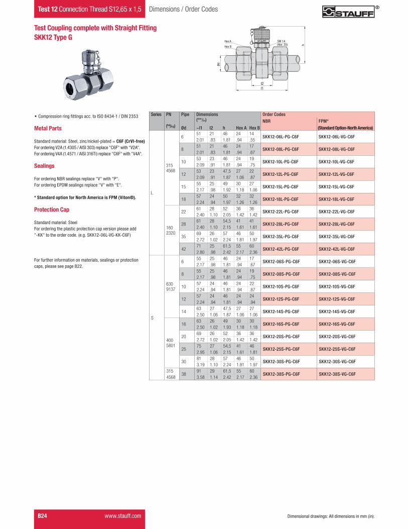
Dimensional drawings: All dimensions in mm (in).B24 www.stauff.com
Test 12 Connection Thread S12,65 x 1,5 Dimensions / Order Codes
h
Ød
Hex B
Hex A(Hex .55)SW 14
l1
l2
Test Coupling complete with Straight FittingSKK12 Type G
l2l1
Series PN Pipe Dimensions Order Codes(mm/in) NBR FPM*
(bar/PSI) Ød ~l1 l2 h Hex A Hex B (Standard Option-North America)
L
315
651 21 46 24 14
SKK12-06L-PG-C6F SKK12-06L-VG-C6F2.01 .83 1.81 .94 .55
851 21 46 24 17
SKK12-08L-PG-C6F SKK12-08L-VG-C6F2.01 .83 1.81 .94 .67
1053 23 46 24 19
SKK12-10L-PG-C6F SKK12-10L-VG-C6F2.09 .91 1.81 .94 .75
456812
53 23 47,5 27 22SKK12-12L-PG-C6F SKK12-12L-VG-C6F
2.09 .91 1.87 1.06 .87
1555 25 49 30 27
SKK12-15L-PG-C6F SKK12-15L-VG-C6F2.17 .98 1.92 1.18 1.06
1857 24 50 32 32
SKK12-18L-PG-C6F SKK12-18L-VG-C6F2.24 .94 1.97 1.26 1.26
160
2261 28 52 36 36
SKK12-22L-PG-C6F SKK12-22L-VG-C6F2.40 1.10 2.05 1.42 1.42
2861 28 54,5 41 41
SKK12-28L-PG-C6F SKK12-28L-VG-C6F2.40 1.10 2.15 1.61 1.61
232035
69 26 57 46 50SKK12-35L-PG-C6F SKK12-35L-VG-C6F
2.72 1.02 2.24 1.81 1.97
4271 25 61,5 55 60
SKK12-42L-PG-C6F SKK12-42L-VG-C6F2.80 .98 2.42 2.17 2.36
S
630
655 25 46 24 17
SKK12-06S-PG-C6F SKK12-06S-VG-C6F2.17 .98 1.81 .94 .67
855 25 46 24 19
SKK12-08S-PG-C6F SKK12-08S-VG-C6F2.17 .98 1.81 .94 .75
1057 24 46 24 22
SKK12-10S-PG-C6F SKK12-10S-VG-C6F9137 2.24 .94 1.81 .94 .87
1257 24 46 24 24
SKK12-12S-PG-C6F SKK12-12S-VG-C6F2.24 .94 1.81 .94 .94
1463 27 47,5 27 27
SKK12-14S-PG-C6F SKK12-14S-VG-C6F2.50 1.06 1.87 1.06 1.06
400
1663 26 49 30 30
SKK12-16S-PG-C6F SKK12-16S-VG-C6F2.50 1.02 1.93 1.18 1.18
2069 26 52 36 36
SKK12-20S-PG-C6F SKK12-20S-VG-C6F2.72 1.02 2.05 1.42 1.42
580125
75 27 54,5 41 46SKK12-25S-PG-C6F SKK12-25S-VG-C6F
2.95 1.06 2.15 1.61 1.81
3081 28 57 46 50
SKK12-30S-PG-C6F SKK12-30S-VG-C6F3.19 1.10 2.24 1.81 1.97
31538
91 29 61,5 55 60SKK12-38S-PG-C6F SKK12-38S-VG-C6F
4568 3.58 1.14 2.42 2.17 2.36
� Compression ring fittings acc. to ISO 8434-1 / DIN 2353
Metal Parts
Standard material: Steel, zinc/nickel-plated = C6F (CrVI-free)For ordering V2A (1.4305 / AISI 303) replace "C6F" with "V2A".For ordering V4A (1.4571 / AISI 316Ti) replace "C6F" with "V4A".
Sealings
For ordering NBR sealings replace "V" with "P".For ordering EPDM sealings replace "V" with "E".
* Standard option for North America is FPM (Viton®).
Protection Cap
Standard material: SteelFor ordering the plastic protection cap version please add "-KK" to the order code. (e.g. SKK12-06L-VG-KK-C6F)
For further information on materials, sealings or protection caps, please see page B22.
NoAm Version TEST.indd 24 10.11.2011 09:08:49

STAU
FFTe
stB
Dimensional drawings: All dimensions in mm (in). www.stauff.com B25
Dimensions / Order Codes Connection Thread S12,65 x 1,5 Test 12
30
(Hex .55)SW 14
Ø d
l 3
Hex A
(1.1
8)
33
Ø d
l 3
(Hex .67)
SW 17
Hex A
(1.3
0)
Test Coupling for 24° Cone FittingsSKK12 Type K
(Hex .67)
l3
(Hex .67)
l333 (1.3
0)
Ød Ød
SW 17
Hex A Hex A
SW 17
Series PN Pipe Dimensions Thread Version Order Codes(mm/in) NBR FPM*
(bar/PSI) Ød l3 Hex A G (Standard Option-North America)
L
315
615,5 14
M12 x 1,5 A SKK12-06L-PK-C6F SKK12-06L-VK-C6F.61 .55
815,5 17
M14 x 1,5 A SKK12-08L-PK-C6F SKK12-08L-VK-C6F.61 .67
1016,5 19
M16 x 1,5 A SKK12-10L-PK-C6F SKK12-10L-VK-C6F.65 .75
456812
17,5 22M18 x 1,5 A SKK12-12L-PK-C6F SKK12-12L-VK-C6F
.69 .87
1521 27
M22 x 1,5 B SKK12-15L-PK-GS-C6F SKK12-15L-VK-GS-C6F.83 1.06
1819,5 32
M26 x 1,5 B SKK12-18L-PK-GS-C6F SKK12-18L-VK-GS-C6F.77 1.26
160
2220,5 36
M30 x 2 B SKK12-22L-PK-GS-C6F SKK12-22L-VK-GS-C6F.81 1.42
2825 41
M36 x 2 B SKK12-28L-PK-GS-C6F SKK12-28L-VK-GS-C6F.98 1.61
232035
30 50M45 x 2 B SKK12-35L-PK-GS-C6F SKK12-35L-VK-GS-C6F
1.18 1.97
4231 60
M52 x 2 B SKK12-42L-PK-GS-C6F SKK12-42L-VK-GS-C6F1.22 2.36
S
630
614,5 17
M14 x 1,5 A SKK12-06S-PK-C6F SKK12-06S-VK-C6F.57 .67
816,5 19
M16 x 1,5 A SKK12-08S-PK-C6F SKK12-08S-VK-C6F.65 .75
1016,5 22
M18 x 1,5 A SKK12-10S-PK-C6F SKK12-10S-VK-C6F9137 .65 .87
1217,5 24
M20 x 1,5 A SKK12-12S-PK-C6F SKK12-12S-VK-C6F.69 .94
1419,5 27
M22 x 1,5 B SKK12-14S-PK-GS-C6F SKK12-14S-VK-GS-C6F.77 1.06
400
1618 30
M24 x 1,5 B SKK12-16S-PK-GS-C6F SKK12-16S-VK-GS-C6F.71 1.18
2024 36
M30 x 2 B SKK12-20S-PK-GS-C6F SKK12-20S-VK-GS-C6F.94 1.42
580125
26 46M36 x 2 B SKK12-25S-PK-GS-C6F SKK12-25S-VK-GS-C6F
1.02 1.81
3030 50
M42 x 2 B SKK12-30S-PK-GS-C6F SKK12-30S-VK-GS-C6F1.18 1.97
31538
34 60M52 x 2 B SKK12-38S-PK-GS-C6F SKK12-38S-VK-GS-C6F
4568 1.34 2.36
� For DKO connection � According to ISO 8434-1 / DIN 2353 � Version A: one-piece design � Version B: screwed design
Metal Parts
Standard material: Steel, zinc/nickel-plated = C6F (CrVI-free)For ordering V2A (1.4305 / AISI 303) replace "C6F" with "V2A".For ordering V4A (1.4571 / AISI 316Ti) replace "C6F" with "V4A".
Sealings
For ordering NBR sealings replace "V" with "P".For ordering EPDM sealings replace "V" with "E".
* Standard option for North America is FPM (Viton®).
Protection Cap
Standard material: SteelFor ordering the plastic protection cap version please add "-KK" to the order code. (e.g. SKK12-06L-VK-KK-C6F)
For further information on materials, sealings or protection caps, please see page B22.
Version A Version B
NoAm Version TEST.indd 25 22.11.2011 10:05:59

Test 12 Connection Thread S12,65 x 1,5 Dimensions / Order Codes
Hex
h
Hex
G
max
.12
(max
.47)
BulkheadSSKK12
h
Hex
Hex
G
Threads
*1 Special thread: buttress thread S12,65 x 1,5
Metal Parts
Standard material: Steel, zinc/nickel-plated = C6F (CrVI-free)For ordering V2A (1.4305 / AISI 303) replace "C6F" with "V2A".For ordering V4A (1.4571 / AISI 316Ti) replace "C6F" with "V4A".
Sealings
For ordering NBR sealings replace "V" with "P".For ordering EPDM sealings replace "V" with "E".
* Standard option for North America is FPM (Viton®).
Thread Dimensions Order Codes(mm/in) NBR FPM*
G h Hex (Standard Option-North America)
S12*1 63 19SSKK12-P-C6F SSKK12-V-C6F
2.48 0.75
Swivel Run Tee with JIC ConnectionSGV-JIC Type F/M
Metal Parts
Standard material: Steel, zinc/nickel-plated = C6F (CrVI-free)For ordering V2A (1.4305 / AISI 303) replace "C6F" with "V2A".For ordering V4A (1.4571 / AISI 316Ti) replace "C6F" with "V4A".
For further information please consult STAUFF.
Thread Dimensions Order Codes(mm/in)
inch Ø d1 Ø d2 l1 l2 l3 l4 Hex A Hex B
7/16–20 UNF7,49 4,9 9 14 37 8 27 17
SGV-7/16UNF-04-JIC1/4-F/M-C6F.29 .19 .35 .55 1.46 .31 1.06 .67
9/16–18 UNF11,05 8,1 10,5 14 37,5 8,5 27 19
SGV-7/16UNF-06-JIC3/8-F/M-C6F.44 .32 .41 .55 1.48 .33 1.06 .75
3/4–16 UNF15,9 10,8 10,5 16,7 43,7 12 30 22
SGV-7/16UNF-08-JIC1/2-F/M-C6F.63 .43 .41 .66 1.72 .47 1.18 .87
1-1/16–12 UNF21,6 16,9 15,4 21,9 50,4 13,5 36 32
SGV-7/16UNF-12-JIC3/4-F/M-C6F.85 .66 .61 .86 1.98 .53 1.42 1.26
1-5/16–12 UNF27,9 23,2 17,3 23,1 53,1 15 41 41
SGV-7/16UNF-16-JIC1-F/M-C6F1.10 .91 .68 .91 2.09 .59 1.61 1.61
l2
7/16-20 UNF
Hex AHex B
l1 l4 15(.59)
l3
Thre
ad
d1 d2
Thre
ad
37°
37°
Protection Cap
Standard material: SteelFor ordering the plastic protection cap version please add "-KK" to the order code. (e.g. SSKK12-V-KK-C6F)
For further information on materials, sealings or protection caps, please see page B22.
Dimensional drawings: All dimensions in mm (in).B26 www.stauff.com
NoAm Version TEST.indd 26 10.11.2011 09:08:56

STAU
FFTe
stB
Dimensions / Order Codes Connection Thread S12,65 x 1,5 Test 12
Dimensional drawings: All dimensions in mm (in).
h
G
S121)
h
S12
Adaptor SAD12
S12*1
S12*1
Version A Version B
Threads
*1 Special thread: buttress thread S12,65 x1,5
Metal Parts
Standard material: Steel, zinc/nickel-plated = C6F (CrVI-free) For ordering V2A (1.4305 / AISI 303) replace "C6F" with "V2A". For ordering V4A (1.4571 / AISI 316Ti) replace "C6F" with "V4A".
Sealings
For ordering NBR sealings replace "V" with "P".For ordering EPDM sealings replace "V" with "E".
* Standard option for North America is FPM (Viton®).
Thread Dimensions Version Order Codes(mm/in) NBR FPM*
G h (Standard Option-North America)
M16 x 233
A SAD12/20-P-C6F SAD12/20-V-C6F1.30
M16 x 1,533
A SAD12/15-P-C6F SAD12/15-V-C6F1.30
Plug in31
B SAD12/10-P-C6F SAD12/10-V-C6F1.22
G
h
(Hex .75)
SW 19
S 12
Hex A
max
.12
(max
.47)
Hex A
h
S12
G
Through hole Ø 18 (.71)
Gauge AdaptorSMA12
Direct Gauge AdaptorSMD12
*1*1
h
h
G
GHex A
Hex ASW 19(Hex .75)
Gauge Adaptor SMA15 Direct Gauge Adaptor SMD15
Threads
*1 Special thread: buttress thread S12,65 x1,5
Metal Parts
Standard material: Steel, zinc/nickel-plated = C6F (CrVI-free) For ordering V2A (1.4305 / AISI 303) replace "C6F" with "V2A". For ordering V4A (1.4571 / AISI 316Ti) replace "C6F" with "V4A".
Sealings
For ordering NBR sealings replace "V" with "P".For ordering EPDM sealings replace "V" with "E".
* Standard option for North America is FPM (Viton®).
Snubber on request.
Thread Dimensions Order Codes(mm/in) NBR FPM*
G h Hex A (Standard Option-North America)
G1/451 19
SMA12-G1/4-P-OR-C6F SMA12-G1/4-V-OR-C6F2.01 .75
G1/261 27
SMA12-G1/2-P-OR-C6F SMA12-G1/2-V-OR-C6F2.40 1.06
1/4 NPT51 19
SMA12-1/4NPT-P-C6F SMA12-1/4NPT-V-C6F2.01 .75
1/2 NPT61 27
SMA12-1/2NPT-P-C6F SMA12-1/2NPT-V-C6F2.40 1.06
G1/435 19
SMD12-G1/4-P-OR-C6F SMD12-G1/4-V-OR-C6F1.38 .75
G1/245 27
SMD12-G1/2-P-OR-C6F SMD12-G1/2-V-OR-C6F1.77 1.06
1/4 NPT35 19
SMD12-1/4NPT-P-C6F SMD12-1/4NPT-V-C6F1.38 .75
1/2 NPT45 27
SMD12-1/2NPT-P-C6F SMD12-1/2NPT-V-C6F1.77 1.06
www.stauff.com B27
NoAm Version TEST.indd 27 10.11.2011 09:08:59

B46 www.stauff.com Dimensional drawings: All dimensions in mm (in).
STAUFF Test General Technical Information
Type A Type A - Threaded port according to factory standardSealing: O-ring Type AThread Dimensions
G
(mm/in)
d1 +0,1 t1 min. t2 min
M8 x 19,5 11 15,5.37 .43 .61
M10 x 111,5 12 16,5.45 .47 .64G
d1
t2
t1
2,5
0,5
30°
Port Connections and Sealing Details
t2t1a0,1 A
A
Gd1
Type D Type D - Parallel threaded port type Z according to DIN 3852 Part 2 (inch)Sealing: Taper Type D suitable sealant requiredThread Dimensions
(mm/in)
G t1 min. t2 min.
Rp1/85,5 9,5.22 .37
Rp1/48,5 13,5.33 .53
Rp3/88,5 13,5.33 .53
Rp1/210,5 16,5.41 .65
t2
t1
G
90°
Type B Type C
Type B and C Type B and C - Threaded port type X acc. to DIN 3852 Part 1 and 2; ISO 9974-1 (metric); ISO 1179-1 (inch)Sealing: Metal joint Type B / Elastomeric sealing Type CThread Dimensions
(mm/in)
G d1 min. t1 min. t2 min. a max.
M10 x 115 8 10 1.59 .31 .39 .04
M12 x 1,518 12 15 1,5.71 .47 .59 .06
M14 x 1,520 12 15 1,5.79 .47 .59 .06
M16 x 1,523 12 15 1,5.91 .47 .59 .06
M18 x 1,525 12 15 2.98 .47 .59 .08
M20 x 1,527 14 17 21.06 .55 .67 .08
M22 x 1,528 14 17 2,51.10 .55 .67 .10
G1/815 8,5 10,5 1.59 .33 .41 .04
G1/420 12,5 15,5 1,5.79 .49 .61 .06
G3/823 12,5 15,5 2.91 .49 .61 .08
G1/228 14,5 18,5 2,51.10 .57 .73 .10
NoAm Version TEST.indd 46 10.11.2011 09:10:29

STAU
FFTe
stB
www.stauff.com B47Dimensional drawings: All dimensions in mm (in).
General Technical Information STAUFF Test
Type D Type D - Taper threaded port according to ANSI/ASME B1.20.1-1983 (NPT)Sealing: Taper Type D suitable sealant requiredThread Dimensions
(mm/in)
G t1 min. t2 min.
1/8–27 NPT6,9 11,6.27 .46
1/4–18 NPT10 16,4.39 .65
1/2–14 NPT13,6 22,6.54 .89
G
90°
t2
t1
Port Connections and Sealing Details
Gd1
t2t1ab
z°
A
0,1 A
0,2 A
d2
Type E Type E - Threaded port according to ISO 6149-1 (metric); ISO 11926-1 (UNF)Sealing: O-ring Type EThread Dimensions
(mm/in)
G d1 +0,1 d2 min. t1 min. t2 min. a +0,4 b max. z° ±1°
M10 x 111,1 16 10 11,5 1,6 1
12°.44 .63 .39 .45 .06 .04
M12 x 1,513,8 19 11,5 14 2,4 1,5
15°.54 .75 .45 .55 .09 .06
M14 x 1,515,8 21 11,5 14 2,4 1,5
15°.62 .83 .45 .55 .09 .06
M16 x 1,517,8 24 13 15,5 2,4 1,5
15°.70 .94 .51 .61 .09 .06
M22 x 1,523,8 29 15,5 18 2,4 2
15°.94 1.14 .61 .71 .09 .08
M27 x 229,4 34 19 22 3,1 2
15°1.16 1.34 .75 .87 .91 .08
5/16–24 UNF9,1 17 10 12 1,9 1,6
12°.36 .67 .39 .47 .07 .06
7/16–24 UNF12,4 21 11,5 14 2,4 1,6
12°.49 .83 .45 .55 .09 .06
1/2–20 UNF14 23 11,5 14 2,4 1,6
12°.55 .91 .45 .55 .09 .06
9/16–18 UNF15,65 25 12,7 15,5 2,5 1,6
12°.62 .98 .50 .61 .10 .06
7/8–14 UNF23,95 34 16,7 20 2,5 2,4
15°.94 1.34 .66 .79 .10 .09
NoAm Version TEST.indd 47 10.11.2011 09:10:30

Test 10 Plug in system Introduction
B28 www.stauff.com
Test Coupling with Ball Check
Fast coupling for
� Monitoring and control of pressure � Venting � Sampling in high- and low-pressure systems
Advantages
� Test system at working pressure � Leak proof connection before ball check is open � Simple connection to measurement, control and switching devices
Working Pressure
� Max. working pressure 400 bar / 5801 PSIFor SMK Type G and K the recommended working pressure of fi tting manufacturer should be noted.
Materials
� Metal Parts: Standard material: Steel, zinc/nickel-plated = C6F (CrVI-free)
� Ball: Stainless Steel
� Sealings: P = NBR (Buna-N®) (Temperature range -20 °C ... +100 °C / -4 °F ... +212 °F)Note: Internal sealings made of FPM, even for standard NBR-type.
V = FPM (Viton®)* (Temperature range -20 °C ... +200 °C / -4 °F ... +392 °F) * Standard option for North America is FPM (Viton®)
E = EPDM Ethylene Propylene Diene Monomer Rubber (for Brake fl uid, Temperature range -40 °C ... +150 °C / -40 °F ... +302 °F)
For ordering NBR or EPDM sealings please replace "V" with "P" or "E".
Media
� Suitable for hydraulic oils and other Mineral oil based fl uids(Check compatibility of seal material)
� For use with other liquid media please consult STAUFF
Test CouplingSMK20
Internal Sealings
Ball
Spring
Sealing at Port Connection
Port Connection
SMK10Test Coupling with Port Connection
SMK10 Type GTest Coupling complete with Straight Fitting
SMK10 Type K Test Coupling for 24° Cone Fittings
NoAm Version TEST.indd 28 10.11.2011 09:09:05

STAU
FFTe
stB
Dimensional drawings: All dimensions in mm (in). www.stauff.com B29
Dimensions / Order Codes Plug in system Test 10
G
h1
SW12
h2
Hex
Test Coupling with Port ConnectionSMK10
Metal Parts
Standard material: Steel, zinc/nickel-plated = C6F (CrVI-free)
Sealings
For ordering NBR sealings replace "V" with "P".For ordering EPDM sealings replace "V" with "E".
* Standard option for North America is FPM (Viton®).
Thread Sealing Working Dimensions Order CodesPressure (mm/in) NBR FPM*
G (bar/PSI) h1 h2 Hex (Standard Option-North America)
M8 x 1Type A
250 17,5 8,5 12SMK10-M8x1-PA-C6F SMK10-M8x1-VA-C6F
3625 .69 .33 .47
M10 x 1400 17,5 9,8 12
SMK10-M10x1-PA-C6F SMK10-M10x1-VA-C6F5801 .69 .39 .47
R1/8 K Type D400 17,5 8 12
SMK10-R1/8K-PD-C6F SMK10-R1/8K-VD-C6F5801 .69 .31 .47
For further information on materials or seals, please see page B28. Further thread versions possible with use of thread adaptors SRS20, please see page B32.
(Hex .75)SW 19
Hex A
M 16
max
.12
G
h
Through hole Ø 18 (Ø .71)
Gauge Adaptor SMA10
M16
Metal Parts
Standard material: Steel, zinc/nickel-plated = C6F (CrVI-free)
Sealings
For ordering NBR sealings replace "V" with "P".For ordering EPDM sealings replace "V" with "E".
* Standard option for North America is FPM (Viton®).
Snubber on request.
Thread Dimensions Order Codes(mm/in) NBR FPM*
G h Hex A (Standard Option-North America)
G1/457 19
SMA10-G1/4-P-OR-C6F SMA10-G1/4-V-OR-C6F2.24 .75
G1/267 27
SMA10-G1/2-P-OR-C6F SMA10-G1/2-V-OR-C6F2.64 1.06
1/4 NPT57 19
SMA10-1/4NPT-P-C6F SMA10-1/4NPT-V-C6F2.24 .75
1/2 NPT67 27
SMA10-1/2NPT-P-C6F SMA10-1/2NPT-V-C6F2.64 1.06
NoAm Version TEST.indd 29 10.11.2011 09:09:07

Test 10 Plug in system Dimensions / Order Codes
Ø 2
0
Hex 2
Hex 1
l 1
h
l 2
(Ø .79)
Test Coupling complete with Straight FittingSMK10 Type G
Hex A
Hex B
Ød
h
l2l1
� Compression ring fittings acc. to ISO 8434-1 / DIN 2353
Metal Parts
Standard material: Steel, zinc/nickel-plated = C6F (CrVI-free)
Sealings
For ordering NBR sealings replace "V" with "P".For ordering EPDM sealings replace "V" with "E".
* Standard option for North America is FPM (Viton®).
For further information on materials or sealings, please see page B28.
Series PN Pipe Dimensions Order Codes(mm/in) NBR FPM*
(bar/PSI) Ød ~l1 l2 h Hex A Hex B (Standard Option-North America)
L
315
651 21 29,5 24 14
SMK10-06L-PG-C6F SMK10-06L-VG-C6F2.01 .83 1.16 .94 .55
851 21 29,5 24 17
SMK10-08L-PG-C6F SMK10-08L-VG-C6F2.01 .83 1.16 .94 .67
1053 23 29,5 24 19
SMK10-10L-PG-C6F SMK10-10L-VG-C6F2.09 .91 1.16 .94 .75
456812
53 23 31 27 22SMK10-12L-PG-C6F SMK10-12L-VG-C6F
2.09 .91 1.22 1.06 .87
1555 25 32,5 30 27
SMK10-15L-PG-C6F SMK10-15L-VG-C6F2.17 .98 1.28 1.18 1.06
1857 24 33,5 32 32
SMK10-18L-PG-C6F SMK10-18L-VG-C6F2.24 .94 1.32 1.26 1.26
160
2261 28 33,5 36 36
SMK10-22L-PG-C6F SMK10-22L-VG-C6F2.40 1.10 1.32 1.42 1.42
2861 28 38 41 41
SMK10-28L-PG-C6F SMK10-28L-VG-C6F2.40 1.10 1.50 1.61 1.61
232035
69 26 40,5 46 50SMK10-35L-PG-C6F SMK10-35L-VG-C6F
2.72 1.02 1.59 1.81 1.97
4271 25 45 55 60
SMK10-42L-PG-C6F SMK10-42L-VG-C6F2.80 .98 1.77 2.17 2.36
S
400
655 25 29,5 24 17
SMK10-06S-PG-C6F SMK10-06S-VG-C6F2.17 .98 1.16 .94 .67
855 25 29,5 24 19
SMK10-08S-PG-C6F SMK10-08S-VG-C6F2.17 .98 1.16 .94 .75
1057 24 29,5 24 22
SMK10-10S-PG-C6F SMK10-10S-VG-C6F2.24 .94 1.16 .94 .87
1257 24 29,5 24 24
SMK10-12S-PG-C6F SMK10-12S-VG-C6F2.24 .94 1.16 .94 .94
1463 27 31 27 27
SMK10-14S-PG-C6F SMK10-14S-VG-C6F5801 2.50 1.06 1.22 1.06 1.06
1663 26 32,5 30 30
SMK10-16S-PG-C6F SMK10-16S-VG-C6F2.50 1.02 1.28 1.18 1.18
2069 26 35,5 36 36
SMK10-20S-PG-C6F SMK10-20S-VG-C6F2.72 1.02 1.40 1.42 1.42
2575 27 38 41 46
SMK10-25S-PG-C6F SMK10-25S-VG-C6F2.95 1.06 1.50 1.61 1.81
3081 28 40,5 46 50
SMK10-30S-PG-C6F SMK10-30S-VG-C6F3.19 1.10 1.59 1.81 1.97
31538
91 29 45 55 60SMK10-38S-PG-C6F SMK10-38S-VG-C6F
4568 3.58 1.14 1.77 2.17 2.36
B30 www.stauff.com
NoAm Version TEST.indd 30 10.11.2011 09:09:09

STAU
FFTe
stB
Dimensions / Order Codes Plug in system Test 10
www.stauff.com B31Dimensional drawings: All dimensions in mm (in).
17,5
l 3
Hex A
Ød
G
(.69)
(Hex. 47)SW 12
17,5
l 3
Hex AØd
G
(.69)
(Hex .47)
SW 12
Test Coupling for 24° Cone FittingsSMK10 Type K
l3
l3
Version A Version B
Series PN Pipe Dimensions Thread Version Order Codes(mm/in) NBR FPM*
(bar/PSI) Ød l3 Hex A G (Standard Option-North America)
L
315
615,5 14
M12 x 1,5 A SMK10-06L-PK-GS-C6F SMK10-06L-VK-GS-C6F.61 .55
815,5 17
M14 x 1,5 A SMK10-08L-PK-GS-C6F SMK10-08L-VK-GS-C6F.61 .67
1016,5 19
M16 x 1,5 A SMK10-10L-PK-GS-C6F SMK10-10L-VK-GS-C6F.65 .75
456812
17,5 22M18 x 1,5 A SMK10-12L-PK-GS-C6F SMK10-12L-VK-GS-C6F
.69 .87
1521 27
M22 x 1,5 B SMK10-15L-PK-GS-C6F SMK10-15L-VK-GS-C6F.83 1.06
1819,5 32
M26 x 1,5 B SMK10-18L-PK-GS-C6F SMK10-18L-VK-GS-C6F.77 1.26
160
2220,5 36
M30 x 2 B SMK10-22L-PK-GS-C6F SMK10-22L-VK-GS-C6F.81 1.42
2825 41
M36 x 2 B SMK10-28L-PK-GS-C6F SMK10-28L-VK-GS-C6F.98 1.61
232035
30 50M45 x 2 B SMK10-35L-PK-GS-C6F SMK10-35L-VK-GS-C6F
1.18 1.97
4231 60
M52 x 2 B SMK10-42L-PK-GS-C6F SMK10-42L-VK-GS-C6F1.22 2.36
S
400
614,5 17
M14 x 1,5 A SMK10-06S-PK-GS-C6F SMK10-06S-VK-GS-C6F.57 .67
816,5 19
M16 x 1,5 A SMK10-08S-PK-GS-C6F SMK10-08S-VK-GS-C6F.65 .75
1016,5 22
M18 x 1,5 A SMK10-10S-PK-GS-C6F SMK10-10S-VK-GS-C6F.65 .87
1217,5 24
M20 x 1,5 A SMK10-12S-PK-GS-C6F SMK10-12S-VK-GS-C6F.69 .94
1419,5 27
M22 x 1,5 B SMK10-14S-PK-GS-C6F SMK10-14S-VK-GS-C6F5801 .77 1.06
1618 30
M24 x 1,5 B SMK10-16S-PK-GS-C6F SMK10-16S-VK-GS-C6F.71 1.18
2024 36
M30 x 2 B SMK10-20S-PK-GS-C6F SMK10-20S-VK-GS-C6F.94 1.42
2526 46
M36 x 2 B SMK10-25S-PK-GS-C6F SMK10-25S-VK-GS-C6F1.02 1.81
3030 50
M42 x 2 B SMK10-30S-PK-GS-C6F SMK10-30S-VK-GS-C6F1.18 1.97
31538
34 60M52 x 2 B SMK10-38S-PK-GS-C6F SMK10-38S-VK-GS-C6F
4568 1.34 2.36
� For DKO connection � According to ISO 8434-1 / DIN 2353
Metal Parts
Standard material: Steel, zinc/nickel-plated = C6F (CrVI-free)
Sealings
For ordering NBR sealings replace "V" with "P".For ordering EPDM sealings replace "V" with "E".
* Standard option for North America is FPM (Viton®).
For further information on materials or sealings, please see page B28.
NoAm Version TEST.indd 31 10.11.2011 09:09:12

B46 www.stauff.com Dimensional drawings: All dimensions in mm (in).
STAUFF Test General Technical Information
Type A Type A - Threaded port according to factory standardSealing: O-ring Type AThread Dimensions
G
(mm/in)
d1 +0,1 t1 min. t2 min
M8 x 19,5 11 15,5.37 .43 .61
M10 x 111,5 12 16,5.45 .47 .64G
d1
t2
t1
2,5
0,5
30°
Port Connections and Sealing Details
t2t1a0,1 A
A
Gd1
Type D Type D - Parallel threaded port type Z according to DIN 3852 Part 2 (inch)Sealing: Taper Type D suitable sealant requiredThread Dimensions
(mm/in)
G t1 min. t2 min.
Rp1/85,5 9,5.22 .37
Rp1/48,5 13,5.33 .53
Rp3/88,5 13,5.33 .53
Rp1/210,5 16,5.41 .65
t2
t1
G
90°
Type B Type C
Type B and C Type B and C - Threaded port type X acc. to DIN 3852 Part 1 and 2; ISO 9974-1 (metric); ISO 1179-1 (inch)Sealing: Metal joint Type B / Elastomeric sealing Type CThread Dimensions
(mm/in)
G d1 min. t1 min. t2 min. a max.
M10 x 115 8 10 1.59 .31 .39 .04
M12 x 1,518 12 15 1,5.71 .47 .59 .06
M14 x 1,520 12 15 1,5.79 .47 .59 .06
M16 x 1,523 12 15 1,5.91 .47 .59 .06
M18 x 1,525 12 15 2.98 .47 .59 .08
M20 x 1,527 14 17 21.06 .55 .67 .08
M22 x 1,528 14 17 2,51.10 .55 .67 .10
G1/815 8,5 10,5 1.59 .33 .41 .04
G1/420 12,5 15,5 1,5.79 .49 .61 .06
G3/823 12,5 15,5 2.91 .49 .61 .08
G1/228 14,5 18,5 2,51.10 .57 .73 .10
NoAm Version TEST.indd 46 10.11.2011 09:10:29

STAU
FFTe
stB
www.stauff.com B47Dimensional drawings: All dimensions in mm (in).
General Technical Information STAUFF Test
Type D Type D - Taper threaded port according to ANSI/ASME B1.20.1-1983 (NPT)Sealing: Taper Type D suitable sealant requiredThread Dimensions
(mm/in)
G t1 min. t2 min.
1/8–27 NPT6,9 11,6.27 .46
1/4–18 NPT10 16,4.39 .65
1/2–14 NPT13,6 22,6.54 .89
G
90°
t2
t1
Port Connections and Sealing Details
Gd1
t2t1ab
z°
A
0,1 A
0,2 A
d2
Type E Type E - Threaded port according to ISO 6149-1 (metric); ISO 11926-1 (UNF)Sealing: O-ring Type EThread Dimensions
(mm/in)
G d1 +0,1 d2 min. t1 min. t2 min. a +0,4 b max. z° ±1°
M10 x 111,1 16 10 11,5 1,6 1
12°.44 .63 .39 .45 .06 .04
M12 x 1,513,8 19 11,5 14 2,4 1,5
15°.54 .75 .45 .55 .09 .06
M14 x 1,515,8 21 11,5 14 2,4 1,5
15°.62 .83 .45 .55 .09 .06
M16 x 1,517,8 24 13 15,5 2,4 1,5
15°.70 .94 .51 .61 .09 .06
M22 x 1,523,8 29 15,5 18 2,4 2
15°.94 1.14 .61 .71 .09 .08
M27 x 229,4 34 19 22 3,1 2
15°1.16 1.34 .75 .87 .91 .08
5/16–24 UNF9,1 17 10 12 1,9 1,6
12°.36 .67 .39 .47 .07 .06
7/16–24 UNF12,4 21 11,5 14 2,4 1,6
12°.49 .83 .45 .55 .09 .06
1/2–20 UNF14 23 11,5 14 2,4 1,6
12°.55 .91 .45 .55 .09 .06
9/16–18 UNF15,65 25 12,7 15,5 2,5 1,6
12°.62 .98 .50 .61 .10 .06
7/8–14 UNF23,95 34 16,7 20 2,5 2,4
15°.94 1.34 .66 .79 .10 .09
NoAm Version TEST.indd 47 10.11.2011 09:10:30

Adaptors for all Test Series Dimensions / Order Codes
M 10 x 1
G
SW
h1
h2
Hex
Thread AdaptorSRS20
Thread Sealing Dimensions Order Codes(mm/in)
G h1 h2 Hex
M10 x 1
Type B
15,5 8,5 17SRS20-M10x1-B-C6F
.61 .33 .67
M12 x 1,515 12 19
SRS20-M12x1,5-B-C6F.59 .47 .75
M14 x 1,515 12 19
SRS20-M14x1,5-B-C6F.59 .47 .75
M16 x 1,58 12 22
SRS20-M16x1,5-B-C6F.31 .47 .87
M18 x 1,515 12 24
SRS20-M18x1,5-B-C6F.59 .47 .94
M22 x 1,510,5 14 27
SRS20-M22x1,5-B-C6F.41 .55 1.06
G1/815,5 8 17
SRS20-G1/8-B-C6F.61 .31 .67
G1/415 12 19
SRS20-G1/4-B-C6F.59 .47 .75
G3/810,5 12 22
SRS20-G3/8-B-C6F.41 .47 .87
G1/210,5 14 27
SRS20-G1/2-B-C6F.41 .55 1.06
M12 x 1,5
Type C
15 12 19SRS20-M12x1,5-PC-C6F
.59 .47 .75
M14 x 1,515 12 19
SRS20-M14x1,5-PC-C6F.59 .47 .75
M18 x 1,515 12 24
SRS20-M18x1,5-PC-C6F.59 .47 .94
G1/816 8 17
SRS20-G1/8-PC-C6F.63 .31 .67
G1/415 12 19
SRS20-G1/4-PC-C6F.59 .47 .75
G3/810,5 12 22
SRS20-G3/8-PC-C6F.41 .47 .87
G1/210,5 14 27
SRS20-G1/2-PC-C6F.41 .55 1.06
R1/4 K
Type D
13 12 17SRS20-R1/4K-D-C6F
.51 .47 .67
R3/8 K13 14 19
SRS20-R3/8K-D-C6F.51 .55 .75
R1/2 K8 19 22
SRS20-R1/2K-D-C6F.31 .75 .87
1/4 NPT10 15 17
SRS20-1/4NPT-D-C6F.39 .59 .67
1/2 NPT8 20 22
SRS20-1/2NPT-D-C6F.31 .79 .87
7/16–20 UNF
Type E
9 9,1 17SRS20-7/16UNF-PE-C6F
.35 .36 .67
1/2–20 UNF15 9,2 17
SRS20-1/2UNF-PE-C6F.59 .36 .67
9/16–18 UNF15,5 10 19
SRS20-9/16UNF-PE-C6F.61 .39 .75
7/8–14 UNF11 16 27
SRS20-7/8UNF-PE-C6F.43 .63 1.06
M14 x 1,514,5 11 19
SRS20-M14x1,5-PE-C6F.57 .43 .75
M16 x 1,58,5 12,5 22
SRS20-M16x1,5-PE-C6F.33 .49 .87
M22 x 1,510 15 27
SRS20-M22x1,5-PE-C6F.39 .59 1.06
M27 x 210 18,5 32
SRS20-M27x2-PE-C6F.39 .73 1.26
Metal Parts
Standard Material SRS20:Steel, zinc/nickel-plated = C6F (CrVI-free)For ordering V2A (1.4305 / AISI 303) replace "C6F" with "V2A".For ordering V4A (1.4571 / AISI 316Ti) replace "C6F" with "V4A".
Sealings
For ordering NBR sealings replace "V" with "P".For ordering EPDM sealings replace "V" with "E".
* Standard option for North America is FPM (Viton®).
Sealing Details
Metal Joint Type B
Elastomeric Sealing Type C
Taper Type D (suitable sealant required)
O-ring Type E
B32 www.stauff.com
NoAm Version TEST.indd 32 10.11.2011 09:09:13

STAU
FFTe
stB
Dimensions / Order Codes for all Test Series Adaptors
www.stauff.com B33
G 1/4
G
h1
SW
h2
Hex
Thread AdaptorSRS15
Metal Parts
Standard material SRS15:Steel, zinc/nickel-plated = C6F (CrVI-free)For ordering V2A (1.4305 / AISI 303) replace "C6F" with "V2A".For ordering V4A (1.4571 / AISI 316Ti) replace "C6F" with "V4A".
Sealings
For ordering NBR sealings replace "V" with "P".For ordering EPDM sealings replace "V" with "E".
* Standard option for North America is FPM (Viton®).
Thread Sealing Dimensions Order Codes(mm/in)
G h1 h2 Hex
M14 x 1,5
Type B
24 12 19SRS15-M14x1,5-B-C6F
.95 .47 .75
M16 x 1,524 12 22
SRS15-M16x1,5-B-C6F.95 .47 .87
M18 x 1,524 12 24
SRS15-M18x1,5-B-C6F.95 .47 .95
M20 x 1,510,5 14 27
SRS15-M20x1,5-B-C6F.41 .55 1.06
G3/824 12 22
SRS15-G3/8-B-C6F.95 .47 .87
G1/210,5 14 27
SRS15-G1/2-B-C6F.41 .55 1.06
M14 x 1,5
Type C
24 12 19SRS15-M14x1,5-PC-C6F
.95 .47 .75
M16 x 1,524 12 22
SRS15-M16x1,5-PC-C6F.95 .47 .87
M18 x 1,524 12 24
SRS15-M18x1,5-PC-C6F.95 .47 .95
G3/824 12 22
SRS15-G3/8-PC-C6F.95 .47 .87
Sealing Details
Metal Joint Type B
Elastomeric Sealing Type C
Ød
G
h
4 x
45°
Welding Adaptor SAS
Metal Parts
Standard material: S235 (St 37), phosphated
Thread Port Dimensions Order CodesConnection (mm/in)
G h Ød
M10 x 1 Type A25 20
SAS-M10x1.98 .79
G1/8
Type B/C
25 20SAS-G1/8
.98 .79
G1/430 22
SAS-G1/41.18 .87
G3/830 25
SAS-G3/81.18 .98
1/4 NPT Type D25 20
SAS-1/4NPT.98 .79
1/2–20 UNF Type E25 20
SAS-1/2UNF.98 .79
NoAm Version TEST.indd 33 10.11.2011 09:09:14

B46 www.stauff.com Dimensional drawings: All dimensions in mm (in).
STAUFF Test General Technical Information
Type A Type A - Threaded port according to factory standardSealing: O-ring Type AThread Dimensions
G
(mm/in)
d1 +0,1 t1 min. t2 min
M8 x 19,5 11 15,5.37 .43 .61
M10 x 111,5 12 16,5.45 .47 .64G
d1
t2
t1
2,5
0,5
30°
Port Connections and Sealing Details
t2t1a0,1 A
A
Gd1
Type D Type D - Parallel threaded port type Z according to DIN 3852 Part 2 (inch)Sealing: Taper Type D suitable sealant requiredThread Dimensions
(mm/in)
G t1 min. t2 min.
Rp1/85,5 9,5.22 .37
Rp1/48,5 13,5.33 .53
Rp3/88,5 13,5.33 .53
Rp1/210,5 16,5.41 .65
t2
t1
G
90°
Type B Type C
Type B and C Type B and C - Threaded port type X acc. to DIN 3852 Part 1 and 2; ISO 9974-1 (metric); ISO 1179-1 (inch)Sealing: Metal joint Type B / Elastomeric sealing Type CThread Dimensions
(mm/in)
G d1 min. t1 min. t2 min. a max.
M10 x 115 8 10 1.59 .31 .39 .04
M12 x 1,518 12 15 1,5.71 .47 .59 .06
M14 x 1,520 12 15 1,5.79 .47 .59 .06
M16 x 1,523 12 15 1,5.91 .47 .59 .06
M18 x 1,525 12 15 2.98 .47 .59 .08
M20 x 1,527 14 17 21.06 .55 .67 .08
M22 x 1,528 14 17 2,51.10 .55 .67 .10
G1/815 8,5 10,5 1.59 .33 .41 .04
G1/420 12,5 15,5 1,5.79 .49 .61 .06
G3/823 12,5 15,5 2.91 .49 .61 .08
G1/228 14,5 18,5 2,51.10 .57 .73 .10
NoAm Version TEST.indd 46 10.11.2011 09:10:29

STAU
FFTe
stB
www.stauff.com B47Dimensional drawings: All dimensions in mm (in).
General Technical Information STAUFF Test
Type D Type D - Taper threaded port according to ANSI/ASME B1.20.1-1983 (NPT)Sealing: Taper Type D suitable sealant requiredThread Dimensions
(mm/in)
G t1 min. t2 min.
1/8–27 NPT6,9 11,6.27 .46
1/4–18 NPT10 16,4.39 .65
1/2–14 NPT13,6 22,6.54 .89
G
90°
t2
t1
Port Connections and Sealing Details
Gd1
t2t1ab
z°
A
0,1 A
0,2 A
d2
Type E Type E - Threaded port according to ISO 6149-1 (metric); ISO 11926-1 (UNF)Sealing: O-ring Type EThread Dimensions
(mm/in)
G d1 +0,1 d2 min. t1 min. t2 min. a +0,4 b max. z° ±1°
M10 x 111,1 16 10 11,5 1,6 1
12°.44 .63 .39 .45 .06 .04
M12 x 1,513,8 19 11,5 14 2,4 1,5
15°.54 .75 .45 .55 .09 .06
M14 x 1,515,8 21 11,5 14 2,4 1,5
15°.62 .83 .45 .55 .09 .06
M16 x 1,517,8 24 13 15,5 2,4 1,5
15°.70 .94 .51 .61 .09 .06
M22 x 1,523,8 29 15,5 18 2,4 2
15°.94 1.14 .61 .71 .09 .08
M27 x 229,4 34 19 22 3,1 2
15°1.16 1.34 .75 .87 .91 .08
5/16–24 UNF9,1 17 10 12 1,9 1,6
12°.36 .67 .39 .47 .07 .06
7/16–24 UNF12,4 21 11,5 14 2,4 1,6
12°.49 .83 .45 .55 .09 .06
1/2–20 UNF14 23 11,5 14 2,4 1,6
12°.55 .91 .45 .55 .09 .06
9/16–18 UNF15,65 25 12,7 15,5 2,5 1,6
12°.62 .98 .50 .61 .10 .06
7/8–14 UNF23,95 34 16,7 20 2,5 2,4
15°.94 1.34 .66 .79 .10 .09
NoAm Version TEST.indd 47 10.11.2011 09:10:30

B36 www.stauff.com
Test Hoses SMS / SGS DN 2 + DN 4 Working Pressure up to 630 bar / 9135 PSI
Technical Data for Test Hose
A B (Standard Version) C DNominal Bore (DN) (mm) DN 2 DN 4Max. Working Pressure (PN) (bar / PSI) 400 / 5801 630 / 9135 340 / 4931 630 / 9135Min. Burst Pressure (bar / PSI) 1100 / 15954 1900 / 27557 850 / 12328 1900 / 27557Testing Pressure (bar / PSI) 600 / 8702 950 / 13778 570 / 8267 950 / 13779
Pressure Rating in bar / PSIat Indicated Temperature
at 0 °C / 32 °F
(bar / PSI)
488 / 7077 768 / 11138 463 / 6715 768 / 11139at 30 °C / 86 °F 440 / 6381 693 / 10051 418 / 6063 693 / 10051at 50°C / 122 °F 400 / 5801 630 / 9137 380 / 5511 630 / 9137at 80°C / 176 °F 344 / 4989 542 / 7861 327 / 4743 542 / 7861at 100 °C / 212 °F 308 / 4467 485 / 7034 293 / 4250 485 / 7034
Working Temperature (°C / °F) -35 °C ... +100 °C / -31 °F ... +212 °F (momentary +120 °C / +248 °F)Inside Diameter (mm / in) 2 / .08 4 / .16Outside Diameter (mm / in) 5 / .20 8,6 / .34
Bending Radiusat working pressure
(mm / in)20 / .79 40 / 1.57
at -20 °C / 4 °F 30 / 1.18 60 / 2.36Max. Coil Length (m / ft) 100 / 328Weight / m (g / oz) 16 / .50 42 / 1.35Inner / Outer Tube PAReinforcement Synthetic FibreStandard hose end material is Steel 11 S Mn Pb 30 (1.0718), zinc/ nickel-plated (Type 15: Steel, black zinc/nickel-plated)Stainless Steel: V2A (1.4305/AISI 303), V4A (1.4571/AISI 316Ti) on request
Standard Hose
STAUFF-Test 20/20 STAUFF-Test 15/15 STAUFF-Test 12/12*2 STAUFF-Test 10/10 Gauge Adaptor
Ø5
L
M16
(Ø.20)Ø5
L
M16 x 1,5
(Ø .20)
Ø5
S12,65 x 1,5
L
(Ø .20)
L
Ø5(Ø .20)
Ø5
L
G1/4
(Ø .20)
� Max. Working Pressure: 400 bar / 5801 PSI
� Burst Pressure: 1100 bar / 15954 PSI
� Pressure/t° factor: to 0 °C 122 % at 30 °C 110 % at 50 °C 100 % at 80 °C 86 % at 100 °C 77 %
� Max. Working Pressure: 630 bar / 9137 PSI
� Burst Pressure: 1900 bar / 27557 PSI
� Pressure/t° factor: to 0 °C 122 % at 30 °C 110 % at 50 °C 100 % at 80 °C 86 % at 100 °C 77 %
� Max. Working Pressure: 400 bar / 5801 PSI
� Burst Pressure: 1100 bar / 15954 PSI
� Pressure/t° factor: to 0 °C 122 % at 30 °C 110 % at 50 °C 100 % at 80 °C 86 % at 100 °C 77 %
� Max. Working Pressure: 400 bar / 5801 PSI
� Burst Pressure: 1100 bar / 15954 PSI
� Pressure/t° factor: to 0 °C 122 % at 30 °C 110 % at 50 °C 100 % at 80 °C 86 % at 100 °C 77 %
� Gauge adaptor 1/4 NPT, G1/2 and 1/2 NPT on request
� Gauge adaptor available for all STAUFF-Test series
*2 Special thread: buttress thread S12,65 x 1,5
Dimensional drawings: All dimensions in mm (in).
NoAm Version TEST.indd 36 10.11.2011 09:10:06

STAU
FFTe
stB
www.stauff.com B37
Working Pressure up to 630 bar / 9135 PSI SMS / SGS DN 2 + DN 4 Test Hoses
Standard Length L*in mm in in305 12610 24915 361219 481524 601829 722438 963048 1206096 240
Bending protection on request.
Order Code STAUFF Test Hose
Hose End 1 (see pages B38 - B43) Hose End 2 (see pages B38 - B43) Length DN / Hose Size Material Hose End20 A . . . . J . . . . only specify when
2 different hose ends are required
Length in mm(see L above)
Standard Lengths see table below.
A = DN 2 400 bar / 5802 PSI Standard hose end material is Steel
11 S Mn Pb 30 (1.0718), zinc/nickel-plated = C6F
Type 15: Steel, black zinc/nickel-plated = C6F
Stainless Steel:
V2A (1.4305/AISI 303),
V4A (1.4571/AISI 316Ti) on request
15 S . . . . D . . . . B*2 = DN 2 630 bar / 9137 PSI12 K . . . . B . . . . C*3 = DN 4 340 bar / 4931 PSI10 L . . . . U . . . . D*3 = DN 4 630 bar / 9137 PSIM . . . . G . . . . P . . . .N . . . . F . . . . etc.
W . . . . C . . . .
*1 for gaseous media type SGS - Test hoses are perforated*2 Standard test hose option for North America is version B.*3 Type C and D - are perforated
SMS *1 20 / M . . . . 1219 B C6F
L
Order Code STAUFF Hose End
Hose End (see pages B38 - B43) DN / Hose Size Material Hose End20 A . . . . J . . . . A = DN 2 400 bar / 5802 PSI Standard hose end material is Steel
11 S Mn Pb 30 (1.0718), zinc/nickel-plated = C6F
Type 15: Steel, black zinc/nickel-plated = C6F
Stainless Steel:
V2A (1.4305/AISI 303),
V4A (1.4571/AISI 316Ti) on request
15 S . . . . D . . . . B = DN 2 630 bar / 9137 PSI12 K . . . . B . . . . C = DN 4 340 bar / 4931 PSI10 L . . . . U . . . . D = DN 4 630 bar / 9137 PSIM . . . . G . . . . P . . . .N . . . . F . . . . etc.W . . . . C . . . .
HE 20 B C6F
NoAm Version TEST.indd 37 10.11.2011 09:10:07

Test Ends Dimensions / Order Codes
Hose End Description Type G Hex(mm/in)
DN Hose Size
STAUFF-TestScrew-type
suitable for test points
20 M16 x 2
2and4
15 M16 x 1,5
12 S12,62 x 1,5
STAUFF-TestScrew-type90° elbow
suitable for test points
O
20 M16 x 2
215 M16 x 1,5
12 S12,62 x 1,5
STAUFF-TestScrew-type90° elbow
suitable for test points
(short wire version)OX
20 M16 x 2
17 .67 215 M16 x 1,5
12 S12,62 x 1,5
STAUFF-TestPlug in-type
10 Plug in system 2
Gauge adaptorBSP-thread
for G3/8, G1/2,M14 x 1,5 and M20 x 1,5swivel nut like type N
M
1/4 G1/4 19 .752and4
1/2 G1/2 27 1.06
3/8 G3/8 22 .87
214 M14 x 1,5 19 .75
20 M20 x 1,5 27 1.06
GG
G
-20
G
SWHex
STAUFF Hose End
Hex
G
Hex
B38 www.stauff.com
NoAm Version TEST.indd 38 10.11.2011 09:10:10

STAU
FFTe
stB
Dimensions / Order Codes Hose Ends
www.stauff.com B39Dimensional drawings: All dimensions in mm (in).
STAUFF Hose End
Hose End Description Type G Hex(mm/in)
DN Hose Size
90° elbowgauge adaptorBSP-thread
for G1/2swivel nut like type N
W
1/4 G1/4 19 .75
2and4
1/2 G1/2 27 1.06
Gauge adaptorNPT-thread
for 1/4 NPTswivel nut like type M
N
1/4 1/4 NPT 19 .75
2
1/2 1/2 NPT 27 1.06
90° elbowgauge adaptorNPT-thread
for 1/2 NPTswivel nut like type N
A
1/4 1/4 NPT 19 .75
2and4
1/2 1/2 NPT 27 1.06
Standpipefor compression ringfittings according to ISO 8434-1 / DIN 2353
Note:Standpipe version is not in accordance with the state of the art. Use at own risk. We recommend the use of the series K, R or L.
S
4 4 LL 2
6 6 L - 6 S
2and4
8 8 L - 8 S
10 10 L - 10 S
12 12 L - 12 S 2
1/4 1/4 2 and 4
Standpipefor compression ringfittings according to ISO 8434-1 / DIN 235390° elbow
Note:Standpipe version is not in accordance with the state of the art. Use at own risk. We recommend the use of the series K, R or L.
SG
6 6 L - 6 S
2and4
8 8 L - 8 S
SW
G
Hex
G
SW
G
20Ød
(se
e G
)
(.79)
Hex
Hex
Hex
Ød (see G)Ød (see G)
NoAm Version TEST.indd 39 10.11.2011 09:10:12

B40 www.stauff.com
Test Ends Dimensions / Order Codes
Hose End Description Type G Hex(mm/in)
DN Hose Size
Seal with O-ringfor 24° cone fitting according to ISO 8434-1 / DIN 2353c/w swivel nut
K
6 L M12 x 1,5 14 .55
2and4
8 L M14 x 1,5 17 .67
10 L M16 x 1,5 19 .75
12 L M18 x 1,5 22 .87
6 S M14 x 1,5 17 .67
8 S M16 x 1,5 19 .75
10 S M18 x 1,5 22 .87
12 S M20 x 1,5 24 .94
Seal with O-ringfor 24° cone fittingaccording to ISO 8434-1 / DIN 2353c/w swivel nut 45° elbow
R
6 L M12 x 1,5 14 .55
2and4
6 S M14 x 1,5 14 .67
Seal with O-ringfor 24° cone fittingaccording to ISO 8434-1 / DIN 2353c/w swivel nut90° elbow
L
6 L M12 x 1,5 14 .55
2and4
8 L M14 x 1,5 17 .67
10 L M16 x 1,5 19 .75
6 S M14 x 1,5 17 .67
8 S M16 x 1,5 19 .75
10 S M18 x 1,5 24 .94
Male threadaccording toDIN 3852-B
G
12 M12 x 1,5 17 .67
2and4
1/8 G1/8 14 .55
1/4 G1/4 19 .75
1/2 G1/2 27 1.06
Male thread NPTaccording toANSI-standard
F
1/8 1/8 NPT 13 .51
2and4
1/4 1/4 NPT 17 .67
G Hex
SW
G
Hex
G
Hex
G
STAUFF Hose End
Hex
Hex
Hex
G
NoAm Version TEST.indd 40 10.11.2011 09:10:14

STAU
FFTe
stB
www.stauff.com B41
Dimensions / Order Codes Hose Ends
STAUFF Hose End
Hose End Description Type G Hex(mm/in)
DN Hose Size
Male threadfor 24° cone fittingaccording toISO 8434-1 / DIN 2353
C
6 L M12 x 1,5 14 .55
2and4
8 L M14 x 1,5 17 .67
6S M14 x 1,5 17 .67
8 S M16 x 1,5 17 .67
Male threadaccording toSAE J 514
J
1/4 7/16–20 UNF 14 .55
2and4
5/16 1/2–20 UNF 14 .55
3/8 9/16–18 UNF 17 .67
Universal sealing headwith swivel nut for24° cone fittingaccording toISO 8434-1 / DIN 2353
D
6 L M12 x 1,5 14 .55
2and4
8 L M14 x 1,5 17 .67
10 L M16 x 1,5 19 .75
12 L M18 x 1,5 22 .87
6 S M14 x 1,5 17 .67
8 S M16 x 1,5 19 .75
10 S M18 x 1,5 22 .87
12 S M20 x 1,5 24 .94
Universal sealing headwith swivel nut for24° cone fittingaccording toISO 8434-1 / DIN 235390° elbow
Q
10 L M16 x 1,5 19 .75
2and4
10 S M18 x 1,5 22 .87
Sealing head withswivel nut forcone fittingaccording to DIN EN 560
B
1/8 G1/8 12 .47
2and4
1/4 G1/4 17 .67
Hex
G
Hex
G
Hex
G
G
Hex
Hex
G
NoAm Version TEST.indd 41 10.11.2011 09:10:16

B42 www.stauff.com
Test Ends Dimensions / Order Codes
STAUFF Hose End
Hose End Description Type G Hex(mm/in)
DN Hose Size
Sealing head withswivel nutaccording to SAE J 51437° cone
U
1/4 7/16–20 UNF 14 .55
2and4
5/16 1/2–20 UNF 17 .67
3/8 9/16–18 UNF 19 .75
Sealing head withswivel nutaccording to SAE J 51645° cone
UR 1/4 7/16–20 UNF 14 .55 2
Sealing head withswivel nutaccording to SAE J 51637° cone90° elbow
E 1/4 7/16–20 UNF 14 .552and4
Sealing head withswivel nutaccording to SAE J 51645° cone90° elbow
ER 1/4 7/16–20 UNF 14 .55 2
Test hosefor air brake systems
P 2 M16 x 1,5 19 .75 2
Hex
G45
°
Hex
G
37°
Hex
G
45°
Hex
G37
°
Hex
Hex
G
NoAm Version TEST.indd 42 10.11.2011 09:10:18

STAU
FFTe
stB
www.stauff.com B43
Dimensions / Order Codes Hose Ends
STAUFF Hose End
Hose End Description Type G Hex(mm/in)
DN Hose Size
Sealing head withswivel nut60° cone
H 1/4 G1/4 17 .672and4
Screw-type ORFSaccording to SAE J 1453
T
9/16 9/16–18 UNF 17 .67
2
11/16 11/16–16 UN 21 .83
Screw-type ORFSaccording toSAE J 145390° elbow
V 11/16 11/16–16 UN 21 .832and4
Hose end with integrated check valve
RV
20 M16 x 2
2
15 M16 x 1,5
Hex
GG
Hex
G
Hex
NoAm Version TEST.indd 43 10.11.2011 09:10:20
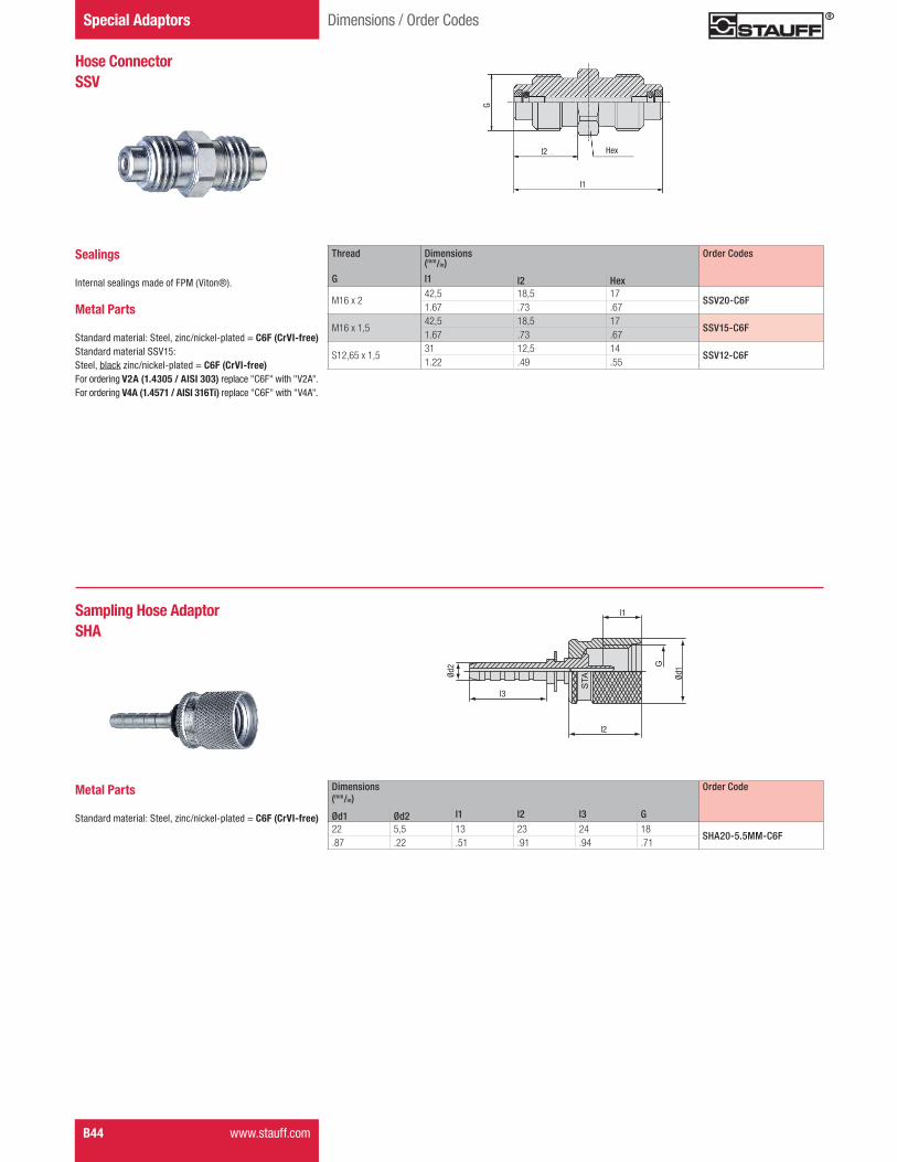
B44 www.stauff.com
Special Adaptors Dimensions / Order Codes
Hose ConnectorSSV
G
l2
l1
Hex
Sealings
Internal sealings made of FPM (Viton®).
Metal Parts
Standard material: Steel, zinc/nickel-plated = C6F (CrVI-free)Standard material SSV15: Steel, black zinc/nickel-plated = C6F (CrVI-free) For ordering V2A (1.4305 / AISI 303) replace "C6F" with "V2A".For ordering V4A (1.4571 / AISI 316Ti) replace "C6F" with "V4A".
Thread Dimensions Order Codes(mm/in)
G l1 l2 Hex
M16 x 242,5 18,5 17
SSV20-C6F1.67 .73 .67
M16 x 1,542,5 18,5 17
SSV15-C6F1.67 .73 .67
S12,65 x 1,531 12,5 14
SSV12-C6F1.22 .49 .55
STA
L1
ØD
1
L2
G
L3
ØD
2
Sampling Hose AdaptorSHA
l1
l2
l3
Ød2
Ød1
Dimensions Order Code(mm/in)
Ød1 Ød2 l1 l2 l3 G22 5,5 13 23 24 18
SHA20-5.5MM-C6F.87 .22 .51 .91 .94 .71
Metal Parts
Standard material: Steel, zinc/nickel-plated = C6F (CrVI-free)
NoAm Version TEST.indd 44 10.11.2011 09:10:22

B46 www.stauff.com Dimensional drawings: All dimensions in mm (in).
STAUFF Test General Technical Information
Type A Type A - Threaded port according to factory standardSealing: O-ring Type AThread Dimensions
G
(mm/in)
d1 +0,1 t1 min. t2 min
M8 x 19,5 11 15,5.37 .43 .61
M10 x 111,5 12 16,5.45 .47 .64G
d1
t2
t1
2,5
0,5
30°
Port Connections and Sealing Details
t2t1a0,1 A
A
Gd1
Type D Type D - Parallel threaded port type Z according to DIN 3852 Part 2 (inch)Sealing: Taper Type D suitable sealant requiredThread Dimensions
(mm/in)
G t1 min. t2 min.
Rp1/85,5 9,5.22 .37
Rp1/48,5 13,5.33 .53
Rp3/88,5 13,5.33 .53
Rp1/210,5 16,5.41 .65
t2
t1
G
90°
Type B Type C
Type B and C Type B and C - Threaded port type X acc. to DIN 3852 Part 1 and 2; ISO 9974-1 (metric); ISO 1179-1 (inch)Sealing: Metal joint Type B / Elastomeric sealing Type CThread Dimensions
(mm/in)
G d1 min. t1 min. t2 min. a max.
M10 x 115 8 10 1.59 .31 .39 .04
M12 x 1,518 12 15 1,5.71 .47 .59 .06
M14 x 1,520 12 15 1,5.79 .47 .59 .06
M16 x 1,523 12 15 1,5.91 .47 .59 .06
M18 x 1,525 12 15 2.98 .47 .59 .08
M20 x 1,527 14 17 21.06 .55 .67 .08
M22 x 1,528 14 17 2,51.10 .55 .67 .10
G1/815 8,5 10,5 1.59 .33 .41 .04
G1/420 12,5 15,5 1,5.79 .49 .61 .06
G3/823 12,5 15,5 2.91 .49 .61 .08
G1/228 14,5 18,5 2,51.10 .57 .73 .10
NoAm Version TEST.indd 46 10.11.2011 09:10:29
STAU
FFTe
stB
www.stauff.com B47Dimensional drawings: All dimensions in mm (in).
General Technical Information STAUFF Test
Type D Type D - Taper threaded port according to ANSI/ASME B1.20.1-1983 (NPT)Sealing: Taper Type D suitable sealant requiredThread Dimensions
(mm/in)
G t1 min. t2 min.
1/8–27 NPT6,9 11,6.27 .46
1/4–18 NPT10 16,4.39 .65
1/2–14 NPT13,6 22,6.54 .89
G
90°
t2
t1
Port Connections and Sealing Details
Gd1
t2t1ab
z°
A
0,1 A
0,2 A
d2
Type E Type E - Threaded port according to ISO 6149-1 (metric); ISO 11926-1 (UNF)Sealing: O-ring Type EThread Dimensions
(mm/in)
G d1 +0,1 d2 min. t1 min. t2 min. a +0,4 b max. z° ±1°
M10 x 111,1 16 10 11,5 1,6 1
12°.44 .63 .39 .45 .06 .04
M12 x 1,513,8 19 11,5 14 2,4 1,5
15°.54 .75 .45 .55 .09 .06
M14 x 1,515,8 21 11,5 14 2,4 1,5
15°.62 .83 .45 .55 .09 .06
M16 x 1,517,8 24 13 15,5 2,4 1,5
15°.70 .94 .51 .61 .09 .06
M22 x 1,523,8 29 15,5 18 2,4 2
15°.94 1.14 .61 .71 .09 .08
M27 x 229,4 34 19 22 3,1 2
15°1.16 1.34 .75 .87 .91 .08
5/16–24 UNF9,1 17 10 12 1,9 1,6
12°.36 .67 .39 .47 .07 .06
7/16–24 UNF12,4 21 11,5 14 2,4 1,6
12°.49 .83 .45 .55 .09 .06
1/2–20 UNF14 23 11,5 14 2,4 1,6
12°.55 .91 .45 .55 .09 .06
9/16–18 UNF15,65 25 12,7 15,5 2,5 1,6
12°.62 .98 .50 .61 .10 .06
7/8–14 UNF23,95 34 16,7 20 2,5 2,4
15°.94 1.34 .66 .79 .10 .09
NoAm Version TEST.indd 47 10.11.2011 09:10:30


![IEEE JOURNAL OF SOLID-STATE CIRCUITS, VOL. 40, …...ac coupling solves the KGD problem [12], enabling test at the high operating frequency before assembly. However, capacitive coupling](https://img.pdfslide.net/doc/110x75/5e293f03c270d721ea7d6ac3/ieee-journal-of-solid-state-circuits-vol-40-ac-coupling-solves-the-kgd-problem.jpg)