Embed Size (px)
Citation preview

Test Equipment Solutions Datasheet
Test Equipment Solutions Ltd specialise in the second user sale, rental and distribution of quality test & measurement (T&M) equipment. We stock all major equipment types such as spectrum analyzers, signal generators, oscilloscopes, power meters, logic analysers etc from all the major suppliers such as Agilent, Tektronix, Anritsu and Rohde & Schwarz.
We are focused at the professional end of the marketplace, primarily working with customers for whom high performance, quality and service are key, whilst realising the cost savings that second user equipment offers. As such, we fully test & refurbish equipment in our in-house, traceable Lab. Items are supplied with manuals, accessories and typically a full no-quibble 2 year warranty. Our staff have extensive backgrounds in T&M, totalling over 150 years of combined experience, which enables us to deliver industry-leading service and support. We endeavour to be customer focused in every way right down to the detail, such as offering free delivery on sales, covering the cost of warranty returns BOTH ways (plus supplying a loan unit, if available) and supplying a free business tool with every order.
As well as the headline benefit of cost saving, second user offers shorter lead times, higher reliability and multivendor solutions. Rental, of course, is ideal for shorter term needs and offers fast delivery, flexibility, try-before-you-buy, zero capital expenditure, lower risk and off balance sheet accounting. Both second user and rental improve the key business measure of Return On Capital Employed.
We are based near Heathrow Airport in the UK from where we supply test equipment worldwide. Our facility incorporates Sales, Support, Admin, Logistics and our own in-house Lab.
All products supplied by Test Equipment Solutions include:
- No-quibble parts & labour warranty (we provide transport for UK mainland addresses).- Free loan equipment during warranty repair, if available.- Full electrical, mechanical and safety refurbishment in our in-house Lab.- Certificate of Conformance (calibration available on request).- Manuals and accessories required for normal operation.- Free insured delivery to your UK mainland address (sales).- Support from our team of seasoned Test & Measurement engineers.- ISO9001 quality assurance.
Test equipment Solutions LtdUnit 8 Elder WayWaterside DriveLangleyBerkshireSL3 6EP
T: +44 (0)1753 596000F: +44 (0)1753 596001
Email: [email protected]: www.TestEquipmentHQ.com

RF DIRECTIONALTHRULINE® WATTMETER
MODEL APM–16

1
The Bird APM-16 is an insertion wattmeter designed to measure RF power and load match in 50 ohm transmission lines. It has a maximum VSWR of 1.05 for frequencies up to 1000 MHz. The meter provides direct readings in watts with an expanded linear scale for easy reading. The scale is graduated for 25, 50, and 100 full scale. Elements are available in a variety of power and frequency ranges (See the Bird Electronic Corporation Catalog for details).
Description
The Bird APM-16 is portable and rugged, with an aluminum housing. For addi-tional protection, the microammeter is specially shock mounted. Bumpers on the base and back allow the meter to stand or lie flat. Refer to Figure 1 to identify components.
At each end of the line section are Bird Quick-Change RF connectors that may be interchanged with any other Bird “QC” connector. The wattmeter housing does not interfere with connector changes.
Figure 1 Outline Drawing
Introduction
3
Traveling Wave Viewpoint
The easiest way to visualize Thruline operation is from a travelling wave view-point. In transmission lines the voltages, currents, standing waves, etc., on any uniform line section result from the interaction of two travelling waves:
The forward wave (and its power) travels from the source to the load. It has RF voltage Ef and current If in phase, with Ef / If = Zo.
The reflected wave (and its power) originates by reflection at the load and travels from the load back to the source. It has an RF voltage Er and current Ir in phase, with Er / Ir = Zo.
Each wave is mathematically simple and has a constant power: Wf = Watts Forward = Ef
2 / Zo = If2 Zo = Ef If Wr = Watts Reflected = Er
2 / Zo = Ir2 Zo = Er IrZo is the characteristic impedance of a uniform line section. For useful lines it is usually a pure resistance of 50 ohms. The RF circuit of the Bird APM-16 is a length of uniform air line with Zo = 50 ohms.
Coupling Circuit
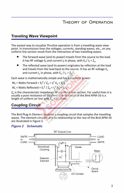
The Bird Plug-In Element contains a coupling circuit that samples the travelling waves. The element circuitry and its relationship to the rest of the Bird APM-16 are illustrated in Figure 5.
Figure 2 Schematic
Theory of Operation

4
Current is produced in the coupling circuit by the travelling waves in the line section. Both inductive and capacitive coupling contribute to this. Inductive cur-rent flows in the direction of the travelling wave, while the capacitive current is independent of the direction of the travelling wave. Therefore, the inductive current produced by one travelling wave will add in phase with the correspond-ing capacitive current, while that produced by the wave travelling in the oppo-site direction will subtract. The additive or “arrow” direction is assigned to the forward wave.
The electrical characteristics of the element are carefully adjusted so that, for the reverse travelling wave, the inductive current will completely cancel the capacitive current. The result is directivity greater than 25 dB. Thus, the element is sensitive at either of its settings, but to only one of the two travelling waves. Thruline Wattmeter measurements are also independent of position along the transmission line.
Like similar diode devices, the Bird APM-16 indicates the carrier component of amplitude modulation, with very little response to side band components added by modulation.
Load Power
For loads with a VSWR of 1.2 or less, the power dissipated in a load (Wl) is equal (with less than one percent error) to the forward power (Wf). When appreciable power is reflected, as with an antenna, it is necessary to use the exact load power, given by:
Wl = Watts into Load = Wf – Wr
Good load resistors, such as Bird Termaline Loads, will give negligible reflected power.
Standing vs. Travelling Waves
As mentioned previously, the Thruline Wattmeter reacts to forward and reverse travelling waves to measure power in a transmission line. The standing wave viewpoint, also widely used, is highly developed both in theory and in practice. This viewpoint can be traced to the early use of slotted transmission lines.
The slotted line measures the standing wave ratio by mechanically positioning a voltage detector at peaks and nulls along a length of line section. Its drawbacks are that it is usually too long, too expensive for good accuracy, not portable, and too slow. These problems grow rapidly as the measurement frequency drops below 1000 MHz. The Thruline Wattmeter by comparison is fast, convenient, and accurate. It provides the same information as a slotted line except for the phase angle of the reflection coefficient (distance, load to minimum).

5
vs.
The simple relationships:
can be used to convert between the standing wave ratio ( and the reflected/forward power ratio , which can be directly read from the Thruline Wattme-ter. The relationship between and is graphed in Figure 3 and Figure 4.
Note: Attenuation, measured in dB, can be derived from the power ratio by the equationNdb = 10 log .
VSWR scales and their attendant controls for setting the reference point have been intentionally omitted from the Bird APM-16. Experience using the Thruline Wattmeter for transmitter tune-up, antenna matching, etc. will show that the power ratio measurement is as useful as the standing wave ratio.
A trial is suggested – forget about VSWR for a few days and think in terms of = Wr / Wf. The meter readings, Wr and Wf, give a useful, approximate picture of the results without bothering to calculate the power ratio exactly. Consider that, for an antenna matching problem, the main objective usually is to mini-mize Wr. Anything done experimentally to this end will be seen when the ele-ment is in the reflected power position.
and Where = VSWR
and = Wr / Wf 1+
1 –----------------= 1–
1+------------=
2

6
Figure 3 Percent Reflected Power vs. VSWR (1.0 – 8.0)

7
Figure 4 Percent Reflected Power vs. VSWR (1.0 – 1.3

8
Low Reflection
= 10% ( = 2) is the typical limit of antenna match. Further effort is frequently not worthwhile because below this level reflected power is hard to measure, and Wl can not be significantly increased. TV and VHF transmitters are examples of systems requiring lower reflected power but for reasons other than maximiz-ing power transmission.
When the same element is used to measure both forward and reflected power, meaningful readings are possible down to about = 5% ( = 1.5). For accurate measurement of very low levels of reflected power, i.e. = 0.6% ( = 1.17), use a second element rated at one tenth of the full scale power of the forward ele-ment. This method should not be used with element ranges differing by more than 10:1.For example, consider an 80 watt transmitter and a Bird APM-16 with 100 and 10 watt elements. Measure Wf with the 100 W element. Measure Wr with the 10 W element (make sure the arrow points towards the transmitter). Wr can be measured down to at least 0.5 W, so that = 0.5 / 80 or about 0.6%, corre-sponding to = 1.17.
Transmitter Monitoring
The Thruline Wattmeter can be used for continuous monitoring of transmitter output or reflected power, for instance while checking intermittent antenna or line faults.
Component Testing
The Bird APM-16 is very helpful in component testing, and may be employed in several ways:1. Insertion VSWR or can be measured by placing the component between
the wattmeter and a good load resistor.2. Attenuation (power lost by heat in a line) as well as insertion VSWR or can be
measured by inserting the unknown line between two Thruline Wattmeters, or between a Thruline Wattmeter and a Termaline Absorption Wattmeter.
Note: Very small attenuations require allowance for normal instru-ment errors. To correct for this without any calculations, connect the wattmeters directly, with no line between them, and adjust their zero settings.
CAUTIONFor low reflection measurements, do not rotate the reflected power element
to read forward power. Damage to the element or wattmeter could result.

9
3. Line loss using open circuit calibration: The high directivity of elements can be exploited in line loss measurements, because of the equality of forward and reflected power with the load connector open or short circuited. In this state the forward and reflected waves have equal power, so that f = 100% and r = ¥. Open circuit testing is preferred to short circuit, because a high quality open circuit is easier to create than a high quality short.To measure insertion loss, use a high quality open circuit to check forward and reverse power equality, then connect an open-circuited, unknown line to the wattmeter. The measured f is the attenuation for two passes along the line (down and back). The attenuation can then be compared with pub-lished data for line type and length (remember to halve Ndb or double the line length to account for the measurement technique).
This measurement should be supplemented by either time domain reflec-tometry or DC continuity and leakage checks, since the attenuation mea-surement alone cannot account for faults such as open or short circuits partway down the line.
Note: Very small attenuations require allowance for normal instru-ment errors. Make sure to note exact readings, or their difference, on the initial equality check, and correct for this.
Frequency Response
Bird Plug-In Elements have a flat frequency response over their specified oper-ating range. A sample set of curves is shown in Figure 5. Notice that for the low power element, the rolloff outside its frequency band is more pronounced than for the high power elements. For example, at 40 MHz the 10C element will have a loss of 4 dB, giving a reading of about 40% of the true value For the 100C, the loss will only be about 1 dB, for a reading at 80% of the true value, and the 500C should be within the normal 5% of full scale tolerance.Figure 5 Representative Frequency Response

10
These curves are typical for all element types (H, A, B, C, D, ...) at their respec-tive frequencies. Since C elements have a frequency range of 100 - 250 MHz, response curves for other element types can be approximated by replacing the 100 and 250 MHz points on the chart with the extremes of the element’s fre-quency range, and recalculating the other frequency points accordingly. For example, for a B element (range 50 - 125 MHz) simply divide all frequencies by two. For an E element (range 400 - 1000 MHz) multiply all frequencies by four.Harmonics or subharmonics that lie outside of the frequency range of the ele-ment may exist in the circuit under test. A rough approximation of the ele-ment’s response to harmonics can be made with these curves. Using an element for measurements outside of its frequency range is not recommended. The response curves presented are only typical, and not guaranteed.
Impedance Mismatch
There may be cases where it is necessary to use the Bird APM-16 with a non-50 ohm transmission line. If the reflected power is less than 10% and the frequency is below 200 MHz, the resulting mismatch will not be too serious. At higher fre-quencies or higher reflected power levels, the load impedance will change when the wattmeter is removed from the circuit.When the line and load impedances are known, the system’s VSWR can be cal-culated by dividing the larger impedance by the smaller. Remember that the VSWR ratio must always be greater than 1.For example, consider using a Bird APM-16 to tune a 70 ohm line. If the load impedance is also 70 ohms, the wattmeter will measure a VSWR of 70 / 50 = 1.4. However, if you remove the wattmeter, the VSWR will actually be 1.0. If the load impedance is 35.7 ohms instead, the VSWR will be 50 / 35.7 = 1.4 with the wattmeter and 70 / 35.7 = 2.0 without it. Caution must therefore be used, since both good and bad matches can have the same measured VSWR. In this case, the correct impedance can be determined by slightly changing the load imped-ance. When the load impedance is near 70 ohms, the Bird 43 will read increas-ing VSWR as the load impedance is increased.
Note: When working with non-50 ohm lines, it is especially import-ant to calculate the load power by subtracting the reflected power from the forward power.

26
Specifications
Frequency Range (Element Dependent)
2 MHz – 2.3 GHz
Power Range (Element Dependent)
1 W – 1 kW
Impedance, Nominal 50 ohms
VSWR, Insertion 1.05:1 max 2 MHz – 1 GHz
Accuracy10° to 35°C–20° to +50°C
± 4% of reading ± 1% of full scale± 6% of reading ± 2% of full scale
Peak/Average Ratio > 10 dB
Settling Time < 1 s
Meter Shock mounted linear scale with expanded scales of 25, 50 and 100 full scale. Includes 5% overrange.
Connectors Bird “QC” N Female normally supplied
Battery Standard 9V battery. 200 hours operation, minimum.
Operating Position Any
EMC Complies with 89/336/EEC and 92/31/EEC
Emissions Immunity Safety EN 55011:1991 Class BEN 50082-2:1995EN 61010-1:1993 in accordance with 79/23/EEC and 93/68/EECComplies with IEC-1010-1,UL-1244, and CSA-231
Temperature, Operating –4 to +122 °F (–20 to +50 °C)
Temperature, Storage –13 to +149 °F (–25 to +65 °C)
Humidity 90% noncondensing max
Dimensions (Nominal) 3-5/8”L x 4”W x 6-7/8”H(92 x 102 x 175 mm)
Weight (Approx.) 4 lb. (1.8 kg) with N-Connectors
Finish Black Powder Coat