Embed Size (px)
Citation preview
Vapor Recovery Test Procedure
TP-201.1A
Emission Factor ForPhase I Systems at Dispensing Facilities
Adopted: April 12, 1996Amended: March 17, 1999
Amended: February 1, 2001
California Air Resources Board February 1, 2001TP-201.1A, Page 1
California Environmental Protection AgencyAir Resources Board
Vapor Recovery Test Procedure
TP-201.1A
Emission Factor ForPhase I Systems at Dispensing Facilities
Definitions common to all certification and test procedures are in:
D-200 Definitions for Vapor Recovery Procedures
For the purpose of this procedure, the term "ARB" refers to the State of California AirResources Board, and the term "ARB Executive Officer" refers to the Executive Officer ofthe ARB or his or her authorized representative or designate.
1. PURPOSE AND APPLICABILITY
1.1 This procedure applies when it is necessary to determine a mass emission factor forthe Phase I System rather than the volumetric efficiency determined by the applicationof TP–201.1. The operation of a vapor processor or vapor incinerator typicallyprecludes the application of TP-201.1.
1.2 The purpose of this test procedure, TP-201.1A, is to determine the emission factor (inunits of pounds of hydrocarbon emitted per 1000 gallons of gasoline transferred fromcargo tank to storage tank, lb/kgal) for installations of Phase I vapor recovery systems(VRS) at gasoline dispensing facilities (GDFs).
2. PRINCIPLE AND SUMMARY OF TEST PROCEDURE
During a fuel delivery, the volume of gasoline transferred from the cargo tank to the storagetank is determined. The mass of any gasoline vapors discharged from the vent(s) of thestorage tank(s) and, if present, from the exhaust of the vapor processor or vapor incineratorunit is determined. The mass emission factor for the fuel transfer event is calculated fromthese determinations.
As required to determine an emission related parameter and except where otherwisespecified, the equipment and procedures specified in the following test methods shall beused.
EPA Method 2A Direct Measurement of Gas Volume Through Pipes and Small Ducts
EPA Method 2B Determination of Exhaust Gas Volume Flow Rate From Gasoline VaporIncinerators
EPA Method 25A Determination of Total Gaseous Organic Compound Emissions Using aFlame Ionization Detector
California Air Resources Board February 1, 2001TP-201.1A, Page 2
EPA Method 25B Determination of Total Gaseous Organic Compound Emissions Using aNondispersive Infrared Analyzer
3. BIASES AND INTERFERENCES
3.1 Bulk Delivery Vapor Leaks
Any vapor leak exceeding the LEL (2.1 volume % as propane), during the gasolinebulk delivery, precludes the use of this method. Vapor concentration is determined ata distance of 1 inch from any potential vapor leak source. Measurements are madeusing the equipment and procedures specified in EPA Method 21 (40 CFR Part 60,App. A).
3.2 Cargo Tank Performance
Gasoline transfers performed using cargo tanks which do not meet the year round(daily) performance standards required by ARB Certification Procedure "CP-204,Certification Procedure for Vapor Recovery Systems of Cargo Tanks" preclude the useof this method.
4. SENSITIVITY, RANGE, AND PRECISION
The measurements of concentration and volumetric parameters required by TP-201.2 arewell within the limits of sensitivity, range, and precision of the specified equipment.
5. EQUIPMENT AND SUPPLIES
5.1 Volume Meters
A volume measuring device (meter) is required at each vent, including those equippedwith pressure-vacuum relief valves and the exhaust of any vapor processor or vaporincinerator. The meter should be equipped with an automatic data gathering systemthat can differentiate direction of flow and record the volume vented in such a mannerthat this data can be correlated with contemporaneous data on the meter temperatureand pressure and the hydrocarbon concentration of vapors passing through the meter.A sampling manifold shall be connected to the meter with taps for hydrocarbon (HC)concentration sampling, a thermocouple, and a pressure sensor connection.
Use a calibrated positive displacement meter or a turbine meter for measurement ofvolumetric flow. The error of the meter shall be less than 2% of the true volume overthe entire range of flow rates for which the meter will be used.
Any volume meter that is installed in the vapor recovery system plumbing shalldemonstrate conformance with the back pressure limit (BPL), specified below:
Meters with a manufacturer specified maximum flow rating of greater thanor equal to 1000 CFH shall demonstrate:
BPL < 1.10 inches water column at a flow rate of 3,000 CFH or themaximum flow rating specified by the manufacturer, whichever is less,and BPL < 0.05 inches water column at a flow rate of 30 CFH.
California Air Resources Board February 1, 2001TP-201.1A, Page 3
Meters with a manufacturer specified maximum flow rating of less than1000 CFH shall demonstrate:
BPL < 0.70 inches water column at a flow rate of 800 CFH and BPL <0.04 inches water column at a flow rate of 16 CFH.
Meter(s) shall be equipped with the following equipment:
(1) taps on the inlet and outlet sides for a differential pressure gauge with a full scalerange of less than or equal to four times the back pressure limit to allow detection of apressure drop greater than the BPL.
(2) Couplings required to connect meters to the VRS at the tank vent lines, the exhaust ofthe vapor processor or the inlet of the vapor incinerator. Couplings shall be sized andconstructed such that the test apparatus does not cause any significant increase in thepressure drop associated with flow through the systems tested.
5.2 Pressure Measurement Device for Volume Meters
Use a pressure measuring device (e.g. transducer, liquid manometer or Magnahelicgauge) with a range selected to ensure that the pressure measured by the device arewithin 10 to 90% of the full scale range. More than one gauge shall be used, ifnecessary. Pressure measurement shall be conducted at the sample couplingattached to the inlet of each volume meter. The error of the pressure measuringdevice shall be no greater than 3% of the true pressure over the entire range ofpressures to be measured by the device.
5.3 Temperature Measurement Device
Use a temperature measuring device (e.g. thermocouple, thermometer) with a designrange suitable for the temperature being measured. Typically, a range of 0 to 200 o Fis suitable for use in this test procedure. Temperature measurement shall beconducted at the sample coupling attached to the inlet of each volume meter. Theambient temperature is also measured and recorded during the Phase I gasolinetransfer. The error in the temperature measuring device shall be no greater than 4degrees Fahrenheit.
5.4 Hydrocarbon Analyzer(s)
Depending on the test point location of the HC measurement, the HC analyzer shall becapable of continuously measuring HC concentrations as follows:
100 ppm to 80 percent by volume using propane as a calibration gas, or75 ppm to 60 percent by volume using butane as a calibration gas.
5.5 Carbon Dioxide (CO2) Analyzer at Vapor Incinerator Exhaust
Use a carbon dioxide analyzer as specified in ARB Method 100 (title 17, CCR, section94114) or USEPA Method 3A, “Determination of Oxygen and Carbon Dioxide

California Air Resources Board February 1, 2001TP-201.1A, Page 4
Concentrations in Emissions from Stationary Sources (Instrumental AnalyzerProcedure)”, 40 CFR Part 60, App. A.
5.6 Carbon Monoxide (CO) Analyzer at Vapor Incinerator Exhaust
Use a carbon monoxide analyzer as specified in ARB Method 100 (title 17, CCR,section 94114) or USEPA Method 10, “Determination of Carbon Monoxide EmissionsFrom Stationary Sources”, 40 CFR Part 60, App. A.
5.7 Combustible Gas Detector
Use a combustible gas detector or explosimeter meeting the specifications required byEPA Method 21 “Determination of Volatile Organic Compounds Leaks”, 40 CFR Part60, App. A or ARB test procedure "TP-204.3, Determination of Leak(s)", to quantifyany vapor leaks occurring during the Phase I gasoline transfer.
5.8 Barometer
Use a mercury, aneroid, or equivalent barometer accurate to within 5 millimeters ofmercury ( 0.2 inches of mercury ) to determine ambient pressure during the Phase Igasoline transfer.
5.9 In-line Plumbing
Design goals for plumbing arrangements, regardless of GDF, are:
(1) Minimize length of additional test piping installed at any sample pointswithin the VRS.
(2) Minimize pressure drop across in-line plumbing and the volume meter.
(3) Return the entire volume of any sample extracted from the vapor return line toprevent a negative bias in the VRS pressure and the mass of pressure drivenfugitive emissions.
(4) Test apparatus plumbing shall be designed for easy adaptability toGDF configurations which may be encountered. Ball valves may be installed atthe inlet and exhaust of volume meters in order to isolate the meter from the VRSin the event that the meter requires servicing during the test. Such ball valvesshall be sized to match the size of the vapor return line and test apparatusplumbing.
5.10 Cargo Tank Fill Line and Vapor Return Line Couplers
The temperature and/or pressure or hydrocarbon concentration of the fluids in thecargo tank fill and vapor return lines is not necessary for determination of the massemission factor for which this procedure is used. However, if deemed necessary, thevolume of the vapor returned to the cargo tank may be estimated based on the volumeof gasoline delivered to the storage tank(s). If this volume is to be corrected to
California Air Resources Board February 1, 2001TP-201.1A, Page 5
standard conditions of temperature and pressure the following equipment will berequired to accommodate temperature and pressure measuring devices.
(1) Coupling for tank truck vapor return line with thermocouple and manometer, taps.Coupling to be the same diameter as the vapor return line.
(2) Coupling for tank truck fuel drop line with thermocouple tap. Coupling to be thesame diameter as the fuel line.
5.11 Calibration Gases
Cylinders of certified, or NIST traceable, calibration gases using propane (or butane) innitrogen capable of providing calibration for the analyzer ranges recommended. Eachrange requires three calibration gases:
(1) High-Range Gas: Concentration between 80 and 100% of range.(2) Mid-Range Gas: Concentration between 40 and 60% of range.(3) Zero Gas: Nitrogen with a hydrocarbon concentration less than 0.25% of
range.
5.12 Gas Dilution System
A gas dilution system which meets the requirements of EPA Method 205, Verificationof Gas Dilution Systems for Field Instrument Calibrations, CFR 40, Part 51, AppendixM, may be used to provide low-level calibration gases from a high-level calibration gas.The calibration gas used with a gas dilution system shall be an EPA Protocol gas. Agas dilution system which meets the requirements of EPA Method 205 may be usedfor all analyzer calibrations and sampling system bias checks. If a diluter is used, itmust be included in the calibration of the analyzer(s).
5.13 Data Acquisition System/Data Recorder
Provide a permanent record of hydrocarbon analyzer data using a strip chart recorder.A datalogger or another electronic data acquisition is also recommended. Data shallbe collected at intervals not to exceed one second. Any electronic data acquisitionsystem must be capable of integration at a ten-second interval. The strip chart, as wellas the data acquisition system, must have a resolution of 0.5 percent of the analyzerrange.
6. CALIBRATIONS
All measurement devices shall be calibrated as described below. A record of all calibrationsshall be maintained.
6.1 Analyzers: Calibration curves shall be produced no longer than six months beforetesting using ARB’s SOP 054, “Standard Operating Procedure for the MultilevelCalibrations of Pollutant Gas Analyzers” September 1, 1997. Field calibrations duringtesting shall be conducted as described in Section 8.1.1.
California Air Resources Board February 1, 2001TP-201.1A, Page 6
6.2 Calibration Gases:
6.2.1 Certification. The calibration gases must be certified according to one of thefollowing options:
6.2.1.1 The EPA Traceability Protocol for Assay and Certification of GaseousCalibration Standards (40 CFR Ch.1, Part 75, App. H), or
6.2.1.2 To an analytical accuracy of + 2% percent, traceable to a referencematerial approved by the National Institute of Standards and Technology(NIST) and recertified annually.
6.2.2 Documentation. Information on calibration gas cylinders shall be entered into alog identifying each cylinder by serial number. Sufficient information shall bemaintained to allow a determination of the certification status of each calibrationgas and shall include: (1) the data put in service, (2) assay result, (3) the datesthe assay was performed, (4) the organization and specific personnel whoperformed the assay, and (5) the date taken out of service.
6.3 Volume Meters: All volume meter calibrations shall be NIST traceable. Volumemeters shall be calibrated on an annual basis against a bell type spirometer at flowrates representing 1, 10, 30, 60, and 90% of the meter capacity. The accuracy of themeter shall be 5% of the true volume measured over the range of flow ratesencountered in application of this test procedure. Alternatively, the field volume metermay be calibrated against a transfer meter. The transfer meter shall be calibratedagainst the bell type spirometer or wet test meter and may not be used in the field as aworking meter.
6.4 Pressure Measuring Device: Calibrate pressure measurement devices prior to andimmediately following the test period with a static pressure calibrator at five points overa range of – 10 to +10 inches water or appropriate range of operation. The accuracyof the device shall be 5%. Alternatively, pressure measurement devices may becalibrated in accordance with manufacturer's specifications with a documentation ofthe specifications and the calibrations in the certification test report.
6.5 Temperature Measuring Device: Temperature measurement devices shall be checkedsemi-annually using an ice bath, ambient air, and boiling water. This temperaturecheck shall be performed by comparison to a NIST traceable measurement device.
7. PRE-TEST REQUIREMENTS
7.1 System and Facility Preparation
Vapor recovery system equipment and components shall be completely operationaland no deliveries to any storage tanks involved in the test shall have occurred withinthe preceding 36 hours.
The evaluation performed by the ARB Executive Officer shall specify the finalrequirements for facility preparation. The guiding principle is that testing activitiesshall not significantly alter GDF or VRS operating conditions. The installation of test

California Air Resources Board February 1, 2001TP-201.1A, Page 7
equipment can alter facility and system values for critical parameters (e.g. therelease of pressure caused by opening the VRS plumbing to install test equipmentat the tank vent or vapor processor or incinerator inlet). Therefore, final preparationprocedures are specified herein. Alternate procedures may be used if approved inwriting by the ARB Executive Officer.
7.1.1 Facility Preparation Procedures
(1) Install all required testing apparatus on the tank vent line(s),and ifpresent,the vapor processor exhaust and vapor incinerator inlet lines andwait at least 16 hours before testing. Until then, provide conditions whichminimally disturb facility and system operations due to the presence ofsuch equipment for such time; or
(2) install all equipment and wait until system parameters that are perturbedby the installation of test equipment, such as pressure and hydrocabonconcentration have returned to within the normal operating rangeestablished by the preliminary evaluation of the VRS. Until then, provideconditions which minimally disturb facility and system operations due tothe presence of such equipment.
8. DAILY PRE-TEST PROCEDURES
8.1 Field Calibration
8.1.1 Hydrocarbon Analyzers: Follow manufacturer’s instructions concerning warm-up time and adjustments. On each test day, prior to data collection, zero theanalyzer with a zero gas and span with known concentrations of calibrationgases at levels which are 40 to 60% and 80 to 100% of the concentrationranges to be used for the test.
Conduct the analyzer calibration error check by sequentially introducing thethree calibration gases (high-range, mid-range and zero gas) and recordingthe analyzer response to each calibration gas. Make no adjustments to thesampling/analysis system except those necessary to achieve the propercalibration gas flowrate. The analyzer calibration error for any calibration gasshall not exceed ±2 percent of the range. If needed, take corrective actionuntil acceptable performance is achieved.
Perform a leak check on the vacuum side of the assembly at the maximumpump vacuum. Correct any leaks found and repeat the leak check andcorrection procedure until no leak is detected.
8.1.2 CO and CO2 Analyzers: Repeat instructions in 8.1.1 for CO and CO2
analyzers if applicable.
8.1.3 Pressure Measurement Device: Prior to and immediately following each dayof testing, record the pressure measuring device(s) response to the pressuregenerated by a static pressure calibrator at 0, 40, and 80% of the specified

California Air Resources Board February 1, 2001TP-201.1A, Page 8
range of operation. If pressure differs more than 10%, recalibrate the device.Document instrument response before and after adjustment.
8.1.4 Temperature Measurement Device. Check the accuracy of the temperaturemeasurement device(s) against an NIST traceable mercury-glassthermometer at ambient temperature prior to and immediately following eachday of testing. If necessary, adjust the temperature read-out in accordancewith manufacturer’s instructions. Provide a copy of these instructions anddocument the instrument response before and after adjustment in the testreport.
8.2 Sampling System Bias Checks: Check sampling set-up by introducing a knownhydrocarbon concentration as close to the sample point as possible. If the differencebetween the analyzer field calibration and the sample system bias check exceeds+5% of the range for the high-level calibration gas, the system fails the bias checkand corrective action must be taken. Calculate bias using Equation 8.3. Allsampling points must pass the bias check before the test can proceed.
where:
Ca = analyzer response for calibration gas for field calibration
Cb = analyzer response for calibration gas for sampling system bias check
R = analyzer range
8.3 Initiate Test Documentation:
8.3.1 Photographs shall be taken at each test point to document the equipment set-up. Any changes in configuration during the test shall also be documented byphotographs, along with the date and time of the modification. A videodemonstrating emission measurement during a fuel delivery isrecommended.
8.3.2 Testers shall maintain a test log which shall consist of a narrativedocumenting activities at the test site, such as Phase I fuelings, modificationsto equipment and the reasons for testing decisions. The tester shall updatethe test log at least twice a day.
8.4 RVP Sample: If required by the ARB Executive Officer, collect gasoline samples ofeach grade as described in title 13, CCR, Section 2296.
x100R
)C(CBias ba
−=
California Air Resources Board February 1, 2001TP-201.1A, Page 9
9. TEST PROCEDURE
9.1 Test Point 1 (Tank Vents) and / or Test Point 2 (Vapor Processor Exhaust)
In this section, the term "vent" and the specified procedures for testing vents shallalso apply to any vapor processor with which such procedures are compatible. Anyassist processor that is incompatible with the application of these procedures shallnot be certified until the compatibility requirements of the certification procedures aremet. Separate equipment and test procedures are specified elsewhere for vaporincinerators.
(1) Remove any PV valve(s) that is (are) installed on the vent(s). Then install thecoupler, volume meter and sample manifold and reinstall the PV Valve at the outletof the sample manifold. Figures 4 and 5 depict the final installation. In these figures,elbows have been use to orient the meter in a horizontal flow direction. This is doneto minimize the chance of contamination falling into the outlet of the meter andjamming the meter. A jammed meter can be detected by higher than normalpressure drop through the meter at normal volumetric flow rates. The differentialpressure gauge installed across the meter is used for this purpose. Horizontalorientation is recommended but not required.
If a vapor processor is present, connect an additional coupler, meter and samplemanifold to the exhaust of the vapor processor. Additional guidance on the directmeasurement of flow through ducts which may be applicable to the vapor processorexhaust, can be found in EPA Method 2A.
(2) Connect the temperature and pressure measuring devices and the HC analyzersample lines and, if required, the sample return lines to the vent sampling manifold.Calibrate the measurement devices in accordance with section 6.
(3) If required, connect the couplers to the tank truck fuel and vapor return lines andconnect the temperature and pressure measuring devices to these couplers.Calibrate the measurement devices in accordance with section 6.
(4) Request that the cargo tank operator identify the volume of gasoline to be transferredfrom the cargo tank using shipping manifests, load rack receipts, etc. Instruct thecargo tank operator to gauge the storage tank(s) and confirm that adequate storagetank ullage is available to accept the full volume to be transferred from the cargotank. Individually record the initial gasoline inventory volumes in each storage tank.
(5) Instruct the cargo tank operator to connect tank truck fill and vapor return lines to theappropriate underground tank connections in accordance with the written procedurefor the Phase I VRS. Ensure that there is no conflict between the normal deliveryprocedures established by the cargo tank owner/operator and those established bythe applicant for Phase I VRS certification.
(6) Check the cargo tank dome hatches, pressure relief valves and vapor return lineconnections with the combustible gas detector before and during the gasolinetransfer. Record any measurements above 100 % of the LEL (2.1 % as propane).
California Air Resources Board February 1, 2001TP-201.1A, Page 10
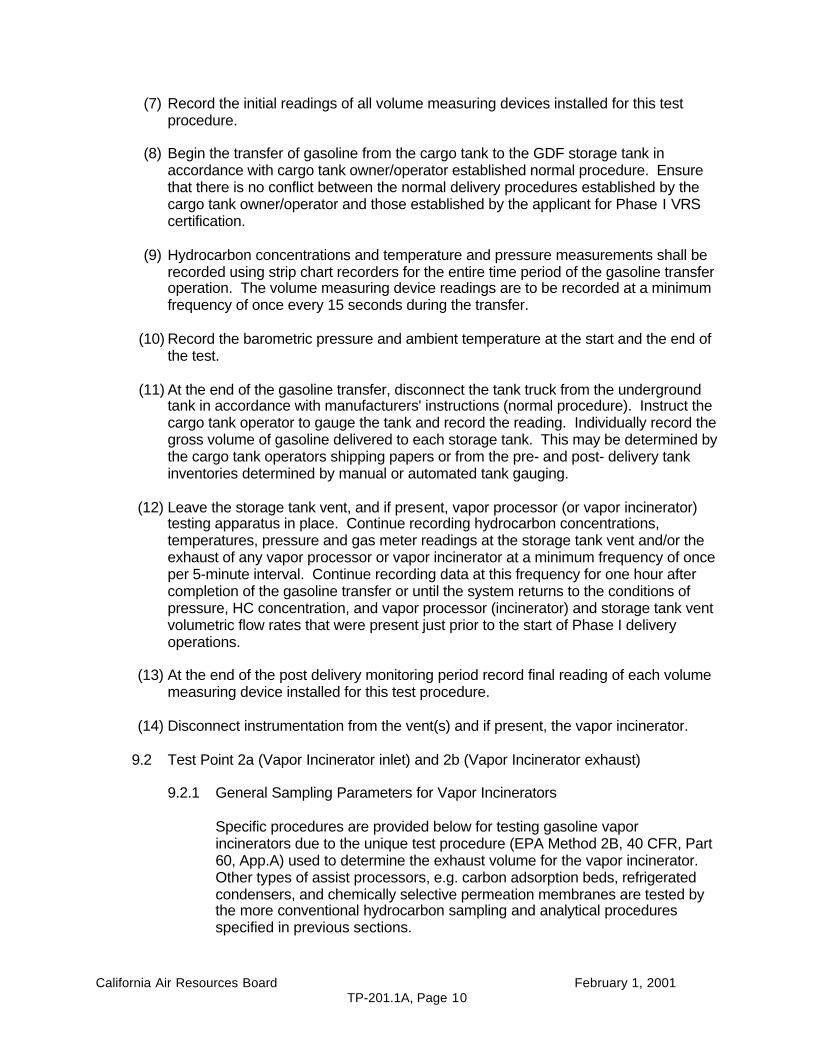
(7) Record the initial readings of all volume measuring devices installed for this testprocedure.
(8) Begin the transfer of gasoline from the cargo tank to the GDF storage tank inaccordance with cargo tank owner/operator established normal procedure. Ensurethat there is no conflict between the normal delivery procedures established by thecargo tank owner/operator and those established by the applicant for Phase I VRScertification.
(9) Hydrocarbon concentrations and temperature and pressure measurements shall berecorded using strip chart recorders for the entire time period of the gasoline transferoperation. The volume measuring device readings are to be recorded at a minimumfrequency of once every 15 seconds during the transfer.
(10) Record the barometric pressure and ambient temperature at the start and the end ofthe test.
(11) At the end of the gasoline transfer, disconnect the tank truck from the undergroundtank in accordance with manufacturers' instructions (normal procedure). Instruct thecargo tank operator to gauge the tank and record the reading. Individually record thegross volume of gasoline delivered to each storage tank. This may be determined bythe cargo tank operators shipping papers or from the pre- and post- delivery tankinventories determined by manual or automated tank gauging.
(12) Leave the storage tank vent, and if present, vapor processor (or vapor incinerator)testing apparatus in place. Continue recording hydrocarbon concentrations,temperatures, pressure and gas meter readings at the storage tank vent and/or theexhaust of any vapor processor or vapor incinerator at a minimum frequency of onceper 5-minute interval. Continue recording data at this frequency for one hour aftercompletion of the gasoline transfer or until the system returns to the conditions ofpressure, HC concentration, and vapor processor (incinerator) and storage tank ventvolumetric flow rates that were present just prior to the start of Phase I deliveryoperations.
(13) At the end of the post delivery monitoring period record final reading of each volumemeasuring device installed for this test procedure.
(14) Disconnect instrumentation from the vent(s) and if present, the vapor incinerator.
9.2 Test Point 2a (Vapor Incinerator inlet) and 2b (Vapor Incinerator exhaust)
9.2.1 General Sampling Parameters for Vapor Incinerators
Specific procedures are provided below for testing gasoline vaporincinerators due to the unique test procedure (EPA Method 2B, 40 CFR, Part60, App.A) used to determine the exhaust volume for the vapor incinerator.Other types of assist processors, e.g. carbon adsorption beds, refrigeratedcondensers, and chemically selective permeation membranes are tested bythe more conventional hydrocarbon sampling and analytical proceduresspecified in previous sections.
California Air Resources Board February 1, 2001TP-201.1A, Page 11
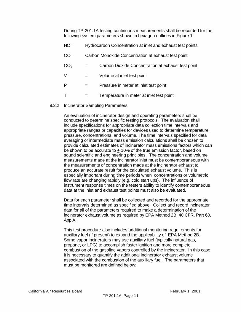
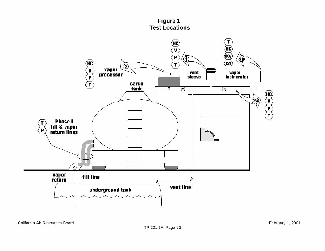
During TP-201.1A testing continuous measurements shall be recorded for thefollowing system parameters shown in hexagon outlines in Figure 1:
HC = Hydrocarbon Concentration at inlet and exhaust test points
CO= Carbon Monoxide Concentration at exhaust test point
CO2 = Carbon Dioxide Concentration at exhaust test point
V = Volume at inlet test point
P = Pressure in meter at inlet test point
T = Temperature in meter at inlet test point
9.2.2 Incinerator Sampling Parameters
An evaluation of incinerator design and operating parameters shall beconducted to determine specific testing protocols. The evaluation shallinclude specifications for appropriate data collection time intervals andappropriate ranges or capacities for devices used to determine temperature,pressure, concentrations, and volume. The time intervals specified for dataaveraging or intermediate mass emission calculations shall be chosen toprovide calculated estimates of incinerator mass emissions factors which canbe shown to be accurate to + 10% of the true emission factor, based onsound scientific and engineering principles. The concentration and volumemeasurements made at the incinerator inlet must be contemporaneous withthe measurements of concentration made at the incinerator exhaust toproduce an accurate result for the calculated exhaust volume. This isespecially important during time periods when concentrations or volumetricflow rate are changing rapidly (e.g. cold start ups). The influence ofinstrument response times on the testers ability to identify contemporaneousdata at the inlet and exhaust test points must also be evaluated.
Data for each parameter shall be collected and recorded for the appropriatetime intervals determined as specified above. Collect and record incineratordata for all of the parameters required to make a determination of theincinerator exhaust volume as required by EPA Method 2B, 40 CFR, Part 60,App.A.
This test procedure also includes additional monitoring requirements forauxiliary fuel (if present) to expand the applicability of EPA Method 2B.Some vapor incinerators may use auxiliary fuel (typically natural gas,propane, or LPG) to accomplish faster ignition and more completecombustion of the gasoline vapors controlled by the incinerator. In this caseit is necessary to quantify the additional incinerator exhaust volumeassociated with the combustion of the auxiliary fuel. The parameters thatmust be monitored are defined below:
California Air Resources Board February 1, 2001TP-201.1A, Page 12
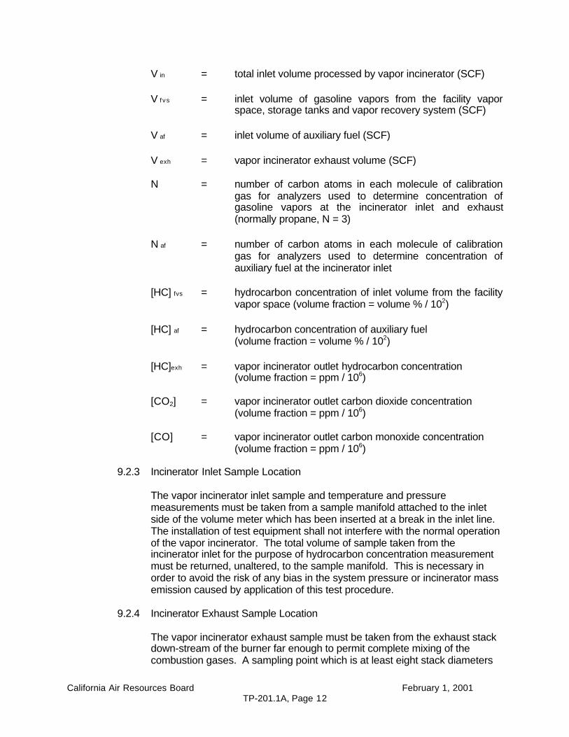
V in = total inlet volume processed by vapor incinerator (SCF)
V f vs = inlet volume of gasoline vapors from the facility vaporspace, storage tanks and vapor recovery system (SCF)
V af = inlet volume of auxiliary fuel (SCF)
V exh = vapor incinerator exhaust volume (SCF)
N = number of carbon atoms in each molecule of calibrationgas for analyzers used to determine concentration ofgasoline vapors at the incinerator inlet and exhaust(normally propane, N = 3)
N af = number of carbon atoms in each molecule of calibrationgas for analyzers used to determine concentration ofauxiliary fuel at the incinerator inlet
[HC] fvs = hydrocarbon concentration of inlet volume from the facilityvapor space (volume fraction = volume % / 102)
[HC] af = hydrocarbon concentration of auxiliary fuel(volume fraction = volume % / 102)
[HC]exh = vapor incinerator outlet hydrocarbon concentration(volume fraction = ppm / 106)
[CO2] = vapor incinerator outlet carbon dioxide concentration(volume fraction = ppm / 106)
[CO] = vapor incinerator outlet carbon monoxide concentration(volume fraction = ppm / 106)
9.2.3 Incinerator Inlet Sample Location
The vapor incinerator inlet sample and temperature and pressuremeasurements must be taken from a sample manifold attached to the inletside of the volume meter which has been inserted at a break in the inlet line.The installation of test equipment shall not interfere with the normal operationof the vapor incinerator. The total volume of sample taken from theincinerator inlet for the purpose of hydrocarbon concentration measurementmust be returned, unaltered, to the sample manifold. This is necessary inorder to avoid the risk of any bias in the system pressure or incinerator massemission caused by application of this test procedure.
9.2.4 Incinerator Exhaust Sample Location
The vapor incinerator exhaust sample must be taken from the exhaust stackdown-stream of the burner far enough to permit complete mixing of thecombustion gases. A sampling point which is at least eight stack diameters

California Air Resources Board February 1, 2001TP-201.1A, Page 13
downstream of any flow disturbance, and two diameter upstream of any flowdisturbance is desirable. Flow disturbances of concern include a bend,expansion, or contraction in the stack, the stack exhaust point, and thelocation of a visible flame.
If the "8 and 2 criteria" cannot be met, a sampling point which is at least twostack diameters downstream of any flow disturbance and one diameterupstream of any flow disturbance may be used. Any alternative samplinglocations which do not meet these minimum criteria must be approved by theARB Executive Officer on the basis of adequate justification, submitted by theapplicant. This justification shall include analysis based on sound scientificand engineering principals, to demonstrate that an incinerator stack withsampling ports which meet the minimum criteria are not feasible for GDFinstallations of the certified VRS. In any event, the sample point shall be noless than one half diameter from the stack exit and one stack diameter abovethe high point of the visible flame and be at a point of maximum velocityhead, normally the center or the stack.
(Further guidance on sampling locations for gaseous pollutant concentrationmeasurement can be found in 40 CFR Pt.60 App. A, Meth. 1 and App. B,Spec. 2.)
Note that any use of temporary stack extensions or other apparatus installedsolely for the purpose of source testing shall not be allowed if there isevidence indicating that the quantity or chemical structure of the incineratoremissions will be altered by the presence of such apparatus.
9.2.5 Incinerator Performance Specifications
The vapor incinerator shall be evaluated and tested to determine anyperformance specifications that are deemed necessary by the ARB ExecutiveOfficer to ensure that GDF installation of the certified VRS are operated in amanner consistent with the operation of the vapor incinerator duringcertification testing following TP-201.1A. The following performancespecifications may warrant evaluation:
(1) a performance specification for time averaged hydrocarbon concentration(as propane) in the incinerator exhaust stream and
(2) a performance specification for time averaged carbon monoxide (CO)concentration in the incinerator exhaust stream and
(3) performance specifications for other critical incinerator operatingparameters such as: maximum and minimum volumetric vaporprocessing rates, exhaust stack temperatures, vapor feed blower fanspeed and inlet pressure etc.
The results of evaluation and testing of the system shall be documented inthe certification test report and shall include:
(1) the identification of the critical incinerator operating parameters,
California Air Resources Board February 1, 2001TP-201.1A, Page 14
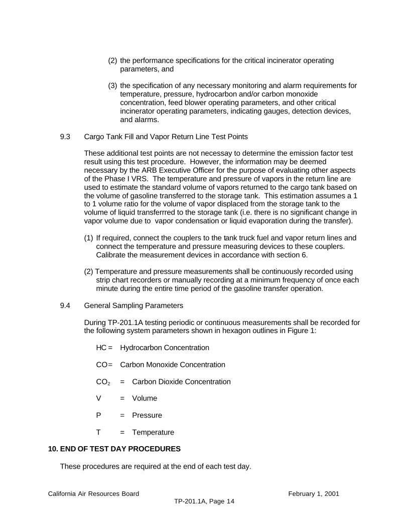
(2) the performance specifications for the critical incinerator operatingparameters, and
(3) the specification of any necessary monitoring and alarm requirements fortemperature, pressure, hydrocarbon and/or carbon monoxideconcentration, feed blower operating parameters, and other criticalincinerator operating parameters, indicating gauges, detection devices,and alarms.
9.3 Cargo Tank Fill and Vapor Return Line Test Points
These additional test points are not necessay to determine the emission factor testresult using this test procedure. However, the information may be deemednecessary by the ARB Executive Officer for the purpose of evaluating other aspectsof the Phase I VRS. The temperature and pressure of vapors in the return line areused to estimate the standard volume of vapors returned to the cargo tank based onthe volume of gasoline transferred to the storage tank. This estimation assumes a 1to 1 volume ratio for the volume of vapor displaced from the storage tank to thevolume of liquid transferrred to the storage tank (i.e. there is no significant change invapor volume due to vapor condensation or liquid evaporation during the transfer).
(1) If required, connect the couplers to the tank truck fuel and vapor return lines andconnect the temperature and pressure measuring devices to these couplers.Calibrate the measurement devices in accordance with section 6.
(2) Temperature and pressure measurements shall be continuously recorded usingstrip chart recorders or manually recording at a minimum frequency of once eachminute during the entire time period of the gasoline transfer operation.
9.4 General Sampling Parameters
During TP-201.1A testing periodic or continuous measurements shall be recorded forthe following system parameters shown in hexagon outlines in Figure 1:
HC = Hydrocarbon Concentration
CO= Carbon Monoxide Concentration
CO2 = Carbon Dioxide Concentration
V = Volume
P = Pressure
T = Temperature
10. END OF TEST DAY PROCEDURES
These procedures are required at the end of each test day.
California Air Resources Board February 1, 2001TP-201.1A, Page 15
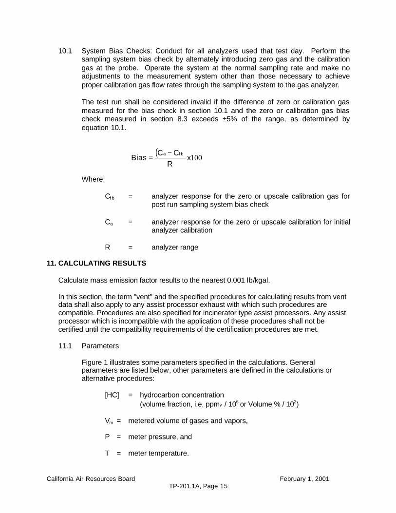
10.1 System Bias Checks: Conduct for all analyzers used that test day. Perform thesampling system bias check by alternately introducing zero gas and the calibrationgas at the probe. Operate the system at the normal sampling rate and make noadjustments to the measurement system other than those necessary to achieveproper calibration gas flow rates through the sampling system to the gas analyzer.
The test run shall be considered invalid if the difference of zero or calibration gasmeasured for the bias check in section 10.1 and the zero or calibration gas biascheck measured in section 8.3 exceeds ±5% of the range, as determined byequation 10.1.
Where:
Cf b = analyzer response for the zero or upscale calibration gas forpost run sampling system bias check
Ca = analyzer response for the zero or upscale calibration for initialanalyzer calibration
R = analyzer range
11. CALCULATING RESULTS
Calculate mass emission factor results to the nearest 0.001 lb/kgal.
In this section, the term "vent" and the specified procedures for calculating results from ventdata shall also apply to any assist processor exhaust with which such procedures arecompatible. Procedures are also specified for incinerator type assist processors. Any assistprocessor which is incompatible with the application of these procedures shall not becertified until the compatibility requirements of the certification procedures are met.
11.1 Parameters
Figure 1 illustrates some parameters specified in the calculations. Generalparameters are listed below, other parameters are defined in the calculations oralternative procedures:
[HC] = hydrocarbon concentration(volume fraction, i.e. ppmv / 106 or Volume % / 102)
Vm = metered volume of gases and vapors,
P = meter pressure, and
T = meter temperature.
( )100x
RCC
Biasf ba −
=
California Air Resources Board February 1, 2001TP-201.1A, Page 16
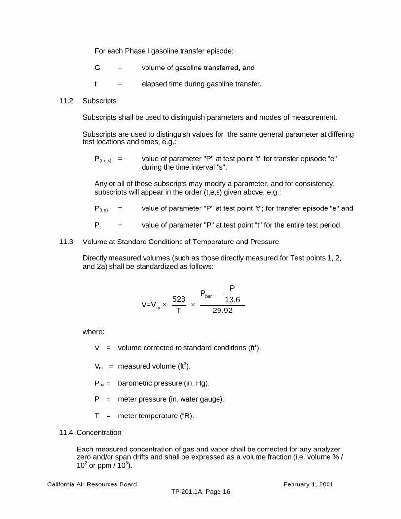
For each Phase I gasoline transfer episode:
G = volume of gasoline transferred, and
t = elapsed time during gasoline transfer.
11.2 Subscripts
Subscripts shall be used to distinguish parameters and modes of measurement.
Subscripts are used to distinguish values for the same general parameter at differingtest locations and times, e.g.:
P(t,e,s) = value of parameter "P" at test point "t" for transfer episode "e"during the time interval "s".
Any or all of these subscripts may modify a parameter, and for consistency,subscripts will appear in the order (t,e,s) given above, e.g.:
P(t,e) = value of parameter "P" at test point "t"; for transfer episode "e" and
Pt = value of parameter "P" at test point "t" for the entire test period.
11.3 Volume at Standard Conditions of Temperature and Pressure
Directly measured volumes (such as those directly measured for Test points 1, 2,and 2a) shall be standardized as follows:
where:
V = volume corrected to standard conditions (ft3).
Vm = measured volume (ft3).
Pbar= barometric pressure (in. Hg).
P = meter pressure (in. water gauge).
T = meter temperature (oR).
11.4 Concentration
Each measured concentration of gas and vapor shall be corrected for any analyzerzero and/or span drifts and shall be expressed as a volume fraction (i.e. volume % /102 or ppm / 106).
+
×
×=92.29
6.13P
P
T528
VVbar
m
California Air Resources Board February 1, 2001TP-201.1A, Page 17
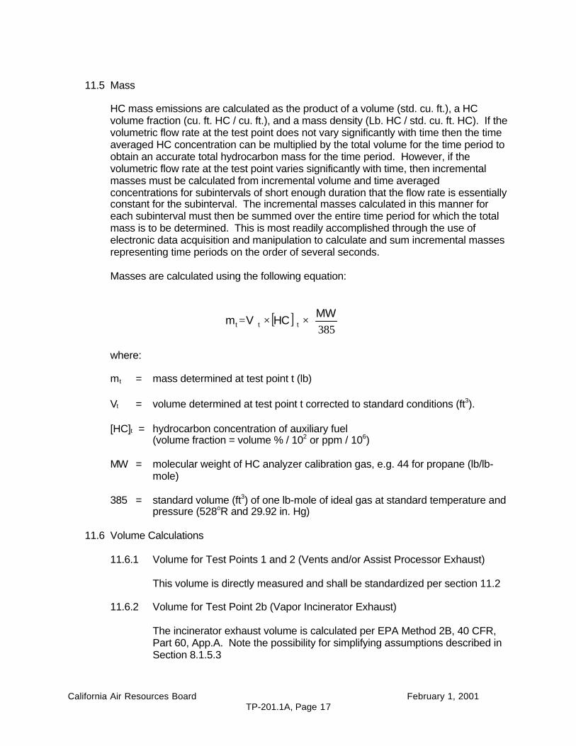
11.5 Mass
HC mass emissions are calculated as the product of a volume (std. cu. ft.), a HCvolume fraction (cu. ft. HC / cu. ft.), and a mass density (Lb. HC / std. cu. ft. HC). If thevolumetric flow rate at the test point does not vary significantly with time then the timeaveraged HC concentration can be multiplied by the total volume for the time period toobtain an accurate total hydrocarbon mass for the time period. However, if thevolumetric flow rate at the test point varies significantly with time, then incrementalmasses must be calculated from incremental volume and time averagedconcentrations for subintervals of short enough duration that the flow rate is essentiallyconstant for the subinterval. The incremental masses calculated in this manner foreach subinterval must then be summed over the entire time period for which the totalmass is to be determined. This is most readily accomplished through the use ofelectronic data acquisition and manipulation to calculate and sum incremental massesrepresenting time periods on the order of several seconds.
Masses are calculated using the following equation:
where:
mt = mass determined at test point t (lb)
Vt = volume determined at test point t corrected to standard conditions (ft3).
[HC]t = hydrocarbon concentration of auxiliary fuel(volume fraction = volume % / 102 or ppm / 106)
MW = molecular weight of HC analyzer calibration gas, e.g. 44 for propane (lb/lb-mole)
385 = standard volume (ft3) of one lb-mole of ideal gas at standard temperature andpressure (528oR and 29.92 in. Hg)
11.6 Volume Calculations
11.6.1 Volume for Test Points 1 and 2 (Vents and/or Assist Processor Exhaust)
This volume is directly measured and shall be standardized per section 11.2
11.6.2 Volume for Test Point 2b (Vapor Incinerator Exhaust)
The incinerator exhaust volume is calculated per EPA Method 2B, 40 CFR,Part 60, App.A. Note the possibility for simplifying assumptions described inSection 8.1.5.3
[ ]
××=
385MW
HC Vm ttt
California Air Resources Board February 1, 2001TP-201.1A, Page 18
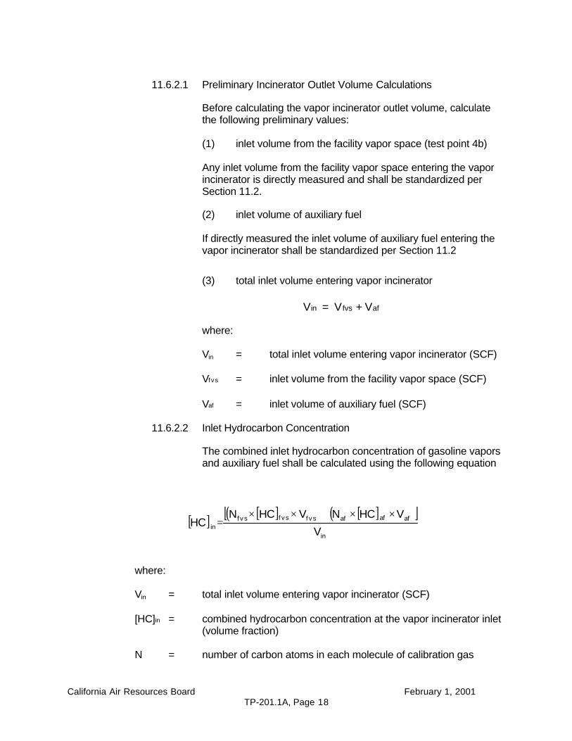
11.6.2.1 Preliminary Incinerator Outlet Volume Calculations
Before calculating the vapor incinerator outlet volume, calculatethe following preliminary values:
(1) inlet volume from the facility vapor space (test point 4b)
Any inlet volume from the facility vapor space entering the vaporincinerator is directly measured and shall be standardized perSection 11.2.
(2) inlet volume of auxiliary fuel
If directly measured the inlet volume of auxiliary fuel entering thevapor incinerator shall be standardized per Section 11.2
(3) total inlet volume entering vapor incinerator
Vin = V fvs + Vaf
where:
Vin = total inlet volume entering vapor incinerator (SCF)
Vf vs = inlet volume from the facility vapor space (SCF)
Vaf = inlet volume of auxiliary fuel (SCF)
11.6.2.2 Inlet Hydrocarbon Concentration
The combined inlet hydrocarbon concentration of gasoline vaporsand auxiliary fuel shall be calculated using the following equation
[ ] [ ]( ) [ ]( )[ ]in
afafaff v sf v sf v sin V
VHCNVHCNHC
××+××=
where:
Vin = total inlet volume entering vapor incinerator (SCF)
[HC]in = combined hydrocarbon concentration at the vapor incinerator inlet(volume fraction)
N = number of carbon atoms in each molecule of calibration gas
California Air Resources Board February 1, 2001TP-201.1A, Page 19
[HC]fvs = hydrocarbon concentration of vapors from the facility vapor spaceat the vapor incinerator inlet (volume fraction)
[HC]af = hydrocarbon concentration of auxiliary fuel (volume fraction)
Note 1:The equation presented above for the combined hydrocarbon concentration at thevapor incinerator inlet, [HC] in, is used when the hydrocarbon concentration of theauxiliary fuel, [HC] af ,is determined during certification testing using a hydrocarbonanalyzer. Simplifying assumptions, which produce acceptable accuracy for theincinerator exhaust mass, can be made when standard auxiliary fuels such asnatural gas, propane or liquefied petroleum gas, are used. The simplificationinvolves the substitution of the carbon concentration of the auxiliary fuel for the termsNaf x [HC]af in the equation above. The carbon concentration (i.e. 1 x [CH4 ] + 2 x[C2H6] + 3 x [C3H8] + . . . ) can be determined from a chemical analysis of theauxiliary fuel which may be available from the auxiliary fuel supplier.
Note 2:If no auxiliary fuel is used by the incinerator the equation for the inlet hydrocarbonconcentration reduces to:
[ ] [ ] f v sf v sin HC NHC ×=
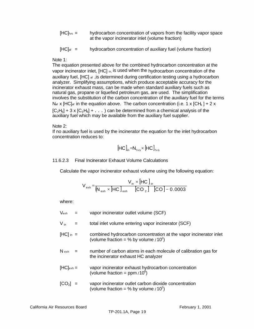
11.6.2.3 Final Incinerator Exhaust Volume Calculations
Calculate the vapor incinerator exhaust volume using the following equation:
[ ][ ]( ) [ ] [ ] 0003.0COCOHCN
HCVV
2exhexh
ininexh −++×
×=
where:
Vexh = vapor incinerator outlet volume (SCF)
V in = total inlet volume entering vapor incinerator (SCF)
[HC] in = combined hydrocarbon concentration at the vapor incinerator inlet(volume fraction = % by volume / 102)
N exh = number of carbon atoms in each molecule of calibration gas forthe incinerator exhaust HC analyzer
[HC]exh = vapor incinerator exhaust hydrocarbon concentration(volume fraction = ppm / 106)
[CO2] = vapor incinerator outlet carbon dioxide concentration(volume fraction = % by volume / 102)

California Air Resources Board February 1, 2001TP-201.1A, Page 20
[CO] = vapor incinerator outlet carbon monoxide concentration(volume fraction = ppm / 106)
0.0003 = assumed background concentration of CO2
(volume fraction = ppm / 106)
11.7 Mass Emission Factor
The mass emission factor is calculated from the total volume of gasoline transferredfrom the cargo tank to the storage tank(s) and the HC mass emissions determined atthe tank vent(s) and if present at the vapor processor or vapor incinerator exhaust.The calculation is performed as follows:
( )G
1000mmEF 21 ×+
=
where:
EF = the Phase I VRS mass emission factor determined during the test(units of pound HC per thousand gallons of gasoline transferred)
G = the total volume of gasoline delivered to the storage tank(s) during the test(units of gross gallons)
m1 = the mass emissions through the tank vent(s)(units of pounds HC as propane)
m2 = the mass emissions through the vapor processor or vapor incinerator exhaust(units of pounds HC as propane)
11.8 Volume of Vapor Returned to Cargo Tank Through Phase I Vapor Return Line
The volume for the vapor return line test point is not necessary for the emission factordetermination for which this test procedure is designed. Further discussion on thedetermination of this parameter is included in TP-201.1.
The volume for the vapor return line test point is not directly measured and shall becalculated as follows:
a2 or 21
mbar
v r VV92.29
6.13P
P
T528
481.7G
V −−
+
×
×
=
where:
Vv r = vapor return line volume corrected to standard conditions.
California Air Resources Board February 1, 2001TP-201.1A, Page 21
V1 = vent line volume corrected to standard conditions.
V2 or 2a = volume entering vapor processor or vapor incinerator corrected tostandard conditions. (Note: The inlet volume to a vapor processor is notnecessary to determine the emission factor for which this test procedureis applicable. Procedures for measuring or estimating the inlet volume toa vapor processor are not presented in this test procedure. An air massbalance based on the volume of air exiting the processor and theconcentration of HC in the processor inlet and exhaust streams mayprovide an adequate estimate of the vapor processor inlet volume.)
G = gallons of gasoline transfered.
Pbar = barometric pressure (in. Hg).
Pm = final pressure in vapor return line (in. water gauge).
T = average temperature of gas stream in vapor return line (oR).
12. REPORTING RESULTS
Written data records must be kept during testing and persons in control of such data mustbe documented in a chain of custody record. Written data records must contain allinformation used to calculate and report final results. All results must be written andsubmitted on acceptable media as specified by the the ARB Executive Officer on acase-by-case basis for each report.
In cases of conflict between hard copy and electronic format, the hard copy shall bepresumed correct, unless the ARB Executive Officer specifies otherwise in writting.
13. ALTERNATIVE TEST PROCEDURES
This procedure shall be conducted as specified. Modifications to this test procedure shall notbe used to determine compliance unless prior written approval has been obtained from theARB Executive Officer, pursuant to Section 14 of Certification Procedure CP-201.
14. REFERENCES
This section is reserved for future specification.
15. EXAMPLE FIGURES AND FORMS
15.1 Figures
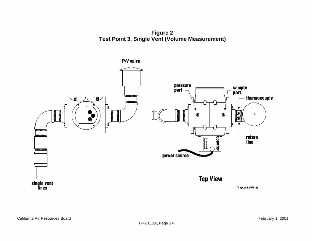
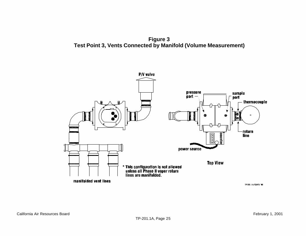
Each figure provides an illustration of test implements which conform to therequirements of this test procedure; other test implements which so conform areacceptable, too. Any specifications or dimensions provided in the figures are forexample only, unless such specifications or dimensions are provided as requirementsin the text of this or some other required test procedure.
California Air Resources Board February 1, 2001TP-201.1A, Page 22
Figures depicting the test apparatus used at the Phase I vapor return line arepresented in TP-201.1
Note:The following figures focus on volume measurements. Further details regardinghydrocarbon concentration measurements are provided in the figures for Phase IItesting in TP-201.2; which may be appropriate if necessary modifications are made toaddress the differences between Phase I and Phase II testing procedures.
Figure 1Test Locations
Figure 2Vent Test Point 3Single Vent (Volume Measurement)
Figure 3Vent Test Point 3Vents Connected by Manifold (Volume Measurement)
California Air Resources Board February 1, 2001TP-201.1A, Page 23
Figure 1 Test Locations
California Air Resources Board February 1, 2001TP-201.1A, Page 24
Figure 2Test Point 3, Single Vent (Volume Measurement)
California Air Resources Board February 1, 2001TP-201.1A, Page 25
Figure 3Test Point 3, Vents Connected by Manifold (Volume Measurement)