Embed Size (px)
Citation preview

This report is for the exclusive use of Intertek's Client and is provided pursuant to the agreement between Intertek and its Client. Intertek's responsibility and liability are limited to the terms and conditions of the agreement. Intertek assumes no liability to any party, other than to the Client in accordance with the agreement, for any loss, expense or damage occasioned by the use of this report. Only the Client is authorized to permit copying or distribution of this report and then only in its entirety. Any use of the Intertek name or one of its marks for the sale or advertisement of the tested material, product or service must first be approved in writing by Intertek. The observations and test results in this report are relevant only to the sample tested. This report by itself does not imply that the material, product, or service is or has ever been under an Intertek certification program. EMC Report for ABB Inc. on the RS85
Page 1 of 49
TEST REPORT
Report Number: 100943193DAL-001 Project Number: G100943193
Report Issue Date: February 6, 2013
Product Designation: Vibrating Fork Level Switch
Model: RS85
Standards: CENELEC EN 61326-1*BEI Issued:2006/05/01 Electrical equipment for measurement, control and laboratory use EMC requirements Part 1: General requirements-IEC 61326-1:2005;:1997 FCC 47CFR 15B clA*CEI Issued:2011/04/21 Title 47 CFR Part 15 Subpart B Unintentional Radiators Class A Verification
Tested by: Client: Intertek Testing Services NA, Inc.
1809 10th St. Suite 400 Plano, TX 75074 - USA
ABB Inc. 18321 Swamp Road
Prairieville, LA 70769 - USA
Report prepared by Report reviewed by
William B. Cullen EMC Team Leader
Shawn McGuinness Senior EMC Engineer
Intertek Report Number 100943193DAL-001 Issued: February 6th 2013
EMC Report for ABB Inc. on the RS85 2 of 49
TABLE OF CONTENTS
1 Introduction and Conclusion .............................................................................................................. 6
2 Test Summary ...................................................................................................................................... 6
3 Test Facility .......................................................................................................................................... 7
4 Description of Equipment Under Test ............................................................................................... 7
5 System setup including cable interconnection details, support equipment and simplified block diagram ........................................................................................................................................................ 8
6 Performance Criterion of the Equipment when tested against the immunity requirements for the European CE Mark ................................................................................................................................ 9
7 Radiated Emissions ........................................................................................................................... 10
8 AC Mains Conducted Emissions-Continuous Disturbance ........................................................... 14
9 Harmonics (IEC 61000-3-2) ................................................................................................................ 21
10 Flicker (IEC 61000-3-3) ....................................................................................................................... 21
11 Electrostatic Discharge Immunity Test (IEC 61000-4-2) ................................................................. 22
12 Radiated, radio-frequency, electromagnetic field immunity test (IEC 61000-4-3) ....................... 27
13 Electrical Fast Transient/Burst Immunity Test (IEC 61000-4-4) ..................................................... 31
14 Immunity to Surge (IEC 61000-4-5) ................................................................................................... 34
15 Conducted, radio-frequency, electromagnetic field immunity test (IEC 61000-4-6) ................... 37
16 Power Frequency Magnetic Field Immunity Test (IEC 61000-4-8) ................................................. 40
17 Voltage Dips / Interruptions Immunity Tests (EN 61000-4-11) ....................................................... 45
18 Measurement Uncertainty ................................................................................................................. 48
19 Revision History ................................................................................................................................. 49
Intertek Report Number 100943193DAL-001 Issued: February 6th 2013
EMC Report for ABB Inc. on the RS85 3 of 49
List of Figures Figure 5-1 EUT Block Diagram ..................................................................................................................... 8
Figure 7-1 Radiated Disturbance Test Setup Front .................................................................................... 11
Figure 7-2 Radiated Disturbance Test Setup Rear ..................................................................................... 11
Figure 8-1 AC Mains Conducted Emissions Setup ..................................................................................... 15
Figure 11-1 ESD Test Setup table-top equipment ...................................................................................... 22
Figure 11-2 ESD Test Setup ....................................................................................................................... 24
Figure 11-3 ESD Test Points Picture 1 ....................................................................................................... 25
Figure 12-1 Radiated, Radio-Frequency, Electromagnetic Field Immunity Test Setup .............................. 27
Figure 12-2 Radio-Frequency Electromagnetic Field Test Setup Picture 1 ................................................ 29
Figure 13-1 Electrical Fast Transient/Burst Test Setup .............................................................................. 31
Figure 13-2 Electrical Fast Transients Test Setup ...................................................................................... 32
Figure 14-1 Surge Immunity Test Setup ..................................................................................................... 34
Figure 14-2 Surge Test Setup ..................................................................................................................... 35
Figure 15-1 Immunity to Conducted Disturbances, induced by Radio-Frequency Fields Test Setup ......... 37
Figure 15-2 Immunity to Conducted Disturbances Test Setup ................................................................... 39
Figure 166-1 Power-Frequency Magnetic Field Test Setup ........................................................................ 40
Figure 166-2 Power Frequency Magnetic Field Immunity Test Setup ........................................................ 42
Figure 166-3 Power Frequency Magnetic Field Immunity Test Setup ........................................................ 43
Figure 166-4 Power Frequency Magnetic Field Immunity Test Setup ........................................................ 44
Figure 177-1 Voltage Dips and Interruptions Test Setup ............................................................................ 46

Intertek Report Number 100943193DAL-001 Issued: February 6th 2013
EMC Report for ABB Inc. on the RS85 4 of 49
List of Tables
Table 7-1 Radiated Disturbance Limit 30 MHz to 1000 MHz ...................................................................... 10
Table 7-2 Radiated Disturbance 30 MHz to 1000 MHz Quasi-Peak ........................................................... 13
Table 8-1 Limits for Conducted Disturbance at the Mains Ports ................................................................. 14
Table 8-2 Conducted Disturbance at AC Mains Line 1 240V/50Hz ............................................................ 19
Table 8-3 Conducted Disturbance at AC Mains Line 2 240V/50Hz ............................................................ 19
Table 11-1 ESD Test Parameters ............................................................................................................... 23
Table 11-2 ESD Test Points ........................................................................................................................ 26
Table 12-1 Radio Frequency Electromagnetic Field Test Parameters ....................................................... 27
Table 13-1 Electrical Fast Transients Test Parameters .............................................................................. 31
Table 13-2 EFT Test Data ........................................................................................................................... 33
Table 14-1 Surge Test Parameters ............................................................................................................. 34
Table 14-2 Surge Test Data ........................................................................................................................ 36
Table 14-3 Surge Test Matrix ...................................................................................................................... 36
Table 155-1 Immunity to Conducted Disturbances Test Parameters ......................................................... 37
Table 155-2 Conducted Disturbances Test Data ........................................................................................ 39
Table 16-1 Power Frequenccy Magnetic Field Test Parameters ................................................................ 40
Table 166-2 Power Frequency Magnetic Field Immunity Data .................................................................. 44
Table 177-1 Voltage Dips and Interruptions Test Parameters .................................................................... 45
Table 177-2 Voltage Dips and Interruptions Test Data ............................................................................... 47

Intertek Report Number 100943193DAL-001 Issued: February 6th 2013
EMC Report for ABB Inc. on the RS85 5 of 49
Table of Graphs Graph 7-1 Radiated emission 30 to 1000MHz horizontal polarity 12
Graph 7-2 Radiated emission 30 to 1000MHz vertical polarity 12
Graph 8-1 Conducted Disturbance at AC Mains Line 1 240V/50Hz 16
Graph 8-2 Conducted Disturbance at AC Mains Line 2 240V/50Hz 16
Test Equipment List Test Equipment 7-1 Radiated Emissions .................................................................................................... 10
Test Equipment 8-1 Conducted Emissions ................................................................................................. 14
Test Equipment 11-1 ESD .......................................................................................................................... 23
Test Equipment 12-1 Radiated Immunity .................................................................................................... 28
Test Equipment 13-1 EFT ........................................................................................................................... 31
Test Equipment 14-1 Surge ........................................................................................................................ 34
Test Equipment 15-1 Conducted Immunity ................................................................................................. 38
Test Equipment 166-1 Power Frequency Magnetic Field Immunity ............................................................ 41
Test Equipment 177-1 Voltage Dips / Interruptions Immunity ..................................................................... 45
Intertek Report Number 100943193DAL-001 Issued: February 6th 2013
EMC Report for ABB Inc. on the RS85 6 of 49
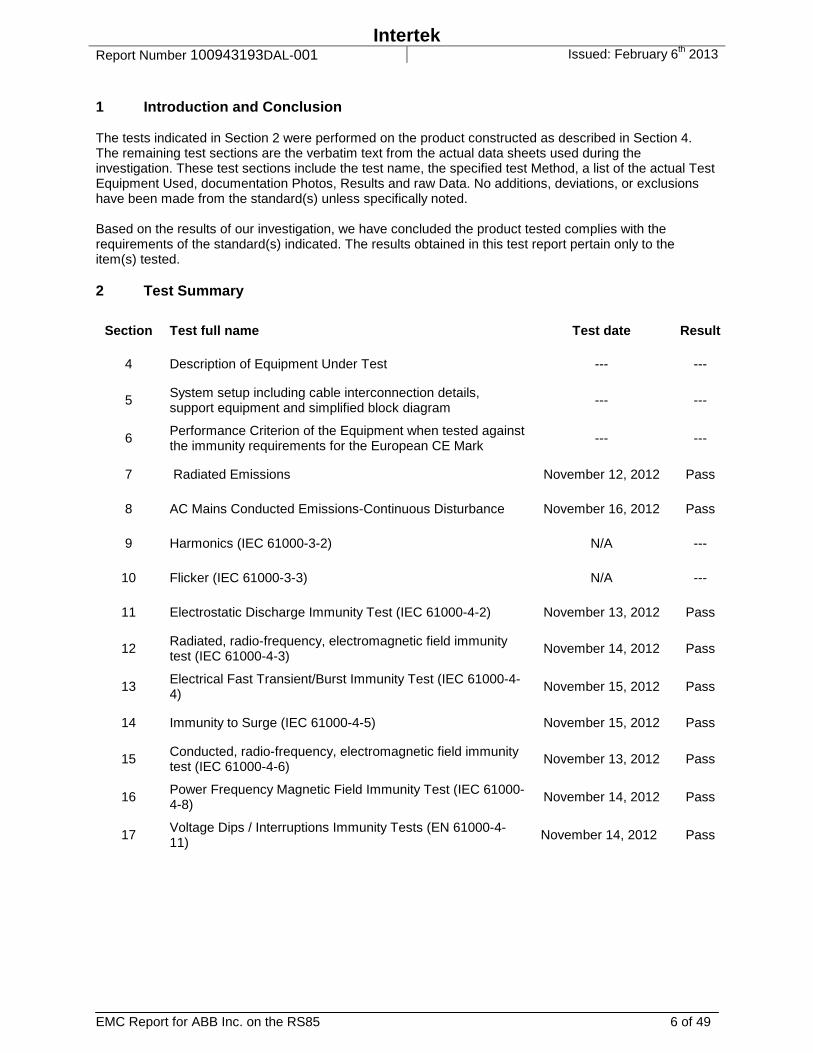
1 Introduction and Conclusion The tests indicated in Section 2 were performed on the product constructed as described in Section 4. The remaining test sections are the verbatim text from the actual data sheets used during the investigation. These test sections include the test name, the specified test Method, a list of the actual Test Equipment Used, documentation Photos, Results and raw Data. No additions, deviations, or exclusions have been made from the standard(s) unless specifically noted. Based on the results of our investigation, we have concluded the product tested complies with the requirements of the standard(s) indicated. The results obtained in this test report pertain only to the item(s) tested. 2 Test Summary
Section Test full name Test date Result
4 Description of Equipment Under Test --- ---
5 System setup including cable interconnection details, support equipment and simplified block diagram
--- ---
6 Performance Criterion of the Equipment when tested against the immunity requirements for the European CE Mark
--- ---
7 Radiated Emissions November 12, 2012 Pass
8 AC Mains Conducted Emissions-Continuous Disturbance November 16, 2012 Pass
9 Harmonics (IEC 61000-3-2) N/A ---
10 Flicker (IEC 61000-3-3) N/A ---
11 Electrostatic Discharge Immunity Test (IEC 61000-4-2) November 13, 2012 Pass
12 Radiated, radio-frequency, electromagnetic field immunity test (IEC 61000-4-3)
November 14, 2012 Pass
13 Electrical Fast Transient/Burst Immunity Test (IEC 61000-4-4)
November 15, 2012 Pass
14 Immunity to Surge (IEC 61000-4-5) November 15, 2012 Pass
15 Conducted, radio-frequency, electromagnetic field immunity test (IEC 61000-4-6)
November 13, 2012 Pass
16 Power Frequency Magnetic Field Immunity Test (IEC 61000-4-8)
November 14, 2012 Pass
17 Voltage Dips / Interruptions Immunity Tests (EN 61000-4-11)
November 14, 2012 Pass
Intertek Report Number 100943193DAL-001 Issued: February 6th 2013
EMC Report for ABB Inc. on the RS85 7 of 49
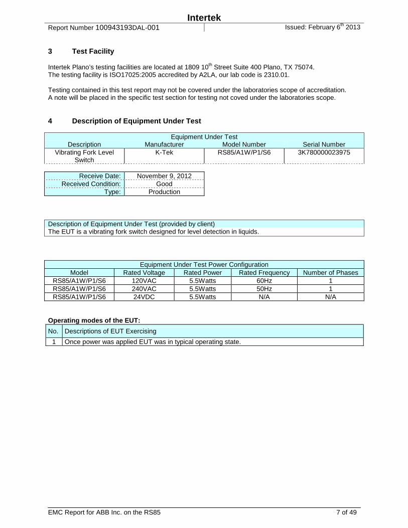
3 Test Facility Intertek Plano’s testing facilities are located at 1809 10th Street Suite 400 Plano, TX 75074. The testing facility is ISO17025:2005 accredited by A2LA, our lab code is 2310.01. Testing contained in this test report may not be covered under the laboratories scope of accreditation. A note will be placed in the specific test section for testing not coved under the laboratories scope. 4 Description of Equipment Under Test
Equipment Under Test Description Manufacturer Model Number Serial Number
Vibrating Fork Level Switch
K-Tek RS85/A1W/P1/S6 3K780000023975
Receive Date: November 9, 2012
Received Condition: Good Type: Production
Description of Equipment Under Test (provided by client) The EUT is a vibrating fork switch designed for level detection in liquids.
Equipment Under Test Power Configuration Model Rated Voltage Rated Power Rated Frequency Number of Phases
RS85/A1W/P1/S6 120VAC 5.5Watts 60Hz 1 RS85/A1W/P1/S6 240VAC 5.5Watts 50Hz 1 RS85/A1W/P1/S6 24VDC 5.5Watts N/A N/A
Operating modes of the EUT:
No. Descriptions of EUT Exercising
1 Once power was applied EUT was in typical operating state.

Intertek Report Number 100943193DAL-001 Issued: February 6th 2013
EMC Report for ABB Inc. on the RS85 8 of 49
5 System setup including cable interconnection details, support equipment and simplified block diagram 5.1 Method:
Record the details of EUT cabling, document the support equipment, and show the interconnections in a block diagram.
Figure 5-1 EUT Block Diagram 5.2 Data:
ID Description Length Shielding Ferrites
A Power Lead 1.4m No No
Support Equipment Description Manufacturer Model Number Serial Number
None --- --- ---
Power Lead
Probe Base
Probe Snout
Intertek Report Number 100943193DAL-001 Issued: February 6th 2013
EMC Report for ABB Inc. on the RS85 9 of 49
6 Performance Criterion of the Equipment when tested against the immunity requirements for the European CE Mark 6.1 Method:
The equipment under test (EUT) is to be installed in accordance with the manufacturer's instructions. The installation process includes, product assembly, connecting any support equipment, connecting power and configuration of the equipment under test. All unused ports should be terminated as instructed by the test standard. The EUT should indicate normal operation in accordance with the Operation Manual. If, as a result of the application of the tests defined in this standard, the apparatus becomes dangerous or unsafe, the apparatus shall be deemed to have failed the test. A functional description and a definition of performance criteria, during or as a consequence of the EMC testing, shall be provided by the manufacturer. Performance criterion A: The apparatus shall continue to operate as intended during and after the test. No degradation of performance or loss of function is allowed below a performance level specified by the manufacturer, when the apparatus is used as intended. The performance level may be replaced by a permissible loss of performance. If the minimum performance level or the permissible performance loss is not specified by the manufacturer, either of these may be derived from the product description and documentation and what the user may reasonably expect from the apparatus if used as intended. Performance criterion B: The apparatus shall continue to operate as intended after the test. No degradation of performance or loss of function is allowed below a performance level specified by the manufacturer, when the apparatus is used as intended. The performance level may be replaced by a permissible loss of performance. During the test, degradation of performance is however allowed. No change of actual operating state or stored data is allowed. If the minimum performance level or the permissible performance loss is not specified by the manufacturer, either of these may be derived from the product description and documentation and what the user may reasonably expect from the apparatus if used as intended. Performance criterion C: Temporary loss of function is allowed, provided the function is self-recoverable or can be restored by the operation of the controls. Performance criterion D: EUT is physically damaged. Product Specific Performance Criterion:
No. Description
1 EUT will remain in selected monitoring program. Description of how performance was observed during testing:
No. Description
1 Visually observed LED status indicators.
Intertek Report Number 100943193DAL-001 Issued: February 6th 2013
EMC Report for ABB Inc. on the RS85 10 of 49
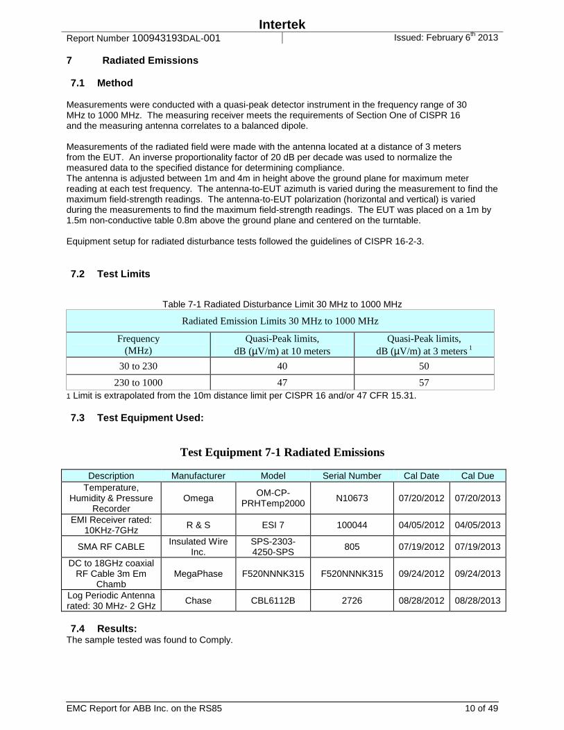
7 Radiated Emissions 7.1 Method
Measurements were conducted with a quasi-peak detector instrument in the frequency range of 30 MHz to 1000 MHz. The measuring receiver meets the requirements of Section One of CISPR 16 and the measuring antenna correlates to a balanced dipole. Measurements of the radiated field were made with the antenna located at a distance of 3 meters from the EUT. An inverse proportionality factor of 20 dB per decade was used to normalize the measured data to the specified distance for determining compliance. The antenna is adjusted between 1m and 4m in height above the ground plane for maximum meter reading at each test frequency. The antenna-to-EUT azimuth is varied during the measurement to find the maximum field-strength readings. The antenna-to-EUT polarization (horizontal and vertical) is varied during the measurements to find the maximum field-strength readings. The EUT was placed on a 1m by 1.5m non-conductive table 0.8m above the ground plane and centered on the turntable. Equipment setup for radiated disturbance tests followed the guidelines of CISPR 16-2-3. 7.2 Test Limits
Table 7-1 Radiated Disturbance Limit 30 MHz to 1000 MHz
Radiated Emission Limits 30 MHz to 1000 MHz
Frequency (MHz)
Quasi-Peak limits, dB (µV/m) at 10 meters
Quasi-Peak limits, dB (µV/m) at 3 meters 1
30 to 230 40 50
230 to 1000 47 57 1 Limit is extrapolated from the 10m distance limit per CISPR 16 and/or 47 CFR 15.31. 7.3 Test Equipment Used:
Test Equipment 7-1 Radiated Emissions
Description Manufacturer Model Serial Number Cal Date Cal Due Temperature,
Humidity & Pressure Recorder
Omega OM-CP-
PRHTemp2000 N10673 07/20/2012 07/20/2013
EMI Receiver rated: 10KHz-7GHz
R & S ESI 7 100044 04/05/2012 04/05/2013
SMA RF CABLE Insulated Wire Inc.
SPS-2303-4250-SPS
805 07/19/2012 07/19/2013
DC to 18GHz coaxial RF Cable 3m Em
Chamb MegaPhase F520NNNK315 F520NNNK315 09/24/2012 09/24/2013
Log Periodic Antenna rated: 30 MHz- 2 GHz
Chase CBL6112B 2726 08/28/2012 08/28/2013
7.4 Results:
The sample tested was found to Comply.
Intertek Report Number 100943193DAL-001 Issued: February 6th 2013
EMC Report for ABB Inc. on the RS85 11 of 49
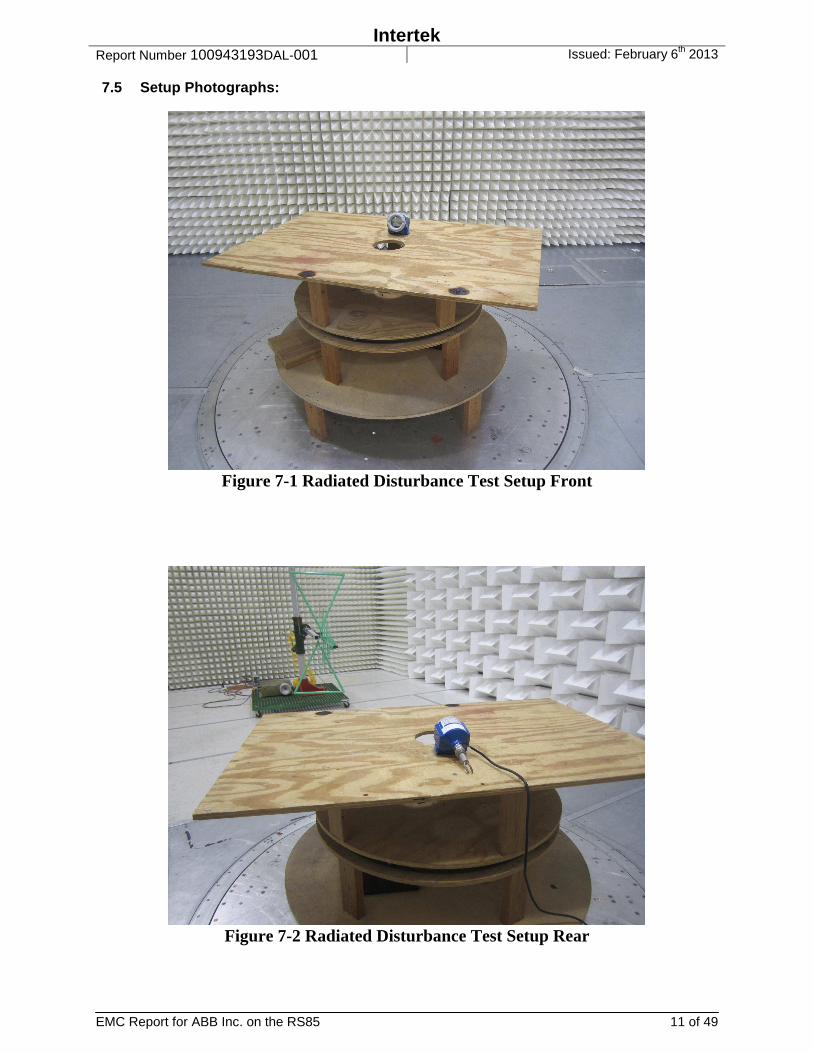
7.5 Setup Photographs:
Figure 7-1 Radiated Disturbance Test Setup Front
Figure 7-2 Radiated Disturbance Test Setup Rear
Intertek Report Number 100943193DAL-001 Issued: February 6th 2013
EMC Report for ABB Inc. on the RS85 12 of 49
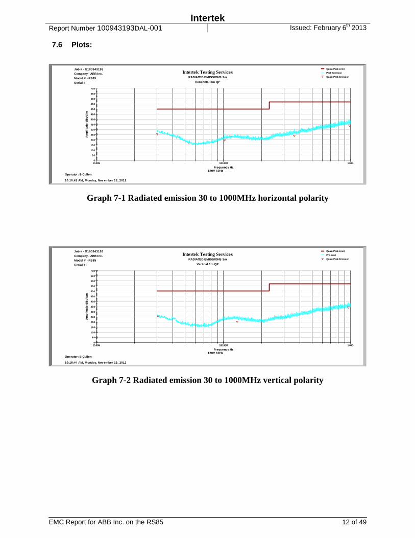
7.6 Plots:
Intertek Testing ServicesRADIATED EMISSIONS 3m
Horizontal 3m QP
10.00M 100.00M 1.00G
Frequency Hz
0
5.0
10.0
15.0
20.0
25.0
30.0
35.0
40.0
45.0
50.0
55.0
60.0
65.0
70.0A
mp
litu
de d
Bu
V/m
10:10:41 AM, Monday, Nov ember 12, 2012
Operator: B Cullen120V 60Hz
Job # - G100943193
Company - ABB Inc.
Model # - RS85
Serial # -
Quasi-Peak Limit
Peak Emission
Quasi-Peak Emission
Graph 7-1 Radiated emission 30 to 1000MHz horizontal polarity
Intertek Testing ServicesRADIATED EMISSIONS 3m
Vertical 3m QP
10.00M 100.00M 1.00G
Frequency Hz
0
5.0
10.0
15.0
20.0
25.0
30.0
35.0
40.0
45.0
50.0
55.0
60.0
65.0
70.0
Am
pli
tude
dB
uV
/m
10:15:44 AM, Monday, Nov ember 12, 2012
Operator: B Cullen120V 60Hz
Job # - G100943193
Company - ABB Inc.
Model # - RS85
Serial # -
Quasi-Peak Limit
Pre-Scan
Quasi-Peak Emission
Graph 7-2 Radiated emission 30 to 1000MHz vertical polarity
Intertek Report Number 100943193DAL-001 Issued: February 6th 2013
EMC Report for ABB Inc. on the RS85 13 of 49
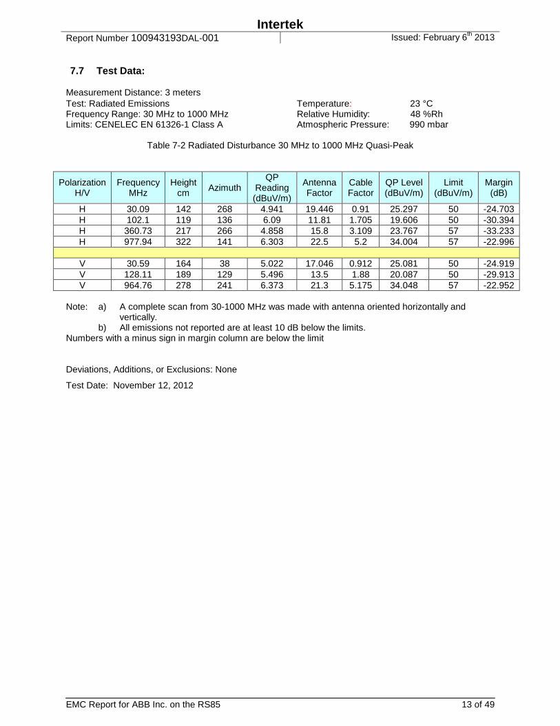
7.7 Test Data:
Measurement Distance: 3 meters Test: Radiated Emissions Temperature: 23 °C Frequency Range: 30 MHz to 1000 MHz Relative Humidity: 48 %Rh Limits: CENELEC EN 61326-1 Class A Atmospheric Pressure: 990 mbar
Table 7-2 Radiated Disturbance 30 MHz to 1000 MHz Quasi-Peak
Polarization H/V
Frequency MHz
Height cm Azimuth
QP Reading (dBuV/m)
Antenna Factor
Cable Factor
QP Level (dBuV/m)
Limit (dBuV/m)
Margin (dB)
H 30.09 142 268 4.941 19.446 0.91 25.297 50 -24.703 H 102.1 119 136 6.09 11.81 1.705 19.606 50 -30.394 H 360.73 217 266 4.858 15.8 3.109 23.767 57 -33.233 H 977.94 322 141 6.303 22.5 5.2 34.004 57 -22.996
V 30.59 164 38 5.022 17.046 0.912 25.081 50 -24.919 V 128.11 189 129 5.496 13.5 1.88 20.087 50 -29.913 V 964.76 278 241 6.373 21.3 5.175 34.048 57 -22.952
Note: a) A complete scan from 30-1000 MHz was made with antenna oriented horizontally and
vertically. b) All emissions not reported are at least 10 dB below the limits.
Numbers with a minus sign in margin column are below the limit Deviations, Additions, or Exclusions: None
Test Date: November 12, 2012

Intertek Report Number 100943193DAL-001 Issued: February 6th 2013
EMC Report for ABB Inc. on the RS85 14 of 49
8 AC Mains Conducted Emissions-Continuous Disturbance 8.1 Method
Measurements were carried out using quasi-peak and average detector receivers in accordance with CISPR 16. An Artificial Mains Network (AMN) is required to provide defined impedance at high frequencies across the power feed at the point of measurement of terminal voltage and also to provide isolation of the circuit under test from the ambient noise on the power lines. An AMN as defined in CISPR 16 was used. The EUT was located so that the distance between the boundary of the EUT and the closest surface of the AMN is 0.8m. Where a flexible mains cord is provided by the manufacturer, this shall be 1m long or if in excess of 1m, the excess cable is folded back and forth as far as possible so as to form a bundle not exceeding 0.4m in length. The EUT was arranged and connected with cables terminated in accordance with the product specification. Conducted disturbance was measured between the phase lead and the reference ground, and between the neutral lead and the reference ground. Both measured values are reported. The EUT was placed on a 1m by 1.5m non-conductive table 0.8m above the ground plane. A vertical, metal reference plane is placed 0.4m from the EUT. The vertical metal reference-plane is at least 2m by 2m. Equipment setup for conducted disturbance tests followed the guidelines of CISPR 16-2-1. 8.2 Test Limits
Table 8-1 Limits for Conducted Disturbance at the Mains Ports
Frequency band MHz
Limit (dBµV) Quasi-Peak Average
0.15-0.50 79 66 0.50-30.00 73 60
8.3 Test Equipment Used:
Test Equipment 8-1 Conducted Emissions
Description Manufacturer Model Serial Number Cal Date Cal Due Temperature, Humidity & Pressure Recorder
Omega OM-CP-PRHTemp2000
N10673 07/20/2012 07/20/2013
EMI Receiver rated: 10KHz-7GHz
R & S ESI 7 100044 04/05/2012 04/05/2013
RF Cable Custom made #0 none 07/19/2012 07/19/2013 LISN, Frequency 10
kHz - 30 MHz FCC FCC-LISN-50-
16-2-08 06045 02/23/2012 02/23/2013
Transient Limiter rated: 9 KHz - 200
MHz, 2.5W Agilent 11947A 3107A03304 07/30/2012 07/30/2013
TILE Profile Intertek 1130-003 Ver10Rev1 07/05/2012 07/05/2013 8.4 Results:
The sample tested was found to comply.

Intertek Report Number 100943193DAL-001 Issued: February 6th 2013
EMC Report for ABB Inc. on the RS85 15 of 49
8.5 Setup Photographs:
Figure 8-1 AC Mains Conducted Emissions Setup
Intertek Report Number 100943193DAL-001 Issued: February 6th 2013
EMC Report for ABB Inc. on the RS85 16 of 49
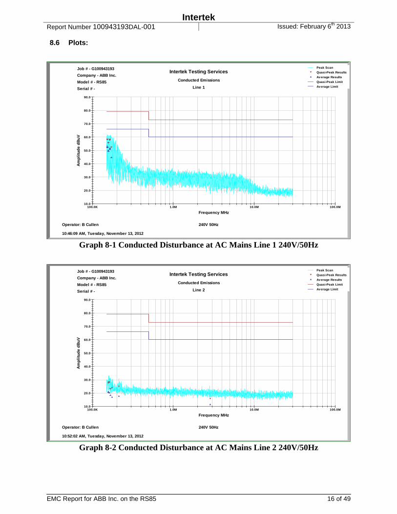
8.6 Plots:
Intertek Testing Services
Conducted Emissions
Line 1
100.0K 1.0M 10.0M 100.0M
Frequency MHz
10.0
20.0
30.0
40.0
50.0
60.0
70.0
80.0
90.0
Am
pli
tud
e d
Bu
V
10:46:09 AM, Tuesday, November 13, 2012
Operator: B Cullen 240V 50Hz
Job # - G100943193
Company - ABB Inc.
Model # - RS85
Serial # -
Peak Scan
Quasi-Peak Results
Av erage Results
Quasi-Peak Limit
Av erage Limit
Graph 8-1 Conducted Disturbance at AC Mains Line 1 240V/50Hz
Intertek Testing Services
Conducted Emissions
Line 2
100.0K 1.0M 10.0M 100.0M
Frequency MHz
10.0
20.0
30.0
40.0
50.0
60.0
70.0
80.0
90.0
Am
pli
tud
e d
Bu
V
10:52:02 AM, Tuesday, November 13, 2012
Operator: B Cullen 240V 50Hz
Job # - G100943193
Company - ABB Inc.
Model # - RS85
Serial # -
Peak Scan
Quasi-Peak Results
Av erage Results
Quasi-Peak Limit
Av erage Limit
Graph 8-2 Conducted Disturbance at AC Mains Line 2 240V/50Hz

Intertek Report Number 100943193DAL-001 Issued: February 6th 2013
EMC Report for ABB Inc. on the RS85 17 of 49
Intertek Testing Services
Conducted Emissions
Line 1
100.0K 1.0M 10.0M 100.0M
Frequency MHz
10.0
20.0
30.0
40.0
50.0
60.0
70.0
80.0
90.0
Am
pli
tud
e d
Bu
V
08:58:01 AM, Tuesday, November 13, 2012
Operator: B Cullen 120V/60Hz
Job # - G100943193
Company - ABB Inc.
Model # - RS85
Serial # -
Peak Scan
Quasi-Peak Results
Av erage Results
Quasi-Peak Limit
Av erage Limit
Graph 8-3 Conducted Disturbance at AC Mains Line 1 120V/60Hz
Intertek Testing Services
Conducted Emissions
Line 2
100.0K 1.0M 10.0M 100.0M
Frequency MHz
10.0
20.0
30.0
40.0
50.0
60.0
70.0
80.0
90.0
Am
pli
tud
e d
Bu
V
09:09:45 AM, Tuesday, November 13, 2012
Operator: B Cullen 120V/60Hz
Job # - G100943193
Company - ABB Inc.
Model # - RS85
Serial # -
Peak Scan
Quasi-Peak Results
Av erage Results
Quasi-Peak Limit
Av erage Limit
Graph 8-4 Conducted Disturbance at AC Mains Line 2 120V/60Hz

Intertek Report Number 100943193DAL-001 Issued: February 6th 2013
EMC Report for ABB Inc. on the RS85 18 of 49
Graph 8-5 Conducted Disturbance at DC Mains Line 1 24VDC
Graph 8-6 Conducted Disturbance at DC Mains Line 2 24VDC

Intertek Report Number 100943193DAL-001 Issued: February 6th 2013
EMC Report for ABB Inc. on the RS85 19 of 49
Data: Standard: CENELEC EN 61326-1 Measurement Uncertainty: 1.74 Test: Conducted Emissions Temperature: 22 ˚C Frequency Range: 150 kHz to 30 MHz Relative Humidity: 46 %Rh Limits: See Table 8-1 Atmospheric Pressure: 997 mbar Measurements made on selected frequencies from line conductor are given below:
Table 8-2 Conducted Disturbance at AC Mains Line 1 240V/50Hz
Frequency Measured QP
Measured Avg
Cable Fac
LISN Fac
Limiter Fac
Final QP
QP Limit
QP Margin
Final Avg
Avg Limit
Avg Margin
MHz dBuV dBuV dB dB dB dBuV dBuV dB dBuV dBuV dB 0.152978 48.888 42.838 0.022 0.1 9.568 58.578 79 -20.422 52.528 66 -13.472 0.153016 48.903 42.813 0.022 0.1 9.568 58.593 79 -20.407 52.504 66 -13.496 0.153692 48.86 43.12 0.022 0.1 9.568 58.55 79 -20.45 52.81 66 -13.19 0.156764 46.138 40.193 0.023 0.1 9.567 55.828 79 -23.172 49.883 66 -16.117 0.15694 45.905 39.816 0.023 0.1 9.567 55.595 79 -23.405 49.506 66 -16.494 0.165046 48.291 41.025 0.023 0.1 9.567 57.981 79 -21.019 50.715 66 -15.285 0.165202 48.402 41.228 0.023 0.1 9.567 58.092 79 -20.908 50.918 66 -15.082 0.166471 48.488 42.066 0.023 0.1 9.567 58.178 79 -20.822 51.756 66 -14.244 0.166633 48.417 42.101 0.023 0.1 9.567 58.107 79 -20.893 51.791 66 -14.209 0.171603 42.768 34.947 0.023 0.1 9.567 52.458 79 -26.542 44.637 66 -21.363
Table 8-3 Conducted Disturbance at AC Mains Line 2 240V/50Hz
Frequency Measured QP
Measured Avg
Cable Fac
LISN Fac
Limiter Fac
Final QP
QP Limit
QP Margin
Final Avg
Avg Limit
Avg Margin
MHz dBuV dBuV dB dB dB dBuV dBuV dB dBuV dBuV dB 0.157975 17.902 11.074 0.023 0.083 9.567 27.575 79 -51.425 20.747 66 -45.253 0.160409 18.689 10.831 0.023 0.08 9.567 28.359 79 -50.641 20.501 66 -45.499 0.161235 18.402 10.418 0.023 0.079 9.567 28.071 79 -50.929 20.087 66 -45.913 0.1678 13.662 8.746 0.023 0.071 9.567 23.323 79 -55.677 18.407 66 -47.593
0.174694 14.478 7.422 0.023 0.062 9.567 24.13 79 -54.87 17.074 66 -48.926 0.211864 15.352 8.173 0.025 0.017 9.565 24.958 79 -54.042 17.78 66 -48.22 2.85753 6.378 1.911 0.074 0.008 9.559 16.018 73 -56.982 11.552 60 -48.448
Table 8-3 Conducted Disturbance at AC Mains Line 1 120V/60Hz
Frequency Measured QP
Measured Avg
Cable Fac
LISN Fac
Limiter Fac
Final QP
QP Limit
QP Margin
Final Avg
Avg Limit
Avg Margin
MHz dBuV dBuV dB dB dB dBuV dBuV dB dBuV dBuV dB 0.152978 48.888 42.838 0.022 0.1 9.568 58.578 79 -20.422 52.528 66 -13.472
0.153016 48.903 42.813 0.022 0.1 9.568 58.593 79 -20.407 52.504 66 -13.496
0.153692 48.86 43.12 0.022 0.1 9.568 58.55 79 -20.45 52.81 66 -13.19
0.156764 46.138 40.193 0.023 0.1 9.567 55.828 79 -23.172 49.883 66 -16.117
0.15694 45.905 39.816 0.023 0.1 9.567 55.595 79 -23.405 49.506 66 -16.494
0.165046 48.291 41.025 0.023 0.1 9.567 57.981 79 -21.019 50.715 66 -15.285
0.165202 48.402 41.228 0.023 0.1 9.567 58.092 79 -20.908 50.918 66 -15.082
0.166471 48.488 42.066 0.023 0.1 9.567 58.178 79 -20.822 51.756 66 -14.244
0.166633 48.417 42.101 0.023 0.1 9.567 58.107 79 -20.893 51.791 66 -14.209
0.171603 42.768 34.947 0.023 0.1 9.567 52.458 79 -26.542 44.637 66 -21.363

Intertek Report Number 100943193DAL-001 Issued: February 6th 2013
EMC Report for ABB Inc. on the RS85 20 of 49
Table 8-4 Conducted Disturbance at AC Mains Line 2 120V/60Hz
Frequency Measured QP
Measured Avg
Cable Fac
LISN Fac
Limiter Fac
Final QP
QP Limit
QP Margin
Final Avg
Avg Limit
Avg Margin
MHz dBuV dBuV dB dB dB dBuV dBuV dB dBuV dBuV dB 0.157975 17.902 11.074 0.023 0.083 9.567 27.575 79 -51.425 20.747 66 -45.253
0.160409 18.689 10.831 0.023 0.08 9.567 28.359 79 -50.641 20.501 66 -45.499
0.161235 18.402 10.418 0.023 0.079 9.567 28.071 79 -50.929 20.087 66 -45.913
0.1678 13.662 8.746 0.023 0.071 9.567 23.323 79 -55.677 18.407 66 -47.593
0.174694 14.478 7.422 0.023 0.062 9.567 24.13 79 -54.87 17.074 66 -48.926
0.211864 15.352 8.173 0.025 0.017 9.565 24.958 79 -54.042 17.78 66 -48.22
2.85753 6.378 1.911 0.074 0.008 9.559 16.018 73 -56.982 11.552 60 -48.448
Table 8-5 Conducted Disturbance at DC Mains Line 1 24VDC
Frequency Measured QP
Measured Avg
Cable Fac
LISN Fac
Limiter Fac
Final QP
QP Limit
QP Margin
Final Avg
Avg Limit
Avg Margin
MHz dBuV dBuV dB dB dB dBuV dBuV dB dBuV dBuV dB 0.158645 19.982 13.996 0.023 0.1 9.567 29.672 79 -49.328 23.686 66 -42.314
0.168692 17.434 13.996 0.023 0.1 9.567 27.124 79 -51.876 23.686 66 -42.314
0.18212 17.239 13.996 0.024 0.1 9.566 26.929 79 -52.071 23.686 66 -42.314
0.207071 19.072 13.996 0.025 0.1 9.565 28.761 79 -50.239 23.685 66 -42.315
0.216911 17.834 14 0.025 0.1 9.565 27.523 79 -51.477 23.689 66 -42.311
0.248519 19.489 14.006 0.026 0.1 9.563 29.178 79 -49.822 23.695 66 -42.305
0.265785 19.457 14.004 0.027 0.1 9.563 29.146 79 -49.854 23.693 66 -42.307
0.293897 17.89 14.002 0.028 0.1 9.561 27.579 79 -51.421 23.691 66 -42.309
0.327844 15.857 13.996 0.029 0.1 9.56 25.546 79 -53.454 23.685 66 -42.315
0.521762 13.681 11.355 0.034 0.1 9.551 23.366 73 -49.634 21.041 60 -38.959
Table 8-6 Conducted Disturbance at DC Mains Line 2 24VDC
Frequency Measured QP
Measured Avg
Cable Fac
LISN Fac
Limiter Fac
Final QP
QP Limit
QP Margin
Final Avg
Avg Limit
Avg Margin
MHz dBuV dBuV dB dB dB dBuV dBuV dB dBuV dBuV dB 0.157154 19.168 13.996 0.023 0.084 9.567 28.842 79 -50.158 23.67 66 -42.33
0.162645 17.249 13.996 0.023 0.077 9.567 26.916 79 -52.084 23.663 66 -42.337
0.17816 17.367 13.996 0.023 0.058 9.567 27.015 79 -51.985 23.644 66 -42.356
0.203547 19.129 13.996 0.024 0.027 9.565 28.746 79 -50.254 23.613 66 -42.387
0.214488 17.507 13.998 0.025 0.014 9.565 27.11 79 -51.89 23.601 66 -42.399
0.250493 18.988 14.006 0.026 0 9.563 28.577 79 -50.423 23.595 66 -42.405
0.271998 15.884 13.037 0.027 0 9.562 25.473 79 -53.527 22.627 66 -43.373
0.294055 17.96 14.002 0.028 0 9.561 27.549 79 -51.451 23.591 66 -42.409
0.322005 15.848 13.996 0.029 0 9.56 25.437 79 -53.563 23.585 66 -42.415
0.561537 14.17 12.827 0.036 0.001 9.549 23.756 73 -49.244 22.413 60 -37.587
Notes: (a) All emissions not reported are at least 10 dB below the limits
(b) Analyzer setting: RBW ≥ 9 kHz, VBW ≥ 30 kHz (c) Detector mode: Quasi-peak unless otherwise specified in the data page (d) Numbers with a minus sign in margin column are below the limit.
Deviations, Additions, or Exclusions: None
Test Date: February 6, 2013

Intertek Report Number 100943193DAL-001 Issued: February 6th 2013
EMC Report for ABB Inc. on the RS85 21 of 49
9 Harmonics (IEC 61000-3-2) Not applicable, EUT is industrial equipment.
10 Flicker (IEC 61000-3-3) Not applicable, EUT is industrial equipment.

Intertek Report Number 100943193DAL-001 Issued: February 6th 2013
EMC Report for ABB Inc. on the RS85 22 of 49
11 Electrostatic Discharge Immunity Test (IEC 61000-4-2) 11.1 Method
Figure 11-1 shows the test configuration for a table top EUT. The ESD test level is set and discharges of positive and negative polarization are applied to the following locations: • The horizontal ground plane • The vertical coupling plane • The conductive surfaces under the test sample • Along all seams and control surfaces of the EUT, that are accessible to user during normal usage
Inside the EUT, only the points and/or surfaces that have to be accessed to perform user’s maintenance are included in the test unless the manufacturer prescribes clear instructions for the use of ESD precautions (e.g. changing the print cartridge for inkjet printers). ESD discharges are not applied to any point of the EUT which are accessible only for maintenance purposes, excluding customer’s maintenance, unless different instruction is given. If a discharge occurs and an error is caused, the type of error, discharge level and location is recorded.
Figure 11-1 ESD Test Setup table-top equipment
Intertek Report Number 100943193DAL-001 Issued: February 6th 2013
EMC Report for ABB Inc. on the RS85 23 of 49
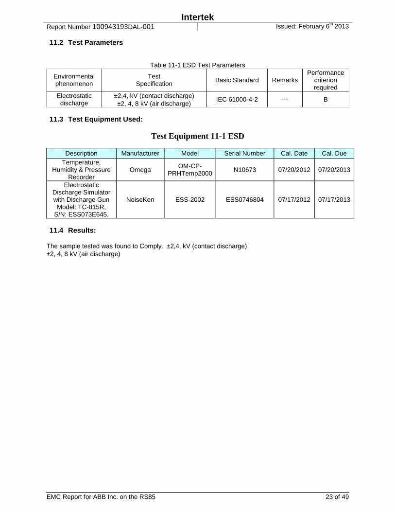
11.2 Test Parameters
Table 11-1 ESD Test Parameters
Environmental phenomenon
Test Specification Basic Standard Remarks
Performance criterion required
Electrostatic discharge
±2,4, kV (contact discharge) ±2, 4, 8 kV (air discharge)
IEC 61000-4-2 --- B
11.3 Test Equipment Used:
Test Equipment 11-1 ESD
Description Manufacturer Model Serial Number Cal. Date Cal. Due Temperature,
Humidity & Pressure Recorder
Omega OM-CP-
PRHTemp2000 N10673 07/20/2012 07/20/2013
Electrostatic Discharge Simulator with Discharge Gun Model: TC-815R,
S/N: ESS073E645.
NoiseKen ESS-2002 ESS0746804 07/17/2012 07/17/2013
11.4 Results:
The sample tested was found to Comply. ±2,4, kV (contact discharge) ±2, 4, 8 kV (air discharge)

Intertek Report Number 100943193DAL-001 Issued: February 6th 2013
EMC Report for ABB Inc. on the RS85 24 of 49
11.5 Setup Photographs:
Figure 11-2 ESD Test Setup
Intertek Report Number 100943193DAL-001 Issued: February 6th 2013
EMC Report for ABB Inc. on the RS85 25 of 49
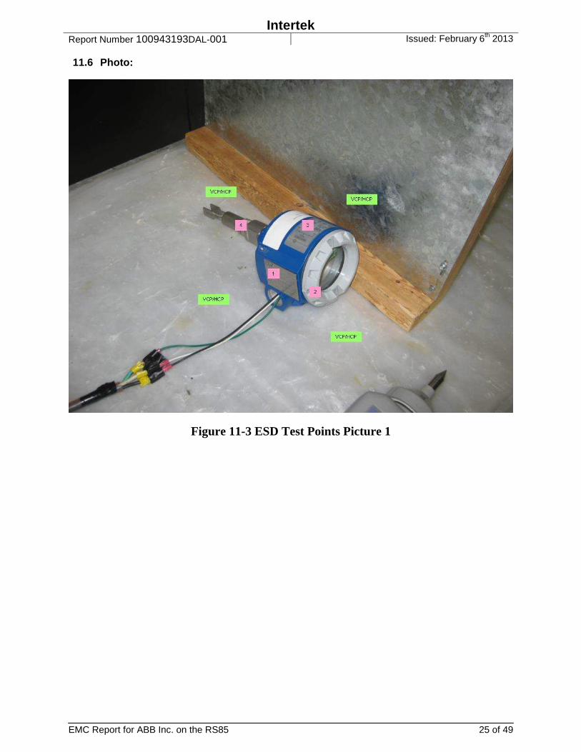
11.6 Photo:
Figure 11-3 ESD Test Points Picture 1

Intertek Report Number 100943193DAL-001 Issued: February 6th 2013
EMC Report for ABB Inc. on the RS85 26 of 49
11.7 Data:
Table 11-2 ESD Test Points
Test Point
Discharge Voltage
Type
Test Voltages, Polarities and Result Classification 2 kV 4 kV 6 kV 8 kV
Air
Dis
char
ges
only
ab
ove
8 kV
15 kV __ kV Pos Neg Pos Neg Pos Neg Pos Neg Pos Neg Pos Neg
HCP Contact A(1) A(1) A(1) A(1) VCP Contact A(2) A(2) A(2) A(2)
1 Contact A A A A 2 Contact A A A A 3 Contact A A A A 4 Contact A A A A
Standard: CENELEC EN 61326-1 Test Levels: 8kV air / 4 kV contact
Input Voltage: 240VAC/50Hz
ESD Observed on Oscilloscope: No
Ambient Temperature: 22 ºC
Relative Humidity: 50 %
Atmospheric Pressure: 996 mbars
Notes: (1) Discharged to Horizontal Coupling Plane, 4 locations. (2) Discharged to Vertical Coupling Plane, 4 locations Deviations, Additions, or Exclusions: None
Test Date: November 13, 2012
Intertek Report Number 100943193DAL-001 Issued: February 6th 2013
EMC Report for ABB Inc. on the RS85 27 of 49
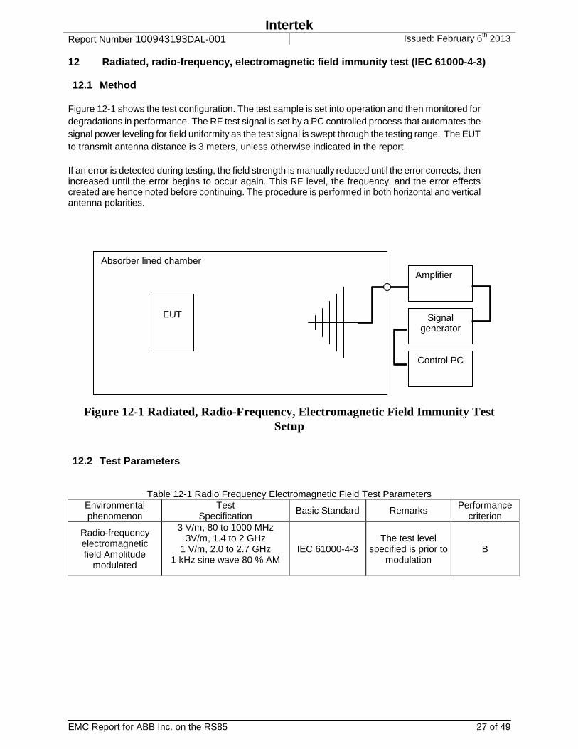
12 Radiated, radio-frequency, electromagnetic field immunity test (IEC 61000-4-3) 12.1 Method
Figure 12-1 shows the test configuration. The test sample is set into operation and then monitored for degradations in performance. The RF test signal is set by a PC controlled process that automates the signal power leveling for field uniformity as the test signal is swept through the testing range. The EUT to transmit antenna distance is 3 meters, unless otherwise indicated in the report. If an error is detected during testing, the field strength is manually reduced until the error corrects, then increased until the error begins to occur again. This RF level, the frequency, and the error effects created are hence noted before continuing. The procedure is performed in both horizontal and vertical antenna polarities.
Figure 12-1 Radiated, Radio-Frequency, Electromagnetic Field Immunity Test Setup
12.2 Test Parameters
Table 12-1 Radio Frequency Electromagnetic Field Test Parameters Environmental phenomenon
Test Specification
Basic Standard Remarks Performance criterion
Radio-frequency electromagnetic field Amplitude
modulated
3 V/m, 80 to 1000 MHz 3V/m, 1.4 to 2 GHz
1 V/m, 2.0 to 2.7 GHz 1 kHz sine wave 80 % AM
IEC 61000-4-3 The test level
specified is prior to modulation
B
Absorber lined chamber
EUT
Amplifier
Signal generator
Control PC
Intertek Report Number 100943193DAL-001 Issued: February 6th 2013
EMC Report for ABB Inc. on the RS85 28 of 49
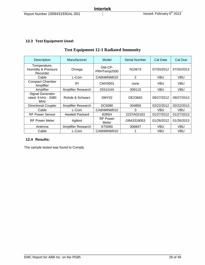
12.3 Test Equipment Used:
Test Equipment 12-1 Radiated Immunity
Description Manufacturer Model Serial Number Cal Date Cal Due
Temperature, Humidity & Pressure
Recorder Omega
OM-CP-PRHTemp2000 N10673 07/20/2012 07/20/2013
Cable L-Com CA6NMNM010 2 VBU VBU Compact Chamber
Amplifier IFI CMX5001 none VBU VBU
Amplifier Amplifier Research 25S1G4A 309110 VBU VBU Signal Generator
rated: 9 kHz - 2080 MHz
Rohde & Schwarz SMY02 DE23662 09/27/2012 09/27/2013
Directional Coupler Amplifier Research DC6080 304859 02/22/2012 02/22/2013 Cable L-Com CA6NMNM010 3 VBU VBU
RF Power Sensor Hewlett Packard 8285H 2237A02163 01/27/2012 01/27/2013
RF Power Meter Agilent RF Power Meter
GB43318053 01/26/2012 01/26/2013
Antenna Amplifier Research AT5080 306847 VBU VBU Cable L-Com CA6NMNM010 1 VBU VBU
12.4 Results:
The sample tested was found to Comply.
Intertek Report Number 100943193DAL-001 Issued: February 6th 2013
EMC Report for ABB Inc. on the RS85 29 of 49
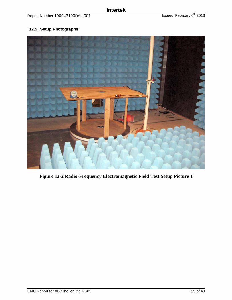
12.5 Setup Photographs:
Figure 12-2 Radio-Frequency Electromagnetic Field Test Setup Picture 1
Intertek Report Number 100943193DAL-001 Issued: February 6th 2013
EMC Report for ABB Inc. on the RS85 30 of 49
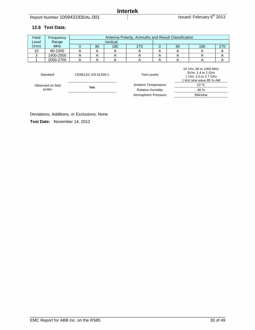
12.6 Test Data:
Field Level (V/m)
Frequency Range MHz
Antenna Polarity, Azimuths and Result Classification Vertical
0 90 180 270 0 90 180 270 10 80-1000 A A A A A A A A 3 1400-2000 A A A A A A A A 1 2000-2700 A A A A A A A A
Standard: CENELEC EN 61326-1 Test Levels:
10 V/m, 80 to 1000 MHz 3V/m, 1.4 to 2 GHz
1 V/m, 2.0 to 2.7 GHz 1 kHz sine wave 80 % AM
Observed on field probe: Yes
Ambient Temperature: 22 ºC
Relative Humidity: 46 %
Atmospheric Pressure: 994mbar
Deviations, Additions, or Exclusions: None
Test Date: November 14, 2012

Intertek Report Number 100943193DAL-001 Issued: February 6th 2013
EMC Report for ABB Inc. on the RS85 31 of 49
13 Electrical Fast Transient/Burst Immunity Test (IEC 61000-4-4) 13.1 Method
The test sample was connected to the test equipment, as shown in Figure 13-1 and monitored for performance. The test level was set, and the test signal of positive and negative polarization was applied to the power line for minimum of 1 minute per polarity. Using a capacitive coupling plate as called out in IEC 61000-4-4; the procedure was then repeated on signal and I/O lines whenever this was applicable.
Figure 13-1 Electrical Fast Transient/Burst Test Setup
13.2 Test parameters
Table 13-1 Electrical Fast Transients Test Parameters Environmental phenomenon
Test Specification
Basic Standard Remarks Performance criterion required
Fast transients on input AC power ports
±1kV 5/50 Tr/Th ns
5 kHz repetition IEC 61000-4-4 --- A
Fast transients on input DC power ports
±1kV 5/50 Tr/Th ns
5 kHz repetition IEC 61000-4-4 --- A
13.3 Test Equipment Used:
Test Equipment 13-1 EFT
Description Manufacturer Model Serial Number Cal Date Cal Due Temperature,
Humidity & Pressure Recorder
Omega OM-CP-
PRHTemp2000 N10673 07/20/2012 07/20/2013
EMC Pro Thermo Electron Corp
EMCProPLUS 0601242 02/27/2012 02/27/2013
CEWare32 Version 4.00
Thermo Electron Corp.
CEWare32 Version 4.00
CEWare32 Version 4.00
VBU VBU
Intertek Report Number 100943193DAL-001 Issued: February 6th 2013
EMC Report for ABB Inc. on the RS85 32 of 49
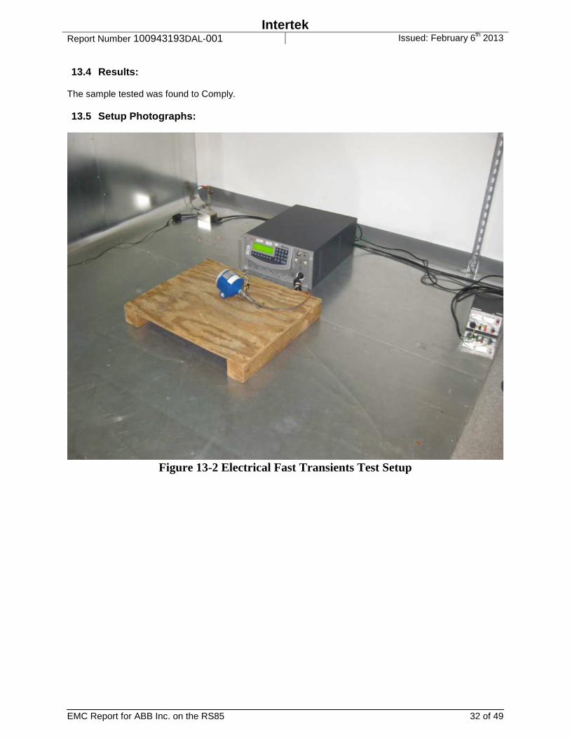
13.4 Results:
The sample tested was found to Comply. 13.5 Setup Photographs:
Figure 13-2 Electrical Fast Transients Test Setup
Intertek Report Number 100943193DAL-001 Issued: February 6th 2013
EMC Report for ABB Inc. on the RS85 33 of 49
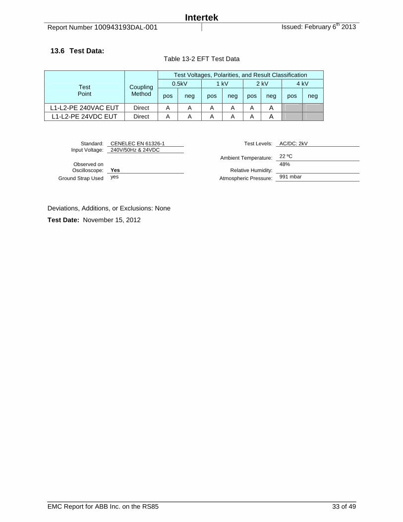
13.6 Test Data:
Table 13-2 EFT Test Data
Test Point
Coupling Method
Test Voltages, Polarities, and Result Classification
0.5kV 1 kV 2 kV 4 kV
pos neg pos neg pos neg pos neg
L1-L2-PE 240VAC EUT Direct A A A A A A
L1-L2-PE 24VDC EUT Direct A A A A A A
Standard: CENELEC EN 61326-1
Test Levels: AC/DC: 2kV Input Voltage: 240V/50Hz & 24VDC
Observed on Oscilloscope: Yes
Ambient Temperature: 22 ºC
Relative Humidity: 48%
Ground Strap Used yes Atmospheric Pressure: 991 mbar
Deviations, Additions, or Exclusions: None
Test Date: November 15, 2012
Intertek Report Number 100943193DAL-001 Issued: February 6th 2013
EMC Report for ABB Inc. on the RS85 34 of 49
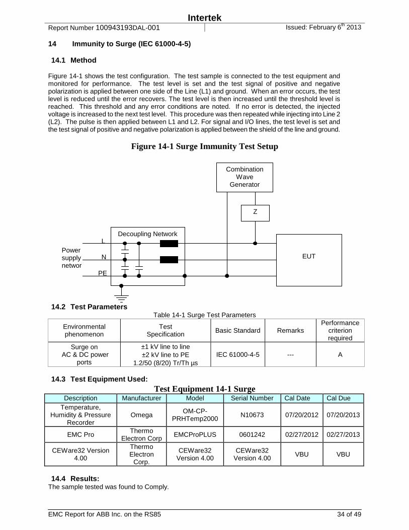
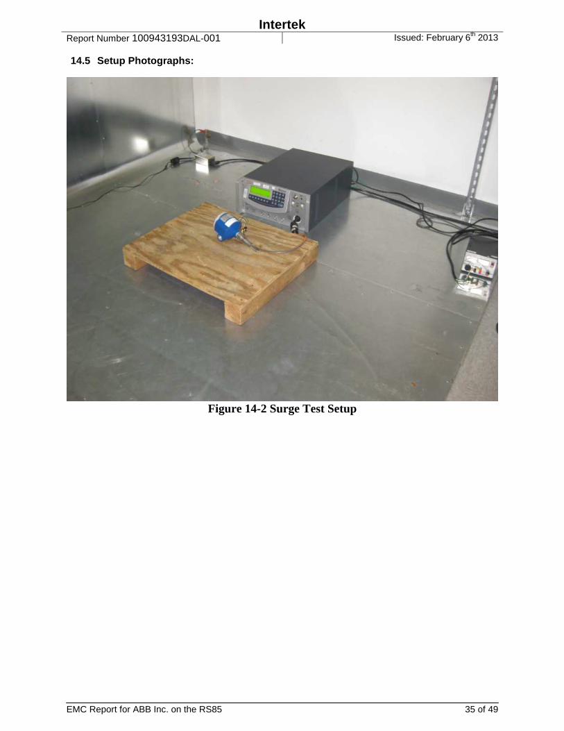
14 Immunity to Surge (IEC 61000-4-5) 14.1 Method
Figure 14-1 shows the test configuration. The test sample is connected to the test equipment and monitored for performance. The test level is set and the test signal of positive and negative polarization is applied between one side of the Line (L1) and ground. When an error occurs, the test level is reduced until the error recovers. The test level is then increased until the threshold level is reached. This threshold and any error conditions are noted. If no error is detected, the injected voltage is increased to the next test level. This procedure was then repeated while injecting into Line 2 (L2). The pulse is then applied between L1 and L2. For signal and I/O lines, the test level is set and the test signal of positive and negative polarization is applied between the shield of the line and ground.
Figure 14-1 Surge Immunity Test Setup
14.2 Test Parameters Table 14-1 Surge Test Parameters
Environmental phenomenon
Test Specification Basic Standard Remarks
Performance criterion required
Surge on AC & DC power
ports
±1 kV line to line ±2 kV line to PE
1.2/50 (8/20) Tr/Th µs IEC 61000-4-5 --- A
14.3 Test Equipment Used:
Test Equipment 14-1 Surge Description Manufacturer Model Serial Number Cal Date Cal Due
Temperature, Humidity & Pressure
Recorder Omega
OM-CP-PRHTemp2000 N10673 07/20/2012 07/20/2013
EMC Pro Thermo Electron Corp
EMCProPLUS 0601242 02/27/2012 02/27/2013
CEWare32 Version 4.00
Thermo Electron
Corp.
CEWare32 Version 4.00
CEWare32 Version 4.00 VBU VBU
14.4 Results:
The sample tested was found to Comply.
Decoupling Network
EUT Power supply network PE
N
L
Combination Wave
Generator
Z
Intertek Report Number 100943193DAL-001 Issued: February 6th 2013
EMC Report for ABB Inc. on the RS85 35 of 49
14.5 Setup Photographs:
Figure 14-2 Surge Test Setup

Intertek Report Number 100943193DAL-001 Issued: February 6th 2013
EMC Report for ABB Inc. on the RS85 36 of 49
14.6 Test Data: Table 14-2 Surge Test Data
Test
Test Voltages, Polarities, and Result Classification
0.5kV 1kV 2kV 4kV
pos neg pos neg pos neg pos neg
L1-PE, at 0 deg A A A A A A
L1-PE, at 90 deg A A A A A A
L1-PE, at 180 deg A A A A A A
L1-PE, at 270 deg A A A A A A
N-PE, at 0 deg A A A A A A
N-PE, at 90 deg A A A A A A
N-PE, at 180 deg A A A A A A
N-PE, at 270 deg A A A A A A
L1-N, at 0 deg A A A A
L1-N, at 90 deg A A A A
L1-N, at 180 deg A A A A
L1-N, at 270 deg A A A A
Standard: CENELEC EN 61326-1 Test Levels: See Table 14-3 Surge Test Matrix Input Voltage: 230V/50Hz & 24VDC
Observed on Oscilloscope: yes
Ambient Temperature: 22 ºC
Relative Humidity: 48 %
Atmospheric Pressure: 992 mbar
Table 14-3 Surge Test Matrix
Test Matrix Line to Physical Earth (ground) Line to Line (or Neutral) AC: +/-2kV +/-1kV DC: +/-2kV +/-1kV
Indoor Signal: N/A N/A Outdoor Signal: N/A N/A
Both 240VAC/50Hz and 24VDC units tested. Deviations, Additions, or Exclusions: None
Test Date: November 15, 2012
Note:
Intertek Report Number 100943193DAL-001 Issued: February 6th 2013
EMC Report for ABB Inc. on the RS85 37 of 49
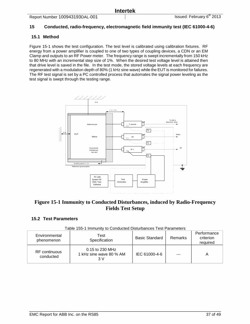
15 Conducted, radio-frequency, electromagnetic field immunity test (IEC 61000-4-6) 15.1 Method
Figure 15-1 shows the test configuration. The test level is calibrated using calibration fixtures. RF energy from a power amplifier is coupled to one of two types of coupling devices, a CDN or an EM Clamp and outputs to an RF Power meter. The frequency range is swept incrementally from 150 kHz to 80 MHz with an incremental step size of 1%. When the desired test voltage level is attained then that drive level is saved in the file. In the test mode, the stored voltage levels at each frequency are regenerated with a modulation depth of 80% (1 kHz sine wave) while the EUT is monitored for failures. The RF test signal is set by a PC controlled process that automates the signal power leveling as the test signal is swept through the testing range.
Figure 15-1 Immunity to Conducted Disturbances, induced by Radio-Frequency Fields Test Setup
15.2 Test Parameters
Table 155-1 Immunity to Conducted Disturbances Test Parameters
Environmental phenomenon
Test Specification Basic Standard Remarks
Performance criterion required
RF continuous conducted
0.15 to 230 MHz 1 kHz sine wave 80 % AM
3 V IEC 61000-4-6 --- A
M2
AF-1
T-network
T2
T2
Balanced pair
Mains
UnscreenedUnbalanced
two-wire
EUT
.1 < L < .3 m
TestGenerator
To AE ortelecomm. lines
Mains
AE
.5 m
Reference ground plane
.5 m
Insulating support h= .1 m
T2
PowerAmplifier
PC withSystem 55EMC TestSoftware

Intertek Report Number 100943193DAL-001 Issued: February 6th 2013
EMC Report for ABB Inc. on the RS85 38 of 49
15.3 Test Equipment Used:
Test Equipment 15-1 Conducted Immunity
Description Manufacturer Model Serial Number Cal Date Cal Due Temperature, Humidity & Pressure Recorder
Omega OM-CP-PRHTemp2000
N10673 07/20/2012 07/20/2013
Coupling Decoupling Network
FCC FCC-801-M3-25A
01027 07/17/2012 07/17/2013
Type N RF Cable Custom made #9 none 07/19/2012 07/19/2013 Power Amplifier Kalmus 757LCB 9183-1 VBU VBU
cable SemFlex RF coax cable none 08/06/2012 08/06/2013
Signal Generator Rohde & Schwarz
SMT03 825784/0016 02/27/2012 02/27/2013
Power Sensor with 437B Power Meter
HP HP 8482H 3318A07268 02/21/2012 02/21/2013
Master Conducted Immunity Ver10Rev0
04-25-12.TIL Intertek 1130-005 1130-005 VBU VBU
15.4 Results:
The sample tested was found to Comply.
Intertek Report Number 100943193DAL-001 Issued: February 6th 2013
EMC Report for ABB Inc. on the RS85 39 of 49
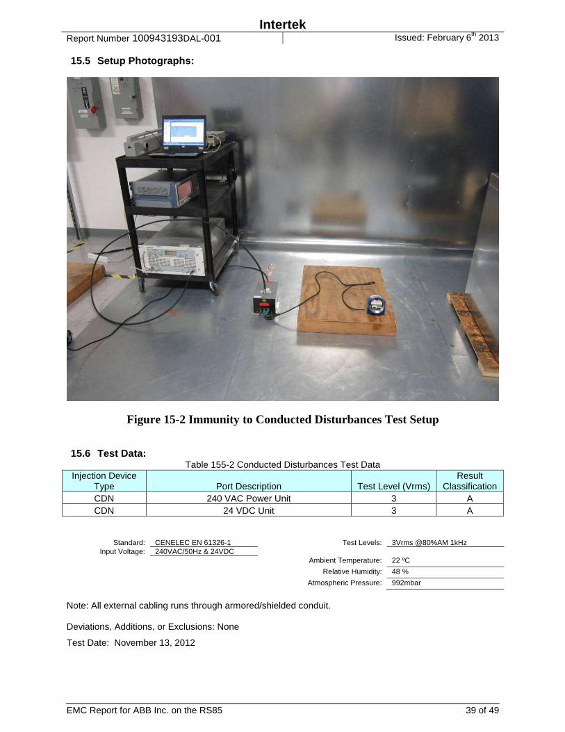
15.5 Setup Photographs:
Figure 15-2 Immunity to Conducted Disturbances Test Setup 15.6 Test Data:
Table 155-2 Conducted Disturbances Test Data Injection Device
Type Port Description Test Level (Vrms) Result
Classification CDN 240 VAC Power Unit 3 A CDN 24 VDC Unit 3 A
Standard: CENELEC EN 61326-1 Test Levels: 3Vrms @80%AM 1kHz Input Voltage: 240VAC/50Hz & 24VDC
Ambient Temperature: 22 ºC
Relative Humidity: 48 %
Atmospheric Pressure: 992mbar
Note: All external cabling runs through armored/shielded conduit. Deviations, Additions, or Exclusions: None
Test Date: November 13, 2012
Intertek Report Number 100943193DAL-001 Issued: February 6th 2013
EMC Report for ABB Inc. on the RS85 40 of 49
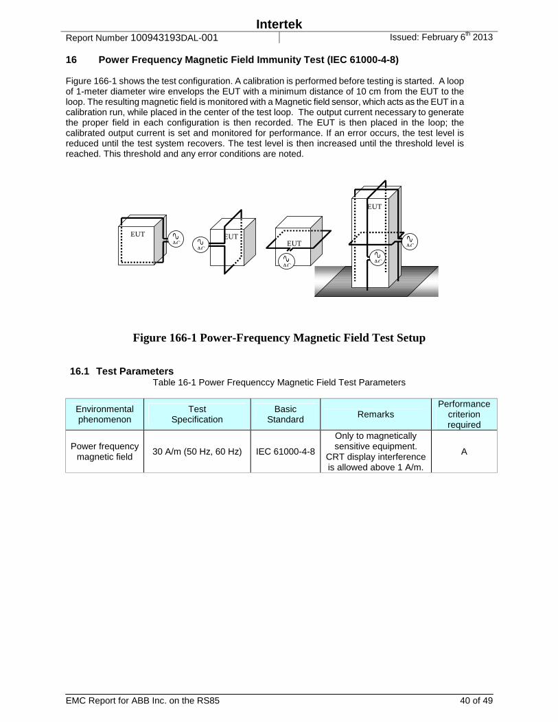
16 Power Frequency Magnetic Field Immunity Test (IEC 61000-4-8) Figure 166-1 shows the test configuration. A calibration is performed before testing is started. A loop of 1-meter diameter wire envelops the EUT with a minimum distance of 10 cm from the EUT to the loop. The resulting magnetic field is monitored with a Magnetic field sensor, which acts as the EUT in a calibration run, while placed in the center of the test loop. The output current necessary to generate the proper field in each configuration is then recorded. The EUT is then placed in the loop; the calibrated output current is set and monitored for performance. If an error occurs, the test level is reduced until the test system recovers. The test level is then increased until the threshold level is reached. This threshold and any error conditions are noted.
EUTAC
EUT
ACEUT
AC
EUT
AC
AC
Figure 166-1 Power-Frequency Magnetic Field Test Setup 16.1 Test Parameters
Table 16-1 Power Frequenccy Magnetic Field Test Parameters
Environmental phenomenon
Test Specification
Basic Standard Remarks
Performance criterion required
Power frequency magnetic field
30 A/m (50 Hz, 60 Hz) IEC 61000-4-8
Only to magnetically sensitive equipment.
CRT display interference is allowed above 1 A/m.
A
Intertek Report Number 100943193DAL-001 Issued: February 6th 2013
EMC Report for ABB Inc. on the RS85 41 of 49
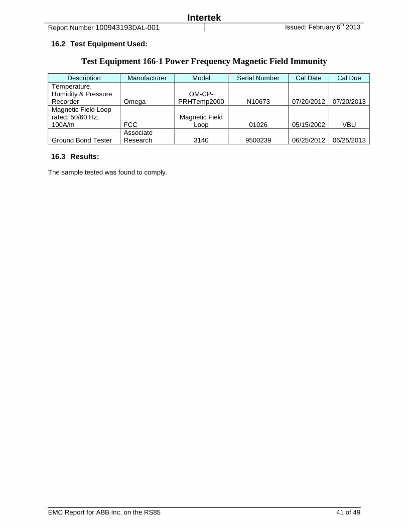
16.2 Test Equipment Used:
Test Equipment 166-1 Power Frequency Magnetic Field Immunity
Description Manufacturer Model Serial Number Cal Date Cal Due Temperature, Humidity & Pressure Recorder Omega
OM-CP-PRHTemp2000 N10673 07/20/2012 07/20/2013
Magnetic Field Loop rated: 50/60 Hz, 100A/m FCC
Magnetic Field Loop 01026 05/15/2002 VBU
Ground Bond Tester Associate Research 3140 9500239 06/25/2012 06/25/2013
16.3 Results:
The sample tested was found to comply.

Intertek Report Number 100943193DAL-001 Issued: February 6th 2013
EMC Report for ABB Inc. on the RS85 42 of 49
16.4 Setup Photographs:
Figure 166-2 Power Frequency Magnetic Field Immunity Test Setup
Intertek Report Number 100943193DAL-001 Issued: February 6th 2013
EMC Report for ABB Inc. on the RS85 43 of 49
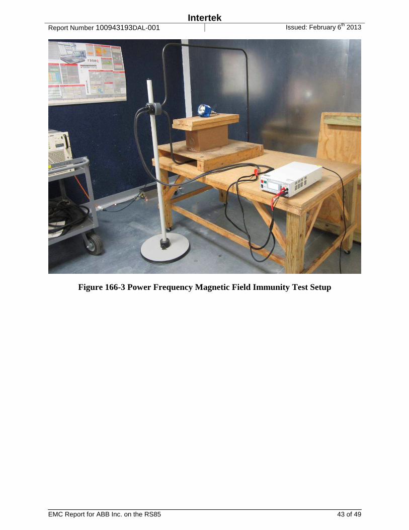
Figure 166-3 Power Frequency Magnetic Field Immunity Test Setup
Intertek Report Number 100943193DAL-001 Issued: February 6th 2013
EMC Report for ABB Inc. on the RS85 44 of 49
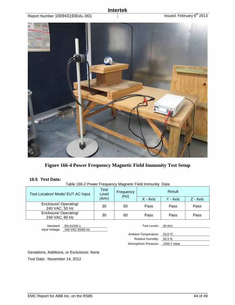
Figure 166-4 Power Frequency Magnetic Field Immunity Test Setup 16.5 Test Data:
Table 166-2 Power Frequency Magnetic Field Immunity Data
Test Location/ Mode/ EUT AC Input Test Level (A/m)
Frequency (Hz)
Result
X - Axis Y - Axis Z - Axis Enclosure/ Operating/
240 VAC, 50 Hz 30 50 Pass Pass Pass
Enclosure/ Operating/ 240 VAC, 60 Hz
30 60 Pass Pass Pass
Standard: EN 61326-1 Test Levels: 30 A/m
Input Voltage: 240 VAC 50/60 Hz
Ambient Temperature: 23.0 ºC
Relative Humidity: 30.3 %
Atmospheric Pressure: 1000.7 mbar Deviations, Additions, or Exclusions: None
Test Date: November 14, 2012

Intertek Report Number 100943193DAL-001 Issued: February 6th 2013
EMC Report for ABB Inc. on the RS85 45 of 49
17 Voltage Dips / Interruptions Immunity Tests (EN 61000-4-11) 17.1 Method
The test sample is connected to the mains dropout and voltage variation simulator and monitored for performance. 17.2 Test Parameters
Table 177-1 Voltage Dips and Interruptions Test Parameters
Test Voltage Parameters Test Point Remarks Results Criteria
240 100 % reduction 1.0 cycle, each polarity
AC Mains B
240 60 % reduction 10 cycle, each polarity
AC Mains B
240 30 % reduction 25 cycles, each polarity
AC Mains C
240 100 % reduction 250 cycles, each polarity
AC Mains C
17.3 Test Equipment Used:
Test Equipment 177-1 Voltage Dips / Interruptions Immunity
Description Manufacturer Model Serial Number Cal Date Cal Due Temperature, Humidity & Pressure Recorder Omega
OM-CP-PRHTemp2000 N10673 07/20/2012 07/20/2013
Power Source rated: 50Hz-1200Hz, 16A, 0V-230V Pacific Power 140TMX 00724/0248 07/19/2012 07/19/2013 PPSD TMX Test System Software Part Number 141481 Ver. 5.03
Pacific Power Source 141481V5.03 141481V5.03 VBU VBU
17.4 Results:
The sample tested was found to Comply.
Intertek Report Number 100943193DAL-001 Issued: February 6th 2013
EMC Report for ABB Inc. on the RS85 46 of 49
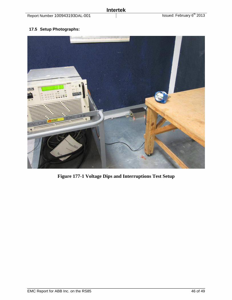
17.5 Setup Photographs:
Figure 177-1 Voltage Dips and Interruptions Test Setup
Intertek Report Number 100943193DAL-001 Issued: February 6th 2013
EMC Report for ABB Inc. on the RS85 47 of 49
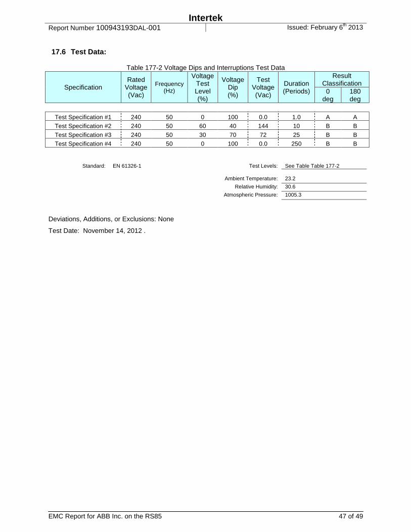
17.6 Test Data:
Table 177-2 Voltage Dips and Interruptions Test Data
Specification Rated
Voltage (Vac)
Frequency (Hz)
Voltage Test Level (%)
Voltage Dip (%)
Test Voltage (Vac)
Duration (Periods)
Result Classification
0 deg
180 deg
Test Specification #1 240 50 0 100 0.0 1.0 A A
Test Specification #2 240 50 60 40 144 10 B B
Test Specification #3 240 50 30 70 72 25 B B
Test Specification #4 240 50 0 100 0.0 250 B B
Standard: EN 61326-1 Test Levels: See Table Table 177-2 Ambient Temperature: 23.2
Relative Humidity: 30.6
Atmospheric Pressure: 1005.3
Deviations, Additions, or Exclusions: None
Test Date: November 14, 2012 .
Intertek Report Number 100943193DAL-001 Issued: February 6th 2013
EMC Report for ABB Inc. on the RS85 48 of 49
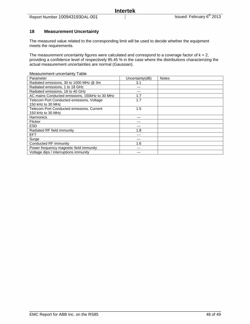
18 Measurement Uncertainty The measured value related to the corresponding limit will be used to decide whether the equipment meets the requirements. The measurement uncertainty figures were calculated and correspond to a coverage factor of k = 2, providing a confidence level of respectively 95.45 % in the case where the distributions characterizing the actual measurement uncertainties are normal (Gaussian). Measurement uncertainty Table Parameter Uncertainty(dB) Notes Radiated emissions, 30 to 1000 MHz @ 3m 3.1 Radiated emissions, 1 to 18 GHz --- Radiated emissions, 18 to 40 GHz --- AC mains Conducted emissions, 150kHz to 30 MHz 1.7 Telecom Port Conducted emissions, Voltage 150 kHz to 30 MHz
1.7
Telecom Port Conducted emissions, Current 150 kHz to 30 MHz
1.5
Harmonics --- Flicker --- ESD --- Radiated RF field immunity 1.8 EFT --- Surge --- Conducted RF immunity 1.6 Power frequency magnetic field immunity --- Voltage dips / interruptions immunity ---
Intertek Report Number 100943193DAL-001 Issued: February 6th 2013
EMC Report for ABB Inc. on the RS85 49 of 49
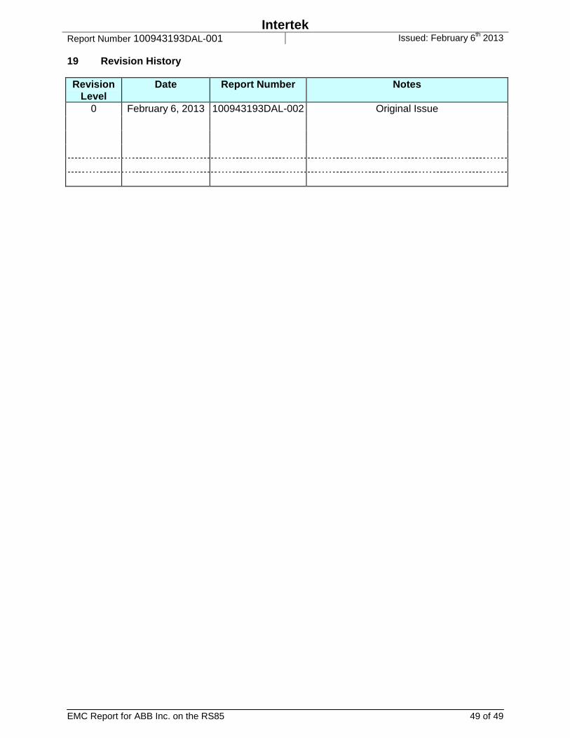
19 Revision History Revision
Level Date Report Number Notes
0 February 6, 2013 100943193DAL-002 Original Issue