Embed Size (px)
Citation preview
TEST REPORTDate: 2013-01-24Report No.: 60.870.12.051.02F
Page 1 of 30TUV SUD Hong Kong Ltd.
3/F, West Wing, Phase 2, 10 Science Park West Avenue, Shatin, Hong Kong
Applicant: SVAT ELECTRONICS4080 Montrose Road, Niagara Falls, ON, L2H1J9Canada
Description of Samples: Model name: Stella™Digital Baby Video Monitor(Parent Unit)
Brand name: LevanaModel no.: Stella™ 30018PUFCCID: SMH-30018PU
Date Samples Received: 2013-01-02
Date Tested: 2013-01-02 to 2013-01-23
Investigation Requested: FCC Part 15 Subpart C, Section 15.247
Conclusions: The submitted product COMPLIED with therequirements of Federal CommunicationsCommission [FCC] Rules and Regulations Part15. The tests were performed in accordance withthe standards described above and on Section 2.2in this Test Report.
Remarks: ----
Checked by: Approved by:-
Ray Cheung Jeff PongProject Engineer Operation Manager
Wireless & Telecom Department Wireless & Telecom Department
Report No.: 60.870.12.051.02F
Page 2 of 30TÜV SÜD Hong Kong Ltd.
3/F, West Wing, Phase 2, 10 Science Park West Avenue, Shatin, Hong Kong
CONTENT:
Cover Page 1 of 30
Content Page 2-3 of 30
1.0 General Details
1.1 Test Laboratory Page 4 of 30
1.2 Applicant Details Page 4 of 30
1.3 Equipment Under Test [EUT] Page 5 of 30
1.4 Related Submittal(s) Grants Page 5 of 30
2.0 Technical Details
2.1 Investigations Requested Page 6 of 30
2.2 Test Standards and Results Summary Page 6 of 30
3.0 Test Methodology
3.1 Radiated Emission Page 7 of 30
3.2 Field Strength Calculation Page 7 of 30
3.3 Conducted Emission Page 7 of 30
4.0 Test Results
4.1 Number of Frequency Hopping Page 8 of 30
4.2 20dB Bandwidth Measurement Page 9-10 of 30
4.3 Hopping Channel Carrier Frequency Separation Page 11 of 30
4.4 Average Time of Occupancy Page 12-14 of 30
4.5 Pseudorandom Hopping Algorithm Page 15 of 30
4.6 Band Edge Measurement Page 16-17 of 30
4.7 Maximum Output Power Page 18-20 of 30
4.8 Out of Band Emissions and Emissions in Restricted Bands Page 20-25 of 30
4.9 Conducted Emission on AC Mains Page 26-28 of 30
Report No.: 60.870.12.051.02F
Page 3 of 30TÜV SÜD Hong Kong Ltd.
3/F, West Wing, Phase 2, 10 Science Park West Avenue, Shatin, Hong Kong
5.0 RF Exposure Compliance Requirement Page 29 of 30
6.0 List of Measurement Equipments Page 30 of 30
Appendix A
Photos of Test Setup
Appendix B
External EUT Photos
Appendix C
Internal EUT Photos
Report No.: 60.870.12.051.02F
Page 4 of 30TÜV SÜD Hong Kong Ltd.
3/F, West Wing, Phase 2, 10 Science Park West Avenue, Shatin, Hong Kong
1.0 General Details
1.1 Test LaboratorySEM. Test Compliance Service Co., Ltd3/F, Jinbao Commerce Building, Xin’an Fanshen Road,Bao’an District, ShenzhenRegistration Number: 994117
Test By:
John Zhi
1.2 Applicant DetailsApplicant
SVAT ELECTRONICS4080 Montrose Road, Niagara Falls, ON, L2H 1J9Canada
Manufacturer
Alford Industries LtdUnit 02, 6th Floor, Yen Sheng Centre, 64 Hoi YuenRoad, Kwun Tong, Kowloon, Hong Kong

Report No.: 60.870.12.051.02F
Page 5 of 30TÜV SÜD Hong Kong Ltd.
3/F, West Wing, Phase 2, 10 Science Park West Avenue, Shatin, Hong Kong
1.3 Equipment Under Test [EUT]
Description of EUT
Product Description: Stella™Digital Baby Video Monitor (Parent Unit)Model No.: Stella™ 30018PUBrand Name: LevanaFCCID: SMH-30018PURating: - DC 5.9V, 1000mA powered by AC/DC power adaptor
or- DC 3.7V, Li-ion Rechargeable Battery
Operated Frequency: 2410.875 – 2471.625 MHzNo. of Operated Channel: 19Accessories and Auxiliary Equipments: - AC/DC power adaptor.
Antenna Type: IntegralManufacture of Antenna: Alford Industries Ltd.Antenna Gain: 0 dBiAntenna Model: N/A
General Operation of EUT
The Equipment Under Test (EUT) is a monitor of wireless baby monitor system which operated at2.4GHz.
FHSS Operation Principle:
This module is controlled by microchip to generate Pseudorandom Frequency Hopping Sequence,this module support 19 hopping channels. Refer to section 4.5 of this report to have more detail ofPseudorandom Hopping Algorithm.
1.4 Related Submittal(s) Grants
This is a signal application subjected to Certificate Authorization.
Report No.: 60.870.12.051.02F
Page 6 of 30TÜV SÜD Hong Kong Ltd.
3/F, West Wing, Phase 2, 10 Science Park West Avenue, Shatin, Hong Kong
2.0 Technical Details
2.1 Investigations Requested
Perform ElectroMagnetic Interference measurement in accordance with FCC 47CFR [Codes ofFederal Regulations] Part 15 and ANSI C63.4: 2003
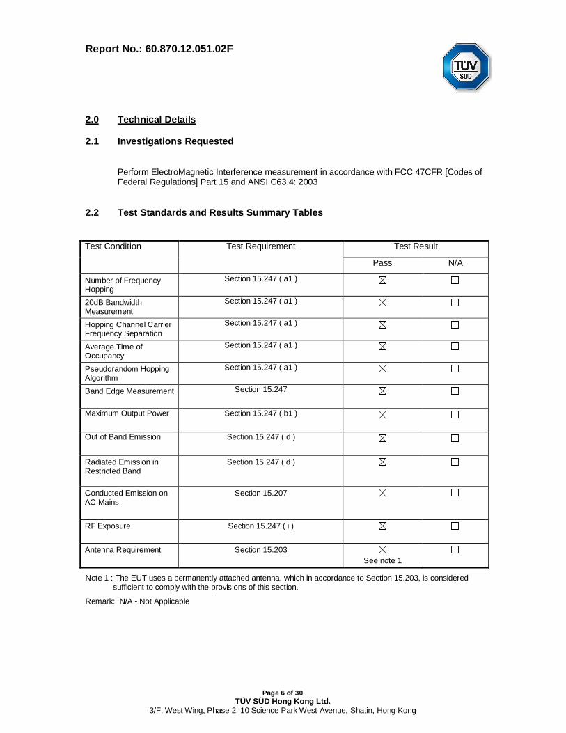
2.2 Test Standards and Results Summary Tables
Test Condition Test Requirement Test Result
Pass N/A
Number of FrequencyHopping
Section 15.247 ( a1 )
20dB BandwidthMeasurement
Section 15.247 ( a1 )
Hopping Channel CarrierFrequency Separation
Section 15.247 ( a1 )
Average Time ofOccupancy
Section 15.247 ( a1 )
Pseudorandom HoppingAlgorithm
Section 15.247 ( a1 )
Band Edge Measurement Section 15.247
Maximum Output Power Section 15.247 ( b1 )
Out of Band Emission Section 15.247 ( d )
Radiated Emission inRestricted Band
Section 15.247 ( d )
Conducted Emission onAC Mains
Section 15.207
RF Exposure Section 15.247 ( i )
Antenna Requirement Section 15.203See note 1
Note 1 : The EUT uses a permanently attached antenna, which in accordance to Section 15.203, is consideredsufficient to comply with the provisions of this section.
Remark: N/A - Not Applicable

Report No.: 60.870.12.051.02F
Page 7 of 30TÜV SÜD Hong Kong Ltd.
3/F, West Wing, Phase 2, 10 Science Park West Avenue, Shatin, Hong Kong
3.0 Test Methodology
3.1 Radiated Emission
The sample was placed 0.8m above the ground plane on a standard emission testsite *. Measurements in both horizontal and vertical polarities were performed.During the test, each emission was maximized by: having the EUT continuouslyworking, investigated all operating modes, rotated about all 3 axis (X, Y & Z) andconsidered typical configuration to obtain worst position, manipulating interconnectingcables, rotating turntable, varying antenna height from 1m to 4m in both horizontaland vertical polarizations. The emissions worst-case are shown in Test Results of thefollowing pages.
3.2 Field Strength Calculation
The field strength at 3 m was established by adding the meter reading of thespectrum analyzer to the factors associated with antenna correction factor, cableloss, preamplifiers and filter attenuation.
The equation is expressed as follow:
FS = R + System FactorSystem Factor = AF + CF + FA – PA
Where FS = Net Field Strength in dBuV/m at 3 meters. R = Reading of Spectrum Analyzer / Test Receiver in dBuV.
AF = Antenna Factor in dB.CF = Cable Attenuation Factor in dB.FA = Filter Attenuation Factor in dB.PA = Preamplifier Factor in dB.
FA and PA are only be used for the measuring frequency above 1 GHz.
3.3 Conducted Emissions
The test was performed in accordance with ANSI C63.4: 2003, with the following:initial measurements were performed in peak and average detection modes on thelive line of personal computer, any emissions recorded within 30dB of the relevantlimit lines were re-measured using quasi-peak and average detection on the live andneutral lines with the worst case recorded in the table of results.
Report No.: 60.870.12.051.02F
Page 8 of 30TÜV SÜD Hong Kong Ltd.
3/F, West Wing, Phase 2, 10 Science Park West Avenue, Shatin, Hong Kong
4.0 Test Results
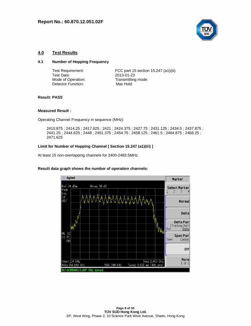
4.1 Number of Hopping Frequency
Test Requirement: FCC part 15 section 15.247 (a1)(iii)Test Date: 2013-01-23Mode of Operation: Transmitting mode.Detector Function: Max Hold
Result: PASS
Measured Result :
Operating Channel Frequency in sequence (MHz):
2410.875 ; 2414.25 ; 2417.625 ; 2421 ; 2424.375 ; 2427.75 ; 2431.125 ; 2434.5 ; 2437.875 ;2441.25 ; 2444.625 ; 2448 ; 2451.375 ; 2454.75 ; 2458.125 ; 2461.5 ; 2464.875 ; 2468.25 ;2471.625
Limit for Number of Hopping Channel [ Section 15.247 (a1)(iii) ]
At least 15 non-overlapping channels for 2400-2483.5MHz.
Result data graph shows the number of operation channels:
Report No.: 60.870.12.051.02F
Page 9 of 30TÜV SÜD Hong Kong Ltd.
3/F, West Wing, Phase 2, 10 Science Park West Avenue, Shatin, Hong Kong
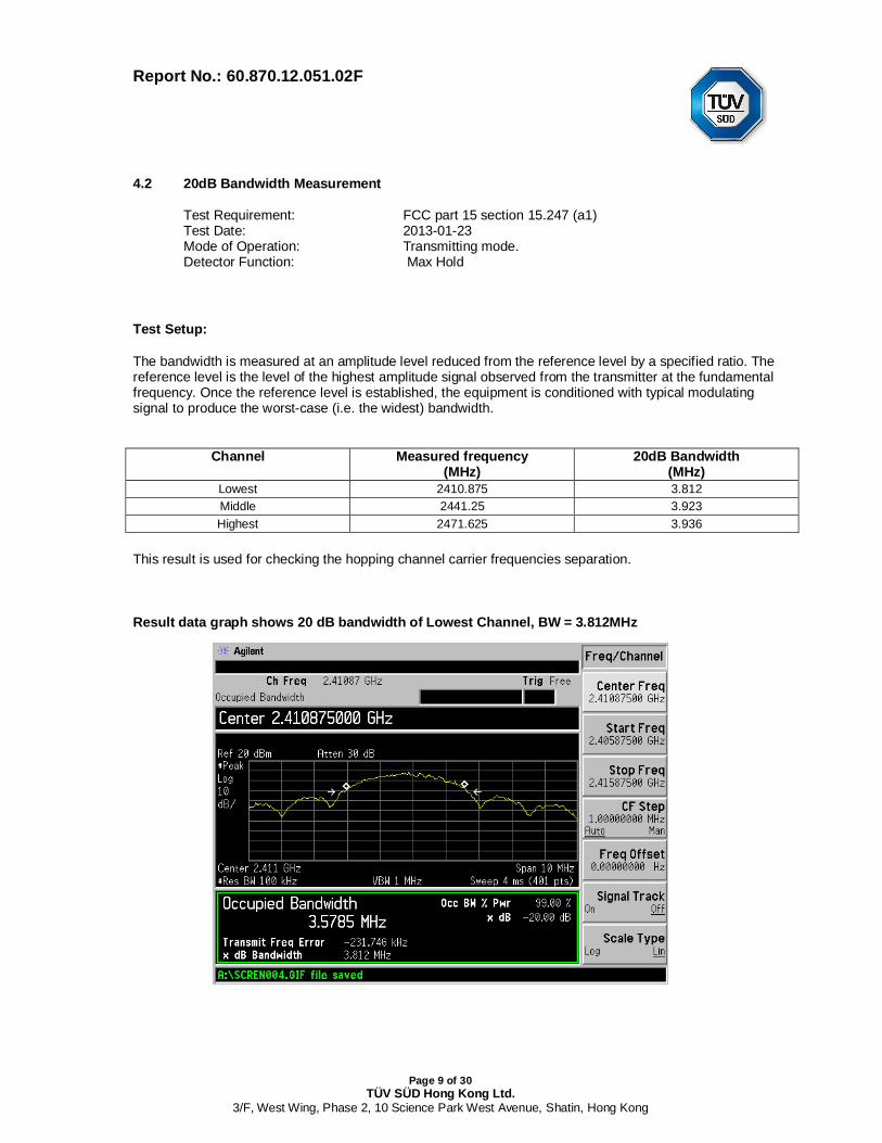
4.2 20dB Bandwidth Measurement
Test Requirement: FCC part 15 section 15.247 (a1)Test Date: 2013-01-23Mode of Operation: Transmitting mode.Detector Function: Max Hold
Test Setup:
The bandwidth is measured at an amplitude level reduced from the reference level by a specified ratio. Thereference level is the level of the highest amplitude signal observed from the transmitter at the fundamentalfrequency. Once the reference level is established, the equipment is conditioned with typical modulatingsignal to produce the worst-case (i.e. the widest) bandwidth.
Channel Measured frequency(MHz)
20dB Bandwidth(MHz)
Lowest 2410.875 3.812Middle 2441.25 3.923Highest 2471.625 3.936
This result is used for checking the hopping channel carrier frequencies separation.
Result data graph shows 20 dB bandwidth of Lowest Channel, BW = 3.812MHz
Report No.: 60.870.12.051.02F
Page 10 of 30TÜV SÜD Hong Kong Ltd.
3/F, West Wing, Phase 2, 10 Science Park West Avenue, Shatin, Hong Kong
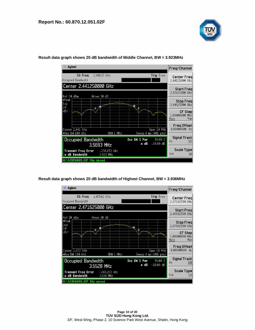
Result data graph shows 20 dB bandwidth of Middle Channel, BW = 3.923MHz
Result data graph shows 20 dB bandwidth of Highest Channel, BW = 3.936MHz
Report No.: 60.870.12.051.02F
Page 11 of 30TÜV SÜD Hong Kong Ltd.
3/F, West Wing, Phase 2, 10 Science Park West Avenue, Shatin, Hong Kong
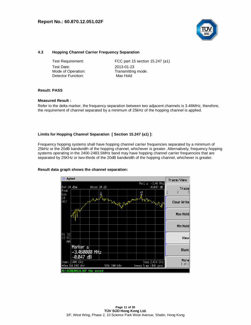
4.3 Hopping Channel Carrier Frequency Separation
Test Requirement: FCC part 15 section 15.247 (a1)Test Date: 2013-01-23Mode of Operation: Transmitting mode.Detector Function: Max Hold
Result: PASS
Measured Result :Refer to the delta marker, the frequency separation between two adjacent channels is 3.46MHz, therefore,the requirement of channel separated by a minimum of 25kHz of the hopping channel is applied.
Limits for Hopping Channel Separation [ Section 15.247 (a1) ]:
Frequency hopping systems shall have hopping channel carrier frequencies separated by a minimum of25kHz or the 20dB bandwidth of the hopping channel, whichever is greater. Alternatively, frequency hoppingsystems operating in the 2400-2483.5MHz band may have hopping channel carrier frequencies that areseparated by 25KHz or two-thirds of the 20dB bandwidth of the hopping channel, whichever is greater.
Result data graph shows the channel separation:
Report No.: 60.870.12.051.02F
Page 12 of 30TÜV SÜD Hong Kong Ltd.
3/F, West Wing, Phase 2, 10 Science Park West Avenue, Shatin, Hong Kong
4.4 Average Time of Channel Occupancy
Test Requirement: FCC part 15 section 15.247 (a1)(iii)Test Date: 2013-01-23Mode of Operation: Transmitting mode.Detector Function: Zero span, Sweep time 1s
Result : PASS
Measured Result :
Each transmission only 19 channels will be used.
Observe time = 19 channels × 0.4s =7. 6s
There are 10 pulses within 760ms
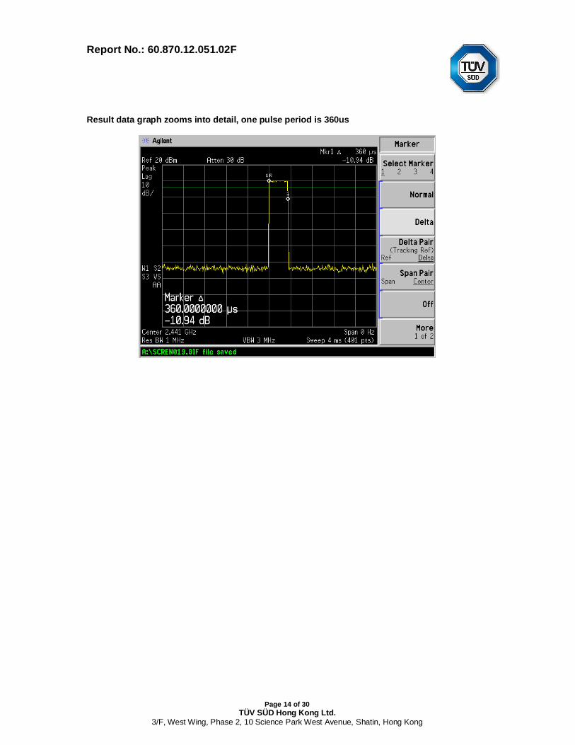
And one set of pulses = 360us
Therefore, the average channel occupancy times (ms)
= 360us x 10 x 10
So, total transmitting time is 0.036s. (<0.4s).
Limits for Average Time of Occupancy [ Section 15.247 (a1)(iii) ]:
The average time of occupancy on any channel shall not be greater than 0.4 second within aperiod of 0.4 seconds multiplied by the number of hopping channels employed.

Report No.: 60.870.12.051.02F
Page 13 of 30TÜV SÜD Hong Kong Ltd.
3/F, West Wing, Phase 2, 10 Science Park West Avenue, Shatin, Hong Kong
Result data graph shows total 19 channels are used
Result data graph shows total 10pulses with 760ms
Report No.: 60.870.12.051.02F
Page 14 of 30TÜV SÜD Hong Kong Ltd.
3/F, West Wing, Phase 2, 10 Science Park West Avenue, Shatin, Hong Kong
Result data graph zooms into detail, one pulse period is 360us
Report No.: 60.870.12.051.02F
Page 15 of 30TÜV SÜD Hong Kong Ltd.
3/F, West Wing, Phase 2, 10 Science Park West Avenue, Shatin, Hong Kong
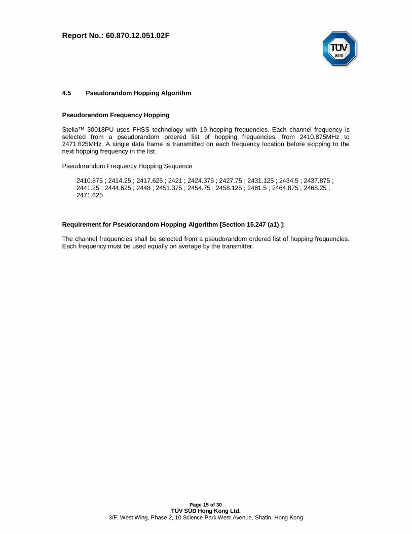
4.5 Pseudorandom Hopping Algorithm
Pseudorandom Frequency Hopping
Stella™ 30018PU uses FHSS technology with 19 hopping frequencies. Each channel frequency isselected from a pseudorandom ordered list of hopping frequencies, from 2410.875MHz to2471.625MHz. A single data frame is transmitted on each frequency location before skipping to thenext hopping frequency in the list.
Pseudorandom Frequency Hopping Sequence
2410.875 ; 2414.25 ; 2417.625 ; 2421 ; 2424.375 ; 2427.75 ; 2431.125 ; 2434.5 ; 2437.875 ;2441.25 ; 2444.625 ; 2448 ; 2451.375 ; 2454.75 ; 2458.125 ; 2461.5 ; 2464.875 ; 2468.25 ;2471.625
Requirement for Pseudorandom Hopping Algorithm [Section 15.247 (a1) ]:
The channel frequencies shall be selected from a pseudorandom ordered list of hopping frequencies.Each frequency must be used equally on average by the transmitter.
Report No.: 60.870.12.051.02F
Page 16 of 30TÜV SÜD Hong Kong Ltd.
3/F, West Wing, Phase 2, 10 Science Park West Avenue, Shatin, Hong Kong
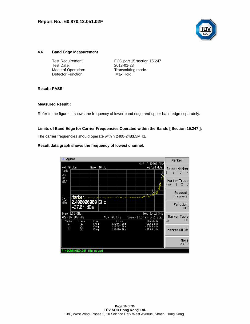
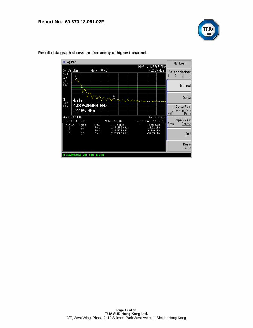
4.6 Band Edge Measurement
Test Requirement: FCC part 15 section 15.247Test Date: 2013-01-23Mode of Operation: Transmitting mode.Detector Function: Max Hold
Result: PASS
Measured Result :
Refer to the figure, it shows the frequency of lower band edge and upper band edge separately.
Limits of Band Edge for Carrier Frequencies Operated within the Bands [ Section 15.247 ]:
The carrier frequencies should operate within 2400-2483.5MHz.
Result data graph shows the frequency of lowest channel.
Report No.: 60.870.12.051.02F
Page 17 of 30TÜV SÜD Hong Kong Ltd.
3/F, West Wing, Phase 2, 10 Science Park West Avenue, Shatin, Hong Kong
Result data graph shows the frequency of highest channel.
Report No.: 60.870.12.051.02F
Page 18 of 30TÜV SÜD Hong Kong Ltd.
3/F, West Wing, Phase 2, 10 Science Park West Avenue, Shatin, Hong Kong
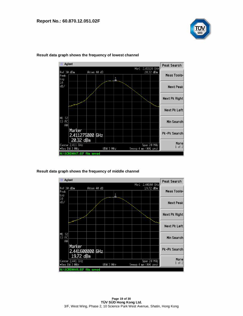
4.7 Maximum Output Power
Test Requirement: FCC part 15 section 15.247 (a1)Test Method: ANSI C63.4:2003Test Date: 2013-01-23Mode of Operation: Transmitting mode.Detector Function: PeakMeasurement BW: RBW 1MHz ; VBW 1MHz
Test Setup:
Result : PASS
Frequency(MHz)
Peak Output Power Limit
(dBm) (W) (dBm) (W)Lowest Channel :
2410.875 19.72 0.094 21 0.125
Middle Channel :2441.25 20.32 0.108 21 0.125
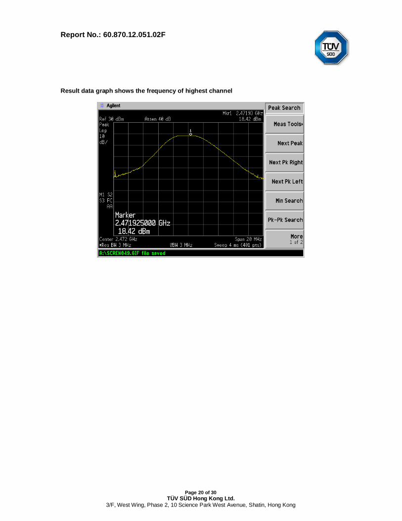
Highest Channel :2472.625 18.42 0.070 21 0.125
Limits for Maximum Output Power [ Section 15.247 (a1)(iii) ]:
For frequency hopping systems employing at least 75 hopping channels: 1 WattFor all other frequency hopping systems in the 2400-2483.5 MHz band: 0.125 Watts
Report No.: 60.870.12.051.02F
Page 19 of 30TÜV SÜD Hong Kong Ltd.
3/F, West Wing, Phase 2, 10 Science Park West Avenue, Shatin, Hong Kong
Result data graph shows the frequency of lowest channel
Result data graph shows the frequency of middle channel
Report No.: 60.870.12.051.02F
Page 20 of 30TÜV SÜD Hong Kong Ltd.
3/F, West Wing, Phase 2, 10 Science Park West Avenue, Shatin, Hong Kong
Result data graph shows the frequency of highest channel

Report No.: 60.870.12.051.02F
Page 21 of 30TÜV SÜD Hong Kong Ltd.
3/F, West Wing, Phase 2, 10 Science Park West Avenue, Shatin, Hong Kong
4.8 Out of Band Emissions and Emissions in Restricted Bands
Test Requirement: FCC part 15 section 15.247 (d )Test Method: ANSI C63.4:2003Test Date: 2013-01-23Mode of Operation: Transmitting mode.Detector Function: PeakMeasurement BW: RBW 100KHz ; VBW 300KHz
Test Setup:
EUT
3m
Pre-Amplifier
MeasuringReceiver
Computer
Turntable
Ground Plane
Semi-Anechoic Chamber
Report No.: 60.870.12.051.02F
Page 22 of 30TÜV SÜD Hong Kong Ltd.
3/F, West Wing, Phase 2, 10 Science Park West Avenue, Shatin, Hong Kong
Result : PASS
Out of Frequency Band Emissions:
For out of band emissions that are close to or exceed 20dB attenuation requirement, andemission falls into restricted band, radiated emission was performed in order to showcompliance with the general radiated emission requirement.
Result Summary:
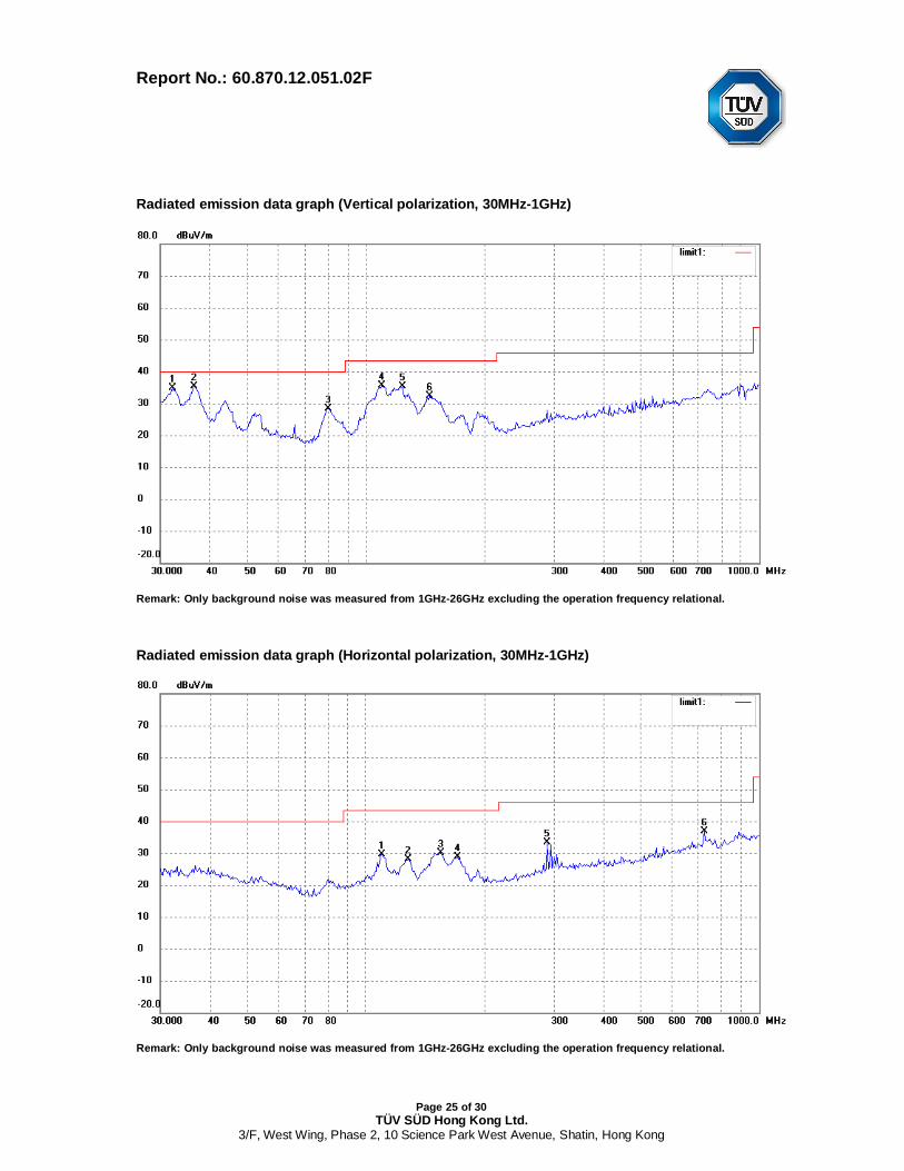
Refer to the emission data graph, result shows that the significant emissions detected arewith more than 20dB below that in the 100kHz bandwidth within the band that contains thehighest level of the desired power.
Limits for Out of Frequency Band Emission [ Section 15.247 (d) ]:
In any 100kHz bandwidth outside the frequency band in which the spread spectrum ordigitally modulated intentional radiator is operating, the radio frequency power that isproduced by the intentional radiator shall be at least 20 dB below that in the 100kHzbandwidth within the band that contains the highest level of the desired power. Attenuationbelow the general limits specified in Section 15.209(a) is not required.
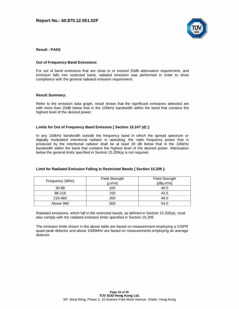
Limit for Radiated Emission Falling in Restricted Bands [ Section 15.209 ]:
Frequency (MHz) Field Strength[ V/m]
Field Strength[dB V/m]
30-88 100 40.088-216 150 43.5216-960 200 46.0
Above 960 500 54.0
Radiated emissions, which fall in the restricted bands, as defined in Section 15.205(a), mustalso comply with the radiated emission limits specified in Section 15.209.
The emission limits shown in the above table are based on measurement employing a CISPRquasi-peak detector and above 1000MHz are based on measurements employing an averagedetector.

Report No.: 60.870.12.051.02F
Page 23 of 30TÜV SÜD Hong Kong Ltd.
3/F, West Wing, Phase 2, 10 Science Park West Avenue, Shatin, Hong Kong
Result : PASS
All Emission and Emissions Fall into Restricted Band were recorded as below:
Emissions E-Field Reading System Field Limit Delta toFrequency Polarity Factor strength at Limit
3mMHz dBuV/m dB dBuV/m dBuV/m dBuV/m
PK 4818.00 V 65.55 -3.90 61.65 74.00 -12.35PK 7233.00 V 59.86 1.12 60.98 74.00 -13.02PK 4818.00 H 58.29 -3.90 54.39 74.00 -19.61PK 7233.00 H 56.78 1.12 57.90 74.00 -16.10
PK 4887.00 V 62.98 -3.69 59.29 74.00 -14.71PK 7325.00 V 58.92 1.53 60.45 74.00 -13.55PK 4887.00 H 54.84 -3.69 51.15 74.00 -22.85PK 7325.00 H 39.91 1.53 41.44 74.00 -32.56
PK 4933.00 V 57.06 -3.56 53.50 74.00 -20.50PK 7417.00 V 50.77 1.93 52.70 74.00 -21.30PK 4933.00 H 52.56 -3.56 49.00 74.00 -25.00PK 7417.00 H 47.49 1.93 49.42 74.00 -24.58
QP 32.18 V 26.41 8.41 34.82 40.00 -5.18QP 36.51 V 26.14 9.13 35.27 40.00 -4.73QP 80.08 V 26.73 1.69 28.42 40.00 -11.58QP 109.80 V 29.65 5.87 35.52 43.50 -7.98QP 123.70 V 30.78 4.60 35.38 43.50 -8.12QP 145.35 V 28.93 3.48 32.41 43.50 -11.09QP 109.80 H 23.76 5.87 29.63 43.50 -13.87QP 128.11 H 23.91 4.27 28.18 43.50 -15.32QP 154.82 H 26.58 3.59 30.17 43.50 -13.33QP 170.79 H 25.08 3.70 28.78 43.50 -14.72QP 289.00 H 23.63 9.67 33.30 46.00 -12.70QP 724.26 H 19.93 16.93 36.86 46.00 -9.14
Spurious Emissions
Radiated Emissions
Lowest Channel
Middle Channel
Highest Channel
Refer to Figures shows the worst case channel’s emission data graph from 30MHz-26GHz.
Report No.: 60.870.12.051.02F
Page 24 of 30TÜV SÜD Hong Kong Ltd.
3/F, West Wing, Phase 2, 10 Science Park West Avenue, Shatin, Hong Kong
Result Summary:
1) Communication mode: All other emissions are more than 20dB below FCC part 15.209limit.
2) No further spurious emissions found between 30 MHz and lowest internal used/generatedfrequency and from 30MHz to 1GHz.
Remarks:
1. “ * ” Radiated emissions which fall in the restricted bands as defined in Section 15.205(a).
2. Emission level with more than 20dB below the FCC required limit is not mentioned in table.
3. Delta to Limit = Field strength (dBµV/m) – Limit (dBµV/m).
4. Calculated measurement uncertainty: 9kHz -30MHz: 1.8dB.30MHz -1GHz: 5.2dB.1GHz -18GHz: 5.1dB.
Report No.: 60.870.12.051.02F
Page 25 of 30TÜV SÜD Hong Kong Ltd.
3/F, West Wing, Phase 2, 10 Science Park West Avenue, Shatin, Hong Kong
Radiated emission data graph (Vertical polarization, 30MHz-1GHz)
Remark: Only background noise was measured from 1GHz-26GHz excluding the operation frequency relational.
Radiated emission data graph (Horizontal polarization, 30MHz-1GHz)
Remark: Only background noise was measured from 1GHz-26GHz excluding the operation frequency relational.
Report No.: 60.870.12.051.02F
Page 26 of 30TÜV SÜD Hong Kong Ltd.
3/F, West Wing, Phase 2, 10 Science Park West Avenue, Shatin, Hong Kong
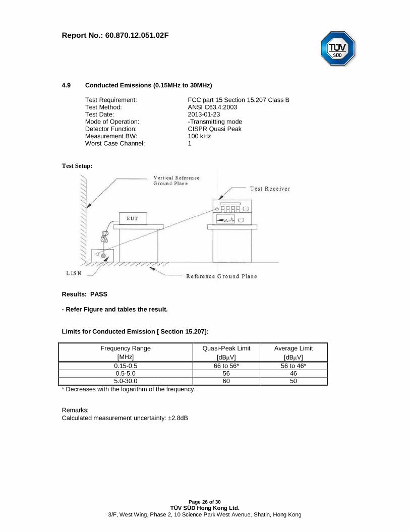
Limits for Conducted Emission [ Section 15.207]:
Frequency Range Quasi-Peak Limit Average Limit[MHz] [dB V] [dB V]
0.15-0.5 66 to 56* 56 to 46*0.5-5.0 56 465.0-30.0 60 50
* Decreases with the logarithm of the frequency.
Remarks:Calculated measurement uncertainty: 2.8dB
4.9 Conducted Emissions (0.15MHz to 30MHz)
Test Requirement: FCC part 15 Section 15.207 Class BTest Method: ANSI C63.4:2003Test Date: 2013-01-23Mode of Operation: -Transmitting modeDetector Function: CISPR Quasi PeakMeasurement BW: 100 kHzWorst Case Channel: 1
Test Setup:
Results: PASS
- Refer Figure and tables the result.
Report No.: 60.870.12.051.02F
Page 27 of 30TÜV SÜD Hong Kong Ltd.
3/F, West Wing, Phase 2, 10 Science Park West Avenue, Shatin, Hong Kong
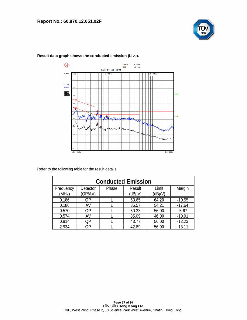
Result data graph shows the conducted emission (Live).
Refer to the following table for the result details:
Frequency Detector Phase Result Limit Margin(MHz) (QP/AV) (dBµV) (dBµV)0.186 QP L 53.65 64.20 -10.550.186 AV L 36.57 54.21 -17.640.570 QP L 50.33 56.00 -5.670.574 AV L 35.09 46.00 -10.910.914 QP L 43.77 56.00 -12.232.934 QP L 42.89 56.00 -13.11
Conducted Emission
Report No.: 60.870.12.051.02F
Page 28 of 30TÜV SÜD Hong Kong Ltd.
3/F, West Wing, Phase 2, 10 Science Park West Avenue, Shatin, Hong Kong
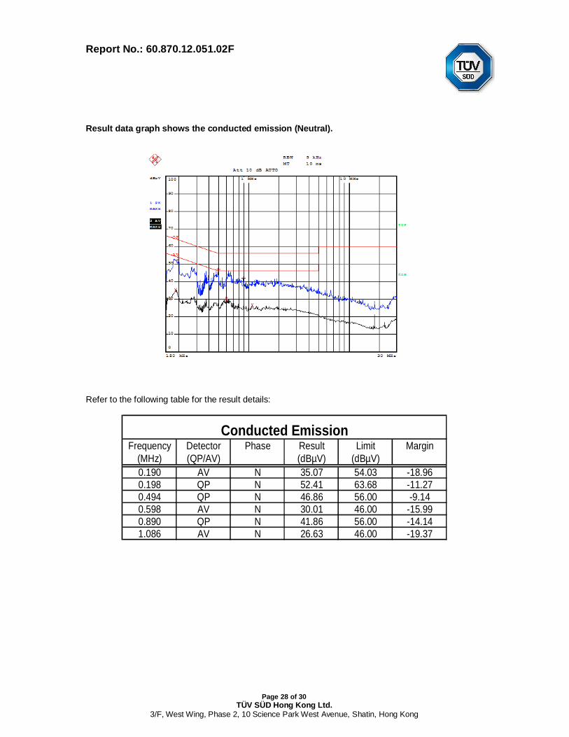
Result data graph shows the conducted emission (Neutral).
Refer to the following table for the result details:
Frequency Detector Phase Result Limit Margin(MHz) (QP/AV) (dBµV) (dBµV)0.190 AV N 35.07 54.03 -18.960.198 QP N 52.41 63.68 -11.270.494 QP N 46.86 56.00 -9.140.598 AV N 30.01 46.00 -15.990.890 QP N 41.86 56.00 -14.141.086 AV N 26.63 46.00 -19.37
Conducted Emission
Report No.: 60.870.12.051.02F
Page 29 of 30TÜV SÜD Hong Kong Ltd.
3/F, West Wing, Phase 2, 10 Science Park West Avenue, Shatin, Hong Kong
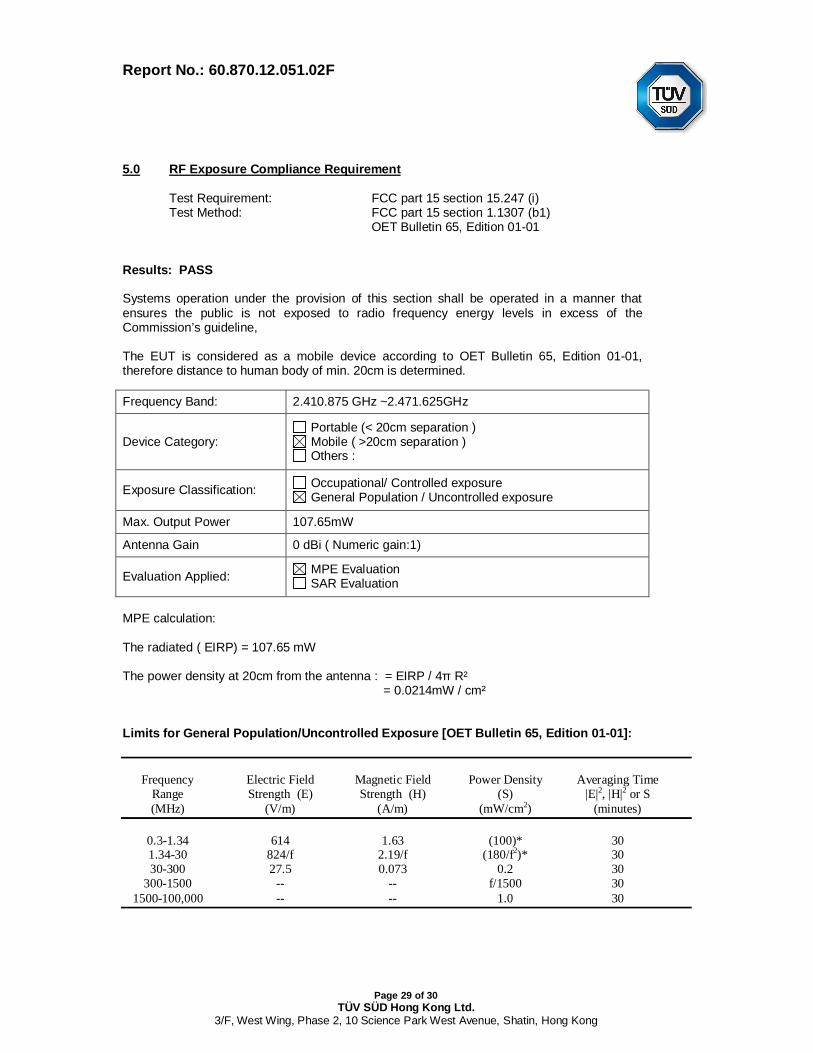
5.0 RF Exposure Compliance Requirement
Test Requirement: FCC part 15 section 15.247 (i)Test Method: FCC part 15 section 1.1307 (b1)
OET Bulletin 65, Edition 01-01
Results: PASS
Systems operation under the provision of this section shall be operated in a manner thatensures the public is not exposed to radio frequency energy levels in excess of theCommission’s guideline,
The EUT is considered as a mobile device according to OET Bulletin 65, Edition 01-01,therefore distance to human body of min. 20cm is determined.
Frequency Band: 2.410.875 GHz ~2.471.625GHz
Device Category: Portable (< 20cm separation ) Mobile ( >20cm separation ) Others :
Exposure Classification: Occupational/ Controlled exposure General Population / Uncontrolled exposure
Max. Output Power 107.65mW
Antenna Gain 0 dBi ( Numeric gain:1)
Evaluation Applied: MPE Evaluation SAR Evaluation
MPE calculation:
The radiated ( EIRP) = 107.65 mW
The power density at 20cm from the antenna : = EIRP / 4 R² = 0.0214mW / cm²
Limits for General Population/Uncontrolled Exposure [OET Bulletin 65, Edition 01-01]:
Frequency Electric Field Magnetic Field Power Density Averaging TimeRange Strength (E) Strength (H) (S) |E|2, |H|2 or S(MHz) (V/m) (A/m) (mW/cm2) (minutes)
0.3-1.34 614 1.63 (100)* 301.34-30 824/f 2.19/f (180/f2)* 3030-300 27.5 0.073 0.2 30
300-1500 -- -- f/1500 30 1500-100,000 -- -- 1.0 30

Report No.: 60.870.12.051.02F
Page 30 of 30TÜV SÜD Hong Kong Ltd.
3/F, West Wing, Phase 2, 10 Science Park West Avenue, Shatin, Hong Kong
6.0 List of Measurement Equipment
Radiated Emission and Bandwidth EmissionsDescription Manufacturer Model no. Serial no. CAL dueSpectrum Analyzer Agilent E4402B US41192821 27 Mar 2013
Test Receiver R & S ESI26 838786/013 27 Mar 2013
DC Power Supply LW APR-3003 N/A 15 Jul 2013
Spectrum Analyzer R & S FSP30 836079/035 27 Mar 2013
Positioning Controller C&C CC-C-1F N/A 19 Dec 2013
RF Switch EM EMSW18 SW060023 19 Dec 2013
Pre-amplifier Agilent 8447F 3113A06717 27 Mar 2013
Pre-amplifier Compliance Direction PAP-1G18 24002 27 Mar 2013
Trilog Broadband Antenna SCHWARZBECK VULB9163 9163-333 24 Feb 2013
Horn Antenna ETS 3117 00086197 24 Feb 2013
Anechoic chamber Albatross Projects MCDC SW060023 19 Mar 2013
Conducted EmissionsDescription Manufacturer Model no. Serial no. CAL dueTest Receiver Rohde & Schwarz ESPI 101611 27 Mar 2013
L.I.S.N Schwarzbeck NSLK8126 8126-224 27 Mar 2013
Pulse Limiter Rohde & Schwarz ESH3-Z2 100911 27 Mar 2013
AMN EMCO 3825/2 11967C 27 Mar 2013
N/A Not Applicable or Not Available