Embed Size (px)
Citation preview
TRF NO. EN 62040-2/A Page 1 of 56 Report No.: ES140331284E Ver.1.0
Standards EN62040-2: 2006
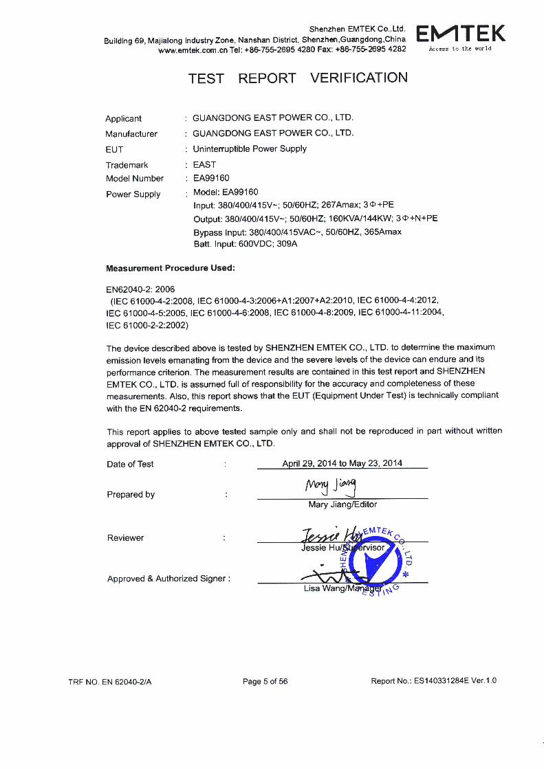
TEST REPORT
For
GUANGDONG EAST POWER CO., LTD.
Uninterruptible Power Supply
Model Number: EA99160
Report Number : ES140331284E Date of Test : April 29, 2014 to May 23, 2014 Date of Report : May 23, 2014
Prepared for : GUANGDONG EAST POWER CO., LTD. Address : No.6 Northern Industry Road, Songshan Lake SCI &
TECH Industry Park, Dongguan City, Guangdong Province, China.
Prepared by : SHENZHEN EMTEK CO., LTD. Address : Bldg 69, Majialong Industry Zone,
Nanshan District, Shenzen, Guangdong, China
Tel: (0755) 26954280 Fax: (0755) 26954282
TRF NO. EN 62040-2/A Page 2 of 56 Report No.: ES140331284E Ver.1.0
TABLE OF CONTENT
Description Page
1. SUMMARY OF TEST RESULT ......................................................................................................................................... 7
2. GENERAL INFORMATION................................................................................................................................................ 8
2.1. Description of Device (EUT) ....................................................................................................................................... 8 2.2. Description of Test Facility .......................................................................................................................................... 8 2.3. Measurement Uncertainty .......................................................................................................................................... 9
3. MEASURING DEVICE AND TEST EQUIPMENT ........................................................................................................ 10
3.1. For Conducted Emission Measurement ................................................................................................................. 10 3.2. For Radiated Emission Measurement .................................................................................................................... 10 3.3. For Electrostatic Discharge Immunity Test ............................................................................................................. 10 3.4. For RF Strength Susceptibility Test ......................................................................................................................... 11 3.5. For Electrical Fast Transient/Burst Immunity Test ................................................................................................ 11 3.6. For Surge Immunity Test ........................................................................................................................................... 11 3.7. For Injected Current Susceptibility Test .................................................................................................................. 11 3.8. For Magnetic Field Immunity Test ........................................................................................................................... 12 3.9. For Voltage Dips and Interruptions Test ................................................................................................................. 12 3.10. Low Frequency Signals Test .................................................................................................................................... 12
4. CONDUCTED EMISSION MEASUREMENT ................................................................................................................ 13
4.1. Block Diagram of Test Setup .................................................................................................................................... 13 4.2. Measuring Standard .................................................................................................................................................. 13 4.3. Power Line Conducted Emission Limits (C3) ........................................................................................................ 13 4.4. EUT Configuration on Measurement ...................................................................................................................... 13 4.5. Operating Condition of EUT ..................................................................................................................................... 14 4.6. Test Procedure ........................................................................................................................................................... 14 4.7. Measuring Results ..................................................................................................................................................... 14
5. RADIATED EMISSION MEASUREMENT ..................................................................................................................... 18
5.1. Block Diagram of Test ............................................................................................................................................... 18 5.2. Measuring Standard .................................................................................................................................................. 18 5.3. Radiated Emission Limits(C3).................................................................................................................................. 19 5.4. EUT Configuration on Test ....................................................................................................................................... 19 5.5. Operating Condition of EUT ..................................................................................................................................... 19 5.6. Test Procedure ........................................................................................................................................................... 19 5.7. Measuring Results ..................................................................................................................................................... 19
6. IMMUNITY PERFORMANCE CRITERIA DESCRIPTION .......................................................................................... 22
7. ELECTROSTATIC DISCHARGE IMMUNITY TEST .................................................................................................... 24
7.1. Block Diagram of Test Setup .................................................................................................................................... 24 7.2. Test Standard ............................................................................................................................................................. 24 7.3. Severity Levels and Performance Criterion ........................................................................................................... 24 7.4. EUT Configuration ..................................................................................................................................................... 25 7.5. Operating Condition of EUT ..................................................................................................................................... 25 7.6. Test Procedure ........................................................................................................................................................... 25 7.7. Test Results ................................................................................................................................................................ 25
8. RF FIELD STRENGTH SUSCEPTIBILITY TEST ........................................................................................................ 27
8.1. Block Diagram of Test ............................................................................................................................................... 27 8.2. Test Standard ............................................................................................................................................................. 27 8.3. Severity Levels and Performance Criterion ........................................................................................................... 28
TRF NO. EN 62040-2/A Page 3 of 56 Report No.: ES140331284E Ver.1.0
8.4. EUT Configuration on Test ....................................................................................................................................... 28 8.5. Operating Condition of EUT ..................................................................................................................................... 28 8.6. Test Procedure ........................................................................................................................................................... 28 8.7. Test Results ................................................................................................................................................................ 29
9. ELECTRICAL FAST TRANSIENT/BURST IMMUNITY TEST ................................................................................... 31
9.1. Block Diagram of Test Setup .................................................................................................................................... 31 9.2. Test Standard ............................................................................................................................................................. 31 9.3. Severity Levels and Performance Criterion ........................................................................................................... 31 9.4. EUT Configuration ..................................................................................................................................................... 32 9.5. Operating Condition of EUT ..................................................................................................................................... 32 9.6. Test Procedure ........................................................................................................................................................... 32 9.7. Test Result .................................................................................................................................................................. 32
10. SURGE IMMUNITY TEST ................................................................................................................................................ 34
10.1. Block Diagram of Test Setup .................................................................................................................................... 34 10.2. Test Standard ............................................................................................................................................................. 34 10.3. Severity Levels and Performance Criterion ........................................................................................................... 34 10.4. EUT Configuration ..................................................................................................................................................... 35 10.5. Operating Condition of EUT ..................................................................................................................................... 35 10.6. Test Procedure ........................................................................................................................................................... 35 10.7. Test Result .................................................................................................................................................................. 35
11. INJECTED CURRENTS SUSCEPTIBILITY TEST ...................................................................................................... 37
11.1. Block Diagram of Test Setup .................................................................................................................................... 37 11.2. Test Standard ............................................................................................................................................................. 37 11.3. Severity Levels and Performance Criterion ........................................................................................................... 37 11.4. EUT Configuration ..................................................................................................................................................... 38 11.5. Operating Condition of EUT ..................................................................................................................................... 38 11.6. Test Procedure ........................................................................................................................................................... 38 11.7. Test Results ................................................................................................................................................................ 38
12. MAGNETIC FIELD SUSCEPTIBILITY TEST ............................................................................................................... 40
12.1. Block Diagram of Test ............................................................................................................................................... 40 12.2. Test Standard ............................................................................................................................................................. 40 12.3. Severity Levels and Performance Criterion ........................................................................................................... 40 12.4. EUT Configuration on Test ....................................................................................................................................... 41 12.5. Test Procedure ........................................................................................................................................................... 41 12.6. Test Results ................................................................................................................................................................ 41
13. VOLTAGE DIPS AND INTERRUPTIONS TEST .......................................................................................................... 43
13.1. Block Diagram of Test Setup .................................................................................................................................... 43 13.2. Test Standard ............................................................................................................................................................. 43 13.3. Severity Levels and Performance Criterion ........................................................................................................... 43 13.4. EUT Configuration ..................................................................................................................................................... 44 13.5. Operating Condition of EUT ..................................................................................................................................... 44 13.6. Test Procedure ........................................................................................................................................................... 44 13.7. Test Result .................................................................................................................................................................. 44
14. LOW FREQUENCY SIGNALS TEST ............................................................................................................................ 46
14.1. Block Diagram of Test Setup .................................................................................................................................... 46 14.2. Test Standard ............................................................................................................................................................. 46 14.3. Operating Condition of EUT ..................................................................................................................................... 46 14.4. Test Results ................................................................................................................................................................ 46
15. TEST PHOTOGRAPH ...................................................................................................................................................... 48
15.1. Photos of Conducted Emission Measurement ...................................................................................................... 48 15.2. Photo of Radiation Emission Measurement........................................................................................................... 49 15.3. Photo of Electrostatic Discharge Test ..................................................................................................................... 50 15.4. Photo of RF Field Strength susceptibility Test ....................................................................................................... 50
TRF NO. EN 62040-2/A Page 4 of 56 Report No.: ES140331284E Ver.1.0
15.5. Photos of Electrical Fast Transient/Burst Test ....................................................................................................... 51 15.6. Photo of Surge Test ................................................................................................................................................... 51 15.7. Photo of Injected Currents Susceptibility Test ....................................................................................................... 52 15.8. Photo of Magnetic Field Immunity Test ................................................................................................................... 52 15.9. Photo of Voltage dips and interruption Test ........................................................................................................... 53 15.10. Photo of Low Frequency Signals Test .............................................................................................................. 53
APPENDIX (Photos of EUT) (2 Pages)
TRF NO. EN 62040-2/A Page 6 of 56 Report No.: ES140331284E Ver.1.0
Modified History
Version Report No. Revision date Summary
Ver.1.0 ES140331284E / Original Report
TRF NO. EN 62040-2/A Page 7 of 56 Report No.: ES140331284E Ver.1.0
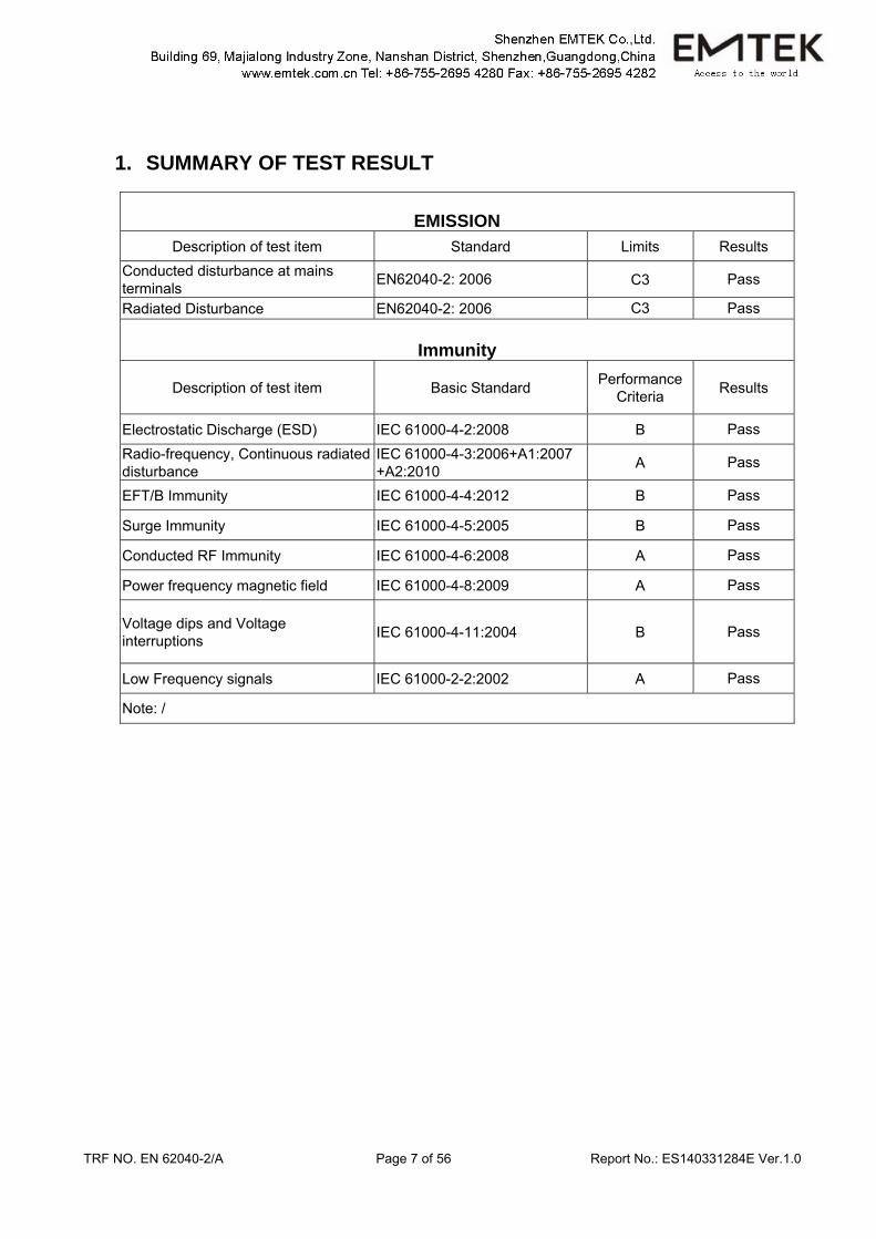
1. SUMMARY OF TEST RESULT
EMISSION
Description of test item Standard Limits Results Conducted disturbance at mains terminals EN62040-2: 2006 C3 Pass
Radiated Disturbance EN62040-2: 2006 C3 Pass
Immunity
Description of test item
Basic Standard
Performance Criteria Results
Electrostatic Discharge (ESD) IEC 61000-4-2:2008 B Pass Radio-frequency, Continuous radiated disturbance
IEC 61000-4-3:2006+A1:2007 +A2:2010 A Pass
EFT/B Immunity IEC 61000-4-4:2012 B Pass
Surge Immunity IEC 61000-4-5:2005 B Pass
Conducted RF Immunity IEC 61000-4-6:2008 A Pass
Power frequency magnetic field IEC 61000-4-8:2009 A Pass
Voltage dips and Voltage interruptions IEC 61000-4-11:2004 B Pass
Low Frequency signals IEC 61000-2-2:2002 A Pass
Note: /
TRF NO. EN 62040-2/A Page 8 of 56 Report No.: ES140331284E Ver.1.0
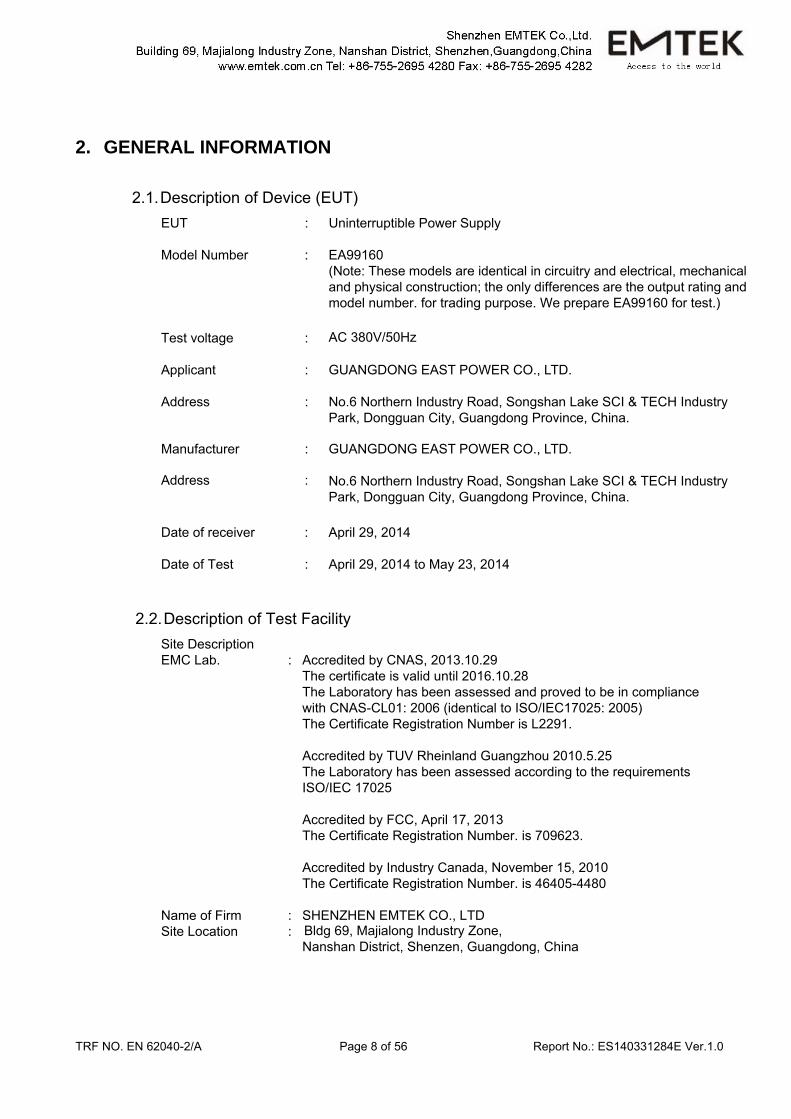
2. GENERAL INFORMATION
2.1. Description of Device (EUT) EUT : Uninterruptible Power Supply Model Number : EA99160
(Note: These models are identical in circuitry and electrical, mechanical and physical construction; the only differences are the output rating and model number. for trading purpose. We prepare EA99160 for test.)
Test voltage : AC 380V/50Hz Applicant : GUANGDONG EAST POWER CO., LTD. Address : No.6 Northern Industry Road, Songshan Lake SCI & TECH Industry
Park, Dongguan City, Guangdong Province, China. Manufacturer : GUANGDONG EAST POWER CO., LTD.
Address : No.6 Northern Industry Road, Songshan Lake SCI & TECH Industry
Park, Dongguan City, Guangdong Province, China. Date of receiver : April 29, 2014 Date of Test : April 29, 2014 to May 23, 2014
2.2. Description of Test Facility Site Description EMC Lab. : Accredited by CNAS, 2013.10.29
The certificate is valid until 2016.10.28 The Laboratory has been assessed and proved to be in compliance with CNAS-CL01: 2006 (identical to ISO/IEC17025: 2005) The Certificate Registration Number is L2291.
Accredited by TUV Rheinland Guangzhou 2010.5.25 The Laboratory has been assessed according to the requirements ISO/IEC 17025
Accredited by FCC, April 17, 2013 The Certificate Registration Number. is 709623.
Accredited by Industry Canada, November 15, 2010 The Certificate Registration Number. is 46405-4480
Name of Firm : SHENZHEN EMTEK CO., LTD Site Location : Bldg 69, Majialong Industry Zone,
Nanshan District, Shenzen, Guangdong, China
TRF NO. EN 62040-2/A Page 9 of 56 Report No.: ES140331284E Ver.1.0
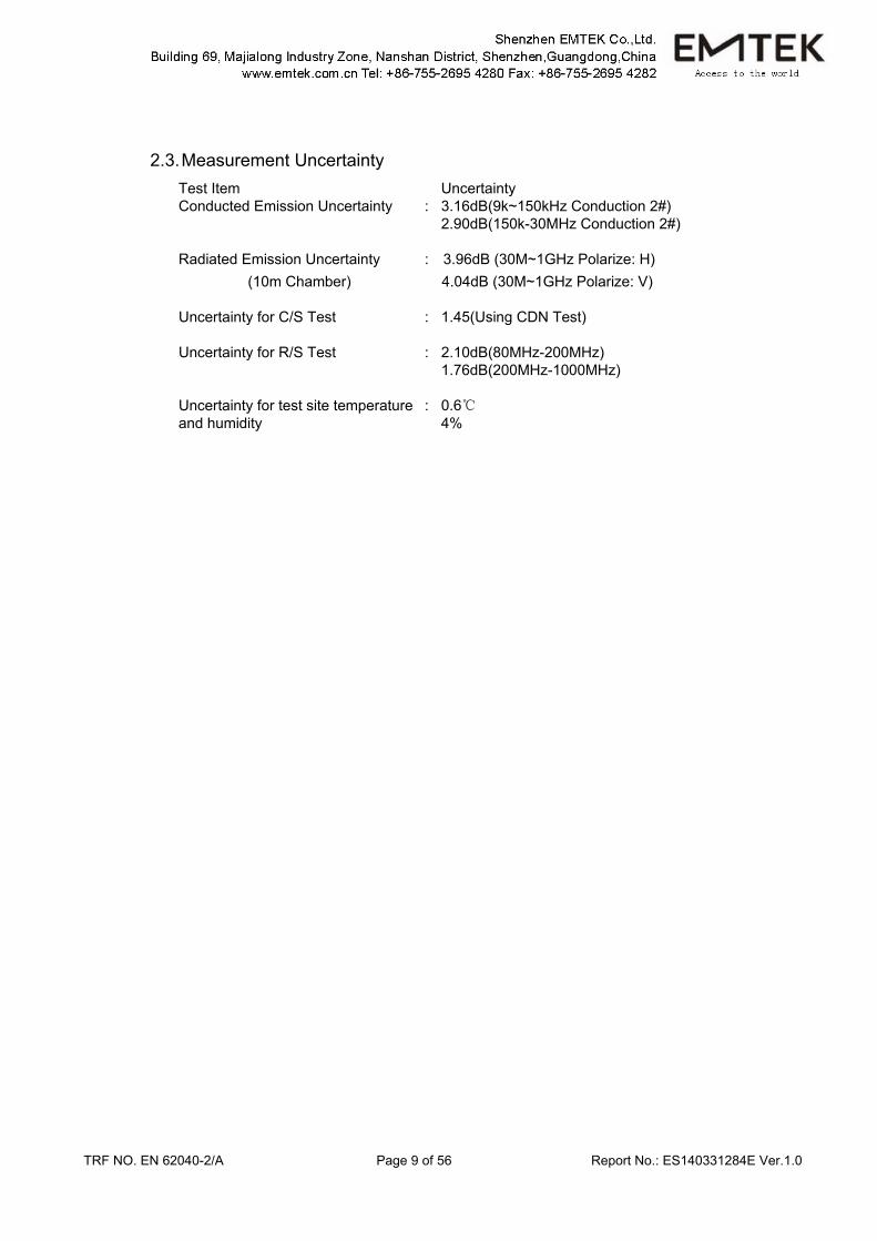
2.3. Measurement Uncertainty Test Item Uncertainty Conducted Emission Uncertainty : 3.16dB(9k~150kHz Conduction 2#) 2.90dB(150k-30MHz Conduction 2#) Radiated Emission Uncertainty : 3.96dB (30M~1GHz Polarize: H)
(10m Chamber) 4.04dB (30M~1GHz Polarize: V)
Uncertainty for C/S Test : 1.45(Using CDN Test) Uncertainty for R/S Test : 2.10dB(80MHz-200MHz) 1.76dB(200MHz-1000MHz) Uncertainty for test site temperature and humidity
: 0.6 4%
TRF NO. EN 62040-2/A Page 10 of 56 Report No.: ES140331284E Ver.1.0
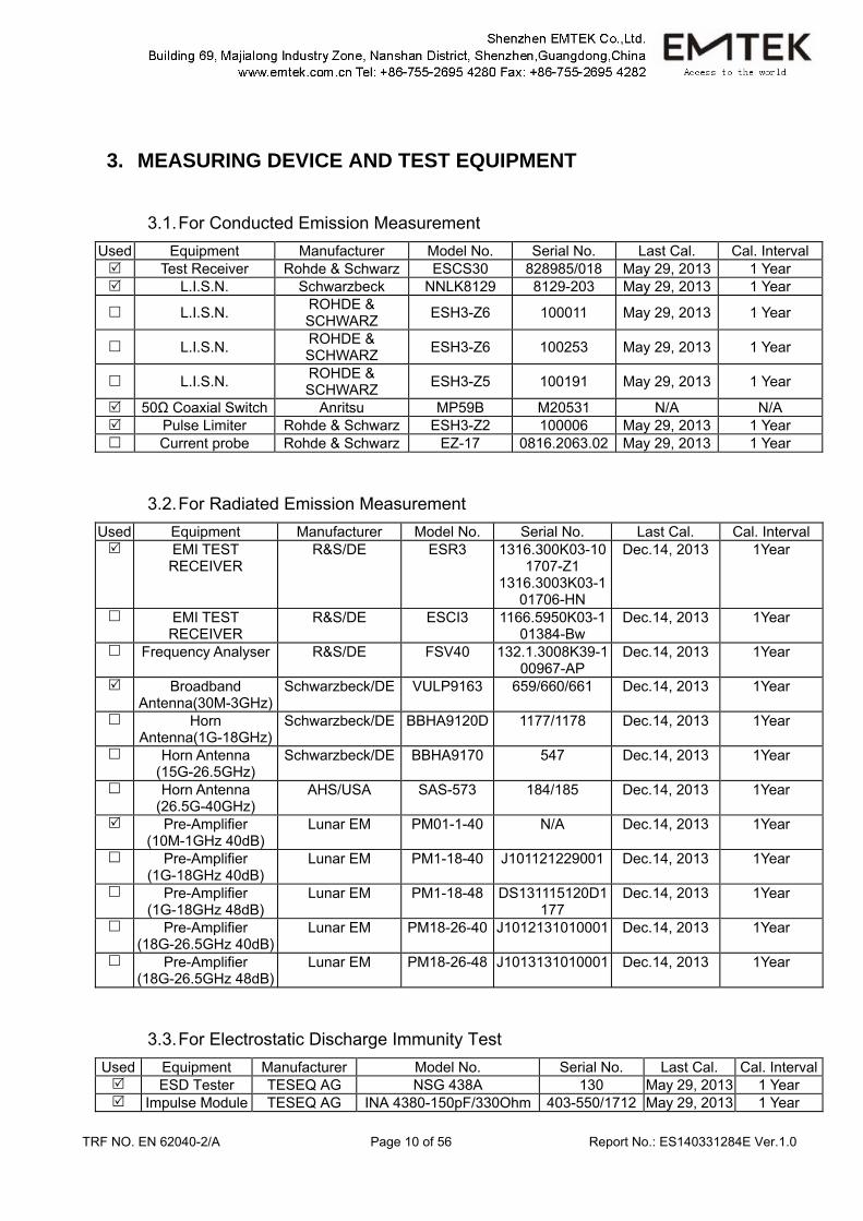
3. MEASURING DEVICE AND TEST EQUIPMENT
3.1. For Conducted Emission Measurement Used Equipment Manufacturer Model No. Serial No. Last Cal. Cal. Interval
Test Receiver Rohde & Schwarz ESCS30 828985/018 May 29, 2013 1 Year L.I.S.N. Schwarzbeck NNLK8129 8129-203 May 29, 2013 1 Year
L.I.S.N. ROHDE & SCHWARZ ESH3-Z6 100011 May 29, 2013 1 Year
L.I.S.N. ROHDE & SCHWARZ ESH3-Z6 100253 May 29, 2013 1 Year
L.I.S.N. ROHDE & SCHWARZ ESH3-Z5 100191 May 29, 2013 1 Year
50Ω Coaxial Switch Anritsu MP59B M20531 N/A N/A Pulse Limiter Rohde & Schwarz ESH3-Z2 100006 May 29, 2013 1 Year Current probe Rohde & Schwarz EZ-17 0816.2063.02 May 29, 2013 1 Year
3.2. For Radiated Emission Measurement Used Equipment Manufacturer Model No. Serial No. Last Cal. Cal. Interval
EMI TEST RECEIVER
R&S/DE ESR3 1316.300K03-101707-Z1
1316.3003K03-101706-HN
Dec.14, 2013 1Year
EMI TEST RECEIVER
R&S/DE ESCI3 1166.5950K03-101384-Bw
Dec.14, 2013 1Year
Frequency Analyser
R&S/DE FSV40 132.1.3008K39-100967-AP
Dec.14, 2013 1Year
Broadband Antenna(30M-3GHz)
Schwarzbeck/DE VULP9163 659/660/661 Dec.14, 2013 1Year
Horn Antenna(1G-18GHz)
Schwarzbeck/DE BBHA9120D 1177/1178 Dec.14, 2013 1Year
Horn Antenna (15G-26.5GHz)
Schwarzbeck/DE BBHA9170 547 Dec.14, 2013 1Year
Horn Antenna (26.5G-40GHz)
AHS/USA SAS-573 184/185 Dec.14, 2013 1Year
Pre-Amplifier (10M-1GHz 40dB)
Lunar EM PM01-1-40 N/A Dec.14, 2013 1Year
Pre-Amplifier (1G-18GHz 40dB)
Lunar EM PM1-18-40 J101121229001 Dec.14, 2013 1Year
Pre-Amplifier (1G-18GHz 48dB)
Lunar EM PM1-18-48 DS131115120D1177
Dec.14, 2013 1Year
Pre-Amplifier (18G-26.5GHz 40dB)
Lunar EM PM18-26-40 J1012131010001 Dec.14, 2013 1Year
Pre-Amplifier (18G-26.5GHz 48dB)
Lunar EM PM18-26-48 J1013131010001 Dec.14, 2013 1Year
3.3. For Electrostatic Discharge Immunity Test Used Equipment Manufacturer Model No. Serial No. Last Cal. Cal. Interval
ESD Tester TESEQ AG NSG 438A 130 May 29, 2013 1 Year Impulse Module TESEQ AG INA 4380-150pF/330Ohm 403-550/1712 May 29, 2013 1 Year
TRF NO. EN 62040-2/A Page 11 of 56 Report No.: ES140331284E Ver.1.0
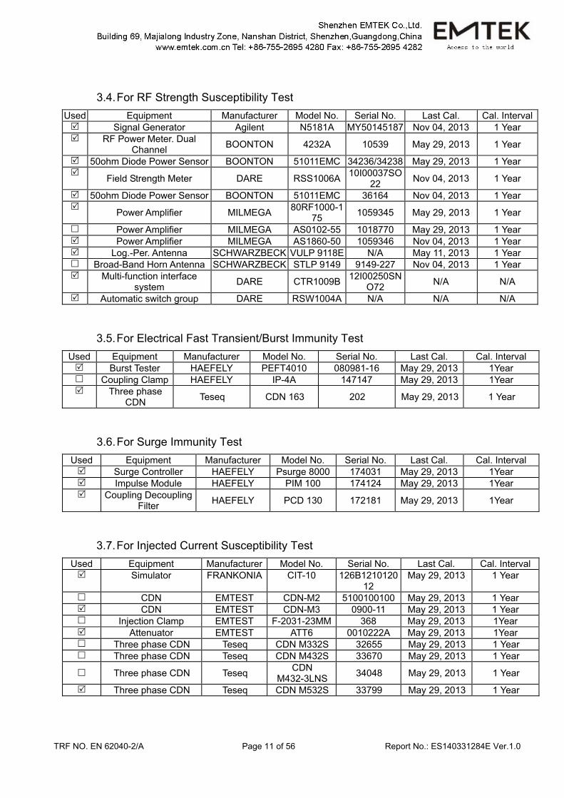
3.4. For RF Strength Susceptibility Test Used Equipment Manufacturer Model No. Serial No. Last Cal. Cal. Interval
Signal Generator Agilent N5181A MY50145187 Nov 04, 2013 1 Year RF Power Meter. Dual
Channel BOONTON 4232A 10539 May 29, 2013 1 Year
50ohm Diode Power Sensor BOONTON 51011EMC 34236/34238 May 29, 2013 1 Year Field Strength Meter DARE RSS1006A 10I00037SO
22 Nov 04, 2013 1 Year
50ohm Diode Power Sensor BOONTON 51011EMC 36164 Nov 04, 2013 1 Year Power Amplifier MILMEGA 80RF1000-1
75 1059345 May 29, 2013 1 Year
Power Amplifier MILMEGA AS0102-55 1018770 May 29, 2013 1 Year Power Amplifier MILMEGA AS1860-50 1059346 Nov 04, 2013 1 Year Log.-Per. Antenna SCHWARZBECK VULP 9118E N/A May 11, 2013 1 Year Broad-Band Horn Antenna SCHWARZBECK STLP 9149 9149-227 Nov 04, 2013 1 Year Multi-function interface
system DARE CTR1009B 12I00250SNO72 N/A N/A
Automatic switch group DARE RSW1004A N/A N/A N/A
3.5. For Electrical Fast Transient/Burst Immunity Test Used Equipment Manufacturer Model No. Serial No. Last Cal. Cal. Interval
Burst Tester HAEFELY PEFT4010 080981-16 May 29, 2013 1Year Coupling Clamp HAEFELY IP-4A 147147 May 29, 2013 1Year Three phase
CDN Teseq CDN 163 202 May 29, 2013 1 Year
3.6. For Surge Immunity Test Used Equipment Manufacturer Model No. Serial No. Last Cal. Cal. Interval
Surge Controller HAEFELY Psurge 8000 174031 May 29, 2013 1Year Impulse Module HAEFELY PIM 100 174124 May 29, 2013 1Year Coupling Decoupling
Filter HAEFELY PCD 130 172181 May 29, 2013 1Year
3.7. For Injected Current Susceptibility Test Used Equipment Manufacturer Model No. Serial No. Last Cal. Cal. Interval
Simulator FRANKONIA CIT-10 126B121012012
May 29, 2013 1 Year
CDN EMTEST CDN-M2 5100100100 May 29, 2013 1 Year CDN EMTEST CDN-M3 0900-11 May 29, 2013 1 Year Injection Clamp EMTEST F-2031-23MM 368 May 29, 2013 1Year Attenuator EMTEST ATT6 0010222A May 29, 2013 1Year Three phase CDN Teseq CDN M332S 32655 May 29, 2013 1 Year Three phase CDN Teseq CDN M432S 33670 May 29, 2013 1 Year
Three phase CDN Teseq CDN M432-3LNS 34048 May 29, 2013 1 Year
Three phase CDN Teseq CDN M532S 33799 May 29, 2013 1 Year
TRF NO. EN 62040-2/A Page 12 of 56 Report No.: ES140331284E Ver.1.0
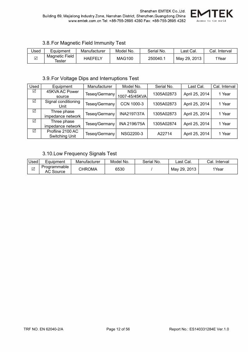
3.8. For Magnetic Field Immunity Test Used Equipment Manufacturer Model No. Serial No. Last Cal. Cal. Interval
Magnetic Field Tester HAEFELY MAG100 250040.1 May 29, 2013 1Year
3.9. For Voltage Dips and Interruptions Test Used Equipment Manufacturer Model No. Serial No. Last Cal. Cal. Interval
45KVA AC Power source Teseq/Germany NSG
1007-45/45KVA 1305A02873 April 25, 2014 1 Year
Signal conditioning Unit Teseq/Germany CCN 1000-3 1305A02873 April 25, 2014 1 Year
Three phase impedance network Teseq/Germany INA2197/37A 1305A02873 April 25, 2014 1 Year
Three phase impedance network Teseq/Germany INA 2196/75A 1305A02874 April 25, 2014 1 Year
Profline 2100 AC Switching Unit Teseq/Germany NSG2200-3 A22714 April 25, 2014 1 Year
3.10.Low Frequency Signals Test Used Equipment Manufacturer Model No. Serial No. Last Cal. Cal. Interval
Programmable AC Source CHROMA 6530 / May 29, 2013 1Year
TRF NO. EN 62040-2/A Page 13 of 56 Report No.: ES140331284E Ver.1.0
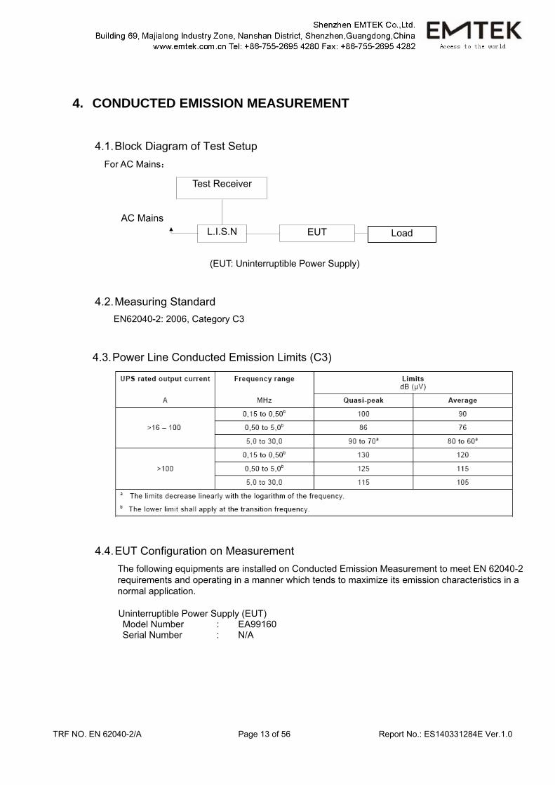
4. CONDUCTED EMISSION MEASUREMENT
4.1. Block Diagram of Test Setup For AC Mains:
(EUT: Uninterruptible Power Supply)
4.2. Measuring Standard EN62040-2: 2006, Category C3
4.3. Power Line Conducted Emission Limits (C3)
4.4. EUT Configuration on Measurement The following equipments are installed on Conducted Emission Measurement to meet EN 62040-2 requirements and operating in a manner which tends to maximize its emission characteristics in a normal application.
Uninterruptible Power Supply (EUT) Model Number : EA99160 Serial Number : N/A
AC Mains L.I.S.N
Test Receiver
EUT Load
TRF NO. EN 62040-2/A Page 14 of 56 Report No.: ES140331284E Ver.1.0
4.5. Operating Condition of EUT 4.5.1. Setup the EUT as shown on Section 4.1.
4.5.2. Turn on the power of all equipments.
4.5.3. Let the EUT work in measuring mode (Line mode) and measure it.
4.6. Test Procedure The EUT is put on the plane 0.1m high above the ground by insulating support and connected to the AC mains through Line Impedance Stability Network (L.I.S.N). This provided a 50ohm coupling impedance for the tested equipments. Both sides of AC line are investigated to find out the maximum conducted emission according to the EN62040-2 regulations during conducted emission measurement. The bandwidth of the field strength meter (R&S Test Receiver ESCS30) is set at 9kHz in 150kHz~30MHz and 200Hz in 9kHz~150kHz. The frequency range from 150kHz to 30MHz is investigated.
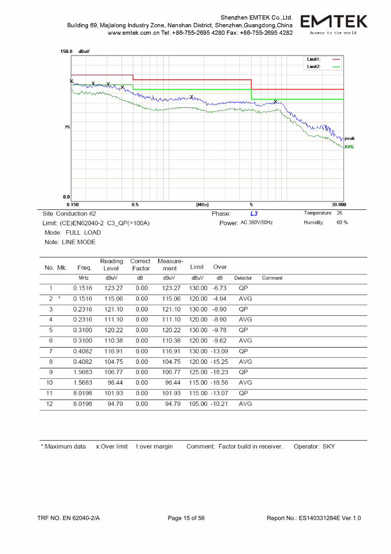
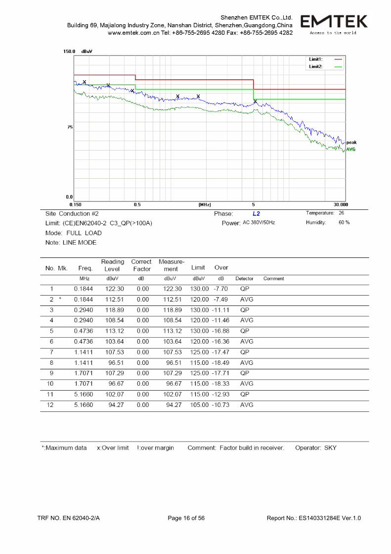
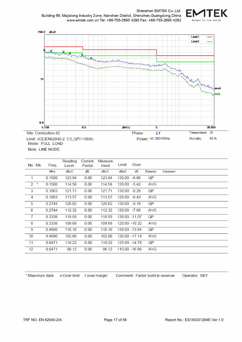
4.7. Measuring Results PASS. Please refer to the following pages.
TRF NO. EN 62040-2/A Page 15 of 56 Report No.: ES140331284E Ver.1.0
TRF NO. EN 62040-2/A Page 16 of 56 Report No.: ES140331284E Ver.1.0
TRF NO. EN 62040-2/A Page 17 of 56 Report No.: ES140331284E Ver.1.0
TRF NO. EN 62040-2/A Page 18 of 56 Report No.: ES140331284E Ver.1.0
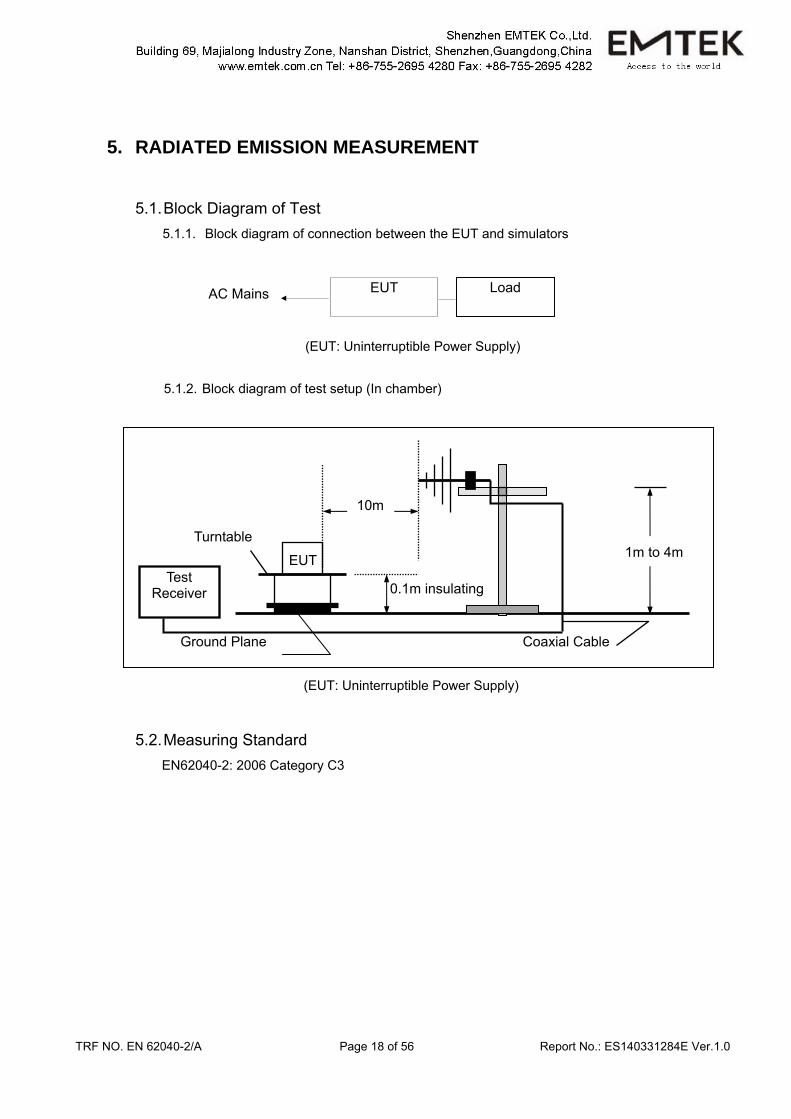
5. RADIATED EMISSION MEASUREMENT
5.1. Block Diagram of Test 5.1.1. Block diagram of connection between the EUT and simulators
(EUT: Uninterruptible Power Supply)
5.1.2. Block diagram of test setup (In chamber)
(EUT: Uninterruptible Power Supply)
5.2. Measuring Standard EN62040-2: 2006 Category C3
1m to 4m
Test Receiver
EUT
10m
0.1m insulating
Turntable
Coaxial Cable Ground Plane
AC Mains EUT Load
TRF NO. EN 62040-2/A Page 19 of 56 Report No.: ES140331284E Ver.1.0
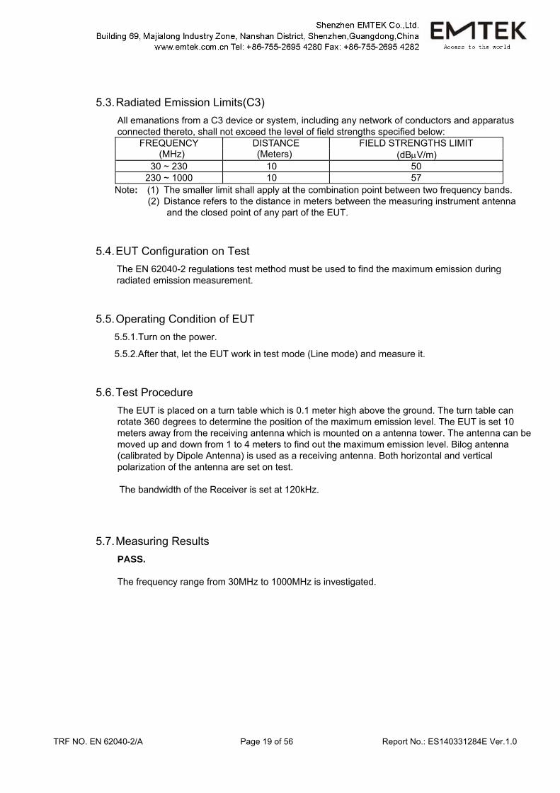
5.3. Radiated Emission Limits(C3) All emanations from a C3 device or system, including any network of conductors and apparatus connected thereto, shall not exceed the level of field strengths specified below:
FREQUENCY DISTANCE FIELD STRENGTHS LIMIT (MHz) (Meters) (dBμV/m)
30 ~ 230 10 50 230 ~ 1000 10 57
Note: (1) The smaller limit shall apply at the combination point between two frequency bands. (2) Distance refers to the distance in meters between the measuring instrument antenna
and the closed point of any part of the EUT.
5.4. EUT Configuration on Test The EN 62040-2 regulations test method must be used to find the maximum emission during radiated emission measurement.
5.5. Operating Condition of EUT 5.5.1.Turn on the power.
5.5.2.After that, let the EUT work in test mode (Line mode) and measure it.
5.6. Test Procedure The EUT is placed on a turn table which is 0.1 meter high above the ground. The turn table can rotate 360 degrees to determine the position of the maximum emission level. The EUT is set 10 meters away from the receiving antenna which is mounted on a antenna tower. The antenna can be moved up and down from 1 to 4 meters to find out the maximum emission level. Bilog antenna (calibrated by Dipole Antenna) is used as a receiving antenna. Both horizontal and vertical polarization of the antenna are set on test. The bandwidth of the Receiver is set at 120kHz.
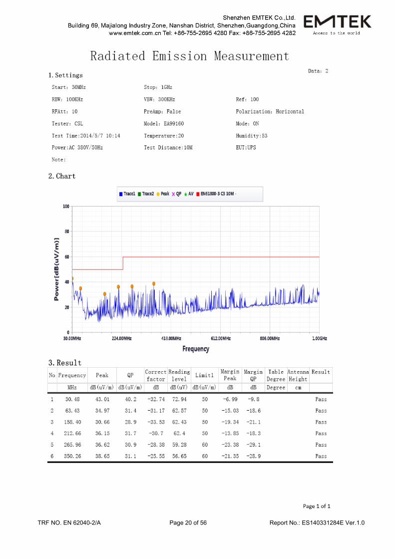
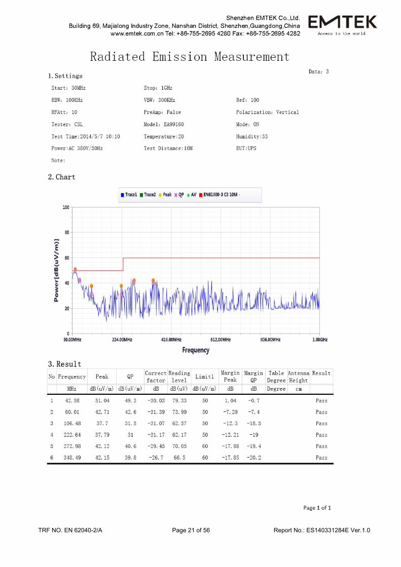
5.7. Measuring Results PASS. The frequency range from 30MHz to 1000MHz is investigated.
TRF NO. EN 62040-2/A Page 20 of 56 Report No.: ES140331284E Ver.1.0
TRF NO. EN 62040-2/A Page 21 of 56 Report No.: ES140331284E Ver.1.0
TRF NO. EN 62040-2/A Page 22 of 56 Report No.: ES140331284E Ver.1.0
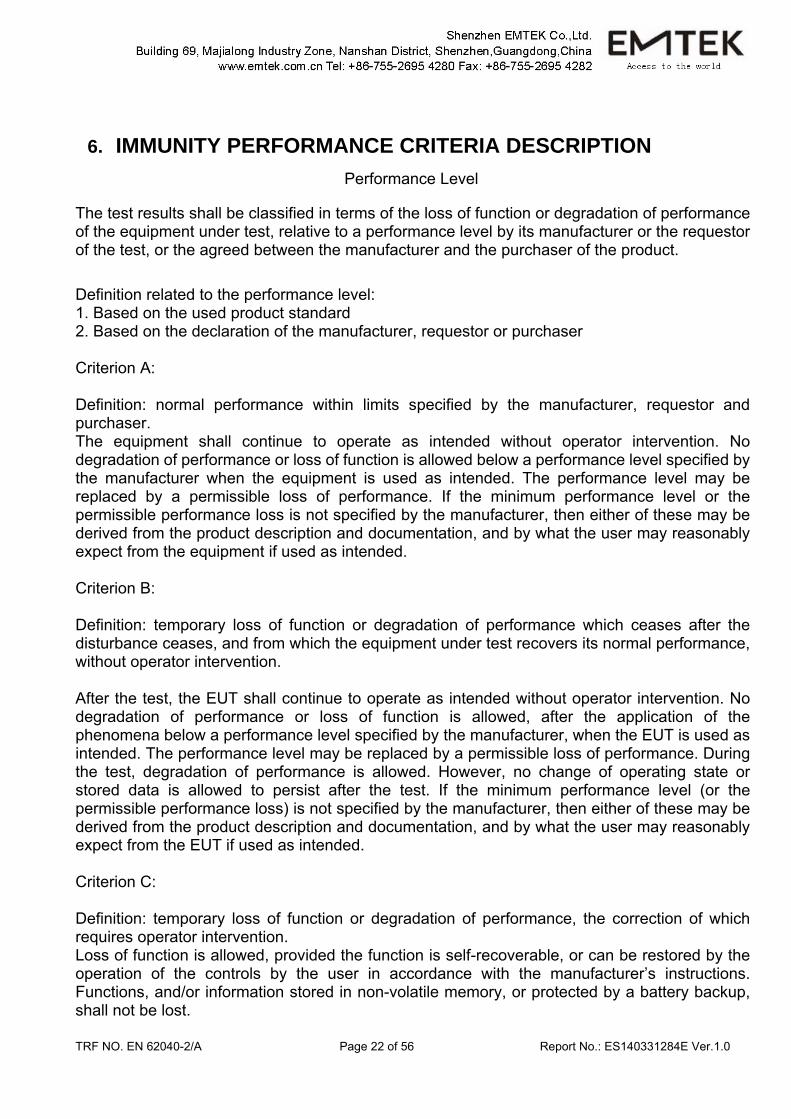
6. IMMUNITY PERFORMANCE CRITERIA DESCRIPTION Performance Level
The test results shall be classified in terms of the loss of function or degradation of performance of the equipment under test, relative to a performance level by its manufacturer or the requestor of the test, or the agreed between the manufacturer and the purchaser of the product. Definition related to the performance level: 1. Based on the used product standard 2. Based on the declaration of the manufacturer, requestor or purchaser Criterion A: Definition: normal performance within limits specified by the manufacturer, requestor and purchaser. The equipment shall continue to operate as intended without operator intervention. No degradation of performance or loss of function is allowed below a performance level specified by the manufacturer when the equipment is used as intended. The performance level may be replaced by a permissible loss of performance. If the minimum performance level or the permissible performance loss is not specified by the manufacturer, then either of these may be derived from the product description and documentation, and by what the user may reasonably expect from the equipment if used as intended. Criterion B: Definition: temporary loss of function or degradation of performance which ceases after the disturbance ceases, and from which the equipment under test recovers its normal performance, without operator intervention. After the test, the EUT shall continue to operate as intended without operator intervention. No degradation of performance or loss of function is allowed, after the application of the phenomena below a performance level specified by the manufacturer, when the EUT is used as intended. The performance level may be replaced by a permissible loss of performance. During the test, degradation of performance is allowed. However, no change of operating state or stored data is allowed to persist after the test. If the minimum performance level (or the permissible performance loss) is not specified by the manufacturer, then either of these may be derived from the product description and documentation, and by what the user may reasonably expect from the EUT if used as intended. Criterion C: Definition: temporary loss of function or degradation of performance, the correction of which requires operator intervention. Loss of function is allowed, provided the function is self-recoverable, or can be restored by the operation of the controls by the user in accordance with the manufacturer’s instructions. Functions, and/or information stored in non-volatile memory, or protected by a battery backup, shall not be lost.
TRF NO. EN 62040-2/A Page 23 of 56 Report No.: ES140331284E Ver.1.0
Criterion D Definition: loss of function or degradation of performance, which is not recoverable, owing to damage to hardware or software, or loss of data.
TRF NO. EN 62040-2/A Page 24 of 56 Report No.: ES140331284E Ver.1.0
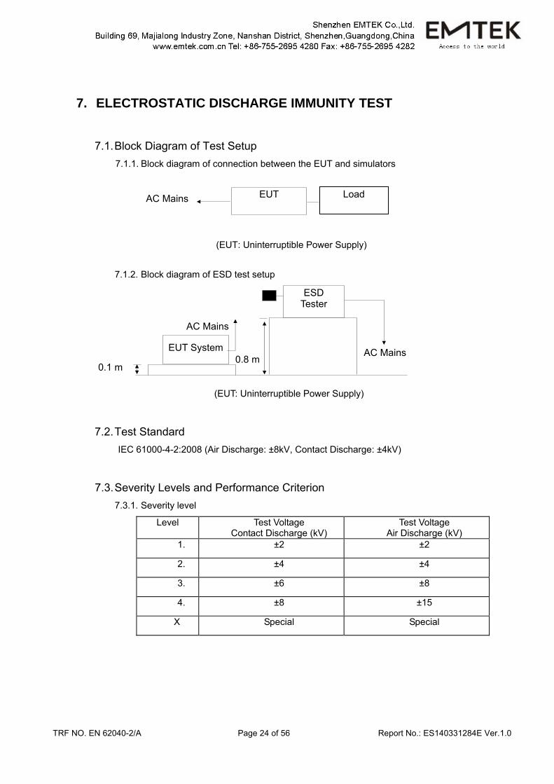
7. ELECTROSTATIC DISCHARGE IMMUNITY TEST
7.1. Block Diagram of Test Setup 7.1.1. Block diagram of connection between the EUT and simulators
(EUT: Uninterruptible Power Supply)
7.1.2. Block diagram of ESD test setup
(EUT: Uninterruptible Power Supply)
7.2. Test Standard IEC 61000-4-2:2008 (Air Discharge: ±8kV, Contact Discharge: ±4kV)
7.3. Severity Levels and Performance Criterion 7.3.1. Severity level
Level Test Voltage Contact Discharge (kV)
Test Voltage Air Discharge (kV)
1. ±2 ±2
2. ±4 ±4
3. ±6 ±8
4. ±8 ±15
X Special Special
AC Mains EUT Load
EUT System
AC Mains
AC Mains
ESD Tester
0.1 m 0.8 m
TRF NO. EN 62040-2/A Page 25 of 56 Report No.: ES140331284E Ver.1.0
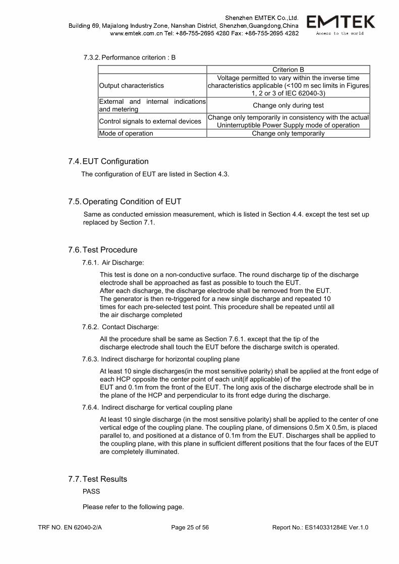
7.3.2. Performance criterion : B
Criterion B
Output characteristics Voltage permitted to vary within the inverse time
characteristics applicable (<100 m sec limits in Figures 1, 2 or 3 of IEC 62040-3)
External and internal indications and metering Change only during test
Control signals to external devices Change only temporarily in consistency with the actual Uninterruptible Power Supply mode of operation
Mode of operation Change only temporarily
7.4. EUT Configuration The configuration of EUT are listed in Section 4.3.
7.5. Operating Condition of EUT Same as conducted emission measurement, which is listed in Section 4.4. except the test set up replaced by Section 7.1.
7.6. Test Procedure 7.6.1. Air Discharge:
This test is done on a non-conductive surface. The round discharge tip of the discharge electrode shall be approached as fast as possible to touch the EUT. After each discharge, the discharge electrode shall be removed from the EUT. The generator is then re-triggered for a new single discharge and repeated 10 times for each pre-selected test point. This procedure shall be repeated until all the air discharge completed
7.6.2. Contact Discharge:
All the procedure shall be same as Section 7.6.1. except that the tip of the discharge electrode shall touch the EUT before the discharge switch is operated.
7.6.3. Indirect discharge for horizontal coupling plane
At least 10 single discharges(in the most sensitive polarity) shall be applied at the front edge of each HCP opposite the center point of each unit(if applicable) of the EUT and 0.1m from the front of the EUT. The long axis of the discharge electrode shall be in the plane of the HCP and perpendicular to its front edge during the discharge.
7.6.4. Indirect discharge for vertical coupling plane
At least 10 single discharge (in the most sensitive polarity) shall be applied to the center of one vertical edge of the coupling plane. The coupling plane, of dimensions 0.5m X 0.5m, is placed parallel to, and positioned at a distance of 0.1m from the EUT. Discharges shall be applied to the coupling plane, with this plane in sufficient different positions that the four faces of the EUT are completely illuminated.
7.7. Test Results PASS Please refer to the following page.
TRF NO. EN 62040-2/A Page 26 of 56 Report No.: ES140331284E Ver.1.0
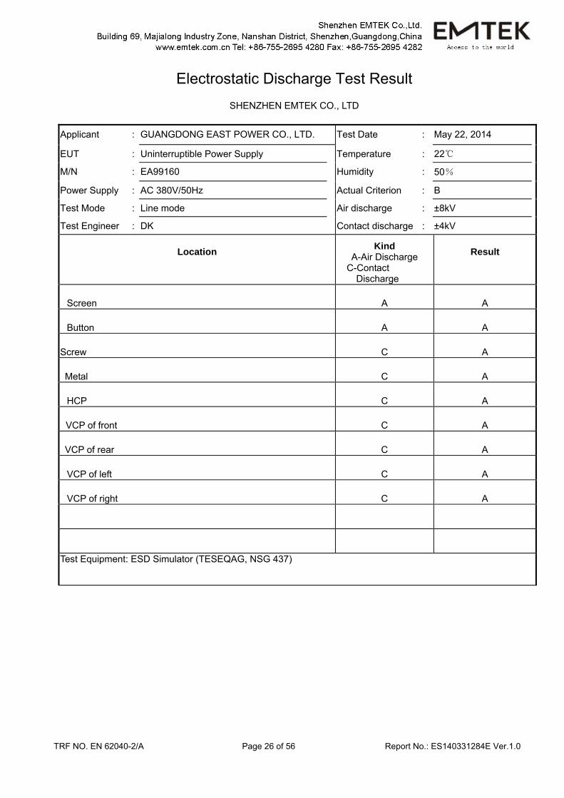
Electrostatic Discharge Test Result
SHENZHEN EMTEK CO., LTD
Applicant : GUANGDONG EAST POWER CO., LTD. Test Date : May 22, 2014
EUT : Uninterruptible Power Supply Temperature : 22
M/N : EA99160 Humidity : 50%
Power Supply : AC 380V/50Hz Actual Criterion : B
Test Mode : Line mode Air discharge : ±8kV
Test Engineer : DK Contact discharge : ±4kV
Location Kind A-Air Discharge
C-Contact Discharge
Result
Screen A A
Button A A
Screw C A
Metal C A
HCP C A
VCP of front C A
VCP of rear C A
VCP of left C A
VCP of right C A
Test Equipment: ESD Simulator (TESEQAG, NSG 437)
TRF NO. EN 62040-2/A Page 27 of 56 Report No.: ES140331284E Ver.1.0
8. RF FIELD STRENGTH SUSCEPTIBILITY TEST
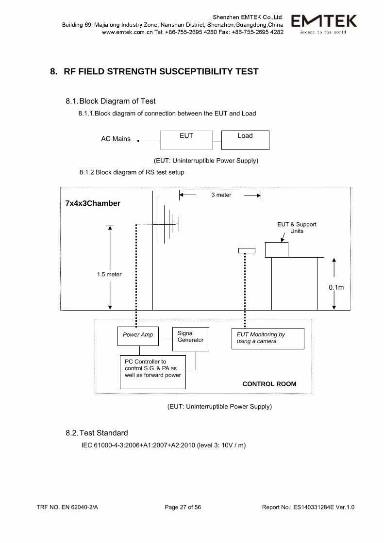
8.1. Block Diagram of Test 8.1.1.Block diagram of connection between the EUT and Load
(EUT: Uninterruptible Power Supply)
8.1.2.Block diagram of RS test setup
(EUT: Uninterruptible Power Supply)
8.2. Test Standard IEC 61000-4-3:2006+A1:2007+A2:2010 (level 3: 10V / m)
0.1m
CONTROL ROOM
Power Amp Signal Generator
EUT Monitoring by using a camera
PC Controller to control S.G. & PA as well as forward power
7x4x3Chamber
EUT & Support Units
3 meter
1.5 meter
AC Mains EUT Load
TRF NO. EN 62040-2/A Page 28 of 56 Report No.: ES140331284E Ver.1.0
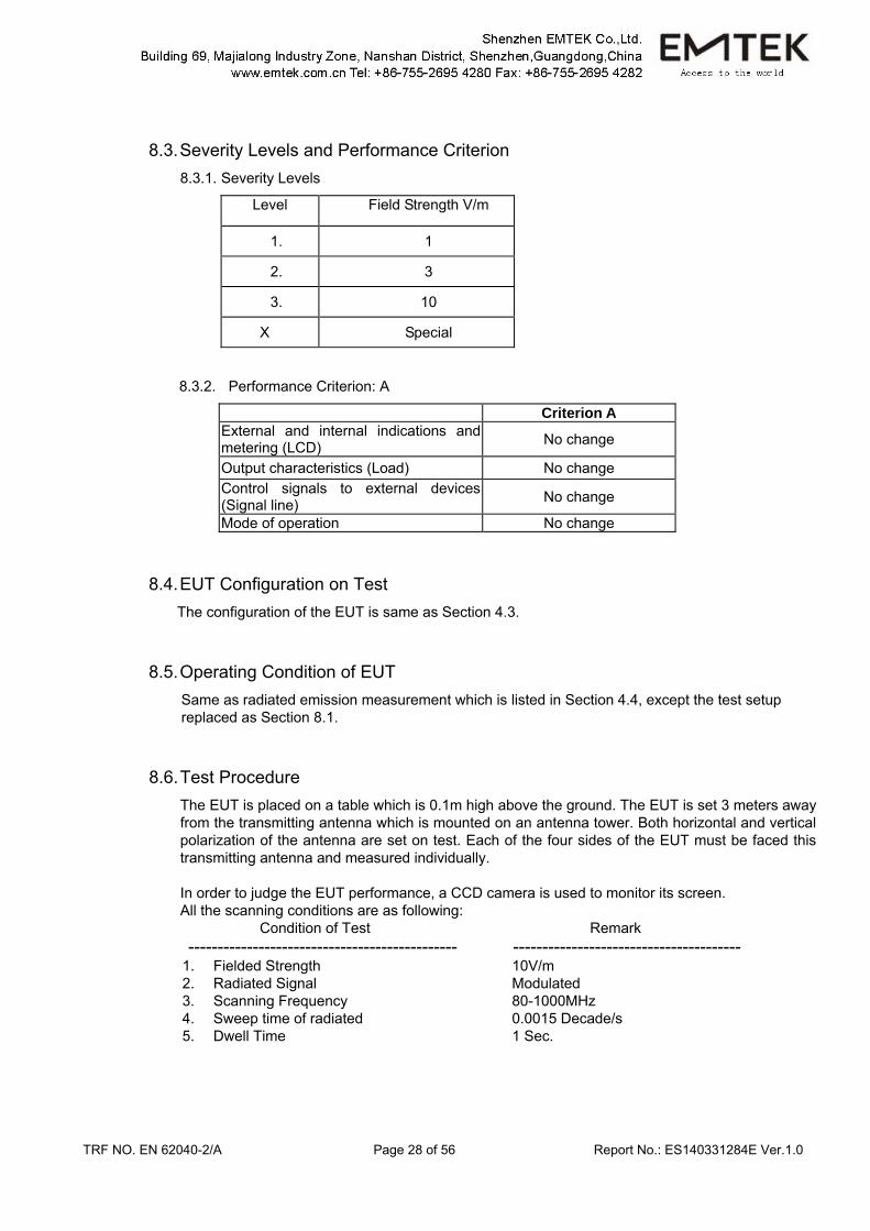
8.3. Severity Levels and Performance Criterion 8.3.1. Severity Levels
Level Field Strength V/m
1. 1
2. 3
3. 10
X Special
8.3.2. Performance Criterion: A
Criterion A External and internal indications and metering (LCD) No change
Output characteristics (Load) No change Control signals to external devices (Signal line) No change
Mode of operation No change
8.4. EUT Configuration on Test The configuration of the EUT is same as Section 4.3.
8.5. Operating Condition of EUT Same as radiated emission measurement which is listed in Section 4.4, except the test setup replaced as Section 8.1.
8.6. Test Procedure The EUT is placed on a table which is 0.1m high above the ground. The EUT is set 3 meters away from the transmitting antenna which is mounted on an antenna tower. Both horizontal and vertical polarization of the antenna are set on test. Each of the four sides of the EUT must be faced this transmitting antenna and measured individually. In order to judge the EUT performance, a CCD camera is used to monitor its screen. All the scanning conditions are as following:
Condition of Test Remark ---------------------------------------------- ---------------------------------------
1. Fielded Strength 2. Radiated Signal 3. Scanning Frequency 4. Sweep time of radiated 5. Dwell Time
10V/m Modulated 80-1000MHz 0.0015 Decade/s 1 Sec.
TRF NO. EN 62040-2/A Page 29 of 56 Report No.: ES140331284E Ver.1.0
8.7. Test Results PASS. Please refer to the following page.
TRF NO. EN 62040-2/A Page 30 of 56 Report No.: ES140331284E Ver.1.0
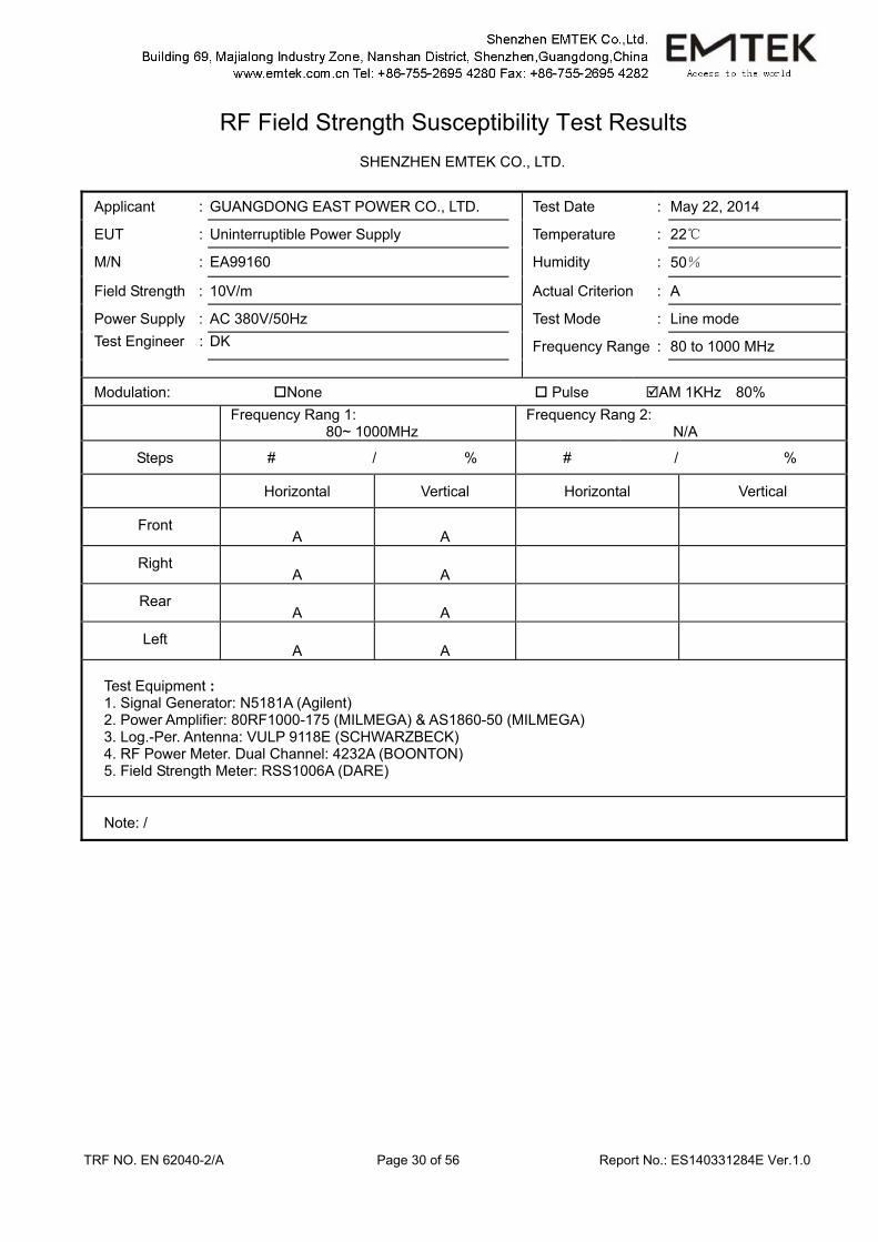
RF Field Strength Susceptibility Test Results
SHENZHEN EMTEK CO., LTD.
Applicant : GUANGDONG EAST POWER CO., LTD. Test Date : May 22, 2014
EUT : Uninterruptible Power Supply Temperature : 22
M/N : EA99160 Humidity : 50%
Field Strength : 10V/m Actual Criterion : A
Power Supply : AC 380V/50Hz Test Mode : Line mode Test Engineer : DK Frequency Range : 80 to 1000 MHz Modulation: None Pulse AM 1KHz 80%
Frequency Rang 1: 80~ 1000MHz
Frequency Rang 2: N/A
Steps # / % # / %
Horizontal Vertical Horizontal Vertical
Front A A
Right A A
Rear A A
Left A A
Test Equipment : 1. Signal Generator: N5181A (Agilent) 2. Power Amplifier: 80RF1000-175 (MILMEGA) & AS1860-50 (MILMEGA) 3. Log.-Per. Antenna: VULP 9118E (SCHWARZBECK) 4. RF Power Meter. Dual Channel: 4232A (BOONTON) 5. Field Strength Meter: RSS1006A (DARE)
Note: /
TRF NO. EN 62040-2/A Page 31 of 56 Report No.: ES140331284E Ver.1.0
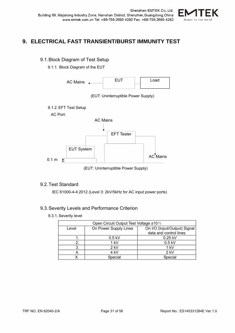
9. ELECTRICAL FAST TRANSIENT/BURST IMMUNITY TEST
9.1. Block Diagram of Test Setup 9.1.1. Block Diagram of the EUT
(EUT: Uninterruptible Power Supply)
9.1.2. EFT Test Setup
AC Port:
(EUT: Uninterruptible Power Supply)
9.2. Test Standard IEC 61000-4-4:2012 (Level 3: 2kV/5kHz for AC input power ports)
9.3. Severity Levels and Performance Criterion 9.3.1. Severity level
Open Circuit Output Test Voltage ±10% Level On Power Supply Lines On I/O (Input/Output) Signal
data and control lines 1. 0.5 kV 0.25 kV 2. 1 kV 0.5 kV 3. 2 kV 1 kV 4. 4 kV 2 kV
X Special Special
AC Mains EUT Load
AC Mains
AC Mains
EFT Tester
0.1 m
EUT System
TRF NO. EN 62040-2/A Page 32 of 56 Report No.: ES140331284E Ver.1.0
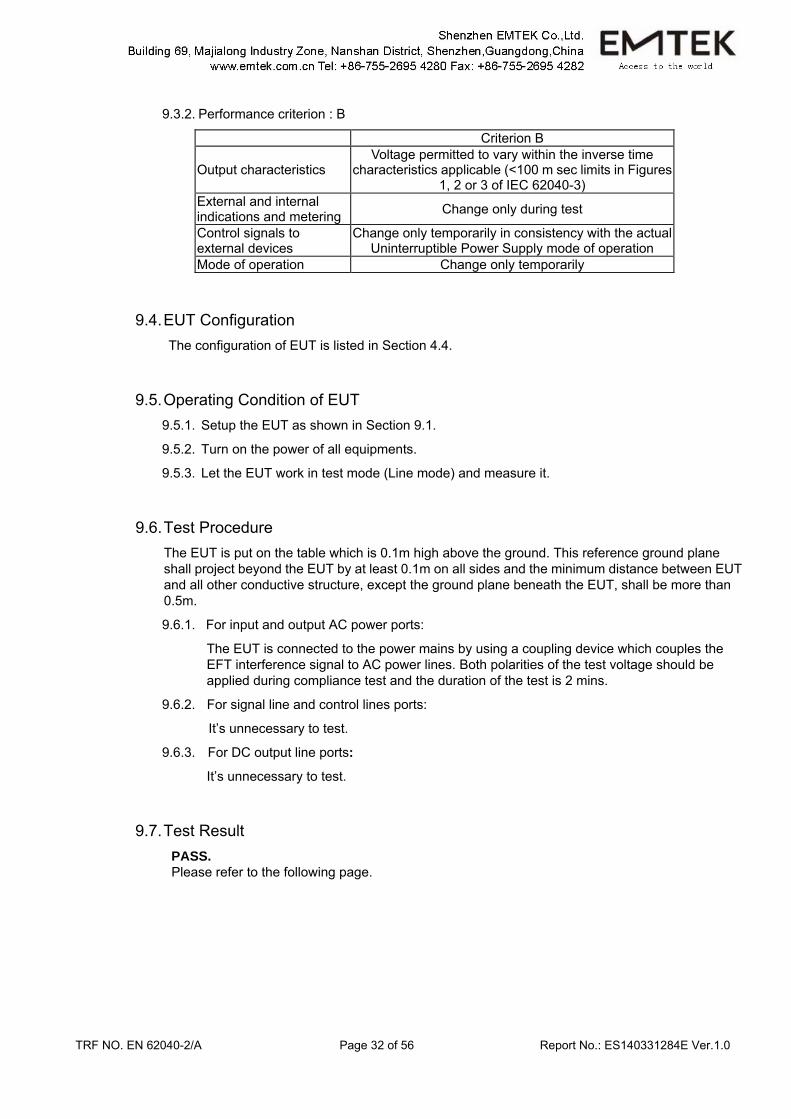
9.3.2. Performance criterion : B
Criterion B
Output characteristics Voltage permitted to vary within the inverse time
characteristics applicable (<100 m sec limits in Figures 1, 2 or 3 of IEC 62040-3)
External and internal indications and metering Change only during test
Control signals to external devices
Change only temporarily in consistency with the actual Uninterruptible Power Supply mode of operation
Mode of operation Change only temporarily
9.4. EUT Configuration The configuration of EUT is listed in Section 4.4.
9.5. Operating Condition of EUT 9.5.1. Setup the EUT as shown in Section 9.1.
9.5.2. Turn on the power of all equipments.
9.5.3. Let the EUT work in test mode (Line mode) and measure it.
9.6. Test Procedure The EUT is put on the table which is 0.1m high above the ground. This reference ground plane shall project beyond the EUT by at least 0.1m on all sides and the minimum distance between EUT and all other conductive structure, except the ground plane beneath the EUT, shall be more than 0.5m.
9.6.1. For input and output AC power ports:
The EUT is connected to the power mains by using a coupling device which couples the EFT interference signal to AC power lines. Both polarities of the test voltage should be applied during compliance test and the duration of the test is 2 mins.
9.6.2. For signal line and control lines ports:
It’s unnecessary to test.
9.6.3. For DC output line ports:
It’s unnecessary to test.
9.7. Test Result PASS. Please refer to the following page.

TRF NO. EN 62040-2/A Page 33 of 56 Report No.: ES140331284E Ver.1.0
Electrical Fast Transient/Burst Test Results
SHENZHEN EMTEK CO., LTD.
Standard IEC 61000-4-4 Result: PASS / FAIL
Applicant : GUANGDONG EAST POWER CO., LTD. EUT : Uninterruptible Power Supply M/N : EA99160
Input Voltage : AC 380V/50Hz Actual Criterion : B Ambient Condition : 23 55% RH
Operation Mode: Line mode
Line : AC input power ports Line : Signal I/O Cable
Coupling : Direct Coupling : Capacitive
Test Time : 120s
Line Test Voltage Result(+) Result(-)
L1, L2, L3, N, PE 2kV A A
L1-L2, L1-L3, L2-L3, L1-N, L2-N, L3-N 2kV A A
L1-PE, L2-PE, L3-PE, N-PE 2kV A A L1-L2-PE, L1-L3-PE, L2-L3-PE,
L1-L2-L3, L1-L2-N, L1-L3-N, L2-L3-N, L1-N-PE, L2-N-PE, L3-N-PE
2kV A A
L1-L2-L3-PE, L1-L2-L3-N, L1-L2-N-PE, L1-L3-N-PE, L2-L3-N-PE 2kV A A
AC output power ports: L1, L2, L3, N, PE 2kV A A
L1-L2, L1-L3, L2-L3, L1-N, L2-N, L3-N 2kV A A
L1-PE, L2-PE, L3-PE, N-PE 2kV A A L1-L2-PE, L1-L3-PE, L2-L3-PE,
L1-L2-L3, L1-L2-N, L1-L3-N, L2-L3-N, L1-N-PE, L2-N-PE, L3-N-PE
2kV A A
L1-L2-L3-PE, L1-L2-L3-N, L1-L2-N-PE, L1-L3-N-PE,
L2-L3-N-PE 2kV A A
Note:
Test Equipment Burst Tester Model : PEFT 4010
TRF NO. EN 62040-2/A Page 34 of 56 Report No.: ES140331284E Ver.1.0
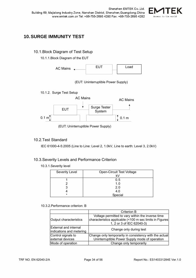
10. SURGE IMMUNITY TEST
10.1.Block Diagram of Test Setup 10.1.1.Block Diagram of the EUT
(EUT: Uninterruptible Power Supply)
10.1.2. Surge Test Setup
(EUT: Uninterruptible Power Supply)
10.2.Test Standard IEC 61000-4-5:2005 (Line to Line: Level 2, 1.0kV, Line to earth: Level 3, 2.0kV)
10.3.Severity Levels and Performance Criterion 10.3.1.Severity level
Severity Level Open-Circuit Test Voltage kV
1 2 3 4 *
0. 5 1. 0 2. 0 4.0
Special
10.3.2.Performance criterion: B
Criterion B
Output characteristics Voltage permitted to vary within the inverse time
characteristics applicable (<100 m sec limits in Figures 1, 2 or 3 of IEC 62040-3)
External and internal indications and metering Change only during test
Control signals to external devices
Change only temporarily in consistency with the actual Uninterruptible Power Supply mode of operation
Mode of operation Change only temporarily
AC Mains EUT Load
AC Mains AC Mains
EUT Surge Tester System
0.1 m0.1 m
TRF NO. EN 62040-2/A Page 35 of 56 Report No.: ES140331284E Ver.1.0
10.4.EUT Configuration The configuration of EUT is listed in Section 4.3.
10.5.Operating Condition of EUT 10.5.1.Setup the EUT as shown in Section 10.1.
10.5.2.Turn on the power of all equipments.
10.5.3.Let the EUT work in test mode (Line mode) and measure it.
10.6.Test Procedure 1) Set up the EUT and test generator as shown on Section 10.1.2.
For line to line coupling mode, provide 1kV 1.2/50us voltage surge. For line to earth mode, provide 2kV 1.2/50us voltage surge. (At open-circuit condition) and 8/20us current surge to EUT selected points.
2) At least 5 positive and 5 negative (polarity) tests with a maximum 1/min repetition rate are conducted during test.
3) Different phase angles are done individually. 4) Record the EUT operating situation during compliance test and decide the EUT immunity
criterion for above each test.
10.7.Test Result PASS.
Please refer to the following page.
TRF NO. EN 62040-2/A Page 36 of 56 Report No.: ES140331284E Ver.1.0
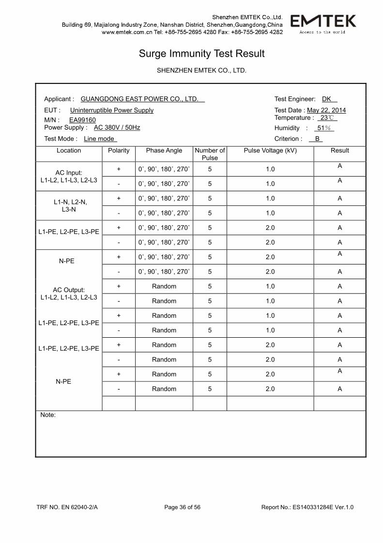
Surge Immunity Test Result
SHENZHEN EMTEK CO., LTD.
Applicant : GUANGDONG EAST POWER CO., LTD. Test Engineer: DK
EUT : Uninterruptible Power Supply Test Date : May 22, 2014 M/N : EA99160 Temperature : 23 Power Supply : AC 380V / 50Hz Humidity : 51% Test Mode : Line mode Criterion : B
Location Polarity Phase Angle Number of Pulse
Pulse Voltage (kV)
Result
AC Input: L1-L2, L1-L3, L2-L3
+ 0˚, 90˚, 180˚, 270˚ 5 1.0 A
- 0˚, 90˚, 180˚, 270˚ 5 1.0 A
L1-N, L2-N, L3-N
+ 0˚, 90˚, 180˚, 270˚ 5 1.0 A
- 0˚, 90˚, 180˚, 270˚ 5 1.0 A
L1-PE, L2-PE, L3-PE + 0˚, 90˚, 180˚, 270˚ 5 2.0 A
- 0˚, 90˚, 180˚, 270˚ 5 2.0 A
N-PE
+ 0˚, 90˚, 180˚, 270˚ 5 2.0 A
- 0˚, 90˚, 180˚, 270˚ 5 2.0 A
AC Output: L1-L2, L1-L3, L2-L3
+ Random 5 1.0 A
- Random 5 1.0 A
L1-PE, L2-PE, L3-PE + Random 5 1.0 A
- Random 5 1.0 A
L1-PE, L2-PE, L3-PE
+ Random 5 2.0 A
- Random 5 2.0 A
N-PE + Random 5 2.0 A
- Random 5 2.0 A
Note:
TRF NO. EN 62040-2/A Page 37 of 56 Report No.: ES140331284E Ver.1.0
11. INJECTED CURRENTS SUSCEPTIBILITY TEST
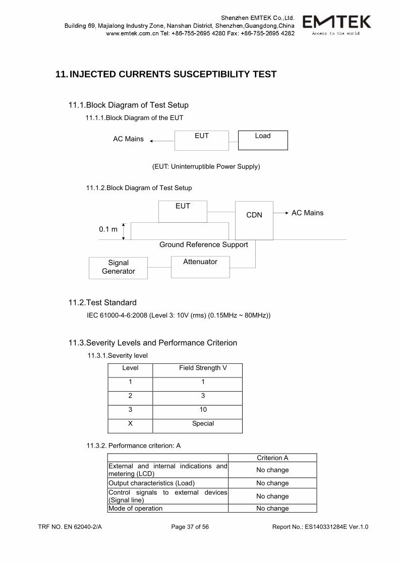
11.1.Block Diagram of Test Setup 11.1.1.Block Diagram of the EUT
(EUT: Uninterruptible Power Supply) 11.1.2. Block Diagram of Test Setup
11.2.Test Standard IEC 61000-4-6:2008 (Level 3: 10V (rms) (0.15MHz ~ 80MHz))
11.3.Severity Levels and Performance Criterion 11.3.1.Severity level
11.3.2. Performance criterion: A
Criterion A External and internal indications and metering (LCD) No change
Output characteristics (Load) No change Control signals to external devices (Signal line) No change
Mode of operation No change
Level Field Strength V
1 1
2 3
3 10
X Special
Ground Reference Support
EUT CDN AC Mains
Signal Generator
Attenuator
0.1 m
AC Mains EUT Load
TRF NO. EN 62040-2/A Page 38 of 56 Report No.: ES140331284E Ver.1.0
11.4.EUT Configuration The configuration of EUT is listed in Section 4.3.
11.5.Operating Condition of EUT 11.5.1.Setup the EUT as shown in Section 11.1.
11.5.2.Turn on the power of all equipments.
11.5.3.Let the EUT work in test mode (Line mode) and measure it.
11.6.Test Procedure 1) Set up the EUT, CDN and test generators as shown on Section 11.1.2. 2) Let the EUT work in test mode and measure it. 3) The EUT are placed on an insulating support 0.1m high above a ground reference plane.
CDN (coupling and decoupling device) is placed on the ground plane about 0.3m from EUT. Cables between CDN and EUT are as short as possible, and their height above the ground reference plane shall be between 30 and 50 mm (where possible).
4) The disturbance signal described below is injected to EUT through CDN. 5) The EUT operates within its operational mode(s) under intended climatic conditions after
power on. 6) The frequency range is swept from 150KHz to80MHz using 10V signal level, and with the
disturbance signal 80% amplitude modulated with a 1KHz sine wave. 7) The rate of sweep shall not exceed 1.5*10-3decades/s. Where the frequency is swept
incrementally, the step size shall not exceed 1% of the start and thereafter 1% of the preceding frequency value.
8) Recording the EUT operating situation during compliance testing and decide the EUT immunity criterion.
11.7.Test Results PASS. Please refer to the following page.
TRF NO. EN 62040-2/A Page 39 of 56 Report No.: ES140331284E Ver.1.0
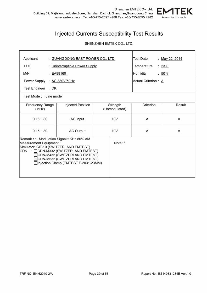
Injected Currents Susceptibility Test Results
SHENZHEN EMTEK CO., LTD.
Applicant : GUANGDONG EAST POWER CO., LTD. Test Date : May 22, 2014
EUT : Uninterruptible Power Supply Temperature : 23
M/N : EA99160 Humidity : 50%
Power Supply : AC 380V/50Hz Actual Criterion : A
Test Engineer : DK
Test Mode : Line mode
Frequency Range (MHz)
Injected Position Strength (Unmodulated)
Criterion Result
0.15 ~ 80 AC Input 10V A A
0.15 ~ 80 AC Output 10V A A
Remark : 1. Modulation Signal:1KHz 80% AM Measurement Equipment : Simulator: CIT-10 (SWITZERLAND EMTEST) CDN : CDN-M332 (SWITZERLAND EMTEST) CDN-M432 (SWITZERLAND EMTEST) CDN-M532 (SWITZERLAND EMTEST)
Injection Clamp (EMTEST F-2031-23MM)
Note: /
TRF NO. EN 62040-2/A Page 40 of 56 Report No.: ES140331284E Ver.1.0
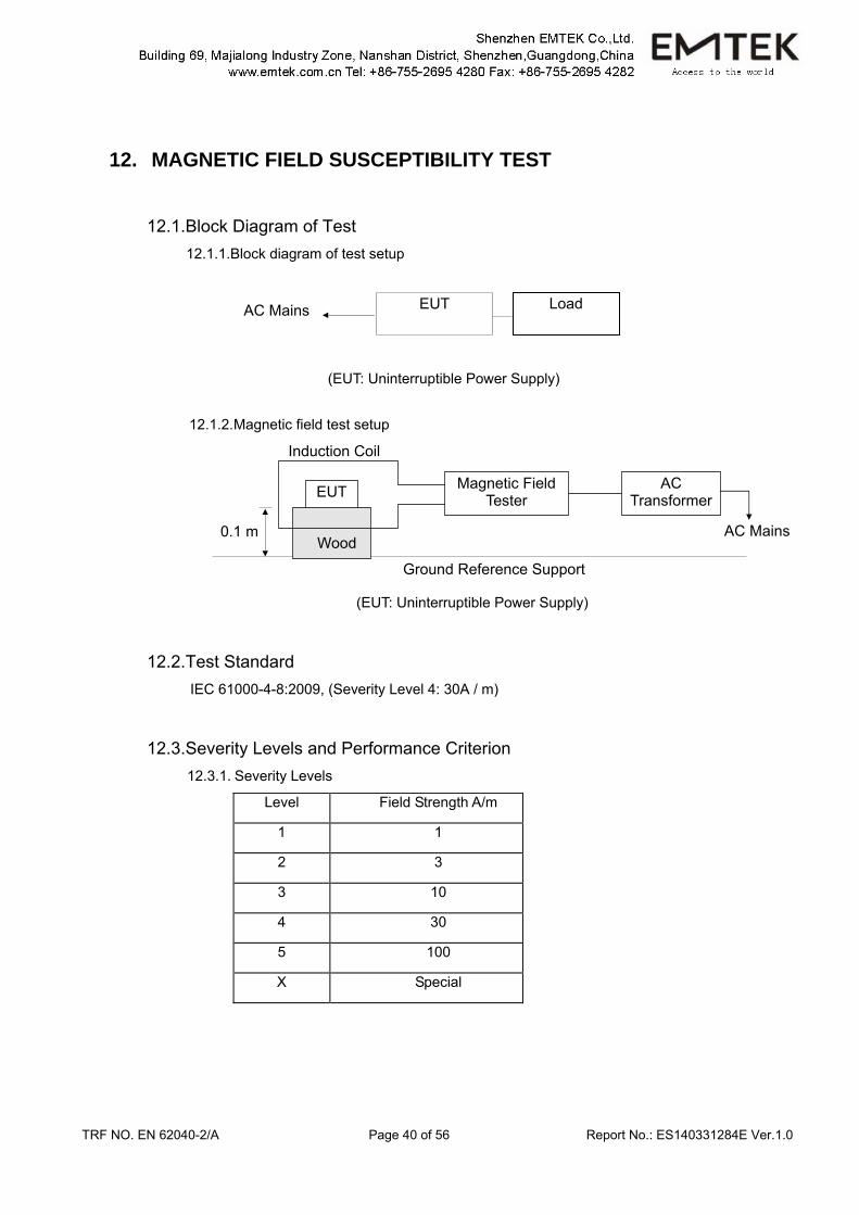
12. MAGNETIC FIELD SUSCEPTIBILITY TEST
12.1.Block Diagram of Test 12.1.1.Block diagram of test setup
(EUT: Uninterruptible Power Supply)
12.1.2. Magnetic field test setup
(EUT: Uninterruptible Power Supply)
12.2.Test Standard IEC 61000-4-8:2009, (Severity Level 4: 30A / m)
12.3.Severity Levels and Performance Criterion 12.3.1. Severity Levels
Level Field Strength A/m
1 1
2 3
3 10
4 30
5 100
X Special
Ground Reference Support
EUT
AC Mains 0.1 m
Magnetic Field Tester
AC Transformer
Wood
Induction Coil
AC Mains EUT Load
TRF NO. EN 62040-2/A Page 41 of 56 Report No.: ES140331284E Ver.1.0
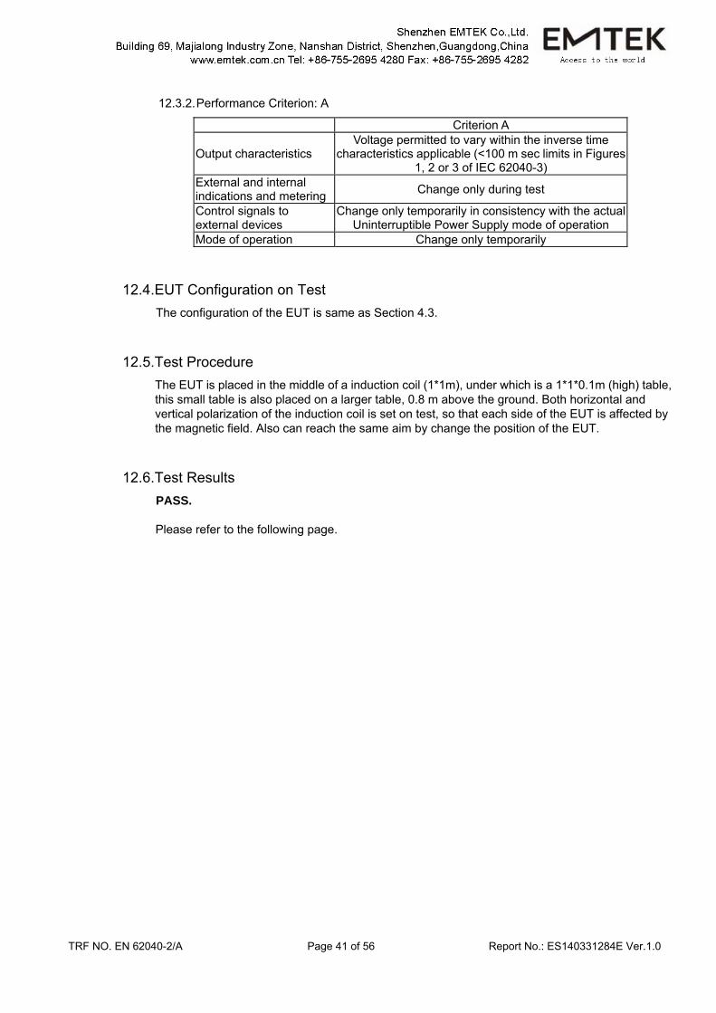
12.3.2. Performance Criterion: A
Criterion A
Output characteristics Voltage permitted to vary within the inverse time
characteristics applicable (<100 m sec limits in Figures 1, 2 or 3 of IEC 62040-3)
External and internal indications and metering Change only during test
Control signals to external devices
Change only temporarily in consistency with the actual Uninterruptible Power Supply mode of operation
Mode of operation Change only temporarily
12.4.EUT Configuration on Test The configuration of the EUT is same as Section 4.3.
12.5.Test Procedure The EUT is placed in the middle of a induction coil (1*1m), under which is a 1*1*0.1m (high) table, this small table is also placed on a larger table, 0.8 m above the ground. Both horizontal and vertical polarization of the induction coil is set on test, so that each side of the EUT is affected by the magnetic field. Also can reach the same aim by change the position of the EUT.
12.6.Test Results PASS. Please refer to the following page.
TRF NO. EN 62040-2/A Page 42 of 56 Report No.: ES140331284E Ver.1.0
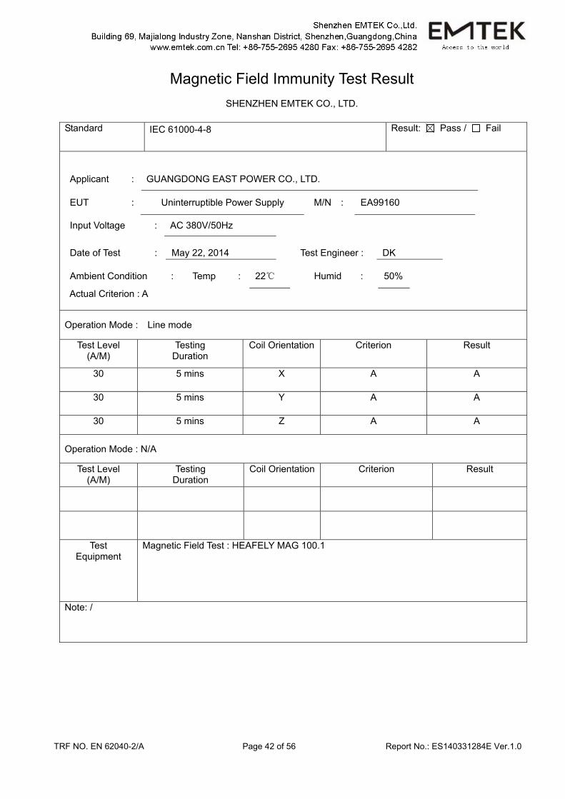
Magnetic Field Immunity Test Result
SHENZHEN EMTEK CO., LTD.
Standard IEC 61000-4-8 Result: Pass / Fail
Input Voltage : AC 380V/50Hz
Date of Test : May 22, 2014 Test Engineer : DK
Ambient Condition : Temp : 22 Humid : 50%
Actual Criterion : A
Applicant : GUANGDONG EAST POWER CO., LTD.
EUT : Uninterruptible Power Supply M/N : EA99160
Operation Mode : Line mode
Test Level (A/M)
Testing Duration
Coil Orientation Criterion Result
30 5 mins X A A
30 5 mins Y A A
30 5 mins Z A A
Operation Mode : N/A
Test Level (A/M)
Testing Duration
Coil Orientation Criterion Result
Test Equipment
Magnetic Field Test : HEAFELY MAG 100.1
Note: /
TRF NO. EN 62040-2/A Page 43 of 56 Report No.: ES140331284E Ver.1.0
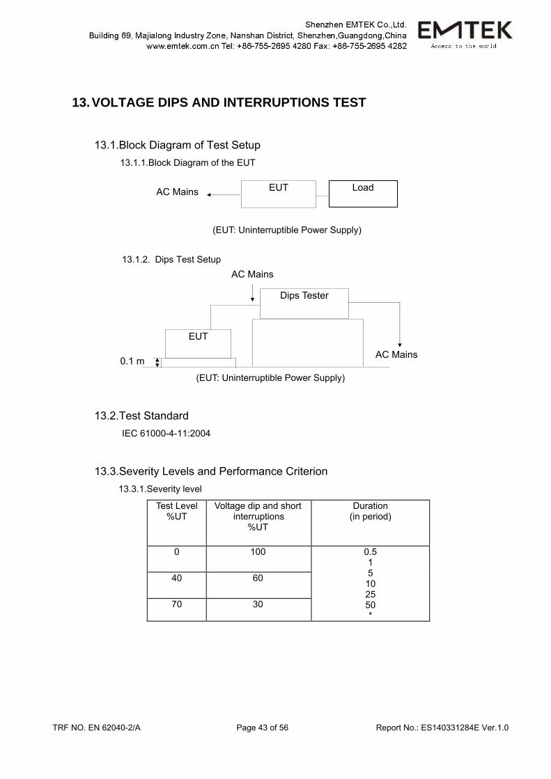
13. VOLTAGE DIPS AND INTERRUPTIONS TEST
13.1.Block Diagram of Test Setup 13.1.1.Block Diagram of the EUT
(EUT: Uninterruptible Power Supply)
13.1.2. Dips Test Setup
(EUT: Uninterruptible Power Supply)
13.2.Test Standard IEC 61000-4-11:2004
13.3.Severity Levels and Performance Criterion 13.3.1.Severity level
Test Level %UT
Voltage dip and short interruptions
%UT
Duration (in period)
0 100 0.5 1 5 10 25 50 *
40 60
70 30
AC Mains EUT Load
AC Mains
AC Mains
Dips Tester
0.1 m
EUT
TRF NO. EN 62040-2/A Page 44 of 56 Report No.: ES140331284E Ver.1.0
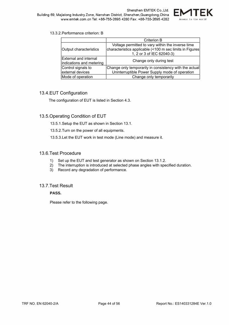
13.3.2. Performance criterion: B
Criterion B
Output characteristics Voltage permitted to vary within the inverse time
characteristics applicable (<100 m sec limits in Figures 1, 2 or 3 of IEC 62040-3)
External and internal indications and metering Change only during test
Control signals to external devices
Change only temporarily in consistency with the actual Uninterruptible Power Supply mode of operation
Mode of operation Change only temporarily
13.4.EUT Configuration The configuration of EUT is listed in Section 4.3.
13.5.Operating Condition of EUT 13.5.1. Setup the EUT as shown in Section 13.1.
13.5.2. Turn on the power of all equipments.
13.5.3. Let the EUT work in test mode (Line mode) and measure it.
13.6.Test Procedure 1) Set up the EUT and test generator as shown on Section 13.1.2. 2) The interruption is introduced at selected phase angles with specified duration. 3) Record any degradation of performance.
13.7.Test Result PASS. Please refer to the following page.
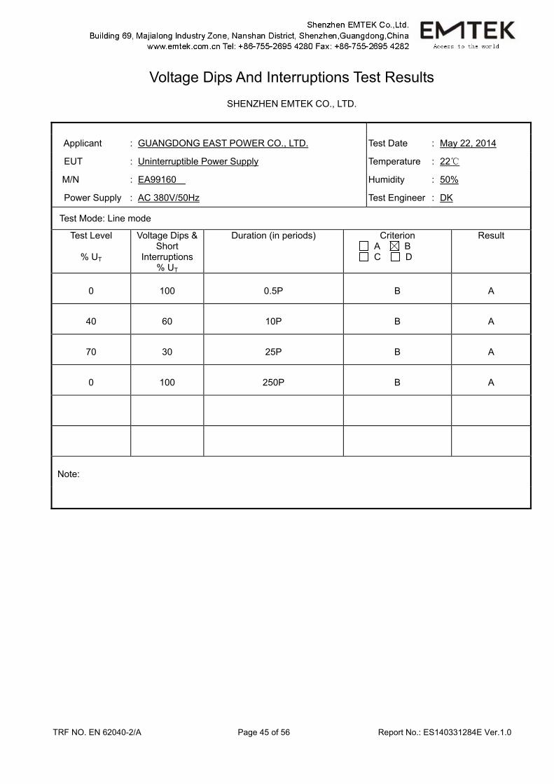
TRF NO. EN 62040-2/A Page 45 of 56 Report No.: ES140331284E Ver.1.0
Voltage Dips And Interruptions Test Results
SHENZHEN EMTEK CO., LTD.
Applicant : GUANGDONG EAST POWER CO., LTD. Test Date : May 22, 2014
EUT : Uninterruptible Power Supply Temperature : 22
M/N : EA99160 Humidity : 50%
Power Supply : AC 380V/50Hz Test Engineer : DK
Test Mode: Line mode
Test Level
% UT
Voltage Dips & Short
Interruptions % UT
Duration (in periods) Criterion A B C D
Result
0 100 0.5P B A
40 60 10P B A
70 30 25P B A
0 100 250P B A
Note:
TRF NO. EN 62040-2/A Page 46 of 56 Report No.: ES140331284E Ver.1.0
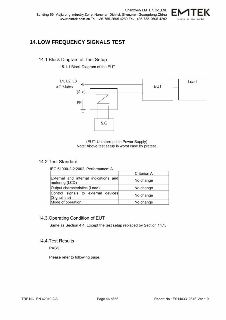
14. LOW FREQUENCY SIGNALS TEST
14.1.Block Diagram of Test Setup 15.1.1 Block Diagram of the EUT
(EUT: Uninterruptible Power Supply) Note: Above test setup is worst case by pretest.
14.2.Test Standard IEC 61000-2-2:2002, Performance: A Criterion A External and internal indications and metering (LCD) No change
Output characteristics (Load) No change Control signals to external devices (Signal line) No change
Mode of operation No change
14.3.Operating Condition of EUT Same as Section 4.4, Except the test setup replaced by Section 14.1.
14.4.Test Results PASS. Please refer to following page.
EUT
Load L1, L2, L3
TRF NO. EN 62040-2/A Page 47 of 56 Report No.: ES140331284E Ver.1.0
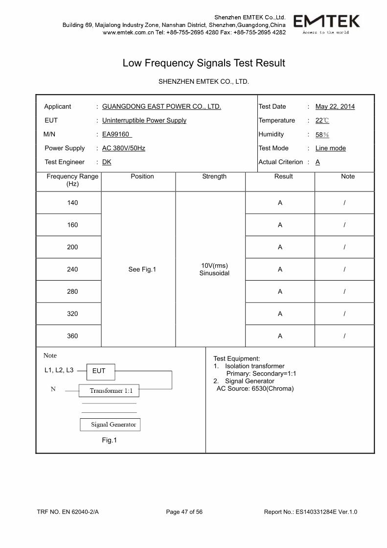
Low Frequency Signals Test Result
SHENZHEN EMTEK CO., LTD.
Applicant : GUANGDONG EAST POWER CO., LTD. Test Date : May 22, 2014
EUT : Uninterruptible Power Supply Temperature : 22
M/N : EA99160 Humidity : 58%
Power Supply : AC 380V/50Hz Test Mode : Line mode
Test Engineer : DK Actual Criterion : A
Frequency Range (Hz)
Position Strength Result Note
140
See Fig.1 10V(rms) Sinusoidal
A /
160 A /
200 A /
240 A /
280 A /
320 A /
360 A /
Test Equipment: 1. Isolation transformer
Primary: Secondary=1:1 2. Signal Generator AC Source: 6530(Chroma)
Note
Fig.1
L1, L2, L3 EUT
TRF NO. EN 62040-2/A Page 48 of 56 Report No.: ES140331284E Ver.1.0
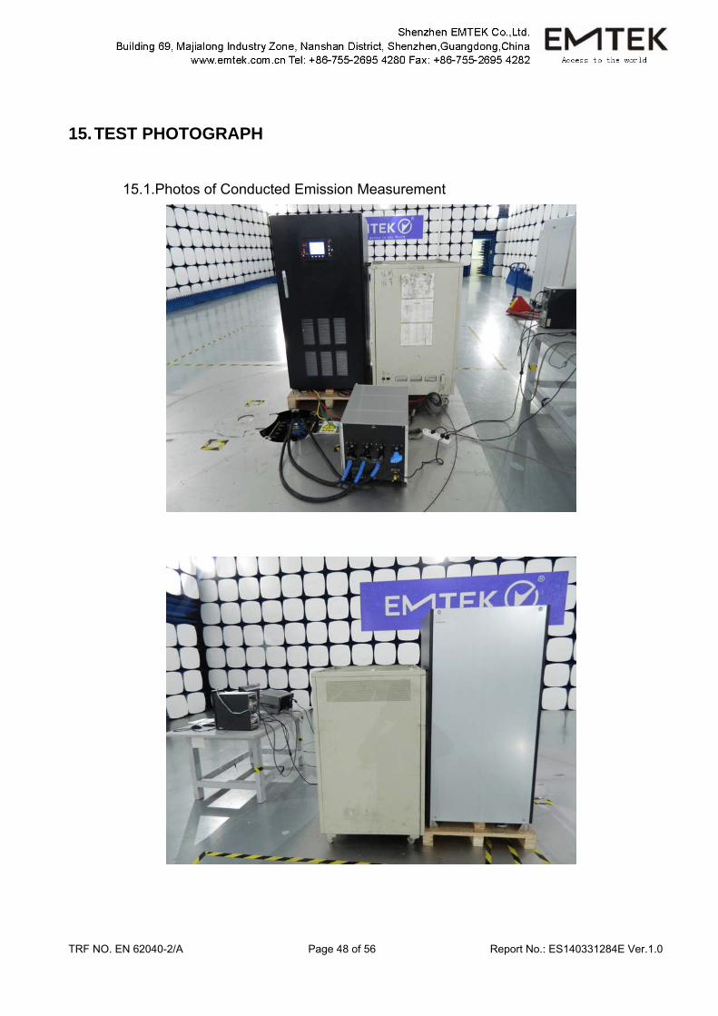
15. TEST PHOTOGRAPH
15.1.Photos of Conducted Emission Measurement
TRF NO. EN 62040-2/A Page 49 of 56 Report No.: ES140331284E Ver.1.0
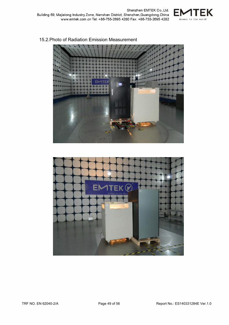
15.2.Photo of Radiation Emission Measurement
TRF NO. EN 62040-2/A Page 50 of 56 Report No.: ES140331284E Ver.1.0
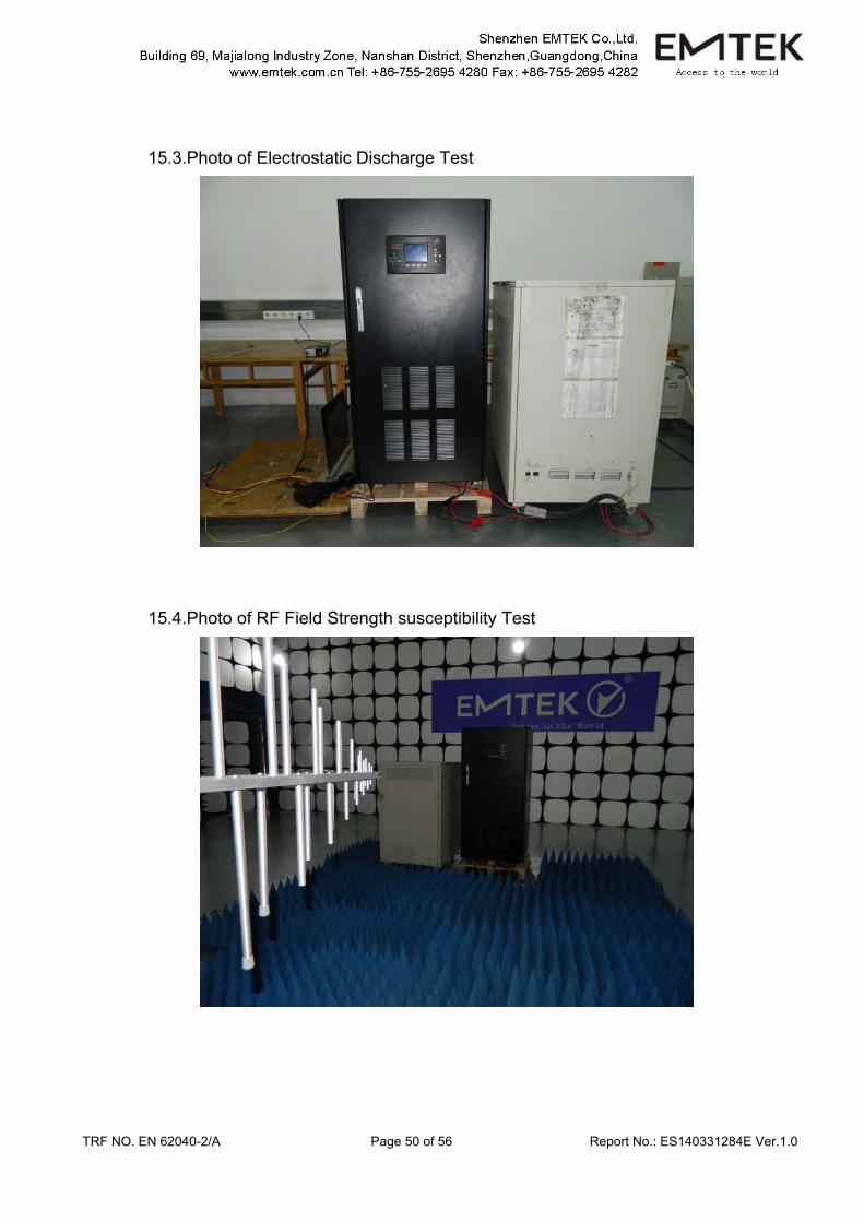
15.3.Photo of Electrostatic Discharge Test
15.4.Photo of RF Field Strength susceptibility Test
TRF NO. EN 62040-2/A Page 51 of 56 Report No.: ES140331284E Ver.1.0
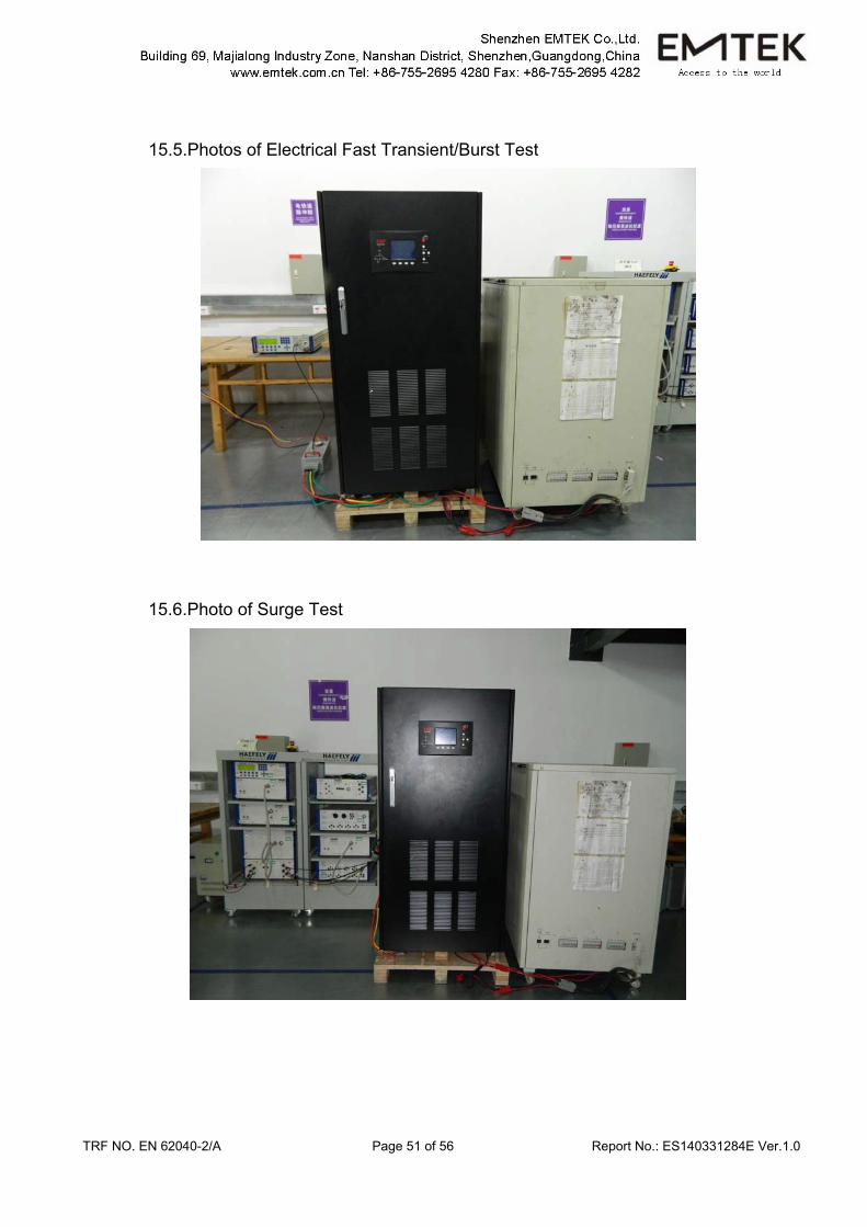
15.5.Photos of Electrical Fast Transient/Burst Test
15.6.Photo of Surge Test
TRF NO. EN 62040-2/A Page 52 of 56 Report No.: ES140331284E Ver.1.0
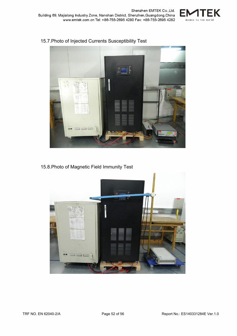
15.7.Photo of Injected Currents Susceptibility Test
15.8.Photo of Magnetic Field Immunity Test
TRF NO. EN 62040-2/A Page 53 of 56 Report No.: ES140331284E Ver.1.0
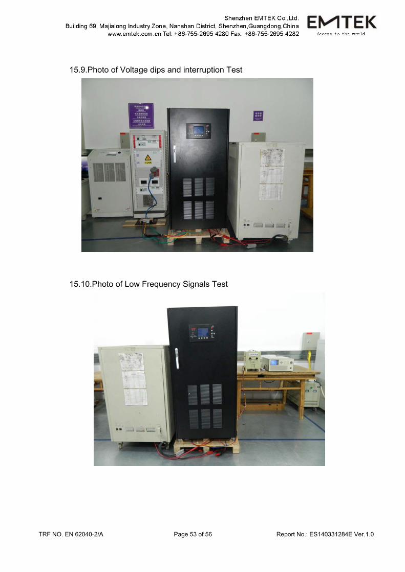
15.9.Photo of Voltage dips and interruption Test
15.10.Photo of Low Frequency Signals Test
TRF NO. EN 62040-2/A Page 54 of 56 Report No.: ES140331284E Ver.1.0
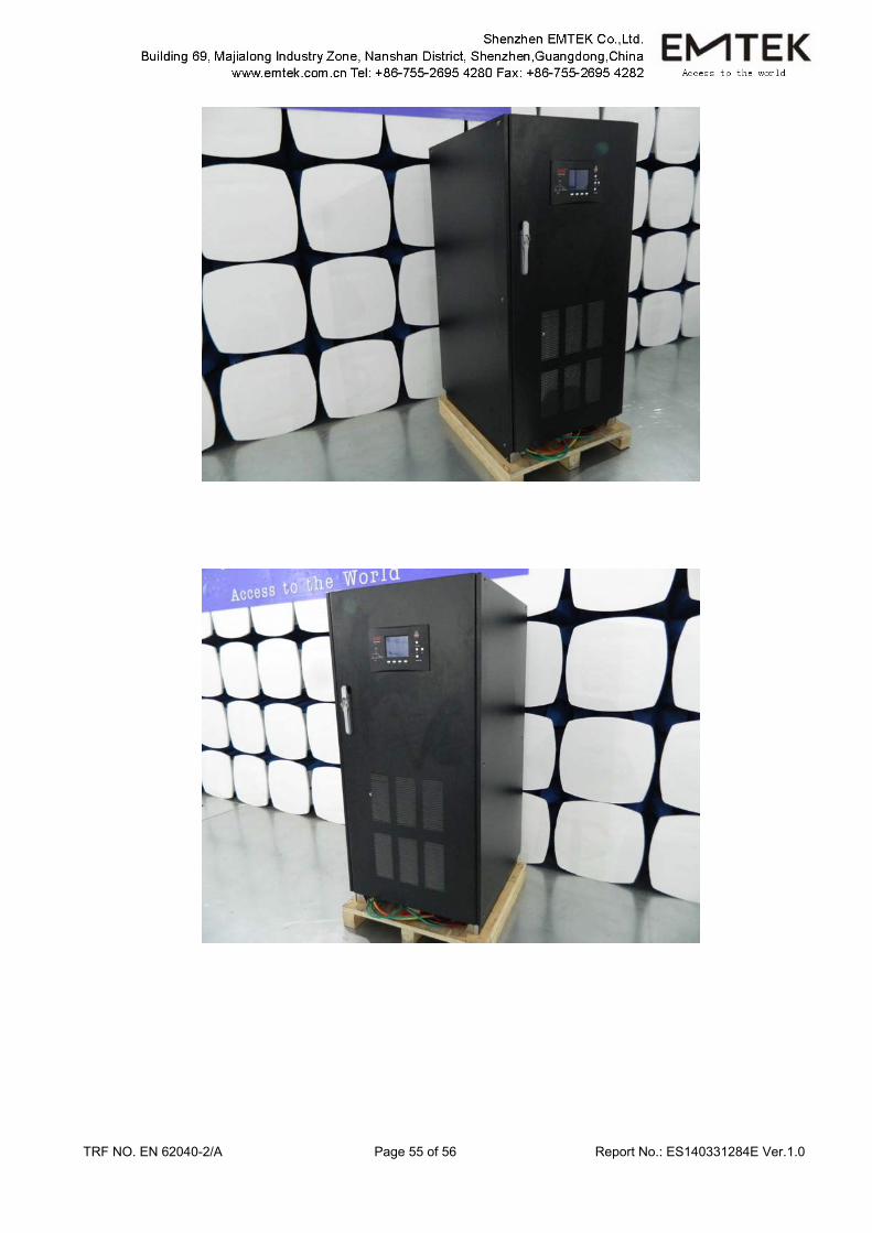
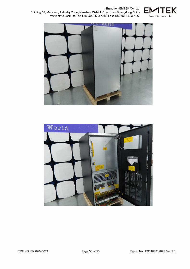
APPENDIX (Photos of EUT)
TRF NO. EN 62040-2/A Page 55 of 56 Report No.: ES140331284E Ver.1.0
TRF NO. EN 62040-2/A Page 56 of 56 Report No.: ES140331284E Ver.1.0