Embed Size (px)
Citation preview
Issue Date: 2014-10-23 Page 1 of 65 Report Reference # 14BAS08046 11
TRF No. IEC60950_1F
Test Report issued under the responsibility of:
TEST REPORT IEC 60950-1
Information technology equipment - Safety - Part 1: General requirements
Report Number. ..............................: 14BAS08046 11
Date of issue ...................................: 2014-10-23
Total number of pages.................... 65
Applicant’s name............................: Shenzhen Jinhuasheng Power Technology Co.,Ltd.
Address ...........................................: G315, Jiahuiyuan, Guihua Fangmapu Vallage, Guanlan, Baoan, Shenzhen, Guangdong, China
Test specification:
Standard ..........................................: IEC 60950-1:2005 (Second Edition) + Am 1:2009 + Am 2:2013
Test procedure................................: CB Scheme
Non-standard test method.............: N/A
Test Report Form No......................: IEC60950_1F
Test Report Form(s) Originator.....: SGS Fimko Ltd
Master TRF......................................: Dated 2014-02
Copyright © 2014 IEC System of Conformity Assessment Schemes for Electrotechnical Equipment and Components (IECEE System). All rights reserved.
This publication may be reproduced in whole or in part for non-commercial purposes as long as the IECEE is acknowledged as copyright owner and source of the material. IECEE takes no responsibility for and will not assume liability for damages resulting from the reader's interpretation of the reproduced material due to its placement and context.
If this Test Report Form is used by non-IECEE members, the IECEE/IEC logo and the reference to the CB Scheme procedure shall be removed.
This report is not valid as a CB Test Report unless signed by an approved CB Testing Laboratory and appended to a CB Test Certificate issued by an NCB in accordance with IECEE 02.
General disclaimer:
The test results presented in this report relate only to the object tested. This report shall not be reproduced, except in full, without the written approval of the Issuing CB Testing Laboratory. The authenticity of this Test Report and its contents can be verified by contacting the NCB, responsible for this Test Report.

Issue Date: 2014-10-23 Page 2 of 65 Report Reference # 14BAS08046 11
TRF No. IEC60950_1F
Test item description ..................: AC ADAPTER
Trade Mark ....................................:
Manufacturer .................................: Same as applicant
Model/Type reference ...................: RS-x/y-S335, JHS-x/y-S335, RS-x/y-S335A, JHS-x/y-S335A (x, y and A are variables, detail see model list on page 7-8)
Ratings ..........................................: Input : 100-240Vac, 50/60Hz, 1.2A max. Output: 15-24Vdc, 0.1-4.0A, 65.2W max.
Testing procedure and testing location:
CB Testing Laboratory: ATT Product Service Co., Ltd.
Testing location/ address ............................ : No. 3 ChangLianShan Industrial Park, ChangAn Town, DongGuan City, GuangDong, China
Associated CB Testing Laboratory:
Testing location/ address ............................ :
Tested by (name + signature) ..................... : Carol Xiong
Approved by (name + signature) ................ : Henry Chen
Testing procedure: TMP/CTF Stage 1:
Testing location/ address ............................ :
Tested by (name + signature) ..................... :
Approved by (name + signature) ................ :
Testing procedure: WMT/CTF Stage 2:
Testing location/ address ............................ :
Tested by (name + signature) ..................... :
Witnessed by (name + signature) ............... :
Approved by (name + signature) ................ :
Testing procedure: SMT/CTF Stage 3 or 4:
Issue Date: 2014-10-23 Page 3 of 65 Report Reference # 14BAS08046 11
TRF No. IEC60950_1F
Testing location/ address ............................ :
Tested by (name + signature) ..................... :
Witnessed by (name + signature) ............... :
Approved by (name + signature) ................ :
Supervised by (name + signature).............. :
List of Attachments (including a total number of pages in each attachment):
National Differences (41 pages) Enclosures (44 pages)
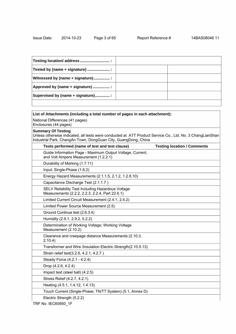
Summary Of Testing Unless otherwise indicated, all tests were conducted at ATT Product Service Co., Ltd. No. 3 ChangLianShan Industrial Park, ChangAn Town, DongGuan City, GuangDong, China
Tests performed (name of test and test clause) Testing location / Comments
Guide Information Page - Maximum Output Voltage, Current, and Volt Ampere Measurement (1.2.2.1)
Durability of Marking (1.7.11)
Input: Single-Phase (1.6.2)
Energy Hazard Measurements (2.1.1.5, 2.1.2, 1.2.8.10)
Capacitance Discharge Test (2.1.1.7 )
SELV Reliability Test Including Hazardous Voltage Measurements (2.2.2, 2.2.3, 2.2.4, Part 22 6.1)
Limited Current Circuit Measurement (2.4.1, 2.4.2)
Limited Power Source Measurement (2.5)
Ground Continue test (2.6.3.4)
Humidity (2.9.1, 2.9.2, 5.2.2)
Determination of Working Voltage; Working Voltage Measurement (2.10.2)
Clearance and creepage distance Measurements (2.10.3, 2.10.4)
Transformer and Wire /Insulation Electric Strength(2.10.5.13)
Strain relief test(3.2.6, 4.2.1, 4.2.7 )
Steady Force (4.2.1 - 4.2.4)
Drop (4.2.6, 4.2.4)
Impact test (steel ball) (4.2.5)
Stress Relief (4.2.7, 4.2.1)
Heating (4.5.1, 1.4.12, 1.4.13)
Touch Current (Single-Phase; TN/TT System) (5.1, Annex D)
Electric Strength (5.2.2)
Issue Date: 2014-10-23 Page 4 of 65 Report Reference # 14BAS08046 11
TRF No. IEC60950_1F
Component Failure (5.3.1, 5.3.4, 5.3.7)
Transformer Abnormal Operation Test(5.3.3, 5.3.7b, Annex C.1)
Power Supply Output Short-Circuit/Overload (5.3.7)
If not otherwise specified, tests were performed on models RS-04/163-S335 and RS-027/24-S335 to represent other similar models.
Summary of Compliance with National Differences:
List of countries addressed: AT, AR, AU, BE, BR, BG, CA, CH, CN, CY, CZ, DE, DK, ES, EU, FI, FR, GB, GR, HU, IE, IS, IL, IT, JP, KR, LT, LU, LV, MT, MY, NL, NO, PL, PT, RO, SE, SG, SI, SK,US
Explanation of used codes: AT=Austria, AR=Argentina, AU=Australia, BE=Belgium, BR=Brazil, BG=Bulgaria CA=Canada, CH=Switzerland, CN=China, CY=Cyprus, CZ=Czech Republic, DE=Germany, DK=Denmark, ES=Estonia, EU=European, FI=Finland, FR=France, GB=United Kingdom, GR=Greece, HU=Hungary, IE=Iceland, IS=Israel, IL=Ireland, IN=India, IT=Italy, JP=Japan, KR=Korea, LT=Latvia, LU=Lithuania, LV=Luxembourg, MT= Malta, MY=Malaysia, NL=The Netherlands, NO=Norway, PL=Poland, PT=Portugal, RO=Romania, SE=Sweden, SG=Singapore, SI=Slovenia, SK=Slovakia, US=United States of America
Issue Date: 2014-10-23 Page 5 of 65 Report Reference # 14BAS08046 11
TRF No. IEC60950_1F
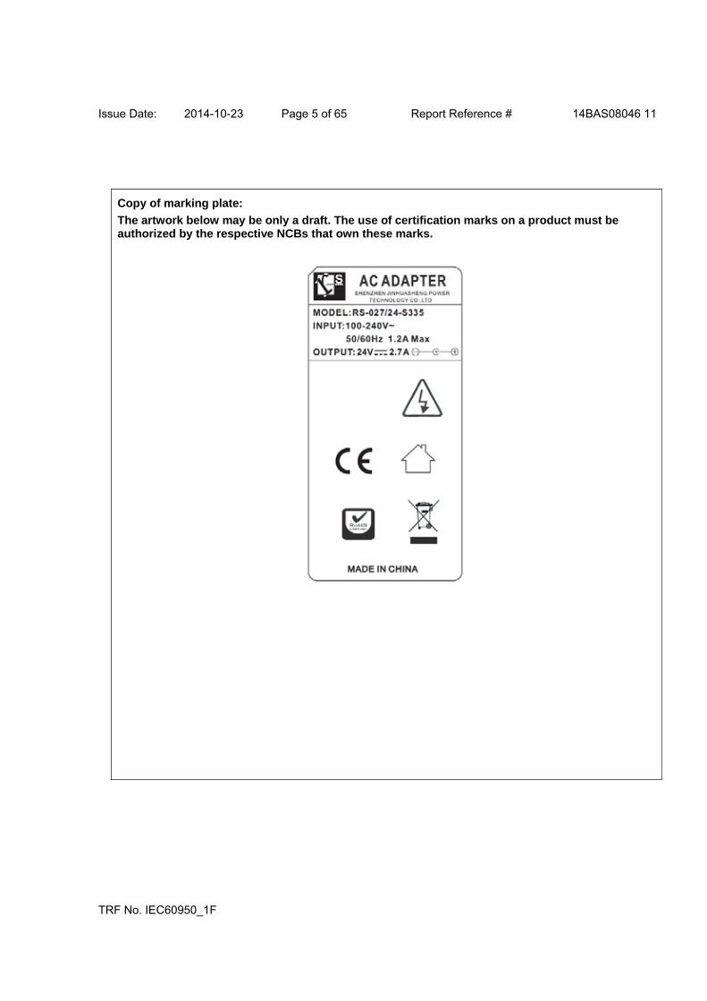
Copy of marking plate:
The artwork below may be only a draft. The use of certification marks on a product must be authorized by the respective NCBs that own these marks.
Issue Date: 2014-10-23 Page 6 of 65 Report Reference # 14BAS08046 11
TRF No. IEC60950_1F
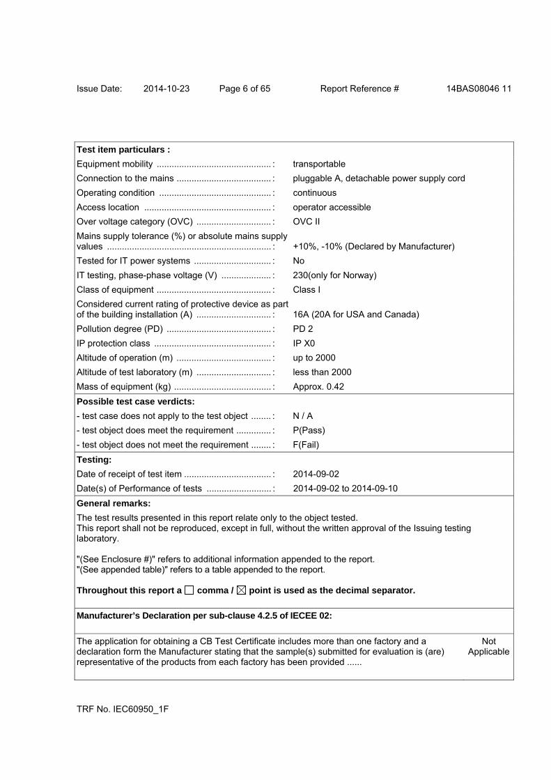
Test item particulars :
Equipment mobility .............................................. : transportable
Connection to the mains ...................................... : pluggable A, detachable power supply cord
Operating condition ............................................. : continuous
Access location ................................................... : operator accessible
Over voltage category (OVC) .............................. : OVC II
Mains supply tolerance (%) or absolute mains supply values .................................................................. : +10%, -10% (Declared by Manufacturer)
Tested for IT power systems ............................... : No
IT testing, phase-phase voltage (V) .................... : 230(only for Norway)
Class of equipment .............................................. : Class I
Considered current rating of protective device as part of the building installation (A) .............................. : 16A (20A for USA and Canada)
Pollution degree (PD) .......................................... : PD 2
IP protection class ............................................... : IP X0
Altitude of operation (m) ...................................... : up to 2000
Altitude of test laboratory (m) .............................. : less than 2000
Mass of equipment (kg) ....................................... : Approx. 0.42
Possible test case verdicts:
- test case does not apply to the test object ........ : N / A
- test object does meet the requirement .............. : P(Pass)
- test object does not meet the requirement ........ : F(Fail)
Testing:
Date of receipt of test item ................................... : 2014-09-02
Date(s) of Performance of tests .......................... : 2014-09-02 to 2014-09-10
General remarks:
The test results presented in this report relate only to the object tested. This report shall not be reproduced, except in full, without the written approval of the Issuing testing laboratory. "(See Enclosure #)" refers to additional information appended to the report. "(See appended table)" refers to a table appended to the report. Throughout this report a comma / point is used as the decimal separator.
Manufacturer’s Declaration per sub-clause 4.2.5 of IECEE 02:
The application for obtaining a CB Test Certificate includes more than one factory and a declaration form the Manufacturer stating that the sample(s) submitted for evaluation is (are) representative of the products from each factory has been provided ......
Not Applicable
Issue Date: 2014-10-23 Page 7 of 65 Report Reference # 14BAS08046 11
TRF No. IEC60950_1F
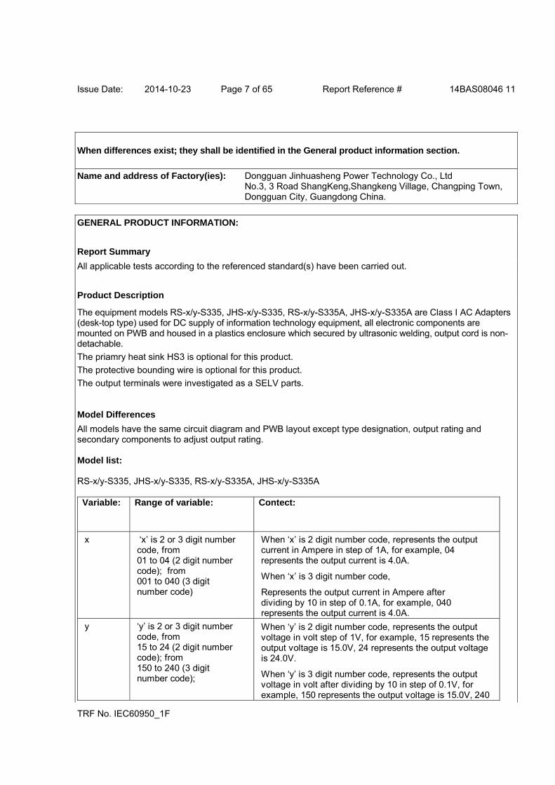
When differences exist; they shall be identified in the General product information section.
Name and address of Factory(ies): Dongguan Jinhuasheng Power Technology Co., Ltd No.3, 3 Road ShangKeng,Shangkeng Village, Changping Town, Dongguan City, Guangdong China.
GENERAL PRODUCT INFORMATION:
Report Summary
All applicable tests according to the referenced standard(s) have been carried out.
Product Description
The equipment models RS-x/y-S335, JHS-x/y-S335, RS-x/y-S335A, JHS-x/y-S335A are Class I AC Adapters (desk-top type) used for DC supply of information technology equipment, all electronic components are mounted on PWB and housed in a plastics enclosure which secured by ultrasonic welding, output cord is non-detachable.
The priamry heat sink HS3 is optional for this product.
The protective bounding wire is optional for this product.
The output terminals were investigated as a SELV parts.
Model Differences
All models have the same circuit diagram and PWB layout except type designation, output rating and secondary components to adjust output rating. Model list: RS-x/y-S335, JHS-x/y-S335, RS-x/y-S335A, JHS-x/y-S335A Variable: Range of variable: Contect:
x ‘x’ is 2 or 3 digit number code, from 01 to 04 (2 digit number code); from 001 to 040 (3 digit number code)
When ‘x’ is 2 digit number code, represents the output current in Ampere in step of 1A, for example, 04 represents the output current is 4.0A.
When ‘x’ is 3 digit number code,
Represents the output current in Ampere after dividing by 10 in step of 0.1A, for example, 040 represents the output current is 4.0A.
y ‘y’ is 2 or 3 digit number code, from 15 to 24 (2 digit number code); from 150 to 240 (3 digit number code);
When ‘y’ is 2 digit number code, represents the output voltage in volt step of 1V, for example, 15 represents the output voltage is 15.0V, 24 represents the output voltage is 24.0V.
When ‘y’ is 3 digit number code, represents the output voltage in volt after dividing by 10 in step of 0.1V, for example, 150 represents the output voltage is 15.0V, 240
Issue Date: 2014-10-23 Page 8 of 65 Report Reference # 14BAS08046 11
TRF No. IEC60950_1F
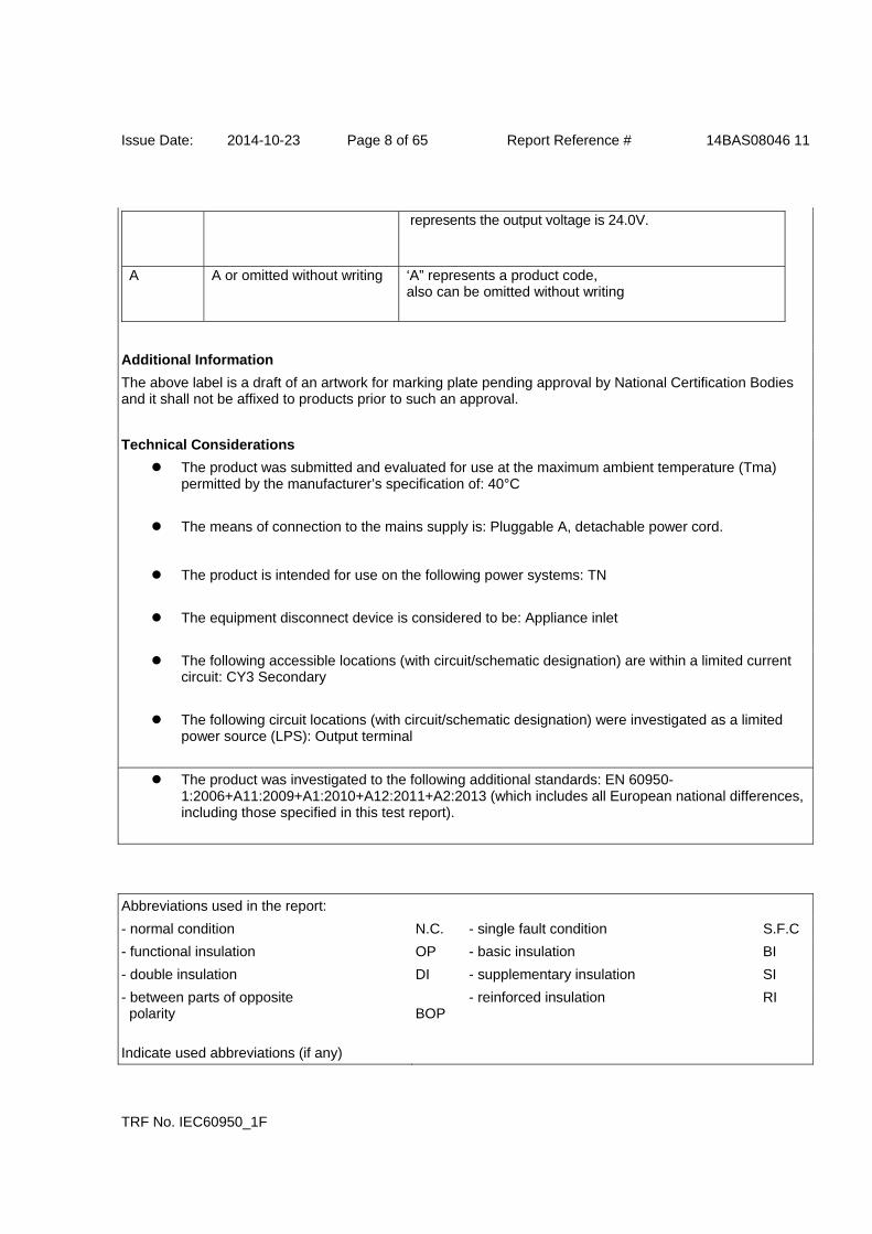
represents the output voltage is 24.0V.
A A or omitted without writing ‘A” represents a product code, also can be omitted without writing
Additional Information
The above label is a draft of an artwork for marking plate pending approval by National Certification Bodies and it shall not be affixed to products prior to such an approval.
Technical Considerations
The product was submitted and evaluated for use at the maximum ambient temperature (Tma) permitted by the manufacturer’s specification of: 40°C
The means of connection to the mains supply is: Pluggable A, detachable power cord.
The product is intended for use on the following power systems: TN
The equipment disconnect device is considered to be: Appliance inlet
The following accessible locations (with circuit/schematic designation) are within a limited current circuit: CY3 Secondary
The following circuit locations (with circuit/schematic designation) were investigated as a limited power source (LPS): Output terminal
The product was investigated to the following additional standards: EN 60950-1:2006+A11:2009+A1:2010+A12:2011+A2:2013 (which includes all European national differences, including those specified in this test report).
Abbreviations used in the report:
- normal condition N.C. - single fault condition S.F.C
- functional insulation OP - basic insulation BI
- double insulation DI - supplementary insulation SI
- between parts of opposite polarity
BOP
- reinforced insulation RI
Indicate used abbreviations (if any)
Issue Date: 2014-10-23 Page 9 of 65 Report Reference # 14BAS08046 11
IEC 60950-1
Clause Requirement + Test Result - Remark Verdict
TRF No. IEC60950_1F
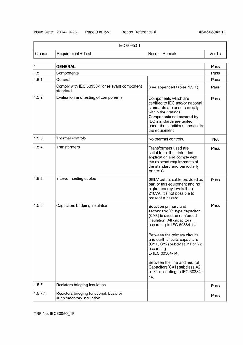
1 GENERAL Pass
1.5 Components Pass
1.5.1 General Pass
Comply with IEC 60950-1 or relevant component standard
(see appended tables 1.5.1) Pass
1.5.2 Evaluation and testing of components Components which are certified to IEC and/or national standards are used correctly within their ratings. Components not covered by IEC standards are tested under the conditions present in the equipment.
Pass
1.5.3 Thermal controls No thermal controls. N/A
1.5.4 Transformers Transformers used are suitable for their intended application and comply with the relevant requirements of the standard and particularly Annex C.
Pass
1.5.5 Interconnecting cables SELV output cable provided as part of this equipment and no higher energy levels than 240VA, it’s not possible to present a hazard
Pass
1.5.6 Capacitors bridging insulation Between primary and secondary: Y1 type capacitor (CY3) is used as reinforced insulation. All capacitors according to IEC 60384-14.
Between the primary circuits and earth circuits capacitors (CY1, CY2) subclass Y1 or Y2 according to IEC 60384-14. Between the line and neutral Capacitors(CX1) subclass X2 or X1 according to IEC 60384-14.
Pass
1.5.7 Resistors bridging insulation Pass
1.5.7.1 Resistors bridging functional, basic or supplementary insulation
Pass

Issue Date: 2014-10-23 Page 10 of 65 Report Reference # 14BAS08046 11
IEC 60950-1
Clause Requirement + Test Result - Remark Verdict
TRF No. IEC60950_1F
1.5.7.2 Resistors bridging double or reinforced insulation between a.c. mains and other circuits
N/A
1.5.7.3 Resistors bridging double or reinforced insulation between a.c. mains and antenna or coaxial cable
N/A
1.5.8 Components in equipment for IT power systems See only Norway deviation N/A
1.5.9 Surge suppressors N/A
1.5.9.1 General N/A
1.5.9.2 Protection of VDRs N/A
1.5.9.3 Bridging of functional insulation by a VDR N/A
1.5.9.4 Bridging of basic insulation by a VDR No such construction. N/A
1.5.9.5 Bridging of supplementary, double or reinforced insulation by a VDR
No such construction. N/A
1.6 Power interface Pass
1.6.1 AC power distribution systems TN power system. Pass
1.6.2 Input current Highest load according to 1.2.2.1 for this equipment is the operation with the maximum specified by the manual instruction. (see appended table 1.6.2)
Pass
1.6.3 Voltage limit of hand-held equipment This appliance is not hand-held equipment.
N/A
1.6.4 Neutral conductor The neutral conductor insulated from earth and from the body throughout the equipment as if it were a line conductor.
Pass
1.7 Marking and instructions Pass
1.7.1 Power rating and identification markings See below Pass
1.7.1.1 Power rating marking Pass
Multiple mains supply connections ........................: Single power source N/A
Rated voltage(s) or voltage range(s) (V) ...............: 100-240Vac Pass
Symbol for nature of supply, for d.c. only ..............: AC source N/A
Rated frequency or rated frequency range (Hz) ....: 50/60Hz Pass

Issue Date: 2014-10-23 Page 11 of 65 Report Reference # 14BAS08046 11
IEC 60950-1
Clause Requirement + Test Result - Remark Verdict
TRF No. IEC60950_1F
Rated current (mA or A).........................................: 1.2A Max. Pass
1.7.1.2 Identification markings Pass
Manufacturer's name or trademark or identification mark .......................................................................:
Pass
Model identification or type reference....................: RS-x/y-S335, JHS-x/y-S335, RS-x/y-S335A, JHS-x/y-S335A
Pass
Symbol for Class II equipment only .......................: Class I equipment N/A
Other markings and symbols .................................: Additional symbol or marking does not give rise to misunderstanding.
Pass
1.7.1.3 Use of graphical symbols N/A
1.7.2 Safety instructions and marking English version safety instruction provided. Other languages will be provided when submitted for national approval.
Pass
1.7.2.1 General Pass
1.7.2.2 Disconnect devices The equipment disconnect device is considered to be: Appliance inlet .
Pass
1.7.2.3 Overcurrent protective device Not type B pluggable Equipment or permanently connected equipment.
N/A
1.7.2.4 IT Power distribution systems See only Norway deviation. N/A
1.7.2.5 Operator access with a tool No such access required. N/A
1.7.2.6 Ozone Ozone not used or generated. N/A
1.7.3 Short duty cycles Equipment is designed for continuous operation.
N/A
1.7.4 Supply voltage adjustment.....................................: No supply voltage adjustable devices used.
N/A
Method and means of adjustment; reference to installation instructions...........................................:
N/A
1.7.5 Power outlets on the equipment ............................: N/A
1.7.6 Fuse identification (marking, special fusing characteristics, cross-reference)............................:
Current fuse used, marking provided on PCB: F1 T3.15AL 250V
Pass
1.7.7 Wiring terminals See below. Pass
1.7.7.1 Protective earthing and bonding terminals ............: Pass
1.7.7.2 Terminals for a.c. mains supply conductors No such terminals provied. N/A
Issue Date: 2014-10-23 Page 12 of 65 Report Reference # 14BAS08046 11
IEC 60950-1
Clause Requirement + Test Result - Remark Verdict
TRF No. IEC60950_1F
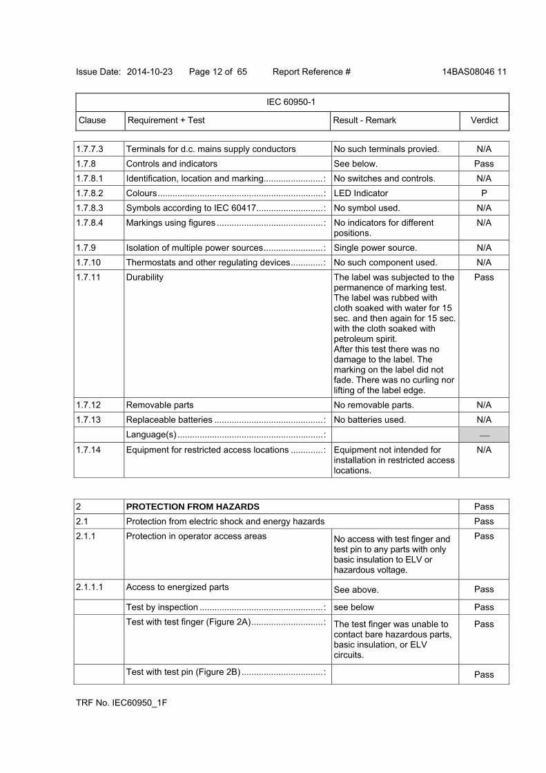
1.7.7.3 Terminals for d.c. mains supply conductors No such terminals provied. N/A
1.7.8 Controls and indicators See below. Pass
1.7.8.1 Identification, location and marking........................: No switches and controls. N/A
1.7.8.2 Colours...................................................................: LED Indicator P
1.7.8.3 Symbols according to IEC 60417...........................: No symbol used. N/A
1.7.8.4 Markings using figures ...........................................: No indicators for different positions.
N/A
1.7.9 Isolation of multiple power sources........................: Single power source. N/A
1.7.10 Thermostats and other regulating devices.............: No such component used. N/A
1.7.11 Durability The label was subjected to the permanence of marking test. The label was rubbed with cloth soaked with water for 15 sec. and then again for 15 sec. with the cloth soaked with petroleum spirit. After this test there was no damage to the label. The marking on the label did not fade. There was no curling nor lifting of the label edge.
Pass
1.7.12 Removable parts No removable parts. N/A
1.7.13 Replaceable batteries ............................................: No batteries used. N/A
Language(s) ...........................................................:
1.7.14 Equipment for restricted access locations .............: Equipment not intended for installation in restricted access locations.
N/A
2 PROTECTION FROM HAZARDS Pass
2.1 Protection from electric shock and energy hazards Pass
2.1.1 Protection in operator access areas No access with test finger and test pin to any parts with only basic insulation to ELV or hazardous voltage.
Pass
2.1.1.1 Access to energized parts See above. Pass
Test by inspection ..................................................: see below Pass
Test with test finger (Figure 2A).............................: The test finger was unable to contact bare hazardous parts, basic insulation, or ELV circuits.
Pass
Test with test pin (Figure 2B) .................................: Pass
Issue Date: 2014-10-23 Page 13 of 65 Report Reference # 14BAS08046 11
IEC 60950-1
Clause Requirement + Test Result - Remark Verdict
TRF No. IEC60950_1F
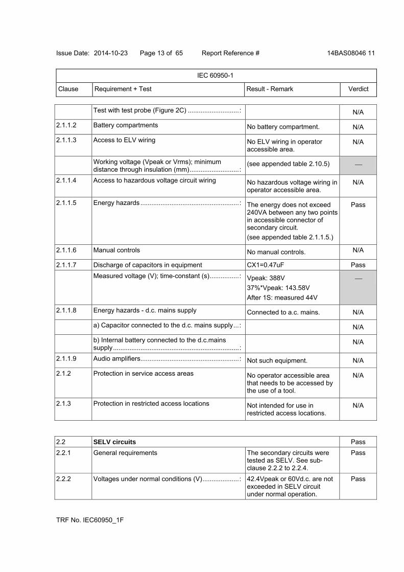
Test with test probe (Figure 2C) ............................: N/A
2.1.1.2 Battery compartments No battery compartment. N/A
2.1.1.3 Access to ELV wiring No ELV wiring in operator accessible area.
N/A
Working voltage (Vpeak or Vrms); minimum distance through insulation (mm)...........................:
(see appended table 2.10.5)
2.1.1.4 Access to hazardous voltage circuit wiring No hazardous voltage wiring in operator accessible area.
N/A
2.1.1.5 Energy hazards......................................................: The energy does not exceed 240VA between any two points in accessible connector of secondary circuit.
(see appended table 2.1.1.5.)
Pass
2.1.1.6 Manual controls No manual controls. N/A
2.1.1.7 Discharge of capacitors in equipment CX1=0.47uF Pass
Measured voltage (V); time-constant (s)................: Vpeak: 388V
37%*Vpeak: 143.58V
After 1S: measured 44V
2.1.1.8 Energy hazards - d.c. mains supply Connected to a.c. mains. N/A
a) Capacitor connected to the d.c. mains supply...: N/A
b) Internal battery connected to the d.c.mains supply.....................................................................:
N/A
2.1.1.9 Audio amplifiers......................................................: Not such equipment. N/A
2.1.2 Protection in service access areas No operator accessible area that needs to be accessed by the use of a tool.
N/A
2.1.3 Protection in restricted access locations Not intended for use in restricted access locations.
N/A
2.2 SELV circuits Pass
2.2.1 General requirements The secondary circuits were tested as SELV. See sub-clause 2.2.2 to 2.2.4.
Pass
2.2.2 Voltages under normal conditions (V)....................: 42.4Vpeak or 60Vd.c. are not exceeded in SELV circuit under normal operation.
Pass
Issue Date: 2014-10-23 Page 14 of 65 Report Reference # 14BAS08046 11
IEC 60950-1
Clause Requirement + Test Result - Remark Verdict
TRF No. IEC60950_1F
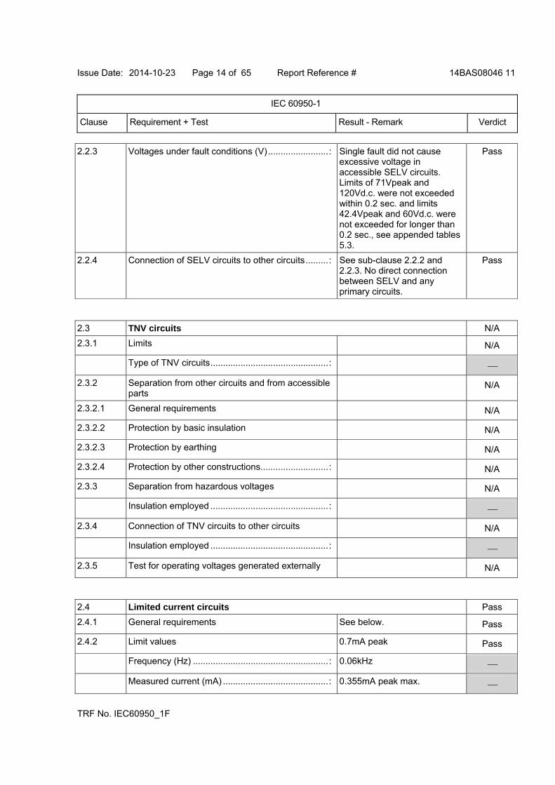
2.2.3 Voltages under fault conditions (V)........................: Single fault did not cause excessive voltage in accessible SELV circuits. Limits of 71Vpeak and 120Vd.c. were not exceeded within 0.2 sec. and limits 42.4Vpeak and 60Vd.c. were not exceeded for longer than 0.2 sec., see appended tables 5.3.
Pass
2.2.4 Connection of SELV circuits to other circuits.........: See sub-clause 2.2.2 and 2.2.3. No direct connection between SELV and any primary circuits.
Pass
2.3 TNV circuits N/A
2.3.1 Limits N/A
Type of TNV circuits...............................................:
2.3.2 Separation from other circuits and from accessible parts
N/A
2.3.2.1 General requirements N/A
2.3.2.2 Protection by basic insulation N/A
2.3.2.3 Protection by earthing N/A
2.3.2.4 Protection by other constructions...........................: N/A
2.3.3 Separation from hazardous voltages N/A
Insulation employed ...............................................:
2.3.4 Connection of TNV circuits to other circuits N/A
Insulation employed ...............................................:
2.3.5 Test for operating voltages generated externally N/A
2.4 Limited current circuits Pass
2.4.1 General requirements See below. Pass
2.4.2 Limit values 0.7mA peak Pass
Frequency (Hz) ......................................................: 0.06kHz
Measured current (mA) ..........................................: 0.355mA peak max.
Issue Date: 2014-10-23 Page 15 of 65 Report Reference # 14BAS08046 11
IEC 60950-1
Clause Requirement + Test Result - Remark Verdict
TRF No. IEC60950_1F
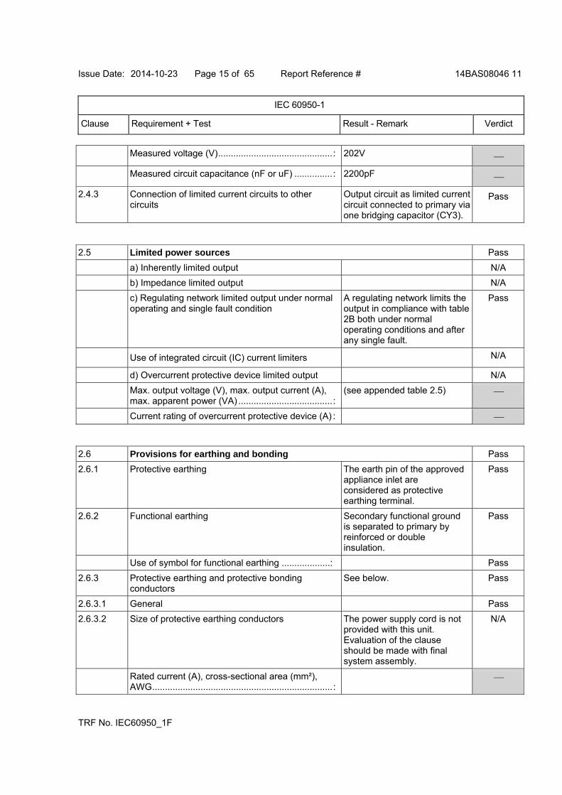
Measured voltage (V).............................................: 202V
Measured circuit capacitance (nF or uF) ...............: 2200pF
2.4.3 Connection of limited current circuits to other circuits
Output circuit as limited current circuit connected to primary via one bridging capacitor (CY3).
Pass
2.5 Limited power sources Pass
a) Inherently limited output N/A
b) Impedance limited output N/A
c) Regulating network limited output under normal operating and single fault condition
A regulating network limits the output in compliance with table 2B both under normal operating conditions and after any single fault.
Pass
Use of integrated circuit (IC) current limiters N/A
d) Overcurrent protective device limited output N/A
Max. output voltage (V), max. output current (A), max. apparent power (VA) .....................................:
(see appended table 2.5)
Current rating of overcurrent protective device (A) :
2.6 Provisions for earthing and bonding Pass
2.6.1 Protective earthing The earth pin of the approved appliance inlet are considered as protective earthing terminal.
Pass
2.6.2 Functional earthing Secondary functional ground is separated to primary by reinforced or double insulation.
Pass
Use of symbol for functional earthing ...................: Pass
2.6.3 Protective earthing and protective bonding conductors
See below. Pass
2.6.3.1 General Pass
2.6.3.2 Size of protective earthing conductors The power supply cord is not provided with this unit. Evaluation of the clause should be made with final system assembly.
N/A
Rated current (A), cross-sectional area (mm²), AWG.......................................................................:
Issue Date: 2014-10-23 Page 16 of 65 Report Reference # 14BAS08046 11
IEC 60950-1
Clause Requirement + Test Result - Remark Verdict
TRF No. IEC60950_1F
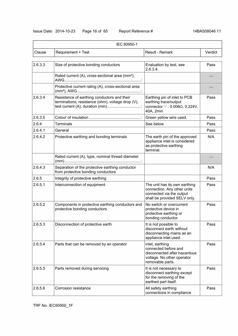
2.6.3.3 Size of protective bonding conductors Evaluation by test, see 2.6.3.4.
Pass
Rated current (A), cross-sectional area (mm²), AWG.......................................................................:
Protective current rating (A), cross-sectional area (mm²), AWG...........................................................:
2.6.3.4 Resistance of earthing conductors and their terminations; resistance (ohm), voltage drop (V), test current (A), duration (min) ...............................:
Earthing pin of inlet to PCB earthing trace/output connector ‘-‘ : 0.006, 0.224V, 40A, 2min
Pass
2.6.3.5 Colour of insulation ................................................: Green yellow wire used. Pass
2.6.4 Terminals See below Pass
2.6.4.1 General Pass
2.6.4.2 Protective earthing and bonding terminals The earth pin of the approved appliance inlet is considered as protective earthing terminal.
N/A
Rated current (A), type, nominal thread diameter (mm).......................................................................:
2.6.4.3 Separation of the protective earthing conductor from protective bonding conductors
N/A
2.6.5 Integrity of protective earthing Pass
2.6.5.1 Interconnection of equipment The unit has its own earthing connection. Any other units connected via the output shall be provided SELV only.
Pass
2.6.5.2 Components in protective earthing conductors and protective bonding conductors
No switch or overcurrent protective device in protective earthing or bonding conductor.
Pass
2.6.5.3 Disconnection of protective earth It is not possible to disconnect earth without disconnecting mains as an appliance inlet used.
Pass
2.6.5.4 Parts that can be removed by an operator inlet, earthing connected before and disconnected after hazardous voltage. No other operator removable parts.
Pass
2.6.5.5 Parts removed during servicing It is not necessary to disconnect earthing except for the removing of the earthed part itself.
Pass
2.6.5.6 Corrosion resistance All safety earthing connections in compliance
Pass

Issue Date: 2014-10-23 Page 17 of 65 Report Reference # 14BAS08046 11
IEC 60950-1
Clause Requirement + Test Result - Remark Verdict
TRF No. IEC60950_1F
with Annex J.
2.6.5.7 Screws for protective bonding No self-tapping screws are used.
N
2.6.5.8 Reliance on telecommunication network or cable distribution system
No TNV N
2.7 Overcurrent and earth fault protection in primary circuits Pass
2.7.1 Basic requirements The equipment relies on current fuse of the wall outlet protection of the building installation in regard to L to N short-circuits. A build-in current fuse provided as overcurrent protection device (see 5.3)
Pass
Instructions when protection relies on building installation
Pluggable equipment type A. N/A
2.7.2 Faults not simulated in 5.3.7 The protection devices are well dimensioned and mounted.
Pass
2.7.3 Short-circuit backup protection Building installation is considered as providing short-circuit backup protection.
Pass
2.7.4 Number and location of protective devices............: Overcurrent protection by one built-in current fuse.
Pass
2.7.5 Protection by several devices Protection provided by one current fuse.
N/A
2.7.6 Warning to service personnel ................................: No service work necessary. N/A
2.8 Safety interlocks N/A
2.8.1 General principles N/A
2.8.2 Protection requirements N/A
2.8.3 Inadvertent reactivation N/A
2.8.4 Fail-safe operation N/A
Protection against extreme hazard N/A
2.8.5 Moving parts N/A
2.8.6 Overriding N/A
2.8.7 Switches, relays and their related circuits N/A
2.8.7.1 Separation distances for contact gaps and their related circuits (mm) ..............................................:
N/A
2.8.7.2 Overload test N/A
2.8.7.3 Endurance test N/A
Issue Date: 2014-10-23 Page 18 of 65 Report Reference # 14BAS08046 11
IEC 60950-1
Clause Requirement + Test Result - Remark Verdict
TRF No. IEC60950_1F
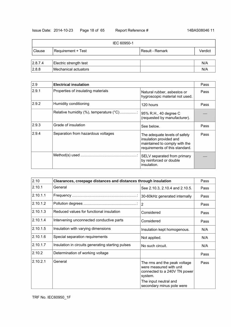
2.8.7.4 Electric strength test N/A
2.8.8 Mechanical actuators N/A
2.9 Electrical insulation Pass
2.9.1 Properties of insulating materials Natural rubber, asbestos or hygroscopic material not used.
Pass
2.9.2 Humidity conditioning 120 hours Pass
Relative humidity (%), temperature (°C) ................: 95% R.H., 40 degree C (requested by manufacturer).
2.9.3 Grade of insulation See below. Pass
2.9.4 Separation from hazardous voltages The adequate levels of safety insulation provided and maintained to comply with the requirements of this standard.
Pass
Method(s) used ......................................................: SELV separated from primary by reinforced or double insulation.
2.10 Clearances, creepage distances and distances through insulation Pass
2.10.1 General See 2.10.3, 2.10.4 and 2.10.5. Pass
2.10.1.1 Frequency ..............................................................: 30-60kHz generated internally Pass
2.10.1.2 Pollution degrees ...................................................: 2 Pass
2.10.1.3 Reduced values for functional insulation Considered Pass
2.10.1.4 Intervening unconnected conductive parts Considered Pass
2.10.1.5 Insulation with varying dimensions Insulation kept homogenous. N/A
2.10.1.6 Special separation requirements Not applied. N/A
2.10.1.7 Insulation in circuits generating starting pulses No such circuit. N/A
2.10.2 Determination of working voltage Pass
2.10.2.1 General The rms and the peak voltage were measured with unit connected to a 240V TN power system.
The input neutral and secondary minus pole were
Pass
Issue Date: 2014-10-23 Page 19 of 65 Report Reference # 14BAS08046 11
IEC 60950-1
Clause Requirement + Test Result - Remark Verdict
TRF No. IEC60950_1F
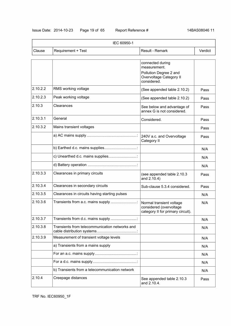
connected during measurement.
Pollution Degree 2 and Overvoltage Category II considered.
2.10.2.2 RMS working voltage (See appended table 2.10.2) Pass
2.10.2.3 Peak working voltage (See appended table 2.10.2) Pass
2.10.3 Clearances See below and advantage of annex G is not considered.
Pass
2.10.3.1 General Considered. Pass
2.10.3.2 Mains transient voltages Pass
a) AC mains supply................................................: 240V a.c. and Overvoltage Category II
Pass
b) Earthed d.c. mains supplies...............................: N/A
c) Unearthed d.c. mains supplies...........................: N/A
d) Battery operation ...............................................: N/A
2.10.3.3 Clearances in primary circuits (see appended table 2.10.3 and 2.10.4)
Pass
2.10.3.4 Clearances in secondary circuits Sub-clause 5.3.4 considered. Pass
2.10.3.5 Clearances in circuits having starting pulses N/A
2.10.3.6 Transients from a.c. mains supply .........................: Normal transient voltage considered (overvoltage category II for primary circuit).
N/A
2.10.3.7 Transients from d.c. mains supply .........................: N/A
2.10.3.8 Transients from telecommunication networks and cable distribution systems......................................:
N/A
2.10.3.9 Measurement of transient voltage levels N/A
a) Transients from a mains supply N/A
For an a.c. mains supply........................................: N/A
For a d.c. mains supply..........................................: N/A
b) Transients from a telecommunication network N/A
2.10.4 Creepage distances See appended table 2.10.3 and 2.10.4.
Pass

Issue Date: 2014-10-23 Page 20 of 65 Report Reference # 14BAS08046 11
IEC 60950-1
Clause Requirement + Test Result - Remark Verdict
TRF No. IEC60950_1F
2.10.4.1 General CTI rating for all materials of minimum 100.
Pass
2.10.4.2 Material group and comparative tracking index Pass
CTI tests.................................................................: Material group IIIb is assumed to be used.
2.10.4.3 Minimum creepage distances (see appended table 2.10.3 and 2.10.4)
Pass
2.10.5 Solid insulation Pass
2.10.5.1 General See below. Pass
2.10.5.2 Distances through insulation (see appended table 2.10.5) Pass
2.10.5.3 Insulating compound as solid insulation N/A
2.10.5.4 Semiconductor devices Approved optocoupler used. Pass
2.10.5.5 Cemented joints No such construction. N/A
2.10.5.6 Thin sheet material - General Pass
2.10.5.7 Separable thin sheet material Used in transformer Pass
Number of layers (pcs)...........................................: 2 layers for reinforced insulation.
2.10.5.8 Non-separable thin sheet material Not such material N/A
2.10.5.9 Thin sheet material - standard test procedure N/A
Electric strength test ..............................................:
2.10.5.10 Thin sheet material - alternative test procedure (see appended table 5.2) Pass
Electric strength test ..............................................:
2.10.5.11 Insulation in wound components Pass
2.10.5.12 Wire in wound components Approved triple-insulated winding wire used in T1 for secondary winding.
Pass
Working voltage .....................................................: The peak working voltage exceeds 71V
Pass
a) Basic insulation not under stress.......................: N/A
b) Basic, supplementary, reinforced insulation ......: See sub-clause 2.10.5.11. Pass
c) Compliance with Annex U..................................: Triple insulation wires used. Pass
Issue Date: 2014-10-23 Page 21 of 65 Report Reference # 14BAS08046 11
IEC 60950-1
Clause Requirement + Test Result - Remark Verdict
TRF No. IEC60950_1F
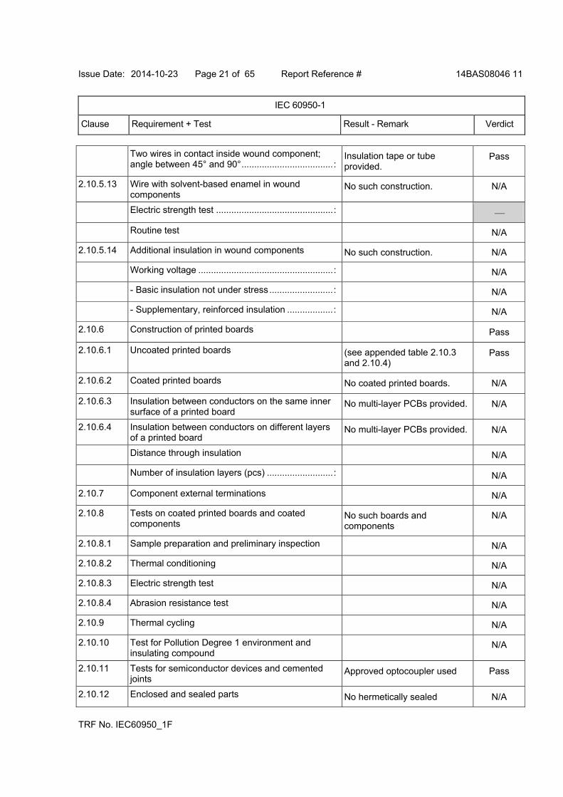
Two wires in contact inside wound component; angle between 45° and 90°....................................:
Insulation tape or tube provided.
Pass
2.10.5.13 Wire with solvent-based enamel in wound components
No such construction. N/A
Electric strength test ..............................................:
Routine test N/A
2.10.5.14 Additional insulation in wound components No such construction. N/A
Working voltage .....................................................: N/A
- Basic insulation not under stress .........................: N/A
- Supplementary, reinforced insulation ..................: N/A
2.10.6 Construction of printed boards Pass
2.10.6.1 Uncoated printed boards (see appended table 2.10.3 and 2.10.4)
Pass
2.10.6.2 Coated printed boards No coated printed boards. N/A
2.10.6.3 Insulation between conductors on the same inner surface of a printed board
No multi-layer PCBs provided. N/A
2.10.6.4 Insulation between conductors on different layers of a printed board
No multi-layer PCBs provided. N/A
Distance through insulation N/A
Number of insulation layers (pcs) ..........................: N/A
2.10.7 Component external terminations N/A
2.10.8 Tests on coated printed boards and coated components
No such boards and components
N/A
2.10.8.1 Sample preparation and preliminary inspection N/A
2.10.8.2 Thermal conditioning N/A
2.10.8.3 Electric strength test N/A
2.10.8.4 Abrasion resistance test N/A
2.10.9 Thermal cycling N/A
2.10.10 Test for Pollution Degree 1 environment and insulating compound
N/A
2.10.11 Tests for semiconductor devices and cemented joints
Approved optocoupler used Pass
2.10.12 Enclosed and sealed parts No hermetically sealed N/A

Issue Date: 2014-10-23 Page 22 of 65 Report Reference # 14BAS08046 11
IEC 60950-1
Clause Requirement + Test Result - Remark Verdict
TRF No. IEC60950_1F
component.
3 WIRING, CONNECTIONS AND SUPPLY Pass
3.1 General Pass
3.1.1 Current rating and overcurrent protection Pass
3.1.2 Protection against mechanical damage The wires are routed away from sharp edges and parts which could damage insulation.
Pass
3.1.3 Securing of internal wiring Pass
3.1.4 Insulation of conductors Uninsulated conductors have been adequately fixed to prevent, in normal use, any reduction of creepage or clearance distances below those prescribed by in 2.9.
Pass
3.1.5 Beads and ceramic insulators Not used. N/A
3.1.6 Screws for electrical contact pressure No such screws provided. N/A
3.1.7 Insulating materials in electrical connections No contact pressure through insulating material.
N/A
3.1.8 Self-tapping and spaced thread screws Not used. N/A
3.1.9 Termination of conductors All conductors are reliable secured.
Pass
10 N pull test Force of 10 N applied to the termination points of the conductors.
Pass
3.1.10 Sleeving on wiring No sleeving used on wirings for supplementary insulation.
N/A
3.2 Connection to mains supply Pass
3.2.1 Means of connection See below. Pass
3.2.1.1 Connection to an a.c. mains supply Connection to an a.c. mains supply by a DETACHABLE POWER SUPPLY CORD.
Pass
3.2.1.2 Connection to a d.c. mains supply Only a.c. mains supply. N/A
Issue Date: 2014-10-23 Page 23 of 65 Report Reference # 14BAS08046 11
IEC 60950-1
Clause Requirement + Test Result - Remark Verdict
TRF No. IEC60950_1F
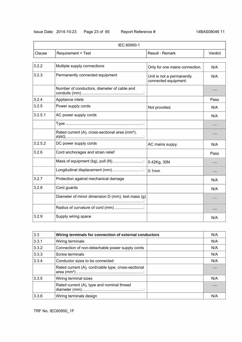
3.2.2 Multiple supply connections Only for one mains connection. N/A
3.2.3 Permanently connected equipment Unit is not a permanently connected equipment.
N/A
Number of conductors, diameter of cable and conduits (mm) ........................................................:
3.2.4 Appliance inlets Pass
3.2.5 Power supply cords Not provided. N/A
3.2.5.1 AC power supply cords N/A
Type .......................................................................:
Rated current (A), cross-sectional area (mm²), AWG.......................................................................:
3.2.5.2 DC power supply cords AC mains suppy. N/A
3.2.6 Cord anchorages and strain relief Pass
Mass of equipment (kg), pull (N)............................: 0.42Kg, 30N
Longitudinal displacement (mm)............................: 0.1mm
3.2.7 Protection against mechanical damage N/A
3.2.8 Cord guards N/A
Diameter of minor dimension D (mm); test mass (g)...............................................................................:
Radius of curvature of cord (mm) ..........................:
3.2.9 Supply wiring space N/A
3.3 Wiring terminals for connection of external conductors N/A
3.3.1 Wiring terminals N/A
3.3.2 Connection of non-detachable power supply cords N/A
3.3.3 Screw terminals N/A
3.3.4 Conductor sizes to be connected N/A
Rated current (A), cord/cable type, cross-sectional area (mm²) .............................................................:
3.3.5 Wiring terminal sizes N/A
Rated current (A), type and nominal thread diameter (mm)........................................................:
3.3.6 Wiring terminals design N/A
Issue Date: 2014-10-23 Page 24 of 65 Report Reference # 14BAS08046 11
IEC 60950-1
Clause Requirement + Test Result - Remark Verdict
TRF No. IEC60950_1F
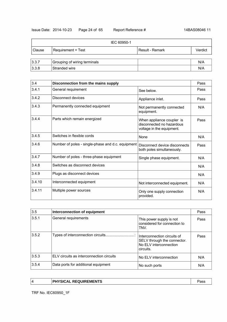
3.3.7 Grouping of wiring terminals N/A
3.3.8 Stranded wire N/A
3.4 Disconnection from the mains supply Pass
3.4.1 General requirement See below. Pass
3.4.2 Disconnect devices Appliance inlet. Pass
3.4.3 Permanently connected equipment Not permanently connected equipment.
N/A
3.4.4 Parts which remain energized When appliance coupler is disconnected no hazardous voltage in the equipment.
Pass
3.4.5 Switches in flexible cords None N/A
3.4.6 Number of poles - single-phase and d.c. equipment Disconnect device disconnects both poles simultaneously.
Pass
3.4.7 Number of poles - three-phase equipment Single phase equipment. N/A
3.4.8 Switches as disconnect devices N/A
3.4.9 Plugs as disconnect devices N/A
3.4.10 Interconnected equipment Not interconnected equipment. N/A
3.4.11 Multiple power sources Only one supply connection provided.
N/A
3.5 Interconnection of equipment Pass
3.5.1 General requirements This power supply is not considered for connection to TNV.
Pass
3.5.2 Types of interconnection circuits............................: Interconnection circuits of SELV through the connector. No ELV interconnection circuits.
Pass
3.5.3 ELV circuits as interconnection circuits No ELV interconnection N/A
3.5.4 Data ports for additional equipment No such ports N/A
4 PHYSICAL REQUIREMENTS Pass
Issue Date: 2014-10-23 Page 25 of 65 Report Reference # 14BAS08046 11
IEC 60950-1
Clause Requirement + Test Result - Remark Verdict
TRF No. IEC60950_1F
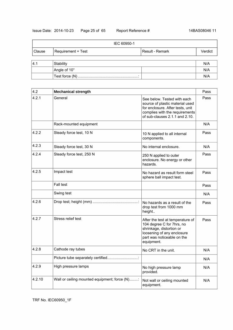
4.1 Stability N/A
Angle of 10° N/A
Test force (N) .........................................................: N/A
4.2 Mechanical strength Pass
4.2.1 General See below. Tested with each source of plastic material used for enclosure. After tests, unit complies with the requirements of sub-clauses 2.1.1 and 2.10.
Pass
Rack-mounted equipment N/A
4.2.2 Steady force test, 10 N 10 N applied to all internal components.
Pass
4.2.3 Steady force test, 30 N No internal enclosure. N/A
4.2.4 Steady force test, 250 N 250 N applied to outer enclosure. No energy or other hazards.
Pass
4.2.5 Impact test No hazard as result form steel sphere ball impact test.
Pass
Fall test Pass
Swing test N/A
4.2.6 Drop test; height (mm) ...........................................: No hazards as a result of the drop test from 1000 mm height..
Pass
4.2.7 Stress relief test After the test at temperature of 104 degree C for 7hrs, no shrinkage, distortion or loosening of any enclosure part was noticeable on the equipment.
Pass
4.2.8 Cathode ray tubes No CRT in the unit. N/A
Picture tube separately certified.............................: N/A
4.2.9 High pressure lamps No high pressure lamp provided.
N/A
4.2.10 Wall or ceiling mounted equipment; force (N)........: Not wall or ceiling mounted equipment.
N/A
Issue Date: 2014-10-23 Page 26 of 65 Report Reference # 14BAS08046 11
IEC 60950-1
Clause Requirement + Test Result - Remark Verdict
TRF No. IEC60950_1F
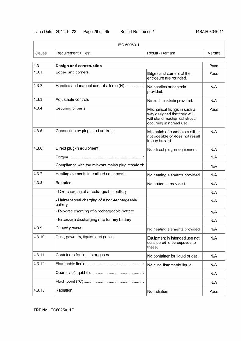
4.3 Design and construction Pass
4.3.1 Edges and corners Edges and corners of the enclosure are rounded.
Pass
4.3.2 Handles and manual controls; force (N) ................: No handles or controls provided.
N/A
4.3.3 Adjustable controls No such controls provided. N/A
4.3.4 Securing of parts Mechanical fixings in such a way designed that they will withstand mechanical stress occurring in normal use.
Pass
4.3.5 Connection by plugs and sockets Mismatch of connectors either not possible or does not result in any hazard.
N/A
4.3.6 Direct plug-in equipment Not direct plug-in equipment. N/A
Torque....................................................................: N/A
Compliance with the relevant mains plug standard: N/A
4.3.7 Heating elements in earthed equipment No heating elements provided. N/A
4.3.8 Batteries No batteries provided. N/A
- Overcharging of a rechargeable battery N/A
- Unintentional charging of a non-rechargeable battery
N/A
- Reverse charging of a rechargeable battery N/A
- Excessive discharging rate for any battery N/A
4.3.9 Oil and grease No heating elements provided. N/A
4.3.10 Dust, powders, liquids and gases Equipment in intended use not considered to be exposed to these.
N/A
4.3.11 Containers for liquids or gases No container for liquid or gas. N/A
4.3.12 Flammable liquids ..................................................: No such flammable liquid. N/A
Quantity of liquid (l) ................................................: N/A
Flash point (°C) ......................................................: N/A
4.3.13 Radiation No radiation Pass
Issue Date: 2014-10-23 Page 27 of 65 Report Reference # 14BAS08046 11
IEC 60950-1
Clause Requirement + Test Result - Remark Verdict
TRF No. IEC60950_1F
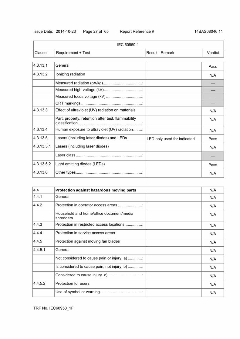
4.3.13.1 General Pass
4.3.13.2 Ionizing radiation N/A
Measured radiation (pA/kg)....................................:
Measured high-voltage (kV)...................................:
Measured focus voltage (kV) .................................:
CRT markings ........................................................:
4.3.13.3 Effect of ultraviolet (UV) radiation on materials N/A
Part, property, retention after test, flammability classification...........................................................:
N/A
4.3.13.4 Human exposure to ultraviolet (UV) radiation........: N/A
4.3.13.5 Lasers (including laser diodes) and LEDs LED only used for indicated Pass
4.3.13.5.1 Lasers (including laser diodes) N/A
Laser class .............................................................:
4.3.13.5.2 Light emitting diodes (LEDs) Pass
4.3.13.6 Other types.............................................................: N/A
4.4 Protection against hazardous moving parts N/A
4.4.1 General N/A
4.4.2 Protection in operator access areas ......................: N/A
Household and home/office document/media shredders
N/A
4.4.3 Protection in restricted access locations................: N/A
4.4.4 Protection in service access areas N/A
4.4.5 Protection against moving fan blades N/A
4.4.5.1 General N/A
Not considered to cause pain or injury. a) .............: N/A
Is considered to cause pain, not injury. b) .............: N/A
Considered to cause injury. c) ...............................: N/A
4.4.5.2 Protection for users N/A
Use of symbol or warning ......................................: N/A
Issue Date: 2014-10-23 Page 28 of 65 Report Reference # 14BAS08046 11
IEC 60950-1
Clause Requirement + Test Result - Remark Verdict
TRF No. IEC60950_1F
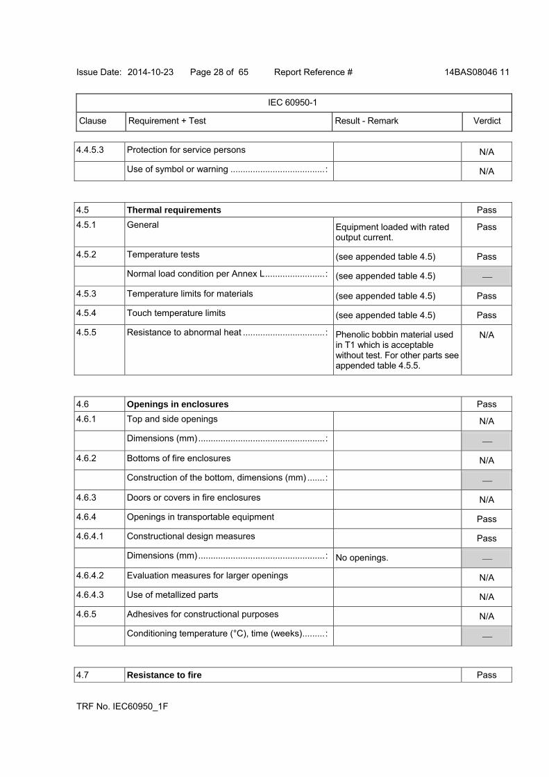
4.4.5.3 Protection for service persons N/A
Use of symbol or warning ......................................: N/A
4.5 Thermal requirements Pass
4.5.1 General Equipment loaded with rated output current.
Pass
4.5.2 Temperature tests (see appended table 4.5) Pass
Normal load condition per Annex L........................: (see appended table 4.5)
4.5.3 Temperature limits for materials (see appended table 4.5) Pass
4.5.4 Touch temperature limits (see appended table 4.5) Pass
4.5.5 Resistance to abnormal heat .................................: Phenolic bobbin material used in T1 which is acceptable without test. For other parts see appended table 4.5.5.
N/A
4.6 Openings in enclosures Pass
4.6.1 Top and side openings N/A
Dimensions (mm)...................................................:
4.6.2 Bottoms of fire enclosures N/A
Construction of the bottom, dimensions (mm) .......:
4.6.3 Doors or covers in fire enclosures N/A
4.6.4 Openings in transportable equipment Pass
4.6.4.1 Constructional design measures Pass
Dimensions (mm)...................................................: No openings.
4.6.4.2 Evaluation measures for larger openings N/A
4.6.4.3 Use of metallized parts N/A
4.6.5 Adhesives for constructional purposes N/A
Conditioning temperature (°C), time (weeks).........:
4.7 Resistance to fire Pass
Issue Date: 2014-10-23 Page 29 of 65 Report Reference # 14BAS08046 11
IEC 60950-1
Clause Requirement + Test Result - Remark Verdict
TRF No. IEC60950_1F
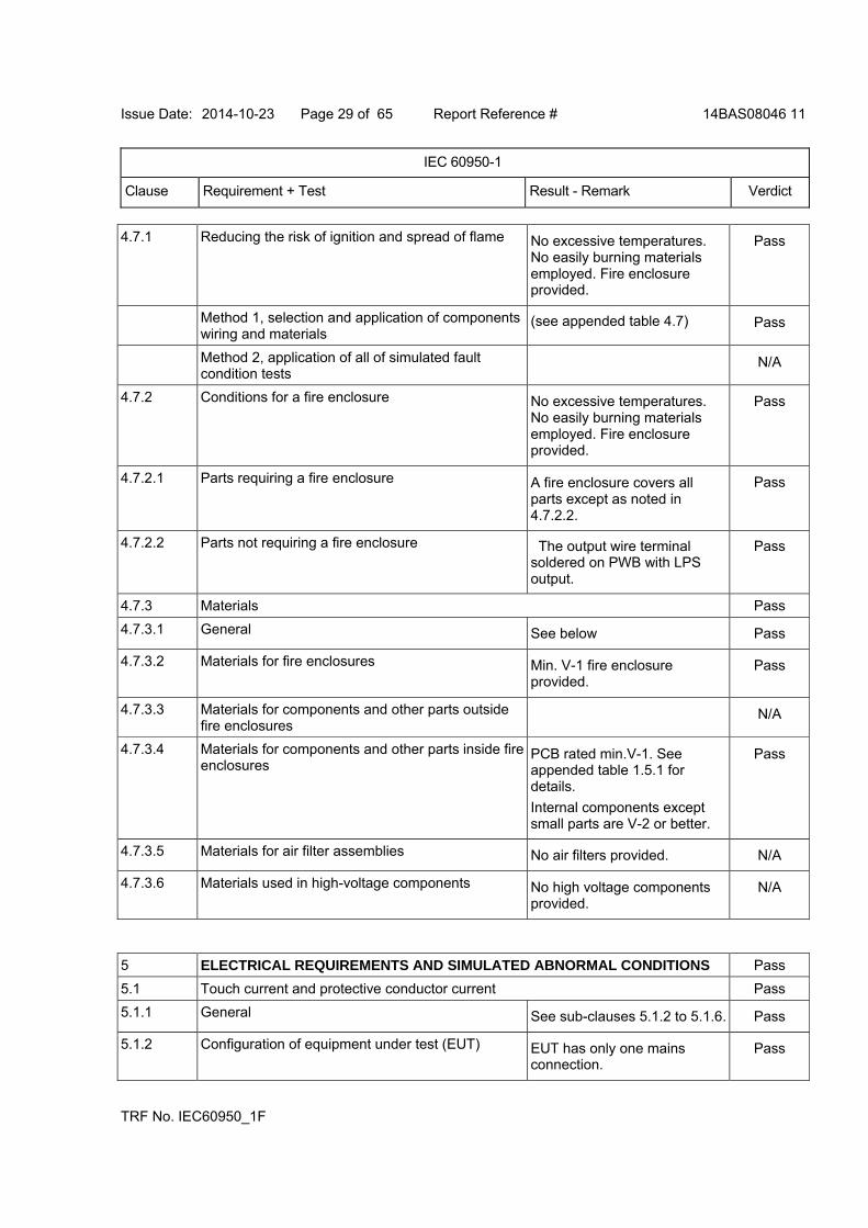
4.7.1 Reducing the risk of ignition and spread of flame No excessive temperatures. No easily burning materials employed. Fire enclosure provided.
Pass
Method 1, selection and application of components wiring and materials
(see appended table 4.7) Pass
Method 2, application of all of simulated fault condition tests
N/A
4.7.2 Conditions for a fire enclosure No excessive temperatures. No easily burning materials employed. Fire enclosure provided.
Pass
4.7.2.1 Parts requiring a fire enclosure A fire enclosure covers all parts except as noted in 4.7.2.2.
Pass
4.7.2.2 Parts not requiring a fire enclosure The output wire terminal soldered on PWB with LPS output.
Pass
4.7.3 Materials Pass
4.7.3.1 General See below Pass
4.7.3.2 Materials for fire enclosures Min. V-1 fire enclosure provided.
Pass
4.7.3.3 Materials for components and other parts outside fire enclosures
N/A
4.7.3.4 Materials for components and other parts inside fire enclosures
PCB rated min.V-1. See appended table 1.5.1 for details.
Internal components except small parts are V-2 or better.
Pass
4.7.3.5 Materials for air filter assemblies No air filters provided. N/A
4.7.3.6 Materials used in high-voltage components No high voltage components provided.
N/A
5 ELECTRICAL REQUIREMENTS AND SIMULATED ABNORMAL CONDITIONS Pass
5.1 Touch current and protective conductor current Pass
5.1.1 General See sub-clauses 5.1.2 to 5.1.6. Pass
5.1.2 Configuration of equipment under test (EUT) EUT has only one mains connection.
Pass
Issue Date: 2014-10-23 Page 30 of 65 Report Reference # 14BAS08046 11
IEC 60950-1
Clause Requirement + Test Result - Remark Verdict
TRF No. IEC60950_1F
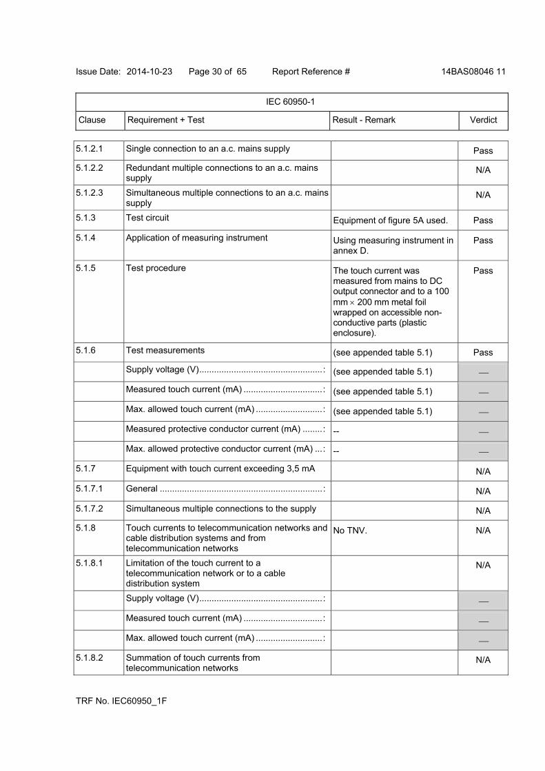
5.1.2.1 Single connection to an a.c. mains supply Pass
5.1.2.2 Redundant multiple connections to an a.c. mains supply
N/A
5.1.2.3 Simultaneous multiple connections to an a.c. mains supply
N/A
5.1.3 Test circuit Equipment of figure 5A used. Pass
5.1.4 Application of measuring instrument Using measuring instrument in annex D.
Pass
5.1.5 Test procedure The touch current was measured from mains to DC output connector and to a 100 mm 200 mm metal foil wrapped on accessible non-conductive parts (plastic enclosure).
Pass
5.1.6 Test measurements (see appended table 5.1) Pass
Supply voltage (V)..................................................: (see appended table 5.1)
Measured touch current (mA) ................................: (see appended table 5.1)
Max. allowed touch current (mA) ...........................: (see appended table 5.1)
Measured protective conductor current (mA) ........: --
Max. allowed protective conductor current (mA) ...: --
5.1.7 Equipment with touch current exceeding 3,5 mA N/A
5.1.7.1 General ..................................................................: N/A
5.1.7.2 Simultaneous multiple connections to the supply N/A
5.1.8 Touch currents to telecommunication networks and cable distribution systems and from telecommunication networks
No TNV. N/A
5.1.8.1 Limitation of the touch current to a telecommunication network or to a cable distribution system
N/A
Supply voltage (V)..................................................:
Measured touch current (mA) ................................:
Max. allowed touch current (mA) ...........................:
5.1.8.2 Summation of touch currents from telecommunication networks
N/A
Issue Date: 2014-10-23 Page 31 of 65 Report Reference # 14BAS08046 11
IEC 60950-1
Clause Requirement + Test Result - Remark Verdict
TRF No. IEC60950_1F
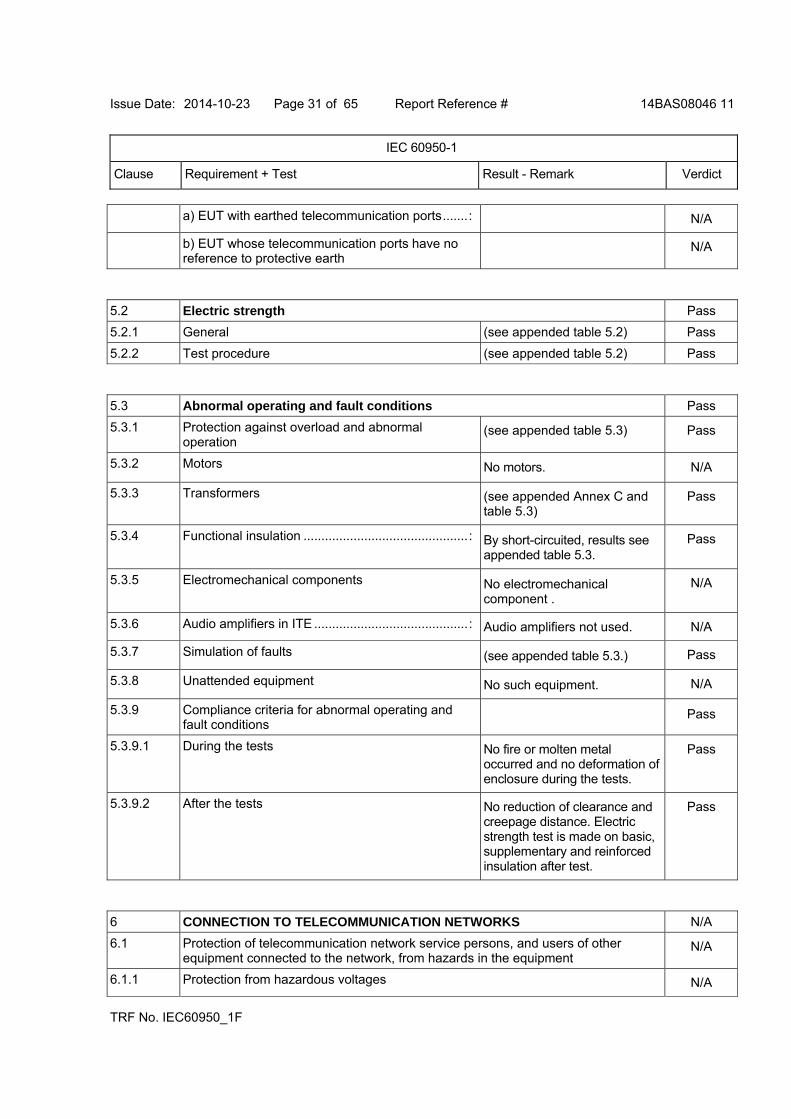
a) EUT with earthed telecommunication ports.......: N/A
b) EUT whose telecommunication ports have no reference to protective earth
N/A
5.2 Electric strength Pass
5.2.1 General (see appended table 5.2) Pass
5.2.2 Test procedure (see appended table 5.2) Pass
5.3 Abnormal operating and fault conditions Pass
5.3.1 Protection against overload and abnormal operation
(see appended table 5.3) Pass
5.3.2 Motors No motors. N/A
5.3.3 Transformers (see appended Annex C and table 5.3)
Pass
5.3.4 Functional insulation ..............................................: By short-circuited, results see appended table 5.3.
Pass
5.3.5 Electromechanical components No electromechanical component .
N/A
5.3.6 Audio amplifiers in ITE ...........................................: Audio amplifiers not used. N/A
5.3.7 Simulation of faults (see appended table 5.3.) Pass
5.3.8 Unattended equipment No such equipment. N/A
5.3.9 Compliance criteria for abnormal operating and fault conditions
Pass
5.3.9.1 During the tests No fire or molten metal occurred and no deformation of enclosure during the tests.
Pass
5.3.9.2 After the tests No reduction of clearance and creepage distance. Electric strength test is made on basic, supplementary and reinforced insulation after test.
Pass
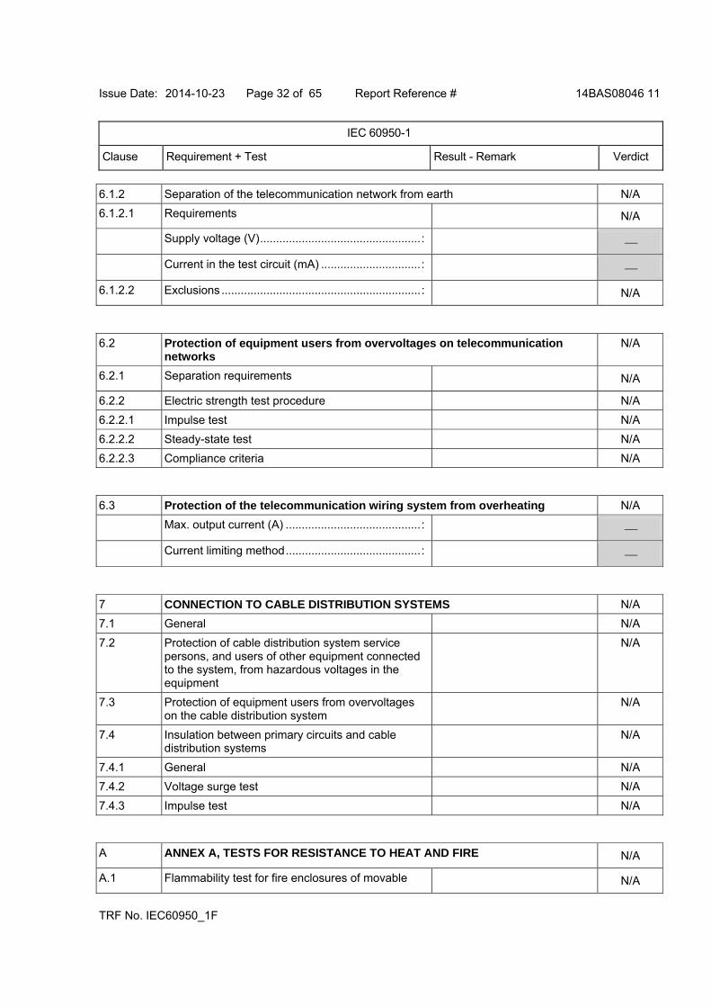
6 CONNECTION TO TELECOMMUNICATION NETWORKS N/A
6.1 Protection of telecommunication network service persons, and users of other equipment connected to the network, from hazards in the equipment
N/A
6.1.1 Protection from hazardous voltages N/A
Issue Date: 2014-10-23 Page 32 of 65 Report Reference # 14BAS08046 11
IEC 60950-1
Clause Requirement + Test Result - Remark Verdict
TRF No. IEC60950_1F
6.1.2 Separation of the telecommunication network from earth N/A
6.1.2.1 Requirements N/A
Supply voltage (V)..................................................:
Current in the test circuit (mA) ...............................:
6.1.2.2 Exclusions ..............................................................: N/A
6.2 Protection of equipment users from overvoltages on telecommunication networks
N/A
6.2.1 Separation requirements N/A
6.2.2 Electric strength test procedure N/A
6.2.2.1 Impulse test N/A
6.2.2.2 Steady-state test N/A
6.2.2.3 Compliance criteria N/A
6.3 Protection of the telecommunication wiring system from overheating N/A
Max. output current (A) ..........................................:
Current limiting method..........................................:
7 CONNECTION TO CABLE DISTRIBUTION SYSTEMS N/A
7.1 General N/A
7.2 Protection of cable distribution system service persons, and users of other equipment connected to the system, from hazardous voltages in the equipment
N/A
7.3 Protection of equipment users from overvoltages on the cable distribution system
N/A
7.4 Insulation between primary circuits and cable distribution systems
N/A
7.4.1 General N/A
7.4.2 Voltage surge test N/A
7.4.3 Impulse test N/A
A ANNEX A, TESTS FOR RESISTANCE TO HEAT AND FIRE N/A
A.1 Flammability test for fire enclosures of movable N/A
Issue Date: 2014-10-23 Page 33 of 65 Report Reference # 14BAS08046 11
IEC 60950-1
Clause Requirement + Test Result - Remark Verdict
TRF No. IEC60950_1F
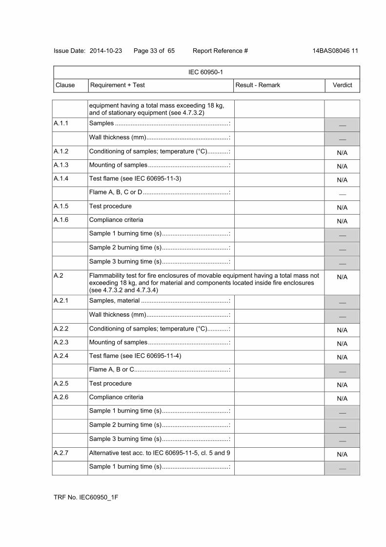
equipment having a total mass exceeding 18 kg, and of stationary equipment (see 4.7.3.2)
A.1.1 Samples .................................................................:
Wall thickness (mm)...............................................:
A.1.2 Conditioning of samples; temperature (°C)............: N/A
A.1.3 Mounting of samples..............................................: N/A
A.1.4 Test flame (see IEC 60695-11-3) N/A
Flame A, B, C or D.................................................:
A.1.5 Test procedure N/A
A.1.6 Compliance criteria N/A
Sample 1 burning time (s)......................................:
Sample 2 burning time (s)......................................:
Sample 3 burning time (s)......................................:
A.2 Flammability test for fire enclosures of movable equipment having a total mass not exceeding 18 kg, and for material and components located inside fire enclosures (see 4.7.3.2 and 4.7.3.4)
N/A
A.2.1 Samples, material ..................................................:
Wall thickness (mm)...............................................:
A.2.2 Conditioning of samples; temperature (°C)............: N/A
A.2.3 Mounting of samples..............................................: N/A
A.2.4 Test flame (see IEC 60695-11-4) N/A
Flame A, B or C......................................................:
A.2.5 Test procedure N/A
A.2.6 Compliance criteria N/A
Sample 1 burning time (s)......................................:
Sample 2 burning time (s)......................................:
Sample 3 burning time (s)......................................:
A.2.7 Alternative test acc. to IEC 60695-11-5, cl. 5 and 9 N/A
Sample 1 burning time (s)......................................:
Issue Date: 2014-10-23 Page 34 of 65 Report Reference # 14BAS08046 11
IEC 60950-1
Clause Requirement + Test Result - Remark Verdict
TRF No. IEC60950_1F
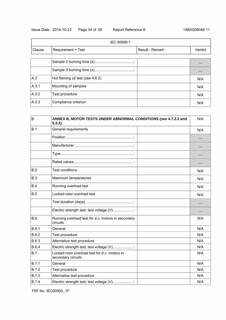
Sample 2 burning time (s)......................................:
Sample 3 burning time (s)......................................:
A.3 Hot flaming oil test (see 4.6.2) N/A
A.3.1 Mounting of samples N/A
A.3.2 Test procedure N/A
A.3.3 Compliance criterion N/A
B ANNEX B, MOTOR TESTS UNDER ABNORMAL CONDITIONS (see 4.7.2.2 and 5.3.2)
N/A
B.1 General requirements N/A
Position ..................................................................:
Manufacturer ..........................................................:
Type .......................................................................:
Rated values ..........................................................:
B.2 Test conditions N/A
B.3 Maximum temperatures N/A
B.4 Running overload test N/A
B.5 Locked-rotor overload test N/A
Test duration (days) ...............................................:
Electric strength test: test voltage (V) ....................:
B.6 Running overload test for d.c. motors in secondary circuits
N/A
B.6.1 General N/A
B.6.2 Test procedure N/A
B.6.3 Alternative test procedure N/A
B.6.4 Electric strength test; test voltage (V) ....................: N/A
B.7 Locked-rotor overload test for d.c. motors in secondary circuits
N/A
B.7.1 General N/A
B.7.2 Test procedure N/A
B.7.3 Alternative test procedure N/A
B.7.4 Electric strength test; test voltage (V) ....................: N/A
Issue Date: 2014-10-23 Page 35 of 65 Report Reference # 14BAS08046 11
IEC 60950-1
Clause Requirement + Test Result - Remark Verdict
TRF No. IEC60950_1F
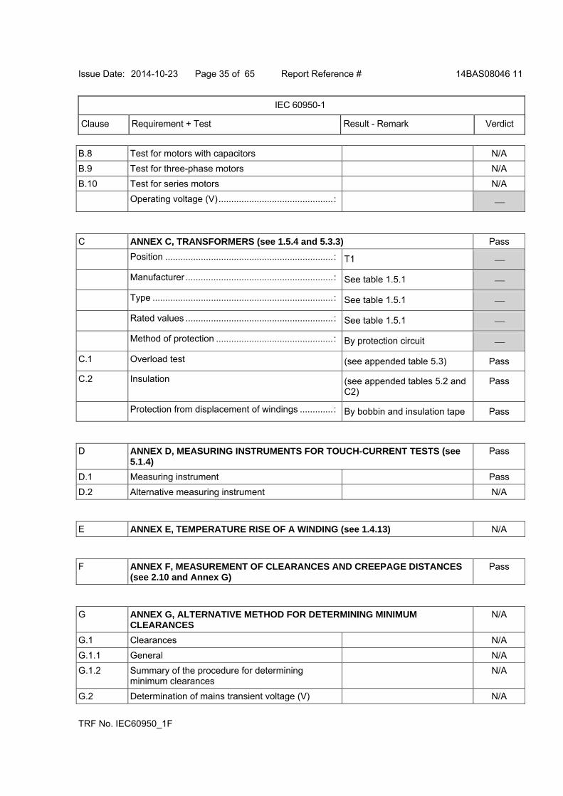
B.8 Test for motors with capacitors N/A
B.9 Test for three-phase motors N/A
B.10 Test for series motors N/A
Operating voltage (V).............................................:
C ANNEX C, TRANSFORMERS (see 1.5.4 and 5.3.3) Pass
Position ..................................................................: T1
Manufacturer ..........................................................: See table 1.5.1
Type .......................................................................: See table 1.5.1
Rated values ..........................................................: See table 1.5.1
Method of protection ..............................................: By protection circuit
C.1 Overload test (see appended table 5.3) Pass
C.2 Insulation (see appended tables 5.2 and C2)
Pass
Protection from displacement of windings .............: By bobbin and insulation tape Pass
D ANNEX D, MEASURING INSTRUMENTS FOR TOUCH-CURRENT TESTS (see 5.1.4)
Pass
D.1 Measuring instrument Pass
D.2 Alternative measuring instrument N/A
E ANNEX E, TEMPERATURE RISE OF A WINDING (see 1.4.13) N/A
F ANNEX F, MEASUREMENT OF CLEARANCES AND CREEPAGE DISTANCES (see 2.10 and Annex G)
Pass
G ANNEX G, ALTERNATIVE METHOD FOR DETERMINING MINIMUM CLEARANCES
N/A
G.1 Clearances N/A
G.1.1 General N/A
G.1.2 Summary of the procedure for determining minimum clearances
N/A
G.2 Determination of mains transient voltage (V) N/A
Issue Date: 2014-10-23 Page 36 of 65 Report Reference # 14BAS08046 11
IEC 60950-1
Clause Requirement + Test Result - Remark Verdict
TRF No. IEC60950_1F
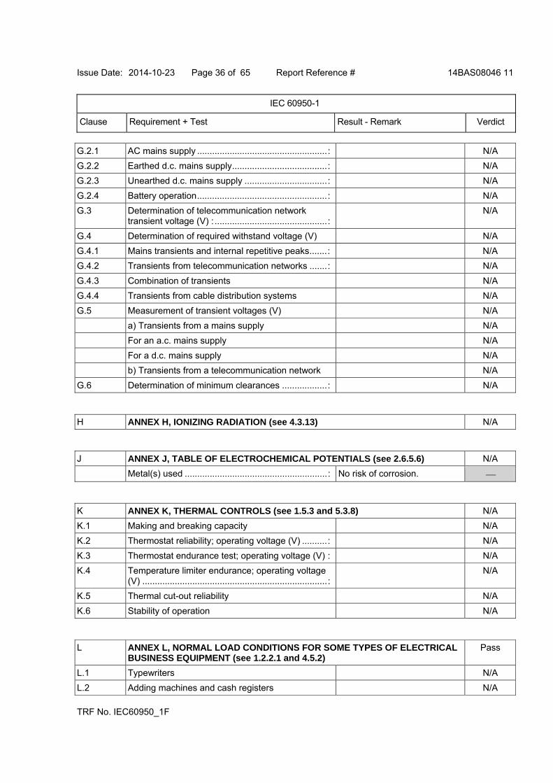
G.2.1 AC mains supply ....................................................: N/A
G.2.2 Earthed d.c. mains supply......................................: N/A
G.2.3 Unearthed d.c. mains supply .................................: N/A
G.2.4 Battery operation....................................................: N/A
G.3 Determination of telecommunication network transient voltage (V) :.............................................:
N/A
G.4 Determination of required withstand voltage (V) N/A
G.4.1 Mains transients and internal repetitive peaks.......: N/A
G.4.2 Transients from telecommunication networks .......: N/A
G.4.3 Combination of transients N/A
G.4.4 Transients from cable distribution systems N/A
G.5 Measurement of transient voltages (V) N/A
a) Transients from a mains supply N/A
For an a.c. mains supply N/A
For a d.c. mains supply N/A
b) Transients from a telecommunication network N/A
G.6 Determination of minimum clearances ..................: N/A
H ANNEX H, IONIZING RADIATION (see 4.3.13) N/A
J ANNEX J, TABLE OF ELECTROCHEMICAL POTENTIALS (see 2.6.5.6) N/A
Metal(s) used .........................................................: No risk of corrosion.
K ANNEX K, THERMAL CONTROLS (see 1.5.3 and 5.3.8) N/A
K.1 Making and breaking capacity N/A
K.2 Thermostat reliability; operating voltage (V) ..........: N/A
K.3 Thermostat endurance test; operating voltage (V) : N/A
K.4 Temperature limiter endurance; operating voltage (V) ..........................................................................:
N/A
K.5 Thermal cut-out reliability N/A
K.6 Stability of operation N/A
L ANNEX L, NORMAL LOAD CONDITIONS FOR SOME TYPES OF ELECTRICAL BUSINESS EQUIPMENT (see 1.2.2.1 and 4.5.2)
Pass
L.1 Typewriters N/A
L.2 Adding machines and cash registers N/A
Issue Date: 2014-10-23 Page 37 of 65 Report Reference # 14BAS08046 11
IEC 60950-1
Clause Requirement + Test Result - Remark Verdict
TRF No. IEC60950_1F
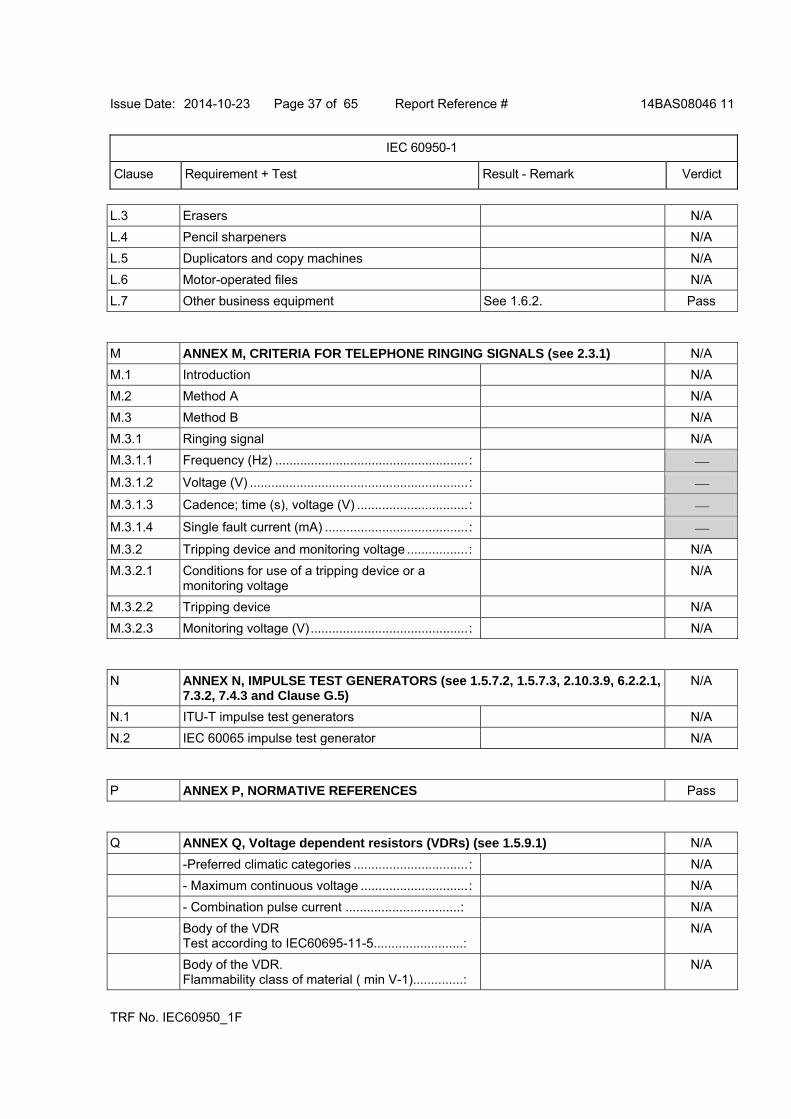
L.3 Erasers N/A
L.4 Pencil sharpeners N/A
L.5 Duplicators and copy machines N/A
L.6 Motor-operated files N/A
L.7 Other business equipment See 1.6.2. Pass
M ANNEX M, CRITERIA FOR TELEPHONE RINGING SIGNALS (see 2.3.1) N/A
M.1 Introduction N/A
M.2 Method A N/A
M.3 Method B N/A
M.3.1 Ringing signal N/A
M.3.1.1 Frequency (Hz) ......................................................:
M.3.1.2 Voltage (V) .............................................................:
M.3.1.3 Cadence; time (s), voltage (V) ...............................:
M.3.1.4 Single fault current (mA) ........................................:
M.3.2 Tripping device and monitoring voltage .................: N/A
M.3.2.1 Conditions for use of a tripping device or a monitoring voltage
N/A
M.3.2.2 Tripping device N/A
M.3.2.3 Monitoring voltage (V)............................................: N/A
N ANNEX N, IMPULSE TEST GENERATORS (see 1.5.7.2, 1.5.7.3, 2.10.3.9, 6.2.2.1, 7.3.2, 7.4.3 and Clause G.5)
N/A
N.1 ITU-T impulse test generators N/A
N.2 IEC 60065 impulse test generator N/A
P ANNEX P, NORMATIVE REFERENCES Pass
Q ANNEX Q, Voltage dependent resistors (VDRs) (see 1.5.9.1) N/A
-Preferred climatic categories ................................: N/A
- Maximum continuous voltage ..............................: N/A
- Combination pulse current ................................: N/A
Body of the VDR Test according to IEC60695-11-5.........................:
N/A
Body of the VDR. Flammability class of material ( min V-1)..............:
N/A
Issue Date: 2014-10-23 Page 38 of 65 Report Reference # 14BAS08046 11
IEC 60950-1
Clause Requirement + Test Result - Remark Verdict
TRF No. IEC60950_1F
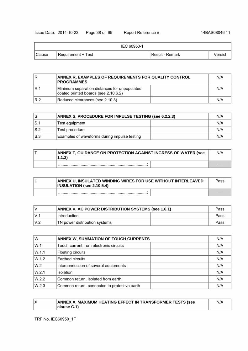
R ANNEX R, EXAMPLES OF REQUIREMENTS FOR QUALITY CONTROL PROGRAMMES
N/A
R.1 Minimum separation distances for unpopulated coated printed boards (see 2.10.6.2)
N/A
R.2 Reduced clearances (see 2.10.3) N/A
S ANNEX S, PROCEDURE FOR IMPULSE TESTING (see 6.2.2.3) N/A
S.1 Test equipment N/A
S.2 Test procedure N/A
S.3 Examples of waveforms during impulse testing N/A
T ANNEX T, GUIDANCE ON PROTECTION AGAINST INGRESS OF WATER (see 1.1.2)
N/A
...............................................................................:
U ANNEX U, INSULATED WINDING WIRES FOR USE WITHOUT INTERLEAVED INSULATION (see 2.10.5.4)
Pass
...............................................................................:
V ANNEX V, AC POWER DISTRIBUTION SYSTEMS (see 1.6.1) Pass
V.1 Introduction Pass
V.2 TN power distribution systems Pass
W ANNEX W, SUMMATION OF TOUCH CURRENTS N/A
W.1 Touch current from electronic circuits N/A
W.1.1 Floating circuits N/A
W.1.2 Earthed circuits N/A
W.2 Interconnection of several equipments N/A
W.2.1 Isolation N/A
W.2.2 Common return, isolated from earth N/A
W.2.3 Common return, connected to protective earth N/A
X ANNEX X, MAXIMUM HEATING EFFECT IN TRANSFORMER TESTS (see clause C.1)
N/A
Issue Date: 2014-10-23 Page 39 of 65 Report Reference # 14BAS08046 11
IEC 60950-1
Clause Requirement + Test Result - Remark Verdict
TRF No. IEC60950_1F
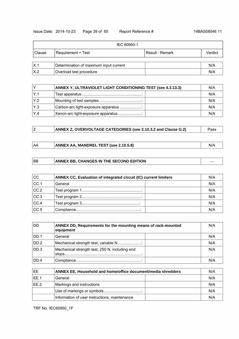
X.1 Determination of maximum input current N/A
X.2 Overload test procedure N/A
Y ANNEX Y, ULTRAVIOLET LIGHT CONDITIONING TEST (see 4.3.13.3) N/A
Y.1 Test apparatus .......................................................: N/A
Y.2 Mounting of test samples .......................................: N/A
Y.3 Carbon-arc light-exposure apparatus ....................: N/A
Y.4 Xenon-arc light-exposure apparatus......................: N/A
Z ANNEX Z, OVERVOLTAGE CATEGORIES (see 2.10.3.2 and Clause G.2) Pass
AA ANNEX AA, MANDREL TEST (see 2.10.5.8) N/A
BB ANNEX BB, CHANGES IN THE SECOND EDITION
CC ANNEX CC, Evaluation of integrated circuit (IC) current limiters N/A
CC.1 General N/A
CC.2 Test program 1.......................................................: N/A
CC.3 Test program 2.......................................................: N/A
CC.4 Test program 3.....................................................: N/A
CC.5 Compliance...........................................................: N/A
DD ANNEX DD, Requirements for the mounting means of rack-mounted equipment
N/A
DD.1 General N/A
DD.2 Mechanical strength test, variable N......................: N/A
DD.3 Mechanical strength test, 250 N, including end stops.......................................................................:
N/A
DD.4 Compliance ............................................................: N/A
EE ANNEX EE, Household and home/office document/media shredders N/A
EE.1 General N/A
EE.2 Markings and instructions N/A
Use of markings or symbols...................................: N/A
Information of user instructions, maintenance N/A
Issue Date: 2014-10-23 Page 40 of 65 Report Reference # 14BAS08046 11
IEC 60950-1
Clause Requirement + Test Result - Remark Verdict
TRF No. IEC60950_1F
and/or servicing instructions ..................................:
EE.3 Inadvertent reactivation test...................................: N/A
EE.4 Disconnection of power to hazardous moving parts N/A
Use of markings or symbols...................................: N/A
EE.5 Protection against hazardous moving parts...........: N/A
Test with test finger (Figure 2A) N/A
Test with wedge probe (Figure EE1 and EE2) ......: N/A
Issue Date: 2014-10-23 Page 41 of 65 Report Reference # 14BAS08046 11
IEC 60950-1
Clause Requirement + Test Result - Remark Verdict
TRF No. IEC60950_1F
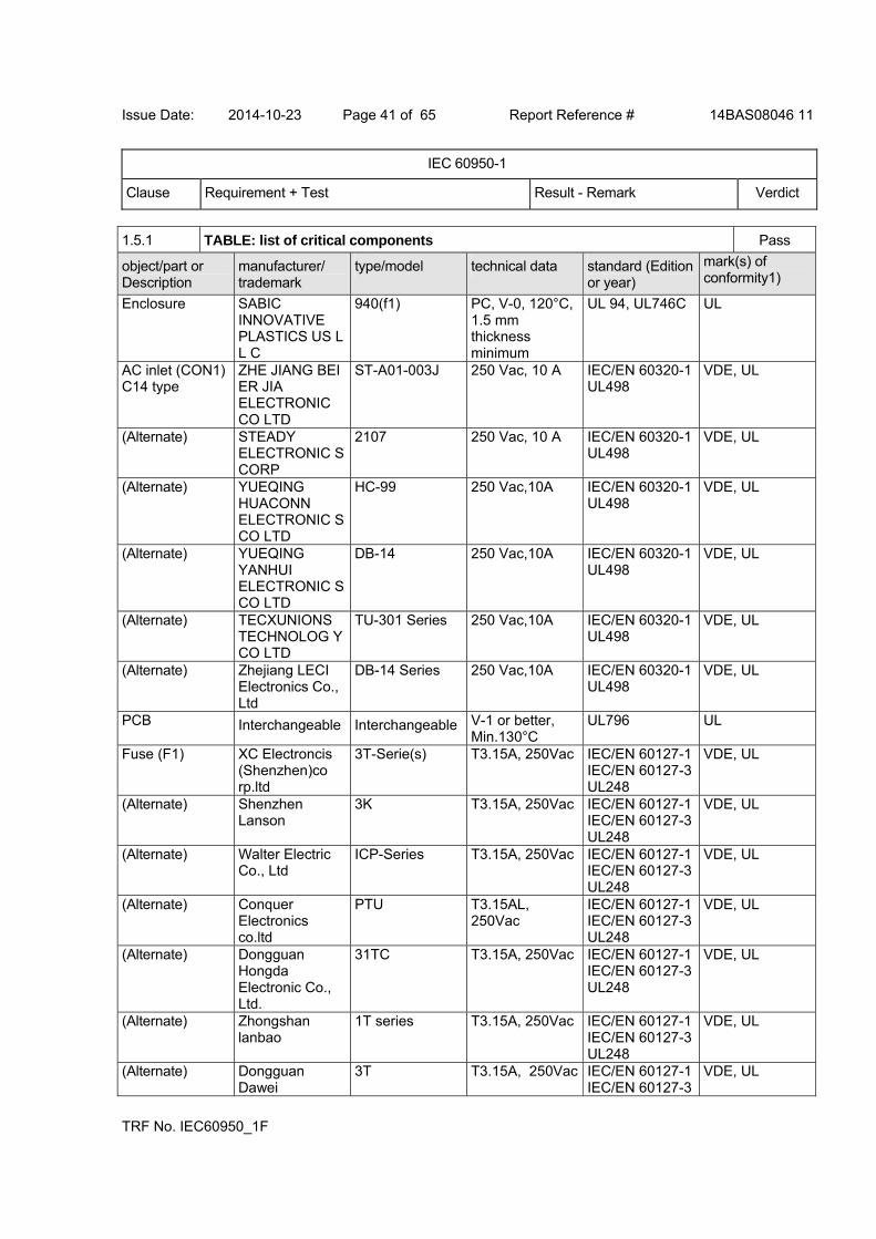
1.5.1 TABLE: list of critical components Pass
object/part or Description
manufacturer/ trademark
type/model technical data standard (Edition or year)
mark(s) of conformity1)
Enclosure SABIC INNOVATIVE PLASTICS US L L C
940(f1) PC, V-0, 120°C, 1.5 mm thickness minimum
UL 94, UL746C UL
AC inlet (CON1) C14 type
ZHE JIANG BEI ER JIA ELECTRONIC CO LTD
ST-A01-003J 250 Vac, 10 A IEC/EN 60320-1 UL498
VDE, UL
(Alternate) STEADY ELECTRONIC S CORP
2107 250 Vac, 10 A IEC/EN 60320-1 UL498
VDE, UL
(Alternate) YUEQING HUACONN ELECTRONIC S CO LTD
HC-99 250 Vac,10A IEC/EN 60320-1 UL498
VDE, UL
(Alternate) YUEQING YANHUI ELECTRONIC S CO LTD
DB-14 250 Vac,10A IEC/EN 60320-1 UL498
VDE, UL
(Alternate) TECXUNIONS TECHNOLOG Y CO LTD
TU-301 Series 250 Vac,10A IEC/EN 60320-1 UL498
VDE, UL
(Alternate) Zhejiang LECI Electronics Co., Ltd
DB-14 Series 250 Vac,10A IEC/EN 60320-1 UL498
VDE, UL
PCB Interchangeable Interchangeable V-1 or better, Min.130°C
UL796 UL
Fuse (F1) XC Electroncis (Shenzhen)co rp.ltd
3T-Serie(s) T3.15A, 250Vac IEC/EN 60127-1 IEC/EN 60127-3 UL248
VDE, UL
(Alternate) Shenzhen Lanson
3K T3.15A, 250Vac IEC/EN 60127-1 IEC/EN 60127-3 UL248
VDE, UL
(Alternate) Walter Electric Co., Ltd
ICP-Series T3.15A, 250Vac IEC/EN 60127-1 IEC/EN 60127-3 UL248
VDE, UL
(Alternate) Conquer Electronics co.ltd
PTU T3.15AL, 250Vac
IEC/EN 60127-1 IEC/EN 60127-3 UL248
VDE, UL
(Alternate) Dongguan Hongda Electronic Co., Ltd.
31TC T3.15A, 250Vac IEC/EN 60127-1 IEC/EN 60127-3 UL248
VDE, UL
(Alternate) Zhongshan lanbao
1T series T3.15A, 250Vac IEC/EN 60127-1 IEC/EN 60127-3 UL248
VDE, UL
(Alternate) Dongguan Dawei
3T T3.15A, 250Vac IEC/EN 60127-1 IEC/EN 60127-3
VDE, UL
Issue Date: 2014-10-23 Page 42 of 65 Report Reference # 14BAS08046 11
IEC 60950-1
Clause Requirement + Test Result - Remark Verdict
TRF No. IEC60950_1F
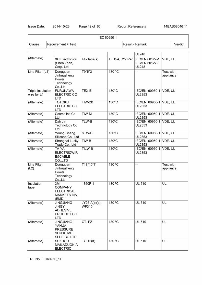
UL248 (Alternate) XC Electronics
(Shen Zhen) Corp. Ltd.
4T-Serie(s) T3.15A, 250Vac IEC/EN 60127-1 IEC/EN 60127-3 UL248
VDE, UL
Line Filter (L1) Dongguan Jinhuasheng Power Technology Co.,Ltd
T9*5*3 130 °C -- Test with appliance
Triple insulation wire for L1
FURUKAWA ELECTRIC CO LTD
TEX-E 130°C IEC/EN 60950-1 UL2353
VDE, UL
(Alternate) TOTOKU ELECTRIC CO LTD
TIW-2X 130°C IEC/EN 60950-1 UL2353
VDE, UL
(Alternate) Cosmolink Co Ltd
TIW-M 130°C IEC/EN 60950-1 UL2353
VDE, UL
(Alternate) Dah Jin Technology Co Ltd
TLW-B 130ºC IEC/EN 60950-1 UL2353
VDE, UL
(Alternate) Young Chang Silicone Co., Ltd
STW-B 130ºC IEC/EN 60950-1 UL2353
VDE, UL
(Alternate) Shanghai Lucky Trade Co., Ltd
TIW-B 130ºC IEC/EN 60950-1 UL2353
VDE, UL
(Alternate) TA YA ELECTRICWIRE&CABLE CO.,LTD
TILW-B 130ºC IEC/EN 60950-1 UL2353
VDE, UL
Line Filter (L2)
Dongguan Jinhuasheng Power Technology Co.,Ltd
T18*10*7 130 ºC -- Test with appliance
Insulation tape
3M COMPANY ELECTRICAL MARKETS DIV (EMD)
1350F-1 130 ºC
UL 510 UL
(Alternate) JINGJIANG JINGYI ADHESIVE PRODUCT CO LTD
JY25-A(b)(c), WF310
130 ºC
UL 510
UL
(Alternate) JINGJIANG YAHUA PRESSURE SENSITIVE SLUE CO LTD
CT, PZ 130 ºC UL 510 UL
(Alternate) SUZHOU MAILADUON A ELECTRIC
JY312(#) 130 ºC UL 510 UL

Issue Date: 2014-10-23 Page 43 of 65 Report Reference # 14BAS08046 11
IEC 60950-1
Clause Requirement + Test Result - Remark Verdict
TRF No. IEC60950_1F
MATERIAL CO LTD
X-Capacitor (CX1)
SHENZHEN SU RONG CAPACITOR S CO LTD
MPX/MKP Min.250V, max.0.47uF, min.100°C. X2 type.
IEC/EN/UL 60384-14
VDE, UL
(Alternate) Shantou High- New Technology Dev. Zone Songtian Enterprise Co., Ltd.
MPX
Min.250V, max.0.47uF, min.100°C. X2 type.
IEC/EN/UL 60384-14
VDE, UL
(Alternate) GUANGDON G SOUTH HONGMING
F Min.250V, max.0.47uF, min.100°C. X2 type.
IEC/EN/UL 60384-14
VDE, UL
(Alternate) Shenzhen Shengxin Capacitor Co.,Ltd
MEX –X2
Min.250V, max.0.47uF, min.100°C. X2 type.
IEC/EN/UL 60384-14
VDE, UL
(Alternate) Hongzhi Enterprises ltd
MPX Min.250V, max.0.47uF, min.100°C. X2 type.
IEC/EN/UL 60384-14
VDE, UL
(Alternate) Liow Gu Electronics Industry Co.,Ltd
GS-L Min.250V, max.0.47uF, min.100°C. X2 type.
IEC/EN/UL 60384-14
VDE, UL
(Alternate) Shenzhen Sinceritty Technology Co..Ltd
MPX/MKP Min.250V, max.0.47uF, min.100°C. X2 type.
IEC/EN/UL 60384-14
VDE, UL
(Alternate) Foshan City Nanhai District Xinyuan Electronic Co.,Ltd
MEX-X2 Min.250V, max.0.47uF, min.100°C. X2 type.
IEC/EN/UL 60384-14
VDE, UL
(Alternate) FOSHAN CITY NANHAI DISTRICT XINYUAN ELECTRONIC CO LTD
MKP-X2 Min.250V, max.0.47uF, min.100°C. X2 type.
IEC/EN/UL 60384-14
VDE, UL
(Alternate) DONGGUAN CITY JURCC ELECTRONICS CO LTD
MPX/MKP # Min.250V, max.0.47uF, min.100°C. X2 type.
IEC/EN/UL 60384-14
VDE, UL
Bleeder resistor (R1, R2, R1X, R2X)
Interchangeable Interchangeable 1M ohm, min. 1/4W.
-- Test with appliance
Bridge Diode (BD1)
Interchangeable Interchangeable Min. 2A, min. 600 V
-- Test with appliance
Issue Date: 2014-10-23 Page 44 of 65 Report Reference # 14BAS08046 11
IEC 60950-1
Clause Requirement + Test Result - Remark Verdict
TRF No. IEC60950_1F
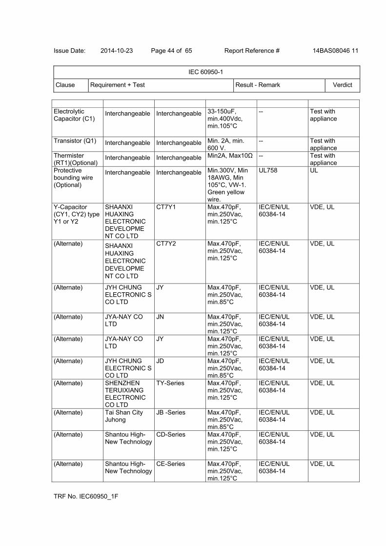
Electrolytic Capacitor (C1)
Interchangeable Interchangeable 33-150uF, min.400Vdc, min.105°C
-- Test with appliance
Transistor (Q1) Interchangeable Interchangeable Min. 2A, min. 600 V.
-- Test with appliance
Thermister (RT1)(Optional)
Interchangeable Interchangeable Min2A, Max10Ω
-- Test with appliance
Protective bounding wire (Optional)
Interchangeable Interchangeable Min.300V, Min 18AWG, Min 105°C, VW-1. Green yellow wire.
UL758 UL
Y-Capacitor (CY1, CY2) type Y1 or Y2
SHAANXI HUAXING ELECTRONIC DEVELOPME NT CO LTD
CT7Y1 Max.470pF, min.250Vac, min.125°C
IEC/EN/UL 60384-14
VDE, UL
(Alternate) SHAANXI HUAXING ELECTRONIC DEVELOPME NT CO LTD
CT7Y2 Max.470pF, min.250Vac, min.125°C
IEC/EN/UL 60384-14
VDE, UL
(Alternate) JYH CHUNG ELECTRONIC S CO LTD
JY Max.470pF, min.250Vac, min.85°C
IEC/EN/UL 60384-14
VDE, UL
(Alternate) JYA-NAY CO LTD
JN Max.470pF, min.250Vac, min.125°C
IEC/EN/UL 60384-14
VDE, UL
(Alternate) JYA-NAY CO LTD
JY Max.470pF, min.250Vac, min.125°C
IEC/EN/UL 60384-14
VDE, UL
(Alternate) JYH CHUNG ELECTRONIC S CO LTD
JD Max.470pF, min.250Vac, min.85°C
IEC/EN/UL 60384-14
VDE, UL
(Alternate) SHENZHEN TERUIXIANG ELECTRONIC CO LTD
TY-Series Max.470pF, min.250Vac, min.125°C
IEC/EN/UL 60384-14
VDE, UL
(Alternate) Tai Shan City Juhong
JB -Series Max.470pF, min.250Vac, min.85°C
IEC/EN/UL 60384-14
VDE, UL
(Alternate) Shantou High-New Technology
CD-Series Max.470pF, min.250Vac, min.125°C
IEC/EN/UL 60384-14
VDE, UL
(Alternate) Shantou High-New Technology
CE-Series Max.470pF, min.250Vac, min.125°C
IEC/EN/UL 60384-14
VDE, UL

Issue Date: 2014-10-23 Page 45 of 65 Report Reference # 14BAS08046 11
IEC 60950-1
Clause Requirement + Test Result - Remark Verdict
TRF No. IEC60950_1F
(Alternate) SUCCESS
ELECTRONIC S CO LTD
SE Max.470pF, min.250Vac, min.125°C
IEC/EN/UL 60384-14
VDE, UL
(Alternate) SUCCESS ELECTRONIC S CO LTD
SB Max.470pF, min.250Vac, min.125°C
IEC/EN/UL 60384-14
VDE, UL
(Alternate) HSUAN TAI ELECTRONIC S CO LTD
CY Max.470pF, min.250Vac, min.125°C
IEC/EN/UL 60384-14
VDE, UL
(Alternate) HSUAN TAI ELECTRONIC S CO LTD
CY Max.470pF, min.250Vac, min.85°C
IEC/EN/UL 60384-14
VDE, UL
(Alternate) GUANGDON G SOUTH HONGMING ELECTRONIC SCIENCE & TECHNOLOG Y CO LTD
F
Max.470pF, min.250Vac, min.125°C
IEC/EN/UL 60384-14
VDE, UL
(Alternate) Shenzhen Haotian Electronics Co.,Ltd
HT
Max.470pF, min.250Vac, min.125°C
IEC/EN/UL 60384-14
VDE, UL
(Alternate) JYH HSU (JEC) ELECTRONICS LTD
JD Max.470pF, min.250Vac, min.125°C
IEC/EN/UL 60384-14
VDE, UL
(Alternate) JYH HSU (JEC) ELECTRONICS LTD
JY Max.470pF, min.250Vac, min.125°C
IEC/EN/UL 60384-14
VDE, UL
(Alternate) Yinan Don's Electronic Component Co., Ltd.
CT81 Max.470pF, min.250Vac, min.125°C
IEC/EN/UL 60384-14
VDE, UL
Y-Capacitor (CY3) type Y1
SHAANXI HUAXING ELECTRONIC DEVELOPME NT CO LTD
CT7Y1
Max.2200pF, min.250Vac, min.125°C
IEC/EN/UL 60384-14
VDE, UL
(Alternate) JYA-NAY CO LTD
JN Max.2200pF, min.250Vac, min.125°C
IEC/EN/UL 60384-14
VDE, UL
(Alternate) SHENZHEN TERUIXIANG ELECTRONIC CO LTD
TY-Series
Max.2200pF, min.250Vac, min.125°C
IEC/EN/UL 60384-14
VDE, UL
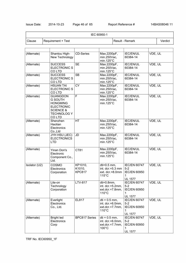
Issue Date: 2014-10-23 Page 46 of 65 Report Reference # 14BAS08046 11
IEC 60950-1
Clause Requirement + Test Result - Remark Verdict
TRF No. IEC60950_1F
(Alternate) Shantou High-
New Technology CD-Series Max.2200pF,
min.250Vac, min.125°C
IEC/EN/UL 60384-14
VDE, UL
(Alternate) SUCCESS ELECTRONIC S CO LTD
SE Max.2200pF, min.250Vac, min.125°C
IEC/EN/UL 60384-14
VDE, UL
(Alternate) SUCCESS ELECTRONIC S CO LTD
SB Max.2200pF, min.250Vac, min.125°C
IEC/EN/UL 60384-14
VDE, UL
(Alternate) HSUAN TAI ELECTRONIC S CO LTD
CY Max.2200pF, min.250Vac, min.125°C
IEC/EN/UL 60384-14
VDE, UL
(Alternate) GUANGDON G SOUTH HONGMING ELECTRONIC SCIENCE & TECHNOLOG Y CO LTD
F Max.2200pF, min.250Vac, min.125°C
IEC/EN/UL 60384-14
VDE, UL
(Alternate) Shenzhen Haotian Electronics Co.,Ltd
HT
Max.2200pF, min.250Vac, min.125°C
IEC/EN/UL 60384-14
VDE, UL
(Alternate) JYH HSU (JEC) ELECTRONICS LTD
JD Max.2200pF, min.250Vac, min.125°C
IEC/EN/UL 60384-14
VDE, UL
(Alternate) Yinan Don's Electronic Component Co., Ltd.
CT81 Max.2200pF, min.250Vac, min.125°C
IEC/EN/UL 60384-14
VDE, UL
Isolator (U2) COSMO Electronics Corporation
KP1010, K1010, KPC817
dti=0.5 mm, int. dcr.=5.3 mm ext. dcr.=8.0mm 115°C
IEC/EN 60747 5-2 IEC/EN 60950 1 UL 1577
VDE, UL
(Alternate) Lite-on Technology Corporation
LTV-817
dti=0.8mm, int. dcr.=5.2mm, ext.dcr.=7.8mm, 110°C
IEC/EN 60747 5-2 IEC/EN 60950 1 UL 1577
VDE, UL
(Alternate) Everlight Electronics Co., Ltd.
EL817
dti = 0.5 mm, int. dcr.=6.0mm, ext.dcr.=7.7mm, 110°C
IEC/EN 60747 5-2 IEC/EN 60950 1 UL 1577
VDE, UL
(Alternate) Bright led Electronics Corp
BPC817 Series
dti = 0.5 mm, int. dcr.=6.0mm, ext.dcr.=7.7mm, 100°C
IEC/EN 60747 5-2 IEC/EN 60950 1 UL 1577
VDE, UL
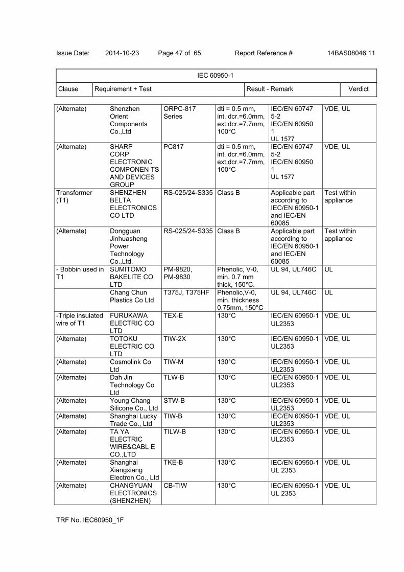
Issue Date: 2014-10-23 Page 47 of 65 Report Reference # 14BAS08046 11
IEC 60950-1
Clause Requirement + Test Result - Remark Verdict
TRF No. IEC60950_1F
(Alternate) Shenzhen Orient Components Co.,Ltd
ORPC-817 Series
dti = 0.5 mm, int. dcr.=6.0mm, ext.dcr.=7.7mm, 100°C
IEC/EN 60747 5-2 IEC/EN 60950 1 UL 1577
VDE, UL
(Alternate) SHARP CORP ELECTRONIC COMPONEN TS AND DEVICES GROUP
PC817
dti = 0.5 mm, int. dcr.=6.0mm, ext.dcr.=7.7mm, 100°C
IEC/EN 60747 5-2 IEC/EN 60950 1 UL 1577
VDE, UL
Transformer (T1)
SHENZHEN BELTA ELECTRONICS CO LTD
RS-025/24-S335
Class B Applicable part according to IEC/EN 60950-1 and IEC/EN 60085
Test within appliance
(Alternate) Dongguan Jinhuasheng Power Technology Co.,Ltd.
RS-025/24-S335
Class B Applicable part according to IEC/EN 60950-1 and IEC/EN 60085
Test within appliance
- Bobbin used in T1
SUMITOMO BAKELITE CO LTD
PM-9820, PM-9830
Phenolic, V-0, min. 0.7 mm thick, 150°C.
UL 94, UL746C UL
Chang Chun Plastics Co Ltd
T375J, T375HF Phenolic,V-0, min. thickness 0.75mm, 150°C
UL 94, UL746C UL
-Triple insulated wire of T1
FURUKAWA ELECTRIC CO LTD
TEX-E 130°C IEC/EN 60950-1 UL2353 下同
VDE, UL
(Alternate) TOTOKU ELECTRIC CO LTD
TIW-2X 130°C IEC/EN 60950-1 UL2353
VDE, UL
(Alternate) Cosmolink Co Ltd
TIW-M 130°C IEC/EN 60950-1 UL2353
VDE, UL
(Alternate) Dah Jin Technology Co Ltd
TLW-B 130°C IEC/EN 60950-1 UL2353
VDE, UL
(Alternate) Young Chang Silicone Co., Ltd
STW-B 130°C IEC/EN 60950-1 UL2353
VDE, UL
(Alternate) Shanghai Lucky Trade Co., Ltd
TIW-B 130°C IEC/EN 60950-1 UL2353
VDE, UL
(Alternate) TA YA ELECTRIC WIRE&CABL E CO.,LTD
TILW-B 130°C IEC/EN 60950-1 UL2353
VDE, UL
(Alternate) Shanghai Xiangxiang Electron Co., Ltd
TKE-B 130°C IEC/EN 60950-1 UL 2353
VDE, UL
(Alternate) CHANGYUAN ELECTRONICS (SHENZHEN)
CB-TIW 130°C IEC/EN 60950-1 UL 2353
VDE, UL
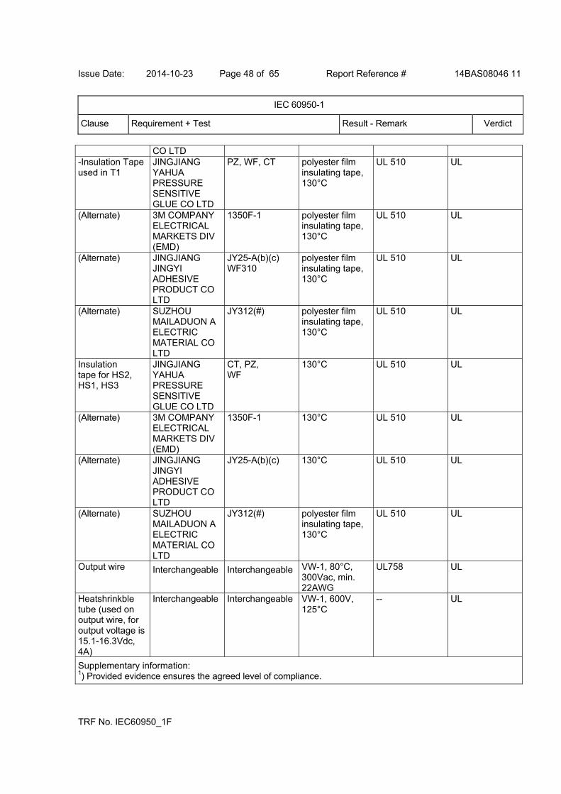
Issue Date: 2014-10-23 Page 48 of 65 Report Reference # 14BAS08046 11
IEC 60950-1
Clause Requirement + Test Result - Remark Verdict
TRF No. IEC60950_1F
CO LTD -Insulation Tape used in T1
JINGJIANG YAHUA PRESSURE SENSITIVE GLUE CO LTD
PZ, WF, CT polyester film insulating tape, 130°C
UL 510 UL
(Alternate) 3M COMPANY ELECTRICAL MARKETS DIV (EMD)
1350F-1 polyester film insulating tape, 130°C
UL 510 UL
(Alternate) JINGJIANG JINGYI ADHESIVE PRODUCT CO LTD
JY25-A(b)(c) WF310
polyester film insulating tape, 130°C
UL 510 UL
(Alternate) SUZHOU MAILADUON A ELECTRIC MATERIAL CO LTD
JY312(#) polyester film insulating tape, 130°C
UL 510 UL
Insulation tape for HS2, HS1, HS3
JINGJIANG YAHUA PRESSURE SENSITIVE GLUE CO LTD
CT, PZ, WF
130°C UL 510 UL
(Alternate) 3M COMPANY ELECTRICAL MARKETS DIV (EMD)
1350F-1 130°C UL 510 UL
(Alternate) JINGJIANG JINGYI ADHESIVE PRODUCT CO LTD
JY25-A(b)(c) 130°C UL 510 UL
(Alternate) SUZHOU MAILADUON A ELECTRIC MATERIAL CO LTD
JY312(#) polyester film insulating tape, 130°C
UL 510 UL
Output wire Interchangeable Interchangeable VW-1, 80°C, 300Vac, min. 22AWG
UL758 UL
Heatshrinkble tube (used on output wire, for output voltage is 15.1-16.3Vdc, 4A)
Interchangeable Interchangeable VW-1, 600V, 125°C
-- UL
Supplementary information: 1) Provided evidence ensures the agreed level of compliance.
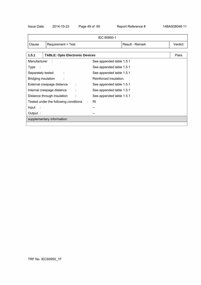
Issue Date: 2014-10-23 Page 49 of 65 Report Reference # 14BAS08046 11
IEC 60950-1
Clause Requirement + Test Result - Remark Verdict
TRF No. IEC60950_1F
1.5.1 TABLE: Opto Electronic Devices Pass
Manufacturer : See appended table 1.5.1
Type : See appended table 1.5.1
Separately tested : See appended table 1.5.1
Bridging insulation : Reinforced insulation.
External creepage distance : See appended table 1.5.1
Internal creepage distance : See appended table 1.5.1
Distance through insulation : See appended table 1.5.1
Tested under the following conditions : RI
Input : --
Output : --
supplementary information:

Issue Date: 2014-10-23 Page 50 of 65 Report Reference # 14BAS08046 11
IEC 60950-1
Clause Requirement + Test Result - Remark Verdict
TRF No. IEC60950_1F
2.1.1.5 c) 1)
TABLE: Max. V, A, VA test Pass
Voltage(rated) (V)
Current(rated) (A)
Voltage (max.) (V)
Current (max.) (A)
VA (max.) (VA)
Model: RS-04/163-S335
16.3 4.0 16.12 5.95 92.3
Model: RS-027/24-S335
24.0 2.7 23.58 3.98 92.5
supplementary information: --
Test Voltage / Frequency: 264V, 60 Hz.
1.6.2 TABLE: electrical data (in normal conditions) Pass
U (V) I (A) I rated (A) P (W) Fuse # I fuse (A) condition/status
For Model: RS-04/163-S335
90V,50Hz 1.307 -- 74.2 F1 1.307 Maximum normal load:16.3Vdc, 4A
90V,60Hz 1.334 -- 74.3 F1 1.334 Same as above
100V,50Hz 1.213 1.2 73.2 F1 1.213 Same as above
100V,60Hz 1.189 1.2 73.3 F1 1.189 Same as above
240V,50Hz 0.546 1.2 71.4 F1 0.546 Same as above
240V,60Hz 0.538 1.2 71.5 F1 0.538 Same as above
264V,50Hz 0.504 -- 71.5 F1 0.504 Same as above
264V,60Hz 0.501 -- 71.7 F1 0.501 Same as above
For Model: RS-027/24-S335
90V,50Hz 1.239 -- 70.5 F1 1.239 Maximum normal load:24Vdc, 2.7A
90V,60Hz 1.258 -- 70.7 F1 1.258 Same as above
100V,50Hz 1.130 1.2 70.0 F1 1.130 Same as above
100V,60Hz 1.149 1.2 70.1 F1 1.149 Same as above
240V,50Hz 0.520 1.2 68.2 F1 0.520 Same as above
240V,60Hz 0.515 1.2 68.4 F1 0.515 Same as above
264V,50Hz 0.481 -- 68.1 F1 0.481 Same as above
264V,60Hz 0.475 -- 68.2 F1 0.475 Same as above
supplementary information:
Test result: the steady state input current did not exceed the rated current at the rated voltage by more than 10 percent under maximum normal load.
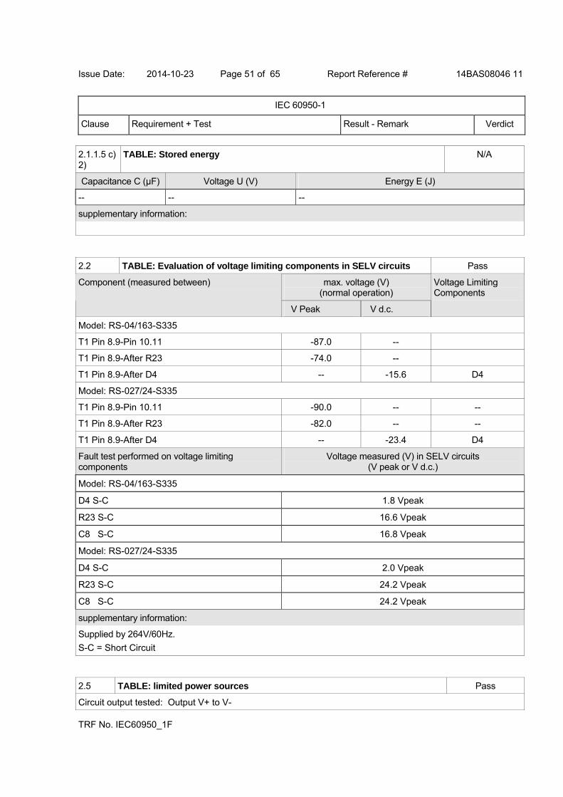
Issue Date: 2014-10-23 Page 51 of 65 Report Reference # 14BAS08046 11
IEC 60950-1
Clause Requirement + Test Result - Remark Verdict
TRF No. IEC60950_1F
2.1.1.5 c) 2)
TABLE: Stored energy N/A
Capacitance C (µF) Voltage U (V) Energy E (J)
-- -- --
supplementary information:
2.2 TABLE: Evaluation of voltage limiting components in SELV circuits Pass
max. voltage (V) (normal operation)
Component (measured between)
V Peak V d.c.
Voltage Limiting Components
Model: RS-04/163-S335
T1 Pin 8.9-Pin 10.11 -87.0 --
T1 Pin 8.9-After R23 -74.0 --
T1 Pin 8.9-After D4 -- -15.6 D4
Model: RS-027/24-S335
T1 Pin 8.9-Pin 10.11 -90.0 -- --
T1 Pin 8.9-After R23 -82.0 -- --
T1 Pin 8.9-After D4 -- -23.4 D4
Fault test performed on voltage limiting components
Voltage measured (V) in SELV circuits (V peak or V d.c.)
Model: RS-04/163-S335
D4 S-C 1.8 Vpeak
R23 S-C 16.6 Vpeak
C8 S-C 16.8 Vpeak
Model: RS-027/24-S335
D4 S-C 2.0 Vpeak
R23 S-C 24.2 Vpeak
C8 S-C 24.2 Vpeak
supplementary information:
Supplied by 264V/60Hz.
S-C = Short Circuit
2.5 TABLE: limited power sources Pass
Circuit output tested: Output V+ to V-
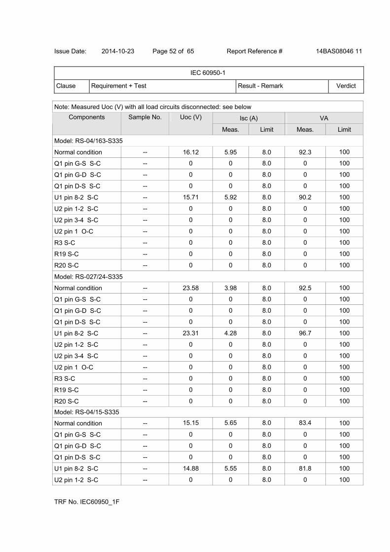
Issue Date: 2014-10-23 Page 52 of 65 Report Reference # 14BAS08046 11
IEC 60950-1
Clause Requirement + Test Result - Remark Verdict
TRF No. IEC60950_1F
Note: Measured Uoc (V) with all load circuits disconnected: see below
Isc (A) VA Components Sample No. Uoc (V)
Meas. Limit Meas. Limit
Model: RS-04/163-S335
Normal condition -- 16.12 5.95 8.0 92.3 100
Q1 pin G-S S-C -- 0 0 8.0 0 100
Q1 pin G-D S-C -- 0 0 8.0 0 100
Q1 pin D-S S-C -- 0 0 8.0 0 100
U1 pin 8-2 S-C -- 15.71 5.92 8.0 90.2 100
U2 pin 1-2 S-C -- 0 0 8.0 0 100
U2 pin 3-4 S-C -- 0 0 8.0 0 100
U2 pin 1 O-C -- 0 0 8.0 0 100
R3 S-C -- 0 0 8.0 0 100
R19 S-C -- 0 0 8.0 0 100
R20 S-C -- 0 0 8.0 0 100
Model: RS-027/24-S335
Normal condition -- 23.58 3.98 8.0 92.5 100
Q1 pin G-S S-C -- 0 0 8.0 0 100
Q1 pin G-D S-C -- 0 0 8.0 0 100
Q1 pin D-S S-C -- 0 0 8.0 0 100
U1 pin 8-2 S-C -- 23.31 4.28 8.0 96.7 100
U2 pin 1-2 S-C -- 0 0 8.0 0 100
U2 pin 3-4 S-C -- 0 0 8.0 0 100
U2 pin 1 O-C -- 0 0 8.0 0 100
R3 S-C -- 0 0 8.0 0 100
R19 S-C -- 0 0 8.0 0 100
R20 S-C -- 0 0 8.0 0 100
Model: RS-04/15-S335
Normal condition -- 15.15 5.65 8.0 83.4 100
Q1 pin G-S S-C -- 0 0 8.0 0 100
Q1 pin G-D S-C -- 0 0 8.0 0 100
Q1 pin D-S S-C -- 0 0 8.0 0 100
U1 pin 8-2 S-C -- 14.88 5.55 8.0 81.8 100
U2 pin 1-2 S-C -- 0 0 8.0 0 100
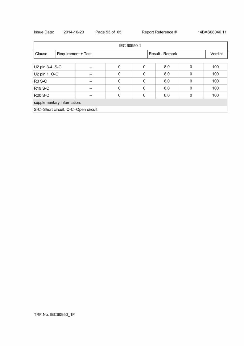
Issue Date: 2014-10-23 Page 53 of 65 Report Reference # 14BAS08046 11
IEC 60950-1
Clause Requirement + Test Result - Remark Verdict
TRF No. IEC60950_1F
U2 pin 3-4 S-C -- 0 0 8.0 0 100
U2 pin 1 O-C -- 0 0 8.0 0 100
R3 S-C -- 0 0 8.0 0 100
R19 S-C -- 0 0 8.0 0 100
R20 S-C -- 0 0 8.0 0 100
supplementary information:
S-C=Short circuit, O-C=Open circuit
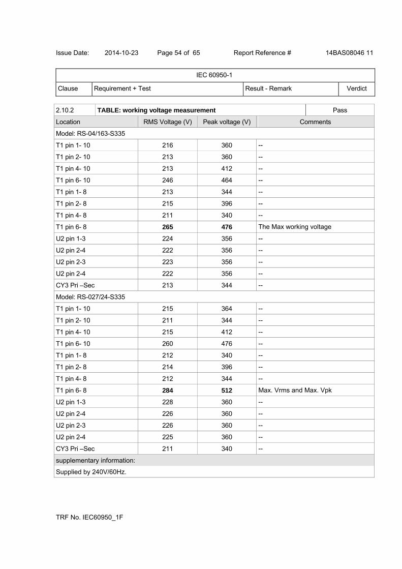
Issue Date: 2014-10-23 Page 54 of 65 Report Reference # 14BAS08046 11
IEC 60950-1
Clause Requirement + Test Result - Remark Verdict
TRF No. IEC60950_1F
2.10.2 TABLE: working voltage measurement Pass
Location RMS Voltage (V) Peak voltage (V) Comments
Model: RS-04/163-S335
T1 pin 1- 10 216 360 --
T1 pin 2- 10 213 360 --
T1 pin 4- 10 213 412 --
T1 pin 6- 10 246 464 --
T1 pin 1- 8 213 344 --
T1 pin 2- 8 215 396 --
T1 pin 4- 8 211 340 --
T1 pin 6- 8 265 476 The Max working voltage
U2 pin 1-3 224 356 --
U2 pin 2-4 222 356 --
U2 pin 2-3 223 356 --
U2 pin 2-4 222 356 --
CY3 Pri –Sec 213 344 --
Model: RS-027/24-S335
T1 pin 1- 10 215 364 --
T1 pin 2- 10 211 344 --
T1 pin 4- 10 215 412 --
T1 pin 6- 10 260 476 --
T1 pin 1- 8 212 340 --
T1 pin 2- 8 214 396 --
T1 pin 4- 8 212 344 --
T1 pin 6- 8 284 512 Max. Vrms and Max. Vpk
U2 pin 1-3 228 360 --
U2 pin 2-4 226 360 --
U2 pin 2-3 226 360 --
U2 pin 2-4 225 360 --
CY3 Pri –Sec 211 340 --
supplementary information:
Supplied by 240V/60Hz.
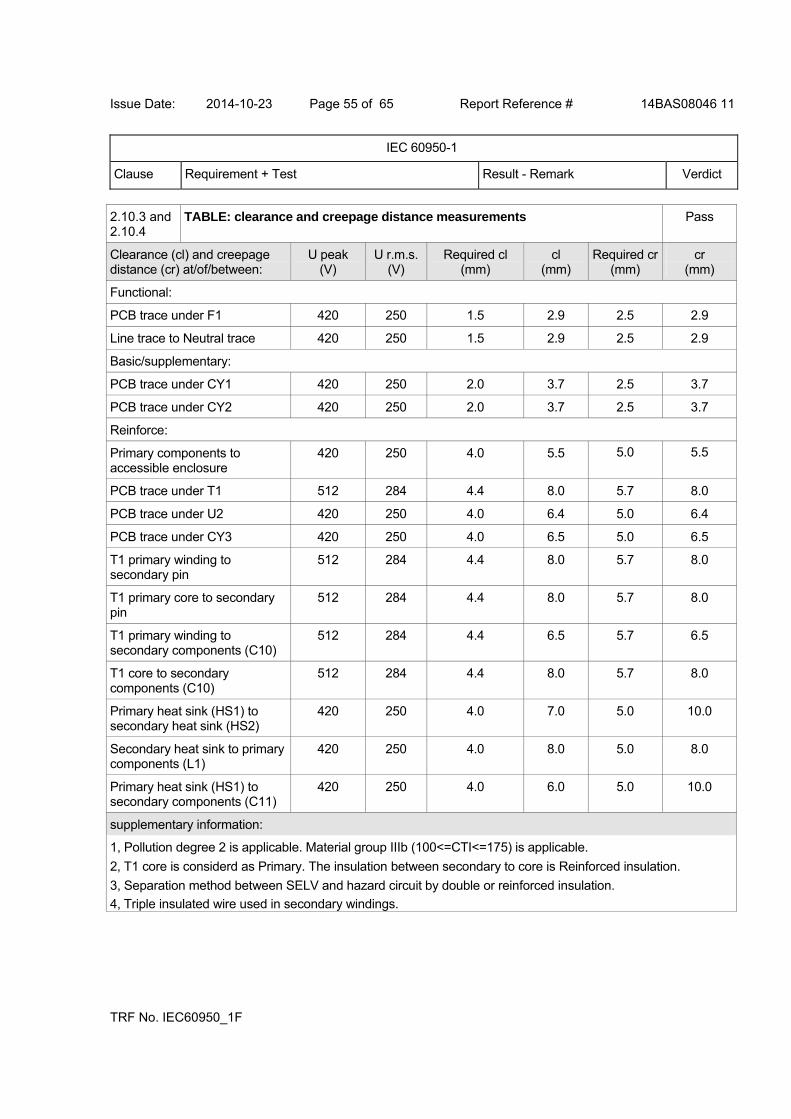
Issue Date: 2014-10-23 Page 55 of 65 Report Reference # 14BAS08046 11
IEC 60950-1
Clause Requirement + Test Result - Remark Verdict
TRF No. IEC60950_1F
2.10.3 and 2.10.4
TABLE: clearance and creepage distance measurements Pass
Clearance (cl) and creepage distance (cr) at/of/between:
U peak (V)
U r.m.s.(V)
Required cl (mm)
cl (mm)
Required cr(mm)
cr (mm)
Functional:
PCB trace under F1 420 250 1.5 2.9 2.5 2.9
Line trace to Neutral trace 420 250 1.5 2.9 2.5 2.9
Basic/supplementary:
PCB trace under CY1 420 250 2.0 3.7 2.5 3.7
PCB trace under CY2 420 250 2.0 3.7 2.5 3.7
Reinforce:
Primary components to accessible enclosure
420 250 4.0 5.5 5.0 5.5
PCB trace under T1 512 284 4.4 8.0 5.7 8.0
PCB trace under U2 420 250 4.0 6.4 5.0 6.4
PCB trace under CY3 420 250 4.0 6.5 5.0 6.5
T1 primary winding to secondary pin
512 284 4.4 8.0 5.7 8.0
T1 primary core to secondary pin
512 284 4.4 8.0 5.7 8.0
T1 primary winding to secondary components (C10)
512 284 4.4 6.5 5.7 6.5
T1 core to secondary components (C10)
512 284 4.4 8.0 5.7 8.0
Primary heat sink (HS1) to secondary heat sink (HS2)
420 250 4.0 7.0 5.0 10.0
Secondary heat sink to primary components (L1)
420 250 4.0 8.0 5.0 8.0
Primary heat sink (HS1) to secondary components (C11)
420 250 4.0 6.0 5.0 10.0
supplementary information:
1, Pollution degree 2 is applicable. Material group IIIb (100<=CTI<=175) is applicable.
2, T1 core is considerd as Primary. The insulation between secondary to core is Reinforced insulation.
3, Separation method between SELV and hazard circuit by double or reinforced insulation.
4, Triple insulated wire used in secondary windings.
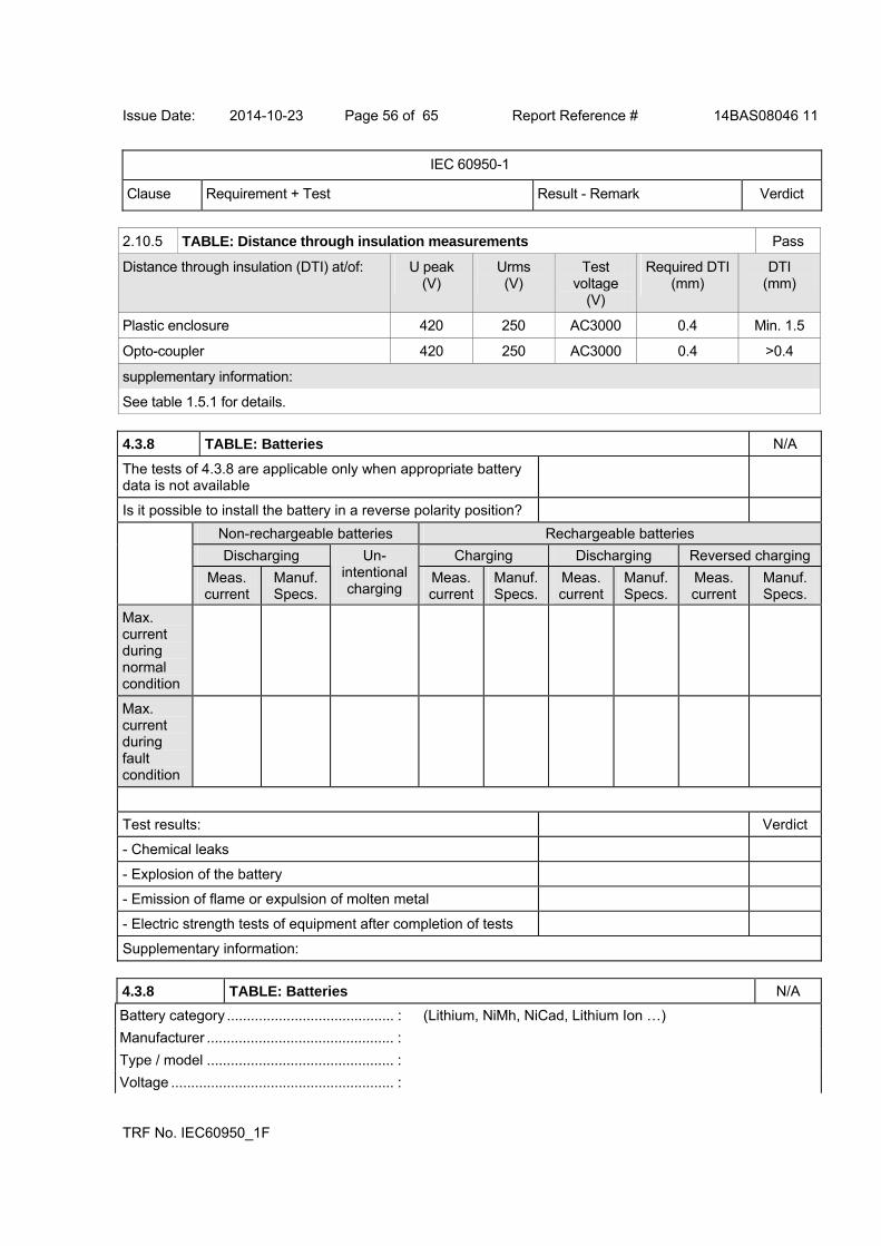
Issue Date: 2014-10-23 Page 56 of 65 Report Reference # 14BAS08046 11
IEC 60950-1
Clause Requirement + Test Result - Remark Verdict
TRF No. IEC60950_1F
2.10.5 TABLE: Distance through insulation measurements Pass
Distance through insulation (DTI) at/of: U peak (V)
Urms (V)
Test voltage
(V)
Required DTI(mm)
DTI (mm)
Plastic enclosure 420 250 AC3000 0.4 Min. 1.5
Opto-coupler 420 250 AC3000 0.4 >0.4
supplementary information:
See table 1.5.1 for details.
4.3.8 TABLE: Batteries N/A
The tests of 4.3.8 are applicable only when appropriate battery data is not available
Is it possible to install the battery in a reverse polarity position?
Non-rechargeable batteries Rechargeable batteries
Discharging Charging Discharging Reversed charging
Meas. current
Manuf. Specs.
Un-intentional charging
Meas. current
Manuf. Specs.
Meas. current
Manuf. Specs.
Meas. current
Manuf. Specs.
Max. current during normal condition
Max. current during fault condition
Test results: Verdict
- Chemical leaks
- Explosion of the battery
- Emission of flame or expulsion of molten metal
- Electric strength tests of equipment after completion of tests
Supplementary information:
4.3.8 TABLE: Batteries N/A
Battery category .......................................... : (Lithium, NiMh, NiCad, Lithium Ion …)
Manufacturer ............................................... :
Type / model ............................................... :
Voltage ........................................................ :
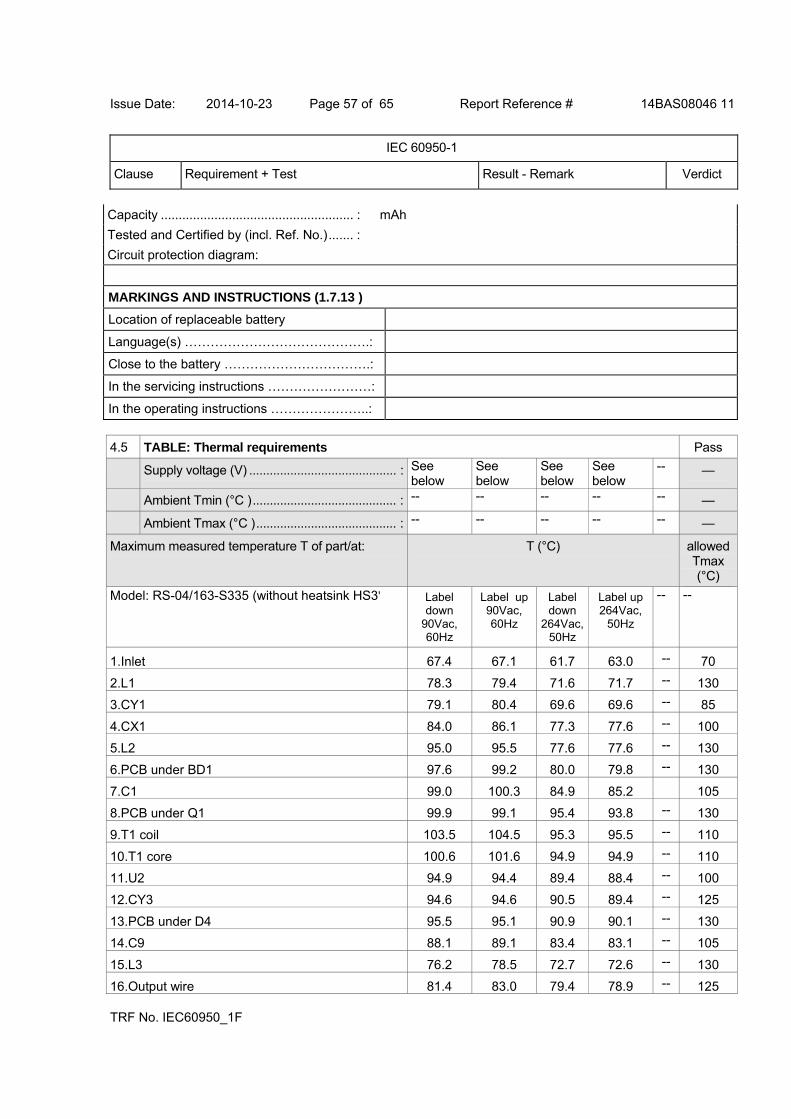
Issue Date: 2014-10-23 Page 57 of 65 Report Reference # 14BAS08046 11
IEC 60950-1
Clause Requirement + Test Result - Remark Verdict
TRF No. IEC60950_1F
Capacity ...................................................... : mAh
Tested and Certified by (incl. Ref. No.)....... :
Circuit protection diagram:
MARKINGS AND INSTRUCTIONS (1.7.13 )
Location of replaceable battery
Language(s) …………………………………….:
Close to the battery …………………………….:
In the servicing instructions ……………………:
In the operating instructions …………………..:
4.5 TABLE: Thermal requirements Pass
Supply voltage (V) ........................................... : See below
See below
See below
See below
-- —
Ambient Tmin (°C ).......................................... : -- -- -- -- -- —
Ambient Tmax (°C )......................................... : -- -- -- -- -- —
Maximum measured temperature T of part/at: T (°C) allowedTmax (°C)
Model: RS-04/163-S335 (without heatsink HS3) Label down
90Vac, 60Hz
Label up 90Vac, 60Hz
Label down
264Vac, 50Hz
Label up 264Vac,
50Hz
-- --
1.Inlet 67.4 67.1 61.7 63.0 -- 70
2.L1 78.3 79.4 71.6 71.7 -- 130
3.CY1 79.1 80.4 69.6 69.6 -- 85
4.CX1 84.0 86.1 77.3 77.6 -- 100
5.L2 95.0 95.5 77.6 77.6 -- 130
6.PCB under BD1 97.6 99.2 80.0 79.8 -- 130
7.C1 99.0 100.3 84.9 85.2 105
8.PCB under Q1 99.9 99.1 95.4 93.8 -- 130
9.T1 coil 103.5 104.5 95.3 95.5 -- 110
10.T1 core 100.6 101.6 94.9 94.9 -- 110
11.U2 94.9 94.4 89.4 88.4 -- 100
12.CY3 94.6 94.6 90.5 89.4 -- 125
13.PCB under D4 95.5 95.1 90.9 90.1 -- 130
14.C9 88.1 89.1 83.4 83.1 -- 105
15.L3 76.2 78.5 72.7 72.6 -- 130
16.Output wire 81.4 83.0 79.4 78.9 -- 125
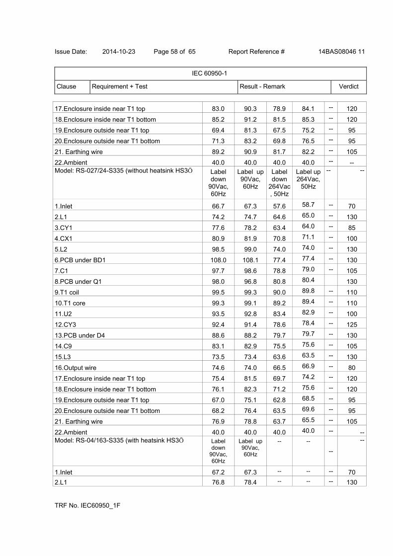
Issue Date: 2014-10-23 Page 58 of 65 Report Reference # 14BAS08046 11
IEC 60950-1
Clause Requirement + Test Result - Remark Verdict
TRF No. IEC60950_1F
17.Enclosure inside near T1 top 83.0 90.3 78.9 84.1 -- 120
18.Enclosure inside near T1 bottom 85.2 91.2 81.5 85.3 -- 120
19.Enclosure outside near T1 top 69.4 81.3 67.5 75.2 -- 95
20.Enclosure outside near T1 bottom 71.3 83.2 69.8 76.5 -- 95
21. Earthing wire 89.2 90.9 81.7 82.2 -- 105
22.Ambient 40.0 40.0 40.0 40.0 -- -- Model: RS-027/24-S335 (without heatsink HS3) Label
down 90Vac, 60Hz
Label up 90Vac, 60Hz
Label down
264Vac, 50Hz
Label up 264Vac,
50Hz
-- --
1.Inlet 66.7 67.3 57.6 58.7 -- 70
2.L1 74.2 74.7 64.6 65.0 -- 130
3.CY1 77.6 78.2 63.4 64.0 -- 85
4.CX1 80.9 81.9 70.8 71.1 -- 100
5.L2 98.5 99.0 74.0 74.0 -- 130
6.PCB under BD1 108.0 108.1 77.4 77.4 -- 130
7.C1 97.7 98.6 78.8 79.0 -- 105
8.PCB under Q1 98.0 96.8 80.8 80.4 130
9.T1 coil 99.5 99.3 90.0 89.8 -- 110
10.T1 core 99.3 99.1 89.2 89.4 -- 110
11.U2 93.5 92.8 83.4 82.9 -- 100
12.CY3 92.4 91.4 78.6 78.4 -- 125
13.PCB under D4 88.6 88.2 79.7 79.7 -- 130
14.C9 83.1 82.9 75.5 75.6 -- 105
15.L3 73.5 73.4 63.6 63.5 -- 130
16.Output wire 74.6 74.0 66.5 66.9 -- 80
17.Enclosure inside near T1 top 75.4 81.5 69.7 74.2 -- 120
18.Enclosure inside near T1 bottom 76.1 82.3 71.2 75.6 -- 120
19.Enclosure outside near T1 top 67.0 75.1 62.8 68.5 -- 95
20.Enclosure outside near T1 bottom 68.2 76.4 63.5 69.6 -- 95
21. Earthing wire 76.9 78.8 63.7 65.5 -- 105
22.Ambient 40.0 40.0 40.0 40.0 -- --Model: RS-04/163-S335 (with heatsink HS3) Label
down 90Vac, 60Hz
Label up 90Vac, 60Hz
-- --
--
--
1.Inlet 67.2 67.3 -- -- -- 70
2.L1 76.8 78.4 -- -- -- 130
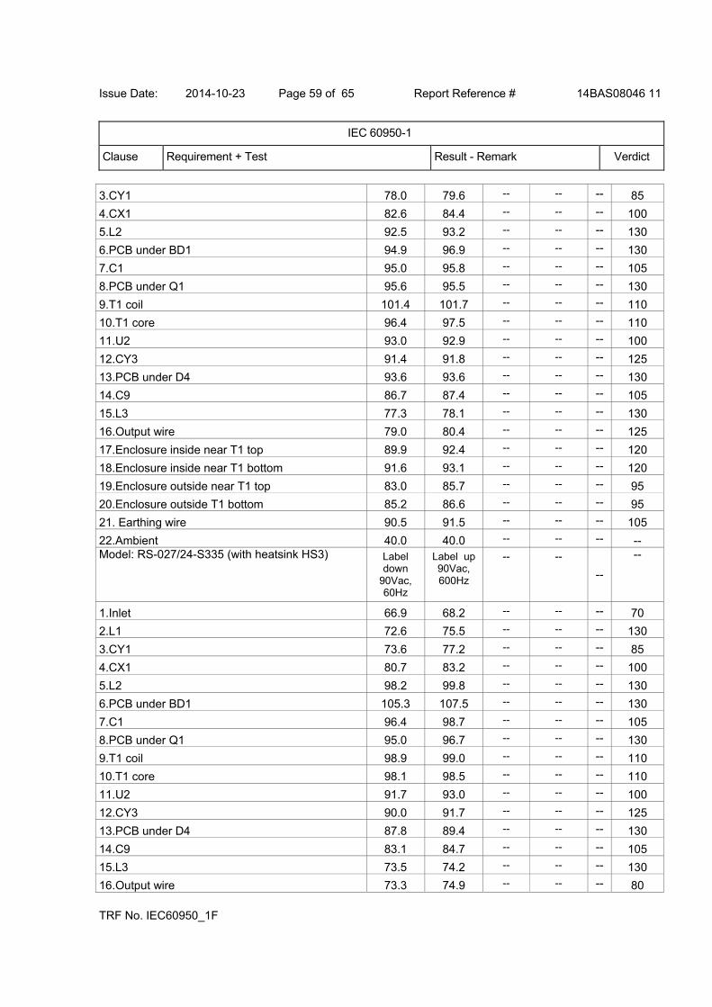
Issue Date: 2014-10-23 Page 59 of 65 Report Reference # 14BAS08046 11
IEC 60950-1
Clause Requirement + Test Result - Remark Verdict
TRF No. IEC60950_1F
3.CY1 78.0 79.6 -- -- -- 85
4.CX1 82.6 84.4 -- -- -- 100
5.L2 92.5 93.2 -- -- -- 130
6.PCB under BD1 94.9 96.9 -- -- -- 130
7.C1 95.0 95.8 -- -- -- 105
8.PCB under Q1 95.6 95.5 -- -- -- 130
9.T1 coil 101.4 101.7 -- -- -- 110
10.T1 core 96.4 97.5 -- -- -- 110
11.U2 93.0 92.9 -- -- -- 100
12.CY3 91.4 91.8 -- -- -- 125
13.PCB under D4 93.6 93.6 -- -- -- 130
14.C9 86.7 87.4 -- -- -- 105
15.L3 77.3 78.1 -- -- -- 130
16.Output wire 79.0 80.4 -- -- -- 125
17.Enclosure inside near T1 top 89.9 92.4 -- -- -- 120
18.Enclosure inside near T1 bottom 91.6 93.1 -- -- -- 120
19.Enclosure outside near T1 top 83.0 85.7 -- -- -- 95
20.Enclosure outside T1 bottom 85.2 86.6 -- -- -- 95
21. Earthing wire 90.5 91.5 -- -- -- 105
22.Ambient 40.0 40.0 -- -- -- -- Model: RS-027/24-S335 (with heatsink HS3) Label
down 90Vac, 60Hz
Label up 90Vac, 600Hz
-- --
--
--
1.Inlet 66.9 68.2 -- -- -- 70
2.L1 72.6 75.5 -- -- -- 130
3.CY1 73.6 77.2 -- -- -- 85
4.CX1 80.7 83.2 -- -- -- 100
5.L2 98.2 99.8 -- -- -- 130
6.PCB under BD1 105.3 107.5 -- -- -- 130
7.C1 96.4 98.7 -- -- -- 105
8.PCB under Q1 95.0 96.7 -- -- -- 130
9.T1 coil 98.9 99.0 -- -- -- 110
10.T1 core 98.1 98.5 -- -- -- 110
11.U2 91.7 93.0 -- -- -- 100
12.CY3 90.0 91.7 -- -- -- 125
13.PCB under D4 87.8 89.4 -- -- -- 130
14.C9 83.1 84.7 -- -- -- 105
15.L3 73.5 74.2 -- -- -- 130
16.Output wire 73.3 74.9 -- -- -- 80

Issue Date: 2014-10-23 Page 60 of 65 Report Reference # 14BAS08046 11
IEC 60950-1
Clause Requirement + Test Result - Remark Verdict
TRF No. IEC60950_1F
17.Enclosure inside near T1 top 79.2 85.6 -- -- -- 120
18.Enclosure inside near T1 bottom 82.3 87.7 -- -- -- 120
19.Enclosure outside near T1 top 70.3 79.1 -- -- -- 95
20.Enclosure outside near T1 bottom 72.2 81.3 -- -- -- 95
21. Earthing wire 69.8 71.7 -- -- -- 105
22.Ambient 40.0 40.0 -- -- -- --
temperature T of winding: t1 (°C) R1 ( ) t2 (°C) R2 ( ) T (°C) -- insulatio
n class
-- -- -- -- -- --
supplementary information:
-- Continuous operation, until steady conditions were established.
-- The temperatures were measured under worst case normal mode defined in 1.2.2.1 and as described in subclause 1.6.2 and at voltages as described in sub-clause 1.4.5.
-- With maximum ambient temperature specified as 40 degree C, Therefore the maximum permitted temperature rises are calculated.
4.5.5 TABLE: Ball pressure test of thermoplastic parts N/A
Allowed impression diameter (mm) ....................... : 2 mm —
part test temperature ( °C) impression diameter (mm)
-- -- --
supplementary information:
Phenolic bobbin material used in T1, which acceptable without test.
4.7 TABLE: resistance to fire N/A
Part Manufacturer of material
Type of material Thickness (mm)
Fammability class
Evidence
-- -- -- -- -- --
supplementary information:
5.1 TABLE: touch current measurement Pass
Measured between: Measured (mA)
Limit (mA)
Comments/Conditions
Output 0.005 0.25 “e” – C; P1 – N; Pri S. – N/A
Output 0.005 0.25 “e” – C; P1 – R; Pri S. – N/A
Enclosure with metal foil 0.005 0.25 “e” – C; P1 – N; Pri S. – N/A

Issue Date: 2014-10-23 Page 61 of 65 Report Reference # 14BAS08046 11
IEC 60950-1
Clause Requirement + Test Result - Remark Verdict
TRF No. IEC60950_1F
Enclosure with metal foil 0.005 0.25 “e” – C; P1 – R; Pri S. – N/A
Output 0.215 3.5 “e” – O; P1 – N; Pri S. – N/A
Output 0.215 3.5 “e” – O; P1 – R; Pri S. – N/A
Enclosure with metal foil 0.005 0.25 “e” – O; P1 – N; Pri S. – N/A
Enclosure with metal foil 0.005 0.25 “e” – O; P1 – R; Pri S. – N/A
supplementary information:
Supplied by 264V/60Hz. Capacitance of Y-cap. bridging Primary to Earth: CY1=CY2=470pF Capacitance of Y-cap. bridging Primary to secondary.: CY3=2200pF Meanings for: C: switch “e” closed R: switch “P1” reversed polarity position. N: switch “P1” normal position. O: switch “e” opened
5.2 TABLE: Electric strength tests, impulse tests and voltage surge tests Pass
Test voltage applied between: Voltage shape (AC, DC, impulse,
surge)
Test voltage (V)
Breakdown Yes / No
Primary circuit to earthing circuit AC 1772Vac No
From Primary (input blades) to Secondary (output) AC 3000Vac No
From Primary (input blades) to Enclosure with metal foil AC 3000Vac No
From T1 Primary to T1 secondary AC 3000Vac No
From T1 Core to T1 secondary AC 3000Vac No
Insulation tape (one layer) AC 3000Vac No
From Enclosure inside to Enclosure outside AC 3000Vac No
supplementary information:
-Test after humidity treatment, heating test, and for the first 2 items also after each fault condition test.
- All sources of Insulation tape and T1 listed in table 1.5.1 have been considered.
5.3 TABLE: Fault condition tests Pass
Ambient temperature ( °C) ................................... 25.2°C —
Power source for EUT: Manufacturer, model/type, output rating......................................
-- —
Component No.
Fault Supply voltage(V)
Test time Fuse # Fuse current(A)
Observation
Model: RS-04/163-S335
BD1 Pin ~ to + S-C 240Vac 1S F1 0.546→0 NC/ NT /NB / No Hazard, IP(F1)
C1 S-C 240Vac 1S F1 0.546→0 NC/ NT /NB / No Hazard,
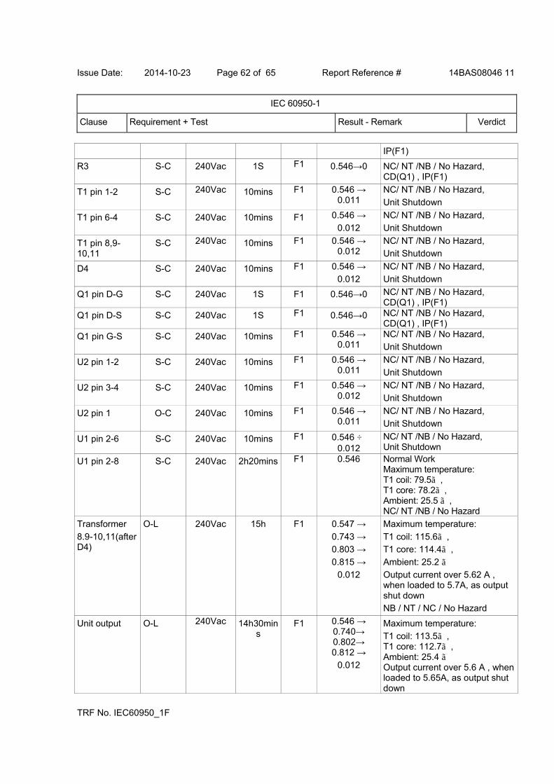
Issue Date: 2014-10-23 Page 62 of 65 Report Reference # 14BAS08046 11
IEC 60950-1
Clause Requirement + Test Result - Remark Verdict
TRF No. IEC60950_1F
IP(F1)
R3 S-C 240Vac 1S F1 0.546→0 NC/ NT /NB / No Hazard, CD(Q1) , IP(F1)
T1 pin 1-2 S-C 240Vac 10mins F1 0.546 → 0.011
NC/ NT /NB / No Hazard,
Unit Shutdown
T1 pin 6-4 S-C 240Vac 10mins F1 0.546 →
0.012
NC/ NT /NB / No Hazard,
Unit Shutdown
T1 pin 8,9-10,11
S-C 240Vac 10mins F1 0.546 → 0.012
NC/ NT /NB / No Hazard, Unit Shutdown
D4 S-C 240Vac 10mins F1 0.546 → 0.012
NC/ NT /NB / No Hazard, Unit Shutdown
Q1 pin D-G S-C 240Vac 1S F1 0.546→0 NC/ NT /NB / No Hazard, CD(Q1) , IP(F1)
Q1 pin D-S S-C 240Vac 1S F1 0.546→0 NC/ NT /NB / No Hazard, CD(Q1) , IP(F1)
Q1 pin G-S S-C 240Vac 10mins F1 0.546 → 0.011
NC/ NT /NB / No Hazard,
Unit Shutdown
U2 pin 1-2 S-C 240Vac 10mins F1 0.546 → 0.011
NC/ NT /NB / No Hazard,
Unit Shutdown
U2 pin 3-4 S-C 240Vac 10mins F1 0.546 → 0.012
NC/ NT /NB / No Hazard,
Unit Shutdown
U2 pin 1 O-C 240Vac 10mins F1 0.546 → 0.011
NC/ NT /NB / No Hazard, Unit Shutdown
U1 pin 2-6 S-C 240Vac 10mins F1 0.546 → 0.012
NC/ NT /NB / No Hazard, Unit Shutdown
U1 pin 2-8 S-C 240Vac 2h20mins F1 0.546 Normal Work Maximum temperature: T1 coil: 79.5 , T1 core: 78.2 , Ambient: 25.5 , NC/ NT /NB / No Hazard
Transformer
8.9-10,11(after D4)
O-L 240Vac 15h F1 0.547 →
0.743 → 0.803 →
0.815 →
0.012
Maximum temperature:
T1 coil: 115.6 , T1 core: 114.4 ,
Ambient: 25.2
Output current over 5.62 A , when loaded to 5.7A, as output shut down NB / NT / NC / No Hazard
Unit output O-L 240Vac 14h30mins
F1 0.546 → 0.740→ 0.802→ 0.812 →
0.012
Maximum temperature:
T1 coil: 113.5 , T1 core: 112.7 , Ambient: 25.4 Output current over 5.6 A , when loaded to 5.65A, as output shut down
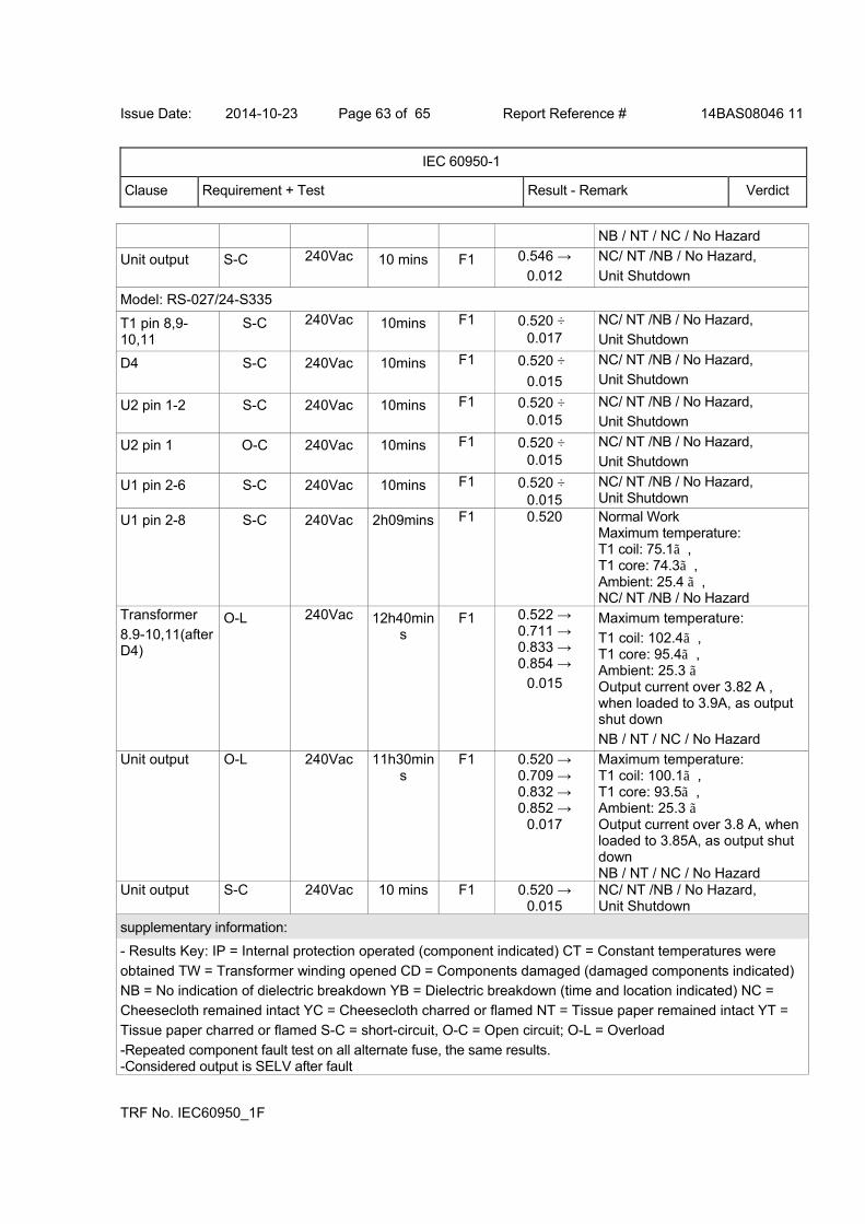
Issue Date: 2014-10-23 Page 63 of 65 Report Reference # 14BAS08046 11
IEC 60950-1
Clause Requirement + Test Result - Remark Verdict
TRF No. IEC60950_1F
NB / NT / NC / No Hazard
Unit output S-C 240Vac 10 mins F1 0.546 →
0.012
NC/ NT /NB / No Hazard,
Unit Shutdown
Model: RS-027/24-S335
T1 pin 8,9-10,11
S-C 240Vac 10mins F1 0.520 → 0.017
NC/ NT /NB / No Hazard,
Unit Shutdown
D4 S-C 240Vac 10mins F1 0.520 →
0.015
NC/ NT /NB / No Hazard, Unit Shutdown
U2 pin 1-2 S-C 240Vac 10mins F1 0.520 → 0.015
NC/ NT /NB / No Hazard, Unit Shutdown
U2 pin 1 O-C 240Vac 10mins F1 0.520 → 0.015
NC/ NT /NB / No Hazard,
Unit Shutdown
U1 pin 2-6 S-C 240Vac 10mins F1 0.520 → 0.015
NC/ NT /NB / No Hazard, Unit Shutdown
U1 pin 2-8 S-C 240Vac 2h09mins F1 0.520 Normal Work Maximum temperature: T1 coil: 75.1 , T1 core: 74.3 , Ambient: 25.4 , NC/ NT /NB / No Hazard
Transformer
8.9-10,11(after D4)
O-L 240Vac 12h40mins
F1 0.522 → 0.711 → 0.833 → 0.854 →
0.015
Maximum temperature:
T1 coil: 102.4 , T1 core: 95.4, Ambient: 25.3 Output current over 3.82 A , when loaded to 3.9A, as output shut down
NB / NT / NC / No Hazard
Unit output O-L 240Vac 11h30mins
F1 0.520 → 0.709 → 0.832 → 0.852 →
0.017
Maximum temperature: T1 coil: 100.1 , T1 core: 93.5 , Ambient: 25.3 Output current over 3.8 A, when loaded to 3.85A, as output shut down NB / NT / NC / No Hazard
Unit output S-C 240Vac 10 mins F1 0.520 → 0.015
NC/ NT /NB / No Hazard, Unit Shutdown
supplementary information:
- Results Key: IP = Internal protection operated (component indicated) CT = Constant temperatures were
obtained TW = Transformer winding opened CD = Components damaged (damaged components indicated) NB = No indication of dielectric breakdown YB = Dielectric breakdown (time and location indicated) NC =
Cheesecloth remained intact YC = Cheesecloth charred or flamed NT = Tissue paper remained intact YT =
Tissue paper charred or flamed S-C = short-circuit, O-C = Open circuit; O-L = Overload
-Repeated component fault test on all alternate fuse, the same results. -Considered output is SELV after fault
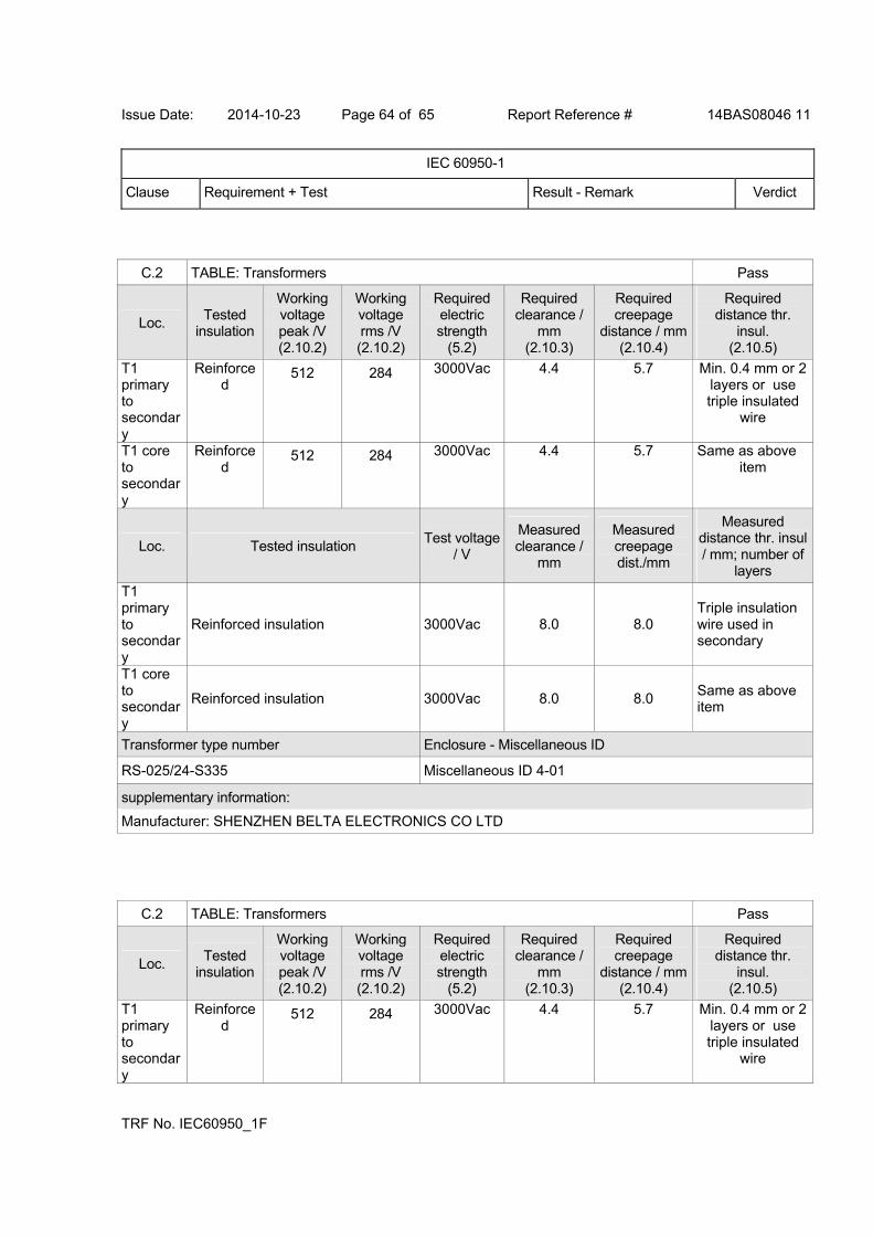
Issue Date: 2014-10-23 Page 64 of 65 Report Reference # 14BAS08046 11
IEC 60950-1
Clause Requirement + Test Result - Remark Verdict
TRF No. IEC60950_1F
C.2 TABLE: Transformers Pass
Loc. Tested
insulation
Working voltage peak /V (2.10.2)
Working voltage rms /V (2.10.2)
Required electric strength
(5.2)
Required clearance /
mm (2.10.3)
Required creepage
distance / mm (2.10.4)
Required distance thr.
insul. (2.10.5)
T1 primary to secondary
Reinforced
512 284 3000Vac 4.4 5.7 Min. 0.4 mm or 2 layers or use triple insulated
wire
T1 core to secondary
Reinforced
512 284 3000Vac 4.4 5.7 Same as above item
Loc. Tested insulation Test voltage
/ V
Measured clearance /
mm
Measured creepage dist./mm
Measured distance thr. insul / mm; number of
layers
T1 primary to secondary
Reinforced insulation 3000Vac 8.0 8.0 Triple insulation wire used in secondary
T1 core to secondary
Reinforced insulation 3000Vac 8.0 8.0 Same as above item
Transformer type number Enclosure - Miscellaneous ID
RS-025/24-S335 Miscellaneous ID 4-01
supplementary information:
Manufacturer: SHENZHEN BELTA ELECTRONICS CO LTD
C.2 TABLE: Transformers Pass
Loc. Tested
insulation
Working voltage peak /V (2.10.2)
Working voltage rms /V (2.10.2)
Required electric strength
(5.2)
Required clearance /
mm (2.10.3)
Required creepage
distance / mm (2.10.4)
Required distance thr.
insul. (2.10.5)
T1 primary to secondary
Reinforced
512 284 3000Vac 4.4 5.7 Min. 0.4 mm or 2 layers or use triple insulated
wire
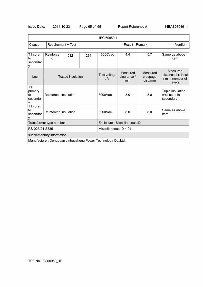
Issue Date: 2014-10-23 Page 65 of 65 Report Reference # 14BAS08046 11
IEC 60950-1
Clause Requirement + Test Result - Remark Verdict
TRF No. IEC60950_1F
T1 core to secondary
Reinforced
512 284 3000Vac 4.4 5.7 Same as above item
Loc. Tested insulation Test voltage
/ V
Measured clearance /
mm
Measured creepage dist./mm
Measured distance thr. insul / mm; number of
layers
T1 primary to secondary
Reinforced insulation 3000Vac 8.0 8.0 Triple insulation wire used in secondary
T1 core to secondary
Reinforced insulation 3000Vac 8.0 8.0 Same as above item
Transformer type number Enclosure - Miscellaneous ID
RS-025/24-S335 Miscellaneous ID 4-01
supplementary information:
Manufacturer: Dongguan Jinhuasheng Power Technology Co.,Ltd.
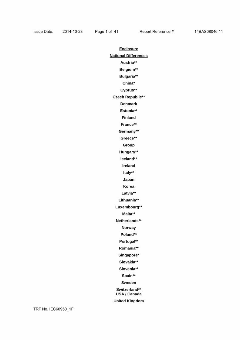
Issue Date: 2014-10-23 Page 1 of 41 Report Reference # 14BAS08046 11
TRF No. IEC60950_1F
Enclosure
National Differences
Austria**
Belgium**
Bulgaria**
China*
Cyprus**
Czech Republic**
Denmark
Estonia**
Finland
France**
Germany**
Greece**
Group
Hungary**
Iceland**
Ireland
Italy**
Japan
Korea
Latvia**
Lithuania**
Luxembourg**
Malta**
Netherlands**
Norway
Poland**
Portugal**
Romania**
Singapore*
Slovakia**
Slovenia**
Spain**
Sweden
Switzerland** USA / Canada
United Kingdom
Issue Date: 2014-10-23 Page 2 of 41 Report Reference # 14BAS08046 11
TRF No. IEC60950_1F
* No National Differences Declared
** Only Group Differences

Issue Date: 2014-10-23 Page 3 of 41 Report Reference # 14BAS08046 11
National Differences
Clause Requirement + Test Result - Remark Verdict
TRF No. IEC60950_1F
Denmark - Differences to IEC 60950-1:2005 (2nd Edition); Am 1:2009
1.2.4.1 In Denmark, certain types of Class I appliances (see sub-clause 3.2.1.1) may be provided with plug not establishing earthing continuity when inserted into Danish socket-outlets.
N/A
1.7.5 In Denmark, socket-outlets for providing power to other equipment shall be in accordance with the Heavy Current Regulations, Section 107-2-D1, Standard Sheet DK 1-3a, DK 1-5a or DK 1-7a, when used on Class I equipment. For stationary equipment, the socket-outlet shall be in accordance with Standard Sheet DK 1-1b or DK 1-5a.
N/A
1.7.5 For CLASS II EQUIPMENT the socket outlet shall be in accordance with Standard Sheet DKA 1-4a. (Heavy Current Regulations, Section 107-2-D1)
N/A
3.2.1.1 Supply cord of single-phase equipment having a rated current not exceeding 13 A shall be provided with a plug according to the Heavy Current Regulations, Section 107-2-D1. Class I equipment provided with socket-outlets with earth contact or which are intended to be used in locations where protection against indirect contact is required according to the wiring rules shall be provided with a plug in accordance with standard sheet DK 2-1a or DK 2-5a. If poly-phase equipment and single-phase equipment having a rated current exceeding 13 A is provided with a supply cord with a plug, this plug shall be in accordance with the Heavy Current Regulations, Section 107-2-D1 or EN 60309-2.
N/A
Finland - Differences to IEC 60950-1:2005 (2nd Edition); Am 1:2009
1.5.7.1 Resistors bridging BASIC INSULATION in CLASS I PLUGGABLE EQUIPMENT TYPE A must comply with the requirements in 1.5.7.2. In addition when a single resistor is used, the resistor must withstand the resistor test in 1.5.7.2.
N/A
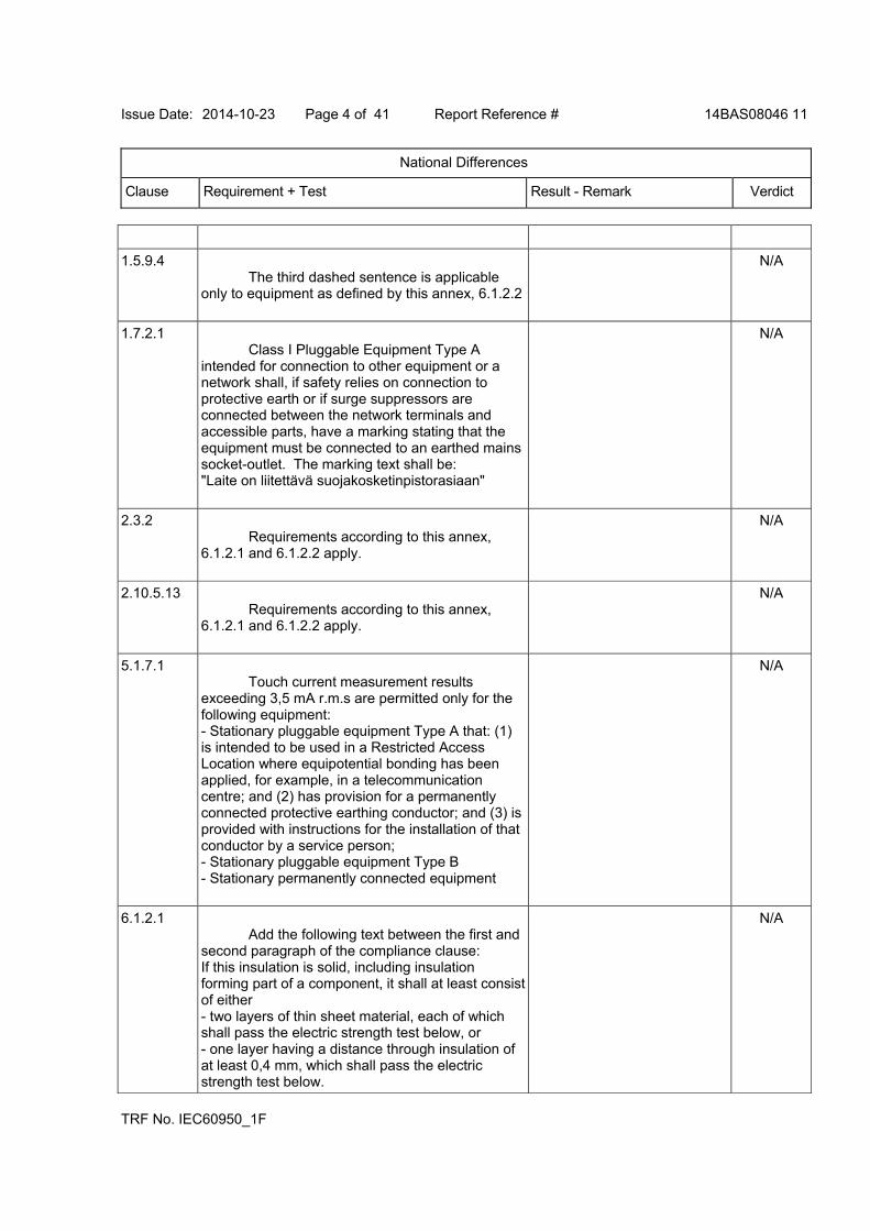
Issue Date: 2014-10-23 Page 4 of 41 Report Reference # 14BAS08046 11
National Differences
Clause Requirement + Test Result - Remark Verdict
TRF No. IEC60950_1F
1.5.9.4 The third dashed sentence is applicable only to equipment as defined by this annex, 6.1.2.2
N/A
1.7.2.1 Class I Pluggable Equipment Type A intended for connection to other equipment or a network shall, if safety relies on connection to protective earth or if surge suppressors are connected between the network terminals and accessible parts, have a marking stating that the equipment must be connected to an earthed mains socket-outlet. The marking text shall be: "Laite on liitettävä suojakosketinpistorasiaan"
N/A
2.3.2 Requirements according to this annex, 6.1.2.1 and 6.1.2.2 apply.
N/A
2.10.5.13 Requirements according to this annex, 6.1.2.1 and 6.1.2.2 apply.
N/A
5.1.7.1 Touch current measurement results exceeding 3,5 mA r.m.s are permitted only for the following equipment: - Stationary pluggable equipment Type A that: (1) is intended to be used in a Restricted Access Location where equipotential bonding has been applied, for example, in a telecommunication centre; and (2) has provision for a permanently connected protective earthing conductor; and (3) is provided with instructions for the installation of that conductor by a service person; - Stationary pluggable equipment Type B - Stationary permanently connected equipment
N/A
6.1.2.1 Add the following text between the first and second paragraph of the compliance clause: If this insulation is solid, including insulation forming part of a component, it shall at least consist of either - two layers of thin sheet material, each of which shall pass the electric strength test below, or - one layer having a distance through insulation of at least 0,4 mm, which shall pass the electric strength test below.
N/A

Issue Date: 2014-10-23 Page 5 of 41 Report Reference # 14BAS08046 11
National Differences
Clause Requirement + Test Result - Remark Verdict
TRF No. IEC60950_1F
Alternatively for components, there is no distance through insulation requirement for the insulation consisting of an insulating compound completely filling the casing, so that CLEARANCES and CREEPAGE DISTANCES do not exist, if the component passes the electric strength test in accordance with the compliance clause below and in addition - passes the tests and inspection criteria of 2.10.11 with an electric strength test of 1,5 kV multiplied by 1,6 (the electric strength test of 2.10.10 shall be performed using 1,5 kV), and - is subject to ROUTINE TESTING for electric strength during manufacturing, using a test voltage of 1,5 kV. It is permitted to bridge this insulation with an optocoupler complying with 2.10.5.4 b). It is permitted to bridge this insulation with a capacitor complying with EN 132400:1994, subclass Y2. A capacitor classified Y3 according to EN 60384-14:2005, may bridge this insulation under the following conditions: - the insulation requirements are satisfied by having a capacitor classified Y3 as defined by EN 60384-14, which in addition to the Y3 testing, is tested with an impulse test of 2,5 kV defined in EN 60950-1:2006, 6.2.2.1; - the additional testing shall be performed on all the test specimens as described in EN 60384-14; - the impulse test of 2,5 kV is to be performed before the endurance test in EN 60384-14, in the sequence of tests as described in EN 60384-14.
6.1.2.2 The exclusions are applicable for permanently connected equipment and pluggable equipment type B and equipment intended to be used in a restricted access location where equipotential bonding has been applied, e.g. in a telecommunication center, and which has provision for a permanently connected protective earthing conductor and is provided with instructions for the installation of that conductor by a service person.
N/A
7.2 Requirements according to this annex, 6.1.2.1 and 6.1.2.2 apply with the term
N/A
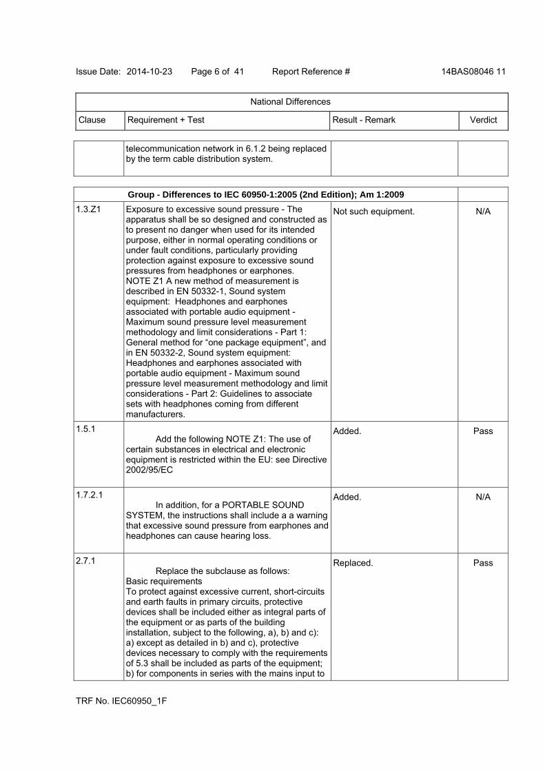
Issue Date: 2014-10-23 Page 6 of 41 Report Reference # 14BAS08046 11
National Differences
Clause Requirement + Test Result - Remark Verdict
TRF No. IEC60950_1F
telecommunication network in 6.1.2 being replaced by the term cable distribution system.
Group - Differences to IEC 60950-1:2005 (2nd Edition); Am 1:2009
1.3.Z1 Exposure to excessive sound pressure - The apparatus shall be so designed and constructed as to present no danger when used for its intended purpose, either in normal operating conditions or under fault conditions, particularly providing protection against exposure to excessive sound pressures from headphones or earphones. NOTE Z1 A new method of measurement is described in EN 50332-1, Sound system equipment: Headphones and earphones associated with portable audio equipment - Maximum sound pressure level measurement methodology and limit considerations - Part 1: General method for “one package equipment”, and in EN 50332-2, Sound system equipment: Headphones and earphones associated with portable audio equipment - Maximum sound pressure level measurement methodology and limit considerations - Part 2: Guidelines to associate sets with headphones coming from different manufacturers.
Not such equipment. N/A
1.5.1 Add the following NOTE Z1: The use of certain substances in electrical and electronic equipment is restricted within the EU: see Directive 2002/95/EC
Added. Pass
1.7.2.1 In addition, for a PORTABLE SOUND SYSTEM, the instructions shall include a a warning that excessive sound pressure from earphones and headphones can cause hearing loss.
Added. N/A
2.7.1 Replace the subclause as follows: Basic requirements To protect against excessive current, short-circuits and earth faults in primary circuits, protective devices shall be included either as integral parts of the equipment or as parts of the building installation, subject to the following, a), b) and c): a) except as detailed in b) and c), protective devices necessary to comply with the requirements of 5.3 shall be included as parts of the equipment; b) for components in series with the mains input to
Replaced. Pass
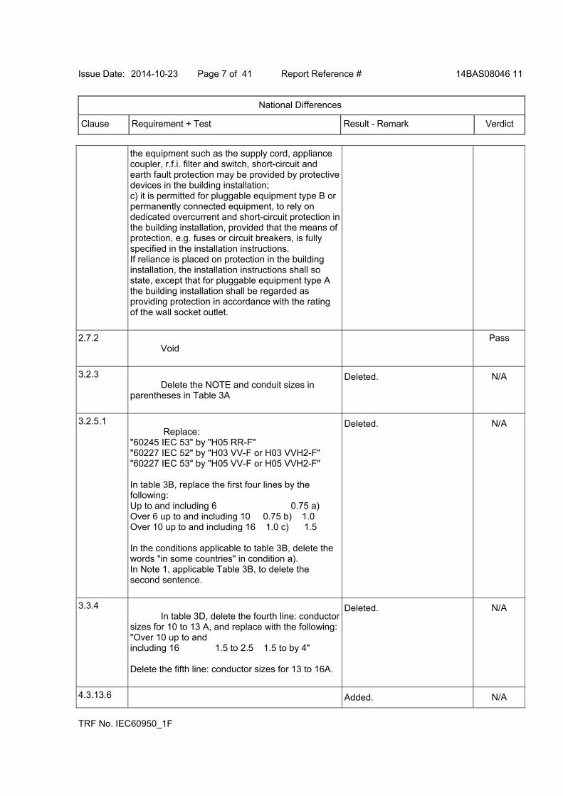
Issue Date: 2014-10-23 Page 7 of 41 Report Reference # 14BAS08046 11
National Differences
Clause Requirement + Test Result - Remark Verdict
TRF No. IEC60950_1F
the equipment such as the supply cord, appliance coupler, r.f.i. filter and switch, short-circuit and earth fault protection may be provided by protective devices in the building installation; c) it is permitted for pluggable equipment type B or permanently connected equipment, to rely on dedicated overcurrent and short-circuit protection in the building installation, provided that the means of protection, e.g. fuses or circuit breakers, is fully specified in the installation instructions. If reliance is placed on protection in the building installation, the installation instructions shall so state, except that for pluggable equipment type A the building installation shall be regarded as providing protection in accordance with the rating of the wall socket outlet.
2.7.2 Void
Pass
3.2.3 Delete the NOTE and conduit sizes in parentheses in Table 3A
Deleted. N/A
3.2.5.1 Replace: "60245 IEC 53" by "H05 RR-F" "60227 IEC 52" by "H03 VV-F or H03 VVH2-F" "60227 IEC 53" by "H05 VV-F or H05 VVH2-F" In table 3B, replace the first four lines by the following: Up to and including 6 0.75 a) Over 6 up to and including 10 0.75 b) 1.0 Over 10 up to and including 16 1.0 c) 1.5 In the conditions applicable to table 3B, delete the words "in some countries" in condition a). In Note 1, applicable Table 3B, to delete the second sentence.
Deleted. N/A
3.3.4 In table 3D, delete the fourth line: conductor sizes for 10 to 13 A, and replace with the following:"Over 10 up to and including 16 1.5 to 2.5 1.5 to by 4" Delete the fifth line: conductor sizes for 13 to 16A.
Deleted. N/A
4.3.13.6 Added. N/A
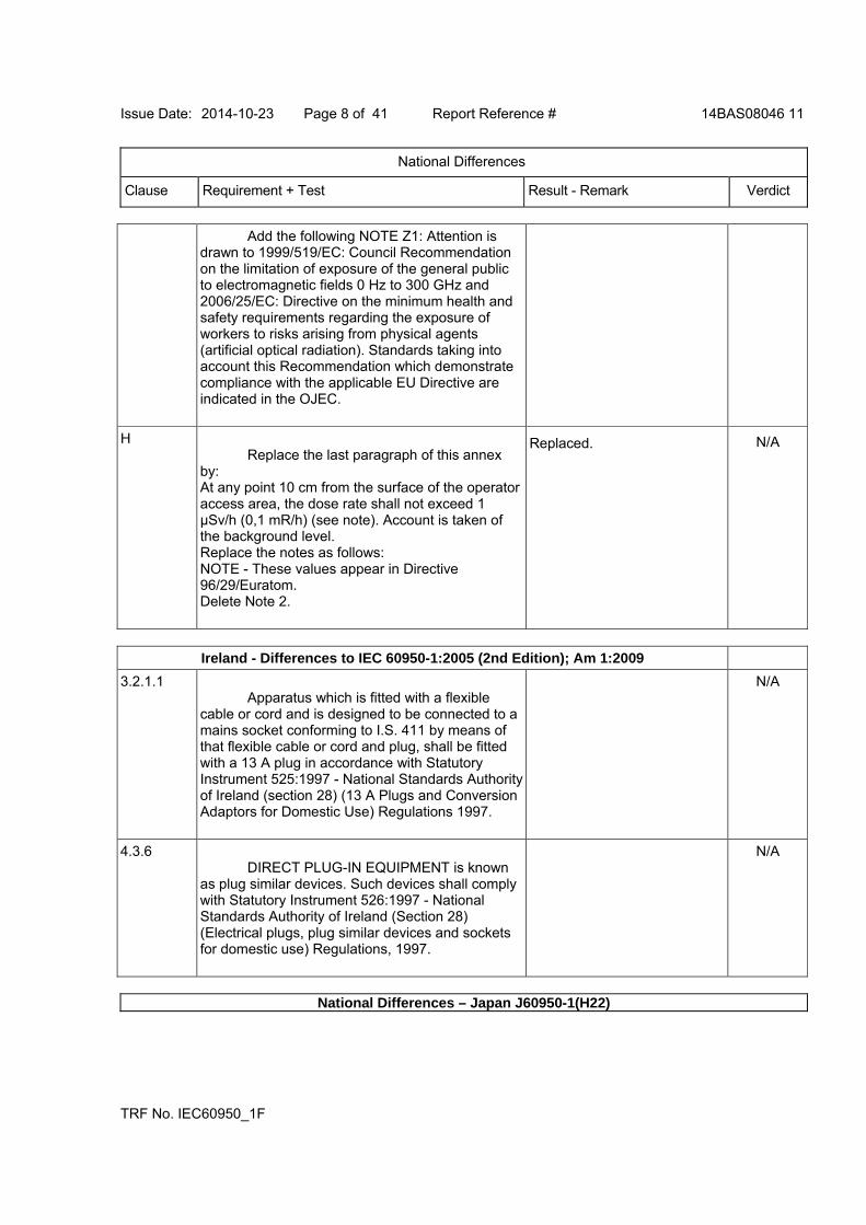
Issue Date: 2014-10-23 Page 8 of 41 Report Reference # 14BAS08046 11
National Differences
Clause Requirement + Test Result - Remark Verdict
TRF No. IEC60950_1F
Add the following NOTE Z1: Attention is drawn to 1999/519/EC: Council Recommendation on the limitation of exposure of the general public to electromagnetic fields 0 Hz to 300 GHz and 2006/25/EC: Directive on the minimum health and safety requirements regarding the exposure of workers to risks arising from physical agents (artificial optical radiation). Standards taking into account this Recommendation which demonstrate compliance with the applicable EU Directive are indicated in the OJEC.
H Replace the last paragraph of this annex by: At any point 10 cm from the surface of the operator access area, the dose rate shall not exceed 1 µSv/h (0,1 mR/h) (see note). Account is taken of the background level. Replace the notes as follows: NOTE - These values appear in Directive 96/29/Euratom. Delete Note 2.
Replaced. N/A
Ireland - Differences to IEC 60950-1:2005 (2nd Edition); Am 1:2009
3.2.1.1 Apparatus which is fitted with a flexible cable or cord and is designed to be connected to a mains socket conforming to I.S. 411 by means of that flexible cable or cord and plug, shall be fitted with a 13 A plug in accordance with Statutory Instrument 525:1997 - National Standards Authority of Ireland (section 28) (13 A Plugs and Conversion Adaptors for Domestic Use) Regulations 1997.
N/A
4.3.6 DIRECT PLUG-IN EQUIPMENT is known as plug similar devices. Such devices shall comply with Statutory Instrument 526:1997 - National Standards Authority of Ireland (Section 28) (Electrical plugs, plug similar devices and sockets for domestic use) Regulations, 1997.
N/A
National Differences – Japan J60950-1(H22)
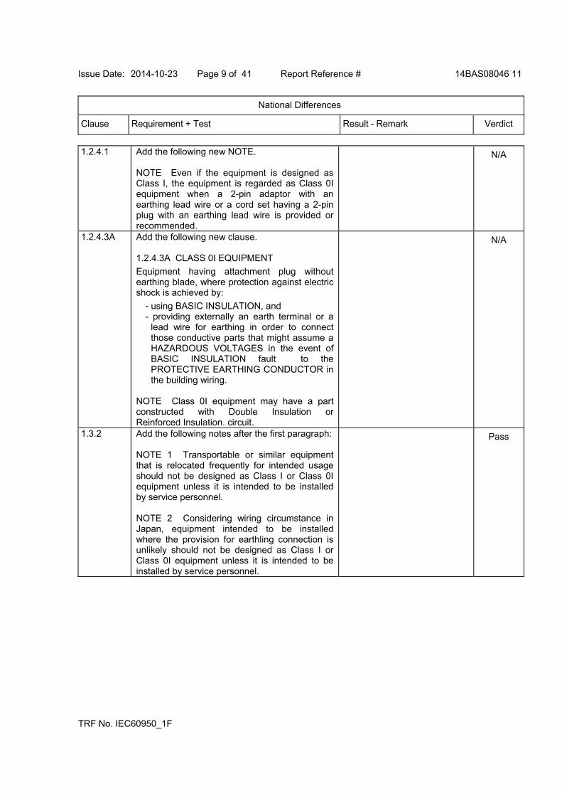
Issue Date: 2014-10-23 Page 9 of 41 Report Reference # 14BAS08046 11
National Differences
Clause Requirement + Test Result - Remark Verdict
TRF No. IEC60950_1F
1.2.4.1 Add the following new NOTE. NOTE Even if the equipment is designed as Class I, the equipment is regarded as Class 0I equipment when a 2-pin adaptor with an earthing lead wire or a cord set having a 2-pin plug with an earthing lead wire is provided or recommended.
N/A
1.2.4.3A Add the following new clause. 1.2.4.3A CLASS 0I EQUIPMENT
Equipment having attachment plug without earthing blade, where protection against electric shock is achieved by:
- using BASIC INSULATION, and - providing externally an earth terminal or a
lead wire for earthing in order to connect those conductive parts that might assume a HAZARDOUS VOLTAGES in the event of BASIC INSULATION fault to the PROTECTIVE EARTHING CONDUCTOR in the building wiring.
NOTE Class 0I equipment may have a part constructed with Double Insulation or Reinforced Insulation. circuit.
N/A
1.3.2 Add the following notes after the first paragraph: NOTE 1 Transportable or similar equipment that is relocated frequently for intended usage should not be designed as Class I or Class 0I equipment unless it is intended to be installed by service personnel. NOTE 2 Considering wiring circumstance in Japan, equipment intended to be installed where the provision for earthling connection is unlikely should not be designed as Class I or Class 0I equipment unless it is intended to be installed by service personnel.
Pass
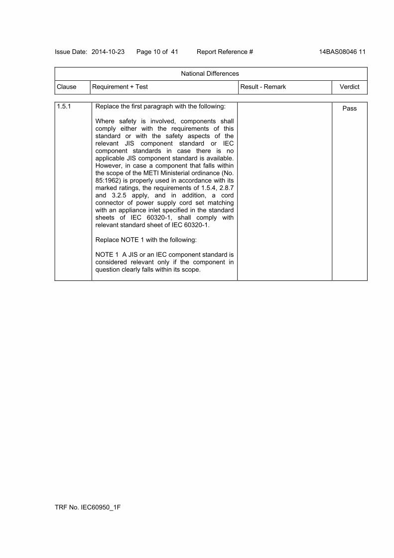
Issue Date: 2014-10-23 Page 10 of 41 Report Reference # 14BAS08046 11
National Differences
Clause Requirement + Test Result - Remark Verdict
TRF No. IEC60950_1F
1.5.1 Replace the first paragraph with the following: Where safety is involved, components shall comply either with the requirements of this standard or with the safety aspects of the relevant JIS component standard or IEC component standards in case there is no applicable JIS component standard is available. However, in case a component that falls within the scope of the METI Ministerial ordinance (No. 85:1962) is properly used in accordance with its marked ratings, the requirements of 1.5.4, 2.8.7 and 3.2.5 apply, and in addition, a cord connector of power supply cord set matching with an appliance inlet specified in the standard sheets of IEC 60320-1, shall comply with relevant standard sheet of IEC 60320-1. Replace NOTE 1 with the following: NOTE 1 A JIS or an IEC component standard is considered relevant only if the component in question clearly falls within its scope.
Pass

Issue Date: 2014-10-23 Page 11 of 41 Report Reference # 14BAS08046 11
National Differences
Clause Requirement + Test Result - Remark Verdict
TRF No. IEC60950_1F
1.5.2 Replace the first sentence in the first dashed paragraph with the following:
- a component that has been demonstrated
to comply with a JIS component standard harmonized with the relevant IEC component standard, or where such JIS component standard is not available, a component that has been demonstrated to comply with the relevant IEC component standard shall be checked for correct application and use in accordance with its rating.
Add a NOTE after the first dashed paragraph as follows: NOTE 1 See 1.7.5A when Type C.14 appliance coupler rated 10 A per IEC 60320-1 is used with an equipment rated not more than 125 V and rated more than 10 A. Replace the first sentence in the third dashed paragraph as follows: - where no relevant IEC component standard
or JIS component standard harmonized with the relevant IEC component standard exists, or where components are used in circuits not in accordance with their specified rating, the components shall be tested under the conditions occurring in the equipment.
Pass
1.5.6 In tihs sub-clause, add “JIS C 5101-14:1998 or” before the reference number, IEC 60384-14:1993.
Pass
1.5.7.2 In tihs sub-clause, add “JIS C 5101-14:1998 or” before the reference number, IEC 60384-14:1993.
Pass
1.5.8 In the first paragraph, add “JIS C 5101-14:1998 or” before the reference number, IEC 60384-14:1993.
Pass
1.7.1 Replace the fifth dashed paragraph with the following: - manufacturer’s or responsible company’s name or trade-mark or identification mark;
Pass
1.7.5 In the second paragraph, add “or JIS C 8303:2007” after the reference number, IEC/TR 60083:1997”.
N/A

Issue Date: 2014-10-23 Page 12 of 41 Report Reference # 14BAS08046 11
National Differences
Clause Requirement + Test Result - Remark Verdict
TRF No. IEC60950_1F
1.7.5A Add the following new clause after 1.7.5 1.7.5A Appliance Couplers
If an appliance coupler according to IEC 60320-1, C.14(rated current: 10 A) is used in equipment whose rated voltage is less than 125 V and the rated current is over 10 A, the following instruction or equivalent shall be described in the user instruction.
“ Use only designated cord set attached in this equipment”
N/A
1.7.12 Replace first sentence with the following: Instructions and equipment marking related to safety shall be in Japanese.
N/A
1.7.17A Add the following new clause after 1.7.17 1.7.17A Marking for CLASS 0I EQUIPMENT For CLASS 0I EQUIPMENT, the following instruction shall be marked on the visible place of the mains plug or the main body:
“Provide an earthing connection” Moreover, for CLASS 0I EQUIPMENT, the following or equivalent instruction shall be indicated on the visible place of the main body or written in the operating instructions:
“Provide an earthing connection before the mains plug is connected to the mains. And, when disconnecting the earthing connection, be sure to disconnect after pulling out the mains plug from the mains.”
N/A
2.1.1.1 In item b) of this sub-clause, replace “IEC 60083” with “JIS C 8303:2007 or Article 1 of the Ministerial Ordinance (No. 85:1962)”
Pass
2.6.3.2 Add the following after the first paragraph. This also applies to the conductor of lead wire for protective earthing of CLASS 0I EQUIPMENT.
N/A
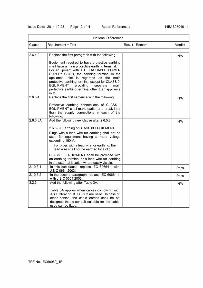
Issue Date: 2014-10-23 Page 13 of 41 Report Reference # 14BAS08046 11
National Differences
Clause Requirement + Test Result - Remark Verdict
TRF No. IEC60950_1F
2.6.4.2 Replace the first paragraph with the following. Equipment required to have protective earthing shall have a main protective earthing terminal. For equipment with a DETACHABLE POWER SUPPLY CORD, the earthing terminal in the appliance inlet is regarded as the main protective earthing terminal except for CLASS 0I EQUIPMENT providing separate main protective earthing terminal other than appliance inlet.
N/A
2.6.5.4 Replace the first sentence with the following. Protective earthing connections of CLASS I EQUIPMENT shall make earlier and break later than the supply connections in each of the following:
N/A
2.6.5.8A Add the following new clause after 2.6.5.8 2.6.5.8A Earthing of CLASS 0I EQUIPMENT
Plugs with a lead wire for earthing shall not be used for equipment having a rated voltage exceeding 150 V.
For plugs with a lead wire for earthing, the lead wire shall not be earthed by a clip.
CLASS 0I EQUIPMENT shall be provided with an earthing terminal or a lead wire for earthing in the external location where easily visible.
N/A
2.10.3.1 In this sub-clause, replace IEC 60664-1 with JIS C 0664:2003.
Pass
2.10.3.2 In the second paragraph, replace IEC 60664-1 with JIS C 0664:2003.
Pass
3.2.3 Add the following after Table 3A: Table 3A applies when cables complying with JIS C 3662 or JIS C 3663 are used. In case of other cables, the cable entries shall be so designed that a conduit suitable for the cable used can be fitted.
N/A

Issue Date: 2014-10-23 Page 14 of 41 Report Reference # 14BAS08046 11
National Differences
Clause Requirement + Test Result - Remark Verdict
TRF No. IEC60950_1F
3.2.5.1 Add the following to the last of first dashed paragraph. Or mains cords shall be of the sheathed type complying with Appendix 1 of Article 1 of the Ministerial Ordinance (No. 85:1962) on stipulating technical requirements for the Electrical Appliance. Add the following to the last of second dashed paragraph. Or mains cords shall be of the sheathed type complying with Appendix 1 of Article 1 of the Ministerial Ordinance (No. 85:1962) on stipulating technical requirements for the Electrical Appliance. Delete 1) in Table 3B.
N/A
3.3.4 Add the following note to Table 3D: NOTE For cables other than those complying with JIS C 3662 or JIS C 3663, terminals shall be suitable for the size of the intended cables.
N/A
3.3.7 Add the following after the first sentence: This requirement is not applicable to the external earting terminal of Class 0I equipment.
N/A
4.3.4 Add the following after the first sentence: This requirement also applies to those connections in Class 0I equipment, where CLEARANCE or CREEPAGE DISTANCES over BASIC INSULATION would be reduced to less than the values specified in 2.10.
Pass
4.3.13.5 Replace the first paragraph with the following: Except as permitted below, equipment shall be classified and labelled according to JIS C 6802:2005, and JIS C 6803:2006 or IEC 60825-2:2000, as applicable. Replace IEC 60825-1 in the second and the last paragraph with JIS C 6802:2005.
N/A

Issue Date: 2014-10-23 Page 15 of 41 Report Reference # 14BAS08046 11
National Differences
Clause Requirement + Test Result - Remark Verdict
TRF No. IEC60950_1F
4.5 Add the following NOTE to Table 4B, 3): NOTE: In case no data for the material is available, Appendix 4, 4. (1). b. 3 of the Interpretation on the Ministerial Ordinance stipulating Technical Specifications for Electrical Appliances (Commerce and Distribution Policy Group No. 3:2008/06/19) may apply.
N/A
5.1.3 Add a note after the first paragraph as follows: NOTE Attention should be drawn to that majority of three-phase power system in Japan is of delta connection, and therefore, in that case, the test is conducted using the test circuit from IEC 60990, figure 13.
N/A
5.1.6
Replace Table 5A as follows:
N/A
6 Replace IEC 60664-1 in NOTE 4 with JIS C 0664.
N/A
7 Replace IEC 60664-1 in NOTE 3 with JIS C 0664:2003.
N/A
Type of equipment
Terminal A of measuring instrument
connected to:
MaximumTOUCH
CURRENTmA r.m.s. 1)
Maximum PROTECTIVE CONDUCTOR
CURRENT
All equipment Accessible parts and circuits not connected to protective earth
0,25 -
HAND-HELD 0,75 -
MOVABLE (other than HAND-HELD, but including TRANSPORTABLE EQUIPMENT
3,5 -
STATIONARY, PLUGGABLE TYPE A
3,5 -
All other STATIONARY EQUIPMENT - not subject to the
conditions of 5.1.7 - subject to the conditions of 5.1.7
Equipment main protective earthing terminal (if any) CLASS I EQUIPMENT
3,5 -
-
5 % of input current
HAND-HELD 0,5 - Others
Equipment main protective earthing terminal (if any) CLASS 0I EQUIPMENT
1,0 -
1) If peak values of TOUCH-CURRENT are measured, the maximum values obtained by multiplying the r.m.s. values by 1,414.
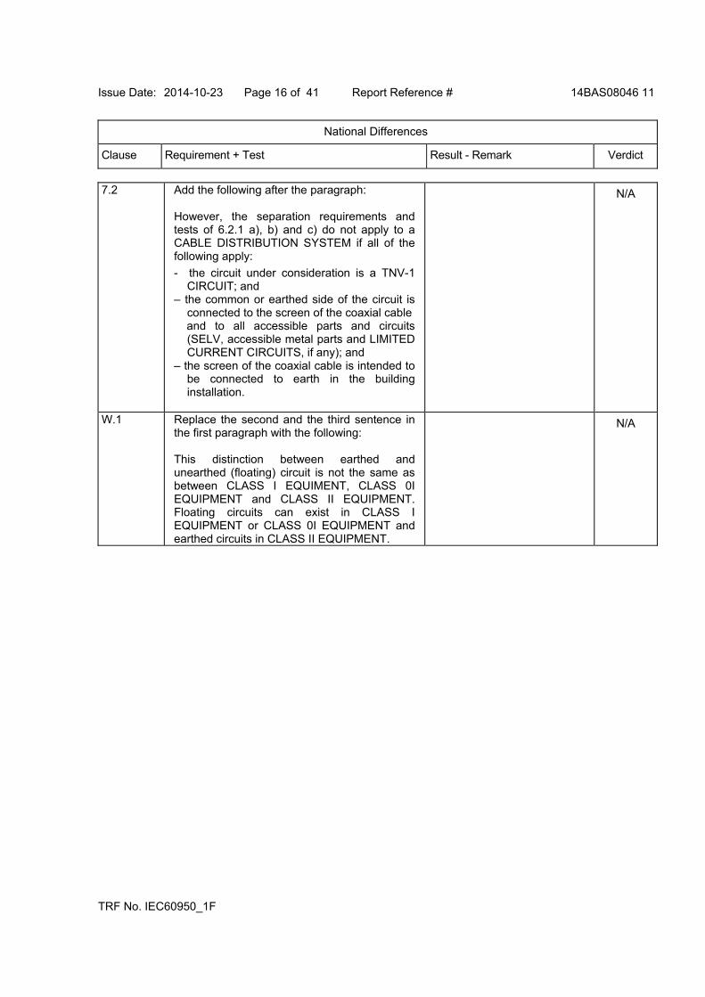
Issue Date: 2014-10-23 Page 16 of 41 Report Reference # 14BAS08046 11
National Differences
Clause Requirement + Test Result - Remark Verdict
TRF No. IEC60950_1F
7.2 Add the following after the paragraph: However, the separation requirements and tests of 6.2.1 a), b) and c) do not apply to a CABLE DISTRIBUTION SYSTEM if all of the following apply:
- the circuit under consideration is a TNV-1 CIRCUIT; and
– the common or earthed side of the circuit is connected to the screen of the coaxial cable
and to all accessible parts and circuits (SELV, accessible metal parts and LIMITED CURRENT CIRCUITS, if any); and
– the screen of the coaxial cable is intended to be connected to earth in the building installation.
N/A
W.1 Replace the second and the third sentence in the first paragraph with the following: This distinction between earthed and unearthed (floating) circuit is not the same as between CLASS I EQUIMENT, CLASS 0I EQUIPMENT and CLASS II EQUIPMENT. Floating circuits can exist in CLASS I EQUIPMENT or CLASS 0I EQUIPMENT and earthed circuits in CLASS II EQUIPMENT.
N/A
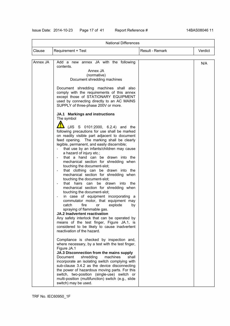
Issue Date: 2014-10-23 Page 17 of 41 Report Reference # 14BAS08046 11
National Differences
Clause Requirement + Test Result - Remark Verdict
TRF No. IEC60950_1F
Annex JA Add a new annex JA with the following contents.
Annex JA (normative)
Document shredding machines Document shredding machines shall also comply with the requirements of this annex except those of STATIONARY EQUIPMENT used by connecting directly to an AC MAINS SUPPLY of three-phase 200V or more. JA.1 Markings and instructions The symbol
(JIS S 0101:2000, 6.2.4) and the following precautions for use shall be marked on readily visible part adjacent to document feed opening. The marking shall be clearly legible, permanent, and easily discernible; - that use by an infants/children may cause
a hazard of injury etc.; - that a hand can be drawn into the
mechanical section for shredding when touching the document-slot;
- that clothing can be drawn into the mechanical section for shredding when touching the document-slot;
- that hairs can be drawn into the mechanical section for shredding when touching the document-slot;
- in case of equipment incorporating a commutator motor, that equipment may catch fire or explode by spraying of flammable gas.
JA.2 Inadvertent reactivation Any safety interlock that can be operated by means of the test finger, Figure JA.1, is considered to be likely to cause inadvertent reactivation of the hazard. Compliance is checked by inspection and, where necessary, by a test with the test finger, Figure JA.1 JA.3 Disconnection from the mains supply Document shredding machines shall incorporate an isolating switch complying with sub-clause 3.4.2 as the device disconnecting the power of hazardous moving parts. For this switch, two-position (single-use) switch or multi-position (multifunction) switch (e.g., slide switch) may be used.
N/A
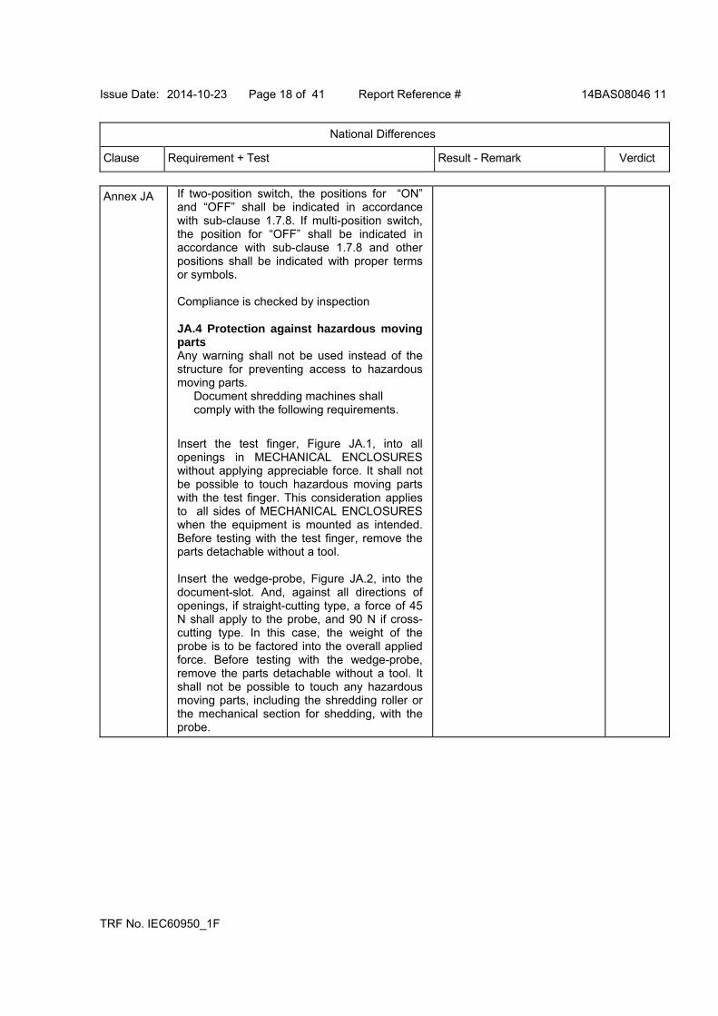
Issue Date: 2014-10-23 Page 18 of 41 Report Reference # 14BAS08046 11
National Differences
Clause Requirement + Test Result - Remark Verdict
TRF No. IEC60950_1F
Annex JA If two-position switch, the positions for “ON” and “OFF” shall be indicated in accordance with sub-clause 1.7.8. If multi-position switch, the position for “OFF” shall be indicated in accordance with sub-clause 1.7.8 and other positions shall be indicated with proper terms or symbols. Compliance is checked by inspection JA.4 Protection against hazardous moving parts Any warning shall not be used instead of the structure for preventing access to hazardous moving parts.
Document shredding machines shall comply with the following requirements.
Insert the test finger, Figure JA.1, into all openings in MECHANICAL ENCLOSURES without applying appreciable force. It shall not be possible to touch hazardous moving parts with the test finger. This consideration applies to all sides of MECHANICAL ENCLOSURES when the equipment is mounted as intended. Before testing with the test finger, remove the parts detachable without a tool. Insert the wedge-probe, Figure JA.2, into the document-slot. And, against all directions of openings, if straight-cutting type, a force of 45 N shall apply to the probe, and 90 N if cross-cutting type. In this case, the weight of the probe is to be factored into the overall applied force. Before testing with the wedge-probe, remove the parts detachable without a tool. It shall not be possible to touch any hazardous moving parts, including the shredding roller or the mechanical section for shedding, with the probe.

Issue Date: 2014-10-23 Page 19 of 41 Report Reference # 14BAS08046 11
National Differences
Clause Requirement + Test Result - Remark Verdict
TRF No. IEC60950_1F
Annex JA
Figure JA.1 Test finger
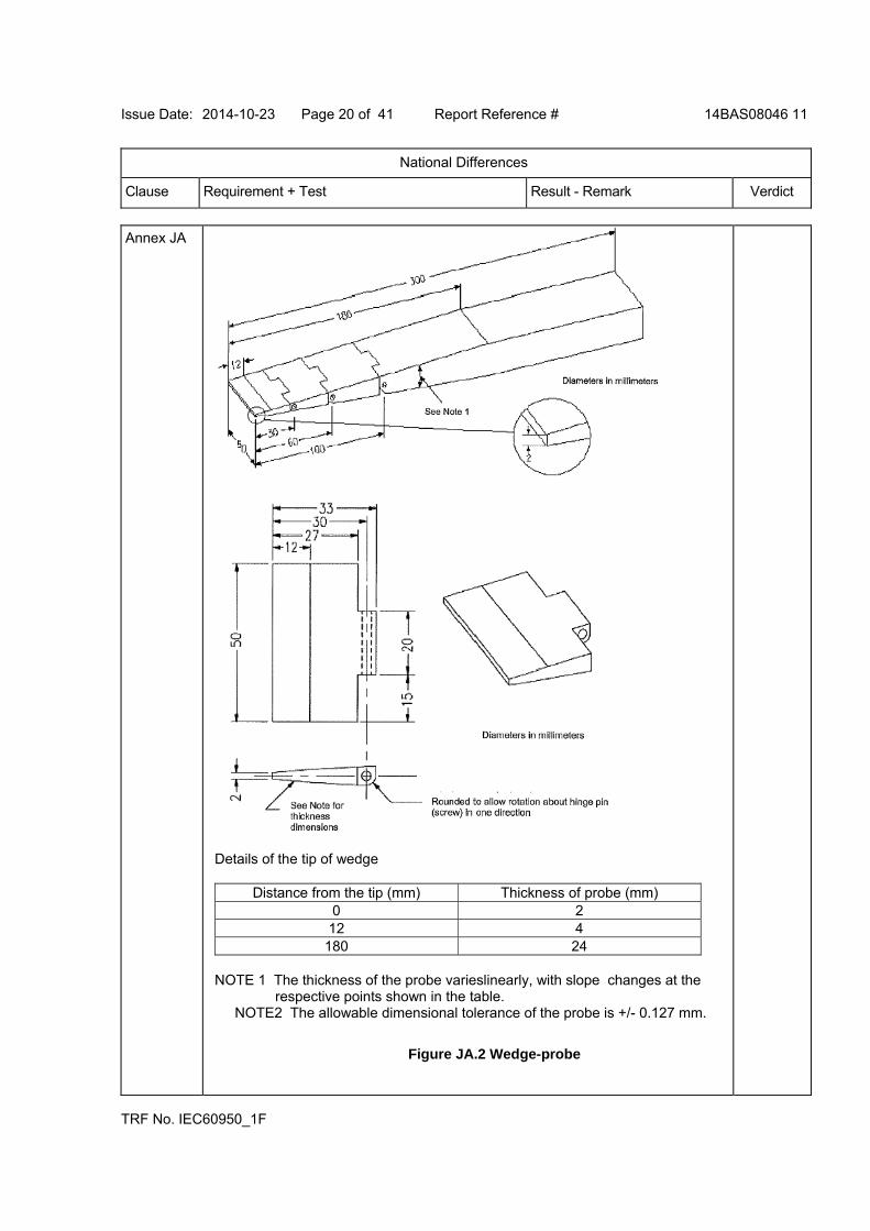
Issue Date: 2014-10-23 Page 20 of 41 Report Reference # 14BAS08046 11
National Differences
Clause Requirement + Test Result - Remark Verdict
TRF No. IEC60950_1F
Annex JA
Details of the tip of wedge
Distance from the tip (mm) Thickness of probe (mm) 0 2 12 4
180 24 NOTE 1 The thickness of the probe varieslinearly, with slope changes at the
respective points shown in the table. NOTE2 The allowable dimensional tolerance of the probe is +/- 0.127 mm.
Figure JA.2 Wedge-probe
Issue Date: 2014-10-23 Page 21 of 41 Report Reference # 14BAS08046 11
National Differences
Clause Requirement + Test Result - Remark Verdict
TRF No. IEC60950_1F
Korea - Differences to IEC 60950-1:2005 (2nd Edition); Am 1:2009
1.5.101 Plugs for the connection of the apparatus to the mains supply shall comply with the Korean requirement (KSC 8305)
N/A
8 EMC - The apparatus shall comply with the relevant CISPR standards
N/A
Norway - Differences to IEC 60950-1:2005 (2nd Edition); Am 1:2009
1.5.7.1 Resistors bridging BASIC INSULATION in CLASS I PLUGGABLE EQUIPMENT TYPE A must comply with the requirements in 1.5.7.2. In addition when a single resistor is used, the resistor must withstand the resistor test in 1.5.7.2.
N/A
1.5.8 Due to the IT power system used (see annex V, figure V.7), capacitors are required to be rated for the applicable line-to-line voltage (230 V).
Pass
1.5.9.4 The third dashed sentence is applicable only to equipment as defined by this annex, 6.1.2.2
N/A
1.7.2.1 Class I Pluggable Equipment Type A intended for connection to other equipment or a network shall, if safety relies on connection to protective earth or if surge suppressors are connected between the network terminals and accessible parts, have a marking stating that the equipment must be connected to an earthed mains socket-outlet. The marking text shall be: "Apparatet må tilkoples jordet stikkontakt"
N/A
1.7.2.1 In Norway, the screen of the cable distribution system is normally not earthed at the entrance of the building and there is normally no equipotential bonding system within the building. Therefore the protective earthing of the building installation need to be isolated from the screen of a
N/A
Issue Date: 2014-10-23 Page 22 of 41 Report Reference # 14BAS08046 11
National Differences
Clause Requirement + Test Result - Remark Verdict
TRF No. IEC60950_1F
cable distribution system. It is however accepted to provide the insulation external to the equipment by an adapter or an interconnection cable with galvanic isolator, which may be provided by e.g. a retailer. The user manual shall then have the following or similar information in Norwegian and Swedish language respectively, depending on in what country the equipment is intended to be used in: "Equipment connected to the protective earthing of the building installation through the mains connection or through other equipment with a connection to protective earthing - and to a cable distribution system using coaxial cable, may in some circumstances create a fire hazard. Connection to a cable distribution system has therefore to be provided through a device providing electrical isolation below a certain frequency range (galvanic isolator, see EN 60728-11)." NOTE: In Norway, due to regulation for installations of cable distribution systems, and in Sweden, a galvanic isolator shall provide electrical insulation below 5 MHz. The insulation shall withstand a dielectric strength of 1,5 kV r.m.s., 50 Hz or 60 Hz, for 1 min. Translation to Norwegian (the Swedish text will also be accepted in Norway): “Utstyr som er koplet til beskyttelsesjord via nettplugg og/eller via annet jordtilkoplet utstyr - og er tilkoplet et kabel-TV nett, kan forårsake brannfare. For å unngå dette skal det ved tilkopling av utstyret til kabel-TV nettet installeres en galvanisk isolator mellom utstyret og kabel-TV nettet."
2.2.4 Requirements according to this annex, 1.7.2.1, 6.1.2.1 and 6.1.2.2 apply.
N/A
2.3.2 Requirements according to this annex, 6.1.2.1 and 6.1.2.2 apply.
N/A
2.3.4 Requirements according to this annex, 1.7.2.1, 6.1.2.1 and 6.1.2.2 apply.
N/A
2.10.5.13 Requirements according to this annex, 6.1.2.1 and 6.1.2.2 apply.
N/A
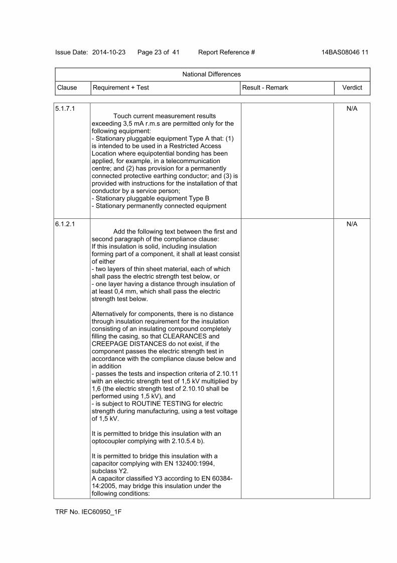
Issue Date: 2014-10-23 Page 23 of 41 Report Reference # 14BAS08046 11
National Differences
Clause Requirement + Test Result - Remark Verdict
TRF No. IEC60950_1F
5.1.7.1 Touch current measurement results exceeding 3,5 mA r.m.s are permitted only for the following equipment: - Stationary pluggable equipment Type A that: (1) is intended to be used in a Restricted Access Location where equipotential bonding has been applied, for example, in a telecommunication centre; and (2) has provision for a permanently connected protective earthing conductor; and (3) is provided with instructions for the installation of that conductor by a service person; - Stationary pluggable equipment Type B - Stationary permanently connected equipment
N/A
6.1.2.1 Add the following text between the first and second paragraph of the compliance clause: If this insulation is solid, including insulation forming part of a component, it shall at least consist of either - two layers of thin sheet material, each of which shall pass the electric strength test below, or - one layer having a distance through insulation of at least 0,4 mm, which shall pass the electric strength test below. Alternatively for components, there is no distance through insulation requirement for the insulation consisting of an insulating compound completely filling the casing, so that CLEARANCES and CREEPAGE DISTANCES do not exist, if the component passes the electric strength test in accordance with the compliance clause below and in addition - passes the tests and inspection criteria of 2.10.11 with an electric strength test of 1,5 kV multiplied by 1,6 (the electric strength test of 2.10.10 shall be performed using 1,5 kV), and - is subject to ROUTINE TESTING for electric strength during manufacturing, using a test voltage of 1,5 kV. It is permitted to bridge this insulation with an optocoupler complying with 2.10.5.4 b). It is permitted to bridge this insulation with a capacitor complying with EN 132400:1994, subclass Y2. A capacitor classified Y3 according to EN 60384-14:2005, may bridge this insulation under the following conditions:
N/A
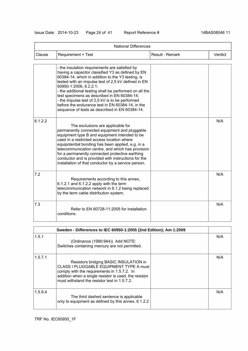
Issue Date: 2014-10-23 Page 24 of 41 Report Reference # 14BAS08046 11
National Differences
Clause Requirement + Test Result - Remark Verdict
TRF No. IEC60950_1F
- the insulation requirements are satisfied by having a capacitor classified Y3 as defined by EN 60384-14, which in addition to the Y3 testing, is tested with an impulse test of 2,5 kV defined in EN 60950-1:2006, 6.2.2.1; - the additional testing shall be performed on all the test specimens as described in EN 60384-14; - the impulse test of 2,5 kV is to be performed before the endurance test in EN 60384-14, in the sequence of tests as described in EN 60384-14.
6.1.2.2 The exclusions are applicable for permanently connected equipment and pluggable equipment type B and equipment intended to be used in a restricted access location where equipotential bonding has been applied, e.g. in a telecommunication centre, and which has provision for a permanently connected protective earthing conductor and is provided with instructions for the installation of that conductor by a service person.
N/A
7.2 Requirements according to this annex, 6.1.2.1 and 6.1.2.2 apply with the term telecommunication network in 6.1.2 being replaced by the term cable distribution system.
N/A
7.3 Refer to EN 60728-11:2005 for installation conditions
N/A
Sweden - Differences to IEC 60950-1:2005 (2nd Edition); Am 1:2009
1.5.1 (Ordinance (1990:944)) Add NOTE: Switches containing mercury are not permitted.
N/A
1.5.7.1 Resistors bridging BASIC INSULATION in CLASS I PLUGGABLE EQUIPMENT TYPE A must comply with the requirements in 1.5.7.2. In addition when a single resistor is used, the resistor must withstand the resistor test in 1.5.7.2.
N/A
1.5.9.4 The third dashed sentence is applicable only to equipment as defined by this annex, 6.1.2.2
N/A
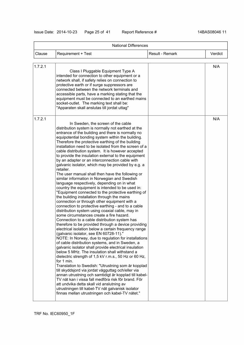
Issue Date: 2014-10-23 Page 25 of 41 Report Reference # 14BAS08046 11
National Differences
Clause Requirement + Test Result - Remark Verdict
TRF No. IEC60950_1F
1.7.2.1 Class I Pluggable Equipment Type A intended for connection to other equipment or a network shall, if safety relies on connection to protective earth or if surge suppressors are connected between the network terminals and accessible parts, have a marking stating that the equipment must be connected to an earthed mains socket-outlet. The marking text shall be: "Apparaten skall anslutas till jordat uttag"
N/A
1.7.2.1 In Sweden, the screen of the cable distribution system is normally not earthed at the entrance of the building and there is normally no equipotential bonding system within the building. Therefore the protective earthing of the building installation need to be isolated from the screen of a cable distribution system. It is however accepted to provide the insulation external to the equipment by an adapter or an interconnection cable with galvanic isolator, which may be provided by e.g. a retailer. The user manual shall then have the following or similar information in Norwegian and Swedish language respectively, depending on in what country the equipment is intended to be used in: "Equipment connected to the protective earthing of the building installation through the mains connection or through other equipment with a connection to protective earthing - and to a cable distribution system using coaxial cable, may in some circumstances create a fire hazard. Connection to a cable distribution system has therefore to be provided through a device providing electrical isolation below a certain frequency range (galvanic isolator, see EN 60728-11)." NOTE: In Norway, due to regulation for installations of cable distribution systems, and in Sweden, a galvanic isolator shall provide electrical insulation below 5 MHz. The insulation shall withstand a dielectric strength of 1,5 kV r.m.s., 50 Hz or 60 Hz, for 1 min. Translation to Swedish: "Utrustning som är kopplad till skyddsjord via jordat vägguttag och/eller via annan utrustning och samtidigt är kopplad till kabel-TV nät kan i vissa fall medfõra risk fõr brand. Fõr att undvika detta skall vid anslutning av utrustningen till kabel-TV nät galvanisk isolator finnas mellan utrustningen och kabel-TV nätet."
N/A
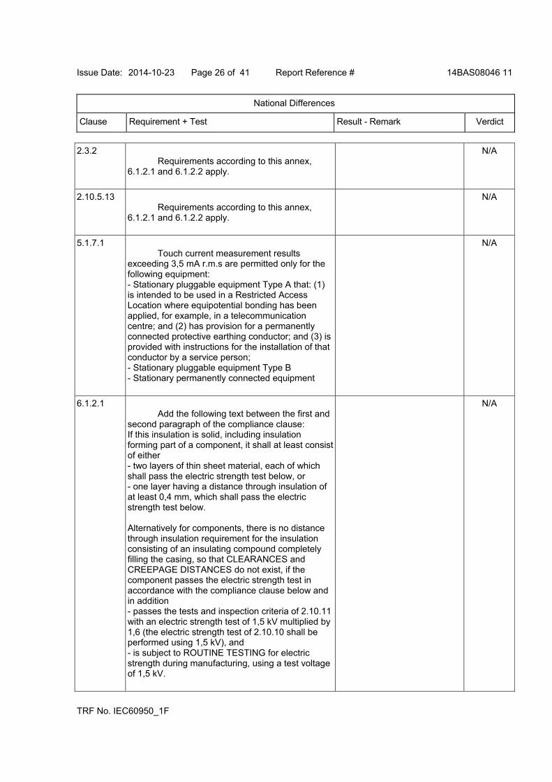
Issue Date: 2014-10-23 Page 26 of 41 Report Reference # 14BAS08046 11
National Differences
Clause Requirement + Test Result - Remark Verdict
TRF No. IEC60950_1F
2.3.2 Requirements according to this annex, 6.1.2.1 and 6.1.2.2 apply.
N/A
2.10.5.13 Requirements according to this annex, 6.1.2.1 and 6.1.2.2 apply.
N/A
5.1.7.1 Touch current measurement results exceeding 3,5 mA r.m.s are permitted only for the following equipment: - Stationary pluggable equipment Type A that: (1) is intended to be used in a Restricted Access Location where equipotential bonding has been applied, for example, in a telecommunication centre; and (2) has provision for a permanently connected protective earthing conductor; and (3) is provided with instructions for the installation of that conductor by a service person; - Stationary pluggable equipment Type B - Stationary permanently connected equipment
N/A
6.1.2.1 Add the following text between the first and second paragraph of the compliance clause: If this insulation is solid, including insulation forming part of a component, it shall at least consist of either - two layers of thin sheet material, each of which shall pass the electric strength test below, or - one layer having a distance through insulation of at least 0,4 mm, which shall pass the electric strength test below. Alternatively for components, there is no distance through insulation requirement for the insulation consisting of an insulating compound completely filling the casing, so that CLEARANCES and CREEPAGE DISTANCES do not exist, if the component passes the electric strength test in accordance with the compliance clause below and in addition - passes the tests and inspection criteria of 2.10.11 with an electric strength test of 1,5 kV multiplied by 1,6 (the electric strength test of 2.10.10 shall be performed using 1,5 kV), and - is subject to ROUTINE TESTING for electric strength during manufacturing, using a test voltage of 1,5 kV.
N/A
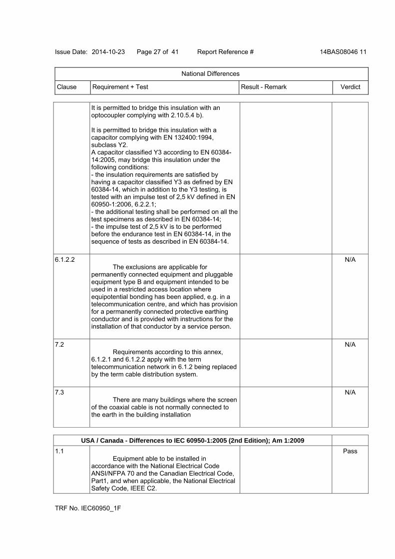
Issue Date: 2014-10-23 Page 27 of 41 Report Reference # 14BAS08046 11
National Differences
Clause Requirement + Test Result - Remark Verdict
TRF No. IEC60950_1F
It is permitted to bridge this insulation with an optocoupler complying with 2.10.5.4 b). It is permitted to bridge this insulation with a capacitor complying with EN 132400:1994, subclass Y2. A capacitor classified Y3 according to EN 60384-14:2005, may bridge this insulation under the following conditions: - the insulation requirements are satisfied by having a capacitor classified Y3 as defined by EN 60384-14, which in addition to the Y3 testing, is tested with an impulse test of 2,5 kV defined in EN 60950-1:2006, 6.2.2.1; - the additional testing shall be performed on all the test specimens as described in EN 60384-14; - the impulse test of 2,5 kV is to be performed before the endurance test in EN 60384-14, in the sequence of tests as described in EN 60384-14.
6.1.2.2 The exclusions are applicable for permanently connected equipment and pluggable equipment type B and equipment intended to be used in a restricted access location where equipotential bonding has been applied, e.g. in a telecommunication centre, and which has provision for a permanently connected protective earthing conductor and is provided with instructions for the installation of that conductor by a service person.
N/A
7.2 Requirements according to this annex, 6.1.2.1 and 6.1.2.2 apply with the term telecommunication network in 6.1.2 being replaced by the term cable distribution system.
N/A
7.3 There are many buildings where the screen of the coaxial cable is not normally connected to the earth in the building installation
N/A
USA / Canada - Differences to IEC 60950-1:2005 (2nd Edition); Am 1:2009
1.1 Equipment able to be installed in accordance with the National Electrical Code ANSI/NFPA 70 and the Canadian Electrical Code, Part1, and when applicable, the National Electrical Safety Code, IEEE C2.
Pass

Issue Date: 2014-10-23 Page 28 of 41 Report Reference # 14BAS08046 11
National Differences
Clause Requirement + Test Result - Remark Verdict
TRF No. IEC60950_1F
1.1.1 Equipment able to be installed in accordance with ANSI/NFPA 75 and NEC Art. 645 unless intended for use outside of computer room and provided with such instructions.
Pass
1.1.2 Equipment in wire-line communication facilities serving high-voltage electric power stations operating at greater than 1kV are excluded.
N/A
1.1.2 Special requirements apply to equipment intended for use outdoors.
N/A
1.4.14 For PLUGGABLE EQUIPMENT TYPE A, the protection in the installation is assumed to be 20 A.
Pass
1.5.1 All IEC standards for components identified in Annex P.1 replaced by the relevant requirements of CSA and UL component standards in Annex P.1.
Pass
1.5.1 All IEC standards for components identified in Annex P.2 alternatively satisfied by the relevant requirements of CSA and UL component standards in Annex P.2.
Pass
1.5.5 Interconnecting cables acceptable for the application regarding voltage, current, temperature, flammability, mechanical serviceability and the like.
Pass
1.5.5 For other than limited power and TNV circuits, the type of output circuit identified for output connector.
N/A
1.5.5 External cable assemblies that exceed 3.05 m in length to be types specified in the NEC and CEC.
N/A
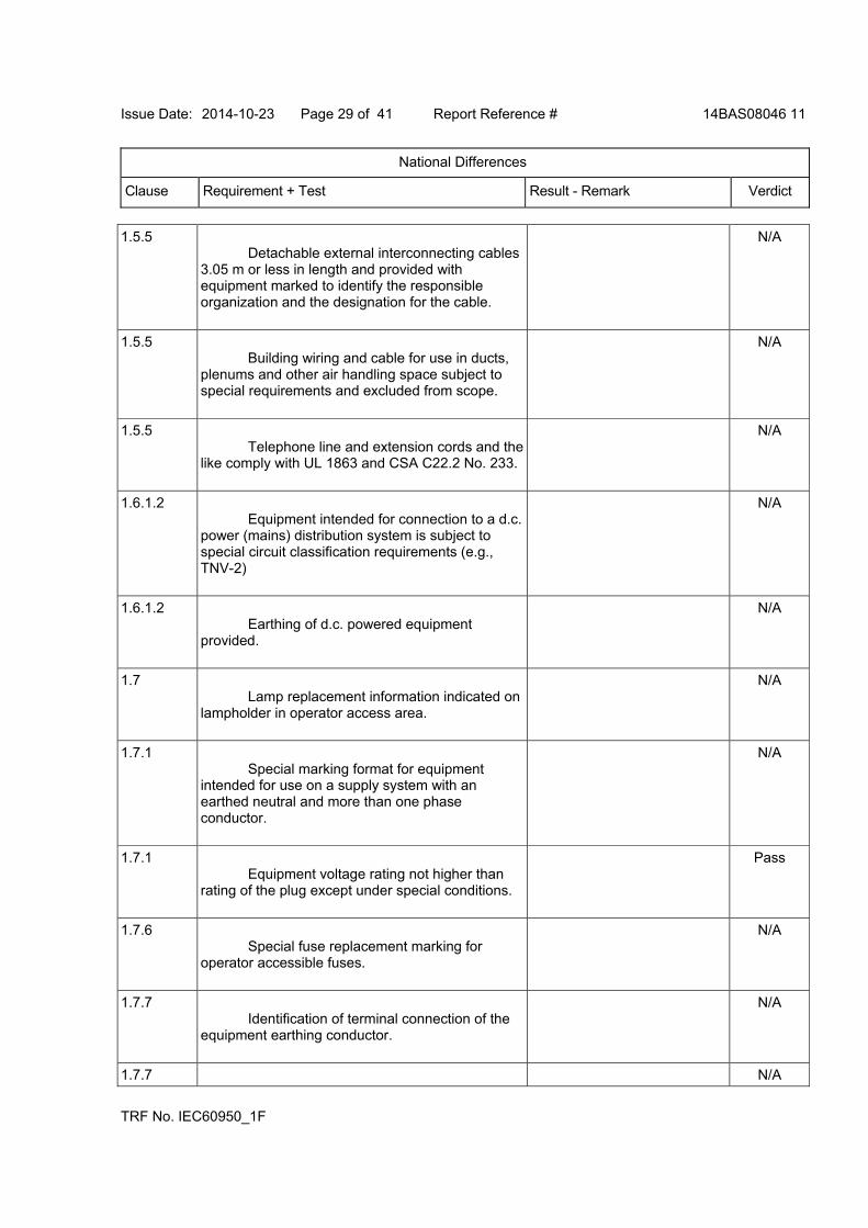
Issue Date: 2014-10-23 Page 29 of 41 Report Reference # 14BAS08046 11
National Differences
Clause Requirement + Test Result - Remark Verdict
TRF No. IEC60950_1F
1.5.5 Detachable external interconnecting cables 3.05 m or less in length and provided with equipment marked to identify the responsible organization and the designation for the cable.
N/A
1.5.5 Building wiring and cable for use in ducts, plenums and other air handling space subject to special requirements and excluded from scope.
N/A
1.5.5 Telephone line and extension cords and the like comply with UL 1863 and CSA C22.2 No. 233.
N/A
1.6.1.2 Equipment intended for connection to a d.c. power (mains) distribution system is subject to special circuit classification requirements (e.g., TNV-2)
N/A
1.6.1.2 Earthing of d.c. powered equipment provided.
N/A
1.7 Lamp replacement information indicated on lampholder in operator access area.
N/A
1.7.1 Special marking format for equipment intended for use on a supply system with an earthed neutral and more than one phase conductor.
N/A
1.7.1 Equipment voltage rating not higher than rating of the plug except under special conditions.
Pass
1.7.6 Special fuse replacement marking for operator accessible fuses.
N/A
1.7.7 Identification of terminal connection of the equipment earthing conductor.
N/A
1.7.7 N/A
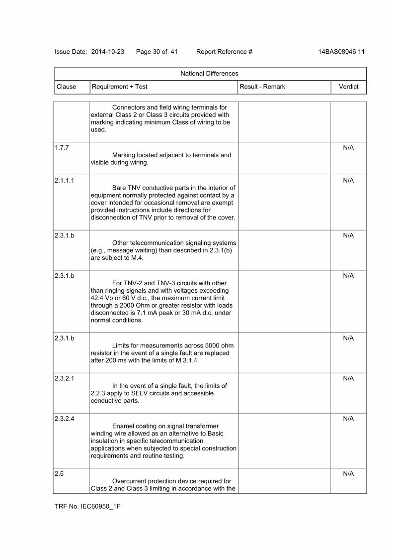
Issue Date: 2014-10-23 Page 30 of 41 Report Reference # 14BAS08046 11
National Differences
Clause Requirement + Test Result - Remark Verdict
TRF No. IEC60950_1F
Connectors and field wiring terminals for external Class 2 or Class 3 circuits provided with marking indicating minimum Class of wiring to be used.
1.7.7 Marking located adjacent to terminals and visible during wiring.
N/A
2.1.1.1 Bare TNV conductive parts in the interior of equipment normally protected against contact by a cover intended for occasional removal are exempt provided instructions include directions for disconnection of TNV prior to removal of the cover.
N/A
2.3.1.b Other telecommunication signaling systems (e.g., message waiting) than described in 2.3.1(b) are subject to M.4.
N/A
2.3.1.b For TNV-2 and TNV-3 circuits with other than ringing signals and with voltages exceeding 42.4 Vp or 60 V d.c., the maximum current limit through a 2000 Ohm or greater resistor with loads disconnected is 7.1 mA peak or 30 mA d.c. under normal conditions.
N/A
2.3.1.b Limits for measurements across 5000 ohm resistor in the event of a single fault are replaced after 200 ms with the limits of M.3.1.4.
N/A
2.3.2.1 In the event of a single fault, the limits of 2.2.3 apply to SELV circuits and accessible conductive parts.
N/A
2.3.2.4 Enamel coating on signal transformer winding wire allowed as an alternative to Basic insulation in specific telecommunication applications when subjected to special construction requirements and routine testing.
N/A
2.5 Overcurrent protection device required for Class 2 and Class 3 limiting in accordance with the
N/A

Issue Date: 2014-10-23 Page 31 of 41 Report Reference # 14BAS08046 11
National Differences
Clause Requirement + Test Result - Remark Verdict
TRF No. IEC60950_1F
NEC, or for a Limited Power Source, not interchangeable with devices of higher ratings if operator replaceable.
2.6 Equipment having receptacles for output a.c. power connectors generated from an internal separately derived source have the earthed (grounded) circuit conductor suitably bonded to earth.
N/A
2.6.3.3 For PLUGGABLE EQUIPMENT TYPE A, if a) b) or c) are not applicable, the current rating of the circuit is taken as 20 A
N/A
2.6.3.3 The first column on Table 2D requirement: “Smaller of the RATED CURRENT of the equipment or the PROTECTIVE CURRENT RATING of the circuit under consideration."
N/A
2.6.3.4 Capacity of connection between earthing terminal and parts required to be earthed subject to special conditions based on the current rating of the circuit.
N/A
2.6.3.4 Protective bonding conductors and their terminals of non-standard constructions (e.g. PWB traces) evaluated to limited short-circuit test of CSA C22.2 No.0.4.
N/A
2.6.4.1 Field wiring terminals for earthing conductors suitable for wire sizes (gauge) used in US and Canada.
N/A
2.7.1 Data for selection of special external branch circuit overcurrent devices marked on the equipment.
N/A
2.7.1 Standard supply outlets protected by overcurrent device in accordance with the NEC, and CEC, Part 1.
N/A
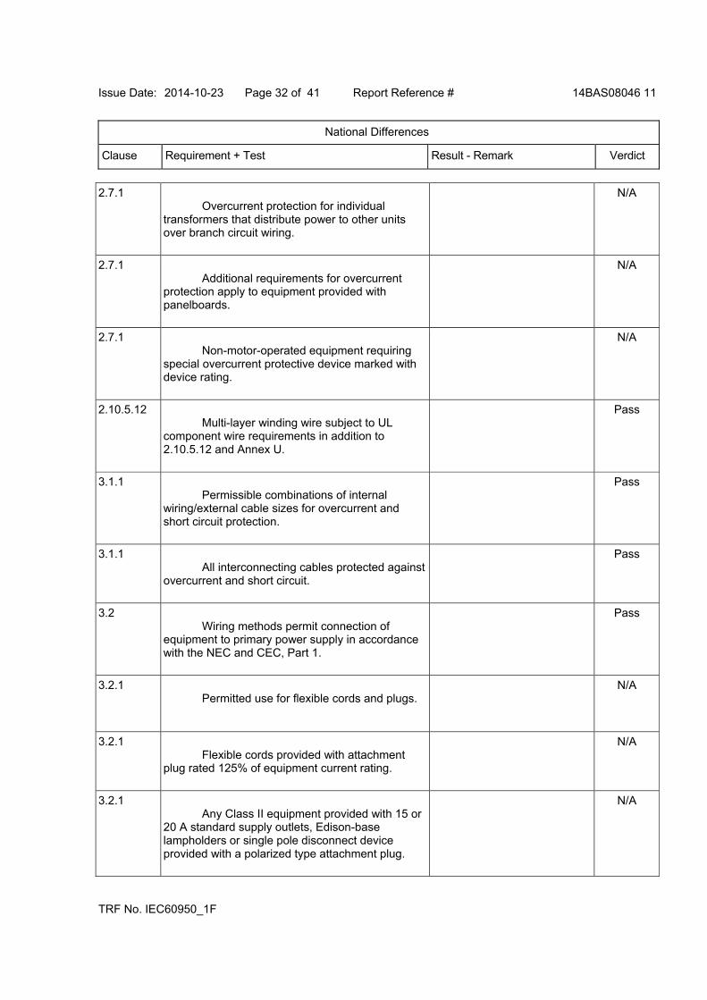
Issue Date: 2014-10-23 Page 32 of 41 Report Reference # 14BAS08046 11
National Differences
Clause Requirement + Test Result - Remark Verdict
TRF No. IEC60950_1F
2.7.1 Overcurrent protection for individual transformers that distribute power to other units over branch circuit wiring.
N/A
2.7.1 Additional requirements for overcurrent protection apply to equipment provided with panelboards.
N/A
2.7.1 Non-motor-operated equipment requiring special overcurrent protective device marked with device rating.
N/A
2.10.5.12 Multi-layer winding wire subject to UL component wire requirements in addition to 2.10.5.12 and Annex U.
Pass
3.1.1 Permissible combinations of internal wiring/external cable sizes for overcurrent and short circuit protection.
Pass
3.1.1 All interconnecting cables protected against overcurrent and short circuit.
Pass
3.2 Wiring methods permit connection of equipment to primary power supply in accordance with the NEC and CEC, Part 1.
Pass
3.2.1 Permitted use for flexible cords and plugs.
N/A
3.2.1 Flexible cords provided with attachment plug rated 125% of equipment current rating.
N/A
3.2.1 Any Class II equipment provided with 15 or 20 A standard supply outlets, Edison-base lampholders or single pole disconnect device provided with a polarized type attachment plug.
N/A
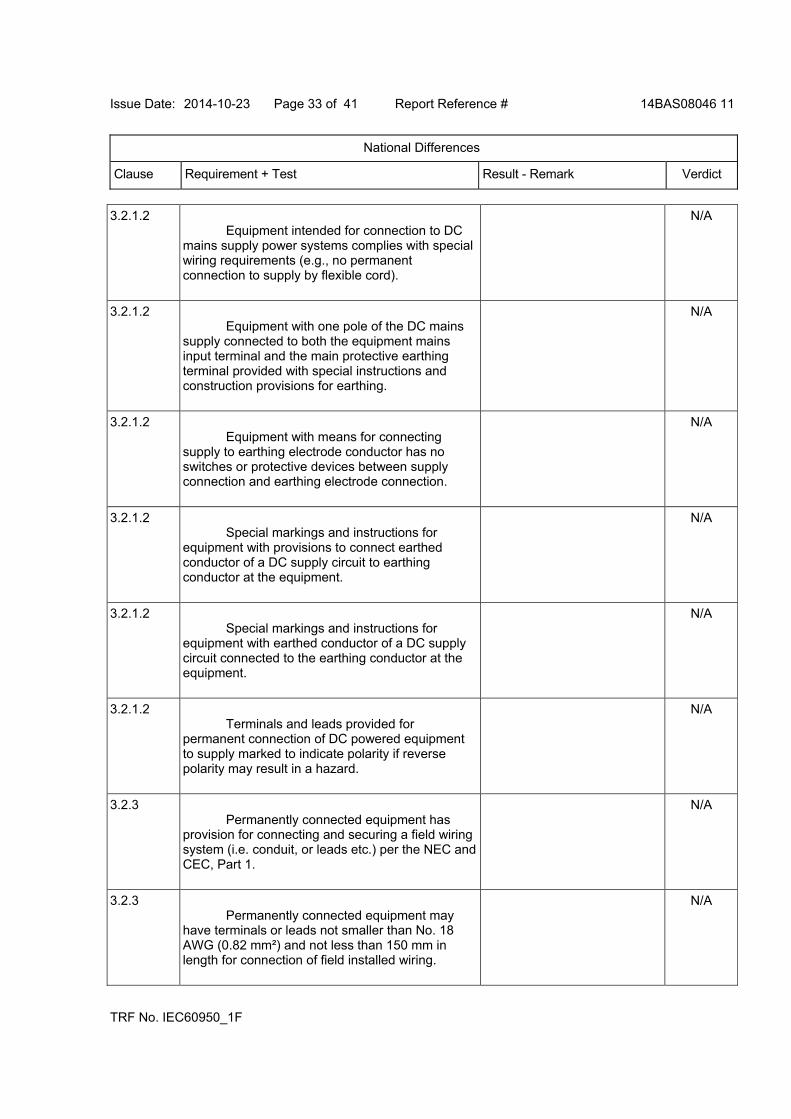
Issue Date: 2014-10-23 Page 33 of 41 Report Reference # 14BAS08046 11
National Differences
Clause Requirement + Test Result - Remark Verdict
TRF No. IEC60950_1F
3.2.1.2 Equipment intended for connection to DC mains supply power systems complies with special wiring requirements (e.g., no permanent connection to supply by flexible cord).
N/A
3.2.1.2 Equipment with one pole of the DC mains supply connected to both the equipment mains input terminal and the main protective earthing terminal provided with special instructions and construction provisions for earthing.
N/A
3.2.1.2 Equipment with means for connecting supply to earthing electrode conductor has no switches or protective devices between supply connection and earthing electrode connection.
N/A
3.2.1.2 Special markings and instructions for equipment with provisions to connect earthed conductor of a DC supply circuit to earthing conductor at the equipment.
N/A
3.2.1.2 Special markings and instructions for equipment with earthed conductor of a DC supply circuit connected to the earthing conductor at the equipment.
N/A
3.2.1.2 Terminals and leads provided for permanent connection of DC powered equipment to supply marked to indicate polarity if reverse polarity may result in a hazard.
N/A
3.2.3 Permanently connected equipment has provision for connecting and securing a field wiring system (i.e. conduit, or leads etc.) per the NEC and CEC, Part 1.
N/A
3.2.3 Permanently connected equipment may have terminals or leads not smaller than No. 18 AWG (0.82 mm²) and not less than 150 mm in length for connection of field installed wiring.
N/A

Issue Date: 2014-10-23 Page 34 of 41 Report Reference # 14BAS08046 11
National Differences
Clause Requirement + Test Result - Remark Verdict
TRF No. IEC60950_1F
3.2.3 If supply wires exceed 60 °C, marking indicates use of 75 °C or 90 °C wiring for supply connection as appropriate.
N/A
3.2.3 Equipment compatible with suitable trade sizes of conduits and cables.
N/A
3.2.5 Power supply cords are required to be no longer than 4.5 m in length. Minimum cord length is required to be 1.5 m, with certain constructions such as external power supplies allowed to consider both input and output cord lengths into the requirement. Flexible power supply cords are required to be compatible with Article 400 of the NEC, and Tables 11 and 12 of the CEC.
Power supply cord not provided
N/A
3.2.5 Conductors in power supply cords sized according to NEC and CEC, Part I.
N/A
3.2.5 Power supply cords and cord sets incorporate flexible cords suitable for the particular application.
N/A
3.2.6 Strain relief provided for non-detachable interconnecting cables not supplied by a limited power source.
Pass
3.2.9 Adequate wire bending space and volume of field wiring compartment required to properly make the field connections.
N/A
3.2.9 Equipment intended solely for installation in Restricted Access Locations using low voltage d.c. systems may not need provision for connecting and securing a field wiring system. A method of securing wiring or instructions provided to ensure the wiring is protected from abuse.
N/A
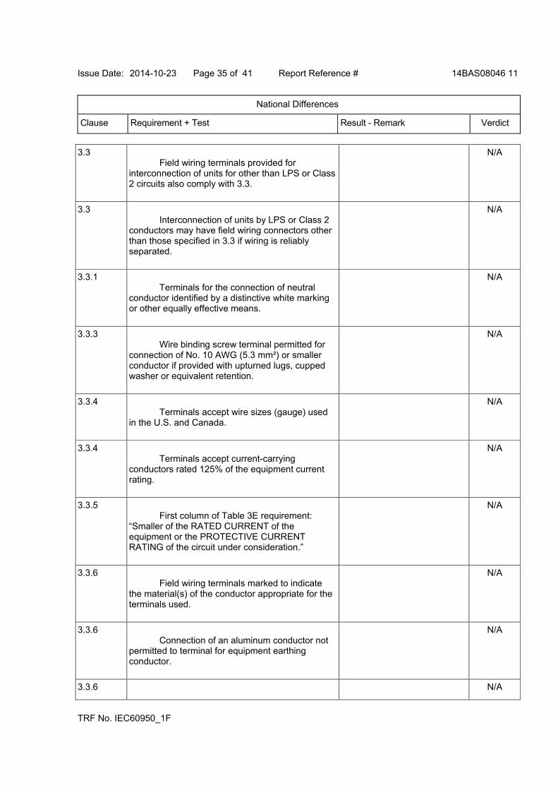
Issue Date: 2014-10-23 Page 35 of 41 Report Reference # 14BAS08046 11
National Differences
Clause Requirement + Test Result - Remark Verdict
TRF No. IEC60950_1F
3.3 Field wiring terminals provided for interconnection of units for other than LPS or Class 2 circuits also comply with 3.3.
N/A
3.3 Interconnection of units by LPS or Class 2 conductors may have field wiring connectors other than those specified in 3.3 if wiring is reliably separated.
N/A
3.3.1 Terminals for the connection of neutral conductor identified by a distinctive white marking or other equally effective means.
N/A
3.3.3 Wire binding screw terminal permitted for connection of No. 10 AWG (5.3 mm²) or smaller conductor if provided with upturned lugs, cupped washer or equivalent retention.
N/A
3.3.4 Terminals accept wire sizes (gauge) used in the U.S. and Canada.
N/A
3.3.4 Terminals accept current-carrying conductors rated 125% of the equipment current rating.
N/A
3.3.5 First column of Table 3E requirement: “Smaller of the RATED CURRENT of the equipment or the PROTECTIVE CURRENT RATING of the circuit under consideration.”
N/A
3.3.6 Field wiring terminals marked to indicate the material(s) of the conductor appropriate for the terminals used.
N/A
3.3.6 Connection of an aluminum conductor not permitted to terminal for equipment earthing conductor.
N/A
3.3.6 N/A
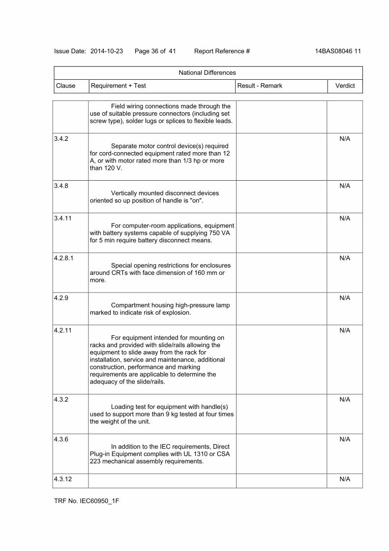
Issue Date: 2014-10-23 Page 36 of 41 Report Reference # 14BAS08046 11
National Differences
Clause Requirement + Test Result - Remark Verdict
TRF No. IEC60950_1F
Field wiring connections made through the use of suitable pressure connectors (including set screw type), solder lugs or splices to flexible leads.
3.4.2 Separate motor control device(s) required for cord-connected equipment rated more than 12 A, or with motor rated more than 1/3 hp or more than 120 V.
N/A
3.4.8 Vertically mounted disconnect devices oriented so up position of handle is "on".
N/A
3.4.11 For computer-room applications, equipment with battery systems capable of supplying 750 VA for 5 min require battery disconnect means.
N/A
4.2.8.1 Special opening restrictions for enclosures around CRTs with face dimension of 160 mm or more.
N/A
4.2.9 Compartment housing high-pressure lamp marked to indicate risk of explosion.
N/A
4.2.11 For equipment intended for mounting on racks and provided with slide/rails allowing the equipment to slide away from the rack for installation, service and maintenance, additional construction, performance and marking requirements are applicable to determine the adequacy of the slide/rails.
N/A
4.3.2 Loading test for equipment with handle(s) used to support more than 9 kg tested at four times the weight of the unit.
N/A
4.3.6 In addition to the IEC requirements, Direct Plug-in Equipment complies with UL 1310 or CSA 223 mechanical assembly requirements.
N/A
4.3.12 N/A
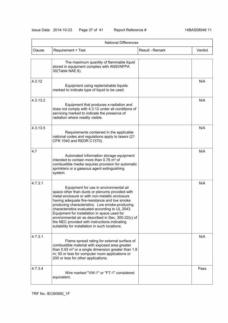
Issue Date: 2014-10-23 Page 37 of 41 Report Reference # 14BAS08046 11
National Differences
Clause Requirement + Test Result - Remark Verdict
TRF No. IEC60950_1F
The maximum quantity of flammable liquid stored in equipment complies with ANSI/NFPA 30(Table NAE.6).
4.3.12 Equipment using replenishable liquids marked to indicate type of liquid to be used.
N/A
4.3.13.2 Equipment that produces x-radiation and does not comply with 4.3.12 under all conditions of servicing marked to indicate the presence of radiation where readily visible.
N/A
4.3.13.5 Requirements contained in the applicable national codes and regulations apply to lasers (21 CFR 1040 and REDR C1370).
N/A
4.7 Automated information storage equipment intended to contain more than 0.76 m³ of combustible media requires provision for automatic sprinklers or a gaseous agent extinguishing system.
N/A
4.7.3.1 Equipment for use in environmental air space other than ducts or plenums provided with metal enclosure or with non-metallic enclosure having adequate fire-resistance and low smoke producing characteristics. Low smoke-producing characteristics evaluated according to UL 2043. Equipment for installation in space used for environmental air as described in Sec. 300-22(c) of the NEC provided with instructions indicating suitability for installation in such locations.
N/A
4.7.3.1 Flame spread rating for external surface of combustible material with exposed area greater than 0.93 m² or a single dimension greater than 1.8 m; 50 or less for computer room applications or 200 or less for other applications.
N/A
4.7.3.4 Wire marked "VW-1" or "FT-1" considered equivalent.
Pass
Issue Date: 2014-10-23 Page 38 of 41 Report Reference # 14BAS08046 11
National Differences
Clause Requirement + Test Result - Remark Verdict
TRF No. IEC60950_1F
5.1.8.2 Special earthing provisions and instructions for equipment with high touch current due to telecommunication network connections.
N/A
5.1.8.3 Touch current due to ringing voltage for equipment containing telecommunication network leads.
N/A
5.3.7 Overloading of SELV connectors and printed wiring board receptacles accessible to the operator.
Pass
5.3.7 Tests interrupted by opening of a component repeated two additional times.
Pass
5.3.9.1 Test interrupted by opening of wire or trace subject to certain conditions.
N/A
6 Specialized instructions provided for telephones that may be connected to a telecommunications network.
N/A
6 Marking identifying function of telecommunication type connectors not used for connection to a telecommunication network.
N/A
6.3 Equipment remotely powered over telecommunication wiring systems provided with specialized markings adjacent to the connection.
N/A
6.3 Overcurrent protection incorporated into equipment to provide power over telecommunication wiring system not interchangeable with devices of higher ratings if operator replaceable.
N/A
6.4 Additional requirements for equipment intended for connection to a telecommunication
N/A

Issue Date: 2014-10-23 Page 39 of 41 Report Reference # 14BAS08046 11
National Differences
Clause Requirement + Test Result - Remark Verdict
TRF No. IEC60950_1F
network using cable subject to overvoltage from power line failures (Fig. 6C).
6.4 Where 26 AWG line cord required by Fig. 6C, either the cord is provided with the equipment or described in the safety instructions.
N/A
7 Equipment associated with the cable distribution system may need to be subjected to applicable parts of Chapter 8 of the NEC.
N/A
H Ionizing radiation measurements made under single fault conditions in accordance with the requirements of the Code of Federal Regulations 21 CFR 1020 and the Canadian Radiation Emitting Devices Act, REDR C1370.
N/A
M.2 Continuous ringing signals evaluated to Method A subjected to special accessibility considerations.
N/A
M.4 Special requirements for message waiting and similar telecommunications signals.
N/A
NAC Equipment intended for use with a generic secondary protector marked with suitable instructions.
N/A
NAC Equipment intended for use with a specific primary or secondary protector marked with suitable instructions.
N/A
NAD Acoustic pressure from an ear piece less than 140 dBA for short duration disturbances, and less than 125 dBA for handsets, 118 dBA for headsets and insert earphones, for long duration disturbances.
N/A
NAD Equipment connected to a
N/A

Issue Date: 2014-10-23 Page 40 of 41 Report Reference # 14BAS08046 11
National Differences
Clause Requirement + Test Result - Remark Verdict
TRF No. IEC60950_1F
telecommunication and cable distribution networks and supplied with an earphone intended to be held against, or in the ear is required to comply with special acoustic pressure requirements.
EE.5 UL articulated accessibility probe (Fig. EE.3) required for assessing accessibility to document/media shredders, instead of Figure 2A test finger.
N/A
United Kingdom - Differences to IEC 60950-1:2005 (2nd Edition); Am 1:2009
2.6.3.3 The current rating of the circuit shall be taken as 13 A, not 16 A.
N/A
2.7.1 To protect against excessive currents and short-circuits in the PRIMARY CIRCUIT of DIRECT PLUG-IN EQUIPMENT, tests according to 5.3 shall be conducted, using an external protective device rated 30 A or 32 A. If these tests fail, suitable protective devices shall be included as integral parts of the DIRECT PLUG-IN EQUIPMENT, so that the requirements of 5.3 are met.
Pass
3.2.1.1 Apparatus which is fitted with a flexible cable or cord and is designed to be connected to a mains socket conforming to BS 1363 by means of that flexible cable or cord and plug, shall be fitted with a "standard plug" in accordance with Statutory Instrument 1786: 1994 - The Plugs and Sockets etc. (Safety) Regulations 1994, unless exempted by those regulations. NOTE: "Standard plug" is defined in SI 1786: 1994 and essentially means an approved plug conforming to BS 1363 or an approved conversion plug.
Pass
3.2.5.1 A power supply cord with conductor of 1.25 mm² is allowed for equipment with a rated current over 10A and up to and including 13A.
N/A
3.3.4 The range of conductor sizes of flexible
N/A
Issue Date: 2014-10-23 Page 41 of 41 Report Reference # 14BAS08046 11
National Differences
Clause Requirement + Test Result - Remark Verdict
TRF No. IEC60950_1F
cords to be accepted by terminals for equipment with a rated current of over 10 A up to and including 13 A is 1.25 mm² to 1.5 mm² nominal cross-sectional area.
4.3.6 The torque test is performed using a socket outlet complying with BS 1363 part 1:1995, including Amendment 1:1997 and Amendment 2:2003 and the plug part of DIRECT PLUG-IN EQUIPMENT shall be assessed to BS 1363: Part 1, 12.1, 12.2, 12.3, 12.9, 12.11, 12.12, 12.13, 12.16 and 12.17, except that the test of 12.17 is performed at not less than 125 °C. Where the metal earth pin is replaced by an Insulated Shutter Opening Device (ISOD), the requirements of clauses 22.2 and 23 also apply.
N/A

Issue Date: 2014-10-23 Page 1 of 44 Report Reference # 14BAS08046 11
TRF No. IEC60950_1F
Enclosures
Type Supplement Id Description
Photographs 3-01 Overall View
Photographs 3-02 Overall View
Photographs 3-03 Inside view
Photographs 3-04 PWB-components side
Photographs 3-05 PWB-trace side
Photographs 3-06 Transformer View
Photographs 3-07 Transformer View
Diagrams 4-01 T1 Spec
Diagrams 4-02 L1 Spec
Diagrams 4-03 L2 Spec
Schematics + PWB 5-01 PWB Layout
Miscellaneous 7-01 Enclosure
Miscellaneous 7-02 SR Spec
Miscellaneous 7-03 HS1 Spec
Miscellaneous 7-04 HS2 Spec
Miscellaneous 7-05 HS3 Spec
Miscellaneous 7-06 EUROPEAN GROUP DIFFERENCES AND NATIONAL DIFFERENCES (TRF EU_GD_IEC60950_1F)
Miscellaneous 7-07 Addition national differences as listed for AS/NZS 60950.1:2011 and Amendment No. 1
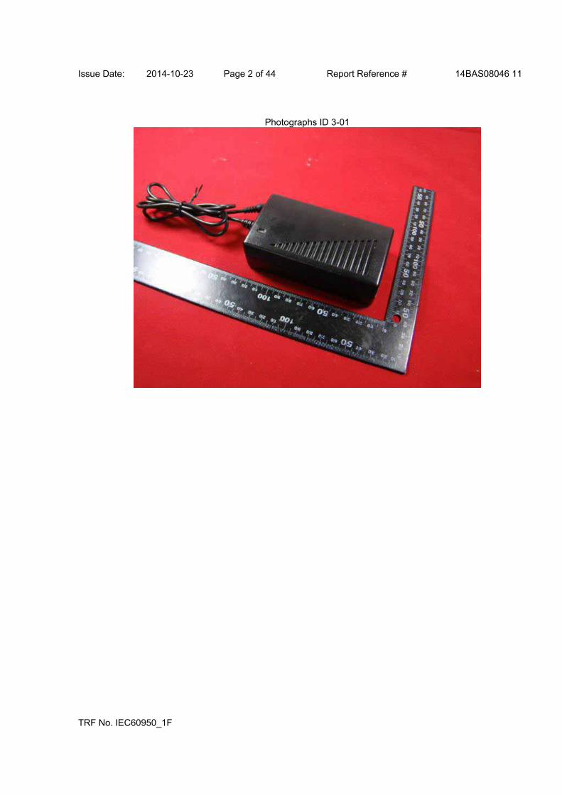
Issue Date: 2014-10-23 Page 2 of 44 Report Reference # 14BAS08046 11
TRF No. IEC60950_1F
Photographs ID 3-01
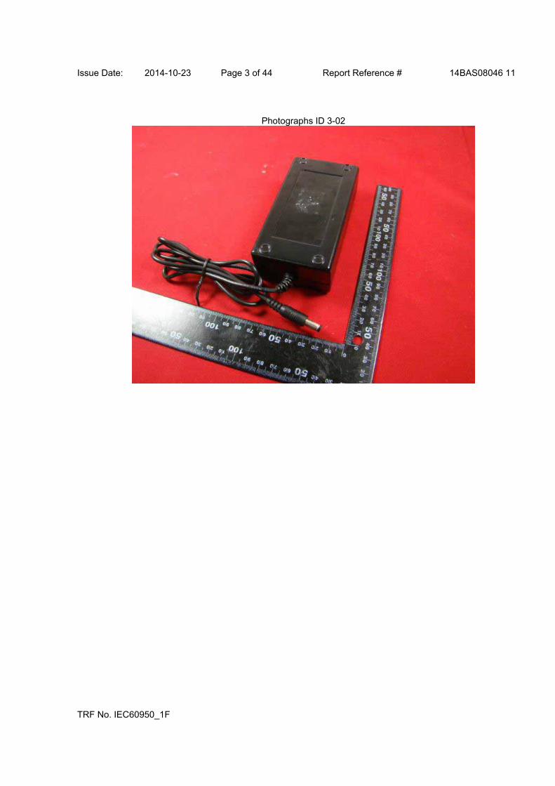
Issue Date: 2014-10-23 Page 3 of 44 Report Reference # 14BAS08046 11
TRF No. IEC60950_1F
Photographs ID 3-02
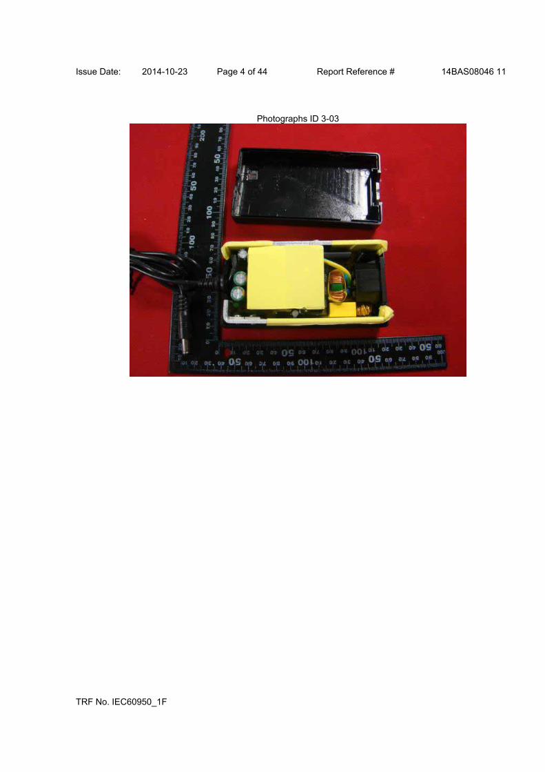
Issue Date: 2014-10-23 Page 4 of 44 Report Reference # 14BAS08046 11
TRF No. IEC60950_1F
Photographs ID 3-03
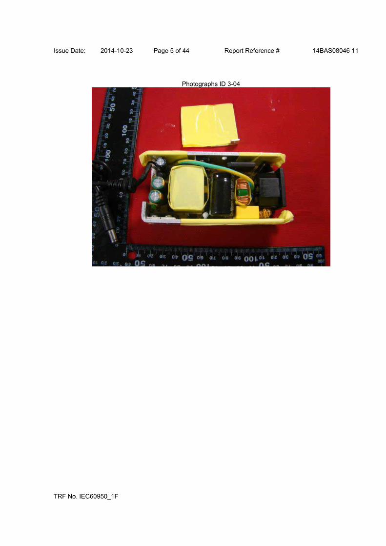
Issue Date: 2014-10-23 Page 5 of 44 Report Reference # 14BAS08046 11
TRF No. IEC60950_1F
Photographs ID 3-04
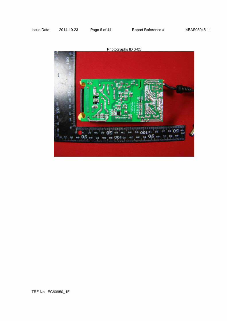
Issue Date: 2014-10-23 Page 6 of 44 Report Reference # 14BAS08046 11
TRF No. IEC60950_1F
Photographs ID 3-05
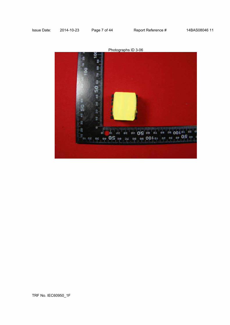
Issue Date: 2014-10-23 Page 7 of 44 Report Reference # 14BAS08046 11
TRF No. IEC60950_1F
Photographs ID 3-06
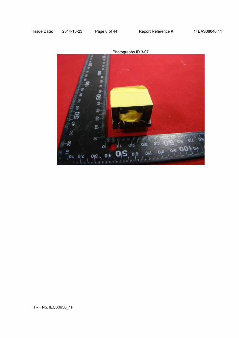
Issue Date: 2014-10-23 Page 8 of 44 Report Reference # 14BAS08046 11
TRF No. IEC60950_1F
Photographs ID 3-07

Issue Date: 2014-10-23 Page 9 of 44 Report Reference # 14BAS08046 11
TRF No. IEC60950_1F
Diagrams ID 4-01

Issue Date: 2014-10-23 Page 10 of 44 Report Reference # 14BAS08046 11
TRF No. IEC60950_1F
Diagrams ID 4-01

Issue Date: 2014-10-23 Page 11 of 44 Report Reference # 14BAS08046 11
TRF No. IEC60950_1F
Diagrams ID 4-02
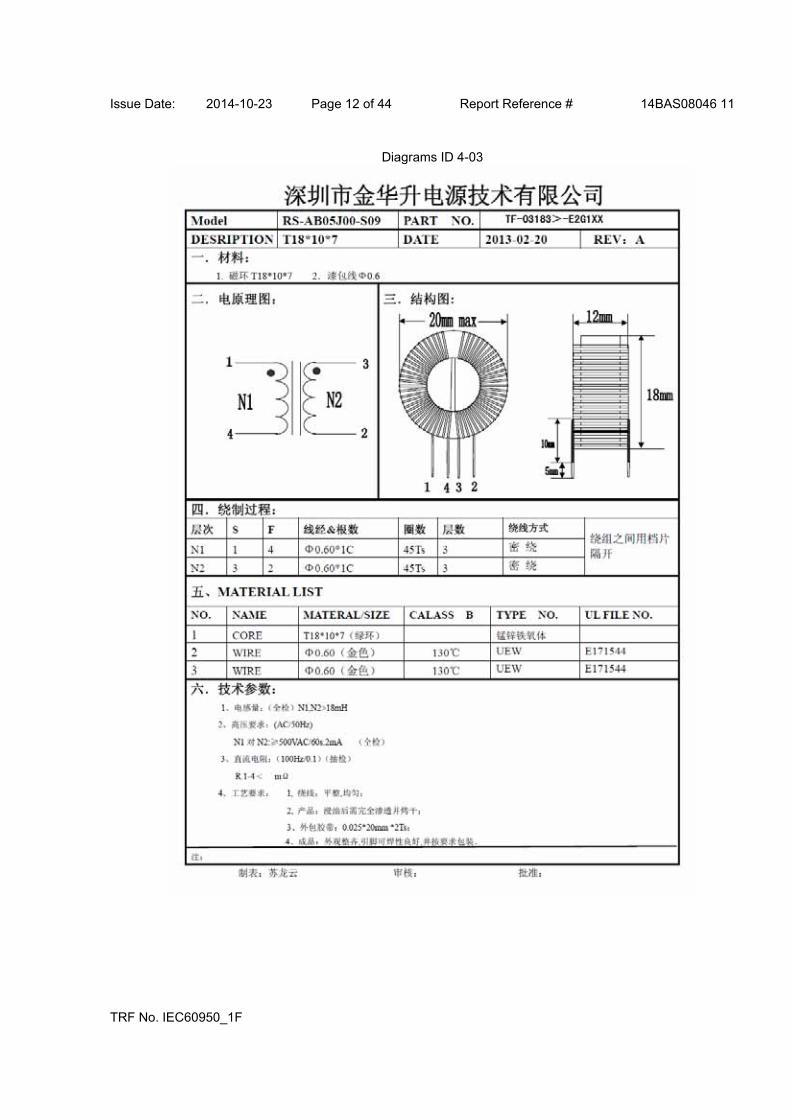
Issue Date: 2014-10-23 Page 12 of 44 Report Reference # 14BAS08046 11
TRF No. IEC60950_1F
Diagrams ID 4-03
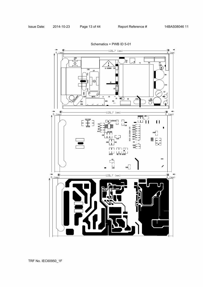
Issue Date: 2014-10-23 Page 13 of 44 Report Reference # 14BAS08046 11
TRF No. IEC60950_1F
Schematics + PWB ID 5-01

Issue Date: 2014-10-23 Page 14 of 44 Report Reference # 14BAS08046 11
TRF No. IEC60950_1F
Miscellaneous ID 7-01
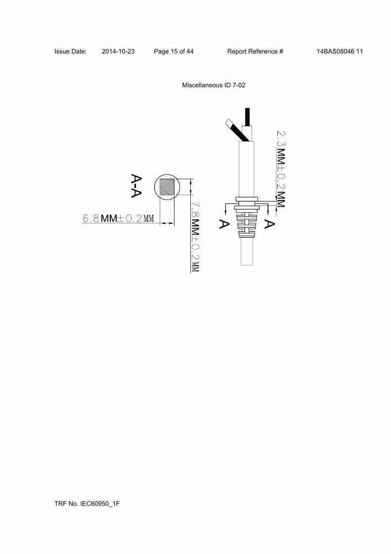
Issue Date: 2014-10-23 Page 15 of 44 Report Reference # 14BAS08046 11
TRF No. IEC60950_1F
Miscellaneous ID 7-02

Issue Date: 2014-10-23 Page 16 of 44 Report Reference # 14BAS08046 11
TRF No. IEC60950_1F
Miscellaneous ID 7-03

Issue Date: 2014-10-23 Page 17 of 44 Report Reference # 14BAS08046 11
TRF No. IEC60950_1F
Miscellaneous ID 7-04
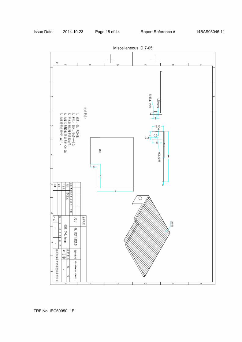
Issue Date: 2014-10-23 Page 18 of 44 Report Reference # 14BAS08046 11
TRF No. IEC60950_1F
Miscellaneous ID 7-05
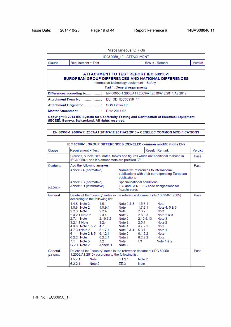
Issue Date: 2014-10-23 Page 19 of 44 Report Reference # 14BAS08046 11
TRF No. IEC60950_1F
Miscellaneous ID 7-06

Issue Date: 2014-10-23 Page 20 of 44 Report Reference # 14BAS08046 11
TRF No. IEC60950_1F
Miscellaneous ID 7-06

Issue Date: 2014-10-23 Page 21 of 44 Report Reference # 14BAS08046 11
TRF No. IEC60950_1F
Miscellaneous ID 7-06
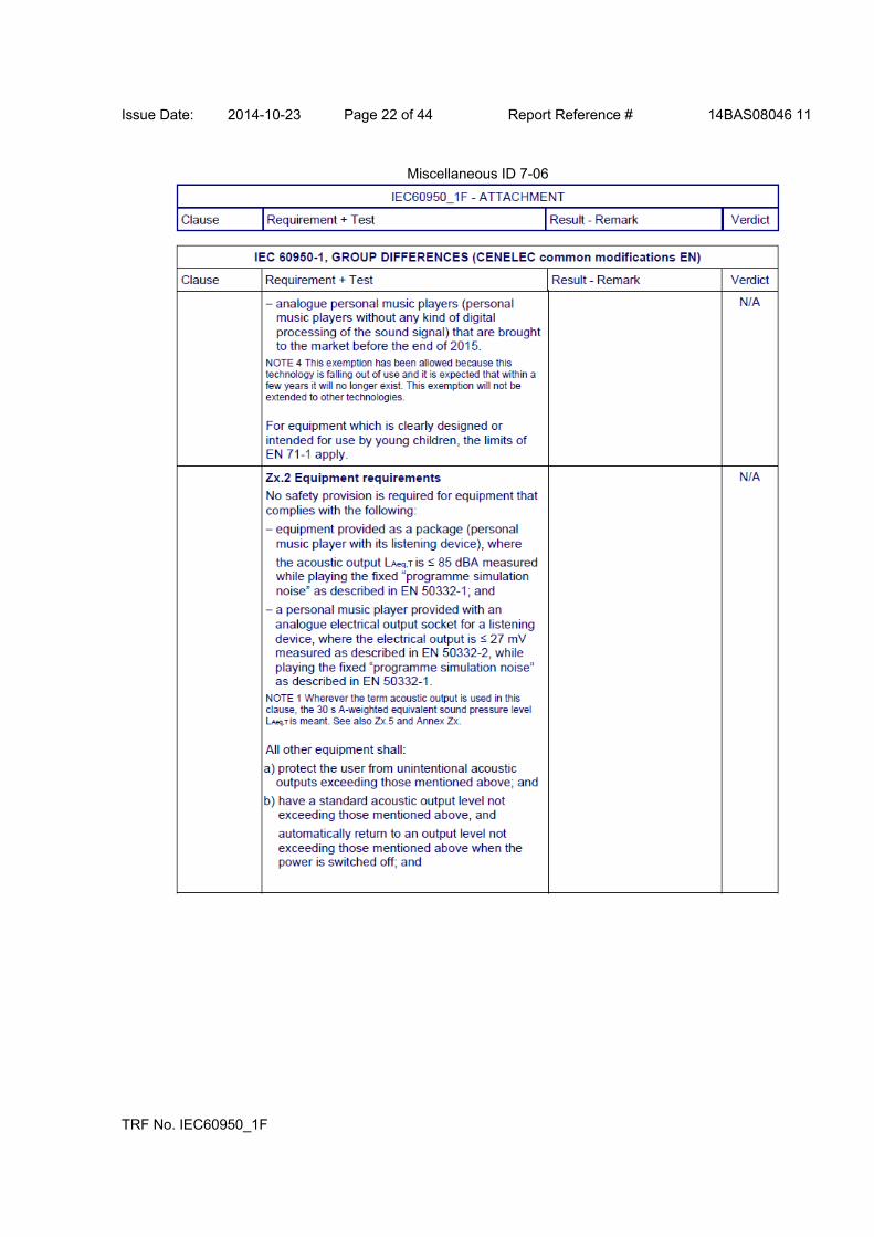
Issue Date: 2014-10-23 Page 22 of 44 Report Reference # 14BAS08046 11
TRF No. IEC60950_1F
Miscellaneous ID 7-06
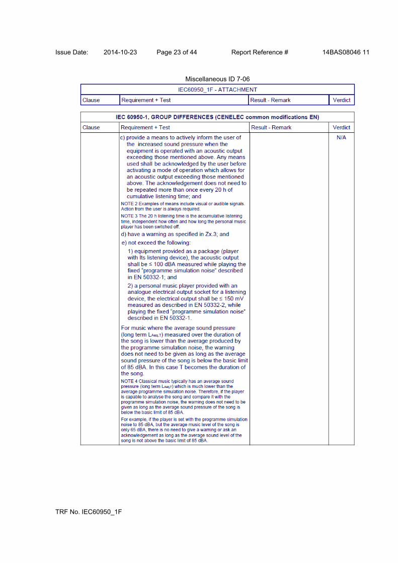
Issue Date: 2014-10-23 Page 23 of 44 Report Reference # 14BAS08046 11
TRF No. IEC60950_1F
Miscellaneous ID 7-06
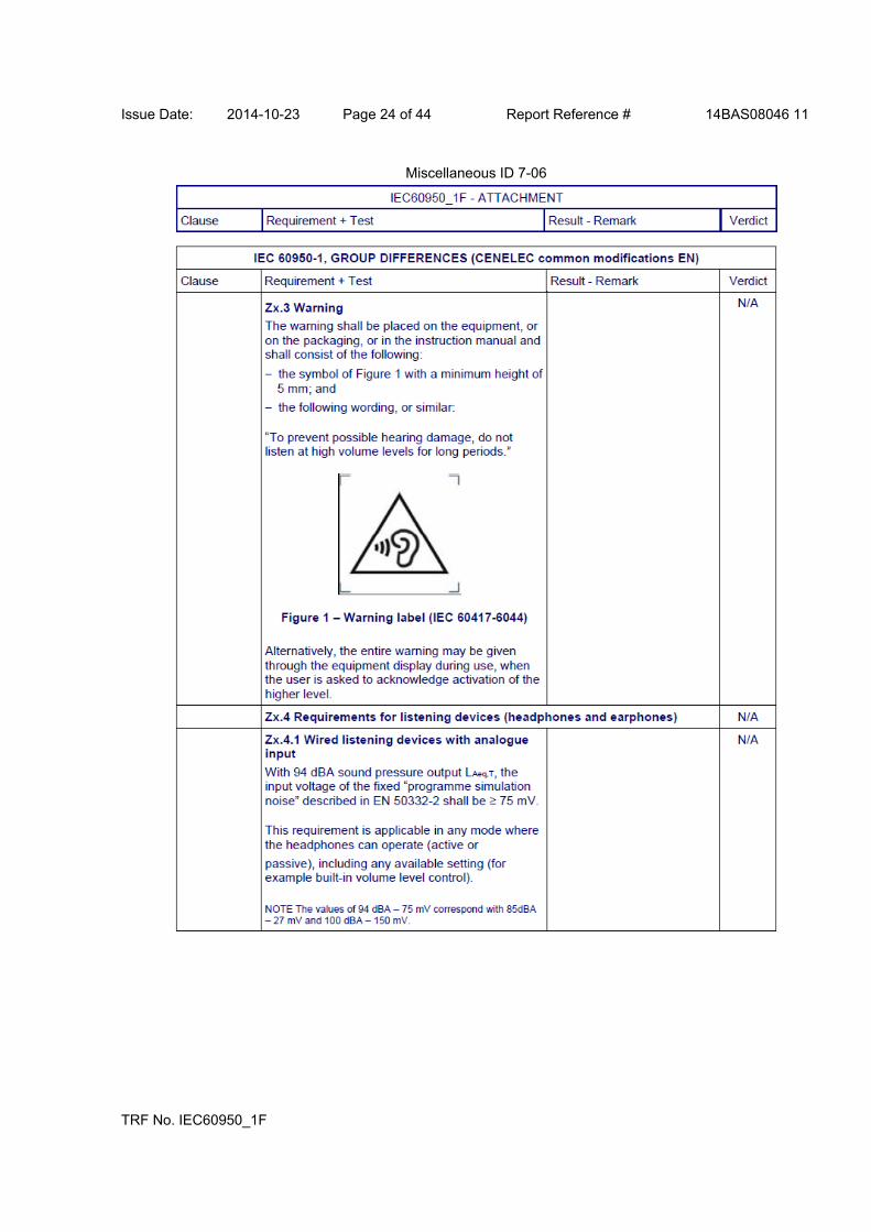
Issue Date: 2014-10-23 Page 24 of 44 Report Reference # 14BAS08046 11
TRF No. IEC60950_1F
Miscellaneous ID 7-06
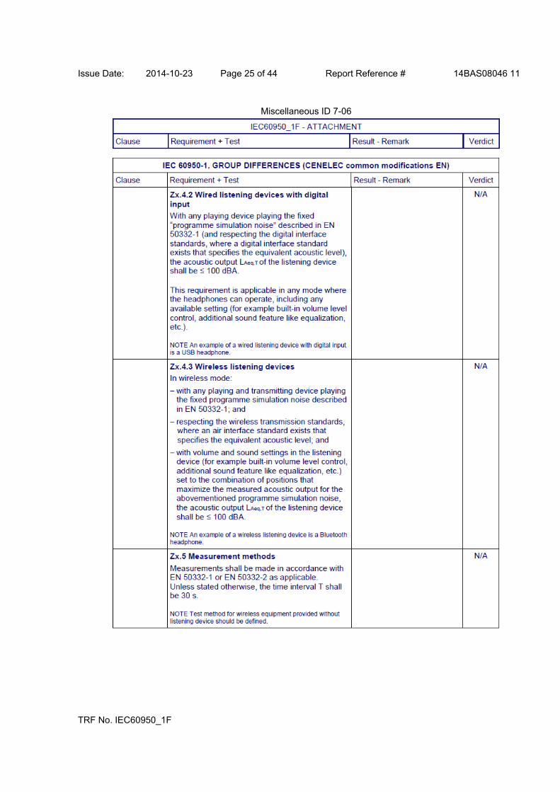
Issue Date: 2014-10-23 Page 25 of 44 Report Reference # 14BAS08046 11
TRF No. IEC60950_1F
Miscellaneous ID 7-06
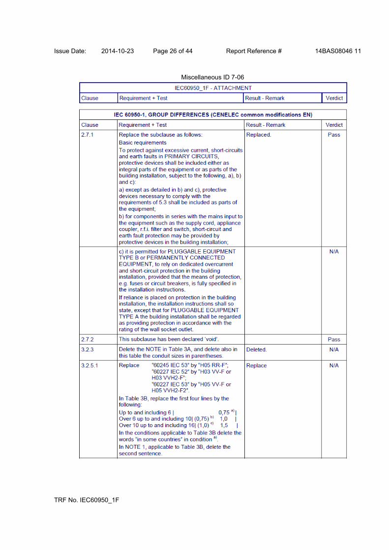
Issue Date: 2014-10-23 Page 26 of 44 Report Reference # 14BAS08046 11
TRF No. IEC60950_1F
Miscellaneous ID 7-06

Issue Date: 2014-10-23 Page 27 of 44 Report Reference # 14BAS08046 11
TRF No. IEC60950_1F
Miscellaneous ID 7-06
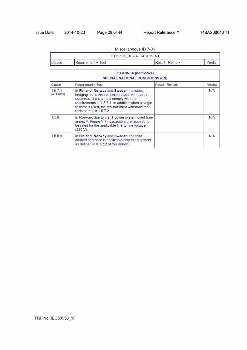
Issue Date: 2014-10-23 Page 28 of 44 Report Reference # 14BAS08046 11
TRF No. IEC60950_1F
Miscellaneous ID 7-06

Issue Date: 2014-10-23 Page 29 of 44 Report Reference # 14BAS08046 11
TRF No. IEC60950_1F
Miscellaneous ID 7-06

Issue Date: 2014-10-23 Page 30 of 44 Report Reference # 14BAS08046 11
TRF No. IEC60950_1F
Miscellaneous ID 7-06
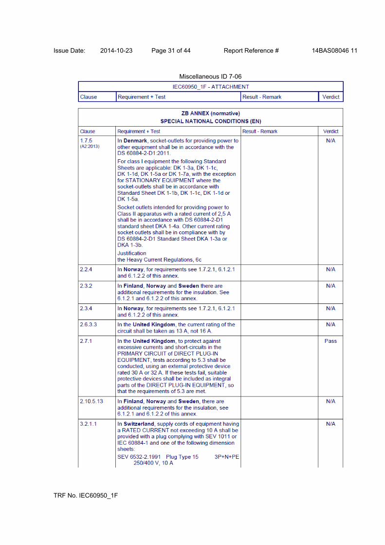
Issue Date: 2014-10-23 Page 31 of 44 Report Reference # 14BAS08046 11
TRF No. IEC60950_1F
Miscellaneous ID 7-06
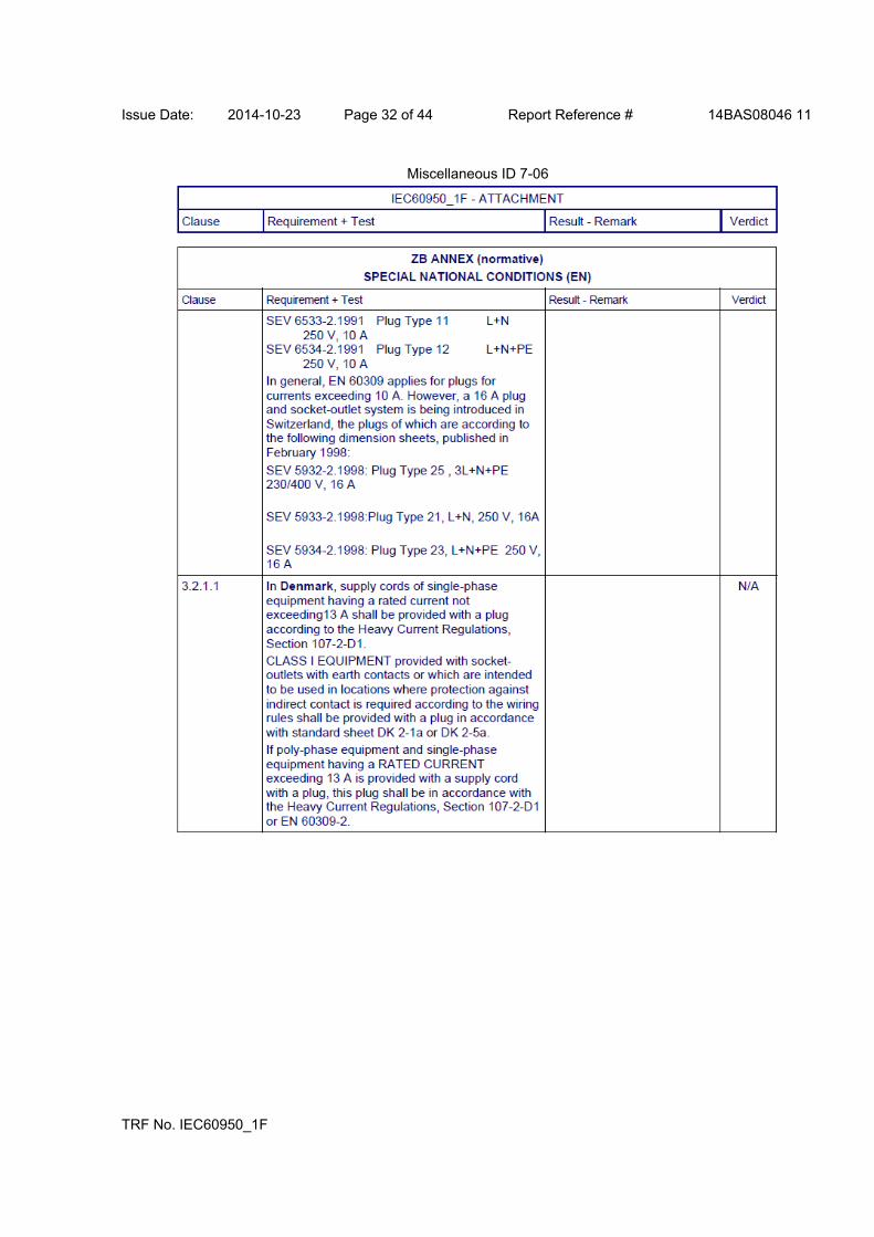
Issue Date: 2014-10-23 Page 32 of 44 Report Reference # 14BAS08046 11
TRF No. IEC60950_1F
Miscellaneous ID 7-06

Issue Date: 2014-10-23 Page 33 of 44 Report Reference # 14BAS08046 11
TRF No. IEC60950_1F
Miscellaneous ID 7-06

Issue Date: 2014-10-23 Page 34 of 44 Report Reference # 14BAS08046 11
TRF No. IEC60950_1F
Miscellaneous ID 7-06
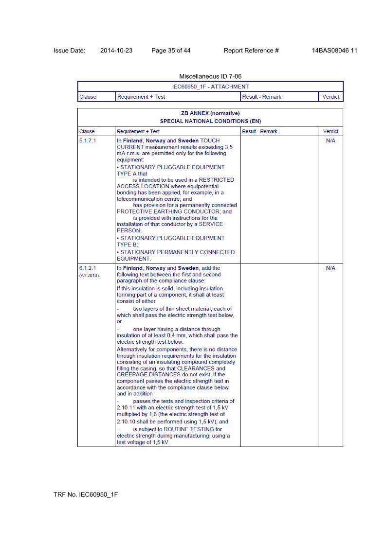
Issue Date: 2014-10-23 Page 35 of 44 Report Reference # 14BAS08046 11
TRF No. IEC60950_1F
Miscellaneous ID 7-06
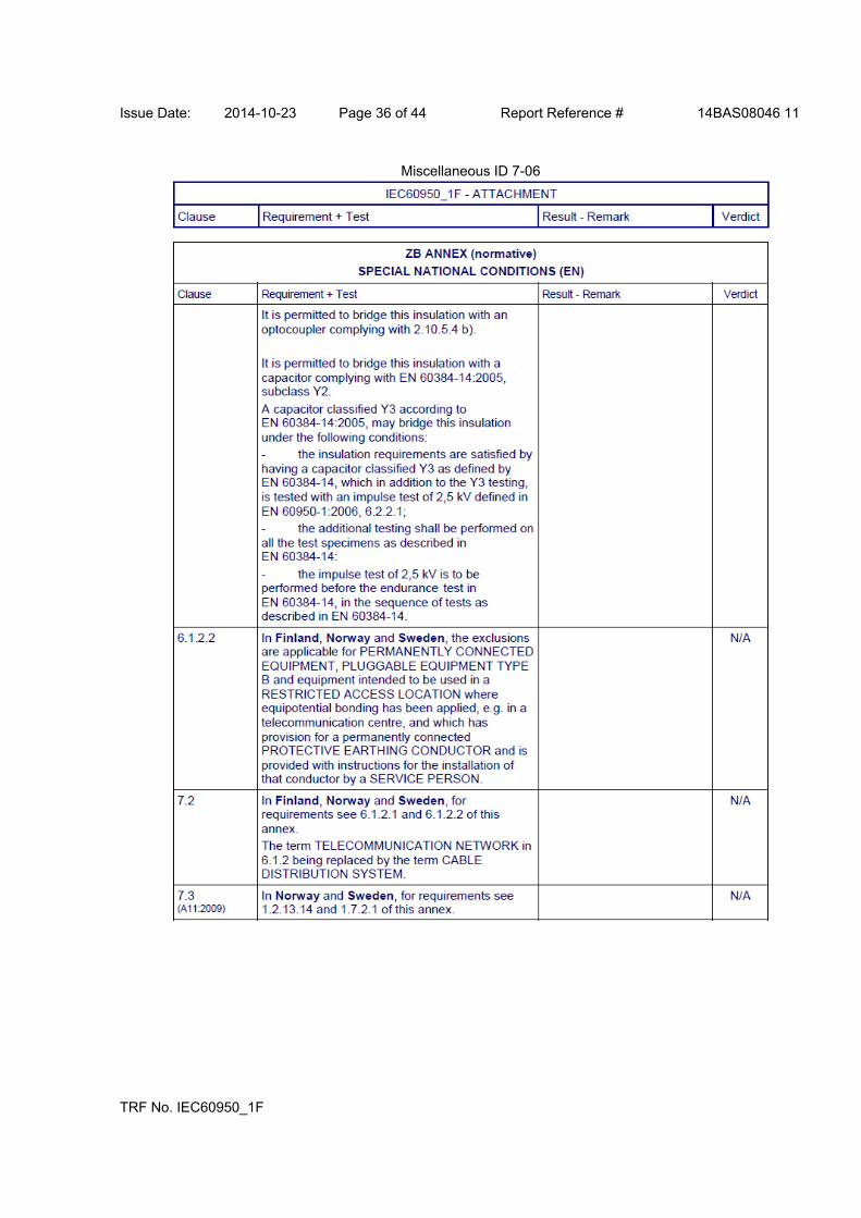
Issue Date: 2014-10-23 Page 36 of 44 Report Reference # 14BAS08046 11
TRF No. IEC60950_1F
Miscellaneous ID 7-06
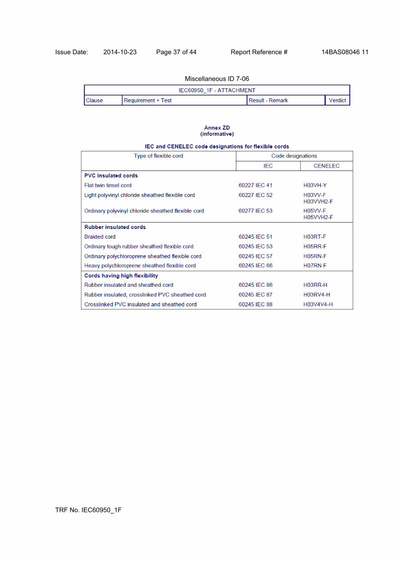
Issue Date: 2014-10-23 Page 37 of 44 Report Reference # 14BAS08046 11
TRF No. IEC60950_1F
Miscellaneous ID 7-06

Issue Date: 2014-10-23 Page 38 of 44 Report Reference # 14BAS08046 11
TRF No. IEC60950_1F
Miscellaneous ID 7-07

Issue Date: 2014-10-23 Page 39 of 44 Report Reference # 14BAS08046 11
TRF No. IEC60950_1F
Miscellaneous ID 7-07
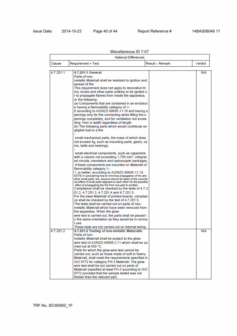
Issue Date: 2014-10-23 Page 40 of 44 Report Reference # 14BAS08046 11
TRF No. IEC60950_1F
Miscellaneous ID 7-07

Issue Date: 2014-10-23 Page 41 of 44 Report Reference # 14BAS08046 11
TRF No. IEC60950_1F
Miscellaneous ID 7-07

Issue Date: 2014-10-23 Page 42 of 44 Report Reference # 14BAS08046 11
TRF No. IEC60950_1F
Miscellaneous ID 7-07

Issue Date: 2014-10-23 Page 43 of 44 Report Reference # 14BAS08046 11
TRF No. IEC60950_1F
Miscellaneous ID 7-07

Issue Date: 2014-10-23 Page 44 of 44 Report Reference # 14BAS08046 11
TRF No. IEC60950_1F
Miscellaneous ID 7-07