Embed Size (px)
Citation preview
ORNL/TM-2017/387 ORNL/NTRC-075, Rev. 0
Test Report of Special Form Qualification Testing for the ORNL U ZiPCAN
O. A. Martinez, Ph.D.
August 2017
Approved for public release. Distribution is unlimited.
ORNL/NTRC-075, Rev. 0, August 2017
DOCUMENT AVAILABILITY Reports produced after January 1, 1996, are generally available free via US Department of Energy (DOE) SciTech Connect. Website http://www.osti.gov/scitech/ Reports produced before January 1, 1996, may be purchased by members of the public from the following source: National Technical Information Service 5285 Port Royal Road Springfield, VA 22161 Telephone 703-605-6000 (1-800-553-6847) TDD 703-487-4639 Fax 703-605-6900 E-mail [email protected] Website http://classic.ntis.gov/ Reports are available to DOE employees, DOE contractors, Energy Technology Data Exchange representatives, and International Nuclear Information System representatives from the following source: Office of Scientific and Technical Information PO Box 62 Oak Ridge, TN 37831 Telephone 865-576-8401 Fax 865-576-5728 E-mail [email protected] Website http://www.osti.gov/contact.html
This report was prepared as an account of work sponsored by an agency of the United States Government. Neither the United States Government nor any agency thereof, nor any of their employees, makes any warranty, express or implied, or assumes any legal liability or responsibility for the accuracy, completeness, or usefulness of any information, apparatus, product, or process disclosed, or represents that its use would not infringe privately owned rights. Reference herein to any specific commercial product, process, or service by trade name, trademark, manufacturer, or otherwise, does not necessarily constitute or imply its endorsement, recommendation, or favoring by the United States Government or any agency thereof. The views and opinions of authors expressed herein do not necessarily state or reflect those of the United States Government or any agency thereof.
ORNL/NTRC-075, Rev. 0, August 2017
ORNL/2017/387 ORNL/NTRC-075
Rev. 0
Reactor and Nuclear Systems Division
TEST REPORT OF SPECIAL FORM QUALIFICATION TESTING FOR THE ORNL U ZIPCAN
O. A. Martinez, Ph.D.
August 2017
Prepared by OAK RIDGE NATIONAL LABORATORY
Oak Ridge, TN 37831-6285 managed by
UT-BATTELLE, LLC for the
OAK RIDGE NATIONAL LABORATORY Nuclear Security and Isotope Technology Division
US DEPARTMENT OF ENERGY under contract DE-AC05-00OR22725


ORNL/NTRC-075, Rev. 0, August 2017 iii
REVISION LOG
Revision # Issue Date Pages affected Comments Revision 0 August 2017 All Original Issue

ORNL/NTRC-075, Rev. 0, August 2017 v
Test Report of Special Form Qualification Testing for the ORNL U ZiPCan
Prepared for Oak Ridge National Laboratory
Nuclear Security and Isotope Technology Division
Prepared by O. A. Martinez, Ph.D.
Oak Ridge National Laboratory
Reactor and Nuclear Systems Division Used Fuel Systems Group
at the National Transportation Research Center
APPROVALS
Name Position Date
O A. Martinez, Ph.D. ORNL Package Testing Program
Matt Feldman, P.E. ORNL Package Testing Program Manager
Michael Houston ORNL Package Testing Quality Representative
John Scaglione Used Fuel System Group Leader

ORNL/NTRC-075, Rev. 0, August 2017 vii
CONTENTS
REVISION LOG .......................................................................................................................................... iii APPROVALS ............................................................................................................................................... v LIST OF FIGURES ..................................................................................................................................... ix LIST OF TABLES ........................................................................................................................................ x ACRONYMS ............................................................................................................................................... xi ABSTRACT .................................................................................................................................................. 1 1. INTRODUCTION ................................................................................................................................ 1
1.1 DESCRIPTION OF THE U ZIPCAN ........................................................................................ 2 1.2 DESCRIPTION OF QUALITY ASSURANCE ACTIVITIES .................................................. 4 1.3 ZIPCAN TEST MATRIX ........................................................................................................... 4 1.4 TEST DATA RECORDS............................................................................................................ 5 1.5 DEVIATIONS FROM THE TEST PLAN ................................................................................. 5
2. PRE-TEST ACTIVITIES ..................................................................................................................... 1 3. SPECIAL FORM TESTS ..................................................................................................................... 1
3.1 IMPACT TEST (ISO 2919:1999(E)) .......................................................................................... 1 3.2 HEAT TEST ............................................................................................................................... 3 3.3 LEAK RATE TESTING ............................................................................................................. 6
3.3.1 Evacuated Envelope (with Back Pressurization) ........................................................... 6 3.3.2 Gas bubble techniques ................................................................................................... 7
4. CONCLUSION ..................................................................................................................................... 0 APPENDIX A. U ZIPCAN DRAWINGS ................................................................................................ A-1 APPENDIX B. TEST FORMS ................................................................................................................. B-1 APPENDIX C. WELD INSPECTION REPORT ..................................................................................... C-1 APPENDIX D. LEAK TESTER CERTIFICATION ............................................................................... D-1 APPENDIX E. LEAK TESTING PROCEDURE .................................................................................... E-1 APPENDIX F. CALIBRATION RECORDS ............................................................................................ F-1

ORNL/NTRC-075, Rev. 0, August 2017 ix
LIST OF FIGURES
Figure 1.1. Top view of the U ZiPCan triangle encasement. ........................................................................ 3 Figure 1.2. Side assembly view. ................................................................................................................... 3 Figure 1.3. U ZiPCan triangle encasement test unit...................................................................................... 4 Figure 3.1. Impact billet 1 m above the ZiPCan. .......................................................................................... 2 Figure 3.2. Before and after impact of the U ZiPCan. .................................................................................. 3 Figure 3.3. Heat test furnace in REDC. ........................................................................................................ 4 Figure 3.4. Type K thermocouple calibration record. ................................................................................... 4 Figure 3.5. Heat test temperature profile. ..................................................................................................... 5 Figure 3.6. U ZipCan post heat test results. .................................................................................................. 5 Figure 3.7. Diagram of helium back pressurization test. .............................................................................. 7 Figure 3.8. Diagram of helium leak testing system. ..................................................................................... 7 Figure 3.9. Vacuum bubble test. ................................................................................................................... 8 Figure A.1. U ZiPCan engineering drawing. ............................................................................................ A-3
ORNL/NTRC-075, Rev. 0, August 2017 x
LIST OF TABLES
Table 1.1. Isotopic distribution of the heat test unit, TU-1 (C1-0290) ......................................................... 3 Table 1.2. Sequence of Tests and Processes for the U ZiPCan ..................................................................... 5 Table 1.3. Detailed sequence of tests and processes for Test Units 1–3 (TU-1 through TU-3) ................... 5 Table 1.4. Heat Test Units mass distribution ................................................................................................ 6 Table 3.1. Leak rate test variables and results for TU-1 and TU-4 ............................................................... 8 Table 3.2. Bubble test results for TU-1 and TU-4 ........................................................................................ 8
ACRONYMS
ANSI American National Standards Institute ASTM American Society for Testing and Materials CFR Code of Federal Regulations NDT non-destructive testing NSC Y-12 National Security Complex ORNL Oak Ridge National Laboratory PTP Package Testing Program QA quality assurance REDC Radiochemical Engineering Development Center RHAC Research Hazard Assessment and Control TIG tungsten inert gas TU test unit ZiPCans Zirconia Pre-Encapsulation Canisters
ORNL/NTRC-075, Rev. 0, August 2017 1
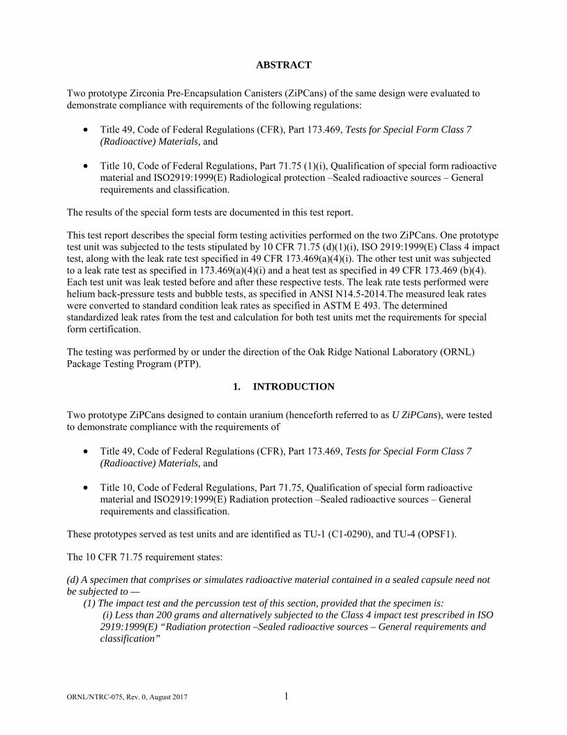
ABSTRACT
Two prototype Zirconia Pre-Encapsulation Canisters (ZiPCans) of the same design were evaluated to demonstrate compliance with requirements of the following regulations:
• Title 49, Code of Federal Regulations (CFR), Part 173.469, Tests for Special Form Class 7 (Radioactive) Materials, and
• Title 10, Code of Federal Regulations, Part 71.75 (1)(i), Qualification of special form radioactive material and ISO2919:1999(E) Radiological protection –Sealed radioactive sources – General requirements and classification.
The results of the special form tests are documented in this test report.
This test report describes the special form testing activities performed on the two ZiPCans. One prototype test unit was subjected to the tests stipulated by 10 CFR 71.75 (d)(1)(i), ISO 2919:1999(E) Class 4 impact test, along with the leak rate test specified in 49 CFR 173.469(a)(4)(i). The other test unit was subjected to a leak rate test as specified in 173.469(a)(4)(i) and a heat test as specified in 49 CFR 173.469 (b)(4). Each test unit was leak tested before and after these respective tests. The leak rate tests performed were helium back-pressure tests and bubble tests, as specified in ANSI N14.5-2014.The measured leak rates were converted to standard condition leak rates as specified in ASTM E 493. The determined standardized leak rates from the test and calculation for both test units met the requirements for special form certification.
The testing was performed by or under the direction of the Oak Ridge National Laboratory (ORNL) Package Testing Program (PTP).
1. INTRODUCTION
Two prototype ZiPCans designed to contain uranium (henceforth referred to as U ZiPCans), were tested to demonstrate compliance with the requirements of
• Title 49, Code of Federal Regulations (CFR), Part 173.469, Tests for Special Form Class 7 (Radioactive) Materials, and
• Title 10, Code of Federal Regulations, Part 71.75, Qualification of special form radioactive material and ISO2919:1999(E) Radiation protection –Sealed radioactive sources – General requirements and classification.
These prototypes served as test units and are identified as TU-1 (C1-0290), and TU-4 (OPSF1).
The 10 CFR 71.75 requirement states:
(d) A specimen that comprises or simulates radioactive material contained in a sealed capsule need not be subjected to —
(1) The impact test and the percussion test of this section, provided that the specimen is: (i) Less than 200 grams and alternatively subjected to the Class 4 impact test prescribed in ISO 2919:1999(E) “Radiation protection –Sealed radioactive sources – General requirements and classification”
ORNL/NTRC-075, Rev. 0, August 2017 2
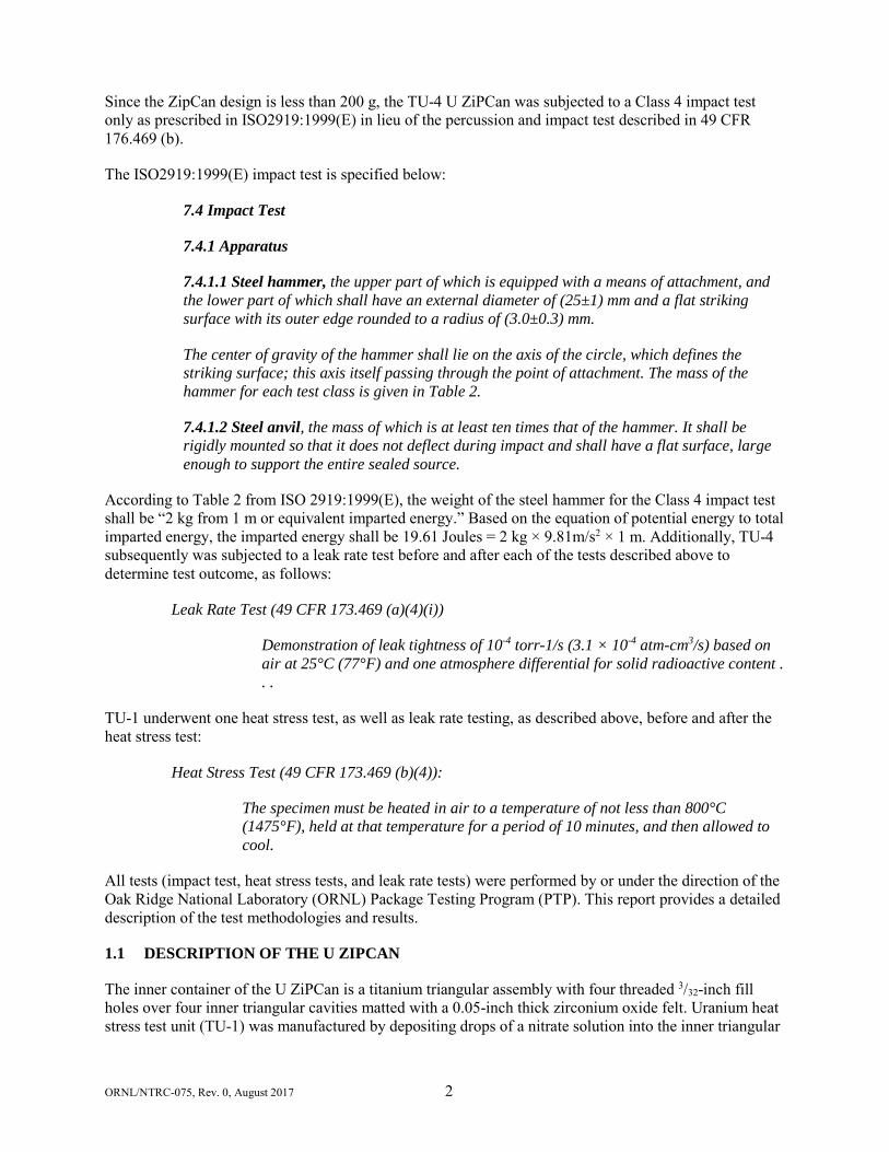
Since the ZipCan design is less than 200 g, the TU-4 U ZiPCan was subjected to a Class 4 impact test only as prescribed in ISO2919:1999(E) in lieu of the percussion and impact test described in 49 CFR 176.469 (b).
The ISO2919:1999(E) impact test is specified below:
7.4 Impact Test
7.4.1 Apparatus
7.4.1.1 Steel hammer, the upper part of which is equipped with a means of attachment, and the lower part of which shall have an external diameter of (25±1) mm and a flat striking surface with its outer edge rounded to a radius of (3.0±0.3) mm.
The center of gravity of the hammer shall lie on the axis of the circle, which defines the striking surface; this axis itself passing through the point of attachment. The mass of the hammer for each test class is given in Table 2.
7.4.1.2 Steel anvil, the mass of which is at least ten times that of the hammer. It shall be rigidly mounted so that it does not deflect during impact and shall have a flat surface, large enough to support the entire sealed source.
According to Table 2 from ISO 2919:1999(E), the weight of the steel hammer for the Class 4 impact test shall be “2 kg from 1 m or equivalent imparted energy.” Based on the equation of potential energy to total imparted energy, the imparted energy shall be 19.61 Joules = 2 kg × 9.81m/s2 × 1 m. Additionally, TU-4 subsequently was subjected to a leak rate test before and after each of the tests described above to determine test outcome, as follows:
Leak Rate Test (49 CFR 173.469 (a)(4)(i))
Demonstration of leak tightness of 10-4 torr-1/s (3.1 × 10⁻⁴ atm-cm3/s) based on air at 25°C (77°F) and one atmosphere differential for solid radioactive content . . .
TU-1 underwent one heat stress test, as well as leak rate testing, as described above, before and after the heat stress test:
Heat Stress Test (49 CFR 173.469 (b)(4)):
The specimen must be heated in air to a temperature of not less than 800°C (1475°F), held at that temperature for a period of 10 minutes, and then allowed to cool.
All tests (impact test, heat stress tests, and leak rate tests) were performed by or under the direction of the Oak Ridge National Laboratory (ORNL) Package Testing Program (PTP). This report provides a detailed description of the test methodologies and results.
1.1 DESCRIPTION OF THE U ZIPCAN
The inner container of the U ZiPCan is a titanium triangular assembly with four threaded 3/32-inch fill holes over four inner triangular cavities matted with a 0.05-inch thick zirconium oxide felt. Uranium heat stress test unit (TU-1) was manufactured by depositing drops of a nitrate solution into the inner triangular
ORNL/NTRC-075, Rev. 0, August 2017 3
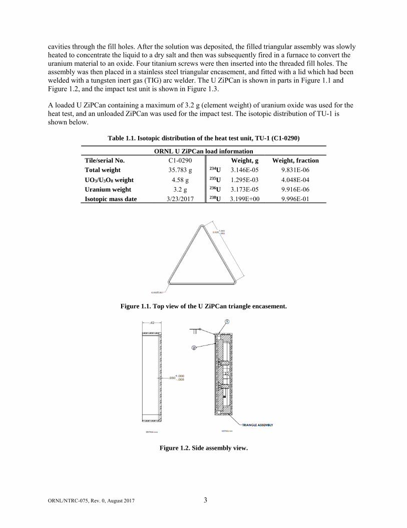
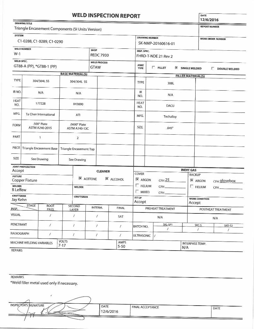
cavities through the fill holes. After the solution was deposited, the filled triangular assembly was slowly heated to concentrate the liquid to a dry salt and then was subsequently fired in a furnace to convert the uranium material to an oxide. Four titanium screws were then inserted into the threaded fill holes. The assembly was then placed in a stainless steel triangular encasement, and fitted with a lid which had been welded with a tungsten inert gas (TIG) arc welder. The U ZiPCan is shown in parts in Figure 1.1 and Figure 1.2, and the impact test unit is shown in Figure 1.3.
A loaded U ZiPCan containing a maximum of 3.2 g (element weight) of uranium oxide was used for the heat test, and an unloaded ZiPCan was used for the impact test. The isotopic distribution of TU-1 is shown below.
Table 1.1. Isotopic distribution of the heat test unit, TU-1 (C1-0290)
ORNL U ZiPCan load information Tile/serial No. C1-0290 Weight, g Weight, fraction Total weight 35.783 g 234U 3.146E-05 9.831E-06 UO3/U3O8 weight 4.58 g 235U 1.295E-03 4.048E-04 Uranium weight 3.2 g 236U 3.173E-05 9.916E-06 Isotopic mass date 3/23/2017 238U 3.199E+00 9.996E-01
Figure 1.1. Top view of the U ZiPCan triangle encasement.
Figure 1.2. Side assembly view.
ORNL/NTRC-075, Rev. 0, August 2017 4
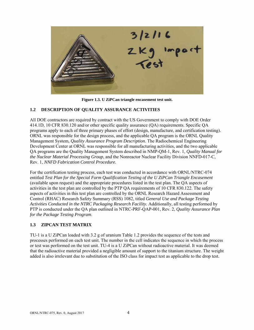
Figure 1.3. U ZiPCan triangle encasement test unit.
1.2 DESCRIPTION OF QUALITY ASSURANCE ACTIVITIES
All DOE contractors are required by contract with the US Government to comply with DOE Order 414.1D, 10 CFR 830.120 and/or other specific quality assurance (QA) requirements. Specific QA programs apply to each of three primary phases of effort (design, manufacture, and certification testing). ORNL was responsible for the design process, and the applicable QA program is the ORNL Quality Management System, Quality Assurance Program Description. The Radiochemical Engineering Development Center at ORNL was responsible for all manufacturing activities, and the two applicable QA programs are the Quality Management System described in NMP-QM-1, Rev. 1, Quality Manual for the Nuclear Material Processing Group, and the Nonreactor Nuclear Facility Division NNFD-017-C, Rev. 1, NNFD Fabrication Control Procedure.
For the certification testing process, each test was conducted in accordance with ORNL/NTRC-074 entitled Test Plan for the Special Form Qualification Testing of the U ZiPCan Triangle Encasement (available upon request) and the appropriate procedures listed in the test plan. The QA aspects of activities in the test plan are controlled by the PTP QA requirements of 10 CFR 830.122. The safety aspects of activities in this test plan are controlled by the ORNL Research Hazard Assessment and Control (RHAC) Research Safety Summary (RSS) 1082, titled General Use and Package Testing Activities Conducted in the NTRC Packaging Research Facility. Additionally, all testing performed by PTP is conducted under the QA plan outlined in NTRC-PRF-QAP-001, Rev. 2, Quality Assurance Plan for the Package Testing Program.
1.3 ZIPCAN TEST MATRIX
TU-1 is a U ZiPCan loaded with 3.2 g of uranium Table 1.2 provides the sequence of the tests and processes performed on each test unit. The number in the cell indicates the sequence in which the process or test was performed on the test unit. TU-4 is a U ZiPCan without radioactive material. It was deemed that the radioactive material provided a negligible amount of support to the titanium structure. The weight added is also irrelevant due to substitution of the ISO class for impact test as applicable to the drop test.
ORNL/NTRC-075, Rev. 0, August 2017 5
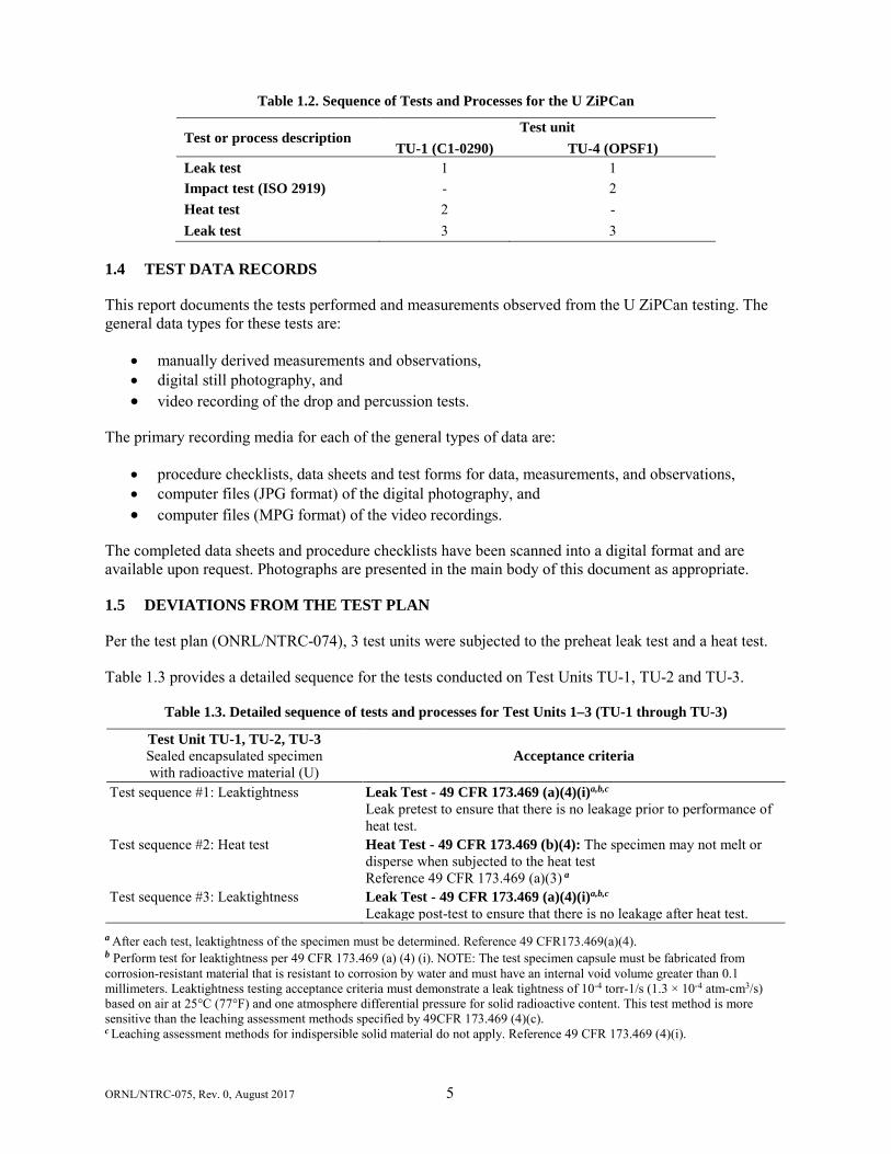
Table 1.2. Sequence of Tests and Processes for the U ZiPCan
Test or process description Test unit
TU-1 (C1-0290) TU-4 (OPSF1) Leak test 1 1 Impact test (ISO 2919) - 2 Heat test 2 - Leak test 3 3
1.4 TEST DATA RECORDS
This report documents the tests performed and measurements observed from the U ZiPCan testing. The general data types for these tests are:
• manually derived measurements and observations, • digital still photography, and • video recording of the drop and percussion tests.
The primary recording media for each of the general types of data are:
• procedure checklists, data sheets and test forms for data, measurements, and observations, • computer files (JPG format) of the digital photography, and • computer files (MPG format) of the video recordings.
The completed data sheets and procedure checklists have been scanned into a digital format and are available upon request. Photographs are presented in the main body of this document as appropriate.
1.5 DEVIATIONS FROM THE TEST PLAN
Per the test plan (ONRL/NTRC-074), 3 test units were subjected to the preheat leak test and a heat test.
Table 1.3 provides a detailed sequence for the tests conducted on Test Units TU-1, TU-2 and TU-3.
Table 1.3. Detailed sequence of tests and processes for Test Units 1–3 (TU-1 through TU-3)
Test Unit TU-1, TU-2, TU-3 Sealed encapsulated specimen with radioactive material (U)
Acceptance criteria
Test sequence #1: Leaktightness Leak Test - 49 CFR 173.469 (a)(4)(i)a,b,c Leak pretest to ensure that there is no leakage prior to performance of heat test.
Test sequence #2: Heat test Heat Test - 49 CFR 173.469 (b)(4): The specimen may not melt or disperse when subjected to the heat test Reference 49 CFR 173.469 (a)(3) a
Test sequence #3: Leaktightness Leak Test - 49 CFR 173.469 (a)(4)(i)a,b,c Leakage post-test to ensure that there is no leakage after heat test.
a After each test, leaktightness of the specimen must be determined. Reference 49 CFR173.469(a)(4). b Perform test for leaktightness per 49 CFR 173.469 (a) (4) (i). NOTE: The test specimen capsule must be fabricated from corrosion-resistant material that is resistant to corrosion by water and must have an internal void volume greater than 0.1 millimeters. Leaktightness testing acceptance criteria must demonstrate a leak tightness of 10-4 torr-1/s (1.3 × 10⁻⁴ atm-cm3/s) based on air at 25°C (77°F) and one atmosphere differential pressure for solid radioactive content. This test method is more sensitive than the leaching assessment methods specified by 49CFR 173.469 (4)(c). c Leaching assessment methods for indispersible solid material do not apply. Reference 49 CFR 173.469 (4)(i).
ORNL/NTRC-075, Rev. 0, August 2017 6
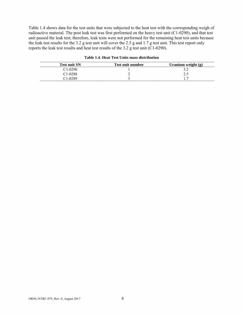
Table 1.4 shows data for the test units that were subjected to the heat test with the corresponding weigh of radioactive material. The post leak test was first performed on the heavy test unit (C1-0290), and that test unit passed the leak test; therefore, leak tests were not performed for the remaining heat test units because the leak test results for the 3.2 g test unit will cover the 2.5 g and 1.7 g test unit. This test report only reports the leak test results and heat test results of the 3.2 g test unit (C1-0290).
Table 1.4. Heat Test Units mass distribution
Test unit SN Test unit number Uranium weight (g) C1-0290 1 3.2 C1-0288 2 2.5 C1-0289 3 1.7

ORNL/NTRC-075, Rev. 0, August 2017 1
2. PRE-TEST ACTIVITIES
The test units were delivered for testing in a ready-to-test condition, so there were no specific pretest activities.
ORNL/NTRC-075, Rev. 0, August 2017 1
3. SPECIAL FORM TESTS
Special form testing requirements are specified in 49 CFR 173.469 (b), 10 CFR 71.75, and ISO 2919:1999(E). For this design, three tests were required: the Class 4 impact test per ISO 2919:1999(E), a heat test, and a leak test. The bending test was not required because the length-to-width ratio of the design is not greater than 10. After each test, each test unit was subjected to a helium leakage rate test and a bubble test as specified in 49 CFR 173.469(a). Each test performed and the results of these tests are described below.
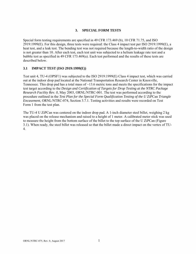
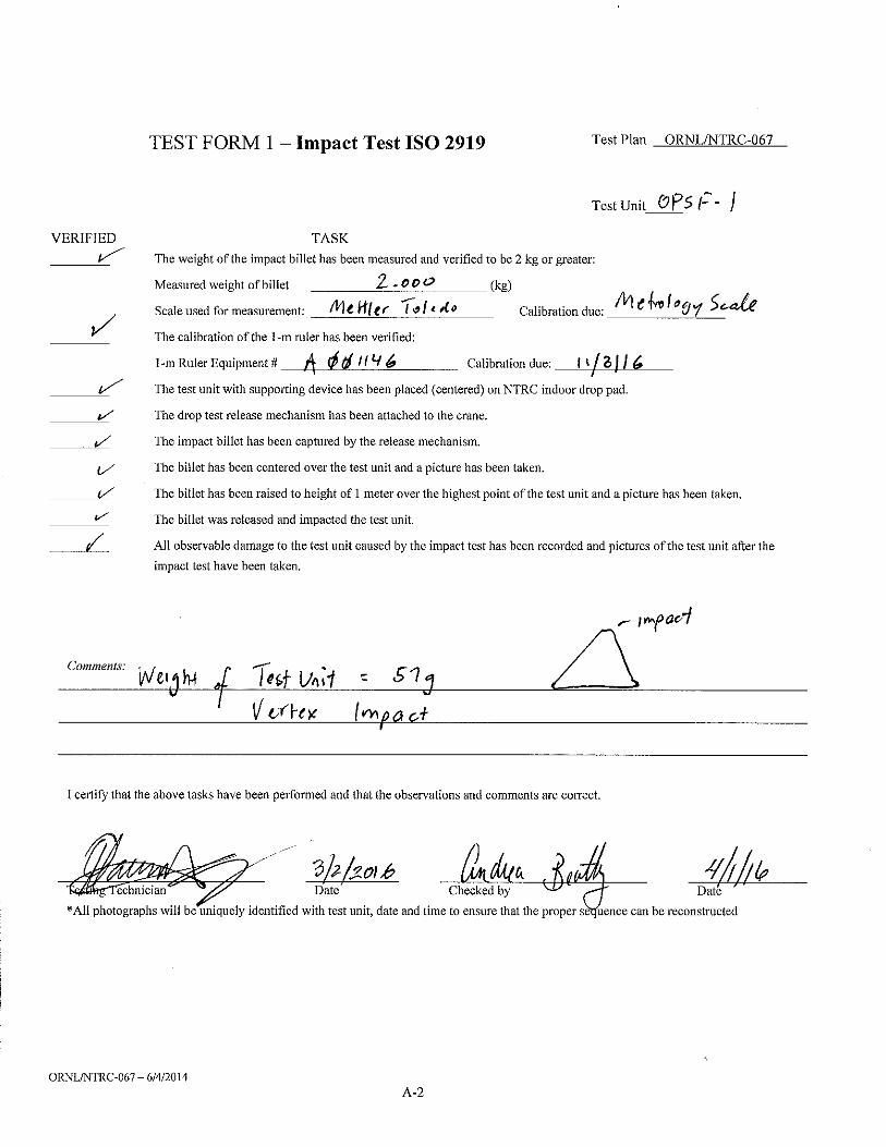
3.1 IMPACT TEST (ISO 2919:1999(E))
Test unit 4, TU-4 (OPSF1) was subjected to the ISO 2919:1999(E) Class 4 impact test, which was carried out at the indoor drop pad located at the National Transportation Research Center in Knoxville, Tennessee. This drop pad has a total mass of ~13.6 metric tons and meets the specifications for the impact test target according to the Design and Certification of Targets for Drop Testing at the NTRC Package Research Facility Rev. 0, May 2003, ORNL/NTRC-001. The test was performed according to the procedure outlined in the Test Plan for the Special Form Qualification Testing of the U ZiPCan Triangle Encasement, ORNL/NTRC-074, Section 3.7.1. Testing activities and results were recorded on Test Form 1 from the test plan.
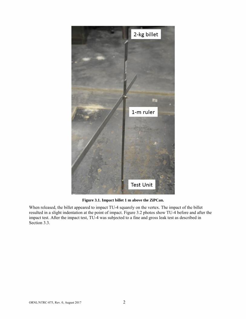
The TU-4 U ZiPCan was centered on the indoor drop pad. A 1-inch diameter steel billet, weighing 2 kg was placed on the release mechanism and raised to a height of 1 meter. A calibrated meter stick was used to measure the height from the bottom surface of the billet to the top surface of the U ZiPCan (Figure 3.1). When ready, the steel billet was released so that the billet made a direct impact on the vertex of TU-4.
ORNL/NTRC-075, Rev. 0, August 2017 2
Figure 3.1. Impact billet 1 m above the ZiPCan.
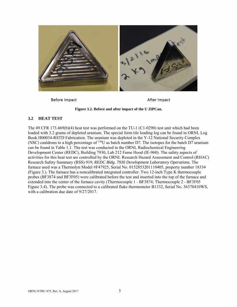
When released, the billet appeared to impact TU-4 squarely on the vertex. The impact of the billet resulted in a slight indentation at the point of impact. Figure 3.2 photos show TU-4 before and after the impact test. After the impact test, TU-4 was subjected to a fine and gross leak test as described in Section 3.3.
ORNL/NTRC-075, Rev. 0, August 2017 3
Figure 3.2. Before and after impact of the U ZiPCan.
3.2 HEAT TEST
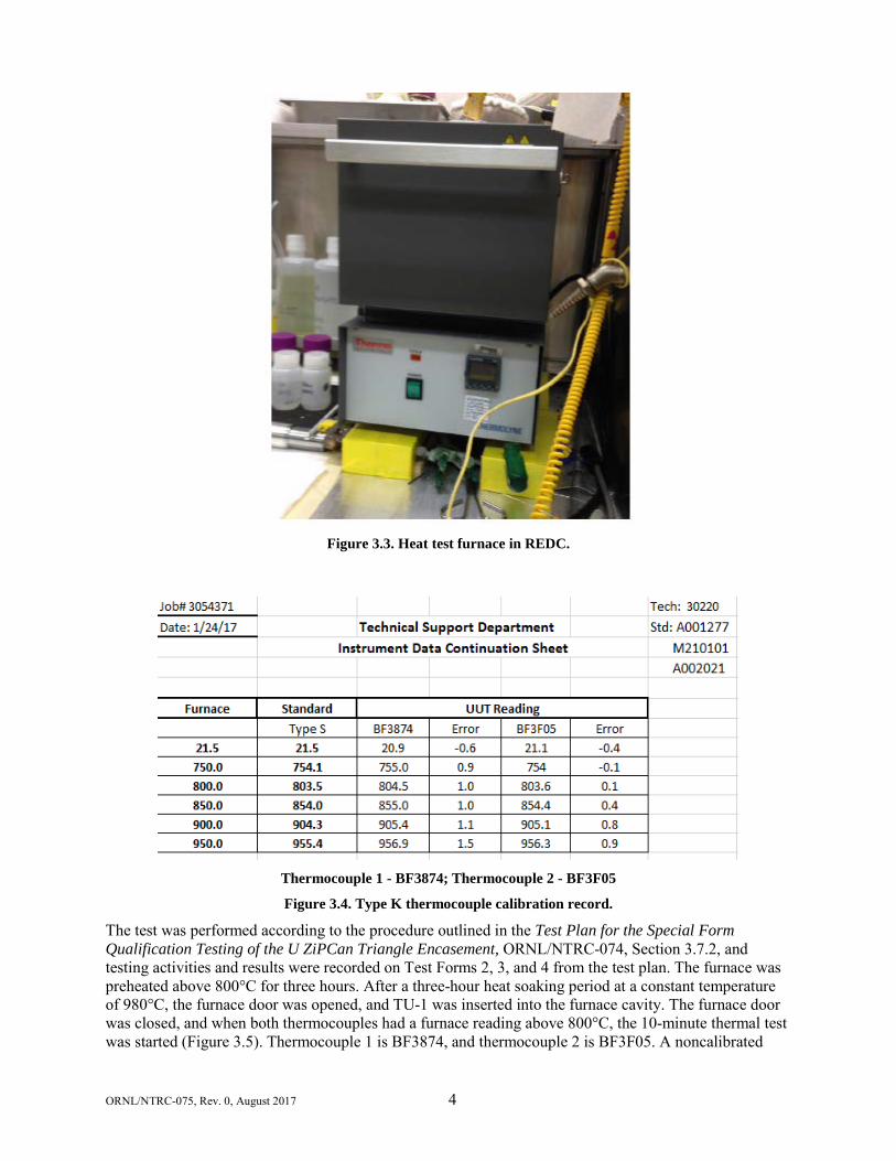
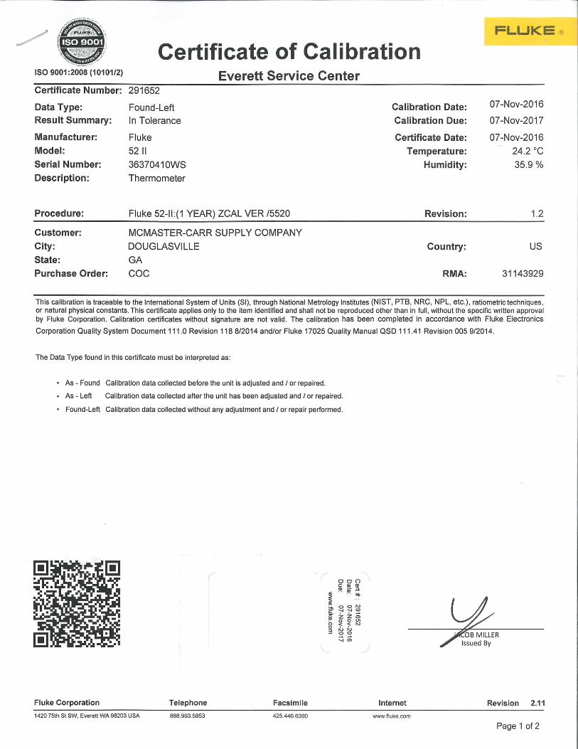
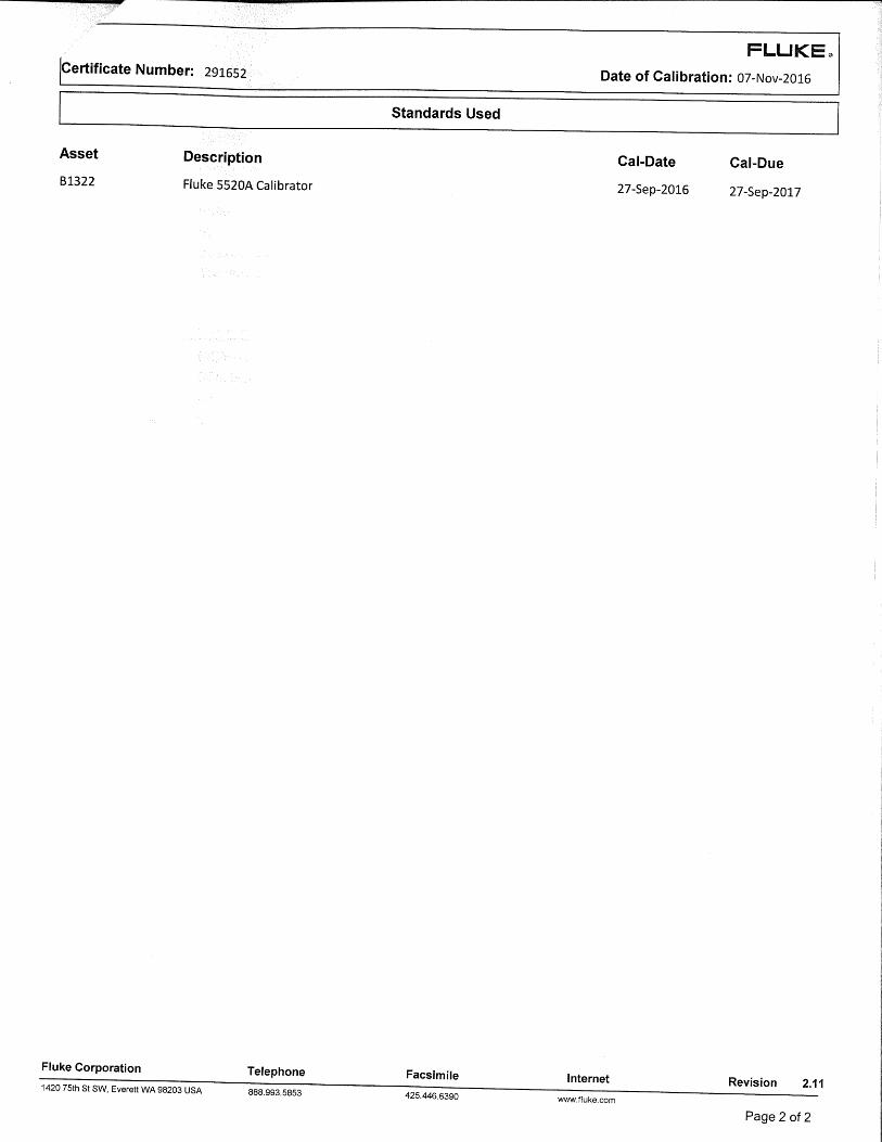
The 49 CFR 173.469(b)(4) heat test was performed on the TU-1 (C1-0290) test unit which had been loaded with 3.2 grams of depleted uranium. The special form tile loading log can be found in ORNL Log Book H00034-RSTD Fabrication. The uranium was depleted in the Y-12 National Security Complex (NSC) cauldrons to a high percentage of 238U as batch number D7. The isotopes for the batch D7 uranium can be found in Table 1.1. The test was conducted in the ORNL Radiochemical Engineering Development Center (REDC), Building 7930, Lab 212 Fume Hood (IE-960). The safety aspects of activities for this heat test are controlled by the ORNL Research Hazard Assessment and Control (RHAC) Research Safety Summary (RSS) 919, REDC Bldg. 7930 Development Laboratory Operations. The furnace used was a Thermolyn Model #F47925, Serial No. 0152853201110405, property number 18334 (Figure 3.). The furnace has a noncalibrated integrated controller. Two 12-inch Type K thermocouple probes (BF3874 and BF3F05) were calibrated before the test and inserted into the top of the furnace and extended into the center of the furnace cavity (Thermocouple 1 - BF3874; Thermocouple 2 - BF3F05 Figure 3.4). The probe was connected to a calibrated fluke thermometer B1332, Serial No. 36370410WS, with a calibration due date of 9/27/2017.
ORNL/NTRC-075, Rev. 0, August 2017 4
Figure 3.3. Heat test furnace in REDC.
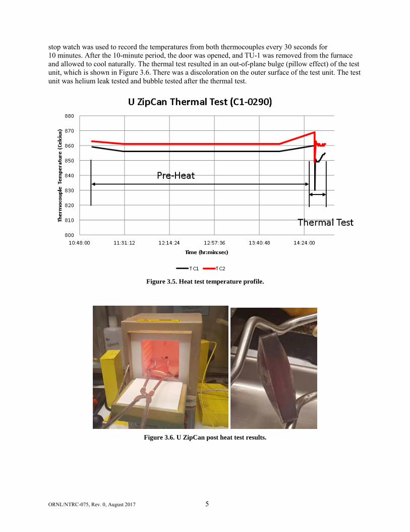
Thermocouple 1 - BF3874; Thermocouple 2 - BF3F05
Figure 3.4. Type K thermocouple calibration record.
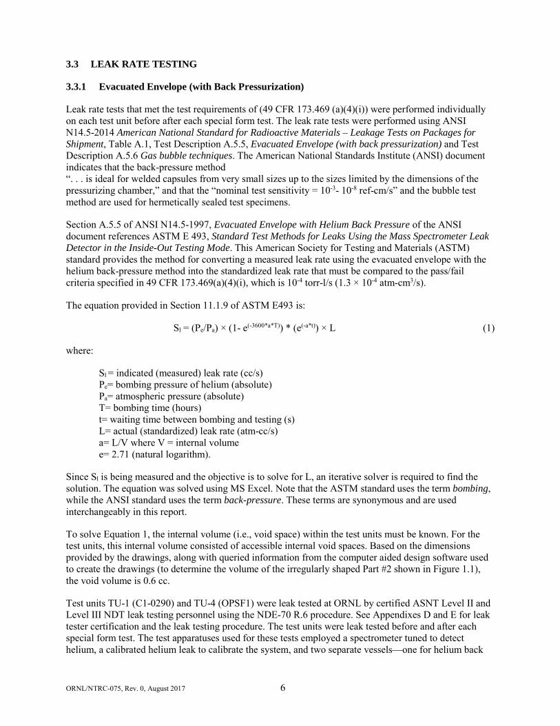
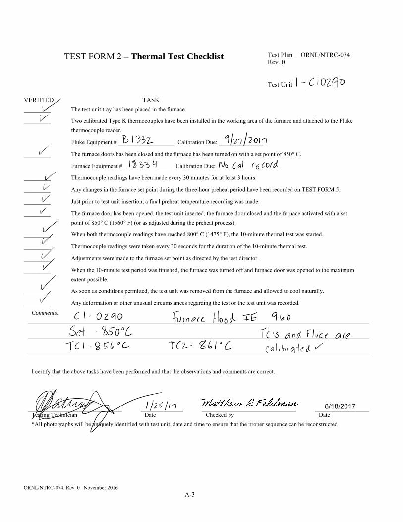
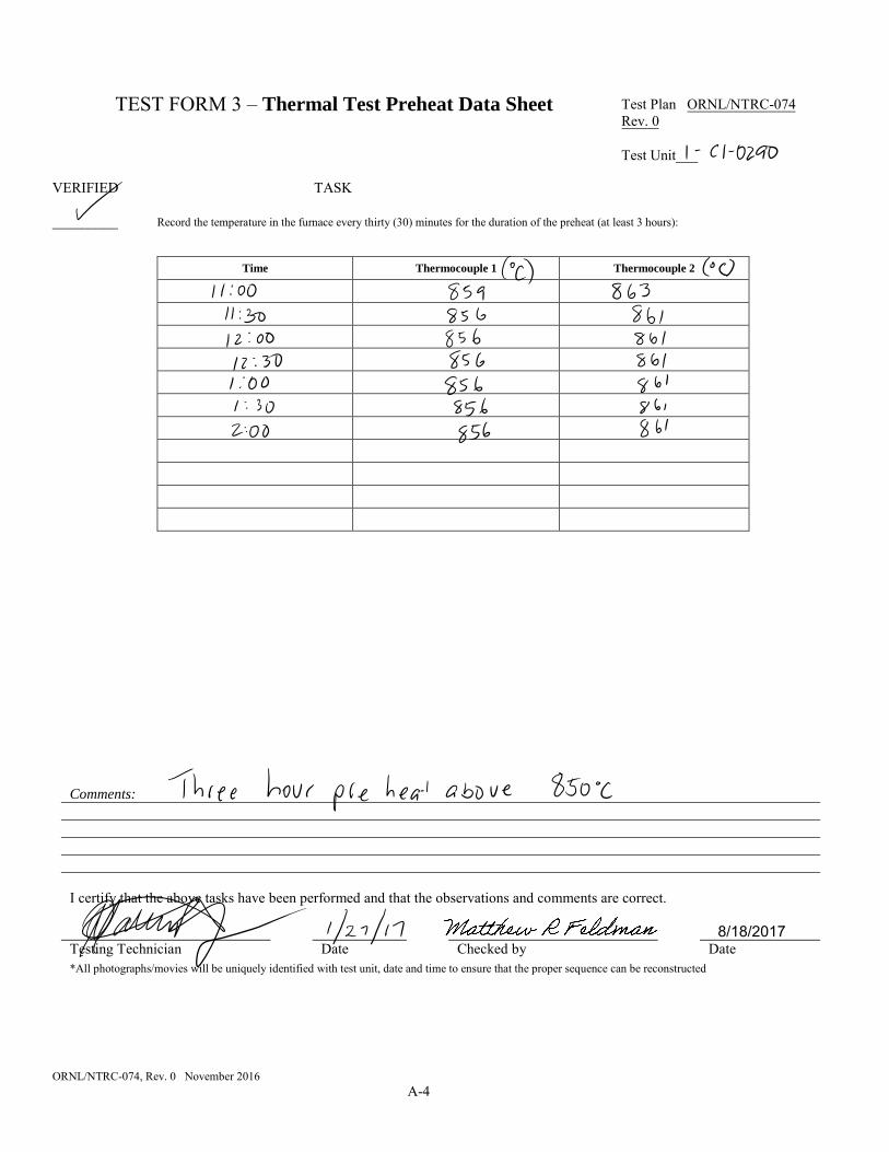
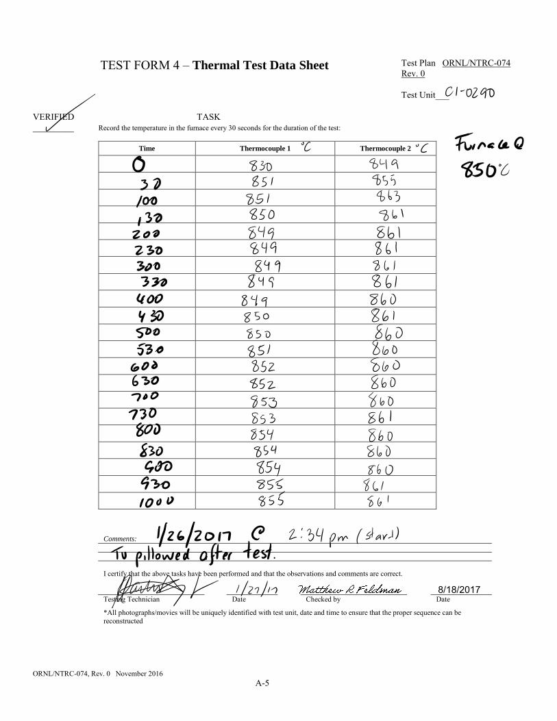
The test was performed according to the procedure outlined in the Test Plan for the Special Form Qualification Testing of the U ZiPCan Triangle Encasement, ORNL/NTRC-074, Section 3.7.2, and testing activities and results were recorded on Test Forms 2, 3, and 4 from the test plan. The furnace was preheated above 800°C for three hours. After a three-hour heat soaking period at a constant temperature of 980°C, the furnace door was opened, and TU-1 was inserted into the furnace cavity. The furnace door was closed, and when both thermocouples had a furnace reading above 800°C, the 10-minute thermal test was started (Figure 3.5). Thermocouple 1 is BF3874, and thermocouple 2 is BF3F05. A noncalibrated
ORNL/NTRC-075, Rev. 0, August 2017 5
stop watch was used to record the temperatures from both thermocouples every 30 seconds for 10 minutes. After the 10-minute period, the door was opened, and TU-1 was removed from the furnace and allowed to cool naturally. The thermal test resulted in an out-of-plane bulge (pillow effect) of the test unit, which is shown in Figure 3.6. There was a discoloration on the outer surface of the test unit. The test unit was helium leak tested and bubble tested after the thermal test.
Figure 3.5. Heat test temperature profile.
Figure 3.6. U ZipCan post heat test results.
ORNL/NTRC-075, Rev. 0, August 2017 6
3.3 LEAK RATE TESTING
3.3.1 Evacuated Envelope (with Back Pressurization)
Leak rate tests that met the test requirements of (49 CFR 173.469 (a)(4)(i)) were performed individually on each test unit before after each special form test. The leak rate tests were performed using ANSI N14.5-2014 American National Standard for Radioactive Materials – Leakage Tests on Packages for Shipment, Table A.1, Test Description A.5.5, Evacuated Envelope (with back pressurization) and Test Description A.5.6 Gas bubble techniques. The American National Standards Institute (ANSI) document indicates that the back-pressure method “. . . is ideal for welded capsules from very small sizes up to the sizes limited by the dimensions of the pressurizing chamber,” and that the “nominal test sensitivity = 10-3- 10-8 ref-cm/s” and the bubble test method are used for hermetically sealed test specimens.
Section A.5.5 of ANSI N14.5-1997, Evacuated Envelope with Helium Back Pressure of the ANSI document references ASTM E 493, Standard Test Methods for Leaks Using the Mass Spectrometer Leak Detector in the Inside-Out Testing Mode. This American Society for Testing and Materials (ASTM) standard provides the method for converting a measured leak rate using the evacuated envelope with the helium back-pressure method into the standardized leak rate that must be compared to the pass/fail criteria specified in 49 CFR 173.469(a)(4)(i), which is 10-4 torr-l/s (1.3 × 10⁻⁴ atm-cm3/s).
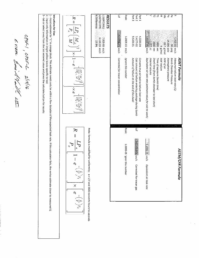
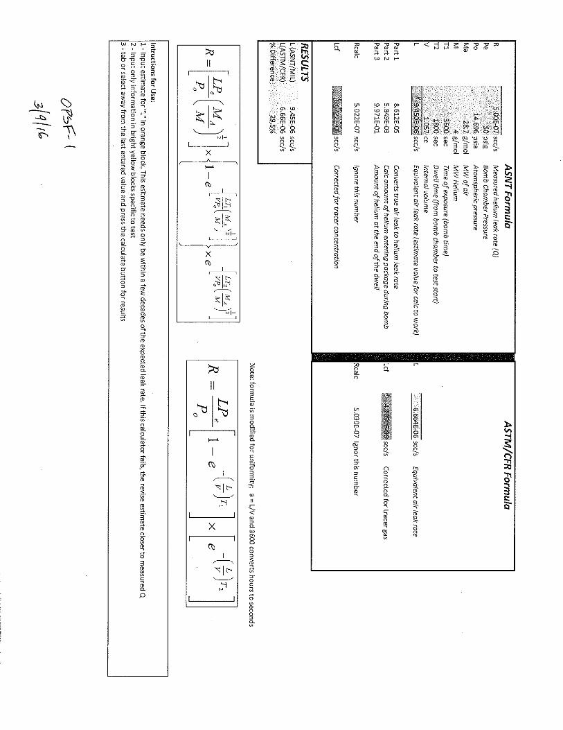
The equation provided in Section 11.1.9 of ASTM E493 is:
Sl = (Pe/Pa) × (1- e(-3600*a*T)) * (e(-a*t)) × L (1)
where:
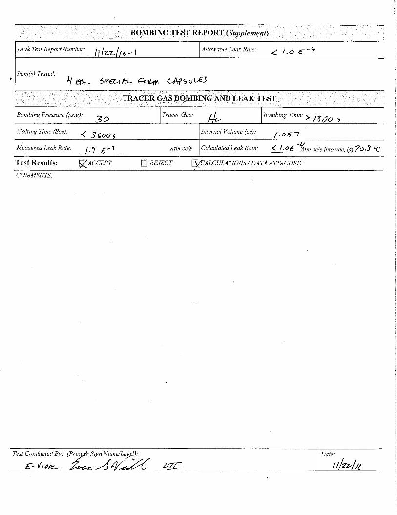
Sl = indicated (measured) leak rate (cc/s) Pe= bombing pressure of helium (absolute) Pa= atmospheric pressure (absolute) T= bombing time (hours) t= waiting time between bombing and testing (s) L= actual (standardized) leak rate (atm-cc/s) a= L/V where V = internal volume e= 2.71 (natural logarithm).
Since Sl is being measured and the objective is to solve for L, an iterative solver is required to find the solution. The equation was solved using MS Excel. Note that the ASTM standard uses the term bombing, while the ANSI standard uses the term back-pressure. These terms are synonymous and are used interchangeably in this report.
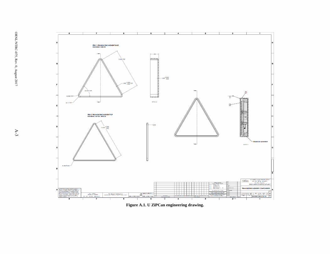
To solve Equation 1, the internal volume (i.e., void space) within the test units must be known. For the test units, this internal volume consisted of accessible internal void spaces. Based on the dimensions provided by the drawings, along with queried information from the computer aided design software used to create the drawings (to determine the volume of the irregularly shaped Part #2 shown in Figure 1.1), the void volume is 0.6 cc.
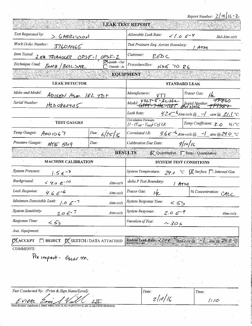
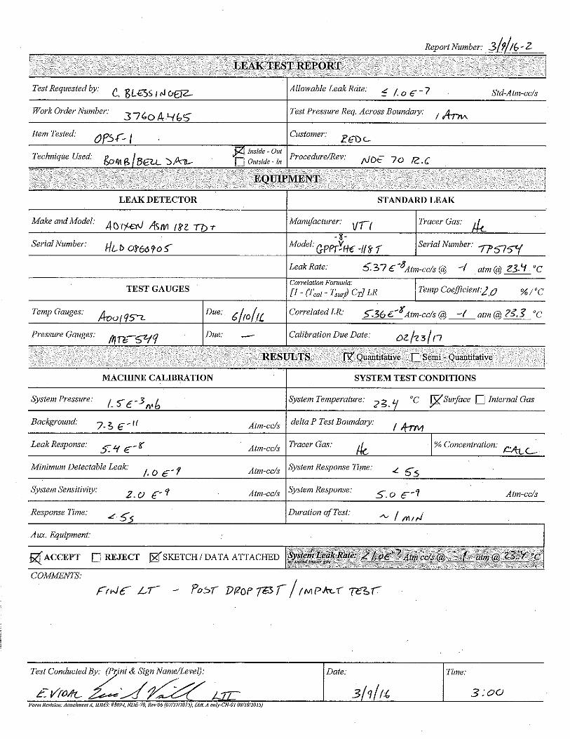
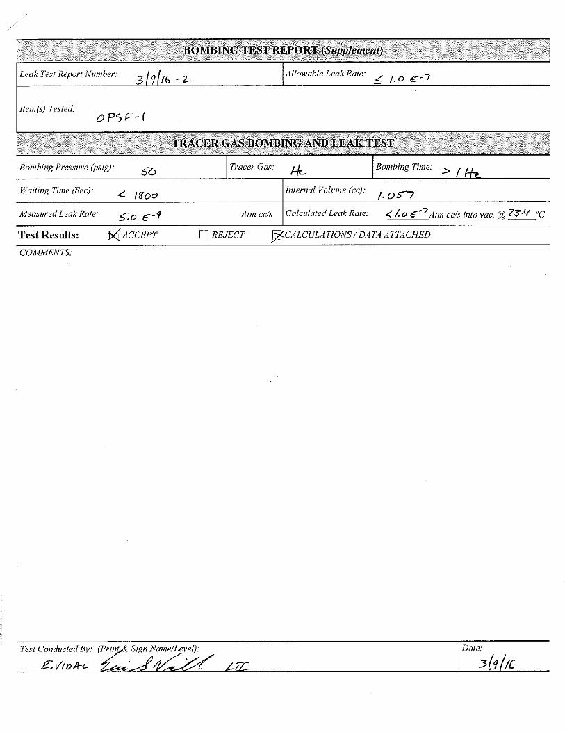
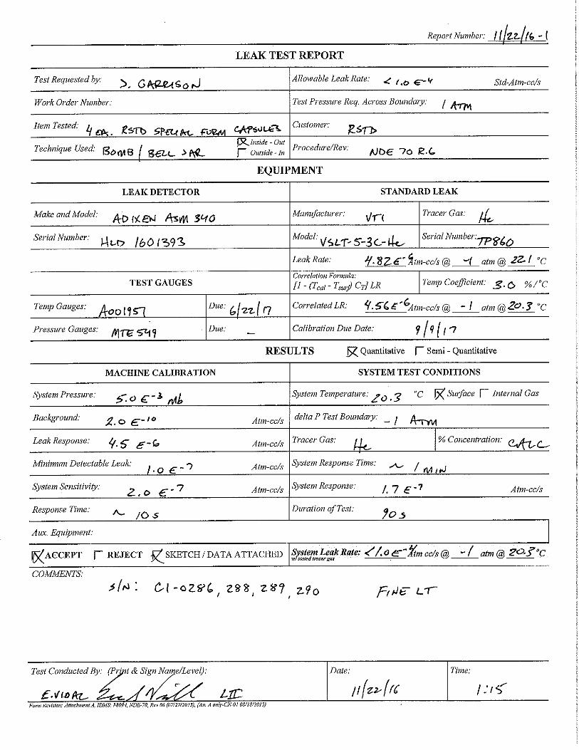
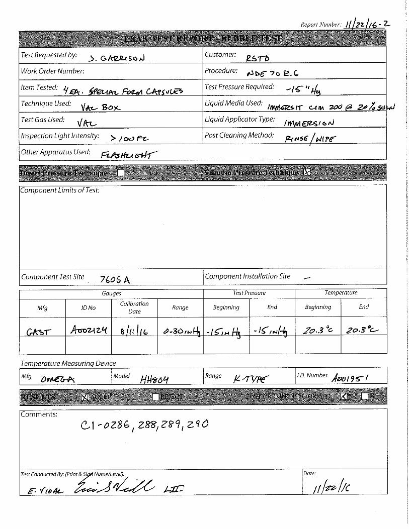
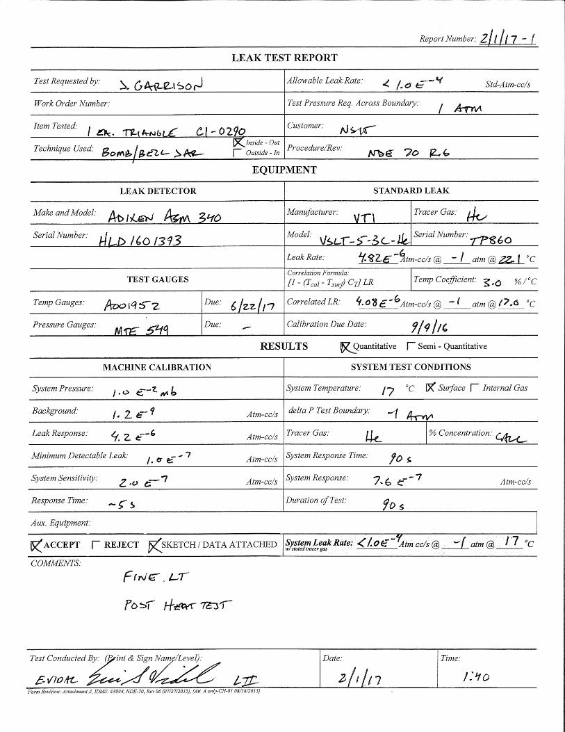
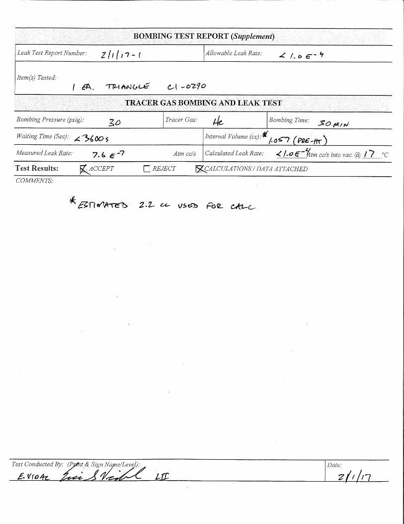
Test units TU-1 (C1-0290) and TU-4 (OPSF1) were leak tested at ORNL by certified ASNT Level II and Level III NDT leak testing personnel using the NDE-70 R.6 procedure. See Appendixes D and E for leak tester certification and the leak testing procedure. The test units were leak tested before and after each special form test. The test apparatuses used for these tests employed a spectrometer tuned to detect helium, a calibrated helium leak to calibrate the system, and two separate vessels—one for helium back
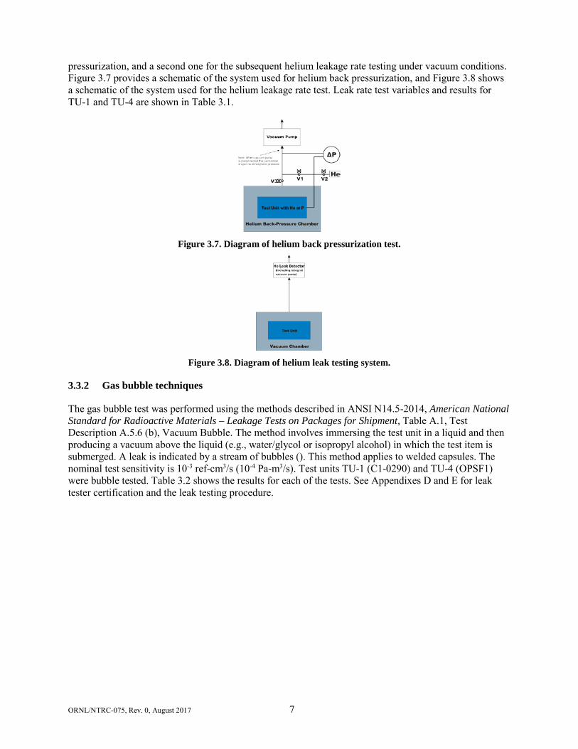
ORNL/NTRC-075, Rev. 0, August 2017 7
pressurization, and a second one for the subsequent helium leakage rate testing under vacuum conditions. Figure 3.7 provides a schematic of the system used for helium back pressurization, and Figure 3.8 shows a schematic of the system used for the helium leakage rate test. Leak rate test variables and results for TU-1 and TU-4 are shown in Table 3.1.
Figure 3.7. Diagram of helium back pressurization test.
Figure 3.8. Diagram of helium leak testing system.
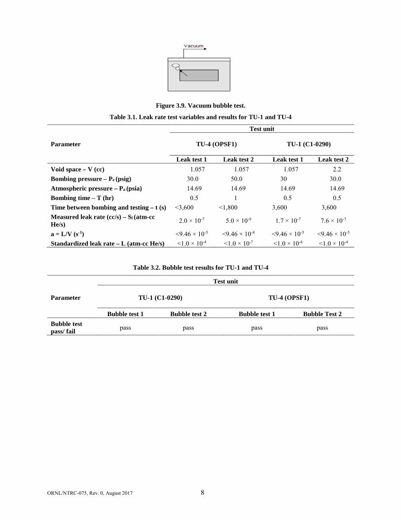
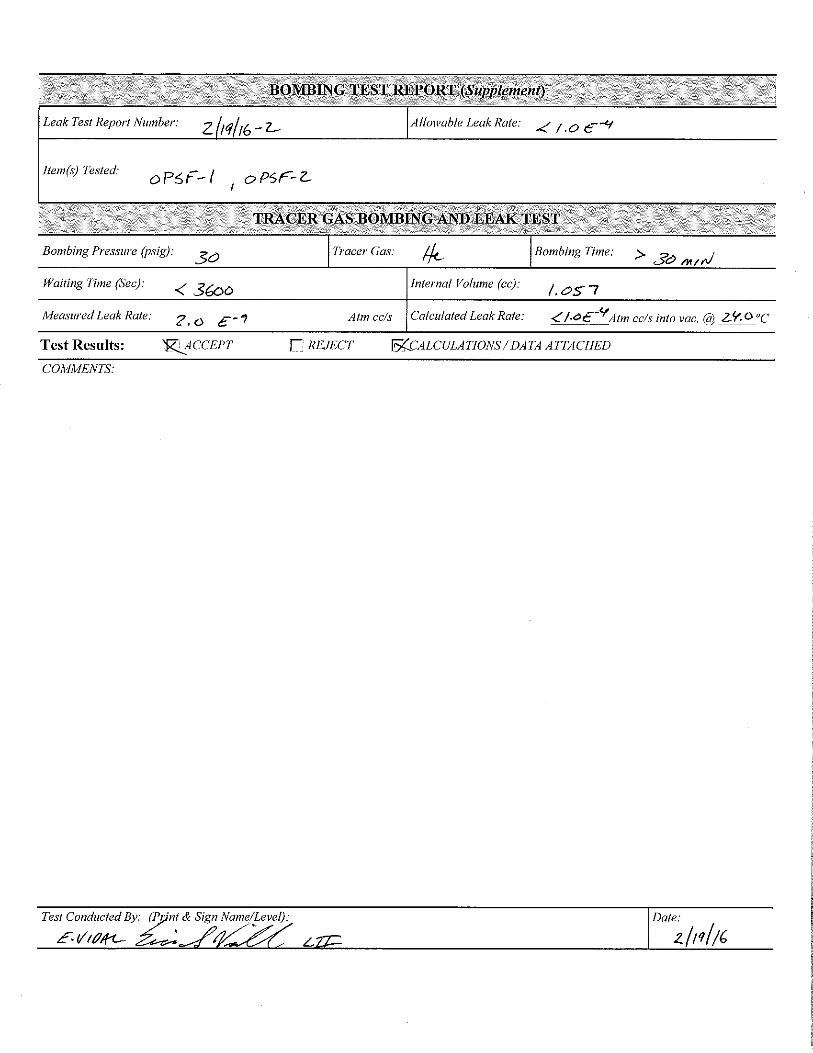
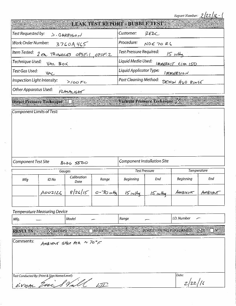
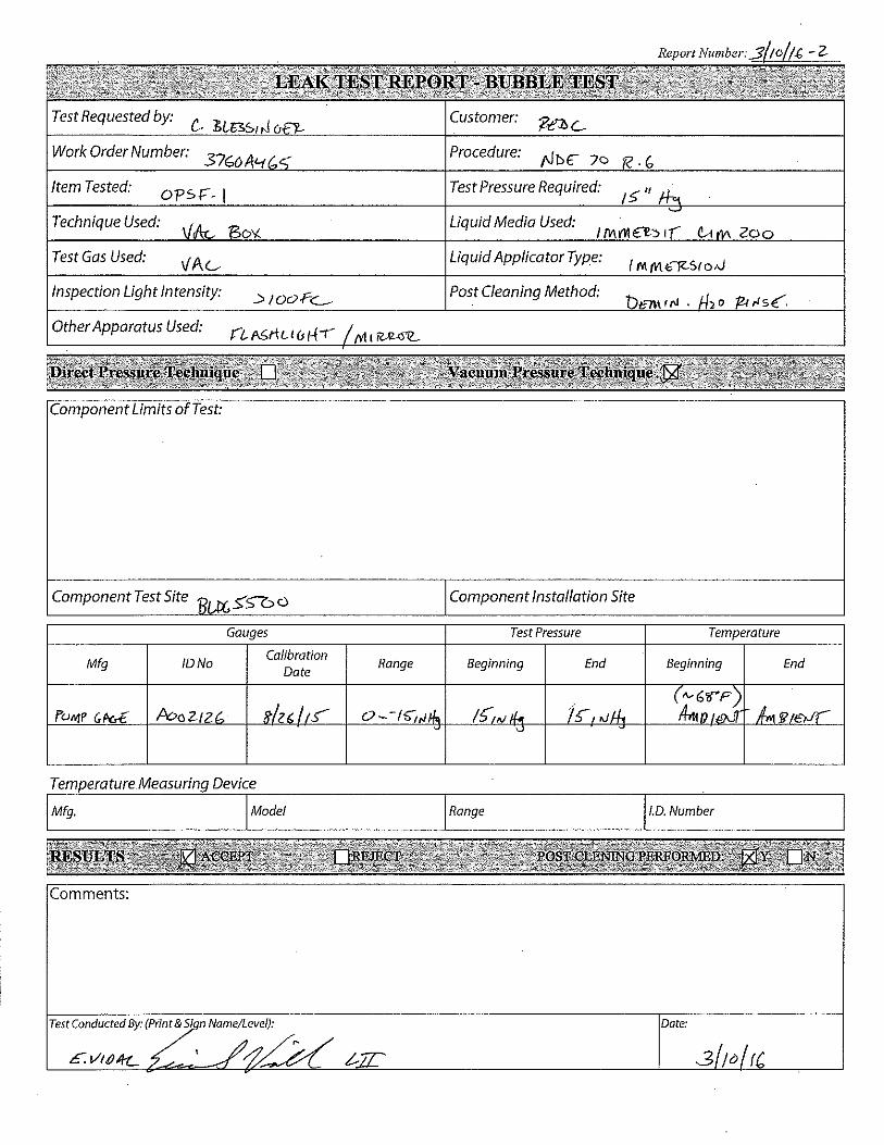
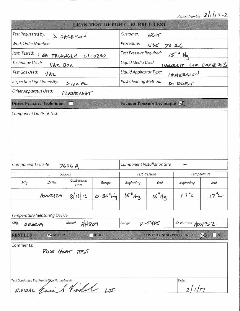
3.3.2 Gas bubble techniques
The gas bubble test was performed using the methods described in ANSI N14.5-2014, American National Standard for Radioactive Materials – Leakage Tests on Packages for Shipment, Table A.1, Test Description A.5.6 (b), Vacuum Bubble. The method involves immersing the test unit in a liquid and then producing a vacuum above the liquid (e.g., water/glycol or isopropyl alcohol) in which the test item is submerged. A leak is indicated by a stream of bubbles (). This method applies to welded capsules. The nominal test sensitivity is 10-3 ref-cm3/s (10-4 Pa-m3/s). Test units TU-1 (C1-0290) and TU-4 (OPSF1) were bubble tested. Table 3.2 shows the results for each of the tests. See Appendixes D and E for leak tester certification and the leak testing procedure.
ORNL/NTRC-075, Rev. 0, August 2017 8
Figure 3.9. Vacuum bubble test.
Table 3.1. Leak rate test variables and results for TU-1 and TU-4
Parameter
Test unit
TU-4 (OPSF1) TU-1 (C1-0290)
Leak test 1 Leak test 2 Leak test 1 Leak test 2 Void space – V (cc) 1.057 1.057 1.057 2.2 Bombing pressure – Pe (psig) 30.0 50.0 30 30.0 Atmospheric pressure – Pa (psia) 14.69 14.69 14.69 14.69 Bombing time – T (hr) 0.5 1 0.5 0.5 Time between bombing and testing – t (s) <3,600 <1,800 3,600 3,600 Measured leak rate (cc/s) – Sl (atm-cc He/s) 2.0 × 10⁻⁷ 5.0 × 10⁻⁹ 1.7 × 10⁻⁷ 7.6 × 10⁻⁷
a = L/V (s-1) <9.46 × 10⁻⁵ <9.46 × 10⁻⁸ <9.46 × 10⁻⁵ <9.46 × 10⁻⁵ Standardized leak rate – L (atm-cc He/s) <1.0 × 10⁻⁴ <1.0 × 10⁻⁷ <1.0 × 10⁻⁴ <1.0 × 10⁻⁴
Table 3.2. Bubble test results for TU-1 and TU-4
Parameter
Test unit
TU-1 (C1-0290) TU-4 (OPSF1)
Bubble test 1 Bubble test 2 Bubble test 1 Bubble Test 2 Bubble test pass/ fail pass pass pass pass

ORNL/NTRC-075, Rev. 0, August 2017 0
4. CONCLUSION
Two prototype U ZiPCans were subjected to the tests specified in 49 CFR 173.469 and 10 CFR 71.75 (d)(1)(i), ISO 2919:1999(E), Class 4 impact test. One unit was subjected to the impact test and to pre- and post-leak rate tests, the other unit was subjected to the heat test followed by a leak rate test. Each unit easily surpassed the leak rate criteria following each test, each test specimen did not break or shatter when subjected to the impact test, and the specimen did not melt or disperse when subjected to the heat test. This testing process has shown that the design of the U Zirconia Pre-Encapsulated Canister meets Special Form Criteria.
ORNL/NTRC-075, Rev. 0, August 2017
APPENDIX A. U ZIPCAN DRAWINGS
OR
NL/N
TRC
-075, Rev. 0, August 2017
A-3
Figure A.1. U ZiPCan engineering drawing.
ORNL/NTRC-075, Rev. 0, August 2017
APPENDIX B. TEST FORMS
ORNL/NTRC-074, Rev. 0 November 2016 A-3
TEST FORM 2 – Thermal Test Checklist Test Plan ORNL/NTRC-074 Rev. 0
Test Unit_____
VERIFIED TASK _________ The test unit tray has been placed in the furnace.
_________ Two calibrated Type K thermocouples have been installed in the working area of the furnace and attached to the Fluke thermocouple reader.
Fluke Equipment # ___________________ Calibration Due: _______________
_________ The furnace doors has been closed and the furnace has been turned on with a set point of 850° C.
Furnace Equipment # _________________ Calibration Due: ________________
_________ Thermocouple readings have been made every 30 minutes for at least 3 hours.
_________ Any changes in the furnace set point during the three-hour preheat period have been recorded on TEST FORM 5.
_________ Just prior to test unit insertion, a final preheat temperature recording was made.
_________ The furnace door has been opened, the test unit inserted, the furnace door closed and the furnace activated with a set point of 850° C (1560° F) (or as adjusted during the preheat process).
_________ When both thermocouple readings have reached 800° C (1475° F), the 10-minute thermal test was started.
_________ Thermocouple readings were taken every 30 seconds for the duration of the 10-minute thermal test.
_________ Adjustments were made to the furnace set point as directed by the test director.
_________ When the 10-minute test period was finished, the furnace was turned off and furnace door was opened to the maximum extent possible.
_________ As soon as conditions permitted, the test unit was removed from the furnace and allowed to cool naturally.
_________ Any deformation or other unusual circumstances regarding the test or the test unit was recorded.
Comments:
I certify that the above tasks have been performed and that the observations and comments are correct.
Testing Technician Date Checked by Date *All photographs will be uniquely identified with test unit, date and time to ensure that the proper sequence can be reconstructed
8/18/2017
ORNL/NTRC-074, Rev. 0 November 2016 A-4
TEST FORM 3 – Thermal Test Preheat Data Sheet Test Plan ORNL/NTRC-074 Rev. 0
Test Unit___
VERIFIED TASK
_________ Record the temperature in the furnace every thirty (30) minutes for the duration of the preheat (at least 3 hours):
Time Thermocouple 1 Thermocouple 2
Comments:
I certify that the above tasks have been performed and that the observations and comments are correct.
Testing Technician Date Checked by Date *All photographs/movies will be uniquely identified with test unit, date and time to ensure that the proper sequence can be reconstructed
8/18/2017
ORNL/NTRC-074, Rev. 0 November 2016 A-5
TEST FORM 4 – Thermal Test Data Sheet Test Plan ORNL/NTRC-074 Rev. 0 Test Unit___
VERIFIED TASK _________ Record the temperature in the furnace every 30 seconds for the duration of the test:
Time Thermocouple 1 Thermocouple 2
Comments: I certify that the above tasks have been performed and that the observations and comments are correct. Testing Technician Date Checked by Date
*All photographs/movies will be uniquely identified with test unit, date and time to ensure that the proper sequence can be reconstructed
8/18/2017
ORNL/NTRC-075, Rev. 0, August 2017
APPENDIX C. WELD INSPECTION REPORT
ORNL/NTRC-075, Rev. 0, August 2017
APPENDIX D. LEAK TESTER CERTIFICATION
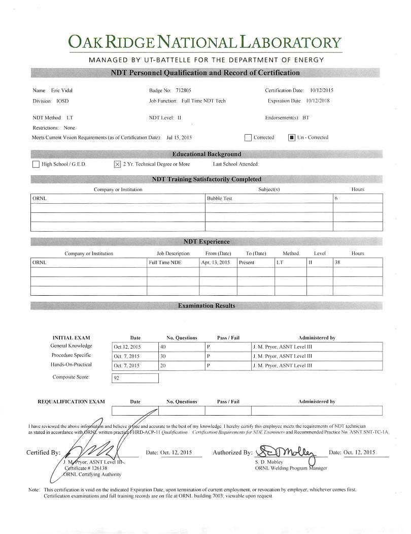
Oak Ridge National LaboratoryMANAGED BY UT-BATTELLE FOR THE DEPARTMENT OF ENERGY
NDT Personnel Quaiincation and Record of Certification '
Name: EricVidal
Division: lOSD
Badge No: 712805
Job Function: Full Time ND T Tech
Certiricalion Date: 10/12/2015
Expiration Date: 10/12/2018
NDT Method: LT NDT Level: II
Restrictions: None
Meets Current Vision Requirements (as ofCertiflcation Dale): Jul 15.2015
Endorsement(s): BT
I I Corrected Un - Corrected
□ High School/G.E.D. 2 Yr. Technical Degree or More Last School Attended:
Company or Institution Subjcct(s)
. :i -'.ts.-;
Hours
ORNL Bubble Test 6
Company or Institution Job Description From (Date) To (Date) Method Level Hours
ORNL Full Time NDE Apr, 13.2015 Present LT 11 38
Examination Results
INITIAL EXAM Date No. Questions Pass / Fail Administered byGeneral Knowledge Oct. 12.2015 40 P J. M. Pryor. ASNT Level III
Procedure Specific Oct. 7,2015 30 P J. M Pryor, ASNT Level ill
Hands-On-Practical Oct. 7,2015 20 P J. M. Pryor. ASNT LcvcMIJ
Composite Score: 92
REQUALIFICATION EXAM Date No. Questions Pass / Fail Administered by
I have reviewed the above inrqpnal^n and believe jwde and accurate to the best of my knowledge. I hereby certify this employee meets the requirements of NDT technicianas stated in accordance with^Rl^ written practi^^HRD-ACP-11 QualificaHon Cerlificalioit Requircmausfor NDK Examiiwrs and Recommended Practice No. ASNT SNT-TC-IA.
Certified By: Date: Oct. 12. 2015 Authorized By:J. Iv^ryor, ASNT Level II™iicate# 126138)RNL Certifying Authority
Date: Oct. 12. 2015
S. D. MobieyORNL Welding Program Manager
Note: This certification is void on the indicated Expiration Date, upon termination of current employment, or revocation by employer, whichever comes fi rst.Certification examinations and full training records arc on fi le at ORNL building 7003; viewable upon request.
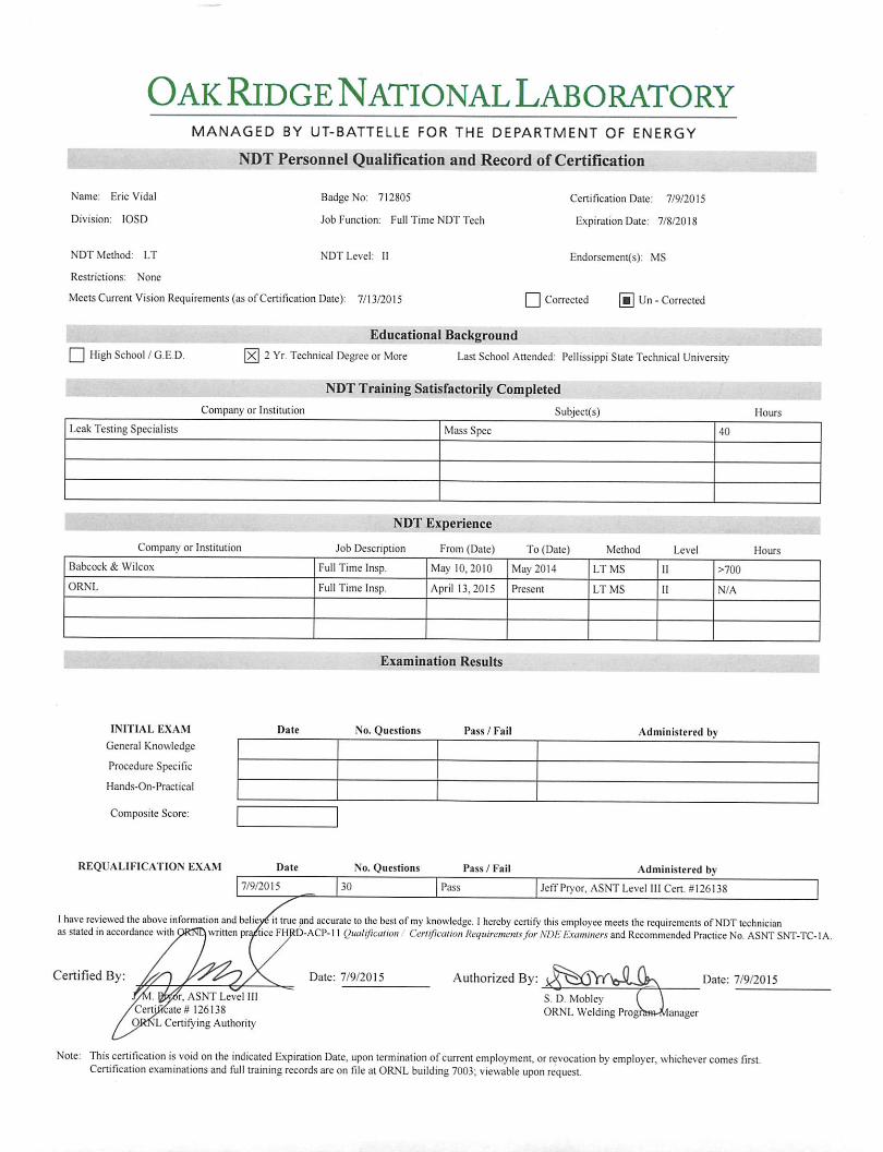
Oak Ridge National LaboratoryMANAGED BY UT-BATTELLE FOR THE DEPARTMENT OF ENERGY
NDT Personnel Qualification and Record of Certification
Name: Eric Vidal
Division: lOSD
Badge No: 712805
Job Function: Full Time NDT Tech
Certification Date: 7/9/2015
Expiration Date: 7/8/2018
NDT Method: LT NDT Level: II
Restrictions: None
Meets Current Vision Requirements (as of Certification Date): 7/13/2015
Endorsement(s): MS
I I Corrected Un - Corrected
Q High School/G.ED,Educational Background ~
2 Yr. Technical Degree or More Last School Attended: Pellissippi State Technical University
Company or Institution
NDT Training Satisfactorily Completed
Subject(s) Hours
Leak Testing Specialists Mass Spec 40
Company or Institution
NDT Experience
Job Description From (Date) To (Date) Method Level
. ; .a
Hours
Babcock & Wilcox Full Time Insp. May 10, 2010 May 2014 LT MS 11 >700
ORNL Full Time Insp. April 13,2015 Present LT MS II N/A
Examination Results
INITIAL EXAM Date No. Questions Pass / Fail Administered byGeneral Knowledge
Procedure Specific
Hands-On-Practical
Composite Score:
REQUALIFICATION EXAM Date No. Questions Pass / Fail Administered by
7/9/2015 30 Pass Jeff Pryor, ASNT Level 111 Cert. //126138
1 have reviewed the above information and beli^it true and accurate to the best of my knowledge. 1 hereby certify this employee meets the requirements of NDT technicianas stated in accordance with ORNQ written pr^ice FHRD-ACP-11 Qualification Cerlficalion Itequiremenisfor NDK Examiners and Recommended Practice No. ASNT SNT-TC-IA.
Certified By: Date: 7/9/2015 Authorized By:
sr, ASNT Level 111
^Certjfi^aie # 126138QftNL Certifying Authority
Date: 7/9/2015
S. D. MobleyORNL Welding Prog? anager
Note; This certification is void on the indicated Expiration Date, upon termination of current employment, or revocation by employer, whichever comes first.Certification examinations and full training records are on file at ORNL building 7003; viewable upon request.
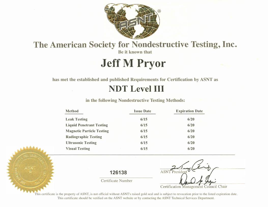
Be it known that
JeffM Pryor
has met the established and published Requirements for Certification by ASNT as
NDT Level III
in the following Nondestructive Testing Methods:
Method Issue Date Expiration Date
Leak Testing 6/15 6/20
Liquid Penetrant Testing 6/15 6/20
Magnetic Particle Testing 6/15 6/20
Radiographic Testing 6/15 6/20
Ultrasonic Testing 6/15 6/20
Visual Testing 6/15 6/20
126138
Certificate Number
This certificate is the property of ASNT, is not official without ASNT's raised gold seal and is subject to revocation prior to the listed expiration date.
This certificate should be verified on the ASNT website or by contacting the ASNT Technical Services Department.
ORNL/NTRC-075, Rev. 0, August 2017
APPENDIX E. LEAK TESTING PROCEDURE
ORNL Leak test procedure not available for public release. Procedure number is NDE 70, Rev. 6
ORNL/NTRC-075, Rev. 0, August 2017
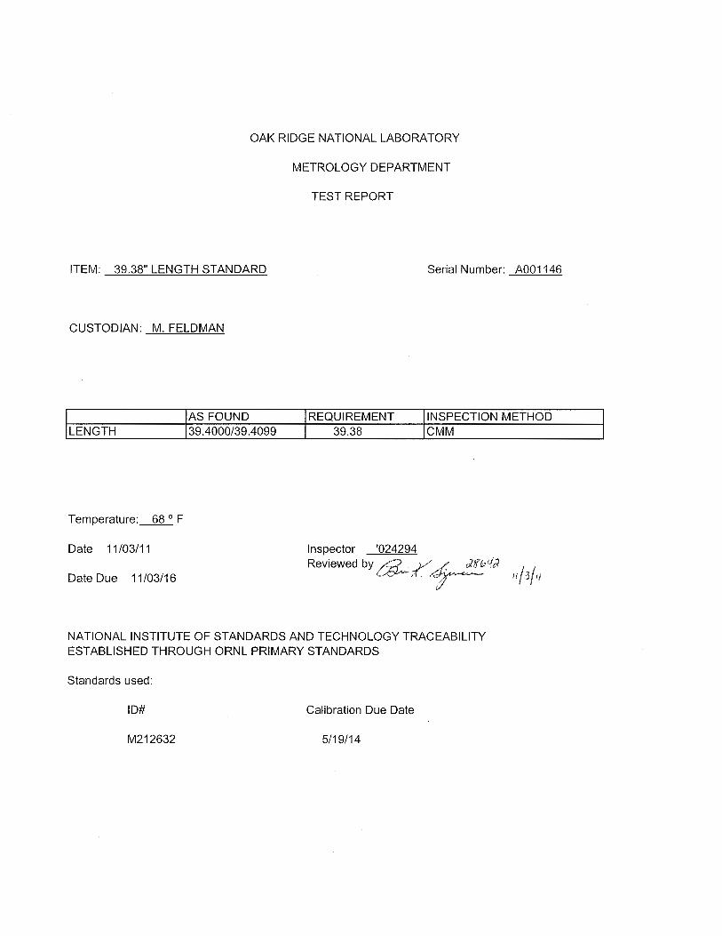
APPENDIX F. CALIBRATION RECORDS
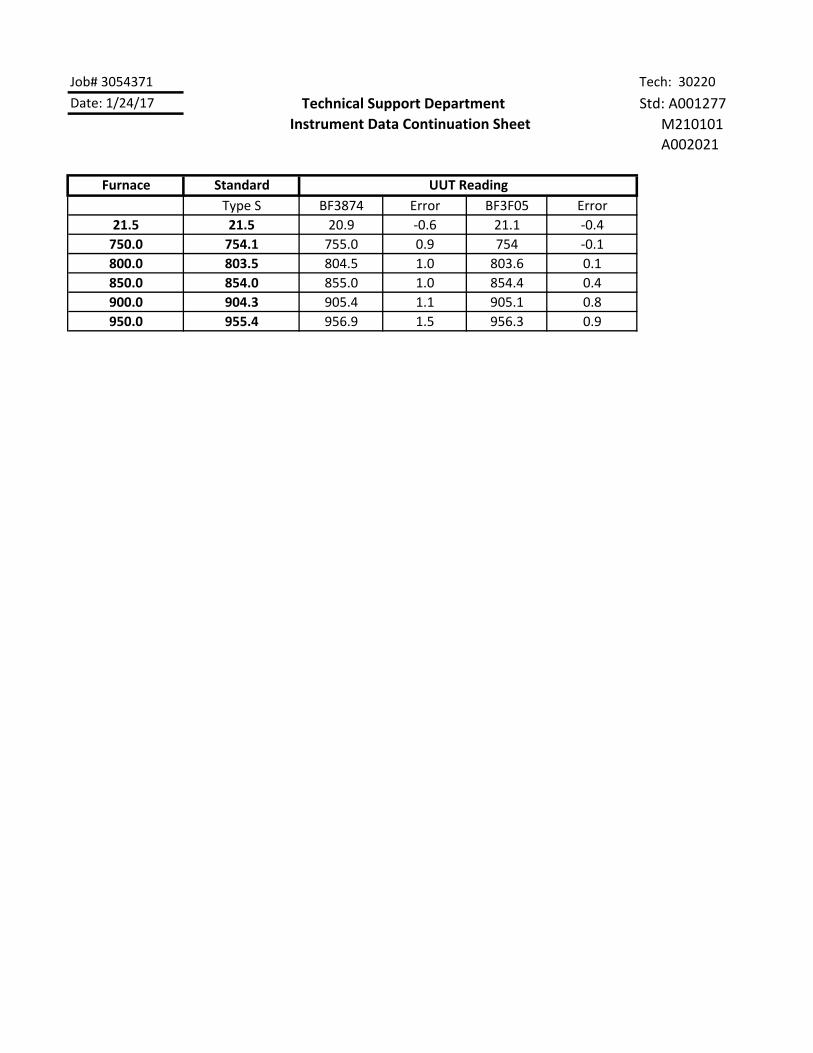
Job# 3054371 Tech: 30220
Date: 1/24/17 Technical Support Department Std: A001277
M210101
A002021
Furnace Standard
Type S BF3874 Error BF3F05 Error
21.5 21.5 20.9 ‐0.6 21.1 ‐0.4
750.0 754.1 755.0 0.9 754 ‐0.1
800.0 803.5 804.5 1.0 803.6 0.1
850.0 854.0 855.0 1.0 854.4 0.4
900.0 904.3 905.4 1.1 905.1 0.8
950.0 955.4 956.9 1.5 956.3 0.9
Instrument Data Continuation Sheet
UUT Reading
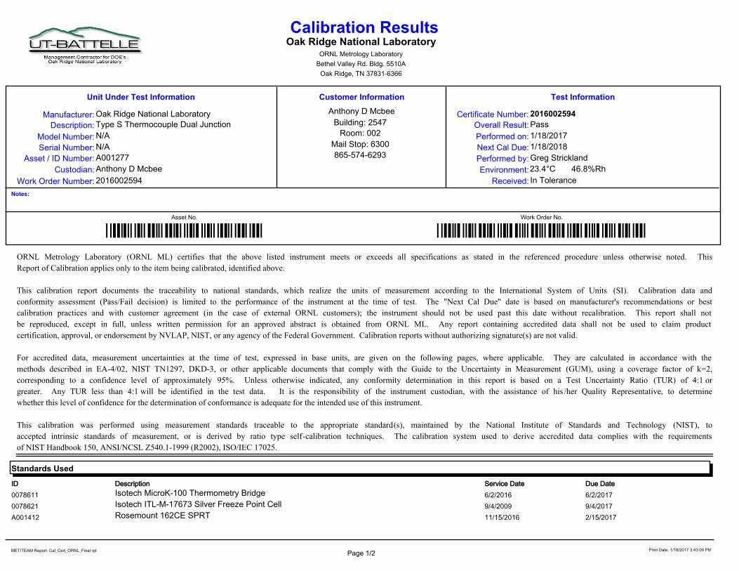
Calibration ResultsOak Ridge National Laboratory
ORNL Metrology Laboratory
Bethel Valley Rd. Bldg. 5510A
Oak Ridge, TN 37831-6366
Work Order Number:
Custodian:
Asset / ID Number:
Serial Number:
Model Number:
Description:
Manufacturer:
Unit Under Test Information Customer Information
Oak Ridge National Laboratory
Type S Thermocouple Dual Junction
N/A
N/A
A001277
Overall Result:
Performed on:
Next Cal Due:
Performed by:
Environment:
Received:
Pass
1/18/2017
1/18/2018
Greg Strickland
In Tolerance
23.4°C 46.8%Rh
Test Information
2016002594
2016002594Certificate Number:
Anthony D Mcbee
Anthony D Mcbee
Building: 2547
Room: 002
Mail Stop: 6300
865-574-6293
Notes:
Asset No. Work Order No.
*2016002594**A001277*ORNL Metrology Laboratory (ORNL ML) certifies that the above listed instrument meets or exceeds all specifications as stated in the referenced procedure unless otherwise noted. This
Report of Calibration applies only to the item being calibrated, identified above.
This calibration report documents the traceability to national standards, which realize the units of measurement according to the International System of Units (SI). Calibration data and
conformity assessment (Pass/Fail decision) is limited to the performance of the instrument at the time of test. The "Next Cal Due" date is based on manufacturer's recommendations or best
calibration practices and with customer agreement (in the case of external ORNL customers); the instrument should not be used past this date without recalibration. This report shall not
be reproduced, except in full, unless written permission for an approved abstract is obtained from ORNL ML. Any report containing accredited data shall not be used to claim product
certification, approval, or endorsement by NVLAP, NIST, or any agency of the Federal Government. Calibration reports without authorizing signature(s) are not valid.
For accredited data, measurement uncertainties at the time of test, expressed in base units, are given on the following pages, where applicable. They are calculated in accordance with the
methods described in EA-4/02, NIST TN1297, DKD-3, or other applicable documents that comply with the Guide to the Uncertainty in Measurement (GUM), using a coverage factor of k=2,
corresponding to a confidence level of approximately 95%. Unless otherwise indicated, any conformity determination in this report is based on a Test Uncertainty Ratio (TUR) of 4:1 or
greater. Any TUR less than 4:1 will be identified in the test data. It is the responsibility of the instrument custodian, with the assistance of his /her Quality Representative, to determine
whether this level of confidence for the determination of conformance is adequate for the intended use of this instrument.
This calibration was performed using measurement standards traceable to the appropriate standard(s), maintained by the National Institute of Standards and Technology (NIST), to
accepted intrinsic standards of measurement, or is derived by ratio type self-calibration techniques. The calibration system used to derive accredited data complies with the requirements
of NIST Handbook 150, ANSI/NCSL Z540.1-1999 (R2002), ISO/IEC 17025.
DescriptionID Due DateService Date
Standards Used
0078611 6/2/2016 6/2/2017Isotech MicroK-100 Thermometry Bridge
0078621 9/4/2009 9/4/2017Isotech ITL-M-17673 Silver Freeze Point Cell
A001412 11/15/2016 2/15/2017Rosemount 162CE SPRT
Page 1/2Print Date: 1/18/2017 3:43:00 PM MET/TEAM Report: Cal_Cert_ORNL_Final.rpt
1/18/2017Certificate Number: 2016002594
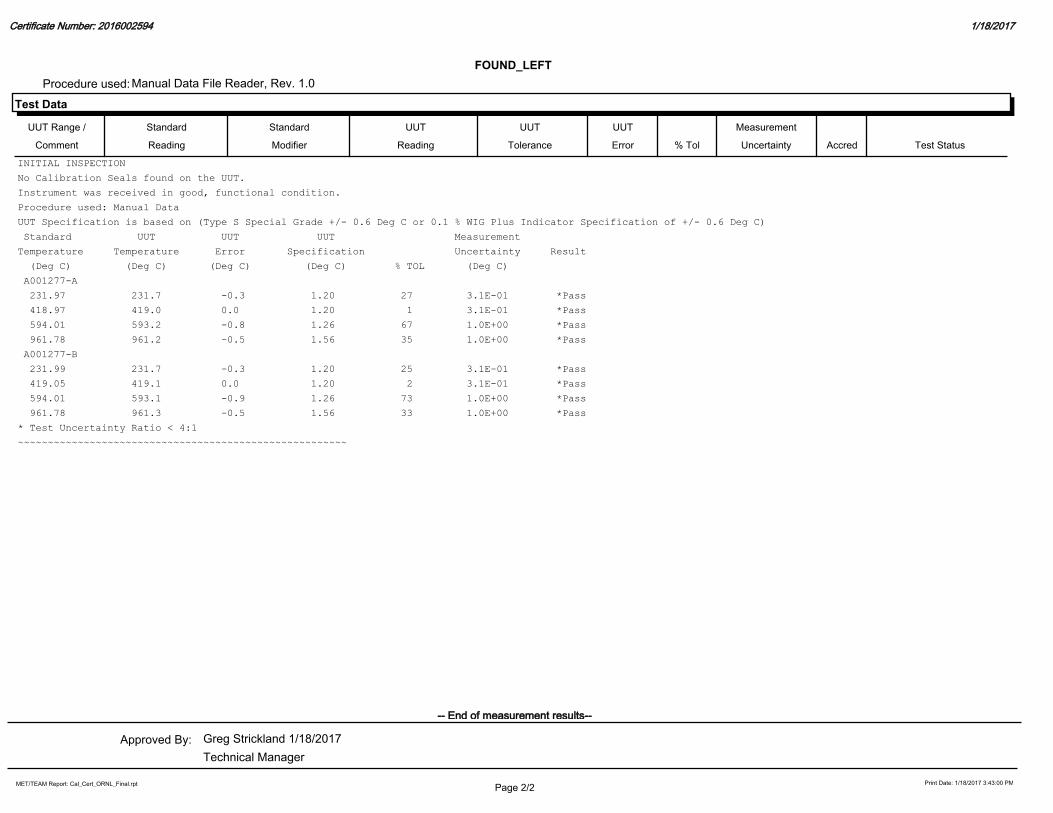
Test Data
FOUND_LEFT
Manual Data File Reader, Rev. 1.0Procedure used:
% Tol
UUT
Reading
Standard
Reading
UUT Range /
Comment
Standard
Modifier
UUT
Tolerance
UUT
Error
Measurement
Uncertainty Accred Test Status
INITIAL INSPECTION
No Calibration Seals found on the UUT.
Instrument was received in good, functional condition.
Procedure used: Manual Data
UUT Specification is based on (Type S Special Grade +/- 0.6 Deg C or 0.1 % WIG Plus Indicator Specification of +/- 0.6 Deg C)
Standard UUT UUT UUT Measurement
Temperature Temperature Error Specification Uncertainty Result
(Deg C) (Deg C) (Deg C) (Deg C) % TOL (Deg C)
A001277-A
231.97 231.7 -0.3 1.20 27 3.1E-01 *Pass
418.97 419.0 0.0 1.20 1 3.1E-01 *Pass
594.01 593.2 -0.8 1.26 67 1.0E+00 *Pass
961.78 961.2 -0.5 1.56 35 1.0E+00 *Pass
A001277-B
231.99 231.7 -0.3 1.20 25 3.1E-01 *Pass
419.05 419.1 0.0 1.20 2 3.1E-01 *Pass
594.01 593.1 -0.9 1.26 73 1.0E+00 *Pass
961.78 961.3 -0.5 1.56 33 1.0E+00 *Pass
* Test Uncertainty Ratio < 4:1
~~~~~~~~~~~~~~~~~~~~~~~~~~~~~~~~~~~~~~~~~~~~~~~~~~~~~~~
Technical Manager
Greg Strickland 1/18/2017Approved By:
-- End of measurement results--
Page 2/2Print Date: 1/18/2017 3:43:00 PM MET/TEAM Report: Cal_Cert_ORNL_Final.rpt


![Testing and Qualification[1]](https://img.pdfslide.net/doc/110x75/577d241a1a28ab4e1e9ba1c0/testing-and-qualification1.jpg)