Embed Size (px)
Citation preview
BY ORDER OF THE COMMANDER SMC Standard SMC-S-016 13 June 2008 ------------------------ Supersedes: New issue
Air Force Space Command
SPACE AND MISSILE SYSTEMS CENTER STANDARD
TEST REQUIREMENTS
FOR LAUNCH, UPPER-STAGE AND SPACE VEHICLES
APPROVED FOR PUBLIC RELEASE; DISTRIBUTION IS UNLIMITED


Contents
1. SCOPE ................................................................................................................................... 1 1.1 Purpose ........................................................................................................................................ 1 1.2 Application .................................................................................................................................. 1 1.3 Baseline Requirements ................................................................................................................ 1 1.4 Tailoring ...................................................................................................................................... 1 1.5 Test Categories ............................................................................................................................ 1 1.6 Exclusions, or Additional Environments..................................................................................... 2
2. REFERENCE DOCUMENTS............................................................................................. 3 2.1 Applicable Documents ................................................................................................................ 3 2.2 Guidance Documents................................................................................................................... 4 2.3 Order of Precedence .................................................................................................................... 4
3. DEFINITIONS ...................................................................................................................... 5 3.1 Airborne Support Equipment....................................................................................................... 5 3.2 Ambient Environment ................................................................................................................. 5 3.3 Burst Factor ................................................................................................................................. 5 3.4 Computer Program ...................................................................................................................... 5 3.5 Design Burst Pressure.................................................................................................................. 5 3.6 Design Factor of Safety ............................................................................................................... 5 3.7 Design Ultimate Load.................................................................................................................. 5 3.8 Design Yield Load....................................................................................................................... 5 3.9 Development Test Article............................................................................................................ 6 3.10 Electromagnetic Compatibility (EMC) Margin........................................................................... 6 3.11 Effective Duration for Acoustics and Random Vibration ........................................................... 6 3.12 Explosive Ordnance Device ........................................................................................................ 6 3.13 Firmware...................................................................................................................................... 6 3.14 Flight Vehicle .............................................................................................................................. 6 3.15 Flight-Critical Item...................................................................................................................... 6 3.16 Functional Testing ....................................................................................................................... 7 3.17 Hot Operational Soak .................................................................................................................. 7 3.18 Launch System ............................................................................................................................ 7 3.19 Launch Vehicle............................................................................................................................ 7 3.20 Limit Load ................................................................................................................................... 7 3.21 Maximum and Minimum Model Temperature Predictions ......................................................... 7 3.22 Maximum and Minimum Predicted Temperatures...................................................................... 7 3.23 Maximum Expected Operating Pressure (MEOP) ...................................................................... 7 3.24 Maximum Predicted Acceleration ............................................................................................... 8 3.25 Maximum Predicted Environment (MPE) for Acoustics ............................................................ 8 3.26 Maximum Predicted Environment (MPE) for Random Vibration .............................................. 8 3.27 Maximum Predicted Environment (MPE) for Shock .................................................................. 8 3.28 Maximum Predicted Environment (MPE) for Sinusoidal Vibration ........................................... 9 3.29 Moving Mechanical Assembly (MMA) ...................................................................................... 9 3.30 Multipaction ................................................................................................................................ 9 3.31 Multi-Unit Module (MUM)......................................................................................................... 9 3.32 On-Orbit System.......................................................................................................................... 9
3.33 Operational Modes ...................................................................................................................... 9 3.34 Part............................................................................................................................................. 10 3.35 Performance Testing.................................................................................................................. 10 3.36 Pressure Component .................................................................................................................. 10 3.37 Pressure Vessel .......................................................................................................................... 10 3.38 Pressurized Structure ................................................................................................................. 10 3.39 Pressurized Subsystem .............................................................................................................. 10 3.40 Proof Factor ............................................................................................................................... 10 3.41 Proof Test .................................................................................................................................. 11 3.42 Reusable Item ............................................................................................................................ 11 3.43 Service Life ............................................................................................................................... 11 3.44 Significant Shock Event ............................................................................................................ 11 3.45 Simulator ................................................................................................................................... 11 3.46 Software..................................................................................................................................... 11 3.47 Software Item ............................................................................................................................ 11 3.48 Software Unit............................................................................................................................. 11 3.49 Space Vehicle ............................................................................................................................ 11 3.50 Statistical Estimates of Vibration, Acoustic, and Shock Environments .................................... 12 3.51 Structural Component................................................................................................................ 12 3.52 Subassembly .............................................................................................................................. 12 3.53 Subsystem.................................................................................................................................. 12 3.54 Survival Temperatures............................................................................................................... 12 3.55 System ....................................................................................................................................... 13 3.56 Temperature Stabilization.......................................................................................................... 13 3.57 Test Discrepancy ....................................................................................................................... 13 3.58 Test Item Failure........................................................................................................................ 13 3.59 Thermal Dwell........................................................................................................................... 13 3.60 Thermal Soak............................................................................................................................. 13 3.61 Thermal Uncertainty Margin ..................................................................................................... 13 3.62 Unit ............................................................................................................................................ 14 3.63 Upper-Stage Vehicle.................................................................................................................. 14 3.64 Vehicle....................................................................................................................................... 14
4. GENERAL REQUIREMENTS......................................................................................... 15 4.1 Baseline Requirements .............................................................................................................. 15
4.1.1 Waivers ................................................................................................................................. 15 4.2 Testing Philosophy .................................................................................................................... 15
4.2.1 Development Tests................................................................................................................ 17 4.2.2 Qualification Tests ................................................................................................................ 18 4.2.3 Protoqualification Tests......................................................................................................... 18 4.2.4 Acceptance Tests................................................................................................................... 18
4.3 Testing Approach ...................................................................................................................... 19 4.3.1 Development ......................................................................................................................... 19
4.3.1.1 Part, Material, and Process Development Tests and Evaluations................................. 19 4.3.2 Qualification.......................................................................................................................... 19
4.3.2.1 Qualification Hardware ................................................................................................ 19 4.3.2.2 Qualification Test Levels and Durations ...................................................................... 20 4.3.2.3 Qualification Retest ...................................................................................................... 20
4.3.3 Protoqualification.................................................................................................................. 20 4.3.3.1 Protoqualification Hardware......................................................................................... 20 4.3.3.2 Protoqualification Test Levels and Durations .............................................................. 21
4.3.3.3 Protoqualification Retest .............................................................................................. 21 4.3.4 Acceptance ............................................................................................................................ 22
4.3.4.1 Acceptance Hardware................................................................................................... 22 4.3.4.2 Acceptance Test Levels and Durations ........................................................................ 22 4.3.4.3 Acceptance Retest ........................................................................................................ 22
4.4 Special Considerations .............................................................................................................. 22 4.4.1 Propulsion Equipment Tests.................................................................................................. 22
4.4.1.1 Engine Line Replaceable Unit (LRU) Acceptance Testing.......................................... 22 4.4.1.2 Engine Line Replaceable Unit (LRU) Qualification Testing ....................................... 23
4.4.2 Thermal Uncertainty Margins ............................................................................................... 23 4.4.2.1 Margins for Passive Thermal Control Hardware.......................................................... 23 4.4.2.2 Margins for Active Thermal Control Hardware ........................................................... 24 4.4.2.3 Margins for Units Controlled by Heat Pipes ................................................................ 24
4.5 Software and Firmware Tests ....................................................................................................25 4.5.1 Software Development Tests ................................................................................................ 25 4.5.2 Software Qualification Tests................................................................................................. 25 4.5.3 Testing of Commercial Off-the-Shelf (COTS) and Reuse Software..................................... 25 4.5.4 Software Regression Testing................................................................................................. 25 4.5.5 Other Software-Related Testing............................................................................................ 25
4.6 Inspections................................................................................................................................. 25 4.6.1 Post Qualification Test Inspections....................................................................................... 26 4.6.2 Post Test Flight Hardware Inspection (Including Launch Site) ............................................ 26
4.7 Test Condition Tolerances......................................................................................................... 26 4.8 Test Plans and Procedures ......................................................................................................... 28
4.8.1 Test Plans .............................................................................................................................. 28 4.8.2 Test Procedures ..................................................................................................................... 28
4.9 Documentation .......................................................................................................................... 29 4.9.1 Test Documentation Files ..................................................................................................... 29 4.9.2 General Test Data.................................................................................................................. 29 4.9.3 Qualification, Protoqualification, and Acceptance................................................................ 29 4.9.4 Test Log ................................................................................................................................ 30 4.9.5 Test Discrepancy................................................................................................................... 30
4.10 Exceptions to General Criteria .................................................................................................. 30 4.10.1 Qualification and Protoqualification by Similarity ............................................................... 30 4.10.2 Unit Thermal Vacuum Test Exemptions............................................................................... 30
5. ALTERNATIVE STRATEGIES....................................................................................... 33 5.1 Spares Strategy .......................................................................................................................... 33 5.2 Flightproof Strategy................................................................................................................... 33 5.3 Combination Test Strategies...................................................................................................... 34
6. UNIT TEST REQUIREMENTS ....................................................................................... 35 6.1 General Requirements ............................................................................................................... 35 6.2 Development Tests .................................................................................................................... 35
6.2.1 Subassembly Development Tests, In-Process Tests, and Inspections................................... 35 6.2.2 Unit Development Tests........................................................................................................ 35 6.2.3 Structural Composite Development Tests............................................................................. 35 6.2.4 Thermal Development Tests ................................................................................................. 36 6.2.5 Shock and Vibration Isolator Development Tests................................................................. 36
6.3 Test Program for Units .............................................................................................................. 36 6.3.1 Unit Wear-In Test ................................................................................................................. 37
6.3.1.1 Purpose ......................................................................................................................... 37 6.3.1.2 Test Description............................................................................................................ 37 6.3.1.3 Test Levels and Duration.............................................................................................. 37 6.3.1.4 Supplementary Requirements....................................................................................... 42
6.3.2 Unit Specification Performance Test .................................................................................... 42 6.3.2.1 Purpose ......................................................................................................................... 42 6.3.2.2 Electrical Test Description ........................................................................................... 42 6.3.2.3 Mechanical Test Description ........................................................................................ 42 6.3.2.4 Supplementary Requirements....................................................................................... 42
6.3.3 Unit Leakage Test ................................................................................................................. 42 6.3.3.1 Purpose ......................................................................................................................... 42 6.3.3.2 Test Description............................................................................................................ 42 6.3.3.3 Test Level and Duration ............................................................................................... 43
6.3.4 Unit Shock Test..................................................................................................................... 43 6.3.4.1 Purpose ......................................................................................................................... 43 6.3.4.2 Test Description............................................................................................................ 43 6.3.4.3 Test Level and Exposure .............................................................................................. 43 6.3.4.4 Supplementary Requirements....................................................................................... 44
6.3.5 Unit Vibration Test ............................................................................................................... 44 6.3.5.1 Purpose ......................................................................................................................... 44 6.3.5.2 Test Description............................................................................................................ 44 6.3.5.3 Test Levels and Duration.............................................................................................. 44 6.3.5.4 Specification Performance............................................................................................ 45 6.3.5.5 Supplementary Requirements....................................................................................... 45 6.3.5.6 Fixture Evaluation ........................................................................................................ 47 6.3.5.7 Special Considerations for Structural Units ................................................................. 47
6.3.6 Unit Acoustic Test................................................................................................................. 47 6.3.6.1 Purpose ......................................................................................................................... 47 6.3.6.2 Test Description............................................................................................................ 47 6.3.6.3 Test Levels and Duration.............................................................................................. 48 6.3.6.4 Supplementary Requirements....................................................................................... 48
6.3.7 Unit Acceleration Test .......................................................................................................... 48 6.3.7.1 Purpose ......................................................................................................................... 48 6.3.7.2 Test Description............................................................................................................ 48 6.3.7.3 Test Levels and Duration.............................................................................................. 50 6.3.7.4 Supplementary Requirements....................................................................................... 50
6.3.8 Unit Thermal Cycle Test, Electrical and Electronic.............................................................. 50 6.3.8.1 Purpose ......................................................................................................................... 50 6.3.8.2 Test Description............................................................................................................ 50 6.3.8.3 Test Levels and Duration.............................................................................................. 52 6.3.8.4 Supplementary Requirements....................................................................................... 55
6.3.9 Unit Thermal Vacuum Test................................................................................................... 55 6.3.9.1 Purpose ......................................................................................................................... 55 6.3.9.2 Test Description............................................................................................................ 55 6.3.9.3 Test Levels and Duration.............................................................................................. 56 6.3.9.4 Supplementary Requirements....................................................................................... 57
6.3.10 Unit Climatic Tests ............................................................................................................... 58 6.3.10.1 Purpose ......................................................................................................................... 58 6.3.10.2 Humidity Test, Unit Qualification................................................................................ 58 6.3.10.3 Sand and Dust Test, Unit Qualification........................................................................ 60 6.3.10.4 Rain Test, Unit Qualification........................................................................................ 61
6.3.10.5 Salt Fog Test, Unit Qualification.................................................................................. 61 6.3.10.6 Explosive Atmosphere Test, Unit Qualification........................................................... 61
6.3.11 Unit Static Load Test ............................................................................................................ 61 6.3.11.1 Purpose ......................................................................................................................... 61 6.3.11.2 Test Description............................................................................................................ 62 6.3.11.3 Test Levels and Duration.............................................................................................. 62 6.3.11.4 Supplementary Requirements....................................................................................... 63
6.3.12 Unit Pressure Test ................................................................................................................. 63 6.3.12.1 Purpose ......................................................................................................................... 63 6.3.12.2 Test Description............................................................................................................ 63 6.3.12.3 Test Levels and Durations ............................................................................................ 64 6.3.12.4 Supplementary Requirements....................................................................................... 64
6.3.13 Unit Electromagnetic Compatibility (EMC) Test ................................................................. 66 6.3.13.1 Purpose ......................................................................................................................... 66 6.3.13.2 Test Description............................................................................................................ 66 6.3.13.3 Test Levels and Duration.............................................................................................. 67
6.3.14 Unit Life Test ........................................................................................................................ 67 6.3.14.1 Purpose ......................................................................................................................... 67 6.3.14.2 Test Description............................................................................................................ 67 6.3.14.3 Test Levels and Durations ............................................................................................ 67 6.3.14.4 Supplementary Requirements....................................................................................... 68
7. SUBSYSTEM TEST REQUIREMENTS ......................................................................... 69 7.1 Requirements ............................................................................................................................. 69 7.2 Subsystem Development Tests .................................................................................................. 69
7.2.1 Mechanical Fit Development Tests....................................................................................... 69 7.2.2 Mode Survey Development Tests ......................................................................................... 69 7.2.3 Structural Development Tests ............................................................................................... 69 7.2.4 Acoustic Development Tests................................................................................................. 70 7.2.5 Shock Development Tests..................................................................................................... 70 7.2.6 Payload Thermal Developmental Testing ............................................................................. 70
7.3 Test Program for Subsystems .................................................................................................... 71 7.3.1 Subsystem Specification Performance Test .......................................................................... 73
7.3.1.1 Purpose ......................................................................................................................... 73 7.3.1.2 Mechanical Test............................................................................................................ 74 7.3.1.3 End-to-End Specification Performance Test ................................................................ 74 7.3.1.4 Supplementary Requirements....................................................................................... 74
7.3.2 Subsystem Static Load Test .................................................................................................. 75 7.3.2.1 Purpose ......................................................................................................................... 75 7.3.2.2 Test Description............................................................................................................ 75 7.3.2.3 Test Levels and Duration.............................................................................................. 75 7.3.2.4 Supplementary Requirements....................................................................................... 76
7.3.3 Subsystem Pressure Test ....................................................................................................... 76 7.3.3.1 Purpose ......................................................................................................................... 76 7.3.3.2 Test Descriptions .......................................................................................................... 76 7.3.3.3 Test Level and Duration ............................................................................................... 76 7.3.3.4 Supplementary Requirements....................................................................................... 76
7.3.4 Subsystem Vibration Test ..................................................................................................... 76 7.3.4.1 Purpose ......................................................................................................................... 76 7.3.4.2 Test Description............................................................................................................ 76 7.3.4.3 Test Levels and Duration.............................................................................................. 76
7.3.4.4 Supplementary Requirements....................................................................................... 76 7.3.5 Subsystem Acoustic Test ...................................................................................................... 76
7.3.5.1 Purpose ......................................................................................................................... 76 7.3.5.2 Test Description............................................................................................................ 77 7.3.5.3 Test Levels and Duration.............................................................................................. 77 7.3.5.4 Supplementary Requirements....................................................................................... 77
7.3.6 Subsystem Shock Test........................................................................................................... 77 7.3.6.1 Purpose ......................................................................................................................... 77 7.3.6.2 Test Description............................................................................................................ 77 7.3.6.3 Test Activations............................................................................................................ 77 7.3.6.4 Supplementary Requirements....................................................................................... 77
7.3.7 Subsystem Thermal Vacuum Test......................................................................................... 77 7.3.7.1 Purpose ......................................................................................................................... 78 7.3.7.2 Test Description............................................................................................................ 78 7.3.7.3 Test Levels and Duration.............................................................................................. 78 7.3.7.4 Specification Performance............................................................................................ 78 7.3.7.5 Supplementary Requirements....................................................................................... 78
7.3.8 Subsystem Separation and Deployment Tests....................................................................... 78 7.3.8.1 Purpose ......................................................................................................................... 78 7.3.8.2 Test Description............................................................................................................ 78 7.3.8.3 Test Activations............................................................................................................ 79 7.3.8.4 Supplementary Requirements....................................................................................... 79
7.3.9 Subsystem Electromagnetic Compatibility (EMC) Test ....................................................... 79 7.3.9.1 Purpose ......................................................................................................................... 79 7.3.9.2 Test Description............................................................................................................ 79 7.3.9.3 Test Levels and Duration.............................................................................................. 79
7.3.10 Mode Survey Test ................................................................................................................. 80 7.3.10.1 Purpose ......................................................................................................................... 80 7.3.10.2 Test Description............................................................................................................ 80 7.3.10.3 Test Levels.................................................................................................................... 80 7.3.10.4 Supplementary Requirements....................................................................................... 81
8. VEHICLE TEST REQUIREMENTS............................................................................... 83 8.1 General Requirements ............................................................................................................... 83 8.2 Vehicle Development Tests....................................................................................................... 83
8.2.1 Mechanical Fit Development Tests....................................................................................... 83 8.2.2 Mode Survey Development Tests ......................................................................................... 83 8.2.3 Structural Development Tests ............................................................................................... 83 8.2.4 Acoustic Development Tests................................................................................................. 84 8.2.5 Shock Development Tests..................................................................................................... 84 8.2.6 Thermal Balance Development Tests ................................................................................... 84 8.2.7 Transportation and Handling Development Tests................................................................. 85 8.2.8 Wind Tunnel Development Tests.......................................................................................... 85
8.3 Test Program for Flight Vehicles .............................................................................................. 86 8.3.1 Vehicle Specification Performance Test ............................................................................... 90
8.3.1.1 Purpose ......................................................................................................................... 90 8.3.1.2 Mechanical Test............................................................................................................ 90 8.3.1.3 End-to-End Specification Performance Test ................................................................ 90 8.3.1.4 Supplementary Requirements....................................................................................... 91
8.3.2 Vehicle Pressure and Leakage Tests ..................................................................................... 91 8.3.2.1 Purpose ......................................................................................................................... 91
8.3.2.2 Test Description............................................................................................................ 91 8.3.2.3 Test Levels and Durations ............................................................................................ 91 8.3.2.4 Supplementary Requirements....................................................................................... 92
8.3.3 Vehicle Electromagnetic Compatibility Test ........................................................................ 92 8.3.3.1 Purpose ......................................................................................................................... 92 8.3.3.2 Test Description............................................................................................................ 92 8.3.3.3 Test Levels and Duration.............................................................................................. 93 8.3.3.4 Supplementary Requirements....................................................................................... 93
8.3.4 Vehicle Shock Test ............................................................................................................... 94 8.3.4.1 Purpose ......................................................................................................................... 94 8.3.4.2 Test Description............................................................................................................ 94 8.3.4.3 Test Activations............................................................................................................ 94 8.3.4.4 Supplementary Requirements....................................................................................... 94
8.3.5 Vehicle Acoustic Test ........................................................................................................... 95 8.3.5.1 Purpose ......................................................................................................................... 95 8.3.5.2 Test Description............................................................................................................ 95 8.3.5.3 Test Level and Duration ............................................................................................... 95 8.3.5.4 Supplementary Requirements....................................................................................... 95
8.3.6 Vehicle Vibration Test .......................................................................................................... 96 8.3.6.1 Purpose ......................................................................................................................... 96 8.3.6.2 Test Description............................................................................................................ 96 8.3.6.3 Test Levels and Durations ............................................................................................ 96 8.3.6.4 Supplementary Requirements....................................................................................... 98
8.3.7 Vehicle Thermal Balance Test .............................................................................................. 98 8.3.7.1 Purpose ......................................................................................................................... 98 8.3.7.2 Test Description............................................................................................................ 98 8.3.7.3 Levels and Duration ..................................................................................................... 99 8.3.7.4 Supplementary Requirements....................................................................................... 99
8.3.8 Vehicle Thermal Vacuum Test ........................................................................................... 100 8.3.8.1 Purpose ....................................................................................................................... 100 8.3.8.2 Test Description.......................................................................................................... 100 8.3.8.3 Test Levels and Durations .......................................................................................... 100 8.3.8.4 Supplementary Requirements..................................................................................... 101
8.3.9 Mode Survey Test ............................................................................................................... 101 8.3.9.1 Purpose ....................................................................................................................... 101 8.3.9.2 Test Description.......................................................................................................... 102 8.3.9.3 Test Levels.................................................................................................................. 102 8.3.9.4 Supplementary Requirements..................................................................................... 102
9. PRELAUNCH VALIDATION AND OPERATIONAL TESTS .................................. 103 9.1 Prelaunch Validation Tests, General Requirements ................................................................ 103 9.2 Prelaunch Validation Test Flow .............................................................................................. 103 9.3 Prelaunch Validation Test Configuration ................................................................................ 104 9.4 Prelaunch Validation Test Descriptions .................................................................................. 104
9.4.1 Performance Tests ............................................................................................................... 104 9.4.1.1 Simulators................................................................................................................... 104 9.4.1.2 Explosive Ordnance and Non-Explosive Firing Circuits ........................................... 104 9.4.1.3 Transportation and Handling Monitoring................................................................... 104 9.4.1.4 Late Removal and Replacement of Flight Hardware ................................................. 104
9.4.2 Propulsion Subsystem Leakage and Functional Tests ........................................................ 105 9.4.3 Launch-critical Ground Support Equipment Tests.............................................................. 105
9.4.4 Compatibility Test, On-Orbit System ................................................................................. 105 9.4.4.1 Purpose ....................................................................................................................... 105 9.4.4.2 Test Description.......................................................................................................... 105 9.4.4.3 Supplementary Requirements..................................................................................... 106
9.5 Follow-On Operational Tests for Space Vehicles ................................................................... 106 9.5.1 Follow-On Operational Tests and Evaluations ................................................................... 106 9.5.2 On-Orbit Testing ................................................................................................................. 106 9.5.3 Reusable Flight Hardware................................................................................................... 106
10. NOTES............................................................................................................................... 107 10.1 Additional Thermal Considerations......................................................................................... 107
10.1.1 Vehicle Alternate Thermal Strategy.................................................................................... 107 10.2 Test Requirements for Acoustic, Vibration, and Shock Environments ................................... 108
10.2.1 Statistical Basis for Test Level............................................................................................ 108 10.2.2 Acceleration of Acceptance Life for Acoustic and Random Vibration Tests ..................... 109 10.2.3 General Requirements for Acoustic and Random Vibration Qualification and Protoqualification Tests.................................................................................................................... 110 10.2.4 Two-Phase Qualification and Protoqualification Test for Vibration and Acoustics ........... 110 10.2.5 Damage-Based Analysis of Flight Vibroacoustic Data....................................................... 111 10.2.6 Threshold Response Spectrum for Shock Significance ...................................................... 111 10.2.7 References ........................................................................................................................... 112
Figures
Figure 4.2-1 Baseline Qualification Test Strategy.......................................................................................... 16 Figure 4.2-2 Protoqualification Strategy........................................................................................................ 16 Figure 6.3.5-1 Minimum Random Vibration Spectrum, Unit Acceptance Tests........................................... 46 Figure 6.3.6-1 Minimum Acoustic Levels, Unit and Vehicle......................................................................... 49 Figure 6.3.8-1 Temperature Profile at Hot Plateau ......................................................................................... 51 Figure 6.3.8-2 Temperature Profile at Cold Plateau ....................................................................................... 51 Figure 6.3.8-3. Unit Test Temperature Ranges and Margins......................................................................... 54 Figure 6.3.10-1 Humidity Test Time Line...................................................................................................... 60 Figure 8.3.7-1 Minimum Random Vibration Spectrum, Vehicle Acceptance Tests ..................................... 97
Tables
Table 4.4-1 Categorization of Passive and Active Thermal Hardware........................................................... 23 Table 4.4.2 Thermal Uncertainty Margins for Passive Cryogenic Hardware................................................. 24 Table 4.7-1 Maximum Allowable Test Tolerances......................................................................................... 27 Table 6.3-1 Unit Qualification and Protoqualification Test Summary ........................................................... 39 Table 6.3-2 Unit Acceptance Test Summary .................................................................................................. 40 Table 6.3-3 Typical Unit Test Level Margins and Duration........................................................................... 41 Table 6.3.12-1 Unit Pressure Cycle Test Requirements ................................................................................. 65 Table 6.3.12-2 Minimum Burst Pressure Requirements................................................................................. 66 Table 7.3-1 Subsystem Qualification and Protoqualification Test Summary................................................. 71 Table 7.3-2 Subsystem Acceptance Test Summary........................................................................................ 72 Table 7.3-3 Typical Subsystem Test Level Margins and Durations ............................................................... 73 Table 8.3-1 Vehicle Qualification and Protoqualification Test Summary...................................................... 87 Table 8.3-2 Vehicle Acceptance Test Summary............................................................................................. 88 Table 8.3-3 Vehicle Test Level Margins and Duration................................................................................... 89

1
1. Scope
1.1 Purpose
This Standard establishes the environmental and structural ground testing requirements for launch vehicles, upper-stage vehicles, space vehicles, and their subsystems and units. In addition, a uniform set of definitions of related terms is established.
1.2 Application
This Standard is applicable to the procurement of space system hardware as a compliance document for the establishment of baseline test requirements. The test requirements herein focus on design verification and the elimination of latent defects to help ensure a high level of confidence in achieving successful space missions.
1.3 Baseline Requirements
This Standard establishes the qualification test strategy as the baseline test requirements. This strategy consists of testing dedicated hardware to qualification levels to verify design, followed by acceptance testing of flight hardware to screen workmanship defects.
1.4 Tailoring
It is intended that these test requirements be tailored to each specific program after considering the design complexity, design margins, vulnerabilities, technology state of the art, in-process controls, mission criticality, life cycle cost, number of vehicles involved, prior usage, and acceptable risk. However, the tailored requirements shall achieve a level of verification equivalent to the baseline requirements described herein. Rationale for each tailored requirement shall be established. If the baseline qualification requirements in this Standard are not tailored by the contract, they stand as written.
1.5 Test Categories
The tests discussed herein are categorized and defined as follows:
a. Development tests. Tests conducted on representative articles to characterize engineering parameters, gather data and validate the design approach.
b. Qualification tests. Tests conducted to demonstrate satisfaction of design requirements including margin and product robustness for designs that have no demonstrated history. A full qualification validates the planned acceptance program, in-process stress screens, and retest environmental stresses resulting from failure and rework. Qualification hardware that is selected for use as flight hardware shall be evaluated and refurbished as necessary to show that the integrity of the hardware is preserved and that adequate margin remains to survive the rigors of launch and provide useful life on orbit.
c. Protoqualification tests. Tests conducted to demonstrate satisfaction of design requirements using reduced amplitude and duration margins. This type of test is generally selected for designs that have limited production where test units will be used for flight. The test program is supplemented with analyses as well as development and other tests to demonstrate margin and life. Protoqualification tests shall validate the planned acceptance program.
2
d. Acceptance tests. Vehicle, subsystem, and unit tests conducted to demonstrate that flight hardware is free of workmanship defects, meets specified performance requirements, and is acceptable for delivery.
e. Prelaunch validation tests. Prelaunch validation tests are conducted at the launch base to assure readiness of the hardware, software, personnel procedures, and mission interfaces to support launch and the program mission.
f. Post launch validation tests. Tests performed following launch to verify specification performance, interface compatibility, calibration, and the ability to meet mission requirements.
1.6 Exclusions, or Additional Environments
Environments other than those specified in this Standard can be sufficiently stressful as to warrant special analysis and testing. These include environments such as nuclear and electromagnetic radiation, natural space environment, and lightning.
3
2. Reference Documents
2.1 Applicable Documents
The following documents of the issue in effect on the date of invitation for bids or request for proposal form a part of this standard to the extent referenced herein.
Military Documents
MIL-STD-810F Environmental Test Methods and Engineering Guidelines
MIL-STD-1833 (USAF) Test Requirements for Ground Equipment and Associated Computer Software Supporting Space Vehicles
DOD-W-83575A Wiring Harness, Space Vehicles, Design and Testing
Industry Standards
AIAA S-080-1998 Space Systems-Metallic Pressure Vessels, Pressurized Structures and Pressure Components
AIAA S-081-2000 Space Systems-Composite Overwrapped Pressure Vessels
AIAA S-110-2005 Space Systems-Structures, Structural Components and Structural Assembly
AIAA S-114-2005 Moving Mechanical Assemblies for Space and Launch Vehicles
AIAA S-113-2005 Criteria for Explosive Systems and Devices Used on Space Vehicles
AIAA S-111-20051 Qualification and Quality Standards for Space-Qualified Solar Cells
AIAA S-112-2005 Qualification and Quality Requirements for Space-Qualified Solar Panels
4
Aerospace Corporation Documents
TOR-2004(3909)-3315 Rev. A Parts, Materials, and Processes Control Program for Space Vehicles
TOR-2004(3909)-3316 Rev. A Technical Requirements for Electronic Parts, Materials, and Processes Used in Space Vehicles
TOR-2004(3909)-3537 Software Development Standard for Space Systems
TOR-2005(8583)-1 Electromagnetic Compatibility Requirements for Space Systems
TOR-2004(8583)-5, Rev. 1 Space Battery Standard
2.2 Guidance Documents
MIL-HDBK-340A, Volume II Test Requirements for Launch, Upper Stage and Space Vehicles: Application Guidelines
DNA-TR-84-140 Satellite Hardness and Survivability; Testing Rationale for Electronic Upset and Burnout Effects
AFSCM 91-710 Range Safety User Requirements Manual
TOR-2003(8583)-2886 Independent Structural Analyses of Integrated Spacecraft/Launch Vehicle Systems
(Unless otherwise indicated, copies of federal and military specifications, standards, and handbooks are available from the Standardization Document Order Desk, 700 Robbins Avenue, Building 4D, Philadelphia, PA 19111-5094.)
2.3 Order of Precedence
In the event of conflict between the text of this document and the references cited herein, the text of this document takes precedence. Nothing in this document, however, supersedes applicable laws and regulations unless a specific exemption has been obtained.
5
3. Definitions
3.1 Airborne Support Equipment
Airborne support equipment is the equipment installed in a flight vehicle to provide support functions and interfaces for the space or upper-stage vehicle during launch and orbital operations of the flight vehicle. This includes the hardware and software that provide the structural, electrical, electronic, and mechanical interfaces between the elements of the flight vehicle.
3.2 Ambient Environment
The ambient environment for a ground test is defined as temperature of 23 ± 10°C (73 ± 18°F), atmospheric pressure of 101 + 2/-23 kPa (29.9 + 0.6/-6.8 in Hg), and relative humidity of 50 ± 30 percent.
3.3 Burst Factor
The burst factor is a multiplying factor applied to the maximum expected operating pressure to obtain the design burst pressure. Burst factor is synonymous with ultimate pressure factor.
3.4 Computer Program
A computer program is a combination of computer instructions and data that enables computer hardware to perform computational or control functions.
3.5 Design Burst Pressure
The design burst pressure is a test pressure that pressurized components must withstand without rupture in the applicable operating environments defined above (3.3).
3.6 Design Factor of Safety
The design factor of safety is a multiplying factor used in the design analysis to account for uncertainties such as mechanical tolerances, analysis limitations and manufacturing variability. The design factor of safety is often called the design safety factor, factor of safety, or, simply, the safety factor. In general, two types of design factors of safety are specified: design yield factor of safety and design ultimate factor of safety.
3.7 Design Ultimate Load
The design ultimate load is a load, or combination of loads, that the structure must withstand without rupture or collapse in the applicable operating environments. It is equal to the product of the limit load and the design ultimate factor of safety.
3.8 Design Yield Load
The design yield load is a load, or combination of loads, that a structure must withstand without experiencing detrimental deformation in the applicable operating environments. It is equal to the product of the limit load and the design yield factor of safety.
6
3.9 Development Test Article
A development test article is a vehicle, subsystem, or unit dedicated to provide design requirement information. The information may be used to check the validity of analytic techniques and assumed design parameters, to uncover unexpected response characteristics, to evaluate design changes, to determine interface compatibility, to demonstrate qualification and acceptance test procedures and techniques, and to determine if the equipment meets its performance specifications. Development test articles are not intended for flight.
3.10 Electromagnetic Compatibility (EMC) Margin
EMC margin is the ratio of the susceptibility of the interface to the emissions present at the interface from all sources. The EMC margin is to be incorporated into the test levels. Qualification margins of 6 dB are acceptable if the combined test uncertainty, part variation, part degradation at end-of-life, and workmanship variation is less than 6 dB. Electro-explosive devices and bridge wires have a 20 dB margin requirement below the DC no-fire value and a 6 dB margin requirement below the RF no-fire value.
3.11 Effective Duration for Acoustics and Random Vibration
To establish basic test requirements, the effective duration in flight for the liftoff and the ascent acoustic and random environments (max-q and transonic) is taken to be 15 sec to be used in conjunction with the MPE spectrum (3.25 and 3.26). For other sources, the effective duration is the time within which the overall excitation is within 6 dB of the maximum overall level. A damage-based analysis method, described in 10.2.5, can be used to identify an optimum environment duration and a corresponding spectrum.
3.12 Explosive Ordnance Device
An explosive ordnance device is a device that contains or is operated by explosives. A cartridge-actuated device (one type of explosive ordnance device) is a mechanism that employs the energy produced by an explosive charge to perform or initiate a mechanical action.
3.13 Firmware
Firmware is the combination of a hardware device (including both reprogrammable and non-reprogrammable devices) and computer instructions and/or computer data that reside as read-only software on the hardware device.
3.14 Flight Vehicle
The flight vehicle, often referred to as the space segment, is the combination of integrated elements of the launch system that is flown (i.e., the launch vehicle(s), the upper-stage vehicle(s), and the space vehicle(s)).
3.15 Flight-Critical Item
A flight-critical item (hardware or software) is one whose failure can affect the system operations sufficiently to cause the loss of the stated vehicle objectives, a partial loss of the mission, or is a hardware or software item whose performance is essential from a range safety standpoint.
7
3.16 Functional Testing
Functional testing is testing performed to assess the operability of the item under test within the boundaries established by design requirements. For example, the test screens for malfunctions, failure to execute, sequence or action, interruption in continuous function, or failure in cause and response.
3.17 Hot Operational Soak
Hot operational soak consists of the total time a unit dwells at hot temperature, after thermal dwell stabilization has occurred and after the unit is turned on. The time a unit stabilizes after being turned on in the hot condition is part of the hot operational soak time (Figure 6.3.8-1).
3.18 Launch System
A launch system is the composite of elements consisting of equipment, skills, and techniques capable of launching and boosting one or more space vehicles into orbit. The launch system includes the flight vehicle and related facilities, ground equipment, material, software, procedures, services, and personnel required for their operation.
3.19 Launch Vehicle
A launch vehicle is one or more of the lower stages of a flight vehicle capable of launching upper-stage vehicles and space vehicles, usually into an orbital trajectory. A fairing to protect the space vehicle during the boost phase is typically considered part of the launch vehicle.
3.20 Limit Load
Limit load is the highest predicted load or combination of loads that a structure or a component in a structural assembly may experience during its service life in association with the applicable operating environments. The corresponding stress is called limit stress. 3.21 Maximum and Minimum Model Temperature Predictions
The maximum and minimum model temperature predictions are the hottest and coldest temperatures predicted from thermal models using applicable effects of worst-case combinations of equipment operation, internal heating, vehicle orientation, solar radiation, eclipse conditions, ascent heating, descent heating, and degradation of thermal surfaces during the service life (Figure 6.3.8-3).
3.22 Maximum and Minimum Predicted Temperatures
The maximum and minimum predicted temperatures (MPT) are the highest and lowest temperatures that an item can experience during its service life, including all test and operational modes. The MPT are established by adding thermal uncertainty margins to the maximum and minimum model temperature predictions (Figure 6.3.8-3).
3.23 Maximum Expected Operating Pressure (MEOP)
The MEOP is the highest pressure that an item in a pressurized subsystem is required to experience during its service life and retain its functionality, in association with its applicable operating environments. Included are the effects of maximum ullage pressure, fluid head due to vehicle
8
quasi-steady and dynamic accelerations, water hammer, slosh, pressure transients and oscillations, temperature, and operating variability of regulators or relief valves.
3.24 Maximum Predicted Acceleration
The maximum predicted acceleration, defined for structural loads analysis and test purposes, is the highest acceleration determined from the combined effects of quasi-steady acceleration, vibration and acoustics, and transient flight events (liftoff, engine ignitions and shutdowns, flight through transonic and maximum dynamic pressure, gust, and vehicle separation). The frequency range of concern is usually limited to below 70 Hz for structural loads resulting from the noted transient events, and to below 300 Hz for secondary structural loads resulting from the vibration and acoustic environments. Maximum accelerations are predicted for each of three mutually perpendicular axes in both positive and negative directions. When a statistical estimate is applicable, the maximum predicted acceleration is at least the acceleration that is not expected to be exceeded on 99 percent of flights, estimated with 90 percent confidence (P99/90) (10.2.1).
3.25 Maximum Predicted Environment (MPE) for Acoustics
The acoustic MPE is a basis for the acceptance-level test spectrum. The MPE is statistically the P95/50 acoustic spectrum subject to a constraint discussed in 10.2.1. The acoustic MPE is expressed as a 1/3-octave-band pressure spectrum in dB (reference 20 µPa) for center frequencies spanning 31 to 10,000 Hz. For the liftoff and ascent acoustic environments during a flight, the spectra for each of a series of 1-second times, overlapped by 50 percent, are enveloped to produce the so-called maxi-max flight spectrum. The resulting P95/50 spectrum is 4.9 dB above the log-mean maxi-max spectrum from a series of flights (10.2.1).
3.26 Maximum Predicted Environment (MPE) for Random Vibration
The random vibration MPE is a basis for the acceptance-level test spectrum. The MPE is statistically the P95/50 random vibration spectrum, subject to a constraint discussed in 10.2.1. The random vibration MPE is expressed as a spectral density in g2/Hz (commonly, termed the power spectral density or PSD) over the frequency range of at least 20 to 2000 Hz. For the liftoff and ascent acoustic environments during a flight, the spectra for each of a series of 1-second times, overlapped by 50 percent, are enveloped to produce the so-called maxi-max flight spectrum. Below 40 Hz, the resolution bandwidth need not be less than 5 Hz. The resulting P95/50 spectrum is 4.9 dB above the log-mean maxi-max spectrum from a series of flights (10.2.1). 3.27 Maximum Predicted Environment (MPE) for Shock
The shock MPE is the basis for the acceptance-level test spectrum. The MPE is statistically the P95/50 shock spectrum, subject to a constraint discussed in 10.2.1. The shock MPE is expressed as a shock response spectrum in g. At each frequency, the shock response spectrum value is the maximum acceleration response induced by the shock in a single-degree-of-freedom system having that natural frequency and a specified Q. Shock transients result from the sudden application or release of loads associated with deployment, separation, impact, and release events. Such events often employ explosive ordnance devices, resulting in a so-called pyroshock environment, characterized by a high-frequency acceleration transient that typically decays within 5 to 15 milliseconds. For such transients, the shock response spectrum is based on a Q of 10 and spans the range from at least 100 Hz to 10,000 Hz at intervals no greater than 1/6 octave. If shock isolators are used and have resonances below 100 Hz, then the range starts below the isolation resonance frequency. For a particular shock event, the P95/50 shock
9
response spectrum is 4.9 dB above the log-mean shock response spectrum (10.2.1). The shock MPE is the envelope of the MPE for all shock events.
3.28 Maximum Predicted Environment (MPE) for Sinusoidal Vibration
The sine MPE is the basis for acceptance-level sinusoidal testing. The MPE is statistically the P95/50 sinusoidal vibration spectrum, subject to a constraint discussed in 10.2.1. The MPE is expressed as the amplitude of sinusoidal acceleration, in units of g, over a frequency range of potentially significant severity as determined by development testing. Typically, a frequency sweep rate in octaves per minute is specified for a test. The sinusoidal vibration may be due to periodic excitations stemming from an instability (examples are pogo, flutter, combustion) or to those due to rotating machinery. Significant sinusoidal excitations may also occur during transportation, typically in the frequency range of 0.3 to 200 Hz.
3.29 Moving Mechanical Assembly (MMA)
A moving mechanical assembly is a mechanical or electromechanical device that controls the movement of one mechanical part of a vehicle relative to another part. Examples are gimbals, actuators, de-spin mechanisms, separation mechanisms, deployment mechanisms, valves, pumps, motors, latches, clutches, springs, dampers, and bearings.
3.30 Multipaction
Multipaction is a form of RF voltage breakdown in a vacuum where the electrons impact the electrodes producing more electrons in resonance resulting in an electrical short.
3.31 Multi-Unit Module (MUM)
A multi-unit module is a testable functional item that is viewed as a complete and separate entity for purposes of manufacturing, maintenance, and record keeping. Examples: superbox, or module with a common motherboard or output/input interface, or a payload module with a common output interface. MUM is testable as a configured item against its own performance specification. It contains families of units, slices, or subassemblies where all of the components are individually qualified and electronically stress screened and meet, at a minimum, the unit test requirements presented this document (Tables 6.3-1 and 6.3-2).
3.32 On-Orbit System
An on-orbit system is the composite of equipment, skills, and techniques permitting on-orbit operation of the space vehicle(s). The on-orbit system includes the space vehicle(s), the command and control network, and related facilities, ground equipment, material, software, procedures, services, and personnel required for their operation.
3.33 Operational Modes
The operational modes for a unit, assembly, subsystem, or system include all combinations of operational configurations or conditions that can occur during its service life. Some examples are battery charging conditions, command mode, readout mode, attitude control mode, redundancy management mode, safe mode, and spinning or despun condition.
10
3.34 Part
A part is a single piece, or two or more joined pieces that are not normally subject to disassembly without destruction or impairment of the design use. Examples are resistors, integrated circuits, relays and roller bearings.
3.35 Performance Testing
Performance testing is conducted on a test item to demonstrate electrical, optical, and mechanical operation of the item before and after satisfying test requirements. Performance testing demonstrates design margins and specification compliance for all pathways and modes within the range of requirements.
3.36 Pressure Component
A pressure component is a unit in a pressurized subsystem, that is designed primarily to sustain the acting pressure; excludes Pressure Vessels, Special Pressurized Equipment (3.37) and Pressurized Structure (3.38). Examples are lines, tubes, fittings, valves, bellows, hoses, regulators, pumps, and accumulators.
3.37 Pressure Vessel
A pressure vessel is a container whose primary purpose is to store pressurized fluids, and has one or more of the following attributes:
a. Contains stored energy of 19,310 J (14,240 ft-lb) or greater, based on adiabatic expansion of a perfect gas.
b. Contains a gas or liquid that would endanger personnel or equipment or create a mishap (accident) if released.
c. May experience a MEOP greater than 690 kPa (100 psi).
Special pressurized equipment such as batteries, sealed containers, heat pipes and cryostats are not included. A piece of equipment that meets the pressure vessel definition, but which is not feasible or cost effective to comply with the requirements applicable to pressure vessels could be categorized as special pressurized equipment.
3.38 Pressurized Structure
A pressurized structure is a structure designed to sustain both internal pressure and vehicle structural loads. A main propellant tank of a launch vehicle is a typical example.
3.39 Pressurized Subsystem
A pressurized subsystem consists of pressure vessels or pressurized structures, or both, and pressure components. Electrical or other control units required for subsystem operation are not included.
3.40 Proof Factor
The proof factor is a multiplying factor applied to the limit load, or maximum expected operating pressure, to obtain the proof load or proof pressure for use in a proof test.
11
3.41 Proof Test
A proof test is an acceptance test used to prove the structural integrity of a unit or assembly, or to establish maximum acceptable flaw sizes for safe-life determination. The proof test gives evidence of satisfactory workmanship and material quality by requiring the absence of failure or detrimental deformation. The proof test load and pressure compensate for the difference in material properties between test and design temperature and humidity, if applicable.
3.42 Reusable Item
A reusable item is a unit, subsystem, or vehicle that is to be used for multiple missions. The service life of reusable hardware includes all planned reuses, refurbishment, and retesting.
3.43 Service Life
The service life of an item starts at the completion of fabrication and continues through all acceptance testing, handling, storage, transportation, prelaunch testing, all phases of launch, orbital operations, disposal, reentry or recovery from orbit, refurbishment, retesting, and reuse that may be required or specified.
3.44 Significant Shock Event
A significant shock event is one that produces a shock MPE (3.27) within 6 dB of the envelope of shock MPEs from all shock events.
3.45 Simulator
A simulator is an electrical, mechanical, or structural unit or part used to validate flight interfaces in lieu of available flight hardware on one side of the interface.
3.46 Software
Software consists of computer programs and/or data. This includes software residing within firmware (see 3.13).
3.47 Software Item
A software item is an aggregation of software, such as a computer program or data that satisfies an end use function. Software items are so designated for purposes of specification, qualification, testing, configuration management, and other purposes.
3.48 Software Unit
A software unit is an element in the design of software, for example, a major subdivision of a software item, a component of that subdivision, a class, object, module, function, routine, or data. A software unit is not the same as a “Unit,” defined in 3.62.
3.49 Space Vehicle
A space vehicle is an integrated set of subsystems and units, including their software, that are capable of supporting an operational role in space. A space vehicle may be an orbiting vehicle, a major portion of an
12
orbiting vehicle, or a payload that performs its mission. It may or may not be attached to a launch or upper-stage vehicle. The airborne support equipment that is peculiar to programs utilizing a recoverable launch or upper-stage vehicle is considered a part of the space vehicle.
3.50 Statistical Estimates of Vibration, Acoustic, and Shock Environments
Qualification and acceptance tests for vibration, acoustic, and shock environments are based upon statistically expected spectral levels. The level of the extreme expected environment used for qualification testing is that level not exceeded on at least 99 percent of flights, and estimated with 90-percent confidence (P99/90 level). The level of the maximum expected environment used for acceptance testing is that not exceeded on at least 95 percent of flights, and estimated with 50-percent confidence (P95/50 level). These statistical estimates are made assuming a lognormal flight-to-flight variability having a standard deviation of 3 dB, unless a different assumption can be justified. As a result, the P95/50 level estimate is 5 dB above the estimated mean (namely, the average of the logarithmic values of the spectral levels of data from all available flights). When data from N flights are used for the estimate, the P99/90 estimate in dB is 2.0 + 3.9/N1/2 above the P95/50 estimate. When data from only one flight are available, those data are assumed to represent the mean, and so the P95/50 is 5 dB higher and the P99/90 level is 6 dB higher than the P95/50 level. When ground testing produces the realistic flight environment (for example, engine operation or activation of explosive ordnance), the statistical distribution can be determined using the test data, provided data from a sufficient number of tests are available (10.2.1).
3.51 Structural Component
A mechanical unit is considered a structural component if its primary function is to sustain load and/or pressure or maintain alignment.
3.52 Subassembly
A subassembly is a unit containing two or more parts, which is capable of disassembly or part replacement. Examples: printed circuit board with parts installed, gear train.
3.53 Subsystem
A subsystem is an assembly of functionally related units, including any associated software. It consists of two or more units and may include interconnection items such as cables or tubing, and the supporting structure to which they are mounted. Examples: electrical power, attitude control, telemetry, thermal control, and propulsion subsystems.
3.54 Survival Temperatures
Survival temperatures are the cold and hot temperatures over which a unit is expected to survive, either operationally or non-operationally. The unit must demonstrate that it can be turned on at these temperatures and, although performance does not need to meet specification, the unit must not show any performance degradation when the environment or unit temperatures are returned to the operational or acceptance temperature range of the unit.
13
3.55 System
A system is a composite of equipment, skills, and techniques capable of performing or supporting an operational role. A system includes all operational equipment, related facilities, material, software, services, and personnel required for its operation.
3.56 Temperature Stabilization
For thermal cycle and thermal vacuum testing, temperature stabilization for a unit is achieved when the unit base-plate is within the allowed test tolerance on the specified test temperature, and the rate of change of temperature has been less than 3°C per hour. For steady-state thermal balance testing, temperature stabilization is achieved when the unit having the largest thermal time constant has a temperature rate of change less than 0.2oC per hour as measured over five hours.
3.57 Test Discrepancy
A test discrepancy is a functional, performance, or structural anomaly that occurs during testing, which may reveal itself as a deviation from specification requirements for the test item. A test discrepancy may be a momentary, unrepeatable event, or it may be a permanent failure to respond in the predicted manner to a specified combination of test environment and functional test stimuli. Test discrepancies include those associated with specification performance, premature operation, failure to operate or cease operation at the prescribed time, and others that are unique to the item. A test discrepancy may be due to a failure of the test item, or may be due to some unintended cause such as from the test setup, test instrumentation, supplied power, test procedures, or computer software used.
3.58 Test Item Failure
A failure of a test item is defined as a test discrepancy that is due to a design, workmanship, process or any quality deficiency in the item being tested. Any test discrepancy is considered a failure of the test item unless it can be determined to have been due to an unrelated cause.
3.59 Thermal Dwell
Thermal dwell of a unit at the hot or cold temperature extreme is the time required to ensure that internal parts and subassemblies have achieved thermal equilibrium. Thermal dwell begins at the onset of temperature stabilization and is followed by specification performance testing.
3.60 Thermal Soak
Thermal soak consists of the total time that a test article is continuously maintained within the allowed tolerance of the specified test temperature. It begins at the onset of thermal stabilization and concludes at the end of performance testing.
3.61 Thermal Uncertainty Margin
The thermal uncertainty margin is included in the thermal analysis of units, subsystems and space vehicles to account for uncertainties in modeling parameters such as complicated view factors, surface properties, contamination, radiation environments, joint conduction, and inadequate ground simulation. For units that have only passive thermal control, the thermal uncertainty margin is a temperature added to analytic thermal model predictions. For units with active thermal control, the thermal uncertainty margin is a control authority (Figure 6.3.8-3).
14
3.62 Unit
A unit is a functional item (hardware and, if applicable, software) that is viewed as a complete and separate entity for purposes of manufacturing, maintenance, and record keeping. Examples: hydraulic actuator, valve, battery, electrical harness, and transmitter.
3.63 Upper-Stage Vehicle
An upper-stage vehicle is a vehicle that has one or more stages of a flight vehicle capable of injecting a space vehicle or vehicles into orbit from the suborbital trajectory.
3.64 Vehicle
Any vehicle defined in this section as a collection of subsystems and units, and may be termed expendable or recoverable, as appropriate.
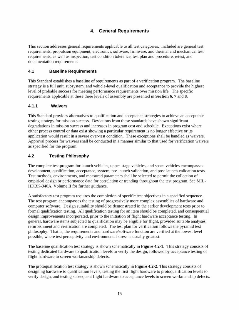
15
4. General Requirements
This section addresses general requirements applicable to all test categories. Included are general test requirements, propulsion equipment, electronics, software, firmware, and thermal and mechanical test requirements, as well as inspection, test condition tolerance, test plan and procedure, retest, and documentation requirements.
4.1 Baseline Requirements
This Standard establishes a baseline of requirements as part of a verification program. The baseline strategy is a full unit, subsystem, and vehicle-level qualification and acceptance to provide the highest level of probable success for meeting performance requirements over mission life. The specific requirements applicable at these three levels of assembly are presented in Section 6, 7 and 8.
4.1.1 Waivers
This Standard provides alternatives to qualification and acceptance strategies to achieve an acceptable testing strategy for mission success. Deviations from these standards have shown significant degradations in mission success and increases in program cost and schedule. Exceptions exist where either process control or data exist showing a particular requirement is no longer effective or its application would result in a severe over-test condition. These exceptions shall be handled as waivers. Approval process for waivers shall be conducted in a manner similar to that used for verification waivers as specified for the program.
4.2 Testing Philosophy
The complete test program for launch vehicles, upper-stage vehicles, and space vehicles encompasses development, qualification, acceptance, system, pre-launch validation, and post-launch validation tests. Test methods, environments, and measured parameters shall be selected to permit the collection of empirical design or performance data for correlation or trending throughout the test program. See MIL-HDBK-340A, Volume II for further guidance.
A satisfactory test program requires the completion of specific test objectives in a specified sequence. The test program encompasses the testing of progressively more complex assemblies of hardware and computer software. Design suitability should be demonstrated in the earlier development tests prior to formal qualification testing. All qualification testing for an item should be completed, and consequential design improvements incorporated, prior to the initiation of flight hardware acceptance testing. In general, hardware items subjected to qualification may be eligible for flight, provided suitable analyses, refurbishment and verification are completed. The test plan for verification follows the pyramid test philosophy. That is, the requirements and hardware/software function are verified at the lowest level possible, where test perceptivity and environmental stress is usually greatest.
The baseline qualification test strategy is shown schematically in Figure 4.2-1. This strategy consists of testing dedicated hardware to qualification levels to verify the design, followed by acceptance testing of flight hardware to screen workmanship defects.
The protoqualification test strategy is shown schematically in Figure 4.2-2. This strategy consists of designing hardware to qualification levels, testing the first flight hardware to protoqualification levels to verify design, and testing subsequent flight hardware to acceptance levels to screen workmanship defects.
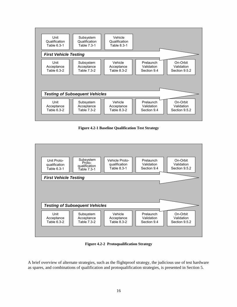
16
Unit Qualification Table 6.3-1
Subsystem Qualification Table 7.3-1
Vehicle QualificationTable 8.3-1
Unit Acceptance Table 6.3-2
Subsystem Acceptance Table 7.3-2
Vehicle Acceptance Table 8.3-2
Prelaunch Validation
Section 9.4
On-Orbit Validation
Section 9.5.2
First Vehicle Testing
Unit Acceptance Table 6.3-2
Subsystem Acceptance Table 7.3-2
Vehicle Acceptance Table 8.3-2
Prelaunch Validation
Section 9.4
On-Orbit Validation
Section 9.5.2
Testing of Subsequent Vehicles
Figure 4.2-1 Baseline Qualification Test Strategy
Unit Proto- qualification Table 6.3-1
Subsystem Proto-
qualification Table 7.3-1
Vehicle Proto-qualification Table 8.3-1
Prelaunch Validation
Section 9.4
On-Orbit Validation
Section 9.5.2
First Vehicle Testing
Unit Acceptance Table 6.3-2
Subsystem Acceptance Table 7.3-2
Vehicle Acceptance Table 8.3-2
Prelaunch Validation
Section 9.4
On-Orbit Validation
Section 9.5.2
Testing of Subsequent Vehicles
Figure 4.2-2 Protoqualification Strategy
A brief overview of alternate strategies, such as the flightproof strategy, the judicious use of test hardware as spares, and combinations of qualification and protoqualification strategies, is presented in Section 5.
17
The environmental tests specified are intended to be imposed sequentially, rather than in combination. Nevertheless, features of the hardware design or of the service environments may warrant the imposition of combined environments in some tests. Examples include combined temperature, acceleration, and vibration when testing units employing elastomeric isolators in their design; and combined shock, vibration, and pressure when testing pressurized components. In formulating the test requirements in these situations, a logical combination of environmental factors should be imposed to enhance perceptiveness and effectiveness.
4.2.1 Development Tests
Development tests, or engineering tests, shall be conducted as required to:
a. Validate new design concepts or the application of proven concepts and techniques to a new configuration.
b. Assist in the evolution of designs from the conceptual phase to the operational phase.
c. Validate design changes.
d. Reduce the risk involved in committing designs to the fabrication of qualification and flight hardware.
e. Develop and validate qualification and acceptance test procedures.
f. Investigate problems or concerns that arise after successful qualification.
Requirements for development testing therefore depend upon the maturity of the subsystems and units used and upon the operational requirements of the specific program. An objective of development testing is to identify problems early in their design evolution so that any required corrective actions can be taken prior to starting formal qualification testing. Development tests should be used to confirm structural and performance margins, manufacturability, testability, maintainability, reliability, life expectancy, and compatibility with system safety. Where practical, development tests should be conducted over a range of operating conditions that exceeds the design limits to identify marginal capabilities and marginal design features. Comprehensive development testing is an especially important ingredient to mission success in programs that plan to use qualification items for flight, including those that allow a reduction in the qualification test levels and durations. Development tests may be conducted on breadboard equipment, prototype hardware, or the development test vehicle equipment.
Development tests may be conducted at in-plant test facilities, which may include subcontractor’s facilities, at a government-approved test bed, or at any other appropriate test facility. However, when performed at a government facility, that facility may require approval of the test plans and procedures. Internal contractor documentation of development test plans, test procedures, and test results are normally used unless stated otherwise by contract.
The development test requirements are necessarily unique to each new launch vehicle, upper-stage vehicle, and space vehicle. Guidelines for conducting appropriate development tests are given in the unit, subsystem, and vehicle test sections.
18
4.2.2 Qualification Tests
Qualification tests shall be conducted to demonstrate that the design, manufacturing process, and acceptance program produce hardware/software that meet specification requirements with adequate margin to accommodate multiple rework and test cycles. In addition, the qualification tests shall validate the planned acceptance program, including test techniques, procedures, equipment, instrumentation, and software. The qualification test baseline can be tailored for each program, if the result is a proven equivalent to that specified herein. Each type of flight item that is to be acceptance tested shall undergo a corresponding qualification test.
A full qualification ensures that subsequent hardware production units will remain flight worthy after surviving multiple acceptance tests that may be necessary because of next assembly failures and/or overstress that may precipitate rework. In general, a single qualification test specimen of a given design shall be exposed to all applicable environmental tests. The use of multiple qualification test specimens may be required for one-time-use devices (such as explosive ordnance or solid-propellant rocket motors). Aside from such cases, multiple qualification specimens of a given design may be used to enhance confidence in the qualification process, but are not required by this Standard. Alternate strategies, when program constraints require qualification hardware to be flown, are discussed in Section 5.
4.2.3 Protoqualification Tests
In systems where it is desirable to use test units, subsystems, or systems for flight, a protoqualification strategy may be considered. Protoqualification testing applies reduced amplitude and duration margins to flight hardware. This testing strategy presumes a higher level of risk, unless mitigated by other testing and analyses. In addition, it also presents reduced retest opportunities in the event of hardware failure, and the potential for late discovery of design defects.
The protoqualification described in this section may be used at the vehicle, subsystem, and unit levels. The normal acceptance shall be conducted on all follow-on flight items. The use of protoqualification for units, subsystems, and/or systems requires technical justification demonstrating that the strategy will meet program requirements while maintaining probability of mission success. Alternate strategies are discussed in Section 5.
4.2.4 Acceptance Tests
Acceptance tests shall be conducted as required to demonstrate the acceptability of each deliverable item to meet performance specification and demonstrate error-free workmanship in manufacturing. Acceptance testing is intended to stress screen items to precipitate incipient failures due to latent defects in parts, processes, materials, and workmanship. The acceptance test baseline can be tailored for each program, if the result is equivalent to that specified herein. If the equipment is to be used by more than one program or in different vehicle locations, the acceptance test conditions should envelop a composite of the worst-case applications. The test baseline can be tailored for each program, considering both the required and other directed tests (i.e., mass properties testing, etc.) not covered in this Standard. For special items, such as some tape recorders and certain batteries, the specified acceptance test environments could result in physical deterioration of materials or other damage. In those cases, less severe acceptance test environments that still satisfy the system operational requirements shall be used.
19
4.3 Testing Approach
4.3.1 Development
Development tests (4.2.1) on representative unit, subsystem, or vehicle hardware may be performed to evaluate design feasibility or performance acceptability or to obtain engineering data. The development test plan, when formulated to obtain desired objectives, may use hardware such as breadboards, engineering models, or development models.
4.3.1.1 Part, Material, and Process Development Tests and Evaluations
Part, material, and process development tests and evaluations are conducted to demonstrate the feasibility of using certain items or processes in the implementation of a design. Development tests, evaluations and subsequent qualifications are required for new types of parts, materials, and processes. TOR-2004(3909)-3315 Rev. A and TOR-2004(3909)-3316 Rev. A shall be used as a source of requirements for this process.
4.3.2 Qualification
4.3.2.1 Qualification Hardware
The hardware subjected to qualification testing shall be produced from the same drawings, using the same materials, tooling, manufacturing process, and level of personnel competency as used for flight hardware.
A single qualification test specimen of a given design shall be exposed to all applicable environmental tests. The use of multiple qualification test specimens may be required for one-time-use devices (such as explosive ordnance or solid-propellant rocket motors).
A vehicle or subsystem qualification test article shall be fabricated using qualification units to the maximum extent practical. Modifications are permitted, if required to accommodate benign changes that may be necessary to conduct the test. These changes include adding instrumentation to record functional parameters, test control limits, or design parameters for engineering evaluation. When structural items are rebuilt or reinforced to meet specific strength or rigidity requirements, all modifications shall be structurally identical to the changes incorporated in flight articles.
The testing allowed prior to the start of qualification testing of an item is:
a. the wear-in or run-in necessary to achieve a smooth, consistent, and controlled operation of MMAs
b. in-process workmanship screening
c. burn-in of certain electrical/electronic assemblies to screen out latent defects
Acceptance testing of qualification hardware may be conducted to verify successful performance at acceptance levels before proceeding to higher levels for formal qualification testing in that environment. For those environments that are applied by axis, both the acceptance and qualification tests may be completed in one axis before switching to another.
20
4.3.2.2 Qualification Test Levels and Durations
The qualification test level for an environment shall add a specified margin to the maximum predicted flight environment (MPE). Qualification test durations or repetitions demonstrate life remaining for flight after a maximum time or repetitions of acceptance testing at all levels of assembly in support of rework or retest of flight hardware. Qualification testing should not create conditions that exceed applicable safety margins or cause unrealistic modes of failure. If the hardware is to be used by more than one program or in different applications within the same program, the qualification test conditions should envelop the worst-case application. Required qualification margins and durations are summarized in the following chapters for unit, subsystem, and system testing.
4.3.2.3 Qualification Retest
Qualification retests occur when the design has changed the form, fit, or function of the hardware or when the hardware service environment has reduced or eliminated demonstrated qualification margins. Qualification tests shall be repeated in the impacted environments. Re-qualification testing shall include specification performance testing and validate all related interfaces.
Retesting may also be necessary if a test discrepancy or test item failure occurs while performing any of the required testing steps. After performing a failure analysis, which identifies, isolates and corrects the root cause of the failure, a retest in the failed environment shall be performed. When previous tests have been invalidated by the failure, those tests shall be repeated.
The minimum retesting for units and Multi-Unit Modules (MUM) shall consist of 3 axes of random vibration and 3 thermal cycles or thermal vacuum cycles. The random vibration retest shall be conducted at qualification levels for one minute per axis and the unit or MUM shall be powered on and monitored. The choice of thermal cycling of thermal vacuum testing shall be consistent with the thermal testing performed for the baseline qualification of the unit. The thermal cycles shall be conducted at qualification test temperatures and include specification performance at the hot and cold temperature extremes during the first and the last cycle. More extensive rework requires retesting that repeats the entire acceptance and qualification test sequence. See Section 4.3.4.3 “Acceptance Retest” for testing the reworked qualification test item to verify workmanship before retesting to qualification levels.
4.3.3 Protoqualification
A protoqualification strategy designs the hardware to qualification-level environments and tests to reduced qualification levels. Development models for critical units are built and tested to demonstrate design feasibility and performance, and provide risk reduction. Subsequent to protoqualification testing, a baseline acceptance program shall be conducted on all flight items.
As indicated in Section 4.2.3, the protoqualification strategy is intended in cases where test hardware will be used as flight hardware. This strategy introduces a higher level of risk into a program since it does not establish service life for the first flight hardware, unless mitigated by conservative design practices and other testing. Limited life is established for subsequent flight hardware.
4.3.3.1 Protoqualification Hardware
The hardware subjected to protoqualification testing shall be produced from the same drawings, using the same materials, tooling, manufacturing process, and level of personnel competency as used for flight hardware.
21
A single protoqualification test specimen of a given design shall be exposed to all applicable environmental tests. When practical, the protoqualification test specimen shall be selected randomly from a group of production items. The use of multiple protoqualification test specimens is required for one-time-use devices (such as explosive ordnance or solid-propellant rocket motors).
A vehicle or subsystem protoqualification test article shall be fabricated using protoqualification units to the maximum extent practical. Modifications are permitted, if required to accommodate benign changes that may be necessary to conduct the test. These changes include adding instrumentation to record functional parameters, test control limits, or design parameters for engineering evaluation. The only testing allowed prior to the start of protoqualification testing of an item is:
a. the wear-in or run-in necessary to achieve a smooth, consistent, and controlled operation of MMAs
b. in-process workmanship screening
c. burn-in of certain electrical/electronic assemblies to screen out latent defects
4.3.3.2 Protoqualification Test Levels and Durations
The protoqualification test level for an environment shall include margin and duration reduced from that for qualification, over the maximum-expected flight environment (MPE). The protoqualification test demonstrates that subsequent hardware has life remaining for flight after acceptance testing at all levels of assembly, but demonstrates little or no margin for retest (see Section 10.2.2). Protoqualification testing should not create conditions that exceed applicable safety margins or cause unrealistic modes of failure. If the equipment is to be used by more than one program or in different applications within the same program, the test conditions should envelop the worst-case application. Required margins and durations are summarized in the following chapters for unit, subsystem, and system testing.
4.3.3.3 Protoqualification Retest
Protoqualification retesting is required when the design has changed the form, fit, or function of the hardware or when predicted environments have increased. Protoqualification retesting shall be performed at protoqualification levels and durations. Protoqualification retesting shall include specification performance testing and validation of all related interfaces.
Retesting may also be necessary if a test discrepancy or test item failure occurs while performing any of the required testing steps. After performing a failure analysis, which identifies, isolates and corrects the root cause of the failure, a retest in the failed environment shall be performed. When previous tests have been invalidated by the failure, those tests shall be repeated.
The minimum retesting for units and MUM shall consist of 3 axes of random vibration and 3 thermal cycles or thermal vacuum cycles. The random vibration retest shall be conducted at protoqualification levels for one minute per axis and the unit shall be powered on and monitored. The choice of thermal cycling or thermal vacuum testing shall be consistent with the thermal testing performed for the baseline protoqualification of the unit. The thermal test shall be conducted at protoqualification test temperatures and include specification performance at the hot and cold temperature extremes during the first and the last cycle. More extensive rework requires retesting that repeats the entire protoqualification test sequence. See Section 4.3.4.3 for workmanship screening to be performed prior to retesting to protoqualification levels. Adequate life for retesting and flight must be established.
22
4.3.4 Acceptance
4.3.4.1 Acceptance Hardware
The item subjected to acceptance testing shall be flight hardware, including software as applicable.
4.3.4.2 Acceptance Test Levels and Durations
To demonstrate workmanship, the acceptance environmental conditions shall stress the hardware to the maximum conditions expected for all flight events, including transportation and handling. Required margins on flight and acceptance test levels and durations are summarized in the following chapters for unit, subsystem, and system testing.
4.3.4.3 Acceptance Retest
Retesting shall be necessary if a test discrepancy or test item failure occurs while performing any of the required testing steps. After performing a failure analysis, which identifies, isolates and corrects the root cause of the failure, a retest in the failed environment shall be performed. When previous tests have been invalidated by the failure, those tests shall be repeated.
To verify workmanship after rework, the minimum retesting for units and MUM shall consist of 3 axes of random vibration and 3 thermal cycles or thermal vacuum cycles. The random vibration retest shall be conducted at acceptance levels for one minute per axis and the unit shall be powered on and monitored. The choice of thermal cycling of thermal vacuum testing shall be consistent with the thermal testing performed for the baseline acceptance of the unit. The thermal cycles shall be conducted at acceptance test temperatures and include specification performance at the hot and cold temperature extremes during the first and the last cycle. More extensive rework requires retesting that repeats the entire acceptance test sequence.
4.4 Special Considerations
4.4.1 Propulsion Equipment Tests
Units that make up a vehicle propulsion subsystem, including units that are integral to or mounted on a motor or engine are covered by this Standard in that they shall be qualified and acceptance tested to the applicable unit requirements specified herein. Testing of a unit on an engine during the engine acceptance test firing may be substituted for part of the unit level acceptance test if it can be established that the environments and duration meet the intent of the individual acceptance test criteria, or if such units are not amenable to testing individually. Environmental testing of thrusters (such as staging rockets, retro-motors, and attitude control thrusters) shall meet the applicable unit requirements of this Standard.
4.4.1.1 Engine Line Replaceable Unit (LRU) Acceptance Testing
An engine LRU is a unit that may be removed and replaced by a new unit, without requiring re-acceptance test firing of the engine with the new unit. If the unit being replaced was included in an engine acceptance test firing as part of its acceptance test, then the replacement unit either shall be subjected to such a test on an engine, or shall undergo equivalent unit-level acceptance testing. Equivalent testing shall consider all appropriate environments such as temperature, vibration, pressure, vacuum, and chemical. Testing shall demonstrate functionality and performance of the unit under conditions similar to those achieved in the engine acceptance test firing and flight.
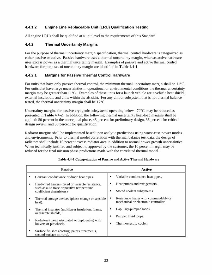
23
4.4.1.2 Engine Line Replaceable Unit (LRU) Qualification Testing
All engine LRUs shall be qualified at a unit level to the requirements of this Standard.
4.4.2 Thermal Uncertainty Margins
For the purpose of thermal uncertainty margin specification, thermal control hardware is categorized as either passive or active. Passive hardware uses a thermal uncertainty margin, whereas active hardware uses excess power as a thermal uncertainty margin. Examples of passive and active thermal control hardware for purposes of uncertainty margin are identified in Table 4.4-1.
4.4.2.1 Margins for Passive Thermal Control Hardware
For units that have only passive thermal control, the minimum thermal uncertainty margin shall be 11°C. For units that have large uncertainties in operational or environmental conditions the thermal uncertainty margin may be greater than 11°C. Examples of these units for a launch vehicle are a vehicle heat shield, external insulation, and units within the aft skirt. For any unit or subsystem that is not thermal balance tested, the thermal uncertainty margin shall be 17°C.
Uncertainty margins for passive cryogenic subsystems operating below –70°C, may be reduced as presented in Table 4.4-2. In addition, the following thermal uncertainty heat-load margins shall be applied: 50 percent in the conceptual phase, 45 percent for preliminary design, 35 percent for critical design review, and 30 percent for qualification.
Radiator margins shall be implemented based upon analytic predictions using worst-case power modes and environments. Prior to thermal model correlation with thermal balance test data, the design of radiators shall include 10 percent excess radiator area in addition to normal power growth uncertainties. When technically justified and subject to approval by the customer, the 10 percent margin may be reduced for the final mission phase predictions made with the correlated thermal model.
Table 4.4-1 Categorization of Passive and Active Thermal Hardware
Passive Active
Constant conductance or diode heat pipes.
Hardwired heaters (fixed or variable resistance, such as auto trace or positive temperature coefficient thermistors).
Thermal storage devices (phase-change or sensible heat).
Thermal insulator (multilayer insulation, foams, or discrete shields).
Radiators (fixed articulated or deployable) with louvers or pinwheels.
Surface finishes (coating, paints, treatments, second-surface mirrors).
Variable conductance heat pipes.
Heat pumps and refrigerators.
Stored coolant subsystems.
Resistance heater with commandable or mechanical or electronic controller.
Capillary-pumped loops.
Pumped fluid loops.
Thermoelectric cooler.
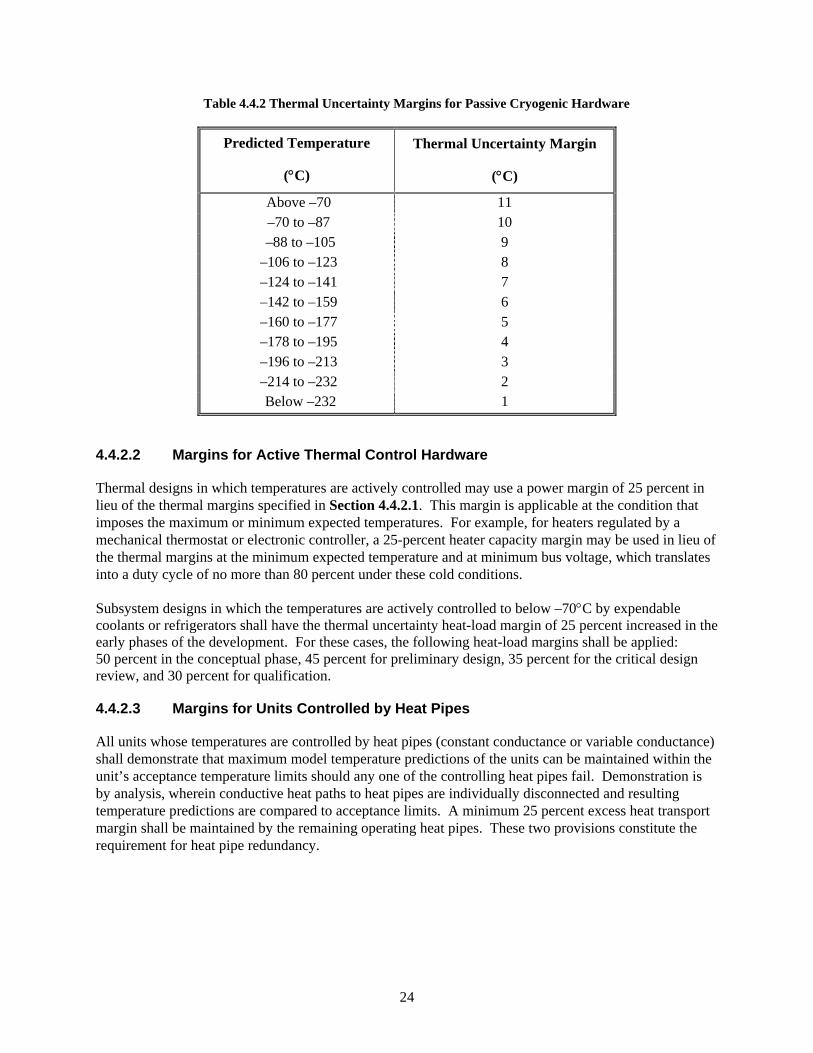
24
Table 4.4.2 Thermal Uncertainty Margins for Passive Cryogenic Hardware
Predicted Temperature
(°C)
Thermal Uncertainty Margin
(°C)
Above –70 11 –70 to –87 10 –88 to –105 9 –106 to –123 8 –124 to –141 7 –142 to –159 6 –160 to –177 5 –178 to –195 4 –196 to –213 3 –214 to –232 2 Below –232 1
4.4.2.2 Margins for Active Thermal Control Hardware
Thermal designs in which temperatures are actively controlled may use a power margin of 25 percent in lieu of the thermal margins specified in Section 4.4.2.1. This margin is applicable at the condition that imposes the maximum or minimum expected temperatures. For example, for heaters regulated by a mechanical thermostat or electronic controller, a 25-percent heater capacity margin may be used in lieu of the thermal margins at the minimum expected temperature and at minimum bus voltage, which translates into a duty cycle of no more than 80 percent under these cold conditions.
Subsystem designs in which the temperatures are actively controlled to below –70°C by expendable coolants or refrigerators shall have the thermal uncertainty heat-load margin of 25 percent increased in the early phases of the development. For these cases, the following heat-load margins shall be applied: 50 percent in the conceptual phase, 45 percent for preliminary design, 35 percent for the critical design review, and 30 percent for qualification.
4.4.2.3 Margins for Units Controlled by Heat Pipes
All units whose temperatures are controlled by heat pipes (constant conductance or variable conductance) shall demonstrate that maximum model temperature predictions of the units can be maintained within the unit’s acceptance temperature limits should any one of the controlling heat pipes fail. Demonstration is by analysis, wherein conductive heat paths to heat pipes are individually disconnected and resulting temperature predictions are compared to acceptance limits. A minimum 25 percent excess heat transport margin shall be maintained by the remaining operating heat pipes. These two provisions constitute the requirement for heat pipe redundancy.
25
4.5 Software and Firmware Tests
4.5.1 Software Development Tests
Software development testing verifies that the software performs as designed. Software development testing shall include software unit testing, software unit integration testing, and software/hardware integration testing.
Software unit testing shall be performed in accordance with TOR-2004(3909)-3537, paragraph 5.7 and its subparagraphs.
Software unit integration testing shall be performed in accordance with TOR-2004(3909)-3537, paragraph 5.8 and its subparagraphs. Software/hardware integration testing shall be performed in accordance with TOR-2004(3909)-3537, paragraph 5.10 and its subparagraphs.
4.5.2 Software Qualification Tests
Software qualification testing verifies that the software meets its specified requirements. Software qualification testing shall be performed in accordance with TOR-2004(3909)-3537, paragraph 5.9 and its paragraphs.
4.5.3 Testing of Commercial Off-the-Shelf (COTS) and Reuse Software
Testing of COTS and reuse software (modified and unmodified) shall be performed in accordance with TOR-2004(3909)-3537, paragraphs, 5.7.2, 5.8.1, 5.9.3, and 5.10.1.
4.5.4 Software Regression Testing
Regression testing of affected software unit test cases, software unit integration test cases, software/hardware integration test cases, and software qualification test cases shall be performed after any modification to previously tested software. Regression testing of appropriate software unit integration, software/hardware integration and/or software qualification test cases shall be performed after the initial loading of the operational flight constants and also after loading any changes to the operational flight constants.
4.5.5 Other Software-Related Testing
Software shall be included along with hardware in all types of testing specified by this standard where the software is needed in order to verify the functionality and performance of the hardware itself or of the integrated hardware/software unit, subsystem, or system.
4.6 Inspections
All units and higher levels of assembly shall be inspected to identify discrepancies before and after testing. The inspections of flight hardware shall not entail the removal of unit covers nor any disassembly, unless specifically called out in the test procedures. Included should be applicable checks of finish, identification markings, and cleanliness. Weight, dimensions, clearances, fastener tightness torques, and breakaway forces and torques will be measured, as applicable, to determine compliance with specifications.
Upon completion of environmental test program, tested hardware shall be inspected as follows:
26
4.6.1 Post Qualification Test Inspections
Inspection of unit/subsystem hardware following completion of qualification shall entail disassembly to the extent that wear and/or mechanical integrity can be confirmed (for example fractures in circuit boards are not present, heavy component staking is in place, there are no broken brackets, wedge locks and internal connectors are secure, etc.). Moving mechanical assemblies that undergo life test can be subjected to an abbreviated inspection sufficient to confirm viability to continue on to the life test followed by a complete disassembly inspection at the conclusion of life testing.
4.6.2 Post Test Flight Hardware Inspection (Including Launch Site)
Flight hardware shall be inspected following environmental testing. Inspection should include applicable checks of finish, identification markings, and cleanliness. Weight, dimensions, clearances, fastener tightness torques, and breakaway forces and torques will be measured, as applicable, to determine compliance with specifications. Inspection of flight hardware shall not entail the removal of unit covers nor any specific disassembly unless called out in the test procedures.
4.7 Test Condition Tolerances
Unless stated otherwise, the specified test parameters shall include the maximum allowable test tolerances listed in Table 4.7-1. For conditions outside the ranges specified, the tolerances shall be appropriate for the purpose of the test.
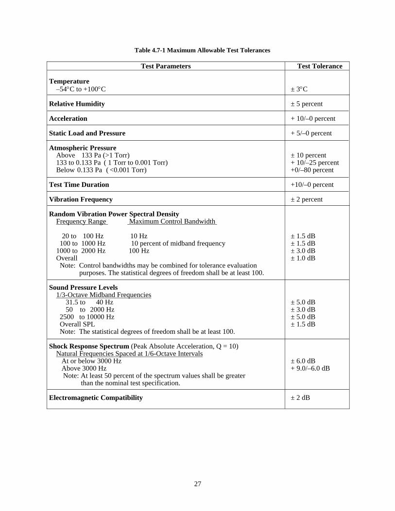
27
Table 4.7-1 Maximum Allowable Test Tolerances
Test Parameters Test Tolerance Temperature –54°C to +100°C Relative Humidity Acceleration Static Load and Pressure Atmospheric Pressure Above 133 Pa (>1 Torr) 133 to 0.133 Pa ( 1 Torr to 0.001 Torr) Below 0.133 Pa ( <0.001 Torr) Test Time Duration Vibration Frequency Random Vibration Power Spectral Density Frequency Range Maximum Control Bandwidth 20 to 100 Hz 10 Hz 100 to 1000 Hz 10 percent of midband frequency 1000 to 2000 Hz 100 Hz Overall Note: Control bandwidths may be combined for tolerance evaluation purposes. The statistical degrees of freedom shall be at least 100. Sound Pressure Levels 1/3-Octave Midband Frequencies 31.5 to 40 Hz 50 to 2000 Hz 2500 to 10000 Hz Overall SPL Note: The statistical degrees of freedom shall be at least 100. Shock Response Spectrum (Peak Absolute Acceleration, Q = 10) Natural Frequencies Spaced at 1/6-Octave Intervals At or below 3000 Hz Above 3000 Hz
Note: At least 50 percent of the spectrum values shall be greater than the nominal test specification.
Electromagnetic Compatibility
± 3°C ± 5 percent + 10/–0 percent + 5/–0 percent ± 10 percent + 10/–25 percent +0/–80 percent +10/–0 percent ± 2 percent ± 1.5 dB ± 1.5 dB ± 3.0 dB ± 1.0 dB ± 5.0 dB ± 3.0 dB ± 5.0 dB ± 1.5 dB ± 6.0 dB + 9.0/–6.0 dB ± 2 dB
28
4.8 Test Plans and Procedures
The test plans and procedures shall be documented in sufficient detail to provide the framework for identifying and interrelating all of the individual tests and test procedures needed.
4.8.1 Test Plans
The test plans shall provide a general description of each test planned and the conditions of the tests. The test plans shall be based upon a function-by-function mission analysis and any specified testing requirements. To the degree practical, tests shall be planned and executed to fulfill test objectives from development through operations. Test objectives shall be planned to verify compliance with the design and specified requirements of the items involved, including interfaces.
Test plans shall include an allowable experimental uncertainty requirement for each measured parameter. Each allowable uncertainty statement shall include a positive and negative uncertainty. Such experimental uncertainty requirements shall support the objectives of the test.
As a minimum, the test plan shall address the following:
a. The allocation of requirements to appropriate testable levels of assembly. Usually this is a reference to a requirements traceability matrix listing all design requirements and indicating a cross-reference to a verification method and to the applicable assembly level.
b. The identification of separate environmental test zones (such as the engine, fairing, or payload).
c. The identification of separate states or modes where the configuration or environmental levels may be different (such as during testing, launch, upper stage transfer, on-orbit, eclipse, or re-entry).
d. The environmental specifications or life-cycle environmental profiles for each of the environmental test zones.
e. The overall test philosophy, testing strategy, and test objective for each item, including any special tailoring or interpretation of design and testing requirements.
f. Required special test equipment, facilities, interfaces, and downtime requirements.
g. Required test tools, test beds, and specialty items necessary to support testing.
h. Standards to be used for the recording of test data on computer compatible electronic media, such as disks or magnetic tape, to facilitate automated accumulation and sorting of data.
i. Include procedures to guard against damage to test article during transportation handling and testing.
j. The collection of parameters and development of a database during testing of units, subsystems, and at the vehicle level to be used for development of software.
4.8.2 Test Procedures
Tests shall be conducted using documented test procedures prepared for performing all of the required tests in accordance with the test objectives in the approved test plans. The test objectives, testing criteria,
29
and pass/fail criteria shall be stated clearly in the test procedures. The test procedures shall cover all operations in enough detail so that there is no doubt as to the execution of any step. Test objectives and criteria shall be stated to relate to design or operations specifications. Where appropriate, minimum/maximum requirements for valid data and pass/fail criteria shall be provided at the procedure step level. Traceability shall be provided from the specifications or requirements to the test procedures. Where practical, the individual procedure step that satisfies the requirement shall be identified. The test procedure for each item shall include, as a minimum, descriptions of the following:
a. Criteria, objectives, assumptions, and constraints
b. Test setup
c. Initialization requirements
d. Input data
e. Test instrumentation
f. Expected intermediate test results
g. Requirements for recording output data
h. Expected output data
i. Minimum/maximum requirements for valid data to consider the test successful
j. Pass/fail criteria for evaluating results, including uncertainty constraints
k. Safety considerations and hazardous conditions
4.9 Documentation
4.9.1 Test Documentation Files
The test plans and procedures including a list of test equipment, calibration dates and accuracy, computer software, test data, test log, test results and conclusions, test discrepancies or deficiencies, operating time/cycles, pertinent analyses, and resolutions shall be documented and maintained. The applicable contractors shall maintain the test documentation file for the duration of their contracts.
4.9.2 General Test Data
Pertinent test data shall be maintained in a quantitative form to permit the evaluation of performance under the various specified test conditions.
4.9.3 Qualification, Protoqualification, and Acceptance
For qualification, protoqualification, and acceptance tests, a summary of the test results shall be documented in test reports. The test report shall state the degree of success in meeting the test objectives and shall document and summarize the test results, deficiencies, problems encountered, and problem resolutions. The responsible contractor design engineer shall certify the accuracy of the results.
30
4.9.4 Test Log
Formal test conduct shall be documented in a test log. The test log shall identify the personnel involved and be time-tagged to permit a reconstruction of test events such as start time, stop time, anomalies, and any periods of interruption.
4.9.5 Test Discrepancy
Anomalies, discrepancies, and failures occurring during test activities shall be documented and dispositioned as specified in the contractor’s quality control plan.
4.10 Exceptions to General Criteria
4.10.1 Qualification and Protoqualification by Similarity
Items shall be deemed qualified by similarity if analyses show that a similar unit has been designed and tested to the same or greater environmental and life performance requirements as specified herein. Typical criteria for qualification by similarity are provided in MIL-HDBK-340A, Volume II. Relevant documentation must prove that the similarity and testing equivalency requirements of the procuring agency have been satisfied.
4.10.2 Unit Thermal Vacuum Test Exemptions
Requirements for unit testing are provided in Tables 6.3-1 and 6.3-2. For electronic units, there may be instances where unit-level acceptance thermal vacuum testing is unnecessary if it can be shown that the design is insensitive to the vacuum environment. A criterion delineating the conditions under which vacuum testing may be exempted needs to be defined early in the program to allow for test planning and risk mitigation activities. As a minimum, the criteria used in assessing vacuum-sensitivity in electronic units should include consideration for confidence gained from identical flight units, the vacuum-sensitive nature of any high-voltage or RF units, susceptibility for arcing, thermal control features that need to be verified in vacuum, deflection of any sealed devices, and electrical or thermal performance issues that may be different under vacuum conditions. For example:
a. Units that have no flight heritage or do not have a qualification unit thermal vacuum test associated with their design shall be tested in a vacuum environment.
b. Units that are inherently vacuum and/or temperature-sensitive, such as RF equipment, shall be tested in a vacuum environment.
c. Units susceptible to corona or multipaction, such as high voltage units, shall be tested in a vacuum environment.
d. Devices that are temperature controlled to within a range of 3°C or less to maintain performance shall be tested in a vacuum environment.
e. If a hermetically sealed device can physically deflect under worst-case conditions such that the clearance between the device wall and a nearby item could cause an electrical short (e.g., a clearance of 2.5 mm or less), the unit shall be tested in a vacuum environment.
f. Units whose electrical performance may be affected by temperature differences between the ambient and vacuum thermal environments shall be tested in a vacuum environment. If the unit
31
performance in vacuum and ambient conditions has been well characterized by test data such that performance problems can be clearly detected in ambient testing, waiver of the vacuum environment may be considered.
g. If analytic thermal modeling results indicate that the presence of air causes a noticeable (greater than 10°C) thermal effect on internal temperature levels and board thermal gradients, the unit shall be tested in a vacuum environment.
h. A unit with any part case temperature prediction within 10ºC of its allowable derated temperature limit under worst-case power dissipation shall be tested in a vacuum environment.
i. Unit thermal analyses shall be performed in vacuum and ambient environments to assess vacuum-sensitivity. If the worst-case temperature difference between the two environments is greater than 10oC, thermal vacuum testing shall be performed.
If the worst-case temperature difference is between 3oC and 10oC and other criteria support ambient testing in lieu of vacuum testing, the baseplate temperature shall be increased during the ambient test to account for junction/case temperature differences between the two environments. If the worst-case temperature difference is less than 3oC, thermal cycling may be performed in lieu of thermal vacuum testing without baseplate temperature modification.
If a unit’s qualification test was performed with a baseplate temperature higher than 10oC above the acceptance baseplate test temperature, then the 10oC limit specified above may be increased to the corresponding higher baseplate temperature.

32
THIS PAGE INTENTIONALLY LEFT BLANK
33
5. Alternative Strategies
The qualification testing in Section 4.3.2 provides a demonstration that the design, manufacturing, and acceptance testing produces flight items that meet specification requirements. In a minimum-risk program, the hardware items subjected to qualification tests are not eligible for flight without careful analysis and refurbishment, since the remaining life from fatigue and wear standpoints is not demonstrated. In programs where it is necessary to demonstrate the flightworthiness of test hardware the strategies described in Section 5.1 and 5.2 as alternatives to the protoqualification strategy may be used at the system, subsystem, and unit levels. A combination of various applications of qualification and protoqualification strategies should be considered to meet the needs for particular items, as deemed necessary. As in the case for protoqualification, the higher risk of deviating from qualification may be partially mitigated by enhanced development testing and by increasing the design margins.
These strategies are particularly intended for use in space vehicle programs that have a very limited number of vehicles, typically one to three. Care should be exercised to ensure that an acceptable balance of demonstrated design margin, workmanship screening, and remaining life for flight are achieved for programs pursuing these options.
5.1 Spares Strategy
This strategy does not alter the qualification and acceptance test requirements presented in Section 4.3.2 and 4.3.4. Yet, in some cases, qualification hardware may be used for flight if the risk is minimized. Typically, the qualification test program results in a qualification test vehicle that was built using units that had been qualification tested at the unit level. After completing the qualification tests, the critical units can be removed from the vehicle and the qualification vehicle can then be refurbished, as necessary. Usually a new set of critical units would be installed that had only been acceptance tested. This refurbished qualification vehicle would then be certified for flight when it satisfactorily completed the vehicle acceptance tests. The qualification units that were removed could be refurbished and used as flight spares.
5.2 Flightproof Strategy
This strategy subjects each flight item to a flightproof test that is an enhanced acceptance test using the protoqualification level, while retaining the acceptance duration. Repeated acceptance testing may or may not be enhanced depending on the significance of hardware modifications during the acceptance program. The risk taken is that there has been no formal demonstration of remaining life for flight. This is a lesser risk than accepted for flight of a protoqualification item since the flightproof test duration is less than that for protoqualification. However, this risk is accepted in the flightproof strategy for all flight items. This risk may be traded against the additional confidence gained that each flightproof item will meet performance requirements in flight after having successfully passed testing beyond the maximum expected flight environments (MPE). Thus, flightproof testing is a check on the adequacy of the capability of each flight item, considering build variability or defects introduced due to handling or testing. Development testing should be used to gain confidence that adequate margin remains after the maximum allowed accumulation of preflight testing.
34
5.3 Combination Test Strategies
Various combinations of strategy may be considered, depending on specific program considerations and the degree of risk deemed acceptable. For example, the protoqualification strategy for units (4.3.3) may be combined with the flightproof strategy for the vehicle. In other cases, the flightproof strategy would be applied to some units peculiar to a single mission, while the protoqualification strategy may be applied to multi-mission units. In such cases, the provisions of each method would apply and the resultant risk would be increased correspondingly.
35
6. Unit Test Requirements
6.1 General Requirements
Unit tests shall normally be accomplished entirely at the unit level. However, in certain circumstances where one or more units are needed to complete a function, the required unit tests may be conducted at the next level of assembly. Tests of units such as interconnect tubing, radio-frequency circuits, and wiring harnesses are examples where at least some of the tests may be accomplished at higher levels of assembly. If moving mechanical assemblies or other units have static or dynamic fluid interfaces or are pressurized during operation, those conditions should be replicated during unit testing. Units shall meet the applicable specification requirements over the entire qualification and acceptance environmental test range.
6.2 Development Tests
6.2.1 Subassembly Development Tests, In-Process Tests, and Inspections
Subassemblies are subjected to development tests and evaluations as required to minimize design risk, to demonstrate manufacturing feasibility, and to assess the design and manufacturing alternatives and trade-offs required to best achieve the development objectives. Tests are conducted as required to develop in-process manufacturing tests, inspections, and acceptance criteria for the items. Opportunity to establish subassembly qualification should be exploited when appropriate. For example, it is often easier to demonstrate design margin and performance at lower levels of assembly, especially in cases where existing designs are integrated into a new and unique next assembly, which will then be re-qualified.
6.2.2 Unit Development Tests
Units are subjected to development tests and evaluations as may be required to minimize design risk, to demonstrate manufacturing feasibility, to establish packaging designs, to demonstrate electrical and mechanical performance, and to demonstrate the capability to withstand environmental stress including storage, transportation, extreme combined environments, and launch base operations. Development tests of deployables, thrust vector controls, and of the attitude control subsystem are normally conducted. Life tests of critical items that may have a wearout failure mode, such as moving mechanical assemblies, should also be conducted. Resonance searches of a unit should be conducted to correlate with a mathematical model and to support design margin or failure evaluations. Development tests and evaluations of vibration and shock test fixtures should be conducted prior to first use to prevent inadvertent over-testing or under-testing, including avoidance of excessive cross-axis responses. These development tests of fixtures should result in the design of shock and vibration test fixtures that can be used during unit qualification and acceptance tests. When it is not practical to use fixtures of the same design for unit qualification and acceptance tests, evaluation surveys should be performed on each fixture design to assure that the unit responses are within allowable margins.
6.2.3 Structural Composite Development Tests
Development tests should be conducted on structural components made of advanced composites or bonded materials, such as payload adapters, payload fairings, motor cases, and composite over-wrapped pressure vessels.
36
If appropriate, testing should include:
a. Static load or burst testing to validate the ultimate structural capabilities under operating conditions, including temperature when appropriate
b. Damage tolerance testing to define acceptance criteria
c. Acoustic transmission loss test for composite fairings
d. Characterization of electrical conductivity
6.2.4 Thermal Development Tests
For critical electrical and electronic units designed to operate in a vacuum environment less than 0.133 Pa (0.001 Torr), thermal mapping for known boundary conditions may be performed in the vacuum environment to verify the internal unit thermal analysis, and to provide data for thermal mathematical model correlation. Once correlated, the thermal model is used to demonstrate that critical part temperature limits, consistent with reliability requirements and performance, are not exceeded.
When electrical and electronic packaging is not accomplished in accordance with known and accepted techniques relative to the interconnect subsystem, parts mounting, board sizes and thickness, number of layers, thermal coefficients of expansion, or installation method, development tests should be performed. The tests should establish confidence in the design and manufacturing processes used.
Heat transport capacity tests may be required for constant and variable conductance heat pipes at the unit level to demonstrate compliance. Thermal conductance tests should be considered to verify conductivity across items such as vibration isolators, thermal isolators, cabling, and any other potentially significant heat conduction path.
6.2.5 Shock and Vibration Isolator Development Tests
When a unit is to be mounted on shock or vibration isolators whose performance is not well known, development testing should be conducted to verify their suitability. The isolators should be exposed to the various induced environments (for example, temperature and chemical environments) to verify retention of isolator performance (especially resonant frequencies and amplifications) and to verify that the isolators have adequate service life. The unit or a rigid simulator with proper mass properties (mass, center of gravity, mass moments of inertia) should be tested on its isolators in each of three orthogonal axes, and, if necessary, in each of three rotational axes. Responses at all corners of the unit should be determined to evaluate isolator effectiveness and, when applicable, to establish the criteria for unit acceptance testing without isolators. When multiple units are supported by a vibration-isolated panel, responses at all units should be measured to account for the contribution of panel vibration modes.
6.3 Test Program for Units
Tables 6.3-1 and 6.3-2 identify unit qualification, protoqualification and acceptance test requirements. When units fall into two or more categories, the required tests specified for each category shall be applied. For example, a star sensor may be considered to fit both “Electrical and Electronic” and “Optical” categories. A thruster with integrated valves would be considered to fit both “Thruster” and “Valve” categories. In these cases, the more stressing requirement set applies. Table 6.3-3 provides a summary of unit test level margins and durations that are discussed in this section.
37
In all tables shown in this Standard where “Evaluation Required” (ER) is noted, an engineering assessment shall be performed to develop rationale for performing or not performing a test.
Additional requirements are specified in TOR-2004(8583)-5, Rev. 1 for batteries, AIAA S-111-2005 for solar cells, and AIAA S-112-2005 for solar panels.
6.3.1 Unit Wear-In Test
6.3.1.1 Purpose
The wear-in test detects material and workmanship defects that occur early in the unit life. Testing also serves to wear-in or run-in mechanical units so they perform in a smooth, consistent, and controlled manner.
6.3.1.2 Test Description
While the unit is operating under conditions representative of operational loads, speed, and environments and while perceptive parameters are being monitored, the unit shall be operated for the specified period. For valves, thrusters, and other items where the number of cycles of operation rather than hours of operation is a better method to ensure detecting infant mortality failures, functional cycling shall be conducted at ambient temperature. For thrusters, a cycle is a hot firing that includes a start, steady-state operation, and shutdown. For hot firings of thrusters utilizing hydrazine propellants, action shall be taken to assure that the flight valves are thoroughly cleaned of all traces of hydrazine following the test firings. Devices that have extremely limited life cycles, such as positive expulsion tanks, are excluded from wear-in test requirements.
6.3.1.3 Test Levels and Duration
a. Pressure. Ambient pressure should normally be used.
b. Temperature. Ambient temperature shall be used for operations if the test objectives can be met. Otherwise, temperatures representative of the operational environment shall be used.
c. Duration. The run-in test shall consist of at least five cycles or 5 percent of the total expected service life-cycles (3.43), whichever is greater, unless the MMA demonstrated the capability to perform in a predictably consistent and controlled manner with fewer cycles.

38
THIS PAGE INTENTIONALLY LEFT BLANK
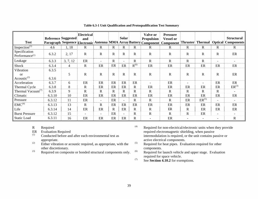
39
Table 6.3-1 Unit Qualification and Protoqualification Test Summary
Test
Reference Paragraph
Suggested Sequence
Electricaland
Electronic
Antenna
MMA
SolarArray
Battery
Valve or Propulsion Component
Pressure Vessel or
Component
Thruster
Thermal
Optical
Structural
Components Inspection(1) 4.6 1, 18 R R R R R R R R R R R Specification Performance(1)
6.3.2 2, 17 R R R R R R R R R R ER
Leakage 6.3.3 3, 7, 12 ER - R - R R R R R - - Shock 6.3.4 4 R ER ER ER R(6) ER ER ER ER ER ER Vibration or Acoustic(2)
6.3.5
6.3.6 5 R R R R R R R R R R ER
Acceleration 6.3.7 6 ER ER ER ER ER - ER - - ER ER Thermal Cycle 6.3.8 8 R ER ER ER R ER ER ER ER ER ER(3) Thermal Vacuum(7) 6.3.9 9 R R R R R R R R R R - Climatic 6.3.10 10 ER ER ER ER ER ER ER ER ER ER ER Pressure 6.3.12 11 ER - ER - R R R ER ER(5) - - EMC(4) 6.3.13 13 R R ER ER ER ER ER ER ER ER ER Life 6.3.14 14 ER ER R ER R R ER R ER ER ER Burst Pressure 6.3.12 15 - - ER - R R R R ER - - Static Load 6.3.11 16 ER ER ER ER R - ER - - - R
R Required ER Evaluation Required (1) Conducted before and after each environmental test as
appropriate. (2) Either vibration or acoustic required, as appropriate, with the
other discretionary. (3) Required on composite or bonded structural components only.
(4) Required for non-electrical/electronic units when they provide required electromagnetic shielding, when passive intermodulation is required, or the unit contains passive or active electrical components.
(5) Required for heat pipes. Evaluation required for other components.
(6) Required for launch vehicle and upper stage. Evaluation required for space vehicle.
(7) See Section 4.10.2 for exemptions.
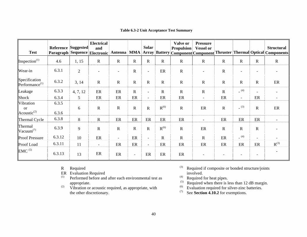
40
Table 6.3-2 Unit Acceptance Test Summary
R Required ER Evaluation Required
(1) Performed before and after each environmental test as appropriate.
(2) Vibration or acoustic required, as appropriate, with the other discretionary.
(3) Required if composite or bonded structure/joints involved.
(4) Required for heat pipes. (5) Required when there is less than 12 dB margin. (6) Evaluation required for silver-zinc batteries. (7) See Section 4.10.2 for exemptions.
Test
Reference Paragraph
Suggested Sequence
Electricaland
Electronic
Antenna
MMA
SolarArray
Battery
Valve or PropulsionComponent
Pressure Vessel or
Component
Thruster
Thermal
Optical
Structural
Components
Inspection(1) 4.6 1, 15 R R R R R R R R R R R
Wear-in 6.3.1 2 - - R - ER R - R - - -
Specification Performance(1)
6.3.2 3, 14 R R R R R R R R R R ER
Leakage 6.3.3 4, 7, 12 ER ER R - R R R R - (4) - - Shock 6.3.4 5 ER ER ER - ER ER - ER - ER - Vibration or Acoustic(2)
6.3.5
6.3.6 6 R R R R R(6) R ER R - (3) R ER
Thermal Cycle 6.3.8 8 R ER ER ER ER ER - ER ER ER - Thermal Vacuum(7)
6.3.9 9 R R R R R(6) R ER R R R -
Proof Pressure 6.3.12 10 ER - ER - R R R ER - (4) - - Proof Load 6.3.11 11 - ER ER - ER ER ER ER ER ER R(3)
EMC (5)
6.3.13 13 ER ER - ER ER ER - - - -
-
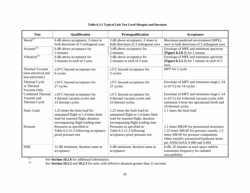
41
Table 6.3-3 Typical Unit Test Level Margins and Duration
Test Qualification Protoqualification Acceptance
Shock(1) 6 dB above acceptance, 3 times in both directions of 3 orthogonal axes
3 dB above acceptance, 2 times in both directions of 3 orthogonal axes
Maximum predicted environment (MPE), once in both directions of 3 orthogonal axes
Acoustic(2) 6 dB above acceptance for 3 minutes
3 dB above acceptance for 2 minutes
Envelope of MPE and minimum spectrum (Figure 6.3.6-1) for 1 minute
Vibration(2) 6 dB above acceptance for 3 minutes in each of 3 axes
3 dB above acceptance for 2 minutes in each of 3 axes
Envelope of MPE and minimum spectrum (Figure 6.3.5-1) for 1 minute in each of 3 axes
Thermal Vacuum (non-electrical and non-electronic)
±10°C beyond acceptance for 6 cycles
±5°C beyond acceptance for 3 cycles
MPT for 1 cycle
Thermal Cycle or Thermal Vacuum Only
±10°C beyond acceptance for 27 cycles
±5°C beyond acceptance for 27 cycles
Envelope of MPT and minimum range (–24 to 61°C) for 14 cycles
Combined Thermal Vacuum and Thermal Cycle
±10°C beyond acceptance for 4 thermal vacuum cycles and 23 thermal cycles
±5°C beyond acceptance for 4 thermal vacuum cycles and 23 thermal cycles
Envelope of MPT and minimum range (–24 to 61°C) for 4 thermal vacuum cycles with minimum 2-hour hot operational dwell and 10 thermal cycles
Static Load 1.25 times the limit load for unmanned flight or 1.4 times limit load for manned flight, duration encompassing flight loading time
1.25 times the limit load for unmanned flight or 1.4 times limit load for manned flight, duration encompassing flight loading time
1.1 times the limit load
Pressure Pressures as specified in Table 6.3.12-2 following acceptance proof pressure test
Pressures as specified in Table 6.3.12-2 following acceptance proof pressure test
1.1 times MEOP for pressurized structures; 1.25 times MEOP for pressure vessels; 1.5 times MEOP for pressure components. Other metallic pressurized hardware items per ANSI/AIAA S-080 and S-081
EMC 12 dB minimum, duration same as acceptance
6 dB minimum, duration same as acceptance
6 dB, 20 minutes at each space vehicle transmitter frequency for radiated susceptibility
(1) See Section 10.2.6 for additional information. (2) See Section 10.2.2 and 10.2.3 for units with effective duration greater than 15 seconds.
42
6.3.1.4 Supplementary Requirements
Perceptive parameters shall be monitored during the wear-in test to detect evidence of performance degradation.
6.3.2 Unit Specification Performance Test
6.3.2.1 Purpose
The specification performance test verifies that the electrical, optical, and mechanical performance of the unit meets the requirements of the unit specification.
6.3.2.2 Electrical Test Description
Electrical tests shall include application of expected voltages, impedances, frequencies, pulses, and waveforms (commands, data, clocking, polarity, etc.) at the electrical interfaces of the unit, including all redundant circuits. These parameters shall be varied throughout their specification ranges and the sequences expected in flight operation. The unit output and response shall be measured to verify that the unit performs to specification requirements. Performance shall also include electrical continuity, response time, or other tests that relate to a particular unit design. Harness specific testing as required by DOD-W-8357A.
6.3.2.3 Mechanical Test Description
Moving mechanical assemblies shall be tested in the configuration corresponding to the worst-case environments and shall be passive or operating corresponding to their state during the corresponding environmental exposure. Torque versus angle and time versus angle, or equivalent linear measurements for linear devices, shall be made. Functional tests shall include stiffness, damping, dynamic response, friction, and breakaway characteristics, where appropriate. Moving mechanical assemblies that contain redundancy in their design shall demonstrate required performance in each redundant mode of operation during the test. Testing of MMAs shall be performed in conformance to AIAA S-114-2005. For explosive actuated devices the requirements specified in AIAA S-113-2005 shall be satisfied.
6.3.2.4 Supplementary Requirements
Specification performance and monitoring tests shall be conducted before, during, and after each of the unit tests to detect anomalous equipment conditions and to assure that performance meets key specification requirements.
6.3.3 Unit Leakage Test
6.3.3.1 Purpose
The leakage test demonstrates the capability of pressurized components and hermetically sealed units to meet the specified design leakage rate requirements.
6.3.3.2 Test Description
An acceptable leak rate to meet mission requirements is based upon development tests and appropriate analyses. An acceptable measurement technique is one that accounts for leak rate variations with differential pressure and hot and cold temperatures and has the required threshold, resolution, and
43
accuracy to detect any leakage equal to or greater than the maximum acceptable leak rate. Consideration should be given to testing units at differential pressures greater or less than the maximum or minimum operating differential pressure to provide some assurance of a qualification margin for leakage. If appropriate, the leak rate test shall be made at qualification hot and cold temperatures with the representative fluid to account for geometry alterations and viscosity changes.
6.3.3.3 Test Level and Duration
The leakage tests shall be performed with the unit pressurized at the maximum differential operating pressure, as well as at the minimum differential operating pressure if the seals are dependent upon pressure for proper sealing. The test duration shall be sufficient to detect any significant leakage. This test shall be performed for qualification, protoqualification and acceptance testing.
6.3.4 Unit Shock Test
6.3.4.1 Purpose
The shock test demonstrates the capability of the unit to survive shock and meet requirements during and after exposure to a margin over the maximum predicted shock environment (MPE) in flight (10.2.1).
6.3.4.2 Test Description
The unit shall be mounted to a fixture through the normal mounting points of the unit. The same test fixture should be used in the qualification and acceptance shock tests. If shock isolators are to be used in service, they shall be installed. The selected test method shall be capable of meeting the required shock spectrum with a transient that has duration comparable to the duration of the expected shock in flight. A mounting of the unit on actual or dynamically similar structure provides a more realistic test than does a mounting on a rigid structure such as a shaker armature or slip table. Sufficient prior development of the test mechanism shall have been carried out to validate the proposed test method before testing qualification or flight hardware. The test environment shall comply with the following conditions:
a. A transient having the prescribed shock spectrum can be generated within specified tolerances.
b. The applied shock transient provides a simultaneous application of the frequency components as opposed to a serial application. Toward this end, it shall be a goal for the duration of the shock transient to approximate the duration of the service shock event. In general, the duration of the shock employed for the shock spectrum analysis shall not exceed 20 milliseconds.
A basis that allows removal of the requirement for a shock test is provided in 6.3.4.4.
6.3.4.3 Test Level and Exposure
The shock spectrum in each direction along each of the three orthogonal axes shall meet the test specification for that direction. For vibration or shock-isolated units, the lower frequency limit of the response spectrum shall be below 0.5 times the natural frequency of the isolated unit. The minimum number of shocks shall be imposed to meet the amplitude criteria in both directions of each of the three orthogonal axes as follows:
Qualification: MPE + 6 dB applied 3 times
Protoqualification: MPE + 3 dB applied 2 times
44
Acceptance: MPE for one application
6.3.4.4 Supplementary Requirements
During qualification testing the interface cable and harness shall be flight equivalent up to the first attachment point. Electrical and electronic units, including redundant circuits, shall be energized and monitored. A specification performance test shall be performed before and after all shock tests. Relays shall not transfer and shall not chatter in excess of specification limits during the shock test.
A shock qualification test is not required along any axis for which both the following are satisfied:
a. The unit does not contain any components that are particularly sensitive to shock, such as crystals and ceramic chips.
b. The shock MPE value (3.27) at all frequencies does not exceed the maximum response due to the random vibration MPE or exceed 0.8 times the frequency in Hz, whichever is larger (10.2.6).
6.3.5 Unit Vibration Test
6.3.5.1 Purpose
The vibration qualification and protoqualification tests demonstrate the ability of the unit to endure a limited duration of acceptance testing and then meet requirements during and after exposure to a margin over the maximum predicted vibration environment (MPE) in flight. The vibration test may be discretionary for a unit having a large surface causing its vibration response to be due predominantly to direct acoustic excitation. Both acoustic and vibration tests are required if necessary to demonstrate the capability to withstand vibration excitation transmitted through its attachments.
6.3.5.2 Test Description
The unit shall be mounted to a fixture through the normal mounting points of the unit. The same test fixture shall be used in the qualification and acceptance vibration tests. Attached wiring harnesses and hydraulic and pneumatic lines up to the first attachment point, instrumentation, and other connecting items shall be included as in the flight configuration. These items shall be connected using flight-like connectors. Such a configuration shall be required when units that employ shock or vibration isolators are tested on their isolators. The suitability of the fixture and test control means shall have been established (6.3.5.6) prior to the qualification testing. The unit shall be tested in each of 3 orthogonal axes.
Units mounted on shock or vibration isolators shall typically require vibration testing at qualification levels in two configurations. A first configuration is with the unit hard-mounted to qualify for the acceptance-level testing if, as is typical, the acceptance testing is performed without the isolators present. The second configuration is with the unit mounted on the isolators to qualify for the flight environment. The unit shall be mounted on isolators of the same lot as those used in service, if practical. Units mounted on isolators shall be controlled at the locations where the isolators are attached to the fixture. Hard-mounted units shall be controlled at the unit mounting attachment or attachments as appropriate.
6.3.5.3 Test Levels and Duration
The basic test levels and duration required for units exposed to the liftoff and ascent vibration, effective duration of 15 seconds (3.11), are as follows:
45
Qualification: 6 dB above acceptance for 3 minutes/axis (10.2.1, 10.2.2)
Protoqualification: 3 dB above acceptance for 2 minutes/axis (10.2.1, 10.2.2)
Acceptance: Envelope of MPE and minimum level shown in Figure 6.3.5-1 for 1 minute/axis
The qualification test demonstrates that adequate life remains for flight after up to 8 minutes of acceptance-level testing for each axis. The protoqualification test demonstrates that adequate life remains for flight after only 1 minute of acceptance-level testing for each axis (10.2.2). The acceptance test demonstrates quality of workmanship.
For units subject to exposure to flight vibration longer than 15 seconds, or to demonstrate another bound on the accumulated duration of acceptance testing, see 10.2.3 for changes to the qualification and protoqualification durations. See 10.2.4 for an alternate test strategy.
For qualification and protoqualification testing of units flown on isolators see (6.3.5.2, 10.2.4).
Low level testing in each axis shall be performed before and after the specified vibration tests to detect any structural changes.
6.3.5.4 Specification Performance
During the test, all electrical and electronic units shall be electrically energized and functionally sequenced through various operational modes to the maximum extent practical. This includes all primary and redundant circuits, and all circuits that do not operate during launch. Several perceptive parameters, such as voltage, current, relay contact, software Built In Test (BIT), etc., shall be monitored for failures or intermittent performance during the test. Continuous monitoring of the unit, including the main bus by a power transient monitoring device, shall be provided to detect intermittent failures.
6.3.5.5 Supplementary Requirements
The vibration spectrum may be limited or notched to prevent unrealistic input forces or unit responses for units whose mass exceeds 23 kilograms (50 pounds) or where analysis has shown the potential for response levels in excess of design limits. See MIL-HDBK-340A, Volume II for additional guidance. The reduction is limited to the minimum spectrum in Figure 6.3.5-1.
Units required to operate under pressure during ascent shall be pressurized to simulate flight conditions, from structural and leakage standpoints, and monitored for pressure decay. Units designed for operation during ascent, and whose maximum or minimum expected temperatures fall outside the normal temperature range, are candidates for combined vibration and temperature testing. When such testing is employed, units shall be conditioned to be as close to the worst-case flight temperature as is practical and monitored for temperature performance during vibration exposure.
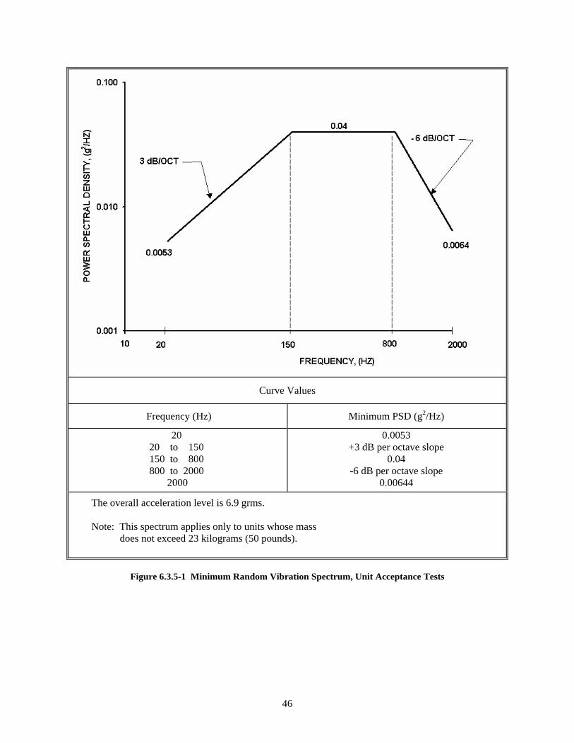
46
Curve Values
Frequency (Hz) Minimum PSD (g2/Hz)
20 20 to 150 150 to 800 800 to 2000
2000
0.0053 +3 dB per octave slope 0.04 -6 dB per octave slope 0.00644
The overall acceleration level is 6.9 grms. Note: This spectrum applies only to units whose mass does not exceed 23 kilograms (50 pounds).
Figure 6.3.5-1 Minimum Random Vibration Spectrum, Unit Acceptance Tests
47
For silver-zinc launch vehicle batteries, this test must be performed after full wet stand time and completion of non-operational thermal cycle testing in order to demonstrate compliance despite corrosion modes stimulated by long stand times or high temperature.
See 10.2.5 for discussion of a damage-based approach to the analysis of flight vibration data for determining the adequacy of established acceptance and qualification or protoqualification testing when new flight data lead to questioning the adequacy of the established MPE spectrum.
6.3.5.6 Fixture Evaluation
The vibration fixture shall be verified by test to uniformly impart motion to the unit under test and to limit the energy transfer, or crosstalk, from the test axis to the other two orthogonal axes. The crosstalk levels shall not exceed the input levels for the respective axes. The dynamic test configuration, fixture, and test article shall be evaluated for crosstalk before initial testing. The fixture shall be re-evaluated for changes in shaker or orientation of the test configuration.
6.3.5.7 Special Considerations for Structural Units
Vibration acceptance tests of structural units are normally not conducted because the process controls, inspections, and proof testing that are implemented are sufficient to assure performance and quality. However, to demonstrate structural integrity of structural units having critical fatigue-type modes of failure, with a low fatigue margin, a vibration qualification test shall be conducted. The test duration shall be four times the fatigue equivalent duration in flight at the extreme expected level. When a structural unit is not subjected to a static strength qualification test, a brief random vibration qualification test shall be conducted with an exposure to 3 dB above the maximum predicted environment. The duration shall be that necessary to achieve a steady-state response, but not less than 10 seconds, to demonstrate that ultimate strength requirements are satisfied.
6.3.6 Unit Acoustic Test
This test is applicable to units with large surface areas that are sensitive to direct acoustic excitation. 6.3.6.1 Purpose
The acoustic qualification and protoqualification tests demonstrate the ability of a unit to endure a limited duration of acceptance testing and then meet requirements during and after exposure to a margin over the maximum predicted acoustic environment (MPE) in flight. Acoustic testing is required for a unit having large surfaces, causing its vibration response to be due predominantly to direct acoustic excitation. For such units, the vibration test is discretionary except as noted in (6.3.5.1).
6.3.6.2 Test Description
The unit in its ascent configuration shall be installed in an acoustic test facility capable of generating sound fields or fluctuating surface pressures that induce unit vibration environments sufficient for unit qualification. The unit shall be mounted on a flight-type support structure or simulation thereof. Significant fluid and pressure conditions affecting structural damping shall be replicated. Appropriate dynamic instrumentation shall be installed to measure vibration and strain responses. Control microphones shall be placed at a minimum of four well-separated locations at one-half the distance from the test article to the nearest chamber wall, but no closer than 0.5 meter (20 inches) to both the test article surface and the chamber wall.
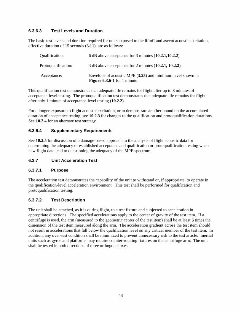
48
6.3.6.3 Test Levels and Duration
The basic test levels and duration required for units exposed to the liftoff and ascent acoustic excitation, effective duration of 15 seconds (3.11), are as follows:
Qualification: 6 dB above acceptance for 3 minutes (10.2.1,10.2.2) Protoqualification: 3 dB above acceptance for 2 minutes (10.2.1, 10.2.2)
Acceptance: Envelope of acoustic MPE (3.25) and minimum level shown in
Figure 6.3.6-1 for 1 minute
This qualification test demonstrates that adequate life remains for flight after up to 8 minutes of acceptance-level testing. The protoqualification test demonstrates that adequate life remains for flight after only 1 minute of acceptance-level testing (10.2.2).
For a longer exposure to flight acoustic excitation, or to demonstrate another bound on the accumulated duration of acceptance testing, see 10.2.3 for changes to the qualification and protoqualification durations. See 10.2.4 for an alternate test strategy.
6.3.6.4 Supplementary Requirements
See 10.2.5 for discussion of a damage-based approach to the analysis of flight acoustic data for determining the adequacy of established acceptance and qualification or protoqualification testing when new flight data lead to questioning the adequacy of the MPE spectrum.
6.3.7 Unit Acceleration Test
6.3.7.1 Purpose
The acceleration test demonstrates the capability of the unit to withstand or, if appropriate, to operate in the qualification-level acceleration environment. This test shall be performed for qualification and protoqualification testing.
6.3.7.2 Test Description
The unit shall be attached, as it is during flight, to a test fixture and subjected to acceleration in appropriate directions. The specified accelerations apply to the center of gravity of the test item. If a centrifuge is used, the arm (measured to the geometric center of the test item) shall be at least 5 times the dimension of the test item measured along the arm. The acceleration gradient across the test item should not result in accelerations that fall below the qualification level on any critical member of the test item. In addition, any over-test condition shall be minimized to prevent unnecessary risk to the test article. Inertial units such as gyros and platforms may require counter-rotating fixtures on the centrifuge arm. The unit shall be tested in both directions of three orthogonal axes.
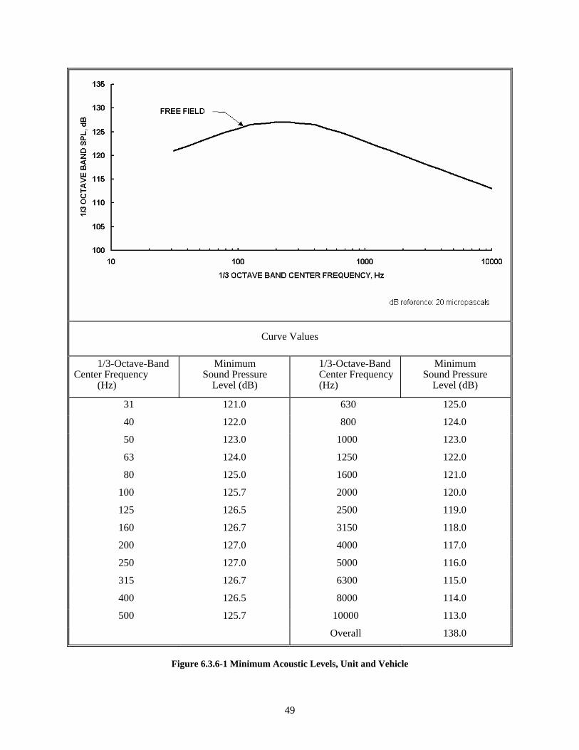
49
Curve Values
1/3-Octave-Band Center Frequency (Hz)
Minimum Sound Pressure Level (dB)
1/3-Octave-Band Center Frequency (Hz)
Minimum Sound Pressure Level (dB)
31 121.0 630 125.0
40 122.0 800 124.0
50 123.0 1000 123.0
63 124.0 1250 122.0
80 125.0 1600 121.0
100 125.7 2000 120.0
125 126.5 2500 119.0
160 126.7 3150 118.0
200 127.0 4000 117.0
250 127.0 5000 116.0
315 126.7 6300 115.0
400 126.5 8000 114.0
500 125.7 10000 113.0
Overall 138.0
Figure 6.3.6-1 Minimum Acoustic Levels, Unit and Vehicle
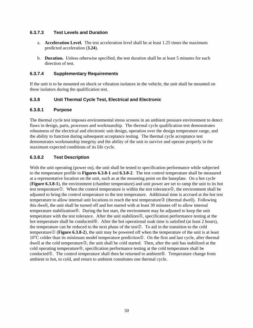
50
6.3.7.3 Test Levels and Duration
a. Acceleration Level. The test acceleration level shall be at least 1.25 times the maximum predicted acceleration (3.24).
b. Duration. Unless otherwise specified, the test duration shall be at least 5 minutes for each direction of test.
6.3.7.4 Supplementary Requirements
If the unit is to be mounted on shock or vibration isolators in the vehicle, the unit shall be mounted on these isolators during the qualification test.
6.3.8 Unit Thermal Cycle Test, Electrical and Electronic
6.3.8.1 Purpose
The thermal cycle test imposes environmental stress screens in an ambient pressure environment to detect flaws in design, parts, processes and workmanship. The thermal cycle qualification test demonstrates robustness of the electrical and electronic unit design, operation over the design temperature range, and the ability to function during subsequent acceptance testing. The thermal cycle acceptance test demonstrates workmanship integrity and the ability of the unit to survive and operate properly in the maximum expected conditions of its life cycle.
6.3.8.2 Test Description
With the unit operating (power on), the unit shall be tested to specification performance while subjected to the temperature profile in Figures 6.3.8-1 and 6.3.8-2. The test control temperature shall be measured at a representative location on the unit, such as at the mounting point on the baseplate. On a hot cycle (Figure 6.3.8-1), the environment (chamber temperature) and unit power are set to ramp the unit to its hot test temperature . When the control temperature is within the test tolerance , the environment shall be adjusted to bring the control temperature to the test temperature. Additional time is accrued at the hot test temperature to allow internal unit locations to reach the test temperature (thermal dwell). Following this dwell, the unit shall be turned off and hot started with at least 30 minutes off to allow internal temperature stabilization . During the hot start, the environment may be adjusted to keep the unit temperature with the test tolerance. After the unit stabilizes , specification performance testing at the hot temperature shall be conducted . After the hot operational soak time is satisfied (at least 2 hours), the temperature can be reduced to the next phase of the test . To aid in the transition to the cold temperature (Figure 6.3.8-2), the unit may be powered off when the temperature of the unit is at least 10oC colder than its minimum model temperature prediction . On the first and last cycle, after thermal dwell at the cold temperature , the unit shall be cold started. Then, after the unit has stabilized at the cold operating temperature , specification performance testing at the cold temperature shall be conducted . The control temperature shall then be returned to ambient . Temperature change from ambient to hot, to cold, and return to ambient constitutes one thermal cycle.
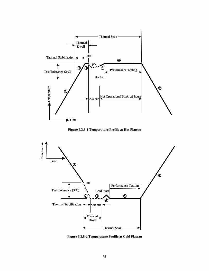
51
Figure 6.3.8-1 Temperature Profile at Hot Plateau
Figure 6.3.8-2 Temperature Profile at Cold Plateau
Time
Tem
pera
ture
Hot Start
Test Tolerance (3oC)
Thermal Stabilization
Thermal Soak
Hot Operational Soak, ≥2 hours ≥30 min
Off
Thermal Dwell
Performance Testing
Time
Tem
pera
ture
Hot Start
Test Tolerance (3oC)
Thermal Stabilization
Thermal Soak
Hot Operational Soak, ≥2 hours ≥30 min
Off
Thermal Dwell
Performance Testing
Off
Cold Start
Time
Tem
pera
ture
Test Tolerance (3oC)
Thermal Stabilization ≥30 min
ThermalDwell
Thermal Soak
Performance TestingOff
Cold Start
Time
Tem
pera
ture
Test Tolerance (3oC)
Thermal Stabilization ≥30 min
ThermalDwell
Thermal Soak
Performance Testing
52
Complete specification performance testing shall be performed at the temperature extremes on the first and last hot and cold cycles and at ambient temperature prior to and following thermal cycling. Functional testing shall be conducted at the temperature extremes on intermediate cycles. The unit shall be powered on and monitored during all transition periods, except as noted, and the health of the unit shall be monitored and key parameters trended. Any required performance of the unit during temperature transitions shall be tested during hot to cold and cold to hot transition times.
6.3.8.3 Test Levels and Duration
a. Pressure and Humidity. The test shall be performed at ambient pressure. When unsealed units are being tested, provisions shall be taken to preclude condensation on and within the unit at low temperature. For example, the chamber may be flooded with dry air or nitrogen. Careful consideration shall also be given to the starting temperatures and temperature transitions applied to avoid moisture condensation. A common practice is to require the first and last half cycle to be conducted hot.
b. Temperature. Units shall be tested to temperature ranges given below and as shown in Figure 6.3.8-3.
Qualification: 10°C beyond acceptance test temperatures or –34 to 71°C (minimum range)
Protoqualification: 5°C beyond acceptance test temperatures or –29 to 66°C (minimum range) Acceptance: Maximum and minimum predicted temperatures or –24 to
61°C (minimum range)
The transition rate between hot and cold shall be at an average rate of 3°C to 5°C per minute, and shall not be slower than 1°C per minute.
c. Duration. The minimum number of thermal cycles shall be as shown when combined with the unit thermal vacuum test (Table 6.3-3):
Qualification: 23 TC and 4 TV Protoqualification: 23 TC and 4 TV Acceptance: 10 TC and 4 TV
When only performing the thermal cycle test, the minimum number of cycles is the combination of thermal vacuum cycles and thermal cycles:
Qualification: 27 cycles
Protoqualification: 27 cycles Acceptance: 14 cycles
53
For Multi-Unit Module (MUM) (3.31), acceptance unit test cycles shall be reduced to 10 thermal cycles if 4 thermal vacuum cycles are performed at the MUM level. The 10 unit thermal cycles may either be unit thermal vacuum cycles or unit thermal cycles.
The last 4 thermal cycles shall be failure free. Units shall remain operational except during the first and last cycle, where a minimum one-half hour is required between unit turn-off and turn-on for stabilization. Units may be turned off during the cold ramp on intermediate cycles to accelerate testing. Thermal soaks at hot and cold temperature plateaus shall be a minimum of 6 hours on the first and last cycle and 1 hour on intermediate cycles. Hot operational soaks shall be a minimum of 2 hours on the first and last cycle and a minimum of 1 hour (coincident with thermal soak) on intermediate cycles. At cold temperatures the unit shall be thermally stabilized before proceeding to further testing. When a unit’s design precludes testing over the temperature ranges specified in Item B, the number of test cycles shall be increased to provide an equivalent level of screening effectiveness. The equation given below shall be used for units that are subjected to thermal cycling only or for the cumulative number of cycles in unit thermal vacuum and thermal cycle testing. The term ΔT is the proposed test temperature range (in degrees C).
Qualification: 27(105/ΔT)1.4 cycles Protoqualification: 27(95/ΔT)1.4 cycles Acceptance: 14(85/ΔT)1.4 cycles
d. Burn-in. For acceptance and protoqualification testing, units shall be “burned in” beyond the
durations prescribed for thermal cycle and thermal vacuum testing. During burn-in, the test unit shall be powered and key parameters trended. The duration of burn-in is such that additional operation shall be accumulated so that the combined duration of unit thermal cycling, unit thermal vacuum and the additional burn-in testing shall be at least 200 hours. For internally redundant units, the operating hours shall consist of at least 100 hours of primary operation and at least 100 hours of redundant operation; the last 50 hours of each (primary and redundant) shall be failure free. The last 100 hours of operation shall be failure free. Specification performance tests shall be performed prior to and following the burn-in test. The test is performed with the unit temperature either cycled between the acceptance temperature range or elevated at the acceptance hot temperature. Testing may be performed at ambient pressure.
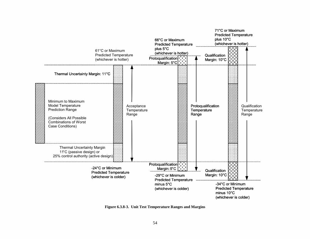
54
QualificationMargin: 10°C
QualificationMargin: 10°C
Qualification TemperatureRange
Acceptance TemperatureRange
Thermal Uncertainty Margin:11°C (passive design) or
25% control authority (active design)
Minimum to Maximum Model Temperature Prediction Range
(Considers All Possible Combinations of Worst Case Conditions)
Thermal Uncertainty Margin: 11°C
Protoqualification Temperature Range
Protoqualification Margin: 5°C
ProtoqualificationMargin: 5°C
-29°C or Minimum Predicted Temperatureminus 5°C(whichever is colder)
-24°C or Minimum Predicted Temperature(whichever is colder)
61°C or Maximum Predicted Temperature(whichever is hotter)
66°C or Maximum Predicted Temperatureplus 5°C(whichever is hotter)
71°C or Maximum Predicted Temperatureplus 10°C(whichever is hotter)
-34°C or Minimum Predicted Temperatureminus 10°C(whichever is colder)
QualificationMargin: 10°C
QualificationMargin: 10°C
Qualification TemperatureRange
Acceptance TemperatureRange
Thermal Uncertainty Margin:11°C (passive design) or
25% control authority (active design)
Minimum to Maximum Model Temperature Prediction Range
(Considers All Possible Combinations of Worst Case Conditions)
Thermal Uncertainty Margin: 11°C
Protoqualification Temperature Range
Protoqualification Margin: 5°C
ProtoqualificationMargin: 5°C
-29°C or Minimum Predicted Temperatureminus 5°C(whichever is colder)
-24°C or Minimum Predicted Temperature(whichever is colder)
61°C or Maximum Predicted Temperature(whichever is hotter)
66°C or Maximum Predicted Temperatureplus 5°C(whichever is hotter)
71°C or Maximum Predicted Temperatureplus 10°C(whichever is hotter)
-34°C or Minimum Predicted Temperatureminus 10°C(whichever is colder)
Figure 6.3.8-3. Unit Test Temperature Ranges and Margins
55
6.3.8.4 Supplementary Requirements
Specification performance tests shall be conducted after unit temperatures have stabilized (3.56) at the hot and cold temperatures during the first and last cycle, and at ambient temperature prior to and following the test. Functional tests shall be performed at hot and cold temperatures on intermediate cycles. During the remainder of the test, electrical and electronic units, including all redundant circuits and paths, shall be cycled through all operational modes. Perceptive parameters shall be monitored for failures, degradation trends, and intermittent behavior. All electrical circuits and all paths shall be verified for circuit performance and continuity. Compliance with allocated performance requirements shall be required over acceptance, protoqualification, and qualification temperature ranges, as appropriate. With customer approval, exceptions may be made where it can be shown that:
a. Full compliance is achieved over the range from the minimum predicted temperature minus 11 deg C to the maximum predicted temperature plus 11 deg C (not necessarily 85 deg C).
b. Analytic results show that the worst degradation from specified performance over the full tested range would have minor system impact.
For moving mechanical assemblies, performance parameters (such as current draw, resistance torque or force, actuation time, velocity or acceleration) shall be monitored. Where practical, force or torque margins shall be determined on moving mechanical assemblies at the temperature extremes. Where this is not practical, minimum acceptable force or torque margin shall be demonstrated. Compatibility with operational fluids shall be verified at test temperature extremes for valves, propulsion units, and other units as appropriate.
6.3.9 Unit Thermal Vacuum Test
6.3.9.1 Purpose
The thermal vacuum test demonstrates specification performance and survivability over combined thermal and vacuum conditions. The qualification thermal vacuum test demonstrates the ability of the unit to perform to specification limits in the qualification environment and to endure the thermal vacuum testing imposed on flight units during acceptance testing. It also serves to verify the unit thermal design. The acceptance thermal vacuum test detects material and workmanship defects and proves flight-worthiness of the unit. Criteria for exemptions to unit thermal vacuum testing are given in Section 4.10.2.
6.3.9.2 Test Description
The unit under test shall be mounted in a vacuum chamber on a thermally controlled heat sink or in a manner similar to its actual installation in the vehicle. The unit surface finishes, which affect radiative heat transfer or contact conductance, shall be thermally equivalent to those on the flight units. For units designed to reject their waste heat through the baseplate, a control temperature sensor shall be attached to either the unit baseplate or the heat sink. The location shall be chosen to correspond as closely as possible to the temperature limits used in the vehicle thermal design analysis or applicable unit-to-vehicle interface criteria. For components cooled primarily by radiation, a representative location on the unit case shall similarly be chosen. The unit heat transfer to the thermally controlled heat sink and the radiation heat transfer to the environment shall be controlled to the same proportions as calculated for the flight environment.
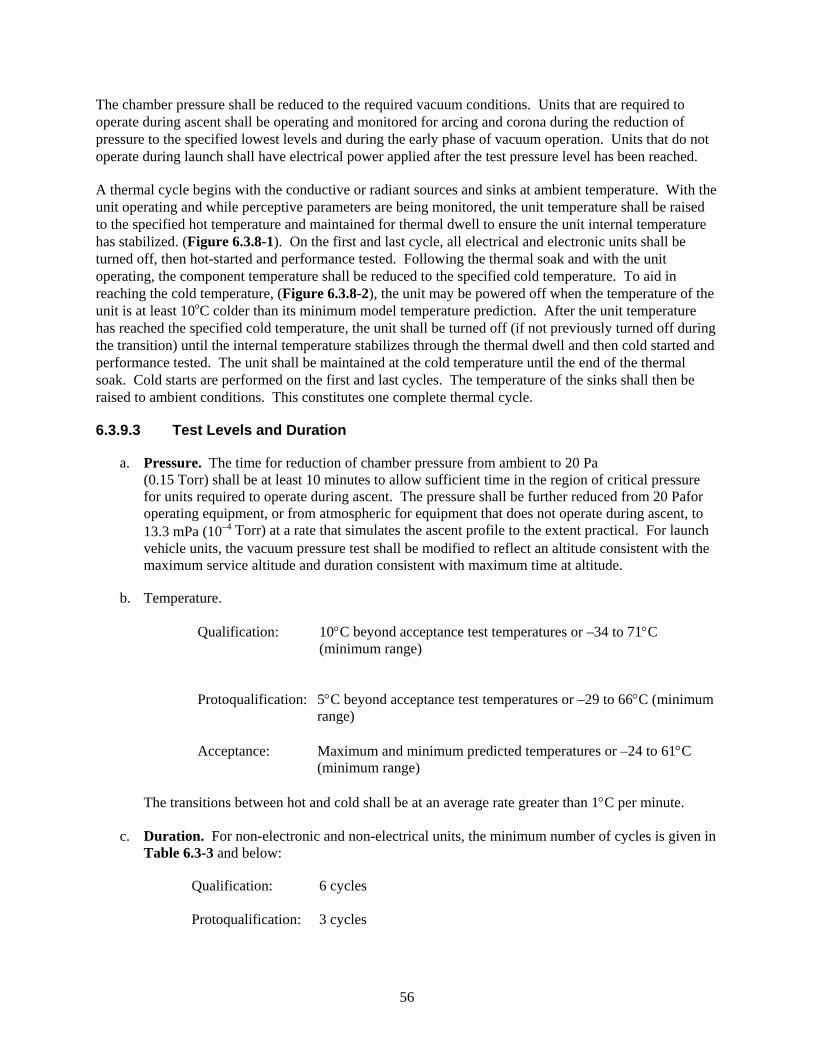
56
The chamber pressure shall be reduced to the required vacuum conditions. Units that are required to operate during ascent shall be operating and monitored for arcing and corona during the reduction of pressure to the specified lowest levels and during the early phase of vacuum operation. Units that do not operate during launch shall have electrical power applied after the test pressure level has been reached.
A thermal cycle begins with the conductive or radiant sources and sinks at ambient temperature. With the unit operating and while perceptive parameters are being monitored, the unit temperature shall be raised to the specified hot temperature and maintained for thermal dwell to ensure the unit internal temperature has stabilized. (Figure 6.3.8-1). On the first and last cycle, all electrical and electronic units shall be turned off, then hot-started and performance tested. Following the thermal soak and with the unit operating, the component temperature shall be reduced to the specified cold temperature. To aid in reaching the cold temperature, (Figure 6.3.8-2), the unit may be powered off when the temperature of the unit is at least 10oC colder than its minimum model temperature prediction. After the unit temperature has reached the specified cold temperature, the unit shall be turned off (if not previously turned off during the transition) until the internal temperature stabilizes through the thermal dwell and then cold started and performance tested. The unit shall be maintained at the cold temperature until the end of the thermal soak. Cold starts are performed on the first and last cycles. The temperature of the sinks shall then be raised to ambient conditions. This constitutes one complete thermal cycle.
6.3.9.3 Test Levels and Duration
a. Pressure. The time for reduction of chamber pressure from ambient to 20 Pa (0.15 Torr) shall be at least 10 minutes to allow sufficient time in the region of critical pressure for units required to operate during ascent. The pressure shall be further reduced from 20 Pafor operating equipment, or from atmospheric for equipment that does not operate during ascent, to 13.3 mPa (10–4 Torr) at a rate that simulates the ascent profile to the extent practical. For launch vehicle units, the vacuum pressure test shall be modified to reflect an altitude consistent with the maximum service altitude and duration consistent with maximum time at altitude.
b. Temperature.
Qualification: 10°C beyond acceptance test temperatures or –34 to 71°C (minimum range)
Protoqualification: 5°C beyond acceptance test temperatures or –29 to 66°C (minimum
range) Acceptance: Maximum and minimum predicted temperatures or –24 to 61°C
(minimum range)
The transitions between hot and cold shall be at an average rate greater than 1°C per minute.
c. Duration. For non-electronic and non-electrical units, the minimum number of cycles is given in Table 6.3-3 and below:
Qualification: 6 cycles Protoqualification: 3 cycles
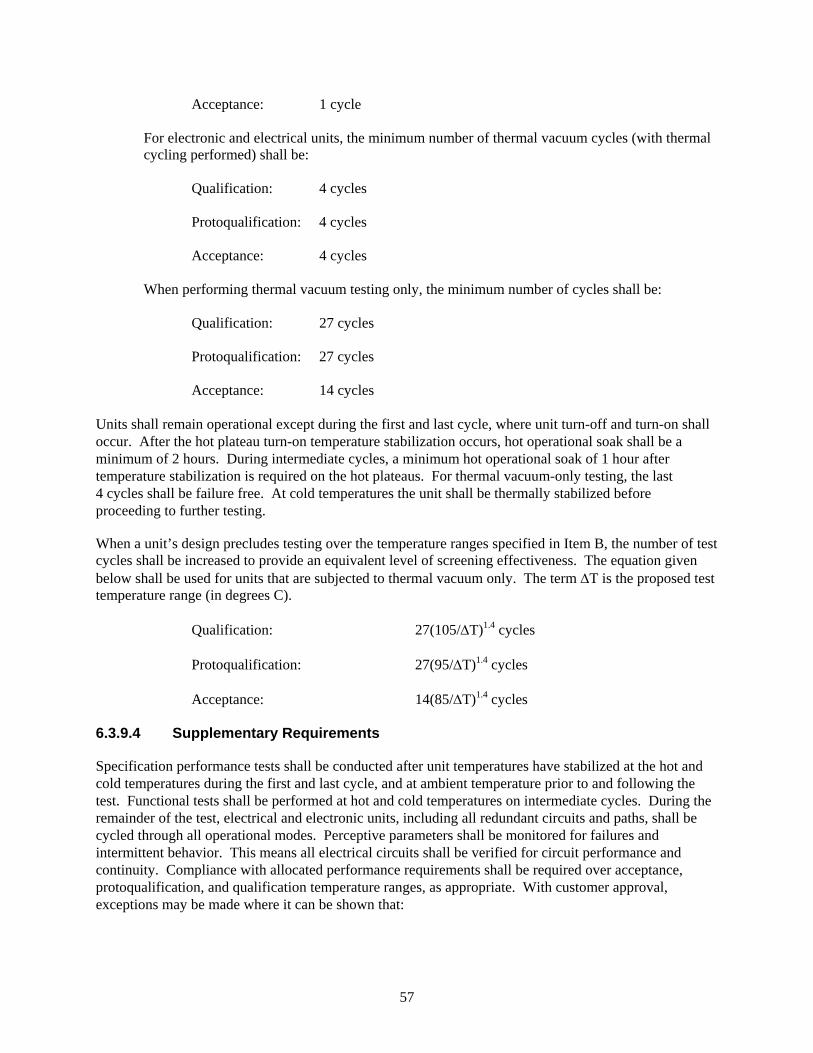
57
Acceptance: 1 cycle
For electronic and electrical units, the minimum number of thermal vacuum cycles (with thermal cycling performed) shall be:
Qualification: 4 cycles Protoqualification: 4 cycles Acceptance: 4 cycles
When performing thermal vacuum testing only, the minimum number of cycles shall be:
Qualification: 27 cycles Protoqualification: 27 cycles
Acceptance: 14 cycles
Units shall remain operational except during the first and last cycle, where unit turn-off and turn-on shall occur. After the hot plateau turn-on temperature stabilization occurs, hot operational soak shall be a minimum of 2 hours. During intermediate cycles, a minimum hot operational soak of 1 hour after temperature stabilization is required on the hot plateaus. For thermal vacuum-only testing, the last 4 cycles shall be failure free. At cold temperatures the unit shall be thermally stabilized before proceeding to further testing.
When a unit’s design precludes testing over the temperature ranges specified in Item B, the number of test cycles shall be increased to provide an equivalent level of screening effectiveness. The equation given below shall be used for units that are subjected to thermal vacuum only. The term ΔT is the proposed test temperature range (in degrees C).
Qualification: 27(105/ΔT)1.4 cycles Protoqualification: 27(95/ΔT)1.4 cycles Acceptance: 14(85/ΔT)1.4 cycles
6.3.9.4 Supplementary Requirements
Specification performance tests shall be conducted after unit temperatures have stabilized at the hot and cold temperatures during the first and last cycle, and at ambient temperature prior to and following the test. Functional tests shall be performed at hot and cold temperatures on intermediate cycles. During the remainder of the test, electrical and electronic units, including all redundant circuits and paths, shall be cycled through all operational modes. Perceptive parameters shall be monitored for failures and intermittent behavior. This means all electrical circuits shall be verified for circuit performance and continuity. Compliance with allocated performance requirements shall be required over acceptance, protoqualification, and qualification temperature ranges, as appropriate. With customer approval, exceptions may be made where it can be shown that:
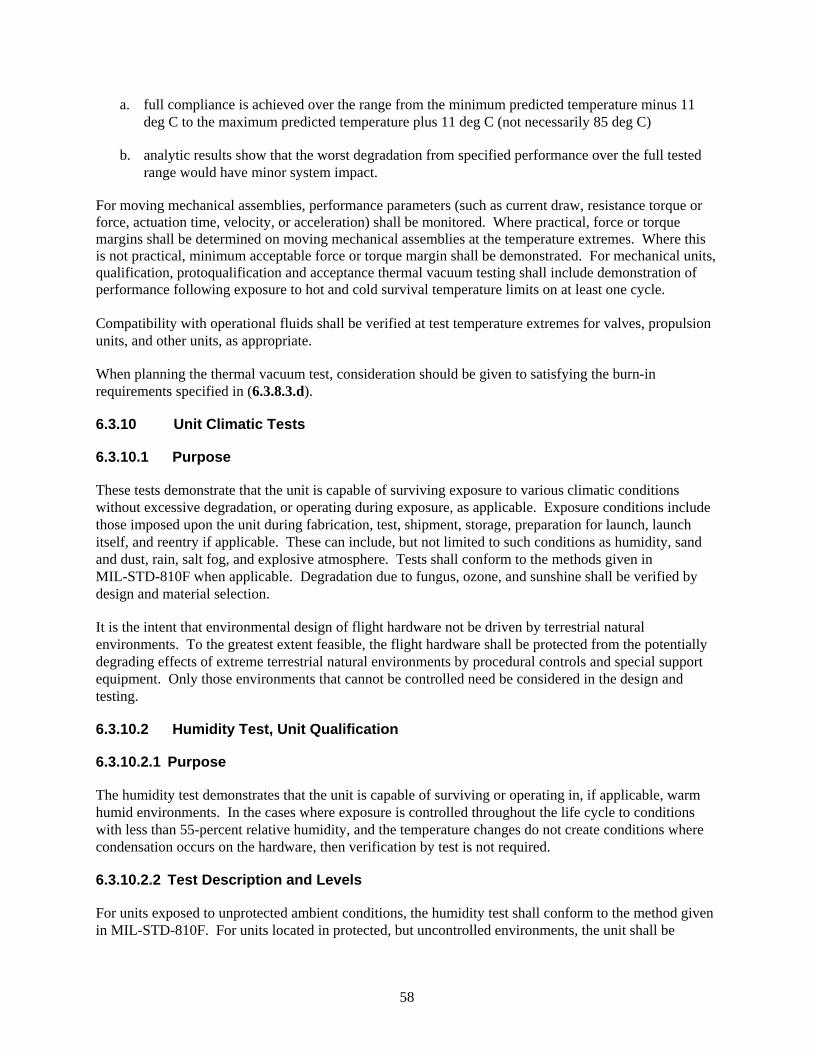
58
a. full compliance is achieved over the range from the minimum predicted temperature minus 11 deg C to the maximum predicted temperature plus 11 deg C (not necessarily 85 deg C)
b. analytic results show that the worst degradation from specified performance over the full tested range would have minor system impact.
For moving mechanical assemblies, performance parameters (such as current draw, resistance torque or force, actuation time, velocity, or acceleration) shall be monitored. Where practical, force or torque margins shall be determined on moving mechanical assemblies at the temperature extremes. Where this is not practical, minimum acceptable force or torque margin shall be demonstrated. For mechanical units, qualification, protoqualification and acceptance thermal vacuum testing shall include demonstration of performance following exposure to hot and cold survival temperature limits on at least one cycle. Compatibility with operational fluids shall be verified at test temperature extremes for valves, propulsion units, and other units, as appropriate.
When planning the thermal vacuum test, consideration should be given to satisfying the burn-in requirements specified in (6.3.8.3.d).
6.3.10 Unit Climatic Tests
6.3.10.1 Purpose
These tests demonstrate that the unit is capable of surviving exposure to various climatic conditions without excessive degradation, or operating during exposure, as applicable. Exposure conditions include those imposed upon the unit during fabrication, test, shipment, storage, preparation for launch, launch itself, and reentry if applicable. These can include, but not limited to such conditions as humidity, sand and dust, rain, salt fog, and explosive atmosphere. Tests shall conform to the methods given in MIL-STD-810F when applicable. Degradation due to fungus, ozone, and sunshine shall be verified by design and material selection.
It is the intent that environmental design of flight hardware not be driven by terrestrial natural environments. To the greatest extent feasible, the flight hardware shall be protected from the potentially degrading effects of extreme terrestrial natural environments by procedural controls and special support equipment. Only those environments that cannot be controlled need be considered in the design and testing.
6.3.10.2 Humidity Test, Unit Qualification
6.3.10.2.1 Purpose
The humidity test demonstrates that the unit is capable of surviving or operating in, if applicable, warm humid environments. In the cases where exposure is controlled throughout the life cycle to conditions with less than 55-percent relative humidity, and the temperature changes do not create conditions where condensation occurs on the hardware, then verification by test is not required.
6.3.10.2.2 Test Description and Levels
For units exposed to unprotected ambient conditions, the humidity test shall conform to the method given in MIL-STD-810F. For units located in protected, but uncontrolled environments, the unit shall be
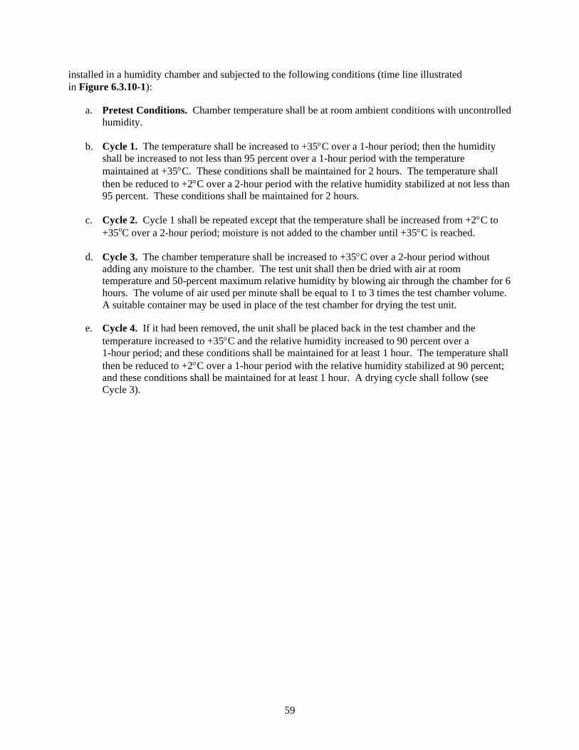
59
installed in a humidity chamber and subjected to the following conditions (time line illustrated in Figure 6.3.10-1):
a. Pretest Conditions. Chamber temperature shall be at room ambient conditions with uncontrolled humidity.
b. Cycle 1. The temperature shall be increased to +35°C over a 1-hour period; then the humidity shall be increased to not less than 95 percent over a 1-hour period with the temperature maintained at +35°C. These conditions shall be maintained for 2 hours. The temperature shall then be reduced to +2°C over a 2-hour period with the relative humidity stabilized at not less than 95 percent. These conditions shall be maintained for 2 hours.
c. Cycle 2. Cycle 1 shall be repeated except that the temperature shall be increased from +2°C to +35oC over a 2-hour period; moisture is not added to the chamber until +35°C is reached.
d. Cycle 3. The chamber temperature shall be increased to +35°C over a 2-hour period without adding any moisture to the chamber. The test unit shall then be dried with air at room temperature and 50-percent maximum relative humidity by blowing air through the chamber for 6 hours. The volume of air used per minute shall be equal to 1 to 3 times the test chamber volume. A suitable container may be used in place of the test chamber for drying the test unit.
e. Cycle 4. If it had been removed, the unit shall be placed back in the test chamber and the temperature increased to +35°C and the relative humidity increased to 90 percent over a 1-hour period; and these conditions shall be maintained for at least 1 hour. The temperature shall then be reduced to +2°C over a 1-hour period with the relative humidity stabilized at 90 percent; and these conditions shall be maintained for at least 1 hour. A drying cycle shall follow (see Cycle 3).
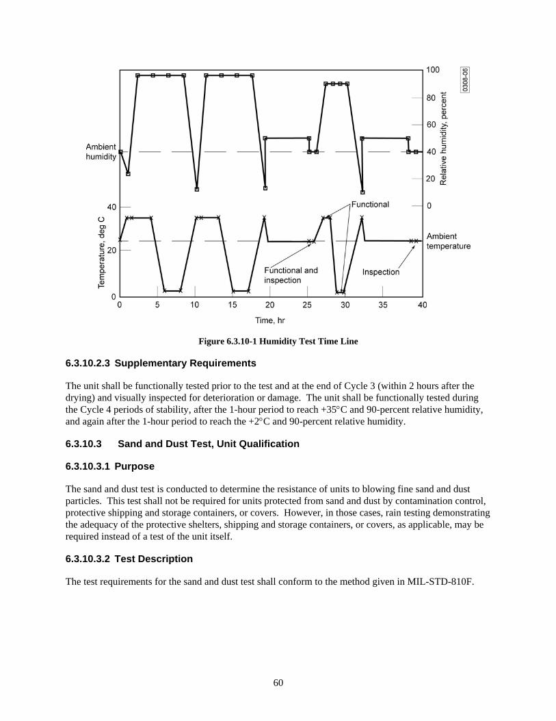
60
Figure 6.3.10-1 Humidity Test Time Line
6.3.10.2.3 Supplementary Requirements
The unit shall be functionally tested prior to the test and at the end of Cycle 3 (within 2 hours after the drying) and visually inspected for deterioration or damage. The unit shall be functionally tested during the Cycle 4 periods of stability, after the 1-hour period to reach +35°C and 90-percent relative humidity, and again after the 1-hour period to reach the +2°C and 90-percent relative humidity.
6.3.10.3 Sand and Dust Test, Unit Qualification
6.3.10.3.1 Purpose
The sand and dust test is conducted to determine the resistance of units to blowing fine sand and dust particles. This test shall not be required for units protected from sand and dust by contamination control, protective shipping and storage containers, or covers. However, in those cases, rain testing demonstrating the adequacy of the protective shelters, shipping and storage containers, or covers, as applicable, may be required instead of a test of the unit itself.
6.3.10.3.2 Test Description
The test requirements for the sand and dust test shall conform to the method given in MIL-STD-810F.
61
6.3.10.4 Rain Test, Unit Qualification
6.3.10.4.1 Purpose
The rain test shall be conducted to determine the resistance of units to rain. Units protected from rain by protective shelters, shipping and storage containers, or covers, shall not require verification by test.
6.3.10.4.2 Test Description
Buildup of the unit, shelter, container, or the cover being tested shall be representative of the actual fielded configuration without any duct tape or temporary sealants. The initial temperature difference between the test item and the spray water shall be a minimum of 10°C. For temperature-controlled containers, the temperature difference between the test item and the spray water shall at least be that between the maximum control temperature and the coldest rain condition in the field. Nozzles used shall produce a square spray pattern or other overlapping pattern (for maximum surface coverage) and droplet size predominantly in the 2 to 4.5 millimeter range at approximately 375 kPa gage pressure (40 psig). At least one nozzle shall be used for each approximately 0.5 m2 (6 ft2) of surface area and each nozzle shall be positioned at 0.5 meter (20 inches) from the test surface. All exposed faces shall be sprayed for at least 40 minutes. The unit under test interior shall be inspected for water penetration at the end of each 40-minute exposure. Evidence of water penetration shall constitute a failure.
6.3.10.5 Salt Fog Test, Unit Qualification
6.3.10.5.1 Purpose
The salt fog test is used to demonstrate the resistance of the unit to the effects of a salt spray atmosphere. The salt fog test is not required if the flight hardware is protected against the salt fog environment by suitable preservation means and protective shipping and storage containers.
6.3.10.5.2 Test Description
The requirements for the salt fog test shall conform to the method given in MIL-STD-810F.
6.3.10.6 Explosive Atmosphere Test, Unit Qualification
6.3.10.6.1 Purpose
Where applicable, devices operating in explosive atmospheric conditions need to be proven incapable of igniting a fuel-air mixture of concern.
6.3.10.6.2 Test Description
The test requirements for the explosive atmosphere test shall conform to the method given in MIL-STD-810F.
6.3.11 Unit Static Load Test
6.3.11.1 Purpose
The structural static load test demonstrates the adequacy of the structural components to meet requirements of strength and stiffness, with the desired qualification margin, when subjected to simulated
62
critical environments predicted to occur during its service life (such as temperature, humidity, pressure, and loads).
6.3.11.2 Test Description
The support and load application fixture shall consist of an adequate replication of the adjacent structural section to provide the boundary conditions necessary to determine the proper sequencing or simultaneity for application of all load cases. When prior loading histories affect the structural adequacy of the test article, these shall be included in the test requirements. If more than one design ultimate load condition is to be applied to the same test specimen, a method of sequential load application shall be developed by which each condition may, in turn, be tested to progressively higher load levels.
Static loads representing the design yield load and the design ultimate load shall be applied to the structure and measurements of the strain and deformation shall be recorded. Strain and deformation shall be measured before loading, after removal of the yield loads, and at several intermediate levels up to yield load for post-test diagnostic purposes. The test conditions shall encompass the extreme predicted combined effects of acceleration, vibration, pressure, preloads, and temperature. These effects can be simulated in the test conditions as long as the failure modes are covered and the design margins are enveloped by the test. For example, temperature effects, such as material strength degradation and additive thermal stresses, can often be accounted for by increasing mechanical loads.
Analysis of flight profiles shall be used for subsequent design modification effort, and to provide data for use in any weight reduction programs. Failure at design yield load means material gross yielding or deflections, which degrade mission performance. Failure at design ultimate load means rupture or collapse.
6.3.11.3 Test Levels and Duration
Qualification:
a. Level. Unless otherwise specified, the load level for ultimate static load test is 1.4 times limit load (3.20) for manned systems and 1.25 times limit load for unmanned systems.
b. Temperature. Critical flight temperature and load combinations shall be simulated or taken into account.
c. Duration. Loads shall be applied as closely as practical to actual flight loading times, with a dwell time not longer than necessary to record test data such as stress, strain, deformation, and temperature.
Protoqualification:
Same as qualification.
Acceptance:
A unit proof load test shall be conducted for all structural units made of composite materials or having adhesively bonded parts. The proof load test detects material, process, and workmanship defects that would respond to structural proof loading. The requirement for the proof load test maybe waived if a proven nondestructive evaluation method, with well established accept/reject criteria, is used for inspecting units.
63
a. Level. Unless otherwise specified, the proof load for flight items shall be 1.1 times limit load (3.20).
b. Duration. Loads shall be applied as closely as practical to actual flight loading times, with a minimum dwell time sufficient to record test data.
6.3.11.4 Supplementary Requirements
For fracture critical parts made of metallic materials, proof tests shall be conducted when non-destructive evaluation is not sufficient to determine the maximum initial crack sizes used in the damage tolerance (safe-life) analyses or tests. The required proof test load level shall be determined based on fracture mechanics calculations. Structural test requirements are specified in AIAA S-110-2005.
6.3.12 Unit Pressure Test
6.3.12.1 Purpose
The pressure test demonstrates adequate margin, so that structural failure does not occur before the design burst pressure is reached, or excessive deformation does not occur at the maximum expected operating pressure, MEOP, (3.23). Table 6.3.12-2 provides minimum design burst pressures for pressurized vessels and hardware.
6.3.12.2 Test Description
a. Proof Pressure Test. For items such as pressurized structures and pressure components, a proof test with a minimum of 1 cycle of proof pressure shall be conducted. Evidence of leakage, a permanent set, or distortion that exceeds a drawing tolerance or failure of any kind shall constitute failure to pass the test. This test shall be performed for qualification, protoqualification, and acceptance testing.
b. Test. The qualifications and protoqualification test procedure consists of cyclic testing followed by one additional cycle at burst pressure, as described below:
Pressure Cycle Test. For pressurized structures and pressure vessels, a pressure cycle test shall be conducted. Requirements for application of external loads in combination with internal pressures during testing shall be evaluated based on the relative magnitude and on the destabilizing effect of stresses due to the external load. If limit combined tensile stresses are enveloped by the test pressure stress, the application of external load is not required. This test shall be performed for qualification and protoqualification. Table 6.3.12-1 provides a summary of unit test requirements.
Burst Test. The pressure shall be increased to the design burst pressure, while simultaneously applying the ultimate external load(s), if appropriate. The internal pressure shall be applied at a sufficiently slow rate that dynamic stresses are negligible. For pressure vessels, after demonstrating no burst at the design burst pressure, the pressure shall be increased to actual burst of the vessel, and the actual burst pressure shall be recorded. This test shall be performed for qualification
c. Exception to Tests. For special pressurized equipment (3.37), such as silver-zinc batteries that contain a pressure relief mechanism, proof test of the pressure release mechanism shall be performed on all flight units. For space vehicle batteries using a special pressurized equipment
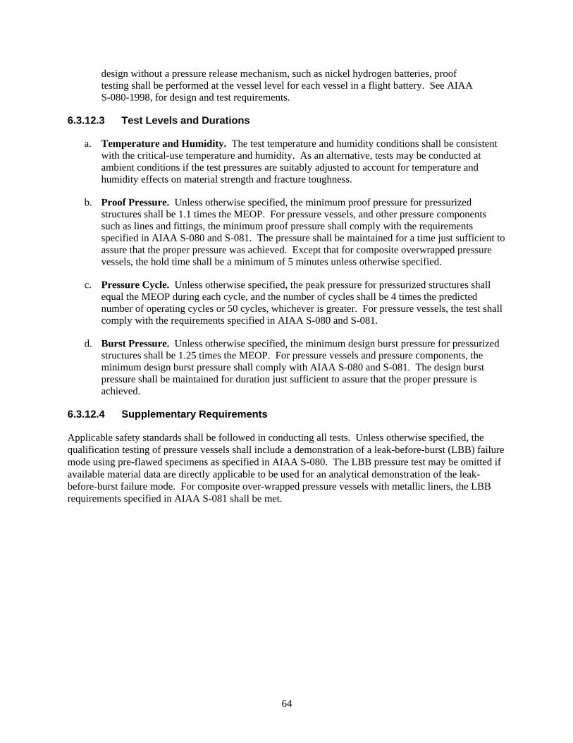
64
design without a pressure release mechanism, such as nickel hydrogen batteries, proof testing shall be performed at the vessel level for each vessel in a flight battery. See AIAA S-080-1998, for design and test requirements.
6.3.12.3 Test Levels and Durations
a. Temperature and Humidity. The test temperature and humidity conditions shall be consistent with the critical-use temperature and humidity. As an alternative, tests may be conducted at ambient conditions if the test pressures are suitably adjusted to account for temperature and humidity effects on material strength and fracture toughness.
b. Proof Pressure. Unless otherwise specified, the minimum proof pressure for pressurized structures shall be 1.1 times the MEOP. For pressure vessels, and other pressure components such as lines and fittings, the minimum proof pressure shall comply with the requirements specified in AIAA S-080 and S-081. The pressure shall be maintained for a time just sufficient to assure that the proper pressure was achieved. Except that for composite overwrapped pressure vessels, the hold time shall be a minimum of 5 minutes unless otherwise specified.
c. Pressure Cycle. Unless otherwise specified, the peak pressure for pressurized structures shall equal the MEOP during each cycle, and the number of cycles shall be 4 times the predicted number of operating cycles or 50 cycles, whichever is greater. For pressure vessels, the test shall comply with the requirements specified in AIAA S-080 and S-081.
d. Burst Pressure. Unless otherwise specified, the minimum design burst pressure for pressurized structures shall be 1.25 times the MEOP. For pressure vessels and pressure components, the minimum design burst pressure shall comply with AIAA S-080 and S-081. The design burst pressure shall be maintained for duration just sufficient to assure that the proper pressure is achieved.
6.3.12.4 Supplementary Requirements
Applicable safety standards shall be followed in conducting all tests. Unless otherwise specified, the qualification testing of pressure vessels shall include a demonstration of a leak-before-burst (LBB) failure mode using pre-flawed specimens as specified in AIAA S-080. The LBB pressure test may be omitted if available material data are directly applicable to be used for an analytical demonstration of the leak-before-burst failure mode. For composite over-wrapped pressure vessels with metallic liners, the LBB requirements specified in AIAA S-081 shall be met.
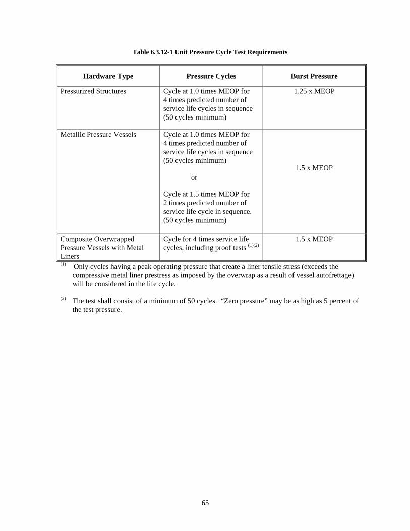
65
Table 6.3.12-1 Unit Pressure Cycle Test Requirements
Hardware Type Pressure Cycles Burst Pressure
Pressurized Structures Cycle at 1.0 times MEOP for 4 times predicted number of service life cycles in sequence (50 cycles minimum)
1.25 x MEOP
Metallic Pressure Vessels Cycle at 1.0 times MEOP for 4 times predicted number of service life cycles in sequence (50 cycles minimum)
or
Cycle at 1.5 times MEOP for 2 times predicted number of service life cycle in sequence. (50 cycles minimum)
1.5 x MEOP
Composite Overwrapped Pressure Vessels with Metal Liners
Cycle for 4 times service life cycles, including proof tests (1)(2)
1.5 x MEOP
(1) Only cycles having a peak operating pressure that create a liner tensile stress (exceeds the compressive metal liner prestress as imposed by the overwrap as a result of vessel autofrettage) will be considered in the life cycle.
(2) The test shall consist of a minimum of 50 cycles. “Zero pressure” may be as high as 5 percent of the test pressure.
66
Table 6.3.12-2 Minimum Burst Pressure Requirements
Pressurized Hardware Item Type Minimum Design Burst Pressure
Pressurized Structures 1.25 x MEOP
Metallic Pressure Vessels, Cryostats, Battery Cases and Sealed Containers 1.5 x MEOP
Composite Overwrapped Pressure Vessels with Metal Liners 1.5 x MEOP
Lines and Fittings with diameters equal to or greater than 1.5 in. 2.5 x MEOP
Heat Pipes, Valves, Regulators, Accumulators, and others Pressure Components 2.5 x MEOP
Fluid Return Section 3.0 x MEOP
Lines and Fittings with diameters less than 1.5 in. 4.0 x MEOP
Fluid Return Hose 5.0 x MEOP
6.3.13 Unit Electromagnetic Compatibility (EMC) Test
6.3.13.1 Purpose
The electromagnetic compatibility test shall demonstrate that the electromagnetic interference characteristics (emission and susceptibility) of the unit, under normal operating conditions, do not result in malfunction of the unit. It also demonstrates that the unit does not emit, radiate, or conduct interference, which could result in malfunction of other units.
6.3.13.2 Test Description
The test shall be conducted in accordance with the requirements of TOR-2005(8583)-1. The intent of testing at the lowest level possible shall be followed. This means that all tests shall be conducted at the unit level to improve the chance of passing the subsystem and vehicle level tests. Radiated emissions shall be performed on all units capable of generating emissions. Acceptance tests shall be performed when there is less than 12 dB margin, or the radiated emissions requirement is more stringent than 10 dBuV/m, or the units have a passive intermodulation requirement. Radiated emission acceptance tests can be deferred to the subsystem or functional module level.
The EMC margin is to be incorporated into the test levels. Qualification margins of 6 dB are acceptable if the combined test uncertainty, part variation, part degradation at end-of-life, and workmanship variation is less than 6 dB. Electroexplosive devices and bridge wires have a 20 dB margin requirement below the DC no-fire value and a 6 dB margin requirement below the RF no-fire value.
67
6.3.13.3 Test Levels and Duration
The test levels shall be as follows:
Qualification: 12 dB
Protoqualification: 6 dB
Acceptance: 6 dB
The test duration shall be 20 minutes at each space vehicle transmitter frequency for radiated susceptibility. Otherwise, the duration is the greater of 3 seconds or the unit response time for susceptibility requirements and 15 milliseconds duration for emission requirements.
6.3.14 Unit Life Test
6.3.14.1 Purpose
The life test applies to units that may have a wear-out, drift, or fatigue-type failure mode, or performance degradation, such as batteries. The test demonstrates that the units have the capability to perform within specification limits for the maximum duration or cycles of operation during repeated ground testing and in flight.
The life test applies to units that may have a wear-out, drift, or fatigue-type failure mode, or performance degradation, due to the operational environment. Operational environment refers to a testing approach that simulates the combined environment and active device powered-on mode or current loaded condition, in which the unit operates in space. For example, solar cell panel life testing needs to consider thermal cycle testing with the solar cells and circuits in the actual operating or current loaded active mode, which can simulate the sunlight operational condition. The test demonstrates that the units have the capability to perform within specification limits for the duration of service life.
6.3.14.2 Test Description
One or more units shall be operated under conditions that simulate their service conditions. Service conditions define the operational environment in which the unit is expected to operate. As such, it is reasonable to demonstrate the condition when the unit is in an active and operational mode. For solar cell devices and unit life testing, the test conditions are to simulate the as-used powered-on or current loaded operational condition. These conditions shall be selected for consistency with end-use requirements and the significant life characteristics of the particular unit. Typical environments are ambient, thermal, thermal vacuum pressure, and vibration. The test shall be designed to demonstrate the ability of the unit to withstand the maximum operating time and the maximum number of operational cycles predicted during its service life (including manufacturing assembly and test) with a suitable margin. Accelerated life testing is permitted.
6.3.14.3 Test Levels and Durations
a. Pressure. For pressurized structures and pressure vessels, the pressure level shall be that specified in 6.3.12.3. For other units, ambient pressure shall be used except where degradation due to a vacuum environment may be anticipated, such as for some unsealed units. In those cases, a pressure of 13.3 mPa (10–4 Torr) or less shall be used.
68
b. Environmental Levels. The maximum expected environmental levels shall be used. Higher levels may be used to accelerate the life testing, if the resulting increase in the rate of degradation is well established and that unrealistic failure modes are not introduced.
c. Duration. For pressurized structures and pressure vessels, the duration shall be no less than 5 minutes. For other units, the total operating time or number of operational cycles shall be at least 2 times that predicted during the service life, including ground testing, in order to demonstrate an adequate margin. For a structural component having a fatigue-type failure mode that has not been subjected to a vibration qualification test, the test duration shall be at least 4 times the specified service life.
d. Functional Duty Cycle. Complete functional tests shall be conducted before the test begins and after completion of the test. During the life test, functional tests shall be conducted in sufficient detail, and at sufficiently short intervals to establish trends.
6.3.14.4 Supplementary Requirements
For statistically based life tests, the duration is dependent upon the number of samples, confidence, and reliability to be demonstrated. Any wearout susceptible mechanism within a unit may be tested separately. For these mechanisms, the duration of the life test shall assure with high confidence that the mechanisms will not wear out and/or unacceptably degrade during their service life. At the end of the life test, mechanisms and moving mechanical assemblies shall be disassembled and inspected for anomalous conditions. The hardware may be disassembled and inspected earlier if warranted. The critical areas of parts that may be subject to fatigue failure shall be inspected to determine their integrity. Life testing is necessary for pressure vessels using bellows or other flexible fluid devices or lines.
Life testing on a lot basis is necessary for silver-zinc batteries to verify capacity and voltage response at the end of wet stand life for at least one charge cycle.
69
7. Subsystem Test Requirements
Subsystems shall be tested to reduce risk when system testing cannot verify subsystem performance.
7.1 Requirements
Subsystem tests shall be conducted on subsystems for any of the following purposes:
a. To verify the design and specification performance. To demonstrate that those subsystems subjected to environmental acceptance tests perform to specification (Table 7.3-2). Table 7.3-1 summarizes qualification and protoqualification testing performed to demonstrate design margins.
b. To provide a more perceptive test versus other levels of testing. A summary of subsystem test level margins and durations are shown in Table 7.3-3.
7.2 Subsystem Development Tests
Vehicles and subsystems are subjected to development tests and evaluations using structural and thermal development models as may be required to confirm dynamic and thermal environmental criteria for design of subsystems, to verify mechanical interfaces, and to assess functional performance of deployment mechanisms and thermal control subsystems. Vehicle-level development testing also provides an opportunity to develop handling and operating procedures as well as to characterize interfaces and interactions.
7.2.1 Mechanical Fit Development Tests
For launch and upper-stage vehicles, a mechanical fit, assembly, and operational interface test with the facilities at the launch or test site is recommended. Flight-weight hardware shall be used if practical; however, a facsimile or portions thereof may be used to conduct the development tests at an early point in the schedule in order to reduce the impact of hardware design changes that may be necessary.
7.2.2 Mode Survey Development Tests
A development mode survey test (modal survey) should be conducted at the subsystem level when uncertainty in the analytically predicted structural dynamic characteristics is judged to be excessive for purposes of structural or control subsystem design. The test article may be the full vehicle or one or more subsystem segments, depending on the physical size of the subsystem being tested relative to the physical size of the test facility and dynamic model verification strategy.
7.2.3 Structural Development Tests
For structures having redundant load paths, structural tests may be required to verify the stiffness and strength properties and to measure member loads, stress distributions, deflections and thermal distortion. The stiffness data are of particular interest where nonlinear structural behavior exists that is not fully exercised in a mode survey test. This may include nonlinear bearings, elastic buckling of panels, gaps at preloaded interfaces, and slipping at friction joints. Systems demonstrating a significant level of nonlinear structural behavior may require an alternative method for dynamic model validation such as high-input sine vibration base shake. The member load and stress distribution data may be used to experimentally verify the structural analysis model and the loads transformation matrix. Deflection data may be also used to experimentally verify the appropriate deflection transformation matrix. These
70
matrices may be used, in conjunction with the dynamic model, to calculate loads such as axial forces, bending moments, shears and torsional moments, and various stresses and deflections, which can be converted into design load and clearance margins for the vehicle. This development test does not replace the structural static load test that is required for subsystem qualification.
7.2.4 Acoustic Development Tests
Since high-frequency vibration responses are difficult to predict by analytical techniques, acoustic development testing of the launch, upper stage, and space vehicles subsystems may be necessary to verify the adequacy of the dynamic design criteria for units. Units that are not installed at the time of the test shall be dynamically simulated with respect to mass, center of gravity, moments of inertia, interface stiffness, and geometric characteristics. To demonstrate adequate design margin of the system in the launch environment, the subsystem shall be exposed to the qualification or proto-qualification acoustic levels and durations. To demonstrate adequacy of workmanship the subsystem shall be exposed to the acceptance acoustic levels and durations.
7.2.5 Shock Development Tests
Since shock responses are difficult to predict by analytical techniques, shock development testing of the launch, upper stage, and space vehicles may be necessary to verify the adequacy of the dynamic design criteria for units. Vehicle units that are not installed at the time of the test shall be dynamically simulated with respect to mass, center of gravity, moments of inertia, interface stiffness, and geometric characteristics. To demonstrate design margin and workmanship adequacy of the system in the launch environment, the vehicle shall be exposed to the acceptance levels. All explosive ordnance devices and other mechanisms capable of imparting a significant shock to the vehicle and its mounted assemblies shall be operated to demonstrate functionality and survivability. Where practical, the shock test shall involve physical separation of elements being deployed or released. When a significant shock is expected from interfacing subsystems not included on the vehicle under test (such as when a fairing separation causes shock responses on an upper stage under test), the adaptor subsystem or suitable simulation shall be attached and appropriate explosive ordnance devices or other means used to simulate the shock imposed. The pyroshock environment may vary significantly from one ordnance activation to another. Therefore, the statistical basis given in 3.27 shall be used for estimating maximum predicted environment. Multiple activations of ordnance devices may be necessary to provide data for better-substantiated estimates.
7.2.6 Payload Thermal Developmental Testing
Prior to space vehicle integration, payloads should be subjected to thermal development testing. The payload thermal vacuum test should include a thermal balance test for thermal model correlation and demonstration of thermal control hardware. Thermal tests may also be performed to measure the thermal conductance across important interfaces and the heat loss through critical thermal blankets. Special tests may also be necessary to verify heat pipe performance in complex configurations or when heat pipes are in a nonhorizontal orientation in system-level thermal testing. Heat pipe operation shall be verified in subsystem and vehicle ground thermal testing. Heat pipes shall be oriented such that they will operate in ground test orientations. Reflux testing is allowed provided that flight-like performance is verified at a lower level of assembly. In the case of heat pipes with three-dimensional bends, a surrogate heat pipe with identical two-dimensional bends may be tested to verify performance. Heat pipe operation of each three-dimensional flight pipe may be verified in reflux at the unit level. Because workmanship is not completely demonstrated for three-dimensional heat pipes, every effort should be made to use two-dimensional heat pipes.
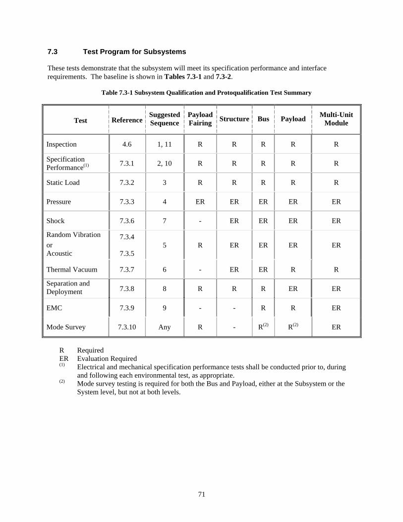
71
7.3 Test Program for Subsystems
These tests demonstrate that the subsystem will meet its specification performance and interface requirements. The baseline is shown in Tables 7.3-1 and 7.3-2.
Table 7.3-1 Subsystem Qualification and Protoqualification Test Summary
Test Reference SuggestedSequence
Payload Fairing Structure Bus Payload Multi-Unit
Module
Inspection 4.6 1, 11 R R R R R
Specification Performance(1) 7.3.1 2, 10 R R R R R
Static Load 7.3.2 3 R R R R R
Pressure 7.3.3 4 ER ER ER ER ER
Shock 7.3.6 7 - ER ER ER ER
Random Vibration or Acoustic
7.3.4
7.3.5 5 R ER ER ER ER
Thermal Vacuum 7.3.7 6 - ER ER R R
Separation and Deployment 7.3.8 8 R R R ER ER
EMC 7.3.9 9 - - R R ER
Mode Survey 7.3.10 Any R - R(2) R(2) ER
R Required ER Evaluation Required (1) Electrical and mechanical specification performance tests shall be conducted prior to, during
and following each environmental test, as appropriate. (2) Mode survey testing is required for both the Bus and Payload, either at the Subsystem or the
System level, but not at both levels.
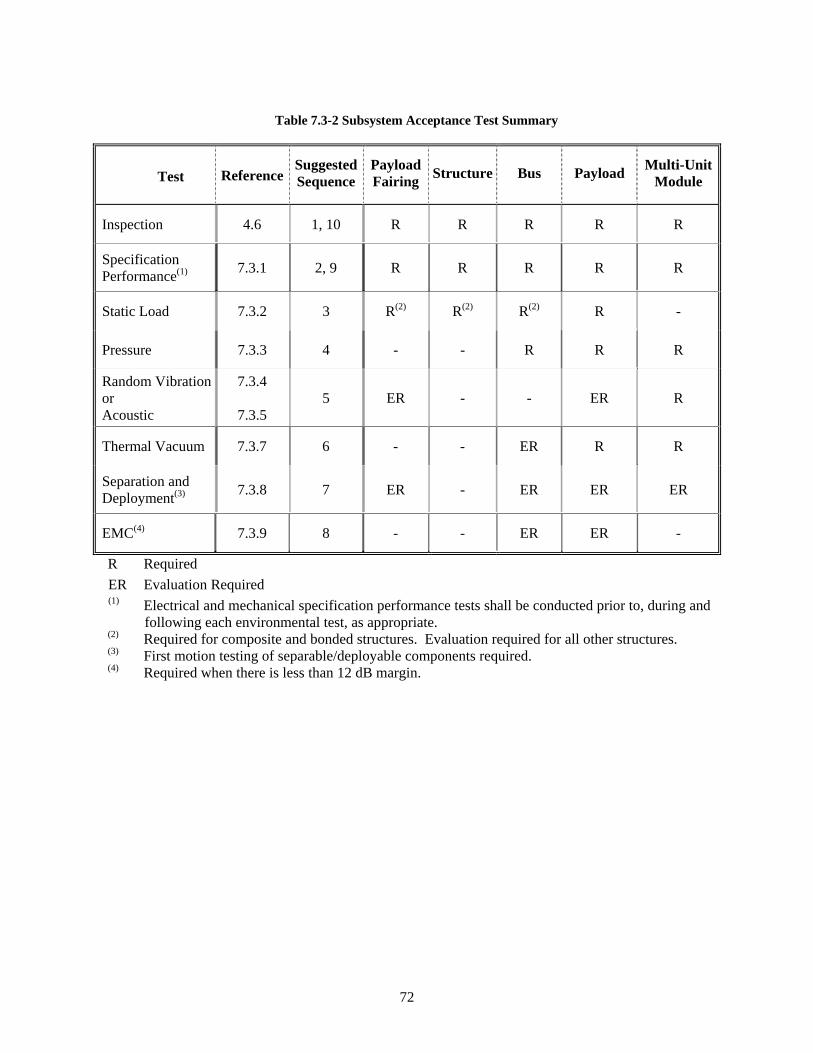
72
Table 7.3-2 Subsystem Acceptance Test Summary
Test Reference SuggestedSequence
Payload Fairing Structure Bus Payload Multi-Unit
Module
Inspection 4.6 1, 10 R R R R R
Specification Performance(1) 7.3.1 2, 9 R R R R R
Static Load 7.3.2 3 R(2) R(2) R(2) R -
Pressure 7.3.3 4 - - R R R
Random Vibration or Acoustic
7.3.4
7.3.5 5 ER - - ER R
Thermal Vacuum 7.3.7 6 - - ER R R
Separation and Deployment(3) 7.3.8 7 ER - ER ER ER
EMC(4) 7.3.9 8 - - ER ER -
R Required ER Evaluation Required
(1) Electrical and mechanical specification performance tests shall be conducted prior to, during and following each environmental test, as appropriate.
(2) Required for composite and bonded structures. Evaluation required for all other structures. (3) First motion testing of separable/deployable components required. (4) Required when there is less than 12 dB margin.
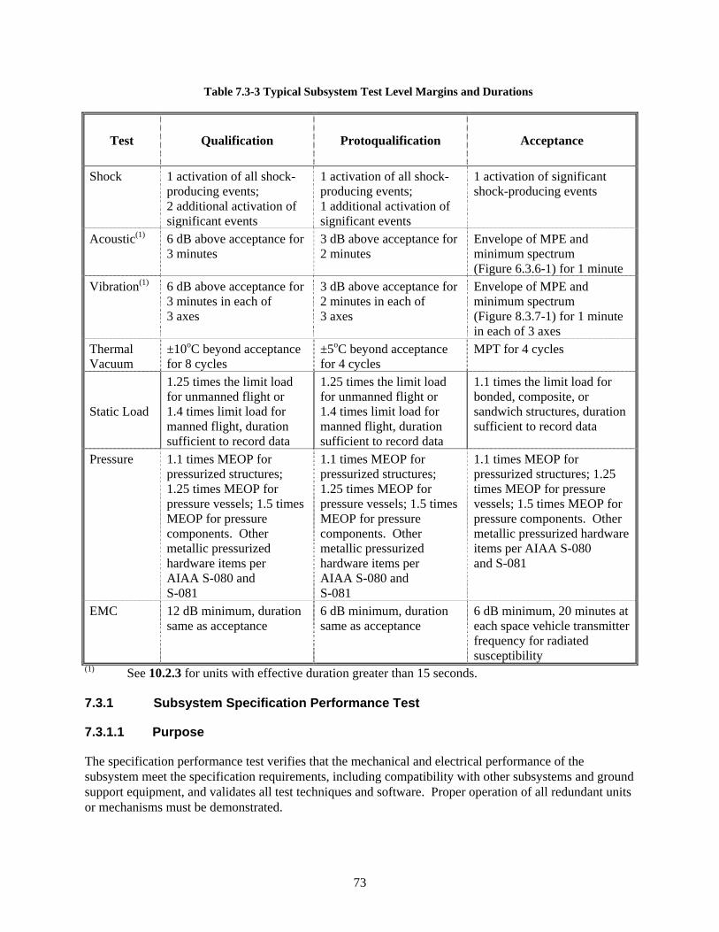
73
Table 7.3-3 Typical Subsystem Test Level Margins and Durations
Test Qualification Protoqualification Acceptance
Shock 1 activation of all shock-producing events; 2 additional activation of significant events
1 activation of all shock-producing events; 1 additional activation of significant events
1 activation of significant shock-producing events
Acoustic(1) 6 dB above acceptance for 3 minutes
3 dB above acceptance for 2 minutes
Envelope of MPE and minimum spectrum (Figure 6.3.6-1) for 1 minute
Vibration(1) 6 dB above acceptance for 3 minutes in each of 3 axes
3 dB above acceptance for 2 minutes in each of 3 axes
Envelope of MPE and minimum spectrum (Figure 8.3.7-1) for 1 minute in each of 3 axes
Thermal Vacuum
±10oC beyond acceptance for 8 cycles
±5oC beyond acceptance for 4 cycles
MPT for 4 cycles
Static Load
1.25 times the limit load for unmanned flight or 1.4 times limit load for manned flight, duration sufficient to record data
1.25 times the limit load for unmanned flight or 1.4 times limit load for manned flight, duration sufficient to record data
1.1 times the limit load for bonded, composite, or sandwich structures, duration sufficient to record data
Pressure 1.1 times MEOP for pressurized structures; 1.25 times MEOP for pressure vessels; 1.5 times MEOP for pressure components. Other metallic pressurized hardware items per AIAA S-080 and S-081
1.1 times MEOP for pressurized structures; 1.25 times MEOP for pressure vessels; 1.5 times MEOP for pressure components. Other metallic pressurized hardware items per AIAA S-080 and S-081
1.1 times MEOP for pressurized structures; 1.25 times MEOP for pressure vessels; 1.5 times MEOP for pressure components. Other metallic pressurized hardware items per AIAA S-080 and S-081
EMC 12 dB minimum, duration same as acceptance
6 dB minimum, duration same as acceptance
6 dB minimum, 20 minutes at each space vehicle transmitter frequency for radiated susceptibility
(1) See 10.2.3 for units with effective duration greater than 15 seconds. 7.3.1 Subsystem Specification Performance Test
7.3.1.1 Purpose
The specification performance test verifies that the mechanical and electrical performance of the subsystem meet the specification requirements, including compatibility with other subsystems and ground support equipment, and validates all test techniques and software. Proper operation of all redundant units or mechanisms must be demonstrated.
74
7.3.1.2 Mechanical Test
Mechanical devices, valves, deployables, and separation subsystems shall be functionally tested at the subsystem level in the launch, orbital, or recovery configuration appropriate to the function. Alignment checks shall be made where appropriate. Fit checks shall be made of the subsystem interfaces using master gages or interface assemblies. The test shall validate that the subsystem performs within maximum and minimum limits under worst-case conditions, including environments, time, and other applicable requirements. Tests shall demonstrate positive margins of strength, torque, and related kinematics and clearances. Where operation in Earth gravity or in an operational temperature environment cannot be performed, a suitable ground test fixture may be used to permit operation and performance evaluation. The pass-fail criteria shall be adjusted as appropriate to account for worst-case maximum and minimum limits that have been modified to adjust for subsystem and ground test conditions.
7.3.1.3 End-to-End Specification Performance Test
These tests shall be performed in accordance with the general requirements stated above. The subsystem should be in its flight configuration with all units and subsystems connected, except explosive-ordnance elements. The test shall verify the integrity of end-to-end circuits, including functions, redundancies, deployment circuitry, end-to-end paths, and at least nominal performance, including radio frequency and other sensor inputs. End-to-end sensor testing may be accomplished with self-test or coupled inputs.
The test shall be designed to operate all units, primary and redundant, and to exercise all commands and operational modes to the extent practical. The operation of all thermally controlled units, such as heaters and thermostats, shall be verified by test. Where control of such units is implemented by sensors, electrical or electronic devices, coded algorithms, or a computer, end-to-end performance testing shall be conducted. The test shall demonstrate that all commands having precondition requirements (such as enable, disable, a specific equipment configuration, and a specific command sequence) cannot be executed unless the preconditions are satisfied. Equipment performance parameters that might affect end-to-end performance, such as command and data rates, shall be varied over specification ranges to demonstrate the performance. Autonomous functions shall be verified. Continuous monitoring of perceptive parameters, including input and output parameters, and the vehicle main bus by a power transient-monitoring device and a current monitoring device, shall be provided to detect intermittent failures.
The subsystem shall be operated through a mission profile with all events occurring in actual flight sequence. This sequence shall include the final countdown, launch, ascent, separation, upper-stage operation, all appropriate orbital operational modes, and return from orbit as appropriate. This sequence shall include live disconnecting of electrical circuits from cable-cutting or connector separation. All explosive-ordnance-firing circuits shall be energized and monitored during these events to verify that the proper energy density is delivered to each device and in the proper sequence. All measurements that are telemetered shall also be monitored and trended during appropriate portions of these events to verify proper operations. As a minimum, “a day in the life of the mission test” shall be run. A portion of this test shall be run with antenna hats removed.
7.3.1.4 Supplementary Requirements
Specification performance tests shall be conducted before and after the environmental subsystem tests program to detect equipment anomalies and to assure that performance meets specification requirements. These tests do not require the mission profile sequence. Sufficient data shall be analyzed to verify the
75
adequacy of the testing and the validity of the data before any change is made to an environmental test configuration, so that any required retesting can be readily accomplished. During these tests, the maximum use of telemetry shall be employed for data acquisition, problem identification, and problem isolation.
7.3.2 Subsystem Static Load Test
7.3.2.1 Purpose
The static load test demonstrates the adequacy of the structural subsystem to meet requirements of strength and stiffness, with the desired qualification margin, when subjected to simulated critical environments predicted to occur during their service life (such as temperature, humidity, pressure, and loads).
7.3.2.2 Test Description
Same as 6.3.11.2.
7.3.2.3 Test Levels and Duration
Qualification:
a. Level. Unless otherwise specified, the load level for the ultimate static load test is 1.4 times limit load (3.20) for manned systems and 1.25 times limit load for unmanned systems.
b. Temperature. Critical flight temperature and load combinations shall be simulated or taken into account.
c. Duration. Loads shall be applied as closely as practical to actual flight loading times, with a dwell time not longer than necessary to record test data such as stress, strain, deformation, and temperature.
Protoqualification:
Same as qualification.
Acceptance:
A subsystem proof load test shall be conducted for all structural units made of composite materials or having adhesively bonded parts. The proof load test detects material, process, and workmanship defects that would respond to structural proof loading. The requirement for the proof load test may be waived if a proven nondestructive evaluation method, with well-established accept/reject criteria, is used for inspecting subsystems.
a. Level. Unless otherwise specified, the proof load for flight items shall be 1.1 times limit load (3.20).
b. Duration. Loads shall be applied as closely as practical to actual flight loading times, with a minimum dwell time sufficient to record test data.
76
7.3.2.4 Supplementary Requirements
Structural test requirements are specified in AIAA S-110-2005.
7.3.3 Subsystem Pressure Test
7.3.3.1 Purpose
The proof pressure test detects material and workmanship defects that could result in failure of the pressurized subsystem.
7.3.3.2 Test Descriptions
Same as 6.3.12.2a
7.3.3.3 Test Level and Duration
Same as 6.3.12.3b
7.3.3.4 Supplementary Requirements
None
7.3.4 Subsystem Vibration Test
7.3.4.1 Purpose
Same as for vehicles. 8.3.6.1
7.3.4.2 Test Description
Same as for vehicles. 8.3.6.2
7.3.4.3 Test Levels and Duration
Same as for vehicles. 8.3.6.3
7.3.4.4 Supplementary Requirements
Same as for vehicles. 8.3.6.4
In addition, subsystems designed for operation during ascent that are exposed to multiple worst-case environments such as thermal and vibration are candidates for combined environmental testing. When such testing is employed, the subsystem shall be tested as close to worst-case flight temperature as is practical and monitored for temperature performance during vibration exposure.
7.3.5 Subsystem Acoustic Test
7.3.5.1 Purpose
Same as for vehicles. 8.3.5.1

77
7.3.5.2 Test Description
Same as for vehicles. 8.3.5.2
7.3.5.3 Test Levels and Duration
Same as for vehicles. 8.3.5.3
7.3.5.4 Supplementary Requirements
Same as for vehicles. 8.3.5.4
7.3.6 Subsystem Shock Test
7.3.6.1 Purpose
Same as for vehicles. 8.3.4.1
7.3.6.2 Test Description
Same as for vehicles. 8.3.4.2
7.3.6.3 Test Activations
Same as for vehicles. 8.3.4.3
7.3.6.4 Supplementary Requirements
Same as for vehicles. 8.3.4.4
7.3.7 Subsystem Thermal Vacuum Test
Subsystems and functional modules shall be temperature cycled in vacuum according to the following criteria:
a. Those subsystems or portions thereof that cannot be tested as a standalone unit to performance specifications at the unit level shall be tested at the subsystem level to unit temperature requirements.
b. Those subsystems or payloads that, at the vehicle level, cannot be tested to their appropriate thermal environments or cannot meet performance specification testing requirements either due to configuration requirements or interaction with other subsystems, shall be tested at the subsystem level to system temperature requirements.
c. Subsystems that are processing hardware and software controlled shall have their processing hardware/software functionality and performance tested over the full range of the subsystem’s unit temperature requirements via hardware and/or simulators (e.g., control system computers).
d. Subsystems, which have an external interface, shall have their external unit interfaces tested to specification performance at temperature extremes at ambient pressure, if the interface unit is tested per the unit thermal vacuum test requirements.
78
7.3.7.1 Purpose
Same as for vehicles. 8.3.8.1. For cases where vehicle thermal vacuum testing is not effective for workmanship screening due to small temperature changes from hot to cold cycles, then thermal cycle testing at the subsystem level shall be applied. See Note 10.1.
7.3.7.2 Test Description
Same as for vehicles. 8.3.8.2. For cases where the thermal cycle test is applied, see Note 10.1.
7.3.7.3 Test Levels and Duration
Same as for vehicles. 8.3.8.3, except as noted in 7.3.7. Thermal cycles shall be added per Note 10.1.1 when system thermal vacuum testing is not effective for workmanship screen.
7.3.7.4 Specification Performance
Same as for vehicles. 8.3.8.4. For cases where the thermal cycle test is applied, see Note 10.1.
7.3.7.5 Supplementary Requirements
Same as for vehicles. 8.3.8.4. For cases where the thermal cycle test is applied, see Note 10.1.
7.3.8 Subsystem Separation and Deployment Tests
7.3.8.1 Purpose
The subsystem separation test shall be performed as a qualification test to validate the adequacy of the separation subsystem to meet its performance requirements on such parameters as separation velocity, acceleration, and angular motion; time to clear and clearances; flexible-body distortion and loads; amount of debris; and explosive-ordnance shock levels. For a payload fairing using a high-energy separation subsystem, the test also demonstrates the structural integrity of the fairing and its generic attachments under the separation shock loads environment. The data from the separation test are also used to validate the analytical method and basic assumptions used in the separation analysis. The validated method is then used to verify that requirements are met under worst-case flight conditions.
7.3.8.2 Test Description
The test fixtures shall duplicate the interfacing structural sections to simulate the separation subsystem boundary conditions existing in the flight article. The remaining boundary conditions for the separating bodies shall simulate the conditions in flight at separation, unless the use of other boundary conditions will permit an unambiguous demonstration that subsystem requirements can be met. The test article shall include all attached flight hardware that could pose a debris threat if detached. When ambient atmospheric pressure may adversely affect the test results, such as for large fairings, the test shall be conducted in a vacuum chamber, duplicating the altitude condition encountered in flight at the time of separation. Critical conditions of temperature, pressure, or loading due to acceleration shall be simulated or taken into account. As a minimum, instrumentation shall include high-speed cameras to record the motion of specially marked target locations, accelerometers to measure the structural response, and other environmental data and strain gages to verify load levels in structurally critical attachments.
79
7.3.8.3 Test Activations
A separation test shall be conducted to demonstrate that requirements on separation performance parameters are met under nominal conditions. When critical off-nominal conditions cannot be modeled with confidence, at least one additional separation test with the worst-case off-nominal condition shall be conducted to determine the effect on the separation process. When force or torque margin requirements are appropriate, a separate test shall be conducted to demonstrate that the margin is at least 100 percent. However, for separation subsystems involving fracture of structural elements, the margin demonstrated shall be at least 50 percent. In addition, debris risk shall be evaluated by conducting a test encompassing the most severe conditions that can occur in flight, or by including loads scaled from those measured in tests under nominal conditions.
7.3.8.4 Supplementary Requirements
A post-test inspection for debris shall be conducted on and around the test article.
7.3.9 Subsystem Electromagnetic Compatibility (EMC) Test
7.3.9.1 Purpose
The electromagnetic compatibility test shall demonstrate that the electromagnetic interference characteristics (emission and susceptibility) of the subsystem, under normal operating conditions, do not result in malfunction of the subsystem. It also demonstrates that the subsystem does not emit, radiate, or conduct interference, which could result in malfunction of other subsystems.
7.3.9.2 Test Description
The test shall be conducted in accordance with the requirements of TOR-2005(8583)-1. All tests shall be conducted at the payload and bus level on the subsystem external EMC interfaces. Acceptance tests shall be performed when there is less than a 12 dB margin, or the radiated emissions requirement is more stringent than 10 dBuV/m, or the subsystem has a passive intermodulation requirement.
The EMC margin is to be incorporated into the test levels. No additional margin is required if the TOR-2005(8583)-1 levels already have the required margin for the interface. Qualification margins of 6 dB are acceptable if the combined test uncertainty, part variation, part degradation at end-of-life, and workmanship variation is less than 6 dB. Electroexplosive devices and bridge wires have a 20 dB margin requirement below the DC no-fire value and a 6 dB margin requirement below the RF no-fire value.
7.3.9.3 Test Levels and Duration
The test levels shall be as follows: Qualification: 12 dB Protoqualification: 6 dB Acceptance: 6 dB
80
The test duration shall be 20 minutes at each space vehicle transmitter frequency for radiated susceptibility. Otherwise, the duration is the greater of 3 seconds or the unit response time for susceptibility requirements and 15 milliseconds duration for emission requirements. 7.3.10 Mode Survey Test
The mode survey test is conducted to obtain data needed to develop dynamic models for loads analyses. It may be conducted on a subsystem or at the vehicle level (8.3.9). TOR-2003(8583)-2886 defines the scope and application of the test.
7.3.10.1 Purpose
The mode survey test (modal survey) is conducted to experimentally derive a structural dynamic model of a vehicle or to provide a basis for test-verification of an analytical model. After upgrading analytically to the flight configuration (such as different propellant loading and minor differences between flight and test unit mass properties), this model is used in analytical simulations of flight loading events to define the verification cycle structural loads. These loads are used to determine structural margins and adequacy of the structural static test loading conditions (7.3.2). They are, therefore, critical for verification of vehicle structural integrity and qualification of the structural subsystem as flight-ready. Where practical, a modal survey is also performed to define or verify models used in the final preflight evaluation of structural dynamic effects on control subsystem precision, stability, and pointing performance.
7.3.10.2 Test Description
The test article shall consist of flight-quality structure with assembled units, payloads, and other major subsystems, and shall contain actual or simulated liquids at specified fill-levels. For large vehicles, complexity and testing practicability may dictate that tests be performed on separate sections of the vehicle. For large launch vehicles in particular, practicality may also dictate use of an integrated program of ground and flight tests, involving substantial flight data acquisition and analysis, to acquire the necessary data for model verification. Wire harnesses, or representative mass simulators, may be installed for the mode survey test. Mass simulators may be used to represent a flight item when its attachment-fixed resonances have been demonstrated by test to occur above the frequency range of interest established for the mode survey test. Dynamic simulators may be used for items that have resonances within the frequency range of interest if they are accurate dynamic representations of the flight item. Alternatively, mass simulators may be used if flight-quality items are subjected separately to mode survey testing that meet test requirements. All mass simulators are to include realistic simulation of interface attach structure and artificial stiffening of the test structure shall be avoided.
The data obtained in the modal survey shall be adequate to define the mode shapes, associated resonant frequencies and damping values, for all modes that occur in the frequency range of interest, typically to 70 Hz. In addition, the first two lateral modes in each coordinate plane, the first axial mode, and the first torsional mode shall be acquired even if their frequencies lie outside the specified test range. The test modes are considered to have acceptable quality when they are orthogonal, with respect to the analytical mass matrix, to within 10 percent.
7.3.10.3 Test Levels
The test is generally conducted at response levels that are low compared to the expected flight levels. Limited testing shall be conducted to evaluate nonlinear behavior, with a minimum of 3 levels used when significant nonlinearity is identified.
81
7.3.10.4 Supplementary Requirements
Because of their criticality to achieving a successful test, appropriate pretest analyses and experimentation shall be performed to:
a. Establish test instrumentation requirements.
b. Evaluate the test stand and fixturing to preclude any boundary condition uncertainties that could compromise test objectives.
c. Verify that mass simulators have no resonances within the frequency range of interest.
d. Establish flexibility to add or modify instrumentation during test to account for unexpected modes.

82
THIS PAGE INTENTIONALLY LEFT BLANK
83
8. Vehicle Test Requirements
8.1 General Requirements
The vehicle-level test baseline assumes that all unit level and subsystem tests have been performed in accordance with this document. Tests that are conducted as acceptance tests for vehicle elements (such as alignments, instrument calibrations, antenna patterns, and mass properties) shall also have been conducted. All flight equipment and software shall be installed prior to beginning of test.
The sequence of tests performed at the vehicle level is shown in Table 8.3-1 for qualification and protoqualification vehicles and in Table 8.3-2 for acceptance vehicles. An overview of vehicle test level margins and durations described in this section is shown in Table 8.3-3.
System-level tests shall be the same as subsystem tests for end-to-end performance, configuration change, command and telemetry performance, external interfaces to the ground and LV component, except that the actual compatibility interface testing to the other external system components need not be done at temperature, if testing against a simulator at temperature was accomplished at a lower level of assembly.
8.2 Vehicle Development Tests
Vehicles are subjected to development tests and evaluations using structural and thermal development models as may be required to confirm dynamic and thermal environmental criteria for design of subsystems, to verify mechanical interfaces, and to assess functional performance of deployment mechanisms and thermal control subsystems. Vehicle-level development testing also provides an opportunity to develop handling and operating procedures as well as to characterize interfaces and interactions.
8.2.1 Mechanical Fit Development Tests
For launch and upper-stage vehicles, a mechanical fit, assembly, and operational interface test with the facilities at the launch or test site is recommended. Flight-weight hardware should be used if practical; however, a facsimile or portions thereof may be used to conduct the development tests at an early point in the schedule in order to reduce the impact of hardware design changes that may be necessary.
8.2.2 Mode Survey Development Tests
A development mode survey test (modal survey) should be conducted at the vehicle level when uncertainty in analytically predicted structural dynamic characteristics is judged to be excessive for purposes of structural or control subsystem design, and an early identification of problem areas is desired. The test article may be full vehicle or one or more substructures depending on size and complexity. Such a development test does not replace a mode survey required for vehicle qualification, unless the test also meets the requirements in 8.3.9.
8.2.3 Structural Development Tests
For structures having redundant load paths, structural tests may be required to verify the stiffness properties and to measure member loads, stress distributions, and deflections. The stiffness data are of particular interest where nonlinear structural behavior exists that is not fully exercised in a mode survey test. This may include nonlinear bearings, elastic buckling of panels, gaping at preloaded interfaces, and
84
slipping at friction joints. Systems demonstrating a significant level of nonlinear structural behavior may require an alternative method for dynamic model validation such as high input sine vibration base shakes. The member load and stress distribution data may be used to experimentally verify the loads transformation matrix. Deflection data may be also used to experimentally verify the appropriate deflection transformation matrix. These matrices may be used, in conjunction with the dynamic model, to calculate loads such as axial forces, bending moments, shears and torsional moments, and various stresses and deflections, which can be converted into design load and clearance margins for the vehicle. This development test does not replace the structural static load test that is required for subsystem qualification.
8.2.4 Acoustic Development Tests
Since high-frequency vibration responses are difficult to predict by analytical techniques, acoustic development testing of the launch, upper-stage, and space vehicles may be necessary to verify the adequacy of the dynamic design criteria for units. Vehicle units that are not installed at the time of the test should be dynamically simulated with respect to mass, center of gravity, moments of inertia, interface stiffness, and geometric characteristics. The test article should be exposed to the maximum predicted flight levels and instrumented at unit and other points of interest to obtain vibration responses for use in verifying unit predictions. Supporting structures such as payload or upper-stage adapters should be included and responses evaluated to understand structurally borne energy that contributes to the response at nearby units.
8.2.5 Shock Development Tests
Since high-frequency shock responses are difficult to predict by analytical techniques, shock development testing of the launch, upper stage, and space vehicles may be necessary to verify the adequacy of the dynamic design criteria for units. Vehicle units that are not installed at the time of the test should be dynamically simulated with respect to mass, center of gravity, moments of inertia, interface stiffness, and geometric characteristics. All explosive ordnance devices and other mechanisms capable of imparting a significant shock to the vehicle and its mounted assemblies should be operated to demonstrate functionality and survivability. Where practical, the shock test should involve physical separation of elements being deployed or released. When a significant shock is expected from interfacing subsystems not included on the vehicle under test (such as when a fairing separation causes shock responses on an upper stage under test), the adaptor subsystem or suitable simulation shall be attached and appropriate explosive ordnance devices or other means used to simulate the shock imposed. The pyroshock environment may vary significantly between ordnance activations. Therefore, the statistical basis given in 3.27 shall be used for estimating maximum expected and extreme spectra. Multiple activations of ordnance devices may be necessary to provide data for improved estimates.
8.2.6 Thermal Balance Development Tests
A thermal balance development test is performed to verify the analytical thermal modeling of launch, upper-stage, or space vehicles, and demonstrate the ability of the thermal control subsystem to maintain temperature limits. For vehicles in which thermally induced structural distortions are critical to mission success, the thermal balance test also evaluates alignment concerns. The test vehicle should consist of flight hardware or a thermally equivalent structure with addition of equipment panels, thermal control insulation, finishes, and thermally equivalent models of electrical, electronic, pneumatic, and mechanical units. Testing should be conducted in a space simulation test chamber capable of simulating the ascent, transfer orbit, and orbital thermal vacuum conditions as may be appropriate. The test consists of simulating different environmental and operational modes and collecting steady state and transient
85
thermal data to correlate the thermal analytic model and verify performance of the thermal control hardware.
8.2.7 Transportation and Handling Development Tests
The handling and transport of launch, upper-stage, space vehicles, or their sub-tier elements, is normally conducted to result in dynamic environments well below those expected for launch and flight. However, since these environments are difficult to predict, it is often necessary to conduct a development test of potentially significant handling and transportation configurations to determine worst-case dynamic inputs. Such a test should use a development model of the item or a simulator which has at least the proper mass properties and RFI shielding effectiveness, instrumented to measure responses of the item. In particular, a drop test representative of a maximum credible operational occurrence should be conducted to demonstrate protection of the item in the handling apparatus and validate design of the shipping container. The data should be sufficient to determine whether the environments are benign relative to the design requirements, or to provide a basis for an analysis to demonstrate lack of damage, or to augment qualification and acceptance testing, if necessary.
8.2.8 Wind Tunnel Development Tests
Flight vehicle aerodynamic and aero-thermal data are needed to establish that the vehicles survive flight, and function properly under the imposed loads. For flight vehicles with a new or significantly changed aerodynamic design, the following wind tunnel tests shall be conducted:
a. Force and Moment Tests. These tests provide the resultant aerodynamic forces and moments acting on the vehicle during the high-dynamic-pressure region of flight. Data from these tests are used in both structural and control subsystem design and in trajectory analysis.
b. Steady-State Pressure Tests. These tests determine the spatial distribution of the steady-state component of the pressures imposed on the vehicle’s external surfaces during the high-dynamic-pressure region of flight. These data are used to obtain the axial air load distributions, which are used to evaluate the static-elastic characteristics of the vehicle. These data along with fluctuating pressures of the external skin environment are also used in compartment venting analyses to determine burst and collapse pressures imposed on the vehicle structure. The design and testing of the payload fairing structure are particularly dependent upon high-quality definition of these pressures.
c. Aerodynamic Heating Tests. These tests determine the heating effects due to fin and fuselage junctures, drag (friction), angle of attack, flow transition, shock wave impingement, proximity effects for multibody vehicles, and surface discontinuities.
d. Base Heating Tests. These tests determine the heating effects due to thermal radiation, multiplume recirculation convection, plume-induced flow separation on the vehicle body, and the base flow field.
e. Thruster Plume-Impingement Heating Tests. These tests determine the heating effects and contamination due to impingement of the thruster plumes.
f. Transonic and Supersonic Buffet and Aerodynamic Noise Tests. These tests define the spatial distribution of the unsteady or fluctuating component of the pressures imposed on the vehicle external surfaces during the high-dynamic-pressure region of flight. These data are used to obtain the dynamic airloads acting to excite the various structural modes of the vehicle and are
86
used in aeroelastic, flutter, and vibroacoustic analyses. These data are also used in compartment venting analyses to determine burst and collapse pressures imposed on the vehicle structure.
g. Ground-Wind-Induced Oscillation Tests. These tests define the resultant forces and moments acting on the vehicle prior to launch when it is exposed to the ground-wind environment. Flexible models or elastically mounted rigid models are used to simulate at least the first cantilever-bending mode of the vehicle. Nearby structures or terrain, which may influence the flow around the vehicle, shall also be simulated.
h. Aerodynamic Staging Tests. These tests determine the forces and moments acting on the core vehicle and solid rocket motors (SRMs) that are oriented in a series of representative positions encountered during SRM booster separation. Data from these tests are used in stage performance analysis.
8.3 Test Program for Flight Vehicles
Testing at the system level is composed of specification/performance tests that are performed under ambient conditions and during or after environmental exposure.
The vehicle configuration shall contain all of its flight subsystems with flight software, and shall interface with external hardware and facilities and or simulators for external interface verification.
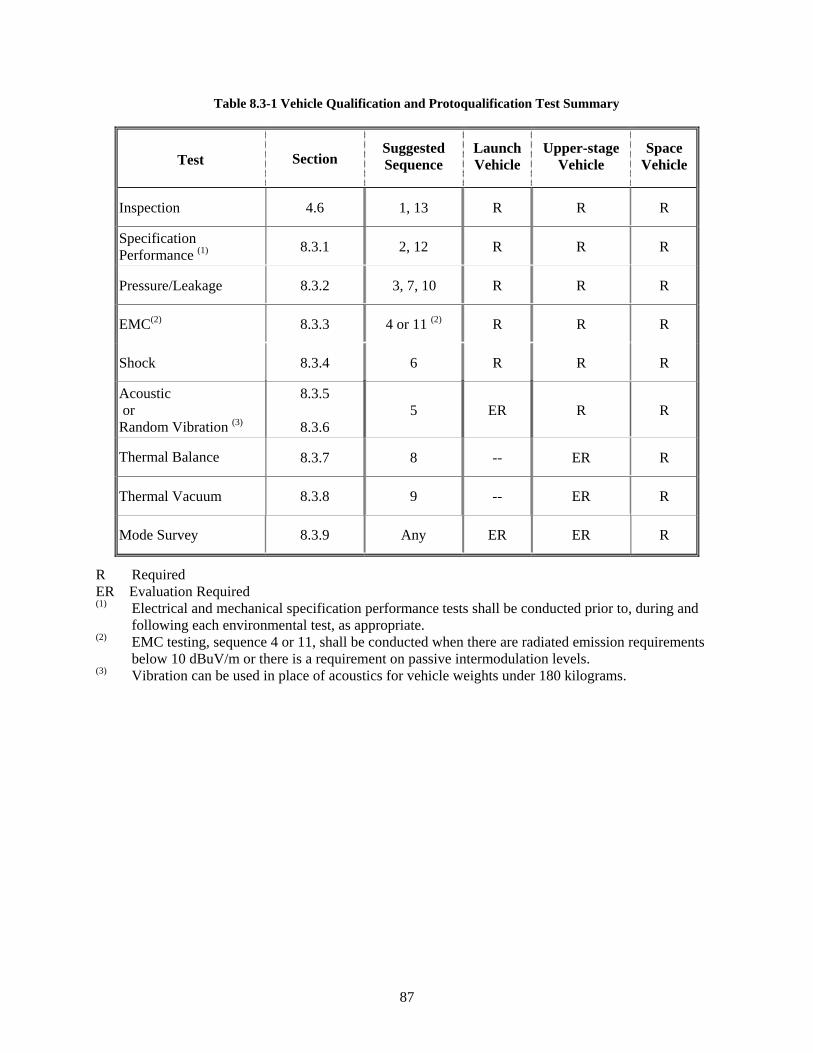
87
Table 8.3-1 Vehicle Qualification and Protoqualification Test Summary
Test Section Suggested Sequence
Launch Vehicle
Upper-stage Vehicle
Space Vehicle
Inspection 4.6 1, 13 R R R
Specification Performance (1) 8.3.1 2, 12 R R R
Pressure/Leakage 8.3.2 3, 7, 10 R R R
EMC(2) 8.3.3 4 or 11 (2) R R R
Shock 8.3.4 6 R R R
Acoustic or Random Vibration (3)
8.3.5
8.3.6 5 ER R R
Thermal Balance 8.3.7 8 -- ER R
Thermal Vacuum 8.3.8 9 -- ER R
Mode Survey 8.3.9 Any ER ER R
R Required
ER Evaluation Required
(1) Electrical and mechanical specification performance tests shall be conducted prior to, during and following each environmental test, as appropriate.
(2) EMC testing, sequence 4 or 11, shall be conducted when there are radiated emission requirements below 10 dBuV/m or there is a requirement on passive intermodulation levels.
(3) Vibration can be used in place of acoustics for vehicle weights under 180 kilograms.
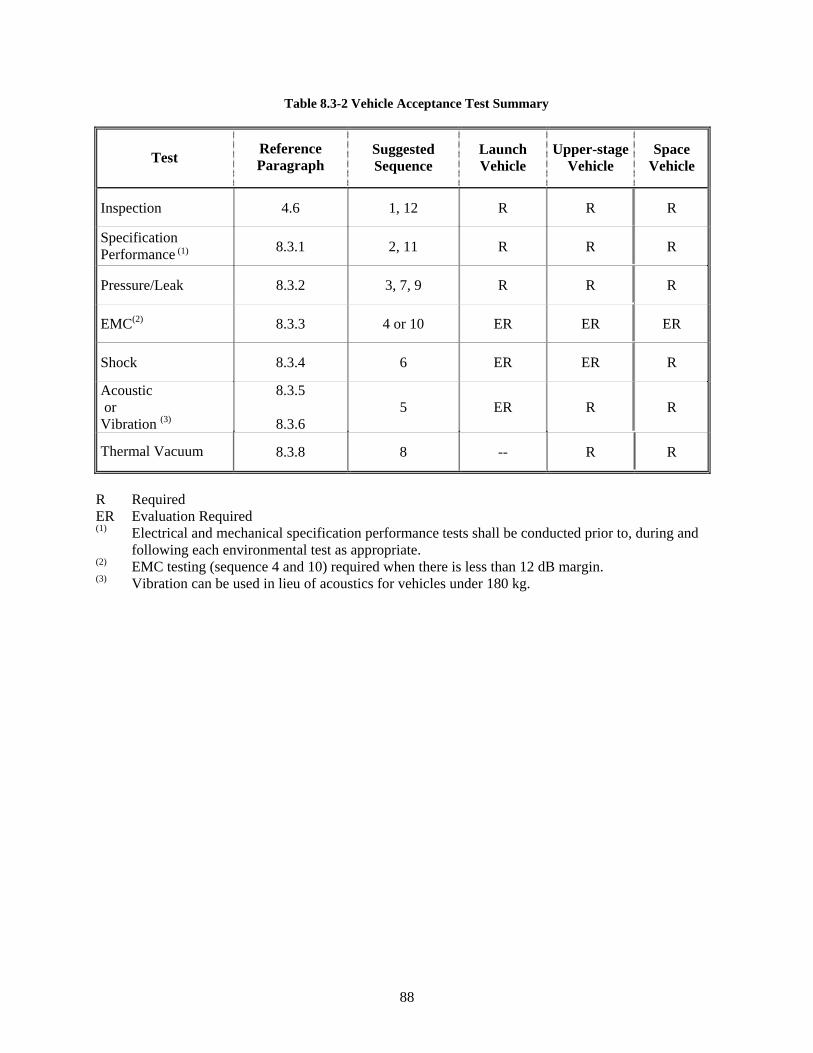
88
Table 8.3-2 Vehicle Acceptance Test Summary
Test Reference Paragraph
Suggested Sequence
Launch Vehicle
Upper-stage Vehicle
Space Vehicle
Inspection 4.6 1, 12 R R R
Specification Performance (1) 8.3.1 2, 11 R R R
Pressure/Leak 8.3.2 3, 7, 9 R R R
EMC(2) 8.3.3 4 or 10 ER ER ER
Shock 8.3.4 6 ER ER R
Acoustic or Vibration (3)
8.3.5
8.3.6 5 ER R R
Thermal Vacuum 8.3.8 8 -- R R
R Required ER Evaluation Required
(1) Electrical and mechanical specification performance tests shall be conducted prior to, during and following each environmental test as appropriate.
(2) EMC testing (sequence 4 and 10) required when there is less than 12 dB margin. (3) Vibration can be used in lieu of acoustics for vehicles under 180 kg.
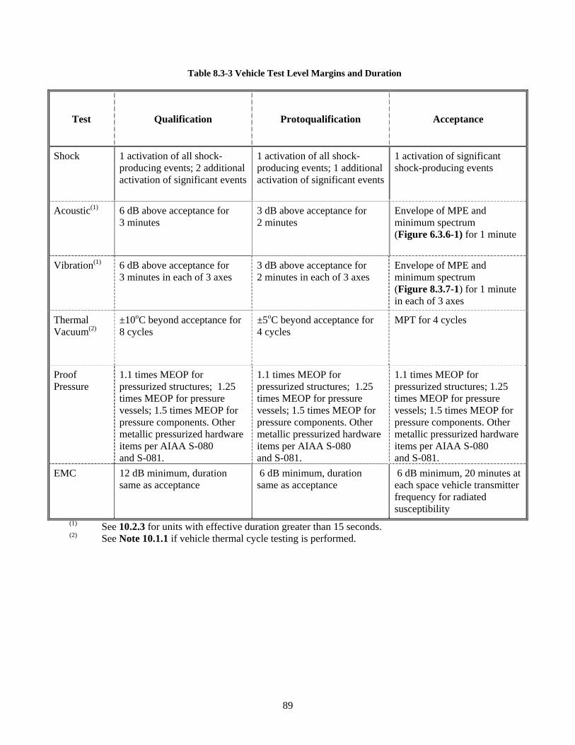
89
Table 8.3-3 Vehicle Test Level Margins and Duration
Test Qualification Protoqualification Acceptance
Shock 1 activation of all shock-producing events; 2 additional activation of significant events
1 activation of all shock-producing events; 1 additional activation of significant events
1 activation of significant shock-producing events
Acoustic(1) 6 dB above acceptance for 3 minutes
3 dB above acceptance for 2 minutes
Envelope of MPE and minimum spectrum (Figure 6.3.6-1) for 1 minute
Vibration(1) 6 dB above acceptance for 3 minutes in each of 3 axes
3 dB above acceptance for 2 minutes in each of 3 axes
Envelope of MPE and minimum spectrum (Figure 8.3.7-1) for 1 minute in each of 3 axes
Thermal Vacuum(2)
±10oC beyond acceptance for 8 cycles
±5oC beyond acceptance for 4 cycles
MPT for 4 cycles
Proof Pressure
1.1 times MEOP for pressurized structures; 1.25 times MEOP for pressure vessels; 1.5 times MEOP for pressure components. Other metallic pressurized hardware items per AIAA S-080 and S-081.
1.1 times MEOP for pressurized structures; 1.25 times MEOP for pressure vessels; 1.5 times MEOP for pressure components. Other metallic pressurized hardware items per AIAA S-080 and S-081.
1.1 times MEOP for pressurized structures; 1.25 times MEOP for pressure vessels; 1.5 times MEOP for pressure components. Other metallic pressurized hardware items per AIAA S-080 and S-081.
EMC 12 dB minimum, duration same as acceptance
6 dB minimum, duration same as acceptance
6 dB minimum, 20 minutes at each space vehicle transmitter frequency for radiated susceptibility
(1) See 10.2.3 for units with effective duration greater than 15 seconds. (2) See Note 10.1.1 if vehicle thermal cycle testing is performed.
90
8.3.1 Vehicle Specification Performance Test
8.3.1.1 Purpose
The specification performance test verifies that the mechanical and electrical performance of the vehicle meet the specification requirements, including compatibility with ground support equipment, and validates all test techniques and software algorithms used in computer-assisted commanding and data processing. Proper operation of all redundant units or mechanisms shall be demonstrated.
8.3.1.2 Mechanical Test
Mechanical devices, valves, deployables, and separation subsystems shall be functionally tested at the vehicle level in the launch, orbital, or recovery configuration appropriate to the function. Alignment checks shall be made where appropriate. Fit checks shall be made of the vehicle physical interfaces using master gauges or interface assemblies. The test shall validate that the vehicle performs within maximum and minimum limits under worst-case conditions including environments, time, and other applicable requirements. Tests shall demonstrate positive margins of strength, torque, and related kinematics and clearances. Where operation in Earth gravity or in an operational temperature environment cannot be performed, a suitable ground test fixture may be used to permit operation and performance evaluation. The pass-fail criteria shall be adjusted as appropriate to account for worst-case maximum and minimum limits that have been modified to adjust for ground test conditions.
8.3.1.3 End-to-End Specification Performance Test
These tests shall be performed in accordance with the general requirements stated above. The vehicle shall be in its flight configuration with all units and subsystems connected, except explosive-ordnance elements. The test shall verify the integrity of end-to-end circuits, including functions, redundancies, deployment circuitry, end-to-end paths, and at least nominal performance, including radio frequency and other sensor inputs. End-to-end sensor testing may be accomplished with self-test or coupled inputs.
The test shall be designed to operate all units, primary and redundant, and to exercise all commands and operational modes to the extent practical. The operation of all thermally controlled units, such as heaters and thermostats, shall be verified by test. Where control of such units is implemented by sensors, electrical or electronic devices, coded algorithms, or a computer, end-to-end performance testing shall be conducted. The test shall demonstrate that all commands having precondition requirements (such as enable, disable, a specific equipment configuration, and a specific command sequence) cannot be executed unless the preconditions are satisfied. Equipment performance parameters that might affect end-to-end performance, such as command and data rates, shall be varied over specification ranges to demonstrate the performance. Autonomous functions shall be verified. Continuous monitoring of perceptive parameters, including input and output parameters, and the vehicle main bus by a power transient-monitoring device and a current monitoring device, shall be provided to detect intermittent failures.
The vehicle shall be operated through a mission profile with all events occurring in actual flight sequence. This sequence shall include the final countdown, launch, ascent, separation, upper-stage operation, all appropriate orbital operational modes, and return from orbit as appropriate. All explosive-ordnance-firing circuits shall be energized and monitored during these events to verify that the proper energy density is delivered to each device and in the proper sequence. All measurements that are telemetered shall also be monitored and trended during appropriate portions of these events to verify proper operations. As a
91
minimum, “a day in the life of the mission test” shall be run. A portion of this test shall be run with antenna hats removed.
During one test in the acceptance sequence, the vehicle shall be subjected to a “plugs-out” test. The purpose of this test is to demonstrate all vehicle systems are in an “as near-flight configuration” as is practical. At the start of the test, umbilicals are disconnected and the vehicle is on flight batteries or flight-like batteries. The vehicle shall be operated through a basic set of functional checkouts and telemetry responses.
8.3.1.4 Supplementary Requirements
Specification performance tests shall be conducted before and after the vehicle environmental test program to detect equipment anomalies and to assure that performance meets specification requirements. These tests may not require the mission profile sequence, however, consideration should be given to the profile when developing the test procedure. Sufficient data shall be analyzed to verify the adequacy of the testing and the validity of the data before any change is made to an environmental test configuration, so that any required retesting can be readily accomplished. The final software testing shall demonstrate that the hardware and software configuration can meet the defined functional subsystem performance specification in a worst-case stressing environment for that function performed by the computer.
8.3.2 Vehicle Pressure and Leakage Tests
8.3.2.1 Purpose
These tests demonstrate the capability of pressurized subsystems to meet the specified flow, pressure, and leakage rate requirements.
8.3.2.2 Test Description
The vehicle shall be placed in a facility that provides the services and safety conditions required to protect personnel and equipment during the testing of high pressure subsystems and in the handling of dangerous fluids. Preliminary tests shall be performed, as necessary, to verify compatibility with the test setup and to ensure proper control of the equipment and test functions. The requirements of the subsystem including flow, leakage, and regulation shall be measured while operating applicable valves, pumps, and motors. The flow checks shall verify that the plumbing configurations are adequate. Checks for subsystem cleanliness, moisture levels, and pH levels shall also be made. Where pressurized subsystems are assembled with other than brazed or welded connections, the specified torque values for these connections shall be verified prior to the initial qualification leak check.
In addition to the high pressure test, propellant tanks and thruster valves shall be tested for leakage under propellant servicing conditions. The subsystem shall be evacuated to the internal pressure normally used for propellant loading and the pressure monitored for decay as an indication of leakage.
This test shall be performed for qualification, protoqualification, and acceptance testing.
8.3.2.3 Test Levels and Durations
a. For launch and upper-stage vehicles that contain pressurized structures, the pressurized subsystem shall be pressurized to a proof pressure that is 1.1 times the maximum expected operating pressure (MEOP) and held constant for a short dwell time, sufficient to assure that the proper
92
pressure was achieved within the allowed test tolerance. The test pressure shall then be reduced to the MEOP for leakage inspection.
b. For space vehicles, unless specified otherwise, the pressurized subsystems shall be pressurized to a proof pressure, which is 1.25 times the MEOP and held for 5 minutes and then the pressure shall be reduced to the MEOP. This sequence shall be conducted 3 times for qualification and once for acceptance testing, followed by inspection for leakage at the MEOP. The duration of the evacuated propulsion subsystem leakage test shall not exceed the time that this condition is normally experienced during propellant loading.
8.3.2.4 Supplementary Requirements
Applicable safety standards shall be followed in conducting all tests. Tests for detecting external leakage shall be performed at such locations as joints, fittings, plugs, and lines. The acceptable leakage rate to meet mission requirements shall be based upon an appropriate analysis. In addition, the measurement technique shall account for leakage rate variations with pressure and temperature and have the required threshold, resolution, and accuracy to detect any leakage equal to or greater than the acceptable leak rate. If appropriate, the leakage rate measurement shall be performed at the MEOP and at operational temperature, with the representative fluid commodity, to account for dimensional and viscosity changes. Times to achieve thermal and pressure equilibrium, test duration, and temperature sensitivity shall be determined by an appropriate combination of analysis and development test, and the results documented. Leakage detection and measurement procedures may require vacuum chambers, bagging of the entire vehicle or localized areas, or other special techniques to achieve the required accuracies. See MIL-STD-1522 for further guidance on integration of pressure components and subsystems.
8.3.3 Vehicle Electromagnetic Compatibility Test
8.3.3.1 Purpose
The electromagnetic compatibility test demonstrates electromagnetic compatibility of the vehicle. EMC testing at the vehicle level assumes that full EMC testing in accordance with TOR-2005(8583)-1 has been accomplished at the unit and/or subsystem level and that bus and payload EMC testing has also occurred in accordance with the tests described herein.
8.3.3.2 Test Description
The operation of the vehicle and selection of instrumentation shall be suitable for determining the margin against malfunctions and unacceptable or undesired responses due to electromagnetic incompatibilities.
The test shall demonstrate satisfactory electrical and electronic equipment operation in conjunction with the expected electromagnetic radiation from other subsystems or equipment, such as from other vehicle elements and ground support equipment. The vehicle shall be subjected to the required tests while in the launch, orbital, and return-from-orbit configurations and in all possible operational modes, as applicable. Special attention shall be given to areas indicated to be marginal by unit-level test and analysis. Potential electromagnetic interference between the test vehicle and other subsystems shall be measured. The tests shall be conducted according to the requirements of TOR-2005(8583)-1. The tests shall include but not be limited to nine main segments:
a. Radio frequency (RF) self-compatibility (all receivers and transmitters receiving and transmitting through flight antennas without antenna hats)
93
b. Power quality
c. Radiated emissions
d. Radiated susceptibility
e. Conducted emissions
f. Power transients
g. Magnetic moments
h. Critical circuit margins
i. Umbilical separation test
Explosive-ordnance devices having bridge wires, but otherwise inert, shall be installed in the vehicle and monitored during all tests.
Acceptance tests shall be performed when there is less than 12 dB margin, or the radiated emissions requirement is more stringent than 10 dBuV/m, or the units have a passive intermodulation requirement. Radiated emission acceptance tests can be deferred to the subsystem or functional module level.
The EMC margin is to be incorporated in to the test levels. No additional margin is required if the TOR-2005(8583)-1 levels already have the required margin for the interface. Qualification margins of 6 dB are acceptable if the combined test uncertainty, part variation, part degradation at end-of-life, and workmanship variation is less than 6 dB. Electroexplosive devices and bridge wires have a 20 dB margin requirement below the DC no-fire value and a 6 dB margin requirement below the RF no-fire value.
8.3.3.3 Test Levels and Duration
The test levels shall be as follows: Qualification: 12 dB Protoqualification: 6 dB Acceptance: 6 dB The test duration shall be 20 minutes at each space vehicle transmitter frequency for radiated susceptibility. Otherwise, the duration is the greater of 3 seconds or the unit response time for susceptibility requirements and 15 milliseconds duration for emission requirements.
8.3.3.4 Supplementary Requirements
Acceptance tests shall be performed when there is less than 12 dB margin, or the radiated emissions requirement is more stringent than 10 dBuV/m, or the subsystem has a passive intermodulation requirement. For guidance on testing rationale for satellite hardness and survivability refer to DNA-TR-84-140.
94
8.3.4 Vehicle Shock Test
8.3.4.1 Purpose
The shock test demonstrates the capability of the vehicle to withstand or, if appropriate, to operate in the induced shock environments. The shock test also yields the data to validate the maximum expected unit shock requirement.
8.3.4.2 Test Description
The vehicle shall be supported and configured to allow flight-like dynamic response of the vehicle with respect to amplitude, frequency content, and paths of transmission. Support of the vehicle may vary during the course of a series of shock tests in order to reflect the configuration at the time of each shock event. Test setups shall avoid undue influence of test fixtures, and prevent recontact of separated portions.
In the shock test or series of shock tests, the vehicle shall be subjected to shock transients that simulate the extreme expected shock environment to the extent practical. Shock events to be considered include separations and deployments initiated by explosive ordnance or other devices, as well as impacts and suddenly applied or released loads that may be significant for unit dynamic response (such as due to an engine transient, parachute deployment, and vehicle landing). All devices on the vehicle capable of imparting significant shock excitation to vehicle units shall be activated. Those potentially significant shock sources not on the vehicle under test, such as on an adjoining payload fairing or a nearby staging joint, shall also be actuated or simulated and applied through appropriate interfacing structures. Dynamic instrumentation shall be installed to measure shock responses in three orthogonal directions at attachments of selected units.
8.3.4.3 Test Activations
Qualification: All explosive-ordnance devices and other potentially significant shock-producing devices or events, including those from sources not installed on the vehicle under test, shall be activated at least one time or simulated as appropriate. The significant shock events shall be activated two additional times to provide for variability in the vehicle test and to provide data for prediction of maximum and extreme expected shock environments for units. Activation of both primary and redundant devices shall be carried out in the same sequence as they are intended to operate in service.
Protoqualification: Same as qualification except only one additional activation of significant shock producing events is required.
Acceptance: One activation of significant shock-producing events is required.
8.3.4.4 Supplementary Requirements
Electrical and electronic units shall be operating and monitored to the maximum extent practical. Continuous monitoring of several perceptive parameters, including input and output parameters, and the vehicle main bus by a power transient-monitoring device, shall be provided to monitor power quality and detect intermittent failures.
95
8.3.5 Vehicle Acoustic Test
8.3.5.1 Purpose
The acoustic test demonstrates the ability of the vehicle to endure acoustic acceptance testing and meet requirements during and after exposure to the extreme expected acoustic environment in flight. Except for items whose environment is dominated by structure-borne vibration, the acoustic test also verifies the adequacy of unit vibration qualification levels and serves as a qualification test and environmental stress screen for items not tested at a lower level of assembly.
8.3.5.2 Test Description
The vehicle in its ascent configuration shall be installed in an acoustic test facility capable of generating sound fields or fluctuating surface pressures that induce vehicle vibration environments sufficient for vehicle qualification. The vehicle shall be mounted on a flight-type support structure or reasonable simulation thereof. Significant fluid and pressure conditions shall be replicated to the extent practical. Appropriate dynamic instrumentation shall be installed to measure vibration responses at attachment points of critical and representative units. Control microphones shall be placed at a minimum of four well-separated locations, preferably at one-half the distance from the test article to the nearest chamber wall, but no closer than 0.5 meter (20 inches) to both the test article surface and the chamber wall. When test article size exceeds facility capability, the vehicle may be appropriately subdivided and acoustically tested as one or more subsystems or assemblies.
8.3.5.3 Test Level and Duration
The basic test levels and duration required for vehicles exposed to the liftoff and ascent acoustic excitation, effective duration of 15 seconds (3.11), are as follows:
Qualification: 6 dB above acceptance for 3 minutes.
Protoqualification: 3 dB above acceptance for 2 minutes.
Acceptance: Envelope of the maximum predicted environment and minimum workmanship level shown in Figure 6.3.6-1 for 1 minute.
8.3.5.4 Supplementary Requirements
During the test, all electrical and electronic units used during launch, ascent, and on orbit, or that may be especially susceptible to vibroacoustic failure modes, shall be electrically energized and sequenced through operational modes to the maximum extent practical, with the exception of units that may sustain damage if energized. Continuous monitoring of appropriate perceptive parameters, including input and output parameters, and the vehicle main bus by a power transient-monitoring device and a current monitoring device, shall be provided to detect intermittent failures.
See 10.2.5 for discussion of a damage-based approach to the analysis of flight acoustic data for determining the adequacy of established acceptance and qualification testing when new flight data bring the adequacy of the MPE spectrum into question.
96
8.3.6 Vehicle Vibration Test
The vibration test may be conducted instead of an acoustic test for small, compact vehicles, which can be excited more effectively via interface vibration than by an acoustic field. Such vehicles typically have a mass under 180 kilograms (400 pounds).
8.3.6.1 Purpose
The vibration test demonstrates vehicle margin over the launch and ascent environments and assures a satisfactory workmanship level screen can be applied for follow-on hardware. Except for items whose response is dominated by acoustic excitation, the vibration test also verifies the adequacy of unit vibration qualification levels and serves as a qualification test and environmental stress screen for items that have not been tested at a lower level of assembly.
8.3.6.2 Test Description
The vehicle and a flight-type adapter, in the ascent configuration, shall be vibrated using one or more shakers through appropriate vibration fixtures. Vibration shall be applied in each of three orthogonal axes, one direction being parallel to the vehicle thrust axis. Instrumentation shall be installed to measure, in those same three axes, the vibration inputs and the vibration responses at attachment points of critical and representative units.
8.3.6.3 Test Levels and Durations
The basic test levels and duration required for vehicles exposed to the liftoff and ascent vibration, effective duration of 15 seconds (3.11), are as follows:
Qualification: 6 dB above acceptance for three minutes/axis.
Protoqualification: 3 dB above acceptance for two minutes/axis.
Acceptance: Envelope of the maximum predicted environment and minimum workmanship level shown in Figure 8.3.7-1 for 1 minute/axis. Notching allowed based on impedance differences in test set up versus flight interface.
Operating time should be divided approximately equally between redundant functions. When insufficient test time is available at the full test level to test redundant circuits, functions, and modes, extended testing using a spectrum no lower than 6 dB below the qualification spectrum shall be conducted as necessary to complete functional testing.
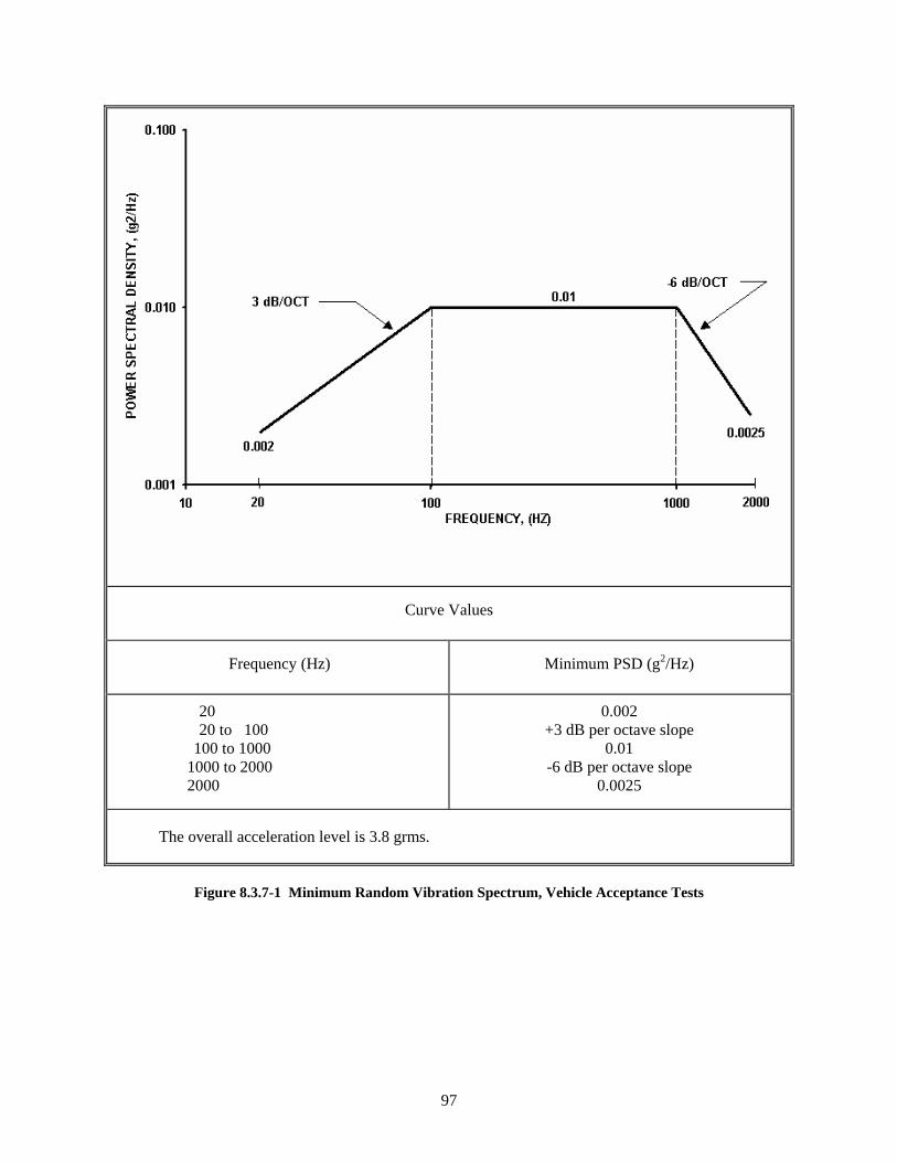
97
Curve Values
Frequency (Hz) Minimum PSD (g2/Hz)
20 20 to 100 100 to 1000 1000 to 2000 2000
0.002 +3 dB per octave slope 0.01 -6 dB per octave slope 0.0025
The overall acceleration level is 3.8 grms.
Figure 8.3.7-1 Minimum Random Vibration Spectrum, Vehicle Acceptance Tests
98
8.3.6.4 Supplementary Requirements
During the test, all electrical and electronic units used during launch, ascent, and on-orbit, or that may be especially susceptible to vibroacoustic failure modes, shall be electrically energized and sequenced through operational modes to the maximum extent practical. Continuous monitoring of appropriate perceptive parameters, including input and output parameters, and the vehicle main bus by a power transient-monitoring device, shall be provided to detect intermittent failures.
See 10.2.5 for discussion of a damage-based approach to the analysis of flight vibration data for determining the adequacy of established acceptance and qualification test requirements when new flight data are outside the experience base used to derive the preflight MPE spectrum.
8.3.7 Vehicle Thermal Balance Test
8.3.7.1 Purpose
The thermal balance test provides the data necessary to verify the analytical thermal model and demonstrates the ability of the vehicle thermal control subsystem to maintain specified temperature limits of units for various operational scenarios throughout the entire vehicle. The thermal balance test can be combined with the thermal vacuum test.
8.3.7.2 Test Description
The qualification or protoqualification vehicle shall be exposed to thermal environments expected by the vehicle during its service life in a thermal balance test. Test instrumentation shall be installed that will produce data that can be correlated to the thermal model over the full range of seasons, equipment duty cycles, ascent conditions, solar angles, maximum and minimum unit thermal dissipations, including effects of bus voltage variations, and eclipse combinations. As a minimum, three test conditions shall be imposed: a hot operational case, a cold operational case and a cold non-operational case. Two additional cases should be imposed: a transient case and a case chosen to check the validity of the correlated model. Other cases that are commonly simulated include eclipse, ascent, safemode and “day-in-the-life” conditions.
Thermal balance test phases need not be worst-case expected flight conditions, but they should not be significantly different from these conditions. Special emphasis shall be placed on defining the test conditions expected to produce the maximum and minimum temperatures of sensitive units such as batteries. Sufficient measurements shall be made on the vehicle internal and external units to verify the vehicle thermal design, hardware and analyses. The operation and power requirements of all thermostatically or electronically controlled heaters and coolers shall be verified during the test, and appropriate control authority demonstrated, both on the primary and redundant circuits.
The test chamber, with the test item installed, shall provide a pressure of no higher than 13.3 mPa(10–4 Torr) for space and upper-stage vehicles, or a pressure commensurate with service altitude for launch vehicles. Where appropriate, provisions should be made to prevent the test item from “viewing” warm chamber walls, by using black-coated cryogenic shrouds of sufficient area and shape that are capable of approximating liquid nitrogen temperatures. The vehicle thermal environment may be supplied by one of the following methods:
99
a. Absorbed Flux. The absorbed solar, albedo, and planetary irradiation is simulated using heater panels or infrared (IR) lamps with their spectrum adjusted for the external thermal coating properties, or using electrical resistance heaters attached to vehicle surfaces.
b. Incident Flux. The intensity, spectral content, and angular distribution of the incident solar, albedo, and planetary irradiation are simulated.
c. Equivalent Radiation Sink Temperature. The equivalent radiation sink temperature is simulated using infrared lamps and calorimeters with optical properties identical to those of the vehicle surface.
d. Combination. The thermal environment is supplied by a combination of the above methods.
The selection of the method and fidelity of the simulation depends upon details of the vehicle thermal design such as vehicle geometry, the size of internally produced heat loads compared with those supplied by the external environment, and the thermal characteristics of the external surfaces. Instrumentation shall be incorporated down to the unit level to evaluate total vehicle performance within operational limits as well as to identify unit problems. The vehicle shall be operated and monitored throughout the test. Dynamic flight simulation of the vehicle thermal environment should be provided unless the external vehicle temperature does not vary significantly with time.
Temperature measurement channels used to define thermal equilibrium shall have stabilities with time (noise level evidenced by varying readings at constant temperature, including bias and precision) commensurate with the time rate of change of temperature (dT/dt) used to define equilibrium. This capability shall be defined as a requirement and demonstrated before test.
8.3.7.3 Levels and Duration
Test conditions and durations for the thermal balance test are dependent upon the vehicle configuration, design, and mission details. Boundary conditions for evaluating the thermal control hardware and design shall include the following:
a. Maximum external absorbed flux plus maximum internal dissipation.
b. Minimum external absorbed flux plus minimum internal power dissipation.
c. Minimum external absorbed flux plus minimum non-operating or stand-by power dissipation.
The thermal time constant of the subsystems and mission profile both influence the time required for the vehicle to achieve thermal equilibrium and hence the test duration.
8.3.7.4 Supplementary Requirements
Success criteria depend on not only survival and operation of each item within specified temperature limits, but also on correlation of the test data with analytic thermal models. Correlation of test results to the thermal model predictions shall be within ±3oC. Lack of correlation with the analytic model may indicate either a deficiency in the model, test setup, or space vehicle hardware. In regions where the correlation exceeds ±3oC, either the thermal model shall be modified to achieve the correlation or an explanation shall be provided as why correlation cannot be achieved. The correlated thermal math model shall be used to make the final temperature predictions for the various mission phases (such as prelaunch,
100
ascent, on-orbit, and disposal orbit). These temperature predictions verify the thermal control design and thermal uncertainty margins.
8.3.8 Vehicle Thermal Vacuum Test
8.3.8.1 Purpose
The qualification thermal vacuum test demonstrates the ability of the vehicle to meet design requirements and establishes the thermal design margin and vehicle performance under thermal vacuum conditions and temperature extremes. Acceptance thermal vacuum testing demonstrates the ability to withstand the thermal stressing environment with margin on temperature range and number of cycles. It also detects material, process and workmanship defects that would respond to thermal vacuum and thermal stress conditions.
8.3.8.2 Test Description
The vehicle shall be placed in a thermal vacuum chamber and a performance specification test performed to assure readiness for chamber closure. The vehicle shall be divided into separate equipment zones, based on the thermal limits of the temperature-sensitive units and similar unit qualification temperatures within each zone. Units that operate during ascent shall be operating and monitored for corona and multipacting, as applicable, as the pressure is reduced to the lowest specified level. The rate of chamber pressure reduction shall be no greater than during ascent, and may have to be slower to allow sufficient time to monitor for corona and multipacting. Equipment that does not operate during launch shall have electrical power applied after the lowest specified pressure level has been reached. A thermal cycle begins with the vehicle at ambient temperature. The temperature is raised to the specified high level and stabilized. Following the high-temperature soak, the temperature shall be reduced to the lowest specified level and stabilized. Following the low-temperature soak, the vehicle shall be returned to ambient temperature to complete one thermal cycle. Performance specification tests shall be conducted during the first and last thermal cycle at both the hot and cold temperature limits with functional operation and monitoring of perceptive parameters during all other cycles. If simulation of the ascent environment is desirable at the beginning of the test, the first cycle may begin with a transition to a cold thermal environment, rather than a hot thermal environment.
In addition to the thermal cycles for an upper-stage or space vehicle, the chamber may be programmed to simulate various orbital flight operations. Execution of operational sequences shall be coordinated with expected environmental conditions, and a complete cycling of all equipment shall be performed including the operating and monitoring of redundant units and paths. Vehicle electrical equipment shall be operating and monitored throughout the test. Temperature monitors shall assure attainment of temperature limits. Strategically placed witness plates, quartz crystal microbalances, or other instrumentation shall be installed in the test chamber to measure the outgassing from the vehicle and test equipment.
8.3.8.3 Test Levels and Durations
Qualification: 10oC beyond acceptance temperatures for 8 cycles.
Protoqualification: 5oC beyond acceptance temperatures for 4 cycles.
Acceptance: Minimum and maximum predicted temperatures for 4 cycles.
101
Temperatures in various equipment areas shall be controlled by the external test environment and internal heating resulting from equipment operation. During the hot and cold half-cycles, the temperature limit is reached as soon as one unit in each equipment area is at its hot or cold temperature. Unit temperatures shall not be allowed to go outside their applicable qualification, protoqualification, or acceptance range at any time during the test. The pressure shall be maintained at no higher than 13.3 mPa (10-4 Torr) but no higher than the pressure commensurate with the highest possible service altitude.
The rate of temperature change shall equal or exceed the maximum predicted mission rate of change. The thermal soak shall be at least 8 hours at each temperature extreme during the first and last cycles. For intermediate cycles, the thermal soak duration shall be at least 4 hours. Operating time shall be divided approximately equally between primary and redundant units. Specification performance tests performed on the last cycle shall be free of failures.
8.3.8.4 Supplementary Requirements
Performance tests shall be conducted after unit temperatures have stabilized at the hot and cold temperatures on the first and last cycle. Before the first cycle and following the last cycle, the test shall also be performed at ambient. For any intermediate cycles, abbreviated specification performance tests at hot and cold temperatures shall be performed. During these tests, electrical and electronic units, including all redundant circuits and paths, shall be cycled through all operational modes. Perceptive parameters shall be monitored for failures and intermittents. All electrical circuits and all paths should be verified for circuit performance and continuity. Specification performance tests may be conducted during temperature transitions.
In some cases, vehicle performance and workmanship objectives may require a vehicle thermal cycle test in addition to a vehicle thermal vacuum test. If payload performance or workmanship screening requires a temperature range that cannot be achieved in ground vacuum testing, then a vehicle thermal cycle test over the desired temperature range shall also be performed as an alternative strategy (10.1.1).
8.3.9 Mode Survey Test
The mode survey test shall be conducted to obtain data required to develop dynamic models for loads analyses. It may be conducted as a system test, or a combination of subsystem tests, as appropriate. TOR-2003(8583)-2886 defines the scope and application of the test.
8.3.9.1 Purpose
The mode survey test (or modal survey) is conducted to experimentally derive a structural dynamic model of a vehicle or to provide a basis for test-verification of an analytical model. After upgrading analytically to the flight configuration (such as different propellant loading and minor differences between flight and test unit mass properties), this model is used in analytical simulations of flight loading events to define the verification cycle structural loads. These loads are used to determine structural margins and adequacy of the structural static test loading conditions (7.3.2). They are, therefore, critical for verification of vehicle structural integrity and qualification of the structural subsystem as flight-ready. Where practical, a mode survey test is also performed to define or verify models used in the final preflight evaluation of structural dynamic effects on control subsystem precision, stability, and pointing performance.
102
8.3.9.2 Test Description
The test article shall consist of flight-quality structure with assembled units, payloads, and other major subsystems, and shall contain actual or simulated liquids at specified fill-levels. For large vehicles, complexity and testing practicability may dictate that tests be performed on separate sections of the vehicle. For large launch vehicles in particular, practicality may also dictate use of an integrated program of ground and flight tests, involving substantial flight data acquisition and analysis, to acquire the necessary data for model verification. Wire harnesses, or representative mass simulators, may be installed for the mode survey test. Mass simulators may be used to represent a flight item when its attachment-fixed resonances have been demonstrated by test to occur above the frequency range of interest established for the mode survey test. Dynamic simulators may be used for items that have resonances within the frequency range of interest if they are accurate dynamic representations of the flight item. Alternatively, mass simulators may be used if flight-quality items are subjected separately to mode survey testing that meet test requirements. All mass simulators are to include realistic simulation of interface attach structure and artificial stiffening of the test structure shall be avoided.
The data obtained in the modal survey shall be adequate to define the mode shapes, associated resonant frequencies and damping values, for all modes that occur in the frequency range of interest, typically to 70 Hz. In addition, the first two lateral modes in each coordinate plane, the first axial mode, and the first torsional mode shall be acquired even if their frequencies lie outside the specified test range. The test modes are considered to have acceptable quality when they are orthogonal, with respect to the analytical mass matrix, to within 10 percent.
8.3.9.3 Test Levels
The test is generally conducted at response levels that are low compared to the expected flight levels. Limited testing shall be conducted to evaluate nonlinear behavior, with a minimum of 3 levels used when significant nonlinearity is identified.
8.3.9.4 Supplementary Requirements
Because of their criticality to achieving a successful test, appropriate pretest, planning, analyses and experimentation shall be performed to:
a. Establish test instrumentation requirements.
b. Evaluate the test stand and fixturing to preclude any boundary condition uncertainties that could compromise test objectives.
c. Verify that mass simulators have no resonances within the frequency range of interest.
d. Establish flexibility to add or modify instrumentation during test to account for unexpected modes.
103
9. Prelaunch Validation and Operational Tests
9.1 Prelaunch Validation Tests, General Requirements
Prelaunch validation testing is accomplished at the factory and at the launch base, with the objective of demonstrating launch system and on-orbit system readiness. Prelaunch validation testing is usually divided into two phases:
Phase A. Integrated system tests (Step 3 tests, MIL-STD-1833).
Phase B. Initial operational tests and evaluations (Step 4 tests, MIL-STD-1833).
During Phase A, the test series establishes the vehicle baseline data in the factory preshipment acceptance tests. When the launch vehicle(s), upper-stage vehicle(s), and space vehicle(s) are first delivered to the launch site, tests shall be conducted as required to assure vehicle readiness for integration with the other vehicles. These tests are intended to identify any changes that may have occurred in vehicle parameters as a result of handling and transportation to the launch base. The launch vehicle(s), upper-stage vehicle(s), and space vehicle(s) may each be delivered as a complete vehicle or they may be delivered as separate stages and first assembled at the launch site as a complete launch system. The prelaunch validation tests are unique for each program in the extent of the operations necessary to ensure that all interfaces are properly tested. For programs that ship a complete vehicle to the launch site, these tests primarily confirm vehicle performance, check for transportation damage, and demonstrate interface compatibility.
During Phase B, initial operational tests and evaluations (Step 4 tests) are conducted following the integrated system tests to demonstrate successful integration of the vehicles with the launch facility, and that compatibility exists between the vehicle hardware, ground equipment, computer software, and within the entire launch system and on-orbit system. The point at which the integrated system tests end and the initial operational tests and evaluations begin is somewhat arbitrary since the tests may be scheduled to overlap in time. To the greatest extent practical or as dictated by the procuring agency, the initial operational tests in the launch vehicle and launch upper stage shall exercise every operational mode in order to ensure that all mission requirements are satisfied. These Step 4 tests shall be conducted in an operational environment, with the equipment in its operational configuration, by the operating personnel, in order to test and evaluate the effectiveness and suitability of the hardware and software. These tests should emphasize reliability, contingency plans, maintainability, supportability, and logistics. These tests should assure compatibility with scheduled range operations including range instrumentation.
9.2 Prelaunch Validation Test Flow
Step 4 testing (MIL-STD-1833) of new or modified ground facilities, ground equipment, or software should be completed prior to starting the prelaunch validation testing of the vehicles at the launch base. The prelaunch validation test flow shall follow a progressive growth pattern to ensure proper operation of each vehicle element prior to progressing to a higher level of assembly and test. In general, tests should follow the launch base buildup cycle. As successive vehicles or subsystems are verified, assembly proceeds to the next level of assembly. Following testing of the vehicles and their interfaces, the vehicles are electrically and mechanically mated and integrated into the launch system. Upper-stage vehicles and space vehicles employing a recoverable flight vehicle shall utilize a flight vehicle simulator to perform mechanical and electrical interface tests prior to integration with the flight vehicle. Following integration of the launch vehicle(s), upper-stage vehicle(s), and space vehicle(s) performance tests of each of the
104
vehicles shall be conducted to ensure its proper operation following the handling operations involved in mating. Vehicle cleanliness shall be monitored. In general, the Step 4 testing of the launch system is conducted first. Bus and Payload testing shall be in accordance with appropriate verification and test plans.
9.3 Prelaunch Validation Test Configuration
During each test, the applicable vehicle(s) shall be in their flight configuration to the maximum extent practical, consistent with safety, control, and monitoring requirements. For programs utilizing a recoverable flight vehicle, the test configuration shall include any airborne support equipment required for the launch, ascent, and space vehicle deployment phases. This equipment shall be mechanically and electrically mated to the space vehicle in its launch configuration. All ground equipment shall be validated prior to being connected to any flight hardware. Test provisions shall be made to verify integrity of circuits into which flight jumpers, arm plugs, or enable plugs have been inserted.
9.4 Prelaunch Validation Test Descriptions
The prelaunch launch vehicle and upper stage validation tests shall exercise and demonstrate satisfactory operation of each of the vehicles through all of their mission phases, to the maximum extent practical. Test data shall be compared to corresponding data obtained in factory tests to identify trends in performance parameters.
9.4.1 Performance Tests
Specification performance tests shall be conducted to validate integrated hardware and software performance and flight worthiness. Mechanical tests shall be conducted for leakage, valve and mechanism operability, and fairing clearance.
9.4.1.1 Simulators
When simulators are employed, the flight interfaces shall be validated when reconnected.
9.4.1.2 Explosive Ordnance and Non-Explosive Firing Circuits
Prior to final connection of the firing circuit to electro-explosive devices (EEDs) and non-explosive actuators (NEAs), the ignition energy levels and redundant circuit isolation shall be validated. Circuit continuity and stray energy checks shall be made prior to connection of a firing circuit to ordnance devices and this check shall be repeated whenever that connection is opened and prior to reconnection.
9.4.1.3 Transportation and Handling Monitoring
Monitoring for shock, vibration, temperature and humidity shall be performed at a minimum at the forward and aft interfaces between the shipping container transporter and the article being shipped, and on the top of the article. Three-axis monitoring shall cover the entire shipment period and the data evaluated as part of the receiving process.
9.4.1.4 Late Removal and Replacement of Flight Hardware
A performance test shall be performed when flight hardware or interfaces have been removed and/or replaced. The performance test shall verify performance of all affected hardware and software and potentially affected interfaces.
105
9.4.2 Propulsion Subsystem Leakage and Functional Tests
Specification performance tests of the launch vehicle propulsion subsystem(s) shall be conducted to verify the proper operation of all units, to the maximum extent practical.
9.4.3 Launch-critical Ground Support Equipment Tests
Hardware associated with ground subsystems that are flight critical and nonredundant (such as umbilicals) shall have been subjected to appropriate tests under simulated functional and environmental conditions of launch. These tests shall include an evaluation of radio frequency (RF) interference between system elements, electrical power interfaces, and the command and control subsystems. For further guidance on Range Safety see AFSCM 91-710.
On a new vehicle design or where significant design changes were made to the telemetry, tracking, or receiving subsystem of an existing vehicle, a test shall be run on the first vehicle to ensure nominal operation and that explosive ordnance devices do not fire when the vehicle is subjected to worst-case electromagnetic interference environment.
9.4.4 Compatibility Test, On-Orbit System
9.4.4.1 Purpose
The compatibility test validates any required compatibility of the upper-stage vehicle, the space vehicle, the on-orbit command and control network, and other elements of the space system.
9.4.4.2 Test Description
Facilities to perform system compatibility tests exist. These facilities can command the launch, upper-stage, and space vehicles, process telemetry from the vehicles, as well as perform tracking and ranging, thus verifying the system compatibility, the command software, the telemetry processing software, and the telemetry modes. The required tests shall include the following:
a. Verification of the compatibility of the radio frequencies and signal waveforms used by the flight unit’s command, telemetry, and tracking links.
b. Verification of the ability of the flight units to accept commands from the command and control network(s).
c. Verification of the command and control network(s) capability to receive, process, display, and record the vehicle(s) telemetry link(s) required to monitor the flight units during launch, ascent, and on-orbit mission phases.
d. Verification of the ability of the flight units to support on-orbit tracking as required for launch, ascent, and on-orbit mission phases.
e. Verification of all uplink and downlink command and telemetry paths or redundant boxes as well as all keying material on-board the space vehicle and on the ground.
f. Verification of all downlink frequencies that contain data.
106
9.4.4.3 Supplementary Requirements
The compatibility test is made with every vehicle to verify system interface compatibility. The test shall be run using the software versions that are integrated into the operational on-orbit software of the vehicle under test. Following the completion of the compatibility test, the on-orbit command and control network configuration of software, hardware, and procedures shall be frozen until the space vehicle is in orbit and initialized.
9.5 Follow-On Operational Tests for Space Vehicles
9.5.1 Follow-On Operational Tests and Evaluations
Follow-on Operational Tests and Evaluations shall be conducted at the launch site in an operational environment, with the equipment in its operational configuration. The assigned operating personnel shall identify operational system deficiencies. (Step 5 in MIL-STD-1833).
9.5.2 On-Orbit Testing
On-orbit testing should be conducted to verify the functional integrity of the space vehicle following launch and orbital maneuvering. Other on-orbit testing requirements are an important consideration in the design of any space vehicle. For example, there may be a need to calibrate on-line equipment or to verify the operational status of off-line equipment while in orbit. However, on-orbit testing is dependent on the built-in design features, and if testing provisions were not provided, the desired tests cannot be accomplished. On-orbit tests are, therefore, so program peculiar that specific requirements are not addressed in this Standard.
9.5.3 Reusable Flight Hardware
Tests of reusable flight hardware shall be conducted as required to achieve a successful space mission. Reusable hardware consists of the vehicles and units intended for repeated missions. Airborne support equipment, that performs its mission while attached to a recoverable launch vehicle, is an example of a candidate for reuse. The reusable equipment would be subjected to repeated exposure to test, launch, flight, and recovery environments throughout its service life. The accumulated exposure time of equipment retained in a recoverable vehicle and of airborne support equipment is a function of the planned number of missions involving this equipment and the retest requirements between missions. The environmental exposure time of airborne support equipment is further dependent on whether or not its use is required during the acceptance testing of other nonrecoverable flight equipment. In any case, the service life of reusable hardware should include all planned reuses and all planned retesting between uses.
The testing requirements for reusable space hardware after the completion of a mission and prior to its reuse on a subsequent mission depends heavily upon the design of the reusable item and the allowable program risk. For those reasons, specific details are not presented in this Standard. Similarly, orbiting space vehicles that have completed their useful life spans may be retrieved by means of a recoverable flight vehicle, refurbished, and reused. Based on present approaches, it is expected that the retrieved space vehicle would be returned to the contractor’s factory for disassembly, physical inspection, and refurbishment. All originally specified acceptance tests shall be conducted before reuse.
107
10. Notes
10.1 Additional Thermal Considerations
10.1.1 Vehicle Alternate Thermal Strategy
In some cases, vehicle performance and workmanship objectives are better addressed in a vehicle thermal cycle test than in a vehicle thermal vacuum test. If payload performance or workmanship screening requires a temperature range that cannot be achieved in ground vacuum testing, then a vehicle thermal cycle test over the desired temperature range shall also be performed.
When a vehicle thermal cycle test is performed, the number of required vehicle thermal vacuum cycles may be reduced from the values given in 8.3.8.3. The test levels and durations of the vehicle thermal cycling test (and the number of thermal vacuum cycles, performed per 8.3.8) shall be:
Qualification: Minimum temperature range shall be 70oC for 6 cycles (with 4 TV cycles required)
Protoqualification: Minimum temperature range shall be 60oC for 3 cycles (with
2 TV cycles required) Acceptance: Minimum temperature range shall be 50oC for 3 cycles (with
2 TV cycles required)
The vehicle qualification thermal cycle test detects design defects and demonstrates the ability of the vehicle to withstand the stressing environment associated with flight vehicle thermal cycle acceptance testing, with a qualification margin on temperature range and maximum number of cycles. The vehicle acceptance thermal cycle test detects material, process and workmanship defects. The vehicle shall be placed in a thermal chamber at ambient pressure, and a specification performance test shall be performed to assure readiness for the test. The vehicle shall be operated and monitored during the entire test, except that vehicle power may be turned off if necessary to reach stabilization at the cold temperature. Vehicle operation shall be asynchronous with the temperature cycling, and redundant units shall be operated for approximately equal times.
Temperature cycling shall begin when the relative humidity of inside spaces of the vehicle is below the value at which the cold test temperature would cause condensation. One complete thermal cycle is a period beginning at ambient temperature, then cycling to one temperature extreme and stabilizing, then to the other temperature extreme and stabilizing, and then returning to ambient temperature. Strategically placed temperature monitors installed on units shall assure attainment and stabilization of the expected temperature extremes for all units. Auxiliary heating and cooling may be employed for selected temperature-sensitive units (e.g., batteries). If it is necessary in order to achieve the required temperature rate of change, parts of the vehicle such as solar arrays and passive thermal equipment may be removed for the test.
Performance tests shall be conducted after unit temperatures have stabilized at the hot and cold temperatures on the first and last cycle. Before the first cycle and following the last cycle, the performance test shall also be performed at ambient. For intermediate cycles, functional tests at hot and cold temperatures shall be performed. During these tests, electrical and electronic units, including all redundant circuits and paths, shall be cycled through all operational modes. Perceptive parameters shall be monitored for failures and intermittents. All electrical circuits and all paths shall be verified for circuit performance and continuity. Specification performance tests and mission profile testing may be conducted during temperature transitions.
108
10.2 Test Requirements for Acoustic, Vibration, and Shock Environments
10.2.1 Statistical Basis for Test Level
a. Flight-to-flight variability of the spectral value at a frequency for acoustic, random vibration, shock, and sinusoidal vibration environments (defined in 3.25, 3.26, 3.27 and 3.28, respectively) is baselined to be log-normally distributed. That is, the normal distribution applies to the logarithms of the spectral values at a particular frequency. Consequently, the estimated mean spectrum is the average of the logarithmic values of available spectra. The standard deviation of spectra from the mean is denoted by σ and is baselined to equal 3 dB. The assumption of log-normal distribution with 3 dB standard deviation is based on repeated measurements on 24 static firings and over 40 flights of a launch vehicle (Reference 1 in 10.2.7).
b. Test levels are generally based on the normal tolerance interval above the estimated flight mean spectrum. The interval depends on a probability P that the test spectrum will not to be exceeded in flight, estimated with a confidence of C. For the special case where σ is known and the mean spectrum value is estimated from N available flights, the test level L for probability P with confidence C is given by
LP/C = σ [zP + zC/N1/2] dB (10.1)
The factor zP multiplied by σ determines the normal probability limit, and the factor zC/N1/2 multiplied by σ determines the confidence limit for the estimate of the mean spectrum. The factors zP and zC are read from a table of the standardized normal density function found in many references, such as Reference 2 in 10.2.7. On a normal distribution plot, the area P lies to the left of the mean plus zP times the standard deviation σ. Likewise, the area C lies to the left of the mean plus zC times the standard deviation σ. Note that zC = 0 for 50% confidence since the mean is the 50-percentile estimate. Numerical examples for acceptance, qualification, and protoqualification are included in c, d, and e below.
c. Acceptance tests are performed at the P95/50 level, shorthand for the probability P = 0.95 and the confidence C = 0.50. Stated another way, there is a 50-50 chance of one exceedence of the P95/50 spectrum in 20 flights. Reading from the following table that z0.95 = 1.645 and z0.50 = 0, acceptance is performed at 4.9 dB above the mean spectrum [from eq. (10.1), L95/50
= 3(1.645 + 0) = 4.9 dB]. Note that this dB value applies no matter how many flights provide data for the estimate of the mean.
d. Qualification is performed at the P99/90 level (P = 0.99 and C = 0.90). Stated another way, there is 1 chance in 10 of exceeding the qualification level once in 100 flights. For the purpose of preflight prediction, a value N =1 is adopted. Then, since z0.99 = 2.322 and z0.90 = 1.282, preflight qualification is performed at 10.8 dB above the mean spectrum [from eq. (10.1), L99/90 = 3(2.322 + 1.282) = 10.8 dB]. The preflight qualification spectrum is therefore baselined to be 6 dB above the acceptance spectrum (a rounding of 10.8 – 4.9 = 5.9). The 6-dB qualification margin is the same as in versions A and B of this standard, where it was based on experience and not on a statistical model.
After N flights are available, updates of the estimates can be made as follows:
1. A revised estimate of the mean spectrum is calculated.
2. The revised estimate of the L95/50 is then 4.9 dB above the revised mean. The result is compared to the previously established acceptance spectrum.
109
3. The revised estimate of the qualification test margin M, the dB difference between the qualification and acceptance levels (from paragraphs c and d above), is
M = L99/90 − L95/50 = 3(2.322 + 1.282 / N1/2) − 3(1.645 + 0) = 3(0.677 + 1.282 / N1/2) dB (10.2)
As the number N of flight data samples grows, the margin decreases since the confidence in its estimate increases. A table relating the estimated margin to the number of flights providing data, using Eq. (10.2), appears below:
Number of flights, N 1 2 3 4 5 6 8 12 Margin, M (dB) 5.9 4.8 4.3 4.0 3.8 3.6 3.4 3.2
The difference is not allowed to fall below 3 dB. When data from a sufficient number of flights, or from ground tests that produce environments that are realistic for flight (for example, engine firings), the applicable statistical distribution can be determined using the available data.
e. Protoqualification is performed at 3 dB above the 95/50 acceptance level, an established practice set to be half the 6 dB increase for baseline qualification. Assuming that the assumed statistical distribution is valid, the protoqualification spectrum is 7.9 dB above the mean (3 dB over the 4.9 dB for acceptance). Since 7.9 dB is 2.63 sigma above the mean (7.9/3), with 50-percent confidence the probability of exceeding the protoqualification level in flight at any particular frequency is 0.0043 (about 1 in 230); this result is read as the probability of exceeding 2.63 sigma above the mean in a normal density table (Reference 2 in 10.2.7). For a 90% confidence, the probability of exceeding the protoqualification level for a single flight is 0.088 or exceedence will occur once in 11 flights; this result is obtained from eq. (10.1), 7.9 = 3[zP + 1.282/1] yielding zP = 1.351 and resulting in a probability of exceedence of 0.088 read from a normal density table.
10.2.2 Acceleration of Acceptance Life for Acoustic and Random Vibration Tests
Spacecraft and many launch vehicle components are exposed to acoustics and random vibration during the liftoff and ascent segments of flight for a nominal period of 15 seconds. Some components maybe exposed to these environments in excess of 15 seconds, such as those located on or near engines.
Baseline acoustic and random vibration qualification and protoqualification tests include a 1-minute duration for the liftoff and ascent flight environment with a margin added to the acceptance spectrum. A longer than the baseline 15-second duration of the maximum predicted environment (3.11) leads to an increased test time for flight of 4 times that of the MPE, where 4 is the duration factor for fatigue life demonstration by test. To insure that flight capability is maintained after the acceptance program on production hardware, the test duration is increased beyond the time required for flight to serve as a life test for a maximum duration acceptance testing. The assumptions are that fatigue is the life limiting mechanism, that Miner’s Rule for fatigue accumulation applies, and that induced stress is proportional to the applied acceleration. Miner’s Rule (Reference 4 in 10.2.7) states that the summation of the product of the number of cycles times their stress amplitude raised to an exponent “b” is proportional to the fraction of life exhausted. Therefore, if TA denotes the upper limit on the duration of acceptance testing, 4TA becomes the duration of the life test for acceptance required if performed with the acceptance spectrum.
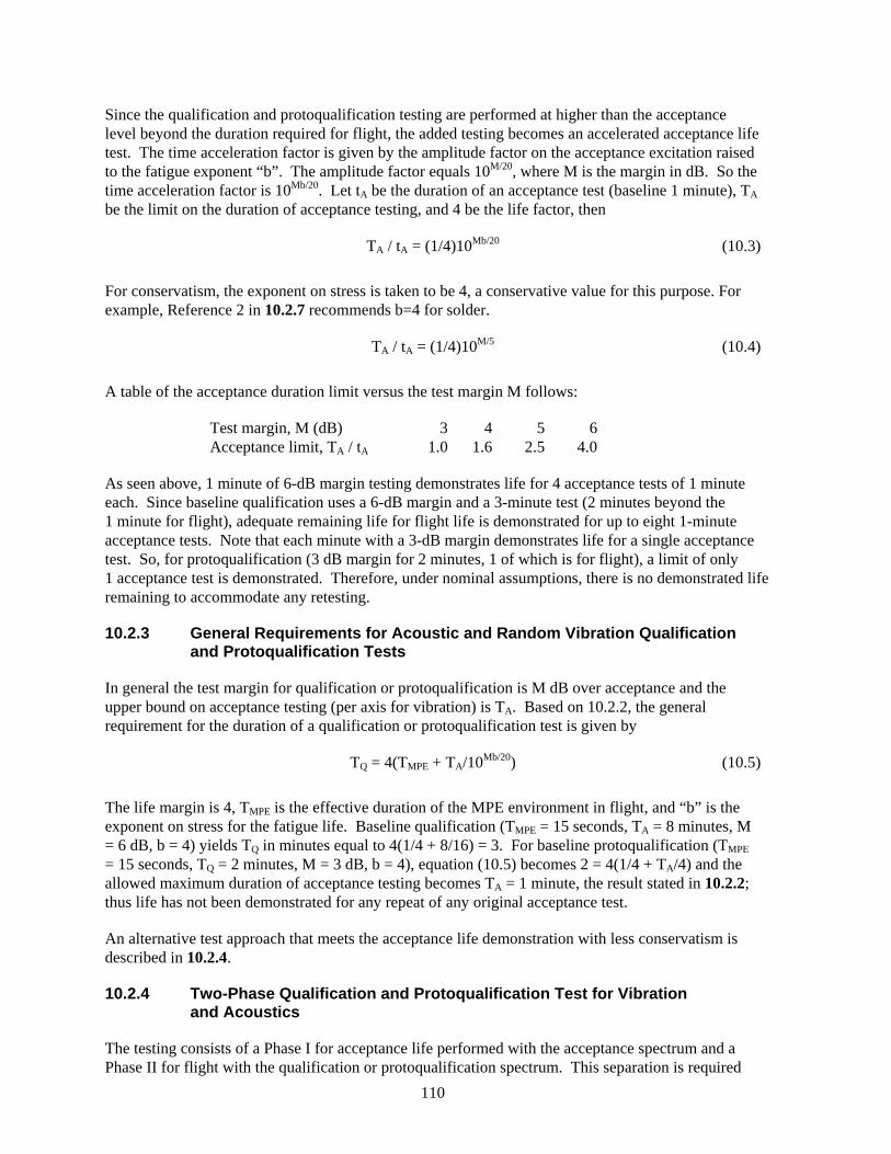
110
Since the qualification and protoqualification testing are performed at higher than the acceptance level beyond the duration required for flight, the added testing becomes an accelerated acceptance life test. The time acceleration factor is given by the amplitude factor on the acceptance excitation raised to the fatigue exponent “b”. The amplitude factor equals 10M/20, where M is the margin in dB. So the time acceleration factor is 10Mb/20. Let tA be the duration of an acceptance test (baseline 1 minute), TA be the limit on the duration of acceptance testing, and 4 be the life factor, then
TA / tA = (1/4)10Mb/20 (10.3)
For conservatism, the exponent on stress is taken to be 4, a conservative value for this purpose. For example, Reference 2 in 10.2.7 recommends b=4 for solder.
TA / tA = (1/4)10M/5 (10.4)
A table of the acceptance duration limit versus the test margin M follows:
Test margin, M (dB) 3 4 5 6 Acceptance limit, TA / tA 1.0 1.6 2.5 4.0
As seen above, 1 minute of 6-dB margin testing demonstrates life for 4 acceptance tests of 1 minute each. Since baseline qualification uses a 6-dB margin and a 3-minute test (2 minutes beyond the 1 minute for flight), adequate remaining life for flight life is demonstrated for up to eight 1-minute acceptance tests. Note that each minute with a 3-dB margin demonstrates life for a single acceptance test. So, for protoqualification (3 dB margin for 2 minutes, 1 of which is for flight), a limit of only 1 acceptance test is demonstrated. Therefore, under nominal assumptions, there is no demonstrated life remaining to accommodate any retesting.
10.2.3 General Requirements for Acoustic and Random Vibration Qualification and Protoqualification Tests
In general the test margin for qualification or protoqualification is M dB over acceptance and the upper bound on acceptance testing (per axis for vibration) is TA. Based on 10.2.2, the general requirement for the duration of a qualification or protoqualification test is given by
TQ = 4(TMPE + TA/10Mb/20) (10.5)
The life margin is 4, TMPE is the effective duration of the MPE environment in flight, and “b” is the exponent on stress for the fatigue life. Baseline qualification (TMPE = 15 seconds, TA = 8 minutes, M = 6 dB, b = 4) yields TQ in minutes equal to 4(1/4 + 8/16) = 3. For baseline protoqualification (TMPE = 15 seconds, TQ = 2 minutes, M = 3 dB, b = 4), equation (10.5) becomes 2 = 4(1/4 + TA/4) and the allowed maximum duration of acceptance testing becomes TA = 1 minute, the result stated in 10.2.2; thus life has not been demonstrated for any repeat of any original acceptance test.
An alternative test approach that meets the acceptance life demonstration with less conservatism is described in 10.2.4.
10.2.4 Two-Phase Qualification and Protoqualification Test for Vibration and Acoustics
The testing consists of a Phase I for acceptance life performed with the acceptance spectrum and a Phase II for flight with the qualification or protoqualification spectrum. This separation is required
111
when the unit is vibration or shock isolated in flight, but acceptance tested without the isolators (6.3.5.2). The two-phase test approach can also be employed to reduce the conservatism in the testing for acceptance life that is built into the baseline qualification and protoqualification requirements. In baseline testing, the acceptance life test is accelerated since it is performed at a higher level than acceptance. For conservatism, the acceleration of the life test is based on a low exponent of 4 for fatigue, as well as the assumptions of linearity and that all amplitudes contribute to fatigue life (that is, not allowing for amplitudes below an endurance limit). For example, by performing the acceptance life testing at 6 dB higher than acceptance (a factor of 2 in amplitude), a time acceleration factor of 24 or 16 is used. If the fatigue exponent were 6, the time acceleration factor would be 26 or 64.
For qualification, Phase I of the testing is an acceptance life test consisting of a normal acceptance test extended in duration to 4 times the set limit on the duration of flight acceptance testing (TA). For example, a 32-minute Phase 1 (per axis for vibration) covers a baseline maximum of 8 minutes of acceptance testing. Phase II is a baseline qualification test for a duration of 4 times the effective duration of the MPE, but not less than 1 minute (4.3.2.2). For the example in 10.2.3, qualification including an accelerated acceptance life test is conducted for 3 minutes at 6 dB above the acceptance level. A corresponding two-phase test is conducted for 32 minutes at the acceptance level, followed by 1 minute at 6 dB above the acceptance level.
For protoqualification, Phase I is an acceptance life test consisting of a normal acceptance test extended in duration to 4 times the set limit on the duration of flight acceptance testing, the same requirement as for qualification. Phase II is a baseline protoqualification test for a duration of 4 times the effective duration of the MPE, but not less than 1 minute (4.3.3.2). So the only change from qualification is the margin used to qualify for flight. For the example in 10.2.3, proto-qualification including an acceleration of a life test for only a single acceptance test is conducted for 3 minutes at 3 dB above the acceptance level. A corresponding two-phase test is conducted for 32 minutes at the acceptance level, followed by 1 minute at 3 dB above the acceptance level.
10.2.5 Damage-Based Analysis of Flight Vibroacoustic Data
Traditional maximax spectral analysis of flight vibroacoustic data for space and launch vehicles (3.14 and 3.19) can lead to excessively conservative testing. An advanced data analysis method (Reference 3 in 10.2.7), based on a simple damage model, employs an extended response spectrum analysis that includes amplitude-cycle counts to deal with fatigue potential. The output is a conservative stationary test specification, but less so than using the maximax basis. The damage-based test specification envelops the damage potential of the nonstationary flight environment for both peak response and fatigue, while recognizing uncertainties in damping and in the fatigue law.
The advanced method enables a more perceptive means for assessing the flightworthiness of units when maximax analysis of new flight data indicates excessive levels. Re-qualification or vibration isolation may then be required. Some experience with the advanced data analysis technique indicates a potential to clear the concern.
10.2.6 Threshold Response Spectrum for Shock Significance
The damage potential of a shock test may be shown to be less than the damage potential from the random vibration acceptance testing over its frequency range, typically 20 to 2000 Hz. For the shock response spectrum values, a response velocity criterion can be used to signify a lack of shock severity, as long as the unit does not contain any components that are particularly sensitive to shock, such as crystals and ceramic chips (6.3.4.4).
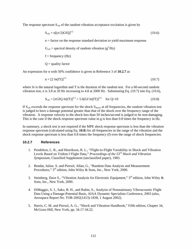
112
The response spectrum Svib of the random vibration acceptance excitation is given by
Svib = n[(π/2)GfQ]1/2 (10.6)
n = factor on the response standard deviation to yield maximum response
Gvib = spectral density of random vibration (g2/Hz)
f = frequency (Hz)
Q = quality factor
An expression for n with 50% confidence is given in Reference 3 of 10.2.7 as
n = [2 ln(fT)]1/2 (10.7)
where ln is the natural logarithm and T is the duration of the random test. For a 60-second random vibration test, n is 3.8 at 20 Hz increasing to 4.8 at 2000 Hz. Substituting Eq. (10.7) into Eq. (10.6),
Svib = [πGfQ ln(fT)]1/2 = 5.6[Gf ln(fT)]1/2 for Q=10 (10.8)
If Svib exceeds the response spectrum for the shock Sshock at all frequencies, the random vibration test is judged to have a damage potential greater than that of the shock over the frequency range of the vibration. A response velocity to the shock less than 50 inches/second is judged to be non-damaging. This is the case if the shock response spectrum value in g is less than 0.8 times the frequency in Hz.
In summary, a shock test is not required if the MPE shock response spectrum is less than the vibration response spectrum (calculated using Eq. 10.8) for all frequencies in the range of the vibration and the shock response spectrum is less than 0.8 times the frequency (f) over the range of shock frequencies.
10.2.7 References
1. Pendelton, L. R., and Henrikson, R. L., “Flight-to-Flight Variability in Shock and Vibration Levels Based on Trident I Flight Data,” Proceedings of the 53rd Shock and Vibration Symposium, Classified Supplement (unclassified paper), 1983.
2. Bendat, Julius. S. and Piersol, Allan, G., “Random Data Analysis and Measurement
Procedures,” 3rd edition, John Wiley & Sons, Inc., New York, 2000.
3. Steinberg, Dave S., “Vibration Analysis for Electronic Equipment,” 3rd edition, John Wiley & Sons, Inc., New York, 2000.
4. DiMaggio, S. J., Sako, B. H., and Rubin, S., Analysis of Nonstationary Vibroacoustic Flight
Data Using a Damage-Potential Basis, AIAA Dynamic Specialists Conference, 2003 (also, Aerospace Report No. TOR-2002(1413)-1838, 1 August 2002).
5. Harris, C. M. and Piersol, A. G., “Shock and Vibration Handbook,” Fifth edition, Chapter 34,
McGraw-Hill, New York, pp. 34.17-34.22.
SMC Standard Improvement Proposal
INSTRUCTIONS 1. Complete blocks 1 through 7. All blocks must be completed. 2. Send to the Preparing Activity specified in block 8. NOTE: Do not be used to request copies of documents, or to request waivers, or clarification of requirements on current contracts. Comments submitted on this form do not constitute or imply authorization to waive any portion of the referenced document(s) or to amend contractual requirements. Comments submitted on this form do not constitute a commitment by the Preparing Activity to implement the suggestion; the Preparing Authority will coordinate a review of the comment and provide disposition to the comment submitter specified in Block 6.
SMC STANDARD CHANGE RECOMMENDATION:
1. Document Number
2. Document Date
3. Document Title
4. Nature of Change (Identify paragraph number; include proposed revision language and supporting data. Attach extra sheets as needed.)
5. Reason for Recommendation
6. Submitter Information
a. Name
b. Organization
c. Address
d. Telephone
e. E-mail address
7. Date Submitted
8. Preparing Activity Space and Missile Systems Center AIR FORCE SPACE COMMAND 483 N. Aviation Blvd. El Segundo, CA 91245 Attention: SMC/EAE March 2008


![[IAC 2013] Design of an Active Space Debris Removal Mission Using Modified Launch Vehicle Upper Stage](https://img.pdfslide.net/doc/110x75/554a385fb4c90582328b48ef/iac-2013-design-of-an-active-space-debris-removal-mission-using-modified-launch-vehicle-upper-stage.jpg)