Embed Size (px)
Citation preview
TEST-STAND STUDY OF A VEHICLE UPPER STAGE EMPLOYING A ROTATING-SOLID-ROCKET ATTITUDE CONTROL SYSTEM AND A COMPARISON WITH ANALOG STUDIES
by A. Tbomus Young und Robert L. Jumes, Jr.
LungZey Reseurcb Center Lungley Stution, Humpton, Vu.
NATIONAL AERONAUTICS AND SPACE ADMINISTRATION WASHINGTON, D.
E,[
i j
https://ntrs.nasa.gov/search.jsp?R=19650025460 2018-07-09T06:53:04+00:00Z
TECH LIBRARY KAFB. NM
NASA TN D-2997
TEST-STAND STUDY O F A VEHICLE UPPER STAGE EMPLOYING A
ROTATING-SOLID -ROCKET ATTITUDE CONTROL SYSTEM
AND A COMPARISON WITH ANALOG STUDIES
By A. Thomas Young and Robert L. James , Jr.
Langley Research Center Langley Station, Hampton, Va.
NATIONAL AERONAUTICS AND SPACE ADMINISTRATION
For sale by the Clearinghouse for Federal Scientific and Technical Information Springfield, Virginia 22151 - Price $2.00
TEST-STAND STUDY OF A VEHICLE UPPER STAGE EMPLOYING A
ROTATING-SOLID-ROCKET ATTITUDE CONTROL SYSTEM
AND A COMPARISON WITH ANALOG STUDIES
By A. Thomas Young and Robert L. James, Jr. Langley Research Center
SUMMARY
A dynamic-test-stand investigation in three degrees of rotational freedom of a space-vehicle upper stage employing a rotating-solid-rocketattitude control system is described. Experimental data received from an onboard telemetry system and a unique photographic technique are presented and compared with results obtained from an analog simulation of the dynamical system. Analysis and comparison of the results from the various sources showed that the system performed as predicted by the analog simulation, thus validating this mathematical representation of the dynamical system. It is shown that the telemetry results, although limited in accuracy, are very valuable in analyzing the attitude control characteristics of the space-vehicle upper stage.
INTRODUCTION
The rotating-solid-rocket control system which is the subject of investigation in the present report has certain attractive features which more conventional spacecraft control systems do not possess. Jet vanes, jetavators,movable main rocket nozzles, and secondary fluid injection systems must be developed as an integral part of the main rocket. However, because of the size and complexity of most propulsion systems, it is desirable to have a control system which can be independently developed. "he present system which utilizes four auxiliary rockets for control forces can be developed independently of the main rocket, and in addition, it is inherently capable of providing velocity control, retrothrust, and spin-up forces. This control concept was developed under NASA contract for the George C. Marshall Space Flight Center (see ref. l), and the Langley Research Center is conducting a comprehensive investigation of this promising control-system concept.
An analog study of the application of this system to control the attitude of a space-vehicle upper stage is presented in reference 2. In this analog analysis, mathematical expressions were used to represent the physical systems comprising the space-vehicle upper stage. The present investigation was undertaken to determine the adequacy of this analog representation of the space-vehicle upper stage.
A full-scale model of the space-vehicle upper stage which included the electro-mechanical flight systems was mounted in a dynamic test stand which provided three degrees of rotatkonal freedom. The attitude control system was activated and provided control during programed vehicle maneuvers and disturbances imparted to the vehicle by solid-fuel disturbance rockets. Data received from an onboard telemetry system provided information on control-rocket deflections and guidance signals from attitude and rate gyros. In addition, the control-rocket thrust performance was monitored with the use of pressure transducers. A unique camera technique was employed to obtain the N e r angles which defined the vehicle attitude during the dynamic test. The data obtained fromthis experiment were compared with the results obtained from an analog simulation of the dynamic model in order to evaluate the adequacy of the mathematical analysis, and these comparisons are reported herein.
SYMBOLS
triangle defined by pivot point of dynamic model, position-indicating ball, and camera
distance between graduated framework and position-indicating ball when dynamic model is vertical, in.
thrust of one control rocket multiplied by cos 10' (control rocket cant angle), lb
distance between camera and graduated framework, in.
mass moment of inertia about X-, Y-, and Z-axes, respectively, slug-ft2
disturbance moments about X-, Y-, and Z-axes, respectively, ft-lb
origin of XE-, YE-, and ZE-axis system
projection of position-indicating ball into YE,ZE plane
rolling velocity, deg/sec or rad/sec
pitching velocity, deg/sec or rad/sec
yawing velocity, deg/sec or rad/sec
distance between pivot point of dynamic model and position-indicating ball, in.
time, sec
body axes of dynamic model
earth-fixed axes
distance along earth-fixed axes, in.
reference axes
center of rotat ion from nose, f t
moment arm f o r control moment about X-axis, f t
moment arm f o r control moment about Y-axis, f t
moment arm f o r control moment about Z-axis, f t
angles contained i n t r iangle defined by A, B, and C, deg
control-rocket deflection angle, deg
angle between camera l i n e of sight and longitudinal axis of dynamic model, deg
pitch, yaw, and roll N e r angles of dynamic model re la t ive t o earth-fixed axes, deg
pitch, yaw, and roll reference angles re la t ive t o earth-fixed axes, deg
pitch, yaw, and roll a t t i t ude e r ror angles re la t ive t o reference axes, deg
Subscr ip t :
i n i t i a l value
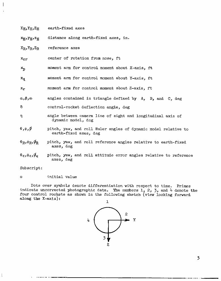
Dots over symbols denote d i f fe ren t ia t ion with respect t o time. Primes indicate uncorrected photographic data. The numbers 1, 2, 3 , and 4 denote the four control rockets as shown i n the following sketch (view looking forward along the X-axis):
1
Z
3
0
MODEL AND TEST APPARATUS
General
A dynamic model consisting of a spacecraft and ballast w a s used i n the test-stand investigation t o simulate a typical space-vehicle upper stage. (See f ig . 1.) The spacecraft housed the control system of research interest , a guidance system, a telemetry system, and other supporting units. A detailed description of the guidance and control systems i s given i n reference 2. The ba l l a s t w a s employed t o provide a dynamic model with center-of-gravity and ine r t i a character is t ics t ha t approximately represented the space-vehicle upper stage used as a test bed i n reference 2. The study w a s conducted with the use of a dynamic t e s t stand (see f ig . 1)that allowed three degrees of rotat ional freedom. The t e s t setup consisted of the dynamic model mounted on a hydraulic bearing pivot allowing three degrees of rotat ional freedom re la t ive t o and within the bounds defined by the fixed test-stand structure. The desired t e s t data were obtained by the telemetry system and a unique camera technique.
Dynamic Model
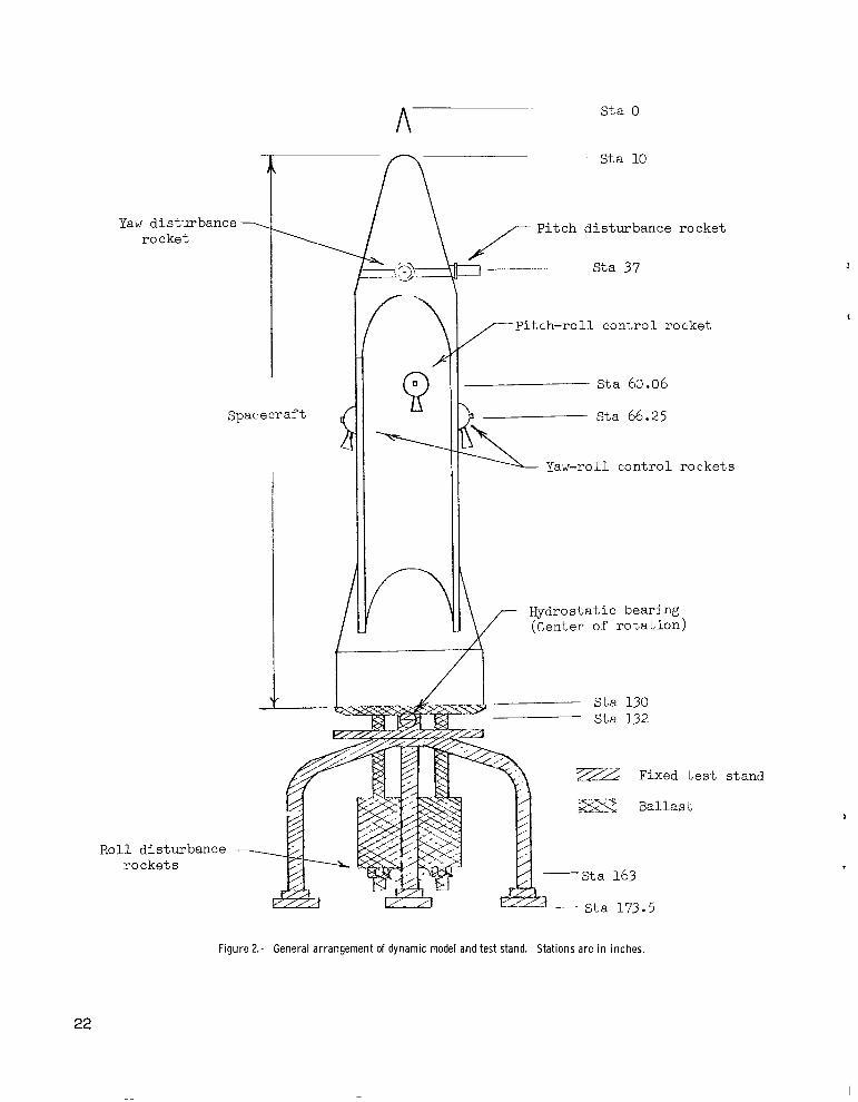
A sketch of the dynamic model and fixed test-stand structure i s included i n figure 2, and a block diagram showing the integration of the individual syst e m s that form the dynamic model i s given i n figure 3.
The point of rotat ional freedom was located a t s ta t ion 132 inches which was also the approximate location of the center of gravi ty of the dynamic model. This geometric arrangement w a s accomplished by adding an additional constraint on the ba l l a s t mass and posit ion selection. The c r i t e r ion f o r the ba l l a s t design was t o sa t i s fy the center-of-gravity requirement as well as t o produce pi tch and y a w i ne r t i a s similar t o those of the space-vehicle upper stage.
The pi tch and yaw ine r t i a s were each 1065 slug-ft*, and the roll i ne r t i a was 55.4 slug-ft2. These ine r t i a s were nearly constant since the mass change during the t e s t w a s s m a l l compared with the m a s s of the dynanic model.
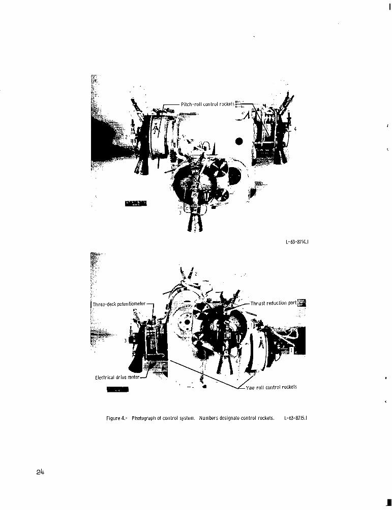
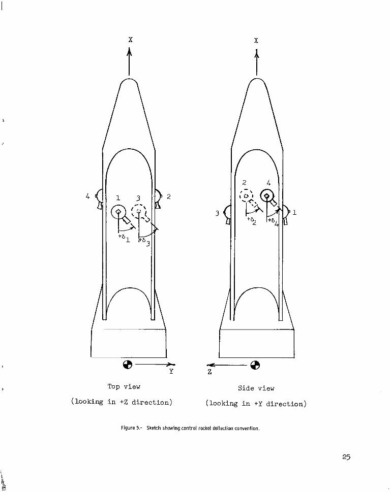
Control system.- The control system t o be considered herein i s p i c to r i a l ly shown i n figure 4. The th rus t of four end-burning solid-propellant rocket motors provides the control forces. The control rockets a r e bearing mounted i n a minimum-volume configuration so t h a t rotat ion of two motors produces pi tch control moments, rotat ion of the remaining two motors produces yaw control moments, and d i f f e ren t i a l deflection of a l l four control rockets produces roll control moments. Figure 5 schematically shows the control rockets deflected t o correct a posit ive yaw er ror ( top view) and a posi t ive pi tch error (s ide view). The control-rocket deflections were limited by design t o G O o . The torque t o produce a control-rocket deflection i s provided by a direct-current e l ec t r i ca l drive motor. The control system has four drive motors, one geared t o each control rocket. Also geared t o each control rocket i s a three-deck potentiometer. One deck provides control-rocket posi t ion feedback f o r s tab i l i t y , and the remaining two a re used as data sensors t o provide information concerning the control-rocket positions.
4
Guidance system.- A posit ion and r a t e monitoring proportional-guidance system i s employed i n the experimental analysis of the control system previously discussed. The guidance system uses two two-degree-of-freedom gyros which provide i n e r t i a l a t t i t ude information i n roll, pitch, and yaw re la t ive t o a reference axis system defined by the spin vectors of the gyros. The guidance system also employs three ra te gyros which are fixed i n the spacecraft such that they measure body rates. The outputs of each gyro and the control-rocket posit ion feedbacks a re weighted and appropriately summed t o provide error signals t o the control system. (See f ig . 3.) The numerical values and procedure fo r the weighting and summing a re described i n reference 2.
Telemetry system.- The purpose of the telemetry system was t o monitor the desired performance parameters and telemeter these data t o a receiving station. The system w a s typ ica l of units employed i n sounding-rocket f l i gh t - t e s t research. The r a t e and a t t i t ude information was obtained from gyros contained i n the guidance system.
The resu l t s which were obtained 'by the telemetry system a re
(1)Roll, pitch, and yaw body r a t e s from ra t e gyros
(2) Roll, pitch, and yaw a t t i t ude e r ror angles from a t t i t ude gy ros
(3) Rotational posit ion of each control rocket
(4) Chamber pressure of control rockets
Test Apparatus
Test stand.- The t e s t stand used i n the experimental study i s shown pictor i a l l y i n f igure 1and schematically i n figure 2. It provided a fixed r ig id pivot about which the dynamic model w a s f ree t o rotate. A b a l l and socket into which hydraulic f lu id was forced under pressure constituted the pivot point. Since the hydraulic-fluid viscosi ty was the only source of resistance, the pivot-point f r i c t i o n w a s negligible. The point of rotat ional freedom was held fixed by structure securely mated with a concrete base.
Camera.- Surrounding the t e s t stand was a structure which provided support f o r the photographic apparatus. (See f ig . 1.) A 16-RL~camera which operated a t a r a t e of 64 frames per second was mounted above the dynamic model and viewed the model from above looking down. Also supported by the s t ructure w a s a graduated framework mounted between the camera and the nose of the dynamic model.
Disturbance rockets.- Solid-fuel rocket motors with an average thrus t l eve l of 3lpounds each and a th rus t duratfon of about 10 seconds were mounted on the dynamic model t o produce known disturbances. Two disturbance rockets were located near the nose a t s ta t ion 36.3 inches, and two were mounted on the lower portion of the ba l l a s t a t s ta t ion 163 inches. The upper rockets were alined 90' apart , and the lower rockets were alined 180° apart with a distance of 10 inches between the center l ines .
5
I
Restraining explosive bolts.- The dynamic model was restrained i n a ve r t i tal posit ion a t the i n i t i a t i o n of the experimental t es t ing by two explosive bol ts . These b o l t s were attached between the base of the dynamic model and the concrete pad located beneath the t e s t stand. The dynamic model w a s f r e e t o ro ta te a f t e r pyrotechnic severing of the two restraining bol ts .
TEST DESCRIPTION
The sequence of events f o r the experimental test i s shown i n the following table :
Time, sec
Precess a t t i t ude gyro spin axis t o define reference ax is system . . . . . -4.4 Zero time f o r the programer used i n the t e s t . . . . . . . . . . . . . . Control-rocket ign i t ion . . . . . . . . . . . . . . . . . . . . . . . . . 76.5 Dynamic-model release . . . . . . . . . . . . . . . . . . . . . . . . . . 78.5 I n i t i a t e roll a t t i t ude and r a t e control as well a s pi tch and yaw
r a t e c o n t r o l . . . . . . . . . . . . . . . . . . . . . . . . . . . . . 79-3 I n i t i a t e pi tch and yaw a t t i t ude control t o give full three-axis
c o n t r o l . . . . . . . . . . . . . . . . . . . . . . . . . . . . . . . . 93.5 Igni te yaw disturbance rocket . . . . . . . . . . . . . . . . . . . . . . 99.5 Ignite roll disturbance rockets . . . . . . . . . . . . . . . . . . . . . 112.9 Ignite pi tch disturbance rocket . . . . . . . . . . . . . . . . . . . . . 126.5
The i n i t i a l orientation of the dynamic model w a s v e r t i c a l and it was held i n t h i s posit ion u n t i l approximately 2 seconds a f t e r control-rocket igni t ion a t which time it w a s released by pyrotechnically severing the two restraining explosive bol ts . After release 'the model was f loa t ing f r e e with the only s tab i l iz ing forces being produced by the research control system.
The dynamic model i s controlled from 0.8 second a f t e r release t o terminat i o n of the experiment. The control period i s divided into two phases. The f i rs t phase i s defined a s roll control and i s effect ive f o r the f i r s t 14.2 seconds. During t h i s time the model i s subject t o roll a t t i t ude and ra te control a s well a s pi tch and yaw ra t e control. The second phase, which i s effect ive from t = 93.5 seconds t o the termination of the experiment, i s a three-axis control phase. During the second phase the model i s controlled i n a t t i t ude and r a t e about the roll, pitch, and y a w axes. A detailed discussion defining the requirements f o r t h i s sequencing i s given i n reference 2.
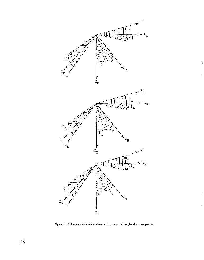
The control task f o r the a t t i t ude control system of the t e s t was t o change the orientation of the model from the i n i t i a l l y ve r t i ca l posit ion t o a predetermined orientation defined by the reference angles OR, qR, and gR. The orient a t ion t o be achieved was established by precessing the gyro spin axes so that a f t e r precession these spin axes defined an orthogonal t r iad , angularly displaced from the XE-, YE-, and ZE-axis system by the angles OR, q ~ ,and $$R. (See f ig . 6.) The gyro precession event occurred a t t = -4.4 seconds. (See table . ) The numerical values fo r the reference angles f o r the t e s t were
6
0
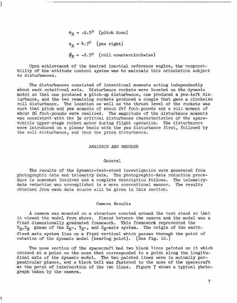
qR = 4.70 (yaw right)
#R = -2.5O (roll counterclockwise)
Upon achievement of the desired inertial reference angles, the responsibility of the attitude control system was to maintain this orientation subject to disturbances.
The disturbances consisted of intentional moments acting independently about each rotational axis. Disturbance rockets were located on the dynamic model so that one produced a pitch-up disturbance, one produced a yaw-left disturbance, and the two remaining rockets produced a couple that gave a clockwise roll disturbance. The location as well as the thrust level of the rockets was such that pitch and yaw moments of about 247 foot-pounds and a roll moment of about 26 foot-pounds were realized. The magnitude of the disturbance moments was consistent with the 30 critical disturbance characteristics of the space-vehicle upper-stage rocket motor during flight operation. The disturbances were introduced on a planar basis with the yaw disturbance first, followed by the roll disturbance, and then the pitch disturbance.
ANALYSIS AND �UEJJLTS
General
The results of the dynamic-test-stand investigation were generated from photographic data and telemetry data. The photographic-data reduction procedure is somewhat involved and a complete description follows. The telemetry-data reduction was accomplished in a more conventional manner. The results obtained from each data source will be given in this section.
Camera Results
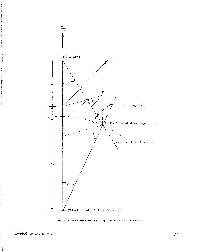
A camera was mounted on a structure erected around the test stand so that it viewed the model from above. Placed between the camera and the model was a fixed dimensionally graduated framework. This framework represented the YE,ZE plane of the XE-, YE-, and %-axis system. The origin of the earth-fixed axis system lies on a fixed vertical which passes through the point of rotation of the dynamic model (bearing point). (See fig. 12.)
The nose section of the spacecraft had two black lines painted on it which crossed at a point on the nose that corresponded to a point along the longitudinal axis of the dynamic model. The two painted lines were in mutually perpendicular planes, and a black ball was fastened to the nose of the spacecraft at the point of intersection of the two lines. Figure 7 shows a typical photograph taken by the camera.
7
'I
The purpose of the camera was t o monitor the motion of the position-indicating b a l l so tha t data could be measured which would define the roll, pitch, and yaw N e r angles re la t ive t o the earth-fixed axis system. (See f i g . 6.) The photographic data needed t o define the pi tch and yaw N e r angles a re the coordinates of the b a l l i n the YE,ZE plane. The rotat ional orientat i o n of the black s t r ipes i n a plane perpendicular t o the l i n e of sight of the camera i s necessary t o determine the r o l l N e r angle. The equations required t o determine the N e r angles 8, +, and 9 from the photographic data a re derived and presented i n appendix A as equations ( ~ 8 ) ,(Alg), and (A20).
The photographic data were a l so employed i n the determination of a t t i t ude e r ror angles. (See f i g . 6.) These angles define the orientation of the dynamic model re la t ive t o the reference axis system. The reference axis system i s known re la t ive t o the earth-fixed axis system by the angles OR, qR, and $R, and the orientation of the dynamicmodel i s defined r e l a t ive t o the earth-fixed axis system by the photographically determined N e r angles. Therefore, the a t t i t ude e r ror angles can be determined with use of the calculated N e r angles and defined reference angles. Equations for the a t t i t ude e r ror angles e,, qE, and are derived and presented a s equations (B7), (B8), and (B9) i n appendix B.
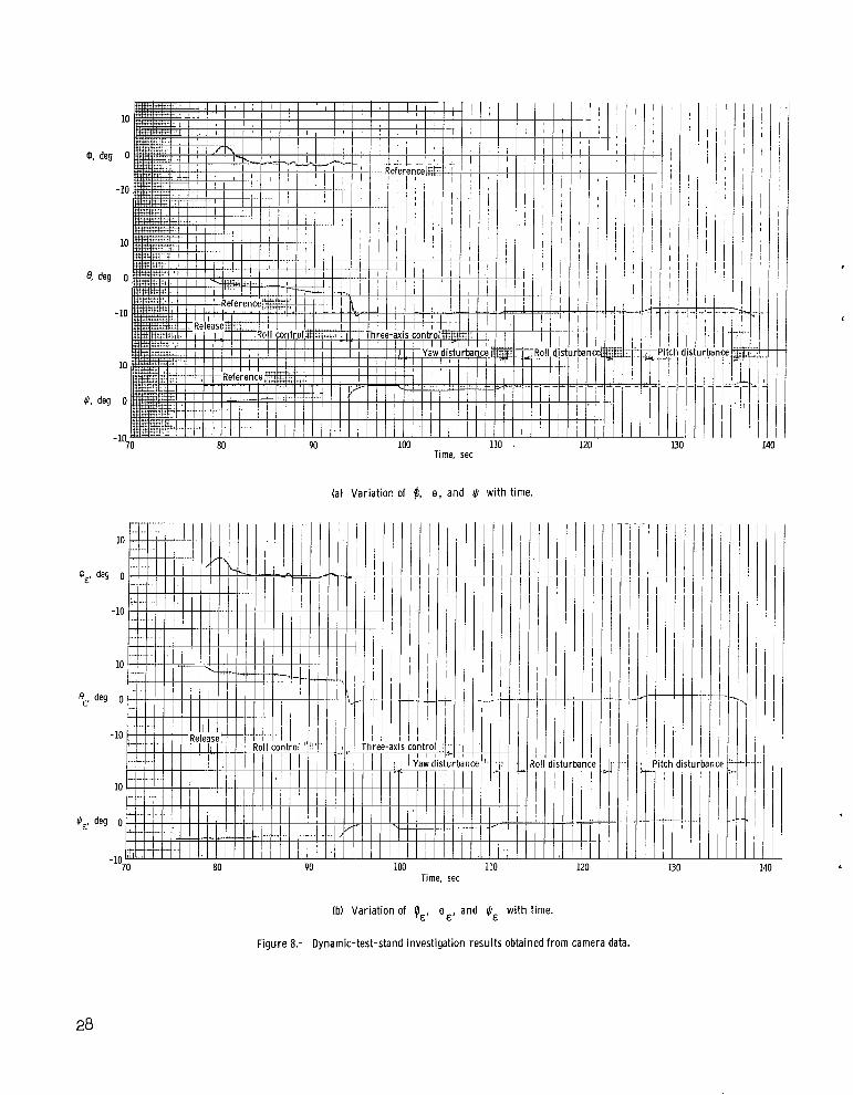
The resu l t s t ha t were obtained from the photographic data a re given i n figure 8. These r e su l t s were obtained by processing data a t 0.125-second intervals, which corresponds t o using every eighth frame obtained by the camera. R o l l resu l t s a r e presented only during roll control because of inaccuracies i n the roll data a f t e r three-axis control when the nose of the model i s rotated away from the l i n e of s ight of the camera. Figure 8(a) shows the N e r angles tha t were determined by using equations (fl8), (Alg), and (A20). This p lo t gives an a t t i t ude time his tory of the dynamic model during the experimental test. The zero value f o r each parameter r e fe r s t o the i n i t i a l orientation, and the dashed l i n e s represent the i n e r t i a l reference angles which define the a t t i t ude t o be achieved.
The closed-loop system comprised of the research control system, guidance system, and model exhibits type-0 servosystem steady-state characterist ics ( r e f . 3 ) ; that is , i n order t o produce a steady control deflection t o balance a steady external moment, a steady actuating ( a t t i t ude ) e r ror must be present. For t h i s reason an a t t i t ude e r ro r i s present during the time period the disturbance rockets are functioning. This e r ror i s represented by the deviations of the N e r angles f romthe reference values and occurs i n each plane corresponding t o the presence of a planned disturbance. (See f ig . 8 (a ) . )
Figure 8(b) shows the var ia t ion of the roll, pitch, and yaw a t t i tude e r ror angles with time. These angles were computed from camera data with the use of equations (B7), (B),and (B9). Zero values f o r the gyro angles correspond t o the dynamic model alined with the reference axis system. The steady-state e r ror discussed previously i s shown i n figure 8(b) .
8
. . . I
Telemetry Results
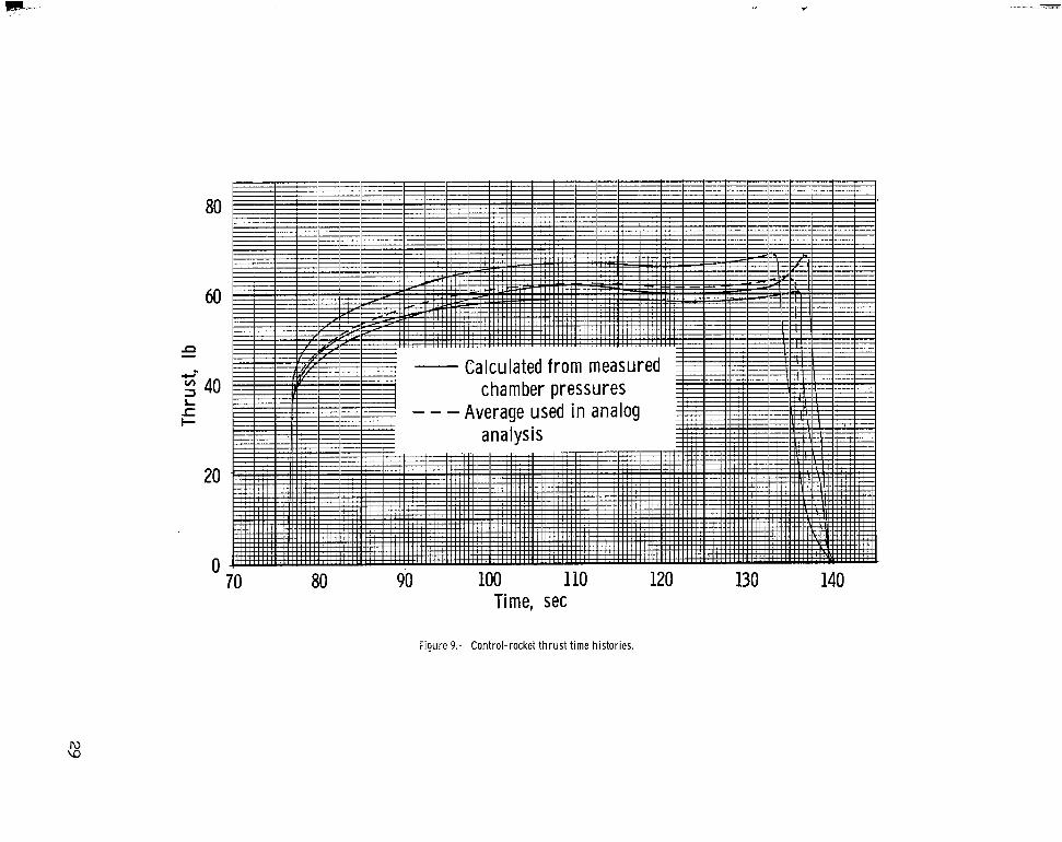
Control-rocket thrust.- Pressure transducers were u t i l i zed t o monitor the chamber pressure of each control rocket, and the r e su l t s were telemetered t o a receiving s ta t ion. The chamber pressure was u t i l i zed t o compute the thrust or available control force of the control rockets. The thrus t was determined by using equations given i n reference 4. The transducer of control rocket number 2 did not function properly; therefore, only three thrust time h is tor ies were determined and these a re shown i n figure 9. The dashed curve represents an average of the experimentally determined resul ts .
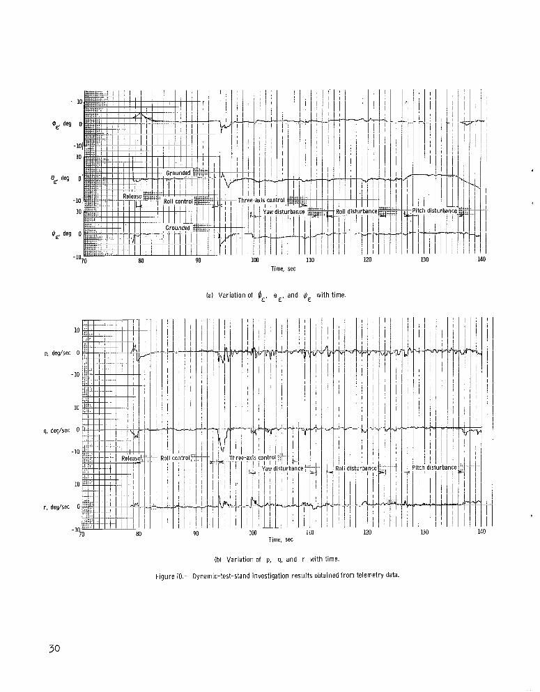
Control parameters.- Figure 10 presents time h is tor ies of the a t t i t ude error angles, body rotat ional veloci ty components, and control-rocket positions tha t were obtained by telemetry. The a t t i t ude e r ror angles are given i n f ig ure lO(a). The outputs of the pi tch and yaw a t t i tude gyros were grounded t o zero during roll control, which w a s necessary since the pi tch and yaw a t t i t ude information i s not used f o r control during t h i s period.
Figure 10(b) gives the variation with time of the body rotat ional velocity components p, q, and r which were sensed by r a t e gyros contained i n the guidance system. The t ransients associated with release, roll capture, and three-axis capture can be seen i n t h i s figure.
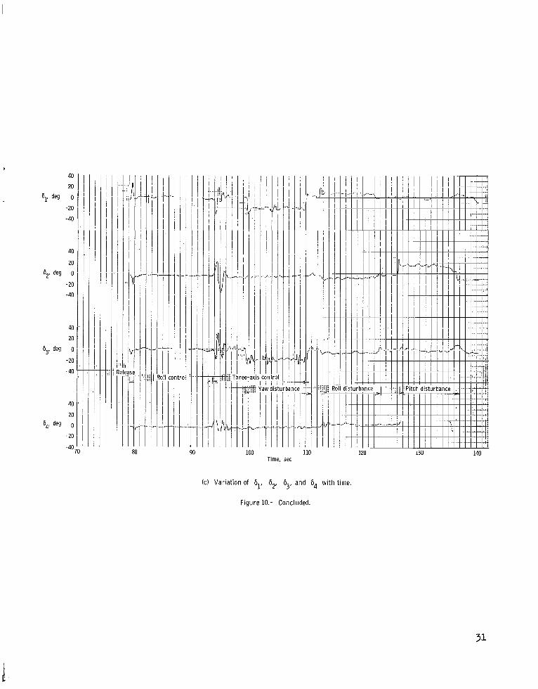
Figure lO(c) shows the posit ion variation of each control rocket with time. These data were obtained by telemetry from the position-indicating potentiome te r s geared t o the control rockets. For each control rocket one deck of the potentiometer provided data within &loo boundaries t o give good position-data resolution. The other data deck measured positions between +60°. These two sources were combined t o give the r e su l t s presented i n f igure lO(c) where, fo r control rocket number 4, no data are shown beyond the &loo boundaries. The steady-state deflections needed t o control the intentional disturbances can a l so be seen i n f igure ~ o ( c ) .
COMPARISON AND DISCUSSION O F ANALOG AND EXFEBIMENTAL RESULTS
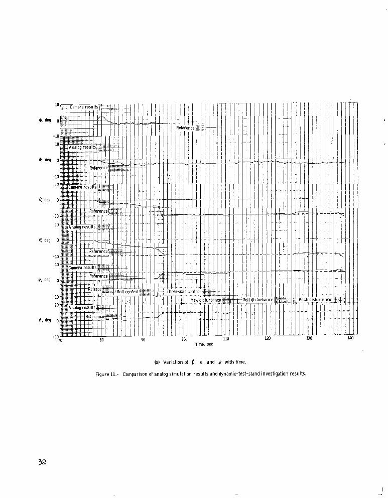
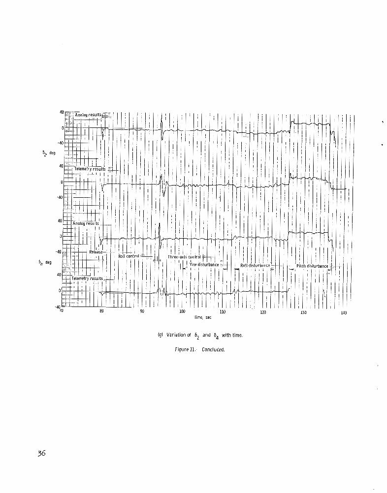
A graphical comparison between the resu l t s obtained from the experimental t e s t and the resu l t s obtained from the analog simulation i s given i n figure 11. where the experimental r e su l t s a re a repeat of previous presentations i n t h i s report. The analog simulatfon makes use of the equations presented i n appendix C.
Figure l l ( a ) shows a comparison of the N e r angles determined photographi c a l l y (experfmental) with those determined by the analog analysis. An examination of the photographically determined roll N e r angle shows that the model rol led posi t ively during the time in te rva l between release and the beginning of control. This posi t ive roll w a s apparently the r e su l t of an extraneous torque, possibly produced by the separation mechanism. This motion i s not shown i n the analog r e su l t s because the moment w a s not defined and was not included i n the analog simulation.
9
Time histories of the pitch N e r angle show that the model was under the influence of a negative pitching moment, which was probablythe result of winds and other external disturbances. This extraneous moment was estimated to be about -55 foot-pounds and was included in the analog simulation. The camera-determined yaw Euler angle diverges (t = I22 sec) from the defined reference value represented by the dashed line. This divergence is apparently caused by a drift of the gyro spin axis which defines the inertial reference. ( In order to represent this drift in figure 8(a), the dashed line would be curved upward.) Since a constant reference was used in the analog analysis, this divergence is not noted in the analog results.
The analog and camera Ner-angle resdts agree extremely well except for the explainable differences which are caused primarily by detailed disturbances that are not definable in the analog representation. The primary criteria for comparison are dynamic stability and damping characteristics.
Figures ll(b), ll(c), and ll(d) give the variations of the attitude error angles with time. Since the experimental results were obtained from both telemetqy and photography, a three-way comparison was possible between these results and those from the analog analysis. Because the telemetry results are unavailable during roll control, a portion of the comparison is lost. Much of the same basic discussion presented with the N e r angle results applies to the error-angle comparison, and as with the M e r angle comparison, the agreement is good. Although there are numerical differences, especially with the telemetry data, the damping characteristics obtained from all three sources are comparable.
Figure ll(e) gives a comparison of the rotational velocity components p, q, and r obtained by telemetry (experimental) and those obtained by analog simulation. Two pronounced points of disagreement are at roll capture and pitch capture. The roll capture disagreement was previously explained as a disturbance which was not included in the analog simulation. The same explanation applies to the pitch-capture disagreement as exemplified by the fact that the rate q was returning to zero when a disturbance redirected it in a negative direction. Much of the low-amplitude oscillation noted in the figure results from the control rockets deflecting indeterminately within unintentional and uncorrectable deadbands. A detailed comparison of the rotational-velocity results is not considered to be realisticj however, a survey of all transients shows good dynamic-stability agreement.
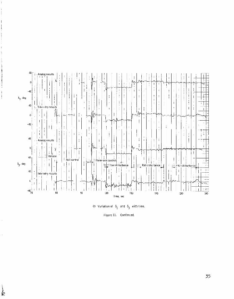
A co arison of the control-rocket position time histories is given in figures llTf) and 11(g). The oscillatory wave which appears to be riding on the deflection traces is the result of system nonlinearities. The steady-state deflections needed to control the intentional disturbances are seen by reviewing the figures. The graphical comparison of the control-rocket deflection results shows good agreement.
10
CONCLUDING REMARKS
The results obtained from a dynamic-test-stand investigation of a space-vehicle upper stage employing actual electro-mechanical systems have been presented. Ekperimental data received from an onboard telemetry system and a unique photographic technique were presented and compared with the results obtained from an analog simulation of the dynamical system.
The N e r angles determined from photographic data showed good agreement with the analog-study results as did the attitude error angles computed from the camera data and those obtained in the analog study. A comparison between the attitude error angles obtained from these data sources and those reduced from telemetry data also showed good agreement in most areas. The body rotational velocity components obtained from telemetry and those obtained from the analog simulation showed the same general trends. The control-rocket position histories from these two data sources were in reasonable agreement. These comparisons also showed that although telemetry results were somewhat limited in accuracy, the telemeter data can be used for a comprehensive analysis of the dynamical system.
The analog simulation employed herein was also used to analyze and define system gains and sequences in a previous analysis of the space-vehicleupper stage. Since this dynamical system functioned as predicted by the analog study, it is concluded that the analog simulation is an adequate mathematical representation of the dynamical system.
Langley Research Center, National Aeronautics and Space Administration,
Langley Station, Hampton, Va., May 12, 1965.
11
APPENDIX A
EQUATIONS FOR FEDUCING CAMERA DATA
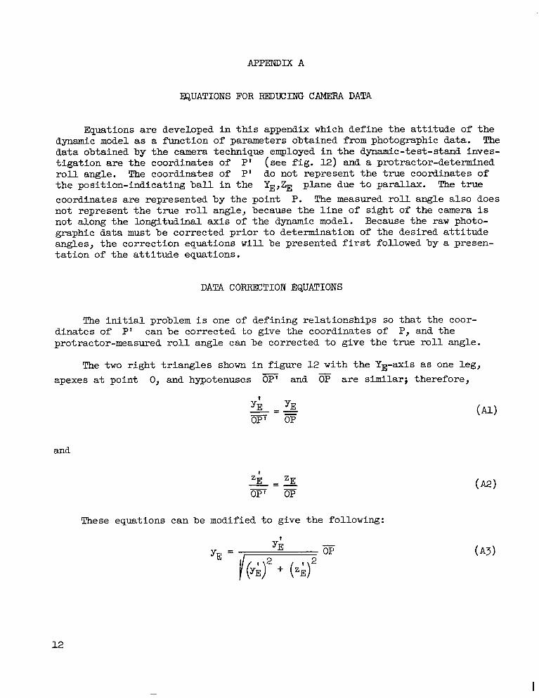
Equations are developed in this appendix which define the attitude of the dynamic model as a function of parameters obtained from photographic data. The data obtained by the camera technique employed in the dynamic-test-stand investigation are the coordinates of P' (see fig. 12) and a protractor-determined r o l l angle. The coordinates of P1 do not represent the true coordinates of the position-indicating ball in the YE,% plane due to parallax. The true coordinates are represented by the point P. The measured roll angle also does not represent the true r o l l angle, because the line of sight of the camera is not along the longitudinal axis of the dynamic model. Because the raw photographic data must be corrected prior to determination of the desired attitude angles, the correction equations will be presented first followed by a presentation of the attitude equations.
DATA CORRECTION EQUATIONS
The initial problem is one of defining relationships so that the coordinates of PI can be corrected to give the coordinates of P, and the protractor-measured r o l l angle can be corrected to give the true roll angle.
The two right triangles shown in figure 12with the YE-axis as one leg,-apexes at point 0, and hypotenuse.s OP1 and are similar; therefore,
and
These equations can be modified to give the following:
-OP
12
I
APPENDIX A
and
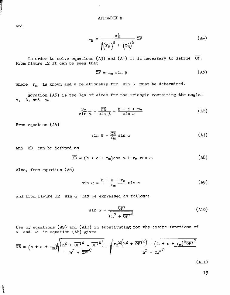
-I n order t o solve equations (A3) and ( A 4 ) it i s necessary t o define OP.
From figure 12 it can be seen tha t -OP = rms i n p (A5)
where rm i s known and a relationship for s i n p must be determined.
Equation ( A 6 ) i s the law of sines for the t r iangle containing the angles a, B, and w.
-I"m=-- - h + e + r qCB s i n a s in p s i n w
From equation ( A 6 )
-and CB can be defined a s
-CB = (h + e + %)COS a + r m COS u
Also, from equation ( A 6 )
h + e + r ms i n w = s in a rm
and from figure 12 s in a maybe expressed a s follows:
-OP'
sin = /-Use of equations ( A 9 ) and (AlO) i n substi tuting f o r the cosine fhnctions of a and w i n equation ( A 8 ) gives
- ( h + e + rm)OP2(h2 + w2) 2 7 2-CB = (h + e + rm)
-2h2 + OP'
-2
APPENDIX A
The negative sign of the second radical of equation ( A l l ) i s necessary since w is greater than goo f o r a l l applications i n t h i s report. Combining equat ions (A7) , (AlO), and (All) gives
-s i n j3 = OP ' [h(h + e + r m ) - /rm2(h2 + w2)- OP' (h + e + rm) rm(h2 + p2)
Equations ( A 3 ) , ( A h ) , ( A 5 ) , and (AU) can now be combined t o give
- ky;)' + (zi)'](h + e + rm)\
h2 + (yi? + ( z i y
and
) /rm2[h2 + (y;)' + (.A)'] - [(yi)' + ( ~ i ) ~ ] ( h - +e + rm ZE = zfh+ e + rm -
h2 + (a)'+ (z;)~
w-4)
Equations (Al3) and (Al4) define the t rue coordinates yE and zE of the
position-indicating b a l l i n the YE,ZE plane.
The protractor-measured r o l l angle 8' i s i n a plane perpendicular t o the l i n e of sight of the camera. The t rue roll angle 9 i s i n a plane perpendicu lar t o the longitudinal ax is of the dynamic model. Therefore, the measured r o l l angle must be projected into the desired plane. The following equation defines t h i s projection:
s i n 9' = cos 7 sin 9 (AI-5)
The value of cos 7 i s the unknown i n eqwtion (Al5) which m u s t be defined. Since 7 and w a re supplementary angles, q may be expressed i n terms of w as
7 = 180 - w
14

I
APPENDIX A
and by combining equations ( ~ 6 )and ( A 9 )
‘(h2 + w2)- (h + e + r m ) 2 p 2 cos q = fm
rm ‘(h‘ + p2) (A171
Equations (Al5) and (Al7) can be used t o define t h e t rue roll angle fl as follows :
yield the results needed t o define the a t t i -Equations (Al3), ( A l k ) , and ( ~ 1 8 ) tude of the dynamic model a s a function of the r a w photographic data.
ANGULAR ATTITUDE EQUATIONS
Euler angles 8, $, and fl define the a t t i t ude o f the dynamic m d e l i n the XE-, YE-, and ZE-axis system. The sine of t he roll E u l e r angle w a s given by equation (Al8), and the p i tch and yaw N e r angles are defined by the fo l lowing equations:
t

APPENDIX B
EQUATIONS USED IN DETERMINING ATTITUDE ERROR ANGLE
Equations were derived in reference 2 which defined the attitude error angles in terms.ofN e r angles and a pitch reference angle. A similar derivation is presented in this appendix in order to define the attitude error angles in terms of M e r angles and roll, pitch, and yaw reference angles. The derivation consists of a series of orthogonal transformations between axis systems. Figure 6 serves as a useful tool in reviewing the following derivation.
The transformation between the earth-fixed axis system (XE, YE, and and the body axis system is
1 0 0 cos 8 0 -sin 9 cos $ sin $ 0
0 cos pl sin 0 1 0 /[-si; + co; 9 J o -sin pl cos pl sin e COS e
JL
which, when simplified, becomes
-COS e COS ~r cos 8 sin I) -sin 8 XE
sin fl sin e cos q sin pl sin e sin 9 sin pl cos 8 YE- cos pl sin $ + cos pl cos $
cos pl sin 8 cos q cos pl sin 9 sin Q COS pl COS e ZE+ sin pl sin + - sin fl cos q - - -
The transformation between the earth-fixed axis system and the reference axis system is::ZR
16
9
4
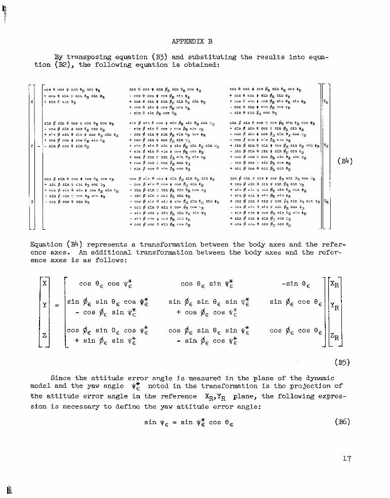
By transposing equation (B3) and subst i tut ing the results in to equat i o n (B2), t he following equation i s obtained:
:os e cos * cos eR cos t, - cos 0 sin t cos eR sin $R i. sin e sin ER
;in # sin e cos 4 cos eR cos t R - cos $ sin $ cos eR cos CR b sin # sin e s i n cos O R s i n $rR i. cos # cos $ cos eR sin pR - s i n # cos e sin OR
:os # sin e cos p cos eR cos tR c sin $ s i n * cos BR cos *R t cos @ sin e sin p cos BR sin *R - sin $ cos * cos eR s i n $rR
- cos $ cos e sin 8 3
cos e cos q s in #R sin eR cos I, - cos e cos * cos gR sin $R + cos e sin * sin BR sin sin $R + cos 8 sin $ cos cos t R - sin 8 sin #R cos eR
sin # s i n e cos t s i n #R sin cos $R - s i n $ sin e cos * cos fiR sin *R - cos 6 sin 4 s i n gR sin BR cos $R + cos # sin p cos 6, sin t R + sin # sin e sin t sin #R sin eR sin tR + sin # sin e sin cos $R COS t R + cos # cos s i n #R sin 8R s i n t R + cos # cos * cos #R cos *R + s i n $ cos 8 sin $R cos BR
cos @ s i n e cos t s i n $R s i n eR cos tR - cos $ s i n e cos cos $R sin VR
+ sin # s i n * s i n $R s i n cos t R - sin # s i n * cos $R s i n t R + cos # s i n e s i n s i n $R sin OR s i n $R + cos $ s i n e s i n * cos & cos tR - s i n $ cos * sin $R s i n eR s i n 6~ - sin $ cos f c o s & cos *R + cos # cos E s in BR cos OR
cos e cos cos #R sin eR cos qR + cos e cos sin pR s i n tR + cos e sin t cos #R sin eR sin pR - cos e sin c sin $R cos *R - sin e cos @R cos e R
s i n # sin e cos cos #R sin eR cos *R + sin # sin e cos 4 sin #R sin $R - cos # sin t cos @R sin ER cos tR - cos $ sin sin $R sin )R + sin # s i n e s i n cos #R s i n eR sin * - s i n # sin e sin * sin #R cos PR + cos # cos cos BR s i n eR sin qR - cos # cos * sin $R cos pR + sin $ cos e cos #R cos BR
cos # s i n e cos * cos @R sin BR cos t R + cos $ s i n e cos + s i n #R sin *R + sin $ s i n * cos fiR s i n OR cos OR + s i n $ sin t s i n $R s i n t R + cos # s i n e s i n t cos #R s i n OR s i n 1 - cos @ sin e s i n * s i n $R cos t R - s in # cos cos plR s i n ER s i n t R + s i n @ cos q s in & cos $8 + cos $ cos e cos $R cos BR
Equation
I=(&) represents a transformation between the body axes and the refer
ence axes. An additional transformation between the body axes and the refer-
COS
ence axes i s as follows:
e, cos q;
s i n plE s i n e, cos - cos pl, s i n qz
cos pl, s in e, cos qzZ + s i n pl, s i n +:
cos e, s i n qz
s i n $, s i n e, s in +E + cos pl, cos Jr;
cos pl, s i n e, s i n qz - s i n pl, cos 9;
-sin 8,
s i n pl, cos e,
cos $4, cos e,
Since the a t t i dude e r ro r ang .e i s measured i n the plane of t he dynamic model and the yaw angle jrz noted i n the transformation i s the projection of t he a t t i t ude e r ro r angle i n the reference XR,YR plane, the following expres
sion i s necessary t o define the yaw a t t i t ude e r ro r angle:
s i n q , = s i n +: cos e, (W
I II111111I I I I I 11111
APPENDIX B
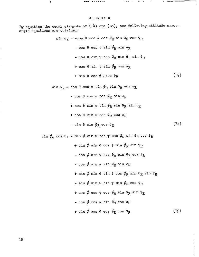
BY quating the equal elements of (Bk) and (B5) the following attitude-errorangle equations are obtained:
sin e, = -cos e COS q COS plR sin 8 R COS \ I ~ R
- cos e COS sin $R sin q R
- cos e sin q COS PIR sin 8 R sin QR
+ cos e sin 9 sin $R COS qR
+ sin e cos @R COS 8 R
sin $, = cos e cos q sin plR sin 8 R cos q R
- cos e COS 9 cos $R sin q R
-t- cos e sin 9 sin $R sin OR sin $R
+ COS 0 sin cas $R COS
- sin e sin #R cos OR
sin @E cos e, = sin $ sin 8 cos q COS plR sin 8 R COS $R
+ sin $ sin e cos .JI sin $R sin $R
- COS # sin + COS @R sin 8 R COS q R
- cos $ sin \cr sin $R sin
+ sin 9 sin e sin $ COS #R sin 8 R sin $R
- sin 9 sin e sin $ sin #R cos q R
+ COS $ COS COS $R sin 8 R sin qR
- cos $ cos + sin & COS
+ sin $ COS e COS $R COS OR
18
.c\
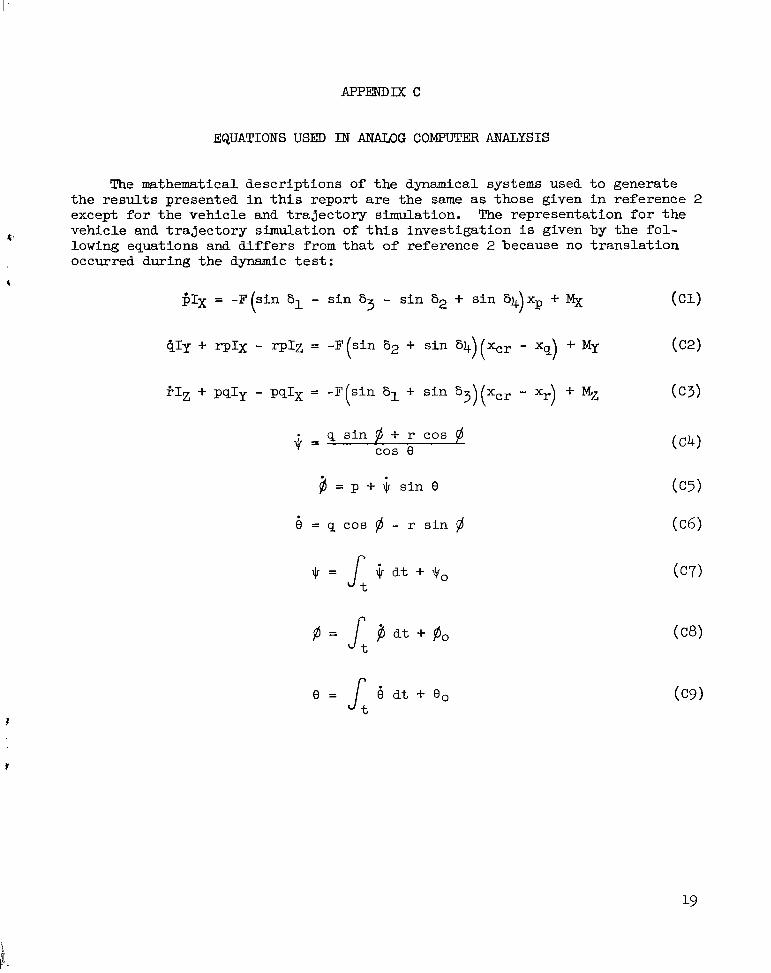
EQUATIONS USED I N ANALOG COMPUTER ANALYSIS
The mathematical descriptions of the dynamical systems used t o generate the resu l t s presented i n t h i s report a r e the same as those given i n reference 2 except f o r the vehicle and t ra jectory simulation. The representation f o r the vehicle and t ra jec tory simulation of this investigation i s given by the fo l lowing equations and d i f f e r s f romthat of reference 2 because no t rans la t ion occurred during the dynamic t e s t :
$IX = -F (s in 61 - s in 65 - s in �i2 + s in 64)xp + % (c1)
q s in. P + r cos $ COS e
= p + j, s i n 8
4
REFENCES
1. Fall, R. C.; Koch, Robert L.; and DeBord, C. J.: Development of the Rocket Velocity and Attitude Control System. Eng. Dept. Rept. No. 2137 (Contract No. NAS 5-483), Allison Div., Gen. Motors Corp., May 29, 1961.
2. Young, A. Thomas; and Harris, Jack E.: An Analog Study of a Rotating-Solid-Rocket Control System and Its Application to Attitude Control,of a Space-Vehicle Upper Stage. NASA TN D-2366,1964. 4
3. Nixon, Floyd E.: Principles of Automatic Controls. Prentice-Ball, Inc., c.1953. 1
4. Barrbe, Marcel; Jaumotte, And&; De Veubeke, Baudouin Fraeijs; and Vandenkerckhove, Jean: Rocket Propulsion. Elsevier Pub. Co., 1960.
20
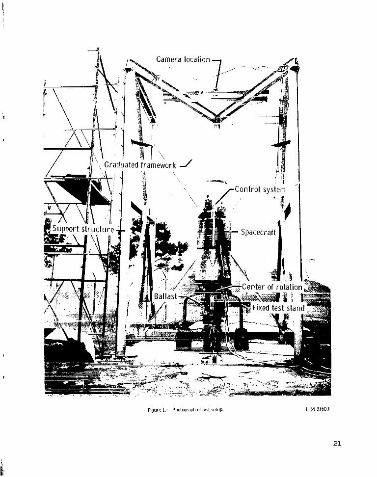
F igu re 1.- Photograph of test setup. L-64-5760.I
21
A Sta 0
Yaw disturbance--. rocket
Spacecraft
ts
stand
Roll disturbance -rockets
Figure 2.- General arrangement of dynamic model a n d test stand. Stations are in inches.
22

” Y
I Control system I Spacecraf t and b a l l a s t I
I I I Contr.01 Control-ro cket I dynamic s d e f l e c t i o n dynamic s I
I
I j I I II Control-rocket Gon t r o1-ro cket I Body I
I d e f l e c t i o n d e f l e c t i o n
I commands angles I motions I I
---I I
I II Weighting and Rate e r r o r s Measuring I I
I summing u n i t u n i t ,,
II i, At t i tude e r r o r s -*
I I
Reference Ia t t i t u d e
Figure 3.- Block diagram of major elements of dynamic model.
Iu w
I
Pitch-rol l control rockets
L-63-8714.1
hree-deck potentiometer Th rus t reduct ion por
3
Electrical drive - ' -- W y a w - r o l I control rockets
F igu re 4.- Photograph of control system. Numbers designate control rockets. L-63-8715.1
24
X X
9 t
J
2 4
3 1
I \ e- -0Y 2
Top view S i d e view
( l o o k i n g i n +Z d i r e c t i o n ) ( l o o k i n g i n +Y d i r e c t i o n )
Figure 5.- Sketch showing contro l rocket deflection convention.
25
yR
zE
LR
Figure 6.- Schematic relat ionship between axis systems. All angles shown are positive.
26
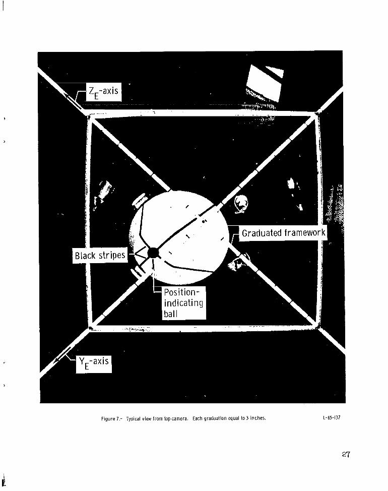
Figure 7.- Typical view f rom top camera. Each graduation equal to 3 inches. L-65-137
27
1 I
II I I I I ~
I 1
i Ii
I i I
j
!i' 1I I I I
h L
i. I-! I !
-'"70 100 110 . Time. sec
(a) Var iat ion of $, e , a n d (I. w i t h time.
I1 III I
!I
I1
4 II
-1U70 80 90 LOO 110 140 Time, sec
(b) Var iat ion of qE, eE , and (I.� w i t h time.
F igu re 8.- Dynamic-test-stand investigation resu l t s obtained f r o m camera data.
28
80
60
Calculated from measured 40 chamber pressures
- - _ Average used in analog anaIysis
20
n " io 80 90 100 110 120 130 140
Time, sec
Figure 9.- Control-rocket thrust t ime histories.
1
, . I
i I
I
I
I ir(
1 1.4!
iI lis CI
i
t rI i!
I 120
(a) Var ia t ion of @E, eE, and oE w i t h time.
Ii I $.p, d e v s e c 4 8 ' I UI
! ~
I I
I II i
i ! I 1
I
q, d e d s e c i w 4 I + I t j; I
-ba,nce i c e ~
I I I I I I I
I
r, d e v s e c i c 41
90 1M) 120 140 Time, sec
(b) Var iat ion of p, q, and r w i t h time.
F igure 10.- Dynamic-test-stand invest igat ion resu l ts obtained f r o m telemetry data.
40 20
bl’ deg o -20 -40
40
20
deg 0
-20 -40
40
20 by de9 0
-20
-40
iancl
100 110 Time, sec
I”
80 90 120 130
(c) Var ia t ion of $, h2‘ 13,and 64 with time.
F igure 10.- Concluded.
140
II
- !
i I I
J.
i ~
I 1 I II
4IIII
I1 1 I II
_1 rI 1.rI
-axis contri 1 . .bi
ITI. I .
100 120 Time, sec
(a) Var iat ion of 8, e , and rj w i t h time.
Figure 11.- Comparison of analog simulat ion resul ts and dynamic-test-stand investigation results.

Time, sec
(b) Variat ion of @E w i t h time.
Time, sec
(c) Var iat ion of 3 E
w i t h time.
I30 140 Time. sec
(d) Variat ion of @E with time.
F igu re 11.- Continued.
33

I ~
iI Ij
I
4
I I I
1
J
L
t
Jance
I ' i ' I 1
T I m80 90 110 UO
Time, sec
(el Var iat ion of p, q, a n d r w i t h time.
F igu re 11.- Continued.
34
-- I I ! n * I I
I 1i i I
I I II I I
I I
~
etry results i L c 1r" P
-40 i
40 , I
I0 1 c
-T;
I -40
II cor I. i by deg I I
I. d
40 ~
Telemetry resu l ts I
' / I l l I 0 L 'ir
I
1 - 4 0 7 ~ 80 90 100 110
Time. sec
( f ) Variat ion of 61 and b3 w i t h t ime
F igu re 11.- Continued.
35
I
i
iI I
j II
,I-
I ! I
II
~
I
h
! I i
I 1
1
~
i I I
1I I+I i
i I I
I
I
~
I I
I
I
i 1
I r i I
I I Itr !
1.'
I Ipi
Ii l
I jII ~
i I
I I
140 Time, sec
(g) Var iat ion of b2 and 64 w i t h time.
Figure 11.- Concluded.
4
I
c
xE
t c (Camera)
\ \ /\
h
-I- 0
- _
PI (P ivot point of dynamic model)
Figure 12.- Sketch used in derivation of equations for reducing camera data.
37L-4469 NASA-Langley, 1965
1
“The aeronautical and space activities of the United States shall be conducted so as to contribute . . . to the expansion of human k120wledge of phenomena in the atmosphere and space. The Administration shall provide for the widest practicable and appropriate dissemination of information concerning its activities and the results thereof .”
-NATIONALAERONAUTICSAND SPACE ACTOF 1958
NASA SCIENTIFIC AND TECHNICAL PUBLICATIONS
TECHNICAL REPORTS: Scientific and technical information considered important, complete, and a lasting contribution to existing knowledge.
TECHNICAL NOTES: Information less broad in scope but nevertheless of importance as a contribution to existing knowledge.
TECHNICAL MEMORANDUMS: Information receiving limited distribution because of preliminary data, security classification, or other reasons.
CONTRACTOR REPORTS: Technical information generated in connection with a NASA contract or grant and released under NASA auspices.
TECHNICAL TRANSLATIONS: Information published in a foreign language considered to merit NASA distribution in English.
TECHNICAL REPRINTS: Information derived from NASA activities and initially published in the form of journal articles.
SPECIAL PUBLICATIONS: Information derived from or of value to NASA activities but not necessarily reporting the results .of individual NASA-programmed scientific efforts. Publications include conference proceedings, monographs, data compilations, handbooks, sourcebooks, and special bibliographies.
Details on the availability of these publications may be obtained from:
SCIENTIFIC AND TECHNICAL INFORMATION DIVISION
NATIONAL AERONAUTICS AND SPACE ADMINISTRATION
Washington, D.C. 20546
i
ti


![Motorized Test Stand with PC Control ESM303 · Adjustable upper and lower solid state limit switches stop test stand travel with 0.001 in. [0.025 mm] repeatability. Adjustable mounting](https://img.pdfslide.net/doc/110x75/602c986bfd38af6cb12ca3e1/motorized-test-stand-with-pc-control-esm303-adjustable-upper-and-lower-solid-state.jpg)